JP2010099884A - Tape printing apparatus - Google Patents

Tape printing apparatus Download PDF

Info

Publication number
JP2010099884A
JP2010099884A JP2008271939A JP2008271939A JP2010099884A JP 2010099884 A JP2010099884 A JP 2010099884A JP 2008271939 A JP2008271939 A JP 2008271939A JP 2008271939 A JP2008271939 A JP 2008271939A JP 2010099884 A JP2010099884 A JP 2010099884A
Authority
JP
Japan
Prior art keywords
tape
cassette
printing
printed
separator
Prior art date
Legal status (The legal status is an assumption and is not a legal conclusion. Google has not performed a legal analysis and makes no representation as to the accuracy of the status listed.)
Granted
Application number
JP2008271939A
Other languages
Japanese (ja)
Other versions
JP5093046B2 (en
Inventor
Terushiro Yamaguchi
晃志郎 山口
Teruo Imamaki
照雄 今牧
Akira Sago
朗 佐郷
Current Assignee (The listed assignees may be inaccurate. Google has not performed a legal analysis and makes no representation or warranty as to the accuracy of the list.)
Brother Industries Ltd
Original Assignee
Brother Industries Ltd
Priority date (The priority date is an assumption and is not a legal conclusion. Google has not performed a legal analysis and makes no representation as to the accuracy of the date listed.)
Filing date
Publication date
Application filed by Brother Industries Ltd filed Critical Brother Industries Ltd
Priority to JP2008271939A priority Critical patent/JP5093046B2/en
Priority to PCT/JP2009/061588 priority patent/WO2010047153A1/en
Priority to CN200980136626.2A priority patent/CN102159405B/en
Priority to EP09821853.0A priority patent/EP2338686B1/en
Publication of JP2010099884A publication Critical patent/JP2010099884A/en
Priority to US13/025,667 priority patent/US8534939B2/en
Application granted granted Critical
Publication of JP5093046B2 publication Critical patent/JP5093046B2/en
Active legal-status Critical Current
Anticipated expiration legal-status Critical

Links

Images

Classifications

    • BPERFORMING OPERATIONS; TRANSPORTING
    • B41PRINTING; LINING MACHINES; TYPEWRITERS; STAMPS
    • B41JTYPEWRITERS; SELECTIVE PRINTING MECHANISMS, i.e. MECHANISMS PRINTING OTHERWISE THAN FROM A FORME; CORRECTION OF TYPOGRAPHICAL ERRORS
    • B41J3/00Typewriters or selective printing or marking mechanisms characterised by the purpose for which they are constructed
    • B41J3/407Typewriters or selective printing or marking mechanisms characterised by the purpose for which they are constructed for marking on special material
    • B41J3/4075Tape printers; Label printers
    • BPERFORMING OPERATIONS; TRANSPORTING
    • B41PRINTING; LINING MACHINES; TYPEWRITERS; STAMPS
    • B41JTYPEWRITERS; SELECTIVE PRINTING MECHANISMS, i.e. MECHANISMS PRINTING OTHERWISE THAN FROM A FORME; CORRECTION OF TYPOGRAPHICAL ERRORS
    • B41J11/00Devices or arrangements  of selective printing mechanisms, e.g. ink-jet printers or thermal printers, for supporting or handling copy material in sheet or web form
    • B41J11/009Detecting type of paper, e.g. by automatic reading of a code that is printed on a paper package or on a paper roll or by sensing the grade of translucency of the paper
    • BPERFORMING OPERATIONS; TRANSPORTING
    • B41PRINTING; LINING MACHINES; TYPEWRITERS; STAMPS
    • B41JTYPEWRITERS; SELECTIVE PRINTING MECHANISMS, i.e. MECHANISMS PRINTING OTHERWISE THAN FROM A FORME; CORRECTION OF TYPOGRAPHICAL ERRORS
    • B41J11/00Devices or arrangements  of selective printing mechanisms, e.g. ink-jet printers or thermal printers, for supporting or handling copy material in sheet or web form
    • B41J11/66Applications of cutting devices
    • B41J11/70Applications of cutting devices cutting perpendicular to the direction of paper feed
    • BPERFORMING OPERATIONS; TRANSPORTING
    • B41PRINTING; LINING MACHINES; TYPEWRITERS; STAMPS
    • B41JTYPEWRITERS; SELECTIVE PRINTING MECHANISMS, i.e. MECHANISMS PRINTING OTHERWISE THAN FROM A FORME; CORRECTION OF TYPOGRAPHICAL ERRORS
    • B41J3/00Typewriters or selective printing or marking mechanisms characterised by the purpose for which they are constructed
    • B41J3/36Typewriters or selective printing or marking mechanisms characterised by the purpose for which they are constructed for portability, i.e. hand-held printers or laptop printers
    • BPERFORMING OPERATIONS; TRANSPORTING
    • B41PRINTING; LINING MACHINES; TYPEWRITERS; STAMPS
    • B41JTYPEWRITERS; SELECTIVE PRINTING MECHANISMS, i.e. MECHANISMS PRINTING OTHERWISE THAN FROM A FORME; CORRECTION OF TYPOGRAPHICAL ERRORS
    • B41J32/00Ink-ribbon cartridges

Abstract

<P>PROBLEM TO BE SOLVED: To provide a tape printing apparatus capable of preventing a printing tape from overlapping and sticking around a label discharging opening even when a separator for the printing tape is released in a tape cassette and conveyed. <P>SOLUTION: When a CPU 91 decides that the kind of the tape cassette mounted in a cassette storing part 8 is a releasing tape cassette 21 with which a printed tape 28 with a pressure-sensitive adhesive from which the separator 53D is released is to be prepared, after only one sheet of the printed tape 28 with the pressure-sensitive adhesive with a specified length from which the separator 53D is released is discharged from the label discharging opening 17, the tape printing is finished. <P>COPYRIGHT: (C)2010,JPO&INPIT

Description

本発明は、長尺状のテープを収納したテープカセットが着脱可能に装着されるテープ印刷装置に関するものである。   The present invention relates to a tape printing apparatus to which a tape cassette containing a long tape is detachably mounted.

従来より、長尺状のテープを収納したテープカセットが着脱可能に装着されるテープ印刷装置に関して種々提案されている。
例えば、レセプタタイプの印字用テープとインクリボンとが収納されたテープカセットが着脱可能に装着され、サーマルヘッド等の印字部によってインクリボンに対面する表面に印刷後、切断機構により切断して排出するテープ印刷装置がある(例えば、特許文献1参照。)。
特開平7−68814号公報(段落(0009)〜(0028)、図2〜図6)
Conventionally, various types of tape printing apparatuses have been proposed in which a tape cassette containing a long tape is detachably mounted.
For example, a tape cassette containing a receptor type printing tape and an ink ribbon is detachably mounted, printed on the surface facing the ink ribbon by a printing unit such as a thermal head, and then cut and discharged by a cutting mechanism. There is a tape printer (see, for example, Patent Document 1).
JP-A-7-68814 (paragraphs (0009) to (0028), FIGS. 2 to 6)

ここで、上述した特許文献1に記載されるテープカセットでは、レセプタタイプの印字用テープは、裏面側に粘着剤が予め塗布され、この粘着剤にセパレータが貼着されているため、排出された印刷テープは、裏面側にセパレータが貼着されており、印刷テープを貼り付ける際に、このセパレータを剥がすのに手間がかかるという問題がある。
しかしながら、このような問題を解決するために、印刷テープのセパレータをテープカセット内で剥離して搬送した場合には、切断した印刷テープは、粘着面が露出した状態で搬送されるため、粘着面がテープ印刷装置のラベル排出口付近に貼り付いて、特に、連続して印刷テープを作成する連続印刷の場合には、テープ印刷装置のラベル排出口付近に印刷テープが重なって貼り付いてしまい、テープ印刷装置のラベル排出口が塞がれてしまうという問題がある。
Here, in the tape cassette described in Patent Document 1 described above, the receptor-type printing tape was discharged because the adhesive was preliminarily applied to the back side and the separator was adhered to the adhesive. The printing tape has a problem in that a separator is attached to the back side, and it takes time to remove the separator when the printing tape is attached.
However, in order to solve such a problem, when the separator of the printing tape is peeled and transported in the tape cassette, the cut printing tape is transported with the adhesive surface exposed. Sticks near the label discharge port of the tape printer, especially in the case of continuous printing to make a printing tape continuously, the print tape overlaps and sticks near the label discharge port of the tape printer, There is a problem that the label discharge port of the tape printer is blocked.

そこで、本発明は、上述した問題点を解決するためになされたものであり、印刷テープのセパレータをテープカセット内で剥離して搬送しても、ラベル排出口付近に印刷テープが重なって貼り付くことを防止することが可能となるテープ印刷装置を提供することを目的とする。   Therefore, the present invention has been made to solve the above-described problems, and even if the separator of the printing tape is peeled off and transported in the tape cassette, the printing tape overlaps and sticks near the label discharge port. It is an object of the present invention to provide a tape printer that can prevent this.

前記目的を達成するため請求項1に係るテープ印刷装置は、テープカセットが着脱可能に装着されるカセット収納部と、前記テープカセットに収納された長尺状のテープを搬送するためのテープ搬送手段と、前記テープに印刷する印刷手段と、テープを切断する切断手段と、を備えたテープ印刷装置において、前記テープに印刷する印刷データと、当該印刷データがテープに印刷されて作成されるラベルの作成枚数とを取得する印刷情報取得手段と、前記カセット収納部に装着されたテープカセットの種類を検出する種類検出手段と、前記種類検出手段を介して検出されたテープカセットの種類は、該テープカセットから排出される前記テープの一面側に粘着面が形成されていると共に、前記粘着面がセパレータで覆われていない状態で排出される剥離テープカセットであるか否かを判定する種類判定手段と、前記カセット収納部に装着されたテープカセットの種類は、前記剥離テープカセットであると判定された場合には、前記印刷手段を介して前記印刷データを1回のみ印刷して前記切断手段による切断位置まで搬送後、テープの搬送を停止して印刷を終了するように制御する印刷制御手段と、を備えたことを特徴とする。   In order to achieve the above object, a tape printing apparatus according to claim 1 includes a cassette storage unit in which a tape cassette is detachably mounted, and a tape transport unit for transporting a long tape stored in the tape cassette. And a printing means for printing on the tape, and a cutting means for cutting the tape. In the tape printing apparatus, the print data to be printed on the tape, and the label created by printing the print data on the tape The print information acquisition means for acquiring the number of sheets produced, the type detection means for detecting the type of the tape cassette mounted in the cassette storage section, and the type of the tape cassette detected via the type detection means are the tape An adhesive surface is formed on one side of the tape that is discharged from the cassette, and the tape is discharged in a state where the adhesive surface is not covered with a separator. A type determining means for determining whether or not the tape is a peeling tape cassette, and when the type of the tape cassette mounted in the cassette storage unit is determined to be the peeling tape cassette, Printing control means for controlling the printing data to be printed only once and transported to a cutting position by the cutting means, and then stopped to stop printing and finish printing.

また、請求項2に係るテープ印刷装置は、請求項1に記載のテープ印刷装置において、前記印刷制御手段は、テープの搬送を停止後、前記切断手段を介してテープを切断するように制御することを特徴とする。   The tape printing apparatus according to claim 2 is the tape printing apparatus according to claim 1, wherein the printing control means controls the tape to be cut through the cutting means after stopping the conveyance of the tape. It is characterized by that.

また、請求項3に係るテープ印刷装置は、請求項1又は請求項2に記載のテープ印刷装置において、前記カセット収納部に装着されたテープカセットの種類は、前記剥離テープカセットであると判定された場合には、前記作成枚数が1枚より多いか否かを判定する枚数判定手段と、前記作成枚数が1枚より多いと判定された場合には、前記印刷データを1回だけ印刷する旨を報知する報知手段と、を備えたことを特徴とする。   According to a third aspect of the present invention, there is provided the tape printer according to the first or second aspect, wherein the type of the tape cassette attached to the cassette housing portion is determined to be the peeling tape cassette. If it is determined that the number of created sheets is greater than one, and a number determination unit that determines whether the number of generated sheets is greater than one, the print data is printed only once. And an informing means for informing the user.

更に、請求項4に係るテープ印刷装置は、請求項1乃至請求項3のいずれかに記載のテープ印刷装置において、前記印刷制御手段は 前記カセット収納部に装着されたテープカセットの種類は、前記剥離テープカセットでないと判定された場合には、前記印刷手段を介して前記印刷情報に含まれる前記印刷データを前記作成枚数分だけ連続印刷すると共に、それぞれ前記切断手段による切断位置まで搬送して切断するように制御することを特徴とする。   Furthermore, the tape printer according to claim 4 is the tape printer according to any one of claims 1 to 3, wherein the print control means is configured such that the type of the tape cassette mounted in the cassette housing portion is If it is determined that it is not a peeling tape cassette, the print data included in the print information is continuously printed by the printing means for the number of sheets to be created, and each is conveyed to a cutting position by the cutting means and cut. It controls to do.

請求項1に係るテープ印刷装置では、カセット収納部に装着されたテープカセットの種類は、該テープカセットから印刷されて排出されるテープの一面側に粘着面が形成されると共に、粘着面がセパレータで覆われていない状態で排出される剥離テープカセットであると判定された場合には、印刷手段を介して印刷データを1回のみ印刷して切断手段による切断位置まで搬送後、テープの搬送を停止して印刷を終了する。   In the tape printer according to claim 1, the type of the tape cassette mounted in the cassette housing portion is such that an adhesive surface is formed on one side of the tape printed and discharged from the tape cassette, and the adhesive surface is a separator. If it is determined that the cassette is a release tape cassette that is discharged without being covered with, the print data is printed only once through the printing means and conveyed to the cutting position by the cutting means, and then the tape is conveyed. Stop and end printing.

これにより、剥離テープカセットをカセット収納部に装着した場合には、印刷データがテープに印刷されて作成されるラベルの作成枚数を2枚以上に設定しても、1回だけ印刷して切断位置まで搬送した場合には、テープへの印刷が終了する。このため、印刷されたテープの一面側に形成された粘着面がセパレータで覆われていない状態で剥離テープカセットから排出されても、テープ印刷装置のラベル排出口付近に印刷テープが、複数枚重なって貼り付くことを防止することが可能となる。また、剥離テープカセットをカセット収納部に装着した場合には、印刷されたテープのセパレータをテープカセット内で剥離して排出することが可能となり、印刷データがテープに印刷されて作成されたラベルを商品等に貼り付ける際に、セパレータを剥がす手間を省くことができる。   As a result, when the peeling tape cassette is mounted in the cassette housing section, even if the number of labels to be created by printing data printed on the tape is set to two or more, the printing position is printed only once. In the case where the tape is conveyed, the printing on the tape is completed. For this reason, even if the adhesive surface formed on one side of the printed tape is not covered with the separator and is discharged from the peeling tape cassette, a plurality of printing tapes overlap in the vicinity of the label discharge port of the tape printer. It is possible to prevent sticking. In addition, when the release tape cassette is installed in the cassette storage section, the printed tape separator can be released in the tape cassette and discharged, and the label created by printing the print data on the tape can be removed. When pasting on a product or the like, it is possible to save time and effort to remove the separator.

また、請求項2に係るテープ印刷装置では、剥離テープカセットをカセット収納部に装着した場合には、印刷データが1回だけテープに印刷された後、切断位置まで搬送されて自動的に切断されるため、印刷データが印刷されると共に、一面側に形成された粘着面がセパレータで覆われていないラベルを容易に作成することができる。   Further, in the tape printer according to claim 2, when the peeling tape cassette is mounted in the cassette housing portion, the print data is printed on the tape only once and then conveyed to the cutting position and automatically cut. Therefore, it is possible to easily create a label in which the print data is printed and the adhesive surface formed on one side is not covered with the separator.

また、請求項3に係るテープ印刷装置では、剥離テープカセットをカセット収納部に装着してラベルの作成枚数を1枚より多く設定した場合には、印刷データを1回だけ印刷する旨、つまり、ラベルを1枚だけ作成する旨が報知されるため、ユーザは、再度印刷データを設定して印刷しなければならないことを容易に認識することが可能となる。   Further, in the tape printer according to claim 3, when the release tape cassette is mounted in the cassette housing portion and the number of labels to be created is set to be more than one, the print data is printed only once, that is, Since it is notified that only one label is to be created, the user can easily recognize that the print data must be set again and printed.

更に、請求項4に係るテープ印刷装置では、剥離テープカセットでない通常テープカセット、つまり、印刷データが印刷されたテープの一面側に形成された粘着面がセパレータで覆われた状態で排出される通常テープカセットをカセット収納部に装着した場合には、ユーザが設定したラベルの作成枚数分だけ連続印刷して、印刷データが印刷された複数枚のラベルを連続して作成することができる。   Further, in the tape printer according to claim 4, the normal tape cassette which is not the peeling tape cassette, that is, the adhesive surface formed on one side of the tape on which the print data is printed is normally discharged in a state covered with the separator. When the tape cassette is mounted in the cassette storage unit, it is possible to continuously create a plurality of labels on which print data is printed by continuously printing as many labels as the number of labels set by the user.

以下、本発明に係るテープ印刷装置について具体化した一実施形態に基づき図面を参照しつつ詳細に説明する。   Hereinafter, a tape printer according to an embodiment of the present invention will be described in detail with reference to the drawings based on an embodiment.

先ず、本実施形態に係るテープ印刷装置1の概略構成について図1乃至図3に基づき説明する。
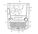
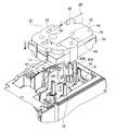
図1は本実施形態に係るテープ印刷装置1の平面図である。図2はテープ印刷装置1の右側面図である。図3はテープ印刷装置1のカセット収納部8に剥離テープカセット21を装着する状態を示す要部拡大斜視図である。
First, a schematic configuration of the tape printer 1 according to the present embodiment will be described with reference to FIGS. 1 to 3.
FIG. 1 is a plan view of a tape printer 1 according to the present embodiment. FIG. 2 is a right side view of the tape printer 1. FIG. 3 is an enlarged perspective view of a main part showing a state in which the peeling tape cassette 21 is mounted in the cassette housing part 8 of the tape printer 1.

図1乃至図3に示すように、本実施形態に係るテープ印刷装置1には、文書データからなるテキストを作成するための文字入力キー2、テキスト等の印刷を指示する印刷キー3、及び、改行指示や各種処理の実行、選択を指示するリターンキー4、文字等のキャラクタを複数行に渡って表示する液晶ディスプレイ(LCD)7上でカーソルを上下、左右に移動させるカーソルキー5等を設けたキーボード6、及び、剥離テープカセット21や後述の通常テープカセット81(図8参照)を収納するカセット収納部8が収納カバー13で覆われて配設されている。   As shown in FIGS. 1 to 3, the tape printer 1 according to the present embodiment includes a character input key 2 for creating text composed of document data, a print key 3 for instructing printing of text, and the like. There are provided a return key 4 for instructing a line feed, executing various processes, selecting, a cursor key 5 for moving the cursor up and down, left and right on a liquid crystal display (LCD) 7 for displaying characters such as characters over a plurality of lines. A cassette housing portion 8 for housing the keyboard 6, the peeling tape cassette 21 and a normal tape cassette 81 (see FIG. 8) described later is covered with a storage cover 13.

また、このキーボード6の下側には、制御回路部90(図11参照)が構成される制御基板12が配設されている。また、カセット収納部8の左側面部には、印刷されて後述のようにセパレータが剥離された印刷済みテープや、セパレータが貼着されている印刷済みテープが排出されるラベル排出口17が形成されている。また、該カセット収納部8の右側面部には、電源アダプタが取り付けられるアダプタ挿入口18、及び不図示のパーソナルコンピュータと接続するためのUSBケーブルが取り付けられるUSBコネクタ19が設けられている。   In addition, a control board 12 on which a control circuit unit 90 (see FIG. 11) is configured is disposed below the keyboard 6. In addition, a label discharge port 17 is formed on the left side surface of the cassette housing portion 8 for discharging a printed tape with a separator peeled off as described later, or a printed tape with a separator attached thereto. ing. In addition, an adapter insertion slot 18 to which a power adapter is attached and a USB connector 19 to which a USB cable for connection to a personal computer (not shown) is attached are provided on the right side surface of the cassette housing portion 8.

また、このカセット収納部8には、サーマルヘッド9と、このサーマルヘッド9に対向するプラテンローラ10と、このプラテンローラ10の下流側のテープサブローラ11と、このテープサブローラ11に対向する金属製のテープ駆動ローラ軸14と、剥離テープカセット21内に収納されるインクリボン52(図4参照)を送るリボン巻取軸15が配置されている他に、更に後述のように両面粘着テープ53(図4参照)から剥離されたセパレータ53D(図4参照)を巻き取るセパレータ巻取軸16等が配置されている。   The cassette housing 8 includes a thermal head 9, a platen roller 10 facing the thermal head 9, a tape sub-roller 11 downstream of the platen roller 10, and a metal facing the tape sub-roller 11. In addition to the tape drive roller shaft 14 and the ribbon take-up shaft 15 for feeding the ink ribbon 52 (see FIG. 4) accommodated in the release tape cassette 21, a double-sided adhesive tape 53 is further described below. A separator take-up shaft 16 and the like for taking up the separator 53D (see FIG. 4) peeled off (see FIG. 4) are disposed.

このサーマルヘッド9は、正面視略縦長四角形の平板状で、前面の左端縁部には、所定個数の各発熱素子R1〜Rn(nは、例えば、128個又は256個である。)が、該左端縁部の辺に沿って一列に配列されて形成されている。また、該サーマルヘッド9は、メッキ鋼板やステンレス鋼板等により形成される正面視略四角形の放熱板9Aの前面の左端縁部に、各発熱素子R1〜Rnの配列方向が、該放熱板9Aの左端縁部の辺に平行になるように接着剤などによって固着されている。そして、該放熱板9Aは、各発熱素子R1〜Rnの配列方向が、剥離テープカセット21の開口部22におけるフィルムテープ51(図4参照)の搬送方向に略直交するように、ビス止め等によってカセット収納部8の下側に取り付けられている。   The thermal head 9 is a flat plate having a substantially rectangular shape when viewed from the front, and a predetermined number of heating elements R1 to Rn (n is, for example, 128 or 256) are provided on the left end edge of the front surface. It is arranged in a line along the side of the left edge. Further, the thermal head 9 is arranged on the left end edge of the front surface of a substantially square heat sink 9A formed of a plated steel plate, a stainless steel plate, or the like so that the arrangement direction of the heat generating elements R1 to Rn is the heat sink 9A. It is fixed with an adhesive or the like so as to be parallel to the side of the left edge. The heat radiating plate 9A is screwed or the like so that the arrangement direction of the heating elements R1 to Rn is substantially orthogonal to the transport direction of the film tape 51 (see FIG. 4) in the opening 22 of the peeling tape cassette 21. It is attached to the lower side of the cassette housing portion 8.

また、リボン巻取軸15は、ステッピングモータ等により構成されるテープ送りモータ103(図11参照)から適宜の駆動機構を介して回転駆動され、後述のように剥離テープカセット21内に回転可能に設けられたリボン巻き取りスプール61(図4参照)内に嵌入されて回転駆動する。また、テープ駆動ローラ軸14は、テープ送りモータ103から適宜の伝達機構を介して回転駆動され、後述のように剥離テープカセット21内に回転可能に設けられた導電性樹脂製のテープ送りローラ63(図4参照)内に嵌入されて回転駆動する。また、セパレータ巻取軸16は、テープ送りモータ103から適宜の伝達機構を介して回転駆動され、後述のように剥離テープカセット21内に回転可能に設けられたセパレータ巻き取りスプール62(図4参照)内に嵌入されて回転駆動する。   Further, the ribbon take-up shaft 15 is rotationally driven through a suitable drive mechanism from a tape feed motor 103 (see FIG. 11) constituted by a stepping motor or the like, and can be rotated in the peeling tape cassette 21 as will be described later. It is inserted into a ribbon take-up spool 61 (see FIG. 4) and is driven to rotate. The tape drive roller shaft 14 is rotationally driven from the tape feed motor 103 via an appropriate transmission mechanism, and is made of a conductive resin tape feed roller 63 provided rotatably in the peeling tape cassette 21 as will be described later. (See FIG. 4) It is inserted into and rotated. The separator take-up shaft 16 is rotationally driven from the tape feed motor 103 via an appropriate transmission mechanism, and is provided with a separator take-up spool 62 (see FIG. 4) rotatably provided in the peeling tape cassette 21 as will be described later. ) And is rotationally driven.

尚、セパレータ巻取軸16をテープ送りモータ103とは別個に設けられたステッピングモータ等により構成される不図示のセパレータ巻取モータから適宜の駆動機構を介して回転駆動するように構成してもよい。これにより、インクリボン52とセパレータ53Dの伸び率等が大きく異なっても、テープ送りモータ103とセパレータ巻取モータとを同期して駆動することにより、該セパレータ53Dを安定して巻き取ることが可能となる。   The separator take-up shaft 16 may be configured to be rotationally driven via an appropriate drive mechanism from a separator take-up motor (not shown) configured by a stepping motor or the like provided separately from the tape feed motor 103. Good. As a result, even if the elongation rates of the ink ribbon 52 and the separator 53D differ greatly, the separator 53D can be stably wound by driving the tape feed motor 103 and the separator take-up motor synchronously. It becomes.

また、図3に示すように、剥離テープカセット21のテープ排出口27(図4参照)及び通常テープカセット81のテープ排出口83(図8参照)の近傍には、印刷済みテープを所定の長さに切断する切断装置としてのはさみ式カッタユニット30が配置されている。このカッタユニット30は、固定刃30Aと、切断用モータ105によって固定刃30Aに対して作動して印刷済みテープを切断する可動刃30Bとから構成されている。   Further, as shown in FIG. 3, a printed tape is placed in the vicinity of the tape outlet 27 (see FIG. 4) of the peeling tape cassette 21 and the tape outlet 83 (see FIG. 8) of the normal tape cassette 81 for a predetermined length. A scissor-type cutter unit 30 is arranged as a cutting device for cutting the blades. The cutter unit 30 includes a fixed blade 30A and a movable blade 30B that operates on the fixed blade 30A by a cutting motor 105 to cut the printed tape.

また、カセット収納部8の底面部には、2つの位置決めピン45、46が、同一高さ寸法に立設されている。そして、剥離テープカセット21や通常テープカセット81をカセット収納部8に装着した際には、剥離テープカセット21及び通常テープカセット81は、各位置決めピン45、46によってカセット収納部8内で適正に位置決めがされる。   Further, two positioning pins 45 and 46 are erected at the same height on the bottom surface of the cassette housing 8. When the peeling tape cassette 21 or the normal tape cassette 81 is attached to the cassette storage unit 8, the peeling tape cassette 21 and the normal tape cassette 81 are properly positioned in the cassette storage unit 8 by the positioning pins 45 and 46. Is done.

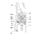
次に、セパレータ53Dが剥離された粘着剤付き印刷済みテープ28が作成される剥離テープカセット21の概略構成について図3乃至図7に基づいて説明する。図4はテープ印刷装置1のカセット収納部8に剥離テープカセット21を装着した状態で剥離テープカセット21の上ケース23を取り外した場合の要部拡大平面図である。図5は図4のテープ排出口27の周囲を拡大した要部拡大図である。図6は図5のテープ排出口27のX1矢視図である。図7は両面粘着テープ53をフィルムテープ51へ圧着後、セパレータ53Dが剥離される状態を模式的に示す図である。   Next, a schematic configuration of the peeling tape cassette 21 in which the pressure-sensitive adhesive-printed tape 28 from which the separator 53D has been peeled will be described with reference to FIGS. FIG. 4 is an enlarged plan view of a main part when the upper case 23 of the peeling tape cassette 21 is removed in a state where the peeling tape cassette 21 is mounted in the cassette housing portion 8 of the tape printer 1. FIG. 5 is an enlarged view of a main part in which the periphery of the tape discharge port 27 of FIG. 4 is enlarged. FIG. 6 is a view taken along the arrow X1 of the tape outlet 27 of FIG. FIG. 7 is a diagram schematically showing a state in which the separator 53D is peeled after the double-sided pressure-sensitive adhesive tape 53 is pressure-bonded to the film tape 51.

図3及び図4に示すように、剥離テープカセット21は、上ケース23と下ケース24とを有する。この剥離テープカセット21には、被印刷テープとしての透明なフィルムテープ51を巻回したテープスプール54を回転可能に支持する支持孔41が形成されている。また、この剥離テープカセット21には、両面粘着テープ53の剥離紙やフィルム等から形成されるセパレータ53D(図7参照)を外側に向けて巻回した両面粘着スプール56を回転可能に支持する支持孔42が形成されている。   As shown in FIGS. 3 and 4, the peeling tape cassette 21 has an upper case 23 and a lower case 24. The release tape cassette 21 is formed with a support hole 41 that rotatably supports a tape spool 54 around which a transparent film tape 51 as a printing tape is wound. Further, the release tape cassette 21 supports a double-sided adhesive spool 56 in which a separator 53D (see FIG. 7) formed of release paper or a film of the double-sided adhesive tape 53 is wound outwardly so as to be rotatable. A hole 42 is formed.

また、この剥離テープカセット21には、テープスプール54と両面粘着スプール56との間の開口部22側に配設されたリボン巻き取りスプール61を回転可能に支持する支持孔43が形成されている。このリボン巻き取りスプール61は、サーマルヘッド9によりフィルムテープ51上に文字等を印刷する際にリボンスプール55からインクリボン52を引き出すとともに、巻き取る。   The release tape cassette 21 has a support hole 43 that rotatably supports the ribbon take-up spool 61 disposed on the opening 22 side between the tape spool 54 and the double-sided adhesive spool 56. . The ribbon take-up spool 61 draws out and winds up the ink ribbon 52 from the ribbon spool 55 when characters or the like are printed on the film tape 51 by the thermal head 9.

また、この剥離テープカセット21には、テープスプール54と両面粘着スプール56との間の開口部22に対向する下ケース24の側壁部24A側に配設されたセパレータ巻き取りスプール62を回転可能に支持する支持孔44が形成されている。このセパレータ巻き取りスプール62は、テープ送りローラ63の外周面に沿って両面粘着テープ53から剥離されたセパレータ53Dを巻き取る。また、下ケース24の側壁部24Aのセパレータ巻き取りスプール62に対向する部分は平面視略円弧状に突出するように形成されている。   Further, in this peeling tape cassette 21, a separator take-up spool 62 disposed on the side wall 24A side of the lower case 24 facing the opening 22 between the tape spool 54 and the double-sided adhesive spool 56 is rotatable. A support hole 44 for support is formed. The separator take-up spool 62 takes up the separator 53D peeled off from the double-sided adhesive tape 53 along the outer peripheral surface of the tape feed roller 63. Further, a portion of the side wall portion 24A of the lower case 24 facing the separator take-up spool 62 is formed so as to protrude in a substantially arc shape in plan view.

また、この剥離テープカセット21には、テープ送りローラ63のテープ搬送方向下流側、つまり、テープ排出口27側に離間して配置された接触コロ65を回転可能に支持する支持孔48が形成されている。
図5及び図6に示すように、この接触コロ65の外周面は、該外周面に軸方向断面V字形の溝部65Aが軸方向に連続して形成されると共に、両端面外周部が軸方向内側に斜めに面取りされて、軸方向に平行な複数の断面略三角形の凸状形状に形成されている。
Further, the peeling tape cassette 21 is formed with a support hole 48 that rotatably supports a contact roller 65 that is spaced apart from the tape feed roller 63 in the tape transport direction, that is, the tape discharge port 27 side. ing.
As shown in FIGS. 5 and 6, the outer peripheral surface of the contact roller 65 is formed with a groove portion 65 </ b> A having an axial cross-section V shape continuously formed in the outer peripheral surface, and the outer peripheral portions on both end surfaces are axial. It is chamfered obliquely inside and formed into a convex shape having a plurality of substantially triangular cross sections parallel to the axial direction.

また、接触コロ65は、両端面中心位置に支持孔48に回転可能に嵌入される各支持軸65Bが立設されると共に、外周面にシリコーン樹脂皮膜が形成されている。そして、この接触コロ65は、セパレータ53Dが剥離された印刷済みテープ28の粘着層53C(図7参照)に接触して、該印刷済みテープ28をテープ排出口27からテープ搬送方向下流側へ案内する。   The contact roller 65 has support shafts 65B that are rotatably inserted into the support holes 48 at the center positions of both end surfaces, and a silicone resin film is formed on the outer peripheral surface. The contact roller 65 contacts the adhesive layer 53C (see FIG. 7) of the printed tape 28 from which the separator 53D has been peeled off, and guides the printed tape 28 from the tape discharge port 27 to the downstream side in the tape transport direction. To do.

また、接触コロ65は、テープ送りローラ63に対向する側壁部24Bよりもテープ搬送方向外側に突出して、固定刃30Aに対向すると共に該固定刃30Aに近接するように設けられている。
また、接触コロ65に対して印刷済みテープ28を挟んで対向する案内壁33は、この接触コロ65よりもテープ搬送方向下流側へ延出されて、印刷済みテープ28を固定刃30Aの近傍位置まで案内可能となるように設けられている。
Further, the contact roller 65 protrudes outward in the tape transport direction from the side wall portion 24B facing the tape feed roller 63, and is provided so as to face the fixed blade 30A and be close to the fixed blade 30A.
Further, the guide wall 33 facing the contact roller 65 with the printed tape 28 interposed therebetween is extended to the downstream side of the contact roller 65 in the tape transport direction, and the printed tape 28 is positioned in the vicinity of the fixed blade 30A. It is provided so that it can be guided to.

また、この剥離テープカセット21には、両面粘着スプール56に巻回された両面粘着テープ53の最大径時の外周面と下ケース24の各側壁部24A、24Cとの間に、この両面粘着テープ53の引出口から下ケース24の側壁部24Aに対向する部分までを覆う平面視略半円形状の案内リブ35が底面部に立設されている。また、案内リブ35の下ケース24の各側壁部24A、24Cに対向する部分には、テープ幅方向に沿って所定高さ(例えば、高さ約1mmである。)突出する各凸状部35A、35Bが全幅に渡って形成されている。   The double-sided pressure-sensitive adhesive tape 21 includes a double-sided pressure-sensitive adhesive tape between the outer peripheral surface of the double-sided pressure-sensitive adhesive tape 53 wound around the double-sided pressure-sensitive adhesive spool 56 and the side walls 24A and 24C of the lower case 24. A guide rib 35 having a substantially semicircular shape in a plan view is provided on the bottom surface so as to cover from the outlet 53 to a portion facing the side wall 24A of the lower case 24. In addition, each convex portion 35A that protrudes at a predetermined height (for example, about 1 mm in height) along the tape width direction at a portion facing the side wall portions 24A and 24C of the lower case 24 of the guide rib 35. , 35B are formed over the entire width.

また、両面粘着スプール56に巻回された両面粘着テープ53に対向する下ケース24の隅部と案内リブ35との間には、略円柱形状のガイドピン36が立設されている。また、上ケース23のガイドピン36に対向する部分には、このガイドピン36の端縁部が嵌入されて支持する支持孔49が形成されている。また、テープ送りローラ63のテープサブローラ11に対して反対側には、セパレータ53Dとの接触面を平面視円弧状に形成されたセパレータ案内壁37が、側壁部24Cから該テープ送りローラ63と所定隙間を形成して内側方向に突出している。   A substantially cylindrical guide pin 36 is provided between the corner of the lower case 24 facing the double-sided adhesive tape 53 wound around the double-sided adhesive spool 56 and the guide rib 35. Further, a support hole 49 is formed in a portion of the upper case 23 facing the guide pin 36 so as to fit and support an end edge portion of the guide pin 36. Further, on the opposite side of the tape feed roller 63 with respect to the tape sub-roller 11, a separator guide wall 37 having a contact surface with the separator 53D formed in an arc shape in a plan view is connected to the tape feed roller 63 from the side wall 24C. A predetermined gap is formed and projects inward.

尚、図3中には、上ケース23に形成された各支持孔41、42、43、44、48のみしか図示されていないが、下ケース24についても同様に上ケース23の各支持孔41、42、43、44、48に対向して各支持孔41、42、43、44、48が形成されている。   In FIG. 3, only the support holes 41, 42, 43, 44, 48 formed in the upper case 23 are shown, but the support holes 41 of the upper case 23 are similarly shown for the lower case 24. , 42, 43, 44, 48 are formed with support holes 41, 42, 43, 44, 48.

また、図4に示すように、剥離テープカセット21内には、透明テープ等からなる被印刷テープであるフィルムテープ51、このフィルムテープ51に印刷を施すためのインクリボン52、更には、印刷がなされたフィルムテープ51に裏貼りされる両面粘着テープ53を各々、テープスプール54、リボンスプール55、両面粘着スプール56に巻回して、下ケース24の底面に立設されるカセットボス58、リールボス59、カセットボス60に回転可能に嵌挿して収納したものであり、更に、使用済みのインクリボン52を巻き取るリボン巻き取りスプール61、及び両面粘着テープ53から剥離されたセパレータ53Dを巻き取るセパレータ巻き取りスプール62を備えている。   As shown in FIG. 4, in the peeling tape cassette 21, a film tape 51 which is a printing tape made of a transparent tape or the like, an ink ribbon 52 for printing on the film tape 51, and further printing is performed. A double-sided adhesive tape 53 backed on the film tape 51 is wound around a tape spool 54, a ribbon spool 55, and a double-sided adhesive spool 56, respectively, and a cassette boss 58 and a reel boss 59 standing on the bottom surface of the lower case 24 are wound. , Which is rotatably inserted into the cassette boss 60 and accommodated therein, and further, a ribbon take-up spool 61 for taking up the used ink ribbon 52 and a separator take-up for taking up the separator 53D peeled off from the double-sided adhesive tape 53. A take-up spool 62 is provided.

尚、図4に示すように、リボン巻き取りスプール61の下部にはクラッチバネ64が取り付けられている。このクラッチバネ64はリボン巻き取りスプール61が逆転して巻き取ったインクリボン52が緩んでしまうことを防止するものである。また、セパレータ巻き取りスプール62の下部にはクラッチバネ66が取り付けられている。このクラッチバネ66はセパレータ巻き取りスプール62が逆転して巻き取ったセパレータ53Dが緩んでしまうことを防止するものである。   As shown in FIG. 4, a clutch spring 64 is attached to the lower part of the ribbon take-up spool 61. The clutch spring 64 prevents the ink ribbon 52 that has been wound up by the reverse of the ribbon take-up spool 61 from being loosened. A clutch spring 66 is attached to the lower part of the separator take-up spool 62. This clutch spring 66 prevents the separator take-up spool 62 from reversing and loosening the separator 53D taken up.

また、図4に示すように、リボンスプール55に巻回され、このリボンスプール55から引き出された未使用インクリボン52は、フィルムテープ51と重ね合わされ、フィルムテープ51と共に開口部22に入り、サーマルヘッド9及びプラテンローラ10の間を通過する。その後、インクリボン52は、フィルムテープ51から引き離され、リボン巻取軸15により回転駆動されるリボン巻き取りスプール61に至り、このリボン巻き取りスプール61により巻き取られる。   Further, as shown in FIG. 4, the unused ink ribbon 52 wound around the ribbon spool 55 and pulled out from the ribbon spool 55 is overlapped with the film tape 51 and enters the opening portion 22 together with the film tape 51, and the thermal It passes between the head 9 and the platen roller 10. Thereafter, the ink ribbon 52 is separated from the film tape 51, reaches a ribbon take-up spool 61 that is rotationally driven by the ribbon take-up shaft 15, and is taken up by the ribbon take-up spool 61.

また、図7に示すように、セパレータ53Dを外側にして両面粘着スプール56に巻回された両面粘着テープ53は、4層構造に構成されている。この両面粘着テープ53の各層は、図7中下側から上側方向へ向かって、フィルムテープ51を接着するための粘着層53A、PET(ポリエチレンテレフタラート)等から成る色付きのベースフィルム53B、商品等の貼り付け対象に貼り付けるための粘着層53C、この粘着層53Cの貼り付け側を覆うセパレータ53Dの順序で積層されて構成されている。   Further, as shown in FIG. 7, the double-sided pressure-sensitive adhesive tape 53 wound around the double-sided pressure-sensitive adhesive spool 56 with the separator 53D on the outside has a four-layer structure. Each layer of the double-sided adhesive tape 53 includes an adhesive layer 53A for adhering the film tape 51 from the lower side to the upper side in FIG. 7, a colored base film 53B made of PET (polyethylene terephthalate), etc. The adhesive layer 53C for attaching to the object to be attached and the separator 53D covering the attachment side of the adhesive layer 53C are laminated in this order.

そして、図4乃至図7に示すように、両面粘着スプール56から引き出された両面粘着テープ53は、テープ駆動ローラ軸14によって回転駆動されるテープ送りローラ63とテープサブローラ11との間を通過し、セパレータ53Dが重ね合わされない側の粘着層53Aがフィルムテープ51の印刷面に圧着される。   4 to 7, the double-sided adhesive tape 53 drawn from the double-sided adhesive spool 56 passes between the tape feed roller 63 and the tape sub-roller 11 that are rotationally driven by the tape drive roller shaft 14. Then, the pressure-sensitive adhesive layer 53 </ b> A on the side where the separator 53 </ b> D is not superimposed is pressure-bonded to the printing surface of the film tape 51.

その後、セパレータ53Dは、フィルムテープ51に圧着された両面粘着テープ53から剥離され、テープ送りローラ63の外周面に沿って両面粘着スプール56側に、つまり、引き出し側方向(図4中、上側方向である。)へ案内される。続いて、セパレータ53Dは、セパレータ案内壁37の壁面に沿って案内リブ35の外側方向に案内されて、凸状部35A、ガイドピン36及び凸状部35Bの外周面に順次沿って、巻回された両面粘着テープ53の外側周縁を通って略直角内側方向へ案内されてセパレータ巻き取りスプール62に至る。   Thereafter, the separator 53D is peeled off from the double-sided pressure-sensitive adhesive tape 53 pressure-bonded to the film tape 51, and is directed to the double-sided pressure-sensitive adhesive spool 56 side along the outer peripheral surface of the tape feed roller 63, that is, the pull-out side direction (upward direction in FIG. 4). ). Subsequently, the separator 53D is guided in the outer direction of the guide rib 35 along the wall surface of the separator guide wall 37, and is sequentially wound along the outer peripheral surfaces of the convex portion 35A, the guide pin 36, and the convex portion 35B. The double-sided adhesive tape 53 is guided to the inner side at a substantially right angle through the outer peripheral edge and reaches the separator take-up spool 62.

そして、セパレータ53Dの先端部は、このセパレータ巻き取りスプール62の外周面に接着テープ等によって固着され、セパレータ巻取軸16により回転駆動される該セパレータ巻き取りスプール62に巻き取られる。尚、セパレータ巻取軸16は、テープ駆動ローラ軸14及びリボン巻取軸15と同期して回転駆動される。   The front end of the separator 53D is fixed to the outer peripheral surface of the separator take-up spool 62 with an adhesive tape or the like, and is taken up by the separator take-up spool 62 that is driven to rotate by the separator take-up shaft 16. The separator take-up shaft 16 is rotationally driven in synchronization with the tape drive roller shaft 14 and the ribbon take-up shaft 15.

また、フィルムテープ51は、テープ駆動ローラ軸14によって回転駆動されるテープ送りローラ63とテープサブローラ11との間を通過後、印刷面に粘着層53A、ベースフィルム53B及び粘着層53Cが積層された状態で接触コロ65に至る。そして、印刷面に粘着層53A、ベースフィルム53B及び粘着層53Cが積層されたフィルムテープ51は、つまり、セパレータ53Dが剥離された粘着剤付き印刷済みテープ28は、粘着層53Cに接触する接触コロ65と、該接触コロ65に対して印刷済みテープ28を挟んで対向する案内壁33とによって案内されて、テープ排出口27から剥離テープカセット21の外部に送り出される。そして、セパレータ53Dが剥離された粘着剤付き印刷済みテープ28は、カッタユニット30を経てテープ印刷装置1のラベル排出口17より外部に送り出される。   Further, after the film tape 51 passes between the tape feed roller 63 and the tape sub-roller 11 that are rotationally driven by the tape drive roller shaft 14, the adhesive layer 53A, the base film 53B, and the adhesive layer 53C are laminated on the printing surface. In this state, the contact roller 65 is reached. The film tape 51 in which the adhesive layer 53A, the base film 53B, and the adhesive layer 53C are laminated on the printing surface, that is, the printed tape 28 with the adhesive 53 from which the separator 53D has been peeled, is in contact with the adhesive layer 53C. 65 and a guide wall 33 facing the contact roller 65 with the printed tape 28 interposed therebetween, and is fed out of the peeling tape cassette 21 from the tape discharge port 27. The pressure-sensitive adhesive-printed tape 28 from which the separator 53D has been peeled is sent out from the label discharge port 17 of the tape printer 1 through the cutter unit 30.

そして、印刷済みテープ28を所定長さ搬送後、切断用モータ105を駆動して可動刃30Bを作動させることによって、セパレータ53Dが剥離された所定長さの粘着剤付き印刷済みテープ28がラベル排出口17より排出される。   Then, after the printed tape 28 is conveyed for a predetermined length, the cutting motor 105 is driven to operate the movable blade 30B, whereby the printed tape 28 with adhesive having a predetermined length from which the separator 53D has been peeled is removed. It is discharged from the outlet 17.

ところで、図4に示すように、下ケース24のフィルムテープ51が巻回されるテープスプール54に対向する角部には、テープカセットの種類(例えば、セパレータ53Dが剥離された粘着剤付き印刷済みテープ28が作成される剥離テープカセット21、セパレータ53Dが貼着された粘着剤付き印刷済みテープ85が作成される通常テープカセット81等である。)、テープ幅(例えば、6mm、9mm、12mm、18mm、24mmとする5種類等である)、テープの材質等を判別するための7個の各カセット判別孔25A〜25Gが略L字状に設けられている。   Incidentally, as shown in FIG. 4, at the corner of the lower case 24 facing the tape spool 54 around which the film tape 51 is wound, the type of the tape cassette (for example, printed with an adhesive with the separator 53D peeled off) has been printed. The tape 28 is made of the release tape cassette 21, the pressure-sensitive adhesive-printed tape 85 to which the separator 53D is attached is usually made of the tape cassette 81, etc.), the tape width (for example, 6 mm, 9 mm, 12 mm, Seven cassette discriminating holes 25A to 25G for discriminating the tape material and the like are provided in a substantially L shape.

但し、7個の各カセット判別孔25A〜25Gのうちの所定箇所が、テープカセットの種類やテープ幅等に対応して貫通している。例えば、図4中、剥離テープカセット21では、7個の各カセット判別孔25A〜25Gのうちの各カセット判別孔25A〜25C、25E〜25Gが貫通して形成され、カセット判別孔25Dは形成されていない。   However, a predetermined portion of the seven cassette discriminating holes 25A to 25G penetrates in accordance with the type of tape cassette, the tape width, and the like. For example, in FIG. 4, in the peeling tape cassette 21, the cassette discrimination holes 25A to 25C and 25E to 25G among the seven cassette discrimination holes 25A to 25G are formed so as to penetrate, and the cassette discrimination hole 25D is formed. Not.

また、カセット収納部8の各カセット判別孔25A〜25Gに対向する底面部には、プッシュ式のマイクロスイッチ等から構成されて、この各カセット判別孔25A〜25Gの有・無を判別するための7個の各カセットセンサP1〜P7(図11参照)が略L字状に設けられている。   Further, the bottom surface portion of the cassette housing portion 8 facing the cassette discrimination holes 25A to 25G is composed of a push-type microswitch or the like for discriminating the presence / absence of the cassette discrimination holes 25A to 25G. Seven cassette sensors P1 to P7 (see FIG. 11) are provided in a substantially L shape.

この各カセットセンサP1〜P7は、プランジャーとマイクロスイッチ等から構成される公知の機械式スイッチからなり、該各プランジャーの上端部は、各カセット判別孔25A〜25Gを貫通して突き出るように設けられている。そして、各カセットセンサP1〜P7に対して各カセット判別孔25A〜25Gが有るか否かを検出して、そのオン・オフ信号によりカセット収納部8に装着されたテープカセットの種類、テープ幅、テープの材質等を検出するものである。   Each of the cassette sensors P1 to P7 includes a known mechanical switch including a plunger, a micro switch, and the like, and the upper end portion of each plunger protrudes through each cassette discrimination hole 25A to 25G. Is provided. And it detects whether each cassette discrimination hole 25A-25G has with respect to each cassette sensor P1-P7, The kind of tape cassette with which the cassette storage part 8 was mounted | worn by the on / off signal, tape width, The tape material is detected.

尚、本実施形態の場合は、各カセットセンサP1〜P7は、そのプランジャーが常には、各カセット判別孔25A〜25Gから突き出るように設けられており、マイクロスイッチがオフ状態になっている。そして、各カセット判別孔25A〜25Gが、各カセットセンサP1〜P7に対向する位置に有る場合には、プランジャーが押下されずマイクロスイッチがオフ状態にあるので、オフ信号が出力される。   In the case of this embodiment, each cassette sensor P1 to P7 is provided such that its plunger always protrudes from each cassette discrimination hole 25A to 25G, and the microswitch is in the OFF state. And when each cassette discrimination | determination hole 25A-25G exists in the position facing each cassette sensor P1-P7, since a plunger is not pressed down but a micro switch is in an OFF state, an OFF signal is output.

一方、各カセット判別孔25A〜25Gが、各カセットセンサP1〜P7に対向する位置に無い場合には、プランジャーが押下されてマイクロスイッチがオン状態になるので、オン信号が出力される。従って、各カセットセンサP1〜P7によって7ビットの「0」、「1」信号が出力され、各カセットセンサP1〜P7が全てオフ状態の場合、即ち、テープカセットが装着されていない場合には、7ビットの「0000000」の信号が出力される。   On the other hand, when each cassette discriminating hole 25A to 25G is not located at a position facing each cassette sensor P1 to P7, the plunger is pressed and the microswitch is turned on, so an on signal is output. Accordingly, when each cassette sensor P1 to P7 outputs a 7-bit “0” or “1” signal and all the cassette sensors P1 to P7 are in an off state, that is, when no tape cassette is mounted, A 7-bit “0000000” signal is output.

これにより、各カセット判別孔25A〜25Gは、7個のうちの最大6個形成されるため、各カセット判別孔25A〜25G毎の有・無を「1」と「0」に対応させることにより、カセット収納部8に装着されたテープカセットの種類、テープ幅、材質等を「0000001」〜「1111111」の7ビットの符号によって検出することができる。例えば、剥離テープカセット21がカセット収納部8に装着されたことを、「0001000」の7ビットの符号によって検出することができる。   As a result, since the cassette discrimination holes 25A to 25G are formed in a maximum of 6 out of 7, the presence / absence of each cassette discrimination hole 25A to 25G is made to correspond to “1” and “0”. The type, tape width, material, and the like of the tape cassette mounted in the cassette storage unit 8 can be detected by a 7-bit code “0000001” to “1111111”. For example, it can be detected by the 7-bit code “0001000” that the peeling tape cassette 21 is mounted in the cassette housing 8.

次に、セパレータ53Dが貼着された粘着剤付き印刷済みテープ85が作成される通常テープカセット81の概略構成について図8乃至図10に基づいて説明する。
図8はテープ印刷装置1のカセット収納部8に通常テープカセット81を装着した状態で通常テープカセット81の上ケース23を取り外した場合の要部拡大平面図である。図9は図8のテープ排出口83の周囲を拡大した要部拡大図である。図10は図9のテープ排出口83のX2矢視図である。尚、通常テープカセット81に係る以下の説明及び図8乃至図10において、上記図3乃至図7に示される剥離テープカセット21の構成と同一符号は、該剥離テープカセット21の構成等と同一あるいは相当部分を示すものである。
Next, a schematic configuration of the normal tape cassette 81 in which the pressure-sensitive adhesive-printed tape 85 with the separator 53D attached is produced will be described with reference to FIGS.
FIG. 8 is an enlarged plan view of the main part when the upper case 23 of the normal tape cassette 81 is removed in a state where the normal tape cassette 81 is mounted in the cassette storage unit 8 of the tape printer 1. FIG. 9 is an enlarged view of a main part in which the periphery of the tape discharge port 83 of FIG. 8 is enlarged. FIG. 10 is a view taken along the arrow X2 of the tape outlet 83 of FIG. In the following description of the normal tape cassette 81 and FIGS. 8 to 10, the same reference numerals as those of the peeling tape cassette 21 shown in FIGS. 3 to 7 are the same as those of the peeling tape cassette 21 or the like. The corresponding part is shown.

図8乃至図10に示すように、通常テープカセット81の概略構成は、剥離テープカセット21とほぼ同じ構成である。
但し、図8乃至図10に示すように、通常テープカセット81には、セパレータ巻き取りスプール62が設けられていない。このため、セパレータ巻取軸16は、支持孔44に挿通されている。また、支持孔44に対向する側壁部24Aは、外側方向に突出していない。また、接触コロ65が設けられておらず、テープ排出口27に替えて、テープ排出口83が形成されている。
As shown in FIGS. 8 to 10, the general configuration of the normal tape cassette 81 is substantially the same as that of the peeling tape cassette 21.
However, as shown in FIGS. 8 to 10, the normal tape cassette 81 is not provided with the separator take-up spool 62. For this reason, the separator winding shaft 16 is inserted through the support hole 44. Further, the side wall portion 24 </ b> A facing the support hole 44 does not protrude outward. Further, the contact roller 65 is not provided, and a tape discharge port 83 is formed instead of the tape discharge port 27.

また、セパレータ53Dが貼着された印刷済みテープ85が排出されるテープ排出口83は、正面視スリット状でテープ搬送方向に所定幅(例えば、幅約3mmである。)に形成されている。このテープ排出口83は、印刷済みテープ85のセパレータ53Dに対向する案内壁83Aと、該案内壁83Aに対して印刷済みテープ85を挟んで該印刷済みテープ85のフィルムテープ51の外側面に接触して該印刷済みテープ85をテープ搬送方向下流側へ案内する案内壁83Bが所定距離(例えば、距離約1mmである。)離間して設けられている。また、各案内壁83A、83Bは、テープ送りローラ63とテープサブローラ11との共通接線を挟んで対向するように設けられている。   Moreover, the tape discharge port 83 through which the printed tape 85 with the separator 53D attached is discharged is formed in a slit shape in a front view and has a predetermined width (for example, a width of about 3 mm) in the tape transport direction. The tape discharge port 83 contacts the outer surface of the film tape 51 of the printed tape 85 with the guide wall 83A facing the separator 53D of the printed tape 85 and the printed tape 85 sandwiched between the guide wall 83A. A guide wall 83B that guides the printed tape 85 to the downstream side in the tape transport direction is provided at a predetermined distance (for example, a distance of about 1 mm). The guide walls 83A and 83B are provided to face each other across a common tangent line between the tape feed roller 63 and the tape sub-roller 11.

また、各案内壁83A、83Bのテープ搬送方向下流側の端縁部は、テープ送りローラ63に対向する側壁部24Bよりもテープ搬送方向下流側方向に延出されて、固定刃30Aに対向すると共に該固定刃30Aに近接するように設けられている。これにより、各案内壁83A、83Bは、印刷済みテープ85を固定刃30Aの近傍位置まで案内可能となるように設けられている。   In addition, the end edge portion of each guide wall 83A, 83B on the downstream side in the tape conveyance direction is extended more downstream in the tape conveyance direction than the side wall portion 24B facing the tape feed roller 63, and faces the fixed blade 30A. In addition, it is provided so as to be close to the fixed blade 30A. Thereby, each guide wall 83A, 83B is provided so that the printed tape 85 can be guided to the position near the fixed blade 30A.

そして、図8乃至図10に示されるように、両面粘着スプール56から引き出された両面粘着テープ53は、テープ駆動ローラ軸14によって回転駆動されるテープ送りローラ63とテープサブローラ11との間を通過し、セパレータ53Dが重ね合わされない側の粘着層53Aがフィルムテープ51の印刷面に圧着される。   As shown in FIGS. 8 to 10, the double-sided adhesive tape 53 drawn from the double-sided adhesive spool 56 is interposed between the tape feed roller 63 and the tape sub-roller 11 that are rotationally driven by the tape drive roller shaft 14. The pressure-sensitive adhesive layer 53A that passes and is not overlaid with the separator 53D is pressure-bonded to the printing surface of the film tape 51.

続いて、印刷面に両面粘着テープ53が圧着されたフィルムテープ51は、セパレータ53Dが貼着された粘着剤付き印刷済みテープ85の状態で、テープ排出口83から通常テープカセット81の外部に送り出される。そして、セパレータ53Dが貼着された粘着剤付き印刷済みテープ85は、カッタユニット30を経てテープ印刷装置1のラベル排出口17より外部に送り出される。   Subsequently, the film tape 51 having the double-sided adhesive tape 53 bonded to the printing surface is fed out of the normal tape cassette 81 from the tape discharge port 83 in the state of the adhesive-printed tape 85 with the separator 53D attached. It is. The pressure-sensitive adhesive-printed tape 85 to which the separator 53D is attached is sent to the outside from the label discharge port 17 of the tape printer 1 through the cutter unit 30.

その後、印刷済みテープ85を所定長さ搬送後、切断用モータ105を駆動して可動刃30Bを作動させることによって、セパレータ53Dが貼着された所定長さの粘着剤付き印刷済みテープ85がラベル排出口17より排出される。   Then, after the printed tape 85 is conveyed for a predetermined length, the movable motor 30B is operated by driving the cutting motor 105, whereby the printed tape 85 with the adhesive having a predetermined length to which the separator 53D is attached is labeled. It is discharged from the discharge port 17.

また、図8に示すように、通常テープカセット81では、下ケース24のフィルムテープ51が巻回されるテープスプール54に対向する角部には、7個の各カセット判別孔25A〜25Gのうちの各カセット判別孔25A、25B、25F、25Gが貫通して形成され、各カセット判別孔25C〜25Eは形成されていない。このため、通常テープカセット81がカセット収納部8に装着されたことを、各カセットセンサP1〜P7から出力される「0011100」の7ビットの符号によって検出することができる。   Further, as shown in FIG. 8, in the normal tape cassette 81, the corner of the lower case 24 facing the tape spool 54 around which the film tape 51 is wound has seven cassette discriminating holes 25A to 25G. The cassette discriminating holes 25A, 25B, 25F, and 25G are formed so as to pass through, and the cassette discriminating holes 25C to 25E are not formed. For this reason, it is possible to detect that the normal tape cassette 81 is mounted in the cassette storage unit 8 by the 7-bit code “0011100” output from each cassette sensor P1 to P7.

次に、テープ印刷装置1の回路構成について図11に基づき説明する。図11はテープ印刷装置1の要部の回路構成を示す回路ブロック図である。
図11に示すように、テープ印刷装置1の制御基板12上に形成される制御回路部90は、CPU91、CG(キャラクタジェネレータ)ROM92、ROM93、フラッシュメモリ94、RAM95、入出力インターフェース(I/F)96、及び通信用インターフェース(I/F)97等を備えている。また、CPU91、CGROM92、ROM93、フラッシュメモリ94、RAM95、入出力インターフェース(I/F)96、及び通信用インターフェース(I/F)97は、バス線98により相互に接続されて、相互にデータのやり取りが行われる。
Next, the circuit configuration of the tape printer 1 will be described with reference to FIG. FIG. 11 is a circuit block diagram illustrating a circuit configuration of a main part of the tape printer 1.
As shown in FIG. 11, the control circuit unit 90 formed on the control board 12 of the tape printer 1 includes a CPU 91, a CG (character generator) ROM 92, a ROM 93, a flash memory 94, a RAM 95, an input / output interface (I / F). ) 96, a communication interface (I / F) 97, and the like. Further, the CPU 91, the CGROM 92, the ROM 93, the flash memory 94, the RAM 95, the input / output interface (I / F) 96, and the communication interface (I / F) 97 are connected to each other by a bus line 98, so Exchanges take place.

ここに、CGROM92には各キャラクタに対応するドットパターンデータが記憶されており、ドットパターンデータがCGROM92から読み出され、そのドットパターンデータに基づいて液晶ディスプレイ(LCD)7上にドットパターンが表示される。
また、ROM93には、各種のプログラムを記憶させておくものであり、後述のようにテープカセットの種類に対応して印刷テープの印刷枚数を制御する印刷制御処理プログラム(図12参照)等のテープ印刷装置1の制御上必要な各種のプログラムが記憶されている。
Here, the dot pattern data corresponding to each character is stored in the CGROM 92. The dot pattern data is read from the CGROM 92, and the dot pattern is displayed on the liquid crystal display (LCD) 7 based on the dot pattern data. The
The ROM 93 stores various programs. As will be described later, a tape such as a print control processing program (see FIG. 12) for controlling the number of printed tapes corresponding to the type of the tape cassette. Various programs necessary for controlling the printing apparatus 1 are stored.

そして、CPU91はかかるROM93に記憶されている各種のプログラムに基づいて各種の演算を行なうものである。また、ROM93には、多数の文字等のキャラクタのそれぞれについて、各キャラクタの輪郭線を規定する輪郭線データ(アウトラインデータ)が各書体(ゴシック系書体、明朝体系書体等)毎に分類されてコードデータに対応して記憶されている。このアウトラインデータに基づいてドットパターンデータが印刷バッファ95B上に展開される。   The CPU 91 performs various calculations based on various programs stored in the ROM 93. In addition, the ROM 93 classifies outline data (outline data) that defines the outline of each character for each typeface (Gothic typeface, Mincho typeface, etc.) for each character such as a large number of characters. Stored in correspondence with the code data. Based on the outline data, the dot pattern data is developed on the print buffer 95B.

また、フラッシュメモリ94は、外部のコンピュータ装置から受信した複数サイズの外字データのドットパターンデータや各種図柄データのドットパターンデータ等に登録番号を付して記憶させておくものであり、テープ印刷装置1の電源をオフしても記憶内容を保持している。   The flash memory 94 stores dot pattern data of multiple-size external character data received from an external computer device, dot pattern data of various symbol data, etc. with a registration number, and is stored in a tape printer. Even if the power of 1 is turned off, the stored contents are retained.

また、RAM95は、CPU91により演算された各種の演算結果を一時的に記憶させておくためのものである。また、サーマルヘッド9を介してフィルムテープ51に印刷する際に印刷データが一時記憶される。更に、RAM95には、テキストメモリ95A、印刷バッファ95B等の各種のメモリが設けられている。   The RAM 95 is for temporarily storing various calculation results calculated by the CPU 91. In addition, print data is temporarily stored when printing on the film tape 51 via the thermal head 9. Further, the RAM 95 is provided with various memories such as a text memory 95A and a print buffer 95B.

このテキストメモリ95Aには、キーボード6から入力された文書データや外字データ等の印刷データとしての編集テキストが格納される。また、印刷バッファ95Bには、複数の文字や記号等のドットパターンや各ドットの形成エネルギ量である印加パルス数等が印刷用ドットパターンデータとして格納され、サーマルヘッド9はかかる印刷バッファ95Bに記憶されている印刷用ドットパターンデータに従ってドット印字を行う。   The text memory 95A stores edited text as print data such as document data and external character data input from the keyboard 6. The print buffer 95B stores dot patterns such as a plurality of characters and symbols, the number of applied pulses, which is the amount of energy for forming each dot, and the like as print dot pattern data, and the thermal head 9 stores the print buffer 95B. Dot printing is performed according to the printed dot pattern data.

また、入出力I/F96には、キーボード6、各カセットセンサP1〜P7と、液晶ディスプレイ(LCD)7に表示データを出力する為のビデオRAMを有するディスプレイコントローラ(LCDC)101と、サーマルヘッド9を駆動する為の駆動回路102と、テープ送りモータ103を駆動する為の駆動回路104と、切断用モータ105を駆動する為の駆動回路106とがそれぞれ接続されている。   The input / output I / F 96 includes a keyboard 6, cassette sensors P 1 to P 7, a display controller (LCDC) 101 having a video RAM for outputting display data to a liquid crystal display (LCD) 7, and a thermal head 9. Are connected to a drive circuit 102 for driving the tape feed motor 103, and a drive circuit 106 for driving the cutting motor 105, respectively.

また、通信用I/F97は、例えば、USB(UniversalSerial Bus)コネクタ19等から構成され、外部のコンピュータ装置とUSBケーブルによって接続され、双方向データ通信が可能になっている。   The communication I / F 97 includes, for example, a USB (Universal Serial Bus) connector 19 and the like, and is connected to an external computer device via a USB cable so that bidirectional data communication is possible.

よって、キーボード6の文字入力キー2を介して文字等が入力された場合、そのテキスト(文書データ)がテキストメモリ95Aに順次記憶されていくとともに、ドットパターン発生制御プログラム及び表示駆動制御プログラム等に基づいてキーボード6を介して入力された文字等に対応するドットパターンが液晶ディスプレイ(LCD)7上に表示される。   Therefore, when a character or the like is input via the character input key 2 of the keyboard 6, the text (document data) is sequentially stored in the text memory 95A, and is also stored in the dot pattern generation control program and the display drive control program. Based on this, a dot pattern corresponding to a character or the like input via the keyboard 6 is displayed on a liquid crystal display (LCD) 7.

また、サーマルヘッド9は駆動回路102を介して駆動され、印刷バッファ95Bに記憶された印刷用ドットパターンデータの印刷を行い、これと同期してテープ送りモータ103が駆動回路104を介して駆動制御され、インクリボン52、フィルムテープ51及び両面粘着テープ53の搬送が行われるものである。また、外部のコンピュータ装置から通信用I/F97を介して入力された印刷データをテキストメモリ95Aが順次記憶し、ドットパターン発生制御プログラムに基づいて印刷バッファ95Bに印刷用ドットパターンデータとして記憶されて、サーマルヘッド9を介してフィルムテープ51に印刷される。   The thermal head 9 is driven via the drive circuit 102 to print the dot pattern data for printing stored in the print buffer 95B, and the tape feed motor 103 is driven and controlled via the drive circuit 104 in synchronization with this. Then, the ink ribbon 52, the film tape 51, and the double-sided adhesive tape 53 are transported. The text memory 95A sequentially stores print data input from an external computer device via the communication I / F 97, and is stored as print dot pattern data in the print buffer 95B based on a dot pattern generation control program. The film tape 51 is printed via the thermal head 9.

次に、このように構成されたテープ印刷装置1のCPU91によって実行される制御処理であって、カセット収納部8に装着されたテープカセットの種類に対応して印刷テープの印刷枚数を制御する印刷制御処理について図12に基づいて説明する。図12はテープ印刷装置1のCPU91によって実行される制御処理であって、カセット収納部8に装着されたテープカセットの種類に対応して印刷テープの印刷枚数を制御する印刷制御処理を示すフローチャートである。   Next, a control process executed by the CPU 91 of the tape printer 1 configured as described above, in which the number of prints on the print tape is controlled in accordance with the type of the tape cassette mounted in the cassette storage unit 8. The control process will be described with reference to FIG. FIG. 12 is a flowchart showing a control process executed by the CPU 91 of the tape printing apparatus 1 and controlling the number of printed tapes corresponding to the type of the tape cassette loaded in the cassette storage unit 8. is there.

図12に示すように、先ず、ステップ(以下、Sと略記する)11において、CPU91は、カセット収納部8に装着されたテープカセットの種類を各カセットセンサP1〜P7を介して検出する。そして、CPU91は、セパレータ53Dが剥離された粘着剤付き印刷済みテープ28が作成される剥離テープカセット21等が装着されたと判定した場合には、RAM95からカセットフラグを読み出して「オン」に設定後、再度RAM95に記憶する。   As shown in FIG. 12, first, in step (hereinafter abbreviated as “S”) 11, the CPU 91 detects the type of the tape cassette mounted in the cassette housing portion 8 via each cassette sensor P <b> 1 to P <b> 7. When the CPU 91 determines that the release tape cassette 21 or the like on which the adhesive-printed tape 28 from which the separator 53D has been peeled is prepared is loaded, the CPU 91 reads the cassette flag from the RAM 95 and sets it to “ON”. The data is stored in the RAM 95 again.

一方、セパレータ53Dが貼着された粘着剤付き印刷済みテープが作成される通常テープカセット81等が装着されたと判定した場合には、RAM95からカセットフラグを読み出して「オフ」に設定後、再度RAM95に記憶する。尚、カセットフラグは、テープ印刷装置1の起動時には、「オフ」に設定されてRAM95に記憶されている。   On the other hand, when it is determined that the normal tape cassette 81 or the like on which the adhesive-printed tape with the separator 53D is attached is attached, the cassette flag is read from the RAM 95 and set to “OFF”, and then the RAM 95 is again set. To remember. The cassette flag is set to “OFF” and stored in the RAM 95 when the tape printer 1 is activated.

例えば、上記通り、各カセットセンサP1〜P7から「0001000」の7ビットの信号が入力された場合には、CPU91は、セパレータ53Dが剥離された粘着剤付き印刷済みテープ28が作成される剥離テープカセット21が装着されたと判定し、RAM95からカセットフラグを読み出して「オン」に設定後、再度RAM95に記憶する。   For example, as described above, when a 7-bit signal of “0001000” is input from each of the cassette sensors P1 to P7, the CPU 91 releases the adhesive tape printed tape 28 from which the separator 53D has been peeled off. It is determined that the cassette 21 is mounted, the cassette flag is read from the RAM 95, set to “ON”, and stored in the RAM 95 again.

また、上記通り、各カセットセンサP1〜P7から「0011100」の7ビットの信号が入力された場合には、CPU91は、セパレータ53Dが貼着された粘着剤付き印刷済みテープ85が作成される通常テープカセット81が装着されたと判定し、RAM95からカセットフラグを読み出して「オフ」に設定後、再度RAM95に記憶する。   Further, as described above, when a 7-bit signal “0011100” is input from each of the cassette sensors P1 to P7, the CPU 91 normally creates the printed tape 85 with the adhesive having the separator 53D attached thereto. It is determined that the tape cassette 81 is loaded, the cassette flag is read from the RAM 95, set to “OFF”, and stored in the RAM 95 again.

そして、S12において、CPU91は、文字入力キー2等を介して入力された印刷データをテキストメモリ95Aに順次記憶すると共に、文字入力キー2等を介して入力された印刷枚数「N」をRAM95に記憶する。   In S12, the CPU 91 sequentially stores the print data input via the character input key 2 or the like in the text memory 95A, and stores the number of prints “N” input via the character input key 2 or the like in the RAM 95. Remember.

続いて、S13において、CPU91は、カセット収納部8に装着されたテープカセットが、セパレータ53Dが貼着された粘着剤付き印刷済みテープ85が作成される通常テープカセット81等か否かを判定する判定処理を実行する。つまり、CPU91は、RAM95からカセットフラッグを読み出し、「オフ」に設定されているか否かを判定する判定処理を実行する。   Subsequently, in S13, the CPU 91 determines whether or not the tape cassette mounted in the cassette storage unit 8 is the normal tape cassette 81 or the like in which the adhesive-printed tape 85 with the separator 53D attached is created. Execute the judgment process. That is, the CPU 91 reads out the cassette flag from the RAM 95 and executes a determination process for determining whether or not “OFF” is set.

そして、カセット収納部8に装着されたテープカセットが、セパレータ53Dが貼着された粘着剤付き印刷済みテープ85が作成される通常テープカセット81等と判定された場合、つまり、RAM95から読み出したカセットフラッグが「オフ」に設定されている場合には(S13:YES)、CPU91は、S14の処理に移行する。   When it is determined that the tape cassette mounted in the cassette storage unit 8 is the normal tape cassette 81 or the like on which the adhesive-printed tape 85 with the separator 53D attached is created, that is, the cassette read from the RAM 95. When the flag is set to “OFF” (S13: YES), the CPU 91 proceeds to the process of S14.

S14において、CPU91は、印刷データをテキストメモリ95Aから読み出し、この印刷データからドットパターン発生制御プログラムに基づいて印刷用ドットパターンデータを生成して印刷バッファ95Bに記憶する。そして、CPU91は、駆動回路102を介してサーマルヘッド9を駆動して、印刷バッファ95Bに記憶された印刷用ドットパターンデータの印刷を行い、これと同期して駆動回路104を介してテープ送りモータ103を駆動して、インクリボン52、フィルムテープ51及び両面粘着テープ53の搬送制御を行う。   In S14, the CPU 91 reads the print data from the text memory 95A, generates print dot pattern data from the print data based on the dot pattern generation control program, and stores it in the print buffer 95B. Then, the CPU 91 drives the thermal head 9 via the drive circuit 102 to print the printing dot pattern data stored in the print buffer 95B, and synchronizes with this to feed the tape feed motor via the drive circuit 104. 103 is driven to control the conveyance of the ink ribbon 52, the film tape 51, and the double-sided adhesive tape 53.

続いて、S15において、CPU91は、印刷バッファ95Bに記憶される印刷用ドットパターンデータをサーマルヘッド9を介して全部印刷したか否か、つまり、印刷が終了したか否かを判定する判定処理を実行する。
そして、印刷が終了していない場合には(S15:NO)、CPU91は、再度S14以降の処理を実行する。
Subsequently, in S15, the CPU 91 performs a determination process for determining whether or not all of the dot pattern data for printing stored in the print buffer 95B has been printed via the thermal head 9, that is, whether or not printing has been completed. Execute.
If the printing has not been completed (S15: NO), the CPU 91 executes the processes after S14 again.

一方、印刷が終了した場合には(S15:YES)、CPU91は、S16の処理に移行する。S16において、CPU91は、駆動回路102を介してサーマルヘッド9の駆動を停止すると共に、駆動回路104を介してテープ送りモータ103を駆動して、セパレータ53Dが貼着された粘着剤付き印刷済みテープ85をカッタユニット30による切断位置まで搬送する。   On the other hand, when printing is completed (S15: YES), the CPU 91 proceeds to the process of S16. In S16, the CPU 91 stops the driving of the thermal head 9 via the drive circuit 102 and drives the tape feed motor 103 via the drive circuit 104 to print the adhesive-coated tape with the separator 53D attached thereto. 85 is conveyed to a cutting position by the cutter unit 30.

続いて、S17において、CPU91は、セパレータ53Dが貼着された粘着剤付き印刷済みテープ85をカッタユニット30による切断位置まで搬送したか否かを判定する判定処理を実行する。そして、セパレータ53Dが貼着された粘着剤付き印刷済みテープ85をカッタユニット30による切断位置まで搬送していないと判定した場合には(S17:NO)、CPU91は、再度S16以降の処理を実行する。   Subsequently, in S <b> 17, the CPU 91 executes a determination process for determining whether or not the adhesive-applied printed tape 85 with the separator 53 </ b> D attached is conveyed to a cutting position by the cutter unit 30. If it is determined that the pressure-sensitive adhesive-printed tape 85 with the separator 53D attached has not been conveyed to the cutting position by the cutter unit 30 (S17: NO), the CPU 91 executes the processes after S16 again. To do.

一方、セパレータ53Dが貼着された粘着剤付き印刷済みテープ85をカッタユニット30による切断位置まで搬送したと判定した場合には(S17:YES)、CPU91は、S18の処理に移行する。S18において、CPU91は、駆動回路104を介してテープ送りモータ103を停止すると共に、駆動回路106を介して切断用モータ105を駆動して可動刃30Bを作動させることによって、セパレータ53Dが貼着された粘着剤付き印刷済みテープ85を所定長さに切断して、ラベル排出口17より排出する。   On the other hand, when it is determined that the pressure-sensitive adhesive-printed tape 85 with the separator 53D attached is conveyed to the cutting position by the cutter unit 30 (S17: YES), the CPU 91 proceeds to the process of S18. In S18, the CPU 91 stops the tape feed motor 103 via the drive circuit 104, and drives the cutting motor 105 via the drive circuit 106 to operate the movable blade 30B, whereby the separator 53D is adhered. The printed adhesive tape 85 with adhesive is cut into a predetermined length and discharged from the label discharge port 17.

そして、S19において、CPU91は、RAM95から印刷枚数「N」を読み出し、この印刷枚数「N」を「1」減算して、再度RAM95に記憶する。
続いて、S20において、CPU91は、RAM95から印刷枚数「N」を再度読み出し、この印刷枚数「N」が「0」か否かを判定する判定処理を実行する。そして、印刷枚数「N」が「0」でない場合には(S20:NO)、CPU91は、再度S14以降の処理を実行する。
一方、印刷枚数「N」が「0」の場合には(S20:YES)、CPU91は、当該処理を終了する。
In S <b> 19, the CPU 91 reads the number of printed sheets “N” from the RAM 95, subtracts “1” from the number of printed sheets “N”, and stores it again in the RAM 95.
Subsequently, in S <b> 20, the CPU 91 reads the number of printed sheets “N” from the RAM 95 again, and executes a determination process for determining whether the number of printed sheets “N” is “0”. If the number of printed sheets “N” is not “0” (S20: NO), the CPU 91 executes the processing from S14 onward again.
On the other hand, when the number of printed sheets “N” is “0” (S20: YES), the CPU 91 ends the process.

他方、上記S13で、カセット収納部8に装着されたテープカセットが、セパレータ53Dが剥離された粘着剤付き印刷済みテープ28が作成される剥離テープカセット21等と判定された場合、つまり、RAM95から読み出したカセットフラッグが「オン」に設定されている場合には(S13:NO)、CPU91は、S21の処理に移行する。   On the other hand, if it is determined in S13 that the tape cassette mounted in the cassette storage unit 8 is the release tape cassette 21 or the like in which the adhesive-printed tape 28 from which the separator 53D has been peeled is created, that is, from the RAM 95. When the read cassette flag is set to “ON” (S13: NO), the CPU 91 proceeds to the process of S21.

S21において、CPU91は、RAM95から印刷枚数「N」を読み出し、この印刷枚数「N」が「1」より大きいか否か、つまり、印刷枚数が2枚以上か否かを判定する判定処理を実行する。
そして、印刷枚数「N」が「1」より大きい場合、つまり、印刷枚数が2枚以上の場合には(S21:YES)、CPU91は、S22の処理に移行する。S22において、CPU41は、RAM95から印刷枚数「N」を再度読み出し、この印刷枚数「N」に「1」を代入してRAM95に記憶する。
In S21, the CPU 91 reads the number of printed sheets “N” from the RAM 95, and executes a determination process for determining whether or not the number of printed sheets “N” is larger than “1”, that is, whether or not the number of printed sheets is two or more. To do.
When the number of printed sheets “N” is larger than “1”, that is, when the number of printed sheets is two or more (S21: YES), the CPU 91 proceeds to the process of S22. In S <b> 22, the CPU 41 reads the number of printed sheets “N” from the RAM 95 again, substitutes “1” for the number of printed sheets “N”, and stores it in the RAM 95.

続いて、S23において、CPU91は、1枚だけ印刷する旨を液晶ディスプレイ7に表示後、S14以降の処理を実行する。例えば、CPU91は、液晶ディスプレイ7に「1枚だけ印刷します」と表示後、S14の処理に移行する。
一方、上記S21で印刷枚数「N」が「1」の場合、つまり、印刷枚数が1枚の場合には(S21:NO)、CPU91は、S14の処理に移行する。
Subsequently, in S23, the CPU 91 displays on the liquid crystal display 7 that only one sheet is to be printed, and then executes the processes after S14. For example, after the CPU 91 displays “print only one sheet” on the liquid crystal display 7, the process proceeds to S14.
On the other hand, if the number of printed sheets “N” is “1” in S21, that is, if the number of printed sheets is one (S21: NO), the CPU 91 proceeds to the process of S14.

そして、CPU91は、S14〜S20の処理を実行して、セパレータ53Dが剥離された粘着剤付き印刷済みテープ28を所定長さに切断してラベル排出口17より排出後、当該処理を終了する。つまり、CPU91は、セパレータ53Dが剥離された所定長さの粘着剤付き印刷済みテープ28を1枚だけラベル排出口17より排出後、テープ印刷を終了する。   And CPU91 performs the process of S14-S20, cut | disconnects the tape 28 with the adhesive with the separator 53D peeled to predetermined length, discharges it from the label discharge port 17, and complete | finishes the said process. That is, the CPU 91 ends the tape printing after discharging only one printed tape 28 with the adhesive having a predetermined length from which the separator 53D has been peeled from the label discharge port 17.

ここで、テープ駆動ローラ軸14、テープ送りローラ63及びテープサブローラ11、テープ送りモータ103、駆動回路104は、テープ搬送手段の一例を構成する。また、サーマルヘッド9、駆動回路102及びプラテンローラ10は、印刷手段の一例を構成する。また、カッタユニット30、切断用モータ105、駆動回路106は、切断手段の一例を構成する。CPU91は、印刷情報取得手段、種類判定手段、印刷制御手段、枚数判定手段の一例として機能する。また、各カセットセンサP1〜P7は、種類検出手段の一例として機能する。また、剥離テープカセット21は、剥離テープカセットの一例として機能する。また、通常テープカセット81は、通常テープカセットの一例として機能する。また、液晶ディスプレイ7は、報知手段の一例として機能する。   Here, the tape drive roller shaft 14, the tape feed roller 63 and the tape sub-roller 11, the tape feed motor 103, and the drive circuit 104 constitute an example of a tape transport unit. The thermal head 9, the drive circuit 102, and the platen roller 10 constitute an example of a printing unit. The cutter unit 30, the cutting motor 105, and the drive circuit 106 constitute an example of a cutting unit. The CPU 91 functions as an example of a print information acquisition unit, a type determination unit, a print control unit, and a number determination unit. Moreover, each cassette sensor P1-P7 functions as an example of a kind detection means. Moreover, the peeling tape cassette 21 functions as an example of a peeling tape cassette. The normal tape cassette 81 functions as an example of a normal tape cassette. The liquid crystal display 7 functions as an example of a notification unit.

従って、本実施形態に係るテープ印刷装置1では、CPU91は、カセット収納部8に装着されたテープカセットの種類が、セパレータ53Dが剥離された粘着剤付き印刷済みテープ28が作成される剥離テープカセット21であると判定した場合には、セパレータ53Dが剥離された所定長さの粘着剤付き印刷済みテープ28を1枚だけラベル排出口17より排出後、テープ印刷を終了する。   Therefore, in the tape printer 1 according to the present embodiment, the CPU 91 determines that the type of the tape cassette mounted in the cassette storage unit 8 is a peeling tape cassette in which the adhesive-printed tape 28 with the separator 53D peeled is created. If it is determined that the number is 21, the printed tape 28 with the adhesive having a predetermined length from which the separator 53D has been peeled is discharged from the label discharge port 17, and the tape printing is finished.

これにより、剥離テープカセット21をカセット収納部8に装着した場合には、キーボード6を介して印刷データを複数枚印刷するように設定しても、1枚だけ印刷して切断位置まで搬送して、所定長さに切断した後、フィルムテープ51への印刷が終了する。このため、セパレータ53Dが剥離された粘着剤付き印刷済みテープ28が剥離テープカセット21から排出されても、テープ印刷装置1のラベル排出口17付近にセパレータ53Dが剥離された所定長さの粘着剤付き印刷済みテープ28が、複数枚重なって貼り付くことを防止することが可能となる。   Thereby, when the peeling tape cassette 21 is mounted in the cassette storage unit 8, even if the print data is set to be printed by the keyboard 6, only one sheet is printed and conveyed to the cutting position. After cutting to a predetermined length, printing on the film tape 51 is completed. For this reason, even if the printed tape 28 with adhesive from which the separator 53D has been peeled is discharged from the peeling tape cassette 21, the adhesive having a predetermined length from which the separator 53D has been peeled in the vicinity of the label discharge port 17 of the tape printer 1. It is possible to prevent a plurality of attached printed tapes 28 from being stuck on each other.

また、剥離テープカセット21をカセット収納部8に装着した場合には、両面粘着テープ53は、テープ送りローラ63とテープサブローラ11とによって、フィルムテープ51の印刷された一方の面に圧着された後、セパレータ53Dが剥離された状態で搬送されることとなる。これにより、所定長さに切断された印刷済みテープ28を商品等に貼り付ける際に、セパレータ53Dを剥がす手間を省くことができる。   When the peeling tape cassette 21 is mounted in the cassette storage unit 8, the double-sided adhesive tape 53 is pressed against one surface on which the film tape 51 is printed by the tape feeding roller 63 and the tape sub-roller 11. Thereafter, the separator 53D is transported in a peeled state. Thereby, when sticking the printed tape 28 cut | disconnected by the predetermined length to goods etc., the effort which removes separator 53D can be saved.

また、剥離テープカセット21をカセット収納部8に装着した場合には、1枚だけセパレータ53Dが剥離された粘着剤付き印刷済みテープ28が作成された後、カッタユニット30を介して自動的に切断されるため、セパレータ53Dが剥離された所定長さの粘着剤付き印刷済みテープ28を容易に作成することができる。   Further, when the peeling tape cassette 21 is mounted in the cassette housing portion 8, after the printed tape 28 with adhesive from which only one separator 53D has been peeled is created, it is automatically cut through the cutter unit 30. Therefore, the printed tape 28 with the adhesive having a predetermined length from which the separator 53D has been peeled can be easily produced.

また、剥離テープカセット21をカセット収納部8に装着して印刷枚数を2枚以上設定した場合には、1枚だけ印刷する旨が液晶ディスプレイ7に表示されるため、ユーザは、再度印刷データを設定して印刷しなければならないことを容易に認識することが可能となる。   In addition, when the release tape cassette 21 is mounted in the cassette storage unit 8 and the number of prints is set to two or more, the fact that only one sheet is printed is displayed on the liquid crystal display 7. It becomes possible to easily recognize that it must be set and printed.

更に、セパレータ53Dが貼着された粘着剤付き印刷済みテープ85が作成される通常テープカセット81をカセット収納部に装着した場合には、ユーザが設定した印刷枚数だけ連続印刷して、複数枚のセパレータ53Dが貼着された所定長さの粘着剤付き印刷済みテープ85を連続して作成することができる。   Further, when the normal tape cassette 81 on which the pressure-sensitive adhesive tape 85 with the separator 53D attached is prepared is mounted in the cassette storage unit, the user continuously prints the number of prints set by the user, A printed tape 85 with a predetermined length of adhesive with the separator 53D attached thereto can be continuously formed.

尚、本発明は前記実施形態に限定されることはなく、本発明の要旨を逸脱しない範囲内で種々の改良、変形が可能であることは勿論である。例えば、以下のようにしてもよい。   In addition, this invention is not limited to the said embodiment, Of course, various improvement and deformation | transformation are possible within the range which does not deviate from the summary of this invention. For example, the following may be used.

(A)ラベル排出口17に印刷済みテープ85を検出する反射型光センサ等により構成された検出装置を設けてもよい。そして、CPU91は、剥離テープカセット21がカセット収納部8に装着されて複数枚印刷する場合には、ラベル排出口17から排出された印刷済みテープ28が取り出されたことを検出する毎に、印刷枚数に達するまで次の印刷済みテープ28を作成するようにしてもよい。   (A) You may provide the detection apparatus comprised by the reflective optical sensor etc. which detect the printed tape 85 in the label discharge port 17. FIG. When the release tape cassette 21 is mounted in the cassette storage unit 8 and prints a plurality of sheets, the CPU 91 performs printing every time it detects that the printed tape 28 discharged from the label discharge port 17 has been taken out. You may make it produce the following printed tape 28 until it reaches the number of sheets.

(B)ラベル排出口17に焦電型赤外線センサ等により構成された人の手を検出する検出装置を設けてもよい。そして、CPU91は、剥離テープカセット21がカセット収納部8に装着されて複数枚印刷する場合には、ラベル排出口17に印刷済みテープ28を排出後、ラベル排出口17に人の手を検出すると、排出された印刷済みテープ28が取り出されたと判定して、印刷枚数に達するまで次の印刷済みテープ28を作成するようにしてもよい。   (B) You may provide the detection apparatus which detects the human hand comprised by the pyroelectric infrared sensor etc. in the label discharge port 17. FIG. When the release tape cassette 21 is mounted in the cassette storage unit 8 and prints a plurality of sheets, the CPU 91 detects a human hand at the label discharge port 17 after discharging the printed tape 28 to the label discharge port 17. Alternatively, it may be determined that the discharged printed tape 28 has been taken out, and the next printed tape 28 may be created until the number of printed sheets is reached.

(C)CPU91は、剥離テープカセット21がカセット収納部8に装着された場合には、前回入力した印刷データを印刷バッファ95Bに記憶しておき、ラベル排出口17に印刷済みテープ28を排出後、印刷キー3が押下されると、前回入力した印刷データをフィルムテープ51に印刷して、再度、印刷済みテープ28を1枚だけ作成するようにしてもよい。   (C) When the release tape cassette 21 is mounted in the cassette storage unit 8, the CPU 91 stores the previously input print data in the print buffer 95 B and discharges the printed tape 28 to the label discharge port 17. When the print key 3 is pressed, the previously input print data may be printed on the film tape 51, and only one printed tape 28 may be created again.

本実施形態に係るテープ印刷装置の平面図である。It is a top view of the tape printer concerning this embodiment. テープ印刷装置の右側面図である。It is a right view of a tape printer. テープ印刷装置のカセット収納部に剥離テープカセットを装着する状態を示す要部拡大斜視図である。It is a principal part expansion perspective view which shows the state which mounts | wears with the peeling tape cassette in the cassette storage part of a tape printer. テープ印刷装置のカセット収納部に剥離テープカセットを装着した状態でテープカセットの上ケースを取り外した場合の要部拡大平面図である。It is a principal part enlarged plan view at the time of removing the upper case of a tape cassette in the state which mounted | wore the cassette storage part of the tape printer with the peeling tape cassette. 図4のテープ排出口の周囲を拡大した要部拡大図である。It is the principal part enlarged view which expanded the circumference | surroundings of the tape discharge port of FIG. 図5のテープ排出口のX1矢視図である。FIG. 6 is an X1 arrow view of the tape outlet of FIG. 5. 両面粘着テープをフィルムテープへ圧着後、セパレータが剥離される状態を模式的に示す図である。It is a figure which shows typically the state from which a separator peels, after crimping | bonding a double-sided adhesive tape to a film tape. テープ印刷装置のカセット収納部に通常テープカセットを装着した状態でテープカセットの上ケースを取り外した場合の要部拡大平面図である。It is a principal part enlarged plan view at the time of removing the upper case of a tape cassette in the state which mounted | wore the cassette storage part of the tape printer with the normal tape cassette. 図8のテープ排出口の周囲を拡大した要部拡大図である。It is the principal part enlarged view which expanded the circumference | surroundings of the tape discharge port of FIG. 図9のテープ排出口のX2矢視図である。FIG. 10 is a view taken along the arrow X2 of the tape discharge port of FIG. 9. テープ印刷装置の要部の回路構成を示す回路ブロック図である。It is a circuit block diagram which shows the circuit structure of the principal part of a tape printer. テープ印刷装置のCPUによって実行される制御処理であって、カセット収納部に装着されたテープカセットの種類に対応して印刷テープの印刷枚数を制御する印刷制御処理を示すフローチャートである。6 is a flowchart showing a control process executed by the CPU of the tape printer, which controls the number of printed tapes corresponding to the type of tape cassette mounted in the cassette storage unit.

符号の説明Explanation of symbols

1 テープ印刷装置
6 キーボード
7 液晶ディスプレイ(LCD)
17 ラベル排出口
21 剥離テープカセット
25A〜25G カセット判別孔
27、83 テープ排出口
28、85 印刷済みテープ
30 カッタユニット
51 フィルムテープ
52 インクリボン
53 両面粘着テープ
53D セパレータ
54 テープスプール
55 リボンスプール
56 両面粘着スプール
61 リボン巻き取りスプール
62 セパレータ巻き取りスプール
63 テープ送りローラ
65 接触コロ
81 通常テープカセット
91 CPU
93 ROM
95 RAM
103 テープ送りモータ
105 切断用モータ
P1〜P7 カセットセンサ
1 Tape Printer 6 Keyboard 7 Liquid Crystal Display (LCD)
17 Label discharge port 21 Release tape cassette 25A-25G Cassette discrimination hole 27, 83 Tape discharge port 28, 85 Printed tape 30 Cutter unit 51 Film tape 52 Ink ribbon 53 Double-sided adhesive tape 53D Separator 54 Tape spool 55 Ribbon spool 56 Double-sided adhesive Spool 61 Ribbon take-up spool 62 Separator take-up spool 63 Tape feed roller 65 Contact roller 81 Normal tape cassette 91 CPU
93 ROM
95 RAM
103 Tape feed motor 105 Cutting motor P1 to P7 Cassette sensor

Claims (4)

テープカセットが着脱可能に装着されるカセット収納部と、前記テープカセットに収納された長尺状のテープを搬送するためのテープ搬送手段と、前記テープに印刷する印刷手段と、テープを切断する切断手段と、を備えたテープ印刷装置において、
前記テープに印刷する印刷データと、当該印刷データがテープに印刷されて作成されるラベルの作成枚数とを取得する印刷情報取得手段と、
前記カセット収納部に装着されたテープカセットの種類を検出する種類検出手段と、
前記種類検出手段を介して検出されたテープカセットの種類は、該テープカセットから排出される前記テープの一面側に粘着面が形成されていると共に、前記粘着面がセパレータで覆われていない状態で排出される剥離テープカセットであるか否かを判定する種類判定手段と、
前記カセット収納部に装着されたテープカセットの種類は、前記剥離テープカセットであると判定された場合には、前記印刷手段を介して前記印刷データを1回のみ印刷して前記切断手段による切断位置まで搬送後、テープの搬送を停止して印刷を終了するように制御する印刷制御手段と、
を備えたことを特徴とするテープ印刷装置。
A cassette storage unit in which the tape cassette is detachably mounted, a tape transport unit for transporting a long tape stored in the tape cassette, a printing unit for printing on the tape, and a cutting for cutting the tape A tape printer comprising:
Print information acquisition means for acquiring print data to be printed on the tape, and the number of labels to be created by printing the print data on the tape;
Type detection means for detecting the type of tape cassette mounted in the cassette storage unit;
The type of the tape cassette detected through the type detection means is such that an adhesive surface is formed on one side of the tape discharged from the tape cassette and the adhesive surface is not covered with a separator. Type determination means for determining whether the release tape cassette is discharged;
When it is determined that the type of the tape cassette installed in the cassette storage unit is the release tape cassette, the print data is printed only once through the printing means, and the cutting position by the cutting means is used. Print control means for controlling the tape to stop and stop printing,
A tape printing apparatus comprising:
前記印刷制御手段は、テープの搬送を停止後、前記切断手段を介してテープを切断するように制御することを特徴とする請求項1に記載のテープ印刷装置。   The tape printing apparatus according to claim 1, wherein the printing control unit controls the tape to be cut through the cutting unit after the conveyance of the tape is stopped. 前記カセット収納部に装着されたテープカセットの種類は、前記剥離テープカセットであると判定された場合には、前記作成枚数が1枚より多いか否かを判定する枚数判定手段と、
前記作成枚数が1枚より多いと判定された場合には、前記印刷データを1回だけ印刷する旨を報知する報知手段と、
を備えたことを特徴とする請求項1又は請求項2に記載のテープ印刷装置。
The number of tape cassettes mounted in the cassette housing section, when it is determined that the release tape cassette, the number determination means for determining whether or not the number of created sheets is more than one;
A notification means for notifying that the print data is printed only once when it is determined that the number of created sheets is greater than one;
The tape printer according to claim 1 or 2, further comprising:
前記印刷制御手段は 前記カセット収納部に装着されたテープカセットの種類は、前記剥離テープカセットでないと判定された場合には、前記印刷手段を介して前記印刷情報に含まれる前記印刷データを前記作成枚数分だけ連続印刷すると共に、それぞれ前記切断手段による切断位置まで搬送して切断するように制御することを特徴とする請求項1乃至請求項3のいずれかに記載のテープ印刷装置。   The print control means creates the print data included in the print information via the printing means when it is determined that the type of the tape cassette mounted in the cassette housing is not the release tape cassette. The tape printer according to any one of claims 1 to 3, wherein the tape printing apparatus is controlled so as to perform continuous printing for the number of sheets, and to convey and cut each to a cutting position by the cutting means.
JP2008271939A 2008-10-22 2008-10-22 Tape printer Active JP5093046B2 (en)

Priority Applications (5)

Application Number Priority Date Filing Date Title
JP2008271939A JP5093046B2 (en) 2008-10-22 2008-10-22 Tape printer
PCT/JP2009/061588 WO2010047153A1 (en) 2008-10-22 2009-06-25 Tape printer
CN200980136626.2A CN102159405B (en) 2008-10-22 2009-06-25 Tape printer
EP09821853.0A EP2338686B1 (en) 2008-10-22 2009-06-25 Tape printer
US13/025,667 US8534939B2 (en) 2008-10-22 2011-02-11 Tape printing apparatus with tape cassette identifying unit

Applications Claiming Priority (1)

Application Number Priority Date Filing Date Title
JP2008271939A JP5093046B2 (en) 2008-10-22 2008-10-22 Tape printer

Publications (2)

Publication Number Publication Date
JP2010099884A true JP2010099884A (en) 2010-05-06
JP5093046B2 JP5093046B2 (en) 2012-12-05

Family

ID=42119203

Family Applications (1)

Application Number Title Priority Date Filing Date
JP2008271939A Active JP5093046B2 (en) 2008-10-22 2008-10-22 Tape printer

Country Status (5)

Country Link
US (1) US8534939B2 (en)
EP (1) EP2338686B1 (en)
JP (1) JP5093046B2 (en)
CN (1) CN102159405B (en)
WO (1) WO2010047153A1 (en)

Cited By (2)

* Cited by examiner, † Cited by third party
Publication number Priority date Publication date Assignee Title
JP2012045755A (en) * 2010-08-25 2012-03-08 Seiko Epson Corp Tape printing device and control method thereof
JP2013075478A (en) * 2011-09-30 2013-04-25 Brother Industries Ltd Tape cassette

Families Citing this family (8)

* Cited by examiner, † Cited by third party
Publication number Priority date Publication date Assignee Title
CN103057287B (en) * 2011-10-20 2017-03-08 江西镭博钛电子科技有限公司 Band printer and Method of printing
EP3424734B1 (en) * 2013-03-22 2020-04-29 Seiko Epson Corporation Tape cartridge and tape printing device
JP6447418B2 (en) * 2015-08-27 2019-01-09 ブラザー工業株式会社 tape
USD817370S1 (en) 2015-09-15 2018-05-08 Jtekt Corporation Control board device for machine tool
JP6624902B2 (en) * 2015-11-20 2019-12-25 セイコーインスツル株式会社 Printing unit and thermal printer
CN106240172B (en) * 2016-08-31 2019-02-12 重庆品胜科技有限公司 A kind of printer engine structure
JP2018147058A (en) * 2017-03-01 2018-09-20 ブラザー工業株式会社 Label creating and processing program, label creating and processing method, and label printer
JP6683179B2 (en) * 2017-07-04 2020-04-15 カシオ計算機株式会社 Tape cassette and printing device

Citations (4)

* Cited by examiner, † Cited by third party
Publication number Priority date Publication date Assignee Title
JPH06305223A (en) * 1993-04-26 1994-11-01 Brother Ind Ltd Printing tape cassette
JPH07205529A (en) * 1994-01-24 1995-08-08 Brother Ind Ltd Tape printer
JP2007185774A (en) * 2004-12-27 2007-07-26 Seiko Epson Corp Printer with peeler
JP2007216515A (en) * 2006-02-16 2007-08-30 Brother Ind Ltd Printer

Family Cites Families (17)

* Cited by examiner, † Cited by third party
Publication number Priority date Publication date Assignee Title
JPH06328813A (en) 1993-05-19 1994-11-29 Brother Ind Ltd Tape forming device
JPH0766814A (en) 1993-08-24 1995-03-10 Anritsu Corp Atm clock regeneration equipment
US5636926A (en) 1993-09-06 1997-06-10 Brother Kogyo Kabushiki Kaisha Tape-shaped label producing device
JPH0768814A (en) 1993-09-06 1995-03-14 Brother Ind Ltd Tape printing device
JPH09327906A (en) 1996-06-11 1997-12-22 Seiko Epson Corp Ink jet printer and cartridge therefor for feeding paper for exclusive use
JP2943742B2 (en) 1996-12-17 1999-08-30 株式会社寺岡精工 Label printer
AU4049200A (en) * 1999-04-05 2000-10-23 Scriptpro, L.L.C. Label printing assembly for use with a medicament dispensing control workstation
JP2001270647A (en) * 2000-03-24 2001-10-02 Casio Comput Co Ltd Printer
JP3846198B2 (en) 2001-01-22 2006-11-15 セイコーエプソン株式会社 Image forming method
JP2004189304A (en) 2002-12-12 2004-07-08 Ishida Co Ltd Label printer
JP4296968B2 (en) * 2004-03-01 2009-07-15 ブラザー工業株式会社 Tape printer
DE602005025078D1 (en) 2004-12-27 2011-01-13 Seiko Epson Corp Printer for printing labels with a peel mechanism for peeling labels from a tape
CN100469658C (en) * 2004-12-27 2009-03-18 精工爱普生株式会社 Printing machine comprising stripper
JP2006212794A (en) * 2005-02-01 2006-08-17 Seiko Epson Corp Label issuance controlling method of label printer
JP4862271B2 (en) * 2005-03-31 2012-01-25 ブラザー工業株式会社 Label making device
WO2010047154A1 (en) * 2008-10-22 2010-04-29 ブラザー工業株式会社 Tape cassette
JP2010100377A (en) * 2008-10-22 2010-05-06 Brother Ind Ltd Tape cassette

Patent Citations (4)

* Cited by examiner, † Cited by third party
Publication number Priority date Publication date Assignee Title
JPH06305223A (en) * 1993-04-26 1994-11-01 Brother Ind Ltd Printing tape cassette
JPH07205529A (en) * 1994-01-24 1995-08-08 Brother Ind Ltd Tape printer
JP2007185774A (en) * 2004-12-27 2007-07-26 Seiko Epson Corp Printer with peeler
JP2007216515A (en) * 2006-02-16 2007-08-30 Brother Ind Ltd Printer

Cited By (2)

* Cited by examiner, † Cited by third party
Publication number Priority date Publication date Assignee Title
JP2012045755A (en) * 2010-08-25 2012-03-08 Seiko Epson Corp Tape printing device and control method thereof
JP2013075478A (en) * 2011-09-30 2013-04-25 Brother Industries Ltd Tape cassette

Also Published As

Publication number Publication date
US20110135373A1 (en) 2011-06-09
JP5093046B2 (en) 2012-12-05
US8534939B2 (en) 2013-09-17
CN102159405A (en) 2011-08-17
EP2338686A4 (en) 2014-01-01
WO2010047153A1 (en) 2010-04-29
CN102159405B (en) 2014-08-06
EP2338686A1 (en) 2011-06-29
EP2338686B1 (en) 2014-12-10

Similar Documents

Publication Publication Date Title
JP5093046B2 (en) Tape printer
JP4978733B2 (en) Tape cassette
JP4001132B2 (en) Tape printer
WO2004000564A1 (en) Tape printer and tape cassette
CN110293770B (en) Printing apparatus, control method, and recording medium
CN110014751B (en) Printing apparatus, printing control method, and storage medium
JP5517058B2 (en) Tape cartridge and label making apparatus
JP2006315104A (en) Sheet processor and program
JP4894821B2 (en) Tape cassette and printing apparatus, and printing apparatus
JP4023354B2 (en) Tape printing apparatus and program
JP5267155B2 (en) Printing apparatus and tape cassette mounted on the printing apparatus
JP6717328B2 (en) Printing device, control method, and program
JP2010099886A (en) Tape cassette
JP2004291534A (en) Tape printing device and program
JP5321898B2 (en) Tape printing apparatus, label printing method, and storage medium storing label printing method program
JP2007070035A (en) Tape for tape printer, and tape printer using the same
JP2009073135A (en) Tape cassette
CN113043753B (en) Printing apparatus
JP2010100377A (en) Tape cassette
JP6924401B2 (en) Printing equipment
JP2023092576A (en) Printing object medium
JP4138338B2 (en) Printer with label peeling mechanism
JP2008241955A (en) Label tape, tape cassette and printer
JP2013075473A (en) Tape printing device
JP2019174709A (en) Tape, tape roll and tape cartridge

Legal Events

Date Code Title Description
A621 Written request for application examination

Free format text: JAPANESE INTERMEDIATE CODE: A621

Effective date: 20100222

A131 Notification of reasons for refusal

Free format text: JAPANESE INTERMEDIATE CODE: A131

Effective date: 20120327

A521 Written amendment

Free format text: JAPANESE INTERMEDIATE CODE: A523

Effective date: 20120516

TRDD Decision of grant or rejection written
A01 Written decision to grant a patent or to grant a registration (utility model)

Free format text: JAPANESE INTERMEDIATE CODE: A01

Effective date: 20120821

A01 Written decision to grant a patent or to grant a registration (utility model)

Free format text: JAPANESE INTERMEDIATE CODE: A01

A61 First payment of annual fees (during grant procedure)

Free format text: JAPANESE INTERMEDIATE CODE: A61

Effective date: 20120903

R150 Certificate of patent or registration of utility model

Ref document number: 5093046

Country of ref document: JP

Free format text: JAPANESE INTERMEDIATE CODE: R150

Free format text: JAPANESE INTERMEDIATE CODE: R150

FPAY Renewal fee payment (event date is renewal date of database)

Free format text: PAYMENT UNTIL: 20150928

Year of fee payment: 3