JP4978733B2 - Tape cassette - Google Patents

Tape cassette Download PDF

Info

Publication number
JP4978733B2
JP4978733B2 JP2010518454A JP2010518454A JP4978733B2 JP 4978733 B2 JP4978733 B2 JP 4978733B2 JP 2010518454 A JP2010518454 A JP 2010518454A JP 2010518454 A JP2010518454 A JP 2010518454A JP 4978733 B2 JP4978733 B2 JP 4978733B2
Authority
JP
Japan
Prior art keywords
tape
separator
double
roller
cassette
Prior art date
Legal status (The legal status is an assumption and is not a legal conclusion. Google has not performed a legal analysis and makes no representation as to the accuracy of the status listed.)
Active
Application number
JP2010518454A
Other languages
Japanese (ja)
Other versions
JPWO2010047154A1 (en
Inventor
晃志郎 山口
康弘 柴田
稔 山本
雅士 加藤
伸夫 加藤
照雄 今牧
強 長江
誉史 堀内
努 加藤
康憲 中村
Current Assignee (The listed assignees may be inaccurate. Google has not performed a legal analysis and makes no representation or warranty as to the accuracy of the list.)
Brother Industries Ltd
Original Assignee
Brother Industries Ltd
Priority date (The priority date is an assumption and is not a legal conclusion. Google has not performed a legal analysis and makes no representation as to the accuracy of the date listed.)
Filing date
Publication date
Application filed by Brother Industries Ltd filed Critical Brother Industries Ltd
Priority to JP2010518454A priority Critical patent/JP4978733B2/en
Publication of JPWO2010047154A1 publication Critical patent/JPWO2010047154A1/en
Application granted granted Critical
Publication of JP4978733B2 publication Critical patent/JP4978733B2/en
Active legal-status Critical Current
Anticipated expiration legal-status Critical

Links

Images

Classifications

    • BPERFORMING OPERATIONS; TRANSPORTING
    • B65CONVEYING; PACKING; STORING; HANDLING THIN OR FILAMENTARY MATERIAL
    • B65HHANDLING THIN OR FILAMENTARY MATERIAL, e.g. SHEETS, WEBS, CABLES
    • B65H35/00Delivering articles from cutting or line-perforating machines; Article or web delivery apparatus incorporating cutting or line-perforating devices, e.g. adhesive tape dispensers
    • B65H35/04Delivering articles from cutting or line-perforating machines; Article or web delivery apparatus incorporating cutting or line-perforating devices, e.g. adhesive tape dispensers from or with transverse cutters or perforators
    • B65H35/06Delivering articles from cutting or line-perforating machines; Article or web delivery apparatus incorporating cutting or line-perforating devices, e.g. adhesive tape dispensers from or with transverse cutters or perforators from or with blade, e.g. shear-blade, cutters or perforators
    • BPERFORMING OPERATIONS; TRANSPORTING
    • B41PRINTING; LINING MACHINES; TYPEWRITERS; STAMPS
    • B41JTYPEWRITERS; SELECTIVE PRINTING MECHANISMS, i.e. MECHANISMS PRINTING OTHERWISE THAN FROM A FORME; CORRECTION OF TYPOGRAPHICAL ERRORS
    • B41J15/00Devices or arrangements of selective printing mechanisms, e.g. ink-jet printers or thermal printers, specially adapted for supporting or handling copy material in continuous form, e.g. webs
    • B41J15/04Supporting, feeding, or guiding devices; Mountings for web rolls or spindles
    • B41J15/044Cassettes or cartridges containing continuous copy material, tape, for setting into printing devices
    • BPERFORMING OPERATIONS; TRANSPORTING
    • B41PRINTING; LINING MACHINES; TYPEWRITERS; STAMPS
    • B41JTYPEWRITERS; SELECTIVE PRINTING MECHANISMS, i.e. MECHANISMS PRINTING OTHERWISE THAN FROM A FORME; CORRECTION OF TYPOGRAPHICAL ERRORS
    • B41J17/00Mechanisms for manipulating page-width impression-transfer material, e.g. carbon paper
    • B41J17/32Detachable carriers or holders for impression-transfer material mechanism
    • BPERFORMING OPERATIONS; TRANSPORTING
    • B41PRINTING; LINING MACHINES; TYPEWRITERS; STAMPS
    • B41JTYPEWRITERS; SELECTIVE PRINTING MECHANISMS, i.e. MECHANISMS PRINTING OTHERWISE THAN FROM A FORME; CORRECTION OF TYPOGRAPHICAL ERRORS
    • B41J3/00Typewriters or selective printing or marking mechanisms characterised by the purpose for which they are constructed
    • B41J3/407Typewriters or selective printing or marking mechanisms characterised by the purpose for which they are constructed for marking on special material
    • B41J3/4075Tape printers; Label printers
    • BPERFORMING OPERATIONS; TRANSPORTING
    • B41PRINTING; LINING MACHINES; TYPEWRITERS; STAMPS
    • B41JTYPEWRITERS; SELECTIVE PRINTING MECHANISMS, i.e. MECHANISMS PRINTING OTHERWISE THAN FROM A FORME; CORRECTION OF TYPOGRAPHICAL ERRORS
    • B41J32/00Ink-ribbon cartridges
    • BPERFORMING OPERATIONS; TRANSPORTING
    • B65CONVEYING; PACKING; STORING; HANDLING THIN OR FILAMENTARY MATERIAL
    • B65HHANDLING THIN OR FILAMENTARY MATERIAL, e.g. SHEETS, WEBS, CABLES
    • B65H37/00Article or web delivery apparatus incorporating devices for performing specified auxiliary operations
    • B65H37/002Web delivery apparatus, the web serving as support for articles, material or another web
    • BPERFORMING OPERATIONS; TRANSPORTING
    • B65CONVEYING; PACKING; STORING; HANDLING THIN OR FILAMENTARY MATERIAL
    • B65HHANDLING THIN OR FILAMENTARY MATERIAL, e.g. SHEETS, WEBS, CABLES
    • B65H39/00Associating, collating, or gathering articles or webs
    • B65H39/16Associating two or more webs
    • BPERFORMING OPERATIONS; TRANSPORTING
    • B65CONVEYING; PACKING; STORING; HANDLING THIN OR FILAMENTARY MATERIAL
    • B65HHANDLING THIN OR FILAMENTARY MATERIAL, e.g. SHEETS, WEBS, CABLES
    • B65H41/00Machines for separating superposed webs
    • BPERFORMING OPERATIONS; TRANSPORTING
    • B65CONVEYING; PACKING; STORING; HANDLING THIN OR FILAMENTARY MATERIAL
    • B65HHANDLING THIN OR FILAMENTARY MATERIAL, e.g. SHEETS, WEBS, CABLES
    • B65H2301/00Handling processes for sheets or webs
    • B65H2301/50Auxiliary process performed during handling process
    • B65H2301/51Modifying a characteristic of handled material
    • B65H2301/511Processing surface of handled material upon transport or guiding thereof, e.g. cleaning
    • B65H2301/5111Printing; Marking
    • BPERFORMING OPERATIONS; TRANSPORTING
    • B65CONVEYING; PACKING; STORING; HANDLING THIN OR FILAMENTARY MATERIAL
    • B65HHANDLING THIN OR FILAMENTARY MATERIAL, e.g. SHEETS, WEBS, CABLES
    • B65H2701/00Handled material; Storage means
    • B65H2701/30Handled filamentary material
    • B65H2701/37Tapes
    • B65H2701/372Ink ribbons
    • BPERFORMING OPERATIONS; TRANSPORTING
    • B65CONVEYING; PACKING; STORING; HANDLING THIN OR FILAMENTARY MATERIAL
    • B65HHANDLING THIN OR FILAMENTARY MATERIAL, e.g. SHEETS, WEBS, CABLES
    • B65H2701/00Handled material; Storage means
    • B65H2701/30Handled filamentary material
    • B65H2701/37Tapes
    • B65H2701/377Adhesive tape
    • B65H2701/3772Double-sided

Description

本発明は、テープ印刷装置に使用されるテープカセットに関するものである。   The present invention relates to a tape cassette used in a tape printer.

従来より、テープ印刷装置に使用されるテープカセットに関して種々提案されている。
例えば、印字用テープとインクリボンとが収納されており、テープスプールに巻回されたレセプタタイプの印字用テープは、4つのコロに案内されて放出部から印字部を経て搬送される。また、リボンスプールに巻回されたインクリボンは、検出経路を経て放出部及び印字部において、印字用テープと略平行に添設され、リボン巻取りスプールに巻き取られるように構成されたテープカセットがある(例えば、特許文献1参照。)。
特開平7−68814号公報(段落(0010)〜(0018)、図2)
Conventionally, various tape cassettes used in tape printers have been proposed.
For example, a printing tape and an ink ribbon are accommodated, and a receptor type printing tape wound around a tape spool is guided by four rollers and conveyed from the discharge section through the printing section. The ink cassette wound around the ribbon spool is attached substantially parallel to the printing tape in the discharge portion and the printing portion through the detection path, and is configured to be wound around the ribbon take-up spool. (For example, refer to Patent Document 1).
JP-A-7-68814 (paragraphs (0010) to (0018), FIG. 2)

ここで、上述した特許文献1に記載されるテープカセットでは、印字用テープはインクリボンと対向する表面に印刷され、印字用テープの裏面側には粘着剤層が予め塗布され、この粘着剤層にセパレータが貼り付けられている。
しかしながら、セパレータは薄い剥離紙やフィルムテープ等で構成されるため、印刷後の印字用テープを貼り付ける際に、このセパレータを剥がすのに手間がかかるという問題がある。
Here, in the tape cassette described in Patent Document 1 described above, the printing tape is printed on the surface facing the ink ribbon, and an adhesive layer is applied in advance on the back side of the printing tape. A separator is affixed to.
However, since the separator is composed of thin release paper, film tape, or the like, there is a problem that it takes time to remove the separator when a printing tape after printing is applied.

そこで、本発明は、上述した問題点を解決するためになされたものであり、印刷後のテープを貼り付ける際に、セパレータを剥がす手間を省くことができるテープカセットを提供することを目的とする。   Therefore, the present invention has been made to solve the above-described problems, and an object of the present invention is to provide a tape cassette that can save the trouble of peeling off the separator when a tape after printing is applied. .

前記目的を達成するため本発明のテープカセットは、長尺状のテープを搬送するためのテープ搬送手段と、前記テープに印刷する印刷手段と、を備えたテープ印刷装置に着脱可能に装着されるテープカセットにおいて、前記搬送手段は、回転可能且つ押し当て可能に設けられたテープサブローラを有し、一面にセパレータが貼着された前記テープを外部へ排出するテープ排出口と、前記テープ排出口のテープ搬送方向上流側に設けられて、前記一面にセパレータが貼着された前記テープを挟んで前記テープサブローラが圧接されると共に、該セパレータに接触しつつ該テープを引き出して搬送するテープ送りローラと、前記テープ排出口で前記テープから剥離された前記セパレータを前記テープ送りローラの外周面に沿って内側方向へ案内するセパレータ案内部と、前記セパレータ案内部から前記テープ送りローラの外周面に沿って内側方向へ案内された前記セパレータの先端部が固着されると共に、該セパレータが巻き取られるセパレータ巻き取りスプールと、を備えたことを特徴とする。   In order to achieve the above object, the tape cassette of the present invention is detachably attached to a tape printing apparatus having a tape transporting means for transporting a long tape and a printing means for printing on the tape. In the tape cassette, the transport means includes a tape sub-roller provided so as to be rotatable and capable of being pressed, and a tape discharge port for discharging the tape having a separator attached to one surface to the outside; and the tape discharge port The tape sub-roller is provided on the upstream side in the tape transport direction, and the tape sub-roller is pressed against the tape with the separator attached to the one surface, and the tape is pulled out and transported while being in contact with the separator. The roller and the separator peeled off from the tape at the tape discharge port are guided inward along the outer peripheral surface of the tape feed roller. A separator guide, and a separator take-up spool on which the leading end of the separator guided inward from the separator guide along the outer peripheral surface of the tape feed roller is fixed, and the separator is taken up. It is characterized by having.

このようなテープカセットでは、テープ送りローラとテープサブローラとによって一面にセパレータが貼着されたテープが引き出され、テープ排出口から外部に排出される際に、テープ排出口で該テープからセパレータが剥離された状態で搬送されることとなる。これにより、印刷後のテープを商品等に貼り付ける際に、セパレータを剥がす手間を省くことができる。   In such a tape cassette, when a tape with a separator attached to one surface is pulled out by a tape feed roller and a tape sub roller and discharged from the tape discharge port to the outside, the separator is removed from the tape at the tape discharge port. It will be conveyed in the peeled state. Thereby, when sticking the tape after printing on goods etc., the effort which peels a separator can be saved.

また、テープ排出口でテープから剥離されたセパレータは、セパレータ案内部によってテープ送りローラの外周面に沿って内側方向へ案内されてセパレータ巻き取りスプールに巻き取られるため、剥離したセパレータをテープカセット内に収納することが可能となり、ユーザは両面粘着テープから剥離したセパレータを廃棄する手間を省くことができる。
また、セパレータは、テープ排出口でテープから剥離されてセパレータ案内部によってテープ送りローラの外周面に沿って内側方向へ案内されるため、セパレータがテープ側に撓んでテープに再度付着することを確実に防止でき、セパレータが剥離されたテープをテープ排出口から外部へスムーズに排出することが可能となる。
The separator peeled off from the tape at the tape discharge port is guided inward along the outer peripheral surface of the tape feed roller by the separator guide, and is taken up by the separator take-up spool. The user can save the trouble of discarding the separator peeled from the double-sided adhesive tape.
Also, since the separator is peeled off from the tape at the tape discharge port and guided inward along the outer peripheral surface of the tape feed roller by the separator guide, it is ensured that the separator bends to the tape side and reattaches to the tape. The tape from which the separator has been peeled can be smoothly discharged from the tape discharge port to the outside.

また、本発明のテープカセットにおいて、前記セパレータ案内部は、前記テープ排出口のテープ搬送方向に対して直角方向の両内側壁部の間に前記両内側壁部と所定隙間を形成して前記テープに貼着されたセパレータに接触するように回転可能に設けられた剥離コロを有し、前記テープ排出口で前記テープから剥離された前記セパレータは、前記剥離コロの外周面に沿って前記テープ送りローラの外周面側方向へ案内されるようにしてもよい。   Further, in the tape cassette of the present invention, the separator guide portion forms a predetermined gap with the inner wall portions between the inner wall portions perpendicular to the tape transport direction of the tape discharge port. A separator roller rotatably provided so as to come into contact with the separator attached to the tape, and the separator peeled from the tape at the tape discharge port is fed to the tape along the outer peripheral surface of the separator roller. You may make it guide to the outer peripheral surface side direction of a roller.

このようなテープカセットでは、テープ排出口に設けられた剥離コロによってテープからセパレータをスムーズに剥離させることが可能となると共に、剥離コロは回転可能なため、テープ走行時の負荷を低減することができ、セパレータが剥離されたテープをテープ排出口から外部へ更にスムーズに排出することが可能となる。   In such a tape cassette, the separator can be smoothly peeled off from the tape by the peeling roller provided at the tape discharge port, and the peeling roller can be rotated, so that the load during running of the tape can be reduced. The tape from which the separator has been peeled can be discharged more smoothly from the tape discharge port to the outside.

また、本発明のテープカセットにおいて、前記剥離コロは、前記テープ送りローラと前記テープサブローラとの共通接線よりも該テープサブローラ側の位置で前記セパレータに接触するように設けられ、前記テープは、前記テープ排出口から前記セパレータが貼着されていない面の方向に傾斜して排出されるようにしてもよい。   In the tape cassette of the present invention, the peeling roller is provided so as to contact the separator at a position closer to the tape sub-roller than a common tangent line of the tape feeding roller and the tape sub-roller. Further, the tape may be discharged from the tape discharge port in a direction inclined to the surface where the separator is not attached.

このようなテープカセットでは、セパレータが剥離されたテープは、テープ排出口からセパレータが貼着されていない面の方向に傾斜して排出される。このため、テープからセパレータが剥離される際に、その粘着力によってテープがセパレータ側に引っ張られても、テープをテープ送りローラとテープサブローラとの共通接線よりも該テープサブローラ側で走行させることが可能となる。これにより、セパレータが剥離されたテープを確実に切断装置の固定刃と可動刃との間に進入させることが可能となる。   In such a tape cassette, the tape from which the separator is peeled is discharged from the tape discharge port in an inclined direction toward the surface where the separator is not attached. For this reason, when the separator is peeled off from the tape, even if the tape is pulled to the separator side by the adhesive force, the tape is caused to run on the tape sub roller side from the common tangent line of the tape feeding roller and the tape sub roller. It becomes possible. As a result, the tape from which the separator has been peeled can surely enter between the fixed blade and the movable blade of the cutting device.

また、本発明のテープカセットにおいて、前記剥離コロと前記テープ送りローラとの間において、前記セパレータと前記テープとの間に挿入されるように設けられた予備剥離部材を備えるようにしてもよい。   The tape cassette of the present invention may further include a preliminary peeling member provided between the peeling roller and the tape feed roller so as to be inserted between the separator and the tape.

このようなテープカセットでは、剥離コロとテープ送りローラとの間において、予備剥離部材によってセパレータがテープから一度剥離された後、再度テープに付着するため、テープのセパレータに対する粘着力を低下させた状態で剥離コロへテープを搬送することが可能となる。これにより、テープからセパレータを剥離コロの外周面に沿って容易に剥離することが可能となり、セパレータが剥離されたテープをテープ排出口へ更にスムーズに搬送することが可能となる。   In such a tape cassette, after the separator is once peeled off from the tape by the preliminary peeling member between the peeling roller and the tape feeding roller, it adheres to the tape again, so that the adhesive strength of the tape to the separator is reduced. It becomes possible to convey the tape to the peeling roller. As a result, the separator can be easily peeled from the tape along the outer peripheral surface of the peeling roller, and the tape from which the separator has been peeled can be more smoothly conveyed to the tape discharge port.

また、本発明のテープカセットにおいて、前記剥離コロは、前記テープ排出口よりもテープ搬送方向外側に突出するように設けてもよい。   Moreover, the tape cassette of this invention WHEREIN: You may provide the said peeling roller so that it may protrude outside a tape conveyance direction rather than the said tape discharge port.

このようなテープカセットでは、剥離コロをテープ排出口よりもテープ搬送方向外側に突出するように設けることによって、この剥離コロの外径を大きくすることが可能となる。これにより、剥離コロの組付け作業を容易に行うことが可能になるとともに、セパレータが剥離されたテープがテープ排出口で詰まることをより確実に防止することが可能となる。   In such a tape cassette, it is possible to increase the outer diameter of the peeling roller by providing the peeling roller so as to protrude outward in the tape transport direction from the tape discharge port. This makes it possible to easily perform the assembling work of the peeling roller and more reliably prevent the tape from which the separator has been peeled from being clogged at the tape discharge port.

また、本発明のテープカセットにおいて、前記テープ印刷装置は、前記テープを切断する切断装置を備え、前記切断装置は、固定刃と可動刃とを有し、前記剥離コロは、該テープ印刷装置に装着された場合には、前記固定刃に対向すると共に該固定刃に近接して配置されるようにしてもよい。   In the tape cassette of the present invention, the tape printer includes a cutting device that cuts the tape, the cutting device includes a fixed blade and a movable blade, and the peeling roller is attached to the tape printing device. When it is mounted, it may be arranged to face the fixed blade and be close to the fixed blade.

このようなテープカセットでは、剥離コロは、固定刃に対向すると共に該固定刃に近接して配置されるため、テープ切断位置とテープの印刷位置との距離を短くすることが可能となり、印刷テープの余白長さを短くすることが可能となる。   In such a tape cassette, the peeling roller faces the fixed blade and is disposed close to the fixed blade, so that the distance between the tape cutting position and the tape printing position can be shortened. It becomes possible to shorten the margin length.

また、本発明のテープカセットにおいて、前記剥離コロに対して前記テープを挟んで対向する前記テープ排出口の内側壁部は、前記剥離コロよりもテープ搬送方向下流側へ延出されて設けられるようにしてもよい。   Further, in the tape cassette of the present invention, the inner wall portion of the tape discharge port facing the peeling roller with the tape interposed therebetween is provided so as to extend downstream from the peeling roller in the tape conveying direction. It may be.

このようなテープカセットでは、剥離コロに対してテープを挟んで対向するテープ排出口の内側壁部は、剥離コロよりもテープ搬送方向下流側へ延出されているため、テープのセパレータが貼着されていない面をより確実に案内することが可能となる。また、剥離コロがテープを切断する切断装置の固定刃に近接して配設された場合には、テープのセパレータが貼着されていない面をテープ切断位置の近傍まで確実に案内することが可能となる。   In such a tape cassette, the inner wall of the tape discharge port facing the peeling roller across the tape extends to the downstream side in the tape transport direction from the peeling roller, so the tape separator is attached. It is possible to more reliably guide the surface that has not been provided. In addition, when the peeling roller is placed close to the fixed blade of the cutting device that cuts the tape, it is possible to reliably guide the surface where the tape separator is not attached to the vicinity of the tape cutting position. It becomes.

また、本発明のテープカセットにおいて、前記セパレータ案内部は、前記テープ排出口の前記テープに貼着されたセパレータに接触する一方の側壁部に貫通して形成されて前記テープから剥離された前記セパレータが進入可能なセパレータ入口を有し、前記テープ排出口の外側端縁部で前記テープから剥離された前記セパレータは、前記セパレータ入口から進入して前記テープ送りローラの外周面側方向へ案内されるようにしてもよい。   Further, in the tape cassette of the present invention, the separator guide portion is formed through the one side wall portion contacting the separator attached to the tape at the tape discharge port, and separated from the tape. Has a separator inlet that can enter, and the separator peeled from the tape at the outer edge of the tape discharge port enters from the separator inlet and is guided toward the outer peripheral surface of the tape feed roller. You may do it.

このようなテープカセットでは、テープ排出口の外側端縁部でテープから剥離されたセパレータは、セパレータに接触する一方の側壁部に貫通して形成されたセパレータ入口から進入してテープ送りローラの外周面側方向へ案内されてセパレータ巻き取りスプールに巻き取られるため、テープ排出口の外側端縁部で剥離したセパレータをテープカセット内にスムーズに収納することが可能となる。   In such a tape cassette, the separator peeled off from the tape at the outer edge of the tape discharge port enters from the separator inlet formed through one side wall contacting the separator and enters the outer periphery of the tape feed roller. Since it is guided in the surface side direction and taken up by the separator take-up spool, the separator peeled off at the outer edge of the tape discharge port can be smoothly stored in the tape cassette.

また、本発明のテープカセットにおいて、前記テープ排出口は、出口側の前記セパレータに対向する端縁部が前記テープ送りローラと前記テープサブローラとの共通接線よりも該テープサブローラ側の位置で前記セパレータに接触するように形成され、前記テープは、前記テープ排出口から前記セパレータが貼着されていない面の方向に傾斜して排出されるようにしてもよい。   Further, in the tape cassette of the present invention, the tape discharge port has an end edge portion facing the separator on the outlet side at a position closer to the tape sub roller than the common tangent line of the tape feed roller and the tape sub roller. The tape may be formed so as to come into contact with the separator, and the tape may be discharged from the tape discharge port in an inclined direction toward a surface where the separator is not attached.

このようなテープカセットでは、セパレータが剥離されたテープは、テープ排出口からセパレータが貼着されていない面の方向に傾斜して排出される。このため、テープからセパレータが剥離される際に、その粘着力によってテープがセパレータ側に引っ張られても、テープをテープ送りローラとテープサブローラとの共通接線よりも該テープサブローラ側で走行させることが可能となる。これにより、セパレータが剥離されたテープを確実に切断装置の固定刃と可動刃との間に進入させることが可能となる。   In such a tape cassette, the tape from which the separator is peeled is discharged from the tape discharge port in an inclined direction toward the surface where the separator is not attached. For this reason, when the separator is peeled off from the tape, even if the tape is pulled to the separator side by the adhesive force, the tape is caused to run on the tape sub roller side from the common tangent line of the tape feeding roller and the tape sub roller. It becomes possible. As a result, the tape from which the separator has been peeled can surely enter between the fixed blade and the movable blade of the cutting device.

また、本発明のテープカセットにおいて、前記テープ排出口の入口側の端縁部と前記テープ送りローラとの間において、前記セパレータと前記テープとの間に挿入されるように設けられた予備剥離部材を備えるようにしてもよい。   Further, in the tape cassette of the present invention, a pre-peeling member provided so as to be inserted between the separator and the tape between the edge portion on the inlet side of the tape discharge port and the tape feed roller. You may make it provide.

このようなテープカセットでは、テープ排出口の入口側の端縁部とテープ送りローラとの間において、予備剥離部材によってセパレータがテープから一度剥離された後、再度テープに付着するため、テープのセパレータに対する粘着力を低下させた状態で、このテープ排出口の外側端縁部へテープを搬送することが可能となる。これにより、テープからセパレータをテープ排出口の外側端縁部で容易に剥離することが可能となり、テープをテープ排出口へ更にスムーズに搬送することが可能となる。   In such a tape cassette, since the separator is once peeled off from the tape by the preliminary peeling member between the edge on the inlet side of the tape discharge port and the tape feed roller, the tape separator is attached again. The tape can be transported to the outer edge of the tape discharge port in a state where the adhesive strength against the tape is lowered. Thus, the separator can be easily peeled from the tape at the outer edge of the tape discharge port, and the tape can be more smoothly conveyed to the tape discharge port.

また、本発明のテープカセットにおいて、一面が前記セパレータで覆われて該セパレータを外側にして巻回されて回転可能に設けられて、前記テープの印刷された面に貼着される両面粘着テープを備え、前記テープは、巻回されて回転可能に設けられると共に、巻回された前記両面粘着テープに対向するように配置され、前記テープ送りローラは、前記テープと前記両面粘着テープとを前記テープサブローラとの間に挟んで引き出して搬送すると共に,該テープの印刷面に該両面粘着テープを圧着し、前記テープ排出口で前記両面粘着テープから剥離された前記セパレータは、前記セパレータ案内部から前記テープ送りローラの外周面に沿って内側方向へ案内された後、更に、巻回される前記両面粘着テープ側へ案内されて前記セパレータ巻き取りスプールに巻き取られるようにしてもよい。   Further, in the tape cassette of the present invention, a double-sided pressure-sensitive adhesive tape that is covered with the separator, is wound around the separator and is rotatably provided, and is attached to the printed surface of the tape. The tape is wound so as to be rotatable, and is disposed so as to face the wound double-sided adhesive tape, and the tape feeding roller includes the tape and the double-sided adhesive tape. The separator peeled from the double-sided adhesive tape at the tape discharge port is attached to the printing surface of the tape by being sandwiched between the sub-roller and conveyed, and is separated from the separator guide portion. After being guided inward along the outer peripheral surface of the tape feed roller, it is further guided to the side of the double-sided pressure-sensitive adhesive tape to be wound and the separator winding It may be wound onto the take spool.

このようなテープカセットでは、両面粘着テープは、テープ送りローラとテープサブローラとによって、テープの印刷された一方の面に圧着された後、テープ排出口で該両面粘着テープからセパレータが剥離された状態で搬送されることとなる。これにより、印刷後のテープを商品等に貼り付ける際に、セパレータを剥がす手間を省くことができる。   In such a tape cassette, the double-sided pressure-sensitive adhesive tape is pressed against one surface on which the tape is printed by the tape feeding roller and the tape sub-roller, and then the separator is peeled off from the double-sided pressure-sensitive adhesive tape at the tape discharge port. It will be conveyed in a state. Thereby, when sticking the tape after printing on goods etc., the effort which peels a separator can be saved.

また、テープ排出口で両面粘着テープから剥離されたセパレータは、セパレータ案内部によってテープ送りローラの外周面側方向へ案内された後、両面粘着テープ側へ案内されてセパレータ巻き取りスプールに巻き取られるため、剥離したセパレータをテープカセット内に収納することが可能となり、ユーザは両面粘着テープから剥離したセパレータを廃棄する手間を省くことができる。   The separator peeled from the double-sided adhesive tape at the tape discharge port is guided toward the outer peripheral surface of the tape feed roller by the separator guide, and then guided to the double-sided adhesive tape side and taken up on the separator take-up spool. Therefore, it is possible to store the peeled separator in the tape cassette, and the user can save the trouble of discarding the separator peeled from the double-sided adhesive tape.

また、セパレータは、テープ排出口で両面粘着テープから剥離されてセパレータ案内部によってテープ送りローラの外周面側方向へ案内された後、両面粘着テープ側へ案内されるため、セパレータがテープ側に撓んで両面粘着テープに再度付着することを確実に防止でき、セパレータが剥離されたテープをテープ排出口から外部へスムーズに排出することが可能となる。   In addition, the separator is peeled off from the double-sided adhesive tape at the tape discharge port, guided to the outer peripheral surface side of the tape feed roller by the separator guide, and then guided to the double-sided adhesive tape side. Therefore, it is possible to surely prevent the double-sided adhesive tape from adhering again, and the tape from which the separator has been peeled can be smoothly discharged from the tape discharge port to the outside.

また、本発明のテープカセットにおいて、前記セパレータ案内部から巻回される前記両面粘着テープ側へ案内された前記セパレータを前記セパレータ巻き取りスプールまで案内する経路上に設けられたガイド部材を備え、前記セパレータ巻き取りスプールは、巻回される前記両面粘着テープと巻回される前記テープとの間に配設され、前記ガイド部材は、前記セパレータを前記セパレータ案内部から巻回される該両面粘着テープの引き出し側へ案内後、該両面粘着テープの外側周縁を通って前記セパレータ巻き取りスプールまで案内するようにしてもよい。   Further, in the tape cassette of the present invention, comprising a guide member provided on a path for guiding the separator guided to the double-sided pressure-sensitive adhesive tape wound from the separator guide portion to the separator take-up spool, The separator take-up spool is disposed between the wound double-sided adhesive tape and the wound tape, and the guide member is wound on the separator from the separator guide portion. After guiding to the drawer side, it may be guided to the separator take-up spool through the outer peripheral edge of the double-sided adhesive tape.

このようなテープカセットでは、セパレータ巻き取りスプールは、巻回される両面粘着テープと巻回されるテープとの間に配設されているため、テープ印刷装置によるテープ印刷が行われることによってセパレータ巻き取りスプールに巻回可能なセパレータの最大巻回長さを容易に大きくすることができ、テープカセットの小型化を図ることが可能となる。また、ガイド部材を介して剥離したセパレータをセパレータ案内部から巻回される両面粘着テープの引き出し側へ案内後、該両面粘着テープの外側周縁を通ってセパレータ巻き取りスプールまで案内することによって、テープカセット内の隙間空間を有効に活用することができ、テープカセットの更なる小型化を図ることが可能となる。   In such a tape cassette, the separator take-up spool is disposed between the double-sided adhesive tape to be wound and the tape to be wound. The maximum winding length of the separator that can be wound around the take-up spool can be easily increased, and the tape cassette can be downsized. In addition, after guiding the separator peeled through the guide member to the drawing side of the double-sided pressure-sensitive adhesive tape wound from the separator guide, the tape is guided to the separator take-up spool through the outer peripheral edge of the double-sided pressure-sensitive adhesive tape. The gap space in the cassette can be used effectively, and the tape cassette can be further miniaturized.

また、本発明のテープカセットにおいて、巻回される前記両面粘着テープと前記テープ送りローラとの間の前記両面粘着テープの経路上において、前記セパレータと該両面粘着テープとの間に挿入されるように設けられたセパレート予備剥離部材を備えるようにしてもよい。   Further, in the tape cassette of the present invention, it is inserted between the separator and the double-sided adhesive tape on the path of the double-sided adhesive tape between the double-sided adhesive tape to be wound and the tape feed roller. You may make it provide the separate preliminary | backup peeling member provided in this.

このようなテープカセットでは、セパレート予備剥離部材によってセパレータが両面粘着テープから一度剥離された後、再度両面粘着テープに貼り合わされてテープ送りローラへ搬送されるため、該両面粘着テープのセパレータに対する粘着力を低下させた状態でテープに圧着させることが可能となる。このため、テープに圧着された両面粘着テープからセパレータを容易に剥離することが可能となり、当該テープをテープ排出口へ更にスムーズに搬送することが可能となる。   In such a tape cassette, the separator is once peeled off from the double-sided pressure-sensitive adhesive tape by the separate pre-peeling member, and then is again bonded to the double-sided pressure-sensitive adhesive tape and conveyed to the tape feed roller. It becomes possible to make it press-fit to a tape in the state which lowered | hung. For this reason, it becomes possible to peel a separator easily from the double-sided adhesive tape crimped | bonded to the tape, and it becomes possible to convey the said tape to a tape discharge port still more smoothly.

また、本発明のテープカセットにおいて、前記セパレータ巻き取りスプールは、該セパレータ巻き取りスプールに最も多く巻回された前記セパレータが、最も多く巻回された前記テープが占有した被印刷テープ占有領域と、最も多く巻回された前記両面粘着テープが占有した両面粘着テープ占有領域とのうちの少なくとも一方の一部領域を占有するように巻回される前記テープと巻回される前記両面粘着テープとの間に配設されるようにしてもよい。   Further, in the tape cassette of the present invention, the separator take-up spool, the separator wound most around the separator take-up spool, the tape-occupied area occupied by the tape wound most, The tape wound so as to occupy at least one partial area of the double-sided adhesive tape occupied area occupied by the most frequently wound double-sided adhesive tape and the double-sided adhesive tape wound You may make it arrange | position between.

このようなテープカセットでは、セパレータ巻き取りスプールに巻回されたセパレータは、最も多くセパレータ巻き取りスプールに巻回された場合に、テープカセット使用開始時において巻回されたテープが配置されていた被印刷テープ占有領域と、テープカセット使用開始時において巻回された両面粘着テープが配置されていた両面粘着テープ占有領域とのうちの少なくとも一方の一部領域を占有する、つまり、少なくとも一方の一部領域を共通して利用する。従って、当該テープカセットは、被印刷テープ占有領域と両面粘着テープ占有領域の2つの領域のうちの少なくとも一方の一部領域を共通して利用することで、テープカセットの大型化を抑制することができ、もって、テープ印刷装置の大型化の抑制に貢献し得る。   In such a tape cassette, when the separator wound around the separator take-up spool is the most wound around the separator take-up spool, the tape on which the tape wound at the start of use of the tape cassette is disposed. Occupies at least one part of the printing tape occupation area and the double-sided adhesive tape occupation area where the double-sided adhesive tape wound at the start of tape cassette use is arranged, that is, at least part of one Use areas in common. Therefore, the tape cassette can suppress an increase in size of the tape cassette by using in common at least one of the two areas of the area to be printed tape and the area occupied by the double-sided adhesive tape. Therefore, it can contribute to the suppression of the enlargement of the tape printer.

更に、本発明のテープカセットにおいて、前記テープは、被印刷面の裏側面を覆うようにセパレータが貼着されて、該セパレータを内側にして巻回されて回転可能に設けられるようにしてもよい。   Furthermore, in the tape cassette of the present invention, the tape may be provided so that the separator is attached so as to cover the back side of the printing surface, and the tape is wound and rotated with the separator inside. .

このようなテープカセットでは、テープ送りローラとテープサブローラとによって被印刷面の裏側面を覆うようにセパレータが貼着されたテープが引き出され、テープ排出口から外部に排出される際に、テープ排出口で該テープからセパレータが剥離された状態で搬送されることとなる。これにより、印刷後のテープを商品等に貼り付ける際に、セパレータを剥がす手間を省くことができる。   In such a tape cassette, when the tape with the separator attached so as to cover the back side of the printing surface is pulled out by the tape feeding roller and the tape sub-roller and is discharged to the outside from the tape discharge port, the tape The separator is transported in a state where the separator is peeled off from the tape at the discharge port. Thereby, when sticking the tape after printing on goods etc., the effort which peels a separator can be saved.

また、テープ排出口でテープから剥離されたセパレータは、セパレータ案内部によってテープ送りローラの外周面に沿って内側方向へ案内されてセパレータ巻き取りスプールに巻き取られるため、剥離したセパレータをテープカセット内に収納することが可能となり、ユーザは両面粘着テープから剥離したセパレータを廃棄する手間を省くことができる。
また、セパレータは、テープ排出口でテープから剥離されてセパレータ案内部によってテープ送りローラの外周面に沿って内側方向へ案内されるため、セパレータがテープ側に撓んでテープに再度付着することを確実に防止でき、セパレータが剥離されたテープをテープ排出口から外部へスムーズに排出することが可能となる。
The separator peeled off from the tape at the tape discharge port is guided inward along the outer peripheral surface of the tape feed roller by the separator guide, and is taken up by the separator take-up spool. The user can save the trouble of discarding the separator peeled from the double-sided adhesive tape.
Also, since the separator is peeled off from the tape at the tape discharge port and guided inward along the outer peripheral surface of the tape feed roller by the separator guide, it is ensured that the separator bends to the tape side and reattaches to the tape. The tape from which the separator has been peeled can be smoothly discharged from the tape discharge port to the outside.

第1実施形態に係るテープ印刷装置の平面図である。It is a top view of the tape printer concerning a 1st embodiment. テープ印刷装置の右側面図である。It is a right view of a tape printer. テープ印刷装置のカセット収納部にテープカセットを装着する状態を示す要部拡大斜視図である。It is a principal part expansion perspective view which shows the state which mounts a tape cassette in the cassette storage part of a tape printer. テープ印刷装置のカセット収納部にテープカセットを装着した状態でテープカセットの上ケースを取り外した場合の要部拡大平面図である。It is a principal part enlarged plan view at the time of removing the upper case of a tape cassette in the state which mounted | wore the cassette storage part of the tape printer. 図4のテープ排出口の周囲を拡大した要部拡大図である。It is the principal part enlarged view which expanded the circumference | surroundings of the tape discharge port of FIG. 図5のテープ排出口のX1矢視図である。FIG. 6 is an X1 arrow view of the tape outlet of FIG. 5. 両面粘着テープをフィルムテープへ圧着後、テープ排出口でセパレータが剥離される状態を模式的に示す図である。It is a figure which shows typically the state from which a separator peels at a tape discharge port after crimping | bonding a double-sided adhesive tape to a film tape. 第1実施形態に係るテープカセットにおけるテープスプール、両面粘着スプール、セパレータ巻き取りスプールの位置関係に関する説明図である。It is explanatory drawing regarding the positional relationship of the tape spool in a tape cassette which concerns on 1st Embodiment, a double-sided adhesive spool, and a separator winding spool. 第2実施形態に係るテープカセットの一例を示す要部拡大図である。It is a principal part enlarged view which shows an example of the tape cassette which concerns on 2nd Embodiment. 図9のX2矢視部分拡大図である。It is the X2 arrow partial enlarged view of FIG. 第3実施形態に係るテープカセットの一例を示す要部拡大図である。It is a principal part enlarged view which shows an example of the tape cassette which concerns on 3rd Embodiment. 第4実施形態に係るテープカセットの一例を示す要部拡大図である。It is a principal part enlarged view which shows an example of the tape cassette which concerns on 4th Embodiment. 図12のX3矢視部分拡大図である。It is the X3 arrow partial enlarged view of FIG. 第5実施形態に係るテープカセットの一例を示す要部拡大図である。It is a principal part enlarged view which shows an example of the tape cassette which concerns on 5th Embodiment. 第6実施形態に係るテープカセットをテープ印刷装置のカセット収納部に装着した状態でテープカセットの上ケースを取り外した場合の要部拡大平面図である。It is a principal part enlarged plan view at the time of removing the upper case of a tape cassette in the state which mounted | wore the cassette storage part of the tape printer with the tape cassette concerning 6th Embodiment. 図15のテープ排出口の周囲を拡大した要部拡大図である。It is the principal part enlarged view which expanded the circumference | surroundings of the tape discharge port of FIG. 図16のテープ排出口のX4矢視図である。It is a X4 arrow line view of the tape discharge port of FIG. 両面粘着テープをフィルムテープへ圧着後、テープ排出口でセパレータが剥離される状態を模式的に示す図である。It is a figure which shows typically the state from which a separator peels at a tape discharge port after crimping | bonding a double-sided adhesive tape to a film tape. 第6実施形態に係るテープカセットにおけるテープスプール、両面粘着スプール、セパレータ巻き取りスプールの位置関係に関する説明図である。It is explanatory drawing regarding the positional relationship of the tape spool in a tape cassette which concerns on 6th Embodiment, a double-sided adhesive spool, and a separator winding spool. 第7実施形態に係るテープカセットの一例を示す要部拡大図である。It is a principal part enlarged view which shows an example of the tape cassette which concerns on 7th Embodiment. 図20のX5矢視部分拡大図である。It is the X5 arrow partial enlarged view of FIG. 第8実施形態に係るテープカセットの一例を示す要部拡大図である。It is a principal part enlarged view which shows an example of the tape cassette which concerns on 8th Embodiment. 第9実施形態に係るテープカセットの一例を示す要部拡大図である。It is a principal part enlarged view which shows an example of the tape cassette which concerns on 9th Embodiment. 図23のX6矢視部分拡大図である。It is the X6 arrow partial enlarged view of FIG. 第10実施形態に係るテープカセットの一例を示す要部拡大図である。It is a principal part enlarged view which shows an example of the tape cassette which concerns on 10th Embodiment. 第11実施形態に係るテープカセットをテープ印刷装置のカセット収納部に装着した状態でテープカセットの上ケースを取り外した場合の要部拡大平面図である。It is a principal part enlarged plan view at the time of removing the upper case of a tape cassette in the state which mounted | wore the cassette storage part of the tape printer with the tape cassette which concerns on 11th Embodiment. 図26のテープ排出口の周囲を拡大した要部拡大図である。It is the principal part enlarged view which expanded the circumference | surroundings of the tape discharge port of FIG. 図27のテープ排出口のX7矢視図である。It is the X7 arrow directional view of the tape discharge port of FIG. 図27のX8矢視部分拡大図である。It is the X8 arrow partial enlarged view of FIG. 図27のX9矢視部分拡大図である。It is the X9 arrow partial enlarged view of FIG. 両面粘着テープをフィルムテープへ圧着後、セパレータが剥離される状態を模式的に示す図である。It is a figure which shows typically the state from which a separator peels, after crimping | bonding a double-sided adhesive tape to a film tape. 第11実施形態に係るテープカセットにおけるテープスプール、両面粘着スプール、セパレータ巻き取りスプールの位置関係に関する説明図である。It is explanatory drawing regarding the positional relationship of the tape spool in a tape cassette which concerns on 11th Embodiment, a double-sided adhesive spool, and a separator winding spool. 第12実施形態に係るテープカセットの一例を示す要部拡大図である。It is a principal part enlarged view which shows an example of the tape cassette which concerns on 12th Embodiment. 図33のX10矢視部分拡大図である。It is a X10 arrow partial enlarged view of FIG. 両面粘着テープをフィルムテープへ圧着後、セパレータが剥離される状態を模式的に示す図である。It is a figure which shows typically the state from which a separator peels, after crimping | bonding a double-sided adhesive tape to a film tape. 第13実施形態に係るテープ印刷装置のカセット収納部を示す要部拡大平面図である。It is a principal part enlarged plan view which shows the cassette storage part of the tape printer which concerns on 13th Embodiment. 第13実施形態に係るテープカセットをカセット収納部に装着した状態でテープカセットの上ケースを取り外した場合の要部拡大平面図である。It is a principal part enlarged plan view at the time of removing the upper case of a tape cassette in the state which mounted | wore the cassette storage part with the tape cassette which concerns on 13th Embodiment. 図37のテープ排出口の周囲を拡大した要部拡大図である。It is the principal part enlarged view which expanded the circumference | surroundings of the tape discharge port of FIG. 図38のテープ排出口のX11矢視図である。It is a X11 arrow directional view of the tape discharge port of FIG. 図37のテープ排出口でセパレータが剥離される状態を模式的に示す図である。It is a figure which shows typically the state from which a separator peels in the tape discharge port of FIG. 第14実施形態に係るテープカセットをカセット収納部に装着した状態でテープカセットの上ケースを取り外した場合の要部拡大平面図である。It is a principal part enlarged plan view at the time of removing the upper case of a tape cassette in the state which mounted | wore the cassette storage part with the tape cassette which concerns on 14th Embodiment. 図41のテープ排出口の周囲を拡大した要部拡大図である。It is the principal part enlarged view which expanded the circumference | surroundings of the tape discharge port of FIG. 図42のテープ排出口のX12矢視図である。FIG. 43 is a view on arrow X12 of the tape outlet of FIG. 42. 図41のテープ排出口でセパレータが剥離される状態を模式的に示す図である。It is a figure which shows typically the state from which a separator peels in the tape discharge port of FIG. 第15実施形態に係るテープカセットをカセット収納部に装着した状態でテープカセットの上ケースを取り外した場合の要部拡大平面図である。It is a principal part enlarged plan view at the time of removing the upper case of a tape cassette in the state which mounted | wore the cassette storage part with the tape cassette which concerns on 15th Embodiment. 図45のテープ排出口の周囲を拡大した要部拡大図である。It is the principal part enlarged view to which the circumference | surroundings of the tape discharge port of FIG. 45 were expanded. 図46のテープ排出口のX13矢視図である。FIG. 47 is a view on arrow X13 of the tape outlet of FIG. 46. 図45のテープ排出口でセパレータが剥離される状態を模式的に示す図である。It is a figure which shows typically the state from which a separator peels in the tape discharge port of FIG. 第16実施形態に係るテープカセットをカセット収納部に装着した状態でテープカセットの上ケースを取り外した場合の要部拡大平面図である。It is a principal part enlarged plan view at the time of removing the upper case of a tape cassette in the state which mounted | wore the cassette storage part with the tape cassette which concerns on 16th Embodiment. 図49のテープ排出口の周囲を拡大した要部拡大図である。It is the principal part enlarged view to which the circumference | surroundings of the tape discharge port of FIG. 49 were expanded. 図50のテープ排出口のX14矢視図である。It is a X14 arrow directional view of the tape discharge port of FIG. 図49のテープ排出口でセパレータが剥離される状態を模式的に示す図である。It is a figure which shows typically the state from which a separator peels in the tape discharge port of FIG.

以下、本発明に係るテープカセットについて具体化した第1実施形態乃至第16実施形態に基づいて図面を参照しつつ詳細に説明する。   Hereinafter, a tape cassette according to the present invention will be described in detail with reference to the drawings based on a first embodiment to a sixteenth embodiment.

[第1実施形態]
先ず、第1実施形態に係るテープカセットが装着されるテープ印刷装置の概略構成について図1乃至図3に基づき説明する。
[First Embodiment]
First, a schematic configuration of a tape printer to which a tape cassette according to the first embodiment is mounted will be described with reference to FIGS. 1 to 3.

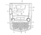
図1乃至図3に示すように、第1実施形態に係るテープ印刷装置1には、文書データからなるテキストを作成するための文字入力キー2、テキスト等の印刷を指示する印刷キー3、及び、改行指示や各種処理の実行、選択を指示するリターンキー4、文字等のキャラクタを複数行に渡って表示する液晶ディスプレイ(LCD)7上でカーソルを上下、左右に移動させるカーソルキー5等を設けたキーボード6、及び、テープカセット21を収納するカセット収納部8が収納カバー13で覆われて配設されている。   As shown in FIGS. 1 to 3, the tape printer 1 according to the first embodiment includes a character input key 2 for creating text composed of document data, a print key 3 for instructing printing of text, and the like. A return key 4 for instructing a line feed and executing various processes, a selection key 4, a cursor key 5 for moving a cursor up and down, left and right on a liquid crystal display (LCD) 7 for displaying characters such as characters over a plurality of lines, etc. The provided keyboard 6 and the cassette storage portion 8 for storing the tape cassette 21 are covered with the storage cover 13.

また、このキーボード6の下側には、制御回路部が構成される制御基板12が配設されている。また、カセット収納部8の左側面部には、印刷されて後述のようにセパレータが剥離されたテープが排出されるラベル排出口17が形成されている。また、該カセット収納部8の右側面部には、電源アダプタが取り付けられるアダプタ挿入口18、及び不図示のパーソナルコンピュータと接続するためのUSBケーブルが取り付けられるUSBコネクタ19が設けられている。   A control board 12 that constitutes a control circuit section is disposed below the keyboard 6. Further, a label discharge port 17 is formed on the left side surface portion of the cassette housing portion 8 for discharging a tape that has been printed and from which the separator has been peeled off as will be described later. In addition, an adapter insertion slot 18 to which a power adapter is attached and a USB connector 19 to which a USB cable for connection to a personal computer (not shown) is attached are provided on the right side surface of the cassette housing portion 8.

また、このカセット収納部8には、サーマルヘッド9と、このサーマルヘッド9に対向するプラテンローラ10と、このプラテンローラ10の下流側のテープサブローラ11と、このテープサブローラ11に対向する金属製のテープ駆動ローラ軸14と、テープカセット21内に収納されるインクリボン52(図4参照)を送るリボン巻取軸15が配置されている他に、更に後述のように両面粘着テープ53(図4参照)から剥離されたセパレータ53D(図4参照)を巻き取るセパレータ巻取軸16等が配置されている。また、プラテンローラ10とテープサブローラ11とは、一体的に揺動可能に設けられ、テープカセット21が装着された場合には、それぞれサーマルヘッド9とテープ送りローラ63(図4参照)に押し当てられる。   The cassette housing 8 includes a thermal head 9, a platen roller 10 facing the thermal head 9, a tape sub-roller 11 downstream of the platen roller 10, and a metal facing the tape sub-roller 11. In addition to the tape drive roller shaft 14 and the ribbon take-up shaft 15 for feeding the ink ribbon 52 (see FIG. 4) accommodated in the tape cassette 21, a double-sided adhesive tape 53 (see FIG. A separator take-up shaft 16 and the like for taking up the separator 53D (see FIG. 4) that has been peeled off (see FIG. 4) are disposed. Further, the platen roller 10 and the tape sub-roller 11 are provided so as to be able to swing integrally. When the tape cassette 21 is mounted, the platen roller 10 and the tape sub-roller 11 are pressed against the thermal head 9 and the tape feed roller 63 (see FIG. 4), respectively. Hit.

このサーマルヘッド9は、正面視略縦長四角形の平板状で、前面の左端縁部には、所定個数の各発熱素子R1〜Rn(nは、例えば、128個又は256個である。)が、該左端縁部の辺に沿って一列に配列されて形成されている。また、該サーマルヘッド9は、メッキ鋼板やステンレス鋼板等により形成される正面視略四角形の放熱板9Aの前面の左端縁部に、各発熱素子R1〜Rn の配列方向が、該放熱板9Aの左端縁部の辺に平行になるように接着剤などによって固着されている。そして、該放熱板9Aは、各発熱素子R1〜Rn の配列方向が、テープカセット21の開口部22におけるフィルムテープ51(図4参照)の搬送方向に略直交するように、ビス止め等によってカセット収納部8の下側に取り付けられている。   The thermal head 9 is a flat plate having a substantially rectangular shape when viewed from the front, and a predetermined number of heating elements R1 to Rn (n is, for example, 128 or 256) are provided on the left end edge of the front surface. It is arranged in a line along the side of the left edge. Further, the thermal head 9 has an arrangement direction of the heat generating elements R1 to Rn on the left end edge of the front surface of the substantially square heat sink 9A formed of a plated steel plate, a stainless steel plate or the like so that the heat sink 9A It is fixed with an adhesive or the like so as to be parallel to the side of the left edge. The heat radiating plate 9A is fixed to the cassette by screws or the like so that the arrangement direction of the heat generating elements R1 to Rn is substantially orthogonal to the transport direction of the film tape 51 (see FIG. 4) in the opening 22 of the tape cassette 21. It is attached to the lower side of the storage unit 8.

また、リボン巻取軸15は、ステッピングモータ等により構成される不図示のテープ送りモータから適宜の駆動機構を介して回転駆動され、後述のようにテープカセット21内に回転可能に設けられたリボン巻き取りスプール61(図4参照)内に嵌入されて回転駆動する。また、テープ駆動ローラ軸14は、テープ送りモータから適宜の伝達機構を介して回転駆動され、後述のようにテープカセット21内に回転可能に設けられた導電性樹脂製のテープ送りローラ63(図4参照)内に嵌入されて回転駆動する。また、セパレータ巻取軸16は、テープ送りモータから適宜の伝達機構を介して回転駆動され、後述のようにテープカセット21内に回転可能に設けられたセパレータ巻き取りスプール62(図4参照)内に嵌入されて回転駆動する。   The ribbon take-up shaft 15 is rotationally driven via a suitable drive mechanism from a tape feed motor (not shown) constituted by a stepping motor or the like, and is a ribbon provided rotatably in the tape cassette 21 as will be described later. It is inserted into the take-up spool 61 (see FIG. 4) and driven to rotate. The tape drive roller shaft 14 is rotationally driven from a tape feed motor through an appropriate transmission mechanism, and is provided with a tape feed roller 63 (see FIG. 4) and is rotationally driven. The separator take-up shaft 16 is rotationally driven from a tape feed motor through an appropriate transmission mechanism, and is installed in a separator take-up spool 62 (see FIG. 4) provided rotatably in the tape cassette 21 as will be described later. It is inserted into and rotated.

尚、セパレータ巻取軸16をテープ送りモータとは別個に設けられたステッピングモータ等により構成される不図示のセパレータ巻取モータから適宜の駆動機構を介して回転駆動するように構成してもよい。これにより、インクリボン52とセパレータ53Dの伸び率等が大きく異なっても該セパレータ53Dを安定して巻き取ることが可能となる。   The separator take-up shaft 16 may be configured to be rotationally driven via an appropriate drive mechanism from a separator take-up motor (not shown) constituted by a stepping motor or the like provided separately from the tape feed motor. . As a result, even if the elongation rates of the ink ribbon 52 and the separator 53D are greatly different, the separator 53D can be stably wound up.

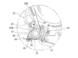
また、図3に示すように、テープカセット21のテープ排出口27(図4参照)の近傍には、剥離コロ65の外周面に沿ってセパレータ53D(図7参照)が剥離された印刷済みテープ28を所定の長さに切断し、セパレータ53Dが剥離された両面粘着テープ付きラベルを生成する切断装置としてのはさみ式カッタユニット30が配置されている。このカッタユニット30は、固定刃30Aと、不図示の切断用モータによって固定刃30Aに対して作動して印刷済みテープ28を切断する可動刃30Bとから構成されている。   Also, as shown in FIG. 3, in the vicinity of the tape outlet 27 (see FIG. 4) of the tape cassette 21, the printed tape with the separator 53D (see FIG. 7) peeled along the outer peripheral surface of the peeling roller 65. A scissor cutter unit 30 is disposed as a cutting device that cuts 28 into a predetermined length and generates a label with a double-sided adhesive tape from which the separator 53D has been peeled off. The cutter unit 30 includes a fixed blade 30A and a movable blade 30B that operates on the fixed blade 30A by a cutting motor (not shown) to cut the printed tape 28.

また、カセット収納部8の底面部には、2つの位置決めピン45、46が、同一高さ寸法に立設されている。そして、テープカセット21をカセット収納部8に装着した際には、テープカセット21は、各位置決めピン45、46によってカセット収納部8内で適正に位置決めがされる。   Further, two positioning pins 45 and 46 are erected at the same height on the bottom surface of the cassette housing 8. When the tape cassette 21 is mounted in the cassette storage unit 8, the tape cassette 21 is properly positioned in the cassette storage unit 8 by the positioning pins 45 and 46.

次ぎに、テープカセット21の概略構成について図3乃至図7に基づいて説明する。
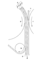
図3及び図4に示すように、テープカセット21は、上ケース23と下ケース24とを有する。このテープカセット21には、被印刷テープとしての透明なフィルムテープ51を巻回したテープスプール54を回転可能に支持する支持孔41が形成されている。また、このテープカセット21には、両面粘着テープ53の剥離紙やフィルム等から形成されるセパレータ53D(図7参照)を外側に向けて巻回した両面粘着スプール56を回転可能に支持する支持孔42が形成されている。
Next, a schematic configuration of the tape cassette 21 will be described with reference to FIGS.
As shown in FIGS. 3 and 4, the tape cassette 21 has an upper case 23 and a lower case 24. The tape cassette 21 is formed with a support hole 41 that rotatably supports a tape spool 54 around which a transparent film tape 51 as a printing tape is wound. Further, the tape cassette 21 has a support hole for rotatably supporting a double-sided adhesive spool 56 in which a separator 53D (see FIG. 7) formed from a release paper or film of the double-sided adhesive tape 53 is wound outward. 42 is formed.

また、このテープカセット21には、テープスプール54と両面粘着スプール56との間の開口部22側に配設されたリボン巻き取りスプール61を回転可能に支持する支持孔43が形成されている。このリボン巻き取りスプール61は、サーマルヘッド9によりフィルムテープ51上に文字等を印刷する際にリボンスプール55からインクリボン52を引き出すとともに、巻き取る。   Further, the tape cassette 21 is formed with a support hole 43 that rotatably supports the ribbon take-up spool 61 disposed on the opening 22 side between the tape spool 54 and the double-sided adhesive spool 56. The ribbon take-up spool 61 draws out and winds up the ink ribbon 52 from the ribbon spool 55 when characters or the like are printed on the film tape 51 by the thermal head 9.

また、このテープカセット21には、テープスプール54と両面粘着スプール56との間の開口部22に対向する下ケース24の側壁部24A側に配設されたセパレータ巻き取りスプール62を回転可能に支持する支持孔44が形成されている。このセパレータ巻き取りスプール62は、剥離コロ65の外周面に沿って両面粘着テープ53から剥離されたセパレータ53Dを巻き取る。また、下ケース24の側壁部24Aのセパレータ巻き取りスプール62に対向する部分は平面視略円弧状に突出するように形成されている。   Further, the tape cassette 21 rotatably supports a separator take-up spool 62 disposed on the side wall 24A side of the lower case 24 facing the opening 22 between the tape spool 54 and the double-sided adhesive spool 56. A support hole 44 is formed. The separator take-up spool 62 takes up the separator 53D peeled off from the double-sided adhesive tape 53 along the outer peripheral surface of the peeling roller 65. Further, a portion of the side wall portion 24A of the lower case 24 facing the separator take-up spool 62 is formed so as to protrude in a substantially arc shape in plan view.

また、このテープカセット21には、テープ送りローラ63のテープ搬送方向下流側、つまり、テープ排出口27側に離間して配置された剥離コロ65を回転可能に支持する支持孔48が形成されている。   Further, the tape cassette 21 is formed with a support hole 48 that rotatably supports a peeling roller 65 that is spaced apart from the tape feed roller 63 in the tape conveying direction, that is, the tape discharge port 27 side. Yes.

また、図5及び図6に示すように、テープ排出口27は、テープ送りローラ63とテープサブローラ11とによって送り出された印刷済みテープ28のテープ厚さ方向に剥離コロ65の外径よりも大きい幅広に開設されると共に、印刷済みテープ28のテープ幅方向に該印刷済みテープ28のテープ幅とほぼ同じ幅に開設されている。   Further, as shown in FIGS. 5 and 6, the tape discharge port 27 has a tape thickness direction of the printed tape 28 fed by the tape feed roller 63 and the tape sub-roller 11 and is larger than the outer diameter of the peeling roller 65. It is opened with a large width and is set to have the same width as the tape width of the printed tape 28 in the tape width direction of the printed tape 28.

また、剥離コロ65は、テープ排出口27のテープ搬送方向に対して直角方向の両内側側壁部を形成する側壁部24Bの印刷済みテープ28側の端縁部から所定距離離間すると共に、印刷済みテープ28のフィルムテープ51の外側面に接触して該印刷済みテープ28をテープ搬送方向下流側へ案内する案内壁33から所定距離離間するように配置されている。   Further, the peeling roller 65 is spaced apart from the edge on the printed tape 28 side of the side wall 24B that forms both inner side walls perpendicular to the tape transport direction of the tape discharge port 27 and printed. The tape 28 is arranged so as to be in contact with the outer surface of the film tape 51 of the tape 28 and to be separated from the guide wall 33 for guiding the printed tape 28 downstream in the tape transport direction by a predetermined distance.

また、この剥離コロ65は、印刷済みテープ28のテープ幅、つまり、両面粘着テープ53のテープ幅とほぼ同じ長さの断面円形の略円柱形状で、両端面中心位置に各支持孔48に回転可能に嵌入される各支持軸65Aが立設されている。また、剥離コロ65は、外周面にシリコーン樹脂皮膜が形成されている。   The peeling roller 65 has a substantially cylindrical shape with a circular cross section having a length substantially the same as the tape width of the printed tape 28, that is, the tape width of the double-sided adhesive tape 53, and rotates to each support hole 48 at the center position of both end surfaces. Each support shaft 65 </ b> A to be fitted is erected. Further, the peeling roller 65 has a silicone resin film formed on the outer peripheral surface.

また、剥離コロ65は、外周面がテープ送りローラ63とテープサブローラ11との共通接線にほぼ接するように、該テープ送りローラ63側に配置され、該テープ送りローラ63とテープサブローラ11とを通過してフィルムテープ51に圧着された両面粘着テープ53のセパレータ53Dに接触し、該セパレータ53Dを外周面に沿ってテープ送りローラ63側へ案内する(図7参照)。   The peeling roller 65 is disposed on the tape feed roller 63 side so that the outer peripheral surface thereof is substantially in contact with the common tangent line between the tape feed roller 63 and the tape sub roller 11. Then, the separator 53D of the double-sided adhesive tape 53 that is pressure-bonded to the film tape 51 is contacted, and the separator 53D is guided along the outer peripheral surface to the tape feed roller 63 side (see FIG. 7).

また、剥離コロ65は、テープ送りローラ63に対向する側壁部24Bよりもテープ搬送方向外側に突出して、固定刃30Aに対向すると共に該固定刃30Aに近接するように設けられている。
また、剥離コロ65に対して印刷済みテープ28を挟んで対向する案内壁33は、この剥離コロ65よりもテープ搬送方向下流側へ延出されて、セパレータ53Dが剥離された印刷済みテープ28を固定刃30Aの近傍位置まで案内可能となるように設けられている。
Further, the peeling roller 65 is provided so as to protrude outward in the tape transport direction from the side wall portion 24B facing the tape feed roller 63, to face the fixed blade 30A, and to be close to the fixed blade 30A.
Further, the guide wall 33 that faces the peeling roller 65 with the printed tape 28 interposed therebetween extends to the downstream side in the tape transport direction from the peeling roller 65, and the printed tape 28 from which the separator 53D has been peeled off. It is provided so that it can be guided to a position near the fixed blade 30A.

また、剥離コロ65に対してセパレータ53Dを挟んで対向する側壁部24Bの端縁部の内側面は、剥離コロ65とテープ送りローラ63との共通接線に対してほぼ平行になるように斜め内側方向(図5中、斜め右上方向である。)に傾斜するように形成されている。これにより、両面粘着テープ53から剥離コロ65の外周面に沿って剥離されてテープ送りローラ63側へ案内されたセパレータ53Dが、側壁部24Bの端縁部と接触するのを防止することができる。   Further, the inner surface of the edge portion of the side wall 24B facing the separation roller 65 with the separator 53D interposed therebetween is obliquely inward so as to be substantially parallel to the common tangent line between the separation roller 65 and the tape feed roller 63. It is formed so as to incline in a direction (in FIG. 5, diagonally right upper direction). Thereby, it is possible to prevent the separator 53D peeled from the double-sided adhesive tape 53 along the outer peripheral surface of the peeling roller 65 and guided to the tape feed roller 63 side from coming into contact with the edge of the side wall portion 24B. .

また、図4に示すように、このテープカセット21には、両面粘着スプール56に巻回された両面粘着テープ53の最大径時の外周面と下ケース24の各側壁部24A、24Cとの間に、この両面粘着テープ53の引出口から下ケース24の側壁部24Aに対向する部分までを覆う平面視略半円形状の案内リブ35が底面部に立設されている。また、案内リブ35の下ケース24の各側壁部24A、24Cに対向する部分には、テープ幅方向に沿って所定高さ(例えば、高さ約1mmである。)突出する各凸状部35A、35Bが全幅に渡って形成されている。   As shown in FIG. 4, the tape cassette 21 includes a space between the outer peripheral surface of the double-sided adhesive tape 53 wound around the double-sided adhesive spool 56 at the maximum diameter and the side walls 24 </ b> A and 24 </ b> C of the lower case 24. Further, a guide rib 35 having a substantially semicircular shape in a plan view is provided on the bottom surface portion so as to cover from the outlet of the double-sided pressure-sensitive adhesive tape 53 to a portion facing the side wall portion 24A of the lower case 24. In addition, each convex portion 35A that protrudes at a predetermined height (for example, about 1 mm in height) along the tape width direction at a portion facing the side wall portions 24A and 24C of the lower case 24 of the guide rib 35. , 35B are formed over the entire width.

また、両面粘着スプール56に巻回された両面粘着テープ53に対向する下ケース24の隅部と案内リブ35との間には、略円柱形状のガイドピン36が立設されている。また、上ケース23のガイドピン36に対向する部分には、このガイドピン36の端縁部が嵌入されて支持する支持孔49が形成されている。また、テープ送りローラ63のテープサブローラ11に対して反対側には、セパレータ53Dとの接触面を平面視円弧状に形成されたセパレータ案内壁37が、側壁部24Cから該テープ送りローラ63と所定隙間を形成して内側方向に突出している。   A substantially cylindrical guide pin 36 is provided between the corner of the lower case 24 facing the double-sided adhesive tape 53 wound around the double-sided adhesive spool 56 and the guide rib 35. Further, a support hole 49 is formed in a portion of the upper case 23 facing the guide pin 36 so as to fit and support an end edge portion of the guide pin 36. Further, on the opposite side of the tape feed roller 63 with respect to the tape sub-roller 11, a separator guide wall 37 having a contact surface with the separator 53D formed in an arc shape in a plan view is connected to the tape feed roller 63 from the side wall portion 24C. A predetermined gap is formed and projects inward.

尚、図3中には、上ケース23に形成された各支持孔41、42、43、44、48のみしか図示されていないが、下ケース24についても同様に上ケース23の各支持孔41、42、43、44、48に対向して各支持孔41、42、43、44、48が形成されている。   In FIG. 3, only the support holes 41, 42, 43, 44, 48 formed in the upper case 23 are shown, but the support holes 41 of the upper case 23 are similarly shown for the lower case 24. , 42, 43, 44, 48 are formed with support holes 41, 42, 43, 44, 48.

また、図4に示すように、テープカセット21内には、透明テープ等からなる被印刷テープであるフィルムテープ51、このフィルムテープ51に印刷を施すためのインクリボン52、更には、印刷がなされたフィルムテープ51に裏貼りされる両面粘着テープ53を各々、テープスプール54、リボンスプール55、両面粘着スプール56に巻回して、下ケース24の底面に立設されるカセットボス58、リールボス59、カセットボス60に回転可能に嵌挿して収納したものであり、更に、使用済みのインクリボン52を巻き取るリボン巻き取りスプール61、及び両面粘着テープ53から剥離されたセパレータ53Dを巻き取るセパレータ巻き取りスプール62を備えている。   As shown in FIG. 4, in the tape cassette 21, a film tape 51 which is a printing tape made of a transparent tape or the like, an ink ribbon 52 for printing on the film tape 51, and further printing is performed. A double-sided adhesive tape 53 backed on the film tape 51 is wound around a tape spool 54, a ribbon spool 55, and a double-sided adhesive spool 56, respectively, and a cassette boss 58, a reel boss 59, The cassette boss 60 is rotatably inserted and stored, and further, a ribbon take-up spool 61 for taking up the used ink ribbon 52 and a separator take-up for taking up the separator 53D peeled off from the double-sided adhesive tape 53. A spool 62 is provided.

尚、図4に示すように、リボン巻き取りスプール61の下部にはクラッチバネ64が取り付けられている。このクラッチバネ64はリボン巻き取りスプール61が逆転して巻き取ったインクリボン52が緩んでしまうことを防止するものである。また、セパレータ巻き取りスプール62の下部にはクラッチバネ66が取り付けられている。このクラッチバネ66はセパレータ巻き取りスプール62が逆転して巻き取ったセパレータ53Dが緩んでしまうことを防止するものである。   As shown in FIG. 4, a clutch spring 64 is attached to the lower part of the ribbon take-up spool 61. The clutch spring 64 prevents the ink ribbon 52 that has been wound up by the reverse of the ribbon take-up spool 61 from being loosened. A clutch spring 66 is attached to the lower part of the separator take-up spool 62. This clutch spring 66 prevents the separator take-up spool 62 from reversing and loosening the separator 53D taken up.

また、図4に示すように、リボンスプール55に巻回され、このリボンスプール55から引き出された未使用インクリボン52は、フィルムテープ51と重ね合わされ、フィルムテープ51と共に開口部22に入り、サーマルヘッド9及びプラテンローラ10の間を通過する。その後、インクリボン52は、フィルムテープ51から引き離され、リボン巻取軸15により回転駆動されるリボン巻き取りスプール61に至り、このリボン巻き取りスプール61により巻き取られる。   Further, as shown in FIG. 4, the unused ink ribbon 52 wound around the ribbon spool 55 and pulled out from the ribbon spool 55 is overlapped with the film tape 51 and enters the opening portion 22 together with the film tape 51, and the thermal It passes between the head 9 and the platen roller 10. Thereafter, the ink ribbon 52 is separated from the film tape 51, reaches a ribbon take-up spool 61 that is rotationally driven by the ribbon take-up shaft 15, and is taken up by the ribbon take-up spool 61.

また、図7に示すように、セパレータ53Dを外側にして両面粘着スプール56に巻回された両面粘着テープ53は、4層構造に構成されている。この両面粘着テープ53の各層は、図7中下側から上側方向へ向かって、フィルムテープ51を接着するための粘着層53A、PET(ポリエチレンテレフタラート)等から成る色付きのベースフィルム53B、商品等の貼り付け対象に貼り付けるための粘着層53C、この粘着層53Cの貼り付け側を覆うセパレータ53Dの順序で積層されて構成されている。   Further, as shown in FIG. 7, the double-sided pressure-sensitive adhesive tape 53 wound around the double-sided pressure-sensitive adhesive spool 56 with the separator 53D on the outside has a four-layer structure. Each layer of the double-sided adhesive tape 53 includes an adhesive layer 53A for adhering the film tape 51 from the lower side to the upper side in FIG. 7, a colored base film 53B made of PET (polyethylene terephthalate), etc. The adhesive layer 53C for attaching to the object to be attached and the separator 53D covering the attachment side of the adhesive layer 53C are laminated in this order.

そして、図4乃至図7に示すように、両面粘着スプール56から引き出された両面粘着テープ53は、テープ駆動ローラ軸14によって回転駆動されるテープ送りローラ63とテープサブローラ11との間を通過し、セパレータ53Dが重ね合わされない側の粘着層53Aがフィルムテープ51の印刷面に圧着される。   4 to 7, the double-sided adhesive tape 53 drawn from the double-sided adhesive spool 56 passes between the tape feed roller 63 and the tape sub-roller 11 that are rotationally driven by the tape drive roller shaft 14. Then, the pressure-sensitive adhesive layer 53 </ b> A on the side where the separator 53 </ b> D is not overlaid is pressure bonded to the printing surface of the film tape 51.

その後、セパレータ53Dは、剥離コロ65の外周面に沿ってフィルムテープ51に圧着された両面粘着テープ53から剥離され、テープ送りローラ63の外周面に沿って両面粘着スプール56側に、つまり、引き出し側方向(図4中、上側方向である。)へ案内される。続いて、セパレータ53Dは、セパレータ案内壁37の壁面に沿って案内リブ35の外側方向に案内されて、凸状部35A、ガイドピン36及び凸状部35Bの外周面に順次沿って、巻回された両面粘着テープ53の外側周縁を通って略直角内側方向へ案内されてセパレータ巻き取りスプール62に至る。   Thereafter, the separator 53D is peeled off from the double-sided adhesive tape 53 that is pressure-bonded to the film tape 51 along the outer peripheral surface of the peeling roller 65, and is pulled out toward the double-sided adhesive spool 56 along the outer peripheral surface of the tape feed roller 63. It is guided in the side direction (upward direction in FIG. 4). Subsequently, the separator 53D is guided in the outer direction of the guide rib 35 along the wall surface of the separator guide wall 37, and is sequentially wound along the outer peripheral surfaces of the convex portion 35A, the guide pin 36, and the convex portion 35B. The double-sided adhesive tape 53 is guided to the inner side at a substantially right angle through the outer peripheral edge and reaches the separator take-up spool 62.

そして、セパレータ53Dの先端部は、このセパレータ巻き取りスプール62の外周面に接着テープ等によって固着され、セパレータ巻取軸16により回転駆動される該セパレータ巻き取りスプール62に巻き取られる。尚、セパレータ巻取軸16は、テープ駆動ローラ軸14及びリボン巻取軸15と同期して回転駆動される。   The front end of the separator 53D is fixed to the outer peripheral surface of the separator take-up spool 62 with an adhesive tape or the like, and is taken up by the separator take-up spool 62 that is driven to rotate by the separator take-up shaft 16. The separator take-up shaft 16 is rotationally driven in synchronization with the tape drive roller shaft 14 and the ribbon take-up shaft 15.

また、フィルムテープ51は、テープ駆動ローラ軸14によって回転駆動されるテープ送りローラ63とテープサブローラ11との間を通過後、印刷面に粘着層53A、ベースフィルム53B、粘着層53C及びセパレータ53Dが積層された状態で剥離コロ65に至る。そして、この剥離コロ65の外周面に沿ってセパレータ53Dが剥離されて、印刷面に粘着層53A、ベースフィルム53B及び粘着層53Cが積層された状態で、つまり、セパレータ53Dが剥離された粘着剤付き印刷済みテープ28の状態で、該剥離コロ65に対して印刷済みテープ28を挟んで対向する案内壁33によって案内されて、テープ排出口27からテープカセット21の外部に送り出される。そして、セパレータ53Dが剥離された粘着剤付き印刷済みテープ28は、カッタユニット30を経てテープ印刷装置1のラベル排出口17より外部に送り出される。   Further, the film tape 51 passes between the tape feed roller 63 and the tape sub-roller 11 that are rotationally driven by the tape drive roller shaft 14, and then has an adhesive layer 53A, a base film 53B, an adhesive layer 53C, and a separator 53D on the printing surface. The peeling roller 65 is reached in a state where is laminated. Then, the separator 53D is peeled along the outer peripheral surface of the peeling roller 65, and the adhesive layer 53A, the base film 53B, and the adhesive layer 53C are laminated on the printing surface, that is, the pressure sensitive adhesive from which the separator 53D has been peeled off. In the state of the attached printed tape 28, it is guided by the guide wall 33 that faces the peeling roller 65 across the printed tape 28, and is sent out of the tape cassette 21 from the tape discharge port 27. The pressure-sensitive adhesive-printed tape 28 from which the separator 53D has been peeled is sent out from the label discharge port 17 of the tape printer 1 through the cutter unit 30.

そして、印刷済みテープ28を所定長さ搬送後、不図示の切断用モータを駆動して可動刃30Bを作動させることによって、セパレータ53Dが剥離された所定長さの粘着剤付き印刷済みテープ28がラベル排出口17より排出される。   Then, after the printed tape 28 is conveyed for a predetermined length, the cutting blade (not shown) is driven to operate the movable blade 30B, whereby the printed tape 28 with the adhesive having a predetermined length from which the separator 53D has been peeled off. It is discharged from the label discharge port 17.

続いて、テープカセット21におけるテープスプール54、両面粘着スプール56、セパレータ巻き取りスプール62の位置関係について図8に基づいて説明する。
上述したように、テープカセット21において、テープスプール54に巻回されているフィルムテープ51は、テープ印刷装置1による印刷が行われる度に引き出される。従って、テープカセット21の使用開始時において、最も多くのフィルムテープ51がテープスプール54に巻回されている(図4参照)。
ここで、テープカセット21の使用開始時点において、テープスプール54に巻回されているフィルムテープ51が占有する領域を「フィルムテープ占有領域67」という。また、このフィルムテープ占有領域67の半径を「フィルムテープ巻回半径R1」という。
Next, the positional relationship among the tape spool 54, the double-sided adhesive spool 56, and the separator take-up spool 62 in the tape cassette 21 will be described with reference to FIG.
As described above, the film tape 51 wound around the tape spool 54 in the tape cassette 21 is pulled out each time printing is performed by the tape printer 1. Therefore, at the start of use of the tape cassette 21, the most film tape 51 is wound around the tape spool 54 (see FIG. 4).
Here, an area occupied by the film tape 51 wound around the tape spool 54 at the start of use of the tape cassette 21 is referred to as a “film tape occupation area 67”. The radius of the film tape occupation area 67 is referred to as “film tape winding radius R1”.

また、フィルムテープ51と同様に、両面粘着テープ53は、テープ印刷装置1による印刷が行われる度に、両面粘着スプール56から引き出される。従って、テープカセット21の使用開始時において、最も多くの両面粘着テープ53が両面粘着スプール56に巻回されている(図4参照)。
ここで、テープカセット21の使用開始時点において、両面粘着スプール56に巻回されている両面粘着テープ53が占有する領域を「両面粘着テープ占有領域68」という。また、この両面粘着テープ占有領域68の半径を「両面粘着テープ巻回半径R2」という。
Similarly to the film tape 51, the double-sided adhesive tape 53 is pulled out from the double-sided adhesive spool 56 every time printing is performed by the tape printer 1. Therefore, at the start of use of the tape cassette 21, the most double-sided adhesive tape 53 is wound around the double-sided adhesive spool 56 (see FIG. 4).
Here, an area occupied by the double-sided adhesive tape 53 wound around the double-sided adhesive spool 56 at the start of use of the tape cassette 21 is referred to as a “double-sided adhesive tape occupation area 68”. The radius of the double-sided adhesive tape occupation area 68 is referred to as “double-sided adhesive tape winding radius R2”.

そして、テープカセット21においては、セパレータ53Dはテープ印刷装置1による印刷が行われる毎に、両面粘着テープ53から剥離され、セパレータ巻き取りスプール62に巻回される。従って、テープカセット21の使用完了時(即ち、テープカセット21がラベルの作成にフィルムテープ51等を使い切った時)に、セパレータ53Dは、セパレータ巻き取りスプール62に対して最も多く巻回され、テープカセット21の内部において最も大きなスペースを占有する。尚、以下の説明において、セパレータ巻き取りスプール62に最も多く巻回されたセパレータ53Dが占有するスペースの半径を「セパレータ巻回半径R3」という。   In the tape cassette 21, the separator 53 </ b> D is peeled off from the double-sided adhesive tape 53 and wound around the separator take-up spool 62 every time printing is performed by the tape printer 1. Therefore, when the use of the tape cassette 21 is completed (that is, when the tape cassette 21 has used up the film tape 51 or the like for label production), the separator 53D is wound most around the separator take-up spool 62, and the tape The largest space is occupied inside the cassette 21. In the following description, the radius of the space occupied by the separator 53D wound most around the separator take-up spool 62 is referred to as “separator winding radius R3”.

上述したように、セパレータ巻き取りスプール62は、テープスプール54と両面粘着スプール56との間に、回転可能に配設されている。そして、図8に示すように、テープカセット21では、テープスプール54の回転中心軸と、セパレータ巻き取りスプール62の回転中心軸を結ぶ直線距離(以下、第1軸間距離L1という。)は、セパレータ巻回半径R3とフィルムテープ巻回半径R1との和よりも小さくなるように構成されている。従って、テープカセット21の使用終了時において、セパレータ巻き取りスプール62に巻回されたセパレータ53Dは、フィルムテープ占有領域67の一部分を占有する。   As described above, the separator take-up spool 62 is rotatably disposed between the tape spool 54 and the double-sided adhesive spool 56. As shown in FIG. 8, in the tape cassette 21, the linear distance connecting the rotation center axis of the tape spool 54 and the rotation center axis of the separator take-up spool 62 (hereinafter referred to as the first inter-axis distance L1) is as follows. It is comprised so that it may become smaller than the sum of separator winding radius R3 and film tape winding radius R1. Therefore, at the end of use of the tape cassette 21, the separator 53 </ b> D wound around the separator take-up spool 62 occupies a part of the film tape occupation area 67.

即ち、第1軸間距離L1を、セパレータ巻回半径R3とフィルムテープ巻回半径R1との和よりも小さくすることにより、テープカセット21は、フィルムテープ51とセパレータ53Dが共通して利用する第1重複領域69を生じさせる。これにより、テープカセット21は、第1重複領域69の大きさに応じて、テープカセット21自体の大型化を抑制し得る。また、テープカセット21の大型化を抑制することにより、当該テープカセット21は、テープ印刷装置1本体の大型化も抑制し得る。   That is, by making the first inter-axis distance L1 smaller than the sum of the separator winding radius R3 and the film tape winding radius R1, the tape cassette 21 uses the film tape 51 and the separator 53D in common. One overlapping region 69 is generated. Thereby, the tape cassette 21 can suppress the enlargement of the tape cassette 21 itself according to the size of the first overlapping region 69. Moreover, the tape cassette 21 can also suppress the enlargement of the tape printer 1 main body by suppressing the enlargement of the tape cassette 21.

また、テープカセット21では、両面粘着スプール56の回転中心軸と、セパレータ巻き取りスプール62の回転中心軸を結ぶ直線距離(以下、第2軸間距離L2という。)は、セパレータ巻回半径R3と両面粘着テープ巻回半径R2との和よりも小さくなるように構成されている。従って、テープカセット21の使用終了時において、セパレータ巻き取りスプール62に巻回されたセパレータ53Dは、両面粘着テープ占有領域68の一部分を占有する。   In the tape cassette 21, the linear distance connecting the rotation center axis of the double-sided adhesive spool 56 and the rotation center axis of the separator take-up spool 62 (hereinafter referred to as the second inter-axis distance L2) is the separator winding radius R3. It is comprised so that it may become smaller than the sum with double-sided adhesive tape winding radius R2. Therefore, at the end of use of the tape cassette 21, the separator 53 </ b> D wound around the separator take-up spool 62 occupies a part of the double-sided adhesive tape occupation area 68.

即ち、第2軸間距離L2を、セパレータ巻回半径R3と両面粘着テープ巻回半径R2との和よりも小さくすることにより、テープカセット21は、両面粘着テープ53とセパレータ53Dとが共通して利用する第2重複領域70を生じさせる。これにより、テープカセット21は、第2重複領域70の大きさに応じて、テープカセット21自体の大型化を抑制し得る。また、テープカセット21の大型化を抑制することにより、当該テープカセット21は、テープ印刷装置1本体の大型化も抑制し得る。   That is, by making the second inter-axis distance L2 smaller than the sum of the separator winding radius R3 and the double-sided adhesive tape winding radius R2, the tape cassette 21 has the double-sided adhesive tape 53 and the separator 53D in common. The second overlapping area 70 to be used is generated. Thereby, the tape cassette 21 can suppress the enlargement of the tape cassette 21 itself according to the size of the second overlapping region 70. Moreover, the tape cassette 21 can also suppress the enlargement of the tape printer 1 main body by suppressing the enlargement of the tape cassette 21.

従って、テープカセット21は、図8に示すように、第1重複領域69と第2重複領域70との何れをも生じさせるので、第1重複領域69の大きさと、第2重複領域70の大きさに応じて、テープカセット21の大型化を更に抑制し得る。そして、これに伴い、テープカセット21は、テープ印刷装置1の大型化についても更に抑制し得る。   Accordingly, as shown in FIG. 8, the tape cassette 21 generates both the first overlap area 69 and the second overlap area 70. Therefore, the size of the first overlap area 69 and the size of the second overlap area 70 are generated. Accordingly, the increase in size of the tape cassette 21 can be further suppressed. Accordingly, the tape cassette 21 can further suppress the enlargement of the tape printer 1.

尚、テープスプール54と両面粘着スプール56との距離を図8に示す状態よりも大きくして、セパレータ巻き取りスプール62をテープカセット21の内側方向へ移動させてもよい。そして、第1軸間距離L1をセパレータ巻回半径R3とフィルムテープ巻回半径R1との和よりも大きくなるように構成し、且つ、第2軸間距離L2をセパレータ巻回半径R3と両面粘着テープ巻回半径R2との和よりも小さくなるように構成してもよい。又は、第1軸間距離L1をセパレータ巻回半径R3とフィルムテープ巻回半径R1との和よりも小さくなるように構成し、且つ、第2軸間距離L2をセパレータ巻回半径R3と両面粘着テープ巻回半径R2との和よりも大きくなるように構成してもよい。   Note that the distance between the tape spool 54 and the double-sided adhesive spool 56 may be made larger than that shown in FIG. 8 and the separator take-up spool 62 may be moved inward of the tape cassette 21. The first inter-axis distance L1 is configured to be larger than the sum of the separator winding radius R3 and the film tape winding radius R1, and the second inter-axis distance L2 is set to the separator winding radius R3 and the double-sided adhesive. You may comprise so that it may become smaller than the sum with tape winding radius R2. Alternatively, the first inter-axis distance L1 is configured to be smaller than the sum of the separator winding radius R3 and the film tape winding radius R1, and the second inter-axis distance L2 is set to the separator winding radius R3 and double-sided adhesive. You may comprise so that it may become larger than the sum with tape winding radius R2.

これにより、テープカセット21は、第1重複領域69と第2重複領域70のうちの何れか一方を生じさせるので、第1重複領域69の大きさと、第2重複領域70の大きさに応じて、テープカセット21の大型化を抑制し得る。そして、これに伴い、テープカセット21は、テープ印刷装置1の大型化についても更に抑制し得る。   As a result, the tape cassette 21 generates one of the first overlap area 69 and the second overlap area 70, so that the tape cassette 21 corresponds to the size of the first overlap area 69 and the size of the second overlap area 70. The enlargement of the tape cassette 21 can be suppressed. Accordingly, the tape cassette 21 can further suppress the enlargement of the tape printer 1.

従って、第1実施形態に係るテープカセット21では、両面粘着テープ53は、テープ送りローラ63とテープサブローラ11とによって、フィルムテープ51の印刷された一方の面に圧着された後、テープ排出口27で該両面粘着テープ53からセパレータ53Dが剥離された状態で搬送されることとなる。これにより、所定長さに切断された印刷済みテープ28を商品等に貼り付ける際に、セパレータ53Dを剥がす手間を省くことができる。   Therefore, in the tape cassette 21 according to the first embodiment, the double-sided adhesive tape 53 is pressure-bonded to one printed surface of the film tape 51 by the tape feed roller 63 and the tape sub-roller 11, and then the tape discharge port. 27, the separator 53D is transported in a state where the separator 53D is peeled off from the double-sided adhesive tape 53. Thereby, when sticking the printed tape 28 cut | disconnected by the predetermined length to goods etc., the effort which removes separator 53D can be saved.

また、テープ排出口27で両面粘着テープ53から剥離コロ65の外周面に沿って剥離されたセパレータ53Dは、テープ送りローラ63とセパレータ案内壁37との間、つまり、両面粘着スプール56側へ案内された後、凸状部35A、ガイドピン36及び凸状部35Bによって巻回された両面粘着テープ53の外側周縁を通って略直角内側方向へ案内されて、セパレータ巻き取りスプール62に巻き取られるため、剥離したセパレータ53Dをテープカセット21内に収納することが可能となり、ユーザは両面粘着テープ53から剥離したセパレータ53Dを廃棄する手間を省くことができる。   The separator 53D peeled from the double-sided adhesive tape 53 at the tape discharge port 27 along the outer peripheral surface of the peeling roller 65 is guided between the tape feed roller 63 and the separator guide wall 37, that is, to the double-sided adhesive spool 56 side. Then, it is guided in the substantially perpendicular inner direction through the outer peripheral edge of the double-sided pressure-sensitive adhesive tape 53 wound by the convex portion 35A, the guide pin 36, and the convex portion 35B, and is wound on the separator take-up spool 62. Therefore, the separated separator 53D can be stored in the tape cassette 21, and the user can save time and effort for discarding the separated separator 53D from the double-sided adhesive tape 53.

また、セパレータ53Dは、テープ排出口27で両面粘着テープ53から剥離コロ65の外周面に沿って剥離されて、テープ送りローラ63とセパレータ案内壁37との間、つまり、両面粘着スプール56側へ案内されるため、セパレータ53Dが印刷済みテープ28側に撓んで両面粘着テープ53の粘着層53Cに再度付着することを確実に防止でき、当該印刷済みテープ28をテープ排出口27から外部へスムーズに排出することが可能となる。   Further, the separator 53D is peeled from the double-sided adhesive tape 53 along the outer peripheral surface of the peeling roller 65 at the tape discharge port 27, and between the tape feed roller 63 and the separator guide wall 37, that is, to the double-sided adhesive spool 56 side. Therefore, it is possible to reliably prevent the separator 53D from flexing toward the printed tape 28 and adhering again to the adhesive layer 53C of the double-sided adhesive tape 53. The printed tape 28 can be smoothly transferred from the tape outlet 27 to the outside. It becomes possible to discharge.

また、剥離コロ65は回転可能なため、印刷済みテープ28の走行時の負荷を低減することができ、該印刷済みテープ28をテープ排出口27から外部へスムーズに排出することが可能となる。
また、剥離コロ65をテープ排出口27よりもテープ搬送方向外側に突出するように設けることによって、この剥離コロ65の外径を大きくすることが可能となる。これにより、剥離コロ65の組付け作業を容易に行うことが可能になるとともに、粘着剤付き印刷済みテープ28が、テープ排出口27で詰まることをより確実に防止することが可能となる。
Further, since the peeling roller 65 is rotatable, it is possible to reduce the load when the printed tape 28 is running, and it is possible to smoothly discharge the printed tape 28 from the tape discharge port 27 to the outside.
Further, by providing the peeling roller 65 so as to protrude outward in the tape transport direction from the tape discharge port 27, the outer diameter of the peeling roller 65 can be increased. As a result, it is possible to easily perform the assembling work of the peeling roller 65 and more reliably prevent the printed tape 28 with adhesive from being clogged at the tape discharge port 27.

また、剥離コロ65は、固定刃30Aに対向すると共に該固定刃30Aに近接して配置されるため、テープ切断位置と印刷済みテープ28の印刷位置との距離を短くすることが可能となり、印刷済みテープ28の余白長さを短くすることが可能となる。   Further, since the peeling roller 65 is disposed opposite to the fixed blade 30A and close to the fixed blade 30A, the distance between the tape cutting position and the printing position of the printed tape 28 can be shortened. The margin length of the used tape 28 can be shortened.

また、剥離コロ65に対して印刷済みテープ28を挟んで対向する案内壁33は、この剥離コロ65よりもテープ搬送方向下流側へ延出されているため、印刷済みテープ28の印刷面の裏面側をより確実に案内することが可能となる。また、剥離コロ65が固定刃30Aに近接して配設されるため、印刷済みテープ28の印刷面の裏面側をテープ切断位置、つまり、固定刃30Aの刃先の近傍まで確実に案内することが可能となる。   Further, since the guide wall 33 facing the peeling roller 65 with the printed tape 28 interposed therebetween extends to the downstream side in the tape transport direction from the peeling roller 65, the back surface of the printed surface of the printed tape 28. It becomes possible to guide the side more reliably. Further, since the peeling roller 65 is disposed in the vicinity of the fixed blade 30A, the back side of the printed surface of the printed tape 28 can be reliably guided to the tape cutting position, that is, the vicinity of the cutting edge of the fixed blade 30A. It becomes possible.

更に、セパレータ巻き取りスプール62は、両面粘着スプール56とテープスプール54との間に配設されているため、テープ印刷装置1によるテープ印刷が行われることによってセパレータ巻き取りスプール62に巻回可能なセパレータ53Dの最大巻回長さを容易に大きくすることができ、テープカセット21の小型化を図ることが可能となる。   Further, since the separator take-up spool 62 is disposed between the double-sided adhesive spool 56 and the tape spool 54, the separator take-up spool 62 can be wound around the separator take-up spool 62 by performing tape printing by the tape printer 1. The maximum winding length of the separator 53D can be easily increased, and the tape cassette 21 can be downsized.

また、剥離したセパレータ53Dを剥離コロ65の外周面に沿ってテープ送りローラ63とセパレータ案内壁37との間、つまり、両面粘着スプール56側へ案内後、セパレータ案内壁37、凸状部35A、ガイドピン36及び凸状部35Bによって巻回された両面粘着テープ53の外側周縁を通ってセパレータ巻き取りスプール62まで案内することによって、テープカセット21内の隙間空間を有効に活用することができ、テープカセット21の更なる小型化を図ることが可能となる。   Further, after the separated separator 53D is guided along the outer peripheral surface of the separation roller 65 between the tape feed roller 63 and the separator guide wall 37, that is, to the double-sided adhesive spool 56 side, the separator guide wall 37, the convex portion 35A, By guiding to the separator take-up spool 62 through the outer peripheral edge of the double-sided pressure-sensitive adhesive tape 53 wound by the guide pin 36 and the convex portion 35B, the gap space in the tape cassette 21 can be effectively utilized. The tape cassette 21 can be further reduced in size.

[第2実施形態]
次に、第2実施形態に係るテープカセット71について図9及び図10に基づいて説明する。尚、以下の説明において上記図1乃至図8の第1実施形態に係るテープカセット21及びテープ印刷装置1の構成等と同一符号は、該第1実施形態に係るテープカセット21及びテープ印刷装置1等の構成等と同一あるいは相当部分を示すものである。
[Second Embodiment]
Next, a tape cassette 71 according to the second embodiment will be described with reference to FIGS. In the following description, the same reference numerals as those of the tape cassette 21 and the tape printer 1 according to the first embodiment in FIGS. 1 to 8 denote the same as those in the tape cassette 21 and the tape printer 1 according to the first embodiment. This indicates the same or corresponding part as the above-described configuration.

第2実施形態に係るテープカセット71の概略構成は、第1実施形態に係るテープカセット21とほぼ同じ構成である。
但し、図9及び図10に示すように、テープ送りローラ63と剥離コロ65との間の、フィルムテープ51の印刷面に両面粘着テープ53が圧着された印刷済みテープ28の経路上において、当該両面粘着テープ53のセパレータ53Dと粘着層53Cとの間に挿入されるように、予備剥離部材の一例としての予備剥離ピン72が設けられている。
The schematic configuration of the tape cassette 71 according to the second embodiment is substantially the same as that of the tape cassette 21 according to the first embodiment.
However, as shown in FIG. 9 and FIG. 10, on the path of the printed tape 28 in which the double-sided adhesive tape 53 is pressure-bonded to the printing surface of the film tape 51 between the tape feeding roller 63 and the peeling roller 65. A preliminary peeling pin 72 as an example of a preliminary peeling member is provided so as to be inserted between the separator 53D of the double-sided pressure-sensitive adhesive tape 53 and the pressure-sensitive adhesive layer 53C.

つまり、予備剥離ピン72によって両面粘着テープ53からセパレータ53Dが一度剥離されている。そして、予備剥離ピン72によって両面粘着テープ53から一度剥離されたセパレータ53Dは、該予備剥離ピン72を通過後、再度、両面粘着テープ53の粘着層53Cに貼り合わされて、剥離コロ65の外周面に沿って剥離されている。   That is, the separator 53 </ b> D is once peeled from the double-sided adhesive tape 53 by the preliminary peeling pin 72. The separator 53D once peeled from the double-sided adhesive tape 53 by the preliminary peeling pin 72 is pasted again to the adhesive layer 53C of the double-sided adhesive tape 53 after passing through the preliminary peeling pin 72, and the outer peripheral surface of the peeling roller 65 Is peeled along.

この予備剥離ピン72は、両面粘着テープ53のテープ幅よりも長い断面円形の略円柱形状で、両端面中心位置に各支持軸72Aが立設されている。また、この予備剥離ピン72の外周面には、シリコーン樹脂皮膜が形成されている。また、テープカセット71の上ケース23及び下ケース24には、予備剥離ピン72の各支持軸72Aを回転可能に支持する各支持孔73が形成されている。そして、予備剥離ピン72の各支持軸72Aは、各支持孔73に挿入されて、回転可能に設けられている。   The preliminary peeling pin 72 has a substantially cylindrical shape with a circular cross section longer than the tape width of the double-sided pressure-sensitive adhesive tape 53, and each support shaft 72A is erected at the center position of both end faces. A silicone resin film is formed on the outer peripheral surface of the preliminary peeling pin 72. Further, the upper case 23 and the lower case 24 of the tape cassette 71 are formed with respective support holes 73 for rotatably supporting the respective support shafts 72A of the preliminary peeling pins 72. And each support shaft 72A of the preliminary | backup peeling pin 72 is inserted in each support hole 73, and is provided rotatably.

従って、第2実施形態に係るテープカセット71では、予備剥離ピン72は、両端部が回転可能に支持されると共に、両面粘着テープ53の粘着層53C及びセパレータ53Dの全幅に渡って接触する。   Therefore, in the tape cassette 71 according to the second embodiment, the preliminary peeling pin 72 is rotatably supported at both ends, and contacts the entire width of the adhesive layer 53C of the double-sided adhesive tape 53 and the separator 53D.

これにより、第2実施形態に係るテープカセット71では、第1実施形態に係るテープカセット21が奏する上記作用効果に加えて、予備剥離ピン72によってセパレータ53Dが両面粘着テープ53から一度剥離された後、再度両面粘着テープ53の粘着層53Cに貼り合わされて剥離コロ65へ搬送されるため、該両面粘着テープ53のセパレータ53Dに対する粘着力を低下させた状態で印刷済みテープ28を剥離コロ65へ搬送することが可能となる。   Thus, in the tape cassette 71 according to the second embodiment, after the separator 53D is once peeled off from the double-sided pressure-sensitive adhesive tape 53 by the preliminary peeling pin 72, in addition to the above-described effects obtained by the tape cassette 21 according to the first embodiment. Since it is again bonded to the adhesive layer 53C of the double-sided adhesive tape 53 and conveyed to the peeling roller 65, the printed tape 28 is conveyed to the peeling roller 65 in a state where the adhesive force of the double-sided adhesive tape 53 to the separator 53D is reduced. It becomes possible to do.

このため、フィルムテープ51に圧着された両面粘着テープ53からセパレータ53Dを剥離コロ65の外周面に沿って容易に剥離することが可能となり、セパレータ53Dが剥離された粘着剤付き印刷済みテープ28をテープ排出口27へスムーズに搬送することが可能となる。   For this reason, it becomes possible to easily peel the separator 53D from the double-sided pressure-sensitive adhesive tape 53 pressure-bonded to the film tape 51 along the outer peripheral surface of the peeling roller 65, and the pressure-sensitive adhesive tape 28 with the separator 53D peeled can be removed. Smooth conveyance to the tape discharge port 27 becomes possible.

[第3実施形態]
次に、第3実施形態に係るテープカセット81について図11に基づいて説明する。尚、以下の説明において上記図1乃至図8の第1実施形態に係るテープカセット21及びテープ印刷装置1の構成等と同一符号は、該第1実施形態に係るテープカセット21及びテープ印刷装置1等の構成等と同一あるいは相当部分を示すものである。また、上記図9及び図10の第2実施形態に係るテープカセット71の構成等と同一符号は、該第2実施形態に係るテープカセット71の構成等と同一あるいは相当部分を示すものである。
[Third Embodiment]
Next, a tape cassette 81 according to a third embodiment will be described with reference to FIG. In the following description, the same reference numerals as those of the tape cassette 21 and the tape printer 1 according to the first embodiment in FIGS. 1 to 8 denote the same as those in the tape cassette 21 and the tape printer 1 according to the first embodiment. This indicates the same or corresponding part as the above-described configuration. The same reference numerals as those of the tape cassette 71 according to the second embodiment in FIGS. 9 and 10 indicate the same or corresponding parts as those of the tape cassette 71 according to the second embodiment.

第3実施形態に係るテープカセット81の概略構成は、第2実施形態に係るテープカセット71とほぼ同じ構成である。
但し、図11に示すように、剥離コロ65の外周面が、テープ送りローラ63とテープサブローラ11との共通接線82よりもテープサブローラ11側に突出するように、テープ厚さ方向に移動されて配置されている。また、案内壁33は、剥離コロ65に対向する面のテープ搬送方向下流側、つまり、出口側の端縁部が、当該剥離コロ65の外周面とテープ送りローラ63の外周面との共通接線上にほぼ位置するように形成されている。
The schematic configuration of the tape cassette 81 according to the third embodiment is substantially the same as that of the tape cassette 71 according to the second embodiment.
However, as shown in FIG. 11, the outer peripheral surface of the peeling roller 65 moves in the tape thickness direction so that it protrudes more toward the tape sub-roller 11 than the common tangent 82 between the tape feed roller 63 and the tape sub-roller 11. Has been placed. In addition, the guide wall 33 has a common surface between the outer peripheral surface of the peeling roller 65 and the outer peripheral surface of the tape feeding roller 63 at the downstream side in the tape conveyance direction of the surface facing the peeling roller 65, that is, the edge of the outlet side. It is formed so as to be substantially located on the line.

従って、第3実施形態に係るテープカセット81では、予備剥離ピン72によって両面粘着テープ53から一度剥離されたセパレータ53Dは、該予備剥離ピン72を通過後、再度、両面粘着テープ53の粘着層53Cに貼り合わされて、剥離コロ65の外周面に沿って剥離されている。また、予備剥離ピン72によって両面粘着テープ53からセパレータ53Dが剥離された印刷済みテープ28は、剥離コロ65の外周面とテープ送りローラ63の外周面との共通接線上を経由して、剥離コロ65の外周面に至る。   Therefore, in the tape cassette 81 according to the third embodiment, the separator 53D once peeled from the double-sided adhesive tape 53 by the preliminary peeling pin 72 passes through the preliminary peeling pin 72 and then again, the adhesive layer 53C of the double-sided adhesive tape 53. Are peeled along the outer peripheral surface of the peeling roller 65. The printed tape 28 from which the separator 53D has been peeled off from the double-sided adhesive tape 53 by the preliminary peeling pin 72 passes through the common tangent line between the outer peripheral surface of the peeling roller 65 and the outer peripheral surface of the tape feed roller 63, and the peeling roller 65 outer peripheral surface.

そして、印刷済みテープ28は、該剥離コロ65の外周面に沿ってセパレータ53Dが剥離された後、案内壁33の出口側の端縁部に接触しつつ外部へ排出される。つまり、両面粘着テープ53からセパレータ53Dが剥離された印刷済みテープ28は、テープ排出口27から両面粘着テープ53が貼着されていない面の方向に傾斜して外部へ排出される。   Then, after the separator 53D is peeled along the outer peripheral surface of the peeling roller 65, the printed tape 28 is discharged to the outside while being in contact with the end edge portion on the outlet side of the guide wall 33. That is, the printed tape 28 from which the separator 53D has been peeled off from the double-sided adhesive tape 53 is discharged from the tape outlet 27 to the outside in a direction of the surface where the double-sided adhesive tape 53 is not attached.

これにより、第3実施形態に係るテープカセット81では、前記第2実施形態に係るテープカセット71が奏する上記作用効果に加えて、両面粘着テープ53からセパレータ53Dが剥離コロ65の外周面に沿って剥離される際に、その粘着力によって印刷済みテープ28がセパレータ53D側に引っ張られても、印刷済みテープ28をテープ送りローラ63とテープサブローラ11との共通接線よりも該テープサブローラ11側で走行させることが可能となる。これにより、印刷済みテープ28を確実に固定刃30Aと可動刃30Bとの間に進入させることが可能となる。   Thereby, in the tape cassette 81 which concerns on 3rd Embodiment, in addition to the said effect produced by the tape cassette 71 which concerns on the said 2nd Embodiment, the separator 53D is along the outer peripheral surface of the peeling roller 65 from the double-sided adhesive tape 53. Even when the printed tape 28 is pulled to the separator 53D side due to the adhesive force at the time of peeling, the printed tape 28 is closer to the tape sub roller 11 side than the common tangent line between the tape feed roller 63 and the tape sub roller 11. It is possible to run on. As a result, the printed tape 28 can surely enter between the fixed blade 30A and the movable blade 30B.

尚、テープカセット81の予備剥離ピン72を取り除くようにしてもよい。これにより、前記第1実施形態に係るテープカセット21が奏する上記作用効果に加えて、両面粘着テープ53からセパレータ53Dが剥離コロ65の外周面に沿って剥離される際に、その粘着力によって印刷済みテープ28がセパレータ53D側に引っ張られても、印刷済みテープ28をテープ送りローラ63とテープサブローラ11との共通接線よりも該テープサブローラ11側で走行させることが可能となる。これにより、印刷済みテープ28を確実に固定刃30Aと可動刃30Bとの間に進入させることが可能となる。   The preliminary peeling pin 72 of the tape cassette 81 may be removed. As a result, in addition to the above-described effects of the tape cassette 21 according to the first embodiment, when the separator 53D is peeled from the double-sided pressure-sensitive adhesive tape 53 along the outer peripheral surface of the peeling roller 65, printing is performed by the adhesive force. Even if the used tape 28 is pulled to the separator 53D side, the printed tape 28 can run on the tape sub-roller 11 side with respect to the common tangent line between the tape feeding roller 63 and the tape sub-roller 11. As a result, the printed tape 28 can surely enter between the fixed blade 30A and the movable blade 30B.

[第4実施形態]
次に、第4実施形態に係るテープカセット71について図12及び図13に基づいて説明する。尚、以下の説明において上記図1乃至図8の第1実施形態に係るテープカセット21及びテープ印刷装置1の構成等と同一符号は、該第1実施形態に係るテープカセット21及びテープ印刷装置1等の構成等と同一あるいは相当部分を示すものである。
[Fourth Embodiment]
Next, a tape cassette 71 according to a fourth embodiment will be described with reference to FIGS. In the following description, the same reference numerals as those of the tape cassette 21 and the tape printer 1 according to the first embodiment in FIGS. 1 to 8 denote the same as those in the tape cassette 21 and the tape printer 1 according to the first embodiment. This indicates the same or corresponding part as the above-described configuration.

第4実施形態に係るテープカセット91の概略構成は、第1実施形態に係るテープカセット21とほぼ同じ構成である。
但し、図12及び図13に示すように、両面粘着スプール56とテープ送りローラ63との間、つまり、両面粘着テープ53の引出口とテープ送りローラ63との間の該両面粘着テープ53の経路上において、両面粘着テープ53のセパレータ53Dと粘着層53Cとの間に挿入されるように、予備剥離部材の一例としての予備剥離ピン92が設けられている。
The schematic configuration of the tape cassette 91 according to the fourth embodiment is substantially the same as that of the tape cassette 21 according to the first embodiment.
However, as shown in FIGS. 12 and 13, the path of the double-sided adhesive tape 53 between the double-sided adhesive spool 56 and the tape feed roller 63, that is, between the outlet of the double-sided adhesive tape 53 and the tape feed roller 63. Above, a preliminary peeling pin 92 as an example of a preliminary peeling member is provided so as to be inserted between the separator 53D of the double-sided pressure-sensitive adhesive tape 53 and the pressure-sensitive adhesive layer 53C.

また、予備剥離ピン92の両面粘着テープ53の搬送方向上流側には、テープカセット91の上ケース23と下ケース24のそれぞれから、該両面粘着テープ53の幅寸法にほぼ等しい距離で相対向するように突出した平面視略横長四角形の一対の上流側ガイド部95A、95Bが設けられている。これにより、一対の上流側ガイド部95A、95Bによって、両面粘着テープ53の幅方向への移動を規制しつつ、この両面粘着テープ53を予備剥離ピン92へ摺動案内することが可能となる。
尚、この一対の上流側ガイド部95A、95Bは、設けなくてもよい。
Further, the upstream side of the preliminary peeling pin 92 in the transport direction of the double-sided pressure-sensitive adhesive tape 53 faces each other at a distance substantially equal to the width dimension of the double-sided pressure-sensitive adhesive tape 53 from each of the upper case 23 and the lower case 24 of the tape cassette 91. A pair of upstream guide portions 95A and 95B that are substantially horizontally long in plan view and protrude in this manner are provided. Accordingly, the double-sided pressure-sensitive adhesive tape 53 can be slidably guided to the preliminary peeling pin 92 while restricting movement of the double-sided pressure-sensitive adhesive tape 53 in the width direction by the pair of upstream guide portions 95A and 95B.
The pair of upstream guide portions 95A and 95B may not be provided.

また、予備剥離ピン92の両面粘着テープ53の搬送方向下流側には、一対の下流側コロ96A、96Bが、両面粘着テープ53を挟んで、該両面粘着テープ53の厚さにほぼ等しい距離で対向するように設けられている。そして、予備剥離ピン92によって両面粘着テープ53から一度剥離されたセパレータ53Dと、該セパレータ53Dが剥離された両面粘着テープ53とが、一対の下流側コロ96A、96B間を通って引き出されている。   In addition, a pair of downstream rollers 96A and 96B are disposed at a distance substantially equal to the thickness of the double-sided adhesive tape 53 with the double-sided adhesive tape 53 sandwiched therebetween on the downstream side in the transport direction of the double-sided adhesive tape 53 of the preliminary peeling pin 92. It is provided so as to face each other. Then, the separator 53D once peeled from the double-sided adhesive tape 53 by the preliminary peeling pin 92 and the double-sided adhesive tape 53 from which the separator 53D has been peeled are drawn out between the pair of downstream rollers 96A and 96B. .

つまり、両面粘着スプール56から引き出された両面粘着テープ53は、一対の上流側ガイド部95A、95Bの間を幅方向への移動を規制されつつ通過して、予備剥離ピン92に案内された後、この予備剥離ピン92によって両面粘着テープ53からセパレータ53Dが一度剥離される。そして、予備剥離ピン92によって両面粘着テープ53から一度剥離されたセパレータ53Dと、該セパレータ53Dが剥離された両面粘着テープ53とは、該予備剥離ピン92を通過後、一対の下流側コロ96A、96Bの間を通過する。更に、この一対の下流側コロ96A、96Bの間を通過したセパレータ53Dは、再度、両面粘着テープ53の粘着層53Cに貼り合わされて、テープ送りローラ63の外周面に沿って引き出されている。   That is, after the double-sided adhesive tape 53 pulled out from the double-sided adhesive spool 56 passes between the pair of upstream guide portions 95A and 95B while being restricted in movement in the width direction and is guided to the preliminary peeling pin 92. The separator 53D is once peeled from the double-sided adhesive tape 53 by the preliminary peeling pin 92. The separator 53D once peeled off from the double-sided adhesive tape 53 by the preliminary peeling pin 92 and the double-sided adhesive tape 53 from which the separator 53D has been peeled off pass through the preliminary peeling pin 92, and then a pair of downstream rollers 96A, Pass between 96B. Further, the separator 53D that has passed between the pair of downstream rollers 96A and 96B is again bonded to the adhesive layer 53C of the double-sided adhesive tape 53 and drawn out along the outer peripheral surface of the tape feed roller 63.

また、予備剥離ピン92は、両面粘着テープ53のテープ幅よりも長い断面円形の略円柱形状で、両端面中心位置に各支持軸92Aが立設されている。また、この予備剥離ピン92の外周面には、シリコーン樹脂皮膜が形成されている。また、テープカセット91の上ケース23及び下ケース24には、予備剥離ピン92の各支持軸92Aを回転可能に支持する各支持孔93が形成されている。   The preliminary peeling pin 92 has a substantially cylindrical shape with a circular cross section longer than the tape width of the double-sided pressure-sensitive adhesive tape 53, and each support shaft 92A is erected at the center position of both end faces. A silicone resin film is formed on the outer peripheral surface of the preliminary peeling pin 92. Further, the upper case 23 and the lower case 24 of the tape cassette 91 are formed with respective support holes 93 for rotatably supporting the respective support shafts 92A of the preliminary peeling pins 92.

従って、この予備剥離ピン92は、各支持軸92Aが各支持孔93に挿入されて、回転可能に設けられるため、該予備剥離ピン92は、両端部が回転可能に支持されると共に、両面粘着テープ53の粘着層53C及びセパレータ53Dの全幅に渡って接触する。   Therefore, since the preliminary peeling pin 92 is rotatably provided with the support shafts 92A inserted into the support holes 93, the preliminary peeling pin 92 is rotatably supported at both ends and double-sided adhesive. The adhesive layer 53C of the tape 53 and the separator 53D make contact over the entire width.

また、一対の下流側コロ96A、96Bは、両面粘着テープ53のテープ幅とほぼ等しい長さの断面円形の略円柱形状で、それぞれの両端面中心位置に各支持軸97が立設されている。また、各下流側コロ96A、96Bの外周面には、シリコーン樹脂皮膜が形成されている。また、テープカセット91の上ケース23及び下ケース24には、両面粘着テープ53の両側縁部に接触して幅方向の移動を規制すると共に両面粘着テープ53を搬送方向へ摺動案内可能に突出する平面視略横長四角形の各段差部98、98が設けられている。   The pair of downstream rollers 96A and 96B has a substantially cylindrical shape with a circular section having a length substantially equal to the tape width of the double-sided adhesive tape 53, and each support shaft 97 is erected at the center position of each end face. . A silicone resin film is formed on the outer peripheral surfaces of the downstream rollers 96A and 96B. Further, the upper case 23 and the lower case 24 of the tape cassette 91 are in contact with both side edges of the double-sided pressure-sensitive adhesive tape 53 to restrict the movement in the width direction and protrude so that the double-sided pressure-sensitive adhesive tape 53 can slide and be guided in the transport direction. Step portions 98 and 98 each having a substantially rectangular shape in plan view are provided.

また、各段差部98、98には、各下流側コロ96A、96Bの各支持軸97を回転可能に支持する一対の支持孔99が形成されている。そして、各下流側コロ96A、96Bの各支持軸97は、各支持孔99に挿入されて、回転可能に支持されると共に、両面粘着テープ53の厚さにほぼ等しい距離で対向するように設けられている。尚、各下流側コロ96A、96Bのうちの少なくとも両面粘着テープ53の粘着層53Aに接触する下流側コロ96Bの外周面だけに、シリコーン樹脂皮膜を形成するようにしてもよい。   Each stepped portion 98, 98 is formed with a pair of support holes 99 that rotatably support the support shafts 97 of the downstream rollers 96A, 96B. The respective support shafts 97 of the respective downstream rollers 96A and 96B are inserted into the respective support holes 99 so as to be rotatably supported and provided so as to face each other at a distance substantially equal to the thickness of the double-sided adhesive tape 53. It has been. A silicone resin film may be formed only on the outer peripheral surface of the downstream roller 96B that contacts at least the adhesive layer 53A of the double-sided adhesive tape 53 of each of the downstream rollers 96A and 96B.

従って、第4実施形態に係るテープカセット91では、両面粘着スプール56から引き出された両面粘着テープ53は、一対の上流側ガイド部95A、95Bの間を幅方向への移動を規制されつつ通過後、両端部を回転可能に支持される予備剥離ピン92によってセパレータ53Dが両面粘着テープ53から剥離される。その後、セパレータ53Dと、セパレータ53Dが剥離された両面粘着テープ53とは、各段差部98、98と各下流側コロ96A、96Bとの間を通過することによって、該セパレータ53Dは、再度、両面粘着テープ53の粘着層53Cに貼り合わされて、テープ送りローラ63の外周面に沿って引き出される。   Therefore, in the tape cassette 91 according to the fourth embodiment, after the double-sided adhesive tape 53 pulled out from the double-sided adhesive spool 56 is passed between the pair of upstream guide portions 95A and 95B while being restricted in movement in the width direction. The separator 53D is peeled from the double-sided pressure-sensitive adhesive tape 53 by the preliminary peeling pins 92 that are rotatably supported at both ends. Thereafter, the separator 53D and the double-sided pressure-sensitive adhesive tape 53 from which the separator 53D has been peeled pass between the step portions 98 and 98 and the downstream rollers 96A and 96B, so that the separator 53D is double-sided again. It is bonded to the adhesive layer 53C of the adhesive tape 53 and pulled out along the outer peripheral surface of the tape feed roller 63.

これにより、第4実施形態に係るテープカセット91では、第1実施形態に係るテープカセット21が奏する上記作用効果に加えて、予備剥離ピン92によってセパレータ53Dが両面粘着テープ53から一度剥離された後、再度両面粘着テープ53の粘着層53Cに貼り合わされてテープ送りローラ63へ搬送されるため、該両面粘着テープ53のセパレータ53Dに対する粘着力を低下させた状態でフィルムテープ51の印刷面に圧着させることが可能となる。   As a result, in the tape cassette 91 according to the fourth embodiment, in addition to the above-described effects obtained by the tape cassette 21 according to the first embodiment, the separator 53D is once peeled from the double-sided adhesive tape 53 by the preliminary peeling pin 92. Since it is again bonded to the adhesive layer 53C of the double-sided adhesive tape 53 and conveyed to the tape feed roller 63, it is pressure-bonded to the printing surface of the film tape 51 in a state where the adhesive strength of the double-sided adhesive tape 53 to the separator 53D is reduced. It becomes possible.

このため、フィルムテープ51に圧着された両面粘着テープ53からセパレータ53Dを剥離コロ65の外周面に沿って容易に剥離することが可能となり、セパレータ53Dが剥離された粘着剤付き印刷済みテープ28をテープ排出口27へスムーズに搬送することが可能となる。   For this reason, it becomes possible to easily peel the separator 53D from the double-sided pressure-sensitive adhesive tape 53 pressure-bonded to the film tape 51 along the outer peripheral surface of the peeling roller 65, and the pressure-sensitive adhesive tape 28 with the separator 53D peeled can be removed. Smooth conveyance to the tape discharge port 27 becomes possible.

[第5実施形態]
次に、第5実施形態に係るテープカセット101について図14に基づいて説明する。尚、以下の説明において上記図1乃至図8の第1実施形態に係るテープカセット21及びテープ印刷装置1の構成等と同一符号は、該第1実施形態に係るテープカセット21及びテープ印刷装置1等の構成等と同一あるいは相当部分を示すものである。また、上記図12及び図13の第4実施形態に係るテープカセット91の構成等と同一符号は、該第4実施形態に係るテープカセット91の構成等と同一あるいは相当部分を示すものである。
[Fifth Embodiment]
Next, a tape cassette 101 according to a fifth embodiment will be described with reference to FIG. In the following description, the same reference numerals as those of the tape cassette 21 and the tape printer 1 according to the first embodiment in FIGS. 1 to 8 denote the same as those in the tape cassette 21 and the tape printer 1 according to the first embodiment. This indicates the same or corresponding part as the above-described configuration. The same reference numerals as those of the tape cassette 91 according to the fourth embodiment in FIGS. 12 and 13 denote the same or corresponding parts as those of the tape cassette 91 according to the fourth embodiment.

第5実施形態に係るテープカセット101の概略構成は、前記第4実施形態に係るテープカセット91とほぼ同じ構成である。
但し、図14に示すように、剥離コロ65の外周面が、テープ送りローラ63とテープサブローラ11との共通接線102よりもテープサブローラ11側に突出するように、テープ厚さ方向に移動されて配置されている。また、案内壁33は、剥離コロ65に対向する面のテープ搬送方向下流側、つまり、出口側の端縁部が、当該剥離コロ65の外周面とテープ送りローラ63の外周面との共通接線上にほぼ位置するように形成されている。
The schematic configuration of the tape cassette 101 according to the fifth embodiment is substantially the same as that of the tape cassette 91 according to the fourth embodiment.
However, as shown in FIG. 14, the outer peripheral surface of the peeling roller 65 moves in the tape thickness direction so that it protrudes more toward the tape sub-roller 11 than the common tangent line 102 between the tape feed roller 63 and the tape sub-roller 11. Has been placed. In addition, the guide wall 33 has a common surface between the outer peripheral surface of the peeling roller 65 and the outer peripheral surface of the tape feeding roller 63 at the downstream side in the tape conveyance direction of the surface facing the peeling roller 65, that is, the edge of the outlet side. It is formed so as to be substantially located on the line.

従って、第5実施形態に係るテープカセット101では、両面粘着スプール56から引き出された両面粘着テープ53は、一対の上流側ガイド部95A、95Bの間を幅方向への移動を規制されつつ通過後、両端部を回転可能に支持される予備剥離ピン92によってセパレータ53Dが両面粘着テープ53から剥離される。その後、セパレータ53Dと、セパレータ53Dが剥離された両面粘着テープ53とは、各段差部98、98と各下流側コロ96A、96Bとの間を通過することによって、該セパレータ53Dは、再度、両面粘着テープ53の粘着層53Cに貼り合わされて、テープ送りローラ63の外周面に沿って引き出される。   Therefore, in the tape cassette 101 according to the fifth embodiment, after the double-sided adhesive tape 53 pulled out from the double-sided adhesive spool 56 is passed between the pair of upstream guide portions 95A and 95B while being restricted from moving in the width direction. The separator 53D is peeled from the double-sided pressure-sensitive adhesive tape 53 by the preliminary peeling pins 92 that are rotatably supported at both ends. Thereafter, the separator 53D and the double-sided pressure-sensitive adhesive tape 53 from which the separator 53D has been peeled pass between the step portions 98 and 98 and the downstream rollers 96A and 96B, so that the separator 53D is double-sided again. It is bonded to the adhesive layer 53C of the adhesive tape 53 and pulled out along the outer peripheral surface of the tape feed roller 63.

また、予備剥離ピン92によって両面粘着テープ53からセパレータ53Dが一度剥離された印刷済みテープ28は、剥離コロ65の外周面とテープ送りローラ63の外周面との共通接線上を経由して、剥離コロ65の外周面に至る。そして、印刷済みテープ28は、該剥離コロ65の外周面に沿ってセパレータ53Dが剥離された後、案内壁33の出口側の端縁部に接触しつつ外部へ排出される。つまり、両面粘着テープ53からセパレータ53Dが剥離された印刷済みテープ28は、テープ排出口27から両面粘着テープ53が貼着されていない面の方向に傾斜して外部へ排出される。   The printed tape 28 from which the separator 53D has been once peeled from the double-sided adhesive tape 53 by the preliminary peeling pin 92 is peeled off via a common tangent line between the outer peripheral surface of the peeling roller 65 and the outer peripheral surface of the tape feed roller 63. It reaches the outer peripheral surface of the roller 65. Then, after the separator 53D is peeled along the outer peripheral surface of the peeling roller 65, the printed tape 28 is discharged to the outside while being in contact with the end edge portion on the outlet side of the guide wall 33. That is, the printed tape 28 from which the separator 53D has been peeled off from the double-sided adhesive tape 53 is discharged from the tape outlet 27 to the outside in a direction of the surface where the double-sided adhesive tape 53 is not attached.

これにより、第5実施形態に係るテープカセット101では、前記第4実施形態に係るテープカセット91が奏する上記作用効果に加えて、両面粘着テープ53からセパレータ53Dが剥離コロ65の外周面に沿って剥離される際に、その粘着力によって印刷済みテープ28がセパレータ53D側に引っ張られても、印刷済みテープ28をテープ送りローラ63とテープサブローラ11との共通接線よりも該テープサブローラ11側で走行させることが可能となる。これにより、印刷済みテープ28を確実に固定刃30Aと可動刃30Bとの間に進入させることが可能となる。   As a result, in the tape cassette 101 according to the fifth embodiment, in addition to the above-described effects obtained by the tape cassette 91 according to the fourth embodiment, the separator 53D extends from the double-sided adhesive tape 53 along the outer peripheral surface of the peeling roller 65. Even when the printed tape 28 is pulled to the separator 53D side due to the adhesive force at the time of peeling, the printed tape 28 is closer to the tape sub roller 11 side than the common tangent line between the tape feed roller 63 and the tape sub roller 11. It is possible to run on. As a result, the printed tape 28 can surely enter between the fixed blade 30A and the movable blade 30B.

[第6実施形態]
次に、第6実施形態に係るテープカセット111について図15乃至図19に基づいて説明する。尚、以下の説明において上記図1乃至図8の第1実施形態に係るテープカセット21及びテープ印刷装置1の構成等と同一符号は、該第1実施形態に係るテープカセット21及びテープ印刷装置1等の構成等と同一あるいは相当部分を示すものである。
[Sixth Embodiment]
Next, a tape cassette 111 according to a sixth embodiment will be described with reference to FIGS. In the following description, the same reference numerals as those of the tape cassette 21 and the tape printer 1 according to the first embodiment in FIGS. 1 to 8 denote the same as those in the tape cassette 21 and the tape printer 1 according to the first embodiment. This indicates the same or corresponding part as the above-described configuration.

第6実施形態に係るテープカセット111の概略構成は、第1実施形態に係るテープカセット21とほぼ同じ構成である。
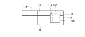
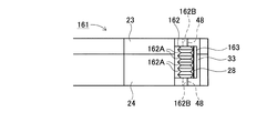
但し、図15乃至図18に示すように、印刷済みテープ28が排出されるテープ排出口112は、正面視スリット状でテープ搬送方向に所定幅(例えば、幅約3mmである。)に形成されている。また、このテープ排出口112の両面粘着テープ53のセパレータ53Dに接触する一方の案内壁112Aに連続する側壁部24B、つまり、テープ送りローラ63に対向する側壁部24Bには、この案内壁112Aの出口側端縁部で両面粘着テープ53から剥離されたセパレータ53Dが進入可能なセパレータ入口113が貫通して形成されている。
The schematic configuration of the tape cassette 111 according to the sixth embodiment is substantially the same as that of the tape cassette 21 according to the first embodiment.
However, as shown in FIGS. 15 to 18, the tape discharge port 112 through which the printed tape 28 is discharged is formed in a slit shape in a front view and has a predetermined width (for example, a width of about 3 mm) in the tape transport direction. ing. Further, the side wall 24B continuous with one guide wall 112A that contacts the separator 53D of the double-sided adhesive tape 53 of the tape discharge port 112, that is, the side wall 24B facing the tape feed roller 63 is provided on the side wall 24B. A separator inlet 113 through which the separator 53D peeled from the double-sided pressure-sensitive adhesive tape 53 can enter is formed so as to penetrate at the outlet side edge.

また、テープ排出口112は、案内壁112Aに対して印刷済みテープ28を挟んで該印刷済みテープ28のフィルムテープ51の外側面に接触して該印刷済みテープ28をテープ搬送方向下流側へ案内する案内壁112Bが所定距離(例えば、距離約1mmである。)離間して設けられている。そして、各案内壁112A、112Bの出口側端縁部は、側壁部24Bよりもテープ搬送方向下流側に突出して、固定刃30Aに対向すると共に該固定刃30Aに近接するように設けられている。   The tape discharge port 112 is in contact with the outer surface of the film tape 51 of the printed tape 28 with the printed tape 28 sandwiched between the guide wall 112A and guides the printed tape 28 downstream in the tape transport direction. The guide walls 112 </ b> B are provided at a predetermined distance (for example, a distance of about 1 mm). And the exit side edge part of each guide wall 112A, 112B protrudes in the tape conveyance direction downstream rather than the side wall part 24B, and is provided so that it may oppose the fixed blade 30A and may be close to this fixed blade 30A. .

また、テープ排出口112を構成する案内壁112Aのテープ搬送方向下流側、つまり、出口側端縁部は、先端部が平面視鋭角状に(例えば、先端角度が約30度〜約50度である。)セパレータ入口113方向へ傾斜する傾斜面112Cを構成するように形成されている。この傾斜面112Cは、該案内壁112Aの出口側端縁部とテープ送りローラ63との共通接線よりも印刷済みテープ28側に傾斜するように形成されて、剥離されたセパレータ53Dと接触しないように構成されている。   Further, the downstream end of the guide wall 112A constituting the tape discharge port 112 in the tape transport direction, that is, the outlet side end edge portion has a sharp tip end portion (for example, the tip angle is about 30 degrees to about 50 degrees). There is an inclined surface 112C that is inclined in the direction of the separator inlet 113. The inclined surface 112C is formed so as to be inclined toward the printed tape 28 with respect to the common tangent line between the outlet side edge of the guide wall 112A and the tape feeding roller 63 so as not to come into contact with the separated separator 53D. It is configured.

また、セパレータ入口113の印刷済みテープ28側の内側側面は、傾斜面112Cのテープ送りローラ63側の端縁部に連続すると共に、該セパレータ入口113のセパレータ53Dを挟んで対向する両内側面は、案内壁112Aの出口側端縁部とテープ送りローラ63との共通接線を挟んで該共通接線に対してほぼ平行になるよう所定距離(例えば、距離約2mmである。)離間して形成されている。   The inner side surface of the separator inlet 113 on the printed tape 28 side is continuous with the edge of the inclined surface 112C on the tape feed roller 63 side, and both inner side surfaces of the separator inlet 113 facing each other with the separator 53D interposed therebetween are The guide wall 112A is formed at a predetermined distance (for example, a distance of about 2 mm) so as to be substantially parallel to the common tangent across the common tangent of the outlet side edge of the guide wall 112A and the tape feed roller 63. ing.

そして、図15乃至図18に示すように、両面粘着スプール56から引き出された両面粘着テープ53は、テープ駆動ローラ軸14によって回転駆動されるテープ送りローラ63とテープサブローラ11との間を通過し、セパレータ53Dが重ね合わされない側の粘着層53Aがフィルムテープ51の印刷面に圧着される。   As shown in FIGS. 15 to 18, the double-sided adhesive tape 53 drawn from the double-sided adhesive spool 56 passes between the tape feed roller 63 and the tape sub-roller 11 that are rotationally driven by the tape drive roller shaft 14. Then, the pressure-sensitive adhesive layer 53 </ b> A on the side where the separator 53 </ b> D is not superimposed is pressure-bonded to the printing surface of the film tape 51.

その後、セパレータ53Dは、テープ排出口112の案内壁112Aの出口側先端縁部に沿ってフィルムテープ51に圧着された両面粘着テープ53から剥離されて、セパレータ入口113内に進入して、テープ送りローラ63の外周面に沿って両面粘着スプール56側に、つまり、引き出し側方向(図15中、上側方向である。)へ案内される。続いて、セパレータ53Dは、セパレータ案内壁37の壁面に沿って案内リブ35の外側方向に案内されて、凸状部35A、ガイドピン36及び凸状部35Bの外周面に順次沿って、巻回された両面粘着テープ53の外側周縁を通って略直角内側方向へ案内されてセパレータ巻き取りスプール62に至る。   Thereafter, the separator 53D is peeled off from the double-sided adhesive tape 53 that is pressure-bonded to the film tape 51 along the outlet side front edge of the guide wall 112A of the tape discharge port 112, enters the separator inlet 113, and feeds the tape. It is guided along the outer peripheral surface of the roller 63 toward the double-sided adhesive spool 56, that is, in the pull-out direction (upward direction in FIG. 15). Subsequently, the separator 53D is guided in the outer direction of the guide rib 35 along the wall surface of the separator guide wall 37, and is sequentially wound along the outer peripheral surfaces of the convex portion 35A, the guide pin 36, and the convex portion 35B. The double-sided adhesive tape 53 is guided to the inner side at a substantially right angle through the outer peripheral edge and reaches the separator take-up spool 62.

そして、セパレータ53Dの先端部は、このセパレータ巻き取りスプール62の外周面に接着テープ等によって固着され、セパレータ巻取軸16により回転駆動される該セパレータ巻き取りスプール62に巻き取られる。尚、セパレータ巻取軸16は、テープ駆動ローラ軸14及びリボン巻取軸15と同期して回転駆動される。   The front end of the separator 53D is fixed to the outer peripheral surface of the separator take-up spool 62 with an adhesive tape or the like, and is taken up by the separator take-up spool 62 that is driven to rotate by the separator take-up shaft 16. The separator take-up shaft 16 is rotationally driven in synchronization with the tape drive roller shaft 14 and the ribbon take-up shaft 15.

また、フィルムテープ51は、テープ排出口112の出口側端縁部でセパレータ53Dが剥離されて、印刷面に粘着層53A、ベースフィルム53B及び粘着層53Cが積層された状態で、つまり、セパレータ53Dが剥離された粘着剤付き印刷済みテープ28の状態で、テープ排出口27からテープカセット21の外部に送り出される。そして、セパレータ53Dが剥離された粘着剤付き印刷済みテープ28は、カッタユニット30を経てテープ印刷装置1のラベル排出口17より外部に送り出される。   In the film tape 51, the separator 53D is peeled off at the edge on the outlet side of the tape discharge port 112, and the adhesive layer 53A, the base film 53B, and the adhesive layer 53C are laminated on the printing surface, that is, the separator 53D. Is sent out of the tape cassette 21 from the tape outlet 27 in the state of the printed tape 28 with the adhesive peeled off. The pressure-sensitive adhesive-printed tape 28 from which the separator 53D has been peeled is sent out from the label discharge port 17 of the tape printer 1 through the cutter unit 30.

そして、印刷済みテープ28を所定長さ搬送後、不図示の切断用モータを駆動して可動刃30Bを作動させることによって、セパレータ53Dが剥離された所定長さの粘着剤付き印刷済みテープ28がラベル排出口17より排出される。   Then, after the printed tape 28 is conveyed for a predetermined length, the cutting blade (not shown) is driven to operate the movable blade 30B, whereby the printed tape 28 with the adhesive having a predetermined length from which the separator 53D has been peeled off. It is discharged from the label discharge port 17.

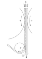
続いて、テープカセット111におけるテープスプール54、両面粘着スプール56、セパレータ巻き取りスプール62の位置関係について図19に基づいて説明する。   Next, the positional relationship among the tape spool 54, the double-sided adhesive spool 56, and the separator take-up spool 62 in the tape cassette 111 will be described with reference to FIG.

上述したように、テープカセット111において、テープスプール54に巻回されているフィルムテープ51は、テープ印刷装置1による印刷が行われる度に引き出される。従って、テープカセット111の使用開始時において、最も多くのフィルムテープ51がテープスプール54に巻回されている(図15参照)。
ここで、テープカセット111の使用開始時点において、テープスプール54に巻回されているフィルムテープ51が占有する領域を「フィルムテープ占有領域115」という。また、このフィルムテープ占有領域115の半径を「フィルムテープ巻回半径R4」という。
As described above, the film tape 51 wound around the tape spool 54 in the tape cassette 111 is pulled out each time printing by the tape printer 1 is performed. Accordingly, at the start of use of the tape cassette 111, the most film tape 51 is wound around the tape spool 54 (see FIG. 15).
Here, an area occupied by the film tape 51 wound around the tape spool 54 at the start of use of the tape cassette 111 is referred to as a “film tape occupation area 115”. The radius of the film tape occupation area 115 is referred to as “film tape winding radius R4”.

また、フィルムテープ51と同様に、両面粘着テープ53は、テープ印刷装置1による印刷が行われる度に、両面粘着スプール56から引き出される。従って、テープカセット111の使用開始時において、最も多くの両面粘着テープ53が両面粘着スプール56に巻回されている(図15参照)。
ここで、テープカセット111の使用開始時点において、両面粘着スプール56に巻回されている両面粘着テープ53が占有する領域を「両面粘着テープ占有領域116」という。また、この両面粘着テープ占有領域116の半径を「両面粘着テープ巻回半径R5」という。
Similarly to the film tape 51, the double-sided adhesive tape 53 is pulled out from the double-sided adhesive spool 56 every time printing is performed by the tape printer 1. Therefore, at the start of use of the tape cassette 111, the most double-sided adhesive tape 53 is wound around the double-sided adhesive spool 56 (see FIG. 15).
Here, the area occupied by the double-sided adhesive tape 53 wound around the double-sided adhesive spool 56 at the start of use of the tape cassette 111 is referred to as a “double-sided adhesive tape occupation area 116”. The radius of the double-sided adhesive tape occupation region 116 is referred to as “double-sided adhesive tape winding radius R5”.

そして、テープカセット111においては、セパレータ53Dはテープ印刷装置1による印刷が行われる毎に、両面粘着テープ53から剥離され、セパレータ巻き取りスプール62に巻回される。従って、テープカセット111の使用完了時(即ち、テープカセット111がラベルの作成にフィルムテープ51等を使い切った時)に、セパレータ53Dは、セパレータ巻き取りスプール62に対して最も多く巻回され、テープカセット111の内部において最も大きなスペースを占有する。尚、以下の説明において、セパレータ巻き取りスプール62に最も多く巻回されたセパレータ53Dが占有するスペースの半径を「セパレータ巻回半径R6」という。   In the tape cassette 111, the separator 53 </ b> D is peeled from the double-sided adhesive tape 53 and wound around the separator take-up spool 62 every time printing is performed by the tape printer 1. Therefore, when the use of the tape cassette 111 is completed (that is, when the tape cassette 111 has used up the film tape 51 or the like for label production), the separator 53D is wound most around the separator take-up spool 62, and the tape The largest space is occupied inside the cassette 111. In the following description, the radius of the space occupied by the separator 53D wound most around the separator take-up spool 62 is referred to as “separator winding radius R6”.

上述したように、セパレータ巻き取りスプール62は、テープスプール54と両面粘着スプール56との間に、回転可能に配設されている。そして、図19に示すように、テープカセット111では、テープスプール54の回転中心軸と、セパレータ巻き取りスプール62の回転中心軸を結ぶ直線距離(以下、第3軸間距離L3という。)は、セパレータ巻回半径R6とフィルムテープ巻回半径R4との和よりも小さくなるように構成されている。従って、テープカセット111の使用終了時において、セパレータ巻き取りスプール62に巻回されたセパレータ53Dは、フィルムテープ占有領域115の一部分を占有する。   As described above, the separator take-up spool 62 is rotatably disposed between the tape spool 54 and the double-sided adhesive spool 56. As shown in FIG. 19, in the tape cassette 111, a linear distance connecting the rotation center axis of the tape spool 54 and the rotation center axis of the separator take-up spool 62 (hereinafter referred to as a third inter-axis distance L3) is as follows. It is comprised so that it may become smaller than the sum of separator winding radius R6 and film tape winding radius R4. Therefore, at the end of use of the tape cassette 111, the separator 53D wound around the separator take-up spool 62 occupies a part of the film tape occupation area 115.

即ち、第3軸間距離L3を、セパレータ巻回半径R6とフィルムテープ巻回半径R4との和よりも小さくすることにより、テープカセット111は、フィルムテープ51とセパレータ53Dが共通して利用する第3重複領域117を生じさせる。これにより、テープカセット111は、第3重複領域117の大きさに応じて、テープカセット111自体の大型化を抑制し得る。また、テープカセット111の大型化を抑制することにより、当該テープカセット111は、テープ印刷装置1本体の大型化も抑制し得る。   That is, by making the third inter-axis distance L3 smaller than the sum of the separator winding radius R6 and the film tape winding radius R4, the tape cassette 111 uses the film tape 51 and the separator 53D in common. Three overlapping regions 117 are generated. Thereby, the tape cassette 111 can suppress the enlargement of the tape cassette 111 itself according to the size of the third overlapping region 117. Moreover, by suppressing the enlargement of the tape cassette 111, the tape cassette 111 can also suppress the enlargement of the main body of the tape printer 1.

また、テープカセット111では、両面粘着スプール56の回転中心軸と、セパレータ巻き取りスプール62の回転中心軸を結ぶ直線距離(以下、第4軸間距離L4という。)は、セパレータ巻回半径R6と両面粘着テープ巻回半径R5との和よりも小さくなるように構成されている。従って、テープカセット111の使用終了時において、セパレータ巻き取りスプール62に巻回されたセパレータ53Dは、両面粘着テープ占有領域116の一部分を占有する。   In the tape cassette 111, the linear distance connecting the rotation center axis of the double-sided adhesive spool 56 and the rotation center axis of the separator take-up spool 62 (hereinafter referred to as the fourth inter-axis distance L4) is the separator winding radius R6. It is comprised so that it may become smaller than the sum with double-sided adhesive tape winding radius R5. Therefore, at the end of use of the tape cassette 111, the separator 53D wound around the separator take-up spool 62 occupies a part of the double-sided adhesive tape occupation area 116.

即ち、第4軸間距離L4を、セパレータ巻回半径R6と両面粘着テープ巻回半径R5との和よりも小さくすることにより、テープカセット111は、両面粘着テープ53とセパレータ53Dとが共通して利用する第4重複領域118を生じさせる。これにより、テープカセット111は、第4重複領域118の大きさに応じて、テープカセット111自体の大型化を抑制し得る。また、テープカセット111の大型化を抑制することにより、当該テープカセット111は、テープ印刷装置1本体の大型化も抑制し得る。   That is, by making the fourth inter-axis distance L4 smaller than the sum of the separator winding radius R6 and the double-sided adhesive tape winding radius R5, the tape cassette 111 has the double-sided adhesive tape 53 and the separator 53D in common. The fourth overlapping area 118 to be used is generated. Thereby, the tape cassette 111 can suppress the enlargement of the tape cassette 111 itself according to the size of the fourth overlapping region 118. Moreover, by suppressing the enlargement of the tape cassette 111, the tape cassette 111 can also suppress the enlargement of the main body of the tape printer 1.

従って、テープカセット111は、図19に示すように、第3重複領域117と第4重複領域118との何れをも生じさせるので、第3重複領域117の大きさと、第4重複領域118の大きさに応じて、テープカセット111の大型化を更に抑制し得る。そして、これに伴い、テープカセット111は、テープ印刷装置1の大型化についても更に抑制し得る。   Accordingly, as shown in FIG. 19, the tape cassette 111 generates both the third overlapping region 117 and the fourth overlapping region 118, and therefore the size of the third overlapping region 117 and the size of the fourth overlapping region 118. Accordingly, the increase in size of the tape cassette 111 can be further suppressed. Accordingly, the tape cassette 111 can further suppress the enlargement of the tape printer 1.

尚、テープスプール54と両面粘着スプール56との距離を図19に示す状態よりも大きくして、セパレータ巻き取りスプール62をテープカセット111の内側方向へ移動させてもよい。そして、第3軸間距離L3をセパレータ巻回半径R6とフィルムテープ巻回半径R4との和よりも大きくなるように構成し、且つ、第4軸間距離L4をセパレータ巻回半径R6と両面粘着テープ巻回半径R5との和よりも小さくなるように構成してもよい。又は、第3軸間距離L3をセパレータ巻回半径R6とフィルムテープ巻回半径R4との和よりも小さくなるように構成し、且つ、第4軸間距離L4をセパレータ巻回半径R6と両面粘着テープ巻回半径R5との和よりも大きくなるように構成してもよい。   Alternatively, the distance between the tape spool 54 and the double-sided adhesive spool 56 may be made larger than that shown in FIG. The third inter-axis distance L3 is configured to be larger than the sum of the separator winding radius R6 and the film tape winding radius R4, and the fourth inter-axis distance L4 is separated from the separator winding radius R6. You may comprise so that it may become smaller than the sum with tape winding radius R5. Alternatively, the third inter-axis distance L3 is configured to be smaller than the sum of the separator winding radius R6 and the film tape winding radius R4, and the fourth inter-axis distance L4 is separated from the separator winding radius R6. You may comprise so that it may become larger than the sum with tape winding radius R5.

これにより、テープカセット111は、第3重複領域117と第4重複領域118のうちの何れか一方を生じさせるので、第3重複領域117の大きさと、第4重複領域118の大きさに応じて、テープカセット111の大型化を抑制し得る。そして、これに伴い、テープカセット111は、テープ印刷装置1の大型化についても更に抑制し得る。   As a result, the tape cassette 111 generates either one of the third overlapping region 117 and the fourth overlapping region 118, so that the size of the third overlapping region 117 and the size of the fourth overlapping region 118 are increased. The enlargement of the tape cassette 111 can be suppressed. Accordingly, the tape cassette 111 can further suppress the enlargement of the tape printer 1.

従って、第6実施形態に係るテープカセット111では、両面粘着テープ53は、テープ送りローラ63とテープサブローラ11とによって、フィルムテープ51の印刷された一方の面に圧着された後、テープ排出口112の出口側端縁部で該両面粘着テープ53からセパレータ53Dが剥離された状態で搬送されることとなる。これにより、所定長さに切断された印刷済みテープ28を商品等に貼り付ける際に、セパレータ53Dを剥がす手間を省くことができる。   Therefore, in the tape cassette 111 according to the sixth embodiment, the double-sided adhesive tape 53 is pressure-bonded to one printed surface of the film tape 51 by the tape feed roller 63 and the tape sub-roller 11, and then the tape discharge port. The separator 53 </ b> D is transported in a state where the separator 53 </ b> D is peeled off from the double-sided pressure-sensitive adhesive tape 53 at the exit edge of 112. Thereby, when sticking the printed tape 28 cut | disconnected by the predetermined length to goods etc., the effort which removes separator 53D can be saved.

また、テープ排出口112で両面粘着テープ53から該テープ排出口112の案内壁112Aの出口側端縁部に沿って剥離されたセパレータ53Dは、セパレータ入口113からテープカセット111内に進入して、テープ送りローラ63とセパレータ案内壁37との間、つまり、両面粘着スプール56側へ案内された後、凸状部35A、ガイドピン36及び凸状部35Bによって巻回された両面粘着テープ53の外側周縁を通って略直角内側方向へ案内されて、セパレータ巻き取りスプール62に巻き取られる。このため、テープ排出口112で両面粘着テープ53から剥離したセパレータ53Dをテープカセット111内にスムーズに収納することが可能となると共に、ユーザは両面粘着テープ53から剥離したセパレータ53Dを廃棄する手間を省くことができる。   Further, the separator 53D peeled from the double-sided adhesive tape 53 at the tape discharge port 112 along the outlet side edge of the guide wall 112A of the tape discharge port 112 enters the tape cassette 111 from the separator inlet 113, Between the tape feed roller 63 and the separator guide wall 37, that is, after being guided to the double-sided adhesive spool 56 side, the outside of the double-sided adhesive tape 53 wound by the convex portion 35A, the guide pin 36, and the convex portion 35B. It is guided to the inner side at a substantially right angle through the peripheral edge and is taken up by the separator take-up spool 62. Therefore, the separator 53D peeled off from the double-sided adhesive tape 53 at the tape discharge port 112 can be smoothly stored in the tape cassette 111, and the user has the trouble of discarding the separator 53D peeled off from the double-sided adhesive tape 53. It can be omitted.

また、セパレータ53Dは、テープ排出口112の案内壁112Aの出口側先端縁部に沿ってフィルムテープ51に圧着された両面粘着テープ53から剥離されて、セパレータ入口113内に進入して、テープ送りローラ63の外周面に沿って両面粘着スプール56側へ案内されるため、セパレータ53Dが印刷済みテープ28側に撓んで両面粘着テープ53の粘着層53Cに再度付着することを確実に防止でき、当該印刷済みテープ28をテープ排出口112から外部へスムーズに排出することが可能となる。   Further, the separator 53D is peeled off from the double-sided adhesive tape 53 that is pressure-bonded to the film tape 51 along the outlet side edge of the guide wall 112A of the tape discharge port 112, enters the separator inlet 113, and feeds the tape. Since it is guided to the double-sided adhesive spool 56 side along the outer peripheral surface of the roller 63, the separator 53D can be reliably prevented from flexing to the printed tape 28 side and adhering again to the adhesive layer 53C of the double-sided adhesive tape 53. The printed tape 28 can be smoothly discharged from the tape discharge port 112 to the outside.

また、テープ排出口112の各案内壁112A、112Bの出口側端縁部は、側壁部24Bよりもテープ搬送方向下流側に突出して、固定刃30Aに対向すると共に該固定刃30Aに近接するように設けられているため、テープ切断位置と印刷済みテープ28の印刷位置との距離を短くすることが可能となり、印刷済みテープ28の余白長さを短くすることが可能となる。   Further, the outlet side edge portions of the guide walls 112A and 112B of the tape discharge port 112 protrude downstream of the side wall portion 24B in the tape transport direction so as to face the fixed blade 30A and to be close to the fixed blade 30A. Therefore, the distance between the tape cutting position and the printing position of the printed tape 28 can be shortened, and the margin length of the printed tape 28 can be shortened.

また、テープ排出口112の各案内壁112A、112Bの出口側端縁部が固定刃30Aに近接して配設されるため、印刷済みテープ28の印刷面の裏面側をテープ切断位置、つまり、固定刃30Aの刃先の近傍まで確実に案内することが可能となる。   Further, since the exit side edge portions of the guide walls 112A and 112B of the tape discharge port 112 are disposed close to the fixed blade 30A, the back side of the printed surface of the printed tape 28 is the tape cutting position, that is, It is possible to reliably guide the vicinity of the cutting edge of the fixed blade 30A.

更に、セパレータ巻き取りスプール62は、両面粘着スプール56とテープスプール54との間に配設されているため、テープ印刷装置1によるテープ印刷が行われることによってセパレータ巻き取りスプール62に巻回可能なセパレータ53Dの最大巻回長さを容易に大きくすることができ、テープカセット111の小型化を図ることが可能となる。   Further, since the separator take-up spool 62 is disposed between the double-sided adhesive spool 56 and the tape spool 54, the separator take-up spool 62 can be wound around the separator take-up spool 62 by performing tape printing by the tape printer 1. The maximum winding length of the separator 53D can be easily increased, and the tape cassette 111 can be downsized.

また、セパレータ入口113からテープカセット111内に進入したセパレータ53Dを該テープ送りローラ63の外周面に沿って、該テープ送りローラ63とセパレータ案内壁37との間、つまり、両面粘着スプール56側へ案内後、セパレータ案内壁37、凸状部35A、ガイドピン36及び凸状部35Bによって巻回された両面粘着テープ53の外側周縁を通ってセパレータ巻き取りスプール62まで案内することによって、テープカセット111内の隙間空間を有効に活用することができ、テープカセット111の更なる小型化を図ることが可能となる。   Further, the separator 53D that has entered the tape cassette 111 from the separator inlet 113 passes along the outer peripheral surface of the tape feed roller 63, between the tape feed roller 63 and the separator guide wall 37, that is, toward the double-sided adhesive spool 56 side. After the guidance, the tape cassette 111 is guided by guiding to the separator take-up spool 62 through the outer peripheral edge of the double-sided adhesive tape 53 wound by the separator guide wall 37, the convex portion 35A, the guide pin 36, and the convex portion 35B. It is possible to effectively utilize the inner clearance space, and it is possible to further reduce the size of the tape cassette 111.

[第7実施形態]
次に、第7実施形態に係るテープカセット121について図20及び図21に基づいて説明する。尚、以下の説明において上記図1乃至図8の第1実施形態に係るテープカセット21及びテープ印刷装置1の構成等と同一符号は、該第1実施形態に係るテープカセット21及びテープ印刷装置1等の構成等と同一あるいは相当部分を示すものである。また、上記図15乃至図19の第6実施形態に係るテープカセット111の構成等と同一符号は、該第6実施形態に係るテープカセット111の構成等と同一あるいは相当部分を示すものである。
[Seventh Embodiment]
Next, a tape cassette 121 according to a seventh embodiment will be described with reference to FIGS. In the following description, the same reference numerals as those of the tape cassette 21 and the tape printer 1 according to the first embodiment in FIGS. 1 to 8 denote the same as those in the tape cassette 21 and the tape printer 1 according to the first embodiment. This indicates the same or corresponding part as the above-described configuration. The same reference numerals as those of the tape cassette 111 according to the sixth embodiment in FIGS. 15 to 19 denote the same or corresponding parts as those of the tape cassette 111 according to the sixth embodiment.

第7実施形態に係るテープカセット121の概略構成は、第6実施形態に係るテープカセット111とほぼ同じ構成である。
但し、図20及び図21に示すように、テープ送りローラ63とテープ排出口112の入口側端縁部との間の、フィルムテープ51の印刷面に両面粘着テープ53が圧着された印刷済みテープ28の経路上において、当該両面粘着テープ53のセパレータ53Dと粘着層53Cとの間に挿入されるように、予備剥離部材の一例としての予備剥離ピン122が設けられている。
The schematic configuration of the tape cassette 121 according to the seventh embodiment is substantially the same as that of the tape cassette 111 according to the sixth embodiment.
However, as shown in FIGS. 20 and 21, a printed tape in which a double-sided adhesive tape 53 is pressure-bonded to the printing surface of the film tape 51 between the tape feeding roller 63 and the entrance edge of the tape discharge port 112. 28, a preliminary peeling pin 122 as an example of a preliminary peeling member is provided so as to be inserted between the separator 53D of the double-sided pressure-sensitive adhesive tape 53 and the adhesive layer 53C.

つまり、予備剥離ピン122によって両面粘着テープ53からセパレータ53Dが一度剥離されている。そして、予備剥離ピン122によって両面粘着テープ53から一度剥離されたセパレータ53Dは、該予備剥離ピン122を通過後、再度、両面粘着テープ53の粘着層53Cに貼り合わされて、テープ排出口112内に搬送された後、このテープ排出口112の案内壁112Aの出口側端縁部で剥離されている。   That is, the separator 53D is once peeled from the double-sided adhesive tape 53 by the preliminary peeling pin 122. The separator 53D once peeled from the double-sided adhesive tape 53 by the preliminary peeling pin 122 is pasted again to the adhesive layer 53C of the double-sided pressure-sensitive adhesive tape 53 after passing through the preliminary peeling pin 122, and enters the tape discharge port 112. After being conveyed, the tape discharge port 112 is peeled off at the outlet side edge of the guide wall 112A.

この予備剥離ピン122は、両面粘着テープ53のテープ幅よりも長い断面円形の略円柱形状で、両端面中心位置に各支持軸122Aが立設されている。また、この予備剥離ピン122の外周面には、シリコーン樹脂皮膜が形成されている。また、テープカセット121の上ケース23及び下ケース24には、予備剥離ピン122の各支持軸122Aを回転可能に支持する各支持孔123が形成されている。そして、予備剥離ピン122の各支持軸122Aは、各支持孔123に挿入されて、回転可能に設けられている。   The preliminary peeling pin 122 has a substantially cylindrical shape with a circular cross section longer than the tape width of the double-sided adhesive tape 53, and each support shaft 122A is erected at the center position of both end faces. A silicone resin film is formed on the outer peripheral surface of the preliminary peeling pin 122. Further, the upper case 23 and the lower case 24 of the tape cassette 121 are formed with respective support holes 123 for rotatably supporting the respective support shafts 122A of the preliminary peeling pins 122. And each support shaft 122A of the preliminary | backup peeling pin 122 is inserted in each support hole 123, and is provided rotatably.

従って、第7実施形態に係るテープカセット121では、予備剥離ピン122は、両端部が回転可能に支持されると共に、両面粘着テープ53の粘着層53C及びセパレータ53Dの全幅に渡って接触する。   Therefore, in the tape cassette 121 according to the seventh embodiment, the preliminary peeling pins 122 are rotatably supported at both ends, and contact over the entire width of the adhesive layer 53C of the double-sided adhesive tape 53 and the separator 53D.

これにより、第7実施形態に係るテープカセット121では、第6実施形態に係るテープカセット111が奏する上記作用効果に加えて、予備剥離ピン122によってセパレータ53Dが両面粘着テープ53から一度剥離された後、再度両面粘着テープ53の粘着層53Cに貼り合わされてテープ排出口112の出口側へ搬送されるため、該両面粘着テープ53のセパレータ53Dに対する粘着力を低下させた状態で印刷済みテープ28を案内壁112Aの出口側端縁部へ搬送することが可能となる。   Thus, in the tape cassette 121 according to the seventh embodiment, after the separator 53D is once peeled from the double-sided pressure-sensitive adhesive tape 53 by the preliminary peeling pin 122, in addition to the above-described effects obtained by the tape cassette 111 according to the sixth embodiment. Since it is again bonded to the adhesive layer 53C of the double-sided adhesive tape 53 and conveyed to the outlet side of the tape discharge port 112, the printed tape 28 is guided in a state where the adhesive force of the double-sided adhesive tape 53 to the separator 53D is reduced. It becomes possible to convey to the exit side edge part of wall 112A.

このため、フィルムテープ51に圧着された両面粘着テープ53からセパレータ53Dをテープ排出口112の案内壁112Aの出口側端縁部に沿って容易に剥離することが可能となり、剥離したセパレータ53Dをセパレータ入口113へスムーズに進入させることができると共に、セパレータ53Dが剥離された粘着剤付き印刷済みテープ28をテープ排出口112の出口側端部からスムーズに排出することが可能となる。   Therefore, the separator 53D can be easily peeled from the double-sided pressure-sensitive adhesive tape 53 pressure-bonded to the film tape 51 along the outlet side edge of the guide wall 112A of the tape outlet 112, and the peeled separator 53D can be separated from the separator 53D. It is possible to smoothly enter the inlet 113, and it is possible to smoothly discharge the pressure-sensitive adhesive-printed tape 28 from which the separator 53D has been peeled off from the outlet side end portion of the tape outlet 112.

[第8実施形態]
次に、第8実施形態に係るテープカセット131について図22に基づいて説明する。尚、以下の説明において上記図15乃至図19の第6実施形態に係るテープカセット111の構成等と同一符号は、該第6実施形態に係るテープカセット111の構成等と同一あるいは相当部分を示すものである。また、上記図20及び図21の第7実施形態に係るテープカセット121の構成等と同一符号は、該第7実施形態に係るテープカセット121の構成等と同一あるいは相当部分を示すものである。
[Eighth Embodiment]
Next, a tape cassette 131 according to an eighth embodiment will be described with reference to FIG. In the following description, the same reference numerals as those of the tape cassette 111 according to the sixth embodiment in FIGS. 15 to 19 denote the same or corresponding parts as those of the tape cassette 111 according to the sixth embodiment. Is. The same reference numerals as those of the tape cassette 121 according to the seventh embodiment in FIGS. 20 and 21 indicate the same or corresponding parts as those of the tape cassette 121 according to the seventh embodiment.

第8実施形態に係るテープカセット131の概略構成は、第7実施形態に係るテープカセット121とほぼ同じ構成である。
但し、図22に示すように、テープ排出口112の出口側が、テープ送りローラ63とテープサブローラ11との共通接線132に対してテープサブローラ11側に遠ざかるように、各案内壁112A、112Bの印刷済みテープ28に対向する案内面が、斜め外側方向へ傾斜するように形成されている。
The schematic configuration of the tape cassette 131 according to the eighth embodiment is substantially the same as that of the tape cassette 121 according to the seventh embodiment.
However, as shown in FIG. 22, the guide walls 112 </ b> A and 112 </ b> B are arranged such that the outlet side of the tape discharge port 112 is away from the common tangent line 132 of the tape feed roller 63 and the tape sub roller 11 toward the tape sub roller 11 side. The guide surface facing the printed tape 28 is formed so as to be inclined obliquely outward.

従って、第8実施形態に係るテープカセット131では、予備剥離ピン122によって両面粘着テープ53から一度剥離されたセパレータ53Dは、該予備剥離ピン122を通過後、再度、両面粘着テープ53の粘着層53Cに貼り合わされて、案内壁112Aの出口側端縁部に沿って剥離されている。また、予備剥離ピン122によって両面粘着テープ53からセパレータ53Dが剥離された印刷済みテープ28は、予備剥離ピン122の外周面とテープ送りローラ63の外周面との共通接線上を経由して、テープ排出口112の入口側端縁部に至る。   Therefore, in the tape cassette 131 according to the eighth embodiment, the separator 53D once peeled from the double-sided adhesive tape 53 by the preliminary peeling pin 122 passes through the preliminary peeling pin 122 and then again, the adhesive layer 53C of the double-sided adhesive tape 53. And peeled along the outlet side edge of the guide wall 112A. The printed tape 28 from which the separator 53D has been peeled from the double-sided adhesive tape 53 by the preliminary peeling pin 122 passes through the common tangent line between the outer peripheral surface of the preliminary peeling pin 122 and the outer peripheral surface of the tape feed roller 63, and then the tape. It reaches the edge on the inlet side of the discharge port 112.

そして、印刷済みテープ28は、該案内壁112Aの出口側端縁部に沿ってセパレータ53Dが剥離された後、テープ排出口112から外部へ排出される。つまり、両面粘着テープ53からセパレータ53Dが剥離された印刷済みテープ28は、テープ排出口112から両面粘着テープ53が貼着されていない面の方向に傾斜して外部へ排出される。   The printed tape 28 is discharged from the tape discharge port 112 to the outside after the separator 53D is peeled off along the outlet side edge of the guide wall 112A. That is, the printed tape 28 from which the separator 53D has been peeled from the double-sided adhesive tape 53 is discharged from the tape outlet 112 to the outside in a direction of the surface where the double-sided adhesive tape 53 is not attached.

これにより、第8実施形態に係るテープカセット131では、前記第7実施形態に係るテープカセット121が奏する上記作用効果に加えて、テープ排出口112の出口側端縁部で、両面粘着テープ53からセパレータ53Dが案内壁112Aの出口側端縁部に沿って剥離される際に、その粘着力によって印刷済みテープ28がセパレータ53D側に引っ張られても、印刷済みテープ28をテープ送りローラ63とテープサブローラ11との共通接線132よりも該テープサブローラ11側で走行させることが可能となる。これにより、印刷済みテープ28を確実に固定刃30Aと可動刃30Bとの間に進入させることが可能となる。   Thereby, in the tape cassette 131 concerning 8th Embodiment, in addition to the said effect produced by the tape cassette 121 concerning said 7th Embodiment, in the exit side edge part of the tape discharge port 112, it is from double-sided adhesive tape 53. When the separator 53D is peeled along the outlet side edge of the guide wall 112A, even if the printed tape 28 is pulled to the separator 53D side by the adhesive force, the printed tape 28 and the tape feed roller 63 and the tape It is possible to run on the tape sub-roller 11 side with respect to the common tangent line 132 with the sub-roller 11. As a result, the printed tape 28 can surely enter between the fixed blade 30A and the movable blade 30B.

尚、テープカセット131の予備剥離ピン122を取り除くようにしてもよい。これにより、前記第6実施形態に係るテープカセット111が奏する上記作用効果に加えて、テープ排出口112の出口側端縁部で、両面粘着テープ53からセパレータ53Dが案内壁112Aの出口側端縁部に沿って剥離される際に、その粘着力によって印刷済みテープ28がセパレータ53D側に引っ張られても、印刷済みテープ28をテープ送りローラ63とテープサブローラ11との共通接線132よりも該テープサブローラ11側で走行させることが可能となる。これにより、印刷済みテープ28を確実に固定刃30Aと可動刃30Bとの間に進入させることが可能となる。   The preliminary peeling pin 122 of the tape cassette 131 may be removed. As a result, in addition to the above-described effects achieved by the tape cassette 111 according to the sixth embodiment, the separator 53D extends from the double-sided adhesive tape 53 to the outlet side edge of the guide wall 112A at the outlet side edge of the tape outlet 112. When the printed tape 28 is pulled toward the separator 53D due to the adhesive force when peeling along the portion, the printed tape 28 is more than the common tangent line 132 between the tape feed roller 63 and the tape sub-roller 11. It becomes possible to run on the tape sub-roller 11 side. As a result, the printed tape 28 can surely enter between the fixed blade 30A and the movable blade 30B.

[第9実施形態]
次に、第9実施形態に係るテープカセット141について図23及び図24に基づいて説明する。尚、以下の説明において上記図1乃至図8の第1実施形態に係るテープカセット21及びテープ印刷装置1の構成等と同一符号は、該第1実施形態に係るテープカセット21及びテープ印刷装置1等の構成等と同一あるいは相当部分を示すものである。また、上記図15乃至図19の第6実施形態に係るテープカセット111の構成等と同一符号は、該第6実施形態に係るテープカセット111の構成等と同一あるいは相当部分を示すものである。
[Ninth Embodiment]
Next, a tape cassette 141 according to a ninth embodiment will be described with reference to FIGS. In the following description, the same reference numerals as those of the tape cassette 21 and the tape printer 1 according to the first embodiment in FIGS. 1 to 8 denote the same as those in the tape cassette 21 and the tape printer 1 according to the first embodiment. This indicates the same or corresponding part as the above-described configuration. The same reference numerals as those of the tape cassette 111 according to the sixth embodiment in FIGS. 15 to 19 denote the same or corresponding parts as those of the tape cassette 111 according to the sixth embodiment.

第9実施形態に係るテープカセット141の概略構成は、第6実施形態に係るテープカセット111とほぼ同じ構成である。
但し、図23及び図24に示すように、両面粘着スプール56とテープ送りローラ63との間、つまり、両面粘着テープ53の引出口とテープ送りローラ63との間の該両面粘着テープ53の経路上において、両面粘着テープ53のセパレータ53Dと粘着層53Cとの間に挿入されるように、予備剥離部材の一例としての予備剥離ピン142が設けられている。
The schematic configuration of the tape cassette 141 according to the ninth embodiment is substantially the same as that of the tape cassette 111 according to the sixth embodiment.
However, as shown in FIGS. 23 and 24, the path of the double-sided adhesive tape 53 between the double-sided adhesive spool 56 and the tape feed roller 63, that is, between the outlet of the double-sided adhesive tape 53 and the tape feed roller 63. Above, a preliminary peeling pin 142 as an example of a preliminary peeling member is provided so as to be inserted between the separator 53D of the double-sided adhesive tape 53 and the adhesive layer 53C.

また、予備剥離ピン142の両面粘着テープ53の搬送方向上流側には、テープカセット141の上ケース23と下ケース24のそれぞれから、該両面粘着テープ53の幅寸法にほぼ等しい距離で相対向するように突出した平面視略横長四角形の一対の上流側ガイド部145A、145Bが設けられている。これにより、一対の上流側ガイド部145A、145Bによって、両面粘着テープ53の幅方向への移動を規制しつつ、この両面粘着テープ53を予備剥離ピン142へ摺動案内することが可能となる。
尚、この一対の上流側ガイド部145A、145Bは、設けなくてもよい。
Further, the upstream side of the preliminary peeling pin 142 in the transport direction of the double-sided pressure-sensitive adhesive tape 53 faces each other at a distance substantially equal to the width dimension of the double-sided pressure-sensitive adhesive tape 53 from each of the upper case 23 and the lower case 24 of the tape cassette 141. A pair of upstream guide portions 145A and 145B having a substantially rectangular shape in plan view and protruding in this manner are provided. As a result, the double-sided adhesive tape 53 can be slidably guided to the preliminary peeling pin 142 while restricting the movement of the double-sided adhesive tape 53 in the width direction by the pair of upstream guide portions 145A and 145B.
The pair of upstream guide portions 145A and 145B may not be provided.

また、予備剥離ピン142の両面粘着テープ53の搬送方向下流側には、一対の下流側コロ146A、146Bが、両面粘着テープ53を挟んで、該両面粘着テープ53の厚さにほぼ等しい距離で対向するように設けられている。そして、予備剥離ピン142によって両面粘着テープ53から一度剥離されたセパレータ53Dと、該セパレータ53Dが剥離された両面粘着テープ53とが、一対の下流側コロ146A、146B間を通って引き出されている。   A pair of downstream rollers 146A, 146B are disposed at a distance substantially equal to the thickness of the double-sided adhesive tape 53 with the double-sided adhesive tape 53 sandwiched between the preliminary peeling pins 142 on the downstream side in the transport direction of the double-sided adhesive tape 53. It is provided so as to face each other. Then, the separator 53D once peeled from the double-sided adhesive tape 53 by the preliminary peeling pin 142 and the double-sided adhesive tape 53 from which the separator 53D has been peeled are drawn through a pair of downstream rollers 146A and 146B. .

つまり、両面粘着スプール56から引き出された両面粘着テープ53は、一対の上流側ガイド部145A、145Bの間を幅方向への移動を規制されつつ通過して、予備剥離ピン142に案内された後、この予備剥離ピン142によって両面粘着テープ53からセパレータ53Dが一度剥離される。そして、予備剥離ピン142によって両面粘着テープ53から一度剥離されたセパレータ53Dと、該セパレータ53Dが剥離された両面粘着テープ53とは、該予備剥離ピン142を通過後、一対の下流側コロ146A、146Bの間を通過する。更に、この一対の下流側コロ146A、146Bの間を通過したセパレータ53Dは、再度、両面粘着テープ53の粘着層53Cに貼り合わされて、テープ送りローラ63の外周面に沿って引き出されている。   That is, after the double-sided adhesive tape 53 pulled out from the double-sided adhesive spool 56 passes between the pair of upstream guide portions 145A and 145B while being restricted in movement in the width direction and is guided to the preliminary peeling pin 142. The separator 53D is once peeled from the double-sided adhesive tape 53 by the preliminary peeling pin 142. The separator 53D once peeled from the double-sided adhesive tape 53 by the preliminary peeling pin 142 and the double-sided adhesive tape 53 from which the separator 53D has been peeled pass through the preliminary peeling pin 142, and then a pair of downstream rollers 146A, Pass between 146B. Further, the separator 53D that has passed between the pair of downstream rollers 146A, 146B is again bonded to the adhesive layer 53C of the double-sided adhesive tape 53 and drawn out along the outer peripheral surface of the tape feed roller 63.

また、予備剥離ピン142は、両面粘着テープ53のテープ幅よりも長い断面円形の略円柱形状で、両端面中心位置に各支持軸142Aが立設されている。また、この予備剥離ピン142の外周面には、シリコーン樹脂皮膜が形成されている。また、テープカセット141の上ケース23及び下ケース24には、予備剥離ピン142の各支持軸142Aを回転可能に支持する各支持孔143が形成されている。   Further, the preliminary peeling pin 142 has a substantially cylindrical shape with a circular cross section longer than the tape width of the double-sided pressure-sensitive adhesive tape 53, and each support shaft 142A is erected at the center position of both end faces. A silicone resin film is formed on the outer peripheral surface of the preliminary peeling pin 142. Further, the upper case 23 and the lower case 24 of the tape cassette 141 are formed with respective support holes 143 for rotatably supporting the respective support shafts 142A of the preliminary peeling pins 142.

従って、この予備剥離ピン142は、各支持軸142Aが各支持孔143に挿入されて、回転可能に設けられるため、該予備剥離ピン142は、両端部が回転可能に支持されると共に、両面粘着テープ53の粘着層53C及びセパレータ53Dの全幅に渡って接触する。   Accordingly, since the preliminary peeling pin 142 is rotatably provided with the support shafts 142A inserted into the support holes 143, the preliminary peeling pin 142 is rotatably supported at both ends and has a double-sided adhesive. The adhesive layer 53C of the tape 53 and the separator 53D make contact over the entire width.

また、一対の下流側コロ146A、146Bは、両面粘着テープ53のテープ幅とほぼ等しい長さの断面円形の略円柱形状で、それぞれの両端面中心位置に各支持軸147が立設されている。また、各下流側コロ146A、146Bの外周面には、シリコーン樹脂皮膜が形成されている。また、テープカセット141の上ケース23及び下ケース24には、両面粘着テープ53の両側縁部に接触して幅方向の移動を規制すると共に両面粘着テープ53を搬送方向へ摺動案内可能に突出する平面視略横長四角形の各段差部148、148が設けられている。   Further, the pair of downstream rollers 146A and 146B has a substantially cylindrical shape with a circular cross section having a length substantially equal to the tape width of the double-sided adhesive tape 53, and each support shaft 147 is erected at the center position of each end face. . A silicone resin film is formed on the outer peripheral surface of each downstream roller 146A, 146B. Further, the upper case 23 and the lower case 24 of the tape cassette 141 are in contact with both side edges of the double-sided adhesive tape 53 to restrict movement in the width direction and protrude so that the double-sided adhesive tape 53 can be slidably guided in the transport direction. Step portions 148 and 148 each having a substantially rectangular shape in plan view are provided.

また、各段差部148、148には、各下流側コロ146A、146Bの各支持軸147を回転可能に支持する一対の支持孔149が形成されている。そして、各下流側コロ146A、146Bの各支持軸147は、各支持孔149に挿入されて、回転可能に支持されると共に、両面粘着テープ53の厚さにほぼ等しい距離で対向するように設けられている。尚、各下流側コロ146A、146Bのうちの少なくとも両面粘着テープ53の粘着層53Aに接触する下流側コロ146Bの外周面だけに、シリコーン樹脂皮膜を形成するようにしてもよい。   Each stepped portion 148, 148 is formed with a pair of support holes 149 that rotatably support the support shafts 147 of the respective downstream rollers 146A, 146B. The support shafts 147 of the downstream rollers 146A and 146B are inserted into the support holes 149 so as to be rotatably supported, and are provided so as to face each other at a distance substantially equal to the thickness of the double-sided adhesive tape 53. It has been. In addition, a silicone resin film may be formed only on the outer peripheral surface of the downstream roller 146B that is in contact with the adhesive layer 53A of the double-sided adhesive tape 53 among the downstream rollers 146A and 146B.

従って、第9実施形態に係るテープカセット141では、両面粘着スプール56から引き出された両面粘着テープ53は、一対の上流側ガイド部145A、145Bの間を幅方向への移動を規制されつつ通過後、両端部を回転可能に支持される予備剥離ピン142によってセパレータ53Dが両面粘着テープ53から剥離される。その後、セパレータ53Dと、セパレータ53Dが剥離された両面粘着テープ53とは、各段差部148、148と各下流側コロ146A、146Bとの間を通過することによって、該セパレータ53Dは、再度、両面粘着テープ53の粘着層53Cに貼り合わされて、テープ送りローラ63の外周面に沿って引き出される。   Therefore, in the tape cassette 141 according to the ninth embodiment, after the double-sided adhesive tape 53 pulled out from the double-sided adhesive spool 56 is passed between the pair of upstream guide portions 145A and 145B while being restricted in movement in the width direction. The separator 53D is peeled from the double-sided adhesive tape 53 by the preliminary peeling pins 142 that are rotatably supported at both ends. Thereafter, the separator 53D and the double-sided pressure-sensitive adhesive tape 53 from which the separator 53D has been peeled pass between the step portions 148 and 148 and the downstream rollers 146A and 146B, whereby the separator 53D is again double-sided. It is bonded to the adhesive layer 53C of the adhesive tape 53 and pulled out along the outer peripheral surface of the tape feed roller 63.

これにより、第9実施形態に係るテープカセット141では、第6実施形態に係るテープカセット111が奏する上記作用効果に加えて、予備剥離ピン142によってセパレータ53Dが両面粘着テープ53から一度剥離された後、再度両面粘着テープ53の粘着層53Cに貼り合わされてテープ送りローラ63へ搬送されるため、該両面粘着テープ53のセパレータ53Dに対する粘着力を低下させた状態でフィルムテープ51の印刷面に圧着させることが可能となる。   Thereby, in the tape cassette 141 according to the ninth embodiment, after the separator 53D is once peeled off from the double-sided pressure-sensitive adhesive tape 53 by the preliminary peeling pin 142, in addition to the above-described operational effects of the tape cassette 111 according to the sixth embodiment. Since it is again bonded to the adhesive layer 53C of the double-sided adhesive tape 53 and conveyed to the tape feed roller 63, it is pressure-bonded to the printing surface of the film tape 51 in a state where the adhesive strength of the double-sided adhesive tape 53 to the separator 53D is reduced. It becomes possible.

このため、フィルムテープ51に圧着された両面粘着テープ53からセパレータ53Dをテープ排出口112の案内壁112Aの出口側端縁部に沿って容易に剥離することが可能となり、剥離したセパレータ53Dをセパレータ入口113へスムーズに進入させることができると共に、セパレータ53Dが剥離された粘着剤付き印刷済みテープ28をテープ排出口112の出口側端部からスムーズに排出することが可能となる。   Therefore, the separator 53D can be easily peeled from the double-sided pressure-sensitive adhesive tape 53 pressure-bonded to the film tape 51 along the outlet side edge of the guide wall 112A of the tape outlet 112, and the peeled separator 53D can be separated from the separator 53D. It is possible to smoothly enter the inlet 113, and it is possible to smoothly discharge the pressure-sensitive adhesive-printed tape 28 from which the separator 53D has been peeled off from the outlet side end portion of the tape outlet 112.

[第10実施形態]
次に、第10実施形態に係るテープカセット151について図25に基づいて説明する。尚、以下の説明において上記図15乃至図19の第6実施形態に係るテープカセット111の構成等と同一符号は、該第6実施形態に係るテープカセット111の構成等と同一あるいは相当部分を示すものである。また、上記図23及び図24の第9実施形態に係るテープカセット141の構成等と同一符号は、該第9実施形態に係るテープカセット141の構成等と同一あるいは相当部分を示すものである。
[Tenth embodiment]
Next, a tape cassette 151 according to the tenth embodiment will be described with reference to FIG. In the following description, the same reference numerals as those of the tape cassette 111 according to the sixth embodiment in FIGS. 15 to 19 denote the same or corresponding parts as those of the tape cassette 111 according to the sixth embodiment. Is. The same reference numerals as those of the tape cassette 141 according to the ninth embodiment in FIGS. 23 and 24 denote the same or corresponding parts as those of the tape cassette 141 according to the ninth embodiment.

第10実施形態に係るテープカセット151の概略構成は、第9実施形態に係るテープカセット141とほぼ同じ構成である。
但し、図25に示すように、テープ排出口112の出口側が、テープ送りローラ63とテープサブローラ11との共通接線152に対してテープサブローラ11側に遠ざかるように、各案内壁112A、112Bの印刷済みテープ28に対向する案内面が、共通接線152に対して斜め外側方向へ傾斜するように形成されている。
The schematic configuration of the tape cassette 151 according to the tenth embodiment is substantially the same as that of the tape cassette 141 according to the ninth embodiment.
However, as shown in FIG. 25, the guide walls 112 </ b> A and 112 </ b> B are arranged so that the outlet side of the tape discharge port 112 is away from the common tangent line 152 between the tape feed roller 63 and the tape sub roller 11 toward the tape sub roller 11 side. The guide surface facing the printed tape 28 is formed so as to be inclined obliquely outward with respect to the common tangent line 152.

従って、第10実施形態に係るテープカセット151では、両面粘着スプール56から引き出された両面粘着テープ53は、一対の上流側ガイド部145A、145Bの間を幅方向への移動を規制されつつ通過後、両端部を回転可能に支持される予備剥離ピン142によってセパレータ53Dが両面粘着テープ53から剥離される。その後、セパレータ53Dと、セパレータ53Dが剥離された両面粘着テープ53とは、各段差部148、148と各下流側コロ146A、146Bとの間を通過することによって、該セパレータ53Dは、再度、両面粘着テープ53の粘着層53Cに貼り合わされて、テープ送りローラ63の外周面に沿って引き出される。   Therefore, in the tape cassette 151 according to the tenth embodiment, after the double-sided adhesive tape 53 pulled out from the double-sided adhesive spool 56 is passed between the pair of upstream guide portions 145A and 145B while being restricted in movement in the width direction. The separator 53D is peeled from the double-sided adhesive tape 53 by the preliminary peeling pins 142 that are rotatably supported at both ends. Thereafter, the separator 53D and the double-sided pressure-sensitive adhesive tape 53 from which the separator 53D has been peeled pass between the step portions 148 and 148 and the downstream rollers 146A and 146B, whereby the separator 53D is again double-sided. It is bonded to the adhesive layer 53C of the adhesive tape 53 and pulled out along the outer peripheral surface of the tape feed roller 63.

そして、フィルムテープ51に両面粘着テープ53が圧着された印刷済みテープ28は、テープ排出口112の入口側端縁部に至る。そして、印刷済みテープ28は、該テープ排出口112の案内壁112Aの出口側端縁部に沿ってセパレータ53Dが剥離された後、テープ排出口112から外部へ排出される。つまり、両面粘着テープ53からセパレータ53Dが剥離された印刷済みテープ28は、テープ排出口112から両面粘着テープ53が貼着されていない面の方向に傾斜して外部へ排出される。   Then, the printed tape 28 in which the double-sided adhesive tape 53 is pressure-bonded to the film tape 51 reaches the inlet side edge of the tape discharge port 112. The printed tape 28 is discharged from the tape discharge port 112 to the outside after the separator 53D is peeled off along the outlet side edge of the guide wall 112A of the tape discharge port 112. That is, the printed tape 28 from which the separator 53D has been peeled from the double-sided adhesive tape 53 is discharged from the tape outlet 112 to the outside in a direction of the surface where the double-sided adhesive tape 53 is not attached.

これにより、第10実施形態に係るテープカセット151では、前記第9実施形態に係るテープカセット141が奏する上記作用効果に加えて、テープ排出口112の出口側端縁部で、両面粘着テープ53からセパレータ53Dが案内壁112Aの出口側端縁部に沿って剥離される際に、その粘着力によって印刷済みテープ28がセパレータ53D側に引っ張られても、印刷済みテープ28をテープ送りローラ63とテープサブローラ11との共通接線152よりも該テープサブローラ11側で走行させることが可能となる。これにより、印刷済みテープ28を確実に固定刃30Aと可動刃30Bとの間に進入させることが可能となる。   Thereby, in the tape cassette 151 concerning 10th Embodiment, in addition to the said effect produced by the tape cassette 141 concerning said 9th Embodiment, it is from the double-sided adhesive tape 53 in the exit side edge part of the tape discharge port 112. When the separator 53D is peeled along the outlet side edge of the guide wall 112A, even if the printed tape 28 is pulled to the separator 53D side by the adhesive force, the printed tape 28 and the tape feed roller 63 and the tape It is possible to run on the tape sub-roller 11 side with respect to the common tangent line 152 with the sub-roller 11. As a result, the printed tape 28 can surely enter between the fixed blade 30A and the movable blade 30B.

[第11実施形態]
次に、第11実施形態に係るテープカセット161について図26乃至図32に基づいて説明する。尚、以下の説明において上記図1乃至図8の第1実施形態に係るテープカセット21及びテープ印刷装置1の構成等と同一符号は、該第1実施形態に係るテープカセット21及びテープ印刷装置1等の構成等と同一あるいは相当部分を示すものである。
[Eleventh embodiment]
Next, a tape cassette 161 according to the eleventh embodiment will be described with reference to FIGS. In the following description, the same reference numerals as those of the tape cassette 21 and the tape printer 1 according to the first embodiment in FIGS. 1 to 8 denote the same as those in the tape cassette 21 and the tape printer 1 according to the first embodiment. This indicates the same or corresponding part as the above-described configuration.

第11実施形態に係るテープカセット161の概略構成は、第1実施形態に係るテープカセット21とほぼ同じ構成である。
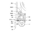
但し、図26乃至図28に示すように、テープカセット161は、テープ送りローラ63のテープ搬送方向下流側、つまり、テープ排出口163側に、剥離コロ65に替えて接触コロ162が回転可能に設けられている。また、テープ送りローラ63に対向する側壁部24Bの該接触コロ162に対向する端縁部は、この接触コロ162の外周面から所定距離(例えば、距離約1mmである。)離間している。
The schematic configuration of the tape cassette 161 according to the eleventh embodiment is substantially the same as that of the tape cassette 21 according to the first embodiment.
However, as shown in FIGS. 26 to 28, in the tape cassette 161, the contact roller 162 can be rotated in place of the peeling roller 65 on the downstream side in the tape transport direction of the tape feed roller 63, that is, on the tape discharge port 163 side. Is provided. Further, the end edge portion of the side wall portion 24 </ b> B facing the tape feeding roller 63 facing the contact roller 162 is separated from the outer peripheral surface of the contact roller 162 by a predetermined distance (for example, a distance of about 1 mm).

また、後述のように、セパレータ53Dは、フィルムテープ51に圧着された両面粘着テープ53から剥離され、テープ送りローラ63の外周面に沿って両面粘着スプール56側に、つまり、引き出し側方向(図26中、上側方向である。)へ案内される(図31参照)。
図27及び図28に示すように、先ず、接触コロ162の外周面は、該外周面に軸方向断面V字形の溝部162Aが軸方向に連続して形成されると共に、両端面外周部が軸方向内側に斜めに面取りされて、軸方向に平行な複数の断面略三角形の凸状形状に形成されている。
Further, as will be described later, the separator 53D is peeled off from the double-sided pressure-sensitive adhesive tape 53 that is pressure-bonded to the film tape 51, and is directed to the double-sided pressure-sensitive adhesive spool 56 side along the outer peripheral surface of the tape feed roller 63, that is, in the drawing side direction (see FIG. 26, the upper direction) (see FIG. 31).
As shown in FIGS. 27 and 28, first, on the outer peripheral surface of the contact roller 162, a groove portion 162A having an axial V-shaped cross section is continuously formed in the outer peripheral surface in the axial direction, and the outer peripheral portions on both end surfaces are axial. It is chamfered obliquely inward in the direction and formed into a convex shape having a plurality of substantially triangular cross sections parallel to the axial direction.

また、接触コロ162は、両端面中心位置に支持孔48に回転可能に嵌入される各支持軸162Bが立設されると共に、外周面にシリコーン樹脂皮膜が形成されている。そして、この接触コロ162は、セパレータ53Dが剥離された印刷済みテープ28の粘着層53C(図31参照)に接触して、該印刷済みテープ28をテープ排出口163からテープ搬送方向下流側へ案内する。   Further, the contact roller 162 has support shafts 162B that are rotatably inserted into the support holes 48 at the center positions of both end surfaces, and a silicone resin film is formed on the outer peripheral surface. The contact roller 162 contacts the adhesive layer 53C (see FIG. 31) of the printed tape 28 from which the separator 53D has been peeled, and guides the printed tape 28 from the tape discharge port 163 to the downstream side in the tape transport direction. To do.

また、接触コロ162は、テープ送りローラ63に対向する側壁部24Bよりもテープ搬送方向外側に突出して、固定刃30Aに対向すると共に該固定刃30Aに近接するように設けられている。
また、接触コロ162に対して印刷済みテープ28を挟んで対向する案内壁33は、この接触コロ162よりもテープ搬送方向下流側へ延出されて、印刷済みテープ28を固定刃30Aの近傍位置まで案内可能となるように設けられている。
Further, the contact roller 162 protrudes outward in the tape transport direction from the side wall portion 24B facing the tape feed roller 63, and is provided so as to face the fixed blade 30A and be close to the fixed blade 30A.
Further, the guide wall 33 facing the contact roller 162 with the printed tape 28 interposed therebetween is extended to the downstream side of the contact roller 162 in the tape transport direction, and the printed tape 28 is positioned in the vicinity of the fixed blade 30A. It is provided so that it can be guided to.

また、図27及び図29に示すように、テープ送りローラ63とテープサブローラ11によってフィルムテープ51に圧着された両面粘着テープ53からセパレータ53Dが剥離される剥離位置近傍のテープ搬送方向下流側、つまり、印刷済みテープ28の粘着層53Cとセパレータ53Dとの間に、剥離部材の一例としての剥離ピン165が設けられ、印刷済みテープ28とセパレータ53Dを分離している。   Further, as shown in FIGS. 27 and 29, the downstream side in the tape transport direction in the vicinity of the peeling position where the separator 53D is peeled off from the double-sided adhesive tape 53 pressure-bonded to the film tape 51 by the tape feeding roller 63 and the tape sub-roller 11, That is, the peeling pin 165 as an example of a peeling member is provided between the adhesive layer 53C of the printed tape 28 and the separator 53D, and separates the printed tape 28 and the separator 53D.

この剥離ピン165は、印刷済みテープ28のテープ幅よりも長い断面円形の略円柱形状で、両端面中心位置に各支持軸165Aが立設されている。また、この剥離ピン165の外周面には、シリコーン樹脂皮膜が形成されている。また、テープカセット161の上ケース23及び下ケース24には、剥離ピン72の各支持軸165Aを回転可能に支持する各支持孔167が形成されている。   The peeling pin 165 has a substantially cylindrical shape with a circular cross section longer than the tape width of the printed tape 28, and each support shaft 165A is erected at the center position of both end faces. Further, a silicone resin film is formed on the outer peripheral surface of the peeling pin 165. Further, the upper case 23 and the lower case 24 of the tape cassette 161 are formed with respective support holes 167 for rotatably supporting the respective support shafts 165A of the peeling pins 72.

そして、剥離ピン165の各支持軸165Aは、各支持孔167に挿入されて、回転可能に設けられている。従って、剥離ピン165は、両端部が回転可能に支持されると共に、印刷済みテープ28の粘着層53C及びセパレータ53Dの全幅に渡って接触する。   And each support shaft 165A of the peeling pin 165 is inserted in each support hole 167 and provided rotatably. Accordingly, both ends of the peeling pin 165 are rotatably supported, and contact is made over the entire width of the adhesive layer 53C of the printed tape 28 and the separator 53D.

また、図27及び図30に示すように、両面粘着スプール56とテープ送りローラ63との間、つまり、両面粘着テープ53の引出口とテープ送りローラ63との間の該両面粘着テープ53の経路上において、両面粘着テープ53のセパレータ53Dと粘着層53Cとの間に挿入されるように、予備剥離部材の一例としての予備剥離ピン166が設けられている。   27 and 30, the path of the double-sided adhesive tape 53 between the double-sided adhesive spool 56 and the tape feed roller 63, that is, between the outlet of the double-sided adhesive tape 53 and the tape feed roller 63. On the top, a preliminary peeling pin 166 as an example of a preliminary peeling member is provided so as to be inserted between the separator 53D of the double-sided adhesive tape 53 and the adhesive layer 53C.

また、予備剥離ピン166の両面粘着テープ53の搬送方向上流側には、テープカセット161の上ケース23と下ケース24のそれぞれから、該両面粘着テープ53の幅寸法にほぼ等しい距離で相対向するように突出した平面視略横長四角形の一対の上流側ガイド部171A、171Bが設けられている。これにより、一対の上流側ガイド部171A、171Bによって、両面粘着テープ53の幅方向への移動を規制しつつ、この両面粘着テープ53を予備剥離ピン166へ摺動案内することが可能となる。
尚、この一対の上流側ガイド部171A、171Bは、設けなくてもよい。
Further, the upstream side of the preliminary peeling pin 166 in the transport direction of the double-sided adhesive tape 53 is opposed to the tape cassette 161 from the upper case 23 and the lower case 24 at a distance substantially equal to the width dimension of the double-sided adhesive tape 53. A pair of upstream guide portions 171A and 171B having a substantially horizontally long rectangular shape in plan view protruding in this manner are provided. Accordingly, the double-sided pressure-sensitive adhesive tape 53 can be slidably guided to the preliminary peeling pin 166 while restricting movement of the double-sided pressure-sensitive adhesive tape 53 in the width direction by the pair of upstream guide portions 171A and 171B.
The pair of upstream guide portions 171A and 171B may not be provided.

また、予備剥離ピン166の両面粘着テープ53の搬送方向下流側には、一対の下流側コロ172A、172Bが、両面粘着テープ53を挟んで、該両面粘着テープ53の厚さにほぼ等しい距離で対向するように設けられている。そして、予備剥離ピン166によって両面粘着テープ53から一度剥離されたセパレータ53Dと、該セパレータ53Dが剥離された両面粘着テープ53とが、一対の下流側コロ172A、172B間を通って引き出されている。   In addition, a pair of downstream rollers 172A and 172B are disposed at a distance substantially equal to the thickness of the double-sided adhesive tape 53 with the double-sided adhesive tape 53 interposed therebetween on the downstream side in the transport direction of the double-sided adhesive tape 53 of the preliminary peeling pin 166. It is provided so as to face each other. Then, the separator 53D once peeled from the double-sided adhesive tape 53 by the preliminary peeling pin 166 and the double-sided adhesive tape 53 from which the separator 53D has been peeled are drawn out between the pair of downstream rollers 172A and 172B. .

つまり、両面粘着スプール56から引き出された両面粘着テープ53は、一対の上流側ガイド部171A、171Bの間を幅方向への移動を規制されつつ通過して、予備剥離ピン166に案内された後、この予備剥離ピン166によって両面粘着テープ53からセパレータ53Dが一度剥離される。そして、予備剥離ピン166によって両面粘着テープ53から一度剥離されたセパレータ53Dと、該セパレータ53Dが剥離された両面粘着テープ53とは、該予備剥離ピン166を通過後、一対の下流側コロ172A、172Bの間を通過する。更に、この一対の下流側コロ172A、172Bの間を通過したセパレータ53Dは、再度、両面粘着テープ53の粘着層53Cに貼り合わされて、テープ送りローラ63の外周面に沿って引き出されている。   That is, after the double-sided adhesive tape 53 pulled out from the double-sided adhesive spool 56 passes between the pair of upstream guide portions 171A and 171B while being restricted in movement in the width direction and is guided to the preliminary peeling pin 166. The separator 53D is once peeled from the double-sided adhesive tape 53 by the preliminary peeling pin 166. The separator 53D once peeled off from the double-sided adhesive tape 53 by the preliminary peeling pin 166 and the double-sided adhesive tape 53 from which the separator 53D has been peeled off pass through the preliminary peeling pin 166, and then a pair of downstream rollers 172A, Pass between 172B. Further, the separator 53D that has passed between the pair of downstream rollers 172A and 172B is again bonded to the adhesive layer 53C of the double-sided adhesive tape 53 and drawn out along the outer peripheral surface of the tape feed roller 63.

また、予備剥離ピン166は、両面粘着テープ53のテープ幅よりも長い断面円形の略円柱形状で、両端面中心位置に各支持軸166Aが立設されている。また、この予備剥離ピン166の外周面には、シリコーン樹脂皮膜が形成されている。また、テープカセット161の上ケース23及び下ケース24には、予備剥離ピン166の各支持軸166Aを回転可能に支持する各支持孔168が形成されている。   Further, the preliminary peeling pin 166 has a substantially cylindrical shape with a circular cross section longer than the tape width of the double-sided adhesive tape 53, and each support shaft 166A is erected at the center position of both end faces. A silicone resin film is formed on the outer peripheral surface of the preliminary peeling pin 166. Further, the upper case 23 and the lower case 24 of the tape cassette 161 are formed with respective support holes 168 for rotatably supporting the respective support shafts 166A of the preliminary peeling pins 166.

従って、この予備剥離ピン166は、各支持軸166Aが各支持孔168に挿入されて、回転可能に設けられるため、該予備剥離ピン166は、両端部が回転可能に支持されると共に、両面粘着テープ53の粘着層53C及びセパレータ53Dの全幅に渡って接触する。   Accordingly, since the preliminary peeling pin 166 is rotatably provided with the support shafts 166A inserted into the support holes 168, the preliminary peeling pin 166 is rotatably supported at both ends and has a double-sided adhesive. The adhesive layer 53C of the tape 53 and the separator 53D make contact over the entire width.

また、一対の下流側コロ172A、172Bは、両面粘着テープ53のテープ幅とほぼ等しい長さの断面円形の略円柱形状で、それぞれの両端面中心位置に各支持軸173が立設されている。また、各下流側コロ172A、172Bの外周面には、シリコーン樹脂皮膜が形成されている。また、テープカセット161の上ケース23及び下ケース24には、両面粘着テープ53の両側縁部に接触して幅方向の移動を規制すると共に両面粘着テープ53を搬送方向へ摺動案内可能に突出する平面視略横長四角形の各段差部174、174が設けられている。   The pair of downstream rollers 172A and 172B has a substantially cylindrical shape with a circular cross section having a length substantially equal to the tape width of the double-sided adhesive tape 53, and each support shaft 173 is erected at the center position of each end face. . A silicone resin film is formed on the outer peripheral surface of each of the downstream rollers 172A and 172B. Further, the upper case 23 and the lower case 24 of the tape cassette 161 come into contact with both side edges of the double-sided pressure-sensitive adhesive tape 53 to restrict the movement in the width direction and protrude so that the double-sided adhesive tape 53 can be slidably guided in the transport direction. Step portions 174 and 174 each having a substantially rectangular shape in plan view are provided.

また、各段差部174、174には、各下流側コロ172A、172Bの各支持軸173を回転可能に支持する一対の支持孔175が形成されている。そして、各下流側コロ172A、172Bの各支持軸173は、各支持孔175に挿入されて、回転可能に支持されると共に、両面粘着テープ53の厚さにほぼ等しい距離で対向するように設けられている。尚、各下流側コロ172A、172Bのうちの少なくとも両面粘着テープ53の粘着層53Aに接触する下流側コロ172Bの外周面だけに、シリコーン樹脂皮膜を形成するようにしてもよい。   Each stepped portion 174, 174 is formed with a pair of support holes 175 for rotatably supporting the support shafts 173 of the downstream rollers 172A, 172B. The respective support shafts 173 of the respective downstream rollers 172A and 172B are inserted into the respective support holes 175 so as to be rotatably supported and provided so as to face each other at a distance substantially equal to the thickness of the double-sided adhesive tape 53. It has been. A silicone resin film may be formed only on the outer peripheral surface of the downstream roller 172B that contacts the adhesive layer 53A of at least the double-sided adhesive tape 53 of the downstream rollers 172A, 172B.

図26乃至図31に示すように、上記のように構成されたテープカセット161では、両面粘着スプール56から引き出された両面粘着テープ53は、一対の上流側ガイド部171A、171Bの間を幅方向への移動を規制されつつ通過後、両端部を回転可能に支持される予備剥離ピン166によってセパレータ53Dが両面粘着テープ53から剥離される。その後、セパレータ53Dと、セパレータ53Dが剥離された両面粘着テープ53とは、各段差部174、174と各下流側コロ172A、172Bとの間を通過することによって、該セパレータ53Dは、再度、両面粘着テープ53の粘着層53Cに貼り合わされて、テープ送りローラ63の外周面に沿って引き出される。そして、両面粘着テープ53は、テープ駆動ローラ軸14によって回転駆動されるテープ送りローラ63とテープサブローラ11との間を通過し、セパレータ53Dが重ね合わされない側の粘着層53Aがフィルムテープ51の印刷面に圧着される。   As shown in FIGS. 26 to 31, in the tape cassette 161 configured as described above, the double-sided adhesive tape 53 pulled out from the double-sided adhesive spool 56 has a width direction between the pair of upstream guide portions 171A and 171B. The separator 53D is peeled from the double-sided pressure-sensitive adhesive tape 53 by the preliminary peeling pins 166 that are rotatably supported at both ends. Thereafter, the separator 53D and the double-sided pressure-sensitive adhesive tape 53 from which the separator 53D has been peeled pass between the step portions 174 and 174 and the downstream rollers 172A and 172B, whereby the separator 53D is double-sided again. It is bonded to the adhesive layer 53C of the adhesive tape 53 and pulled out along the outer peripheral surface of the tape feed roller 63. The double-sided adhesive tape 53 passes between the tape feed roller 63 and the tape sub-roller 11 that are rotationally driven by the tape drive roller shaft 14, and the adhesive layer 53 A on the side where the separator 53 D is not superimposed is printed on the film tape 51. Crimped to the surface.

その後、セパレータ53Dは、フィルムテープ51に圧着された両面粘着テープ53から剥離され、テープ送りローラ63の外周面に沿って両面粘着スプール56側に、つまり、引き出し側方向(図26中、上側方向である。)へ案内される。続いて、セパレータ53Dは、セパレータ案内壁37の壁面に沿って案内リブ35の外側方向に案内されて、凸状部35A、ガイドピン36及び凸状部35Bの外周面に順次沿って、巻回された両面粘着テープ53の外側周縁を通って略直角内側方向へ案内されてセパレータ巻き取りスプール62に至る。   Thereafter, the separator 53D is peeled off from the double-sided pressure-sensitive adhesive tape 53 pressure-bonded to the film tape 51, and is directed to the double-sided pressure-sensitive adhesive spool 56 side along the outer peripheral surface of the tape feed roller 63, that is, in the pulling-out direction ). Subsequently, the separator 53D is guided in the outer direction of the guide rib 35 along the wall surface of the separator guide wall 37, and is sequentially wound along the outer peripheral surfaces of the convex portion 35A, the guide pin 36, and the convex portion 35B. The double-sided adhesive tape 53 is guided to the inner side at a substantially right angle through the outer peripheral edge and reaches the separator take-up spool 62.

そして、セパレータ53Dの先端部は、このセパレータ巻き取りスプール62の外周面に接着テープ等によって固着され、セパレータ巻取軸16により回転駆動される該セパレータ巻き取りスプール62に巻き取られる。尚、セパレータ巻取軸16は、テープ駆動ローラ軸14及びリボン巻取軸15と同期して回転駆動される。   The front end of the separator 53D is fixed to the outer peripheral surface of the separator take-up spool 62 with an adhesive tape or the like, and is taken up by the separator take-up spool 62 that is driven to rotate by the separator take-up shaft 16. The separator take-up shaft 16 is rotationally driven in synchronization with the tape drive roller shaft 14 and the ribbon take-up shaft 15.

また、フィルムテープ51は、テープ駆動ローラ軸14によって回転駆動されるテープ送りローラ63とテープサブローラ11との間を通過後、印刷面に粘着層53A、ベースフィルム53B及び粘着層53Cが積層された状態で接触コロ162に至る。そして、印刷面に粘着層53A、ベースフィルム53B及び粘着層53Cが積層されたフィルムテープ51は、つまり、セパレータ53Dが剥離された粘着剤付き印刷済みテープ28は、粘着層53Cに接触する接触コロ162と、該接触コロ162に対して印刷済みテープ28を挟んで対向する案内壁33とによって案内されて、テープ排出口163からテープカセット161の外部に送り出される。そして、セパレータ53Dが剥離された粘着剤付き印刷済みテープ28は、カッタユニット30を経てテープ印刷装置1のラベル排出口17より外部に送り出される。   Further, after the film tape 51 passes between the tape feed roller 63 and the tape sub-roller 11 that are rotationally driven by the tape drive roller shaft 14, the adhesive layer 53A, the base film 53B, and the adhesive layer 53C are laminated on the printing surface. In this state, the contact roller 162 is reached. The film tape 51 in which the adhesive layer 53A, the base film 53B, and the adhesive layer 53C are laminated on the printing surface, that is, the printed tape 28 with the adhesive 53 from which the separator 53D has been peeled, is in contact with the adhesive layer 53C. It is guided by 162 and the guide wall 33 facing the contact roller 162 with the printed tape 28 interposed therebetween, and is sent out from the tape discharge port 163 to the outside of the tape cassette 161. The pressure-sensitive adhesive-printed tape 28 from which the separator 53D has been peeled is sent out from the label discharge port 17 of the tape printer 1 through the cutter unit 30.

そして、印刷済みテープ28を所定長さ搬送後、不図示の切断用モータを駆動して可動刃30Bを作動させることによって、セパレータ53Dが剥離された所定長さの粘着剤付き印刷済みテープ28がラベル排出口17より排出される。   Then, after the printed tape 28 is conveyed for a predetermined length, the cutting blade (not shown) is driven to operate the movable blade 30B, whereby the printed tape 28 with the adhesive having a predetermined length from which the separator 53D has been peeled off. It is discharged from the label discharge port 17.

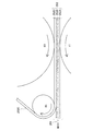
続いて、テープカセット161におけるテープスプール54、両面粘着スプール56、セパレータ巻き取りスプール62の位置関係について図32に基づいて説明する。   Next, the positional relationship among the tape spool 54, the double-sided adhesive spool 56, and the separator take-up spool 62 in the tape cassette 161 will be described with reference to FIG.

上述したように、テープカセット161において、テープスプール54に巻回されているフィルムテープ51は、テープ印刷装置1による印刷が行われる度に引き出される。従って、テープカセット161の使用開始時において、最も多くのフィルムテープ51がテープスプール54に巻回されている(図26参照)。
ここで、テープカセット161の使用開始時点において、テープスプール54に巻回されているフィルムテープ51が占有する領域を「フィルムテープ占有領域177」という。また、このフィルムテープ占有領域177の半径を「フィルムテープ巻回半径R7」という。
As described above, the film tape 51 wound around the tape spool 54 in the tape cassette 161 is pulled out every time printing by the tape printer 1 is performed. Accordingly, at the start of use of the tape cassette 161, the most film tape 51 is wound around the tape spool 54 (see FIG. 26).
Here, an area occupied by the film tape 51 wound around the tape spool 54 at the start of use of the tape cassette 161 is referred to as a “film tape occupation area 177”. The radius of the film tape occupation area 177 is referred to as “film tape winding radius R7”.

また、フィルムテープ51と同様に、両面粘着テープ53は、テープ印刷装置1による印刷が行われる度に、両面粘着スプール56から引き出される。従って、テープカセット161の使用開始時において、最も多くの両面粘着テープ53が両面粘着スプール56に巻回されている(図26参照)。
ここで、テープカセット161の使用開始時点において、両面粘着スプール56に巻回されている両面粘着テープ53が占有する領域を「両面粘着テープ占有領域178」という。また、この両面粘着テープ占有領域178の半径を「両面粘着テープ巻回半径R8」という。
Similarly to the film tape 51, the double-sided adhesive tape 53 is pulled out from the double-sided adhesive spool 56 every time printing is performed by the tape printer 1. Accordingly, at the start of use of the tape cassette 161, the most double-sided adhesive tape 53 is wound around the double-sided adhesive spool 56 (see FIG. 26).
Here, an area occupied by the double-sided adhesive tape 53 wound around the double-sided adhesive spool 56 at the start of use of the tape cassette 161 is referred to as a “double-sided adhesive tape occupation area 178”. The radius of the double-sided adhesive tape occupation area 178 is referred to as “double-sided adhesive tape winding radius R8”.

そして、テープカセット161においては、セパレータ53Dはテープ印刷装置1による印刷が行われる毎に、両面粘着テープ53から剥離され、セパレータ巻き取りスプール62に巻回される。従って、テープカセット161の使用完了時(即ち、テープカセット161がラベルの作成にフィルムテープ51等を使い切った時)に、セパレータ53Dは、セパレータ巻き取りスプール62に対して最も多く巻回され、テープカセット161の内部において最も大きなスペースを占有する。尚、以下の説明において、セパレータ巻き取りスプール62に最も多く巻回されたセパレータ53Dが占有するスペースの半径を「セパレータ巻回半径R9」という。   In the tape cassette 161, the separator 53 </ b> D is peeled off from the double-sided adhesive tape 53 and wound around the separator take-up spool 62 every time printing is performed by the tape printer 1. Therefore, when the use of the tape cassette 161 is completed (that is, when the tape cassette 161 has used up the film tape 51 or the like for label production), the separator 53D is wound most around the separator take-up spool 62, and the tape The largest space is occupied inside the cassette 161. In the following description, the radius of the space occupied by the separator 53D wound most around the separator take-up spool 62 is referred to as “separator winding radius R9”.

上述したように、セパレータ巻き取りスプール62は、テープスプール54と両面粘着スプール56との間に、回転可能に配設されている。そして、図32に示すように、テープカセット161では、テープスプール54の回転中心軸と、セパレータ巻き取りスプール62の回転中心軸を結ぶ直線距離(以下、第5軸間距離L5という。)は、セパレータ巻回半径R9とフィルムテープ巻回半径R7との和よりも小さくなるように構成されている。従って、テープカセット161の使用終了時において、セパレータ巻き取りスプール62に巻回されたセパレータ53Dは、フィルムテープ占有領域177の一部分を占有する。   As described above, the separator take-up spool 62 is rotatably disposed between the tape spool 54 and the double-sided adhesive spool 56. As shown in FIG. 32, in the tape cassette 161, a linear distance connecting the rotation center axis of the tape spool 54 and the rotation center axis of the separator take-up spool 62 (hereinafter referred to as a fifth inter-axis distance L5) is as follows. It is comprised so that it may become smaller than the sum of separator winding radius R9 and film tape winding radius R7. Accordingly, at the end of use of the tape cassette 161, the separator 53D wound around the separator take-up spool 62 occupies a part of the film tape occupation area 177.

即ち、第5軸間距離L5を、セパレータ巻回半径R9とフィルムテープ巻回半径R7との和よりも小さくすることにより、テープカセット161は、フィルムテープ51とセパレータ53Dが共通して利用する第5重複領域179を生じさせる。これにより、テープカセット161は、第5重複領域179の大きさに応じて、テープカセット161自体の大型化を抑制し得る。また、テープカセット161の大型化を抑制することにより、当該テープカセット161は、テープ印刷装置1本体の大型化も抑制し得る。   That is, by making the fifth inter-axis distance L5 smaller than the sum of the separator winding radius R9 and the film tape winding radius R7, the tape cassette 161 uses the film tape 51 and the separator 53D in common. A five overlap region 179 is generated. Thereby, the tape cassette 161 can suppress the enlargement of the tape cassette 161 itself according to the size of the fifth overlapping region 179. Moreover, the tape cassette 161 can also suppress the enlargement of the tape printer 1 main body by suppressing the enlargement of the tape cassette 161.

また、テープカセット161では、両面粘着スプール56の回転中心軸と、セパレータ巻き取りスプール62の回転中心軸を結ぶ直線距離(以下、第6軸間距離L6という。)は、セパレータ巻回半径R9と両面粘着テープ巻回半径R8との和よりも小さくなるように構成されている。従って、テープカセット161の使用終了時において、セパレータ巻き取りスプール62に巻回されたセパレータ53Dは、両面粘着テープ占有領域178の一部分を占有する。   In the tape cassette 161, a linear distance connecting the rotation center axis of the double-sided adhesive spool 56 and the rotation center axis of the separator take-up spool 62 (hereinafter referred to as a sixth inter-axis distance L6) is the separator winding radius R9. It is comprised so that it may become smaller than the sum with double-sided adhesive tape winding radius R8. Therefore, at the end of use of the tape cassette 161, the separator 53D wound around the separator take-up spool 62 occupies a part of the double-sided adhesive tape occupation area 178.

即ち、第6軸間距離L6を、セパレータ巻回半径R9と両面粘着テープ巻回半径R8との和よりも小さくすることにより、テープカセット161は、両面粘着テープ53とセパレータ53Dとが共通して利用する第6重複領域180を生じさせる。これにより、テープカセット111は、第6重複領域180の大きさに応じて、テープカセット161自体の大型化を抑制し得る。また、テープカセット161の大型化を抑制することにより、当該テープカセット161は、テープ印刷装置1本体の大型化も抑制し得る。   That is, by making the sixth inter-axis distance L6 smaller than the sum of the separator winding radius R9 and the double-sided adhesive tape winding radius R8, the tape cassette 161 has the double-sided adhesive tape 53 and the separator 53D in common. A sixth overlapping area 180 to be used is generated. Thereby, the tape cassette 111 can suppress the enlargement of the tape cassette 161 itself according to the size of the sixth overlap region 180. Moreover, the tape cassette 161 can also suppress the enlargement of the tape printer 1 main body by suppressing the enlargement of the tape cassette 161.

従って、テープカセット161は、図32に示すように、第5重複領域179と第6重複領域180との何れをも生じさせるので、第5重複領域179の大きさと、第6重複領域180の大きさに応じて、テープカセット161の大型化を更に抑制し得る。そして、これに伴い、テープカセット161は、テープ印刷装置1の大型化についても更に抑制し得る。   Accordingly, as shown in FIG. 32, the tape cassette 161 generates both the fifth overlap region 179 and the sixth overlap region 180. Therefore, the size of the fifth overlap region 179 and the size of the sixth overlap region 180 are generated. Accordingly, the increase in size of the tape cassette 161 can be further suppressed. As a result, the tape cassette 161 can further suppress the increase in size of the tape printer 1.

尚、テープスプール54と両面粘着スプール56との距離を図32に示す状態よりも大きくして、セパレータ巻き取りスプール62をテープカセット161の内側方向へ移動させてもよい。そして、第5軸間距離L5をセパレータ巻回半径R9とフィルムテープ巻回半径R7との和よりも大きくなるように構成し、且つ、第6軸間距離L6をセパレータ巻回半径R9と両面粘着テープ巻回半径R8との和よりも小さくなるように構成してもよい。又は、第5軸間距離L5をセパレータ巻回半径R9とフィルムテープ巻回半径R7との和よりも小さくなるように構成し、且つ、第6軸間距離L6をセパレータ巻回半径R9と両面粘着テープ巻回半径R8との和よりも大きくなるように構成してもよい。   The separator take-up spool 62 may be moved inward of the tape cassette 161 by setting the distance between the tape spool 54 and the double-sided adhesive spool 56 larger than the state shown in FIG. The fifth inter-axis distance L5 is configured to be larger than the sum of the separator winding radius R9 and the film tape winding radius R7, and the sixth inter-axis distance L6 is set to the separator winding radius R9 and the double-sided adhesive. You may comprise so that it may become smaller than the sum with tape winding radius R8. Alternatively, the fifth inter-axis distance L5 is configured to be smaller than the sum of the separator winding radius R9 and the film tape winding radius R7, and the sixth inter-axis distance L6 is set to the separator winding radius R9 and double-sided adhesive. You may comprise so that it may become larger than the sum with tape winding radius R8.

これにより、テープカセット161は、第5重複領域179と第6重複領域180のうちの何れか一方を生じさせるので、第5重複領域179の大きさと、第6重複領域180の大きさに応じて、テープカセット161の大型化を抑制し得る。そして、これに伴い、テープカセット161は、テープ印刷装置1の大型化についても更に抑制し得る。   As a result, the tape cassette 161 generates either one of the fifth overlapping region 179 and the sixth overlapping region 180, so that it depends on the size of the fifth overlapping region 179 and the size of the sixth overlapping region 180. The enlargement of the tape cassette 161 can be suppressed. As a result, the tape cassette 161 can further suppress the increase in size of the tape printer 1.

従って、第11実施形態に係るテープカセット161では、両面粘着テープ53は、テープ送りローラ63とテープサブローラ11とによって、フィルムテープ51の印刷された一方の面に圧着された後、セパレータ53Dが剥離された状態で搬送されることとなる。これにより、所定長さに切断された印刷済みテープ28を商品等に貼り付ける際に、セパレータ53Dを剥がす手間を省くことができる。   Therefore, in the tape cassette 161 according to the eleventh embodiment, the double-sided adhesive tape 53 is pressed against one printed surface of the film tape 51 by the tape feed roller 63 and the tape sub-roller 11, and then the separator 53D is provided. It will be conveyed in the peeled state. Thereby, when sticking the printed tape 28 cut | disconnected by the predetermined length to goods etc., the effort which removes separator 53D can be saved.

また、セパレータ53Dは、テープ送りローラ63の外周面に沿ってセパレータ案内壁37へ案内された後、凸状部35A、ガイドピン36及び凸状部35Bによって巻回された両面粘着テープ53の外側周縁を通って略直角内側方向へ案内されて、セパレータ巻き取りスプール62に巻き取られるため、剥離したセパレータ53Dをテープカセット161内に収納することが可能となり、ユーザは両面粘着テープ53から剥離したセパレータ53Dを廃棄する手間を省くことができる。   The separator 53D is guided to the separator guide wall 37 along the outer peripheral surface of the tape feed roller 63, and then the outer side of the double-sided adhesive tape 53 wound by the convex portion 35A, the guide pin 36, and the convex portion 35B. Since it is guided to the inner side at a substantially right angle through the peripheral edge and taken up by the separator take-up spool 62, the peeled separator 53D can be stored in the tape cassette 161, and the user peeled off the double-sided adhesive tape 53. The trouble of discarding the separator 53D can be saved.

また、両面粘着テープ53が圧着されてセパレータ53Dが剥離された印刷済みテープ28は、セパレータ53Dが剥離された両面粘着テープ53の粘着層53Cに接触する接触コロ162と案内壁33とに挟まれて搬送されるため、印刷済みテープ28がセパレータ53D側に撓んでテープ排出口163で詰まることを防止して、当該印刷済みテープ28をテープ排出口163から外部へスムーズに排出することが可能となる。   Further, the printed tape 28 having the separator 53D peeled off by being pressure-bonded to the double-sided adhesive tape 53 is sandwiched between the contact roller 162 that contacts the adhesive layer 53C of the double-sided adhesive tape 53 from which the separator 53D has been peeled off and the guide wall 33. Therefore, it is possible to prevent the printed tape 28 from being bent toward the separator 53D and clogging at the tape discharge port 163, and to smoothly discharge the printed tape 28 from the tape discharge port 163 to the outside. Become.

また、接触コロ162をテープ排出口163よりもテープ搬送方向外側に突出するように設けることによって、この接触コロ162の外径を大きくすることが可能となる。これにより、接触コロ162の組付け作業を容易に行うことが可能になるとともに、セパレータ53Dが剥離された粘着剤付き印刷済みテープ28が、テープ排出口163で詰まることをより確実に防止することが可能となる。   Further, by providing the contact roller 162 so as to protrude outward in the tape transport direction from the tape discharge port 163, the outer diameter of the contact roller 162 can be increased. This makes it possible to easily assemble the contact roller 162 and more reliably prevent the adhesive-printed tape 28 from which the separator 53D has been peeled off from clogging at the tape outlet 163. Is possible.

また、接触コロ162は、固定刃30Aに対向すると共に該固定刃30Aに近接して配置されるため、テープ切断位置と印刷済みテープ28の印刷位置との距離を短くすることが可能となり、印刷済みテープ28の余白長さを短くすることが可能となる。   Further, since the contact roller 162 is disposed close to the fixed blade 30A and close to the fixed blade 30A, the distance between the tape cutting position and the printing position of the printed tape 28 can be shortened. The margin length of the used tape 28 can be shortened.

また、案内壁33は、接触コロ162よりもテープ搬送方向下流側へ延出されているため、印刷済みテープ28の印刷面の裏面側をより確実に案内することが可能となる。また、接触コロ162が固定刃30Aに近接して配設されるため、印刷済みテープ28の印刷面の裏面側をテープ切断位置、つまり、固定刃30Aの刃先の近傍まで確実に案内することが可能となる。   Further, since the guide wall 33 extends to the downstream side in the tape transport direction from the contact roller 162, the back surface side of the printed surface of the printed tape 28 can be guided more reliably. Further, since the contact roller 162 is disposed close to the fixed blade 30A, the back surface side of the printed surface of the printed tape 28 can be reliably guided to the tape cutting position, that is, the vicinity of the blade edge of the fixed blade 30A. It becomes possible.

また、接触コロ162は、両面粘着テープ53の粘着層53Cに接触する外周面が、軸方向に平行な複数の断面略三角形の凸状形状に形成されているため、接触コロ162と両面粘着テープ53の粘着層53Cとの接触面積を小さくすることが可能となる。これにより、接触コロ162の外周面が両面粘着テープ53の粘着層53Cからスムーズに離れることが可能となり、印刷済みテープ28をテープ排出口163から外部へスムーズに排出することができる。   Further, the contact roller 162 has an outer peripheral surface that contacts the adhesive layer 53C of the double-sided adhesive tape 53 formed in a convex shape having a plurality of substantially triangular cross sections parallel to the axial direction. It is possible to reduce the contact area of 53 with the adhesive layer 53C. Accordingly, the outer peripheral surface of the contact roller 162 can be smoothly separated from the adhesive layer 53C of the double-sided adhesive tape 53, and the printed tape 28 can be smoothly discharged from the tape discharge port 163 to the outside.

また、接触コロ162の両面粘着テープ53の粘着層53Cに接触する外周面には、粘着剤による粘着力を小さくするシリコーン樹脂皮膜が形成されているため、接触コロ162の外周面が両面粘着テープ53の粘着層53Cからスムーズに離れることが可能となり、印刷済みテープ28をテープ排出口163から外部へ更にスムーズに排出することが可能となる。   Moreover, since the silicone resin film which reduces the adhesive force by an adhesive is formed in the outer peripheral surface which contacts the adhesive layer 53C of the double-sided adhesive tape 53 of the contact roller 162, the outer peripheral surface of the contact roller 162 is a double-sided adhesive tape. Thus, the printed tape 28 can be discharged smoothly from the tape discharge port 163 to the outside.

更に、セパレータ巻き取りスプール62は、両面粘着スプール56とテープスプール54との間に配設されているため、テープ印刷装置1によるテープ印刷が行われることによってセパレータ巻き取りスプール62に巻回可能なセパレータ53Dの最大巻回長さを容易に大きくすることができ、テープカセット161の小型化を図ることが可能となる。   Further, since the separator take-up spool 62 is disposed between the double-sided adhesive spool 56 and the tape spool 54, the separator take-up spool 62 can be wound around the separator take-up spool 62 by performing tape printing by the tape printer 1. The maximum winding length of the separator 53D can be easily increased, and the tape cassette 161 can be reduced in size.

また、剥離したセパレータ53Dをテープ送りローラ63の外周面に沿って両面粘着スプール56に巻回される両面粘着テープ53の引き出し側へ案内後、セパレータ案内壁37、凸状部35A、ガイドピン36及び凸状部35Bによって巻回された両面粘着テープ53の外側周縁を通ってセパレータ巻き取りスプール62まで案内することによって、テープカセット161内の隙間空間を有効に活用することができ、テープカセット161の更なる小型化を図ることが可能となる。   Further, after the separated separator 53D is guided along the outer peripheral surface of the tape feeding roller 63 to the drawing side of the double-sided adhesive tape 53 wound around the double-sided adhesive spool 56, the separator guide wall 37, the convex portion 35A, and the guide pin 36 are provided. Further, the gap space in the tape cassette 161 can be effectively utilized by guiding to the separator take-up spool 62 through the outer peripheral edge of the double-sided adhesive tape 53 wound by the convex portion 35B. It is possible to further reduce the size of the.

また、剥離ピン165によってフィルムテープ51に圧着された両面粘着テープ53からセパレータ53Dをスムーズに剥離させることが可能となる。また、テープカセット161では、両面粘着テープ53から剥離されたセパレータ53Dが、振動等によって再度両面粘着テープ53の粘着層53Cへ付着するのを当該剥離ピン165によって確実に防止することが可能となる。   In addition, the separator 53D can be smoothly peeled from the double-sided pressure-sensitive adhesive tape 53 pressure-bonded to the film tape 51 by the peeling pin 165. Further, in the tape cassette 161, it is possible to reliably prevent the separator 53D peeled from the double-sided adhesive tape 53 from adhering again to the adhesive layer 53C of the double-sided adhesive tape 53 due to vibration or the like. .

また、予備剥離ピン166によってセパレータ53Dが両面粘着テープ53から一度剥離された後、再度両面粘着テープ53の粘着層53Cに貼り合わされてテープ送りローラ63へ搬送されるため、該両面粘着テープ53のセパレータ53Dに対する粘着力を低下させた状態でフィルムテープ51の印刷面に圧着させることが可能となる。   Further, after the separator 53D is once peeled off from the double-sided adhesive tape 53 by the preliminary peeling pin 166, it is again bonded to the adhesive layer 53C of the double-sided adhesive tape 53 and conveyed to the tape feed roller 63. It becomes possible to make it press-bond to the printing surface of the film tape 51 in a state where the adhesive strength to the separator 53D is reduced.

このため、フィルムテープ51に圧着された両面粘着テープ53からセパレータ53Dを容易に剥離することが可能となる。また、剥離ピン165によってフィルムテープ51に圧着された両面粘着テープ53からセパレータ53Dを更にスムーズに剥離させることが可能となり、セパレータ53Dが剥離された粘着剤付き印刷済みテープ28をテープ排出口163へ更にスムーズに搬送することが可能となる。   For this reason, the separator 53D can be easily peeled from the double-sided pressure-sensitive adhesive tape 53 pressure-bonded to the film tape 51. In addition, the separator 53D can be more smoothly peeled from the double-sided pressure-sensitive adhesive tape 53 pressure-bonded to the film tape 51 by the peeling pin 165, and the pressure-sensitive adhesive printed tape 28 from which the separator 53D has been peeled is transferred to the tape discharge port 163. Furthermore, it becomes possible to convey smoothly.

[第12実施形態]
次に、第12実施形態に係るテープカセット181について図33乃至図35に基づいて説明する。尚、以下の説明において上記図1乃至図8の第1実施形態に係るテープカセット21及びテープ印刷装置1の構成等と同一符号は、該第1実施形態に係るテープカセット21及びテープ印刷装置1等の構成等と同一あるいは相当部分を示すものである。また、上記図26乃至図32の第11実施形態に係るテープカセット161の構成等と同一符号は、該第11実施形態に係るテープカセット161の構成等と同一あるいは相当部分を示すものである。
[Twelfth embodiment]
Next, a tape cassette 181 according to a twelfth embodiment will be described with reference to FIGS. In the following description, the same reference numerals as those of the tape cassette 21 and the tape printer 1 according to the first embodiment in FIGS. 1 to 8 denote the same as those in the tape cassette 21 and the tape printer 1 according to the first embodiment. This indicates the same or corresponding part as the above-described configuration. The same reference numerals as those of the tape cassette 161 according to the eleventh embodiment in FIGS. 26 to 32 indicate the same or corresponding parts as those of the tape cassette 161 according to the eleventh embodiment.

第12実施形態に係るテープカセット181の概略構成は、第11実施形態に係るテープカセット161とほぼ同じ構成である。
但し、図33乃至図35に示すように、上記剥離ピン165に替えて、テープ送りローラ63とテープサブローラ11によってフィルムテープ51に圧着された両面粘着テープ53と該テープ送りローラ63との間に、両面粘着テープ53のセパレータ53Dに接触する接触部材の一例としての接触ピン182が設けられている。また、接触ピン182は、テープ送りローラ63と所定距離(例えば、距離約0.5mmである。)だけ離間するように設けられている。
The schematic configuration of the tape cassette 181 according to the twelfth embodiment is substantially the same as that of the tape cassette 161 according to the eleventh embodiment.
However, as shown in FIGS. 33 to 35, instead of the peeling pin 165, the tape feed roller 63 and the tape sub-roller 11 are bonded to the film tape 51 between the double-sided adhesive tape 53 and the tape feed roller 63. Further, a contact pin 182 as an example of a contact member that contacts the separator 53D of the double-sided pressure-sensitive adhesive tape 53 is provided. Further, the contact pin 182 is provided so as to be separated from the tape feeding roller 63 by a predetermined distance (for example, a distance of about 0.5 mm).

そして、セパレータ53Dは、接触ピン182の外周面に沿ってフィルムテープ51に圧着された両面粘着テープ53から剥離されて、再度、テープ送りローラ63の外周面に沿って両面粘着スプール56側に、つまり、引き出し側方向(図33中、上側方向である。)へ案内される。続いて、セパレータ53Dは、上記第11実施形態に係るテープカセット161と同様に、セパレータ案内壁37の壁面に沿って案内リブ35の外側方向に案内されてセパレータ巻き取りスプール62に至る。   Then, the separator 53D is peeled off from the double-sided adhesive tape 53 that is pressure-bonded to the film tape 51 along the outer peripheral surface of the contact pin 182, and again toward the double-sided adhesive spool 56 along the outer peripheral surface of the tape feed roller 63. That is, it is guided in the pull-out direction (the upper direction in FIG. 33). Subsequently, similarly to the tape cassette 161 according to the eleventh embodiment, the separator 53D is guided in the outer direction of the guide rib 35 along the wall surface of the separator guide wall 37 and reaches the separator take-up spool 62.

この接触ピン182は、印刷済みテープ28のテープ幅よりも長い断面円形の略円柱形状で、両端面中心位置に各支持軸182Aが立設されている。また、テープカセット181の上ケース23及び下ケース24には、接触ピン182の各支持軸182Aを回転可能に支持する各支持孔183が形成されている。そして、接触ピン182の各支持軸182Aは、各支持孔183に挿入されて、回転可能に設けられている。   The contact pin 182 has a substantially cylindrical shape with a circular cross section longer than the tape width of the printed tape 28, and each support shaft 182A is erected at the center position of both end faces. Further, the upper case 23 and the lower case 24 of the tape cassette 181 are formed with respective support holes 183 that rotatably support the respective support shafts 182A of the contact pins 182. Each support shaft 182A of the contact pin 182 is inserted into each support hole 183 and is rotatably provided.

従って、第12実施形態に係るテープカセット181では、接触ピン182は、両端部が回転可能に支持されると共に、フィルムテープ51に圧着された両面粘着テープ53のセパレータ53Dの全幅に渡って接触する。   Accordingly, in the tape cassette 181 according to the twelfth embodiment, the contact pins 182 are rotatably supported at both ends, and contact the entire width of the separator 53D of the double-sided pressure-sensitive adhesive tape 53 that is pressure-bonded to the film tape 51. .

上記のように構成されたテープカセット181では、両面粘着スプール56から引き出された両面粘着テープ53は、一対の上流側ガイド部171A、171Bの間を幅方向への移動を規制されつつ通過後、両端部を回転可能に支持される予備剥離ピン166によってセパレータ53Dが両面粘着テープ53から剥離される。その後、セパレータ53Dと、セパレータ53Dが剥離された両面粘着テープ53とは、各段差部174、174と各下流側コロ172A、172Bとの間を通過することによって、該セパレータ53Dは、再度、両面粘着テープ53の粘着層53Cに貼り合わされて、テープ送りローラ63の外周面に沿って引き出される。そして、両面粘着テープ53は、テープ駆動ローラ軸14によって回転駆動されるテープ送りローラ63とテープサブローラ11との間を通過し、セパレータ53Dが重ね合わされない側の粘着層53Aがフィルムテープ51の印刷面に圧着される。   In the tape cassette 181 configured as described above, the double-sided adhesive tape 53 pulled out from the double-sided adhesive spool 56 passes through the pair of upstream guide portions 171A and 171B while being restricted in movement in the width direction, Separator 53D is peeled from double-sided adhesive tape 53 by preliminary peeling pins 166 that are rotatably supported at both ends. Thereafter, the separator 53D and the double-sided pressure-sensitive adhesive tape 53 from which the separator 53D has been peeled pass between the step portions 174 and 174 and the downstream rollers 172A and 172B, whereby the separator 53D is double-sided again. It is bonded to the adhesive layer 53C of the adhesive tape 53 and pulled out along the outer peripheral surface of the tape feed roller 63. The double-sided adhesive tape 53 passes between the tape feed roller 63 and the tape sub-roller 11 that are rotationally driven by the tape drive roller shaft 14, and the adhesive layer 53 A on the side where the separator 53 D is not superimposed is printed on the film tape 51. Crimped to the surface.

その後、セパレータ53Dは、接触ピン182の外周面に沿ってフィルムテープ51に圧着された両面粘着テープ53から剥離されて、再度、テープ送りローラ63の外周面に沿って両面粘着スプール56側に、つまり、引き出し側方向(図33中、上側方向である。)へ案内される。続いて、セパレータ53Dは、セパレータ案内壁37の壁面に沿って案内リブ35の外側方向に案内されて、凸状部35A、ガイドピン36及び凸状部35Bの外周面に順次沿って、巻回された両面粘着テープ53の外側周縁を通って略直角内側方向へ案内されてセパレータ巻き取りスプール62に至る。   Thereafter, the separator 53D is peeled off from the double-sided pressure-sensitive adhesive tape 53 that is pressure-bonded to the film tape 51 along the outer peripheral surface of the contact pin 182, and again toward the double-sided adhesive spool 56 along the outer peripheral surface of the tape feed roller 63. That is, it is guided in the pull-out direction (the upper direction in FIG. 33). Subsequently, the separator 53D is guided in the outer direction of the guide rib 35 along the wall surface of the separator guide wall 37, and is sequentially wound along the outer peripheral surfaces of the convex portion 35A, the guide pin 36, and the convex portion 35B. The double-sided adhesive tape 53 is guided to the inner side at a substantially right angle through the outer peripheral edge and reaches the separator take-up spool 62.

そして、セパレータ53Dの先端部は、このセパレータ巻き取りスプール62の外周面に接着テープ等によって固着され、セパレータ巻取軸16により回転駆動される該セパレータ巻き取りスプール62に巻き取られる。尚、セパレータ巻取軸16は、テープ駆動ローラ軸14及びリボン巻取軸15と同期して回転駆動される。   The front end of the separator 53D is fixed to the outer peripheral surface of the separator take-up spool 62 with an adhesive tape or the like, and is taken up by the separator take-up spool 62 that is driven to rotate by the separator take-up shaft 16. The separator take-up shaft 16 is rotationally driven in synchronization with the tape drive roller shaft 14 and the ribbon take-up shaft 15.

また、フィルムテープ51は、テープ駆動ローラ軸14によって回転駆動されるテープ送りローラ63とテープサブローラ11との間を通過後、印刷面に粘着層53A、ベースフィルム53B及び粘着層53Cが積層された状態で接触コロ162に至る。そして、印刷面に粘着層53A、ベースフィルム53B及び粘着層53Cが積層されたフィルムテープ51は、つまり、セパレータ53Dが剥離された粘着剤付き印刷済みテープ28は、粘着層53Cに接触する接触コロ162と、該接触コロ162に対して印刷済みテープ28を挟んで対向する案内壁33とによって案内されて、テープ排出口163からテープカセット161の外部に送り出される。そして、セパレータ53Dが剥離された粘着剤付き印刷済みテープ28は、カッタユニット30を経てテープ印刷装置1のラベル排出口17より外部に送り出される。   Further, after the film tape 51 passes between the tape feed roller 63 and the tape sub-roller 11 that are rotationally driven by the tape drive roller shaft 14, the adhesive layer 53A, the base film 53B, and the adhesive layer 53C are laminated on the printing surface. In this state, the contact roller 162 is reached. The film tape 51 in which the adhesive layer 53A, the base film 53B, and the adhesive layer 53C are laminated on the printing surface, that is, the printed tape 28 with the adhesive 53 from which the separator 53D has been peeled, is in contact with the adhesive layer 53C. It is guided by 162 and the guide wall 33 facing the contact roller 162 with the printed tape 28 interposed therebetween, and is sent out from the tape discharge port 163 to the outside of the tape cassette 161. The pressure-sensitive adhesive-printed tape 28 from which the separator 53D has been peeled is sent out from the label discharge port 17 of the tape printer 1 through the cutter unit 30.

そして、印刷済みテープ28を所定長さ搬送後、不図示の切断用モータを駆動して可動刃30Bを作動させることによって、セパレータ53Dが剥離された所定長さの粘着剤付き印刷済みテープ28がラベル排出口17より排出される。   Then, after the printed tape 28 is conveyed for a predetermined length, the cutting blade (not shown) is driven to operate the movable blade 30B, whereby the printed tape 28 with the adhesive having a predetermined length from which the separator 53D has been peeled off. It is discharged from the label discharge port 17.

これにより、第12実施形態に係るテープカセット181では、第11実施形態に係るテープカセット161が奏する上記作用効果に加えて、接触ピン182によって両面粘着テープ53を押さえつつ、この接触ピン182の外周面に沿って搬送することで印刷済みテープ28の搬送方向とは異なる方向へ急激にセパレータ53Dの搬送方向を切り換えることにより、両面粘着テープ53からセパレータ53Dをスムーズに剥離させることが可能となる。また、接触ピン182によって両面粘着テープ53から剥離されたセパレータ53Dを外側方向に張ることが可能となり、剥離されたセパレータ53Dの撓みを防止してスムーズにテープ送りローラ63の外周面へ案内することが可能となる。   As a result, in the tape cassette 181 according to the twelfth embodiment, in addition to the above-described effects achieved by the tape cassette 161 according to the eleventh embodiment, the double-sided adhesive tape 53 is pressed by the contact pin 182 and the outer periphery of the contact pin 182 By transporting along the surface, the separator 53D can be smoothly peeled from the double-sided adhesive tape 53 by rapidly switching the transport direction of the separator 53D in a direction different from the transport direction of the printed tape 28. Further, the separator 53D peeled from the double-sided adhesive tape 53 by the contact pin 182 can be stretched outward, and the peeled separator 53D can be prevented from being bent and smoothly guided to the outer peripheral surface of the tape feed roller 63. Is possible.

また、予備剥離ピン166によってセパレータ53Dが両面粘着テープ53から一度剥離された後、再度両面粘着テープ53の粘着層53Cに貼り合わされてテープ送りローラ63へ搬送されるため、該両面粘着テープ53のセパレータ53Dに対する粘着力を低下させた状態でフィルムテープ51の印刷面に圧着させることが可能となる。   Further, after the separator 53D is once peeled off from the double-sided adhesive tape 53 by the preliminary peeling pin 166, it is again bonded to the adhesive layer 53C of the double-sided adhesive tape 53 and conveyed to the tape feed roller 63. It becomes possible to make it press-bond to the printing surface of the film tape 51 in a state where the adhesive strength to the separator 53D is reduced.

このため、接触ピン92によってフィルムテープ51に圧着された両面粘着テープ53からセパレータ53Dをスムーズに剥離させることが可能となり、セパレータ53Dが剥離された粘着剤付き印刷済みテープ28をテープ排出口163へスムーズに搬送することが可能となる。   For this reason, the separator 53D can be smoothly peeled from the double-sided pressure-sensitive adhesive tape 53 pressure-bonded to the film tape 51 by the contact pin 92, and the pressure-sensitive adhesive printed tape 28 from which the separator 53D has been peeled is transferred to the tape discharge port 163. Smooth conveyance is possible.

[第13実施形態]
次に、第13実施形態に係るテープ印刷装置201及びテープカセット221について図36乃至図40に基づいて説明する。尚、以下の説明において上記図1乃至図8の第1実施形態に係るテープ印刷装置1及びテープカセット21の構成等と同一符号は、該第1実施形態に係るテープ印刷装置1及びテープカセット21等の構成等と同一あるいは相当部分を示すものである。
[Thirteenth embodiment]
Next, a tape printer 201 and a tape cassette 221 according to the thirteenth embodiment will be described with reference to FIGS. In the following description, the same reference numerals as those of the tape printer 1 and the tape cassette 21 according to the first embodiment in FIGS. 1 to 8 denote the same as those in the tape printer 21 and the tape cassette 21 according to the first embodiment. This indicates the same or corresponding part as the above-described configuration.

第13実施形態に係るテープ印刷装置201の概略構成は、第1実施形態に係るテープ印刷装置1とほぼ同じ構成である。但し、テープ印刷装置201は、カセット収納部8に替えて、テープカセット221(図37参照)を収納するカセット収納部202が設けられている点で異なっている。   The schematic configuration of the tape printing apparatus 201 according to the thirteenth embodiment is substantially the same as that of the tape printing apparatus 1 according to the first embodiment. However, the tape printing apparatus 201 is different in that a cassette storage unit 202 that stores a tape cassette 221 (see FIG. 37) is provided instead of the cassette storage unit 8.

ここで、カセット収納部202について図36に基づいて説明する。図36に示すように、カセット収納部202には、回転可能に立設されたプラテンローラ203と、このプラテンローラ203のテープ搬送方向下流側に配置された金属製のテープ駆動ローラ軸14と、プラテンローラ203に対向するサーマルヘッド9と、テープ駆動ローラ軸14に対向するテープサブローラ11と、テープカセット221内に収納されるインクリボン222(図37参照)を送るリボン巻取軸205が配置されている他に、更に後述のようにレセプターテープ223(図37参照)から剥離されたセパレータ223C(図40参照)を巻き取るセパレータ巻取軸206等が配置されている。   Here, the cassette storage unit 202 will be described with reference to FIG. As shown in FIG. 36, in the cassette storage unit 202, a platen roller 203 that is rotatably provided, a metal tape drive roller shaft 14 that is disposed downstream of the platen roller 203 in the tape transport direction, and A thermal head 9 facing the platen roller 203, a tape sub-roller 11 facing the tape drive roller shaft 14, and a ribbon take-up shaft 205 for feeding an ink ribbon 222 (see FIG. 37) stored in the tape cassette 221 are arranged. In addition to this, a separator take-up shaft 206 and the like for winding the separator 223C (see FIG. 40) peeled off from the receptor tape 223 (see FIG. 37) are arranged as described later.

また、カセット収納部202内において、ヘッドホルダ207が支持軸208により回動可能に枢支されている。このヘッドホルダ207には、上端面に放熱板9Aが立設されると共に、この放熱板9Aのプラテンローラ203に対向する側縁部に、サーマルヘッド9がテープ搬送方向に略直交するように取り付けられている。また、ヘッドホルダ207の先端部には、テープサブローラ11が回転可能に軸支されている。そして、テープカセット221が装着された場合には、このヘッドホルダ207がプラテンローラ203側方向へ回動されて、サーマルヘッド9がプラテンローラ203に押し当てられると共に、テープサブローラ11がテープ送りローラ63に押し当てられるように構成されている(図37参照)。   A head holder 207 is pivotally supported by a support shaft 208 in the cassette storage unit 202. A heat radiating plate 9A is erected on the upper end surface of the head holder 207, and the thermal head 9 is attached to a side edge portion of the heat radiating plate 9A facing the platen roller 203 so as to be substantially orthogonal to the tape transport direction. It has been. Further, the tape sub-roller 11 is pivotally supported at the tip of the head holder 207 so as to be rotatable. When the tape cassette 221 is mounted, the head holder 207 is rotated in the platen roller 203 direction so that the thermal head 9 is pressed against the platen roller 203 and the tape sub-roller 11 is a tape feed roller. It is comprised so that it may press against 63 (refer FIG. 37).

また、リボン巻取軸205は、ステッピングモータ等により構成される不図示のテープ送りモータから適宜の駆動機構を介して回転駆動され、後述のようにテープカセット221内に回転可能に設けられたリボン巻き取りスプール225(図37参照)内に嵌入されて回転駆動する。また、テープ駆動ローラ軸14は、テープ送りモータから適宜の伝達機構を介して回転駆動され、後述のようにテープカセット221内に回転可能に設けられた導電性樹脂製のテープ送りローラ63(図37参照)内に嵌入されて回転駆動する。また、セパレータ巻取軸206は、テープ送りモータから適宜の伝達機構を介して回転駆動され、後述のようにテープカセット221内に回転可能に設けられたセパレータ巻き取りスプール226(図37参照)内に嵌入されて回転駆動する。   Further, the ribbon take-up shaft 205 is rotationally driven through a suitable drive mechanism from a tape feed motor (not shown) constituted by a stepping motor or the like, and is a ribbon provided rotatably in the tape cassette 221 as will be described later. It is inserted into the take-up spool 225 (see FIG. 37) and is driven to rotate. The tape drive roller shaft 14 is rotationally driven from a tape feed motor through an appropriate transmission mechanism, and a tape feed roller 63 made of conductive resin (see FIG. 5) provided rotatably in the tape cassette 221 as will be described later. 37) and is rotationally driven. Further, the separator take-up shaft 206 is rotationally driven from the tape feed motor through an appropriate transmission mechanism, and is installed in a separator take-up spool 226 (see FIG. 37) provided rotatably in the tape cassette 221 as will be described later. It is inserted into and rotated.

尚、セパレータ巻取軸206をテープ送りモータとは別個に設けられたステッピングモータ等により構成される不図示のセパレータ巻取モータから適宜の駆動機構を介して回転駆動するように構成してもよい。これにより、インクリボン222とセパレータ223Cの伸び率等が大きく異なっても該セパレータ223Cを安定して巻き取ることが可能となる。   The separator take-up shaft 206 may be configured to be rotationally driven via an appropriate drive mechanism from a separator take-up motor (not shown) constituted by a stepping motor or the like provided separately from the tape feed motor. . As a result, even if the elongation rates of the ink ribbon 222 and the separator 223C are greatly different, the separator 223C can be stably wound up.

また、テープカセット221のテープ排出口227(図37参照)の近傍には、剥離コロ65の外周面に沿ってセパレータ223Cが剥離された印刷済みテープ228を所定の長さに切断し、セパレータ223Cが剥離された粘着剤付きラベルを生成する切断装置としてのはさみ式カッタユニット30が配置されている。このカッタユニット30は、固定刃30Aと、不図示の切断用モータによって固定刃30Aに対して作動して印刷済みテープ228を切断する可動刃30Bとから構成されている。また、カッタユニット30のテープ搬送方向下流側(図36中、左側)の側面部には、印刷されて後述のようにセパレータが剥離されたテープが排出されるラベル排出口17が形成されている。   Further, in the vicinity of the tape outlet 227 (see FIG. 37) of the tape cassette 221, the printed tape 228 from which the separator 223C has been peeled along the outer peripheral surface of the peeling roller 65 is cut to a predetermined length, and the separator 223C is cut. A scissor-type cutter unit 30 is disposed as a cutting device that generates a label with an adhesive from which is peeled. The cutter unit 30 includes a fixed blade 30A and a movable blade 30B that operates on the fixed blade 30A by a cutting motor (not shown) to cut the printed tape 228. Further, a label discharge port 17 is formed on the side surface of the cutter unit 30 on the downstream side in the tape transport direction (left side in FIG. 36) through which the printed tape with the separator peeled as described later is discharged. .

次ぎに、テープカセット221の概略構成について図37乃至図40に基づいて説明する。
図37に示すように、テープカセット221内には、レセプターテープ223が剥離紙やフィルム等から形成されるセパレータ223Cを内側に向けて巻回されたテープスプール231が、底面に立設されたカセットボス232に回転可能に嵌挿されている。
Next, a schematic configuration of the tape cassette 221 will be described with reference to FIGS.
As shown in FIG. 37, in the tape cassette 221, a tape spool 231 in which a receptor tape 223 is wound with a separator 223C formed of release paper, a film or the like facing inward is a cassette erected on the bottom surface. The boss 232 is rotatably inserted.

ここで、図40に示すように、セパレータ223Cを内側にしてテープスプール231に巻回されたレセプターテープ223は、3層構造に形成されている。このレセプターテープ223の各層は、図40中下側から上側方向に向かって、インクリボン222とサーマルヘッド9を介して一面側(図40中、下側の面である。)に印刷される透明又は色付きのフィルムテープ223A、商品等の貼り付け対象に貼り付けるための粘着層223B、この粘着層223Bの貼り付け側を覆うセパレータ223Cの順序で積層されて構成されている。   Here, as shown in FIG. 40, the receptor tape 223 wound around the tape spool 231 with the separator 223C on the inside has a three-layer structure. Each layer of the receptor tape 223 is printed on one side (the lower side in FIG. 40) through the ink ribbon 222 and the thermal head 9 from the lower side to the upper side in FIG. Alternatively, the color film tape 223A, an adhesive layer 223B to be attached to an object to be attached such as a product, and a separator 223C that covers the attachment side of the adhesive layer 223B are laminated in this order.

また、図37に示すように、テープカセット221内には、インクリボン222が巻回されたリボンスプール233が、底面に立設されるリールボス235に回転可能に嵌挿されている。また、使用済みのインクリボン222を巻き取るリボン巻き取りスプール225、及びレセプターテープ223から剥離されたセパレータ223Cを巻き取るセパレータ巻き取りスプール226が軸方向両端部を回転可能に支持されている。   As shown in FIG. 37, in the tape cassette 221, a ribbon spool 233 around which an ink ribbon 222 is wound is rotatably inserted into a reel boss 235 standing on the bottom surface. A ribbon take-up spool 225 for taking up the used ink ribbon 222 and a separator take-up spool 226 for taking up the separator 223C peeled off from the receptor tape 223 are rotatably supported at both ends in the axial direction.

また、テープ排出口227の上流側には導電性樹脂製のテープ送りローラ63が軸方向両端部を回転可能に支持されている。また、テープ送りローラ63のテープ搬送方向下流側、つまり、テープ排出口227側には、剥離コロ65が軸方向両端部を回転可能に支持されている。   Further, on the upstream side of the tape outlet 227, a tape feed roller 63 made of conductive resin is supported so as to be rotatable at both ends in the axial direction. Further, on the downstream side in the tape transport direction of the tape feed roller 63, that is, on the tape discharge port 227 side, the peeling roller 65 is supported so as to be rotatable at both axial ends.

また、図38及び図39に示すように、上ケース237と下ケース238とによって形成されるテープ排出口227は、テープ送りローラ63とテープサブローラ11とによって送り出された印刷済みテープ228のテープ厚さ方向に剥離コロ65の外径よりも大きい幅広に開設されると共に、印刷済みテープ228のテープ幅方向に該印刷済みテープ228のテープ幅とほぼ同じ幅に開設されている。   As shown in FIGS. 38 and 39, the tape discharge port 227 formed by the upper case 237 and the lower case 238 is a tape of the printed tape 228 fed by the tape feed roller 63 and the tape sub-roller 11. The width of the tape is larger than the outer diameter of the peeling roller 65 in the thickness direction, and the width of the printed tape 228 is approximately the same as the tape width of the printed tape 228.

また、剥離コロ65は、テープ排出口227のテープ搬送方向に対して直角方向の両内側側壁部を形成する側壁部238Bの印刷済みテープ228側の端縁部から所定距離離間すると共に、印刷済みテープ228のフィルムテープ223Aの外側面に接触して該印刷済みテープ228をテープ搬送方向下流側へ案内する案内壁239から所定距離離間するように配置されている。   Further, the peeling roller 65 is spaced apart from the edge on the printed tape 228 side of the side wall 238B that forms both inner side walls perpendicular to the tape transport direction of the tape discharge port 227 and printed. The tape 228 is arranged so as to be in contact with the outer surface of the film tape 223A of the tape 228 and to be separated from the guide wall 239 for guiding the printed tape 228 downstream in the tape transport direction by a predetermined distance.

また、この剥離コロ65は、印刷済みテープ228のテープ幅、つまり、レセプターテープ223のテープ幅とほぼ同じ長さの断面円形の略円柱形状で、両端面中心位置に各支持軸65Aが立設され、上ケース237と下ケース238とに形成された各支持孔248に回転可能に嵌入されている。また、剥離コロ65は、外周面にシリコーン樹脂皮膜が形成されている。   Further, the peeling roller 65 has a substantially cylindrical shape with a circular section having a length substantially the same as the tape width of the printed tape 228, that is, the tape width of the receptor tape 223, and each support shaft 65A is erected at the center position of both end faces. The upper case 237 and the lower case 238 are rotatably inserted into the support holes 248 formed therein. Further, the peeling roller 65 has a silicone resin film formed on the outer peripheral surface.

また、剥離コロ65は、外周面がテープ送りローラ63とテープサブローラ11との共通接線にほぼ接するように、該テープ送りローラ63側に配置され、該テープ送りローラ63とテープサブローラ11とを通過したレセプターテープ223のセパレータ223Cに接触し、該セパレータ223Cを外周面に沿ってテープ送りローラ63側へ案内する(図40参照)。   The peeling roller 65 is disposed on the tape feed roller 63 side so that the outer peripheral surface thereof is substantially in contact with the common tangent line between the tape feed roller 63 and the tape sub roller 11. Then, the separator 223C of the receptor tape 223 that has passed through is contacted and guided to the tape feed roller 63 side along the outer peripheral surface (see FIG. 40).

また、剥離コロ65は、テープ送りローラ63に対向する側壁部238Bよりもテープ搬送方向外側に突出して、固定刃30Aに対向すると共に該固定刃30Aに近接するように設けられている。
また、剥離コロ65に対して印刷済みテープ228を挟んで対向する案内壁239は、この剥離コロ65よりもテープ搬送方向下流側へ延出されて、セパレータ223Cが剥離された印刷済みテープ228を固定刃30Aの近傍位置まで案内可能となるように設けられている。
Further, the peeling roller 65 is provided so as to protrude outward in the tape transport direction from the side wall portion 238B facing the tape feed roller 63, to face the fixed blade 30A, and to be close to the fixed blade 30A.
Further, the guide wall 239 facing the peeling roller 65 with the printed tape 228 interposed therebetween is extended to the downstream side in the tape transport direction from the peeling roller 65, and the printed tape 228 from which the separator 223C has been peeled is removed. It is provided so that it can be guided to a position near the fixed blade 30A.

また、剥離コロ65に対してセパレータ223Cを挟んで対向する側壁部238Bの端縁部の内側面は、剥離コロ65とテープ送りローラ63との共通接線に対してほぼ平行になるように斜め内側方向(図38中、斜め右上方向である。)に傾斜するように形成されている。これにより、レセプターテープ223から剥離コロ65の外周面に沿って剥離されてテープ送りローラ63側へ案内されたセパレータ223Cが、側壁部238Bの端縁部と接触するのを防止することができる。また、テープ送りローラ63のテープサブローラ11に対して反対側には、セパレータ223Cとの接触面を平面視円弧状に形成されたセパレータ案内壁240が、側壁部238Bから該テープ送りローラ63と所定隙間を形成して内側方向に突出している。   Further, the inner surface of the edge portion of the side wall portion 238B facing the separation roller 65 with the separator 223C interposed therebetween is obliquely inward so as to be substantially parallel to the common tangent line between the separation roller 65 and the tape feed roller 63. It is formed so as to incline in a direction (in FIG. 38, it is an oblique upper right direction). Thereby, it is possible to prevent the separator 223C peeled from the receptor tape 223 along the outer peripheral surface of the peeling roller 65 and guided to the tape feed roller 63 side from coming into contact with the edge of the side wall 238B. Further, on the opposite side of the tape feed roller 63 with respect to the tape sub-roller 11, a separator guide wall 240 having a contact surface with the separator 223C formed in an arc shape in a plan view is connected to the tape feed roller 63 from the side wall portion 238B. A predetermined gap is formed and projects inward.

そして、図37に示すように、リボンスプール233に巻回され、このリボンスプール233から引き出された未使用インクリボン222は、レセプターテープ223のフィルムテープ223A側の面に重ね合わされ、レセプターテープ223と共に開口部236に入り、サーマルヘッド9及びプラテンローラ203の間を通過する。その後、インクリボン222は、レセプターテープ223から引き離され、リボン巻取軸205により回転駆動されるリボン巻き取りスプール225に至り、このリボン巻き取りスプール225により巻き取られる。   Then, as shown in FIG. 37, the unused ink ribbon 222 wound around the ribbon spool 233 and pulled out from the ribbon spool 233 is superimposed on the surface of the receptor tape 223 on the film tape 223A side, and together with the receptor tape 223. It enters the opening 236 and passes between the thermal head 9 and the platen roller 203. Thereafter, the ink ribbon 222 is pulled away from the receptor tape 223, reaches the ribbon take-up spool 225 that is driven to rotate by the ribbon take-up shaft 205, and is taken up by the ribbon take-up spool 225.

一方、図37乃至図40に示すように、フィルムテープ223Aに印刷されたレセプターテープ223は、テープ駆動ローラ軸14によって回転駆動されるテープ送りローラ63とテープサブローラ11との間を通過後、剥離コロ65に至る。その後、セパレータ223Cは、剥離コロ65の外周面に沿ってレセプターテープ223から剥離され、テープ送りローラ63の外周面に沿ってセパレータ案内壁240へ案内される。続いて、セパレータ223Cは、セパレータ案内壁240の壁面に沿って案内されてセパレータ巻き取りスプール226に至る。   On the other hand, as shown in FIGS. 37 to 40, the receptor tape 223 printed on the film tape 223A passes between the tape feed roller 63 and the tape sub-roller 11 that are rotationally driven by the tape drive roller shaft 14, It reaches the peeling roller 65. Thereafter, the separator 223 </ b> C is peeled from the receptor tape 223 along the outer peripheral surface of the peeling roller 65, and is guided to the separator guide wall 240 along the outer peripheral surface of the tape feed roller 63. Subsequently, the separator 223 </ b> C is guided along the wall surface of the separator guide wall 240 and reaches the separator take-up spool 226.

そして、セパレータ223Cの先端部は、このセパレータ巻き取りスプール226の外周面に接着テープ等によって固着され、セパレータ巻取軸206により回転駆動される該セパレータ巻き取りスプール226に巻き取られる。尚、セパレータ巻取軸206は、テープ駆動ローラ軸14及びリボン巻取軸205と同期して回転駆動される。   The leading end of the separator 223C is fixed to the outer peripheral surface of the separator take-up spool 226 with an adhesive tape or the like, and is taken up by the separator take-up spool 226 that is driven to rotate by the separator take-up shaft 206. The separator take-up shaft 206 is driven to rotate in synchronization with the tape drive roller shaft 14 and the ribbon take-up shaft 205.

また、セパレータ223Cが剥離されたレセプターテープ223、つまり、粘着剤付き印刷済みテープ228は、該剥離コロ65に対して印刷済みテープ228を挟んで対向する案内壁239によって案内されて、テープ排出口227からテープカセット221の外部に送り出される。そして、セパレータ223Cが剥離された粘着剤付き印刷済みテープ228は、カッタユニット30を経てテープ印刷装置201のラベル排出口17より外部に送り出される。   Further, the receptor tape 223 from which the separator 223C has been peeled, that is, the printed tape 228 with adhesive, is guided by the guide wall 239 facing the peeling roller 65 with the printed tape 228 interposed therebetween, and a tape discharge port. 227 to the outside of the tape cassette 221. The pressure-sensitive adhesive-printed tape 228 from which the separator 223 </ b> C has been peeled is sent to the outside from the label discharge port 17 of the tape printer 201 through the cutter unit 30.

そして、印刷済みテープ228を所定長さ搬送後、不図示の切断用モータを駆動して可動刃30Bを作動させることによって、セパレータ223Cが剥離された所定長さの粘着剤付き印刷済みテープ228がラベル排出口17より排出される。   Then, after transporting the printed tape 228 for a predetermined length, the cutting blade (not shown) is driven to operate the movable blade 30B, whereby the printed tape 228 with adhesive having a predetermined length from which the separator 223C has been peeled off is obtained. It is discharged from the label discharge port 17.

従って、第13実施形態に係るテープ印刷装置201及びテープカセット221では、レセプターテープ223は、サーマルヘッド9を介してインクリボン222が重ねられたフィルムテープ223A側に印刷された後、テープ排出口227でセパレータ223Cが剥離された状態で搬送されることとなる。これにより、所定長さに切断された印刷済みテープ228を商品等に貼り付ける際に、セパレータ223Cを剥がす手間を省くことができる。   Therefore, in the tape printer 201 and the tape cassette 221 according to the thirteenth embodiment, the receptor tape 223 is printed on the side of the film tape 223A on which the ink ribbon 222 is superimposed via the thermal head 9, and then the tape discharge port 227. Thus, the separator 223C is conveyed in a peeled state. Thereby, when sticking the printed tape 228 cut | disconnected by predetermined length to goods etc., the effort which peels off separator 223C can be saved.

また、テープ排出口227でレセプターテープ223から剥離コロ65の外周面に沿って剥離されたセパレータ223Cは、テープ送りローラ63とセパレータ案内壁240との間へ案内されて、セパレータ巻き取りスプール226に巻き取られる。これにより、剥離したセパレータ223Cをテープカセット221内に収納することが可能となり、ユーザはレセプターテープ223から剥離したセパレータ223Cを廃棄する手間を省くことができる。   The separator 223C peeled off from the receptor tape 223 at the tape discharge port 227 along the outer peripheral surface of the peeling roller 65 is guided between the tape feed roller 63 and the separator guide wall 240, and is fed to the separator take-up spool 226. It is wound up. As a result, the peeled separator 223C can be stored in the tape cassette 221, and the user can save the trouble of discarding the separated separator 223C from the receptor tape 223.

また、セパレータ223Cは、テープ排出口227でレセプターテープ223から剥離コロ65の外周面に沿って剥離されて、テープ送りローラ63とセパレータ案内壁240との間へ案内されるため、セパレータ223Cが印刷済みテープ228側に撓んでレセプターテープ223の粘着層223Bに再度付着することを確実に防止でき、当該印刷済みテープ228をテープ排出口227から外部へスムーズに排出することが可能となる。   Further, the separator 223C is peeled off from the receptor tape 223 at the tape discharge port 227 along the outer peripheral surface of the peeling roller 65 and guided between the tape feed roller 63 and the separator guide wall 240, so that the separator 223C is printed. It is possible to reliably prevent the tape from being bent to the side of the used tape 228 and reattaching to the adhesive layer 223B of the receptor tape 223, and the printed tape 228 can be smoothly discharged from the tape discharge port 227 to the outside.

また、剥離コロ65は回転可能なため、印刷済みテープ228の走行時の負荷を低減することができ、該印刷済みテープ228をテープ排出口227から外部へスムーズに排出することが可能となる。
また、剥離コロ65をテープ排出口227よりもテープ搬送方向外側に突出するように設けることによって、この剥離コロ65の外径を大きくすることが可能となる。これにより、剥離コロ65の組付け作業を容易に行うことが可能になるとともに、粘着剤付き印刷済みテープ228が、テープ排出口227で詰まることをより確実に防止することが可能となる。
Further, since the peeling roller 65 can rotate, the load when the printed tape 228 travels can be reduced, and the printed tape 228 can be smoothly discharged from the tape discharge port 227 to the outside.
Further, the outer diameter of the peeling roller 65 can be increased by providing the peeling roller 65 so as to protrude outward from the tape discharge port 227 in the tape conveying direction. As a result, it is possible to easily perform the assembling work of the peeling roller 65 and more reliably prevent the printed tape 228 with adhesive from being clogged at the tape discharge port 227.

また、剥離コロ65は、固定刃30Aに対向すると共に該固定刃30Aに近接して配置されるため、テープ切断位置と印刷済みテープ228の印刷位置との距離を短くすることが可能となり、印刷済みテープ228の余白長さを短くすることが可能となる。   Further, since the peeling roller 65 is disposed close to the fixed blade 30A and close to the fixed blade 30A, the distance between the tape cutting position and the printing position of the printed tape 228 can be shortened. The margin length of the used tape 228 can be shortened.

また、剥離コロ65に対して印刷済みテープ228を挟んで対向する案内壁239は、この剥離コロ65よりもテープ搬送方向下流側へ延出されているため、印刷済みテープ228の印刷面をより確実に案内することが可能となる。また、剥離コロ65が固定刃30Aに近接して配設されるため、印刷済みテープ228の印刷面をテープ切断位置、つまり、固定刃30Aの刃先の近傍まで確実に案内することが可能となる。   Further, since the guide wall 239 facing the peeling roller 65 with the printed tape 228 interposed therebetween is extended to the downstream side in the tape transport direction from the peeling roller 65, the printed surface of the printed tape 228 is more It is possible to guide with certainty. Further, since the peeling roller 65 is disposed close to the fixed blade 30A, it is possible to reliably guide the printing surface of the printed tape 228 to the tape cutting position, that is, to the vicinity of the cutting edge of the fixed blade 30A. .

[第14実施形態]
次に、第14実施形態に係るテープカセット251について図41乃至図44に基づいて説明する。尚、以下の説明において、上記図36乃至図40の第13実施形態に係るテープ印刷装置201及びテープカセット221の構成等と同一符号は、該第13実施形態に係るテープ印刷装置201及びテープカセット221の構成等と同一あるいは相当部分を示すものである。
[Fourteenth embodiment]
Next, a tape cassette 251 according to the fourteenth embodiment will be described with reference to FIGS. In the following description, the same reference numerals as in the configuration of the tape printer 201 and the tape cassette 221 according to the thirteenth embodiment in FIGS. 36 to 40 denote the tape printer 201 and the tape cassette according to the thirteenth embodiment. 221 shows the same or corresponding part as the configuration of 221.

第14実施形態に係るテープカセット251は、第13実施形態に係るテープカセット221と比較して、インクリボン222、インクリボン222が巻回されるリボンスプール233、リールボス235、及び、使用済みのインクリボン222を巻き取るリボン巻き取りスプール225が設けられていない点で異なっている。   Compared with the tape cassette 221 according to the thirteenth embodiment, the tape cassette 251 according to the fourteenth embodiment has an ink ribbon 222, a ribbon spool 233 around which the ink ribbon 222 is wound, a reel boss 235, and used ink. The difference is that a ribbon take-up spool 225 for taking up the ribbon 222 is not provided.

図41に示すように、テープカセット251内には、感熱テープ252が剥離紙やフィルム等から形成されるセパレータ252C(図44参照)を内側に向けて巻回されたテープスプール253が、底面に立設されたカセットボス255に回転可能に嵌挿されている。また、感熱テープ252から剥離されたセパレータ252Cを巻き取るセパレータ巻き取りスプール226が軸方向両端部を回転可能に支持されている。   As shown in FIG. 41, a tape spool 253 in which a thermal tape 252 is wound with a separator 252C (see FIG. 44) formed of release paper, a film, or the like facing inward is formed on the bottom surface. The cassette boss 255 is erected so as to be rotatable. Further, a separator take-up spool 226 for taking up the separator 252C peeled off from the heat-sensitive tape 252 is supported rotatably at both ends in the axial direction.

ここで、図44に示すように、セパレータ252Cを内側にしてテープスプール253に巻回された感熱テープ252は、3層構造に形成されている。この感熱テープ252の各層は、図44中下側から上側方向に向かって、表面部に(図44中、下側面である。)感熱発色層が形成されたベーステープ252A、商品等の貼り付け対象に貼り付けるための粘着層252B、この粘着層252Bの貼り付け側を覆うセパレータ252Cの順序で積層されて構成されている。   Here, as shown in FIG. 44, the thermal tape 252 wound around the tape spool 253 with the separator 252C on the inside has a three-layer structure. Each layer of the heat-sensitive tape 252 is attached to a base tape 252A having a heat-sensitive coloring layer formed on the surface portion (the lower surface in FIG. 44) from the lower side to the upper side in FIG. The adhesive layer 252B for attaching to the object and the separator 252C covering the attachment side of the adhesive layer 252B are laminated in order.

また、図41に示すように、テープ排出口256の上流側には導電性樹脂製のテープ送りローラ63が軸方向両端部を回転可能に支持されている。また、テープ送りローラ63のテープ搬送方向下流側、つまり、テープ排出口256側には、剥離コロ65が軸方向両端部を回転可能に支持されている。   As shown in FIG. 41, on the upstream side of the tape discharge port 256, a tape feed roller 63 made of conductive resin is supported rotatably at both ends in the axial direction. Further, on the downstream side in the tape transport direction of the tape feed roller 63, that is, on the tape discharge port 256 side, peeling rollers 65 are rotatably supported at both ends in the axial direction.

また、図42及び図43に示すように、上ケース257と下ケース258とによって形成されるテープ排出口256は、テープ送りローラ63とテープサブローラ11とによって送り出された印刷済みテープ261のテープ厚さ方向に剥離コロ65の外径よりも大きい幅広に開設されると共に、印刷済みテープ261のテープ幅方向に該印刷済みテープ261のテープ幅とほぼ同じ幅に開設されている。   42 and 43, the tape discharge port 256 formed by the upper case 257 and the lower case 258 is a tape of the printed tape 261 fed out by the tape feed roller 63 and the tape sub-roller 11. The width of the tape is larger than the outer diameter of the peeling roller 65 in the thickness direction, and the width of the printed tape 261 is approximately the same as the tape width of the printed tape 261.

また、剥離コロ65は、テープ排出口256のテープ搬送方向に対して直角方向の両内側側壁部を形成する側壁部258Bの印刷済みテープ261側の端縁部から所定距離離間すると共に、印刷済みテープ261のベーステープ252Aの外側面に接触して該印刷済みテープ261をテープ搬送方向下流側へ案内する案内壁262から所定距離離間するように配置されている。   Further, the peeling roller 65 is spaced apart from the edge on the printed tape 261 side of the side wall portion 258B that forms both inner side wall portions perpendicular to the tape transport direction of the tape discharge port 256 and printed. The tape 261 is arranged so as to be in contact with the outer surface of the base tape 252A and to be separated from the guide wall 262 for guiding the printed tape 261 downstream in the tape transport direction by a predetermined distance.

また、この剥離コロ65は、印刷済みテープ261のテープ幅、つまり、感熱テープ252のテープ幅とほぼ同じ長さの断面円形の略円柱形状で、両端面中心位置に各支持軸65Aが立設され、上ケース257と下ケース258とに形成された各支持孔263に回転可能に嵌入されている。また、剥離コロ65は、外周面にシリコーン樹脂皮膜が形成されている。   Further, the peeling roller 65 has a substantially cylindrical shape with a circular cross section having the same length as the tape width of the printed tape 261, that is, the tape width of the thermal tape 252, and each support shaft 65A is erected at the center position of both end faces. The upper case 257 and the lower case 258 are rotatably inserted into the support holes 263. Further, the peeling roller 65 has a silicone resin film formed on the outer peripheral surface.

また、剥離コロ65は、外周面がテープ送りローラ63とテープサブローラ11との共通接線にほぼ接するように、該テープ送りローラ63側に配置され、該テープ送りローラ63とテープサブローラ11とを通過した感熱テープ252のセパレータ252Cに接触し、該セパレータ252Cを外周面に沿ってテープ送りローラ63側へ案内する(図44参照)。   The peeling roller 65 is disposed on the tape feed roller 63 side so that the outer peripheral surface thereof is substantially in contact with the common tangent line between the tape feed roller 63 and the tape sub roller 11. Is contacted with the separator 252C of the thermal tape 252 and the separator 252C is guided to the tape feed roller 63 side along the outer peripheral surface (see FIG. 44).

また、剥離コロ65は、テープ送りローラ63に対向する側壁部258Bよりもテープ搬送方向外側に突出して、固定刃30Aに対向すると共に該固定刃30Aに近接するように設けられている。
また、剥離コロ65に対して印刷済みテープ261を挟んで対向する案内壁262は、この剥離コロ65よりもテープ搬送方向下流側へ延出されて、セパレータ252Cが剥離された印刷済みテープ261を固定刃30Aの近傍位置まで案内可能となるように設けられている。
Further, the peeling roller 65 is provided so as to protrude outward in the tape transport direction from the side wall portion 258B facing the tape feed roller 63, to face the fixed blade 30A, and to be close to the fixed blade 30A.
Further, the guide wall 262 facing the peeling roller 65 with the printed tape 261 interposed therebetween extends to the downstream side of the peeling roller 65 in the tape transport direction, and the printed tape 261 from which the separator 252C has been peeled is removed. It is provided so that it can be guided to a position near the fixed blade 30A.

また、剥離コロ65に対してセパレータ252Cを挟んで対向する側壁部258Bの端縁部の内側面は、剥離コロ65とテープ送りローラ63との共通接線に対してほぼ平行になるように斜め内側方向(図42中、斜め右上方向である。)に傾斜するように形成されている。これにより、感熱テープ252から剥離コロ65の外周面に沿って剥離されてテープ送りローラ63側へ案内されたセパレータ252Cが、側壁部258Bの端縁部と接触するのを防止することができる。また、テープ送りローラ63のテープサブローラ11に対して反対側には、セパレータ252Cとの接触面を平面視円弧状に形成されたセパレータ案内壁265が、側壁部258Bから該テープ送りローラ63と所定隙間を形成して内側方向に突出している。   Further, the inner surface of the edge portion of the side wall portion 258B facing the separation roller 65 with the separator 252C interposed therebetween is obliquely inward so as to be substantially parallel to the common tangent line between the separation roller 65 and the tape feed roller 63. It is formed so as to incline in the direction (in the diagonally upper right direction in FIG. 42). Thereby, it is possible to prevent the separator 252C peeled from the thermal tape 252 along the outer peripheral surface of the peeling roller 65 and guided to the tape feed roller 63 side from coming into contact with the edge of the side wall 258B. Further, on the opposite side of the tape feed roller 63 with respect to the tape sub-roller 11, a separator guide wall 265 having a contact surface with the separator 252C formed in an arc shape in a plan view is connected to the tape feed roller 63 from the side wall portion 258B. A predetermined gap is formed and projects inward.

そして、図41に示すように、テープスプール253に巻回され、このテープスプール253から引き出された感熱テープ252は、開口部266に入り、サーマルヘッド9及びプラテンローラ203の間を通過する。
そして、図42乃至図44に示すように、ベーステープ252Aに印刷された感熱テープ252は、テープ駆動ローラ軸14によって回転駆動されるテープ送りローラ63とテープサブローラ11との間を通過後、剥離コロ65に至る。その後、セパレータ252Cは、剥離コロ65の外周面に沿って感熱テープ252から剥離され、テープ送りローラ63の外周面に沿ってセパレータ案内壁265へ案内される。続いて、セパレータ252Cは、セパレータ案内壁265の壁面に沿って案内されてセパレータ巻き取りスプール226に至る。
As shown in FIG. 41, the thermal tape 252 wound around the tape spool 253 and pulled out from the tape spool 253 enters the opening 266 and passes between the thermal head 9 and the platen roller 203.
As shown in FIGS. 42 to 44, the thermal tape 252 printed on the base tape 252A passes between the tape feed roller 63 and the tape sub-roller 11 that are rotationally driven by the tape drive roller shaft 14, It reaches the peeling roller 65. Thereafter, the separator 252 </ b> C is peeled from the thermal tape 252 along the outer peripheral surface of the peeling roller 65 and guided to the separator guide wall 265 along the outer peripheral surface of the tape feed roller 63. Subsequently, the separator 252 </ b> C is guided along the wall surface of the separator guide wall 265 and reaches the separator take-up spool 226.

そして、セパレータ252Cの先端部は、このセパレータ巻き取りスプール226の外周面に接着テープ等によって固着され、セパレータ巻取軸206により回転駆動される該セパレータ巻き取りスプール226に巻き取られる。尚、セパレータ巻取軸206は、テープ駆動ローラ軸14と同期して回転駆動される。   The leading end of the separator 252C is fixed to the outer peripheral surface of the separator take-up spool 226 with an adhesive tape or the like, and is taken up by the separator take-up spool 226 that is driven to rotate by the separator take-up shaft 206. The separator take-up shaft 206 is driven to rotate in synchronization with the tape drive roller shaft 14.

また、セパレータ252Cが剥離された感熱テープ252、つまり、粘着剤付き印刷済みテープ261は、該剥離コロ65に対して印刷済みテープ261を挟んで対向する案内壁262によって案内されて、テープ排出口256からテープカセット251の外部に送り出される。そして、セパレータ252Cが剥離された粘着剤付き印刷済みテープ261は、カッタユニット30を経てテープ印刷装置201のラベル排出口17より外部に送り出される。   Further, the heat-sensitive tape 252 from which the separator 252C has been peeled, that is, the printed tape 261 with adhesive, is guided by the guide wall 262 facing the peeled roller 65 with the printed tape 261 interposed therebetween, and a tape discharge port. 256 to the outside of the tape cassette 251. The pressure-sensitive adhesive-printed tape 261 from which the separator 252C has been peeled is sent out from the label discharge port 17 of the tape printer 201 through the cutter unit 30.

そして、印刷済みテープ261を所定長さ搬送後、不図示の切断用モータを駆動して可動刃30Bを作動させることによって、セパレータ252Cが剥離された所定長さの粘着剤付き印刷済みテープ261がラベル排出口17より排出される。   Then, after the printed tape 261 is conveyed for a predetermined length, the movable blade 30B is operated by driving a cutting motor (not shown), whereby the printed tape 261 with an adhesive having a predetermined length from which the separator 252C has been peeled off. It is discharged from the label discharge port 17.

従って、第14実施形態に係るテープ印刷装置201及びテープカセット251では、感熱テープ252は、サーマルヘッド9を介してベーステープ252A側に印刷された後、テープ排出口256でセパレータ252Cが剥離された状態で搬送されることとなる。これにより、所定長さに切断された印刷済みテープ261を商品等に貼り付ける際に、セパレータ252Cを剥がす手間を省くことができる。   Therefore, in the tape printer 201 and the tape cassette 251 according to the fourteenth embodiment, the thermal tape 252 is printed on the base tape 252A side via the thermal head 9, and then the separator 252C is peeled off at the tape discharge port 256. It will be conveyed in a state. Thereby, when sticking the printed tape 261 cut | disconnected by predetermined length to goods etc., the effort which peels off separator 252C can be saved.

また、テープ排出口256で感熱テープ252から剥離コロ65の外周面に沿って剥離されたセパレータ252Cは、テープ送りローラ63とセパレータ案内壁265との間へ案内されて、セパレータ巻き取りスプール226に巻き取られるため、剥離したセパレータ252Cをテープカセット251内に収納することが可能となり、ユーザは感熱テープ252から剥離したセパレータ252Cを廃棄する手間を省くことができる。   The separator 252C peeled off from the thermal tape 252 along the outer peripheral surface of the peeling roller 65 at the tape discharge port 256 is guided between the tape feed roller 63 and the separator guide wall 265, and is fed to the separator take-up spool 226. Since it is wound up, it is possible to store the separated separator 252C in the tape cassette 251, and the user can save the trouble of discarding the separated separator 252C from the thermal tape 252.

また、セパレータ252Cは、テープ排出口256で感熱テープ252から剥離コロ65の外周面に沿って剥離されて、テープ送りローラ63とセパレータ案内壁265との間へ案内されるため、セパレータ252Cが印刷済みテープ261側に撓んで感熱テープ252の粘着層252Bに再度付着することを確実に防止でき、当該印刷済みテープ261をテープ排出口256から外部へスムーズに排出することが可能となる。   Further, the separator 252C is peeled from the thermal tape 252 along the outer peripheral surface of the peeling roller 65 at the tape discharge port 256 and guided between the tape feed roller 63 and the separator guide wall 265, so that the separator 252C is printed. It is possible to reliably prevent the tape from being bent toward the used tape 261 and reattaching to the adhesive layer 252B of the heat-sensitive tape 252, and the printed tape 261 can be smoothly discharged from the tape discharge port 256 to the outside.

また、剥離コロ65は回転可能なため、印刷済みテープ261の走行時の負荷を低減することができ、該印刷済みテープ261をテープ排出口256から外部へスムーズに排出することが可能となる。
また、剥離コロ65をテープ排出口256よりもテープ搬送方向外側に突出するように設けることによって、この剥離コロ65の外径を大きくすることが可能となる。これにより、剥離コロ65の組付け作業を容易に行うことが可能になるとともに、粘着剤付き印刷済みテープ261が、テープ排出口256で詰まることをより確実に防止することが可能となる。
Further, since the peeling roller 65 can rotate, the load when the printed tape 261 is running can be reduced, and the printed tape 261 can be smoothly discharged from the tape discharge port 256 to the outside.
Further, by providing the peeling roller 65 so as to protrude outward in the tape transport direction from the tape discharge port 256, the outer diameter of the peeling roller 65 can be increased. As a result, it is possible to easily perform the assembling work of the peeling roller 65 and more reliably prevent the printed tape 261 with adhesive from being clogged at the tape discharge port 256.

また、剥離コロ65は、固定刃30Aに対向すると共に該固定刃30Aに近接して配置されるため、テープ切断位置と印刷済みテープ261の印刷位置との距離を短くすることが可能となり、印刷済みテープ261の余白長さを短くすることが可能となる。   Further, since the peeling roller 65 is disposed so as to face the fixed blade 30A and close to the fixed blade 30A, the distance between the tape cutting position and the printing position of the printed tape 261 can be shortened. The margin length of the used tape 261 can be shortened.

また、剥離コロ65に対して印刷済みテープ261を挟んで対向する案内壁262は、この剥離コロ65よりもテープ搬送方向下流側へ延出されているため、印刷済みテープ261の印刷面をより確実に案内することが可能となる。また、剥離コロ65が固定刃30Aに近接して配設されるため、印刷済みテープ261の印刷面をテープ切断位置、つまり、固定刃30Aの刃先の近傍まで確実に案内することが可能となる。   In addition, the guide wall 262 that faces the peeling roller 65 with the printed tape 261 interposed therebetween extends to the downstream side of the peeling roller 65 in the tape transport direction, so that the printed surface of the printed tape 261 is more It is possible to guide with certainty. Further, since the separation roller 65 is disposed in the vicinity of the fixed blade 30A, the printing surface of the printed tape 261 can be reliably guided to the tape cutting position, that is, to the vicinity of the cutting edge of the fixed blade 30A. .

[第15実施形態]
次に、第15実施形態に係るテープカセット271について図45乃至図48に基づいて説明する。尚、以下の説明において、上記図36乃至図40の第13実施形態に係るテープ印刷装置201及びテープカセット221の構成等と同一符号は、該第13実施形態に係るテープ印刷装置201及びテープカセット221の構成等と同一あるいは相当部分を示すものである。
[Fifteenth embodiment]
Next, a tape cassette 271 according to a fifteenth embodiment will be described with reference to FIGS. In the following description, the same reference numerals as in the configuration of the tape printer 201 and the tape cassette 221 according to the thirteenth embodiment in FIGS. 36 to 40 denote the tape printer 201 and the tape cassette according to the thirteenth embodiment. 221 shows the same or corresponding part as the configuration of 221.

第15実施形態に係るテープカセット271の概略構成は、第13実施形態に係るテープカセット221とほぼ同じ構成である。
但し、図45乃至図48に示すように、印刷済みテープ228が排出されるテープ排出口272は、正面視スリット状でテープ搬送方向に所定幅(例えば、幅約3mmである。)に形成されている。また、このテープ排出口272のレセプターテープ223のセパレータ223Cに接触する一方の案内壁272Aに連続する側壁部238B、つまり、テープ送りローラ63に対向する側壁部238Bには、この案内壁272Aの出口側端縁部でレセプターテープ223から剥離されたセパレータ232Cが進入可能なセパレータ入口273が貫通して形成されている。
The schematic configuration of the tape cassette 271 according to the fifteenth embodiment is substantially the same as that of the tape cassette 221 according to the thirteenth embodiment.
However, as shown in FIGS. 45 to 48, the tape discharge port 272 through which the printed tape 228 is discharged is formed in a slit shape in a front view and has a predetermined width (for example, a width of about 3 mm) in the tape transport direction. ing. Further, a side wall portion 238B continuous with one guide wall 272A contacting the separator 223C of the receptor tape 223 of the tape discharge port 272, that is, a side wall portion 238B facing the tape feed roller 63 is provided at the outlet of the guide wall 272A. A separator inlet 273 through which the separator 232C peeled off from the receptor tape 223 can enter is formed through the side edge.

また、テープ排出口272は、案内壁272Aに対して印刷済みテープ228を挟んで該印刷済みテープ228のフィルムテープ223Aの外側面に接触して該印刷済みテープ228をテープ搬送方向下流側へ案内する案内壁272Bが所定距離(例えば、距離約1mmである。)離間して設けられている。そして、各案内壁272A、272Bの出口側端縁部は、側壁部238Bよりもテープ搬送方向下流側に突出して、固定刃30Aに対向すると共に該固定刃30Aに近接するように設けられている。   The tape outlet 272 contacts the outer surface of the film tape 223A of the printed tape 228 with the printed tape 228 sandwiched between the guide wall 272A and guides the printed tape 228 downstream in the tape transport direction. The guide walls 272B are provided at a predetermined distance (for example, a distance of about 1 mm). And the exit edge part of each guide wall 272A, 272B protrudes in the tape conveyance direction downstream rather than the side wall part 238B, and is provided so that it may oppose the fixed blade 30A, and may adjoin this fixed blade 30A. .

また、テープ排出口272を構成する案内壁272Aのテープ搬送方向下流側、つまり、出口側端縁部は、先端部が平面視鋭角状に(例えば、先端角度が約30度〜約50度である。)セパレータ入口273方向へ傾斜する傾斜面272Cを構成するように形成されている。この傾斜面272Cは、該案内壁272Aの出口側端縁部とテープ送りローラ63との共通接線よりも印刷済みテープ228側に傾斜するように形成されて、剥離されたセパレータ223Cと接触しないように構成されている。   Further, the downstream end of the guide wall 272A constituting the tape discharge port 272 in the tape transport direction, that is, the outlet side end edge portion has a sharp tip end portion (for example, the tip angle is about 30 degrees to about 50 degrees). There is an inclined surface 272C which is inclined in the direction of the separator inlet 273. The inclined surface 272C is formed so as to be inclined toward the printed tape 228 side with respect to the common tangent line between the outlet side edge of the guide wall 272A and the tape feeding roller 63 so as not to contact the separated separator 223C. It is configured.

また、セパレータ入口273の印刷済みテープ228側の内側側面は、傾斜面272Cのテープ送りローラ63側の端縁部に連続すると共に、該セパレータ入口273のセパレータ223Cを挟んで対向する両内側面は、案内壁272Aの出口側端縁部とテープ送りローラ63との共通接線を挟んで該共通接線に対してほぼ平行になるよう所定距離(例えば、距離約2mmである。)離間して形成されている。   The inner side surface of the separator inlet 273 on the printed tape 228 side is continuous with the edge of the inclined surface 272C on the tape feed roller 63 side, and both inner side surfaces of the separator inlet 273 facing each other across the separator 223C are The guide wall 272A is formed at a predetermined distance (for example, a distance of about 2 mm) so as to be substantially parallel to the common tangent across the common tangent between the outlet side edge of the guide wall 272A and the tape feed roller 63. ing.

そして、図45乃至図48に示すように、フィルムテープ223Aに印刷されたレセプターテープ223は、テープ駆動ローラ軸14によって回転駆動されるテープ送りローラ63とテープサブローラ11との間を通過後、テープ排出口272の出口側端縁部に至る。その後、セパレータ223Cは、テープ排出口272の案内壁272Aの出口側先端縁部に沿ってレセプターテープ223から剥離されて、セパレータ入口273内に進入して、テープ送りローラ63の外周面に沿ってセパレータ案内壁240へ案内される。続いて、セパレータ223Cは、セパレータ案内壁240の壁面に沿って案内されてセパレータ巻き取りスプール226に至る。   45 to 48, the receptor tape 223 printed on the film tape 223A passes between the tape feed roller 63 and the tape sub-roller 11 that are rotationally driven by the tape drive roller shaft 14, It reaches the outlet side edge of the tape outlet 272. Thereafter, the separator 223 </ b> C is peeled off from the receptor tape 223 along the outlet side edge of the guide wall 272 </ b> A of the tape outlet 272, enters the separator inlet 273, and runs along the outer peripheral surface of the tape feed roller 63. Guided to the separator guide wall 240. Subsequently, the separator 223 </ b> C is guided along the wall surface of the separator guide wall 240 and reaches the separator take-up spool 226.

そして、セパレータ223Cの先端部は、このセパレータ巻き取りスプール226の外周面に接着テープ等によって固着され、セパレータ巻取軸206により回転駆動される該セパレータ巻き取りスプール226に巻き取られる。尚、セパレータ巻取軸206は、テープ駆動ローラ軸14及びリボン巻取軸205と同期して回転駆動される。   The leading end of the separator 223C is fixed to the outer peripheral surface of the separator take-up spool 226 with an adhesive tape or the like, and is taken up by the separator take-up spool 226 that is driven to rotate by the separator take-up shaft 206. The separator take-up shaft 206 is driven to rotate in synchronization with the tape drive roller shaft 14 and the ribbon take-up shaft 205.

また、セパレータ223Cが剥離されたレセプターテープ223、つまり、粘着剤付き印刷済みテープ228は、テープ排出口272からテープカセット271の外部に送り出される。そして、セパレータ223Cが剥離された粘着剤付き印刷済みテープ228は、カッタユニット30を経てテープ印刷装置201のラベル排出口17より外部に送り出される。   Also, the receptor tape 223 from which the separator 223C has been peeled, that is, the printed tape 228 with adhesive, is sent out from the tape outlet 272 to the outside of the tape cassette 271. The pressure-sensitive adhesive-printed tape 228 from which the separator 223 </ b> C has been peeled is sent to the outside from the label discharge port 17 of the tape printer 201 through the cutter unit 30.

そして、印刷済みテープ228を所定長さ搬送後、不図示の切断用モータを駆動して可動刃30Bを作動させることによって、セパレータ223Cが剥離された所定長さの粘着剤付き印刷済みテープ228がラベル排出口17より排出される。   Then, after transporting the printed tape 228 for a predetermined length, the cutting blade (not shown) is driven to operate the movable blade 30B, whereby the printed tape 228 with adhesive having a predetermined length from which the separator 223C has been peeled off is obtained. It is discharged from the label discharge port 17.

従って、第15実施形態に係るテープ印刷装置201及びテープカセット271では、レセプターテープ223は、サーマルヘッド9を介してインクリボン222が重ねられたフィルムテープ223A側に印刷された後、テープ排出口272でセパレータ223Cが剥離された状態で搬送されることとなる。これにより、所定長さに切断された印刷済みテープ228を商品等に貼り付ける際に、セパレータ223Cを剥がす手間を省くことができる。   Therefore, in the tape printer 201 and the tape cassette 271 according to the fifteenth embodiment, the receptor tape 223 is printed on the side of the film tape 223A on which the ink ribbon 222 is superimposed via the thermal head 9, and then the tape discharge port 272. Thus, the separator 223C is conveyed in a peeled state. Thereby, when sticking the printed tape 228 cut | disconnected by predetermined length to goods etc., the effort which peels off separator 223C can be saved.

また、テープ排出口272でレセプターテープ223から該テープ排出口272の案内壁272Aの出口側端縁部に沿って剥離されたセパレータ223Cは、セパレータ入口273からテープカセット271内に進入して、テープ送りローラ63とセパレータ案内壁240との間へ案内されて、セパレータ巻き取りスプール226に巻き取られる。これにより、剥離したセパレータ223Cをテープカセット271内に収納することが可能となり、ユーザはレセプターテープ223から剥離したセパレータ223Cを廃棄する手間を省くことができる。   Further, the separator 223C peeled off from the receptor tape 223 at the tape discharge port 272 along the outlet side edge portion of the guide wall 272A of the tape discharge port 272 enters the tape cassette 271 from the separator inlet 273, and the tape It is guided between the feed roller 63 and the separator guide wall 240 and is taken up by the separator take-up spool 226. As a result, the peeled separator 223C can be stored in the tape cassette 271 and the user can save time and effort for discarding the separated separator 223C from the receptor tape 223.

また、セパレータ223Cは、テープ排出口272の案内壁272Aの出口側先端縁部に沿ってレセプターテープ223から剥離されて、セパレータ入口273内に進入して、テープ送りローラ63とセパレータ案内壁240との間へ案内されるため、セパレータ223Cが印刷済みテープ228側に撓んでレセプターテープ223の粘着層223Bに再度付着することを確実に防止でき、当該印刷済みテープ228をテープ排出口272から外部へスムーズに排出することが可能となる。   The separator 223C is peeled off from the receptor tape 223 along the outlet side edge of the guide wall 272A of the tape discharge port 272, enters the separator inlet 273, and the tape feed roller 63, the separator guide wall 240, and the like. Therefore, it is possible to reliably prevent the separator 223C from flexing toward the printed tape 228 and adhering again to the adhesive layer 223B of the receptor tape 223, and the printed tape 228 is transferred from the tape discharge port 272 to the outside. It becomes possible to discharge smoothly.

また、テープ排出口272の各案内壁272A、272Bの出口側端縁部は、側壁部238Bよりもテープ搬送方向下流側に突出して、固定刃30Aに対向すると共に該固定刃30Aに近接するように設けられているため、テープ切断位置と印刷済みテープ228の印刷位置との距離を短くすることが可能となり、印刷済みテープ228の余白長さを短くすることが可能となる。   Further, the outlet side edge portions of the guide walls 272A and 272B of the tape discharge port 272 protrude downstream of the side wall portion 238B in the tape transport direction so as to face the fixed blade 30A and to be close to the fixed blade 30A. Therefore, the distance between the tape cutting position and the printing position of the printed tape 228 can be shortened, and the margin length of the printed tape 228 can be shortened.

また、テープ排出口272の各案内壁272A、272Bの出口側端縁部が固定刃30Aに近接して配設されるため、印刷済みテープ228の印刷面をテープ切断位置、つまり、固定刃30Aの刃先の近傍まで確実に案内することが可能となる。   Further, since the outlet side edge portions of the guide walls 272A and 272B of the tape discharge port 272 are disposed close to the fixed blade 30A, the printed surface of the printed tape 228 is placed at the tape cutting position, that is, the fixed blade 30A. It is possible to reliably guide to the vicinity of the cutting edge.

[第16実施形態]
次に、第16実施形態に係るテープカセット281について図49乃至図52に基づいて説明する。尚、以下の説明において、上記図41乃至図44の第14実施形態に係るテープ印刷装置201及びテープカセット251の構成等と同一符号は、該第14実施形態に係るテープ印刷装置201及びテープカセット251の構成等と同一あるいは相当部分を示すものである。
[Sixteenth Embodiment]
Next, a tape cassette 281 according to the sixteenth embodiment will be described with reference to FIGS. In the following description, the same reference numerals as those of the tape printer 201 and the tape cassette 251 according to the fourteenth embodiment in FIGS. 41 to 44 denote the same as those in the fourteenth embodiment. 251 shows the same or corresponding parts as the configuration of H.251.

第16実施形態に係るテープカセット281の概略構成は、第14実施形態に係るテープカセット251とほぼ同じ構成である。
但し、図49乃至図52に示すように、印刷済みテープ261が排出されるテープ排出口282は、正面視スリット状でテープ搬送方向に所定幅(例えば、幅約3mmである。)に形成されている。また、このテープ排出口282の感熱テープ252のセパレータ252Cに接触する一方の案内壁282Aに連続する側壁部258B、つまり、テープ送りローラ63に対向する側壁部258Bには、この案内壁282Aの出口側端縁部で感熱テープ252から剥離されたセパレータ252Cが進入可能なセパレータ入口283が貫通して形成されている。
The schematic configuration of the tape cassette 281 according to the sixteenth embodiment is substantially the same as that of the tape cassette 251 according to the fourteenth embodiment.
However, as shown in FIGS. 49 to 52, the tape discharge port 282 from which the printed tape 261 is discharged is formed in a slit shape in a front view and has a predetermined width (for example, a width of about 3 mm) in the tape transport direction. ing. Further, a side wall portion 258B that is continuous with one guide wall 282A that contacts the separator 252C of the thermal tape 252 of the tape discharge port 282, that is, a side wall portion 258B that faces the tape feed roller 63, is an outlet of the guide wall 282A. A separator inlet 283 through which the separator 252 </ b> C peeled from the thermal tape 252 can enter is formed through the side edge.

また、テープ排出口282は、案内壁282Aに対して印刷済みテープ261を挟んで該印刷済みテープ261のベーステープ252Aの外側面に接触して該印刷済みテープ261をテープ搬送方向下流側へ案内する案内壁282Bが所定距離(例えば、距離約1mmである。)離間して設けられている。そして、各案内壁282A、282Bの出口側端縁部は、側壁部258Bよりもテープ搬送方向下流側に突出して、固定刃30Aに対向すると共に該固定刃30Aに近接するように設けられている。   The tape discharge port 282 contacts the outer surface of the base tape 252A of the printed tape 261 with the printed tape 261 sandwiched between the guide wall 282A and guides the printed tape 261 downstream in the tape transport direction. The guide walls 282B are provided at a predetermined distance (for example, a distance of about 1 mm). And the exit side edge part of each guide wall 282A, 282B protrudes in the tape conveyance direction downstream rather than the side wall part 258B, and it is provided so that it may oppose the fixed blade 30A and may be close to this fixed blade 30A. .

また、テープ排出口282を構成する案内壁282Aのテープ搬送方向下流側、つまり、出口側端縁部は、先端部が平面視鋭角状に(例えば、先端角度が約30度〜約50度である。)セパレータ入口283方向へ傾斜する傾斜面282Cを構成するように形成されている。この傾斜面282Cは、該案内壁282Aの出口側端縁部とテープ送りローラ63との共通接線よりも印刷済みテープ261側に傾斜するように形成されて、剥離されたセパレータ252Cと接触しないように構成されている。   Further, the downstream end of the guide wall 282A constituting the tape discharge port 282 in the tape transport direction, that is, the outlet side end edge portion has a sharp tip end portion (for example, the tip angle is about 30 degrees to about 50 degrees). There is an inclined surface 282C that is inclined in the direction of the separator inlet 283. The inclined surface 282C is formed so as to be inclined toward the printed tape 261 side with respect to the common tangent line between the outlet side edge of the guide wall 282A and the tape feed roller 63 so as not to contact the separated separator 252C. It is configured.

また、セパレータ入口283の印刷済みテープ261側の内側側面は、傾斜面282Cのテープ送りローラ63側の端縁部に連続すると共に、該セパレータ入口283のセパレータ252Cを挟んで対向する両内側面は、案内壁282Aの出口側端縁部とテープ送りローラ63との共通接線を挟んで該共通接線に対してほぼ平行になるよう所定距離(例えば、距離約2mmである。)離間して形成されている。   Further, the inner side surface of the separator inlet 283 on the printed tape 261 side is continuous with the end edge portion of the inclined surface 282C on the tape feed roller 63 side, and both inner side surfaces facing the separator 252C of the separator inlet 283 are opposed to each other. The guide wall 282A is formed at a predetermined distance (for example, a distance of about 2 mm) so as to be substantially parallel to the common tangent across the common tangent of the outlet side edge of the guide wall 282A and the tape feed roller 63. ing.

そして、図49乃至図52に示すように、ベーステープ252Aに印刷された感熱テープ252は、テープ駆動ローラ軸14によって回転駆動されるテープ送りローラ63とテープサブローラ11との間を通過後、テープ排出口282の出口側端縁部に至る。その後、セパレータ252Cは、テープ排出口282の案内壁282Aの出口側先端縁部に沿って感熱テープ252から剥離されて、セパレータ入口283内に進入して、テープ送りローラ63の外周面に沿ってセパレータ案内壁265へ案内される。続いて、セパレータ252Cは、セパレータ案内壁265の壁面に沿って案内されてセパレータ巻き取りスプール226に至る。   As shown in FIGS. 49 to 52, the thermal tape 252 printed on the base tape 252A passes between the tape feed roller 63 and the tape sub-roller 11 rotated by the tape drive roller shaft 14, It reaches the outlet side edge of the tape discharge port 282. Thereafter, the separator 252 </ b> C is peeled off from the thermal tape 252 along the outlet side leading edge of the guide wall 282 </ b> A of the tape discharge port 282, enters the separator inlet 283, and runs along the outer peripheral surface of the tape feed roller 63. Guided to the separator guide wall 265. Subsequently, the separator 252 </ b> C is guided along the wall surface of the separator guide wall 265 and reaches the separator take-up spool 226.

そして、セパレータ252Cの先端部は、このセパレータ巻き取りスプール226の外周面に接着テープ等によって固着され、セパレータ巻取軸206により回転駆動される該セパレータ巻き取りスプール226に巻き取られる。尚、セパレータ巻取軸206は、テープ駆動ローラ軸14と同期して回転駆動される。   The leading end of the separator 252C is fixed to the outer peripheral surface of the separator take-up spool 226 with an adhesive tape or the like, and is taken up by the separator take-up spool 226 that is driven to rotate by the separator take-up shaft 206. The separator take-up shaft 206 is driven to rotate in synchronization with the tape drive roller shaft 14.

また、セパレータ252Cが剥離された感熱テープ252、つまり、粘着剤付き印刷済みテープ261は、テープ排出口282からテープカセット281の外部に送り出される。そして、セパレータ252Cが剥離された粘着剤付き印刷済みテープ261は、カッタユニット30を経てテープ印刷装置201のラベル排出口17より外部に送り出される。   Further, the heat-sensitive tape 252 from which the separator 252C has been peeled, that is, the printed tape 261 with an adhesive, is sent out from the tape outlet 282 to the outside of the tape cassette 281. The pressure-sensitive adhesive-printed tape 261 from which the separator 252C has been peeled is sent out from the label discharge port 17 of the tape printer 201 through the cutter unit 30.

そして、印刷済みテープ261を所定長さ搬送後、不図示の切断用モータを駆動して可動刃30Bを作動させることによって、セパレータ252Cが剥離された所定長さの粘着剤付き印刷済みテープ261がラベル排出口17より排出される。   Then, after the printed tape 261 is conveyed for a predetermined length, the movable blade 30B is operated by driving a cutting motor (not shown), whereby the printed tape 261 with an adhesive having a predetermined length from which the separator 252C has been peeled off. It is discharged from the label discharge port 17.

従って、第16実施形態に係るテープ印刷装置201及びテープカセット281では、感熱テープ252は、サーマルヘッド9を介してベーステープ252A側に印刷された後、テープ排出口282でセパレータ252Cが剥離された状態で搬送されることとなる。これにより、所定長さに切断された印刷済みテープ261を商品等に貼り付ける際に、セパレータ252Cを剥がす手間を省くことができる。   Therefore, in the tape printer 201 and the tape cassette 281 according to the sixteenth embodiment, the thermal tape 252 is printed on the base tape 252A side via the thermal head 9, and then the separator 252C is peeled off at the tape outlet 282. It will be conveyed in a state. Thereby, when sticking the printed tape 261 cut | disconnected by predetermined length to goods etc., the effort which peels off separator 252C can be saved.

また、テープ排出口282で感熱テープ252から該テープ排出口282の案内壁282Aの出口側端縁部に沿って剥離されたセパレータ252Cは、セパレータ入口283からテープカセット281内に進入して、テープ送りローラ63とセパレータ案内壁265との間へ案内されて、セパレータ巻き取りスプール226に巻き取られる。これにより、剥離したセパレータ252Cをテープカセット281内に収納することが可能となり、ユーザは感熱テープ252から剥離したセパレータ252Cを廃棄する手間を省くことができる。   Further, the separator 252C peeled from the thermal tape 252 along the outlet side edge of the guide wall 282A of the tape outlet 282 at the tape outlet 282 enters the tape cassette 281 from the separator inlet 283, and then enters the tape cassette 281. It is guided between the feed roller 63 and the separator guide wall 265 and is taken up by the separator take-up spool 226. Thus, the peeled separator 252C can be stored in the tape cassette 281 and the user can save the trouble of discarding the separated separator 252C from the thermal tape 252.

また、セパレータ252Cは、テープ排出口282の案内壁282Aの出口側先端縁部に沿って感熱テープ252から剥離されて、セパレータ入口283内に進入して、テープ送りローラ63とセパレータ案内壁265との間へ案内されるため、セパレータ252Cが印刷済みテープ261側に撓んで感熱テープ252の粘着層252Bに再度付着することを確実に防止でき、当該印刷済みテープ261をテープ排出口282から外部へスムーズに排出することが可能となる。   Further, the separator 252C is peeled off from the thermal tape 252 along the outlet side edge of the guide wall 282A of the tape discharge port 282 and enters the separator inlet 283, and the tape feed roller 63, the separator guide wall 265, and the like. Therefore, it is possible to reliably prevent the separator 252C from being bent to the printed tape 261 side and reattaching to the adhesive layer 252B of the thermal tape 252. The printed tape 261 can be removed from the tape discharge port 282 to the outside. It becomes possible to discharge smoothly.

また、テープ排出口282の各案内壁282A、282Bの出口側端縁部は、側壁部258Bよりもテープ搬送方向下流側に突出して、固定刃30Aに対向すると共に該固定刃30Aに近接するように設けられているため、テープ切断位置と印刷済みテープ261の印刷位置との距離を短くすることが可能となり、印刷済みテープ261の余白長さを短くすることが可能となる。   Further, the outlet side edge portions of the guide walls 282A, 282B of the tape discharge port 282 protrude downstream of the side wall portion 258B in the tape transport direction so as to face the fixed blade 30A and to be close to the fixed blade 30A. Therefore, the distance between the tape cutting position and the printing position of the printed tape 261 can be shortened, and the margin length of the printed tape 261 can be shortened.

また、テープ排出口282の各案内壁282A、282Bの出口側端縁部が固定刃30Aに近接して配設されるため、印刷済みテープ261の印刷面をテープ切断位置、つまり、固定刃30Aの刃先の近傍まで確実に案内することが可能となる。   In addition, since the outlet side edge portions of the guide walls 282A and 282B of the tape discharge port 282 are disposed close to the fixed blade 30A, the printed surface of the printed tape 261 is placed at the tape cutting position, that is, the fixed blade 30A. It is possible to reliably guide to the vicinity of the cutting edge.

尚、本発明は前記第1実施形態乃至第16実施形態に限定されることはなく、本発明の要旨を逸脱しない範囲内で種々の改良、変形が可能であることは勿論である。   In addition, this invention is not limited to the said 1st Embodiment thru | or 16th Embodiment, Of course, various improvement and deformation | transformation are possible within the range which does not deviate from the summary of this invention.

1、201 テープ印刷装置
11 テープサブローラ
21、71、81、91、101、111、121、131 テープカセット
141、151、161、181、221、251、271 テープカセット
281 テープカセット
27、112、163、227、256、272、282 テープ排出口
28、228、261 印刷済みテープ
33、112A、112B、272A、272B、282A、282B 案内壁
51、223A フィルムテープ
52、222 インクリボン
53 両面粘着テープ
53A、53C、223B、252B 粘着層
53B ベースフィルム
53D、223C、252C セパレータ
54、231、253 テープスプール
55、233 リボンスプール
56 両面粘着スプール
61、225 リボン巻き取りスプール
62、226 セパレータ巻き取りスプール
63 テープ送りローラ
65 剥離コロ
67、115、177 フィルムテープ占有領域
68、116、178 両面粘着テープ占有領域
69 第1重複領域
70 第2重複領域
72、92、122、142、166 予備剥離ピン
82、102、132、152 共通接線
113、273、283 セパレータ入口
117 第3重複領域
118 第4重複領域
162 接触コロ
165 剥離ピン
179 第5重複領域
180 第6重複領域
182 接触ピン
252A ベーステープ
223 レセプターテープ
252 感熱テープ
1,201 Tape printing apparatus 11 Tape sub-roller 21, 71, 81, 91, 101, 111, 121, 131 Tape cassette 141, 151, 161, 181, 221, 251, 271 Tape cassette 281 Tape cassette 27, 112, 163 227, 256, 272, 282 Tape outlet 28, 228, 261 Printed tape 33, 112A, 112B, 272A, 272B, 282A, 282B Guide wall 51, 223A Film tape 52, 222 Ink ribbon 53 Double-sided adhesive tape 53A, 53C, 223B, 252B Adhesive layer 53B Base film 53D, 223C, 252C Separator 54, 231, 253 Tape spool 55, 233 Ribbon spool 56 Double-sided adhesive spool 61, 225 Ribbon take-up spool 62, 226 Separator take-up spool 63 Tape feed roller 65 Peeling roller 67, 115, 177 Film tape occupation area 68, 116, 178 Double-sided adhesive tape occupation area 69 First overlap area 70 Second overlap area 72, 92, 122 , 142, 166 Preliminary peeling pin 82, 102, 132, 152 Common tangent 113, 273, 283 Separator inlet 117 Third overlap region 118 Fourth overlap region 162 Contact roller 165 Strip pin 179 Fifth overlap region 180 Sixth overlap region 182 Contact pin 252A Base tape 223 Receptor tape 252 Thermal tape

Claims (15)

長尺状のテープを搬送するためのテープ搬送手段と、前記テープに印刷する印刷手段と、を備えたテープ印刷装置に着脱可能に装着されるテープカセットにおいて、
前記搬送手段は、回転可能且つ押し当て可能に設けられたテープサブローラを有し、
一面にセパレータが貼着された前記テープを外部へ排出するテープ排出口と、
前記テープ排出口のテープ搬送方向上流側に設けられて、前記一面にセパレータが貼着された前記テープを挟んで前記テープサブローラが圧接されると共に、該セパレータに接触しつつ該テープを引き出して搬送するテープ送りローラと、
前記テープ排出口で前記テープから剥離された前記セパレータを前記テープ送りローラの外周面に沿って内側方向へ案内するセパレータ案内部と、
前記セパレータ案内部から前記テープ送りローラの外周面に沿って内側方向へ案内された前記セパレータの先端部が固着されると共に、該セパレータが巻き取られるセパレータ巻き取りスプールと、
を備えたことを特徴とするテープカセット。
In a tape cassette that is detachably attached to a tape printing device comprising a tape conveying means for conveying a long tape and a printing means for printing on the tape,
The transport means includes a tape sub-roller provided to be rotatable and pressable,
A tape discharge port for discharging the tape with a separator attached to one surface to the outside;
The tape sub-roller is provided on the upstream side of the tape discharge direction with respect to the tape discharge direction and sandwiched between the tape and the tape sub-roller is in pressure contact, and the tape is pulled out while being in contact with the separator. A tape feed roller for conveying,
A separator guide for guiding the separator peeled from the tape at the tape discharge port inward along the outer peripheral surface of the tape feed roller;
A separator take-up spool on which the leading end of the separator guided inward along the outer peripheral surface of the tape feed roller from the separator guide is fixed, and the separator is wound;
A tape cassette characterized by comprising:
前記セパレータ案内部は、前記テープ排出口のテープ搬送方向に対して直角方向の両内側壁部の間に前記両内側壁部と所定隙間を形成して前記テープに貼着されたセパレータに接触するように回転可能に設けられた剥離コロを有し、
前記テープ排出口で前記テープから剥離された前記セパレータは、前記剥離コロの外周面に沿って前記テープ送りローラの外周面側方向へ案内されることを特徴とする請求項1に記載のテープカセット。
The separator guide portion is in contact with a separator attached to the tape by forming a predetermined gap with the inner wall portions between the inner wall portions perpendicular to the tape transport direction of the tape discharge port. And has a peeling roller provided rotatably,
2. The tape cassette according to claim 1, wherein the separator peeled from the tape at the tape discharge port is guided toward the outer peripheral surface of the tape feed roller along the outer peripheral surface of the peeling roller. .
前記剥離コロは、前記テープ送りローラと前記テープサブローラとの共通接線よりも該テープサブローラ側の位置で前記セパレータに接触するように設けられ、
前記テープは、前記テープ排出口から前記セパレータが貼着されていない面の方向に傾斜して排出されることを特徴とする請求項2に記載のテープカセット。
The peeling roller is provided so as to come into contact with the separator at a position closer to the tape sub-roller than a common tangent line between the tape feeding roller and the tape sub-roller.
3. The tape cassette according to claim 2, wherein the tape is discharged from the tape discharge port in an inclined direction toward a surface where the separator is not attached. 4.
前記剥離コロと前記テープ送りローラとの間において、前記セパレータと前記テープとの間に挿入されるように設けられた予備剥離部材を備えたことを特徴とする請求項2又は請求項3に記載のテープカセット。  The preliminary peeling member provided so that it might be inserted between the said separator and the said tape between the said peeling roller and the said tape feed roller was provided, The Claim 2 or Claim 3 characterized by the above-mentioned. Tape cassette. 前記剥離コロは、前記テープ排出口よりもテープ搬送方向外側に突出するように設けられていることを特徴とする請求項2乃至請求項4のいずれかに記載のテープカセット。  The tape cassette according to any one of claims 2 to 4, wherein the peeling roller is provided so as to protrude outward in the tape transport direction from the tape discharge port. 前記テープ印刷装置は、前記テープを切断する切断装置を備え、
前記切断装置は、固定刃と可動刃とを有し、
前記剥離コロは、該テープ印刷装置に装着された場合には、前記固定刃に対向すると共に該固定刃に近接して配置されることを特徴とする請求項2乃至請求項5のいずれかに記載のテープカセット。
The tape printer includes a cutting device for cutting the tape,
The cutting device has a fixed blade and a movable blade,
6. The peeling roller according to claim 2, wherein when the peeling roller is mounted on the tape printing apparatus, the peeling roller faces the fixed blade and is disposed close to the fixed blade. The tape cassette described.
前記剥離コロに対して前記テープを挟んで対向する前記テープ排出口の内側壁部は、前記剥離コロよりもテープ搬送方向下流側へ延出されて設けられていることを特徴とする請求項2乃至請求項6のいずれかに記載のテープカセット。  The inner wall portion of the tape discharge port facing the peeling roller with the tape interposed therebetween is provided to extend further downstream in the tape transport direction than the peeling roller. The tape cassette according to any one of claims 1 to 6. 前記セパレータ案内部は、前記テープ排出口の前記テープに貼着されたセパレータに接触する一方の側壁部に貫通して形成されて前記テープから剥離された前記セパレータが進入可能なセパレータ入口を有し、
前記テープ排出口の外側端縁部で前記テープから剥離された前記セパレータは、前記セパレータ入口から進入して前記テープ送りローラの外周面側方向へ案内されることを特徴とする請求項1に記載のテープカセット。
The separator guide portion has a separator inlet through which the separator peeled from the tape can enter and penetrates one side wall portion of the tape discharge port that contacts the separator attached to the tape. ,
The separator separated from the tape at the outer edge of the tape discharge port enters from the separator inlet and is guided toward the outer peripheral surface of the tape feed roller. Tape cassette.
前記テープ排出口は、出口側の前記セパレータに対向する端縁部が前記テープ送りローラと前記テープサブローラとの共通接線よりも該テープサブローラ側の位置で前記セパレータに接触するように形成され、
前記テープは、前記テープ排出口から前記セパレータが貼着されていない面の方向に傾斜して排出されることを特徴とする請求項8に記載のテープカセット。
The tape discharge port is formed such that an edge portion facing the separator on the outlet side is in contact with the separator at a position closer to the tape sub roller than a common tangent line of the tape feeding roller and the tape sub roller. ,
The tape cassette according to claim 8, wherein the tape is discharged from the tape discharge port in an inclined direction toward a surface where the separator is not attached.
前記テープ排出口の入口側の端縁部と前記テープ送りローラとの間において、前記セパレータと前記テープとの間に挿入されるように設けられた予備剥離部材を備えたことを特徴とする請求項8又は請求項9に記載のテープカセット。  A pre-peeling member provided to be inserted between the separator and the tape is provided between an edge portion on the inlet side of the tape discharge port and the tape feed roller. Item 10. A tape cassette according to item 8 or claim 9. 一面が前記セパレータで覆われて該セパレータを外側にして巻回されて回転可能に設けられて、前記テープの印刷された面に貼着される両面粘着テープを備え、
前記テープは、巻回されて回転可能に設けられると共に、巻回された前記両面粘着テープに対向するように配置され、
前記テープ送りローラは、前記テープと前記両面粘着テープとを前記テープサブローラとの間に挟んで引き出して搬送すると共に,該テープの印刷面に該両面粘着テープを圧着し、
前記テープ排出口で前記両面粘着テープから剥離された前記セパレータは、前記セパレータ案内部から前記テープ送りローラの外周面に沿って内側方向へ案内された後、更に、巻回される前記両面粘着テープ側へ案内されて前記セパレータ巻き取りスプールに巻き取られることを特徴とする請求項1乃至請求項10のいずれかに記載のテープカセット。
One side is covered with the separator, is wound around the separator and is provided rotatably, and includes a double-sided pressure-sensitive adhesive tape that is attached to the printed surface of the tape,
The tape is wound and provided rotatably, and is disposed so as to face the wound double-sided adhesive tape,
The tape feed roller is drawn and transported with the tape and the double-sided adhesive tape sandwiched between the tape sub-rollers, and the double-sided adhesive tape is pressure-bonded to the printing surface of the tape,
The separator peeled from the double-sided pressure-sensitive adhesive tape at the tape discharge port is guided inward along the outer peripheral surface of the tape feed roller from the separator guide portion, and is further wound. 11. The tape cassette according to claim 1, wherein the tape cassette is guided to the side and wound on the separator take-up spool.
前記セパレータ案内部から巻回される前記両面粘着テープ側へ案内された前記セパレータを前記セパレータ巻き取りスプールまで案内する経路上に設けられたガイド部材を備え、
前記セパレータ巻き取りスプールは、巻回される前記両面粘着テープと巻回される前記テープとの間に配設され、
前記ガイド部材は、前記セパレータを前記セパレータ案内部から巻回される該両面粘着テープの引き出し側へ案内後、該両面粘着テープの外側周縁を通って前記セパレータ巻き取りスプールまで案内することを特徴とする請求項11に記載のテープカセット。
A guide member provided on a path for guiding the separator guided to the double-sided adhesive tape side wound from the separator guide portion to the separator take-up spool;
The separator take-up spool is disposed between the wound double-sided adhesive tape and the wound tape,
The guide member guides the separator to the pull-out side of the double-sided adhesive tape wound from the separator guide, and then guides the separator to the separator take-up spool through the outer peripheral edge of the double-sided adhesive tape. The tape cassette according to claim 11.
巻回される前記両面粘着テープと前記テープ送りローラとの間の前記両面粘着テープの経路上において、前記セパレータと該両面粘着テープとの間に挿入されるように設けられたセパレート予備剥離部材を備えたことを特徴とする請求項11又は請求項12に記載のテープカセット。  On the path of the double-sided pressure-sensitive adhesive tape between the double-sided pressure-sensitive adhesive tape to be wound and the tape feed roller, a separate pre-peeling member provided so as to be inserted between the separator and the double-sided pressure-sensitive adhesive tape The tape cassette according to claim 11, wherein the tape cassette is provided. 前記セパレータ巻き取りスプールは、該セパレータ巻き取りスプールに最も多く巻回された前記セパレータが、最も多く巻回された前記テープが占有した被印刷テープ占有領域と、最も多く巻回された前記両面粘着テープが占有した両面粘着テープ占有領域とのうちの少なくとも一方の一部領域を占有するように巻回される前記テープと巻回される前記両面粘着テープとの間に配設されていることを特徴とする請求項11乃至請求項13のいずれかに記載のテープカセット。  The separator take-up spool includes a printing tape occupation area occupied by the tape wound most on the separator take-up spool and the double-sided adhesive wound most on the tape. It is disposed between the tape that is wound so as to occupy a partial region of at least one of the double-sided adhesive tape occupied region that the tape occupies and the double-sided adhesive tape that is wound. The tape cassette according to any one of claims 11 to 13, wherein the tape cassette is characterized. 前記テープは、被印刷面の裏側面を覆うようにセパレータが貼着されて、該セパレータを内側にして巻回されて回転可能に設けられていることを特徴とする請求項1乃至請求項10のいずれかに記載のテープカセット。  11. The tape is provided so that a separator is attached so as to cover a back side of a printing surface, and the tape is wound around the separator so as to be rotatable. A tape cassette according to any one of the above.
JP2010518454A 2008-10-22 2009-06-25 Tape cassette Active JP4978733B2 (en)

Priority Applications (1)

Application Number Priority Date Filing Date Title
JP2010518454A JP4978733B2 (en) 2008-10-22 2009-06-25 Tape cassette

Applications Claiming Priority (6)

Application Number Priority Date Filing Date Title
JP2008271999 2008-10-22
JP2008271998 2008-10-22
JP2008271999 2008-10-22
JP2008271998 2008-10-22
PCT/JP2009/061599 WO2010047154A1 (en) 2008-10-22 2009-06-25 Tape cassette
JP2010518454A JP4978733B2 (en) 2008-10-22 2009-06-25 Tape cassette

Publications (2)

Publication Number Publication Date
JPWO2010047154A1 JPWO2010047154A1 (en) 2012-03-22
JP4978733B2 true JP4978733B2 (en) 2012-07-18

Family

ID=42119204

Family Applications (1)

Application Number Title Priority Date Filing Date
JP2010518454A Active JP4978733B2 (en) 2008-10-22 2009-06-25 Tape cassette

Country Status (5)

Country Link
US (1) US9061858B2 (en)
EP (1) EP2338687B1 (en)
JP (1) JP4978733B2 (en)
CN (1) CN102099196B (en)
WO (1) WO2010047154A1 (en)

Cited By (3)

* Cited by examiner, † Cited by third party
Publication number Priority date Publication date Assignee Title
US8568117B2 (en) 2002-01-24 2013-10-29 Emerson Climate Technologies, Inc. Powder metal scrolls
US8684711B2 (en) 2007-01-26 2014-04-01 Emerson Climate Technologies, Inc. Powder metal scroll hub joint
US8955220B2 (en) 2009-03-11 2015-02-17 Emerson Climate Technologies, Inc. Powder metal scrolls and sinter-brazing methods for making the same

Families Citing this family (12)

* Cited by examiner, † Cited by third party
Publication number Priority date Publication date Assignee Title
JP5093046B2 (en) * 2008-10-22 2012-12-05 ブラザー工業株式会社 Tape printer
JP5916474B2 (en) * 2012-03-29 2016-05-11 セイコーエプソン株式会社 Tape processing unit
EP2845741B1 (en) * 2012-05-02 2019-08-28 Brother Kogyo Kabushiki Kaisha Adhesive tape cartridge
JP6291716B2 (en) * 2013-04-15 2018-03-14 ブラザー工業株式会社 Tape cassette
EP2792496B1 (en) * 2013-04-15 2016-10-26 Brother Kogyo Kabushiki Kaisha Tape cassette
JP6329096B2 (en) * 2015-03-19 2018-05-23 セイコーエプソン株式会社 Tape cartridge
JP6365377B2 (en) 2015-03-31 2018-08-01 ブラザー工業株式会社 Tape cassette
JP7105688B2 (en) * 2018-03-29 2022-07-25 セイコーエプソン株式会社 ribbon cartridge
CN115447290B (en) * 2018-03-29 2023-11-03 精工爱普生株式会社 Ribbon cartridge
JP7356643B2 (en) * 2019-06-28 2023-10-05 ブラザー工業株式会社 tape cassette
JP7338267B2 (en) * 2019-06-28 2023-09-05 ブラザー工業株式会社 cassette
JP7383912B2 (en) * 2019-06-28 2023-11-21 ブラザー工業株式会社 cassette

Citations (2)

* Cited by examiner, † Cited by third party
Publication number Priority date Publication date Assignee Title
JPH061006A (en) * 1992-06-18 1994-01-11 Brother Ind Ltd Tape printer
JPH0769497A (en) * 1993-09-06 1995-03-14 Mitsubishi Pencil Co Ltd Tape cartridge for label

Family Cites Families (19)

* Cited by examiner, † Cited by third party
Publication number Priority date Publication date Assignee Title
JPS5564667A (en) * 1978-11-08 1980-05-15 Canon Inc Cassette for video tape
US4626313A (en) * 1985-01-02 1986-12-02 Sanitary Scale Company Manual label applicator
JP3212039B2 (en) * 1992-02-21 2001-09-25 ブラザー工業株式会社 Tape printer
GB9314386D0 (en) * 1993-07-12 1993-08-25 Esselte Dymo Nv A cassette for a thermal printer
JPH0766814A (en) 1993-08-24 1995-03-10 Anritsu Corp Atm clock regeneration equipment
US5636926A (en) 1993-09-06 1997-06-10 Brother Kogyo Kabushiki Kaisha Tape-shaped label producing device
JPH0768814A (en) 1993-09-06 1995-03-14 Brother Ind Ltd Tape printing device
JP3394572B2 (en) * 1993-10-22 2003-04-07 株式会社サトー Heat seal label printing method and printer
JP3411110B2 (en) 1994-09-14 2003-05-26 株式会社サトー Peeling mount winding device
JP3342596B2 (en) 1995-03-17 2002-11-11 東芝テック株式会社 Label printer
JPH09327906A (en) * 1996-06-11 1997-12-22 Seiko Epson Corp Ink jet printer and cartridge therefor for feeding paper for exclusive use
JP3703573B2 (en) * 1996-07-01 2005-10-05 株式会社イシダ Label printer
US6843297B2 (en) * 2001-12-31 2005-01-18 Eastman Kodak Company Laminate cartridge
JP4001132B2 (en) 2004-07-08 2007-10-31 セイコーエプソン株式会社 Tape printer
JP4517841B2 (en) * 2004-12-07 2010-08-04 ブラザー工業株式会社 Printing medium, tape making apparatus and tape cassette
JP2007313681A (en) * 2006-05-23 2007-12-06 Alps Electric Co Ltd Ink ribbon cassette
KR20070113072A (en) 2006-05-23 2007-11-28 알프스 덴키 가부시키가이샤 Ink-ribbon cassette and printer using the same
US20080226374A1 (en) 2007-03-14 2008-09-18 Brother Kogyo Kabushiki Kaisha Tape cassette and tape printer
JP2008221726A (en) * 2007-03-14 2008-09-25 Brother Ind Ltd Tape cassette and printer

Patent Citations (2)

* Cited by examiner, † Cited by third party
Publication number Priority date Publication date Assignee Title
JPH061006A (en) * 1992-06-18 1994-01-11 Brother Ind Ltd Tape printer
JPH0769497A (en) * 1993-09-06 1995-03-14 Mitsubishi Pencil Co Ltd Tape cartridge for label

Cited By (3)

* Cited by examiner, † Cited by third party
Publication number Priority date Publication date Assignee Title
US8568117B2 (en) 2002-01-24 2013-10-29 Emerson Climate Technologies, Inc. Powder metal scrolls
US8684711B2 (en) 2007-01-26 2014-04-01 Emerson Climate Technologies, Inc. Powder metal scroll hub joint
US8955220B2 (en) 2009-03-11 2015-02-17 Emerson Climate Technologies, Inc. Powder metal scrolls and sinter-brazing methods for making the same

Also Published As

Publication number Publication date
EP2338687B1 (en) 2015-02-11
EP2338687A4 (en) 2014-02-26
CN102099196B (en) 2013-11-06
EP2338687A1 (en) 2011-06-29
WO2010047154A1 (en) 2010-04-29
US9061858B2 (en) 2015-06-23
JPWO2010047154A1 (en) 2012-03-22
CN102099196A (en) 2011-06-15
US20110008090A1 (en) 2011-01-13

Similar Documents

Publication Publication Date Title
JP4978733B2 (en) Tape cassette
JP5093046B2 (en) Tape printer
JP4577436B2 (en) Cutting mechanism for printing apparatus, and printing apparatus having the same
JP2009214431A (en) Tape cassette
KR100395830B1 (en) Tape printing apparatus
JP5821983B2 (en) Tape cassette
WO2006070569A1 (en) Double-face printing label printer
JP7338775B2 (en) cassette
JP4962520B2 (en) Tape cassette and tape printer
JP6447418B2 (en) tape
JP2010099886A (en) Tape cassette
JP2010100377A (en) Tape cassette
JP5359820B2 (en) Tape cassette
JP2010100378A (en) Tape cassette
JP5233877B2 (en) Tape cassette and tape printer
JP2005053177A (en) Tape printer
JP2010234785A (en) Tape printer
JP2009073135A (en) Tape cassette
US11884087B2 (en) Tape cartridge
JP4962521B2 (en) Tape cassette and tape printer
JP4375026B2 (en) Printing tape and tape cartridge provided with the same
JP2023092576A (en) Printing object medium
JP4962524B2 (en) Tape printer
JP2010110874A (en) Cutter mechanism, cutter device, and tape printing device
JP2009073134A (en) Printer

Legal Events

Date Code Title Description
A621 Written request for application examination

Free format text: JAPANESE INTERMEDIATE CODE: A621

Effective date: 20120220

TRDD Decision of grant or rejection written
A01 Written decision to grant a patent or to grant a registration (utility model)

Free format text: JAPANESE INTERMEDIATE CODE: A01

Effective date: 20120321

A01 Written decision to grant a patent or to grant a registration (utility model)

Free format text: JAPANESE INTERMEDIATE CODE: A01

A61 First payment of annual fees (during grant procedure)

Free format text: JAPANESE INTERMEDIATE CODE: A61

Effective date: 20120403

FPAY Renewal fee payment (event date is renewal date of database)

Free format text: PAYMENT UNTIL: 20150427

Year of fee payment: 3

R150 Certificate of patent or registration of utility model

Ref document number: 4978733

Country of ref document: JP

Free format text: JAPANESE INTERMEDIATE CODE: R150

Free format text: JAPANESE INTERMEDIATE CODE: R150