JP2010082261A - Game machine - Google Patents
Game machine Download PDFInfo
- Publication number
- JP2010082261A JP2010082261A JP2008255545A JP2008255545A JP2010082261A JP 2010082261 A JP2010082261 A JP 2010082261A JP 2008255545 A JP2008255545 A JP 2008255545A JP 2008255545 A JP2008255545 A JP 2008255545A JP 2010082261 A JP2010082261 A JP 2010082261A
- Authority
- JP
- Japan
- Prior art keywords
- game
- command signal
- jackpot
- period
- output
- Prior art date
- Legal status (The legal status is an assumption and is not a legal conclusion. Google has not performed a legal analysis and makes no representation as to the accuracy of the status listed.)
- Pending
Links
Images


Abstract
Description
本発明は、遊技機に関する。 The present invention relates to a gaming machine.
遊技機として、例えば、遊技球を使用するパチンコ機が知られている。パチンコ機は、主制御回路や副制御回路等を有している。主制御回路は、大当たり遊技獲得条件が成立すると、遊技者に有利な大当たり遊技を発生させる大当たり遊技発生処理を実行する。大当たり遊技獲得条件としては、例えば、遊技球が始動入賞口に入球したこと(小当たり遊技条件の成立)に起因して、可変入賞装置(「電動役物」と呼ばれている)の開口部を開閉する開閉部材を短期間開制御(開閉制御を含む)し、有効期間内に、遊技球が開口部を介してV入賞口に入球した条件が用いられる。大当たり遊技では、可変入賞装置の開閉部材を、小当たり遊技時より長い期間開制御(開閉制御を含む)するラウンド遊技を、ラウンド遊技継続条件が満足されることにより最大ラウンド数まで継続可能である。ラウンド遊技継続条件としては、例えば、予め定められているラウンド遊技期間内に遊技球がV入賞口に入球した条件が用いられる。
主制御回路は、大当たり遊技発生処理では、先ず、大当たり遊技が発生する(大当たりである)ことを報知する大当たりオープニング演出の開始を指示する大当たりオープニングコマンド信号を副制御回路に出力する。副制御回路は、主制御回路から大当たりオープニングコマンド信号が出力されると、表示装置、スピーカ、ランプ(LED)等を用いて大当たりオープニング演出を行う。次に、主制御回路は、大当たりオープニング演出を行う期間(大当たりオープニング期間)が経過すると、第1回目のラウンド遊技が発生することを報知する第1ラウンド遊技演出の開始を指示する第1ラウンドコマンド信号を副制御回路に出力するとともに、第1ラウンド遊技を開始する。副制御回路は、主制御回路から第1ラウンドコマンド信号が出力されると、表示装置、スピーカ、ランプ(LED)等を用いて第1ラウンド遊技演出を行う。そして、主制御回路は、ラウンド遊技継続条件が満足されると、第2回目のラウンド遊技演出の開始を指示する第2ラウンドコマンド信号を副制御回路に出力するとともに、第2ラウンド遊技を開始する。副制御回路は、主制御回路から第2ラウンドコマンド信号が出力されると、第2ラウンド遊技演出を行う。以下、同様にして、主制御回路は、ラウンド遊技継続条件が満足される毎に、ラウンドコマンド信号を副制御回路に出力するとともに、ラウンド遊技を開始する。そして、主制御回路は、大当たり遊技が終了すると(例えば、ラウンド遊技を最大ラウンド数行った場合あるいはラウンド遊技継続条件が満足されなかった場合には)、大当たり遊技の終了を報知する大当たりエンディング演出の開始を指示する大当たりエンディングコマンド信号を副制御回路に出力する。副制御回路は、主制御回路から大当たりエンディングコマンド信号が出力されると、表示装置、スピーカ、ランプ(LED)等を用いて大当たりエンディング演出を行う。
As a gaming machine, for example, a pachinko machine that uses a gaming ball is known. The pachinko machine has a main control circuit, a sub-control circuit, and the like. When the jackpot game acquisition condition is satisfied, the main control circuit executes a jackpot game generation process for generating a jackpot game advantageous to the player. As the jackpot game acquisition condition, for example, the opening of the variable winning device (called “electrical accessory”) due to the game ball entering the start winning gate (establishment of the jackpot game condition) The condition that the opening / closing member that opens and closes the opening / closing member is controlled to open for a short period (including opening / closing control) and the game ball enters the V winning opening through the opening within the effective period is used. In the big hit game, the round game in which the opening / closing member of the variable winning device is opened for a longer period (including the open / close control) than the small hit game can be continued up to the maximum number of rounds if the round game continuation condition is satisfied . As the round game continuation condition, for example, a condition in which a game ball enters a V winning opening within a predetermined round game period is used.
In the jackpot game generation process, the main control circuit first outputs a jackpot opening command signal instructing the start of a jackpot opening effect informing that a jackpot game is generated (a jackpot) to the sub-control circuit. When the jackpot opening command signal is output from the main control circuit, the sub-control circuit performs a jackpot opening effect using a display device, a speaker, a lamp (LED), and the like. Next, when the period for performing the jackpot opening effect (the jackpot opening period) has elapsed, the main control circuit instructs the start of the first round game effect informing that the first round game will occur. A signal is output to the sub-control circuit and the first round game is started. When the first round command signal is output from the main control circuit, the sub control circuit performs the first round game effect using a display device, a speaker, a lamp (LED), and the like. When the round game continuation condition is satisfied, the main control circuit outputs a second round command signal instructing the start of the second round game effect to the sub control circuit and starts the second round game. . When the second round command signal is output from the main control circuit, the sub control circuit performs the second round game effect. In the same manner, the main control circuit outputs a round command signal to the sub control circuit and starts a round game every time the round game continuation condition is satisfied. Then, when the jackpot game is ended (for example, when the maximum number of round games is performed or when the round game continuation condition is not satisfied), the main control circuit provides a jackpot ending effect for informing the end of the jackpot game. A jackpot ending command signal for instructing the start is output to the sub-control circuit. When the jackpot ending command signal is output from the main control circuit, the sub-control circuit performs a jackpot ending effect using a display device, a speaker, a lamp (LED), and the like.
ところで、遊技中に、停電等によって電源が遮断されると、主制御回路等が動作を停止するため遊技が停止される。一般的に、停電復旧等によって電源が供給された時に、前回の電源遮断時の遊技状態から遊技を再開することができるようにするために、主制御回路は、電源遮断時に停電時処理を実行する。停電時処理では、例えば、RAMの所定領域に記憶されている遊技情報をRAMのバックアップ領域に記憶、保持させる。そして、電源が供給されると、前回の電源遮断時の遊技状態から遊技を再開させるために、主制御回路は、復電時処理を実行する。復電時処理では、RAMのバックアップ領域に記憶、保持されている遊技情報を読み出してRAMの所定領域に記憶させる。主制御回路は、復電時処理が終了すると、停電復旧の報知を指示する停電復旧報知コマンド信号を副制御回路に出力する。副制御回路は、主制御回路から停電復旧報知コマンド信号が出力されると、停電が復旧したことを示す停電復旧報知情報(例えば、「停電が復旧しました。」というメッセージ情報)を表示装置に表示させる。遊技者は、表示装置に表示される停電復旧報知情報によって、停電が復旧したこと(電源が投入されたこと)を判別することができる。(特許文献1参照)
ここで、例えば、大当たりオープニング演出を行っている状態で停電等によって電源が遮断され、その後停電復旧等によって電源が供給されると、主制御回路は、復電時処理を実行した後、停電復旧報知コマンド信号を副制御回路に出力する。そして、前回の電源遮断時の遊技状態から遊技を開始するため、復電時処理を実行してから、[大当たりオープニング期間−前回大当たりオープニングコマンド信号を出力してから電源が遮断されるまで(停電時処理を実行するまで)の期間]が経過した時点で第1ラウンドコマンド信号を副制御回路に出力する。この場合、副制御回路は、主制御回路から停電復旧報知コマンド信号が出力された時点で、停電が復旧したことを示す停電復旧報知情報を表示装置に表示させた後、主制御回路から第1ラウンドコマンド信号が出力されるまで待機する。すなわち、電源投入時、主制御回路から停電復旧報知コマンド信号が出力されてから第1ラウンドコマンド信号が出力されるまでの期間、表示装置に停電復旧報知情報が表示される。
大当たりオープニング演出を行う大当たりオープニング期間としては、例えば、14.6秒が設定される。このため、例えば、主制御回路から大当たりオープニングコマンド信号が副制御回路に出力された直後に停電等によって電源が遮断された場合には、停電復旧等によって電源が供給された時、大当たりオープニング期間(例えは、14.6秒)に略等しい期間の間、表示装置に停電復旧報知情報が表示されることになる。この場合、表示装置に停電復旧報知情報が表示されている状態が長い期間継続されるため、遊技者は、遊技が開始可能となるまでの待機期間を判別することができず、不快な思いをする虞がある。
本発明は、このような点に鑑みて創案されたものであり、電源供給時に、遊技者が、遊技が開始可能となるまでの待機期間を容易に判別することができる技術を提供することを目的とする。
Here, for example, when the power is shut down due to a power failure while the jackpot opening effect is being performed, and then the power is supplied due to power failure recovery, etc., the main control circuit performs power recovery and then recovers from the power failure A notification command signal is output to the sub-control circuit. Then, in order to start the game from the gaming state at the time of the previous power cut-off, after executing the process at the time of power recovery, the [Big hit opening period-until the last big hit open command signal is output until the power is cut off (power failure The first round command signal is output to the sub-control circuit when the period of time until the time processing is executed]. In this case, after the power failure recovery notification command signal is output from the main control circuit, the sub control circuit displays the power failure recovery notification information indicating that the power failure has been recovered on the display device, and then the first control circuit starts from the main control circuit. Wait until the round command signal is output. That is, when the power is turned on, the power failure recovery notification information is displayed on the display device during a period from when the power failure recovery notification command signal is output from the main control circuit to when the first round command signal is output.
For example, 14.6 seconds is set as the jackpot opening period for performing the jackpot opening effect. For this reason, for example, when the power is shut down due to a power failure or the like immediately after the jackpot opening command signal is output from the main control circuit to the sub-control circuit, when the power is supplied due to power failure recovery or the like, the jackpot opening period ( For example, during the period approximately equal to 14.6 seconds), the power failure recovery notification information is displayed on the display device. In this case, since the state where the power failure recovery notification information is displayed on the display device continues for a long period of time, the player cannot determine the waiting period until the game can start, and feels uncomfortable. There is a risk of doing.
The present invention was devised in view of the above points, and provides a technique that allows a player to easily determine a waiting period until a game can be started when power is supplied. Objective.
本発明の遊技機は、遊技球を使用する遊技機として構成される。本発明の遊技機は、少なくとも、特別領域と、特別領域への遊技球の入球を禁止あるいは許容する開閉手段と、主制御手段と、副制御手段と、表示手段を備えている。例えば、開口部と、開口部を開閉する開閉部材と、開口部を通過した遊技球が移動する入賞空間および入賞空間に連設されているV入賞口と一般入賞口を有している可変入賞装置(「電動役物」と呼ばれる)を有する遊技機として構成される。この場合、V入賞口が本発明の「特別領域」に対応し、開口部を開閉する開閉部材が本発明の「開閉手段」に対応する。開閉手段は、開状態にある時に必ず遊技球が特別領域に入球する開閉手段を用いる必要は無く、開状態にある時に遊技球が特別領域に入球可能となる開閉手段であればよい。
主制御手段は、大当たり遊技か獲得条件の成立に起因して、大当たり遊技を発生させる。大当たり遊技獲得条件としては、例えば、当たり遊技獲得条件の成立に起因して可変入賞装置の開閉部材を一定期間開制御(開閉制御を含む)し、有効期間内に、遊技球がV入賞口に入球(通過を含む)した条件が用いられる。あるいは、当たり遊技獲得条件の成立に起因して抽選を行い、抽選結果が大当たりである条件(当たり判定用乱数が大当たり値と一致する条件)が用いられる。大当たり遊技では、ラウンド遊技を、ラウンド遊技継続条件が満足されることにより、最大ラウンド数まで継続可能である。ラウンド遊技では、例えば、可変入賞装置の開閉部材を、当たり遊技獲得条件成立時より長い期間開制御(開閉制御を含む)される。ラウンド遊技継続条件としては、例えば、予め定められたラウンド遊技期間内に遊技球がV入賞口に入球した条件が用いられる。主制御手段は、大当たり遊技を発生させる場合には、先ず、大当たり遊技オープニング情報を表示手段に表示させることを指示する大当たり遊技オープニングコマンド信号を副制御手段に出力し、その後大当たりオープニング情報を表示手段に表示させる大当たりオープニング期間が経過すると、ラウンド遊技毎に、ラウンド遊技情報を表示手段に表示させることを指示するラウンドコマンド信号を副制御手段に出力する。また、主制御手段は、電源投入時には、前回の電源遮断時の遊技状態から遊技を開始する。例えば、主制御手段は、電源遮断時における停電時処理(RAMの所定領域に記憶されている遊技情報をRAMのバックアップ領域に記憶、保持させる処理)および電源投入時における復電時処理(RAMのバックアップ領域に記憶、保持されている遊技情報を読み出してRAMの所定領域に記憶させる処理)を実行することによって、前回の電源遮断時の遊技状態から遊技を再開することができる。なお、一般的には、主制御手段は、クリア信号出力手段からクリア信号が出力されていない状態で電源が投入された場合に復電時処理を実行する。
副制御手段は、主制御手段から大当たりオープニングコマンド信号が出力されると、大当たりオープニング情報の表示手段への表示を開始させ、主制御手段からラウンドコマンド信号が出力されると、ラウンド遊技情報の表示手段への表示を開始させる。副制御手段が表示手段に情報を表示させる態様としては、一般的には、表示手段を駆動する表示手段駆動手段に副制御手段から表示コマンド信号(あるいは表示制御信号)を出力する態様が用いられる。
さらに、本発明では、副制御手段は、電源投入時、電源投入時からの経過期間を示す停電復旧経過期間情報を、当該停電復旧経過期間情報が大当たりオープニング期間に対応する経過期間を示す状態となるまでの範囲内で、表示手段に順次表示させる。「電源投入時からの経過期間」としては、副制御手段が動作を開始した時点からの経過期間や、主制御手段が復電時処理を実行した時点(例えば、復電時処理を実行して停電復旧報知コマンド信号を出力した時点)からの経過期間等を用いることができる。「電源投入時からの経過期間を示す停電復旧経過期間情報」としては、遊技者が電源投入時からの経過期間を判別可能な種々の情報を用いることができる。「停電復旧経過期間情報が大当たりオープニング期間に対応する経過期間を示す状態となるまでの範囲内で、表示手段に順次表示させる」という記載は、例えば、大当たりオープニング期間に対応する経過期間を示す停電復旧経過期間情報が表示される前に、主制御手段から主コマンド信号が出力された場合等には、停電復旧経過期間情報の表示が停止されることを表している。停電復旧経過期間情報が大当たりオープニング期間に対応する経過期間を示す状態は、実際に表示手段に表示されている必要はなく、遊技者が推測可能であればよい。例えば、経過期間とともに表示手段の表示画面の横方向に延びるバーを停電復旧経過期間情報として用いる場合には、バーが最も延びた状態がオープニング期間に対応する経過期間を表す。
本発明では、電源投入時には、電源投入時からの経過期間を示す停電復旧経過期間情報が、大当たりオープニング期間に対応する経過期間を示す状態となるまでの範囲内で、表示手段に順次表示される。このため、遊技者は、表示手段に表示されている停電復旧経過期間情報で示される電源投入時からの経過期間と大当たりオープニング期間との差、すなわち、遊技が開始可能となるまでの待機期間(詳しくは、最大待機期間)を判別することができる。なお、電源が遮断された時点によっては、大当たりオープニング期間に対応する経過期間を示す停電復旧経過期間情報が表示される前に、遊技が開始可能となって停電復旧経過期間情報の表示が停止することもある。この場合には、表示手段に表示されている最大待機期間が経過する前に遊技が開始可能となるため、遊技者が不快に思うことはない。
The gaming machine of the present invention is configured as a gaming machine that uses gaming balls. The gaming machine of the present invention includes at least a special area, an opening / closing means for prohibiting or allowing a game ball to enter the special area, a main control means, a sub-control means, and a display means. For example, a variable prize having an opening, an opening / closing member that opens and closes the opening, a winning space in which a game ball that has passed through the opening moves, and a V winning opening and a general winning opening that are connected to the winning space. It is configured as a gaming machine having a device (referred to as an “electric accessory”). In this case, the V winning opening corresponds to the “special area” of the present invention, and the opening / closing member for opening and closing the opening corresponds to the “opening / closing means” of the present invention. The opening / closing means does not necessarily need to be an opening / closing means that allows the game ball to enter the special area when in the open state, and may be any opening / closing means that allows the game ball to enter the special area when in the open state.
The main control means generates a jackpot game due to the jackpot game or the establishment of the acquisition condition. As the jackpot game acquisition condition, for example, the opening / closing member of the variable winning device is controlled to open for a certain period (including opening / closing control) due to the establishment of the winning game acquisition condition, The condition of entering (including passing) is used. Alternatively, a lottery is performed due to the establishment of the winning game acquisition condition, and a condition that the lottery result is a jackpot (a condition in which the hit determination random number matches the jackpot value) is used. In the jackpot game, the round game can be continued up to the maximum number of rounds when the round game continuation condition is satisfied. In a round game, for example, the opening / closing member of the variable winning device is subjected to opening control (including opening / closing control) for a longer period than when the winning game acquisition condition is satisfied. As the round game continuation condition, for example, a condition in which a game ball enters a V winning opening within a predetermined round game period is used. When generating a jackpot game, the main control means first outputs a jackpot game opening command signal instructing the display means to display the jackpot game opening information on the display means, and then displays the jackpot opening information on the display means. When the jackpot opening period to be displayed in elapses, for each round game, a round command signal instructing to display the round game information on the display means is output to the sub-control means. Further, when the power is turned on, the main control means starts the game from the gaming state at the previous power-off. For example, the main control means performs a power failure process at power-off (a process for storing and holding game information stored in a predetermined area of the RAM in a backup area of the RAM) and a power recovery process at the time of power-on (RAM The game can be resumed from the gaming state at the time of the previous power cut-off by executing a process of reading game information stored and held in the backup area and storing it in a predetermined area of the RAM. In general, the main control means executes power recovery processing when the power is turned on in a state where no clear signal is output from the clear signal output means.
The sub-control means starts displaying the jackpot opening information on the display means when the jackpot opening command signal is output from the main control means, and displays the round game information when the round command signal is output from the main control means. The display on the means is started. As a mode in which the sub control unit displays information on the display unit, a mode in which a display command signal (or a display control signal) is output from the sub control unit to the display unit driving unit that drives the display unit is generally used. .
Further, in the present invention, the sub-control means, when the power is turned on, the power failure recovery elapsed period information indicating the elapsed time since the power is turned on, the power failure recovery elapsed period information indicates the elapsed period corresponding to the jackpot opening period Within the range up to, the display means sequentially displays. The “elapsed period from power-on” refers to the elapsed period from the time when the sub-control means starts operating, or the time when the main control means executes the power recovery process (for example, executing the power recovery process The elapsed period from the time when the power failure recovery notification command signal is output can be used. As the “power failure recovery elapsed period information indicating the elapsed period from power-on”, various information that allows the player to determine the elapsed period from the time of power-on can be used. For example, the description that “display is sequentially displayed on the display means within the range until the power failure recovery elapsed period information indicates the elapsed period corresponding to the jackpot opening period” is, for example, a power failure indicating the elapsed period corresponding to the jackpot opening period If the main command signal is output from the main control means before the recovery elapsed period information is displayed, it indicates that the display of the power failure recovery elapsed period information is stopped. The state in which the power failure recovery elapsed period information indicates the elapsed period corresponding to the jackpot opening period does not need to be actually displayed on the display means, and may be any player can guess. For example, when a bar extending in the horizontal direction on the display screen of the display unit together with the elapsed period is used as the power failure recovery elapsed period information, the state in which the bar is extended most represents the elapsed period corresponding to the opening period.
In the present invention, when the power is turned on, the power failure recovery elapsed period information indicating the elapsed period since the power is turned on is sequentially displayed on the display means within a range until the elapsed period corresponding to the jackpot opening period is reached. . For this reason, the player determines the difference between the elapsed time from power-on indicated by the power failure recovery elapsed period information displayed on the display means and the jackpot opening period, that is, a waiting period until the game can start ( Specifically, the maximum waiting period) can be determined. Depending on when the power is cut off, before the power failure recovery elapsed period information indicating the elapsed period corresponding to the jackpot opening period is displayed, the game can start and the display of the power failure recovery elapsed period information stops. Sometimes. In this case, the game can be started before the maximum waiting period displayed on the display means elapses, so that the player does not feel uncomfortable.
本発明を用いることにより、電源供給時に、遊技者は、遊技が開始可能となるまでの待機期間を容易に判別することができる。 By using the present invention, at the time of power supply, the player can easily determine the waiting period until the game can start.
以下に、本発明をパチンコ機1として構成した実施の形態を、図面を参照して説明する。図1は、パチンコ機1の全体を示す斜視図である。図2は、遊技盤7の正面図であり、図3は、遊技盤7の背面図である。パチンコ機1は、本発明の「遊技機」に対応する。
図1に示されているように、パチンコ機1は、外枠2、内枠(前面枠とも呼ばれる)3、遊技盤7、ガラス扉4等を主体にして構成されている。内枠2は、パチンコ機1の前方側(遊技者側)から見て左側縁部が、ヒンジ機構(図示省略)により外枠2に対して回動可能(開閉可能)に取り付けられている。遊技盤7は、内枠3に取り付けられている。ガラス扉4は、パチンコ機1の前方側から見て左側縁部が、ヒンジ機構により内枠3に対して回動可能(開閉可能)に取り付けられている。
内枠3には、外枠2に対する内枠3の開閉状態を検出し、内枠3の開閉状態を示す枠開閉検出信号を出力する枠開閉検出器8が取り付けられている。枠開閉検出器8は、本発明の「枠開閉検出装置」あるいは「枠開閉検出手段」に対応する。また、内枠3には、内枠3に対するガラス扉4の開閉状態を検出し、ガラス扉4の開閉状態を示す扉開閉検出信号を出力する扉開閉検出器9が取り付けられている。扉開閉検出器9は、本発明の「扉開閉検出装置」あるいは「扉開閉検出手段」に対応する。本実施の形態では、枠開閉検出器8および扉開閉検出器9として、固定接点と可動接点を有するスイッチが用いられている。なお、スイッチとしては、外枠2あるいはガラス扉4との当接によって可動接点が移動する機械式スイッチ等の種々のスイッチを用いることができる。
また、内枠3には、遊技盤7にガイドレールによって形成されている遊技領域に遊技球を発射させる発射ハンドル6が設けられている。
Below, the embodiment which constituted the present invention as
As shown in FIG. 1, the
A frame open /
The
遊技盤7の前面側(遊技者側)には、図2に示されているように、ガイドレールによって遊技領域10が形成されている。
遊技領域10の下方には始動入賞口11が設けられている。なお、図示は省略しているが、遊技球が始動入賞口11に入球したことを検出し、遊技球が始動入賞口11に入球したことを示す始動入賞球検出信号を出力する始動入賞球検出器11aが設けられている。始動入賞球検出器11aは、本発明の「始動入賞球検出手段」に対応する。
遊技領域10の中央には可変入賞装置20(通常、「電動役物」と呼ばれている)が設けられている。可変入賞装置20は、本発明の「可変入賞手段」に対応する。可変入賞装置20には、遊技球が移動可能な入賞空間21が形成されている。可変入賞装置20の上部には、開口部22aが形成されているとともに、この開口部22aを開閉する開閉部材(可動部材)22が設けられている。開閉部材22は、図2の上下方向に移動可能(スライド可能)であり、上方に移動することによって開口部22aが閉じられ、下方に移動することによって開口部22aが開く。開口部22aは入賞空間21と連通されており、開閉部材22が下方に移動して開口部22aが開いている時に開口部22aを通過した遊技球は、入賞空間21内を移動する。入賞空間21の下部には、V入賞口(「特別入賞口」と呼ばれることもある)24と一般入賞口25が、入賞空間21に連設されている。開口部22aを通過した遊技球は、V入賞口24と一般入賞口25のいずれかに入球する。なお、図示は省略しているが、遊技球がV入賞口24に入球したことを検出し、遊技球がV入賞口24に入球(通過を含む)したことを示すV入賞球検出信号を出力するV入賞球検出器24a、遊技球が一般入賞口25に入球(通過を含む)したことを検出し、遊技球が一般入賞口25に入球したことを示す一般入賞球検出信号を出力する一般入賞球検出器25aが設けられている。
V入賞口24は、本発明の「特別領域」に対応し、「一般入賞口」は、本発明の「一般領域」に対応する。V入賞球検出器24aは、本発明の「特別球検出装置」あるいは「特別球検出手段」に対応し、一般入賞球検出器25aは、本発明の「一般球検出装置」あるいは「一般球検出手段」に対応する。開閉部材22は、本発明の「開閉手段」に対応する。
As shown in FIG. 2, a
A
In the center of the
The V winning opening 24 corresponds to the “special area” of the present invention, and the “general winning opening” corresponds to the “general area” of the present invention. The V winning ball detector 24a corresponds to the “special ball detecting device” or “special ball detecting means” of the present invention, and the general winning ball detector 25a is the “general ball detecting device” or “general ball detecting” of the present invention. Corresponds to “means”. The opening / closing
可変入賞装置20の入賞空間21の中央の後方側(反遊技者側)には、装飾図柄等を用いて種々の遊技演出を行う装飾図柄表示装置30が設けられている。本実施の形態では、装飾図柄表示装置30としては、種々の演出表示を行うことができる液晶表示装置が用いられている。装飾図柄表示装置30は、本発明の「表示装置」あるいは「表示手段」に対応する。
また、遊技盤12の正面側には、遊技者側から見て右側上方に、異常報知ランプ12が設けられている。本実施の形態では、異常報知ランプ12として、LEDが用いられている。異常報知ランプ12は、本発明の「異常報知装置」あるいは「異常報知手段」に対応する。
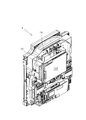
遊技盤7の背面側(反遊技者側)には、図3に示されているように、各種の基板が基板ボックスに収容された状態で配設されている。例えば、後述する主制御基板110が収容された基板ボックス、副制御基板120が収容された基板ボックス、払出制御基板130が収容された基板ボックス、電源基板150が収容された基板ボックス等が配設されている。
また、パチンコ機1に外力が加えられたことを検出する外力検出器15が設けられている。本実施の形態では、外力検出器15として振動検出器が用いられている。なお、外力検出器15は、遊技盤7に加えられた外力を検出するように配置するのが好ましい。外力検出器(振動検出器)15は、本発明の「外力検出装置」あるいは「外力検出手段」に対応する。
なお、図示されていないが、本実施の形態では、磁気を検出する磁気検出器14が設けられている。磁気検出器14は、磁石等から発生する磁気を用いて遊技球の移動方向を不正に変える不正遊技を検出するためのものである。本実施の形態では、磁気検出器14は、遊技盤7に、始動入賞口11の近傍に配置される。磁気検出装置14は、本発明の「磁気検出手段」に対応する。
また、図示されていないが、電源投入時にRAMに記憶されている情報をクリアするためのRAMクリアスイッチ18が設けられている。RAMに記憶されている全情報を消去する場合(RAMを初期化する場合)には、RAMクリアスイッチ18を操作した状態で電源を投入する。RAMクリアスイッチ18は、本発明の「クリア信号を出力するクリア信号出力装置」あるいは「クリア信号を出力するクリア信号出力手段」に対応する。
また、内枠3や遊技盤7には、装飾あるいは遊技演出のためのスピーカ126(音発生器)、LED(発光ダイオード)(光発生器)127が設けられている。LED127の種類、数や配置位置等は、装飾効果や遊技演出効果等を考慮して適宜選択される。
On the rear side (anti-player side) in the center of the winning
In addition, an
As shown in FIG. 3, various substrates are arranged on the back side (the anti-player side) of the
Further, an
Although not shown, in the present embodiment, a magnetic detector 14 for detecting magnetism is provided. The magnetic detector 14 is for detecting an illegal game that illegally changes the moving direction of the game ball using magnetism generated from a magnet or the like. In the present embodiment, the magnetic detector 14 is disposed on the
Although not shown, a RAM clear switch 18 is provided for clearing information stored in the RAM when the power is turned on. When erasing all information stored in the RAM (when initializing the RAM), the power is turned on while the RAM clear switch 18 is operated. The RAM clear switch 18 corresponds to “a clear signal output device that outputs a clear signal” or “a clear signal output unit that outputs a clear signal” of the present invention.
The
次に、本実施の形態のパチンコ機1の制御系の概略構成を、図4を用いて説明する。本実施の形態のパチンコ機1には、主制御基板110、副制御基板120、払出制御基板130、外部端子板140、電源基板150等の基板が設けられている。なお、図4には図示していないが、本実施の形態のパチンコ機1は、これ以外の種々の基板、遊技用機器、検出器が設けられている。
Next, a schematic configuration of the control system of the
主制御基板110には、主制御回路111、ROMやRAMを含む記憶回路112、電圧変換回路115。停電検出回路116等が配設されている。主制御回路111は、本発明の「主制御手段」に対応し、記憶回路112は、本発明の「主制御用記憶回路」あるいは「主制御用記憶手段」に対応に対応する。
主制御基板110には、始動入賞球検出信号を出力する始動入賞球検出器11a、V入賞球検出信号を出力するV入賞球検出器24a、一般入賞球検出信号を出力する一般入賞球検出器25a、振動検出信号を出力する振動検出器15、磁気検出信号を出力する磁気検出器14、RAMクリア信号を出力するRAMクリアスイッチ18、特別図柄表示装置13、可変入賞装置20の開口部22aを開閉する開閉部材22、異常報知ランプ12、副制御基板120、払出制御基板130等が接続されている。なお、太線はバスを示している。
主制御回路111は、入力信号と、記憶回路112に記憶されている情報(例えば、制御プログラムや各種の乱数発生プログラム等のプログラムや制御データ等の記憶情報)に基づいて主制御信号を出力する。例えば、当たり判定用乱数に基づいた当落指定主コマンド信号(当たり判定用乱数が小当たり値と一致する(小当たりである)場合には小当たりであることを示す当落指定主コマンド信号、当たり判定用乱数が大当たり値と一致する(大当たりである)場合には大当たりを示す当落指定主コマンド信号、当たり判定用乱数が小当たり値および大当たり値と一致しない(はずれ時)場合にははずれを示す当落指定主コマンド信号)と、変動パターン判定用乱数に基づいた変動パターン主コマンド信号(小当たりである場合には小当たり変動パターン判定用乱数に対応する小当たり変動パターンを示す変動パターン主コマンド信号、大当たりである場合には大当たり変動パターン判定用乱数に対応する大当たり変動パターンを示す変動パターン主コマンド信号、はずれである場合にははずれ変動パターン判定用乱数に対応するはずれ変動パターンを示す変動パターン主コマンド信号)を主制御信号として副制御回路121に出力する。なお、変動パターン主コマンド信号としては、変動パターンの変動時間を(例えば、小当たり変動パターン判定用乱数に対応する小当たり変動パターンの変動期間、大当たり変動パターン判定用乱数に対応する大当たり変動パターンの変動期間、はずれ変動パターン判定用乱数に対応するはずれ変動パターンの変動期間)を示すコマンド信号を用いることもできる。また、V入賞球検出信号や一般入賞球検出信号の入力に応答して、賞球数を示す払出用主コマンド信号を主制御信号として払出制御回路131に出力する。また、可変入賞装置20の開閉部材22を駆動する開閉部材用駆動装置に、開閉部材制御信号を主制御信号として出力する。また、特別図柄表示装置30を駆動する特別図柄表示装置駆動装置に、特別図柄制御信号を主制御信号として出力する。また、異常報知ランプ12を駆動する異常報知ランプ駆動装置に、異常報知ランプ制御信号を主制御信号として出力する。
The main control board 110 includes a
On the main control board 110, a starting winning ball detector 11a that outputs a starting winning ball detection signal, a V winning ball detector 24a that outputs a V winning ball detection signal, and a general winning ball detector that outputs a general winning ball detection signal. 25a, a
The
副制御基板120には、副制御回路121、ROMやRAMを含む記憶回路122、VDP(ビデオディスプレイプロセッサ)(画像処理回路)123、音源IC124、電圧変換回路125等が配設されている。副制御回路121は、本発明の「副制御手段」に対応し、記憶回路122は、本発明の「副制御用記憶回路」あるいは「副制御用記憶手段」に対応する。
副制御基板120には、主制御基板110、装飾図柄表示装置30、スピーカ126、ランプ(LED)127が接続されている。
副制御回路121は、主制御回路111から出力された主コマンド信号と、記憶回路122に記憶されている情報(例えば、制御プログラムや各種の乱数発生プログラム等のプログラムや制御データ等の記憶情報)に基づいて、副制御信号を出力する。例えば、主制御回路111から出力された当落指定主コマンド信号および変動パターン主コマンド信号に基づいて、抽選結果に対応する停止図柄(小当たり停止図柄、大当たり停止図柄、はずれ停止図柄)および変動パターン(小当たり変動パターン、大当たり変動パターン、はずれ変動パターン)を決定し、決定した停止図柄および変動パターンを装飾図柄表示装置30に表示させるための表示制御信号を副制御信号としてVDP123に出力する。例えば、当落指定主コマンド信号が小当たりを示している場合には、小当たり図柄の中から停止図柄を決定(選択)し、決定した停止図柄および変動パターン主コマンド信号で示される変動パターン(小当たり変動パターン)を表示させるための表示制御信号を出力し、当落指定主コマンド信号が大当たりを示している場合には、大当たり図柄の中から停止図柄を決定(選択)し、決定した停止図柄および変動パターン主コマンド信号で示される変動パターン(大当たり変動パターン)を表示させるための表示制御信号を出力し、当落指定コマンド信号がはずれを示している場合には、はずれ図柄の中から停止図柄を決定(選択)し、決定した停止図柄および変動パターン主コマンド信号で示される変動パターン(はずれ変動パターン)を表示させるための表示制御信号を出力する。なお、変動パターン主コマンド信号が変動パターンの変動期間を示している場合には、変動パターン主コマンド信号で示される変動期間を有する変動パターン(小当たり変動パターン、大当たり変動パターン、はずれ変動パターン)の中から装飾図柄表示装置30に表示させる変動パターンを決定(選択)する。
VDP133は、入力された表示制御信号に基づいて、記憶回路から装飾図柄画像情報、キャラクタ画像情報や背景画像情報等を読み出し、読み出した各画像情報を、大きさや配置位置を調整しながら合成することによって表示画面に対応するビットマップデータを作成する。そして、作成したビットマップデータに基づいて装飾図柄表示装置30を制御する。
The
The
The
The
また、副制御回路121は、音による演出を行うために、装飾図柄表示装置30に表示させる変動パターン(小当たり変動パターン、大当たり変動パターン、はずれ変動パターン)に対応する音用副コマンド信号を副制御信号として音源IC124に出力する。音源IC124は、音制御回路と音制御用記憶回路を有しており、入力された音用副コマンド信号と音制御用記憶回路に記憶されている情報に基づいて、スピーカ126を駆動する音制御信号を出力する。
また、副制御回路121は、光による演出を行うために、装飾図柄表示装置30に表示させる変動パターンに対応させて、ランプ127を制御するランプ制御信号を副制御信号として出力する。
なお、図4では、装飾図柄表示装置30を制御する制御回路(例えば、VDP等)を副制御基板120に配設したが、装飾図柄表示装置30を制御する制御回路(例えば、表示制御回路、VDP等)を配設した表示制御基板を設けることもできる。この場合には、副制御回路121は、主制御回路111から出力された当落指定主コマンド信号に基づいて停止図柄(小当たり図柄、大当たり図柄、はずれ図柄)を決定し、決定した停止図柄を示す図柄コマンド信号を、主制御回路111から出力された当落指定主コマンド信号および変動パターン主コマンド信号に付加した表示用副コマンド信号(あるいは、図柄コマンド信号を変動パターン主コマンド信号に付加した表示副コマンド信号)を副制御信号として表示制御回路に出力する。表示制御回路は、副制御回路121から出力された表示用副コマンド信号に含まれている図柄コマンド信号で示される停止図柄および変動パターン主コマンド信号で示される変動パターンを装飾図柄表示装置30に表示する。
いずれの場合も、本願発明の「副制御手段は、表示手段に情報を表示させる」構成に包含される。
The
Further, the
In FIG. 4, a control circuit (for example, VDP or the like) for controlling the decorative
In either case, it is included in the “sub-control means displays information on the display means” according to the present invention.
払出制御基板130には、払出制御回路131、ROMやRAMを含む記憶回路(払出制御用記憶回路)132、電圧変換回路135等が配設されている。払出制御回路131は、本発明の「払出制御手段」に対応し、記憶回路132は、本発明の「払出制御用記憶回路」あるいは「払出制御用記憶手段」に対応する。
払出制御基板130には、枠開閉検出信号を出力する枠開閉検出器8、扉開閉検出信号を出力する扉開閉検出器9、発射装置16、払出装置133、主制御基板110、外部端子板140が接続されている。
払出制御回路131は、主制御回路111から出力された払出用主コマンド信号と、記憶回路132に記憶されている情報に基づいて、払出制御信号を払出装置133に出力し、払出用主コマンド信号で示される数の遊技球を払出装置133から払い出す。また、発射ハンドル6の回動量に対応した発射制御信号を発射装置16に出力する。
On the payout control board 130, a
The dispensing control board 130 includes a frame opening /
The
電源基板150には、電源回路151が配設されている。電源回路151は、本発明の「電源手段」に対応する。電源回路151は、例えば、AC24V電源をDC34V電源、DC12V電源、DC5V電源等に変換する。電源回路151としては、交流電源を直流電源に変換する公知の電源回路が用いられる。電源回路151からのDC12V電源およびDC34V電源は、電源線L1およびL2を介して払出制御基板130、主制御基板110、副制御基板120等に供給される。
本実施の形態では、払出制御基板130、主制御基板110、副制御基板120には、電源回路151から供給されるDC12V電源をDC5V電源に変換する電圧変換回路135、115、125が設けられている。DV5V電源は、制御回路等の駆動電源として用いられる。電圧変換回路135、115、125としては、直流電源の電圧を変換する公知の電圧変換回路が用いられる。電圧変換回路135、115、125は、本発明の「電圧変換手段」に対応する。
また、停電時等の電源遮断時に、主制御回路111に停電時処理を実行させるための停電検出信号(「停電予告信号」と呼ばれる)を出力する停電検出回路116が設けられている。本実施の形態では、DC12V電源の電圧が停電検出設定値より低下すると停電検出信号を出力する停電検出回路116が主制御基板110に設けられている。停電検出設定値は、停電検出信号が出力された時点で主制御回路111が停電時処理を実行する間、DC5V電源の電圧が主制御回路111の動作電圧以下に低下しない値に設定される。主制御回路111は、停電時処理において、記憶回路112のRAMの所定領域に記憶されている、その時(停電発生時)の遊技状態を示す遊技情報をRAMのバックアップ領域に記憶させる。ここで、電源遮断時に、RAMに記憶されている情報を保持させるために、RAMにバックアップ電源を供給するバックアップ電源装置が設けられる。バックアップ電源装置としては、好適には、主制御基板110に設けられたコンデンサが用いられる。勿論、電源基板150に設けられたコンデンサを用いることができる。なお、停電検出回路116は、DC12V電源以外の電源の電圧に基づいて停電検出信号を出力するように構成することもでき、また、電源基板150に設けることもできる。
A
In the present embodiment, the payout control board 130, the main control board 110, and the
Further, a power
外部端子板140は、払出制御基板130に接続されており、フォトモスリレー141、142、143を有している。フォトモスリレー141、142、143は、フォトカプラを用いた回路であり、非接触の信号経路を形成する。外部端子板140は、払出制御基板130から出力された扉開閉検出信号、枠開閉検出信号、異常報知信号、その他、大当たり信号等の遊技情報を、フォトモスリレー141、142、143を介して、ホールコンピュータ等の管理装置に出力する。
管理装置は、各遊技機の外部端子板140から出力された扉開閉検出信号、枠開閉検出信号に基づいて、ガラス扉4あるいは内枠3が開いている(開状態にある)遊技機を判別する。また、各遊技機の外部端子板140から出力された異常報知信号に基づいて、不正遊技が行われている遊技機を判別する。
The external terminal board 140 is connected to the payout control board 130 and has photo MOS relays 141, 142, and 143. The photo MOS relays 141, 142, and 143 are circuits using photocouplers, and form a non-contact signal path. The external terminal board 140 receives game information such as a door opening / closing detection signal, a frame opening / closing detection signal, an abnormality notification signal, and a jackpot signal output from the payout control board 130 via the photo MOS relays 141, 142, and 143. Output to a management device such as a hall computer.
Based on the door opening / closing detection signal and the frame opening / closing detection signal output from the external terminal board 140 of each gaming machine, the management device discriminates the gaming machine in which the
本実施の形態のパチンコ機1の通常の動作(不正検出および不正防止動作を除く動作)の一例を以下に説明する。
遊技球が始動入賞口11に入球すると(当たり遊技獲得条件が成立すると)、始動入賞球検出器11aから、遊技球が始動入賞口11に入球したことを示す始動入賞球検出信号が出力される。
主制御回路111は、遊技球が始動入賞口11に入球したことを示す始動入賞球検出信号が入力されると、当たり判定用乱数、変動パターン判定用乱数(小当たり変動パターン判定用乱数、大当たり変動パターン判定用乱数、はずれ変動パターン判定用乱数)を取得する。そして、抽選結果を装飾図柄表示装置30に表示させる変動開始時に、読み取った当たり判定用乱数に基づいて抽選結果を判定するとともに、抽選結果に対応する当落指定主コマンド信号および変動パターン主コマンド信号を出力する。例えば、読み取った当たり判定用乱数が小当たり値と一致する(小当たりである)場合には、小当たりであることを示す当落指定主コマンド信号および読み取った小当たり変動パターン判定用乱数に対応する小当たり変動パターンを示す変動パターン主コマンド信号を出力する。また、読み取った当たり判定用乱数が大当たり値と一致する(大当たりである)場合には、大当たりであることを示す当落指定主コマンド信号および読み取った大当たり変動パターン判定用乱数に対応する大当たり変動パターンを示す変動パターン主コマンド信号を出力する。また、読み取った当たり判定用乱数が小当たり値および大当たり値と一致しない(はずれである)場合には、はずれであることを示す当落指定主コマンド信号および読み取ったはずれ変動パターン判定用乱数に対応するはずれ変動パターンを示す変動パターン主コマンド信号を出力する。
An example of normal operations (operations other than fraud detection and fraud prevention operations) of the
When a game ball enters the start winning opening 11 (when the winning game acquisition condition is satisfied), a start winning ball detection signal indicating that the game ball has entered the
When a start winning ball detection signal indicating that a game ball has entered the
副制御回路121は、主制御回路111から出力された当落指定主コマンド信号および変動パターン主コマンド信号に基づいて停止図柄および変動パターンを決定し、決定した停止図柄および変動パターンを装飾図柄表示装置30に表示させるための表示制御信号をVDP123に出力する。また、変動パターンに対応する音をスピーカ125から発生させるために、変動パターンに対応する音用副コマンド信号を音源IC124に出力する。また、変動パターンに対応する光をランプ126から発生させるために、変動パターンに対応する光制御信号によってランプ126を駆動する。
The
そして、主制御回路111は、当たり判定用乱数が小当たり値と一致している(小当たりである)場合には、小当たり変動パターン判定用乱数に対応する小当たり変動パターンの変動期間経過後、小当たり遊技発生処理を実行する。
小当たり遊技発生処理では、可変入賞装置20の開閉部材22を一定期間開制御(開閉制御を含む)して開口部22aを開状態(開閉状態を含む)とする。そして、小当たり遊技開始時から(開閉部材22の開制御を開始してから)有効期間が経過するまでの間に、遊技球がV入賞口24に入球し、遊技球がV入賞口24に入球したことを示すV入賞球検出信号がV入賞球検出器24aから出力された場合(大当たり遊技獲得条件が成立した場合)には、大当たり遊技発生処理を実行する。
なお、当たり判定用乱数が大当たり値と一致する(大当たりである)場合には、大当たり変動パターン判定用乱数に対応する大当たり変動パターンの変動期間経過後に、大当たり遊技発生処理を実行する。
Then, when the hit determination random number matches the small hit value (is a small hit), the
In the small hit game generation process, the opening / closing
When the hit determination random number matches the jackpot value (the jackpot), the jackpot game generation process is executed after the change period of the jackpot variation pattern corresponding to the jackpot variation pattern determination random number has elapsed.
大当たり遊技発生処理では、図12(a)に示されているように動作する。図12(a)に示されている大当たり遊技発生処理では、ラウンド遊技を、ラウンド遊技継続条件が満足されることによりラウンド設定回数(=15回)まで継続可能である。
主制御回路111は、大当たり遊技獲得条件の成立(小当たり遊技中に遊技球がV入賞口24に入球したこと、あるいは、当たり判定用乱数が大当たり値と一致したこと)によって、時点t1で大当たりフラグをセットする。そして、主制御回路111は、時点t1で、大当たりオープニング演出の開始を指示する大当たりオープニングコマンド信号を副制御回路121に出力する。副制御回路121は、時点t1で、主制御回路111から大当たりオープニングコマンド信号が出力されると、装飾図柄表示装置30、スピーカ126、ランプ127を制御して、大当たり遊技が発生することを報知する大当たりオープニング演出を行う。例えば、「大当たり」等のメッセージ情報を含む大当たりオープニング情報を装飾図柄表示装置30に表示する。大当たりオープニングコマンド信号は、本発明の「大当たり遊技が発生することを示す大当たりオープニング情報を表示手段に表示させることを指示する大当たりオープニングコマンド信号」に対応する。
主制御回路111は、大当たりオープニングコマンド信号を副制御回路121に出力した後、大当たりオープニング演出を行う期間(大当たりオープニング期間)T1経過した時点t2で、第1回目のラウンド遊技演出(第1ラウンド遊技演出)の開始を指示する第1ラウンドコマンド信号を副制御回路121に出力する。本実施の形態では、大当たりオープニング期間T1として14.6秒が設定されている。また、主制御回路111は、第1ラウンド遊技を実行する。第1ラウンド遊技では、可変入賞装置20の開閉部材22を、小当たり時より長い期間開制御する。副制御回路121は、時点t2で、主制御回路111から第1ラウンドコマンド信号が出力されると、装飾図柄表示装置30、スピーカ126、ランプ127を制御して、第1ラウンド遊技が発生することを報知する第1ラウンド遊技演出を行う。例えば、「ラウンド1」等のメッセージ情報を含むラウンド遊技情報を装飾図柄表示装置30に表示する。
大当たりオープニング演出を行う期間T1は、本発明の「大当たりオープニング期間」に対応する。ラウンドコマンド信号は、本発明の「ラウンド遊技が発生することを示すラウンド遊技情報を表示手段に表示させることを指示するラウンドコマンド信号」に対応する。
主制御回路111は、第1ラウンド遊技中にラウンド遊技継続条件が満足されると、時点t3で、可変入賞装置20の開閉部材22の開制御を停止する。本実施の形態では、ラウンド遊技継続条件として、第2ラウンド遊技期間T2内に遊技球がV入賞口24に入球した条件が用いられる。そして、休止期間T4が経過した時点t4で、第2回目のラウンド遊技演出(第2ラウンド遊技演出)の開始を指示する第2ラウンドコマンド信号を副制御回路121に出力する。また、主制御回路111は、可変入賞装置20の開閉部材22を開制御して第2ラウンド遊技を実行する。副制御回路121は、時点t4で、主制御回路111から第2ラウンドコマンド信号が出力されると、装飾図柄表示装置30、スピーカ126、ランプ127を制御して、第2ラウンド遊技が発生することを報知する第2ラウンド遊技演出を行う。例えば、「ラウンド2」等のメッセージ情報を含むラウンド遊技情報を装飾図柄表示装置30に表示する。
以下、同様にして、主制御回路111は、ラウンド遊技継続条件が満足される毎に、ラウンドコマンド信号を副制御回路121出力するとともに、ラウンド遊技を実行する。副制御回路121は、主制御回路111からラウンドコマンド信号が出力されると、ラウンド遊技演出を行う。なお、ラウンド遊技期間T2としては、適宜の期間が設定される。
そして、主制御回路111は、第15番目のラウンド遊技が終了した場合(最大ラウンド数のラウンド遊技を実行した場合)には、時点t30で、大当たりフラグをリセットするとともに、可変入賞装置20の開閉部材22の開制御を停止する。また、主制御回路111は、時点t30で、大当たりエンディング演出の開始を指示する大当たりエンディングコマンド信号を副制御回路121に出力する。副制御回路121は、時点t30で、主制御回路111から大当たりエンディングコマンド信号が出力されると、装飾図柄表示装置30、スピーカ126、ランプ127を制御して、大当たり遊技が終了することを報知する大当たりエンディング演出を行う。例えば、「大当たり終了」等のメッセージ情報を含む大当たりエンディング情報を装飾図柄表示装置30に表示する。
The jackpot game generation process operates as shown in FIG. In the jackpot game generation process shown in FIG. 12A, the round game can be continued up to the round setting number (= 15 times) when the round game continuation condition is satisfied.
The
The
The period T1 during which the jackpot opening effect is performed corresponds to the “jackpot opening period” of the present invention. The round command signal corresponds to the “round command signal for instructing the display means to display round game information indicating that a round game will occur” of the present invention.
When the round game continuation condition is satisfied during the first round game, the
Similarly, the
When the fifteenth round game is completed (when the maximum number of round games is executed), the
なお、主制御回路111から、当落指定主コマンド信号、変動パターン主コマンド信号および停止図柄を示す図柄主コマンド信号を副制御回路121に出力するように構成することもできる。例えば、主制御回路111は、遊技球が始動入賞口11に入球すると、当たり判定用乱数、変動パターン判定用乱数(小当たり変動パターン判定用乱数、大当たり変動パターン判定用乱数、はずれ変動パターン判定用乱数)と図柄判定用乱数(小当たり図柄判定用乱数、大当たり図柄判定用乱数、はずれ図柄判定用乱数)を読み取る。そして、読み取った当たり判定用乱数が小当たり値と一致する場合には、小当たりであることを示す当落指定主コマンド信号、読み取った小当たり変動パターン判定用乱数に対応する小当たり変動パターンを示す変動パターン主コマンド信号および読み取った小当たり図柄判定用乱数に対応する小当たり図柄を示す図柄主コマンド信号を出力する。また、読み取った当たり判定用乱数が大当たり値と一致する場合には、大当たりであることを示す当落指定主コマンド信号、読み取った大当たり変動パターン判定用乱数に対応する大当たり変動パターンを示す変動パターン主コマンド信号および読み取った大当たり図柄判定用乱数に対応する大当たり図柄を示す図柄主コマンド信号を出力する。また、読み取った当たり判定用乱数が小当たり値および大当たり値と一致しない場合には、はずれであることを示す当落指定主コマンド信号、読み取ったはずれ変動パターン判定用乱数に対応するはずれ変動パターンを示す変動パターン主コマンド信号および読み取ったはずれ図柄判定用乱数に対応するはずれ図柄を示す図柄主コマンド信号を出力する。この場合には、副制御回路121は、主制御回路111から出力された図柄主コマンド信号および変動パターン主コマンド信号に基づいて停止図柄および変動パターンを決定し、決定した停止図柄および変動パターンを装飾図柄表示装置30に示させるための表示制御信号をVDP123に出力するように構成する。なお、副制御回路121は、装飾図柄表示装置30に表示させる図柄や変動パターンが、当落指定主コマンド信号で示される当落判定結果(当たり判定用乱数が小当たり値あるいは大当たり値と一致しているか否か)に対応するように監視、制御する。
The
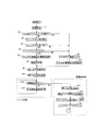
次に、本実施の形態の主制御回路111の処理を、図5に示すフローチャートを用いて説明する。図5は、主制御回路111の電源投入時処理とメイン処理の概略を説明するフローチャートである。図5に示す電源投入時処理は、営業開始時や保守点検作業後に電源スイッチが投入されてDC5V電源の電圧が主制御回路111の動作電圧に達した時あるいは停電が復旧してDC5V電源の電圧が主制御回路111の動作電圧に達した時に開始される。
Next, the processing of the
ステップA1では、主制御回路111の初期設定が行われる。
ステップA2では、RAMクリアスイッチ18が操作されているか否かを判定する。RAMクリアスイッチ18は、RAMに記憶されている情報を消去し、初期値から遊技を開始させる場合に操作される。典型的には、RAMクリアスイッチ18は営業開始時に操作される。一方、前回の停電時の遊技状態から遊技を再開させる場合には、RAMクリアスイッチ18は操作されない。RAMクリアスイッチ18が操作されている場合(RAMクリアスイッチ18からRAMクリア信号が出力されている場合)にはステップA9に進み、RAMクリアスイッチ18が操作されていない場合(RAMクリアスイッチ18からRAMクリア信号が出力されていない場合)にはステップA3に進む。このステップA2では、「RAMクリアスイッチ18が操作されている状態で駆動電源が供給されたか否かを判定する処理」が実行される。
ステップA3では、記憶回路112のRAMに記憶されている遊技情報等が正常であるか否か(RAMに記憶されている遊技情報が停電中に変化しているか否か)を判定するための判定情報を算出する。本実施の形態では、RAMに記憶されている遊技情報等のチェックサム値を判定情報として算出している。
ステップA4では、ステップA3で算出した判定情報を用いて、RAMに記憶されている情報が正常であるか否か(RAMに記憶されている遊技情報等が停電中に変化しているか否か)を判定する。本実施の形態では、ステップA3で算出したチェックサム値とRAMに記憶されているチェックサム値(前回の停電時処理時に算出したチェックサム値)が一致しているか否かを判断する。算出したチェックサム値とRAMに記憶されているチェックサム値が一致している場合にはステップA5に進み、一致していない場合にはステップA9に進む。
In step A1, the
In step A2, it is determined whether or not the RAM clear switch 18 is operated. The RAM clear switch 18 is operated when erasing information stored in the RAM and starting a game from an initial value. Typically, the RAM clear switch 18 is operated at the start of business. On the other hand, when the game is resumed from the game state at the time of the previous power failure, the RAM clear switch 18 is not operated. When the RAM clear switch 18 is operated (when the RAM clear signal is output from the RAM clear switch 18), the process proceeds to step A9. When the RAM clear switch 18 is not operated (from the RAM clear switch 18 to the RAM If the clear signal is not output), the process proceeds to step A3. In this step A2, “a process for determining whether or not drive power is supplied while the RAM clear switch 18 is being operated” is executed.
In step A3, a determination for determining whether or not the game information or the like stored in the RAM of the
In step A4, whether or not the information stored in the RAM is normal using the determination information calculated in step A3 (whether the game information or the like stored in the RAM has changed during a power failure). Determine. In the present embodiment, it is determined whether or not the checksum value calculated in step A3 matches the checksum value stored in the RAM (the checksum value calculated during the previous power failure process). If the calculated checksum value matches the checksum value stored in the RAM, the process proceeds to step A5. If not, the process proceeds to step A9.
ステップA5では、バックアップフラグがセットされているか否か(「1」に設定されているか否か)を判断する。バックアップフラグは、前回の停電時処理時に、停電時処理が正常に終了したか否かを示すフラグである。すなわち、前回の停電時処理が正常に終了した場合にはセットされ(「1」が設定され)、正常に終了していない場合にはリセットされる(「0」が設定される)。バックアップフラグがセットされている場合にはステップA6に進み、リセットされている場合にはステップA9に進む。このステップA5では、「前回の停電時処理が正常に終了したか否かを判定する」処理が実行される。
ステップA6では、RAMクリアスイッチ18が操作されてない状態で主制御回路111が動作状態となり、また、RAMに記憶されている遊技情報等が正常であり、さらに、前回の停電時処理が正常に終了したことを判定し、RAMに記憶されている遊技情報等に基づいて遊技を再開する(前回の停電発生時の遊技状態から遊技を再開する)。すなわち、RAMの作業領域の復電時設定を行う。
In step A5, it is determined whether or not the backup flag is set (whether or not it is set to “1”). The backup flag is a flag indicating whether or not the power failure process has been normally completed during the previous power failure process. That is, it is set (“1” is set) when the previous power failure process is normally completed, and is reset (“0” is set) when it is not normally completed. If the backup flag is set, the process proceeds to step A6, and if it is reset, the process proceeds to step A9. In this step A5, a process of “determining whether or not the previous power failure process has ended normally” is executed.
In step A6, the
ステップA7では、復電時処理を実行する。復電時処理では、例えば、RAMに記憶されている遊技情報や主制御信号(主コマンド信号や制御信号)をRAMの所定領域に記憶する。この時、停電が復旧したことを示す停電復旧報知コマンド信号を作成し、RAMの出力領域に記憶する。RAMの出力領域に記憶されているコマンド信号等は、図6に示されているタイマ割込処理のステップB9において出力される。主制御回路111から停電復旧報知コマンド信号が出力されると、副制御回路121は、例えば、装飾図柄表示装置30に停電復旧情報を表示する。
In step A7, power recovery processing is executed. In the power recovery process, for example, game information and main control signals (main command signals and control signals) stored in the RAM are stored in a predetermined area of the RAM. At this time, a power failure recovery notification command signal indicating that the power failure has been recovered is created and stored in the output area of the RAM. The command signal and the like stored in the output area of the RAM are output in step B9 of the timer interrupt process shown in FIG. When the power failure recovery notification command signal is output from the
ここで、前回の電源遮断が、大当たりオープニングコマンド信号を出力してから第1ラウンドコマンド信号を出力するまでの間に発生した場合には、主制御回路111は、前回の電源遮断の遊技状態から遊技を再開するために、電源が投入されてから(例えば、復電時処理を実行してから)、[大当たりオープニング期間T1−前回大当たりオープニングコマンド信号を出力してから電源が遮断される(停電時処理を実行する)までの期間]が経過した時点で第1ラウンドコマンド信号を出力する。この場合、副制御回路121は、主制御回路111から停電復旧報知コマンド信号が出力された時点で停電復旧報知を行った後(例えば、停電復旧報知情報を装飾図柄表示装置30に表示した後)、主制御回路111から第1ラウンドコマンド信号が出力されるまで待機する。大当たりオープニング期間T1として14.6秒が設定され、前回の電源遮断が、大当たりオープニングコマンド信号を出力した直後に発生した場合には、電源投入時、略14.6秒の期間、装飾図柄表示装置30に停電復旧報知情報が表示されている状態が維持される。このため、遊技者は、遊技が開始可能となるまでの期間(待機期間)を判別することができず、不快に感じる。本実施の形態では、遊技者が、遊技が開始可能となるまでの期間を用に判別することができるように、主制御回路111から停電復旧報知コマンド信号が出力されると、電源投入時からの経過期間を示す停電復旧経過期間情報が、当該停電復旧経過期間情報が大当たりオープニング期間T1に対応する経過期間を示す状態なるまでの範囲内で、装飾図柄表示装置30に表示されるように構成されている。
Here, if the previous power shutdown occurs between the time when the jackpot opening command signal is output and the time when the first round command signal is output, the
図13(a)に、装飾図柄表示装置30に表示される、停電復旧経過期間情報32を含む停電復旧報知画面の一例が示されている。図13(a)に示されている停電復旧報知画面は、停電復旧報知情報31、停電復旧経過期間情報32を有している。停電復旧報知情報31としては、停電が復旧したことを示す情報、例えば、「停電復旧中」等のメッセージ情報が用いられる。図13(a)に示されている停電復旧報知画面では、停電復旧経過期間情報32として、大当たりオープニング期間T1に対応する間隔Twを有する箇所33aと33b間の大当たりオープニング期間情報(実際には表示されていない仮想の大当たりオープニング期間情報)33の一方の箇所32aから他方の箇所32cの方向に、電源投入時からの経過期間に対応する長さTxを有する直線情報(例えば、バー)が用いられている。ここで、停電復旧経過期間情報32は、一方側の端部(固定端部)32aが固定表示され、他方側の端部(可動端部)32bが電源投入時からの経過期間に対応して、大当たりオープニング期間情報33の他方の箇所32cの方向に順次移動して表示される。図13(a)に示されている停電復旧報知画面では、遊技者は、停電復旧経過期間情報32の長さTxと、当該停電復旧経過期間情報32の最大長Twとの差、すなわち、停電復旧経過期間情報32の可動端部32bと仮想の大当たりオープニング期間情報33の他方の箇所33bとの間の間隔により、遊技が開始可能となるまでの待機期間(詳しくは、最大待機期間)を容易に判別することができる。
なお、停電復旧経過期間情報32および情報(仮想情報)33としては、両者の長さ、特に、両者の長さの差が判別可能な種々の情報を用いることができる。例えば、曲線情報を用いることもできる。この場合には、一方の箇所と他方の箇所の間の曲線形状の長さが大当たりオープニング期間T1に対応する曲線情報および一方の端部と他方の端部の間の曲線形状の長さが電源投入時からの経過期間に対応する曲線情報が表示される。
FIG. 13A shows an example of the power failure recovery notification screen including the power failure recovery elapsed
In addition, as the power failure recovery elapsed
停電復旧経過期間情報を含む停電復旧報知画面としては、図14に示されている停電復旧報知画面を用いることもできる。
図14に示されている停電復旧報知画面は、停電復旧報知情報131、停電復旧経過期間情報132、大当たりオープニング期間情報133を有している。図14に示されている停電復旧報知画面では、図13(1)に示されている停電復旧報知画面では表示されていなかった、大当たりオープニング期間T1に対応する長さTwを有する大当たりオープニング期間情報133が画面上に表示されている。
図14に示されている停電復旧報知画面では、遊技者は、停電復旧経過期間情報132の長さTxと、当該停電復旧経過期間情報32の最大長である、大当たりオープニング期間情報133の長さTwとの差、すなわち、停電復旧経過期間情報132の可動端部132bと大当たりオープニング期間情報133の他方の箇所133bとの間の間隔を容易に判別することができるため、遊技が開始可能となるまでの待機期間(詳しくは、最大待機期間)を容易に判別することができる。
As the power failure recovery notification screen including the power failure recovery elapsed period information, the power failure recovery notification screen shown in FIG. 14 can also be used.
The power failure recovery notification screen shown in FIG. 14 has power failure
In the power failure recovery notification screen shown in FIG. 14, the player determines the length Tx of the power failure recovery elapsed
ここで、前回の電源の遮断が、大当たりオープニングコマンド信号を出力してから第1ラウンドコマンド信号を出力するまでの期間に発生した場合には、電源が投入されてから、[大当たりオープニング期間T1−前回大当たりオープニングコマンド信号を出力してから電源が遮断される(停電時処理を実行する)までの期間]経過した時点で第1ラウンド遊技が開始される。一方、前回の電源の遮断が、これ以外の遊技状態で発生した場合には、電源が投入されると、直ちに遊技を開始することができる。このため、前回の電源の遮断が、大当たりオープニングコマンド信号を出力してから第1ラウンドコマンド信号を出力するまでの間に発生した場合と、それ以外の場合で、装飾図柄表示装置30に表示させる停電復旧画面を変更するのが好ましい。
例えば、前回の電源の遮断が、大当たりオープニングコマンド信号を出力してから第1ラウンドコマンド信号を出力するまでの期間に発生した場合には、主制御回路111から第1の停電復旧報知コマンド信号を副制御回路121に出力する。副制御回路121は、主制御回路111から第1の停電復旧報知コマンド信号が出力されると、例えば、図13(a)に示されているような、停電復旧報知情報31と、電源投入時からの経過期間を示す停電復旧経過期間情報32を有する第1の停電復旧画面を装飾図柄表示装置30に表示させる。なお、電源投入時からの経過期間を示す停電復旧経過期間情報32のみを有する第1の停電復旧画面を用いることもできる。
一方、前回の電源の遮断が、大当たりオープニングコマンド信号を出力してから第1ラウンドコマンド信号を出力するまでの期間以外の期間に発生した場合には、主制御回路111から第2の停電復旧報知コマンド信号を副制御回路121に出力する。副制御回路121は、主制御回路111から第2の停電復旧報知コマンド信号が出力されると、例えば、図15に示されているような、「停電が復旧しました。遊技を開始してください。」等の停電復旧報知情報を有する第2の停電復旧画面を装飾図柄表示装置30に表示する。なお、第1の停電復旧画面の停電復旧情報と第2の停電復旧画面の停電復旧報知情報としては、異なる報知情報(メッセージ情報)を用いるのが好ましい。
このように構成することにより、遊技者は、装飾図柄表示装置30に第1の停電復旧画面が表示された場合には、第1ラウンド遊技が開始されるまで、第1の停電復旧画面に表示されている待機期間(最大待機期間=Tw−Tx)待機すればよいことを容易に判別することができる。一方、装飾図柄表示装置30に第2の停電復旧画面が表示された場合には、直ちに遊技を開始することができることを容易に判別することができる。
Here, when the previous power shutdown occurs in the period from the output of the jackpot opening command signal to the output of the first round command signal, the power supply is turned on [the jackpot opening period T1- The first round game is started when the period from the last output of the jackpot opening command signal to the time when the power is turned off (the process at the time of power failure is executed) has elapsed. On the other hand, if the previous power interruption occurred in other gaming states, the game can be started immediately after the power is turned on. For this reason, the decorative
For example, when the previous power shutdown occurs in the period from the output of the jackpot opening command signal to the output of the first round command signal, the
On the other hand, when the previous power interruption occurs in a period other than the period from the output of the jackpot opening command signal to the output of the first round command signal, the
With this configuration, when the first power failure recovery screen is displayed on the decorative
図5に戻り、ステップA9では、RAMクリアスイッチ18が操作されている状態で主制御回路111が動作状態となった(電源が供給された)こと、あるいは、RAMに記憶されている遊技情報等が異常であること、あるいは、前回の停電時処理が正常に終了していないことを判定し、RAMの全領域をクリア(初期化)するクリア処理(初期化処理)を実行する。例えば、RAMの全領域に初期値「0」を設定する。なお、記憶回路112のROMに記憶されている初期値を読み出してRAMに設定する方法を用いることもできる。
ステップA10では、RAMの作業領域を初期設定する。この初期設定では、ROMに記憶されている初期値を読み出し、読み出した初期値をRAMの作業領域に設定する。また、RAMクリア時処理を実行する。RAMクリア時処理では、例えば、RAMを初期化したことを示すRAMクリア報知コマンド信号、各制御回路や遊技用機器の検査を行うためのテストコマンド信号を作成し、RAMの出力領域に記憶する。なお、主制御回路111からRAMクリア報知コマンド信号が出力されると、副制御回路121は、RAMが初期化されたことを示す初期化報知情報を装飾図柄表示装置30に表示する。また、主制御回路111からテストコマンド信号が出力されると、各制御回路や各遊技用機器の検査が行われる。
Returning to FIG. 5, in step A9, the
In step A10, the RAM work area is initialized. In this initial setting, the initial value stored in the ROM is read, and the read initial value is set in the work area of the RAM. Also, RAM clear processing is executed. In the RAM clearing process, for example, a RAM clear notification command signal indicating that the RAM has been initialized and a test command signal for inspecting each control circuit and gaming device are created and stored in the output area of the RAM. When a RAM clear notification command signal is output from the
ステップA8では、割り込み初期設定を行う。割り込み初期設定では、主制御回路111のメイン処理内でタイマ割り込み処理を行う割り込み周期が設定される。本実施の形態では、割り込み周期として4msが設定される。勿論、メイン処理は、タイマ割り込み周期より短い周期で実行される。
ステップA11では、割り込み許可設定を行う。割り込み許可設定により、ステップA8で設定したタイマ割り込み周期毎のタイマ割り込み処理が実行される。
In step A8, interrupt initialization is performed. In the interrupt initial setting, an interrupt cycle for performing timer interrupt processing in the main processing of the
In step A11, interrupt permission is set. Due to the interrupt permission setting, timer interrupt processing for each timer interrupt cycle set in step A8 is executed.
ステップA12では、停電検出回路116から停電検出信号(停電予告信号)が出力されたか否かを判断する。停電検出回路116から停電検出信号が出力されていない場合にはステップA13に進み、停電検出信号が出力された場合にはステップA14に進む。
ステップA13では、非当落乱数の更新処理を行う。非当落乱数は、当たりであるか否かの判定に直接使用しない乱数を意味する。例えば、下限値と上限値の間で順次加算されるカウント値を当たり判定用乱数として用いるとともに、1周期毎にカウント開始値(初期値)を更新する場合(「初期値更新型乱数」という)に、初期値として用いられる当たり判定用乱数の初期値用乱数が対応する。
ステップA13の処理を終了した後ステップA12に戻る。
ステップA11とA13によってメイン処理が実行される。なお、メイン処理内においてタイマ割り込み周期(例えば、4ms)毎にタイマ割り込み処理Bが実行される。
In step A12, it is determined whether or not a power failure detection signal (power failure notice signal) is output from the power
In step A13, a non-winning random number update process is performed. The non-winning random number means a random number that is not directly used for determining whether or not it is a win. For example, when a count value sequentially added between the lower limit value and the upper limit value is used as a hit determination random number and the count start value (initial value) is updated every cycle (referred to as “initial value update type random number”). Corresponds to the random number for initial value of the random number for hit determination used as the initial value.
After finishing the process of step A13, it returns to step A12.
The main process is executed by steps A11 and A13. In the main process, the timer interrupt process B is executed every timer interrupt cycle (for example, 4 ms).
ステップA14では、割り込み禁止設定を行う。割り込み禁止設定により、以後のタイマ割り込み処理が禁止され、RAMに記憶されている遊技情報等の書き換えが禁止される。
ステップA15では、停電クリア信号の出力を開始する。これにより、主制御回路111からの主制御信号の出力が停止され、遊技用機器の駆動が停止する。遊技用機器の駆動が停止されることによって、電力消費が抑制され、主制御回路111による停電時処理のための電力が確保される。
ステップA16では、次回の主制御回路111の電源投入時処理を実行する時に、RAMに記憶されている遊技情報等が正常であるか否か(RAMに記憶されている遊技情報等が停電中に変化しているか否か)を判定するための判定情報を作成する。本実施の形態では、RAMに記憶されている遊技情報等のチェックサム値を算出している。そして、RAMに記憶されている遊技情報等と算出したチェックサム値をバックアップ情報としてRAMのバックアップ領域に記憶する。判定情報としては、チェックサム値に限定されず、パリティデータ等の種々の判定情報を用いることができる。
ステップA17では、ステップA16の処理を終了した後、バックアップフラグを、停電時処理を終了したことを示す「1」に設定する。なお、ステップA16の処理が完了しなかった場合には、バックアップフラグは、停電時処理が終了しなかったことを示す「0」の状態(RAMが初期化された時の状態)に保持される。
In step A14, interrupt prohibition setting is performed. With the interrupt prohibition setting, subsequent timer interrupt processing is prohibited, and rewriting of game information and the like stored in the RAM is prohibited.
In step A15, output of the power failure clear signal is started. Thereby, the output of the main control signal from the
In step A16, whether or not the game information stored in the RAM is normal when the next power-on process of the
In step A17, after finishing the process of step A16, the backup flag is set to “1” indicating that the process at the time of power failure is finished. If the process of step A16 is not completed, the backup flag is held in a state of “0” (a state when the RAM is initialized) indicating that the process at the time of power failure has not ended. .
次に、主制御回路111のメイン処理内で実行されるタイマ割り込み処理を図6に示すフローチャートにより説明する。図6に示すタイマ割り込み処理は、図5に示したメイン処理内で、ステップA8で設定されたタイマ割り込み周期(本実施の形態では、4ms)毎に実行される。
ステップB1では、遊技中断フラグがセットされているか否かを判断する。「遊技中断フラグ」については後述する。遊技中断フラグがセットされている場合にはステップB10に進み、セットされていない場合にはステップB2に進む。遊技中断フラグは、本発明の「不正が行われたことを示す不正情報」に対応する。
ステップB2では、振動検出フラグがセットされているか否かを判断する。振動検出フラグは後述する。振動検出フラグがセットされていない場合にはステップB3に進み、セットされている場合にはステップB10に進む。振動検出フラグは、本発明の「遊技機に外力が加えられたことを示す外力印加情報」に対応する。
ステップB3では、各種信号の入力処理を行う。入力された信号は、入力情報としてRAMの入力領域に書き込まれる。入力される信号としては、例えば、遊技球が始動入賞口11に入球したことを示す始動入賞球検出信号、遊技球がV入賞口24に入球したことを示すV入賞球検出信号、遊技球が一般入賞口25に入球したことを示す一般入賞球検出信号等が用いられる。
ステップB4では、タイマ更新処理を行う。例えば、装飾図柄表示装置30に表示する装飾図柄の変動表示期間、大当たりオープニング情報を表示する大当たりオープニング期間T1、ラウンド遊技継続条件が満足されたか否かを判断する際に用いられるラウンド遊技期間T2等を減算する。この場合、値が「0」になることによって、各期間が終了したことを判別することができる。あるいは、信号を出力した後のACK信号(応答信号)の入力判定期間を減算する。入力判定期間が「0」に達するまでにACK信号が入力されなかったことにより、異常が発生していることを判別する。なお、本実施の形態では、4ms毎にタイマ割り込み処理を実行しているため、各期間は、4msずつ減算される。
Next, a timer interrupt process executed in the main process of the
In step B1, it is determined whether or not a game interruption flag is set. The “game interruption flag” will be described later. When the game interruption flag is set, the process proceeds to step B10, and when it is not set, the process proceeds to step B2. The game interruption flag corresponds to “illegal information indicating that fraud has been performed” in the present invention.
In step B2, it is determined whether or not a vibration detection flag is set. The vibration detection flag will be described later. If the vibration detection flag is not set, the process proceeds to step B3, and if it is set, the process proceeds to step B10. The vibration detection flag corresponds to “external force application information indicating that an external force is applied to the gaming machine” of the present invention.
In step B3, various signals are input. The input signal is written as input information in the input area of the RAM. Examples of the input signal include a start winning ball detection signal indicating that a game ball has entered the
In step B4, timer update processing is performed. For example, the decorative symbol variable display period displayed on the decorative
ステップB5では、RAMに記憶されている当たり判定用乱数の更新処理を行う。複数の当たり判定用乱数を用いている場合には、RAMに記憶されている複数の当たり判定用乱数を更新する。なお、当たり判定用乱数の更新処理において、各周期の初期値として非当落乱数が設定される。これにより、当たり判定用乱数(当たり判定用カウント値)が設定値(小当たり値、大当たり値)と一致する時点を予測するのが困難となり、不正遊技を防止することができる。
なお、ステップB5では、ステップA13での非当落乱数更新処理と同様の更新処理も行われる。このように、非当落乱数の更新処理を、メイン処理内およびメイン処理内のタイマ割り込み処理内それぞれで行うことにより、当たり初期値用乱数(当たり初期値用カウント値)のランダム性がより高まる。
In Step B5, the hit determination random number stored in the RAM is updated. When a plurality of hit determination random numbers are used, the plurality of hit determination random numbers stored in the RAM are updated. In the hit determination random number update process, a non-winning random number is set as the initial value of each cycle. This makes it difficult to predict when the hit determination random number (the hit determination count value) matches the set value (small hit value, big hit value), and can prevent illegal games.
In step B5, an update process similar to the non-winning random number update process in step A13 is also performed. In this way, the randomness of the random number for winning initial value (count value for winning initial value) is further increased by performing the update process of the non-winning random number in each of the main process and the timer interrupt process in the main process.
ステップB6では、賞球払出処理を行う。賞球払出処理では、RAMの入力領域から遊技球が入賞口(始動入賞口、V入賞口、一般入賞口等)に入球したことを示している入力情報を読み出し、読み出した入力情報に対応する(遊技球が入球した入賞口に対応する)賞球数を示す払出用主コマンド信号をRAMの出力領域に書き込む。
ステップB7では、不正検出処理を行う。不正検出処理については後述する。不正を検出した場合には、外部に異常報知信号を出力するためにRAMの出力領域に異常報知信号を書き込む。
ステップB8では、当たり遊技発生処理を実行する。当たり遊技発生処理については後述する。
ステップB9では、信号出力処理を行う。例えば、RAMの出力領域に書き込まれている出力情報を読み出して出力する。
In step B6, a prize ball payout process is performed. In the winning ball payout processing, input information indicating that a game ball has entered a winning opening (start winning opening, V winning opening, general winning opening, etc.) is read from the input area of the RAM and corresponds to the read input information. A payout main command signal indicating the number of winning balls (corresponding to a winning opening into which a game ball has entered) is written in the output area of the RAM.
In step B7, fraud detection processing is performed. The fraud detection process will be described later. When fraud is detected, the abnormality notification signal is written in the output area of the RAM in order to output the abnormality notification signal to the outside.
In step B8, a winning game generation process is executed. The winning game generation process will be described later.
In step B9, signal output processing is performed. For example, output information written in the output area of the RAM is read and output.
本実施の形態では、小当たりである場合に、可変入賞装置20の開閉部材22が開制御され、有効期間内に遊技球がV入賞口24に入球すると大当たり遊技が発生する。この場合、遊技機に外力を加えることによって遊技球を不正に移動させ、あるいは、磁石等の磁気を使用して遊技球を不正に移動させてV入賞口24に入球させる不正が行なわれる虞が高い。
ステップB10では、遊技球がV入賞口24に入球していないため、不正遊技が行われている可能性は低いが、小当たり遊技中(有効期間内)に、遊技機に外力が加えられたことが検出されているため、不正遊技が行われる虞があると判断し、異常報知1処理を実行する。異常報知1処理では、例えば、遊技店の係員等に注意を促すために、設定期間(例えば、30秒)異常報知ランプ12を点灯させる。これにより、遊技点の係員等は、異常報知ランプ12が設定期間点灯することによって、不正遊技が行われる虞があることを認識することができる。
In the present embodiment, in the case of a small hit, the opening / closing
In Step B10, since the game ball has not entered the V winning opening 24, it is unlikely that an illegal game is being performed, but an external force is applied to the game machine during the small hit game (within the validity period). Therefore, it is determined that there is a possibility that an illegal game will be performed, and
ステップB11では、不正遊技が行われている可能性が高いため、遊技中断処理を実行する。遊技中断処理としては、大当たり遊技による特典(典型的には、賞球の払出)を得ることができないようにする処理が用いられる。例えば、賞球の払出を無効にする処理を実行する。賞球の払出を無効にする方法としては、例えば、入賞球検出信号の入力を禁止する方法と、入力された入賞球検出信号に対応する賞球数を示す払出用主コマンド信号の払出制御回路131への出力を禁止する方法を用いることができる。あるいは、払出停止コマンド信号を出力して、発射装置16を駆動するモータへの電源供給を停止させる方法を用いることができる。なお、有効期間内に、遊技機に外力が加えられるとともに、遊技球がV入賞口24に入球した場合には、不正遊技によって遊技球がV入賞口24に入球した可能性が高いため、遊技の中断は、遊技店の係員等による遊技中断復旧処理が実行されるまで保持されるように構成するのが好ましい。例えば、遊技中断フラグがセットされている間、遊技を中断するように構成するのが好ましい。
ステップB12では、異常報知2処理を実行する。異常報知2処理では、例えば、異常報知ランプ12を点灯させる。遊技を中断している場合には、異常報知ランプ12を連続して(遊技中断フラグがセットされている間)点灯させるのが好ましいが、設定期間だけ点灯させるように構成することもできる。また、異常報知2処理では、異常報知信号をRAMの出力領域に書き込む。この異常報知信号は、ステップB9において、外部端子坂140からホールコンピュータ等に出力される。
なお、遊技中断を報知する(異常報知2処理で用いる)異常報知ランプと、外力が加えられたことを報知する(異常報知1処理で用いる)異常報知知ランプは、同じランプを用いてもよいし、異なるランプを用いてもよい。また、同じ色のランプを用いてもよいし、異なる色のランプを用いてもよい。また、同じ点灯態様で点灯させてもよいし、異なる点灯態様で点灯させてもよい。
In step B11, since there is a high possibility that an illegal game is being performed, a game interruption process is executed. As the game interruption process, a process for preventing a bonus (typically, payout of a prize ball) from being a big hit game is used. For example, processing for invalidating the payout of prize balls is executed. As a method of invalidating the payout of the winning ball, for example, a method of prohibiting the input of the winning ball detection signal and a payout main command signal payout control circuit indicating the number of winning balls corresponding to the input winning ball detection signal A method of prohibiting output to 131 can be used. Alternatively, a method of outputting a payout stop command signal and stopping the power supply to the motor that drives the launching device 16 can be used. It should be noted that, during the effective period, an external force is applied to the gaming machine, and when a game ball enters the V winning opening 24, there is a high possibility that the gaming ball has entered the V winning opening 24 due to illegal gaming. It is preferable that the interruption of the game is held until a game interruption recovery process is performed by a game store clerk or the like. For example, it is preferable that the game is interrupted while the game interruption flag is set.
In step B12,
The same lamp may be used as the abnormality notification lamp for notifying the game interruption (used in the
次に、図6のステップB7の不正検出処理の一例を、図7に示すフローチャートにより説明する。本実施の形態では、遊技機に外力が加えられたことを検出する振動検出器15と磁気を検出する磁気検出器14を用いて不正遊技を検出している。ここで、前述したように、可変入賞装置20を有するパチンコ機1では、遊技球が始動入賞口11に入球したことを示す始動入賞球検出信号の入力(当たり遊技獲得条件の成立)に起因して取得した当たり判定用乱数が小当たり値と一致し(小当たりとなり)、可変入賞装置20の開口部22aを介した遊技球がV入賞口24に入球することによって大当たり遊技が発生する。このため、小当たり遊技中に振動検出器15から振動検出信号が入力されたことを判別することにより、不正遊技をより精度よく検出することができる。
ステップC1では、磁気検出器14によって磁気が検出されたか否かを判断する。磁気が検出された場合にはステップC2に進み、磁気が検出されない場合にはステップC3に進む。
ステップC2では、磁気検出フラグをセットする(磁気を検出したことを示す磁気検出情報を記憶する)。磁石等は通常の遊技で使用しないため、磁気を検出した場合には、直ちに磁気検出フラグをセットする。
ステップC3では、振動検出器15によって遊技機に外力が加えられたことが検出されたか否かを判断する。遊技機に外力が加えられたことが検出された場合にはステップC4に進み、遊技機に外力が加えられていることが検出されない場合には処理を終了する。
ステップC4では、小当たり遊技中であるか否かを判断する、小当たり遊技中であるか否かは、例えば、小当たり遊技を開始してから前述した有効期間内であるか否かによって判断する。小当たり遊技中である場合にはステップC5に進み、小当たり遊技中でない場合には処理を終了する。
ステップC5では、振動検出フラグをセットする(外力が印加されたことを示す外力印加情報を記憶する)。このステップC5は、外力の印加による不正遊技が行われる可能性が高い小当たり遊技中に、遊技機に外力が印加されたことが検出された場合に振動検出フラグをセットする。これにより、振動検出器の誤動作を防止しながら、不正遊技の検出精度を高めることができる。
Next, an example of the fraud detection process in step B7 in FIG. 6 will be described with reference to the flowchart shown in FIG. In the present embodiment, the illegal game is detected by using the
In Step C1, it is determined whether or not magnetism is detected by the magnetic detector 14. If magnetism is detected, the process proceeds to step C2, and if magnetism is not detected, the process proceeds to step C3.
In step C2, a magnetic detection flag is set (magnetic detection information indicating that magnetism has been detected is stored). Since magnets and the like are not used in normal games, a magnetism detection flag is immediately set when magnetism is detected.
In step C3, it is determined whether or not the
In step C4, it is determined whether or not a small hit game is being performed. Whether or not a small hit game is being determined is determined, for example, based on whether or not the small hit game is within the above-described effective period. To do. If it is in the small hit game, the process proceeds to step C5. If it is not in the small hit game, the process is terminated.
In step C5, a vibration detection flag is set (external force application information indicating that an external force is applied is stored). This step C5 sets a vibration detection flag when it is detected that an external force has been applied to the gaming machine during a small hit game where there is a high possibility that an illegal game will be performed by applying an external force. Thereby, it is possible to increase the accuracy of detecting illegal games while preventing malfunction of the vibration detector.
次に、図6のステップB8の当たり遊技発生処理の一例を、図8に示すフローチャートを用いて説明する。
ステップD1では、装飾図柄表示装置30に装飾図柄が変動表示されているか否かを判断する。装飾図柄が変動表示されているか否かは、例えば、主制御回路111から表示用主コマンド信号を出力してから、変動パターンに対応する変動表示期間が経過しているか否かによって判断することができる。装飾図柄が変動表示されていない場合にはステップD2に進み、装飾図柄が変動表示されている場合にはステップD9に進む。
ステップD2では、小当たり遊技中であるか否かを判断する。小当たり遊技中であるか否かは、例えば、主制御回路111が小当たり遊技を開始してから前述した有効期間が経過しているか否か(小当たりフラグがセットされているか否か)によって判断することができる。小当たり遊技中でない場合にはステップD3に進み、小当たり遊技中である場合にはステップD19に進む。
ステップD3では、大当たり遊技中であるか否かを判断する。大当たり遊技中であるか否かは、例えば、主制御回路111から大当たりオープニングコマンド信号を出力した時点から大当たりエンディング演出が終了する時点までの期間内であるか否か(大当たりフラグがセットされているか否か)によって判断することができる。大当たり遊技中でない場合にはステップD4に進み、大当たり遊技中である場合には処理を終了する。
ステップD4では、保留数が1以上であるか否かを判断する。なお、本実施の形態では、遊技球が始動入賞口11に入球すると(当たり遊技獲得条件が成立すると)、当たり判定用乱数、変動パターン判定用乱数(小当たり変動パターン判定用乱数、大当たり変動パターン判定用乱数、はずれ変動パターン判定用乱数)を取得し、上限保留数の範囲内で保留情報として保留するように構成されている。保留数が1以上である場合にはステップD5に進み、保留数が1未満、すなわち、保留数が0の場合にはステップD8に進む。
ステップD5では、保留した時点が最も古い保留情報を読み出すとともに、保留数から1を減算する。
ステップD6では、ステップD5で読み出した保留情報に基づいて変動表示期間を設定する。例えば、当たり判定用乱数に基づいて当落を判定し、当落判定結果が小当たりの場合(当たり判定用乱数が小当たり値と一致する場合)には、小当たり変動パターン判定用乱数に対応する小当たり変動パターンの変動期間を変動表示期間として設定する。当落判定結果が大当たりの場合(当たり判定用乱数が大当たり値と一致する場合)には、大当たり変動パターン判定用乱数に対応する大当たり変動パターンの変動期間を変動表示期間として設定する。当落判定結果がはずれの場合(当たり判定用乱数が小当たり値および大当たり値と一致しない場合)には、はずれ変動パターン判定用乱数に対応するはずれ変動パターンの変動期間を変動表示期間として設定する。
ステップD7では、変動表示開始コマンド信号を副制御回路121に出力する。例えば、当落判定結果を示す当落指定主コマンド信号と変動パターンを示す変動パターン主コマンド信号を出力した後、処理を終了する。例えば、当落判定結果が小当たりである場合には、小当たりであることを示す当落指定主コマンド信号と小当たり変動パターン判定用乱数に対応する小当たり変動パターンを示す変動パターン主コマンド信号を出力し、当落判定結果が大当たりである場合には、大当たりであることを示す当落指定主コマンド信号と大当たり変動パターン判定用乱数に対応する大当たり変動パターンを示す変動パターン主コマンド信号を出力し、当落判定結果がはずれである場合には、はずれであることを示す当落指定主コマンド信号とはずれ変動パターン判定用乱数に対応するはずれ変動パターンを示す変動パターン主コマンド信号を出力する。副制御回路121は、前述したように、主制御回路111から出力された当落指定主コマンド信号と変動パターン主コマンド信号に基づいて停止図柄と変動パターンを決定し、決定した停止図柄と変動パターンを装飾図柄表示装置30に表示させる。
ステップD8では、待機処理を実行した後、処理をする。待機処理については、後述する。
Next, an example of the winning game generation process in step B8 in FIG. 6 will be described using the flowchart shown in FIG.
In step D1, it is determined whether or not the decorative symbols are variably displayed on the decorative
In step D2, it is determined whether or not a small hit game is being played. Whether or not the small hit game is in progress depends on, for example, whether or not the above-mentioned effective period has elapsed since the
In step D3, it is determined whether or not a jackpot game is being played. Whether or not the jackpot game is in progress is, for example, whether or not it is within the period from the time when the jackpot opening command signal is output from the
In step D4, it is determined whether or not the number of holds is 1 or more. In the present embodiment, when a game ball enters the start winning opening 11 (when the winning game acquisition condition is satisfied), a winning determination random number, a variation pattern determining random number (small hit variation pattern determining random number, jackpot variation) A random number for determining a pattern, a random number for determining a variation variation pattern), and holding it as holding information within the range of the upper limit holding number. When the hold number is 1 or more, the process proceeds to step D5, and when the hold number is less than 1, that is, when the hold number is 0, the process proceeds to step D8.
In step D5, the hold information with the oldest hold time is read, and 1 is subtracted from the hold number.
In step D6, a variable display period is set based on the hold information read in step D5. For example, if the winning determination is based on the hit determination random number and the winning determination result is a small hit (when the hit determination random number matches the small hit value), the small corresponding to the small hit variation pattern determination random number The fluctuation period of the hit fluctuation pattern is set as the fluctuation display period. When the winning determination result is a jackpot (when the hit determination random number matches the jackpot value), the variation period of the jackpot variation pattern corresponding to the jackpot variation pattern determination random number is set as the variation display period. When the winning determination result is out of place (when the hit determination random number does not match the small hit value or the big hit value), the change period of the outset change pattern corresponding to the outset change pattern determination random number is set as the change display period.
In step D7, the variable display start command signal is output to the
In step D8, the process is performed after the standby process is executed. The standby process will be described later.
ステップD9では、ステップD6で設定した変動表示期間が経過したか否かを判断する。変動表示期間が経過していない場合には処理を終了し、変動表示期間が終了した場合にはステップD10に進む。
ステップD10では、小当たりか否かを判断する。小当たりであるか否かは、例えば、ステップD5で読み出した保留情報に含まれている当たり判定用乱数が小当たり値と一致しているか否か(当落判定結果が小当たりであるか否か)によって判断する。小当たりである場合にはステップD11に進み、小当たりでない場合にはステップD14に進む。
ステップD11では、図柄停止コマンド信号を出力する。これにより、副制御回路121は、ステップD7で出力された当落指定主コマンド信号に基づいて決定した停止図柄(この場合、小当たり図柄)を装飾図柄表示装置30に停止表示(確定表示)させる。
ステップD12では、小当たりフラグをセットする(例えば、「1」にする)。
ステップD13では、小当たり遊技発生処理を実行した後、処理を終了する。小当たり遊技発生処理では、可変入賞装置の開閉部材22を設定期間開制御(開閉制御を含む)した後、処理を終了する。
In step D9, it is determined whether or not the variable display period set in step D6 has elapsed. If the variable display period has not elapsed, the process ends. If the variable display period ends, the process proceeds to step D10.
In step D10, it is determined whether or not a small hit. Whether or not it is a small hit is, for example, whether or not the hit determination random number included in the hold information read in step D5 matches the small hit value (whether or not the winning determination result is a small hit) ) If it is a small hit, the process proceeds to Step D11, and if not, the process proceeds to Step D14.
In step D11, a symbol stop command signal is output. As a result, the
In step D12, a small hit flag is set (for example, “1”).
In step D13, after the small hit game generation process is executed, the process ends. In the small hit game generation process, the opening / closing
ステップD14では、大当たりであるか否かを判断する。大当たりであるか否かは、例えば、ステップD5で読み出した保留情報に含まれている当たり判定用乱数が大当たり値と一致しているか否か(当落判定結果が大当たりであるか否か)によって判断する。大当たりである場合にはステップD15に進み、大当たりでない場合にはステップD18に進む。
ステップD15では、大当たりフラグをセットする(例えば、「1」にする)。
ステップD16では、図柄停止コマンド信号を出力する。これにより、副制御回路121は、ステップD7で出力された当落指定主コマンド信号に基づいて決定した停止図柄(この場合、大当たり図柄)を装飾図柄表示装置30に停止表示(確定表示)させる。
ステップD17では、大当たり遊技発生処理を実行した後、処理を修了する。大当たり遊技発生処理については後述する。
ステップD18では、図柄停止コマンド信号を出力した後、処理を終了する。これにより、副制御回路121は、ステップD7で出力された当落指定主コマンド信号に基づいて決定した停止図柄(この場合、はずれ図柄)を装飾図柄表示装置30に停止表示(確定表示)させる。
In step D14, it is determined whether or not it is a big hit. Whether or not the jackpot is determined by, for example, whether or not the hit determination random number included in the hold information read in step D5 matches the jackpot value (whether or not the winning determination result is a jackpot). To do. If it is a big hit, the process proceeds to step D15, and if not, the process proceeds to step D18.
In step D15, a jackpot flag is set (for example, “1”).
In step D16, a symbol stop command signal is output. As a result, the
In step D17, after the jackpot game generation process is executed, the process is completed. The jackpot game generation process will be described later.
In step D18, after outputting the symbol stop command signal, the process is terminated. As a result, the
ステップD19では、小当たり遊技が終了したか否かを判断する。小当たり遊技が終了したか否かは、例えば、主制御回路111が小当たり遊技を開始してから前述した有効期間が経過しているか否かによって判断することができる。小当たり遊技が終了している場合にはステップD20に進み、小当たり遊技が終了していない場合には処理を終了する。
ステップD20では、大当たり遊技移行判定処理を実行する。小当たり遊技中(小当たり遊技を開始してから有効期間内)に遊技球がV入賞口24に入球すると、小当たり遊技から大当たり遊技に移行するため、不正遊技が行われる虞がある。この大当たり遊技移行判定処理では、小当たり遊技から大当たり遊技への移行が不正遊技によるものか否かを判断する。大当たり遊技移行判定処理については後述する。
ステップD21では、小当たりフラグをリセットする(例えば、「0」にする)。
ステップD22では、小当たり遊技中(有効期間内)に遊技球がV入賞口24に入球したか否か(遊技球がV入賞口24に入球したことを示すV入賞球検出信号が出力されたか否か)を判断する。小当たり遊技中に遊技球がV入賞口24に入球した場合にはステップD23に進み、遊技球がV入賞口24に入球しなかった場合には処理を終了する。
ステップD23では、大当たりフラグをセットする(例えば、「1」にする)。
ステップD24では、大当たり遊技発生処理を実行した後、処理を修了する。
In step D19, it is determined whether or not the small hit game has ended. Whether or not the small hit game has ended can be determined, for example, based on whether or not the above-described effective period has elapsed since the
In step D20, a jackpot game transition determination process is executed. If the game ball enters the V winning opening 24 during the small hit game (within the effective period after the start of the small hit game), the game shifts from the small hit game to the big win game, and there is a possibility that an illegal game is performed. In the jackpot game transition determination process, it is determined whether or not the transition from the jackpot game to the jackpot game is due to an illegal game. The jackpot game transition determination process will be described later.
In step D21, the small hit flag is reset (for example, “0”).
In Step D22, a V winning ball detection signal indicating whether or not a gaming ball has entered the V winning opening 24 is output during the small hit game (within the validity period). Or not). If a game ball enters the V winning opening 24 during the small hit game, the process proceeds to step D23, and if the game ball does not enter the V winning opening 24, the process ends.
In step D23, a jackpot flag is set (for example, “1” is set).
In step D24, after the jackpot game generation process is executed, the process is completed.
次に、図8のステップD17、D24の大当たり遊技発生処理の一例を、図9に示すフローチャートを用いて説明する。
ステップE1では、大当たりフラグがセットされているか否かを判断する。大当たりフラグがセットされている場合にはステップE2に進み、大当たりフラグがセットされていない(リセットされている)場合には処理を終了する。
ステップE2では、ラウンド数(ラウンド遊技の回数)が「0」であるか否かを判断する。ラウンド数が「0」である場合(第1ラウンド遊技が開始されていない場合)にはステップE3に進み、ラウンド数が「0」でない場合(ラウンド遊技が開始されている場合)にはステップE11に進む。ステップE3では、大当たりオープニングコマンド信号を出力済であるか否かを判断する。大当たりオープニングコマンド信号を出力済でない場合にはステップE4に進み、大当たりオープニングコマンド信号を出力済である場合にはステップE6に進む。
ステップE4では、大当たりオープニング期間T1を設定する。
ステップE5では、大当たりオープニングコマンド信号を出力した後処理を終了する。例えば、大当たりオープニングコマンド信号をRAMの出力領域に書き込む。副制御回路121は、主制御回路111から大当たりオープニングコマンド信号が出力されると、大当たりオープニング情報を装飾図柄表示装置30に表示させるとともに、スピーカ126およびランプ127を制御して大当たりオープニング演出を行う。
Next, an example of the jackpot game generation process in steps D17 and D24 of FIG. 8 will be described using the flowchart shown in FIG.
In step E1, it is determined whether or not the jackpot flag is set. If the jackpot flag is set, the process proceeds to step E2, and if the jackpot flag is not set (reset), the process is terminated.
In step E2, it is determined whether or not the number of rounds (number of round games) is “0”. When the number of rounds is “0” (when the first round game is not started), the process proceeds to Step E3. When the number of rounds is not “0” (when the round game is started), Step E11 is performed. Proceed to In step E3, it is determined whether or not the jackpot opening command signal has been output. If the jackpot opening command signal has not been output, the process proceeds to step E4. If the jackpot opening command signal has been output, the process proceeds to step E6.
In step E4, a jackpot opening period T1 is set.
In step E5, after outputting the jackpot opening command signal, the processing is terminated. For example, the jackpot opening command signal is written in the output area of the RAM. When the jackpot opening command signal is output from the
ステップE6では、大当たりオープニング期間T1が経過したか否かを判断する。大当たりオープニング期間T1が経過した場合(大当たりオープニング演出を大当たりオープニング期間T1の間実行した場合)にはステップE7に進み、大当たりオープニング期間T1が経過していない場合には処理を終了する。
ステップE7では、ラウンド数に1を加算する。この場合、ラウンド数は「1」となる。
ステップE8では、ラウンド遊技演出の開始を指示するラウンドコマンド信号を出力する。例えば、ラウンドコマンド信号をRAMの出力領域に書き込む。この場合、第1ラウンド遊技の演出の開始を指示する第1ラウンドコマンド信号を出力する。副制御回路121は、主制御回路111から第1ラウンドコマンド信号が出力されると、第1ラウンド遊技情報を装飾図柄表示装置30に表示させるとともに、スピーカ126およびランプ127を制御して第1ラウンド遊技演出を行う。例えば、「ラウンド1」等のラウンド情報を含む第1ラウンド遊技画面を装飾図柄表示装置30に表示させる。
ステップE9では、ラウンド遊技期間T2を設定する。
ステップE10では、ラウンド遊技発生処理を実行した後、処理を終了する、
In step E6, it is determined whether or not the jackpot opening period T1 has elapsed. When the jackpot opening period T1 has elapsed (when the jackpot opening effect is executed during the jackpot opening period T1), the process proceeds to step E7, and when the jackpot opening period T1 has not elapsed, the process ends.
In step E7, 1 is added to the number of rounds. In this case, the number of rounds is “1”.
In step E8, a round command signal instructing the start of a round game effect is output. For example, a round command signal is written in the output area of the RAM. In this case, a first round command signal that instructs the start of the effect of the first round game is output. When the first round command signal is output from the
In step E9, a round game period T2 is set.
In step E10, after executing the round game generation process, the process is terminated.
ステップE11では、ラウンド遊技継続条件が満足されたか否かを判断する。ラウンド遊技継続条件としては、例えば、ラウンド遊技期間T2内に遊技球がV入賞口24に入球した条件が用いられる。ラウンド遊技継続条件が満足されている場合にはステップE12に進み、ラウンド遊技継続条件が満足されていない場合にはステップE17に進む。
ステップE12では、ラウンド数に1を加算する。この場合、ラウンド数は「2」となる。
ステップE13では、ラウンド数が最大ラウンド数(例えば、15回)を超えているか否かを判断する。ラウンド数が最大ラウンド数を超えていない場合にはステップE14に進み、ラウンド数が最大ラウンド数を超えている場合(ラウンド遊技が最大ラウンド数行われた場合)にはステップE18に進む。
ステップE14では、ラウンド遊技演出の開始を指示するラウンドコマンド信号を出力する。例えば、ラウンドコマンド信号をRAMの出力領域に書き込む。この場合、第2ラウンドコマンド信号を出力する。
ステップE15では、ラウンド遊技期間T2を設定する。
ステップE16では、ラウンド遊技発生処理を実行した後、処理を終了する。ステップE14〜E16での処理は、ラウンド数が異なるだけで、ステップE8〜E10での処理と同様である。
In step E11, it is determined whether or not the round game continuation condition is satisfied. As the round game continuation condition, for example, a condition in which a game ball enters the V winning opening 24 during the round game period T2 is used. If the round game continuation condition is satisfied, the process proceeds to step E12. If the round game continuation condition is not satisfied, the process proceeds to step E17.
In step E12, 1 is added to the number of rounds. In this case, the number of rounds is “2”.
In step E13, it is determined whether or not the number of rounds exceeds the maximum number of rounds (for example, 15 times). When the number of rounds does not exceed the maximum number of rounds, the process proceeds to step E14. When the number of rounds exceeds the maximum number of rounds (when the round game has been performed with the maximum number of rounds), the process proceeds to step E18.
In step E14, a round command signal instructing the start of a round game effect is output. For example, a round command signal is written in the output area of the RAM. In this case, a second round command signal is output.
In step E15, a round game period T2 is set.
In step E16, after the round game generation process is executed, the process ends. The processing in steps E14 to E16 is the same as the processing in steps E8 to E10, except that the number of rounds is different.
ステップE17では、ラウンド遊技期間T2が経過したか否かを判断する。ラウンド遊技期間T2が経過した場合(ラウンド遊技継続条件が満足されなかった場合)にはステップE18に進み、ラウンド遊技期間T2が経過していない場合には処理を終了する。
ステップE18では、大当たり遊技エンディング演出の開始を指示する大当たりエンディングコマンド信号を出力する。副制御回路121は、主制御回路111から大当たりエンディングコマンド信号が出力されると、大当たりエンディング情報を装飾図柄表示装置30に表示させるとともに、スピーカ126およびランプ127を制御して大当たりエンディング演出を行う。例えば、「大当たり遊技終了」等のメッセージ情報を含む大当たりエンディング画面を装飾図柄表示装置30に表示する。
ステップE19では、ラウンド数を「0」に設定する。
ステップE20では、大当たりフラグをリセットする(例えば「0」とする)。
In step E17, it is determined whether or not the round game period T2 has elapsed. When the round game period T2 has elapsed (when the round game continuation condition has not been satisfied), the process proceeds to step E18, and when the round game period T2 has not elapsed, the process ends.
In step E18, a jackpot ending command signal for instructing the start of the jackpot game ending effect is output. When the jackpot ending command signal is output from the
In step E19, the number of rounds is set to “0”.
In step E20, the jackpot flag is reset (for example, “0”).
次に、図8のステップD8の待機処理の一例を、図10に示すフローチャート用いて説明する。
ステップF1では、磁気検出フラグがセットされているか否か(磁気検出情報が記憶されているか否か)を判断する。磁気検出フラグがセットされている場合にはステップF2に進み、磁気検出フラグがセットされていない場合には処理を終了する。
ステップF2では、遊技中断フラグをセットする。ステップF2の処理によって、装飾図柄表示装置30に装飾図柄が変動表示されてなく、小当たり遊技および大当たり遊もが発生していない時に磁気が検出された場合には、直ちに遊技中断フラグをセットする。これにより、図6に示されているタイマ割り込み処理のステップB1、B11によって直ちに遊技が中断される。すなわち、通常の遊技において磁気は使用しないため、磁気が検出された場合には不正遊技が行われる虞が高く、直ちに遊技を中断する。
Next, an example of the standby process in step D8 of FIG. 8 will be described using the flowchart shown in FIG.
In Step F1, it is determined whether or not a magnetic detection flag is set (whether or not magnetic detection information is stored). If the magnetism detection flag is set, the process proceeds to step F2, and if the magnetism detection flag is not set, the process ends.
In step F2, a game interruption flag is set. If the decorative
次に、図8のステップD20の大当たり遊技移行判定処理の一例を、図11に示すフローチャートを用いて説明する。小当たり遊技中に不正遊技を判別した場合には、直ちに遊技を中断させるのではなく、小当たり遊技が終了した後に遊技を中断させる。
ステップG1では、小当たり遊技中(有効期間内)に遊技球がV入賞口24に入球したか否かを判断する。小当たり遊技中に遊技球がV入賞口24に入球した場合にはステップG2に進み、V入賞口24に入球しなかった場合にはステップG4に進む。
ステップG2では、磁気検出フラグあるいは振動検出フラグがセットされているか否かを判断する。このステップG2では、小当たり遊技中(有効期間内)に、遊技球がV入賞口24に入球するとともに、磁気あるいは振動が検出されたか否かを、小当たり遊技が終了した時点で判別する処理である。小当たり遊技中に、遊技球がV入賞口24に入球するとともに、磁気または振動が検出された場合にはステップG3に進み、小当たり遊技中に、遊技球がV入賞口24に入球しなかったか、あるいは、磁気または振動が検出されなかった場合にはステップG4に進む。
ステップG3では、遊技中断フラグをセットする。ステップG3では、小当たり遊技中(有効期間内)に、遊技球がV入賞口24に入球するとともに、磁気あるいは振動が検出された場合に、小当たり遊技が終了した時点で遊技中断フラグをセットし、図6に示すタイマ割り込み処理のステップB1、B11によって遊技中断処理を実行する。
ステップG4では、振動検出フラグをリセットする。ステップG4の処理によって、小当たり遊技中(有効期間内)に、遊技球がV入賞口24に入球しなかった場合、あるいは、遊技球がV入賞口24に入球したが、磁気あるいは振動が検出されなかった場合には、不正遊技によって遊技球がV入賞口24に入球した可能性が低いため、遊技の中断は行わず、振動検出フラグもリセットする。小当たり遊技中に不正遊技が行われても、大当たり遊技が発生するのは小当たり遊技が終了した後であるため、遊技店に不利益は発生しない。また、小当たり遊技が終了した後に遊技を中断させることにより、遊技中断に対するインパクトを抑制することができる。
Next, an example of the jackpot game transition determination process in step D20 of FIG. 8 will be described using the flowchart shown in FIG. When an illegal game is determined during the small hit game, the game is not interrupted immediately, but the game is interrupted after the small hit game ends.
In step G1, it is determined whether or not a game ball has entered the V winning opening 24 during the small hit game (within the validity period). If a game ball has entered the V winning opening 24 during the small hit game, the process proceeds to step G2, and if it has not entered the V winning opening 24, the process proceeds to step G4.
In step G2, it is determined whether a magnetic detection flag or a vibration detection flag is set. In this step G2, during the small hit game (within the validity period), the game ball enters the V winning opening 24, and whether or not magnetism or vibration is detected is determined when the small hit game ends. It is processing. During the small hit game, the game ball enters the V winning opening 24, and when magnetism or vibration is detected, the process proceeds to step G3, and during the small hit game, the game ball enters the V winning opening 24. If no magnetic field or vibration is detected, the process proceeds to step G4.
In step G3, a game interruption flag is set. In step G3, during the small hit game (within the validity period), when the game ball enters the V winning opening 24 and magnetism or vibration is detected, a game interruption flag is set when the small hit game ends. The game interruption process is executed in steps B1 and B11 of the timer interruption process shown in FIG.
In step G4, the vibration detection flag is reset. If the game ball does not enter the V winning opening 24 during the small hit game (within the effective period) or the game ball has entered the V winning opening 24 by the process of step G4, Is not detected, there is a low possibility that the game ball has entered the V winning opening 24 due to an illegal game, so the game is not interrupted and the vibration detection flag is reset. Even if a fraudulent game is played during the small hit game, the big hit game is generated after the small hit game is completed, so that there is no disadvantage in the game store. Further, by interrupting the game after the small hit game is completed, the impact on the game interruption can be suppressed.
次に、大当たり遊技発生処理中に停電等によって電源が遮断された場合の概略動作を、図12を用いて具体的に説明する。図12には、大当たりオープニングコマンド信号が出力されてから第1コマンド信号が出力されるまでの期間に電源が遮断され、RAMクリアスイッチ18が操作されていない状態で電源が投入された場合を示している。
時点t1で大当たりオープニングコマンド信号が出力されてから期間Ta経過した時点Xaで電源が遮断された場合(停電(1))、電源投入時には、図12(b)で示すように動作する。停電復旧等によって電源が供給されると、主制御回路111は、復電時処理を実行し、停電復旧報知コマンド信号を副制御回路121に出力する。副制御回路121は、主制御回路から停電復旧報知コマンド信号が出力されると、例えば、図13(a)に示されている停電復旧報知画面を装飾図柄表示装置30に表示させる。図13(a)に示されている停電復旧報知画面では、電源投入時から(例えば、主制御回路から停電復旧報知コマンド信号が出力されてから)の経過期間に応じて停電復旧経過期間情報33の長さTxが変化し、可動端部32bが順次移動表示される。遊技者は、停電復旧報知画面に表示されている停電復旧経過期間情報32の可動端部32bと仮想の大当たりオープニング期間情報33の他方の箇所33bとの間の間隔により、現時点から遊技が開始可能となるまでの待機期間(詳しくは、最大待機期間)を容易に判別することができる。そして、主制御回路111は、停電復旧報知コマンド信号を出力してから、[大当たりオープニング期間T1−前回大当たりオープニングコマンド信号が出力されてから電源が遮断されるまでの期間Ta]経過した時点で、第1ラウンドコマンド信号を副制御回路121に出力するとともに、第1ラウンド遊技発生処理を実行する。副制御回路121は、主制御回路から第1ラウンドコマンド信号が出力されると、第1ラウンド遊技情報を装飾図柄表示装置30に表示する。この場合、装飾図柄表示装置30には、図13(b)に示されている停電復旧報知画面が表示されている。
時点t1で大当たりオープニングコマンド信号が出力されてから期間Tb経過した時点Xbで電源が遮断された場合(停電(2))、電源投入時には、図12(c)で示すように動作する。この場合には、主制御回路111は、停電復旧報知コマンド信号を副制御回路121に出力してから、[大当たりオープニング期間T1−期間Tb]経過した時点で、第1ラウンドコマンド信号を副制御回路121に出力するとともに、第1ラウンド遊技発生処理を実行する。副制御回路121は、装飾図柄表示装置30に図13(c)に示されている停電復旧報知画面が表示されている状態で、主制御回路からの第1ラウンドコマンド信号の出力により、第1ラウンド遊技情報を装飾図柄表示装置30に表示する。
時点t1で大当たりオープニングコマンド信号が出力されてから期間Tc経過した時点Xcで電源が遮断された場合(停電(3))、電源投入時には、図12(d)で示すように動作する。この場合には、主制御回路111は、停電復旧報知コマンド信号を副制御回路121に出力してから、[大当たりオープニング期間T1−期間Tc]経過した時点で、第1ラウンドコマンド信号を副制御回路121に出力するとともに、第1ラウンド遊技発生処理を実行する。副制御回路121は、装飾図柄表示装置30に図13(d)に示されている停電復旧報知画面が表示されている状態で、主制御回路からの第1ラウンドコマンド信号の出力により、第1ラウンド遊技情報を装飾図柄表示装置30に表示する。
Next, the schematic operation when the power is cut off due to a power failure or the like during the jackpot game generation process will be specifically described with reference to FIG. FIG. 12 shows a case where the power is turned off during the period from the output of the jackpot opening command signal to the output of the first command signal and the RAM clear switch 18 is not operated. ing.
When the power supply is shut off at time point Xa after a period Ta has elapsed from the output of the jackpot opening command signal at time point t1 (power failure (1)), operation is performed as shown in FIG. When power is supplied due to power failure recovery or the like, the
When the power supply is shut off at time point Xb after the period Tb has elapsed since the jackpot opening command signal is output at time point t1 (power failure (2)), the operation is performed as shown in FIG. In this case, the
When the power supply is shut off at time point Xc after the period Tc has elapsed since the jackpot opening command signal was output at time point t1 (power failure (3)), the operation is performed as shown in FIG. In this case, the
なお、大当たりオープニングコマンド信号が出力されてから第1コマンド信号が出力されるまでの期間に電源が遮断された場合と、大当たりオープニングコマンド信号が出力されてから第1コマンド信号が出力されるまでの期間を除く期間に電源が遮断された場合で、装飾図柄表示装置30に表示する停電復旧報知画面を変更することもできる。
例えば、主制御回路111は、大当たりオープニングコマンド信号が出力されてから第1コマンド信号が出力されるまでの期間に電源が遮断され、RAMクリアスイッチ18が操作されていない状態で電源が投入された場合には、復電時処理を実行し、第1の停電復旧報知コマンド信号を副制御回路121に出力する。副制御回路121は、主制御回路111から第1の停電復旧報知コマンド信号が出力されると、例えば、図13(a)に示されている停電復旧報知画面を装飾図柄表示装置30に表示させる。
また、主制御回路111は、大当たりオープニングコマンド信号が出力されてから第1コマンド信号が出力されるまでの期間を除く期間に電源が遮断され、RAMクリアスイッチ18が操作されていない状態で電源が投入された場合には、復電時処理を実行し、第2の停電復旧報知コマンド信号を副制御回路121に出力する。副制御回路121は、主制御回路111から第2の停電復旧報知コマンド信号が出力されると、例えば、図14に示されている停電復旧報知画面を装飾図柄表示装置30に表示させる。この場合には、遊技者は、直ちに遊技を開始することができることを判別することができる。
It should be noted that when the power is shut off during the period from the output of the jackpot opening command signal to the output of the first command signal, and from when the jackpot opening command signal is output until the first command signal is output. When the power is shut off during the period other than the period, the power failure recovery notification screen displayed on the decorative
For example, the
Further, the
本実施の形態では、遊技中断フラグがセットされると、遊技中断フラグがセットされている間遊技の中断処理が実行される。前述したように、瞬時停電等によって短期間電源が遮断された場合、電源復旧時に電源遮断時の遊技状態から遊技を再開させることができるように、電源遮断中にRAMに着き込まれている情報を保持するためのバックアップ電源が設けられている。RAMクリアスイッチ18を操作した状態で電源を投入することによってRAMを初期化することができるが、このような遊技中断フラグのみをリセットするためRAMを初期化する方法を用いるのは適切でない。
そこで、遊技中断フラグのみをリセットすることができる遊技中断復旧処理を設けるのが好ましい。遊技中断復旧処理としては、種々の処理方法を用いることができる。本実施の形態では、電源スイッチは遊技機の背面に設けられているため、電源スイッチを操作するためには内枠3を外枠2から開放する必要があることに着目し、内枠3が外枠2に対して開放されている状態で電源を投入する処理を遊技中断復旧処理として用いている。
本実施の形態の遊技中断復旧処理を含む電源投入時処理(メイン処理を含む)の概略を説明するフローチャートが図16に示されている。図16に示すフローチャートのステップH1、H2によって遊技中断復旧処理が実行される。
電源が投入されると、ステップA1で初期設定が行われる。
ステップH1では、内枠3が外枠2に対して開放されているか否かを判断する。内枠3が外枠2に対して開放されているか否かは、枠開閉検出器8からの枠開閉検出信号によって判断することができる。内枠3が外枠2に対して開放されている場合にはステップH2に進み、内枠3が外枠2に対して開放されていない(閉じている)場合にはステップA2に進む。
ステップH2では、遊技中断フラグ、磁気検出フラグ、振動検出フラグをリセットする。
以後のステップA2〜A17の処理は、図5に示したステップA1〜A17の処理と同様である、説明を省略する。
本実施の形態の遊技中断復旧処理を用いることにより、特別の操作を行うことなく、また、RAMを初期化することなく遊技中断フラグをリセット(不正遊技が行われていることを示す不正情報を消去)することができる。これにより、遊技中断復旧処理を容易に行うことができる。
In the present embodiment, when the game interruption flag is set, a game interruption process is executed while the game interruption flag is set. As described above, when the power is shut off for a short period of time due to an instantaneous power failure or the like, the information that is stored in the RAM during the power shutdown so that the game can be resumed from the gaming state at the time of power shutdown when the power is restored A backup power source is provided to hold the battery. Although the RAM can be initialized by turning on the power while the RAM clear switch 18 is operated, it is not appropriate to use the method of initializing the RAM in order to reset only such a game interruption flag.
Therefore, it is preferable to provide a game interruption recovery process that can reset only the game interruption flag. Various processing methods can be used as the game interruption recovery processing. In this embodiment, since the power switch is provided on the back of the gaming machine, it is necessary to open the
FIG. 16 shows a flowchart for explaining the outline of the power-on process (including the main process) including the game interruption recovery process of the present embodiment. Game interruption recovery processing is executed by steps H1 and H2 of the flowchart shown in FIG.
When the power is turned on, initialization is performed in step A1.
In step H1, it is determined whether or not the
In step H2, the game interruption flag, the magnetic detection flag, and the vibration detection flag are reset.
The subsequent steps A2 to A17 are the same as the steps A1 to A17 shown in FIG.
By using the game interruption recovery process of this embodiment, the game interruption flag is reset without performing any special operation or initializing the RAM (the illegal information indicating that the illegal game is being performed). Can be erased). Thereby, a game interruption recovery process can be performed easily.
以上のように、本実施の形態では、電源投入時に、電源投入時からの経過期間を示す停電復旧経過期間情報が、当該停電復旧経過期間情報が大当たりオープニング期間に対応する経過期間を示す状態なるまでの範囲内で、装飾図柄表示装置(表示手段)に順次表示される。これにより、遊技者は、装飾図柄表示装置に表示される停電復旧経過期間情報に基づいて、現時点から遊技が開始可能となるまでの待機期間(詳しくは、最大待機期間)を容易に判別することができる。 As described above, in the present embodiment, when power is turned on, the power failure recovery elapsed period information indicating the elapsed period since the power is turned on is in a state where the power failure recovery elapsed period information indicates an elapsed period corresponding to the jackpot opening period. Within the range up to this, it is sequentially displayed on the decorative symbol display device (display means). Thus, the player can easily determine the standby period (specifically, the maximum standby period) from the current time until the game can be started based on the power failure recovery elapsed period information displayed on the decorative symbol display device. Can do.
また、本実施の形態では、V入賞口24の有効期間内に、遊技機に外力が加えられた場合には、パチンコ機に設けられている異常報知ランプを設定期間動作させるように構成されている。これにより、遊技店の係員等は、不正遊技は行われていないが、不正遊技が行われる虞があることを認識することができるため、不正遊技に対する対策を講じることができる。また、パチンコ機に設けられている異常報知ランプが動作することによって、不正遊技を抑制する効果を期待することができる。
また、V入賞口24の有効期間内に、遊技機に外力が加えられるとともに、遊技球がV入賞口24に入球した場合には、遊技を中断させるとともに外部(例えば、ホールコンピュータや遊技店の係員等)に出力する。これにより、不正遊技の検出および防止を精度よく行うことができる。
また、小当たり遊技中に不正遊技が検出された場合には、小当たり遊技を終了した後に遊技を中断させることにより、遊技者に遊技の中断によるインパクトを抑制することができる。
Further, in the present embodiment, when an external force is applied to the gaming machine within the effective period of the V winning opening 24, the abnormality notification lamp provided in the pachinko machine is configured to operate for a set period. Yes. Thereby, a clerk at a game store or the like can recognize that there is a possibility that the illegal game is performed although the illegal game is not performed, and therefore, it is possible to take measures against the illegal game. Moreover, the effect of suppressing an illegal game can be expected by operating an abnormality notification lamp provided in the pachinko machine.
In addition, an external force is applied to the gaming machine within the effective period of the V winning opening 24, and when a game ball enters the V winning opening 24, the game is interrupted and externally (for example, a hall computer or a game store). To the staff in charge). Thereby, it is possible to detect and prevent illegal games with high accuracy.
In addition, when an illegal game is detected during the small hit game, the game is interrupted after the small hit game is ended, so that the impact caused by the interruption of the game can be suppressed.
本発明は実施の形態で説明した構成に限定されず、種々の変更、追加、削除が可能である。
実施の形態では、当たり遊技獲得条件が成立すると抽選を行い、抽選結果が大当たりである場合(当たり判定用乱数が大当たり値と一致する場合)には、大当たり遊技を発生させ、抽選結果が小当たりである場合(当たり判定用乱数が小当たり値と一致する場合)には、小当たり遊技を発生させ、小当たり遊技において、遊技球が特別領域(V入賞口)に入球したことに起因して大当たり遊技を発生させる遊技機について説明したが、本発明は、このような構成の遊技機に限定されない。例えば、当たり遊技獲得条件が成立すると、特別領域への遊技球の入球を禁止あるいは許容する開閉部材を一定期間開制御し、有効期間内に遊技球が開口部を介して特別領域に入球したことに起因して大当たり遊技を発生させる遊技機、あるいは、当たり遊技獲得条件が成立すると抽選を行い、抽選結果が大当たりである場合(当たり判定用乱数が大当たり値と一致する場合)に大当たり遊技を発生させる遊技機として構成することもできる。
電源投入時には、停電復旧経過期間情報のみを装飾図柄表示装置(表示手段)に表示させてもよい。停電復旧経過期間情報としては、電源投入時からの経過期間と大当たりオープニング期間との差が判別可能な種々の情報を用いることができる。
停電復旧報知情報としては、停電が復旧したことを報知可能な適宜の情報を用いることができる。例えば、電源投入時からの経過期間に対応して順次変化する情報を用いることができる。
小当たり遊技中(有効期間内)に遊技機に外力が加えられた場合に、異常報知ランプを設定期間作動させたが、この処理は省略することもできる。
異常報知手段としては、ランプに限定されず、装飾図柄表示装置やスピーカ等を用いることもできる。
遊技中断復旧処理としては、実施の形態で説明した処理に限定されず種々の処理を用いることができる。
実施の形態で説明した各構成は個々に用いることもできるし、適宜選択した複数を組み合わせて用いることもできる。
実施の形態で説明した各フローチャートの各処理や処理手順は、適宜変更、削除、追加することができる。
パチンコ機として構成した場合について説明したが、本発明は、パチンコ機以外の種々の形式の遊技機として構成することができる。
The present invention is not limited to the configuration described in the embodiment, and various changes, additions, and deletions are possible.
In the embodiment, when the winning game acquisition condition is satisfied, a lottery is performed, and when the lottery result is a big hit (when the random number for winning determination coincides with the big hit value), the big hit game is generated and the lottery result is a small hit (When the hit determination random number matches the small hit value), a small hit game is generated, and in the small hit game, the game ball has entered the special area (V winning opening). Although a gaming machine that generates a jackpot game has been described, the present invention is not limited to the gaming machine having such a configuration. For example, when the winning game acquisition condition is satisfied, the opening / closing member that prohibits or permits the entry of the game ball into the special area is controlled to open for a certain period, and the game ball enters the special area through the opening within the effective period. A game that generates a jackpot game due to the fact that a lottery game is performed, or a lottery is performed when a winning game acquisition condition is met, and the lottery result is a jackpot (when the hit determination random number matches the jackpot value) It can also be configured as a gaming machine that generates.
When the power is turned on, only the power failure recovery elapsed period information may be displayed on the decorative symbol display device (display means). As the power failure recovery elapsed period information, it is possible to use various kinds of information capable of determining the difference between the elapsed period from the time of power-on and the jackpot opening period.
As the power failure recovery notification information, appropriate information capable of notifying that the power failure has been recovered can be used. For example, it is possible to use information that sequentially changes in accordance with an elapsed period from when the power is turned on.
When an external force is applied to the gaming machine during the small hit game (within the effective period), the abnormality notification lamp is operated for a set period, but this process can be omitted.
The abnormality notifying means is not limited to a lamp, and a decorative symbol display device, a speaker, or the like can also be used.
The game interruption recovery process is not limited to the process described in the embodiment, and various processes can be used.
Each configuration described in the embodiment can be used individually, or a plurality selected as appropriate can be used in combination.
Each process and processing procedure of each flowchart described in the embodiment can be changed, deleted, or added as appropriate.
Although the case where it is configured as a pachinko machine has been described, the present invention can be configured as various types of gaming machines other than the pachinko machine.
本発明は、以下のように構成することもできる。
例えば、「(態様1)請求項1の遊技機であって、前記主制御手段は、電源投入時、停電復旧報知コマンド信号を前記副制御手段に出力し、前記副制御手段は、前記主制御手段から前記停電復旧報知コマンド信号が出力されると、前記停電復旧経過期間情報を前記表示手段に表示させることを特徴とする遊技機。」として構成することができる。
態様1では、主制御手段は、電源投入時に停電復旧報知コマンド信号を出力し、副制御手段は、主制御手段から停電復旧報知コマンド信号が出力されると停電復旧経過期間情報を表示手段に表示する。典型的には、主制御手段は、電源投入時に、復電時処理を実行した後停電復旧報知コマンド信号を副制御手段に出力する。
本態様では、主制御手段の動作に同期して停電復旧経過期間情報を表示手段に表示されるため、遊技者は、遊技が開始可能となるまでの待機期間を正確に判別することができる。
The present invention can also be configured as follows.
For example, “(Mode 1) is a gaming machine according to
In
In this aspect, since the power failure recovery elapsed period information is displayed on the display means in synchronization with the operation of the main control means, the player can accurately determine the waiting period until the game can be started.
また、「(態様2)請求項1または態様1の遊技機であって、前記副制御手段は、前記大当たりオープニング期間に対応する間隔を有する2箇所の間に、一方の箇所から他方の箇所の方向に、電源投入時からの経過期間に対応する長さを有するように前記停電電復旧経過期間情報を前記表示手段に表示させることを特徴とする遊技機。」として構成することができる。
態様2では、大当たりオープニング期間に対応する間隔を有する2箇所の間に、一方の箇所から他方の箇所の方向に、電源投入時からの経過期間に対応する長さを有するように停電電復旧経過期間情報が表示手段に表示される。長さを有する停電復旧経過期間情報としては、直線情報や曲線情報の種々の情報を用いることができる。
本態様では、停電復旧経過期間情報の長さと大当たりオープニング期間に対応する長さを有する仮想大当たりオープニング期間情報の長さとの差を判別すればよいため、遊技が開始可能となるまでの待機期間をより容易に判別することがで
Further, "(Aspect 2) The gaming machine according to
In
In this aspect, it is only necessary to determine the difference between the length of the power failure recovery elapsed period information and the length of the virtual jackpot opening period information having a length corresponding to the jackpot opening period, so the waiting period until the game can be started It ’s easier to identify
また、「(態様3)請求項1または態様1の遊技機であって、前記副制御手段は、前記大当たりオープニング期間に対応する長さを有する大当たりオープニング期間情報を前記表示手段に表示させるとともに、前記オープニング期間情報の長さ方向の一方の端部から他方の端部の方向に、電源投入時からの経過期間に対応する長さを有するように前記停電電復旧経過期間情報を前記表示手段に表示させることを特徴とする遊技機。」として構成することができる。
態様3では、大当たりオープニング期間に対応する長さを有する大当たりオープニング期間情報と、大当たりオープニング期間情報の長さ方向の一方の端部から他方の端部の方向に、電源投入時からの経過期間に対応する長さを有するように停電電復旧経過期間情報が表示手段に表示される。長さを有する停電復旧経過期間情報および大当たりオープニング期間情報としては、直線情報や曲線情報の種々の情報を用いることができる。
本態様では、大当たりオープニング期間情報に沿って停電復旧経過期間情報が表示されているため、停電復旧経過期間情報の長さと大当たりオープニング期間情報の長さの差を容易に判別することができる。このため、遊技が開始可能となるまでの待機期間を一層容易に判別することがで
Further, "(Aspect 3) The gaming machine according to
In
In this aspect, since the power failure recovery elapsed period information is displayed along the jackpot opening period information, it is possible to easily determine the difference between the length of the power failure recovery elapsed period information and the length of the jackpot opening period information. Therefore, it is possible to more easily determine the waiting period until the game can be started.
また、「(態様4)特別領域への遊技球の入球を禁止あるいは許容する開閉手段と、主制御手段と、副制御手段と、表示手段を備え、
前記主制御手段は、大当たり遊技獲得条件の成立に起因して、前記開閉手段を開制御するラウンド遊技を、ラウンド遊技継続条件が満足されることにより最大ラウンド数まで継続可能な大当たり遊技を発生させ、また、前記大当たり遊技を発生させる場合には、大当たりオープニングコマンド信号を前記副制御手段に出力し、その後大当たりオープニング情報を前記表示手段に表示する大当たりオープニング期間が経過すると、ラウンド遊技毎にラウンドコマンド信号を前記副制御手段に出力し、さらに、電源投入時には、前回電源が遮断された時の遊技状態から遊技を開始し、
前記副制御手段は、前記主制御手段から前記大当たりオープニングコマンド信号が出力されると、大当たり遊技が発生することを示す大当たりオープニング情報を前記表示手段に表示させ、前記主制御手段からラウンドコマンド信号が出力されると、ラウンド遊技が発生することを示すラウンド遊技情報を前記表示手段に表示させる遊技機であって、
前記主制御手段は、電源投入時、前回の停電が前記大当たりオープンコマンド信号を出力してから前記ラウンドコマンド信号を出力するまでの期間で発生した場合には第1の停電復旧報知コマンド信号を出力し、前回の停電が前記大当たりオープンコマンド信号を出力してから前記ラウンドコマンド信号を出力するまでの期間を除く期間で発生した場合には第2の停電復旧報知コマンド信号を出力し、
前記副制御手段は、前記主制御手段から前記第1の停電復旧報知コマンド信号が出力されると、電源投入時からの経過期間を示す停電復旧経過期間情報を、当該停電復旧経過期間情報が前記大当たりオープニング期間に対応する経過期間を示す状態になるまでの範囲内で、前記表示手段に順次表示させ、前記主制御手段から前記第2の停電復旧報知コマンド信号が出力されると、停電が復旧したことを示す停電復旧報知情報を前記表示手段に表示させることを特徴とする遊技機。」として構成することができる。
態様4では、主制御手段は、電源投入時、前回の停電が大当たりオープンコマンド信号を出力してからラウンドコマンド信号を出力するまでの期間で発生した場合には第1の停電復旧報知コマンド信号を出力し、前回の停電が大当たりオープンコマンド信号を出力してからラウンドコマンド信号を出力するまでの期間を除く期間で発生した場合には第2の停電復旧報知コマンド信号を出力する。そして副制御手段は、主制御手段から第1の停電復旧報知コマンド信号が出力されると、電源投入時からの経過期間を示す停電復旧経過期間情報を、当該停電復旧経過期間情報が前記大当たりオープニング期間に対応する経過期間を示す状態になるまでの範囲内で、表示手段に順次表示させ、主制御手段から第2の停電復旧報知コマンド信号が出力されると、停電が復旧したことを示す停電復旧報知情報を表示手段に表示させる。なお、第2の停電復旧報知コマンド信号が出力された場合には、停電復旧報知情報のみを表示するのが好ましい。また、第1の停電復旧報知コマンド信号が出力された場合にも、停電復旧報知情報を表示してもよい。この場合には、第1の停電復旧報知コマンド信号が出力された場合に表示される停電復旧報知情報と第2の停電復旧報知コマンド信号が出力された場合に表示される停電復旧報知情報としては、異なる報知情報を用いるのが好ましい。
本態様では、前回の停電が大当たりオープンコマンド信号を出力してからラウンドコマンド信号を出力するまでの期間で発生した場合には、停電復旧経過期間情報が表示手段に表示され、前回の停電が大当たりオープンコマンド信号を出力してからラウンドコマンド信号を出力するまでの期間を除く期間で発生した場合には、停電復旧報知情報が表示手段に表示される。
本態様では、遊技者は、表示手段に停電復旧経過期間情報が表示される場合には、停電復旧経過期間情報に基づいた待機期間待機すればよいことを判別し、停電復旧報知情報が表示手段に表示される場合には直ちに遊技を開始することができることを判別することができる。
In addition, “(Aspect 4) includes an opening / closing means for prohibiting or allowing a game ball to enter the special area, a main control means, a sub-control means, and a display means,
The main control means generates a jackpot game that can continue to the maximum number of rounds when the round game continuation condition is satisfied due to the establishment of the jackpot game acquisition condition. In addition, when the jackpot game is generated, a jackpot opening command signal is output to the sub-control means, and after that the jackpot opening period for displaying the jackpot opening information on the display means has passed, a round command is issued for each round game. A signal is output to the sub-control means, and when the power is turned on, the game is started from the gaming state when the power was last cut off,
When the jackpot opening command signal is output from the main control means, the sub control means displays jackpot opening information indicating that a jackpot game is generated on the display means, and a round command signal is output from the main control means. A game machine that, when output, causes the display means to display round game information indicating that a round game will occur,
The main control means outputs a first power failure recovery notification command signal when power is turned on and a previous power failure occurs in a period from the output of the jackpot open command signal to the output of the round command signal. When a previous power failure occurs in a period excluding the period from the output of the jackpot open command signal to the output of the round command signal, a second power failure recovery notification command signal is output,
When the first power failure recovery notification command signal is output from the main control means, the sub control means outputs power failure recovery elapsed period information indicating an elapsed period from power-on, and the power failure recovery elapsed period information is The power is restored when the second power failure recovery notification command signal is output from the main control means and sequentially displayed on the display means until the elapsed time corresponding to the jackpot opening period is reached. A power failure recovery notification information indicating that the game has been performed is displayed on the display means. Can be configured.
In
In this mode, when the previous power failure occurs in the period from the output of the jackpot open command signal to the output of the round command signal, the power failure recovery elapsed period information is displayed on the display means, and the previous power failure is a jackpot. When it occurs in a period excluding the period from the output of the open command signal to the output of the round command signal, the power failure recovery notification information is displayed on the display means.
In this aspect, when the power failure recovery elapsed period information is displayed on the display unit, the player determines that the standby period based on the power failure recovery elapsed period information may be waited, and the power failure recovery notification information is displayed on the display unit. If it is displayed on the screen, it can be determined that the game can be started immediately.
また、「(態様5)主制御手段と、副制御手段と、表示手段と、開口部、前記開口部を開閉する開閉手段、前記開口部を通過した遊技球が移動する入賞空間および前記入賞空間に連設された特別領域を有する可変入賞手段と、遊技球が前記特別領域に入球したことを検出する特別球検出手段を備え、
前記主制御手段は、当たり遊技獲得条件の成立に起因して前記開閉手段を開制御するとともに有効期間を設定し、前記有効期間内に前記特別球検出手段によって遊技球が前記特別領域に入球したことが検出されたことに起因して、前記開閉手段を開制御するラウンド遊技を、ラウンド遊技継続条件が満足されることにより最大ラウンド数まで継続可能な大当たり遊技を発生させ、また、前記大当たり遊技を発生させる場合には、大当たりオープニングコマンド信号を前記副制御手段に出力し、その後大当たりオープニング情報を前記表示手段に表示する大当たりオープニング期間が経過すると、ラウンド遊技毎にラウンドコマンド信号を前記副制御手段に出力し、さらに、電源投入時には、前回電源が遮断された時の遊技状態から遊技を開始し、
前記副制御手段は、前記主制御手段から前記大当たりオープニングコマンド信号が出力されると、大当たり遊技が発生することを示す大当たりオープニング情報を前記表示手段に表示させ、前記主制御手段からラウンドコマンド信号が出力されると、ラウンド遊技が発生することを示すラウンド遊技情報を前記表示手段に表示させる遊技機であって、
前記副制御手段は、電源投入時、電源投入時からの経過期間を示す停電復旧経過期間情報を、当該停電復旧経過期間情報が前記大当たりオープニング期間に対応する経過期間を示す状態になるまでの範囲内で、前記表示手段に順次表示させることを特徴とする遊技機。」として構成することができる。
態様5では、開口部、前記開口部を開閉する開閉手段、前記開口部を通過した遊技球が移動する入賞空間および前記入賞空間に連設された特別領域を有する可変入賞手段を備える遊技機において、電源投入時に、電源投入時からの経過期間を示す停電復旧経過期間情報が、当該停電復旧経過期間情報が前記大当たりオープニング期間に対応する経過期間を示す状態になるまでの範囲内で、表示手段に順次表示される。
これにより、請求項1の発明と同様の効果を有する。なお、本態様は、前述した各態様の構成を適宜選択して用いることができる。
Further, “(Aspect 5) main control means, sub-control means, display means, opening, opening / closing means for opening / closing the opening, winning space for moving the game ball passing through the opening, and winning space Variable winning means having a special area connected to the special area, and special ball detecting means for detecting that a game ball has entered the special area,
The main control means controls the opening / closing means to be opened and sets an effective period due to the establishment of the winning game acquisition condition, and the special ball detecting means enters the special area within the effective period. Due to the fact that it has been detected, the round game for controlling the opening and closing means to open is generated a jackpot game that can be continued up to the maximum number of rounds when the round game continuation condition is satisfied, and the jackpot game When a game is to be generated, a jackpot opening command signal is output to the sub-control means, and after that a jackpot opening period for displaying the jackpot opening information on the display means has elapsed, the round command signal is sent to the sub-control for each round game. Output to the means, and when the power is turned on, the game starts from the gaming state when the power was last cut off ,
When the jackpot opening command signal is output from the main control means, the sub control means displays jackpot opening information indicating that a jackpot game is generated on the display means, and a round command signal is output from the main control means. A game machine that, when output, causes the display means to display round game information indicating that a round game will occur,
The sub-control means has a power outage recovery elapsed period information indicating an elapsed period from the time of power on, a range until the power outage recovery elapsed period information indicates an elapsed period corresponding to the jackpot opening period A game machine that is sequentially displayed on the display means. Can be configured.
In a fifth aspect, in a gaming machine comprising: an opening, an opening / closing means for opening and closing the opening, a winning space in which a game ball that has passed through the opening moves, and a variable winning means having a special area continuously provided in the winning space In the range until the power failure recovery elapsed period information indicating the elapsed period since the power was turned on, when the power is turned on, until the power failure recovery elapsed period information indicates the elapsed period corresponding to the jackpot opening period Are displayed in sequence.
This has the same effect as that of the first aspect of the invention. Note that in this aspect, the configuration of each aspect described above can be appropriately selected and used.
また、「(態様6)態様5の遊技機であって、遊技機に外力が加えられたことを検出する外力検出手段を備え、前記主制御手段は、前記有効期間内に、前記外力検出手段によって遊技機に外力が加えられたことが検出されるとともに、前記遊技球検出手段によって遊技球が前記特別領域を通過したことが検出された場合には、遊技を中断させることを特徴とする遊技機。」として構成することができる。
態様6では、有効期間内に、遊技機に外力が加えられたことが検出されるとともに、遊技球が特別領域を通過したことが検出された場合には、遊技を中断させる。なお、外力検出器は、遊技機の遊技盤に外力が加えられたことを検出するように配置するのが好ましい。
本態様では、外力検出装置の検出精度や配置位置等に影響されずに、遊技機への外力の印加による不正遊技を精度よく検出および防止することができる。
Further, “(Aspect 6) is a gaming machine according to Aspect 5, further comprising an external force detection means for detecting that an external force is applied to the gaming machine, wherein the main control means includes the external force detection means within the effective period. The game is interrupted when it is detected that an external force is applied to the gaming machine by the game ball and the game ball detecting means detects that the game ball has passed through the special area. Can be configured.
In the
In this aspect, it is possible to accurately detect and prevent an illegal game due to the application of an external force to the gaming machine without being affected by the detection accuracy or arrangement position of the external force detection device.
また、「(態様7)態様5の遊技機であって、前記主制御手段は、前記有効期間内に、前記外力検出手段によって遊技機に外力が加えられたことが検出されるとともに、前記遊技球検出手段によって遊技球が前記特別領域を通過したことが検出された場合には、不正が行われたことを示す不正情報を記憶し、前記不正情報を記憶している間遊技を中断させることを特徴とする遊技機。」として構成することができる。
態様7では、有効期間内に、遊技機に外力が加えられたことが検出されるとともに、遊技球が特別領域を通過したことが検出された場合には、不正が行われたことを示す不正情報を記憶する。そして、この不正情報を記憶している間、遊技を中断させる。不正情報を記憶する方法としては、例えば、不正情報に対応するフラグ(遊技中断フラグ)をセットする方法を用いることができる。
通常、遊技機には、停電復旧時に停電発生時の状態から遊技を再会させるために、停電中にRAMに記憶情報を保持させるバックアップ電源が設けられている。これにより、不正情報を記憶すると、遊技店の係員等が遊技中断復旧処理を実行して不正情報の記憶を解除するまで、遊技の中断処理が継続される。
本態様では、不正遊技を検出して不正情報を記憶した場合には、容易に不正情報の記憶を解除することができないため、不正遊技を確実に防止することができる。
Further, “(Aspect 7) The gaming machine according to Aspect 5, wherein the main control means detects that an external force is applied to the gaming machine by the external force detection means within the effective period, and the gaming machine When it is detected by the ball detection means that the game ball has passed through the special area, illegal information indicating that fraud has been performed is stored, and the game is interrupted while the illegal information is stored. It can be configured as “a gaming machine characterized by”.
In
Normally, a gaming machine is provided with a backup power source that retains stored information in a RAM during a power failure in order to reunite the game from the state at the time of the power failure when the power failure is restored. As a result, when the illegal information is stored, the game interruption process is continued until the clerk of the game store or the like executes the game interruption recovery process to cancel the storage of the illegal information.
In this aspect, when the illegal game is detected and the illegal information is stored, since the illegal information cannot be easily stored, the illegal game can be surely prevented.
また、「(態様8)態様6または態様7の遊技機であって、異常報知手段を備え、前記主制御手段は、前記有効期間内に、前記外力検出手段によって遊技機に外力が加えられたことが検出された場合には、前記異常報知手段を作動させることを特徴とする遊技機。」として構成することができる。
態様8では、有効期間内に遊技機に外力が加えられたが遊技球が特別領域を通過していない場合には、不正遊技が行われていないが、不正遊技が行われる虞があることを異常報知装置によって報知する。これにより、遊技店の係員等は、不正遊技を未然に防止することができる。
In addition, “(Aspect 8) is a gaming machine according to
In
また、「(態様9)態様8の遊技機であって、前記主制御手段は、前記有効期間内に、前記外力検出手段によって遊技機に外力が加えられたことが検出された場合には、前記異常報知手段を設定期間作動させることを特徴とする遊技機。」として構成することができる。
態様9では、有効期間内に、遊技機に外力が加えられたが、遊技球が特別領域を通過していない場合には、異常報知装置を設定期間作動させる。本態様は、有効期間内に遊技機に外力が加えられるとともに遊技球が特別領域を通過した場合には異常報知装置を作動させない構成あるいは異常報知装置を連続して作動させる構成と組み合わせると好適である。このように構成することにより、不正遊技が行われる虞がある場合の報知と不正遊技が行われた場合の報知を区別して認識することができるため、それぞれに対応した対策を講じることができる。
Further, “(Aspect 9) A gaming machine according to
In the aspect 9, the external force is applied to the gaming machine within the effective period, but when the game ball does not pass through the special area, the abnormality notification device is operated for the set period. This aspect is suitable when combined with a configuration in which an abnormality notification device is not activated or an abnormality notification device is operated continuously when an external force is applied to the gaming machine within the effective period and the game ball passes through a special area. is there. By configuring in this way, it is possible to distinguish and recognize the notification when there is a possibility that an illegal game will be performed and the notification when the illegal game is performed, and therefore it is possible to take measures corresponding to each.
また、「(態様10)態様6〜9のいずれかの遊技機であって、前記主制御手段は、前記有効期間内に、前記外力検出手段によって遊技機に外力が加えられたことが検出された場合には、遊技機に外力が加えられたことを示す外力印加情報を記憶し、前記外力印加情報を記憶したことによって前記異常報知手段を設定期間作動させ、また、前記有効期間内に、前記遊技球検出手段によって遊技球が前記特別領域を通過したことが検出されなかった場合には、前記外力印加情報を消去することを特徴とする遊技機。」として構成することができる。
態様10では、有効期間内に遊技機に外力が加えられた場合には、外力印加情報を記憶する。そして、外力印加情報を記憶した場合には、設定期間異常報知装置を作動させる。これにより、遊技店の係員等は、不正遊技が行われる虞があることを認識することができる。また、有効期間内に遊技球が特別領域を通過しなかった場合には、外力印加情報の記憶を消去する。外力印加情報を記憶する方法としては、例えば、外力印加に対応するフラグ(外力検出フラグ)をセットする方法を用いることができる。
有効期間内に遊技機に外力が加えられたが、当該有効期間内に遊技球が特別領域を通過しなかった場合には、不正遊技を目的としないで遊技機に外力が加えられた可能性がある。このような場合、有効期間が経過した時点で外力印加情報の記憶を消去する必要があるが、本態様では、有効期間が経過すると自動的に外力印加情報の記憶が解除される。このため、外力印加情報の記憶を解除する作業が不要となる。
Further, “(Aspect 10) A gaming machine according to any one of
In
If an external force is applied to the gaming machine within the effective period, but the game ball does not pass through the special area within the effective period, the possibility that the external force was applied to the gaming machine without aiming at illegal gaming There is. In such a case, it is necessary to erase the storage of the external force application information when the effective period has elapsed, but in this aspect, the storage of the external force application information is automatically released when the effective period elapses. For this reason, the operation | work which cancel | releases the memory | storage of external force application information becomes unnecessary.
また、「(態様11)態様5〜10のいずれかの遊技機であって、磁気を検出する磁気検出手段を備え、前記主制御手段は、前記磁気検出手段によって磁気が検出された場合には、遊技を中断させることを特徴とする遊技機。」として構成することができる。
態様11では、磁気が検出された場合には、遊技を中断させる。本態様を用いることによって、磁石を用いた不正の検出および防止も行うことができる。
Further, "(Aspect 11) A gaming machine according to any one of Aspects 5 to 10, further comprising magnetic detection means for detecting magnetism, wherein the main control means is configured to detect magnetism by the magnetic detection means. , A gaming machine characterized by interrupting a game. ”
In
1 パチンコ機(遊技機)
2 外枠
3 内枠
4 ガラス扉
6 発射ハンドル
7 遊技盤
8 枠開閉検出器(枠開閉検出手段)
9 扉開閉検出器(扉開閉検出手段)
10 遊技領域
11 始動入賞口
11a 始動入賞球検出器(始動入賞球検出手段)
12 異常報知ランプ(異常報知手段)
13 特別図柄表示装置
14 磁気検出器(磁気検出手段)
15 振動検出器(振動検出手段)
18 RAMクリアスイッチ(クリア信号出力手段)
20 可変入賞装置(可変入賞手段)
21 入賞空間
22 開閉部材
22a 開口部
24 V入賞口(特別領域)
24a V入賞球検出器(特別球検出手段)
25 一般入賞口(一般領域)
25a 一般入賞球検出器(一般球検出手段)
30 装飾図柄表示装置(表示手段)
110 主制御基板
111 主制御回路(主制御手段)
112 記憶回路(主制御用記憶手段)
115 電圧変換回路(電圧変換手段)
120 副制御基板
121 副制御回路(副制御手段)
122 記憶回路(副制御用記憶回路)
123 VDP
124 音源IC
125 電圧変換回路(電圧変換手段)
126 スピーカ(音発生手段)
127 ランプ(LED)(光発生手段)
130 払出制御基板
131 払出制御回路(払出制御手段)
132 記憶回路(払出制御用記憶手段)
133 払出装置(払出手段)
135 電圧変換回路(電圧変換手段)
140 外部端子板
150 電源基板
151 電源回路(電源手段)
1 Pachinko machine (game machine)
2
9 Door open / close detector (door open / close detection means)
10
12 Abnormality notification lamp (abnormality notification means)
13 Special symbol display device 14 Magnetic detector (magnetic detection means)
15 Vibration detector (vibration detection means)
18 RAM clear switch (clear signal output means)
20 Variable winning device (variable winning means)
21 winning
24a V winning ball detector (special ball detector)
25 General prize opening (general area)
25a General winning ball detector (general ball detecting means)
30 Decorative design display device (display means)
110
112 Storage circuit (main control storage means)
115 Voltage conversion circuit (voltage conversion means)
120
122 Memory circuit (Sub-control memory circuit)
123 VDP
124 Sound source IC
125 Voltage conversion circuit (voltage conversion means)
126 Speaker (sound generating means)
127 Lamp (LED) (light generation means)
130
132 Memory circuit (memory means for payout control)
133 Dispensing device (dispensing means)
135 Voltage conversion circuit (voltage conversion means)
140 External terminal board 150
Claims (1)
前記主制御手段は、大当たり遊技獲得条件の成立に起因して、前記開閉手段を開制御するラウンド遊技を、ラウンド遊技継続条件が満足されることにより最大ラウンド数まで継続可能な大当たり遊技を発生させ、また、前記大当たり遊技を発生させる場合には、大当たりオープニングコマンド信号を前記副制御手段に出力し、その後大当たりオープニング情報を前記表示手段に表示させる大当たりオープニング期間が経過すると、ラウンド遊技毎にラウンドコマンド信号を前記副制御手段に出力し、さらに、電源投入時には、前回電源が遮断された時の遊技状態から遊技を開始し、
前記副制御手段は、前記主制御手段から大当たりオープニングコマンド信号が出力されると、大当たりが発生することを示す大当たりオープニング情報を前記表示手段に表示させ、前記主制御手段からラウンドコマンド信号が出力されると、ラウンド遊技が発生することを示すラウンド遊技情報を前記表示手段に表示させる遊技機であって、
前記副制御手段は、電源投入時、電源投入時からの経過期間を示す停電復旧経過期間情報を、当該停電復旧経過期間情報が前記大当たりオープニング期間に対応する経過期間を示す状態になるまでの範囲内で、前記表示手段に順次表示させることを特徴とする遊技機。 Open / close means for prohibiting or allowing game balls to enter the special area, main control means, sub-control means, and display means,
The main control means generates a jackpot game that can continue to the maximum number of rounds when the round game continuation condition is satisfied due to the establishment of the jackpot game acquisition condition. In addition, when the jackpot game is generated, the jackpot opening command signal is output to the sub-control means, and after that the jackpot opening period for displaying the jackpot opening information on the display means has passed, the round command for each round game A signal is output to the sub-control means, and when the power is turned on, the game is started from the gaming state when the power was previously turned off,
When the jackpot opening command signal is output from the main control means, the sub control means displays jackpot opening information indicating that a jackpot is generated on the display means, and a round command signal is output from the main control means. Then, a gaming machine that causes the display means to display round game information indicating that a round game is to be generated,
The sub-control means has a power outage recovery elapsed period information indicating an elapsed period from the time of power on, a range until the power outage recovery elapsed period information indicates an elapsed period corresponding to the jackpot opening period A game machine that is sequentially displayed on the display means.
Priority Applications (1)
| Application Number | Priority Date | Filing Date | Title |
|---|---|---|---|
| JP2008255545A JP2010082261A (en) | 2008-09-30 | 2008-09-30 | Game machine |
Applications Claiming Priority (1)
| Application Number | Priority Date | Filing Date | Title |
|---|---|---|---|
| JP2008255545A JP2010082261A (en) | 2008-09-30 | 2008-09-30 | Game machine |
Publications (2)
| Publication Number | Publication Date |
|---|---|
| JP2010082261A true JP2010082261A (en) | 2010-04-15 |
| JP2010082261A5 JP2010082261A5 (en) | 2011-10-20 |
Family
ID=42246800
Family Applications (1)
| Application Number | Title | Priority Date | Filing Date |
|---|---|---|---|
| JP2008255545A Pending JP2010082261A (en) | 2008-09-30 | 2008-09-30 | Game machine |
Country Status (1)
| Country | Link |
|---|---|
| JP (1) | JP2010082261A (en) |
Cited By (16)
| Publication number | Priority date | Publication date | Assignee | Title |
|---|---|---|---|---|
| JP2013240668A (en) * | 2013-07-22 | 2013-12-05 | Universal Entertainment Corp | Game machine |
| JP2014124210A (en) * | 2012-12-25 | 2014-07-07 | Sankyo Co Ltd | Game machine |
| JP2015083182A (en) * | 2014-12-22 | 2015-04-30 | 株式会社三共 | Game machine |
| JP2015131052A (en) * | 2014-01-15 | 2015-07-23 | 株式会社藤商事 | Game machine |
| JP2015150175A (en) * | 2014-02-13 | 2015-08-24 | 株式会社三共 | Game machine |
| JP2016093591A (en) * | 2016-02-09 | 2016-05-26 | 株式会社藤商事 | Game machine |
| JP2016202993A (en) * | 2016-09-13 | 2016-12-08 | 株式会社藤商事 | Game machine |
| JP2017029592A (en) * | 2015-08-05 | 2017-02-09 | 株式会社三共 | Game machine |
| JP2017029593A (en) * | 2015-08-05 | 2017-02-09 | 株式会社三共 | Game machine |
| JP2017029594A (en) * | 2015-08-05 | 2017-02-09 | 株式会社三共 | Game machine |
| JP2017029595A (en) * | 2015-08-05 | 2017-02-09 | 株式会社三共 | Game machine |
| JP2017119210A (en) * | 2017-04-07 | 2017-07-06 | 株式会社藤商事 | Game machine |
| JP2017213433A (en) * | 2017-08-22 | 2017-12-07 | 株式会社大一商会 | Game machine |
| JP2018051386A (en) * | 2018-01-12 | 2018-04-05 | 株式会社大一商会 | Game machine |
| JP2018175884A (en) * | 2018-07-12 | 2018-11-15 | 株式会社ソフイア | Game machine |
| JP2019115781A (en) * | 2019-04-24 | 2019-07-18 | 株式会社ソフイア | Game machine |
Citations (4)
| Publication number | Priority date | Publication date | Assignee | Title |
|---|---|---|---|---|
| JPH10118249A (en) * | 1996-10-24 | 1998-05-12 | Sanyo Bussan Kk | Game machine |
| JPH11319223A (en) * | 1998-05-08 | 1999-11-24 | Ace Denken:Kk | Game machine |
| JP2001259209A (en) * | 2000-03-17 | 2001-09-25 | Sophia Co Ltd | Game machine |
| JP2007167457A (en) * | 2005-12-22 | 2007-07-05 | Samii Kk | Game machine |
-
2008
- 2008-09-30 JP JP2008255545A patent/JP2010082261A/en active Pending
Patent Citations (4)
| Publication number | Priority date | Publication date | Assignee | Title |
|---|---|---|---|---|
| JPH10118249A (en) * | 1996-10-24 | 1998-05-12 | Sanyo Bussan Kk | Game machine |
| JPH11319223A (en) * | 1998-05-08 | 1999-11-24 | Ace Denken:Kk | Game machine |
| JP2001259209A (en) * | 2000-03-17 | 2001-09-25 | Sophia Co Ltd | Game machine |
| JP2007167457A (en) * | 2005-12-22 | 2007-07-05 | Samii Kk | Game machine |
Cited By (16)
| Publication number | Priority date | Publication date | Assignee | Title |
|---|---|---|---|---|
| JP2014124210A (en) * | 2012-12-25 | 2014-07-07 | Sankyo Co Ltd | Game machine |
| JP2013240668A (en) * | 2013-07-22 | 2013-12-05 | Universal Entertainment Corp | Game machine |
| JP2015131052A (en) * | 2014-01-15 | 2015-07-23 | 株式会社藤商事 | Game machine |
| JP2015150175A (en) * | 2014-02-13 | 2015-08-24 | 株式会社三共 | Game machine |
| JP2015083182A (en) * | 2014-12-22 | 2015-04-30 | 株式会社三共 | Game machine |
| JP2017029593A (en) * | 2015-08-05 | 2017-02-09 | 株式会社三共 | Game machine |
| JP2017029592A (en) * | 2015-08-05 | 2017-02-09 | 株式会社三共 | Game machine |
| JP2017029594A (en) * | 2015-08-05 | 2017-02-09 | 株式会社三共 | Game machine |
| JP2017029595A (en) * | 2015-08-05 | 2017-02-09 | 株式会社三共 | Game machine |
| JP2016093591A (en) * | 2016-02-09 | 2016-05-26 | 株式会社藤商事 | Game machine |
| JP2016202993A (en) * | 2016-09-13 | 2016-12-08 | 株式会社藤商事 | Game machine |
| JP2017119210A (en) * | 2017-04-07 | 2017-07-06 | 株式会社藤商事 | Game machine |
| JP2017213433A (en) * | 2017-08-22 | 2017-12-07 | 株式会社大一商会 | Game machine |
| JP2018051386A (en) * | 2018-01-12 | 2018-04-05 | 株式会社大一商会 | Game machine |
| JP2018175884A (en) * | 2018-07-12 | 2018-11-15 | 株式会社ソフイア | Game machine |
| JP2019115781A (en) * | 2019-04-24 | 2019-07-18 | 株式会社ソフイア | Game machine |
Similar Documents
| Publication | Publication Date | Title |
|---|---|---|
| JP2010082261A (en) | Game machine | |
| JP5178130B2 (en) | Game machine | |
| JP5630723B2 (en) | Game machine | |
| JP5034060B2 (en) | Game machine | |
| JP4979804B2 (en) | Amusement stand | |
| JP4993191B2 (en) | Game machine | |
| JP6711874B2 (en) | Amusement machine | |
| JP2010178990A (en) | Slot machine | |
| JP5256424B2 (en) | Game machine | |
| JP2010035877A (en) | Slot machine | |
| JP2006271685A (en) | Game machine | |
| JP2010035878A (en) | Slot machine | |
| JP5252174B2 (en) | Game machine | |
| JP2020010861A (en) | Game machine | |
| JP2006271680A (en) | Game machine | |
| JP2016026026A (en) | Slot machine | |
| JP2010178991A (en) | Slot machine | |
| JP2006271687A (en) | Game machine | |
| JP3741666B2 (en) | Game machine, computer program and recording medium | |
| JP5918790B2 (en) | Slot machine | |
| JP6711872B2 (en) | Amusement machine | |
| JP6711873B2 (en) | Amusement machine | |
| JP6711871B2 (en) | Amusement machine | |
| JP5360862B2 (en) | Game machine | |
| JP2009050633A (en) | Game machine |
Legal Events
| Date | Code | Title | Description |
|---|---|---|---|
| A521 | Written amendment |
Free format text: JAPANESE INTERMEDIATE CODE: A523 Effective date: 20110901 |
|
| A621 | Written request for application examination |
Effective date: 20110930 Free format text: JAPANESE INTERMEDIATE CODE: A621 |
|
| A131 | Notification of reasons for refusal |
Effective date: 20130307 Free format text: JAPANESE INTERMEDIATE CODE: A131 |
|
| A977 | Report on retrieval |
Free format text: JAPANESE INTERMEDIATE CODE: A971007 Effective date: 20130307 |
|
| A521 | Written amendment |
Free format text: JAPANESE INTERMEDIATE CODE: A523 Effective date: 20130430 |
|
| A02 | Decision of refusal |
Effective date: 20131107 Free format text: JAPANESE INTERMEDIATE CODE: A02 |