JP2020010861A - Game machine - Google Patents
Game machine Download PDFInfo
- Publication number
- JP2020010861A JP2020010861A JP2018135458A JP2018135458A JP2020010861A JP 2020010861 A JP2020010861 A JP 2020010861A JP 2018135458 A JP2018135458 A JP 2018135458A JP 2018135458 A JP2018135458 A JP 2018135458A JP 2020010861 A JP2020010861 A JP 2020010861A
- Authority
- JP
- Japan
- Prior art keywords
- setting
- game
- value
- setting change
- state
- Prior art date
- Legal status (The legal status is an assumption and is not a legal conclusion. Google has not performed a legal analysis and makes no representation as to the accuracy of the status listed.)
- Withdrawn
Links
Images


Abstract
Description
本発明は、パチンコ遊技機等の遊技機に関する。 The present invention relates to a gaming machine such as a pachinko gaming machine.
遊技機として、遊技媒体である遊技球を発射装置によって遊技領域に発射し、遊技領域に設けられている入賞口などの入賞領域に遊技球が入賞すると、所定の入賞価値を遊技者に与えるように構成されたものがある。さらに、識別情報を可変表示(「変動」ともいう。)可能な可変表示手段が設けられ、可変表示手段において識別情報の可変表示の表示結果が特定表示結果となった場合に、所定の遊技価値を遊技者に与えるように構成されたものがある(いわゆるパチンコ機)。 As a gaming machine, a game ball, which is a game medium, is launched into a game area by a launch device, and when a game ball wins a winning area such as a winning opening provided in the game area, a predetermined winning value is given to the player. There is one that is configured. Further, variable display means capable of variably displaying (also referred to as “fluctuations”) the identification information is provided, and when the display result of the variable display of the identification information becomes a specific display result in the variable display means, a predetermined game value is provided. (A so-called pachinko machine).
なお、入賞価値とは、入賞領域への遊技球の入賞に応じて賞球を払い出したり得点や景品を付与したりすることである。また、遊技価値とは、特定表示結果となった場合に遊技機の遊技領域に設けられた可変入賞球装置の状態が打球が入賞しやすい遊技者にとって有利な状態になることや、遊技者にとって有利な状態になるための権利を発生させたりすることや、賞球払出の条件が成立しやすくなる状態になることである。 The prize value means paying out a prize ball, giving a score, or giving a prize in accordance with a prize of a game ball in a prize area. In addition, the game value means that when a specific display result is obtained, the state of the variable winning ball device provided in the game area of the gaming machine is in a state that is advantageous for a player who can easily win a hit ball, That is, a right to be in an advantageous state is generated, or a condition for paying out a prize ball is easily satisfied.
パチンコ遊技機では、始動入賞口に遊技球が入賞したことにもとづいて可変表示手段において開始される特別図柄(識別情報)の可変表示の表示結果として、あらかじめ定められた特定の表示態様が導出表示された場合に、「大当り(有利状態)」が発生する。なお、導出表示とは、図柄を停止表示させることである。大当りが発生すると、例えば、大入賞口が所定回数開放して打球が入賞しやすい大当り遊技状態に移行する。そして、各開放期間において、所定個(例えば10個)の大入賞口への入賞があると大入賞口は閉成する。そして、大入賞口の開放回数は、所定回数(例えば16ラウンド)に固定されている。なお、各開放について開放時間(例えば29秒)が決められ、入賞数が所定個に達しなくても開放時間が経過すると大入賞口は閉成する。以下、各々の大入賞口の開放期間をラウンドということがある。 In the pachinko gaming machine, a predetermined specific display mode is derived and displayed as a display result of a variable display of a special symbol (identification information) started by the variable display means based on a game ball winning the starting winning opening. In this case, a "big hit (advantageous state)" occurs. Note that the derivation display is to stop and display the symbol. When a big hit occurs, for example, the big winning opening is opened a predetermined number of times, and the state shifts to a big hit game state in which a hit ball is easy to win. Then, in each open period, when a predetermined number (for example, 10) of winning prizes is won, the winning prize opening is closed. The number of opening of the special winning opening is fixed to a predetermined number (for example, 16 rounds). An opening time (for example, 29 seconds) is determined for each opening, and if the opening time elapses even if the number of winnings does not reach a predetermined number, the winning opening is closed. Hereinafter, the opening period of each special winning opening may be referred to as a round.
そのような遊技機において、例えば、特許文献1には、パチンコ遊技機の前枠を開放した状態で設定値の変更等の操作が可能であることが記載されている。また、特許文献2には、互いに直交する3軸に沿って配置されたアモルファスワイヤに外部から与えられた磁界によるインピーダンスの変化を検出して各々の変化量にもとづく検出電圧を出力する構成の磁気センサを用いて、磁石が遊技機近傍に存在するか否かを検出する(すなわち異常を検出する)構成が記載されている。
In such a gaming machine, for example,
特許文献2に記載された構成を特許文献1に記載されたパチンコ遊技機に適用することが考えられる。しかしながら、単純に適用すると、設定値の変更等の操作を行うために前枠が開閉されること(すなわち前枠の状態の変化)が、磁気センサの検出値(例えば基準値)に影響を及ぼし、誤検出が生じるおそれがある。
It is conceivable to apply the configuration described in
そこで、本発明は、誤検出のおそれを低減することができる遊技機を提供することを目的とする。 Therefore, an object of the present invention is to provide a gaming machine that can reduce the possibility of erroneous detection.
(1)上記目的を達成するため、本願発明に係る遊技機は、駆動源により可動体(例えば、可動体32)を動作させる遊技機であって、第1制御手段(例えば、遊技制御用マイクロコンピュータ100)と、第1制御手段により動作制御されて基準値(例えば、基準磁界設定部136IW204において設定される不正磁場を判定するための基準値)を検出するとともに、該基準値からの磁界の変化が基準範囲外となると第1制御手段に通知を行う磁石センサ(例えば、第1磁気検出器136IW100や第2磁気検出器136IW101)と、第1制御手段から出力される情報にもとづいて駆動源の動作制御を行い可動体を動作させる第2制御手段(例えば、演出制御用CPU120)とを備え、第2制御手段は、第1制御手段から出力される電源が投入されたことを特定可能な特定情報(例えば、設定確認処理終了コマンドや設定変更処理終了コマンド、電断からの復旧を指示するコマンド、初期化を指示するコマンド等の電源投入コマンド)にもとづいて可動体の初期動作を行い(例えば、演出制御用CPU120がステップ72AKS014、72AKS023を実行する部分。図9−11参照)、第1制御手段は、電源が投入された後に第2制御手段に特定情報を出力し、少なくとも第2制御手段による可動体の初期動作が終了するまで磁石センサに基準値を検出させない(例えば、CPU103がステップ136IWS021、136IWS023、136IWS032、および136IWS033のいずれかと、ステップ136IWS034a〜136IWS034bの処理を実行する部分。図9−12、図9−13参照)ことを特徴とする。
そのような構成によれば、誤検出のおそれを低減することができる。
(1) In order to achieve the above object, a gaming machine according to the present invention is a gaming machine in which a movable body (for example, a movable body 32) is operated by a driving source, and a first control means (for example, a game control microcontroller). The computer 100) detects a reference value (for example, a reference value for determining an incorrect magnetic field set in the reference magnetic field setting unit 136IW204) controlled by the first control unit, and detects a magnetic field from the reference value. A magnet sensor (for example, a first magnetic detector 136IW100 or a second magnetic detector 136IW101) for notifying the first control means when the change is outside the reference range, and a drive source based on information output from the first control means. And a second control means (for example, effect control CPU 120) for controlling the operation of the movable body and operating the movable body. The second control means outputs the output from the first control means. (For example, a power-on command such as a setting confirmation processing end command, a setting change processing end command, a command for instructing recovery from a power interruption, and a command for initializing). (For example, the
According to such a configuration, the risk of erroneous detection can be reduced.
(2)上記目的を達成するため、本願発明に係る遊技機の他の態様は、駆動源により可動体(例えば、可動体32)を動作させる遊技機であって、第1制御手段(例えば、遊技制御用マイクロコンピュータ100)と、第1制御手段により動作制御されて基準値(例えば、基準磁界設定部136IW204において設定される不正磁場を判定するための基準値)を検出するとともに、該基準値からの磁界の変化が基準範囲外となると第1制御手段に通知を行う磁石センサ(例えば、第1磁気検出器136IW100や第2磁気検出器136IW101)と、第1制御手段から出力される情報にもとづいて駆動源の動作制御を行い可動体を動作させる第2制御手段(例えば、演出制御用CPU120)と、閉鎖状態と開放状態とに変化可能な扉体(例えば、遊技機用枠3)とを備え、第1制御手段は、扉体が閉鎖状態である場合に、第2制御手段に特定情報(例えば、設定確認処理終了コマンドや設定変更処理終了コマンド、電断からの復旧を指示するコマンド、初期化を指示するコマンド等の電源投入コマンド)を出力するとともに、磁石センサに基準値を検出させ(例えば、CPU103がステップ136IWS021a〜S021c、136IWS023a〜S023b、136IWS032a〜S032c、および136IWS033a〜S033bのいずれかの処理を実行する部分。図9−14、図9−15参照)、第2制御手段は、第1制御手段から出力される特定情報にもとづいて可動体の初期動作を行う(例えば、演出制御用CPU120がステップ72AKS014、72AKS023を実行する部分。図9−11、図9−14、図9−15参照)ことを特徴とする。
そのような構成によれば、誤検出のおそれを低減することができる。
(2) In order to achieve the above object, another aspect of the gaming machine according to the present invention is a gaming machine in which a movable body (for example, a movable body 32) is operated by a driving source, and a first control unit (for example, A game control microcomputer 100) and a reference value (for example, a reference value for determining an unauthorized magnetic field set in the reference magnetic field setting unit 136IW204) controlled by the first control means, and the reference value The magnet sensor (for example, the first magnetic detector 136IW100 or the second magnetic detector 136IW101) that notifies the first control means when the change in the magnetic field from the outside of the reference range, and the information output from the first control means. Second control means (for example,
According to such a configuration, the risk of erroneous detection can be reduced.
(3)上記目的を達成するため、本願発明に係る遊技機の他の態様は、駆動源により可動体(例えば、可動体32)を動作させる遊技機であって、第1制御手段(例えば、遊技制御用マイクロコンピュータ100)と、第1制御手段により動作制御されて基準値(例えば、基準磁界設定部136IW204において設定される不正磁場を判定するための基準値)を検出するとともに、該基準値からの磁界の変化が基準範囲外となると第1制御手段に通知を行う磁石センサ(例えば、第1磁気検出器136IW100や第2磁気検出器136IW101)と、第1制御手段から出力される情報にもとづいて駆動源の動作制御を行い可動体を動作させる第2制御手段(例えば、演出制御用CPU120)と、閉鎖状態と開放状態とに変化可能な扉体(例えば、遊技機用枠3)とを備え、第1制御手段は、電源が投入された後に第2制御手段に特定情報(例えば、設定確認処理終了コマンドや設定変更処理終了コマンド、電断からの復旧を指示するコマンド、初期化を指示するコマンド等の電源投入コマンド)を出力し(例えば、CPU103がステップ136IWS021、136IWS023、136IWS032、および136IWS033のいずれかの処理を実行する部分。図9−16参照)、扉体が閉鎖状態である場合に、第2制御手段に所定情報(例えば、遊技機用枠3が閉鎖状態であることを指定するコマンド)を出力する(例えば、CPU103がステップ059IWS003の処理を実行する部分。図9−10参照)とともに、磁石センサに基準値を検出させ(例えば、例えば、CPU103がステップ136IWS034c〜136IWS034dの処理を実行する部分。図9−16、図9−17参照)、第2制御手段は、第1制御手段から出力される特定情報および所定情報にもとづいて可動体の初期動作を行う(例えば、図9−17参照)ことを特徴とする。
そのような構成によれば、誤検出のおそれを低減することができる。
(3) In order to achieve the above object, another aspect of the gaming machine according to the present invention is a gaming machine in which a movable body (for example, a movable body 32) is operated by a driving source, and a first control unit (for example, A game control microcomputer 100) and a reference value (for example, a reference value for determining an unauthorized magnetic field set in the reference magnetic field setting unit 136IW204) controlled by the first control means, and the reference value The magnet sensor (for example, the first magnetic detector 136IW100 or the second magnetic detector 136IW101) that notifies the first control means when the change in the magnetic field from the outside of the reference range, and the information output from the first control means. Second control means (for example,
According to such a configuration, the risk of erroneous detection can be reduced.
(4)上記(1)から(3)のいずれかの遊技機において、複数の可動体を備え、複数の可動体のいずれの初期動作が行われる期間も磁石センサに基準値を検出させる期間と重複しないようにしてもよい。
そのような構成によれば、誤検出のおそれを低減することができる。
(4) In the gaming machine according to any one of (1) to (3), a plurality of movable bodies are provided, and a period during which any of the plurality of movable bodies performs an initial operation is a period during which the magnet sensor detects a reference value. It may not be duplicated.
According to such a configuration, the risk of erroneous detection can be reduced.
(5)上記(1)から(4)のいずれかの遊技機において、複数の扉体(例えば、遊技機用枠3やガラス扉枠3a)を備え、第1制御手段は、全ての扉体が閉鎖状態である場合に、磁石センサに基準値を検出させるようにしてもよい。
そのような構成によれば、誤検出のおそれを低減することができる。
(5) In the gaming machine according to any one of (1) to (4), a plurality of doors (for example, the
According to such a configuration, the risk of erroneous detection can be reduced.
(6)上記(1)から(5)のいずれかの遊技機において、可動体の動作は、初期動作と演出動作とで動作態様が異なるようにしてもよい。
そのような構成によれば、初期動作を好適に行うことができる。
(6) In the gaming machine according to any one of (1) to (5), the operation of the movable body may be different between the initial operation and the effect operation.
According to such a configuration, the initial operation can be suitably performed.
(基本説明)
まず、パチンコ遊技機1の基本的な構成及び制御(一般的なパチンコ遊技機の構成及び制御でもある。)について説明する。
(Basic explanation)
First, the basic configuration and control of the pachinko gaming machine 1 (which is also the configuration and control of a general pachinko gaming machine) will be described.
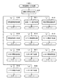
(パチンコ遊技機1の構成等)
図1は、パチンコ遊技機1の正面図であり、主要部材の配置レイアウトを示す。パチンコ遊技機(遊技機)1は、大別して、遊技盤面を構成する遊技盤(ゲージ盤)2と、遊技盤2を支持固定する遊技機用枠(台枠)3とから構成されている。遊技盤2には、遊技領域が形成され、この遊技領域には、遊技媒体としての遊技球が、所定の打球発射装置から発射されて打ち込まれる。
(Structure of
FIG. 1 is a front view of the
遊技盤2の所定位置(図1に示す例では、遊技領域の右側方)には、複数種類の特別識別情報としての特別図柄(特図ともいう)の可変表示(特図ゲームともいう)を行う第1特別図柄表示装置4A及び第2特別図柄表示装置4Bが設けられている。これらは、それぞれ、7セグメントのLEDなどからなる。特別図柄は、「0」〜「9」を示す数字や「−」などの点灯パターンなどにより表される。特別図柄には、LEDを全て消灯したパターンが含まれてもよい。
At a predetermined position of the game board 2 (in the example shown in FIG. 1, on the right side of the game area), a variable display (also called a special figure game) of a special symbol (also called a special figure) as a plurality of kinds of special identification information is provided. A first special
なお、特別図柄の「可変表示」とは、例えば、複数種類の特別図柄を変動可能に表示することである(後述の他の図柄についても同じ)。変動としては、複数の図柄の更新表示、複数の図柄のスクロール表示、1以上の図柄の変形、1以上の図柄の拡大/縮小などがある。特別図柄や後述の普通図柄の変動では、複数種類の特別図柄又は普通図柄が更新表示される。後述の飾り図柄の変動では、複数種類の飾り図柄がスクロール表示又は更新表示されたり、1以上の飾り図柄が変形や拡大/縮小されたりする。なお、変動には、ある図柄を点滅表示する態様も含まれる。可変表示の最後には、表示結果として所定の特別図柄が停止表示(導出又は導出表示などともいう)される(後述の他の図柄の可変表示についても同じ)。なお、可変表示を変動表示、変動と表現する場合がある。 The “variable display” of a special symbol means, for example, that a plurality of types of special symbols are displayed so as to be variable (the same applies to other symbols described later). The fluctuation includes update display of a plurality of symbols, scroll display of a plurality of symbols, deformation of one or more symbols, enlargement / reduction of one or more symbols, and the like. In the case of the change of the special symbol or the ordinary symbol described later, a plurality of types of special symbols or ordinary symbols are updated and displayed. In the variation of the decorative symbols described later, a plurality of types of decorative symbols are scrolled or updated, and one or more decorative symbols are deformed or enlarged / reduced. Note that the variation includes a mode in which a certain symbol is blinked. At the end of the variable display, a predetermined special symbol is stopped (also referred to as derived or derived display) as a display result (the same applies to the variable display of other symbols described later). Note that the variable display may be referred to as a variable display or a variable display.
なお、第1特別図柄表示装置4Aにおいて可変表示される特別図柄を「第1特図」ともいい、第2特別図柄表示装置4Bにおいて可変表示される特別図柄を「第2特図」ともいう。また、第1特図を用いた特図ゲームを「第1特図ゲーム」といい、第2特図を用いた特図ゲームを「第2特図ゲーム」ともいう。なお、特別図柄の可変表示を行う特別図柄表示装置は1種類であってもよい。
The special symbol variably displayed on the first special
遊技盤2における遊技領域の中央付近には画像表示装置5が設けられている。画像表示装置5は、例えばLCD(液晶表示装置)や有機EL(Electro Luminescence)等から構成され、各種の演出画像を表示する。画像表示装置5は、プロジェクタ及びスクリーンから構成されていてもよい。画像表示装置5には、各種の演出画像が表示される。
An
例えば、画像表示装置5の画面上では、第1特図ゲームや第2特図ゲームと同期して、特別図柄とは異なる複数種類の装飾識別情報としての飾り図柄(数字などを示す図柄など)の可変表示が行われる。ここでは、第1特図ゲーム又は第2特図ゲームに同期して、「左」、「中」、「右」の各飾り図柄表示エリア5L、5C、5Rにおいて飾り図柄が可変表示(例えば上下方向のスクロール表示や更新表示)される。なお、同期して実行される特図ゲーム及び飾り図柄の可変表示を総称して単に可変表示ともいう。
For example, on the screen of the
画像表示装置5の画面上には、実行が保留されている可変表示に対応する保留表示や、実行中の可変表示に対応するアクティブ表示を表示するための表示エリアが設けられていてもよい。保留表示及びアクティブ表示を総称して可変表示に対応する可変表示対応表示ともいう。
On the screen of the
保留されている可変表示の数は保留記憶数ともいう。第1特図ゲームに対応する保留記憶数を第1保留記憶数、第2特図ゲームに対応する保留記憶数を第2保留記憶数ともいう。また、第1保留記憶数と第2保留記憶数との合計を合計保留記憶数ともいう。 The number of variable displays suspended is also referred to as the number of suspended storages. The number of reserved storages corresponding to the first special figure game is also referred to as a first reserved storage number, and the number of reserved storages corresponding to the second special figure game is also referred to as a second reserved storage number. In addition, the sum of the first reserved storage number and the second reserved storage number is also referred to as a total reserved storage number.
また、遊技盤2の所定位置には、複数のLEDを含んで構成された第1保留表示器25Aと第2保留表示器25Bとが設けられ、第1保留表示器25Aは、LEDの点灯個数によって、第1保留記憶数を表示し、第2保留表示器25Bは、LEDの点灯個数によって、第2保留記憶数を表示する。
At a predetermined position of the
画像表示装置5の下方には、入賞球装置6Aと、可変入賞球装置6Bとが設けられている。
Below the
入賞球装置6Aは、例えば所定の玉受部材によって常に遊技球が進入可能な一定の開放状態に保たれる第1始動入賞口を形成する。第1始動入賞口に遊技球が進入したときには、所定個(例えば3個)の賞球が払い出されるとともに、第1特図ゲームが開始され得る。
The winning
可変入賞球装置6B(普通電動役物)は、ソレノイド81(図2参照)によって閉鎖状態と開放状態とに変化する第2始動入賞口を形成する。可変入賞球装置6Bは、例えば、一対の可動翼片を有する電動チューリップ型役物を備え、ソレノイド81がオフ状態であるときに可動翼片が垂直位置となることにより、当該可動翼片の先端が入賞球装置6Aに近接し、第2始動入賞口に遊技球が進入しない閉鎖状態になる(第2始動入賞口が閉鎖状態になるともいう。)。その一方で、可変入賞球装置6Bは、ソレノイド81がオン状態であるときに可動翼片が傾動位置となることにより、第2始動入賞口に遊技球が進入できる開放状態になる(第2始動入賞口が開放状態になるともいう。)。第2始動入賞口に遊技球が進入したときには、所定個(例えば3個)の賞球が払い出されるとともに、第2特図ゲームが開始され得る。なお、可変入賞球装置6Bは、閉鎖状態と開放状態とに変化するものであればよく、電動チューリップ型役物を備えるものに限定されない。
The variable
遊技盤2の所定位置(図1に示す例では、遊技領域の左右下方4箇所)には、所定の玉受部材によって常に一定の開放状態に保たれる一般入賞口10が設けられる。この場合には、一般入賞口10のいずれかに進入したときには、所定個数(例えば10個)の遊技球が賞球として払い出される。
At a predetermined position of the game board 2 (in the example shown in FIG. 1, four lower left and right sides of the game area), a general winning
入賞球装置6Aと可変入賞球装置6Bの下方には、大入賞口を有する特別可変入賞球装置7が設けられている。特別可変入賞球装置7は、ソレノイド82(図2参照)によって開閉駆動される大入賞口扉を備え、その大入賞口扉によって開放状態と閉鎖状態とに変化する特定領域としての大入賞口を形成する。
Below the winning
一例として、特別可変入賞球装置7では、大入賞口扉用(特別電動役物用)のソレノイド82がオフ状態であるときに大入賞口扉が大入賞口を閉鎖状態として、遊技球が大入賞口に進入(通過)できなくなる。その一方で、特別可変入賞球装置7では、大入賞口扉用のソレノイド82がオン状態であるときに大入賞口扉が大入賞口を開放状態として、遊技球が大入賞口に進入しやすくなる。
As an example, in the special variable winning
大入賞口に遊技球が進入したときには、所定個数(例えば14個)の遊技球が賞球として払い出される。大入賞口に遊技球が進入したときには、例えば第1始動入賞口や第2始動入賞口及び一般入賞口10に遊技球が進入したときよりも多くの賞球が払い出される。
When game balls enter the special winning opening, a predetermined number (for example, 14) of game balls are paid out as prize balls. When the game ball enters the large winning opening, more prize balls are paid out than when the game ball enters the first starting winning opening, the second starting winning opening, and the general winning
一般入賞口10を含む各入賞口に遊技球が進入することを「入賞」ともいう。特に、始動口(第1始動入賞口、第2始動入賞口始動口)への入賞を始動入賞ともいう。
A game ball entering each winning port including the general winning
遊技盤2の所定位置(図1に示す例では、遊技領域の左側方)には、普通図柄表示器20が設けられている。一例として、普通図柄表示器20は、7セグメントのLEDなどからなり、特別図柄とは異なる複数種類の普通識別情報としての普通図柄の可変表示を行う。普通図柄は、「0」〜「9」を示す数字や「−」などの点灯パターンなどにより表される。普通図柄には、LEDを全て消灯したパターンが含まれてもよい。このような普通図柄の可変表示は、普図ゲームともいう。
At a predetermined position of the game board 2 (in the example shown in FIG. 1, on the left side of the game area), a
画像表示装置5の左方には、遊技球が通過可能な通過ゲート41が設けられている。遊技球が通過ゲート41を通過したことに基づき、普図ゲームが実行される。
On the left side of the
普通図柄表示器20の上方には、普図保留表示器25Cが設けられている。普図保留表示器25Cは、例えば4個のLEDを含んで構成され、実行が保留されている普図ゲームの数である普図保留記憶数をLEDの点灯個数により表示する。
Above the
遊技盤2の表面には、上記の構成以外にも、遊技球の流下方向や速度を変化させる風車及び多数の障害釘が設けられている。遊技領域の最下方には、いずれの入賞口にも進入しなかった遊技球が取り込まれるアウト口が設けられている。
On the surface of the
遊技機用枠3の左右上部位置には、効果音等を再生出力するためのスピーカ8L、8Rが設けられており、さらに遊技領域周辺部には、遊技効果用の遊技効果ランプ9が設けられている。遊技効果ランプ9は、LEDを含んで構成されている。
遊技盤2の所定位置(図1では図示略)には、演出に応じて動作する可動体32が設けられている。
At a predetermined position (not shown in FIG. 1) of the
遊技機用枠3の右下部位置には、遊技球を打球発射装置により遊技領域に向けて発射するために遊技者等によって操作される打球操作ハンドル(操作ノブ)30が設けられている。
At the lower right position of the
遊技領域の下方における遊技機用枠3の所定位置には、賞球として払い出された遊技球や所定の球貸機により貸し出された遊技球を、打球発射装置へと供給可能に保持(貯留)する打球供給皿(上皿)が設けられている。上皿の下方には、上皿満タン時に賞球が払い出される打球供給皿(下皿)が設けられている。
At a predetermined position of the
遊技領域の下方における遊技機用枠3の所定位置には、遊技者が把持して傾倒操作が可能なスティックコントローラ31Aが取り付けられている。スティックコントローラ31Aには、遊技者が押下操作可能なトリガボタンが設けられている。スティックコントローラ31Aに対する操作は、コントローラセンサユニット35A(図2参照)により検出される。
At a predetermined position of the
遊技領域の下方における遊技機用枠3の所定位置には、遊技者が押下操作などにより所定の指示操作を可能なプッシュボタン31Bが設けられている。プッシュボタン31Bに対する操作は、プッシュセンサ35B(図2参照)により検出される。
At a predetermined position of the
パチンコ遊技機1では、遊技者の動作(操作等)を検出する検出手段として、スティックコントローラ31Aやプッシュボタン31Bが設けられるが、これら以外の検出手段が設けられていてもよい。
In the
(遊技の進行の概略)
パチンコ遊技機1が備える打球操作ハンドル30への遊技者による回転操作により、遊技球が遊技領域に向けて発射される。遊技球が通過ゲート41を通過すると、普通図柄表示器20による普図ゲームが開始される。なお、前回の普図ゲームの実行中の期間等に遊技球が通過ゲート41を通過した場合(遊技球が通過ゲート41を通過したが当該通過に基づく普図ゲームを直ちに実行できない場合)には、当該通過に基づく普図ゲームは所定の上限数(例えば4)まで保留される。
(Outline of the progress of the game)
A game ball is fired toward a game area by a rotation operation by a player on a hit ball operation handle 30 provided in the
この普図ゲームでは、特定の普通図柄(普図当り図柄)が停止表示されれば、普通図柄の表示結果が「普図当り」となる。その一方、確定普通図柄として、普図当り図柄以外の普通図柄(普図ハズレ図柄)が停止表示されれば、普通図柄の表示結果が「普図ハズレ」となる。「普図当り」となると、可変入賞球装置6Bを所定期間開放状態とする開放制御が行われる(第2始動入賞口が開放状態になる)。
In this ordinary symbol game, if a specific ordinary symbol (a symbol per ordinary symbol) is stopped and displayed, the display result of the ordinary symbol becomes "a symbol per ordinary symbol". On the other hand, if a normal symbol (regular symbol lost symbol) other than the symbol per regular symbol is stopped and displayed as the fixed ordinary symbol, the display result of the ordinary symbol is “regular symbol lost”. When "per day" is reached, an opening control is performed to open the variable winning
入賞球装置6Aに形成された第1始動入賞口に遊技球が進入すると、第1特別図柄表示装置4Aによる第1特図ゲームが開始される。
When the game ball enters the first starting winning opening formed in the winning
可変入賞球装置6Bに形成された第2始動入賞口に遊技球が進入すると、第2特別図柄表示装置4Bによる第2特図ゲームが開始される。
When the game ball enters the second starting winning opening formed in the variable winning
なお、特図ゲームの実行中の期間や、後述する大当り遊技状態や小当り遊技状態に制御されている期間に、遊技球が始動入賞口へ進入(入賞)した場合(始動入賞が発生したが当該始動入賞に基づく特図ゲームを直ちに実行できない場合)には、当該進入に基づく特図ゲームは所定の上限数(例えば4)までその実行が保留される。 Note that, when the game ball enters (wins) the starting winning opening during a period during which the special figure game is being executed, or during a period in which the game is controlled to the big hitting game state or the small hitting game state, which will be described later. When the special figure game based on the start winning prize cannot be immediately executed), the execution of the special figure game based on the entry is suspended up to a predetermined upper limit number (for example, 4).
特図ゲームにおいて、確定特別図柄として特定の特別図柄(大当り図柄、例えば「7」、後述の大当り種別に応じて実際の図柄は異なる。)が停止表示されれば、「大当り」となり、大当り図柄とは異なる所定の特別図柄(小当り図柄、例えば「2」)が停止表示されれば、「小当り」となる。また、大当り図柄や小当り図柄とは異なる特別図柄(ハズレ図柄、例えば「−」)が停止表示されれば「ハズレ」となる。 In the special figure game, if a specific special symbol (big hit symbol, for example, “7”, an actual symbol is different depending on the type of big hit described later) is stopped and displayed as the fixed special symbol, the big hit symbol is obtained. If a predetermined special symbol (small hit symbol, for example, “2”) different from the above is stopped and displayed, “small hit” is obtained. If a special symbol (losing symbol, for example, “−”) different from the big hit symbol or the small hit symbol is stopped and displayed, “losing” is obtained.
特図ゲームでの表示結果が「大当り」になった後には、遊技者にとって有利な有利状態として大当り遊技状態に制御される。特図ゲームでの表示結果が「小当り」になった後には、小当り遊技状態に制御される。 After the display result in the special figure game becomes “big hit”, the big hit gaming state is controlled as an advantageous state advantageous to the player. After the display result in the special figure game becomes “small hit”, the state is controlled to the small hit game state.
大当り遊技状態では、特別可変入賞球装置7により形成される大入賞口が所定の態様で開放状態となる。当該開放状態は、所定期間(例えば29秒間や1.8秒間)の経過タイミングと、大入賞口に進入した遊技球の数が所定個数(例えば9個)に達するまでのタイミングと、のうちのいずれか早いタイミングまで継続される。前記所定期間は、1ラウンドにおいて大入賞口を開放することができる上限期間であり、以下、開放上限期間ともいう。このように大入賞口が開放状態となる1のサイクルをラウンド(ラウンド遊技)という。大当り遊技状態では、当該ラウンドが所定の上限回数(15回や2回)に達するまで繰り返し実行可能となっている。
In the big hit gaming state, the special winning opening formed by the special variable winning
大当り遊技状態においては、遊技者は、遊技球を大入賞口に進入させることで、賞球を得ることができる。従って、大当り遊技状態は、遊技者にとって有利な状態である。大当り遊技状態におけるラウンド数が多い程、また、開放上限期間が長い程遊技者にとって有利となる。 In the big hit game state, the player can obtain a prize ball by causing the game ball to enter the big winning opening. Therefore, the big hit gaming state is an advantageous state for the player. The greater the number of rounds in the jackpot gaming state and the longer the open upper limit period, the more advantageous to the player.
なお、「大当り」には、大当り種別が設定されている。例えば、大入賞口の開放態様(ラウンド数や開放上限期間)や、大当り遊技状態後の遊技状態(後述の、通常状態、時短状態、確変状態など)を複数種類用意し、これらに応じて大当り種別が設定されている。大当り種別として、多くの賞球を得ることができる大当り種別や、賞球の少ない又はほとんど賞球を得ることができない大当り種別が設けられていてもよい。 Note that the "big hit" is set with a big hit type. For example, a plurality of types of opening modes of the special winning opening (the number of rounds and the upper limit period of opening) and a game state after the big hit game state (a normal state, a time saving state, a probable change state, etc., which will be described later) are prepared. The type has been set. As the big hit type, a big hit type where many prize balls can be obtained or a big hit type where few or almost no prize balls can be obtained may be provided.
小当り遊技状態では、特別可変入賞球装置7により形成される大入賞口が所定の開放態様で開放状態となる。例えば、小当り遊技状態では、一部の大当り種別のときの大当り遊技状態と同様の開放態様(大入賞口の開放回数が上記ラウンド数と同じであり、かつ、大入賞口の閉鎖タイミングも同じ等)で大入賞口が開放状態となる。なお、大当り種別と同様に、「小当り」にも小当り種別を設けてもよい。
In the small hitting game state, the special winning opening formed by the special variable winning
大当り遊技状態が終了した後は、上記大当り種別に応じて、時短状態や確変状態に制御されることがある。 After the big hit game state is ended, the time may be controlled to a time saving state or a certain change state depending on the big hit type.
時短状態では、平均的な特図変動時間(特図を変動させる期間)を通常状態よりも短縮させる制御(時短制御)が実行される。時短状態では、平均的な普図変動時間(普図を変動させる期間)を通常状態よりも短縮させたり、普図ゲームで「普図当り」となる確率を通常状態よりも向上させる等により、第2始動入賞口に遊技球が進入しやすくなる制御(高開放制御、高ベース制御)も実行される。時短状態は、特別図柄(特に第2特別図柄)の変動効率が向上する状態であるので、遊技者にとって有利な状態である。 In the time saving state, control (time saving control) for shortening the average special figure fluctuation time (the period during which the special figure is fluctuated) is performed as compared with the normal state. In the time-saving state, the average time of fluctuating fluctuating time (period of fluctuating fluctuating figure) is shortened compared to the normal state, and the probability of "per-figure hit" in the frug drawing game is improved than in the normal state. Controls (high opening control, high base control) that allow the game balls to easily enter the second start winning opening are also executed. The time saving state is a state in which the fluctuation efficiency of the special symbol (especially the second special symbol) is improved, and is therefore an advantageous state for the player.
確変状態(確率変動状態)では、時短制御に加えて、表示結果が「大当り」となる確率が通常状態よりも高くなる確変制御が実行される。確変状態は、特別図柄の変動効率が向上することに加えて「大当り」となりやすい状態であるので、遊技者にとってさらに有利な状態である。 In the probability variation state (probability variation state), in addition to the time saving control, the probability variation control in which the probability that the display result is “big hit” is higher than that in the normal state is executed. The probable change state is a state that is more advantageous to the player because the change efficiency of the special symbol is improved and the state is likely to be a “big hit”.
時短状態や確変状態は、所定回数の特図ゲームが実行されたことと、次回の大当り遊技状態が開始されたこと等といった、いずれか1つの終了条件が先に成立するまで継続する。所定回数の特図ゲームが実行されたことが終了条件となるものを、回数切り(回数切り時短、回数切り確変等)ともいう。 The time saving state and the probable change state continue until one of the end conditions such as the execution of the predetermined number of special figure games and the start of the next big hit game state is satisfied first. The condition that the execution of the special figure game a predetermined number of times is an end condition is also referred to as a number cut (number cut time reduction, number cut probability change, etc.).
通常状態とは、遊技者にとって有利な大当り遊技状態等の有利状態、時短状態、確変状態等の特別状態以外の遊技状態のことであり、普図ゲームにおける表示結果が「普図当り」となる確率及び特図ゲームにおける表示結果が「大当り」となる確率などのパチンコ遊技機1が、パチンコ遊技機1の初期設定状態(例えばシステムリセットが行われた場合のように、電源投入後に所定の復帰処理を実行しなかったとき)と同一に制御される状態である。
The normal state is a game state other than a special state such as a jackpot game state that is advantageous to the player, a time-saving state, a probable change state, or the like. The
確変制御が実行されている状態を高確状態、確変制御が実行されていない状態を低確状態ともいう。時短制御が実行されている状態を高ベース状態、時短制御が実行されていない状態を低ベース状態ともいう。これらを組み合わせて、時短状態は低確高ベース状態、確変状態は高確高ベース状態、通常状態は低確低ベース状態などともいわれる。高確状態かつ低ベース状態は高確低ベース状態ともいう。 The state in which the probable change control is being executed is also referred to as a high-probability state, and the state in which the probable change control is not being executed is referred to as a low-probability state. The state in which the time-saving control is executed is also called a high base state, and the state in which the time-saving control is not executed is called a low base state. By combining these, the time-saving state is also called a low-probability high-base state, the probable change state is a high-precision high-base state, and the normal state is also a low-probability low-base state. The high-accuracy low-base state is also referred to as a high-accuracy low-base state.
小当り遊技状態が終了した後は、遊技状態の変更が行われず、特図ゲームの表示結果が「小当り」となる以前の遊技状態に継続して制御される(但し、「小当り」発生時の特図ゲームが、上記回数切りにおける上記所定回数目の特図ゲームである場合には、当然遊技状態が変更される)。なお、特図ゲームの表示結果として「小当り」がなくてもよい。 After the small hitting game state ends, the game state is not changed, and the control is continued to the game state before the display result of the special figure game becomes "small hit" (however, "small hit" occurs If the special figure game at that time is the special figure game of the predetermined number of times in the above number cut, the game state is naturally changed). Note that the display result of the special figure game does not have to have “small hit”.
なお、遊技状態は、大当り遊技状態中に遊技球が特定領域(例えば、大入賞口内の特定領域)を通過したことに基づいて、変化してもよい。例えば、遊技球が特定領域を通過したとき、その大当り遊技状態後に確変状態に制御してもよい。 Note that the gaming state may change based on the fact that the game ball has passed a specific area (for example, a specific area within a special winning opening) during the big hit gaming state. For example, when a game ball passes through a specific area, it may be controlled to be in a positively changed state after the big hit game state.
(演出の進行など)
パチンコ遊技機1では、遊技の進行に応じて種々の演出(遊技の進行状況を報知したり、遊技を盛り上げたりする演出)が実行される。当該演出について以下説明する。なお、当該演出は、画像表示装置5に各種の演出画像を表示することによって行われるが、当該表示に加えて又は代えて、スピーカ8L、8Rからの音声出力、及び/又は、遊技効果ランプ9の点等/消灯、可動体32の動作等により行われてもよい。
(Progress of production etc.)
In the
遊技の進行に応じて実行される演出として、画像表示装置5に設けられた「左」、「中」、「右」の飾り図柄表示エリア5L、5C、5Rでは、第1特図ゲーム又は第2特図ゲームが開始されることに対応して、飾り図柄の可変表示が開始される。第1特図ゲームや第2特図ゲームにおいて表示結果(確定特別図柄ともいう。)が停止表示されるタイミングでは、飾り図柄の可変表示の表示結果となる確定飾り図柄(3つの飾り図柄の組合せ)も停止表示(導出)される。
In the “left”, “middle”, “right” decorative
飾り図柄の可変表示が開始されてから終了するまでの期間では、飾り図柄の可変表示の態様が所定のリーチ態様となる(リーチが成立する)ことがある。ここで、リーチ態様とは、画像表示装置5の画面上にて停止表示された飾り図柄が後述の大当り組合せの一部を構成しているときに未だ停止表示されていない飾り図柄については可変表示が継続している態様などのことである。
During the period from the start of the variable display of the decorative symbol to the end thereof, the mode of the variable display of the decorative symbol may be a predetermined reach mode (reach is established). Here, the reach mode is a variable display for a decorative symbol that has not been stopped and displayed when the decorative symbol stopped and displayed on the screen of the
また、飾り図柄の可変表示中に上記リーチ態様となったことに対応してリーチ演出が実行される。パチンコ遊技機1では、演出態様に応じて表示結果(特図ゲームの表示結果や飾り図柄の可変表示の表示結果)が「大当り」となる割合(大当り信頼度、大当り期待度とも呼ばれる。)が異なる複数種類のリーチ演出が実行される。リーチ演出には、例えば、ノーマルリーチと、ノーマルリーチよりも大当り信頼度の高いスーパーリーチと、がある。
In addition, a reach effect is executed in response to the reach mode during the variable display of the decorative symbol. In the
特図ゲームの表示結果が「大当り」となるときには、画像表示装置5の画面上において、飾り図柄の可変表示の表示結果として、予め定められた大当り組合せとなる確定飾り図柄が導出される(飾り図柄の可変表示の表示結果が「大当り」となる)。一例として、「左」、「中」、「右」の飾り図柄表示エリア5L、5C、5Rにおける所定の有効ライン上に同一の飾り図柄(例えば、「7」等)が揃って停止表示される。
When the display result of the special figure game is “big hit”, a fixed decoration pattern which is a predetermined big hit combination is derived as a display result of the variable display of the decoration pattern on the screen of the image display device 5 (decoration). The display result of the variable display of the symbol is "big hit"). As an example, the same decorative symbol (for example, “7”) is stopped and displayed on predetermined effective lines in the “left”, “middle”, and “right” decorative
大当り遊技状態の終了後に確変状態に制御される「確変大当り」である場合には、奇数の飾り図柄(例えば、「7」等)が揃って停止表示され、大当り遊技状態の終了後に確変状態に制御されない「非確変大当り(通常大当り)」である場合には、偶数の飾り図柄(例えば、「6」等)が揃って停止表示されるようにしてもよい。この場合、奇数の飾り図柄を確変図柄、偶数の飾り図柄を非確変図柄(通常図柄)ともいう。非確変図柄でリーチ態様となった後に、最終的に「確変大当り」となる昇格演出を実行するようにしてもよい。 In the case of "probable change big hit" which is controlled to the probable change state after the end of the big hit game state, an odd number of decorative symbols (for example, "7" etc.) are stopped and displayed together, and after the big hit game state is ended, the probable change state is set. In the case of a non-probable variable jackpot (normal jackpot) that is not controlled, an even number of decorative symbols (for example, “6”) may be stopped and displayed together. In this case, the odd-numbered decorative symbols are also referred to as positive variation symbols, and the even-numbered decorative symbols are also referred to as non-positive variable symbols (normal symbols). After the non-probable design has reached the reach mode, a promotion effect that eventually becomes a “probable change” may be executed.
特図ゲームの表示結果が「小当り」となるときには、画像表示装置5の画面上において、飾り図柄の可変表示の表示結果として、予め定められた小当り組合せとなる確定飾り図柄(例えば、「1 3 5」等)が導出される(飾り図柄の可変表示の表示結果が「小当り」となる)。一例として、「左」、「中」、「右」の飾り図柄表示エリア5L、5C、5Rにおける所定の有効ライン上にチャンス目を構成する飾り図柄が停止表示される。なお、特図ゲームの表示結果が、一部の大当り種別(小当り遊技状態と同様の態様の大当り遊技状態の大当り種別)の「大当り」となるときと、「小当り」となるときとで、共通の確定飾り図柄が導出表示されてもよい。
When the display result of the special figure game is “small hit”, as a display result of the variable display of the decorative symbol on the screen of the
特図ゲームの表示結果が「ハズレ」となる場合には、飾り図柄の可変表示の態様がリーチ態様とならずに、飾り図柄の可変表示の表示結果として、非リーチ組合せの確定飾り図柄(「非リーチハズレ」ともいう。)が停止表示される(飾り図柄の可変表示の表示結果が「非リーチハズレ」となる)ことがある。また、表示結果が「ハズレ」となる場合には、飾り図柄の可変表示の態様がリーチ態様となった後に、飾り図柄の可変表示の表示結果として、大当り組合せでない所定のリーチ組合せ(「リーチハズレ」ともいう)の確定飾り図柄が停止表示される(飾り図柄の可変表示の表示結果が「リーチハズレ」となる)こともある。 When the display result of the special figure game is “losing”, the decorative display variable display mode does not become the reach mode, and the non-reach combination fixed decorative pattern (“ (Also referred to as “non-reach loss”) may be stopped and displayed (the display result of the variable display of the decorative pattern is “non-reach loss”). Further, when the display result is “losing”, after the decorative design variable display mode becomes the reach mode, a predetermined reach combination other than the jackpot combination (“reach loss”) is displayed as the decorative symbol variable display display result. ) May be stopped (the display result of the variable display of the decorative symbol is "reach loss").
パチンコ遊技機1が実行可能な演出には、上記の可変表示対応表示(保留表示やアクティブ表示)を表示することも含まれる。また、他の演出として、例えば、大当り信頼度を予告する予告演出等が飾り図柄の可変表示中に実行される。予告演出には、実行中の可変表示における大当り信頼度を予告する予告演出や、実行前の可変表示(実行が保留されている可変表示)における大当り信頼度を予告する先読み予告演出がある。先読み予告演出として、可変表示対応表示(保留表示やアクティブ表示)の表示態様を通常とは異なる態様に変化させる演出が実行されるようにしてもよい。
The effects that can be executed by the
また、画像表示装置5において、飾り図柄の可変表示中に飾り図柄を一旦仮停止させた後に可変表示を再開させることで、1回の可変表示を擬似的に複数回の可変表示のように見せる擬似連演出を実行するようにしてもよい。
Also, in the
大当り遊技状態中にも、大当り遊技状態を報知する大当り中演出が実行される。大当り中演出としては、ラウンド数を報知する演出や、大当り遊技状態の価値が向上することを示す昇格演出が実行されてもよい。また、小当り遊技状態中にも、小当り遊技状態を報知する小当り中演出が実行される。なお、小当り遊技状態中と、一部の大当り種別(小当り遊技状態と同様の態様の大当り遊技状態の大当り種別で、例えばその後の遊技状態を高確状態とする大当り種別)での大当り遊技状態とで、共通の演出を実行することで、現在が小当り遊技状態中であるか、大当り遊技状態中であるかを遊技者に分からないようにしてもよい。そのような場合であれば、小当り遊技状態の終了後と大当り遊技状態の終了後とで共通の演出を実行することで、高確状態であるか低確状態であるかを識別できないようにしてもよい。 During the big hit game state, a big hit effect is performed to notify the big hit game state. As the large hit production, a production that notifies the number of rounds or a promotion production that indicates that the value of the big hit game state is improved may be executed. In addition, during the small hitting game state, a small hitting effect for notifying the small hitting game state is executed. In addition, the big hit game in the small hit game state and in some big hit types (a big hit type of the big hit game state in the same mode as the small hit game state, for example, a big hit type in which the subsequent game state is a high accuracy state) By executing a common effect in the state and the state, the player may not be able to know whether the current state is the small hitting game state or the big hitting game state. In such a case, by executing a common effect after the end of the small hitting game state and after the end of the big hitting gaming state, it is possible to make it impossible to distinguish between the high-accuracy state and the low-accuracy state. You may.
また、例えば特図ゲーム等が実行されていないときには、画像表示装置5にデモ(デモンストレーション)画像が表示される(客待ちデモ演出が実行される)。 Further, for example, when a special map game or the like is not being executed, a demonstration (demonstration) image is displayed on the image display device 5 (a customer waiting demonstration effect is executed).
(基板構成)
パチンコ遊技機1には、例えば図2に示すような主基板11、演出制御基板12、音声制御基板13、ランプ制御基板14、中継基板15などが搭載されている。その他にも、パチンコ遊技機1の背面には、例えば払出制御基板、情報端子基板、発射制御基板、電源基板などといった、各種の基板が配置されている。
(Board configuration)
In the
主基板11は、メイン側の制御基板であり、パチンコ遊技機1における上記遊技の進行(特図ゲームの実行(保留の管理を含む)、普図ゲームの実行(保留の管理を含む)、大当り遊技状態、小当り遊技状態、遊技状態など)を制御する機能を有する。主基板11は、遊技制御用マイクロコンピュータ100、スイッチ回路110、ソレノイド回路111などを有する。
The
主基板11に搭載された遊技制御用マイクロコンピュータ100は、例えば1チップのマイクロコンピュータであり、ROM(Read Only Memory)101と、RAM(Random Access Memory)102と、CPU(Central Processing Unit)103と、乱数回路104と、I/O(Input/Output port)105とを備える。
The
CPU103は、ROM101に記憶されたプログラムを実行することにより、遊技の進行を制御する処理(主基板11の機能を実現する処理)を行う。このとき、ROM101が記憶する各種データ(後述の変動パターン、後述の演出制御コマンド、後述の各種決定を行う際に参照される各種テーブルなどのデータ)が用いられ、RAM102がメインメモリとして使用される。RAM102は、その一部または全部がパチンコ遊技機1に対する電力供給が停止しても、所定期間記憶内容が保存されるバックアップRAMとなっている。なお、ROM101に記憶されたプログラムの全部又は一部をRAM102に展開して、RAM102上で実行するようにしてもよい。
The
乱数回路104は、遊技の進行を制御するときに使用される各種の乱数値(遊技用乱数)を示す数値データを更新可能にカウントする。遊技用乱数は、CPU103が所定のコンピュータプログラムを実行することで更新されるもの(ソフトウェアで更新されるもの)であってもよい。
The
I/O105は、例えば各種信号(後述の検出信号)が入力される入力ポートと、各種信号(第1特別図柄表示装置4A、第2特別図柄表示装置4B、普通図柄表示器20、第1保留表示器25A、第2保留表示器25B、普図保留表示器25Cなどを制御(駆動)する信号、ソレノイド駆動信号)を伝送するための出力ポートとを含んで構成される。
The I /
スイッチ回路110は、遊技球検出用の各種スイッチ(ゲートスイッチ21、始動口スイッチ(第1始動口スイッチ22Aおよび第2始動口スイッチ22B)、カウントスイッチ23)からの検出信号(遊技球が通過又は進入してスイッチがオンになったことを示す検出信号など)を取り込んで遊技制御用マイクロコンピュータ100に伝送する。検出信号の伝送により、遊技球の通過又は進入が検出されたことになる。
The
ソレノイド回路111は、遊技制御用マイクロコンピュータ100からのソレノイド駆動信号(例えば、ソレノイド81やソレノイド82をオンする信号など)を、普通電動役物用のソレノイド81や大入賞口扉用のソレノイド82に伝送する。
The
主基板11(遊技制御用マイクロコンピュータ100)は、遊技の進行の制御の一部として、遊技の進行に応じて演出制御コマンド(遊技の進行状況等を指定(通知)するコマンド)を演出制御基板12に供給する。主基板11から出力された演出制御コマンドは、中継基板15により中継され、演出制御基板12に供給される。当該演出制御コマンドには、例えば主基板11における各種の決定結果(例えば、特図ゲームの表示結果(大当り種別を含む。)、特図ゲームを実行する際に使用される変動パターン(詳しくは後述))、遊技の状況(例えば、可変表示の開始や終了、大入賞口の開放状況、入賞の発生、保留記憶数、遊技状態)、エラーの発生等を指定するコマンド等が含まれる。
The main board 11 (game control microcomputer 100), as a part of the control of the progress of the game, the effect control command (command for designating (notifying) the progress of the game, etc.) according to the progress of the game. 12 The effect control command output from the
演出制御基板12は、主基板11とは独立したサブ側の制御基板であり、演出制御コマンドを受信し、受信した演出制御コマンドに基づいて演出(遊技の進行に応じた種々の演出であり、可動体32の駆動、エラー報知、電断復旧の報知等の各種報知を含む)を実行する機能を有する。
The
演出制御基板12には、演出制御用CPU120と、ROM121と、RAM122と、表示制御部123と、乱数回路124と、I/O125とが搭載されている。
The
演出制御用CPU120は、ROM121に記憶されたプログラムを実行することにより、表示制御部123とともに演出を実行するための処理(演出制御基板12の上記機能を実現するための処理であり、実行する演出の決定等を含む)を行う。このとき、ROM121が記憶する各種データ(各種テーブルなどのデータ)が用いられ、RAM122がメインメモリとして使用される。
The
演出制御用CPU120は、コントローラセンサユニット35Aやプッシュセンサ35Bからの検出信号(遊技者による操作を検出したときに出力される信号であり、操作内容を適宜示す信号)に基づいて演出の実行を表示制御部123に指示することもある。
The
表示制御部123は、VDP(Video Display Processor)、CGROM(Character Generator ROM)、VRAM(Video RAM)などを備え、演出制御用CPU120からの演出の実行指示に基づき、演出を実行する。
The
表示制御部123は、演出制御用CPU120からの演出の実行指示に基づき、実行する演出に応じた映像信号を画像表示装置5に供給することで、演出画像を画像表示装置5に表示させる。表示制御部123は、さらに、演出画像の表示に同期した音声出力や、遊技効果ランプ9の点灯/消灯を行うため、音指定信号(出力する音声を指定する信号)を音声制御基板13に供給したり、ランプ信号(ランプの点灯/消灯態様を指定する信号)をランプ制御基板14に供給したりする。また、表示制御部123は、可動体32を動作させる信号を当該可動体32又は当該可動体32を駆動する駆動回路に供給する。
The
音声制御基板13は、スピーカ8L、8Rを駆動する各種回路を搭載しており、当該音指定信号に基づきスピーカ8L、8Rを駆動し、当該音指定信号が指定する音声をスピーカ8L、8Rから出力させる。
The
ランプ制御基板14は、遊技効果ランプ9を駆動する各種回路を搭載しており、当該ランプ信号に基づき遊技効果ランプ9を駆動し、当該ランプ信号が指定する態様で遊技効果ランプ9を点灯/消灯する。このようにして、表示制御部123は、音声出力、ランプの点灯/消灯を制御する。
The
なお、音声出力、ランプの点灯/消灯の制御(音指定信号やランプ信号の供給等)、可動体32の制御(可動体32を動作させる信号の供給等)は、演出制御用CPU120が実行するようにしてもよい。
The sound output, control of turning on / off the lamp (supply of a sound designation signal or a lamp signal, etc.), and control of the movable body 32 (supply of a signal for operating the
乱数回路124は、各種演出を実行するために使用される各種の乱数値(演出用乱数)を示す数値データを更新可能にカウントする。演出用乱数は、演出制御用CPU120が所定のコンピュータプログラムを実行することで更新されるもの(ソフトウェアで更新されるもの)であってもよい。
The
演出制御基板12に搭載されたI/O125は、例えば主基板11などから伝送された演出制御コマンドを取り込むための入力ポートと、各種信号(映像信号、音指定信号、ランプ信号)を伝送するための出力ポートとを含んで構成される。
The I /
演出制御基板12、音声制御基板13、ランプ制御基板14といった、主基板11以外の基板をサブ基板ともいう。パチンコ遊技機1のようにサブ基板が機能別に複数設けられていてもよいし、1のサブ基板が複数の機能を有するように構成してもよい。
Boards other than the
(動作)
次に、パチンコ遊技機1の動作(作用)を説明する。
(motion)
Next, the operation (action) of the
(主基板11の主要な動作)
まず、主基板11における主要な動作を説明する。パチンコ遊技機1に対して電力供給が開始されると、遊技制御用マイクロコンピュータ100が起動し、CPU103によって遊技制御メイン処理が実行される。図3は、主基板11におけるCPU103が実行する遊技制御メイン処理を示すフローチャートである。
(Main operation of the main board 11)
First, main operations of the
図3に示す遊技制御メイン処理では、CPU103は、まず、割込禁止に設定する(ステップS1)。続いて、必要な初期設定を行う(ステップS2)。初期設定には、スタックポインタの設定、内蔵デバイス(CTC(カウンタ/タイマ回路)、パラレル入出力ポート等)のレジスタ設定、RAM102をアクセス可能状態にする設定等が含まれる。
In the game control main process shown in FIG. 3, the
次いで、クリアスイッチからの出力信号がオンであるか否かを判定する(ステップS3)。クリアスイッチは、例えば電源基板に搭載されている。クリアスイッチがオンの状態で電源が投入されると、出力信号(クリア信号)が入力ポートを介して遊技制御用マイクロコンピュータ100に入力される。クリアスイッチからの出力信号がオンである場合(ステップS3;Yes)、初期化処理(ステップS8)を実行する。初期化処理では、CPU103は、RAM102に記憶されるフラグ、カウンタ、バッファをクリアするRAMクリア処理を行い、作業領域に初期値を設定する。
Next, it is determined whether the output signal from the clear switch is on (step S3). The clear switch is mounted on, for example, a power supply board. When the power is turned on while the clear switch is on, an output signal (clear signal) is input to the
また、CPU103は、初期化を指示する演出制御コマンドを演出制御基板12に送信する(ステップS9)。演出制御用CPU120は、当該演出制御コマンドを受信すると、例えば画像表示装置5において、遊技機の制御の初期化がなされたことを報知するための画面表示を行う。
Further, the
クリアスイッチからの出力信号がオンでない場合には(ステップS3;No)、RAM102(バックアップRAM)にバックアップデータが保存されているか否かを判定する(ステップS4)。不測の停電等(電断)によりパチンコ遊技機1への電力供給が停止したときには、CPU103は、当該電力供給の停止によって動作できなくなる直前に、電源供給停止時処理を実行する。この電源供給停止時処理では、RAM102にデータをバックアップすることを示すバックアップフラグをオンする処理、RAM102のデータ保護処理等が実行される。データ保護処理には、誤り検出符号(チェックサム、パリティビット等)の付加、各種データをバックアップする処理が含まれる。バックアップされるデータには、遊技を進行するための各種データ(各種フラグ、各種タイマの状態等を含む)の他、前記バックアップフラグの状態や誤り検出符号も含まれる。ステップS4では、バックアップフラグがオンであるか否かを判定する。バックアップフラグがオフでRAM102にバックアップデータが記憶されていない場合(ステップS4;No)、初期化処理(ステップS8)を実行する。
If the output signal from the clear switch is not on (step S3; No), it is determined whether backup data is stored in the RAM 102 (backup RAM) (step S4). When the power supply to the
RAM102にバックアップデータが記憶されている場合(ステップS4;Yes)、CPU103は、バックアップしたデータのデータチェックを行い(誤り検出符号を用いて行われる)、データが正常か否かを判定する(ステップS5)。ステップS5では、例えば、パリティビットやチェックサムにより、RAM102のデータが、電力供給停止時のデータと一致するか否かを判定する。これらが一致すると判定された場合、RAM102のデータが正常であると判定する。
If the backup data is stored in the RAM 102 (Step S4; Yes), the
RAM102のデータが正常でないと判定された場合(ステップS5;No)、内部状態を電力供給停止時の状態に戻すことができないので、初期化処理(ステップS8)を実行する。
If it is determined that the data in the
RAM102のデータが正常であると判定された場合(ステップS5;Yes)、CPU103は、主基板11の内部状態を電力供給停止時の状態に戻すための復旧処理(ステップS6)を行う。復旧処理では、CPU103は、RAM102の記憶内容(バックアップしたデータの内容)に基づいて作業領域の設定を行う。これにより、電力供給停止時の遊技状態に復旧し、特別図柄の変動中であった場合には、後述の遊技制御用タイマ割込み処理の実行によって、復旧前の状態から特別図柄の変動が再開されることになる。
When it is determined that the data in the
そして、CPU103は、電断からの復旧を指示する演出制御コマンドを演出制御基板12に送信する(ステップS7)。これに合わせて、バックアップされている電断前の遊技状態を指定する演出制御コマンドや、特図ゲームの実行中であった場合には当該実行中の特図ゲームの表示結果を指定する演出制御コマンドを送信するようにしてもよい。これらコマンドは、後述の特別図柄プロセス処理で送信設定されるコマンドと同じコマンドを使用できる。演出制御用CPU120は、電断からの復旧時を特定する演出制御コマンドを受信すると、例えば画像表示装置5において、電断からの復旧がなされたこと又は電断からの復旧中であることを報知するための画面表示を行う。演出制御用CPU120は、前記演出制御コマンドに基づいて、適宜の画面表示を行うようにしてもよい。
Then, the
復旧処理または初期化処理を終了して演出制御基板12に演出制御コマンドを送信した後には、CPU103は、乱数回路104を初期設定する乱数回路設定処理を実行する(ステップS10)。そして、所定時間(例えば2ms)毎に定期的にタイマ割込がかかるように遊技制御用マイクロコンピュータ100に内蔵されているCTCのレジスタの設定を行い(ステップS11)、割込みを許可する(ステップS12)。その後、ループ処理に入る。以後、所定時間(例えば2ms)ごとにCTCから割込み要求信号がCPU103へ送出され、CPU103は定期的にタイマ割込み処理を実行することができる。
After transmitting the effect control command to the
こうした遊技制御メイン処理を実行したCPU103は、CTCからの割込み要求信号を受信して割込み要求を受け付けると、図4のフローチャートに示す遊技制御用タイマ割込み処理を実行する。図4に示す遊技制御用タイマ割込み処理を開始すると、CPU103は、まず、所定のスイッチ処理を実行することにより、スイッチ回路110を介してゲートスイッチ21、第1始動口スイッチ22A、第2始動口スイッチ22B、カウントスイッチ23といった各種スイッチからの検出信号の受信の有無を判定する(ステップS21)。続いて、所定のメイン側エラー処理を実行することにより、パチンコ遊技機1の異常診断を行い、その診断結果に応じて必要ならば警告を発生可能とする(ステップS22)。この後、所定の情報出力処理を実行することにより、例えばパチンコ遊技機1の外部に設置されたホール管理用コンピュータに供給される大当り情報(大当りの発生回数等を示す情報)、始動情報(始動入賞の回数等を示す情報)、確率変動情報(確変状態となった回数等を示す情報)などのデータを出力する(ステップS23)。
When receiving the interrupt request signal from the CTC and receiving the interrupt request, the
情報出力処理に続いて、主基板11の側で用いられる遊技用乱数の少なくとも一部をソフトウェアにより更新するための遊技用乱数更新処理を実行する(ステップS24)。この後、CPU103は、特別図柄プロセス処理を実行する(ステップS25)。CPU103がタイマ割込み毎に特別図柄プロセス処理を実行することにより、特図ゲームの実行及び保留の管理や、大当り遊技状態や小当り遊技状態の制御、遊技状態の制御などが実現される(詳しくは後述)。
Subsequent to the information output process, a game random number updating process for updating at least a part of the game random number used on the
特別図柄プロセス処理に続いて、普通図柄プロセス処理が実行される(ステップS26)。CPU103がタイマ割込み毎に普通図柄プロセス処理を実行することにより、ゲートスイッチ21からの検出信号に基づく(通過ゲート41に遊技球が通過したことに基づく)普図ゲームの実行及び保留の管理や、「普図当り」に基づく可変入賞球装置6Bの開放制御などを可能にする。普図ゲームの実行は、普通図柄表示器20を駆動することにより行われ、普図保留表示器25Cを点灯させることにより普図保留数を表示する。
Subsequent to the special symbol processing, the ordinary symbol processing is executed (step S26). The
普通図柄プロセス処理を実行した後、遊技制御用タイマ割込み処理の一部として、電断が発生したときの処理、賞球を払い出すための処理等などが行われてもよい。その後、CPU103は、コマンド制御処理を実行する(ステップS27)。CPU103は、上記各処理にて演出制御コマンドを送信設定することがある。ステップS27のコマンド制御処理では、送信設定された演出制御コマンドを演出制御基板12などのサブ側の制御基板に対して伝送させる処理が行われる。コマンド制御処理を実行した後には、割込みを許可してから、遊技制御用タイマ割込み処理を終了する。
After executing the normal symbol process process, a process when a power failure occurs, a process for paying out award balls, and the like may be performed as part of the game control timer interrupt process. Thereafter, the
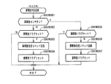
図5は、特別図柄プロセス処理として、図4に示すステップS25にて実行される処理の一例を示すフローチャートである。この特別図柄プロセス処理において、CPU103は、まず、始動入賞判定処理を実行する(ステップS101)。
FIG. 5 is a flowchart showing an example of a process executed in step S25 shown in FIG. 4 as a special symbol process process. In this special symbol process process, the
始動入賞判定処理では、始動入賞の発生を検出し、RAM102の所定領域に保留情報を格納し保留記憶数を更新する処理が実行される。始動入賞が発生すると、表示結果(大当り種別を含む)や変動パターンを決定するための乱数値が抽出され、保留情報として記憶される。また、抽出した乱数値に基づいて、表示結果や変動パターンを先読み判定する処理が実行されてもよい。保留情報や保留記憶数を記憶した後には、演出制御基板12に始動入賞の発生、保留記憶数、先読み判定等の判定結果を指定するための演出制御コマンドを送信するための送信設定が行われる。こうして送信設定された始動入賞時の演出制御コマンドは、例えば特別図柄プロセス処理が終了した後、図4に示すステップS27のコマンド制御処理が実行されることなどにより、主基板11から演出制御基板12に対して伝送される。
In the start winning determination process, a process of detecting the occurrence of the start winning, storing the hold information in a predetermined area of the
S101にて始動入賞判定処理を実行した後、CPU103は、RAM102に設けられた特図プロセスフラグの値に応じて、ステップS110〜S120の処理のいずれかを選択して実行する。なお、特別図柄プロセス処理の各処理(ステップS110〜S120)では、各処理に対応した演出制御コマンドを演出制御基板12に送信するための送信設定が行われる。
After executing the start winning determination processing in S101, the
ステップS110の特別図柄通常処理は、特図プロセスフラグの値が“0”(初期値)のときに実行される。この特別図柄通常処理では、保留情報の有無などに基づいて、第1特図ゲーム又は第2特図ゲームを開始するか否かの判定が行われる。また、特別図柄通常処理では、表示結果決定用の乱数値に基づき、特別図柄や飾り図柄の表示結果を「大当り」または「小当り」とするか否かや「大当り」とする場合の大当り種別を、その表示結果が導出表示される以前に決定(事前決定)する。さらに、特別図柄通常処理では、決定された表示結果に対応して、特図ゲームにおいて停止表示させる確定特別図柄(大当り図柄や小当り図柄、ハズレ図柄のいずれか)が設定される。その後、特図プロセスフラグの値が“1”に更新され、特別図柄通常処理は終了する。なお、第2特図を用いた特図ゲームが第1特図を用いた特図ゲームよりも優先して実行されるようにしてもよい(特図2優先消化ともいう)。また、第1始動入賞口及び第2始動入賞口への遊技球の入賞順序を記憶し、入賞順に特図ゲームの開始条件を成立させるようにしてもよい(入賞順消化ともいう)。 The special symbol normal process in step S110 is executed when the value of the special symbol process flag is “0” (initial value). In the special symbol normal processing, it is determined whether to start the first special figure game or the second special figure game based on the presence or absence of the hold information. Also, in the special symbol normal processing, based on the random number value for determining the display result, whether the display result of the special symbol or decorative symbol is "big hit" or "small hit", or the big hit type in the case of "big hit" Is determined (predetermined) before the display result is derived and displayed. Further, in the special symbol normal processing, a fixed special symbol (any of a big hit symbol, a small hit symbol, or a lost symbol) to be stopped and displayed in the special symbol game is set in accordance with the determined display result. Thereafter, the value of the special figure process flag is updated to “1”, and the special special pattern normal processing ends. Note that the special figure game using the second special figure may be executed prior to the special figure game using the first special figure (also referred to as special figure 2 priority digestion). Further, the order of winning the game balls into the first starting winning opening and the second starting winning opening may be stored, and the start condition of the special figure game may be established in the order of the winning (also referred to as winning the order).
乱数値に基づき各種の決定を行う場合には、ROM101に格納されている各種のテーブル(乱数値と比較される決定値が決定結果に割り当てられているテーブル)が参照される。主基板11における他の決定、演出制御基板12における各種の決定についても同じである。演出制御基板12においては、各種のテーブルがROM121に格納されている。
When making various decisions based on random numbers, various tables stored in the ROM 101 (tables in which decision values to be compared with random numbers are assigned to decision results) are referred to. The same applies to other decisions made on the
ステップS111の変動パターン設定処理は、特図プロセスフラグの値が“1”のときに実行される。この変動パターン設定処理には、表示結果を「大当り」または「小当り」とするか否かの事前決定結果等に基づき、変動パターン決定用の乱数値を用いて変動パターンを複数種類のいずれかに決定する処理などが含まれている。変動パターン設定処理では、変動パターンを決定したときに、特図プロセスフラグの値が“2”に更新され、変動パターン設定処理は終了する。 The variation pattern setting process in step S111 is executed when the value of the special figure process flag is “1”. In this variation pattern setting process, a variation pattern is selected from a plurality of types using a random value for variation pattern determination based on a result of a prior determination as to whether the display result is “big hit” or “small hit”. And the like are determined. In the variation pattern setting process, when the variation pattern is determined, the value of the special figure process flag is updated to “2”, and the variation pattern setting process ends.
変動パターンは、特図ゲームの実行時間(特図変動時間)(飾り図柄の可変表示の実行時間でもある)や、飾り図柄の可変表示の態様(リーチの有無等)、飾り図柄の可変表示中の演出内容(リーチ演出の種類等)を指定するものであり、可変表示パターンとも呼ばれる。 The fluctuation pattern is the execution time of the special figure game (the special figure fluctuation time) (also the execution time of the variable display of the decorative symbol), the mode of variable display of the decorative symbol (reach or not, etc.), and the variable display of the decorative symbol. (Such as the type of reach effect), and is also referred to as a variable display pattern.
ステップS112の特別図柄変動処理は、特図プロセスフラグの値が“2”のときに実行される。この特別図柄変動処理には、第1特別図柄表示装置4Aや第2特別図柄表示装置4Bにおいて特別図柄を変動させるための設定を行う処理や、その特別図柄が変動を開始してからの経過時間を計測する処理などが含まれている。また、計測された経過時間が変動パターンに対応する特図変動時間に達したか否かの判定も行われる。そして、特別図柄の変動を開始してからの経過時間が特図変動時間に達したときには、特図プロセスフラグの値が“3”に更新され、特別図柄変動処理は終了する。
The special symbol change process in step S112 is executed when the value of the special figure process flag is “2”. The special symbol change process includes a process for setting a special symbol to be changed in the first special
ステップS113の特別図柄停止処理は、特図プロセスフラグの値が“3”のときに実行される。この特別図柄停止処理には、第1特別図柄表示装置4Aや第2特別図柄表示装置4Bにて特別図柄の変動を停止させ、特別図柄の表示結果となる確定特別図柄を停止表示(導出)させるための設定を行う処理が含まれている。そして、表示結果が「大当り」である場合には特図プロセスフラグの値が“4”に更新される。その一方で、大当りフラグがオフであり、表示結果が「小当り」である場合には、特図プロセスフラグの値が“8”に更新される。また、表示結果が「ハズレ」である場合には、特図プロセスフラグの値が“0”に更新される。表示結果が「小当り」又は「ハズレ」である場合、時短状態や確変状態に制御されているときであって、回数切りの終了成立する場合には、遊技状態も更新される。特図プロセスフラグの値が更新されると、特別図柄停止処理は終了する。
The special symbol stop processing in step S113 is executed when the value of the special figure process flag is “3”. In this special symbol stop processing, the change of the special symbol is stopped by the first special
ステップS114の大当り開放前処理は、特図プロセスフラグの値が“4”のときに実行される。この大当り開放前処理には、表示結果が「大当り」となったことなどに基づき、大当り遊技状態においてラウンドの実行を開始して大入賞口を開放状態とするための設定を行う処理などが含まれている。大入賞口を開放状態とするときには、大入賞口扉用のソレノイド82に対してソレノイド駆動信号を供給する処理が実行される。このときには、例えば大当り種別がいずれであるかに対応して、大入賞口を開放状態とする開放上限期間や、ラウンドの上限実行回数を設定する。これらの設定が終了すると、特図プロセスフラグの値が“5”に更新され、大当り開放前処理は終了する。 The big hit opening pre-processing of step S114 is executed when the value of the special figure process flag is “4”. The big hit opening pre-processing includes, for example, a process of starting a round in the big hit gaming state and setting a big winning opening to an open state based on a display result of “big hit” or the like. Have been. When opening the special winning opening, a process of supplying a solenoid drive signal to the solenoid 82 for the special winning opening door is executed. At this time, an opening upper limit period in which the special winning opening is opened and an upper limit execution number of rounds are set in accordance with, for example, the type of the big hit. When these settings are completed, the value of the special figure process flag is updated to "5", and the big hit opening pre-processing ends.
ステップS115の大当り開放中処理は、特図プロセスフラグの値が“5”のときに実行される。この大当り開放中処理には、大入賞口を開放状態としてからの経過時間を計測する処理や、その計測した経過時間やカウントスイッチ23によって検出された遊技球の個数などに基づいて、大入賞口を開放状態から閉鎖状態に戻すタイミングとなったか否かを判定する処理などが含まれている。そして、大入賞口を閉鎖状態に戻すときには、大入賞口扉用のソレノイド82に対するソレノイド駆動信号の供給を停止させる処理などを実行した後、特図プロセスフラグの値が“6”に更新し、大当り開放中処理を終了する。
The big hit opening processing in step S115 is executed when the value of the special figure process flag is “5”. The processing during the opening of the jackpot is based on the processing of measuring the elapsed time from the opening of the jackpot, and the number of game balls detected by the
ステップS116の大当り開放後処理は、特図プロセスフラグの値が“6”のときに実行される。この大当り開放後処理には、大入賞口を開放状態とするラウンドの実行回数が設定された上限実行回数に達したか否かを判定する処理や、上限実行回数に達した場合に大当り遊技状態を終了させるための設定を行う処理などが含まれている。そして、ラウンドの実行回数が上限実行回数に達していないときには、特図プロセスフラグの値が“5”に更新される一方、ラウンドの実行回数が上限実行回数に達したときには、特図プロセスフラグの値が“7”に更新される。特図プロセスフラグの値が更新されると、大当り解放後処理は終了する。 The post-big hit release processing in step S116 is executed when the value of the special figure process flag is "6". The post-big hit opening process includes a process of determining whether or not the number of times of execution of the round for opening the big winning port has reached a set upper limit number of times, and a process of determining whether the number of times of execution of the round has reached the upper limit number of times. And the like for performing a setting for terminating the process. When the number of rounds has not reached the upper limit number of executions, the value of the special figure process flag is updated to “5”. On the other hand, when the number of rounds has reached the upper limit number of executions, The value is updated to "7". When the value of the special figure process flag is updated, the post-jackpot release processing ends.
ステップS117の大当り終了処理は、特図プロセスフラグの値が“7”のときに実行される。この大当り終了処理には、大当り遊技状態の終了を報知する演出動作としてのエンディング演出が実行される期間に対応した待ち時間が経過するまで待機する処理や、大当り遊技状態の終了に対応して確変制御や時短制御を開始するための各種の設定を行う処理などが含まれている。こうした設定が行われたときには、特図プロセスフラグの値が“0”に更新され、大当り終了処理は終了する。 The big hit end processing in step S117 is executed when the value of the special figure process flag is “7”. The big hit end process includes a process of waiting until a waiting time corresponding to a period during which an ending effect is executed as an effect operation for notifying the end of the big hit game state, and a change in response to the end of the big hit game state. The processing includes various settings for starting control and time-saving control. When such a setting is made, the value of the special figure process flag is updated to “0”, and the big hit end processing ends.
ステップS118の小当り開放前処理は、特図プロセスフラグの値が“8”のときに実行される。この小当り開放前処理には、表示結果が「小当り」となったことに基づき、小当り遊技状態において大入賞口を開放状態とするための設定を行う処理などが含まれている。このときには、特図プロセスフラグの値が“9”に更新され、小当り開放前処理は終了する。 The small hit release pre-processing of step S118 is executed when the value of the special figure process flag is “8”. The small hit opening pre-processing includes a process of setting the large winning opening to the open state in the small hitting game state based on the fact that the display result is “small hit”. At this time, the value of the special figure process flag is updated to “9”, and the small hit release pre-processing ends.
ステップS119の小当り開放中処理は、特図プロセスフラグの値が“9”のときに実行される。この小当り開放中処理には、大入賞口を開放状態としてからの経過時間を計測する処理や、その計測した経過時間などに基づいて、大入賞口を開放状態から閉鎖状態に戻すタイミングとなったか否かを判定する処理などが含まれている。大入賞口を閉鎖状態に戻して小当り遊技状態の終了タイミングとなったときには、特図プロセスフラグの値が“10”に更新され、小当り開放中処理は終了する。 The small hit opening processing in step S119 is executed when the value of the special figure process flag is "9". The processing during opening of the small hits includes processing for measuring the elapsed time from the opening of the special winning opening and timing for returning the special winning opening from the open state to the closed state based on the measured elapsed time. It includes a process of determining whether or not the event has occurred. When the big winning opening is returned to the closed state and the timing of ending the small hitting game state is reached, the value of the special figure process flag is updated to “10”, and the small hit opening processing ends.
ステップS120の小当り終了処理は、特図プロセスフラグの値が“10”のときに実行される。この小当り終了処理には、小当り遊技状態の終了を報知する演出動作が実行される期間に対応した待ち時間が経過するまで待機する処理などが含まれている。ここで、小当り遊技状態が終了するときには、小当り遊技状態となる以前のパチンコ遊技機1における遊技状態を継続させる。小当り遊技状態の終了時における待ち時間が経過したときには、特図プロセスフラグの値が“0”に更新され、小当り終了処理は終了する。
The small hit end processing in step S120 is executed when the value of the special figure process flag is “10”. The small hit ending process includes a process of waiting until a waiting time corresponding to a period during which the effect operation for notifying the end of the small hit gaming state is performed is performed. Here, when the small hitting game state ends, the gaming state in the
(演出制御基板12の主要な動作)
次に、演出制御基板12における主要な動作を説明する。演出制御基板12では、電源基板等から電源電圧の供給を受けると、演出制御用CPU120が起動して、図6のフローチャートに示すような演出制御メイン処理を実行する。図6に示す演出制御メイン処理を開始すると、演出制御用CPU120は、まず、所定の初期化処理を実行して(ステップS71)、RAM122のクリアや各種初期値の設定、また演出制御基板12に搭載されたCTC(カウンタ/タイマ回路)のレジスタ設定等を行う。また、初期動作制御処理を実行する(ステップS72)。初期動作制御処理では、可動体32を駆動して初期位置に戻す制御、所定の動作確認を行う制御といった可動体32の初期動作を行う制御が実行される。
(Main operation of effect control board 12)
Next, main operations of the
その後、タイマ割込みフラグがオンとなっているか否かの判定を行う(ステップS73)。タイマ割込みフラグは、例えばCTCのレジスタ設定に基づき、所定時間(例えば2ミリ秒)が経過するごとにオン状態にセットされる。このとき、タイマ割込みフラグがオフであれば(ステップS73;No)、ステップS73の処理を繰り返し実行して待機する。 Thereafter, it is determined whether or not the timer interrupt flag is turned on (step S73). The timer interrupt flag is set to an on state every time a predetermined time (for example, 2 milliseconds) elapses based on, for example, a register setting of the CTC. At this time, if the timer interrupt flag is off (step S73; No), the process of step S73 is repeatedly executed, and the process stands by.
また、演出制御基板12の側では、所定時間が経過するごとに発生するタイマ割込みとは別に、主基板11からの演出制御コマンドを受信するための割込みが発生する。この割込みは、例えば主基板11からの演出制御INT信号がオン状態となることにより発生する割込みである。演出制御INT信号がオン状態となることによる割込みが発生すると、演出制御用CPU120は、自動的に割込み禁止に設定するが、自動的に割込み禁止状態にならないCPUを用いている場合には、割込み禁止命令(DI命令)を発行することが望ましい。演出制御用CPU120は、演出制御INT信号がオン状態となることによる割込みに対応して、例えば所定のコマンド受信割込み処理を実行する。このコマンド受信割込み処理では、I/O125に含まれる入力ポートのうちで、中継基板15を介して主基板11から送信された制御信号を受信する所定の入力ポートより、演出制御コマンドを取り込む。このとき取り込まれた演出制御コマンドは、例えばRAM122に設けられた演出制御コマンド受信用バッファに格納する。その後、演出制御用CPU120は、割込み許可に設定してから、コマンド受信割込み処理を終了する。
Further, on the side of the
ステップS73にてタイマ割込みフラグがオンである場合には(ステップS73;Yes)、タイマ割込みフラグをクリアしてオフ状態にするとともに(ステップS74)、コマンド解析処理を実行する(ステップS75)。コマンド解析処理では、例えば主基板11の遊技制御用マイクロコンピュータ100から送信されて演出制御コマンド受信用バッファに格納されている各種の演出制御コマンドを読み出した後に、その読み出された演出制御コマンドに対応した設定や制御などが行われる。例えば、どの演出制御コマンドを受信したかや演出制御コマンドが特定する内容等を演出制御プロセス処理等で確認できるように、読み出された演出制御コマンドをRAM122の所定領域に格納したり、RAM122に設けられた受信フラグをオンしたりする。また、演出制御コマンドが遊技状態を特定する場合、遊技状態に応じた背景の表示を表示制御部123に指示してもよい。
If the timer interrupt flag is on in step S73 (step S73; Yes), the timer interrupt flag is cleared and turned off (step S74), and a command analysis process is executed (step S75). In the command analysis process, for example, after reading various effect control commands transmitted from the
ステップS75にてコマンド解析処理を実行した後には、演出制御プロセス処理を実行する(ステップS76)。演出制御プロセス処理では、例えば画像表示装置5の表示領域における演出画像の表示動作、スピーカ8L、8Rからの音声出力動作、遊技効果ランプ9及び装飾用LEDといった装飾発光体における点灯動作、可動体32の駆動動作といった、各種の演出装置を動作させる制御が行われる。また、各種の演出装置を用いた演出動作の制御内容について、主基板11から送信された演出制御コマンド等に応じた判定や決定、設定などが行われる。
After executing the command analysis process in step S75, the CPU executes the effect control process process (step S76). In the effect control process, for example, a display operation of an effect image in a display area of the
ステップS76の演出制御プロセス処理に続いて、演出用乱数更新処理が実行され(ステップS77)、演出制御基板12の側で用いられる演出用乱数の少なくとも一部がソフトウェアにより更新される。その後、ステップS73の処理に戻る。ステップS73の処理に戻る前に、他の処理が実行されてもよい。
Following the effect control process in step S76, an effect random number update process is executed (step S77), and at least a part of the effect random numbers used on the
図7は、演出制御プロセス処理として、図6のステップS76にて実行される処理の一例を示すフローチャートである。図7に示す演出制御プロセス処理において、演出制御用CPU120は、まず、先読予告設定処理を実行する(ステップS161)。先読予告設定処理では、例えば、主基板11から送信された始動入賞時の演出制御コマンドに基づいて、先読み予告演出を実行するための判定や決定、設定などが行われる。また、当該演出制御コマンドから特定される保留記憶数に基づき保留表示を表示するための処理が実行される。
FIG. 7 is a flowchart illustrating an example of the processing executed in step S76 in FIG. 6 as the effect control process processing. In the effect control process process illustrated in FIG. 7, the
ステップS161の処理を実行した後、演出制御用CPU120は、例えばRAM122に設けられた演出プロセスフラグの値に応じて、以下のようなステップS170〜S177の処理のいずれかを選択して実行する。
After executing the processing of step S161, the
ステップS170の可変表示開始待ち処理は、演出プロセスフラグの値が“0”(初期値)のときに実行される処理である。この可変表示開始待ち処理は、主基板11から可変表示の開始を指定するコマンドなどを受信したか否かに基づき、画像表示装置5における飾り図柄の可変表示を開始するか否かを判定する処理などを含んでいる。画像表示装置5における飾り図柄の可変表示を開始すると判定された場合、演出プロセスフラグの値を“1”に更新し、可変表示開始待ち処理を終了する。
The variable display start waiting process in step S170 is a process executed when the value of the effect process flag is “0” (initial value). This variable display start waiting process is a process of determining whether or not to start the variable display of the decorative symbol on the
ステップS171の可変表示開始設定処理は、演出プロセスフラグの値が“1”のときに実行される処理である。この可変表示開始設定処理では、演出制御コマンドにより特定される表示結果や変動パターンに基づいて、飾り図柄の可変表示の表示結果(確定飾り図柄)、飾り図柄の可変表示の態様、リーチ演出や各種予告演出などの各種演出の実行の有無やその態様や実行開始タイミングなどを決定する。そして、その決定結果等を反映した演出制御パターン(表示制御部123に演出の実行を指示するための制御データの集まり)を設定する。その後、設定した演出制御パターンに基づいて、飾り図柄の可変表示の実行開始を表示制御部123に指示し、演出プロセスフラグの値を“2”に更新し、可変表示開始設定処理を終了する。表示制御部123は、飾り図柄の可変表示の実行開始の指示により、画像表示装置5において、飾り図柄の可変表示を開始させる。
The variable display start setting process in step S171 is a process executed when the value of the effect process flag is “1”. In the variable display start setting process, based on the display result and the variation pattern specified by the effect control command, the display result of the decorative design variable display (fixed decorative design), the variable display mode of the decorative design, the reach Whether or not various effects such as a notice effect are to be executed, the mode thereof, the execution start timing, and the like are determined. Then, an effect control pattern (a set of control data for instructing the
ステップS172の可変表示中演出処理は、演出プロセスフラグの値が“2”のときに実行される処理である。この可変表示中演出処理において、演出制御用CPU120は、表示制御部123を指示することで、ステップS171にて設定された演出制御パターンに基づく演出画像を画像表示装置5の表示画面に表示させることや、可動体32を駆動させること、音声制御基板13に対する指令(効果音信号)の出力によりスピーカ8L、8Rから音声や効果音を出力させること、ランプ制御基板14に対する指令(電飾信号)の出力により遊技効果ランプ9や装飾用LEDを点灯/消灯/点滅させることといった、飾り図柄の可変表示中における各種の演出制御を実行する。こうした演出制御を行った後、例えば演出制御パターンから飾り図柄の可変表示終了を示す終了コードが読み出されたこと、あるいは、主基板11から確定飾り図柄を停止表示させることを指定するコマンドを受信したことなどに対応して、飾り図柄の表示結果となる確定飾り図柄を停止表示させる。確定飾り図柄を停止表示したときには、演出プロセスフラグの値が“3”に更新され、可変表示中演出処理は終了する。
The variable display effect processing in step S172 is processing executed when the value of the effect process flag is “2”. In the variable display effect processing, the
ステップS173の特図当り待ち処理は、演出プロセスフラグの値が“3”のときに実行される処理である。この特図当り待ち処理において、演出制御用CPU120は、主基板11から大当り遊技状態又は小当り遊技状態を開始することを指定する演出制御コマンドの受信があったか否かを判定する。そして、大当り遊技状態又は小当り遊技状態を開始することを指定する演出制御コマンドを受信したきに、そのコマンドが大当り遊技状態の開始を指定するものであれば、演出プロセスフラグの値を“6”に更新する。これに対して、そのコマンドが小当り遊技状態の開始を指定するものであれば、演出プロセスフラグの値を小当り中演出処理に対応した値である“4”に更新する。また、大当り遊技状態又は小当り遊技状態を開始することを指定するコマンドを受信せずに、当該コマンドの受信待ち時間が経過したときには、特図ゲームにおける表示結果が「ハズレ」であったと判定して、演出プロセスフラグの値を初期値である“0”に更新する。演出プロセスフラグの値を更新すると、特図当り待ち処理を終了する。
The waiting process per special figure in step S173 is a process executed when the value of the effect process flag is “3”. In the waiting process per special figure, the
ステップS174の小当り中演出処理は、演出制御プロセスフラグの値が“4”のときに実行される処理である。この小当り中演出処理において、演出制御用CPU120は、例えば小当り遊技状態における演出内容に対応した演出制御パターン等を設定し、その設定内容に基づく小当り遊技状態における各種の演出制御を実行する。また、小当り中演出処理では、例えば主基板11から小当り遊技状態を終了することを指定するコマンドを受信したことに対応して、演出プロセスフラグの値を小当り終了演出に対応した値である“5”に更新し、小当り中演出処理を終了する。
The small hit production process in step S174 is a process executed when the value of the production control process flag is “4”. In the small hit effect production process, the
ステップS175の小当り終了演出処理は、演出制御プロセスフラグの値が“5”のときに実行される処理である。この小当り終了演出処理において、演出制御用CPU120は、例えば小当り遊技状態の終了などに対応した演出制御パターン等を設定し、その設定内容に基づく小当り遊技状態の終了時における各種の演出制御を実行する。その後、演出プロセスフラグの値を初期値である“0”に更新し、小当り終了演出処理を終了する。
The small hit end effect process of step S175 is a process executed when the value of the effect control process flag is “5”. In the small hit end effect processing, the
ステップS176の大当り中演出処理は、演出プロセスフラグの値が“6”のときに実行される処理である。この大当り中演出処理において、演出制御用CPU120は、例えば大当り遊技状態における演出内容に対応した演出制御パターン等を設定し、その設定内容に基づく大当り遊技状態における各種の演出制御を実行する。また、大当り中演出処理では、例えば主基板11から大当り遊技状態を終了することを指定するコマンドを受信したことに対応して、演出制御プロセスフラグの値をエンディング演出処理に対応した値である“7”に更新し、大当り中演出処理を終了する。
The big hit production process in step S176 is a process executed when the value of the production process flag is “6”. In the big hit effect processing, the
ステップS177のエンディング演出処理は、演出プロセスフラグの値が“7”のときに実行される処理である。このエンディング演出処理において、演出制御用CPU120は、例えば大当り遊技状態の終了などに対応した演出制御パターン等を設定し、その設定内容に基づく大当り遊技状態の終了時におけるエンディング演出の各種の演出制御を実行する。その後、演出プロセスフラグの値を初期値である“0”に更新し、エンディング演出処理を終了する。
The ending effect process of step S177 is a process executed when the value of the effect process flag is “7”. In this ending effect process, the
(基本説明の変形例)
この発明は、上記基本説明で説明したパチンコ遊技機1に限定されず、本発明の趣旨を逸脱しない範囲で、様々な変形及び応用が可能である。
(Modification of the basic description)
The present invention is not limited to the
上記基本説明のパチンコ遊技機1は、入賞の発生に基づいて所定数の遊技媒体を景品として払い出す払出式遊技機であったが、遊技媒体を封入し入賞の発生に基づいて得点を付与する封入式遊技機であってもよい。
The
特別図柄の可変表示中に表示されるものは1種類の図柄(例えば、「−」を示す記号)だけで、当該図柄の表示と消灯とを繰り返すことによって可変表示を行うようにしてもよい。さらに可変表示中に当該図柄が表示されるものも、可変表示の停止時には、当該図柄が表示されなくてもよい(表示結果としては「−」を示す記号が表示されなくてもよい)。 Only one type of symbol (for example, a symbol indicating "-") is displayed during the variable display of the special symbol, and the variable display may be performed by repeating the display and the extinguishing of the symbol. Further, when the symbol is displayed during the variable display, the symbol may not be displayed when the variable display is stopped (the sign indicating "-" may not be displayed as a display result).
上記基本説明では、遊技機としてパチンコ遊技機1を示したが、メダルが投入されて所定の賭け数が設定され、遊技者による操作レバーの操作に応じて複数種類の図柄を回転させ、遊技者によるストップボタンの操作に応じて図柄を停止させたときに停止図柄の組合せが特定の図柄の組み合わせになると、所定数のメダルが遊技者に払い出されるゲームを実行可能なスロット機(例えば、ビッグボーナス、レギュラーボーナス、RT、AT、ART、CZ(以下、ボーナス等)のうち1以上を搭載するスロット機)にも本発明を適用可能である。
In the above basic description, the
本発明を実現するためのプログラム及びデータは、パチンコ遊技機1に含まれるコンピュータ装置などに対して、着脱自在の記録媒体により配布・提供される形態に限定されるものではなく、予めコンピュータ装置などの有する記憶装置にインストールしておくことで配布される形態を採っても構わない。さらに、本発明を実現するためのプログラム及びデータは、通信処理部を設けておくことにより、通信回線等を介して接続されたネットワーク上の、他の機器からダウンロードすることによって配布する形態を採っても構わない。
The program and data for realizing the present invention are not limited to a form that is distributed and provided to a computer device or the like included in the
そして、ゲームの実行形態も、着脱自在の記録媒体を装着することにより実行するものだけではなく、通信回線等を介してダウンロードしたプログラム及びデータを、内部メモリ等に一旦格納することにより実行可能とする形態、通信回線等を介して接続されたネットワーク上における、他の機器側のハードウェア資源を用いて直接実行する形態としてもよい。さらには、他のコンピュータ装置等とネットワークを介してデータの交換を行うことによりゲームを実行するような形態とすることもできる。 The game can be executed not only by installing a removable recording medium, but also by temporarily storing a program and data downloaded via a communication line or the like in an internal memory or the like. Alternatively, the program may be directly executed using hardware resources of another device on a network connected via a communication line or the like. Furthermore, the game may be executed by exchanging data with another computer device or the like via a network.
なお、本明細書において、演出の実行割合などの各種割合の比較の表現(「高い」、「低い」、「異ならせる」などの表現)は、一方が「0%」の割合であることを含んでもよい。例えば、一方が「0%」の割合で、他方が「100%」の割合又は「100%」未満の割合であることも含む。 In the present specification, one of the expressions for comparing various ratios such as the execution ratio of effects (expressions such as “high”, “low”, and “differentiate”) is that one of the ratios is “0%”. May be included. For example, it may include that one is a ratio of “0%” and the other is a ratio of “100%” or a ratio of less than “100%”.
[特徴部21TMに関する説明]
次に、特徴部21TMに関して説明する。パチンコ遊技機1には、例えば図8−1に示すような主基板11、演出制御基板12、ターミナル基板(情報出力基板)21TM016といった、各種の制御基板が搭載されている。また、パチンコ遊技機1には、主基板11と演出制御基板12との間で伝送される各種の制御信号を中継するための中継基板15なども搭載されている。その他にも、パチンコ遊技機1における遊技盤2などの背面には、例えば払出制御基板、発射制御基板、インタフェース基板などといった、各種の基板が配置されている。
[Explanation about the characteristic part 21TM]
Next, the characteristic portion 21TM will be described. Various control boards such as a
なお、前述した図2に示すように、主基板11には、第1始動口スイッチ22A及び第2始動口スイッチ22B、並びに、第1特別図柄表示装置4A及び第2特別図柄表示装置4B等の各種部品が接続されており、演出制御基板12には、スピーカ8L、8R、枠LED9等の各種演出装置が接続されているが、図8−1では、これらを省略している。
As shown in FIG. 2 described above, the
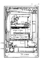
主基板11は、メイン側の制御基板であり、図8−3に示すように、基板ケース21TM201に収納された状態でパチンコ遊技機1の背面に搭載され、パチンコ遊技機1における遊技の進行を制御するための各種回路が搭載されている。主基板11は、主として、特図ゲームにおいて用いる乱数の設定機能、所定位置に配設されたスイッチ等からの信号の入力を行う機能、演出制御基板12などからなるサブ側の制御基板に宛てて、指令情報の一例となる制御コマンドを制御信号として出力して送信する機能、ホールの管理コンピュータに対して各種情報を出力する機能などを備えている。また、主基板11は、第1特別図柄表示装置4Aと第2特別図柄表示装置4Bを構成する各LED(例えばセグメントLED)などの点灯/消灯制御を行って第1特図や第2特図の変動表示を制御することや、普通図柄表示器20の点灯/消灯/発色制御などを行って普通図柄表示器20による普通図柄の変動表示を制御することといった、所定の表示図柄の変動表示を制御する機能も備えている。
The
また、主基板11には、図8−3に示すように、パチンコ遊技機1の背面側から視認可能な表示モニタ21TM029が設けられており、該表示モニタ21TM029に、入賞に関する各種の入賞情報を表示する機能も備えている。尚、表示モニタ21TM029の左側方には表示切替スイッチ21TM030が設けられており、該表示切替スイッチ21TM030の操作によって表示モニタ21TM029に表示されている情報を切り替えることが可能となっている。
Further, as shown in FIG. 8C, the
主基板11には、例えば遊技制御用マイクロコンピュータ100や、遊技球検出用の各種スイッチからの検出信号の他、電源断信号、クリア信号、リセット信号等の各種信号を取り込んで遊技制御用マイクロコンピュータ100に伝送するスイッチ回路110、ターミナル基板21TM016からセキュリティ信号等の各種の信号の出力を行うための情報出力回路112が搭載されている。
The
また、図8−1に示す主基板11は、図8−3に示すように、透過性を有する合成樹脂材からなる基板ケース21TM201に封入されており、主基板11の中央には表示モニタ21TM029(例えば、7セグメント)が配置され、表示モニタ21TM029の右側には表示切替スイッチ21TM030が配置されている。表示モニタ21TM029及び表示切替スイッチ21TM030は、主基板11を視認する際の正面に配置されている。主基板11の背面中央下部には、後述する設定変更モードまたは設定確認モードに切り替えるための錠スイッチ21TM051(図8−1参照)が設けられている。主基板11は、遊技機用枠3を開放していない状態では視認できないので、主基板11を視認する際の正面とは、遊技機用枠3を開放した状態における遊技盤2の裏面側を視認する際の正面であり、パチンコ遊技機1の正面とは異なる。ただし、主基板11を視認する際の正面とパチンコ遊技機1の正面とが共通するようにしてもよい。
As shown in FIG. 8C, the
また、主基板11(遊技制御用マイクロコンピュータ100)は、各入賞口(大入賞口、第2始動入賞口、第1始動入賞口、第1〜第4一般入賞口、以下、「進入領域」ともいう)への遊技球の進入数の集計を行い、該集計による連比、役比などの各種の入賞情報が表示モニタ21TM029に表示されるようになっており、これら入賞情報が表示されることで、遊技場に設置後における連比、役比などの各種の入賞情報を確認できる。つまり、パチンコ遊技機1のメーカ側においては、予め定められた頻度で一般入賞口に遊技球が進入するように(試験を通過するように)遊技盤面を設計することが通常である。また、試験を行う際には、あらかじめ定められた頻度で一般入賞口に遊技球が進入しているかが確認される。さらに、パチンコ遊技機1を設置した後においても、どのような調整が行われているか、その調整の結果、設計どおりの頻度で一般入賞口に遊技球が進入しているかが確認される。そこで、本実施例のパチンコ遊技機1では、当該パチンコ遊技機1において、設置後にどのような調整を加えられたかを認識できるようになっている。
The main board 11 (the game control microcomputer 100) has a winning opening (large winning opening, second starting winning opening, first starting winning opening, first to fourth general winning opening, hereinafter referred to as "entry area"). ), And the various kinds of winning information such as the connection ratio and the winning ratio based on the counting are displayed on the display monitor 21TM029, and the winning information is displayed. Thereby, various winning information such as the connection ratio and the winning combination after the installation in the game hall can be confirmed. That is, on the maker side of the
また、電源基板は、透過性を有する合成樹脂材からなる基板ケースに封入されており、電源基板の背面右側下部には、後述する大当りの当選確率(出玉率)等の設定値を変更するための設定スイッチとして機能するクリアスイッチ(設定切替スイッチ)21TM052と、電源スイッチ21TM055が設けられている。遊技場の店員等が、パチンコ遊技機1に電源電圧が供給されていない状態で、電源スイッチ21TM055を操作することで、主基板11、演出制御基板12、払出制御基板21TM037等の各基板に所定の動作電圧が供給される。さらに、電源スイッチ21TM055が操作されるタイミングで、クリアスイッチ(設定切替スイッチ)21TM052が操作されていれば、遊技制御用マイクロコンピュータ100にクリア信号が入力され、後述する初期化処理(RAMクリア)が実行される。同じ電源基板上において、電源スイッチ21TM055とクリアスイッチ(設定切替スイッチ)21TM052を近くに配置することで、電源投入操作及び初期化操作を行い易いようにしている。
The power supply board is sealed in a board case made of a synthetic resin material having transparency. On the lower right side of the back of the power supply board, set values such as a jackpot winning probability (a payout rate) described later are changed. A clear switch (setting changeover switch) 21TM052 functioning as a setting switch and a power switch 21TM055 are provided. By operating the power switch 21TM055 in a state where the power supply voltage is not supplied to the
尚、錠スイッチ21TM051及びクリアスイッチ(設定切替スイッチ)21TM052は、パチンコ遊技機1の背面側に設けられており、所定のキー操作により開放可能な遊技機用枠3を開放しない限り操作不可能とされており、所定のキーを所持する店員のみが操作可能となる。また、錠スイッチ21TM051はキー操作を要することから、遊技店の店員のなかでも、錠スイッチ21TM051の操作を行うキーを所持する店員のみ操作が可能とされている。また、錠スイッチ21TM051は、所定のキーによってONとOFFの切替操作を実行可能なスイッチであるが、該切替操作を実行可能であると共に該切替操作とは異なる操作(例えば、押込み操作)を実行可能なスイッチであっても良い。
The lock switch 21TM051 and the clear switch (setting changeover switch) 21TM052 are provided on the back side of the
なお、錠スイッチ21TM051は、ON状態又はOFF状態を維持可能である。即ち、遊技場の店員等により力を加えられなくても、錠スイッチ21TM051は、ON状態又はOFF状態を維持可能である。また、錠スイッチ21TM051は、OFF状態でのみキーを挿抜可能な構成とする。このような構成によれば、遊技場の店員等は、キーを回収するために錠スイッチ21TM051をOFF状態としなければならないので、遊技場の店員等が錠スイッチ21TM051をON状態としたまま放置してしまうことを防ぐことができる。 Note that the lock switch 21TM051 can maintain an ON state or an OFF state. In other words, the lock switch 21TM051 can maintain the ON state or the OFF state even when no force is applied by a store clerk or the like at the game arcade. The lock switch 21TM051 has a configuration in which a key can be inserted and removed only in an OFF state. According to such a configuration, the clerk at the game hall must turn off the lock switch 21TM051 in order to collect the keys, so that the clerk at the game hall leaves the lock switch 21TM051 in the ON state. Can be prevented.
尚、図8−3に示すように、パチンコ遊技機1の背面側の下部には、各入賞口に入賞した遊技球やアウト口に進入した遊技球をパチンコ遊技機1外に排出するためのノズル(排出口)が設けられており、該ノズル内には、パチンコ遊技機1内から排出される遊技球を検出する(発射された遊技球を検出する)ための排出口スイッチ21TM070が設けられている。該排出口スイッチ21TM070は、スイッチ回路110に接続されている。
As shown in FIG. 8-3, the lower part of the back side of the
主基板11から演出制御基板12に向けて伝送される制御信号は、中継基板15によって中継される。中継基板15を介して主基板11から演出制御基板12に対して伝送される制御コマンドは、例えば電気信号として送受信される演出制御コマンドである。演出制御コマンドには、例えば画像表示装置5における画像表示動作を制御するために用いられる表示制御コマンドや、スピーカ8L、8Rからの音声出力を制御するために用いられる音声制御コマンド、枠LED9や装飾用LEDの点灯動作などを制御するために用いられるLED制御コマンドが含まれている。
The control signal transmitted from the
図8−2は、払出制御基板21TM037および球払出装置21TM097などの払出に関連する構成要素を示すブロック図である。図8−2に示すように、払出制御基板21TM037には、払出制御用CPU21TM371を含む払出制御用マイクロコンピュータ21TM370が搭載されている。この実施の形態では、払出制御用マイクロコンピュータ21TM370は、1チップマイクロコンピュータであり、少なくともRAMが内蔵されている。払出制御用マイクロコンピュータ21TM370、RAM(図示せず)、払出制御用プログラムを格納したROM(図示せず)およびI/Oポート等は、払出制御基板21TM037を構成する。すなわち、払出制御基板21TM037は、払出制御用CPU21TM371、RAMおよびROMを有する払出制御用マイクロコンピュータ21TM370と、I/Oポートとで実現される。また、I/Oポートは、払出制御用マイクロコンピュータ21TM370に内蔵されていてもよい。 FIG. 8B is a block diagram illustrating components related to payout, such as the payout control board 21TM037 and the ball payout device 21TM097. As shown in FIG. 8B, on the payout control board 21TM037, a payout control microcomputer 21TM370 including a payout control CPU 21TM371 is mounted. In this embodiment, the payout control microcomputer 21TM370 is a one-chip microcomputer and has at least a built-in RAM. The payout control microcomputer 21TM370, a RAM (not shown), a ROM (not shown) storing a payout control program, an I / O port, and the like constitute a payout control board 21TM037. That is, the payout control board 21TM037 is realized by the payout control microcomputer 21TM370 having the payout control CPU 21TM371, RAM and ROM, and the I / O port. Further, the I / O port may be built in the payout control microcomputer 21TM370.
球切れスイッチ21TM187、満タンスイッチ21TM048および払出個数カウントスイッチ21TM301からの検出信号は、中継基板21TM072を介して払出制御基板21TM037のI/Oポート21TM372fに入力される。なお、この実施の形態では、払出個数カウントスイッチ21TM301からの検出信号は、払出制御用マイクロコンピュータ21TM370に入力されたあと、I/Oポート21TM372aおよび出力回路21TM373Bを介して主基板11に出力される。
The detection signals from the ball out switch 21TM187, the full tank switch 21TM048, and the payout number count switch 21TM301 are input to the I / O port 21TM372f of the payout control board 21TM037 via the relay board 21TM072. In this embodiment, the detection signal from the payout number count switch 21TM301 is input to the payout control microcomputer 21TM370, and then is output to the
また、払出制御基板21TM037には、図8−2に示すように、遊技盤2を支持固定する遊技機用枠3の開放を検知する遊技機枠開放センサと、遊技盤2の前面を開閉可能に覆うガラス扉枠3aの開放を検知する扉枠開放センサと、を備える遊技機枠・扉枠開放センサ21TM300が接続されており、これらのセンサから出力される検知信号に基づいて、各種の異常(エラー)の発生を判定する機能も備えている。なお、遊技機用枠3の開放が検知されたときの検知信号と、ガラス扉枠3aの開放が検知されたときの検出信号とは、異なる端子に入力されることにより、払出制御用マイクロコンピュータ21TM370は、遊技機用枠3の開放状態と、ガラス扉枠3aの開放状態とを、区別して認識可能となっている。
As shown in FIG. 8B, the payout control board 21TM037 has a game machine frame opening sensor for detecting the opening of the
また、払出モータ位置センサ21TM295からの検出信号は、中継基板21TM072を介して払出制御基板21TM037のI/Oポート21TM372eに入力される。払出モータ位置センサ21TM295は、払出モータ21TM289の回転位置を検出するための発光素子(LED)と受光素子とによるセンサであり、遊技球が詰まったこと、すなわちいわゆる球噛みを検出するために用いられる。払出制御基板21TM037に搭載されている払出制御用マイクロコンピュータ21TM370は、球切れスイッチ21TM187からの検出信号が球切れ状態を示していたり、満タンスイッチ21TM048からの検出信号が満タン状態を示していると、球払出処理を停止する。 The detection signal from the payout motor position sensor 21TM295 is input to the I / O port 21TM372e of the payout control board 21TM037 via the relay board 21TM072. The payout motor position sensor 21TM295 is a sensor including a light emitting element (LED) and a light receiving element for detecting the rotational position of the payout motor 21TM289, and is used to detect that a game ball is clogged, that is, to detect a so-called ball bite. . The payout control microcomputer 21TM370 mounted on the payout control board 21TM037 indicates that the detection signal from the ball out switch 21TM187 indicates a ball out state or the detection signal from the full switch 21TM048 indicates a full state. Then, the ball payout process is stopped.
さらに、満タンスイッチ21TM048からの検出信号が満タン状態を示していると、払出制御用マイクロコンピュータ21TM370は、打球発射装置からの球発射を停止させるために、発射基板21TM090に対してローレベルの満タン信号を出力する。発射基板21TM090のAND回路21TM091が出力する発射モータ21TM094への発射モータ信号は、発射基板21TM090から発射モータ21TM094に伝えられる。払出制御用マイクロコンピュータ21TM370からの満タン信号は、発射基板21TM090に搭載されたAND回路21TM091の入力側の一方に入力され、駆動信号生成回路21TM092からの駆動信号(発射モータ21TM094を駆動するための信号であって、電源基板からの電源を供給する役割を果たす信号である。)は、AND回路21TM091の入力側の他方に入力される。そして、AND回路21TM091の発射モータ信号が発射モータ21TM094に入力される。すなわち、払出制御用マイクロコンピュータ21TM370が満タン信号を出力している間は、発射モータ21TM094への発射モータ信号の出力が停止される。 Further, when the detection signal from the full tank switch 21TM048 indicates the full state, the payout control microcomputer 21TM370 sets the low level to the firing board 21TM090 to stop the ball firing from the hitting ball firing device. Outputs a full signal. The firing motor signal to the firing motor 21TM094 output from the AND circuit 21TM091 of the firing board 21TM090 is transmitted from the firing board 21TM090 to the firing motor 21TM094. The full signal from the payout control microcomputer 21TM370 is input to one of the input sides of an AND circuit 21TM091 mounted on the launch board 21TM090, and the drive signal from the drive signal generation circuit 21TM092 (for driving the launch motor 21TM094). The signal is a signal that serves to supply power from the power supply board.) Is input to the other of the input sides of the AND circuit 21TM091. Then, the firing motor signal of the AND circuit 21TM091 is input to the firing motor 21TM094. That is, while the payout control microcomputer 21TM370 is outputting the full signal, the output of the firing motor signal to the firing motor 21TM094 is stopped.
払出制御用マイクロコンピュータ21TM370には、遊技制御用マイクロコンピュータ100とシリアル通信で信号を入出力(送受信)するためのシリアル通信回路21TM380が内蔵されている。この実施の形態では、遊技制御用マイクロコンピュータ100と 払出制御用マイクロコンピュータ21TM370とは、シリアル通信回路21TM505,21TM380を介して、遊技制御用マイクロコンピュータ100と 払出制御用マイクロコンピュータ21TM370との間の接続確認を行うために、一定の間隔(例えば1秒)で信号(賞球要求信号、受信ACK信号)をやり取り(送受信)している。すなわち、遊技制御用マイクロコンピュータ100は、シリアル通信回路21TM505を介して、一定の間隔で接続確認を行うための信号(この実施の形態における賞球要求信号)を送信し、 払出制御用マイクロコンピュータ21TM370は、遊技制御用マイクロコンピュータ100からの賞球要求信号を受信した場合、その旨を通知する信号(受信ACK信号)を遊技制御用マイクロコンピュータ100に送信する。この実施の形態では、賞球要求信号や受信ACK信号に特定のデータを乗せることにより、賞球要求信号や受信ACK信号を送受信するタイミングにおいて、遊技制御用マイクロコンピュータ100と払出制御用マイクロコンピュータ21TM370との間で特定のデータをやり取りするように構成している。例えば、入賞が発生した場合には、遊技制御用マイクロコンピュータ100は、払い出すべき賞球個数を示すデータを、賞球要求信号の所定ビットを異ならせることにより設定し、当該設定がなされた賞球要求信号を 払出制御用マイクロコンピュータ21TM370に送信する。そして、 払出制御用マイクロコンピュータ21TM370は、賞球払出動作が終了すると、賞球終了を示すデータを、受信ACK信号の所定ビットを異ならせることにより設定し、当該設定がなされた受信ACK信号を遊技制御用マイクロコンピュータ100に送信する。また、所定のエラー(球貸し、満タン、球切れなどのエラー)が発生した場合には、エラーの内容を示すデータを、受信ACK信号の所定ビットを異ならせることにより設定し、当該設定がなされた受信ACK信号を遊技制御用マイクロコンピュータ100に送信する。
The payout control microcomputer 21TM370 has a built-in serial communication circuit 21TM380 for inputting / outputting (transmitting / receiving) signals with the
払出制御用マイクロコンピュータ21TM370は、出力ポート21TM372bを介して、賞球払出数を示す賞球情報信号および貸し球数を示す球貸し個数信号をターミナル基板(枠用外部端子基板と盤用外部端子基板とを含む)21TM160に出力する。なお、出力ポート21TM372bの外側に、ドライバ回路が設置されているが、図8−2では記載省略されている。 The payout control microcomputer 21TM370 transmits, via the output port 21TM372b, a prize ball information signal indicating the number of prize balls paid out and a ball lending number signal indicating the number of lending balls to a terminal board (an external terminal board for a frame and an external terminal board for a board). Is output to 21TM160. Although a driver circuit is provided outside the output port 21TM372b, it is omitted in FIG. 8-2.
また、 払出制御用マイクロコンピュータ21TM370は、出力ポート21TM372cを介して、7セグメントLEDによるエラー表示用LED21TM374にエラー信号を出力する。さらに、出力ポート21TM372bを介して、点灯/消灯を指示するための信号を賞球LED21TM053および球切れLED21TM054に出力する。なお、払出制御基板21TM037の入力ポート21TM372fには、エラー状態を解除するためのエラー解除スイッチ21TM375からの検出信号が入力される。エラー解除スイッチ21TM375は、ソフトウェアリセットによってエラー状態を解除するために用いられる。 Also, the payout control microcomputer 21TM370 outputs an error signal to the error display LED 21TM374 using a 7-segment LED via the output port 21TM372c. Further, a signal for instructing turning on / off is output to prize ball LED21TM053 and ball out LED21TM054 via output port 21TM372b. The detection signal from the error release switch 21TM375 for releasing the error state is input to the input port 21TM372f of the payout control board 21TM037. The error release switch 21TM375 is used to release an error state by software reset.
さらに、 払出制御用マイクロコンピュータ21TM370からの払出モータ21TM289への駆動信号は、出力ポート21TM372aおよび中継基板21TM072を介して球払出装置21TM097の払出機構部分における払出モータ21TM289に伝えられる。なお、出力ポート21TM372aの外側に、ドライバ回路(モータ駆動回路)が設置されているが、図8−3では記載省略されている。 Further, a drive signal from the payout control microcomputer 21TM370 to the payout motor 21TM289 is transmitted to the payout motor 21TM289 in the payout mechanism of the ball payout device 21TM097 via the output port 21TM372a and the relay board 21TM072. Although a driver circuit (motor drive circuit) is provided outside the output port 21TM372a, it is omitted in FIG. 8-3.
遊技機に隣接して設置されているカードユニット21TM050には、カードユニット制御用マイクロコンピュータが搭載されている。また、カードユニット21TM050には、使用可表示ランプ、連結台方向表示器、カード投入表示ランプおよびカード挿入口が設けられている。インタフェース基板(中継基板)21TM066には、度数表示LED21TM060、球貸し可LED21TM061、球貸スイッチ21TM062および返却スイッチ21TM063が接続される。 A card unit control microcomputer is mounted on the card unit 21TM050 installed adjacent to the gaming machine. In addition, the card unit 21TM050 is provided with a usable indication lamp, a connection stand direction indicator, a card insertion indication lamp, and a card insertion slot. To the interface board (relay board) 21TM066, a frequency display LED 21TM060, a ball lending enable LED 21TM061, a ball lending switch 21TM062, and a return switch 21TM063 are connected.
インタフェース基板21TM066からカードユニット21TM050には、遊技者の操作に応じて、球貸スイッチ21TM062が操作されたことを示す球貸スイッチ信号および返却スイッチ21TM063が操作されたことを示す返却スイッチ信号が与えられる。また、カードユニット21TM050からインタフェース基板21TM066には、プリペイドカードの残高を示すカード残高表示信号および球貸し可表示信号が与えられる。カードユニット21TM050と払出制御基板21TM037の間では、接続信号(VL信号)、ユニット操作信号(BRDY信号)、球貸し要求信号(BRQ信号)、球貸し完了信号(EXS信号)およびパチンコ機動作信号(PRDY信号)が入力ポート21TM372fおよび出力ポート21TM372dを介して送受信される。カードユニット21TM050と払出制御基板21TM037の間には、インタフェース基板21TM066が介在している。よって、接続信号(VL信号)等の信号は、図8−2に示すように、インタフェース基板21TM066を介してカードユニット21TM050と払出制御基板21TM037の間で送受信されることになる。 From the interface board 21TM066, to the card unit 21TM050, a ball rental switch signal indicating that the ball rental switch 21TM062 has been operated and a return switch signal indicating that the return switch 21TM063 has been operated are supplied to the card unit 21TM050 according to the operation of the player. . Further, a card balance display signal indicating the balance of the prepaid card and a ball lending permission display signal are given from the card unit 21TM050 to the interface board 21TM066. Between the card unit 21TM050 and the payout control board 21TM037, a connection signal (VL signal), a unit operation signal (BRDY signal), a ball lending request signal (BRQ signal), a ball lending completion signal (EXS signal), and a pachinko machine operation signal ( PRDY signal) is transmitted and received via the input port 21TM372f and the output port 21TM372d. An interface board 21TM066 is interposed between the card unit 21TM050 and the payout control board 21TM037. Therefore, a signal such as a connection signal (VL signal) is transmitted and received between the card unit 21TM050 and the payout control board 21TM037 via the interface board 21TM066, as shown in FIG. 8-2.
パチンコ遊技機1の電源が投入されると、払出制御基板21TM037に搭載されている 払出制御用マイクロコンピュータ21TM370は、カードユニット21TM050にPRDY信号を出力する。また、カードユニット制御用マイクロコンピュータは、電源が投入されると、VL信号を出力する。 払出制御用マイクロコンピュータ21TM370は、VL信号の入力状態によってカードユニット21TM050の接続状態/未接続状態を判定する。カードユニット21TM050においてカードが受け付けられ、球貸スイッチが操作され球貸スイッチ信号が入力されると、カードユニット制御用マイクロコンピュータは、払出制御基板21TM037にBRDY信号を出力する。この時点から所定の遅延時間が経過すると、カードユニット制御用マイクロコンピュータは、払出制御基板21TM037にBRQ信号を出力する。
When the
そして、 払出制御用マイクロコンピュータ21TM370は、カードユニット21TM050に対するEXS信号を立ち上げ、カードユニット21TM050からのBRQ信号の立ち下がりを検出すると、払出モータ21TM289を駆動し、所定個の貸し球を遊技者に払い出す。そして、払出が完了したら、 払出制御用マイクロコンピュータ21TM370は、カードユニット21TM050に対するEXS信号を立ち下げる。その後、カードユニット21TM050からのBRDY信号がオン状態でないことを条件に、遊技制御用マイクロコンピュータ100から払出指令信号を受けると賞球払出制御を実行する。
Then, the payout control microcomputer 21TM370 raises the EXS signal to the card unit 21TM050, and when detecting the fall of the BRQ signal from the card unit 21TM050, drives the payout motor 21TM289 to send a predetermined number of loaned balls to the player. Pay out. When the payout is completed, the payout control microcomputer 21TM370 lowers the EXS signal to the card unit 21TM050. Thereafter, under the condition that the BRDY signal from the card unit 21TM050 is not in the ON state, when a payout command signal is received from the
カードユニット21TM050で用いられる電源電圧AC24Vは払出制御基板21TM037から供給される。すなわち、カードユニット21TM050に対する電源基板からの電力供給は、払出制御基板21TM037およびインタフェース基板21TM066を介して行われる。この例では、インタフェース基板21TM066内に配されているカードユニット21TM050に対するAC24Vの電源供給ラインに、カードユニット21TM050を保護するためのヒューズが設けられ、カードユニット21TM050に所定電圧以上の電圧が供給されることが防止される。 The power supply voltage AC24V used in the card unit 21TM050 is supplied from the payout control board 21TM037. That is, power supply from the power supply board to the card unit 21TM050 is performed via the payout control board 21TM037 and the interface board 21TM066. In this example, a fuse for protecting the card unit 21TM050 is provided in a power supply line of 24V AC for the card unit 21TM050 provided in the interface board 21TM066, and a voltage higher than a predetermined voltage is supplied to the card unit 21TM050. Is prevented.
本実施例のパチンコ遊技機1は、設定値に応じて大当りの当選確率(出玉率)が変わる構成とされている。詳しくは、後述する特別図柄プロセス処理の特別図柄通常処理において、設定値に応じた表示結果判定テーブル(当選確率)を用いることにより、大当りの当選確率(出玉率)が変わるようになっている。設定値は1〜6の6段階からなり、6が最も出玉率が高く、6,5,4,3,2,1の順に値が小さくなるほど出玉率が低くなる。すなわち、設定値として6が設定されている場合には遊技者にとって最も有利度が高く、5,4,3,2,1の順に値が小さくなるほど有利度が段階的に低くなる。
The
図8−4(A)〜(F)は、各設定値に対応する表示結果判定テーブルを示す説明図である。表示結果判定テーブルとは、ROM101に記憶されているデータの集まりであって、MR1と比較される当り判定値が設定されているテーブルである。各表示結果判定テーブルは、変動特図指定バッファが1(第1)である、つまり、第1特別図柄が変動表示の対象とされている場合と、変動特図指定バッファが2(第2)である、つまり、第2特別図柄が変動表示の対象とされている場合のそれぞれについて、大当りとする判定値が設定されている。
FIGS. 8A to 8F are explanatory diagrams showing display result determination tables corresponding to each set value. The display result determination table is a set of data stored in the
図8−4(A)に示すように、設定値1に対応する表示結果判定テーブルを用いるときに、変動特図指定バッファが第1である場合、つまり、第1特別図柄が変動表示の対象とされている場合には、設定値が「2」、「3」、「4」、「5」、「6」である場合よりも低い確率(1/300)で大当りに当選するようになっている。また、変動特図指定バッファが第2である場合には、大当りに対応する判定値として、変動特図指定バッファが第1である場合と同様の判定値が設定されており、第2特別図柄が変動表示の対象とされている場合にも、第1特別図柄が変動表示の対象とされている場合と同じ確率(1/300)で大当りに当選するようになっている。
As shown in FIG. 8-4 (A), when using the display result determination table corresponding to the
また、図8−4(B)に示すように、設定値2に対応する表示結果判定テーブルを用いるときに、変動特図指定バッファが第1である場合には、設定値が「1」である場合よりも高い確率(1/280)で大当りに当選するようになっている。また、変動特図指定バッファが第2である場合には、大当りに対応する判定値として、変動特図指定バッファが第1である場合と同様の判定値が設定されており、第2特別図柄が変動表示の対象とされている場合にも、第1特別図柄が変動表示の対象とされている場合と同じ確率(1/280)で大当りに当選するようになっている。
Further, as shown in FIG. 8-4 (B), when using the display result determination table corresponding to the setting
また、図8−4(C)に示すように、設定値3に対応する表示結果判定テーブルを用いるときに、変動特図指定バッファが第1である場合には、設定値が「1」、「2」である場合よりも高い確率(1/280)で大当りに当選するようになっている。また、変動特図指定バッファが第2である場合には、大当りに対応する判定値として、変動特図指定バッファが第1である場合と同様の判定値が設定されており、第2特別図柄が変動表示の対象とされている場合にも、第1特別図柄が変動表示の対象とされている場合と同じ確率(1/280)で大当りに当選するようになっている。
Also, as shown in FIG. 8C, when the display result determination table corresponding to the
また、図8−4(D)に示すように、設定値4に対応する表示結果判定テーブルを用いるときに、変動特図指定バッファが第1である場合には、設定値が「1」、「2」、「3」である場合よりも高い確率(1/250)で大当りに当選するようになっている。また、変動特図指定バッファが第2である場合には、大当りに対応する判定値として、変動特図指定バッファが第1である場合と同様の判定値が設定されており、第2特別図柄が変動表示の対象とされている場合にも、第1特別図柄が変動表示の対象とされている場合と同じ確率(1/250)で大当りに当選するようになっている。
Further, as shown in FIG. 8D, when the display result determination table corresponding to the
また、図8−4(E)に示すように、設定値5に対応する表示結果判定テーブルを用いるときに、変動特図指定バッファが第1である場合には、設定値が「1」、「2」、「3」、「4」である場合よりも高い確率(1/235)で大当りに当選するようになっている。また、変動特図指定バッファが第2である場合には、大当りに対応する判定値として、変動特図指定バッファが第1である場合と同様の判定値が設定されており、第2特別図柄が変動表示の対象とされている場合にも、第1特別図柄が変動表示の対象とされている場合と同じ確率(1/235)で大当りに当選するようになっている。
Further, as shown in FIG. 8E, when using the display result determination table corresponding to the setting
また、図8−4(F)に示すように、設定値5に対応する表示結果判定テーブルを用いるときに、変動特図指定バッファが第1である場合には、設定値が「1」、「2」、「3」、「4」、「5」である場合よりも高い確率(1/220)で大当りに当選するようになっている。また、変動特図指定バッファが第2である場合には、大当りに対応する判定値として、変動特図指定バッファが第1である場合と同様の判定値が設定されており、第2特別図柄が変動表示の対象とされている場合にも、第1特別図柄が変動表示の対象とされている場合と同じ確率(1/220)で大当りに当選するようになっている。
As shown in FIG. 8F, when the display result determination table corresponding to the
つまり、CPU103は、その時点で設定されている設定値に対応する表示結果判定テーブルを参照して、MR1の値が図8−4(A)〜(F)に示す大当りに対応するいずれかの当り判定値に一致すると、特別図柄に関して大当り(大当りA〜大当りF)とすることを決定する。すなわち、設定値に応じた確率で大当りの当選を決定する。尚、図8−4(A)〜(F)に示す「確率」は、大当りになる確率(割合)を示す。また、大当りにするか否か決定するということは、大当り遊技状態に制御するか否か決定するということであるが、第1特別図柄表示装置4Aまたは第2特別図柄表示装置4Bにおける停止図柄を大当り図柄にするか否か決定するということでもある。
That is, the
また、本実施例では、CPU103は、図8−4(A)〜(F)に示す表示結果判定テーブルを用いて大当りとするか否かを判定するようになっているが、大当り判定テーブルを別個に設け、大当りの判定は、変動特図指定バッファによらず第1特別図柄の変動表示である場合と第2特別図柄の変動表示である場合とで共通のテーブルを用いて行うようにしてもよい。
In the present embodiment, the
尚、本実施例では、パチンコ遊技機1に設定可能な設定値として1〜6の計6個の設定値を設けているが、本発明はこれに限定されるものではなく、パチンコ遊技機1に設定可能な設定値は、2個、3個、4個、5個、または7個以上であってもよい。
In this embodiment, a total of six
(設定示唆演出)
設定コマンドを受信した演出制御用CPU120は、設定コマンドが指定する設定値に応じた演出を実行することにより、設定値を示唆することが可能である。例えば、大当り遊技状態が終了したときに実行されるエンディング演出の態様を、指定された設定値に応じて異ならせることで、遊技者に設定値を示唆することが可能である。図8−5(1)、(2)、及び(3)は、設定示唆演出の例を示している。図8−5(1)は、大当り終了画面において「晴れ」態様のエンディング画像が選択された例、図8−5(2)は、大当り終了画面において「曇り」態様のエンディング画面が選択された例、図8−5(3)は、大当り終了画面において「雨」態様のエンディング画像が選択された例を示している。また、図8−5(4)は、設定示唆演出の態様を、設定コマンドが指定した設定値に基づいて決定するためのテーブルの具体例を示す説明図である。
(Setting suggestion effect)
The
CPU103は、設定値を指定する設定コマンドを演出制御用CPU120に送信している。また、CPU103は、大当り遊技状態が終了したときに、画像表示装置5においてエンディング演出を実行するための演出制御用コマンドを演出制御用CPU120に送信する。演出制御用CPU120は、受信した設定コマンドにより指定された設定値をRAM102に記憶することにより、記憶した設定値に基づいてエンディング演出の態様を決定可能である。例えば、大当り遊技状態が終了したときに送信される演出制御用コマンドに基づいて、画像表示装置5に、大当り遊技状態が終了したことを報知する文字(「BONUS終了」の文字)と共に、記憶している設定値に基づいて決定された態様(晴れの態様、曇りの態様、雨の態様)のエンディング画像を表示することが可能となる。
The
図8−5(4)に示すテーブルには、設定コマンドで指定された設定値が「1,2」である場合、「3,4」である場合、及び「5,6」である場合について、それぞれ、設定示唆演出の態様を、図8−5(1)に示す「晴れ」態様に決定する場合、図8−5(2)に示す「曇り」態様に決定する場合、及び図8−5(3)に示す「雨」態様に決定する場合、の判定値が割り振られている。 The table shown in FIG. 8-5 (4) shows that the setting values specified by the setting command are “1, 2”, “3, 4”, and “5, 6”. When the mode of the setting suggestion effect is determined to be the “sunny” mode shown in FIG. 8-5 (1), the mode is determined to be the “cloudy” mode shown in FIG. 8-5 (2), and FIG. When the determination is made in the “rain” mode shown in 5 (3), the determination value of is assigned.
演出制御用CPU120は、受信した設定コマンドで指定された設定値が「1」又は「2」である場合には、低い割合(例えば20%)で(1)に示す「晴れ」態様の設定示唆演出(エンディング演出)を実行することに決定し、中程度の割合(例えば40%)で(2)に示す「曇り」態様の設定示唆演出(エンディング演出)を実行することに決定し、中程度の割合(例えば40%)で(3)に示す「雨」態様の設定示唆演出(エンディング演出)を実行することに決定する。また、演出制御用CPU120は、受信した設定コマンドで指定された設定値が「3」又は「4」である場合には、低い割合(例えば20%)で(1)に示す「晴れ」態様の設定示唆演出(エンディング演出)を実行することに決定し、高い割合(例えば50%)で(2)に示す「曇り」態様の設定示唆演出(エンディング演出)を実行することに決定し、中程度の割合(例えば30%)で(3)に示す「雨」態様の設定示唆演出(エンディング演出)を実行することに決定する。また、演出制御用CPU120は、受信した設定コマンドで指定された設定値が「5」又は「6」である場合には、高い割合(例えば50%)で(1)に示す「晴れ」態様の設定示唆演出(エンディング演出)を実行することに決定し、低い割合(例えば20%)で(2)に示す「曇り」態様の設定示唆演出(エンディング演出)を実行することに決定し、中程度の割合(例えば30%)で(3)に示す「雨」態様の設定示唆演出(エンディング演出)を実行することに決定する。
When the setting value specified by the received setting command is “1” or “2”,
このように、設定値に応じて設定示唆演出の各態様の決定割合を異ならせることにより、遊技者は設定示唆演出がどのような態様で実行されるかに関心を抱くことになり、設定示唆演出の興趣を向上させることができる。本例では、遊技者は、大当り遊技状態が終了したときに実行されるエンディング演出がどのような態様で実行されるかに関心を抱くことになり、特に、「晴れ」態様でエンディング演出が実行されることに期待することになる。 In this way, by making the determination ratio of each mode of the setting suggestion effect different according to the setting value, the player becomes interested in what mode the setting suggestion effect is performed, and The entertainment of the production can be improved. In this example, the player is interested in the manner in which the ending effect executed when the big hit gaming state ends is performed, and in particular, the ending effect is executed in the “sunny” mode. You expect it to be done.
(電源投入時処理)
次に、電源投入時処理について説明する。
図8−6〜図8−8は、パチンコ遊技機1の電源投入時に遊技制御用マイクロコンピュータ100において実行される処理の一例を示す図である。
(Process at power-on)
Next, the power-on processing will be described.
FIGS. 8-6 to 8-8 are diagrams illustrating an example of processing executed by the
図8−6に示すように、遊技制御用マイクロコンピュータ100のCPU103は、電源が投入された後に、バックアップRAM領域のデータチェックを行う(ステップS21TM4010)。この処理は、データチェックとしてパリティチェックを行う。
As shown in FIG. 8-6, the
チェック結果が正常であれば(ステップS21TM4010でYES)、CPU103は、RAM102の設定値格納領域に格納されている設定値が、正規の値、例えば、0〜5の何れかに合致するか否かを確認する(ステップS21TM4020)。本例では設定値格納領域に格納されている設定値として、0、1、2、3、4、及び5の6つの数字を正規の値としており、大当り確率が異なる6段階の設定値を設けている。本例における設定値0は前述した図8−4等で示す設定値1に相当し、本例における設定値1は前述した図8−4等で示す設定値2に相当し、本例における設定値2は前述した図8−4等で示す設定値3に相当し、本例における設定値3は前述した図8−4等で示す設定値4に相当し、本例における設定値4は前述した図8−4等で示す設定値5に相当し、本例における設定値5は前述した図8−4等で示す設定値6に相当する。
If the check result is normal (YES in step S21TM4010), the
ここで、本例では、パチンコ遊技機1が遊技機メーカから出荷される際(遊技場に設置される前)には、設定値格納領域に、上記正規の値のうち最も大当り確率が低い値(本例では0)が記憶されているものとする。なお、設定値格納領域のデータが壊れている場合には、正規の値となっていない場合がある。設定値が正規の値であれば(ステップS21TM4020でYES)、設定変更中フラグがセットされているか否かを確認する(ステップS21TM4030)。設定変更中フラグは、後述する設定変更モードに移行したときにセットされ(ステップS21TM4580)、錠スイッチ21TM051がOFF状態に切り替えられたときにクリアされる(ステップS21TM4720)。
Here, in this example, when the
設定変更中フラグがセットされていなければ(ステップS21TM4030でNO)、CPU103は、クリアスイッチ(設定切替スイッチ)21TM052がON状態であるか否かを確認する(ステップS21TM4040)。
If the setting change flag is not set (NO in step S21TM4030),
クリアスイッチ(設定切替スイッチ)21TM052がON状態であれば(ステップS21TM4040でYES)、CPU103は、RAMクリアフラグを1に設定する(ステップS21TM4050)。RAMクリアフラグの値は、RAMクリア(遊技状態の初期化)が実行されることに決定されたか否かを示す値であり、値が1である場合にはRAMクリアが実行されることに決定されたことを示している。本例では、RAMクリアフラグが1にセットされた時点では実際にRAMクリアは実行されておらず、設定変更モードに制御される場合には、設定変更モードに関する処理が終了した後にRAMクリアが実行されることになる。
If clear switch (setting switch) 21TM052 is ON (YES in step S21TM4040),
RAMクリアフラグの値が格納される領域は、バックアップRAM領域には含まれない。そのため電源断が発生した場合にはRAMクリアフラグの値は保持されず、電源復旧時のRAMクリアフラグの値は0(初期値が非セット状態)となっている。なお、遊技状態が初期化されることの報知は、設定変更モード又は設定確認モードに制御される前に行われるようにしても良く、後述するように、設定変更モード又は設定確認モードの終了後に行われるようにしても良い。 The area where the value of the RAM clear flag is stored is not included in the backup RAM area. Therefore, when a power failure occurs, the value of the RAM clear flag is not held, and the value of the RAM clear flag at the time of power recovery is 0 (the initial value is not set). The notification that the game state is initialized may be performed before being controlled to the setting change mode or the setting confirmation mode, and as described later, after the end of the setting change mode or the setting confirmation mode. It may be performed.
一方、クリアスイッチ(設定切替スイッチ)21TM052がOFF状態であれば(ステップS21TM4040でNO)、CPU103は、ステップS21TM4060に移行する。
On the other hand, if the clear switch (setting changeover switch) 21TM052 is in the OFF state (NO in step S21TM4040), the
次いで、CPU103は、遊技機用枠3又はガラス扉枠3aが開放状態となっているか否かを確認する(ステップS21TM4060)。ここで、前述したように、遊技機用枠3の開放状態、ガラス扉枠3aの開放状態は、遊技機枠・扉枠開放センサ21TM300により検出可能となっており、遊技機枠・扉枠開放センサ21TM300から払出制御用マイクロコンピュータ21TM370に、遊技機用枠3の開放状態が検出されたことを示す検出信号、ガラス扉枠3aの開放状態が検出されたことを示す検出信号が出力される。払出制御用マイクロコンピュータ21TM370が、遊技機用枠3の開放状態が検出されたことを認識すると、遊技制御用マイクロコンピュータ100に、遊技機用枠3の開放状態が検出された旨を通知し、ガラス扉枠3aの開放状態が検出されたことを認識すると、遊技制御用マイクロコンピュータ100に、ガラス扉枠3aの開放状態が検出された旨を通知することで、遊技制御用マイクロコンピュータ100側で、遊技機用枠3の開放状態と、ガラス扉枠3aの開放状態とを、個別に認識可能となっている。
Next, the
なお、遊技機枠・扉枠開放センサ21TM300から遊技制御用マイクロコンピュータ100に対して、遊技機用枠3の開放状態が検出されたことを示す検出信号、ガラス扉枠3aの開放状態が検出されたことを示す検出信号が出力される構成とした場合(即ち、遊技制御用マイクロコンピュータ100が遊技機枠・扉枠開放センサ21TM300を備える場合)には、遊技制御用マイクロコンピュータ100は、これらの検出信号の入力によって、遊技機用枠3の開放状態と、ガラス扉枠3aの開放状態とを、個別に認識可能となる。
In addition, a detection signal indicating that the open state of the
CPU103が、遊技機用枠3の開放状態又はガラス扉枠3aの開放状態を認識した場合には(ステップS21TM4060でYES)、錠スイッチ21TM051がON状態であるか否かを確認する(ステップS21TM4070)。そして、錠スイッチ21TM051がON状態であれば(ステップS21TM4070でYES)、図8−7に示す、設定変更モード又は設定確認モードに関連したステップS21TM4510以降の処理、に移行する。設定変更モードに移行した場合には設定値の確認及び変更が可能となり、設定確認モードに移行した場合には設定値の確認が可能となる。
When the
即ち、バックアップRAM領域のデータチェック結果が正常であり(ステップS21TM4010でYES)、設定値が正規の値であり(ステップS21TM4020でYES)、設定変更中に電源断が発生していない場合には(ステップS21TM4030でNO)、遊技機用枠3が開放状態であり(ステップS21TM4060でYES)、且つ、錠スイッチ21TM051がON状態である(ステップS21TM4070でYES)ことを条件として、設定値の変更及び/又は確認が可能となる。一方、遊技機用枠3が閉鎖状態であるか(ステップS21TM4060でNO)、又は、錠スイッチ21TM051がOFF状態である(ステップS21TM4070でNO)場合には、設定変更モード及び設定確認モードの何れのモードにも制御されることなく、後述するステップS21TM4760(設定コマンドの送信)に移行する。
That is, when the data check result of the backup RAM area is normal (YES in step S21TM4010), the set value is a regular value (YES in step S21TM4020), and the power is not interrupted during the setting change ( The setting values are changed and / or changed on condition that the
本実施形態では、設定値の変更を許可しないものの設定値を確認することが可能な状態(設定確認モード)とするためには、(1)遊技機用枠3が開放状態であり、(2)錠スイッチ21TM051がON状態である、という2つの条件が必要となっている。CPU103は、ステップS21TM4060及びステップS21TM4070の判定処理によって、これら(1)及び(2)の条件が何れも成立していることを確認したときに、設定値を確認することが可能な状態(設定確認モード)に移行可能としている。また、これら(1)及び(2)の条件に加えて、さらに、(3)クリアスイッチ(設定切替スイッチ)21TM052がON状態である(YES)と判定されたことに基づいてRAMクリアフラグがセットされていることを条件として、後述するように、設定値を変更することが可能な状態(設定変更モード)に移行可能となっている。
In the present embodiment, in order to change the set value but not to allow the set value to be checked (setting check mode), (1) the
前述したように、設定値を確認又は変更するために操作しなければならない錠スイッチ21TM051は、遊技盤2の裏面側に設けられており、遊技機用枠3を開放状態としなければ操作することができない。仮に、遊技機用枠3が開放状態となっていないにもかかわらず、錠スイッチ21TM051が操作されたということは、遊技機枠・扉枠開放センサ21TM300に異常があるか、又は、何らかの不正な手段で設定値の確認又は変更が行われようとしている可能性がある。このような状態で、設定値の確認又は変更を許可することは不適切であるため、本実施形態では、遊技機用枠3が開放状態となっていないときには、パチンコ遊技機1を設定確認モード及び設定変更モードの何れにも制御させないようにしている。
As described above, the lock switch 21TM051, which must be operated to confirm or change the set value, is provided on the back side of the
なお、本実施形態では、(1)の条件として、遊技機用枠3又はガラス扉枠3aの何れか一方が開放状態となっているときには、パチンコ遊技機1を設定確認モード又は設定変更モードに制御可能としているが、このような形態に限らず、仮に、ガラス扉枠3aが開放状態となっていても、遊技機用枠3が開放状態となっていなければ、設定確認モード及び設定変更モードの何れにも制御させないようにしても良い。
In this embodiment, when one of the
一方、ステップS21TM4060で、遊技機用枠3の開放状態又はガラス扉枠3aの開放状態を認識しなかった場合(ステップS21TM4060でNO)、即ち、遊技機用枠3及びガラス扉枠3aが何れも閉鎖状態となっている場合には、設定変更モード及び設定確認モードの何れのモードにも制御されることなく、後述するステップS21TM4760(設定コマンドの送信)に移行する。また、ステップS21TM4070で、錠スイッチ21TM051がOFF状態であることが確認されると(ステップS21TM4070でNO)、設定変更モード及び設定確認モードの何れのモードにも制御されることなく、後述するステップS21TM4760(設定コマンドの送信)に移行する。
On the other hand, in step S21TM4060, when the opened state of the
バックアップRAM領域のデータチェックにおいて(ステップS21TM4010)、チェック結果が異常であれば(ステップS21TM4010でNO)、CPU103は、ステップS21TM4120に移行する。また、設定値格納領域に格納されている値のチェックにおいて(ステップS21TM4020)、設定値格納領域に正規の値(0〜5)が格納されていない場合には(ステップS21TM4020でNO)、CPU103は、ステップS21TM4120に移行する。また、設定変更中フラグのチェックにおいて(ステップS21TM4030)、設定変更中フラグがセットされていることが確認された場合には(ステップS21TM4030でYES)、CPU103は、ステップS21TM4120に移行する。
In the data check of the backup RAM area (Step S21TM4010), if the check result is abnormal (NO in Step S21TM4010), the
ここで、仮に、設定値格納領域に正規の値(0〜5)が格納されている場合であっても、バックアップRAM領域の一部が壊れている場合には、ステップS21TM4010でNOと判定されて、ステップS21TM4120に移行する。即ち、設定値格納領域に格納されている値が不適切である可能性がある場合には、設定変更モード移行条件(後述するステップS21TM4120〜ステップS21TM4140)が成立していることに基づいて設定変更モードに制御されることになる。また、仮に、バックアップRAM領域のデータチェックにおいて(ステップS21TM4010)、チェック結果が正常であっても(ステップS21TM4010でYES)、設定値格納領域に正規の値(0〜5)が格納されていない場合には(ステップS21TM4020でNO)、設定変更モード移行条件(後述するステップS21TM4120〜ステップS21TM4140)が成立していることに基づいて設定変更モードに制御されることになる。また、前回の電源断発生時に設定変更モードに制御されていた場合には、設定変更モード移行条件(後述するステップS21TM4120〜ステップS21TM4140)が成立していることに基づいて設定変更モードに制御されることになる。 Here, even if normal values (0 to 5) are stored in the set value storage area, if a part of the backup RAM area is broken, NO is determined in step S21TM4010. Then, control goes to a step S21TM4120. That is, when there is a possibility that the value stored in the setting value storage area is inappropriate, the setting change is performed based on the satisfaction of the setting change mode transition condition (steps S21TM4120 to S21TM4140 described later). Mode. Also, if the data in the backup RAM area is checked (step S21TM4010), even if the check result is normal (YES in step S21TM4010), the normal value (0 to 5) is not stored in the set value storage area. (NO in step S21TM4020), the setting change mode is controlled based on the satisfaction of the setting change mode transition condition (steps S21TM4120 to S21TM4140 described later). If the setting change mode has been controlled at the time of the previous power failure, the setting change mode is controlled based on the satisfaction of the setting change mode transition condition (steps S21TM4120 to S21TM4140 described later). Will be.
ステップS21TM4120において、CPU103は、遊技機用枠3又はガラス扉枠3aが開放状態となっているか否かを確認する(ステップS21TM4120)。CPU103が、遊技機用枠3の開放状態又はガラス扉枠3aの開放状態を認識した場合には(ステップS21TM4120でYES)、錠スイッチ21TM051がON状態であるか否かを確認する(ステップS21TM4130)。
In step S21TM4120, the
錠スイッチ21TM051がON状態であれば(ステップS21TM4130でYES)、CPU103は、クリアスイッチ(設定切替スイッチ)21TM052がON状態であるか否かを確認する(ステップS21TM4140)。
If lock switch 21TM051 is ON (YES in step S21TM4130),
クリアスイッチ(設定切替スイッチ)21TM052がON状態であれば(ステップS21TM4140でYES)、CPU103は、RAMクリアフラグを1に設定する(ステップS21TM4150)。そして、図8−7に示す、設定変更モードに関連したステップS21TM4510以降の処理が実行される。
If clear switch (setting switch) 21TM052 is ON (YES in step S21TM4140),
一方、ステップS21TM4120で、遊技機用枠3の開放状態又はガラス扉枠3aの開放状態を認識しなかった場合(ステップS21TM4120でNO)、即ち、遊技機用枠3及びガラス扉枠3aが何れも閉鎖状態となっている場合、ステップS21TM4130で、錠スイッチ21TM051がON状態となっていない場合(ステップS21TM4130でNO)、ステップS21TM4140において、クリアスイッチ(設定切替スイッチ)21TM052がON状態となっていない場合(ステップS21TM4140でNO)には、CPU103は、設定変更モードに関連したステップS21TM4510以降の処理を実行することなく、設定値格納領域に格納されている設定値が異常である可能性があることを示す設定値異常エラーコマンドを演出制御用CPU120に送信する。
On the other hand, when the opened state of the
演出制御用CPU120は、設定値異常エラーコマンドを受信すると、画像表示装置5において、設定値が異常である可能性があることを報知する。例えば「設定値が異常である可能性があります」というメッセージを表示する。さらに、演出制御用CPU120は、画像表示装置5において、一旦は電源断の状態(電源スイッチ21TM055をOFF)にした後、電源再投入時(電源スイッチ21TM055をON時)に設定変更モードに移行させて設定値を変更するための操作を行う(設定値を確定させる)ように促す報知を行う。例えば「電源断後に電源を再投入して設定変更モードに移行させて下さい」というメッセージを表示する。なお、スピーカ8L、8Rからの音声出力により、同様の報知を行うようにしても良い。
Upon receiving the setting value error command, the
次いで、演出制御用CPU120は、電源断となるまで所定のループ処理(ステップS21TM4200〜ステップS21TM4220の繰り返し)を実行する。
Next,
このループ処理では、CPU103が、4msのウエイト(ステップS21TM4200)を行った後に、表示モニタ21TM029に「E」の文字を表示すること等により、「設定値が正規の値(0〜5)ではない可能性があるにもかかわらず設定変更モードに制御するための移行条件(ステップS21TM4120〜ステップS21TM4140で全てYESと判定されること)が成立しておらず設定変更モードに移行していないこと」を報知する(ステップS21TM4210)。そして、セキュリティ信号線の一端が接続されている出力端子(端子番号10)からセキュリティ信号を出力する(ステップS21TM4220)。セキュリティ信号はセキュリティ信号線の他端が接続されている外部装置(例えば、複数の遊技機の情報を管理するホールコンピュータ、当該遊技機に対応して設けられるカードユニット又は呼出ランプ装置等)に入力される。
In this loop processing, the
ループ処理の期間は、表示モニタ21TM029が備える7セグメント表示器に、4ms毎に「E」の文字が表示されることになる。4msのウエイトを設けることで7セグメント表示器に過度の熱が滞留して表示器にダメージを及ぼすことを防止するようにしている。また、ループ処理の期間はセキュリティ信号が継続して出力されている。セキュリティ信号を外部出力することで、ホールコンピュータ等の外部装置において、セキュリティ信号が入力されたことに基づいて当該パチンコ遊技機1で所定事象(本例では、設定値が正規の値(0〜5)ではない可能性があるにもかかわらず設定変更モードに制御するための移行条件が成立しておらず設定変更モードに移行していないこと)が発生した可能性を特定可能となる。
During the loop processing, the character "E" is displayed every 4 ms on the 7-segment display of the display monitor 21TM029. The provision of the weight of 4 ms prevents excessive heat from staying in the 7-segment display and damaging the display. Also, the security signal is continuously output during the loop processing. By outputting the security signal to an external device such as a hall computer or the like, a predetermined event (in this example, the set value is a regular value (0 to 5) in the
ステップS21TM4200〜ステップS21TM4220のループ処理は、電力供給が停止するまで(電源スイッチ21TM055がOFFとされるまで)継続されることになる。 The loop processing of steps S21TM4200 to S21TM4220 is continued until the power supply is stopped (until the power switch 21TM055 is turned off).
即ち、バックアップRAM領域のデータチェック結果が異常である場合(ステップS21TM4010でNO)、設定値が正規の値ではない場合(ステップS21TM4020でNO)、及び、設定変更中に電源断が発生した場合(即ち、電源投入時に設定変更中フラグがセットされていた場合であり、ステップS21TM4030でYESと判定される場合)、のいずれかに該当する場合には、この状態で遊技を行わせるべきではなく、通常遊技処理(例えば、賞球処理や特別図柄プロセス処理等を含む遊技制御用タイマ割込処理)に移行する前に、設定値格納領域の設定値を正規の値に確定させる必要がある。そのため、RAMクリアフラグをセットして設定変更モードに移行させるようにしている。 That is, when the data check result of the backup RAM area is abnormal (NO in step S21TM4010), when the set value is not a regular value (NO in step S21TM4020), and when the power is cut off during the setting change ( That is, when the setting change flag is set when the power is turned on, and when YES is determined in step S21TM4030), the game should not be performed in this state. Before proceeding to a normal game process (for example, a game control timer interrupt process including a prize ball process and a special symbol process process), it is necessary to fix the set value in the set value storage area to a regular value. Therefore, the RAM clear flag is set and the mode is changed to the setting change mode.
本実施形態では、設定値の変更が可能な状態(設定変更モード)とするためには、(1)遊技機用枠3が開放状態であり、(2)錠スイッチ21TM051がON状態であり、(3)クリアスイッチ(設定切替スイッチ)21TM052がON状態である、という3つの条件が必要となっている。CPU103は、ステップS21TM4120、ステップS21TM4130、及びステップS21TM4140の判定処理によって、これら(1)〜(3)の条件が何れも成立していることを確認したときに、設定値の変更が可能な状態(設定変更モード)に移行可能としている。
In the present embodiment, in order to change the setting value (setting change mode), (1) the
仮に、(1)〜(3)の条件のうち何れかの条件が成立していなければ、設定値の変更が許可されないため、設定値格納領域の設定値を正規の値に確定させることができず、通常遊技処理に移行させることができない。そのため、ステップS21TM4120、ステップS21TM4130、及びステップS21TM4140の判定処理のうち、何れかでNOと判定された場合には、前述したループ処理(ステップS21TM4200〜ステップS21TM4220)に移行する。 If any of the conditions (1) to (3) is not satisfied, the change of the set value is not permitted, so that the set value of the set value storage area can be fixed to a normal value. Therefore, it is not possible to shift to the normal game processing. Therefore, if the determination in any of Steps S21TM4120, S21TM4130, and S21TM4140 is NO, the process shifts to the above-described loop processing (Steps S21TM4200 to S21TM4220).
ループ処理(ステップS21TM4200〜ステップS21TM4220)に移行してしまうと通常遊技処理に移行することができなくなるため、遊技場の店員等は、一旦パチンコ遊技機1を電源断として再度電源を投入しなければならない。このように、設定変更モードに移行するための条件が成立していない場合には、一旦は電源断を行わせて、次の電源投入時に(1)〜(3)の条件を全て成立させるようにして、設定変更モードに移行させ、設定値格納領域の設定値を正規の値に確定させるようにしている。 If the process shifts to the loop process (step S21TM4200 to step S21TM4220), it is not possible to shift to the normal game process. No. As described above, when the condition for shifting to the setting change mode is not satisfied, the power is turned off once, and all the conditions (1) to (3) are satisfied at the next power-on. Then, the mode is shifted to the setting change mode, and the set value of the set value storage area is fixed to a regular value.
なお、CPU103は、(1)〜(3)の条件のうち何れかの条件が成立していない場合には、第1特別図柄表示装置4Aや第2特別図柄表示装置4Bを、予め定められた電源断指示態様で発光させることにより、電源をOFF状態とするように促すようにしても良い。
If any of the conditions (1) to (3) is not satisfied, the
本実施形態では、設定変更中フラグがセットされていない場合(ステップS21TM4030でNO)、設定値の変更を許可しないものの、設定値を確認することが可能な状態(設定確認モード)とするために、(1)遊技機用枠3が開放状態であり(ステップS21TM4060でYES)、(2)錠スイッチ21TM051がON状態である(ステップS21TM4070でYES)、という2つの条件が必要となっている。
In the present embodiment, when the setting change flag is not set (NO in step S21TM4030), the setting change is not permitted, but the setting value can be checked (setting check mode). (1) The
しかしながら、設定変更中フラグがセットされている場合には(ステップS21TM4030でYES)、(1)遊技機用枠3が開放状態であり(ステップS21TM4120でYES)、(2)錠スイッチ21TM051がON状態である(ステップS21TM4130でYES)、という2つの条件が成立している場合であっても、設定確認モードに制御されることはない。これら(1)及び(2)の条件が成立している場合であっても、(3)ステップS21TM4140でクリアスイッチ(設定切替スイッチ)21TM052がON状態でない(NO)と判定された場合には、設定変更モード及び設定確認モードの何れのモードにも制御されることなく遊技停止状態(ステップS21TM4200〜ステップS21TM4220のループ処理)に制御されることになる。
However, if the setting change flag is set (YES in step S21TM4030), (1) the
次に、設定変更モード及び設定確認モードに関連する処理について、図8−7及び図8−8を用いて説明する。図8−7の処理において、CPU103は、RAM102の設定値格納領域に格納されている設定値が、正規の値(本例では0〜5の何れか)に合致するか否かを確認する(ステップS21TM4510)。設定値格納領域に正規の値(0〜5)が格納されている場合には(ステップS21TM4510でYES)、ステップS21TM4530に移行する。設定値格納領域に正規の値(0〜5)が格納されていない場合には(ステップS21TM4510でNO)、CPU103は、設定値格納領域に、正規の値として、最も大当り確率が低い「0」を格納する(ステップS21TM4520)。そして、ステップS21TM4530に移行する。
Next, processing related to the setting change mode and the setting confirmation mode will be described with reference to FIGS. 8-7 and 8-8. In the process of FIG. 8-7, the
次いで、CPU103は、4msのウエイト(ステップS21TM4530)を行った後に、電源断用処理を実行する(ステップS21TM4540)。電源断用処理において、CPU103は、不測の停電等を含む電源断に基づく電源断信号が入力されているか否かを確認して、電源断信号が入力されている場合には、当該電力供給の停止によって動作できなくなる直前に、電源供給停止時処理を実行する。この電源供給停止時処理では、RAM102にデータをバックアップすることを示すバックアップフラグをオンする処理、RAM102のデータ保護処理等が実行される。データ保護処理には、誤り検出符号(チェックサム、パリティビット等)の付加、各種データをバックアップする処理が含まれる。バックアップされるデータには、遊技を進行するための各種データ(各種フラグ、各種タイマの状態等を含む)の他、前記バックアップフラグの状態や誤り検出符号も含まれる。即ち、電源断用処理では所定のバックアップ領域にチェックデータを格納する。
Next, after performing a wait of 4 ms (step S21TM4530), the
これにより、設定変更モード又は設定確認モードに制御されているときに(ステップS21TM4530〜ステップS21TM4620の繰返し処理、又は、ステップS21TM4530〜ステップS21TM4570及びステップS21TM4650の繰返し処理が行われているときに)、電源断が発生した場合、電源復旧後のステップS21TM4010で適切にデータチェックが実行されることになる。 Thereby, when the setting change mode or the setting confirmation mode is controlled (when the repetition processing of steps S21TM4530 to S21TM4620 or the repetition processing of steps S21TM4530 to S21TM4570 and step S21TM4650 is performed), If a power failure occurs, the data is properly checked in step S21TM4010 after the power is restored.
次いで、CPU103は、設定値格納領域に格納されている設定値(本例では0〜5)に対応した値を、表示モニタ21TM029に表示させる(ステップS21TM4550)。ここで、表示モニタ21TM029に表示される値は、設定値格納領域に格納されている値(0〜5)に1を加算した値(1〜6)である。遊技場の店員は通常、設定値の範囲を1〜6と認識しているため、設定値格納領域に格納されている値をそのまま表示モニタ21TM029に表示させてしまうと、遊技場の店員が実際の設定値を誤って認識してしまうおそれがある。従って、本例では[設定値格納領域に格納されている値+1]を、設定値として表示モニタ21TM029に表示させるようにしている。次いで、CPU103は、セキュリティ信号を出力する(ステップS21TM4560)。
Next, the
次いで、CPU103は、RAMクリアフラグが0であるか否かを確認する(ステップS21TM4570)。RAMクリアフラグが0であれば(ステップS21TM4570でYES)、即ち、モード(ここでは設定確認モード)終了後にRAMクリアが実行されない場合には、CPU103は、設定確認モードに制御されたことを指定する設定確認モードコマンドを送信し(ステップS21TM4650)、ステップS21TM4680に移行する。演出制御用CPU120は、設定確認モードコマンドを受信したことに基づいて、遊技制御用マイクロコンピュータ100が設定確認モードに移行したことを特定可能である。従って、画像表示装置5やスピーカ8L、8Rにより、当該遊技機が設定確認モードに制御されていることを報知することが可能となる。
Next, the
一方、RAMクリアフラグが1であれば(ステップS21TM4570でNO)、即ち、モード(ここでは設定変更モード)終了後にRAMクリアが実行される場合には、CPU103は、設定値の変更が行われている可能性があることを示す設定変更中フラグをセットする(ステップS21TM4580)。設定変更中フラグの値が格納される領域は、バックアップRAM領域に含まれるため、電源断の状態となっても、設定変更中フラグの値は保持される。そのため設定変更モードに制御されているときに電源断が発生した場合には、次回の電源投入時に設定変更中フラグの値が1の状態(セット状態)となっている。
On the other hand, if the RAM clear flag is 1 (NO in step S21TM4570), that is, if the RAM clear is executed after the mode (here, the setting change mode) ends, the
次いで、CPU103は、設定変更モードに制御されたことを指定する設定変更モードコマンドを送信する(ステップS21TM4590)。演出制御用CPU120は、設定変更モードコマンドを受信したことに基づいて、遊技制御用マイクロコンピュータ100が設定変更モードに移行したことを特定可能である。従って、画像表示装置5やスピーカ8L、8Rにより、当該遊技機が設定変更モードに制御されていることを報知することが可能となる。
Next,
次いで、CPU103は、設定切替スイッチ(クリアスイッチ)21TM052が操作されたか否かを示す設定切替スイッチ情報を入力し(ステップS21TM4600)、設定切替スイッチ(クリアスイッチ)21TM052が操作されたか否かを確認する(ステップS21TM4610)。
Next, the
設定切替スイッチ(クリアスイッチ)21TM052が操作されていなければ(ステップS21TM4610でNO)、CPU103は、ステップS21TM4680に移行する。設定切替スイッチ(クリアスイッチ)21TM052が操作された場合には(ステップS21TM4610でYES)、CPU103は、RAM102の設定値格納領域に格納されている設定値を更新して(ステップS21TM4620)、ステップS21TM4680に移行する。更新された設定値は次回のステップS21TM4550で表示モニタ21TM029に表示される。
If setting switch (clear switch) 21TM052 has not been operated (NO in step S21TM4610),
遊技場の店員が、設定切替スイッチ(クリアスイッチ)21TM052を操作する(ステップS21TM4610でYES)毎に、設定値格納領域に格納されている設定値が更新される(ステップS21TM4620)。例えば、正規の設定値が0〜5の範囲であり、設定変更モードに制御されたとき(電源投入時、前回の電源断発生時)に設定値格納領域に格納されていた設定値が3であったとすると、設定変更操作毎に、設定値格納領域に格納される設定値が、3→4→5→0→1→2→3の順序で更新され、これに応じて、表示モニタ21TM029に表示される情報が、4→5→6→1→2→3→4の順序で更新されることになる。 Each time a store clerk at the game hall operates the setting changeover switch (clear switch) 21TM052 (YES in step S21TM4610), the set value stored in the set value storage area is updated (step S21TM4620). For example, the normal set value is in the range of 0 to 5, and the set value stored in the set value storage area when the mode is controlled to the setting change mode (when the power is turned on and when the last power is turned off) is 3 If so, the setting values stored in the setting value storage area are updated in the order of 3 → 4 → 5 → 0 → 1 → 2 → 3 for each setting change operation, and the display monitor 21TM029 is accordingly updated. The displayed information is updated in the order of 4 → 5 → 6 → 1 → 2 → 3 → 4.
ここで、現在の設定値の表示(ステップS21TM4550)及びセキュリティ信号の出力(ステップS21TM4560)、並びに設定確認モードコマンドの送信(ステップS21TM4650)を実行可能であるが、設定変更モードコマンドの送信(ステップS21TM4590)及び設定値の更新(ステップS21TM4620)を実行できない状態は、設定値の確認は可能であるか設定値の変更はできない設定確認モードに相当する。設定確認モードに制御されている期間は、ステップS21TM4530〜ステップS21TM4570及びステップS21TM4650の処理が繰り返し実行されることになる。 Here, the display of the current setting value (step S21TM4550), the output of the security signal (step S21TM4560), and the transmission of the setting confirmation mode command (step S21TM4650) can be executed, but the transmission of the setting change mode command (step S21TM4590). ) And the state in which the setting value cannot be updated (step S21TM4620) correspond to a setting confirmation mode in which the setting value can be confirmed or the setting value cannot be changed. During the period in which the mode is controlled to the setting confirmation mode, the processing of steps S21TM4530 to S21TM4570 and step S21TM4650 is repeatedly executed.
設定確認モードには、錠スイッチ21TM051がON状態であり(ステップS21TM4070でYESと判定され)、クリアスイッチ(設定切替スイッチ)21TM052がOFF状態であること(ステップS21TM4040でNOと判定されてRAMクリアフラグが0のままであること)に基づいて制御される。 In the setting confirmation mode, the lock switch 21TM051 is in the ON state (determined as YES in step S21TM4070), and the clear switch (setting changeover switch) 21TM052 is in the OFF state (determined as NO in step S21TM4040 and the RAM clear flag). Is kept 0).
また、現在の設定値の表示(ステップS21TM4550)及びセキュリティ信号の出力(ステップS21TM4560)を実行可能であると共に、設定変更モードコマンドの送信(ステップS21TM4590)及び設定値の更新(ステップS21TM4620)を実行可能な状態は、設定値の確認及び変更が可能な設定変更モードに相当する。 In addition, the display of the current setting value (step S21TM4550) and the output of the security signal (step S21TM4560) can be executed, and the transmission of the setting change mode command (step S21TM4590) and the updating of the setting value (step S21TM4620) can be executed. This state corresponds to a setting change mode in which setting values can be checked and changed.
設定変更モードには、錠スイッチ21TM051がON状態であり(ステップS21TM4070又はステップS21TM4130でYESと判定され)、クリアスイッチ(設定切替スイッチ)21TM052がON状態であること(ステップS21TM4040又はステップS21TM4140でYESと判定されて、ステップS21TM4050又はステップS21TM4150でRAMクリアフラグが1に設定されていること)に基づいて制御される。 In the setting change mode, the lock switch 21TM051 is in the ON state (YES in step S21TM4070 or step S21TM4130), and the clear switch (setting changeover switch) 21TM052 is in the ON state (YES in step S21TM4040 or step S21TM4140). The determination is made and the RAM clear flag is set to 1 in step S21TM4050 or step S21TM4150).
なお、設定確認モードコマンドに関しては、設定確認モード制御時に1回のみ送信されるコマンドである。そのため、CPU103は、設定確認モードコマンドを送信したときに、設定確認モードコマンドを送信したことを特定可能であり電源断時のバックアップ記憶が不要な設定確認モードコマンド送信フラグをセットするようにしておき、設定変更中フラグがクリアされたとき(ステップS21TM4720)に、設定確認モードコマンド送信フラグをクリアするようにしても良い。そして、設定確認モードコマンド送信フラグがセットされていない場合にのみ、設定確認モードコマンドを送信可能としても良い。同様に、設定変更モードコマンドに関しては、設定変更モード制御時に1回のみ送信されるコマンドである。そのため、CPU103は、設定変更モードコマンドを送信したときに、設定変更モードコマンドを送信したことを特定可能であり電源断時のバックアップ記憶が不要な設定変更モードコマンド送信フラグをセットするようにしておき、設定変更中フラグがクリアされたとき(ステップS21TM4720)に、設定変更モードコマンド送信フラグをクリアするようにしても良い。そして、設定変更モードコマンド送信フラグがセットされていない場合にのみ、設定変更モードコマンドを送信可能としても良い。
The setting confirmation mode command is a command transmitted only once during the setting confirmation mode control. Therefore, when transmitting the setting confirmation mode command, the
CPU103は、ステップS21TM4680において、錠スイッチ21TM051がOFF状態であるか否かを確認する。そして、錠スイッチ21TM051がON状態であれば(ステップS21TM4680でNO)、再び4msのウエイト(ステップS21TM4530)を行った後にステップS21TM4540以降の処理を繰り返す。即ち、RAMクリアフラグの値が0であれば設定確認モードの制御を継続し、RAMクリアフラグの値が1であれば設定変更モードの制御を継続する。
In step S21TM4680, the
ステップS21TM4680において、錠スイッチ21TM051がOFF状態であれば(ステップS21TM4680でYES)、CPU103は、設定変更モード又は設定確認モードを終了させて、セキュリティ信号タイマの値として1000msを設定する(ステップS21TM4710)。セキュリティ信号タイマの値として所定時間が設定されることで、その後、通常遊技処理に移行した際の情報出力処理において、セキュリティ信号タイマの値が所定時間から0msになるまでセキュリティ信号が継続して出力されることになる。例えば、遊技制御用タイマ割込処理が2ms毎に実行される場合には、セキュリティ信号タイマの値が2msずつ減算され、0msになった時点でセキュリティ信号の出力が停止される。従って、ステップS21TM4710の時点では、設定変更モードが終了したのか、あるいは、設定確認モードが終了したのかにかかわらず、セキュリティ信号の残り出力期間が1000msに設定されていることになる。
In step S21TM4680, if lock switch 21TM051 is OFF (YES in step S21TM4680),
即ち、図8−9(1)に示すように、設定変更モード及び設定確認モードの何れかの制御の開始に対応してセキュリティ信号の出力を開始し(ステップS21TM4560)、設定変更モード及び設定確認モードの何れかの制御の終了に対応して、設定変更モード及び設定確認モードの何れかの制御の終了から少なくとも1secが経過するまでセキュリティ信号を継続して出力するようにセキュリティ信号タイマの値をセットする(ステップS21TM4710)。 That is, as shown in FIG. 8A (1), the output of the security signal is started in response to the start of the control of either the setting change mode or the setting confirmation mode (step S21TM4560), and the setting change mode and the setting confirmation are started. In response to the end of any control in the mode, the value of the security signal timer is set so that the security signal is continuously output until at least 1 sec has elapsed from the end of the control in either the setting change mode or the setting confirmation mode. It is set (step S21TM4710).
ここで、ステップS21TM4560でセキュリティ信号の出力を開始する処理は、設定変更モードに制御されるか、あるいは設定確認モードに制御されるかにかかわらず(何れのモードに制御されるかの判定を行うことなく)共通の処理として実行されている。また、ステップS21TM4710においてセキュリティ信号の残り出力期間をセットする処理も、設定変更モードに制御されたのか、あるいは設定確認モードに制御されたのかにかかわらず(何れのモードに制御されたかの判定を行うことなく)共通の処理として実行されている。このように、設定変更モードに制御される場合と、設定確認モードに制御される場合とで、セキュリティ信号の出力開始制御及び出力終了制御を共通化することにより、セキュリティ信号の出力制御を簡素化し、制御負担を軽減させることができる。 Here, the process of starting the output of the security signal in step S21TM4560 is performed irrespective of whether it is controlled to the setting change mode or to the setting confirmation mode (determination of which mode is performed). (Without) a common process. In step S21TM4710, the process of setting the remaining output period of the security signal is also performed regardless of whether the mode is controlled to the setting change mode or the setting confirmation mode. No) is performed as a common process. As described above, the output control of the security signal is simplified by controlling the output start control and the output end control of the security signal in common when the mode is controlled to the setting change mode and when the mode is controlled to the setting confirmation mode. Thus, the control burden can be reduced.
また、設定変更モード及び設定確認モードの何れかの制御の開始に対応してセキュリティ信号の出力を開始し、設定変更モード及び設定確認モードの何れかの制御の終了に対応してセキュリティ信号の出力を停止することにより、ホールコンピュータ等の外部装置に対して、当該遊技機が設定変更モード又は設定確認モードに制御された可能性があることを適切に通知することができる。 In addition, the output of the security signal is started in response to the start of the control in either the setting change mode or the setting confirmation mode, and the output of the security signal is output in response to the end of the control in either the setting change mode or the setting confirmation mode. , It is possible to appropriately notify an external device such as a hall computer that the gaming machine may have been controlled to the setting change mode or the setting confirmation mode.
ここで、設定変更モード又は設定確認モードの制御が終了した直後のステップS21TM4710では、設定変更モードに制御された場合と、設定確認モードに制御された場合とで共通の値(1000ms)をセキュリティ信号タイマにセットしている。しかしながら、設定変更モードに制御された場合と、設定変更モードに制御された場合とで、セキュリティ信号の出力開始制御及び出力終了制御を両方とも共通化してしまうと、外部装置側で何れのモードに制御されたのかを把握することが困難となってしまう。 Here, in step S21TM4710 immediately after the end of the control of the setting change mode or the setting confirmation mode, a common value (1000 ms) between the case where the control is performed in the setting change mode and the case where the control is performed in the setting confirmation mode is a security signal. Set to timer. However, if both the output start control and the output end control of the security signal are shared between the case where the control is performed in the setting change mode and the case where the control is performed in the setting change mode, the external device side can use any mode. It becomes difficult to grasp whether the control has been performed.
そこで、本実施形態では、図8−9(2)に示すように、設定変更モードに制御された場合、即ちRAMクリアフラグが1にセットされている場合には、一旦はステップS21TM4710でセキュリティ信号タイマの値として1000msをセットした後に、後述するステップS21TM4770でNOと判定されたことに基づいて、RAMクリア後のステップS21TM1465でセキュリティ信号タイマの値として30000msを再セットする(上書きする)ようにしている。即ち、セキュリティ信号の残り出力期間を一旦は1secにセットした後に、セキュリティ信号の残り出力期間を30secに再セットする(上書きする)ようにしている。 Therefore, in this embodiment, as shown in FIG. 8-9 (2), when the mode is controlled to the setting change mode, that is, when the RAM clear flag is set to 1, the security signal is temporarily set in step S21TM4710. After setting the timer value to 1000 ms, based on the determination of NO in step S21TM4770 described later, reset (overwrite) the security signal timer value of 30,000 ms in step S21TM1465 after the RAM is cleared. I have. That is, after the security signal remaining output period is once set to 1 second, the security signal remaining output period is reset (overwritten) to 30 seconds.
以上に示した信号出力制御を行った場合、セキュリティ信号の最終的な出力停止タイミングは、図8−9(2)に示すように、設定確認モードに制御されていた場合には設定確認モード終了から1secが経過したタイミングとなり、設定変更モードに制御されていた場合には設定変更モード終了から30secが経過したタイミングとなる。 When the above-described signal output control is performed, the final output stop timing of the security signal is, as shown in FIG. 8-9 (2), when the setting check mode is controlled, the setting check mode ends. 1 sec has elapsed since the start of the setting change mode, and 30 sec has elapsed since the end of the setting change mode.
具体的には、設定確認モードに制御されていた場合(RAMクリアが行われず、セキュリティ信号タイマの値が1秒から変更されなかった場合)には、割込許可後の遊技制御用タイマ割込処理(例えば、情報出力処理)において、セキュリティ信号タイマの値が1000msから0msになるまでセキュリティ信号の出力を継続し、設定変更モードに制御されていた場合(RAMクリアが行われた場合であり、セキュリティ信号タイマの値が1秒から30秒に変更された場合)には、割込許可後の遊技制御用タイマ割込処理(例えば、情報出力処理)において、セキュリティ信号タイマの値が30000msから0msになるまでセキュリティ信号の出力を継続することになる。なお、設定確認モードに制御されていた場合、設定変更モードに制御されていた場合に、遊技制御用タイマ割込処理に移行する前のタイミングで、セキュリティ信号タイマの値が所定時間(1000ms又は30000ms)から0msになるまでセキュリティ信号の出力を継続するようにして、セキュリティ信号の出力終了後に遊技制御用タイマ割込処理に移行するようにしても良い。 Specifically, when the mode is controlled to the setting confirmation mode (when the RAM is not cleared and the value of the security signal timer is not changed from 1 second), the game control timer interrupt after the interrupt is permitted. In processing (for example, information output processing), the output of the security signal is continued until the value of the security signal timer changes from 1000 ms to 0 ms, and the mode is controlled to the setting change mode (this is the case where the RAM is cleared. When the value of the security signal timer is changed from 1 second to 30 seconds), the value of the security signal timer is changed from 30,000 ms to 0 ms in the game control timer interrupt process (for example, information output process) after the interrupt is permitted. The output of the security signal is continued until. When the mode is controlled to the setting confirmation mode, or when the mode is controlled to the setting change mode, the value of the security signal timer is set to a predetermined time (1000 ms or 30000 ms) at a timing before shifting to the game control timer interrupt processing. ) May be continued from 0 ms until the output of the security signal is completed, and after the output of the security signal ends, the process may shift to the timer interrupt processing for game control.
このように、設定確認モードの制御が終了した場合と、設定変更モードの制御が終了した場合とで、少なくとも1secはセキュリティ信号が継続して出力されることになり、設定変更モードに制御された場合には、設定変更モードの制御が終了してから30secが経過するまでセキュリティ信号が継続して出力されることになる。このような構成により、セキュリティ信号の出力制御を共通化しつつ、設定確認モードに制御された場合と、設定変更モードに制御された場合とで、セキュリティ信号の出力期間を異ならせることができる。 As described above, the security signal is continuously output for at least 1 sec between when the control in the setting confirmation mode is finished and when the control in the setting change mode is finished, and the control is switched to the setting change mode. In this case, the security signal is continuously output until 30 seconds elapse after the control of the setting change mode ends. With such a configuration, the output period of the security signal can be made different between the case where control is performed in the setting confirmation mode and the case where control is performed in the setting change mode, while sharing the output control of the security signal.
その結果、外部装置においては、初期化処理が実行されずに設定確認モードに制御されたのか、又は、初期化処理が実行されて設定変更モードに制御されたのかを把握することも可能となる。例えば、セキュリティ信号の出力期間が30秒未満であれば初期化処理が実行されることなく設定確認モードに制御されたことを特定可能であり、セキュリティ信号の出力期間が30秒以上であれば初期化処理が実行されて設定変更モードに制御された可能性があることを推定可能となる。 As a result, in the external device, it is also possible to know whether the initialization process has been performed and the setting has been controlled to the setting confirmation mode, or the initialization process has been performed and the setting has been changed to the setting change mode. . For example, if the output period of the security signal is less than 30 seconds, it is possible to specify that the control mode has been set to the setting confirmation mode without performing the initialization process. It is possible to estimate that there is a possibility that the setting process has been executed and the setting change mode has been controlled.
なお、磁気異常等の遊技停止対象エラーが異常検出センサにより検出された場合にも、セキュリティ信号が出力されることになる。この場合のセキュリティ信号は、遊技機の電源がOFFとなるまで継続して出力される。また、CPU103は、異常検出センサにより異常が検出されたことに基づいてRAM102のバックアップ領域(ただし初期化処理によりクリアされる領域)に異常検出フラグをセットする。そして、電源復旧時に異常検出フラグがセットされていることに基づいて、セキュリティ信号を4分間出力するものとする。
It should be noted that a security signal is also output when a game stop target error such as a magnetic abnormality is detected by the abnormality detection sensor. The security signal in this case is continuously output until the power of the gaming machine is turned off. Further, the
ここで、電源復旧時に設定確認モードに制御された場合には、RAMクリアが実行されないため、信号出力処理において異常検出フラグの値が初期化されずにセットされたままの状態となっており、セキュリティ信号を電源ONから4分間継続して出力することが可能である。即ち、セキュリティ信号の出力期間を、設定確認モードの制御終了から1秒が経過するまでの期間に限定させないことが可能となる。一方で、電源復旧時に設定変更モードに制御された場合には、RAMクリアが実行されることになるため、その後の信号出力処理において異常検出フラグがクリアされた状態となっており(電源断発生時に異常が検出されていたか否かが不明な状態となっており)、結果として、セキュリティ信号の出力期間は、設定変更モードの終了から30秒が経過するまでの期間(RAMクリアの実行に応じた期間)となる。 Here, when the mode is controlled to the setting confirmation mode at the time of power restoration, since the RAM clear is not executed, the value of the abnormality detection flag remains set without being initialized in the signal output processing. It is possible to output the security signal continuously for 4 minutes after the power is turned on. That is, it is possible to limit the output period of the security signal to a period until one second elapses from the end of the control of the setting confirmation mode. On the other hand, if the setting is changed to the setting change mode when the power is restored, the RAM is cleared, so that the abnormality detection flag is cleared in the subsequent signal output processing (the power failure occurs). At this time, it is unknown whether or not an abnormality has been detected.) As a result, the output period of the security signal is a period from the end of the setting change mode until 30 seconds elapse (according to the execution of the RAM clear). Period).
なお、図8−7のステップS21TM4710に示す例では、セキュリティ信号タイマの値として1秒を設定するようにしているが、このような形態に限らず、設定変更モード又は設定確認モードの終了後に最初に設定するセキュリティ信号タイマの値は、少なくともセキュリティ信号が出力されたことを外部装置側で認識可能な期間であれば良く、例えば50ms以上であれば良い。即ち、設定変更モードが終了した場合と設定確認モードが終了した場合とで、共通の50msをセキュリティ信号タイマの値として設定しても良い。 In the example shown in step S21TM4710 of FIG. 8-7, 1 second is set as the value of the security signal timer. However, the present invention is not limited to this mode. The value of the security signal timer to be set in the period may be at least a period in which the external device can recognize that the security signal has been output, and may be, for example, 50 ms or more. That is, a common 50 ms may be set as the value of the security signal timer when the setting change mode ends and when the setting confirmation mode ends.
ステップS21TM4710の処理の後、CPU103は、設定変更中フラグをクリアする(ステップS21TM4720)。ここで、設定変更中フラグがクリアされたことにより、これ以降に電源断が発生した場合には、電源復旧時に設定変更中フラグがセットされていない(ステップS21TM4030でNO)と判定されることになる。
After the processing in step S21TM4710, the
次いで、CPU103は、表示モニタ21TM029に表示している設定値を消去する(ステップS21TM4730)。そして、設定値格納領域に格納されている設定値(0〜5の何れか)を設定コマンドにセットして、その設定コマンドを送信する(ステップS21TM4760)。なお、電源投入時に設定変更モード及び設定確認モードの何れのモードにも制御されない場合であっても、ステップS21TM4760の処理は実行されることになり、設定コマンドが送信される。
Next, the
ここで、遊技者は通常、設定値の範囲を1〜6と認識しており、演出制御用CPU120側で、設定コマンドが指定する値(設定値格納領域に格納されている値)をそのまま画像表示装置5に表示してしまうと、遊技者が設定値を誤って理解してしまうおそれがある。そこで、本実施形態では、演出制御用CPU120側で、設定コマンドにより指定される値(0〜5)に1を加算した値を設定値(1〜6)として認識し、設定値1〜6の範囲で、設定値を示唆する演出を実行するようにしている。
Here, the player usually recognizes the range of the set value as 1 to 6, and the
なお、このような形態に限らず、CPU103が、設定値格納領域に格納されている設定値(0〜5)に1を加算した値(1〜6)を設定コマンドにセットして、演出制御用CPU120に送信するようにしても良い。これにより、設定コマンドが指定する設定値の範囲は1〜6となり、遊技者が通常認識している範囲と合致することになる。演出制御用CPU120側では、設定コマンドが指定する設定値(1〜6)をそのまま画像表示装置5に表示したり、あるいは、設定コマンドが指定する設定値(1〜6)を示唆する演出を実行することで、適切に設定値を報知又は示唆することができる。また、演出制御用CPU120側で、受信した設定コマンドが指定する設定値に対して加算処理を行うことも不要となり、演出制御用CPU120側の制御負担を軽減できる。
The present invention is not limited to this mode, and the
前述したように、演出制御用CPU120は、設定コマンドの受信により、設定確認モード又は設定変更モードが終了したことを特定可能である。また、設定コマンドが指定する設定値に応じた演出を実行することにより、設定値を示唆することが可能である。例えば、大当り遊技状態が終了したときに実行されるエンディング演出の態様を、指定された設定値に応じて異ならせることで、遊技者に設定値を示唆することが可能である。
As described above, the
次いで、CPU103は、RAMクリアフラグの値が0であるか否かを確認する(ステップS21TM4770)。
Next, the
ここで、RAMクリアフラグの値が0である(ステップS21TM4770でYES)ということは、バックアップRAM領域のデータチェック結果が正常であり(ステップS21TM4010でYES)、設定値が正規の値である(ステップS21TM4020でYES)、と判定され、且つ、設定変更中に電源断が発生しておらず(ステップS21TM4030でNO)、さらに、クリアスイッチ(設定切替スイッチ)21TM052がOFF状態である(ステップS21TM4040でNO)ということであるから、RAMクリアを伴わない電源断復旧時の処理を実行すれば良い。 Here, the fact that the value of the RAM clear flag is 0 (YES in step S21TM4770) means that the data check result of the backup RAM area is normal (YES in step S21TM4010), and the set value is a normal value (step S21TM4010). It is determined that the answer is YES in S21TM4020, the power is not interrupted during the setting change (NO in step S21TM4030), and the clear switch (setting changeover switch) 21TM052 is in the OFF state (NO in step S21TM4040). That is, it is only necessary to execute the process at the time of power-off recovery without RAM clear.
CPU103は、RAMクリアフラグの値が0である場合、電源投入時にバックアップRAM領域のデータチェック結果が正常であった場合の処理を実行して、割込許可後に遊技制御用タイマ割込処理(特別図柄プロセス処理等を含む)に移行すれば良い。即ち、設定変更モード及び設定確認モードの何れにも制御されなかった場合、又は、設定確認モードの制御が終了した場合には、CPU103は、RAMクリアフラグの値が0であることに基づいてRAMクリアを実行することなく、電源断復旧時のコマンドとしてバックアップコマンドを送信して、通常遊技処理に移行することになる。
When the value of the RAM clear flag is 0, the
演出制御用CPU120では、このバックアップコマンド(復旧時のコマンド)を受信したことに基づいて、電力供給停止時のデータに基づいて電源断からの復旧が行われたこと(RAMクリアは行われてないこと)を認識する。演出制御用CPU120は、バックアップコマンドを受信すると、例えば画像表示装置5、スピーカ8L、8R、枠LED9等の演出装置において、電力供給停止時のデータに基づいて電源断からの復旧が行われたこと(RAMクリアは行われてないこと)を報知することが可能である。
In the
一方、RAMクリアフラグの値が1である(ステップS21TM4770でNO)ということは、ステップS21TM4050又はステップS21TM4150で、RAMクリアが1に設定されており、RAMクリアを実行することに決定されているということであるから、RAMクリアを伴う電源投入時の処理を実行すれば良い。 On the other hand, the fact that the value of the RAM clear flag is 1 (NO in step S21TM4770) means that RAM clear is set to 1 in step S21TM4050 or step S21TM4150, and it is determined to execute RAM clear. Therefore, it is only necessary to execute the process at the time of power-on with the RAM clear.
CPU103は、RAMクリアフラグの値が1である場合、セキュリティ信号タイマの値として30秒を設定する処理、及び電源投入時にバックアップRAM領域のデータチェック結果が異常であった場合の処理を実行して、割込許可後に遊技制御用タイマ割込処理(特別図柄プロセス処理等を含む)に移行すれば良い。
When the value of the RAM clear flag is 1, the
図8−8に示すように、CPU103は、RAMクリアフラグが1であることに基づいてRAMクリア処理を行う(ステップS21TM1410)。RAMクリア処理では、RAM102の遊技状態情報格納領域に格納されている電力供給停止前の遊技状態を示すデータ(特別図柄プロセスフラグ、確変フラグ、時短フラグ、保留記憶等)はクリアされて、初期値が設定されるが、RAM102の設定値格納領域に格納されている設定値はクリアされず、RAMクリア処理の前から変更されない。また、設定値毎に、連比、役比、及びベース等の各集計値(表示モニタ21TM029に表示可能な遊技情報)が記憶されている領域も、クリアされず、これら設定値毎の各集計値は、RAMクリア処理の前から変更されない。そして、表示モニタ21TM029に「C」の文字を表示すること等により、遊技状態が初期化されたことを報知する(ステップS21TM1420)。なお、RAMクリア処理によって、所定のデータ(例えば、普通図柄当り判定用乱数を生成するためのカウンタのカウント値のデータ)は0に初期化されるが、任意の値またはあらかじめ決められている値に初期化するようにしてもよい。また、RAM102の全領域を初期化せず、所定のデータ(例えば、普通図柄当り判定用乱数を生成するためのカウンタのカウント値のデータ)をそのままにしてもよい。
As shown in FIG. 8-8, the
このRAMクリア処理において設定値格納領域に格納されている設定値をクリアさせない理由は、(a)設定変更モードに制御されなかった場合には、電源投入時に設定値格納領域には正規の値が格納されていたことになり(ステップS21TM4020でYES)、(b)設定変更モードに制御された場合には、設定値格納領域の値が0に設定されたか(ステップS21TM4520)又は設定変更モード中の操作によって正規の値が格納されている(ステップS21TM4610及びステップS21TM4620)ためである。さらに、RAMクリア処理以降は、設定変更モードに制御することができず、設定値格納領域に格納されている値を変更する機会がないためである。 The reason why the set value stored in the set value storage area is not cleared in the RAM clear processing is as follows. (A) If the setting change mode is not controlled, a regular value is stored in the set value storage area when the power is turned on. This means that the data has been stored (YES in step S21TM4020), and (b) when the mode is controlled to the setting change mode, whether the value of the set value storage area has been set to 0 (step S21TM4520) or during the setting change mode This is because a normal value is stored by the operation (step S21TM4610 and step S21TM4620). Further, after the RAM clear processing, the setting change mode cannot be controlled, and there is no opportunity to change the value stored in the setting value storage area.
次いで、CPU103は、ROM101に格納されている初期化時設定テーブルの先頭アドレスをポインタに設定し(ステップS21TM1430)、初期化時設定テーブルの内容を順次作業領域に設定する(ステップS21TM1440)。ステップS21TM1430およびステップS21TM1440の処理によって、例えば、普通図柄当り判定用乱数カウンタ、特別図柄バッファ、総賞球数格納バッファ、特別図柄プロセスフラグなど制御状態に応じて選択的に処理を行うためのフラグに初期値が設定される。
Next, the
ステップS21TM1430、ステップS21TM1440の実行後、CPU103は、RAM102の設定値格納領域に格納されている設定値を読み出す(ステップS21TM1450)。後述する遊技制御用タイマ割込処理では、ここで読み出された設定値に基づいて特別図柄プロセス処理における大当り判定が実行される。次いで、CPU103は、電源投入時(あるいは設定変更モードの終了時)に初期化処理が行われたことを指定する初期化コマンドを送信する(ステップS21TM1460)。演出制御用CPU120では、この初期化コマンドを受信したことに基づいて、初期化処理が行われたこと(電力供給停止時のデータに基づいて電源断からの復旧が行われずに、RAMクリアが行われたこと)を認識する。演出制御用CPU120は、初期化コマンドを受信すると、例えば画像表示装置5、スピーカ8L、8R、枠LED9等の演出装置において、遊技状態等の初期化が行われたこと(電力供給停止時のデータに基づいて電源断からの復旧が行われずに、RAMクリアが行われたこと)を報知することが可能である。
After executing Step S21TM1430 and Step S21TM1440, the
次いで、CPU103は、セキュリティ信号タイマの値として30秒を設定する(ステップS21TM1465)。これにより、設定変更モード終了後のステップS21TM4710で設定されていたセキュリティ信号タイマの値(1秒)が、RAMクリアが実行されたことに対応した値(30秒)に変更(上書き)されることになる。また、設定変更モード及び設定確認モードの何れのモードにも制御されることなくRAMクリアが実行された場合には、ステップS21TM4710が実行されることなく(セキュリティ信号タイマの値として1秒が設定されることなく)、セキュリティ信号タイマの値が、RAMクリアが実行されたことに対応した30秒に設定される。一方、RAMクリアが実行されなかった場合(設定確認モードに制御された場合を含む)には、このステップS21TM1465の処理は実行されないので、セキュリティ信号タイマの値はステップS21TM4710で設定された1秒のままである。
Next, the
このステップS21TM1465又は前述したステップS21TM4710で、セキュリティ信号タイマの値が設定されたことにより、割込許可後の遊技制御用タイマ割込処理においてセキュリティ信号が出力されることになり(情報出力処理)、その後、割込許可により遊技制御用タイマ割込処理が実行される毎に、セキュリティ信号タイマの値が2msずつ減算され、セキュリティ信号タイマの値が0となったタイミングでセキュリティ信号の出力が停止されることになる。 By setting the value of the security signal timer in step S21TM1465 or step S21TM4710 described above, a security signal is output in the game control timer interrupt process after the interrupt is permitted (information output process). Thereafter, every time the game control timer interrupt process is executed by permitting the interrupt, the value of the security signal timer is decremented by 2 ms, and the output of the security signal is stopped at the timing when the value of the security signal timer becomes 0. Will be.
そして、CPU103は、シリアル通信回路21TM505の設定処理を実行する(ステップS21TM1480)。この設定処理では、主基板11の出力回路21TM067から払出制御基板21TM037の入力回路21TM373Aに接続確認信号が出力される。また、遊技制御用マイクロコンピュータ100のシリアル通信回路21TM505と、払出制御用マイクロコンピュータ21TM370のシリアル通信回路21TM380との通信を実行可能な状態に設定する。
Then,
次に、CPU103は、乱数回路104を初期設定する乱数回路設定処理を実行する(ステップS21TM1490)。CPU103は、例えば、乱数回路設定プログラムに従って処理を実行することによって、乱数回路104に特図表示結果判定用の乱数値MR1の値を更新させるための設定を行う。
Next, the
そして、ステップS21TM1500において、CPU103は、所定時間(例えば2ms)毎に定期的にタイマ割込がかかるように遊技制御用マイクロコンピュータ100に内蔵されているCTCのレジスタの設定を行う。すなわち、初期値として例えば2msに相当する値が所定のレジスタ(時間定数レジスタ)に設定される。この実施例では、2ms毎に定期的にタイマ割込がかかるとする。
Then, in step S21TM1500, the
次いで、CPU103は、表示用乱数更新処理(ステップS21TM1520)および初期値用乱数更新処理(ステップS21TM1530)を繰返し実行する。表示用乱数更新処理および初期値用乱数更新処理を実行するときには割込禁止状態に設定し(ステップS21TM1510)、表示用乱数更新処理および初期値用乱数更新処理の実行が終了すると割込許可状態に設定する(ステップS21TM1540)。これにより、遊技制御用タイマ割込み処理を実行可能な通常遊技処理に移行する。本実施例では、表示用乱数とは、大当りとしない場合の特別図柄の停止図柄を決定するための乱数や大当りとしない場合にリーチとするか否かを決定するための乱数であり、表示用乱数更新処理とは、表示用乱数を発生するためのカウンタのカウント値を更新する処理である。また、初期値用乱数更新処理とは、初期値用乱数を発生するためのカウンタのカウント値を更新する処理である。この実施例では、初期値用乱数とは、普通図柄に関して当りとするか否か決定するための乱数を発生するためのカウンタ(普通図柄当り判定用乱数発生カウンタ)のカウント値の初期値を決定するための乱数である。後述する遊技の進行を制御する遊技制御処理(遊技制御用マイクロコンピュータ100が、遊技機に設けられている演出表示装置、可変入賞球装置、球払出装置等の遊技用の装置を、自身で制御する処理、または他のマイクロコンピュータに制御させるために指令信号を送信する処理、遊技装置制御処理ともいう)において、普通図柄当り判定用乱数のカウント値が1周(普通図柄当り判定用乱数の取りうる値の最小値から最大値までの間の数値の個数分歩進したこと)すると、そのカウンタに初期値が設定される。
Next,
なお、本例では、CPU103は、ステップS21TM4770でRAMクリアフラグが0である(YES)と判定された場合、遊技機用枠3及びガラス扉枠3aが何れも閉鎖状態となっているか否かを確認することなく(遊技機用枠3又はガラス扉枠3aの状態によらず)、電源断復旧時の処理に移行しているが、このような形態に限らず、ステップS21TM4770でRAMクリアフラグが0である(YES)と判定された場合、遊技機用枠3及びガラス扉枠3aが何れも閉鎖状態となっていることを条件として(遊技機用枠3又はガラス扉枠3aの状態に応じて)、電源断復旧時の処理に移行しても良い。
In this example, when it is determined in step S21TM4770 that the RAM clear flag is 0 (YES), the
また、本例では、CPU103は、ステップS21TM4770でRAMクリアフラグが1である(NO)と判定された場合、遊技機用枠3及びガラス扉枠3aが何れも閉鎖状態となっているか否かを確認することなく(遊技機用枠3又はガラス扉枠3aの状態によらず)、電源投入時の処理(ステップS21TM1410(RAMクリア)以降の処理)に移行しているが、このような形態に限らず、ステップS21TM4770でRAMクリアフラグが1である(NO)と判定された場合、遊技機用枠3及びガラス扉枠3aが何れも閉鎖状態となっていることを条件として(遊技機用枠3又はガラス扉枠3aの状態に応じて)、電源投入時の処理(ステップS21TM1410(RAMクリア)以降の処理)に移行しても良い。
Further, in this example, when it is determined in step S21TM4770 that the RAM clear flag is 1 (NO), the
以上に示したように、遊技場の店員等は、電源投入時に錠スイッチ21TM051をON状態とし、クリアスイッチ(設定切替スイッチ)21TM052をON状態とすることで、パチンコ遊技機1を設定変更モードに制御させることが可能であると共に、遊技状態等を初期化させること(RAMクリアを実行させること)ことが可能となる。また、電源投入時に錠スイッチ21TM051をON状態とし、クリアスイッチ(設定切替スイッチ)21TM052をOFF状態とすることで、パチンコ遊技機1を設定確認モードに制御させることが可能であると共に、遊技状態等を初期化させない(ステップS21TM4040又はステップS21TM4140でNOと判定させてRAMクリアフラグを1に設定させないこと)ことが可能となる。このように、遊技場の店員は、パチンコ遊技機1を設定変更モード及び設定確認モードの何れに制御させるのかを選択可能であると共に、遊技状態等を初期化させるか否かも選択可能となっている。
As described above, the clerk at the game hall or the like sets the
前述したように、電源投入時に設定変更中フラグがセットされている場合には、電源断発生時に設定変更モードに制御されていたことになるため、設定値が不安定な状態となっており、遊技場側で確定させようとしている設定値が設定値格納領域に格納されていない可能性がある。図8−6〜図8−8に示した例では、CPU103は、設定変更中フラグがセットされていること(ステップS21TM4030でYES)に基づいて、通常遊技処理に移行させず遊技停止状態(ステップS21TM4200〜ステップS21TM4220のループ処理)に制御可能なようにしており、遊技停止状態への制御に対応してセキュリティ信号を出力するようにしている(ステップS21TM4220)。
As described above, if the setting change flag is set when the power is turned on, it means that the setting was changed to the setting change mode when the power was cut off. There is a possibility that the setting value that is to be determined on the game arcade side is not stored in the setting value storage area. In the example shown in FIGS. 8-6 to 8-8, based on the fact that the setting change flag is set (YES in step S21TM4030), the
このような構成とすることにより、設定値が不安定な状態で遊技が開始される(遊技制御用タイマ割込処理が実行される)ことを防止するとともに、電源が投入されたときに、電源断発生時に設定変更モードに制御されていたことを外部装置に通知可能としている。 With this configuration, it is possible to prevent the game from being started in a state where the set value is unstable (the game control timer interrupt processing is executed), and to prevent the power from being turned on when the power is turned on. It is possible to notify the external device that the setting change mode has been controlled when a disconnection occurs.
また、図8−6〜図8−8に示した例では、CPU103は、設定変更中フラグがセットされていること(ステップS21TM4030でYES)に基づいて、設定変更モードに移行するための条件(ステップS21TM4120〜ステップS21TM4140が全てYESであること)が成立していない場合に、設定値異常エラーコマンドを送信する(ステップS21TM4190)とともに、遊技停止状態(ステップS21TM4200〜ステップS21TM4220のループ処理)において表示モニタ21TM029に「E」の文字を表示するエラー表示を行う(ステップS21TM4210)。
Further, in the example shown in FIGS. 8-6 to 8-8, the
図8−10に示す例では、表示モニタ21TM029を構成する各7セグメント表示器21TM029A〜21TM029Dに、それぞれ「E」の文字を表示することで、遊技場の店員に異常の発生(設定変更モードに制御されていた状態で電源断が発生した可能性があること)を明確に報知するようにしている。また、設定値異常エラーコマンドを受信した演出制御用CPU120は、画像表示装置5に「電源断後に電源を再投入して設定変更モードに移行させて下さい」というメッセージを表示することにより、遊技場の店員等に、一旦は電源断の状態(電源スイッチ21TM055をOFF)にした後、電源再投入時(電源スイッチ21TM055をON時)に設定変更モードに移行させて設定値を変更するための操作を行う(設定値を確定させる)ように促す報知を行う。
In the example shown in FIG. 8-10, the character “E” is displayed on each of the seven-segment displays 21TM029A to 21TM029D constituting the display monitor 21TM029, thereby causing the store clerk of the amusement arcade to generate an abnormality (in the setting change mode). (It is possible that a power failure has occurred in a controlled state). The
本例では、(a)電源投入時に設定変更中フラグがセットされていた場合において、設定変更モードに制御するための移行条件が成立している場合、即ち、(i)遊技機用枠3が開放状態であり(ステップS21TM4120でYES)、(ii)錠スイッチ21TM051がON状態であり(ステップS21TM4130でYES)、且つ、(iii)クリアスイッチ(設定切替スイッチ)21TM052がON状態である(ステップS21TM4140でYES)、と判定された場合には、設定変更モードに制御される。その結果、主基板11側でのエラー表示(ステップS21TM4210:表示モニタ21TM029における「E」の表示)は実行されず、演出制御基板12側でのメッセージ表示(「電源断後に電源を再投入して設定変更モードに移行させて下さい」)も行われないことになる。
In this example, (a) the setting change flag is set when the power is turned on, and the transition condition for controlling to the setting change mode is satisfied, that is, (i) the
ここで、設定変更モードコマンド(ステップS21TM4590)を受信した演出制御用CPU120では、画像表示装置5に設定変更モードに制御されたこと、即ち、設定変更操作(設定切替スイッチ(クリアスイッチ)21TM052の操作)に応じて設定値の変更が可能であることを報知できる。例えば、「設定変更モード中です」というメッセージや、「設定変更操作を行って設定値を変更して下さい」というメッセージを画像表示装置5に表示させることができる。これにより、遊技場の店員等は、設定変更モードに制御されていることを把握可能であり、設定切替スイッチ(クリアスイッチ)21TM052を操作することで、設定値格納領域に格納されている設定値を、予定していた設定値に変更した後に、錠スイッチ21TM051をOFF状態に切り替えることで、設定値を確定させてパチンコ遊技機1を通常遊技処理に移行させることができる。
Here, in the
一方で、(b)電源投入時に設定変更中フラグがセットされていた場合において、設定変更モードに制御するための移行条件が成立していない場合、即ち、上記(i)〜(iii)のうちの何れかの条件が不成立の場合には、設定変更モードに制御されることなく、設定値異常エラーコマンド送信(ステップS21TM4190)後に遊技停止状態(ステップS21TM4200〜ステップS21TM4220のループ処理)に制御される。その結果、主基板11側でのエラー表示(ステップS21TM4210:表示モニタ21TM029における「E」の表示)が実行されるとともに、演出制御基板12側でのメッセージ表示(「電源断後に電源を再投入して設定変更モードに移行させて下さい」)も行われることになる。 On the other hand, (b) when the setting change flag is set when the power is turned on, and when the transition condition for controlling to the setting change mode is not satisfied, that is, among the above (i) to (iii) If any of the conditions is not satisfied, the game is stopped (the loop processing of steps S21TM4200 to S21TM4220) after the set value abnormality error command is transmitted (step S21TM4190) without being controlled to the setting change mode. . As a result, an error is displayed on the main board 11 (step S21TM4210: "E" is displayed on the display monitor 21TM029), and a message is displayed on the effect control board 12 ("Power is turned off and on again." To change to the setting change mode. ").
このように、主基板11側でのエラー表示(ステップS21TM4210:表示モニタ21TM029における「E」の表示)が実行されるとともに、演出制御基板12側でのメッセージ表示(「電源断後に電源を再投入して設定変更モードに移行させて下さい」)も行われる場合には、遊技機の状態として、設定変更モード中に電源断が発生したにもかかわらず電源復旧後に設定変更モードへの移行条件が成立していない状態であることが報知されることになる。この場合には、遊技場の店員等は、設定変更モードに制御されておらず、遊技停止状態となっていること(電源を再投入して設定変更モードに制御させる必要があること)を把握可能である。従って、一端電源をOFFにした後に、設定変更モードへの移行条件(i)〜(iii)が全て成立するように操作して電源を再投入する。そして、設定変更モードにおいて、設定切替スイッチ(クリアスイッチ)21TM052を操作することで、設定値格納領域に格納されている設定値を、予定していた設定値に変更した後に、錠スイッチ21TM051をOFF状態に切り替えることで、設定値を確定させてパチンコ遊技機1を通常遊技処理に移行させることができる。
As described above, the error display on the
このように、設定変更モードにおいて電源断が発生した場合には、電源復旧時に遊技機の状態を適切に報知することができる。 As described above, when the power is cut off in the setting change mode, the state of the gaming machine can be appropriately notified when the power is restored.
ここで、電源復旧時に設定変更モードへの移行条件が成立している(a)の場合には、主基板11側でのエラー表示(ステップS21TM4210:表示モニタ21TM029における「E」の表示)が行われることなく自動的に設定変更モードに移行されることになり、不要なエラー表示を回避して適切に設定値の変更を促すことができる。
Here, when the condition for shifting to the setting change mode is satisfied at the time of power restoration (a), an error display on the
一方で、電源復旧時に設定変更モードへの移行条件が成立していない(b)の場合には、設定変更モード中に電源断が発生したにもかかわらず、電源復旧時に設定変更モードに移行できない状態となっているため、強制的に遊技停止状態(ステップS21TM4200〜ステップS21TM4220のループ処理)に制御され、主基板11側でのエラー表示(ステップS21TM4210:表示モニタ21TM029における「E」の表示)が行われることになる。これにより、設定値が確定していない不安定な状態での遊技の進行を制限することができ、適切な遊技制御を実現できる。
On the other hand, if the condition for shifting to the setting change mode is not satisfied at the time of power restoration (b), the system cannot shift to the setting change mode at the time of power restoration, despite the fact that power is cut off during the setting change mode. Since the state is in the state, the game is forcibly controlled to the game stop state (loop processing of step S21TM4200 to step S21TM4220), and an error display on the
なお、設定変更中フラグがセットされている場合に(ステップS21TM4030でYES)、設定変更モードに移行するための移行条件(i)〜(iii)が全て成立している場合と、移行条件(i)〜(iii)の何れかが成立していない場合とで、設定値が異常である可能性があることを示すコマンドとして異なるコマンドを送信するようにしても良い。 If the setting change flag is set (YES in step S21TM4030), the transition conditions (i) to (iii) for transition to the setting change mode are all satisfied, and the transition condition (i ) To (iii), a different command may be transmitted as a command indicating that the setting value may be abnormal depending on whether any of the conditions is not satisfied.
例えば、移行条件が成立している場合には、設定値が異常である可能性があることを示すコマンドであり且つ設定変更モードに移行されたこと(あるいは移行する条件が成立していること)を示すコマンドを送信し、このコマンドを受信した演出制御用CPU120では、「設定値が異常である可能性があります」というメッセージ及び「自動的に設定変更モードに制御されます」というメッセージを画像表示装置5に表示させるようにすると良い。一方、移行条件が成立していない場合には、前述したようにステップS21TM4190の設定値異常エラーコマンドを送信すると良い。
For example, when the transition condition is satisfied, the command indicates that the set value may be abnormal, and the mode is shifted to the setting change mode (or the condition for shifting is satisfied). The
設定変更モード又は設定確認モードが終了して通常遊技処理へ移行した後は、遊技機用枠3及びガラス扉枠3aが何れも閉鎖状態となっているときに、(1)錠スイッチ21TM051が操作されたこと(OFF状態からON状態となったこと)に応じて、遊技制御用マイクロコンピュータ100から演出制御用CPU120に対して、錠スイッチ操作コマンドが送信され、(2)設定切替スイッチ(クリアスイッチ)21TM052が操作されたこと(OFF状態からON状態となったこと)に応じて、遊技制御用マイクロコンピュータ100から演出制御用CPU120に対して、設定切替スイッチ操作コマンドが送信されることになる。
After the setting change mode or the setting confirmation mode ends and the process proceeds to the normal game process, when both the
そして、演出制御基板12(演出制御用CPU120)は、錠スイッチ操作コマンド、及び/又は、設定切替スイッチ操作コマンドを受信したことに基づいて、設定変更モード及び設定確認モードの何れにも制御されていないにもかかわらず、設定値を変更させるための操作が行われたことを特定して、その旨を報知可能である。例えば、錠スイッチ操作コマンドを受信したことに基づいて、画像表示装置5において「錠スイッチの操作を検出しました。」の文字を表示する異常操作警告報知を実行する。また、設定切替スイッチ操作コマンドを受信したことに基づいて、「設定切替スイッチの操作を検出しました。」の文字を表示する異常操作警告報知を実行する。これにより、遊技場の店員等は、設定変更モード及び設定確認モードの何れにも制御されていないにもかかわらず設定値を変更させるための操作が行われたことを明確に把握して、不正が行われていないか等を確認することができる。
The effect control board 12 (effect control CPU 120) is controlled in either the setting change mode or the setting confirmation mode based on receiving the lock switch operation command and / or the setting changeover switch operation command. Despite the absence, it is possible to specify that an operation for changing the set value has been performed, and to notify that fact. For example, based on the reception of the lock switch operation command, the
なお、このような形態に限らず、遊技制御用マイクロコンピュータ100は、設定変更モード又は設定確認モードが終了して通常遊技処理へ移行した後は、錠スイッチ21TM051が操作されたか否か、及び、設定切替スイッチ(クリアスイッチ)21TM052が操作されたか否か、を確認することなく、錠スイッチ操作コマンド及び設定切替スイッチ操作コマンドを送信しないようにしても良い。このように、通常遊技処理(遊技制御用タイマ割込処理)が実行されている期間は、設定値を変更するための操作及び設定値を確認するための操作の実行状況を確認しないようにすることで、遊技制御用マイクロコンピュータ100の制御負担を軽減することが可能になる。
In addition, the
(電源投入時処理の変形例)
図8−6に示した例では、電源投入時に設定変更中フラグがセットされていた場合には(ステップS21TM4030でYES)、(i)遊技機用枠3が開放状態であり(ステップS21TM4120でYES)、(ii)錠スイッチ21TM051がON状態であり(ステップS21TM4130でYES)、且つ、(iii)クリアスイッチ(設定切替スイッチ)21TM052がON状態である(ステップS21TM4140でYES)、という3条件が成立していることを確認した場合にのみ、RAMクリアフラグを1に設定して(ステップS21TM4150)、設定変更モードに移行した(ステップS21TM4570でNO)。
(Modified example of power-on processing)
In the example shown in FIG. 8-6, if the setting change flag is set when the power is turned on (YES in step S21TM4030), (i) the
このような形態に限らず、図8−11に示すように、電源投入時に設定変更中フラグがセットされていた場合には(ステップS21TM4030でYES)、(i)〜(iii)の3条件が成立しているか否かを確認することなく、RAMクリアフラグを1に設定して(ステップS21TM4150)、設定変更モードに移行する(ステップS21TM4570でNO)ようにしても良い。 The present invention is not limited to this mode, and as shown in FIG. 8-11, when the setting change flag is set when the power is turned on (YES in step S21TM4030), the three conditions (i) to (iii) are satisfied. The RAM clear flag may be set to 1 (step S21TM4150) and the mode may be shifted to the setting change mode (NO in step S21TM4570) without confirming whether or not the condition is satisfied.
図8−11に示す処理では、バックアップRAM領域のデータチェック結果が異常である場合(ステップS21TM4010でNO)、設定値が正規の値ではない場合(ステップS21TM4020でNO)、設定変更中フラグがセットされている場合(ステップS21TM4030でYES)に、(i)〜(iii)の条件が成立しているか否かを判定することなく、RAMクリアフラグを1に設定して(ステップS21TM4150)、設定変更モードに制御され(ステップS21TM4570でNO)、遊技停止状態(ステップS21TM4200〜ステップS21TM4220のループ処理に相当する処理)には制御されない部分が、図8−6に示した処理と異なる。それ以外の部分は、図8−6〜図8−8に示した処理と同様である。 In the process shown in FIG. 8-11, if the data check result of the backup RAM area is abnormal (NO in step S21TM4010), if the set value is not a regular value (NO in step S21TM4020), the setting change flag is set. If it has been performed (YES in step S21TM4030), the RAM clear flag is set to 1 (step S21TM4150) without determining whether the conditions (i) to (iii) are satisfied, and the setting is changed. The part that is controlled in the mode (NO in step S21TM4570) and is not controlled in the game stop state (the processing corresponding to the loop processing in step S21TM4200 to step S21TM4220) is different from the processing shown in FIG. 8-6. Other parts are the same as the processing shown in FIGS. 8-6 to 8-8.
このような形態とした場合であっても、電源投入時に設定変更中フラグがセットされていることに基づいて、RAMクリアフラグが1に設定されて設定変更モードに移行されることになり、設定変更中に電源断が発生した場合の遊技機の状態を適切に定めることができる。 Even in such a case, the RAM clear flag is set to 1 based on the setting change flag being set when the power is turned on, and the mode shifts to the setting change mode. It is possible to appropriately determine the state of the gaming machine when a power failure occurs during the change.
図8−11に示す例では、設定変更中フラグがセットされていない場合には(ステップS21TM4030でNO)、(i)遊技機用枠3が開放状態であり、(ii)錠スイッチ21TM051がON状態であり、且つ、(iii)クリアスイッチ(設定切替スイッチ)21TM052がON状態である、という3条件が成立していることに基づいて、設定変更モードに制御される(ステップS21TM4570でNOと判定されて、設定値格納領域の設定値を変更可能な状態となる)のに対して、設定変更中フラグがセットされている場合(ステップS21TM4030でYES)には、(i)〜(iii)の3条件が成立しているか否かにかかわらず、強制的に設定変更モードに制御されることになる。
In the example shown in FIG. 8-11, when the setting change flag is not set (NO in step S21TM4030), (i) the
このように、設定変更モードに制御されているときに電源断が発生した場合には、電源復旧時に設定変更中フラグが設定されていることに基づいて、(i)〜(iii)の3条件が成立しているか否かにかかわらず自動的に設定変更モードに制御されることにより、設定値を確定させるための作業性を向上させることができる。 As described above, when the power is cut off during the control to the setting change mode, the three conditions (i) to (iii) based on the setting change flag being set when the power is restored. Is automatically controlled to the setting change mode irrespective of whether or not is established, the workability for fixing the set value can be improved.
ここで、設定変更中フラグがセットされている場合(ステップS21TM4030でYES)には、(ii)錠スイッチ21TM051がON状態である(ステップS21TM4130でYES)という条件が成立していない場合でも、設定変更モードに制御されることになる。その結果、設定変更モードにおいては、錠スイッチ21TM051がOFF状態のままで、設定切替スイッチ(クリアスイッチ)21TM052を操作することで、設定値格納領域に格納されている設定値が変更されることになる(図8−7のステップS21TM4610〜ステップS21TM4620)。 Here, if the setting change flag is set (YES in step S21TM4030), the setting is performed even if the condition that (ii) lock switch 21TM051 is ON (YES in step S21TM4130) is not satisfied. It will be controlled to change mode. As a result, in the setting change mode, the setting value stored in the setting value storage area is changed by operating the setting change switch (clear switch) 21TM052 while the lock switch 21TM051 remains OFF. (Steps S21TM4610 to S21TM4620 in FIG. 8-7).
前述したように、設定変更モードを終了させる条件は、錠スイッチ21TM051をON状態からOFF状態に切り替えることである(ステップS21TM4680でYESと判定させることである)。そのため、設定値の変更操作を行った遊技場の店員は、設定値を確定して設定変更モードを終了させるために、錠スイッチ21TM051がOFF状態であれば、一旦、錠スイッチ21TM051をOFF状態からON状態に切り替えた後に、錠スイッチ21TM051をON状態からOFF状態に切り替える(ステップS21TM4680でYESと判定させる)ことになる。 As described above, the condition for terminating the setting change mode is that the lock switch 21TM051 is switched from the ON state to the OFF state (determining YES in step S21TM4680). Therefore, the store clerk who has performed the setting value change operation, once the lock switch 21TM051 is in the OFF state, in order to fix the set value and terminate the setting change mode, once the lock switch 21TM051 is turned off. After switching to the ON state, the lock switch 21TM051 is switched from the ON state to the OFF state (YES in step S21TM4680).
このように、設定変更中フラグがセットされていない場合と(ステップS21TM4030でNO)、設定変更中フラグがセットされている場合とで(ステップS21TM4030でYES)、設定変更モードの制御を開始させる条件を異ならせる一方で、設定変更モードの制御を終了させる条件(錠スイッチ21TM051をON状態からOFF状態に切り替える操作)は共通化することで、設定変更モードの制御を終了させる条件を明確にして、適切に通常遊技処理に移行させるようにしている。 As described above, when the setting change flag is not set (NO in step S21TM4030) and when the setting change flag is set (YES in step S21TM4030), the condition for starting the control of the setting change mode is set. On the other hand, the conditions for terminating the control of the setting change mode (the operation of switching the lock switch 21TM051 from the ON state to the OFF state) are made common to clarify the conditions for terminating the control of the setting change mode. The game is appropriately shifted to the normal game process.
ここで、設定変更中フラグがセットされている(ステップS21TM4030でYES)ことに基づいて設定変更モードに制御された場合に、錠スイッチ21TM051をON状態にするように促す報知を行うようにしても良い。例えば、CPU103は、設定変更中フラグがセットされている場合に(ステップS21TM4030でYES)、ステップS21TM4150でRAMクリアフラグを1に設定するとともに、設定値異常エラーコマンドを送信する(前述したステップS21TM4190に相当する処理を実行する)ようにしておき、設定値異常エラーコマンド(ステップS21TM4110)を受信した演出制御用CPU120が、「錠スイッチを一旦ONにして、設定値変更後にOFFに切り替えて下さい」というメッセージを画像表示装置5に表示するようにしても良い。
Here, when the setting change mode is controlled based on the setting change flag being set (YES in step S21TM4030), a notification that prompts the user to turn on the lock switch 21TM051 may be issued. good. For example, if the setting change flag is set (YES in step S21TM4030), the
なお、図8−6〜図8−8、並びに図8−11に示した処理においては、設定変更中フラグがセットされている状態では通常遊技処理に移行できないようになっている。そのため、遊技機メーカが、パチンコ遊技機1を出荷する際(遊技場への設置前)に、予め設定変更中フラグをセットさせておくことで、その後、遊技場側では、設定変更モードを経て設定値を変更し、設定変更モードを終了させなければ、当該パチンコ遊技機1での遊技を行わせることができなくなる。これにより、遊技場でパチンコ遊技機1を設置する際に、確実に設定変更モードに制御させて設定変更操作を行わせ、設定値を確定させる措置をとるようにすることができる。
In the processing shown in FIGS. 8-6 to 8-8 and 8-11, it is not possible to shift to the normal game processing while the setting change flag is set. Therefore, the gaming machine maker sets the setting change flag in advance when shipping the pachinko gaming machine 1 (before installing the
(設定値変更中に電源断が発生した場合の設定値記憶制御)
次に、設定値変更中に電源断が発生した場合の設定値記憶制御に関して、図8−12を用いて説明する。図8−7に示した例では、設定変更モードにおいて、設定切替スイッチ(クリアスイッチ)21TM052が操作されることで、設定値格納領域に格納されている設定値自体が変更されることになる。
(Setting value storage control in case of power failure during setting value change)
Next, the control for storing the set value when the power is cut off during the change of the set value will be described with reference to FIGS. In the example shown in FIG. 8-7, in the setting change mode, by operating the setting changeover switch (clear switch) 21TM052, the set value itself stored in the set value storage area is changed.
まず、設定変更モード中に設定値の変更操作が行われて、錠スイッチ21TM051がON状態からOFF状態に切り替えられる前(設定変更モード終了前)に電源断が発生した場合の制御に関して、図8−12(1)を用いて説明する。 First, FIG. 8 relates to control in the case where the power is cut off before the lock switch 21TM051 is switched from the ON state to the OFF state (before the setting change mode ends) by performing a setting value changing operation during the setting change mode. This will be described using -12 (1).
順番1に示すように、電源投入時に錠スイッチ21TM051をON状態として(クリアスイッチ21TM052もON状態として)設定変更モードに制御させるものとする。本例では、この電源投入時において、RAM102の設定値格納領域に設定値として「0」が格納されている。次いで、順番2に示すように、設定変更モードが開始されたことに伴い、RAM102の設定値格納領域に格納されている設定値「0」が読み出されて、読み出された設定値に1を加算した「1」が表示モニタ21TM029に表示されることになる。この時点で錠スイッチ21TM051はON状態のままである。
As shown in the
次いで、順番3に示すように、設定変更モードにおいて、1回目の設定切替スイッチ(クリアスイッチ)21TM052の操作が行われたことに基づいて、設定値格納領域に格納される設定値が「0」から「1」に変更され、変更後の設定値に1を加算した「2」が表示モニタ21TM029に表示されることになる。この時点で錠スイッチ21TM051はON状態のままである。さらに、順番4に示すように、設定変更モードにおいて、2回目の設定切替スイッチ(クリアスイッチ)21TM052の操作が行われたことに基づいて、設定値格納領域に格納される設定値が「1」から「2」に変更され、変更後の設定値に1を加算した「3」が表示モニタ21TM029に表示されることになる。この時点で錠スイッチ21TM051はON状態のままである。
Next, as shown in the
次いで、順番5に示すように、設定変更モードにおいて、錠スイッチ21TM051がON状態のままで、即ち、設定変更モードを終了させる操作が行われる前に、電源断が発生したものとする。このとき、設定値格納領域には、2回目の設定切替スイッチ(クリアスイッチ)21TM052の操作が行われた後の設定値「2」が格納された状態である。電源断の状態では、RAM102のバックアップ領域に形成された設定値格納領域に格納されている設定値「2」がそのまま保持されることになる。
Next, as shown in the
次いで、順番6に示すように、電源投入時に錠スイッチ21TM051をON状態として(クリアスイッチ21TM052もON状態として)設定変更モードに制御させるものとする。この電源投入時において、RAM102の設定値格納領域に設定値として「2」が格納されている。この設定値「2」は、前回の設定変更モード中の電源断発生時に設定値格納領域に格納されていた値である。
Next, as shown in the
次いで、順番7に示すように、設定変更モードが開始されたことに伴い、RAM102の設定値格納領域に格納されている設定値「2」が読み出されて、読み出された設定値に1を加算した「3」が表示モニタ21TM029に表示されることになる。この時点で錠スイッチ21TM051はON状態のままである。
Next, as shown in the
なお、順番6の電源投入時には、設定変更中フラグがセットされた状態であるため、前述した図8−11に示した制御を適用する場合、錠スイッチ21TM051がOFF状態であっても(又はクリアスイッチ21TM052がOFF状態であっても)、自動的に設定変更モードに制御されることになる。そのため、順番6及び順番7における錠スイッチ21TM051の状態は、OFF状態である場合がある。
When the power is turned on in the
このように、設定変更モードにおいて設定値の変更が行われて、錠スイッチ21TM051がOFF状態とされることなく(設定変更モードを終了させることなく)電源断が発生した場合には、電源復旧時に、前回の設定変更モードにおける変更後の設定値が設定値格納領域に保持された状態となっている。従って、電源復旧時には、既に予定していた設定値が設定されている場合もあり、この場合には、遊技場の店員は改めて設定値を変更する操作を行わずとも、設定変更モードを終了させて遊技機を通常遊技処理に移行させれば良いため、作業性を向上させることができる。 As described above, when the setting value is changed in the setting change mode and the power is cut off without turning off the lock switch 21TM051 (without terminating the setting change mode), the power supply is restored when the power is restored. In this state, the set value after the change in the previous setting change mode is held in the set value storage area. Therefore, when the power is restored, the set value that has already been scheduled may be set. In this case, the clerk of the game arcade terminates the setting change mode without performing the operation of changing the set value again. It is sufficient to shift the gaming machine to the normal game processing, so that workability can be improved.
次に、設定変更モード中に設定値の変更操作が行われて、錠スイッチ21TM051がON状態からOFF状態に切り替えられた後(設定変更モード終了後)に電源断が発生した場合の制御に関して、図8−12(2)を用いて説明する。 Next, regarding the control in the case where the power is cut off after the lock switch 21TM051 is switched from the ON state to the OFF state (after the setting change mode ends) by performing a setting value changing operation during the setting change mode, This will be described with reference to FIG.
順番1〜順番4に関しては、図8−12(1)に示した例と同様であり、説明を省略する。次いで、順番5に示すように、設定変更モードにおいて、錠スイッチ21TM051がON状態からOFF状態に切り替えられたことにより、設定変更モードが終了する。これにより、2回目の設定切替スイッチ(クリアスイッチ)21TM052の操作が行われた後の設定値「2」が、最終的な設定値として確定する。このとき設定値格納領域には設定値として「2」が格納されており、表示モニタ21TM029には、確定した設定値に1を加算した「3」が表示されている。
その後に、順番6に示すように、電源スイッチ21TM055をOFF状態とする操作が行われて、電力供給が停止された状態となったものとする。この電源断の状態では、RAM102のバックアップ領域に形成された設定値格納領域に格納されている設定値「2」がそのまま保持されることになる。
After that, as shown in the
次いで、順番7に示すように、電源投入時に錠スイッチ21TM051をON状態として(クリアスイッチ21TM052もON状態として)設定変更モードに制御させるものとする。この電源投入時において、RAM102の設定値格納領域に設定値として「2」が格納されている。この設定値「2」は、前回の設定変更モード終了時に最終的に設定値格納領域に格納されていた値である。
Next, as shown in the
次いで、順番8に示すように、設定変更モードが開始されたことに伴い、RAM102の設定値格納領域に格納されている設定値「2」が読み出されて、読み出された設定値に1を加算した「3」が表示モニタ21TM029に表示されることになる。この時点で錠スイッチ21TM051はON状態のままである。
Next, as shown in the
図8−12(1)及び(2)に示すように、設定変更モードに制御されているときに電源断が発生した場合と、設定変更モードの制御が終了した後に電力供給が停止された場合とで、何れの場合にも、電源復旧時には、前回の設定変更モードにおける設定変更操作に応じて変更された後の設定値、即ち電源断直前に設定値格納領域に格納されていた設定値が、有効な設定値(電源復旧時に設定格納領域に格納されている設定値)となっている。 As shown in FIGS. 8-12 (1) and (2), when the power is cut off while being controlled in the setting change mode, and when the power supply is stopped after the control in the setting change mode ends. In either case, at the time of power restoration, the setting value changed in accordance with the setting change operation in the previous setting change mode, that is, the setting value stored in the setting value storage area immediately before the power is turned off, is used. , The effective set value (the set value stored in the setting storage area when the power is restored).
なお、図8−12に示した設定値の記憶制御に限られない。即ち、設定変更モードに制御されたときに設定値格納領域に格納されている設定値を設定情報一時記憶領域にコピーして、設定変更モードに制御されているときに設定切替スイッチ(クリアスイッチ)21TM052が操作された場合には、設定値格納領域の設定値を変更せずに設定情報一時記憶領域に記憶されている設定値を変更し、設定変更モードを終了させる操作(錠スイッチ21TM051をON状態からOFF状態に切り替える操作)が行われたことに基づいて、設定情報一時記憶領域に記憶されている設定値を設定値格納領域に格納して(上書きして)設定値を確定させるようにしても良い。なお、この場合に表示モニタ21TM029に表示させる設定値は、設定情報一時記憶領域に記憶されている設定値(0〜5)に1を加算した値(1〜6)となり、設定情報一時記憶領域に記憶されている設定値が変更されることに応じて、表示モニタ21TM029に表示される設定値も変化することになる。 Note that the present invention is not limited to the storage control of the set values shown in FIGS. That is, the setting value stored in the setting value storage area is copied to the setting information temporary storage area when controlled in the setting change mode, and the setting changeover switch (clear switch) is controlled in the setting change mode. When the 21TM052 is operated, the setting value stored in the setting information temporary storage area is changed without changing the setting value in the setting value storage area, and the operation of terminating the setting change mode (the lock switch 21TM051 is turned on). The setting value stored in the setting information temporary storage area is stored in the setting value storage area (by overwriting) based on the fact that the operation of switching from the state to the OFF state is performed, and the setting value is determined. May be. In this case, the setting value to be displayed on the display monitor 21TM029 is a value (1 to 6) obtained by adding 1 to the setting value (0 to 5) stored in the setting information temporary storage area. Is changed, the set value displayed on the display monitor 21TM029 also changes.
このような構成とすることで、電源投入に伴い設定変更モードに制御され、設定変更操作が行われた場合(表示モニタ21TM029に表示される設定値が変更された場合)であっても、設定変更モードを終了させる操作が完了することなく(錠スイッチ21TM051がOFF状態に切り替えられることなく)、電源断が発生した場合には、RAM102の設定値格納領域に格納されている設定値は、電源投入時(設定変更モードにおいて設定変更操作が行われる前)から変更されていないことになる。即ち、電力供給停止状態では、前回の電源投入時に設定値格納領域に格納されていた設定値が引き続き保持されていることになる。従って、電源復旧後に設定変更モード又は設定確認モードに制御されたときに表示モニタ21TM029(第1表示部21TM029A)に表示される設定値は、前回の電源投入時にRAM102の設定値格納領域に格納されていた設定値に応じた値となる。
With such a configuration, even when the setting is changed to the setting change mode upon power-on and a setting change operation is performed (when the setting value displayed on the display monitor 21TM029 is changed), the setting is changed. If the power is turned off without completing the operation of ending the change mode (without turning off the lock switch 21TM051), the set value stored in the set value storage area of the
このように、設定変更モードに制御されているときに電源断が発生した場合の設定値を適切に定めることができる。また、設定変更モードが終了していない不安定な状態において電力供給が停止された場合に、設定値の変更を制限することができる。 As described above, it is possible to appropriately set a set value in the case where power is cut off while being controlled in the setting change mode. Further, when the power supply is stopped in an unstable state in which the setting change mode has not ended, the change of the set value can be limited.
上記の実施形態に示した設定変更モード及び設定確認モードに関連した制御は、複数の設定値(例えば0〜5)が設けられており、設定値に応じて大当り確率が異なる遊技機に対して適用可能であるが、これに限らず、複数の設定値(例えば0〜5)が設けられているものの、設定値によらず大当り確率は共通である(例えば、設定値0〜5の全てに関して大当り確率が300分の1である)遊技機に対しても適用可能である。 In the control related to the setting change mode and the setting confirmation mode described in the above embodiment, a plurality of setting values (for example, 0 to 5) are provided, and a gaming machine having a different jackpot probability according to the setting value is provided. Although applicable, the present invention is not limited to this. Although a plurality of set values (for example, 0 to 5) are provided, the jackpot probability is common regardless of the set values (for example, for all of the set values 0 to 5). It is also applicable to gaming machines (the jackpot probability is 1/300).
また、本特徴部21TMでは、以下に示す発明が開示されている。 Also, the present invention described below is disclosed in the feature section 21TM.
特開2010−200902号公報(段落0007)に示すように、複数段階の設定値を外部からの設定変更操作に基づいて変更する設定変更手段を備える遊技機が提案されている。また、特開2014−200506号公報(段落0102)に示すように、主制御基板の外部出力端子から、「大当たり信号」等が出力される遊技機が提案されている。特開2010−200902号公報(段落0007)に記載されたような遊技機に関しては、設定値の変更等の際に、設定に関連する制御状態を外部装置側で把握することが必要となる場合があるが、特開2014−200506号公報(段落0102)に記載されている従来の遊技機の信号出力技術を適用しても、外部装置側でこれを把握することが困難であるという課題がある。手段O1〜手段O4に係る発明は、上記の実状に鑑みてなされたものであり、設定に関連する制御状態を遊技機外部に適切に通知可能な遊技機を提供することにある。 As disclosed in Japanese Patent Application Laid-Open No. 2010-200902 (Paragraph 0007), there has been proposed a gaming machine including a setting change unit that changes a set value in a plurality of stages based on an external setting change operation. Further, as disclosed in Japanese Patent Application Laid-Open No. 2014-200506 (paragraph 0102), a gaming machine in which a "big hit signal" or the like is output from an external output terminal of a main control board has been proposed. In the case of a gaming machine as described in Japanese Patent Application Laid-Open No. 2010-200902 (paragraph 0007), when it is necessary to grasp the control state related to the setting on the external device side when the setting value is changed or the like. However, even if the conventional game machine signal output technology described in Japanese Patent Application Laid-Open No. 2014-200506 (paragraph 0102) is applied, there is a problem that it is difficult for the external device to grasp this. is there. The invention according to the means O1 to O4 has been made in view of the above situation, and an object thereof is to provide a gaming machine capable of appropriately notifying a control state related to setting to the outside of the gaming machine.
手段O1の遊技機は、
設定値(大当り判定用乱数の範囲が異なる設定値0〜5の6段階)に応じた制御(特別図柄プロセス処理における大当り判定処理等)を実行可能な遊技機(パチンコ遊技機1)であって、
設定値を変更可能な設定変更モードに制御可能な設定変更モード制御手段(ステップS21TM4530〜ステップS21TM4620を実行可能な遊技制御用マイクロコンピュータ100)と、
設定値を確認可能な設定確認モードに制御可能な設定確認モード制御手段(ステップS21TM4530〜ステップS21TM4570及びステップS21TM4650を実行可能な遊技制御用マイクロコンピュータ100)と、
前記設定変更モード及び前記設定確認モードの何れかの制御の開始に対応して特定信号(セキュリティ信号)を出力する特定信号出力手段(ステップS21TM4560でセキュリティ信号を出力する遊技制御用マイクロコンピュータ100)と、
特定信号が出力される期間に関する値(セキュリティ信号タイマの値)を設定する設定手段(セキュリティ信号タイマの値をセットする遊技制御用マイクロコンピュータ100)と、を備え、
前記設定手段は、前記設定変更モードに制御される場合と前記設定確認モードに制御される場合とで共通の所定値を設定可能であり(ステップS21TM4710でセキュリティ信号タイマの値として1秒を設定し)、
前記特定信号出力手段は、前記設定変更モード及び前記設定確認モードの何れかの制御の終了に対応して、少なくとも前記所定値に対応した期間が経過するまで特定信号を出力する(設定確認モードの終了に伴い設定確認モードの終了から1秒が経過するまでセキュリティ信号を継続して出力し、設定変更モードの終了に伴い設定変更モードの終了から30秒が経過するまでセキュリティ信号を継続して出力する)
ことを特徴とする。
これによれば、設定に関連する遊技機の状態を外部装置に適切に通知できる。
The game machine of the means O1 is:
A gaming machine (pachinko gaming machine 1) capable of executing control (eg, a jackpot determination process in a special symbol process process) in accordance with a set value (six stages of
Setting change mode control means (
Setting confirmation mode control means (
A specific signal output unit (a
Setting means (a
The setting means can set a common predetermined value in the case of being controlled in the setting change mode and in the case of being controlled in the setting confirmation mode (in step S21TM4710, 1 second is set as the value of the security signal timer. ),
The specific signal output means outputs a specific signal at least until a period corresponding to the predetermined value elapses in response to the end of the control in either the setting change mode or the setting confirmation mode (the setting confirmation mode With the end, the security signal is continuously output until 1 second elapses from the end of the setting check mode, and with the end of the setting change mode, the security signal is continuously output until 30 seconds elapse from the end of the setting change mode. Do)
It is characterized by the following.
According to this, the state of the gaming machine related to the setting can be appropriately notified to the external device.
手段O2の遊技機は、
手段O1の遊技機であって、
遊技状態を初期化する初期化手段(ステップS21TM4050、ステップS21TM4150でRAMクリアフラグがセットされていることに基づいてRAMクリア(ステップS21TM1410)を実行する遊技制御用マイクロコンピュータ100)を備え、
前記初期化手段は前記設定変更モードの制御に伴い遊技状態を初期化し(設定変更モードに制御される場合には、設定変更モードに制御された後にRAMクリアが実行されており)、
前記設定手段は、前記所定値を設定した後(ステップS21TM4710でセキュリティ信号タイマの値として1秒を設定した後)に、前記所定値に対応した期間よりも長い期間に対応した特定値を設定可能であり(RAMクリアが実行される場合にはステップS21TM1465でセキュリティ信号タイマの値として30秒を設定可能であり)、
前記特定信号出力手段は、前記設定変更モードの制御の終了に対応して、前記特定値に対応した期間が経過するまで特定信号を出力する(設定変更モードの終了に伴い設定変更モードの終了から30秒が経過するまでセキュリティ信号を継続して出力する)
ことを特徴とする。
これによれば、設定変更モードの制御が終了した場合及び設定確認モードの制御が終了した場合の何れの場合にも少なくとも所定値に対応した期間は特定信号が出力されることになり、設定変更モードに制御された場合には所定値に対応した期間よりも長い期間、特定信号が出力されることになるため、設定手段による設定処理を共通化しつつ設定変更モードと設定確認モードとで異なる出力期間を設定することが可能となる。
The game machine of means O2 is
The game machine of means O1,
Initialization means for initializing the game state (
The initialization means initializes a game state in accordance with the control of the setting change mode (when controlled to the setting change mode, the RAM is cleared after being controlled to the setting change mode),
After setting the predetermined value (after setting 1 second as a value of the security signal timer in step S21TM4710), the setting unit can set a specific value corresponding to a period longer than the period corresponding to the predetermined value. (If the RAM clear is executed, 30 seconds can be set as the value of the security signal timer in step S21TM1465)
The specific signal output means outputs a specific signal in response to the end of the control of the setting change mode until a period corresponding to the specific value elapses (from the end of the setting change mode along with the end of the setting change mode). Continue to output security signal until 30 seconds elapse)
It is characterized by the following.
According to this, the specific signal is output at least during the period corresponding to the predetermined value both when the control in the setting change mode is completed and when the control in the setting confirmation mode is completed, and the setting change is performed. When the mode is controlled, the specific signal is output for a period longer than the period corresponding to the predetermined value, so that the setting process by the setting unit is common and the output is different between the setting change mode and the setting confirmation mode. The period can be set.
手段O3の遊技機は、
手段O1又は手段O2の遊技機であって、
前記設定変更モードにおいて、前記設定変更モードを終了させるための特定操作(ステップS21TM4680で錠スイッチ21TM051がOFFとされたことの検出)が行われることなく当該遊技機への電力供給が停止された場合に特定情報(設定変更中フラグ)を記憶する特定情報記憶手段(RAM102のバックアップ領域において、設定変更モードに移行したことに基づいてステップS21TM4580で設定変更中フラグをセットし、設定変更モードが終了したことに基づいてステップS21TM4720で設定変更中フラグをクリアする遊技制御用マイクロコンピュータ100)を備え、
当該遊技機への電力供給が開始された場合に前記特定情報記憶手段に前記特定情報が記憶されているときに(電源復旧時のステップS21TM4030で設定変更中フラグがセットされていると判定された場合に)、遊技停止状態とするとともに特定信号を出力する(設定変更モードに移行するための条件が成立していないことに基づいてステップS21TM4200〜ステップS21TM4220の処理を電源断まで繰り返し実行する)ことが可能である
ことを特徴とする。
これによれば、設定変更モードの制御中に電力供給が停止された場合に、電力供給再開時に遊技機の状態を外部装置に適切に通知することができる。
The game machine of means O3 is
A game machine of means O1 or means O2,
In the setting change mode, when power supply to the gaming machine is stopped without performing a specific operation (detecting that the lock switch 21TM051 is turned off in step S21TM4680) to end the setting change mode. The setting change flag is set in step S21TM4580 based on the transition to the setting change mode in the specific information storage means (in the backup area of the RAM 102), which stores the setting information (setting change flag), and the setting change mode ends. Game control microcomputer 100) that clears the setting change flag in step S21TM4720 based on the
When the specific information is stored in the specific information storage means when the power supply to the gaming machine is started (when it is determined that the setting change flag is set in step S21TM4030 when the power is restored). In this case, the game is stopped and a specific signal is output (the processing of steps S21TM4200 to S21TM4220 is repeatedly executed until the power is turned off based on the condition for shifting to the setting change mode not being satisfied). Is possible.
According to this, when the power supply is stopped during the control of the setting change mode, it is possible to appropriately notify the state of the gaming machine to the external device when the power supply is restarted.
手段O4の遊技機は、
手段O1〜手段O3から選択される何れかの遊技機であって、
遊技の進行を制御する遊技制御手段(遊技制御用タイマ割込処理を実行する遊技制御用マイクロコンピュータ100)と、
演出の実行を制御する演出制御手段(演出制御用CPU120)と、を備え、
前記遊技制御手段は、
表示手段(表示モニタ21TM029)と、
前記設定変更モード制御手段(ステップS21TM4530〜ステップS21TM4620の処理を実行する遊技制御用マイクロコンピュータ100)と、
前記設定変更モードにおいて、前記設定変更モードを終了させるための特定操作が行われることなく(ステップS21TM4680で錠スイッチ21TM051がOFFとされる操作が検出されることなく)当該遊技機への電力供給が停止された場合に特定情報を記憶する特定情報記憶手段(RAM102のバックアップ領域において、設定変更モードに移行したことに基づいてステップS21TM4580で設定変更中フラグをセットし、設定変更モードが終了したことに基づいてステップS21TM4720で設定変更中フラグをクリアする遊技制御用マイクロコンピュータ100)と、を有し、
当該遊技機への電力供給が開始された場合に前記特定情報記憶手段に前記特定情報が記憶されているときに(電源復旧時のステップS21TM4030で設定変更中フラグがセットされていると判定された場合に)、前記表示手段においてエラー報知を実行するとともに前記演出制御手段にエラーコマンドを送信することが可能であり(ステップS21TM4190で設定値異常エラーコマンドを送信し、ステップS21TM4210のエラー表示において表示モニタ21TM029に「E」の文字を表示することが可能であり)、
前記演出制御手段は、前記エラーコマンドを受信したことに応じて、設定値を変更するための操作を促す報知を行う(画像表示装置5に「電源断後に電源を再投入して設定変更モードに移行させて下さい」というメッセージを表示する)
ことを特徴とする。
これによれば、遊技場の店員に対して遊技機の状態を適切に報知できるとともに、設定値を変更するための操作を促すことができる。
The game machine of means O4 is
Any one of the gaming machines selected from the means O1 to the means O3,
Game control means (
Effect control means (effect control CPU 120) for controlling the execution of the effect,
The game control means,
Display means (display monitor 21TM029);
The setting change mode control means (the
In the setting change mode, power is not supplied to the gaming machine without performing a specific operation for terminating the setting change mode (without detecting an operation of turning off the lock switch 21TM051 in step S21TM4680). Specific information storage means for storing specific information when stopped (in the backup area of the
When the specific information is stored in the specific information storage means when the power supply to the gaming machine is started (when it is determined that the setting change flag is set in step S21TM4030 when the power is restored). In this case, it is possible to execute an error notification on the display means and transmit an error command to the effect control means (transmit a setting value error error command in step S21TM4190 and display a display monitor in the error display in step S21TM4210). It is possible to display the letter "E" on 21TM029),
In response to receiving the error command, the effect control unit issues a notification for prompting an operation for changing a setting value. Please migrate! "Message is displayed)
It is characterized by the following.
According to this, it is possible to appropriately notify the state of the gaming machine to the clerk at the amusement arcade, and to prompt an operation for changing the set value.
また、特開2010−200902号公報(段落0007)に示すように、複数段階の設定値を外部からの設定変更操作に基づいて変更する設定変更手段を備える遊技機が提案されている。特開2010−200902号公報(段落0007)に記載されたような遊技機では、設定値を変更する際に電力供給が停止された場合に、遊技機の状態を適切に報知する必要がある。手段P1〜手段P4に係る発明は、上記の実状に鑑みてなされたものであり、設定値を変更する際に電力供給が停止された場合に、遊技機の状態を適切に報知する遊技機を提供することにある。 Further, as disclosed in Japanese Patent Application Laid-Open No. 2010-200902 (paragraph 0007), there has been proposed a gaming machine including a setting change unit that changes a set value of a plurality of stages based on a setting change operation from outside. In a gaming machine described in Japanese Patent Application Laid-Open No. 2010-200902 (paragraph 0007), it is necessary to appropriately notify the state of the gaming machine when the power supply is stopped when changing the set value. The invention according to the means P1 to P4 has been made in view of the above situation, and provides a gaming machine that appropriately notifies the state of the gaming machine when the power supply is stopped when the set value is changed. To provide.
手段P1の遊技機は、
設定値(大当り判定用乱数の範囲が異なる設定値0〜5の6段階)に応じた制御(特別図柄プロセス処理における大当り判定処理等)を実行可能な遊技機(パチンコ遊技機1)であって、
設定値を変更可能な設定変更モードに制御可能な設定変更モード制御手段(ステップS21TM4530〜ステップS21TM4620を実行可能な遊技制御用マイクロコンピュータ100)と、
前記設定変更モードに制御されたことを特定可能な特定情報を記憶する特定情報記憶手段(設定変更モードに移行したことに基づいてステップS21TM4580で設定変更中フラグをセットし、設定変更モードが終了したことに基づいてステップS21TM4720で設定変更中フラグをクリアする遊技制御用マイクロコンピュータ100)と、を備え、
前記特定情報記憶手段は、当該遊技機への電力供給が停止された後も前記特定情報を記憶可能であり(設定変更中フラグの値はRAM102のバックアップ領域に格納されており)、
当該遊技機への電力供給が開始された場合に前記特定情報記憶手段に前記特定情報が記憶されているときに(電源復旧時のステップS21TM4030で設定変更中フラグがセットされていると判定された場合に)、エラー報知を実行可能なエラー報知手段(設定変更モードへの移行条件が成立していない場合にステップS21TM4210でエラー表示を行う遊技制御用マイクロコンピュータ100)をさらに備える
ことを特徴とする。
これによれば、設定変更モードにおいて電力供給が停止された場合に遊技機の状態を適切に報知することができる。
The gaming machine of the means P1
A gaming machine (pachinko gaming machine 1) capable of executing control (eg, a jackpot determination process in a special symbol process process) in accordance with a set value (six stages of
Setting change mode control means (
Specific information storage means for storing specific information that can specify that the setting change mode has been controlled (the setting change flag is set in step S21TM4580 based on the transition to the setting change mode, and the setting change mode ends. Game control microcomputer 100) for clearing the setting change flag in step S21TM4720 based on the above.
The specific information storage means can store the specific information even after the power supply to the gaming machine is stopped (the value of the setting change flag is stored in a backup area of the RAM 102),
When the specific information is stored in the specific information storage means when the power supply to the gaming machine is started (when it is determined that the setting change flag is set in step S21TM4030 when the power is restored). In this case, an error notification means capable of executing error notification (a
According to this, when the power supply is stopped in the setting change mode, it is possible to appropriately notify the state of the gaming machine.
手段P2の遊技機は、
手段P1の遊技機であって、
前記設定変更モード制御手段は、設定変更条件が成立していること(電源投入時に、遊技機用枠3が開放状態となっており、錠スイッチ21TM051がON状態であり、且つ、クリアスイッチ(設定切替スイッチ)21TM052がON状態であること)に基づいて前記設定変更モードに制御可能であり、
当該遊技機への電力供給が開始された場合に前記特定情報記憶手段に前記特定情報が記憶されているときに(電源復旧時のステップS21TM4030で設定変更中フラグがセットされていると判定された場合に)、前記設定変更条件が成立していることに基づいて、前記エラー報知を実行することなく前記設定変更モードに制御可能である(電源投入時に、ステップS21TM4120、ステップS21TM4130、ステップS21TM4140ですべてYESと判定されたことに基づいて、ステップS21TM4200〜ステップS21TM4220のループ処理に移行することなく設定変更モードに移行する)
ことを特徴とする。
これによれば、設定変更モードに制御される条件が成立しているときにはエラー報知を実行することなく設定変更モードに制御されることになり、不要なエラー報知を回避して適切に設定値の変更を促すことができる。
The game machine of the means P2 is
The gaming machine of the means P1,
The setting change mode control means determines that the setting change condition is satisfied (when the power is turned on, the
When the specific information is stored in the specific information storage means when the power supply to the gaming machine is started (when it is determined that the setting change flag is set in step S21TM4030 when the power is restored). In this case, it is possible to control to the setting change mode without executing the error notification based on the establishment of the setting change condition (when power is turned on, all of the steps S21TM4120, S21TM4130, and S21TM4140 are performed). (Based on the determination of YES, the mode shifts to the setting change mode without shifting to the loop processing of steps S21TM4200 to S21TM4220.)
It is characterized by the following.
According to this, when the condition for controlling the setting change mode is satisfied, the control is switched to the setting change mode without executing the error notification, and unnecessary error notification is avoided to appropriately set the setting value. Can encourage change.
手段P3の遊技機は、
手段P1又は手段P2の遊技機であって、
当該遊技機への電力供給が開始された場合に前記特定情報記憶手段に前記特定情報が記憶されているときに(電源復旧時のステップS21TM4030で設定変更中フラグがセットされていると判定された場合に)、前記エラー報知を実行するとともに遊技停止状態とすることが可能である(電源投入時に、設定変更モードへの移行条件が成立していない場合には(ステップS21TM4120〜ステップS21TM4140の何れかでNOと判定された場合には)、設定変更モードに移行することなくステップS21TM4200〜ステップS21TM4220のループ処理に移行する)
ことを特徴とする。
これによれば、設定値が不安定な状態での遊技の進行を制限することができ、適切な遊技制御を実現できる。
The game machine of the means P3 is
A game machine of means P1 or means P2,
When the specific information is stored in the specific information storage means when the power supply to the gaming machine is started (when it is determined that the setting change flag is set in step S21TM4030 when the power is restored). In this case, it is possible to execute the error notification and to set the game to a stop state (when the power-on condition is not satisfied when shifting to the setting change mode is satisfied (any one of steps S21TM4120 to S21TM4140). If the answer is NO in step S21TM4200, the processing shifts to the loop processing of steps S21TM4200 to S21TM4220 without shifting to the setting change mode).
It is characterized by the following.
According to this, it is possible to limit the progress of the game in a state where the set value is unstable, and it is possible to realize appropriate game control.
手段P4の遊技機は、
手段P1〜手段P3から選択される何れかの遊技機であって、
遊技の進行を制御する遊技制御手段(遊技制御用タイマ割込処理を実行する遊技制御用マイクロコンピュータ100)と、
演出の実行を制御する演出制御手段(演出制御用CPU120)と、を備え、
前記遊技制御手段は、
表示手段(表示モニタ21TM029)と、
前記設定変更モード制御手段(ステップS21TM4530〜ステップS21TM4620の処理を実行する遊技制御用マイクロコンピュータ100)と、
前記特定情報記憶手段と、を有し、
当該遊技機への電力供給が開始された場合に前記特定情報記憶手段に前記特定情報が記憶されているときに(電源復旧時のステップS21TM4030で設定変更中フラグがセットされていると判定された場合に)、前記表示手段において前記エラー報知を実行するとともに前記演出制御手段にエラーコマンドを送信することが可能であり(ステップS21TM4190で設定値異常エラーコマンドを送信し、ステップS21TM4210のエラー表示において表示モニタ21TM029に「E」の文字を表示することが可能であり)、
前記演出制御手段は、前記エラーコマンドを受信したことに応じて、設定値を変更するための操作を促す報知を行う(画像表示装置5に「電源断後に電源を再投入して設定変更モードに移行させて下さい」というメッセージを表示する)
ことを特徴とする。
これによれば、遊技場の店員に対して遊技機の状態を適切に報知できるとともに、設定値を変更するための操作を促すことができる。
The game machine of means P4 is
Any one of the gaming machines selected from the means P1 to the means P3,
Game control means (
Effect control means (effect control CPU 120) for controlling the execution of the effect,
The game control means,
Display means (display monitor 21TM029);
The setting change mode control means (the
Said specific information storage means,
When the specific information is stored in the specific information storage means when the power supply to the gaming machine is started (when it is determined that the setting change flag is set in step S21TM4030 when the power is restored). In this case, it is possible to execute the error notification in the display means and to transmit an error command to the effect control means (transmit a set value abnormal error command in step S21TM4190, and display in the error display in step S21TM4210). It is possible to display the letter "E" on the monitor 21TM029),
In response to receiving the error command, the effect control unit issues a notification for prompting an operation for changing a setting value. Please migrate! "Message is displayed)
It is characterized by the following.
According to this, it is possible to appropriately notify the state of the gaming machine to the clerk at the amusement arcade, and to prompt an operation for changing the set value.
また、特開2010−200902号公報(段落0007)に示すように、複数段階の設定値を外部からの設定変更操作に基づいて変更する設定変更手段を備える遊技機が提案されている。特開2010−200902号公報(段落0007)に記載されたような遊技機では、設定値を変更する際に電力供給が停止された場合に、遊技機の状態を適切に定める必要がある。手段Q1〜手段Q5に係る発明は、上記の実状に鑑みてなされたものであり、設定値を変更する際に電力供給が停止された場合に、遊技機の状態を適切に定める遊技機を提供することにある。 Further, as disclosed in Japanese Patent Application Laid-Open No. 2010-200902 (paragraph 0007), there has been proposed a gaming machine including a setting change unit that changes a set value of a plurality of stages based on a setting change operation from outside. In a gaming machine described in Japanese Patent Application Laid-Open No. 2010-200902 (paragraph 0007), it is necessary to appropriately determine the state of the gaming machine when power supply is stopped when changing a set value. The invention according to the means Q1 to the means Q5 has been made in view of the above situation, and provides a gaming machine that appropriately determines the state of the gaming machine when the power supply is stopped when changing the set value. Is to do.
手段Q1の遊技機は、
設定値(大当り判定用乱数の範囲が異なる設定値0〜5の6段階)に応じた制御(特別図柄プロセス処理における大当り判定処理等)を実行可能な遊技機(パチンコ遊技機1)であって、
設定値を変更可能な設定変更モードに制御可能な設定変更モード制御手段(ステップS21TM4530〜ステップS21TM4620を実行可能な遊技制御用マイクロコンピュータ100)と、
前記設定変更モードに制御されたことを特定可能な特定情報を記憶する特定情報記憶手段(設定変更モードに移行したことに基づいてステップS21TM4580で設定変更中フラグをセットし、設定変更モードが終了したことに基づいてステップS21TM4720で設定変更中フラグをクリアする遊技制御用マイクロコンピュータ100)と、を備え、
前記特定情報記憶手段は、当該遊技機への電力供給が停止された後も前記特定情報を記憶可能であり(設定変更中フラグの値はRAM102のバックアップ領域に格納されており)、
前記設定変更モード制御手段は、当該遊技機への電力供給が開始された場合に前記特定情報記憶手段に前記特定情報が記憶されているときに(電源復旧時のステップS21TM4030で設定変更中フラグがセットされていると判定された場合に)、前記設定変更モードに制御する(電源投入時に、遊技機用枠3が開放状態となっており、錠スイッチ21TM051がON状態であり、且つ、クリアスイッチ(設定切替スイッチ)21TM052がON状態である、という設定変更モードに移行するための条件が成立しているか否かにかかわらず、自動的に設定変更モードに制御する)
ことを特徴とする。
これによれば、遊技状態の初期化を伴う設定変更モードにおいて電力供給が停止された場合に遊技機の状態を適切に定めることができる。
なお、手段Q1の遊技機が、前記設定変更モードの制御に対応して遊技状態を初期化する初期化手段(例えば、ステップS21TM4050、ステップS21TM4150でRAMクリアフラグがセットされていることに基づいてRAMクリア(ステップS21TM1410)を実行する遊技制御用マイクロコンピュータ100)を更に備えていても良い。
The gaming machine of the means Q1 is:
A gaming machine (pachinko gaming machine 1) capable of executing control (eg, a jackpot determination process in a special symbol process process) in accordance with a set value (six stages of
Setting change mode control means (
Specific information storage means for storing specific information that can specify that the setting change mode has been controlled (the setting change flag is set in step S21TM4580 based on the transition to the setting change mode, and the setting change mode ends. Game control microcomputer 100) for clearing the setting change flag in step S21TM4720 based on the above.
The specific information storage means can store the specific information even after the power supply to the gaming machine is stopped (the value of the setting change flag is stored in a backup area of the RAM 102),
The setting change mode control means, when the specific information is stored in the specific information storage means when the power supply to the gaming machine is started (when the setting change flag is set in step S21TM4030 at the time of power restoration). When the power is turned on, the
It is characterized by the following.
According to this, when the power supply is stopped in the setting change mode involving the initialization of the gaming state, the state of the gaming machine can be appropriately determined.
It should be noted that the gaming machine of the means Q1 initializes the gaming state in response to the control of the setting change mode (for example, based on the fact that the RAM clear flag is set in steps S21TM4050 and S21TM4150, the RAM A game control microcomputer 100) that executes clearing (step S21TM1410) may be further provided.
手段Q2の遊技機は、
手段Q1の遊技機であって、
前記設定変更モード制御手段は、当該遊技機への電力供給が開始された場合に、前記特定情報記憶手段に前記特定情報が記憶されていないときには設定変更条件が成立していることに基づいて前記設定変更モードに制御し(電源投入時に、設定変更中フラグがセットされていない場合には(ステップS21TM4030でNO)、遊技機用枠3が開放状態となっており、錠スイッチ21TM051がON状態であり、且つ、RAMクリアフラグが1である(クリアスイッチ(設定切替スイッチ)21TM052がON状態であったことにより設定変更モード終了後にRAMクリアが実行される)、という設定変更モードに移行するための条件が成立していることに基づいて設定変更モードに移行し)、前記特定情報記憶手段に前記特定情報が記憶されている場合には前記設定変更条件が成立しているか否かにかかわらず前記設定変更モードに制御する(電源投入時に、設定変更中フラグがセットされている場合には(ステップS21TM4030でYES)、設定変更モードに移行するための条件が成立しているか否かにかかわらず、自動的に設定変更モードに制御する)
ことを特徴とする。
これによれば、設定変更モード制御中に電源断が発生した場合には、電源復旧時に特定情報が記憶されていることに基づいて、設定変更条件が成立していないときにも設定変更モードに制御されることになるため、作業性を向上させることができる。
The gaming machine of means Q2 is
The gaming machine of means Q1,
The setting change mode control means, when the power supply to the gaming machine is started, when the specific information is not stored in the specific information storage means, the setting change condition is satisfied based on When the setting change mode is controlled (when the setting change flag is not set when the power is turned on (NO in step S21TM4030), the
It is characterized by the following.
According to this, when the power is cut off during the setting change mode control, the setting change mode is set even when the setting change condition is not satisfied, based on the fact that the specific information is stored when the power is restored. Since it is controlled, workability can be improved.
手段Q3の遊技機は、
手段Q1又は手段Q2の遊技機であって、
前記設定変更モード制御手段は、当該遊技機への電力供給が開始された場合の移行操作(電源投入時に、設定変更中フラグがセットされていないときには(ステップS21TM4030でNO)、遊技機用枠3が開放状態となっており、錠スイッチ21TM051がON状態であり、且つ、RAMクリアフラグが1である(クリアスイッチ(設定切替スイッチ)21TM052がON状態であったことにより設定変更モード終了後にRAMクリアが実行される)、という設定変更モードに移行するための条件が成立していること)に基づいて前記設定変更モードに制御することが可能であり、前記設定変更モードに制御されているときの特定操作(ステップS21TM4680で錠スイッチ21TM051がOFFになったことが確認されたこと)に基づいて前記設定変更モードを終了させることが可能であり、
前記特定情報記憶手段は、前記設定変更モードに制御されるときに前記特定情報を記憶し(設定変更モードの制御が開始されたステップS21TM4580のタイミングで設定変更中フラグをセットし)、前記特定操作に基づいて前記設定変更モードが終了するときに前記特定情報を消去し(設定変更モードの制御が終了したステップS21TM4720のタイミングで設定変更中フラグをクリアし)、
前記設定変更モード制御手段は、当該遊技機への電力供給が開始された場合に、前記特定情報記憶手段に前記特定情報が記憶されているときには前記移行操作が行われたか否かにかかわらず前記設定変更モードに制御し(電源投入時に、設定変更中フラグがセットされている場合には(ステップS21TM4030でYES)、設定変更モードに移行するための条件が成立しているか否かにかかわらず、自動的に設定変更モードに制御し)、前記特定操作に基づいて前記設定変更モードを終了させる(ステップS21TM4680で錠スイッチ21TM051がOFFになったことが確認されたことに基づいて設定変更モードを終了させる)
ことを特徴とする。
これによれば設定変更モードの制御を終了させる条件を適切に定めることができる。
The gaming machine of means Q3 is
A game machine of means Q1 or means Q2,
The setting change mode control means performs a transition operation when the power supply to the gaming machine is started (when the setting change flag is not set when the power is turned on (NO in step S21TM4030), the
The specific information storage means stores the specific information when the setting change mode is controlled (sets a setting change flag at the timing of step S21TM4580 when control of the setting change mode is started), and performs the specific operation. When the setting change mode ends, the specific information is deleted (the setting change-in-progress flag is cleared at the timing of step S21TM4720 at which the control of the setting change mode ends) based on
The setting change mode control means, when the power supply to the gaming machine is started, when the specific information is stored in the specific information storage means, regardless of whether or not the transition operation has been performed Control is performed in the setting change mode (when the setting change flag is set at power-on (YES in step S21TM4030), regardless of whether the condition for shifting to the setting change mode is satisfied or not. The setting change mode is automatically controlled) and the setting change mode is ended based on the specific operation (the setting change mode is ended based on the confirmation that the lock switch 21TM051 has been turned off in step S21TM4680). Let it do)
It is characterized by the following.
According to this, the condition for terminating the control of the setting change mode can be appropriately determined.
手段Q4の遊技機は、
手段Q1〜手段Q3から選択される何れかの遊技機であって、
設定値(大当り判定用乱数の範囲が異なる設定値0〜5の6段階)を記憶する設定値記憶手段(設定値が格納されるRAM102の設定値格納領域)を備え、
前記設定値記憶手段に記憶されている設定値に応じた制御(特別図柄プロセス処理における大当り判定処理等)を実行可能であり、
前記設定変更モードに制御されているときの変更操作に基づいて前記設定値記憶手段に記憶されている設定値を変更し(ステップS21TM4610で設定切替スイッチ(クリアスイッチ)21TM052が操作された場合には設定値格納領域に格納されている設定値を変更し)、
前記設定変更モード制御手段は、前記設定変更モードに制御されているときの特定操作に基づいて前記設定変更モードを終了させ(ステップS21TM4680で錠スイッチ21TM051がOFFになったことが確認されたことに基づいて設定変更モードを終了させ)、
前記設定値記憶手段は、前記設定変更モードに制御されている場合に前記特定操作が行われることなく当該遊技機への電力供給が停止されたときに、前記設定変更モードにおいて前記変更操作により変更された後の設定値を継続して記憶する(設定値格納領域はRAM102のバックアップ領域に形成されており、設定変更モード中に設定切替スイッチ(クリアスイッチ)21TM052が操作されると設定値格納領域に格納されている設定値自体が変更されることになるため、設定変更モード中に電源断が発生した場合でも変更操作により変更された後の設定値が保持される)
ことを特徴とする。
これによれば、電力供給が再開されたときに、電源断発生前の設定変更モードにおいて変更操作により変更された後の設定値が設定値記憶手段に記憶されており、当該設定値に応じた制御が実行されることになるため作業性を向上できる。
The gaming machine of means Q4 is
Any one of the gaming machines selected from the means Q1 to the means Q3,
A set value storage unit (a set value storage area of the
Control according to the set values stored in the set value storage means (such as a big hit determination process in a special symbol process process) can be executed;
The setting value stored in the setting value storage unit is changed based on the change operation when the setting change mode is controlled (when the setting changeover switch (clear switch) 21TM052 is operated in step S21TM4610). Change the setting value stored in the setting value storage area),
The setting change mode control means terminates the setting change mode based on a specific operation while being controlled to the setting change mode (in step S21TM4680, it is confirmed that the lock switch 21TM051 has been turned off). Exits the configuration change mode based on the
When the power supply to the gaming machine is stopped without performing the specific operation while being controlled to the setting change mode, the setting value storage unit changes the setting value in the setting change mode by the change operation. The set value after the setting is continuously stored (the set value storage area is formed in the backup area of the
It is characterized by the following.
According to this, when the power supply is resumed, the setting value changed by the change operation in the setting change mode before the power failure occurs is stored in the setting value storage means, and the setting value corresponding to the setting value is stored. Since the control is executed, workability can be improved.
手段Q5の遊技機は、
手段Q1〜手段Q3から選択される何れかの遊技機であって、
設定値(大当り判定用乱数の範囲が異なる設定値0〜5の6段階)を記憶する設定値記憶手段(設定値が格納されるRAM102の設定値格納領域)を備え、
前記設定値記憶手段に記憶されている設定値に応じた制御(特別図柄プロセス処理における大当り判定処理等)を実行可能であり、
前記設定変更モード制御手段は、前記設定変更モードに制御されているときの変更操作と(設定変更モードにおいて設定切替スイッチ(クリアスイッチ)21TM052が操作された場合には設定値格納領域に格納されている設定値ではなく設定情報一時記憶領域に記憶されている設定値のみを変更し)、該変更操作後の特定操作とに基づいて前記設定値記憶手段に記憶されている設定値を変更するとともに前記設定変更モードを終了させ(設定変更モードにおいて錠スイッチ21TM051がOFFになったことが確認されたことに基づいてそのとき設定情報一時記憶領域に記憶されている設定値を設定値格納領域に格納して有効な設定値として確定させるとともに設定変更モードを終了させ)、
前記設定値記憶手段は、前記設定変更モードに制御されている場合に前記特定操作が行われることなく当該遊技機への電力供給が停止されたときに、前記設定変更モードにおいて前記変更操作が行われる前の設定値を記憶する(設定変更モード中に設定切替スイッチ(クリアスイッチ)21TM052が操作された場合でも錠スイッチ21TM051がOFFに切り替えられなければ設定値格納領域に格納されている設定値自体は変更されないため、設定変更モード中に電源断が発生した場合には設定変更モードに制御される前の設定値が保持される)
ことを特徴とする。
これによれば、設定変更モードが終了していない不安定な状態において電力供給が停止された場合に、設定値の変更を制限することができる。
The gaming machine of means Q5 is
Any one of the gaming machines selected from the means Q1 to the means Q3,
A set value storage unit (a set value storage area of the
Control according to the set values stored in the set value storage means (such as a big hit determination process in a special symbol process process) can be executed;
The setting change mode control means stores the change operation when the setting change mode is controlled and the setting change mode (clear switch) 21TM052 when the setting change mode is controlled in the setting change mode. Only the setting value stored in the setting information temporary storage area, not the setting value stored in the setting information temporary storage area), and changing the setting value stored in the setting value storage means based on the specific operation after the change operation. The setting change mode is terminated (based on the confirmation that the lock switch 21TM051 has been turned off in the setting change mode, the setting value stored in the setting information temporary storage area at that time is stored in the setting value storage area). To set as a valid set value and exit the setting change mode),
The setting value storage means is configured to execute the change operation in the setting change mode when power supply to the gaming machine is stopped without performing the specific operation when the setting change mode is being controlled. The set value before being set is stored (even when the setting change switch (clear switch) 21TM052 is operated during the setting change mode, the set value itself stored in the set value storage area unless the lock switch 21TM051 is turned off). Is not changed, so if a power failure occurs during the setting change mode, the setting value before being controlled by the setting change mode is retained.)
It is characterized by the following.
According to this, when the power supply is stopped in an unstable state in which the setting change mode has not ended, the change of the set value can be limited.
(特徴部059IWに関する説明)
次に、特徴部059IWについて説明する。図9−1は、磁気検出器、設定基板および主基板の一例を示すブロック図である。図9−1に示すように、主基板11には、設定基板136IW300を介して第1磁気検出器136IW100および第2磁気検出器136IW101が接続されている。第1磁気検出器136IW100および第2磁気検出器136IW101は、パチンコ遊技機1の外部における磁石を用いた不正操作を検出するためのセンサであって、不正操作による外部磁界を検出した場合、遊技制御用マイクロコンピュータ100にエラー信号を出力する。遊技制御用マイクロコンピュータ100は、エラー信号を受信した場合、画像表示装置5や、スピーカ8L、8R、ホール管理用コンピュータと通信可能な通信部を使用してホールスタッフ等の管理者に対し、パチンコ遊技機1に異常があったことを報知する異常報知処理を実行する。
(Explanation about the characteristic part 059IW)
Next, the characteristic portion 059IW will be described. FIG. 9-1 is a block diagram illustrating an example of a magnetic detector, a setting board, and a main board. As shown in FIG. 9A, a first magnetic detector 136IW100 and a second magnetic detector 136IW101 are connected to the
例えば、遊技制御用マイクロコンピュータ100は、ステップS22のメイン側エラー処理において、第1磁気検出器136IW100または第2磁気検出器136IW101からのエラー信号が磁界検出(磁石検出)に対応する状態(例えば、ハイレベル)になっているか否かを確認する。なお、以下、エラー信号が磁界検出(磁石検出)に対応する状態になっていることをエラー信号が出力されているといい、エラー信号が磁界未検出(磁石未検出)に対応する状態(例えば、ローレベル)になっていることをエラー信号が出力されていないという。
For example, in the main-side error process of step S22, the
エラー信号が出力されている場合には、異常が検知されたことを報知するための異常報知処理を実行する。本特徴部059IWでは、異常報知処理として、遊技制御用マイクロコンピュータ100は、演出制御基板12に対し、例えば「磁石発見」を示す画像や異常検出の旨を示す画像を画像表示装置5に表示する制御を行う。また、遊技制御用マイクロコンピュータ100は、演出制御基板12に対し、異常報知音に対応する音番号データを音声制御基板130に出力させ、スピーカ8L、8Rから異常報知音が出力させる。また、遊技制御用マイクロコンピュータ100は、ステップS23の情報出力処理において、異常が検知されたパチンコ遊技機1の識別情報等を含む情報を、通信部を介してホール管理用コンピュータに送信する処理を行う。
If an error signal has been output, an abnormality notification process for notifying that an abnormality has been detected is performed. In the characteristic portion 059IW, as the abnormality notification processing, the
以上のような異常報知処理によって、遊技球を入賞領域に不正に誘導するような不正行為に使用される可能性がある磁石、または不正行為に使用されている磁石が発見された場合には、パチンコ遊技機1において、画像表示装置5において異常を示す状態が表示されるとともに、スピーカ8L、8Rから異常報知音が出力される。そして、ホール管理用コンピュータに対しても通報が行われる。
In the case where a magnet that may be used for fraudulent activities such as illegally guiding a game ball to a winning area or a magnet that is used for fraudulent activities is found by the above abnormality notification processing, In the
なお、第1磁気検出器136IW100または第2磁気検出器136IW101からエラー信号が出力されたときに実行する異常報知処理としては、画像表示装置5のみを用いて異常報知を行うことや、スピーカ8L、8Rのみを用いて異常報知を行う等、適宜形態を採用することが可能である。また、他の演出装置(例えば、LED等の発光体)を用いて異常報知を行うことや、画像表示装置5やスピーカ8L、8Rと、他の演出装置(例えば、LED等の発光体)とを併用してもよい。
Note that the abnormality notification processing performed when an error signal is output from the first magnetic detector 136IW100 or the second magnetic detector 136IW101 includes performing abnormality notification using only the
また、本特徴部059IWでは、この異常報知処理を遊技制御用マイクロコンピュータ100で実行することとしているが、異常報知処理は、演出制御用マイクロコンピュータ100等、遊技制御用マイクロコンピュータ100以外の構成を使用して実行することとしてもよい。
Also, in the present characteristic part 059IW, this abnormality notification processing is executed by the
本特徴部059IWでは、第1磁気検出器136IW100または第2磁気検出器136IW101からエラー信号が出力されると、ホールスタッフ等の管理者により所定の解除操作が行われるまで、異常報知処理は継続して実行される。異常報知処理は、この他、パチンコ遊技機1に対する電力供給が停止されるまで継続して実行する、あるいは、第1磁気検出器136IW100または第2磁気検出器136IW101からのエラー信号の出力が無くなると(エラー信号が磁界未検出(磁石未検出)に対応する状態になると)、異常報知を終了する等、各種継続の形態を採用することが可能である。
In the characteristic portion 059IW, when an error signal is output from the first magnetic detector 136IW100 or the second magnetic detector 136IW101, the abnormality notification processing is continued until a predetermined release operation is performed by an administrator such as a hall staff. Executed. In addition, the abnormality notification processing is continuously executed until the power supply to the
本特徴部059IWでは、第1磁気検出器136IW100および第2磁気検出器136IW101には、第1磁気検出器136IW100および第2磁気検出器136IW101への電源供給の設定や、有効検出方向の設定をするための設定基板136IW300が接続されている。なお、本特徴部059IWでは、2つの磁気検出器を設ける構成となっているが、1つの磁気検出器を設ける構成であってもよいし、3つ以上の磁気検出器を設ける構成であってもよい。 In the feature section 059IW, the first magnetic detector 136IW100 and the second magnetic detector 136IW101 are used to set the power supply to the first magnetic detector 136IW100 and the second magnetic detector 136IW101 and to set the effective detection direction. Setting board 136IW300 is connected. In addition, in the characteristic part 059IW, two magnetic detectors are provided. However, one magnetic detector may be provided, or three or more magnetic detectors may be provided. Is also good.
本特徴部059IWの第1磁気検出器136IW100および第2磁気検出器136IW101は、直方体形状で形成される6面の内、2面(第1取付面S1、第2取付面S2)をパチンコ遊技機1に対する取付面として使用可能としている。取付面の選定(取付態様の選定)は、パチンコ遊技機1の機種毎に異なるパチンコ遊技機1の背面の状況によって選定される。本特徴部059IWでは、2面の内の何れかの取付面を選定した際、パチンコ遊技機1に対する取付面積(取付面の面積に相当)、パチンコ遊技機1の背面における磁気検出器の突出し量、磁気検出器のケーブル導出孔から導出されるケーブルの導出方向が異なるため、パチンコ遊技機1の背面の状況に対応することが可能となる。ここで、磁気検出器について座標系を定義しておく。第1取付面S1がxy平面と平行となるように、そして、第2取付面S2がzx平面と平行となるように、互いに直交するx軸、y軸、z軸を定義する。
The first magnetic detector 136IW100 and the second magnetic detector 136IW101 of the characteristic part 059IW have two pachinko gaming machines formed of two surfaces (a first mounting surface S1 and a second mounting surface S2) among six surfaces formed in a rectangular parallelepiped shape. 1 can be used as a mounting surface. The selection of the mounting surface (selection of the mounting mode) is selected depending on the state of the back surface of the
本特徴部059IWの第1磁気検出器136IW100および第2磁気検出器136IW101は、互いに直交するx軸、y軸、z軸を磁気検出方向として検出することが可能である。具体的には、磁気検出器に搭載されている、x軸センサがx軸方向の磁気を検出し、y軸センサがy軸方向の磁気を検出し、z軸センサがz軸方向の磁気を検出する。本特徴部059IWの磁気検出器は、x軸、y軸、z軸中、2軸を有効検出方向として設定することが可能である。すなわち、xy平面、zx平面の内、何れかの平面を磁気を検出する有効平面として設定することが可能である。本特徴部059IWにおける有効平面の設定は、設定基板136IW300の回路構成(ハード仕様)によって実現しているが、有効平面の設定は、この他、設定基板136IW300あるいは磁気検出器に設けた機械的スイッチを切り換えることで行う(ハード仕様)、あるいは、遊技制御用マイクロコンピュータ100、あるいは、演出制御用マイクロコンピュータ100等のプログラム処理で行う(ソフト仕様)等、各種形態を採用することが可能である。
The first magnetic detector 136IW100 and the second magnetic detector 136IW101 of the present feature 059IW can detect the x-axis, y-axis, and z-axis orthogonal to each other as the magnetic detection direction. Specifically, the x-axis sensor mounted on the magnetic detector detects magnetism in the x-axis direction, the y-axis sensor detects magnetism in the y-axis direction, and the z-axis sensor detects magnetism in the z-axis direction. To detect. The magnetic detector of this feature 059IW can set two axes as an effective detection direction among the x-axis, the y-axis, and the z-axis. That is, any one of the xy plane and the zx plane can be set as an effective plane for detecting magnetism. The setting of the effective plane in the characteristic portion 059IW is realized by the circuit configuration (hardware specification) of the setting board 136IW300. The setting of the effective plane is also performed by a mechanical switch provided on the setting board 136IW300 or the magnetic detector. (Hardware specification), or by performing program processing of the
図9−2は、第1磁気検出器136IW100の構成例を、設定基板136IW300および主基板11とともに示すブロック図である。なお、図9−2には、第1磁気検出器136IW100の構成のみが示されているが、第2磁気検出器136IW101の構成は第1磁気検出器136IW100と同様であるため、図示は省略されている。以下、第1磁気検出器136IW100および第2磁気検出器136IW101を総称して単に磁気検出器ともいう。
FIG. 9B is a block diagram illustrating a configuration example of the first magnetic detector 136IW100 together with the setting board 136IW300 and the
図9−2に示すように、本特徴部059IWでは、第1磁気検出器136IW100は、磁気検出素子136IW110と制御回路136IW120とを含んで構成されている。制御回路136IW120は、AD変換器136IW121と、制御部136IW122を含んで構成されている。AD変換器136IW121は、磁気検出素子136IW110が出力するアナログ信号である検出電圧をデジタル信号に変換する。また、制御回路136IW120は、平均処理、基準値設定処理、有効面設定処理、比較処理を実行可能としている。なお、制御回路136IW120には、プログラムに従って制御動作を行うマイクロコントローラを使用することができる。制御回路136IW120としてマイクロコントローラを使用する場合には、上述する各処理はプログラムで実現される。 As shown in FIG. 9B, in the present characteristic portion 059IW, the first magnetic detector 136IW100 includes a magnetic detecting element 136IW110 and a control circuit 136IW120. The control circuit 136IW120 includes an AD converter 136IW121 and a control unit 136IW122. The AD converter 136IW121 converts a detection voltage, which is an analog signal output from the magnetic detection element 136IW110, into a digital signal. Further, the control circuit 136IW120 can execute an averaging process, a reference value setting process, an effective surface setting process, and a comparison process. Note that a microcontroller that performs a control operation according to a program can be used as the control circuit 136IW120. When a microcontroller is used as the control circuit 136IW120, each process described above is realized by a program.
磁気検出素子136IW110は、互いに直交する3軸(x軸、y軸、z軸)に沿って配置されたアモルファスワイヤに外部から与えられた磁界によるインピーダンスの変化を検出して各々の変化量にもとづく検出電圧を出力する構成であり、制御回路136IW120は、磁気検出素子136IW110に対してチャネル信号を出力する機能を有する。チャネル信号は、x軸の検出素子(x軸センサ)、y軸の検出素子(y軸センサ)、z軸の検出素子(z軸センサ)のうちのどの検出素子からの検出電圧を出力させるのかを選択するための信号である。 The magnetic detection element 136IW110 detects a change in impedance due to a magnetic field externally applied to an amorphous wire disposed along three axes (x-axis, y-axis, z-axis) orthogonal to each other, and based on each change amount. This is a configuration for outputting a detection voltage, and the control circuit 136IW120 has a function of outputting a channel signal to the magnetic detection element 136IW110. Which one of the x-axis detection element (x-axis sensor), the y-axis detection element (y-axis sensor), and the z-axis detection element (z-axis sensor) should output the detection voltage as the channel signal? Is a signal for selecting.
平均処理は、第1磁気検出器136IW100が出力する検出電圧値を時間平均する処理である。基準値設定処理は、第1磁気検出器136IW100が出力する検出電圧に基づいて、合成磁界変化量を検出するための基準値を設定する処理である。有効面設定処理は、磁気検出素子136IW110が出力する3軸の磁気検出方向中、2軸を有効検出方向に有する有効平面を設定する処理である。本特徴部059IWでは、xy平面、zx平面に平行な2面中の1面を、磁気検出器の取り付け態様に応じて有効平面として設定している。比較処理は、有効平面上における合成磁界変化量が、磁石を使用した不正検出判定のための閾値を超えた場合、エラー信号を遊技制御用マイクロコンピュータ100に対して出力する処理である。
The averaging process is a process of time-averaging the detected voltage value output from the first magnetic detector 136IW100. The reference value setting process is a process of setting a reference value for detecting a combined magnetic field change amount based on a detection voltage output from the first magnetic detector 136IW100. The effective plane setting processing is processing for setting an effective plane having two axes in the effective detection direction among the three magnetic detection directions output by the magnetic detection element 136IW110. In the present characteristic portion 059IW, one of two surfaces parallel to the xy plane and the zx plane is set as an effective plane according to the mounting mode of the magnetic detector. The comparison process is a process of outputting an error signal to the
図9−2に示すように、本特徴部059IWでは、設定基板136IW300は、主基板11(遊技制御用マイクロコンピュータ100)から磁気検出器CLRT信号が入力されると、パチンコ遊技機1の電源から供給される電源電圧に基づいて各磁気検出器(第1磁気検出器136IW100および第2磁気検出器136IW101)に電源電圧を供給するとともに、各磁気検出器(第1磁気検出器136IW100および第2磁気検出器136IW101)に対応する、有効検出方向を選択するため選択信号Saを出力する機能を備えている。換言すれば、設定基板136IW300は、パチンコ遊技機1への電源供給が開始されても、主基板11(遊技制御用マイクロコンピュータ100)から磁気検出器CLRT信号が入力されなければ、各磁気検出器に電源電圧を供給せず、選択信号Saも出力しない。
As shown in FIG. 9B, in the present characteristic part 059IW, when the magnetic detector CLRT signal is input from the main board 11 (game control microcomputer 100), the setting board 136IW300 is switched from the power supply of the
設定基板136IW300は、主基板11(遊技制御用マイクロコンピュータ100)からの磁気検出器CLRT信号の入力に基づいて、各磁気検出器(第1磁気検出器136IW100および第2磁気検出器136IW101)への電源電圧の供給をオフ状態からオン状態に切り替えるトランジスタを有して構成されている。また、設定基板136IW300は、主基板11(遊技制御用マイクロコンピュータ100)からの磁気検出器CLRT信号の入力に基づいて、電源電圧を各磁気検出器(第1磁気検出器136IW100および第2磁気検出器136IW101)の設定に応じた選択信号Saに変換して出力する回路を有して構成されている。主基板11ではROM101やRAM102の容量に制限が設けられているが、本特徴部059IWでは、各磁気検出器(第1磁気検出器136IW100および第2磁気検出器136IW101)の各種設定を設定基板136IW300で行うことで、遊技制御用マイクロコンピュータ100における処理負担を削減することが可能となっている。
The setting board 136IW300 is connected to each of the magnetic detectors (the first magnetic detector 136IW100 and the second magnetic detector 136IW101) based on the input of the magnetic detector CLRT signal from the main substrate 11 (the game control microcomputer 100). The transistor includes a transistor that switches supply of a power supply voltage from an off state to an on state. In addition, the setting board 136IW300 converts the power supply voltage to each magnetic detector (the first magnetic detector 136IW100 and the second magnetic detection) based on the input of the magnetic detector CLRT signal from the main board 11 (the game control microcomputer 100). 136IW101) and a circuit for converting the signal into a selection signal Sa according to the setting and outputting the selection signal Sa. In the
本特徴部059IWでは、一の磁気検出器CLRT信号の入力に基づいて、複数の磁気検出器への電源供給を行うように構成されているため、部品の増加を抑制することができるとともに、遊技制御用マイクロコンピュータ100等における処理負担を軽減することができる。なお、本特徴部059IWで示す構成例に限らず、複数の磁気検出器の電源供給を個別にコントロールするために、電源電圧の供給をオン状態とオフ状態とに切り替え可能なトランジスタを複数設けるようにしてもよい。この場合、各トランジスタに対して磁気検出器CLRT信号を個別に入力する構成としてもよいし、一の磁気検出器CLRT信号を入力すると各トランジスタが対応する磁気検出器への電源電圧の供給をオフ状態からオン状態に切り替える構成としてもよい。
The feature 059IW is configured to supply power to a plurality of magnetic detectors based on the input of one magnetic detector CLRT signal. The processing load on the
本特徴部059IWでは、各磁気検出器(第1磁気検出器136IW100および第2磁気検出器136IW101)への電源電圧の供給をオフ状態からオン状態に切り替えると、パチンコ遊技機1への電源供給が停止されるまでオン状態が継続されるが、例えば、各磁気検出器への電源電圧の供給がオン状態になった後に、遊技機用枠3が開放状態になったときには、一時的に各磁気検出器への電源電圧の供給をオン状態からオフ状態に切り替える制御を行うようにしてもよいし、各磁気検出器からエラー信号を出力させない制御を行うようにしてもよいし、エラー信号が出力されても異常報知処理を行わない制御を行うようにしてもよい。このような制御は、遊技制御用マイクロコンピュータ100や演出制御用マイクロコンピュータ100等のプログラム処理で行う(ソフト仕様)ことにより実現可能である。このような構成により、遊技機用枠3が開放状態となることによる磁界変化によって、不適当な異常報知が行われてしまうことを防止することができる。
In the characteristic portion 059IW, when the supply of the power supply voltage to each of the magnetic detectors (the first magnetic detector 136IW100 and the second magnetic detector 136IW101) is switched from the off state to the on state, the power supply to the
また、本特徴部059IWでは、遊技制御用マイクロコンピュータ100のプログラム処理(ソフト仕様)により、磁気検出器CLRT信号が出力され、各磁気検出器(第1磁気検出器136IW100および第2磁気検出器136IW101)への電源電圧の供給がオフ状態からオン状態に切り替えられる構成であるが、他の構成を採用してもよい。例えば、本特徴部059IWの扉開放センサ136IW090および設定キー136IW051(詳細については後述する)からの出力信号は主基板11に入力されるが、これを分岐させて設定基板136IW300にも入力される構成とし、扉開放センサ136IW090および設定キー136IW051がいずれもオフ状態であるときに、設定基板136IW300において各磁気検出器(第1磁気検出器136IW100および第2磁気検出器136IW101)への電源電圧の供給をオン状態にする回路構成(ハード仕様)としてもよい。このような構成により、遊技制御用マイクロコンピュータ100における処理負担を削減することが可能となる。
In the characteristic part 059IW, a magnetic detector CLRT signal is output by program processing (software specification) of the
本特徴部059IWでは、設定基板136IW300において各磁気検出器への電源供給をコントロールしているが、他の部品(例えば、ソレノイド81,82や、可動体32を駆動させるためのモータ、各種スイッチなど。具体的には、ソレノイド(34V)やモータ(12V、15V、18V、20V)、スイッチ(12V)など)への電源供給とともにコントロールする構成であってもよい。すなわち、電源供給をコントロールする設定基板136IW300は、磁気検出器専用でなくてもよい。なお、本特徴部059IWでは、設定基板136IW300のトランジスタ等のコントロール用の部品により分けられているが、磁気検出器に供給されている電圧は、他の部品(例えば、ソレノイド81,82や、可動体32を駆動させるためのモータなど)に供給されている電圧と同じである。
In the characteristic portion 059IW, the power supply to each magnetic detector is controlled by the setting board 136IW300, but other components (for example, solenoids 81 and 82, motors for driving the
本特徴部059IWでは、主基板11→電源供給をコントロールする機能を有する中継基板(本例では、設定基板136IW300)→磁気検出器という経路で磁気検出器への電源供給をコントロールする構成となっているが、このような構成に限らず、主基板11→電源供給をコントロールする機能を有する電源基板→主基板11(または中継基板)→磁気検出器という経路で磁気検出器への電源供給をコントロールする構成としてもよい。具体的には、電源基板において、交流電源(AC24V)から直流電圧に変化(DC34V)した後、磁気検出器用の電源を直接作成するようにしてもよく、その際に主基板11から電源基板に対してコントロール用の信号を出力するようにしてもよい。すなわち、主基板11から電源基板にコントロール用の信号が入力されると、電源基板において作成された磁気検出器用の電源が磁気検出器に供給されるようにしてもよい。また、主基板11から電源基板での専用電圧の生成をコントロールする場合には、磁気検出器に限らず、遊技球を検出するための各種スイッチや、遊技機の振動を検出するための振動センサ、ソレノイドやモータ等への電力供給をコントロールするようにしてもよい。この場合には、遊技の進行や制御上、動作をコントロールしたいときに対象となる部品へ電源供給が行われることになる。
In the characteristic part 059IW, the power supply to the magnetic detector is controlled by a route of the
図9−3は、磁気検出器の構成の一例を示すブロック図であり、図9−4は、磁気検出器の入出力部(入出力端子)端子の機能を説明する説明図である。本特徴部059IWの第1磁気検出器136IW100は、磁気検出素子136IW110と、制御回路136IW120とを含んで構成された装置である。図9−3に示す例では、第1磁気検出器136IW100は、磁気検出素子136IW110と、制御回路136IW120と、外部から入力される+12Vの電圧を安定化して磁気検出素子136IW110と制御回路136IW120に供給するレギュレータ136IW183と、選択信号Sa(SELECTから入力)を入力して、制御回路136IW120に出力するバッファ回路136IW186と、エラー信号を出力する出力トランジスタ136IW184とを含んで構成されている。
FIG. 9C is a block diagram illustrating an example of the configuration of the magnetic detector, and FIG. 9D is an explanatory diagram illustrating the function of an input / output unit (input / output terminal) terminal of the magnetic detector. The first magnetic detector 136IW100 of the characteristic part 059IW is a device including a magnetic detecting element 136IW110 and a control circuit 136IW120. In the example shown in FIG. 9C, the first magnetic detector 136IW100 stabilizes the voltage of +12 V input from the outside, and supplies it to the magnetic detection element 136IW110 and the control circuit 136IW120. 136 IW 183, a
本特徴部059IWでは、選択信号Saとして、Hi(例えば、電源電圧12[V])とLow(例えば、0[V]GND)とがあり、SELECT端子にHi(例えば、電源電圧12[V])の選択信号Saを供給するときには、12V端子への電源供給がコントロールされている電源と同じ電源を供給するように構成されている。このような構成により、配線が複雑になってしまうことを防止することができる。なお、本特徴部059IWの構成例に限らず、それぞれ専用電源を設けるようにしてもよい。そのように構成することにより、磁気検出器の検出精度を高める効果や、誤作動の発生を抑制する効果を得ることができる。 In the present characteristic part 059IW, there are Hi (for example, power supply voltage 12 [V]) and Low (for example, 0 [V] GND) as the selection signal Sa, and Hi (for example, power supply voltage 12 [V]) is connected to the SELECT terminal. When the selection signal Sa is supplied, the same power supply as the power supply whose power supply to the 12V terminal is controlled is supplied. With such a configuration, it is possible to prevent the wiring from becoming complicated. The present invention is not limited to the configuration example of the characteristic portion 059IW, and a dedicated power supply may be provided for each. With such a configuration, it is possible to obtain the effect of increasing the detection accuracy of the magnetic detector and the effect of suppressing the occurrence of malfunction.
本特徴部059IWでは、制御回路136IW120を実現するマイクロコントローラのソフトウェアによって、センサの特性のばらつき等や地磁気の影響を排除する。具体的には、磁気検出器に対する電力供給が開始されたときに磁気検出素子136IW110から検出電圧を入力して、入力した検出電圧に基づいて基準値を設定する。そして、有効平面について磁気検出器からの検出電圧の基準値からの変化量(合成磁界変化量)を算出し、変化量が閾値を越えた場合に、パチンコ遊技機1の近傍に磁石が存在すると判定し、エラー信号を出力する。なお、設定した基準値を適宜補正することで、電磁部品の着磁等による環境の変化にも対応可能とするようにしてもよい。 In the characteristic part 059IW, variations in sensor characteristics and the influence of geomagnetism are eliminated by software of a microcontroller that realizes the control circuit 136IW120. Specifically, when power supply to the magnetic detector is started, a detection voltage is input from the magnetic detection element 136IW110, and a reference value is set based on the input detection voltage. Then, a change amount (synthetic magnetic field change amount) of the detection voltage from the magnetic detector from the reference value is calculated for the effective plane. Judge and output an error signal. The set reference value may be appropriately corrected so as to be able to cope with an environmental change due to the magnetization of the electromagnetic component or the like.
図9−5は、制御部136IW122の制御構成例を示すブロック図である。本特徴部059IWの制御回路136IW120は、x軸、y軸、z軸に対応する磁界変化量算出部136IW202x、202y、202zと、合成ベクトル算出部136IW233と、磁界検出部136IW234とを備えて構成されている。磁界変化量算出部136IW202x、202y、202zは、磁気検出素子136IW110の出力に基づいて、各軸方向の磁界変化量(周囲磁場の変化)を監視する監視処理を実行する。合成ベクトル算出部136IW233は、各軸方向の磁界変化量に基づいて、2軸で構成された平面内の合成磁界変化量を算出する。磁界検出部136IW234は、ある平面(選択信号Saにて設定される平面)内における合成磁界変化量を閾値と比較し閾値を超えた場合、不正な磁場変化を示すエラー信号を出力する検出処理を実行する。本特徴部059IWでは、このように監視処理、検出処理を磁気検出器内の制御部136IW122で実行することとしている。このような形態に代え、監視処理および検出処理の何れか1つの処理は、磁気検出器以外で行うこととしてもよい。磁気検出器以外で行う場合、パチンコ遊技機1内の遊技制御用マイクロコンピュータ100や、演出制御用マイクロコンピュータ100等で実行することが考えられる。
FIG. 9E is a block diagram illustrating a control configuration example of the control unit 136IW122. The control circuit 136IW120 of the feature unit 059IW includes a magnetic field change amount calculation unit 136IW202x, 202y, 202z corresponding to the x-axis, y-axis, and z-axis, a combined vector calculation unit 136IW233, and a magnetic field detection unit 136IW234. ing. The magnetic field change amount calculation units 136IW202x, 202y, and 202z execute a monitoring process of monitoring the magnetic field change amount (change in the surrounding magnetic field) in each axial direction based on the output of the magnetic detection element 136IW110. The composite vector calculation unit 136IW233 calculates the composite magnetic field change in a plane formed by two axes based on the magnetic field change in each axial direction. The magnetic field detection unit 136IW234 performs a detection process of comparing a synthetic magnetic field change amount in a certain plane (a plane set by the selection signal Sa) with a threshold and outputting an error signal indicating an incorrect magnetic field change when the change exceeds the threshold. Execute. In the characteristic portion 059IW, the monitoring process and the detection process are executed by the control unit 136IW122 in the magnetic detector. Instead of such an embodiment, any one of the monitoring process and the detection process may be performed by a device other than the magnetic detector. When the processing is performed by means other than the magnetic detector, the processing may be performed by the
磁界変化量算出部136IW202x、202y、202zは、それぞれ、x軸センサ、y軸センサ、z軸センサの検出電圧値について基準値を算出し、現在の検出電圧値(平均化された検出電圧値)と基準値の差である磁界変化量を各軸について算出する。図9−5には、x軸についての磁界変化量算出部136IW202xの構成例が示されているが、y軸、z軸についての磁界変化量算出部136IW202y、202zは、磁界変化量算出部136IW202xの構成例と同様である。 The magnetic field change amount calculation units 136IW202x, 202y, and 202z respectively calculate reference values for the detection voltage values of the x-axis sensor, the y-axis sensor, and the z-axis sensor, and the current detection voltage value (averaged detection voltage value) And a magnetic field change amount which is a difference between the reference value and the reference value is calculated for each axis. FIG. 9-5 shows a configuration example of the magnetic field change amount calculation unit 136IW202x for the x-axis. The magnetic field change amount calculation units 136IW202y and 202z for the y-axis and the z-axis include This is the same as the configuration example.
制御部136IW122は、x軸センサ、y軸センサ、z軸センサから出力され、AD変換器136IW121でデジタル信号化されたデータを2msの周期で順に選択する。すなわち、2ms毎に、x軸、y軸、z軸のデータが制御部136IW122に入力される。各軸のデータは、対応する磁界変化量算出部136IW202x〜202zに入力され、各軸について磁界変化量が算出される。 The control unit 136IW122 sequentially selects data output from the x-axis sensor, the y-axis sensor, and the z-axis sensor and converted into a digital signal by the AD converter 136IW121 at a cycle of 2 ms. That is, the data of the x-axis, the y-axis, and the z-axis are input to the control unit 136IW122 every 2 ms. The data of each axis is input to the corresponding magnetic field change amount calculation unit 136IW202x to 202z, and the magnetic field change amount is calculated for each axis.
磁界変化量算出部136IW202xに入力されたデータは、レジスタ136IW251に記憶され、2ms経過する毎に、次段のレジスタ136IW252〜258に順次シフト転送される。なお、最終段のレジスタ258に記憶したデータは、新しいデータがシフト転送される毎に破棄される。第1平均化部136IW203は、レジスタ136IW251〜258に記憶するデータを平均化することで、x軸センサの出力するデータを時間平均する。本特徴部059IWでは、このようにデータを時間平均することで、瞬間的な磁界変化の検出を排除している。 The data input to the magnetic field change amount calculation unit 136IW202x is stored in the register 136IW251, and is sequentially shifted and transferred to the next-stage registers 136IW252 to 258 every 2 ms. The data stored in the final register 258 is discarded every time new data is shifted. The first averaging unit 136IW203 averages the data stored in the registers 136IW251 to 258 to average the data output from the x-axis sensor over time. In the characteristic portion 059IW, detection of an instantaneous magnetic field change is excluded by time-averaging data in this manner.
図9−5に示す基準磁界設定部136IW204は、磁気検出器への電源供給が開始されてから所定期間(例えば5秒間)経過したときに、基準値を算出する。具体的には、基準磁界設定部136IW204は、第1平均化部136IW203が出力するデータを、基準磁界設定部136IW204のレジスタ136IW261〜268(図示せず)に順次シフト転送して格納する。第1平均化部136IW203は2ms毎にデータを出力するため、14ms経過後に全てのレジスタ136IW261〜268にデータが格納される。基準磁界設定部136IW204の第2平均化部136IW273(図示せず)は、レジスタ136IW261〜268に格納したデータを平均化して基準値として出力する。 The reference magnetic field setting unit 136IW204 illustrated in FIG. 9-5 calculates a reference value when a predetermined period (for example, 5 seconds) has elapsed since the power supply to the magnetic detector was started. Specifically, the reference magnetic field setting unit 136IW204 sequentially shifts and stores the data output from the first averaging unit 136IW203 to registers 136IW261 to 268 (not shown) of the reference magnetic field setting unit 136IW204. Since the first averaging unit 136IW203 outputs data every 2 ms, the data is stored in all the registers 136IW261 to 268 after 14 ms. A second averaging unit 136IW273 (not shown) of the reference magnetic field setting unit 136IW204 averages the data stored in the registers 136IW261 to 268 and outputs the data as a reference value.
図9−5に示す減算部136IW205は、第1平均化部136IW203が出力する現在値から、基準磁界設定部136IW204が出力する基準値を減算し、その絶対値をとった値を各軸に関する磁界変化量として算出する。算出された各軸に関する磁界変化量は合成ベクトル算出部136IW233に出力される。したがって、合成ベクトル算出部136IW233には、磁界変化量(基準値に対する磁界変化の絶対値)が入力されることになる。制御部136IW122は、y軸センサ、z軸センサの出力についても、x軸センサの出力に対する処理と同様の処理を実行する。したがって、合成ベクトル算出部136IW233には、3軸(x軸、y軸、z軸)に関する磁界変化量が入力される。 The subtraction unit 136IW205 illustrated in FIG. 9-5 subtracts the reference value output by the reference magnetic field setting unit 136IW204 from the current value output by the first averaging unit 136IW203, and calculates the absolute value of the value obtained by subtracting the absolute value. It is calculated as the amount of change. The calculated magnetic field change amount for each axis is output to the composite vector calculation unit 136IW233. Therefore, the resultant magnetic field change amount (the absolute value of the change in the magnetic field with respect to the reference value) is input to the composite vector calculation unit 136IW233. The control unit 136IW122 executes the same processing as that for the output of the x-axis sensor for the outputs of the y-axis sensor and the z-axis sensor. Therefore, the magnetic field change amounts for three axes (x-axis, y-axis, and z-axis) are input to the composite vector calculation unit 136IW233.
合成ベクトル算出部136IW233は、入力された3つの磁界変化量の値からx軸とy軸、y軸とz軸、z軸とx軸の組について合成磁界変化量を算出する。例えば、x軸とy軸の組の合成磁界変化量は、x軸の磁界変化量の2乗とy軸の磁界変化量の2乗の和の平方根として算出される。すなわち、xy平面における合成磁界変化量となる。他の2組(y軸とz軸、z軸とx軸)についても同様に演算が行われることで、それぞれ、yz平面、zx平面における合成磁界変化量が算出される。算出された各平面(xy平面、yz平面、zx平面)に関する合成磁界変化量は磁界検出部136IW234に出力される。 The combined vector calculation unit 136IW233 calculates a combined magnetic field change amount for a set of the x-axis and the y-axis, the y-axis and the z-axis, and the z-axis and the x-axis from the three input magnetic field change amounts. For example, the combined magnetic field change of the set of the x-axis and the y-axis is calculated as the square root of the sum of the square of the x-axis magnetic field change and the square of the y-axis magnetic field change. That is, the amount of change in the synthetic magnetic field in the xy plane is obtained. The other two sets (the y-axis and the z-axis, and the z-axis and the x-axis) are similarly operated to calculate the combined magnetic field change amounts in the yz plane and the zx plane, respectively. The calculated combined magnetic field change amount for each plane (xy plane, yz plane, zx plane) is output to the magnetic field detection unit 136IW234.
磁界検出部136IW234は、パチンコ遊技機1の外部(ガラス扉枠2の側)から磁石による不正操作によって発生する不正磁場の有無を検出する。不正磁場が検出された場合、磁界検出部136IW234は、主基板11の遊技制御用マイクロコンピュータ100にエラー信号を出力する。本特徴部059IWでは、この磁界検出部136IW234にて、有効面設定機能を実現している。有効面設定機能は、磁気検出素子136IW110が出力する3軸の磁気検出方向中、2軸を有効検出方向に有する有効平面を設定する機能である。本特徴部059IWでは、xy平面、zx平面中の2面中の1面を、磁気検出器の取り付け態様に応じて有効平面として設定している。
The magnetic field detection unit 136IW234 detects the presence or absence of an illegal magnetic field generated by an illegal operation using a magnet from outside the pachinko gaming machine 1 (on the side of the glass door frame 2). When an illegal magnetic field is detected, the magnetic field detection unit 136IW234 outputs an error signal to the
パチンコ遊技機1への電源供給開始に伴い、設定基板136IW300に電源電圧が印加開始され、かつ主基板11(遊技制御用マイクロコンピュータ100)から設定基板136IW300に対して磁気検出器CLRT信号が出力されると、設定基板136IW300は、電源電圧を第1磁気検出器136IW100の端子(12V)に供給するとともに、電源電圧に基づいて発生させた所定の選択信号Saを、第1磁気検出器136IW100の端子(SELECT)に供給する。第1磁気検出器136IW100の制御回路136IW120は、この選択信号Saに基づいて2軸の有効検出方向を有する有効平面を設定する。磁界検出部136IW234は、合成ベクトル算出部136IW233から出力する3つの合成磁界変化量の内、有効平面に対応する1の合成磁界変化量を判定のために使用する。
With the start of power supply to the
本特徴部059IWでは、制御回路136IW120は、入力された選択信号Saに応じて2軸の有効検出方向を有する有効平面を設定する。選択信号SaがHi(例えば、電源電圧)を示す場合、磁気検出器のx軸とy軸を有効検出方向(xy平面が有効平面)として設定し、z軸方向を無効軸として設定する。選択信号SaがLow(例えば、0[V]GND)を示す場合、磁気検出器のz軸とx軸を有効検出方向(zx平面が有効平面)として設定し、y軸方向を無効軸として設定する。 In the characteristic portion 059IW, the control circuit 136IW120 sets an effective plane having two axes of effective detection directions according to the input selection signal Sa. When the selection signal Sa indicates Hi (for example, power supply voltage), the x-axis and the y-axis of the magnetic detector are set as an effective detection direction (the xy plane is an effective plane), and the z-axis direction is set as an invalid axis. When the selection signal Sa indicates Low (for example, 0 [V] GND), the z-axis and the x-axis of the magnetic detector are set as an effective detection direction (the zx plane is an effective plane), and the y-axis direction is set as an invalid axis. I do.
このように、本特徴部059IWでは、設定基板136IW300に対する電源供給に基づいて発生する選択信号Saによって、2軸の有効検出方向を有する有効平面を設定している。有効平面の設定は、本特徴部059IWのように設定基板136IW300を使用した形態のみならず、磁気検出器を主基板11あるいは演出制御基板12の制御によって行う形態としてもよい。
As described above, in the characteristic portion 059IW, an effective plane having two-axis effective detection directions is set by the selection signal Sa generated based on power supply to the setting board 136IW300. The setting of the effective plane is not limited to the mode using the setting substrate 136IW300 as in the present characteristic part 059IW, but may be the mode in which the magnetic detector is controlled by the
磁界検出部136IW234は、選択信号Saに基づいて選択された有効平面に対応する合成磁界変化量を閾値と比較して、合成磁界変化量が閾値を超えた場合、遊技制御用マイクロコンピュータ100に対してエラー信号を出力する比較機能を有している。
The magnetic field detection unit 136IW234 compares the combined magnetic field change amount corresponding to the effective plane selected based on the selection signal Sa with a threshold value, and when the combined magnetic field change amount exceeds the threshold value, the
(特徴部059IWにおける設定値の変更および確認)
次に、特徴部059IWにおける設定値の変更および確認について説明する。特徴部059IWでは、主基板11は、第1部材と第2部材とにより開放可能に構成された基板ケースに収納された状態でパチンコ遊技機1の背面に搭載されている。また、主基板11には、設定変更状態または設定確認状態に切り替えるための設定キー136IW051と、設定変更状態において大当りの当選確率(出玉率)等の設定値を変更するための設定スイッチとして機能する設定切替スイッチ136IW052とが設けられている。
(Change and confirmation of set values in the feature section 059IW)
Next, the change and confirmation of the set value in the characteristic portion 059IW will be described. In the characteristic portion 059IW, the
これら設定キー136IW051及び設定切替スイッチ136IW052といった遊技者が操作可能な操作部が設けられた設定切替本体部は、主基板11とともに基板ケース内に収容されており、設定キー136IW051及び設定切替スイッチ136IW052は、基板ケースを開放しなくても操作可能となるように基板ケースの背面右部に形成された開口を介して背面側に露出している。
The setting switch main body provided with an operation unit that can be operated by the player, such as the setting key 136IW051 and the setting switch 136IW052, is housed in the board case together with the
設定キー136IW051及び設定切替スイッチ52を有する基板ケースは、パチンコ遊技機1の背面に設けられているため、遊技機用枠3を閉鎖した状態ではパチンコ遊技機1の正面側からの操作が不可能であり、所定の扉キーを用いて遊技機用枠3を開放することで操作が可能となる。また、設定キー136IW051は、遊技場の店員等が所有する設定キーの操作を要することから、設定キーを所持する店員のみ操作が可能とされている。また、設定キー136IW051は、ONとOFFの切替操作を実行可能なスイッチでもある。尚、この特徴部059IWでは、扉キーと設定キーとが別個のキーである形態を例示したが、一のキーにて兼用されていてもよい。
Since the board case having the setting key 136IW051 and the setting changeover switch 52 is provided on the back surface of the
(特徴部059IWにおける遊技制御メイン処理)
図9−6および図9−7は、特徴部059IWにおける遊技制御メイン処理を示すフローチャートである。なお、本特徴部059IWにおいて、ステップIWS001〜S002の処理は、図3で示したステップS1〜S2の処理と同様である。
(Game control main processing in the characteristic part 059IW)
FIG. 9-6 and FIG. 9-7 are flowcharts showing the game control main process in the characteristic unit 059IW. Note that, in the present characteristic part 059IW, the processing of steps IWS001 to S002 is the same as the processing of steps S1 to S2 shown in FIG.
初期設定を行うと、CPU103は、設定基板136IW300に対する磁気検出器CTRL信号の出力をオフとする(すなわち磁気検出器CTRL信号を出力しない)制御を行う(ステップS136IWS002a)。
After the initial setting, the
ステップS136IWS002aの処理が実行されることによって、本特徴部059IWでは、パチンコ遊技機1への電源供給が開始されても、直ちに設定基板136IW300に対する磁気検出器CTRL信号が出力されることはない。すなわち、パチンコ遊技機1への電源供給が開始されても、直ちに磁気検出器への電源供給が開始され、基準磁界設定部136IW204において基準値が設定されることはない。
By executing the processing in step S136IWS002a, even if the power supply to the
次いで、CPU103は、遊技機への電源供給を開始したときに演出制御手段(具体的には、演出制御用CPU120)が起動するまでの時間を計測するための演出制御手段起動待ちタイマをセットする(ステップ136IWS003)。この場合、演出制御手段起動待ちタイマには、遊技機への電源供給を開始してから演出制御用CPU120が起動するまでに十分な時間がセットされる。次いで、CPU103は、演出制御手段起動待ちタイマの値を1減算し(ステップ136IWS004)、減算後の演出制御手段起動待ちタイマの値が0となっているか否かを確認する(ステップ136IWS005)。演出制御手段起動待ちタイマの値が0となっていなければ、ステップ136IWS004に戻り、ステップ136IWS004〜S005の処理を繰り返し実行する。演出制御手段起動待ちタイマの値が0となっていれば、ステップ136IWS006に移行する。
Next, the
次いで、CPU103は、例えば、RAM102に工場出荷時の設定のままであることを示す工場出荷時設定フラグ(例えば、このフラグは、後述するRAMクリア処理1,2や復旧処理が実行されてもクリアされないようにし、後述する設定変更処理が実行されたときにクリアされる)がセットされるようにしておき、ステップ136IWS006では、この工場出荷時設定フラグがセットされているか否かを確認するようにすればよい。なお、そのような態様にかぎらず、例えば、設定値として工場出荷時のままであることを示す値(例えば、「0」や「−」)をセットするようにし、ステップ136IWS006で設定値の値が工場出荷時の値のままであるか否かを確認するようにしてもよい。工場出荷時の設定のままであれば(ステップ136IWS006;No)、ステップIWS010に移行する。
Next, for example, the
工場出荷時の設定でなければ(ステップ136IWS006;Yes)、すなわち少なくとも既に1回は設定値の変更が行われていれば、CPU103は、ステップS4と同様の処理により、RAM102(バックアップRAM)にバックアップデータが保存されているか否かを判定する(ステップ136IWS007)。具体的には、ステップ136IWS007では、CPU103は、バックアップフラグがオンであるか否かを判定する。バックアップフラグがオフでRAM102にバックアップデータが記憶されていない場合(ステップ136IWS007;No)、ステップ136IWS010に移行する。
If the setting is not the factory setting (step 136IWS006; Yes), that is, if the setting value has been changed at least once, the
RAM102にバックアップデータが記憶されている場合(ステップ136IWS007;Yes)、CPU103は、ステップS5と同様の処理により、バックアップしたデータのデータチェックを行い(誤り検出符号を用いて行われる)、データが正常か否かを判定する(ステップ136IWS008)。ステップ136IWS008では、例えば、パリティビットやチェックサムにより、RAM102のデータが、電力供給停止時のデータと一致するか否かを判定する。これらが一致すると判定された場合、RAM102のデータが正常であると判定する。RAM102のデータが正常でないと判定された場合(ステップ136IWS008;No)、ステップ136IWS010に移行する。
If the backup data is stored in the RAM 102 (step 136IWS007; Yes), the
RAM102のデータが正常であると判定された場合(ステップ136IWS008;Yes)、CPU103は、現在設定値の変更中であることを示す設定変更中フラグがセットされているか否かを確認する(ステップ136IWS009)。設定変更中フラグがセットされていれば(ステップ136IWS009;No)、すなわち設定値の変更中に電断などが発生して遊技機への電源供給が再開された場合、ステップ136IWS010に移行する。
If it is determined that the data in the
ステップ136IWS010では、CPU103は、RAM異常エラー報知コマンドを演出制御用CPU120に対して送信する制御を行う(ステップ136IWS010)。
In step 136IWS010, the
次いで、CPU103は、扉開放センサ136IW090からの出力信号がオンであるか否かを判定する(ステップ136IWS011)。扉開放センサ136IW090からの出力信号がオンであれば(すなわち、遊技機用枠3が開放状態であれば)、CPU103は、設定キー136IW051がオンであるか否かを判定する(ステップ136IWS012)。設定キー136IW051がオンであれば、CPU103は、クリアスイッチからの出力信号がオンであるか否かを判定する(ステップ136IWS013)。クリアスイッチからの出力信号がオンであれば、CPU103は、RAMクリア1処理を実行する(ステップ136IWS014)。RAMクリア1処理では、CPU103は、RAM102に記憶されるフラグ、カウンタ、バッファをクリアするRAMクリア処理を行い、作業領域に初期値を設定する。ただし、RAMクリア1処理では、RAM102の記憶領域のうち連比や役比、ベースなどの性能表示用の情報を記憶する領域以外の領域がクリアされ、連比や役比、ベースなどの性能表示用の情報はクリアされず保持される。また、RAMクリア1処理では、RAM102に記憶される設定値の値もクリアされる。そして、ステップ136IWS027に移行する。
Next, the
一方、扉開放センサ136IW090からの出力信号がオフである場合や(すなわち、遊技機用枠3が閉鎖状態である場合。ステップ136IWS011のN)、設定キー136IW051がオフである場合(ステップ136IWS012のN)、クリアスイッチからの出力信号がオフである場合(ステップ136IWS013のN)には、ステップ136IWS014には移行せず、ループ処理に移行する。
On the other hand, when the output signal from the door open sensor 136IW090 is off (that is, when the
ステップ136IWS006〜S014の処理が実行されることによって、本特徴部059IWでは、バックアップRAMが正常でない場合や(ステップ136IWS007,S008のN)、工場出荷時用の設定のままとなっている場合(ステップ136IWS006のY)、設定変更中に電断などが発生した場合(ステップ136IWS009のY)には、遊技機用枠3が開放された状態で設定キー136IW051がオン操作され且つクリアスイッチがオン操作されたことを条件にRAMクリアされてステップ136IWS027以降の設定値の変更が可能となる。一方で、遊技機用枠3が開放され、設定キー136IW051およびクリアスイッチがオン操作されないかぎり、ループ処理が実行され、設定値の変更を行えず、遊技制御も進行しない。
By executing the processing of steps 136IWS006 to S014, in the present feature 059IW, if the backup RAM is not normal (N in steps 136IWS007 and S008), or if the default settings for factory shipment remain (step S136IWS007 and S008). 136IWS006, Y), when a power failure occurs during the setting change (Step 136IWS009, Y), the setting key 136IW051 is turned on and the clear switch is turned on with the
設定変更中フラグがセットされていなければ(ステップ136IWS009;No)、CPU103は、クリアスイッチからの出力信号がオンであるか否かを判定する(ステップ136IWS015)。
If the setting change flag is not set (step 136IWS009; No), the
クリアスイッチからの出力信号がオンでなければ、CPU103は、扉開放センサ136IW090からの出力信号がオンであるか否かを判定する(ステップ136IWS016)。扉開放センサ136IW090からの出力信号がオンであれば、CPU103は、設定キー136IW051がオンであるか否かを判定する(ステップ136IWS017)。設定キー136IW051がオンであれば、CPU103は、設定確認処理を開始することを示す設定確認処理開始コマンドを演出制御基板12に送信する(ステップ136IWS018)。
If the output signal from the clear switch is not on, the
演出制御基板12側では、設定確認処理開始コマンドを受信すると、設定確認中である旨を報知する制御を行う(例えば、画像表示装置5において所定の画像を表示したり、スピーカ8L、8Rから所定の音を出力したり、装飾用LEDといった装飾発光体を所定の態様により発光させたりする)。なお、この場合、演出制御基板12側において、プッシュボタン31Bなど演出用の操作ボタンが押下されることによって、「メンテナンスモード」などと表示してメンテナンスモードに移行するように構成してもよい。「メンテナンスモード」とは、例えば、リアルタイムクロックの日時設定や、各種エラーの発生履歴(いつどのようなエラーが発生したかの記録)、設定変更履歴(いつ設定値を変更したかや変更後の設定値の記録)を確認できるモードである。なお、設定キー136IW051がオフとなり設定確認処理や設定変更処理が終了すると、メンテナンスモードも終了する。
Upon receiving the setting confirmation processing start command, the
次いで、CPU103は、設定確認処理(ステップ136IWS019)を実行する。設定確認処理では、CPU103は、RAM102のバックアップ領域に格納されている設定値を特定し、特定した設定値を表示モニタに表示する。そして、遊技機用枠3が開放状態であり且つ設定キー136IW051がオンの間は設定値を表示モニタに表示する。設定キー136IW051がオンではない状態となると(すなわちオフになると)、設定確認処理を終了する。
Next, the
設定確認処理を終了すると、CPU103は、ステップS6と同様の処理により、主基板11の内部状態を電力供給停止時の状態に戻すための復旧処理(ステップ136IWS020)を行う。復旧処理では、CPU103は、RAM102の記憶内容(バックアップしたデータの内容)に基づいて作業領域の設定を行う。次いで、CPU103は、設定確認処理が終了したことを示す設定確認処理終了コマンドを演出制御基板12に送信する(ステップ136IWS021)。そして、ステップ136IWS034aに移行する。
Upon completion of the setting confirmation process, the
一方、扉開放センサ136IW090からの出力信号がオンでなかった場合(ステップ136IWS016のN)や設定キー136IW051がオンでなかった場合(ステップ136IWS017のN)には、CPU103は、ステップS6と同様の処理により、主基板11の内部状態を電力供給停止時の状態に戻すための復旧処理(ステップ136IWS022)を行う。復旧処理では、CPU103は、RAM102の記憶内容(バックアップしたデータの内容)に基づいて作業領域の設定を行う。また、CPU103は、ステップS7と同様の処理により、電断からの復旧を指示する演出制御コマンドを演出制御基板12に送信する(ステップ136IWS023)。そして、ステップ136IWS034bに移行する。
On the other hand, when the output signal from the door open sensor 136IW090 is not on (N in step 136IWS016) or when the setting key 136IW051 is not on (N in 136IWS017), the
クリアスイッチからの出力信号がオンであれば、CPU103は、RAMクリア2処理を実行する(ステップ136IWS024)。RAMクリア2処理では、CPU103は、RAM102に記憶されるフラグ、カウンタ、バッファをクリアするRAMクリア処理を行い、作業領域に初期値を設定する。ただし、RAMクリア2処理では、RAM102の記憶領域のうち連比や役比、ベースなどの性能表示用の情報を記憶する領域、および設定値を記憶する領域以外の領域がクリアされ、連比や役比、ベースなどの性能表示用の情報、および設定値の情報はクリアされず保持される。
If the output signal from the clear switch is on, the
次いで、CPU103は、扉開放センサ136IW090からの出力信号がオンであるか否かを判定する(ステップ136IWS025)。扉開放センサ136IW090からの出力信号がオンであれば、CPU103は、設定キー136IW051がオンであるか否かを判定する(ステップ136IWS026)。設定キー136IW051がオンであれば、CPU103は、設定変更中フラグをセットする(ステップ136IWS027)。
Next, the
次いで、CPU103は、設定変更処理を開始することを示す設定変更処理開始コマンドを演出制御基板12に送信する(ステップ136IWS028)。演出制御基板12側では、設定変更処理開始コマンドを受信すると、設定変更中である旨を報知する制御を行う(例えば、画像表示装置5において所定の画像を表示したり、スピーカ8L、8Rから所定の音を出力したり、装飾用LEDといった装飾発光体を所定の態様により発光させたりする)。
Next, the
次いで、CPU103は、設定変更処理(ステップ136IWS029)を実行する。設定変更処理では、CPU103は、RAM102のバックアップ領域に格納されている設定値を特定し、特定した設定値を表示モニタに表示する。次いで、CPU103は、設定切替スイッチ136IW052からの出力信号がオンであれば、表示モニタに表示されている設定値を更新表示する。また、表示モニタに表示されている設定値(更新後の設定値)をRAM102のバックアップ領域に記憶(既に記憶されている設定値に対して更新記憶)させる。そして、設定キー136IW051がオンではない状態となると(すなわちオフになると)、設定変更処理を終了する。
Next, the
設定変更処理を終了すると、CPU103は、設定変更中フラグをリセットする(ステップ136IWS030)。また、CPU103は、設定された設定値を示す設定値コマンドを演出制御基板12に送信する(ステップ136IWS031)。また、設定変更処理が終了したことを示す設定変更処理終了コマンドを演出制御基板12に送信する(ステップ136IWS032)。そして、ステップ136IWS034aに移行する。
When the setting change processing ends, the
一方、扉開放センサ136IW090からの出力信号がオンでなかった場合(ステップ136IWS025のN)や設定キー136IW051がオンでなかった場合(ステップ136IWS026のN)には、CPU103は、ステップS9と同様の処理により、初期化を指示する演出制御コマンドを演出制御基板12に送信する(ステップS136IWS033)。そして、ステップ136IWS034bに移行する。
On the other hand, when the output signal from the door open sensor 136IW090 is not on (N in step 136IWS025) or when the setting key 136IW051 is not on (N in step 136IWS026), the
ステップS136IW034aでは、所定の待機期間(例えば30秒)がセットされた待機期間タイマの値を1減算して、減算後の待機期間タイマの値が0となっているか否かを確認する。待機期間タイマの値が0となっていなければ、ステップS136IW034aの処理を繰り返し実行する。待機期間タイマの値が0となっていれば、ステップ136IWS034bに移行する。 In step S136IW034a, the value of the standby period timer in which the predetermined standby period (for example, 30 seconds) is set is subtracted by 1, and it is confirmed whether the value of the standby period timer after the subtraction is 0 or not. If the value of the waiting period timer has not become 0, the processing of step S136IW034a is repeatedly executed. If the value of the waiting period timer has become 0, the flow shifts to step 136IWS034b.
ステップS136IW034bでは、CPU103は、設定基板136IW300に対する磁気検出器CTRL信号の出力をオンとする(すなわち磁気検出器CTRL信号を出力する)制御を行う(ステップS136IWS034b)。その後、ステップIWS035〜S037の処理を行うが、これらの処理は、図3で示したステップS10〜S12の処理と同様である。
In step S136IW034b, the
本特徴部059IWでは、パチンコ遊技機1への電源供給が開始されたときに、設定基板136IW300に対する磁気検出器CTRL信号を出力可能であるが、ステップS136IWS002a,ステップS136IWS034bの処理が実行されることによって、遊技機用枠3が開放されている場合(または設定確認処理もしくは設定変更処理が行われている場合)には、少なくとも遊技機用枠3が閉鎖されるまで(または設定確認処理もしくは設定変更処理が終了するまで)、設定基板136IW300に対する磁気検出器CTRL信号が出力されることはない。すなわち、少なくとも遊技機用枠3が閉鎖されるまで(または設定確認処理もしくは設定変更処理が終了するまで)、磁気検出器への電源供給が開始され、基準磁界設定部136IW204において不正磁場を判定するための基準値が設定されることはない。このような構成により、パチンコ遊技機1への電源供給が開始されたときに、遊技機用枠3が開放されている状態(または設定確認処理もしくは設定変更処理が行われている状態)で、不正磁場を判定するための基準値が設定されること、すなわち、不適切な基準値が設定されることを防止することができる。
In the characteristic portion 059IW, when the power supply to the
また、ステップS136IWS034aの処理が実行されることによって、本特徴部059IWでは、パチンコ遊技機1への電源供給が開始されたときに、遊技機用枠3が開放されている場合(または設定確認処理もしくは設定変更処理が行われている場合)には、遊技機用枠3が閉鎖された後(または設定確認処理もしくは設定変更処理が終了した後)、所定の待機期間が経過するまで設定基板136IW300に対する磁気検出器CTRL信号が出力されることはない。すなわち、遊技機用枠3が閉鎖された後(または設定確認処理もしくは設定変更処理が終了した後)、所定の待機期間が経過するまで、磁気検出器への電源供給が開始され、基準磁界設定部136IW204において不正磁場を判定するための基準値が設定されることはない。このような構成により、開放している遊技機用枠3を閉鎖したものの、半開き等の状態であったために再度開放してから閉鎖するという操作が行われたとしても、しっかり閉鎖されるまでに十分な期間を待機期間として確保し、待機期間が経過した後に基準値が設定されるため、不適切な基準値が設定されることを防止することができる。
Further, by executing the processing of step S136IWS034a, in the present characteristic part 059IW, when the power supply to the
なお、本特徴部059IWでは、設定値の変更や確認を行うために、遊技機用枠3を開放する必要があるように構成されているが、遊技機用枠3を開放しなくても設定値の変更や確認を行うことができる構成であるときにも、設定確認処理もしくは設定変更処理が終了した後、所定の待機期間が経過するまで設定基板136IW300に対する磁気検出器CTRL信号が出力されないようにすることにより、設定値の変更や確認後に遊技機用枠3が開閉されたとしても、閉鎖されるまでに十分な期間を待機期間として確保し、不適切な基準値が設定されることを防止することができる。
In addition, in this characteristic part 059IW, it is configured so that the
次に、設定確認処理(ステップ121IWS019)について説明する。図9−8(A)は、設定確認処理(ステップ121IWS019)を示すフローチャートである。
Next, the setting confirmation processing (
設定確認処理では、CPU103は、先ず、RAM102のバックアップ領域に格納されている設定値を特定し、特定した設定値を表示モニタ121IW029に表示する(ステップ121IWSA01)。
In the setting confirmation processing, the
次いで、CPU103は、設定キー121IW051からの出力信号がオンであるか否かを判定する(ステップ121IWSA02)。設定キー121IW051がオンであれば、CPU103は、扉開放センサ121IW090からの出力信号がオンであるか否かを判定する(ステップ121IWSA03)。扉開放センサ121IW090からの出力信号がオンであれば、ステップ121IWSA02に移行し、ステップ121IWSA02〜SA03の処理を繰り返し実行する。すなわち、遊技機用枠121IW003が開放状態であり且つ設定キー121IW051がオンの間は設定値を表示モニタ121IW029に表示する。
Next, the
扉開放センサ121IW090からの出力信号がオンでなければ、CPU103は、設定確認エラー処理を実行する(ステップ121IWSA04)。そして、その後、ループ処理に移行する。なお、ステップ121IWSA04では、例えば、CPU103は、設定確認エラーである旨を示すコマンドを送信して、演出制御用CPU120側でコマンドを受信したことにもとづいて設定確認エラー報知を実行するようにしてもよい。また、例えば、CPU103は、遊技機が搭載する基板のエラー用LEDを点灯などさせることによってエラー報知を行うようにしてもよい。また、本例では、設定確認エラー処理を実行すると、ループ処理に移行することによって、その後、電源を再投入するまでエラー状態を継続し、処理を進行させないようにしている。
If the output signal from the door opening sensor 121IW090 is not on, the
設定キー121IW051がオンでなければ、設定確認処理を終了する。 If the setting key 121IW051 is not on, the setting confirmation processing ends.
次に、設定変更処理(ステップ121IWS029)について説明する。図9−8(B)は、設定変更処理(ステップ121IWS029)を示すフローチャートである。 Next, the setting change process (step 121 IWS029) will be described. FIG. 9B is a flowchart illustrating the setting change process (step 121 IWS029).
設定変更処理では、CPU103は、先ず、RAM102のバックアップ領域に格納されている設定値を特定し、特定した設定値を表示モニタ121IW029に表示する(ステップ121IWSB01)。
In the setting change process, the
次いで、CPU103は、設定切替スイッチ121IW052からの出力信号がオンであるか否かを判定する(ステップ121IWSB02)。設定切替スイッチ121IW052からの出力信号がオンでなければ、ステップ121IWSB05に移行する。設定切替スイッチ121IW052からの出力信号がオンとであれば(ステップ121IWSB02のY)、CPU103は、表示モニタ121IW029に表示されている設定値を更新表示する(ステップ121IWSB03)。例えば、表示モニタ121IW029に設定値として「1」が表示されている場合は、表示モニタ121IW029の表示を「2」に更新表示し、表示モニタ121IW029に設定値として「2」が表示されている場合は、表示モニタ121IW029の表示を「3」に更新表示し、表示モニタ121IW029に設定値として「3」が表示されている場合は、表示モニタ121IW029の表示を「1」に更新表示すればよい。また、CPU103は、表示モニタ121IW029に表示されている設定値(更新後の設定値)をRAM102のバックアップ領域に記憶(既に記憶されている設定値に対して更新記憶)させる(ステップ121IWSB04)。
Next, the
次いで、CPU103は、設定キー121IW051からの出力信号がオンであるか否かを判定する(ステップ121IWSB05)。設定キー121IW051がオンであれば、CPU103は、扉開放センサ121IW090からの出力信号がオンであるか否かを判定する(ステップ121IWSB06)。扉開放センサ121IW090からの出力信号がオンであれば、ステップ121IWSB02に移行し、ステップ121IWSB02〜SB06の処理を繰り返し実行する。すなわち、遊技機用枠121IW003が開放状態であり且つ設定キー121IW051がオンの間はステップ121IWSB02〜SB06の処理が繰り返し実行される。
Next, the
扉開放センサ121IW090からの出力信号がオンでなければ、CPU103は、設定変更エラー処理を実行する(ステップ121IWSB07)。そして、その後、ループ処理に移行する。なお、ステップ121IWSB07では、例えば、CPU103は、設定変更エラーである旨を示すコマンドを送信して、演出制御用CPU120側でコマンドを受信したことにもとづいて設定変更エラー報知を実行するようにしてもよい。また、例えば、CPU103は、遊技機が搭載する基板のエラー用LEDを点灯などさせることによってエラー報知を行うようにしてもよい。また、本例では、設定変更エラー処理を実行すると、ループ処理に移行することによって、その後、電源を再投入するまでエラー状態を継続し、処理を進行させないようにしている。なお、この場合、ステップ121IWS027で設定変更中フラグがセットされたままとなっていることから、電源が再投入された後、RAMクリア1処理が実行されて(ステップ121IWS009のY、121IWS014参照)、エラー状態が解除されることになる。
If the output signal from the door open sensor 121IW090 is not on, the
設定キー121IW051がオンでなければ、設定変更処理を終了する。 If the setting key 121IW051 is not on, the setting change process ends.
図9−9には、磁気検出器による磁気変化の検出と各種信号の関係を示すタイムチャートが示されている。このタイムチャートには、磁気検出器で検出するx軸磁気変化の様子が示されている。磁気検出器で検出する磁気変化は、y軸、z軸についても変化するが、ここでの図示は省略する。 FIG. 9-9 is a time chart showing a relationship between detection of a magnetic change by the magnetic detector and various signals. This time chart shows the state of the x-axis magnetic change detected by the magnetic detector. The magnetic change detected by the magnetic detector also changes with respect to the y-axis and the z-axis, but illustration is omitted here.
図9−9(A)には、一般的な構成による磁気検出器による磁気変化の検出と各種信号の関係を示すタイムチャートが示されており、図9−9(B)には、本特徴部059IWの構成による磁気検出器による磁気変化の検出と各種信号の関係を示すタイムチャートが示されている。 FIG. 9-9 (A) is a time chart showing the relationship between the detection of a magnetic change by a magnetic detector having a general configuration and various signals, and FIG. 9-9 (B) shows this characteristic. A time chart showing a relationship between detection of a magnetic change by a magnetic detector and various signals by the configuration of the unit 059IW is shown.
ここで、一般的な構成とは、パチンコ遊技機1への電源供給が開始されたときに磁気検出器への電源供給が開始され、不正磁場を判定するための基準値が設定される構成であり、本特徴部059IWの構成とは、パチンコ遊技機1への電源供給が開始されたときに設定確認処理または設定変更処理が行われている場合(または遊技機用枠3が開放されている場合)には、設定確認処理または設定変更処理が終了した後(または遊技機用枠3が閉鎖された後)、所定の待機期間が経過するまで不正磁場を判定するための基準値が設定されない構成である。
Here, the general configuration is a configuration in which power supply to the magnetic detector is started when power supply to the
図9−9(A)に示す一般的な構成の例では、パチンコ遊技機1への電源供給が開始された時点(t1)で、磁気検出器への電源供給が開始されるとともに、選択信号Saが入力される。そして、磁気検出器において、不正磁場を判定するための基準値が設定される。このとき、設定値の変更や確認、エラー解除、遊技再開操作等のために遊技機用枠3が開放されている場合には、基準値の設定後に遊技機用枠3が閉鎖されることになる。ここで、遊技機用枠3の状態の変化(具体的には、開放状態から閉鎖状態への変化)によって磁気検出器の周囲の磁界変化が生じると、図9−9(A)に示すように、遊技機用枠3が閉鎖された時点(t2)で磁気検出器が検出するx軸磁気の検出値が大きく変化し、合成磁界変化量が閾値を超えた時点(t3)で、磁気検出器からエラー信号が出力される。
In the example of the general configuration shown in FIG. 9A, at the time (t1) when the power supply to the
図9−9(A)に示すように、一般的な構成では、遊技機用枠3の状態の変化による磁気検出器の周囲の磁界変化を不正磁気と誤検出してしまい、遊技者を不快にさせてしまうとともに、管理者の管理負担を増加させてしまうおそれがある。また、図9−9(A)に示すケースでは、基準値が適切に設定されないため、遊技機用枠3の状態の変化による磁気検出器の周囲の磁界変化が生じたタイミングに限らず、不正磁気ではないものを不正磁気と誤検出してしまうおそれもある。また、逆に本来検出したい不正磁気を検出できなくなるおそれもある。
As shown in FIG. 9A, in a general configuration, a change in the magnetic field around the magnetic detector due to a change in the state of the
一方、図9−9(B)に示す本特徴部059IWの構成の例では、パチンコ遊技機1への電源供給が開始された時点(T1)で、設定値の変更や確認、エラー解除、遊技再開操作等のために遊技機用枠3が開放されている場合には、主基板11(遊技制御用マイクロコンピュータ100)から設定基板136IW300に対して磁気検出器CLRT信号が出力されない。そのため、磁気検出器への電源供給が開始されず、不正磁場を判定するための基準値も設定されない。その後、図9−9(B)に示すように、遊技機用枠3が閉鎖されると(T2)、所定の待機期間(T2〜T3)が経過した後に、主基板11(遊技制御用マイクロコンピュータ100)から設定基板136IW300に対して磁気検出器CLRT信号が出力される。すると、磁気検出器への電源供給が開始されるとともに、選択信号Saが入力される。そして、磁気検出器において、不正磁場を判定するための基準値が設定される。この場合には、基準値の設定後に遊技機用枠3の状態の変化することがないため、誤検出を抑制することができる。
On the other hand, in the example of the configuration of the characteristic portion 059IW shown in FIG. 9B, at the time (T1) when the power supply to the
次に、扉開放判定処理について説明する。図9−10は、遊技機用枠3の状態に関する判定を行う扉開放判定処理の一例を示すフローチャートである。扉開放判定処理は、例えば、図4のメイン側エラー処理(S22)内において一部の処理として行われる処理である。
Next, the door open determination process will be described. FIG. 9-10 is a flowchart illustrating an example of a door open determination process for determining a state of the
扉開放判定処理では、まずCPU103は、扉開放センサ136IW090からの出力信号がオンであるか否かを判定する(ステップ059IWS001)。扉開放センサ136IW090からの出力信号がオンであれば(すなわち、遊技機用枠3が開放状態であれば)、CPU103は、扉開放フラグがセットされているか否かを確認する(ステップ059IWS005)。そして、扉開放フラグがセットされてなければ、CPU103は、遊技機用枠3が開放状態であることを指定する演出制御コマンドを演出制御基板12に送信し(ステップ059IWS006)、遊技機用枠3が開放状態であることを示す扉開放フラグをセットする(ステップ059IWS007)。
In the door open determination process, first, the
扉開放センサ136IW090からの出力信号がオフであれば(すなわち、遊技機用枠3が閉鎖状態であれば)、CPU103は、扉開放フラグがセットされているか否かを確認する(ステップ059IWS002)。そして、扉開放フラグがセットされていれば、CPU103は、遊技機用枠3が閉鎖状態であることを指定する演出制御コマンドを演出制御基板12に送信し(ステップ059IWS003)、扉開放フラグをリセットする(ステップ059IWS004)。
If the output signal from the door open sensor 136IW090 is off (that is, if the
ステップ059IWS001、ステップ059IWS002〜ステップ059IWS004の処理が実行されることにより、演出制御基板12側において、遊技機用枠3が閉鎖状態であることを指定する演出制御コマンドを受信したときに、遊技機用枠3が開放状態から閉鎖状態に変化したことを特定することができる。また、ステップ059IWS001、ステップ059IWS005〜ステップ059IWS007の処理が実行されることにより、演出制御基板12側において、遊技機用枠3が開放状態であることを指定する演出制御コマンドを受信したときに、遊技機用枠3が閉鎖状態から開放状態に変化したことを特定することができる。
By executing the processing of step 059IWS001, step 059IWS002 to step 059IWS004, when the
なお、図9−10に示す例では、遊技機用枠3の状態を指定する演出制御コマンドを、遊技機用枠3の状態に変化があると送信するように構成されているが、このような構成に限らず、例えば、所定期間ごとに送信するようにしてもよいし、始動入賞の発生や球切れ等の所定の事象が発生するごとに送信するようにしてもよい。
In the example shown in FIGS. 9 to 10, the effect control command for specifying the state of the
次に、電源投入時コマンド処理について説明する。本特徴部059IWでは、図6に示す演出制御メイン処理において、初期動作制御処理(ステップS72)に代えて電源投入時コマンド処理を実行する。電源投入時コマンド処理が実行されることにより、可動体32の初期動作が実行される。
Next, the power-on command processing will be described. The feature unit 059IW executes a power-on command process instead of the initial operation control process (step S72) in the effect control main process shown in FIG. The initial operation of the
図9−11は、電源投入時コマンド処理の一例を示すフローチャートである。電源投入時コマンド処理では、演出制御用CPU120は、電力供給の開始に伴い主基板11から送信された演出制御コマンドを、受信コマンドとして取得し、その内容を判定する。具体的には、受信コマンドがRAMクリア(初期化)を通知する内容であるか否かを判定する(ステップ72AKS001)。
FIG. 9-11 is a flowchart illustrating an example of the power-on command processing. In the power-on command processing, the
RAMクリア(初期化)を通知するコマンドではない場合には(ステップ72AKS001;No)、受信コマンドが電断からの復旧を指定するコマンドであるか否かを判定する(ステップ72AKS002)。電断からの復旧を指定するコマンドではない場合には(ステップ72AKS002;No)、受信コマンドが設定変更処理開始コマンドであるか否かを判定する(ステップ72AKS003)。設定変更処理開始コマンドではない場合には(ステップ72AKS003;No)、受信コマンドが設定確認処理開始コマンドであるか否かを判定する(ステップ72AKS004)。設定確認処理開始コマンドではない場合には(ステップ72AKS004;No)、ステップ72AKS001に戻り、受信コマンドを取得するまでステップ72AKS001〜AKS024を繰り返し実行して待機する。なお、受信コマンドを取得できずに予め定められたエラー判定時間が経過した場合には、受信コマンドのエラーが発生したことを報知してもよい。 If the command is not a command for notifying RAM clear (initialization) (step 72AKS001; No), it is determined whether the received command is a command for designating recovery from power interruption (step 72AKS002). If the command is not a command for designating recovery from a power failure (Step 72AKS002; No), it is determined whether the received command is a setting change processing start command (Step 72AKS003). If it is not the setting change processing start command (step 72AKS003; No), it is determined whether the received command is the setting confirmation processing start command (step 72AKS004). If the received command is not a setting confirmation process start command (step 72AKS004; No), the process returns to step 72AKS001, and repeats steps 72AKS001 to AKS024 until a received command is acquired. When a predetermined error determination time elapses without obtaining the reception command, it may be notified that an error of the reception command has occurred.
ステップ72AKS003にて受信コマンドが設定変更処理開始コマンドであると判定された場合には(ステップ72AKS003;Yes)、遊技停止状態開始時処理を実行する(ステップ72AKS005)。遊技停止状態開始時処理では、パチンコ遊技機1における遊技の進行を停止させる遊技停止状態となることに対応して、遊技の進行に伴う演出制御の進行を停止させる。ステップ72AKS005にて実行される遊技停止状態開始時処理では、例えば、主基板11から送信される演出制御コマンドのうち、設定変更処理終了コマンド以外のコマンドについては、受信を無効とする設定を行うようにすればよい。これにより、例えば演出図柄の可変表示や大当り中の演出表示といった、遊技の進行に伴う各種の演出が実行されないように規制すればよい。設定変更処理開始コマンドを受信した場合には、設定変更状態となることに対応した遊技停止状態であるときに、遊技停止状態ではないときに実行可能な遊技の進行に伴う各種の演出が、実行されないという範囲あるいは限界としての制限が設けられる。
When it is determined in step 72AKS003 that the received command is a setting change process start command (step 72AKS003; Yes), a game stop state start process is executed (step 72AKS005). In the game stop state start time process, the progress of the effect control accompanying the progress of the game is stopped in response to the game stop state in which the progress of the game in the
ステップ72AKS005にて遊技停止状態開始時処理を実行した後には、設定変更報知を開始する制御を行う(ステップ72AKS006)。例えば、演出制御用CPU120は、設定変更報知に対応して予め用意された制御データに基づき、画像表示装置5に設定変更報知画面を表示させ、スピーカ8L、8Rから設定変更報知音声を出力させるように、制御を行えばよい。こうして設定変更報知の制御が開始された後には、設定変更を終了するか否かを判定する(ステップ72AKS008)。ステップ72AKS008では、主基板11からの受信コマンドが設定変更処理終了コマンドである場合に、設定変更を終了すると判定すればよい。設定変更処理終了コマンドの受信がなく、設定変更を終了しない場合には(ステップ72AKS008;No)、ステップ72AKS008を繰り返し実行して待機する。
After executing the game stop state start time process in step 72AKS005, control to start setting change notification is performed (step 72AKS006). For example, the
ステップ72AKS008にて設定変更を終了すると判定した場合には(ステップ72AKS008;Yes)、設定変更報知を終了する制御を行う(ステップ72AKS009)。例えば、演出制御用CPU120は、画像表示装置5における設定変更報知画面の表示を終了させ、スピーカ8L、8Rによる設定変更報知音声の出力を終了させるように、制御を行えばよい。こうして設定変更報知の制御が終了した後には、遊技停止状態終了時処理を実行する(ステップ72AKS010)。遊技停止状態終了時処理では、無効とされていた主基板11からのコマンド受信を有効とする設定を行うようにすればよい。これにより、例えば演出図柄の可変表示や大当り中の演出表示といった、遊技の進行に伴う各種の演出が実行可能となるように規制を解除すればよい。
When it is determined in step 72AKS008 that the setting change is to be ended (step 72AKS008; Yes), control is performed to end the setting change notification (step 72AKS009). For example, the
遊技停止状態終了時処理を実行した後には、可動体32の初期動作を行うイニシャル動作実行制御を行う(ステップ72AKS013)。例えば、演出制御用CPU120は、イニシャル制御パターンデータをROM121の所定領域から読み出し、読出データに基づいて動作用モータによる可動体32の動作制御を実行する。なお、可動体32の初期動作は、演出時の演出動作とは異なる動作態様である。例えば、初期動作では、素早く動作を完了させるために一気に最高速度で動作させて最高速度で動作を完了させ、演出動作では、動作速度を変化させたり、一時的に停止させたり、所定の位置で振動させたりする(例えば、モータ駆動音が伝わるように2相励磁のロック状態にする。すなわち、移動しているときに限らず移動していないときのモータの駆動制御も初期動作とは異なる)など、演出上の魅せ方として移動以外の要素を含む動作が行われる。このように、初期動作を演出動作とは異なる動作態様とすることにより、可動体32の初期動作を好適に短期間で行うことができる。
After executing the game stop state end processing, an initial operation execution control for performing an initial operation of the
その後、初期化報知を実行する制御を行う(ステップ72AKS014)。例えば、演出制御用CPU120は、初期化報知に対応して予め用意された制御データに基づき、予め定められた初期化報知時間が経過するまでの初期化報知期間において、画像表示装置5に初期化報知画面を表示させ、スピーカ8L、8Rから初期化報知音声を出力させるように、制御を行えばよい。ステップ72AKS001にて受信コマンドがRAMクリアを通知するコマンドであると判定した場合にも(ステップ72AKS001;Yes)、イニシャル動作実行制御を行った後に、初期化報知を実行できるようにすればよい。こうして、電源投入による電力供給の開始に伴いクリアスイッチの押下操作となる動作が検出された場合に対応して、RAM102の記憶内容が初期化(クリア)されたことを報知できる。
Thereafter, control for executing the initialization notification is performed (step 72AKS014). For example, the
ステップ72AKS004にて受信コマンドが設定確認処理開始コマンドであると判定された場合には(ステップ72AKS004;Yes)、遊技停止状態開始時処理を実行する(ステップ72AKS015)。ステップ72AKS015にて実行される遊技停止状態開始時処理では、例えば、主基板11から送信される演出制御コマンドのうち、設定確認処理終了コマンド以外のコマンドについては、受信を無効とする設定を行うようにすればよい。これにより、例えば演出図柄の可変表示や大当り中の演出表示といった、遊技の進行に伴う各種の演出が実行されないように規制すればよい。設定確認処理開始コマンドを受信した場合には、設定確認状態となることに対応した遊技停止状態であるときに、遊技停止状態ではないときに実行可能な遊技の進行に伴う各種の演出が、実行されないという範囲あるいは限界としての制限が設けられる。
If it is determined in step 72AKS004 that the received command is a setting confirmation process start command (step 72AKS004; Yes), a game stop state start process is executed (step 72AKS015). In the game stop state start process executed in step 72AKS015, for example, among the effect control commands transmitted from the
ステップ72AKS015にて遊技停止状態開始時処理を実行した後には、設定確認報知を開始する制御を行う(ステップ72AKS016)。例えば、演出制御用CPU120は、設定確認報知に対応して予め用意された制御データに基づき、画像表示装置5に設定確認報知画面を表示させ、スピーカ8L、8Rから設定確認報知音声を出力させるように、制御を行えばよい。こうして設定確認報知の制御が開始された後には、設定確認を終了するか否かを判定する(ステップ72AKS018)。ステップ72AKS018では、主基板11からの受信コマンドが設定確認処理終了コマンドである場合に、設定確認を終了すると判定すればよい。設定確認処理終了コマンドの受信がなく、設定確認を終了しない場合には(ステップ72AKS018;No)、ステップ72AKS018を繰り返し実行して待機する。
After executing the game stop state start process in step 72AKS015, control is performed to start setting confirmation notification (step 72AKS016). For example, the
ステップ72AKS018にて設定確認を終了すると判定した場合には(ステップ72AKS018;Yes)、設定確認報知を終了する制御を行う(ステップ72AKS019)。例えば、演出制御用CPU120は、画像表示装置5における設定確認報知画面の表示を終了させ、スピーカ8L、8Rによる設定確認報知音声の出力を終了させるように、制御を行えばよい。こうして、設定確認報知の制御が終了した後には、遊技停止状態終了時処理を実行する(ステップ72AKS020)。これにより、例えば演出図柄の可変表示や大当り中の演出表示といった、遊技の進行に伴う各種の演出が実行可能となるように規制を解除すればよい。
If it is determined in step 72AKS018 that the setting confirmation is to be ended (step 72AKS018; Yes), control is performed to end the setting confirmation notification (step 72AKS019). For example, the
遊技停止状態終了時処理を実行した後には、可動体32の初期動作を行うイニシャル動作実行制御を行う(ステップ72AKS023)。
After executing the game stop state end processing, an initial operation execution control for performing an initial operation of the
その後、復旧報知を実行する制御を行ってもよい。例えば、演出制御用CPU120は、復旧報知に対応して予め用意された制御データに基づき、画像表示装置5に復旧報知画面を表示させ、スピーカ8L、8Rから復旧報知音声を出力させるように、制御を行ってもよい。ステップ72AKS002にて受信コマンドが電断からの復旧を指定するコマンドであると判定した場合にも(ステップ72AKS002;Yes)、イニシャル動作実行制御を行った後に、復旧報知を実行できるようにしてもよい。これらの場合には、電源投入による電力供給の開始に伴いクリアスイッチの押下操作となる動作が検出されない場合に対応して、RAM102の記憶内容が停電時の内容に復旧されたことを報知できればよい。
Thereafter, control for executing the recovery notification may be performed. For example, the
本特徴部059IWでは、遊技機の電源投入後に、磁気検出器において不正磁場を判定するための基準値が設定されるが、このとき可動体32の初期動作が実行されていると、基準値の設定時点と設定後とで、可動体32の状態の変化(例えば、可動体32の位置の変化の他に、可動体を動作させるモータや可動体内に設けられたモータの動作状況の変化)によって磁気検出器の周囲の磁界変化が生じるおそれがある。すると、可動体32の状態の変化による磁気検出器の周囲の磁界変化を不正磁気と誤検出してしまい、遊技者を不快にさせてしまうとともに、管理者の管理負担を増加させてしまうおそれがある。また、基準値が適切に設定されないため、可動体32の状態の変化による磁気検出器の周囲の磁界変化が生じたタイミングに限らず、不正磁気ではないものを不正磁気と誤検出してしまうおそれもある。また、逆に本来検出したい不正磁気を検出できなくなるおそれもある。
In the present characteristic unit 059IW, a reference value for determining an incorrect magnetic field is set in the magnetic detector after the power of the gaming machine is turned on. At this time, when the initial operation of the
そこで、本特徴部059IWでは、以下に説明する変形例のように構成することで、可動体32の初期動作が行われている期間と磁気検出器において基準値を設定する期間とが重ならないようにしてもよい。なお、可動体が複数設けられている場合には、いずれの可動体の初期動作が行われている期間も磁気検出器において基準値を設定する期間に重ならないようにしてもよい。
Thus, in the characteristic portion 059IW, by configuring as in a modified example described below, the period during which the
(変形例1)
図9−12は、変形例1における遊技制御メイン処理を示すフローチャートである。変形例1では、図9−7に示す遊技制御メイン処理に代えて、図9−12に示す遊技制御メイン処理を実行する。以下、図9−7と図9−12との相違点について主に説明する。
(Modification 1)
FIG. 9-12 is a flowchart showing a game control main process in the first modification. In the first modification, a game control main process shown in FIG. 9-12 is executed instead of the game control main process shown in FIG. 9-7. Hereinafter, differences between FIGS. 9-7 and 9-12 will be mainly described.
変形例1では、ステップ136IWS021において設定確認処理終了コマンドを送信した後、ステップ136IWS032において設定変更処理終了コマンドを送信した後、ステップ136IWS023において電断からの復旧を指示するコマンドを送信した後、またはステップ136IWS033において初期化を指示するコマンドを送信した後に、所定の待機期間(例えば、30秒間)が経過すると(ステップ136IWS034a)、CPU103は、設定基板136IW300に対する磁気検出器CTRL信号の出力をオンとする(すなわち磁気検出器CTRL信号を出力する)制御を行う(ステップS136IWS034b)。
In the first modification, after transmitting a setting confirmation processing end command in step 136IWS021, transmitting a setting change processing end command in step 136IWS032, transmitting a command instructing restoration from a power failure in step 136IWS023, or After a predetermined waiting period (for example, 30 seconds) elapses after transmitting a command instructing initialization in 136IWS033 (step 136IWS034a), the
本特徴部059IWでは、電源投入後に、設定確認処理終了コマンド、設定変更処理終了コマンド、電断からの復旧を指示するコマンド、および初期化を指示するコマンドのいずれかのコマンド(以下、これらのコマンドを総称して電源投入コマンドともいう)が主基板11から送信され、演出制御基板12側においてそのコマンドが受信されると、可動体32(複数設けられている場合には各可動体)を初期動作させる制御が実行される(例えば、図9−11に示す電源投入時コマンド処理が実行されることにより実現される)。そこで、図9−12に示す変形例1では、電源投入コマンドを送信した後に、可動体32を初期動作が実行される期間(例えば、20秒間)よりも長い待機期間(例えば、30秒間)が経過するまで、設定基板136IW300に対する磁気検出器CTRL信号の出力をオンとせず、待機期間が経過した後に磁気検出器CTRL信号の出力をオンとする(すなわち磁気検出器CTRL信号を出力する)制御を行うように構成されている。このような構成により、可動体32の初期動作が行われている期間と磁気検出器において基準値を設定する期間とが重ならないようにすることができる。すなわち、磁気検出器において不適切な基準値が設定されることを防止することができ、誤検出のおそれを低減することができる。
In the characteristic unit 059IW, after the power is turned on, any one of a setting confirmation processing end command, a setting change processing end command, a command for instructing restoration from power interruption, and a command for instructing initialization (hereinafter, these commands) Are collectively referred to as a power-on command) from the
なお、本特徴部059IWでは、設定確認処理終了コマンド、設定変更処理終了コマンド、電断からの復旧を指示するコマンド、および初期化を指示するコマンドを総称して電源投入コマンドとし、これらのいずれかのコマンドを演出制御基板12側において受信したときに、各コマンド特有の処理を実行するとともに、可動体32を初期動作させる制御を実行するように構成されているが、設定確認処理終了コマンド、設定変更処理終了コマンド、電断からの復旧を指示するコマンド、および初期化を指示するコマンドとは別に、電源投入コマンドという演出制御コマンドを設け、演出制御基板12側において電源投入コマンドを受信したときに、可動体32を初期動作させる制御を実行するようにしてもよい。
In the characteristic part 059IW, a setting confirmation processing end command, a setting change processing end command, a command for instructing restoration from a power failure, and a command for instructing initialization are collectively referred to as a power-on command. Is received on the
図9−13は、変形例1における磁気検出器の基準値設定タイミングと可動体の初期動作タイミングとの関係を示すタイムチャートである。 FIG. 9-13 is a time chart illustrating the relationship between the reference value setting timing of the magnetic detector and the initial operation timing of the movable body in the first modification.
図9−13に示す例では、設定変更処理が終了すると、主基板11(遊技制御用マイクロコンピュータ100)から演出制御基板12に電源投入コマンド(ここでは設定変更処理終了コマンド)が送信され、可動体32の初期動作が開始される(T1)。そして、可動体32の初期動作は、予め定められた初期動作期間(例えば、20秒間)経過後に終了する(T2)。電源投入コマンド(ここでは設定変更処理終了コマンド)の送信後、所定の待機期間(例えば、初期動作期間よりも長い30秒間。T1〜T3)が経過した後には、主基板11(遊技制御用マイクロコンピュータ100)から設定基板136IW300に対して磁気検出器CLRT信号が出力される。すると、磁気検出器への電源供給が開始されるとともに、選択信号Saが入力される。そして、磁気検出器において、不正磁場を判定するための基準値が設定される(例えば、図9−13に示す例では、磁気検出器 電源の斜線部により示される期間において基準値が設定される)。
In the example illustrated in FIGS. 9 to 13, when the setting change processing ends, a power-on command (here, a setting change processing end command) is transmitted from the main board 11 (the game control microcomputer 100) to the
図9−13に示す例では、可動体32の初期動作の終了後に磁気検出器の基準値が設定されるため、磁気検出器において不適切な基準値が設定されることを防止することができ、誤検出のおそれを低減することができる。
In the example illustrated in FIGS. 9 to 13, since the reference value of the magnetic detector is set after the end of the initial operation of the
(変形例2)
図9−14は、変形例2における遊技制御メイン処理を示すフローチャートである。変形例2では、図9−7に示す遊技制御メイン処理に代えて、図9−14に示す遊技制御メイン処理を実行する。以下、図9−7と図9−14との相違点について主に説明する。
(Modification 2)
FIG. 9-14 is a flowchart illustrating a game control main process according to the second modification. In the second modification, a game control main process shown in FIG. 9-14 is executed instead of the game control main process shown in FIG. 9-7. Hereinafter, differences between FIGS. 9-7 and 9-14 will be mainly described.
変形例2では、ステップ136IWS020において復旧処理が終了すると、扉開放センサ121IW090からの出力信号がオンであるか否かを確認し(ステップ136IWS021a)、出力信号がオンでなければ、CPU103は、設定基板136IW300に対する磁気検出器CTRL信号の出力をオンとする(すなわち磁気検出器CTRL信号を出力する)制御を行う(ステップS136IWS021b)。その後、設定確認処理終了コマンドを送信する(ステップS136IWS021c)。
In the second modification, when the restoration process is completed in step 136IWS020, it is checked whether or not the output signal from the door open sensor 121IW090 is on (step 136IWS021a). If the output signal is not on, the
また、ステップ136IWS016において扉開放センサ121IW090からの出力信号がオンでなければ、CPU103は、復旧処理を実行し(ステップ136IWS022)、設定基板136IW300に対する磁気検出器CTRL信号の出力をオンとする(すなわち磁気検出器CTRL信号を出力する)制御を行う(ステップS136IWS023a)。その後、電断からの復旧を指示するコマンドを送信する(ステップS136IWS023b)。
If the output signal from the door open sensor 121IW090 is not on in step 136IWS016, the
また、ステップ136IWS031において設定値コマンドを送信すると、扉開放センサ121IW090からの出力信号がオンであるか否かを確認し(ステップ136IWS032a)、出力信号がオンでなければ、CPU103は、設定基板136IW300に対する磁気検出器CTRL信号の出力をオンとする(すなわち磁気検出器CTRL信号を出力する)制御を行う(ステップS136IWS032b)。その後、設定変更処理終了コマンドを送信する(ステップS136IWS032c)。
Also, when the set value command is transmitted in step 136IWS031, it is checked whether or not the output signal from the door open sensor 121IW090 is on (step 136IWS032a). If the output signal is not on, the
また、ステップ136IWS025において扉開放センサ121IW090からの出力信号がオンでなければ、CPU103は、設定基板136IW300に対する磁気検出器CTRL信号の出力をオンとする(すなわち磁気検出器CTRL信号を出力する)制御を行う(ステップS136IWS033a)。その後、初期化を指示するコマンドを送信する(ステップS136IWS033b)。
If the output signal from the door open sensor 121IW090 is not on in step 136IWS025, the
図9−14に示す変形例2では、設定変更処理や設定確認処理の終了後、遊技機用枠3が閉鎖状態となった後に、磁気検出器CTRL信号の出力をオンとする(すなわち磁気検出器CTRL信号を出力する)制御を行い、その後、電源投入コマンドを送信するように構成されている。変形例2の構成では、後述する図9−15に示すように、磁気検出器CTRL信号の出力をオンとした時点から磁気検出器において基準値が設定されるまでの期間が、電源投入コマンドが送信された時点から可動体32(複数設けられている場合には各可動体)の初期動作が開始されるまでの期間よりも短い。そのため、磁気検出器において基準値が設定された後に、可動体32の初期動作が開始され、可動体32の初期動作が行われている期間と磁気検出器において基準値を設定する期間とが重ならないようにすることができる。すなわち、磁気検出器において不適切な基準値が設定されることを防止することができ、誤検出のおそれを低減することができる。
In Modification Example 2 shown in FIGS. 9 to 14, after the setting change process or the setting confirmation process is completed, the output of the magnetic detector CTRL signal is turned on after the
なお、図9−14に示す変形例2では、磁気検出器CTRL信号の出力をオンとする(すなわち磁気検出器CTRL信号を出力する)制御を行った直後に、電源投入コマンドを送信するように構成されているが、例えば、所定の待機期間(例えば、5秒間)が経過した後に、電源投入コマンドを送信するように構成して、確実に磁気検出器において基準値が設定された後に可動体32の初期動作が開始されるようにしてもよい。 In the second modification shown in FIGS. 9 to 14, the power-on command is transmitted immediately after the control of turning on the output of the magnetic detector CTRL signal (that is, outputting the magnetic detector CTRL signal) is performed. For example, it is configured to transmit a power-on command after a predetermined standby period (for example, 5 seconds) has elapsed, and the movable body is reliably set after the reference value is set in the magnetic detector. 32 may be started.
また、遊技機が複数の扉体(例えば、遊技機用枠3やガラス扉枠3a)を備えている場合(また例えば、各扉体に対応する扉開放センサを備えている場合)には、全ての扉体が閉鎖状態である場合(例えば、全ての扉開放センサにより対応する扉体が閉鎖状態であることが検知された場合)に、磁気検出器に基準値を検出させるようにしてもよい。
When the gaming machine has a plurality of doors (for example, the
図9−15は、変形例2における磁気検出器の基準値設定タイミングと可動体の初期動作タイミングとの関係を示すタイムチャートである。 FIG. 9-15 is a time chart illustrating the relationship between the reference value setting timing of the magnetic detector and the initial operation timing of the movable body in the second modification.
図9−15に示す例では、設定変更処理が終了し遊技機用枠3が閉鎖状態となると、主基板11(遊技制御用マイクロコンピュータ100)から設定基板136IW300に対して磁気検出器CLRT信号が出力される(T1)。すると、磁気検出器への電源供給が開始されるとともに、選択信号Saが入力される。そして、磁気検出器において、不正磁場を判定するための基準値が設定される(例えば、図9−15に示す例では、磁気検出器 電源の斜線部により示される期間において基準値が設定される)。また、主基板11(遊技制御用マイクロコンピュータ100)から演出制御基板12に電源投入コマンド(ここでは設定変更処理終了コマンド)が送信され、可動体32の初期動作が開始される(T2)。そして、可動体32の初期動作は、開始から20秒経過後に終了する(T3)。
In the example shown in FIGS. 9 to 15, when the setting change process is completed and the
図9−15に示す例では、磁気検出器の基準値が設定された後に、可動体32の初期動作が開始されるため、磁気検出器において不適切な基準値が設定されることを防止することができ、誤検出のおそれを低減することができる。
In the example illustrated in FIGS. 9 to 15, since the initial operation of the
(変形例3)
図9−16は、変形例3における遊技制御メイン処理を示すフローチャートである。変形例3では、図9−7に示す遊技制御メイン処理に代えて、図9−16に示す遊技制御メイン処理を実行する。以下、図9−7と図9−16との相違点について主に説明する。
(Modification 3)
FIG. 9-16 is a flowchart showing a game control main process according to the third modification. In the third modification, a game control main process shown in FIG. 9-16 is executed instead of the game control main process shown in FIG. 9-7. Hereinafter, differences between FIGS. 9-7 and 9-16 will be mainly described.
変形例3では、ステップ136IWS021において設定確認処理終了コマンドを送信した後、ステップ136IWS032において設定変更処理終了コマンドを送信した後、ステップ136IWS023において電断からの復旧を指示するコマンドを送信した後、またはステップ136IWS033において初期化を指示するコマンドを送信した後に、扉開放センサ121IW090からの出力信号がオンであるかを確認し(ステップ136IWS034c)、オンでなければ(すなわち遊技機用枠3が閉鎖状態であれば)、CPU103は、設定基板136IW300に対する磁気検出器CTRL信号の出力をオンとする(すなわち磁気検出器CTRL信号を出力する)制御を行う(ステップS136IWS034d)。なお、遊技機が複数の扉体(例えば、遊技機用枠3やガラス扉枠3a)を備えている場合(また例えば、各扉体に対応する扉開放センサを備えている場合)には、全ての扉体が閉鎖状態である場合(例えば、全ての扉開放センサにより対応する扉体が閉鎖状態であることが検知された場合)に、磁気検出器に基準値を検出させるようにしてもよい。
In the modified example 3, after transmitting the setting confirmation processing end command in step 136IWS021, transmitting the setting change processing end command in step 136IWS032, transmitting the command instructing restoration from the power interruption in step 136IWS023, or After transmitting a command instructing initialization in 136IWS033, it is checked whether or not the output signal from the door open sensor 121IW090 is on (step 136IWS034c). If it is not on (that is, if the
また、変形例3では、図9−11に示す電源投入時コマンド処理において、ステップS72AKS013およびステップS72AKS023の前に、遊技機用枠3が閉鎖状態であることを指定するコマンドを受信しているか否かを確認し、受信していると、イニシャル動作実行制御を行うように構成されている。すなわち、電源投入コマンドと遊技機用枠3が閉鎖状態であることを指定するコマンドとの両方を受信したことにもとづいて、可動体32(複数設けられている場合には各可動体)の初期動作を実行するように構成されている。
In the third modification, in the power-on command processing shown in FIGS. 9-11, before step S72AKS013 and step S72AKS023, whether or not a command designating that the
図9−16に示す変形例3では、設定変更処理や設定確認処理が終了すると電源投入コマンドを送信し、遊技機用枠3が閉鎖状態となった後に磁気検出器CTRL信号の出力をオンとする(すなわち磁気検出器CTRL信号を出力する)制御を行うように構成されている。また、図9−10に示すように、遊技機用枠3が閉鎖状態となると、遊技機用枠3が閉鎖状態であることを指定するコマンドを送信するように構成されている。そして、演出制御基板12側において、電源投入コマンドと遊技機用枠3が閉鎖状態であることを指定するコマンドとの両方を受信したことにもとづいて、可動体32の初期動作を実行するように構成されている。なお、変形例3の構成では、後述する図9−17に示すように、磁気検出器CTRL信号の出力をオンとした時点から磁気検出器において基準値が設定されるまでの期間が、電源投入コマンドおよび遊技機用枠3が閉鎖状態であることを指定するコマンドが送信された時点から可動体32の初期動作が開始されるまでの期間よりも短い。そのため、磁気検出器において基準値が設定された後に、可動体32の初期動作が開始され、可動体32の初期動作が行われている期間と磁気検出器において基準値を設定する期間とが重ならないようにすることができる。すなわち、磁気検出器において不適切な基準値が設定されることを防止することができ、誤検出のおそれを低減することができる。
In the third modification shown in FIG. 9-16, when the setting change processing or the setting confirmation processing is completed, a power-on command is transmitted, and after the
図9−17は、変形例3における磁気検出器の基準値設定タイミングと可動体の初期動作タイミングとの関係を示すタイムチャートである。 FIG. 9-17 is a time chart illustrating the relationship between the reference value setting timing of the magnetic detector and the initial operation timing of the movable body according to the third modification.
図9−17に示す例では、設定変更処理が終了すると、主基板11(遊技制御用マイクロコンピュータ100)から演出制御基板12に電源投入コマンド(ここでは設定変更処理終了コマンド)が送信される(T1)。その後、遊技機用枠3が閉鎖状態となると、主基板11(遊技制御用マイクロコンピュータ100)から設定基板136IW300に対して磁気検出器CLRT信号が出力される(T2)。すると、磁気検出器への電源供給が開始されるとともに、選択信号Saが入力される。そして、磁気検出器において、不正磁場を判定するための基準値が設定される(例えば、磁気検出器 電源の斜線部により示される期間において基準値が設定される)。また、遊技機用枠3が閉鎖状態となると、主基板11(遊技制御用マイクロコンピュータ100)から演出制御基板12に遊技機用枠3が閉鎖状態であることを指定するコマンドを送信する。すると、電源投入コマンド(ここでは設定変更処理終了コマンド)と遊技機用枠3が閉鎖状態であることを指定するコマンドとの両方を受信したことにもとづいて、可動体32の初期動作が開始される(T3)。そして、可動体32の初期動作は、開始から20秒経過後に終了する(T4)。
In the example illustrated in FIGS. 9 to 17, when the setting change processing ends, a power-on command (here, a setting change processing end command) is transmitted from the main board 11 (the game control microcomputer 100) to the effect control board 12 ( T1). Thereafter, when the
図9−17に示す例では、磁気検出器の基準値が設定された後に、可動体32の初期動作が開始されるため、磁気検出器において不適切な基準値が設定されることを防止することができ、誤検出のおそれを低減することができる。
In the example illustrated in FIGS. 9 to 17, the initial operation of the
なお、変形例3では、演出制御基板12において、電源投入コマンドと遊技機用枠3が閉鎖状態であることを指定するコマンドとの両方を受信すると、直ちに可動体32の初期動作を開始するように構成されているが、例えば、両方のコマンドを受信し、さらに所定の待機期間(例えば、5秒間)が経過した後に、可動体32の初期動作を開始するように構成して、確実に磁気検出器において基準値が設定された後に可動体32の初期動作が開始されるようにしてもよい。
In the third modification, upon receiving both the power-on command and the command for designating that the
以上に説明したように、本特徴部059IWには、以下に示す第1発明が含まれている。つまり、従来、設定操作にもとづいて複数段階の設定値のうちのいずれかの設定値に設定可能に構成され、設定されている設定値にもとづいて有利状態の制御を実行可能に構成されたパチンコ遊技機として、例えば、特開2010−200902号公報に記載されたものがある。特開2010−200902号公報には、パチンコ遊技機の前枠を開放した状態で設定値の変更等の操作が可能であることが記載されている。他方で、例えば、特開2009−279247号公報には、互いに直交する3軸に沿って配置されたアモルファスワイヤに外部から与えられた磁界によるインピーダンスの変化を検出して各々の変化量にもとづく検出電圧を出力する構成の磁気センサを用いて、磁石が遊技機近傍に存在するか否かを検出する構成が記載されており、このような構成を特開2010−200902号公報に記載されたパチンコ遊技機に適用することが考えられる。しかしながら、単純に適用すると、設定値の変更等の操作を行うために前枠が開閉されること(すなわち前枠の状態の変化)が、磁気センサの検出値(例えば基準値)に影響を及ぼし、誤検出が生じるおそれがある。そのため、該問題点に着目した場合に、該問題を解決する第1発明の手段1の遊技機として、
遊技者にとって有利な有利状態(例えば、大当り遊技状態)に制御可能な遊技機であって、
複数の設定値(例えば、設定値「1」〜設定値「3」)のうちのいずれかの設定値に設定可能な設定手段(例えば、遊技制御用マイクロコンピュータ100におけるステップ136IWS029を実行する部分)と、
設定されている設定値にもとづいて前記有利状態に関する制御を実行可能な遊技制御手段(例えば、遊技制御用マイクロコンピュータ100におけるステップS114〜S117を実行する部分)と、
電源投入されたときに基準値(例えば、基準磁界設定部136IW204において設定される不正磁場を判定するための基準値)を設定可能であり、該基準値にもとづいて不正な磁界の変化を検出する磁気検出器(例えば、第1磁気検出器136IW100や第2磁気検出器136IW101)と、
前記磁気検出器により不正な磁界の変化が検出されたことにもとづいて、異常の発生を報知する報知手段(例えば、遊技制御用マイクロコンピュータ100が、ステップS22のメイン側エラー処理において、第1磁気検出器136IW100または第2磁気検出器136IW101からのエラー信号が磁界検出(磁石検出)に対応する状態(例えば、ハイレベル)になっている場合には、異常が検知されたことを報知するための異常報知処理を実行する)とを備え、
前記基準値は、電源投入されたときに設定値の変更が行われている場合には、少なくとも設定値の変更が終了するまで設定されない(例えば、遊技制御用マイクロコンピュータ100は、設定変更処理が実行されている場合には、少なくとも設定変更処理が終了するまでは、磁気検出器CTRL信号を出力せず(図9−7参照)、設定基板136IW300は、磁気検出器CTRL信号が出力されるまで磁気検出器への電源供給を開始せず、基準値は、磁気検出器への電源供給が開始されるまで設定されない(図9−2参照))
ことを特徴とする遊技機が記載されており、この特徴によれば、誤検出を防ぎ、好適に異常の発生を報知することができる。
As described above, the present invention 059IW includes the following first invention. That is, conventionally, a pachinko machine that is configured to be able to be set to one of a plurality of set values based on a setting operation and is capable of executing an advantageous state control based on the set value that has been set. As a gaming machine, for example, there is one described in Japanese Patent Application Laid-Open No. 2010-200902. Japanese Patent Application Laid-Open No. 2010-200902 describes that an operation such as a change of a set value can be performed with a front frame of a pachinko gaming machine opened. On the other hand, for example, Japanese Unexamined Patent Application Publication No. 2009-279247 discloses a method of detecting a change in impedance due to a magnetic field externally applied to an amorphous wire arranged along three axes orthogonal to each other and detecting the change based on each change amount. A configuration for detecting whether or not a magnet is present in the vicinity of a game machine using a magnetic sensor configured to output a voltage is described, and such a configuration is described in Japanese Patent Application Laid-Open No. 2010-200902. It can be applied to gaming machines. However, when applied simply, the opening and closing of the front frame (that is, a change in the state of the front frame) for performing an operation such as a change of a set value affects a detection value (for example, a reference value) of the magnetic sensor. Erroneous detection may occur. Therefore, when focusing on the problem, as a gaming machine of the
A gaming machine that can be controlled to an advantageous state (for example, a jackpot gaming state) advantageous to a player,
Setting means capable of setting any one of a plurality of setting values (for example, setting value “1” to setting value “3”) (for example, a part that executes step 136IWS029 in the game control microcomputer 100) When,
A game control means (for example, a part for executing steps S114 to S117 in the game control microcomputer 100) capable of executing control relating to the advantageous state based on the set value;
When the power is turned on, a reference value (for example, a reference value for determining an unauthorized magnetic field set in the reference magnetic field setting unit 136IW204) can be set, and an unauthorized change in the magnetic field is detected based on the reference value. A magnetic detector (for example, a first magnetic detector 136IW100 or a second magnetic detector 136IW101);
Notification means for notifying the occurrence of an abnormality based on the detection of an illegal change in the magnetic field by the magnetic detector (for example, the
If the set value is changed when the power is turned on, the reference value is not set at least until the change of the set value is completed (for example, the
A gaming machine characterized by this is described, and according to this feature, erroneous detection can be prevented, and the occurrence of an abnormality can be appropriately reported.
更には、第1発明の手段2の遊技機として、
基準値は、電源投入されたときに設定値の変更が行われている場合には、設定値の変更が終了した後、所定期間経過するまで設定されない(例えば、遊技制御用マイクロコンピュータ100は、設定変更処理が実行されている場合には、設定変更処理の終了後、所定の待機期間が経過するまでは、磁気検出器CTRL信号を出力しない(図9−7参照))
ようにしてもよいことが記載されており、このような構成によれば、好適に不正な磁界の変化を検出することができる。
Furthermore, as a game machine of the
If the set value is changed when the power is turned on, the reference value is not set until a predetermined period elapses after the set value is changed (for example, the
It is described that this may be done, and according to such a configuration, an illegal change in the magnetic field can be suitably detected.
更には、第1発明の手段3の遊技機として、
磁気検出器への電源供給を制御する電源制御手段(例えば、設定基板136IW300)を備え、
前記電源制御手段は、電源投入されたときに設定値の変更が行われている場合には、前記磁気検出器への電源供給を行わない(例えば、遊技制御用マイクロコンピュータ100は、設定変更処理が実行されている場合には、磁気検出器CTRL信号を出力せず(図9−7参照)、設定基板136IW300は、磁気検出器CTRL信号が出力されるまで磁気検出器への電源供給を開始しない(図9−2参照))
ようにしてもよいことが記載されており、このような構成によれば、好適に不正な磁界の変化を検出することができる。
Furthermore, as a game machine of the
A power control unit (for example, a setting board 136IW300) for controlling power supply to the magnetic detector;
The power control means does not supply power to the magnetic detector if the set value is changed when the power is turned on (for example, the
It is described that this may be done, and according to such a configuration, an illegal change in the magnetic field can be suitably detected.
更には、第1発明の手段4の遊技機として、
複数の磁気検出器(例えば、第1磁気検出器136IW100や第2磁気検出器136IW101)を備え、
電源制御手段は、一の信号にもとづいて複数の前記磁気検出器への電源供給を行う(例えば、設定基板136IW300は、磁気検出器CTRL信号が出力されると、第1磁気検出器136IW100および第2磁気検出器136IW101への電源供給を開始する。図9−1,図9−2参照)
ようにしてもよいことが記載されており、このような構成によれば、部品の増加を抑制することができるとともに、処理負担を軽減することができる。
Furthermore, as a gaming machine of the
A plurality of magnetic detectors (for example, a first magnetic detector 136IW100 and a second magnetic detector 136IW101);
The power supply control means supplies power to the plurality of magnetic detectors based on one signal (for example, when the setting board 136IW300 outputs the magnetic detector CTRL signal, the first magnetic detector 136IW100 and the (2) Power supply to the magnetic detector 136IW101 is started. (See FIGS. 9-1 and 9-2.)
It is described that such a configuration may be adopted. According to such a configuration, it is possible to suppress an increase in the number of components and to reduce a processing load.
また、本特徴部059IWには、以下に示す第2発明が含まれている。つまり、従来、設定操作にもとづいて複数段階の設定値のうちのいずれかの設定値に設定可能に構成され、設定されている設定値にもとづいて有利状態の制御を実行可能に構成されたパチンコ遊技機として、例えば、特開2010−200902号公報に記載されたものがある。特開2010−200902号公報には、パチンコ遊技機の前枠を開放した状態で設定値の変更等の操作が可能であることが記載されている。他方で、例えば、特開2009−279247号公報には、互いに直交する3軸に沿って配置されたアモルファスワイヤに外部から与えられた磁界によるインピーダンスの変化を検出して各々の変化量にもとづく検出電圧を出力する構成の磁気センサを用いて、磁石が遊技機近傍に存在するか否かを検出する構成が記載されており、このような構成を特開2010−200902号公報に記載されたパチンコ遊技機に適用することが考えられる。しかしながら、単純に適用すると、設定値の変更等の操作を行うために前枠が開閉されること(すなわち前枠の状態の変化)が、磁気センサの検出値(例えば基準値)に影響を及ぼし、誤検出が生じるおそれがある。そのため、該問題点に着目した場合に、該問題を解決する第2発明の手段1の遊技機として、
遊技者にとって有利な有利状態(例えば、大当り遊技状態)に制御可能な遊技機であって、
複数の設定値(例えば、設定値「1」〜設定値「3」)のうちのいずれかの設定値に設定可能な設定手段(例えば、遊技制御用マイクロコンピュータ100におけるステップ136IWS029を実行する部分)と、
設定されている設定値にもとづいて前記有利状態に関する制御を実行可能な遊技制御手段(例えば、遊技制御用マイクロコンピュータ100におけるステップS114〜S117を実行する部分)と、
電源投入されたときに基準値(例えば、基準磁界設定部136IW204において設定される不正磁場を判定するための基準値)を設定可能であり、該基準値にもとづいて不正な磁界の変化を検出する磁気検出器(例えば、第1磁気検出器136IW100や第2磁気検出器136IW101)と、
前記磁気検出器により不正な磁界の変化が検出されたことにもとづいて、異常の発生を報知する報知手段(例えば、遊技制御用マイクロコンピュータ100が、ステップS22のメイン側エラー処理において、第1磁気検出器136IW100または第2磁気検出器136IW101からのエラー信号が磁界検出(磁石検出)に対応する状態(例えば、ハイレベル)になっている場合には、異常が検知されたことを報知するための異常報知処理を実行する)と、
開閉可能な開閉体(例えば、遊技機用枠3)とを備え、
前記基準値は、電源投入されたときに前記開閉体が開放されている場合には、少なくとも前記開閉体が閉鎖されるまで設定されない(例えば、遊技制御用マイクロコンピュータ100は、遊技機用枠3が開放されている場合には、少なくとも遊技機用枠3が閉鎖されるまでは、磁気検出器CTRL信号を出力せず(図9−7参照)、設定基板136IW300は、磁気検出器CTRL信号が出力されるまで磁気検出器への電源供給を開始せず、基準値は、磁気検出器への電源供給が開始されるまで設定されない(図9−2参照))
ことを特徴とする遊技機が記載されており、この特徴によれば、誤検出を防ぎ、好適に異常の発生を報知することができる。
In addition, the present invention 059IW includes the following second invention. That is, conventionally, a pachinko machine that is configured to be able to be set to one of a plurality of set values based on a setting operation and is capable of executing an advantageous state control based on the set value that has been set. As a gaming machine, for example, there is one described in Japanese Patent Application Laid-Open No. 2010-200902. Japanese Patent Application Laid-Open No. 2010-200902 describes that an operation such as a change of a set value can be performed with a front frame of a pachinko gaming machine opened. On the other hand, for example, Japanese Unexamined Patent Application Publication No. 2009-279247 discloses a method of detecting a change in impedance due to a magnetic field externally applied to an amorphous wire arranged along three axes orthogonal to each other and detecting the change based on each change amount. A configuration for detecting whether or not a magnet is present in the vicinity of a game machine using a magnetic sensor configured to output a voltage is described, and such a configuration is described in Japanese Patent Application Laid-Open No. 2010-200902. It can be applied to gaming machines. However, when applied simply, the opening and closing of the front frame (that is, a change in the state of the front frame) for performing an operation such as a change of a set value affects a detection value (for example, a reference value) of the magnetic sensor. Erroneous detection may occur. Therefore, when focusing on the problem, as a gaming machine of the
A gaming machine that can be controlled to an advantageous state (for example, a jackpot gaming state) advantageous to a player,
Setting means capable of setting any one of a plurality of setting values (for example, setting value “1” to setting value “3”) (for example, a part that executes step 136IWS029 in the game control microcomputer 100) When,
A game control means (for example, a part for executing steps S114 to S117 in the game control microcomputer 100) capable of executing control relating to the advantageous state based on the set value;
When the power is turned on, a reference value (for example, a reference value for determining an unauthorized magnetic field set in the reference magnetic field setting unit 136IW204) can be set, and an unauthorized change in the magnetic field is detected based on the reference value. A magnetic detector (for example, a first magnetic detector 136IW100 or a second magnetic detector 136IW101);
Notification means for notifying the occurrence of an abnormality based on the detection of an illegal change in the magnetic field by the magnetic detector (for example, the
An openable and closable body (for example, a gaming machine frame 3),
If the open / close body is open when the power is turned on, the reference value is not set until at least the open / close body is closed (for example, the
A gaming machine characterized by this is described, and according to this feature, erroneous detection can be prevented, and the occurrence of an abnormality can be appropriately reported.
更には、第2発明の手段2の遊技機として、
基準値は、電源投入されたときに開閉体が開放されている場合には、開閉体が閉鎖された後、所定期間経過するまで設定されない(例えば、遊技制御用マイクロコンピュータ100は、遊技機用枠3が開放されている場合には、遊技機用枠3が閉鎖された後、所定の待機期間が経過するまでは、磁気検出器CTRL信号を出力しない(図9−7参照))
ようにしてもよいことが記載されており、このような構成によれば、好適に不正な磁界の変化を検出することができる。
Furthermore, as a game machine of the
If the opening / closing body is opened when the power is turned on, the reference value is not set until a predetermined period elapses after the opening / closing body is closed (for example, the
It is described that this may be done, and according to such a configuration, an illegal change in the magnetic field can be suitably detected.
更には、第2発明の手段3の遊技機として、
磁気検出器への電源供給を制御する電源制御手段(例えば、設定基板136IW300)を備え、
前記電源制御手段は、電源投入されたときに開閉体が開放されている場合には、前記磁気検出器への電源供給を行わない(例えば、遊技制御用マイクロコンピュータ100は、遊技機用枠3が開放されている場合には、磁気検出器CTRL信号を出力せず(図9−7参照)、設定基板136IW300は、磁気検出器CTRL信号が出力されるまで磁気検出器への電源供給を開始しない(図9−2参照))
ようにしてもよいことが記載されており、このような構成によれば、好適に不正な磁界の変化を検出することができる。
Furthermore, as a game machine of the
A power control unit (for example, a setting board 136IW300) for controlling power supply to the magnetic detector;
The power control means does not supply power to the magnetic detector when the open / close body is open when the power is turned on (for example, the
It is described that this may be done, and according to such a configuration, an illegal change in the magnetic field can be suitably detected.
更には、第2発明の手段4の遊技機として、
複数の磁気検出器(例えば、第1磁気検出器136IW100や第2磁気検出器136IW101)を備え、
電源制御手段は、一の信号にもとづいて複数の前記磁気検出器への電源供給を行う(例えば、設定基板136IW300は、磁気検出器CTRL信号が出力されると、第1磁気検出器136IW100および第2磁気検出器136IW101への電源供給を開始する。図9−1,図9−2参照)
ようにしてもよいことが記載されており、このような構成によれば、部品の増加を抑制することができるとともに、処理負担を軽減することができる。
Furthermore, as a game machine of the
A plurality of magnetic detectors (for example, a first magnetic detector 136IW100 and a second magnetic detector 136IW101);
The power supply control means supplies power to the plurality of magnetic detectors based on one signal (for example, when the setting board 136IW300 outputs the magnetic detector CTRL signal, the first magnetic detector 136IW100 and the (2) Power supply to the magnetic detector 136IW101 is started. (See FIGS. 9-1 and 9-2.)
It is described that such a configuration may be adopted. According to such a configuration, it is possible to suppress an increase in the number of components and to reduce a processing load.
また、本特徴部059IWには、以下に示す第3発明が含まれている。つまり、従来、設定操作にもとづいて複数段階の設定値のうちのいずれかの設定値に設定可能に構成され、設定されている設定値にもとづいて有利状態の制御を実行可能に構成されたパチンコ遊技機として、例えば、特開2010−200902号公報に記載されたものがある。特開2010−200902号公報には、パチンコ遊技機の前枠を開放した状態で設定値の変更等の操作が可能であることが記載されている。他方で、例えば、特開2009−279247号公報には、互いに直交する3軸に沿って配置されたアモルファスワイヤに外部から与えられた磁界によるインピーダンスの変化を検出して各々の変化量にもとづく検出電圧を出力する構成の磁気センサを用いて、磁石が遊技機近傍に存在するか否かを検出する構成が記載されており、このような構成を特開2010−200902号公報に記載されたパチンコ遊技機や、可動体を動作させるパチンコ遊技機に適用することが考えられる。しかしながら、単純に適用すると、設定値の変更等の操作を行うために前枠が開閉されること(すなわち前枠の状態の変化)や、可動体の状態の変化(例えば、可動体の位置の変化の他に、可動体を動作させるモータや可動体内に設けられたモータの動作状況の変化)が、磁気センサの検出値(例えば基準値)に影響を及ぼし、誤検出が生じるおそれがある。そのため、該問題点に着目した場合に、該問題を解決する第3発明の手段1−1の遊技機として、
駆動源により可動体(例えば、可動体32)を動作させる遊技機であって、
第1制御手段(例えば、遊技制御用マイクロコンピュータ100)と、
第1制御手段により動作制御されて基準値(例えば、基準磁界設定部136IW204において設定される不正磁場を判定するための基準値)を検出するとともに、該基準値からの磁界の変化が基準範囲外となると第1制御手段に通知を行う磁石センサ(例えば、第1磁気検出器136IW100や第2磁気検出器136IW101)と、
第1制御手段から出力される情報にもとづいて駆動源の動作制御を行い可動体を動作させる第2制御手段(例えば、演出制御用CPU120)とを備え、
第2制御手段は、第1制御手段から出力される電源が投入されたことを特定可能な特定情報(例えば、設定確認処理終了コマンドや設定変更処理終了コマンド、電断からの復旧を指示するコマンド、初期化を指示するコマンド等の電源投入コマンド)にもとづいて可動体の初期動作を行い(例えば、演出制御用CPU120がステップ72AKS014、72AKS023を実行する部分。図9−11参照)、
第1制御手段は、電源が投入された後に第2制御手段に特定情報を出力し、少なくとも第2制御手段による可動体の初期動作が終了するまで磁石センサに基準値を検出させない(例えば、CPU103がステップ136IWS021、136IWS023、136IWS032、および136IWS033のいずれかと、ステップ136IWS034a〜136IWS034bの処理を実行する部分。図9−12、図9−13参照)
ことを特徴とする遊技機が記載されており、この特徴によれば、誤検出のおそれを低減することができる。
Further, the characteristic portion 059IW includes the following third invention. That is, conventionally, a pachinko machine that is configured to be able to be set to one of a plurality of set values based on a setting operation and is capable of executing an advantageous state control based on the set value that has been set. As a gaming machine, for example, there is one described in Japanese Patent Application Laid-Open No. 2010-200902. Japanese Patent Application Laid-Open No. 2010-200902 describes that an operation such as a change of a set value can be performed with a front frame of a pachinko gaming machine opened. On the other hand, for example, Japanese Unexamined Patent Application Publication No. 2009-279247 discloses a method of detecting a change in impedance due to a magnetic field externally applied to an amorphous wire arranged along three axes orthogonal to each other and detecting the change based on each change amount. A configuration for detecting whether or not a magnet is present in the vicinity of a game machine using a magnetic sensor configured to output a voltage is described, and such a configuration is described in Japanese Patent Application Laid-Open No. 2010-200902. It is considered that the present invention is applied to a gaming machine or a pachinko gaming machine that operates a movable body. However, when applied simply, the front frame is opened / closed (that is, the state of the front frame changes) or the state of the movable body changes (for example, the position of the movable body changes). In addition to the change, a change in the operating state of the motor that operates the movable body or the motor provided in the movable body) may affect the detection value (for example, the reference value) of the magnetic sensor, and erroneous detection may occur. Therefore, when focusing on the problem, as a gaming machine of the means 1-1 of the third invention for solving the problem,
A game machine that operates a movable body (for example, a movable body 32) by a driving source,
First control means (for example, a game control microcomputer 100);
The operation is controlled by the first control means to detect a reference value (for example, a reference value for determining an incorrect magnetic field set in the reference magnetic field setting unit 136IW204), and a change in the magnetic field from the reference value is out of the reference range. A magnet sensor (for example, the first magnetic detector 136IW100 or the second magnetic detector 136IW101) that notifies the first control means when
Second control means (for example, effect control CPU 120) for controlling the operation of the drive source based on the information output from the first control means and operating the movable body,
The second control means outputs identification information (for example, a setting confirmation processing end command or a setting change processing end command, a command for instructing restoration from a power interruption, output from the first control means) that can specify that the power is turned on. , An initial operation of the movable body is performed based on a power-on command such as a command for initialization (for example, a part where the
The first control unit outputs the specific information to the second control unit after the power is turned on, and does not allow the magnet sensor to detect the reference value at least until the initial operation of the movable body by the second control unit is completed (for example, the CPU 103). Performs one of steps 136IWS021, 136IWS023, 136IWS032, and 136IWS033, and the processing of steps 136IWS034a to 136IWS034b (see FIGS. 9-12 and 9-13).
A gaming machine characterized by this is described, and according to this feature, the risk of erroneous detection can be reduced.
更には、第3発明の手段1−2の遊技機として、
駆動源により可動体(例えば、可動体32)を動作させる遊技機であって、
第1制御手段(例えば、遊技制御用マイクロコンピュータ100)と、
第1制御手段により動作制御されて基準値(例えば、基準磁界設定部136IW204において設定される不正磁場を判定するための基準値)を検出するとともに、該基準値からの磁界の変化が基準範囲外となると第1制御手段に通知を行う磁石センサ(例えば、第1磁気検出器136IW100や第2磁気検出器136IW101)と、
第1制御手段から出力される情報にもとづいて駆動源の動作制御を行い可動体を動作させる第2制御手段(例えば、演出制御用CPU120)と、
閉鎖状態と開放状態とに変化可能な扉体(例えば、遊技機用枠3)とを備え、
第1制御手段は、扉体が閉鎖状態である場合に、第2制御手段に特定情報(例えば、設定確認処理終了コマンドや設定変更処理終了コマンド、電断からの復旧を指示するコマンド、初期化を指示するコマンド等の電源投入コマンド)を出力するとともに、磁石センサに基準値を検出させ(例えば、CPU103がステップ136IWS021a〜S021c、136IWS023a〜S023b、136IWS032a〜S032c、および136IWS033a〜S033bのいずれかの処理を実行する部分。図9−14、図9−15参照)、
第2制御手段は、第1制御手段から出力される特定情報にもとづいて可動体の初期動作を行う(例えば、演出制御用CPU120がステップ72AKS014、72AKS023を実行する部分。図9−11、図9−14、図9−15参照)
ことを特徴とする遊技機が記載されており、この特徴によれば、誤検出のおそれを低減することができる。
Furthermore, as a game machine of the means 1-2 of the third invention,
A game machine that operates a movable body (for example, a movable body 32) by a driving source,
First control means (for example, a game control microcomputer 100);
The operation is controlled by the first control means to detect a reference value (for example, a reference value for determining an incorrect magnetic field set in the reference magnetic field setting unit 136IW204), and a change in the magnetic field from the reference value is out of the reference range. A magnet sensor (for example, the first magnetic detector 136IW100 or the second magnetic detector 136IW101) that notifies the first control means when
Second control means (for example, effect control CPU 120) for controlling the operation of the drive source based on the information output from the first control means and operating the movable body;
A door (for example, a gaming machine frame 3) that can be changed between a closed state and an open state;
When the door is in the closed state, the first control means sends the second control means specific information (for example, a setting confirmation processing end command or a setting change processing end command, a command for instructing restoration from a power interruption, initialization, And the magnet sensor detects a reference value (for example, the
The second control means performs an initial operation of the movable body based on the specific information output from the first control means (for example, a part where the
A gaming machine characterized by this is described, and according to this feature, the risk of erroneous detection can be reduced.
更には、第3発明の手段1−3の遊技機として、
駆動源により可動体(例えば、可動体32)を動作させる遊技機であって、
第1制御手段(例えば、遊技制御用マイクロコンピュータ100)と、
第1制御手段により動作制御されて基準値(例えば、基準磁界設定部136IW204において設定される不正磁場を判定するための基準値)を検出するとともに、該基準値からの磁界の変化が基準範囲外となると第1制御手段に通知を行う磁石センサ(例えば、第1磁気検出器136IW100や第2磁気検出器136IW101)と、
第1制御手段から出力される情報にもとづいて駆動源の動作制御を行い可動体を動作させる第2制御手段(例えば、演出制御用CPU120)と、
閉鎖状態と開放状態とに変化可能な扉体(例えば、遊技機用枠3)とを備え、
第1制御手段は、
電源が投入された後に第2制御手段に特定情報(例えば、設定確認処理終了コマンドや設定変更処理終了コマンド、電断からの復旧を指示するコマンド、初期化を指示するコマンド等の電源投入コマンド)を出力し(例えば、CPU103がステップ136IWS021、136IWS023、136IWS032、および136IWS033のいずれかの処理を実行する部分。図9−16参照)、
扉体が閉鎖状態である場合に、第2制御手段に所定情報(例えば、遊技機用枠3が閉鎖状態であることを指定するコマンド)を出力する(例えば、CPU103がステップ059IWS003の処理を実行する部分。図9−10参照)とともに、磁石センサに基準値を検出させ(例えば、例えば、CPU103がステップ136IWS034c〜136IWS034dの処理を実行する部分。図9−16、図9−17参照)、
第2制御手段は、第1制御手段から出力される特定情報および所定情報にもとづいて可動体の初期動作を行う(例えば、図9−17参照)
ことを特徴とする遊技機が記載されており、この特徴によれば、誤検出のおそれを低減することができる。
Furthermore, as a gaming machine of the means 1-3 of the third invention,
A game machine that operates a movable body (for example, a movable body 32) by a driving source,
First control means (for example, a game control microcomputer 100);
The operation is controlled by the first control means to detect a reference value (for example, a reference value for determining an incorrect magnetic field set in the reference magnetic field setting unit 136IW204), and a change in the magnetic field from the reference value is out of the reference range. A magnet sensor (for example, the first magnetic detector 136IW100 or the second magnetic detector 136IW101) that notifies the first control means when
Second control means (for example, effect control CPU 120) for controlling the operation of the drive source based on the information output from the first control means and operating the movable body;
A door (for example, a gaming machine frame 3) that can be changed between a closed state and an open state;
The first control means includes:
After the power is turned on, specific information (for example, a power-on command such as a setting confirmation processing end command, a setting change processing end command, a command for instructing recovery from a power interruption, and a command for initializing) is given to the second control means. (For example, a part where the
When the door is in the closed state, predetermined information (for example, a command designating that the
The second control means performs an initial operation of the movable body based on the specific information and the predetermined information output from the first control means (for example, see FIGS. 9 to 17).
A gaming machine characterized by this is described, and according to this feature, the risk of erroneous detection can be reduced.
更には、第3発明の手段2の遊技機として、
複数の可動体を備え、
複数の可動体のいずれの初期動作が行われる期間も磁石センサに基準値を検出させる期間と重複しない
ようにしてもよいことが記載されており、このような構成によれば、誤検出のおそれを低減することができる。
Furthermore, as a game machine of the
With multiple movable bodies,
It is described that the period during which any of the plurality of movable bodies performs the initial operation may not overlap with the period during which the magnet sensor detects the reference value.According to such a configuration, erroneous detection may occur. Can be reduced.
更には、第3発明の手段3の遊技機として、
複数の扉体(例えば、遊技機用枠3やガラス扉枠3a)を備え、
第1制御手段は、全ての扉体が閉鎖状態である場合に、磁石センサに基準値を検出させる
ようにしてもよいことが記載されており、このような構成によれば、誤検出のおそれを低減することができる。
Furthermore, as a game machine of the
A plurality of doors (for example, a
It is described that the first control means may cause the magnet sensor to detect the reference value when all the doors are in the closed state. According to such a configuration, the first control means may cause erroneous detection. Can be reduced.
更には、第3発明の手段4の遊技機として、
可動体の動作は、初期動作と演出動作とで動作態様が異なる
ようにしてもよいことが記載されており、このような構成によれば、初期動作を好適に行うことができる。
Furthermore, as a game machine of the
It is described that the operation of the movable body may be different in the operation mode between the initial operation and the effect operation. According to such a configuration, the initial operation can be performed appropriately.
なお、この特徴部059IWで示した構成は、特徴部31AKなど他の特徴部で示した構成と適宜組み合わせて遊技機を構成することが可能である。 Note that the configuration shown by the characteristic portion 059IW can be appropriately combined with the configuration shown by another characteristic portion such as the characteristic portion 31AK to form a gaming machine.
1 … パチンコ遊技機
2 … 遊技盤
3 … 遊技機用枠
4A、4B … 特別図柄表示装置
5 … 画像表示装置
6A … 入賞球装置
6B … 可変入賞球装置
7 … 特別可変入賞球装置
8L、8R … スピーカ
9 … 遊技効果ランプ
10 … 一般入賞口
11 … 主基板
12 … 演出制御基板
13 … 音声制御基板
14 … ランプ制御基板
15 … 中継基板
20 … 普通図柄表示器
21 … ゲートスイッチ
22A、22B … 始動口スイッチ
23 … カウントスイッチ
30 … 打球操作ハンドル
31A … スティックコントローラ
31B … プッシュボタン
32 … 可動体
100 … 遊技制御用マイクロコンピュータ
101、121 … ROM
102、122 … RAM
103 … CPU
104、124 … 乱数回路
105、125 … I/O
120 … 演出制御用CPU
123 … 表示制御部
DESCRIPTION OF
102, 122 ... RAM
103 ... CPU
104, 124:
120… effect control CPU
123 ... display control unit
Claims (3)
第1制御手段と、
前記第1制御手段により動作制御されて基準値を検出するとともに、該基準値からの磁界の変化が基準範囲外となると前記第1制御手段に通知を行う磁石センサと、
前記第1制御手段から出力される情報にもとづいて前記駆動源の動作制御を行い前記可動体を動作させる第2制御手段とを備え、
前記第2制御手段は、前記第1制御手段から出力される電源が投入されたことを特定可能な特定情報にもとづいて前記可動体の初期動作を行い、
前記第1制御手段は、電源が投入された後に前記第2制御手段に前記特定情報を出力し、少なくとも前記第2制御手段による前記可動体の初期動作が終了するまで前記磁石センサに前記基準値を検出させない
ことを特徴とする遊技機。 A gaming machine that operates a movable body by a driving source,
First control means;
A magnet sensor that is controlled in operation by the first control means to detect a reference value, and notifies the first control means when a change in the magnetic field from the reference value is out of a reference range;
Second control means for controlling the operation of the driving source based on information output from the first control means and operating the movable body,
The second control means performs an initial operation of the movable body based on specific information that can specify that the power output from the first control means has been turned on,
The first control unit outputs the specific information to the second control unit after the power is turned on, and the reference value is supplied to the magnet sensor at least until the initial operation of the movable body by the second control unit ends. A gaming machine characterized by not detecting a game machine.
第1制御手段と、
前記第1制御手段により動作制御されて基準値を検出するとともに、該基準値からの磁界の変化が基準範囲外となると前記第1制御手段に通知を行う磁石センサと、
前記第1制御手段から出力される情報にもとづいて前記駆動源の動作制御を行い前記可動体を動作させる第2制御手段と、
閉鎖状態と開放状態とに変化可能な扉体とを備え、
前記第1制御手段は、前記扉体が閉鎖状態である場合に、前記第2制御手段に特定情報を出力するとともに、前記磁石センサに前記基準値を検出させ、
前記第2制御手段は、前記第1制御手段から出力される前記特定情報にもとづいて前記可動体の初期動作を行う
ことを特徴とする遊技機。 A gaming machine that operates a movable body by a driving source,
First control means;
A magnet sensor that is controlled in operation by the first control means to detect a reference value, and notifies the first control means when a change in the magnetic field from the reference value is out of a reference range;
Second control means for controlling the operation of the drive source based on information output from the first control means to operate the movable body;
With a door body that can be changed between a closed state and an open state,
The first control means, when the door is in a closed state, outputs specific information to the second control means, and causes the magnet sensor to detect the reference value,
The gaming machine, wherein the second control means performs an initial operation of the movable body based on the specific information output from the first control means.
第1制御手段と、
前記第1制御手段により動作制御されて基準値を検出するとともに、該基準値からの磁界の変化が基準範囲外となると前記第1制御手段に通知を行う磁石センサと、
前記第1制御手段から出力される情報にもとづいて前記駆動源の動作制御を行い前記可動体を動作させる第2制御手段と、
閉鎖状態と開放状態とに変化可能な扉体とを備え、
前記第1制御手段は、
電源が投入された後に前記第2制御手段に特定情報を出力し、
前記扉体が閉鎖状態である場合に、前記第2制御手段に所定情報を出力するとともに、前記磁石センサに前記基準値を検出させ、
前記第2制御手段は、前記第1制御手段から出力される前記特定情報および前記所定情報にもとづいて前記可動体の初期動作を行う
ことを特徴とする遊技機。 A gaming machine that operates a movable body by a driving source,
First control means;
A magnet sensor that is controlled in operation by the first control means to detect a reference value, and notifies the first control means when a change in the magnetic field from the reference value is out of a reference range;
Second control means for controlling the operation of the drive source based on information output from the first control means to operate the movable body;
With a door body that can be changed between a closed state and an open state,
The first control means includes:
Outputting specific information to the second control means after the power is turned on,
When the door body is in a closed state, while outputting predetermined information to the second control means, and causing the magnet sensor to detect the reference value,
The gaming machine, wherein the second control means performs an initial operation of the movable body based on the specific information and the predetermined information output from the first control means.
Priority Applications (1)
| Application Number | Priority Date | Filing Date | Title |
|---|---|---|---|
| JP2018135458A JP2020010861A (en) | 2018-07-19 | 2018-07-19 | Game machine |
Applications Claiming Priority (1)
| Application Number | Priority Date | Filing Date | Title |
|---|---|---|---|
| JP2018135458A JP2020010861A (en) | 2018-07-19 | 2018-07-19 | Game machine |
Related Child Applications (1)
| Application Number | Title | Priority Date | Filing Date |
|---|---|---|---|
| JP2020201602A Division JP2021035646A (en) | 2020-12-04 | 2020-12-04 | Game machine |
Publications (2)
| Publication Number | Publication Date |
|---|---|
| JP2020010861A true JP2020010861A (en) | 2020-01-23 |
| JP2020010861A5 JP2020010861A5 (en) | 2020-03-05 |
Family
ID=69168949
Family Applications (1)
| Application Number | Title | Priority Date | Filing Date |
|---|---|---|---|
| JP2018135458A Withdrawn JP2020010861A (en) | 2018-07-19 | 2018-07-19 | Game machine |
Country Status (1)
| Country | Link |
|---|---|
| JP (1) | JP2020010861A (en) |
Cited By (4)
| Publication number | Priority date | Publication date | Assignee | Title |
|---|---|---|---|---|
| JP2021137143A (en) * | 2020-03-03 | 2021-09-16 | 株式会社ニューギン | Game machine |
| JP2021137146A (en) * | 2020-03-03 | 2021-09-16 | 株式会社ニューギン | Game machine |
| JP2021137145A (en) * | 2020-03-03 | 2021-09-16 | 株式会社ニューギン | Game machine |
| JP2021137144A (en) * | 2020-03-03 | 2021-09-16 | 株式会社ニューギン | Game machine |
Citations (5)
| Publication number | Priority date | Publication date | Assignee | Title |
|---|---|---|---|---|
| JP2013081608A (en) * | 2011-10-07 | 2013-05-09 | Sanyo Product Co Ltd | Game machine |
| JP2015231457A (en) * | 2014-06-10 | 2015-12-24 | 株式会社ニューギン | Game machine |
| JP2016214410A (en) * | 2015-05-15 | 2016-12-22 | 京楽産業.株式会社 | Game machine |
| JP2017185161A (en) * | 2016-04-10 | 2017-10-12 | 株式会社藤商事 | Game machine |
| JP2018133096A (en) * | 2018-04-02 | 2018-08-23 | Kddi株式会社 | Communication capacity managing device, coupon issuing method, and program |
-
2018
- 2018-07-19 JP JP2018135458A patent/JP2020010861A/en not_active Withdrawn
Patent Citations (5)
| Publication number | Priority date | Publication date | Assignee | Title |
|---|---|---|---|---|
| JP2013081608A (en) * | 2011-10-07 | 2013-05-09 | Sanyo Product Co Ltd | Game machine |
| JP2015231457A (en) * | 2014-06-10 | 2015-12-24 | 株式会社ニューギン | Game machine |
| JP2016214410A (en) * | 2015-05-15 | 2016-12-22 | 京楽産業.株式会社 | Game machine |
| JP2017185161A (en) * | 2016-04-10 | 2017-10-12 | 株式会社藤商事 | Game machine |
| JP2018133096A (en) * | 2018-04-02 | 2018-08-23 | Kddi株式会社 | Communication capacity managing device, coupon issuing method, and program |
Cited By (8)
| Publication number | Priority date | Publication date | Assignee | Title |
|---|---|---|---|---|
| JP2021137143A (en) * | 2020-03-03 | 2021-09-16 | 株式会社ニューギン | Game machine |
| JP2021137146A (en) * | 2020-03-03 | 2021-09-16 | 株式会社ニューギン | Game machine |
| JP2021137145A (en) * | 2020-03-03 | 2021-09-16 | 株式会社ニューギン | Game machine |
| JP2021137144A (en) * | 2020-03-03 | 2021-09-16 | 株式会社ニューギン | Game machine |
| JP7127867B2 (en) | 2020-03-03 | 2022-08-30 | 株式会社ニューギン | game machine |
| JP7127866B2 (en) | 2020-03-03 | 2022-08-30 | 株式会社ニューギン | game machine |
| JP7127868B2 (en) | 2020-03-03 | 2022-08-30 | 株式会社ニューギン | game machine |
| JP7127869B2 (en) | 2020-03-03 | 2022-08-30 | 株式会社ニューギン | game machine |
Similar Documents
| Publication | Publication Date | Title |
|---|---|---|
| JP2020010861A (en) | Game machine | |
| JP2020022594A (en) | Game machine | |
| JP2020044195A (en) | Game machine | |
| JP2020018478A (en) | Game machine | |
| JP6907159B2 (en) | Pachinko machine | |
| JP2020048755A (en) | Game machine | |
| JP2020044194A (en) | Game machine | |
| JP2020005731A (en) | Game machine | |
| JP6675438B2 (en) | Gaming machine | |
| JP2020036775A (en) | Game machine | |
| JP2020028360A (en) | Game machine | |
| JP2020036817A (en) | Game machine | |
| JP2020010746A (en) | Game machine | |
| JP2021035646A (en) | Game machine | |
| JP2021013865A (en) | Game machine | |
| JP2019146743A (en) | Game machine | |
| JP2019154963A (en) | Game machine | |
| JP6829704B2 (en) | Game machine | |
| JP2019180943A (en) | Game machine | |
| JP2020005730A (en) | Game machine | |
| JP6814176B2 (en) | Game machine | |
| JP6814175B2 (en) | Game machine | |
| JP2020065588A (en) | Game machine | |
| JP2020065587A (en) | Game machine | |
| JP2019198341A (en) | Game machine |
Legal Events
| Date | Code | Title | Description |
|---|---|---|---|
| A621 | Written request for application examination |
Free format text: JAPANESE INTERMEDIATE CODE: A621 Effective date: 20190820 |
|
| A521 | Request for written amendment filed |
Free format text: JAPANESE INTERMEDIATE CODE: A523 Effective date: 20200108 |
|
| A131 | Notification of reasons for refusal |
Free format text: JAPANESE INTERMEDIATE CODE: A131 Effective date: 20201006 |
|
| A761 | Written withdrawal of application |
Free format text: JAPANESE INTERMEDIATE CODE: A761 Effective date: 20201207 |