JP2010069985A - 車両用シフトレバー装置 - Google Patents
車両用シフトレバー装置 Download PDFInfo
- Publication number
- JP2010069985A JP2010069985A JP2008237783A JP2008237783A JP2010069985A JP 2010069985 A JP2010069985 A JP 2010069985A JP 2008237783 A JP2008237783 A JP 2008237783A JP 2008237783 A JP2008237783 A JP 2008237783A JP 2010069985 A JP2010069985 A JP 2010069985A
- Authority
- JP
- Japan
- Prior art keywords
- slider
- shift lever
- guide rail
- indicator panel
- rail
- Prior art date
- Legal status (The legal status is an assumption and is not a legal conclusion. Google has not performed a legal analysis and makes no representation as to the accuracy of the status listed.)
- Granted
Links
Images

Landscapes
- Arrangement Or Mounting Of Control Devices For Change-Speed Gearing (AREA)
Abstract
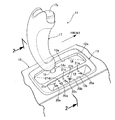
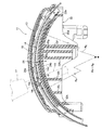
【解決手段】 シフトレバー15を揺動させると円弧状のスライダ14が、インジケータパネル13の下方両側縁に沿って設けられた円弧状のガイドレール24にガイドされて摺動し、シフトレバー15が選択するシフトポジションがスライダ14の窓孔14bを透過する光でポジションプレート18に表示される。スライダ14の曲率半径Rsをガイドレール24の曲率半径Rgよりも小さく設定し、かつ窓孔14bをスライダ14のスライド方向中央部に設けたので、窓孔14bはガイドレール24の上部レール24a側に付勢されてポジションプレート18に接近するため、窓孔14bの視認性を高めてシフトポジションの把握を容易にすることができる。
【選択図】 図3
Description
13a 長孔
13b 開口
14 スライダ
14a 貫通孔
14b 窓孔(表示部)
15 シフトレバー
18 ポジションプレート
24 ガイドレール
24a 上部レール
24b 下部レール
24c スリット
25 ランプ
Rs スライダの自由状態における曲率半径
Rr ガイドレールの曲率半径
Claims (3)
- 車体に揺動自在に枢支されてシフトポジションを選択するシフトレバー(15)と、前記シフトレバー(15)の中間部が貫通する長孔(13a)が形成されたインジケータパネル(13)と、前記インジケータパネル(13)の長孔(13a)の下方両側縁に沿って設けられた円弧状のガイドレール(24)と、前記シフトレバー(15)の中間部が貫通する貫通孔(14a)を有して前記ガイドレール(24)に摺動自在に嵌合する円弧状のスライダ(14)と、前記インジケータパネル(13)に前記選択されたシフトポジションを表示する表示部(14b)とを備える車両用シフトレバー装置において、
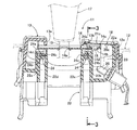
前記スライダ(14)は前記ガイドレール(24)の上部レール(24a)および下部レール(24b)間に形成されたスリット(24c)に摺動自在に嵌合し、前記スライダ(14)の自由状態における曲率半径(Rs)は前記ガイドレール(24)の曲率半径(Rr)よりも小さく設定されるとともに、前記表示部(14b)は前記スライダ(14)のスライド方向中央部に設けられることを特徴とする車両用シフトレバー装置。 - 前記スライダ(14)のスライド方向両端部の下面は前記ガイドレール(24)の下部レール(24b)に接触し、前記スライダ(14)のスライド方向中央部の上面は前記ガイドレール(24)の上部レール(24a)に接触することを特徴とする、請求項1に記載の車両用シフトレバー装置。
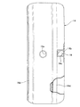
- シフトポジションが表記されて前記インジケータパネル(13)の開口(13b)に設けられるポジションプレート(18)と、前記ポジションプレート(18)の裏面側に配置されるランプ(25)とを備え、前記表示部は、前記ポジションプレート(18)の裏面側に重なる前記スライダ(14)のスライド方向中央部に形成された窓孔(14b)で構成され、前記ランプ(25)から出た光が前記窓孔(14b)を透過して前記ポジションプレート(18)の所定位置を照射することを特徴とする、請求項1または請求項2に記載の車両用シフトレバー装置。
Priority Applications (1)
| Application Number | Priority Date | Filing Date | Title |
|---|---|---|---|
| JP2008237783A JP5059722B2 (ja) | 2008-09-17 | 2008-09-17 | 車両用シフトレバー装置 |
Applications Claiming Priority (1)
| Application Number | Priority Date | Filing Date | Title |
|---|---|---|---|
| JP2008237783A JP5059722B2 (ja) | 2008-09-17 | 2008-09-17 | 車両用シフトレバー装置 |
Publications (2)
| Publication Number | Publication Date |
|---|---|
| JP2010069985A true JP2010069985A (ja) | 2010-04-02 |
| JP5059722B2 JP5059722B2 (ja) | 2012-10-31 |
Family
ID=42202175
Family Applications (1)
| Application Number | Title | Priority Date | Filing Date |
|---|---|---|---|
| JP2008237783A Expired - Fee Related JP5059722B2 (ja) | 2008-09-17 | 2008-09-17 | 車両用シフトレバー装置 |
Country Status (1)
| Country | Link |
|---|---|
| JP (1) | JP5059722B2 (ja) |
Cited By (2)
| Publication number | Priority date | Publication date | Assignee | Title |
|---|---|---|---|---|
| CN109030225A (zh) * | 2018-06-29 | 2018-12-18 | 中国电建集团中南勘测设计研究院有限公司 | 一种用于水压致裂法地应力试验中实时观测岩体裂缝的设备 |
| CN111038253A (zh) * | 2019-12-26 | 2020-04-21 | 宁波高发汽车控制系统股份有限公司 | 一种换挡器的面板连接结构 |
Citations (3)
| Publication number | Priority date | Publication date | Assignee | Title |
|---|---|---|---|---|
| JPH09156396A (ja) * | 1995-12-06 | 1997-06-17 | Delta Kogyo Co Ltd | 車両用シフトレバー装置のインジケータ取付構造 |
| JPH09216527A (ja) * | 1996-02-13 | 1997-08-19 | Sakae Riken Kogyo Kk | 変速機用シフト装置 |
| JP2005186720A (ja) * | 2003-12-25 | 2005-07-14 | Fuji Kiko Co Ltd | シフトレバー装置 |
-
2008
- 2008-09-17 JP JP2008237783A patent/JP5059722B2/ja not_active Expired - Fee Related
Patent Citations (3)
| Publication number | Priority date | Publication date | Assignee | Title |
|---|---|---|---|---|
| JPH09156396A (ja) * | 1995-12-06 | 1997-06-17 | Delta Kogyo Co Ltd | 車両用シフトレバー装置のインジケータ取付構造 |
| JPH09216527A (ja) * | 1996-02-13 | 1997-08-19 | Sakae Riken Kogyo Kk | 変速機用シフト装置 |
| JP2005186720A (ja) * | 2003-12-25 | 2005-07-14 | Fuji Kiko Co Ltd | シフトレバー装置 |
Cited By (2)
| Publication number | Priority date | Publication date | Assignee | Title |
|---|---|---|---|---|
| CN109030225A (zh) * | 2018-06-29 | 2018-12-18 | 中国电建集团中南勘测设计研究院有限公司 | 一种用于水压致裂法地应力试验中实时观测岩体裂缝的设备 |
| CN111038253A (zh) * | 2019-12-26 | 2020-04-21 | 宁波高发汽车控制系统股份有限公司 | 一种换挡器的面板连接结构 |
Also Published As
| Publication number | Publication date |
|---|---|
| JP5059722B2 (ja) | 2012-10-31 |
Similar Documents
| Publication | Publication Date | Title |
|---|---|---|
| US5540180A (en) | Gear position indicating arrangement in automatic transmission shift control device | |
| JP5227607B2 (ja) | 車両用収容ボックス | |
| JP2008230608A (ja) | 車室内の照明装置 | |
| JP5059722B2 (ja) | 車両用シフトレバー装置 | |
| JP4442854B2 (ja) | オートマチックトランスミッションのレンジ位置表示装置 | |
| JP5866978B2 (ja) | 車両のシフト操作装置 | |
| JP2006273114A (ja) | 自動変速機付き車両の表示装置 | |
| JP3420014B2 (ja) | シフトレバー装置用カバースライド | |
| CN103253130B (zh) | 车辆用变速操作装置的指示器及车辆用变速操作装置 | |
| JP4448744B2 (ja) | 車室内の照明装置 | |
| JP2007168765A (ja) | Atセレクタカバー | |
| JP2009248847A (ja) | 車両用表示装置 | |
| JP5889714B2 (ja) | スイッチ装置 | |
| JP5547025B2 (ja) | シフト装置 | |
| JP5634678B2 (ja) | 車両用表示装置 | |
| JP6023583B2 (ja) | シフトレバーのレンジ位置表示装置 | |
| JP2006076557A (ja) | 車室内の照明装置 | |
| JP2006111101A (ja) | 車両用ドリンクホルダー | |
| JP2007084033A (ja) | シフトレバー装置 | |
| KR100435284B1 (ko) | 자동차용 계기판 | |
| JP3643256B2 (ja) | 自動変速機のシフトレバー装置 | |
| JPH05246260A (ja) | 車両用自動変速機の操作装置 | |
| JP5767902B2 (ja) | 車両用計器 | |
| JPH1178581A (ja) | シフトレバー装置 | |
| JP2007022200A (ja) | 車室内の照明装置 |
Legal Events
| Date | Code | Title | Description |
|---|---|---|---|
| A621 | Written request for application examination |
Free format text: JAPANESE INTERMEDIATE CODE: A621 Effective date: 20101125 |
|
| A977 | Report on retrieval |
Free format text: JAPANESE INTERMEDIATE CODE: A971007 Effective date: 20111227 |
|
| A131 | Notification of reasons for refusal |
Free format text: JAPANESE INTERMEDIATE CODE: A131 Effective date: 20120411 |
|
| A521 | Request for written amendment filed |
Free format text: JAPANESE INTERMEDIATE CODE: A523 Effective date: 20120611 |
|
| TRDD | Decision of grant or rejection written | ||
| A01 | Written decision to grant a patent or to grant a registration (utility model) |
Free format text: JAPANESE INTERMEDIATE CODE: A01 Effective date: 20120718 |
|
| A01 | Written decision to grant a patent or to grant a registration (utility model) |
Free format text: JAPANESE INTERMEDIATE CODE: A01 |
|
| A61 | First payment of annual fees (during grant procedure) |
Free format text: JAPANESE INTERMEDIATE CODE: A61 Effective date: 20120802 |
|
| FPAY | Renewal fee payment (event date is renewal date of database) |
Free format text: PAYMENT UNTIL: 20150810 Year of fee payment: 3 |
|
| R150 | Certificate of patent or registration of utility model |
Ref document number: 5059722 Country of ref document: JP Free format text: JAPANESE INTERMEDIATE CODE: R150 Free format text: JAPANESE INTERMEDIATE CODE: R150 |
|
| R250 | Receipt of annual fees |
Free format text: JAPANESE INTERMEDIATE CODE: R250 |
|
| LAPS | Cancellation because of no payment of annual fees |