JP2010043718A - 減速機構付モータ - Google Patents
減速機構付モータ Download PDFInfo
- Publication number
- JP2010043718A JP2010043718A JP2008210024A JP2008210024A JP2010043718A JP 2010043718 A JP2010043718 A JP 2010043718A JP 2008210024 A JP2008210024 A JP 2008210024A JP 2008210024 A JP2008210024 A JP 2008210024A JP 2010043718 A JP2010043718 A JP 2010043718A
- Authority
- JP
- Japan
- Prior art keywords
- worm wheel
- worm
- housing portion
- wheel housing
- bottom cover
- Prior art date
- Legal status (The legal status is an assumption and is not a legal conclusion. Google has not performed a legal analysis and makes no representation as to the accuracy of the status listed.)
- Granted
Links
- 210000000078 claw Anatomy 0.000 claims description 58
- 230000002093 peripheral effect Effects 0.000 claims description 21
- 238000007789 sealing Methods 0.000 abstract description 6
- 230000002159 abnormal effect Effects 0.000 abstract 1
- 238000004891 communication Methods 0.000 description 3
- 239000013013 elastic material Substances 0.000 description 2
- 239000005357 flat glass Substances 0.000 description 2
- 238000012423 maintenance Methods 0.000 description 2
- 230000004308 accommodation Effects 0.000 description 1
- 230000015572 biosynthetic process Effects 0.000 description 1
- 239000011521 glass Substances 0.000 description 1
- 230000013011 mating Effects 0.000 description 1
- 238000012986 modification Methods 0.000 description 1
- 230000004048 modification Effects 0.000 description 1
- 238000000465 moulding Methods 0.000 description 1
- 239000011347 resin Substances 0.000 description 1
- 229920005989 resin Polymers 0.000 description 1
- 230000035939 shock Effects 0.000 description 1
- 238000003466 welding Methods 0.000 description 1
Images


Landscapes
- Power-Operated Mechanisms For Wings (AREA)
- Gear Transmission (AREA)
- Connection Of Motors, Electrical Generators, Mechanical Devices, And The Like (AREA)
Abstract
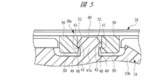
【解決手段】ウォームホイール収容部19は、底壁部と円筒壁部19bとを有する有底円筒形状となっており、その開口部にボトムカバー35が組み付けられて密閉される。ボトムカバー35にはシール部材36が装着されており、このシール部材36の外周部には軸方向に突出する軸方向突起部57が設けられている。一方、円筒壁部19bの内壁表面には、返し構造としての段差部59が設けられており、当該段差部59には斜面60が形成されている。ウォームホイール収容部19とボトムカバー35とが組み付けられると、軸方向突起部57は段差部59の斜面60に当接されて当該斜面60により径方向外側に案内される。これにより、ウォームホイール収容部19とボトムカバー35との間の軸方向のガタが抑制され、ガタによる異音の発生が防止される。
【選択図】図7
Description
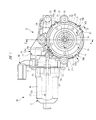
11 モータ本体
12 ギヤ部
13 回転軸
13a アーマチュア軸
13b ウォーム軸
14 モータヨーク
14a フランジ部
15 ボルト
16 ギヤケース
17 ウォーム収容部
17a 開口部
18 ウォーム
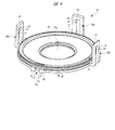
19 ウォームホイール収容部
19a 底壁部
19b 円筒壁部
20 ウォームホイール
20a 歯部
20b ボス部
21 円筒部
21a 貫通孔
22 出力軸
22a 溝
23 環状凸部
24 連通孔
26 ダンパ部材
26a 弾性部
26b 連結部
27 従動プレート
27a 大径部
27b 小径部
28 凹部
29 突起部
30 突起部
31 出力ギヤ
31a ギヤ孔
32 係止部材
33 Oリング
35 ボトムカバー
35a 突出孔
36 シール部材
38a,38b 係止爪
39 爪部
40 溝
41 係合部
42 係合面
43 先端部
44 溝
45 係合面
47a,47b 凸片
48 アンダーカット部
49 係合面
50 切り欠き部
51 係合面
52 係合部
53,54 壁部
56 径方向突起部
57 軸方向突起部
58 切り欠き部
58a シール面
59 段差部(返し構造)
60 斜面
61 整流子
62 コネクタユニット
63 ブラシホルダ
D 隙間
Claims (4)
- アーマチュア軸を回転自在に支持するヨークと、
前記アーマチュア軸と一体回転し、ウォームが設けられたウォーム軸と、
前記ウォーム軸を収容するウォーム収容部と、前記ウォーム軸のウォームと噛み合うウォームホイールを収容する有底形状のウォームホイール収容部とを備え、前記ヨークが取り付けられるギヤケースと、
前記ウォームホイール収容部の開口部を覆うボトムカバーと、
前記ウォームホイール収容部と前記ボトムカバーとを爪係合する複数の係止構造とを有する減速機構付モータであって、
前記ウォームホイール収容部側に向けて軸方向に突出する軸方向突起部を外周部に備え、前記ボトムカバーに設けられて前記ボトムカバーと前記ウォームホイール収容部との間を密閉するシール部材と、
前記ウォームホイール収容部の内壁表面に設けられ、前記軸方向突起部が当接されて当該軸方向突起部を径方向外側に案内する斜面を備えた返し構造とを有することを特徴とする減速機構付モータ。 - ウォームが設けられた回転軸を回転自在に支持するヨークと、
前記ウォームを収容するウォーム収容部と、前記ウォームと噛み合うウォームホイールを収容する有底形状のウォームホイール収容部とを備え、前記ヨークが取り付けられるギヤケースと、
前記ウォームホイール収容部の開口部を覆うボトムカバーと、
前記ウォームホイール収容部と前記ボトムカバーとを爪係合する複数の係止構造とを有する減速機構付モータであって、
前記ウォームホイール収容部側に向けて軸方向に突出する軸方向突起部を外周部に備え、前記ボトムカバーに設けられて前記ボトムカバーと前記ウォームホイール収容部との間を密閉するシール部材と、
前記ウォームホイール収容部の内壁表面に設けられ、前記軸方向突起部が当接されて当該軸方向突起部を径方向外側に案内する斜面を備えた返し構造とを有することを特徴とする減速機構付モータ。 - 請求項1または2記載の減速機構付モータにおいて、前記軸方向突起部は前記複数の係止構造が設けられる箇所に対応して設けられていることを特徴とする減速機構付モータ。
- 請求項1〜3のいずれか1項に記載の減速機構付モータにおいて、前記シール部材の外周部には、径方向外側に突出して前記ウォームホイール収容部の内壁表面に設けられたシール面に当接する径方向突起部が設けられることを特徴とする減速機構付モータ。
Priority Applications (1)
| Application Number | Priority Date | Filing Date | Title |
|---|---|---|---|
| JP2008210024A JP4950962B2 (ja) | 2008-08-18 | 2008-08-18 | 減速機構付モータ |
Applications Claiming Priority (1)
| Application Number | Priority Date | Filing Date | Title |
|---|---|---|---|
| JP2008210024A JP4950962B2 (ja) | 2008-08-18 | 2008-08-18 | 減速機構付モータ |
Publications (2)
| Publication Number | Publication Date |
|---|---|
| JP2010043718A true JP2010043718A (ja) | 2010-02-25 |
| JP4950962B2 JP4950962B2 (ja) | 2012-06-13 |
Family
ID=42015260
Family Applications (1)
| Application Number | Title | Priority Date | Filing Date |
|---|---|---|---|
| JP2008210024A Active JP4950962B2 (ja) | 2008-08-18 | 2008-08-18 | 減速機構付モータ |
Country Status (1)
| Country | Link |
|---|---|
| JP (1) | JP4950962B2 (ja) |
Cited By (2)
| Publication number | Priority date | Publication date | Assignee | Title |
|---|---|---|---|---|
| JP2014093787A (ja) * | 2012-10-31 | 2014-05-19 | Mitsuba Corp | モータ装置 |
| JP2017143695A (ja) * | 2016-02-12 | 2017-08-17 | アスモ株式会社 | モータ |
Citations (5)
| Publication number | Priority date | Publication date | Assignee | Title |
|---|---|---|---|---|
| JPH11261254A (ja) * | 1998-03-13 | 1999-09-24 | Japan Aviation Electronics Ind Ltd | プリント基板の取付構造 |
| JP2001200938A (ja) * | 2000-01-13 | 2001-07-27 | Mitsubishi Heavy Ind Ltd | くさび型シール |
| JP2001346352A (ja) * | 2000-03-30 | 2001-12-14 | Asmo Co Ltd | ギヤードモータ |
| JP2003047204A (ja) * | 2001-05-25 | 2003-02-14 | Webasto Vehicle Systems Internatl Gmbh | 駆動装置 |
| JP2007247825A (ja) * | 2006-03-17 | 2007-09-27 | Nok Corp | シールリング |
-
2008
- 2008-08-18 JP JP2008210024A patent/JP4950962B2/ja active Active
Patent Citations (5)
| Publication number | Priority date | Publication date | Assignee | Title |
|---|---|---|---|---|
| JPH11261254A (ja) * | 1998-03-13 | 1999-09-24 | Japan Aviation Electronics Ind Ltd | プリント基板の取付構造 |
| JP2001200938A (ja) * | 2000-01-13 | 2001-07-27 | Mitsubishi Heavy Ind Ltd | くさび型シール |
| JP2001346352A (ja) * | 2000-03-30 | 2001-12-14 | Asmo Co Ltd | ギヤードモータ |
| JP2003047204A (ja) * | 2001-05-25 | 2003-02-14 | Webasto Vehicle Systems Internatl Gmbh | 駆動装置 |
| JP2007247825A (ja) * | 2006-03-17 | 2007-09-27 | Nok Corp | シールリング |
Cited By (2)
| Publication number | Priority date | Publication date | Assignee | Title |
|---|---|---|---|---|
| JP2014093787A (ja) * | 2012-10-31 | 2014-05-19 | Mitsuba Corp | モータ装置 |
| JP2017143695A (ja) * | 2016-02-12 | 2017-08-17 | アスモ株式会社 | モータ |
Also Published As
| Publication number | Publication date |
|---|---|
| JP4950962B2 (ja) | 2012-06-13 |
Similar Documents
| Publication | Publication Date | Title |
|---|---|---|
| JP5173668B2 (ja) | 減速機構付モータ | |
| JP5129690B2 (ja) | 減速機構付モータ | |
| WO2012026430A1 (ja) | モータ装置およびその製造方法 | |
| JP5766193B2 (ja) | ワイパモータ | |
| JP4563119B2 (ja) | ギアユニットおよびケーブル窓昇降システム用のモータ駆動ギアユニット | |
| EP2103842B1 (en) | Motor with reduction gear | |
| JP2012137114A (ja) | 減速機構付モータ | |
| WO2015004795A1 (ja) | モータ装置 | |
| JP4950962B2 (ja) | 減速機構付モータ | |
| JP5931697B2 (ja) | モータ装置 | |
| JP6410396B2 (ja) | モータ装置 | |
| JP5563910B2 (ja) | 減速機構付モータ | |
| JP6624996B2 (ja) | アクチュエータ | |
| JP5719548B2 (ja) | 減速機構付きモータ | |
| JP2010091009A (ja) | 減速機構付モータ | |
| JP2010230153A (ja) | クラッチ機構、および減速機付モータ | |
| JP6711727B2 (ja) | 駆動機構 | |
| JP2010048352A (ja) | クラッチ機構、クラッチ付減速機、および減速機付モータ | |
| JP7034810B2 (ja) | 減速機構及び減速機付モータ | |
| JP5546177B2 (ja) | 減速機付モータ | |
| CN213228278U (zh) | 一种驱动装置及车辆天窗 | |
| JP5350938B2 (ja) | モータ装置及びモータ装置の組付け方法 | |
| JP2010223404A (ja) | クラッチ機構、および減速機付モータ | |
| JP6711702B2 (ja) | 減速機付モータ | |
| JP2020041587A (ja) | 減速機構、及び減速機付モータ |
Legal Events
| Date | Code | Title | Description |
|---|---|---|---|
| A621 | Written request for application examination |
Free format text: JAPANESE INTERMEDIATE CODE: A621 Effective date: 20110210 |
|
| A977 | Report on retrieval |
Free format text: JAPANESE INTERMEDIATE CODE: A971007 Effective date: 20120224 |
|
| TRDD | Decision of grant or rejection written | ||
| A01 | Written decision to grant a patent or to grant a registration (utility model) |
Free format text: JAPANESE INTERMEDIATE CODE: A01 Effective date: 20120306 |
|
| A01 | Written decision to grant a patent or to grant a registration (utility model) |
Free format text: JAPANESE INTERMEDIATE CODE: A01 |
|
| A61 | First payment of annual fees (during grant procedure) |
Free format text: JAPANESE INTERMEDIATE CODE: A61 Effective date: 20120309 |
|
| FPAY | Renewal fee payment (event date is renewal date of database) |
Free format text: PAYMENT UNTIL: 20150316 Year of fee payment: 3 |
|
| R150 | Certificate of patent or registration of utility model |
Ref document number: 4950962 Country of ref document: JP Free format text: JAPANESE INTERMEDIATE CODE: R150 Free format text: JAPANESE INTERMEDIATE CODE: R150 |