JP2010036844A - 乗物用盗難防止装置 - Google Patents
乗物用盗難防止装置 Download PDFInfo
- Publication number
- JP2010036844A JP2010036844A JP2008205390A JP2008205390A JP2010036844A JP 2010036844 A JP2010036844 A JP 2010036844A JP 2008205390 A JP2008205390 A JP 2008205390A JP 2008205390 A JP2008205390 A JP 2008205390A JP 2010036844 A JP2010036844 A JP 2010036844A
- Authority
- JP
- Japan
- Prior art keywords
- outer cylinder
- operation knob
- cylinder
- hole
- mechanical key
- Prior art date
- Legal status (The legal status is an assumption and is not a legal conclusion. Google has not performed a legal analysis and makes no representation as to the accuracy of the status listed.)
- Granted
Links
- 238000003780 insertion Methods 0.000 claims abstract description 18
- 230000037431 insertion Effects 0.000 claims abstract description 18
- 230000000149 penetrating effect Effects 0.000 claims description 2
- 230000000903 blocking effect Effects 0.000 abstract 1
- 238000005192 partition Methods 0.000 description 4
- 210000005069 ears Anatomy 0.000 description 2
- 230000002265 prevention Effects 0.000 description 2
- 230000004308 accommodation Effects 0.000 description 1
- 230000005540 biological transmission Effects 0.000 description 1
- 230000008878 coupling Effects 0.000 description 1
- 238000010168 coupling process Methods 0.000 description 1
- 238000005859 coupling reaction Methods 0.000 description 1
- 230000006378 damage Effects 0.000 description 1
- 238000000034 method Methods 0.000 description 1
Images


Landscapes
- Lock And Its Accessories (AREA)
Abstract
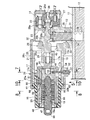
【解決手段】盗難防止作動手段13に連結されてボディ15に回動可能に支承されるアウターシリンダ17に、キー孔19への正規のメカニカルキー58の挿入および非挿入に応じてアウターシリンダ17の回動を許容する状態および回動を阻止する状態を切換えるインナシリンダ16が同軸に挿入され、アウターシリンダ17を介在させたインナーシリンダ16および操作ノブ18間に、キー孔19への正規のメカニカルキー58の挿入時に操作ノブ18およびアウターシリンダ17を相対回動不能に連結する連結切換手段59が設けられる。
【選択図】 図2
Description
13・・・盗難防止作動手段であるステアリングロック機構
15・・・ボディ
16・・・インナーシリンダ
17・・・アウターシリンダ
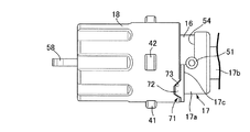
18・・・操作ノブ
19・・・キー孔
20・・・タンブラー
51・・・ピン
52・・・第1支持孔
53・・・第2支持孔
58・・・メカニカルキー
59・・・連結切換手段
71・・・位置決め・トルクリミッタ機構
Claims (3)
- 支持体(11)に固定されるボディ(15)と、キー孔(19)を有して前記ボディ(15)に回動不能に支持されるとともに複数のタンブラー(20)が装着されるインナーシリンダ(16)と、該インナーシリンダ(16)と同軸に配置される操作ノブ(18)とを備え、前記キー孔(19)への正規のメカニカルキー(58)の挿入に応じて盗難防止作動手段(13)に回動操作力を伝達するように前記操作ノブ(18)を回動操作することを可能とした乗物用盗難防止装置において、前記盗難防止作動手段(13)に連結されて前記ボディ(15)に回動可能に支承されるアウターシリンダ(17)に、前記キー孔(19)への正規のメカニカルキー(58)の非挿入時に前記アウターシリンダ(17)に前記タンブラー(20)を係合させてアウターシリンダ(17)の回動を阻止する状態ならびに前記キー孔(19)への正規のメカニカルキー(58)の挿入時に前記アウターシリンダ(17)への前記タンブラー(20)の係合を解除して該アウターシリンダ(17)の回動を許容する状態を切換えるようにして前記インナーシリンダ(16)が同軸に挿入され、前記キー孔(19)への正規のメカニカルキー(58)の挿入時には前記操作ノブ(18)および前記アウターシリンダ(17)を相対回動不能に連結するものの前記キー孔(19)への正規のメカニカルキー(58)の非挿入時には前記操作ノブ(18)および前記アウターシリンダ(17)の連結を解除する連結切換手段(59)が前記アウターシリンダ(17)を介在させた前記インナーシリンダ(16)および前記操作ノブ(18)間に設けられ、前記操作ノブ(18)が、前記アウターシリンダ(17)の前記ボディ(15)からの突出部を覆って該アウターシリンダ(17)に相対回動可能に支持されることを特徴とする乗物用盗難防止装置。
- 前記アウターシリンダ(17)の回動を許容するようにして該アウターシリンダ(17)の側壁を貫通するピン(51)の一端部が、前記ボディ(15)のうち前記支持体(11)に近接、対向する側面に開口する第1支持孔(52)に挿通され、前記インナーシリンダ(16)に設けられた第2支持孔(53)に前記ピン(51)の他端部が挿通されることを特徴とする請求項1記載の乗物用盗難防止装置。
- 前記アウターシリンダ(17)および前記操作ノブ(18)の相対位置を前記連結切換手段(59)で連結することを可能とした位置に定めるとともに、前記連結切換手段(59)が非連結状態にあるときの操作ノブ(18)への回転作動力の入力時には操作ノブ(18)をアウターシリンダ(17)まわりに空転させる位置決め・トルクリミッタ機構(71)が、前記アウターシリンダ(17)および前記操作ノブ(18)間に設けられることを特徴とする請求項1または2記載の乗物用盗難防止装置。
Priority Applications (1)
| Application Number | Priority Date | Filing Date | Title |
|---|---|---|---|
| JP2008205390A JP4979656B2 (ja) | 2008-08-08 | 2008-08-08 | 乗物用盗難防止装置 |
Applications Claiming Priority (1)
| Application Number | Priority Date | Filing Date | Title |
|---|---|---|---|
| JP2008205390A JP4979656B2 (ja) | 2008-08-08 | 2008-08-08 | 乗物用盗難防止装置 |
Publications (3)
| Publication Number | Publication Date |
|---|---|
| JP2010036844A true JP2010036844A (ja) | 2010-02-18 |
| JP2010036844A5 JP2010036844A5 (ja) | 2010-12-09 |
| JP4979656B2 JP4979656B2 (ja) | 2012-07-18 |
Family
ID=42009818
Family Applications (1)
| Application Number | Title | Priority Date | Filing Date |
|---|---|---|---|
| JP2008205390A Expired - Fee Related JP4979656B2 (ja) | 2008-08-08 | 2008-08-08 | 乗物用盗難防止装置 |
Country Status (1)
| Country | Link |
|---|---|
| JP (1) | JP4979656B2 (ja) |
Cited By (1)
| Publication number | Priority date | Publication date | Assignee | Title |
|---|---|---|---|---|
| CN115126348A (zh) * | 2022-04-29 | 2022-09-30 | 李翔宇 | 一种互锁弹子空转锁体及其钥匙 |
Citations (2)
| Publication number | Priority date | Publication date | Assignee | Title |
|---|---|---|---|---|
| JP3616279B2 (ja) * | 1999-07-22 | 2005-02-02 | 朝日電装株式会社 | イグニッションスイッチ |
| JP3616298B2 (ja) * | 2000-03-14 | 2005-02-02 | 朝日電装株式会社 | イグニッションスイッチ |
-
2008
- 2008-08-08 JP JP2008205390A patent/JP4979656B2/ja not_active Expired - Fee Related
Patent Citations (2)
| Publication number | Priority date | Publication date | Assignee | Title |
|---|---|---|---|---|
| JP3616279B2 (ja) * | 1999-07-22 | 2005-02-02 | 朝日電装株式会社 | イグニッションスイッチ |
| JP3616298B2 (ja) * | 2000-03-14 | 2005-02-02 | 朝日電装株式会社 | イグニッションスイッチ |
Cited By (1)
| Publication number | Priority date | Publication date | Assignee | Title |
|---|---|---|---|---|
| CN115126348A (zh) * | 2022-04-29 | 2022-09-30 | 李翔宇 | 一种互锁弹子空转锁体及其钥匙 |
Also Published As
| Publication number | Publication date |
|---|---|
| JP4979656B2 (ja) | 2012-07-18 |
Similar Documents
| Publication | Publication Date | Title |
|---|---|---|
| US8607600B2 (en) | Pin locking device | |
| JP3527394B2 (ja) | ステアリングロック装置 | |
| WO2005026476A1 (ja) | シリンダ錠 | |
| CN105026664B (zh) | 圆筒锁 | |
| JP4353848B2 (ja) | シリンダ錠 | |
| JP6153849B2 (ja) | ステアリングロック装置 | |
| JP4979656B2 (ja) | 乗物用盗難防止装置 | |
| JP2015227584A (ja) | シリンダ錠装置 | |
| JP3441033B2 (ja) | ステアリングロック装置 | |
| JP4025551B2 (ja) | シリンダ錠装置 | |
| JP4035224B2 (ja) | ステアリングロック装置 | |
| JP4403395B2 (ja) | シリンダ錠 | |
| JP6422105B2 (ja) | シリンダ錠装置 | |
| JP7343408B2 (ja) | シリンダ錠装置 | |
| JP2003327084A (ja) | ステアリングロック装置 | |
| JP4512922B2 (ja) | シリンダ錠 | |
| JP2007055292A (ja) | ステアリングロック装置 | |
| JP2015085814A (ja) | ステアリングロック装置 | |
| JP5007195B2 (ja) | イグニッション操作装置 | |
| JP4328665B2 (ja) | 錠装置 | |
| JP4031715B2 (ja) | ステアリングロック装置 | |
| EP1829757B1 (en) | Combination ignition switch and steering lock assembly for a motorcycle | |
| JP4766960B2 (ja) | ステアリングロック装置 | |
| JP4213622B2 (ja) | 錠装置 | |
| JP2006182191A (ja) | ステアリングロック装置 |
Legal Events
| Date | Code | Title | Description |
|---|---|---|---|
| A521 | Written amendment |
Free format text: JAPANESE INTERMEDIATE CODE: A523 Effective date: 20101026 |
|
| A621 | Written request for application examination |
Free format text: JAPANESE INTERMEDIATE CODE: A621 Effective date: 20101125 |
|
| A977 | Report on retrieval |
Free format text: JAPANESE INTERMEDIATE CODE: A971007 Effective date: 20120315 |
|
| TRDD | Decision of grant or rejection written | ||
| A01 | Written decision to grant a patent or to grant a registration (utility model) |
Free format text: JAPANESE INTERMEDIATE CODE: A01 Effective date: 20120328 |
|
| A01 | Written decision to grant a patent or to grant a registration (utility model) |
Free format text: JAPANESE INTERMEDIATE CODE: A01 |
|
| A61 | First payment of annual fees (during grant procedure) |
Free format text: JAPANESE INTERMEDIATE CODE: A61 Effective date: 20120417 |
|
| FPAY | Renewal fee payment (prs date is renewal date of database) |
Free format text: PAYMENT UNTIL: 20150427 Year of fee payment: 3 |
|
| R150 | Certificate of patent (=grant) or registration of utility model |
Free format text: JAPANESE INTERMEDIATE CODE: R150 |
|
| LAPS | Cancellation because of no payment of annual fees |