JP2010036844A - Theft preventative device for vehicle - Google Patents

Theft preventative device for vehicle Download PDF

Info

Publication number
JP2010036844A
JP2010036844A JP2008205390A JP2008205390A JP2010036844A JP 2010036844 A JP2010036844 A JP 2010036844A JP 2008205390 A JP2008205390 A JP 2008205390A JP 2008205390 A JP2008205390 A JP 2008205390A JP 2010036844 A JP2010036844 A JP 2010036844A
Authority
JP
Japan
Prior art keywords
outer cylinder
operation knob
cylinder
hole
mechanical key
Prior art date
Legal status (The legal status is an assumption and is not a legal conclusion. Google has not performed a legal analysis and makes no representation as to the accuracy of the status listed.)
Granted
Application number
JP2008205390A
Other languages
Japanese (ja)
Other versions
JP4979656B2 (en
JP2010036844A5 (en
Inventor
Yoichi Uda
洋一 宇田
Ichiro Yui
一郎 由比
Takashi Ishizuka
貴士 石塚
Current Assignee (The listed assignees may be inaccurate. Google has not performed a legal analysis and makes no representation or warranty as to the accuracy of the list.)
Minebea AccessSolutions Inc
Original Assignee
Honda Lock Manufacturing Co Ltd
Priority date (The priority date is an assumption and is not a legal conclusion. Google has not performed a legal analysis and makes no representation as to the accuracy of the date listed.)
Filing date
Publication date
Application filed by Honda Lock Manufacturing Co Ltd filed Critical Honda Lock Manufacturing Co Ltd
Priority to JP2008205390A priority Critical patent/JP4979656B2/en
Publication of JP2010036844A publication Critical patent/JP2010036844A/en
Publication of JP2010036844A5 publication Critical patent/JP2010036844A5/ja
Application granted granted Critical
Publication of JP4979656B2 publication Critical patent/JP4979656B2/en
Expired - Fee Related legal-status Critical Current
Anticipated expiration legal-status Critical

Links

Images

Landscapes

  • Lock And Its Accessories (AREA)

Abstract

<P>PROBLEM TO BE SOLVED: To prevent a rotative operational force from being transmitted to a theft preventative operational means even in cases where a tumbler is unjustly operated aiming at trouble making or theft-committing in a theft preventative device for vehicles whose operational knob can be rotatably operated so that a rotative operational force is transmitted to a theft preventative working means in response to the insertion of a regular mechanical key into the keyhole of the inner cylinder. <P>SOLUTION: Into an outer cylinder 17 to be connected to a theft preventative working means 13 and rotatably supported by a body 15, an inner cylinder is coaxially inserted for switching between states for allowing the outer cylinder 17 to rotate or blocking it from rotating in response to the insertion/non-insertion of the regular mechanical key 58 into the keyhole 19. A connection changeover means 59 for connecting an operational knob 18 and the outer cylinder 17 relatively unrotatably at the time of the insertion of the regular mechanical key 58 into the keyhole 19, is installed, between the inner cylinder 16 and the operational knob 18 with the outer cylinder 17 in between. <P>COPYRIGHT: (C)2010,JPO&INPIT

Description

本発明は、支持体に固定されるボディと、キー孔を有して前記ボディに回動不能に支持されるとともに複数のタンブラーが装着されるインナーシリンダと、該インナーシリンダと同軸に配置される操作ノブとを備え、前記キー孔への正規のメカニカルキーの挿入に応じて盗難防止作動手段に回動操作力を伝達するように前記操作ノブを回動操作することを可能とした乗物用盗難防止装置に関する。   The present invention includes a body that is fixed to a support, an inner cylinder that has a key hole and is non-rotatably supported by the body and on which a plurality of tumblers are mounted, and is disposed coaxially with the inner cylinder. A vehicle theft comprising an operation knob and capable of rotating the operation knob so as to transmit a rotation operation force to the anti-theft actuating means in response to insertion of a regular mechanical key into the key hole The present invention relates to a prevention device.

乗物用盗難防止装置として、タンブラーが装着されたインナーシリンダのキー孔に正規のメカニカルキーを挿入し、該メカニカルキーの握り部を握ってインナーシリンダを回動駆動することで、ステアリングロック機構のロックピンやイグニッションスイッチを作動せしめるようにしたものが、従来から一般的に行われている。   As a vehicle anti-theft device, a regular mechanical key is inserted into the key hole of the inner cylinder where the tumbler is mounted, and the inner cylinder is rotated by holding the grip of the mechanical key. Conventionally, a pin or an ignition switch is operated.

ところが、上述のような従来のものでは、握り部を握っての操作性の観点や、操作強度の観点からメカニカルキー全体が大型化し、インナーシリンダの大型化を招いたり、メカニカルキーの携帯性が悪化したりする。特に自動二輪車のようにグローブを嵌めた手でメカニカルキーを操作するものでは、より顕著にそのような課題が生じることになる。   However, in the conventional ones as described above, the entire mechanical key is enlarged from the viewpoint of operability when grasping the grip portion and the viewpoint of operation strength, leading to an increase in the size of the inner cylinder, and the portability of the mechanical key is reduced. It gets worse. In particular, when a mechanical key is operated with a hand fitted with a glove such as a motorcycle, such a problem occurs more remarkably.

そこでメカニカルキーおよび操作ノブを分離して設け、メカニカルキーの操作によって操作ノブの操作の許可および禁止を切換え、操作ノブによってロックピンやイグニッションスイッチ操作の回動負荷を負担するようにしたものが特許文献1および特許文献2で開示されている。
特許第3616279号公報 特許第3616298号公報
Therefore, there is a patent that separates the mechanical key and the operating knob, switches the permission and prohibition of operation of the operating knob by operating the mechanical key, and bears the rotational load of operating the lock pin and ignition switch by the operating knob It is disclosed in Document 1 and Patent Document 2.
Japanese Patent No. 3616279 Japanese Patent No. 3616298

上記特許文献1で開示されるものでは、固定のボディに回動不能に支持されたインナーシリンダを囲繞する操作ノブが回動可能にして前記ボディに支承され、インナーシリンダのキー孔に正規のメカニカルキーを挿入しない状態ではインナーシリンダに装着されたタンブラーが操作ノブに係合することで操作ノブの回動が阻止され、キー孔に正規のメカニカルキーを挿入した状態ではタンブラーの操作ノブへの係合が解除されることによって操作ノブの回動が許容されるようにしている。   In the technique disclosed in Patent Document 1, an operation knob that surrounds an inner cylinder that is non-rotatably supported by a fixed body is pivoted and supported by the body. When the key is not inserted, the tumbler attached to the inner cylinder engages with the operation knob, thereby preventing the operation knob from rotating. When the regular mechanical key is inserted into the key hole, the tumbler is engaged with the operation knob. The operation knob is allowed to rotate by releasing the connection.

また上記特許文献2で開示されるものでは、固定のボディが備える円筒部内に、イグニッションスイッチの一部を構成する可動接点盤に相対回動不能に連結されたインナーシリンダが回動可能に挿入され、前記可動接点板に相対回動不能に連結されて前記円筒部を囲繞する操作ノブが回動可能にして前記ボディに支承され、インナーシリンダのキー孔に正規のメカニカルキーを挿入しない状態ではインナーシリンダに装着されたタンブラーがボディの前記円筒部に係合することでインナーシリンダおよび可動接点盤の回動すなわち可動接点盤に連結されている操作ノブの回動が阻止され、キー孔に正規のメカニカルキーを挿入した状態ではタンブラーの前記円筒部への係合が解除されることによってインナーシリンダおよび可動接点盤の回動すなわち可動接点盤に連結されている操作ノブの回動が許容されるようにしている。   Moreover, in what is disclosed by the said patent document 2, the inner cylinder connected to the movable contact board which comprises a part of ignition switch so that relative rotation is impossible is rotatably inserted in the cylindrical part with which a fixed body is provided. An operation knob that is connected to the movable contact plate so as not to rotate relative to the cylindrical portion and is supported by the body so that the operation knob is rotatable, and an inner mechanical key is not inserted into the key hole of the inner cylinder. When the tumbler mounted on the cylinder engages with the cylindrical portion of the body, the inner cylinder and the movable contact panel are prevented from rotating, that is, the operation knob connected to the movable contact panel is prevented from rotating. When the mechanical key is inserted, the inner cylinder and the movable contact panel are rotated by releasing the engagement of the tumbler with the cylindrical portion. Rotation of the operation knob is connected to ie movable contact point board is to be allowed.

ところが、上記特許文献1および特許文献2で開示されるものでは、正規のメカニカルキーを用いることなく、不正な操作によってタンブラーを作動せしめることで操作ノブを不当に回動操作するピッキングに対する考慮がなされていない。また操作ノブを回動操作し易い分、メカニカルキーをキー孔に挿入せずに操作ノブを回動するいたずらや、操作ミスによる無理まわしによる破壊に対する考慮がなされていない。   However, in the one disclosed in Patent Document 1 and Patent Document 2 described above, consideration is given to picking in which the operation knob is illegally rotated by operating the tumbler by an unauthorized operation without using a regular mechanical key. Not. In addition, since the operation knob can be easily rotated, no consideration is given to the mischief of rotating the operation knob without inserting the mechanical key into the key hole, or the destruction caused by the forcible turning due to an operation error.

本発明は、かかる事情に鑑みてなされたものであり、いたずらや盗難目的でタンブラーを不正操作しても操作ノブの回動操作力が盗難防止作動手段に伝達されることがないようにした乗物用盗難防止装置を提供することを目的とする。   The present invention has been made in view of such circumstances, and a vehicle in which the turning operation force of the operation knob is not transmitted to the anti-theft operation means even if the tumbler is illegally operated for the purpose of mischief or theft. An object of the present invention is to provide an anti-theft device.

上記目的を達成するために、請求項1記載の発明は、支持体に固定されるボディと、キー孔を有して前記ボディに回動不能に支持されるとともに複数のタンブラーが装着されるインナーシリンダと、該インナーシリンダと同軸に配置される操作ノブとを備え、前記キー孔への正規のメカニカルキーの挿入に応じて盗難防止作動手段に回動操作力を伝達するように前記操作ノブを回動操作することを可能とした乗物用盗難防止装置において、前記盗難防止作動手段に連結されて前記ボディに回動可能に支承されるアウターシリンダに、前記キー孔への正規のメカニカルキーの非挿入時に前記アウターシリンダに前記タンブラーを係合させてアウターシリンダの回動を阻止する状態ならびに前記キー孔への正規のメカニカルキーの挿入時に前記アウターシリンダへの前記タンブラーの係合を解除して該アウターシリンダの回動を許容する状態を切換えるようにして前記インナーシリンダが同軸に挿入され、前記キー孔への正規のメカニカルキーの挿入時には前記操作ノブおよび前記アウターシリンダを相対回動不能に連結するものの前記キー孔への正規のメカニカルキーの非挿入時には前記操作ノブおよび前記アウターシリンダの連結を解除する連結切換手段が前記アウターシリンダを介在させた前記インナーシリンダおよび前記操作ノブ間に設けられ、前記操作ノブが、前記アウターシリンダの前記ボディからの突出部を覆って該アウターシリンダに相対回動可能に支持されることを特徴とする。   In order to achieve the above object, a first aspect of the present invention includes a body fixed to a support, an inner having a key hole and non-rotatably supported by the body and having a plurality of tumblers attached thereto. A cylinder and an operation knob disposed coaxially with the inner cylinder, and the operation knob is transmitted so as to transmit a rotation operation force to the anti-theft operation means in response to insertion of a regular mechanical key into the key hole. In the vehicle anti-theft device capable of rotating, an outer cylinder connected to the anti-theft actuating means and rotatably supported by the body is connected to a non-regular mechanical key to the key hole. When the tumbler is engaged with the outer cylinder during insertion to prevent the outer cylinder from rotating, and when the regular mechanical key is inserted into the key hole, The inner cylinder is inserted coaxially so as to switch the state of allowing the outer cylinder to rotate by releasing the engagement of the tumbler with the cylinder, and when inserting a regular mechanical key into the key hole, Although the operation knob and the outer cylinder are connected in a relatively non-rotatable manner, a connection switching means for releasing the connection between the operation knob and the outer cylinder interposes the outer cylinder when a normal mechanical key is not inserted into the key hole. Further, the operation knob is provided between the inner cylinder and the operation knob, and the operation knob is supported by the outer cylinder so as to be relatively rotatable so as to cover a protruding portion of the outer cylinder from the body.

また請求項2記載の発明は、請求項1記載の発明の構成に加えて、前記アウターシリンダの回動を許容するようにして該アウターシリンダの側壁を貫通するピンの一端部が、前記ボディのうち前記支持体に近接、対向する側面に開口する第1支持孔に挿通され、前記インナーシリンダに設けられた第2支持孔に前記ピンの他端部が挿通されることを特徴とする。   According to a second aspect of the present invention, in addition to the configuration of the first aspect of the present invention, one end of a pin that penetrates the side wall of the outer cylinder so as to allow the outer cylinder to rotate is provided on the body. Of these, the first support hole is opened in the side surface close to and opposite to the support body, and the other end of the pin is inserted into the second support hole provided in the inner cylinder.

さらに請求項3記載の発明は、請求項1または2記載の発明の構成に加えて、前記アウターシリンダおよび前記操作ノブの相対位置を前記連結切換手段で連結することを可能とした位置に定めるとともに、前記連結切換手段が非連結状態にあるときの操作ノブへの回転作動力の入力時には操作ノブをアウターシリンダまわりに空転させる位置決め・トルクリミッタ機構が前記アウターシリンダおよび前記操作ノブ間に設けられることを特徴とする。   In addition to the configuration of the invention described in claim 1 or 2, the invention described in claim 3 defines the relative positions of the outer cylinder and the operation knob at a position where the connection switching means can be connected. A positioning / torque limiter mechanism is provided between the outer cylinder and the operation knob for rotating the operation knob around the outer cylinder when a rotational operation force is input to the operation knob when the connection switching means is in a non-connected state. It is characterized by.

なお実施例のヘッドパイプ11が本発明の支持体に対応し、実施例のステアリングロック機構13が本発明の盗難防止作動手段に対応する。   The head pipe 11 of the embodiment corresponds to the support body of the present invention, and the steering lock mechanism 13 of the embodiment corresponds to the anti-theft operation means of the present invention.

請求項1記載の発明によれば、インナーシリンダに正規のメカニカルキーを挿入しない限り、連結切換手段は、操作ノブおよびアウターシリンダを相対回動不能に連結することはないので、いたずらや盗難目的でタンブラーを不正操作してアウターシリンダの回動を可能としても、操作ノブはアウターシリンダのまわりに空転するのみで操作ノブの回動操作力がアウターシリンダを介して盗難防止作動手段に伝達されることはない。またインナーシリンダに正規のメカニカルキーを挿入すると、連結切換手段によって操作ノブおよびアウターシリンダが相対回動不能に連結され、アウターシリンダがインナーシリンダのまわりに回動可能となるので、操作ノブの回動操作力がアウターシリンダを介して盗難防止作動手段に伝達されることになる。   According to the first aspect of the invention, unless the proper mechanical key is inserted into the inner cylinder, the connection switching means does not connect the operation knob and the outer cylinder so as not to be relatively rotatable. Even if the tumbler can be tampered with and the outer cylinder can be rotated, the operating knob only rotates idlely around the outer cylinder, and the operating force of the operating knob is transmitted to the anti-theft actuating means via the outer cylinder. There is no. When a proper mechanical key is inserted into the inner cylinder, the operation knob and the outer cylinder are connected so as not to rotate relative to each other by the connection switching means, and the outer cylinder can rotate around the inner cylinder. The operating force is transmitted to the anti-theft actuating means via the outer cylinder.

また請求項2記載の発明によれば、アウターシリンダの回動を許容しつつボディおよびインナーシリンダをピンで連結してインナーシリンダを回動不能としてボディに支持することが容易となり、しかもピンの一端部が挿通される第1支持孔が、支持体に近接、対向するボディの側面に開口するものであるので、ボディを支持体に取付けた状態ではピンの一端部は支持体で隠れてしまうことになり、ピンがいたずらによって外されてしまい、インナーシリンダが不所望に回動可能となってしまうことはない。   According to the second aspect of the present invention, it is easy to connect the body and the inner cylinder with the pin while allowing the outer cylinder to rotate, and make the inner cylinder non-rotatable and support it on the body. Since the first support hole through which the part is inserted opens in the side surface of the body that is close to and faces the support body, one end of the pin is hidden by the support body when the body is attached to the support body. Thus, the pin is not removed by mischief, and the inner cylinder cannot be turned undesirably.

さらに請求項3記載の発明によれば、位置決め・トルクリミッタ機構によってアウターシリンダおよび操作ノブの相対位置を連結切換手段で連結することを可能とした位置に定めることが可能であるとともに、連結切換手段が非連結状態にあるときの操作ノブへの回転作動力の入力時には位置決め・トルクリミッタ機構によって操作ノブをアウターシリンダまわりに空転させることができるので、いたずらによって操作ノブが回転操作されてもその回転作動力がアウターシリンダに伝わることがなく、盗難防止作動手段が不所望に解除作動してしまうことを回避することができる。   Further, according to the third aspect of the present invention, the relative position between the outer cylinder and the operation knob can be determined by the positioning / torque limiter mechanism at the position where the coupling switching means can be connected, and the connection switching means. When the rotational operating force is input to the operation knob when the is in a disconnected state, the operation knob can be idled around the outer cylinder by the positioning / torque limiter mechanism. The operating force is not transmitted to the outer cylinder, and it is possible to avoid the anti-theft operating means from being undesirably released.

以下、本発明の実施の形態を、添付の図面に示した本発明の一実施例に基づいて説明する。   DESCRIPTION OF THE PREFERRED EMBODIMENTS Embodiments of the present invention will be described below based on one embodiment of the present invention shown in the accompanying drawings.

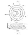
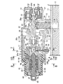
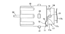
図1〜図10は本発明の一実施例を示すものであり、図1は盗難防止装置の正面図、図2は操作ノブがLOCK位置にあってキー孔にメカニカルキーを挿入していない状態での図1の2−2線断面図、図3はキー孔に正規のメカニカルキーを挿入して操作ノブをON位置に回動した状態での図2に対応した断面図、図4は盗難防止装置の分解斜視図、図5はボディカバーを外した状態での図3の5矢視図、図6は図2の6−6線断面展開図、図7は図3の7−7線断面図、図8は図3の8−8線に沿う断面図であって(a)は操作ノブがOFF位置にあってメカニカルキーの非挿入状態を示し、(b)はメカニカルキーを挿入して操作ノブをON位置に回動した状態を示す図、図9は図2の9−9線断面図、図10は正規のメカニカルキーを挿入した状態での図9に対応した断面図である。   1 to 10 show an embodiment of the present invention, FIG. 1 is a front view of an anti-theft device, and FIG. 2 is a state where an operation knob is in a LOCK position and no mechanical key is inserted into a key hole. Fig. 3 is a cross-sectional view taken along line 2-2 in Fig. 1, Fig. 3 is a cross-sectional view corresponding to Fig. 2 in a state in which a normal mechanical key is inserted into the key hole and the operation knob is turned to the ON position, and Fig. 4 is theft. 5 is an exploded perspective view of the prevention device, FIG. 5 is a view taken in the direction of the arrow 5 in FIG. 3 with the body cover removed, FIG. 6 is a sectional development view taken along the line 6-6 in FIG. FIGS. 8 and 8 are cross-sectional views taken along the line 8-8 in FIG. 3. FIG. 8A shows a state in which the operation knob is in the OFF position and the mechanical key is not inserted, and FIG. FIG. 9 is a sectional view taken along the line 9-9 in FIG. 2, and FIG. It is a sectional view corresponding to FIG. 9 in ON state.

先ず図1〜図4において、乗物たとえば自動二輪車の車体フレームにおけるヘッドパイプ11には、本発明に従う盗難防止装置が取付けられる。この盗難防止装置は、前記ヘッドパイプ11で操向可能に支承されるステアリングシャフト12に係合することを可能とした盗難防止作動手段としてのステアリングロック機構13の施・解錠操作、ならびにイグニッションスイッチ14のスイッチング態様の切換操作を可能とするものであり、前記ヘッドパイプ11に取付けられるボディ15と、有底のキー孔19を有して前記ボディ15に回動不能に支持されるとともに複数のタンブラー20,20…が装着されるインナーシリンダ16と、前記ステアリングロック機構13および前記イグニッションスイッチ14に連結されて前記ボディ15に回動可能に支承されるとともに前記インナーシリンダ16が同軸に挿入されるアウターシリンダ17と、前記インナーシリンダ16と同軸に配置されるようにして前記アウターシリンダ17の前記ボディ15からの突出部を覆って該アウターシリンダ17に相対回動可能に支持される操作ノブ18とを備える。   1 to 4, an antitheft device according to the present invention is attached to a head pipe 11 in a vehicle body frame of a vehicle such as a motorcycle. This anti-theft device includes a steering lock mechanism 13 as an anti-theft actuating means that can be engaged with a steering shaft 12 supported so as to be steerable by the head pipe 11, and an ignition switch. The switching operation of 14 switching modes is enabled, and it has a body 15 attached to the head pipe 11 and a bottomed key hole 19 and is supported non-rotatably by the body 15 and has a plurality of rotations. The inner cylinder 16 to which the tumblers 20, 20... Are mounted, and the steering lock mechanism 13 and the ignition switch 14 are connected to the body 15 so as to be pivotally supported, and the inner cylinder 16 is inserted coaxially. Outer cylinder 17 and coaxial with inner cylinder 16 Wherein so as to be over the protrusion from the body 15 of the outer cylinder 17 and an operation knob 18 supported relatively rotatably on the outer cylinder 17.

前記ボディ15には、該ボディ15の前端(図2および図3の左端)に開口するシリンダ孔21と、ボディ15の後端(図2および図3の右端)に開口するスイッチ収容孔22と、シリンダ孔21およびスイッチ収容孔22間を隔てる隔壁23と、該隔壁23の前方かつ前記ヘッドパイプ11とは反対側で開口して前記シリンダ孔21の後端に通じる開口部25とが設けられる。   The body 15 has a cylinder hole 21 that opens at the front end (the left end in FIGS. 2 and 3) of the body 15, and a switch housing hole 22 that opens at the rear end of the body 15 (the right end in FIGS. 2 and 3). A partition wall 23 that separates the cylinder hole 21 and the switch housing hole 22 and an opening 25 that opens in front of the partition wall 23 and on the side opposite to the head pipe 11 and communicates with the rear end of the cylinder hole 21 are provided. .

このボディ15にはボディカバー26が取付けられるものであり、該ボディカバー26は、前記ボディ15の前端部を同軸に囲繞する短円筒部26aと、前記ボディ15の前端との間に間隔をあけた前方に配置されるようにして前記短円筒部26aの前端から半径方向内方に張り出す内向き鍔部26bと、前記ボディ15の半周を覆うようにして横断面円弧状に形成されて前記短円筒部26aに連なるカバー板部26cとを一体に有し、ボディ15にボディカバー26が取付けられた状態で前記開口部25が前記カバー板部26cで閉じられる。   A body cover 26 is attached to the body 15, and the body cover 26 is a front part having a gap between a short cylindrical portion 26 a that coaxially surrounds the front end of the body 15 and the front end of the body 15. The inward flange portion 26b projecting inward in the radial direction from the front end of the short cylindrical portion 26a and the short cylinder formed in an arc shape in cross section so as to cover a half circumference of the body 15 A cover plate portion 26c connected to the portion 26a is integrally formed, and the opening 25 is closed by the cover plate portion 26c in a state where the body cover 26 is attached to the body 15.

前記スイッチ収容孔22内にはイグニッションスイッチ14が配設されるものであり、該イグニッションスイッチ14が備えるコンタクトホルダ27がスイッチ収容孔22に回動可能に嵌合され、前記隔壁23に、前記シリンダ孔21および前記スイッチ収容孔22と同軸である貫通孔24が設けられる。   An ignition switch 14 is disposed in the switch housing hole 22, and a contact holder 27 provided in the ignition switch 14 is rotatably fitted in the switch housing hole 22, and the cylinder 23 is inserted into the cylinder 23. A through hole 24 that is coaxial with the hole 21 and the switch accommodation hole 22 is provided.

アウターシリンダ17は、前端を開放した有底円筒状に形成されるシリンダ主部17aと、該シリンダ主部17aの後部に同軸に連なる連結軸部17bとを一体に有し、連結軸部17bは横断面非円形に形成される。前記シリンダ主部17aは、その一部を前記ボディ15から前方に突出させるようにして前記シリンダ孔21に軸方向のスライドを可能とするとともに軸線まわりの回動を可能として挿入されており、シリンダ主部17aの後部外周には、前記シリンダ孔21の内周に摺接するようにして半径方向外方に張り出す鍔部17cが一体に設けられる。   The outer cylinder 17 integrally has a cylinder main portion 17a formed in a bottomed cylindrical shape with an open front end and a connecting shaft portion 17b coaxially connected to the rear portion of the cylinder main portion 17a. It is formed in a non-circular cross section. The cylinder main portion 17a is inserted into the cylinder hole 21 so that a part of the cylinder main portion 17a protrudes forward from the body 15 so as to be axially slidable and rotatable around the axis. On the outer periphery of the rear portion of the main portion 17a, a flange portion 17c projecting radially outward so as to be in sliding contact with the inner periphery of the cylinder hole 21 is integrally provided.

前記シリンダ孔21の後部内にはジョイント部材28が収容されており、このジョイント部材28は、軸方向の摺動を可能とするものの相対回動を不能とするようにして前記アウターシリンダ17の連結軸部17bを嵌合せしめる連結凹部29を形成する連結部28aと、該連結部28aに連なってクランク状に形成されるカム部28bと、前記隔壁23の貫通孔24に回動可能かつ軸方向の移動を可能として挿通されるようにして前記カム部に連なる軸部28cと、非円形形状を有して前記軸部28cに連なるスイッチ連結軸部28dとを一体に有し、スイッチ連結軸部28dはイグニッションスイッチ14の前記コンタクトホルダ27に、軸方向の相対移動を可能としつつ軸線まわりの相対回動を阻止するようにして嵌合、連結される。   A joint member 28 is accommodated in the rear portion of the cylinder hole 21, and the joint member 28 allows sliding in the axial direction, but disables relative rotation, and connects the outer cylinder 17. A connecting portion 28a that forms a connecting recess 29 into which the shaft portion 17b is fitted, a cam portion 28b that is formed in a crank shape connected to the connecting portion 28a, and is rotatable in the through hole 24 of the partition wall 23 in the axial direction. The shaft portion 28c connected to the cam portion so as to be inserted through the cam portion and the switch connecting shaft portion 28d having a non-circular shape and connected to the shaft portion 28c are integrally provided, and the switch connecting shaft portion 28d is fitted and connected to the contact holder 27 of the ignition switch 14 so as to prevent relative rotation around the axis while allowing relative movement in the axial direction.

ステアリングロック機構13は、シリンダ孔21の軸線と直交する平面内でスライド作動してステアリングシャフト12に係合することを可能としてボディ15に支承されるロックピン31と、前記ジョイント部材28のカム部28bを貫通せしめて前記ロックピン31に固定される連結部材32と、ロックピン31をステアリングシャフト12との係合を解除する側に付勢するようにして連結部材32およびボディ15間に縮設されるばね33とを備える。   The steering lock mechanism 13 includes a lock pin 31 supported on the body 15 so as to be able to engage with the steering shaft 12 by sliding operation in a plane orthogonal to the axis of the cylinder hole 21, and a cam portion of the joint member 28. A connecting member 32 that is fixed to the lock pin 31 by passing through 28b, and is contracted between the connecting member 32 and the body 15 so as to urge the lock pin 31 to the side where the engagement with the steering shaft 12 is released. The spring 33 is provided.

前記ボディ15には、前記開口部25と反対側で外側方に突出するとともに前記ヘッドパイプ11に取付けられる取付け突部15aが一体に突設されており、前記シリンダ孔21の軸線と直交する方向に延びて前記取付け突部15aに設けられた摺動孔34に前記ロックピン31が摺動可能に嵌合され、シリンダ孔21内で前記連結部材32にジョイント部材28のカム部28bが連結される。すなわち連結部材32には、前記カム部28bを挿通せしめる連結孔35が設けられるものであり、カム部28bがクランク状に形成されていることにより、ジョイント部材28が回動するのに伴ってロックピン31がスライド駆動される。   A mounting protrusion 15 a that protrudes outward on the opposite side of the opening 25 and is attached to the head pipe 11 is integrally formed on the body 15, and is orthogonal to the axis of the cylinder hole 21. The lock pin 31 is slidably fitted in a slide hole 34 provided in the mounting projection 15a and the cam portion 28b of the joint member 28 is connected to the connection member 32 in the cylinder hole 21. The That is, the connecting member 32 is provided with a connecting hole 35 through which the cam portion 28b is inserted, and the cam portion 28b is formed in a crank shape so that the joint member 28 is locked as the joint member 28 rotates. The pin 31 is driven to slide.

一方、ヘッドパイプ11の側壁には、前記摺動孔34に通じる透孔36が設けられ、ヘッドパイプ11で操向可能に支承されるステアリングシャフト12の前記透孔36および前記摺動孔34に対応した軸方向位置には係止凹部37が設けられており、前記ロックピン31は、図2で示すように、係止凹部37に係合してステアリングシャフト12の回動を阻止する状態すなわち転舵操作を阻止する状態と、図3で示すように、ボディ15内に引き込まれることで係止凹部37から離脱してステアリングシャフト12の回動を許容する状態すなわち転舵操作を許容する状態とを切換えることができる。   On the other hand, the side wall of the head pipe 11 is provided with a through hole 36 that communicates with the sliding hole 34. The through hole 36 and the sliding hole 34 of the steering shaft 12 that are supported to be steerable by the head pipe 11. Locking recesses 37 are provided at corresponding axial positions, and the lock pin 31 engages with the locking recesses 37 to prevent the steering shaft 12 from rotating as shown in FIG. A state in which the steering operation is blocked, and a state in which the steering shaft 12 is allowed to rotate by being pulled into the body 15 to be released from the locking recess 37 as shown in FIG. Can be switched.

ところでアウターシリンダ17は、ジョイント部材28に相対回動不能に連結されるものであり、ジョイント部材28がステアリングロック機構13およびイグニッションスイッチ14に連結されるので、アウターシリンダ17はジョイント部材28を介してステアリングロック機構13およびイグニッションスイッチ14に連結されることになる。   By the way, the outer cylinder 17 is connected to the joint member 28 so as not to be relatively rotatable. Since the joint member 28 is connected to the steering lock mechanism 13 and the ignition switch 14, the outer cylinder 17 is connected via the joint member 28. The steering lock mechanism 13 and the ignition switch 14 are connected.

前記ジョイント部材28の前記軸部28cおよび前記スイッチ連結軸部28d間に形成された段部28eに当接されたばね受け板38およびコンタクトホルダ27間には戻しばね39が縮設されており、この戻しばね39のばね力によりジョイント部材28は前方側(図2および図3の左方側)に弾発付勢される。但し受け板38がボディ15の隔壁23に当接することでジョイント部材28の前進限は規制される。またジョイント部材28の前端の連結凹部29内には、ジョイント部材28およびアウターシリンダ17間に縮設されるばね40が収容されており、このばね40が発揮するばね力によってアウターシリンダ17は前方に向けて弾発付勢される。   A return spring 39 is contracted between a spring receiving plate 38 and a contact holder 27 that are in contact with a step portion 28e formed between the shaft portion 28c of the joint member 28 and the switch connecting shaft portion 28d. The joint member 28 is elastically biased toward the front side (the left side in FIGS. 2 and 3) by the spring force of the return spring 39. However, the forward limit of the joint member 28 is restricted when the receiving plate 38 abuts against the partition wall 23 of the body 15. A spring 40 that is contracted between the joint member 28 and the outer cylinder 17 is accommodated in the connecting recess 29 at the front end of the joint member 28, and the outer cylinder 17 is moved forward by the spring force exerted by the spring 40. The bullet is energized towards.

図5を併せて参照して、操作ノブ18は、アウターシリンダ17の鍔部17cに後端を対向させるとともアウターシリンダ17の前端に当接するようにして半径方向内方に張り出す鍔部18aを前端に有してアウターシリンダ17の前記鍔部17cよりも前方で該アウターシリンダ17を同軸に囲繞する円筒状に形成されており、操作ノブ18の後部はボディ15におけるシリンダ孔21の前部に嵌合される。また操作ノブ18の外周には、略半周にわたる円弧状の第1突部41と、第1突部41の両端間の中央部に配置される第2突部42とが、前記ボディカバー26の前端の内向き鍔部26bと、前記ボディ15の前端との間に配置されるようにして一体に突設される。   Referring also to FIG. 5, the operation knob 18 has a flange 18 a that protrudes inward in the radial direction so that its rear end faces the flange 17 c of the outer cylinder 17 and abuts against the front end of the outer cylinder 17. Is formed in a cylindrical shape that coaxially surrounds the outer cylinder 17 in front of the flange portion 17c of the outer cylinder 17, and the rear portion of the operation knob 18 is the front portion of the cylinder hole 21 in the body 15. Fitted. Further, on the outer periphery of the operation knob 18, an arc-shaped first protrusion 41 that extends approximately half a circumference and a second protrusion 42 that is disposed at the center between both ends of the first protrusion 41 are provided at the front end of the body cover 26. The inwardly extending flange portion 26b and the front end of the body 15 are integrally protruded.

而してジョイント部材28およびアウターシリンダ17間に縮設されるばね40のばね力によってアウターシリンダ17は前方に向けて弾発付勢されるのであるが、アウターシリンダ17の鍔部17cが操作ノブ18の後端に当接し、操作ノブ18が備える第1および第2突部41,42が前記ボディカバー26の前端の内向き鍔部26bに当接することでアウターシリンダ17および操作ノブ18の前進が阻止される。また操作ノブ18およびアウターシリンダ17は、操作ノブ18の第1および第2突部41,42がボディ15の前端に当接する後退限まで後退することが可能である。   Thus, the outer cylinder 17 is elastically biased forward by the spring force of the spring 40 contracted between the joint member 28 and the outer cylinder 17, but the flange portion 17c of the outer cylinder 17 is operated by the operation knob. 18, the first and second protrusions 41, 42 included in the operation knob 18 come into contact with the inward flange 26 b at the front end of the body cover 26, so that the outer cylinder 17 and the operation knob 18 are moved forward. Be blocked. Further, the operation knob 18 and the outer cylinder 17 can be retracted to the retreat limit where the first and second protrusions 41 and 42 of the operation knob 18 abut against the front end of the body 15.

図1に注目して、前記操作ノブ18は、LOCK位置からOFF位置を経てON位置に至るまで回動することが可能であり、操作ノブ18がアウターシリンダ17とともにLOCK位置にあるときには前記ステアリングロック機構13のロックピン31が係止凹部37に係合してステアリングシャフト12の回動を阻止する状態すなわち転舵操作を阻止する状態にあり、操作ノブ18がアウターシリンダ17とともにOFF位置に回動したときには前記ステアリングロック機構13のロックピン31が係止凹部37との係合を解除してステアリングシャフト12の回動を許容する状態すなわち転舵操作を許容する状態にあり、操作ノブ18がアウターシリンダ17とともにON位置に回動したときにはイグニッションスイッチ14が図示しないエンジンを始動させるようにスイッチング態様を変化させることになる。   Referring to FIG. 1, the operation knob 18 can be rotated from the LOCK position to the ON position through the OFF position. When the operation knob 18 is in the LOCK position together with the outer cylinder 17, the steering lock is performed. The lock pin 31 of the mechanism 13 engages with the locking recess 37 to prevent the steering shaft 12 from rotating, that is, to prevent the steering operation, and the operation knob 18 rotates to the OFF position together with the outer cylinder 17. When this occurs, the lock pin 31 of the steering lock mechanism 13 is disengaged from the engaging recess 37 to allow the steering shaft 12 to rotate, that is, to permit the turning operation, and the operation knob 18 is in the outer state. When the cylinder 17 is rotated to the ON position, the ignition switch 14 is not shown. It will change the switching mode so as to start the engine.

図6を併せて参照して、前記操作ノブ18は、前記OFF位置から前記LOCK位置に回動操作するときにはプッシュ操作が要求されるものであり、前記ボディカバー26の前端の内向き鍔部26bには、操作ノブ18がOFF位置にあるときに該操作ノブ18の第2突部42をON位置側から当接せしめるようにして操作ノブ18の軸方向に延びる規制面44を有するガイド突部43が後方に向けて突設されており、操作ノブ18がOFF位置にあるときには該操作ノブ18の第2突部42が前記規制面44に当接することでLOCK位置側への回動が阻止されることになり、第2突部42がガイド突部43を乗り越える位置まで操作ノブ18をプッシュ操作することで操作ノブ18のLOCK位置までの回動操作が可能となる。一方、前記ガイド突部43の前記OFF位置側に臨む面は、OFF位置側に向かうにつれて次第に後方位置となるように傾斜した傾斜面45として形成されており、操作ノブ18をLOCK位置からOFF位置に回動操作する際には、第2突部42が前記傾斜面45でガイドされることにより、操作ノブ18はガイド突部43を乗り越えるように自動的に押し込まれることになる。   Referring also to FIG. 6, the operation knob 18 is required to be pushed when it is rotated from the OFF position to the LOCK position, and the operation knob 18 is provided on the inwardly facing flange portion 26 b at the front end of the body cover 26. The guide protrusion 43 has a restricting surface 44 extending in the axial direction of the operation knob 18 so that the second protrusion 42 of the operation knob 18 is brought into contact with the operation knob 18 from the ON position side when the operation knob 18 is in the OFF position. Is protruded rearward, and when the operation knob 18 is in the OFF position, the second protrusion 42 of the operation knob 18 abuts against the restriction surface 44 to prevent the rotation toward the LOCK position. Therefore, the operation knob 18 can be turned to the LOCK position by pushing the operation knob 18 until the second protrusion 42 passes over the guide protrusion 43. On the other hand, the surface of the guide projection 43 facing the OFF position is formed as an inclined surface 45 that is inclined so as to gradually become the rear position toward the OFF position, and the operation knob 18 is moved from the LOCK position to the OFF position. When the second projecting portion 42 is guided by the inclined surface 45, the operation knob 18 is automatically pushed so as to get over the guide projecting portion 43.

図7を併せて参照して、前記アウターシリンダ17のシリンダ主部17aは、前方に開放した収容凹部46を形成するものであり、この収容凹部46にインナーシリンダ16が挿入される。このインナーシリンダ16には前端を開放した有底のキー孔19が設けられ、そのキー孔19に通じる挿入孔47を有するキャップ48がインナーシリンダ16の前端に取付けられる。またインナーシリンダ16を前方に付勢するばね49がシリンダ主部17aおよびインナーシリンダ16間に設けられる。   Referring also to FIG. 7, the cylinder main portion 17 a of the outer cylinder 17 forms a housing recess 46 opened forward, and the inner cylinder 16 is inserted into the housing recess 46. The inner cylinder 16 is provided with a bottomed key hole 19 whose front end is opened, and a cap 48 having an insertion hole 47 communicating with the key hole 19 is attached to the front end of the inner cylinder 16. A spring 49 that biases the inner cylinder 16 forward is provided between the cylinder main portion 17 a and the inner cylinder 16.

しかもアウターシリンダ17の回動を許容するようにして該アウターシリンダ17の側壁を貫通するピン51の一端部が、前記ボディ15のうち前記ヘッドパイプ11に近接、対向する側面に開口する第1支持孔52に挿通され、前記インナーシリンダ16の内端部に設けられた有底の第2支持孔53に前記ピン51の他端部が挿通されるものであり、前記ばね49で前方に付勢されているインナーシリンダ16は収容凹部46内で固定配置されるようにしてボディ15に支持されることになる。   Moreover, a first support in which one end portion of the pin 51 penetrating the side wall of the outer cylinder 17 so as to allow the rotation of the outer cylinder 17 opens on the side surface of the body 15 that is close to and faces the head pipe 11. The other end of the pin 51 is inserted into the bottomed second support hole 53 provided at the inner end of the inner cylinder 16 through the hole 52, and biased forward by the spring 49. The inner cylinder 16 is supported by the body 15 so as to be fixedly disposed in the housing recess 46.

前記アウターシリンダ17におけるシリンダ主部17aの後部には、前記ピン51を挿通せしめる挿通孔54が、シリンダ主部17aの外周に設けられた鍔部17cの一部を切欠くようにして設けられ、この挿通孔54は、アウターシリンダ17のLOCK位置およびON位置間の回動を許容するようにしてシリンダ主部17aの周方向に長く延びるように形成されるとともに、アウターシリンダ17に連結された状態にある操作ノブ18の前記OFF位置および前記LOCK位置間での軸方向移動を可能とするためにシリンダ主部17aの軸方向に長く形成される。   An insertion hole 54 through which the pin 51 is inserted is provided at a rear portion of the cylinder main portion 17a of the outer cylinder 17 so as to cut out a part of the flange portion 17c provided on the outer periphery of the cylinder main portion 17a. The insertion hole 54 is formed so as to extend long in the circumferential direction of the cylinder main portion 17 a so as to allow the outer cylinder 17 to be rotated between the LOCK position and the ON position, and is connected to the outer cylinder 17. In order to enable the axial movement between the OFF position and the LOCK position of the operation knob 18 located in the cylinder main body 17a, it is formed long in the axial direction.

図8において、シリンダ主部17aにおける収容凹部46の内周の周方向に間隔をあけた複数個所たとえば4個所には軸方向に延びる係合溝55,55…が設けられており、インナーシリンダ16には、その軸方向に間隔をあけた位置に配置される複数のタンブラー20,20…が、前記係合溝55,55…の1つに係合することを可能として装着され、各タンブラー20,20…およびインナーシリンダ16間には、タンブラー20,20…を前記係合溝の1つに係合させる方向に付勢するばね56…がそれぞれ介装される。   8, a plurality of, for example, four locations spaced in the circumferential direction of the inner periphery of the accommodating recess 46 in the cylinder main portion 17a are provided with engaging grooves 55, 55... Extending in the axial direction. Are mounted so as to be able to engage with one of the engaging grooves 55, 55..., Which are arranged at positions spaced apart in the axial direction. , 20... And the inner cylinder 16 are respectively provided with springs 56 for urging the tumblers 20, 20.

而して前記タンブラー20,20…は、前記キー孔19にメカニカルキー58が挿入されていない状態では図8(a)で示すように、前記係合溝55,55…の1つに係合しており、ボディ15に固定的に支持されたインナーシリンダ16のタンブラー20,20…が係合溝55に係合することによってアウターシリンダ17の回動は阻止されている。また前記キー孔19に正規のメカニカルキー58が挿入されると、各タンブラー20,20…は、図8(b)で示すように、係合溝55との係合を解除するようにインナーシリンダ16内に退避する位置まで前記ばね56…のばね力に抗して移動しており、この状態で操作ノブ18を回動操作することでアウターシリンダ17が回動される。   Thus, the tumblers 20, 20... Engage with one of the engagement grooves 55, 55... As shown in FIG. 8A when the mechanical key 58 is not inserted into the key hole 19. The outer cylinder 17 is prevented from rotating when the tumblers 20, 20... Of the inner cylinder 16 fixedly supported by the body 15 are engaged with the engagement grooves 55. When the regular mechanical key 58 is inserted into the key hole 19, each tumbler 20, 20,... Is disengaged from the engagement groove 55 as shown in FIG. 16 is moved against the spring force of the springs 56... The outer cylinder 17 is rotated by rotating the operation knob 18 in this state.

すなわちインナーシリンダ16は、ステアリングロック機構13およびイグニッションスイッチ14に連結されてボディ15に回動可能に支承されるアウターシリンダ17に、キー孔19への正規のメカニカルキー58の非挿入時にアウターシリンダ17にタンブラー20,20…を係合させてアウターシリンダ17の回動を阻止する状態と、前記キー孔19への正規のメカニカルキー58の挿入時にアウターシリンダ17へのタンブラー20,20…の係合を解除して該アウターシリンダ17の回動を許容する状態とを切換えるようにして、アウターシリンダ17におけるシリンダ主部17aに同軸に挿入されることになる。   That is, the inner cylinder 16 is connected to the steering lock mechanism 13 and the ignition switch 14, and is supported on the body 15 so as to be rotatable. When the regular mechanical key 58 is not inserted into the key hole 19, the outer cylinder 17 To prevent the outer cylinder 17 from rotating, and when the regular mechanical key 58 is inserted into the key hole 19, the tumblers 20, 20,. Is released, and the outer cylinder 17 is inserted into the cylinder main portion 17a of the outer cylinder 17 in a coaxial manner so as to be switched to a state in which the rotation of the outer cylinder 17 is allowed.

前記アウターシリンダ17を介在させた前記インナーシリンダ16および前記操作ノブ18間には、前記キー孔19への正規のメカニカルキー58の挿入時には操作ノブ18およびアウターシリンダ17を相対回動不能に連結するものの前記キー孔19への正規のメカニカルキー58の非挿入時には前記操作ノブ18および前記アウターシリンダ17の連結を解除する連結切換手段59が設けられる。   Between the inner cylinder 16 and the operation knob 18 with the outer cylinder 17 interposed, the operation knob 18 and the outer cylinder 17 are connected so as not to rotate relative to each other when the regular mechanical key 58 is inserted into the key hole 19. However, when the regular mechanical key 58 is not inserted into the key hole 19, connection switching means 59 for releasing the connection between the operation knob 18 and the outer cylinder 17 is provided.

図9を併せて参照して、前記連結切換手段59は、前記タンブラー20,20…が配設されている部分よりも後方に配置されて前記各タンブラー20,20…と平行な方向にスライドすることを可能としてインナーシリンダ16に装着される第1スイライダー60と、第1スイライダー60に当接する方向にばね付勢されてアウターシリンダ17にスライド可能に支持される第2スイライダー61とを備え、第2スイライダー61が操作ノブ18に係合可能である。   Referring also to FIG. 9, the connection switching means 59 is arranged behind the portion where the tumblers 20, 20... Are arranged and slides in a direction parallel to the tumblers 20, 20. A first swirler 60 that is attached to the inner cylinder 16 and a second swirler 61 that is spring-biased in a direction to contact the first swirler 60 and is slidably supported by the outer cylinder 17. The second swider 61 can be engaged with the operation knob 18.

第1スイライダー60は、キー孔19に挿入された正規のメカニカルキー58の先端部を挿通せしめる挿通孔62を有するものであり、メカニカルキー58の非挿入時には、図9で示すように、前記複数の係合溝55,55…の1つに一端部を突出させた非作動位置にあり、前記挿通孔62に正規のメカニカルキー58が挿入されると、図10で示すように、第1スイライダー60はその一端部を前記係合溝55から離脱させてインナーシリンダ16内に引き込まれる作動位置に駆動される。   The first swirler 60 has an insertion hole 62 through which the tip of a regular mechanical key 58 inserted into the key hole 19 is inserted. When the mechanical key 58 is not inserted, as shown in FIG. When one of the plurality of engaging grooves 55, 55... Is in a non-actuated position with one end projecting and a regular mechanical key 58 is inserted into the insertion hole 62, as shown in FIG. The swirler 60 is driven to an operating position in which one end thereof is detached from the engagement groove 55 and is drawn into the inner cylinder 16.

而して第1スイライダー60の他端には、第1スイライダー60が作動位置に移動したときには、インナーシリンダ16の軸方向から見たときに該インナーシリンダ16の外周に重なる円弧状の押圧面63が形成される。   Thus, at the other end of the first swirler 60, when the first swirler 60 is moved to the operating position, an arcuate pressure that overlaps the outer periphery of the inner cylinder 16 when viewed from the axial direction of the inner cylinder 16. A surface 63 is formed.

第2スイライダー61は、アウターシリンダ17の周方向に沿う両側に突出した耳部61a,61aをアウターシリンダ17の半径方向に沿う一端側に有するものであり、この第2スイライダー61の一端には、第1スイライダー60の前記押圧面63に当接する円弧状の受圧面64が形成される。またアウターシリンダ17には、第2スイライダー61を、第1スイライダー60のスライド方向とは斜めに交差する方向にスライドさせることを可能として挿入せしめる挿入孔65が設けられ、その挿入孔65に対応した係合孔66が操作ノブ18に設けられる。   The second swider 61 has ears 61 a, 61 a projecting on both sides along the circumferential direction of the outer cylinder 17 on one end side along the radial direction of the outer cylinder 17. Is formed with an arc-shaped pressure receiving surface 64 which is in contact with the pressing surface 63 of the first swirler 60. The outer cylinder 17 is provided with an insertion hole 65 for allowing the second swirler 61 to be slid in a direction obliquely intersecting the sliding direction of the first swirler 60. A corresponding engagement hole 66 is provided in the operation knob 18.

前記挿入孔65が設けられる部分で前記アウターシリンダ17の外周には円弧状の凹部67が形成されており、その凹部67に収容されるようにしてアウターシリンダ17の外周に取付けられるスライダカバー68に、第2スイライダー61の他端側を挿通せしめる開口部69が設けられる。しかも第2スイライダー61の前記両耳部61a…およびスライダーカバー68間に第2スイライダー61の受圧面64を第1スイライダー60の押圧面63に当接させる方向に第2スイライダー61を付勢する一対のばね70,70が縮設される。   An arc-shaped recess 67 is formed on the outer periphery of the outer cylinder 17 at a portion where the insertion hole 65 is provided, and a slider cover 68 attached to the outer periphery of the outer cylinder 17 so as to be accommodated in the recess 67. An opening 69 through which the other end of the second swider 61 is inserted is provided. In addition, the second swirler 61 is placed in a direction in which the pressure receiving surface 64 of the second swider 61 is brought into contact with the pressing surface 63 of the first swider 60 between the both ears 61a of the second swider 61 and the slider cover 68. A pair of springs 70 and 70 to be urged are contracted.

而して第1スイライダー60が前記非作動位置にあるときには、図9で示すように、第2スイライダー61の他端部は操作ノブ18の係合孔66から内方に離脱した位置にあり、この状態ではアウターシリンダ17および操作ノブ18は非連結状態にある。また第2スイライダー61が作動位置にあるときには、図10で示すように、第2スイライダー61の他端部は操作ノブ18の係合孔66に係合しており、この状態でアウターシリンダ17および操作ノブ18が連結されることになり、操作ノブ18の回動操作に応じてアウターシリンダ17は操作ノブ18とともに回動することになる。この際、第1スイライダー60の押圧面63と、第2スイライダー61の受圧面64とは、アウターシリンダ17の回動範囲内で常時摺接するように形成される。   Thus, when the first swirler 60 is in the non-operating position, as shown in FIG. 9, the other end of the second swirler 61 is in a position where it is detached inward from the engagement hole 66 of the operation knob 18. In this state, the outer cylinder 17 and the operation knob 18 are not connected. When the second swider 61 is in the operating position, the other end of the second swider 61 is engaged with the engagement hole 66 of the operation knob 18 as shown in FIG. 17 and the operation knob 18 are connected, and the outer cylinder 17 rotates together with the operation knob 18 in accordance with the rotation operation of the operation knob 18. At this time, the pressing surface 63 of the first swirler 60 and the pressure receiving surface 64 of the second swirler 61 are formed so as to be in sliding contact with each other within the rotation range of the outer cylinder 17.

ところで前記連結切換手段59によってアウターシリンダ17および操作ノブ18を連結するためには、アウターシリンダ17および操作ノブ18の相対位置は、アウターシリンダ17に設けられる挿入孔65と操作ノブ18に向けられる係合孔66とが相互に対応した位置にあることが必要であり、そのようにアウターシリンダ17および操作ノブ18の相対位置を定めるとともに、連結切換手段59が非連結状態にあるときの操作ノブ18への回動作動力の入力時には操作ノブ18をアウターシリンダ17まわりに空転させる位置決め・トルクリミッタ機構71が、アウターシリンダ17および操作ノブ18間に設けられる。   By the way, in order to connect the outer cylinder 17 and the operation knob 18 by the connection switching means 59, the relative positions of the outer cylinder 17 and the operation knob 18 are directed to the insertion hole 65 provided in the outer cylinder 17 and the operation knob 18. It is necessary for the joint hole 66 to be in a position corresponding to each other, so that the relative positions of the outer cylinder 17 and the operation knob 18 are determined, and the operation knob 18 when the connection switching means 59 is in the non-connected state. A positioning / torque limiter mechanism 71 is provided between the outer cylinder 17 and the operation knob 18 so as to idle the operation knob 18 around the outer cylinder 17 when the rotational movement power is input to.

図5で明示するように、前記位置決め・トルクリミッタ機構71は、アウターシリンダ17の鍔部17cに一体に設けられて前方側に突出する山形の突部72と、該突部72を嵌合せしめるせしめるようにして操作ノブ18の後端に設けられた嵌合凹部73とで構成されるものであり、突部72が嵌合凹部73に嵌合した状態で、アウターシリンダ17および操作ノブ18の相対位置は、連結切換手段59によって連結可能な位置にある。またアウターシリンダ17および操作ノブ18が連結切換手段59によって連結されていない状態で操作ノブ18に回転作動力が入力されたときには、嵌合凹部73を突部72から離脱させるように操作ノブ18が、アウターシリンダ17を後退させつつそのまわりに空転することになり、操作ノブ18からアウターシリンダ17に回動力が伝達されることはない。   As clearly shown in FIG. 5, the positioning / torque limiter mechanism 71 is fitted with the protrusion 72 and an angular protrusion 72 that is provided integrally with the flange 17 c of the outer cylinder 17 and protrudes forward. The fitting recess 73 is provided at the rear end of the operation knob 18 so that the protrusion 72 is fitted in the fitting recess 73. The relative position is a position that can be connected by the connection switching means 59. In addition, when the rotational operating force is input to the operation knob 18 in a state where the outer cylinder 17 and the operation knob 18 are not connected by the connection switching means 59, the operation knob 18 is configured to disengage the fitting recess 73 from the protrusion 72. The outer cylinder 17 rotates backward while being retracted, and the rotational force is not transmitted from the operation knob 18 to the outer cylinder 17.

次にこの実施例の作用について説明すると、キー孔19を有するとともに複数のタンブラー20,20…が装着されてボディ15に回動不能に支持されるインナーシリンダ16が、ステアリングロック機構13およびイグニッションスイッチ14に連結されてボディ15に回動可能に支承されるアウターシリンダ17に同軸に挿入され、キー孔19への正規のメカニカルキー58の非挿入時にはアウターシリンダ17にタンブラー20,20…が係合することでアウターシリンダ17の回動が阻止され、キー孔19への正規のメカニカルキー58の挿入時にはアウターシリンダ17へのタンブラー20,20…の係合を解除してアウターシリンダ17の回動が許容され、アウターシリンダ17のボディ15からの突出部を覆って該アウターシリンダ17に相対回動可能に支持される操作ノブ18が、キー孔19への正規のメカニカルキー58の挿入時には連結切換手段59によってアウターシリンダ17に相対回動不能に連結され、キー孔19への正規のメカニカルキー58の非挿入時には連結切換手段59による操作ノブ18およびアウターシリンダ17の連結が解除される。   Next, the operation of this embodiment will be described. An inner cylinder 16 having a key hole 19 and a plurality of tumblers 20, 20... Mounted to be non-rotatably supported by the body 15 includes a steering lock mechanism 13 and an ignition switch. 14 is coaxially inserted into the outer cylinder 17 that is rotatably supported by the body 15 and is engaged with the outer cylinder 17 when the regular mechanical key 58 is not inserted into the key hole 19. Thus, the rotation of the outer cylinder 17 is prevented, and when the regular mechanical key 58 is inserted into the key hole 19, the engagement of the tumblers 20, 20,. The outer casing 17 is covered with the outer cylinder 17 so as to cover the protruding portion from the body 15. The operation knob 18 supported so as to be relatively rotatable with respect to the rotor 17 is connected to the outer cylinder 17 so as not to be rotatable relative to the key hole 19 by the connection switching means 59 when the regular mechanical key 58 is inserted into the key hole 19. When the regular mechanical key 58 is not inserted, the connection of the operation knob 18 and the outer cylinder 17 by the connection switching means 59 is released.

したがってインナーシリンダ16のキー孔19に正規のメカニカルキー58を挿入しない限り、連結切換手段59は、操作ノブ18およびアウターシリンダ17を相対回動不能に連結することはなく、いたずらや盗難目的でタンブラー20,20…を不正操作してアウターシリンダ17の回動を可能としても、操作ノブ18はアウターシリンダ17のまわりに空転するのみで操作ノブ18の回動操作力がアウターシリンダ17を介してステアリングロック機構13およびイグニッションスイッチ14に伝達されることはない。またインナーシリンダ16のキー孔19に正規のメカニカルキー58を挿入すると、連結切換手段59によって操作ノブ18およびアウターシリンダ17が相対回動不能に連結され、アウターシリンダ17がインナーシリンダ16のまわりに回動可能となるので、操作ノブ18の回動操作力がアウターシリンダ17を介してステアリングロック機構13およびイグニッションスイッチ14に伝達されることになる。   Therefore, unless the regular mechanical key 58 is inserted into the key hole 19 of the inner cylinder 16, the connection switching means 59 does not connect the operation knob 18 and the outer cylinder 17 so that they cannot be rotated relative to each other. Even if the outer cylinder 17 can be turned by improperly operating 20, 20,..., The operation knob 18 only rotates idly around the outer cylinder 17, and the turning operation force of the operation knob 18 is steered via the outer cylinder 17. There is no transmission to the lock mechanism 13 and the ignition switch 14. When a regular mechanical key 58 is inserted into the key hole 19 of the inner cylinder 16, the operation switch 18 and the outer cylinder 17 are connected so as not to rotate relative to each other by the connection switching means 59, and the outer cylinder 17 rotates around the inner cylinder 16. Therefore, the turning operation force of the operation knob 18 is transmitted to the steering lock mechanism 13 and the ignition switch 14 via the outer cylinder 17.

またアウターシリンダ17の回動を許容するようにして該アウターシリンダ17の側壁を貫通するピン51の一端部が、ボディ15のうちヘッドパイプ11に近接、対向する側面に開口する第1支持孔52に挿通され、前記インナーシリンダ16に設けられた第2支持孔53に前記ピン51の他端部が挿通されるので、アウターシリンダ17の回動を許容しつつボディ15およびインナーシリンダ16をピン51で連結してインナーシリンダ16を回動不能としてボディ15に支持することが容易となり、しかもピン51の一端部が挿通される第1支持孔52が、ヘッドパイプ11に近接、対向するボディ15の側面に開口するものであるので、ボディ15をヘッドパイプ11に取付けた状態ではピン51の一端部はヘッドパイプ11で隠れてしまうことになり、ピン51がいたずらによって外されてしまい、インナーシリンダ16が不所望に回動可能となってしまうことはない。   In addition, a first support hole 52 that opens at a side face of the body 15 that is close to and faces the head pipe 11 of the pin 51 that penetrates the side wall of the outer cylinder 17 so as to allow the outer cylinder 17 to rotate. The other end of the pin 51 is inserted into the second support hole 53 provided in the inner cylinder 16, so that the body 15 and the inner cylinder 16 are connected to the pin 51 while allowing the outer cylinder 17 to rotate. The first support hole 52 into which one end of the pin 51 is inserted is close to the head pipe 11 and is opposed to the head pipe 11. Since it opens to the side, one end of the pin 51 is hidden by the head pipe 11 when the body 15 is attached to the head pipe 11. Will be put away, will be removed by the pin 51 Gaitazura never inner cylinder 16 becomes rotatable undesirably.

さらにアウターシリンダ17および操作ノブ18間には、アウターシリンダ17および操作ノブ18の相対位置を連結切換手段59で連結することを可能とした位置に定めるとともに、連結切換手段59が非連結状態にあるときの操作ノブ18への回転作動力の入力時には操作ノブ18をアウターシリンダ17まわりに空転させる位置決め・トルクリミッタ機構71が設けられるので、位置決め・トルクリミッタ機構71によってアウターシリンダ17および操作ノブ18の相対位置を連結切換手段59で連結することを可能とした位置に定めることが可能であるとともに、連結切換手段59が非連結状態にあるときの操作ノブ18へのいたずらによる回転作動力の入力時には、位置決め・トルクリミッタ機構71によって操作ノブ18をアウターシリンダ17まわりに空転させるようにして、ステアリングロック機構13が不所望にロック状態を解除してしまうことを回避することができる。   Furthermore, between the outer cylinder 17 and the operation knob 18, the relative position of the outer cylinder 17 and the operation knob 18 is determined at a position where the connection switching means 59 can be connected, and the connection switching means 59 is in a non-connected state. Since a positioning / torque limiter mechanism 71 is provided to rotate the operating knob 18 around the outer cylinder 17 when a rotational operating force is input to the operating knob 18 at that time, the positioning / torque limiter mechanism 71 causes the outer cylinder 17 and the operating knob 18 to move. The relative position can be set to a position where the connection switching means 59 can be connected, and at the time of inputting the rotational operation force due to the mischief to the operation knob 18 when the connection switching means 59 is in the non-connected state. The operation knob 18 is moved by the positioning / torque limiter mechanism 71. So as to idle around the coater cylinder 17, it is possible to prevent the steering lock mechanism 13 will unlock state undesirably.

なお操作ノブ18がいたずら等で空転した後には、操作ノブ18を回転操作することで突部72を嵌合凹部73に嵌合せればよいが、その嵌合は、嵌合したときの音や回転負荷の変化および振動等で確認することができる。   Note that after the operation knob 18 is idle due to mischief or the like, the operation knob 18 may be rotated to fit the protrusion 72 into the fitting recess 73. This can be confirmed by a change in rotational load and vibration.

以上、本発明の実施例を説明したが、本発明は上記実施例に限定されるものではなく、特許請求の範囲に記載された本発明を逸脱することなく種々の設計変更を行うことが可能である。   Although the embodiments of the present invention have been described above, the present invention is not limited to the above-described embodiments, and various design changes can be made without departing from the present invention described in the claims. It is.

たとえば上記実施例では自動二輪車に本発明を適用した場合について説明したが、本発明は、自動二輪車以外にも、四輪車両や船舶を含む乗物に広く適用可能である。   For example, although the case where the present invention is applied to a motorcycle has been described in the above embodiment, the present invention can be widely applied to vehicles including four-wheeled vehicles and ships in addition to motorcycles.

盗難防止装置の正面図である。It is a front view of an antitheft device. 操作ノブがLOCK位置にあってキー孔にメカニカルキーを挿入していない状態での図1の2−2線断面図である。FIG. 2 is a cross-sectional view taken along line 2-2 of FIG. 1 in a state where an operation knob is in a LOCK position and a mechanical key is not inserted into a key hole. キー孔に正規のメカニカルキーを挿入して操作ノブをON位置に回動した状態での図2に対応した断面図である。It is sectional drawing corresponding to FIG. 2 in the state which inserted the regular mechanical key in the key hole, and rotated the operation knob to the ON position. 盗難防止装置の分解斜視図である。It is a disassembled perspective view of an antitheft device. ボディカバーを外した状態での図3の5矢視図である。FIG. 5 is a view taken in the direction of arrow 5 in FIG. 3 with the body cover removed. 図2の6−6線断面図である。FIG. 6 is a sectional view taken along line 6-6 of FIG. 図3の7−7線断面図である。FIG. 7 is a sectional view taken along line 7-7 in FIG. 3. 図3の8−8線に沿う断面図であって(a)は操作ノブがOFF位置にあってメカニカルキーの非挿入状態を示し、(b)はメカニカルキーを挿入して操作ノブをON位置に回動した状態を示す図である。FIG. 8 is a cross-sectional view taken along line 8-8 in FIG. 3, where (a) shows the non-inserted state of the mechanical key with the operating knob in the OFF position, and (b) shows the operating knob in the ON position with the mechanical key inserted. FIG. 図2の9−9線断面図である。FIG. 9 is a sectional view taken along line 9-9 in FIG. 2. 正規のメカニカルキーを挿入した状態での図9に対応した断面図である。FIG. 10 is a cross-sectional view corresponding to FIG. 9 with a regular mechanical key inserted.

符号の説明Explanation of symbols

11・・・支持体であるヘッドパイプ
13・・・盗難防止作動手段であるステアリングロック機構
15・・・ボディ
16・・・インナーシリンダ
17・・・アウターシリンダ
18・・・操作ノブ
19・・・キー孔
20・・・タンブラー
51・・・ピン
52・・・第1支持孔
53・・・第2支持孔
58・・・メカニカルキー
59・・・連結切換手段
71・・・位置決め・トルクリミッタ機構
DESCRIPTION OF SYMBOLS 11 ... Head pipe 13 which is support body ... Steering lock mechanism 15 which is anti-theft operation means ... Body 16 ... Inner cylinder 17 ... Outer cylinder 18 ... Operation knob 19 ... Key hole 20 ... Tumbler 51 ... Pin 52 ... First support hole 53 ... Second support hole 58 ... Mechanical key 59 ... Connection switching means 71 ... Positioning / torque limiter mechanism

Claims (3)

支持体(11)に固定されるボディ(15)と、キー孔(19)を有して前記ボディ(15)に回動不能に支持されるとともに複数のタンブラー(20)が装着されるインナーシリンダ(16)と、該インナーシリンダ(16)と同軸に配置される操作ノブ(18)とを備え、前記キー孔(19)への正規のメカニカルキー(58)の挿入に応じて盗難防止作動手段(13)に回動操作力を伝達するように前記操作ノブ(18)を回動操作することを可能とした乗物用盗難防止装置において、前記盗難防止作動手段(13)に連結されて前記ボディ(15)に回動可能に支承されるアウターシリンダ(17)に、前記キー孔(19)への正規のメカニカルキー(58)の非挿入時に前記アウターシリンダ(17)に前記タンブラー(20)を係合させてアウターシリンダ(17)の回動を阻止する状態ならびに前記キー孔(19)への正規のメカニカルキー(58)の挿入時に前記アウターシリンダ(17)への前記タンブラー(20)の係合を解除して該アウターシリンダ(17)の回動を許容する状態を切換えるようにして前記インナーシリンダ(16)が同軸に挿入され、前記キー孔(19)への正規のメカニカルキー(58)の挿入時には前記操作ノブ(18)および前記アウターシリンダ(17)を相対回動不能に連結するものの前記キー孔(19)への正規のメカニカルキー(58)の非挿入時には前記操作ノブ(18)および前記アウターシリンダ(17)の連結を解除する連結切換手段(59)が前記アウターシリンダ(17)を介在させた前記インナーシリンダ(16)および前記操作ノブ(18)間に設けられ、前記操作ノブ(18)が、前記アウターシリンダ(17)の前記ボディ(15)からの突出部を覆って該アウターシリンダ(17)に相対回動可能に支持されることを特徴とする乗物用盗難防止装置。   A body (15) fixed to the support (11), an inner cylinder having a key hole (19) and being non-rotatably supported by the body (15) and mounted with a plurality of tumblers (20) (16) and an operation knob (18) arranged coaxially with the inner cylinder (16), and an anti-theft actuating means in accordance with insertion of a regular mechanical key (58) into the key hole (19). In the vehicle anti-theft device capable of rotating the operation knob (18) so as to transmit the rotating operation force to (13), the body is connected to the anti-theft actuating means (13) and connected to the body. When the regular mechanical key (58) is not inserted into the key hole (19), the tumbler (20) is attached to the outer cylinder (17). A state in which the outer cylinder (17) is prevented from rotating, and the tumbler (20) is engaged with the outer cylinder (17) when the regular mechanical key (58) is inserted into the key hole (19). The inner cylinder (16) is coaxially inserted so as to switch the state of allowing the outer cylinder (17) to rotate, and the normal mechanical key (58) is inserted into the key hole (19). Although the operation knob (18) and the outer cylinder (17) are connected so as not to be relatively rotatable at the time of insertion, the operation knob (18) and the operation knob (18) at the time of non-insertion of the regular mechanical key (58) into the key hole (19) The inner cylinder in which the connection switching means (59) for releasing the connection of the outer cylinder (17) interposes the outer cylinder (17). 16) and the operation knob (18), and the operation knob (18) covers the protrusion of the outer cylinder (17) from the body (15) and rotates relative to the outer cylinder (17). A vehicle antitheft device characterized by being movably supported. 前記アウターシリンダ(17)の回動を許容するようにして該アウターシリンダ(17)の側壁を貫通するピン(51)の一端部が、前記ボディ(15)のうち前記支持体(11)に近接、対向する側面に開口する第1支持孔(52)に挿通され、前記インナーシリンダ(16)に設けられた第2支持孔(53)に前記ピン(51)の他端部が挿通されることを特徴とする請求項1記載の乗物用盗難防止装置。   One end of a pin (51) penetrating the side wall of the outer cylinder (17) so as to allow the outer cylinder (17) to rotate is close to the support (11) in the body (15). The second support hole (53) provided in the inner cylinder (16) is inserted into the first support hole (52) opened on the opposite side surface, and the other end of the pin (51) is inserted into the second support hole (53). The vehicle antitheft device according to claim 1. 前記アウターシリンダ(17)および前記操作ノブ(18)の相対位置を前記連結切換手段(59)で連結することを可能とした位置に定めるとともに、前記連結切換手段(59)が非連結状態にあるときの操作ノブ(18)への回転作動力の入力時には操作ノブ(18)をアウターシリンダ(17)まわりに空転させる位置決め・トルクリミッタ機構(71)が、前記アウターシリンダ(17)および前記操作ノブ(18)間に設けられることを特徴とする請求項1または2記載の乗物用盗難防止装置。   The relative position of the outer cylinder (17) and the operation knob (18) is determined to be a position where the connection switching means (59) can be connected, and the connection switching means (59) is in a non-connected state. A positioning / torque limiter mechanism (71) that idles the operation knob (18) around the outer cylinder (17) when a rotational operating force is input to the operation knob (18) is provided to the outer cylinder (17) and the operation knob. (18) The vehicle antitheft device according to claim 1 or 2, wherein the antitheft device for vehicles is provided.
JP2008205390A 2008-08-08 2008-08-08 Vehicle anti-theft device Expired - Fee Related JP4979656B2 (en)

Priority Applications (1)

Application Number Priority Date Filing Date Title
JP2008205390A JP4979656B2 (en) 2008-08-08 2008-08-08 Vehicle anti-theft device

Applications Claiming Priority (1)

Application Number Priority Date Filing Date Title
JP2008205390A JP4979656B2 (en) 2008-08-08 2008-08-08 Vehicle anti-theft device

Publications (3)

Publication Number Publication Date
JP2010036844A true JP2010036844A (en) 2010-02-18
JP2010036844A5 JP2010036844A5 (en) 2010-12-09
JP4979656B2 JP4979656B2 (en) 2012-07-18

Family

ID=42009818

Family Applications (1)

Application Number Title Priority Date Filing Date
JP2008205390A Expired - Fee Related JP4979656B2 (en) 2008-08-08 2008-08-08 Vehicle anti-theft device

Country Status (1)

Country Link
JP (1) JP4979656B2 (en)

Citations (2)

* Cited by examiner, † Cited by third party
Publication number Priority date Publication date Assignee Title
JP3616298B2 (en) * 2000-03-14 2005-02-02 朝日電装株式会社 Ignition switch
JP3616279B2 (en) * 1999-07-22 2005-02-02 朝日電装株式会社 Ignition switch

Patent Citations (2)

* Cited by examiner, † Cited by third party
Publication number Priority date Publication date Assignee Title
JP3616279B2 (en) * 1999-07-22 2005-02-02 朝日電装株式会社 Ignition switch
JP3616298B2 (en) * 2000-03-14 2005-02-02 朝日電装株式会社 Ignition switch

Also Published As

Publication number Publication date
JP4979656B2 (en) 2012-07-18

Similar Documents

Publication Publication Date Title
US8607600B2 (en) Pin locking device
JP3527394B2 (en) Steering lock device
KR20070120111A (en) Disengageable lock for motor vehicle locking system
WO2005026476A1 (en) Cylinder lock
JP4353848B2 (en) Cylinder lock
JPH07108652B2 (en) Vehicle steering lock device
JP2014177802A (en) Cylinder lock
JP4979656B2 (en) Vehicle anti-theft device
JP2015227584A (en) Cylinder lock device
JP2007055292A (en) Steering lock device
JP6153849B2 (en) Steering lock device
JP4512922B2 (en) Cylinder lock
JP3441033B2 (en) Steering lock device
JP4025551B2 (en) Cylinder lock device
JP6422105B2 (en) Cylinder lock device
JP4035224B2 (en) Steering lock device
JP4403395B2 (en) Cylinder lock
JP7343408B2 (en) cylinder lock device
JP2003327084A (en) Steering lock device
EP1829757B1 (en) Combination ignition switch and steering lock assembly for a motorcycle
JP4766960B2 (en) Steering lock device
JP4571557B2 (en) Locking device
JP5007195B2 (en) Ignition operation device
JP4328665B2 (en) Locking device
JP4031715B2 (en) Steering lock device

Legal Events

Date Code Title Description
A521 Written amendment

Free format text: JAPANESE INTERMEDIATE CODE: A523

Effective date: 20101026

A621 Written request for application examination

Free format text: JAPANESE INTERMEDIATE CODE: A621

Effective date: 20101125

A977 Report on retrieval

Free format text: JAPANESE INTERMEDIATE CODE: A971007

Effective date: 20120315

TRDD Decision of grant or rejection written
A01 Written decision to grant a patent or to grant a registration (utility model)

Free format text: JAPANESE INTERMEDIATE CODE: A01

Effective date: 20120328

A01 Written decision to grant a patent or to grant a registration (utility model)

Free format text: JAPANESE INTERMEDIATE CODE: A01

A61 First payment of annual fees (during grant procedure)

Free format text: JAPANESE INTERMEDIATE CODE: A61

Effective date: 20120417

FPAY Renewal fee payment (prs date is renewal date of database)

Free format text: PAYMENT UNTIL: 20150427

Year of fee payment: 3

R150 Certificate of patent (=grant) or registration of utility model

Free format text: JAPANESE INTERMEDIATE CODE: R150

LAPS Cancellation because of no payment of annual fees