JP2010023901A - 流動体収容容器に取り付ける着脱式注出口および流動体収容容器 - Google Patents
流動体収容容器に取り付ける着脱式注出口および流動体収容容器 Download PDFInfo
- Publication number
- JP2010023901A JP2010023901A JP2008189613A JP2008189613A JP2010023901A JP 2010023901 A JP2010023901 A JP 2010023901A JP 2008189613 A JP2008189613 A JP 2008189613A JP 2008189613 A JP2008189613 A JP 2008189613A JP 2010023901 A JP2010023901 A JP 2010023901A
- Authority
- JP
- Japan
- Prior art keywords
- spout
- fluid container
- fluid
- mounting portion
- main body
- Prior art date
- Legal status (The legal status is an assumption and is not a legal conclusion. Google has not performed a legal analysis and makes no representation as to the accuracy of the status listed.)
- Granted
Links
- 239000012530 fluid Substances 0.000 title claims abstract description 123
- 238000007789 sealing Methods 0.000 claims abstract description 22
- 238000003860 storage Methods 0.000 claims abstract description 15
- 238000003825 pressing Methods 0.000 claims description 33
- 230000037431 insertion Effects 0.000 claims description 24
- 238000003780 insertion Methods 0.000 claims description 24
- 229920005989 resin Polymers 0.000 claims description 22
- 239000011347 resin Substances 0.000 claims description 22
- 239000000463 material Substances 0.000 claims description 20
- 230000002093 peripheral effect Effects 0.000 claims description 13
- 239000013013 elastic material Substances 0.000 claims description 4
- 238000005520 cutting process Methods 0.000 claims description 2
- 230000007423 decrease Effects 0.000 claims description 2
- 239000007788 liquid Substances 0.000 abstract description 9
- 230000003014 reinforcing effect Effects 0.000 description 7
- 238000005304 joining Methods 0.000 description 6
- 238000004519 manufacturing process Methods 0.000 description 5
- 230000004308 accommodation Effects 0.000 description 4
- 238000000605 extraction Methods 0.000 description 4
- 239000002184 metal Substances 0.000 description 4
- 238000003466 welding Methods 0.000 description 3
- 235000013361 beverage Nutrition 0.000 description 2
- 239000003814 drug Substances 0.000 description 2
- 235000013305 food Nutrition 0.000 description 2
- 229920005668 polycarbonate resin Polymers 0.000 description 2
- 239000004431 polycarbonate resin Substances 0.000 description 2
- 230000002787 reinforcement Effects 0.000 description 2
- 229920002379 silicone rubber Polymers 0.000 description 2
- 230000000694 effects Effects 0.000 description 1
- 238000010999 medical injection Methods 0.000 description 1
- 229910052755 nonmetal Inorganic materials 0.000 description 1
- 238000004806 packaging method and process Methods 0.000 description 1
Images


Landscapes
- Bag Frames (AREA)
Abstract
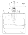
【解決手段】本願発明に係る流動体収容容器に取り付ける着脱式注出口11は、流動体が収容される流動体収容容器(例えば流動体パウチ1)の出口部分となる注出口装着部5に挿入される注出口本体12と、この注出口本体12に形成されて流動体収容容器の収容室4内部を外部に連通させる注出通路14と、注出口本体12の周囲に環装され、注出口装着部5の内側で拡径して注出口本体12と注出口装着部5との間を液密にシールすると共に注出口本体12を注出口装着部5に固定する拡径シール手段(26,28)とを備えてなることを特徴とする。
【選択図】 図10
Description
[発明の実施の形態1]
[発明の実施の形態2]
[発明の実施の形態3]
[発明の実施の形態4]
[発明の実施の形態5]
3 接合代
4 収容室
5 注出口装着部
7 カットライン
8 カットポイント
11 注出口
14 注出通路
22 キャップ
26 拡径シール手段を構成する密閉部材としてのシールブッシュ
28 拡径シール手段を構成する拡径機構部
30 ワッシャー
31 押圧ブッシュ
32 インサートヘッド
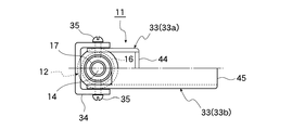
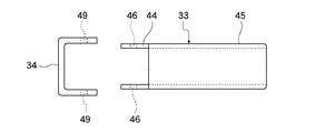
33 カムレバー
34 補強クランプ
35 ビス
40 ガイドプレート
51 挿入深さ決定手段を構成する雄テーパー部
52 挿入深さ決定手段を構成する雌テーパー部
75 挿入深さ決定手段を構成する突起状ストッパー
D1 雄テーパー部の最大外径
D2 雌テーパー部の最小内径
T シート状素材の引き裂き方向
Claims (9)
- 流動体が収容される流動体収容容器の出口部分となる注出口装着部に挿入される注出口本体と、
前記注出口本体に形成されて前記流動体収容容器の収容室内部を外部に連通させる注出通路と、
前記注出口本体の周囲に環装され、前記注出口装着部の内側で拡径して前記注出口本体と前記注出口装着部との間を液密にシールすると共に前記注出口本体を前記注出口装着部に固定する拡径シール手段と、
を備えてなることを特徴とする流動体収容容器に取り付ける着脱式注出口。 - 前記拡径シール手段は、
前記注出口本体の外周に環装された弾性材料でなる密閉部材と、
前記密閉部材を前記注出口本体の軸方向に圧縮変形させてその外径を拡径させ、前記密閉部材の外周面を前記注出口装着部の内周面に圧接させる拡径機構部と、
を備えてなることを特徴とする請求項1に記載の流動体収容容器に取り付ける着脱式注出口。 - 前記拡径機構部に、所定角度の回動により前記密閉部材を軸方向に押圧可能なカムレバーを設けたことを特徴とする請求項2に記載の流動体収容容器に取り付ける着脱式注出口。
- 前記流動体収容容器が、樹脂シート状素材を重ね合わせてその周囲を接合したパウチ状である場合に、前記注出口本体の先端に、前記注出口装着部を形成する二枚のシート状素材の間へ挿入されるガイド部を設けたことを特徴とする請求項1乃至3の何れかに記載の流動体収容容器に取り付ける着脱式注出口。
- 前記注出通路の外端を密閉するキャップを設けたことを特徴とする請求項1乃至4の何れかに記載の流動体収容容器に取り付ける着脱式注出口。
- 請求項1乃至5に記載の着脱式注出口と、この着脱式注出口が装着される流動体収容容器の出口部分となる注出口装着部との少なくとも一方に、前記着脱式注出口の注出口本体を前記注出口装着部に適正な深さで挿入させる挿入深さ決定手段を設けたことを特徴とする流動体収容容器に取り付ける着脱式注出口および流動体収容容器。
- 前記挿入深さ決定手段は、前記注出口本体に設けた、前記注出口装着部の内部側に向かって縮径する雄テーパー部と、前記注出口装着部に設けた、前記注出口装着部の内部側に向かって縮径する雌テーパー部とを備えて構成され、前記雄テーパー部の最大外径を前記雌テーパー部の最小内径よりも大きく設定し、前記雄テーパー部が前記雌テーパー部の中で行き詰まった位置が前記注出口本体の適正な挿入深さとなるようにしたことを特徴とする請求項6に記載の流動体収容容器に取り付ける着脱式注出口および流動体収容容器。
- 前記挿入深さ決定手段は、前記注出口本体が前記注出口装着部に適正な深さで挿入された時点で前記注出口装着部の先端に当接するよう、前記注出口本体に設けられた突起状ストッパーであることを特徴とする請求項6に記載の流動体収容容器に取り付ける着脱式注出口および流動体収容容器。
- 請求項1乃至8に記載の流動体収容容器は、樹脂シート状素材を重ね合わせてその周囲を接合したパウチ状であり、前記樹脂シート状素材は、一方向にのみ引き裂き可能な直線カット性を持ち、前記流動体収容容器の製造時において、その出口部分となる注出口装着部の先端は閉塞されており、この注出口装着部を開封する方向と前記シート状素材の引き裂き方向とを合致させた上、前記流動体収容容器の一側辺に、前記注出口装着部の先端をカットするカットラインの起点となるカットポイントを設けたことを特徴とする流動体収容容器。
Priority Applications (1)
| Application Number | Priority Date | Filing Date | Title |
|---|---|---|---|
| JP2008189613A JP5248942B2 (ja) | 2008-07-23 | 2008-07-23 | 流動体収容容器に取り付ける着脱式注出口および流動体収容容器 |
Applications Claiming Priority (1)
| Application Number | Priority Date | Filing Date | Title |
|---|---|---|---|
| JP2008189613A JP5248942B2 (ja) | 2008-07-23 | 2008-07-23 | 流動体収容容器に取り付ける着脱式注出口および流動体収容容器 |
Related Child Applications (1)
| Application Number | Title | Priority Date | Filing Date |
|---|---|---|---|
| JP2013082691A Division JP2013136420A (ja) | 2013-04-11 | 2013-04-11 | 流動体収容容器に取り付ける着脱式注出口および流動体収容容器 |
Publications (2)
| Publication Number | Publication Date |
|---|---|
| JP2010023901A true JP2010023901A (ja) | 2010-02-04 |
| JP5248942B2 JP5248942B2 (ja) | 2013-07-31 |
Family
ID=41730089
Family Applications (1)
| Application Number | Title | Priority Date | Filing Date |
|---|---|---|---|
| JP2008189613A Active JP5248942B2 (ja) | 2008-07-23 | 2008-07-23 | 流動体収容容器に取り付ける着脱式注出口および流動体収容容器 |
Country Status (1)
| Country | Link |
|---|---|
| JP (1) | JP5248942B2 (ja) |
Cited By (1)
| Publication number | Priority date | Publication date | Assignee | Title |
|---|---|---|---|---|
| JP2022057898A (ja) * | 2020-09-30 | 2022-04-11 | 天龍化学工業株式会社 | パウチ容器 |
Citations (10)
| Publication number | Priority date | Publication date | Assignee | Title |
|---|---|---|---|---|
| JPH03126822U (ja) * | 1990-04-03 | 1991-12-20 | ||
| JPH10157747A (ja) * | 1996-11-29 | 1998-06-16 | Taketomo:Kk | 袋状容器 |
| JPH10236488A (ja) * | 1997-02-20 | 1998-09-08 | Daiwa Gravure Co Ltd | 液体取り出し装置 |
| JPH11504605A (ja) * | 1996-03-04 | 1999-04-27 | ロックタイト(アイルランド)リミテッド | 流体流コネクタ、流体圧力機構および流体、例えば接着剤のための製品タンクの蓋 |
| JP2002160780A (ja) * | 2000-11-27 | 2002-06-04 | Taisei Kako Co Ltd | スプレーノズルの取付構造並びに取付方法 |
| JP2004238047A (ja) * | 2003-02-07 | 2004-08-26 | Kyodo Printing Co Ltd | 包装袋 |
| JP2006500131A (ja) * | 2002-09-25 | 2006-01-05 | メデックス | 柔軟性嚢状容器および関連する注入装置 |
| JP2008007153A (ja) * | 2006-06-28 | 2008-01-17 | Tokyo Ohka Kogyo Co Ltd | 流体用容器及びそれを用いた流体入り容器 |
| JP3139517U (ja) * | 2007-11-28 | 2008-02-21 | 株式会社 汎用 | コック取付具 |
| JP2008063006A (ja) * | 2006-08-10 | 2008-03-21 | Haruo Minegishi | ゲル状流体の充填容器とその搾り出し装置 |
-
2008
- 2008-07-23 JP JP2008189613A patent/JP5248942B2/ja active Active
Patent Citations (10)
| Publication number | Priority date | Publication date | Assignee | Title |
|---|---|---|---|---|
| JPH03126822U (ja) * | 1990-04-03 | 1991-12-20 | ||
| JPH11504605A (ja) * | 1996-03-04 | 1999-04-27 | ロックタイト(アイルランド)リミテッド | 流体流コネクタ、流体圧力機構および流体、例えば接着剤のための製品タンクの蓋 |
| JPH10157747A (ja) * | 1996-11-29 | 1998-06-16 | Taketomo:Kk | 袋状容器 |
| JPH10236488A (ja) * | 1997-02-20 | 1998-09-08 | Daiwa Gravure Co Ltd | 液体取り出し装置 |
| JP2002160780A (ja) * | 2000-11-27 | 2002-06-04 | Taisei Kako Co Ltd | スプレーノズルの取付構造並びに取付方法 |
| JP2006500131A (ja) * | 2002-09-25 | 2006-01-05 | メデックス | 柔軟性嚢状容器および関連する注入装置 |
| JP2004238047A (ja) * | 2003-02-07 | 2004-08-26 | Kyodo Printing Co Ltd | 包装袋 |
| JP2008007153A (ja) * | 2006-06-28 | 2008-01-17 | Tokyo Ohka Kogyo Co Ltd | 流体用容器及びそれを用いた流体入り容器 |
| JP2008063006A (ja) * | 2006-08-10 | 2008-03-21 | Haruo Minegishi | ゲル状流体の充填容器とその搾り出し装置 |
| JP3139517U (ja) * | 2007-11-28 | 2008-02-21 | 株式会社 汎用 | コック取付具 |
Cited By (2)
| Publication number | Priority date | Publication date | Assignee | Title |
|---|---|---|---|---|
| JP2022057898A (ja) * | 2020-09-30 | 2022-04-11 | 天龍化学工業株式会社 | パウチ容器 |
| JP7553087B2 (ja) | 2020-09-30 | 2024-09-18 | 天龍化学工業株式会社 | パウチ容器 |
Also Published As
| Publication number | Publication date |
|---|---|
| JP5248942B2 (ja) | 2013-07-31 |
Similar Documents
| Publication | Publication Date | Title |
|---|---|---|
| CN103492276B (zh) | 具有适配器的密封装置 | |
| JP4533887B2 (ja) | 医療用液体を収容するパック用のコネクタおよび医療用液体のパック | |
| EP1201598B1 (en) | Quick-locking device for effecting hygienic transfer of flowable material from a container by piercing | |
| EP2346746B1 (en) | Valve | |
| EP2385919B1 (en) | Poppet seal fitment for a collapsible bag | |
| KR20010071244A (ko) | 끼움부속 관 및 밸브를 가진 유체분배장치 | |
| PL216609B1 (pl) | Urządzenie stosowane w składanej torebce do dozowania cieczy i substancji półstałych | |
| US9609969B1 (en) | Deformable elastomeric valve and valve assembly | |
| CN103765073A (zh) | 用于可塌缩容器的无菌鸭嘴翻盖装配体 | |
| JP2007517604A (ja) | 漏出防止装置及びその方法 | |
| CN109803715B (zh) | 用于含有液体的医疗包装的连接器 | |
| JP5248942B2 (ja) | 流動体収容容器に取り付ける着脱式注出口および流動体収容容器 | |
| AU718270B2 (en) | Plastic stop-cock for liquid containers | |
| JP3795404B2 (ja) | ホース状袋を空にするための装置 | |
| JP2013136420A (ja) | 流動体収容容器に取り付ける着脱式注出口および流動体収容容器 | |
| JP4502194B2 (ja) | 可撓性容器のスパウト | |
| WO1991005190A1 (en) | Dispensing valve | |
| JP4999348B2 (ja) | 詰替え用パウチ | |
| JP2020050412A (ja) | カバー部材付きスパウト | |
| JP7473415B2 (ja) | 注出用スパウト及び注出用スパウト付き容器 | |
| MX2008001202A (es) | Recipiente para un liquido y un gas propulsor que comprende una valvula. | |
| AU632177B2 (en) | Dispensing valve | |
| JP6182444B2 (ja) | スパウトおよびスパウト付き収容体 | |
| HK1143122B (en) | Pouring member | |
| HK1143122A1 (en) | Pouring member |
Legal Events
| Date | Code | Title | Description |
|---|---|---|---|
| A621 | Written request for application examination |
Free format text: JAPANESE INTERMEDIATE CODE: A621 Effective date: 20110419 |
|
| A131 | Notification of reasons for refusal |
Free format text: JAPANESE INTERMEDIATE CODE: A131 Effective date: 20121204 |
|
| A521 | Request for written amendment filed |
Free format text: JAPANESE INTERMEDIATE CODE: A523 Effective date: 20130124 |
|
| TRDD | Decision of grant or rejection written | ||
| A01 | Written decision to grant a patent or to grant a registration (utility model) |
Free format text: JAPANESE INTERMEDIATE CODE: A01 Effective date: 20130326 |
|
| A61 | First payment of annual fees (during grant procedure) |
Free format text: JAPANESE INTERMEDIATE CODE: A61 Effective date: 20130411 |
|
| R150 | Certificate of patent or registration of utility model |
Ref document number: 5248942 Country of ref document: JP Free format text: JAPANESE INTERMEDIATE CODE: R150 Free format text: JAPANESE INTERMEDIATE CODE: R150 |
|
| FPAY | Renewal fee payment (event date is renewal date of database) |
Free format text: PAYMENT UNTIL: 20160419 Year of fee payment: 3 |
|
| R250 | Receipt of annual fees |
Free format text: JAPANESE INTERMEDIATE CODE: R250 |
|
| R250 | Receipt of annual fees |
Free format text: JAPANESE INTERMEDIATE CODE: R250 |
|
| R250 | Receipt of annual fees |
Free format text: JAPANESE INTERMEDIATE CODE: R250 |
|
| R250 | Receipt of annual fees |
Free format text: JAPANESE INTERMEDIATE CODE: R250 |