JP2010004841A - Reaping and transfer device of multi-ridge reaping combine harvester - Google Patents

Reaping and transfer device of multi-ridge reaping combine harvester Download PDF

Info

Publication number
JP2010004841A
JP2010004841A JP2008170788A JP2008170788A JP2010004841A JP 2010004841 A JP2010004841 A JP 2010004841A JP 2008170788 A JP2008170788 A JP 2008170788A JP 2008170788 A JP2008170788 A JP 2008170788A JP 2010004841 A JP2010004841 A JP 2010004841A
Authority
JP
Japan
Prior art keywords
conveying
conveying device
merging
cereal
reaping
Prior art date
Legal status (The legal status is an assumption and is not a legal conclusion. Google has not performed a legal analysis and makes no representation as to the accuracy of the status listed.)
Pending
Application number
JP2008170788A
Other languages
Japanese (ja)
Other versions
JP2010004841A5 (en
Inventor
Hakuro Takahashi
伯郎 高橋
Wahei Ishiga
和平 石賀
Tatsuya Miyake
達也 三宅
Ryuji Akehi
龍二 明比
Current Assignee (The listed assignees may be inaccurate. Google has not performed a legal analysis and makes no representation or warranty as to the accuracy of the list.)
Iseki and Co Ltd
Iseki Agricultural Machinery Mfg Co Ltd
Original Assignee
Iseki and Co Ltd
Iseki Agricultural Machinery Mfg Co Ltd
Priority date (The priority date is an assumption and is not a legal conclusion. Google has not performed a legal analysis and makes no representation as to the accuracy of the date listed.)
Filing date
Publication date
Application filed by Iseki and Co Ltd, Iseki Agricultural Machinery Mfg Co Ltd filed Critical Iseki and Co Ltd
Priority to JP2008170788A priority Critical patent/JP2010004841A/en
Publication of JP2010004841A publication Critical patent/JP2010004841A/en
Publication of JP2010004841A5 publication Critical patent/JP2010004841A5/ja
Pending legal-status Critical Current

Links

Images

Abstract

<P>PROBLEM TO BE SOLVED: To increase reaping work efficiency, by compactly providing a combine harvester having a reaping and transfer device for multi-ridge reaping. <P>SOLUTION: A grain culm-confluent transfer device (4), which set its transfer starting end at the right side part of a reaping device (2) to serially flow together the reaped culm from the front side and to transfer to the rear upper side of a body (3), is set to incline against the center left side of the reaping width, a central transfer device (6) flowing the reaped culm to the base part side of the grain culm-confluent transfer device (4) and a right transfer device (7) flowing the culm to the middle position of the device (4) are provided, the central transfer device (6) is set along the longitudinal direction to be almost linear, and the right transfer device (7) is set to incline to the culm transfer direction side of the grain culm-confluent transfer device (4). <P>COPYRIGHT: (C)2010,JPO&INPIT

Description

この発明は、多条刈のコンバインにおいて、多条の刈取穀稈を安定よく合流させる刈取搬送装置に関する。   The present invention relates to a harvesting and conveying apparatus for stably joining a plurality of harvested cereal culms in a combine for harvesting multiple strands.

従来から多条刈のコンバインに関する公知技術は、公開公報上にも多数公開されており、例えば、特開2008−99707号の公開特許公報がその一例である。
該公開特許公報に開示されている公知技術は、明細書と図面によれば、本件出願の前提となる多条刈の刈取部が、図4、及び図5に示され、明細書にその構成が説明されている。該公報の刈取部は、6条刈であるが、記載によると、前部に刈取穀稈条ごとに分草杆(公報の記載は分草板)が配置され、その後方に、各刈取条ごとに引起しケース、突起付きベルト、掻込みスターホイールが順次設けられ、下部位置には、広幅の刈刃が、更に、後方には左右の掻込み合流搬送チエンがそれぞれ設けられ、6条の穀稈条列の刈り取りと合流搬送ができる構成となっている。
Conventionally, a number of known techniques relating to combine harvesting have been published in public gazettes, for example, Japanese Patent Publication No. 2008-99707 is an example.
According to the specification and drawings, the publicly known technology disclosed in the published patent gazette shows a multi-row mowing part as a premise of the present application shown in FIG. 4 and FIG. Has been explained. The cutting part of the publication is a 6-row cutting, but according to the description, a weed culm (a weeding board is described in the publication) is arranged at the front part for each cutting grain stub, and behind each cutting stub A case, a belt with protrusions, and a staring star wheel are provided in sequence, a wide cutting blade is provided at the lower position, and a left and right scavenging and joining chain is provided at the rear. It has a configuration that can harvest and join the grain row.

そして、該公報に記載された発明は、伝動ケースの下側に空間部を形成することによって、搬送途中の刈取穀稈株元部の引掛りや、藁草・泥土などの堆積を防止できる効果があると記載されている。
特開2008−99707号公開特許公報
And the invention described in this publication has the effect of preventing catching of the harvested grain culm stock in the middle of conveyance and accumulation of grass, mud, etc. by forming a space part below the transmission case. It is described that there is.
Japanese Patent Laid-Open No. 2008-99707

各穀稈条ごとの刈取穀稈を合流させながら後部上方まで搬送する合流用穀稈搬送装置に対して、その前側に配置して各条の刈取穀稈を合流位置まで搬送して合流させる搬送装置を有する多条刈の刈取搬送装置は、合流用穀稈搬送装置の搬送穀稈が比較的少量の搬送行程前半位置では、搬送方向に沿うように同じ方向に傾斜させて、流れの方向に自然に合流すると円滑な合流搬送が可能となり、前記合流用穀稈搬送装置の中間部から後半に達して搬送穀稈の量が増加してくると、該合流用穀稈搬送装置に対する搬送装置の角度を大きく取って、合流部分のスペースを広くすることにより、搬送穀稈の適確な受継・合流搬送が可能となることが知られている。   Conveyance that is arranged on the front side of the cereal conveying device for merging and that conveys the reaped cereals of each item to the merging position with respect to the cereal conveying device for merging that conveys the reaping cereal for each cereal ridge together In the first half of the transport stroke, the multi-row cutting harvesting and transporting device having the apparatus is inclined in the same direction along the transport direction in the first half position of the transport stroke, and in the direction of flow. When it merges naturally, it becomes possible to smoothly join and convey, and when the amount of the conveyed culm increases from the middle part of the merging cereal conveying device to the latter half, the conveying device for the merging cereal conveying device It is known that by taking a large angle and widening the space of the merged portion, it is possible to accurately transfer and merge the conveyed cereal.

しかしながら、従来公知の多条刈の刈取搬送装置には全くその例はなく、前項で説明した特許文献1(該発明は、6条刈であるために、中間部に2条の穀稈条列を刈り取って集めて1条とした搬送装置がある。)に示されているように、前側から刈取穀稈を搬送して合流用の穀稈搬送装置に合流させる搬送装置は、合流搬送装置に対して常に直角に近い大きな角度で接し、両方の搬送装置の間に大きな合流空間部ができる構成となっている。   However, there is no example of a conventionally known multi-row cutting harvesting and conveying device. Patent Document 1 described in the previous section (Since the invention is 6-row cutting, two rows of grain ridges are arranged in the middle portion. As shown in Fig. 2), the conveying device that conveys the harvested cereal from the front side and joins it to the merging cereal conveying device is In contrast, it is always in contact with a large angle close to a right angle, and a large merging space is formed between both conveying devices.

したがって、従来装置は、合流用穀稈搬送装置が搬送する穀稈の量に応じて、前側から搬送して受継ぎ供給する搬送装置の角度に配慮する等の工夫がなく、常に、前記合流用穀稈搬送装置に対する搬送装置の角度を大きく取って、合流部分のスペースを広くするもので、円滑な穀稈の受継ぎ合流が出来ない課題がある。   Therefore, the conventional apparatus does not have any contrivance such as considering the angle of the conveying device that is conveyed from the front side and supplied continuously according to the amount of the corn straw conveyed by the merging cereal conveying device. The angle of the conveying device with respect to the cereal conveying device is increased to widen the space at the merging portion, and there is a problem that smooth cereal cereal inheritance cannot be achieved.

更に、従来の合流用穀稈搬送装置(前記特許文献1の右株元合流搬送チエン33Rが相当する。)は、キャビンの前側に配置しているにもかかわらず、直線状に形成され、キャビンを後方にずらして装置せざるを得ない構成となっており、必然的にコンバインの全長が長くなる課題がある。   Furthermore, the conventional cereal conveying device for merging (corresponding to the right stock former merging and conveying chain 33R of Patent Document 1) is formed in a straight line in spite of being arranged on the front side of the cabin. Since the apparatus has to be shifted backward, the combined length of the combine inevitably increases.

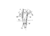
この発明は、上記課題を解決するために、請求項1に記載した発明は、刈取装置(2)の右側部に搬送始端部を位置させて刈取穀稈を前側から順次合流させながら車体(3)の後部上方に搬送する合流用穀稈搬送装置(4)を刈幅の中央左側に向けて傾斜させて設け、該合流用穀稈搬送装置(4)の搬送終端部分に、前記刈取装置(2)の左側部に搬送始端部を位置させて複数条の刈取穀稈をまとめて合流させる穀稈搬送装置(5)の搬送終端部を臨ませて設け、前記合流用穀稈搬送装置(4)に対して刈取穀稈を基部側に合流する中搬送装置(6)と中間位置に合流する右搬送装置(7)とを設け、前記中搬送装置(6)を前後方向に沿わせて略直線状に設け、右搬送装置(7)を前記合流用穀稈搬送装置(4)の穀稈搬送方向側に傾斜させて設けたことを特徴とする多条刈コンバインの刈取搬送装置とした。   In order to solve the above-mentioned problem, the invention according to claim 1 is directed to the vehicle body (3), with the conveying start end located on the right side of the reaping device (2) and the cereal grains being joined sequentially from the front side. ) The condylar cereal conveyor device (4) that conveys the rear upper part is provided to be inclined toward the central left side of the cutting width, and the reaping device (4) 2) The starting end part of the conveyance is positioned on the left side of the cereals conveying device (5) for bringing together the plurality of harvested cereal grains, and the conveying terminal part of the cereal conveying apparatus (4) is provided. ) Is provided with a middle conveying device (6) for merging the harvested cereal rice cake to the base side and a right conveying device (7) for merging at the intermediate position, and the middle conveying device (6) is approximately along the front-rear direction. It is provided in a straight line, and the right conveyor (7) is inclined toward the corn straw transporting direction side of the merging grain straw conveyor (4). That Te was provided was cutting conveying apparatus for a multi-strip cutting Combine characterized by.

合流用穀稈搬送装置(4)に対して、搬送の途中位置に刈取穀稈を合流する中搬送装置(6)と右搬送装置(7)との2つの搬送装置(6,7)から、合流位置における合流用穀稈搬送装置(4)が搬送している穀稈層(量)に応じて合流角度を変えて設け、刈取穀稈を安定よく整然と合流させることができるものとしている。   From the two conveying devices (6, 7) of the middle conveying device (6) and the right conveying device (7) for merging the harvested cereal rice cake to the midway position for the cereal conveying device for merging (4), The merging angle is changed according to the culm layer (amount) conveyed by the merging cereal conveyance device (4) at the merging position so that the harvested cereal can be merged stably and orderly.

つぎに、請求項2に記載した発明は、前記合流用穀稈搬送装置(4)は、車体(3)の前部右側に寄せて配置された運転席(8)の前側を経由して側方に向かう搬送経路を形成する構成とし、該合流用穀稈搬送装置(4)は、少なくとも前記運転席(8)の左側に達した部分から後側の部位を平面視でへ字状に近い形状に屈曲させて後方に向けて前記運転席(8)を迂回させたことを特徴とする請求項1記載の多条刈コンバインの刈取搬送装置とした。   Next, the invention described in claim 2 is such that the corn mash transporting device (4) is connected to the front side of the front part of the vehicle body (3) via the front side of the driver seat (8). The condensate culm conveying device (4) is configured to form at least a rear portion from a portion reaching the left side of the driver seat (8) in a plan view. 2. The harvesting and conveying apparatus for a multi-row harvesting combine according to claim 1, wherein the driver seat (8) is detoured toward the rear by being bent into a shape.

合流用穀稈搬送装置(4)は、搬送始端部分から順次供給される多条の刈取穀稈条列を整然と合流させながら搬送して、最終的に1つの流れにまとめて後部の搬送装置に受け継ぎ搬送するものでありながら、運転席(8)を極力前寄りに配置して搭載できるものとしている。   The corn mash conveying device (4) for merging conveys multiple rows of harvested corn ridge rows that are sequentially supplied from the conveying start end portion while orderly merging them, and finally gathers them into one flow to the rear conveying device. The driver's seat (8) can be placed and installed as far as possible while being inherited and conveyed.

この構成によって、コンバインは、多条刈にかかわらず全長を長くすることなく構成できて、運転席(8)からの前方視界を確保できるものとなった。   With this configuration, the combine can be configured without increasing the overall length regardless of the multi-row cutting, and the forward view from the driver's seat (8) can be secured.

請求項1記載の発明によると、合流用穀稈搬送装置(4)に対して、中搬送装置(6)と右搬送装置(7)とから刈取穀稈を合流するにあたり、合流用穀稈搬送装置(4)が搬送している穀稈の量に応じて、中搬送装置(6)及び右搬送装置(7)の合流角度を変えて設け、刈取穀稈を安定よく整然と合流させることができ、刈取作業を能率よく行うことができる。   According to the first aspect of the present invention, when the harvested culm is joined from the middle transporting device (6) and the right transporting device (7) to the converging culm transporting device (4), the converging culm transporting Depending on the amount of cereal that the device (4) is conveying, the merging angle of the middle conveying device (6) and the right conveying device (7) can be changed, and the harvested cereal can be stably and orderly merged. The cutting operation can be performed efficiently.

請求項2記載の発明によると、上記請求項1記載の発明の効果に加えて、刈取搬送装置を運転席(8)に接近させることによって多条刈の大型コンバインにかかわらず全長を短くして機体をコンパクトに構成でき、運転席(8)からの前方視界を良好に確保でき、刈取作業の能率を高めることができる。   According to the invention described in claim 2, in addition to the effect of the invention described in claim 1, the overall length is shortened by bringing the cutting and conveying device closer to the driver's seat (8) regardless of the large combine of multi-row cutting. The airframe can be configured compactly, the front view from the driver's seat (8) can be secured satisfactorily, and the efficiency of the cutting operation can be increased.

以下、この発明の実施例を図面に基づいて具体的に説明する。
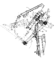
まず、コンバインは、図5に示すように、左右一対のクローラ10,10を装備した車体3上に、穀稈供給口11を前側に位置させて脱穀装置12を搭載し、その前側に刈取搬送装置1を昇降自由に連結した構成としている。
Embodiments of the present invention will be specifically described below with reference to the drawings.
First, as shown in FIG. 5, the combine is mounted with a threshing device 12 on the vehicle body 3 equipped with a pair of left and right crawlers 10, with the cereal supply port 11 positioned on the front side, and cut and conveyed on the front side. It is set as the structure which connected the apparatus 1 freely raising / lowering.

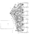
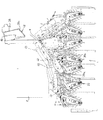
そして、刈取搬送装置1を支持する機枠構成は、上記脱穀装置12の前側、車体3の前部に刈取懸架台が装置され、その刈取懸架台上に基部を枢着状態に支持した後部フレーム13を、前部下方に延長してその前端部に、横向きの伝動ケース14を連結して平面視T型の伝動機構を内装した刈取支持フレーム15を構成している。そして、刈取搬送装置1は、前記刈取支持フレーム15上に各部材を取り付けて支持するが、図1に平面視で示した実施例の場合、前部低位置に8個の分草杆17を、略等間隔を保持して横方向に順次配置し、前記伝動ケース14の前側機枠に固着して設けている。そして、刈取装置2は、前記横向きの伝動ケース14の前側機枠から前方側に支持して設け、前記した各分草杆17の後方位置に横方向の全幅に渡って配置しており、各穀稈条列ごとに掻込まれる穀稈の根元を刈り取る構成としている。   And the machine frame structure which supports the cutting and conveying apparatus 1 is a rear frame in which a cutting suspension base is installed on the front side of the threshing device 12 and the front part of the vehicle body 3, and the base is supported pivotally on the cutting suspension base. 13 is extended to the lower front part, and a horizontal transmission case 14 is connected to the front end thereof to constitute a cutting support frame 15 having a T-type transmission mechanism in plan view. The cutting and conveying apparatus 1 attaches and supports each member on the cutting support frame 15, but in the case of the embodiment shown in a plan view in FIG. These are arranged sequentially in the horizontal direction while maintaining substantially equal intervals, and are fixed to the front machine casing of the transmission case 14. The reaping device 2 is provided on the front side from the front machine casing of the lateral transmission case 14 and is disposed over the entire lateral width at the rear position of each of the weed culverts 17. The roots of the cereals that are stirred for each cereal row are reaped.

そして、穀稈掻込み装置は、図1、乃至図4に示すように、掻込みラグベルト18と掻込みスターホイール19とからなり、前側を広くV字型にして圃場に植えられている穀稈列を掻込み、前記刈取装置2に案内する左右一対を1組として、全部で3組を横方向に配置した構成としている。   As shown in FIG. 1 to FIG. 4, the culm scraping device is composed of a rake belt 18 and a stirrer star wheel 19, and cereals that are planted in the field with the front side wide and V-shaped. The pair of left and right guides to the reaping device 2 is set as one set, and a total of three sets are arranged in the horizontal direction.

そして、一つの穀稈掻込み装置は、図面から明らかなように、一つの掻込みラグベルト18と掻込みスターホイール19とからなり、対向側には案内杆20を設けて1条の穀稈列を掻込んで前記刈取装置2に案内する構成としている。   And, as is apparent from the drawing, one culm scoring device is composed of a single scrub lug belt 18 and a stir star wheel 19, and a guide culm 20 is provided on the opposite side to form a single culm row. And is guided to the reaping device 2.

このように、実施例に係る多条刈の刈取搬送装置1を構成する前記穀稈掻込み装置は、刈取支持フレーム15上に、3組の2条用の左右一対の掻込みラグベルト18,18、掻込みスターホイール19,19と、1条用の掻込みラグベルト18、掻込みスターホイール19とによって、全部で7条の植え付け穀稈列を同時に刈取る7条刈りの構成としている。21は穀稈引起し装置を示し、各刈取条ごとに設けている。   As described above, the culm scraping device constituting the multi-row cutting harvesting and transporting device 1 according to the embodiment is provided on the cutting support frame 15 with the three pairs of left and right pair of stiffening lug belts 18 and 18. By using the staring star wheels 19, 19, the one streak lug belt 18, and the stirrer star wheel 19, a total of seven planted grain rows are simultaneously harvested. Reference numeral 21 denotes a grain raising device, which is provided for each cutting line.

そして、合流用穀稈搬送装置4は、図1、乃至図4に示すように、根元チエン22と穂先搬送ラグ23とから構成するが、搬送始端部を前記刈取装置2の右側に位置させて、右側チエン24に接続させて配置し2条の刈取穀稈を引き継ぐ位置に設け、搬送途中で前側から順次合流させながら車体3の後部上方に搬送するように中央から更に、左寄りに向けて傾斜させて配置した構成としている。そして、穀稈搬送装置5は、図面に示すように、搬送始端部を前記刈取装置2の左端側に位置させ、左2条の刈取穀稈をまとめて搬送し、その終端部分を前記合流用穀稈搬送装置4の搬送終端部分に供給して合流させる構成としている。   As shown in FIG. 1 to FIG. 4, the merging cereal conveyance device 4 is composed of a root chain 22 and a tip conveyance lug 23, and the conveyance start end is located on the right side of the reaping device 2. , Connected to the right chain 24, provided at a position to take over the two harvested cereal grains, and inclined further toward the left from the center so as to be conveyed to the upper rear part of the vehicle body 3 while being merged sequentially from the front side in the middle of conveyance It is set as the structure arranged. Then, as shown in the drawing, the cereal haul conveying device 5 positions the conveying start end portion on the left end side of the reaping device 2, conveys the left two reaped cereal halves together, and uses the terminal portion for the merging. It is set as the structure which is supplied to the conveyance termination | terminus part of the cereal conveyance apparatus 4, and makes it merge.

そして、中搬送装置6は、2条の刈取穀稈を集めて、前記合流用穀稈搬送装置4の基部側(搬送方向の下手側)に合流する位置に設けているが、この場合、車体3の前後方向に沿わせて略直線状に配置した構成としている。そして、右搬送装置7は、図1から解るように、前記中搬送装置6の右側にあって、前記合流用穀稈搬送装置4の中間位置に合流する配置とするが、この場合、該合流用穀稈搬送装置4の穀稈搬送方向側に傾斜させて搬送方向に沿わせながら合流する構成としている。   And the middle conveyance apparatus 6 is provided in the position which collects the two cutting cereals and joins to the base side (lower side of a conveyance direction) of the said corn cereal conveyance apparatus 4 in this case. 3 is arranged in a substantially straight line along the front-rear direction. As shown in FIG. 1, the right transport device 7 is located on the right side of the middle transport device 6 and joins the intermediate position of the merging grain transport device 4. In this case, It is set as the structure which inclines in the corn straw conveyance direction side of the grain cereal conveying apparatus 4 and joins along the conveyance direction.

このように、右搬送装置7は、前記合流用穀稈搬送装置4が搬送している穀稈量が比較的少ない部分での合流であるから、合流部分のスペースをできる限り狭くして搬送方向に沿わせながら合流させる構成とし、一方、中搬送装置6は、合流位置において、合流用穀稈搬送装置4の搬送穀稈量が増加して層が厚くなって搬送されて来るから、合流角度を大きく取って広い合流スペースを確保する構成としている。   Thus, since the right conveyance device 7 is a merge at a portion where the amount of the culm transported by the merged culm conveying device 4 is relatively small, the space of the merged portion is made as narrow as possible to the conveyance direction. On the other hand, the middle conveying device 6 is conveyed at the merging position because the amount of the mash of the mashing device 4 for merging increases and the layer becomes thicker at the merging position. A large confluence space is secured by taking a large area.

そして、前記合流用穀稈搬送装置4は、平面視において、前記車体3の前部右側に寄せて配置された運転席8の前側を横切って配置し、その運転席8の左側にまで延長して車体3の左側に搬送する構成としている。そして、合流用穀稈搬送装置4は、図1から解るように、前記運転席8の左側に達した部分から平面視でへ字状に近い形状に屈曲させて後方に向けて設けており、前記運転席8を迂回させた構成としている。この場合、合流用穀稈搬送装置4を構成している根元チエン22は、図1に示す実施例では、非搬送側を後側から押圧ローラ25を押し当てて前側にへ字状に近い形状に屈曲させた構成としている。   Then, the cereal grain conveying device 4 is arranged across the front side of the driver's seat 8 arranged close to the front right side of the vehicle body 3 in plan view, and extends to the left side of the driver's seat 8. In this way, it is conveyed to the left side of the vehicle body 3. And, as shown in FIG. 1, the conjugation cereal conveying device 4 is bent toward a shape close to a square shape in a plan view from the portion that has reached the left side of the driver's seat 8 and is provided toward the rear. The driver seat 8 is bypassed. In this case, in the embodiment shown in FIG. 1, the root chain 22 constituting the merging grain conveying device 4 has a shape close to a front shape by pressing the non-conveying side from the rear side with the pressing roller 25. It is made into the structure bent to.

そして、前記合流用穀稈搬送装置4、前記穀稈搬送装置5、前記中搬送装置6、及び前記右搬送装置7は、具体的な記載を省略している部分もあるが、それぞれ根元チエンと穂先ラグとによって、穀稈の株元側を挟持して穂先側をラグに係合しながら搬送する構成で、従来公知の技術を採用して構成している。   And although the said corn straw conveying apparatus 4, the said corn straw conveying apparatus 5, the said middle conveying apparatus 6, and the said right conveying apparatus 7 also have the part which has abbreviate | omitted specific description, respectively, The head lug sandwiches the stock side of the grain and transports it while engaging the head side with the lug, and employs a conventionally known technique.

以上述べたように、この発明の実施例は、合流用穀稈搬送装置4の搬送行程の中間部分に、中搬送装置6と右搬送装置7とを前側に配置して、それぞれ刈取穀稈を合流するにあたり、合流用穀稈搬送装置4が搬送している穀稈の量に応じて、2つの搬送装置6,7の合流角度を変えて設け、刈取穀稈を安定よく整然と合流させることができるものとしている。   As described above, according to the embodiment of the present invention, the middle conveying device 6 and the right conveying device 7 are arranged on the front side in the middle part of the conveying stroke of the merging cereal conveying device 4, and the harvested cereal cocoons are respectively provided. In merging, according to the amount of cereals conveyed by the corn mash conveying device 4 for merging, the merging angle of the two conveying devices 6, 7 can be changed to provide a stable and orderly merging of the harvested cereals. It is supposed to be possible.

そして、実施例の合流用穀稈搬送装置4は、上述の通り、搬送始端部分、更に搬送途中において、順次供給される多条の刈取穀稈条列を整然と合流させながら搬送して、最終的に1条にまとめて後部の搬送装置に受け継ぎ搬送するものでありながら、運転席8を極力前寄りに配置して搭載できる利点を備えている。   Then, as described above, the corn mash conveying apparatus 4 of the embodiment conveys the multiple cut corn ridge rows that are sequentially supplied while orderly merging in the conveyance start end portion and further in the middle of the conveyance. However, the driver's seat 8 can be arranged and mounted as close to the front as possible.

すなわち、実施例は、多条刈の大型コンバインにもかかわらず全長を長くすることなく製作できて、運転席8からの前方視界を良好に確保できるから、安全で効率よく作業ができるものとなっている。   In other words, the embodiment can be manufactured without increasing the overall length in spite of the large combine of the multi-row cutting, and the front view from the driver's seat 8 can be secured well, so that the work can be performed safely and efficiently. ing.

つぎに、刈取搬送装置1について、他の具体的な実施例を説明する。
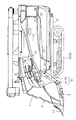
まず、既に、図1に基づいて説明した右搬送装置7は、一つの掻込みラグベルト18と一個の掻込みスターホイール19とからなる穀稈掻込装置と、これらに後続させて設けた根元チエン7aと、更に、対向側には案内杆20を設けて圃場の1条の穀稈列を掻込んで刈取装置2に案内し、刈取後、株元位置を挟持して搬送する構成としている。そして、前記案内杆20は、図6に示すように、根元チエン7a側に張圧する挟持スプリング27を、穀稈を挟持して搬送する経路の略中央位置(挟持搬送区間の中心位置)に配置して設け、挟持搬送の全工程における挟持力の安定を図るものとしている。
Next, another specific embodiment of the harvesting and conveying apparatus 1 will be described.
First, the right transport device 7 already described with reference to FIG. 1 includes a culm scoring device comprising one stir lug belt 18 and one stir star wheel 19, and a root chain provided subsequent thereto. In addition, a guide rod 20 is provided on the opposite side, and a single row of grain ridges is scraped and guided to the harvesting device 2, and after the harvesting, the stock position is held and conveyed. As shown in FIG. 6, the guide rod 20 is arranged at a substantially central position (center position of the holding and conveying section) of the path for holding and holding the culm with the holding spring 27 tensioned to the root chain 7 a side. Thus, the clamping force is stabilized in all the processes of clamping conveyance.

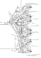
つぎに、合流用穀稈搬送装置4は、図3、及び図4に示すように、根元チエン22と穂先搬送ラグ23とから構成していることは、既に説明したが、実施例の構成では、穂先搬送ラグ23のすぐ上側から穀稈の搬送通路に沿わせて後側に穀稈上部をガイドする案内板28を後方に傾斜させて配置し、搬送穀稈の上部を載せた状態でガイドできる構成としている。そして、上部穂先搬送ラグ30a,30bは、図3、及び図4に示すように、前記穂先搬送ラグ23の上方位置において、搬送径路の前部と後部とに2分割して配置し、前側から後側に向けてラグを突出させながら穀稈の上部を、前記案内板28上にガイドしながら搬送する構成としている。この場合、上部穂先搬送ラグ30aは、右端2条の刈取穀稈の上部を円滑に搬送誘導する位置にあり、一方の上部穂先搬送ラグ30bは、左隣の1条の刈取穀稈条列を合流搬送させる位置に配置した構成にして、穀稈合流の円滑化を図っている。更に、特徴的な構成は、図4の側断面視で示すように、一方の上部穂先搬送ラグ30bを、対向側に配置した案内板28の板面に対して、直角に近い角度を保ちながら穀稈穂部を係合搬送する構成にしている。   Next, as shown in FIG. 3 and FIG. 4, it has already been described that the merging grain conveying device 4 is composed of the root chain 22 and the tip conveying lug 23, but in the configuration of the example, The guide plate 28 that guides the upper part of the cereals is arranged on the rear side along the conveyance path of the cereals from the upper side of the tip conveying lug 23, and is guided with the upper part of the conveyed cereals placed thereon. It is configured as possible. And as shown in FIG.3 and FIG.4, the upper tip conveyance lugs 30a and 30b are divided | segmented into the front part and rear part of a conveyance path in the upper position of the said tip conveyance lug 23, and are arrange | positioned from the front side. The upper part of the cereal is conveyed while being guided on the guide plate 28 while protruding the lug toward the rear side. In this case, the upper tip transport lug 30a is in a position that smoothly conveys and guides the upper part of the rightmost two harvested cereal grains, and one upper tip transport lug 30b has one row of harvested grain ridges adjacent to the left. It is configured to be arranged at the position to be joined and transported, so that the cereal merging is facilitated. Further, as shown in the side sectional view of FIG. 4, the characteristic configuration is that while maintaining the angle close to a right angle with respect to the plate surface of the guide plate 28 arranged on the opposite side, the one upper tip conveyance lug 30b. It is configured to engage and convey the grain head portion.

このように、上部穂先搬送ラグ30a,30bは、運転席8のすぐ前方位置において、右側2条の合流位置と、その搬送下手側で合流した3条の刈取穀稈穂先側部分をより安定した姿勢で搬送することが可能となり、更に、合流用穀稈搬送装置4を、運転席8の左側に達した部分で平面視へ字状に近い形状に屈曲させる構成にする場合にも、上部穂先搬送ラグ30bに影響を与えることなく構成できる利点がある。   In this way, the upper tip transport lugs 30a and 30b are more stable at the position immediately before the driver's seat 8 at the joining position of the right two strips and the three strips of the harvested grain panicle tip that joined at the lower transport side. It is also possible to transport in a posture, and the upper tip is also used when the conjugation cereal transporting device 4 is bent to a shape close to a letter shape in plan view at a portion reaching the left side of the driver's seat 8. There exists an advantage which can be comprised without affecting the conveyance lug 30b.

そして、合流用穀稈搬送装置4は、図1、乃至図4に基づいて既に説明したように、根元チエン22の搬送始端部を、前記刈取装置2の右側に位置させて、右側チエン24の上側に位置させて接続させ、2条の刈取穀稈を引き継ぐ位置に設けている。そして、合流用穀稈搬送装置4を構成する根元チエン22は、図面に示すように、斜め後方に延長するが、搬送途中で前側から順次穀稈を合流させながら車体3の後部上方に搬送するように中央から更に、左寄りに向けて傾斜させて配置した構成としている。そして、根元チエン22は、図1、又は図2から解るように、右搬送装置7の根元チエン7aより搬送方向の下手側位置で、中搬送装置6より前方位置において、非搬送側を後側から押圧ローラ25を押し当てて前側にへ字状に近い形状に屈曲させた構成としているのである。   Then, as already explained based on FIG. 1 to FIG. 4, the conjugating culm conveying device 4 has the conveying start end portion of the root chain 22 positioned on the right side of the reaping device 2, and the right chain 24. It is located on the upper side, connected, and provided at a position to take over the two harvested cereal grains. And as shown in the drawing, the root chain 22 constituting the merging grain feeder 4 extends obliquely rearward, and conveys the cereals from the front side in the middle of conveyance while conveying them upward in the rear part of the vehicle body 3. Thus, it is set as the structure which inclined further toward the left from the center. As shown in FIG. 1 or FIG. 2, the root chain 22 is located at the lower side position in the transport direction from the root chain 7 a of the right transport device 7, and at the front position from the middle transport device 6, the non-transport side at the rear side. Therefore, the pressing roller 25 is pressed against the front side and bent to a shape close to a hemispherical shape.

つぎに、既に説明した構成と重複する部分もあるが、穀稈穂部の搬送について、実施例を説明する。
まず、穀稈穂部の搬送装置、すなわち、穂先ラグは、特に、搬送始端部にあっては、後述する穀稈引起し装置21の引起し作用との関連において、穀稈上部の受継ぎ位置での円滑な搬送を行うために重要になってくる。そして、実施例の如く多条刈の刈取搬送装置1は、進行方向左側の穀稈引起し装置21の引起し終端部分(上部)と、後続する穀稈搬送装置(穀稈上部)との関係位置が課題となっている。
Next, although there is a part which overlaps with the structure already demonstrated, an Example is described about conveyance of a grain spike part.
First, the conveying device of the grain spikelet part, that is, the tip lug, especially at the conveyance start end part, the inheritance position of the upper part of the grain straw in relation to the raising action of the grain raising device 21 described later. It becomes important for smooth transport in Then, as in the embodiment, the multi-row cutting harvesting and conveying apparatus 1 is a relationship between the raising end portion (upper part) of the grain raising apparatus 21 on the left side in the traveling direction and the subsequent grain raising apparatus (upper part of the rice straw). Location is a challenge.

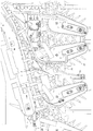
図3に示した実施例において、一番左側にある穀稈搬送装置5は、2条の穀稈条列を刈り取った後、まとめて合流用穀稈搬送装置4まで搬送するが、根元チエン5aの上方に、搬送工程の長い一段目の穂先ラグ31を配置し、その更に上方に、搬送工程を短くした二段目の穂先ラグ32を配置した二段穂先搬送の構成としている。そして、中搬送装置6は、図面に示すように、根元チエン6aの上方に比較的長い穂先ラグ33と、その上方に、短い穂先ラグ34を搬送径路に沿わせて二段搬送構成としている。   In the embodiment shown in FIG. 3, the leftmost cereal carrying device 5 cuts the two rows of cereal ridges, and then collectively conveys them to the merging cereal carrying device 4. A first stage tip lug 31 having a long transport process is disposed above the second stage tip lug 31, and a second stage tip lug 32 having a shorter transport process is disposed further above. Then, as shown in the drawing, the intermediate transfer device 6 has a two-stage transfer configuration with a relatively long tip lug 33 above the root chain 6a and a short tip lug 34 above it along the transfer path.

このように構成することによって、多条刈の刈取搬送装置1は、2条の穀稈条列をまとめてそれぞれ搬送する左側の2つの搬送装置5,6の穀稈穂部の搬送が確実に出来るものとなっている。すなわち、各穂先ラグ31,32,33,34は、穀稈引起し装置21からの穀稈上部の受け継ぎ(穂先部分の取り込み)の不良を未然に防止して、円滑な受け継ぎ搬送を行うことができるものとしている。   By constructing in this way, the multi-row cutting harvesting and conveying apparatus 1 reliably conveys the grain panicle portions of the two left-side conveying apparatuses 5 and 6 that respectively convey the two rows of grain ridges. It is possible. That is, the tip lugs 31, 32, 33, and 34 can prevent the poor inheritance (uptake of the tip portion) of the top of the cereal from the device 21 and perform smooth inheritance conveyance. It is supposed to be possible.

そして、刈取搬送装置1は、図3に示し、既に説明したように、右側の3条の搬送装置については、それぞれ上部穂先搬送ラグ30a,30bを一段構成にして穂先部分の搬送を行う構成としている。実施例の構成では、刈取搬送装置1の右側の穀稈引起し装置21から合流用穀稈搬送装置4側には穀稈上部が抜け易く、停滞が少ないから一段構成にしている。   Then, as shown in FIG. 3 and already described, the cutting and conveying apparatus 1 has a configuration in which the upper three tip conveying lugs 30a and 30b are configured in a single stage to convey the tip portion as described above. Yes. In the configuration of the embodiment, the upper part of the culm is easy to come out from the cereal pulling device 21 on the right side of the chopping and conveying device 1 to the side of the merging culm transporting device 4, and the stagnation is small.

このように、実施例に係る刈取搬送装置1は、右側3条の搬送装置に二段の穂先ラグを設けないで、一段構成の上部穂先搬送ラグ30a,30bを設けることにより軽量化が図られ、前後方向の後部フレーム13を中心とした左右の重量バランスが確保できる特徴と、併せて、コスト低減の効果もある。   Thus, the cutting and conveying apparatus 1 according to the embodiment is reduced in weight by providing the upper tip conveying lugs 30a and 30b having a one-stage configuration without providing the two-stage tip lugs in the right three-line conveying apparatus. In addition to the feature that the right and left weight balance around the rear frame 13 in the front-rear direction can be secured, there is also an effect of cost reduction.

そして、刈取搬送装置1は、図8に示すように、最も右側に位置した上部穂先搬送ラグ30aを外した構成とすれば、穀稈穂部の搬送機能が若干後退するが、重量軽減とコスト低減では大きな効果が発揮できる。   Then, as shown in FIG. 8, if the cutting and conveying apparatus 1 is configured to remove the upper tip conveying lug 30a located on the rightmost side, the conveying function of the grain spike part is slightly retracted, but weight reduction and cost are reduced. A great effect can be achieved by reduction.

つぎに、運転席8の右前側から左側を経由し、後方の脱穀装置12側にまで延長した合流用穀稈搬送装置4とこれに接続する供給搬送装置38の穂先搬送に関し、図9、及び図10に示す実施例を説明する。   Next, with respect to the tip transportation of the conjugation cereal conveyor device 4 extended to the rear threshing device 12 side through the left side from the right front side of the driver's seat 8 and the supply conveyor device 38 connected thereto, FIG. The embodiment shown in FIG. 10 will be described.

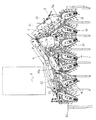
まず、実施例は、既に説明している図1、及び図3の刈取搬送装置1と同一の7条刈であるが、合流用穀稈搬送装置4と、該合流穀稈搬送装置4の終端部から搬送穀稈を受け継いで後方の脱穀装置12まで搬送して供給する供給搬送装置38との上方に配置して穂先部分を係合しながら搬送する穂先搬送装置39に関する。なお、この場合、穂先搬送装置39は、既に説明した穂先ラグと同様に、図10の如く、搬送ケース40に従来公知の起立、倒伏しながら移動する穂先ラグ42を有する穂先チエン41を、内装、巻回して構成している。   First, the embodiment is a seven-row mowing that is the same as the reaping and conveying apparatus 1 of FIG. 1 and FIG. 3 that has already been described, but the merging culm conveying apparatus 4 and the end of the merging cereal conveying apparatus 4 The present invention relates to a tip transport device 39 that is disposed above the supply transport device 38 that inherits the transported cereal from the section and transports it to the rear threshing device 12 and engages the tip portion. In this case, the tip transport device 39 has the tip chain 41 having the tip lag 42 that moves while standing upright and lying down on the transport case 40 as shown in FIG. It is composed by winding.

そして、穂先搬送装置39は、図面に示すように、合流用の根元チエン22の上方に沿わせて、穂先搬送装置39a,39bに2分割して前後に接続して配置し、受継ぎ搬送を可能とし、更に、供給搬送装置38の上方に穂先搬送装置39cを配置して受継ぎ搬送ができるように、3分割した構成としている。そして、中間の穂先搬送装置39bは、図10に示すように、搬送ケース40の後部を刈取支持フレーム15の後部フレーム13から上方に延長した伝動支持筒43の上部に伝動可能に支持して設け、その前部上側に、右側の穂先搬送装置39aを重ね合わせて伝動可能に連結して支持した構成としている。そして、供給搬送装置38の上方に配置した後部の穂先搬送装置39cは、前側2つの穂先搬送装置39a,39bとは別の伝動支持装置によって支持され伝動されながら、前側から搬送されてくる穀稈層の穂部を受け継ぎながら脱穀装置12に供給できる体勢に順次倒伏させるように搬送する構成としている。   Then, as shown in the drawing, the tip transport device 39 is divided into two tip transport devices 39a and 39b and connected to the front and back along the upper portion of the joining base chain 22 to carry out the inherited transport. In addition, the tip conveying device 39c is arranged above the supply conveying device 38 so that it can be transferred by inheritance. Then, as shown in FIG. 10, the intermediate tip conveying device 39 b is provided by supporting the rear part of the conveying case 40 on the upper part of the transmission supporting cylinder 43 extending upward from the rear frame 13 of the cutting support frame 15 so as to be capable of transmission. The right tip conveying device 39a is overlapped and connected to the front upper side so as to be capable of transmission. The rear tip transport device 39c arranged above the supply transport device 38 is supported and transmitted by a transmission support device different from the two front tip transport devices 39a and 39b, and is transported from the front side. It is set as the structure conveyed so that it may fall in order to the posture which can be supplied to the threshing apparatus 12, inheriting the head part of a layer.

このように、実施例に係る穂先搬送装置39a,39b,39cは、3分割して順次受け継いで連続搬送が可能に配置した構成としているから穀稈上部の搬送を円滑に行うことができるのは勿論であるが、各搬送ケース40の接続部位が、平面視で折り曲げして接続が可能であるから、運転席8との干渉を避けながら運転席8を前寄せに配置できる。そのため、コンバインは、運転席8からの前方視界を確保できる特徴と、併せて、車体全長を短く出来て、多条刈型で大型になりがちである構成をコンパクトにできる特徴がある。そして、合流用穀粒搬送装置4上の2つの穂先搬送装置39a,39bは、連続した一体構成にして、支持と伝動とを一体化して構成を合理的にした利点もある。   Thus, since the tip conveying device 39a, 39b, 39c according to the embodiment is configured to be divided into three parts and successively inherited so that continuous conveyance is possible, it is possible to smoothly convey the upper part of the cereal. Of course, since the connection part of each conveyance case 40 can be bent and connected in a plan view, the driver's seat 8 can be disposed forward while avoiding interference with the driver's seat 8. For this reason, the combine has a feature that can secure a forward view from the driver's seat 8 and a feature that can shorten the overall length of the vehicle body and make the configuration that tends to be large in a multi-row cutting type. And the two tip conveying apparatuses 39a and 39b on the grain conveying apparatus 4 for merging also have the advantage which made the structure rational by integrating a support and transmission into the continuous integrated structure.

つぎに、7条の穀稈引起し装置21について、その伝動機構の実施例を図面に基づき説明する。
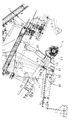
まず、引起し伝動筒45は、図11に示すように、下方の地面側に沿って横向きに配設している伝動ケース14の上方に略平行状態に配置し、該伝動ケース14の端部に下部を連結した縦型伝動筒46の上部を連結して正面視コ字型に枠組みした構成としている。そして、引起し伝動軸47は、前記引起し伝動筒45に内装して軸架され、前記伝動ケース14内の刈取伝動軸48からベベルギヤ49,49、縦型伝動筒46内の縦軸50、引起し変速装置51を経由して伝動する構成となっている。
Next, an embodiment of the transmission mechanism of the grain culling pulling device 21 of Article 7 will be described with reference to the drawings.
First, as shown in FIG. 11, the raised transmission cylinder 45 is arranged in a substantially parallel state above the transmission case 14 disposed laterally along the lower ground side, and an end portion of the transmission case 14 is arranged. The upper part of the vertical transmission cylinder 46 having the lower part connected to the upper part is connected to form a U-shaped frame. The pulling transmission shaft 47 is mounted on the pulling transmission tube 45 so as to be pivoted. From the cutting transmission shaft 48 in the transmission case 14, the bevel gears 49 and 49, the vertical shaft 50 in the vertical transmission tube 46, The structure is such that it is raised and transmitted via the transmission 51.

そして、前記引起し伝動筒45は、図面に示すように、適宜間隔を隔てた位置に5個の引起し動力の取出しケース53を配置して取り付け、その各ケース53に内装した伝動軸54には、前記引起し伝動軸47から2個のベベルギヤ55,55を介して動力を分岐して取り出し、伝動できる構成としている。そして、伝動ギヤケース56は、前記取出しケース53の先端部(下端部)に連結して引起し動力伝動軸57を設け、前記伝動軸54の動力を引起しケースに入力する構成とするが、実施例の場合、引起し動力伝動軸57が右側(図11の右側であって、コンバインでは左側)から1本(1条)、2本(2条)、2本(2条)と設けられ、つぎの1本(1条)は、伝動ギヤケース56が取出しケース53からオフセットされた位置に設けられ、最も右に1本(1条)が設けられた構成としている。   As shown in the drawing, the pulling transmission cylinder 45 has five pulling power take-out cases 53 arranged and attached at appropriate intervals, and is attached to a transmission shaft 54 built in each case 53. Is configured such that power can be branched and extracted from the pulling transmission shaft 47 via two bevel gears 55 and 55 and transmitted. The transmission gear case 56 is connected to the distal end portion (lower end portion) of the take-out case 53 and is raised to provide a power transmission shaft 57, and the power of the transmission shaft 54 is raised and input to the case. In the case of the example, the raising power transmission shaft 57 is provided with one (1), 2 (2), 2 (2) from the right side (the right side in FIG. 11 and the left side in the combine), The next one (one item) is provided at a position where the transmission gear case 56 is offset from the take-out case 53, and one item (one item) is provided on the rightmost side.

このように、7条刈りの刈取搬送装置1は、7条の穀稈引起し装置21を刈取条間に対応させて配置するために、伝動ギヤケース56を取出しケース53からオフセットして配置し、穀稈の引起し作用が円滑にでき引起し姿勢の安定を図る構成としている。   In this manner, the seven-cut mowing and conveying device 1 is arranged by offsetting the transmission gear case 56 from the take-out case 53 in order to arrange the seven-row culm pulling and raising device 21 in correspondence with the mowing rows, It has a structure in which the raising action of the cereals can be made smoothly and the posture is made stable.

つぎに、車体フレーム60の前端部と刈取搬送装置1との間に設けた振れ止め装置61について、図12、乃至図14に示した実施例を説明する。
まず、多条刈の刈取搬送装置1は、既に説明し図12にも示すように、後部フレーム13とその前に固着した横向きの伝動ケース14とからなる刈取支持フレーム15に刈取装置2や各般送装置を伝動可能に支持し、広幅にして7条の穀稈列を刈取できる構成としている。実施例の場合、刈取搬送装置1は、進行方向に向かって後部フレーム13より左側に3条の刈取搬送通路を配置し、右側に4条の刈取搬送通路を配置して若干右側が長く形成されている。そして、振れ止め装置61は、図面に示すように、2枚の振れ止め板61a,61bを枢着連結し、一方の振れ止め板61aの端部を車体フレーム60の前端に設けたブラケット62に枢着連結し、他方の振れ止め板61bの端部を伝動ケース14に枢着連結して、刈取搬送装置1の振れ止め作用を可能に構成している。そして、振れ止め装置61は、図面に示した実施例の場合、合流用搬送装置4の搬送始端部、すなわち、根元チエン22の下方位置に配置して横向きの伝動ケース14と車体フレーム60とを連結した構成としている。
Next, the embodiment shown in FIGS. 12 to 14 will be described with respect to the steadying device 61 provided between the front end portion of the vehicle body frame 60 and the cutting and conveying device 1.
First, as described above and shown in FIG. 12, the multi-row mowing and conveying apparatus 1 includes the mowing apparatus 2 and each of the mowing support frame 15 including the rear frame 13 and the lateral transmission case 14 fixed in front thereof. The feeding device is supported so as to be able to transmit power, and is configured to be wide so that the row of 7 grains can be cut. In the case of the embodiment, the cutting and conveying apparatus 1 has three cutting and conveying paths arranged on the left side of the rear frame 13 in the traveling direction, and four cutting and conveying paths are arranged on the right side so that the right side is slightly longer. ing. As shown in the drawing, the steady rest device 61 pivotally connects two steady rest plates 61 a and 61 b, and an end portion of one steady rest plate 61 a is attached to a bracket 62 provided at the front end of the vehicle body frame 60. It is pivotally connected, and the end portion of the other steadying plate 61b is pivotally connected to the transmission case 14 so that the steadying action of the cutting and conveying apparatus 1 is possible. In the case of the embodiment shown in the drawings, the steady rest device 61 is arranged at the conveyance start end portion of the merging conveyance device 4, that is, at the lower position of the root chain 22, and the lateral transmission case 14 and the vehicle body frame 60 are arranged. Concatenated structure.

そして、前記振れ止め装置61は、図13に示すように、側部に垂れ下がり防止用の張圧スプリング63を配置し、前記2枚の振れ止め板61a,61bの上端部位と下端部位とをスプリングで引き合うように連結して余分の垂れ下がりを防止できる構成としている。そして、65は雑草溜りを防止する排除板を示している。   As shown in FIG. 13, the steady rest device 61 is provided with tension springs 63 for preventing drooping on the side, and the upper end portion and the lower end portion of the two steady rest plates 61a and 61b are used as springs. By connecting so as to attract each other, it is possible to prevent excessive sagging. Reference numeral 65 denotes an exclusion plate for preventing weed accumulation.

以上述べたように、振れ止め装置61は、多条刈のため刈幅が広くなった刈取搬送装置1の後部フレーム13を中心とした左右部分の上下方向の振れを未然に防止し、安定した走行、刈取作用を行うことができるものとなった。そして、実施例の場合、振れ止め装置61は、穀稈の搬送通路を避けて低い位置に設けたから、搬送穀稈の障害になることはない。そして、張圧スプリング63は、2枚の振れ止め板61a,61bの上端部位と下端部位とが弾性的に引き合うように連結したから、振れ止め装置61の必要以上の伸び(下がり)を抑制して刈取搬送装置1の一方側の垂れ下がりをなくして、極力水平に保持できるものとしている。   As described above, the steady rest device 61 prevents the vertical shake of the left and right portions around the rear frame 13 of the cutting and conveying device 1 whose cutting width has been widened due to the multiple cuttings, and is stable. It became possible to run and harvest. And in the case of an Example, since the steadying apparatus 61 was provided in the low position avoiding the conveyance path | route of the grain candy, it does not become an obstruction | occlusion of the conveyance candy. Since the tension spring 63 is connected so that the upper end portion and the lower end portion of the two anti-rest plates 61a and 61b are elastically attracted to each other, the extension (lowering) of the anti-rest device 61 is suppressed more than necessary. Therefore, it is assumed that the cutting and conveying device 1 can be held horizontally as much as possible without sagging on one side.

また、雑草溜りを防止する排除板65は、伝動ケース14の上側に取り付けているから、作業中に雑草が溜まって搬送に障害となることを防止し、刈取搬送装置を上昇すると、反転して雑草を地面に排出ができものとなっている。   Further, since the exclusion plate 65 for preventing weed accumulation is attached to the upper side of the transmission case 14, it prevents the weeds from accumulating during the operation and obstructs the conveyance. Weeds can be discharged to the ground.

つぎに、図15、乃至図17に示した搬送ラグ67について、実施例を説明する。
従来から、この種の搬送ラグ67は、合成樹脂を素材として成形加工によって製作するが、使用頻度によって強度上の課題があった。
Next, an embodiment of the transport lug 67 shown in FIGS. 15 to 17 will be described.
Conventionally, this type of conveyance lug 67 is manufactured by molding using synthetic resin as a raw material, but there is a problem in strength depending on the frequency of use.

実施例の搬送ラグ67は、図面に示すように、内面を空洞にしてその横断面がU字型の長い形状で、背の面で穀稈を係合して搬送する構成としている。そして、搬送ラグ67は、図16に示したように、外周縁に縁肉厚部68を内空側の周囲に形成し、基部側から中間部位に至る間に、内側肉厚部69を形成して、長さ方向の基部側の肉厚を、従来型の縁肉厚部68のみの厚みに対比して2倍程度の厚みに形成している。そして、搬送ラグ67は、図16、及び図17に示すように、前記内側肉厚部69内に、基部側と中間部位に隔たった位置とに最低2箇所の横肉厚部70を設けて前記左右の内側肉厚部69を一体に連結した構成としている。   As shown in the drawings, the transport lug 67 of the embodiment has a long shape with a U-shaped cross section with a hollow inner surface, and is configured to engage and transport the cereals on the back surface. Then, as shown in FIG. 16, the conveying lug 67 is formed with an edge thick portion 68 around the inner periphery on the outer peripheral edge, and an inner thick portion 69 is formed between the base side and the intermediate portion. Then, the thickness on the base side in the length direction is formed to be about twice as large as the thickness of the conventional edge thickness portion 68 alone. As shown in FIGS. 16 and 17, the transport lug 67 is provided with at least two lateral thick portions 70 in the inner thick portion 69 at positions separated from the base side and the intermediate portion. The left and right inner thick portions 69 are integrally connected.

このように、実施例に係る搬送ラグ67は、成形加工時において、外周縁に形成している縁肉厚部68の内側に内側肉厚部69を形成して基部側から半分程度の先端に至る間の肉厚を厚く形成して大幅に強度を増し、更に、基部と中間部との2箇所に横肉厚部70を形成して、左右の縁肉厚部68と内側肉厚部69とを連結して強固な一体構成に成形している。   Thus, the conveyance lug 67 according to the embodiment forms the inner thick portion 69 inside the rim thick portion 68 formed on the outer peripheral edge at the time of molding processing, and is formed at the tip about half from the base side. The thickness is greatly increased by increasing the thickness between them, and the lateral thickness portion 70 is formed at two locations of the base portion and the intermediate portion, and the left and right edge thickness portions 68 and the inner thickness portion 69 are Are connected to form a strong integrated structure.

71はラグチエンへの取付け用の孔、72は摺動案内部を示している。
以上述べたように、搬送ラグ67は、従来の縁肉厚部68に沿わせて基部側に内側肉厚部69を設け、更に、横肉厚部70によって左右を一体に連結して強度アップを図った構成にしているから、従来の搬送ラグに比較して大幅に強度が増して耐久性に富む搬送ラグを提供できるものとなった。
Reference numeral 71 denotes a hole for attachment to the ragthien, and 72 denotes a sliding guide portion.
As described above, the conveying lug 67 is provided with the inner thick portion 69 on the base side along the conventional edge thick portion 68, and further, the lateral thick portion 70 is integrally connected to the left and right to increase the strength. Since the configuration is as shown, it is possible to provide a transport lug that is significantly stronger and more durable than conventional transport lugs.

つぎに、藁屑溜まり防止カバー75の実施例を、図18、乃至図21に基づいて説明する。
まず、穂部搬送装置76は、穂先ラグ77を有する搬送ケース78を脱穀装置12の穀稈供給口11のすぐ前側に配置し、搬送穀稈を最終段階で横向きに倒伏させて供給体勢に誘導できる構成としている。そして、後フレーム13と伝動ケース79とは略T字状に連結され、伝動ケース79の右端に刈取入力プーリ80が軸架され、刈取りと搬送との動力が入力される構成としている。そして、藁屑溜まり防止カバー75は、図面に示すように、上部の前後方向の端縁部fを前記搬送ケース78の下側端に沿わせて連結し、後部フレーム13の上方を覆うように斜め下方に向けて左側まで延長して補強パイプ81に連結している。そして、補強パイプ80は、下端部を後部フレーム13の左側に固着し、上端部を後左上側に延長し、前記伝動ケース79の前側に沿わせて連結固着し、前記後部フレーム13と前記伝動ケース79とを強固に一体化する構成としている。
Next, an example of the dust accumulation prevention cover 75 will be described with reference to FIGS.
First, the head transport device 76 arranges the transport case 78 having the tip lug 77 just in front of the cereal supply port 11 of the threshing device 12, and inverts the transport cereal laterally at the final stage to guide the supply posture. It can be configured. The rear frame 13 and the transmission case 79 are connected in a substantially T shape, and a cutting input pulley 80 is pivoted on the right end of the transmission case 79 so that power for cutting and conveyance is input. As shown in the drawing, the soot accumulation prevention cover 75 is connected so that the upper and lower end edges f along the lower end of the transport case 78 and cover the upper part of the rear frame 13. It extends obliquely downward to the left and is connected to the reinforcing pipe 81. The reinforcing pipe 80 has a lower end portion fixed to the left side of the rear frame 13, an upper end portion extended to the rear left upper side, and connected and fixed along the front side of the transmission case 79, and the rear frame 13 and the transmission The case 79 is firmly integrated.

82は供給チエン、83は受継ぎチエン、84はフィードチエンを示している。
以上のように構成した、藁屑溜まり防止カバー75は、図18、及び図20に示すように、刈取脱穀作業中に、上側からカバー75上に落下してくる藁屑を、後部フレーム13の上方で、傾斜面に沿わせて前進方向の左側に案内し、その後部フレーム13より左側から地上に排出することができる。したがって、後部フレーム13や伝動ケース79は、落下してくる藁屑が溜まることはほとんどなくなって地上に滑り落ちるから、溜まった藁屑によって障害を受けることがない。
82 is a supply chain, 83 is a transfer chain, and 84 is a feed chain.
As shown in FIG. 18 and FIG. 20, the soot dust accumulation prevention cover 75 configured as described above is configured to remove the soot falling on the cover 75 from the upper side during the mowing and threshing operation on the rear frame 13. Upward, it can guide along the inclined surface to the left side in the forward direction, and can be discharged from the left side of the rear frame 13 to the ground. Accordingly, the rear frame 13 and the transmission case 79 are hardly damaged by the accumulated waste dust because the falling waste dust hardly accumulates and slides down to the ground.

このようにして、実施例は、藁屑溜まり防止カバー75によって、穀稈の搬送障害等をなくし、搬送穀稈を供給チエン82から受け継ぎチエン83を経由してフィードチエン84に受け継がせて脱穀装置12に供給できる特徴がある。   In this way, in the embodiment, the threshing device is configured to eliminate the trouble of conveying the cereal by the swarf accumulation prevention cover 75 and to pass the transported culm from the supply chain 82 to the feed chain 84 via the joint chain 83. 12 can be supplied.

つぎに、刈取支持フレーム15を構成する伝動ケース14上に設けた雑草除去装置85について、図22、乃至図24に示す実施例を説明する。
まず、刈取支持フレーム15は、図22に示す実施例のように、後部フレーム13の前部に横向きの伝動ケース14を連結して刈取装置や搬送装置等を取り付けて伝動可能に支持した刈取搬送装置1を構成している。そして、雑草除去装置85は、図22、及び図24に示すように、伝動ケース14の背後に沿わせて設けてリードカム軸86によって左右に往復駆動されて雑草等の除去ができる構成としている。
Next, the embodiment shown in FIGS. 22 to 24 will be described with respect to the weed removing device 85 provided on the transmission case 14 constituting the cutting support frame 15.
First, as shown in the embodiment shown in FIG. 22, the cutting support frame 15 is connected to a front transmission case 14 at the front portion of the rear frame 13 and is attached to a cutting device, a transfer device or the like to support the transmission. The apparatus 1 is configured. As shown in FIGS. 22 and 24, the weed removing device 85 is provided along the back of the transmission case 14 and is configured to be able to remove weeds and the like by being reciprocated left and right by the lead cam shaft 86.

具体的に説明すると、リードカム軸86は、図面に示すように、前記伝動ケース14の背後に平行に沿わせて軸架し、一方側に装備したモーター87に連結して正・逆転可能に設けられ、雑草除去装置85の駆動部85bを螺装して左右に往復摺動する構成としている。そして、雑草除去装置85は、リードカム軸86上の前記駆動部85bと、伝動ケース14上を覆わせて清掃可能に設けた清掃部87aとをアーム85cによって連結して一体に左右移動できる構成としている。   More specifically, as shown in the drawing, the lead cam shaft 86 is mounted parallel to the back of the transmission case 14 and connected to a motor 87 provided on one side so as to be capable of forward / reverse rotation. The driving unit 85b of the weed removing device 85 is screwed and reciprocated to the left and right. The weed removing device 85 is configured such that the driving unit 85b on the lead cam shaft 86 and the cleaning unit 87a that covers the transmission case 14 and is provided so as to be cleaned can be connected to each other by an arm 85c so as to move integrally left and right. Yes.

なお、88,88は前記リードカム軸86の左右両端あるリミットスイッチ
89は減速ケース、90は案内杆である。
以上の構成によって、雑草除去装置85は、モータ87の駆動により正転されるリードカム軸86上を駆動部85bが左方向に移動して左端に達し、リミットスイッチ88に接触すると、スイッチONとなってモータ87を停止した後、逆転を開始してリードカム軸86を逆転し、駆動部85bを右方向に移動する構成となっている。このようにして、雑草除去装置85は、伝動ケース14上の清掃部87aと、リードカム軸86上の駆動部85bとが一体に左右往復移動しながら、清掃部87aが伝動ケース14上の雑草等の清掃ができる構成としている。
Reference numerals 88 and 88 denote limit switches 89 on the left and right ends of the lead cam shaft 86, a deceleration case, and 90 a guide rod.
With the above configuration, the weed removal device 85 is switched on when the drive unit 85b moves leftward on the lead cam shaft 86 rotated forward by the drive of the motor 87 and reaches the left end, and contacts the limit switch 88. After the motor 87 is stopped, the reverse rotation is started to reverse the lead cam shaft 86, and the drive unit 85b is moved to the right. In this manner, the weed removing device 85 is configured such that the cleaning portion 87a is reciprocally moved left and right integrally with the cleaning portion 87a on the transmission case 14 and the drive portion 85b on the lead cam shaft 86, and the weed etc. It can be cleaned.

そして、実施例は、図22に示すように、後部フレーム13の前端に連結した横向きの伝動ケース14上において、後部フレーム13を中心にして左右両側にそれぞれ雑草除去装置85,85を配置して左右の装置が単独で往復摺動して除去作業が出来る構成としている。   In the embodiment, as shown in FIG. 22, weed removal devices 85, 85 are arranged on both the left and right sides of the rear frame 13 on the lateral transmission case 14 connected to the front end of the rear frame 13. The left and right devices can reciprocate independently and can be removed.

このように、実施例の雑草除去装置85は、刈取搬送装置1の前部低位置にある伝動ケース14上に蓄積しようとする雑草を除去できるから、搬送通路上の障害を事前に排除できる特徴がある。   As described above, the weed removing device 85 according to the embodiment can remove the weeds that are to be accumulated on the transmission case 14 at the front lower position of the cutting and conveying device 1, so that the obstacle on the conveying path can be eliminated in advance. There is.

刈取搬送装置の平面図Top view of reaping and conveying equipment 刈取搬送装置の側面図Side view of the cutting and conveying device 刈取搬送装置の平面図Top view of reaping and conveying equipment 刈取搬送装置の一部の側断面図Partial cross-sectional view of the cutting and conveying device 多条刈コンバインの側面図Side view of multi-row combine 右搬送装置の案内杆の平面図Plan view of guide rod of right transport device 根元チエンと右側チエンとの関係位置を示す側面図Side view showing the relationship between the root chain and the right chain 刈取搬送装置の平面図Top view of reaping and conveying equipment 刈取搬送装置の平面図Top view of reaping and conveying equipment 前図9の側面図Side view of previous Fig. 9 穀稈引起し装置の伝動装置を展開して示す断面図Sectional drawing which expands and shows the transmission apparatus of the grain raising apparatus 刈取搬送装置の平面図Top view of reaping and conveying equipment 刈取搬送装置の一部の側面図Side view of a part of the cutting and conveying device 刈取搬送装置の上昇位置の側面図Side view of the raised position of the cutting and conveying device 搬送ラグの側面図Side view of transport lug 搬送ラグの平面図Top view of transport lug 搬送ラグの側断面図Side cross-sectional view of transport lug コンバインの前部の側面図Side view of the front of the combine 前図18の要部を拡大して示す正面図The front view which expands and shows the principal part of previous FIG. 刈取搬送装置の平面図Top view of reaping and conveying equipment 雑草溜まり防止カバーの平面図Top view of weed pool prevention cover 刈取搬送装置の背面図Rear view of the cutting and conveying device 前図22の要部の背面図Rear view of main part of previous FIG. 雑草除去装置の側面図Side view of weed removal device

符号の説明Explanation of symbols

1 刈取搬送装置 2 刈取装置
3 車体 4 合流用穀稈搬送装置
5 穀稈搬送装置 6 中搬送装置
7 右搬送装置 8 運転席
DESCRIPTION OF SYMBOLS 1 Harvesting and conveying apparatus 2 Harvesting apparatus 3 Car body 4 Conjunction cereal conveying apparatus 5 Grain conveying apparatus 6 Middle conveying apparatus 7 Right conveying apparatus 8 Driver's seat

Claims (2)

刈取装置(2)の右側部に搬送始端部を位置させて刈取穀稈を前側から順次合流させながら車体(3)の後部上方に搬送する合流用穀稈搬送装置(4)を刈幅の中央左側に向けて傾斜させて設け、該合流用穀稈搬送装置(4)の搬送終端部分に、前記刈取装置(2)の左側部に搬送始端部を位置させて複数条の刈取穀稈をまとめて合流させる穀稈搬送装置(5)の搬送終端部を臨ませて設け、前記合流用穀稈搬送装置(4)に対して刈取穀稈を基部側に合流する中搬送装置(6)と中間位置に合流する右搬送装置(7)とを設け、前記中搬送装置(6)を前後方向に沿わせて略直線状に設け、右搬送装置(7)を前記合流用穀稈搬送装置(4)の穀稈搬送方向側に傾斜させて設けたことを特徴とする多条刈コンバインの刈取搬送装置。   The culm grain transporting device (4) for transporting the harvested cereal rice cake from the front side to the right side of the reaping device (2) and transporting the harvested cereal rice cake sequentially from the front side to the rear upper part of the vehicle body (3) Inclined toward the left side, and a plurality of chopped cereals are gathered by positioning the conveying start end on the left side of the reaping device (2) at the conveying terminal portion of the merging cereal conveying device (4). The intermediate conveying device (6) and the intermediate conveying device (6) for merging the harvested cereals to the base side with respect to the merging culm conveying device (4) A right conveying device (7) that merges at the position, the middle conveying device (6) is provided in a substantially straight line along the front-rear direction, and the right conveying device (7) is disposed on the cornice conveying device for merging (4 ), And a cutting and conveying device for a multi-row harvesting combine. 前記合流用穀稈搬送装置(4)は、車体(3)の前部右側に寄せて配置された運転席(8)の前側を経由して側方に向かう搬送経路を形成する構成とし、該合流用穀稈搬送装置(4)は、少なくとも前記運転席(8)の左側に達した部分から後側の部位を平面視でへ字状に近い形状に屈曲させて後方に向けて前記運転席(8)を迂回させたことを特徴とする請求項1記載の多条刈コンバインの刈取搬送装置。   The cereal transporting device (4) for merging is configured to form a transport path that goes sideways via the front side of the driver's seat (8) arranged close to the front right side of the vehicle body (3), The conjugation cereal conveyor device (4) is configured to bend the rear portion from at least the portion reaching the left side of the driver seat (8) into a shape close to a square shape in a plan view and to face the driver seat backward. The multi-crop combine harvesting and conveying apparatus according to claim 1, wherein (8) is bypassed.
JP2008170788A 2008-06-30 2008-06-30 Reaping and transfer device of multi-ridge reaping combine harvester Pending JP2010004841A (en)

Priority Applications (1)

Application Number Priority Date Filing Date Title
JP2008170788A JP2010004841A (en) 2008-06-30 2008-06-30 Reaping and transfer device of multi-ridge reaping combine harvester

Applications Claiming Priority (1)

Application Number Priority Date Filing Date Title
JP2008170788A JP2010004841A (en) 2008-06-30 2008-06-30 Reaping and transfer device of multi-ridge reaping combine harvester

Publications (2)

Publication Number Publication Date
JP2010004841A true JP2010004841A (en) 2010-01-14
JP2010004841A5 JP2010004841A5 (en) 2011-06-02

Family

ID=41586038

Family Applications (1)

Application Number Title Priority Date Filing Date
JP2008170788A Pending JP2010004841A (en) 2008-06-30 2008-06-30 Reaping and transfer device of multi-ridge reaping combine harvester

Country Status (1)

Country Link
JP (1) JP2010004841A (en)

Cited By (9)

* Cited by examiner, † Cited by third party
Publication number Priority date Publication date Assignee Title
JP2011177089A (en) * 2010-02-26 2011-09-15 Iseki & Co Ltd Combine harvester
CN107535186A (en) * 2016-06-23 2018-01-05 株式会社久保田 United reaper
CN112136476A (en) * 2019-06-27 2020-12-29 株式会社久保田 Combine harvester
KR20210001966A (en) 2019-06-27 2021-01-06 가부시끼 가이샤 구보다 Combine
KR20210001941A (en) 2019-06-27 2021-01-06 가부시끼 가이샤 구보다 Combine
KR20210001957A (en) 2019-06-27 2021-01-06 가부시끼 가이샤 구보다 Combine
JP2021003078A (en) * 2019-06-27 2021-01-14 株式会社クボタ combine
JP2021003082A (en) * 2019-06-27 2021-01-14 株式会社クボタ combine
KR20210158343A (en) 2020-06-23 2021-12-30 가부시끼 가이샤 구보다 Combine

Citations (12)

* Cited by examiner, † Cited by third party
Publication number Priority date Publication date Assignee Title
JPS5333637A (en) * 1976-09-09 1978-03-29 Hitachi Maxell Method of manufacturing heat sensitive magnetic recording paper
JPS55138318A (en) * 1979-04-17 1980-10-29 Yanmar Agricult Equip Pickkup device of combined harvester
JPS62169925A (en) * 1986-01-21 1987-07-27 Matsushita Electric Ind Co Ltd Cock device for gas instrument
JPH0144031Y2 (en) * 1983-02-04 1989-12-20
JPH039617Y2 (en) * 1982-10-30 1991-03-11
JPH05123038A (en) * 1991-11-02 1993-05-21 Iseki & Co Ltd Reaping member of combine
JPH05123037A (en) * 1991-11-07 1993-05-21 Iseki & Co Ltd Reaping member of combine
JPH10262437A (en) * 1997-03-27 1998-10-06 Iseki & Co Ltd Threshing depth adjusting device of combine or the like
JP2004024138A (en) * 2002-06-26 2004-01-29 Iseki & Co Ltd Grain culm-conveying apparatus for combine harvester
JP2004057091A (en) * 2002-07-30 2004-02-26 Yanmar Agricult Equip Co Ltd Combine harvester
JP2004113187A (en) * 2002-09-27 2004-04-15 Kubota Corp Rail fitting structure for grain culm conveying unit in combine harvester
JP2004201531A (en) * 2002-12-24 2004-07-22 Iseki & Co Ltd Grain straw transport apparatus of combine harvester

Patent Citations (12)

* Cited by examiner, † Cited by third party
Publication number Priority date Publication date Assignee Title
JPS5333637A (en) * 1976-09-09 1978-03-29 Hitachi Maxell Method of manufacturing heat sensitive magnetic recording paper
JPS55138318A (en) * 1979-04-17 1980-10-29 Yanmar Agricult Equip Pickkup device of combined harvester
JPH039617Y2 (en) * 1982-10-30 1991-03-11
JPH0144031Y2 (en) * 1983-02-04 1989-12-20
JPS62169925A (en) * 1986-01-21 1987-07-27 Matsushita Electric Ind Co Ltd Cock device for gas instrument
JPH05123038A (en) * 1991-11-02 1993-05-21 Iseki & Co Ltd Reaping member of combine
JPH05123037A (en) * 1991-11-07 1993-05-21 Iseki & Co Ltd Reaping member of combine
JPH10262437A (en) * 1997-03-27 1998-10-06 Iseki & Co Ltd Threshing depth adjusting device of combine or the like
JP2004024138A (en) * 2002-06-26 2004-01-29 Iseki & Co Ltd Grain culm-conveying apparatus for combine harvester
JP2004057091A (en) * 2002-07-30 2004-02-26 Yanmar Agricult Equip Co Ltd Combine harvester
JP2004113187A (en) * 2002-09-27 2004-04-15 Kubota Corp Rail fitting structure for grain culm conveying unit in combine harvester
JP2004201531A (en) * 2002-12-24 2004-07-22 Iseki & Co Ltd Grain straw transport apparatus of combine harvester

Cited By (11)

* Cited by examiner, † Cited by third party
Publication number Priority date Publication date Assignee Title
JP2011177089A (en) * 2010-02-26 2011-09-15 Iseki & Co Ltd Combine harvester
CN107535186A (en) * 2016-06-23 2018-01-05 株式会社久保田 United reaper
CN112136476A (en) * 2019-06-27 2020-12-29 株式会社久保田 Combine harvester
KR20210001966A (en) 2019-06-27 2021-01-06 가부시끼 가이샤 구보다 Combine
KR20210001949A (en) 2019-06-27 2021-01-06 가부시끼 가이샤 구보다 Combine
KR20210001941A (en) 2019-06-27 2021-01-06 가부시끼 가이샤 구보다 Combine
KR20210001957A (en) 2019-06-27 2021-01-06 가부시끼 가이샤 구보다 Combine
JP2021003078A (en) * 2019-06-27 2021-01-14 株式会社クボタ combine
JP2021003082A (en) * 2019-06-27 2021-01-14 株式会社クボタ combine
JP7105741B2 (en) 2019-06-27 2022-07-25 株式会社クボタ combine
KR20210158343A (en) 2020-06-23 2021-12-30 가부시끼 가이샤 구보다 Combine

Similar Documents

Publication Publication Date Title
JP2010004841A (en) Reaping and transfer device of multi-ridge reaping combine harvester
JP2010004841A5 (en)
US7473168B2 (en) Conveyor feeder house chain slat
JP5016463B2 (en) Combine
JP5018443B2 (en) Multi-row harvesting combine
JP2016185108A (en) Combine-harvester
JP2009142173A5 (en)
JP2009153437A (en) Multi-row reaping combine harvester
JP2009153437A5 (en)
JP2009106252A (en) Combine harvester
JP5003468B2 (en) Harvesting and conveying device for multi-row harvesting combine
JP4957755B2 (en) Combine
JP2009044991A (en) Combine harvester
JP7260497B2 (en) combine
JP6437360B2 (en) Combine
JP7123012B2 (en) combine
JP2011004628A5 (en)
JP7260498B2 (en) combine
JP2007236275A (en) Combine harvester
JP2009153436A5 (en)
JP5055979B2 (en) Cutting section of multi-row harvesting combine
JP4524620B2 (en) Combine
JP5480802B2 (en) Combine
JP2001224224A (en) Reaping section for combine harvester
JP4037959B2 (en) Combine harvester

Legal Events

Date Code Title Description
A621 Written request for application examination

Free format text: JAPANESE INTERMEDIATE CODE: A621

Effective date: 20091224

A521 Written amendment

Free format text: JAPANESE INTERMEDIATE CODE: A523

Effective date: 20110415

A977 Report on retrieval

Effective date: 20110622

Free format text: JAPANESE INTERMEDIATE CODE: A971007

A131 Notification of reasons for refusal

Free format text: JAPANESE INTERMEDIATE CODE: A131

Effective date: 20110719

A521 Written amendment

Effective date: 20110917

Free format text: JAPANESE INTERMEDIATE CODE: A523

A02 Decision of refusal

Free format text: JAPANESE INTERMEDIATE CODE: A02

Effective date: 20120221