JP2009149389A - Floating unit and device having the same - Google Patents
Floating unit and device having the same Download PDFInfo
- Publication number
- JP2009149389A JP2009149389A JP2007326935A JP2007326935A JP2009149389A JP 2009149389 A JP2009149389 A JP 2009149389A JP 2007326935 A JP2007326935 A JP 2007326935A JP 2007326935 A JP2007326935 A JP 2007326935A JP 2009149389 A JP2009149389 A JP 2009149389A
- Authority
- JP
- Japan
- Prior art keywords
- conveyance path
- air
- workpiece
- groove
- guide groove
- Prior art date
- Legal status (The legal status is an assumption and is not a legal conclusion. Google has not performed a legal analysis and makes no representation as to the accuracy of the status listed.)
- Pending
Links
Images


Abstract
Description
本発明は、液晶ディスプレイ(LCD)、プラズマディスプレイパネル(PDP)、カラーフィルタ等のワークを浮上させ、非接触で搬送する浮上ユニット及びそれを有する装置に関する。 The present invention relates to a floating unit that floats a workpiece such as a liquid crystal display (LCD), a plasma display panel (PDP), and a color filter and conveys the workpiece in a non-contact manner, and an apparatus having the floating unit.
LCDやPDPといったフラットパネルディスプレイ(FPD)に用いられるガラス基板は、画面の大型化の要望に応じ、サイズが大型化する傾向にある。 Glass substrates used in flat panel displays (FPD) such as LCDs and PDPs tend to increase in size in response to demands for larger screens.
従来のFPD製造工程では、ガラス基板をローラで搬送していたが、ガラス基板とローラとの間の摩擦、ガラス基板に与えるストレスの問題等により、ガラス基板を圧縮空気で浮上させて搬送することが考えられている。 In a conventional FPD manufacturing process, a glass substrate is transported by a roller. However, due to friction between the glass substrate and the roller, a problem of stress applied to the glass substrate, etc., the glass substrate is floated by compressed air and transported. Is considered.
しかし、特許文献1のような浮上ユニットは、図20に示すように、浮上ブロック200の天井壁202に形成したエア吹上げ孔204からエアを吹上げて、ガラス基板206を浮上させる方式を採用しているため、エア吹上げ孔204の間でガラス基板206に反りが発生する。
本発明は係る事実を考慮し、ガラス基板等のワークに反りを発生させずに浮上させて搬送できる浮上ユニット及びそれを有する装置を提供することを課題とする。 This invention considers the fact which concerns, and makes it a subject to provide the floating unit which can be floated and conveyed without generate | occur | producing a workpiece | work, such as a glass substrate, and an apparatus having the same.
請求項1に記載の発明は、気密空間を形成し、天井壁には前記気密空間に連通する流体通過孔が形成されているチャンバーと、下側が前記天井壁に固定され、上側にはワークを搬送する搬送路を形成している多孔質体と、前記気密空間に流体を供給し、前記流体通過孔と前記多孔質体の空隙とを通じて前記搬送路側から流体を噴出させる流体供給手段と、を有し、前記多孔質体の前記搬送路には、搬送路サイド側で開口して搬送路中央側になるに従いワーク搬送方向に延びる溝部を少なくとも有する流体案内溝が形成されていることを特徴とする。 According to the first aspect of the present invention, a chamber in which an airtight space is formed, a fluid passage hole communicating with the airtight space is formed in the ceiling wall, a lower side is fixed to the ceiling wall, and a workpiece is provided on the upper side. A porous body forming a transport path for transport, and a fluid supply means for supplying a fluid to the airtight space and ejecting the fluid from the transport path side through the fluid passage hole and the gap of the porous body. And a fluid guide groove having at least a groove portion that opens in the conveyance path side and extends in the workpiece conveyance direction as it becomes the conveyance path center side is formed in the conveyance path of the porous body. To do.
請求項1に記載の発明では、流体供給手段でチャンバーの気密空間に流体を供給すると、天井壁に形成された流体通過孔から流体が噴出する。天井壁には多孔質体が固定されているので多孔質体の空隙から流体が噴出する。 In the first aspect of the present invention, when a fluid is supplied to the airtight space of the chamber by the fluid supply means, the fluid is ejected from a fluid passage hole formed in the ceiling wall. Since the porous body is fixed to the ceiling wall, the fluid is ejected from the gap of the porous body.
つまり、多孔質体の上側、すなわち搬送路側では、全面から流体が噴出して、全面がエアベアリング面となるため、ワークに反りを発生させずに浮上させて、搬送することが可能となる。 That is, on the upper side of the porous body, that is, on the conveyance path side, the fluid is ejected from the entire surface and the entire surface becomes the air bearing surface, so that the workpiece can be lifted and conveyed without causing warpage.
また、ワークが搬送方向に移動することによって、ワーク下側の空気(以下、ワーク下空気という)が空気の粘性によってワークとともに搬送方向に移動する。従って、多孔質体の搬送路に形成された上記の流体案内溝内の空気には、搬送方向に移動する力がワーク下空気から及ぼされる。 Further, when the workpiece moves in the conveyance direction, the air under the workpiece (hereinafter referred to as “under-work air”) moves in the conveyance direction together with the workpiece due to the viscosity of the air. Therefore, a force that moves in the transport direction is exerted on the air in the fluid guide groove formed in the transport path of the porous body from the air under the work.
ここで、この流体案内溝は、搬送路サイド側で開口して搬送路中央側になるに従いワーク搬送方向に延びる溝部を少なくとも有する。従って、ワーク下空気から及ぼされる搬送方向への移動力によって、溝部内の空気は搬送路中央側に向けて溝部内を移動する。これに伴い、搬送路サイド側の開口から溝部内に空気が流入する。すなわち、溝部内では搬送路サイド側の開口から空気が流入し、この溝部の搬送路中央側端部で搬送路上に空気が流出する。従って、ワークを浮上させる力を更に発生させることができる。 Here, the fluid guide groove has at least a groove portion that opens in the conveyance path side and extends in the workpiece conveyance direction as it reaches the conveyance path center side. Therefore, the air in the groove portion moves in the groove portion toward the center of the conveyance path by the moving force exerted from the air under the workpiece in the conveying direction. Along with this, air flows into the groove from the opening on the side of the conveyance path. That is, air flows in from the opening on the side of the conveyance path in the groove, and air flows out on the conveyance path at the end of the groove on the center side of the conveyance path. Accordingly, it is possible to further generate a force for floating the workpiece.
請求項2に記載の発明は、前記搬送路の中央ラインに対して対称となるように前記流体案内溝が形成されていることを特徴とする。
請求項2に記載の発明では、搬送路の中央ラインの両側で、流体案内溝内の空気流動を同じとすることができ、中央ライン両側での浮力を同じとすることができる。従って、ワークの搬送状態をより安定させることができる。
The invention according to claim 2 is characterized in that the fluid guide groove is formed so as to be symmetric with respect to a central line of the transport path.
In the second aspect of the invention, the air flow in the fluid guide groove can be made the same on both sides of the central line of the conveyance path, and the buoyancy on both sides of the central line can be made the same. Therefore, the conveyance state of a workpiece | work can be stabilized more.
請求項3に記載の発明は、前記流体案内溝が前記搬送路の中央ラインからサイド側へ直線状に延びた形状にされていることを特徴とする。
請求項3に記載の発明では、流体案内溝内を空気が直線状に流れるので、流体案内溝内での空気の流動抵抗が小さい。
The invention according to claim 3 is characterized in that the fluid guide groove is formed in a shape extending linearly from the central line of the transport path to the side.
In the invention described in claim 3, since air flows linearly in the fluid guide groove, the flow resistance of air in the fluid guide groove is small.
請求項4に記載の発明は、前記流体案内溝には、ワーク搬送方向に突となった溝突部が形成されていることを特徴とする。
請求項4に記載の発明では、ワークの搬送に伴って、上記の溝突部から多量の空気が搬送路上に流出する。従って、ワークを更に浮上させ易い。
According to a fourth aspect of the present invention, the fluid guide groove is formed with a groove protrusion that protrudes in the workpiece conveyance direction.
In the invention according to claim 4, a large amount of air flows out from the groove protrusion onto the conveyance path as the workpiece is conveyed. Therefore, it is easier to lift the workpiece.
請求項5に記載の発明は、前記流体案内溝には、ワーク搬送方向とは逆方向に突となった逆方向溝突部が形成されていることを特徴とする。
請求項5に記載の発明は、ワークの搬送に伴って、搬送路上の空気が上記の逆方向溝突部に流入する。従って、ワークを搬送路側に引き付けることができ、ワークの搬送状態を更に安定させることができる。
According to a fifth aspect of the present invention, the fluid guide groove is formed with a reverse groove protrusion that protrudes in a direction opposite to the workpiece conveyance direction.
According to the fifth aspect of the present invention, the air on the conveyance path flows into the reverse groove protrusion as the workpiece is conveyed. Accordingly, the workpiece can be attracted to the conveyance path side, and the conveyance state of the workpiece can be further stabilized.
請求項6に記載の発明は、前記多孔質体の搬送路側に保護膜が形成されていることを特徴とする。
The invention described in
保護膜を形成する手法としては特に限定しない。例えば塗装、電解メッキ、無電解メッキ、物理気相成長法(PVD。真空蒸着法、イオンプレーティング法、スパッタリング法など)、化学気相成長法(CVD)、イオンプランテーション法等の公知の方法を行うことによって保護膜を形成する。 The method for forming the protective film is not particularly limited. For example, known methods such as painting, electroplating, electroless plating, physical vapor deposition (PVD, vacuum deposition, ion plating, sputtering, etc.), chemical vapor deposition (CVD), ion plantation, etc. By doing so, a protective film is formed.
請求項6に記載の発明では、多孔質体の上側に形成された保護膜によって多孔質体の剥離防止、強度向上が図られている。
In the invention described in
請求項7に記載の発明は、請求項1〜6のうちのいずれか1項に記載の浮上ユニットを有することを特徴とする。
装置としては、例えば、露光装置、検査装置、欠陥修復装置、コータ装置である。
The invention described in claim 7 has the levitation unit described in any one of claims 1 to 6.
Examples of the apparatus include an exposure apparatus, an inspection apparatus, a defect repair apparatus, and a coater apparatus.
請求項8に記載の発明は、請求項1〜6のうちのいずれか1項に記載の浮上ユニットによって搬送路の一部が形成され、搬送路の残りは、前記流体案内溝が形成されていない浮上ユニットによって形成されていることを特徴とする。
請求項8に記載の発明では、上記の流体案内溝が形成された浮上ユニットと流体案内溝が形成されていない浮上ユニットとを混在させて配置することができる。
According to an eighth aspect of the present invention, a part of the conveyance path is formed by the levitation unit according to any one of the first to sixth aspects, and the fluid guide groove is formed in the remainder of the conveyance path. It is characterized by being formed by no floating unit.
In the invention according to claim 8, the floating unit in which the fluid guide groove is formed and the floating unit in which the fluid guide groove is not formed can be mixed and arranged.
本発明は上記構成としたので、ガラス基板等のワークに反りを与えずに浮上させて搬送できる。 Since this invention set it as the said structure, it can be floated and conveyed, without giving curvature to workpieces, such as a glass substrate.
[第1実施形態]
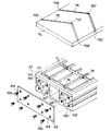
図1〜図3には、第1実施形態に係る浮上ユニットが組み込まれた露光装置12が示されている。
[First Embodiment]
1 to 3 show an
(基本的な構成)
この露光装置12は、レール14と横材16で長枠状に構成された組付けフレーム18を備えている。組付けフレーム18は、ポスト20で枠状のベースフレーム22の上方に支持されている。
(Basic configuration)
The
また、レール14の間には複数本の梁材28が架け渡されている。チャンバー36の一方の端部側の梁材28の上には、第1コンプレッサー32からチューブ34を介して負圧と正圧の空気が供給されるエア供給ボックス29が配置されている。このエア供給ボックス29の上には、レール14に沿って第1実施形態に係る浮上ユニット10が3列セットされている。なお、コンプレッサーから供給するものは空気に限らず、窒素やアルゴン、ヘリウム等の不活性ガス、二酸化炭素等の気体でもよい。また、水等の液体でもよい。
A plurality of
なお、エア供給ボックス29は、第1コンプレッサー32から供給された加圧空気によって負圧と正圧とを発生させるエジェクタであってもよい。
The
また、エア供給ボックス29が配置されていない梁材28の上には、チャンバー36の高さ調整をする高さ調整部材30が配置されている。
Further, a
浮上ユニット10のチャンバー36の底板には、エア供給ボックス29と接続され、負圧と正圧の空気が供給される3つの供給口(図示省略)が形成されている。
The bottom plate of the
さらに、図1で示すレール14の右方には、レール14の間へ支持プレート38が架け渡されている。この支持プレート38には、後述の第2実施形態に係る浮上ユニット40がセットされている。支持プレート38の下面側からは、第2コンプレッサー44からチューブ46を介して負圧と正圧の空気が供給される。そして、浮上ユニット40のチャンバー80の底板に形成された3つの供給口(図示省略)へ負圧と正圧の空気が供給される。
Further, a support plate 38 is bridged between the
さらに、手前側のレール14には、リニア式の搬送装置50が搭載されている。この搬送装置50には、バキューム式の吸盤52を複数備えており、浮上したガラス基板Pの下面をチャックしてワーク搬送方向Uに搬送する構成である。なお、搬送装置50は、ワーク搬送方向Uとは逆方向に移動することも可能とされている。
Further, a
浮上ユニット10の上方で浮上されたガラス基板Pは、搬送装置50により浮上ユニット40方向へ浮上搬送される。浮上搬送されたガラス基板Pは、浮上ユニット40の上方で浮上状態が維持されたまま、図示しない露光手段により露光され、所定の回路パターンが形成される。
The glass substrate P levitated above the
また、チャンバー36には、長手方向に沿って、冷却媒体(例えば水)が流れる流路(図示せず)が形成されている。この流路は、浮上ユニット10のワーク搬送上流端側に配置されている調整部材30よりもやや搬送方向下流側の位置で下方に向けられていて、下方端に給水口が形成されて給水管55(図1参照)が接続されている。また、この流路は、浮上ユニット10のワーク搬送下流端側に配置されているエア供給ボックス29よりもやや搬送方向上流側の位置で下方に向けられていて、下方端に排水口が形成されて排水管57(図1参照)が接続されている。これにより、流路のワーク搬送方向上流側のほうがワーク搬送方向下流側よりも冷却効果が大きくなっている。
The
(具体的な構成)
次に、第1実施形態に係る浮上ユニット10の具体的な構成を説明する。
(Specific configuration)
Next, a specific configuration of the
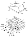
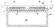
図4〜図9に示すように、浮上ユニット10のチャンバー36は、断面が長方形状の長い筒体であり、内側に設けられた2枚の隔壁54で内部空間が、中央の長方形状断面の吸引室56、長方形状断面の噴出室58,60に区画されている。そして、チャンバー36の端面に側板62を接合することで、チャンバー36の吸引室56、噴出室58,60は気密空間となる。
As shown in FIGS. 4 to 9, the
図6に示すように、チャンバー36の端面には、ねじ穴150が形成された台座部152が設けられている。また、側板62には、取付穴154が形成されている。このねじ穴150と取付穴154は、チャンバー36の端面に側板62を重ねたときに、ねじ穴150と取付穴154が対向する位置関係で形成されている。そして、ねじ穴150と取付穴154が対向した状態で、取付穴154とねじ穴150にねじ156が挿通されることにより、チャンバー36と側板62が螺号される。
As shown in FIG. 6, a
なお、チャンバー36と側板62との接合には、ねじ156による螺合の他、接着剤などの他の手段によって行うことも可能である。
The
しかし、チャンバー36と側板62とを接着剤によって接合することとした場合には、接着剤の硬化時間が必要となるため製造効率の向上を図ることができないこと、および接合後に分解することが困難となるためメンテナンスや部品交換を行い難くなることから、チャンバー36と側板62との接合を前記のようにねじ156によって行うことが好ましい。
However, when the
吸引室56には、前述した供給口から負圧の空気が供給され、噴出室58,60には、正圧の空気が供給される。
Negative pressure air is supplied to the
また、チャンバー36の側面には、軽量化を図るため長溝64が長手方向に沿って形成されている。
A
一方、チャンバー36の天井壁37には、4つの区画に分けられた格子溝部(格子状の溝部)68が形成されている。なお、区画に分けて格子溝部68をそれぞれ形成したのは、天井壁37に接合される多孔質板76へ、均一に空気を供給することが可能となるためである。ただし、本発明では、格子溝部68が形成される区画の数が限定されるものではなく、1つの区画によってチャンバー36を構成してもよい。
On the other hand, a lattice groove portion (lattice-like groove portion) 68 divided into four sections is formed on the
格子溝部68の溝底には、本発明の流体通過孔である通気孔74が貫通し、直線上に複数並んでいる。この通気孔74は、噴出室60と連通している。また、格子溝部68の溝底には吸気孔70が形成され、吸引室56に連通している。そして、格子溝部68の溝底には、本発明の流体通過孔である通気孔72が形成されている。この通気孔72は、噴出室58に連通している。
A plurality of ventilation holes 74 that are fluid passage holes of the present invention pass through the groove bottom of the
このように溝部が形成されたチャンバー36の天井壁37には、板状に加工された多孔質板76が接合される。この多孔質板76は、例えば多孔質グラファイト、焼結金属、多孔質セラミックス、多孔質樹脂などで構成させることが出来る。
A
多孔質グラファイトで構成させると、軽量化の向上、機械的強度の向上、製造費の低廉化、表面の平坦度向上を図れるとともに、ガラス基板Pと接触してしまった場合に、ガラス基板Pの損傷を少なくすることができる。 When composed of porous graphite, it is possible to improve the weight reduction, the mechanical strength, the manufacturing cost, the surface flatness, and when the glass substrate P comes into contact with the glass substrate P, Damage can be reduced.
また、多孔質板の軽量化を図ることができる。また、多孔質板76の導電性による静電気アースの機能も付加することができる。
In addition, the weight of the porous plate can be reduced. In addition, the function of electrostatic grounding due to the conductivity of the
多孔質板76の通気率が0.2〜6.0cm2/sの範囲内であると、浮上ユニット10で搬送されるワーク(ガラス基板P)を効果的に浮上させることができる。また、多孔質板76の気孔率が5〜25vol%であると、ワークを更に効果的に浮上させることができる。
When the air permeability of the
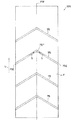
図3、図4に示すように(図5、図6、図8、図9も参照)、多孔質板76の搬送路F(搬送路面F)には、搬送路サイド側で開口75Eを形成して搬送路中央側になるに従いワーク搬送方向Uに徐々に延びる空気案内溝75が形成されている。この空気案内溝75は、搬送路面Fの中央ラインFMに対して対称形状であって、開口75Eから中央ラインFMまでが直線状とされている。従って、平面視でワーク搬送方向Uに突となった溝突部75Tが中央ラインFM上及びその近傍に形成されている。
なお、図1、図3では各多孔質板76に空気案内溝75が4つ形成されている例を図示し、図4、図5では各多孔質板76に空気案内溝75が5つ形成されている例を図示しているが、本実施形態では、特に空気案内溝75の本数を限定するものではない。
As shown in FIGS. 3 and 4 (see also FIGS. 5, 6, 8, and 9), an
1 and 3 show an example in which four
チャンバー36と多孔質板76とが接合された状態で、チャンバー36に形成された吸気孔70と、多孔質板76に形成された吸引孔78とが互いに対向して連通する。
In a state where the
接合方法としては、定盤の上へ多孔質板76のエアベアリング面となる面を下にして置き、チャンバー36の天井壁37に接着剤を塗布し多孔質板76に重ね合わせ、錘を載せて固定する方法が一例として挙げられる。なお、接着剤は、格子溝部68に食み出さないように塗布することが望ましい。
As a joining method, the surface to be the air bearing surface of the
ここで、格子溝部68を多孔質板76の裏面に形成せずに、チャンバー36の天井壁37に形成したのは、多孔質板76の裏面に溝部を形成する場合と比較して、チャンバーの天井部に溝部を形成した方が、精度良く、容易に溝部を形成することができるからである。
Here, the
特に、ガラス基板Pの浮上量のばらつきを少なくして安定して浮上させるためには、多孔質板76のベアリング面の平坦度を小さく(より平坦に)する必要があるが、多孔質板76の裏面に溝部を形成すると、多孔質板76のベアリング面の平坦度を小さくすることが困難になる。
In particular, in order to reduce the variation in the flying height of the glass substrate P and stably float it, the flatness of the bearing surface of the
これに対して、本発明では、多孔質板の裏面に溝部が形成されていないことから、多孔質板のベアリング面の平坦度を小さくすることが可能となるため、ガラス基板Pの浮上量にばらつきを少なくして安定して浮上させることができる。 On the other hand, in the present invention, since the groove is not formed on the back surface of the porous plate, the flatness of the bearing surface of the porous plate can be reduced. It is possible to float stably with less variation.
ここで、多孔質板76の空隙から空気が噴出して全面をエアベアリング面とするメカニズムについて簡単に説明する。
Here, a mechanism in which air is ejected from the gap of the
多孔質板76には、互いに連通する複数の微細な空隙が形成されている。格子溝部68から噴出された空気は、格子溝部68と多孔質板76の下面とで形成された空気通路を伝わりながら多孔質板76の空隙を通過し、多孔質板76のベアリング面から外部へ向けて噴出する。このとき、微細な空隙は互いに連通していることから、空気通路の上方だけでなく、ベアリング面の全面から噴出する。
In the
次に、第1実施形態に係る浮上ユニット10の作用を説明する。
Next, the operation of the
第1コンプレッサー32から、正圧の空気(例えば50〜400kPa)を噴出室58,60へ供給し、負圧の空気(例えば0〜-50kPa)を吸引室56へ供給(吸引室56から空気を吸引)する。
From the
噴出室58,60へ供給された空気は、通気孔72,74から噴出し、多孔質板76の下面と格子溝部68とで形成された空気通路を伝って、多孔質板76の下面に均等に行き渡り、多孔質板76の空隙から噴出する。
The air supplied to the
つまり、多孔質板76の全面から空気が噴出して、多孔質板76の全面がエアベアリング面となるため、ガラス基板Pに反りを発生させずに浮上させて、多孔質板76と非接触で搬送することが可能となる。この浮上したガラス基板Pを吸盤52がチャックして矢印方向に搬送装置50が搬送する。
That is, since air is ejected from the entire surface of the
また、吸引室56に供給された負圧の空気は吸気孔70を介して多孔質板76に形成された吸引孔78にガラス基板Pを吸引する力を発生させる。この吸気孔70によって発生した吸引力は、多孔質板76から噴出した空気によって浮上したガラス基板Pの浮上量を規制するものである。従って、この吸引力を制御することによって、ガラス基板Pの浮上量を制御することが可能となる。
The negative pressure air supplied to the
また、ガラス基板Pがワーク搬送方向Uに移動することによって、ガラス基板下側の空気(以下、ワーク下空気L(図8参照)という)の一部が空気の粘性によってガラス基板Pとともに搬送方向に移動する。従って、空気案内溝75内の空気には、ワーク搬送方向Uに移動する力がワーク下空気Lから及ぼされる。
Moreover, when the glass substrate P moves in the workpiece conveyance direction U, a part of the air below the glass substrate (hereinafter referred to as workpiece lower air L (see FIG. 8)) is conveyed along with the glass substrate P by the viscosity of the air. Move to. Therefore, a force that moves in the workpiece conveyance direction U is exerted on the air in the
ここで、この空気案内溝75は、上述したように、搬送路サイド側で開口して搬送路中央側になるに従いワーク搬送方向Uに徐々に延びている。従って、ワーク下空気Lから及ぼされるワーク搬送方向Uへの移動力によって、空気案内溝75内の空気は溝内を中央ラインFMに向けて矢印S方向に移動する。これに伴い、開口75Eから空気案内溝75内に空気が流入する。すなわち、空気案内溝75内では、低圧となった開口75Eから空気が流入し、高圧となった溝突部75T及びその近傍で搬送路面F上に空気が流出する。
従って、溝突部75T及びその近傍でガラス基板Pを浮上させる力を更に発生させることができる。そして、開口75E及びその近傍では低圧となっているので、ガラス基板Pを搬送路面F側に引き付けることができ、ガラス基板Pが安定して搬送される。
Here, as described above, the
Therefore, it is possible to further generate a force that causes the glass substrate P to float at and near the
なお、本実施形態では全ての多孔質板76に空気案内溝75が形成されている例で説明したが、本発明はこれに限らず、空気案内溝75が形成されていない多孔質板が少なくとも一部に配置されていてもよい。
In this embodiment, the
例えば図10に示すように、3本の各チャンバーで、空気案内溝75が形成されている多孔質板76と、空気案内溝75が形成されていない多孔質板77とを交互に配置してもよい。これにより、装置としてのコストダウンを図ることができる。
For example, as shown in FIG. 10, in each of the three chambers, a
更には、図11に示すように、空気案内溝75が形成されている多孔質板76の配置位置を隣り合うチャンバーで互い違いとなるように千鳥状に配置してもよい。このような配置にしても、装置としてのコストダウンを図ることができる。
Furthermore, as shown in FIG. 11, the arrangement positions of the
[第2実施形態]
次に、第2実施形態に係る浮上ユニット40を説明する。
[Second Embodiment]
Next, the
浮上ユニット40の基本的な構成は、第1実施形態の浮上ユニット10と同一であるので、図12及び図13に示すチャンバー80の溝部の構成と、多孔質板82の構成、形状について説明する。
Since the basic configuration of the
チャンバー80の天井壁には、長手方向に4本の縦溝部97と幅方向に複数の横溝部102が形成されており、縦溝部97と横溝部102で複数の離島86が所定の間隔で形成されている。横溝部102の溝底には通気孔92が形成されている。この通気孔92は、図示しない噴出室に連通している。また、離島86には、吸引室と連通する吸気孔90が形成されている。
On the ceiling wall of the
一方、多孔質板82には、チャンバー80の天井壁と重ね合わせたとき、吸気孔90と対応する位置に吸引孔96が形成されている。また、多孔質板82の両側には、貫通孔101が形成されており、チャンバー80に形成された取付孔94へビスを挿入して、多孔質板82をチャンバー80に固定できるようになっている。
On the other hand, a
また、多孔質板82の搬送路面Fには、搬送路サイド側で開口85Eを形成して搬送路中央側になるに従いワーク搬送方向Uに徐々に延びる空気案内溝85が形成されている。この空気案内溝85は、第1実施形態と同様、搬送路面Fの中央ラインFMに対して対称形状であって、開口85Eから中央ラインFMまでが直線状とされている。従って、平面視でワーク搬送方向Uに突となった溝突部85Tが中央ラインFM上及びその近傍に形成されている。
In addition, an
以上の構成の浮上ユニット40では、多孔質板82の表面に貫通孔101を形成することでビス止めが可能となる。また、多孔質板82に溝加工しないので、多孔質板82の平坦度が維持できる。さらに、吸気孔を等間隔に配置することで、ガラス基板Pの浮上量をバランスよく規制することができる。
In the floating
また、ワーク(ガラス基板P)がワーク搬送方向Uに移動することによって、ワーク下空気の一部が空気の粘性によってワークとともにワーク搬送方向Uに移動する。従って、空気案内溝85内の空気には、ワーク搬送方向Uに移動する力がワーク下空気から及ぼされる。従って、第1実施形態と同様、ワークの搬送に伴い、空気案内溝85内の空気は溝内を中央ラインFMに向けて矢印S方向に移動する。この結果、開口85Eから空気案内溝85内に空気が流入する。すなわち、低圧となった開口85Eから空気案内溝85に空気が流入し、高圧となった溝突部85T及びその近傍で空気案内溝85から搬送路面F上に空気が流出する。従って、溝突部85T及びその近傍でワークを浮上させる力を更に発生させることができる。そして、開口85E及びその近傍では低圧となっているので、ワークを搬送路面F側に引き付けることができ、ワークが安定して搬送される。
Moreover, when a workpiece | work (glass substrate P) moves to the workpiece conveyance direction U, a part of workpiece | work lower air moves to the workpiece conveyance direction U with a workpiece | work by the viscosity of air. Therefore, a force that moves in the workpiece conveyance direction U is exerted on the air in the
なお、図1〜図11に示す実施形態では、浮上ユニット10がチャンバー36の天井壁に4枚の多孔質板76が接合されて構成されている。また、図12及び図13に示す実施形態では、浮上ユニット40が、チャンバー80の天井壁に1枚の多孔質板82が接合されている。しかし、本発明は、多孔質板の数が限定されるものではない。また、多孔質板に限らず、上面側に搬送路を形成することができる限り、一般的な多孔質体であってもよい。
In the embodiment shown in FIGS. 1 to 11, the
[第3実施形態]
次に、第3実施形態について説明する。図14に示すように、本実施形態に係る浮上ユニットでは、第1実施形態に比べ、多孔質板76に代えて、搬送路面側に保護膜114が形成されている多孔質板116が設けられている。
[Third Embodiment]
Next, a third embodiment will be described. As shown in FIG. 14, in the levitation unit according to the present embodiment, a
多孔質板116の上面側は、多孔質板116の剥離を防ぐとともに強度向上を図るために保護膜114(図6参照)によって被覆されている。剥離によるパーティクル発生を抑制できる為、クリーンルーム内での使用に適する。保護膜114は、多孔質板116の上面に開口している空隙を塞がないように形成されている。そして、多孔質板116と保護膜114とによって搬送路面Fが形成されている。
The upper surface side of the
保護膜114は、例えば樹脂で構成されている。これにより、保護膜の軽量化を図ることができるとともに、保護膜の形成が容易になる。この場合、樹脂が、エポキシ樹脂、フェノール樹脂、フラン樹脂、フッ素樹脂、ナイロンから選ばれる少なくとも1種の樹脂で構成されていてもよい。
The
また、保護膜114は、金属又は金属化合物で構成されている。これにより、保護膜114の強度向上を図ることができる。また、保護膜114が導電性となるので、静電気アースの機能を保護膜114に付加することができる。この場合、金属又は金属化合物が、Ni、Zn、Cr、Cu、Ag、Fe、Sn、Mgから選ばれる少なくとも1種の元素を含んでいてもよい。また、この金属又は金属化合物によって、保護膜114として黒色メッキ膜又は針状メッキ膜が形成されていてもよい。これにより、光の反射率を低下させることができるので、露光プロセスで反射率の低い搬送路が要求されるラインに適した浮上ユニットとすることができる。
The
また、保護膜114が、ガラス状炭素又はダイヤモンドライクカーボンのうちの少なくとも1種で構成されていてもよい。これにより、保護膜114が導電性となることにより静電気アースの機能が付加される。また、光の反射率を低下させることができるので、露光プロセスで反射率の低い搬送路が要求されるラインに更に適した浮上ユニットとすることができる。また、保護膜114は、例えばガラス等の二酸化ケイ素を含む物質で構成されていてもよい。これにより、保護膜の化学的安定性を図ることができる。
Further, the
[第4実施形態]
次に、第4実施形態について説明する。図15に示すように、本実施形態に係る浮上ユニットでは、吸気孔70及び吸引孔78が中央ラインFMに沿って第1実施形態よりも多数(例えば各空気案内溝75の間に1つずつ)形成されている。これにより、ワーク(ガラス基板P)をより安定させた状態で搬送することができる。
なお、吸気孔70の位置は、ワーク搬送方向に等間隔で配置されていることが、負圧を均等に作用できるため好ましい。この場合、ワーク搬送方向Uに隣り合う空気案内溝の間とされていることが、負圧と正圧とを均等に作用させることができるため、ワークを安定した状態で搬送する観点でより好ましい。
[Fourth Embodiment]
Next, a fourth embodiment will be described. As shown in FIG. 15, in the levitation unit according to the present embodiment, a larger number of intake holes 70 and suction holes 78 than the first embodiment along the center line FM (for example, one between each
In addition, it is preferable that the positions of the air intake holes 70 are arranged at equal intervals in the workpiece conveyance direction because a negative pressure can be applied uniformly. In this case, being between the air guide grooves adjacent to each other in the workpiece conveyance direction U is more preferable from the viewpoint of conveying the workpiece in a stable state because negative pressure and positive pressure can be applied equally. .
[第5実施形態]
次に、第5実施形態について説明する。図16、図17に示すように、本実施形態に係る浮上ユニットでは、第1実施形態に比べ、吸気孔70(図7参照)及び吸引孔78が形成されていない多孔質板126が多孔質板76に代えて設けられている。
[Fifth Embodiment]
Next, a fifth embodiment will be described. As shown in FIGS. 16 and 17, in the levitation unit according to the present embodiment, the
本実施形態では、ワーク(ガラス基板P)の搬送に伴い、各搬送路の空気案内溝75では矢印S方向に空気が流れており、開口75Eから空気案内溝75内に空気吸引されて搬送路面Fの中央ラインFMで空気案内溝75から空気が噴き出している。従って、開口75E及びその近傍では低圧となっているので、ガラス基板Pを搬送路面側に引き付けることができ、ガラス基板Pが安定して搬送される。このため、特に吸気孔が形成されていなくても、ワークをワーク搬送方向Uに安定して搬送することが可能である。
In the present embodiment, as the workpiece (glass substrate P) is transported, air flows in the direction of arrow S in the
この構成により、図17に示すように、隔壁部54(図8参照)を除去しチャンバー内を全て噴出室58とすることができる。従って、本実施形態により、構成が簡素な浮上ユニットとすることができる。
With this configuration, as shown in FIG. 17, the partition wall portion 54 (see FIG. 8) can be removed, and the entire chamber can be made into the
[第6実施形態]
次に、第6実施形態について説明する。図18に示すように、本実施形態に係る浮上ユニットでは、第5実施形態に比べ、空気案内溝の形状が異なる多孔質板136が多孔質板126(図16参照)に代えて設けられている。
[Sixth Embodiment]
Next, a sixth embodiment will be described. As shown in FIG. 18, in the levitation unit according to the present embodiment, a
多孔質板136の搬送路面側に形成された空気案内溝135は、搬送路面Fの中央ラインFMに対して対称形状とされた平面視W形状とされている。
従って、空気案内溝135の中央ラインFMの両側には、平面視でワーク搬送方向Uに突となった溝突部135TA、135TBがそれぞれ形成されている。そして、中央ラインFM及びその近傍には、平面視でワーク搬送方向Uとは逆方向に突となった逆方向溝突部135TZが形成されている。
この構成により、中央ラインFMの片側では、搬送路サイド側に開口して溝突部135TAまで直線状に延びる外側溝部135Jと、溝突部135TAから逆方向溝突部135TZまで直線状に延びる内側溝部135Eと、が空気案内溝135には形成されている。中央ラインのもう片側でも同様の溝形状となっている。
本実施形態では、ワーク(ガラス基板P)をワーク搬送方向Uに搬送することによって空気案内溝135内を矢印S方向に空気が流れ、2つの溝突部135TA、135TBからそれぞれ空気が搬送路面上に流出する。従って、2つの溝突部135TA、135TB及びこれらの近傍で、ワークを浮上させる力を更に発生させることができる。
これにより、より安定した状態でワークを搬送することができる。
The
Therefore, on both sides of the center line FM of the
With this configuration, on one side of the center line FM, an
In the present embodiment, when the workpiece (glass substrate P) is conveyed in the workpiece conveyance direction U, air flows in the
Thereby, a workpiece | work can be conveyed in the more stable state.
また、逆方向溝突部135TZ及びその近傍では、ワークの搬送に伴い、搬送路面上の空気が内側溝部135Eに流入する。そして、流入したこの空気は溝突部135TA、135TBから流出する。従って、逆方向溝突部135TZ及びその近傍では2つの溝突部135TA、135TBと比較すると低圧となるので、ワークを搬送路面側に引き付けることができ、ワークが更に安定して搬送される。
In addition, at the reverse groove protrusion 135TZ and its vicinity, air on the conveyance path surface flows into the
[第7実施形態]
次に、第7実施形態について説明する。図19に示すように、本実施形態に係る浮上ユニットでは、第1実施形態に比べ、空気案内溝の形状が異なる多孔質板146が多孔質板76に代えて設けられている。
[Seventh Embodiment]
Next, a seventh embodiment will be described. As shown in FIG. 19, in the levitation unit according to the present embodiment, a
多孔質板146の搬送路面側に形成された空気案内溝145は、第1実施形態に比べ、中央ラインFMの両側で、ワーク搬送方向Uに隣り合う溝同士の間隔の1/2だけ溝位置がずらして配置されている。
The
本実施形態により、ワークをワーク搬送方向Uに搬送することに伴って、ワーク下空気の粘性により、各空気案内溝145では矢印S方向に空気が流れる。すなわち、搬送路サイド側に形成された開口145Eから空気が流入し、搬送路中央側の溝端部145Mで、すなわち中央ラインFM及びその近傍で空気が搬送路面上に流出する。
これにより、他の実施形態と同様に、より安定した状態でワークを搬送することができる。
According to this embodiment, as the workpiece is conveyed in the workpiece conveyance direction U, air flows in the direction of the arrow S in each
Thereby, like other embodiment, a workpiece | work can be conveyed in a more stable state.
なお、図1〜図19に示す実施形態では、本発明の浮上ユニット10、40が露光装置に組み込まれたものであるが、本発明はこれに限定されるものではなく、露光装置以外に、例えば検査装置、欠陥修復装置、コータ装置等、ガラス基板を搬送するための装置に使用できるものである。
In the embodiment shown in FIG. 1 to FIG. 19, the floating
さらに、図1〜図19に示す実施形態では、浮上ユニット10、40により搬送される被搬送体としてガラス基板を例にして説明したが、本発明はこれに限定されるものではなく、例えば、樹脂板や金属板等、ガラス基板以外の被搬送体を搬送するものであってもよい。
Furthermore, in embodiment shown in FIGS. 1-19, although the glass substrate was demonstrated to the example as a to-be-conveyed body conveyed by the floating
10 浮上ユニット
32 第1コンプレッサー(気体供給手段)
36 チャンバー
37 天井壁
40 浮上ユニット
44 第2コンプレッサー(気体供給手段)
72 通気孔
74 通気孔
75 空気案内溝(気体案内溝)
75T 溝突部
76 多孔質板(多孔質体)
80 チャンバー
85 空気案内溝(気体案内溝)
85T 溝突部
114 保護膜
116 多孔質板(多孔質体)
126 多孔質板(多孔質体)
135 空気案内溝(気体案内溝)
135J 外側溝部(溝部)
135TA 溝突部
135TB 溝突部
135TZ 逆方向溝突部
136 多孔質板(多孔質体)
146 多孔質板(多孔質体)
145 空気案内溝(気体案内溝)
F 搬送路面(搬送路)
FM 中央ライン
P ガラス基板(ワーク)
U ワーク搬送方向
10 Floating
36
72
80
126 Porous plate (porous body)
135 Air guide groove (gas guide groove)
135J Outside groove (groove)
135TA groove protrusion 135TB groove protrusion 135TZ
146 Porous plate (porous body)
145 Air guide groove (gas guide groove)
F Transport surface (transport path)
FM center line P glass substrate (work)
U Work transfer direction
Claims (8)
下側が前記天井壁に固定され、上側にはワークを搬送する搬送路を形成している多孔質体と、
前記気密空間に流体を供給し、前記流体通過孔と前記多孔質体の空隙とを通じて前記搬送路側から流体を噴出させる流体供給手段と、
を有し、
前記多孔質体の前記搬送路には、搬送路サイド側で開口して搬送路中央側になるに従いワーク搬送方向に延びる溝部を少なくとも有する流体案内溝が形成されていることを特徴とする浮上ユニット。 A chamber in which an airtight space is formed and a fluid passage hole communicating with the airtight space is formed in the ceiling wall;
A porous body having a lower side fixed to the ceiling wall and an upper side forming a conveyance path for conveying a workpiece;
Fluid supply means for supplying a fluid to the airtight space and ejecting the fluid from the transport path side through the fluid passage hole and the gap of the porous body;
Have
The floating unit is characterized in that a fluid guide groove having at least a groove portion that opens in the conveyance path side and opens in the conveyance path center side is formed in the conveyance path of the porous body. .
搬送路の残りは、前記流体案内溝が形成されていない浮上ユニットによって形成されていることを特徴とする請求項7に記載の装置。 A part of a conveyance path is formed by the levitation unit according to any one of claims 1 to 6,
8. The apparatus according to claim 7, wherein the remainder of the conveyance path is formed by a floating unit in which the fluid guide groove is not formed.
Priority Applications (1)
| Application Number | Priority Date | Filing Date | Title |
|---|---|---|---|
| JP2007326935A JP2009149389A (en) | 2007-12-19 | 2007-12-19 | Floating unit and device having the same |
Applications Claiming Priority (1)
| Application Number | Priority Date | Filing Date | Title |
|---|---|---|---|
| JP2007326935A JP2009149389A (en) | 2007-12-19 | 2007-12-19 | Floating unit and device having the same |
Publications (2)
| Publication Number | Publication Date |
|---|---|
| JP2009149389A true JP2009149389A (en) | 2009-07-09 |
| JP2009149389A5 JP2009149389A5 (en) | 2011-02-10 |
Family
ID=40919033
Family Applications (1)
| Application Number | Title | Priority Date | Filing Date |
|---|---|---|---|
| JP2007326935A Pending JP2009149389A (en) | 2007-12-19 | 2007-12-19 | Floating unit and device having the same |
Country Status (1)
| Country | Link |
|---|---|
| JP (1) | JP2009149389A (en) |
Cited By (4)
| Publication number | Priority date | Publication date | Assignee | Title |
|---|---|---|---|---|
| EP2388808A1 (en) * | 2010-05-20 | 2011-11-23 | Westfälische Wilhelms-Universität Münster | Contactless transport system |
| JP2012138481A (en) * | 2010-12-27 | 2012-07-19 | Tokyo Ohka Kogyo Co Ltd | Coating device and coating method |
| JP2019529283A (en) * | 2016-09-13 | 2019-10-17 | コーニング インコーポレイテッド | Apparatus and method for processing glass substrate |
| EP3900025A4 (en) * | 2018-12-21 | 2022-09-14 | Kateeva, Inc. | Devices, systems, and methods for controlling floatation of a substrate |
Citations (5)
| Publication number | Priority date | Publication date | Assignee | Title |
|---|---|---|---|---|
| JPH06255775A (en) * | 1993-03-05 | 1994-09-13 | Ochiai Nekusasu:Kk | Carrying device |
| JPH08293292A (en) * | 1995-04-25 | 1996-11-05 | Matsushita Electric Ind Co Ltd | Conveyor for thin battery member |
| JP2004331265A (en) * | 2003-05-01 | 2004-11-25 | Olympus Corp | Floating unit and substrate inspection device |
| JP2006206320A (en) * | 2005-01-27 | 2006-08-10 | Taesung Engineering Corp | Plate glass carrying device |
| JP2007106521A (en) * | 2005-10-11 | 2007-04-26 | Nippon Sekkei Kogyo:Kk | Air table for conveying thin material and conveyance device for thin material |
-
2007
- 2007-12-19 JP JP2007326935A patent/JP2009149389A/en active Pending
Patent Citations (5)
| Publication number | Priority date | Publication date | Assignee | Title |
|---|---|---|---|---|
| JPH06255775A (en) * | 1993-03-05 | 1994-09-13 | Ochiai Nekusasu:Kk | Carrying device |
| JPH08293292A (en) * | 1995-04-25 | 1996-11-05 | Matsushita Electric Ind Co Ltd | Conveyor for thin battery member |
| JP2004331265A (en) * | 2003-05-01 | 2004-11-25 | Olympus Corp | Floating unit and substrate inspection device |
| JP2006206320A (en) * | 2005-01-27 | 2006-08-10 | Taesung Engineering Corp | Plate glass carrying device |
| JP2007106521A (en) * | 2005-10-11 | 2007-04-26 | Nippon Sekkei Kogyo:Kk | Air table for conveying thin material and conveyance device for thin material |
Cited By (6)
| Publication number | Priority date | Publication date | Assignee | Title |
|---|---|---|---|---|
| EP2388808A1 (en) * | 2010-05-20 | 2011-11-23 | Westfälische Wilhelms-Universität Münster | Contactless transport system |
| JP2012138481A (en) * | 2010-12-27 | 2012-07-19 | Tokyo Ohka Kogyo Co Ltd | Coating device and coating method |
| JP2019529283A (en) * | 2016-09-13 | 2019-10-17 | コーニング インコーポレイテッド | Apparatus and method for processing glass substrate |
| JP7002824B2 (en) | 2016-09-13 | 2022-01-20 | コーニング インコーポレイテッド | Equipment and methods for processing glass substrates |
| US11420895B2 (en) | 2016-09-13 | 2022-08-23 | Corning Incorporated | Apparatus and method for processing a glass substrate |
| EP3900025A4 (en) * | 2018-12-21 | 2022-09-14 | Kateeva, Inc. | Devices, systems, and methods for controlling floatation of a substrate |
Similar Documents
| Publication | Publication Date | Title |
|---|---|---|
| JP5047545B2 (en) | Levitation transport unit | |
| JP2009073646A (en) | Floating method and floating unit | |
| JP2008007319A5 (en) | ||
| JP4814050B2 (en) | Levitation transport unit | |
| US7931755B2 (en) | Method for removing deposit from substrate and method for drying substrate, as well as apparatus for removing deposit from substrate and apparatus for drying substrate using these methods | |
| JP2006182563A (en) | Floating device and carrying device | |
| WO2013150894A1 (en) | Levitation air plate | |
| JP2011225355A (en) | Air floating unit, stage device, inspection system, exposure system, and application system | |
| WO2006052919A1 (en) | Non-contact porous air bearing and glass flattening device | |
| KR20110000984A (en) | Precision plate flotation system | |
| JP2009149389A (en) | Floating unit and device having the same | |
| JP2006264804A (en) | Flotation unit for large flat panel, and non-contact carrying device using the same | |
| KR100831135B1 (en) | Air table for conveying sheet material and conveyer with the same | |
| KR101064893B1 (en) | Plate flotation system | |
| JP2009161283A (en) | Levitating unit and device | |
| JP2010260715A (en) | Levitation unit and levitation device | |
| JP6605871B2 (en) | Substrate floating transfer device | |
| JP2010254453A (en) | Floating device | |
| TWI389240B (en) | The support of the workpiece | |
| JP2009032984A (en) | Floating conveying unit | |
| WO2012066613A1 (en) | Gas-permeable conveyance table | |
| JP5740394B2 (en) | Swirl flow forming body and non-contact transfer device | |
| JP2011246213A (en) | Substrate conveyance device | |
| KR100830053B1 (en) | Chuck for carrying substrate of non-contact type | |
| JP4376641B2 (en) | Air floating conveyor |
Legal Events
| Date | Code | Title | Description |
|---|---|---|---|
| A521 | Written amendment |
Free format text: JAPANESE INTERMEDIATE CODE: A523 Effective date: 20101220 |
|
| A621 | Written request for application examination |
Effective date: 20101220 Free format text: JAPANESE INTERMEDIATE CODE: A621 |
|
| A977 | Report on retrieval |
Effective date: 20121024 Free format text: JAPANESE INTERMEDIATE CODE: A971007 |
|
| A131 | Notification of reasons for refusal |
Effective date: 20121030 Free format text: JAPANESE INTERMEDIATE CODE: A131 |
|
| A02 | Decision of refusal |
Free format text: JAPANESE INTERMEDIATE CODE: A02 Effective date: 20130402 |