JP2009105273A - Resin sealing mold - Google Patents
Resin sealing mold Download PDFInfo
- Publication number
- JP2009105273A JP2009105273A JP2007276539A JP2007276539A JP2009105273A JP 2009105273 A JP2009105273 A JP 2009105273A JP 2007276539 A JP2007276539 A JP 2007276539A JP 2007276539 A JP2007276539 A JP 2007276539A JP 2009105273 A JP2009105273 A JP 2009105273A
- Authority
- JP
- Japan
- Prior art keywords
- mold
- resin
- heater
- compression
- thickness
- Prior art date
- Legal status (The legal status is an assumption and is not a legal conclusion. Google has not performed a legal analysis and makes no representation as to the accuracy of the status listed.)
- Pending
Links
Images


Abstract
Description
本発明は、半導体チップ等が搭載された被成形品を樹脂にて封止する樹脂封止の技術分野に関する。 The present invention relates to a technical field of resin sealing in which a molded product on which a semiconductor chip or the like is mounted is sealed with resin.
半導体等の電子部品の実装分野では、露光等のパターンニング技術によって回路設計されたベアチップをウェハから切り出し、これをダイ上にマウントし、さらにワイヤボンディング等によって外部端子と結線し、その後、樹脂封止する工程がある。 In the field of mounting electronic parts such as semiconductors, a bare chip whose circuit is designed by patterning technology such as exposure is cut out from the wafer, mounted on a die, and further connected to an external terminal by wire bonding or the like, and then sealed with resin. There is a process to stop.
この樹脂封止工程では、熱を与えることによって硬化を促進するいわゆる熱硬化性樹脂が用いられるが、樹脂をキャビティ内に充填した後、数分間を樹脂の硬化時間(キュアタイム)に費やしており、生産性が低い(サイクルタイムが長い)という問題があった。 In this resin sealing process, a so-called thermosetting resin that accelerates curing by applying heat is used, but after filling the resin into the cavity, several minutes are spent on the resin curing time (cure time). There was a problem of low productivity (long cycle time).
この硬化時間の短縮を図るものとして図10に示した樹脂パッケージ装置が公知である(特許文献1参照)。この樹脂パッケージ装置は所謂トランスファ型の装置であり、対向して配置される上下金型内部に設けられた通常のヒータ10のほかに、カル部12およびキャビティ14の近傍に吸発熱体16、17を設けるように構成されている。また、吸発熱体16、17は、断熱体18、19に取り囲まれている。
As a means for shortening the curing time, the resin package device shown in FIG. 10 is known (see Patent Document 1). This resin package device is a so-called transfer-type device, and in addition to the
このような構成の樹脂パッケージ装置を用いることで、樹脂封止の押し出し時(樹脂流動時)においては、吸発熱体16、17の吸熱作用により、カル部12やキャビティ14が封止樹脂の溶融温度に保持されることから、該封止樹脂の粘度が適切な値に保持され、キャビティ14内の樹脂の押し出し速度を適切な値に維持することができるとされている。更に、押し出し工程を完了した時点においては、吸発熱体16、17の放熱作用によって、カル部12やキャビティ14の内部が、封止樹脂の硬化温度にまで加熱され、樹脂の硬化が促進されるというものである。
By using the resin package apparatus having such a configuration, when the resin sealing is pushed out (when the resin flows), the
一般的に、封止材料としての熱硬化性樹脂は、エポキシにガラスフィラーを混入させたもの等が利用される。この封止材料は、ある一定の温度域内で流動性を増し(粘度が低下し)、それ以上の温度で硬化が促進する(粘度が増加する)という性質を有している。単純に、樹脂の硬化時間(キュアタイム)の短縮化のみを実現するのであれば、予め金型の温度を高め(樹脂の流動性を確保するために樹脂が低粘度となる温度域よりも高め)に設定しておいたり、より早い段階から金型の温度を高い状態に切り替えることで、より素早く樹脂を硬化させることが可能である。しかしながら、予め金型の温度を高く設定したり、より早い段階から金型の温度を切り替えるということは流動時の段階で樹脂の硬化を促すことを意味するため、樹脂の流動性悪化による他の問題点(例えば、樹脂が均一に広がらない、粘度の増加によってボンディングワイヤ等を切断・短絡させてしまう、ボイドが発生する等)が顕在化してしまう。 Generally, as the thermosetting resin as the sealing material, a glass filler mixed with epoxy is used. This sealing material has the property of increasing fluidity (decrease in viscosity) within a certain temperature range and promoting curing (increasing viscosity) at a temperature higher than that. If you only want to shorten the resin curing time (cure time), simply increase the mold temperature in advance (in order to ensure resin fluidity, higher than the temperature range where the resin has a low viscosity) ), Or by switching the mold temperature to a higher state from an earlier stage, the resin can be cured more quickly. However, setting the temperature of the mold in advance or switching the temperature of the mold from an earlier stage means that the resin is hardened at the stage of flow, and therefore other problems due to deterioration of the fluidity of the resin Problems (for example, the resin does not spread uniformly, the bonding wire or the like is cut or short-circuited due to an increase in viscosity, or a void occurs) become apparent.
即ち、図11に示したように、例えば金型の温度を予め高めに設定していた場合等には、「樹脂の硬化が完了するまでの時間」を短くすることができるものの、圧縮工程において樹脂の流動性が高く維持されている時間が短く、上手く樹脂を充填できないという問題が生じる。また、金型内部に設置されたヒータをコントロールしても、金型自体の熱容量が大きいためレスポンスが悪く、細かく温度を変化させることが困難である。 That is, as shown in FIG. 11, for example, when the temperature of the mold is set high in advance, the “time until resin curing is completed” can be shortened. There is a problem in that the time during which the fluidity of the resin is kept high is short and the resin cannot be filled well. Moreover, even if the heater installed in the mold is controlled, the heat capacity of the mold itself is large, so that the response is poor and it is difficult to change the temperature finely.
特に近年における携帯電話等に使用される半導体製品は、超薄型化・微細化が進行しており、精度のよい樹脂封止を行なうべく樹脂を低粘度化して流動性を確保している。このように低粘度の樹脂の使用が前提となれば、硬化完了までの時間がより必要とされると同時に、予め金型の温度を高く設定する等の手法は、流動性を確保するという観点から問題がある。 In particular, semiconductor products used for mobile phones and the like in recent years have been made ultra-thin and finer, and the resin has low viscosity to ensure fluidity in order to perform accurate resin sealing. If the use of a low-viscosity resin is premised in this way, more time is required until curing is complete, and at the same time, techniques such as setting the mold temperature high in advance ensure fluidity. There is a problem.
本発明は、このような問題点を解決するべくなされたものであって、樹脂の硬化が完了するまでの時間(キュアタイム)を短縮すると同時に、樹脂流動時においては樹脂の流動性を高く維持することが可能な樹脂封止金型を提供することをその課題としている。 The present invention has been made to solve such problems, and shortens the time (curing time) until the curing of the resin is completed, and at the same time maintains the fluidity of the resin at the time of resin flow. An object of the present invention is to provide a resin-sealed mold that can be used.
本発明は、対向する第1、第2の金型で半導体チップが搭載された被成形品をクランプし、前記金型内に充填した樹脂を用いて前記被成形品を封止する樹脂封止金型であって、前記第1、第2の金型の少なくとも一方には、前記金型内に充填される前記樹脂の前記金型の対向方向の厚みよりも前記金型の表面に近い位置に、第1のヒータを配置することにより、上記課題を解決するものである。 The present invention clamps a molded product on which a semiconductor chip is mounted with first and second molds facing each other, and seals the molded product using a resin filled in the mold. A mold, wherein at least one of the first and second molds is closer to the surface of the mold than the thickness of the resin filled in the mold in the opposing direction of the mold Further, the above-described problem is solved by arranging the first heater.
このように、金型の相手金型側表面の近傍(金型内に充填される樹脂の対向方向の厚みよりも金型の表面に近い位置)にヒータを配置することによって、金型に接触している樹脂の温度を細かく制御することが可能となった。即ち、例えば、樹脂の流動性を高く維持したい場合には、当該第1のヒータを「流動性を高く維持できる温度域」に設定し、流動が完了した後は直ちに硬化を促進する温度域にまで切り替える。ここで本発明では、金型の表面近傍にヒータが敷設されている。近年では、樹脂の金型の対向方向の厚み(例えばキャビティの厚み)は1mmに満たないものも多いことを考慮すると、実質的に、金型の殆ど表面に相当する位置となるが、このような位置であるからこそ、金型の熱容量の影響を回避して、よりリアルタイムに樹脂の温度を制御することが可能となっている。 In this way, the heater is placed in the vicinity of the mold side surface of the mold (position closer to the mold surface than the thickness of the resin filled in the mold in the opposite direction), thereby contacting the mold. It has become possible to finely control the temperature of the resin used. That is, for example, when it is desired to maintain the fluidity of the resin at a high level, the first heater is set to “a temperature range in which the fluidity can be maintained at a high level”, and immediately after the flow is completed, the temperature is set to a temperature range that promotes curing. Switch until. Here, in the present invention, a heater is laid near the surface of the mold. In recent years, considering that the thickness of the resin mold in the opposite direction (for example, the thickness of the cavity) is often less than 1 mm, the position is substantially equivalent to the surface of the mold. Because of this position, it is possible to control the temperature of the resin in real time while avoiding the influence of the heat capacity of the mold.
なお、本発明は、特許文献1に記載された技術のように、カル部12やキャビティ14の近傍に吸発熱体16、17を設ける技術と異なり、蓄積された熱を放出するというものではないため、加熱を能動的に制御することが可能である。
Unlike the technique described in
また、前記第1のヒータを、相手金型側表面に露出するように構成すれば、最も樹脂の温度を細かく制御することが可能である。 Further, if the first heater is configured so as to be exposed on the mating mold side surface, the temperature of the resin can be controlled most finely.
一方で、前記第1のヒータの相手金型側に保護層を形成すれば、繰り返される樹脂封止作業によっても、金型に配置された第1のヒータが損傷等することを防止することができる。 On the other hand, if a protective layer is formed on the opposite mold side of the first heater, it is possible to prevent the first heater disposed on the mold from being damaged by repeated resin sealing operations. it can.
例えばこの保護層の対向方向の厚みを、前記金型内に充填される前記樹脂の対向方向の厚みの0.1〜1倍とすることで、本発明の趣旨(目的)を損なうことなく、優れた保護性能を発揮することが可能となる。 For example, by making the thickness in the facing direction of the protective layer 0.1 to 1 times the thickness in the facing direction of the resin filled in the mold, without impairing the spirit (purpose) of the present invention, It is possible to exhibit excellent protection performance.
このとき、例えば、前記第1のヒータの反相手金型側に、断熱層を形成するような構成とすれば、第1のヒータによって発生した熱をより効率的に樹脂側(例えばキャビティ、カル、ランナ側)へと導くことができる。 At this time, for example, if a heat insulating layer is formed on the opposite mold side of the first heater, the heat generated by the first heater can be more efficiently transferred to the resin side (for example, cavity, calf). , Runner side).
例えばこの断熱層の対向方向の厚みを、前記金型内に充填される前記樹脂の対向方向の厚みの1〜10倍とすることで、構造的な強度を保ちつつ、優れた断熱性を確保することが可能となる。断熱層を構成する材料の特性等にもよるが、1倍に満たない場合は十分な断熱効果を発揮することができず、10倍を超える場合には、金型全体の構造的な強度が十分に確保できない。
For example, by making the thickness in the facing direction of the
勿論、金型表面の近傍(または表面)に配置した前記第1のヒータのみによる制御ではなく、前記第1のヒータが配置されている金型の内部に、第2のヒータを埋設するような構成とすれば、熱容量の大きな金型を所定の温度に維持する役割を内蔵された第2のヒータに委ねることができるため、第1のヒータは、樹脂の硬化を促進することだけを考慮した設計が可能となる。 Of course, the second heater is embedded in the mold in which the first heater is disposed, instead of being controlled only by the first heater disposed in the vicinity (or surface) of the mold surface. With the configuration, the role of maintaining the mold having a large heat capacity at a predetermined temperature can be entrusted to the built-in second heater, so that the first heater only takes into account the acceleration of resin curing. Design becomes possible.
また、前記第1、第2の金型の少なくとも一方が、貫通孔を有する枠状金型と、該貫通孔に嵌合して相手金型側に摺動可能な圧縮金型とからなり、前記第1のヒータを、前記圧縮金型の表面に敷設すれば、施行上有利である。即ち、第1又は第2の金型を構成する圧縮金型は、同様に金型を構成する枠状金型とは別部品として取り扱うことが可能であり、当該圧縮金型のみを必要により加工等すれば足り、枠状金型部分は従来の金型をそのまま利用することが可能となる。また場合によっては、圧縮金型においてもその表面に第1のヒータを敷設するのみで足り、圧縮金型自体の加工をも不要である。 Further, at least one of the first and second molds is composed of a frame-shaped mold having a through-hole and a compression mold that can be fitted into the through-hole and slid to the mating mold side, It is advantageous in practice if the first heater is laid on the surface of the compression mold. That is, the compression mold that constitutes the first or second mold can be handled as a separate part from the frame mold that similarly constitutes the mold, and only the compression mold is processed if necessary. It is sufficient to use the conventional mold as it is for the frame-shaped mold portion. In some cases, it is only necessary to lay the first heater on the surface of the compression mold, and it is not necessary to process the compression mold itself.
このとき、前記第1のヒータが配置される面積が、前記圧縮金型の表面積と同一であるように構成すれば、キャビティ内の樹脂を均一に温度管理することが可能となる。 At this time, if the area in which the first heater is disposed is the same as the surface area of the compression mold, the temperature of the resin in the cavity can be uniformly controlled.
本発明を適用することにより、高品質な樹脂封止を短いサイクルタイムで完了することが可能となる。 By applying the present invention, high-quality resin sealing can be completed in a short cycle time.
以下、添付図面を参照しつつ、本発明の実施形態の一例について詳細に説明する。 Hereinafter, an example of an embodiment of the present invention will be described in detail with reference to the accompanying drawings.
図1は、本発明の実施形態の一例である樹脂封止金型100の概略構成図である。図2は、ヒータユニット140を中心とした拡大図である。図3は、ヒータユニット140を中心とした拡大図であって、キャビティ厚みH1との関係性を示した図である。図4は、樹脂封止金型100の概略封止工程図である。図5は、本発明にかかる樹脂封止金型100を用いた場合の樹脂の硬化度(粘度)と時間との関係を示した図である。なお、説明および理解容易のため、図面の縮尺等は部分的に誇張した表現を採用しており、必ずしも実際の金型を構成する各部の比率と同一ではない。
FIG. 1 is a schematic configuration diagram of a resin-sealed mold 100 that is an example of an embodiment of the present invention. FIG. 2 is an enlarged view centering on the
<樹脂封止金型の構成>
樹脂封止金型100は、上下に対向して配置された上型102と下型104とで構成される。また当該上型102と下型104とは、図示せぬプレス機構と接続されており、所定のタイミングで当接・離間することが可能とされている。
<Configuration of resin-sealed mold>
The resin-sealed mold 100 is composed of an
下型104は、対向方向に貫通した貫通孔106Aを有する枠状金型106と、この貫通孔106Aに嵌合して上下に進退動可能な圧縮金型108とで構成されている。またこの枠状金型106は、圧縮金型108の鍔部からバネ110を介して支持されている。また、圧縮金型108の表面、即ち、上型102側の表面にはヒータユニット140が配置されている(ヒータユニット140についての詳細は後述する。)。更にこの圧縮金型108の内部には、内部ヒータ(カートリッジヒータ)108が埋設されており、圧縮金型108全体の温度を所定の温度に維持管理することが可能とされている。
The lower mold 104 includes a frame-shaped
なお、本実施形態では、圧縮金型108の表面の一部にのみヒータユニット140が配置されているが、圧縮金型108の表面の面積全てにヒータユニット140を配置するような構成を採用することも可能である。そのような構成とすれば、キャビティ170内の樹脂160をより均一に温度管理することが可能となる。
In this embodiment, the
一方、上型102の表面(下型104側表面)には、図示せぬ吸着機構が設けられており、搬送機構(図示しない)によって金型内に搬送されてきた基板(被成形品)130を吸着して保持することが可能とされている。 On the other hand, a suction mechanism (not shown) is provided on the surface of the upper mold 102 (surface on the lower mold 104 side), and a substrate (molded product) 130 conveyed into the mold by a conveyance mechanism (not shown). Can be adsorbed and held.
なお、図1における符号150は、封止材料としての樹脂160が金型表面に付着することを防止したり、樹脂封止後の成形品の離型性を向上させるためのリリースフィルム(離型フィルム)である。また、上型102と下型104とで基板130をクランプすることによって形成される空間がキャビティ170である。
In addition, the code |
<ヒータユニットの構成>
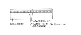
次に、ヒータユニット140の構成について説明する。ヒータユニット140は、例えば電熱ヒータ等によって構成されたシート状のシートヒータ(第1のヒータ)140Bと、このシートヒータ140Bの上面、即ち、キャビティ170側に配置される保護プレート(保護層)140Aと、シートヒータ140Bと圧縮金型108との間(反上型102側)に形成される断熱層140Cとから構成されている。
<Configuration of heater unit>
Next, the configuration of the
保護プレート140Aは、例えば圧縮金型108を構成する材料と同様の材質によって構成され、樹脂封止の際の圧力等からシートヒータ140Bを充分に保護することが可能な強度が保たれている。即ち、ここでの保護プレート140Aは、ヒータユニット140を構成すると同時に、圧縮金型108自身を構成する部材である。換言すると、シートヒータ140Bが、保護プレート140Aの厚み分だけ金型内に埋められるように配置されている。また、断熱層140Cは、シートヒータ140Bによって発生した熱を、効率的に保護プレート140Aを介してキャビティ170側へと導くために、シートヒータ140Bから圧縮金型108側へと熱が伝導するのを防止する目的で設けられている。この断熱層は、例えばセラミック等の材料によって形成されている。勿論この断熱層の材料が、セラミックに限定されるわけではなく、シートヒータ140Bによって発生した熱を効率的に遮断できる限りにおいて、様々な材料および構造の断熱層を用いることが可能である。また、本実施形態における断熱層140Cはシートヒータ140Bと隣接するような配置構成とされているが、離れていてもよい。
The
また、図3に示すように、本実施形態においては、保護プレート140Aの厚み(上型102と下型104との対向方向の厚み)H2は、圧縮工程完了時におけるキャビティ170の厚み(上型102と下型104との間に充填されている樹脂160の対向方向の厚み)H1の1倍以下である必要がある。即ち、シートヒータ140Bが、金型内に充填される樹脂160の金型の対向方向の厚みよりも金型の表面に近い位置に配置されている。また、断熱層140Cの厚み(上型102と下型104との対向方向の厚み)H3は、同様に、圧縮工程完了時におけるキャビティ170の厚みH1との比較において1〜10倍が望ましい。これは、断熱層を構成する材料の特性等にもよるが、1倍に満たない場合は十分な断熱効果を発揮することができず、10倍を超える場合には、金型全体の構造的な強度が十分に確保できないことに起因している。
Further, as shown in FIG. 3, in the present embodiment, the thickness of the
なお、本発明においては、これらの保護プレート(保護層)140Aや断熱層140Cは必ずしも必須の構成要素とはならない。例えばシートヒータ140B自体が繰り返される樹脂封止作業に十分に耐えうる構造である場合には不用であり、シートヒータ140Bが金型表面に露出していてもよい。また、断熱層140Cにおいても同様であり、例えば、金型を構成する材料自体の熱伝導率が低い場合には、断熱層を省略した構成も可能である。
In the present invention, these protective plate (protective layer) 140A and heat insulating
また、本実施形態では、シートヒータ140Bが、圧縮金型108の表面に敷設されており、施行上有利である。即ち、下型104を構成する圧縮金型108は、同様に下型104を構成する枠状金型106とは別部品として取り扱うことが可能であり、当該圧縮金型108のみを必要により加工等すれば足り、枠状金型106の部分は従来の金型をそのまま利用することが可能となる。また場合によっては、圧縮金型108においてもその表面にシートヒータ104Bを敷設するのみで足り、圧縮金型108自体の加工をも不要である。
In the present embodiment, the
<樹脂封止金型の作用>
続いて図4を参照しつつ、この樹脂封止金型100を用いた樹脂封止の工程について簡単に説明する。
<Operation of resin-sealed mold>
Next, a resin sealing process using the resin sealing mold 100 will be briefly described with reference to FIG.
図4(A)に示すように、当初、上型102と下型104とは離間している。この状態で、図示せぬ搬送機構によって、上型102の表面に半導体チップ132が搭載された基板130が搬送され吸着保持される。一方、下型104のキャビティ170(枠状金型106と圧縮金型108との段差が形成されている部分)には、図示せぬ搬送機構によって封止材料としての樹脂160が投入される(より正確には、下型104の表面にはリリースフィルム150が吸着保持されているため、当該リリースフィルム150上に投入される。)。本実施形態においては、この樹脂160は、予め所定の形状に予備的に成形されたプリフォーム樹脂が用いられている。勿論、このようにプリフォーム樹脂に限定されるものではなく、粉状、粒状、ペレット状等の様々な形態の樹脂であっても差し支えない。
As shown in FIG. 4A, the
またこの時点においては、圧縮金型108の内部に設けられた内部ヒータ108Aによって、この圧縮金型108全体の温度が所定の温度域(投入された樹脂160の流動性が高い温度域)に維持されている。その結果、キャビティ170内に樹脂160が投入されると同時に、樹脂は溶融し始め、流動性が向上する。一方で、圧縮金型108に配置されたシートヒータ140B(ヒータユニット140)は動作していない。
At this time, the temperature of the
次に、図4(B)に示すように、上型102と下型104とが当接する。この動作によって、キャビティ170内に投入された樹脂160が圧縮されつつ、キャビティ170内に均一に充填する作業が行なわれる(圧縮工程)。この時点においても圧縮金型108に配置されたシートヒータ140B(ヒータユニット140)は動作しておらず、専ら、圧縮金型108の内部に設けられた内部ヒータ108Aによって、樹脂160の流動性が高い温度域に金型の温度が維持されている。その結果、当該樹脂160の流動によって半導体チップ等に設けられているボンディングワイヤ等の短絡・切断を誘発することもなく、更に、流動性の高さから、キャビティ170内に均一に樹脂160を充填させることが可能となっている。
Next, as shown in FIG. 4B, the
続いて、図4(C)に示したように、圧縮金型108による圧縮工程が完了すると同時に(またはその前後に)、圧縮金型108に配置されたシートヒータ140B(ヒータユニット140)が動作し、キャビティ170内に充填された樹脂160の温度を一気に硬化温度域にまで加熱する。本実施形態におけるシートヒータ140B(ヒータユニット140)は、前述した通り、圧縮金型108の表面に保護プレート140Aのみを介して配置されており、素早く樹脂160の温度を変化させることが可能である。また、シートヒータ140Bの下には断熱層140Cが設けられているため、当該シートヒータ140B(ヒータユニット140)で発生した熱が、圧縮金型108全体へと逃げることなく効率的にキャビティ170内に充填されている樹脂160側へと導かれる。
Subsequently, as shown in FIG. 4C, when the compression process by the
なお、シートヒータ140Bの動作が開始される時点は、必ずしも圧縮工程が完了すると同時である必要はない。例えば、圧縮工程が終了する以前からある程度の温度域(例えば樹脂の流動性が高い温度域)で動作させておき、圧縮工程終了と同時に(またはその前後に)温度を切り替えるような制御を行ってもよい。
Note that the time when the operation of the
このようなプロセスにより樹脂封止が行われる際の、樹脂の硬化度(粘度)と時間との関係を示したものが図5である。この図5に示しているように、本発明を適用した樹脂封止金型100を使用して樹脂封止を行なった場合には、圧縮工程が終わると同時に急速に樹脂の硬化度が上昇している。即ち、圧縮工程が完了するまでの間は、樹脂材料としての樹脂の流動性を高く維持すると同時に、樹脂の流動が終った段階で速やかに樹脂を硬化させ、樹脂の硬化が完了するまでの時間(キュアタイム)を短縮している。その結果、樹脂の流動性が高い状態でキャビティ内に均一に樹脂を充填させることによって高い樹脂封止品質を保つと同時に、短いサイクルタイムで樹脂封止を完了することが可能となっている。 FIG. 5 shows the relationship between the degree of cure (viscosity) of resin and time when resin sealing is performed by such a process. As shown in FIG. 5, when resin sealing is performed using the resin sealing mold 100 to which the present invention is applied, the degree of curing of the resin rapidly increases as soon as the compression process is completed. ing. That is, until the compression process is completed, the fluidity of the resin as the resin material is kept high, and at the same time, the resin is quickly cured at the stage where the resin flow is finished, and the time until the resin is completely cured (Cure time) is shortened. As a result, it is possible to complete the resin sealing in a short cycle time while maintaining a high resin sealing quality by uniformly filling the cavity with the resin in a state where the resin fluidity is high.
また、次回の封止作業に移行する場合には、キャビティ170周辺の温度を樹脂の流動性が高い温度域にまで下げておく必要がある。本実施形態では、金型の表面に保護プレート140Aのみを介してシートヒータ140Bが配置されているため、例えば、金型表面にブロワ等によって空気を当てること等により、簡易且つ迅速に温度を低下させることができる。
Further, when shifting to the next sealing operation, it is necessary to lower the temperature around the
<本発明の他の実施形態について>
また、上記実施形態においては下型104を構成する圧縮金型側108にのみヒータユニット140が設けられていたが、上型102側に設けるような構成を採用しても良い。例えば図6に示すように、圧縮金型208の表面にヒータユニット240Aを敷設すると同時に、基板230を吸着固定する上型202側の表面にも、同様にヒータユニット240Bを敷設するような構成を採用してもよい。このようにすれば、上下方向から被成形品である基板230をより均一な状態で温度管理することが可能となり、封止後の基板230の「反り」等を防止すること可能となる。なお係る場合、上型202側に敷設されるヒータユニット240Bは、圧縮金型208側に設けるヒータユニット240Aと同様の構成である必要は無い。即ち、本実施形態のように、上型202が直接封止材料としての樹脂に接するのではなく基板230を介して接しているような場合には、ヒータユニット240Bの大きさや設定温度に関しては適宜に変更・調整可能である。
<About another embodiment of the present invention>
Further, in the above embodiment, the
また、図7に示すように、圧縮金型408に配置されるヒータユニット440を、例えばインサート408Aを介して着脱可能に構成しても良い。このような構成とすれば、性能の異なるヒータユニットを適宜取り替えることが容易となる。
Further, as shown in FIG. 7, the
<トランスファ方式への適用例>
なお、上記では全て所謂「圧縮金型」を例に説明しているが、トランスファ方式の樹脂封止金型にも幅広く適用することが可能である。図8および図9に、トランスファ方式の金型への適用例を示している。
<Application example to transfer system>
In the above description, the so-called “compression mold” is described as an example. However, the present invention can be widely applied to transfer type resin-sealed molds. FIG. 8 and FIG. 9 show application examples to a transfer mold.
トランスファ方式の金型に適用する場合には、キャビティのみならず、カル部やランナ部に対応する位置に第1のヒータ(例えばシートヒータ)を配置することによって、カル部やランナ部を流動する樹脂や滞留する樹脂の温度を積極的に管理することができる。図8および図9に示した例では、カル部36、536の表面や近傍に、第1のヒータ(局部ヒータ)46、546が配置されている。このような構成とすれば、硬化工程において、樹脂に厚み(A2)があるカル部36、536に存在する樹脂をより積極的に硬化させることによって、ランナ部50等との硬化タイミングを揃えることが可能となる。かかる場合の第1のヒータ(局部ヒータ)46、546の金型表面からの位置は、当該第1のヒータ(局部ヒータ)46、546に対応する位置に充填されている樹脂の厚み(即ち、カル部36、536厚みA2)よりも金型表面に近い位置に配置すればよい(図9の例で説明すると、A3≦A2という関係が成り立つ)。
When applied to a transfer mold, not only the cavity but also the first heater (for example, a seat heater) is disposed at a position corresponding to the cull part or the runner part, so that the cull part or the runner part flows. The temperature of the resin and the staying resin can be positively managed. In the example shown in FIGS. 8 and 9, first heaters (local heaters) 46 and 546 are disposed on or near the surfaces of the
本発明は、熱硬化性樹脂を用いた樹脂成形金型に広く適用することが可能である。 The present invention can be widely applied to a resin molding die using a thermosetting resin.
100…樹脂封止金型
102…上型
104…下型
106…枠状金型
106A…貫通孔
108…圧縮金型
108A…内部ヒータ
110…バネ
130…基板(被成形品)
132…半導体チップ
140…ヒータユニット
140A…保護プレート(保護層)
140B…ヒータ
140C…断熱層
150…リリースフィルム
160…樹脂(封止樹脂)
170…キャビティ
DESCRIPTION OF SYMBOLS 100 ...
132 ...
140B ...
170 ... cavity
Claims (9)
前記第1、第2の金型の少なくとも一方には、前記金型内に充填される前記樹脂の前記金型の対向方向の厚みよりも前記金型の表面に近い位置に、第1のヒータが配置されている
ことを特徴とする樹脂封止金型。 A resin-sealed mold that clamps a molded product on which a semiconductor chip is mounted with opposing first and second molds and seals the molded product using a resin filled in the mold. And
At least one of the first and second molds has a first heater at a position closer to the mold surface than the thickness of the resin filled in the mold in the opposing direction of the mold. A resin-sealed mold characterized in that is disposed.
前記第1のヒータが、相手金型側表面に露出している
ことを特徴とする樹脂封止金型。 In claim 1,
The first heater is exposed on the surface of the mating mold. A resin-sealed mold.
前記第1のヒータの相手金型側には保護層が形成されている
ことを特徴とする樹脂封止金型。 In claim 1,
A resin-sealed mold, wherein a protective layer is formed on the mold side of the first heater.
前記保護層の対向方向の厚みが、前記金型内に充填される前記樹脂の対向方向の厚みの0.1〜1倍である
ことを特徴とする樹脂封止金型。 In claim 3,
The resin-sealing mold, wherein the thickness of the protective layer in the facing direction is 0.1 to 1 times the thickness in the facing direction of the resin filled in the mold.
前記第1のヒータの反相手金型側に、断熱層が形成されている
ことを特徴とする樹脂封止金型。 In any one of Claims 1 thru | or 4,
A resin-sealed mold, wherein a heat insulating layer is formed on the opposite mold side of the first heater.
前記断熱層の対向方向の厚みが、前記金型内に充填される前記樹脂の対向方向の厚みの1〜10倍である
ことを特徴とする樹脂封止金型。 In claim 5,
The resin-sealing mold, wherein the thickness of the heat insulating layer in the facing direction is 1 to 10 times the thickness of the resin in the facing direction filled in the mold.
前記第1のヒータが配置されている金型の内部に、第2のヒータが埋設されている
ことを特徴とする樹脂封止金型。 The resin-sealed mold according to any one of claims 1 to 6, wherein a second heater is embedded in a mold in which the first heater is disposed.
前記第1、第2の金型の少なくとも一方が、貫通孔を有する枠状金型と、該貫通孔に嵌合して相手金型側に摺動可能な圧縮金型とからなり、
前記第1のヒータが、前記圧縮金型に配置されている
ことを特徴とする樹脂封止金型。 In any one of Claims 1 thru | or 7,
At least one of the first and second molds is composed of a frame-shaped mold having a through-hole and a compression mold that can be fitted into the through-hole and slidable on the counterpart mold side,
The first heater is disposed in the compression mold. A resin-sealed mold.
前記第1のヒータが配置される面積が、前記圧縮金型の表面積と同一である
ことを特徴とする樹脂封止金型。 In claim 8,
The area where the first heater is disposed is the same as the surface area of the compression mold.
Priority Applications (1)
| Application Number | Priority Date | Filing Date | Title |
|---|---|---|---|
| JP2007276539A JP2009105273A (en) | 2007-10-24 | 2007-10-24 | Resin sealing mold |
Applications Claiming Priority (1)
| Application Number | Priority Date | Filing Date | Title |
|---|---|---|---|
| JP2007276539A JP2009105273A (en) | 2007-10-24 | 2007-10-24 | Resin sealing mold |
Related Child Applications (1)
| Application Number | Title | Priority Date | Filing Date |
|---|---|---|---|
| JP2012178960A Division JP2012256925A (en) | 2012-08-10 | 2012-08-10 | Resin seal mold |
Publications (1)
| Publication Number | Publication Date |
|---|---|
| JP2009105273A true JP2009105273A (en) | 2009-05-14 |
Family
ID=40706664
Family Applications (1)
| Application Number | Title | Priority Date | Filing Date |
|---|---|---|---|
| JP2007276539A Pending JP2009105273A (en) | 2007-10-24 | 2007-10-24 | Resin sealing mold |
Country Status (1)
| Country | Link |
|---|---|
| JP (1) | JP2009105273A (en) |
Cited By (2)
| Publication number | Priority date | Publication date | Assignee | Title |
|---|---|---|---|---|
| CN102347244A (en) * | 2010-07-29 | 2012-02-08 | 东和株式会社 | Resin sealing device and manufacturing method for resin sealing electronic component |
| KR20200132664A (en) * | 2019-05-17 | 2020-11-25 | 토와 가부시기가이샤 | Molding model, resin molding device and method for manufacturing resin molding product |
Citations (8)
| Publication number | Priority date | Publication date | Assignee | Title |
|---|---|---|---|---|
| JPS59232840A (en) * | 1983-06-16 | 1984-12-27 | Toshiba Corp | Package molding device |
| JPS6154633A (en) * | 1984-08-24 | 1986-03-18 | Matsushita Electric Works Ltd | Metal mold for semiconductor resin sealing |
| JPS6154635A (en) * | 1984-08-24 | 1986-03-18 | Matsushita Electric Works Ltd | Metal mold for semiconductor resin sealing |
| JPS6251416A (en) * | 1985-08-30 | 1987-03-06 | Sony Corp | Resin encapsulating mold |
| JPH02192742A (en) * | 1989-01-20 | 1990-07-30 | Oki Electric Ind Co Ltd | Resin sealing method of semiconductor device |
| JPH05162138A (en) * | 1991-12-13 | 1993-06-29 | Toshiba Corp | Mold device |
| JPH1190969A (en) * | 1997-09-22 | 1999-04-06 | Hitachi Ltd | Method and device for molding and manufacture of semiconductor device |
| JP2000299335A (en) * | 1998-07-10 | 2000-10-24 | Apic Yamada Corp | Manufacture of semiconductor device and resin-sealing apparatus |
-
2007
- 2007-10-24 JP JP2007276539A patent/JP2009105273A/en active Pending
Patent Citations (8)
| Publication number | Priority date | Publication date | Assignee | Title |
|---|---|---|---|---|
| JPS59232840A (en) * | 1983-06-16 | 1984-12-27 | Toshiba Corp | Package molding device |
| JPS6154633A (en) * | 1984-08-24 | 1986-03-18 | Matsushita Electric Works Ltd | Metal mold for semiconductor resin sealing |
| JPS6154635A (en) * | 1984-08-24 | 1986-03-18 | Matsushita Electric Works Ltd | Metal mold for semiconductor resin sealing |
| JPS6251416A (en) * | 1985-08-30 | 1987-03-06 | Sony Corp | Resin encapsulating mold |
| JPH02192742A (en) * | 1989-01-20 | 1990-07-30 | Oki Electric Ind Co Ltd | Resin sealing method of semiconductor device |
| JPH05162138A (en) * | 1991-12-13 | 1993-06-29 | Toshiba Corp | Mold device |
| JPH1190969A (en) * | 1997-09-22 | 1999-04-06 | Hitachi Ltd | Method and device for molding and manufacture of semiconductor device |
| JP2000299335A (en) * | 1998-07-10 | 2000-10-24 | Apic Yamada Corp | Manufacture of semiconductor device and resin-sealing apparatus |
Cited By (4)
| Publication number | Priority date | Publication date | Assignee | Title |
|---|---|---|---|---|
| CN102347244A (en) * | 2010-07-29 | 2012-02-08 | 东和株式会社 | Resin sealing device and manufacturing method for resin sealing electronic component |
| JP2012033584A (en) * | 2010-07-29 | 2012-02-16 | Towa Corp | Resin sealing device and resin sealing method |
| KR20200132664A (en) * | 2019-05-17 | 2020-11-25 | 토와 가부시기가이샤 | Molding model, resin molding device and method for manufacturing resin molding product |
| KR102273522B1 (en) * | 2019-05-17 | 2021-07-05 | 토와 가부시기가이샤 | Molding model, resin molding device and method for manufacturing resin molding product |
Similar Documents
| Publication | Publication Date | Title |
|---|---|---|
| KR101317617B1 (en) | Apparatus and methods for molded underfills in flip chip packaging | |
| TWI680527B (en) | Carrying mechanism, resin molding device, method for transferring molding object to molding die, and method for manufacturing resin molded product | |
| CN103620752A (en) | Method for manufacturing resin-sealed electronic component and device for manufacturing resin-sealed electronic component | |
| JP6560498B2 (en) | Resin sealing method and resin molded product manufacturing method | |
| JP4336499B2 (en) | Resin sealing molding method and apparatus for electronic parts | |
| JP2010109246A (en) | Semiconductor device, and method of manufacturing the same | |
| JP2012049414A (en) | Method and apparatus for manufacturing resin encapsulation molded article having substrate exposure face | |
| TW201923993A (en) | Resin-molding device and method for producing resin-molded product capable of changing the depth of the mold cavity by using the mold wedge mechanism to fix the cavity block | |
| TW202039200A (en) | Resin molding device and manufacturing method for resin molded article | |
| JP2009105273A (en) | Resin sealing mold | |
| JP2005306018A (en) | Injection casting system for encapsulating semiconductor device and its usage | |
| JP2010050323A (en) | Electronic device, and method of manufacturing the same | |
| TW202019657A (en) | Molding die, resin molding device, and method for manufacturing resin-molded product includes two mold-film pressing members to clamp and apply tension to the release film | |
| JP4825572B2 (en) | Resin sealing device and resin sealing method by transfer molding | |
| JP2012256925A (en) | Resin seal mold | |
| TW201927514A (en) | Resin molding device and manufacturing method of resin molded product capable of constituting a molding die with a small number of parts | |
| JP5490605B2 (en) | Resin sealing device and resin sealing method | |
| TWI663039B (en) | Compression molding device, compression molding method, and manufacturing method of compression molded product | |
| JP5308107B2 (en) | Circuit device manufacturing method | |
| TWI778332B (en) | Resin molding apparatus and method for producing resin molded product | |
| JP6171920B2 (en) | Mold package | |
| TWI402922B (en) | Molding method of semiconductor chips | |
| JP6182951B2 (en) | Semiconductor device and manufacturing method thereof | |
| JP6445536B2 (en) | Electronic component molding and surface treatment method | |
| JP2022177557A (en) | Resin molding device and method for producing resin molding |
Legal Events
| Date | Code | Title | Description |
|---|---|---|---|
| A621 | Written request for application examination |
Free format text: JAPANESE INTERMEDIATE CODE: A621 Effective date: 20100119 |
|
| A977 | Report on retrieval |
Free format text: JAPANESE INTERMEDIATE CODE: A971007 Effective date: 20100419 |
|
| A131 | Notification of reasons for refusal |
Free format text: JAPANESE INTERMEDIATE CODE: A131 Effective date: 20120612 |
|
| A02 | Decision of refusal |
Free format text: JAPANESE INTERMEDIATE CODE: A02 Effective date: 20130507 |