JP2008266910A - Projection structure of anchorage or deviator of tendon, and construction method therefor - Google Patents
Projection structure of anchorage or deviator of tendon, and construction method therefor Download PDFInfo
- Publication number
- JP2008266910A JP2008266910A JP2007108292A JP2007108292A JP2008266910A JP 2008266910 A JP2008266910 A JP 2008266910A JP 2007108292 A JP2007108292 A JP 2007108292A JP 2007108292 A JP2007108292 A JP 2007108292A JP 2008266910 A JP2008266910 A JP 2008266910A
- Authority
- JP
- Japan
- Prior art keywords
- concrete
- fixing
- concrete frame
- deflection
- deflecting
- Prior art date
- Legal status (The legal status is an assumption and is not a legal conclusion. Google has not performed a legal analysis and makes no representation as to the accuracy of the status listed.)
- Withdrawn
Links
Images


Landscapes
- Reinforcement Elements For Buildings (AREA)
- Bridges Or Land Bridges (AREA)
Abstract
Description
この発明は、プレストレストコンクリート構造物においてPC鋼材等の緊張材の端部を定着する定着部または緊張材の向きを変える偏向部の突起構造及びこれら定着部または偏向部の施工方法に関するものである。 The present invention relates to a fixing portion for fixing an end portion of a tension material such as a PC steel material in a prestressed concrete structure or a protrusion structure of a deflection portion for changing the direction of the tension material, and a method for constructing the fixing portion or the deflection portion.
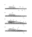
橋梁等のプレストレストコンクリート構造物(以下、PC構造物)において、油圧ジャッキ等により緊張された緊張材(以下、PC鋼材)の端部は、一般に図6に示すような支圧板61と筒形等の鋼製の定着具62に固定され、その緊張力が保持される。また、定着具62は、図7に示すような定着突起71を介して、PC鋼材60の緊張力をプレストレスとしてコンクリート躯体70に導入する。
In a prestressed concrete structure (hereinafter referred to as a PC structure) such as a bridge, an end portion of a tension material (hereinafter referred to as a PC steel material) that has been tensioned by a hydraulic jack or the like generally has a
定着突起71の周辺のコンクリートには、大きな局部応力が生じるため、定着具62の背面には、図6に示すようなスパイラル筋63や図7に示すような格子状に組まれたグリッド筋72が配置され、さらに図7に示すような鉄筋73が密に配置されることになる。ここに示した例は、PC箱桁橋の下床版における突起定着方式の例であるが、上床版の突起定着方式やウェブ突起定着方式の場合も同様である。
Since a large local stress is generated in the concrete around the
また、外ケーブル方式のPC構造物においては、図8に示すようなPC鋼材の外ケーブル80を偏向させるための偏向部(ディビエータ)81が設けられるが、上記の定着突起と同様に局部応力補強のための鉄筋等が密に配置される。
Further, in the external cable type PC structure, there is provided a
また、本発明に関連する先行技術文献として、定着具と補強鉄筋の一部をプレキャストコンクリート中に埋設してなるプレキャストブロックの定着部材を場所打ちのPC構造物の型枠の所定位置に前もって設置し、この定着部材をそれから突出させた補強鉄筋によりPC構造物のコンクリートに一体化させる方法がある(特許文献1参照)。 In addition, as a prior art document related to the present invention, a fixing member of a precast block in which a fixing tool and a part of a reinforcing steel bar are embedded in precast concrete is installed in advance in a predetermined position of a cast-in-place PC structure. In addition, there is a method of integrating the fixing member into the concrete of the PC structure with a reinforcing reinforcing bar protruding therefrom (see Patent Document 1).
また、PC構造物のコンクリートの内、定着部周辺のコンクリートに繊維補強セメント系複合材料を用い、この定着部に接する一般部には強度の低い普通コンクリートを用いることで、定着具と補強鉄筋を不要にする方法がある(特許文献2参照)。 Also, among the concrete of PC structures, fiber reinforced cementitious composite material is used for the concrete around the fixing part, and ordinary concrete with low strength is used for the general part in contact with the fixing part, so that the fixing tool and the reinforcing steel bar are attached. There is a method of making it unnecessary (see Patent Document 2).
前述した従来の場所打ち工法(図6、図7)によるPC鋼材の定着部や偏向部の施工には、以下に示す安全性、生産性にかかわる課題がある。 The construction of the fixing portion and the deflection portion of the PC steel material by the conventional cast-in-place method (FIGS. 6 and 7) described above has the following problems related to safety and productivity.
(1) 下床版の鉄筋が配置された上で、即ち足元の悪い状態で、定着部の場合、重量物である定着具を設置しなければならず、安全性に問題がある。 (1) In the case of the fixing part with the lower floor slab reinforcing bars arranged, that is, in a poor condition, a fixing tool which is a heavy object must be installed, which is a problem in safety.
(2) 定着部では、定着具や補強筋が複雑に配置されるため、また偏向部でも、補強筋が複雑に配置されるため、これらの配置と組み立てに時間と労力を要する。 (2) Since fixing tools and reinforcing bars are arranged in a complicated manner in the fixing portion, and reinforcing bars are also arranged in a complicated manner in the deflection portion, it takes time and labor to arrange and assemble them.
(3) 定着部や偏向部の突起の型枠は、浮き型枠としなければならないため、サポート等の設置が必要であり、型枠の組立てに時間と労力を要する。また、サポートが桁の中の空間を占有するため、下床版施工時のコンクリートの打設作業性を劣らせる。 (3) Since the molds of the protrusions of the fixing unit and the deflection unit must be floating molds, it is necessary to install a support or the like, and time and labor are required for assembling the molds. In addition, since the support occupies the space in the girder, the workability of placing concrete during lower floor slab construction is inferior.
(4)上記の(2)、(3)の理由により、桁をブロック施工するサイクル工程の中で、定着部や偏向部の突起の組立てがクリティカルパス(最も問題が生じやすく時間もかかる工程部分)となる場合がある。 (4) Due to the reasons of (2) and (3) above, the assembly of the fixing part and deflection part protrusion is a critical path (the process part that is most likely to cause problems and takes a long time) in the cycle process of blocking the girder. ).
これらの課題に対し、先行技術文献の特許文献1の発明では、定着突起一式を工場製作することで、現場における定着部の組立て及びコンクリート打設を省き、工数削減を図ろうとしている。しかし、このようにして製作されたプレキャスト定着突起は、図7に示すような標準的な形状寸法において、重量が約1.4tonとなり、狭い桁の中で所定の位置に設置することは、作業上非常に困難である。
In response to these problems, the invention of
また、特許文献2の発明では、定着具と補強鉄筋が不要になり、それらの組み立て作業も不要になり、コンクリートの充填性の問題も解消されるが、部位毎に種類の異なるコンクリートを打設することは品質管理及び施工管理の面から煩雑である。また、コンクリートを分割打設する場合には、打設したコンクリート自身の硬化時の水和熱に伴う、不均一な温度分布に起因する温度応力によるひび割れや、後打ちする部位に打設したコンクリートの収縮時に先行して打設されたコンクリートから外部拘束を受けることによる収縮ひび割れ等の発生が懸念されるため、コンクリートの品質に与える影響が大きい。この他、高性能の特殊コンクリートは材料費が高価であるため、広範囲な部分に使用すれば、不経済となる。
Further, in the invention of
この発明は、プレストレストコンクリート構造物の緊張材の定着部や偏向部の施工に際して、重量物である定着具、補強鉄筋、型枠などを設置するための作業足場をコンクリート面とすることができ、作業性及び安全性の向上を図ることができ、また定着部や偏向部の突起の型枠が浮き型枠とならず、型枠の組立ての時間と労力の低減を図ることができ、さらに桁をブロック施工するサイクル工程において、クリティカルパスとなる定着部や偏向部の突起の組立てをサイクル工程から外すことができ、サイクル工程の短縮を図ることができる緊張材の定着部または偏向部の突起構造及びその施工方法を提供するものである。 This invention can be used as a concrete surface as a work scaffold for installing a fixing tool, a reinforcing bar, a formwork, etc., which are heavy objects, in the construction of a fixing part and a deflecting part of a tension material of a prestressed concrete structure, Workability and safety can be improved, and the molds of the projections of the fixing unit and the deflection unit do not become floating molds, which can reduce the time and labor for assembling the molds, In the cycle process for building blocks, it is possible to remove the assembly of the fixing part and deflection part projections that become critical paths from the cycle process, and to shorten the cycle process. And the construction method is provided.
本発明の請求項1に係る発明は、プレストレストコンクリート構造物に配置される緊張材(PC鋼材など)の端部が定着される定着部または緊張材が挿通される偏向部の突起構造であり、定着部または偏向部の位置においてコンクリート躯体の内部に一端側が埋設され、他端側がコンクリート躯体の外部へ突出する接続部材(コンクリートジベル)と、この接続部材を介してコンクリート躯体に一体化される定着部または偏向部のコンクリート突起とを備えていることを特徴とする緊張材の定着部または偏向部の突起構造である。コンクリート躯体とコンクリート突起を分割し、予めコンクリート躯体部分に接続部材の下部を埋設しておき、コンクリート突起部分は後施工で打設するのが好ましい。
The invention according to
本発明は、例えば、図1に示すように、PC箱桁橋の下床版等におけるPC鋼材等の定着部あるいは偏向部に適用されるものであり、定着部や偏向部を下床版等のコンクリート躯体の施工と分離して後施工で構築するものである。この後施工に当り、下床版等と定着部等とを一体化するための接続手段として孔あき鋼板ジベル等のコンクリートジベルを下床版等の施工時に予め埋設しておくものである。 For example, as shown in FIG. 1, the present invention is applied to a fixing portion or a deflection portion such as a PC steel material in a lower floor slab of a PC box girder bridge. It will be constructed separately from the construction of the concrete frame in the post-construction. In the subsequent construction, concrete gibbles such as perforated steel plate gibbles are embedded in advance during construction of the lower floor slab as a connecting means for integrating the lower floor slab and the fixing part.
本発明によれば、定着部や偏向部の施工に際して、重量物であるPC鋼材等の定着具、補強鉄筋、型枠などを設置する際に、作業足場がコンクリート面となるため、従来のように鉄筋が配置された足元が悪い状態での作業とはならず、作業性及び安全性を向上させることができる。また、コンクリート面の上に定着部や偏向部の型枠を設置でき、型枠が浮き型枠とならないため、型枠の組立ての時間と労力を低減することができる。さらに、桁をブロック施工するサイクル工程において、クリティカルパスとなる定着部や偏向部の突起の組立てをサイクル工程から外すことができる。 According to the present invention, since the work scaffolding becomes a concrete surface when installing a fixing tool such as a PC steel material, which is a heavy object, a reinforcing bar, a formwork, or the like during construction of the fixing unit and the deflecting unit, Therefore, the work is not performed in a state in which the rebar is disposed in a poor state, and workability and safety can be improved. In addition, since the formwork of the fixing part and the deflecting part can be installed on the concrete surface and the formwork does not become a floating formwork, the time and labor for assembling the formwork can be reduced. In addition, in the cycle process in which the girders are blocked, the assembly of the fixing part and the projection of the deflecting part, which become a critical path, can be removed from the cycle process.
なお、本発明の突起構造は、上述の理由から、コンクリート突起部分を後施工で打設するのが好ましいが、コンクリート躯体部分の配筋作業時に接続部材を設置し、コンクリート突起とコンクリート躯体を同時に打設することも可能である。 In addition, for the above-mentioned reason, it is preferable that the protrusion structure of the present invention is to place the concrete protrusion portion by post-construction. However, the connecting member is installed at the time of the reinforcement work of the concrete frame portion, and the concrete protrusion and the concrete frame are simultaneously placed. It is also possible to cast.
本発明の請求項2に係る発明は、プレストレストコンクリート構造物に配置される緊張材(PC鋼材など)の端部が定着される定着部または緊張材が挿通される偏向部の突起構造であり、定着部または偏向部の位置においてコンクリート躯体の内部に一端側が埋設され、他端側がコンクリート躯体の外部へ突出する接続部材(コンクリートジベル)と、この接続部材の突出部分に一体的に接続される定着部または偏向部の鋼製突起とを備えていることを特徴とする緊張材の定着部または偏向部の突起構造である。
The invention according to
これは、例えば、図3に示すように、コンクリート製の突起の代わりに鋼製の突起を用いる場合であり、コンクリートジベルの突出部分に鋼製突起をボルトや溶接で接合し、この鋼製突起をコンクリートジベルを介してコンクリート躯体と一体化する。 For example, as shown in FIG. 3, a steel projection is used in place of a concrete projection, and the steel projection is joined to the projecting portion of the concrete diver by bolts or welding. Is integrated with the concrete frame through a concrete gibber.
本発明の請求項3に係る発明は、請求項1または請求項2のいずれか一つに記載の突起構造において、接続部材(コンクリートジベル)が孔あき鋼板ジベルであり、コンクリート躯体内の部分の孔にコンクリート躯体の鉄筋が挿通され、あるいは前記孔をスリットとし、このスリットにコンクリート躯体の鉄筋が配置されていることを特徴とする緊張材の定着部または偏向部の突起構造である。
The invention according to
これは、例えば、図1〜図4に示すように、コンクリートジベルに孔あき鋼板ジベルを用いる場合であり、コンクリート躯体内に埋設される下部の孔にコンクリート躯体の鉄筋を挿通し、引抜け耐力を確保する。スリットを用いた場合には、コンクリート躯体の鉄筋の上に設置しやすくなる利点がある。このスリットタイプの場合には、孔あき鋼板ジベルの下端にフランジを設け、あるいは下部を波形とするなどして、引抜け耐力の増加を図るのが好ましい。また、孔あき鋼板ジベルのコンクリート躯体内の孔やスリットに挿通される貫通鉄筋は、コンクリートの割裂を拘束する割裂補強筋としての機能も有するが、図5に示すように、横方向の貫通鉄筋(配力筋)の他に必要に応じて弓形等の貫通鉄筋を割裂補強筋として用いる。貫通鉄筋を弓形とすれば、複雑な配筋の斜め上から挿入し挿通させることができ、また軸回りに回転させることで貫通鉄筋の向きを好ましい方向にすることができる。 For example, as shown in FIG. 1 to FIG. 4, a perforated steel plate is used for the concrete jib, and the reinforcing rod of the concrete case is inserted into the lower hole embedded in the concrete case, and the pull-out strength Secure. When a slit is used, there exists an advantage which becomes easy to install on the reinforcing bar of a concrete frame. In the case of this slit type, it is preferable to increase the pull-out strength by providing a flange at the lower end of the perforated steel plate gibber or by corrugating the lower part. In addition, the penetrating rebar inserted through the hole or slit in the concrete casing of the perforated steel plate gibel also has a function as a split reinforcing bar that constrains the splitting of the concrete. However, as shown in FIG. In addition to (strengthening bars), penetrating reinforcing bars such as bows are used as split reinforcements as necessary. If the penetrating rebar has an arcuate shape, it can be inserted and inserted obliquely from above the complicated bar arrangement, and the direction of the penetrating rebar can be set to a preferred direction by rotating around the axis.
本発明の請求項4に係る発明は、請求項1または請求項3のいずれか一つに記載の突起構造において、接続部材が緊張材を挟んで配置される一対の孔あき鋼板ジベルであり、この一対の孔あき鋼板ジベルがボルト部材で連結されていることを特徴とする緊張材の定着部または偏向部の突起構造である。
The invention according to
これは、例えば、図5(a)に示すように、コンクリート製の突起において、一対の孔あき鋼板ジベルをねじ鉄筋とカップラー等のボルト部材で連結し、これを緊張材方向に間隔をおいて複数配置することにより、コンクリートの割裂補強筋として用いる場合であり、スパイラル筋を省略することができる。 For example, as shown in FIG. 5 (a), in a concrete protrusion, a pair of perforated steel plate gibels are connected by a screw rebar and a bolt member such as a coupler, and this is spaced apart in the direction of the tension material. By arranging a plurality, it is a case where it is used as a split reinforcing bar for concrete, and the spiral bar can be omitted.
本発明の請求項5に係る発明は、請求項1、請求項3または請求項4のいずれか一つに記載の突起構造において、接続部材(コンクリートジベル)がコンクリート躯体内に位置する内部部分とコンクリート躯体の外に位置する外部部分とに分割され、内部部分に外部部分が接合されることを特徴とする緊張材の定着部または偏向部の突起構造である。
The invention according to
これは、例えば、図5(b)に示すように、コンクリート製の突起において、コンクリートジベルをコンクリート上面で上下に2分割し、ボルト等で接合する場合である。コンクリート躯体の施工時にコンクリートジベルがコンクリート上面から突出せず、コンクリート躯体の施工が容易となる、定着部等の補強鉄筋の設置が容易になるなどの利点がある。 For example, as shown in FIG. 5 (b), this is a case where, in a concrete protrusion, a concrete diver is divided into two vertically on the concrete upper surface and joined with a bolt or the like. There is an advantage that the concrete gibber does not protrude from the top surface of the concrete during construction of the concrete frame, the construction of the concrete frame is easy, and the installation of reinforcing bars such as anchoring parts becomes easy.
本発明の請求項6に係る発明は、プレストレストコンクリート構造物に配置される緊張材(PC鋼材など)の端部が定着される定着部または緊張材が挿通される偏向部の施工方法であり、請求項1から請求項5までのいずれか一つに記載の接続部材(コンクリートジベル)をコンクリート躯体の配筋時にコンクリート躯体の定着部または偏向部の位置に設置し、コンクリート躯体のコンクリートを打設し、コンクリートの硬化後、コンクリート突起の場合、コンクリート躯体上に定着部または偏向部の鉄筋、型枠を配置し、型枠内にコンクリートを打設し、前記接続部材を介してコンクリート躯体と一体化された定着部または偏向部のコンクリート突起を形成し、あるいは鋼製突起の場合、前記接続部材に鋼製突起を接続し、前記接続部材を介してコンクリート躯体と一体化された定着部または偏向部の鋼製突起を形成することを特徴とする緊張材の定着部または偏向部の施工方法である。
The invention according to
コンクリート突起や鋼製突起を後施工で構築する場合であり、例えば、図2に示すような手順で施工を行う。コンクリート躯体の配筋時には接続部材を配置するだけなので、配筋作業への支障はない。コンクリート躯体のコンクリートを打設する段階で定着部等の施工がブロック施工のサイクル工程から外れる。定着部等の定着具、補強鉄筋、型枠などの設置作業をコンクリート面の上で行うことができ、作業性が向上する。 This is a case where concrete protrusions and steel protrusions are constructed by post-construction. For example, construction is performed according to the procedure shown in FIG. Since only connecting members are placed when placing concrete frames, there is no obstacle to the placement work. At the stage where the concrete of the concrete frame is placed, the construction of the fixing part etc. is out of the block construction cycle process. Installation work such as fixing parts such as fixing parts, reinforcing bars and formwork can be performed on the concrete surface, improving workability.
本発明は、以上のような構成からなるので、次のような効果が得られる。 Since the present invention is configured as described above, the following effects can be obtained.
(1)定着部や偏向部において、重量物であるPC鋼材等の定着具を設置する際に、また補強鉄筋の配筋作業や型枠設置作業などを行う際に、作業足場がコンクリート面となるため、従来のように鉄筋が配置された足元が悪い状態での作業とはならず、作業性及び安全性を向上させることができる。 (1) When installing fixing tools such as PC steel, which is a heavy object, in the fixing section and deflection section, and when performing reinforcing bar reinforcement work and formwork installation work, the work scaffold will be placed on the concrete surface. Therefore, the work is not performed in a state where the step where the reinforcing bars are arranged is bad as in the prior art, and workability and safety can be improved.
(2)コンクリート面の上に定着部や偏向部の型枠を設置でき、型枠が浮き型枠とならないため、型枠の組立ての時間と労力を低減することができる。 (2) Since the formwork of the fixing part and the deflection part can be installed on the concrete surface and the formwork does not become a floating formwork, the time and labor for assembling the formwork can be reduced.
(3)桁をブロック施工するサイクル工程の中で、定着部や偏向部の突起の組立てをサイクル工程から外すことができ、定着部や偏向部の突起の組立てがクリティカルパスとならず、サイクル工程の短縮を図ることができる。 (3) In the cycle process of constructing the girder block, the assembly of the protrusions of the fixing unit and the deflection unit can be removed from the cycle process, and the assembly of the projections of the fixing unit and the deflection unit does not become a critical path. Can be shortened.
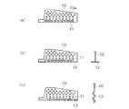
この実施の形態は、PC箱桁橋の下床版におけるPC鋼材の定着突起に本発明の突起構造を適用した例である。図1は、本発明のコンクリート製の突起構造の一例を示す鉛直断面図である。図2は、図1の突起構造の施工手順を示す鉛直断面図である。図3は、本発明の鋼製の突起構造の一例を示す鉛直断面図である。図4は、本発明で用いる孔あき鋼板ジベルの他の例を示す側面図等である。図5は、本発明のコンクリート製の突起構造の変形例を示す鉛直断面図である。 This embodiment is an example in which the projection structure of the present invention is applied to a fixing projection of a PC steel material in a lower floor slab of a PC box girder bridge. FIG. 1 is a vertical sectional view showing an example of a concrete projection structure of the present invention. FIG. 2 is a vertical sectional view showing a construction procedure of the protruding structure of FIG. FIG. 3 is a vertical sectional view showing an example of the steel projection structure of the present invention. FIG. 4 is a side view showing another example of a perforated steel plate gibber used in the present invention. FIG. 5 is a vertical sectional view showing a modification of the concrete projection structure of the present invention.
図1の実施形態において、PC箱桁橋の下床版1の所定の位置にPC鋼材の定着突起部2を施工するに当たり、下床版1の施工時に一体化用のコンクリートジベルとしての接続部材10の下部を埋設しておき、コンクリート製の定着突起部2を下床版1の施工と分離して後施工で構築する。定着突起部2は接続部材10を介して下床版1と一体化される。
In the embodiment of FIG. 1, when the fixing
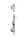
接続部材10には、例えばSM鋼などの孔あき鋼板ジベルを用いる。下床版1には、縦横に鉄筋1a、1bが配筋されており、縦方向(橋軸方向)の鉄筋1aの間に孔あき鋼板ジベル10を立てて配置し、下床版1に埋設される下部の孔10aに横方向の鉄筋1bを挿通する。この孔あき鋼板ジベル10は、橋軸方向のPC鋼材3を挟むように一対で配置するのが好ましい。
For the connecting
施工は以下のような手順で行う(図2参照)。 Construction is performed in the following procedure (see Fig. 2).
(a)下床版1の配筋時に孔あき鋼板ジベル10を設置する。この配筋時には、鋼板を配置するだけなので、下床版1の配筋作業への支障はない。
(A) A perforated
(b)下床版1のコンクリートを打設する。この段階で、定着突起の施工が桁のブロック施工のサイクル工程から外れる。
(B) The concrete of the
(c)下床版1のコンクリート硬化後、定着突起部2の定着具4、スパイラル筋5、補強鉄筋6等を配置し、型枠7を設置する。この段階では、コンクリート面上の作業となるため、作業性がよい。なお、下床版1にはPC鋼材3のシース管8が配設されている。
(C) After the concrete of the
(d)型枠7内にコンクリートを打設し、コンクリート製の定着突起部2を形成する。この定着突起部2は、孔あき鋼板ジベル10を介して下床版1に一体化される。
(D) Concrete is placed in the
後施工する定着突起部2は、コンクリート製でなくてもよい。例えば、図3に示すように、鋼製の定着突起20でもよい。孔あき鋼板ジベル10は、下床版1から大きく突出させる必要はなく、この突出部分に鋼製の定着突起20をボルトや溶接などで接合する。
The fixing
また、コンクリートジベルとしての接続部材は孔あき鋼板ジベルでなくてもよい。例えば、図4に示すように、孔あき鋼板ジベル10の下部の孔10aを下に向かって開口するスリット11としてもよい。このスリットタイプの場合、横方向の鉄筋を挿通させる必要がなく、横方向の鉄筋の上から配置することができ、設置が容易となる利点がある。また、このスリットタイプの場合、下端にフランジ12を付けたり、下部を波形13とすることにより、引抜け耐力を増加させるのが好ましい。
Further, the connecting member as a concrete jib does not have to be a perforated steel plate jib. For example, as shown in FIG. 4, the
また、コンクリート定着突起の場合、図5(a)に示すように、定着具4を挟んで配置された孔あき鋼板ジベル10の上端部同士をねじ鉄筋14とカップラー15を用いて連結し、これを橋軸方向に間隔をおいて複数配置し、割裂補強筋として用い、スパイラル筋の代替えとすることもできる。さらに、孔あき鋼板ジベル10の下部には、横方向の貫通鉄筋1bや比較的短い弓形等の貫通鉄筋16を挿通し、これら貫通鉄筋を割裂補強筋として用いる。
In the case of a concrete fixing protrusion, as shown in FIG. 5 (a), the upper ends of the perforated
ここで、孔あき鋼板ジベル10では、その孔10aに鉄筋を配置した方が、強度や剛性に優れている。しかし、孔あき鋼板ジベル10を配置した後に、コンクリート躯体(下床版)1に埋設される部分にある孔10aに、割裂補強筋としての横方向の鉄筋1bを挿通することは、施工上、必ずしも容易ではない。そこで、孔あき鋼板ジベル10の孔を図4に示すようにスリットタイプとし、このスリットに、孔あき鋼板ジベル10と直交するコンクリート躯体の鉄筋1bが配置されるようにすれば、施工が容易となる。この場合、設計上コンクリート躯体の貫通鉄筋1bだけで強度が不足する場合に、別途設けた孔10aに割裂補強筋として直線状等の貫通鉄筋16を挿通しておく。
Here, in the perforated
また、孔あき鋼板ジベル10の孔をスリットとせず、通常の孔10aとする場合は、コンクリート躯体の鉄筋が配置された状態、例えば図2(a)の状態においても、容易に割裂補強筋を挿通できるように、図5(b)に示すように、弓形あるいは緩い角度でV字形状や折れ線形状に加工した鉄筋16を割裂補強筋として用いる。即ち、図5の床版下配力筋1b1、上下の主筋1a1、1a2を配筋した状態で、孔あき鋼板ジベル10を設置してから、上筋と下筋の間にある孔10aに鉄筋16を挿通するのは、容易ではない。しかし、鉄筋16を図5(b)に示すように曲げると、斜め上から挿通することが可能であり、上配力筋1b2を設置した後からでも、挿通は可能となる。
In addition, when the hole of the perforated
なお、弓形等の鉄筋16は、図5(b)に示すように、左右一対の孔あき鋼板ジベル10の両方の孔10aに跨る長さのものでもよく、図5(a)に示すように、それぞれの孔あき鋼板ジベル10ごとに配置してもよい。
In addition, as shown in FIG.5 (b), the reinforcement | strengthening bar |
また、PC鋼材の緊張力や偏向力が作用し、接続部材である孔あき鋼板ジベル10がコンクリートに対してずれが生じると、コンクリートが割裂する。これに対して、割裂補強筋は引張力が生じ、その反作用が割裂補強筋の付着を介してコンクリートの割裂を拘束する。従って、弓形の割裂補強筋16の場合、孔あき鋼板ジベル10がずれようとする方向に凹あるいはV字状に開いていると、割裂補強筋にはむしろ圧縮力が生じるので好ましくない。弓形の割裂補強筋16では、挿通した後、割裂補強筋を任意の向き、例えば鉄筋を含む面が水平になるように鉄筋の軸回りに回転させることも可能である。これにより、図5(c)に示すように、孔あき鋼板ジベル10に対する鉄筋16の交差角度を少しでも好ましい方向にすることが可能である。図5(c)は孔あき鋼板レベル10のずれる方向に対してV字状の鉄筋16が反対方向に開き、引っ張り力が作用する好ましい配置の場合である。また、隣接して配置されているPC鋼材と鉄筋16との錯綜を避けることも可能となる。
Moreover, when the tension | tensile_strength force and deflection | deviation force of PC steel materials act and the slip | perforated
また、図5(d)に示すように、孔あき鋼板ジベル10を下床版1の上面で2分割し、分割した上部10Aと下部10Bにそれぞれフランジ17を形成しておき、下床版1に埋設したインサート18とナット19などにより上部10Aと下部10Bとをフランジ接合するようにしてもよい。この分割接合タイプの場合、下床版1の施工時に上から突出するものがないため、施工が容易となる、定着突起部の鉄筋等の設置が容易になるなどの利点がある。
Further, as shown in FIG. 5 (d), the perforated
なお、以上はPC箱桁橋の下床版の定着突起について説明したが、ウェブの定着突起、偏向部、その他の突起にも本発明を適用することができる。 In the above description, the fixing protrusion of the lower floor slab of the PC box girder bridge has been described. However, the present invention can also be applied to a fixing protrusion, a deflection portion, and other protrusions of the web.
1……プレストレストコンクリート構造物(PC箱桁橋の下床版)
1a、1b……鉄筋
2……定着突起部
3……PC鋼材
4……定着具
5……スパイラル筋
6……補強鉄筋
7……型枠
8……シース管
10……接続部材(孔あき鋼板ジベル)
10a……孔
11……スリット
12……フランジ
13……波形
14……ねじ鉄筋
15……カップラー
16……鉄筋
17……フランジ
18……インサート
19……ナット
20……鋼製の定着突起
1. Prestressed concrete structure (lower floor version of PC box girder bridge)
DESCRIPTION OF
10a ...
Claims (6)
定着部または偏向部の位置においてコンクリート躯体の内部に一端側が埋設され、他端側がコンクリート躯体の外部へ突出する接続部材と、この接続部材を介してコンクリート躯体に一体化される定着部または偏向部のコンクリート突起とを備えていることを特徴とする緊張材の定着部または偏向部の突起構造。 It is a protruding structure of a fixing portion where an end portion of a tension material arranged in a prestressed concrete structure is fixed or a deflection portion where a tension material is inserted,
A connecting member in which one end side is embedded inside the concrete frame at the position of the fixing unit or the deflecting unit and the other end side protrudes to the outside of the concrete frame, and the fixing unit or the deflecting unit integrated with the concrete frame via the connecting member And a protrusion structure of the fixing portion or the deflecting portion of the tension material.
定着部または偏向部の位置においてコンクリート躯体の内部に一端側が埋設され、他端側がコンクリート躯体の外部へ突出する接続部材と、この接続部材の突出部分に一体的に接続される定着部または偏向部の鋼製突起とを備えていることを特徴とする緊張材の定着部または偏向部の突起構造。 It is a protruding structure of a fixing portion where an end portion of a tension material arranged in a prestressed concrete structure is fixed or a deflection portion where a tension material is inserted,
One end side is embedded in the concrete frame at the position of the fixing unit or the deflection unit, and the other end side protrudes to the outside of the concrete frame, and the fixing unit or the deflection unit integrally connected to the protruding part of the connection member The protrusion structure of the fixing part or the deflecting part of the tension material, characterized by comprising: a steel protrusion.
請求項1から請求項5までのいずれか一つに記載の接続部材をコンクリート躯体の配筋時にコンクリート躯体の定着部または偏向部の位置に設置し、コンクリート躯体のコンクリートを打設し、コンクリートの硬化後、コンクリート突起の場合、コンクリート躯体上に定着部または偏向部の鉄筋、型枠を配置し、型枠内にコンクリートを打設し、前記接続部材を介してコンクリート躯体と一体化された定着部または偏向部のコンクリート突起を形成し、あるいは鋼製突起の場合、前記接続部材に鋼製突起を接続し、前記接続部材を介してコンクリート躯体と一体化された定着部または偏向部の鋼製突起を形成することを特徴とする緊張材の定着部または偏向部の施工方法。 It is a construction method of a fixing portion where an end portion of a tension material arranged in a prestressed concrete structure is fixed or a deflection portion where a tension material is inserted,
The connecting member according to any one of claims 1 to 5 is installed at a position of a fixing portion or a deflecting portion of the concrete frame when the concrete frame is arranged, and the concrete of the concrete frame is placed, After hardening, in the case of concrete protrusions, the fixing part or deflection part rebars and formwork are placed on the concrete frame, the concrete is placed in the formwork, and the fixing is integrated with the concrete frame via the connecting member Forming a concrete projection of the part or the deflection unit, or in the case of a steel projection, connecting the steel projection to the connection member, and making the steel of the fixing unit or the deflection unit integrated with the concrete frame via the connection member A method for constructing a tension member fixing portion or deflecting portion, characterized by forming protrusions.
Priority Applications (1)
| Application Number | Priority Date | Filing Date | Title |
|---|---|---|---|
| JP2007108292A JP2008266910A (en) | 2007-04-17 | 2007-04-17 | Projection structure of anchorage or deviator of tendon, and construction method therefor |
Applications Claiming Priority (1)
| Application Number | Priority Date | Filing Date | Title |
|---|---|---|---|
| JP2007108292A JP2008266910A (en) | 2007-04-17 | 2007-04-17 | Projection structure of anchorage or deviator of tendon, and construction method therefor |
Publications (1)
| Publication Number | Publication Date |
|---|---|
| JP2008266910A true JP2008266910A (en) | 2008-11-06 |
Family
ID=40046765
Family Applications (1)
| Application Number | Title | Priority Date | Filing Date |
|---|---|---|---|
| JP2007108292A Withdrawn JP2008266910A (en) | 2007-04-17 | 2007-04-17 | Projection structure of anchorage or deviator of tendon, and construction method therefor |
Country Status (1)
| Country | Link |
|---|---|
| JP (1) | JP2008266910A (en) |
Cited By (7)
| Publication number | Priority date | Publication date | Assignee | Title |
|---|---|---|---|---|
| CN103194966A (en) * | 2012-01-09 | 2013-07-10 | 上海市基础工程有限公司 | Protection method for conducting wire of embedded instrument |
| CN103321148A (en) * | 2013-07-19 | 2013-09-25 | 济南金曰公路工程有限公司 | Bridge guardrail base split bolt hole plugging structure and process |
| JP6334802B1 (en) * | 2017-12-18 | 2018-05-30 | 黒沢建設株式会社 | Precast PC slab connection structure and connection method |
| CN109024310A (en) * | 2018-06-20 | 2018-12-18 | 广西交通科学研究院有限公司 | Limit the construction method of the external concrete beam bridge steel reinforced concrete anchoring piece of Local Cracking |
| CN109024271A (en) * | 2018-06-20 | 2018-12-18 | 广西交通科学研究院有限公司 | Limit the construction method of the built-in concrete beam bridge steel reinforced concrete anchoring piece of Local Cracking |
| CN113605717A (en) * | 2021-08-05 | 2021-11-05 | 中国二十二冶集团有限公司 | Large-caliber cranked steel pipe column bracket positioning and assembling method |
| CN113738119A (en) * | 2021-09-07 | 2021-12-03 | 青建集团股份公司 | Large-span prestressed concrete beam roof tooth block tensioning construction method with bonding |
-
2007
- 2007-04-17 JP JP2007108292A patent/JP2008266910A/en not_active Withdrawn
Cited By (9)
| Publication number | Priority date | Publication date | Assignee | Title |
|---|---|---|---|---|
| CN103194966A (en) * | 2012-01-09 | 2013-07-10 | 上海市基础工程有限公司 | Protection method for conducting wire of embedded instrument |
| CN103321148A (en) * | 2013-07-19 | 2013-09-25 | 济南金曰公路工程有限公司 | Bridge guardrail base split bolt hole plugging structure and process |
| CN103321148B (en) * | 2013-07-19 | 2015-08-19 | 济南金曰公路工程有限公司 | Bridge guardrail base split bolt holes blocking structure and plugging technology |
| JP6334802B1 (en) * | 2017-12-18 | 2018-05-30 | 黒沢建設株式会社 | Precast PC slab connection structure and connection method |
| JP2019108725A (en) * | 2017-12-18 | 2019-07-04 | 黒沢建設株式会社 | Coupling structure and coupling method of precast pc floor slabs |
| CN109024310A (en) * | 2018-06-20 | 2018-12-18 | 广西交通科学研究院有限公司 | Limit the construction method of the external concrete beam bridge steel reinforced concrete anchoring piece of Local Cracking |
| CN109024271A (en) * | 2018-06-20 | 2018-12-18 | 广西交通科学研究院有限公司 | Limit the construction method of the built-in concrete beam bridge steel reinforced concrete anchoring piece of Local Cracking |
| CN113605717A (en) * | 2021-08-05 | 2021-11-05 | 中国二十二冶集团有限公司 | Large-caliber cranked steel pipe column bracket positioning and assembling method |
| CN113738119A (en) * | 2021-09-07 | 2021-12-03 | 青建集团股份公司 | Large-span prestressed concrete beam roof tooth block tensioning construction method with bonding |
Similar Documents
| Publication | Publication Date | Title |
|---|---|---|
| KR102075165B1 (en) | Concrete filled tubular column and connecting structure of the same and construction method thereof | |
| JP2008266910A (en) | Projection structure of anchorage or deviator of tendon, and construction method therefor | |
| KR20090068536A (en) | Concrete-composite crossbeam and construction methods of slab structure using the same | |
| JP5607892B2 (en) | Reinforcement method for reinforced concrete column beam joints | |
| JP4888915B2 (en) | Building structure using composite structural beams with beam ends made of PC | |
| KR100609184B1 (en) | Joint Structure of Precast Concrete Beam and Column Unit | |
| JP2019052424A (en) | JOINT STRUCTURE OF PCa SLAB AND ITS CONSTRUCTION METHOD | |
| KR101200563B1 (en) | A Steel Composite Bridge Having Steel Plates Connected by Using Concrete Cross Beams and Its Constructing Method | |
| JP5602455B2 (en) | Beam members and building structures | |
| JP2010261270A (en) | Composite structure and method for constructing composite structure building | |
| KR100894650B1 (en) | Rahmen bridge with preflexion load and manufacturing method the same | |
| JP2007092354A (en) | Joint method of pre-cast concrete construction beam-column | |
| JP4447632B2 (en) | Beam and beam-column joint structure and method of joining the same | |
| KR100540625B1 (en) | Constructing Method of Composite Beam Stiffened with In-Situ Concrete Panel Having Embedded Lower Flange | |
| KR100865133B1 (en) | A fixing device, a pre-fabricating forms for concrete-structure and the construction method thereof | |
| KR100860592B1 (en) | Temporary system for vertical structure using precast concreat block | |
| KR100695491B1 (en) | A fixing device, a pre-fabricating forms for concrete-structure and the construction method thereof | |
| JP2007291636A (en) | Mixed-structure beam | |
| JP4842093B2 (en) | Flat plate construction method | |
| KR100596072B1 (en) | Composite Beam Stiffened with Prestressed Concrete Panel Having Embedded Lower Flange and Constructing Method thereof | |
| KR100626326B1 (en) | concrete structure | |
| JP2008179944A (en) | Construction method of steel beam of beam end rc construction to column | |
| JP3909488B2 (en) | Seismic reinforcement structure of existing building and its construction method | |
| JP2010248746A (en) | Embedded form | |
| JP2006169837A (en) | Column-beam joint structure of reinforced concrete construction |
Legal Events
| Date | Code | Title | Description |
|---|---|---|---|
| A300 | Withdrawal of application because of no request for examination |
Free format text: JAPANESE INTERMEDIATE CODE: A300 Effective date: 20100706 |