JP3909488B2 - Seismic reinforcement structure of existing building and its construction method - Google Patents
Seismic reinforcement structure of existing building and its construction method Download PDFInfo
- Publication number
- JP3909488B2 JP3909488B2 JP2001362457A JP2001362457A JP3909488B2 JP 3909488 B2 JP3909488 B2 JP 3909488B2 JP 2001362457 A JP2001362457 A JP 2001362457A JP 2001362457 A JP2001362457 A JP 2001362457A JP 3909488 B2 JP3909488 B2 JP 3909488B2
- Authority
- JP
- Japan
- Prior art keywords
- wall
- existing building
- frame
- column
- wall plate
- Prior art date
- Legal status (The legal status is an assumption and is not a legal conclusion. Google has not performed a legal analysis and makes no representation as to the accuracy of the status listed.)
- Expired - Fee Related
Links
Images


Landscapes
- Load-Bearing And Curtain Walls (AREA)
- Working Measures On Existing Buildindgs (AREA)
Description
【0001】
【発明の属する技術分野】
本発明は、RC(reinforced concrete:鉄筋コンクリート)造の柱および梁からなるRCフレームを有する既存建物の耐震補強構造およびその施工方法に関する。
【0002】
【従来の技術】
従来、RC造や鉄骨鉄筋(SRC)造の既存建物に対して耐震補強を行う場合、RC造の柱および梁からなるRC架構(フレーム)内に後打ちコンクリートによる耐震壁を構築する工法が採られてきた。
その際、耐震壁を増設した部位の構造物としての剛性を高めて耐震性を確保すべく、RCフレームと対向する増設耐震補強壁の四周にはそれぞれアンカー筋が埋設されており、これによって増設耐震補強壁はRCフレームと一体化されている。
【0003】
【発明が解決しようとする課題】
上記従来の既存建物の耐震補強構造は、既存のRC造の柱および梁からなるRCフレームと後打ちによる耐震壁を一体的に接合することが重要なポイントとなっている。そのため、既存のRC造の柱および梁からなるRCフレームの内側にアンカーボルトを多数突設するが、アンカーボルト穴の削孔時に騒音、振動、粉塵の発生等があり、「居ながら」の施工ができない問題があった。また、アンカーボルト穴の削孔の際、既存のRC造の柱や梁の主筋やせん断補強筋と干渉した場合には改めてアンカーボルト穴を削孔する必要があるのみならず、アンカーボルト穴の削孔によって既存の柱や梁を傷めてその強度を低下させ、わけても鉛直荷重を支承している柱に強度低下を招くと落階の危険を生じる問題がある。
【0004】
本発明は、上記従来技術における問題を解決し、既存のRC造の柱および梁からなるRCフレームの内側に耐震補強壁を構築するに際して、既存のRC造の柱および梁からなるRCフレームの内側にアンカーボルトを突設する必要がなく、従って、アンカーボルト穴の削孔に伴う騒音、振動、粉塵の発生がなくまた、既存のRC造の柱や梁の強度低下を招くことがないとともに、施工が容易かつ迅速にできる、既存建物の耐震補強構造およびその施工方法を提供することを目的とする。
【0005】
【課題を解決するための手段】
上記課題を解決するための請求項1に記載の発明は、既存建物のRC造の柱の少なくとも上下端部に、横断面コ字状であって、RCフレーム内に建て込まれるPC壁板を指向して開口部を有するとともに、該開口部を形成する両壁面部をRC造の柱の鉛直壁面を超えて延出せしめた補強用部材を配設・固着して前記RC造の柱の少なくとも上下端部を補強するとともに、鉄骨枠組内部に壁筋およびプレストレス導入用鉄筋を配筋してコンクリートを打設したPC壁板を、前記既存建物のRC造の柱および梁からなるRCフレーム内に建て込み、前記既存建物のRC造の柱の少なくとも上下端部に配設・固着された補強用部材とPC壁板の鉄骨枠とを、鉄骨枠の、PC壁板の厚さ方向両側に接合部材の一端を固着し、他端を補強用部材の前記延出部分の鉛直壁面に衝合しボルト及びナットによって締結して接合しさらに、少なくともRCフレーム内周面とPC壁板の鉄骨枠間に充填材を配設してなる既存建物の耐震補強構造である。
【0006】
請求項2に記載の発明は、 既存建物のRC造の柱の少なくとも上下端部に配設・固着される補強用部材が鋼板であり、PC壁板における壁筋およびプレストレス導入用鉄筋が鉛直方向および水平方向に格子状にまたは既存建物のRC造の柱の軸心に対して傾斜して格子状に配筋されたものであり、充填材がモルタルである請求項1に記載の既存建物の耐震補強構造である。
【0007】
請求項3に記載の発明は、 既存建物のRC造の柱の少なくとも上下端部に、横断面コ字状であって、RCフレーム内に建て込まれるPC壁板を指向して開口部を有するとともに、該開口部を形成する両壁面部をRC造の柱の鉛直壁面を超えて延出せしめた補強用部材を配設・固着して前記RC造の柱少なくとも上下端部を補強し、一方、鉄骨枠組内に壁筋およびプレストレス導入用鉄筋を配筋してコンクリートを打設してPC壁板をプレハブしておき、該PC壁板を既存建物のRC造の柱および梁からなるRCフレーム内に建て込み、前記既存建物のRC造の柱の少なくとも上下端部に配設・固着された補強用部材とPC壁板の鉄骨枠とを、鉄骨枠の、PC壁板の厚さ方向両側に接合部材の一端を固着し、他端を補強用部材の前記延出部分の鉛直壁面に衝合しボルト及びナットによって締結して接合しまた、PC壁板におけるプレストレス導入用鉄筋に張力を付与してプレストレスを導入しさらに、少なくともRCフレーム内周面とPC壁板の鉄骨枠間に充填材を配設することを特徴とする既存建物の耐震補強構造の施工方法である。
【0008】
請求項4に記載の発明は、既存建物のRC造の柱の少なくとも上下端部に配設・固着される補強用部材が鋼板であり、PC壁板における壁筋およびプレストレス導入用鉄筋が鉛直方向および水平方向に格子状にまたは既存建物のRC造の柱の軸心に対して傾斜して格子状に配筋するものであり、充填材が無収縮モルタルである請求項3に記載の既存建物の耐震補強構造の施工方法である。
【0009】
【発明の実施の形態】
以下、本発明をその好ましい実施形態に則して説明する。
【0010】
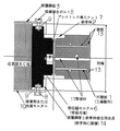
図1は、本発明の既存建物の耐震補強構造を示す正面図である。図2は、既存建物のRC造の柱における補強用部材とPC壁板(壁パネル)における鉄骨枠の接合状態および無収縮モルタルの充填状態を示す横断面図である。図3は、PC壁板(壁パネル)相互を接合するための一実施形態を示す横断面図である。図4は、本発明の既存建物の耐震補強構造の荷重・変形特性を、従来の既存建物の耐震補強構造のそれと比較して示すグラフである。
【0011】
図1乃至図3において、1はPC壁板(precast concrete panel)であって、鉄骨枠(この実施形態にあっては、図2および図3に示すように、H形鋼)2の枠組みの内側にRC造の壁パネルとして打設される。また、PC壁板1は、この実施形態においては、工場生産(プレハブ)される。
【0012】
PC壁板1には、壁筋13および高強度鉄筋11が配筋されている。
高強度鉄筋11の端部にはねじが刻設され、図2および図3に示すように、鉄骨枠2(H形鋼)のウェブ部に穿設された孔から突出し、プレストレス導入ナット7によって張力が付与されるよう構成されている。この実施形態においては、高強度鉄筋11および壁筋13は、図2および図3に示すように、PC壁板1の辺に平行に縦横に格子状に配筋されている。PC壁板相互接合用の高強度鉄筋11にはシースが被覆されている。この状態でコンクリートが打設され、PC壁板1(RC壁パネル)として工場生産(プレハブ)される。
【0013】
高強度鉄筋11および壁筋13は、PC壁板1内で傾斜して、たとえばPC壁板1の辺に対し45°の角度で相互に直交する格子状に配筋されてもよい。また、壁筋13のみが傾斜する格子状に、高強度鉄筋11はPC壁板1の辺に平行に縦横に格子状に配筋されてもよい。
【0014】
PC壁板1相互を接合するには、この実施形態においては、図1および図3に示すように、高強度鉄筋11の端部を互いに左右ねじとなるようにねじを刻設し、カプラ12たとえばターンバックルによって緊締し、プレストレス導入ナット7で高強度鉄筋11に所定の張力即ちPC壁板1内にプレストレス(圧縮応力)を付与する。然る後、無収縮モルタルを充填材6として図1乃至図3に示す部位に充填して耐震補強壁として仕上げる。無収縮モルタル6打設充填は、PC壁板1を施工現場にて既設RCフレーム内に建て込み、既存のRC造柱4の上下端部に予め配設・固着されている補強用部材3(被覆鋼板)と、PC壁板1における鉄骨枠2とを、鉄骨枠2に溶接されている接合部材14を介して接合ボルト8およびナット9によって締結した後になされる。
【0015】
このようにして構成される本発明の既存建物の耐震補強構造は、PC壁板1にプレストレスを導入しているから、耐震補強壁のせん断ひび割れに対する抵抗力を高めることができるとともに、万一ひび割れを生じた場合でも、耐震補強壁の膨張を小さく抑えることができ、耐震補強壁の膨張に起因する既存のRCフレームの損傷を防止することができる。
【0016】
補強用部材3、この実施形態においては被覆鋼板は、既存のRC造の柱4の少なくとも上下端部に配設・固着される。この実施形態においては、図2に示すように、鋼板を既存のRC造の柱4の断面にコ字状に嵌装し接着剤10或いは充填モルタル10を介して固着して形成される。この補強用部材3の配設・固着によって、RC造の柱4の上下端部のせん断耐力が格段に増強される。既存のRC造の柱4の上下端部の補強手段として、たとえば炭素繊維をRC造の柱4の上下端部に巻回する方法を採ることもできる。
【0017】
このように、本発明においては、既存のRC造の柱4の少なくとも上下端部に補強用部材3(被覆鋼板)が配設・固着されるので、地震等による水平力で耐震補強壁が対角線方向に変形し、既存のRC造の柱4の上下端部にせん断力が集中する場合も、この部分のせん断破壊を確実に防止できる。
【0018】
而して、既存のRCフレームの破壊が生じないので、増設耐震補強壁の水平せん断強度はPC壁板1のせん断強度によって決まり、PC壁板1の強度を高くすれば、増設耐震補強構造の水平せん断強度も高くすることができる。このことは、究極的には曲げ降伏強度まで増設耐震補強構造の水平せん断強度を上昇させ得ることを意味しており、従来の補強構造より確実に強度の高い耐震補強構造となる。
【0019】
5はRC造の梁であって、既存の建物におけるもので、RC造の柱4と相俟ってRCフレームを構成する。
【0020】
次に、本発明の既存建物の耐震補強構造の施工方法について説明する。先ず、PC壁板1を工場でプレハブする。この実施形態においては、壁筋13および高強度鉄筋11たとえばPC鋼棒を鉄骨枠2枠組みの内側で、PC壁板1の辺と平行になるように格子状に配筋する。
図2および図3に示すように、壁筋13をPC壁板1厚さ方向における表裏層側に、高強度鉄筋11を中央部になるようにして配筋する。その際、高強度鉄筋11の、ねじが刻設されている端部を、図2および図3に示すように、鉄骨枠2(H形鋼)のウェブ部に穿設されている孔を通して突出せしめ、プレストレス導入ナット7で締結する。
この状態で型枠を装着し、コンクリートを打設してPC壁板1を工場生産(プレハブ)する。
【0021】
一方、図2に示すように、既存建物のRC造の柱4の上下端部に、鋼板製の横断面コ字状の補強用部材3を嵌装し、接着剤10或いはモルタル10を介して固着する。こうして、既存のRC造の柱4の上下端部を補強し、せん断強度を高くする。
【0022】
次いで、既存のRC造の柱4および梁5からなるRCフレームにプレハブしたPC壁板1を建て込み、PC壁板1相互を、図3に示すように、相対向する端部において左右ねじが刻設されている高強度鉄筋11を、PC壁板1における鉄骨枠2(H形鋼)のウェブ部に穿設されている孔を通して突出せしめ、これにカプラ12(ターンバックル)を螺合させて、このカプラ12によってPC壁板1を締結しさらに、プレストレス導入ナット7によって縦横の高強度鉄筋11に所定のプレストレスを付与する。
【0023】
その後、PC壁板1における鉄骨枠2と、既存のRC造の柱4の少なくとも上下端部に配設・固着されている補強用部材3(被覆鋼板)とを、図2に示すように、鉄骨枠2に溶接・固着されている接合部材14を介して現場接合ボルト8およびナット9によって締結する。
【0024】
然る後、図1乃至図3に示すように、PC壁板1と既存のRC造の柱4および梁5との間ならびに相隣るPC壁板1の鉄骨枠2相互間に無収縮充填モルタルを打設、養生せしめて既存建物の耐震補強壁を完成させる。なお、PC壁板1を有開口壁パネルとすれば、有開口増設壁耐震補強が可能である。
【0025】
本発明の既存建物の耐震補強構造の荷重・変形特性を、従来の耐震補強構造のそれと比較して図4に模式的に示す。
図4において、曲線aは、既存の建物のままで耐震補強壁を増設しない場合の荷重・変形特性、曲線bは、従来技術によって耐震補強壁を増設したケースの荷重・変形特性であって、増設した耐震補強壁と既存のRC造柱および梁との接合部ならびに既存のRC造柱の上下端部にせん断破壊を生ずる場合の荷重・変形特性を示す。曲線cは、既存のRC造柱の上下端部を補強した場合の、増設耐震補強壁にせん断破壊を生ずる場合の荷重・変形特性を示す。
【0026】
曲線dは、本発明の、既存のRC造柱の上下端部を補強するとともに、増設耐震補強壁と既存のRCフレームの間をアンカーボルト等で結合することなく、PC壁板を既存のRCフレーム内に建て込み、既存のRC造柱の上下端部の補強用部材とPC壁板における鉄骨部材を締結しさらに、増設耐震補強壁に縦横にプレストレスを導入した耐震補強構造の荷重・変形特性を示す。耐震補強壁が曲げ降伏によって破壊されるまで変形が進行することを示している。
【0027】
図4から明らかなように、本発明の既存建物の耐震補強構造は、優れた荷重・変形特性を有している。
【0028】
【発明の効果】
本発明によれば、既存の建物におけるRC造の柱や梁(RCフレーム)にアンカーボルト突設用削孔等を全く行う必要がないから、RCフレームを損傷して強度を低下せしめることがないことならびに、既存のRC造の柱上下端部に鋼板等補強用部材による補強を施しているからこの部分のせん断破壊を確実に防止でき、高い荷重・変形特性をもつ耐震補強構造とすることができる。
【0029】
増設耐震補強壁には、縦横にプレストレスを導入しているから、地震等による水平せん断力が壁パネル(PC壁板)に作用しても、壁パネルの膨張に起因する既存のRC造の柱や梁(RCフレーム)を損傷せしめるなどしてその強度を低下させることがきわめて少ない。万一、壁パネルにひび割れを生じた場合も、ひび割れが目立たない。
【0030】
本発明における増設耐震補強壁用壁板(壁パネル)は工場で生産(プレハブ)できるから、良質な高強度コンクリート壁板とすることができる。こうして得られた壁パネルを施工現場で建て込み、壁パネル相互をカプラで接合し、壁パネルにおける鉄骨枠を、既存建物のRC造の柱の上下端部補強部に締結し、無収縮モルタルを充填するだけで施行できる。而して、耐震補強壁の増設に際して、騒音、振動、粉塵の発生がなくまた、施工が容易であり短期間で可能となる。
【図面の簡単な説明】
【図1】 本発明の既存建物の耐震補強構造を示す正面図
【図2】 本発明における既設RC造の柱の補強部と、PC壁板における鉄骨枠との接合状態を示す横断面図
【図3】 PC壁板相互の接合・締結状態を示す横断面図
【図4】 本発明の既存建物の耐震補強構造の荷重・変形特性を、従来の技術によるものと対比して示すグラフ
【符号の説明】
1 PC壁板
2 鉄骨枠
3 補強用部材(被覆鋼板)
4 既設RC造柱
5 既設RC造梁
6 充填材(無収縮モルタル)
7 プレストレス導入ナット
8 現場接合ボルト
9 ナット
10 接着剤または充填モルタル
11 高強度鉄筋
12 カプラ
13 壁筋
14 接合部材[0001]
BACKGROUND OF THE INVENTION
The present invention relates to a seismic reinforcement structure for an existing building having an RC frame made of RC (reinforced concrete) columns and beams, and a construction method thereof.
[0002]
[Prior art]
Conventionally, when retrofitting an existing RC or SRC structure, a method of constructing a seismic wall made of post-cast concrete in an RC frame (frame) composed of RC columns and beams has been adopted. Has been.
At that time, in order to increase the rigidity as the structure of the part where the earthquake-resistant wall was added and to secure the earthquake resistance, anchor reinforcements were buried in the four circumferences of the additional earthquake-proof reinforcement wall facing the RC frame, respectively. The seismic reinforcement wall is integrated with the RC frame.
[0003]
[Problems to be solved by the invention]
In the conventional seismic reinforcement structure of the existing building, it is an important point to integrally join the existing RC frame made of RC columns and beams and the seismic wall by the back-up. Therefore, many anchor bolts are projected inside the RC frame consisting of existing RC columns and beams, but there is noise, vibration, dust generation, etc. when drilling the anchor bolt holes. There was a problem that could not be. When drilling an anchor bolt hole, if it interferes with the existing RC column or beam main bar or shear reinforcement bar, not only the anchor bolt hole needs to be drilled, but also the anchor bolt hole There is a problem that the existing pillars and beams are damaged by drilling and the strength is lowered, especially when the strength is lowered in the column supporting the vertical load, which causes a risk of falling.
[0004]
The present invention solves the above-described problems in the prior art, and in constructing a seismic reinforcement wall inside an RC frame made of existing RC columns and beams, the inside of the RC frame made of existing RC columns and beams. There is no need to project anchor bolts, and therefore there is no generation of noise, vibration and dust associated with drilling anchor bolt holes, and there is no reduction in strength of existing RC columns and beams, An object of the present invention is to provide a seismic reinforcement structure for an existing building that can be easily and quickly constructed and a construction method thereof.
[0005]
[Means for Solving the Problems]
In order to solve the above-mentioned problem, the invention according to
[0006]
The invention according to
[0007]
The invention according to
[0008]
According to a fourth aspect of the present invention, the reinforcing member disposed and fixed on at least the upper and lower ends of the RC column of the existing building is a steel plate, and the wall bars and the prestress introduction reinforcing bars in the PC wall board are vertical. The existing reinforcement according to
[0009]
DETAILED DESCRIPTION OF THE INVENTION
Hereinafter, the present invention will be described according to preferred embodiments thereof.
[0010]
FIG. 1 is a front view showing a seismic reinforcement structure for an existing building according to the present invention. FIG. 2 is a cross-sectional view showing a joining state of a steel frame in a reinforcing member and a PC wall plate (wall panel) in an RC column of an existing building and a filling state of non-shrink mortar. FIG. 3 is a cross-sectional view showing an embodiment for joining PC wall plates (wall panels) to each other. FIG. 4 is a graph showing the load / deformation characteristics of the seismic reinforcement structure of an existing building according to the present invention in comparison with that of a conventional seismic reinforcement structure of an existing building.
[0011]
1 to 3,
[0012]
As shown in FIG. 2 and FIG. 3, a screw is engraved at the end of the high-
[0013]
The high-
[0014]
In order to join the
[0015]
Since the seismic reinforcement structure of the existing building of the present invention configured as described above introduces pre-stress to the
[0016]
The reinforcing
[0017]
In this way, in the present invention, the reinforcing members 3 (covered steel plates) are disposed and fixed on at least the upper and lower ends of the existing
[0018]
Thus, since the existing RC frame does not break, the horizontal shear strength of the additional seismic reinforcement wall is determined by the shear strength of the
[0019]
[0020]
Next, the construction method of the seismic reinforcement structure of the existing building of this invention is demonstrated. First, the
As shown in FIGS. 2 and 3, the
In this state, the formwork is mounted, concrete is placed, and the
[0021]
On the other hand, as shown in FIG. 2, reinforcing
[0022]
Next, the prefabricated
[0023]
After that, as shown in FIG. 2, the
[0024]
Thereafter, as shown in FIG. 1 to FIG. 3, there is no shrinkage filling between the
[0025]
FIG. 4 schematically shows the load / deformation characteristics of the seismic reinforcement structure of the existing building of the present invention in comparison with that of the conventional seismic reinforcement structure.
In FIG. 4, a curve a is a load / deformation characteristic when an earthquake-proof reinforcement wall is not added in an existing building, and a curve b is a load / deformation characteristic of a case where an earthquake-proof reinforcement wall is added according to the prior art. The load / deformation characteristics when shear failure occurs at the joint between the expanded seismic reinforcement wall and the existing RC column and beam and at the upper and lower ends of the existing RC column are shown. Curve c shows the load / deformation characteristics when shear failure occurs in the additional seismic reinforcement wall when the upper and lower ends of the existing RC column are reinforced.
[0026]
The curve d reinforces the upper and lower ends of the existing RC column of the present invention, and connects the PC wall plate to the existing RC without connecting the additional seismic reinforcing wall and the existing RC frame with an anchor bolt or the like. Load and deformation of the seismic reinforcement structure built in the frame, fastening the reinforcing members at the upper and lower ends of the existing RC pillars and the steel frame members of the PC wall plate, and introducing prestress vertically and horizontally to the additional seismic reinforcement wall Show the characteristics. It shows that deformation progresses until the seismic reinforcement wall is destroyed by bending yielding.
[0027]
As is clear from FIG. 4, the seismic reinforcement structure for an existing building of the present invention has excellent load / deformation characteristics.
[0028]
【The invention's effect】
According to the present invention, there is no need to drill anchor bolts or the like in RC pillars or beams (RC frame) in an existing building, so the RC frame is not damaged and the strength is not lowered. In addition, since the existing RC pillars are reinforced with reinforcing members such as steel plates, it is possible to reliably prevent shear failure of this part, and to make an earthquake-proof reinforcement structure with high load / deformation characteristics. it can.
[0029]
Since the prestress is introduced into the expanded seismic reinforcement wall in the vertical and horizontal directions, even if horizontal shearing force due to earthquakes acts on the wall panel (PC wallboard), the existing RC structure is caused by the expansion of the wall panel. It is extremely rare to reduce the strength by damaging the pillars and beams (RC frame). In the unlikely event that a wall panel is cracked, the crack is not noticeable.
[0030]
Since the wall plate (wall panel) for expansion seismic reinforcement wall in the present invention can be produced (prefabricated) at the factory, it can be a high-quality high-strength concrete wall plate. The wall panels obtained in this way are built at the construction site, the wall panels are joined together with couplers, the steel frame on the wall panels is fastened to the upper and lower ends of the RC columns of the existing building, and the non-shrink mortar is attached. It can be implemented simply by filling. Thus, when the seismic reinforcement wall is added, noise, vibration and dust are not generated, and the construction is easy and can be performed in a short period of time.
[Brief description of the drawings]
FIG. 1 is a front view showing a seismic reinforcement structure of an existing building according to the present invention. FIG. 2 is a cross-sectional view showing a joining state of a reinforcing portion of an existing RC column in the present invention and a steel frame in a PC wall plate. [Fig. 3] Cross-sectional view showing the state of joining and fastening between PC wall plates [Fig. 4] Graph showing the load / deformation characteristics of the seismic reinforcement structure of an existing building according to the present invention in comparison with the conventional technology Explanation of]
1
4 Existing
7
Claims (4)
Priority Applications (1)
| Application Number | Priority Date | Filing Date | Title |
|---|---|---|---|
| JP2001362457A JP3909488B2 (en) | 2001-11-28 | 2001-11-28 | Seismic reinforcement structure of existing building and its construction method |
Applications Claiming Priority (1)
| Application Number | Priority Date | Filing Date | Title |
|---|---|---|---|
| JP2001362457A JP3909488B2 (en) | 2001-11-28 | 2001-11-28 | Seismic reinforcement structure of existing building and its construction method |
Publications (2)
| Publication Number | Publication Date |
|---|---|
| JP2003161041A JP2003161041A (en) | 2003-06-06 |
| JP3909488B2 true JP3909488B2 (en) | 2007-04-25 |
Family
ID=19172952
Family Applications (1)
| Application Number | Title | Priority Date | Filing Date |
|---|---|---|---|
| JP2001362457A Expired - Fee Related JP3909488B2 (en) | 2001-11-28 | 2001-11-28 | Seismic reinforcement structure of existing building and its construction method |
Country Status (1)
| Country | Link |
|---|---|
| JP (1) | JP3909488B2 (en) |
Families Citing this family (4)
| Publication number | Priority date | Publication date | Assignee | Title |
|---|---|---|---|---|
| CN103669651B (en) * | 2013-12-26 | 2017-01-11 | 北京工业大学 | Infilled wall with build-in cross steel bars and manufacturing method of infilled wall |
| KR102321433B1 (en) * | 2021-07-01 | 2021-11-05 | (주)에이엠에스 엔지니어링 | Seismic Reinforcement Structure Of Being Mounted On Exterior |
| KR102365116B1 (en) * | 2021-07-30 | 2022-02-23 | (주)에이엠에스 엔지니어링 | Seismic Reinforcement Construction Method And Structure Of Masonry Wall |
| CN115045418B (en) * | 2022-07-19 | 2024-08-09 | 西安建筑科技大学 | Embedded self-resetting energy dissipation RC frame structure swinging wall and assembly method thereof |
-
2001
- 2001-11-28 JP JP2001362457A patent/JP3909488B2/en not_active Expired - Fee Related
Also Published As
| Publication number | Publication date |
|---|---|
| JP2003161041A (en) | 2003-06-06 |
Similar Documents
| Publication | Publication Date | Title |
|---|---|---|
| US20100325998A1 (en) | Masonry with vertical reinforced concrete strengthening | |
| JP2000144905A (en) | Mixed structural beam | |
| JP4942475B2 (en) | Reinforcement method and structure of existing columns | |
| KR102110559B1 (en) | Wall structure for reinforcing joint capability and construction method therefor | |
| JP2008266910A (en) | Projection structure of anchorage or deviator of tendon, and construction method therefor | |
| JP3909488B2 (en) | Seismic reinforcement structure of existing building and its construction method | |
| KR102398605B1 (en) | Construction method of seismic retrofit system using pc panel | |
| JP3999591B2 (en) | Seismic control structure of concrete structure with fiber reinforced cementitious material | |
| JP2927402B2 (en) | Column-beam joint structure of concrete building | |
| JP3384785B2 (en) | Construction method of damping wall | |
| JP3851563B2 (en) | Frame reinforcement structure and its construction method | |
| JP4660810B2 (en) | Boundary beam damper | |
| JP3116767B2 (en) | Existing building seismic isolation structuring method | |
| JP7538063B2 (en) | Wooden members | |
| JP4045502B2 (en) | Structure | |
| JPH11152908A (en) | Earthquake resistant reinforcing structure for existing building, and its method | |
| KR102440307B1 (en) | Seismic retrofit structure of masonry buildings | |
| JP3830062B2 (en) | Seismic reinforcement method for reinforced concrete buildings | |
| JP3942973B2 (en) | Seismic control structure of concrete structure with fiber reinforced cementitious material | |
| JPS5920492Y2 (en) | PC version strength fixing structure | |
| JP3519331B2 (en) | Joint structure between bundle columns and beams of seismic retrofit unit | |
| JP4658826B2 (en) | SC wall block, SC wall block manufacturing method, and SC structure construction method | |
| JP3700129B2 (en) | Joint structure of composite structure and construction method thereof | |
| JPS62264230A (en) | Construction of body of multistairs building | |
| JP2540314B2 (en) | Steel rebar concrete columns and beams |
Legal Events
| Date | Code | Title | Description |
|---|---|---|---|
| A621 | Written request for application examination |
Free format text: JAPANESE INTERMEDIATE CODE: A621 Effective date: 20041126 |
|
| A977 | Report on retrieval |
Free format text: JAPANESE INTERMEDIATE CODE: A971007 Effective date: 20060908 |
|
| A131 | Notification of reasons for refusal |
Free format text: JAPANESE INTERMEDIATE CODE: A131 Effective date: 20060919 |
|
| A521 | Written amendment |
Free format text: JAPANESE INTERMEDIATE CODE: A523 Effective date: 20061108 |
|
| TRDD | Decision of grant or rejection written | ||
| A01 | Written decision to grant a patent or to grant a registration (utility model) |
Free format text: JAPANESE INTERMEDIATE CODE: A01 Effective date: 20070110 |
|
| A61 | First payment of annual fees (during grant procedure) |
Free format text: JAPANESE INTERMEDIATE CODE: A61 Effective date: 20070115 |
|
| R150 | Certificate of patent or registration of utility model |
Free format text: JAPANESE INTERMEDIATE CODE: R150 |
|
| FPAY | Renewal fee payment (event date is renewal date of database) |
Free format text: PAYMENT UNTIL: 20110202 Year of fee payment: 4 |
|
| FPAY | Renewal fee payment (event date is renewal date of database) |
Free format text: PAYMENT UNTIL: 20120202 Year of fee payment: 5 |
|
| FPAY | Renewal fee payment (event date is renewal date of database) |
Free format text: PAYMENT UNTIL: 20130202 Year of fee payment: 6 |
|
| S533 | Written request for registration of change of name |
Free format text: JAPANESE INTERMEDIATE CODE: R313533 |
|
| FPAY | Renewal fee payment (event date is renewal date of database) |
Free format text: PAYMENT UNTIL: 20130202 Year of fee payment: 6 |
|
| R350 | Written notification of registration of transfer |
Free format text: JAPANESE INTERMEDIATE CODE: R350 |
|
| LAPS | Cancellation because of no payment of annual fees |