JP5602455B2 - Beam members and building structures - Google Patents
Beam members and building structures Download PDFInfo
- Publication number
- JP5602455B2 JP5602455B2 JP2010038485A JP2010038485A JP5602455B2 JP 5602455 B2 JP5602455 B2 JP 5602455B2 JP 2010038485 A JP2010038485 A JP 2010038485A JP 2010038485 A JP2010038485 A JP 2010038485A JP 5602455 B2 JP5602455 B2 JP 5602455B2
- Authority
- JP
- Japan
- Prior art keywords
- panel
- column
- prestress
- section
- beam member
- Prior art date
- Legal status (The legal status is an assumption and is not a legal conclusion. Google has not performed a legal analysis and makes no representation as to the accuracy of the status listed.)
- Expired - Fee Related
Links
Images


Description
本発明は、梁部材および建物構造体に関する。 The present invention relates to a beam member and a building structure.
柱梁架構を構築する際に、プレキャスト製の梁部材を利用する場合がある。
プレキャスト製の梁部材を利用した柱梁架構の構築は、梁部材を支保工などの仮設部材で支持した状態で、梁部材と柱部材との接合部であるパネル部を現場打ちコンクリートにより構築し、柱と梁との一体化を行うのが一般的である。
When building a column beam frame, a precast beam member may be used.
The construction of a column beam frame using precast beam members is done by constructing the panel part, which is a joint between the beam member and the column member, with cast-in-place concrete while the beam member is supported by a temporary member such as a support work. In general, the column and the beam are integrated.
ところが、梁部材を支持するための支保工の設置や撤去にかかる手間が早期施工の妨げとなることや、多数の支保工の材料費によりコストが高価となる場合があった。 However, the labor for installing and removing the support for supporting the beam member may hinder early construction, and the cost may be high due to the material costs of many support works.
そのため、特許文献1には、支保工を配置することなくプレキャスト梁を利用した柱梁架構を形成することを可能とした、柱梁架構構造が開示されている。
Therefore,
かかる柱梁架構構造は、梁部材の端部を、隣接する他の梁部材と突き合わせた状態で柱の上面に載置することにより構成されている。
この構造では、柱の上端部には梁と連結するための差し筋受け入れ部が予め形成されており、梁同士の突合せ部を貫通するように差し筋を挿通して差し筋受け入れ部に定着させることで、当該柱と2本の梁部材とが一体に連結されている。梁部材の両端部は、柱によって支持されているため、梁部材を支持するための支保工を省略し、支保工の設置や撤去に要する手間を省くことが可能となる。
Such a column beam frame structure is configured by placing the end portion of the beam member on the upper surface of the column in a state of abutting against another adjacent beam member.
In this structure, a reinforcing bar receiving portion for connecting to the beam is formed in advance at the upper end portion of the column, and the reinforcing bar is inserted through the butting portion between the beams and fixed to the reinforcing bar receiving portion. Thus, the pillar and the two beam members are integrally connected. Since both ends of the beam member are supported by columns, it is possible to omit a support work for supporting the beam member, and to save time and labor required for installing and removing the support work.
前記従来の柱梁架構構造では、柱の上面において2本の梁部材が突き合わされているため、梁部材と柱との接地面積が限られている。そのため、梁のスパンが長く、梁の重量が大きくなると、梁部材同士の突き合せ部における固定が不安定となる場合があった。
また、梁部材と柱部材とが交差するパネル部では、梁部材同士を突き合わせた接合部(乾式の打継ぎ部またはモルタルが介在する打継ぎ部)が存在するため、地震時に梁から大きな曲げやせん断力がパネル部に作用した時に、接合部がずれて剛性が低下したり、パネル部の耐力が低下するおそれがある。
さらに、分断されたパネル部のフープ筋同士を接合するとしてもその作業に手間を要していた。また、直交方向から他の梁が取付く場合には、直交する梁主筋の継手と交錯するため、その配筋作業は困難を極めていた。ところが、これらの問題についての検討は特許文献1ではなされていなかった。
In the conventional column beam frame structure, since two beam members are abutted on the upper surface of the column, the ground contact area between the beam member and the column is limited. For this reason, when the span of the beam is long and the weight of the beam is increased, there is a case where the fixation at the butt portion between the beam members becomes unstable.
In addition, in the panel part where the beam member and the column member intersect, there is a joint part (dry joint part or joint part where mortar is interposed) where the beam members are butted together. When a shearing force acts on the panel portion, the joint portion may be displaced to reduce the rigidity, or the proof stress of the panel portion may be reduced.
Furthermore, even if the hoop muscles of the divided panel portions are joined together, it takes time and labor for the work. Further, when another beam is attached from the orthogonal direction, it is difficult to perform the bar arrangement work because it intersects with the joint of the orthogonal beam main bars. However, these problems have not been studied in
本発明は、効率よくかつ安全に柱梁架構を構築することを可能とするプレキャスト製の梁部材と、この梁部材を備える建物構造体を提供することを課題とする。 An object of the present invention is to provide a precast beam member capable of efficiently and safely constructing a column beam frame, and a building structure including the beam member.
このような課題を解決する本発明の梁部材は、内法スパンに相当する梁部と、前記梁部の両端に形成されて柱の上面に載置されるパネル部と、が一体に形成されたプレキャスト製の梁部材であって、前記パネル部は、前記柱と同等の平断面形状に成形されており、前記パネル部の上面に他の柱が立設されていて、一方の前記パネル部から他方の前記パネル部に至る緊張材を備えており、前記梁部の端部と前記パネル部にプレストレスが導入されていないアンボンド区間が設けられているとともに、梁部の前記端部以外にプレストレスが導入されたプレストレス区間が設けられており、前記アンボンド区間の前記緊張材の周囲にシース管が設けられており、前記シース管と前記緊張材とが、プレストレス区間へのプレストレス導入後に前記シース管と前記緊張材との隙間に充填された充填材により固定されていることを特徴としている。
この梁部材のパネル部には、柱の主筋の位置に対応して鉄筋挿通孔が形成されていてもよいし、柱の主筋の位置に対応して縦筋が配筋されていてもよい。
ここで、「柱と同等の平断面形状」とは、柱の平断面形状と完全に一致する場合に限定されない。例えば、柱の主筋の全てを挿通し得る形状であれば、柱の平断面形状を相違する場合であっても「柱と同等の平断面形状」に含むものとする。
In the beam member of the present invention that solves such a problem, a beam portion corresponding to an internal span and a panel portion that is formed at both ends of the beam portion and placed on the upper surface of the column are integrally formed. A precast beam member, wherein the panel part is formed in a flat cross-sectional shape equivalent to the pillar, and another pillar is erected on the upper surface of the panel part , and one of the panel parts A tension member extending from the first to the other panel portion, and provided with an unbonded section where no prestress is introduced into the end portion of the beam portion and the panel portion, and other than the end portion of the beam portion. A prestress section into which prestress is introduced is provided, a sheath pipe is provided around the tendon in the unbond section, and the sheath pipe and the tendon are prestressed into the prestress section. After introduction It is characterized in that it is fixed by the filling material filled in the gap between the the tube tendon.
In the panel portion of the beam member, reinforcing bar insertion holes may be formed corresponding to the positions of the main bars of the columns, or vertical bars may be arranged corresponding to the positions of the main bars of the columns.
Here, the “flat cross-sectional shape equivalent to a column” is not limited to the case where it completely matches the flat cross-sectional shape of the column. For example, if it is a shape which can insert all the main bars of a pillar, even if it is a case where the plane cross-sectional shape of a pillar differs, it shall be included in "the cross-sectional shape equivalent to a pillar."
かかる梁部材によれば、梁部とパネル部とが一体に形成されているため、柱の上端にパネル部を載置するのみで梁部が支持される。このため、効率よく安全に柱梁架構を構築することが可能となる。また、パネル部は、柱と同等の平断面形状に形成されているため、柱上に安定して載置できる。また、パネル部内には、梁部材同士の接合部が存在しないため、地震時等においても十分な剛性や強度を確保できる。 According to such a beam member, since the beam portion and the panel portion are integrally formed, the beam portion is supported only by placing the panel portion on the upper end of the column. For this reason, it becomes possible to construct a column beam frame efficiently and safely. Moreover, since the panel part is formed in the flat cross-sectional shape equivalent to a pillar, it can be stably mounted on a pillar. Further, since there is no joint between the beam members in the panel portion, sufficient rigidity and strength can be ensured even during an earthquake.
また、前記梁部の端部と前記パネル部にアンボンド区間を設けているため、この部位におけるコンクリートへの負荷を軽減させることができる。 Further, since the provided end and unbonded zone in the panel portion of the beam portion can Rukoto and reduce the load on the concrete at this site.
また、前記アンボンド区間のスパン中央側に隣接する部位は、緊張材を中心としてコンクリートを放射状に押し広げる力が作用して付着割裂破壊を起こす可能性がある部位であるため、当該部位に対して、前記緊張材を囲むスパイラル筋を配筋することにより、この部位におけるコンクリートの割裂強度を高めてもよい。 In addition, the portion adjacent to the center side of the span of the unbonded section is a portion that may cause adhesion split fracture due to the force that spreads the concrete radially around the tension material, The splitting strength of the concrete at this part may be increased by arranging a spiral line surrounding the tendon.
なお、前記梁部材を利用して構築された建物構造体おいて、隣り合う梁部材同士の間に、現場打ちコンクリートにより構築された中間梁を形成することで、連続した梁を構築することが可能となり、大規模な建物の構築が可能となる。 In addition, in a building structure constructed using the beam members, it is possible to construct a continuous beam by forming an intermediate beam constructed of cast-in-place concrete between adjacent beam members. It becomes possible and construction of a large-scale building becomes possible.
本発明の梁部材および建物構造体によれば、柱梁架構を効率よくかつ安全に柱梁架構を構築することが可能となる。 According to the beam member and the building structure of the present invention, it is possible to construct the column beam frame efficiently and safely.
第一の実施の形態(参考実施形態)に係る建物構造体Sは、図1に示すように、複数本の柱1,1,…と隣り合う柱1,1,…上に横架された梁2とにより構成されている。
As shown in FIG. 1, the building structure S according to the first embodiment (reference embodiment) is horizontally mounted on the
なお、建物構造体Sを構成する柱1および梁2の数は限定されるものではなく、構築される建物の規模に応じて適宜設定すればよい。
In addition, the number of the
本実施形態の梁2は、梁部材3を使用して形成するプレキャスト区間A,Aと、現場打ち施工により中間梁4を形成する現場打ち区間Bとを備えるものとする。
The
梁部材3は、図1に示すように、隣り合う柱1,1に架設されており、内法スパンに相当する梁部31と、梁部31の両端に形成されて柱1の上面に載置されるパネル部32,32と、が一体に形成された部材である。
As shown in FIG. 1, the
本実施形態では、図2(a)および(b)に示すように、梁部31の下部に緊張材33が配筋されている。緊張材33は、パネル部32,32まで通し配筋されている。本実施形態では緊張材33としてPC鋼より線や異形鉄筋を使用するが、緊張材33を構成する材料は限定されるものではない。また、緊張材33の配筋は、下部に限定されない。
In the present embodiment, as shown in FIGS. 2A and 2B, a
プレキャスト区間Aの梁2は、図2(a)および(c)に示すように、プレキャスト部材である梁部31の上面に現場打ちコンクリートを打設することにより形成されている。
As shown in FIGS. 2A and 2C, the
梁部31の上面に打設された現場打ちコンクリート部分31aは、図2(c)に示すように、スラブ5と一体にコンクリートを打設することで形成されている。これにより、梁2とスラブ5との一体化がなされている。
The cast-in-
緊張材33には緊張力が付与されている。なお、緊張材33に付与される緊張力はプレテンションであってもよいし、ポストテンションであってもよい。
緊張材33の端部の周囲には、図2(a)および(b)に示すように、スパイラル筋34が配設されている。なお、スパイラル筋34は必要に応じて配設すればよく、省略してもよい。
As shown in FIGS. 2A and 2B, a
パネル部32は、図2(a)に示すように、柱1の上面へ載置される部分である。
パネル部32は、図2(a)および(b)に示すように、柱1と同等の平断面形状に成形されているとともに、梁2の梁せいと同等の高さを有して形成されている。
パネル部32の上面には、上層階の柱1が立設される。
The
As shown in FIGS. 2A and 2B, the
On the upper surface of the
本実施形態では、柱1の柱主筋11,11,…の位置に対応して鉄筋挿通孔35,35,…がパネル部32に形成されており、下方の柱1の上面から突出する柱主筋11,11,…を当該鉄筋挿通孔35,35,…に挿通させた状態で、パネル部32を柱1の上面に配置する。
In this embodiment, the reinforcing bar insertion holes 35, 35,... Are formed in the
柱主筋11を挿通した状態で、鉄筋挿通孔35に充填材が充填されることで、パネル部32と柱1との一体化が行われている。
The
柱主筋11は、パネル部32を貫通して、上方の柱1に挿入されている。下階の柱1の柱主筋11を上階の柱1まで連続させた状態で配筋することで、上下の柱1,1同士の一体化が実現されている。
The column
図2(a)に示すように、パネル部32の上部には、L字状の上端筋36が配筋されている。上端筋36は、一方の端部が梁部31側に突出しており、現場打ちコンクリート部分31aの施工時に、梁2の上端筋37と、継手部材38を介して連結される。
パネル部32と現場打ちコンクリート部分31aは、上端筋36,37を介して一体化がなされている。
As shown in FIG. 2A, an L-shaped
The
中間梁4は、図1に示すように、左右のプレキャスト区間A,Aに挟まれた現場打ち区間Bにおいて、現場打ちコンクリートにより形成される。
As shown in FIG. 1, the
中間梁4は、両端がそれぞれ隣接する梁部材3のパネル部32の側面に接続するように形成されている。
中間梁4と梁部材3との接続方法は限定されるものではなく、例えば、梁部材3のパネル部32から突出する鉄筋を連結・延長して中間梁4を構築したり、パネル部32にアンカー等の接続部材を設置した状態で中間梁4を構築するなど、適宜行えばよい。
The
The method of connecting the
中間梁4の施工は、図1に示すように、吊り型枠41を利用して構築する。吊り型枠41は、隣り合う梁部材3,3のパネル部32,32に架設された吊り型枠用治具42を利用して現場打ち区間Bに配置される。
なお、中間梁4の施工方法は限定されるものではなく、適宜行えばよい。
The construction of the
In addition, the construction method of the
本実施形態の建物構造体Sは、梁2の架設を行う際に、区間Aの支保工が不要になるので、施工性に優れている。そのため、効率よくかつ安全に柱梁架構を構築することが可能となる。
The building structure S of the present embodiment is excellent in workability because the support work in the section A is not required when the
また、梁部材3は、簡易に柱1への固定を行うことが可能なため、施工時に梁2を支持するために必要となる支保工を省略あるいは少数化することが可能となり、大幅なコストダウンおよび工期短縮が可能となる。
In addition, since the
また、パネル部32を全体としてプレキャスト化することにより、柱梁接合部について安定した品質と剛性や強度を確保することが可能となる。
また、梁部材3は、予めパネル部32が一体に形成されているため、大スパンにも対応することが可能である。また、緊張材33があらかじめ配設されていることにより、柱梁架構の構築時に、梁せいの低いプレキャスト梁(梁部31)の端部に大きなせん断力が生じても、これを安全に柱1に伝達し得る優れた耐力を有している。
Further, by precasting the
Moreover, since the
また、梁部材3の緊張材33の付着割裂破壊が生じやすい両端部の周囲には、スパイラル筋34が配設されているため、付着割裂破壊および緊張力導入時(緊張材開放時)のはだ圧による割裂を両端から拘束するとともに、緊張材33の端部における緊張材33を中心として放射状に押し広げる力が拘束されている。
In addition, since
また、隣り合う梁部材3,3同士の間に中間梁4を構築することで、連続した梁2を形成し、大規模な建物構造体Sを構築することを可能としている。
Further, by constructing the
第二の実施の形態の梁部材3も、隣り合う柱1,1に架設されており、内法スパンに相当する梁部31と、梁部31の両端に形成されて柱1の上面に載置されるパネル部32,32と、が一体に形成された部材である(図1参照)。
The
梁部材3には、図3(a)および(b)に示すように、梁部31の下部に緊張材33が配筋されている。緊張材33は、一方のパネル部32から他方のパネル部32まで通し配筋されている。本実施形態では緊張材33として異形鉄筋を使用するが、緊張材33を構成する材料は限定されるものではない。また、緊張材33の配筋は、梁部31の下部に限定されない。なお、緊張材33には、プレテンション方式により緊張力が付与されている。
As shown in FIGS. 3A and 3B, a
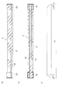
梁部材3には、プレストレス区間A1とアンボンド区間A2,A2とが形成されている。本実施形態では、梁部31の端部とパネル部32をアンボンド区間A2としている。アンボンド区間A2には、緊張材33の周囲にシース管39が配設されている。シース管39と緊張材33との間の空間には、充填材(グラウト材等)が充填されている。
The
プレストレス区間A1とアンボンド区間A2との境界部分には、定着金物33aが配置されている。定着金物33aは、緊張材33に固定されている。
また、プレストレス区間A1の両端部(アンボンド区間A2のスパン中央側の端部に隣接する部位)には、緊張材33を囲むスパイラル筋34が配筋されている。
A fixing
Further,
この他、第二の実施の形態に係る梁部材3の構成は、第一の実施の形態で示した梁部材3の構成と同様なため、詳細な説明は省略する。
In addition, since the configuration of the
梁部材3の構築は、工場や作業ヤードにて行う。具体的には、まず、図示しない型枠に緊張材33を配筋し、緊張力を導入する(図4(a)および(b)参照)。このとき、緊張材33の両端部には、アンボンド区間A2の位置に対応してシース管39を配設する。また、シース管39のスパン中央側(プレストレス区間A1側)の端部には、定着金物33aを配設し、定着金物33aのスパン中央側にはスパイラル筋34を配設する。
The
次に、型枠内にコンクリートを打設し、コンクリート硬化後に、緊張材33端部の拘束を解除する。これにより、シース管39が配置されていないプレストレス区間A1にプレテンション方式によるプレストレスが導入される。
Next, concrete is placed in the mold, and after the concrete is hardened, the end of the
プレストレス区間A1へのプレストレス導入後、シース管39内に充填材を充填する。さらに、緊張材33の先端に定着金物33aを固定するとともに、この定着金物33aの周囲にモルタルを充填する。
After the prestress is introduced into the prestress section A1, the
以上、第二の実施の形態の梁部材3によれば、梁部31の端部とパネル部32にアンボンド区間を備えているため、図3(c)に示すように、プレストレス区間A1のみに、プレストレスを導入し、たわみの大きい梁の中央域に十分な耐力をもたせることができる。
As described above, according to the
本実施形態では、地震荷重を受けた際に、ひび割れが発生しやすい梁部31の両端部(梁部31とパネル部32との接合部)をアンボンド区間A2とし、RC造(鉄筋コンクリート造)に近い応力状態としている。アンボンド区間にひび割れが生じた場合であっても、プレストレス区間A1における定着金物33aとコンクリートとの付着には影響がおよび難いので、大地震の前後でプレストレスの大きさに差が生じにくい。
In this embodiment, when receiving an earthquake load, both ends of the beam portion 31 (joint portion between the
また、シース管39のスパン中央側(プレストレス区間A1の両端部)の定着域A1’には、スパイラル筋34が配筋されているため、付着割裂破壊および緊張力導入時(緊張材開放時)のはだ圧による割裂を両端から拘束するとともに、プレストレス区間A1の端部における緊張材33を中心として放射状に押し広げる力が拘束されている。
In addition, since the
また、プレストレス区間A1の両端には、定着金物33aが配設されているため、より効果的にプレストレスを導入することができる。
In addition, since the fixing
この他の第二の実施の形態の梁部材3の効果は、第一の実施の形態の梁部材3と同様なため、詳細な説明は省略する。
Since the effects of the
梁部材3を利用した建物構造体Sの左右のプレキャスト区間A,Aに挟まれた現場打ち区間Bにおいて、現場打ちコンクリートにより中間梁4を形成する場合は、中間梁4の両端がそれぞれ隣接する梁部材3のパネル部32の側面に接続するように形成する(図1参照)。
When the
中間梁4と梁部材3との接続方法は限定されるものではないが、本実施形態では、図5に示すように、梁部材3のパネル部32から突出する緊張材33および鉄筋37に、継手部材38(機械式継手)を介して中間梁4の鉄筋41,41を連結することで、一体化に構築する。
Although the connection method of the
この他、中間梁4に関する事項は、第一の実施の形態で示した内容と同様なため、詳細な説明は省略する。
In addition, since the matters regarding the
以上、本発明について、好適な実施形態について説明した。しかし、本発明は、前述の各実施形態に限られず、前記の各構成要素については、本発明の趣旨を逸脱しない範囲で、適宜変更が可能であることはいうまでもない。
例えば、柱1は、プレキャスト部材により構築してもよいし、現場施工により構築してもよい。
The preferred embodiments of the present invention have been described above. However, the present invention is not limited to the above-described embodiments, and it goes without saying that the above-described constituent elements can be appropriately changed without departing from the spirit of the present invention.
For example, the
また、パネル部32の構成は限定されるものではなく、例えば、柱1の柱主筋11の位置に予め縦筋をパネル部32を貫通させた状態で配筋しておき、当該縦筋を上下の柱1の端部に挿入させた状態で、柱主筋11と連続させるものとしてもよい。
Moreover, the structure of the
また、前記実施形態では、梁部材3をハーフプレキャスト部材により構成する場合について説明したが、梁部材3はフルプレキャスト部材であってもよい。
Moreover, although the said embodiment demonstrated the case where the
また、前記各実施形態では、プレストレスが導入された区間の両端部に、緊張材33の周囲にスパイラル筋34を配筋する場合について説明したが、柱梁架構が地下に配設されている場合など、地震力などによる梁部31の端部の損傷が少ない場合には、図6に示すように、梁部31およびパネル部32の全体にプレストレスを導入し、さらに、スパイラル筋34などの補強部材を省略してもよい。
定着域A1’となるパネル部32はボリュームが大きいため、緊張材33に対する被り厚さを大きく取れるため、付着割裂補強用のアンボンド処理やスパイラル筋34を省略できる。
Moreover, although each said embodiment demonstrated the case where the
Since the
また、前記実施形態では、順梁タイプにより構成された建物構造体Sについて説明したが、図7(a)および(b)に示すように、逆梁タイプであってもよい。この場合においてスラブ5は、スラブ5の下面と梁部材3の下面とが面一となるように形成する。つまり、スラブ型枠51を梁部材3の下面に合わせて配置した状態で、スラブ5の配筋およびコンクリート打設を行う。
Moreover, although the building structure S comprised by the forward beam type was demonstrated in the said embodiment, as shown to Fig.7 (a) and (b), a reverse beam type may be sufficient. In this case, the
また、前記実施形態では、梁部材3の下部に緊張材33を配置する場合について説明したが、梁スパンが短い場合には、梁部材3の下部にプレストレスを付与しなくてもよい。
また、中間梁4は建物の規模や施工手順等に応じて形成すればよく、省略してもよい。
In the above-described embodiment, the case where the
The
また、前記実施形態では、2本の柱1,1に梁部材3を横架させる場合について説明したが、1つの梁部材3が3本以上の柱1上に載置されていてもよい。この場合において、パネル部32は、柱1の位置に対応して形成されているものとし、梁部2は各パネル部32間に形成されているものとする。
Moreover, although the said embodiment demonstrated the case where the
1 柱
2 梁
3 梁部材
31 梁部
32 パネル部
33 緊張材
34 スパイラル筋
39 シース管
4 中間梁
A1 プレストレス区間
A2 アンボンド区間
S 建物構造体
DESCRIPTION OF
Claims (3)
前記パネル部は、前記柱と同等の平断面形状に成形されており、前記柱の主筋の位置に対応して、鉄筋挿通孔が形成または縦筋が配筋されていて、
前記パネル部の上面に他の柱が立設されていて、
一方の前記パネル部から他方の前記パネル部に至る緊張材を備えており、
前記梁部の端部と前記パネル部にプレストレスが導入されていないアンボンド区間が設けられているとともに、梁部の前記端部以外にプレストレスが導入されたプレストレス区間が設けられており、
前記アンボンド区間の前記緊張材の周囲にシース管が設けられており、
前記シース管と前記緊張材とが、プレストレス区間へのプレストレス導入後に前記シース管と前記緊張材との隙間に充填された充填材により固定されていることを特徴とする、梁部材。 A precast beam member in which a beam portion corresponding to an inner span and a panel portion formed on both ends of the beam portion and placed on the upper surface of a column are integrally formed,
The panel portion is formed in a flat cross-sectional shape equivalent to the column, and a reinforcing bar insertion hole is formed or a vertical bar is arranged corresponding to the position of the main bar of the column,
Other pillars are erected on the upper surface of the panel part ,
Comprises a tension member extending from the panel portion of the hand to the other of the panel,
An unbonded section where prestress is not introduced into the end of the beam part and the panel part is provided, and a prestressed section where prestress is introduced is provided in addition to the end of the beam part,
A sheath tube is provided around the tendon in the unbonded section;
The beam member , wherein the sheath tube and the tendon are fixed by a filler filled in a gap between the sheath tube and the tendon after the prestress is introduced into the prestress section .
前記パネル部は、前記柱と同等の平断面形状に成形されており、前記柱の主筋の位置に対応して、鉄筋挿通孔が形成または縦筋が配筋されていて、
前記パネル部の上面に他の柱が立設されていて、
一方の前記パネル部から他方の前記パネル部に至る緊張材を備えており、
前記梁部の端部と前記パネル部にアンボンド区間を設けてなり、
前記アンボンド区間のスパン中央側の端部に隣接する部位に、前記緊張材を囲むスパイラル筋を配筋することを特徴とする、梁部材。 A precast beam member in which a beam portion corresponding to an inner span and a panel portion formed on both ends of the beam portion and placed on the upper surface of a column are integrally formed,
The panel portion is formed in a flat cross-sectional shape equivalent to the column, and a reinforcing bar insertion hole is formed or a vertical bar is arranged corresponding to the position of the main bar of the column,
Other pillars are erected on the upper surface of the panel part ,
Comprises a tension member extending from the panel portion of the hand to the other of the panel,
Ri Na provided unbonded zone in the panel portion and the end portion of the beam portion,
The portion adjacent to the end portion of the span center of the front Symbol unbonded zone, characterized by Haisuji spiral muscle surrounding the tension member, the beam member.
隣り合う梁部材同士の間に、現場打ちコンクリートにより構築された中間梁を備えることを特徴とする、建物構造体。 A building structure constructed using the beam member according to claim 1 or 2 ,
A building structure comprising an intermediate beam constructed of cast-in-place concrete between adjacent beam members.
Priority Applications (1)
| Application Number | Priority Date | Filing Date | Title |
|---|---|---|---|
| JP2010038485A JP5602455B2 (en) | 2009-12-24 | 2010-02-24 | Beam members and building structures |
Applications Claiming Priority (3)
| Application Number | Priority Date | Filing Date | Title |
|---|---|---|---|
| JP2009293054 | 2009-12-24 | ||
| JP2009293054 | 2009-12-24 | ||
| JP2010038485A JP5602455B2 (en) | 2009-12-24 | 2010-02-24 | Beam members and building structures |
Publications (2)
| Publication Number | Publication Date |
|---|---|
| JP2011149265A JP2011149265A (en) | 2011-08-04 |
| JP5602455B2 true JP5602455B2 (en) | 2014-10-08 |
Family
ID=44536477
Family Applications (1)
| Application Number | Title | Priority Date | Filing Date |
|---|---|---|---|
| JP2010038485A Expired - Fee Related JP5602455B2 (en) | 2009-12-24 | 2010-02-24 | Beam members and building structures |
Country Status (1)
| Country | Link |
|---|---|
| JP (1) | JP5602455B2 (en) |
Families Citing this family (5)
| Publication number | Priority date | Publication date | Assignee | Title |
|---|---|---|---|---|
| JP5908787B2 (en) * | 2012-05-21 | 2016-04-26 | 鹿島建設株式会社 | Pre-tensioned prestressed concrete member |
| JP6393170B2 (en) * | 2014-11-28 | 2018-09-19 | 大成建設株式会社 | Design method for prestressed concrete beams. |
| CN109726451B (en) * | 2018-12-12 | 2023-01-13 | 中国航空工业集团公司西安飞机设计研究所 | Method for evaluating equivalent stress of uniformly distributed pressure center borne by wall plate under solid support condition |
| CN109684694B (en) * | 2018-12-12 | 2023-01-13 | 中国航空工业集团公司西安飞机设计研究所 | Method for evaluating equivalent stress of uniformly distributed pressure centers borne by wall plate under simply supported condition |
| JP7270412B2 (en) * | 2019-02-21 | 2023-05-10 | 大成建設株式会社 | Reinforcement structure of masonry building |
Family Cites Families (4)
| Publication number | Priority date | Publication date | Assignee | Title |
|---|---|---|---|---|
| JPS61225467A (en) * | 1985-03-28 | 1986-10-07 | 清水建設株式会社 | Beam |
| JP4546621B2 (en) * | 2000-06-28 | 2010-09-15 | 株式会社竹中工務店 | Self-isolated construction method and self-isolated structure of RC structure |
| JP4555737B2 (en) * | 2005-06-06 | 2010-10-06 | 株式会社竹中工務店 | Seismic wall and method of constructing the seismic wall |
| JP5154962B2 (en) * | 2008-02-01 | 2013-02-27 | 株式会社竹中工務店 | Precast concrete structural member joint structure, building, and construction method of building |
-
2010
- 2010-02-24 JP JP2010038485A patent/JP5602455B2/en not_active Expired - Fee Related
Also Published As
| Publication number | Publication date |
|---|---|
| JP2011149265A (en) | 2011-08-04 |
Similar Documents
| Publication | Publication Date | Title |
|---|---|---|
| KR100797194B1 (en) | Composite concrete column and construction method using the same | |
| KR102187993B1 (en) | Prefabricated Bridge Structure and Construction Method | |
| KR101136926B1 (en) | Composite beam by prestressed concrete filled tube | |
| JP5991132B2 (en) | Seismic reinforcement structure and construction method | |
| KR101862278B1 (en) | Steel composite concrete member | |
| JP5602455B2 (en) | Beam members and building structures | |
| JP5607892B2 (en) | Reinforcement method for reinforced concrete column beam joints | |
| JP2008266910A (en) | Projection structure of anchorage or deviator of tendon, and construction method therefor | |
| JP2015025330A (en) | Lightweight floor slab, lightweight floor slab construction method, and lightweight floor slab connection structure | |
| KR101750177B1 (en) | Punching shear stiffening member of cutting bridge type and method for constructing footing using of the same | |
| JP2010261270A (en) | Composite structure and method for constructing composite structure building | |
| JP5342312B2 (en) | Precast member installation method | |
| JP5658966B2 (en) | Composite beam, composite beam joint structure, and composite beam joint method | |
| JP6574336B2 (en) | Steel-framed reinforced concrete columns and buildings using the same | |
| JP4447632B2 (en) | Beam and beam-column joint structure and method of joining the same | |
| JP2007191865A (en) | Structure for jointing prestressed precast concrete member and member to be jointed, and prestressed precast concrete member | |
| JP2009144399A (en) | Connection method for prestressed concrete member and reinforced concrete building | |
| JP2015025314A (en) | Construction method for precast concrete skeleton | |
| JP2009108500A (en) | Precast beam construction method, precast beam, precast beam joint structure, and building | |
| JP2012162927A (en) | Prestressed concrete skeleton inducing no secondary stress | |
| KR101150369B1 (en) | Complex girder for building | |
| JP4439938B2 (en) | Wall type reinforced concrete structure and its construction method | |
| JP6052460B2 (en) | Seismic reinforcement structure and construction method | |
| JP2006169837A (en) | Column-beam joint structure of reinforced concrete construction | |
| KR100694763B1 (en) | Construction methods of underground structure adopting concrete-composite crossbeam |
Legal Events
| Date | Code | Title | Description |
|---|---|---|---|
| A621 | Written request for application examination |
Free format text: JAPANESE INTERMEDIATE CODE: A621 Effective date: 20121108 |
|
| A977 | Report on retrieval |
Free format text: JAPANESE INTERMEDIATE CODE: A971007 Effective date: 20131002 |
|
| A131 | Notification of reasons for refusal |
Free format text: JAPANESE INTERMEDIATE CODE: A131 Effective date: 20131008 |
|
| TRDD | Decision of grant or rejection written | ||
| A01 | Written decision to grant a patent or to grant a registration (utility model) |
Free format text: JAPANESE INTERMEDIATE CODE: A01 Effective date: 20140805 |
|
| A61 | First payment of annual fees (during grant procedure) |
Free format text: JAPANESE INTERMEDIATE CODE: A61 Effective date: 20140820 |
|
| R150 | Certificate of patent or registration of utility model |
Ref document number: 5602455 Country of ref document: JP Free format text: JAPANESE INTERMEDIATE CODE: R150 |
|
| LAPS | Cancellation because of no payment of annual fees |