JP5658966B2 - Composite beam, composite beam joint structure, and composite beam joint method - Google Patents
Composite beam, composite beam joint structure, and composite beam joint method Download PDFInfo
- Publication number
- JP5658966B2 JP5658966B2 JP2010228538A JP2010228538A JP5658966B2 JP 5658966 B2 JP5658966 B2 JP 5658966B2 JP 2010228538 A JP2010228538 A JP 2010228538A JP 2010228538 A JP2010228538 A JP 2010228538A JP 5658966 B2 JP5658966 B2 JP 5658966B2
- Authority
- JP
- Japan
- Prior art keywords
- composite beam
- joint
- joining
- block
- composite
- Prior art date
- Legal status (The legal status is an assumption and is not a legal conclusion. Google has not performed a legal analysis and makes no representation as to the accuracy of the status listed.)
- Expired - Fee Related
Links
Images


Description
本発明は、鉄骨とコンクリートとによって構成される複合梁、この複合梁の接合構造、及びこの複合梁の接合方法に関する。 The present invention relates to a composite beam composed of steel and concrete, a joint structure of the composite beam, and a method of joining the composite beam.
近年、建物の室空間を広くするニーズが増えており、また、建物を低コストで建設することが望まれている。これに対して、建物の内周コア壁及び外周骨組み(柱及び梁)を経済性に優れた鉄筋コンクリート造とし、内周コア壁と外周骨組みとを長大スパンの鉄骨梁でつないで柱の数を少なくする建築構造が提案されており、これに伴って、内周コア壁や外周骨組みに鉄骨梁を効率よく接合する方法が求められている。 In recent years, there is an increasing need for widening the room space of a building, and it is desired to construct a building at a low cost. In contrast, the inner core wall and outer frame (columns and beams) of the building are made of reinforced concrete with excellent economic efficiency, and the number of columns is reduced by connecting the inner core wall and outer frame with long span steel beams. In order to reduce the number of building structures, a method for efficiently joining a steel beam to an inner peripheral core wall or an outer peripheral frame is required.
特許文献1には、柱の上部に、梁鉄骨の端部に設けられたアンカー兼補強筋を配置しコンクリートを打設して、柱に梁鉄骨を接合する方法が開示されている。しかし、この方法は、柱に梁鉄骨を接合する際に煩雑なコンクリート打設作業を行なわなければならない。 Patent Document 1 discloses a method in which an anchor / reinforcing bar provided at an end portion of a beam steel frame is arranged at the upper portion of a column, concrete is placed, and the beam steel frame is joined to the column. However, this method requires a complicated concrete placing operation when joining the beam steel frame to the column.
本発明は係る事実を考慮し、コンクリート製の構造体に鉄骨梁を効率よく接合することが可能な複合梁、複合梁の接合構造、及び複合梁の接合方法を提供することを課題とする。 In view of such a fact, an object of the present invention is to provide a composite beam, a composite beam joint structure, and a composite beam joining method capable of efficiently joining a steel beam to a concrete structure.
第1態様の発明は、コンクリート製の構造体の接合面に形成された接続孔と、鉄骨梁と該鉄骨梁の端部に一体に設けられるとともに貫通孔が形成され前記接合面に端面が対向するコンクリート製のブロック部とを備える複合梁と、前記貫通孔と前記接続孔とへ挿入されて前記構造体に前記ブロック部を接合する接合部材と、を有する複合梁の接合構造である。 According to the first aspect of the present invention, there is provided a connection hole formed on a joint surface of a concrete structure, a steel beam and an end portion of the steel beam, and a through-hole formed so that the end surface faces the joint surface. A composite beam having a concrete block portion, and a joining member that is inserted into the through hole and the connection hole and joins the block portion to the structure.
第1態様の発明では、鉄骨梁と、この鉄骨梁の端部に一体に設けられたコンクリート製のブロック部とを複合梁が備えている。そして、コンクリート製の構造体の接合面に形成された接続孔と、ブロック部に形成された貫通孔とへ接合部材を挿入して構造体にブロック部を接合することにより、構造体に鉄骨梁を効率よく接合することができる。 In the invention of the first aspect, the composite beam includes a steel beam and a concrete block portion provided integrally with an end of the steel beam. And by inserting a joining member into the connection hole formed in the joint surface of the structure made of concrete and the through hole formed in the block part and joining the block part to the structure, the steel beam is attached to the structure. Can be efficiently joined.
第2態様の発明は、第1態様の複合梁の接合構造において、前記接合部材に緊張力が付与されている。 According to the second aspect of the invention, in the composite beam joint structure of the first aspect , a tension force is applied to the joint member.
第2態様の発明では、接合部材に緊張力が付与されることにより、複合梁の端部の曲げ耐力を向上させることができる。 In the invention of the second aspect , the bending strength of the end portion of the composite beam can be improved by applying tension to the joining member.
第3態様の発明は、鉄骨梁と該鉄骨梁の端部に一体に設けられ貫通孔が形成されたコンクリート製のブロック部とを備える複合梁を、コンクリート製の構造体の接合面に前記ブロック部の端面が対向するように配置する複合梁配置工程と、接合部材を前記貫通孔と前記接合面に形成された接続孔とへ挿入して前記構造体に前記ブロック部を接合するブロック部接合工程と、を有する複合梁の接合方法である。 According to a third aspect of the present invention, there is provided a composite beam comprising a steel beam and a concrete block portion integrally provided at an end portion of the steel beam and having a through hole formed on the joint surface of a concrete structure. A composite beam arrangement step of arranging the end portions of the portions to face each other, and block portion joining for joining the block portion to the structure by inserting a joining member into the through hole and the connection hole formed in the joining surface A method of joining the composite beam.
第3態様の発明では、複合梁の接合方法が、複合梁配置工程とブロック部接合工程とを有している。複合梁配置工程では、複合梁が備えるコンクリート製のブロック部の端面がコンクリート製の構造体の接合面に対向するように、複合梁を配置する。ブロック部接合工程では、ブロック部に形成された貫通孔と、構造体の接合面に形成された接続孔とへ接合部材を挿入して、構造体にブロック部を接合する。よって、複合梁の接合方法において、第1態様と同様の効果を得ることができる。 In the invention of the third aspect , the composite beam joining method includes a composite beam arranging step and a block portion joining step. In the composite beam arranging step, the composite beam is arranged so that the end face of the concrete block portion included in the composite beam faces the joint surface of the concrete structure. In the block part joining step, a joining member is inserted into the through hole formed in the block part and the connection hole formed in the joint surface of the structure, and the block part is joined to the structure. Therefore, in the composite beam joining method, the same effect as that of the first aspect can be obtained.
第4態様の発明は、鉄骨梁と、前記鉄骨梁の端部に一体に設けられ端面がコンクリート製の構造体の接合面に対向するコンクリート製のブロック部と、前記ブロック部に形成され、該ブロック部を前記構造体に接合する接合部材が貫通する貫通孔と、を有する複合梁である。 According to a fourth aspect of the present invention, there is provided a steel beam, a concrete block portion provided integrally with an end portion of the steel beam and having an end surface opposed to a joint surface of a concrete structure, and the block portion, And a through-hole through which a joining member joining the block portion to the structure passes.
第4態様の発明では、複合梁が、鉄骨梁、コンクリート製のブロック部、及び貫通孔を有している。ブロック部は、鉄骨梁の端部に一体に設けられており、貫通孔は、ブロック部に形成されている。貫通孔には、コンクリート製の構造体にブロック部を接合する接合部材が貫通する。よって、複合梁において、第1態様と同様の効果を得ることができる。 In the invention of the fourth aspect , the composite beam has a steel beam, a concrete block portion, and a through hole. The block part is integrally provided at the end of the steel beam, and the through hole is formed in the block part. A joining member that joins the block portion to the concrete structure passes through the through hole. Therefore, in the composite beam, the same effect as the first aspect can be obtained.
本発明は上記構成としたので、コンクリート製の構造体に鉄骨梁を効率よく接合することが可能な複合梁、複合梁の接合構造、及び複合梁の接合方法を提供することができる。 Since the present invention is configured as described above, it is possible to provide a composite beam, a composite beam joint structure, and a composite beam joining method capable of efficiently joining a steel beam to a concrete structure.
図面を参照しながら、本発明の複合梁、複合梁の接合構造、及び複合梁の接合方法を説明する。まず、本発明の第1の実施形態について説明する。 With reference to the drawings, a composite beam, a composite beam joining structure, and a composite beam joining method of the present invention will be described. First, a first embodiment of the present invention will be described.
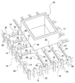
第1の実施形態では、図1の斜視図に示すように、建物10が、構造体としての内周コア壁12、複合梁14及び外周骨組み16によって構成されている。外周骨組み16は、梁18、及び構造体としての柱20によって構成されている。複合梁14は、内部コア壁12と柱20との間に架設されている。すなわち、複合梁14は、内周コア壁12と柱20とに接合されている。
In the first embodiment, as shown in the perspective view of FIG. 1, the
柱20、梁18及び内周コア壁12は、鉄筋コンクリートによって形成されている。柱20、梁18及び複合梁14は、プレキャスト部材であり、内周コア壁12は、現場打ちコンクリートにより形成されている。
The
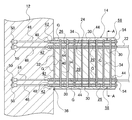
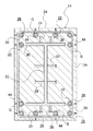
複合梁14は、図2の側断面図、及び図2のA−A断面図である図3に示すように、鉄骨梁22、鉄筋コンクリート製のブロック部24、及び貫通孔26を有している。ブロック部24は、鉄骨梁22の端部の周囲を囲むようにして略四角柱状に形成されており、鉄骨梁22の端部と一体に設けられている。
The
鉄骨梁22のフランジ及びウェブの表面には、スタッドボルト28が設けられている。これにより、鉄骨梁22の端部とブロック部24との一体化が高められ、鉄骨梁22とブロック部24との間における曲げモーメントの伝達効率を向上させることができる。
貫通孔26は、ブロック部24に埋設されたシース管30の中空部によって形成され、鉄骨梁22の材軸方向へ略水平にブロック部24を貫通している。図3に示すように、貫通孔26は、ブロック部24の上部及び下部において、横方向に所定の間隔をあけてそれぞれ6つ設けられている。すなわち、合計12の貫通孔26がブロック部24に形成されている。シース管30の端面は、ブロック部24の端面32とほぼ面一となっている。すなわち、シース管30の端部は、ブロック部24の端面32から突出していない。
The
ブロック部24の内部には、全てのシース管30を囲むようにしてせん断補強筋34が設けられている。ブロック部24が短スパンの場合、鉄骨梁22に曲げモーメントが作用したときに、ブロック部24の両端部には大きなせん断力が発生するので、この部分のせん断補強筋34の鉄筋量を多くする(せん断補強筋34の数を増やす、又はせん断補強筋34の径を大きくする)のが好ましい。
A
図1には、内周コア壁12に複合梁14を接合する複合梁の接合構造36と、柱20に複合梁14を接合する複合梁の接合構造38と、が示されている。以下の説明では、複合梁の接合構造36について説明するが、複合梁の接合構造38についても同様である。
FIG. 1 shows a composite
図2に示すように、複合梁の接合構造36は、内周コア壁12の接合面40に形成された接続孔42、接合部材としての鉄筋44、及び複合梁14を有している。鉄筋44の両端部には、雄ネジが形成されている。
As shown in FIG. 2, the composite
接続孔42は、内周コア壁12の内部に略水平に埋設された壁主筋としての鉄筋46の一方端部に設けられた継手部48に形成されており、接続孔42の内壁には鉄筋44の雄ネジが捩じ込まれる雌ネジが形成されている。鉄筋46の他方端部には、定着部材50が設けられている。定着部材50は、所定の背面被り強度が確保できる位置(例えば、背面被りが100mm以上となる位置)に配置されていればよい。
The
鉄筋46は、各貫通孔26と各接続孔42とがそれぞれ連通するように配置されている。すなわち、合計12本の鉄筋46が配置されている。継手部48の端面は、内周コア壁12の接合面40とほぼ面一となっている。すなわち、継手部48の端部は、内周コア壁12の接合面40から突出していない。
The reinforcing
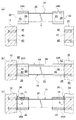
次に、複合梁14を用いた複合梁の接合方法について、図4(a)〜(c)の側面図を用いて説明する。なお、説明をわかり易くするために、内周コア壁12に接合されるブロック部24をブロック部24Aとし、柱20に接合されるブロック部24をブロック部24Bとする。
Next, the joining method of the composite beam using the
まず、図4(a)に示すように、内周コア壁12及び柱20の施工を完了させた後に、内周コア壁12の接合面40にブロック部24Aの端面32が対向し、柱20の接合面52にブロック部24Bの端面32が対向するように、複合梁14を配置する(複合梁配置工程)。このとき、内周コア壁12の接合面40とブロック部24Aの端面32との間、及び柱20の接合面52とブロック部24Bの端面32との間に10〜20mm程度の隙間56を有するようにする。
First, as shown in FIG. 4A, after the construction of the inner
次に、図4(b)に示すように、鉄筋44を貫通孔26と接続孔42とへ略水平に挿入して、内周コア壁12にブロック部24Aを接合し、柱20にブロック部24Bを接合する(ブロック部接合工程)。ブロック部接合工程を更に詳しく説明すると、まず、貫通孔26へ鉄筋44を挿入し、接続孔42に形成されている雌ネジに鉄筋44の先端部に形成された雄ネジを捩じ込み締め付けて接続する。次に、鉄筋44の末端部に形成された雄ネジに、定着プレート54の略中央に形成されている雌ネジを捩じ込み締め付けて、鉄筋44の末端部をブロック部24A、24Bに固定する。
Next, as shown in FIG. 4 (b), the reinforcing
次に、図4(c)に示すように、隙間56の周囲をエアーチューブ等のシール部材(不図示)によりシールした後、隙間56へグラウトGを注入し、この隙間56から貫通孔26へグラウトGを送り込む。そして、シース管30に設けられたグラウト排出孔58からグラウトGを排出して、隙間56及び貫通孔26へグラウトGを充填し硬化させる(グラウト充填工程)。これにより、ブロック部24A、24Bに鉄筋44を定着することができる。また、隙間56に充填され硬化したグラウトGによって、内周コア壁12とブロック部24A、柱20とブロック部24Bとの一体化を図ることができる。
Next, as shown in FIG. 4 (c), the periphery of the
次に、本発明の第1の実施形態の作用及び効果について説明する。 Next, the operation and effect of the first embodiment of the present invention will be described.
第1の実施形態の複合梁14、複合梁14を用いた複合梁の接合構造36、38、及び複合梁14を用いた複合梁の接合方法では、図4(a)〜(c)で示したように、貫通孔26と接続孔42とへ接合部材としての鉄筋44を挿入して、構造体としての内周コア壁12と柱20とにブロック部24を接合することにより、コンクリート打設等の煩雑な作業を行なわずに、コンクリート製の構造体に鉄骨梁22(複合梁14)を効率よく接合することができる。
The
また、内周コア壁12と柱20との間に複合梁14を配置するときには、ブロック部24の端面32、内周コア壁12の接合面40、及び柱20の接合面52から、鉄筋44や継手部48等の接合用部材が突出していないので、複合梁14を上下移動させて、内周コア壁12と柱20とに対して複合梁14を配置することができる。また、内周コア壁12のように構造体がコンクリート壁の場合、継手部48等の接合用部材を壁面から突出させて設けなくてよいので、ジャンピングフォーム等の移動式型枠を用いてコンクリート壁を施工することができる。
Further, when the
また、ブロック部24によって鉄骨梁22に剛性を付与することができ、複合梁14の剛性を大きくすることができるので、複合梁14に支持される床スラブの振動を低減することができる。また、曲げモーメントが大きくなる、鉄骨梁22の端部にブロック部24を部分的に設けることにより、複合梁14の重量を大きく増やすことなく鉄骨梁22に剛性を付与することができる。さらに、せん断補強筋等によってブロック部24に補強を施すことにより、鉄骨梁22の構造断面サイズを大きくすることなく、複合梁14の端部の耐力を向上させることができる。これらにより、軽量かつ高い剛性の複合梁14を構成することができる。例えば、経済性に優れた長大スパンの複合梁14を構築することができる。
Moreover, since the rigidity of the
また、軽量の複合梁14を構成することができるので、この複合梁14を用いて構築される建物の重量を軽くすることができる。これにより、例えば、建物の基礎構造や免震構造の支持荷重を小さく抑えることができ、基礎構造や免震構造の建設コストを低減することができる。
Moreover, since the lightweight
また、複合梁14が架け渡される内周コア壁12や柱20の構造体の施工誤差(複合梁14が架け渡される構造体間のスパン距離の寸法誤差)を、構造体と複合梁との接合部の目地(隙間56)によって吸収することができる。また、貫通孔26の径を大きくすることにより、貫通孔26や接続孔42の施工誤差(貫通孔26と接続孔42との中心のずれ)を吸収することができる。
Further, the construction error of the structure of the inner
次に、本発明の第2の実施形態とその作用及び効果について説明する。 Next, a second embodiment of the present invention and its operation and effect will be described.
第2の実施形態の説明において、第1の実施形態と同じ構成のものは、同符号を付すると共に、適宜省略して説明する。
図5の側断面図に示すように、第2の実施形態の複合梁60、及び複合梁の接合構造62では、管通孔64が、ブロック部24に埋設されたシース管30の中空部によって形成され、側面視にてブロック部24を斜めに貫通している。鉄筋46は、定着部材50が設けられている側の端部が内周コア壁12の内部で略水平になるように、折り曲げられている。シース管30の端部は、ブロック部24の端面32から突出していない。また、継手部48の端部は、内周コア壁12の接合面40から突出していない。
In the description of the second embodiment, the same components as those in the first embodiment are denoted by the same reference numerals and are appropriately omitted.
As shown in the side sectional view of FIG. 5, in the
そして、貫通孔64と接続孔42とへ挿入された接合部材としての鉄筋44により、内周コア壁12にブロック部24を接合している。この状態で、ブロック部24の左右側面付近に配置された鉄筋44と、この鉄筋44よりも内側に配置された鉄筋44とは、側面視にてX字状に交差している。
And the
よって、第2の実施形態の複合梁60、及び複合梁の接合構造62では、鉄筋44を斜めに配置することにより、鉄筋44の軸力として、ブロック部24に生じるせん断力に抵抗することができるので、ブロック部24のせん断強度を向上させることができる。よって、ブロック部24を短スパンにした場合においても、必要とするせん断強度を確保することができる。
Therefore, in the
次に、本発明の第3の実施形態とその作用及び効果について説明する。 Next, a third embodiment of the present invention and its operation and effect will be described.
第3の実施形態の説明において、第1の実施形態と同じ構成のものは、同符号を付すると共に、適宜省略して説明する。
図6の側断面図に示すように、第3の実施形態の複合梁66、及び複合梁の接合構造68では、鉄筋コンクリート製のブロック部74A、74B(不図示)が、鉄骨梁22の端部の下部フランジ70の上面と、上部フランジ72の下面との間に鉄骨梁22と一体に設けられている。ブロック部74A、74Bは、鉄骨梁22の正面視にてウェブ88を介して左右に設けられている。
In the description of the third embodiment, components having the same configurations as those of the first embodiment are denoted by the same reference numerals, and are appropriately omitted.
As shown in the side sectional view of FIG. 6, in the
ブロック部74A、74Bには、このブロック部74A、74Bに埋設されたシース管30の中空部により貫通孔76が形成されている。ブロック部74A、74Bには、それぞれ1つの貫通孔76がブロック部74A、74Bを略水平に貫通するように形成されている。
Through
接合部材としての鉄筋44は、柱20の接合面52に設けられた接続孔42と、貫通孔76とに挿入されて、柱20にブロック部74A、74Bを接合している。ブロック部74Aに設けられた鉄筋44と、ブロック部74Bに設けられた鉄筋44とは、側面視にて略同じ位置に略水平に配置され、平面視にて、鉄骨梁22のウェブ88に対して略線対称に配置されている。シース管30の端部は、ブロック部74A、74Bの端面78から突出していない。接続孔42は、一方の端部が下方へ延びるL字状に曲げられた鉄筋46の他方の端部に設けられた継手部48に形成されている。継手部48の端部は、柱20の接合面52から突出していない。
The reinforcing
よって、複合梁の接合構造68では、ブロック部74A、74Bが柱20にピン接合と略同様に接合され、複合梁66の端部に発生する曲げモーメントに抵抗せずに、複合梁66の端部から柱20へせん断力を伝達する。また、複合梁66の端部の構成を簡略化することができる。これにより、構造体(柱20)に作用する曲げモーメントを小さくすることができ、小さな曲げ耐力を有する構造体(柱20)を設計することができる。
Therefore, in the composite beam
以上、本発明の第1〜第3の実施形態について説明した。 The first to third embodiments of the present invention have been described above.
なお、第1〜第3の実施形態では、接合部材としての鉄筋44により構造体(内周コア壁12、柱20)にブロック部24A、24B、74A、74Bを接合した例を示したが、この鉄筋44に緊張力を付与してもよい。鉄筋44に緊張力を付与すれば、複合梁14、60、66の端部にプレストレスが導入される。これにより、複合梁14、60、66の端部に圧縮応力が発生し、複合梁14、60、66の端部に作用する曲げモーメントにより生じる曲げ引張応力が低減される。また、複合梁14、60、66の端部に軸力が加えられるので、複合梁14、60、66の端部の曲げ耐力を向上させることができる。これらにより、複合梁14、60、66の端部の曲げ耐力を向上させることができる。
In the first to third embodiments, an example in which the
また、複合梁14、60、66の端部に大きなプレストレスを導入できれば、鉄筋コンクリート(ブロック部24A、24B、74A、74B)のエネルギー吸収能力を発揮させるとともに、原点指向型の履歴特性を得ることができる。鉄筋44への緊張力の付与は、鉄筋44に対する定着プレート54の締め付けによって行ってもよいし、油圧ジャッキ等の緊張装置を用いて行なってもよい。また、接合部材をPC鋼棒やPC鋼より線等のPC鋼材としてもよい。また、鉄筋44とは別にプレストレス導入用の緊張部材を設けるようにしてもよい。
Moreover, if a large prestress can be introduced into the ends of the
複合梁の端部にプレストレスを導入する場合、ブロック部の上下端部付近の位置にプレストレスを導入するのが好ましい。例えば、図3であれば、鉄骨梁22の上部フランジの上方に配置された、ブロック部24の幅方向中央寄りの2つの鉄筋44と、鉄骨梁22の下部フランジの下方に配置された、ブロック部24の幅方向中央寄りの2つの鉄筋44とに緊張力を付与すればよい。
When prestress is introduced into the end of the composite beam, it is preferable to introduce prestress at a position near the upper and lower ends of the block. For example, in FIG. 3, two reinforcing
このように、ブロック部の上下端部付近の位置にプレストレスを導入すると、複合梁の端部が回転したときのこの回転に抵抗するモーメントが、梁成に近い距離にプレストレス(力)を掛けた値となり、ブロック部の他の位置にプレストレスを導入するよりも大きなモーメントを効率よく得ることができる。 In this way, when prestress is introduced near the upper and lower ends of the block, the moment that resists this rotation when the end of the composite beam rotates will cause prestress (force) to be applied to the distance close to the beam formation. A multiplied moment can be obtained more efficiently than when prestress is introduced at other positions of the block portion.
また、第1〜第3の実施形態では、継手部48やシース管30を、内周コア壁12の接合面40、ブロック部24A、24Bの端面32、柱20の接合面52や、ブロック部74A、74Bの端面から突出させない例を示したが、継手部48やシース管30は、内周コア壁12の接合面40、ブロック部24A、24Bの端面32、柱20の接合面52や、ブロック部74A、74Bの端面から突出させてもよい。
In the first to third embodiments, the
また、第1〜第3の実施形態では、継手部48を鉄筋46の端部に設けた例を示したが、鉄筋46に接続された捩じ込み式や差し込み式の機械式継手を継手部としてもよい。例えば、鉄筋46に接続されたスプライススリーブを継手部としてもよい。この場合には、スプライススリーブと、鉄筋44、46との間にグラウトを充填する。
In the first to third embodiments, an example in which the
また、第1〜第3の実施形態では、構造体としての内周コア壁12、柱20、及びブロック部24A、24B、74A、74Bを、鉄筋コンクリートによって形成した例を示したが、構造体は、コンクリートによって形成されていればよく、スチールファイバ、炭素繊維等を有する繊維補強コンクリートや、高強度コンクリートによって形成してもよい。 また、第1〜第3の実施形態の適用が可能な構造体は、現場打ちコンクリートによって形成してもよいし、プレキャスト部材であってもよい。また、構造体は、壁や梁であってもよいし、建物のどの平面位置に配置されていてもよい。
In the first to third embodiments, an example in which the inner
また、第1〜第3の実施形態では、シース管30の中空部により貫通孔26、64、76を形成した例を示したが、接合部材としての鉄筋44の挿入が可能であれば、どのような方法で貫通孔を形成してもよい。
Further, in the first to third embodiments, the example in which the through
また、第1〜第3の実施形態では、定着プレート54により鉄筋44の端部をブロック部24A、24B、74A、74Bに固定した例を示したが、支圧プレートを介したナットにより鉄筋44の端部をブロック部24A、24B、74A、74Bに固定してもよい。
In the first to third embodiments, an example in which the end portion of the reinforcing
また、第1及び第2の実施形態では、鉄筋46の一方の端部に定着部材50を設けた例を示したが、鉄筋46の両端に継手部48を設けるようにしてもよい。
In the first and second embodiments, an example in which the fixing
また、図7の平面図に示すように、第1〜第3の実施形態で示した複合梁14、60、66を壁80から任意の方向へ配置するようにしてもよい。図7には、壁80のコーナー部から3方向へ複合梁14が配置されている例が示されている。
Further, as shown in the plan view of FIG. 7, the composite beams 14, 60, 66 shown in the first to third embodiments may be arranged in an arbitrary direction from the
また、第1〜第3の実施形態で示した複合梁の接合構造36、38、62、68を用いて、鉄骨柱の柱頭部と、これに支持される基礎梁とを接合してもよいし、また、図8に示すように、複合梁としての複数のフレーム部材82を、構造体としてのジョイント部材84に接合して屋根構造86を構成するようにしてもよい。また、建物の外周フレームの接合に、第1〜第3の実施形態で示した複合梁の接合構造36、38、62、68を用いてもよい。
Further, the column heads of the steel columns and the foundation beams supported by the steel columns may be joined using the composite
また、第1〜第3の実施形態では、貫通孔26、64、76にグラウトGを充填した例を示したが、貫通孔26、64、76にグラウト等の材料を充填しないで、又は貫通孔26、64、76に弾性接着剤(例えば、エポソフト(登録商標))を充填して、接合部材としての鉄筋44をアンボンド化してもよい。このようにすれば、構造体(内周コア壁12、柱20)に接合された複合梁14、60、66を容易に解体することができ、複合梁14、60、66の再利用を図ることができる。
In the first to third embodiments, the grout G is filled in the through
以上、本発明の第1〜第3の実施形態について説明したが、本発明はこうした実施形態に何等限定されるものでなく、第1〜第3の実施形態を組み合わせて用いてもよいし、本発明の要旨を逸脱しない範囲において、種々なる態様で実施し得ることは勿論である。 The first to third embodiments of the present invention have been described above, but the present invention is not limited to such embodiments, and the first to third embodiments may be used in combination. Needless to say, the present invention can be implemented in various modes without departing from the gist of the present invention.
12 内周コア壁(構造体)
14、60、66 複合梁
20 柱(構造体)
22 鉄骨梁
24、24A、24B、74A、74B ブロック部
26、64、76 貫通孔
32、78 端面
36、38、62、68 複合梁の接合構造
40、52 接合面
42 接続孔
44 鉄筋(接合部材)
80 壁(構造体)
82 フレーム部材(複合梁)
84 ジョイント部材(構造体)
12 Inner core wall (structure)
14, 60, 66
22 Steel beams 24, 24A, 24B, 74A,
80 wall (structure)
82 Frame members (composite beams)
84 Joint member (structure)
Claims (4)
前記継手部に接続され前記構造体に埋設された定着部材と、
鉄骨梁と、該鉄骨梁の端部に一体に設けられるとともに貫通孔が形成され前記接合面に端面が対向するコンクリート製のブロック部と、を備える複合梁と、
前記貫通孔と前記接続孔とへ挿入されて前記構造体に前記ブロック部を接合する接合部材と、
を有する複合梁の接合構造。 A joint portion embedded in a concrete structure and having a connection hole facing the joint surface of the structure;
A fixing member connected to the joint and embedded in the structure;
And steel beams, and concrete block portion end surface on the joint surface through hole is formed with integrally provided on an end portion of the iron trabecular faces, the composite beams comprising,
A joining member that is inserted into the through hole and the connection hole and joins the block portion to the structure;
Composite beam joint structure having
接合部材を前記貫通孔と前記接合面に形成された接続孔とへ挿入して前記構造体に前記ブロック部を接合するブロック部接合工程と、
を有し、
前記接続孔は、前記構造体に埋設された継手部に形成されており、前記継手部は、前記構造体に埋設された定着部材に接続されている複合梁の接合方法。 The composite beams, the end face of said block portion to the joint surface of the concrete structure facing comprising a steel beam, a concrete block portion a through hole is provided integrally formed on an end portion of the iron trabeculae, the A composite beam placement process to place
A block part joining step for joining the block part to the structure by inserting a joining member into the through hole and a connection hole formed in the joining surface;
I have a,
The connection hole is formed in a joint portion embedded in the structure, and the joint portion is connected to a fixing member embedded in the structure .
前記鉄骨梁の端部に一体に設けられ端面がコンクリート製の構造体の接合面に対向するコンクリート製のブロック部と、
前記ブロック部に形成され、該ブロック部を前記構造体に接合する接合部材が貫通する貫通孔と、
を有し、
前記ブロック部は、前記構造体に埋設された継手部に前記接合面に面して形成されている接続孔と前記貫通孔とへ前記接合部材を挿入することにより前記構造体に接合され、前記継手部は、前記構造体に埋設された定着部材に接続されている複合梁。 A steel beam,
A concrete block portion provided integrally with an end portion of the steel beam and having an end surface opposed to a joint surface of the concrete structure;
A through hole formed in the block portion and through which a joining member for joining the block portion to the structure passes;
I have a,
The block part is joined to the structure by inserting the joining member into a connection hole formed in the joint part embedded in the structure facing the joining surface and the through hole, The joint portion is a composite beam connected to a fixing member embedded in the structure .
Priority Applications (1)
| Application Number | Priority Date | Filing Date | Title |
|---|---|---|---|
| JP2010228538A JP5658966B2 (en) | 2010-10-08 | 2010-10-08 | Composite beam, composite beam joint structure, and composite beam joint method |
Applications Claiming Priority (1)
| Application Number | Priority Date | Filing Date | Title |
|---|---|---|---|
| JP2010228538A JP5658966B2 (en) | 2010-10-08 | 2010-10-08 | Composite beam, composite beam joint structure, and composite beam joint method |
Publications (2)
| Publication Number | Publication Date |
|---|---|
| JP2012082600A JP2012082600A (en) | 2012-04-26 |
| JP5658966B2 true JP5658966B2 (en) | 2015-01-28 |
Family
ID=46241762
Family Applications (1)
| Application Number | Title | Priority Date | Filing Date |
|---|---|---|---|
| JP2010228538A Expired - Fee Related JP5658966B2 (en) | 2010-10-08 | 2010-10-08 | Composite beam, composite beam joint structure, and composite beam joint method |
Country Status (1)
| Country | Link |
|---|---|
| JP (1) | JP5658966B2 (en) |
Families Citing this family (4)
| Publication number | Priority date | Publication date | Assignee | Title |
|---|---|---|---|---|
| JP6121772B2 (en) * | 2013-03-28 | 2017-04-26 | 株式会社フジタ | Hybrid beam |
| JP6310648B2 (en) * | 2013-06-19 | 2018-04-11 | 戸田建設株式会社 | Joint structure of reinforced concrete member and steel member |
| JP2015014134A (en) * | 2013-07-05 | 2015-01-22 | 株式会社竹中工務店 | Core box of building, building comprising core box, and construction method for core box of building |
| JP6240426B2 (en) * | 2013-07-31 | 2017-11-29 | 株式会社竹中工務店 | Steel member fixing structure |
Family Cites Families (2)
| Publication number | Priority date | Publication date | Assignee | Title |
|---|---|---|---|---|
| JPH0673203U (en) * | 1993-03-30 | 1994-10-11 | 株式会社間組 | Beam-column joint structure |
| ITUD20060249A1 (en) * | 2006-11-30 | 2008-06-01 | Tecnostrutture S R L | PILLAR FOR CONSTRUCTION BUILDINGS AND STRUCTURAL NODE CONSISTING OF SUCH A PILLAR AND ONE OR MORE HORIZONTAL STRUCTURAL ELEMENTS |
-
2010
- 2010-10-08 JP JP2010228538A patent/JP5658966B2/en not_active Expired - Fee Related
Also Published As
| Publication number | Publication date |
|---|---|
| JP2012082600A (en) | 2012-04-26 |
Similar Documents
| Publication | Publication Date | Title |
|---|---|---|
| JP2010156183A (en) | Column wall member, column wall structure, building having the column wall structure, and method for manufacturing the column wall member | |
| JP5991132B2 (en) | Seismic reinforcement structure and construction method | |
| JP5946041B2 (en) | Column beam connection structure, column beam connection method, and precast concrete stigma member | |
| JP4917168B1 (en) | Seismic reinforcement structure and method using compression braces | |
| JP5658966B2 (en) | Composite beam, composite beam joint structure, and composite beam joint method | |
| JP2011202419A (en) | Structure and method for joining shaft member and rc member | |
| JP5483055B2 (en) | Mixed structural beam | |
| JP4949116B2 (en) | Wall unit and shear wall | |
| JP2011149265A (en) | Beam member and building structure | |
| JP2007092354A (en) | Joint method of pre-cast concrete construction beam-column | |
| JP2013112972A (en) | Building structure | |
| JP2014088657A (en) | Buckling restraining brace and aseismatic reinforcing structure using the same | |
| JP5087026B2 (en) | Seismic reinforcement structure | |
| KR101209363B1 (en) | Concrete block for seismic reinforcement of H-shaped column and seismic reinforcing method using the same | |
| JP2011202420A (en) | Structure and method for joining shaft member and rc member | |
| JP2008063816A (en) | Aseismatic reinforcing structure and aseismatic reinforcement construction method | |
| JP2009068182A (en) | Aseismatic reinforcing structure and method for existing building | |
| JP5726675B2 (en) | Reinforcement structure of existing building | |
| JP2012162927A (en) | Prestressed concrete skeleton inducing no secondary stress | |
| JP4439938B2 (en) | Wall type reinforced concrete structure and its construction method | |
| JP5108555B2 (en) | Precast member joint structure | |
| JP7449254B2 (en) | How to build a shear wall | |
| JP3870871B2 (en) | Reinforcement structure of frame | |
| JP5432977B2 (en) | Precast member joint structure | |
| JP7401145B1 (en) | Structural base materials, structural members and structures |
Legal Events
| Date | Code | Title | Description |
|---|---|---|---|
| A621 | Written request for application examination |
Free format text: JAPANESE INTERMEDIATE CODE: A621 Effective date: 20130926 |
|
| A977 | Report on retrieval |
Free format text: JAPANESE INTERMEDIATE CODE: A971007 Effective date: 20140509 |
|
| A131 | Notification of reasons for refusal |
Free format text: JAPANESE INTERMEDIATE CODE: A131 Effective date: 20140513 |
|
| A521 | Written amendment |
Free format text: JAPANESE INTERMEDIATE CODE: A523 Effective date: 20140626 |
|
| TRDD | Decision of grant or rejection written | ||
| A01 | Written decision to grant a patent or to grant a registration (utility model) |
Free format text: JAPANESE INTERMEDIATE CODE: A01 Effective date: 20141125 |
|
| A61 | First payment of annual fees (during grant procedure) |
Free format text: JAPANESE INTERMEDIATE CODE: A61 Effective date: 20141201 |
|
| R150 | Certificate of patent or registration of utility model |
Ref document number: 5658966 Country of ref document: JP Free format text: JAPANESE INTERMEDIATE CODE: R150 |
|
| LAPS | Cancellation because of no payment of annual fees |