JP2007209471A - Game machine - Google Patents

Game machine Download PDF

Info

Publication number
JP2007209471A
JP2007209471A JP2006031494A JP2006031494A JP2007209471A JP 2007209471 A JP2007209471 A JP 2007209471A JP 2006031494 A JP2006031494 A JP 2006031494A JP 2006031494 A JP2006031494 A JP 2006031494A JP 2007209471 A JP2007209471 A JP 2007209471A
Authority
JP
Japan
Prior art keywords
display
image
data
effect control
game
Prior art date
Legal status (The legal status is an assumption and is not a legal conclusion. Google has not performed a legal analysis and makes no representation as to the accuracy of the status listed.)
Granted
Application number
JP2006031494A
Other languages
Japanese (ja)
Other versions
JP4865348B2 (en
Inventor
Daisuke Miyamoto
大介 宮本
Takaya Yoneda
隆哉 米田
Current Assignee (The listed assignees may be inaccurate. Google has not performed a legal analysis and makes no representation or warranty as to the accuracy of the list.)
Sankyo Co Ltd
Original Assignee
Sankyo Co Ltd
Priority date (The priority date is an assumption and is not a legal conclusion. Google has not performed a legal analysis and makes no representation as to the accuracy of the date listed.)
Filing date
Publication date
Application filed by Sankyo Co Ltd filed Critical Sankyo Co Ltd
Priority to JP2006031494A priority Critical patent/JP4865348B2/en
Publication of JP2007209471A publication Critical patent/JP2007209471A/en
Application granted granted Critical
Publication of JP4865348B2 publication Critical patent/JP4865348B2/en
Active legal-status Critical Current
Anticipated expiration legal-status Critical

Links

Images

Abstract

<P>PROBLEM TO BE SOLVED: To appropriately recover the display state of a game machine from the abnormal state while preventing increase of the program capacity and complication of the process. <P>SOLUTION: A CPU installed in a presentation controlling microcomputer prevents the start of execution of a presentation controlling interrupt process corresponding to the occurrence of a timer interrupt by starting a loop process if the value in an event interrupt stand-by timer reaches a limit time determination value without detecting an event interrupt (the step S372: Yes). Then, if a reset signal is in the on-state based on the occurrence of the time-out without clearance of a reset IC with a watchdog, feeding of the power supply voltage to the presentation controlling microcomputer is stopped by a power control circuit, and is restarted after the elapse of prescribed time, so that the presentation controlling microcomputer is rebooted. In this case, the initial setting of a VDP is executed as when the power feeding to the game machine is started. <P>COPYRIGHT: (C)2007,JPO&INPIT

Description

本発明は、パチンコ遊技機やスロットマシン等の遊技機といった、遊技者が所定の遊技を行うことが可能な遊技機に関する。   The present invention relates to a gaming machine such as a pachinko gaming machine or a slot machine that allows a player to play a predetermined game.

パチンコ遊技機やスロットマシン等の遊技機として、所定の識別情報(表示図柄ともいう)を変動可能に表示する可変表示を行い、その表示結果が予め定められた特定表示結果となった場合に遊技者にとって有利な遊技状態(例えば大当り遊技状態などの特定遊技状態や、ビッグボーナスあるいはレギュラーボーナスなどの特別遊技状態など)に制御可能となるように構成されたものがある。   As a gaming machine such as a pachinko machine or a slot machine, a game is performed when predetermined display information (also referred to as a display pattern) is variably displayed and the display result is a predetermined specific display result. Some are configured to be controllable to a game state advantageous to the player (for example, a specific game state such as a big hit game state, a special game state such as a big bonus or a regular bonus).

このような遊技機には、遊技の進行状況に応じて、液晶表示装置(LCD;Liquid Crystal Display)等の表示装置上に所定のキャラクタを登場させたり、そのキャラクタを変化させたり、実写画像などの多色画像を表示させたり、スピーカから音声を出力させたり、ランプ・LED等の発光体を明滅させたりすることによって、各種の遊技演出が行われるものもある。   In such a gaming machine, a predetermined character appears on a display device such as a liquid crystal display (LCD) according to the progress of the game, the character is changed, a live-action image, etc. In some cases, various game effects are performed by displaying a multicolor image of the above, outputting sound from a speaker, or blinking a light emitter such as a lamp or LED.

ここで、画像データの転送を受けて画像表示装置に描画する描画装置を用いて表示演出が実行される遊技機において、表示演出などを制御するための演算処理装置が所定時間にわたって描画装置からの割込み信号を待機したときには、描画装置の初期データを再設定することにより、通常動作への復帰を可能にすることが提案されている(例えば特許文献1)。
特開平10−85406号公報
Here, in a gaming machine in which a display effect is executed using a drawing device that receives the transfer of image data and draws on the image display device, an arithmetic processing unit for controlling the display effect is provided from the drawing device for a predetermined time. When waiting for an interrupt signal, it has been proposed that the initial data of the drawing apparatus is reset so that the normal operation can be restored (for example, Patent Document 1).
JP-A-10-85406

特許文献1に記載の技術では、演算処理装置が所定時間にわたって描画装置からの割込み信号を待機したときに、描画装置の初期データを再設定するために専用の処理を実行するようにしている。そのため、プログラム容量が増大し、異常発生時における処理が複雑になるという問題があった。   In the technique described in Patent Document 1, when the arithmetic processing unit waits for an interrupt signal from the drawing device for a predetermined time, a dedicated process is executed to reset the initial data of the drawing device. For this reason, there is a problem in that the program capacity increases and the processing when an abnormality occurs becomes complicated.

この発明は、上記実状に鑑みてなされたものであり、プログラム容量の増大や処理の複雑化を防止しつつ、異常な表示状態から適切に復旧させることができる遊技機を提供することを目的とする。   The present invention has been made in view of the above circumstances, and an object thereof is to provide a gaming machine capable of appropriately recovering from an abnormal display state while preventing an increase in program capacity and complication of processing. To do.

上記課題を解決するため、本願の請求項1に記載の遊技機は、遊技者が所定の遊技を行うことが可能な遊技機(例えばパチンコ遊技機1、あるいはスロットマシン500など)であって、複数種類の演出画像を含む各種画像の表示を行う画像表示手段(例えば画像表示装置5、510など)と、遊技の進行を制御する遊技制御手段(例えば遊技制御用マイクロコンピュータ100、610など)と、演出制御用マイクロコンピュータ(例えば演出制御用マイクロコンピュータ120、630など)及び画像処理用プロセッサ(例えばVDP141など)を含み、前記画像表示手段の表示動作を制御する表示制御手段(例えば演出制御基板12、620など)とを備え、前記表示制御手段は、前記演出制御用マイクロコンピュータの制御状態を復旧させるために必要なデータ(例えば演出バックアップ用データなど)を記憶するデータ記憶手段(例えばRAM133のバックアップ領域など)を含み、前記画像処理用プロセッサは、前記画像表示手段による画像表示に関わる所定の処理が完了したことを示す完了信号を、前記演出制御用マイクロコンピュータに対して出力する完了信号出力手段(例えば動画像用デコーダ158がステップS466の処理を実行する部分など)を含み、前記演出制御用マイクロコンピュータは、前記演出制御用マイクロコンピュータの起動に対応して、前記画像処理用プロセッサの初期設定を行う画像処理初期設定手段(例えばCPU131がステップS51にて演出初期設定処理を実行する部分など)と、前記画像処理用プロセッサに対して前記処理の開始を指令する処理指令手段(例えばCPU131がステップS364の処理を実行する部分など)と、前記完了信号出力手段からの完了信号を検出する完了信号検出手段(例えばCPU131がステップS366の処理を実行する部分や、リセット/割込みコントローラ136がステップS407の処理を実行する部分など)と、前記処理指令手段からの指令が送出された後に前記完了信号検出手段によって前記完了信号出力手段からの完了信号が検出されずに予め定められた待機期間が経過したことに対応して、前記演出制御用マイクロコンピュータを再起動させる演出制御再起動手段(例えばステップS372におけるYesの判定に対応してCPU131がループ処理を実行する部分など)と、前記演出制御再起動手段により再起動を行うにあたり、前記データ記憶手段へのデータ記憶を行うデータ退避手段(例えばCPU131がステップS77の処理を実行する部分など)と、前記演出制御再起動手段によって再起動されたことに対応して、前記データ記憶手段に記憶されているデータに基づいて該再起動される前の制御状態を復旧させた後、該復旧させた制御状態から前記画像表示手段の表示動作を再開させる再開制御手段(例えばCPU131がステップS324、S325の処理を実行する部分など)とを含む。ここで、画像表示に関わる所定の処理は、例えば、画像表示手段に画像を表示させるために用いられる画像データ等を、複数の記憶手段の間で転送する処理や、所定の記憶手段から読み出すことなどにより取得した画像データ等をそのまま、あるいは圧縮や伸張などといった所定の変換を施した後に、別の記憶手段に書き込んで記憶させる処理、画像データ等に基づき画像表示手段に画像を表示させる処理、複数種類の画像データ等を用いて画像表示手段における画像の表示用データを作成する(描画する)処理などといった、各種の画像表示に関わる処理のうち、少なくともいずれか1種類を含む処理として予め定められていればよい。また、画像処理用プロセッサの初期設定には、画像処理用プロセッサが備える所定の記憶手段における記憶内容を初期化することや、画像処理用プロセッサに内蔵された各種処理手段(例えばデータ処理手段など)により実行中の処理を初期化や中断すること、画像表示手段の表示画面に対応した記憶領域の割当てを行って表示領域を設定すること、画像表示手段における表示画像の更新周期を設定することなどといった、各種の初期設定のうち、少なくともいずれか1種類の設定を含む動作として予め定められていればよい。   In order to solve the above problems, a gaming machine according to claim 1 of the present application is a gaming machine (for example, a pachinko gaming machine 1 or a slot machine 500) in which a player can perform a predetermined game, Image display means for displaying various images including a plurality of types of effect images (for example, image display devices 5, 510, etc.), game control means for controlling the progress of the game (for example, game control microcomputers 100, 610, etc.), Display control means (for example, an effect control board 12) including an effect control microcomputer (for example, an effect control microcomputer 120, 630) and an image processing processor (for example, VDP 141) to control the display operation of the image display means. 620, etc.), and the display control means controls the control state of the effect control microcomputer. Including data storage means (for example, a backup area of the RAM 133) for storing data necessary for aging (for example, production backup data, etc.), and the image processing processor has a predetermined function related to image display by the image display means. Completion signal output means for outputting a completion signal indicating that the processing is completed to the effect control microcomputer (for example, a portion where the moving picture decoder 158 executes the process of step S466), and the effect control The microcomputer for image processing performs initial setting of the image processing processor in response to the activation of the effect control microcomputer (for example, the part where the CPU 131 executes the effect initial setting process in step S51, etc.) ) And the processing for the image processing processor. Process command means for instructing the start of the process (for example, the part where the CPU 131 executes the process of step S364) and completion signal detection means for detecting the completion signal from the completion signal output means (for example, the CPU 131 executes the process of step S366) And the completion signal from the completion signal output means by the completion signal detection means after the instruction from the processing instruction means is transmitted. In response to the elapse of a predetermined standby period without being detected, effect control restarting means for restarting the effect control microcomputer (for example, the CPU 131 performs loop processing in response to the determination of Yes in step S372). Etc.) and the effect control restart means In response to the operation, the data saving means for storing data in the data storage means (for example, the part where the CPU 131 executes the process of step S77) and the effect control restarting means correspond to the restarting. And a restart control means for resuming the display operation of the image display means from the restored control state after restoring the control state before the restart based on the data stored in the data storage means ( For example, the CPU 131 includes a part for executing the processes of steps S324 and S325). Here, the predetermined process related to image display is, for example, a process of transferring image data used for displaying an image on the image display unit between a plurality of storage units, or reading from a predetermined storage unit. Processing the image data obtained by the above as it is or after performing a predetermined conversion such as compression or expansion, processing to write and store in another storage means, processing to display an image on the image display means based on the image data, It is predetermined as a process including at least one of various processes related to image display, such as a process of creating (drawing) image display data in the image display means using a plurality of types of image data. It only has to be done. Further, for initial setting of the image processing processor, the contents stored in a predetermined storage means included in the image processing processor are initialized, and various processing means (for example, data processing means) incorporated in the image processing processor. Initialize or interrupt the process being executed by setting, assign a storage area corresponding to the display screen of the image display means, set the display area, set the display image update period in the image display means, etc. As long as the operation includes at least one of the various initial settings, it is only necessary to be determined in advance.

請求項2に記載の遊技機においては、前記演出制御用マイクロコンピュータに供給される電源電圧の低下を検出したことに対応して、電圧低下検出信号(例えば電源断信号など)を出力する電源監視手段(例えば電断検出回路137など)を備え、前記データ退避手段は、前記電源監視手段から電圧低下検出信号が出力されたことに対応して、制御状態を復旧させるために必要なデータを前記データ記憶手段に記憶させる(例えばステップS73、S74におけるYesの判定に対応して、CPU131がステップS76の処理を実行する部分など)。   3. The gaming machine according to claim 2, wherein a power supply monitoring that outputs a voltage drop detection signal (for example, a power-off signal) in response to detecting a drop in power supply voltage supplied to the production control microcomputer. Means (for example, a power interruption detection circuit 137), and the data saving means stores data necessary for restoring the control state in response to the output of the voltage drop detection signal from the power supply monitoring means. The data is stored in the data storage means (for example, the part where the CPU 131 executes the process of step S76 in response to the determination of Yes in steps S73 and S74).

請求項3に記載の遊技機において、前記表示制御手段は、動き補償予測符号化による圧縮データを含む動画像データを格納する圧縮データ格納手段(例えばCGROM142の動画像データエリア142Bなど)を含み、前記画像処理用プロセッサは、前記圧縮データ格納手段から読み出した動画像データをデコードするデコード手段(例えば動画像用デコーダ158がステップS461、S462の処理を実行する部分など)と、前記デコード手段によりデコードされた動画像データに基づいて生成される画像を前記画像表示手段に順次表示させることによって動画像の再生を行う動画像再生手段(例えば描画回路154が第1〜第Xピクチャバッファ155−1〜155−Xから順次に画像データを読み出してフレームバッファメモリ156に書き込む部分や、表示回路157がフレームバッファメモリ156の記憶データを読み出して画像表示装置5に出力する部分など)とを含み、前記完了信号出力手段は、前記デコード手段による動画像データのデコードが完了したことを示す完了信号を、前記演出制御用マイクロコンピュータに対して出力し、前記処理指令手段は、前記デコード手段により動画像データをデコードする処理の開始を指令するデコード開始指令手段(例えばCPU131がステップS364の処理を実行する部分など)を含み、前記演出制御再起動手段は、前記デコード開始指令手段からの指令が送出された後に前記完了信号検出手段によって前記完了信号出力手段からの完了信号が検出されずに前記待機期間が経過したこと(例えばステップS364の処理を実行した後にステップS372にてYesと判定されたこと)に対応して、前記演出制御用マイクロコンピュータを再起動させる。   4. The gaming machine according to claim 3, wherein the display control means includes compressed data storage means (for example, a moving image data area 142B of the CGROM 142) for storing moving image data including compressed data obtained by motion compensation predictive coding. The image processing processor includes decoding means for decoding the moving image data read from the compressed data storage means (for example, a portion where the moving image decoder 158 executes the processing of steps S461 and S462), and decoding by the decoding means. Moving image reproduction means (for example, the drawing circuit 154 includes first to X-th picture buffers 155-1 to 155) that reproduces a moving image by sequentially displaying images generated based on the moving image data on the image display means. The frame buffer memory 1 reads image data sequentially from 155-X. 6 and a portion where the display circuit 157 reads out the data stored in the frame buffer memory 156 and outputs it to the image display device 5, etc., and the completion signal output means decodes the moving image data by the decoding means. Is output to the effect control microcomputer, and the process command means instructs the decode start command means (for example, to start the process of decoding moving image data by the decode means (for example, And the effect control restarting means completes the completion signal output means by the completion signal detection means after the instruction from the decode start instruction means is sent. That the waiting period has elapsed without detection of a signal (for example, step S364) In response to the determination that Yes at step S372) after executing the process, to restart the presentation control microcomputer.

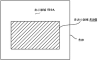
請求項4に記載の遊技機においては、前記画像表示手段の前面または背面に配置される遊技用部品(例えば特別図柄表示装置4や可変表示装置501、装飾部材31、32、33など)を備え、前記画像表示手段は、各種画像の表示が行われる表示領域(例えば表示領域5A、510Aなど)と、前記遊技用部品の配置位置に対応して各種画像の表示が制限される非表示領域(例えば非表示領域5B、510Bなど)とを含み、前記表示制御手段は、前記画像表示手段における画像の表示用データを記憶する表示用データ記憶手段(例えばフレームバッファメモリ156など)と、表示対象の画像が前記非表示領域に配置されるか否かを判定する配置判定手段(例えば描画回路154がステップS444の処理を実行する部分や、CPU131がステップS501の処理を実行する部分など)と、前記配置判定手段により前記非表示領域に配置されると判定した画像を示す画像データについて、前記表示用データ記憶手段に対する書き込みを制限する表示用データ書込制限手段(例えばステップS444におけるYesの判定に対応してステップS445の処理がスキップされる部分や、ステップS501におけるYesの判定に対応してステップS502の処理が実行されない部分など)とを含む。   According to a fourth aspect of the present invention, there is provided a gaming component (for example, the special symbol display device 4, the variable display device 501, the decorative members 31, 32, 33, etc.) disposed on the front or back of the image display means. The image display means includes a display area in which various images are displayed (for example, display areas 5A and 510A) and a non-display area in which display of various images is restricted corresponding to the arrangement position of the gaming parts ( The display control means includes display data storage means (for example, a frame buffer memory 156) for storing image display data in the image display means, and a display target display object. Arrangement determining means for determining whether or not an image is arranged in the non-display area (for example, the part where the drawing circuit 154 executes the process of step S444, or the CPU 13 Display data for restricting writing to the display data storage unit with respect to image data indicating an image determined to be arranged in the non-display area by the arrangement determination unit) Write restriction means (for example, a part where the process of step S445 is skipped in response to the determination of Yes in step S444, a part where the process of step S502 is not executed in response to the determination of Yes in step S501, etc.) .

請求項5に記載の遊技機において、前記表示制御手段は、演出画像に対応した画像要素データを含む複数種類の画像要素データを記憶する画像要素データ記憶手段(例えばCGROM142のスプライトデータエリア142Aなど)を含み、前記画像処理用プロセッサは、画像要素データに基づいて表示用データを作成するための処理を実行するデータ処理手段(例えば転送制御回路152や描画回路154など)と、前記表示用データ記憶手段から読み出した表示用データを前記画像表示手段に出力する表示用データ出力手段(例えば表示回路157など)とを含み、前記演出制御用マイクロコンピュータは、画像要素データの読出位置及び書込位置を前記画像処理用プロセッサに通知して、前記画像表示手段における表示画像の更新を指令する表示画像更新指令手段(例えばCPU131がステップS345の処理を実行する部分など)を含み、前記配置判定手段は、前記表示画像更新指令手段から通知された画像要素データの書込位置が前記非表示領域に対応した書込位置であるか否かを判定する書込位置判定手段(例えば描画回路154がステップS444の処理を実行する部分など)を含み、前記表示用データ書込制限手段は、前記書込位置判定手段により前記非表示領域に対応すると判定された書込位置に前記データ処理手段によって画像要素データが書き込まれることを制限する(例えば描画回路154がステップS424におけるYesの判定に対応してステップS425の処理をスキップする部分など)。   6. The gaming machine according to claim 5, wherein said display control means stores image element data storage means for storing a plurality of types of image element data including image element data corresponding to the effect image (for example, sprite data area 142A of CGROM 142). The image processing processor includes a data processing means (for example, a transfer control circuit 152 and a drawing circuit 154) that executes processing for creating display data based on image element data, and the display data storage. Display data output means (for example, a display circuit 157) that outputs display data read from the means to the image display means, and the effect control microcomputer determines the reading position and writing position of the image element data. Notifying the image processing processor and instructing to update the display image in the image display means. Display image update command means (for example, the part where the CPU 131 executes the process of step S345), and the arrangement determination means is configured such that the writing position of the image element data notified from the display image update command means is not displayed. A writing position determining means for determining whether or not the writing position corresponds to the area (for example, a portion where the drawing circuit 154 executes the process of step S444); The writing position determining unit restricts writing of image element data by the data processing unit to the writing position determined to correspond to the non-display area (for example, the drawing circuit 154 corresponds to the determination of Yes in step S424). For example, a portion skipping the processing of step S425).

請求項6に記載の遊技機において、前記表示制御手段は、演出画像に対応した画像要素データを含む複数種類の画像要素データを記憶する画像要素データ記憶手段(例えばCGROM142のスプライトデータエリア142Aなど)を含み、前記画像処理用プロセッサは、画像要素データに基づいて表示用データを作成するための処理を実行するデータ処理手段(例えば転送制御回路152や描画回路154など)と、前記表示用データ記憶手段から読み出した表示用データを前記画像表示手段に出力する表示用データ出力手段(例えば表示回路157など)とを含み、前記演出制御用マイクロコンピュータは、画像要素データの読出位置及び書込位置を前記画像処理用プロセッサに通知して、前記画像表示手段における表示画像の更新を指令する表示画像更新指令手段(例えばCPU131がステップS385の処理を実行する部分など)を含み、前記表示用データ書込制限手段は、前記配置判定手段により前記非表示領域に配置されると判定した画像要素を示す画像要素データについて、前記表示画像更新指令手段によって前記表示用データ記憶手段への書き込みが指令されることを制限する(例えばCPU131がステップS501におけるYesの判定に対応してステップS502の処理を実行しない部分など)。   7. The gaming machine according to claim 6, wherein the display control means stores image element data storage means (for example, a sprite data area 142A of the CGROM 142) that stores a plurality of types of image element data including image element data corresponding to the effect image. The image processing processor includes a data processing means (for example, a transfer control circuit 152 and a drawing circuit 154) that executes processing for creating display data based on image element data, and the display data storage. Display data output means (for example, a display circuit 157) that outputs display data read from the means to the image display means, and the effect control microcomputer determines the reading position and writing position of the image element data. Notifying the image processing processor and instructing to update the display image in the image display means. Display image update command means (for example, a portion where the CPU 131 executes the process of step S385), and the display data writing restriction means determines that the display data write restriction means is arranged in the non-display area by the arrangement determination means The image element data indicating the element is restricted from being instructed to be written into the display data storage unit by the display image update command unit (for example, the CPU 131 performs the process of step S502 in response to the determination of Yes in step S501). Etc.)

本発明は、以下に示す効果を有する。   The present invention has the following effects.

請求項1に記載の遊技機によれば、処理指令手段からの指令が送出された後に完了信号検出手段によって完了信号出力手段からの完了信号が検出されずに所定の待機期間が経過した場合には、演出制御再起動手段によって演出制御用マイクロコンピュータの再起動が行われる。この再起動にあたっては、制御状態を復旧させるために必要なデータが、データ退避手段によりデータ記憶手段に記憶される。そして、遊技機への電力供給が開始された場合などと同様に、画像処理初期設定手段によって画像処理用プロセッサの初期設定が行われることになる。また、演出制御再起動手段によって再起動されたことに対応して、再開制御手段が、データ記憶手段の記憶データにより再起動される以前の制御状態を復旧させた後、復旧させた制御状態から画像表示手段の表示動作を再開させる。
これにより、再起動の際に制御状態を復旧させるための処理を流用することで、完了信号が検出されずに待機期間が経過した場合に専用の処理を実行する必要がないので、プログラム容量の増大や処理の複雑化を防止しつつ、異常な表示状態から適切に復旧させることができる。また、完了信号が検出されずに待機期間が経過した場合に途中となっていた表示動作を復旧後に再開させることができ、異常な表示状態からのより適切な復旧が可能になる。
According to the gaming machine of the first aspect, when a predetermined waiting period elapses without detection of the completion signal from the completion signal output means by the completion signal detection means after the instruction from the processing instruction means is sent. The effect control microcomputer is restarted by the effect control restarting means. In this restart, data necessary for restoring the control state is stored in the data storage means by the data saving means. As in the case where power supply to the gaming machine is started, the image processing processor is initialized by the image processing initial setting means. Further, in response to being restarted by the production control restarting means, the restart control means recovers the control state before being restarted by the stored data of the data storage means, and then from the recovered control state. The display operation of the image display means is resumed.
As a result, by diverting the process for restoring the control state at the time of restarting, it is not necessary to execute a dedicated process when the waiting period elapses without detecting the completion signal. It is possible to appropriately recover from an abnormal display state while preventing an increase or complication of processing. In addition, the display operation that has been in the middle when the completion period is not detected and the standby period elapses can be resumed after recovery, and more appropriate recovery from an abnormal display state is possible.

請求項2に記載の遊技機においては、電源監視手段が電源電圧の低下を検出したことに対応して電圧低下検出信号を出力したことにより、制御状態を復旧させるために必要なデータを、データ退避手段がデータ記憶手段に記憶させる。
これにより、演出制御用マイクロコンピュータの再起動が行われる場合に制御状態を復旧させるための特別な制御を行う必要がないので、処理の複雑化を防止しつつ、異常な表示状態から適切に復旧させることができる。
In the gaming machine according to claim 2, data necessary for restoring the control state by outputting a voltage drop detection signal in response to the power supply monitoring means detecting a drop in the power supply voltage is stored as data The saving unit stores the data in the data storage unit.
This eliminates the need for special control to restore the control state when the production control microcomputer is restarted, so that it can properly recover from an abnormal display state while preventing complications in processing. Can be made.

請求項3に記載の遊技機においては、動画像データをデコードするデコード手段によるデコードが完了したことを示す完了信号が、完了信号出力手段によって画像処理用プロセッサから演出制御用マイクロコンピュータに対して出力される。そして、演出制御再起動手段は、デコード開始指令手段からの指令が送出された後に完了信号検出手段によって完了信号出力手段からの完了信号が検出されずに待機期間が経過したことに対応して、演出制御用マイクロコンピュータを再起動させる。
これにより、動画像データのデコードに異常が発生して動画像の再生が中断された場合でも、所定の待機期間が経過すれば異常な表示状態から適切に復旧させることができる。
In the gaming machine according to claim 3, a completion signal indicating completion of decoding by the decoding means for decoding the moving image data is output from the image processing processor to the effect control microcomputer by the completion signal output means. Is done. Then, the production control restarting means corresponds to the fact that the waiting period has elapsed without the completion signal from the completion signal output means being detected by the completion signal detecting means after the instruction from the decoding start instruction means is sent, Restart the production control microcomputer.
As a result, even when an abnormality occurs in the decoding of the moving image data and the reproduction of the moving image is interrupted, it is possible to appropriately recover from the abnormal display state if a predetermined standby period elapses.

請求項4に記載の遊技機においては、配置判定手段によって非表示領域に配置されると判定した画像を示す画像データについて、表示用データ書込制限手段が表示用データ記憶手段に対する書き込みを制限する。
これにより、非表示領域に配置される画像の画像データが表示用データ記憶手段に書き込まれる場合に比べて、表示演出における制御負担を軽減することができる。また、遊技機を設計する段階で非表示領域に画像を表示させないための配慮を行う必要がなくなり、遊技機の設計負担を軽減することができる。
In the gaming machine according to claim 4, the display data writing restricting means restricts writing to the display data storing means for the image data indicating the image determined to be arranged in the non-display area by the arrangement determining means. .
Thereby, compared with the case where the image data of the image arrange | positioned at a non-display area is written in the display data storage means, the control burden in a display effect can be reduced. In addition, it is not necessary to give consideration to prevent an image from being displayed in the non-display area at the stage of designing the gaming machine, and the design burden on the gaming machine can be reduced.

請求項5に記載の遊技機においては、書込位置判定が、表示画像更新指令手段から通知された書込位置は非表示領域に対応した書込位置であるか否かを判定する。そして、非表示領域に対応すると判定された書込位置にデータ処理手段によって画像要素データが書き込まれることを、表示用データ書込制限手段によって制限する。
これにより、演出制御用マイクロコンピュータの側では、非表示領域であるか否かを判断する必要がないことから、非表示領域が存在しない場合と同様の構成によって表示演出における制御負担を軽減することができる。
In the gaming machine according to claim 5, the writing position determination determines whether or not the writing position notified from the display image update command means is a writing position corresponding to the non-display area. Then, the display data writing restricting means restricts that the data processing means writes the image element data at the writing position determined to correspond to the non-display area.
Thereby, since it is not necessary to determine whether or not it is a non-display area on the side of the effect control microcomputer, the control burden in the display effect can be reduced by the same configuration as when there is no non-display area. Can do.

請求項6に記載の遊技機においては、配置判定手段により非表示領域に配置されると判定した画像要素を示す画像要素データについて、表示画像更新指令手段によって表示用データ記憶手段への書き込みが指令されることを、表示用データ書込制限手段により制限する。
これにより、画像処理用プロセッサの側では、非表示領域であるか否かを判断する必要がないことから、非表示領域が存在しない場合と同様の構成によって表示演出における制御負担を軽減することができる。
In the gaming machine according to claim 6, with respect to the image element data indicating the image element determined to be arranged in the non-display area by the arrangement determination means, the display image update instruction means writes to the display data storage means. This is restricted by the display data writing restriction means.
As a result, since it is not necessary for the image processing processor to determine whether or not it is a non-display area, it is possible to reduce the control burden in the display effect with the same configuration as when there is no non-display area. it can.

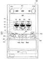
以下、図面を参照しつつ、本発明の一実施形態を詳細に説明する。図1は、本実施例におけるパチンコ遊技機1の正面図であり、主要部材の配置レイアウトを示す。パチンコ遊技機(遊技機)1は、大別して、遊技盤面を構成する遊技盤(ゲージ盤)2と、遊技盤2を支持固定する遊技機用枠(台枠)3とから構成されている。遊技盤2にはガイドレールによって囲まれた、ほぼ円形状の遊技領域が形成されている。この遊技領域の中央位置上方には、識別可能な識別情報としての特別図柄を変動可能に表示(可変表示)する特別図柄表示装置4が設けられている。   Hereinafter, an embodiment of the present invention will be described in detail with reference to the drawings. FIG. 1 is a front view of a pachinko gaming machine 1 according to the present embodiment, and shows an arrangement layout of main members. The pachinko gaming machine (gaming machine) 1 is roughly composed of a gaming board (gauge board) 2 constituting a gaming board surface and a gaming machine frame (base frame) 3 for supporting and fixing the gaming board 2. The game board 2 is formed with a substantially circular game area surrounded by guide rails. Above the central position of the game area, there is provided a special symbol display device 4 for displaying (variably displaying) a special symbol as identifiable identification information in a variable manner.

特別図柄表示装置4の下方には、始動入賞口を形成する普通可変入賞球装置6が配置されている。普通可変入賞球装置6の下方には、大入賞口を形成する特別可変入賞球装置7や、普通図柄表示装置20が設けられている。普通図柄表示装置20は、発光ダイオード(LED)等を備えて構成され、遊技領域に設けられた通過ゲート41を通過した遊技球がゲートスイッチ21(図3)によって検出されたことを実行条件とする普通図ゲームにおいて、点灯、点滅、発色などが制御される。この普通図ゲームにおいて所定の当りパターンで表示が行われると、普通図ゲームにおける表示結果が「当り」となり(普通当り)、普通可変入賞球装置6を構成する電動チューリップの可動翼片を所定時間が経過するまで傾動制御する。   Below the special symbol display device 4, an ordinary variable winning ball device 6 that forms a start winning opening is arranged. Below the ordinary variable winning ball apparatus 6, a special variable winning ball apparatus 7 that forms a large winning opening and an ordinary symbol display apparatus 20 are provided. The normal symbol display device 20 is configured to include a light emitting diode (LED) or the like, and an execution condition is that a game ball that has passed through a passing gate 41 provided in the gaming area is detected by the gate switch 21 (FIG. 3). In the normal view game, lighting, blinking, coloring, etc. are controlled. When display is performed with a predetermined hit pattern in this normal game, the display result in the normal game is “win” (normal hit), and the movable wing piece of the electric tulip constituting the normal variable winning ball apparatus 6 is set for a predetermined time. Tilt is controlled until elapses.

特別図柄表示装置4は、例えば7セグメントやドットマトリクスのLED等から構成されている。特別図柄表示装置4は、普通可変入賞球装置6が形成する始動入賞口への遊技球の入賞により始動条件が成立したことに基づいて行われる可変表示ゲームとしての特図ゲームにおいて、例えば「0」〜「9」を示す数字等から構成される特別図柄を可変表示する。各特別図柄には、例えば各図柄が示す数字と同一の番号といった、各々の特別図柄に対応した図柄番号が付されている。なお、特別図柄表示装置4は、特定の停止図柄が遊技者に把握されることを困難にするために、例えば「00」〜「99」を示す数字など、より多種類の図柄を可変表示するように構成されていてもよい。   The special symbol display device 4 includes, for example, 7-segment or dot matrix LEDs. The special symbol display device 4 is, for example, “0” in a special game as a variable display game that is performed based on the fact that a start condition is established by winning a game ball in a start winning opening formed by the normal variable pay ball device 6. ”To“ 9 ”are variably displayed special symbols composed of numbers and the like. Each special symbol is assigned a symbol number corresponding to each special symbol, for example, the same number as the number indicated by each symbol. The special symbol display device 4 variably displays more types of symbols such as numbers indicating “00” to “99” in order to make it difficult for the player to grasp a specific stop symbol. It may be configured as follows.

特別図柄表示装置4により行われる特図ゲームでは、特別図柄の変動を開始させた後、所定時間が経過すると、特別図柄の可変表示結果となる確定特別図柄を停止表示(導出表示)する。このとき、特別図柄表示装置4にて特図ゲームでの確定特別図柄として特定の特別図柄(大当り図柄)が停止表示されれば特定表示結果としての「大当り」となり、大当り図柄以外の特別図柄が停止表示されれば「ハズレ」となる。特図ゲームでの可変表示結果が「大当り」になると、特別可変入賞球装置7が備える開閉板を開閉させることによる特定遊技状態としての大当り遊技状態に制御される。この実施の形態におけるパチンコ遊技機1では、具体的な一例として、「7」を示す特別図柄を大当り図柄とし、それ以外の数値を示す特別図柄をハズレ図柄としている。   In the special symbol game performed by the special symbol display device 4, when a predetermined time elapses after the variation of the special symbol is started, the fixed special symbol that is a variable symbol display result is stopped (derived display). At this time, if a special symbol (big hit symbol) is stopped and displayed as a confirmed special symbol in the special symbol game on the special symbol display device 4, it becomes a “big hit” as a specific display result, and a special symbol other than the big bonus symbol is displayed. If it is stopped, it will be “lost”. When the variable display result in the special figure game becomes “hit”, the game is controlled to the big win game state as the specific game state by opening and closing the opening / closing plate of the special variable winning ball apparatus 7. In the pachinko gaming machine 1 according to this embodiment, as a specific example, a special symbol indicating “7” is a jackpot symbol, and a special symbol indicating other numerical values is a lost symbol.

特別図柄表示装置4による特図ゲームでの確定特別図柄として大当り図柄である「7」を示す特別図柄が停止表示されたことに基づく大当り遊技状態では、特別可変入賞球装置7の開閉板により、所定の開放期間(例えば29秒)あるいは所定個数(例えば10個)の入賞球が発生するまでの期間において大入賞口が開放され、開放されている間は遊技盤2の表面を落下する遊技球が受け止められて大入賞口への入賞が可能となり、その後に大入賞口を閉鎖することで1回のラウンドが終了する。そして、この開閉サイクルとしてのラウンドを所定の上限回数(例えば15ラウンド)まで繰り返すことができる。大入賞口に入賞した遊技球は、カウントスイッチ24(図3)によって検出され、その検出結果に基づき所定個数(例えば「15」)の賞球の払出が行われる。このように、大当り遊技状態は、通常遊技状態に比べて遊技者にとって有利な遊技状態である。なお、通常遊技状態とは、例えばパチンコ遊技機1の電源投入直後などにおける初期設定状態のような、大当り遊技状態以外の遊技状態のことである。   In the jackpot gaming state based on the special symbol indicating “7” which is a jackpot symbol as a confirmed special symbol in the special symbol game by the special symbol display device 4, by the opening / closing plate of the special variable winning ball device 7, A game ball that drops on the surface of the game board 2 during a predetermined opening period (for example, 29 seconds) or a period until a predetermined number (for example, 10) of winning balls are generated and the large winning opening is opened. Is received, and it becomes possible to enter the grand prize opening, and then the round is closed by closing the grand prize opening. The round as the open / close cycle can be repeated up to a predetermined upper limit number (for example, 15 rounds). The game balls that have won the big prize opening are detected by the count switch 24 (FIG. 3), and a predetermined number (for example, “15”) of prize balls are paid out based on the detection result. Thus, the big hit gaming state is a gaming state that is more advantageous for the player than the normal gaming state. The normal gaming state is a gaming state other than the big hit gaming state, such as an initial setting state immediately after power-on of the pachinko gaming machine 1, for example.

遊技盤2の前面には、遊技領域のほぼ全面を覆うように、画像表示装置5が配置されている。ここでの「ほぼ全面」とは、少なくとも遊技領域の周縁部に設けられる装飾部材31、32、33等よりも内側となる領域のことである。画像表示装置5は、例えばLCDパネルや有機EL(Electro Luminescence)パネルなどを用いて構成され、多数の画素(ピクセル)を用いたドットマトリクス方式による画面表示を行うものであればよい。例えば、画像表示装置5の表示画面では、特別図柄表示装置4による特図ゲームにおける特別図柄の変動表示に対応して、3つに分割された表示領域としての可変表示部にて、各々が識別可能な複数種類の飾り図柄を変動可能に表示する可変表示を行う。この例では、画像表示装置5に「左」、「中」、「右」の可変表示部が配置され、各可変表示部にて飾り図柄が可変表示される。そして、特別図柄表示装置4における特別図柄の変動が開始されるときには、画像表示装置5における「左」、「中」、「右」の各可変表示部にて飾り図柄の変動(例えば図柄の切換やスクロール)を開始させ、その後、特別図柄表示装置4における特別図柄の可変表示結果として確定特別図柄が停止表示されるときに、画像表示装置5における「左」、「中」、「右」の各可変表示部にて確定飾り図柄となる飾り図柄が停止表示されることで、可変表示結果となる飾り図柄の組合せが停止表示(導出表示)される。   An image display device 5 is disposed on the front surface of the game board 2 so as to cover almost the entire game area. Here, “substantially the entire surface” refers to a region on the inner side of the decorative members 31, 32, 33, etc. provided at least at the peripheral edge of the game region. The image display device 5 may be any device that is configured using, for example, an LCD panel, an organic EL (Electro Luminescence) panel, or the like, and performs screen display by a dot matrix method using a large number of pixels (pixels). For example, on the display screen of the image display device 5, each is identified by a variable display unit as a display area divided into three corresponding to the special symbol variable display in the special symbol game by the special symbol display device 4. A variable display that displays a variety of possible decorative patterns in a variable manner is performed. In this example, variable display portions “left”, “middle”, and “right” are arranged on the image display device 5, and decorative symbols are variably displayed on each variable display portion. Then, when the change of the special symbol in the special symbol display device 4 is started, the change of the decorative symbol (for example, the change of the symbol) is performed on each of the “left”, “middle”, and “right” variable display portions in the image display device 5. When the confirmed special symbol is stopped and displayed as a variable display result of the special symbol on the special symbol display device 4, the “left”, “middle”, and “right” on the image display device 5 are started. By stopping the display of the decorative pattern that becomes the confirmed decorative pattern in each variable display section, the combination of the decorative pattern that is the variable display result is stopped and displayed (derived display).

画像表示装置5の表示画面に設けられた「左」、「中」、「右」の各可変表示部では、例えば「1」〜「8」の数字を示す図柄が、変動可能に表示される。「左」、「中」、「右」の各可変表示部では、各数字を示す図柄を所定の順番に表示あるいは消去させることで、飾り図柄の可変表示が行われる。より具体的には、「1」〜「8」の数字を示す図柄を順番に表示し、「8」の数字を示す図柄に続いて「1」の数字を示す図柄を表示すればよい。   In each of the “left”, “middle”, and “right” variable display sections provided on the display screen of the image display device 5, for example, symbols indicating numbers “1” to “8” are displayed variably. . In each of the “left”, “middle”, and “right” variable display portions, the decorative symbols are variably displayed by displaying or deleting the symbols indicating the numbers in a predetermined order. More specifically, the symbols indicating the numbers “1” to “8” may be displayed in order, and the symbols indicating the number “1” may be displayed following the symbols indicating the number “8”.

特別図柄表示装置4による特図ゲームにおける確定特別図柄として大当り図柄が導出表示された大当りが発生する場合には、画像表示装置5における飾り図柄の可変表示結果として、「左」、「中」、「右」の各可変表示部にて同一の飾り図柄が停止表示される。したがって、画像表示装置5における飾り図柄の可変表示結果として、「左」、「中」、「右」の各可変表示部にて同一の飾り図柄が停止表示された後に、パチンコ遊技機1が大当り遊技状態に制御されることになる。   When a big hit is generated in which a big hit symbol is derived and displayed as a confirmed special symbol in the special symbol game by the special symbol display device 4, the decorative display variable display result on the image display device 5 is “left”, “middle”, The same decorative design is stopped and displayed on each “right” variable display section. Therefore, as a result of variable display of the decorative symbols in the image display device 5, after the same decorative symbols are stopped and displayed on the “left”, “middle”, and “right” variable display portions, the pachinko gaming machine 1 is a big hit The game state will be controlled.

画像表示装置5には、普通可変入賞球装置6が形成する始動入賞口に入賞した有効入賞球数としての保留記憶数(特図保留記憶数)を表示する特別図柄始動記憶表示エリアが設けられていてもよい。特別図柄始動記憶表示エリアでは、特図保留記憶数が所定の上限値(例えば「4」)未満のときの有効始動入賞に対応して、入賞表示が行われる。具体的な一例として、特図保留記憶数が1加算されたときには、通常青色であった表示部位のうちの1つ(例えば青色となっている表示部位のうち左端の表示部位)を赤色表示に変化させる。また、特図保留記憶数が1減算されたときには、赤色表示されている表示部位のうちの1つ(例えば赤色となっている表示部位のうち右端の表示部位)を青色表示に戻す。あるいは、特別図柄始動記憶表示エリアでは、特図保留記憶数を示す数字を表示することなどにより、特図保留記憶数を遊技者等が認識できるようにしてもよい。また、特図保留記憶数を表示する表示器(特別図柄始動記憶表示器)を、画像表示装置5の表示領域に配置された特別図柄始動記憶表示エリアとは別個に設けるようにしてもよい。   The image display device 5 is provided with a special symbol start memory display area for displaying the number of reserved memories (the number of special figure reserved memories) as the number of effective winning balls won in the start winning opening formed by the normally variable winning ball apparatus 6. It may be. In the special symbol start memory display area, a winning display is performed in response to an effective start winning when the special figure reservation storage number is less than a predetermined upper limit value (for example, “4”). As a specific example, when 1 is added to the special figure reservation storage number, one of the display parts that is normally blue (for example, the leftmost display part among the display parts that are blue) is displayed in red. Change. Further, when 1 is subtracted from the special figure reserved storage number, one of the display parts displayed in red (for example, the display part at the right end of the display part in red) is returned to blue display. Alternatively, in the special symbol start storage display area, a number indicating the special figure reserved memory number may be displayed so that the player or the like can recognize the special figure reserved memory number. Further, a display (special symbol start memory display) for displaying the number of special symbol hold memories may be provided separately from the special symbol start memory display area arranged in the display area of the image display device 5.

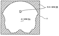
この画像表示装置5の画面上には、例えば図2に示すように、各種画像の表示が行われる表示領域5Aと、画像表示が制限される非表示領域5Bとが設けられている。例えば、特別図柄表示装置4の前面における配置部分や、遊技領域の周縁部に設けられる装飾部材31、32、33の背面における配置部分、及び遊技領域を外れた遊技機用枠3の背面における配置部分などには、画像を表示するための液晶や液晶を構成する部材(例えば偏光板など)、液晶を制御する回路などが設けられておらず、物理的に画像を表示せずに透明なままの非表示領域5Bとなっている。他方、表示領域5Aの裏面には、例えば背後から表示領域5Aを照射するバックライトや、パチンコ遊技機1の内部を隠蔽する隠蔽部材などが設けられている。   On the screen of the image display device 5, for example, as shown in FIG. 2, a display area 5A where various images are displayed and a non-display area 5B where image display is restricted are provided. For example, an arrangement portion on the front surface of the special symbol display device 4, an arrangement portion on the back surface of the decorative members 31, 32, 33 provided on the peripheral portion of the game area, and an arrangement on the back surface of the gaming machine frame 3 outside the game area The part is not provided with a liquid crystal for displaying an image, a member constituting the liquid crystal (for example, a polarizing plate), a circuit for controlling the liquid crystal, etc., and remains transparent without displaying an image physically. The non-display area 5B. On the other hand, on the back surface of the display area 5A, for example, a backlight that irradiates the display area 5A from behind, a concealing member that conceals the interior of the pachinko gaming machine 1, and the like are provided.

普通可変入賞球装置6は、ソレノイド81(図3)によって垂直(通常開放)位置と傾動(拡大開放)位置との間で可動制御される一対の可動翼片を有する電動チューリップ型役物(普通電動役物)を備え、始動入賞口を形成する。普通可変入賞球装置6に形成された始動入賞口へと進入した遊技球は、始動口スイッチ22(図3)によって検出され、その検出に基づき特図ゲームを実行するための実行条件(始動条件)が成立する。始動口スイッチ22によって遊技球が検出されたことに基づいて、所定個数(例えば4個)の賞球の払い出しが行われる。   The normal variable winning ball apparatus 6 is an electric tulip-type accessory (ordinary normal) having a pair of movable wing pieces that are controlled by a solenoid 81 (FIG. 3) between a vertical (normally open) position and a tilt (enlarged open) position. It has an electric accessory) and forms a start winning opening. The game ball that has entered the start winning opening formed in the normal variable winning ball apparatus 6 is detected by the start opening switch 22 (FIG. 3), and an execution condition (starting condition) for executing the special game based on the detection. ) Holds. Based on the detection of the game ball by the start port switch 22, a predetermined number (for example, four) of prize balls are paid out.

特別可変入賞球装置7は、ソレノイド82(図3)によって入賞領域となる大入賞口を開成・閉成制御する開閉板を備えて構成される。この開閉板は、例えばパチンコ遊技機1の電源投入後に大当り遊技状態が発生する以前までのような通常時には、大入賞口を閉成した状態にある。他方、特別図柄表示装置4による特図ゲームにおける可変表示結果に基づいて大当り遊技状態となった場合に、ソレノイド82によって大入賞口を所定期間あるいは所定個数の入賞球が発生するまでの期間において開成した後、閉成する。ここで、大入賞口に入賞して遊技盤2の背面に導かれた遊技球のうち一方の領域(V入賞領域;特別領域)に入ったものはV入賞スイッチ23(図3)で検出された後にカウントスイッチ24で検出され、他方の領域に入った遊技球は、そのままカウントスイッチ24で検出されるようにしてもよい。この場合、遊技盤2の背面には、大入賞口内の経路を切り替えるためのソレノイドが設けられていてもよい。そして、大当り遊技状態における最終ラウンド以外の各ラウンドでは、V入賞スイッチ23によって遊技球が検出されることが、次のラウンドへと移行できるための条件となるようにしてもよい。あるいは、V入賞領域を設けずに、大当り遊技状態における最終ラウンド以外の各ラウンドでは、常に次のラウンドへと移行できるようにしてもよい。   The special variable winning ball apparatus 7 includes an opening / closing plate that opens and closes a large winning opening serving as a winning area by a solenoid 82 (FIG. 3). The opening / closing plate is in a state in which the big prize opening is closed at a normal time, for example, before the big hit gaming state occurs after the power of the pachinko gaming machine 1 is turned on. On the other hand, when a big hit gaming state is achieved based on the variable display result in the special symbol game by the special symbol display device 4, the big winning opening is opened by the solenoid 82 for a predetermined period or until a predetermined number of winning balls are generated. After closing. Here, out of the game balls led to the back of the game board 2 after winning the big winning opening and entering one area (V winning area; special area) is detected by the V winning switch 23 (FIG. 3). A game ball that is detected by the count switch 24 and enters the other area may be detected by the count switch 24 as it is. In this case, a solenoid for switching the route in the special winning opening may be provided on the back of the game board 2. Then, in each round other than the final round in the big hit gaming state, the detection of the game ball by the V winning switch 23 may be a condition for shifting to the next round. Alternatively, without providing the V winning area, it is possible to always shift to the next round in each round other than the final round in the big hit gaming state.

また、遊技盤2の表面には、上記の構成以外にも、ランプを内蔵した風車、アウト口等が設けられている。遊技機用枠3の左右上部位置には、効果音等を再生出力する効果音発生装置としてのスピーカ8L、8Rが設けられている。さらに遊技領域周辺部には、電飾部材としての遊技効果ランプ9が設けられている。パチンコ遊技機1の遊技領域における各構造物(例えば普通可変入賞球装置6や特別可変入賞球装置7等)の周囲には電飾部材に含まれる装飾用LEDが設置されていてもよい。遊技機用枠3の右下部位置には、遊技球を発射するために遊技者等によって操作される打球操作ハンドル(操作ノブ)が設けられている。   In addition to the above configuration, the surface of the game board 2 is provided with a windmill with a built-in lamp, an outlet, and the like. Speakers 8L and 8R as sound effect generators for reproducing and outputting sound effects and the like are provided at the left and right upper positions of the gaming machine frame 3. Further, a game effect lamp 9 as an electric decoration member is provided in the periphery of the game area. A decorative LED included in the electric decoration member may be installed around each structure (for example, the normal variable winning ball device 6 or the special variable winning ball device 7) in the game area of the pachinko gaming machine 1. A hitting operation handle (operation knob) operated by a player or the like to launch a game ball is provided at a lower right position of the gaming machine frame 3.

パチンコ遊技機1には、例えば図3に示すような電源基板10、主基板11、演出制御基板12といった、各種の制御基板が搭載されている。主基板11と演出制御基板12との間には、主基板11から演出制御基板12へと伝送される各種の制御信号を中継するための信号中継基板13なども設けられている。その他にも、パチンコ遊技機1には、払出制御基板や発射制御基板、インタフェース基板などといった、各種基板が設けられていてもよい。   Various control boards such as a power supply board 10, a main board 11, and an effect control board 12 as shown in FIG. 3 are mounted on the pachinko gaming machine 1. Between the main board 11 and the effect control board 12, a signal relay board 13 for relaying various control signals transmitted from the main board 11 to the effect control board 12 is also provided. In addition, the pachinko gaming machine 1 may be provided with various boards such as a payout control board, a launch control board, and an interface board.

電源基板10は、主基板11や演出制御基板12等の各制御基板と独立して設置され、パチンコ遊技機1内の各制御基板及び機構部品が使用する電圧を生成する。例えば、電源基板10では、AC24V、VLP(直流+24V)、VSL(直流+30V)、VDD(直流+12V)、VCC(直流+5V)及びVBB(直流+5V)を生成する。電源基板10は、例えば変圧回路と、直流電圧生成回路と、電源監視回路とを備えて構成される。また、電源基板10には、押下操作などの所定操作に応じてクリア信号を出力するクリアスイッチや、バックアップ電源となるコンデンサが設けられていてもよい。加えて、電源基板10には、パチンコ遊技機1内の各制御基板及び機構部品への電力供給を実行または遮断するための電源スイッチが設けられていてもよい。あるいは、電源スイッチは、パチンコ遊技機1において、電源基板10の外に設けられていてもよい。   The power supply board 10 is installed independently of each control board such as the main board 11 and the effect control board 12, and generates a voltage used by each control board and mechanism component in the pachinko gaming machine 1. For example, the power supply board 10 generates AC24V, VLP (DC + 24V), VSL (DC + 30V), VDD (DC + 12V), VCC (DC + 5V), and VBB (DC + 5V). The power supply board 10 includes, for example, a transformer circuit, a DC voltage generation circuit, and a power supply monitoring circuit. Further, the power supply substrate 10 may be provided with a clear switch that outputs a clear signal in response to a predetermined operation such as a pressing operation, or a capacitor that serves as a backup power supply. In addition, the power supply board 10 may be provided with a power switch for executing or cutting off the power supply to each control board and the mechanical components in the pachinko gaming machine 1. Alternatively, the power switch may be provided outside the power supply board 10 in the pachinko gaming machine 1.

図3に示す主基板11は、メイン側の制御基板であり、パチンコ遊技機1における遊技の進行を制御するための各種回路が搭載されている。主基板11は、主として、特図ゲームにおいて用いる乱数の設定機能、所定位置に配設されたスイッチ等からの信号の入力を行う機能、演出制御基板12などからなるサブ側の制御基板に宛てて、指令情報の一例となる制御コマンドを制御信号として出力して送信する機能、ホールの管理コンピュータに対して各種情報を出力する機能などを備えている。また、主基板11は、特別図柄表示装置4を構成する各セグメントの点灯/消灯制御を行うことにより特別図柄表示装置4における特別図柄の変動表示を制御する一方で、普通図柄表示装置20の点灯/点滅/発色制御を行うことにより普通図柄表示装置20における普通図柄の変動表示を制御する。主基板11には、例えば遊技制御用マイクロコンピュータ100や、遊技球検出用の各種スイッチからの検出信号を取り込んで遊技制御用マイクロコンピュータ100に伝送するスイッチ回路101、遊技制御用マイクロコンピュータ100からの指令に従って各ソレノイド81、82に対する駆動信号を出力するソレノイド回路102などが搭載されている。   The main board 11 shown in FIG. 3 is a main-side control board, and various circuits for controlling the progress of the game in the pachinko gaming machine 1 are mounted. The main board 11 is mainly addressed to a sub-side control board composed of a random number setting function used in a special game, a function of inputting a signal from a switch or the like disposed at a predetermined position, and an effect control board 12. A function of outputting and transmitting a control command as an example of command information as a control signal, a function of outputting various information to a hall management computer, and the like are provided. The main board 11 controls the special symbol display on the special symbol display device 4 by controlling the lighting / extinction of each segment constituting the special symbol display device 4, while the normal symbol display device 20 is turned on. By controlling the blinking / coloring control, the normal symbol display on the normal symbol display device 20 is controlled. The main board 11 includes, for example, a game control microcomputer 100, a switch circuit 101 that receives detection signals from various switches for game ball detection and transmits them to the game control microcomputer 100, and the game control microcomputer 100. A solenoid circuit 102 that outputs a drive signal for each of the solenoids 81 and 82 according to the command is mounted.

図3に示すように、主基板11には、ゲートスイッチ21、始動口スイッチ22、V入賞スイッチ23、カウントスイッチ24からの検出信号を受信するための配線が接続されている。なお、ゲートスイッチ21、始動口スイッチ22、V入賞スイッチ23、カウントスイッチ24は、例えばセンサと称されるものなどのように、遊技媒体としての遊技球を検出できる任意の構成を有するものであればよい。加えて、主基板11には、普通可変入賞球装置6における可動翼片の傾動制御を行うための指令信号をソレノイド81に伝送する配線や、特別可変入賞球装置7における開閉板の開閉制御を行うための指令信号をソレノイド82に伝送する配線が接続されている。さらに、主基板11には、特別図柄表示装置4や普通図柄表示装置20の表示制御を行うための指令信号を伝送する配線が接続されている。   As shown in FIG. 3, wiring for receiving detection signals from the gate switch 21, the start port switch 22, the V winning switch 23, and the count switch 24 is connected to the main board 11. Note that the gate switch 21, the start port switch 22, the V winning switch 23, and the count switch 24 may have any configuration that can detect a game ball as a game medium, such as a sensor. That's fine. In addition, the main board 11 is provided with wiring for transmitting a command signal for performing tilt control of the movable blade piece in the normal variable winning ball apparatus 6 to the solenoid 81 and opening / closing control of the opening / closing plate in the special variable winning ball apparatus 7. A wiring for transmitting a command signal for performing the operation to the solenoid 82 is connected. Furthermore, the main board 11 is connected to a wiring for transmitting a command signal for performing display control of the special symbol display device 4 and the normal symbol display device 20.

主基板11から演出制御基板12に向けて出力される制御信号は、信号中継基板13によって中継される。主基板11には、例えば信号中継基板13に対応する主基板側コネクタが設けられ、主基板側コネクタと遊技制御用マイクロコンピュータ100との間には、出力バッファ回路が接続されている。出力バッファ回路は、主基板11から信号中継基板13を介して演出制御基板12へ向かう方向にのみ信号を通過させることができ、信号中継基板13から主基板11への信号の入力を阻止する。従って、演出制御基板12や信号中継基板13の側から主基板11側に信号が伝わる余地はない。   A control signal output from the main board 11 toward the effect control board 12 is relayed by the signal relay board 13. The main board 11 is provided with a main board side connector corresponding to, for example, the signal relay board 13, and an output buffer circuit is connected between the main board side connector and the game control microcomputer 100. The output buffer circuit can pass a signal only in the direction from the main board 11 to the effect control board 12 via the signal relay board 13 and prevents the signal from being input from the signal relay board 13 to the main board 11. Therefore, there is no room for signals to be transmitted from the production control board 12 or the signal relay board 13 side to the main board 11 side.

信号中継基板13には、例えば主基板11から演出制御基板12に対して出力される制御信号を伝送するための配線毎に、伝送方向規制回路が設けられていればよい。各伝送方向規制回路は、主基板11対応の主基板用コネクタにアノードが接続されるとともに演出制御基板12対応の演出制御基板用コネクタにカソードが接続されたダイオードと、一端がダイオードのカソードに接続されるとともに他端がグランド(GND)接続された抵抗とから構成されている。この構成により、各伝送方向規制回路は、演出制御基板12から信号中継基板13への信号の入力を阻止して、主基板11から演出制御基板12へ向かう方向にのみ信号を通過させることができる。従って、演出制御基板12の側から主基板11側に信号が伝わる余地はない。なお、主基板への不正な信号の入力を防ぐために、主基板とサブ基板との間に主基板からサブ基板への信号の出力のみを規制する一方向データ転送手段を設けたものは既に提案されている(例えば、特開平8−224339号公報などを参照)。しかしながら、主基板と一方向データ転送手段との間には主基板への信号入力を規制するものがないため、一方向データ転送手段に改変を加えることで主基板に不正な信号を入力させることが可能であった。この実施の形態では、信号中継基板13において制御信号を伝送するための配線毎に伝送方向規制回路を設けるとともに、主基板11にて遊技制御用マイクロコンピュータ100と主基板側コネクタの間に出力バッファ回路を設けることで、外部から主基板11への不正な信号の入力を、より確実に防止することができる。   The signal relay board 13 may be provided with a transmission direction regulating circuit for each wiring for transmitting a control signal output from the main board 11 to the effect control board 12, for example. Each transmission direction regulating circuit includes a diode having an anode connected to the main board connector corresponding to the main board 11 and a cathode connected to the presentation control board connector corresponding to the presentation control board 12, and one end connected to the cathode of the diode. And a resistor having the other end connected to the ground (GND). With this configuration, each transmission direction regulating circuit can prevent signals from being input from the effect control board 12 to the signal relay board 13 and pass signals only in the direction from the main board 11 to the effect control board 12. . Therefore, there is no room for signals to be transmitted from the production control board 12 side to the main board 11 side. In order to prevent unauthorized input of signals to the main board, a one-way data transfer means that restricts only the signal output from the main board to the sub board between the main board and the sub board has already been proposed. (See, for example, JP-A-8-224339). However, since there is nothing that regulates signal input to the main board between the main board and the one-way data transfer means, it is possible to input illegal signals to the main board by modifying the one-way data transfer means. Was possible. In this embodiment, a transmission direction regulating circuit is provided for each wiring for transmitting a control signal in the signal relay board 13, and an output buffer is provided between the game control microcomputer 100 and the main board side connector on the main board 11. By providing the circuit, it is possible to more reliably prevent an illegal signal input from the outside to the main board 11.

このような信号中継基板13を介して主基板11から演出制御基板12に対して送信される制御コマンドは、例えば電気信号として伝送される演出制御コマンドである。演出制御コマンドには、例えば画像表示装置5における画像表示動作を制御するために用いられる表示制御コマンドや、スピーカ8L、8Rからの音声出力を制御するために用いられる音声制御コマンド、遊技効果ランプ9や装飾用LEDの点灯動作などを制御するために用いられるランプ制御コマンドが含まれている。図4は、この実施の形態で用いられる演出制御コマンドの内容の一例を示す説明図である。演出制御コマンドは、例えば2バイト構成であり、1バイト目はMODE(コマンドの分類)を示し、2バイト目はEXT(コマンドの種類)を表す。MODEデータの先頭ビット(ビット7)は必ず「1」とされ、EXTデータの先頭ビットは「0」とされる。なお、図4に示されたコマンド形態は一例であって、他のコマンド形態を用いてもよい。また、この例では、制御コマンドが2つの制御信号で構成されることになるが、制御コマンドを構成する制御信号数は、1であってもよいし、3以上の複数であってもよい。   The control command transmitted from the main board 11 to the effect control board 12 via the signal relay board 13 is an effect control command transmitted as an electric signal, for example. The effect control command includes, for example, a display control command used to control an image display operation in the image display device 5, a voice control command used to control sound output from the speakers 8L and 8R, and a game effect lamp 9 And a lamp control command used for controlling the lighting operation of the decorative LED and the like. FIG. 4 is an explanatory diagram showing an example of the contents of the effect control command used in this embodiment. The effect control command has, for example, a 2-byte structure, and the first byte indicates MODE (command classification), and the second byte indicates EXT (command type). The first bit (bit 7) of the MODE data is always “1”, and the first bit of the EXT data is “0”. The command form shown in FIG. 4 is an example, and other command forms may be used. In this example, the control command is composed of two control signals. However, the number of control signals constituting the control command may be one or a plurality of three or more.

図4に示す例において、コマンド80XXhは、特別図柄表示装置4による特図ゲームで特別図柄の可変表示を開始するときに送信される可変表示開始コマンドである。なお、XXhは不特定の16進数であるであることを示し、演出制御コマンドによる指示内容に応じて任意に設定される値であればよい。可変表示開始コマンドでは、例えば特別図柄や飾り図柄の可変表示パターンなどに対応して異なるEXTデータが設定される。この実施の形態では、飾り図柄の可変表示態様がリーチとなることなくハズレ組合せの確定飾り図柄を導出表示する可変表示パターンとして、通常ハズレパターンが複数種類用意されている。また、飾り図柄の可変表示態様をリーチとした後に大当り組合せまたはハズレ組合せの確定飾り図柄を導出表示する可変表示パターンとして、リーチパターンが複数種類用意されている。   In the example shown in FIG. 4, the command 80XXh is a variable display start command that is transmitted when the special symbol display device 4 starts the variable symbol special symbol display in the special symbol game. XXh indicates an unspecified hexadecimal number, and may be a value arbitrarily set according to the instruction content by the effect control command. In the variable display start command, for example, different EXT data is set corresponding to a variable display pattern of a special symbol or a decorative symbol. In this embodiment, a plurality of types of normal losing patterns are prepared as variable display patterns for deriving and displaying a definitive decorative symbol of a losing combination without the decorative symbol variable display mode becoming reach. Also, a plurality of reach patterns are prepared as variable display patterns for deriving and displaying a definite decorative combination of a big hit combination or a lost combination after setting the variable display mode of the decorative design as reach.

ここで、リーチとは、画像表示装置5にて導出表示した飾り図柄が大当り組合せの一部を構成しているときに未だ導出表示していない飾り図柄(リーチ変動図柄という)については変動表示が行われている表示態様、あるいは、全て又は一部の飾り図柄が大当り図柄の全て又は一部を構成しながら同期して変動表示している表示態様のことである。具体的には、予め定められた組合せ有効ライン上の一部の可変表示部に予め定められた大当り組合せを構成する図柄を停止表示しているときに未だ停止表示していない組合せ有効ライン上の可変表示部において変動表示が行われている表示態様(例えば、表示領域に設けられた「左」、「中」、「右」の可変表示部のうち「左」、「右」の可変表示部には大当り図柄の一部となる(例えば「7」の数字を示す飾り図柄)が停止表示されている状態で「中」の可変表示部は未だ変動表示が行われている表示態様)、あるいは、有効ライン上の可変表示部の全て又は一部の飾り図柄が大当り図柄の全て又は一部を構成しながら同期して変動表示している表示態様(例えば、表示領域に設けられた「左」、「中」、「右」の可変表示部の全てで変動表示が行われてどの状態が表示されても同一の飾り図柄が揃っている態様で変動表示が行われている表示態様)である。また、リーチの際に、通常と異なる演出がランプや音などで行われることがある。この演出をリーチ演出という。また、リーチの際に、画像表示装置5にてキャラクタ(人物等を模した演出表示であり、飾り図柄とは異なるもの)を表示させたり、背景の表示態様を変化させたり、飾り図柄の変動表示態様を変化させたりすることがある。このキャラクタの表示や背景の表示態様、飾り図柄の変動態様の変化を、リーチ演出表示という。   Here, the reach means that a decorative display (referred to as a reach variation pattern) that has not yet been derived and displayed when the decorative pattern derived and displayed by the image display device 5 forms a part of the jackpot combination is a variable display. It is a display mode that is being performed, or a display mode in which all or some of the decorative symbols are synchronously displayed while constituting all or part of the jackpot symbol. Specifically, on the combination effective line that has not been stopped yet when the symbols constituting the predetermined jackpot combination are stopped and displayed on some of the variable display portions on the predetermined combination effective line. Display mode in which variable display is performed in the variable display section (for example, “left”, “right” variable display sections among the “left”, “middle”, “right” variable display sections provided in the display area Is a display mode in which a variable display part of “medium” is still in a variable display state while a part of the jackpot symbol (for example, a decorative symbol indicating the number “7”) is stopped and displayed, or A display mode in which all or part of the decorative symbols on the variable display portion on the effective line are synchronously displayed while constituting all or part of the jackpot symbol (for example, “left” provided in the display area) , Fluctuate in all of the “middle” and “right” variable displays It shows a display manner in variable display is being performed manner which state is performed have all the same decoration pattern be displayed). In addition, during the reach, unusual effects may be performed with lamps or sounds. This production is called reach production. Further, during the reach, the image display device 5 displays a character (an effect display imitating a person or the like, which is different from the decorative design), changes the display mode of the background, or changes the decorative design. The display mode may be changed. This change in character display, background display mode, and decorative pattern variation mode is referred to as reach effect display.

コマンド90XXhは、特別図柄や飾り図柄の可変表示結果の種類などを示す表示結果通知コマンドである。表示結果通知コマンドでは、例えば飾り図柄の可変表示などの実行結果として停止表示される飾り図柄の表示結果が、リーチとならずにハズレとなる通常ハズレであるか、リーチとなった後にハズレとなるリーチハズレであるか、リーチとなった後に大当りとなるかなどといった、表示結果の種類に対応して、異なるEXTデータが設定される。   The command 90XXh is a display result notification command indicating the type of variable display result of special symbols and decorative symbols. In the display result notification command, for example, the display result of the decorative symbol that is stopped and displayed as an execution result of the variable display of the decorative symbol, for example, is a normal loss that is lost instead of reaching, or is lost after reaching reach Different EXT data is set in accordance with the type of display result, such as whether it is a reach loss or a big hit after reaching reach.

コマンドA000hは、特別図柄表示装置4による特図ゲームや画像表示装置5における飾り図柄の可変表示にて大当りとなったことにより、大当り遊技状態が開始されることを示す大当り開始コマンドである。コマンドA1XXhは、大当り遊技状態において開始されるラウンドの回数を示す大当りラウンド数通知コマンドである。コマンドB000hは、大当り遊技状態が終了することを示す大当り終了コマンドである。   The command A000h is a big hit start command indicating that the big hit gaming state is started when a big hit is made in the special symbol game by the special symbol display device 4 or the variable display of the decorative symbols on the image display device 5. The command A1XXh is a jackpot round number notification command indicating the number of rounds started in the jackpot gaming state. Command B000h is a jackpot end command indicating that the jackpot gaming state is ended.

図5は、主基板11に搭載された遊技制御用マイクロコンピュータ100の構成例を示す図である。図5に示す遊技制御用マイクロコンピュータ100は、例えば1チップマイクロコンピュータであり、CPU(Central Processing Unit)111と、ROM(Read Only Memory)112と、RAM(Random Access Memory)113と、乱数回路114と、入出力ポート115とを備えて構成されている。CPU111は、ROM112に記憶されているユーザプログラムやデータを読み出し、RAM113をワークエリアとして使用して、プログラムに従った制御動作を行う。   FIG. 5 is a diagram illustrating a configuration example of the game control microcomputer 100 mounted on the main board 11. A game control microcomputer 100 shown in FIG. 5 is, for example, a one-chip microcomputer, and includes a CPU (Central Processing Unit) 111, a ROM (Read Only Memory) 112, a RAM (Random Access Memory) 113, and a random number circuit 114. And an input / output port 115. The CPU 111 reads the user program and data stored in the ROM 112, and uses the RAM 113 as a work area to perform a control operation according to the program.

主基板11では、乱数回路114によって、主基板11の側において用いられる各種の乱数の全てまたは一部が生成される。例えば、主基板11の側では、大当り判定用の乱数値や普通当り判定用の乱数値、リーチ判定用の乱数値、可変表示パターン決定用の乱数値などが用いられる。なお、遊技効果を高めるために、主基板11の側でこれら以外の乱数値が用いられてもよい。これらの乱数値を示す数値データの全てまたは一部は、乱数回路114にてカウントされればよい。また、これらの乱数値の一部を示す数値データは、CPU111が乱数回路114とは異なるランダムカウンタを用いて、ソフトウェアによる更新によってカウントするようにしてもよい。   In the main board 11, the random number circuit 114 generates all or a part of various random numbers used on the main board 11 side. For example, on the main board 11 side, a random number value for jackpot determination, a random number value for ordinary hit determination, a random value for reach determination, a random value for variable display pattern determination, or the like is used. In order to enhance the gaming effect, random numbers other than these may be used on the main board 11 side. All or part of the numerical data indicating these random numbers may be counted by the random number circuit 114. Further, numerical data indicating a part of these random number values may be counted by updating by software using a random counter different from the random number circuit 114 by the CPU 111.

大当り判定用の乱数値は、大当りの発生によりパチンコ遊技機1が大当り遊技状態となるか否かの判定を行うために用いられる乱数値である。すなわち、大当り判定用の乱数値は、特別図柄表示装置4による特図ゲームや画像表示装置5における飾り図柄の可変表示での表示結果の種類が大当りとなるかハズレとなるかの判定を行うために用いられる。普通当り判定用の乱数値は、普通図柄表示装置20による普通図ゲームにおける表示結果を「当り」とするか否かの判定を行うために用いられる乱数値である。リーチ判定用の乱数値は、飾り図柄の可変表示態様をリーチとするか否かの判定を行うために用いられる乱数値である。可変表示パターン決定用の乱数値は、特別図柄や飾り図柄の可変表示パターンを、予め用意された複数種類のいずれかに決定するために用いられる表示用の乱数値である。   The random number value for jackpot determination is a random value used for determining whether or not the pachinko gaming machine 1 is in the jackpot gaming state due to occurrence of the jackpot. That is, the random number value for determining the big hit is used to determine whether the type of display result in the special display game by the special symbol display device 4 or the variable display of the decorative symbols in the image display device 5 is a big hit or a loss. Used for. The random number value for determining the normal hit is a random value used for determining whether or not the display result of the normal symbol game by the normal symbol display device 20 is “win”. The reach determination random number value is a random value used for determining whether or not the variable display mode of decorative symbols is to be reached. The random number value for variable display pattern determination is a random number value for display that is used to determine a variable display pattern of a special symbol or a decorative symbol as one of a plurality of types prepared in advance.

ROM112には、ゲーム制御用のユーザプログラムの他にも、遊技の進行を制御するために用いられる各種のデータテーブルが格納されている。例えば、ROM112は、CPU111が各種の判定や決定を行うために用意された複数の判定テーブルや決定テーブルを構成するテーブルデータを記憶する。判定テーブルとしては、特図ゲームにおける確定特別図柄を大当り図柄として可変表示結果を大当りとする否かを判定するために参照される大当り判定テーブルや、普通図ゲームにおける表示結果を「当り」とするか否かを判定するために参照される普通当り判定テーブル、特別図柄や飾り図柄の可変表示結果がハズレとなるときに飾り図柄の可変表示態様をリーチとするか否かを判定するために参照されるリーチ判定テーブルなどが含まれている。   In addition to the game control user program, the ROM 112 stores various data tables used for controlling the progress of the game. For example, the ROM 112 stores table data constituting a plurality of determination tables and determination tables prepared for the CPU 111 to make various determinations and determinations. As a determination table, a big hit determination table referred to for determining whether or not a variable display result is a big hit with a confirmed special symbol in a special figure game as a big hit symbol, or a display result in a normal figure game is set to “win”. Ordinary hit determination table referred to determine whether or not the variable symbol display mode of the special symbol or decorative symbol is lost when the variable symbol display result of the special symbol or decorative symbol is lost. The reach determination table to be used is included.

大当り判定テーブルは、大当り判定用の乱数値が特図ゲームの表示結果を大当りとすることを示す大当り判定値データと合致するか、特図ゲームの表示結果をハズレとすることを示すハズレ判定値データと合致するかを、判定可能にする設定データなどから構成されていればよい。普通当り判定テーブルは、普通当り判定用の乱数値が普通図ゲームの表示結果を「当り」とすることを示す普通当り判定値データと合致するか、普通図ゲームの表示結果を「ハズレ」とすることを示すハズレ判定値データと合致するかを、判定可能にする設定データなどから構成されていればよい。リーチ判定テーブルは、リーチ判定用の乱数値が飾り図柄の可変表示態様をリーチとすることを示すリーチ判定値データと合致するか、リーチとしない通常ハズレ判定値データと合致するかを、判定可能にする設定データなどから構成されていればよい。   The big hit determination table is a loss determination value indicating that the random number for determining the big hit matches the big hit determination value data indicating that the display result of the special figure game is a big hit or the display result of the special figure game is lost. What is necessary is just to be comprised from the setting data etc. which can determine whether it corresponds with data. In the normal hit determination table, the random number for determining the normal hit matches the normal hit determination value data indicating that the display result of the normal game is “win”, or the display result of the normal game is “lost”. What is necessary is just to be comprised from the setting data etc. which can determine whether it corresponds with the loss determination value data which show doing. The reach determination table can determine whether the reach determination random number value matches the reach determination value data indicating that the variable display mode of the decorative design is reached, or the normal loss determination value data that is not reached It only has to be configured from setting data to be set.

ROM112に記憶される決定テーブルには、特図ゲームでの可変表示結果として導出表示する確定特別図柄を決定するための確定特別図柄決定テーブルや、特別図柄や飾り図柄の可変表示パターンを決定するための可変表示パターン決定テーブルなどが含まれている。   In the determination table stored in the ROM 112, a fixed special symbol determination table for determining a fixed special symbol to be derived and displayed as a variable display result in a special symbol game, or a variable display pattern of a special symbol or a decorative symbol is determined. The variable display pattern determination table is included.

可変表示パターン決定テーブルは、例えば各可変表示パターンと、可変表示パターン決定用の乱数値とを対応付けることにより、可変表示パターン決定用の乱数値に基づいて可変表示パターンの選択を可能にする選択データなどから構成されていればよい。可変表示パターン決定テーブルにて各可変表示パターンを示すデータは、例えば可変表示パターン決定テーブル内において、あるいは可変表示パターン決定テーブルとは異なる可変表示パターン設定用のテーブルなどにおいて、特別図柄や飾り図柄の総可変表示時間を示すデータや、可変表示開始コマンドにてEXTデータとして設定される制御データなどと、対応付けられていればよい。   The variable display pattern determination table is, for example, selection data that enables selection of a variable display pattern based on a random display pattern determination random number value by associating each variable display pattern with a random display pattern determination random value. And so on. The data indicating each variable display pattern in the variable display pattern determination table is, for example, in the variable display pattern determination table or in a variable display pattern setting table different from the variable display pattern determination table. It only needs to be associated with data indicating the total variable display time, control data set as EXT data by the variable display start command, and the like.

RAM113には、パチンコ遊技機1における遊技状態などを制御するために用いられる各種のデータを保持する領域が設けられている。例えば、RAM113には、特図保留記憶部、普通図保留記憶部、確定特別図柄記憶部、遊技制御フラグ設定部、遊技制御タイマ設定部、遊技制御カウンタ設定部、遊技制御バッファ設定部などとして、各種のデータを保持する領域が設けられていればよい。   The RAM 113 is provided with an area for holding various data used for controlling the gaming state and the like in the pachinko gaming machine 1. For example, in the RAM 113, as a special figure storage unit, a normal diagram storage unit, a confirmed special symbol storage unit, a game control flag setting unit, a game control timer setting unit, a game control counter setting unit, a game control buffer setting unit, etc. It is only necessary to provide an area for holding various data.

特図保留記憶部は、普通可変入賞球装置6が形成する始動入賞口に遊技球が進入(入賞)して特別図柄表示装置4による特図ゲームを実行するための実行条件が成立したものの、従前の特図ゲームを実行中である等の理由のために可変表示を開始するための開始条件が成立していない特図ゲームに関する保留情報を記憶する。例えば、特図保留記憶部は、始動入賞口への入賞順に保留番号と関連付けて、その入賞による実行条件の成立に基づいてCPU111により乱数回路114等から抽出された大当り判定用の乱数値を示す数値データを保留データとし、その数が所定の上限値(例えば「4」)に達するまで記憶する。   Although the special figure holding storage unit has an execution condition for executing the special figure game by the special symbol display device 4 when the game ball enters (wins) the start winning opening formed by the normally variable winning ball device 6, On-hold information relating to a special figure game in which a start condition for starting variable display is not satisfied due to reasons such as executing a conventional special figure game is stored. For example, the special figure holding storage unit associates with the holding number in the order of winning to the start winning opening, and shows the random value for jackpot determination extracted from the random number circuit 114 or the like by the CPU 111 based on the establishment of the execution condition by the winning. Numerical data is stored as pending data, and stored until the number reaches a predetermined upper limit (eg, “4”).

普通図保留記憶部は、遊技領域に設けられた通過ゲート41を遊技球が通過して普通図柄表示装置20による普通図ゲームを実行するための実行条件が成立したものの、従前の普通図ゲームを実行中である等の理由のために可変表示を開始するための開始条件が成立していない普通図ゲームに関する保留情報を記憶する。例えば、普通図保留記憶部は、通過ゲート41を遊技球が通過した順番で保留番号と関連付けて、その通過による実行条件の成立に基づいてCPU111により乱数回路114等から抽出された普通当り判定用の乱数値を示す数値データを保留データとし、その数が所定の上限値(例えば「4」)に達するまで記憶する。   The normal diagram holding storage unit stores the previous normal diagram game although the execution condition for the normal symbol display device 20 to execute the normal diagram game is satisfied when the game ball passes through the passing gate 41 provided in the game area. On-hold information relating to a normal game in which a start condition for starting variable display is not satisfied due to reasons such as being executed is stored. For example, the normal diagram hold storage unit associates with the hold numbers in the order in which the game balls have passed through the passing gate 41, and for normal hit determination extracted from the random number circuit 114 or the like by the CPU 111 based on the establishment of the execution condition by the passage. Is stored as pending data, and the number is stored until the number reaches a predetermined upper limit (eg, “4”).

確定特別図柄記憶部は、特別図柄表示装置4による特図ゲームにて可変表示結果として導出表示される確定特別図柄を示すデータを記憶する。遊技制御フラグ設定部は、パチンコ遊技機1における遊技状態やスイッチ回路101を介して各種スイッチから伝送された信号等に応じて、各々セットあるいはクリアされる複数種類のフラグを設定するためのデータを記憶する。遊技制御タイマ設定部は、パチンコ遊技機1での遊技制御に用いられる複数種類のタイマ値を示すデータを記憶する。遊技制御カウンタ設定部は、パチンコ遊技機1での遊技制御に用いられる複数種類のカウント値を示すデータを記憶する。遊技制御バッファ設定部は、パチンコ遊技機1での遊技制御に用いられる各種のデータを一時的に記憶する。なお、フラグ設定やカウンタ/タイマに用いる回路は、RAM113とは別に設けたレジスタ回路などによって構成してもよい。   The confirmed special symbol storage unit stores data indicating a confirmed special symbol derived and displayed as a variable display result in a special symbol game by the special symbol display device 4. The game control flag setting unit stores data for setting a plurality of types of flags that are set or cleared in accordance with the gaming state in the pachinko gaming machine 1, signals transmitted from various switches via the switch circuit 101, and the like. Remember. The game control timer setting unit stores data indicating a plurality of types of timer values used for game control in the pachinko gaming machine 1. The game control counter setting unit stores data indicating a plurality of types of count values used for game control in the pachinko gaming machine 1. The game control buffer setting unit temporarily stores various data used for game control in the pachinko gaming machine 1. The circuit used for flag setting and counter / timer may be constituted by a register circuit provided separately from the RAM 113.

入出力ポート115は、遊技制御用マイクロコンピュータ100に伝送された各種信号を取り込むための入力ポートと、遊技制御用マイクロコンピュータ100の外部へと各種信号を伝送するための出力ポートとを含んで構成されている。   The input / output port 115 includes an input port for taking in various signals transmitted to the game control microcomputer 100 and an output port for transmitting various signals to the outside of the game control microcomputer 100. Has been.

図3に示す演出制御基板12は、主基板11とは独立したサブ側の制御基板であり、信号中継基板13を介して主基板11から送信された制御コマンドを受信して、画像表示装置5、スピーカ8L、8R及び遊技効果ランプ9といった演出用の電気部品を制御するための各種回路が搭載されている。すなわち、演出制御基板12は、画像表示装置5における表示動作や、スピーカ8L、8Rからの音声出力動作、遊技効果ランプ9におけるランプの点灯動作及び消灯動作などといった、演出用の電気部品に所定の演出動作を実行させるための制御内容を決定する機能を備えている。   The effect control board 12 shown in FIG. 3 is a sub-side control board independent of the main board 11, receives a control command transmitted from the main board 11 via the signal relay board 13, and receives the image display device 5. In addition, various circuits for controlling electric parts for production such as the speakers 8L and 8R and the game effect lamp 9 are mounted. That is, the effect control board 12 has predetermined electrical components for effects such as display operation in the image display device 5, sound output operation from the speakers 8L and 8R, and lamp lighting operation and extinguishing operation in the game effect lamp 9. It has a function of determining the control content for executing the rendering operation.

演出制御基板12には、画像表示装置5に映像信号を伝送する配線や、スピーカ8L、8R及び遊技効果ランプ9に駆動信号を伝送する配線などが接続されている。図3に示すように、演出制御基板12には、演出制御用マイクロコンピュータ120と、表示制御部121と、音制御部122と、ランプ制御部123と、ウォッチドッグ付リセットIC124と、電力制御回路125とが搭載されている。   The effect control board 12 is connected to wiring for transmitting video signals to the image display device 5 and wiring for transmitting drive signals to the speakers 8L and 8R and the game effect lamp 9. As shown in FIG. 3, the effect control board 12 includes an effect control microcomputer 120, a display control unit 121, a sound control unit 122, a lamp control unit 123, a reset IC 124 with a watchdog, and a power control circuit. 125 is mounted.

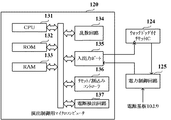
図6は、演出制御基板12に搭載された演出制御用マイクロコンピュータ120の構成例を示す図である。また、図6には、演出制御基板12に搭載されたウォッチドッグ付リセットIC124や電力制御回路125も示されている。図6に示す演出制御用マイクロコンピュータ120は、例えば1チップマイクロコンピュータなどを用いて構成され、CPU131と、ROM132と、RAM133と、乱数回路134と、入出力ポート135と、リセット/割込みコントローラ136と、電断検出回路137とを備えている。CPU131は、ROM132に記憶されているユーザプログラムやデータを読み出し、RAM133をワークエリアとして使用して、プログラムに従った制御動作を行う。   FIG. 6 is a diagram illustrating a configuration example of the effect control microcomputer 120 mounted on the effect control board 12. 6 also shows a reset IC 124 with a watchdog and a power control circuit 125 mounted on the effect control board 12. 6 is configured using, for example, a one-chip microcomputer, and includes a CPU 131, a ROM 132, a RAM 133, a random number circuit 134, an input / output port 135, a reset / interrupt controller 136, and the like. And a power interruption detection circuit 137. The CPU 131 reads the user program and data stored in the ROM 132 and uses the RAM 133 as a work area to perform a control operation according to the program.

演出制御基板12では、乱数回路134によって、演出制御基板12の側において用いられる各種の乱数の全てまたは一部が生成される。例えば、演出制御基板12の側では、確定飾り図柄決定用の乱数値や予告決定用の乱数値などが用いられる。なお、演出効果を高めるために、演出制御基板12の側でこれら以外の乱数値が用いられてもよい。これらの乱数値を示す数値データの全部または一部は、乱数回路134にてカウントされればよい。また、これらの乱数値を示す数値データの一部は、CPU131が乱数回路134とは異なるランダムカウンタを用いて、ソフトウェアによる更新によってカウントするようにしてもよい。   In the effect control board 12, the random number circuit 134 generates all or a part of various random numbers used on the effect control board 12 side. For example, on the side of the effect control board 12, a random value for determining a definite decorative design, a random value for determining a notice, or the like is used. In order to enhance the effect, a random value other than these may be used on the effect control board 12 side. All or part of the numerical data indicating these random numbers may be counted by the random number circuit 134. Further, a part of numerical data indicating these random numbers may be counted by updating by software using a random counter different from the random number circuit 134 by the CPU 131.

確定飾り図柄決定用の乱数値は、飾り図柄の可変表示における表示結果として導出表示する確定飾り図柄を決定するために用いられる乱数値である。予告決定用の乱数値は、特別図柄や飾り図柄の可変表示結果が大当りとなることや、飾り図柄の可変表示態様がリーチとなることなどを予告するための予告演出を実行するか否かを決定し、実行すると決定した場合には予告演出の態様を決定するために用いられる乱数値である。   The random number value for determining the fixed decorative design is a random value used for determining the fixed decorative design that is derived and displayed as the display result in the variable display of the decorative design. The random number value for determining the notice determines whether or not to execute a notice effect for notifying that the variable display result of special symbols or decorative symbols will be a big hit, or that the variable display mode of decorative symbols will be reached. It is a random value used to determine the mode of the notice effect when it is determined and executed.

ROM132には、CPU131による制御動作を決定するためのデータとして、例えば複数種類の飾り図柄決定テーブルや、予告決定テーブル、演出制御パターンテーブルなどを構成するデータが記憶されている。飾り図柄決定テーブルは、確定飾り図柄決定用の乱数値に基づき、画像表示装置5における飾り図柄の可変表示結果として導出表示される確定飾り図柄などを決定するために用いられるテーブルである。予告決定テーブルは、予告決定用の乱数値に基づき、予告演出を実行するか否かや、実行する場合における予告演出の態様を示す予告パターンなどを決定するために用いられるテーブルである。   The ROM 132 stores, for example, data constituting a plurality of types of decorative symbol determination tables, a notice determination table, and an effect control pattern table as data for determining the control operation by the CPU 131. The decorative symbol determination table is a table used to determine a fixed decorative symbol that is derived and displayed as a variable display result of the decorative symbol in the image display device 5 based on a random value for determining the fixed decorative symbol. The notice determination table is a table used for determining whether or not a notice effect is to be executed, a notice pattern indicating a form of the notice effect when it is executed, and the like based on a random number value for determining a notice.

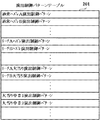
演出制御パターンテーブルの具体的な一例として、この実施の形態では、図7に示すような構成を有する演出制御パターンテーブル201が用いられる。この演出制御パターンテーブル201には、画像表示装置5における表示動作の内容や、スピーカ8L、8R等の音声出力制御の内容、遊技効果ランプ9等による演出内容といった、各種の演出制御の内容を示すデータが、演出制御パターンとして複数種類格納されている。演出制御パターンテーブル201に格納される複数種類の演出制御パターンはそれぞれ、例えば図8に示すように、演出制御タイマ設定値、演出制御タイマ判定値#1〜#n(nは任意の自然数)、表示制御データ#1〜#n、音声制御データ#1〜#n、ランプ制御データ#1〜#nといった、演出動作を制御するための各種データから構成され、時系列的に、画像表示装置5での表示内容や、スピーカ8L、8Rからの音声出力内容、遊技効果ランプ9による演出内容といった、各種の演出制御の内容や、演出制御の切換タイミング等が設定されている。   As a specific example of the effect control pattern table, an effect control pattern table 201 having a configuration as shown in FIG. 7 is used in this embodiment. This effect control pattern table 201 shows the contents of various effect controls such as the contents of the display operation in the image display device 5, the contents of the sound output control of the speakers 8L, 8R, etc., the contents of the effects by the game effect lamp 9, etc. A plurality of types of data are stored as production control patterns. Each of the plurality of types of effect control patterns stored in the effect control pattern table 201 is, for example, as shown in FIG. 8, effect control timer setting values, effect control timer determination values # 1 to #n (n is an arbitrary natural number), The image display device 5 is composed of various data for controlling the production operation, such as display control data # 1 to #n, audio control data # 1 to #n, and lamp control data # 1 to #n. The contents of various effects control, such as the contents displayed on the screen, the contents of audio output from the speakers 8L and 8R, the contents of effects by the game effect lamp 9, and the switching timing of the effects control are set.

演出制御パターンテーブル201には、例えば画像表示装置5にて飾り図柄の可変表示が実行される期間内における演出動作に対応した複数種類の演出制御パターンが格納されている。また、大当り遊技状態に制御される期間内における演出動作に対応した演出制御パターンも、演出制御パターンテーブル201に格納されている。   The effect control pattern table 201 stores, for example, a plurality of types of effect control patterns corresponding to the effect operation within a period in which the decorative display variable display is executed on the image display device 5. In addition, the effect control pattern corresponding to the effect operation in the period controlled to the big hit gaming state is also stored in the effect control pattern table 201.

図6に示す演出制御用マイクロコンピュータ120が備えるRAM133には、演出動作を制御するために用いられる各種のデータを保持する領域が設けられている。例えば、RAM133には、確定飾り図柄記憶部、演出制御フラグ設定部、演出制御タイマ設定部、演出制御カウンタ設定部、演出制御バッファ設定部、可変表示パターン格納部、表示結果格納部、特図保留記憶数格納部、ラウンド数格納部、予告パターン格納部などとして、各種のデータを保持する領域が設けられていればよい。そして、RAM133の少なくとも一部は、電源基板10において作成されるバックアップ電源によってバックアップされているバックアップRAMである。すなわち、演出制御用マイクロコンピュータ120への電力供給が停止されたり、演出制御用マイクロコンピュータ120の再起動が行われても、所定時間は、RAM133の少なくとも一部の内容は保存される。   The RAM 133 provided in the effect control microcomputer 120 shown in FIG. 6 is provided with an area for holding various data used for controlling the effect operation. For example, in the RAM 133, a confirmed decorative symbol storage unit, an effect control flag setting unit, an effect control timer setting unit, an effect control counter setting unit, an effect control buffer setting unit, a variable display pattern storage unit, a display result storage unit, a special figure hold An area for holding various data may be provided as a storage number storage unit, a round number storage unit, a notice pattern storage unit, and the like. At least a part of the RAM 133 is a backup RAM that is backed up by a backup power source created in the power supply substrate 10. That is, even if the power supply to the effect control microcomputer 120 is stopped or the effect control microcomputer 120 is restarted, at least part of the contents of the RAM 133 is saved for a predetermined time.

確定飾り図柄記憶部は、画像表示装置5における飾り図柄の可変表示にて可変表示結果として導出表示される確定飾り図柄を示すデータを記憶する。演出制御フラグ設定部は、例えば画像表示装置5の表示状態などといった演出動作状態や主基板11から送信された演出制御コマンド等に応じて、各々セットあるいはクリアされる複数種類のフラグを設定するためのデータを記憶する。演出制御タイマ設定部は、例えば画像表示装置5での表示制御などといった演出制御に用いられる複数種類のタイマ値を示すデータを記憶する。演出制御カウンタ設定部は、例えば画像表示装置5での表示制御などといった演出制御に用いられる複数種類のカウント値を示すデータを記憶する。なお、フラグ設定やカウンタ/タイマに用いる回路は、RAM133とは別に設けたレジスタ回路などによって構成してもよい。   The confirmed decorative symbol storage unit stores data indicating a fixed decorative symbol that is derived and displayed as a variable display result in the variable display of decorative symbols on the image display device 5. The effect control flag setting unit sets a plurality of types of flags that are set or cleared according to the effect operation state such as the display state of the image display device 5, the effect control command transmitted from the main board 11, and the like. Store the data. The effect control timer setting unit stores data indicating a plurality of types of timer values used for effect control such as display control on the image display device 5, for example. The effect control counter setting unit stores data indicating a plurality of types of count values used for effect control such as display control on the image display device 5, for example. The circuit used for flag setting and counter / timer may be constituted by a register circuit provided separately from the RAM 133.

また、演出制御バッファ設定部には、演出制御基板12にて受信した主基板11からのコマンドを一時的に格納するための演出側受信コマンドバッファなどが設けられる。可変表示パターン格納部は、例えば可変表示開始コマンドにおけるEXTデータを記憶することなどにより、主基板11から通知された可変表示パターンなどを特定可能なデータを格納する。表示結果格納部は、例えば表示結果通知コマンドにおけるEXTデータを記憶することなどにより、主基板11から通知された表示結果の種類などを特定可能なデータを格納する。特図保留記憶数格納部は、主基板11から通知された特図保留記憶数を特定可能なデータを格納する。ラウンド数格納部は、例えば大当りラウンド数通知コマンドにおけるEXTデータを記憶することなどにより、主基板11から通知された大当り遊技状態におけるラウンド数を特定可能なデータを格納する。予告パターン格納部は、予告演出表示を実行するために決定した予告パターンを特定可能なデータを格納する。   The effect control buffer setting unit is provided with an effect-side reception command buffer for temporarily storing commands from the main board 11 received by the effect control board 12. The variable display pattern storage unit stores data that can specify the variable display pattern notified from the main board 11 by storing, for example, EXT data in the variable display start command. The display result storage unit stores data that can specify the type of the display result notified from the main board 11 by storing, for example, EXT data in the display result notification command. The special figure reserved memory number storage unit stores data that can specify the special figure reserved memory number notified from the main board 11. The round number storage unit stores data that can specify the round number in the big hit gaming state notified from the main board 11 by storing, for example, EXT data in the big hit round number notification command. The notice pattern storage unit stores data that can specify the notice pattern determined to execute the notice effect display.

演出制御用マイクロコンピュータ120が備える入出力ポート135は、演出制御用マイクロコンピュータ120に伝送された各種信号を取り込むための入力ポートと、演出制御用マイクロコンピュータ120の外部へと各種信号を伝送するための出力ポートとを含んで構成されている。例えば、入出力ポート135の出力ポートからは、表示制御部121へと伝送される表示制御指令や、音制御部122へと伝送される音声制御指令、ランプ制御部123へと伝送されるランプ制御指令などが出力される。また、入出力ポート135の出力ポートには、ウォッチドック付リセットIC124を初期化させるクリア信号を出力するための出力端子が含まれている。また、入出力ポート135の入力ポートには、電力制御回路125から供給される電源電圧を入力するための入力端子が含まれている。なお、電力制御回路125から供給される電源電圧は、入出力ポート135とは異なる専用の電源端子に入力されてもよい。   The effect control microcomputer 120 has an input / output port 135 for inputting various signals transmitted to the effect control microcomputer 120 and for transmitting various signals to the outside of the effect control microcomputer 120. Output port. For example, from the output port of the input / output port 135, a display control command transmitted to the display control unit 121, a voice control command transmitted to the sound control unit 122, and a lamp control transmitted to the lamp control unit 123. Commands are output. The output port of the input / output port 135 includes an output terminal for outputting a clear signal for initializing the reset IC 124 with watchdog. The input port of the input / output port 135 includes an input terminal for inputting a power supply voltage supplied from the power control circuit 125. Note that the power supply voltage supplied from the power control circuit 125 may be input to a dedicated power supply terminal different from the input / output port 135.

リセット/割込みコントローラ136は、演出制御用マイクロコンピュータ120の内部あるいは外部で発生する各種リセット、割込み要求を制御するためのものである。リセット/割込みコントローラ136が制御するリセットには、システムリセットとユーザリセットが含まれている。システムリセットは、所定のシステムリセット端子に一定の期間にわたりローレベルの信号が入力されたときに発生するリセットである。ユーザリセットは、所定のユーザリセット端子に一定の期間にわたりローレベルの信号が入力されたことや、指定エリア外走行禁止(IAT)信号が発生したこと、あるいは、インターバルリセット信号が発生したことなどといった、所定の要因により発生するリセットである。   The reset / interrupt controller 136 is for controlling various reset and interrupt requests generated inside or outside the production control microcomputer 120. Resets controlled by the reset / interrupt controller 136 include system resets and user resets. The system reset is a reset that occurs when a low level signal is input to a predetermined system reset terminal for a certain period. User resets include a low level signal input to a predetermined user reset terminal for a certain period of time, an out-of-designated area prohibition (IAT) signal, or an interval reset signal. The reset is caused by a predetermined factor.

また、リセット/割込みコントローラ136が制御する割込みには、Xクラス割込み(XIRQ)、Iクラス割込み(IRQ)、ソフトウェア割込み(SWI)、イリーガルオペコードトラップ(ILGOP)といった4種類の割込みが含まれている。Xクラス割込みは、所定のXIRQ端子に一定の期間にわたりローレベルの信号が入力されたときに発生する割込みである。Iクラス割込みは、ユーザプログラムにより割込み要求の受付を許可/禁止できる割込みであり、所定のIRQ端子に一定の期間にわたりローレベルの信号が入力されたことや、所定のタイマ回路からの割込み要求信号が発生したこと、所定の通信回路からの割込み要求信号が発生したことなどといった、予め定められた各種の割込み要因により発生する割込みである。   The interrupts controlled by the reset / interrupt controller 136 include four types of interrupts: X class interrupt (XIRQ), I class interrupt (IRQ), software interrupt (SWI), and illegal opcode trap (ILGOP). . The X class interrupt is an interrupt that occurs when a low level signal is input to a predetermined XIRQ terminal for a certain period. An I class interrupt is an interrupt that can allow / prohibit acceptance of an interrupt request by a user program. A low level signal is input to a predetermined IRQ terminal for a certain period, or an interrupt request signal from a predetermined timer circuit. This is an interrupt generated by various predetermined interrupt factors such as occurrence of an interrupt, an interrupt request signal from a predetermined communication circuit, and the like.

電断検出回路137は、電力制御回路125を介して電源基板10から供給される電源電圧を監視し、電源電圧の低下が検出された場合に、電源断の発生をCPU131等に通知するためのものである。例えば、電断検出回路137は、電源電圧が予め定められた電断判定値以下に低下した場合に、電源断の発生を示す電源断信号をオン状態とする。他方、電源電圧が電断判定値よりも高電圧となっている場合には、電源断信号をオフ状態とする。電断検出回路137から出力された電源断信号は、例えばCPU131に伝送されて、電源断が発生したか否かを確認するために用いられる。   The power interruption detection circuit 137 monitors the power supply voltage supplied from the power supply substrate 10 via the power control circuit 125, and notifies the CPU 131 and the like of the occurrence of power interruption when a decrease in the power supply voltage is detected. Is. For example, when the power supply voltage drops below a predetermined power interruption determination value, the power interruption detection circuit 137 turns on a power interruption signal indicating the occurrence of power interruption. On the other hand, when the power supply voltage is higher than the power interruption determination value, the power interruption signal is turned off. The power-off signal output from the power-off detection circuit 137 is transmitted to the CPU 131, for example, and used to check whether or not a power-off has occurred.

図3に示す表示制御部121は、演出制御用マイクロコンピュータ120からの表示制御指令などに基づき、画像表示装置5における表示動作の制御を行うものである。例えば、表示制御部121は、画像表示装置5に画像の切換表示を実行させることなどにより、飾り図柄の可変表示や各種の演出表示を実行させるための制御を行う。   The display control unit 121 shown in FIG. 3 controls the display operation in the image display device 5 based on a display control command from the effect control microcomputer 120. For example, the display control unit 121 performs control for executing variable display of decorative symbols and various effect displays by causing the image display device 5 to perform switching display of images.

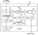
図9は、表示制御部121のハードウェア構成例を示すブロック図である。図9に示すように、表示制御部121には、VDP141(Video Display Processor)と、CGROM(Character Generator ROM)142とが含まれている。VDP141は、例えば画像表示装置5にて画像表示を行うための高速描画機能や表示出力機能などを有し、演出制御用マイクロコンピュータ120からの表示制御指令に従った画像処理を実行する。CGROM142は、画像表示装置5にて画像表示を行うために使用される各種の画像データを記憶する。CGROM142が記憶する画像データには、複数種類の飾り図柄などを示す複数種類の演出画像に対応した複数種類の画像要素データや、飾り図柄とは異なる複数種類の演出画像に対応した複数種類の動画像データなどが含まれている。   FIG. 9 is a block diagram illustrating a hardware configuration example of the display control unit 121. As illustrated in FIG. 9, the display control unit 121 includes a VDP 141 (Video Display Processor) and a CGROM (Character Generator ROM) 142. The VDP 141 has, for example, a high-speed drawing function and a display output function for displaying an image on the image display device 5, and executes image processing in accordance with a display control command from the effect control microcomputer 120. The CGROM 142 stores various image data used for displaying an image on the image display device 5. The image data stored in the CGROM 142 includes a plurality of types of image element data corresponding to a plurality of types of effect images indicating a plurality of types of decorative designs, and a plurality of types of moving images corresponding to a plurality of types of effect images different from the decorative symbols. Image data is included.

VDP141は、図9に示すように、ホストインタフェース151と、転送制御回路152と、CGROMインタフェース153と、描画回路154と、一時記憶メモリ155と、フレームバッファメモリ156と、表示回路157と、動画像用デコーダ158とを備えている。   As shown in FIG. 9, the VDP 141 includes a host interface 151, a transfer control circuit 152, a CGROM interface 153, a drawing circuit 154, a temporary storage memory 155, a frame buffer memory 156, a display circuit 157, a moving image Decoder 158.

ホストインタフェース151は、演出制御用マイクロコンピュータ120との間で各種データをやり取りするためのアドレス入力端子やデータ入出力端子などを含んで構成されている。転送制御回路152は、演出制御用マイクロコンピュータ120からの表示制御指令などに基づき、CGROM142から読み出された画像要素データの一時記憶メモリ155に対する転送を制御する。例えば、転送制御回路152は、DMA(Direct Memory Access)転送を用いてCGROM142から一時記憶メモリ155へのデータ転送を行うためのDMA装置を備えている。   The host interface 151 includes an address input terminal and a data input / output terminal for exchanging various data with the production control microcomputer 120. The transfer control circuit 152 controls the transfer of the image element data read from the CGROM 142 to the temporary storage memory 155 based on a display control command from the effect control microcomputer 120. For example, the transfer control circuit 152 includes a DMA device for performing data transfer from the CGROM 142 to the temporary storage memory 155 using DMA (Direct Memory Access) transfer.

CGROMインタフェース153は、CGROM142に記憶されている画像要素データを読み出すためのアドレス出力端子やデータ入力端子などを含んで構成されている。描画回路154は、一時記憶メモリ155に一時記憶された画像要素データに基づき画像表示装置5における画像の表示用データを作成するための描画処理を実行する。また、描画回路154は、一時記憶メモリ155に設けられた第1〜第Xピクチャバッファ155−1〜155−X(図10)から、動画像用デコーダ158によりデコードされたピクチャデータを順次に読み出してフレームバッファメモリ156に書き込むことで、動画像データに基づいて生成される画像を画像表示装置5に順次表示させることによる動画像の再生を可能にする。   The CGROM interface 153 includes an address output terminal and a data input terminal for reading image element data stored in the CGROM 142. The drawing circuit 154 executes a drawing process for creating image display data in the image display device 5 based on the image element data temporarily stored in the temporary storage memory 155. The drawing circuit 154 sequentially reads out the picture data decoded by the moving picture decoder 158 from the first to Xth picture buffers 155-1 to 155-X (FIG. 10) provided in the temporary storage memory 155. By writing the data in the frame buffer memory 156, it is possible to reproduce a moving image by sequentially displaying images generated based on the moving image data on the image display device 5.

一時記憶メモリ155は、例えばVRAM(Video RAM)などを用いて構成され、CGROM142から読み出された画像要素データや動画像データを一時記憶する。例えば、一時記憶メモリ155には、動画像用デコーダ158がCGROM142から読み出された動画像データのデコードを行うことにより再生された複数のピクチャデータを一時記憶するために、第1〜第Xピクチャバッファ155−1〜155−X(Xは任意の自然数)となる記憶領域が設けられている。   The temporary storage memory 155 is configured using, for example, a VRAM (Video RAM) or the like, and temporarily stores image element data and moving image data read from the CGROM 142. For example, the temporary storage memory 155 stores the first to Xth pictures in order to temporarily store a plurality of picture data reproduced by the moving picture decoder 158 decoding the moving picture data read from the CGROM 142. Storage areas serving as buffers 155-1 to 155-X (X is an arbitrary natural number) are provided.

フレームバッファメモリ156は、例えば一時記憶メモリ155とは異なるVRAMなどを用いて構成され、描画回路154による描画処理などにより作成される画像の表示用データを記憶する。例えば、フレームバッファメモリ156は、画像表示装置5における1画面分の表示領域に画像を表示させるために用いられる画像データの容量よりも大きな記憶容量を有している。フレームバッファメモリ156では、アドレス管理を容易にするために、例えば図11に示すように、表示用データを記憶する表示用データエリアにおいて、画像表示装置5の画面上における表示領域5Aのみならず非表示領域5Bに対しても、アドレスが割り当てられている。   The frame buffer memory 156 is configured using, for example, a VRAM or the like different from the temporary storage memory 155, and stores image display data created by a drawing process or the like by the drawing circuit 154. For example, the frame buffer memory 156 has a storage capacity larger than the capacity of the image data used for displaying an image in the display area for one screen in the image display device 5. In the frame buffer memory 156, in order to facilitate address management, for example, as shown in FIG. 11, in the display data area for storing display data, not only the display area 5A on the screen of the image display device 5 but also the non-display area. An address is also assigned to the display area 5B.

図9に示す表示回路157は、フレームバッファメモリ156から読み出した表示用データを階調データとし、所定のクロック信号に基づいて走査信号を生成して画像表示装置5に出力することなどにより、画像表示装置5の画面上に画像を表示させるための回路である。   The display circuit 157 shown in FIG. 9 uses the display data read from the frame buffer memory 156 as gradation data, generates a scanning signal based on a predetermined clock signal, and outputs it to the image display device 5. This is a circuit for displaying an image on the screen of the display device 5.

動画像用デコーダ158は、例えば動き補償予測符号化によりデータ圧縮された状態でCGROM142に記憶されている動画像データを読み出し、所定の伸張処理を実行することなどにより、動画像データのデコードを行う。   The moving image decoder 158 decodes moving image data by reading out moving image data stored in the CGROM 142 in a state where the data is compressed by, for example, motion compensation predictive coding, and executing a predetermined expansion process. .

図12は、演出制御用マイクロコンピュータ120が備えるCPU131からVDP141に対して送信される表示制御指令となる各種コマンドの具体例を示す図である。図12に示すように、この実施の形態では、転送表示コマンド、動画像デコード開始コマンド、動画像デコードNOPコマンドなどといったコマンドが、表示制御指令としてCPU131からVDP141に対して送信される。   FIG. 12 is a diagram illustrating specific examples of various commands serving as display control commands transmitted from the CPU 131 included in the effect control microcomputer 120 to the VDP 141. As shown in FIG. 12, in this embodiment, commands such as a transfer display command, a moving image decoding start command, a moving image decoding NOP command, and the like are transmitted from the CPU 131 to the VDP 141 as display control commands.

転送表示コマンドは、CGROM142に記憶されている画像要素データ、または、一時記憶メモリ155に一時記憶されている画像要素データについて、フレームバッファメモリ156に書き込ませて、当該画像要素データが示す画像要素を画像表示装置5の画面上に表示するよう指令するためのコマンドである。例えば、転送表示コマンドは、CGROM142または一時記憶メモリ155における画像要素データの読出アドレス、フレームバッファメモリ156における画像要素データの書込アドレス、画像要素データのデータ量などを、VDP141に通知するためのデータを含んでいる。   The transfer display command causes the image element data stored in the CGROM 142 or the image element data temporarily stored in the temporary storage memory 155 to be written in the frame buffer memory 156 and the image element indicated by the image element data is displayed. This is a command for instructing display on the screen of the image display device 5. For example, the transfer display command is data for notifying the VDP 141 of the read address of the image element data in the CGROM 142 or the temporary storage memory 155, the write address of the image element data in the frame buffer memory 156, the data amount of the image element data, and the like. Is included.

なお、CGROM142または一時記憶メモリ155における画像要素データの読出アドレスに代えて、例えば読出対象となる画像要素データが示す演出画像に付された識別情報(例えば画像要素データが示す演出キャラクタのキャラクタ番号)などといった、CGROM142や一時記憶メモリ155から読み出す画像要素データの読出位置を特定可能にする任意の情報が用いられてもよい。また、フレームバッファメモリ156における画像要素データの書込アドレスに代えて、例えば画像表示装置5の画面上における画像要素の表示座標(例えば画像要素における左上部の表示座標)などといった、フレームバッファメモリ156における画像要素データの書込位置を特定可能にする任意の情報が用いられてもよい。   In place of the read address of the image element data in the CGROM 142 or the temporary storage memory 155, for example, identification information attached to the effect image indicated by the image element data to be read (for example, the character number of the effect character indicated by the image element data) Any information that makes it possible to specify the reading position of the image element data read from the CGROM 142 or the temporary storage memory 155 may be used. Further, instead of the writing address of the image element data in the frame buffer memory 156, the frame buffer memory 156 such as the display coordinates of the image elements on the screen of the image display device 5 (for example, the display coordinates at the upper left of the image elements), Arbitrary information that makes it possible to specify the writing position of the image element data in may be used.

動画像デコード開始コマンドは、VDP141が備える動画像用デコーダ158に対して、動画像データのデコード開始を指令するためのコマンドである。動画像デコードNOPコマンドは、VDP141が備える動画像用デコーダ158に対して、動画像データのデコード待機(NOP;No OPeration)を指令するためのコマンドである。   The moving image decoding start command is a command for instructing the moving image decoder 158 included in the VDP 141 to start decoding moving image data. The moving picture decoding NOP command is a command for instructing the moving picture data decoder 158 included in the VDP 141 to wait for decoding moving picture data (NOP; No OPeration).

CGROM142は、画像表示装置5にて飾り図柄を含めた各種の演出画像を表示するために使用される各種の画像要素データや動画像データなどを記憶しておくためのものである。図13は、CGROM142におけるアドレスマップの一例を示す図である。図13に示すように、CGROM142には、スプライト描画用の画像要素データを記憶するための領域であるスプライトデータエリア142Aと、符号化された動画像データを記憶するための領域である動画像データエリア142Bとが設けられている。この実施の形態では、CGROM142におけるアドレスSPSTAからアドレスSPENDまでの記憶領域が、スプライトデータエリア142Aに設定されている。また、CGROM142におけるアドレスMVSTAからアドレスMVENDまでの記憶領域が、動画像データエリア142Bに設定されている。   The CGROM 142 is for storing various image element data and moving image data used for displaying various effect images including decorative designs on the image display device 5. FIG. 13 is a diagram illustrating an example of an address map in the CGROM 142. As shown in FIG. 13, the CGROM 142 has a sprite data area 142A that is an area for storing image element data for sprite drawing and moving image data that is an area for storing encoded moving image data. An area 142B is provided. In this embodiment, the storage area from the address SPSTA to the address SPEND in the CGROM 142 is set in the sprite data area 142A. In addition, a storage area from the address MVSTA to the address MVEND in the CGROM 142 is set in the moving image data area 142B.

動画像データエリア142Bに記憶されている動画像データは、動き補償予測符号化によりデータ圧縮されており、例えば図14に示すようなストリーム構成を有している。動画像データエリア142Bには、複数種類の動画像データがそれぞれ、例えば動画像による1単位の遊技演出の種類ごとに1つの動画像ファイルに格納された状態で記憶されている。各動画像ファイルは、ファイルヘッダと、少なくとも1つのフレームヘッダ及びフレームごとの圧縮データとを含む。例えば、1フレーム分の圧縮データは、Iピクチャ、Pピクチャ、Bピクチャのいずれかに分類され、フレームヘッダには、いずれのピクチャの種類を識別するための情報や、各ピクチャの表示順序を指定する情報などが含まれている。Iピクチャは、フレーム内符号化によって符号化されているピクチャである。Pピクチャは、過去のフレームのみを用いて前方向の動き補償予測を行うピクチャである。Bピクチャは、過去及び未来の両方のフレームを用いて双方向の動き補償予測を行うピクチャである。   The moving image data stored in the moving image data area 142B is data-compressed by motion compensated prediction encoding, and has a stream configuration as shown in FIG. 14, for example. In the moving image data area 142B, a plurality of types of moving image data are stored, for example, in a state where they are stored in one moving image file for each type of game effect of one unit by moving images. Each moving image file includes a file header, at least one frame header, and compressed data for each frame. For example, compressed data for one frame is classified as either an I picture, a P picture, or a B picture, and information for identifying the type of any picture and the display order of each picture are specified in the frame header. Information to be included. An I picture is a picture that has been encoded by intraframe encoding. The P picture is a picture that performs forward motion compensation prediction using only past frames. A B picture is a picture that performs bi-directional motion compensation prediction using both past and future frames.

図3に示す音制御部122は、演出制御用マイクロコンピュータ120からの音声制御指令などに基づき、スピーカ8L、8Rにおける音声出力動作の制御を行うものである。例えば、音制御部122は、演出制御用マイクロコンピュータ120からの音声制御指令に対応した音声信号を生成し、スピーカ8L、8Rに供給することによって音声を出力させる音声出力回路などを含んでいる。   The sound control unit 122 shown in FIG. 3 controls the sound output operation in the speakers 8L and 8R based on the sound control command from the production control microcomputer 120. For example, the sound control unit 122 includes an audio output circuit that generates an audio signal corresponding to an audio control command from the production control microcomputer 120 and outputs the audio signal to the speakers 8L and 8R, and the like.

ランプ制御部123は、演出制御用マイクロコンピュータ120からのランプ制御指令などに基づき、遊技効果ランプ9等における点灯動作、消灯動作、点滅動作などの制御を行うものである。例えば、ランプ制御部123は、演出制御用マイクロコンピュータ120からのランプ制御指令に対応したランプ駆動信号を生成し、遊技効果ランプ9や各種の装飾用ランプ、LED等の電飾部材に供給することによって点灯動作、消灯動作、点滅動作などを行わせるランプドライバ回路などを含んでいる。   The lamp control unit 123 controls the lighting operation, the extinguishing operation, the blinking operation, and the like in the game effect lamp 9 and the like based on a lamp control command from the effect control microcomputer 120. For example, the lamp control unit 123 generates a lamp drive signal corresponding to the lamp control command from the effect control microcomputer 120 and supplies the lamp drive signal to the game effect lamp 9, various decorative lamps, and an electric decoration member such as an LED. Includes a lamp driver circuit that performs lighting operation, extinguishing operation, blinking operation, and the like.

なお、音制御部122やランプ制御部123は、演出制御基板12の外部に設置された所定の制御基板上に搭載されていてもよい。   Note that the sound control unit 122 and the lamp control unit 123 may be mounted on a predetermined control board installed outside the effect control board 12.

ウォッチドッグ付リセットIC124は、ウォッチドッグ回路を内蔵したリセット用のICである。ウォッチドッグ付リセットIC124は、例えば所定のクロック信号の立上がりエッジまたは立下がりエッジに応答して、ウォッチドッグ回路のタイマ値をアップカウントまたはダウンカウントする。そして、演出制御用マイクロコンピュータ120から伝送されるクリア信号がオン状態となったことに応答して、ウォッチドッグ回路のタイマ値を初期化する。   The reset IC 124 with a watchdog is a reset IC with a built-in watchdog circuit. The reset IC with watchdog 124 counts up or down the timer value of the watchdog circuit in response to, for example, a rising edge or a falling edge of a predetermined clock signal. Then, the timer value of the watchdog circuit is initialized in response to the clear signal transmitted from the production control microcomputer 120 being turned on.

ここで、ウォッチドッグ回路にて計測可能な時間、すなわちウォッチドッグ回路のタイマ値が初期値から最終値までアップカウントまたはダウンカウントされるまでの時間は、演出制御用マイクロコンピュータ120にて演出動作を制御するためのタイマ割込みが発生する周期よりも長くなるように設定されている。そして、演出制御用マイクロコンピュータ120においてCPU131がタイマ割込みの発生に対応した割込み処理を定期的に実行している場合には、演出制御用マイクロコンピュータ120から伝送されるクリア信号が定期的にオン状態となることから、タイマ値が最終値に達することはない。他方、CPU131によってタイマ割込みの発生に対応した割込み処理が正常に実行されない場合には、クリア信号がオン状態にならないため、タイマ値が最終値に達することになる。こうしてウォッチドッグ回路のタイマ値が最終値に達してタイムアウトしたときには、所定のリセット信号をオン状態として出力し、電力制御回路125に入力させる。   Here, the time that can be measured by the watchdog circuit, that is, the time until the timer value of the watchdog circuit is up-counted or down-counted from the initial value to the final value is determined by the effect control microcomputer 120. It is set to be longer than the cycle in which a timer interrupt for control occurs. When the CPU 131 periodically executes interrupt processing corresponding to the occurrence of the timer interrupt in the effect control microcomputer 120, the clear signal transmitted from the effect control microcomputer 120 is periodically turned on. Therefore, the timer value never reaches the final value. On the other hand, when the interrupt processing corresponding to the occurrence of the timer interrupt is not normally executed by the CPU 131, the clear signal is not turned on, so that the timer value reaches the final value. Thus, when the timer value of the watchdog circuit reaches the final value and times out, a predetermined reset signal is output as an ON state and input to the power control circuit 125.

電力制御回路125は、電源基板10から供給された電源電圧を、演出制御基板12上の各部位に配送するための回路である。この実施の形態では、電力制御回路125に、ウォッチドッグ付リセットIC124から出力されたリセット信号が入力される。そして、このリセット信号がオン状態となった場合に、電力制御回路125は、演出制御用マイクロコンピュータ120に対する電源電圧の供給を所定時間が経過するまで停止させた後に、電源電圧の供給を再開させる。演出制御用マイクロコンピュータ120では、電力制御回路125からの電源電圧の供給が停止されると動作を停止し、電源電圧の供給が再開された場合には、パチンコ遊技機1への電力供給が開始された場合と同様にして再び起動する。なお、ウォッチドッグ付リセットIC124や電力制御回路125は、電源基板10から供給された電源電圧を、演出制御用マイクロコンピュータ120内の各部位に配送するか遮断するかを切り替えるための回路として、演出制御用マイクロコンピュータ120に内蔵されていてもよい。   The power control circuit 125 is a circuit for delivering the power supply voltage supplied from the power supply board 10 to each part on the effect control board 12. In this embodiment, the reset signal output from the reset IC with watchdog 124 is input to the power control circuit 125. When the reset signal is turned on, the power control circuit 125 stops the supply of the power supply voltage to the effect control microcomputer 120 until a predetermined time has elapsed, and then restarts the supply of the power supply voltage. . The production control microcomputer 120 stops its operation when the supply of the power supply voltage from the power control circuit 125 is stopped, and starts the supply of power to the pachinko gaming machine 1 when the supply of the power supply voltage is resumed. Start again in the same way as The reset IC with watchdog 124 and the power control circuit 125 are provided as circuits for switching whether the power supply voltage supplied from the power supply board 10 is delivered to each part in the production control microcomputer 120 or cut off. It may be built in the control microcomputer 120.

次に、本実施例におけるパチンコ遊技機1の動作(作用)を説明する。主基板11では、電源基板10からの電力供給が開始されると、遊技制御用マイクロコンピュータ100が起動し、CPU111によって図15のフローチャートに示すような遊技制御メイン処理が実行される。図15に示す遊技制御メイン処理を開始すると、まず、割込み禁止に設定し(ステップS1)、割込みモードの設定を行う(ステップS2)。例えば、ステップS2では、遊技制御用マイクロコンピュータ100の特定レジスタ(Iレジスタ)の値(1バイト)と内蔵デバイスが出力する割込みベクタ(1バイト:最下位ビットは“0”)とを合成することにより割込みアドレスが生成されるマスク可能割込みの割込みモードが設定される。マスク可能な割込みが発生したときには、遊技制御用マイクロコンピュータ100が自動的に割込み禁止状態となる設定を行うとともに、プログラムカウンタの内容がスタックにセーブされればよい。   Next, the operation (action) of the pachinko gaming machine 1 in this embodiment will be described. In the main board 11, when power supply from the power supply board 10 is started, the game control microcomputer 100 is activated, and the CPU 111 executes a game control main process as shown in the flowchart of FIG. When the game control main process shown in FIG. 15 is started, first, interrupt prohibition is set (step S1), and an interrupt mode is set (step S2). For example, in step S2, the value (1 byte) of the specific register (I register) of the gaming control microcomputer 100 and the interrupt vector (1 byte: the least significant bit is “0”) output from the built-in device are synthesized. Sets the interrupt mode for maskable interrupts that generate interrupt addresses. When a maskable interrupt is generated, the game control microcomputer 100 is automatically set to be in an interrupt disabled state, and the contents of the program counter may be saved in the stack.

続いて、例えばスタックポインタ指定アドレスの設定など、スタックポインタに関わる設定を行う(ステップS3)。また、遊技制御用マイクロコンピュータ100における内蔵デバイスレジスタの設定(初期化)を行う(ステップS4)。そして、遊技制御用マイクロコンピュータ100における内蔵周辺回路であるCTC(カウンタ/タイマ)及びPIO(パラレル入出力ポート)の設定(初期化)を行う(ステップS5)。その後、RAM113をアクセス可能に設定する(ステップS6)。   Subsequently, settings relating to the stack pointer such as setting of a stack pointer designation address are performed (step S3). The built-in device register in the game control microcomputer 100 is set (initialized) (step S4). Then, CTC (counter / timer) and PIO (parallel input / output port) which are built-in peripheral circuits in the game control microcomputer 100 are set (initialized) (step S5). Thereafter, the RAM 113 is set to be accessible (step S6).

ステップS6の処理に続いて、CPU111は、パチンコ遊技機1において例えば電源基板10に設けられているクリアスイッチがオン状態であるか否かを判定する(ステップS7)。このとき、CPU111は、クリアスイッチの状態を1回だけ確認するようにしてもよいが、複数回確認するようにしてもよい。例えば、クリアスイッチがオフ状態であることを1回確認したら、所定時間(例えば0.1秒)が経過した後に、クリアスイッチの状態をもう1回確認する。このとき、クリアスイッチがオフ状態であれば、クリアスイッチはオフ状態である旨の判定を行うようにする。他方、このときにクリアスイッチがオン状態であれば、所定時間が経過した後に、クリアスイッチの状態を再び確認するようにしてもよい。なお、クリアスイッチの状態を再確認する回数は1回であってもよいし、複数回であってもよい。また、2回チェックして、チェック結果が一致していなかったときに、もう一度確認するようにしてもよい。   Following the process of step S6, the CPU 111 determines whether or not a clear switch provided on, for example, the power supply board 10 in the pachinko gaming machine 1 is in an on state (step S7). At this time, the CPU 111 may confirm the state of the clear switch only once, but may confirm it a plurality of times. For example, if it is confirmed once that the clear switch is in the OFF state, the state of the clear switch is confirmed once after a predetermined time (for example, 0.1 second) has elapsed. At this time, if the clear switch is in an off state, it is determined that the clear switch is in an off state. On the other hand, if the clear switch is on at this time, the state of the clear switch may be confirmed again after a predetermined time has elapsed. It should be noted that the number of times of reconfirming the state of the clear switch may be one time or a plurality of times. Further, it is possible to check twice and check again when the check results do not match.

ステップS7にてクリアスイッチがオフ状態であるときには(ステップS7;No)、RAM113のバックアップ領域に所定のバックアップデータがあるか否かの判定を行う(ステップS8)。例えば、ステップS8の処理において、CPU111は、RAM113の遊技制御フラグ設定部などに設けられたバックアップフラグがオンとなっているか否かを判定する。このとき、バックアップフラグがオンであれば、RAM113の所定領域における記憶データのチェックサムを算出するなどして記憶データが正常であるか否かを判定し、正常であると判定された場合には、バックアップデータがあると判断する。これに対して、バックアップフラグがオフである場合や、記憶データが正常ではない場合には、バックアップデータがないと判断する。   When the clear switch is OFF in step S7 (step S7; No), it is determined whether or not there is predetermined backup data in the backup area of the RAM 113 (step S8). For example, in the process of step S8, the CPU 111 determines whether or not a backup flag provided in a game control flag setting unit of the RAM 113 is on. At this time, if the backup flag is on, it is determined whether or not the stored data is normal by calculating a checksum of the stored data in a predetermined area of the RAM 113. Determine that there is backup data. On the other hand, if the backup flag is off or the stored data is not normal, it is determined that there is no backup data.

ステップS8にてバックアップデータがあると判定された場合には(ステップS8;Yes)、CPU111は、遊技制御用マイクロコンピュータ100の内部状態などを電力供給停止時の状態に戻すための遊技状態復旧処理を行う(ステップS9)。そして、例えばRAM113のバックアップ領域に保存されていたプログラムカウンタの退避値をプログラムカウンタに設定することで、そのアドレスに対応する処理に復帰する。   If it is determined in step S8 that there is backup data (step S8; Yes), the CPU 111 restores the game state for returning the internal state of the game control microcomputer 100 to the state when the power supply is stopped. Is performed (step S9). Then, for example, by setting the saved value of the program counter stored in the backup area of the RAM 113 in the program counter, the process returns to the process corresponding to the address.

ステップS7にてクリアスイッチがオン状態である場合や(ステップS7;Yes)、ステップS8にてバックアップデータがないと判定された場合には(ステップS8;No)、RAM113をクリアして初期化するとともに(ステップS10)、演出制御基板12等といったサブ基板の初期化を行う(ステップS11)。このときには、遊技制御用マイクロコンピュータ100の内部状態などもクリアして初期状態とする。   If the clear switch is on in step S7 (step S7; Yes), or if it is determined in step S8 that there is no backup data (step S8; No), the RAM 113 is cleared and initialized. At the same time (step S10), the sub-board such as the effect control board 12 is initialized (step S11). At this time, the internal state of the game control microcomputer 100 is also cleared to the initial state.

この後、CPU111は、割込みの設定を行う(ステップS12)。例えば、ステップS12の処理において、CPU111は、ROM112に記憶されている割込み初期設定データに基づきCTCのレジスタ設定を行うことなどにより、所定時間(例えば2ミリ秒)ごとに遊技の進行を制御するためのタイマ割込みを発生させるようにする。また、ステップS12の処理では、所定のレジスタ設定を行うことなどにより、複数種類の割込み要因に対応した複数種類の割込み処理における優先順位を設定するようにしてもよい。   Thereafter, the CPU 111 sets an interrupt (step S12). For example, in the process of step S12, the CPU 111 controls the progress of the game every predetermined time (for example, 2 milliseconds) by setting the CTC register based on the interrupt initial setting data stored in the ROM 112. To generate a timer interrupt. Further, in the process of step S12, priority may be set in a plurality of types of interrupt processing corresponding to a plurality of types of interrupt factors by setting a predetermined register.

ステップS12の処理を実行した後には、割込み禁止としてから(ステップS13)、メイン側乱数値更新処理を実行して(ステップS14)、割込みを許可するという(ステップS15)、一連の処理を繰り返し実行する。ステップS14にて実行されるメイン側乱数値更新処理は、主基板11の側で用いられる乱数値の全部または一部をソフトウェアにより更新するための処理である。   After executing the process of step S12, the interrupt is prohibited (step S13), the main random number value update process is executed (step S14), the interrupt is permitted (step S15), and a series of processes are repeatedly executed. To do. The main random number update process executed in step S14 is a process for updating all or part of the random values used on the main board 11 side by software.

図16は、遊技制御用マイクロコンピュータ100にて遊技の進行を制御するためのタイマ割込みが発生するごとにCPU111によって実行される遊技制御割込み処理の一例を示すフローチャートである。なお、タイマ割込みなどのマスク可能な割込みが発生すると、CPU111は、自動的に割込み禁止状態に設定するとともに、プログラムカウンタの内容をスタックにセーブする。図16に示す遊技制御割込み処理を開始すると、CPU111は、まず、内部レジスタを退避した後(ステップS20)、所定のスイッチ処理を実行することにより、スイッチ回路101を介して各スイッチから入力される検出信号の状態を判定する(ステップS21)。続いて、図15のステップS14と同様のメイン側乱数値更新処理を実行する(ステップS22)。次に、例えばステップS21におけるスイッチ処理の実行結果に基づき、始動入賞処理を実行する(ステップS23)。始動入賞処理では、始動口スイッチ22からの始動入賞信号がオン状態となることにより普通可変入賞球装置6が形成する始動入賞口への遊技球の入賞が検出されたことに応じて、大当り判定用の乱数値を示す数値データを乱数回路114等から抽出して、RAM113の特図保留記憶部に記憶させるなどの処理を実行する。   FIG. 16 is a flowchart showing an example of a game control interrupt process executed by the CPU 111 each time a timer interrupt for controlling the progress of the game is generated in the game control microcomputer 100. When a maskable interrupt such as a timer interrupt occurs, the CPU 111 automatically sets the interrupt disabled state and saves the contents of the program counter in the stack. When the game control interrupt process shown in FIG. 16 is started, the CPU 111 first saves the internal register (step S20), and then executes a predetermined switch process to input from each switch via the switch circuit 101. The state of the detection signal is determined (step S21). Subsequently, a main random number update process similar to step S14 in FIG. 15 is executed (step S22). Next, for example, a start winning process is executed based on the execution result of the switch process in step S21 (step S23). In the start winning process, a big hit determination is made in response to the detection of a game ball winning at the start winning opening formed by the normally variable winning ball apparatus 6 when the start winning signal from the start opening switch 22 is turned on. The numerical data indicating the random number value for use is extracted from the random number circuit 114 or the like and stored in the special figure holding storage unit of the RAM 113.

始動入賞処理に続いて、CPU111は、特別図柄プロセス処理を実行する(ステップS24)。特別図柄プロセス処理では、RAM113の遊技制御フラグ設定部に設けられた特別図柄プロセスフラグの値をパチンコ遊技機1における遊技の進行状況に応じて更新し、特別図柄表示装置4における表示動作の制御や特別可変入賞球装置7における大入賞口開閉動作の設定などを所定の手順で行うために、各種の処理が選択されて実行される。特別図柄プロセス処理に続いて、普通図柄プロセス処理が実行される(ステップS25)。CPU111は、普通図柄プロセス処理を実行することにより、普通図柄表示装置20における表示動作(例えばLEDの点灯、消灯など)を制御して、普通図柄の可変表示(例えば、点灯・点滅表示など)や普通可変入賞球装置6における可動翼片の傾動制御の設定などを可能にする。   Following the start winning process, the CPU 111 executes a special symbol process (step S24). In the special symbol process, the value of the special symbol process flag provided in the game control flag setting unit of the RAM 113 is updated according to the progress of the game in the pachinko gaming machine 1 to control the display operation in the special symbol display device 4. Various processes are selected and executed in order to set the special winning opening / closing operation in the special variable winning ball apparatus 7 in a predetermined procedure. Following the special symbol process, the normal symbol process is executed (step S25). The CPU 111 executes normal symbol process processing to control display operations (for example, lighting and extinguishing of LEDs) in the normal symbol display device 20, and to perform variable display of normal symbols (for example, lighting and blinking) and the like. Setting of tilt control of the movable blade piece in the normal variable winning ball apparatus 6 is enabled.

さらに、CPU111は、コマンド制御処理を実行することにより、主基板11から演出制御基板12等のサブ基板に対して制御コマンドを送信させる(ステップS26)。例えば、コマンド制御処理では、RAM113の遊技制御バッファ設定部に設けられた各種の送信コマンドバッファに送信コマンドが格納されているか否かを判定し、格納されているときには、その送信コマンドに対応する格納データを読み出す。そして、読出データを入出力ポート115に設けられた所定の出力ポートにセットすることなどにより、サブ基板に対する制御コマンドの送信を制御する。その後、所定の情報出力処理を実行することにより、例えばパチンコ遊技機1の外部に設置されたホール管理用コンピュータに供給される大当り情報、始動情報、確率変動情報などのデータを出力する(ステップS27)。   Further, the CPU 111 causes the main board 11 to transmit a control command to a sub-board such as the effect control board 12 by executing a command control process (step S26). For example, in the command control process, it is determined whether or not a transmission command is stored in various transmission command buffers provided in the game control buffer setting unit of the RAM 113. Read data. Then, transmission of a control command to the sub-board is controlled by setting read data to a predetermined output port provided in the input / output port 115, for example. After that, by executing a predetermined information output process, for example, data such as jackpot information, starting information, probability variation information supplied to a hall management computer installed outside the pachinko gaming machine 1 is output (step S27). ).

続いて、CPU111は、所定のソレノイド出力処理を実行することにより、所定の条件が成立したときに普通可変入賞球装置6における可動翼片の傾動制御や特別可変入賞球装置7における開閉板の開閉制御を行う(ステップS28)。この後、所定の賞球処理を実行することにより、各スイッチから入力された検出信号に基づく賞球数の設定などを行い、払出制御基板に対して払出制御コマンドを出力可能とする(ステップS29)。そして、ステップS20にて退避したレジスタの内容を復帰させるとともに(ステップS30)、割込みを許可してから(ステップS31)、遊技制御割込み処理を終了する。   Subsequently, the CPU 111 executes predetermined solenoid output processing to control the tilting of the movable blade piece in the normal variable winning ball device 6 and open / close the opening / closing plate in the special variable winning ball device 7 when a predetermined condition is satisfied. Control is performed (step S28). Thereafter, by executing predetermined prize ball processing, the number of prize balls is set based on the detection signal input from each switch, and the payout control command can be output to the payout control board (step S29). ). Then, the contents of the register saved in step S20 are restored (step S30), the interrupt is permitted (step S31), and the game control interrupt process is terminated.

図17は、特別図柄プロセス処理として、図16に示すステップS24にて実行される処理の一例を示すフローチャートである。図17に示す特別図柄プロセス処理において、CPU111は、RAM113の遊技制御フラグ設定部に設けられた特別図柄プロセスフラグの値に応じて、以下のようなステップS100〜S106の各処理を実行する。   FIG. 17 is a flowchart showing an example of processing executed in step S24 shown in FIG. 16 as special symbol process processing. In the special symbol process shown in FIG. 17, the CPU 111 executes the following steps S100 to S106 according to the value of the special symbol process flag provided in the game control flag setting unit of the RAM 113.

ステップS100の特別図柄通常処理は、特別図柄プロセスフラグの値が“0”のときに実行される。この特別図柄通常処理は、RAM113の特図保留記憶部に格納された大当り判定用の乱数値を示す数値データに基づき、特別図柄表示装置4による特図ゲームを開始するか否かを判定する処理などを含んでいる。ステップS101の可変表示開始時処理は、特別図柄プロセスフラグの値が“1”のときに実行される。この可変表示開始時処理は、特別図柄表示装置4による特図ゲームにおける特別図柄の可変表示結果として停止表示される確定特別図柄を設定する処理や、特別図柄及び飾り図柄の可変表示パターンを決定する処理などを含んでいる。また、可変表示開始時処理では、例えば確定特別図柄に対応した制御データをRAM113の遊技制御バッファ設定部にも受けられた演出用送信コマンドバッファにセットすることなどにより、演出制御基板12に対して表示結果通知コマンドを送信するための設定を行う。加えて、可変表示開始時処理では、例えば特別図柄及び飾り図柄の可変表示パターンに対応した制御データを演出用送信コマンドバッファにセットすることなどにより、演出制御基板12に対して可変表示開始コマンドを送信するための設定を行う。   The special symbol normal process in step S100 is executed when the value of the special symbol process flag is “0”. This special symbol normal process is a process for determining whether or not to start a special symbol game by the special symbol display device 4 based on numerical data indicating a random number value for jackpot determination stored in the special symbol storage unit of the RAM 113. Etc. The variable display start process in step S101 is executed when the value of the special symbol process flag is “1”. In the variable display start process, a process for setting a fixed special symbol that is stopped and displayed as a variable symbol display result of the special symbol in the special symbol game by the special symbol display device 4 and a variable symbol display pattern for the special symbol and the decorative symbol are determined. Includes processing. In the variable display start process, for example, by setting the control data corresponding to the confirmed special symbol in the effect transmission command buffer also received by the game control buffer setting unit of the RAM 113, the effect control board 12 is controlled. Configure settings for sending display result notification commands. In addition, in the variable display start process, for example, a variable display start command is sent to the effect control board 12 by setting control data corresponding to the variable display pattern of special symbols and decorative symbols in the effect transmission command buffer. Configure settings for sending.

ステップS102の可変表示制御処理は、特別図柄プロセスフラグの値が“2”のときに実行される。この可変表示制御処理は、RAM113の遊技制御タイマ設定部に設けられた可変表示タイマにおけるタイマ値に基づいて、特別図柄表示装置4による特図ゲームにおける残りの可変表示時間を計測する処理などを含んでいる。ステップS103の可変表示停止時処理は、特別図柄プロセスフラグの値が“3”のときに実行される。この可変表示停止時処理では、特別図柄表示装置4にて確定特別図柄を導出表示させて特別図柄の可変表示を終了させる。   The variable display control process of step S102 is executed when the value of the special symbol process flag is “2”. This variable display control process includes a process of measuring the remaining variable display time in the special figure game by the special symbol display device 4 based on the timer value in the variable display timer provided in the game control timer setting unit of the RAM 113. It is out. The variable display stop process in step S103 is executed when the value of the special symbol process flag is “3”. In the variable display stop process, the special symbol display device 4 derives and displays the confirmed special symbol and ends the variable symbol variable display.

ステップS104の大入賞口開放前処理は、特別図柄プロセスフラグの値が“4”のときに実行される。この大入賞口開放前処理では、例えば所定の制御データを演出用送信コマンドバッファにセットすることなどにより、演出制御基板12に対して大当り開始コマンドを送信するための設定を行う。また、大入賞口開放前処理は、特別可変入賞球装置7の開閉板により大入賞口を開閉するなどの大当り動作における初期化処理などを含んでいる。ステップS105の大入賞口開放中処理は、特別図柄プロセスフラグの値が“5”のときに実行される。この大入賞口開放中処理は、特別可変入賞球装置7の開閉板により大入賞口を開閉するなどの大当り動作に関する様々な処理や、特別可変入賞球装置7が形成する大入賞口における1回あたりの開放時間をチェックする処理などを含んでいる。また、大入賞口開放中処理では、特別可変入賞球装置7による大当り動作の終了かどうかを判定し、終了ならば特別図柄プロセスフラグの値を“6”に更新する。ステップS106の大当り終了処理は、特別図柄プロセスフラグの値が“6”のときに実行される。この大当り終了処理は、例えば所定の制御データを演出用送信コマンドバッファにセットすることなどにより、演出制御基板12に対して大当り終了コマンドを送信するための設定を行う処理などを含んでいる。   The pre-opening process for the special winning opening in step S104 is executed when the value of the special symbol process flag is “4”. In the special winning opening opening pre-processing, for example, setting for transmitting a big hit start command to the effect control board 12 is performed by setting predetermined control data in the effect transmission command buffer. Further, the pre-opening process for the big winning opening includes an initialization process in the big hit operation such as opening and closing the big winning opening by the opening / closing plate of the special variable winning ball apparatus 7. The special winning opening opening process in step S105 is executed when the value of the special symbol process flag is “5”. This process during the opening of the special prize winning opening is performed in various processes related to the big hit operation such as opening / closing the big winning prize opening by the opening / closing plate of the special variable winning prize ball apparatus 7 or once in the big prize opening formed by the special variable winning ball apparatus 7. It includes processing to check the opening time. Further, in the special winning opening opening process, it is determined whether or not the big hitting operation by the special variable winning ball device 7 is finished, and if it is finished, the value of the special symbol process flag is updated to “6”. The jackpot end process in step S106 is executed when the value of the special symbol process flag is “6”. The jackpot end process includes a process of setting for transmitting a jackpot end command to the effect control board 12 by setting predetermined control data in the effect transmission command buffer, for example.

次に、演出制御基板12における動作を説明する。演出制御基板12では、電源基板10から電源電圧の供給を受けると、演出制御用マイクロコンピュータ120が起動し、CPU131が図18のフローチャートに示すような演出制御メイン処理を実行する。図18に示す演出制御メイン処理を開始すると、CPU131は、まず、所定の演出初期設定処理を実行する(ステップS51)。   Next, the operation in the effect control board 12 will be described. In the effect control board 12, when the power supply voltage is supplied from the power supply board 10, the effect control microcomputer 120 is activated, and the CPU 131 executes an effect control main process as shown in the flowchart of FIG. When the effect control main process shown in FIG. 18 is started, the CPU 131 first executes a predetermined effect initial setting process (step S51).

図19は、図18のステップS51にて実行される演出初期設定処理の一例を示すフローチャートである。この演出初期設定処理において、CPU131は、まず、割込み禁止に設定し(ステップS301)、割込みモードの設定を行う(ステップS302)。例えば、ステップS302では、演出制御用マイクロコンピュータ120の特定レジスタ(Iレジスタ)の値(1バイト)と内蔵デバイスが出力する割込みベクタ(1バイト:最下位ビットは“0”)とを合成することにより割込みアドレスが生成されるマスク可能割込みの割込みモードが設定される。   FIG. 19 is a flowchart showing an example of the effect initial setting process executed in step S51 of FIG. In the effect initial setting process, the CPU 131 first sets the interrupt prohibition (step S301) and sets the interrupt mode (step S302). For example, in step S302, the value (1 byte) of the specific register (I register) of the production control microcomputer 120 and the interrupt vector (1 byte: the least significant bit is “0”) output from the built-in device are synthesized. Sets the interrupt mode for maskable interrupts that generate interrupt addresses.

続いて、例えばスタックポインタ指定アドレスの設定など、スタックポインタに関わる設定を行う(ステップS303)。また、演出制御用マイクロコンピュータ120における内蔵デバイスレジスタの設定(初期化)を行う(ステップS304)。そして、演出制御用マイクロコンピュータ120における内蔵周辺回路であるCTC(カウンタ/タイマ)及びPIO(パラレル入出力ポート)の設定(初期化)を行う(ステップS305)。その後、RAM133をアクセス可能に設定する(ステップS306)。   Subsequently, settings relating to the stack pointer, such as setting of a stack pointer designation address, are performed (step S303). In addition, the built-in device register in the production control microcomputer 120 is set (initialized) (step S304). Then, CTC (counter / timer) and PIO (parallel input / output port), which are built-in peripheral circuits in the production control microcomputer 120, are set (initialized) (step S305). Thereafter, the RAM 133 is set to be accessible (step S306).

この後、例えばVDP141に所定の初期化信号を送信してから、VDP141の内蔵レジスタにセットするための初期設定データを送信するなどといった、VDP141の初期設定を行う(ステップS307)。このとき、VDP141では、演出制御用マイクロコンピュータ120から受信した初期化信号や初期設定データなどに基づき、例えば、一時記憶メモリ155やフレームバッファメモリ156の記憶内容を初期化したり、転送制御回路152や描画回路154あるいは動画像用デコーダ158などにより実行中の処理を初期化や中断したり、画像表示装置5の表示画面に対応したフレームバッファメモリ156における記憶領域の割当てを行って表示領域(例えば実表示領域や仮想表示領域など)を設定したり、画像表示装置5における表示画像の更新周期を設定したりするなどといった、各種設定動作のうちの少なくとも1つを行う処理が実行されればよい。また、例えばROM132に記憶されている乱数初期設定データに基づき乱数回路134の動作設定を行うことなどにより、演出制御基板12の側で用いられる乱数値を生成するための設定を行う(ステップS308)。さらに、例えばROM132に記憶されている割込み初期設定データに基づきリセット/割込みコントローラ136の設定やCTCのレジスタ設定を行うことなどにより、割込みの設定を行ってから(ステップS309)、演出初期設定処理を終了する。   Thereafter, initial setting of the VDP 141 is performed, for example, a predetermined initialization signal is transmitted to the VDP 141 and then initial setting data for setting in the internal register of the VDP 141 is transmitted (step S307). At this time, in the VDP 141, for example, the storage contents of the temporary storage memory 155 and the frame buffer memory 156 are initialized based on the initialization signal and the initial setting data received from the effect control microcomputer 120, the transfer control circuit 152, A display area (for example, an actual area) is initialized or interrupted by the drawing circuit 154 or the moving picture decoder 158 or assigned to a storage area in the frame buffer memory 156 corresponding to the display screen of the image display device 5. A process for performing at least one of various setting operations such as setting a display area, a virtual display area, or the like, or setting a display image update period in the image display device 5 may be executed. Further, for example, by setting the operation of the random number circuit 134 based on the random number initial setting data stored in the ROM 132, the setting for generating the random value used on the side of the effect control board 12 is performed (step S308). . Further, for example, after setting the interrupt by setting the reset / interrupt controller 136 or the CTC register based on the interrupt initial setting data stored in the ROM 132 (step S309), the effect initial setting process is performed. finish.

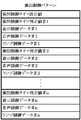
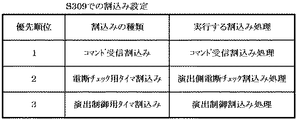
ステップS309における設定では、例えばCTCのレジスタ設定を行うことなどにより、演出制御用マイクロコンピュータ120にて所定時間(例えば2ミリ秒)ごとに演出動作を制御するためのタイマ割込みを発生させるようにする。加えて、ステップS309における設定では、演出制御用マイクロコンピュータ120にて発生する各種の割込み要因に対応して実行する割込み処理の優先順位を設定する。この実施の形態では、例えば図20に示すように、主基板11から送信された演出制御コマンドを受信した場合に発生するコマンド受信割込みに対応した割込み処理(コマンド受信割込み処理)の優先順位が最も高く、続いて演出制御用マイクロコンピュータ120にて電源断の発生を監視するための電断チェック用タイマ割込みに対応した割込み処理(演出側電断チェック割込み処理)、演出動作を制御するための演出制御用タイマ割込みに対応した割込み処理(演出制御割込み処理)の順番となるように、各割込み処理の優先順位を定める。   In the setting in step S309, for example, by setting the CTC register, the production control microcomputer 120 generates a timer interrupt for controlling the production operation every predetermined time (for example, 2 milliseconds). . In addition, in the setting in step S309, the priority order of interrupt processing to be executed corresponding to various interrupt factors generated in the effect control microcomputer 120 is set. In this embodiment, for example, as shown in FIG. 20, the priority of interrupt processing (command reception interrupt processing) corresponding to a command reception interrupt that occurs when an effect control command transmitted from the main board 11 is received is the highest. Next, an interrupt process corresponding to a power interruption check timer interrupt for monitoring the occurrence of power interruption by the production control microcomputer 120 (production side power interruption check interruption process), an effect for controlling the production operation The priority order of each interrupt process is determined so as to be the order of the interrupt process (effect control interrupt process) corresponding to the control timer interrupt.

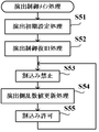
以上のような演出初期設定処理に続いて、CPU131は、例えば演出制御用マイクロコンピュータ120の内部状態などといった演出制御基板12における制御状態を電力供給停止時の状態に復旧させるための演出制御復旧処理を実行する(図18のステップS52)。   Following the effect initial setting process as described above, the CPU 131 restores the control state in the effect control board 12 such as the internal state of the effect control microcomputer 120 to the state when the power supply is stopped. Is executed (step S52 in FIG. 18).

図21は、図18のステップS52にて実行される演出制御復旧処理の一例を示すフローチャートである。この演出制御復旧処理において、CPU131は、まず、RAM133のデータチェックを行い、チェック結果が正常であるか否かを判定する(ステップS321)。ステップS321の処理では、例えばRAM133の所定領域における記憶データを用いてチェックサムを算出し、算出されたチェックサムとRAM133の演出制御バッファ設定部に設けられた演出チェックサムバッファに記憶されているチェックサムとを比較する。ここで、演出チェックサムバッファには、前回の電力供給停止時に、同様の処理によって算出されたチェックサムが記憶されている。この演出チェックサムバッファは、バックアップ電源によってバックアップされるRAM133のバックアップ領域に含まれており、電力供給が停止した場合でも、所定期間は演出チェックサムバッファの内容が保存されることになる。算出されたチェックサムと演出チェックサムバッファに記憶されているチェックサムとの比較結果が不一致であれば、RAM133の所定領域におけるデータが電力供給停止時のデータとは異なっていることから、チェック結果が正常でないと判断される。   FIG. 21 is a flowchart showing an example of the effect control restoration process executed in step S52 of FIG. In this effect control restoration process, the CPU 131 first checks the data in the RAM 133 and determines whether or not the check result is normal (step S321). In the process of step S321, for example, a checksum is calculated using data stored in a predetermined area of the RAM 133, and the checksum calculated and a check stored in the effect checksum buffer provided in the effect control buffer setting unit of the RAM 133 are calculated. Compare with Sam. Here, the effect checksum buffer stores a checksum calculated by the same processing when the power supply was stopped last time. This effect checksum buffer is included in the backup area of the RAM 133 backed up by the backup power source, and the contents of the effect checksum buffer are stored for a predetermined period even when the power supply is stopped. If the comparison result between the calculated checksum and the checksum stored in the effect checksum buffer does not match, the data in the predetermined area of the RAM 133 is different from the data when the power supply is stopped. Is determined to be not normal.

ステップS321におけるチェック結果が正常である場合には(ステップS321;Yes)、RAM133の演出制御フラグ設定部に設けられた演出バックアップフラグがオンとなっているか否かを判定する(ステップS322)。演出バックアップフラグの状態は、電力供給が停止するときに、演出制御フラグ設定部に設定される。そして、この演出バックアップフラグの設定箇所がバックアップ電源によってバックアップされることで、電力供給が停止した場合でも、演出バックアップフラグの状態は保存されることになる。ステップS322の処理では、例えば演出バックアップフラグの値として「55H」が演出制御フラグ設定部に設定されていれば、バックアップあり(オン状態)であると判断される。これに対して、「55H」以外の値が設定されていればバックアップなし(オフ状態)であると判断される。なお、ステップS322のような演出バックアップフラグがオンとなっているか否かの判定を、ステップS321のようなチェック結果の判定よりも先に行い、演出バックアップフラグがオンであるときにRAM133のデータチェック結果が正常であるか否かを判定するようにしてもよい。   If the check result in step S321 is normal (step S321; Yes), it is determined whether or not the effect backup flag provided in the effect control flag setting unit of the RAM 133 is on (step S322). The state of the effect backup flag is set in the effect control flag setting unit when the power supply is stopped. And the state of the production backup flag is preserved even when the power supply is stopped by backing up the set location of the production backup flag by the backup power source. In the process of step S322, for example, if “55H” is set as the value of the effect backup flag in the effect control flag setting unit, it is determined that there is a backup (ON state). On the other hand, if a value other than “55H” is set, it is determined that there is no backup (OFF state). Note that the determination as to whether or not the effect backup flag is turned on as in step S322 is performed prior to the determination of the check result as in step S321, and the data check of the RAM 133 is performed when the effect backup flag is turned on. You may make it determine whether a result is normal.

ステップS322にて演出バックアップフラグがオンであるときには(ステップS322;Yes)、演出バックアップフラグをクリアしてオフ状態とした後(ステップS323)、CPU131が、演出制御用マイクロコンピュータ120の内部状態などを電力供給が停止されたときの状態に戻すための復旧時における設定を行う(ステップS324)。具体的な一例として、ステップS324の処理では、まず、ROM132に格納されているバックアップ時設定テーブルの先頭アドレスをポインタに設定し、バックアップ時設定テーブルの内容を順次に、RAM133内の作業領域に設定する。ここで、RAM133の作業領域がバックアップ電源によってバックアップされている場合には、バックアップ時設定テーブルには、作業領域のうちで初期化してもよい領域についての初期化データが設定されていればよい。続いて、バックアップ電源によりバックアップされるRAM133のバックアップ領域から、制御状態を復旧させるための演出バックアップ用データを読み出し、その読出データに応じてCPU131の内蔵レジスタやRAM133の作業領域の設定を、演出制御用マイクロコンピュータ120が再起動される以前の状態に復旧させる。   When the effect backup flag is on in step S322 (step S322; Yes), after clearing the effect backup flag to turn it off (step S323), the CPU 131 changes the internal state of the effect control microcomputer 120, and the like. Setting at the time of recovery for returning to the state when the power supply is stopped is performed (step S324). As a specific example, in the process of step S324, first, the start address of the backup setting table stored in the ROM 132 is set as a pointer, and the contents of the backup setting table are sequentially set in the work area in the RAM 133. To do. Here, when the work area of the RAM 133 is backed up by a backup power source, it is only necessary to set initialization data for an area that may be initialized in the work area in the backup setting table. Subsequently, the production backup data for restoring the control state is read from the backup area of the RAM 133 backed up by the backup power source, and the settings of the internal register of the CPU 131 and the work area of the RAM 133 are set according to the read data. The microcomputer 120 is restored to the state before being restarted.

この後、CPU131は、ステップS324での設定に基づき、例えばVDP141に復旧後の状態に応じた表示制御指令となるコマンドを送信することなどにより、VDP141における各種制御の再開設定を行ってから(ステップS325)、演出制御復旧処理を終了する。なお、ステップS325の処理を実行した後には、例えばステップS324における制御状態の復帰によりプログラムカウンタに設定された退避値に対応する処理への復帰を行うようにすればよい。   Thereafter, based on the setting in step S324, the CPU 131 performs various control resumption settings in the VDP 141 by, for example, sending a command that becomes a display control command corresponding to the state after restoration to the VDP 141 (step S324). S325), the effect control restoration process is terminated. Note that after executing the process of step S325, for example, the process may be returned to the process corresponding to the saved value set in the program counter by the return of the control state in step S324.

また、ステップS321におけるチェック結果が正常ではない場合や(ステップS321;No)、ステップS322にて演出バックアップフラグがオフである場合には(ステップS322;No)、RAM133の初期化を行う(ステップS326)。ステップS326の処理に続いて、演出制御用マイクロコンピュータ120の内部状態などを初期状態とするための初期化時における設定を行ってから(ステップS327)、演出制御復旧処理を終了する。   If the check result in step S321 is not normal (step S321; No), or if the effect backup flag is off in step S322 (step S322; No), the RAM 133 is initialized (step S326). ). Subsequent to the process of step S326, after setting for initialization to set the internal state of the effect control microcomputer 120 to the initial state (step S327), the effect control restoration process is terminated.

図18のステップS52にて以上のような演出制御復旧処理を実行した後には、割込み禁止としてから(ステップS53)、演出側乱数値更新処理を実行して(ステップS54)、割込みを許可するという(ステップS55)、一連の処理を繰り返し実行する。ステップS54にて実行される演出側乱数値更新処理は、演出制御基板12の側で用いられる乱数値の全部または一部をソフトウェアにより更新するための処理である。   After performing the effect control restoration process as described above in step S52 in FIG. 18, after interrupt prohibition (step S53), the effect random number value update process is executed (step S54), and the interrupt is permitted. (Step S55), a series of processing is repeatedly executed. The effect side random number value update process executed in step S54 is a process for updating all or part of the random number values used on the effect control board 12 side by software.

演出制御用マイクロコンピュータ120では、例えばRAM133の演出制御フラグ設定部などに、各種の割込みに対応した割込みフラグが設けられている。なお、このような割込みフラグに代えて、CPU131に内蔵された割込みレジスタを用いるようにしてもよい。そして、演出制御用マイクロコンピュータ120にて各種の割込みが発生した場合には、例えばリセット/割込みコントローラ136によって発生した割込みの種類に対応した割込みフラグがオン状態にセットされる。このとき、リセット/割込みコントローラ136は、割込みの発生をCPU131に通知するための割込み信号をオン状態にセットする。CPU131では、マスク可能な割込みが発生した場合に、割込みが許可されていれば、リセット/割込みコントローラ136からの割込み信号がオン状態となったことに応答して、RAM133の演出制御フラグ設定部などに設けられたそれぞれの割込みフラグをチェックすることにより、発生した割込み要因を特定する。そして、同時に複数種類の割込み要因が発生している場合には、優先順位が高くなるように設定されているものから、発生した割込み要因に対応する割込み処理を実行する。   In the effect control microcomputer 120, for example, the effect control flag setting unit of the RAM 133 is provided with interrupt flags corresponding to various interrupts. Instead of such an interrupt flag, an interrupt register built in the CPU 131 may be used. When various interrupts occur in the production control microcomputer 120, for example, an interrupt flag corresponding to the type of interrupt generated by the reset / interrupt controller 136 is set to an on state. At this time, the reset / interrupt controller 136 sets an interrupt signal for notifying the CPU 131 of the occurrence of an interrupt to an on state. In the CPU 131, when an interrupt that can be masked is generated, if the interrupt is permitted, the CPU 133 produces an effect control flag setting unit of the RAM 133 in response to the interrupt signal from the reset / interrupt controller 136 being turned on. The cause of the interrupt that occurred is specified by checking the respective interrupt flags provided in. When a plurality of types of interrupt factors are generated at the same time, the interrupt processing corresponding to the generated interrupt factors is executed from the one set so as to have a higher priority.

例えば、演出制御用マイクロコンピュータ120では、所定時間が経過する毎に発生するタイマ割込みとは別に、主基板11から演出制御コマンドを受信するための割込みが発生する。この割込みは、例えば主基板11からの演出制御INT信号がオン状態となることにより発生する割込みである。演出制御INT信号がオン状態となることによる割込みが発生するとコマンド受信割込みフラグがオン状態となり、CPU131は、自動的に割込み禁止状態に設定するとともに、プログラムカウンタなどといった内蔵レジスタの内容をスタックにセーブする。   For example, the effect control microcomputer 120 generates an interrupt for receiving an effect control command from the main board 11 separately from a timer interrupt that occurs every time a predetermined time elapses. This interruption is generated when, for example, an effect control INT signal from the main board 11 is turned on. When an interrupt occurs due to the turn-on of the effect control INT signal, the command reception interrupt flag is turned on, and the CPU 131 automatically sets the interrupt disabled state and saves the contents of the built-in registers such as the program counter in the stack. To do.

主基板11からの演出制御INT信号がオン状態となることにより発生した割込みに対応して、CPU131は、例えば所定のコマンド受信割込み処理を実行する。このコマンド受信割込み処理では、コマンド受信割込みフラグをクリアしてオフ状態とした後に、演出制御用マイクロコンピュータ120が備える入出力ポート135に含まれる入力ポートのうちで、信号中継基板13を介して主基板11から送信された制御信号を受信する所定の入力ポートから、演出制御コマンドとなる制御信号を取り込む。このとき取り込まれた演出制御コマンドは、例えばRAM133の演出制御バッファ設定部に設けられた演出側受信コマンドバッファに格納する。一例として、演出制御コマンドが2バイト構成である場合には、1バイト目(MODE)と2バイト目(EXT)を順次に受信して演出側受信コマンドバッファに格納する。その後、CPU131は、スタックにセーブした内蔵レジスタの内容を復帰させるとともに割込みを許可してから、コマンド受信割込み処理を終了する。   In response to the interrupt generated when the effect control INT signal from the main board 11 is turned on, the CPU 131 executes a predetermined command reception interrupt process, for example. In this command reception interrupt process, after the command reception interrupt flag is cleared and turned off, the input port included in the input / output port 135 included in the effect control microcomputer 120 is mainly connected via the signal relay board 13. A control signal serving as an effect control command is captured from a predetermined input port that receives a control signal transmitted from the substrate 11. The effect control command captured at this time is stored, for example, in an effect side reception command buffer provided in the effect control buffer setting unit of the RAM 133. As an example, when the production control command has a 2-byte configuration, the first byte (MODE) and the second byte (EXT) are sequentially received and stored in the production side reception command buffer. Thereafter, the CPU 131 restores the contents of the internal register saved in the stack and permits an interrupt, and then ends the command reception interrupt process.

また、電源断の発生を監視するための電断チェック用タイマ割込みが発生した場合に、CPU131は、図22のフローチャートに示すような演出側電断チェック割込み処理を実行する。このとき、CPU131は、自動的に割込み禁止状態に設定する。図22に示す演出側電断チェック割込み処理において、CPU131は、例えばRAM133の演出制御フラグ設定部などに設けられた電断チェック用タイマ割込みフラグをクリアしてオフ状態とする(ステップS71)。これとともに、例えばプログラムカウンタなどといった内蔵レジスタの内容をスタックにセーブして退避する(ステップS72)。この後、電断検出回路137からの電源断信号がオン状態となっているか否かを判定する(ステップS73)。   When a power interruption check timer interrupt for monitoring the occurrence of a power interruption occurs, the CPU 131 executes a production side power interruption check interrupt process as shown in the flowchart of FIG. At this time, the CPU 131 automatically sets the interrupt disabled state. In the effect-side power interruption check interrupt process shown in FIG. 22, the CPU 131 clears the power interruption check timer interrupt flag provided in, for example, the effect control flag setting unit of the RAM 133 and turns it off (step S71). At the same time, the contents of the built-in register such as a program counter are saved in the stack and saved (step S72). Thereafter, it is determined whether or not the power-off signal from the power-off detection circuit 137 is on (step S73).

ステップS73にて電源断信号がオン状態である場合には(ステップS73;Yes)、所定の電断判定時間が経過したか否かを判定する(ステップS74)。ここで、CPU131は、ステップS73にて最初に電源断信号がオン状態であると判定されてからの経過時間を計測し、ステップS74の処理では、計測された経過時間が電断判定時間に達したか否かを判定すればよい。この場合、ステップS73にて続けて電源断信号がオン状態であると判定されている期間では、経過時間の計測が継続される。これに対して、ステップS73にて一旦電源断信号がオフ状態であると判定されたことにより、経過時間の計測動作を初期化すればよい。   If the power-off signal is on in step S73 (step S73; Yes), it is determined whether a predetermined power-off determination time has elapsed (step S74). Here, the CPU 131 measures the elapsed time since it was first determined in step S73 that the power-off signal is in the on state. In the process of step S74, the measured elapsed time reaches the power-off determination time. What is necessary is just to determine whether it did. In this case, the measurement of the elapsed time is continued in the period in which it is determined in step S73 that the power-off signal is in the on state. In contrast, when it is determined in step S73 that the power-off signal is once off, the elapsed time measurement operation may be initialized.

ステップS73にて電源断信号がオフ状態であると判定された場合や(ステップS73;No)、ステップS74にて電断判定時間が経過していないと判定された場合には(ステップS74;No)、ステップS72にて退避した内蔵レジスタの内容を復帰させてから(ステップS75)、演出側電断チェック割込み処理を終了する。このときには、CPU131が割込みを許可すればよい。   If it is determined in step S73 that the power-off signal is in an off state (step S73; No), or if it is determined in step S74 that the power-off determination time has not elapsed (step S74; No). ) After restoring the contents of the built-in register saved in step S72 (step S75), the production side power interruption check interrupt process is terminated. At this time, the CPU 131 may permit the interruption.

ステップS74にて電断判定時間が経過したと判定された場合には(ステップS74;Yes)、例えばRAM133の所定領域における記憶データなどを用いて、演出バックアップ用データの設定を行う(ステップS76)。ここで、例えばRAM133の演出制御フラグ設定部に設けられた各種フラグの値やRAM133の演出制御タイマ設定部に設けられた各種タイマのタイマ値により演出制御用マイクロコンピュータ120での制御状態や表示制御部121での各種処理の進行状況が特定することができるのであれば、これらのフラグやタイマの値を示すデータにより、演出バックアップ用データを構成すればよい。また、例えばCPU131の内蔵レジスタ(例えばプログラムカウンタ)の格納値などから演出制御用マイクロコンピュータ120での制御状態や表示制御部121での各種処理の進行状況が特定することができるのであれば、こうした内蔵レジスタの格納値を示すデータにより、演出バックアップ用データを構成すればよい。あるいは、フラグやタイマの値を示すデータと内蔵レジスタの格納値を示すデータとを組み合わせることにより、演出バックアップ用データを構成してもよい。その他にも、演出制御用マイクロコンピュータ120での制御状態や表示制御部121での各種処理の進行状況を特定して再起動後に復旧可能とする任意のデータが、演出バックアップ用データに含まれてもよい。   If it is determined in step S74 that the power interruption determination time has elapsed (step S74; Yes), for example, data for effect backup is set using stored data in a predetermined area of the RAM 133 (step S76). . Here, for example, the control state and display control in the effect control microcomputer 120 based on the values of various flags provided in the effect control flag setting unit of the RAM 133 and the timer values of various timers provided in the effect control timer setting unit of the RAM 133. As long as the progress of various processes in the unit 121 can be specified, the production backup data may be configured by data indicating the values of these flags and timers. Further, for example, if the control state in the production control microcomputer 120 and the progress of various processes in the display control unit 121 can be specified from the stored value of a built-in register (for example, a program counter) of the CPU 131 or the like. The effect backup data may be constituted by data indicating the stored value of the built-in register. Alternatively, the effect backup data may be configured by combining data indicating the value of the flag or timer and data indicating the stored value of the built-in register. In addition, any data that can be recovered after restarting by specifying the control state in the production control microcomputer 120 and the progress of various processes in the display control unit 121 is included in the production backup data. Also good.

ステップS76の処理に続いて、CPU131は、例えばRAM133の所定領域における記憶データを用いてチェックサムを算出することなどにより、チェックデータを作成する(ステップS77)。そして、RAM133の演出制御フラグ設定部に設けられた演出バックアップフラグをオン状態にセットしてから(ステップS78)、RAM133へのアクセスを禁止する(ステップS79)。なお、RAM133の一部が電源基板10において作成されるバックアップ電源によってバックアップされる場合には、ステップS76にて設定した演出バックアップ用データや、ステップS77にて作成したチェックデータ、ステップS78にてオン状態に設定した演出バックアップフラグを示すデータなどを、それぞれの処理の終了時などにRAM133のバックアップ領域に記憶させるようにすればよい。この後、CPU131は、所定のループ処理に入り、演出制御用マイクロコンピュータ120の動作停止まで待機する。   Subsequent to the processing in step S76, the CPU 131 creates check data by calculating a checksum using, for example, data stored in a predetermined area of the RAM 133 (step S77). And after setting the effect backup flag provided in the effect control flag setting part of RAM133 to an ON state (step S78), access to RAM133 is prohibited (step S79). When part of the RAM 133 is backed up by a backup power source created on the power supply board 10, the effect backup data set in step S76, the check data created in step S77, and turned on in step S78. Data indicating the effect backup flag set in the state may be stored in the backup area of the RAM 133 at the end of each process. Thereafter, the CPU 131 enters a predetermined loop process and waits until the operation control microcomputer 120 stops operating.

演出制御用マイクロコンピュータ120において演出の進行を制御するための演出制御用タイマ割込みが発生した場合に、CPU131は、図23のフローチャートに示すような演出制御割込み処理を実行する。このとき、CPU131は、自動的に割込みのマスクを行い、演出制御割込み処理の実行中に同じ優先順位の割込み要因に対応する割込み処理の実行を開始させないようにする。なお、このときにマスクが行われることによっても、演出制御用タイマ割込みよりも優先順位が高い割込み要因に対応した割込み処理の実行は許可される。図23に示す演出制御割込み処理を開始すると、CPU131は、まず、演出制御用タイマ割込みフラグをクリアしてオフ状態にするとともに(ステップS91)、例えばプログラムカウンタなどといった内部レジスタの内容をスタックにセーブして退避する(ステップS92)。   When an effect control timer interrupt for controlling the progress of the effect is generated in the effect control microcomputer 120, the CPU 131 executes an effect control interrupt process as shown in the flowchart of FIG. At this time, the CPU 131 automatically masks the interrupt so that the interrupt process corresponding to the interrupt factor having the same priority is not started during the execution of the effect control interrupt process. Note that even when masking is performed at this time, execution of interrupt processing corresponding to an interrupt factor having a higher priority than that of the effect control timer interrupt is permitted. When the effect control interrupt process shown in FIG. 23 is started, the CPU 131 first clears the effect control timer interrupt flag to turn it off (step S91), and saves the contents of an internal register such as a program counter in the stack. And evacuate (step S92).

続いて、CPU131は、例えば入出力ポート135に含まれる所定の出力ポートにウォッチドッグクリア信号をオン状態とするための制御データをセットすることなどにより、ウォッチドッグ付リセットIC124をクリアする(ステップS93)。次に、主基板11から送信された演出制御コマンドを解析するためのコマンド解析処理を実行する(ステップS94)。また、CPU131は、演出制御プロセス処理を実行する(ステップS95)。この演出制御プロセス処理では、パチンコ遊技機1における演出動作の進行状況に応じて、画像表示装置5の表示やスピーカ8L、8Rからの音声出力、遊技効果ランプ9の点灯動作などにより各種の演出を実行するための設定が行われる。そして、演出側乱数値更新処理が実行されることにより(ステップS96)、演出制御基板12の側にて乱数回路134等によりカウントされる各種の乱数値が更新される。この後、ステップS92にて退避したレジスタの内容を復帰させてから(ステップS97)、演出制御割込み処理を終了する。なお、演出制御割込み処理を終了するときには、CPU131がマスク解除を行えばよい。   Subsequently, the CPU 131 clears the reset IC 124 with a watchdog by setting control data for turning on the watchdog clear signal in a predetermined output port included in the input / output port 135, for example (step S93). ). Next, a command analysis process for analyzing the effect control command transmitted from the main board 11 is executed (step S94). In addition, the CPU 131 executes effect control process processing (step S95). In this effect control process, various effects are produced by the display of the image display device 5, the sound output from the speakers 8L and 8R, the lighting operation of the game effect lamp 9, etc. Settings for execution are made. Then, by executing the effect side random number value update process (step S96), various random number values counted by the random number circuit 134 or the like on the effect control board 12 side are updated. Thereafter, the contents of the register saved in step S92 are restored (step S97), and the effect control interrupt process is terminated. It should be noted that when the effect control interrupt process is ended, the CPU 131 may cancel the mask.

図24は、図23のステップS95にて実行される演出制御プロセス処理の一例を示すフローチャートである。図24に示す演出制御プロセス処理では、例えばRAM133の演出制御フラグ設定部に設けられた演出制御プロセスフラグの値に応じて、以下のようなステップS150〜S155の各処理が実行される。   FIG. 24 is a flowchart showing an example of the effect control process executed in step S95 of FIG. In the effect control process shown in FIG. 24, for example, the following processes of steps S150 to S155 are executed according to the value of the effect control process flag provided in the effect control flag setting unit of the RAM 133.

ステップS150の可変表示開始コマンド受信待ち処理は、演出制御プロセスフラグの値が“0”のときに実行される処理である。この可変表示開始コマンド受信待ち処理は、主基板11からの可変表示開始コマンドを受信したか否かに基づいて画像表示装置5における飾り図柄の可変表示を開始するか否かを判定する処理などを含んでいる。   The variable display start command reception waiting process in step S150 is a process executed when the value of the effect control process flag is “0”. The variable display start command reception waiting process includes a process of determining whether or not to start variable display of decorative symbols on the image display device 5 based on whether or not a variable display start command is received from the main board 11. Contains.

ステップS151の可変表示制御設定処理は、演出制御プロセスフラグの値が“1”のときに実行される。この可変表示制御設定処理は、特別図柄表示装置4による特図ゲームにて特別図柄が変動表示されることに対応して、画像表示装置5における飾り図柄の可変表示を含めた各種の演出動作を行うために、例えば図7に示すような演出制御パターンテーブル201に格納されている複数種類の演出制御パターンのうちから、可変表示パターンや表示結果の種類に対応するものを選択する処理などを含んでいる。   The variable display control setting process in step S151 is executed when the value of the effect control process flag is “1”. This variable display control setting process performs various effect operations including variable display of decorative symbols on the image display device 5 in response to the special symbols being variably displayed in the special symbol game by the special symbol display device 4. For example, a process for selecting a variable display pattern or a display result corresponding to the type of display result from a plurality of types of effect control patterns stored in the effect control pattern table 201 as shown in FIG. It is out.

ステップS152の図柄可変表示中処理は、演出制御プロセスフラグの値が“2”のときに実行される。この処理において、CPU131は、RAM133の演出制御タイマ設定部に設けられた演出制御タイマにおけるタイマ値に対応して、演出制御パターンから表示制御データ、音声制御データ、ランプ制御データなどの演出制御データを読み出す。このとき読み出された演出制御データに従って、例えば画像表示装置5の表示制御や、スピーカ8L、8Rの音声出力制御、遊技効果ランプ9の点灯制御などといった、飾り図柄の可変表示中における各種の演出制御が行われる。そして、演出制御パターンから飾り図柄の可変表示の終了に対応した演出制御データが読み出されると、大当り開始コマンド受信待ち時間に対応して予め定められたタイマ初期値を演出制御タイマに設定する。この後、演出制御タイマのカウントダウン動作を開始するとともに、演出制御プロセスフラグの値を大当り開始待ち処理に対応した値である“3”に更新する。   The variable symbol display process in step S152 is executed when the value of the effect control process flag is “2”. In this process, the CPU 131 generates presentation control data such as display control data, audio control data, and lamp control data from the presentation control pattern corresponding to the timer value in the presentation control timer provided in the presentation control timer setting unit of the RAM 133. read out. Various effects during variable display of decorative symbols, such as display control of the image display device 5, audio output control of the speakers 8L and 8R, lighting control of the game effect lamp 9, etc., according to the effect control data read at this time. Control is performed. Then, when the effect control data corresponding to the end of the variable display of the decorative design is read from the effect control pattern, a timer initial value determined in advance corresponding to the jackpot start command reception waiting time is set in the effect control timer. Thereafter, the countdown operation of the effect control timer is started, and the value of the effect control process flag is updated to “3” which is a value corresponding to the big hit start waiting process.

ステップS153の大当り開始待ち処理は、演出制御プロセスフラグの値が“3”のときに実行される。この処理において、CPU131は、主基板11から送信された大当り開始コマンドの受信があったか否かを判定する。そして、大当り開始コマンドを受信した場合には、飾り図柄の可変表示結果が大当りであるとの判断に基づき、演出制御プロセスフラグの値を大当り演出処理に対応した値である“4”に更新する。これに対して、主基板11からの大当り開始コマンドを受信することなく、演出制御タイマがタイムアウトした場合には、飾り図柄の可変表示結果がハズレであるとの判断に基づき、演出制御プロセスフラグの値を初期値である“0”に更新する。   The big hit start waiting process in step S153 is executed when the value of the effect control process flag is “3”. In this process, the CPU 131 determines whether or not a jackpot start command transmitted from the main board 11 has been received. Then, when the jackpot start command is received, the value of the effect control process flag is updated to “4”, which is a value corresponding to the jackpot effect process, based on the determination that the decorative symbol variable display result is the jackpot. . On the other hand, when the effect control timer times out without receiving the jackpot start command from the main board 11, the effect control process flag of the effect control process flag is determined based on the determination that the decorative symbol variable display result is lost. The value is updated to “0” which is an initial value.

ステップS154の大当り演出処理は、演出制御プロセスフラグの値が“4”のときに実行される処理である。この処理において、CPU131は、例えば画像表示装置5における表示動作を制御して大当り遊技状態に応じた画像を表示させたり、スピーカ8L、8Rにおける音声出力動作を制御して大当り遊技状態に応じた音声を出力させたり、遊技効果ランプ9における点灯/消灯動作を制御して大当り遊技状態に応じた点灯・消灯・点滅の動作をさせたりするといった、大当り遊技状態における各種の演出制御を行う。そして、大当り遊技状態において実行されるラウンド遊技が最終ラウンド(例えば第15ラウンド)の終了に達したことや、主基板11から送信される大当り終了コマンドを受信したことなどに対応して、演出制御プロセスフラグの値を大当り終了演出処理に対応した値である“5”に更新する。ステップS155の大当り終了演出処理は、演出制御プロセスフラグの値が“5”のときに実行される。この大当り終了演出処理は、例えば画像表示装置5に画像を表示させたり、スピーカ8L、8Rから音声を出力させたり、遊技効果ランプ9を点灯させたりすることにより、大当り遊技状態の終了を報知するための演出動作を制御する処理を含んでいる。   The big hit effect process of step S154 is a process executed when the value of the effect control process flag is “4”. In this process, for example, the CPU 131 controls the display operation in the image display device 5 to display an image corresponding to the jackpot gaming state, or controls the sound output operation in the speakers 8L and 8R to play the sound corresponding to the jackpot gaming state. Various effects control in the big hit gaming state is performed such that the lighting / extinguishing operation of the game effect lamp 9 is controlled to turn on / off / blink in accordance with the big hit gaming state. Then, in response to the fact that the round game executed in the big hit game state has reached the end of the final round (for example, the fifteenth round), the big hit end command transmitted from the main board 11 has been received, etc. The value of the process flag is updated to “5” which is a value corresponding to the big hit end effect process. The big hit end effect process in step S155 is executed when the value of the effect control process flag is “5”. In the jackpot end effect process, for example, the end of the jackpot gaming state is notified by displaying an image on the image display device 5, outputting sound from the speakers 8L and 8R, or lighting the game effect lamp 9. The process which controls the production | presentation operation | movement for this is included.

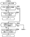
図25は、図24のステップS152にて実行される図柄可変表示中処理の一例を示すフローチャートである。この図柄可変表示中処理において、CPU131は、まず、演出制御タイマにおける値である演出制御タイマ値を、例えば1減算するなどして更新する(ステップS221)。そして、ステップS221にて更新された演出制御タイマ値が、例えば図8に示すような演出制御パターンに含まれる演出制御タイマ判定値#1、#2、…、#nのいずれかと合致するか否かを判定する(ステップS222)。このとき、タイマ判定値のいずれかと合致すれば(ステップS222;Yes)、その合致すると判定された判定値に対応して演出制御パターンに格納されている表示制御データ、音声制御データ、ランプ制御データといった、各種制御データを読み出す(ステップS223)。そして、ステップS223にて読み出された表示制御データに基づき、画像表示装置5における表示の更新タイミングであるか否かを判定する(ステップS224)。   FIG. 25 is a flowchart showing an example of the variable symbol display process executed in step S152 of FIG. In the symbol variable display process, the CPU 131 first updates the effect control timer value, which is a value in the effect control timer, by subtracting, for example, 1 (step S221). Then, whether or not the effect control timer value updated in step S221 matches any of the effect control timer determination values # 1, # 2,..., #N included in the effect control pattern as shown in FIG. Is determined (step S222). At this time, if it matches any of the timer determination values (step S222; Yes), display control data, sound control data, lamp control data stored in the effect control pattern corresponding to the determination value determined to match. Are read out (step S223). Then, based on the display control data read in step S223, it is determined whether or not it is the display update timing in the image display device 5 (step S224).

ステップS224にて表示の更新タイミングであれば(ステップS224;Yes)、所定の表示更新指令処理を実行する(ステップS225)。これに対して、表示の更新タイミングではない場合には(ステップS224;No)、ステップS225の処理をスキップする。続いて、ステップS223での読出データに対応する音声やランプの制御指令を送出する(ステップS226)。   If it is the display update timing in step S224 (step S224; Yes), a predetermined display update command process is executed (step S225). On the other hand, when it is not the display update timing (step S224; No), the process of step S225 is skipped. Subsequently, a voice or lamp control command corresponding to the read data in step S223 is sent (step S226).

ステップS222にて演出制御タイマ判定値#1、#2、…、#nのいずれとも合致しない旨の判定がなされた場合や(ステップS222;No)、ステップS226の処理を実行した後には、例えばステップS223での読出データが所定の終了コードであるか否かを判定することや、あるいはステップS221にて更新された演出制御タイマ値が所定値(例えば「0」)に達したか否かを判定することなどにより、画像表示装置5における飾り図柄の可変表示の終了タイミングとなったか否かを判定する(ステップS227)。このとき、可変表示の終了タイミングではなければ(ステップS227;No)、図柄可変表示中処理を終了する。   When it is determined in step S222 that the production control timer determination values # 1, # 2,..., #N do not match (step S222; No), after the process of step S226 is executed, for example, It is determined whether or not the read data in step S223 is a predetermined end code, or whether or not the effect control timer value updated in step S221 has reached a predetermined value (eg, “0”). As a result of the determination, it is determined whether or not it is the end timing of variable display of decorative symbols on the image display device 5 (step S227). At this time, if it is not the end timing of variable display (step S227; No), the variable symbol display process is ended.

ステップS227にて可変表示の終了タイミングであると判定された場合には(ステップS227;Yes)、所定の大当り開始コマンド受信待機用初期値を演出制御タイマに設定し(ステップS228)、演出制御プロセスフラグを大当り開始待ち処理に対応した値である“3”に更新してから(ステップS229)、図柄可変表示中処理を終了する。   If it is determined in step S227 that it is the end timing of variable display (step S227; Yes), a predetermined big hit start command reception standby initial value is set in the effect control timer (step S228), and the effect control process After the flag is updated to “3” which is a value corresponding to the big hit start waiting process (step S229), the variable symbol display process is ended.

図26は、図25のステップS225にて実行される表示更新指令処理の一例を示すフローチャートである。この表示更新指令処理において、CPU131は、まず、例えば演出制御タイマ値に対応して演出制御パターンから読み出した表示制御データなどから、表示を更新する対象となる画像要素を特定する(ステップS341)。続いて、例えば演出制御パターンから読み出した表示制御データなどから、CGROM142のスプライトデータエリア142Aまたは一時記憶メモリ155における画像要素データの読出アドレスを特定する(ステップS342)。また、例えば演出制御パターンから読み出した表示制御データなどから、画像要素の表示位置(表示座標)に対応したフレームバッファメモリ156における画像要素データの書込アドレスを特定する(ステップS343)。さらに、更新対象となる画像要素を示す画像要素データのデータ量を特定する(ステップS344)。その後、ステップS342〜S344にて特定した画像要素データの読出アドレス、書込アドレス、データ量に基づき、転送表示コマンドを作成してVDP141に送信する(ステップS345)。   FIG. 26 is a flowchart showing an example of the display update command process executed in step S225 of FIG. In this display update command process, the CPU 131 first specifies an image element whose display is to be updated from, for example, display control data read from the effect control pattern corresponding to the effect control timer value (step S341). Subsequently, the read address of the image element data in the sprite data area 142A of the CGROM 142 or the temporary storage memory 155 is specified from the display control data read from the effect control pattern, for example (step S342). Also, for example, the writing address of the image element data in the frame buffer memory 156 corresponding to the display position (display coordinates) of the image element is specified from the display control data read from the effect control pattern (step S343). Further, the data amount of the image element data indicating the image element to be updated is specified (step S344). Thereafter, based on the read address, write address, and data amount of the image element data specified in steps S342 to S344, a transfer display command is created and transmitted to the VDP 141 (step S345).

ステップS345の処理を実行した後には、全ての表示対象となる画像要素についての指令が完了したか否かを判定する(ステップS346)。そして、指令が完了していなければ(ステップS346;No)、ステップS341の処理に戻る。これに対して、全ての更新対象となる画像要素についての指令が完了すれば(ステップS346;Yes)、表示更新指令処理を終了する。   After executing the process of step S345, it is determined whether or not the command for all image elements to be displayed is completed (step S346). If the command is not completed (step S346; No), the process returns to step S341. On the other hand, if the command for all the image elements to be updated is completed (step S346; Yes), the display update command process is terminated.

図27は、図24のステップS154にて実行される大当り演出処理の一例を示すフローチャートである。この大当り演出処理において、CPU131は、まず、主基板11から送信される大当りラウンド数通知コマンドの受信があったか否かを判定する(ステップS241)。このとき、大当りラウンド数通知コマンドの受信があれば(ステップS241;Yes)、例えば図7に示すような演出制御パターンテーブル201に格納されている複数種類の演出制御パターンのうちから大当りラウンド数に対応した演出制御パターンを読み出すことなどといった、大当りラウンド数に対応して演出動作を制御するための設定を行う(ステップS242)。ステップS241にて大当りラウンド数通知コマンドの受信がなければ(ステップS241;No)、ステップS242の処理をスキップする。   FIG. 27 is a flowchart showing an example of the big hit effect process executed in step S154 of FIG. In the jackpot effect process, the CPU 131 first determines whether or not a jackpot round number notification command transmitted from the main board 11 has been received (step S241). At this time, if the big hit round number notification command is received (step S241; Yes), for example, the big hit round number is selected from a plurality of types of production control patterns stored in the production control pattern table 201 as shown in FIG. Settings are made to control the rendering operation corresponding to the number of big hit rounds, such as reading out the corresponding rendering control pattern (step S242). If the big hit round number notification command is not received in step S241 (step S241; No), the process of step S242 is skipped.

続いて、主基板11から送信される大当り終了コマンドの受信があったか否かを判定する(ステップS243)。そして、大当り終了コマンドの受信があれば(ステップS243;Yes)、演出制御プロセスフラグの値を大当り終了演出処理に対応した値である“5”に更新してから(ステップS244)、大当り演出処理を終了する。これに対して、ステップS243にて大当り終了コマンドの受信がなければ(ステップS243;No)、演出制御タイマ値を、例えば1減算するなどして更新する(ステップS245)。   Subsequently, it is determined whether or not a jackpot end command transmitted from the main board 11 has been received (step S243). If a jackpot end command is received (step S243; Yes), the value of the effect control process flag is updated to “5” which is a value corresponding to the jackpot end effect process (step S244), and then the jackpot effect process is performed. Exit. On the other hand, if the big hit end command is not received in step S243 (step S243; No), the effect control timer value is updated by subtracting, for example, 1 (step S245).

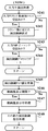
ステップS245の処理を実行した後には、演出制御パターンから読み出した表示制御データや、ステップS245にて更新した演出制御タイマ値などに基づいて、動画像データを用いた動画像の表示を行う動画像表示期間であるか否かを判定する(ステップS246)。ステップS246にて動画像表示期間である場合には(ステップS246;Yes)、所定の動画像表示中処理を実行する(ステップS247)。これに対して、動画像表示期間ではない場合には(ステップS246;No)、ステップS247の処理をスキップする。この後、演出制御パターンから読み出した各種制御データに対応して、その他の演出制御に関する指令を行うための処理を実行してから(ステップS248)、大当り演出処理を終了する。   After executing the process of step S245, a moving image that displays a moving image using moving image data based on the display control data read from the effect control pattern, the effect control timer value updated in step S245, or the like. It is determined whether or not it is the display period (step S246). If it is the moving image display period in step S246 (step S246; Yes), a predetermined moving image display process is executed (step S247). On the other hand, when it is not a moving image display period (step S246; No), the process of step S247 is skipped. Thereafter, in response to the various control data read from the effect control pattern, processing for issuing other instructions related to effect control is executed (step S248), and then the big hit effect process is terminated.

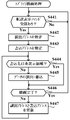
図28は、図27のステップS247にて実行される動画像表示中処理の一例を示すフローチャートである。この動画像表示中処理において、CPU131は、まず、動画像データを用いて再生される画像が、1フレーム目の画像であるか否かを判定する(ステップS361)。例えば、ステップS361の処理において、CPU131は、演出制御タイマ値やCGROM142における動画像データの読出位置(例えば読出アドレス)を指定する動画像読出ポインタの格納値などから、動画像ファイルを新たに読み出すのか継続して読み出すのかを特定する。そして、動画像ファイルを新たに読み出す場合には、1フレーム目の画像であると判定する一方で、継続して読み出す場合には、1フレーム目の画像ではないと判定すればよい。   FIG. 28 is a flowchart showing an example of the moving image display process executed in step S247 of FIG. In the moving image display process, the CPU 131 first determines whether or not the image reproduced using the moving image data is the first frame image (step S361). For example, in the process of step S361, the CPU 131 newly reads out the moving image file from the presentation control timer value or the stored value of the moving image reading pointer that specifies the reading position (for example, reading address) of the moving image data in the CGROM 142. Specify whether to continue reading. When a new moving image file is read, it is determined that the image is the first frame, while when it is continuously read, it is determined that the image is not the first frame.

ステップS361にて1フレーム目の画像であると判定された場合には(ステップS361;Yes)、例えば動画像読出ポインタの値を読出対象となる動画像ファイルに対応した読出アドレスに設定することなどといった、動画像再生用に設けられたレジスタの初期設定を行う(ステップS362)。これに対して、1フレーム目の画像ではないと判定された場合には(ステップS361;No)、前回の動画像表示中処理が終了するときに後述するステップS369の処理で退避されたレジスタの内容を復帰させる(ステップS363)。   If it is determined in step S361 that the image is the first frame (step S361; Yes), for example, the value of the moving image read pointer is set to a read address corresponding to the moving image file to be read. The initial setting of the register provided for moving image reproduction is performed (step S362). On the other hand, when it is determined that the image is not the first frame (step S361; No), when the previous moving image display process ends, the register saved in the process of step S369, which will be described later, is saved. The contents are restored (step S363).

この後、CPU131は、動画像デコード開始コマンドを作成してVDP141に送信する(ステップS364)。また、CPU131は、RAM133の演出制御タイマ設定部に設けられたイベント割込み待ちタイマを初期化して、経過時間の計測をスタートさせる(ステップS365)。続いて、RAM133の演出制御フラグ設定部に設けられたイベント割込みフラグがオンとなったか否かを判定する(ステップS366)。ここで、イベント割込みフラグは、VDP141にて1フレーム分の画像に対応したピクチャデータの再生が完了したときに、VDP141が備える動画像用デコーダ158にてイベント割込みが発生したことに対応してオン状態にセットされる。   Thereafter, the CPU 131 creates a moving image decoding start command and transmits it to the VDP 141 (step S364). In addition, the CPU 131 initializes an event interruption waiting timer provided in the effect control timer setting unit of the RAM 133 and starts measuring elapsed time (step S365). Subsequently, it is determined whether or not the event interrupt flag provided in the effect control flag setting unit of the RAM 133 has been turned on (step S366). Here, the event interrupt flag is turned on in response to occurrence of an event interrupt in the moving picture decoder 158 included in the VDP 141 when the reproduction of picture data corresponding to an image for one frame is completed in the VDP 141. Set to state.

ステップS366にてイベント割込みフラグがオンである場合には(ステップS366;Yes)、イベント割込みフラグをクリアしてオフ状態とした後(ステップS367)、例えば1つの動画像ファイルに格納された動画像データに対応して、最終フレームのデコードが完了したか否かを判定する(ステップS368)。ステップS368にて最終フレームのデコードが完了していないと判定された場合には(ステップS368;No)、レジスタの内容を退避してから(ステップS369)、動画像表示中処理を終了する。これに対して、最終フレームのデコードが完了したと判定された場合には(ステップS368;Yes)、ステップS369の処理をスキップする。この後、CPU131は、動画像デコードNOPコマンドを作成してVDP141に送信してから(ステップS370)、動画像表示中処理を終了する。   If the event interrupt flag is on in step S366 (step S366; Yes), after clearing the event interrupt flag to turn it off (step S367), for example, a moving image stored in one moving image file Corresponding to the data, it is determined whether or not the decoding of the last frame has been completed (step S368). If it is determined in step S368 that the decoding of the final frame has not been completed (step S368; No), the contents of the register are saved (step S369), and the moving image display processing is terminated. On the other hand, when it is determined that the decoding of the final frame is completed (step S368; Yes), the process of step S369 is skipped. Thereafter, the CPU 131 creates a moving image decoding NOP command and transmits it to the VDP 141 (step S370), and then ends the moving image display processing.

また、ステップS366にてイベント割込みフラグがオフである場合には(ステップS366;No)、イベント割込み待ちタイマにおけるタイマ値であるイベント割込み待ちタイマ値を、例えば1加算するなどして更新する(ステップS371)。そして、ステップS371における更新後のイベント割込み待ちタイマ値が、所定の制限時間判定値に達したか否かを判定する(ステップS372)。このとき、制限時間判定値に達していなければ(ステップS372;No)、ステップS366の処理に戻る。これに対して、ステップS372にて制限時間判定値に達したと判定された場合には(ステップS372;Yes)、所定のループ処理に入り、演出制御用マイクロコンピュータ120が再起動されるまで待機する。   If the event interrupt flag is off in step S366 (step S366; No), the event interrupt wait timer value, which is the timer value in the event interrupt wait timer, is updated, for example, by adding 1 (step S366). S371). Then, it is determined whether or not the updated event interrupt wait timer value in step S371 has reached a predetermined time limit determination value (step S372). At this time, if the time limit determination value has not been reached (step S372; No), the processing returns to step S366. On the other hand, if it is determined in step S372 that the time limit determination value has been reached (step S372; Yes), a predetermined loop process is entered and waits until the effect control microcomputer 120 is restarted. To do.

図29は、演出制御用マイクロコンピュータ120が備えるリセット/割込みコントローラ136により実行されるリセット/割込み制御処理の一例を示すフローチャートである。このリセット/割込み制御処理において、リセット/割込みコントローラ136は、まず、主基板11から送信された演出制御コマンドを受信したことによるコマンド受信割込みが発生したか否かを判定する(ステップS401)。このとき、コマンド受信割込みが発生していれば(ステップS401;Yes)、例えばRAM133の演出制御フラグ設定部に設けられたコマンド受信割込みフラグをオン状態にセットする(ステップS402)。   FIG. 29 is a flowchart showing an example of a reset / interrupt control process executed by the reset / interrupt controller 136 included in the effect control microcomputer 120. In this reset / interrupt control process, the reset / interrupt controller 136 first determines whether or not a command reception interrupt has occurred due to the reception of the effect control command transmitted from the main board 11 (step S401). At this time, if a command reception interrupt has occurred (step S401; Yes), for example, a command reception interrupt flag provided in the effect control flag setting unit of the RAM 133 is set to an on state (step S402).

ステップS401にてコマンド受信割込みが発生していないと判定された場合には(ステップS401;No)、例えば電断チェック用に設けられた所定のCTCがタイムアウトしたことによる電断チェック用タイマ割込みが発生したか否かを判定する(ステップS403)。このとき、電断チェック用タイマ割込みが発生していれば(ステップS403;Yes)、例えばRAM133の演出制御フラグ設定部に設けられた電断チェック用タイマ割込みフラグをオン状態にセットする(ステップS404)。   If it is determined in step S401 that a command reception interrupt has not occurred (step S401; No), for example, a power interruption check timer interrupt is generated when a predetermined CTC provided for power interruption check times out. It is determined whether or not it has occurred (step S403). At this time, if a power interruption check timer interrupt has occurred (step S403; Yes), for example, a power interruption check timer interrupt flag provided in the effect control flag setting unit of the RAM 133 is set to an on state (step S404). ).

ステップS403にて電断チェック用タイマ割込みが発生していないと判定された場合には(ステップS403;No)、例えば演出制御用に設けられた所定のCTCがタイムアウトしたことによる演出制御用タイマ割込みが発生したか否かを判定する(ステップS405)。このとき、演出制御用タイマ割込みが発生していれば(ステップS405;Yes)、例えばRAM133の演出制御フラグ設定部に設けられた演出制御用タイマ割込みフラグをオン状態にセットする(ステップS406)。   If it is determined in step S403 that a power interruption check timer interrupt has not occurred (step S403; No), for example, an effect control timer interrupt due to a time-out of a predetermined CTC provided for effect control Whether or not has occurred is determined (step S405). At this time, if an effect control timer interrupt has occurred (step S405; Yes), for example, an effect control timer interrupt flag provided in the effect control flag setting unit of the RAM 133 is set to the on state (step S406).

ステップS405にて演出制御用タイマ割込みが発生していないと判定された場合には(ステップS405;No)、VDP141からのイベント割込み信号がオン状態となったか否かを判定することにより、イベント割込みが発生したか否かを判定する(ステップS407)。このとき、イベント割込みが発生していれば(ステップS407;Yes)、例えばRAM133の演出制御フラグ設定部に設けられたイベント割込みフラグをオン状態にセットする(ステップS408)。   When it is determined in step S405 that the production control timer interrupt has not occurred (step S405; No), the event interrupt is determined by determining whether or not the event interrupt signal from the VDP 141 is turned on. Whether or not has occurred is determined (step S407). At this time, if an event interrupt has occurred (step S407; Yes), for example, an event interrupt flag provided in the effect control flag setting unit of the RAM 133 is set to an on state (step S408).

ステップS407にてイベント割込みが発生していないと判定された場合には(ステップS407;No)、その他の割込みが発生したか否かを判定する(ステップS409)。このとき、何らかの割込みが発生していれば(ステップS409;Yes)、発生した割込みに対応して、例えば所定の割込みフラグをオン状態にセットするなどといった、予め定められた処理を実行する(ステップS410)。ステップS409にて割込みが発生していないと判定された場合や(ステップS409;No)、ステップS402、S404、S406、S408、S410の処理のいずれかを実行した後には、ステップS401の処理に戻る。   If it is determined in step S407 that no event interrupt has occurred (step S407; No), it is determined whether another interrupt has occurred (step S409). At this time, if any interrupt has occurred (step S409; Yes), a predetermined process such as setting a predetermined interrupt flag to an on state is executed in response to the generated interrupt (step S409). S410). If it is determined in step S409 that no interrupt has occurred (step S409; No), or after performing any of the processes in steps S402, S404, S406, S408, and S410, the process returns to step S401. .

図30は、演出制御用マイクロコンピュータ120が備える電断検出回路137により実行される電断検出処理の一例を示すフローチャートである。この電断検出処理において、電断検出回路137は、まず、電力制御回路125から演出制御用マイクロコンピュータ120への供給電圧が、電断検出判定値として予め定めた電圧値以下となっているか否かを判定する(ステップS421)。このとき、供給電圧が電断検出判定値以下であれば(ステップS421;Yes)、所定の電断発生判定時間が経過したか否かを判定する(ステップS422)。ここで、電断検出回路137は、ステップS421にて最初に供給電圧が電断検出判定値以下であると判定されてからの経過時間を計測し、ステップS422の処理では、計測された経過時間が電断発生判定時間に達したか否かを判定すればよい。この場合、ステップS421にて続けて供給電圧が電断検出判定値以下であると判定されている期間では、経過時間の計測が継続される。これに対して、ステップS421にて一旦供給電圧が電断検出判定値を超えたと判定されることにより、経過時間の計測動作を初期化すればよい。なお、電断発生判定時間を最小値(例えば「0」)に設定しておけば、ステップS421にて供給電圧が電断検出判定値以下であると判定された場合に、直ちに電断発生判定時間が経過したと判断することができる。   FIG. 30 is a flowchart illustrating an example of a power interruption detection process executed by the power interruption detection circuit 137 provided in the effect control microcomputer 120. In this power failure detection process, the power failure detection circuit 137 first determines whether or not the supply voltage from the power control circuit 125 to the effect control microcomputer 120 is equal to or lower than a predetermined voltage value as a power failure detection determination value. Is determined (step S421). At this time, if the supply voltage is equal to or less than the power interruption detection determination value (step S421; Yes), it is determined whether or not a predetermined power interruption occurrence determination time has elapsed (step S422). Here, the power interruption detection circuit 137 measures the elapsed time since it was first determined in step S421 that the supply voltage is equal to or lower than the power interruption detection determination value. In the process of step S422, the measured elapsed time is measured. It may be determined whether or not the power interruption occurrence determination time has been reached. In this case, the measurement of the elapsed time is continued in the period in which it is determined in step S421 that the supply voltage is equal to or less than the power interruption detection determination value. In contrast, once it is determined in step S421 that the supply voltage has exceeded the power interruption detection determination value, the elapsed time measurement operation may be initialized. If the interruption occurrence determination time is set to a minimum value (for example, “0”), the interruption occurrence determination is immediately performed when it is determined in step S421 that the supply voltage is equal to or less than the interruption detection determination value. It can be determined that time has passed.

ステップS422にて電断発生判定時間が経過したと判定された場合には(ステップS422;Yes)、CPU131へと伝送される電源断信号をオン状態に設定する(ステップS423)。ステップS423にて電源断信号をオン状態に設定した後には、後述するステップS425にて電源断信号がオフ状態に設定されるまで、継続してオン状態の電源断信号を出力するようにすればよい。ステップS423の処理を実行した後には、ステップS421の処理に戻る。   If it is determined in step S422 that the power interruption occurrence determination time has elapsed (step S422; Yes), the power-off signal transmitted to the CPU 131 is set to the on state (step S423). After the power-off signal is set to the on state in step S423, the on-state power-off signal is continuously output until the power-off signal is set to the off state in step S425 described later. Good. After executing the process of step S423, the process returns to the process of step S421.

また、ステップS421にて供給電圧が電断検出判定値となる電圧値を超えていると判定された場合には(ステップS421;No)、所定の電断終了判定時間が経過したか否かを判定する(ステップS424)。ここで、電断検出回路137は、ステップS421にて最初に供給電圧が電断検出判定値を超えていると判定されてからの経過時間を計測し、ステップS424の処理では、計測された経過時間が電断終了判定時間に達したか否かを判定すればよい。この場合、ステップS421にて続けて供給電圧が電断検出判定値を超えていると判定されている期間では、経過時間の計測が継続される。これに対して、ステップS421にて一旦供給電圧が電断検出判定値以下になったと判定されることにより、経過時間の計測動作を初期化すればよい。なお、電断終了判定時間を最小値(例えば「0」)に設定しておけば、ステップS421にて供給電圧が電断検出判定値を超えたと判定された場合に、直ちに電断終了判定時間が経過したと判断することができる。   If it is determined in step S421 that the supply voltage exceeds the voltage value that is the power interruption detection determination value (step S421; No), whether or not a predetermined power interruption end determination time has elapsed is determined. Determination is made (step S424). Here, the power failure detection circuit 137 measures the elapsed time since it was first determined in step S421 that the supply voltage exceeds the power failure detection determination value. In the process of step S424, the measured progress is measured. It may be determined whether or not the time has reached the power interruption end determination time. In this case, the measurement of the elapsed time is continued in the period in which it is determined in step S421 that the supply voltage exceeds the power interruption detection determination value. In contrast, once it is determined in step S421 that the supply voltage has become equal to or less than the power interruption detection determination value, the elapsed time measurement operation may be initialized. If the power interruption end determination time is set to the minimum value (eg, “0”), the power interruption end determination time is immediately determined when it is determined in step S421 that the supply voltage has exceeded the power interruption detection determination value. It can be determined that has passed.

ステップS424にて電断終了判定時間が経過したと判定された場合には(ステップS424;Yes)、CPU131へと伝送される電源断信号をオフ状態に設定する(ステップS425)。ステップS425にて電源断信号をオフ状態に設定した後には、前述したステップS423にて電源断信号がオン状態に設定されるまで、継続してオフ状態の電源断信号を出力するようにすればよい。ステップS424にて電断終了判定時間が経過していないと判定された場合や(ステップS424;No)、ステップS425の処理を実行した後には、ステップS421の処理に戻る。   If it is determined in step S424 that the power interruption end determination time has elapsed (step S424; Yes), the power-off signal transmitted to the CPU 131 is set to an off state (step S425). After the power-off signal is set to the off state in step S425, the power-off signal in the off state is continuously output until the power-off signal is set to the on state in step S423 described above. Good. When it is determined in step S424 that the power interruption end determination time has not elapsed (step S424; No), after the process of step S425 is executed, the process returns to step S421.

図31は、VDP141が備える転送制御回路152や描画回路154により実行されるスプライト描画処理の一例を示すフローチャートである。このスプライト描画処理では、まず、演出制御用マイクロコンピュータ120から送信された転送表示コマンドの受信があったか否かを判定する(ステップS441)。演出制御用マイクロコンピュータ120からの受信コマンドがなければ(ステップS441;No)、ステップS441の処理を繰り返し実行して待機する。   FIG. 31 is a flowchart illustrating an example of sprite drawing processing executed by the transfer control circuit 152 and the drawing circuit 154 included in the VDP 141. In this sprite drawing process, first, it is determined whether or not a transfer display command transmitted from the effect control microcomputer 120 has been received (step S441). If there is no command received from the effect control microcomputer 120 (step S441; No), the process of step S441 is repeatedly executed and the system waits.

ステップS441にて転送表示コマンドの受信がある場合には(ステップS441;Yes)、転送表示コマンドに含まれるデータから、CGROM142のスプライトデータエリア142Aまたは一時記憶メモリ155における画像要素データの読出アドレスを特定する(ステップS442)。続いて、転送表示コマンドに含まれるデータから、フレームバッファメモリ156における画像要素データの書込アドレスを特定する(ステップS443)。そして、例えばステップS443にて特定した書込アドレスに基づき、フレームバッファメモリ156における画像要素データの書込先が非表示領域となるか否かの判定を行う(ステップS444)。例えば、ステップS444の処理において、描画回路154は、ステップS443にて特定された書込アドレスが、フレームバッファメモリ156にて画像表示装置5の画面上における非表示領域5Bに割り当てられたアドレスと合致するか否かを判定し、合致する場合には、書込先が非表示領域になると判断する。   When the transfer display command is received in step S441 (step S441; Yes), the read address of the image element data in the sprite data area 142A of the CGROM 142 or the temporary storage memory 155 is specified from the data included in the transfer display command. (Step S442). Subsequently, the writing address of the image element data in the frame buffer memory 156 is specified from the data included in the transfer display command (step S443). Then, for example, based on the write address specified in step S443, it is determined whether or not the image element data write destination in the frame buffer memory 156 is a non-display area (step S444). For example, in the process of step S444, the drawing circuit 154 matches the address assigned to the non-display area 5B on the screen of the image display device 5 in the frame buffer memory 156 by the writing address specified in step S443. If it matches, it is determined that the writing destination is a non-display area.

ステップS444にて書込先が非表示領域ではないと判定された場合には(ステップS444;No)、画像要素データの読出動作と書込動作が行われる(ステップS445)。例えば、転送表示コマンドによりCGROM142のスプライトデータエリア142Aにおける画像要素データの読出アドレスが通知された場合には、転送制御回路152がCGROM142の読出アドレスから画像要素データを読み出して、一時記憶メモリ155に書き込んで記憶させる。このとき、転送制御回路152は、一時記憶メモリ155における画像要素データの記憶アドレスを、描画回路154に通知すればよい。そして、描画回路154は、転送制御回路152から通知された一時記憶メモリ155の記憶アドレスから画像要素データを読み出し、転送表示コマンドにより通知されたフレームバッファメモリ156の書込アドレスに書き込むことにより、表示用データの作成を行う。また、例えば、転送表示コマンドにより一時記憶メモリ155における画像要素データの読出アドレスが通知された場合には、描画回路154が一時記憶メモリ155の読出アドレスから画像要素データを読み出し、転送表示コマンドにより通知されたフレームバッファメモリ156の書込アドレスに書き込むことにより、表示用データの作成を行う。   If it is determined in step S444 that the writing destination is not a non-display area (step S444; No), image element data reading and writing operations are performed (step S445). For example, when the read display command of the image element data in the sprite data area 142 A of the CGROM 142 is notified by the transfer display command, the transfer control circuit 152 reads the image element data from the read address of the CGROM 142 and writes it to the temporary storage memory 155. To remember. At this time, the transfer control circuit 152 may notify the drawing circuit 154 of the storage address of the image element data in the temporary storage memory 155. Then, the drawing circuit 154 reads the image element data from the storage address of the temporary storage memory 155 notified from the transfer control circuit 152, and writes the image element data to the write address of the frame buffer memory 156 notified by the transfer display command. Create data for use. Further, for example, when the read address of the image element data in the temporary storage memory 155 is notified by the transfer display command, the drawing circuit 154 reads the image element data from the read address of the temporary storage memory 155 and notifies by the transfer display command. Display data is created by writing to the write address of the frame buffer memory 156.

ステップS444にて書込先が非表示領域であると判定された場合には(ステップS444;Yes)、ステップS445の処理をスキップする。したがって、演出制御用マイクロコンピュータ120からの転送表示コマンドを受信していても、フレームバッファメモリ156における画像要素データの書込先が画像表示装置5の画面上における非表示領域5Bに対応した書込位置となる場合には、転送制御回路152により画像要素データがCGROM142から読み出されて一時記憶メモリ155に書き込まれることや、描画回路154により画像要素データが一時記憶メモリ155から読み出されてフレームバッファメモリ156に書き込まれることが、制限される。   If it is determined in step S444 that the writing destination is a non-display area (step S444; Yes), the process of step S445 is skipped. Therefore, even if the transfer display command is received from the effect control microcomputer 120, the writing destination of the image element data in the frame buffer memory 156 is the writing corresponding to the non-display area 5B on the screen of the image display device 5. In the case of the position, the image element data is read from the CGROM 142 by the transfer control circuit 152 and written to the temporary storage memory 155, or the image element data is read from the temporary storage memory 155 by the drawing circuit 154. Writing to the buffer memory 156 is restricted.

この後、フレームバッファメモリ156に画像要素データを書き込むことによる描画(表示用データの作成)が完了したか否かを判定し(ステップS446)、完了していなければ(ステップS446;No)、読出アドレスと書込アドレスを更新した後(ステップS447)、ステップS444の処理に戻る。他方、ステップS446にて描画が完了すれば(ステップS446;Yes)、ステップS441の処理に戻り、さらに演出制御用マイクロコンピュータ120からの転送表示コマンドを受信するまで待機する。   Thereafter, it is determined whether or not drawing (creation of display data) by writing image element data to the frame buffer memory 156 is completed (step S446). If not completed (step S446; No), reading is performed. After updating the address and the write address (step S447), the process returns to step S444. On the other hand, if the drawing is completed in step S446 (step S446; Yes), the process returns to step S441, and further waits until a transfer display command is received from the effect control microcomputer 120.

また、描画回路154は、図31のフローチャートに示すようなスプライト描画処理の他にも、例えば所定の動画像描画処理を実行する。この動画像描画処理では、演出制御用マイクロコンピュータ120からの動画像デコード開始コマンドを受信したことに応答して、一時記憶メモリ155内に設けられた第1〜第Xピクチャバッファ155−1〜155−Xから、動画像用デコーダ158によりデコードされたピクチャデータを順次に読み出してフレームバッファメモリ156に書き込むことで、表示用データの更新を行う。   In addition to the sprite drawing process as shown in the flowchart of FIG. 31, the drawing circuit 154 executes, for example, a predetermined moving image drawing process. In this moving image drawing process, the first to Xth picture buffers 155-1 to 155 provided in the temporary storage memory 155 in response to receiving the moving image decoding start command from the effect control microcomputer 120. From -X, the picture data decoded by the moving picture decoder 158 is sequentially read out and written in the frame buffer memory 156 to update the display data.

図32は、VDP141が備える動画像用デコーダ158により実行される動画像デコード処理の一例を示すフローチャートである。動画像用デコーダ158は、演出制御用マイクロコンピュータ120からの動画像デコード開始コマンドを受信したことに応答して、図32に示すような動画像デコード処理の実行を開始する。この動画像デコード処理では、まず、CGROM142に記憶されている演出に使用する動画像データから1フレーム分のピクチャを示すピクチャデータを読み出す(ステップS461)。ピクチャデータは、動画像データにて配列されている順番に従って再生することができるような順番で読み出される。なお、再生される順番とデコードされる順番は必ずしも一致しない。例えば、Bピクチャは、その後に配されているIピクチャ又はPピクチャをデコードしたあとにデコードされる。ステップS461の処理において、動画像用デコーダ158は、演出制御用マイクロコンピュータ120から通知された演出に使用する動画像データの情報に基づき、CGROM142における動画像データの読出位置(例えば読出アドレス)を指定する読出ポインタの値(読出ポインタ値)や、一時記憶メモリ155に設けられた第1〜第Xピクチャバッファ155−1〜155−Xのうちでデコード後のピクチャデータを蓄積させるものを指定するピクチャバッファポインタの値(ピクチャバッファポインタ値)の設定を行うようにすればよい。   FIG. 32 is a flowchart illustrating an example of a moving image decoding process executed by the moving image decoder 158 included in the VDP 141. In response to receiving the moving picture decoding start command from the effect control microcomputer 120, the moving picture decoder 158 starts execution of the moving picture decoding process as shown in FIG. In this moving image decoding process, first, picture data indicating a picture for one frame is read out from moving image data used for presentation stored in the CGROM 142 (step S461). The picture data is read out in an order that can be reproduced according to the order in which the picture data is arranged. Note that the playback order and the decoding order do not necessarily match. For example, a B picture is decoded after an I picture or a P picture arranged thereafter is decoded. In the process of step S461, the moving picture decoder 158 designates the reading position (for example, reading address) of the moving picture data in the CGROM 142 based on the moving picture data information used for the presentation notified from the presentation control microcomputer 120. A picture designating the value of the read pointer to be read (read pointer value) or the first to Xth picture buffers 155-1 to 155-X provided in the temporary storage memory 155 for storing the decoded picture data The buffer pointer value (picture buffer pointer value) may be set.

ステップS461にてピクチャデータを読み出した後、動画像用デコーダ158は、その読出データをデコードし(ステップS462)、デコード後のピクチャデータをピクチャバッファポインタ値に対応した第1〜第Xピクチャバッファ155−1〜155−Xのいずれかに書き込んで記憶させる(ステップS463)。続いて、読出ポインタ値の更新と(ステップS464)、ピクチャバッファポインタ値の更新を行い(ステップS465)、ホストインタフェース151を介して演出制御用マイクロコンピュータ120に対してイベント割込み信号を出力する(ステップS466)。このときには、例えばイベント割込み信号の出力期間を計測するためのタイマをスタートさせて、そのタイマ値が所定の信号出力期間判定値に達したか否かを判定することなどにより、信号出力期間が終了したか否かを判定する(ステップS467)。あるいは、演出制御用マイクロコンピュータ120からイベント割込み信号を受け付けたことに対する応答信号を受信したか否かの判定を行うことにより、信号出力期間が終了したか否かを判断するようにしてもよい。   After reading the picture data in step S461, the moving picture decoder 158 decodes the read data (step S462), and the decoded picture data corresponds to the first to Xth picture buffers 155 corresponding to the picture buffer pointer values. -1 to 155-X are written and stored (step S463). Subsequently, the reading pointer value is updated (step S464), the picture buffer pointer value is updated (step S465), and an event interrupt signal is output to the effect control microcomputer 120 via the host interface 151 (step S465). S466). At this time, for example, a timer for measuring the output period of the event interrupt signal is started and the signal output period is ended by determining whether or not the timer value has reached a predetermined signal output period determination value. It is determined whether or not (step S467). Alternatively, it may be determined whether or not the signal output period has ended by determining whether or not a response signal for receiving the event interrupt signal from the effect control microcomputer 120 has been received.

ステップS467にて信号出力期間が終了しない場合には(ステップS467;No)、ステップS467の処理を繰り返し実行して待機する。これに対して、信号出力期間が終了した場合には(ステップS467;Yes)、イベント割込み信号の出力を停止してから(ステップS468)、動画像デコード処理を終了する。   When the signal output period does not end in step S467 (step S467; No), the process of step S467 is repeatedly executed and waits. On the other hand, when the signal output period has ended (step S467; Yes), the output of the event interrupt signal is stopped (step S468), and then the moving image decoding process ends.

このように、動画像デコード処理では、ステップS462の処理を実行することにより1フレーム分のピクチャを示すピクチャデータのデコードが完了するごとに、ステップS466の処理を実行してイベント割込み信号を出力するようにしている。そのため、例えばステップS462におけるピクチャデータのデコード処理に障害が発生した場合のように、ピクチャデータのデコードが完了しない場合には、イベント割込み信号が出力されないことになる。演出制御用マイクロコンピュータ120では、リセット/割込みコントローラ136が図29に示すステップS407の処理を実行するとともに、CPU131が図28に示すステップS366の処理を実行することにより、VDP141からイベント割込み信号が出力されたか否かを判定することができる。そして、ステップS372にてイベント割込み信号が出力されずにイベント割込み待ちタイマ値が制限時間判定値に達した旨の判定がなされた場合には(ステップS372;Yes)、所定のループ処理に入る。   As described above, in the moving image decoding process, every time the decoding of the picture data indicating the picture for one frame is completed by executing the process of step S462, the process of step S466 is executed to output the event interrupt signal. I am doing so. Therefore, for example, when a failure occurs in the picture data decoding process in step S462, when the picture data decoding is not completed, the event interrupt signal is not output. In the effect control microcomputer 120, the reset / interrupt controller 136 executes the process of step S407 shown in FIG. 29, and the CPU 131 executes the process of step S366 shown in FIG. 28, whereby an event interrupt signal is output from the VDP 141. It can be determined whether or not it has been done. If it is determined in step S372 that the event interrupt signal has not been output and the event interrupt wait timer value has reached the time limit determination value (step S372; Yes), a predetermined loop process is entered.

演出制御用マイクロコンピュータ120では、演出制御用タイマ割込みが発生すると、CPU131が自動的に割込みのマスクを行い、演出制御割込み処理の実行中に同じ優先順位の割込み要因に対応する割込み処理の実行を開始させないようにする。そのため、CPU131がステップS372におけるYesの判定によりループ処理に入ると、それ以後は、さらに演出制御割込み処理の実行を開始させることができなくなる。   In the effect control microcomputer 120, when the effect control timer interrupt occurs, the CPU 131 automatically masks the interrupt, and executes the interrupt process corresponding to the interrupt factor of the same priority during the effect control interrupt process. Do not let it start. For this reason, when the CPU 131 enters the loop process based on the determination of Yes in step S372, the execution of the effect control interrupt process cannot be started thereafter.

図23のフローチャートに示す演出制御割込み処理では、ステップS93の処理によりウォッチドッグ付リセットIC124をクリアする。そのため、演出制御割込み処理の実行が開始されずに所定時間が経過すると、ウォッチドッグ付リセットIC124にてタイムアウトが発生し、電力制御回路125に伝送されるリセット信号がオン状態となる。電力制御回路125では、ウォッチドッグ付リセットIC124から伝送されたリセット信号がオン状態となった場合に、演出制御用マイクロコンピュータ120に対する電源電圧の供給を所定時間が経過するまで停止させた後に、電源電圧の供給を再開させる。ここで、電力制御回路125が電源電圧の供給を停止させるときには、その電圧値を比較的緩やかに低下させるようにすればよい。このようにして、電力制御回路125は、演出制御用マイクロコンピュータ120に対する電源電圧の供給を停止させた後、所定時間が経過してからその供給を再開させることで、演出制御用マイクロコンピュータ120を再起動させる。これにより、例えばVDP141の動画像用デコーダ158によるピクチャデータのデコード処理で障害が発生するなどして、VDP141からイベント割込み信号が出力されずに予め定められた待機時間が経過した場合には、演出制御用マイクロコンピュータ120を再起動させることができる。   In the effect control interrupt process shown in the flowchart of FIG. 23, the reset IC with watchdog 124 is cleared by the process of step S93. Therefore, when the execution of the effect control interrupt process is not started and a predetermined time elapses, a timeout occurs in the reset IC with watchdog 124, and the reset signal transmitted to the power control circuit 125 is turned on. In the power control circuit 125, when the reset signal transmitted from the watchdog reset IC 124 is turned on, the supply of the power supply voltage to the effect control microcomputer 120 is stopped until a predetermined time has elapsed, Restart the voltage supply. Here, when the power control circuit 125 stops the supply of the power supply voltage, the voltage value may be lowered relatively slowly. In this way, the power control circuit 125 stops the supply of the power supply voltage to the effect control microcomputer 120, and then restarts the supply after a predetermined time has elapsed, thereby causing the effect control microcomputer 120 to operate. Reboot. As a result, for example, when a failure occurs in the decoding process of picture data by the moving picture decoder 158 of the VDP 141, an event interrupt signal is not output from the VDP 141, and a predetermined standby time elapses. The control microcomputer 120 can be restarted.

演出制御用マイクロコンピュータ120が備えるCPU131は、演出制御用マイクロコンピュータ120の起動に対応して、図18に示すステップS51にて演出初期設定処理を実行する。そして、図19のフローチャートに示す演出初期設定処理のステップS307にて、VDP141の初期設定を行うことで、例えばVDP141の動画像用デコーダ158に障害が発生していても、これを解除して初期状態に戻すことができる。   The CPU 131 included in the effect control microcomputer 120 executes an effect initial setting process in step S51 shown in FIG. 18 in response to the activation of the effect control microcomputer 120. Then, in step S307 of the effect initial setting process shown in the flowchart of FIG. 19, by performing the initial setting of the VDP 141, for example, even if a failure occurs in the moving picture decoder 158 of the VDP 141, this is canceled and the initial setting is made It can be returned to the state.

その後、CPU131は、演出制御用マイクロコンピュータ120の起動に対応して、図18に示すステップS52にて演出制御復旧処理を実行する。ここで、演出制御用マイクロコンピュータ120では、電断検出回路137が図30のフローチャートに示すような電断検出処理を実行しており、ステップS421にて電力制御回路125からの供給電圧が電断検出判定値以下となった後に(ステップS421;Yes)、ステップS422にて電断発生判定時間が経過すれば(ステップS422;Yes)、CPU131へと伝送される電源断信号をオン状態に設定する(ステップS423)。CPU131では、図22のフローチャートに示すような演出側電断チェック割込み処理が実行される。この演出側電断チェック割込み処理は、演出制御割込み処理よりも優先順位が高いことから、演出制御用タイマ割込みの発生により割込みのマスクが行われた場合でも、電断チェック用タイマ割込みの発生に対応して、その実行を開始することができる。   Thereafter, in response to the activation of the effect control microcomputer 120, the CPU 131 executes effect control recovery processing in step S52 shown in FIG. Here, in the production control microcomputer 120, the power interruption detection circuit 137 executes the power interruption detection process as shown in the flowchart of FIG. 30, and the supply voltage from the power control circuit 125 is interrupted in step S421. After the detection determination value or less (step S421; Yes), if the power interruption occurrence determination time elapses in step S422 (step S422; Yes), the power interruption signal transmitted to the CPU 131 is set to the on state. (Step S423). In the CPU 131, a production side power interruption check interrupt process as shown in the flowchart of FIG. 22 is executed. This stage-side power interruption check interrupt process has a higher priority than the production control interrupt process, so even if an interruption is masked due to the production control timer interrupt, the interruption check timer interrupt is generated. Correspondingly, its execution can be started.

このような演出側電断チェック割込み処理において、CPU131は、ステップS73にて電断検出回路137から伝送される電源断信号がオン状態であると判定された後に(ステップS73;Yes)、ステップS74にて電断判定時間が経過すれば(ステップS74;Yes)、演出制御用マイクロコンピュータ120における演出動作の制御状態をバックアップするための処理を実行する。すなわち、CPU131は、ステップS76の処理を実行することにより、バックアップ電源によりバックアップされているRAM133のバックアップ領域に、演出制御用マイクロコンピュータ120への電圧供給が停止される以前における制御状態を復旧させるための演出バックアップ用データを設定して記憶させる。   In such effect side power interruption check interrupt processing, the CPU 131 determines in step S73 that the power interruption signal transmitted from the electric interruption detection circuit 137 is on (step S73; Yes), and then proceeds to step S74. If the power interruption determination time has elapsed (step S74; Yes), a process for backing up the control state of the effect operation in the effect control microcomputer 120 is executed. That is, the CPU 131 executes the process of step S76 to restore the control state before the voltage supply to the effect control microcomputer 120 is stopped in the backup area of the RAM 133 backed up by the backup power source. Set and store the production backup data.

CPU131は、図21のフローチャートに示す演出制御復旧処理のステップS324にて、RAM133のバックアップ領域に記憶されている演出バックアップ用データを読み出すことで、制御状態を演出制御用マイクロコンピュータ120が再起動される以前の状態に復旧させることができる。   In step S324 of the effect control restoration process shown in the flowchart of FIG. 21, the CPU 131 reads the effect backup data stored in the backup area of the RAM 133, whereby the effect control microcomputer 120 is restarted. Can be restored to its previous state.

以上説明したように、上記実施の形態におけるパチンコ遊技機1では、演出制御用マイクロコンピュータ120が備えるリセット/割込みコントローラ136により、図29のステップS407にて、VDP141からのイベント割込み信号がオン状態となることによるイベント割込みの発生が検出される。演出制御用マイクロコンピュータ120が備えるCPU131は、図28のステップS372にて、リセット/割込みコントローラ136によりイベント割込みの発生が検出されずにイベント割込み待ちタイマ値が制限時間判定値に達すると、所定のループ処理に入り、演出制御用タイマ割込みの発生に対応する演出制御割込み処理の実行を開始させないようにする。そして、図23に示すステップS93の処理が実行されないためにウォッチドッグ付リセットIC124にてタイムアウトが発生し、電力制御回路125にオン状態のリセット信号が入力された場合には、演出制御用マイクロコンピュータ120に対する電源電圧の供給を停止した後、所定時間が経過してからその供給を再開することで、演出制御用マイクロコンピュータ120を再起動させる。この場合には、パチンコ遊技機1への電力供給が開始された場合などと同様に、CPU131が図18に示すステップS51の演出初期設定処理を実行し、図19のステップS307にてVDP141の初期設定を行う。これにより、演出制御用マイクロコンピュータ120の側でVDP141におけるイベント割込みの発生が検出されずに、予め定められた待機期間が経過した場合に、専用の処理を実行することなく、VDP141の初期設定を行うことができ、プログラム容量の増大や処理の複雑化を防止しつつ、異常な表示状態から適切に復旧させることができる。   As described above, in the pachinko gaming machine 1 in the above embodiment, the event interrupt signal from the VDP 141 is turned on in step S407 of FIG. 29 by the reset / interrupt controller 136 provided in the production control microcomputer 120. The occurrence of an event interrupt is detected. In step S372 in FIG. 28, the CPU 131 provided in the effect control microcomputer 120 determines that the event interrupt wait timer value reaches the time limit determination value when the occurrence of the event interrupt is not detected by the reset / interrupt controller 136. A loop process is entered so that the execution of the effect control interrupt process corresponding to the occurrence of the effect control timer interrupt is not started. Then, because the process of step S93 shown in FIG. 23 is not executed, a timeout occurs in the reset IC with watchdog 124, and when an on-state reset signal is input to the power control circuit 125, an effect control microcomputer After the supply of the power supply voltage to 120 is stopped, the production control microcomputer 120 is restarted by restarting the supply after a predetermined time has elapsed. In this case, as in the case where power supply to the pachinko gaming machine 1 is started, the CPU 131 executes the effect initial setting process in step S51 shown in FIG. 18, and the initial VDP 141 is set in step S307 in FIG. Set up. As a result, when the occurrence of an event interrupt in the VDP 141 is not detected on the side of the effect control microcomputer 120 and a predetermined standby period has elapsed, the initial setting of the VDP 141 is performed without executing a dedicated process. It is possible to recover from an abnormal display state while preventing an increase in program capacity and complication of processing.

また、演出制御用マイクロコンピュータ120では、電力制御回路125からの供給電圧が電断検出判定値以下となった後に、電断発生判定時間が経過すれば、電断検出回路137が図30に示すステップS423の処理を実行することにより、電源断信号をオン状態に設定する。CPU131では、演出制御用タイマ割込みよりも優先順位が高い電断チェック用タイマ割込みに対応する割込み処理として、図22のフローチャートに示すような演出側電断チェック割込み処理を実行する。そして、電断検出回路137から伝送される電源断信号がオン状態となった後に、電断判定時間が経過すれば、ステップS76にて演出バックアップ用データをRAM133のバックアップ領域に設定して記憶させる。そして、CPU131が演出制御用マイクロコンピュータ120の再起動に対応して図18に示すステップS52の演出制御復旧処理を実行した場合には、図21のステップS324にてRAM133のバックアップ領域に記憶されている演出バックアップ用データにより、演出制御用マイクロコンピュータ120の制御状態を再起動される以前の状態に復旧させる。これにより、演出制御用マイクロコンピュータ120の側でVDP141におけるイベント割込みの発生が検出されずに、予め定められた待機期間が経過した場合に、途中となっていた表示動作を再起動後に続きから実行することができ、異常な表示状態からのより適切な復旧が可能になる。また、演出制御用マイクロコンピュータ120が再起動される場合に、制御状態を復旧させるための特別な制御を行う必要がないので、処理の複雑化を防止しつつ、異常な表示状態から適切に復旧させることができる。   Further, in the production control microcomputer 120, if the power interruption occurrence determination time elapses after the supply voltage from the power control circuit 125 becomes equal to or less than the power interruption detection determination value, the power interruption detection circuit 137 is shown in FIG. By executing the process of step S423, the power-off signal is set to the on state. The CPU 131 executes a production side power interruption check interrupt process as shown in the flowchart of FIG. 22 as an interrupt process corresponding to the power interruption check timer interrupt having a higher priority than the production control timer interrupt. If the power interruption determination time has elapsed after the power interruption signal transmitted from the electric interruption detection circuit 137 is turned on, the effect backup data is set and stored in the backup area of the RAM 133 in step S76. . When the CPU 131 executes the effect control restoration process in step S52 shown in FIG. 18 in response to the restart of the effect control microcomputer 120, it is stored in the backup area of the RAM 133 in step S324 in FIG. The control state of the production control microcomputer 120 is restored to the state before it is restarted by the production backup data. As a result, the event control occurrence in the VDP 141 is not detected on the side of the effect control microcomputer 120, and when the predetermined standby period has elapsed, the display operation that has been in progress is continued after the restart. It is possible to recover more appropriately from an abnormal display state. In addition, when the production control microcomputer 120 is restarted, it is not necessary to perform special control for restoring the control state, so that it is appropriately recovered from the abnormal display state while preventing the processing from becoming complicated. Can be made.

VDP141では、動画像用デコーダ158が図32に示すステップS462でのデコードを行った後に、ステップS466の処理により演出制御用マイクロコンピュータ120に対してイベント割込み信号を出力させる。そして、演出制御用マイクロコンピュータ120では、CPU131が図28のステップS364にて動画像デコード開始コマンドをVDP141に送信した後に、リセット/割込みコントローラ136が図29のステップS407にてイベント割込みの発生を検出せずに、CPU131がステップS372にて制限時間判定値に達したと判定することで、所定のループ処理に入る。その後、ウォッチドッグ付リセットIC124におけるタイムアウト発生に基づき、電力制御回路125が演出制御用マイクロコンピュータ120に対する電源電圧の供給を所定時間が経過するまで停止させてから再開させることで、演出制御用マイクロコンピュータ120を再起動させる。これにより、動画像データのデコードに異常が発生して動画像の再生が中断された場合でも、所定の待機期間が経過すれば異常な表示状態から適切に復旧させることができる。   In the VDP 141, after the moving picture decoder 158 performs the decoding in step S462 shown in FIG. 32, the event control signal is output to the effect control microcomputer 120 by the process in step S466. In the production control microcomputer 120, after the CPU 131 transmits a moving image decoding start command to the VDP 141 in step S364 of FIG. 28, the reset / interrupt controller 136 detects the occurrence of an event interrupt in step S407 of FIG. If the CPU 131 determines that the time limit determination value has been reached in step S372, a predetermined loop process is entered. Thereafter, based on the occurrence of a timeout in the reset IC 124 with watchdog, the power control circuit 125 stops and restarts the supply of the power supply voltage to the effect control microcomputer 120 until a predetermined time elapses, thereby producing the effect control microcomputer. 120 is restarted. As a result, even when an abnormality occurs in the decoding of the moving image data and the reproduction of the moving image is interrupted, it is possible to appropriately recover from the abnormal display state if a predetermined standby period elapses.

画像表示装置5の画面上には、例えば特別図柄表示装置4の前面における配置部分や装飾部材31、32、33の背面における配置部分などに、画像表示が制限される非表示領域5Bが設けられている。また、VDP141が備える転送制御回路152や描画回路154は、演出制御用マイクロコンピュータ120からの転送表示コマンドを受信したことに応答して図31のフローチャートに示すようなスプライト描画処理を実行し、ステップS444にて画像要素データの書込先が非表示領域となるか否かの判定を行う。そして、書込先が非表示領域となる場合には、演出制御用マイクロコンピュータ120から転送表示コマンドを受信していても、ステップS445の処理をスキップすることにより、フレームバッファメモリ156に対する画像要素データの書き込みを制限する。これにより、画像表示装置5の画面上における非表示領域5Bに対応して割り当てられたフレームバッファメモリ156のアドレスに画像要素データを書き込んで表示用データを作成する場合に比べて、表示演出における制御負担を軽減することができる。   On the screen of the image display device 5, for example, a non-display area 5 </ b> B in which image display is restricted is provided in the arrangement portion on the front surface of the special symbol display device 4, the arrangement portion on the back surface of the decorative members 31, 32, and 33. ing. Further, the transfer control circuit 152 and the drawing circuit 154 included in the VDP 141 execute a sprite drawing process as shown in the flowchart of FIG. 31 in response to the reception of the transfer display command from the effect control microcomputer 120. In S444, it is determined whether or not the image element data write destination is a non-display area. When the writing destination is a non-display area, the image element data for the frame buffer memory 156 is skipped by skipping the process of step S445 even if the transfer display command is received from the effect control microcomputer 120. Restrict writing. Thereby, the control in the display effect is performed as compared with the case where the display element is created by writing the image element data to the address of the frame buffer memory 156 allocated corresponding to the non-display area 5B on the screen of the image display device 5. The burden can be reduced.

また、VDP141では転送制御回路152や描画回路154が自動的に書込先が非表示領域である場合の書き込みを制限するようにしているので、パチンコ遊技機1などの遊技機を設計する段階で非表示領域5Bに画像を表示させないための配慮を行う必要がなくなり、パチンコ遊技機1等といった遊技機の設計負担を軽減することができる。加えて、VDP141が備える転送制御回路152や描画回路154により図31に示すステップS444のような処理を実行することで、演出制御用マイクロコンピュータ120の側では、画像要素の表示位置が画像表示装置5の画面上における非表示領域5Bに含まれるか否かを判断する必要がなく、非表示領域5Bが存在しない場合と同様の処理によって表示演出における制御負担の増大を防止できる。   In addition, in the VDP 141, the transfer control circuit 152 and the drawing circuit 154 automatically limit writing when the writing destination is a non-display area, so at the stage of designing a gaming machine such as the pachinko gaming machine 1 It is not necessary to take care to prevent an image from being displayed in the non-display area 5B, and the design burden of a gaming machine such as the pachinko gaming machine 1 can be reduced. In addition, by executing processing such as step S444 shown in FIG. 31 by the transfer control circuit 152 and the drawing circuit 154 included in the VDP 141, the display position of the image element is set to the image display device on the side of the effect control microcomputer 120. Therefore, it is not necessary to determine whether or not the image is included in the non-display area 5B on the screen 5, and an increase in the control burden in the display effect can be prevented by the same processing as when the non-display area 5B does not exist.

この発明は、上記実施の形態に限定されず、様々な変形及び応用が可能である。例えば、上記実施の形態では、VDP141が備える転送制御回路152や描画回路154が図31に示すステップS444のような処理を実行することで、画像要素データの書込先が非表示領域となる場合にフレームバッファメモリ156への書き込みを制限するものとして説明した。しかしながら、この発明はこれに限定されず、例えば演出制御用マイクロコンピュータ120の側において、書込先が非表示領域となる場合におけるフレームバッファメモリ156への書き込みを制限するための処理を実行するようにしてもよい。   The present invention is not limited to the above embodiment, and various modifications and applications are possible. For example, in the above embodiment, the transfer control circuit 152 or the drawing circuit 154 included in the VDP 141 executes processing such as step S444 shown in FIG. In the above description, the writing to the frame buffer memory 156 is limited. However, the present invention is not limited to this. For example, on the side of the production control microcomputer 120, a process for restricting writing to the frame buffer memory 156 when the writing destination is a non-display area is executed. It may be.

この場合、演出制御用マイクロコンピュータ120が備えるCPU131は、図25のステップS225にて実行する表示更新指令処理として、図26のフローチャートに示すような処理に代えて、図33のフローチャートに示すような処理を実行する。図33に示す表示更新指令処理では、まず、図26のステップS341、S342と同様にして、表示を更新する対象となる画像要素を特定するとともに(ステップS381)、画像要素データの読出アドレスを特定する(ステップS382)。この後、図33に示す表示更新指令処理では、図34のフローチャートに示す書込アドレス設定処理を実行する(ステップS383)。   In this case, the CPU 131 provided in the effect control microcomputer 120 replaces the process shown in the flowchart of FIG. 26 as the display update command process executed in step S225 of FIG. 25, as shown in the flowchart of FIG. Execute the process. In the display update command processing shown in FIG. 33, first, in the same manner as steps S341 and S342 in FIG. 26, the image element whose display is to be updated is specified (step S381), and the read address of the image element data is specified. (Step S382). Thereafter, in the display update command process shown in FIG. 33, the write address setting process shown in the flowchart of FIG. 34 is executed (step S383).

図34に示す書込アドレス設定処理では、まず、図33のステップS381にて特定された表示を更新する対象となる画像要素の配置が、画像表示装置5の画面上における非表示領域5Bに対応した配置を含んでいるか否かを判定する(ステップS501)。例えば、CPU131は、演出制御パターンから読み出した表示制御データから画像表示装置5の画面上における画像要素の表示位置(例えば表示座標)を特定し、表示対象となる画像要素のサイズ(例えば幅や高さなど)から、画像要素の少なくとも一部が非表示領域5B内に配置されるか否かを判定する。そして、画像要素の少なくとも一部が非表示領域5B内に配置される場合には、非表示領域5Bに対応した配置を含んでいると判断する。   In the write address setting process shown in FIG. 34, first, the arrangement of the image elements to be updated in the display specified in step S381 in FIG. 33 corresponds to the non-display area 5B on the screen of the image display device 5. It is determined whether or not the arrangement is included (step S501). For example, the CPU 131 specifies the display position (for example, display coordinates) of the image element on the screen of the image display device 5 from the display control data read from the effect control pattern, and the size (for example, width or height) of the image element to be displayed. From this, it is determined whether or not at least a part of the image element is arranged in the non-display area 5B. When at least a part of the image element is arranged in the non-display area 5B, it is determined that the image element includes an arrangement corresponding to the non-display area 5B.

ステップS501にて非表示領域5Bに対応した配置を含んでいないと判定された場合には(ステップS501;No)、フレームバッファメモリ156における画像要素データの書込アドレスとして、表示対象の画像要素の全体を画像表示装置5の画面上に表示させるためのアドレスを設定してから(ステップS502)、書込アドレス設定処理を終了して、図33に示すステップS384の処理に進む。例えば、CPU131は、ステップS502において表示対象の画像要素を構成する全ての画素についてフレームバッファメモリ156での書込アドレスを指定することで、画像要素の全体を画像表示装置5の画面上に表示させるようにする。   If it is determined in step S501 that the arrangement corresponding to the non-display area 5B is not included (step S501; No), the image element data write address in the frame buffer memory 156 is used as the image element data to be displayed. After setting the address for displaying the entire image on the screen of the image display device 5 (step S502), the write address setting process is terminated, and the process proceeds to the process of step S384 shown in FIG. For example, the CPU 131 displays the entire image element on the screen of the image display device 5 by designating the write address in the frame buffer memory 156 for all the pixels constituting the image element to be displayed in step S502. Like that.

これに対して、ステップS501にて非表示領域5Bに対応した配置を含んでいると判定された場合には(ステップS501;Yes)、その画像要素の全体が非表示領域5B内に配置されるのか、一部が非表示領域5B内に配置されるのかを判定する(ステップS503)。このとき、一部が非表示領域5B内に配置されて、全体が非表示領域5B内に配置されるわけではないと判定した場合には(ステップS503;No)、フレームバッファメモリ156における画像要素データの書込アドレスとして、非表示領域5Bに対応する書込先を除外したアドレスを設定してから(ステップS504)、書込アドレス設定処理を終了して、図31に示すステップS384の処理に進む。例えば、CPU131は、ステップS503において表示対象の画像要素を構成する各画素についてフレームバッファメモリ156での書込アドレスを特定し、その書込アドレスのうちで非表示領域5Bに割り当てられたアドレスを除外することで、表示領域5Aに割り当てられたアドレスのみがVDP141に通知されるように設定する。   On the other hand, when it is determined in step S501 that the arrangement corresponding to the non-display area 5B is included (step S501; Yes), the entire image element is arranged in the non-display area 5B. Or whether a part is arranged in the non-display area 5B (step S503). At this time, when it is determined that a part is arranged in the non-display area 5B and the whole is not arranged in the non-display area 5B (step S503; No), the image element in the frame buffer memory 156 After setting an address excluding the write destination corresponding to the non-display area 5B as the data write address (step S504), the write address setting process is terminated, and the process of step S384 shown in FIG. move on. For example, the CPU 131 specifies the write address in the frame buffer memory 156 for each pixel constituting the image element to be displayed in step S503, and excludes the address assigned to the non-display area 5B among the write addresses. As a result, only the address assigned to the display area 5A is set to be notified to the VDP 141.

また、ステップS503にて画像要素の全体が非表示領域5B内に配置されると判定した場合には(ステップS503;Yes)、図33に示すステップS386の処理に進む。これにより、画像要素の全体が非表示領域5Bに配置される場合には、フレームバッファメモリ156における画像要素データの書込アドレスが設定されず、VDP141への転送表示コマンドの送信も行われないことになる。   If it is determined in step S503 that the entire image element is arranged in the non-display area 5B (step S503; Yes), the process proceeds to step S386 shown in FIG. Thereby, when the entire image element is arranged in the non-display area 5B, the writing address of the image element data in the frame buffer memory 156 is not set, and the transfer display command is not transmitted to the VDP 141. become.

以上のような書込アドレス設定処理を実行した後に図33に示すステップS384の処理に進んだ場合には、フレームバッファメモリ156に書き込まれる画像要素データのデータ量である書込データ量を特定する(ステップS384)。その後、ステップS382〜S384にて特定した画像要素データの読出アドレス、書込アドレス、書込データ量に基づき、転送表示コマンドを作成してVDP141に送信する(ステップS385)。   When the process proceeds to the process of step S384 shown in FIG. 33 after executing the write address setting process as described above, the write data amount that is the data amount of the image element data written to the frame buffer memory 156 is specified. (Step S384). Thereafter, a transfer display command is created and transmitted to the VDP 141 based on the read address, write address, and write data amount of the image element data specified in steps S382 to S384 (step S385).

ステップS345の処理を実行した後や、図34のステップS503にて画像要素の全体が非表示領域5Bに配置されると判定した場合には、全ての表示対象となる画像要素についての指令が完了したか否かを判定する(ステップS386)。そして、指令が完了していなければ(ステップS386;No)、ステップS381の処理に戻る。これに対して、全ての更新対象となる画像要素についての指令が完了すれば(ステップS386;Yes)、表示更新指令処理を終了する。   After executing the process of step S345 or when it is determined in step S503 of FIG. 34 that the entire image element is arranged in the non-display area 5B, the command for all image elements to be displayed is completed. It is determined whether or not (step S386). If the command is not completed (step S386; No), the process returns to step S381. On the other hand, if the command for all the image elements to be updated is completed (step S386; Yes), the display update command process is terminated.

このようにして、CPU131は、図34のステップS501にて画像要素の配置が非表示領域5Bに対応した配置を含んでいるか否かの判定を行う。そして、非表示領域5Bに対応した配置を含んでいる場合には、非表示領域5Bに対応する書込先を除外した書込アドレスを設定したり、書込アドレスの設定を行わないようにすることで、フレームバッファメモリ156に対する画像要素データの書き込みを制限する。これにより、画像表示装置5の画面上における非表示領域5Bに対応して割り当てられたフレームバッファメモリ156のアドレスに画像要素データを書き込んで表示用データを作成する場合に比べて、表示演出における制御負担を軽減することができる。   In this way, the CPU 131 determines whether or not the image element arrangement includes an arrangement corresponding to the non-display area 5B in step S501 of FIG. If the layout corresponding to the non-display area 5B is included, the write address excluding the write destination corresponding to the non-display area 5B is set, or the write address is not set. This restricts the writing of image element data to the frame buffer memory 156. Thereby, the control in the display effect is performed as compared with the case where the display element is created by writing the image element data to the address of the frame buffer memory 156 allocated corresponding to the non-display area 5B on the screen of the image display device 5. The burden can be reduced.

また、CPU131は自動的に書込先が非表示領域である場合の書き込みを制限するようにしているので、パチンコ遊技機1などの遊技機を設計する段階で非表示領域に画像を表示させないための配慮を行う必要がなくなり、遊技機の設計負担を軽減することができる。加えて、演出制御用マイクロコンピュータ120が備えるCPU131により図34のフローチャートに示すような書込アドレス設定処理を実行することで、VDP141の側では、画像要素の表示位置が画像表示装置5の画面上における非表示領域5Bに含まれるか否かを判断する必要がなく、非表示領域5Bが存在しない場合と同様の処理によって表示演出における制御負担の増大を防止できる。   In addition, since the CPU 131 automatically restricts writing when the writing destination is a non-display area, an image is not displayed in the non-display area at the stage of designing a gaming machine such as the pachinko gaming machine 1. This eliminates the need for consideration of the game machine and can reduce the design burden of the gaming machine. In addition, the CPU 131 provided in the effect control microcomputer 120 executes the write address setting process as shown in the flowchart of FIG. 34, so that the display position of the image element is on the screen of the image display device 5 on the VDP 141 side. It is not necessary to determine whether or not it is included in the non-display area 5B, and an increase in the control burden in the display effect can be prevented by the same processing as when the non-display area 5B does not exist.

上記実施の形態では、遊技機の例として、特別図柄や飾り図柄を可変表示する機能や各種の演出画像を表示する機能を有するパチンコ遊技機1を用いて説明した。しかしながら、この発明は、上記実施の形態におけるパチンコ遊技機1に限定されず、スロットマシンなどの他の遊技機にも適用することができる。以下、この発明を他の遊技機の一例であるスロットマシンに適用した場合について説明する。   In the above embodiment, as an example of the gaming machine, the description has been given using the pachinko gaming machine 1 having a function of variably displaying special symbols and decorative symbols and a function of displaying various effect images. However, the present invention is not limited to the pachinko gaming machine 1 in the above embodiment, but can be applied to other gaming machines such as a slot machine. Hereinafter, a case where the present invention is applied to a slot machine which is an example of another gaming machine will be described.

図35は、この発明を適用したスロットマシンの一例となるスロットマシン500の正面図であり、主要部材のレイアウトを示す。スロットマシン500は、大別して、前面が開口する筐体と、この筐体の側端に回動自在に枢支された前面扉とから構成されている。   FIG. 35 is a front view of a slot machine 500 as an example of a slot machine to which the present invention is applied, and shows a layout of main members. The slot machine 500 is roughly composed of a housing whose front surface is open and a front door pivotally supported at a side end of the housing.

スロットマシン500の筐体内部には、外周に複数種の図柄が配列されたリールDL、DC、DRを水平方向に並設した可変表示装置501が設置されている。また、スロットマシン500の前面扉には、表示機能を有する画像表示装置510が設けられている。画像表示装置510には、1つの透明な透視窓が設けられており、例えばリールDL、DC、DRに配列された図柄のうち連続する3つの図柄が、この透視窓から見えるように配置されている。画像表示装置510の画面上には、例えば図36に示すように、各種画像の表示が行われる表示領域510Aと、画像表示が制限される非表示領域510Bとが設けられている。そして、画像表示装置510において可変表示装置501の前面に配置された透視窓の部分は、上記実施の形態における画像表示装置5の画面上における非表示領域5Bと同様に、画像表示が制限される非表示領域510Bとなっている。すなわち、非表示領域510には、画像を表示するための液晶や液晶を構成する部材(例えば偏光板など)、液晶を制御する回路などが設けられておらず、物理的に画像を表示せずに透明なままとなっている。他方、表示領域510Aの裏面には、例えば背後から表示領域510Aを照射するバックライトや、スロットマシン500の内部を隠蔽する隠蔽部材などが設けられている。   Inside the casing of the slot machine 500, there is installed a variable display device 501 in which reels DL, DC, DR having a plurality of kinds of symbols arranged on the outer periphery are arranged in parallel in the horizontal direction. An image display device 510 having a display function is provided on the front door of the slot machine 500. The image display device 510 is provided with one transparent see-through window. For example, three consecutive symbols arranged on the reels DL, DC, and DR are arranged so that they can be seen from the see-through window. Yes. On the screen of the image display device 510, for example, as shown in FIG. 36, a display area 510A where various images are displayed and a non-display area 510B where image display is restricted are provided. In the image display device 510, the portion of the see-through window arranged in front of the variable display device 501 is limited in image display, like the non-display area 5B on the screen of the image display device 5 in the above embodiment. It is a non-display area 510B. That is, the non-display area 510 is not provided with a liquid crystal for displaying an image, a member constituting the liquid crystal (for example, a polarizing plate), a circuit for controlling the liquid crystal, and the like, and does not physically display an image. It remains transparent. On the other hand, on the back surface of the display area 510A, for example, a backlight that irradiates the display area 510A from behind, a concealing member that conceals the inside of the slot machine 500, and the like are provided.

リールDL、DC、DRの外周部には、例えば「赤7」、「白7」、「BAR」、「JAC」、「スイカ」、「チェリー」、「ベル」といった、互いに識別可能な複数種類の図柄が所定の順序で描かれている。リールDL、DC、DRの外周部に描かれた図柄は、画像表示装置510の透視窓を通して各々上中下三段に表示されている。   On the outer periphery of the reels DL, DC, DR, for example, “Red 7”, “White 7”, “BAR”, “JAC”, “Watermelon”, “Cherry”, “Bell”, which can be distinguished from each other Are drawn in a predetermined order. The symbols drawn on the outer peripheries of the reels DL, DC, and DR are displayed on the upper, middle, and lower three stages through the perspective windows of the image display device 510.

各リールDL、DC、DRは、各々対応して設けられたリールモータ651L、651C、651R(図37)によって回転させることで、各リールDL、DC、DRの図柄が画像表示装置510の透視窓を通して連続的に変化しつつ表示されるとともに、各リールDL、DC、DRの回転を停止させることで、3つの連続する図柄が表示結果として、画像表示装置510の透視窓を通して視認可能に導出表示されるようになっている。   The reels DL, DC, and DR are rotated by reel motors 651L, 651C, and 651R (FIG. 37) provided in correspondence with each other, so that the symbols of the reels DL, DC, and DR are displayed in the see-through window of the image display device 510. Display continuously changing, and by stopping the rotation of each of the reels DL, DC, and DR, three consecutive symbols are displayed as a display result so as to be visible through the viewing window of the image display device 510. It has come to be.

スロットマシン500の前面扉における画像表示装置510の下部には、遊技者が各種の操作を行うための各種入力スイッチ等が配される操作テーブル520が設けられている。操作テーブル520の奥側には、メダルを投入可能なメダル投入口502、メダルを1枚分の賭数を設定(BET)するためのBETスイッチ503、1ゲームで賭けることのできる最高枚数分(本例では3枚分)の賭数を設定するためのMAXBETスイッチ504、クレジット(遊技者所有の遊技用価値として記憶されているメダル数)として記憶されているメダル及び賭数の設定に用いたメダルを精算するための精算スイッチ508が設けられている。メダル投入口502に投入されたメダルは、所定の投入メダルセンサによって検知される。   Below the image display device 510 at the front door of the slot machine 500 is provided an operation table 520 on which various input switches and the like for the player to perform various operations are arranged. On the far side of the operation table 520, there are a medal insertion slot 502 into which medals can be inserted, a BET switch 503 for setting (BET) the number of bets for one medal, and the maximum number of bets that can be bet in one game ( MAXBET switch 504 for setting the number of bets (three in this example), used for setting the medal and bet number stored as credit (the number of medals stored as a player's own game value) A checkout switch 508 for paying out medals is provided. The medal inserted into the medal insertion slot 502 is detected by a predetermined insertion medal sensor.

操作テーブル520の手前側には、スロットマシン500にてゲームを開始する際に操作されるスタートレバー505、リールDL、DC、DRの回転を各々停止する際に操作されるストップスイッチ506L、506C、506Rが設けられている。操作テーブル520の下部には、メダルが払い出されるメダル払出口507が設けられている。   On the front side of the operation table 520, a start lever 505 operated when starting the game in the slot machine 500, stop switches 506L, 506C operated when stopping the rotation of the reels DL, DC, DR, respectively. 506R is provided. A medal payout exit 507 through which medals are paid out is provided at the bottom of the operation table 520.

スロットマシン500の前面扉における画像表示装置510の上部には、スロットマシン500での遊技に関する各種の情報を表示するための遊技情報表示部が設けられている。例えば、遊技情報表示部は、クレジットとして記憶されているメダル枚数が表示されるクレジット表示器や、ビッグボーナス中のメダルの獲得枚数やエラー発生時にその内容を示すエラーコード等が表示される補助表示器、入賞の発生により払い出されたメダル枚数が表示されるペイアウト表示器などを備えている。遊技情報表示部の左右には、効果音を発する2つのスピーカ511L、511Rが設けられている。その他、画像表示装置510の上部には、遊技効果ランプ512が設けられており、操作テーブル520の前面左右には、それぞれ遊技効果ランプ513、514が設けられている。   In the upper part of the image display device 510 in the front door of the slot machine 500, a game information display unit for displaying various information related to games in the slot machine 500 is provided. For example, the game information display unit displays a credit indicator that displays the number of medals stored as credits, an auxiliary display that displays the number of medals acquired in the big bonus, an error code indicating the contents when an error occurs, and the like And a payout display for displaying the number of medals paid out when a prize is generated. Two speakers 511L and 511R that emit sound effects are provided on the left and right sides of the game information display section. In addition, game effect lamps 512 are provided on the upper part of the image display device 510, and game effect lamps 513 and 514 are provided on the left and right sides of the operation table 520, respectively.

スロットマシン500においてゲームを行う場合には、まず、メダルをメダル投入口502から投入するか、あるいはクレジットを使用して賭数を設定する。クレジットを使用するにはBETスイッチ503またはMAXBETスイッチ504を操作する。こうして賭数が設定されると、入賞ラインL1〜L5が有効となり、スタートレバー505の操作が有効な状態、すなわち、ゲームが開始可能な状態となる。   When a game is played in the slot machine 500, first, medals are inserted from the medal insertion slot 502, or credits are used to set the number of bets. To use the credit, the BET switch 503 or the MAXBET switch 504 is operated. When the number of bets is set in this way, the pay lines L1 to L5 are valid, and the operation of the start lever 505 is valid, that is, the game can be started.

ゲームが開始可能な状態でスタートレバー505が操作されると、その操作がスタートレバースイッチ505A(図37)により検知されたことに基づき、各リールDL、DC、DRが回転し、各リールDL、DC、DRの図柄が連続的に変動する。この状態でいずれかのストップスイッチ506L、506C、506Rが操作されると、対応するリールDL、DC、DRの回転が停止し、画像表示装置510の透視窓を通して表示結果が視認可能に導出表示される。   When the start lever 505 is operated in a state where the game can be started, the reels DL, DC, DR rotate based on the detection of the operation by the start lever switch 505A (FIG. 37), and the reels DL, The DC and DR symbols vary continuously. If any one of the stop switches 506L, 506C, and 506R is operated in this state, the rotation of the corresponding reels DL, DC, and DR is stopped, and the display result is derived and displayed so as to be visible through the see-through window of the image display device 510. The

そして、全てのリールDL、DC、DRの回転が停止されることで1ゲームが終了し、有効化されたいずれかの入賞ラインL1〜L5上に予め定められた役と呼ばれる図柄の組合せが各リールDL、DC、DRの表示結果として停止した場合には入賞が発生する。入賞となる役の種類には、大別して、メダルの付与を伴う小役と、賭数の設定を必要とせずに次のゲームを開始可能となる再遊技役と、遊技状態の移行を伴う特別役とがあり、遊技状態に応じて入賞となる役が定められている。スロットマシン500では、スタートレバー505が操作されたタイミングで抽出した乱数値に基づき、遊技状態に応じて定められた各役の入賞の発生を許容するか否かを決定する内部抽選を行う。この内部抽選に当選して入賞の発生が許容されていることを、「内部当選している」ともいう。各役の当選のうち、小役及び再遊技役の当選は、その当選が決定されたゲームにおいてのみ有効とされるが、特別役の当選は、その内部抽選により発生が許容された役が揃うまで有効とされる。すなわち特別役となる入賞の発生が一度許容されると、例え、各ゲームにて特別役となる入賞を発生させることができなかった場合でも、その当選は次のゲームへ持ち越されることになる。   Then, when the rotation of all the reels DL, DC, and DR is stopped, one game is finished, and each combination of symbols called predetermined roles on each of the activated pay lines L1 to L5 is displayed. When the display results of the reels DL, DC, DR are stopped, a winning is generated. The types of winning combinations are roughly divided into small roles with medals, re-players that can start the next game without the need to set the number of bets, and special cases that have a transition in gaming state. There is a role, and the winning combination is determined according to the gaming state. In the slot machine 500, an internal lottery is performed to determine whether or not the winning of each combination determined according to the gaming state is allowed based on the random number value extracted at the timing when the start lever 505 is operated. The fact that winning in this internal lottery and winning is permitted is also referred to as “internal winning”. Of the winning of each role, the winning of the small role and the replaying role is valid only in the game for which the winning is determined, but the winning of the special role has the roles allowed to be generated by the internal lottery. It is effective until. In other words, once the occurrence of a special winning combination is allowed, even if the special winning combination cannot be generated in each game, the winning is carried over to the next game.

スロットマシン500における遊技状態には、例えばレギュラーボーナス、ビッグボーナス、通常遊技状態がある。レギュラーボーナスの遊技状態では、例えばJAC、チェリー、スイカ及びベルなどの小役が、入賞となる役として定められており、内部抽選での抽選対象とされる。ビッグボーナスでは、所定の小役ゲームにおいて、例えばチェリー、スイカ及びベルなどの小役や、レギュラーボーナス及びJACINなどの特別役が、入賞となる役として定められており、各小役ゲームにおける内部抽選での抽選対象とされる。通常遊技状態では、例えばチェリー、スイカ及びベルなどの小役や、リプレイなどの再遊技役、ビッグボーナス、レギュラーボーナスなどの特別役が、入賞となる役として予め定められており、各ゲームにおける内部抽選での抽選対象とされる。   The gaming state in the slot machine 500 includes, for example, a regular bonus, a big bonus, and a normal gaming state. In the regular bonus game state, for example, small roles such as JAC, cherry, watermelon, and bell are defined as winning combinations and are subject to lottery in the internal lottery. In the big bonus, small roles such as cherries, watermelons and bells, and special roles such as regular bonus and JACIN are defined as winning roles in a given small role game. It is a lottery target. In the normal gaming state, for example, small roles such as cherry, watermelon and bell, replay roles such as replay, special roles such as big bonus, regular bonus, etc. are predetermined as winning roles, It is a lottery target in the lottery.

通常遊技状態においてビッグボーナスとなる特別役の入賞が発生すると、遊技状態がビッグボーナスに移行する。ビッグボーナスでは、小役ゲームと称される所定のゲームを行うことができる。ビッグボーナスは、当該ビッグボーナス中において遊技者に付与したメダルの総数が規定枚数(例えば466枚)以上となった場合に終了する。通常遊技状態やビッグボーナス中の小役ゲームにおいてレギュラーボーナスとなる特別役の入賞が発生すると、遊技状態がレギュラーボーナスに移行する。また、ビッグボーナス中の小役ゲームにおいてJACINとなる特別役の入賞が発生すると、遊技状態がレギュラーボーナスに移行する。レギュラーボーナスは、12ゲーム消化した場合と、8ゲーム入賞(役の種類はいずれでもよい)した場合のいずれか早いほうで終了する。ビッグボーナス中のレギュラーボーナスで当該ビッグボーナス中において遊技者に付与したメダルの総数が規定枚数以上となった場合は、ビッグボーナスとともに当該レギュラーボーナスも終了する。   When a special role winning that becomes a big bonus occurs in the normal gaming state, the gaming state shifts to the big bonus. With the big bonus, a predetermined game called a small role game can be played. The big bonus is ended when the total number of medals given to the player in the big bonus becomes equal to or more than a prescribed number (eg, 466). When a special role winning that becomes a regular bonus occurs in a small role game in a normal gaming state or a big bonus, the gaming state shifts to a regular bonus. In addition, when a special role winning that becomes JACIN occurs in the small role game in the big bonus, the gaming state shifts to the regular bonus. The regular bonus ends when 12 games have been consumed or when 8 games have been won (any kind of combination can be used), whichever comes first. If the total number of medals awarded to the player during the big bonus exceeds the specified number with the regular bonus in the big bonus, the regular bonus is terminated together with the big bonus.

スロットマシン500では、遊技状態がレギュラーボーナスやビッグボーナスなどの特別遊技状態に移行している場合に、通常遊技状態よりも多くのメダルを遊技者が獲得でき、通常遊技状態よりも遊技者にとって有利な遊技状態となる。なお、特別遊技状態はレギュラーボーナスやビッグボーナスなどに限らず、通常遊技状態に比べて遊技者が多くのメダルを獲得することが期待でき、通常遊技状態よりも遊技者にとって有利な遊技状態であればよい。このような通常遊技状態よりも遊技者にとって有利な遊技状態としては、例えば、リールの導出条件(例えば停止順や停止タイミング)が満たされることを条件に発生する報知対象入賞の導出条件を満たす操作手順が報知される遊技状態(いわゆるアシストタイム)や、少なくともいずれか1つのリールの引込範囲を制限することで、ストップスイッチ506L、506C、506Rが操作された際に表示されている図柄が停止しやすいように制御し、遊技者が目押しを行うことで入賞図柄の組合せを導出させることが可能となるチャレンジタイム(CT)、特定の入賞(例えばリプレイ入賞やシングルボーナス入賞等)の発生が許容される確率が高まる遊技状態(いわゆるリプレイタイムや集中状態)等、さらには、これらを組み合わせた遊技状態などであればよい。   In the slot machine 500, when the gaming state is shifted to a special gaming state such as a regular bonus or a big bonus, the player can acquire more medals than the normal gaming state, which is more advantageous to the player than the normal gaming state. It becomes a game state. Note that the special gaming state is not limited to a regular bonus or a big bonus, and it can be expected that the player will win more medals than the normal gaming state, and the gaming state may be more advantageous to the player than the normal gaming state. That's fine. As such a gaming state that is more advantageous to the player than the normal gaming state, for example, an operation that satisfies the conditions for deriving notification target winnings that occur on condition that reel deriving conditions (for example, stop order and stop timing) are satisfied By restricting the gaming state (so-called assist time) in which the procedure is notified and the pull-in range of at least one of the reels, the symbols displayed when the stop switches 506L, 506C, 506R are operated are stopped. Challenge time (CT) that allows control to be easily controlled and allows players to derive a combination of winning symbols, and allow for specific winnings (such as replay winnings and single bonus winnings) Game state (so-called replay time or concentration state) that increases the probability of being played, and further combining these It may be any such tricks state.

スロットマシン500には、例えば図37に示すような主基板600、演出制御基板620、リールユニット650などが搭載されている。その他にも、スロットマシン500には、主基板600に接続された電源基板や中継基板等の他の基板も搭載されている。主基板600には、遊技制御用マイクロコンピュータ610が設けられている。遊技制御用マイクロコンピュータ610は、上記実施の形態における遊技制御用マイクロコンピュータ100と同様に、プログラムに従った制御を行うCPU、ユーザプログラムやデータを記憶するROM、ワークエリアとしてCPUにより使用されるRAMなどを備えて構成されている。   In the slot machine 500, for example, a main board 600, an effect control board 620, a reel unit 650 and the like as shown in FIG. 37 are mounted. In addition, other boards such as a power supply board and a relay board connected to the main board 600 are also mounted on the slot machine 500. The main board 600 is provided with a game control microcomputer 610. Similar to the game control microcomputer 100 in the above embodiment, the game control microcomputer 610 is a CPU that performs control according to a program, a ROM that stores user programs and data, and a RAM that is used by the CPU as a work area. And so on.

リールユニット650は、リールモータ651L、651C、651R、リールランプ652、リールセンサ653などを備えて構成される。リールモータ651L、651C、651Rは、各リールDL、DC、DRを回転させるためのモータである。リールランプ652は、各リールDL、DC、DRの内部に設けられ、各リールDL、DC、DRに描かれた図柄のうち、可変表示装置501にて視認可能となる図柄をリールの内側から照射するためのランプである。リールセンサ653は、各リールDL、DC、DRの回転状態や回転数などを検知するためのセンサである。   The reel unit 650 includes reel motors 651L, 651C, 651R, a reel lamp 652, a reel sensor 653, and the like. The reel motors 651L, 651C, and 651R are motors for rotating the reels DL, DC, and DR. The reel lamp 652 is provided inside each reel DL, DC, DR, and irradiates a symbol that can be visually recognized by the variable display device 501 among the symbols drawn on each reel DL, DC, DR from the inside of the reel. It is a lamp to do. The reel sensor 653 is a sensor for detecting the rotation state and the rotation speed of each reel DL, DC, DR.

演出制御基板620には、演出制御用マイクロコンピュータ630や、表示制御部631、音制御部632、ランプ制御部633などが搭載されている。また、演出制御基板620には、上記実施の形態におけるウォッチドッグ付リセットIC124と同様の回路や、電力制御回路125と同様の回路も搭載されている。なお、ウォッチドッグ付リセットICや電力制御回路などの回路は、電源基板から供給された電源電圧を、演出制御用マイクロコンピュータ630内の各部位に配送するか遮断するかを切り替えるための回路として、演出制御用マイクロコンピュータ630に内蔵されていてもよい。演出制御用マイクロコンピュータ630は、上記実施の形態における演出制御用マイクロコンピュータ120と同様に、プログラムに従った制御を行うCPU、ユーザプログラムやデータを記憶するROM、ワークエリアとしてCPUにより使用されるRAM、リセット/割込みコントローラ、電断検出回路などを備えて構成されている。表示制御部631は、画像表示装置510における表示動作の制御を行うものであり、上記実施の形態における表示制御部121と同様に、演出制御用マイクロコンピュータ630からの表示制御指令に従った画像処理を実行するVDPと、画像表示装置510にて画像表示を行うために使用される各種の画像データを記憶するCGROMとを備えて構成されている。   On the effect control board 620, an effect control microcomputer 630, a display control unit 631, a sound control unit 632, a lamp control unit 633, and the like are mounted. The effect control board 620 is also equipped with a circuit similar to the reset IC with watchdog 124 in the above embodiment and a circuit similar to the power control circuit 125. Note that circuits such as a reset IC with a watchdog and a power control circuit are circuits for switching whether the power supply voltage supplied from the power supply board is delivered to or shut off from each part in the production control microcomputer 630. It may be incorporated in the production control microcomputer 630. The effect control microcomputer 630 is similar to the effect control microcomputer 120 in the above embodiment, a CPU that performs control according to a program, a ROM that stores user programs and data, and a RAM that is used by the CPU as a work area. , A reset / interrupt controller, a power interruption detection circuit, and the like. The display control unit 631 controls the display operation in the image display device 510. Similarly to the display control unit 121 in the above embodiment, the image processing according to the display control command from the effect control microcomputer 630 is performed. And a CGROM that stores various image data used for displaying an image on the image display device 510.

表示制御部631が備えるVDPには、上記実施の形態と同様に、ホストインタフェース、転送制御回路、CGROMインタフェース、描画回路、一時記憶メモリ、フレームバッファメモリ、表示回路、動画像用デコーダなどが設けられている。表示制御部631が備えるVDPに設けられたフレームバッファメモリでは、アドレス管理を容易にするために、上記実施の形態におけるフレームバッファメモリ156と同様に、表示用データを記憶する表示用データエリアにおいて、画像表示装置510の画面上における表示領域510Aのみならず非表示領域510Bに対しても、アドレスが割り当てられている。   The VDP provided in the display control unit 631 is provided with a host interface, a transfer control circuit, a CGROM interface, a drawing circuit, a temporary storage memory, a frame buffer memory, a display circuit, a moving image decoder, and the like, as in the above embodiment. ing. In the frame buffer memory provided in the VDP provided in the display control unit 631, in order to facilitate address management, in the display data area for storing display data, as in the frame buffer memory 156 in the above embodiment, Addresses are assigned not only to the display area 510A on the screen of the image display device 510 but also to the non-display area 510B.

演出制御用マイクロコンピュータ630では、主基板600から受信した演出制御コマンドに基づく演出制御パターンに従って画像表示装置510やスピーカ511L、511R、遊技効果ランプ512〜514などによる演出動作を制御するための処理が、CPUによって実行される。   In the effect control microcomputer 630, processing for controlling the effect operation by the image display device 510, the speakers 511L and 511R, the game effect lamps 512 to 514, and the like according to the effect control pattern based on the effect control command received from the main board 600 is performed. Executed by the CPU.

演出制御用マイクロコンピュータ630が備えるリセット/割込みコントローラは、上記実施の形態における図29のステップS407と同様に、表示制御部631が備えるVDPからのイベント割込み信号がオン状態となることによるイベント割込みの発生を検出することで、完了信号検出手段を構成する。演出制御用マイクロコンピュータ630が備えるCPUは、上記実施の形態における図28のステップS372と同様にして、リセット/割込みコントローラによりイベント割込みの発生が検出されずにイベント割込み待ちタイマ値が制限時間判定値に達すると、所定のループ処理に入り、演出制御用タイマ割込みの発生に対応する割込み処理の実行を開始させないようにする。この演出制御用タイマ割込みの発生に対応する割込み処理では、上記実施の形態における図23に示すステップS93と同様の処理を実行して、演出制御基板620に搭載されたウォッチドッグ付リセットICをクリアする。こうした割込み処理が実行されないために演出制御基板620に搭載されたウォッチドッグ付リセットICにてタイムアウトが発生し、演出制御基板620に搭載された電力制御回路にオン状態のリセット信号が入力された場合には、演出制御用マイクロコンピュータ630に対する電源電圧の供給を停止した後、所定時間が経過してからその供給を再開することで、演出制御用マイクロコンピュータ630のを再起動させる演出制御再起動手段を構成する。また、演出制御用マイクロコンピュータ630が備えるCPUは、上記実施の形態における図18に示すステップS51の演出初期設定処理と同様の処理を実行し、上記実施の形態における図19のステップS307と同様にして、表示制御部631が備えるVDPの初期設定を行うことで、画像処理初期設定手段を構成する。このとき、表示制御部631が備えるVDPでは、演出制御用マイクロコンピュータ630から受信した初期化信号や初期設定データなどに基づき、例えば、一時記憶メモリやフレームバッファメモリの記憶内容を初期化すること、転送制御回路や描画回路あるいは動画像用デコーダなどにより実行中の処理を初期化や中断すること、画像表示装置510の表示画面に対応したフレームバッファメモリにおける記憶領域の割当てを行って表示領域を設定すること、画像表示装置510における表示画像の更新周期を設定することなどといった、各種設定動作のうちの少なくとも1つを行う処理が実行されればよい。   The reset / interrupt controller provided in the production control microcomputer 630 is configured to perform an event interrupt when the event interrupt signal from the VDP provided in the display control unit 631 is turned on, as in step S407 of FIG. 29 in the above embodiment. Completion signal detection means is configured by detecting occurrence. The CPU included in the effect control microcomputer 630 is similar to step S372 in FIG. 28 in the above embodiment, and the event interrupt wait timer value is not detected by the reset / interrupt controller, and the event interrupt wait timer value is the time limit determination value. Is reached, a predetermined loop process is started, and execution of the interrupt process corresponding to the generation of the production control timer interrupt is not started. In the interruption process corresponding to the generation of the production control timer interruption, the same process as step S93 shown in FIG. 23 in the above embodiment is executed to clear the reset IC with a watchdog mounted on the production control board 620. To do. When such an interruption process is not executed, a time-out occurs in the reset IC with watchdog mounted on the effect control board 620, and an on-state reset signal is input to the power control circuit mounted on the effect control board 620. The effect control restarting means for restarting the effect control microcomputer 630 by restarting the supply after a predetermined time has elapsed after the supply of power supply voltage to the effect control microcomputer 630 is stopped. Configure. Further, the CPU included in the effect control microcomputer 630 executes the same process as the effect initial setting process in step S51 shown in FIG. 18 in the above-described embodiment, and similarly to step S307 in FIG. 19 in the above-described embodiment. Thus, by performing the initial setting of the VDP provided in the display control unit 631, an image processing initial setting unit is configured. At this time, in the VDP provided in the display control unit 631, for example, the storage contents of the temporary storage memory or the frame buffer memory are initialized based on the initialization signal or the initial setting data received from the effect control microcomputer 630. The display area is set by initializing or interrupting the processing being executed by the transfer control circuit, the drawing circuit, or the moving image decoder, and by allocating a storage area in the frame buffer memory corresponding to the display screen of the image display device 510. It is only necessary to execute a process for performing at least one of various setting operations such as setting the display image update period in the image display device 510.

このような構成により、演出制御用マイクロコンピュータ630が再起動された場合には、スロットマシン500への電力供給が開始された場合などと同様に、表示制御部631が備えるVDPの初期設定を行うことができる。そして、演出制御用マイクロコンピュータ630の側で表示制御部631が備えるVDPにおけるイベント割込みの発生が検出されずに、予め定められた待機期間が経過した場合に、専用の処理を実行することなく、VDPの初期設定を行うことができ、プログラム容量の増大や処理の複雑化を防止しつつ、異常な表示状態から適切に復旧させることができる。   With such a configuration, when the production control microcomputer 630 is restarted, the VDP included in the display control unit 631 is initialized as in the case where power supply to the slot machine 500 is started. be able to. Then, when the occurrence of an event interruption in the VDP provided in the display control unit 631 is not detected on the side of the effect control microcomputer 630 and a predetermined standby period has elapsed, without performing dedicated processing, Initial setting of VDP can be performed, and it is possible to appropriately recover from an abnormal display state while preventing an increase in program capacity and complication of processing.

また、演出制御用マイクロコンピュータ630では、演出制御基板620に搭載された電力制御回路からの供給電圧が電断検出判定値以下となった後に、電断発生判定時間が経過すれば、電断検出回路が上記実施の形態における図30のステップS423と同様の処理を実行することにより、電源断信号をオン状態に設定することで、電源監視手段を構成する。演出制御用マイクロコンピュータ630が備えるCPUでは、演出制御用タイマ割込みよりも優先順位が高い電断チェック用タイマ割込みに対応する割込み処理として、上記実施の形態における図22のフローチャートに示す演出側電断チェック割込み処理と同様の処理を実行する。そして、電断検出回路から伝送される電源断信号がオン状態となった後に、電断判定時間が経過すれば、上記実施の形態における図22のステップS76と同様に、演出バックアップ用データをデータ記憶手段となるRAMのバックアップ領域に設定して記憶させることで、データ退避手段を構成する。そして、演出制御用マイクロコンピュータ630が備えるCPUは、演出制御用マイクロコンピュータ630の再起動に対応して、上記実施の形態における図18に示すステップS52と同様にして演出制御復旧処理を実行する。こうして、上記実施の形態における図21のステップS324と同様に、RAMのバックアップ領域に記憶されている演出バックアップ用データにより、演出制御用マイクロコンピュータ630の制御状態を再起動される以前の状態に復旧させることで、状態復旧手段を構成する。また、上記実施の形態における図21のステップS325と同様に、表示制御部631が備えるVDPにおける各種制御の再開設定を行うことで、再開制御手段を構成する。   Further, in the effect control microcomputer 630, if the power interruption occurrence determination time elapses after the supply voltage from the power control circuit mounted on the effect control board 620 becomes equal to or less than the power interruption detection determination value, the power interruption detection is performed. The circuit performs the same process as step S423 of FIG. 30 in the above embodiment, thereby setting the power-off signal to the on state, thereby configuring the power monitoring means. In the CPU included in the effect control microcomputer 630, as the interrupt processing corresponding to the power interruption check timer interrupt having a higher priority than the effect control timer interrupt, the effect side power interruption shown in the flowchart of FIG. The same processing as the check interrupt processing is executed. Then, if the power interruption determination time elapses after the power interruption signal transmitted from the electric interruption detection circuit is turned on, the effect backup data is stored in the same manner as step S76 in FIG. 22 in the above embodiment. A data saving unit is configured by setting and storing the data in a backup area of a RAM serving as a storage unit. Then, the CPU included in the effect control microcomputer 630 executes the effect control restoration process in the same manner as step S52 shown in FIG. 18 in the above embodiment, in response to the restart of the effect control microcomputer 630. Thus, similar to step S324 of FIG. 21 in the above embodiment, the control state of the effect control microcomputer 630 is restored to the state before the restart by the effect backup data stored in the RAM backup area. By doing so, state recovery means is configured. Further, similarly to step S325 of FIG. 21 in the above embodiment, the restart control unit is configured by performing restart setting of various controls in the VDP provided in the display control unit 631.

このような構成により、演出制御用マイクロコンピュータ630の側で表示制御部631が備えるVDPにおけるイベント割込みの発生が検出されずに、予め定められた待機期間が経過した場合に、途中となっていた表示動作を再起動後に続きから実行することができ、異常な表示状態からのより適切な復旧が可能になる。また、演出制御用マイクロコンピュータ630が再起動される場合に、制御状態を復旧させるための特別な制御を行う必要がないので、処理の複雑化を防止しつつ、異常な表示状態から適切に復旧させることができる。   With such a configuration, the occurrence of an event interrupt in the VDP provided in the display control unit 631 is not detected on the side of the effect control microcomputer 630, and the process is halfway when a predetermined standby period has elapsed. The display operation can be continued after the restart, and a more appropriate recovery from the abnormal display state is possible. In addition, when the production control microcomputer 630 is restarted, it is not necessary to perform special control for restoring the control state, so that it is properly recovered from the abnormal display state while preventing the processing from becoming complicated. Can be made.

表示制御部631が備えるVDPでは、動画像用デコーダが上記実施の形態における図32に示すステップS462と同様にして動画像データのデコードを行った後、上記実施の形態におけるステップS466の処理と同様に、演出制御用マイクロコンピュータ630に対してイベント割込み信号を出力させる。そして、演出制御用マイクロコンピュータ630では、CPUが上記実施の形態における図28のステップS364と同様にして動画像デコード開始コマンドを表示制御部631が備えるVDPに送信した後、リセット/割込みコントローラが上記実施の形態における図29のステップS407と同様の処理によりイベント割込みの発生を検出せずに、CPUが上記実施の形態における図28に示すステップS372と同様にして制限時間判定値に達したと判定することで、所定のループ処理に入る。その後、演出制御基板620に搭載されたウォッチドッグ付リセットICにおけるタイムアウト発生に基づき、演出制御基板620に搭載された電力制御回路が演出制御用マイクロコンピュータ630に対する電源電圧の供給を所定時間が経過するまで停止させてから再開させることで、演出制御用マイクロコンピュータ630を再起動させる。これにより、動画像データのデコードに異常が発生して動画像の再生が中断された場合でも、所定の待機期間が経過すれば異常な表示状態から適切に復旧させることができる。   In the VDP provided in the display control unit 631, after the moving image decoder decodes moving image data in the same manner as in step S462 shown in FIG. 32 in the above embodiment, the same processing as in step S466 in the above embodiment. Then, an event interrupt signal is output to the production control microcomputer 630. Then, in the effect control microcomputer 630, after the CPU transmits a moving image decoding start command to the VDP provided in the display control unit 631 in the same manner as in step S364 in FIG. 28 in the above embodiment, the reset / interrupt controller performs the above-described operation. It is determined that the CPU has reached the time limit determination value in the same manner as in step S372 shown in FIG. 28 in the above embodiment without detecting the occurrence of an event interrupt by the same processing as in step S407 in FIG. 29 in the embodiment. Thus, a predetermined loop process is entered. Thereafter, based on the occurrence of timeout in the reset IC with watchdog mounted on the effect control board 620, the power control circuit mounted on the effect control board 620 passes the supply of the power supply voltage to the effect control microcomputer 630 for a predetermined time. The production control microcomputer 630 is restarted by restarting the system until it is stopped. As a result, even when an abnormality occurs in the decoding of the moving image data and the reproduction of the moving image is interrupted, it is possible to appropriately recover from the abnormal display state if a predetermined standby period elapses.

画像表示装置510の画面上には、例えば可変表示装置501の前面における配置部分などに、画像表示が制限される非表示領域510Bが設けられている。また、表示制御部631が備えるVDPに設けられた転送制御回路や描画回路は、演出制御用マイクロコンピュータ630からの転送表示コマンドを受信したことに応答して、上記実施の形態における図31のフローチャートに示すようなスプライト描画処理と同様の処理を実行する。そして、上記実施の形態における図31のステップS444と同様にして画像要素データの書込先が非表示領域となるか否かの判定を行うことで、書込位置判定手段を含んだ配置判定手段を構成する。この判定処理において、書込先が非表示領域となる場合には、演出制御用マイクロコンピュータ630から転送表示コマンドを受信していても、上記実施の形態におけるステップS445と同様の処理をスキップすることにより、表示制御部631が備えるVDPに設けられたフレームバッファメモリに対する画像要素データの書き込みを制限する表示用データ書込制限手段を構成する。   On the screen of the image display device 510, a non-display area 510B in which image display is restricted is provided, for example, at an arrangement portion on the front surface of the variable display device 501. Further, the transfer control circuit and the drawing circuit provided in the VDP provided in the display control unit 631 respond to the reception of the transfer display command from the effect control microcomputer 630, and the flowchart of FIG. 31 in the above embodiment. A process similar to the sprite drawing process as shown in FIG. Then, similarly to step S444 in FIG. 31 in the above embodiment, it is determined whether or not the image element data writing destination is a non-display area, thereby arranging the position determining means including the writing position determining means. Configure. In this determination process, when the writing destination is a non-display area, even if a transfer display command is received from the effect control microcomputer 630, the same process as step S445 in the above embodiment is skipped. As a result, a display data write restriction unit for restricting the writing of image element data to the frame buffer memory provided in the VDP provided in the display control unit 631 is configured.

このような構成により、画像表示装置510の画面上における非表示領域510Bに対応して割り当てられたフレームバッファメモリのアドレスに画像要素データを書き込んで表示用データを作成する場合に比べて、表示演出における制御負担を軽減することができる。また、表示制御部631が備えるVDPでは、転送制御回路や描画回路が自動的に書込先が非表示領域である場合の書き込みを制限することで、スロットマシン500などの遊技機を設計する段階で非表示領域に画像を表示させないための配慮を行う必要がなくなり、遊技機の設計負担を軽減することができる。加えて、表示制御部631が備えるVDPに設けられた転送制御回路や描画回路により上記実施の形態における図31に示すステップS444と同様の処理を実行することで、演出制御用マイクロコンピュータ630の側では、画像要素の表示位置が画像表示装置510の画面上における非表示領域510Bに含まれるか否かを判断する必要がなく、非表示領域510Bが存在しない場合と同様の処理によって表示演出における制御負担の増大を防止できる。   With such a configuration, a display effect is produced as compared with the case where image element data is written to the address of the frame buffer memory allocated corresponding to the non-display area 510B on the screen of the image display device 510 to create display data. Can reduce the control burden. In the VDP provided in the display control unit 631, the transfer control circuit and the drawing circuit automatically limit the writing when the writing destination is a non-display area, thereby designing a gaming machine such as the slot machine 500. Therefore, it is not necessary to take care to prevent the image from being displayed in the non-display area, and the design burden of the gaming machine can be reduced. In addition, the processing similar to that in step S444 shown in FIG. 31 in the above embodiment is performed by the transfer control circuit and the drawing circuit provided in the VDP included in the display control unit 631, so that the effect control microcomputer 630 side Then, it is not necessary to determine whether or not the display position of the image element is included in the non-display area 510B on the screen of the image display device 510, and the control in the display effect is performed by the same processing as when the non-display area 510B does not exist. Increase in burden can be prevented.

演出制御用マイクロコンピュータ630が備えるCPUは、図33に示す表示更新指令処理や図34に示す書込アドレス設定処理と同様の処理を実行するようにしてもよい。この場合には、上記実施の形態における図34のステップS501と同様にして画像要素の配置が非表示領域510Bに対応した配置を含んでいるか否かの判定を行うことで、配置判定手段を構成する。そして、非表示領域510Bに対応した配置を含んでいる場合には、上記実施の形態における図34のステップS504と同様にして非表示領域510Bに対応する書込先を除外した書込アドレスを設定したり、上記実施の形態における図34のステップS503でYesと判定された場合と同様に書込アドレスの設定を行わないようにすることで、表示制御部631が備えるVDPに設けられたフレームバッファメモリに対する画像要素データの書き込みを制限する表示用データ書込制限手段を構成する。   The CPU included in the effect control microcomputer 630 may execute processing similar to the display update command processing shown in FIG. 33 and the write address setting processing shown in FIG. In this case, the arrangement determination unit is configured by determining whether or not the arrangement of the image elements includes an arrangement corresponding to the non-display area 510B in the same manner as in step S501 of FIG. 34 in the above embodiment. To do. If the layout corresponding to the non-display area 510B is included, the write address excluding the write destination corresponding to the non-display area 510B is set in the same manner as in step S504 of FIG. 34 in the above embodiment. Or the frame buffer provided in the VDP provided in the display control unit 631 by not setting the write address in the same manner as in the case where the determination in step S503 in FIG. Display data writing restriction means for restricting writing of image element data to the memory is configured.

このような構成により、画像表示装置510の画面上における非表示領域510Bに対応して割り当てられたフレームバッファメモリのアドレスに画像要素データを書き込んで表示用データを作成する場合に比べて、表示演出における制御負担を軽減することができる。また、演出制御用マイクロコンピュータ630が備えるCPUにより自動的に書込先が非表示領域である場合の書き込みを制限することで、スロットマシン500などの遊技機を設計する段階で非表示領域に画像を表示させないための配慮を行う必要がなくなり、遊技機の設計負担を軽減することができる。加えて、演出制御用マイクロコンピュータ630が備えるCPUにより上記実施の形態における図34のフローチャートに示すような書込アドレス設定処理と同様の処理を実行することで、表示制御部631が備えるVDPでは、画像要素の表示位置が画像表示装置510の画面上における非表示領域510Bに含まれるか否かを判断する必要がなく、非表示領域510Bが存在しない場合と同様の処理によって表示演出における制御負担の増大を防止できる。   With such a configuration, a display effect is produced as compared with the case where image element data is written to the address of the frame buffer memory allocated corresponding to the non-display area 510B on the screen of the image display device 510 to create display data. Can reduce the control burden. In addition, by restricting writing when the writing destination is a non-display area by the CPU included in the effect control microcomputer 630, an image is displayed in the non-display area at the stage of designing a gaming machine such as the slot machine 500. This eliminates the need to take care to prevent the display of the game machine, thereby reducing the design burden of the gaming machine. In addition, in the VDP provided in the display control unit 631, the CPU provided in the effect control microcomputer 630 performs the same process as the write address setting process as illustrated in the flowchart of FIG. It is not necessary to determine whether or not the display position of the image element is included in the non-display area 510B on the screen of the image display device 510, and the control burden on the display effect is similar to the case where the non-display area 510B does not exist. Increase can be prevented.

なお、演出制御用マイクロコンピュータ630が備えるCPUは、演出制御パターンから読み出した表示制御データに基づき、例えば入賞していない通常の遊技期間中や、入賞の発生によりレギュラーボーナスやビッグボーナスの遊技状態に移行している期間中などに、上記実施の形態における図27に示すステップS247にて実行される動画像表示中処理と同様の処理を実行して、画像表示装置510の画面上にて、動画像データを用いた動画像による演出を実行させるようにしてもよい。   Note that the CPU included in the effect control microcomputer 630 is based on display control data read from the effect control pattern, for example, during a normal game period in which no winning is made, or in a regular bonus or big bonus game state due to the occurrence of a win. During the transition period, the same processing as the moving image display processing executed in step S247 shown in FIG. 27 in the above embodiment is executed, and the moving image is displayed on the screen of the image display device 510. You may make it perform the effect by the moving image using image data.

以上説明したように、この発明をスロットマシンにも適用することができ、スロットマシンに適用した場合であってもパチンコ遊技機に適用した場合と同様の効果を得ることができる。   As described above, the present invention can be applied to a slot machine, and even when applied to a slot machine, the same effects as those applied to a pachinko gaming machine can be obtained.

上記実施の形態では、電断検出回路137からの電源断信号がオン状態となった場合に、CPU131が図22のステップS76〜S79の処理を実行することで、演出制御用マイクロコンピュータ120の再起動を行うにあたり、制御状態を復旧させるための演出バックアップ用データをRAM133のバックアップ領域に設定して記憶させるものとして説明した。しかしながら、この発明はこれに限定されず、演出制御用マイクロコンピュータ120の再起動を行うにあたり、任意のタイミングで制御状態を復旧させるためのデータを記憶できるものであればよい。例えば、CPU131は、図28のステップS372にてリセット/割込みコントローラ136によりイベント割込みの発生が検出されずにイベント割込み待ちタイマ値が制限時間判定値に達した場合に、図22のステップS76〜S79と同様の処理を実行することにより制御状態を復旧させるためのデータをRAM133のバックアップ領域に設定して記憶させてから、所定のループ処理に入るようにしてもよい。この場合には、ウォッチドッグ付リセットIC124からのリセット信号を演出制御用マイクロコンピュータ120に入力させ、リセット/割込みコントローラ136が、オン状態のリセット信号を検出したことに対応して、演出制御用マイクロコンピュータ120のリセットを発生させて再起動させるようにしてもよい。   In the above embodiment, when the power-off signal from the power-off detection circuit 137 is turned on, the CPU 131 executes the processing of steps S76 to S79 in FIG. It has been described that the effect backup data for restoring the control state is set and stored in the backup area of the RAM 133 before starting. However, the present invention is not limited to this, and any data can be used as long as it can store data for restoring the control state at an arbitrary timing when the production control microcomputer 120 is restarted. For example, when the occurrence of an event interrupt is not detected by the reset / interrupt controller 136 in step S372 in FIG. 28 and the event interrupt wait timer value reaches the time limit determination value, the CPU 131 proceeds to steps S76 to S79 in FIG. Data for restoring the control state by executing the same process as described above may be set and stored in the backup area of the RAM 133, and then a predetermined loop process may be entered. In this case, the reset signal from the reset IC 124 with a watchdog is input to the effect control microcomputer 120, and the reset / interrupt controller 136 detects that the on-state reset signal has been detected. The computer 120 may be reset and restarted.

また、上記実施の形態では、VDP141が備える動画像用デコーダ158によりピクチャデータのデコードが完了したことを示すイベント割込み信号を、VDP141から演出制御用マイクロコンピュータ120に対して出力し、このイベント割込み信号が出力されずにイベント割込み待ちタイマ値が制限時間判定値に達した旨の判定がなされた場合に、演出制御用マイクロコンピュータ120を再起動させるものとして説明した。しかしながら、この発明はこれに限定されず、例えばVDP141において画像表示装置5における画像表示に関する所定の処理が完了したことを示す任意の完了信号を、VDP141から演出制御用マイクロコンピュータ120に対して出力し、この完了信号が出力されずに所定の待ち時間が経過した場合に、演出制御用マイクロコンピュータ120を再起動させるものであればよい。そして、完了信号を出力するためにVDP141において完了すべき処理としては、例えば、転送制御回路152によりCGROM142から読み出した画像要素データや動画像データを一時記憶メモリ155に対して転送する処理や、描画回路154により一時記憶メモリ155から読み出した画像要素データや動画像データをフレームバッファメモリ156に書き込んで記憶させる処理や、動画像用デコーダ158によりCGROM142または一時記憶メモリ155から読み出した動画像デコーダに対して所定の変換を施す処理や、描画回路154が一時記憶メモリ155から読み出した複数種類の画像要素データや動画像データなどを用いて画像表示装置5における1画面分の表示用データを作成する(描画する)処理などといった、各種の画像表示に関わる処理のうち、少なくともいずれか1種類を含む処理として、予め定められていればよい。   In the above embodiment, the event interrupt signal indicating that the decoding of the picture data is completed by the moving picture decoder 158 included in the VDP 141 is output from the VDP 141 to the effect control microcomputer 120, and this event interrupt signal is output. It has been described that the production control microcomputer 120 is restarted when it is determined that the event interrupt wait timer value has reached the time limit determination value without being output. However, the present invention is not limited to this. For example, the VDP 141 outputs an arbitrary completion signal indicating that a predetermined process related to image display in the image display device 5 has been completed to the effect control microcomputer 120. As long as a predetermined waiting time elapses without outputting this completion signal, the effect control microcomputer 120 may be restarted. As processing to be completed in the VDP 141 in order to output a completion signal, for example, processing for transferring image element data or moving image data read from the CGROM 142 by the transfer control circuit 152 to the temporary storage memory 155, drawing, Processing for writing image element data and moving image data read from the temporary storage memory 155 by the circuit 154 to the frame buffer memory 156 and storing them, and for moving image decoders read from the CGROM 142 or the temporary storage memory 155 by the moving image decoder 158 Display data for one screen in the image display device 5 is created using a process for performing predetermined conversion and a plurality of types of image element data and moving image data read out from the temporary storage memory 155 by the drawing circuit 154 ( Drawing) processing etc. Of the processing relating to various image display, as a process that includes at least one type, it is sufficient predetermined.

加えて、本発明の遊技機は、パチンコ遊技機等の弾球遊技機において画像表示装置を有するものであれば、例えば、一般電役機、又はパチコンと呼ばれる確率設定機能付き弾球遊技機等であっても構わない。また、本発明は、入賞球の検出に応答して所定数の賞球を払い出す払出式遊技機に限定されるものではなく、遊技球を封入し入賞球の検出に応答して得点を付与する封入式遊技機にも適用することができる。   In addition, if the gaming machine of the present invention has an image display device in a ball game machine such as a pachinko game machine, for example, a general electric machine or a ball game machine with a probability setting function called a Pachi-Con It does not matter. In addition, the present invention is not limited to a payout type gaming machine that pays out a predetermined number of prize balls in response to detection of winning balls, and encloses game balls and gives points in response to detection of winning balls. It can also be applied to an enclosed game machine.

さらに、本発明の遊技機は、メダル並びにクレジットを使用してゲームを実施可能なスロットマシンに限らず、例えばパチンコ球を用いてゲームを行うスロットマシンや、メダルが外部に排出されることなくクレジットを使用して遊技可能な完全クレジット式のスロットマシン、可変表示装置が画像にて表示される画像式のスロットマシンなどにも適用することができる。   Furthermore, the gaming machine of the present invention is not limited to a slot machine that can play a game using medals and credits, for example, a slot machine that plays a game using pachinko balls, or credits without medals being discharged to the outside. The present invention can also be applied to a complete credit type slot machine that can be played using the game, an image type slot machine in which a variable display device is displayed as an image, and the like.

パチンコ遊技機1やスロットマシン500の動作をシミュレーションするゲーム機などにも本発明を適用することができる。本発明を実現するためのプログラム及びデータは、コンピュータ装置等に対して、着脱自在の記録媒体により配布・提供される形態に限定されるものではなく、予めコンピュータ装置等の有する記憶装置にプリインストールしておくことで配布される形態を採っても構わない。さらに、本発明を実現するためのプログラム及びデータは、通信処理部を設けておくことにより、通信回線等を介して接続されたネットワーク上の、他の機器からダウンロードすることによって配布する形態を採っても構わない。   The present invention can also be applied to a game machine that simulates the operation of the pachinko gaming machine 1 or the slot machine 500. The program and data for realizing the present invention are not limited to a form distributed and provided to a computer device or the like by a detachable recording medium, but preinstalled in a storage device such as a computer device or the like in advance. You may take the form distributed by keeping it. Further, the program and data for realizing the present invention are distributed by downloading from other devices on a network connected via a communication line or the like by providing a communication processing unit. It doesn't matter.

そして、ゲームの実行形態も、着脱自在の記録媒体を装着することにより実行するものだけではなく、通信回線等を介してダウンロードしたプログラム及びデータを、内部メモリ等に一旦格納することにより実行可能とする形態、通信回線等を介して接続されたネットワーク上における、他の機器側のハードウェア資源を用いて直接実行する形態としてもよい。さらには、他のコンピュータ装置等とネットワークを介してデータの交換を行うことによりゲームを実行するような形態とすることもできる。   The game execution mode is not only executed by attaching a detachable recording medium, but can also be executed by temporarily storing a program and data downloaded via a communication line or the like in an internal memory or the like. It is also possible to execute directly using hardware resources on the other device side on a network connected via a communication line or the like. Furthermore, the game can be executed by exchanging data with other computer devices or the like via a network.

この実施の形態におけるパチンコ遊技機の正面図である。It is a front view of the pachinko gaming machine in this embodiment. 画像表示装置の画面上における表示領域と非表示領域の一例を示す図である。It is a figure which shows an example of the display area and non-display area on the screen of an image display apparatus. パチンコ遊技機に搭載された各種の制御基板などを示す構成図である。It is a block diagram which shows the various control boards etc. which were mounted in the pachinko game machine. 演出制御コマンドの内容の一例を示す説明図である。It is explanatory drawing which shows an example of the content of an effect control command. 遊技制御用マイクロコンピュータの構成例を示すブロック図である。It is a block diagram which shows the structural example of the microcomputer for game control. 演出制御用マイクロコンピュータの構成例を示すブロック図である。It is a block diagram which shows the structural example of the microcomputer for production control. 演出制御パターンテーブルの構成例を示す図である。It is a figure which shows the structural example of an effect control pattern table. 演出制御パターンの構成例を示す図である。It is a figure which shows the structural example of an effect control pattern. 表示制御部の構成例を示すブロック図である。It is a block diagram which shows the structural example of a display control part. 一時記憶メモリに設けられたピクチャバッファの構成例を示す図である。It is a figure which shows the structural example of the picture buffer provided in the temporary memory. フレームバッファメモリにおける表示用データエリアの一例を示す図である。It is a figure which shows an example of the data area for a display in a frame buffer memory. 演出制御用マイクロコンピュータからVDPに送信される表示制御指令の一例を示す図である。It is a figure which shows an example of the display control command transmitted to VDP from the microcomputer for production control. CGROMにおけるアドレスマップの一例を示す図である。It is a figure which shows an example of the address map in CGROM. 動画像データの構成例を示す図である。It is a figure which shows the structural example of moving image data. 遊技制御メイン処理の一例を示すフローチャートである。It is a flowchart which shows an example of a game control main process. 遊技制御割込み処理の一例を示すフローチャートである。It is a flowchart which shows an example of a game control interruption process. 特別図柄プロセス処理の一例を示すフローチャートである。It is a flowchart which shows an example of a special symbol process process. 演出制御メイン処理の一例を示すフローチャートである。It is a flowchart which shows an example of production control main processing. 演出初期設定処理の一例を示すフローチャートである。It is a flowchart which shows an example of an effect initial setting process. 割込みの設定例を示す説明図である。It is explanatory drawing which shows the example of a setting of interruption. 演出制御復旧処理の一例を示すフローチャートである。It is a flowchart which shows an example of an effect control recovery process. 演出側電断チェック割込み処理の一例を示すフローチャートである。It is a flowchart which shows an example of a production side power interruption check interruption process. 演出制御割込み処理の一例を示すフローチャートである。It is a flowchart which shows an example of an effect control interruption process. 演出制御プロセス処理の一例を示すフローチャートである。It is a flowchart which shows an example of production control process processing. 図柄可変表示中処理の一例を示すフローチャートである。It is a flowchart which shows an example of a process during symbol variable display. 表示更新指令処理の一例を示すフローチャートである。It is a flowchart which shows an example of a display update command process. 大当り演出処理の一例を示すフローチャートである。It is a flowchart which shows an example of a big hit effect process. 動画像表示中処理の一例を示すフローチャートである。It is a flowchart which shows an example of a process during moving image display. リセット/割込み制御処理の一例を示すフローチャートである。It is a flowchart which shows an example of a reset / interrupt control process. 電断検出処理の一例を示すフローチャートである。It is a flowchart which shows an example of a power interruption detection process. スプライト描画処理の一例を示すフローチャートである。It is a flowchart which shows an example of a sprite drawing process. 動画像デコード処理の一例を示すフローチャートである。It is a flowchart which shows an example of a moving image decoding process. 表示更新指令処理の変形例を示すフローチャートである。It is a flowchart which shows the modification of a display update command process. 書込アドレス設定処理の一例を示すフローチャートである。It is a flowchart which shows an example of a write address setting process. この発明が適用されるスロットマシンの正面図である。It is a front view of the slot machine to which this invention is applied. スロットマシンが備える画像表示装置の画面上における表示領域と非表示領域の一例を示す図である。It is a figure which shows an example of the display area and non-display area on the screen of the image display apparatus with which a slot machine is provided. スロットマシンに搭載された各種の制御基板などを示す構成図である。It is a block diagram which shows the various control boards etc. which were mounted in the slot machine.

符号の説明Explanation of symbols

1 … パチンコ遊技機
2 … 遊技盤
3 … 遊技機用枠
4 … 特別図柄表示装置
5、510 … 画像表示装置
6 … 普通可変入賞球装置
7 … 特別可変入賞球装置
8L、8R、511L、511R … スピーカ
9、512、513、514 … 遊技効果ランプ
10 … 電源基板
11、600 … 主基板
12、620 … 演出制御基板
13 … 信号中継基板
20 … 普通図柄表示装置
21 … ゲートスイッチ
22 … 始動口スイッチ
23 … V入賞スイッチ
24 … カウントスイッチ
41 … 通過ゲート
81、82 … ソレノイド
100、610 … 遊技制御用マイクロコンピュータ
111、131 … CPU
112、132 … ROM
113、133 … RAM
114、134 … 乱数回路
115、135 … 入出力ポート
120、630 … 演出制御用マイクロコンピュータ
121、631 … 表示制御部
122、632 … 音制御部
123、633 … ランプ制御部
124 … ウォッチドッグ付リセットIC
125 … 電力制御回路
136 … リセット/割込みコントローラ
137 … 電断検出回路
141 … VDP
142 … CGROM
142A … スプライトデータエリア
142B … 動画像データエリア
151 … ホストインタフェース
152 … 転送制御回路
153 … CGROMインタフェース
154 … 描画回路
155 … 一時記憶メモリ
155−1〜155−X … ピクチャバッファ
156 … フレームバッファメモリ
157 … 表示回路
158 … 動画像用デコーダ
201 … 演出制御パターンテーブル
DESCRIPTION OF SYMBOLS 1 ... Pachinko machine 2 ... Game board 3 ... Gaming machine frame 4 ... Special symbol display device 5, 510 ... Image display device 6 ... Normal variable winning ball device 7 ... Special variable winning ball device 8L, 8R, 511L, 511R ... Speakers 9, 512, 513, 514 ... Game effect lamps 10 ... Power supply board 11, 600 ... Main board 12, 620 ... Production control board 13 ... Signal relay board 20 ... Normal symbol display device 21 ... Gate switch 22 ... Start-up switch 23 … V winning switch 24… Count switch 41… Passing gate 81, 82… Solenoid 100, 610… Game control microcomputer 111, 131… CPU
112, 132 ... ROM
113, 133 ... RAM
114, 134 ... Random number circuits 115, 135 ... I / O ports 120, 630 ... Production control microcomputers 121, 631 ... Display control units 122, 632 ... Sound control units 123, 633 ... Lamp control unit 124 ... Reset IC with watchdog
125 ... Power control circuit 136 ... Reset / interrupt controller 137 ... Power failure detection circuit 141 ... VDP
142 ... CGROM
142A ... Sprite data area 142B ... Moving image data area 151 ... Host interface 152 ... Transfer control circuit 153 ... CGROM interface 154 ... Drawing circuit 155 ... Temporary storage memory 155-1 to 155-X ... Picture buffer 156 ... Frame buffer memory 157 ... Display circuit 158... Moving picture decoder 201... Production control pattern table

Claims (6)

遊技者が所定の遊技を行うことが可能な遊技機であって、
複数種類の演出画像を含む各種画像の表示を行う画像表示手段と、
遊技の進行を制御する遊技制御手段と、
演出制御用マイクロコンピュータ及び画像処理用プロセッサを含み、前記画像表示手段の表示動作を制御する表示制御手段とを備え、
前記表示制御手段は、前記演出制御用マイクロコンピュータの制御状態を復旧させるために必要なデータを記憶するデータ記憶手段を含み、
前記画像処理用プロセッサは、前記画像表示手段による画像表示に関わる所定の処理が完了したことを示す完了信号を、前記演出制御用マイクロコンピュータに対して出力する完了信号出力手段を含み、
前記演出制御用マイクロコンピュータは、
前記演出制御用マイクロコンピュータの起動に対応して、前記画像処理用プロセッサの初期設定を行う画像処理初期設定手段と、
前記画像処理用プロセッサに対して前記処理の開始を指令する処理指令手段と、
前記完了信号出力手段からの完了信号を検出する完了信号検出手段と、
前記処理指令手段からの指令が送出された後に前記完了信号検出手段によって前記完了信号出力手段からの完了信号が検出されずに予め定められた待機期間が経過したことに対応して、前記演出制御用マイクロコンピュータを再起動させる演出制御再起動手段と、
前記演出制御再起動手段により再起動を行うにあたり、前記データ記憶手段へのデータ記憶を行うデータ退避手段と、
前記演出制御再起動手段によって再起動されたことに対応して、前記データ記憶手段に記憶されているデータに基づいて該再起動される前の制御状態を復旧させた後、該復旧させた制御状態から前記画像表示手段の表示動作を再開させる再開制御手段とを含む、
ことを特徴とする遊技機。
A gaming machine in which a player can play a predetermined game,
Image display means for displaying various images including a plurality of types of effect images;
Game control means for controlling the progress of the game;
A display control means for controlling the display operation of the image display means, including an effect control microcomputer and an image processing processor;
The display control means includes data storage means for storing data necessary for restoring the control state of the production control microcomputer,
The image processing processor includes a completion signal output means for outputting a completion signal indicating completion of a predetermined process related to image display by the image display means to the effect control microcomputer,
The production control microcomputer is:
Image processing initial setting means for performing initial setting of the image processing processor in response to activation of the effect control microcomputer;
Processing command means for commanding the image processing processor to start the processing;
A completion signal detection means for detecting a completion signal from the completion signal output means;
In response to a predetermined waiting period elapses without detection of the completion signal from the completion signal output means by the completion signal detection means after the instruction from the processing instruction means is sent, the effect control Effect control restarting means for restarting the microcomputer,
In performing the restart by the effect control restarting means, a data saving means for storing data in the data storage means,
In response to being restarted by the effect control restarting means, after the control state before the restarting is restored based on the data stored in the data storage means, the restored control Restart control means for restarting the display operation of the image display means from the state,
A gaming machine characterized by that.
前記演出制御用マイクロコンピュータに供給される電源電圧の低下を検出したことに対応して、電圧低下検出信号を出力する電源監視手段を備え、
前記データ退避手段は、前記電源監視手段から電圧低下検出信号が出力されたことに対応して、制御状態を復旧させるために必要なデータを前記データ記憶手段に記憶させる、
ことを特徴とする請求項1に記載の遊技機。
In response to detecting a drop in the power supply voltage supplied to the effect control microcomputer, the power supply monitoring means for outputting a voltage drop detection signal,
The data saving means stores data necessary for restoring the control state in the data storage means in response to the output of the voltage drop detection signal from the power supply monitoring means.
The gaming machine according to claim 1.
前記表示制御手段は、動き補償予測符号化による圧縮データを含む動画像データを格納する圧縮データ格納手段を含み、
前記画像処理用プロセッサは、
前記圧縮データ格納手段から読み出した動画像データをデコードするデコード手段と、
前記デコード手段によりデコードされた動画像データに基づいて生成される画像を前記画像表示手段に順次表示させることによって動画像の再生を行う動画像再生手段とを含み、
前記完了信号出力手段は、前記デコード手段による動画像データのデコードが完了したことを示す完了信号を、前記演出制御用マイクロコンピュータに対して出力し、
前記処理指令手段は、前記デコード手段により動画像データをデコードする処理の開始を指令するデコード開始指令手段を含み、
前記演出制御再起動手段は、前記デコード開始指令手段からの指令が送出された後に前記完了信号検出手段によって前記完了信号出力手段からの完了信号が検出されずに前記待機期間が経過したことに対応して、前記演出制御用マイクロコンピュータを再起動させる、
ことを特徴とする請求項1または2に記載の遊技機。
The display control means includes compressed data storage means for storing moving image data including compressed data by motion compensation predictive coding,
The image processing processor includes:
Decoding means for decoding moving image data read from the compressed data storage means;
Moving image reproduction means for reproducing a moving image by sequentially displaying images generated based on the moving image data decoded by the decoding means on the image display means,
The completion signal output means outputs a completion signal indicating that the decoding of the moving image data by the decoding means is completed to the microcomputer for effect control,
The processing command means includes a decode start command means for commanding start of processing for decoding moving image data by the decoding means,
The effect control restarting means responds to the fact that the waiting period has passed without the completion signal from the completion signal output means being detected by the completion signal detecting means after the instruction from the decoding start instruction means has been sent. And restarting the production control microcomputer,
The gaming machine according to claim 1 or 2, characterized in that.
前記画像表示手段の前面または背面に配置される遊技用部品を備え、
前記画像表示手段は、
各種画像の表示が行われる表示領域と、
前記遊技用部品の配置位置に対応して各種画像の表示が制限される非表示領域とを含み、
前記表示制御手段は、
前記画像表示手段における画像の表示用データを記憶する表示用データ記憶手段と、
表示対象の画像が前記非表示領域に配置されるか否かを判定する配置判定手段と、
前記配置判定手段により前記非表示領域に配置されると判定した画像を示す画像データについて、前記表示用データ記憶手段に対する書き込みを制限する表示用データ書込制限手段とを含む、
ことを特徴とする請求項1、2または3に記載の遊技機。
A game component disposed on the front or back of the image display means,
The image display means includes
A display area where various images are displayed;
A non-display area in which display of various images is restricted corresponding to the arrangement position of the gaming parts,
The display control means includes
Display data storage means for storing image display data in the image display means;
Arrangement determining means for determining whether an image to be displayed is arranged in the non-display area;
Display data writing restriction means for restricting writing to the display data storage means for image data indicating an image determined to be arranged in the non-display area by the arrangement determination means,
The gaming machine according to claim 1, 2, or 3.
前記表示制御手段は、演出画像に対応した画像要素データを含む複数種類の画像要素データを記憶する画像要素データ記憶手段を含み、
前記画像処理用プロセッサは、
画像要素データに基づいて表示用データを作成するための処理を実行するデータ処理手段と、
前記表示用データ記憶手段から読み出した表示用データを前記画像表示手段に出力する表示用データ出力手段とを含み、
前記演出制御用マイクロコンピュータは、画像要素データの読出位置及び書込位置を前記画像処理用プロセッサに通知して、前記画像表示手段における表示画像の更新を指令する表示画像更新指令手段を含み、
前記配置判定手段は、前記表示画像更新指令手段から通知された画像要素データの書込位置が前記非表示領域に対応した書込位置であるか否かを判定する書込位置判定手段を含み、
前記表示用データ書込制限手段は、前記書込位置判定手段により前記非表示領域に対応すると判定された書込位置に前記データ処理手段によって画像要素データが書き込まれることを制限する、
ことを特徴とする請求項4に記載の遊技機。
The display control means includes image element data storage means for storing a plurality of types of image element data including image element data corresponding to the effect image,
The image processing processor includes:
Data processing means for executing processing for creating display data based on image element data;
Display data output means for outputting the display data read from the display data storage means to the image display means,
The production control microcomputer includes a display image update command means for notifying the image processing processor of a reading position and a writing position of image element data and instructing an update of a display image in the image display means,
The arrangement determining means includes writing position determining means for determining whether or not the writing position of the image element data notified from the display image update command means is a writing position corresponding to the non-display area,
The display data writing restricting means restricts writing of image element data by the data processing means to a writing position determined by the writing position determining means to correspond to the non-display area;
The gaming machine according to claim 4, wherein:
前記表示制御手段は、演出画像に対応した画像要素データを含む複数種類の画像要素データを記憶する画像要素データ記憶手段を含み、
前記画像処理用プロセッサは、
画像要素データに基づいて表示用データを作成するための処理を実行するデータ処理手段と、
前記表示用データ記憶手段から読み出した表示用データを前記画像表示手段に出力する表示用データ出力手段とを含み、
前記演出制御用マイクロコンピュータは、画像要素データの読出位置及び書込位置を前記画像処理用プロセッサに通知して、前記画像表示手段における表示画像の更新を指令する表示画像更新指令手段を含み、
前記表示用データ書込制限手段は、前記配置判定手段により前記非表示領域に配置されると判定した画像要素を示す画像要素データについて、前記表示画像更新指令手段によって前記表示用データ記憶手段への書き込みが指令されることを制限する、
ことを特徴とする請求項4に記載の遊技機。
The display control means includes image element data storage means for storing a plurality of types of image element data including image element data corresponding to the effect image,
The image processing processor includes:
Data processing means for executing processing for creating display data based on image element data;
Display data output means for outputting the display data read from the display data storage means to the image display means,
The production control microcomputer includes a display image update command means for notifying the image processing processor of a reading position and a writing position of image element data and instructing an update of a display image in the image display means,
The display data writing restricting unit is configured to store the image element data indicating the image element determined to be arranged in the non-display area by the arrangement determining unit to the display data storage unit by the display image update command unit. Restrict writing to be commanded,
The gaming machine according to claim 4, wherein:
JP2006031494A 2006-02-08 2006-02-08 Game machine Active JP4865348B2 (en)

Priority Applications (1)

Application Number Priority Date Filing Date Title
JP2006031494A JP4865348B2 (en) 2006-02-08 2006-02-08 Game machine

Applications Claiming Priority (1)

Application Number Priority Date Filing Date Title
JP2006031494A JP4865348B2 (en) 2006-02-08 2006-02-08 Game machine

Publications (2)

Publication Number Publication Date
JP2007209471A true JP2007209471A (en) 2007-08-23
JP4865348B2 JP4865348B2 (en) 2012-02-01

Family

ID=38488387

Family Applications (1)

Application Number Title Priority Date Filing Date
JP2006031494A Active JP4865348B2 (en) 2006-02-08 2006-02-08 Game machine

Country Status (1)

Country Link
JP (1) JP4865348B2 (en)

Cited By (27)

* Cited by examiner, † Cited by third party
Publication number Priority date Publication date Assignee Title
JP2009247678A (en) * 2008-04-08 2009-10-29 Fujishoji Co Ltd Game machine
JP2012231944A (en) * 2011-04-28 2012-11-29 Olympia:Kk Game machine
JP2012231943A (en) * 2011-04-28 2012-11-29 Olympia:Kk Game machine
JP2020162836A (en) * 2019-03-29 2020-10-08 株式会社サンセイアールアンドディ Game machine
JP2021104445A (en) * 2018-08-21 2021-07-26 株式会社ユニバーサルエンターテインメント Game machine
JP2021104446A (en) * 2018-08-21 2021-07-26 株式会社ユニバーサルエンターテインメント Game machine
JP2021104464A (en) * 2017-12-20 2021-07-26 株式会社ユニバーサルエンターテインメント Game machine
JP2021118879A (en) * 2018-08-21 2021-08-12 株式会社ユニバーサルエンターテインメント Game machine
JP2022031536A (en) * 2018-10-24 2022-02-18 株式会社藤商事 Game machine
JP2022074983A (en) * 2020-11-06 2022-05-18 サミー株式会社 Game machine
JP7299506B2 (en) 2020-11-06 2023-06-28 サミー株式会社 game machine
JP7299508B2 (en) 2020-11-06 2023-06-28 サミー株式会社 game machine
JP7299505B2 (en) 2020-11-06 2023-06-28 サミー株式会社 game machine
JP7299507B2 (en) 2020-11-06 2023-06-28 サミー株式会社 game machine
JP7349618B2 (en) 2021-08-13 2023-09-25 サミー株式会社 gaming machine
JP7349619B2 (en) 2021-08-13 2023-09-25 サミー株式会社 gaming machine
JP7349620B2 (en) 2021-08-13 2023-09-25 サミー株式会社 gaming machine
JP7425321B2 (en) 2020-10-20 2024-01-31 サミー株式会社 gaming machine
JP7425316B2 (en) 2020-10-20 2024-01-31 サミー株式会社 gaming machine
JP7425322B2 (en) 2020-10-20 2024-01-31 サミー株式会社 gaming machine
JP7425319B2 (en) 2020-10-20 2024-01-31 サミー株式会社 gaming machine
JP7425315B2 (en) 2020-10-20 2024-01-31 サミー株式会社 gaming machine
JP7425318B2 (en) 2020-10-20 2024-01-31 サミー株式会社 gaming machine
JP7425313B2 (en) 2020-10-20 2024-01-31 サミー株式会社 gaming machine
JP7425314B2 (en) 2020-10-20 2024-01-31 サミー株式会社 gaming machine
JP7425320B2 (en) 2020-10-20 2024-01-31 サミー株式会社 gaming machine
JP7425317B2 (en) 2020-10-20 2024-01-31 サミー株式会社 gaming machine

Citations (9)

* Cited by examiner, † Cited by third party
Publication number Priority date Publication date Assignee Title
JPH1085406A (en) * 1996-09-19 1998-04-07 Sophia Co Ltd Display controller of game machine
JP2001046595A (en) * 1999-08-05 2001-02-20 Sankyo Kk Game machine
JP2003190561A (en) * 2001-12-28 2003-07-08 Sankyo Kk Game machine
JP2004177088A (en) * 2002-11-29 2004-06-24 Tiger Vacuum Bottle Co Ltd Soft ice making device
JP2004283509A (en) * 2003-03-25 2004-10-14 Okumura Yu-Ki Co Ltd Game machine
JP2005066030A (en) * 2003-08-25 2005-03-17 Sankyo Kk Game machine
JP2005224644A (en) * 2005-05-12 2005-08-25 Sankyo Kk Game machine
JP2005245694A (en) * 2004-03-03 2005-09-15 Daiman:Kk Game machine
JP2005270272A (en) * 2004-03-24 2005-10-06 Sankyo Kk Game machine

Patent Citations (9)

* Cited by examiner, † Cited by third party
Publication number Priority date Publication date Assignee Title
JPH1085406A (en) * 1996-09-19 1998-04-07 Sophia Co Ltd Display controller of game machine
JP2001046595A (en) * 1999-08-05 2001-02-20 Sankyo Kk Game machine
JP2003190561A (en) * 2001-12-28 2003-07-08 Sankyo Kk Game machine
JP2004177088A (en) * 2002-11-29 2004-06-24 Tiger Vacuum Bottle Co Ltd Soft ice making device
JP2004283509A (en) * 2003-03-25 2004-10-14 Okumura Yu-Ki Co Ltd Game machine
JP2005066030A (en) * 2003-08-25 2005-03-17 Sankyo Kk Game machine
JP2005245694A (en) * 2004-03-03 2005-09-15 Daiman:Kk Game machine
JP2005270272A (en) * 2004-03-24 2005-10-06 Sankyo Kk Game machine
JP2005224644A (en) * 2005-05-12 2005-08-25 Sankyo Kk Game machine

Cited By (33)

* Cited by examiner, † Cited by third party
Publication number Priority date Publication date Assignee Title
JP2009247678A (en) * 2008-04-08 2009-10-29 Fujishoji Co Ltd Game machine
JP2012231944A (en) * 2011-04-28 2012-11-29 Olympia:Kk Game machine
JP2012231943A (en) * 2011-04-28 2012-11-29 Olympia:Kk Game machine
JP2021104464A (en) * 2017-12-20 2021-07-26 株式会社ユニバーサルエンターテインメント Game machine
JP7141491B2 (en) 2017-12-20 2022-09-22 株式会社ユニバーサルエンターテインメント game machine
JP7047162B2 (en) 2018-08-21 2022-04-04 株式会社ユニバーサルエンターテインメント Pachinko machine
JP2021104446A (en) * 2018-08-21 2021-07-26 株式会社ユニバーサルエンターテインメント Game machine
JP2021118879A (en) * 2018-08-21 2021-08-12 株式会社ユニバーサルエンターテインメント Game machine
JP2021104445A (en) * 2018-08-21 2021-07-26 株式会社ユニバーサルエンターテインメント Game machine
JP7141489B2 (en) 2018-08-21 2022-09-22 株式会社ユニバーサルエンターテインメント game machine
JP7141490B2 (en) 2018-08-21 2022-09-22 株式会社ユニバーサルエンターテインメント game machine
JP2022031536A (en) * 2018-10-24 2022-02-18 株式会社藤商事 Game machine
JP7305738B2 (en) 2018-10-24 2023-07-10 株式会社藤商事 game machine
JP2020162836A (en) * 2019-03-29 2020-10-08 株式会社サンセイアールアンドディ Game machine
JP7425316B2 (en) 2020-10-20 2024-01-31 サミー株式会社 gaming machine
JP7425315B2 (en) 2020-10-20 2024-01-31 サミー株式会社 gaming machine
JP7425317B2 (en) 2020-10-20 2024-01-31 サミー株式会社 gaming machine
JP7425320B2 (en) 2020-10-20 2024-01-31 サミー株式会社 gaming machine
JP7425314B2 (en) 2020-10-20 2024-01-31 サミー株式会社 gaming machine
JP7425313B2 (en) 2020-10-20 2024-01-31 サミー株式会社 gaming machine
JP7425318B2 (en) 2020-10-20 2024-01-31 サミー株式会社 gaming machine
JP7425319B2 (en) 2020-10-20 2024-01-31 サミー株式会社 gaming machine
JP7425322B2 (en) 2020-10-20 2024-01-31 サミー株式会社 gaming machine
JP7425321B2 (en) 2020-10-20 2024-01-31 サミー株式会社 gaming machine
JP2022074983A (en) * 2020-11-06 2022-05-18 サミー株式会社 Game machine
JP7299506B2 (en) 2020-11-06 2023-06-28 サミー株式会社 game machine
JP7239843B2 (en) 2020-11-06 2023-03-15 サミー株式会社 game machine
JP7299507B2 (en) 2020-11-06 2023-06-28 サミー株式会社 game machine
JP7299505B2 (en) 2020-11-06 2023-06-28 サミー株式会社 game machine
JP7299508B2 (en) 2020-11-06 2023-06-28 サミー株式会社 game machine
JP7349620B2 (en) 2021-08-13 2023-09-25 サミー株式会社 gaming machine
JP7349619B2 (en) 2021-08-13 2023-09-25 サミー株式会社 gaming machine
JP7349618B2 (en) 2021-08-13 2023-09-25 サミー株式会社 gaming machine

Also Published As

Publication number Publication date
JP4865348B2 (en) 2012-02-01

Similar Documents

Publication Publication Date Title
JP4865348B2 (en) Game machine
JP7376142B2 (en) gaming machine
JP4528732B2 (en) Game machine
JP7376145B2 (en) gaming machine
JP4764442B2 (en) Game machine
JP7376144B2 (en) gaming machine
JP2008206682A (en) Game machine
JP6875186B2 (en) Pachinko machine
JP7376157B2 (en) gaming machine
JP4528730B2 (en) Game machine
JP2015163279A (en) Game machine
JP7376156B2 (en) gaming machine
JP4865347B2 (en) Game machine
JP5958942B2 (en) Game machine
JP4528733B2 (en) Game machine
JP4789105B2 (en) Game machine
JP7341556B2 (en) gaming machine
JP7376159B2 (en) gaming machine
JP6700209B2 (en) Amusement machine
JP2006271553A (en) Picture performance development system
JP6933494B2 (en) Pachinko machine
JP7376181B2 (en) gaming machine
JP7355411B2 (en) gaming machine
JP7376160B2 (en) gaming machine
JP7341555B2 (en) gaming machine

Legal Events

Date Code Title Description
A621 Written request for application examination

Free format text: JAPANESE INTERMEDIATE CODE: A621

Effective date: 20090120

A131 Notification of reasons for refusal

Free format text: JAPANESE INTERMEDIATE CODE: A131

Effective date: 20110531

TRDD Decision of grant or rejection written
A01 Written decision to grant a patent or to grant a registration (utility model)

Free format text: JAPANESE INTERMEDIATE CODE: A01

Effective date: 20111101

A01 Written decision to grant a patent or to grant a registration (utility model)

Free format text: JAPANESE INTERMEDIATE CODE: A01

A61 First payment of annual fees (during grant procedure)

Free format text: JAPANESE INTERMEDIATE CODE: A61

Effective date: 20111110

FPAY Renewal fee payment (event date is renewal date of database)

Free format text: PAYMENT UNTIL: 20141118

Year of fee payment: 3

R150 Certificate of patent or registration of utility model

Ref document number: 4865348

Country of ref document: JP

Free format text: JAPANESE INTERMEDIATE CODE: R150

R250 Receipt of annual fees

Free format text: JAPANESE INTERMEDIATE CODE: R250

R250 Receipt of annual fees

Free format text: JAPANESE INTERMEDIATE CODE: R250

R250 Receipt of annual fees

Free format text: JAPANESE INTERMEDIATE CODE: R250

R250 Receipt of annual fees

Free format text: JAPANESE INTERMEDIATE CODE: R250

R250 Receipt of annual fees

Free format text: JAPANESE INTERMEDIATE CODE: R250

R250 Receipt of annual fees

Free format text: JAPANESE INTERMEDIATE CODE: R250

R250 Receipt of annual fees

Free format text: JAPANESE INTERMEDIATE CODE: R250

R250 Receipt of annual fees

Free format text: JAPANESE INTERMEDIATE CODE: R250

R250 Receipt of annual fees

Free format text: JAPANESE INTERMEDIATE CODE: R250

R250 Receipt of annual fees

Free format text: JAPANESE INTERMEDIATE CODE: R250