JP7425321B2 - gaming machine - Google Patents
gaming machine Download PDFInfo
- Publication number
- JP7425321B2 JP7425321B2 JP2020175945A JP2020175945A JP7425321B2 JP 7425321 B2 JP7425321 B2 JP 7425321B2 JP 2020175945 A JP2020175945 A JP 2020175945A JP 2020175945 A JP2020175945 A JP 2020175945A JP 7425321 B2 JP7425321 B2 JP 7425321B2
- Authority
- JP
- Japan
- Prior art keywords
- winning
- game
- replay
- stop
- activated
- Prior art date
- Legal status (The legal status is an assumption and is not a legal conclusion. Google has not performed a legal analysis and makes no representation as to the accuracy of the status listed.)
- Active
Links
- 238000000034 method Methods 0.000 claims description 1076
- 230000008569 process Effects 0.000 claims description 1041
- 238000012545 processing Methods 0.000 claims description 845
- 230000005856 abnormality Effects 0.000 claims description 80
- 230000000875 corresponding effect Effects 0.000 description 1209
- 238000003825 pressing Methods 0.000 description 457
- 230000000694 effects Effects 0.000 description 385
- PZTQVMXMKVTIRC-UHFFFAOYSA-L chembl2028348 Chemical compound [Ca+2].[O-]S(=O)(=O)C1=CC(C)=CC=C1N=NC1=C(O)C(C([O-])=O)=CC2=CC=CC=C12 PZTQVMXMKVTIRC-UHFFFAOYSA-L 0.000 description 321
- 230000008859 change Effects 0.000 description 293
- 238000010586 diagram Methods 0.000 description 273
- 238000003860 storage Methods 0.000 description 273
- 230000006870 function Effects 0.000 description 226
- 230000001186 cumulative effect Effects 0.000 description 160
- 230000007704 transition Effects 0.000 description 150
- 238000007726 management method Methods 0.000 description 139
- 238000004519 manufacturing process Methods 0.000 description 123
- 241000219109 Citrullus Species 0.000 description 115
- 235000012828 Citrullus lanatus var citroides Nutrition 0.000 description 115
- 230000004397 blinking Effects 0.000 description 109
- 239000000872 buffer Substances 0.000 description 102
- 238000012790 confirmation Methods 0.000 description 99
- 238000011084 recovery Methods 0.000 description 97
- 241000167854 Bourreria succulenta Species 0.000 description 78
- 235000019693 cherries Nutrition 0.000 description 78
- 238000004364 calculation method Methods 0.000 description 68
- 101100193926 Candida albicans (strain SC5314 / ATCC MYA-2876) RBR3 gene Proteins 0.000 description 56
- 101100125350 Candida albicans (strain SC5314 / ATCC MYA-2876) HYR3 gene Proteins 0.000 description 47
- 230000008014 freezing Effects 0.000 description 47
- 238000007710 freezing Methods 0.000 description 47
- QMBJSIBWORFWQT-DFXBJWIESA-N Chlormadinone acetate Chemical compound C1=C(Cl)C2=CC(=O)CC[C@]2(C)[C@@H]2[C@@H]1[C@@H]1CC[C@@](C(C)=O)(OC(=O)C)[C@@]1(C)CC2 QMBJSIBWORFWQT-DFXBJWIESA-N 0.000 description 46
- 230000007423 decrease Effects 0.000 description 44
- 238000001514 detection method Methods 0.000 description 44
- 238000002360 preparation method Methods 0.000 description 43
- 230000002265 prevention Effects 0.000 description 39
- 238000012546 transfer Methods 0.000 description 37
- 230000004913 activation Effects 0.000 description 36
- 230000002159 abnormal effect Effects 0.000 description 27
- 238000003780 insertion Methods 0.000 description 25
- 230000037431 insertion Effects 0.000 description 25
- 238000007562 laser obscuration time method Methods 0.000 description 21
- 230000000630 rising effect Effects 0.000 description 20
- 238000012360 testing method Methods 0.000 description 20
- 239000002243 precursor Substances 0.000 description 19
- 238000012986 modification Methods 0.000 description 18
- 230000004048 modification Effects 0.000 description 18
- 230000008901 benefit Effects 0.000 description 16
- 230000002829 reductive effect Effects 0.000 description 16
- 230000005284 excitation Effects 0.000 description 14
- 230000002427 irreversible effect Effects 0.000 description 14
- 230000003213 activating effect Effects 0.000 description 13
- 230000033228 biological regulation Effects 0.000 description 13
- 230000002093 peripheral effect Effects 0.000 description 12
- 230000006854 communication Effects 0.000 description 10
- 238000004891 communication Methods 0.000 description 10
- 238000009826 distribution Methods 0.000 description 9
- 239000012536 storage buffer Substances 0.000 description 9
- 238000013461 design Methods 0.000 description 8
- 230000000295 complement effect Effects 0.000 description 7
- 230000001276 controlling effect Effects 0.000 description 7
- 230000003247 decreasing effect Effects 0.000 description 7
- 238000005516 engineering process Methods 0.000 description 7
- 238000005259 measurement Methods 0.000 description 7
- 230000000717 retained effect Effects 0.000 description 7
- 230000002441 reversible effect Effects 0.000 description 7
- 230000005540 biological transmission Effects 0.000 description 6
- 238000007654 immersion Methods 0.000 description 6
- 230000009471 action Effects 0.000 description 5
- 238000012937 correction Methods 0.000 description 5
- 238000006243 chemical reaction Methods 0.000 description 4
- 238000005520 cutting process Methods 0.000 description 4
- 125000004122 cyclic group Chemical group 0.000 description 4
- 230000006866 deterioration Effects 0.000 description 4
- 238000007689 inspection Methods 0.000 description 4
- 230000001788 irregular Effects 0.000 description 4
- 230000014759 maintenance of location Effects 0.000 description 4
- 230000007257 malfunction Effects 0.000 description 4
- 230000003287 optical effect Effects 0.000 description 4
- 244000208734 Pisonia aculeata Species 0.000 description 3
- 206010047571 Visual impairment Diseases 0.000 description 3
- 238000013459 approach Methods 0.000 description 3
- 239000011295 pitch Substances 0.000 description 3
- 230000004044 response Effects 0.000 description 3
- 206010012335 Dependence Diseases 0.000 description 2
- 102220474974 POTE ankyrin domain family member C_F28C_mutation Human genes 0.000 description 2
- 241000287530 Psittaciformes Species 0.000 description 2
- 102220506795 Vitelline membrane outer layer protein 1 homolog_F27C_mutation Human genes 0.000 description 2
- 238000009825 accumulation Methods 0.000 description 2
- FFBHFFJDDLITSX-UHFFFAOYSA-N benzyl N-[2-hydroxy-4-(3-oxomorpholin-4-yl)phenyl]carbamate Chemical compound OC1=C(NC(=O)OCC2=CC=CC=C2)C=CC(=C1)N1CCOCC1=O FFBHFFJDDLITSX-UHFFFAOYSA-N 0.000 description 2
- 238000011161 development Methods 0.000 description 2
- 238000000605 extraction Methods 0.000 description 2
- 238000012423 maintenance Methods 0.000 description 2
- 238000012544 monitoring process Methods 0.000 description 2
- 230000009466 transformation Effects 0.000 description 2
- 230000001131 transforming effect Effects 0.000 description 2
- 102220494226 GTPase RhebL1_F28A_mutation Human genes 0.000 description 1
- 208000001613 Gambling Diseases 0.000 description 1
- KLARSDUHONHPRF-UHFFFAOYSA-N [Li].[Mn] Chemical compound [Li].[Mn] KLARSDUHONHPRF-UHFFFAOYSA-N 0.000 description 1
- 230000001133 acceleration Effects 0.000 description 1
- 230000001174 ascending effect Effects 0.000 description 1
- 230000006399 behavior Effects 0.000 description 1
- 238000005452 bending Methods 0.000 description 1
- 230000007175 bidirectional communication Effects 0.000 description 1
- 239000000470 constituent Substances 0.000 description 1
- 239000013256 coordination polymer Substances 0.000 description 1
- 230000007547 defect Effects 0.000 description 1
- 239000000284 extract Substances 0.000 description 1
- 230000002349 favourable effect Effects 0.000 description 1
- 230000010365 information processing Effects 0.000 description 1
- 239000004973 liquid crystal related substance Substances 0.000 description 1
- 239000000463 material Substances 0.000 description 1
- 230000036961 partial effect Effects 0.000 description 1
- 230000002250 progressing effect Effects 0.000 description 1
- 230000009467 reduction Effects 0.000 description 1
- 239000004248 saffron Substances 0.000 description 1
- 238000010187 selection method Methods 0.000 description 1
- 238000004088 simulation Methods 0.000 description 1
- 230000009747 swallowing Effects 0.000 description 1
- 238000011144 upstream manufacturing Methods 0.000 description 1
Images


Classifications
-
- Y—GENERAL TAGGING OF NEW TECHNOLOGICAL DEVELOPMENTS; GENERAL TAGGING OF CROSS-SECTIONAL TECHNOLOGIES SPANNING OVER SEVERAL SECTIONS OF THE IPC; TECHNICAL SUBJECTS COVERED BY FORMER USPC CROSS-REFERENCE ART COLLECTIONS [XRACs] AND DIGESTS
- Y02—TECHNOLOGIES OR APPLICATIONS FOR MITIGATION OR ADAPTATION AGAINST CLIMATE CHANGE
- Y02D—CLIMATE CHANGE MITIGATION TECHNOLOGIES IN INFORMATION AND COMMUNICATION TECHNOLOGIES [ICT], I.E. INFORMATION AND COMMUNICATION TECHNOLOGIES AIMING AT THE REDUCTION OF THEIR OWN ENERGY USE
- Y02D10/00—Energy efficient computing, e.g. low power processors, power management or thermal management
Description
本発明は、遊技機に関するものである。 The present invention relates to a gaming machine.
従来より、遊技機の1つとして、スロットマシンが知られている(たとえば、特許文献1参照)。 2. Description of the Related Art Slot machines have been known as one type of gaming machine (for example, see Patent Document 1).
本発明が解決しようとする課題は、遊技機としての性能を向上させることである。 The problem to be solved by the present invention is to improve the performance of a gaming machine.
本発明は、以下の解決手段によって上述の課題を解決する(かっこ書きで、対応する実施形態の構成を示す。)。
本発明(第13実施形態)は、
所定のカウンタ(8ビットカウンタ501)と、
第1のレジスタ(割込み待ちモニタレジスタ301)と、
第2のレジスタ(カウンタ設定レジスタ503)と、
を備え、
メイン処理(図97)と、タイマ割込み処理(図232)を実行可能とし、
メイン処理は、割込みを禁止する命令(DI命令、又はCALLEX命令)から割込みを許可する命令(EI命令、又はRETEX命令)まで割込みを禁止する割込み禁止状態を有し、
割込み禁止期間の設計上の最大時間を「S」とし、所定のカウンタの値がタイムアウトする周期の時間を「T」としたとき、「T>S」となるように構成され、
所定のカウンタの値を更新しタイムアウトすると(図233中、「T1」)、所定のレジスタに割込み要求があったことを示す情報を記憶可能に構成され(割込み待ちモニタレジスタ301をオンにし)、
電源がオンとなった後、第2のレジスタに特定値を記憶すると、所定のカウンタの値の更新を開始可能に構成され、
第2のレジスタに特定値を記憶した後にRWM異常の判定処理を実行し、当該RWM異常の判定処理を実行した後に、割込みを許可する命令を実行可能に構成され、
第1のレジスタに割込み要求があったことを示す情報を記憶している状況が割込み許可状態である場合は、タイマ割込み処理を実行可能に構成され、
第1のレジスタに割込み要求があったことを示す情報を記憶している状況が割込み禁止状態である場合は、第1のレジスタに記憶されている割込み要求があったことを示す情報をクリアせず、割込み許可状態となった後にタイマ割込み処理を実行可能に構成され、
割込み禁止状態である場合でも所定のカウンタの値を更新可能に構成され、
割込み禁止状態でタイムアウトをN回(Nは、2以上の数値)した場合であっても、割込み許可状態となった後に割込み禁止状態でタイムアウトをN回したことに基づいてタイマ割込み処理がN回連続して実行されないように構成され(図235)、
タイマ割込み処理を実行する際に、第1のレジスタに記憶されている割込み要求があったことを示す情報をクリア可能に構成される
ことを特徴とする。
The present invention solves the above-mentioned problems by the following solving means (the structure of the corresponding embodiment is shown in parentheses).
The present invention (13th embodiment)
A predetermined counter (8-bit counter 501),
A first register (interrupt wait monitor register 301),
a second register (counter setting register 503);
Equipped with
Enables main processing (Fig. 97) and timer interrupt processing (Fig. 232),
The main process has an interrupt disable state that disables interrupts from an instruction that disables interrupts (DI instruction or CALLEX instruction) to an instruction that enables interrupts (EI instruction or RETEX instruction),
When the designed maximum time of the interrupt prohibition period is "S" and the time of the period in which the value of a predetermined counter times out is "T", it is configured such that "T>S",
When the value of a predetermined counter is updated and times out (“T1” in FIG. 233), information indicating that an interrupt request has been received is stored in a predetermined register (by turning on the interrupt wait monitor register 301),
After the power is turned on, when a specific value is stored in the second register, updating of the value of a predetermined counter can be started;
After storing a specific value in the second register, a RWM abnormality determination process is executed, and after the RWM abnormality determination process is executed, an instruction to permit an interrupt is executed.
If the state in which the first register stores information indicating that an interrupt request has been made is an interrupt enabled state, the timer interrupt processing is configured to be able to be executed;
If the state in which the first register stores information indicating that an interrupt request has been made is an interrupt disabled state, clear the information stored in the first register that indicates that an interrupt request has been made. It is configured to be able to execute timer interrupt processing after entering the interrupt enabled state.
It is configured so that the value of a predetermined counter can be updated even when interrupts are disabled.
Even if timeout is executed N times in interrupt disabled state (N is a value of 2 or more), timer interrupt processing will be executed N times based on N times of timeout in interrupt disabled state after entering interrupt enabled state. configured so as not to be executed continuously (Fig. 235),
When executing timer interrupt processing, information indicating that there is an interrupt request stored in the first register can be cleared.
It is characterized by
本発明によれば、遊技機としての性能を向上させることができる。 According to the present invention, the performance as a gaming machine can be improved.
本明細書において、用語の意味は、以下の通りである。
「ベット」とは、遊技を行うためにメダル(遊技媒体)を賭けることをいう。メダルをベットするには、メダル投入口47から実際のメダルを手入れ投入するか、又はクレジット(貯留)されているメダルをベットするためにベットスイッチ40を操作する。
一方、「クレジット(「貯留」ともいう。)」とは、上記「ベット」とは異なり、スロットマシン10内部にメダルを貯留することをいう。本明細書では、「クレジット」というときは、「ベット」を含まない意味で使用する。
さらに、「投入」とは、メダルをベット又はクレジットすることをいう。
また、「規定数」とは、当該遊技で遊技を開始(実行)可能なベット数をいう。たとえば、規定数「2」又は「3」である遊技では、ベット数「2」又は「3」のいずれかで遊技を開始可能であり、ベット数「1」で遊技を行うことはできない。
なお、説明の便宜上、「規定数」を「ベット数」と称する場合もある。
一方、「ベット数」というときは、「規定数」以外を指す場合もある。たとえば規定数「2」又は「3」の遊技において、1枚のメダルが投入された時点(遊技開始前)では、ベット数は「1」(その時点でベットされている数)である。
In this specification, the meanings of the terms are as follows.
“Bet” refers to betting medals (gaming media) in order to play a game. To bet medals, the player either inserts actual medals through the
On the other hand, "credit (also referred to as "storage")" is different from the above-mentioned "bet" and refers to the storage of medals inside the
Furthermore, "insertion" refers to betting or crediting medals.
Further, the "regular number" refers to the number of bets that can be started (executed) in the game. For example, in a game where the specified number is "2" or "3", the game can be started with either the number of bets "2" or "3", and the game cannot be played with the number of bets "1".
Note that for convenience of explanation, the "prescribed number" may also be referred to as the "bet number."
On the other hand, the term "bet number" may refer to something other than the "specified number." For example, in a game with a specified number of "2" or "3", when one medal is inserted (before the game starts), the bet number is "1" (the number bet at that time).
「手入れ」とは、遊技者が、メダル投入口47(後述)からメダルを投入することをいう。
「手入れベット」とは、遊技者が、メダル投入口47からメダルを手入れすることにより、メダルをベットすることをいう。
「手入れクレジット」とは、遊技者が、メダル投入口47からメダルを手入れすることにより、メダルをクレジットすること(クレジットを加算する)ことをいう。
"Care" means that the player inserts medals from the medal slot 47 (described later).
"Care bet" means that the player bets on medals by taking care of the medals from the
"Care credit" means that the player credits the medals (adds credits) by taking care of the medals from the
「ベットメダル」とは、ベットされているメダルをいう。
「貯留メダル」とは、クレジット(貯留)されているメダルをいう。
「貯留ベット」とは、遊技者がベットスイッチ40(後述)を操作することにより、当該遊技でベット可能な範囲内において、クレジットされているメダルの一部又は全部を、遊技を行うためにベットすることをいう。
「自動ベット」とは、リプレイが入賞したときに、スロットマシン10の制御処理により、前回遊技でベットされていた数のメダルを自動でベットすることをいう。
ここで、小役に対応する図柄組合せが停止表示(有効ラインに停止したことを意味する。以下同じ。)したことを「小役の入賞」と称する。
一方、「遊技機の認定及び型式の検定等に関する規則(以下、単に「規則」という。)」では、リプレイに対応する図柄組合せが停止表示したときは、再遊技に係る条件装置の作動であって「入賞」ではないと解釈されている。
しかし、本願(本明細書等)では、リプレイについても役の1つとして扱い(再遊技役)、リプレイに対応する図柄組合せが停止表示したことを「リプレイの入賞」と称する場合がある。
「精算」とは、ベットメダル及び/又は貯留メダルを遊技者に対して払い出すことをいう。本実施形態では、精算スイッチ43(後述)が操作されたときに精算処理を実行する。
“Bet medal” refers to a medal that has been bet on.
"Reserved medals" refer to medals that have been credited (reserved).
A "storage bet" is a bet by which a player operates the bet switch 40 (described later) to place a part or all of the credited medals within the bettable range for the game in order to play the game. It means to do something.
"Automatic bet" refers to automatically betting the number of medals bet in the previous game by the control processing of the
Here, the fact that the symbol combination corresponding to the small winning combination is stopped and displayed (meaning that it has stopped on the active line; the same applies hereinafter) is referred to as "winning a small winning combination".
On the other hand, the "Regulations Concerning Certification and Type Testing of Gaming Machines (hereinafter simply referred to as the "Rules")" states that when a symbol combination corresponding to replay is displayed in a stopped state, a conditional device related to replay is activated. This is interpreted as not "winning".
However, in the present application (this specification, etc.), replay is also treated as one of the winning combinations (replay winning combination), and the stop display of the symbol combination corresponding to the replay is sometimes referred to as "replay winning."
“Settlement” refers to paying out bet medals and/or stored medals to the player. In this embodiment, the payment process is executed when the payment switch 43 (described later) is operated.
「払出し」とは、役の入賞に基づきメダルを遊技者に払い出すこと、又は上記精算によりメダルを払い出すことをいう。役の入賞に基づきメダルを遊技者に払い出すときは、クレジットとして貯留すること(貯留メダルを加算すること、換言すれば、RWM53(後述)に記憶された電子データを更新すること)、及び払出し口(図示せず)から実際のメダルを払い出すことの双方を含む。メダルの払出しは、たとえば「50」枚を限界枚数としてクレジットし、クレジット数が「50」を超えた分のメダルは、遊技者に対して実際に払い出すように制御する。
なお、「払出し」を、「付与」と称する場合もある。したがって、「払出し数」を「付与数」と称する場合もある。
"Payout" refers to paying out medals to the player based on the winning combination, or paying out medals based on the above-mentioned settlement. When paying out medals to a player based on a winning combination, the medals are stored as credits (adding the stored medals, in other words, updating the electronic data stored in the RWM 53 (described later)), and paying out the medals. This includes both dispensing actual medals from a mouth (not shown). The payout of medals is controlled so that, for example, "50" medals are credited as a limit number, and medals in excess of "50" are actually paid out to the player.
Note that "payout" may also be referred to as "granting". Therefore, the "number of payouts" may be referred to as the "number of grants."
「遊技媒体」は、本実施形態ではメダルであるが、たとえば封入式(ECO)遊技機のような場合には、遊技媒体として電子情報(電子メダル、電子データ)が用いられる。なお、「電子情報」とは、たとえば貸出し機に金銭(紙幣)を投入すると、その金銭に対応する分の電子情報に変換されるとともに、その電子情報の一部又は全部を、遊技機で遊技を行うための遊技媒体として遊技機にクレジット可能となるものである。
なお、「遊技媒体」は、「遊技価値」と称する場合もある。
The "gaming medium" is a medal in this embodiment, but in the case of an enclosed type (ECO) gaming machine, for example, electronic information (electronic medals, electronic data) is used as the gaming medium. Furthermore, "electronic information" refers to, for example, when money (banknotes) is inserted into a lending machine, it is converted into electronic information corresponding to the amount of money, and part or all of that electronic information can be used to play a game on a gaming machine. Credit can be placed on a gaming machine as gaming media for playing games.
Note that "gaming media" may also be referred to as "gaming value."
また、遊技媒体が電子情報である場合において、「メダルの払出し」とは、遊技機に備えられた遊技媒体クレジット装置にクレジット(加算)することを意味する。したがって、「メダルの払出し」とは、実際にメダルをホッパー35(後述)から払い出すことのみを意味するものではなく、遊技媒体クレジット装置に、入賞役に対応する配当分の電子情報をクレジット(加算)する処理も含まれる。 Furthermore, when the game medium is electronic information, "paying out medals" means crediting (adding) to a game medium credit device provided in the game machine. Therefore, "paying out medals" does not only mean actually paying out medals from the hopper 35 (described later), but also crediting electronic information for the payout corresponding to the winning combination to the game media credit device ( It also includes processing for adding (addition).
「N-1」遊技目、「N」遊技目、「N+1」遊技目、・・・(「N」は、2以上の整数)と遊技が進行する場合において、現在の遊技が「N」遊技目であるとき、「N」遊技目の遊技を「今回遊技」と称する。また、「N-1」遊技目の遊技を「前回遊技」と称する。さらにまた、「N+1」遊技目の遊技を「次回遊技」と称する。 When the game progresses from "N-1" game, "N" game, "N+1" game, etc. ("N" is an integer of 2 or more), the current game is "N" game. When the number is ``N'', the game with the ``N'' game is called the ``current game''. In addition, the "N-1" game is referred to as the "previous game." Furthermore, the "N+1" game is referred to as the "next game."
本明細書において、数字の末尾(特に、8ビット)に「(B)」を付した数値は、2進数を意味する。同様に、数字の末尾に「(H)」、「H」又は「h」を付した数値は、16進数を意味する。具体的には、たとえば10進数で「16」を示す数値は、2進数では「00010000(B)」と表記し、16進数では「10(H)」、「10H」又は「10h」と表記する。また、10進数を意味する数値については、必要に応じて「16(D)」と表記する。
ただし、2進数、10進数、及び16進数のいずれであるかが明確であるときは、それぞれ「(B)」、「(D)」、「(H)」、「H」又は「h」の末尾記号を省略する場合がある。
In this specification, a numerical value with "(B)" appended to the end of the number (especially 8 bits) means a binary number. Similarly, numbers with "(H)", "H", or "h" appended to the end of the numbers mean hexadecimal numbers. Specifically, for example, a numerical value that indicates "16" in decimal is written as "00010000 (B)" in binary, and "10 (H)", "10H", or "10h" in hexadecimal. . In addition, a numerical value meaning a decimal number is written as "16 (D)" if necessary.
However, if it is clear whether it is a binary number, decimal number, or hexadecimal number, "(B)", "(D)", "(H)", "H" or "h" respectively. The trailing symbol may be omitted.
また、ストップスイッチ42が操作された瞬間からリール31が停止するまでの間(最大移動コマ数)に、有効ラインに停止表示させたい所望の図柄を有効ラインに停止させることができる確率を「引込み率(PB)」という。
そして、適切なリール31の位置で(対象図柄を最大移動コマ数の範囲内において有効ラインに停止可能な操作タイミングで)ストップスイッチ42を操作しなければ、対象図柄を有効ラインに停止させる(有効ラインまで引き込む)ことができないことを「PB≠1」と称する。
これに対し、ストップスイッチ42が操作された瞬間のリール31がどの位置であっても(ストップスイッチ42の操作タイミングにかかわらず)、対象図柄を常に有効ラインに停止させる(引き込む)ことができることを「PB=1」と称する。
In addition, the probability that a desired symbol can be stopped on the active line from the moment the
If the
On the other hand, no matter what position the
また、ストップスイッチ42の「操作態様」とは、ストップスイッチ42の押し順、及び/又は操作タイミング(対象図柄が有効ラインに停止するためのストップスイッチの押すタイミング)を意味する。
さらにまた、ストップスイッチ42の「有利な操作態様」とは、ストップスイッチ42の操作態様によって遊技結果(有効ラインに停止する図柄組合せ)に有利/不利が生じる遊技において、払出しを有する若しくは払出し数の多い図柄組合せが停止する操作態様、有利なRTに移行(昇格)する図柄組合せが停止する操作態様、又は不利なRTに移行(転落)しない図柄組合せが停止する操作態様をいう。「有利な操作態様」は、正解操作態様、正解押し順とも称される。
Further, the "operation mode" of the
Furthermore, the "advantageous operation mode" of the
「ストップスイッチ42の操作態様によって遊技結果に有利/不利が生じる遊技」は、たとえば、払出し数が異なる複数種類の小役(ベル)に重複当選した遊技(いわゆる「押し順ベル」に当選した遊技)において、ストップスイッチ42の操作態様によって入賞する小役(ベル)の種類が異なる(払出し数が異なる)場合に相当する。また、たとえば、複数種類のリプレイに当選した遊技(重複リプレイ当選時。いわゆる「押し順リプレイ」に当選した遊技)において、入賞したリプレイの種類によってRTが移行するような場合も相当する。
"Games in which the game result is advantageous/disadvantageous depending on the operation mode of the
「指示機能」とは、ストップスイッチ42の操作態様を遊技者に指示する機能を意味する。指示機能は、原則として、ストップスイッチ42の有利な操作態様を遊技者に指示する機能である。
いいかえれば、「指示機能」は、入賞を容易にする装置を指す。
なお、「指示」内容を見えるように示すことが「表示」であり、指示内容を遊技者に知らせることが「報知」である。よって、「指示機能」は、「表示機能」でもあり、「報知機能」でもある。
The "instruction function" means a function that instructs the player how to operate the
In other words, the "instruction function" refers to a device that facilitates winning.
Note that "display" means to visually show the contents of the "instruction", and "notification" means to notify the player of the contents of the instruction. Therefore, the "instruction function" is both a "display function" and a "notification function."
また、ストップスイッチ42の操作態様の報知は、最も有利となる操作態様の報知に限らない可能性がある。そして、最も有利となるストップスイッチ42の操作態様の報知を「指示機能の作動」としてもよいが、最も有利となるストップスイッチ42の操作態様を含むいずれかの操作態様の報知を「指示機能の作動」としてもよい。
たとえば、押し順ベルが6択押し順である場合において、その押し順ベル当選時の配当が、押し順に応じて、1枚、3枚、4枚、10枚、又は取りこぼし(非入賞)のいずれかになると仮定する。
ここで、10枚役を入賞させるための押し順を報知することは、ストップスイッチ42の有利な操作態様の報知であり、「指示機能の作動」に該当することはもちろんである。
一方、1枚役、3枚役、又は4枚役を入賞させるための押し順を報知することを、「有利な操作態様の報知(指示機能の作動)」としてもよく、「有利な操作態様の報知」としなくてもよい。
Further, the notification of the operation mode of the
For example, if the order of pressing the bell is 6 selections, the payout when the bell is won will be 1, 3, 4, 10, or missed (non-winning) depending on the order of pressing. Assume that
Here, notifying the pressing order for winning a 10-card combination is notifying an advantageous operating mode of the
On the other hand, notifying the pressing order for winning a 1-card, 3-card, or 4-card winning combination may be referred to as "notification of an advantageous operation mode (activation of an instruction function)" or "advantageous operation mode It does not have to be "notice of".
4枚役を入賞させるための押し順は、10枚役を入賞させない押し順であるから、最も有利となる操作態様ではない。しかし、ベット数「3」に対して払出し数「4」となり、当該遊技の差枚数は「+1」となるから、差枚数を増加させる操作態様であり、必ずしも不利な操作態様とはいえない。
同様に、3枚役を入賞させるための押し順は、10枚役を入賞させない押し順であるから、最も有利な操作態様ではない。しかし、ベット数「3」に対して払出し数「3」となり、差枚数を現状維持する(差枚数を減少させない)操作態様であるから、必ずしも不利な操作態様とはいえない。
The pressing order for winning a 4-card combination is not the most advantageous operation mode because it is the pressing order that does not allow a 10-card combination to win. However, since the number of payouts is "4" for the number of bets "3", and the difference in the number of coins for the game is "+1", this is an operation mode that increases the difference in number of coins, and is not necessarily a disadvantageous operation mode.
Similarly, the pressing order for winning a 3-card combination is not the most advantageous operation mode because it is the pressing order that does not allow a 10-card combination to win. However, since the number of bets is "3" and the number of payouts is "3", and the difference number is maintained as it is (does not decrease the difference number), this is not necessarily a disadvantageous operation state.
さらに同様に、1枚役を入賞させるための押し順は、10枚役を入賞させない押し順であるから、最も有利な操作態様ではない。さらに、ベット数「3」に対して払出し数「1」となり、差枚数を減少させる操作態様である。しかし、役をとりこぼさない操作態様ともいえるので、不利な操作態様とはいえない可能性がある。 Furthermore, similarly, the pressing order for winning a 1-card combination is not the most advantageous operation mode because it is the pressing order that does not allow a 10-card combination to win. Furthermore, this is an operation mode in which the number of payouts is "1" for the number of bets "3", reducing the difference in the number of coins. However, since it can be said to be an operating mode that does not leave out any winnings, it may not be said to be a disadvantageous operating mode.
本実施形態では、押し順ベル当選時における指示機能の作動では、払出し数が最も多い役が入賞する操作態様(正解押し順)を報知する。
しかし、たとえば有利区間中の差枚カウンタ値(後述)が上限値(「2400(D)」)に近づいたが、有利区間の残り遊技回数(後述する有利区間クリアカウンタ値)に余裕があるときは、押し順ベルに当選したときに、上記のようにたとえば3枚役や4枚役を入賞させる押し順を報知し、差数カウンタ値が現状維持となるように制御することが考えられる。
In this embodiment, when the push order bell is won, the instruction function is activated to notify the operation mode (correct answer push order) in which the combination with the largest number of payouts wins.
However, for example, if the difference counter value (described later) during the advantageous section approaches the upper limit (2400 (D)), but there is still room in the remaining number of games in the advantageous section (advantageous section clear counter value described later). It is conceivable that when the push order bell is won, the push order for winning a 3-card winning combination or a 4-card winning combination is notified as described above, and the difference counter value is controlled so as to maintain the current status.
また、本実施形態において、指示機能の作動は、一の規定数に限られる。たとえば、指示機能を作動させる規定数を「3」と定めたとする。この場合、AT中の規定数「2」又は「3」の遊技において、ベット数「3」で遊技を開始し、押し順ベルに当選したときは、指示機能を作動可能である。これに対し、ベット数「2」で遊技を開始したときは、押し順ベルに当選したときであっても、指示機能は作動不可能である。 Further, in this embodiment, the operation of the instruction function is limited to one prescribed number. For example, assume that the specified number of instruction functions to be activated is set to "3". In this case, in a game with a prescribed number of "2" or "3" during AT, when the game is started with a bet number of "3" and the push order bell is won, the instruction function can be activated. On the other hand, when the game is started with the bet number "2", the instruction function cannot be activated even if the push order bell is won.
「遊技区間」には、「通常区間(非有利区間)」と「有利区間」とを備える。なお、5.9号機では「待機区間」(有利区間抽選に当選したが、未だ有利区間に移行していない遊技区間)を設けていたが、現時点での6号機規則では、「待機区間」等は設けられていない。ただし、これに限らず、通常区間及び有利区間以外の遊技区間を設けてもよい。
「通常区間」とは、指示機能に係る信号、具体的には後述する押し順指示番号や入賞及びリプレイ条件装置番号(正解押し順を判別可能な情報)を周辺基板(たとえば、サブ制御基板80)に送信することを禁止する遊技区間であり、かつ、指示機能に係る性能に一切影響を及ぼさない(指示機能に係る処理を実行しない)遊技区間を指す。換言すれば、通常区間は、操作態様を報知できない遊技区間である。ただし、役の抽選に加え、有利区間に移行するか否かの決定(抽選等)を行うことができる。
The "gaming section" includes a "normal section (non-advantageous section)" and an "advantageous section." In addition, the No. 5.9 machine had a "waiting section" (a gaming section that won the advantageous section lottery but has not yet transitioned to the advantageous section), but the current No. 6 machine rules have a "waiting section" etc. is not provided. However, the present invention is not limited to this, and game sections other than the normal section and the advantageous section may be provided.
"Normal section" refers to signals related to the instruction function, specifically the press order instruction number and winning and replay condition device number (information that can determine the correct press order), which will be described later, to the peripheral board (for example, the sub control board 80). ), which is a game period that does not affect the performance related to the instruction function at all (no processing related to the instruction function is executed). In other words, the normal section is a game section in which the operation mode cannot be notified. However, in addition to the lottery of winning combinations, it is also possible to determine whether or not to move to an advantageous section (by lottery, etc.).
通常区間では、指示機能を作動させてはならないため、メイン制御基板60と電気的に接続された所定の表示装置(LED等)での押し順指示情報の表示を行うことができないし、指示機能に係る信号を周辺基板に送信しないので、サブ制御基板80に電気的に接続された画像表示装置23による有利な操作態様の表示(報知)を行うこともできない。
In the normal section, the instruction function must not be activated, so the push order instruction information cannot be displayed on a predetermined display device (such as an LED) electrically connected to the
一方、「有利区間」とは、指示機能に係る性能を有する(指示機能を作動させてよい)遊技区間であり、具体的には、指示機能を作動させる場合には、メイン制御基板60において指示内容(ストップスイッチ42の操作態様)が識別できるように押し順指示情報を表示する場合に限り、指示機能に係る信号をサブ制御基板80に送信することができる遊技区間を指す。換言すれば、有利区間は、指示機能の作動ができる(指示機能を作動させてもよい)遊技区間、すなわちストップスイッチ42の操作態様の表示ができる(表示してもよい)遊技区間である。
ただし、サブ制御基板80は、メイン制御基板60が行う指示内容や、受信した指示機能に係る信号に反する演出を出力することはできない。
On the other hand, the "advantageous section" is a game section that has the performance related to the instruction function (the instruction function may be activated). Specifically, when the instruction function is activated, the instruction It refers to a game section in which a signal related to the instruction function can be transmitted to the
However, the
また、有利区間は、ストップスイッチ42の操作態様によって遊技結果に有利/不利が生じる遊技であっても、指示機能を作動させなくても差し支えない。
一方、有利区間中は、ストップスイッチ42の操作態様によって遊技結果に有利/不利が生じる遊技では、常に指示機能を作動させてストップスイッチ42の操作態様を表示してもよい。
AT(報知遊技状態)は、ストップスイッチ42の操作態様によって遊技結果に有利/不利が生じる遊技において、ストップスイッチ42の操作態様を報知する遊技状態である。したがって、ATは、常に有利区間中であり、非有利区間中にATが実行されることはない。
Moreover, even if the advantageous section is a game in which the game result is advantageous/disadvantageous depending on the operation mode of the
On the other hand, during the advantageous period, in a game where the game result is advantageous/disadvantageous depending on the operation mode of the
AT (notification gaming state) is a gaming state in which the operating mode of the
また、ATは、ストップスイッチ42の操作態様によって遊技結果に有利/不利が生じる遊技では、常に(100%で)ストップスイッチ42の操作態様を報知してもよいが、所定期間における出玉率を規則で定められた範囲内にするため等に、ストップスイッチ42の操作態様によって遊技結果に有利/不利が生じる遊技であっても、ストップスイッチ42の操作態様を報知しないことも考えられる。
たとえば、AT中に差数カウンタの上限値に近づいたが、未だAT遊技回数が残っているような場合には、ATを延命する観点から、一時的に、ストップスイッチ42の操作態様を報知しない(指示機能を作動させない)ことも考えられる。
Further, in a game where the operation mode of the
For example, if the difference counter approaches the upper limit value during AT, but the number of AT games still remains, the operation mode of the
また、有利区間とATとの関係については、種々設定することができる。たとえば第1に、「有利区間=AT」に設定することが挙げられる。この場合、有利区間に当選したことと、ATに当選したこととは、等価である。そして、有利区間の1遊技目からATが開始される。また、有利区間の終了とともにATが終了する。 Furthermore, various settings can be made regarding the relationship between the advantageous section and the AT. For example, the first option is to set "advantageous section=AT". In this case, winning in the advantageous section and winning in AT are equivalent. Then, AT starts from the first game in the advantageous section. Further, AT ends at the end of the advantageous section.
また第2に、「AT≠有利区間」に設定することが挙げられる。
この場合、有利区間に移行しただけでは、ATの開始(実行)条件を満たさないようにし、有利区間中であることを条件に、ATを実行するか否かを抽選等で決定し、ATを実行することに決定したときは、当該ATの所定の終了条件を満たすまでATを実行することが挙げられる。なお、有利区間に移行したときに非ATであるときは、たとえば、メイン遊技状態として、通常区間、前兆、CZ(チャンスゾーン(ATに当選しやすい期間))等に設定することが挙げられる。
A second method is to set "AT≠advantageous section".
In this case, simply moving to an advantageous section will not satisfy the AT start (execution) conditions, and on the condition that it is in an advantageous section, whether or not to execute AT is determined by lottery etc. When it is decided to execute the AT, the AT may be executed until a predetermined termination condition for the AT is satisfied. In addition, if it is non-AT when moving to the advantageous section, for example, the main game state may be set to the normal section, omen, CZ (chance zone (period where it is easy to win AT)), etc.
有利区間移行後に前兆に移行するときは、必ず本前兆に移行するようにして、本前兆の所定遊技回数の終了後、ATに移行してもよい。あるいは、有利区間移行時又は有利区間移行後に、本前兆とするかガセ前兆とするかを抽選等によって決定し、本前兆に決定されたときは本前兆終了後にATに移行するようにしてもよい。また、ガセ前兆に決定されたときは、ガセ前兆終了後は、有利区間を維持してもよく、あるいは通常区間に移行してもよい。
さらにまた、ATの終了条件を満たしたときは、AT及び有利区間の双方を終了させてもよい。あるいは、ATは終了するものの、有利区間の終了条件を満たしていないときは、有利区間を継続(非ATかつ有利区間)してもよい。有利区間と同時にATを開始したときも同様である。
When transitioning to a precursor after transitioning to an advantageous section, the transition may be made to the actual precursor, and after a predetermined number of games of the actual precursor are completed, the transition may be made to AT. Alternatively, at the time of transition to an advantageous section or after a transition to an advantageous section, it may be determined by lottery whether to use a real omen or a false omen, and if it is determined to be a real omen, the transition to AT may be made after the main omen ends. . Further, when it is determined that the false sign is false, the advantageous zone may be maintained after the false sign ends, or the advantageous zone may be shifted to the normal zone.
Furthermore, when the AT termination condition is satisfied, both the AT and the advantageous section may be terminated. Alternatively, if the AT ends but the conditions for ending the advantageous section are not met, the advantageous section may be continued (non-AT and advantageous section). The same applies when AT is started at the same time as the advantageous section.
また、有利区間を開始するときに有利区間の遊技回数を決定し、その有利区間中は、有利区間に関する抽選等を実行しないことが挙げられる。
さらにまた、有利区間を開始するときに有利区間の初期遊技回数を決定し、有利区間中は、有利区間の(残り)遊技回数を上乗せ(加算)するか否かの決定(抽選等)を行うことが挙げられる。
さらに、有利区間に所定の終了条件を定め、有利区間の所定の終了条件を満たしたときは、有利区間の残り遊技回数(あるいは、ATの残り遊技回数)を有する場合であっても、その時点で有利区間を終了することが挙げられる。
Further, when starting the advantageous section, the number of games played in the advantageous section is determined, and during the advantageous section, a lottery etc. related to the advantageous section is not executed.
Furthermore, when starting the advantageous section, the initial number of games in the advantageous section is determined, and during the advantageous section, it is determined (by lottery, etc.) whether to add (add) the (remaining) number of games in the advantageous section. This can be mentioned.
Furthermore, if a predetermined end condition is set for an advantageous section, and the predetermined end condition for an advantageous section is met, even if the remaining number of games in the advantageous section (or the remaining number of games in AT) is reached, at that point One example is to end the advantageous section at .
ここで、有利区間の「所定の終了条件」とは、後述する差数カウンタ値が「2400(D)」を超えたこと、又は後述する有利区間クリアカウンタ(有利区間中の遊技回数)が「1500(D)」に到達したことが挙げられる。これらのいずれかの条件を満たしたときは、有利区間の終了条件を満たすと判断し、次回遊技から通常区間(非有利区間)に移行する。この場合、最終遊技がATであっても、有利区間の終了と同時にATも終了する。 Here, the "predetermined end condition" of the advantageous section means that the difference counter value described later exceeds "2400 (D)" or that the advantageous section clear counter (number of games played during the advantageous section) described later is " 1500 (D)''. When any of these conditions is met, it is determined that the conditions for ending the advantageous section are satisfied, and the next game is shifted to the normal section (non-advantageous section). In this case, even if the final game is AT, the AT ends at the same time as the advantageous section ends.
有利区間では、後述する有利区間表示LED(「区間表示器」とも称される。)77を点灯させる。有利区間表示LED77は、有利区間中は常に点灯させてもよいが、有利区間に移行した後、所定の点灯条件を満たしたときに点灯させてもよい。
ここで、「所定の点灯条件」とは、たとえば、有利区間であり、かつ、区間Sim出玉率が「1」を超える遊技状態において、指示機能を作動させるときが挙げられる。なお、有利区間表示LED77を一旦点灯させた後は、有利区間中はその点灯を維持する。
In the advantageous section, an advantageous section display LED (also referred to as a "section indicator") 77, which will be described later, is turned on. The advantageous
Here, the "predetermined lighting condition" includes, for example, when the instruction function is activated in a gaming state in which the game is in an advantageous section and the section Sim ball payout rate exceeds "1". Note that once the advantageous
また、「区間Sim(シミュレーション)出玉率」とは、当選役に対応する図柄組合せが必ず停止表示する(「PB≠1」の役に当選したときであっても、当該役に対応する図柄組合せが停止表示する)と仮定し、かつ、当選役に対応する図柄組合せが複数種類有するときは遊技者に最も有利となる図柄組合せ(押し順ベル当選時には、最大払出しとなる高目ベル)が停止表示すると仮定したときの出玉率である。区間Sim出玉率の計算では、役物作動(1BB作動等)による出玉(払出し数)を含めない。また、リプレイに当選した遊技では、ベット数「3」であるときは、払出し数を「0」とカウントし、リプレイの入賞に基づく再遊技(リプレイに当選した遊技の次回遊技)では、ベット数「0」、払出し数「x」(「x」は、当該遊技での払出し数)として計算する。あるいは、リプレイに当選した遊技の払出し数、及びその次回遊技のベット数をカウントしないようにしてもよい。
さらにまた、「区間Sim出玉率が「1」を超える遊技状態」とは、区間Sim出玉率が「1」を超えるように設定されたRTやメイン遊技状態が挙げられる。
ここで、区間Sim出玉率が「1」を超えるRTとしては、たとえばリプレイ当選確率が高く設定されたRTが挙げられる。
また、メイン遊技状態として、通常、CZ(チャンスゾーン)、AT、引戻し区間等が設けられているとすると、区間Sim出玉率が「1」を超えるメイン遊技状態としては、ATが挙げられる。
In addition, "Section Sim (simulation) ball payout rate" means that the symbol combination corresponding to the winning combination is always stopped and displayed (even when winning the "PB ≠ 1" combination, the symbol combination corresponding to the winning combination is always stopped and displayed). If there are multiple types of symbol combinations corresponding to the winning combination, the symbol combination that is most advantageous to the player (when the push order bell is won, the high bell that will give the maximum payout) will be selected. This is the ball payout rate when it is assumed that the display is stopped. In calculating the section Sim ball payout rate, the balls (number of payouts) due to accessory actions (1BB action, etc.) are not included. In addition, in a game that won a replay, if the number of bets is "3", the number of payouts will be counted as "0", and in a replay based on a winning replay (the next game of the game that won a replay), the number of bets will be counted as "0". It is calculated as "0" and the number of payouts as "x"("x" is the number of payouts in the game). Alternatively, the number of payouts for games that win replays and the number of bets for the next game may not be counted.
Furthermore, the "gaming state in which the section Sim ball payout rate exceeds 1" includes RT and main game states in which the section Sim ball payout rate is set to exceed "1."
Here, examples of RTs in which the section Sim payout rate exceeds "1" include RTs with a high replay winning probability.
Furthermore, assuming that CZ (chance zone), AT, pullback sections, etc. are usually provided as the main game state, the main game state in which the section Sim ball payout rate exceeds "1" is AT.
有利区間を終了するとき、より具体的には、有利区間の最終遊技において、たとえば後述する遊技終了チェック処理、あるいは有利区間の最終遊技の次回遊技における遊技開始セット処理時に、有利区間表示LED77を消灯する。有利区間の終了条件を満たしたときは、後述する有利区間表示LEDフラグの初期化処理を実行することにより、その後の割込み処理において有利区間表示LED77が消灯する。
When ending the advantageous section, more specifically, in the final game of the advantageous section, for example, during the game end check process described later, or during the game start setting process for the next game of the last game of the advantageous section, the advantageous
「有利区間に係る処理」とは、たとえば以下の処理が挙げられる。
1)有利区間の(移行)抽選
2)有利区間クリアカウンタの更新(減算、クリア)
3)差数カウンタの更新(演算、クリア)
4)有利区間種別フラグの更新
5)有利区間表示LED77の制御(有利区間表示LEDフラグの更新)
The "processing related to advantageous sections" includes, for example, the following processing.
1) Advantageous section (transition) lottery 2) Update of advantageous section clear counter (subtraction, clear)
3) Update the difference counter (calculation, clear)
4) Update of advantageous section type flag 5) Control of advantageous section display LED 77 (update of advantageous section display LED flag)
また、「指示機能に係る処理」とは、たとえば以下の処理が挙げられる。
1)押し順指示情報の表示(指示機能の作動)
2)ATの抽選
3)ゲーム数管理型AT(残り遊技回数が「0」となったときにATを終了する仕様)の場合、AT遊技回数カウンタの更新(減算、上乗せ加算、クリア)
4)差枚数管理型AT(残り差枚数が「0」となったときにATを終了する仕様)の場合、AT差枚数カウンタの更新(減算、上乗せ加算、クリア)
Further, the "processing related to the instruction function" includes, for example, the following processing.
1) Display of push order instruction information (operation of instruction function)
2) AT lottery 3) In the case of game number management type AT (specification that ends AT when the number of remaining games reaches "0"), update the AT game number counter (subtraction, addition, clearing)
4) For differential number management type AT (specification that ends AT when the remaining differential number becomes "0"), update the AT differential number counter (subtraction, addition, clear)
そして、現時点における規則では、有利区間に係る処理、及び指示機能に係る処理は、いずれも、以下を除き、一の遊技状態(RT)において、一の規定数で実行可能と定められている。そこで、本実施形態では、規定数「3」では有利区間に係る処理及び指示機能に係る処理を実行可能とし、規定数「2」では有利区間に係る処理及び指示機能に係る処理を実行不可能とした。
ただし、有利区間中においては、有利区間クリアカウンタの更新、及び差数カウンタの更新は、いずれの規定数であっても、実行する必要がある。
According to the current rules, it is stipulated that both the processing related to the advantageous section and the processing related to the instruction function can be executed in one gaming state (RT) in one prescribed number, except for the following. Therefore, in this embodiment, when the specified number is "3", the process related to the advantageous section and the process related to the instruction function can be executed, and when the specified number is "2", the process related to the advantageous section and the process related to the instruction function cannot be executed. And so.
However, during the advantageous section, it is necessary to update the advantageous section clear counter and the difference counter, regardless of the specified number.
また、本実施形態では、役抽選結果が非当選であるとき(たとえば、後述する図26の当選番号「0」のとき)、換言すれば、条件装置の非作動時の遊技では、有利区間に係る処理(有利区間移行抽選)を実行しないと定める。しかし、これに限らず、役抽選結果が非当選であっても有利区間に係る処理を実行してもよい。
一方、本実施形態では、役抽選結果が非当選であっても、非当選確率が所定値以上(極端に低確率でないとき。たとえば「1/17500」以上。)であれば、指示機能に係る処理(AT抽選処理)を実行可能とする。
In addition, in this embodiment, when the lottery result is non-winning (for example, when the winning number is "0" in FIG. 26, which will be described later), in other words, in the game when the conditional device is not activated, It is determined that such processing (advantageous section transition lottery) will not be executed. However, the present invention is not limited to this, and the process related to the advantageous section may be executed even if the lottery result is non-winning.
On the other hand, in this embodiment, even if the lottery result is non-winning, if the probability of non-winning is more than a predetermined value (when the probability is not extremely low; for example, "1/17500" or more), the instruction function is applied. The process (AT lottery process) is made executable.
さらにまた、有利区間移行抽選(有利区間に係る処理)を実行した結果、有利区間移行抽選に当選したときは、次回遊技から有利区間となる。したがって、有利区間移行抽選(有利区間に係る処理)を実行し、有利区間に当選した遊技で、正解押し順の報知(指示機能に係る処理)を実行することはできない。
ただし、有利区間移行抽選(有利区間に係る処理)とAT抽選(指示機能に係る処理)とを一遊技で行うことは差し支えない。さらに、たとえば、特定の役抽選結果となったときは、(抽選を実行することなく)有利区間かつATに決定してもよい。
Furthermore, as a result of executing the advantageous section transfer lottery (processing related to advantageous sections), if the advantageous section transfer lottery is won, the next game will be an advantageous section. Therefore, in a game in which an advantageous section transition lottery (processing related to an advantageous section) is executed and an advantageous section is won, notification of the correct answer pressing order (processing related to the instruction function) cannot be executed.
However, there is no problem in performing the advantageous section transfer lottery (processing related to the advantageous section) and the AT lottery (processing related to the instruction function) in one game. Furthermore, for example, when a specific winning lottery result is obtained, it may be determined to be an advantageous section and AT (without executing the lottery).
管理情報表示LED(「役比モニタ」又は「比率表示器」ともいう。)74は、たとえば、4個のLEDからなり、2桁の識別セグ(下記5項目のうちのいずれの項目であるかを所定の記号等によって表示するLED)と、2桁の比率セグ(算出された比率を表示するためのLED)とから構成されている。 The management information display LED (also referred to as a "role ratio monitor" or "ratio display") 74 is composed of, for example, four LEDs, and has a two-digit identification segment (which of the following five items is displayed). (LED for displaying the calculated ratio using a predetermined symbol, etc.) and a two-digit ratio segment (LED for displaying the calculated ratio).
管理情報表示LED74は、以下の1)~5)の5項目の比率を、所定時間ごとに繰り返して表示する。
1)有利区間比率(累計)(7U.)、又は指示込役物比率(累計)(7P.)のいずれか
2)連続役物比率(6000遊技)(6y.)
3)役物比率(6000遊技)(7y.)
4)連続役物比率(累計)(6A.)
5)役物比率(累計)(7A.)
The management
1) Either advantageous section ratio (cumulative total) (7U.) or designated accessory ratio (cumulative) (7P.) 2) Continuous accessory ratio (6000 games) (6y.)
3) Accessory ratio (6000 games) (7y.)
4) Continuous role ratio (cumulative) (6A.)
5) Accessory ratio (cumulative total) (7A.)
たとえば、役物比率(累計)を表示する場合において、その比率が「50」%であるときは、役物比率(累計)を示す記号「7A.」を識別セグに表示し、「50」を比率セグに表示する。
ここで、「累計」とは、それまでにカウントし続けた数値の総和を指し、本実施形態では、少なくとも「175000」遊技回数以上になるまではカウントする。そして、累計が「175000」遊技回数に満たないものであるときは、たとえば点滅表示によって比率を表示し、「175000」遊技回数以上であるときは、たとえば点灯表示によって比率を表示する。累計は、「175000」遊技回数以上となった後も、RWM53の所定アドレスに記憶可能な値(上限値)に到達するまで加算し続ける。
また、「6000遊技」とは、1セットを「400」遊技回数とし、その15セットを合計した遊技回数である。
For example, when displaying the accessory ratio (cumulative total), if the ratio is "50"%, the symbol "7A." indicating the accessory ratio (cumulative total) is displayed in the identification segment, and "50" is displayed. Display in the ratio segment.
Here, the "cumulative total" refers to the total sum of numerical values that have been counted up to that point, and in this embodiment, counting is continued until the number of games has reached at least "175,000". When the cumulative total is less than "175,000" the number of games played, the ratio is displayed, for example, by a blinking display, and when it is more than "175,000" number of games, the ratio is displayed, for example, by a lighting display. Even after the total number of games exceeds "175,000", the total continues to be added until it reaches a value (upper limit) that can be stored in a predetermined address of the
Furthermore, "6000 games" is the total number of games played for 15 sets, where one set is "400" times.
「有利区間比率」とは、全遊技区間(非有利区間+有利区間)に対して、有利区間に滞在していた比率(割合)を指す。具体的には、たとえば全遊技区間の遊技回数が「1000」で、その間の有利区間の遊技回数が「700」であるときは、有利区間比率は、「70%」となる。
また、「指示込役物比率」とは、役物作動時の払出し数と、指示機能を作動させた遊技での払出し数との合計を、総払出し数で割った値である。なお、役物を搭載していないスロットマシンでは、「指示込役物比率」は、指示機能を作動させた遊技での払出し数を総払出し数で割った値となる。
役物作動時の払出し数と、指示機能を作動させた遊技での払出し数の総和は、指示込役物カウンタによってカウントされる。
The "advantageous section ratio" refers to the ratio (ratio) of staying in the advantageous section to all gaming sections (non-advantageous section + advantageous section). Specifically, for example, when the number of games played in all the game sections is "1000" and the number of games played in the advantageous section between them is "700", the advantageous section ratio is "70%".
Furthermore, the "instruction-inclusive accessory ratio" is the value obtained by dividing the sum of the number of payouts when the accessory is activated and the number of payouts in a game in which the instruction function is activated by the total number of payouts. In addition, in a slot machine that is not equipped with an accessory, the "instruction included accessory ratio" is the value obtained by dividing the number of payouts in a game in which the instruction function is activated by the total number of payouts.
The sum of the number of payouts when the accessory is activated and the number of payouts in the game in which the instruction function is activated is counted by the instruction-included accessory counter.
さらにまた、「指示機能を作動させた遊技での払出し数」は、指示機能の作動により表示された押し順に従ってストップスイッチ42を操作したことに基づいて、たとえば10枚ベルが入賞したときは、指示込役物カウンタに「10」が加算される。
これに対し、指示機能を作動させた遊技において、表示された押し順と異なる押し順でストップスイッチ42を操作したために、たとえば1枚ベルが入賞したときは、指示込役物カウンタに「1」が加算される。
同様に、指示機能を作動させた遊技において、表示された押し順と異なる押し順でストップスイッチ42を操作したために、当選役を取りこぼしたとき(役の非入賞時)は、指示込役物カウンタには加算されない。換言すれば、前回遊技でのカウント値のままとなる。
Furthermore, the "number of payouts in the game in which the instruction function was activated" is based on the operation of the
On the other hand, in a game where the instruction function is activated, if the
Similarly, in a game where the instruction function is activated, if the winning combination is missed (when the winning combination is not won) because the
なお、AT中に共通ベルに当選したときは、押し順ベルに当選したときと同様に指示機能を作動させ、獲得数表示LED78に押し順指示情報(ダミー)を表示する場合と、指示機能を作動させない場合とが挙げられる。そして、共通ベルの当選時に指示機能を作動させた場合には、当該遊技での払出し数は、指示込役物カウンタに加算される。 In addition, when winning the common bell during AT, the instruction function is activated in the same way as when winning the push order bell, and the instruction function is activated in the same way as when winning the push order bell. There are also cases where it is not activated. When the instruction function is activated when the common bell is won, the number of payouts in the game is added to the instruction-included accessory counter.
一方、共通ベルに当選した場合において、指示機能を作動させないときは、当該遊技の払出し数は、指示込役物カウンタに加算されない。ただし、総払出数しカウンタには加算される。この場合、サブ制御基板80により、画像又は音声により正解押し順を報知する場合も含まれる。
On the other hand, when the common bell is won and the instruction function is not activated, the number of payouts for the game is not added to the instruction-included accessory counter. However, the total number of payouts will be added to the counter. In this case, the
また、特別役(役物)として、BB(第一種役物連続作動装置;第一種ビッグボーナス)、RB(第一種特別役物;レギュラーボーナス)、及びMB(第二種役物連続作動装置;第二種ビッグボーナス)を挙げることができる。
ここで、BBは、RBを連続して作動させることができる装置である。すなわち、BB遊技中は、RB遊技が連続して実行される。また、RB遊技中は、小役の当選確率が高くなる。さらにまた、RB遊技中のメダルの払出し枚数が所定枚数を超えると、RB遊技が終了する。さらに、BB遊技中のメダルの払出し枚数が所定枚数を超えると、BB遊技が終了する。
In addition, as special bonuses (accessories), BB (first-class accessory continuous operation device; first-class big bonus), RB (first-class special accessory; regular bonus), and MB (second-class accessory continuous operation device) Actuating device;
Here, BB is a device that can operate RB continuously. That is, during the BB game, the RB game is executed continuously. Furthermore, during the RB game, the probability of winning a small winning combination increases. Furthermore, when the number of medals paid out during the RB game exceeds a predetermined number, the RB game ends. Further, when the number of medals paid out during the BB game exceeds a predetermined number, the BB game ends.
また、MBは、CB(第二種特別役物)を連続して作動させることができる装置である。すなわち、MB遊技中は、CB遊技が連続して実行される。さらにまた、CB遊技中は、役抽選手段61による抽選結果にかかわらず、すべての小役に重複当選した状態になるとともに、特定のリール31(たとえば、左リール31)について、ストップスイッチ42が操作された瞬間からリール31が停止するまでの時間が75ms以内(最大移動コマ数が1コマ)になる。さらに、CB遊技は、1遊技で終了し、MB遊技中のメダルの払出し枚数が所定枚数を超えると、MB遊技が終了する。
Moreover, MB is a device that can continuously operate CB (
また、特別役に当選したときは、当選した特別役に対応する図柄組合せが有効ラインに停止するまで、特別役の当選情報を次回遊技に持ち越す。
そして、特別役に当選していない遊技を「非内部中」といい、特別役に当選したが、当選した特別役に対応する図柄組合せが有効ラインに停止していないとき、すなわち特別役の当選情報を持ち越している遊技を「内部中」という。
Furthermore, when a special prize is won, the winning information of the special prize is carried over to the next game until the symbol combination corresponding to the won special prize stops on the active line.
A game in which a special role has not been won is called a "non-internal" game, and a game in which a special role has been won but the symbol combination corresponding to the won special role has not stopped on the active line, that is, a special role has been won. A game in which information is carried over is called "internal play."
また、BBに当選し、BBに対応する図柄組合せが有効ラインに停止(BBが入賞)すると、今回遊技におけるメダルの払出しはないが、次回遊技から、BB遊技を開始する。BB遊技中は、RB遊技が連続して実行されることにより、小役の当選確率が高くなる。そして、BB遊技中のメダルの払出し枚数が所定枚数を超えると、BB遊技を終了し、次回遊技から、BB遊技に移行する前の遊技状態に戻る。 Further, when BB is won and the symbol combination corresponding to BB stops on the active line (BB wins), no medals are paid out in the current game, but the BB game starts from the next game. During the BB game, the probability of winning a small winning combination increases as the RB game is executed continuously. When the number of medals paid out during the BB game exceeds a predetermined number, the BB game is ended and the next game returns to the gaming state before shifting to the BB game.
さらにまた、BBに当選したが、BBに対応する図柄組合せが有効ラインに停止しないと、BBに対応する図柄組合せが有効ラインに停止するまで、BBの当選情報を次回遊技に持ち越す。BBの当選情報を持ち越している遊技状態を「BB内部中」という。
なお、BB内部中への移行タイミングは、適宜設定することができる。たとえば、BBに当選した当該遊技で、すべてのリール31の停止後に、BB内部中に移行させてもよく、また、BBに当選した当該遊技ではBB内部中に移行させず、次回遊技でBB内部中に移行させてもよい。
Furthermore, if the BB is won but the symbol combination corresponding to the BB does not stop on the active line, the winning information on the BB is carried over to the next game until the symbol combination corresponding to the BB stops on the active line. A gaming state in which BB winning information is carried over is called "BB internal".
Note that the timing of transition to the inside of the BB can be set as appropriate. For example, in the game in which the BB was won, after all the
また、RBに当選し、RBに対応する図柄組合せが有効ラインに停止(RBが入賞)すると、今回遊技におけるメダルの払出しはないが、次回遊技から、RB遊技を開始する。RB遊技中は、小役の当選確率が高くなる。そして、RB遊技中のメダルの払出し枚数が所定枚数を超えると、RB遊技を終了し、次回遊技から、RB遊技に移行する前の遊技状態に戻る。 Furthermore, when RB is won and the symbol combination corresponding to RB stops on the active line (RB wins), no medals are paid out in the current game, but the RB game starts from the next game. During the RB game, the probability of winning a small prize increases. When the number of medals paid out during the RB game exceeds a predetermined number, the RB game is ended and the next game returns to the gaming state before the transition to the RB game.
さらにまた、RBに当選したが、RBに対応する図柄組合せが有効ラインに停止しないと、RBに対応する図柄組合せが有効ラインに停止するまで、RBの当選情報を次回遊技に持ち越す。RBの当選情報を持ち越している遊技状態を「RB内部中」という。
なお、RB内部中への移行タイミングは、BB内部中への移行タイミングと同様に、適宜設定することができる。たとえば、RBに当選した当該遊技で、すべてのリール31の停止後に、RB内部中に移行させてもよく、また、RBに当選した当該遊技ではRB内部中に移行させず、次回遊技でRB内部中に移行させてもよい。
Furthermore, when an RB is won but the symbol combination corresponding to the RB does not stop on the active line, the winning information of the RB is carried over to the next game until the symbol combination corresponding to the RB stops on the active line. A gaming state in which RB winning information is carried over is called "RB internal".
Note that the timing of transition to the inside of the RB can be set as appropriate, similar to the timing of transition to the inside of the BB. For example, in the game in which the RB is won, after all the
また、MBに当選し、MBに対応する図柄組合せが有効ラインに停止(MBが入賞)すると、今回遊技におけるメダルの払出しはないが、次回遊技から、MB遊技を開始する。MB遊技中は、CB遊技が連続して実行される。そして、MB遊技中のメダルの払出し枚数が所定枚数を超えると、MB遊技を終了し、次回遊技から、MB遊技に移行する前の遊技状態に戻る。
さらにまた、MBに当選したが、MBに対応する図柄組合せが有効ラインに停止しないと、MBに対応する図柄組合せが有効ラインに停止するまで、MBの当選情報を次回遊技に持ち越す。MBの当選情報を持ち越している遊技状態を「MB内部中」という。
Furthermore, when the MB is won and the symbol combination corresponding to the MB stops on the active line (MB wins), no medals are paid out in the current game, but the MB game starts from the next game. During the MB game, the CB game is executed continuously. Then, when the number of medals paid out during the MB game exceeds a predetermined number, the MB game is ended and the next game returns to the gaming state before shifting to the MB game.
Furthermore, if the MB is won but the symbol combination corresponding to the MB does not stop on the active line, the winning information of the MB is carried over to the next game until the symbol combination corresponding to the MB stops on the active line. A gaming state in which MB winning information is carried over is called "MB internal".
「RT」とは、抽選対象となる役の種類(数)及びその当選確率が特有の抽選状態であることを意味し、「RT移行」とは、一のRTから他の一のRTに移行することによって、抽選対象となる少なくとも1つのリプレイの当選確率が変動することを意味する。
したがって、一のRTにおけるリプレイの種類及びその当選確率は、そのRT特有の値であり、一のRTと、他の一のRTとで、リプレイの種類及びその当選確率がすべて同一になることはない。ただし、一のRTと、他の一のRTとで、リプレイの当選確率の合算値が同一になることは、差し支えない。
なお、「非RT」とは、RTの概念に含まれないという意味ではなく、「RT0」と等価である。したがって、本明細書において「RT」というときは、非RTを含む。
"RT" means that the type (number) of winning combinations to be drawn and the winning probability are unique to the lottery, and "RT transition" means a transition from one RT to another RT. This means that the winning probability of at least one replay to be drawn will vary.
Therefore, the type of replay and the probability of winning for one RT are values specific to that RT, and the types of replay and the probability of winning for one RT will never be the same. do not have. However, it is acceptable for one RT and another RT to have the same total replay winning probability.
Note that "non-RT" does not mean that it is not included in the concept of RT, but is equivalent to "RT0". Therefore, in this specification, "RT" includes non-RT.
「連続役物比率」とは、総払出し数に対する、第一種特別役物(RB)の作動時における払出し数の比率を指す。したがって、本実施形態では、「総払い出し数に対する、1BB作動中の払出し数」を指す。
たとえば、「6000」遊技回数における総払出し数が「2000枚」で、そのうち、「第一種特別役物(RB)」作動時の払出し数が「500枚」であったとき、「連続役物比率(6000遊技)」は、「25(%)」となる。
The "continuous bonus ratio" refers to the ratio of the number of payouts when the first type special bonus (RB) is activated to the total number of payouts. Therefore, in this embodiment, it refers to "the number of payouts during 1BB operation relative to the total number of payouts."
For example, if the total number of payouts in the number of games played is ``6000'' is ``2000 pieces'', and the number of payouts when the ``
また、「役物比率」とは、総払出し数に対する、役物作動時における払出し数の比率を指す。ここで、「役物」とは、上記の第一種特別役物に加えて、第二種特別役物(CB)、MB(2BBとも称される。第二種役物連続作動装置。CBが連続作動。)、SB(シングルボーナス)が含まれる。
なお、上記5項目において、その項目に該当する機能を備えていない遊技機では、比率セグを「--」と点灯表示する。
たとえば、「RB(第1種特別役物)」を備えていない場合には、連続役物比率は存在しないので、比率表示番号「2」及び「4」の表示時には、比率セグを「--」と点灯表示する。
以上のように、管理情報表示LED74には、5種類の比率を表示するが、所定の条件を満たした場合の所定のタイミングでは、テストパターンを表示する。
Moreover, the "accessory object ratio" refers to the ratio of the number of payouts when the accessory is activated to the total number of payouts. Here, "accessories" refers to the above-mentioned first-class special accessories, as well as second-class special accessories (CB), also referred to as MB (2BB). Second-class accessories continuous operation device. CB ), SB (single bonus) is included.
In addition, in the above five items, if a gaming machine is not equipped with a function corresponding to that item, the ratio segment is displayed as "--" by lighting up.
For example, if "RB (
As described above, five types of ratios are displayed on the management
また、有利区間比率及び指示込役物比率は、規則上、70%以下にすべきことが定められている。また、役物比率は70%以下にすべきことが記載されており、連続役物比率は60%以下にすべきことが規定されている。
このため、管理情報表示LED74に表示された情報を見ることで、規則上の範囲内に収まっているか否かを確認することができる。
Further, the rules stipulate that the advantageous section ratio and the instruction-inclusive accessory ratio should be 70% or less. Furthermore, it is stated that the ratio of accessories should be 70% or less, and it is stipulated that the ratio of consecutive accessories should be 60% or less.
Therefore, by looking at the information displayed on the management
なお、有利区間比率を70%以下とする仕様の遊技機を「7U」タイプと称し、指示込役物比率を70%以下とする仕様の遊技機を「7P」タイプと称する。有利区間を備える遊技機では、「7U」タイプ又は「7P」タイプのいずれかとなる。「7U」タイプの場合には、有利区間比率(累計)を管理情報表示LED74に表示し、「7P」タイプの場合には、指示込役物比率(累計)を表示する。
「7U」タイプでは、全遊技区間に対する有利区間の比率が「70」%以下にする必要があるが、「7P」タイプでは、指示機能の作動及び役物作動によって払い出された払出し数が総払出し数の70%以下にすればよく、たとえば遊技区間のうちの全期間、あるいはほとんどが有利区間であってもよい。
Note that a gaming machine with a specification in which the advantageous section ratio is 70% or less is referred to as a "7U" type, and a gaming machine with a specification in which the instruction-inclusive accessory ratio is 70% or less is referred to as a "7P" type. A gaming machine with an advantageous section is either of the "7U" type or the "7P" type. In the case of the "7U" type, the advantageous section ratio (cumulative) is displayed on the management
In the "7U" type, the ratio of advantageous sections to all game sections must be 70% or less, but in the "7P" type, the total number of payouts due to the operation of the instruction function and the operation of the accessory is The number of payouts may be 70% or less, and for example, the entire period or most of the game period may be an advantageous period.
たとえば、非有利区間に移行したときは、100%の確率で有利区間抽選に当選するように設定すること、ほぼ100%(たとえば98%程度)の確率で有利区間抽選に当選するように設定すること、あるいは、高確率(たとえば、70%)で有利区間抽選に当選するように設定することが挙げられる。
「7U」タイプは、設定値自体を参照して指示機能に係る処理(たとえばAT抽選)を行うことはできないが、「7P」タイプは、設定値自体を参照して指示機能に係る処理を行うことが可能である。
For example, when moving to a non-advantageous section, the settings should be set so that there is a 100% probability of winning the advantageous section lottery, and the setting should be set so that the probability of winning the advantageous section lottery is approximately 100% (for example, about 98%). Alternatively, it may be set to have a high probability (for example, 70%) of winning the advantageous section lottery.
The "7U" type cannot perform processing related to the instruction function (for example, AT lottery) by referring to the setting value itself, but the "7P" type can perform processing related to the instruction function by referring to the setting value itself. Is possible.
また、管理情報表示LED74は、性能表示モニタとして、ぱちんこ遊技機においても適用可能である。
この場合の管理情報表示LED74(性能表示モニタ)は、スロットマシン(回胴式遊技機)の場合と同様に、2桁の識別セグと、2桁の比率セグとから構成される。そして、アウト球「60000」個ごとのリアルタイム(計測中)のベース値(「ベース値」とは、100個のアウト球に対してセーフ球が何個であるかを示す。)と、「60000」個ごとの1回前、2回前、及び3回前のベース値を順次表示する。たとえばリアルタイムのベース値の識別セグを「bL.」と表示し、1回前のベース値の識別セグを「b1.」と表示し、2回前のース値の識別セグを「b2.」と表示し、3回前のベース値の識別セグを「b3.」と表示する。
このように、管理情報表示LED74は、遊技機のうち、スロットマシンに限らず、ぱちんこ遊技機においても適用される。
Furthermore, the management
In this case, the management information display LED 74 (performance display monitor) is composed of a two-digit identification segment and a two-digit ratio segment, as in the case of a slot machine (player type gaming machine). Then, the base value in real time (during measurement) for each ``60,000'' out balls (``base value'' indicates how many safe balls are out of 100 out balls) and the ``60,000 out balls''. ” The base values of the first, second, and third base values are displayed sequentially for each item. For example, the real-time base value identification segment is displayed as "bL.", the previous base value identification segment is displayed as "b1.", and the two previous base value identification segment is displayed as "b2." and the identification segment of the base value three times before is displayed as "b3.".
In this way, the management
<第1実施形態>
以下、図面等を参照して、第1実施形態について説明する。
第1実施形態は、当選を持ち越している特別役(1BB)の入賞を押し順によって回避する仕様のスロットマシンである。
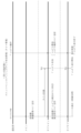
図1は、第1実施形態における遊技機の一例であるスロットマシン10の制御の概略を示すブロック図である。
スロットマシン10に設けられた代表的な制御基板として、メイン制御基板50とサブ制御基板80とを備える。
メイン制御基板50は、入力ポート51及び出力ポート52を有し、RWM53、ROM54、メインCPU55等を備える(図1で図示したもののみを備える意味ではない)。
<First embodiment>
The first embodiment will be described below with reference to the drawings and the like.
The first embodiment is a slot machine designed to avoid winning of the special winning combination (1BB), which carries over the winnings, depending on the order in which the players are pressed.
FIG. 1 is a block diagram schematically showing control of a
Typical control boards provided in the
The
図1において、メイン制御基板50と、ベットスイッチ40等の操作スイッチを含む遊技進行用の周辺機器とは、入力ポート51又は出力ポート52を介して電気的に接続されている。入力ポート51は、操作スイッチ等の信号が入力される接続部であり、出力ポート52は、モータ32等の周辺機器に対して信号を送信する接続部である。
図1中、入力用の周辺機器は、その周辺機器からの信号がメイン制御基板50に向かう矢印で表示しており、出力用の周辺機器は、メイン制御基板50からその周辺機器に向かう矢印で示している(サブ制御基板80も同様である)。
In FIG. 1, the
In FIG. 1, peripheral devices for input are indicated by arrows that direct signals from the peripheral devices toward the
RWM53は、遊技の進行等に基づいた各種データ(変数)を記憶(更新)可能な記憶媒体である。
ROM54は、遊技の進行に必要なプログラムや各種データ(たとえば、データテーブル)等を記憶しておく記憶媒体である。
メインCPU55は、メイン制御基板50上に設けられたCPU(演算機能を備えるIC)を指し、遊技の進行に必要なプログラムの実行、演算等を行い、具体的には、役の抽選、リール31の駆動制御、及び入賞時の払出し等を実行する。
The
The
The
また、メイン制御基板50上には、RWM53、ROM54、メインCPU55及びレジスタを含むMPUが搭載される。なお、RWM53及びROM54は、MPU内部に搭載されるもの以外に、外部に備えていてもよい。
なお、後述するサブ制御基板80上においても、RWM83、ROM84、及びサブCPU85を含むMPUが搭載される。なお、RWM83及びROM84は、MPU内部に搭載されるもの以外に、外部に備えてもよい。
Furthermore, an MPU including an
Note that an MPU including an
図1において、メダル投入口47から投入されたメダルは、メダルセレクタ内部に送られる。
メダルセレクタ内には、図1に示すように、通路センサ46、ブロッカ45、投入センサ44(一対の投入センサ44a及び44b)が設けられており(ただし、これらに限定されるものではない)、これらは、メイン制御基板50と電気的に接続されている。
メダル投入口47から投入されたメダルは、最初に、通路センサ46に検知されるように構成されている。
In FIG. 1, medals inserted through the
As shown in FIG. 1, inside the medal selector, a
The medals inserted through the
さらに、通路センサ46の下流側には、ブロッカ45が設けられている。ブロッカ45は、メダルの投入を許可/不許可にするためのものであり、メダルの投入が不許可状態のときは、メダル投入口47から投入されたメダルを払出し口から返却するメダル通路を形成する。これに対し、メダルの投入が許可状態のときは、メダル投入口47から投入されたメダルをホッパー35に案内するメダル通路を形成する。ブロッカ45は、たとえば、メダルセレクタ内のメダル通路の一部に形成された開口部(メダル返却口に通じる開口部)を塞いでメダルをホッパー35側に案内するためのメダル通路を形成する切替え部材と、その切替え部材を駆動するためのアクチュエータ等とから構成されている。
Furthermore, a
ここで、ブロッカ45は、遊技中(リール31の回転開始時から、全リール31が停止し、役の入賞時には入賞役に対応する払出しの終了時まで)は、メダルの投入を不許可状態とする。すなわち、ブロッカ45がメダルの投入を許可するのは、少なくとも遊技が行われていないときである。
Here, the
メダルセレクタ内において、ブロッカ45のさらに下流側には、投入センサ(光学センサ)44が設けられている。投入センサ44は、本実施形態では所定距離を隔てて配置された一対の投入センサ44a及び44bからなり、メダルが一方の投入センサ44aにより検知されてから所定時間を経過した後に他方の投入センサ44bにより検知されるように構成されている。そして、一対の投入センサ44がそれぞれオン/オフとなるタイミングに基づいて、正しいメダルが投入されたか否かを判断する。
In the medal selector, an input sensor (optical sensor) 44 is provided further downstream of the
また、図1に示すように、メイン制御基板50には、遊技者が操作する操作スイッチとして、ベットスイッチ40(40a又は40b)、スタートスイッチ41、(左、中、右)ストップスイッチ42、及び精算スイッチ43が電気的に接続されている。
ここで、「操作スイッチ(又は、単に、「スイッチ」)」とは、遊技者(操作者)による操作体の操作に基づいて(外部からの力を受け)、電気信号のオン/オフを切り替える装置(電気回路及び/又は電気部品を含む)を指し、遊技者が操作する操作体の形状を限定するものではない。
As shown in FIG. 1, the
Here, the "operation switch (or simply, "switch")" is used to turn on/off an electric signal based on the operation of the operating body by the player (operator) (receiving external force). This refers to a device (including an electric circuit and/or electric parts), and does not limit the shape of the operating body operated by the player.
操作スイッチがオフ状態であるときは、たとえば発光素子からの光が受光素子に入射し続けている(受光素子が光を検知し続けているときは、操作スイッチはオフ状態にある。)。そして、遊技者等により操作スイッチ(の操作体)が操作されると、発光素子からの光が受光素子に入射しない状態となる。この状態を検知したときに、操作スイッチがオン状態になったことを示す電気信号をメイン制御基板50に送信する。なお、上記とは逆に、操作スイッチがオフ状態であるときは発光素子からの光が受光素子に入射せず、発光素子からの光が受光素子に入射したときにオン状態となるように構成してもよい。
When the operating switch is in the off state, for example, light from the light emitting element continues to enter the light receiving element (when the light receiving element continues to detect light, the operating switch is in the off state). Then, when a player or the like operates the operation switch (the operation body thereof), the light from the light emitting element does not enter the light receiving element. When this state is detected, an electrical signal indicating that the operation switch has been turned on is transmitted to the
本実施形態では、スタートスイッチ41の操作体は、レバー(棒)状であり(このため、「スタートレバー(スイッチ)41」とも称される。)、ベットスイッチ40、ストップスイッチ42、及び精算スイッチ43の操作体は、押しボタン状である(このため、「ベットボタン(スイッチ)40」、「停止(ストップ)ボタン(スイッチ)42」、「精算ボタン(スイッチ)43」とも称される)。
In this embodiment, the operating body of the
また、図1では図示しないが、操作スイッチの操作体及び/又はその周囲若しくは近傍には、LED(発光手段)が設けられている。そして、その操作スイッチの操作受付けが許可状態にあるときは、たとえばその操作スイッチに対応するLED等を青色発光し、その操作スイッチの操作受付けが不許可状態にあるときは、たとえばその操作スイッチのLED等を赤色発光することにより、その操作スイッチの許可/不許可状態を遊技者に示すようにしている。 Although not shown in FIG. 1, an LED (light emitting means) is provided on the operating body of the operating switch and/or around or near the operating body. When the operation acceptance of the operation switch is in the permitted state, for example, the LED corresponding to the operation switch emits blue light, and when the operation acceptance of the operation switch is in the disallowance state, for example, the LED corresponding to the operation switch is emitted in blue. By emitting red light from an LED or the like, the permission/disapproval state of the operation switch is indicated to the player.
具体的には、たとえば全リール31が回転中であり、ストップスイッチ42の操作が受付け可能な状態であるときは、すべてのストップスイッチ42のLEDを青色発光させ、操作可能であることを遊技者に示す。そして、1つのストップスイッチ42が操作されると、操作されたストップスイッチ42に対応するリール31が停止制御される。その後、残りのストップスイッチ42が操作可能となるのは、停止制御されたリール31に対応するモータ32の励磁状態が終了し、かつ、操作されたストップスイッチ42の検知センサ42eがオフになった後である。したがって、その間は、すべてのストップスイッチ42のLEDを赤色発光する。そして、操作されたストップスイッチ42に対応するモータ32の励磁状態が終了し、かつ、そのストップスイッチ42に対応する検知センサ42eがオフになったときは、すでに操作されたストップスイッチ42のLEDは赤色発光のままであるが、未だ操作されていないストップスイッチ42のLEDについては青色発光させる。
Specifically, for example, when all the
ベットスイッチ40は、貯留されたメダルを今回遊技のためにベットするときに遊技者に操作される操作スイッチである。本実施形態では、1枚のメダルを投入するための1ベットスイッチ40aと、3枚(最大数、規定数)のメダルを投入するための3ベットスイッチ40bとを備える。
なお、これに限らず、2枚ベット用のベットスイッチを設けてもよい。
The
Note that the present invention is not limited to this, and a bet switch for two bets may be provided.
なお、規定数は、たとえば、役物非作動時/作動時に応じて予め定められている。具体的には、役物非作動時、SB作動時、1BB作動時は3枚、2BB作動時は2枚、等のように設定されている。1ベットスイッチ40aを2回操作すると2枚のメダルを投入可能であり、3回操作すると3枚のメダルを投入可能である。また、規定数が3枚であるときは、3ベットスイッチ40bを操作すれば一時に3枚のメダルを投入可能であり、規定数が2枚であるときは、3ベットスイッチ40bを操作すれば一時に2枚のメダルを投入可能である。規定数未満がすでにベットされている状態で3ベットスイッチ40bを操作すれば、ベット数が3枚となるようにベット処理が行われる。 Note that the prescribed number is predetermined, for example, depending on when the accessory is not activated/when it is activated. Specifically, the number is set to 3 when the accessory is not activated, when the SB is activated, when 1BB is activated, and 2 when 2BB is activated, etc. By operating the 1-bet switch 40a twice, it is possible to insert two medals, and by operating it three times, it is possible to insert three medals. Also, when the specified number is 3, you can insert 3 medals at once by operating the 3-bet switch 40b, and when the specified number is 2, you can insert 3 medals at once by operating the 3-bet switch 40b. Two medals can be inserted at once. If the 3-bet switch 40b is operated in a state where less than the prescribed number has already been bet, the bet processing is performed so that the number of bets becomes three.
また、スタートスイッチ41は、(左、中、右のすべての)リール31を始動させるときに遊技者に操作される操作スイッチである。
さらにまた、ストップスイッチ42は、3つ(左、中、右)のリール31に対応して3つ設けられ、対応するリール31を停止させるときに遊技者に操作される操作スイッチである。
さらに、精算スイッチ43は、スロットマシン10内部にベット及び/又は貯留(クレジット)されたメダルを払い戻す(ペイアウトする)ときに遊技者に操作される操作スイッチである。
Further, the
Furthermore, three
Further, the
また、図1に示すように、メイン制御基板50には、表示基板75が電気的に接続されている。なお、実際には、メイン制御基板50と表示基板75との間には、中継基板が設けられ、メイン制御基板50と中継基板、及び中継基板と表示基板75とが接続されているが、図1では中継基板の図示を省略している。このように、メイン制御基板50と表示基板75とは、直接ハーネス等で接続されていてもよいが、両者間に別の基板が介在してもよい。
さらに、制御基板同士が直接ハーネス等で接続されていることに限らず、他の別基板(中継基板等)を介して接続されていてもよい。たとえば、メイン制御基板50とサブ制御基板80との間に1つ以上の他の別基板(中継基板等)が介在してもよい。
Further, as shown in FIG. 1, a
Furthermore, the control boards are not limited to being directly connected to each other with a harness or the like, but may be connected via another separate board (relay board, etc.). For example, one or more other boards (such as a relay board) may be interposed between the
表示基板75には、クレジット数表示LED76、及び獲得数表示LED78が搭載されている。
クレジット数表示LED76は、スロットマシン10内部に貯留(クレジット)されたメダル枚数を表示するLEDであり、上位桁及び下位桁の2桁から構成されている。
The
The credit
また、獲得数表示LED78は、役の入賞時に、払出し数(遊技者の獲得数)を表示するLEDであり、クレジット数表示LED76と同様に、上位桁及び下位桁の2桁から構成されている。
なお、獲得数表示LED78は、払い出されるメダルがないときは、消灯するように制御してもよい。あるいは、上位桁を消灯し、下位桁のみを「0」表示してもよい。
In addition, the acquired
Note that the acquired
また、獲得数表示LED78は、通常は獲得数を表示するが、エラー発生時にはエラーの内容(種類)を表示するLEDとして機能する。
さらにまた、獲得数表示LED78は、AT中に押し順を報知する遊技では、押し順指示情報を表示する(有利な押し順を報知する)LEDとして機能する。よって、本実施形態における獲得数表示LED78は、獲得数、エラー内容、及び押し順指示情報の表示を兼ねるLEDである。ただし、これに限らず、押し順指示情報を表示する専用のLED等を設けてもよいのはもちろんである。
なお、AT中において、有利な押し順の報知は、サブ制御基板80に接続された画像表示装置23によっても実行される。
The acquisition
Furthermore, the obtained number display LED 78 functions as an LED for displaying push order instruction information (notifying an advantageous push order) in a game that notifies the push order during AT. Therefore, the acquisition
Note that during AT, notification of an advantageous pressing order is also performed by the
図1において、メイン制御基板50には、図柄表示装置のモータ(本実施形態ではステッピングモータ)32等が電気的に接続されている。
図柄表示装置は、図柄を表示する(本実施形態では3つの)リール31と、各リール31をそれぞれ駆動するモータ32と、リール31の位置を検出するためのリールセンサ33とを含む。
In FIG. 1, the
The symbol display device includes reels 31 (three in this embodiment) that display symbols, a
モータ32は、リール31を回転させるための駆動手段となるものであり、各リール31の回転中心部に連結され、後述するリール制御手段65によって制御される。
ここで、リール31は、左リール31、中リール31、右リール31からなり、左リール31を停止させるときに操作するストップスイッチ42が左ストップスイッチ42であり、中リール31を停止させるときに操作するストップスイッチ42が中ストップスイッチ42であり、右リール31を停止させるときに操作するストップスイッチ42が右ストップスイッチ42である。
なお、左リール31を第1リール31と称する場合があり、中リール31を第2リール31と称する場合があり、右リール31を第3リール31と称する場合がある。
The
Here, the
Note that the
リール31は、リング状のものであって、その外周面には複数種類の図柄(役に対応する図柄組合せを構成している図柄)を印刷したリールテープを貼付したものである。
また、各リール31には、1個(2個以上であってもよい)のインデックスが設けられている。インデックスは、リール31のたとえば周側面に凸状に設けられており、リール31が所定位置を通過したか否かや、1回転したか否か等を検出するときに用いられる。そして、各インデックスは、リールセンサ33により検知される。リールセンサ33の信号は、メイン制御基板50に電気的に接続されている。そして、インデックスがリールセンサ33を検知する(切る)と、その入力信号がメイン制御基板50に入力され、そのリール31が所定位置を通過したことが検知される。
The
Further, each
また、リールセンサ33がリール31のインデックスを検知した瞬間の基準位置上の図柄を予めROM54に記憶している。これにより、インデックスを検知した瞬間の基準位置上の図柄を検知することができる。さらに、リールセンサ33がリール31のインデックスを検知した瞬間から、(ステッピング)モータ32を何パルス駆動すれば、前記基準位置上の図柄から数えて何図柄先の図柄を有効ライン上に停止させることができるかを識別可能となる。
Further, the symbol on the reference position at the moment when the
また、メイン制御基板50には、メダル払出し装置が電気的に接続されている。メダル払出し装置は、メダルを溜めておくためのホッパー35と、ホッパー35のメダルを払出し口から払い出すときに駆動するホッパーモータ36と、ホッパーモータ36から払い出されたメダルを検出するための払出しセンサ37を備える。
Further, a medal payout device is electrically connected to the
メダル投入口47から手入れされ、受け付けられた(正常であると判断された)メダルは、ホッパー35内に収容されるように形成されている。
払出しセンサ(光学センサ)37は、本実施形態では、所定距離を隔てて配置された一対の払出しセンサ37a及び37bからなる。そして、メダルが払い出されるときには、そのメダルにより所定の移動部材が移動する。所定の移動部材の移動によって、払出しセンサ37a及び37bがオン/オフされる。所定時間の範囲内で払出しセンサ37a及び37bがそれぞれオン/オフされたか否かに基づいて、メダルが正しく払い出されたか否かを判断する。
The medals that have been cleaned and accepted (determined to be normal) from the
In this embodiment, the payout sensor (optical sensor) 37 includes a pair of payout sensors 37a and 37b arranged at a predetermined distance apart. Then, when a medal is paid out, a predetermined moving member is moved by the medal. The dispensing sensors 37a and 37b are turned on/off by movement of a predetermined moving member. Based on whether the payout sensors 37a and 37b are turned on/off within a predetermined time range, it is determined whether the medals are correctly paid out.
たとえば、ホッパーモータ36が駆動しているにもかかわらず、一対の払出しセンサ37のオンを検知しないときは、メダルが払い出されていないと判断し、ホッパーエラー(メダルなし)と検知される。
一方、払出しセンサ37の少なくとも1つがオン信号を出力し続けたままとなったときは、メダル詰まりが生じたと検知する。
For example, if it is not detected that the pair of
On the other hand, when at least one of the
遊技者は、遊技を開始するときは、ベットスイッチ40の操作により予めクレジットされたメダルを投入するか(貯留ベット)、又はメダル投入口47からメダルを手入れ投入する(手入れベット)。当該遊技の規定数のメダルがベットされた状態でスタートスイッチ41が操作されると、そのときに発生する信号がメイン制御基板50に入力される。メイン制御基板50(具体的には、後述するリール制御手段65)は、この信号を受信すると、役抽選手段61による抽選を行うとともに、すべてのモータ32を駆動制御して、すべてのリール31を回転させるように制御する。このようにしてリール31がモータ32によって回転されることで、リール31上の図柄は、所定の速度で表示窓内で上下方向に移動表示される。
When starting a game, the player inserts medals credited in advance by operating the bet switch 40 (storage bet) or inserts medals from the medal slot 47 (care bet). When the
そして、遊技者は、ストップスイッチ42を押すことで、そのストップスイッチ42に対応するリール31(たとえば、左ストップスイッチ42に対応する左リール31)の回転を停止させる。ストップスイッチ42が操作されると、そのときに発生する信号がメイン制御基板50に入力される。メイン制御基板50(具体的には、後述するリール制御手段65)は、この信号を受信すると、そのストップスイッチ42に対応するモータ32を駆動制御して、役抽選手段61の抽選結果(内部抽せん手段により決定した結果)に対応するように、そのモータ32に係るリール31の停止制御を行う。
Then, by pressing the
そして、すべてのリール31の停止時における図柄組合せにより、今回遊技の遊技結果を表示する。さらに、いずれかの役に対応する図柄組合せが有効ラインに停止したとき(その役の入賞となったとき)は、入賞した役に対応するメダルの払出し等が行われる。
Then, the game result of the current game is displayed based on the symbol combination when all the
次に、メイン制御基板50の具体的構成について説明する。
図1に示すように、メイン制御基板50のメインCPU55は、以下の役抽選手段61等を備える。本実施形態における以下の各手段は例示であり、本実施形態で示した手段に限定されるものではない。
Next, the specific configuration of the
As shown in FIG. 1, the
役抽選手段61は、当選番号の抽選(決定、選択)を行う。ここで、「役抽選手段61による当選番号の抽選」は、風営法規則(遊技機の認定及び型式の検定等に関する規則。以下、単に「規則」という。)における「内部抽せん」と同じであり、役抽選手段61による抽選結果は、規則における「内部抽せんにより決定した結果」と同じである。したがって、役抽選手段61を、規則に合わせた表現で、「内部抽せん手段61」とも称する。
役抽選手段61により当選番号が決定されると、その当選番号に基づいて、入賞及びリプレイ条件装置番号、並びに役物条件装置番号が決定され、当該遊技で作動可能となる入賞及びリプレイ条件装置、並びに役物条件装置が定まることとなる。このため、役抽選手段61は、条件装置番号の決定(抽選又は選択)手段、当選役決定(抽選又は選択)手段等とも称される。
The winning combination lottery means 61 performs lottery (determination, selection) of winning numbers. Here, the "drawing of winning numbers by the prize drawing means 61" is the same as the "internal drawing" in the Entertainment Business Law Regulations (regulations regarding certification of gaming machines and type examination, etc., hereinafter simply referred to as "Rules"). The lottery result by the winning combination lottery means 61 is the same as the "result determined by internal lottery" in the rules. Therefore, the combination lottery means 61 is also referred to as "internal lottery means 61" in accordance with the rules.
When the winning number is determined by the prize lottery means 61, the winning and replay condition device number and the prize condition device number are determined based on the winning number, and the winning and replay condition device becomes operable in the game. In addition, the accessory condition device will be determined. Therefore, the winning combination lottery means 61 is also referred to as a condition device number determination (lottery or selection) means, a winning combination determination (lottery or selection) means, or the like.
役抽選手段61は、たとえば、抽選用の乱数発生手段(ハードウェア乱数等)と、この乱数発生手段が発生する乱数を抽出する乱数抽出手段と、乱数抽出手段が抽出した乱数値に基づいて、当選番号を決定する当選番号決定手段とを備えている。 The winning lottery means 61 includes, for example, a random number generating means for lottery (hardware random numbers, etc.), a random number extracting means for extracting the random numbers generated by the random number generating means, and a random number extracting means based on the random number extracted by the random number extracting means. and winning number determining means for determining the winning number.
乱数発生手段は、所定の領域(たとえば10進数で「0」~「65535」)の乱数を発生させる。乱数は、たとえば200n(ナノ)secで1カウントを行うカウンターが「0」~「65535」の範囲を1サイクルとしてカウントし続ける乱数であり、スロットマシン10の電源が投入されている間は、乱数をカウントし続ける。
The random number generation means generates random numbers in a predetermined range (for example, "0" to "65535" in decimal notation). The random number is a random number that continues counting in the range of "0" to "65535" as one cycle by a counter that counts once every 200n (nano) seconds, for example, and while the
乱数抽出手段は、乱数発生手段によって発生した乱数を、所定の時、本実施形態では遊技者によりスタートスイッチ41が操作(オン)された時に抽出する。判定手段は、乱数抽出手段により抽出された乱数値を、後述する抽選テーブルと照合することにより、その乱数値が属する領域に対応する当選番号を決定する。
The random number extraction means extracts the random number generated by the random number generation means at a predetermined time, in this embodiment, when the
当選フラグ制御手段62は、役抽選手段61による抽選結果に基づいて、各役に対応する当選フラグのオン/オフを制御するものである。本実施形態では、すべての役について、役ごとに当選フラグを備える。そして、役抽選手段61による抽選においていずれかの役の当選となったときは、その役の当選フラグをオンにする(当選フラグを立てる)。なお、役の当選には、当選役が1つである場合(単独当選)と、当選役が複数ある場合(重複当選)とが挙げられる。 The winning flag control means 62 controls on/off of the winning flag corresponding to each winning combination based on the lottery result by the winning combination lottery means 61. In this embodiment, a winning flag is provided for each role for all roles. When one of the winning combinations is won in the lottery by the winning combination lottery means 61, the winning flag for that winning combination is turned on (the winning flag is set). Note that there are two cases of winning a winning combination: a case where there is only one winning combination (single winning) and a case where there are multiple winning combinations (multiple winning).
押し順指示番号選択手段63は、役抽選手段61による当選番号の抽選結果(押し順ベル、又は押し順リプレイ当選時)に基づいて、押し順指示番号(正解押し順に相当する番号)の選択(決定)を行うものである。
ここで選択される押し順指示番号の「押し順」とは、遊技者にとって有利な押し順(正解押し順)を意味する。たとえば押し順ベルの当選時には、高目ベルを入賞させる押し順(正解押し順)を指す。また、リプレイ重複当選時は、有利なRTに昇格させる押し順又は不利なRTに転落させない押し順を指す。
The push order instruction number selection means 63 selects a push order instruction number (a number corresponding to the correct push order) based on the lottery result of the winning number by the winning combination lottery means 61 (when a push order bell or a push order replay is won). decision).
The “push order” of the press order instruction numbers selected here means a press order (correct press order) that is advantageous for the player. For example, when a push order bell is won, it refers to the push order (correct answer push order) that makes the higher bell win the prize. In addition, when a replay double win occurs, it refers to the push order that promotes to an advantageous RT or the push order that does not allow the RT to fall to a disadvantageous RT.
本実施形態では、当選番号ごとに、それぞれ固有の押し順指示番号を備える。
そして、AT中に、押し順ベル又は押し順リプレイに当選したときは、メイン制御基板50は、上述した獲得数表示LED78に、押し順指示番号に対応する押し順指示情報、具体的には「=*」(「*」=1、2、・・)のような情報を表示する。このように、有利な押し順を有する条件装置の作動時に、押し順指示情報を表示する機能は、指示機能とも称される。
また、AT中に、押し順ベル又は押し順リプレイに当選したときは、メイン制御基板50は、遊技の開始時(スタートスイッチ41が操作され、当選番号が決定された後)に、サブ制御基板80に対し、押し順指示番号に対応するコマンドを送信する。
サブ制御基板80は、当該コマンドを受信したときは、正解押し順を画像表示装置23で画像表示する。
In this embodiment, each winning number is provided with a unique push order instruction number.
Then, when winning the push order bell or push order replay during AT, the
In addition, when winning the push order bell or push order replay during AT, the
When the
なお、メイン制御基板50が選択した押し順指示番号をサブ制御基板80に送信することができるのは、有利区間(AT)中に限られる。したがって、通常区間において押し順指示番号選択手段63により押し順指示番号が選択されたとしても、その押し順指示番号がサブ制御基板80に送信されることはない。なお、通常区間では、押し順指示番号を選択しなくてもよい。
Note that the push order instruction number selected by the
演出グループ番号選択手段64は、当選番号に対応する演出グループ番号であって、サブ制御基板80に送信するための番号を選択するものである。
ここで、当選番号に対応する演出グループ番号が予め定められている。そして、演出グループ番号選択手段64は、スタートスイッチ41が操作されることにより当選番号が決定すると、当該遊技の当選番号に対応する演出グループ番号を選択し、メイン制御基板50は、選択した演出グループ番号をサブ制御基板80に送信する。サブ制御基板80は、受信した演出グループ番号に基づいて、当選役に関する演出を出力する。演出グループ番号は、上記の押し順指示番号と異なり、毎遊技選択され、メイン制御基板50からサブ制御基板80に送信される。
The performance group number selection means 64 is for selecting the performance group number corresponding to the winning number to be transmitted to the
Here, the performance group number corresponding to the winning number is determined in advance. When the winning number is determined by operating the
また、メイン制御基板50は、サブ制御基板80に対し、当該遊技の当選番号を送信しない。このため、サブ制御基板80は、当該遊技の当選番号を知ることはできない。ただし、サブ制御基板80は、毎遊技、演出ブループ番号を受信するので、受信した演出グループ番号に基づいて、演出を出力可能となる。ただし、押し順ベル又は押し順リプレイの当選時であっても、演出グループ番号から正解押し順を判断できないので、サブ制御基板80は、演出グループ番号に基づいて正解押し順を報知することはない。これに対し、AT中は、押し順ベル又は押し順リプレイの当選時は、メイン制御基板50からサブ制御基板80に対し、押し順指示番号を送信する。これにより、サブ制御基板80は、受信した押し順指示番号に基づいて、正解押し順を報知可能となる。
Further, the
リール制御手段65は、リール31の回転開始命令を受けたとき、特に本実施形態ではスタートスイッチ41の操作を検知したときに、すべて(3つ)のリール31の回転を開始するように制御する。
さらに、リール制御手段65は、役抽選手段61により当選番号の決定が行われた後、今回遊技における当選フラグのオン/オフを参照して、当選フラグのオン/オフに対応する停止位置決定テーブルを選択するとともに、ストップスイッチ42が操作されたときに、ストップスイッチ42の操作を検知したときのタイミングに基づいて、そのストップスイッチ42に対応するリール31の停止位置を決定するとともに、モータ32を駆動制御して、その決定した位置にそのリール31を停止させるように制御する。
The reel control means 65 controls all (three)
Furthermore, after the winning numbers are determined by the winning combination lottery means 61, the reel control means 65 refers to the on/off of the winning flag in the current game, and generates a stop position determination table corresponding to the on/off of the winning flag. is selected, and when the
たとえば、リール制御手段65は、少なくとも1つの当選フラグがオンである遊技では、リール31の停止制御の範囲内において、当選役(当選フラグがオンになっている役)に対応する図柄組合せを有効ラインに停止可能にリール31を停止制御するとともに、当選役以外の役(当選フラグがオフになっている役)に対応する図柄組合せを有効ラインに停止させないようにリール31を停止制御する。
For example, in a game where at least one winning flag is on, the reel control means 65 enables the symbol combination corresponding to the winning combination (the winning flag is on) within the range of stop control of the
ここで、「リール31の停止制御の範囲内」とは、ストップスイッチ42が操作された瞬間からリール31が実際に停止するまでの時間又はリール31の回転量(移動図柄(コマ)数)の範囲内を意味する。
本実施形態では、リール31は、定速時は1分間で約80回転する速度で回転される。
そして、ストップスイッチ42が操作されたときは、MB作動中の所定のリール31(たとえば、中リール31)を除き、ストップスイッチ42が操作された瞬間からリール31を停止させるまでの時間が190ms以内に設定されている。これにより、本実施形態では、MB作動中の所定のリール31を除き、ストップスイッチ42が操作された瞬間の図柄からリール31が停止するまでの最大移動図柄数が4図柄に設定されている。
Here, "within the range of stop control of the
In this embodiment, the
When the
一方、MB作動中の所定のリール31については、ストップスイッチ42が操作された瞬間からリール31を停止させるまでの時間が75ms以内に設定されている。これにより、MB作動中の所定のリール31については、ストップスイッチ42が操作された瞬間の図柄からリール31が停止するまでの最大移動図柄数が1図柄に設定されている。
On the other hand, for a
そして、ストップスイッチ42の操作を検知した瞬間に、リール31の停止制御の範囲内にある図柄のいずれかが所定の有効ラインに停止させるべき図柄であるときは、ストップスイッチ42が操作されたときに、その図柄が所定の有効ラインに停止するように制御される。
すなわち、ストップスイッチ42が操作された瞬間に直ちにリール31を停止させると、当選番号に対応する役の図柄が所定の有効ラインに停止しないときには、リール31を停止させるまでの間に、リール31の停止制御の範囲内においてリール31を回転移動制御することで、当選番号に対応する役の図柄をできる限り所定の有効ラインに停止させるように制御する(引込み停止制御)。
At the moment when the operation of the
That is, if the
また逆に、ストップスイッチ42が操作された瞬間に直ちにリール31を停止させると、当選番号に対応しない役の図柄組合せが有効ラインに停止してしまうときは、リール31の停止時に、リール31の停止制御の範囲内においてリール31を回転移動制御することで、当選番号に対応しない役の図柄組合せを有効ラインに停止させないように制御する(蹴飛ばし停止制御)。
さらに、複数の役に当選している遊技(たとえば、押し順ベル当選時)では、ストップスイッチ42の押し順や、ストップスイッチ42の操作タイミングに応じて、入賞させる役の優先順位が予め定められており、所定の優先順位によって、最も優先する役に係る図柄の引込み停止制御を行う。
Conversely, if the
Furthermore, in a game where multiple winning combinations are won (for example, when the push order bell is won), the priority order of winning combinations is determined in advance according to the order in which the stop switches 42 are pressed and the timing at which the stop switches 42 are operated. According to a predetermined priority order, control is performed to stop the drawing of symbols related to the most prioritized winning combination.
入賞判定手段66は、リール31の停止時に、有効ラインに停止したリール31の図柄組合せが、いずれかの役に対応する図柄組合せであるか否かを判断するものである。
ここで、入賞判定手段66は、実際に、役に対応する図柄組合せが有効ラインに停止したか否かを検知することはない。具体的には、当該遊技で作動した条件装置と、ストップスイッチ42の押し順及び/又はストップスイッチ42の操作タイミングとから、リール31が実際に停止する前に有効ラインに停止する図柄組合せを予め判断するか、又はリール31の停止後に有効ラインに停止した図柄組合せを予め判断する。
The winning determination means 66 determines, when the
Here, the winning determination means 66 does not actually detect whether or not the symbol combination corresponding to the winning combination has stopped on the active line. Specifically, from the condition device activated in the game, the pressing order of the
制御コマンド送信手段71は、サブ制御基板80に対し、サブ制御基板80で出力する演出に必要な情報(制御コマンド)を送信する。
制御コマンドとしては、たとえばベットスイッチ40が操作されたときの情報、スタートスイッチ41が操作されたときの情報、押し順指示番号(AT中、かつ正解押し順を有する当選番号に当選したときのみ)、演出グループ番号、RT(遊技状態)情報、ストップスイッチ42が操作されたときの情報、入賞した役の情報等が挙げられる。
The control command transmitting means 71 transmits information (control commands) necessary for the production output by the
The control commands include, for example, information when the
図1において、サブ制御基板80は、遊技中及び遊技待機中における演出(情報)の選択や出力等を制御するものである。
ここで、メイン制御基板50とサブ制御基板80とは、電気的に接続されており、メイン制御基板50(制御コマンド送信手段71)は、パラレル通信によってサブ制御基板80に一方向で、演出の出力に必要な情報(制御コマンド)を送信する。
なお、メイン制御基板50とサブ制御基板80とは、電気的に接続されることに限らず、光通信手段を用いた接続であってもよい。さらに、電気的接続及び光通信接続のいずれも、パラレル通信に限らず、シリアル通信であってもよく、シリアル通信とパラレル通信とを併用してもよい。
In FIG. 1, the
Here, the
Note that the
サブ制御基板80は、メイン制御基板50と同様に、入力ポート81、出力ポート82、RWM83、ROM84、及びサブCPU85等を備える。
サブ制御基板80には、入力ポート81又は出力ポート82を介して、図1に示すような以下の演出ランプ21等の演出用周辺機器が電気的に接続されている。ただし、演出用の周辺機器は、これらに限られるものではない。
RWM83は、サブCPU85が演出を制御するときに取り込んだデータ等を一時的に記憶可能な記憶媒体である。
また、ROM84は、演出用データとして、演出に係る抽選を行うとき等のプログラムや各種データ等を記憶しておく記憶媒体である。
Like the
The
The
Further, the
演出ランプ21は、たとえばLED等からなり、所定の条件を満たしたときに、それぞれ所定のパターンで点灯する。なお、演出ランプ21には、各リール31の内周側に配置され、リール31に表示された図柄(表示窓から見える上下に連続する3図柄)を背後から照らすためのバックランプ、リール31の上部からリール31上の図柄を照光する蛍光灯、スロットマシン10のフロントドア前面に配置され、役の入賞時等に点滅する枠ランプ等が含まれる。
The
また、スピーカ22は、遊技中に各種の演出を行うべく、所定の条件を満たしたときに、所定のサウンドを出力するものである。
さらにまた、画像表示装置23は、液晶ディスプレイ、有機ELディスプレイ、ドットディスプレイ等からなるものであり、遊技中に各種の演出画像(正解押し順、当該遊技で作動する条件装置に対応する演出等)や、遊技情報(役物作動時や有利区間(AT)中の遊技回数や獲得枚数等)等を表示するものである。
Further, the
Furthermore, the
また、第1実施形態では、特別遊技(役物作動状態)として、1BB遊技(1BB作動状態)、及びRB遊技(RB作動状態)を備える。1BB遊技(1BB作動状態)やRB遊技(RB作動状態)は、厳密にはRTには含まれないが、RTの1つとしてもよい。
さらにまた、第1実施形態のRBは、1BB遊技の一般遊技(1BB遊技において、RB遊技以外の遊技を意味する。)中に抽選される役であり、1BB遊技の一般遊技中にRBに当選し、RBが入賞すると、1BB遊技中において一般遊技からRB遊技に移行する。このため、1BB遊技の一般遊技で抽選されるRBを「SRB(シフトRB)」とも称する。
Further, in the first embodiment, a 1BB game (1BB operating state) and an RB game (RB operating state) are provided as special games (accessories operating state). Strictly speaking, 1BB games (1BB operating state) and RB games (RB operating state) are not included in RT, but they may be one type of RT.
Furthermore, the RB in the first embodiment is a winning combination that is drawn during the general game of the 1BB game (meaning a game other than the RB game in the 1BB game), and the RB is won during the general game of the 1BB game. However, when the RB wins, the game shifts from the general game to the RB game during the 1BB game. For this reason, the RB that is drawn in the general game of the 1BB game is also referred to as "SRB (shift RB)".
なお、第1実施形態において、「役物未作動時」とは、当選しているが未だ作動していない状態を含むものとする。たとえば1BBに当選していない場合や、1BBに当選して1BB内部中となっているが、1BB遊技中でない場合には「1BB未作動時」と称し、1BB遊技中である場合には「1BB作動時」と称する。RBについても同様である。
また、指示機能の作動及び押し順の示唆演出を実行できるのは、有利区間中に限られ、非有利区間(通常区間)では指示機能の作動及び押し順の示唆演出を実行することができない。したがって、下記において、指示機能の作動及び押し順の示唆演出を実行する場合は、有利区間であるものとする。
In the first embodiment, "when the accessory is not activated" includes a state where the accessory has been won but has not yet been activated. For example, if you have not won 1BB, or if you have won 1BB and are in 1BB, but you are not playing 1BB, it is called "1BB inactive", and if you are playing 1BB, it is called "1BB inactive". "When in operation." The same applies to RB.
Furthermore, the operation of the instruction function and the presentation suggesting the push order can be performed only during the advantageous section, and the operation of the instruction function and the presentation suggesting the push order cannot be executed during the non-advantageous section (normal section). Therefore, in the following, when the instruction function is activated and the push order suggestion effect is executed, it is assumed that the area is advantageous.
また、第1実施形態では、役抽選手段61により、「当選番号」の抽選を実行する。したがって、役抽選手段61は、「当選番号抽選(決定、選択)手段」とも称する。そして、当選番号が決定すると、その当選番号に対応する「条件装置番号」を生成する。
「条件装置番号」(「当選情報」とも称する。)には、「役物条件装置番号」と、「入賞及びリプレイ条件装置番号」とを有する。そして、当選番号が決定し、条件装置番号が生成されると、その条件装置番号に対応する条件装置が作動することにより、作動した条件装置に対応する役の図柄組合せが有効ラインに停止表示可能となる。
Further, in the first embodiment, the winning number lottery means 61 performs a lottery of "winning numbers". Therefore, the winning number lottery means 61 is also referred to as "winning number lottery (determination, selection) means". When the winning number is determined, a "condition device number" corresponding to the winning number is generated.
The "condition device number" (also referred to as "winning information") includes an "accessory condition device number" and a "winning and replay condition device number." Then, when the winning number is determined and a conditional device number is generated, the conditional device corresponding to that conditional device number is activated, and the symbol combination of the role corresponding to the activated conditional device can be stopped and displayed on the active line. becomes.
第1実施形態の当選番号は、後述するたとえば図24及び図25に示すように、当選番号「0」~「100」(「0」は非当選(いわゆるハズレ)に相当する。)を備える。
そして、当選番号が決定すると、その当選番号に対応する「条件装置番号」を生成する。たとえば図24において、当選番号「4」に決定されると、役物条件装置番号「1」(図13)並びに入賞及びリプレイ条件装置番号「2」(図14)が生成される。
The winning numbers of the first embodiment include winning numbers "0" to "100"("0" corresponds to a non-winning (so-called loser)), as shown in FIGS. 24 and 25, which will be described later.
When the winning number is determined, a "condition device number" corresponding to the winning number is generated. For example, in FIG. 24, when the winning number "4" is determined, the accessory condition device number "1" (FIG. 13) and the winning and replay condition device number "2" (FIG. 14) are generated.
図2は、第1実施形態におけるリール31の図柄配列を示す図である。図2に示すように、第1実施形態では、各リール31は、20コマからなる。また、図2では、図柄番号を併せて図示している。
また、第1実施形態では、ストップスイッチ42が操作された瞬間からリール31が停止するまでの最大移動図柄数は「4」に設定されている。
FIG. 2 is a diagram showing the symbol arrangement of the
Further, in the first embodiment, the maximum number of symbols to be moved from the moment the
したがって、たとえば1つのリール31上で、特定図柄を5図柄間隔で4個配置すれば、いずれの位置でストップスイッチ42が操作されても、常に特定図柄を有効ラインに停止可能となる。具体的には、左リール31において、「リプレイ」は、5番、10番、15番、及び0番に配置されている。すなわち、左リール31における「リプレイ」は、5図柄間隔4個配置である。したがって、左リール31については、どのタイミングで左ストップスイッチ42が操作されても、常に、有効ラインに「リプレイ」を停止させることができる。なお、このような図柄配置を「「PB=1」配置」と称する場合がある。一方、このような図柄配置になっていない場合を、「「PB≠1」配置」と称する場合がある。
Therefore, for example, if four specific symbols are arranged at intervals of five symbols on one
そして、左リール31では、「リプレイ」及び「ベルA」は、それぞれ「PB=1」配置である。
また、中リール31では、「リプレイ」、「ベルA」、「ベルB」は、それぞれ「PB=1」配置である。
さらにまた、右リール31では、「リプレイ」、「ベルA」、「ベルB」は、それぞれ「PB=1」配置である。
さらに、中リール31において、1番の「ブランク」、6番の「黒BAR」、11番の「赤7」、16番の「チェリー」は、これら4図柄合算で「PB=1」配置である。したがって、どのタイミングで中ストップスイッチ42が操作されても、「ブランク」、「黒BAR」、「赤7」又は「チェリー」のいずれかを有効ラインに停止可能である。右リール31についても同様である。
On the
Furthermore, on the
Furthermore, on the
Furthermore, on the
さらにまた、中リール31では、「スイカA」又は「スイカB」は、これら2図柄合算で「PB=1」配置である。
さらに、右リール31では、「青BAR」、「スイカA」又は「スイカB」は、これら3図柄合算で「PB=1」配置である。
Furthermore, on the
Further, on the
図3は、表示窓(透明窓)18と、各リール31の位置関係と、有効ライン(図柄組合せを表示する表示ライン)とを示す図である。
表示窓18から、内部に配置されたリール31が透視できるようになっている。
各リール31は、本実施形態では横方向に並列に3つ(左リール31、中リール31、及び右リール31)設けられている。さらに、各リール31は、表示窓18から、上下に連続する3図柄が見えるように配置されている。よって、スロットマシン10の表示窓17から、合計9個の図柄(コマ)が見えるように配置されている。
FIG. 3 is a diagram showing the display window (transparent window) 18, the positional relationship of each
The
In this embodiment, three reels 31 (left
また、図3では、本明細書における図柄位置の称呼を図示している。本明細書では、リール31ごとに、表示窓18から見える停止時の図柄位置を、上から順に「上段」、「中段」、「下段」と称し、左リール31であれば、それぞれ「左上段」、「左中段」、「左下段」と称するものとする。
Further, FIG. 3 illustrates the names of symbol positions in this specification. In this specification, for each
さらにまた、図3に示すように、表示窓18から見える9個の図柄に対し、有効ラインが設定されている。
ここで、「有効ライン」とは、リール31の停止時における図柄の並びラインであって図柄組合せを形成させる図柄組合せライン(表示ライン)であり、かつ、いずれかの役に対応する図柄組合せがそのラインに停止したときに、その役の入賞となるラインである。本実施形態では、いずれの遊技状態であっても規定数は3枚であり、いずれの遊技状態であっても有効ラインが同一に設定されている。
Furthermore, as shown in FIG. 3, valid lines are set for nine symbols visible from the
Here, the "valid line" is a line where symbols are lined up when the
本実施形態の有効ラインは、いわゆる右下がりの一直線状のライン(「左上段」-「中中段」-「右下段」)である。これ以外は無効ラインである。
なお、遊技状態ごとに規定数を異ならせてもよい(たとえば1BB作動中の規定数を「2枚」にする等)。さらに、遊技状態ごとや規定数ごとに有効ラインの位置や数を異ならせてもよい(たとえば特定の規定数では有効ラインを複数本にする等)。
The effective line in this embodiment is a so-called linear line descending to the right ("upper left row" - "middle middle row" - "lower right row"). Lines other than this are invalid lines.
Note that the prescribed number may be different for each gaming state (for example, the prescribed number during 1BB operation may be set to "2", etc.). Further, the position and number of active lines may be varied for each gaming state or for each specified number (for example, a plurality of active lines may be provided for a specific specified number).
図4~図11は、第1実施形態における役(役抽選手段61で抽選される当選番号に対応する役等)等の種類、図柄組合せ、払出し枚数等を示す図である。
まず、図4に示すように、第1実施形態の遊技状態としては、役物未作動時、1BB作動時のRB(役物)未作動時、RB作動時が挙げられ、これらの遊技状態の規定数は、いずれも「3」枚に設定されている。
図4~図12において、「3枚(1)」とは、役物未作動時に相当し、特に第1実施形態では、1BB遊技以外の遊技に相当する。
FIGS. 4 to 11 are diagrams showing types of winning combinations (such as winning numbers corresponding to the winning numbers drawn by the winning lottery means 61), symbol combinations, number of coins to be paid out, etc. in the first embodiment.
First, as shown in FIG. 4, the gaming states of the first embodiment include when the accessory is not activated, when the RB (accessory) is not activated when 1BB is activated, and when the RB is activated. The prescribed number is set to "3" in both cases.
In FIGS. 4 to 12, "3 pieces (1)" corresponds to the time when the accessory is not activated, and particularly in the first embodiment, corresponds to games other than the 1BB game.
また、「3枚(2)」とは、1BB作動中(1BB遊技中)のRB未作動時に相当する。さらにまた、「3枚(3)」とは、1BB作動中(1BB遊技中)かつRB作動時(RB遊技中)に相当する。
たとえば図4において、役番号「001」の1BBは、規定数3枚(1)のとき(役物未作動時)には抽選対象となるが、規定数3枚(2)及び規定数3枚(3)のときは抽選対象にならないことを意味する。
Further, "3 coins (2)" corresponds to the time when RB is not activated while 1BB is in operation (during 1BB game). Furthermore, "3 pieces (3)" corresponds to when 1BB is in operation (during 1BB game) and RB is in operation (during RB game).
For example, in Figure 4, 1BB with the winning number "001" becomes a lottery target when the specified number is 3 (1) (when the accessory is not activated), but when the specified number is 3 (2) and the specified number is 3. (3) means that it is not eligible for lottery.
図4中、役番号「001」~「003」は、特別役(役物)に相当する。本実施形態では、特別役として1種類の1BBと、2種類のRB(RBA及びRBB)とが設けられている。
役物未作動時において1BBに当選し、1BBが入賞すると、今回遊技におけるメダルの払い出しはないが、次回遊技から、特別遊技に相当する1BB作動(1BB遊技)に移行する。
また、1BB作動(1BB遊技)中は、RBが抽選される。1BB作動中にRBに当選し、RBが入賞すると、今回遊技におけるメダルの払い出しはないが、次回遊技から、1BB作動(1BB遊技)中のRB作動(RB遊技)に移行する。
In FIG. 4, the winning numbers "001" to "003" correspond to special winning combinations (official objects). In this embodiment, one type of 1BB and two types of RB (RBA and RBB) are provided as special winnings.
If 1BB is won and 1BB is won when the accessory is not activated, no medals will be paid out in the current game, but the next game will shift to 1BB activation (1BB game) corresponding to a special game.
Further, during 1BB operation (1BB game), RB is drawn. If the RB wins and the RB wins during the 1BB operation, no medals will be paid out in the current game, but the next game will shift to the RB operation (RB game) during the 1BB operation (1BB game).
なお、1BB作動中かつRB未作動時を、「1BB遊技の一般遊技」と称する場合がある。そして、1BB遊技の一般遊技のうち、RBに当選していない状態を1BB作動中かつRB非内部中と称し、RBに当選している状態を1BB作動中かつRB内部中と称する場合がある。
RB作動の終了条件を満たした場合において、1BB作動の終了条件を満たすときは1BB作動を終了して役物未作動時(通常遊技)に移行する。一方、RB作動の終了条件を満たした場合において、1BB作動の終了条件を満たさないときは、1BB作動(かつRB未作動時)に移行する。
Note that the time when the 1BB is in operation and the RB is not in operation may be referred to as a "general game of the 1BB game." In the general game of the 1BB game, the state in which the RB is not won is sometimes referred to as 1BB in operation and RB not inside, and the state in which RB is won is sometimes referred to as 1BB in action and RB inside.
When the termination condition of the RB operation is satisfied, when the termination condition of the 1BB operation is satisfied, the 1BB operation is terminated and the game shifts to the time when the accessory is not activated (normal game). On the other hand, when the termination conditions for RB operation are met, but when the termination conditions for 1BB operation are not satisfied, the process shifts to 1BB operation (and when RB is not activated).
図4に示す役番号「004」~図7に示す役番号「149」は、いずれも、リプレイ(再遊技役)に相当する。第1実施形態では、リプレイの種類として、リプレイ01~15を備える。図4~図7に示すように、役物未作動時(3枚(1))、及び1BB作動時のRB未作動時(3枚(2))には、リプレイ01~15のいずれも抽選対象となる。これに対し、1BB作動中のRB作動時(3枚(3))にはリプレイは抽選されない。
また、いずれのリプレイも、図柄組合せが「PB=1」に設定されている。たとえばリプレイ03の図柄組合せは、「チェリー」-「黒BAR/赤7/ブランク/チェリー」-「ベルA」であるが、左リール31の「チェリー」及び右リール31の「ベルA」は、「PB=1」配置である。また、中リール31の「黒BAR/赤7/ブランク/チェリー」は、これら4図柄合算で「PB=1」配置である。
The winning numbers "004" shown in FIG. 4 to the winning numbers "149" shown in FIG. 7 all correspond to replays (replay winnings). In the first embodiment, replays 01 to 15 are provided as types of replays. As shown in Figures 4 to 7, when the accessory is not activated (3 pieces (1)) and when the RB is not activated when 1BB is activated (3 pieces (2)), replays 01 to 15 are all drawn by lottery. Targeted. On the other hand, when RB is activated (3 pieces (3)) when 1BB is activated, replay is not drawn.
Further, in both replays, the symbol combination is set to "PB=1". For example, the symbol combination of
図8~図11は、第1実施形態の小役を示している。第1実施形態の小役としては、小役001~小役118が設けられている。
小役001~小役008は、入賞時の払出し枚数が7枚に設定されており、小役のうちの最大払出し枚数に設定されている。小役001~小役008は、いわゆる押し順ベル当選時(後述)の高目ベルとなる役である。
また、小役009~小役117は、入賞時の払出し枚数が1枚に設定されており、いわゆる押し順ベル当選時の低目ベル等となる役である。
さらにまた、小役118は、1BB作動時かつRB作動時にのみ抽選される特殊役であり、入賞時の払出し枚数が1枚に設定されている。
8 to 11 show the small winning combinations of the first embodiment. As the small winnings of the first embodiment,
For
In addition, the small winning
Furthermore, the small winning
上述した各役において、次回遊技以降に持ち越される役と、持ち越されない役とがある。1BB及びRBは次回遊技以降に持越し可能な役であり、小役及びリプレイは、次回遊技以降に持越し不可能な役である。 In each of the above-mentioned roles, there are roles that are carried over to the next game and others that are not carried over. 1BB and RB are roles that can be carried over to the next game or later, and small roles and replays are roles that cannot be carried over to the next game or later.
図12は、第1実施形態におけるパターン図柄組合せを示す図である。第1実施形態では、押し順ベル当選時に、不正解押し順でストップスイッチ42を操作した場合には、上述した1枚役が入賞する場合と、役の非入賞となる場合(とりこぼし)とを有する。そして、役の非入賞となった場合には、図12に示すパターン図柄組合せのいずれかが表示される。パターン図柄組合せは、こぼし目とも称される。詳細は後述するが、パターン図柄組合せは、RT移行条件の1つに設定されている。
図12において、パターン図柄組合せは役自体ではないが、説明の便宜上、図4~図12の通し番号として、パターン図柄組合せに対しても役番号を付している。
FIG. 12 is a diagram showing pattern symbol combinations in the first embodiment. In the first embodiment, when the push order bell is won, if the
In FIG. 12, the pattern symbol combinations are not the winning combinations themselves, but for convenience of explanation, winning numbers are also given to the pattern symbol combinations as serial numbers in FIGS. 4 to 12.
図13~図23は、条件装置番号、条件装置及び当選役等を示す図である。
まず、役抽選手段61では、当選番号が抽選される。当選番号は、たとえば後述する図24及び図25に示すように、当選番号「0」~「100」を備える。そして、たとえば図24中、当選番号「4」に当選したときは、役物条件装置番号「1」(図13)に対応する条件装置「1BB」、並びに入賞及びリプレイ条件装置番号「2」(図14)に対応する条件装置「リプレイB」が作動可能となる。
13 to 23 are diagrams showing condition device numbers, condition devices, winning combinations, etc.
First, the winning numbers are drawn in the winning combination lottery means 61. The winning numbers include winning numbers "0" to "100", for example, as shown in FIGS. 24 and 25, which will be described later. For example, if the winning number "4" in FIG. The conditional device "Replay B" corresponding to FIG. 14) becomes operational.
図13は、役物(特に第1実施形態では1BB及びRB)条件装置を示している。
役物条件装置番号「1」に相当する1BB条件装置は、1BBに当選した場合に作動可能となる役物条件装置である。この1BB条件装置が作動すると、当選役である1BBが入賞可能となる。
また、図13の備考欄には、役物条件装置の作動終了条件を示している。1BB条件装置は、メダルの獲得枚数が218枚を超えるまで継続し、メダルの獲得枚数が218枚を超えると1BB条件装置の作動終了条件を満たし、1BB条件装置の作動を終了する。
同様に、RBA条件装置及びRBB条件装置は、いずれも、8回の入賞若しくは12回の遊技、又は1BB条件装置の作動終了に基づき終了する。
FIG. 13 shows the accessory (particularly 1BB and RB in the first embodiment) condition device.
The 1BB condition device corresponding to accessory condition device number "1" is a accessory condition device that becomes operable when 1BB is won. When this 1BB condition device is activated, it becomes possible to win the winning combination of 1BB.
In addition, the remarks column in FIG. 13 shows the operation end conditions of the accessory condition device. The 1BB condition device continues until the number of acquired medals exceeds 218, and when the number of acquired medals exceeds 218, the operation termination condition of the 1BB condition device is satisfied and the operation of the 1BB condition device is terminated.
Similarly, both the RBA condition device and the RBB condition device end based on 8 wins or 12 games, or the end of operation of the 1BB condition device.
図14~図23は、入賞及びリプレイ条件装置を示している。入賞及びリプレイ条件装置番号のうち、「1」~「19」は、リプレイに係る条件装置番号であり、「20」~「98」は、小役に係る条件装置番号である。
たとえば入賞及びリプレイ条件装置番号「1」に相当するリプレイA条件装置の当選役には、リプレイ01~07(7種類のリプレイ)が含まれる。このように、1つの条件装置に複数の当選役が含まれる場合、当該条件装置の作動時には、当選役のうちすべての役に対応する図柄組合せが停止可能としてもよく、あるいは、一部(少なくとも1つ)の役に対応する図柄組合せが停止可能としてもよい。
本実施形態では、複数種類のリプレイの重複当選となっても、いずれか1つのリプレイのみが入賞する。同様に、後述するように複数種類の小役の重複当選となる場合もあるが、この場合には、本実施形態では小役が重複入賞する場合はなく、いずれか1つの小役のみが入賞可能となる。
14 to 23 show winning and replay condition devices. Among the winning and replay condition device numbers, “1” to “19” are condition device numbers related to replay, and “20” to “98” are condition device numbers related to small winnings.
For example, the winning combination of the replay A condition device corresponding to the winning and replay condition device number “1” includes
In this embodiment, even if multiple types of replays are won repeatedly, only one of the replays wins. Similarly, as described below, multiple types of small roles may be won repeatedly, but in this case, in this embodiment, there is no case where multiple small roles are won, and only one of the small roles wins. It becomes possible.
リプレイA条件装置~リプレイK条件装置において、備考欄には、押し順と停止図柄組合せ(リプレイの種類)との関係を併せて示している。備考欄中、たとえば「左1st」とは、左第一停止を意味する。
第1実施形態では、いずれの押し順(左第一停止、中第一停止、右第一停止)でもリプレイが入賞する。
また、リプレイA条件装置~リプレイI条件装置の備考欄において、右第一停止中、「?」、「○」は、「青BAR」が中段に停止可能であるか否か(「○」は、「青BAR」が中段に停止可能であり、「?」は、「青BAR」が中段に停止しない)を示している。詳細な説明については割愛するが、第1実施形態では、1BB作動中に、リプレイA~リプレイI条件装置の作動時に、右押し(右第一停止)かつ「青BAR」を中段に狙わせる演出を出力し、中段に停止した「青BAR」のリール31や数に応じて、有利さを示唆する演出を出力する。
In the Replay A condition device to the Replay K condition device, the notes column also shows the relationship between the push order and the stop symbol combination (replay type). In the notes column, for example, "left 1st" means the first stop on the left.
In the first embodiment, Replay wins in any order of pressing (left first stop, middle first stop, right first stop).
In addition, in the notes column for Replay A condition device to Replay I condition device, "?" and "○" indicate whether the "Blue BAR" can be stopped in the middle stage during the first stop on the right ("○" indicates , "Blue BAR" can be stopped in the middle row, and "?" indicates that "Blue BAR" cannot be stopped in the middle row. A detailed explanation will be omitted, but in the first embodiment, during the 1BB operation, when the Replay A to Replay I condition devices are activated, the effect is to press right (right first stop) and aim the "Blue BAR" at the middle stage. is output, and a performance suggesting an advantage is output according to the
リプレイA条件装置には、当選役としてリプレイ01~07が含まれ、リプレイA条件装置の作動時には、本実施形態では、左又は中第一停止時にはリプレイ01又はリプレイ02を停止させ、右第一停止時にはリプレイ01を停止させる。
リプレイ01の図柄組合せは、図4中、役番号「004」~「007」である。したがって、リプレイ01の入賞時には、「リプレイ」-「黒BAR/赤7/ブランク/チェリー」-「ベルA」が有効ラインに停止する。中リール31の停止時に「黒BAR/赤7/ブランク/チェリー」が有効ライン(中中段)に停止すると、中上段には「リプレイ」が停止する。また、右リール31の停止時に「ベルA」が有効ライン(右下段)に停止すると、右上段には「リプレイ」が停止する。よって、リプレイ01の図柄組合せが有効ラインに停止する(リプレイ01が入賞する)と、上段ライン(無効ライン)に「リプレイ」-「リプレイ」-「リプレイ」(上段リプレイ)が停止する。
一方、リプレイ02の入賞時には、「リプレイ」-「リプレイ」-「リプレイ」が有効ラインに停止する。
The Replay A condition device includes
The symbol combinations of
On the other hand, when Replay 02 wins, "Replay" - "Replay" - "Replay" stops at the active line.
なお、リプレイ01及びリプレイ02のいずれも、「PB=1」であるので、任意の方を停止させることができる。したがって、リプレイA条件装置作動時において、左又は中第一停止時には、ストップスイッチ42の押し順や操作タイミングに応じて、リプレイ01を停止させる場合とリプレイ02を停止させる場合とを割り振っており、停止出目を多様化させている。このことは、以下に説明するリプレイB~リプレイK条件装置作動時における左又は中第一停止時にも同様に当てはまる。
Note that since both
また、リプレイA条件装置作動時に、右第一停止では、いずれのリール31も、中段に「青BAR」は停止しない。右リール31の停止時に4番の「青BAR」を中段に狙って右ストップスイッチ42を操作すると、3番の「ベルB」は右下段には停止せず、5番の「ベルA」が右下段に停止する。同様に、中リール31の停止時に19番の「青BAR」を中段に狙って中ストップスイッチ42を操作すると、19番の「青BAR」は中中段には停止せず、1番の「ブランク」が中中段に停止する。
さらに同様に、左リール31の停止時に16番の「青BAR」を中段に狙って左ストップスイッチ42を操作すると、17番の「チェリー」は左上段には停止せず、0番の「リプレイ」が左上段に停止する。これにより、リプレイ01が停止する。
Further, when the replay A condition device is activated, the "blue BAR" does not stop at the middle stage of any
Furthermore, in the same way, when the
リプレイB条件装置は、当選役としてリプレイ01~リプレイ08を含み、その停止制御は、リプレイA条件装置作動時と同じである。また、逆押しをしたときに、リプレイA条件装置作動時と同様に、「青BAR」が中段に停止する場合はない。
リプレイC条件装置は、当選役として、リプレイ01~リプレイ07及びリプレイ09を含み、リプレイC条件装置の作動時において、左又は中第一停止時にはリプレイ01又はリプレイ02が停止可能となり、右第一停止時はリプレイ04が停止可能となる。
The Replay B condition device includes
The Replay C condition device includes
リプレイC条件装置作動時に、右第一停止では、図14に示すように、右リール31のみ、中段に「青BAR」が停止する。右リール31の停止時に4番の「青BAR」を中段に狙って右ストップスイッチ42を操作すると、その位置で右リール31が停止し、3番の「ベルB」が右下段(有効ライン)に停止する。また、中中段には「黒BAR/赤7/ブランク/チェリー」が停止し、「青BAR」は停止しない。さらにまた、左上段には「チェリー/ベルA」が停止し、左中段には「青BAR」は停止しない。
When the replay C condition device is activated, at the first stop on the right, only the
リプレイD条件装置は、当選役としてリプレイ01~リプレイ07及びリプレイ10を含み、リプレイD条件装置の作動時には、左又は中第一停止時はリプレイ01又はリプレイ02が停止可能となり、右第一停止時は役番号「021」のリプレイ05が停止可能となる。
リプレイD条件装置作動時の右第一停止時は、中リール31のみ、中中段に「青BAR」が停止可能となる。一方、右リール31の停止時に4番の「青BAR」を中段に狙ったときは、この位置では停止せず(3番の「ベルB」は右下段には停止せず)、右下段には「ベルA」が停止する。また、左上段には「リプレイ」が停止し、左中段には「青BAR」は停止しない。これにより、役番号「021」のリプレイ05が停止する。
The Replay D condition device includes
When the right first stop occurs when the replay D condition device is activated, only the
リプレイE条件装置は、当選役としてリプレイ01~リプレイ07及びリプレイ11を含み、リプレイE条件装置の作動時には、左又は中第一停止時はリプレイ01又はリプレイ02が停止可能となり、右第一停止時はリプレイ03が停止可能となる。
リプレイE条件装置作動時の右第一停止時は、左リール31のみ、左中段に「青BAR」が停止可能となる。左中段に「青BAR」が停止すると、左上段(有効ライン)には「チェリー」が停止する。また、右リール31には「ベルA」が有効ラインに停止し、中リール31には「黒BAR/赤7/ブランク/チェリー」が有効ラインに停止する。
リプレイF条件装置は、当選役としてリプレイ01~リプレイ07及びリプレイ12を含み、リプレイF条件装置の作動時には、左又は中第一停止時はリプレイ01又はリプレイ02が停止可能となり、右第一停止時は役番号「022」のリプレイ05が停止可能となる。
The Replay E condition device includes
When the right first stop occurs when the Replay E condition device is activated, only the
The Replay F condition device includes
リプレイF条件装置作動時の右第一停止時は、右及び中リール31の中段に「青BAR」が停止可能となる。右リール31の中段に「青BAR」が停止すると右下段には「ベルB」が停止する。中リール31の停止時には「青BAR」が中段に停止する。さらにまた、左リール31の停止時には左上段に「リプレイ」が停止し、左中段には「青BAR」は停止しない。これにより、役番号「022」のリプレイ05が停止する。
When the right first stop occurs when the replay F condition device is activated, the "blue BAR" can be stopped at the middle stage of the right and
リプレイG条件装置は、当選役としてリプレイ01~リプレイ07及びリプレイ13を含み、リプレイG条件装置の作動時には、左又は中第一停止時はリプレイ01又はリプレイ02が停止可能となり、右第一停止時はリプレイ04が停止可能となる。
リプレイG条件装置作動時の右第一停止時は、右及び左リール31について、中段に「青BAR」が停止可能となる。右リール31の停止時に右中段に「青BAR」が停止すると右下段には「ベルB」が停止する。また、中リール31の停止時に中中段に「青BAR」を狙うと「青BAR」は停止せずに「黒BAR/赤7/ブランク/チェリー」が停止する。さらにまた、左リール31の停止時に左中段に「青BAR」が停止したときは左上段には「チェリー」が停止する。
The Replay G condition device includes
When the right first stop occurs when the replay G condition device is activated, the "blue BAR" can be stopped in the middle row of the right and left
リプレイH条件装置は、当選役としてリプレイ01~リプレイ07及びリプレイ14を含み、リプレイH条件装置の作動時には、左又は中第一停止時はリプレイ01又はリプレイ02が停止可能となり、右第一停止時はリプレイ05が停止可能となる。
リプレイH条件装置作動時の右第一停止時は、中及び左リール31について、中段に「青BAR」が停止可能となる。右リール31の停止時には右下段には「ベルA」が停止し、右中段に「青BAR」は停止しない。
また、中リール31の停止時に中中段に「青BAR」を狙うとその位置で停止する。さらにまた、左リール31の停止時に左中段に「青BAR」を狙うとその位置で停止し、左上段には「チェリー」が停止する。これにより、役番号「023」のリプレイ05が停止する。
The Replay H condition device includes
When the right first stop occurs when the replay H condition device is activated, the "blue BAR" can be stopped in the middle row of the middle and left
Furthermore, when the
リプレイI条件装置は、当選役としてリプレイ01~リプレイ07及びリプレイ15を含み、リプレイI条件装置の作動時には、左又は中第一停止時はリプレイ01又はリプレイ02が停止可能となり、右第一停止時はリプレイ05が停止可能となる。
リプレイI条件装置作動時の右第一停止時は、右、中及び左リール31について、中段に「青BAR」が停止可能となる。右リール31の停止時には右中段に「青BAR」を狙うとその位置で停止し、右下段には「ベルB」が停止する。
また、中リール31の停止時に中中段に「青BAR」を狙うとその位置で停止する。さらにまた、左リール31の停止時に左中段に「青BAR」を狙うとその位置で停止し、左上段には「チェリー」が停止する。これにより、中段ラインに「青BAR」揃いとなり、役番号「024」のリプレイ05が停止する。
The Replay I condition device includes
When the right first stop occurs when the Replay I condition device is activated, the "blue BAR" can be stopped in the middle row of the right, middle, and left
Furthermore, when the
リプレイJ条件装置は、当選役としてリプレイ01、リプレイ02及びリプレイ15を含み、リプレイJ条件装置の作動時には、左又は中第一停止時はリプレイ01又はリプレイ02が停止可能となり、右第一停止時はリプレイ15が停止可能となる。
また、右第一停止時には、右、中及び左リール31の中段に「赤7」が停止可能となる。右リール31の中段に「赤7」が停止したときは右下段には「ベルA」が停止する。また、中リール31の中段に「赤7」を狙うとその位置で停止する。さらにまた、左リール31の中段に「赤7」を狙うとその位置で停止し、左上段には「ベルB」が停止する。これにより、役番号「147」のリプレイ15が停止し、中段に「赤7」揃いが停止する。
たとえばATに関する抽選(AT遊技回数の上乗せ等)に当選する等、遊技者に有利となる条件が成立した場合において、リプレイJ条件装置の作動時に、遊技者に対し、「赤7」を目押しさせる演出を出力し、「赤7」揃いを見せるようにする。
The Replay J condition device includes
Furthermore, when the right first stop occurs, "
For example, if a condition that is advantageous to the player is established, such as winning a lottery related to AT (additional number of AT games, etc.), when the Replay J condition device is activated, the player is asked to press "
リプレイK条件装置は、当選役としてリプレイ01及びリプレイ02を含み、リプレイK条件装置の作動時には、左又は中第一停止時はリプレイ01又はリプレイ02が停止可能となり、右第一停止時はリプレイ01が停止可能となる。
また、右第一停止時には、右及び中リール31の中段に「赤7」が停止可能となるが、左リール31の中段には「赤7」は停止しない。右リール31の中段に「赤7」が停止したときは右下段には「ベルA」が停止する。また、中リール31の中段には「赤7」が停止可能となる。さらにまた、左リール31の中段に「赤7」を狙ったときは、15番の「リプレイ」が左上段に停止して「赤7」は左中段には停止しない。これにより、役番号「005」のリプレイ01が停止する。
リプレイK条件装置作動時においても、リプレイJ条件装置作動時と同様に、「赤7」を目押しさせる演出を出力し、「赤7」揃いを見せないようにする。
The Replay K condition device includes
Furthermore, when the right first stop occurs, "
Even when the replay K condition device is activated, similar to when the replay J condition device is activated, an effect that makes the user press the "red 7" is output to prevent the "red 7" from being shown.
リプレイL条件装置の作動時には、リプレイ08を有効ラインに停止させる。ここで、リプレイ08を有効ラインに停止させたときに、有効ラインに「スイカA/スイカB」-「スイカA/スイカB」-「スイカA/スイカB」が停止可能となる。
また、リプレイM条件装置の作動時には、リプレイ09を有効ラインに停止させる。ここで、リプレイ09を有効ラインに停止させたときに、有効ライン上にはスイカ図柄が揃わないが、「左上段」-「中中段」-「右上段」に「スイカA/スイカB」-「スイカA/スイカB」-「スイカA/スイカB」が停止可能となる。
When the replay L condition device is activated, the replay 08 is stopped at the active line. Here, when replay 08 is stopped on the effective line, "Watermelon A/Watermelon B" - "Watermelon A/Watermelon B" - "Watermelon A/Watermelon B" can be stopped on the effective line.
Further, when the replay M condition device is activated, the
リプレイN条件装置の作動時には、リプレイ06が停止可能となり、有効ラインに「リプレイ」-「ベルA/ベルB」-「ベルA/ベルB」からなるチャンス目を停止させる。
リプレイO条件装置の作動時には、リプレイ07が停止可能となり、リプレイN条件装置の作動時と同様に、有効ラインに「リプレイ」-「ベルA/ベルB」-「ベルA/ベルB」からなるチャンス目を停止させる。
リプレイP条件装置の作動時には、リプレイ10が停止可能となり、有効ラインに「リプレイ」-「スイカA/スイカB」-「スイカA/スイカB」からなるチャンス目を停止させる。
チャンス目の信頼度は、「強チャンス目>チャンス目A≒チャンス目B」である。後述する図24において、当選番号「16」~「18」当選時に、チャンス目を出現させるとともに、AT抽選を実行する。このため、AT当選期待度は、「当選番号「18」>当選番号「16」≒「17」」となっている。
When the Replay N condition device is activated,
When the Replay O condition device is activated,
When the replay P condition device is activated, the
The reliability of the chances is "strong chances>chances A≒chances B". In FIG. 24, which will be described later, when winning numbers "16" to "18" are won, a chance eye appears and an AT lottery is executed. Therefore, the AT winning expectation is "winning number '18'> winning number '16'≒'17'".
リプレイQ条件装置は、当選役としてリプレイ11及びリプレイ12を含み、リプレイQ条件装置作動時には、リプレイ11又はリプレイ12を停止させるようにする。左リール31の停止時に左上段に「チェリー」を狙うと(リプレイ11)その位置で停止する。また、左リール31の停止時に左上段に「ベルA」を狙うと(リプレイ12)その位置で停止し、左下段には「チェリー」が停止する。左上段又は左下段の「チェリー」の停止形(角チェリー)が弱チェリーを表すようにする。
リプレイR条件装置は、当選役としてリプレイ11~リプレイ13を含み、リプレイR条件装置作動時には、リプレイ11、又はリプレイ13のいずれかを停止させるようにする。左リール31の停止時に左上段に8番若しくは18番の「ブランク」(リプレイ13)、又は3番の「黒BAR」(リプレイ13)を停止可能とし、左中段に「チェリー」を停止可能とする。この停止形(中段チェリー)が強チェリーを表すものとなる。
リプレイS条件装置は、当選役としてリプレイ11~リプレイ14を含み、リプレイS条件装置作動時には、リプレイ11、リプレイ13又はリプレイ14のいずれかを停止させるようにする。リプレイR条件装置作動時と同様に、左中段に「チェリー」(強チェリー)を停止可能とする。
The Replay Q condition device includes
The Replay R condition device includes
The Replay S condition device includes
以上のリプレイ条件装置においては、図24に示すように、リプレイAは単独当選し、1BBと重複当選しない。
これに対し、リプレイB~リプレイSは、非内部中では常に1BBと重複当選する。1BB条件装置とリプレイB~リプレイS条件装置が同時に作動する遊技では、リプレイB~リプレイS条件装置に基づくリール停止制御が優先され、常にいずれかのリプレイが入賞し、1BBが入賞する場合はない。
一方、1BB当選後の内部中遊技(図28、図30)では、リプレイA~リプレイS条件装置作動時の遊技では、1BB条件装置も作動しているが、リプレイの入賞が優先され、常にリプレイが入賞し、1BBが入賞する場合はない。
In the replay condition device described above, as shown in FIG. 24, Replay A wins alone and does not win twice with 1BB.
On the other hand, Replay B to Replay S are always won twice with 1BB in non-internal matches. In games where the 1BB condition device and the Replay B to Replay S condition device operate at the same time, the reel stop control based on the Replay B to Replay S condition device takes priority, and one of the Replays always wins, and 1BB never wins. .
On the other hand, in internal games after winning a 1BB (Fig. 28, Fig. 30), in games when the Replay A to Replay S condition device is activated, the 1BB condition device is also activated, but the winning of the replay takes priority and the replay is always There is no case where 1BB wins and 1BB wins.
1BB作動中かつRB内部中では、図34に示すように、リプレイA~リプレイS条件装置作動時の遊技では、同時に役物条件装置が作動する場合はなく(リプレイA~リプレイSが単独当選し)、常にリプレイが入賞する。
1BB作動中かつRB内部中において、リプレイA~リプレイS条件装置作動時の遊技では、同時にRBA又はRBB条件装置も作動するが、リプレイの入賞が優先され、常にリプレイが入賞し、RBA又はRBBが入賞する場合はない。
When 1BB is in operation and inside RB, as shown in Figure 34, in the game when Replay A to Replay S condition devices are activated, there is no case where accessory condition devices are activated at the same time (Replay A to Replay S are won individually). ), replays always win.
When 1BB is operating and inside RB, in a game when the Replay A to Replay S condition device is activated, the RBA or RBB condition device will also be activated at the same time, but Replay's winnings will have priority, and Replay will always win, and RBA or RBB will be activated. There is no chance of winning.
いわゆる押し順ベルの条件装置は、以下の種類から構成されている。
小役A群条件装置:小役A01条件装置~小役A24条件装置
小役B群条件装置:小役B01条件装置~小役B24条件装置
小役C群条件装置:小役C01条件装置~小役C24条件装置
たとえば、後述する図24中、当選番号「22」に当選した遊技では、小役A01条件装置が作動する遊技となる。
まず、小役A01条件装置~小役A24条件装置と、正解押し順との関係は、以下の通りである。
小役A01条件装置~小役A04条件装置:正解押し順123(左中右)
小役A05条件装置~小役A08条件装置:正解押し順132(左右中)
小役A09条件装置~小役A12条件装置:正解押し順213(中左右)
小役A13条件装置~小役A16条件装置:正解押し順231(中右左)
小役A17条件装置~小役A20条件装置:正解押し順312(右左中)
小役A21条件装置~小役A24条件装置:正解押し順321(右中左)
以下、いくつかの条件装置を抜粋して、当該条件装置作動時のリール停止制御について説明する。
The so-called push order bell condition devices are comprised of the following types.
Minor role A group condition device: Minor role A01 condition device ~ Minor role A24 condition device Minor role B group condition device: Minor role B01 condition device ~ Minor role B24 condition device Minor role C group condition device: Minor role C01 condition device ~ Small role Win C24 condition device For example, in a game in which the winning number “22” is won in FIG. 24, which will be described later, the small win A01 condition device is activated.
First, the relationship between the small win A01 condition device to the small win A24 condition device and the correct answer pressing order is as follows.
Minor role A01 condition device ~ Minor role A04 condition device: Correct answer press order 123 (left center right)
Small role A05 condition device ~ Small role A08 condition device: Correct answer press order 132 (left and right middle)
Small role A09 condition device ~ Small role A12 condition device: Correct answer press order 213 (middle left and right)
Minor role A13 condition device ~ Minor role A16 condition device: Correct answer press order 231 (middle right left)
Minor role A17 condition device ~ Minor role A20 condition device: Correct answer press order 312 (right left middle)
Minor role A21 condition device ~ Minor role A24 condition device: Correct answer press order 321 (right middle left)
Hereinafter, some condition devices will be selected and reel stop control when the condition devices are activated will be explained.
図15(図16以降の図も同様である)において、たとえば小役A01条件装置の備考欄中、「123」とは、押し順123(左中右)を示す。また、たとえば「2--」とは、第一停止が「2(中)」で、第二及び第三停止が任意であることを示す。
図15において、小役A01条件装置は、小役001、009~016、025、026、041、042、065、066(合計15個)の当選役を含むものであり、押し順に応じて、それぞれ所定の小役が入賞可能となる条件装置である。
小役A01条件装置作動時において、押し順123時には、「PB=1(1/1)」で小役001を入賞させる。一方、押し順132時には、「1/2」の割合で小役009~小役016が入賞可能となる。換言すれば、押し順132時には、「1/2」の割合で役の非入賞となり、上述したパターン図柄組合せが出現する。
小役A01条件装置作動時において、左第一停止時には、小役001の左リール図柄である「リプレイ」を左上段に停止させる。次に、中第二停止時には、「ベルA」を中中段に停止させる。さらに、右第三停止時には、「スイカA/スイカB/青BAR」を右下段に停止させる。これにより、「PB=1」で小役001が入賞する。
なお、小役001入賞時には、有効ラインには「リプレイ」-「ベルA」-「スイカA/スイカB/青BAR」が停止するが、中段ラインには「ベルA」-「ベルA」-「ベルA」が停止する。
In FIG. 15 (the same applies to the figures after FIG. 16), for example, in the notes column of the small win A01 condition device, "123" indicates the push order 123 (left middle right). Further, for example, "2--" indicates that the first stop is "2 (medium)" and the second and third stops are optional.
In FIG. 15, the small winning combination A01 condition device includes winning winning combinations of small winning
When the small winning combination A01 condition device is activated, when the push order is 123, the small winning
When the small winning combination A01 condition device is activated, at the time of the first left stop, "Replay", which is the left reel symbol of the small winning
In addition, when winning
一方、左第一停止時に「リプレイ」を左上段に停止させた後、右第二停止であるときは、小役009~小役016のいずれかを入賞可能とするために、右下段に、「赤7/黒BAR/ブランク/チェリー」を停止させる。これら4図柄合算で「PB=1」配置であるので、右第二停止時にはこれらのいずれかの図柄を常に右下段に停止させる。
次に、中第三停止時には、小役009~小役016のいずれかを入賞可能とするために、中中段に、「黒BAR/赤7/ブランク/チェリー」を停止させる。そして、小役に対応する図柄を停止させることができないときは、パターン図柄組合せに対応する図柄を停止させる。
On the other hand, after stopping "Replay" in the upper left row at the first stop on the left, when the second stop is on the right, in order to make it possible to win any of the
Next, at the middle third stop, "Black BAR/
たとえば第1に、「リプレイ」-「回転中」-「黒BAR」となっているときは、中中段に「黒BAR/赤7」を停止させることができれば、小役010又は小役012の入賞となるが、中中段に「黒BAR/赤7」を停止させることができないときは、役の非入賞となる。
そして、「リプレイ」-「回転中」-「黒BAR」となっている場合において、中リール31の停止時に「黒BAR/赤7」が停止する割合は「1/2」である。
停止形が「リプレイ」-「黒BAR/赤7」-「黒BAR」となったときは、小役010又は小役012の入賞となる。
一方、「リプレイ」-「回転中」-「黒BAR」となっている場合において、中リール31の停止時に「黒BAR/赤7」を停止させることができないときは、「ベルB」を停止させる。これにより、停止形は「リプレイ」-「ベルB」-「黒BAR」となり、パターン02(役番号「301」)となる。
For example, firstly, when it is "Replay" - "Rotating" - "Black BAR", if you can stop "Black BAR/
In the case of "Replay" - "Rotating" - "Black BAR", the rate at which "Black BAR/
When the stop form becomes "Replay" - "Black BAR/
On the other hand, in the case of "Replay" - "Rotating" - "Black BAR", if "Black BAR/
第2に、「リプレイ」-「回転中」-「赤7」となっているときは、中中段に「黒BAR/赤7」を停止させることができれば、小役009又は小役011の入賞となるが、中中段に「黒BAR/赤7」を停止させることができないときは、役の非入賞となる。
そして、「リプレイ」-「回転中」-「赤7」となっている場合において、中リール31の停止時に「黒BAR/赤7」が停止する割合は「1/2」である。
停止形が「リプレイ」-「黒BAR/赤7」-「赤7」となったときは、小役009又は小役011の入賞となる。
一方、「リプレイ」-「回転中」-「赤7」となっている場合において、中リール31の停止時に「黒BAR/赤7」を停止させることができないときは、「ベルB」を停止させる。これにより、停止形は「リプレイ」-「ベルB」-「赤7」となり、パターン02(役番号「300」)となる。
Second, when "Replay" - "Rotating" - "
In the case of "Replay" - "Rotating" - "
When the stop type becomes "Replay" - "Black BAR/
On the other hand, when "Replay" - "Rotating" - "
第3に、「リプレイ」-「回転中」-「ブランク」となっているときは、中中段に「ブランク/チェリー」を停止させることができれば、小役013又は小役015の入賞となるが、中中段に「ブランク/チェリー」を停止させることができないときは、役の非入賞となる。
そして、「リプレイ」-「回転中」-「ブランク」となっている場合において、中リール31の停止時に「ブランク/チェリー」が停止する割合は「1/2」である。
停止形が「リプレイ」-「ブランク/チェリー」-「ブランク」となったときは、小役013又は小役015の入賞となる。
一方、「リプレイ」-「回転中」-「ブランク」となっている場合において、中リール31の停止時に「ブランク/チェリー」を停止させることができないときは、「ベルB」を停止させる。これにより、停止形は「リプレイ」-「ベルB」-「ブランク」となり、パターン02(役番号「302」)となる。
Thirdly, when it is "Replay" - "Rotating" - "Blank", if you can stop "Blank/Cherry" in the middle row, you will win
In the case of "replay" - "rotating" - "blank", the rate at which "blank/cherry" stops when the
When the stop form becomes "Replay" - "Blank/Cherry" - "Blank", the winning result is
On the other hand, in the case of "Replay" - "Rotating" - "Blank", if "Blank/Cherry" cannot be stopped when the
第4に、「リプレイ」-「回転中」-「チェリー」となっているときは、中中段に「ブランク/チェリー」を停止させることができれば、小役014又は小役016の入賞となるが、中中段に「ブランク/チェリー」を停止させることができないときは、役の非入賞となる。
そして、「リプレイ」-「回転中」-「チェリー」となっている場合において、中リール31の停止時に「ブランク/チェリー」が停止する割合は「1/2」である。
停止形が「リプレイ」-「ブランク/チェリー」-「チェリー」となったときは、小役014又は小役016の入賞となる。
Fourthly, when it is "Replay" - "Rotating" - "Cherry", if you can stop "Blank/Cherry" in the middle row, you will win
In the case of "replay" - "rotating" - "cherry", the rate at which "blank/cherry" stops when the
When the stop form becomes "replay" - "blank/cherry" - "cherry", the winning result is small winning
一方、「リプレイ」-「回転中」-「チェリー」となっている場合において、中リール31の停止時に「ブランク/チェリー」を停止させることができないときは、「ベルB」を停止させる。これにより、停止形は「リプレイ」-「ベルB」-「チェリー」となり、パターン02(役番号「303」)となる。
以上より、小役A01条件装置作動時における押し順132時には、「1/2」の割合で小役009~小役016が入賞し、「1/2」の割合でパターン02が停止する(役の非入賞となる)。
On the other hand, in the case of "Replay" - "Rotating" - "Cherry", if "Blank/Cherry" cannot be stopped when the
From the above, at
また、小役A01条件装置作動時において、中第一停止時は、図15に示すように、「1/8」の割合で小役025~小役026の入賞となり、「7/8」の割合で役の非入賞(パターン図柄組合せの停止)となる。
具体的には、中第一停止時は、中中段に「ベルB」を停止させる(PB=1)。また、中第一停止後の左停止時には左上段に「赤7」を引き込む。左リール31の「赤7」は1箇所のみに設けられているので、引込み率すなわち停止割合は「1/4」となる。
さらにまた、中第一停止後の右停止時には右下段に「赤7/黒BAR」を引き込む。右リール31の「赤7/黒BAR」は5図柄間隔で各1箇所に設けられているので、引込み率すなわち停止割合は「1/2」となる。
一方、「回転中」-「ベルB」-「赤7/黒BAR」となった場合において、左停止時に「赤7」を停止させることができないときは、「リプレイ」(PB=1)を停止させる。
In addition, when the small win A01 condition device is activated, when the middle first stop occurs, as shown in FIG. The ratio will result in a winning combination (stopping of pattern symbol combinations).
Specifically, when the middle first stop occurs, "Bell B" is stopped at the middle middle stage (PB=1). Also, when stopping on the left after the middle first stop, "
Furthermore, when stopping on the right after the first stop in the center, "
On the other hand, in the case of "Rotating" - "Bell B" - "
また、「赤7」-「ベルB」-「回転中」となった場合において、右停止時に「赤7/黒BAR」を停止させることができないときは、「ベルA」(PB=1)を停止させる。
以上より、中第一停止時に「赤7」-「ベルB」-「赤7/黒BAR」が停止する割合は「1/8」となる。
また、小役025~小役026の非入賞時の停止形は、
「リプレイ」-「ベルB」-「赤7/黒BAR」(パターン02)
「赤7」-「ベルB」-「ベルA」(パターン03)
のいずれかとなる。
In addition, in the case of "
From the above, the ratio at which "
In addition, the stop form when
"Replay" - "Bell B" - "
"
It will be one of the following.
さらにまた、小役A01条件装置作動時において、右第一停止時は、図15に示すように、「1/8」の割合で小役041~小役042の入賞となり、「7/8」の割合で役の非入賞(パターン図柄組合せの停止)となる。
具体的には、右第一停止時は、右下段に「ベルB」を停止させる(PB=1)。また、右第一停止後の左停止時には左上段に「赤7」を引き込む。上記のように、「赤7」の引込み率は「1/4」である。
さらにまた、右第一停止後の中停止時には中中段に「赤7/黒BAR」を引き込む。上記のように、「赤7/黒BAR」の引込み率は「1/2」となる。
一方、「回転中」-「赤7/黒BAR」-「ベルB」となった場合において、左停止時に「赤7」を停止させることができないときは、「リプレイ」(PB=1)を停止させる。
Furthermore, when the small win A01 condition device is activated, when the right first stop occurs, as shown in FIG. The winning combination will be non-winning (the pattern symbol combination will stop) at a ratio of .
Specifically, at the first stop on the right, "Bell B" is stopped at the lower right stage (PB=1). Also, when stopping on the left after the first stop on the right, "
Furthermore, at the middle stop after the right first stop, the "
On the other hand, in the case of "Rotating" - "
また、「赤7」-「回転中」-「ベルB」となった場合において、中停止時に「赤7/黒BAR」を停止させることができないときは、「リプレイ」(PB=1)を停止させる。
以上より、右第一停止時に「赤7」-「赤7/黒BAR」-「ベルB」が停止する割合は「1/8」となる。
また、小役041~小役042の非入賞時の停止形は、
「リプレイ」-「赤7/黒BAR」-「ベルB」(パターン05)
「赤7」-「リプレイ」-「ベルB」(パターン04)
のいずれかとなる。
In addition, in the case of "
From the above, the ratio at which "
In addition, the stop form when
"Replay" - "
"
It will be one of the following.
次に、小役A01条件装置作動時において、1BB遊技中のRB内部中(一般遊技中)は、ストップスイッチ42の押し順にかかわらず小役001を入賞させるように停止制御する。小役001を入賞させるときの停止制御は、正解押し順123時と同様である。
一方、小役A01条件装置作動時において、1BB遊技中の一般遊技中(RB非内部中)は、ストップスイッチ42の押し順にかかわらず、小役065又は小役066を入賞させるように停止制御する。小役065及び小役066は、通常遊技中(役物未作動時)には停止しないが、小役A01条件装置に含まれる当選役であるので、1BB遊技中に限り、小役065又は小役066を停止可能としている。条件装置に含まれる小役の当選役については、いずれかの遊技状態で出現可能とする必要があるためである。このことは、小役A02~小役A24条件装置の小役067~小役112についても同様である。
また、小役065又は小役066のように、1BB遊技中の一般遊技中(RB非内部中)に入賞可能となる役は、「PB≠1」(左リール31の「赤7」は「1/4」で停止、中及び右リール31の図柄は「PB=1」。よって入賞割合は「1/4」。)である。
Next, when the small winning combination A01 condition device is activated, the RB interior during the 1BB game (during the general game) is controlled to stop so that the small winning
On the other hand, when the small prize A01 condition device is activated, during the general game during the 1BB game (RB non-internal), the stop control is performed so that the
In addition, the winning combinations such as
小役A02~小役A04条件装置作動時においても、上記と同様に、正解押し順123時には小役001(高目ベル(7枚役))を入賞させる。また、第一停止押し順正解(左)かつ第二停止押し順不正解(右)の場合には、「1/2」の割合で1枚役を入賞させ、「1/2」の割合で取りこぼし(パターン図柄組合せ表示)となるように制御する。
また、第一停止押し順不正解(中又は右)の場合には、「1/8」の割合で1枚役を入賞させ、「7/8」の割合で取りこぼし(パターン図柄組合せ表示)となるように制御する。
Even when the small winning combination A02 to small winning combination A04 condition device is activated, the small winning combination 001 (high bell (7-card winning combination)) is won when the correct answer press order is 123, similarly to the above. In addition, if the first stop press order is correct (left) and the second stop press order is incorrect (right), a 1-card winning combination will be won at a ratio of "1/2", and a winning combination will be awarded at a ratio of "1/2". Control is performed so that the pattern is left out (pattern design combination display).
In addition, if the first stop is pressed in the wrong order (middle or right), a 1-card winning combination will be won at a rate of ``1/8'' and a winning combination will be won at a rate of ``7/8'' (pattern symbol combination display). control so that
小役A05条件装置作動時において、正解押し順132時には、「PB=1」で小役002を入賞させる。小役002の入賞時には、有効ライン上に「リプレイ」-「ベルA」-「リプレイ」が停止するが、中段ラインには、「ベルA」-「ベルA」-「ベルB」が停止する。
一方、押し順123時には、「1/2」の割合で小役009~小役016を入賞させ、「1/2」の割合で役の非入賞となる(パターン図柄組合せの停止)。
小役A05条件装置作動時において、左第一停止時には、小役002の左リール図柄である「リプレイ」を左上段に停止させる。次に、右第二停止時には、「リプレイ」を右下段に停止させる。さらに、中第三停止時には、「ベルA」を中中段に停止させる。これにより、「PB=1」で小役002が入賞する。
When the small win A05 condition device is activated, when the correct answer press order is 132, the
On the other hand, at
When the small winning combination A05 condition device is activated, at the time of the first left stop, "Replay", which is the left reel symbol of the small winning
一方、左第一停止時に「リプレイ」を左上段に停止させた後、中第二停止であるときは、小役009~小役016のいずれかを入賞可能とするために、中中段に、「赤7/黒BAR/ブランク/チェリー」を停止させる(合算で「PB=1」)。
次に、右第三停止時には、右下段に、テンパイしている小役に対応する図柄を停止させ、テンパイしている小役に対応する図柄を停止させることができないときは、パターン図柄組合せに対応する図柄を停止させる。
この場合、中中段に「赤7/黒BAR/ブランク/チェリー」のいずれも図柄が停止しても、テンパイしている小役を停止させることができる割合は「1/2」である。たとえば「リプレイ」-「赤7」-「回転中」となった場合には、「1/2」の割合で「赤7/黒BAR」を停止させ、小役011又は小役012を入賞させることができる。
よって、小役A05条件装置作動時における押し順123時には、「1/2」の割合で小役009~小役016が入賞し、「1/2」の割合でパターン図柄組合せが停止する(役の非入賞となる)。
On the other hand, after stopping "Replay" in the upper left row at the first stop on the left, when it is the second stop in the middle, in order to make it possible to win any of the
Next, at the third stop on the right, the symbol corresponding to the small winning combination that is in full swing is stopped in the lower right row, and if it is not possible to stop the symbol that corresponds to the small winning combination that is full, the pattern symbol combination is Stop the corresponding symbol.
In this case, even if all the symbols "
Therefore, at
また、小役A05条件装置作動時において、中第一停止時は、図15に示すように、「1/8」の割合で小役033~小役034の入賞となり、「7/8」の割合で役の非入賞(パターン図柄組合せの停止)となる。
具体的には、中第一停止時は、中中段に「ベルB」を停止させる(PB=1)。また、中第一停止後の左停止時には左上段に「赤7」を引き込む(割合「1/4」)。
さらにまた、中第一停止後の右停止時には右下段に「赤7/黒BAR」を引き込む(割合「1/2」)。
一方、小役033~小役034の非入賞時の停止形は、
「リプレイ」-「ベルB」-「赤7/黒BAR」(パターン02)
「赤7」-「ベルB」-「ベルA」(パターン03)
のいずれかとなる。
In addition, when the small win A05 condition device is activated, when the middle first stop occurs, as shown in FIG. Depending on the percentage, the winning combination will be non-winning (stopping of pattern symbol combinations).
Specifically, when the middle first stop occurs, "Bell B" is stopped at the middle middle stage (PB=1). Also, when stopping on the left after the first stop in the middle, "
Furthermore, when stopping on the right after the first stop in the center, "
On the other hand, the stop form when
"Replay" - "Bell B" - "
"
It will be one of the following.
さらにまた、小役A05条件装置作動時において、右第一停止時は、図15に示すように、「1/8」の割合で小役049~小役050の入賞となり、「7/8」の割合で役の非入賞(パターン図柄組合せの停止)となる。
具体的には、右第一停止時は、右下段に「ベルB」を停止させる(PB=1)。また、右第一停止後の左停止時には左上段に「赤7」を引き込む。上記のように、「赤7」の引込み率は「1/4」である。
さらにまた、右第一停止後の中停止時には中中段に「ブランク/チェリー」を引き込む。「ブランク/チェリー」の引込み率は「1/2」となる。
以上より、右第一停止時に「赤7」-「赤7/黒BAR」-「ベルB」が停止する割合は「1/8」となる。
一方、小役049~小役050の非入賞時の停止形は、
「リプレイ」-「赤7/黒BAR」-「ベルB」(パターン05)
「赤7」-「リプレイ」-「ベルB」(パターン04)
のいずれかとなる。
Furthermore, when the small win A05 condition device is activated, when the right first stop occurs, as shown in FIG. The winning combination will be non-winning (the pattern symbol combination will stop) at a ratio of .
Specifically, when the right first stop is made, "Bell B" is stopped at the lower right stage (PB=1). Also, when stopping on the left after the first stop on the right, "
Furthermore, at the middle stop after the first right stop, "Blank/Cherry" is pulled into the middle middle stage. The attraction rate of "Blank/Cherry" is "1/2".
From the above, the ratio at which "
On the other hand, the stop form when
"Replay" - "
"
It will be one of the following.
さらにまた、小役A05条件装置作動時において、1BB遊技中のRB内部中(一般遊技中)は、ストップスイッチ42の押し順にかかわらず小役002を入賞させるように停止制御する。この場合の停止制御は、正解押し順123時と同様である。
一方、小役A05条件装置作動時において、1BB遊技中の一般遊技中(RB非内部中)は、ストップスイッチ42の押し順にかかわらず、小役075又は小役076を入賞させるように停止制御する。
Furthermore, when the small winning combination A05 condition device is activated, the RB inside during the 1BB game (during the general game) is controlled to stop so that the small winning
On the other hand, when the small winning combination A05 condition device is activated, during normal gaming during 1BB gaming (RB non-internal), stop control is performed so that small winning combination 075 or small winning combination 076 is won regardless of the order in which the
小役A06~小役A08条件装置作動時においても、上記と同様に、正解押し順132時には小役002(高目ベル(7枚役))を入賞させる。また、第一停止押し順正解(左)かつ第二停止押し順不正解(中)の場合には、「1/2」の割合で1枚役が入賞し、「1/2」の割合で取りこぼし(パターン図柄組合せ表示)となる。
また、第一停止押し順不正解(中又は右)の場合には、「1/8」の割合で1枚役が入賞し、「7/8」の割合で取りこぼし(パターン図柄組合せ表示)となる。
Even when the small winning combination A06 to small winning combination A08 condition device is activated, the small winning combination 002 (high bell (7-card winning combination)) is won when the correct answer press order is 132, similarly to the above. In addition, if the first stop press order is correct (left) and the second stop press order is incorrect (middle), a 1-card winning combination will be won at a rate of ``1/2''; It will be missed (pattern design combination display).
Also, if the first stop is pressed in the wrong order (middle or right), one card will win at a rate of ``1/8'' and will be lost at a rate of ``7/8'' (pattern symbol combination display). Become.
小役A09条件装置作動時において、正解押し順213時には、「PB=1」で小役003又は小役004を入賞させる。一方、押し順231時には、「1/2」の割合で小役025~小役032を入賞させ、「1/2」の割合で役の非入賞となる(パターン図柄組合せの停止)。
小役A09条件装置作動時において、中第一停止時には、小役003の中リール図柄である「ベルB」を中中段に停止させる(PB=1)。次に、左第二停止時には、「青BAR」又は「ベルB」(いずれも「PB≠1」)を停止可能であるときはそれぞれ「青BAR」又は「ベルB」を停止させる。「青BAR」又は「ベルB」を停止させることができないときは「ベルA」(PB=1)を停止させる。
次に、右第三停止時に、「ベルA/青BAR」-「ベルB」-「回転中」となっているときは、「ベルB」を右下段に停止させる(PB=1)。これにより、小役003が入賞する。
When the small win A09 condition device is activated, when the correct answer press order is 213, the
When the small win A09 condition device is activated, at the first stop in the middle, the "Bell B" which is the middle reel symbol of the
Next, at the third stop on the right, if "Bell A/Blue BAR" - "Bell B" - "Rotating", "Bell B" is stopped at the lower right stage (PB=1). As a result, the small winning
また、右第三停止時に、「ベルB」-「ベルB」-「回転中」となっているときは、「ベルA」を右下段に停止させる(PB=1)。これにより、小役004が入賞する。
Further, when the third stop on the right side is "Bell B" - "Bell B" - "Rotating", "Bell A" is stopped at the lower right stage (PB=1). As a result, the small winning
小役003の入賞時には、有効ライン上に「ベルA/青BAR」-「ベルB」-「ベルB」が停止する。
また、小役004の入賞時には、有効ライン上に「ベルB」-「ベルB」-「ベルA」(ベル揃い)が停止する。
なお、上記の小役A09条件装置作動時以外にも、後述する小役A17条件装置作動時における正解押し順312時等、入賞可能となる小役を2種類有し、かつ、いずれか一方の小役だけで「PB=1」となっている場合を有するが、停止出目の多様化を図るため、「PB≠1」の小役を停止可能であるときは、当該小役を停止させる場合がある。
When winning the small winning
Furthermore, when the small winning
In addition to the above-mentioned small win A09 condition device activation, there are two types of small win that can be won, such as when the correct answer press order is 312 when the minor win A17 condition device is activated, which will be described later. There are cases where only a minor role has "PB = 1", but in order to diversify the stopping results, if it is possible to stop a minor role with "PB≠1", that minor role will be stopped. There are cases.
一方、中第一停止時に「ベルB」を中中段に停止させた後、右第二停止であるときは、小役025~小役032のいずれかを入賞可能とするために、右下段に、「赤7/黒BAR/ブランク/チェリー」を停止させる(合算で「PB=1」)。
次に、左第三停止時には、左上段に、テンパイしている小役に対応する図柄を停止させ、テンパイしている小役に対応する図柄を停止させることができないときは、パターン図柄組合せに対応する図柄を停止させる。
この場合、右下段に「赤7/黒BAR/ブランク/チェリー」のいずれの図柄が停止しても、テンパイしている小役を停止させることができる割合は「1/2」である。たとえば「回転中」-「ベルB」-「赤7」となった場合には、「1/2」の割合で「赤7/青BAR」を停止させ、小役025又は小役027を入賞させることができる。
よって、小役A09条件装置作動時における押し順231時には、「1/2」の割合で小役025~小役032が入賞し、「1/2」の割合でパターン図柄組合せが停止する(役の非入賞となる)。
On the other hand, after stopping "Bell B" in the middle middle row at the first stop in the middle, when it is the second stop on the right, in order to make it possible to win any of the
Next, at the third stop on the left, the symbol corresponding to the small winning combination that is full is stopped in the upper left row, and if it is not possible to stop the symbol that corresponds to the small winning combination that is full, the pattern symbol combination is Stop the corresponding symbol.
In this case, even if any of the symbols "
Therefore, at
また、小役A09条件装置作動時において、左第一停止時は、図16に示すように、「1/8」の割合で小役009~小役010の入賞となり、「7/8」の割合で役の非入賞(パターン図柄組合せの停止)となる。
具体的には、左第一停止時は、左上段に「リプレイ」を停止させる(PB=1)。また、左第一停止後の中停止時には中中段に「黒BAR」を引き込む(割合「1/4」)。
さらにまた、左第一停止後の右停止時には右下段に「赤7/黒BAR」を引き込む(割合「1/2」)。
一方、小役009~小役010の非入賞時の停止形は、
「リプレイ」-「ベルB」-「赤7/黒BAR」(パターン02)
「リプレイ」-「ベルB」-「ベルA」(パターン03)
のいずれかとなる。
In addition, when the small win A09 condition device is activated, when the left first stop is performed, as shown in FIG. The ratio will result in a winning combination (stopping of pattern symbol combinations).
Specifically, when the left first stop occurs, the "replay" is stopped at the upper left stage (PB=1). Also, when stopping in the middle after the first stop on the left, the "black BAR" is drawn into the middle middle stage (ratio "1/4").
Furthermore, when stopping on the right after the first stop on the left, "
On the other hand, the stop form when
"Replay" - "Bell B" - "
"Replay" - "Bell B" - "Bell A" (Pattern 03)
It will be one of the following.
さらにまた、小役A09条件装置作動時において、右第一停止時は、図16に示すように、「1/8」の割合で小役057の入賞となり、「7/8」の割合で役の非入賞(パターン図柄組合せの停止)となる。
具体的には、右第一停止時は、右下段に「リプレイ」を停止させる(PB=1)。また、右第一停止後の左停止時には左上段に「スイカA/スイカB」を引き込む。「スイカA/スイカB」の引込み率は「1/2」である。
さらにまた、右第一停止後の中停止時には中中段に「黒BAR」を引き込む。「黒BAR」の引込み率は「1/4」となる。
以上より、右第一停止時に「スイカA/スイカB」-「黒BAR」-「リプレイ」が停止する割合は「1/8」となる。
一方、小役057の非入賞時の停止形は、
「スイカA/スイカB/赤7/青BAR」-「リプレイ」-「リプレイ」(パターン04)
「リプレイ」-「黒BAR/赤7/ブランク/チェリー」-「リプレイ」(パターン01)
のいずれかとなる。
Furthermore, when the small win A09 condition device is activated, when the right first stop occurs, as shown in FIG. This will result in non-winning (stopping of pattern symbol combinations).
Specifically, when the first right stop occurs, "replay" is stopped at the lower right stage (PB=1). Furthermore, when stopping on the left after the first stop on the right, "Watermelon A/Watermelon B" is drawn into the upper left row. The attraction rate of "Watermelon A/Watermelon B" is "1/2".
Furthermore, when stopping in the middle after the first stop on the right, a "black BAR" is pulled into the middle middle stage. The attraction rate of "Black BAR" is "1/4".
From the above, the rate at which "Watermelon A/Watermelon B" - "Black BAR" - "Replay" stops at the first right stop is "1/8".
On the other hand, the stop form of
"Watermelon A/Watermelon B/
"Replay" - "Black BAR/
It will be one of the following.
次に、小役A09条件装置作動時において、1BB遊技中のRB内部中(一般遊技中)は、ストップスイッチ42の押し順にかかわらず小役003又は小役004を入賞させるように停止制御する。この場合の停止制御は、正解押し順213時と同様である。
一方、小役A09条件装置作動時において、1BB遊技中の一般遊技中(RB非内部中)は、ストップスイッチ42の押し順にかかわらず、小役081又は小役082を入賞させるように停止制御する。
Next, when the small winning combination A09 condition device is activated, the RB inside during the 1BB game (during the general game) is controlled to stop so that the small winning
On the other hand, when the small win A09 condition device is activated, during the general game during the 1BB game (RB non-internal), the stop control is performed so that the small win 081 or the small win 082 is won regardless of the order in which the
小役A10~小役A12条件装置作動時においても、上記と同様に、正解押し順213時には小役003又は小役004(高目ベル(7枚役))を入賞させ、第一停止押し順正解(中)かつ第二停止押し順不正解(右)の場合には、「1/2」の割合で1枚役を入賞させ、「1/2」の割合でパターン図柄組合せを停止させる。
また、第一停止押し順不正解(左又は右)の場合には、「1/8」の割合で1枚役を入賞させ、「7/8」の割合でパターン図柄組合せを停止させる。
さらにまた、上記と同様に、小役A13~小役A16条件装置作動時においては、正解押し順231時には小役005(高目ベル(7枚役))を入賞させ、第一停止押し順正解(中)かつ第二停止押し順不正解(左)の場合には、「1/2」の割合で1枚役を入賞させ、「1/2」の割合でパターン図柄組合せを停止させる。
また、第一停止押し順不正解(左又は右)の場合には、「1/8」の割合で1枚役を入賞させ、「7/8」の割合でパターン図柄組合せを停止させる。
Even when the small win A10 to small win A12 condition device is activated, in the same way as above, when the correct answer press order is 213, the
Further, if the first stop pressing order is incorrect (left or right), a one-card winning combination is won at a rate of "1/8" and the pattern symbol combination is stopped at a rate of "7/8".
Furthermore, in the same way as above, when the small winning combination A13 to small winning combination A16 condition device is activated, the small winning combination 005 (high bell (7 pieces)) is won when the correct answer press order is 231, and the first stop pressing order is correct. (middle) and if the second stop pressing order is incorrect (left), a 1-card winning combination is won at a rate of "1/2", and the pattern symbol combination is stopped at a rate of "1/2".
Further, if the first stop pressing order is incorrect (left or right), a one-card winning combination is won at a rate of "1/8" and the pattern symbol combination is stopped at a rate of "7/8".
小役A17条件装置作動時において、正解押し順312時には、「PB=1」で小役006又は小役007を入賞させる。一方、押し順321時には、「1/2」の割合で小役041~小役048を入賞させ、「1/2」の割合で役の非入賞となる(パターン図柄組合せの停止)。
小役A17条件装置作動時において、右第一停止時には、小役006及び小役007の右リール図柄である「ベルB」を右下段に停止させる。次に、左第二停止時には、「青BAR」又は「ベルB」(いずれも「PB≠1」)を停止可能であるときは「青BAR」又は「ベルB」を左上段に停止させ、「青BAR」又は「ベルB」を停止させることができないときは「ベルA」(PB=1)を左上段に停止させる。
さらに、中第三停止時に、「青BAR/ベルA」-「回転中」-「ベルB」であるときには「ベルA」を中中段に停止させる。これにより、小役006が入賞する。
一方、中第三停止時に、「ベルB」-「回転中」-「ベルB」であるときには「リプレイ」を中中段に停止させる。これにより、小役007が入賞する。
When the small win A17 condition device is activated, when the correct answer press order is 312, the
When the small winning combination A17 condition device is activated, when the right first stop occurs, "Bell B" which is the right reel symbol of the small winning
Further, when stopping at the middle third stage, if "Blue BAR/Bell A" - "Rotating" - "Bell B", "Bell A" is stopped at the middle middle stage. As a result, the small winning
On the other hand, when the middle third stop is "Bell B" - "Rotating" - "Bell B", the "Replay" is stopped at the middle third stage. As a result, the small winning
一方、右第一停止時に「ベルB」を右下段に停止させた後、中第二停止であるときは、小役041~小役048のいずれかを入賞可能とするために、中中段に、「赤7/黒BAR/ブランク/チェリー」を停止させる(合算で「PB=1」)。
次に、左第三停止時には、左上段に、テンパイしている小役に対応する図柄を停止させ、テンパイしている小役に対応する図柄を停止させることができないときは、パターン図柄組合せに対応する図柄を停止させる。
この場合、中中段に「赤7/黒BAR/ブランク/チェリー」のいずれの図柄が停止しても、テンパイしている小役を停止させることができる割合は「1/2」である。たとえば「回転中」-「赤7」-「ベルB」となった場合には、「1/2」の割合で「赤7/青BAR」を停止させ、小役042又は小役044を入賞させることができる。
よって、小役A17条件装置作動時における押し順321時には、「1/2」の割合で小役041~小役048が入賞し、「1/2」の割合でパターン図柄組合せが停止する(役の非入賞となる)。
On the other hand, after stopping "Bell B" in the lower right row at the first stop on the right, when it comes to the second stop in the middle, in order to make it possible to win any of the
Next, at the third stop on the left, the symbol corresponding to the small winning combination that is full is stopped in the upper left row, and if it is not possible to stop the symbol corresponding to the small winning combination that is full, the pattern symbol combination is Stop the corresponding symbol.
In this case, even if any of the symbols "
Therefore, at
また、小役A17条件装置作動時において、左第一停止時は、図17に示すように、「1/8」の割合で小役009又は小役011の入賞となり、「7/8」の割合で役の非入賞(パターン図柄組合せの停止)となる。
具体的には、左第一停止時は、左上段に「リプレイ」を停止させる(PB=1)。また、左第一停止後の中停止時には中中段に「黒BAR/赤7」を引き込む(割合「1/2」)。
さらにまた、左第一停止後の右停止時には右下段に「赤7」を引き込む(割合「1/4」)。
一方、小役009又は小役011の非入賞時の停止形は、
「リプレイ」-「黒BAR/赤7/ブランク/チェリー」-「リプレイ」(パターン01)
「リプレイ」-「ベルB」-「黒BAR/赤7/ブランク/チェリー」(パターン02)
のいずれかとなる。
In addition, when the small win A17 condition device is activated, when the left first stop is performed, as shown in FIG. The ratio will result in a winning combination (stopping of pattern symbol combinations).
Specifically, when the left first stop occurs, the "replay" is stopped at the upper left stage (PB=1). Also, when stopping in the middle after the first left stop, "Black BAR/
Furthermore, when stopping on the right after the first stop on the left, "
On the other hand, the stop form of
"Replay" - "Black BAR/
"Replay" - "Bell B" - "Black BAR/
It will be one of the following.
さらにまた、小役A17条件装置作動時において、中第一停止時は、図17に示すように、「1/8」の割合で小役037又は小役039の入賞となり、「7/8」の割合で役の非入賞(パターン図柄組合せの停止)となる。
具体的には、中第一停止時は、右下段に「ベルB」を停止させる(PB=1)。また、中第一停止後の左停止時には左上段に「スイカA/スイカB」を引き込む(引込み率「1/2」)。
さらにまた、中第一停止後の右停止時には右下段に「赤7」を引き込む(引込み率「1/4」)。
一方、小役037又は小役039の非入賞時の停止形は、
「スイカA/スイカB/赤7/青BAR」-「ベルB」-「ベルA」(パターン03)
「リプレイ」-「ベルB」-「赤7/黒BAR/ブランク/チェリー」(パターン02)
のいずれかとなる。
Furthermore, when the small win A17 condition device is activated, when the middle first stop occurs, as shown in FIG. The winning combination will be non-winning (the pattern symbol combination will stop) at a ratio of .
Specifically, when the middle first stop occurs, "Bell B" is stopped at the lower right stage (PB=1). Furthermore, when stopping on the left after the middle first stop, "Watermelon A/Watermelon B" is pulled into the upper left row (retraction rate "1/2").
Furthermore, when stopping on the right after the first stop in the middle, "
On the other hand, the stop form when small winning
"Watermelon A/Watermelon B/
"Replay" - "Bell B" - "
It will be one of the following.
次に、小役A17条件装置作動時において、1BB遊技中のRB内部中(一般遊技中)は、ストップスイッチ42の押し順にかかわらず小役006又は小役007を入賞させるように停止制御する。この場合の停止制御は、押し順正解312時と同様である。
一方、小役A01条件装置作動時において、1BB遊技中の一般遊技中(RB非内部中)は、ストップスイッチ42の押し順にかかわらず、小役097又は小役098(入賞割合「1/4」)を入賞させるように停止制御する。
Next, when the small winning combination A17 condition device is activated, the RB inside during the 1BB game (during the general game) is controlled to stop so that the small winning
On the other hand, when the small prize A01 condition device is activated, during the general game during 1BB game (RB non-internal), regardless of the order in which the
小役A18~小役A20条件装置作動時においても、上記と同様に、正解押し順312時には小役006又は小役007(高目ベル(7枚役))を入賞させ、第一停止押し順正解(右)かつ第二停止押し順不正解(中)の場合には、「1/2」の割合で1枚役を入賞させ、「1/2」の割合でパターン図柄組合せを停止させる。
また、第一停止押し順不正解(左又は中)の場合には、「1/8」の割合で1枚役を入賞させ、「7/8」の割合でパターン図柄組合せを停止させる。
また、小役A21~小役A24条件装置作動時においては、正解押し順321時には小役008(高目ベル(7枚役))を入賞させ、第一停止押し順正解(右)かつ第二停止押し順不正解(左)の場合には、「1/2」の割合で1枚役を入賞させ、「1/2」の割合でパターン図柄組合せを停止させる。
また、第一停止押し順不正解(左又は中)の場合には、「1/8」の割合で1枚役を入賞させ、「7/8」の割合でパターン図柄組合せを停止させる。
Even when the small winning combination A18 to small winning combination A20 condition device is activated, in the same way as above, when the correct answer press order is 312, the small winning
Further, if the first stop pressing order is incorrect (left or middle), a one-card winning combination is won at a rate of ``1/8'', and the pattern symbol combination is stopped at a rate of ``7/8''.
In addition, when the small role A21 to minor role A24 condition device is activated, when the correct answer press order is 321, the small role 008 (high bell (7-card role)) is won, and the first stop press order is correct (right) and the second If the stop press order is incorrect (left), a one-card winning combination is won at a rate of ``1/2'' and the pattern combination is stopped at a rate of ``1/2''.
Further, if the first stop pressing order is incorrect (left or middle), a one-card winning combination is won at a rate of ``1/8'', and the pattern symbol combination is stopped at a rate of ``7/8''.
小役B01~小役B24条件装置は、それぞれ小役A01~小役A24条件装置に類似する条件装置であり、小役A01~小役A24条件装置と同様に、正解押し順では7枚役を入賞させ、第一停止押し順正解かつ第二停止押し順不正解の場合には「1/2」の割合で1枚役を入賞させ、「1/2」の割合でパターン図柄組合せを停止させる。
また、第一停止押し順不正解の場合には、「1/8」の割合で1枚役を入賞させ、「7/8」の割合でパターン図柄組合せを停止させる。
小役B01~小役B24条件装置は、それぞれ、小役A01~小役A24条件装置に対し、当選役として小役116を加えたものであり、それ以外は小役A01~小役A24条件装置と同じである。
また、小役B01~小役B24条件装置は、それぞれ、小役A01~小役A24条件装置に対し、役物未作動時における正解押し順及び不正解押し順は同一である。さらに、小役B01~小役B24条件装置は、それぞれ、小役A01~小役A24条件装置に対し、役物未作動時における正解押し順時の入賞役、並びに不正解押し順時に入賞可能となる役及びその入賞率についても同一である。
The small role B01 to minor role B24 condition devices are similar to the minor role A01 to minor role A24 condition devices, respectively, and like the minor role A01 to minor role A24 condition device, the correct answer pressing order requires a 7-card role. If the first stop press order is correct and the second stop press order is incorrect, a 1-card winning combination will be won at a rate of ``1/2'', and the pattern symbol combination will be stopped at a rate of ``1/2''. .
Further, if the first stop pressing order is incorrect, a one-card winning combination is won at a rate of "1/8", and the pattern symbol combination is stopped at a rate of "7/8".
The small role B01 to minor role B24 condition devices are each the minor role A01 to minor role A24 condition device, with the
Further, the small winning combination B01 to small winning combination B24 condition devices are the same as the correct pressing order and the incorrect pressing order when the accessory is not activated, respectively, to the small winning combination A01 to small winning combination A24 condition device. Furthermore, the small winning combination B01 to small winning combination B24 condition devices can be used for the small winning combination A01 to small winning combination A24 condition devices, respectively. The same applies to the winning combinations and their winning rates.
たとえば小役B01条件装置は、正解押し順123では「PB=1」で小役001を入賞させる点で、小役A01条件装置と同じである。
また、小役B01条件装置は、不正解押し順132では「1/2」の割合で小役009~小役016を入賞可能とする点は小役A01条件装置と同じである。
さらにまた、小役B01条件装置は、不正解押し順中第一停止では「1/8」の割合で小役025~小役026を入賞可能とする点は小役A01条件装置と同じである。
さらに、小役B01条件装置は、不正解押し順右第一停止では「1/8」の割合で小役041~小役042を入賞可能とする点は小役A01条件装置と同じである。
For example, the small winning combination B01 condition device is the same as the small winning combination A01 condition device in that in the correct
Further, the small winning combination B01 condition device is the same as the small winning combination A01 condition device in that it is possible to win small winning
Furthermore, the small win B01 condition device is the same as the small win A01 condition device in that it is possible to win
Further, the small winning combination B01 condition device is the same as the small winning combination A01 condition device in that it is possible to win small winning
一方、小役B01条件装置~小役B24条件装置は、それぞれ、小役A01~小役A24条件装置に対し、役物作動時の入賞役が相違する。
小役B01~小役B04条件装置では、1BB作動中は、左第一停止のときは「PB=1」で小役001を入賞させる。
また、小役B05~小役B08条件装置では、1BB作動中は、左第一停止のときは「PB=1」で小役002を入賞させる。
さらにまた、小役B09~小役B12条件装置では、1BB作動中は、中第一停止のときは「PB=1」で小役003又は小役004を入賞させる。
さらに、小役B13~小役B16条件装置では、1BB作動中は、中第一停止のときは「PB=1」で小役005を入賞させる。
また、小役B17~小役B20条件装置では、1BB作動中は、右第一停止のときは「PB=1」で小役006又は小役007を入賞させる。
さらにまた、小役B21~小役B24条件装置では、1BB作動中は、右第一停止のときは「PB=1」で小役008を入賞させる。
On the other hand, the small winning combination B01 condition device to the small winning combination B24 condition device are different from the small winning combination A01 to small winning combination A24 condition device in the winning combination when the accessory is activated.
In the small winning combination B01 to small winning combination B04 condition device, during 1BB operation, when the left first stop is performed, the small winning
Further, in the small winning combination B05 to small winning combination B08 condition device, during the 1BB operation, when the left first stop is performed, the small winning
Furthermore, in the small winning combination B09 to small winning combination B12 condition device, during the 1BB operation, when the first stop is in the middle, the small winning
Furthermore, in the small winning combination B13 to small winning combination B16 condition device, during the 1BB operation, when the middle first stop is performed, the small winning
Further, in the small winning combination B17 to small winning combination B20 condition device, during the 1BB operation, when the right first stop is performed, the small winning
Furthermore, in the small winning combination B21 to small winning combination B24 condition device, during the 1BB operation, when the right first stop is performed, the small winning
小役C01~小役C24条件装置は、それぞれ小役B01~小役B24条件装置に類似する条件装置であり、小役B01~小役B24条件装置と同様に、役物未作動時において、正解押し順では7枚役を入賞させ、不正解押し順では1枚役又は取りこぼしとなる条件装置である。
小役C01~小役C24条件装置は、それぞれ、小役A01~小役A24条件装置に対し、当選役として小役117を加えたものであり、それ以外は小役A01~小役A24条件装置と同じである。
さらに、小役C01~小役C24条件装置は、それぞれ、小役B01~小役B24条件装置と同一の停止制御が実行される条件装置である。
The small role C01 to small role C24 condition devices are similar to the small role B01 to small role B24 condition devices, respectively, and like the small role B01 to small role B24 condition device, when the accessory is not activated, the correct answer is This is a conditional device in which a 7-card winning combination is won in the pressing order, and a 1-card winning combination or a loss in the incorrect pressing order.
The small role C01 to minor role C24 condition devices are the minor role A01 to minor role A24 condition devices, with the
Furthermore, the small winning combination C01 to small winning combination C24 condition devices are condition devices in which the same stop control as the small winning combination B01 to small winning combination B24 condition device is executed, respectively.
小役D01~小役D04条件装置は、図25及び図27に示すように、1BBの非内部中遊技では、1BB条件装置と同時に作動する(1BBと、小役D1~小役D4のいずれか1つとが重複当選する)場合を有する。
また、小役D01~小役D04条件装置は、図29及び図31に示すように、1BBの内部中遊技(1BB条件装置が作動している遊技)で作動する(1BB内部中に、小役D1~小役D4のいずれか1つが単独当選する)場合を有する。
さらにまた、小役D01~小役D04条件装置は、図33及び図35に示すように、1BB作動中に作動する場合を有する。
As shown in FIGS. 25 and 27, the small role D01 to D04 condition device operates simultaneously with the 1BB condition device in the 1BB non-internal medium game (either 1BB or the small role D1 to D4). There is a case where one person wins multiple times).
In addition, the small win D01 to small win D04 condition devices operate in the internal medium game of 1BB (game in which the 1BB condition device is activated) (the small win There is a case where any one of D1 to D4 is won individually.
Furthermore, the small winning combination D01 to small winning combination D04 condition devices may operate during 1BB operation, as shown in FIGS. 33 and 35.
小役D1条件装置は、1BB未作動時(非内部中及び内部中)において、左第一停止時は、「PB=1」で、小役025~小役040を停止させる。
これに対し、1BB未作動時において、中又は右第一停止時は、1BBを最大表示させる。ここで、「1BBを最大表示」とは、1BBの図柄組合せをできる限り有効ラインに停止させる停止制御である。たとえば、中第一停止であるときは、「スイカB」を中中段に停止させる。その後、左停止時は「ベルB」を左上段に停止させ、右停止時は「ベルA」を右下段に停止させる。ここで、左リール31の「ベルB」及び中リール31の「スイカB」は「PB≠1」である。一方、右リール31の「ベルA」は「PB=1」である。よって、1BBの図柄組合せは「PB≠1」である。
The small winning combination D1 condition device stops small winning
On the other hand, when 1BB is not activated, 1BB is displayed at its maximum when the center or right first stop occurs. Here, "maximum display of 1BB" is a stop control that stops the symbol combination of 1BB on the active line as much as possible. For example, when it is the middle first stop, "Watermelon B" is stopped at the middle middle stage. Thereafter, when stopping on the left, "Bell B" is stopped at the upper left stage, and when stopping on the right, "Bell A" is stopped at the lower right stage. Here, “Bell B” on the
たとえば「回転中」-「回転中」-「ベルA」となった場合において、中リール31の停止時に「スイカB」を停止させることができないときは、「黒BAR/赤7/ブランク/チェリー」(合算で「PB=1」)を停止させ、さらに、左リール31の停止時には「赤7/青BAR/スイカA/スイカB」(合算で「PB=1」)を停止させ、小役115を入賞させる。
一方、「ベルB」-「回転中」-「ベルA」となった場合において、中リール31の停止時に「スイカB」を停止させることができないときは、「青BAR/スイカA」を停止させ(「スイカB/青BAR/スイカA」で「PB=1」)、小役113を入賞させる。
同様に、「回転中」-「スイカB」-「ベルA」となった場合において、左リール31の停止時に「ベルB」を停止させることができないときは、「チェリー」を停止させ(「チェリー/ベルB」で「PB=1」)、小役114を入賞させる。
よって、1BBを停止させることができないときは、小役113~小役115のいずれかが停止可能となるので、役の取りこぼし(非入賞)は生じない。
For example, in the case of "Rotating" - "Rotating" - "Bell A", if "Watermelon B" cannot be stopped when the
On the other hand, in the case of "Bell B" - "Rotating" - "Bell A", if "Watermelon B" cannot be stopped when the
Similarly, in the case of "Rotating" - "Watermelon B" - "Bell A", if "Bell B" cannot be stopped when the
Therefore, when 1BB cannot be stopped, any of the small winning
また、小役D1条件装置は、1BB作動時には、ストップスイッチ42の押し順にかかわらず、「PB=1」で1枚役を入賞させる。この場合には、小役025~小役040である「赤7/青BAR/スイカA/スイカB」-「ベルB」-「赤7/黒BAR/ブランク/チェリー」を停止させる(合算で「PB=1」)。
In addition, when the small winning combination D1 condition device operates 1BB, regardless of the order in which the
小役D2条件装置は、1BB未作動時において、中第一停止時は、「PB=1」で、小役025~小役040を停止させる。
これに対し、1BB未作動時において、左又は右第一停止時は、1BBを最大表示させる。1BBを停止させることができないときは、小役113~小役116を入賞させる(役の取りこぼしは生じない)。
また、小役D2条件装置は、1BB作動時には、ストップスイッチ42の押し順にかかわらず、「PB=1」で1枚役を入賞させる。この場合には、小役025~小役040を停止させる。
The small winning combination D2 condition device stops small winning
On the other hand, when 1BB is not activated and the left or right side is first stopped, 1BB is displayed at its maximum. When 1BB cannot be stopped,
In addition, when the small winning combination D2 condition device operates 1BB, regardless of the order in which the
小役D3条件装置は、1BB未作動時において、押し順312時は、「PB=1」で小役115を入賞させる。一方、1BB未作動時において、押し順312以外の場合は、1BBを最大表示させる。1BBを停止させることができないときは、小役113~小役115又は小役117を入賞させる(役の取りこぼしは生じない)。
また、小役D3条件装置は、1BB作動時には、ストップスイッチ42の押し順にかかわらず、「PB=1」で1枚役を入賞させる。この場合には、小役025~小役040を停止させる。
The small winning combination D3 condition device allows the small winning
In addition, when the small winning combination D3 condition device operates 1BB, regardless of the order in which the
小役D4条件装置は、1BB未作動時において、押し順321時は、「PB=1」で小役115を入賞させる。一方、1BB未作動時において、押し順321以外の場合は、1BBを最大表示させる。1BBを停止させることができないときは、小役113~小役117を入賞させる(役の取りこぼしは生じない)。
また、小役D4条件装置は、1BB作動時には、ストップスイッチ42の押し順にかかわらず、「PB=1」で1枚役を入賞させる。この場合には、小役025~小役040を停止させる。
The small winning combination D4 condition device allows the small winning
In addition, when the small winning combination D4 condition device operates 1BB, regardless of the order in which the
小役E条件装置は、当選役として小役009~023、025~039、041~055を含むが、これらすべての役の図柄組合せを合算しても図柄配列上「PB≠1」となっている。よって、小役E条件装置の作動時には、目押しが必要であり、「PB≠1」役となっている。
小役F条件装置は、当選役として、小役118を除くすべての小役001~小役117を含むものであり、ストップスイッチ42の押し順にかかわらず、いずれかの7枚役(小役001~小役008)を入賞させる(PB=1)。また、ストップスイッチ42の押し順に応じて、たとえば押し順123時には小役001を入賞させ、押し順132時には小役002を入賞させ、・・・と定められている。
小役G条件装置は、当選役として、小役001~小役117と、1BB作動中にのみ抽選される小役118を含むものである。1BB作動中にのみ小役118が抽選されることから、小役118を「増加役」と称する場合がある。小役G条件装置の作動時には、「PB=1」で小役118(1枚役)を入賞させる。
The small role E condition device includes small roles 009-023, 025-039, and 041-055 as winning roles, but even if you add up the symbol combinations of all these roles, "PB≠1" due to the symbol arrangement. There is. Therefore, when the small win E condition device is activated, it is necessary to press the eye, and the win is "PB≠1".
The small winning combination F condition device includes all the small winning
The small winning combination G condition device includes small winning
図24~図37は、第1実施形態における置数表(各当選番号ごとの当選確率)を示す図である。置数表では、RT(遊技状態)ごと及び設定値ごとの置数を示している。図24~図37で示す数値を「65536」で割ると、当選確率となる。たとえば、図24中、当選番号「4」の置数は、全設定共通で「1524」であり、当選確率は、「1524/65536」となる。
当選番号「0」~「100」のうち、当選番号「0」は非当選に相当し、当選番号「1」~「100」はいずれかの役の当選に相当する。
24 to 37 are diagrams showing number tables (winning probability for each winning number) in the first embodiment. The number table shows the number for each RT (gaming state) and each set value. Dividing the numerical values shown in FIGS. 24 to 37 by "65536" gives the probability of winning. For example, in FIG. 24, the winning number "4" is set to "1524" for all settings, and the winning probability is "1524/65536."
Among the winning numbers "0" to "100", the winning number "0" corresponds to not winning, and the winning numbers "1" to "100" correspond to winning any of the roles.
また、「設定値」は、遊技者の有利度に関するものであり、第1実施形態では、「設定1」~「設定6」の6段階を設けている。そして、設定値が高くなるほど、遊技者の有利度が高くなるように設定している。
図24~図37において、たとえば図24中、当選番号「4」に当選すると、役物条件装置番号「1」の1BB条件装置(図13)、並びに、入賞及びリプレイ条件装置番号「2」のリプレイB条件装置(図14)が作動可能となり、リプレイ01又はリプレイ02が停止可能となる。
Furthermore, the "setting value" relates to the player's advantage, and in the first embodiment, there are six levels, "setting 1" to "setting 6." The setting is such that the higher the set value, the higher the player's advantage.
In FIGS. 24 to 37, for example, if the winning number "4" in FIG. The Replay B condition device (FIG. 14) is enabled and
また、各置数表においては、有利区間の抽選(有利区間移行抽選)の有無を併せて表示している。「○」は、当該当選番号に当選したときに有利区間抽選が実行されることを意味し、「?」は、当該当選番号に当選したときに有利区間抽選が実行されないことを意味する。「-」は、抽選の対象となっていないために(置数が「0」であることにより)有利区間の抽選対象にならないことを意味する。さらに第1実施形態では、有利区間抽選が実行されるときは、「1/1」の確率で有利区間に当選するように設定されている。
第1実施形態において、有利区間の抽選が実行されないのは、非当選時、RBA、RBB、リプレイA、1BB及びリプレイB、小役G当選時である。
In addition, in each number table, the presence or absence of an advantageous section lottery (advantageous section shift lottery) is also displayed. "○" means that the advantageous section lottery will be executed when the winning number is won, and "?" means that the advantageous section lottery will not be executed when the winning number is won. "-" means that it is not a lottery target for the advantageous section because it is not a lottery target (because the number is "0"). Furthermore, in the first embodiment, when the advantageous section lottery is executed, it is set so that the probability of winning the advantageous section is "1/1".
In the first embodiment, the lottery in the advantageous section is not executed when there is no winning, when RBA, RBB, Replay A, 1BB, Replay B, and Small Role G are won.
ここで、非内部中と内部中とで異なる当選確率を有する当選番号については、有利区間の抽選をしないように設定している。このため、たとえば非RTの非内部中と非RTの内部中とで異なる当選確率となっている当選番号「3」(リプレイA)当選時は、有利区間移行抽選は実行しない。
また、当選番号「4」は、役物作動時(1BB作動中)において、RB非内部中とRB内部中とで当選確率が異なるため(図32及び図34参照)、当選番号「4」当選時は、有利区間移行抽選は実行しない。
Here, for winning numbers that have different winning probabilities for non-internal and internal winning numbers, it is set so that the lottery in the advantageous section is not performed. For this reason, for example, when winning number "3" (replay A) is won, which has different winning probabilities for non-RT non-internal and non-RT internal, the advantageous section transition lottery is not executed.
In addition, when the winning number "4" is activated (1BB is in operation), the winning probability is different between when the RB is not inside and when it is inside the RB (see Figures 32 and 34). At this time, the advantageous section transfer lottery will not be executed.
同様に、当選番号「1」及び「2」は、役物作動時(1BB作動中)において、RB非内部中とRB内部中とで当選確率が異なるため、当選番号「1」及び「2」当選時には有利区間移行抽選は実行しない。
さらにまた、当選番号「100」は、1BB作動中かつRB作動中(図37)と、他の遊技状態とで当選確率が異なるため、当選番号「100」当選時には有利区間移行抽選は実行しない。
さらに、各遊技状態ごとの置数表において、最後の部分には、1BB、リプレイ、及び小役の合算値を示している。
Similarly, the winning numbers "1" and "2" have different winning probabilities when the accessory is activated (1BB is in operation), when the RB is not inside the RB, and when the RB is inside the RB. At the time of winning, the lottery for shifting to advantageous areas will not be executed.
Furthermore, since the probability of winning the winning number "100" differs between when 1BB is in operation and RB is in operation (FIG. 37) and in other gaming states, the advantageous section transition lottery is not executed when the winning number "100" is won.
Furthermore, in the number table for each gaming state, the last part shows the total value of 1BB, replay, and small winning combination.
まず、図24及び図25は、非RTかつ非内部中(1BB非内部中)における当選番号「1」~「100」の置数を示す図である。非内部中では、役物については1BBが抽選される(当選番号「4」~「21」、及び「94」~「97」)が、RB(当選番号「1」及び「2」)は抽選されない。RBは後述する1BB作動中のRB非内部中で抽選される。
また、非RTでは、後述するRT1のときと異なり、当選番号「3」(リプレイA)は抽選されない。リプレイA以外のリプレイB~リプレイSについては、1BBと重複当選するように設定されている。
また、押し順ベルに相当する当選番号「22」~「93」は、いずれも抽選される。また、レア小役としての小役D01~小役D04は、1BBとの重複当選するように設定されている(当選番号「94」~「97」)。
さらにまた、当選番号「98」及び「99」は、レア小役として抽選されるが、当選番号「100」は、抽選されない。当選番号「100」は、後述する1BB作動中かつRT作動中でのみ抽選される。
First, FIGS. 24 and 25 are diagrams showing the numbers of winning numbers "1" to "100" in non-RT and non-internal (1BB non-internal). In non-inside, 1BB (winning numbers ``4'' to ``21'' and ``94'' to ``97'') will be drawn for accessories, but RB (winning numbers ``1'' and ``2'') will be drawn by lottery. Not done. The RB is drawn among the RB non-internals during the 1BB operation, which will be described later.
Furthermore, in non-RT, the winning number "3" (replay A) is not drawn, unlike in RT1, which will be described later. Replay B to Replay S other than Replay A are set to be won in duplicate with 1BB.
In addition, all winning numbers "22" to "93" corresponding to the bells to be pressed are drawn by lottery. Furthermore, small prizes D01 to D04 as rare minor prizes are set to be won in duplicate with 1BB (winning numbers "94" to "97").
Furthermore, the winning numbers "98" and "99" are drawn as rare minor prizes, but the winning number "100" is not drawn. The winning number "100" is drawn only during 1BB operation and RT operation, which will be described later.
図26及び図27は、RT1かつ非内部中における置数を示す図である。RT1かつ非内部中において、非RTかつ非内部中と異なる点は、当選番号「3」(リプレイA)が抽選される点である。また、非RTかつ非内部中における非当選確率に対応する置数「3638」が当選番号「3」の当選置数となっているため、RT1かつ非内部中における非当選確率は「0」である。
図28及び図29は、非RTかつ1BB内部中における置数を示す図である。1BB内部中となったときは、1BBは抽選されないので、当選番号「4」~「21」は、リプレイの単独当選となる。同様に、当選番号「94」~「97」は、小役Dの単独当選となる。当選番号「4」~「21」及び「94」~「97」の置数は、非RTの非内部中と1BB内部中とで同一である。
なお、内部中において当選番号「4」~「21」又は「94」~「97」に当選したときは、それぞれ、1BB条件装置が作動している状態で当該当選番号に対応する条件装置が作動する。したがって、非内部中において当選番号「4」~「21」又は「94」~「97」に当選して作動する条件装置の組合せと、内部中において当該当選番号に当選して作動する条件装置との組合せは、同じである。
FIG. 26 and FIG. 27 are diagrams showing the numbers placed in RT1 and non-internal. The difference between RT1 and non-internal is that the winning number "3" (Replay A) is drawn. In addition, since the number "3638" corresponding to the non-winning probability for non-RT and non-internals is the winning number for the winning number "3", the non-winning probability for RT1 and non-internals is "0". be.
FIG. 28 and FIG. 29 are diagrams showing the number of non-RTs and inside 1BB. If 1BB is inside, 1BB will not be drawn, so winning numbers "4" to "21" will be single wins in the replay. Similarly, the winning numbers "94" to "97" are single winnings of the small winning combination D. The winning numbers "4" to "21" and "94" to "97" are the same in non-RT non-internal and 1BB internal.
In addition, when winning numbers "4" to "21" or "94" to "97" are won internally, the condition device corresponding to the winning number is activated while the 1BB condition device is activated. do. Therefore, there is a combination of conditional devices that operate when the winning numbers "4" to "21" or "94" to "97" are won in non-internal situations, and a conditional device that operates when the winning numbers are won in internal situations. The combinations are the same.
図30及び図31は、RT1かつ1BB内部中における置数を示す図である。上記と同様に、当選番号「4」~「21」は、リプレイの単独当選となり、当選番号「94」~「97」は、小役Dの単独当選となる。当選番号「4」~「21」及び「94」~「97」の置数は、RT1の非内部中と1BB内部中とで同一である。
図32及び図33は、1BB作動中かつRB非内部中における置数を示す図である。1BB作動中は、1BB及びリプレイは抽選されないので、当選番号「3」~「21」の置数はいずれも「0」である。また、RB非内部中では、RBA及びRBBが抽選される。さらにまた、小役の当選に相当する当選番号「22」~「100」の置数は、1BB未作動時の1BB内部中と同一である。さらに、非当選確率は「0」である。
FIGS. 30 and 31 are diagrams showing the numbers placed inside RT1 and 1BB. Similarly to the above, winning numbers "4" to "21" are single wins for replays, and winning numbers "94" to "97" are single wins for small role D. The winning numbers "4" to "21" and "94" to "97" are the same in non-internal portions of RT1 and in internal portions of 1BB.
FIGS. 32 and 33 are diagrams showing the number of positions when 1BB is in operation and RB is not inside. While 1BB is in operation, 1BB and Replay are not drawn, so all winning numbers "3" to "21" are set to "0". Furthermore, among RB non-internals, RBA and RBB are drawn by lottery. Furthermore, the number of winning numbers "22" to "100" corresponding to the winning of the small winning combination is the same as in the 1BB when the 1BB is not activated. Furthermore, the non-winning probability is "0".
図34及び図35は、1BB作動中かつRB内部中(RT2)における置数を示す図である。RB内部中になるとRBは抽選されないので、当選番号「1」及び「2」の置数はいずれも「0」である。また、RB非内部中と異なり、リプレイ(単独当選)はすべて抽選される(当選番号「3」~「21」)。ここで、当選番号「3」及び「4」の置数は、RT1かつ1BB内部中と「1」だけ相違する。さらにまた、小役の当選に相当する当選番号「22」~「100」の置数は、1BB作動中かつRB非内部中と同様である。さらに、非当選確率は「0」である。
図36及び図37は、1BB作動中かつRB作動中における置数を示す図である。この遊技状態では、当選番号「99」及び「100」のみが抽選される。非当選確率は「17291/65536」である。
FIGS. 34 and 35 are diagrams showing the numbers set during 1BB operation and inside RB (RT2). Since the RB is not drawn when it is inside the RB, the numbers set for the winning numbers "1" and "2" are both "0". Also, unlike RB non-internal matches, all replays (single winnings) are drawn by lottery (winning numbers "3" to "21"). Here, the numbers set for the winning numbers "3" and "4" differ by "1" from those in RT1 and 1BB. Furthermore, the winning numbers "22" to "100" corresponding to the winning of the small winning combination are the same as when 1BB is in operation and RB is not inside. Furthermore, the non-winning probability is "0".
FIGS. 36 and 37 are diagrams showing the number of positions during 1BB operation and RB operation. In this gaming state, only winning numbers "99" and "100" are drawn. The probability of not winning is "17291/65536".
次に、第1実施形態におけるRT遷移について説明する。
図38は、第1実施形態におけるRT遷移を示す図である。まず、RWM53が初期化されると、非RTに移行する。ここでの「RWM初期化」とは、RWM53の全範囲の初期化を示し、1BBに当選している情報や、RT状態を含むものである。RT状態のデータが初期化されると「0」となるが、RT状態のデータが「0」の場合は、非RTに相当する。
最初の非RTは、非RTかつ1BB非内部中である。非RTかつ1BB非内部中は、押し順ベルに当選してパターン図柄組合せが停止するか、又は1BBに当選するまで維持される。非RTかつ1BB非内部中において、パターン図柄組合せが停止する前に1BBに当選したときは、非RTかつ1BB内部中となり、この非RTかつ1BB内部中においてパターン図柄組合せが出現してもRT1には移行しない。
Next, RT transition in the first embodiment will be explained.
FIG. 38 is a diagram showing RT transition in the first embodiment. First, when the
The first non-RT is non-RT and 1BB non-internal. While it is not RT and 1BB is not inside, it is maintained until the push order bell is won and the pattern symbol combination stops, or until 1BB is won. If you win 1BB before the pattern symbol combination stops while it is non-RT and not inside 1BB, it becomes non-RT and inside 1BB, and even if the pattern symbol combination appears in this non-RT and inside 1BB, it will not be RT1. will not migrate.
一方、非RTかつ1BB非内部中において、1BBに当選する前にパターン図柄組合せが出現したときは、RT1かつ1BB非内部中に移行する。RT1に移行したときは、1BB遊技を経由しなければ非RTに移行することはない。そして、RT1かつ1BB非内部中において1BBに当選すると、RT1かつ1BB内部中となる。
非RTかつ1BB内部中、及びRT1かつ1BB内部中は、1BBが入賞するまで維持される。
On the other hand, when a pattern symbol combination appears before winning 1BB during non-RT and 1BB non-internal, the game shifts to RT1 and 1BB non-internal. When transitioning to RT1, there is no transition to non-RT unless the game goes through the 1BB game. If you win 1BB while RT1 and 1BB is not inside, you will become RT1 and 1BB inside.
Non-RT and inside 1BB and RT1 and inside 1BB are maintained until 1BB is won.
ここで、非RTかつ1BB非内部中において、1BBの当選確率は、上述したように置数「16682」であるので(図25参照)、比較的早期に当選する。
一方、押し順ベルの当選置数の合算値(当選番号「22」~「93」は、「45216」であり、そのうち、パターン図柄組合せが出現する割合は、
0×1/6+1/6×1/2+1/3×7/8+1/3×7/8
≒0.667
である。
よって、
押し順ベルに当選し、パターン図柄組合せが出現する割合(置数相当値)は、
45216×0.667
≒30159
となる。
Here, since the probability of winning 1BB among non-RT and non-internal 1BB is the set number "16682" as described above (see FIG. 25), the winning probability is relatively early.
On the other hand, the total value of the winning numbers of the pressing order bells (the winning numbers "22" to "93" are "45216", and the proportion of pattern symbol combinations appearing among them is:
0 x 1/6 + 1/6 x 1/2 + 1/3 x 7/8 + 1/3 x 7/8
≒0.667
It is.
Therefore,
The rate of winning the push order bell and the pattern symbol combination appearing (number equivalent value) is
45216×0.667
≒30159
becomes.
したがって、「パターン図柄組合せが出現する割合」/(パターン図柄が出現する割合+1BBに当選する割合)
=30159/(30159+16682)
≒0.644
となる。
よって、非RTかつ1BB非内部中においては、約64%の割合でRT1かつ1BB非内部中となり、約36%の割合で非RTかつ1BB内部中となる。
Therefore, "proportion of pattern symbol combinations appearing"/(proportion of pattern symbols appearing + percentage of winning 1BB)
=30159/(30159+16682)
≒0.644
becomes.
Therefore, among non-RT and 1BB non-internal, about 64% of the time it is RT1 and 1BB non-internal, and about 36% of the time it is non-RT and 1BB internal.
非RTかつ1BB内部中、又はRT1かつ1BB内部中において1BBが入賞すると、1BB作動中に移行する。1BB作動中は、最初は、1BB作動かつRB非内部中となる。1BB作動かつRB非内部中ではRBが抽選される。そして、RBに当選すると、1BB作動かつRB内部中となり、この遊技状態がRT2となる。そして、RT2において、RBが入賞すると、1BB作動かつRB作動中となる。
図13に示すように、1BB作動は、218枚を超えるメダルの払出しにより終了する。また、1BB作動かつRB作動中は、入賞8回又は12回の遊技で終了する。1BB作動かつRB作動の終了条件を満たし、かつ、1BB作動の終了条件を満たしていないときは、再度、1BB作動かつRB非内部中に移行する。
1BB作動において1BB作動の終了条件を満たしたときは、1BB作動を終了して非RTに移行する。
When 1BB is won in non-RT and inside 1BB, or in RT1 and inside 1BB, the game shifts to 1BB operation. When 1BB is in operation, initially, 1BB is in operation and RB is not internal. When 1BB is activated and RB is not inside, RB is drawn by lottery. When the RB is won, 1BB is activated and the RB is inside, and this gaming state becomes RT2. Then, in RT2, when RB wins, 1BB is activated and RB is activated.
As shown in FIG. 13, the 1BB operation ends when more than 218 medals are paid out. Furthermore, when 1BB is in operation and RB is in operation, the game ends after winning 8 or 12 times. When the termination conditions for 1BB operation and RB operation are satisfied, and the termination conditions for 1BB operation are not satisfied, the process shifts to 1BB operation and RB non-internal state again.
When the condition for ending the 1BB operation is satisfied in the 1BB operation, the 1BB operation is ended and the state shifts to non-RT.
図39は、第1実施形態における指示機能を示す図である。指示モニタは、第1実施形態では、1つの7セグを使用する。したがって、指示モニタは、獲得数表示LED78の下位桁を使用してもよく、あるいは、別個に設けた専用の表示器であってもよい。
指示機能の作動(指示モニタの点灯)は、スタートスイッチ41操作時である。より詳しくは、スタートスイッチ41が操作され、役の抽選が実行され、当選番号が決定した場合において、当該遊技で指示機能の作動条件を満たすと判断したときである。
また、指示機能の作動終了(指示モニタの消灯)は、全停後(ここでは、すべてのストップスイッチ42が遊技者の指から離された時に相当する。)である。
FIG. 39 is a diagram showing the instruction function in the first embodiment. In the first embodiment, the instruction monitor uses one 7-segment. Therefore, the instruction monitor may use the lower digits of the acquisition
The instruction function is activated (lighting of the instruction monitor) when the
Further, the operation of the instruction function ends (the instruction monitor turns off) after all stops (here, this corresponds to when all the stop switches 42 are released from the player's fingers).
押し順指示番号は、「A1」~「A7」を有する。「A1」~「A6」は、6択押し順の「123(左中右)」~「321(右中左)」に対応している。たとえば小役A01条件装置作動時は、押し順指示番号「A1」が選択され、指示モニタには押し順指示情報「1」が表示される。
また、たとえば押し順指示番号「A1」が選択され、指示モニタに押し順指示情報「1」が表示されるときは、サブ表示内容(画像表示装置23に表示される内容)は、「1・2・3」や「左・中・右」等である。
The push order instruction numbers include "A1" to "A7". “A1” to “A6” correspond to “123 (left middle right)” to “321 (right middle left)” in the 6-selection pressing order. For example, when the small win A01 condition device is activated, the push order instruction number "A1" is selected, and the push order instruction information "1" is displayed on the instruction monitor.
For example, when the push order instruction number "A1" is selected and the push order instruction information "1" is displayed on the instruction monitor, the sub display content (the content displayed on the image display device 23) is "1. 2, 3" or "left, middle, right."
また、押し順指示番号「A7」は、非RTかつ1BB内部中においてATを実行しているときに、小役D1~D4条件装置作動時の遊技で、1BBを入賞させるときの押し順指示番号であり、指示モニタには「7」と表示する。
図23に示したように、小役D1条件装置作動時は、左第一停止以外で1BBが最大表示となる。また、小役D2条件装置作動時は、中第一停止以外で1BBが最大表示となる。さらにまた、小役D3条件装置作動時は、押し順312以外で1BBが最大表示となる。さらに、小役D4条件装置作動時は、押し順321以外で1BBが最大表示となる。
そこで、小役D条件装置作動時に1BBを入賞させる場合において、小役D1条件装置作動時は、指示モニタに「7」を表示するとともに、サブ表示内容として、逆押し(「←」を表示)を示唆(報知)する。一方、小役D2~小役D4条件装置作動時は、指示モニタに「7」を表示するとともに、サブ表示内容として、順押し(「→」を表示)を示唆する。さらに、上記表示に加えて、「狙え!」のような音声及び/又は表示による示唆(報知)を実行してもよい。
In addition, the push order instruction number "A7" is the push order instruction number when winning 1BB in a game when the small role D1 to D4 condition device is activated when AT is executed in non-RT and inside 1BB. , and "7" is displayed on the instruction monitor.
As shown in FIG. 23, when the small winning combination D1 condition device is activated, 1BB becomes the maximum display except for the left first stop. In addition, when the small winning combination D2 condition device is activated, 1BB becomes the maximum display except for the middle first stop. Furthermore, when the small winning combination D3 condition device is activated, 1BB becomes the maximum display other than the
Therefore, when winning 1BB when the minor role D1 condition device is activated, "7" is displayed on the instruction monitor and the sub-display content is a reverse press ("←" is displayed). Suggest (inform). On the other hand, when the small winning combination D2 to small winning combination D4 condition device is activated, "7" is displayed on the instruction monitor, and a forward push ("→" is displayed) is suggested as the sub-display content. Furthermore, in addition to the above display, a suggestion (notification) by voice and/or display such as "Aim!" may be performed.
図40は、非RT(1BB未作動時)において、ATの実行中に小役D条件装置が作動し、1BBを入賞させようとする場合の画像表示例を示す図である。
図40の例では、まず、1BBの入賞となる図柄組合せである「ベルB(左上段)」-「スイカB(中中段)」-「ベルA(右下段)」を表示する。
さらに、左側には、遊技機のリール31の図柄配列を画像表示し、各リール31ごとに狙うべき図柄の位置を画像表示する。この例では、左リール31は12番(ベルB)、中リール31は4番又は14番のいずれか(スイカB)、右リール31は5番、10番、15番、又は0番のいずれか(ベルA)を狙うべきことを示している。なお、図40では、リール31の図柄配列上の図柄を番号のみで図示しているが、実際には、図柄が表示されている。
さらにまた、1BBの入賞を促す報知を実行する場合において、小役D1条件装置作動時は、「狙ってください」の言葉とともに逆押しの矢印を画像表示する。一方、小役D2~小役D4条件装置作動時は、「狙ってください」の言葉とともに順押しの矢印を画像表示する。
FIG. 40 is a diagram showing an example of an image display when the small winning combination D condition device is activated during execution of AT in non-RT (when 1BB is not activated) and an attempt is made to win 1BB.
In the example of FIG. 40, first, the winning symbol combination of 1BB, ``Bell B (upper left row)'' - ``Watermelon B (middle middle row)'' - ``Bell A (lower right row)'' is displayed.
Further, on the left side, the symbol arrangement of the
Furthermore, in the case of executing the notification to encourage winning of 1BB, when the small role D1 condition device is activated, a reverse arrow is displayed as an image along with the words "Please aim". On the other hand, when the small role D2 to minor role D4 condition device is activated, the words "Please aim" are displayed along with an image of an arrow for pressing the order.
第1実施形態では、非RT及びRT1のいずれも、AT抽選を実行し、AT抽選に当選したときは、所定遊技回数の前兆を経て、ATを実行する。ATに当選したときやAT開始時等にATの初期遊技回数を決定し、AT中はAT遊技回数の上乗せを実行する。ATの抽選方法等についての詳細は、第1実施形態では説明を省略する。
AT中は、小役A01~小役C24条件装置作動時に、7枚役を入賞させるための正解押し順を報知する。押し順の報知は、メイン制御基板50側では、指示機能を作動させることにより指示モニタに、図39で示した押し順指示情報を表示する。また、サブ制御基板80側では、画像表示装置23に、正解押し順(「1・2・3」や「左・中・右」等)を画像表示する。
In the first embodiment, both the non-RT and RT1 players execute the AT lottery, and when they win the AT lottery, they execute the AT after a predetermined number of games have been played. The initial number of AT games is determined when the AT is won or when the AT is started, and the number of AT games is added during the AT. A detailed explanation of the AT lottery method and the like will be omitted in the first embodiment.
During AT, when the small winning combination A01 to small winning combination C24 condition device is activated, the correct pressing order for winning the 7-card winning combination is announced. The push order is notified by activating the instruction function on the
非RTかつ1BB非内部中において、1BBに当選する場合は、図24及び図25中、当選番号「4」~「21」に当選した場合(1BBとリプレイとが重複当選した場合)、及び当選番号「94」~「97」に当選した場合(1BBと小役Dとが重複当選した場合)である。
非RTかつ1BB非内部中において、当選番号「4」~「21」に当選した遊技(1BBとリプレイとが重複当選した遊技)では、常にリプレイが入賞し、1BBが入賞する場合はない。また、当該遊技では、指示機能が作動したり、画像表示装置23で特定の押し順を示唆したりする場合はない。
Non-RT and non-1BB internal, if you win 1BB, if you win winning numbers "4" to "21" in Figures 24 and 25 (if you win 1BB and Replay twice), and This is a case where numbers "94" to "97" are won (a case where 1BB and small role D are won twice).
In non-RT and non-1BB games, in games where winning numbers "4" to "21" are won (games in which 1BB and Replay win multiple times), Replay always wins and 1BB never wins. Further, in this game, there is no case where an instruction function is activated or a specific pressing order is suggested on the
非RTかつ1BB内部中遊技において、役の非当選時(当選番号「0」のとき)は、作動している条件装置は1BBのみとなるので、当該遊技では1BBが入賞可能となる。ただし、1BBの図柄組合せは「PB≠1」であるので、目押しをしなければ1BBは入賞しない。また、非RTかつ1BB内部中遊技において、役の非当選時は、ストップスイッチ42の押し順にかかわらず、1BBの図柄組合せを狙えば1BBは入賞可能となる。
非RTかつ1BB内部中遊技において、役の非当選時に1BBが入賞したときは1BB作動に移行し、1BBが入賞しないときは、次回遊技以降も非RTかつ1BB内部中遊技が継続する。
そして、非RTかつ1BB内部中遊技において、役の非当選時は、1BBの入賞を回避するためのストップスイッチ42の操作情報等を報知しない。ただし、非RTかつ1BB内部中遊技における役の非当選時(1BBが入賞可能な遊技)では、1BBが入賞可能であることを示唆する演出(たとえばリールフラッシュ等)を実行してもよい。
In a non-RT and 1BB internal game, when a winning combination is not won (when the winning number is "0"), only 1BB is the operating conditional device, so 1BB can be won in the game. However, since the symbol combination of 1BB is "PB≠1", 1BB will not win if you do not press it. In addition, in a non-RT and 1BB internal game, when a winning combination is not won, 1BB can be won by aiming at the symbol combination of 1BB, regardless of the order in which the
In a non-RT and 1BB internal game, when 1BB wins when a combination is not won, the game shifts to 1BB operation, and when 1BB does not win, the non-RT and 1BB internal game continues from the next game onwards.
In the non-RT and 1BB internal game, when the winning combination is not won, operation information of the
また、非RT(非内部中又は内部中)において、小役D条件装置作動時(当選番号「94」~「97」に当選したとき)は、1BBが入賞する場合がある。図23に示すように、たとえば第1に、小役D1条件装置作動時は、左第一停止であれば「PB=1」で小役025~小役040のいずれか(1枚役)が入賞するが、中又は右第一停止時には、1BB最大表示となるためである。
この場合、当該遊技がAT中であるか否かで報知内容が異なる。
In addition, in non-RT (non-internal or internal), when the small win D condition device is activated (when winning numbers "94" to "97" are won), 1BB may be won. As shown in FIG. 23, for example, firstly, when the small win D1 condition device is activated, if the first stop is on the left, "PB=1" and one of the
In this case, the content of the notification differs depending on whether the game is in AT mode or not.
非RTにおいて、ATの実行中でない場合に、小役D条件装置作動時は、1BBの入賞を回避するために、1枚役を入賞させるための押し順を報知する。たとえば小役D1条件装置作動時は、左第一停止を報知する。具体的には、メイン制御基板50は、図39中、押し順指示番号「A1」又は「A2」のいずれかを選択する。選択する方法としては、抽選によって、それぞれ50%の確率で「A1」又は「A2」を選択することが挙げられる。そして、選択した押し順指示番号に対応する押し順指示情報を指示モニタに表示する(指示機能の作動)。
また、サブ制御基板80は、押し順指示番号に対応する押し順を画像表示する。たとえば選択された押し順指示番号が「A1」であるときは、サブ制御基板80は、画像表示装置23に、押し順(「1・2・3」や「左・中・右」等)を画像表示する。
In non-RT, when AT is not being executed, when the small winning combination D condition device is activated, the pressing order for winning a 1-card winning combination is notified in order to avoid winning a 1BB winning combination. For example, when the small prize D1 condition device is activated, the left first stop is notified. Specifically, the
Further, the
また、非RTにおいて、ATの実行中でない場合に、小役D2条件装置作動時は、1BBの入賞を回避するために、中第一停止を報知する。具体的には、メイン制御基板50は、図39中、押し順指示番号「A3」又は「A4」のいずれかを選択する。選択する方法としては、上記と同様に抽選によって選択することが挙げられる。そして、選択した押し順指示番号に対応する押し順指示情報を指示モニタに表示し(指示機能の作動)、画像表示装置23には、押し順指示番号に対応する押し順を画像表示する。
In addition, in non-RT, when AT is not being executed, when the small winning combination D2 condition device is activated, the middle first stop is notified in order to avoid winning of 1BB. Specifically, the
さらにまた、非RTにおいて、ATの実行中でない場合に、小役D3条件装置作動時は、1BBの入賞を回避するために、押し順「312」を報知する。具体的には、メイン制御基板50は、図39中、押し順指示番号「A5」を選択する。そして、選択した押し順指示番号「A5」に対応する押し順指示情報「5」を指示モニタに表示し(指示機能の作動)、画像表示装置23には、押し順指示番号に対応する押し順「312」を画像表示する。
Furthermore, in non-RT, when AT is not being executed, when the small winning combination D3 condition device is activated, the push order "312" is notified in order to avoid winning 1BB. Specifically, the
さらに、非RTにおいて、ATの実行中でない場合に、小役D4条件装置作動時は、1BBの入賞を回避するために、押し順「321」を報知する。具体的には、メイン制御基板50は、図39中、押し順指示番号「A6」を選択する。そして、選択した押し順指示番号「A6」に対応する押し順指示情報「6」を指示モニタに表示し(指示機能の作動)、画像表示装置23には、押し順指示番号に対応する押し順「321」を画像表示する。
以上のようにして、非RTにおいて、ATの実行中でない場合に、小役D条件装置作動時は、指示機能の作動により1枚役を入賞させるための押し順が報知されるので、その押し順に従ってストップスイッチ42を操作すれば、当該遊技では、当選を持ちしている1BBが入賞することはない。
Furthermore, in non-RT, when AT is not being executed, when the small winning combination D4 condition device is activated, the push order "321" is notified in order to avoid winning 1BB. Specifically, the
As described above, in non-RT, when AT is not in progress, when the small winning combination D condition device is activated, the instruction function is activated to notify the pressing order for winning a 1-card winning combination. If the
一方、非RTにおいて、ATの実行中である場合に、小役D条件装置作動時には、1BBを入賞させるため、1BBを入賞させる押し順を示唆する演出(1BBを入賞させるための操作態様を遊技者が理解可能な演出)を実行する。
ここで、非RTにおいて、ATに当選した後、ATの実行前(AT前兆中)に小役D条件装置の作動となったときは、1BBを入賞させる押し順を示唆する演出を実行するか否かは、任意である。AT前兆中に1BBを入賞させる押し順を示唆する演出を実行すれば、遊技者は、ATの当選(これからATが実行されること)を知ることができる。そこで、ATの当選を遊技者に知られることを避けたいのであれば、ATの開始後に、小役D条件装置が作動する遊技で、1BBを入賞させる押し順を示唆する演出を実行すればよい。あるいは、AT前兆中に1BBを入賞させる押し順を示唆する演出を実行し、当該演出をATの当選確定演出として用いるのであれば、AT前兆中に当該演出を出力してもよい。
On the other hand, in non-RT, when AT is being executed and the small role D condition device is activated, in order to win 1BB, there is an effect that suggests the push order to win 1BB (the operation mode for winning 1BB is perform a performance that can be understood by a person.
Here, in non-RT, if the small role D condition device is activated after winning AT and before the AT is executed (during the AT precursor), an effect that suggests the push order to win 1BB will be executed. Whether or not to do so is optional. If an effect suggesting the push order to win 1BB during the AT precursor is executed, the player can know that the AT will be won (that the AT will be executed from now on). Therefore, if you want to avoid players from knowing about the winning of AT, after the start of AT, in a game where the small role D condition device is activated, you can perform an effect that suggests the push order to win 1BB. . Alternatively, if a performance suggesting the push order for winning 1BB is executed during the AT precursor and the performance is used as an AT winning confirmation performance, the performance may be output during the AT precursor.
小役D条件装置作動時に1BBを入賞させる押し順を示唆する演出を実行する方法としては、上述した図40に示した内容を画像表示する。
また、この場合には、押し順指示番号「A7」が選択され、指示モニタには、図39中、「7」が表示される。
非RTにおいて、ATの実行中である場合に、小役D条件装置作動時に1BBが入賞したときは、次回遊技から、1BB作動かつATとなる。
As a method of executing an effect that suggests the push order to win 1BB when the small winning combination D condition device is activated, the content shown in FIG. 40 described above is displayed as an image.
Further, in this case, the push order instruction number "A7" is selected, and "7" in FIG. 39 is displayed on the instruction monitor.
In non-RT, if AT is being executed and 1BB is won when the small winning combination D condition device is activated, 1BB will be activated and AT from the next game.
なお、当選番号「94」~「97」の合算置数は「7360」(当選確率が約「11.2」%)であるので、ほとんどの場合は、AT中に当選番号「94」~「97」のいずれかに当選し、1BBの入賞機会が付与されると考えられる。しかし、AT中に当選番号「94」~「97」に当選しなかったときは、非RTのままATが実行される。
さらにまた、非RTのままATが実行されている場合においても、役の非当選置数は「3638」であるので、役の非当選遊技となったときは、1BBが入賞する可能性を有する。AT中であっても、役の非当選となった遊技では、1BBを入賞させることを示唆する演出を実行しないが、仮に1BBが入賞したときは、上記と同様に、1BB作動中かつATの状態で遊技が進行する。
ただし、AT中の役の非当選となった遊技で、1BBを入賞させることを示唆する演出(上述したリールフラッシュ等)を実行してもよい。より早期に非RTから(1BB遊技を経由して)RT1に移行すれば、長期的に見て、遊技者に有利となるからである。
In addition, the total number of winning numbers "94" to "97" is "7360" (winning probability is approximately "11.2"%), so in most cases, winning numbers "94" to "97" will be entered during AT. It is thought that if you win one of ``97'', you will be given a chance to win 1BB. However, if the winning numbers "94" to "97" are not won during the AT, the AT is executed without RT.
Furthermore, even when AT is executed without RT, the number of non-winning positions for the winning combination is "3638", so when it becomes a non-winning game for the winning combination, there is a possibility that 1BB will win. . Even if AT is in progress, in a game where the winning combination is not won, a performance suggesting that 1BB will be won will not be executed, but if 1BB is won, as above, if 1BB is in operation and AT is The game progresses in this state.
However, in a game in which the winning combination during AT is not won, an effect (such as the above-mentioned reel flash) suggesting that 1BB will be won may be executed. This is because if the player shifts from non-RT to RT1 (via 1BB game) earlier, it will be advantageous for the player in the long run.
ATの実行中であるか否かにかかわらず、1BBの作動を終了すると、非RTかつ1BB非内部中に移行する。そして、1BBに当選する前にパターン図柄組合せが停止すればRT1かつ1BB非内部中に移行し、その後に1BBが当選すればRT1かつ1BB内部中となる。
これに対し、パターン図柄組合せが停止する前に1BBに当選したときは、非RTかつ1BB内部中となり、その後は、ATに当選し、ATの実行に基づいて1BBが入賞するまでは、非RTかつ1BB内部中が維持される。
Regardless of whether AT is being executed or not, when the operation of 1BB is finished, it transitions to non-RT and non-1BB internal state. If the pattern symbol combination stops before 1BB is won, it will shift to RT1 and 1BB not inside, and if 1BB is won after that, it will become RT1 and 1BB inside.
On the other hand, if you win 1BB before the pattern symbol combination stops, it will be non-RT and 1BB is inside, and after that, it will be non-RT until you win AT and 1BB is won based on the execution of AT. And the inside of 1BB is maintained.
また、上述したように、非RTかつ1BB内部中と、RT1かつ1BB内部中とでは、出玉率が相違する。このため、1BB作動を終了して非RTに移行した後、非RTかつ1BB内部中に移行したか、又はRT1かつ1BB内部中に移行したかによって、出玉率の有利/不利が生じる。具体的には、非RTの方がRT1よりも出玉率が低くなる。
そこで第1実施形態では、非RTかつ1BB内部中に移行したときは、RT1かつ1BB内部中の出玉率に近づけるため、押し順ベル当選時(小役A01~小役C24条件装置作動時)に、所定割合で正解押し順を報知する(指示機能を作動させる)。
また、非RTでは役の非当選を有し、非RTかつ非ATでは役の非当選時に1BBの入賞を回避するように目押しが必要となる。このため、非RTからRT1への移行を促すためにも、非RTでATを開始したときは、1BBが入賞可能な遊技で1BBの入賞を指示する。
なお、1BB作動中かつRB内部中の置数は、RT1かつ1BB内部中の置数と略同一となっている。このため、1BB作動中かつRB内部中においてATを実行すれば、RT1かつ1BB内部中においてATを実行することと変わらない出玉が得られる。
Moreover, as mentioned above, the ball payout rate is different between non-RT and inside 1BB and RT1 and inside 1BB. Therefore, after finishing the 1BB operation and moving to non-RT, there will be an advantage/disadvantage in the payout rate depending on whether the ball is moved to non-RT and inside 1BB, or whether it is moved to RT1 and inside 1BB. Specifically, the ball payout rate is lower in non-RT than in RT1.
Therefore, in the first embodiment, in order to bring the ball payout rate close to that of RT1 and 1BB inside when it is non-RT and inside 1BB, when the push order bell is won (when the small win A01 to small win C24 condition device is activated) The correct press order is notified at a predetermined rate (instruction function is activated).
In addition, in non-RT, there is a non-winning of the winning combination, and in non-RT and non-AT, it is necessary to keep an eye on the winning combination to avoid winning the 1BB when the winning combination is not won. Therefore, in order to encourage the transition from non-RT to RT1, when AT is started in non-RT, an instruction is given to win 1BB in a game where 1BB can be won.
Note that the number set inside RB while 1BB is in operation is approximately the same as the number set inside RT1 and 1BB. Therefore, if AT is executed while 1BB is in operation and inside RB, the same ball payout as when AT is executed while RT1 and 1BB is inside can be obtained.
ここで、非RTとRT1とにおける出玉率等について説明する。
非RTでは、上述したように、非当選確率は、「3638/65536」である。これに対し、RT1における非当選確率は「0」である。また、非RTとRT1とで、小役の当選確率は同一である。したがって、出玉率は、非RTよりもRT1の方が高くなる。
ここで、「出玉率」とは、「アウト枚数/イン枚数」と定める。そして、「イン枚数」とは、ベット枚数(規定数)を指し、役物未作動時は「3」枚である。
Here, the ball payout rate and the like in non-RT and RT1 will be explained.
For non-RTs, as mentioned above, the non-winning probability is "3638/65536". On the other hand, the non-winning probability in RT1 is "0". Furthermore, the probability of winning a small winning combination is the same for non-RT and RT1. Therefore, the ball payout rate is higher in RT1 than in non-RT.
Here, the "ball output rate" is defined as "number of out coins/number of in coins". The "number of coins in" refers to the number of coins bet (specified number), and is "3" when the accessory is not activated.
また、「アウト枚数」とは、払出し枚数の期待値を指す。たとえば押し順ベル当選時は、「1/6」の割合で正解押し順となって7枚役が入賞するものとする。また、第一停止正解かつ第二停止不正解の場合(割合「1/6」)には、「1/2」の割合で1枚役が入賞し、かつ「1/2」の割合で取りこぼしになるものとする。さらにまた、第一停止不正解(割合「2/3」)の場合には、割合「1/8」で1枚役が入賞し、割合「7/8」で取りこぼしになるものとする。 Furthermore, the "number of coins out" refers to the expected value of the number of coins to be paid out. For example, when the pressing order bell is won, it is assumed that the correct pressing order is at a rate of 1/6 and a winning combination of 7 cards is won. In addition, if the first stop is correct and the second stop is incorrect (ratio ``1/6''), a 1-card winning combination will be won at a rate of ``1/2'', and a winning combination will be missed at a rate of ``1/2''. shall be. Furthermore, in the case of an incorrect answer at the first stop (ratio "2/3"), it is assumed that a one-card winning combination is won at a ratio "1/8" and is lost at a ratio "7/8".
さらに、リプレイの図柄組合せが停止表示したときは、第1に、今回遊技でのアウト枚数を「0」、かつ次回遊技のイン枚数を「0」とする方法が挙げられる。また第2に、今回遊技でのアウト枚数を「3」、かつ次回遊技のイン枚数を「3」とする方法が挙げられる。以下の例では、後者によって算出する。
さらにまた、設定1~設定6によって出玉率が異なるが、上記は、設定1を例にして出玉率を算出している。
Furthermore, when the replay symbol combination is stopped and displayed, the first method is to set the number of out pieces in the current game to ``0'' and the number of in pieces in the next game to ``0''. A second method is to set the number of coins out in the current game to "3" and the number of coins in for the next game to be "3". In the example below, the latter is used for calculation.
Furthermore, although the ball payout rate differs depending on
非RTの払出し枚数期待値は、以下の通りである。
(a)リプレイに基づく払出し枚数期待値
8978/65536
(b)押し順ベルに基づく払出し枚数期待値
45216/65536×(7×1/6+1×1/2×1/6+1×1/3×1/8+1×1/3×1/8)
(c)小役Dに基づく払出し枚数期待値
1840/65536×1×4
なお、小役D条件装置作動時は、1枚役が「PB=1」で入賞するものとする。
(d)小役E及び小役Fに基づく払出し枚数期待値
340/65536×1+4/65536×7
なお、小役E条件装置作動時は、1枚役が「PB=1」で入賞するものとする。
以上より、非RTにおける払出し枚数期待値は、約「1.4488」となる。
よって、出玉率は、
1.4488/3≒0.4829(48.29%)
となる。
The expected value of the number of coins to be paid out for non-RT is as follows.
(a) Expected number of coins paid out based on
(b) Expected number of coins to be paid out based on pressing order bell 45216/65536 x (7 x 1/6 + 1 x 1/2 x 1/6 + 1 x 1/3 x 1/8 + 1 x 1/3 x 1/8)
(c) Expected number of payouts based on
It should be noted that when the small winning combination D condition device is activated, it is assumed that the 1-card winning combination is "PB=1" and a prize is won.
(d) Expected number of payouts based on minor role E and
It should be noted that when the small winning combination E condition device is activated, it is assumed that the 1-card winning combination is "PB=1" and a prize is won.
From the above, the expected value of the number of coins to be paid out in non-RT is approximately "1.4488".
Therefore, the ball payout rate is
1.4488/3≒0.4829 (48.29%)
becomes.
一方、RT1では、リプレイの当選確率のみが異なる。
RT1において、リプレイに基づく払出し枚数期待値は、
12616/65536
である。
したがって、RT1における払出し枚数期待値は、約「1.6153」となる。
よって、出玉率は、
1.6153/3≒0.5384(53.84%)
となる。
On the other hand, in RT1, only the replay winning probability is different.
In RT1, the expected value of the number of coins paid out based on replay is:
12616/65536
It is.
Therefore, the expected value of the number of coins to be paid out in RT1 is approximately "1.6153".
Therefore, the ball payout rate is
1.6153/3≒0.5384 (53.84%)
becomes.
また、RT1と非RTとで、払出し枚数期待値の差は、
1.6153-1.4488=0.1665
となる。
よって、押し順ベル当選時に、払出し枚数期待値を「0.1665」だけ増加させるために、x回に1回の割合で正解押し順を報知する場合、
45216/65536×7×1/x=0.1665
を満たせばよい。
Also, the difference in expected value of the number of payouts between RT1 and non-RT is as follows:
1.6153-1.4488=0.1665
becomes.
Therefore, in order to increase the expected value of the number of coins to be paid out by "0.1665" when the push order bell is won, if the correct push order is announced once every x times,
45216/65536×7×1/x=0.1665
All you have to do is satisfy.
なお、上記計算式では、非RTの出玉率とRT1の出玉率とを同一にするための正確な値は算出できない(正解押し順となる確率が高くなる場合には、その分、不正解押し順となる確率が低くなるので、不正解押し順の確率からその分を減じる必要がある。)が、計算式の簡素化のため、近似値を算出するものとする。
よって、
x≒29
となる。
すなわち、押し順ベル当選時に、29回に1回の割合(約3.45%)で正解押し順を報知すれば、非RTとRT1とで、払出し枚数期待値(出玉率)を略同一にすることが可能となる。
Note that with the above calculation formula, it is not possible to calculate an accurate value to make the non-RT ball payout rate and the RT1 ball payout rate the same (if the probability of hitting the correct answer increases, the Since the probability of the correct pressing order is low, it is necessary to subtract that amount from the probability of the incorrect pressing order.) However, in order to simplify the calculation formula, an approximate value is calculated.
Therefore,
x≒29
becomes.
In other words, if the correct pressing order is announced once every 29 times (approximately 3.45%) when the pressing order bell is won, the expected value of the number of coins to be paid out (ball payout rate) will be approximately the same for non-RT and RT1. It becomes possible to
このため、第1実施形態では、RT1かつ1BB非内部中では、AT中でない限り、押し順ベル当選時に正解押し順を報知しない(指示機能を作動させない)。これに対し、非RTかつ1BB非内部中では、約3.45%の割合で、正解押し順を報知する(指示機能を作動させる)。
なお、このように制御するには、たとえば押し順ベル当選時に、約3.45%の確率で当選する抽選を実行し、当該抽選に当選したときは、正解押し順を報知することが挙げられる。
For this reason, in the first embodiment, in RT1 and 1BB non-interior, unless AT is in progress, the correct pressing order is not announced (the instruction function is not activated) when the pressing order bell is won. On the other hand, in non-RT and non-inside 1BB, the correct pressing order is notified (the instruction function is activated) at a rate of about 3.45%.
In addition, in order to control in this way, for example, when the push order bell is won, a lottery with a probability of winning of about 3.45% is executed, and when the lottery is won, the correct answer press order is announced. .
また第2に、押し順ベルの合算置数は、上述したように「45216」であるから、その約3.45%に相当する「1560」に相当する置数について正解押し順を報知するように予め設定することが挙げられる。
たとえば、小役B24の置数「1520」と、小役C15~小役C24の合計値数「10×4」との合算値が「1560」であるから、小役B24及び小役C15~小役C24の当選時に、正解押し順を報知するように予め設定しておくことが挙げられる。
Second, since the total number of pressing order bells is "45216" as mentioned above, the correct pressing order is announced for the number corresponding to "1560", which is about 3.45% of that number. For example, it may be set in advance.
For example, since the sum of the number "1520" of the small winning combination B24 and the total value "10 x 4" of the small winning combination C15 to small winning combination C24 is "1560", the small winning combination B24 and the small winning combination C15 to small An example of this is setting in advance to notify the correct pressing order when winning combination C24.
第1実施形態では、RT1かつ1BB内部中となったときは、1BBを入賞させないで、1BB内部中のままで遊技を消化することを前提としている。
また、RT1かつ1BB内部中では、上述したように非当選確率は「0」であるので、役の非当選となったことに基づいて1BBが入賞する場合はない。RT1かつ1BB内部中において、1BBが入賞する可能性を有するのは、小役D条件装置作動時である。そこで、小役D条件装置作動時は、1BBを入賞させないための押し順であって、1枚役を(PB=1で)入賞させるための押し順を報知する。この点は、非RT中と同様である。
In the first embodiment, when it becomes RT1 and 1BB inside, it is assumed that the game is played without winning 1BB and with 1BB inside.
Further, within RT1 and 1BB, the non-winning probability is "0" as described above, so there is no case where 1BB wins based on the winning combination. Among RT1 and 1BB, 1BB has a possibility of winning when the small win D condition device is activated. Therefore, when the small winning combination D condition device is activated, the pressing order is to prevent winning of 1BB, and the pressing order to win winning of 1 winning combination (PB=1) is notified. This point is the same as during non-RT.
なお、非RTかつ1BB非内部中において、パターン図柄組合せが停止したことに基づいて、RT1かつ1BB非内部中となった後は、以下のようになる。
まず、RT1かつ1BB非内部中において、当選番号「4」~「21」に当選した遊技(1BBとリプレイとが重複当選した遊技)では、常にリプレイが入賞し、1BBが入賞する場合はない。また、当該遊技では、指示機能が作動したり、画像表示装置23で特定の押し順を示唆する場合はない。したがって、当該遊技では、ストップスイッチ42の押し順にかかわらず常にリプレイが入賞し、1BBが入賞する場合はない。そして、次回遊技より、RT1かつ1BB内部中となる。
また、RT1かつ1BB非内部中において、当選番号「94」~「97」に当選した遊技(1BBと小役Dとが重複当選した遊技)では、1BBの入賞を回避する押し順が指示されるので、当該押し順に従えば1BBが入賞する場合はない。
In addition, based on the fact that the pattern symbol combination has stopped during non-RT and 1BB non-internal, after becoming RT1 and 1BB non-internal, the following will occur.
First, during RT1 and 1BB non-internal, in games where winning numbers "4" to "21" are won (games where 1BB and Replay win multiple times), Replay always wins and 1BB never wins. Further, in this game, no instruction function is activated or a specific pressing order is suggested on the
In addition, during RT1 and 1BB non-internal, in games where winning numbers "94" to "97" are won (games where 1BB and small role D are won at the same time), the pressing order to avoid winning the 1BB is instructed. Therefore, if you follow the pressing order, there is no chance that 1BB will win.
以上より、第1実施形態では、指示機能の作動及び押し順の示唆演出として、以下を実行する。なお、指示機能の作動及び押し順の示唆演出を実行できるのは、有利区間中に限られ、非有利区間(通常区間)では指示機能の作動及び押し順の示唆演出を実行することができない。下記において、指示機能の作動及び押し順の示唆演出を実行するのは、有利区間であるものとする。
(1)非RT中
a)非AT中
小役D条件装置作動時に、1枚役を入賞させる(1BBを入賞させない)ために指示機能を作動させ、1枚役を入賞させる押し順を報知する。
また、小役A1~小役C24条件装置作動時に、RT1の出玉率に近づけるため、所定割合(上記例では29回に1回の割合)で、指示機能を作動させ、7枚役を入賞させる押し順を報知する。ただし、後述するように、指示機能を作動させない場合があってもよい。
b)AT中
小役A1~小役C24条件装置作動時に、指示機能を作動させ、7枚役を入賞させる押し順を報知する。ただし、後述するように、指示機能を作動させない場合があってもよい。
また、小役D条件装置作動時に、1BBを入賞させるための押し順示唆演出を実行する(AT前兆中に実行してもよい)。この場合、指示モニタには「7」を表示する。
As described above, in the first embodiment, the following is performed as the operation of the instruction function and the suggestion of the order of pressing. Note that the operation of the instruction function and the presentation suggesting the push order can be executed only during the advantageous section, and the operation of the instruction function and the presentation suggesting the push order cannot be executed during the non-advantageous section (normal section). In the following, it is assumed that the instruction function is activated and the push order suggestion effect is performed in an advantageous section.
(1) During non-RT a) During non-AT When the small winning combination D condition device is activated, the instruction function is activated in order to win a 1-card winning combination (not to win a 1BB winning combination), and the press order for winning a 1-card winning combination is notified. .
In addition, when the small winning combination A1 to small winning combination C24 condition device is activated, in order to get the ball payout rate close to RT1, the instruction function is activated at a predetermined rate (in the above example, once every 29 times), and a 7-card winning combination is activated. Notify the order in which to press the button. However, as will be described later, there may be cases where the instruction function is not activated.
b) During AT When the small winning combination A1 to small winning combination C24 condition device is activated, the instruction function is activated to notify the pressing order to win the 7-card winning combination. However, as will be described later, there may be cases where the instruction function is not activated.
Further, when the small winning combination D condition device is activated, a push order suggestion effect for winning 1BB is executed (this may be executed during the AT precursor). In this case, "7" is displayed on the instruction monitor.
(2)RT1中
a)非AT中
小役D条件装置作動時に、1枚役を入賞させる(1BBを入賞させない)ために指示機能を作動させ、1枚役を入賞させる押し順を報知する。
b)AT中
小役A1~小役C24条件装置作動時に、指示機能を作動させ、7枚役を入賞させる押し順を報知する。ただし、後述するように、指示機能を作動させない場合があってもよい。
また、小役D条件装置作動時に、1枚役を入賞させる(1BBを入賞させない)ために指示機能を作動させ、1枚役を入賞させる押し順を報知する。
(2) During RT1 a) During non-AT When the small winning combination D condition device is activated, the instruction function is activated in order to win a 1-card winning combination (not to win a 1BB winning combination), and notifies the pressing order for winning a 1-card winning combination.
b) During AT When the small winning combination A1 to small winning combination C24 condition device is activated, the instruction function is activated to notify the pressing order to win the 7-card winning combination. However, as will be described later, there may be cases where the instruction function is not activated.
Further, when the small winning combination D condition device is activated, an instruction function is activated to win a 1-card winning combination (not to win a 1BB winning combination), and the pressing order for winning a 1-card winning combination is notified.
指示込役物比率は、175000回の遊技において70%未満にする必要がある。このため、175000回の遊技における指示込役物比率が所定値以上(たとえば68%以上)である場合には、指示込役物比率が所定割合(たとえば65%未満)となるまで、押し順ベル当選時の指示機能の作動を実行しないことが挙げられる。
あるいは、正解押し順でストップスイッチ42を操作したときに、1枚小役や3枚小役が入賞するような条件装置を設けておき、指示込役物比率が所定値以上(たとえば68%以上)である場合には、7枚役については指示機能を作動させないが、1枚役や3小役を入賞可能とする条件装置作動時には、指示機能を作動させてもよい。
また、指示込役物比率が所定値以上(たとえば68%以上)である場合には、指示機能を作動させないものの、たとえば、小役A1条件装置作動時に、「1・?・?」と画像表示し、指示機能を作動させない場合よりは7枚役の入賞確率を高める報知を実行することが挙げられる。
The instruction-inclusive accessory ratio needs to be less than 70% in 175,000 games. Therefore, if the instruction-inclusive accessory ratio in 175,000 games is equal to or higher than a predetermined value (for example, 68% or more), the push order button will be changed until the instruction-inclusive accessory ratio reaches the predetermined ratio (for example, less than 65%). An example of this is not executing the instruction function at the time of winning.
Alternatively, a condition device is provided such that when the
In addition, if the instruction-inclusive accessory ratio is above a predetermined value (for example, 68% or more), the instruction function will not be activated, but for example, when the small role A1 condition device is activated, an image will be displayed as "1・?・?" However, it is possible to carry out a notification that increases the probability of winning a 7-card combination compared to the case where the instruction function is not activated.
第1実施形態のような仕様に設定すれば、1BB内部中であってもリプレイの当選確率を低く設定することができる。これにより、その分、押し順ベルの当選確率を高くすることができるので、瞬発率の高い遊技機とすることができる。
また、小役D条件装置作動時には、指示機能を作動させることで1BBの入賞を回避できるので、目押しによって1BBの入賞を回避する仕様と比較して、1BBの入賞回避を容易に行うことができる。ただし、後述する第2実施形態と比較すると、1BBが誤入賞する可能性が第2実施形態よりも高くなる。
If the specifications are set as in the first embodiment, the replay winning probability can be set low even within 1BB. As a result, the probability of winning the push order bell can be increased accordingly, so that the gaming machine can have a high instantaneous winning rate.
In addition, when the small role D condition device is activated, it is possible to avoid winning a 1BB by activating the instruction function, so it is easier to avoid winning a 1BB compared to a specification that avoids winning a 1BB by pressing the eyes. can. However, when compared with the second embodiment described later, the possibility that 1BB will be won by mistake is higher than in the second embodiment.
なお、第1実施形態より明らかであるが、非AT中であっても指示機能を作動させる場合がある。一方、AT中であっても指示機能を作動させない場合があってもよい。
よって、「非AT」とは必ずしも指示機能を作動させない遊技状態ではない。同様に、「AT」とは、必ずしも指示機能を作動させる遊技状態ではない。
ただし、非AT中は、指示機能を作動させることが可能な当選番号の当選時に、指示機能を作動させない割合の方が指示機能を作動させる割合よりも高いことは明らかである。
同様に、AT中は、指示機能を作動させることが可能な当選番号の当選時に、指示機能を作動させる割合の方が指示機能を作動させない割合よりも高いことは明らかである。
ここで、上記の「指示機能を作動させる(作動させない)割合」とは、特に、小役A~小役C条件装置作動時(押し順ベル当選時)における割合を示している。
換言すれば、非ATにおいて小役D条件装置作動時に1BBの入賞を回避するために指示機能を作動させる割合(100%)と、ATにおいて小役D条件装置作動時に指示機能を作動させる割合(100%)とは、同一である。ここで、ATかつRT1では、小役D条件装置作動時に、1BBの入賞を回避するように指示機能を作動させる。これに対し、非RTかつATでは、小役D条件装置作動時に、1BBの入賞を促すように指示機能を作動させる。
Note that, as is clear from the first embodiment, the instruction function may be activated even during non-AT. On the other hand, the instruction function may not be activated even during AT.
Therefore, "non-AT" is not necessarily a gaming state in which the instruction function is not activated. Similarly, "AT" is not necessarily a gaming state that activates the instruction function.
However, it is clear that during non-AT, when a winning number that allows the instruction function to be activated is won, the proportion of the instruction function not being activated is higher than the proportion of the instruction function being activated.
Similarly, during AT, when a winning number that allows the instruction function to be activated is won, it is clear that the proportion of the instruction function that is activated is higher than the proportion that the instruction function is not activated.
Here, the above-mentioned "ratio of activating (not activating) the instruction function" particularly indicates the ratio when the small winning combination A to small winning combination C condition device is activated (when the push order bell is won).
In other words, the percentage (100%) of activating the instruction function to avoid winning 1BB when the small role D condition device is activated in a non-AT, and the percentage (100%) of activating the instruction function when the minor role D condition device is activated in an AT. 100%) is the same. Here, in AT and RT1, when the small winning combination D condition device is activated, the instruction function is activated to avoid winning of 1BB. On the other hand, in non-RT and AT, when the small winning combination D condition device is activated, the instruction function is activated to encourage winning of 1BB.
なお、非ATにおいて指示機能を作動させる割合は常に一定ではなく、第1実施形態では、RT1よりも非RTの方が指示機能を作動させる割合が高い。具体的には、RT1では原則として非AT中における小役A~小役C条件装置作動時に指示機能を作動させる割合は「0」である。一方、非RTかつ非ATでは、所定割合(上述した例では、約29回に1回の割合)で小役A~小役C条件装置作動時に指示機能を作動させる。
なお、上記の解釈には、175000回の遊技における指示込役物比率がずっと所定値(たとえば68%以上)であったために、AT中であってもほとんど指示機能を作動させることができないような極めて稀なケースは除かれる。
Note that the ratio of activating the instruction function in non-ATs is not always constant, and in the first embodiment, the ratio of activating the instruction function in non-ATs is higher than in RT1. Specifically, in RT1, as a general rule, the ratio of operating the instruction function when the small winning combination A to small winning C condition device is activated during non-AT is "0". On the other hand, in non-RT and non-AT, the instruction function is activated at a predetermined rate (in the above example, about once every 29 times) when the small win A to small win C condition device is activated.
In addition, the above interpretation includes a case where the instruction function can hardly be activated even during AT because the instruction-inclusive accessory ratio in the 175,000 games has always been a predetermined value (for example, 68% or more). Very rare cases are excluded.
以上のような第1実施形態の非AT(指示機能を作動させることが可能な当選番号の当選時に、指示機能を作動させない割合の方が指示機能を作動させる割合よりも高い状態)を、「第1報知制御状態」と称する場合がある。
また、第1実施形態のAT(指示機能を作動させることが可能な当選番号の当選時に、指示機能を作動させる割合の方が指示機能を作動させない割合よりも高い状態)を、「第2報知制御状態」と称する場合がある。
いずれにせよ、第1実施形態において、「非AT」は、指示機能を作動させない場合と指示機能を作動させる場合との双方を有する遊技状態である。同様に、「AT」は、指示機能を作動させない場合と指示機能を作動させる場合との双方を有する遊技状態である。
The non-AT of the first embodiment (a state in which the proportion of not operating the instruction function is higher than the proportion of activating the instruction function when a winning number that can activate the instruction function is won) is defined as `` This state may also be referred to as "first notification control state".
In addition, the AT of the first embodiment (a state in which the proportion of operating the instruction function is higher than the proportion of not operating the instruction function when a winning number that can activate the instruction function is won) is defined as "second notification". Sometimes referred to as "control state".
In any case, in the first embodiment, "non-AT" is a gaming state that has both a case where the instruction function is not activated and a case where the instruction function is activated. Similarly, "AT" is a gaming state that has both a case where the instruction function is not activated and a case where the instruction function is activated.
<第2実施形態>
第2実施形態は、有利区間の1遊技目で、現在のRTがどのRTであるかを確認し、RTに応じて、ATに係る決定(優遇、冷遇等)を実行するものである。「ATに係る決定(優遇、冷遇等)」は、以下の例では、AT天井遊技回数に関するものである。
第2実施形態では、AT天井遊技回数が設けられている。ここで、「AT天井遊技回数」とは、有利区間中の非ATにおいてATに当選することなく到達可能な最大(上限)遊技回数をいう。非ATにおいてAT天井遊技回数に到達すると、AT(ここでは、後述する「第1段階のAT」を意味する。)を実行することに決定し、(第1段階の)ATを発動させる。なお、AT天井遊技回数に到達したときは、すぐに(第1段階の)ATを発動させてもよく、あるいは、所定遊技回数の前兆を経由して(第1段階の)ATを発動させてもよい。
また、第2実施形態では、ATとして、第1段階のATと第2段階のATとを有する。第1段階のATは、1BB未作動時に抽選されるATである。そして、第1段階のATに当選し、1BB遊技に移行すると、1BB遊技中に第1段階のATを実行しつつ、1BB遊技中に第2段階のATを抽選する。第1段階のATは1BB遊技の終了とともに終了する。第2段階のATに当選したときは、1BB遊技の終了後の1BB未作動時に、第2段階のATを実行する。
<Second embodiment>
In the second embodiment, in the first game of the advantageous section, it is confirmed which RT the current RT is, and a decision regarding AT (preferential treatment, cold treatment, etc.) is executed according to the RT. In the following example, the "decision related to AT (preferential treatment, preferential treatment, etc.)" is related to the number of AT ceiling games.
In the second embodiment, an AT ceiling game count is provided. Here, the "AT ceiling number of games" refers to the maximum (upper limit) number of games that can be reached without winning an AT in a non-AT in an advantageous section. When the number of AT ceiling games is reached in a non-AT, it is decided to execute AT (here, meaning "first stage AT" which will be described later), and the (first stage) AT is activated. Furthermore, when the AT ceiling number of games is reached, the AT (first stage) may be activated immediately, or the AT (first stage) may be activated via a sign of the predetermined number of games. Good too.
Further, in the second embodiment, the AT includes a first stage AT and a second stage AT. The first stage AT is an AT that is selected by lottery when 1BB is not activated. Then, when the first stage AT is won and the game moves to the 1BB game, the first stage AT is executed during the 1BB game, and the second stage AT is drawn by lottery during the 1BB game. The first stage AT ends with the end of the 1BB game. When the second stage AT is won, the second stage AT is executed when the 1BB is not activated after the 1BB game ends.
図41は、第2実施形態におけるRT遷移図である。
ここで、第1実施形態では、遊技状態が非RTであるときに限り、AT実行後に1BBを入賞させるが、RT1に滞在しているときには1BBを入賞させない仕様であった。
これに対し、第2実施形態では、1BB内部中(図41中、RT2)において、有利区間であって第1段階のATに当選していないときは、1BBを入賞させないようにする。たとえば第1実施形態と同様に、小役D条件装置の作動時に、1BBを入賞させない押し順を報知する。
一方、1BB内部中(図41中、RT2)において、第1段階のATに当選したときは、いずれのRTに滞在していても1BBを入賞させ、1BB遊技において第1段階のATを実行する。さらに、ATかつ1BB遊技中(特に、後述するRB内部中であるRT3)において、第2段階のATを実行するかを抽選等で決定する。そして、当該抽選に当選したときは、1BB遊技終了後のRT1又はRT2において第2段階のATを実行する。一方、当該抽選に当選しなかったときは、1BB遊技の終了時に第1段階のATを終了する。すなわち、この場合には、第2段階のATには移行しない。
FIG. 41 is an RT transition diagram in the second embodiment.
Here, in the first embodiment, only when the gaming state is non-RT, 1BB is allowed to be won after AT is executed, but 1BB is not allowed to be won when the player is staying in RT1.
On the other hand, in the second embodiment, within 1BB (RT2 in FIG. 41), when it is an advantageous section and the first stage AT has not been won, 1BB is not allowed to win. For example, similar to the first embodiment, when the small winning combination D condition device is activated, the pressing order that does not allow winning of 1BB is notified.
On the other hand, when winning the first stage AT in 1BB (RT2 in Figure 41), win 1BB no matter which RT you stay in and execute the first stage AT in the 1BB game. . Furthermore, during an AT and 1BB game (particularly during RT3, which will be described later in RB), whether to execute the second stage AT is determined by lottery or the like. Then, when winning the lottery, the second stage AT is executed in RT1 or RT2 after the 1BB game ends. On the other hand, when the lottery is not won, the first stage AT ends at the end of the 1BB game. That is, in this case, the process does not proceed to the second stage AT.
図41に示すように、1BB未作動時(通常遊技中)のRTとして、非RT、RT1及びRT2を備える。非RTは、RWM初期化後に移行する遊技状態(RTの1種)であり、RT1は、1BB遊技終了後に移行する1BB非内部中のRTである。RT2は、非RT又はRT1において1BBに当選したときに移行する1BB内部中のRTである。 As shown in FIG. 41, non-RT, RT1, and RT2 are provided as RTs when 1BB is not activated (during normal gaming). Non-RT is a gaming state (a type of RT) that transitions after RWM initialization, and RT1 is a 1BB non-internal RT that transitions after the 1BB game ends. RT2 is an RT within 1BB that is transferred when 1BB is won in a non-RT or RT1.
RT2において1BBが入賞すると、1BB作動かつRB非内部中に移行する。第2実施形態の1BB遊技は、最初に一般遊技を実行し、この一般遊技でRBの抽選を実行する。RBに当選すると、RT3(1BB作動かつRB内部中)に移行する。そして、当選を持ち越しているRBが入賞すると、1BB作動かつRB作動に移行する。
1BB作動は、1BB遊技での獲得枚数が所定枚数に到達したことに設定されている。また、RB作動は、2回の遊技又は2回の入賞によって終了し、RB作動終了時に1BB作動の終了条件を満たしていないときは再度1BB作動かつRB非内部中に移行する。
1BB作動の終了条件を満たしたときは、1BB作動を終了してRT1(1BB後RT)に移行する。RT1において1BBに当選したときは、RT2に移行する。
When 1BB is won in RT2, the game shifts to 1BB operation and RB non-internal state. In the 1BB game of the second embodiment, a general game is first executed, and an RB lottery is executed in this general game. If you win RB, you will move to RT3 (1BB activated and RB inside). Then, when the RB that carries over winning wins, the system shifts to 1BB operation and RB operation.
The 1BB operation is set when the number of coins acquired in the 1BB game reaches a predetermined number. Further, the RB operation ends after two games or two winnings, and if the termination condition of the 1BB operation is not satisfied at the end of the RB operation, the RB operation shifts to the 1BB operation again and the RB is not inside.
When the conditions for ending the 1BB operation are met, the 1BB operation is ended and the process moves to RT1 (RT after 1BB). If you win 1BB in RT1, move to RT2.
なお、第2実施形態の条件装置の種類や置数については説明を省略するが、たとえば、第1実施形態で説明した条件装置及び置数と同じとすることも可能である。
たとえば、図41中、非RT(RWM初期化後RT)の置数は、図24及び図25に示す置数とすることが挙げられる。また、図41中、RT1(1BB後RT)の置数は、図26及び図27に示す置数とすることが挙げられる。さらにまた、図41中、RT2(1BB内部中RT)の置数は、図30及び図31に示す置数とすることが挙げられる。
Although the description of the type and number of condition devices in the second embodiment will be omitted, it is possible to use the same condition devices and number of conditions as described in the first embodiment, for example.
For example, in FIG. 41, the number of non-RTs (RT after RWM initialization) may be set to the numbers shown in FIGS. 24 and 25. Further, in FIG. 41, the number of RT1 (RT after 1BB) may be the number shown in FIGS. 26 and 27. Furthermore, in FIG. 41, the number RT2 (RT inside 1BB) may be set to the number shown in FIGS. 30 and 31.
さらに、図41中、1BB作動かつRB非内部中の置数は、図32及び図33に示す置数とすることが挙げられる。
また、図41中、RT3(1BB作動かつRB内部中)の置数は、図34及び図35に示す置数とすることが挙げられる。
さらにまた、図41中、1BB作動かつRB作動の置数は、図36及び図37に示す置数とすることが挙げられる。
Furthermore, in FIG. 41, the numbers set during 1BB operation and RB non-internal may be set to the numbers shown in FIGS. 32 and 33.
Further, in FIG. 41, the number of RT3 (1BB operating and inside RB) may be set to the number shown in FIGS. 34 and 35.
Furthermore, in FIG. 41, the numbers for 1BB operation and RB operation may be the numbers shown in FIGS. 36 and 37.
第2実施形態では、非RT又はRT1においてATに当選したときは、1BBに当選するまで待機する。
また、RT2において、第1段階のATに当選していないときは、小役D条件装置の作動時に、第1実施形態と同様に、1BBの入賞を回避するように指示機能を作動させる。
そして、第1段階のATに当選したときは、小役D条件装置の作動時に、1BBの入賞を示唆する演出(1BBを入賞させるための操作態様を遊技者が理解可能な演出)を実行する。
非RT又はRT1においてATに当選し、その後に1BBに当選したときも同様である。
In the second embodiment, when AT is won in non-RT or RT1, the player waits until 1BB is won.
Further, in RT2, when the first stage AT is not won, when the small winning combination D condition device is activated, the instruction function is activated to avoid winning 1BB as in the first embodiment.
When the first stage AT is won, when the small role D condition device is activated, a performance suggesting a 1BB win (a performance that allows the player to understand the operation mode for winning the 1BB) is executed. .
The same thing applies when you win AT in non-RT or RT1 and then win 1BB.
また、1BB作動かつRB内部中(RT3)において第2段階のATに当選し、1BB遊技を終了してRT1に移行し、このRT1において第2段階のATを実行する場合には、当該第2段階のATの実行中に1BBに当選し、RT2に移行したとしても、小役D条件装置の作動時に1BBを入賞させるための演出を出力することはなく、第1段階のATに当選していないときと同様に1BBの入賞を回避するように指示機能を作動させる。 In addition, if you win the second stage AT while 1BB is active and inside RB (RT3), end the 1BB game and move to RT1, and execute the second stage AT in this RT1, Even if you win 1BB during the execution of stage AT and move to RT2, the effect for winning 1BB will not be output when the small role D condition device is activated, and you will not win the first stage AT. In the same way as when there is no prize, the instruction function is activated to avoid winning 1BB.
第2実施形態では、電源のオン/オフや設定変更が実行されても、1BBの当選情報は消去されない。したがって、電源のオン/オフや設定変更が行われたとしても、非RTには移行しない。工場出荷時の後、非RTに移行するのは、RWM53の抜き差しが行われる等、意図しない事象の発生時に、RWM53の記憶領域の全範囲が初期化された場合に限られる。なお、RWM53の抜き差しが行われたときは、ゴト行為対策として、設定値情報を含むRWM53の記憶領域の全範囲を初期化する。
ここで、本実施形態では、図1中、メインCPU55、RWM53、ROM54が1チップで構成されており、当該チップを抜き差しした場合には、RWM53の記憶領域の全範囲が初期化(全データが消去)されるように構成されている。このため、RWM53の記憶領域の全範囲が初期化された場合には、ゴト行為のような不正行為が行われた可能性がある。
In the second embodiment, even if the power is turned on/off or the settings are changed, the winning information of 1BB is not deleted. Therefore, even if the power is turned on/off or the settings are changed, it will not shift to non-RT. The transition to non-RT after factory shipment is limited to when the entire range of the storage area of the
Here, in this embodiment, the
図42は、第2実施形態において、RT移行と、有利区間の開始及び終了と、AT当選の有無との関係を示すタイムチャートである。
図41で示すRT遷移図の例では、1BB作動かつRB内部中(RT3)にRBが入賞すると、1BB作動かつRB作動に移行することを示したが、実際には、RB内部中ではRBを入賞させずに1BB作動かつRB内部中のまま遊技を継続させるようにする。
FIG. 42 is a time chart showing the relationship between RT transition, the start and end of an advantageous section, and the presence or absence of AT winning in the second embodiment.
In the example of the RT transition diagram shown in FIG. 41, it is shown that when RB wins while 1BB is active and inside the RB (RT3), the transition to 1BB is active and RB is activated, but in reality, the RB inside the RB To continue a game with 1BB operating and RB inside without winning a prize.
また、上述したように、有利区間かつ1BB未作動時(非RT、RT1、又はRT2)において第1段階のAT抽選を実行し、第1段階のAT抽選に当選したときは、1BBを入賞させて1BB遊技に移行させ、1BB遊技のRB内部中において第2段階のAT抽選を実行する。この第2段階のAT抽選に当選したときは、1BB遊技の終了後のRT1において第2段階のATを開始する。一方、1BB遊技のRB内部中において第2段階のAT抽選に当選しなかったときは、1BB遊技(1BB作動)の終了とともに第1段階のATを終了し、第2段階のATは実行されない。 In addition, as mentioned above, if the first stage AT lottery is executed in an advantageous section and 1BB is not activated (non-RT, RT1, or RT2) and the first stage AT lottery is won, 1BB will be won. Then, the game is shifted to a 1BB game, and a second stage AT lottery is executed inside the RB of the 1BB game. When winning the second stage AT lottery, the second stage AT starts at RT1 after the end of the 1BB game. On the other hand, when the second stage AT lottery is not won within the RB of the 1BB game, the first stage AT ends with the end of the 1BB game (1BB operation), and the second stage AT is not executed.
図42において、「非有利」とは、非有利区間(通常区間)を示している。同様に、「有利」とは、有利区間を示している。また、図42の例では、説明の簡素化のため、非有利区間では1遊技目に有利区間移行抽選に当選し、有利区間への移行が決定すると、次回遊技では有利区間になるものとする。ただし、実際には、非有利区間において、当該遊技の当選役に基づいて有利区間移行抽選を行うので、非有利区間の1遊技目に必ずしも有利区間移行抽選に当選するとは限らない。
通常ルートにおいて、非RTとなるのは、最初の工場出荷時のときのみである。非RTの1遊技目は非有利区間であるが、当該1遊技目に有利区間移行抽選に当選し、有利区間への移行が決定すると、2遊技目から有利区間に移行するものとする。また、非RTにおいて1BBに当選すると、次回遊技からRT2(1BB内部中RT)に移行する。そして、RT2において第1段階のAT抽選に当選すると、1BBを入賞させる。1BBが入賞すると、1BB遊技のRB非内部中に移行する。1BB遊技の非内部中遊技では、この例では第2段階のAT抽選を実行しない。RBに当選し、1BB遊技のRB内部中に移行すると、第2段階のAT抽選を実行する。
1BB遊技のRB内部中において、図42では、ルートA、ルートB、ルートC、及びルートEの4種類を図示している。
In FIG. 42, "non-advantageous" indicates a non-advantageous section (normal section). Similarly, "advantageous" indicates an advantageous section. In addition, in the example of FIG. 42, for the sake of simplicity of explanation, it is assumed that in the non-advantageous section, the first game in the non-advantageous section wins the advantageous section transfer lottery, and once the transfer to the advantageous section is determined, the next game will be the advantageous section. . However, in reality, in the non-advantageous section, the advantageous section transfer lottery is performed based on the winning combination of the game, so it is not necessarily the case that the player wins the advantageous section transfer lottery in the first game of the non-advantageous section.
In the normal route, non-RT occurs only at the time of initial shipment from the factory. The first non-RT game is a non-advantageous section, but if the first game wins an advantageous section transfer lottery and the transfer to the advantageous section is determined, the second game will be transferred to the advantageous section. Also, if you win 1BB in non-RT, you will move to RT2 (1BB internal RT) from the next game. Then, when winning the first stage AT lottery in RT2, 1BB is awarded. When 1BB wins, the game shifts to the RB non-internal state of the 1BB game. In the non-internal medium game of the 1BB game, the second stage AT lottery is not executed in this example. If the player wins the RB and moves into the RB of the 1BB game, the second stage AT lottery is executed.
Inside the RB of the 1BB game, FIG. 42 shows four types of routes: route A, route B, route C, and route E.
ルートAは、1BB遊技のRB内部中に第2段階のATに当選した例を示している。この場合には、1BB遊技を終了し、RT1に移行すると、第2段階のATを開始する。そして、この例では、第2段階のAT中に1BBに当選し、RT2に移行した後、RT2において第2段階のATが終了した例である。RT2において第2段階のATを終了するときは、同時に有利区間を終了させる。そして、次回遊技で、再度、有利区間移行抽選が実行され、有利区間移行抽選に当選し、有利区間への移行が決定すると、有利区間に移行させている。
なお、第2実施形態において、有利区間を意図的に終了させる場合には、メイン遊技状態の遊技終了時処理において有利区間終了準備(M_ADVEND_STBY )を実行することにより、有利区間クリアカウンタに「1」を保存する。これにより、有利区間クリアカウンタ管理において、減算後の有利区間クリアカウンタ値が「0」となり、有利区間の終了処理(指示機能に関するRWM領域(たとえば、メイン遊技状態、差数カウンタ等の記憶領域)の初期化)が実行される。
ルートAの場合には、有利区間の1遊技目がRT2である例である。有利区間の1遊技目がRT2であるときは、AT天井遊技回数は、高く(たとえば「777」遊技に)設定される。
Route A shows an example in which the second stage AT is won during the RB of a 1BB game. In this case, when the 1BB game is finished and the game moves to RT1, the second stage AT is started. In this example, the player wins 1BB during the second stage AT, moves to RT2, and then ends the second stage AT at RT2. When ending the second stage AT in RT2, the advantageous section is ended at the same time. Then, in the next game, the advantageous section transfer lottery is executed again, and when the advantageous section transfer lottery is won and the transfer to the advantageous section is determined, the transfer is made to the advantageous section.
In the second embodiment, when intentionally ending the advantageous section, the advantageous section clear counter is set to "1" by executing the advantageous section end preparation (M_ADVEND_STBY) in the process at the end of the game in the main game state. Save. As a result, in the advantageous section clear counter management, the advantageous section clear counter value after subtraction becomes "0", and the advantageous section end processing (RWM area related to instruction function (for example, storage area for main game state, difference counter, etc.) initialization) is executed.
In the case of route A, the first game in the advantageous section is RT2. When the first game in the advantageous section is RT2, the AT ceiling game count is set high (for example, to "777" games).
ルートBは、1BB遊技のRB内部中において第2段階のATに非当選であったときの例(1)を示している。この場合には、1BB遊技を終了し、RT1に移行しても第2段階のATは開始しない。そして、1BB遊技のRB内部中において第2段階のATに当選しなかったときは、有利区間の終了抽選を実行する。ルートBは、有利区間の終了抽選に当選しなかった例である。この場合には、ルートBに示すように、RT1において1BBに当選したとき(RT1の終了時)に有利区間を終了させる。そして、次回遊技のRT2の1遊技目で有利区間移行抽選を実行し、有利区間移行抽選に当選し、有利区間への移行が決定すると、有利区間に移行させる。この場合は、ルートAと同様に、有利区間の1遊技目がRT2であるので、AT天井遊技回数は、ルートAと同じ(たとえば「777」遊技)となる。 Route B shows an example (1) when the second stage AT is not won within the RB of a 1BB game. In this case, even if the 1BB game ends and the game moves to RT1, the second stage AT does not start. Then, when the AT of the second stage is not won within the RB of the 1BB game, a lottery at the end of the advantageous section is executed. Route B is an example in which the lottery at the end of the advantageous section was not won. In this case, as shown in route B, the advantageous section ends when 1BB is won in RT1 (at the end of RT1). Then, in the first game of RT2 of the next game, an advantageous section transfer lottery is executed, and when the advantageous section transfer lottery is won and transfer to the advantageous section is determined, the transfer is made to the advantageous section. In this case, like route A, the first game in the advantageous section is RT2, so the number of AT ceiling games is the same as route A (eg, "777" game).
ルートCは、1BB遊技のRB内部中において第2段階のATに非当選であったときの例(2)を示している。
ルートB及びルートCは、いずれも、1BB遊技のRB内部中において第2段階のAT非当選となった例を示しているが、ルートCは、たとえば主人公が特殊な負け方をする演出を実行するか否かの抽選に当選し、当該演出が実行されたような例である。このような場合には、AT天井遊技回数を優遇するように設定される。ここで、AT天井遊技回数を優遇するか否かを判断するためのフラグ(AT天井優遇フラグ)を有しており、ルートCのように、第2段階のATに非当選であったが上記のような特殊な演出が実行されたような場合には、AT天井優遇フラグをオンにする。
Route C shows an example (2) when the second stage AT is not won within the RB of the 1BB game.
Routes B and C both show examples where the second stage of AT is not won within the RB of a 1BB game, but route C, for example, executes a production in which the main character loses in a special way. This is an example in which a player wins a lottery to decide whether or not to play, and the performance is executed. In such a case, the AT ceiling game count is set to be given preferential treatment. Here, there is a flag (AT ceiling preferential treatment flag) for determining whether or not to give preferential treatment to the number of AT ceiling games. When a special performance such as is executed, the AT ceiling preferential treatment flag is turned on.
ルートCでは、ルートBと同様に、1BB遊技を終了し、RT1に移行してもATは開始しない。しかし、ルートCでは、AT天井優遇フラグがオンになっているので、1BB遊技の終了時に有利区間を終了するように設定されている。換言すれば、AT天井優遇フラグがオフであるときは、1BB遊技終了時に有利区間を維持するように設定されている。
そして、1BB遊技の終了後、RT1に移行するが、このRT1の1遊技目で、有利区間移行抽選を実行し、有利区間移行抽選に当選し、有利区間への移行が決定すると、有利区間に移行させる。この場合は、ルートBと異なり、有利区間の1遊技目がRT1であるので、AT天井遊技回数は低く(たとえば「333」遊技に)設定される。
In route C, similarly to route B, AT does not start even if the 1BB game ends and moves to RT1. However, in route C, since the AT ceiling preferential treatment flag is turned on, the advantageous section is set to end at the end of the 1BB game. In other words, when the AT ceiling preferential treatment flag is off, it is set to maintain the advantageous section at the end of the 1BB game.
Then, after the 1BB game ends, it moves to RT1, but in the first game of RT1, an advantageous section transition lottery is executed, and when the advantageous section transition lottery is won and the transition to the advantageous zone is determined, the transition to the advantageous zone is decided. Migrate. In this case, unlike route B, the first game in the advantageous section is RT1, so the number of AT ceiling games is set low (for example, to "333" games).
ルートEは、イレギュラーボーナスの例を示している。上述したように、RT2において第1段階のAT抽選に当選したときは、1BBを入賞させるようにするが、ルートEは、RT2において第1段階のAT抽選に当選していないにもかかわらず1BBを(誤って)入賞させてしまったときの例である。この場合には、1BB遊技のRB内部中において第2段階のAT抽選は実行しないか又は冷遇し、有利区間終了抽選も実行しない。したがって、1BB遊技の終了後、RT1、さらにはRT2に移行しても、有利区間のままである。 Route E shows an example of an irregular bonus. As mentioned above, when winning the first stage AT lottery in RT2, 1BB is awarded, but in route E, 1BB is awarded even though the first stage AT lottery is not won in RT2. This is an example of when you (accidentally) win a prize. In this case, within the RB of the 1BB game, the second stage AT lottery is not executed or is given a cold treatment, and the advantageous section end lottery is also not executed. Therefore, even if the game moves to RT1 and then to RT2 after the 1BB game ends, it remains in the advantageous section.
ルートDは、上述した通常ルートとは異なる特殊ルートを示している。
上述したように、設定変更が実行されたときは、RT情報、及び1BBの当選持越し情報は維持される。ただし、設定変更により有利区間に係る情報は消去されるので、非有利区間に移行する。したがって、通常ルートの最初のRT2に示すように、RT2かつ有利区間であるときに設定変更が行われたときは1遊技目は非有利区間であるが、この最初の遊技で有利区間移行抽選を実行し、有利区間移行抽選に当選し、有利区間への移行が決定すると、次回遊技から有利区間に移行させる。
したがって、ホールに設置された後に非RTとなったときは、不正行為(ゴト行為)の可能性が高い。そこで、非RTにおいて有利区間移行抽選が実行され、有利区間に移行したときは、AT天井遊技回数は、ルートAと同様に高く(たとえば「777」遊技に)設定される。
Route D indicates a special route different from the above-mentioned normal route.
As described above, when the setting change is executed, the RT information and the 1BB winning carryover information are maintained. However, since the information related to the advantageous section is deleted due to the setting change, the section shifts to the non-advantageous section. Therefore, as shown in RT2 at the beginning of the normal route, if the settings are changed when RT2 is in the advantageous section, the first game will be in the non-advantageous section, but in this first game, the lottery to move to the advantageous section will be performed. When the game is executed, the lottery for moving to an advantageous section is won, and the transfer to the advantageous section is determined, the game is transferred to the advantageous section from the next game.
Therefore, if it becomes non-RT after being installed in the hall, there is a high possibility that it is a fraudulent act (rogue act). Therefore, when the advantageous section transfer lottery is executed in non-RT and the transfer is made to the advantageous section, the AT ceiling game count is set high (for example, to "777" games) as in route A.
さらに、非RTにおいて非有利区間から有利区間に移行したときは、有利区間の1遊技目のRT情報を記憶しておき、最初に1BB遊技に移行し、1BB遊技のRB内部中(RT3)に移行したときは、第2段階のATには非当選とする(AT非当選(3))。さらに、1BB遊技のRB内部中において有利区間を終了させ、非有利区間とした後、当該非有利区間において有利区間移行抽選を実行し、有利区間移行抽選に当選し、有利区間への移行が決定すると、次回遊技から有利区間に移行させる。1BB遊技のRB内部中に有利区間に移行したときは、AT天井遊技回数は高く設定される。
このように設定することにより、不正行為によって意図せずに容易に出玉が獲得されてしまうことを防止できる。
なお、特殊ルートとなったときであっても、1BBに当選して1BB内部中となった後、設定変更が実行されれば、RT2(通常ルート)に移行することができる。
Furthermore, when transitioning from a non-advantageous section to an advantageous section in a non-RT, the RT information of the first game in the advantageous section is stored, and the first step is to move to a 1BB game, and then to the RB inside (RT3) of the 1BB game. When the transition is made, the candidate will not be elected to the second stage of AT (AT not elected (3)). Furthermore, after ending the advantageous section within the RB of the 1BB game and making it a non-advantageous section, an advantageous section transfer lottery is executed in the non-advantageous section, the advantageous section transfer lottery is won, and the transfer to the advantageous section is determined. Then, the next game will be shifted to the advantageous section. When shifting to an advantageous section during the RB of a 1BB game, the number of AT ceiling games is set high.
By setting in this way, it is possible to prevent balls from being easily acquired unintentionally due to fraudulent acts.
Note that even when the special route is selected, if a setting change is executed after winning 1BB and becoming within 1BB, it is possible to shift to RT2 (normal route).
以上のように、図42の例では、有利区間の1遊技目がどのRTであるかに応じて、AT天井遊技回数を異ならせている。
具体的には、
有利区間の1遊技目が非RTであるとき(特殊ルート):AT天井高
有利区間の1遊技目がRT1であるとき(ルートC):AT天井低
有利区間の1遊技目がRT2であるとき(ルートA、B):AT天井高
有利区間の1遊技目が1BB遊技中であるとき(ルートD):AT天井高
に設定されている。
このように設定することにより、有利区間の1遊技目がどのRTであるかに応じて、AT当選までの期待値を異ならせることができる。
As described above, in the example of FIG. 42, the number of AT ceiling games is varied depending on which RT is the first game in the advantageous section.
in particular,
When the first game in the advantageous section is non-RT (special route): AT ceiling high When the first game in the advantageous section is RT1 (route C): AT ceiling low When the first game in the advantageous section is RT2 (Route A, B): AT ceiling height When the first game in the advantageous section is a 1BB game, (Route D): AT ceiling height is set.
By setting in this way, the expected value until AT winning can be varied depending on which RT is the first game in the advantageous section.
したがって、たとえばATに関する決定を優遇するか否かの抽選等を実行し、この抽選に当選したときは、所定のフラグをオンにする。所定のフラグがオンであるときには、所定のRT(上記の例では1BB遊技のRB内部中)において有利区間を終了させる。そして、有利区間の終了後はすぐに有利区間移行抽選に当選するように設定しておけば、所望のRTで有利区間に移行させることができる。これにより、ATに関する決定の優遇を任意に実行できるようになる。 Therefore, for example, a lottery is performed to determine whether or not to give preferential treatment to decisions related to AT, and when the lottery is won, a predetermined flag is turned on. When the predetermined flag is on, the advantageous section is ended at a predetermined RT (in the above example, inside the RB of a 1BB game). Then, by setting the lottery to win the advantageous section transition immediately after the end of the advantageous section, it is possible to transfer to the advantageous section at a desired RT. This makes it possible to arbitrarily give preferential treatment to AT-related decisions.
なお、上記例では、有利区間の1遊技目がRT1であるときはAT天井を低くし、有利区間の1遊技目がRT1以外のRTであるときはAT天井を高くしたが、これに限らず、たとえば有利区間の1遊技目がRT1であるときはAT天井を低くし、有利区間の1遊技目がRT2であるときはAT天井を通常に設定し、有利区間の1遊技目がRT1及びRT2以外のRTであるときはAT天井を高くする等、より細かく分けてもよい。また、AT天井に限らず、有利区間の1遊技目がRT1であるときはAT当選確率を高確率とし、有利区間の1遊技目がRT2であるときはAT当選確率を通常確率とし、有利区間の1遊技目がRT1及びRT2以外のRTであるときはAT当選確率を低確率とすること等も挙げられる。
なお、第2実施形態では、有利区間の1遊技目のRTに応じてATに係る決定(優遇、冷遇等)を実行する例を示したが、これに限らず、有利区間に当選した遊技において作動している条件装置やRTに応じてATに係る決定を実行してもよい。
また、有利区間移行時のRT情報を保持し、有利区間の1遊技目に当該RT情報に応じてATに係る決定(優遇、冷遇等)を実行してもよい。
In addition, in the above example, when the first game in the advantageous section is RT1, the AT ceiling is lowered, and when the first game in the advantageous section is RT other than RT1, the AT ceiling is raised, but this is not limited to this. For example, when the first game in an advantageous section is RT1, the AT ceiling is set low, when the first game in the advantageous section is RT2, the AT ceiling is set to normal, and the first game in the advantageous section is set to RT1 and RT2. If the RT is other than that, the AT ceiling may be made higher, etc., and the AT ceiling may be made more detailed. In addition to the AT ceiling, when the first game in an advantageous section is RT1, the AT winning probability is set as a high probability, and when the first game in an advantageous section is RT2, the AT winning probability is set as a normal probability; When the first game is an RT other than RT1 and RT2, the AT winning probability may be set to a low probability.
In addition, in the second embodiment, an example was shown in which a decision related to AT (preferential treatment, cold treatment, etc.) is executed according to the RT of the first game in an advantageous section, but the present invention is not limited to this. AT-related decisions may be made depending on the operating conditional device or RT.
Further, the RT information at the time of transition to the advantageous section may be held, and a decision regarding AT (preferential treatment, cold treatment, etc.) may be executed in accordance with the RT information in the first game of the advantageous section.
<第3実施形態>
上述した第1実施形態では、役物未作動時における規定数は、どの遊技状態(RT)であっても「3」枚であった(図4等参照)。
これに対し、第3実施形態では、1BBに当選するまでは規定数「2」で遊技を実行し、1BBに当選した後(1BB内部中)は規定数「3」で遊技を実行することを前提とする。
規定数「2」で1BBに当選したときは、規定数「2」の遊技に限り、1BBが入賞可能となる。換言すれば、規定数「2」で1BBに当選した後、規定数「3」で遊技を実行しているときは、役の非当選時の遊技であっても当該1BBが入賞することはない。
そこで、第3実施形態では、規定数「2」で1BBを当選させた後、規定数「3」で遊技を実行する。規定数「3」における1BB内部中遊技では1BBが入賞する場合はなく、1BB内部中のままで非ATとATとを繰り返す。
<Third embodiment>
In the first embodiment described above, the prescribed number when the accessory is not activated is "3" regardless of the gaming state (RT) (see FIG. 4, etc.).
On the other hand, in the third embodiment, the game is executed with the specified number "2" until winning 1BB, and after winning 1BB (within 1BB), the game is executed with the specified number "3". Assumed.
When winning 1BB with the specified number "2", 1BB can be won only in games with the specified number "2". In other words, after winning 1BB with the specified number "2", when playing a game with the specified number "3", the 1BB will not win even if the game is played when the winning combination is not won. .
Therefore, in the third embodiment, after winning 1BB with the specified number "2", a game is executed with the specified number "3". In the 1BB internal game with the specified number "3", there is no case where 1BB wins, and non-AT and AT are repeated with 1BB internal.
第3実施形態におけるリール31の図柄配列は、第1実施形態(図2)と同一である。
また、第3実施形態では、役構成が第1実施形態と異なる。
図43~図49は、第3実施形態における役の図柄組合せ及び払出し枚数等を示す図である。
第3実施形態では、1BBとして、2種類の1BBA及び1BBBを備える。図43に示すように、役物未作動時において、1BBAは、規定数「3」の遊技で抽選される1BBであり、1BBBは、規定数「2」の遊技で抽選される1BBである。
また、第3実施形態では、1BB作動中は、(RBに対応する図柄組合せを停止させることなく)RBが連続作動するタイプのものであるので、RBに対応する図柄組合せは設けられていない。
The symbol arrangement of the
Further, in the third embodiment, the combination of winnings is different from the first embodiment.
FIGS. 43 to 49 are diagrams showing symbol combinations of winning combinations, the number of payouts, etc. in the third embodiment.
In the third embodiment, two types of 1BBA and 1BBB are provided as 1BB. As shown in FIG. 43, when the accessory is not activated, 1BBA is 1BB drawn in a game with a specified number of "3", and 1BBB is 1BB drawn in a game with a specified number of "2".
Further, in the third embodiment, while the 1BB is in operation, the RB is of a type that operates continuously (without stopping the symbol combinations corresponding to the RB), so no symbol combinations corresponding to the RB are provided.
第3実施形態において、リプレイは、リプレイ01~リプレイ12が設けられている。
ここで、役番号「003」のリプレイ01~役番号「027」のリプレイ07は、第1実施形態の役番号「004」のリプレイ01~役番号「028」のリプレイ07と同一の図柄組合せである。
また、役番号「028」のリプレイ08~役番号「091」のリプレイ12は、第1実施形態の役番号「086」のリプレイ11~役番号「149」のリプレイ15と同一の図柄組合せである。
In the third embodiment, replays are provided as
Here,
Furthermore, Replay 08 with role number “028” to Replay 12 with role number “091” are the same symbol combinations as
小役は、小役001~小役117を有する。小役001~小役008は、15枚役である点で第1実施形態と相違する。
また、役番号「092」の小役001~役番号「215」の小役112は、第1実施形態の役番号「150」の小役001~役番号「273」の小役112と同一の図柄組合せである。
さらにまた、役番号「216」の小役113~役番号「262」の小役117は、第3実施形態固有の小役である。
The small winnings include
In addition, the
Furthermore, the
図50~図56は、第3実施形態における条件装置番号、条件装置及び当選役等を示す図である。
まず、図50は、役物(特に第3実施形態では1BBA及び1BBB)条件装置を示している。
役物条件装置番号「1」に相当する1BBA条件装置は、1BBAに当選した場合に作動可能となる役物条件装置である。この1BBA条件装置が作動すると、当選役である1BBAが入賞可能となる。
同様に、役物条件装置番号「2」に相当する1BBB条件装置は、1BBBに当選した場合に作動可能となる役物条件装置であり、1BBB条件装置が作動すると、1BBBが入賞可能となる。
50 to 56 are diagrams showing condition device numbers, condition devices, winning combinations, etc. in the third embodiment.
First, FIG. 50 shows a conditional device for accessories (particularly 1BBA and 1BBB in the third embodiment).
The 1BBA condition device corresponding to accessory condition device number "1" is a accessory condition device that becomes operable when winning 1BBA. When this 1BBA condition device is activated, it becomes possible to win the winning combination of 1BBA.
Similarly, the 1BBB condition device corresponding to the accessory condition device number "2" is an accessory condition device that can be activated if 1BBB is won, and when the 1BBB condition device is activated, 1BBB can be won.
1BBA条件装置作動時は、RBAが連続作動となり、33枚を超える払出しで終了条件を満たす。したがって、RBAに対応する役物条件装置番号は設けられていない。
同様に、1BBB条件装置作動時は、RBBが連続作動となり、7枚を超える払出しで終了条件を満たす。したがって、RBBに対応する役物条件装置番号は設けられていない。
また、RBA及びRBBは、いずれも、2回の遊技又は2回の入賞で終了するか、又は1BBの作動終了によって終了する。
RBA又はRBBの作動が終了し、1BBの作動終了条件を満たしていない場合には、再度、それぞれRBA又はRBBが作動する。
When the 1BBA condition device is activated, the RBA is activated continuously, and the termination condition is satisfied when more than 33 coins are paid out. Therefore, no accessory condition device number corresponding to the RBA is provided.
Similarly, when the device operates under the 1BBB condition, RBB operates continuously, and the end condition is satisfied when more than 7 coins are paid out. Therefore, no accessory condition device number corresponding to RBB is provided.
Further, both RBA and RBB end with two games or two wins, or end with the end of 1BB operation.
When the operation of RBA or RBB is completed and the operation termination condition of 1BB is not satisfied, RBA or RBB is activated again.
図51~図56は、入賞及びリプレイ条件装置を示している。入賞及びリプレイ条件装置番号のうち、「1」~「16」は、リプレイに係る条件装置番号であり、「17」~「70」は、小役に係る条件装置番号である。
リプレイに係る条件装置番号「1」~「9」は、第1実施形態におけるリプレイに係る条件装置番号「1」~「9」に対し、含まれる当選役が一部相違するものを有するが、ストップスイッチ42の押し順に応じて停止可能となるリプレイの種類は第1実施形態と同一である。また、右第一停止時に「青BAR」が停止可能となるリール31についても同一である。
51 to 56 show winning and replay condition devices. Among the winning and replay condition device numbers, “1” to “16” are condition device numbers related to replay, and “17” to “70” are condition device numbers related to small winnings.
The condition device numbers “1” to “9” related to replay have some winning combinations that are different from the condition device numbers “1” to “9” related to replay in the first embodiment, The types of replays that can be stopped depending on the order in which the stop switches 42 are pressed are the same as in the first embodiment. Further, the same applies to the
リプレイに係る条件装置番号「10」は、右第一停止で「赤」揃いとなるときに停止するリプレイがリプレイ12である点で、第1実施形態におけるリプレイに係る条件装置番号「10」と相違する。
リプレイに係る条件装置番号「11」は、第1実施形態におけるリプレイに係る条件装置番号「11」と同一である。
The condition device number “10” related to the replay is different from the condition device number “10” related to the replay in the first embodiment in that the replay that stops when “red” is aligned at the first right stop is
The condition device number “11” related to replay is the same as the condition device number “11” related to replay in the first embodiment.
リプレイに係る条件装置番号「12」は、第1実施形態におけるリプレイに係る条件装置番号「14」に対し、含まれる当選役が第1実施形態と相違するものの、出現可能なチャンス目は第1実施形態におけるリプレイに係る条件装置番号「14」と同一である。
同様に、リプレイに係る条件装置番号「13」は、第1実施形態におけるリプレイに係る条件装置番号「15」に対し、含まれる当選役が第1実施形態と相違するものの、出現可能なチャンス目は第1実施形態におけるリプレイに係る条件装置番号「15」と同一である。
リプレイに係る条件装置番号「14」~「16」は、それぞれ第1実施形態におけるリプレイに係る条件装置番号「17」~「19」に対し、含まれる当選役が第1実施形態と相違するものの、出現可能な停止形(左上段チェリー又は左中段チェリー)はそれぞれ第1実施形態におけるリプレイに係る条件装置番号「17」~「19」と同一である。
The replay-related condition device number “12” is different from the replay condition device number “14” in the first embodiment, although the winning combinations included are different from those in the first embodiment, but the chances that can appear are the first. This is the same as the condition device number "14" related to replay in the embodiment.
Similarly, the replay-related condition device number "13" is different from the replay-related condition device number "15" in the first embodiment, although the winning combinations included are different from those in the first embodiment. is the same as the condition device number "15" related to replay in the first embodiment.
The condition device numbers “14” to “16” related to replay are different from the condition device numbers “17” to “19” related to replay in the first embodiment, although the winning combinations included are different from those in the first embodiment. , the stop shapes (upper left cherry or middle left cherry) that can appear are the same as the condition device numbers "17" to "19" related to replay in the first embodiment.
第3実施形態における押し順ベルに係る条件装置は、小役A01~小役A24条件装置、及び小役B01~小役B24条件装置が設けられているが、第1実施形態における小役C01~小役C24条件装置は設けられていない。
小役A01~小役A24条件装置は、それぞれ、第1実施形態における小役A01~小役A24条件装置に対し、含まれる当選役、及びストップスイッチ42の押し順に対応する入賞可能な役が同一に設定されている。ただし、第3実施形態では、1BB作動中(RBA作動中及びRBB作動中)には小役A01~小役A24条件装置が作動する場合はない(後述する図69~図72に示すように、当選番号「19」~「42」は、1BB作動中には抽選されない。)点で、第1実施形態と相違する。
The condition device related to the push order bell in the third embodiment includes a small role A01 to small role A24 condition device and a small role B01 to small role B24 condition device, but in the first embodiment, the small role C01 to A small role C24 condition device is not provided.
The winning combinations included in the minor winning combinations A01 to minor winning combination A24 condition devices and the winning winning combinations corresponding to the pressing order of the
また、小役B01~小役B24条件装置は、それぞれ、第1実施形態における小役B01~小役B24条件装置に対し、当選役に小役113が含まれ、かつ当選役に小役116が含まれない点で、第1実施形態と相違する。ただし、小役B01~小役B24条件装置は、それぞれ、第1実施形態における小役B01~小役B24条件装置に対し、ストップスイッチ42の押し順に対応する入賞可能な役が同一に設定されている。また、第3実施形態では、1BB作動中(RBA作動中及びRBB作動中)には小役B01~小役B24条件装置が作動する場合はない(後述する図69~図72に示すように、当選番号「43」~「66」は、1BB作動中には抽選されない。)点で、第1実施形態と相違する。
In addition, the small winning combination B01 to small winning combination B24 condition devices are different from the small winning combination B01 to small winning combination B24 condition device in the first embodiment in that the winning combination includes the small winning
小役C条件装置は、当選役として小役113及び114を含み、「PB≠1」である条件装置である。小役C条件装置作動時は、目押しにより、「スイカA/B」-「スイカA/B」-「スイカA/B」(スイカ揃い)を停止可能である。
小役D条件装置は、当選役として小役115を含み、強チャンス目Aである「スイカA/B」-「スイカA/B」-「リプレイ」(スイカ揃い崩れ)を停止可能とする条件装置である。強チャンス目Aは、小役115(3枚役)に相当する。
小役E条件装置は、当選役として小役116を含み、強チャンス目Bである「リプレイ」-「スイカA/B」-「スイカA/B」(スイカ揃い崩れ)を停止可能とする条件装置である。強チャンス目Bは、小役116(3枚役)に相当する。
The small winning combination C condition device is a conditional device that includes small winning
The small winning combination D condition device includes the small winning
The small winning combination E condition device includes the small winning
小役F条件装置は、当選役として小役009~056(1枚役)を含むが、これらすべての役の図柄組合せを合算しても図柄配列上「PB≠1」となっている。よって、小役F条件装置の作動時には、目押しが必要であり、「PB≠1」役となっている。
小役G条件装置は、当選役として、小役117を除くすべての小役001~小役116を含むものであり、ストップスイッチ42の押し順にかかわらず、いずれかの15枚役(小役001~小役008)を入賞させる(PB=1)。また、ストップスイッチ42の押し順に応じて、たとえば押し順123時には小役001を入賞させ、押し順132時には小役002を入賞させ、・・・と定められている。
小役H条件装置は、当選役として、小役009~114と、1BB作動中にのみ抽選される小役117を含むものである。1BB作動中にのみ小役117が抽選されることから、小役117を「増加役」と称する場合がある。小役H条件装置の作動時には、「PB=1」で小役117(1枚役)を入賞させる。
The small winning combination F condition device includes small winning
The small winning combination G condition device includes all the small winning
The small winning combination H condition device includes small winning
図57~図72は、第3実施形態における置数表(各当選番号ごとの当選確率)を示す図である。第3実施形態では、役物未作動時は、規定数「2」と規定数「3」とのいずれでも遊技可能である。このため、第3実施形態において、役物未作動時の遊技状態では、規定数「2」と規定数「3」との双方の置数表を示している。
第3実施形態では、非RTかつ非内部中遊技では、規定数「2」で遊技を実行させ、1BBBに当選すると、次回遊技からRT1に移行する。そしてRT1では、規定数「3」で遊技を実行させる。
57 to 72 are diagrams showing number tables (winning probability for each winning number) in the third embodiment. In the third embodiment, when the accessory is not activated, the game can be played with either the specified number "2" or the specified number "3". Therefore, in the third embodiment, in the game state when the accessory is not activated, the number table for both the prescribed number "2" and the prescribed number "3" is shown.
In the third embodiment, in a non-RT and non-internal game, the game is executed with a specified number of "2", and when 1BBB is won, the next game is shifted to RT1. Then, in RT1, a game is executed with the specified number "3".
まず、図57及び図58は、非RTかつ非内部中及び規定数「2」での置数を示す図である。
図57において、非RTかつ非内部中及び規定数「2」では、1BBとして1BBBのみが抽選される(1BBAは抽選されない)。また、リプレイは、リプレイAのみが抽選される。非RTかつ非内部中及び規定数「2」では、1BBBの当選確率は「16384/65536」であるから、早期に1BBBに当選する。
なお、非RTかつ非内部中及び規定数「2」の遊技において、1BBBに当選した遊技では、1BBBが入賞する場合がある。1BBBに当選した遊技で1BBBが入賞しなかった場合には、次回遊技からRT1かつ1BBB内部中に移行し、その後は1BBBが入賞することはない(ただし、これに限らず、1BBBを入賞可能としてもよい。)。これに対し、1BBBに当選した遊技で1BBBが入賞したときは、1BB遊技を経由して、再度、非RTかつ非内部中の遊技に戻るようにする。
図59及び図60は、非RTかつ非内部中及び規定数「3」での置数を示す図である。上述したように、非RTかつ非内部中では規定数「2」で遊技を実行させたいが、規定数「3」でも遊技が可能である。このため、非RTかつ非内部中において規定数「3」で遊技を実行したときは、図59及び図60に示す当選確率となる。
First, FIGS. 57 and 58 are diagrams showing the numbers set in non-RT, non-internal, and specified number "2".
In FIG. 57, in the case of non-RT, non-internal, and specified number "2", only 1BBB is drawn as 1BB (1BBA is not drawn). Further, in the replay, only replay A is drawn. Since the probability of winning 1BBB is ``16384/65536'' for non-RT, non-internal, and specified number "2", 1BBB will be won early.
Note that in a game that is non-RT, non-internal, and has a specified number of "2," in a game where 1BBB is won, 1BBB may be won. If 1BBB is not won in a game in which 1BBB is won, the game will move to RT1 and 1BBB from the next game, and 1BBB will not be won after that. ). On the other hand, when 1BBB is won in a game in which 1BBB is won, the game returns to the non-RT and non-internal game via the 1BB game.
FIG. 59 and FIG. 60 are diagrams showing the number set in non-RT, non-internal, and specified number "3". As mentioned above, in a non-RT and non-internal setting, it is desirable to play a game with the specified number "2", but it is also possible to play with the specified number "3". Therefore, when a game is executed with the specified number "3" in non-RT and non-internal play, the winning probabilities are as shown in FIGS. 59 and 60.
なお、置数表において、その遊技状態において意図しない規定数であるときは、「イレギュラー」と表記している。
非RTかつ非内部中及び規定数「3」では、1BBBは抽選されずに1BBAが抽選される。1BBAの当選確率は「17065/65536」であるため、早期に1BBAに当選する。詳細は後述するが、非RTかつ非内部中において1BBAに当選し、1BBAの当選を持ち越したときは、次回遊技移行も非RTのままであり、RT1には移行しない。
In addition, in the number table, when the specified number is unintended in the game state, it is written as "irregular".
For non-RT, non-internal and specified number "3", 1BBB is not drawn, but 1BBA is drawn. Since the probability of winning 1BBA is "17065/65536", you will win 1BBA early. The details will be described later, but if you win 1BBA during non-RT and non-internal play and carry over the winning of 1BBA, the next game will remain non-RT and will not shift to RT1.
図61及び図62は、RT1かつ1BBB内部中及び規定数「3」での置数を示す図である。
ここで、規定数「2」で当選した1BBBは、規定数「2」の遊技でなければ入賞しないように設定されている。同様に、規定数「3」で当選した1BBAは、規定数「3」の遊技でなければ入賞しないように設定されている。
したがって、非RTかつ非内部中及び規定数「2」において1BBBに当選し、RT1かつ1BBB内部中となった場合において、規定数「3」で遊技を実行していれば、1BBBが入賞することはない。
FIG. 61 and FIG. 62 are diagrams showing the number set in RT1 and 1BBB and the specified number "3".
Here, it is set so that 1BBB won with the specified number of "2" will not be won unless the game has the specified number of "2". Similarly, the 1BBA won with the specified number "3" is set so that it will not be won unless the game is played with the specified number "3".
Therefore, if you win 1 BBB with a non-RT, non-internal, and specified number of "2", and if you become
図61に示すように、RT1かつ1BBB内部中及び規定数「3」では、「17065/65536」の確率で非当選となるが、非当選遊技でも規定数「3」であるので1BBBは入賞しない。
第3実施形態では、RT1かつ1BBB内部中及び規定数「3」で遊技を実行し続けることを前提としており、この遊技状態においてAT抽選を実行し、ATに当選すると、ATをその終了条件を満たすまで実行する。換言すれば、RT1かつ1BBB内部中及び規定数「3」において、非ATとATとを繰り返すことを前提とする。
As shown in Figure 61, with RT1 and 1BBB inside and the specified number "3", the probability of not winning is "17065/65536", but even in a non-winning game, the specified number is "3", so 1BBB will not win. .
In the third embodiment, it is assumed that the game continues to be played with RT1 and 1BBB inside and the specified number "3", and when the AT lottery is executed in this gaming state and the AT is won, the AT is set to the end condition. Run until satisfied. In other words, it is assumed that non-AT and AT are repeated within RT1 and 1BBB and in the specified number "3".
図63及び図64は、非RTかつ1BBA内部中及び規定数「3」での置数を示す図である。非RTかつ非内部中において、1BBAは規定数「3」の遊技で当選しているので、非RTかつ1BBA内部中及び規定数「3」では、役の非当選となったときに、1BBAを入賞可能である。
図65及び図66は、非RTかつ1BBA内部中及び規定数「2」での置数を示す図である。上述したように、1BBAは規定数「3」で当選した特別役であるので、この規定数「2」の遊技状態では、役の非当選の遊技であっても1BBAが入賞することはない。
FIG. 63 and FIG. 64 are diagrams showing the number set in non-RT and inside 1BBA and the specified number "3". In non-RT and non-internal, 1BBA is won in the game with the specified number of "3", so in non-RT and in 1BBA and in the game with the specified number of "3", when the hand is not won, 1BBA is won. It is possible to win.
FIG. 65 and FIG. 66 are diagrams showing the number set in non-RT and inside 1BBA and the specified number "2". As mentioned above, since 1BBA is a special winning combination with the specified number "3", in the gaming state with the specified number "2", 1BBA will not win even if the winning combination is a non-winning game.
図67及び図68は、RT1かつ1BBB内部中及び規定数「2」での置数を示す図である。上述したように、第3実施形態では、RT1かつ1BBB内部中及び規定数「3」での遊技を前提としている。しかし、RT1かつ1BBB内部中は、規定数「2」でも遊技が可能となっているので、この規定数「2」に対応する置数についても定められている。
RT1かつ1BBB内部中及び規定数「2」では、役の非当選確率は「0」に設定されている。よって、規定数「2」であっても当選を持ち越している1BBBが入賞する場合はない。
FIG. 67 and FIG. 68 are diagrams showing the number set in RT1 and 1BBB and the specified number "2". As mentioned above, in the third embodiment, it is assumed that the game is played with RT1, 1 BBB inside, and a specified number of "3". However, within RT1 and 1BBB, it is possible to play even with the specified number "2", so the number corresponding to the specified number "2" is also determined.
When RT1 and 1BBB are inside and the specified number is "2", the non-winning probability of the winning combination is set to "0". Therefore, even if the stipulated number is "2", there is no case where 1BBB, which carries over the winnings, wins the prize.
ここで、RT1かつ1BBB内部中及び規定数「3」(図61及び図62)における出玉率は、以下の通りである。
(a)リプレイに基づく払出し枚数期待値
8978/65536×3(≒0.411)
(b)押し順ベルに基づく払出し枚数期待値
38472/65536×(15×1/6+1×1/2×1/6+1×1/3×1/8+1×1/3×1/8)(≒1.565)
(c)小役Cに基づく払出し枚数期待値
656/65536×1(≒0.01)
なお、小役C条件装置作動時は、1枚役が「PB=1」で入賞するものとする。
(d)小役D及び小役Eに基づく払出し枚数期待値
164/65536×3×2(≒0.015)
(e)小役Gに基づく払出し枚数期待値
37/65536×15(≒0.00847)
以上より、RT1かつ1BBB内部中及び規定数「3」における払出し枚数期待値は、約「2」となる。
よって、出玉率は、
2/3≒0.67
となる。
Here, the ball payout rate in RT1 and 1BBB inside and the specified number "3" (FIGS. 61 and 62) is as follows.
(a) Expected number of coins paid out based on
(b) Expected number of coins to be paid out based on pressing order bell 38472/65536 x (15 x 1/6 + 1 x 1/2 x 1/6 + 1 x 1/3 x 1/8 + 1 x 1/3 x 1/8) (≒ 1 .565)
(c) Expected value of number of coins paid out based on
In addition, when the small winning combination C condition device is activated, it is assumed that the winning combination is "PB=1" with one card winning.
(d) Expected value of number of coins paid out based on minor role D and
(e) Expected value of number of coins paid out based on
From the above, the expected value of the number of coins to be paid out at RT1 and 1BBB inside and the specified number of coins is "3" is approximately "2".
Therefore, the ball payout rate is
2/3≒0.67
becomes.
一方、RT1かつ1BBB内部中及び規定数「2」(図67及び図68)における出玉率は、以下の通りである。
(a)リプレイに基づく払出し枚数期待値
25632/65536×3(≒1.173)
(b)押し順ベルに基づく払出し枚数期待値
9600/65536×(15×1/6+1×1/2×1/6+1×1/3×1/8+1×1/3×1/8)(≒0.391)
(c)小役Fに基づく払出し枚数期待値
30754/65536×1(≒0.4693)
なお、小役F条件装置作動時は、1枚役が「PB=1」で入賞するものとする。
以上より、RT1かつ1BBB内部中及び規定数「2」における払出し枚数期待値は、約「2」となる。
On the other hand, the ball payout rate in RT1 and 1BBB inside and the specified number "2" (FIGS. 67 and 68) is as follows.
(a) Expected value of number of payouts based on
(b) Expected number of coins to be paid out based on pressing order bell 9600/65536 x (15 x 1/6 + 1 x 1/2 x 1/6 + 1 x 1/3 x 1/8 + 1 x 1/3 x 1/8) (≒0 .391)
(c) Expected value of number of coins paid out based on small role F 30754/65536×1 (≒0.4693)
It should be noted that when the small winning combination F condition device is activated, it is assumed that the 1-card winning combination is "PB=1" and a prize is won.
From the above, the expected value of the number of coins to be paid out when RT1 and 1BBB is inside and the specified number is "2" is approximately "2".
よって、出玉率は、
2/3≒0.67
となる。
これにより、RT1かつ1BBB内部中において、規定数「2」又は規定数「3」のいずれであっても、出玉率は略同一であるので、出玉率について有利/不利は生じない。
ただし、有利区間移行抽選及びAT抽選は、規定数「3」の遊技でのみ実行する。したがって、規定数「2」で遊技を実行しても遊技者にメリットはない。
Therefore, the ball payout rate is
2/3≒0.67
becomes.
As a result, within RT1 and 1BBB, the ball payout rate is substantially the same regardless of whether the number is "2" or "3", so there is no advantage/disadvantage in the ball payout rate.
However, the advantageous section transfer lottery and the AT lottery are executed only in games with a specified number of "3". Therefore, there is no benefit to the player even if the game is played with the prescribed number of "2".
図69及び図70は、RBA作動中の規定数「3」での置数を示す図である。なお、RBA作動中は、規定数「3」でのみ遊技が可能である。
非RTかつ1BBA内部中において、規定数「3」で遊技を実行するときには、役の非当選時に1BBAの図柄組合せを目押しすれば、1BBAを入賞させることができる。1BBAが入賞すると、次回遊技から、1BBA作動中となる。1BBA作動中は、RBAが連続作動する状態となる。
なお、RBA作動中における出玉率は、以下の通りである。
(a)リプレイに基づく払出し枚数期待値
1571/65536×3(≒0.0719)
(b)小役Gに基づく払出し枚数期待値
6450/65536×15(≒1.476)
(c)小役Hに基づく払出し枚数期待値
33045/65536×1(≒0.504)
以上より、RBA作動中における払出し枚数期待値は、約「2」となる。
よって、出玉率は、
2/3≒0.67
となる。
FIGS. 69 and 70 are diagrams showing the number set at the specified number "3" during RBA operation. Note that while the RBA is in operation, it is possible to play only with the specified number "3".
When playing a game with the specified number "3" in a non-RT game and within 1BBA, if you press the symbol combination of 1BBA when the combination is non-winning, you can win 1BBA. If 1BBA wins, 1BBA will be in operation from the next game. While 1BBA is in operation, RBA is in continuous operation.
Note that the ball payout rate during RBA operation is as follows.
(a) Expected value of number of coins paid out based on
(b) Expected value of number of coins paid out based on
(c) Expected value of number of coins paid out based on
From the above, the expected value of the number of coins to be paid out during RBA operation is approximately "2".
Therefore, the ball payout rate is
2/3≒0.67
becomes.
これにより、非RTにおいて意図的に規定数「3」で遊技を実行して1BBAに当選させ、非RTかつ1BBA内部中において1BBAを入賞させ、1BBA遊技を実行したとしても、出玉率は「1」を超えないので、遊技者にメリットはない。
さらに、第3実施形態では、非RTかつ非内部中遊技、非RTかつ1BBA内部中遊技、及び1BBA作動中は、AT抽選を実行しない。これにより、遊技者は、これらの遊技状態ではAT当選のメリットを受けることができないので、これらのイレギュラーな状態で遊技を消化するメリットはない。
As a result, even if you intentionally execute a game with the specified number of "3" in a non-RT and win 1BBA, and win 1BBA in a non-RT and within 1BBA and execute a 1BBA game, the ball payout rate is Since the value does not exceed 1, there is no benefit to the player.
Furthermore, in the third embodiment, the AT lottery is not executed during non-RT and non-internal games, non-RT and 1BBA internal games, and during 1BBA operation. As a result, the player cannot receive the benefit of AT winning in these gaming states, so there is no merit in playing the game in these irregular states.
ただし、RT1かつ1BBB内部中において、遊技者が、3枚のメダルを投入しようとしたが操作ミスによって2枚のメダルを投入しただけでスタートスイッチ42を操作した場合や、1ベットスイッチ40aを2回操作しただけでスタートスイッチ42を操作したような場合には、規定数「2」で遊技が実行される場合がある。ただし、当該遊技では、AT抽選を実行しないという不利益を有する。また、この場合には、後述する演出によって、遊技者が、規定数「2」で遊技をしたことを知らせるようにする。
However, during RT1 and 1BBB, if a player attempts to insert three medals but due to an operational error, only inserts two medals and then operates the
図71及び図72は、RBB作動中の規定数「3」での置数を示す図である。上述したように、RT1かつ1BBB内部中では、1BBBが入賞することはない。しかし、非RTかつ非内部中及び規定数「2」の遊技では、図57に示すように、1BBBが単独当選する。したがって、1BBBに単独当選した遊技において1BBBの図柄組合せを目押しすれば、1BBBを入賞可能である。1BBBを入賞させたときは1BB遊技に移行する。1BBBの入賞に基づく1BB遊技では、上述したようにRBBが連続作動する状態となる。RBB作動中は、図71及び図72に示す置数に従って抽選が実行される。 FIGS. 71 and 72 are diagrams showing the number set at the specified number "3" during RBB operation. As mentioned above, within RT1 and 1BBB, 1BBB will never win. However, in a game that is non-RT, non-internal, and has a prescribed number of "2," 1BBB wins alone, as shown in FIG. Therefore, if you hit the symbol combination of 1BBB in a game where you win 1BBB alone, you can win 1BBB. When 1BBB is won, the game shifts to 1BB game. In the 1BB game based on the winning of 1BBB, the RBB operates continuously as described above. While the RBB is in operation, a lottery is executed according to the numbers shown in FIGS. 71 and 72.
図73は、第3実施形態におけるRT遷移を示す図である。
RWM初期化が実行されると、非RT(かつ非内部中)に移行する。なお、図73における「RWM初期化」とは、電源断復帰を正常に行うことができない場合の設定変更処理時に行われる(復帰不可能エラー発生時の)RWM初期化を意味する。
換言すれば、図73に示すRWM初期化が実行されるのは、RWM53の抜き差し(ゴト行為)を行ったり、復帰不可能エラーが発生したことに基づいてRWM53の全範囲を初期化した場合である。それ以外のたとえば電源のオン/オフや、通常の設定変更処理が実行された場合には、1BBの当選持ち越し情報は消去されずに維持される。ただし、設定変更処理が実行された場合には、1BBの当選持ち越し情報を消去してもよい。
FIG. 73 is a diagram showing RT transition in the third embodiment.
When RWM initialization is executed, it transitions to non-RT (and non-internal). Note that "RWM initialization" in FIG. 73 means RWM initialization that is performed during the setting change process (when an unrecoverable error occurs) when the power-off recovery cannot be performed normally.
In other words, the RWM initialization shown in FIG. 73 is executed when the
図73に示すRWM初期化が実行されると、RT情報も消去され、非RTかつ非内部中となる。
非RTかつ非内部中では、上述したように、規定数「2」で遊技を行うことを前提としている。非RTかつ非内部中において規定数「2」で遊技を行ったときは、1BBBに当選するまで非RTかつ非内部中を維持する。そして、1BBBに当選したときは、次回遊技から、RT1(1BBB内部中)に移行する。なお、1BBBに当選した遊技で1BBBを入賞させたときは、次回遊技から1BB作動中(RBB作動中)となる。なお、上述したように、非RTかつ非内部中及び規定数「2」の遊技において、1BBBに当選した遊技で1BBBが入賞する場合を有するので、図73では、1BBBが入賞して1BB作動中に移行する場合を図示している。1BBBが入賞して1BBB作動中に移行したときは、RBBの連続作動となる。1BBB作動の終了条件を満たしたときは、非RTかつ非内部中に移行する。
When the RWM initialization shown in FIG. 73 is executed, the RT information is also erased and becomes non-RT and non-internal.
In non-RT and non-internal play, as mentioned above, it is assumed that the game is played with the specified number of "2". When playing a game with the specified number of ``2'' while being non-RT and non-internal, the non-RT and non-internal status is maintained until 1BBB is won. Then, when winning 1BBB, the next game will proceed to RT1 (inside 1BBB). Furthermore, when you win 1BBB in a game where you win 1BBB, 1BB will be in operation (RBB in operation) from the next game. As mentioned above, in non-RT and non-internal games and in games with the specified number of "2", there are cases where 1BBB is won in a game where 1BBB is won, so in FIG. 73, 1BBB is won and 1BB is in operation. The diagram shows the case where the transition is made. When 1BBB wins and the game shifts to 1BBB operation, RBB continues to operate. When the termination conditions for 1BBB operation are met, the transition is made to non-RT and non-internal state.
一方、非RTかつ非内部中及び規定数「2」の遊技において1BBBに当選し、当該遊技で1BBBが入賞せず、RT1かつ1BBB内部中に移行したときは、上述したように、規定数「2」及び規定数「3」のいずれの場合も1BBBの図柄組合せが停止表示することはない。よって、RWM初期化されない限り、RT1かつ1BBB内部中が維持される。市場では、RT1かつ1BBB内部中がずっと続く。 On the other hand, if you win 1BBB in a game that is non-RT, non-internal, and has a specified number of "2," and you do not win 1BBB in that game and move to RT1 and 1BBB internal, as described above, if you win 1BBB in a game with a specified number of "2", In both cases of ``2'' and the specified number ``3'', the symbol combination of 1BBB will not be stopped and displayed. Therefore, unless RWM is initialized, RT1 and 1BBB are maintained. In the market, RT1 and 1BBB internal conditions continue.
これに対し、非RTかつ非内部中において、意図しない規定数「3」で遊技を行い、1BBAに当選すると、非RTのままで、次回遊技から非RTかつ1BBA内部中に移行する。非RTかつ1BBA内部中となったときは、1BBAを入賞させて1BBA遊技を経由しない限り、RT1に移行することはない。
非RTかつ1BBA内部中は、1BBAの図柄組合せが停止表示(入賞)するまで継続される。1BBAの図柄組合せが停止表示すると、1BBA作動中となる。そして、1BBA作動中は、RBAの連続作動となる。1BBA作動の終了条件を満たしたときは、非RTかつ非内部中に移行する。
On the other hand, if a player plays a game with an unintended specified number of "3" during non-RT and non-internal play and wins 1BBA, the player remains non-RT and shifts to non-RT and 1BBA from the next game. When the game becomes non-RT and within 1BBA, it will not shift to RT1 unless you win 1BBA and go through the 1BBA game.
During non-RT and 1BBA, it continues until the 1BBA symbol combination is stopped and displayed (winning). When the 1BBA symbol combination is stopped and displayed, 1BBA is in operation. While 1BBA is in operation, RBA is in continuous operation. When the termination conditions for 1BBA operation are met, the transition is made to non-RT and non-internal state.
次に、第3実施形態における制御処理について説明する。以下に説明する制御処理は、規定数「2」と規定数「3」との相違点を示すものである。
図74は、第3実施形態におけるメイン遊技状態別スタート時処理を示すフローチャートである。なお、図74の処理が実行される前に、役抽選処理が実行されているものとする。
図74において、ステップS2601では、今回遊技で1BBに当選したか否かが判断される。上述したように、1BBに当選するのは、非RTかつ非内部中遊技のときである。今回遊技で1BBに当選したと判断されたときは本フローチャートによる処理を終了し、1BBに当選しなかったと判断されたときはステップS2602に進む。なお、ステップS2601において、今回遊技以前に1BBに当選し、既に1BB内部中となっている場合は「No」と判断される。
Next, control processing in the third embodiment will be explained. The control processing described below shows the difference between the specified number "2" and the specified number "3".
FIG. 74 is a flowchart showing the start time processing for each main game state in the third embodiment. It is assumed that the winning combination lottery process is executed before the process in FIG. 74 is executed.
In FIG. 74, in step S2601, it is determined whether or not the player won 1BB in the current game. As mentioned above, winning 1BB is during non-RT and non-internal games. When it is determined that 1BB has been won in the current game, the process according to this flowchart is ended, and when it is determined that 1BB has not been won, the process advances to step S2602. Note that in step S2601, if the player won 1BB before the current game and is already within 1BB, the determination is "No".
ステップS2602では、今回遊技が1BB作動中であるか否かを判断する。1BB作動中であると判断されたときは本フローチャートによる処理を終了し、1BB作動中でないと判断されたときはステップS2603に進む。
ステップS2603では、今回遊技の規定数が3枚であるか否かを判断する。規定数が3枚であると判断したときはステップS2604に進み、規定数が3枚でない(換言すれば、2枚である)と判断したときは本フローチャートによる処理を終了する。
ステップS2604では、今回遊技のメイン遊技状態が「0」であるか否かを判断する。第3実施形態では、非有利区間(通常区間)であるときはメイン遊技状態が「0」であり、有利区間であるときはメイン遊技状態は「1」以上であるものとする。したがって、ステップS2604では、今回遊技が有利区間であるか否かを判断している。ステップS2064においてメイン遊技状態が「0」であると判断されたときはステップS2606に進み、メイン遊技状態が「0」でないと判断されたときはステップS2605に進む。
In step S2602, it is determined whether the current game is in 1BB operation. When it is determined that 1BB is in operation, the process according to this flowchart is ended, and when it is determined that 1BB is not in operation, the process advances to step S2603.
In step S2603, it is determined whether the specified number of coins for the current game is three. When it is determined that the prescribed number is three, the process advances to step S2604, and when it is determined that the prescribed number is not three (in other words, it is two), the process according to this flowchart is ended.
In step S2604, it is determined whether the main game state of the current game is "0". In the third embodiment, it is assumed that the main gaming state is "0" when it is a non-advantageous section (normal section), and the main gaming state is "1" or more when it is an advantageous section. Therefore, in step S2604, it is determined whether or not the current game is in an advantageous section. When it is determined in step S2064 that the main gaming state is "0", the process advances to step S2606, and when it is determined that the main gaming state is not "0", the process advances to step S2605.
なお、図57及び図58に示すように、非RTかつ非内部中及び規定数「2」の遊技では、有利区間抽選は実行されないので、たとえばRWM初期化に基づいて非RTかつ非内部中となったときは、非有利区間(通常区間)である。そして、1BBBに当選し、次回遊技からRT1かつ1BBB内部中及び規定数「3」に移行したときは、図61及び図62に示すように、役の非当選時及びリプレイA、B当選時以外は有利区間抽選が実行される。さらに、第3実施形態では、有利区間移行抽選は、たとえばリプレイC~P当選時は「9000/16384」、小役A~G当選時は「12000/16384」の確率で当選するように置数が設定されている。よって、1~2遊技を消化すれば有利区間に当選するように設定されている。 In addition, as shown in FIGS. 57 and 58, the advantageous section lottery is not executed in a game that is non-RT, non-internal, and the specified number is "2," so, for example, based on RWM initialization, it is determined that the non-RT, non-internal, and When this happens, it is a non-advantageous section (normal section). Then, when you win 1BBB and move to RT1 and 1BBB inside and the specified number "3" from the next game, as shown in FIGS. An advantageous section lottery will be executed. Furthermore, in the third embodiment, the advantageous section transition lottery is set such that the probability of winning is "9000/16384" when replay C to P is won, and "12000/16384" when winning small prizes A to G. is set. Therefore, it is set so that if you play one or two games, you will win the advantageous section.
図74において、ステップS2605では、指示処理を実行する。ここでは、今回遊技が指示機能を作動させる遊技に相当するか否かを判断し、指示機能を作動させる遊技であるときは、指示機能に係る処理を実行する。そしてステップS2606に進む。
ステップS2606では、メイン遊技状態に応じたスタート時処理を実行する。たとえば今回遊技がメイン遊技状態「0」(非有利区間)であるときは有利区間移行抽選を実行し、有利区間かつ非ATであるときはAT抽選を実行し、有利区間かつATであるときはAT上乗せ抽選を実行等する。そして本フローチャートによる処理を終了する。
In FIG. 74, in step S2605, instruction processing is executed. Here, it is determined whether or not the current game corresponds to a game that activates the instruction function, and when the game is a game that activates the instruction function, processing related to the instruction function is executed. Then, the process advances to step S2606.
In step S2606, start processing is executed according to the main game state. For example, when the current game is in the main game state "0" (non-advantageous section), an advantageous section transition lottery is executed, when it is an advantageous section and non-AT, an AT lottery is executed, and when it is an advantageous section and AT, an AT lottery is executed. Execute an AT additional lottery. Then, the process according to this flowchart ends.
図74の処理から明らかなように、規定数「3」枚のときはメイン遊技状態に応じたスタート時処理を実行するが、規定数「3」枚でないとき(「2」枚であるとき)はメイン遊技状態に応じたスタート時処理は実行されない。
具体的には、規定数「2」であるときは、第1に、非有利区間であっても有利区間移行抽選は実行されない。このことは、図57~図68からも明らかである。また第2に、有利区間であるか否かにかかわらず、ATに関する抽選は実行されない。さらにまた第3に、AT中であっても、ATに関する抽選(AT中の遊技回数の上乗せ抽選等)は実行されない。
As is clear from the process in FIG. 74, when the specified number of sheets is "3", the start process according to the main game state is executed, but when the specified number is not "3" (when it is "2") In this case, the start processing according to the main game state is not executed.
Specifically, when the predetermined number is "2", firstly, the advantageous section transition lottery is not executed even if it is a non-advantageous section. This is also clear from FIGS. 57 to 68. Secondly, regardless of whether it is an advantageous section or not, a lottery regarding AT is not executed. Furthermore, thirdly, even during AT, a lottery related to AT (such as an additional lottery for the number of games played during AT) is not executed.
図75は、第3実施形態におけるメイン遊技状態別全停時処理を示すフローチャートである。
図75において、ステップS2611では、今回遊技で1BBに当選したか否かが判断される。この処理は、ステップS2601と同様の処理である。今回遊技で1BBに当選したと判断されたときはステップS2615に進み、1BBに当選しなかったと判断されたときはステップS2612に進む。なお、ステップS2611において、今回遊技以前に1BBに当選し、既に1BB内部中となっている場合は「No」と判断される。
FIG. 75 is a flowchart showing the main game state-based total stop processing in the third embodiment.
In FIG. 75, in step S2611, it is determined whether or not the player won 1BB in the current game. This process is similar to step S2601. If it is determined that 1BB has been won in this game, the process advances to step S2615, and if it is determined that 1BB has not been won, the process advances to step S2612. Note that in step S2611, if the player won 1BB before the current game and is already within 1BB, the determination is "No".
ステップS2612では、今回遊技が1BB作動中であるか否かを判断する。この処理は、ステップS2602と同様の処理である。1BB作動中であると判断されたときはステップS2615に進み、1BB作動中でないと判断されたときはステップS2613に進む。
ステップS2613では、今回遊技の規定数が3枚であるか否かを判断する。この処理は、ステップS2603と同様の処理である。規定数が3枚であると判断したときはステップS2614に進み、規定数が3枚でない(換言すれば、2枚である)と判断したときはステップS2615に進む。
In step S2612, it is determined whether the current game is in 1BB operation. This process is similar to step S2602. When it is determined that 1BB is in operation, the process advances to step S2615, and when it is determined that 1BB is not in operation, the process advances to step S2613.
In step S2613, it is determined whether the specified number of coins for the current game is three. This process is similar to step S2603. When it is determined that the prescribed number is three, the process advances to step S2614, and when it is determined that the prescribed number is not three (in other words, it is two), the process advances to step S2615.
ステップS2614では、メイン遊技状態に応じた全停時処理を実行する。この処理は、たとえばメイン遊技状態の更新処理、ATに係る更新処理(AT遊技回数カウンタの更新、ATフラグの更新、引戻し遊技回数カウンタの更新、CZ遊技回数カウンタの更新等)を行う。そしてステップS2615に進む。
ステップS2615では、有利区間クリアカウンタ処理を実行する。そして本フローチャートによる処理を終了する。
In step S2614, a full stop process is executed depending on the main game state. This process includes, for example, updating the main game state, updating the AT (AT game counter, AT flag, pullback game counter, CZ game counter, etc.). Then, the process advances to step S2615.
In step S2615, advantageous section clear counter processing is executed. Then, the process according to this flowchart ends.
以上の処理において、メイン遊技状態に応じた全停時処理は、規定数「3」のときだけ実行され、規定数「2」では実行されない。したがって、たとえばAT中に規定数「2」で遊技を実行したときは、AT遊技回数カウンタは更新されないこととなる。ただし、後述するように、AT獲得枚数(後述する差数カウンタに基づく値)は更新される。
一方、規定数「2」又は「3」のいずれであっても、ステップS2615における有利区間クリカウンタ管理処理が実行されるので、後述する有利区間クリアカウンタ及び差数カウンタは更新される。
In the above process, the full stop process according to the main game state is executed only when the specified number is "3", and is not executed when the specified number is "2". Therefore, for example, when a game is executed with the specified number "2" during AT, the AT game number counter will not be updated. However, as described later, the number of AT acquisitions (a value based on a difference counter as described later) is updated.
On the other hand, regardless of whether the predetermined number is "2" or "3", the advantageous section clear counter management process in step S2615 is executed, so the advantageous section clear counter and the difference counter, which will be described later, are updated.
図76は、図75のステップS2615における有利区間クリアカウンタ管理処理を示すフローチャートである。
ステップS2621では、有利区間クリアカウンタから「1」を減算する。次にステップS2622に進み、ステップS2621における「1」減算前の有利区間クリアカウンタ値が「0」であるか否かを判断する。「0」であると判断したときはステップS2623に進み、「0」でないと判断したときはステップS2625に進む。
FIG. 76 is a flowchart showing the advantageous section clear counter management process in step S2615 of FIG.
In step S2621, "1" is subtracted from the advantageous section clear counter. Next, the process advances to step S2622, and it is determined whether the advantageous section clear counter value before being subtracted by "1" in step S2621 is "0". When it is determined that it is "0", the process advances to step S2623, and when it is determined that it is not "0", the process advances to step S2625.
ステップS2623では、メイン遊技状態が「0」であるか否かを判断する。上述したように、メイン遊技状態が「0」であるときは非有利区間(通常区間)であることを意味する。また、今回遊技の遊技開始時にメイン遊技状態が「0」であっても、有利区間の移行抽選に当選したときは、ステップS2623の時点ではメイン遊技状態は「0」以外の値となっている。
メイン遊技状態が「0」であると判断したときは本フローチャートによる処理を終了する。一方、メイン遊技状態が「0」でないと判断したときはステップS2624に進む。ステップS2624では、有利区間クリアカウンタに、有利区間の遊技回数の上限値(初期値)「1500(D)」を保存(セット)する。そして本フローチャートによる処理を終了する。減算前の有利区間クリアカウンタ値が「0」であり、かつメイン遊技状態が「0」でないときは、今回遊技で有利区間移行抽選に当選したことを意味する。
In step S2623, it is determined whether the main game state is "0". As mentioned above, when the main game state is "0", it means that it is a non-advantageous section (normal section). Furthermore, even if the main game state is "0" at the start of the current game, if the transition lottery for the advantageous section is won, the main game state is a value other than "0" at the time of step S2623. .
When it is determined that the main game state is "0", the processing according to this flowchart is ended. On the other hand, when it is determined that the main game state is not "0", the process advances to step S2624. In step S2624, the upper limit value (initial value) of the number of games in the advantageous section "1500 (D)" is stored (set) in the advantageous section clear counter. Then, the process according to this flowchart ends. When the advantageous section clear counter value before subtraction is "0" and the main game state is not "0", it means that the player has won the advantageous section transition lottery in the current game.
一方、ステップS2622において減算前の値が「0」でないと判断され、ステップS2625に進むと、減算結果(「1」減算後の有利区間クリアカウンタ値)が「0」であるか否かを判断する。「0」であると判断したときは、有利区間の終了条件(遊技回数「1500」)を満たすのでステップS2629に進む。これに対し、減算結果が「0」でないと判断したときはステップS2626に進む。
ステップS2626では、今回遊技でリプレイが表示されたか否かを判断する。リプレイが表示されたときは差数カウンタを更新しないためである。リプレイが表示されたと判断したときはステップS2628に進み、リプレイが表示されていないと判断したときはステップS2627に進む。
On the other hand, in step S2622, it is determined that the value before subtraction is not "0", and when the process proceeds to step S2625, it is determined whether the subtraction result (advantageous section clear counter value after subtracting "1") is "0". do. If it is determined that the result is "0", the end condition for the advantageous section (the number of games played is "1500") is satisfied, so the process advances to step S2629. On the other hand, if it is determined that the subtraction result is not "0", the process advances to step S2626.
In step S2626, it is determined whether a replay was displayed in the current game. This is because the difference counter is not updated when a replay is displayed. If it is determined that the replay is displayed, the process advances to step S2628, and if it is determined that the replay is not displayed, the process advances to step S2627.
ステップS2627では、差数カウンタに、「払出し数-規定数」を加算し、差数カウンタ値を更新する。加算後の差数カウンタ値がマイナスとなったときは「0」に補正する。すなわち、差数カウンタの下限値は「0」である。そしてステップS2628に進む。
ステップS2628では、差数カウンタが「2400(D)」を超えたか否かを判断する。なお、リプレイの表示時は今回遊技では差数カウンタが更新されていないためにステップS2628を飛ばしてもよいが、確認のため、差数カウンタの上限値判断を実行している。
In step S2627, "number of payouts - prescribed number" is added to the difference counter to update the difference counter value. When the difference counter value after addition becomes negative, it is corrected to "0". That is, the lower limit value of the difference counter is "0". Then, the process advances to step S2628.
In step S2628, it is determined whether the difference counter exceeds "2400 (D)". Note that when the replay is displayed, step S2628 may be skipped because the difference counter has not been updated in the current game, but for confirmation, the upper limit value of the difference counter is determined.
差数カウンタ値が「2400」を超えると判断したときは、有利区間の終了条件を満たすため、ステップS2629に進む。一方、差数カウンタ値が「2400」を超えていないと判断したときは本フローチャートによる処理を終了する。
ステップS2629では、指示機能に係るパラメータをすべて「0」にする。そして本フローチャートによる処理を終了する。
If it is determined that the difference counter value exceeds "2400", the process advances to step S2629 in order to satisfy the conditions for ending the advantageous section. On the other hand, when it is determined that the difference counter value does not exceed "2400", the process according to this flowchart is ended.
In step S2629, all parameters related to the instruction function are set to "0". Then, the process according to this flowchart ends.
以上のように、有利区間クリアカウンタ管理処理は、規定数が「2」又は「3」のいずれであっても実行されるので、有利区間クリアカウンタ及び差数カウンタは必ず更新される。ここで、AT中の獲得枚数は、差数カウンタに基づいてカウントされる。たとえば、ATの1遊技目の差数カウンタ値(通常は「0」)を、獲得数「0」として算出する。これにより、AT中に画像表示装置23上に表示される獲得枚数は、差数カウンタ値に基づく値となっている。そして、規定数が「2」又は「3」のいずれであっても差数カウンタは更新されるので、規定数が「2」又は「3」のいずれであってもAT中の獲得枚数は更新される。これに対し、上述したように、AT中に規定数「3」で遊技を行ったときはAT遊技回数は更新されるが、AT中に規定数「2」で遊技を行ったときはAT遊技回数は更新されない。ただし、この場合にも、更新されない状態であるがAT遊技回数は画像表示装置23上に表示されている。
また、AT中に規定数「2」で遊技を行ったときは、AT中の遊技回数は更新されないので、AT遊技回数に基づくATの終了条件を満たすことはないが、有利区間クリアカウンタ及び差数カウンタは更新されるので、有利区間クリアカウンタ又は差数カウンタに基づく有利区間の終了条件を満たすことにより、AT及び有利区間が終了する場合がある。
As described above, the advantageous section clear counter management process is executed regardless of whether the specified number is "2" or "3", so the advantageous section clear counter and the difference counter are always updated. Here, the number of coins acquired during AT is counted based on the difference counter. For example, the difference counter value (usually "0") of the first game of AT is calculated as the number of gains "0". As a result, the number of acquired images displayed on the
Also, if you play a game with the specified number of "2" during AT, the number of games played during AT will not be updated, so the AT end condition based on the number of AT games will not be met, but the advantageous section clear counter and difference will not be updated. Since the number counter is updated, the AT and advantageous section may end by satisfying the condition for ending the advantageous section based on the advantageous section clear counter or the difference counter.
次に、規定数「2」で遊技が実行されたときの特有の制御について説明する。
(1)規定数「2」における遊技での特有画像の表示
規定数「2」で遊技が開始されたときは、規定数「2」特有の演出(たとえば、静止画像又は静止画像に近い特有画像を表示し、音声なし又は特有の音声とすることが挙げられる。以下、規定数「2」特有の画像を「特有画像」と称する。)に切り替えることが挙げられる。さらにこの場合、「2枚がけ遊技中」等の文字を画像表示することが挙げられる。当該特有の演出が規定数「2」のときにのみ実行されれば、遊技者は、誤って規定数「2」で遊技を行ってしまったことをすぐに知ることができる。また、特有画像を出力することで、AT抽選が実行されないことを遊技者に示唆することができる。
なお、本実施形態における「特有画像」とは、「1枚絵」等と称される場合もあるが、完全な静止画像に限られず、画像の一部が動いているような場合を含む。たとえば特有画像としてキャラクタを表示した場合において、キャラクタの髪が風でなびいているような場合や、キャラクタが定期的にまばたきをするような場合が挙げられる。
Next, specific control when a game is executed with the specified number "2" will be explained.
(1) Display of a unique image in a game with a specified number of “2” When a game is started with a specified number of “2”, an effect unique to the specified number of “2” (for example, a still image or a unique image similar to a still image) is displayed. (Hereinafter, an image unique to the specified number "2" will be referred to as a "specific image."). Furthermore, in this case, text such as "2-card game in progress" may be displayed as an image. If the particular performance is executed only when the specified number is "2", the player can immediately know that he has played the game with the specified number "2" by mistake. Furthermore, by outputting the unique image, it is possible to suggest to the player that the AT lottery will not be executed.
Note that the "unique image" in this embodiment is sometimes referred to as a "single picture" or the like, but is not limited to a completely still image, and includes cases where part of the image is moving. For example, when a character is displayed as a unique image, the character's hair may be waving in the wind, or the character may blink periodically.
なお、規定数「2」で遊技が実行されたときは、メイン制御基板50からサブ制御基板80に対し、演出コマンドを送信しないようにしてもよい。このようにすることで、規定数「2」の遊技では、前回遊技の演出がそのまま出力され続ける。あるいは、規定数「2」に対応する演出を出力するときは、規定数「2」で遊技が実行されたことを示す特定のコマンドを送信してもよい。
Incidentally, when the game is executed with the specified number "2", the production command may not be transmitted from the
ここで、RT1(非AT中)における規定数「2」の遊技では、特有画像を表示するが、非RT(非内部中)における規定数「2」の遊技では、通常の演出(1BB内部中のときに規定数「3」で遊技が行われたときの演出と同じ演出)を出力することが挙げられる。本実施形態では、非RTでは1BBBを当選させるために規定数「2」で遊技を行うことを前提(正常)としていることから、非RT中は、規定数「2」で遊技が行われたときに実行される演出に基づいて、正常な遊技状態に滞在しているか否かを判断することができる。
また、AT終了時や1BB遊技終了時に、のめり込み防止表示を出力する場合がある。のめり込み防止表示中に規定数「2」で遊技が実行されたときは、特有画像よりも前にのめり込み防止表示を出力する(特有画像とのめり込み防止表示とで、のめり込み防止表示のレイヤーの方を前にする。)。これにより、のめり込み防止表示が特有画像によって遮蔽されないので、のめり込み防止表示を確実に表示することができる。
Here, in a game with a specified number of "2" in RT1 (during non-AT), a special image is displayed, but in a game with a specified number of "2" in non-RT (during non-AT), a normal effect (during 1BB internal) is displayed. An example of this is to output the same effect as the effect when the game is played with the specified number "3". In this embodiment, since it is assumed (normally) that the game is played with the specified number "2" in order to win 1 BBB during non-RT, it is assumed that the game is played with the specified number "2" during non-RT. It is possible to judge whether or not the game is staying in a normal gaming state based on the performance that is executed at the time.
Furthermore, an addictive prevention display may be output at the end of the AT or the end of the 1BB game. When a game is executed with the specified number "2" while the addictive prevention display is displayed, the addictive prevention display is output before the special image (between the unique image and the addictive prevention display, the layer of the addictive prevention display is placed in front) ). As a result, the immersion prevention display is not blocked by the unique image, so that the immersion prevention display can be reliably displayed.
また、規定数「2」で遊技が実行されたときは、スタートスイッチ41の操作により規定数が確定するために、スタートスイッチ41の操作と同時(遊技開始と同時)に特有画像を表示する。この特有画像は、少なくとも第3ストップスイッチ42操作時(全停時)まで継続し、払出し処理終了時や、次回遊技のためのベット処理が実行されたときに特有画像の表示を終了することが挙げられる。
Further, when a game is executed with the specified number "2", the specified number is determined by operating the
(2)非AT中における画像表示
遊技ごとに「1」以上のポイントを付与し(当選役等に応じて付与ポイント数が異なる)、溜まったポイント数に応じてAT抽選を実行することが挙げられる。この場合、規定数「3」の遊技ではポイントを付与するが、規定数「2」の遊技ではポイントを付与しない。したがって、規定数「2」の遊技では、ポイント数は更新されない。
(2) Image display during non-AT One example is to award "1" or more points for each game (the number of points awarded varies depending on the winning combination, etc.), and to execute an AT lottery according to the number of accumulated points. It will be done. In this case, points are awarded for games with a specified number of "3", but no points are awarded for games with a specified number of "2". Therefore, in a game where the specified number is "2", the number of points is not updated.
(3)AT天井遊技回数カウンタ
非AT中の遊技回数をカウントし、当該遊技回数が所定値に到達したときはATを発動する天井機能を有する場合において、天井までの遊技回数をカウントするAT天井遊技回数カウンタについては、規定数「3」の遊技では更新するが、規定数「2」の遊技では更新しないことが挙げられる。
(3) AT ceiling game counter Counts the number of games played during non-AT, and when the number of games reaches a predetermined value, it has a ceiling function that activates AT, the AT ceiling counts the number of games played up to the ceiling. Regarding the number of games counter, it is updated in games with a specified number of "3", but not updated in games with a specified number of "2".
(4)前兆カウンタ
ガセ前兆及び本前兆中に、AT発動予定までの残り遊技回数を画像表示する場合がある。この遊技回数は、前兆カウンタにより管理される。そして、規定数「3」の遊技では前兆カウンタを更新し、残り遊技回数(画像)を更新するが、規定数「2」の遊技では前兆カウンタを更新せず、かつ残り遊技回数(画像)を更新しない。
(5)ATに関する抽選
非AT中は、上述したように、規定数「3」ではATに関する抽選を実行可能とするが、規定数「2」ではATに関する抽選を実行しない。
(4) Precursor Counter The remaining number of games until the scheduled AT activation may be displayed as an image during the false premonitory and the real premonitory. This number of games is managed by a precursor counter. Then, in a game with a specified number of "3", the precursor counter is updated and the remaining number of games (image) is updated, but in a game with a specified number of "2", the precursor counter is not updated and the number of remaining games (image) is updated. Not updated.
(5) Lottery related to AT During non-AT, as mentioned above, the specified number "3" allows the lottery related to AT to be executed, but the specified number "2" does not execute the lottery related to AT.
(6)スタートスイッチ41の操作時の演出
スタートスイッチ41操作時に、役抽選を実行し、役抽選結果に対応する演出を実行する場合において、規定数「3」で遊技が開始されたときは、役抽選結果に対応する演出を実行するが、規定数「2」で遊技が開始されたときは、役抽選結果に対応する演出を実行しない。ただし、規定数「2」で遊技が開始されたときは、規定数「2」で遊技が開始されたことに対応する特有の演出(上述した特有画像の表示等)を実行する場合がある。
また、連続演出の実行中において、スタートスイッチ41操作時に演出を進行(発展)させるようにセットされている場合に、規定数「3」で遊技が開始されたときは、連続演出を進行するが、規定数「2」で遊技が開始されたときは、連続演出を進行しない。この場合には、それまでの(前回遊技の終了時における)演出を維持するか、又は規定数「2」で遊技が開始されたことに対応する特有の演出を実行することが挙げられる。
(6) Performance when the
In addition, while a continuous performance is being executed, if the performance is set to advance (develop) when the
さらにまた、連続演出の実行中において、規定数「2」で遊技が行われた後、次回遊技が規定数「3」で行われたときは、当該次回遊技では連続演出を実行する。
具体的には、3遊技間の連続演出が実行可能な場合において、1遊技目の遊技を規定数「3」で行ったときは1遊技目の連続演出を実行する。次に、2遊技目の遊技を規定数「2」で行ったときは、2遊技目の連続演出は実行されず、特有の演出を実行する。そして、3遊技目の遊技を規定数「3」で行ったときは、3遊技目の連続演出を実行する。
Furthermore, during the execution of the continuous performance, after a game is played with the specified number "2", when the next game is played with the specified number "3", the continuous performance is executed in the next game.
Specifically, in a case where a continuous performance between three games can be executed, when the first game is played with a specified number of "3", the continuous performance of the first game is executed. Next, when the second game is played with the prescribed number "2", the continuous performance of the second game is not performed, but a unique performance is performed. Then, when the third game is played with the specified number "3", the continuous performance of the third game is executed.
(7)AT中の演出
AT中に規定数「2」で遊技を行った場合には、上述したように、AT遊技回数の更新は行わない。すなわち、AT遊技回数カウンタを更新しない。これにより、ATの残り遊技回数が減算されないので、遊技者が誤って規定数「2」で遊技を行ってしまってもAT遊技回数を損することはない。なお、AT遊技回数カウンタを更新しないものの、AT中は、AT遊技回数の表示自体は行っている。
また、AT中は、獲得枚数を表示し続け、遊技開始時及び遊技終了時に、AT中の獲得枚数を更新する。AT中の獲得枚数は、上述したように差数カウンタ値に基づいて更新される。ただし、これに限らず、サブ制御基板80に獲得枚数カウンタを設け、サブ制御基板80の獲得枚数カウンタに基づいて(サブ制御基板80側で独自に)AT中の獲得枚数を更新することも可能である。
(7) Performance during AT If a game is played with the specified number "2" during AT, the number of AT games is not updated as described above. That is, the AT game number counter is not updated. As a result, the remaining number of AT games is not subtracted, so even if the player mistakenly plays a game with the specified number "2", the number of AT games will not be lost. Although the AT game count counter is not updated, the AT game count itself is displayed during AT.
Also, during AT, the number of acquired coins is continuously displayed, and the number of acquired coins during AT is updated at the start of the game and at the end of the game. The number of coins acquired during AT is updated based on the difference counter value as described above. However, the invention is not limited to this, and it is also possible to provide an acquired number of coins counter on the
(8)AT中に、獲得枚数の節目を画像表示する場合(たとえば、「1000枚ゲット!」等)に、規定数「3」で獲得枚数1000枚を達成したときは「1000枚ゲット!」等を画像表示するが、規定数「2」で獲得枚数1000枚を達成したときは「1000枚ゲット!」等を画像表示しないことが挙げられる。
この場合には、それ以降の規定数「3」の遊技で「1000枚ゲット!」を画像表示する。たとえば獲得枚数が1000枚に到達したことを表示済みであるか否かを示すフラグを設ける。そして、規定数「3」で獲得枚数1000枚になったときは当該フラグをオンにするが、規定数「2」で獲得枚数1000枚になったときは当該フラグをオンにしない。その後に規定数「3」の遊技が行われ、「1000枚ゲット!」を画像表示して、当該フラグをオンにする。規定数「2」の遊技で獲得枚数1000枚になった後の規定数「3」の遊技では、リプレイ表示時や役の非入賞時であっても「1000枚ゲット!」を画像表示してもよい。もちろん、その後の規定数「3」の遊技で役の入賞を待って「1000枚ゲット!」を画像表示してもよい。
(8) When displaying an image of the number of acquired coins during AT (for example, "Get 1000 coins!"), if the number of acquired coins reaches 1000 coins with the specified number "3", "Get 1000 coins!" will be displayed. etc., but when the number of acquired sheets reaches 1000 sheets with the specified number "2", an image such as "Get 1000 sheets!" may not be displayed.
In this case, an image of "Get 1000 coins!" is displayed in subsequent games with the prescribed number of "3". For example, a flag is provided to indicate whether or not the fact that the number of acquired coins has reached 1000 has already been displayed. Then, when the number of acquired coins reaches 1000 coins with the specified number "3", the flag is turned on, but when the number of acquired coins reaches 1000 coins with the prescribed number "2", the flag is not turned on. After that, a specified number of games "3" is played, an image "Get 1000 coins!" is displayed, and the flag is turned on. After reaching 1000 pieces in a game with the specified number of ``2'', in a game with the specified number of ``3'', the image ``Get 1000 pieces!'' will be displayed even if the replay is displayed or the winning combination is not won. Good too. Of course, the image ``Get 1000 pieces!'' may be displayed after waiting for the winning combination in the subsequent game with the specified number of ``3''.
(9)エンディングフラグを有する場合
有利区間クリアカウンタに基づいて、たとえば有利区間の遊技回数が「1400」~「1450」程度となったときにエンディングフラグをセットし、AT中の場合には、もうすぐATを終了することや、次のセットのATに移行しないことを遊技者に報知する場合がある。ここで、規定数「2」で遊技を行った結果、エンディングフラグをセットすべき遊技回数に到達したときは、エンディングフラグをセットしてもよく、セットしなくてもよい。エンディングフラグをセットしたときには、演出をエンディング用に切替え可能となるので、規定数「2」で遊技を行っても有利区間の終了が近づいていることを遊技者に報知できる。一方、エンディングフラグをセットしないときは、演出がエンディング用に切り替わることはない。ただし、その後に規定数「3」で遊技を行ったときにはエンディングフラグがセットされる。この場合には、演出がエンディング用に切り替わってからATが終了するまでの遊技回数が、ずっと規定数「3」で遊技を行っていた場合よりも少なくなる。
(9) When there is an ending flag Based on the advantageous section clear counter, the ending flag is set when the number of games played in the advantageous section is about "1400" to "1450", and if the AT is in progress, it will be set soon. The player may be notified that the AT will end or that the AT of the next set will not proceed. Here, as a result of playing the game with the specified number of "2", when the number of games for which the ending flag should be set is reached, the ending flag may or may not be set. When the ending flag is set, the performance can be switched to the ending, so even if the game is played with the specified number "2", the player can be informed that the end of the advantageous section is approaching. On the other hand, when the ending flag is not set, the production does not switch to the ending. However, when a game is played with the specified number "3" after that, the ending flag is set. In this case, the number of times the game is played from the time the performance is switched to the ending until the AT ends is smaller than the case where the game is played with the specified number "3" all the time.
また、有利区間クリアカウンタに基づいて、有利区間の遊技回数上限値(1500遊技)間近になったときに、カウントダウン表示を実行する場合がある。このカウントダウンは、規定数「2」でも実行することが挙げられる。ただし、規定数「2」のときのカウントダウンと規定数「3」のときのカウントダウンとで、異なる画像表示を行うことが可能である。たとえば規定数「2」のときのカウントダウンは、上述した特有画像を表示することが挙げられる。 Further, based on the advantageous section clear counter, a countdown display may be executed when the upper limit of the number of games in the advantageous section (1500 games) is approaching. This countdown may also be executed with a specified number of "2". However, it is possible to display different images depending on the countdown when the specified number is "2" and the countdown when the specified number is "3". For example, the countdown when the specified number is "2" may be performed by displaying the above-mentioned unique image.
(10)有利区間終了時の演出
有利区間の最終遊技が規定数「2」であったときは、有利区間の終了画面を画像表示してもよく、あるいは画像表示しなくてもよい。
(11)有利区間終了後の演出
有利区間を終了した後、非有利区間の1遊技目を規定数「2」で実行したときは、非有利区間に移行したことを示す演出(画像表示)を実行する。さらに、非有利区間の2遊技目も規定数「2」で遊技が実行されたときは、非有利区間の1遊技目の演出を維持する。これにより、有利区間から非有利区間に移行するときは、規定数「2」で遊技が行われた場合であっても、その旨を遊技者に報知することができる。
(10) Performance at the end of advantageous section When the final game of the advantageous section is the specified number "2", the end screen of the advantageous section may be displayed as an image, or may not be displayed as an image.
(11) Performance after the end of the advantageous section When the first game in the non-advantageous section is executed with the specified number of "2" after the end of the advantageous section, the effect (image display) indicating that the period has shifted to the non-advantageous section will be displayed. Execute. Further, when the second game in the non-advantageous section is also executed with the prescribed number of "2", the performance of the first game in the non-advantageous section is maintained. Thereby, when shifting from an advantageous section to a non-advantageous section, the player can be notified of this even if the specified number of games is "2".
(12)非RTにおいて1BBに当選し、かつ当該遊技で1BBを入賞させた場合には、1BB遊技が終了するまで、1BB遊技中であることを示す特有画像と獲得枚数を画像表示する。獲得枚数の更新も行う。また、この場合の1BB遊技中は、規定数「3」で遊技が行われたとしても(第3実施形態の1BB遊技は、規定数「3」に限られる。)、通常の1BB遊技中の演出は実行しない。このようなケースのように、規定数「3」であっても通常の演出が実行されない場合がある。このように制御することで、当該1BB遊技がイレギュラーな遊技であることを遊技者に知らせることができる。 (12) When winning 1BB in non-RT and winning 1BB in the game, a unique image indicating that the 1BB game is in progress and the number of acquired coins are displayed until the 1BB game ends. The number of acquired coins will also be updated. Also, during the 1BB game in this case, even if the game is played with the specified number "3" (the 1BB game of the third embodiment is limited to the specified number "3"), during the normal 1BB game The performance is not performed. As in this case, the normal performance may not be executed even if the specified number is "3". By controlling in this manner, it is possible to notify the player that the 1BB game is an irregular game.
<第4実施形態>
第4実施形態は、プッシュボタン(「演出スイッチ」、「演出ボタン」、「サブボタン」等とも称する。)の有効管理に関するものである。
図1(第1実施形態)では、プッシュボタンの図示を省略したが、実際には、サブ制御基板80に対し、プッシュボタンが電気的に接続されている。また、サブ制御基板80とプッシュボタンとは、双方向通信が可能に構成されている。
プッシュボタンは、その操作が行われたことに基づいて演出を進行(発展)させる場合等に用いられる。プッシュボタンの操作に基づき演出を進行させる場合には、プッシュボタンを画像表示するとともに、その時点における演出を維持するようにする。そして、プッシュボタンが操作されたときは、プッシュボタンの画像表示を消去するとともに、演出を進行させる。以下、必要に応じて、このような演出を「プッシュボタン演出」と称する。なお、プッシュボタン演出は、1遊技で1回実行される場合と、1遊技で複数回実行される場合とがある。
<Fourth embodiment>
The fourth embodiment relates to effective management of push buttons (also referred to as "effect switch,""effectbutton,""subbutton," etc.).
Although the push button is not shown in FIG. 1 (first embodiment), the push button is actually electrically connected to the
The push button is used to advance (develop) the performance based on the push button being operated. When the performance is to be advanced based on the operation of the push button, the push button is displayed as an image and the performance at that time is maintained. Then, when the push button is operated, the image display of the push button is erased and the performance is advanced. Hereinafter, such an effect will be referred to as a "push button effect" as necessary. Note that the push button effect may be executed once in one game, or may be executed multiple times in one game.
また、図1において、メイン制御基板50とサブ制御基板80とは、メイン制御基板50からサブ制御基板80に対する一方向通信である。
ここで、サブ制御基板80は、図1では1枚基板のように図示されているが、1枚基板の場合だけでなく、サブメイン基板(第1サブ制御基板)とサブサブ基板(第2サブ制御基板)とに分けられている場合もある。一方、サブ制御基板80が、サブメイン基板(第1サブ制御基板)とサブサブ基板(第2サブ制御基板)とを含む1枚基板からなる場合もある。サブ制御基板80がサブメイン基板(第1サブ制御基板)とサブサブ基板(第2サブ制御基板)とに分けられている場合には、サブメイン基板(第1サブ制御基板)とサブサブ基板(第2サブ制御基板)とは、双方向通信が可能に構成されている。
なお、メイン制御基板50は、メイン制御手段50、主制御基板50、主制御手段50とも称する。
また、サブ制御基板80は、サブ制御手段80、副制御基板80、副制御手段80とも称する。
さらにまた、サブメイン基板は、第1副制御基板、第1副制御手段、演出制御基板、演出制御手段とも称する。
さらに、サブサブ基板は、第2副制御基板、第2副制御手段、画像制御基板、画像制御手段とも称する。
Further, in FIG. 1, the
Here, although the
Note that the
Further, the
Furthermore, the sub-main board is also referred to as a first sub-control board, first sub-control means, effect control board, or effect control means.
Further, the sub-sub board is also referred to as a second sub-control board, second sub-control means, image control board, or image control means.
また、1枚のサブ制御基板80上に、サブメインCPUとサブサブCPUとを搭載している場合には、サブメインCPUとサブサブCPUとが双方向通信可能に構成されていることはもちろんである。
以下、「サブメイン基板(第1サブ制御基板)又はサブメインCPU」を単に「サブメイン」と称し、サブサブ基板(第2サブ制御基板)又はサブサブCPUを単に「サブサブ」と称する。
なお、サブメインは、演出全体を統括・制御する基板(CPU)である。また、サブサブは、サブメインの下位に属し、演出のうち、映像の制御に特化した基板(CPU)である。
Furthermore, when a sub-main CPU and a sub-sub CPU are mounted on one
Hereinafter, the "sub-main board (first sub-control board) or sub-main CPU" will be simply referred to as "sub-main", and the sub-sub-board (second sub-control board) or sub-sub CPU will be simply referred to as "sub-sub".
Note that the sub-main is a board (CPU) that supervises and controls the entire performance. Further, the sub-sub is a board (CPU) that belongs to the lower level of the sub-main and is specialized for controlling images in the production.
サブメインは、演出抽選を実行し、演出を決定すると、サブサブに対し、決定した演出に対応する演出指定コマンド(サブサブ側で実行すべき演出を特定可能なコマンド)を送信する。サブサブは、演出指定コマンドを受信すると、当該演出指定コマンドに従って映像を選択し、映像を画像表示する。ここで、サブメインが演出指定コマンドを送信した時から、サブサブが映像の画像表示を開始するまでの間には、遅延(タイムラグ)が発生する。映像の出力処理等に一定の時間を要するためである。
また、サブメインは、プッシュボタンを常時有効にしているわけではなく、所定時間の範囲内で有効にする。プッシュボタンは、たとえばストップスイッチ42と同様に、常時オン/オフは検知されるが、有効でないときは、たとえオンされてもその操作は無視される。
When the sub-main executes the performance lottery and determines the performance, it sends to the sub-sub a performance designation command (a command that allows the sub-sub to specify the performance to be executed) corresponding to the determined performance. Upon receiving the production designation command, the sub-sub selects a video according to the production designation command and displays the video as an image. Here, a delay (time lag) occurs between the time when the sub-main sends the production designation command and the time when the sub-main starts displaying the video image. This is because video output processing and the like require a certain amount of time.
Further, in the sub-main, the push button is not always enabled, but is enabled within a predetermined time range. For example, like the
ここで、サブメインがサブサブに対して演出指定コマンドを送信した時にプッシュボタンを有効にし、サブサブがプッシュボタンの映像を画像表示した場合には(この映像により、遊技者に対し、プッシュボタンが有効であることを報知し、プッシュボタンの操作を促すものとなる。)、サブメインがプッシュボタンを有効にしたタイミングと、サブサブがプッシュボタンに係る映像の画像表示を開始したタイミングとの間にずれが生じる。そこで、第4実施形態では、このずれを解消するために、以下の方法を採用する。 Here, when the sub-main sends a production designation command to the sub-sub, the push button is enabled, and the sub-sub displays an image of the push button (this image indicates to the player that the push button is enabled). ), there is a discrepancy between the timing when the sub-main activates the push button and the timing when the sub-sub starts displaying the image related to the push button. occurs. Therefore, in the fourth embodiment, the following method is adopted in order to eliminate this deviation.
第1の方法は、サブメインのタイマ値に基づいてプッシュボタンを有効にする方法(タイマ管理)である。具体的には、RWM53に、タイマ値を記憶する記憶領域を設け、演出指定コマンドを送信する際(送信する前、送信時、又は送信後)に当該記憶領域にタイマ値(初期値)をセットする。そして、一定時間ごと(たとえば割込み処理ごと)にタイマ値を減算していき、タイマ値が所定値(たとえば「0」)となったときは、所定時間を経過したと判断し、プッシュボタンを有効にする。一方、サブサブは、演出指定コマンドを受信したときから前記所定時間を経過したタイミングで映像を表示すれば、映像の表示タイミングとプッシュボタンが有効になるタイミングとを略一致させることができる。なお、プッシュボタンを有効にするタイミングを、映像の表示開始タイミングよりもわずかに早くしてもよい。
また、タイマ管理の場合において、1遊技で複数回のプッシュボタン演出を実行する場合がある。
The first method is to enable a push button based on a sub-main timer value (timer management). Specifically, a storage area for storing timer values is provided in the
Furthermore, in the case of timer management, push button effects may be executed multiple times in one game.
なお、演出によっては、1遊技で、N1秒(たとえば「3」秒)経過時にプッシュボタンを有効にし、次にN2秒(たとえば「10」秒)経過時にプッシュボタンを有効にする場合がある。この場合には、上記記憶領域にN2秒に対応するタイマ値を記憶し、タイマ値がN1秒経過に相当する値となったときはプッシュボタンを有効にし、次に、タイマ値がN2秒経過に相当する値(たとえば「0」)となったときはプッシュボタンを有効にする。
さらに、N1秒(たとえば「3」秒)経過時にプッシュボタンを有効にする場合と、N2(たとえば「10」)秒経過時にプッシュボタンを有効にする場合とがある。このように、演出指定コマンドによってタイマ値が異なる場合には、それぞれN1秒経過に相当する値、及びN2秒経過に相当する値を上記記憶領域に記憶するが、この場合の記憶領域は同一の記憶領域である。
Note that depending on the performance, in one game, the push button may be enabled when N1 seconds (for example, "3" seconds) have elapsed, and then the push button may be enabled when N2 seconds (for example, "10" seconds) have elapsed. In this case, store the timer value corresponding to N2 seconds in the above storage area, enable the push button when the timer value reaches a value corresponding to the elapse of N1 seconds, and then When the value corresponding to (for example, "0") is reached, the push button is enabled.
Further, there are cases in which the push button is enabled when N1 seconds (for example, "3" seconds) have elapsed, and cases in which the push button is enabled when N2 (for example, "10") seconds have elapsed. In this way, when the timer value differs depending on the effect specification command, the value corresponding to the elapse of N1 seconds and the value corresponding to the elapse of N2 seconds are stored in the above storage area, but in this case, the storage area is the same. It is a storage area.
ここで、タイマ管理の場合において、タイマによる計時中に電源断が発生したときは、
(1)電源断からの復帰後にタイマ計測を再開する方法(この場合には、電源断時にその時点におけるタイマ値を保持し、電源断からの復帰時にも、当該タイマ値を保持している)と、
(2)電源断からの復帰時に改めてタイマ値の初期値(電源断前に選択された演出指定コマンドで定められているタイマ値の初期値)を設定し、電源断からの復帰後にタイマによる計時を開始する方法と、
(3)電源断からの復帰時にタイマ値をクリアし、電源断からの復帰後はタイマ値を計時しない方法(この場合には、プッシュボタン演出を実行しない)と
が挙げられる。
ここで、上記(2)の場合には、タイマ値の初期値をセットしたときに、サブサブに対して演出指定コマンドを再送信する。
また、上記(3)の場合には、プッシュボタンは操作されなかったものとみなして復帰する場合と、操作されたものとみなして復帰する場合とが挙げられる。プッシュボタンは操作されたものとみなして復帰する場合は、プッシュボタンの操作に対応する演出を実行する。
In the case of timer management, if a power outage occurs while the timer is measuring time,
(1) Method of restarting timer measurement after returning from a power outage (in this case, the timer value at that point in time is held when the power is off, and the timer value is also held when the power is returned from the power outage) and,
(2) When returning from a power outage, set the initial value of the timer value (the initial value of the timer value determined by the production specification command selected before the power outage), and use the timer to measure the time after returning from the power outage. how to get started and
(3) A method of clearing the timer value upon recovery from a power outage and not counting the timer value after recovery from a power outage (in this case, the push button effect is not executed).
Here, in the case of (2) above, when the initial value of the timer value is set, the effect designation command is retransmitted to the sub-sub.
In the case of (3) above, there are two cases: a case where the push button is assumed not to have been operated and the push button returns, and a case where the push button is assumed to have been operated and the push button returns. If the push button is deemed to have been operated and returns, an effect corresponding to the operation of the push button is executed.
さらに、タイマによる計時中に電源断が発生した場合において、電源断時の遊技状態が遊技者に有利な特定の遊技状態(CZや、前兆の最終遊技であるとき等)であるときは、電源断からの復帰時に、特定画像(上述した「1枚絵」等)を表示する。このように制御するには、たとえば電源断からの復帰時に、メイン遊技状態のデータや、前兆カウンタ値を参照することで判断する。
なお、上述したメイン遊技状態の記憶領域や、前兆カウンタの記憶領域は、メイン制御基板50のRWM53、及びサブ制御基板80のRWM83の双方に設けられている。メイン制御基板50は、毎遊技、たとえばスタートスイッチ41の操作時に、メイン遊技状態の情報や、前兆カウンタ値をサブ制御基板80に送信する。サブ制御基板80は、これらの情報を受信すると、サブ制御基板80側のRWM83に記憶する。したがって、電源断からの復帰時に、サブ制御基板80側でメイン遊技状態の情報や前兆カウンタ値を保持していれば、サブ制御基板80側で電源断前のメイン遊技状態や前兆カウンタ値を判断することができる。したがって、この場合には、電源断からの復帰時に、メイン制御基板50からサブ制御基板80に対してメイン遊技状態の情報や前兆カウンタ値を改めて送信することはしない。
Furthermore, if a power outage occurs while the timer is measuring time, and the gaming state at the time of the power outage is a specific gaming state that is advantageous to the player (such as CZ or the final game of a sign, etc.), the power When returning from a disconnection, a specific image (such as the above-mentioned "single picture") is displayed. In order to control in this way, for example, upon recovery from a power-off, the judgment is made by referring to the data of the main game state and the value of the precursor counter.
The storage area for the main gaming state and the storage area for the precursor counter described above are provided in both the
また、スタートスイッチ41が操作され、指示機能の作動により正解押し順が報知された後、最初のストップスイッチ42が操作される前(全リール31の回転中)に電源断が発生した場合において、電源断から復帰したときには、再度、全リール31の回転状態に復帰する。この場合には、再度、指示機能が作動し、サブ制御基板80は、正解押し順を画像表示する。よって、この場合には特定画像は表示しない。
一方、すべてのリール31が停止した後、次回遊技のベットが行われる前に電源断が発生した場合には、電源断から復帰したときに、特定画像を表示する。メイン制御基板50からサブ制御基板80に対して、リール31の停止コマンドが送信され、サブ制御基板80は、当該停止コマンドに基づく情報を記憶している。したがって、サブ制御基板80は、電源断からの復帰時に、停止コマンドに基づく情報(サブ制御基板80で記憶している情報)に基づいて、全リール31の回転中に復帰するのか、又は全リール31の停止状態に復帰するのかを判断することができる。
Furthermore, if the power is cut off after the
On the other hand, if a power outage occurs after all the
なお、特定画像の表示は、タイマによる計時中に限らなくてもよい。電源断からの復帰時(ここでは、上述したように、全リール31の停止時かつベットが行われる前に電源断が発生し、当該電源断から復帰した場合に相当する。)に特定画像を表示すれば、ホール管理者や遊技者は、電源断時の遊技状態が遊技者に有利な特定の遊技状態であったことを一目で知ることができる。また、有利な特定の遊技状態において遊技者が意図しない電源断が発生した場合に、この電源断からの復帰時に通常画面を表示してしまうと、電源断に基づきリセットがかかって有利な特定の遊技状態がクリアされてしまった(通常の遊技状態に移行してしまった)と遊技者が誤認することを防止することができる。
Note that the display of the specific image does not have to be limited to the time being measured by the timer. When the power is restored from a power outage (as described above, this corresponds to the case where a power outage occurs when all
また、第2の方法は、サブメインが上記タイマを持たず、フィードバックコマンドを用いる方法である。具体的には、サブサブは、映像を選択した際(映像の出力処理の開始前、開始時、又は開始後)に、サブメインに対してフィードバックコマンド(プッシュボタンに係る映像の生成が完了した旨のコマンド)を送信する。そして、サブメインは、このフィードバックコマンドを受信したときにプッシュボタンを有効化する。特に、第1の方法では、タイマ値を記憶する記憶領域をRWM53に設ける必要があるが、フィードバックコマンドを送信する方法では、当該記憶領域を設ける必要がないというメリットがある。また、タイマ管理による方法では、演出指定コマンドごとにタイマ値を設けておく必要があるが、フィードバックコマンドを送信する方法では、演出指定コマンドの数が増大しても、個々のタイマ値を管理することが不要となり、容量を削減することができる。
A second method is a method in which the submain does not have the above-mentioned timer and uses a feedback command. Specifically, when selecting a video (before, at the start, or after the start of video output processing), the sub-sub sends a feedback command to the sub-main (indicating that video generation related to the push button has been completed). command). The submain then activates the pushbutton when it receives this feedback command. In particular, in the first method, it is necessary to provide a storage area in the
上記第2の方法では、プッシュボタン演出のみならず、映像表示開始タイミングと、ランプの点灯態様変更タイミングや、音量変更タイミングとを同期させることがより容易となる。
ここで、画像表示を行う場合において、サブメインは、サブサブに対し、背景(ステージ画面)演出(2系演出とも称される)に係るコマンドと、キャラクタ演出(4系演出とも称される)に係るコマンドとを送信する。サブサブは、それぞれ背景演出に係るコマンドを受信すると背景に係る映像生成を実行するとともに、キャラクタ演出に係るコマンドを受信するとキャラクタに係る映像生成を実行する。
In the second method, it becomes easier to synchronize not only the push button effect but also the video display start timing, the lamp lighting mode change timing, and the volume change timing.
Here, when displaying an image, the sub-main sends commands to the sub-sub related to background (stage screen) production (also referred to as 2-type production) and character production (also referred to as 4-type production). and send such commands. When each sub-sub receives a command related to background effect, it executes image generation related to the background, and when it receives a command related to character effect, it executes image generation related to the character.
そして、背景及びキャラクタの双方の映像の生成が終了すると、サブサブは、サブメインに対し、フィードバックコマンド(映像完了コマンド)を送信する。サブメインは、このフィードバックコマンドを受信すると、その映像の表示開始に対応する演出、たとえばランプの点灯態様を変更したり、音量を変更する。したがって、映像と、ランプや音声との同期をより正確にとることが可能となる。 When the generation of both the background and character images is completed, the sub-sub sends a feedback command (video completion command) to the sub-main. When the sub-main receives this feedback command, it performs effects corresponding to the start of displaying the video, such as changing the lighting mode of a lamp or changing the volume. Therefore, it becomes possible to more accurately synchronize the video with the lamp and audio.
また、プッシュボタン演出の中には、フェード演出を実行する場合がある。なお、フェード演出を実行するか否かは、演出指定コマンドによって定められている。ここで、プッシュボタンのフェード演出とは、導入演出(演出初期)中に、最終的な表示態様以外の態様でプッシュボタンを画像表示し、この画像表示の時点ではプッシュボタンが未だ有効化されていない状態の演出である。この導入演出では、たとえばプッシュボタン演出がこれから発生することを示唆する演出を実行する。
フェード演出を実行した後、最終的なプッシュボタンの画像を表示する際(表示する前、表示した時、又は表示した後)に、サブサブは、サブメインに対し、フィードバックコマンドを送信する。サブメインは、このフィードバックコマンドを受信すると、プッシュボタンを有効にする。
Further, among the push button effects, a fade effect may be executed. Note that whether or not to execute the fade effect is determined by the effect designation command. Here, the push button fade effect is an image display of the push button in a mode other than the final display mode during the introduction effect (initial stage of the effect), and the push button is not yet activated at the time of this image display. This is a performance in which there is no such thing. In this introductory performance, for example, a performance that suggests that a push button performance will occur is performed.
After executing the fade effect, the sub-sub sends a feedback command to the sub-main when displaying the final push button image (before displaying, when displaying, or after displaying). When the submain receives this feedback command, it activates the pushbutton.
サブメインは、プッシュボタンが操作されたと判断すると、プッシュボタンが操作されたことを示すコマンドをサブサブに送信する。また、サブメインは、プッシュボタンが操作されたことを検知すると、プッシュボタンを無効化する。ここで、プッシュボタンが1回操作されればプッシュボタンが操作されたと判断してプッシュボタンを無効化する場合と、プッシュボタンを有効化してからプッシュボタンを無効化するまでの所定時間、何回操作されてもプッシュボタンの操作を有効とする場合とがある。後者の場合には、プッシュボタンが1回操作されるごとに、演出を変化させる場合がある。 When the sub-main determines that the push button has been operated, it sends a command indicating that the push button has been operated to the sub-sub. Furthermore, when the submain detects that the push button has been operated, it disables the push button. Here, if the push button is operated once, it is determined that the push button has been operated and the push button is disabled, and how many times is the predetermined time from enabling the push button to disabling the push button. There are cases where the push button operation is valid even if it is operated. In the latter case, the effect may be changed each time the push button is operated.
そして、プッシュボタンが無効化されると、その後のプッシュボタンの無効期間中は、遊技者によりプッシュボタンが操作されてもサブサブに対してプッシュボタンの操作コマンドを送信しない。
また、プッシュボタン演出を実行した場合において、遊技者がプッシュボタンを操作しなかった場合には、次回遊技に移行するまでは、プッシュボタンは有効となっている。ここで、「次回遊技に移行するまで」とは、たとえば、今回遊技でリプレイが停止しなかったときは「次回遊技のベットが行われるまで」に相当し、今回遊技でリプレイが停止したときは「次回遊技でスタートスイッチ41が操作されるまで」に相当する。
なお、「次回遊技に移行するまで」のタイミングとしては、今回遊技でリプレイが停止しなかったときと、今回遊技でリプレイが停止したときとで、同一としてもよい。たとえば、どちらのタイミングも「次回遊技でスタートスイッチ41が操作されるまで」としてもよい。
Once the push button is disabled, during the subsequent push button disabled period, no push button operation command is sent to the sub-sub even if the player operates the push button.
Further, when the push button effect is executed, if the player does not operate the push button, the push button remains valid until the next game starts. Here, "until the next game starts" means, for example, if the replay does not stop in the current game, it corresponds to "until the bet is placed in the next game", and if the replay stops in the current game, This corresponds to "until the
In addition, the timing of "until moving to the next game" may be the same when the replay is not stopped in the current game and when the replay is stopped in the current game. For example, both timings may be set to "until the
図77は、第4実施形態において、プッシュボタンの有効管理をタイマで行う場合のスロットマシンの例を示すタイムチャートである。図中、2本の2点鎖線は、それぞれメイン側とサブメイン側との区切り、及びサブメイン側とサブサブ側との区切りを示す線である(後述する図78~図82も同様である。)。 FIG. 77 is a time chart showing an example of a slot machine in which push buttons are effectively managed using a timer in the fourth embodiment. In the figure, two dashed two-dot lines indicate the division between the main side and the sub-main side, and the division between the sub-main side and the sub-sub side (the same applies to FIGS. 78 to 82, which will be described later). ).
図77において、遊技者によりスタートスイッチ41が操作されると、メイン(メイン制御基板50)は、その信号を検知し、役抽選を実行する。そして、抽選結果コマンドをサブメインに送信する。サブメインは、抽選結果コマンド(今回遊技の役抽選結果)に応じて演出抽選を実行する。この例では、プッシュボタン演出を有する演出に決定されたものとする(以下の例も同様である)。サブメインは、サブサブに対し、決定した演出に対応する演出指定コマンドを送信する。また、演出指定コマンドの送信と同時に、決定した演出に対応するタイマ値(プッシュボタンを有効にするまでの時間の計測)を開始する。計測時間は、決定した演出によって定められており、この例では時間T01である。
In FIG. 77, when the
サブメインは、タイマが時間T01を計測したと判断したときは、プッシュボタンを有効化する。
一方、サブサブは、演出指定コマンドを受信すると、演出(映像処理)を開始する。また、サブサブが受信した演出指定コマンドには、演出開始から時間T01経過後にプッシュボタンの表示を開始する旨が定められている。したがって、サブサブは、この演出指定コマンドに従って、演出開始から時間T01経過後にプッシュボタンの表示を開始する。これにより、演出開始時から、プッシュボタンが有効になるタイミングと、プッシュボタンの表示が開始されるタイミングとを、略同一にすることができる。
遊技者によりプッシュボタンが操作されると、その信号がサブメインに送信される。サブメインは、この信号を受信するとプッシュボタンを無効化する。さらに、サブメインは、プッシュボタン操作コマンドをサブサブに送信する。サブサブは、プッシュボタン操作コマンドを受信すると、演出を発展させる(プッシュボタンの操作に対応する演出を実行する)。さらに、プッシュボタンの表示を終了する。
When the sub-main determines that the timer has measured time T01, it activates the push button.
On the other hand, upon receiving the production designation command, the sub-sub starts production (video processing). Further, the effect designation command received by the sub-sub specifies that the display of the push button is to be started after the elapse of time T01 from the start of the effect. Accordingly, the sub-sub starts displaying the push button after time T01 has elapsed from the start of the performance in accordance with this performance designation command. Thereby, the timing at which the push button becomes effective and the timing at which the display of the push button starts can be made substantially the same from the start of the performance.
When the push button is operated by the player, the signal is transmitted to the sub-main. When the submain receives this signal, it disables the pushbutton. Furthermore, the sub-main sends push button operation commands to the sub-sub. When the sub-sub receives the push button operation command, it develops the effect (executes the effect corresponding to the push button operation). Furthermore, the display of the push button is ended.
なお、演出指定コマンドを送信するタイミングは、演出指定コマンドで定められた演出実行タイミングよりも前であれば、スタートスイッチ41の操作時に限らず、ストップスイッチ42の操作時(第一停止時、第二停止時、又は第三停止時のいずれか)でもよい。このことは、以下の例も同様である。
また、スタートスイッチ41の操作時からプッシュボタンが操作される前の間に、ストップスイッチ42の操作等、遊技者による他の操作(プッシュボタン操作以外の操作)が行われることが考えられる。この場合には、遊技者による前記他の操作の後であっても、プッシュボタンの操作により演出が発展する。換言すえば、プッシュボタンの操作による演出の発展は、遊技者による前記他の操作の影響を受けない。このことは、以下の例も同様である。
Note that the timing for transmitting the production designation command is not limited to when the
Further, it is conceivable that the player performs other operations (operations other than the push button operation), such as operation of the
図78は、第4実施形態において、プッシュボタンの有効管理をフィードバックコマンドで行う場合のスロットマシンの例を示すタイムチャートである。図78の例では、図77の例と異なり、サブメインは、プッシュボタンを有効にする時間を計測するためのタイマを有していない。
図78において、遊技者によりスタートスイッチ41が操作されると、メインは、その信号を検知し、役抽選を実行する。そして、抽選結果コマンドをサブメインに送信する。サブメインは、抽選結果コマンド(当該遊技の役抽選結果)に応じて演出抽選を実行する。サブメインは、サブサブに対し、決定した演出に対応する演出指定コマンドを送信する。
FIG. 78 is a time chart showing an example of a slot machine in which push buttons are effectively managed using feedback commands in the fourth embodiment. In the example of FIG. 78, unlike the example of FIG. 77, the submain does not have a timer for measuring the time to enable the push button.
In FIG. 78, when the
サブサブは、演出指定コマンドを受信すると、演出(映像処理)を開始する。また、サブサブが受信した演出指定コマンドには、演出開始から時間T01経過後にプッシュボタンの表示を開始する旨が定められている。したがって、サブサブは、この演出指定コマンドに従って、演出開始から時間T01経過後にプッシュボタンの表示を開始する。サブサブは、プッシュボタンの表示を開始すると、フィードバックコマンド(プッシュボタンの表示が完了した、あるいはプッシュボタンの表示を開始した旨のコマンド)をサブメインに送信する。サブメインは、このフィードバックコマンドを受信すると、プッシュボタンを有効化する。これにより、プッシュボタンの表示が開始されたタイミングとプッシュボタンを有効化するタイミングとを略同一にすることができる。 Upon receiving the production designation command, the sub-sub starts production (video processing). Furthermore, the effect designation command received by the sub-sub specifies that the display of the push button is to be started after the elapse of time T01 from the start of the effect. Accordingly, the sub-sub starts displaying the push button after time T01 has elapsed from the start of the performance in accordance with this performance designation command. When the sub-sub starts displaying the push button, it sends a feedback command (a command indicating that the display of the push button has been completed or that the display of the push button has started) to the sub-main. When the submain receives this feedback command, it activates the pushbutton. Thereby, the timing at which the display of the push button is started and the timing at which the push button is activated can be made substantially the same.
遊技者によりプッシュボタンが操作されると、その信号がサブメインに送信される。サブメインは、この信号を受信するとプッシュボタンを無効化する。さらに、サブメインは、プッシュボタン操作コマンドをサブサブに送信する。サブサブは、プッシュボタン操作コマンドを受信すると、演出を発展させる(プッシュボタンの操作に対応する演出を実行する)。さらに、プッシュボタンの表示を終了する。 When the push button is operated by the player, the signal is transmitted to the sub-main. When the submain receives this signal, it disables the pushbutton. Further, the sub-main sends push button operation commands to the sub-sub. When the sub-sub receives the push button operation command, it develops the effect (executes the effect corresponding to the push button operation). Furthermore, the display of the push button is ended.
図79~図82は、遊技機がぱちんこ遊技機であるときのプッシュボタン有効管理を示すタイムチャートである。ぱちんこ遊技機においても、スロットマシン10と同様に、メイン、サブメイン、サブサブを備える。サブメインは演出ランプ541やスピーカ542の出力を制御し、サブサブは、画像表示装置543の出力を制御する。
79 to 82 are time charts showing push button validity management when the gaming machine is a pachinko gaming machine. Similarly to the
図79は、第4実施形態におけるぱちんこ遊技機において、プッシュボタンの有効管理の例1を示すタイムチャートであり、タイマ管理によりプッシュボタンを有効化する例である。したがって、図79は、スロットマシン10の図77に対応する例である。この図79及び後述する図80は、1遊技中に2回、プッシュボタンを有効化する例を示している。
図79において、遊技球が始動口532に入球して始動口スイッチ533がオンになると、メインは、特別図柄表示装置531の変動を開始するとともに、大当たり抽選や変動パターン抽選を実行する。メインは、変動パターンを決定すると、サブメインに対し、変動パターンコマンドを送信する。
FIG. 79 is a time chart showing an example 1 of effective management of push buttons in the Pachinko gaming machine according to the fourth embodiment, and is an example of enabling the push buttons by timer management. Therefore, FIG. 79 is an example corresponding to FIG. 77 of the
In FIG. 79, when a game ball enters the starting port 532 and the starting port switch 533 is turned on, the main part starts varying the special symbol display device 531 and executes a jackpot lottery or a variable pattern lottery. When the main determines a variation pattern, it sends a variation pattern command to the submain.
サブメインは、受信した変動パターンに基づいて、演出抽選を実行し、演出を決定し、決定した演出に対応する演出指定コマンドをサブサブに送信する。この例において指定された演出は、予告A~D→ノーマルリーチ→スーパーリーチの順に出力する演出であるものとする。なお、「予告」とは、その種類に応じて、その後のノーマルリーチやスーパーリーチの出現頻度や、当選期待度を示唆する演出である。また、「ノーマルリーチ」とは、その種類に応じて当選期待度が低~中を示唆する演出である。さらにまた、「スーパーリーチ」とは、その種類に応じて当選期待度が中~高を示唆する演出である。これらの各演出の実行中は、演出図柄を変動させる。また、サブメインは、演出指定コマンドの送信時点からの時間をタイマで計測する。そして、時間T11経過後にプッシュボタンを有効化する。 The sub-main executes a performance lottery based on the received variation pattern, determines a performance, and transmits a performance designation command corresponding to the determined performance to the sub-sub. In this example, it is assumed that the specified performance is a performance that is output in the order of previews A to D → normal reach → super reach. Note that the "notice" is a performance that suggests the frequency of subsequent appearance of normal reach and super reach, and the degree of expectation of winning, depending on the type. Furthermore, "normal reach" is a performance that suggests that the expectation of winning is low to medium depending on the type. Furthermore, "super reach" is a performance that suggests that the expectation of winning is medium to high depending on the type. During execution of each of these performances, the performance symbols are varied. Further, the sub-main measures the time from the time of sending the production designation command using a timer. Then, after time T11 has elapsed, the push button is activated.
サブサブは、演出指定コマンドを受信すると、予告A、B→予告C、D→ノーマルリーチ→スーパーリーチの順に演出(映像)を実行する。
また、サブサブは、演出指定コマンドに基づいて、演出開始時から時間T11を経過したと判断すると、プッシュボタンの表示を開始する。この例では、予告C及びDの途中にプッシュボタンの表示を開始するものである。サブメインからサブサブに送信される演出指定コマンドには、演出開始時から時間T11経過後にプッシュボタンの表示を開始するように定められている。これにより、演出開始時から時間T11の時点で、サブメインにおけるプッシュボタンの有効化タイミングと、サブサブにおけるプッシュボタンの表示開始タイミングとを略一致させることが可能となる。
When the sub-sub receives the production designation command, it executes production (video) in the order of previews A, B → preview C, D → normal reach → super reach.
Further, when the sub-sub determines that time T11 has elapsed from the start of the performance based on the performance designation command, it starts displaying the push button. In this example, the display of the push button is started in the middle of the previews C and D. The effect specifying command sent from the sub-main to the sub-sub is specified to start displaying the push button after a time T11 has elapsed from the start of the effect. This makes it possible to substantially match the activation timing of the push button in the sub-main and the display start timing of the push button in the sub-sub at time T11 from the start of the performance.
また、この例では、1回目のプッシュボタン演出時には、遊技者はプッシュボタンを操作しなかった例を示している(後述する図80も同様である)。サブメインは、プッシュボタンを有効化すると、プッシュボタンを有効化した時点からタイマを用いて計時を行う。この例では、プッシュボタンの有効時間は時間T13であり、プッシュボタンを有効化した時から時間T13を経過する前にプッシュボタンが操作されたときはプッシュボタンの操作に対応する演出を実行し、プッシュボタンを有効化した時から時間T13を経過してもプッシュボタンが操作されなかったときはプッシュボタンを無効化する。
プッシュボタンを有効化した時から時間T13を経過してもプッシュボタンが操作されなかったために、サブメインは、プッシュボタンを無効化する。そして、プッシュボタンの無効コマンドをサブサブに送信する。これにより、サブサブは、プッシュボタンの表示を終了する。
Furthermore, this example shows an example in which the player did not operate the push button during the first push button presentation (the same applies to FIG. 80, which will be described later). When the submain activates the push button, it uses a timer to measure time from the time the push button is activated. In this example, the valid time of the push button is time T13, and if the push button is operated before time T13 has elapsed since the push button was activated, an effect corresponding to the push button operation is executed, If the push button is not operated even after time T13 has elapsed since the push button was activated, the push button is deactivated.
Since the push button has not been operated even after time T13 has elapsed since the push button was enabled, the sub-main disables the push button. Then, a command to disable the push button is sent to the sub-sub. As a result, the sub-sub finishes displaying the push button.
なお、図79では図示していないが、プッシュボタンを有効化した時から時間T13を経過する前にプッシュボタンが操作されたときは、サブメインは、プッシュボタンを無効化するとともに、プッシュボタンの操作コマンドをサブサブに送信する。サブサブは、このコマンドを受信すると、演出を発展させ(プッシュボタンの操作に対応する演出を実行し)、プッシュボタンの表示を終了する。 Although not shown in FIG. 79, if the push button is operated before time T13 has elapsed since the push button was enabled, the submain disables the push button and also disables the push button. Send operational commands to sub-subs. When the sub-sub receives this command, it develops the effect (executes the effect corresponding to the operation of the push button) and ends the display of the push button.
さらにまた、サブメインは、演出指定コマンドの送信時点からの時間をタイマで計測し続けており、演出指定コマンドの送信時点から時間T12経過後にプッシュボタンを有効化する。そして、サブメインは、プッシュボタンを有効化すると、プッシュボタンを有効化した時点からタイマを用いて計時を行う。この例では、プッシュボタンの有効時間は時間T14であり、プッシュボタンを有効化した時から時間T14を経過する前にプッシュボタンが操作されたときはプッシュボタンの操作に対応する演出を実行するが、プッシュボタンを有効化した時から時間T14を経過してもプッシュボタンが操作されなかったときはプッシュボタンを無効化する。 Furthermore, the sub-main continues to measure the time from the time of transmission of the production designation command with a timer, and activates the push button after time T12 has elapsed from the transmission of the production designation command. Then, when the push button is activated, the sub-main uses a timer to measure time from the time the push button is activated. In this example, the valid time of the push button is time T14, and if the push button is operated before time T14 has elapsed since the push button was activated, the effect corresponding to the push button operation is executed. If the push button is not operated even after time T14 has elapsed since the push button was activated, the push button is deactivated.
一方、サブサブは、演出指定コマンドに基づいて、演出開始時から時間T12を経過したと判断すると、プッシュボタンの表示を開始する。この例では、スーパーリーチの途中でプッシュボタンの表示を開始するものである。サブメインからサブサブに送信される演出指定コマンドには、演出開始時から時間T12経過後にプッシュボタンの表示を開始するように定められている。これにより、上記と同様に、時間T12の時点で、サブサブにおけるプッシュボタンの表示開始タイミングと、サブメインにおけるプッシュボタンの有効化タイミングとを略一致させることが可能となる。
そして、この例では、プッシュボタンが有効化されてから時間T14を経過する前に遊技者によりプッシュボタンが操作された例を示している。
なお、図79中、時間T14(有効時間)内にプッシュボタンが操作された場合は、時間T14のタイマ計時を終了する。図79では、時間T14の有効時間の範囲がわかるように便宜上図示している(この点は、図80の時間T14、図81の時間T14、及び図82の時間T43についても同様である。)。
On the other hand, when the sub-sub determines that time T12 has elapsed from the start of the performance based on the performance designation command, it starts displaying the push button. In this example, the display of the push button is started in the middle of the super reach. The effect specifying command sent from the sub-main to the sub-sub is specified to start displaying the push button after a time T12 has elapsed from the start of the effect. As a result, similarly to the above, at time T12, it is possible to substantially match the display start timing of the push button in the sub-sub with the activation timing of the push button in the sub-main.
In this example, the push button is operated by the player before time T14 has elapsed since the push button was activated.
Note that in FIG. 79, if the push button is operated within time T14 (valid time), the timer ends counting time T14. In FIG. 79, the valid time range of time T14 is illustrated for convenience (this point also applies to time T14 in FIG. 80, time T14 in FIG. 81, and time T43 in FIG. 82). .
遊技者によりプッシュボタンが操作されると、その信号がサブメインに送信される。サブメインは、この信号を受信するとプッシュボタンを無効化する。さらに、サブメインは、プッシュボタン操作コマンドをサブサブに送信する。サブサブは、プッシュボタン操作コマンドを受信すると、演出を切り替える(プッシュボタンの操作に対応する演出を実行する)。さらに、プッシュボタンの表示を終了する。
その後、サブサブは、サブメインから受信した演出指定コマンドに基づいて演出を実行し続け、演出指定コマンドに従って演出を終了する。
一方、メインは、特別図柄表示装置531の変動を停止すると、サブメインに対し、変動停止コマンドを送信する。さらに、この変動停止コマンドは、サブメインからサブサブにも送信される。これにより、サブメイン及びサブサブは、メイン側での変動が終了したことを知ることができる。
When the push button is operated by the player, the signal is transmitted to the sub-main. When the submain receives this signal, it disables the pushbutton. Further, the sub-main sends push button operation commands to the sub-sub. When the sub-sub receives a push button operation command, it switches the effect (executes the effect corresponding to the push button operation). Furthermore, the display of the push button is ended.
Thereafter, the sub-sub continues to perform the performance based on the performance designation command received from the sub-main, and ends the performance in accordance with the performance designation command.
On the other hand, when the main stops the fluctuation of the special symbol display device 531, it sends a fluctuation stop command to the sub-main. Furthermore, this fluctuation stop command is also sent from the sub-main to the sub-sub. This allows the sub-main and sub-sub to know that the fluctuation on the main side has ended.
図80は、第4実施形態におけるぱちんこ遊技機において、プッシュボタンの有効管理の例2を示すタイムチャートである。この例は、図79と異なり、プッシュボタンを有効化するためのタイマを用いずにフィードバックコマンドによりプッシュボタンを有効化する例である。それ以外は図79と同様である。
図80において、メインは、特別図柄の変動を開始するとともに、大当たり抽選や変動パターン抽選を実行する。メインは、変動パターンを決定すると、サブメインに対し、変動パターンコマンドを送信する。
サブメインは、受信した変動パターンに基づいて、演出抽選を実行し、演出を指定し、演出指定コマンドをサブサブに送信する。
FIG. 80 is a time chart showing an example 2 of effective management of push buttons in the Pachinko gaming machine according to the fourth embodiment. This example differs from FIG. 79 in that the push button is activated by a feedback command without using a timer for activating the push button. The rest is the same as FIG. 79.
In FIG. 80, the main part starts the variation of special symbols and executes the jackpot lottery and the variable pattern lottery. When the main determines a variation pattern, it sends a variation pattern command to the submain.
The sub-main executes a performance lottery based on the received variation pattern, specifies a performance, and sends a performance designation command to the sub-sub.
サブサブは、演出指定コマンドに基づいて、演出開始時から時間T11を経過したと判断すると、プッシュボタンの表示を開始する。そして、プッシュボタンの表示を開始すると、サブメインに対し、フィードバックコマンド(プッシュボタンの表示が完了した、あるいはプッシュボタンの表示を開始した旨のコマンド)を送信する。サブメインは、このフィードバックコマンドを受信すると、プッシュボタンを有効にする。これにより、タイマによることなく、演出開始時から時間T11の時点で、サブメインによるプッシュボタンの有効化タイミングと、サブサブによるプッシュボタンの表示を開始するタイミングとを略一致させることができる。 When the sub-sub determines that time T11 has elapsed from the start of the performance based on the performance designation command, it starts displaying the push button. Then, when the display of the push button is started, a feedback command (a command indicating that the display of the push button has been completed or that display of the push button has started) is sent to the submain. When the submain receives this feedback command, it activates the pushbutton. Thereby, without using a timer, the activation timing of the push button by the sub-main and the timing at which the sub-sub starts displaying the push button can be made substantially coincident at time T11 from the start of the performance.
また、サブメインは、プッシュボタンを有効化すると、プッシュボタンを有効化した時点からタイマを用いて計時を行う。時間T13を経過した後、サブメインは、プッシュボタンを無効化する。そして、プッシュボタンの無効コマンドをサブサブに送信する。これにより、サブサブは、プッシュボタンの表示を終了する。 Further, when the push button is activated, the sub-main uses a timer to measure time from the time the push button is activated. After time T13 has elapsed, the submain disables the push button. Then, a command to disable the push button is sent to the sub-sub. As a result, the sub-sub finishes displaying the push button.
同様に、サブサブは、演出指定コマンドに基づいて、演出開始時から時間T12を経過したと判断すると、プッシュボタンの表示を開始する。そして、プッシュボタンを表示すると、サブメインに対し、フィードバックコマンドを送信する。サブメインは、このフィードバックコマンドを受信すると、プッシュボタンを有効にする。この後の処理は、上述した図79と同様であるので、説明を省略する。 Similarly, when the sub-sub determines that time T12 has elapsed from the start of the performance based on the performance designation command, it starts displaying the push button. Then, when the push button is displayed, a feedback command is sent to the submain. When the submain receives this feedback command, it activates the pushbutton. The subsequent processing is the same as that in FIG. 79 described above, so the explanation will be omitted.
図81は、第4実施形態におけるぱちんこ遊技機において、プッシュボタンの有効管理の例3を示すタイムチャートであり、この例は、図80と同様にフィードバックコマンドによりプッシュボタンを有効化する例である。
図81において、メインは、特別図柄の変動を開始するとともに、大当たり抽選や変動パターン抽選を実行する。メインは、変動パターンを決定すると、サブメインに対し、変動パターンコマンドを送信する。
FIG. 81 is a time chart showing example 3 of effective management of push buttons in the pachinko gaming machine according to the fourth embodiment, and this example is an example in which the push buttons are enabled by a feedback command similar to FIG. 80. .
In FIG. 81, the main part starts changing the special symbols and also executes the jackpot lottery and the variable pattern lottery. When the main determines a variation pattern, it sends a variation pattern command to the submain.
サブメインは、受信した変動パターンに基づいて、演出抽選を実行し、演出を指定し、演出指定コマンドをサブサブに送信する。図81の例では、図80の例と異なり、演出指定コマンドを分割して送信する。最初の演出指定コマンドは、予告A及びBを出力するためのものである。この演出指定コマンドを受信すると、サブサブは、予告A及びBに係る演出を実行する。また、サブメインは、最初の演出指定コマンドの送信と同時にタイマによって計時を開始する。
次に、サブメインは、時間T31を経過したと判断すると、サブサブに対し、予告C及びDを出力するための演出指定コマンドを送信する。この演出指定コマンドを受信すると、サブサブは、予告C及びDに係る演出を実行する。
さらに、サブメインは、最初の演出指定コマンドの送信時から時間T32を経過したと判断すると、サブサブに対し、ノーマルリーチを出力するための演出指定コマンドを送信する。この演出指定コマンドを受信すると、サブサブは、ノーマルリーチに係る演出を実行する。
The sub-main executes a performance lottery based on the received variation pattern, specifies a performance, and sends a performance designation command to the sub-sub. In the example of FIG. 81, unlike the example of FIG. 80, the effect designation command is divided and transmitted. The first production designation command is for outputting previews A and B. Upon receiving this production designation command, the sub-sub executes the production related to previews A and B. Further, the sub-main starts measuring time by a timer at the same time as sending the first production designation command.
Next, when the sub-main determines that time T31 has elapsed, it transmits an effect designation command for outputting previews C and D to the sub-sub. Upon receiving this performance designation command, the sub-sub executes the performances related to previews C and D.
Furthermore, when the sub-main determines that time T32 has elapsed since the transmission of the first production designation command, the sub-main transmits a production designation command for outputting a normal reach to the sub-sub. Upon receiving this performance designation command, the sub-sub executes the performance related to normal reach.
さらに、サブメインは、最初の演出指定コマンドの送信時から時間T33を経過したと判断すると、サブサブに対し、スーパーリーチを出力するための演出指定コマンドを送信する。この演出指定コマンドを受信すると、サブサブは、スーパーリーチに係る演出を実行する。
このようにして、サブメインは、サブサブに対し、演出指定コマンドを4回送信し、サブサブは、演出指定コマンドを受信するごとに、演出を順次切り替えていく。
さらにまた、サブサブは、演出指定コマンドに基づいて、演出開始時から時間T12を経過したと判断すると、プッシュボタンの表示を開始する。そして、それ以降の処理は図80の例と同一であるので説明を省略する。
Further, when the sub-main determines that time T33 has elapsed since the transmission of the first production designation command, the sub-main transmits a production designation command for outputting a super reach to the sub-sub. Upon receiving this performance designation command, the sub-sub executes the performance related to super reach.
In this way, the sub-main transmits the production designation command to the sub-sub four times, and the sub-sub sequentially switches the production each time it receives the production designation command.
Furthermore, when the sub-sub determines that time T12 has elapsed from the start of the performance based on the performance designation command, it starts displaying the push button. The subsequent processing is the same as the example shown in FIG. 80, so a description thereof will be omitted.
図82は、第4実施形態におけるぱちんこ遊技機において、プッシュボタンの有効管理の例4を示すタイムチャートである。この例では、プッシュボタンが天井方向に飛び出る機能を備えている。このプッシュボタンは、通常のプッシュボタンと同様に、プッシュ操作を行うことが可能である。さらに、プッシュボタンが天井方向に飛び出し、プッシュボタンがレバー状に変形し、遊技者がレバー操作を行うことが可能に形成されている。
図82において、メインは、変動を開始して各種抽選を実行し、変動パターンコマンドをサブメインに送信する。サブメインは、変動パターンコマンドを受信すると、演出を抽選で決定し、演出指定コマンドをサブサブに送信する。演出指定コマンドの概要は、図79と同様である。
FIG. 82 is a time chart showing example 4 of effective management of push buttons in the Pachinko gaming machine according to the fourth embodiment. In this example, the push button has the function of popping out toward the ceiling. This push button can be pushed in the same way as a normal push button. Further, the push button protrudes toward the ceiling, deforms into a lever shape, and is configured so that the player can operate the lever.
In FIG. 82, the main starts variation, executes various lottery draws, and sends variation pattern commands to the submain. When the sub-main receives the variable pattern command, it determines the performance by lottery and sends the performance designation command to the sub-sub. The outline of the effect designation command is the same as that shown in FIG. 79.
サブサブは、演出指定コマンドに基づいて、演出開始時から時間T41を経過したタイミングで、フィードバックコマンドをサブメインに送信する。このフィードバックコマンドは、サブメインに対し、プッシュボタンをレバー状に変形させることを要求するものである。サブメインは、このフィードバックコマンドを受信すると、プッシュボタンをレバー状に変形することを開始する。サブメインは、プッシュボタンをレバー状に変形することを完了したときは、演出指定コマンドをサブサブに送信する。この演出指定コマンドは、プッシュボタンをレバー状に変形することを完了した旨のコマンドである。また、サブサブは、演出指定コマンドに基づいて、演出開始時から時間T42を経過したタイミングで、レバーの表示を開始する。さらに、サブサブは、サブメインから上述した演出指定コマンド(プッシュボタンをレバー状に変形することを完了した旨のコマンド)を受信していることを条件として、フィードバックコマンドをサブメインに送信する。このフィードバックコマンドは、レバーを有効にするためのコマンドである。 The sub-sub sends a feedback command to the sub-main based on the performance designation command at a timing when time T41 has elapsed since the start of the performance. This feedback command requests the submain to transform the push button into a lever shape. When the submain receives this feedback command, it starts transforming the push button into a lever shape. When the sub-main completes transforming the push button into a lever shape, it sends an effect designation command to the sub-sub. This effect designation command is a command indicating that the transformation of the push button into a lever shape has been completed. Further, the sub-sub starts displaying the lever at a timing when time T42 has elapsed from the start of the performance based on the performance designation command. Furthermore, the sub-sub sends a feedback command to the sub-main on the condition that it has received the above-mentioned production designation command (command indicating that the transformation of the push button into a lever shape has been completed) from the sub-main. This feedback command is a command to enable the lever.
サブメインは、上記フィードバックコマンドを受信すると、レバーを有効化する。さらに、レバーを有効化した時から、レバーの有効時間の計測を開始する。この例では、レバーの有効時間は、時間T43に設定されている。
そして、この例では、レバーが有効化されてから時間T43を経過する前に遊技者によりレバーが操作された例を示している。
遊技者によりレバーが操作されると、その信号がサブメインに送信される。サブメインは、この信号を受信するとレバーを無効化する。さらに、サブメインは、レバー操作コマンドをサブサブに送信する。サブサブは、レバー操作コマンドを受信すると、演出を発展させる(レバーの操作に対応する演出を実行する)。さらに、レバーの表示を終了する。
その後、サブサブは、サブメインから受信した演出指定コマンドに基づいて演出を実行し続け、演出指定コマンドに従って演出を終了する。
When the sub-main receives the feedback command, it activates the lever. Furthermore, the measurement of the effective time of the lever starts from the moment the lever is enabled. In this example, the effective time of the lever is set to time T43.
In this example, the lever is operated by the player before time T43 has elapsed since the lever was activated.
When the lever is operated by the player, the signal is sent to the sub-main. When the submain receives this signal, it disables the lever. Further, the sub-main sends a lever operation command to the sub-sub. When the sub-sub receives a lever operation command, it develops a performance (executes a performance corresponding to the lever operation). Furthermore, the display of the lever is ended.
Thereafter, the sub-sub continues to perform the performance based on the performance designation command received from the sub-main, and ends the performance in accordance with the performance designation command.
一方、メインは、特別図柄表示装置531の変動を停止すると、サブメインに対し、変動停止コマンドを送信する。さらに、この変動停止コマンドは、サブサブにも送信される。これにより、サブメイン及びサブサブは、メイン側での変動が終了したことを知ることができる。
また、図82では図示しないが、サブメインは、レバーを無効化した後、遊技終了時までに、レバーの変形を元に戻してプッシュボタンの形態に戻す処理を実行する。
On the other hand, when the main stops the fluctuation of the special symbol display device 531, it sends a fluctuation stop command to the sub-main. Furthermore, this fluctuation stop command is also sent to the sub-sub. This allows the sub-main and sub-sub to know that the fluctuation on the main side has ended.
Further, although not shown in FIG. 82, the sub-main executes a process after disabling the lever and returning the lever to its original shape by returning it to its original shape by the end of the game.
以上、第1~第4実施形態について説明したが、本発明は、上述した内容に限定されるものではなく、たとえば以下のような種々の変形が可能である。
A.第1実施形態
(1)第1実施形態では、非ATにおける非RTとRT1とにおいて、非RTでは所定割合で押し順ベル当選時に正解押し順を報知し、RT1では押し順ベル当選時に正解押し順を報知しない仕様とした。しかし、これに限らず、非ATかつRT1においても、特定割合で押し順ベル当選時に正解押し順を報知する仕様としてもよい。非AT中に、非RT及びRT1のいずれでも、押し順ベル当選時に正解押し順を報知する場合を有するようにすれば、遊技者に対し、現在のRTが非RTであるかRT1であるかをわかりにくくすることができる。この場合に、非ATかつRT1において押し順ベル当選時に正解押し順を報知する割合を「x」とし、非ATかつ非RTにおいて押し順ベル当選時に正解押し順を報知する割合を「y」としたとき、「y=x+前記所定割合(実施形態では、約3.45%)」とすればよい。
Although the first to fourth embodiments have been described above, the present invention is not limited to the contents described above, and various modifications such as the following are possible, for example.
A. First Embodiment (1) In the first embodiment, in non-AT non-RTs and RT1, non-RTs are notified of the correct press order when the press order bell is won at a predetermined rate, and in RT1, the correct answer press is notified when the press order bell is won. The order was not announced. However, the present invention is not limited to this, and even in non-AT and RT1, the correct pressing order may be notified at a specific rate when the pressing order bell is won. During non-AT, if there is a case where the correct press order is notified when the press order bell is won for both non-RT and RT1, it is possible to inform the player whether the current RT is non-RT or RT1. can be made difficult to understand. In this case, let "x" be the ratio of notifying the correct pressing order when the pressing order bell is won in non-AT and RT1, and "y" be the ratio of notifying the correct pressing order when the pressing order bell is won in non-AT and non-RT. In this case, "y=x+the predetermined ratio (in the embodiment, about 3.45%)" may be used.
(2)AT中において、175000回の遊技における指示込役物比率が所定値以上(たとえば68%以上)である場合には、指示込役物比率が所定割合(たとえば65%未満)となるまで、押し順ベル当選時に指示機能を作動させなくてもよいとした。しかし、このような場合に指示機能を全く作動させないのではなく、指示機能の作動割合を少なくしてもよい。たとえば、抽選によって指示機能を作動させるか否かを決定してもよい。換言すれば、AT中において、175000回の遊技における指示込役物比率が所定値以上(たとえば68%以上)であるときには、指示機能の作動割合を「0%」にするのではなく、「100%」未満にすればよい。 (2) During AT, if the instruction-inclusive accessory ratio in 175,000 games is more than a predetermined value (for example, 68% or more), until the instruction-inclusive accessory ratio reaches the predetermined ratio (for example, less than 65%) , it is not necessary to activate the instruction function when the push order bell is won. However, in such a case, instead of not operating the instruction function at all, the operating ratio of the instruction function may be reduced. For example, it may be determined whether or not to activate the instruction function by lottery. In other words, during AT, when the instruction-inclusive accessory ratio in 175,000 games is more than a predetermined value (for example, 68% or more), the operation percentage of the instruction function is not set to "0%" but is set to "100%". It should be less than %.
(3)ATかつ非RTにおいて、小役D条件装置作動時には、1BBの入賞を示唆する演出を実行し、役の非当選時(当該遊技の当選番号が「0」の場合)には、1BBの入賞を示唆する演出を実行していない。しかし、これに限らず、ATかつ非RTにおける役の非当選時に、規則に抵触しない範囲内において、1BBを入賞させることが可能である(1BBを入賞させてもよい)状態であることを遊技者が理解可能な演出を実行してもよい。このようにすれば、ATかつ非RTにおいて、小役D条件装置の作動を待つことなく1BBを入賞させることが可能となる。 (3) In AT and non-RT, when the small role D condition device is activated, a performance that suggests a 1BB prize is executed, and when the role is not won (when the winning number of the game is "0"), a 1BB prize is executed. did not execute a performance that suggested winning a prize. However, this is not limited to this, and when a winning combination is not won in AT and non-RT, it is possible to win 1BB within the range that does not violate the rules (it is possible to win 1BB). It is also possible to perform a presentation that can be understood by a person. In this way, in AT and non-RT, it becomes possible to win 1BB without waiting for the operation of the small win D condition device.
(4)ATかつ非RTにおいて、1BBを入賞させた後、1BB遊技の実行中は、ATの終了条件を満たさない限り、AT中の演出を継続する。したがって、ATかつ1BB遊技中に押し順ベルに当選したときは、指示機能の作動によって正解押し順を報知する。
一方、1BB遊技中にATの終了条件を満たしたときは、次回遊技からは、非ATかつ1BB遊技となる。この場合には、押し順ベルに当選しても指示機能を作動させない。よって、正解押し順は報知されない。
また、ATかつ1BB遊技中において、RBに当選した遊技では、RBの入賞を回避すべきことを示唆する演出を実行してもよい。RBが入賞してRB遊技に移行すると、出玉率が低下するためである。
(4) In AT and non-RT, after winning 1BB, while the 1BB game is being executed, the performance during AT will continue unless the AT end condition is met. Therefore, when the player wins the push order bell during the AT and 1BB game, the correct push order is notified by operating the instruction function.
On the other hand, if the AT end condition is satisfied during a 1BB game, the next game will be a non-AT and 1BB game. In this case, even if the push order bell is won, the instruction function will not be activated. Therefore, the correct answer pressing order is not reported.
Furthermore, during an AT and 1BB game, in a game where the RB is won, an effect may be performed that suggests that the RB should be avoided. This is because when the RB wins and the game shifts to the RB game, the ball payout rate decreases.
(5)ATかつRT1において、小役D条件装置作動時に、遊技者が誤って1BBを入賞させてしまったときは、そのままATを継続する場合と、ペナルティとしてATを終了する場合とが挙げられる。
前者の場合は、上述したATかつ1BB遊技と同様に、ATの終了条件を満たさない限り、押し順ベルに当選したときは、指示機能の作動によって正解押し順を報知する。一方、1BB遊技中にATの終了条件を満たしたときは、次回遊技からは、非ATかつ1BB遊技となる。この場合には、押し順ベルに当選しても指示機能を作動させない。よって、正解押し順は報知されない。
また、後者の場合には、非ATかつ1BB遊技となる。非ATかつ1BB遊技では、押し順ベルに当選しても指示機能を作動させない。よって、正解押し順は報知されない。
(5) In AT and RT1, if the player accidentally wins 1BB when the small role D condition device is activated, there are two cases: to continue the AT as it is, or to terminate the AT as a penalty. .
In the former case, as in the above-mentioned AT and 1BB game, unless the AT end condition is satisfied, when the push order bell is won, the correct push order is notified by operating the instruction function. On the other hand, if the AT end condition is satisfied during a 1BB game, the next game will be a non-AT and 1BB game. In this case, even if the push order bell is won, the instruction function will not be activated. Therefore, the correct answer pressing order is not reported.
In the latter case, it will be a non-AT and 1BB game. In a non-AT and 1BB game, the instruction function is not activated even if the push order bell is won. Therefore, the correct answer pressing order is not reported.
(6)第1実施形態では、小役D条件装置作動時に1BBを入賞可能とした。このため、非RTかつ非AT中やRT1中には、小役D条件装置作動時に1BBを入賞させないように指示機能を作動させ、非RTかつAT中には、小役D条件装置作動時に1BBの入賞を促すように指示機能を作動させた。しかし、これに限らず、非RTかつ非AT中やRT1中に、小役D条件装置作動時に1BBを入賞させないための指示機能を作動させず、また、非RTかつAT中に、小役D条件装置作動時に1BBの入賞を促すための指示機能を作動させないことも可能である。さらには、指示機能は作動させないが、1BBの入賞を回避することを示唆する演出や、1BBの入賞を促す示唆演出(リールフラッシュや音声等による演出)を実行することが可能である。
この場合には、小役D条件装置作動時には指示機能を作動させず、小役A~C条件装置作動時にのみ指示機能を作動させることとなる。したがって、この場合には、非RTかつ非AT中は、所定割合(上述の例では約29回に1回の割合)で小役A~C条件装置作動時に指示機能を作動させるが、RT1かつ非ATでは、指示機能を作動させる割合を「0」にすることも可能である。
(6) In the first embodiment, it is possible to win 1BB when the small win D condition device is activated. For this reason, during non-RT and non-AT, or during RT1, an instruction function is activated so as not to win 1BB when the small role D condition device is activated, and during non-RT and AT, when the small role D condition device is activated, the instruction function is activated. The instruction function was activated to encourage winning. However, this is not limited to this, and the instruction function to prevent winning of 1BB when the small winning D condition device is activated is not activated during non-RT and non-AT, or during RT1, and the small winning D It is also possible to not operate the instruction function for prompting the player to win 1BB when the conditional device is activated. Furthermore, although the instruction function is not activated, it is possible to execute a presentation suggesting to avoid winning 1BB or a suggestion presentation (performance using reel flash, audio, etc.) to encourage winning 1BB.
In this case, the instruction function is not activated when the small win D condition device is activated, and the instruction function is activated only when the small win A to C condition device is activated. Therefore, in this case, during non-RT and non-AT, the instruction function is activated when the small role A to C condition device is activated at a predetermined rate (approximately once every 29 times in the above example), but when RT1 and In a non-AT, it is also possible to set the rate at which the instruction function is activated to "0".
(7)第1実施形態では、175000回の遊技における指示込役物比率を70%未満にするために、175000回の遊技における指示込役物比率がたとえば68%以上になったときは、AT中であっても指示機能の作動を規制してもよいとした。しかし、このような規制は任意であり、AT中における指示機能を作動させる割合を「100」%にしてもよい。
以上より、「指示機能を作動させる割合」は、「0」の場合があってもよく、「100」%の場合があってもよい。
(7) In the first embodiment, in order to make the instruction-inclusive accessory ratio in 175,000 games less than 70%, when the instruction-inclusive accessory ratio in 175,000 games becomes 68% or more, AT It is allowed to restrict the operation of the instruction function even when the vehicle is inside. However, such regulation is arbitrary, and the ratio of operating the instruction function during AT may be set to "100"%.
From the above, the "rate of operating the instruction function" may be "0" or "100"%.
B.第2実施形態
(1)第2実施形態では、RT遷移の例として図41を示したが、これに限らず、役物未作動時のRTとして少なくとも複数のRTを有する場合に、どのRTにおいて非有利区間から有利区間に移行したかによって、ATに関する抽選の有利度を変えることが可能である。
また、第2実施形態では、1BB遊技のRB内部中にAT抽選を実行したが、これに限らず、RB非内部中やRB作動中にAT抽選を実行することも可能である。さらにまた、どの遊技状態においてどのような条件を満たしたときに、ATに関する有利度をどのように変えるかについても任意に設定することが可能である。
たとえば1BB遊技中に特殊役を抽選し、この特殊役に当選したときは、ATに関する抽選を優遇することが挙げられる。また、特定遊技状態で非有利区間から有利区間に移行したときにATに関する抽選を優遇することに予め定めておけば、1BB遊技中に特殊役に当選したときには、その後、特定遊技状態に移行したときに、非有利区間から有利区間に移行させればよい。
B. Second Embodiment (1) In the second embodiment, FIG. 41 is shown as an example of RT transition. It is possible to change the advantageousness of the lottery regarding AT depending on whether the period has shifted from a non-advantageous section to an advantageous section.
Further, in the second embodiment, the AT lottery is executed while the RB is inside the 1BB game, but the AT lottery can be executed not only when the RB is not inside the RB or while the RB is in operation. Furthermore, it is also possible to arbitrarily set how the advantage regarding AT is changed in which gaming state and when what conditions are satisfied.
For example, when a special winning combination is drawn during a 1BB game and the special winning combination is won, a lottery related to AT may be given preferential treatment. In addition, if it is predetermined that AT-related drawings will be given preferential treatment when the specific gaming state shifts from a non-advantageous section to an advantageous section, when a special winning combination is won during a 1BB game, the system will then shift to the specific gaming state. Sometimes, it is sufficient to shift from a non-advantageous section to an advantageous section.
C.第3実施形態
(1)第3実施形態において、非RTの規定数「2」のときは、RT1の規定数「3」のときと同じ演出を実行し、意図する規定数であることを遊技者に示すようにした。ここで、非RTにおいて規定数「3」の遊技では、特有画像を表示すること等によって、意図しない規定数であることを遊技者に知らせてもよい。
(2)非ATかつRT1において規定数「2」で遊技を行った場合には、AT抽選を実行しないようにした。しかし、これに限らず、AT抽選自体は実行するが、AT当選確率を冷遇する(当選確率は「0」を超えるが、ほとんど当選しない確率にする)ことも可能である。
また、AT中に遊技回数の上乗せ抽選を実行する場合において、規定数「2」で遊技を行ったときは、上乗せ抽選を実行しない場合と、上乗せ抽選自体は実行するが上乗せ当選確率を冷遇する場合とが挙げられる。
C. Third Embodiment (1) In the third embodiment, when the specified number of non-RTs is "2", the same effect as when the specified number of RT1 is "3" is executed, and the game I tried to show it to people. Here, in a non-RT game where the specified number is "3," the player may be informed that the specified number is unintended by displaying a unique image or the like.
(2) When a game is played with a specified number of "2" in non-AT and RT1, the AT lottery is not executed. However, the present invention is not limited to this, and although the AT lottery itself is executed, it is also possible to ignore the AT winning probability (the winning probability exceeds "0", but the probability of winning is almost zero).
In addition, when executing an additional lottery for the number of games played during AT, if the specified number of games is "2", the additional lottery will not be executed, or the additional lottery itself will be executed but the additional winning probability will be ignored. Examples include cases.
D.第4実施形態
(1)第4実施形態では、サブサブからサブメインに対し、フィードバックコマンドを送信する場合の例として、プッシュボタンの画像表示を開始したことを例示した。
しかし、これに限らず、たとえば第1に、上述した4系演出の表示完了のタイミングでフィードバックコマンドを送信することが挙げられる。これにより、4系演出の開始タイミングに合わせて、ランプの点灯態様や音量変更が可能となる。
また第2に、上述したプッシュボタンのフェード演出開始タイミングでフィードバックコマンドを送信することが挙げられる。これにより、フェード演出の開始タイミングに合わせて、ランプの点灯態様や音量変更が可能となる。
D. Fourth Embodiment (1) In the fourth embodiment, as an example of transmitting a feedback command from a sub-sub to a sub-main, the display of an image of a push button is started.
However, the present invention is not limited to this, and, for example, firstly, the feedback command may be transmitted at the timing when the display of the above-mentioned 4-system effect is completed. This makes it possible to change the lighting mode of the lamps and the volume in accordance with the start timing of the 4th system performance.
A second method is to transmit a feedback command at the start timing of the push button fade effect described above. This makes it possible to change the lamp lighting mode and volume in accordance with the start timing of the fade effect.
さらにまた第3に、ぱちんこ遊技機において、画像表示装置23に保留球に対応する画像を表示し、保留球に対応する画像を変化させる(たとえば色を変化させる)ことにより、当該保留球の大当たり期待度が高いことを示唆する保留球昇格演出を実行する場合がある。この場合に、保留球昇格演出の開始タイミングでフィードバックコマンドを送信することが挙げられる。これにより、保留球昇格演出の開始タイミングに合わせて、ランプの点灯態様や音量変更が可能となる。
さらに第4に、ぱちんこ遊技機において、大当たり確定を示唆するV表示演出を実行する場合がある。この場合に、V表示演出の開始タイミングでフィードバックコマンドを送信することが挙げられる。これにより、V表示演出の開始タイミングに合わせて、ランプの点灯態様や音量変更が可能となる。
Furthermore, thirdly, in the Pachinko gaming machine, by displaying an image corresponding to the held ball on the
Fourthly, in the pachinko game machine, there are cases where a V display effect indicating a confirmed jackpot is executed. In this case, a feedback command may be transmitted at the start timing of the V display effect. This makes it possible to change the lamp lighting mode and volume in accordance with the start timing of the V display effect.
E.その他
(1)第1~第4実施形態、及びこれらの各実施形態の変形例は、単独で実施されることに限らず、適宜組み合わせて実施することが可能である。
(2)第1~第4実施形態では、遊技機の例としてスロットマシン10、及びぱちんこ遊技機の例に挙げたが、たとえばカジノマシンや、遊技の用に供するメダルを遊技媒体として使用しない封入式遊技機(メダルレス遊技機)等にも適用することが可能である。
E. Others (1) The first to fourth embodiments and the modified examples of each of these embodiments are not limited to being implemented alone, but can be implemented in appropriate combinations.
(2) In the first to fourth embodiments, the
<第5実施形態>
第5実施形態では、電源スイッチ11、ドアスイッチ17、設定キー挿入口151、設定キースイッチ152、及び設定変更(リセット)スイッチ153を備えている。
また、ドアスイッチ17、設定キースイッチ152、及び設定変更(リセット)スイッチ153は、入力ポート51を介して、メイン制御基板50と電気的に接続されている。
<Fifth embodiment>
The fifth embodiment includes a
Furthermore, the
電源スイッチ11は、電源をオン/オフするときに操作されるスイッチである。
以下の説明では、電源スイッチ11をオンにすることを、「電源を投入する」、「電源をオンにする」又は「電源の供給を再開する」と称する場合を有する。
また、電源スイッチ11をオフにすることを、「電源をオフにする」又は「電源の供給を遮断する」と称する場合を有する。
The
In the following description, turning on the
Furthermore, turning off the
ドアスイッチ17は、フロントドア12の開放を検知するスイッチであって、キャビネット13又はフロントドア12に取り付けられている。
フロントドア12は、通常は閉じられているが、たとえば、電源投入時、設定変更時、設定確認時、エラー発生時、メダル補給時等には、フロントドア12が開放される。
The
The
そして、フロントドア12が閉じられている状態では、ドアスイッチ17がオフになるとともに、フロントドア12が開放された状態では、ドアスイッチ17がオンになるように設定されている。これにより、フロントドア12の開放を検知することができる。
なお、フロントドア12が閉じられている状態では、ドアスイッチ17がオンになるとともに、フロントドア12が開放された状態では、ドアスイッチ17がオフになるように設定することにより、フロントドア12の開放を検知するようにしてもよい。
When the
Note that by setting the
設定キースイッチ152は、設定値を変更可能な設定変更状態(「設定変更モード」若しくは「設定変更中」とも称する。)又は設定値を変更できないが確認可能な設定確認状態(「設定確認モード」若しくは「設定確認中」とも称する。)に移行させるときに用いられるスイッチである。
設定キー挿入口151から設定キーを挿入し、設定キーを時計回りに90度回転させることにより、設定キースイッチ152がオン(「第1態様」とも称する。)になり、この状態から設定キーを反時計回りに90度回転させることにより、設定キースイッチ152がオフ(「第2態様」とも称する。)になるように設定されている。
The setting
By inserting the setting key from the setting
設定変更(リセット)スイッチ153は、設定変更スイッチ153、リセットスイッチ153、及びRWMクリアスイッチ153を兼ねるスイッチである。
設定変更スイッチ153は、設定変更状態において、設定値を変更するときに操作されるスイッチである。
また、リセットスイッチ153は、発生したエラーの除去後に、エラー発生前の状態に復帰させる(エラー状態を解除する)ときに操作されるスイッチである。
さらにまた、RWMクリアスイッチ153は、RWM53における所定の記憶領域を初期化(クリア)するときに操作されるスイッチである。
The setting change (reset)
The setting
Further, the
Furthermore, the RWM
以下の説明では、「設定変更(リセット)スイッチ153」と称する場合と、「設定変更スイッチ153」と称する場合と、「リセットスイッチ153」と称する場合と、「RWMクリアスイッチ153」と称する場合とを有する。
また、設定キースイッチ152や設定変更スイッチ(リセットスイッチ/RWMクリアスイッチ)153等の各種スイッチがオンの状態であることを「操作されている」と称し、オフの状態であることを「操作されていない」と称する場合を有する。
なお、本実施形態では、設定変更スイッチ153、リセットスイッチ153、及びRWMクリアスイッチ153を一体としたが、これに限らず、設定変更スイッチ153、リセットスイッチ153、及びRWMクリアスイッチ153を別々に設けてもよい。
In the following explanation, there will be cases where it will be referred to as the “setting change (reset)
Furthermore, when various switches such as the setting
Note that in this embodiment, the setting
また、第5実施形態では、「遊技区間」として、「通常区間」と「有利区間」とを有している。
「通常区間」は、指示機能に係る信号を周辺基板(たとえば、サブ制御基板80)に送信することを禁止する遊技区間であり、かつ、指示機能に係る性能に一切影響を及ぼさない(指示機能を作動させない)遊技区間である。すなわち、通常区間は、ストップスイッチ42の有利な操作態様を報知しない遊技区間である。なお、通常区間を「非有利区間」と称する場合を有する。
「有利区間」は、指示機能に係る性能を有する(指示機能を作動させてよい)遊技区間である。すなわち、有利区間は、ストップスイッチ42の操作態様(たとえば正解押し順)を報知可能な遊技区間である。
Furthermore, in the fifth embodiment, the "gaming section" includes a "normal section" and an "advantageous section."
The "normal section" is a game section in which transmitting signals related to the instruction function to the peripheral board (for example, the sub-control board 80) is prohibited, and does not affect the performance related to the instruction function at all (instruction function (does not operate) is the gaming section. That is, the normal section is a game section in which the advantageous operation mode of the
The "advantageous section" is a game section that has performance related to the instruction function (the instruction function may be activated). That is, the advantageous section is a game section in which the operation mode of the stop switch 42 (for example, the order in which the correct answer is pressed) can be notified.
また、第5実施形態では、有利区間であることを遊技者に表示可能な有利区間表示LED77を備えている。通常区間では、有利区間表示LED77は消灯し、有利区間では、有利区間表示LED77は点灯する。すなわち、有利区間表示LED77が消灯しているときは通常区間であることを示し、有利区間表示LED77が点灯しているときは有利区間であることを示す。このように、第5実施形態では、有利区間表示LED77の表示態様(消灯又は点灯)と遊技区間(通常区間又は有利区間)とは、一対一の関係で対応している。
たとえば、図31に示すように、獲得数表示LED78のデジット4aのセグメントPを有利区間表示LED77として用いることができる。また、獲得数表示LED78とは別個独立して有利区間表示LED77を設けることもできる。
Furthermore, the fifth embodiment includes an advantageous
For example, as shown in FIG. 31, the segment P of digit 4a of the acquisition
なお、通常区間から有利区間に移行してもすぐには有利区間表示LED77を点灯させず、有利区間に移行した後、所定の条件を満たしたとき(たとえば、ストップスイッチ42の有利な操作態様の報知を開始するとき)に、有利区間表示LED77を点灯させるようにしてもよい。この場合、有利区間表示LED77が点灯しているときは有利区間であることを示すが、有利区間表示LED77が消灯しているときは、通常区間である場合と有利区間である場合とを有する。
Note that even when the normal section shifts to the advantageous section, the advantageous
図83は、第5実施形態におけるメインCPU55、ROM54、及びRWM53の構成を説明する図である。
メイン制御基板50上に、メインCPU55、RWM53、及びROM54を備えている。
また、図83に示すように、メイン制御基板50上には、1チップマイクロプロセッサ(以下、単に「チップ」という。)が搭載されており、このチップ内に、メインCPU55を備えている。さらにまた、メインCPU55は、内蔵メモリーを有し、この内蔵メモリーは、(内蔵)ROM54と(内蔵)RWM53とを有している。さらに、ROM54及びRWM53のアドレスは、連続している。
FIG. 83 is a diagram illustrating the configurations of the
A
Further, as shown in FIG. 83, a one-chip microprocessor (hereinafter simply referred to as a "chip") is mounted on the
ROM54の記憶領域は、使用領域と使用領域外とを有し、また、使用領域及び使用領域外は、それぞれ、制御領域とデータ領域とを有している。
ここで、「使用領域」は、遊技の進行に関係する情報が記憶される記憶領域である。
また、「制御領域」は、メイン制御手段50により実行される各種プログラムが記憶される記憶領域であり、「プログラム領域」とも称する。
さらにまた、「データ領域」は、プログラム以外の情報が記憶される記憶領域であり、プログラムの実行時に使用されるデータが記憶される記憶領域である。
The storage area of the
Here, the "use area" is a storage area in which information related to the progress of the game is stored.
Further, the "control area" is a storage area in which various programs executed by the main control means 50 are stored, and is also referred to as a "program area."
Furthermore, the "data area" is a storage area where information other than the program is stored, and is a storage area where data used when executing the program is stored.
さらに、「使用領域外」は、遊技の進行に関係しない情報が記憶される記憶領域であり、たとえば、後述する管理情報表示LED74の点灯を制御するためのプログラム、試験時に用いられるプログラムや、及び不正防止のためのプログラム等が記憶される記憶領域である。
また、「使用領域外」は、使用領域と同様に、制御領域とデータ領域とを有している。使用領域の制御領域を「第1制御領域」又は「第1プログラム領域」と称し、使用領域外の制御領域を「第2制御領域」又は「第2プログラム領域」と称する場合も有する。
さらにまた、使用領域の制御領域(第1制御領域、第1プログラム領域)に記憶されるプログラムを「第1プログラム」と称し、使用領域外の制御領域(第2制御領域、第2プログラム領域)に記憶されるプログラムを「第2プログラム」と称する場合も有する。
Furthermore, the "outside use area" is a storage area in which information not related to the progress of the game is stored, such as a program for controlling the lighting of the management
Furthermore, the "outside of the used area" includes a control area and a data area, similar to the used area. The control area of the used area is sometimes referred to as a "first control area" or "first program area," and the control area outside the used area is sometimes referred to as a "second control area" or "second program area."
Furthermore, the program stored in the control area (first control area, first program area) of the used area is referred to as the "first program", and the program stored in the control area (second control area, second program area) outside the used area is referred to as the "first program". The program stored in the second program may also be referred to as the "second program."
ROM54の使用領域の制御領域に記憶されているプログラム(第1プログラム)の実行中は、ROM54の使用領域のデータ領域に記憶されているデータの参照(アクセス)は許可しつつ、ROM54の使用領域外のデータ領域に記憶されているデータの参照は禁止している。
同様に、ROM54の使用領域外の制御領域に記憶されているプログラム(第2プログラム)の実行中は、ROM54の使用領域外のデータ領域に記憶されているデータの参照は許可しつつ、ROM54の使用領域のデータ領域に記憶されているデータの参照は禁止している。
While the program (first program) stored in the control area of the used area of the
Similarly, while the program (second program) stored in the control area outside the used area of the
RWM53の記憶領域は、ROM54と同様に、使用領域と使用領域外とを有し、また、使用領域及び使用領域外は、それぞれ、作業領域とスタック領域とを有している。
図83に示すように、アドレス「F000(H)」~「F1FF(H)」が使用領域であり、アドレス「F200(H)」~「F20F(H)」が未使用領域であり、アドレス「F210(H)」~「F3FF(H)」が使用領域外である。
Like the
As shown in FIG. 83, addresses "F000(H)" to "F1FF(H)" are used areas, addresses "F200(H)" to "F20F(H)" are unused areas, and addresses "F210(H)" to "F3FF(H)" are outside the usage area.
ROM54の使用領域の制御領域に記憶されているプログラム(第1プログラム)の実行中は、RWM53の使用領域に記憶されているデータについては、参照(アクセス)も書き換え(上書き)も許可しているが、RWM53の使用領域外に記憶されているデータについては、参照は許可しつつ、書き換えは禁止している。
同様に、ROM54の使用領域外の制御領域に記憶されているプログラム(第2プログラム)の実行中は、RWM53の使用領域外に記憶されているデータについては、参照も書き換えも許可しているが、RWM53の使用領域のデータについては、参照は許可しつつ、書き換えは禁止している。処理が複雑にならないようにするためである。
While the program (first program) stored in the control area of the used area of the
Similarly, while the program (second program) stored in the control area outside the used area of the
また、使用領域外のプログラム(第2プログラム)の実行中に、プログラムの暴走等によって、RWM53の使用領域のデータの書き換え(上書き)が行われてしまうことを防止するために、RWM53の使用領域と使用領域外との間に未使用領域を設けている。
さらに、使用領域外のプログラム(第2プログラム)の実行中に割込み処理が入ると、割込み処理によってRWM53の使用領域のデータの書き換え(上書き)が行われる可能性があるため、使用領域外のプログラム(第2プログラム)の実行中は、割込み処理を禁止している。
In addition, in order to prevent the data in the used area of the
Furthermore, if an interrupt process occurs while a program (second program) outside the used area is being executed, the data in the used area of the RWM53 may be rewritten (overwritten) by the interrupt process. While the (second program) is being executed, interrupt processing is prohibited.
また、図83に示すように、ROM54には、使用領域及び使用領域外の他に、その他の領域としてプログラム管理エリア等を有している。
さらにまた、図83に示すように、RWM53には、使用領域及び使用領域外の他に、その他の領域として未使用領域等を有している。
Further, as shown in FIG. 83, the
Furthermore, as shown in FIG. 83, the
さらに、内蔵メモリー全体の記憶領域のうち、ROM54及びRWM53以外の領域として、内蔵レジスタエリアや、未使用領域等を有している。
また、内蔵レジスタエリアには、たとえばAレジスタ~Lレジスタ、及び送信用レジスタ等が設けられている。
Further, among the storage areas of the entire built-in memory, areas other than the
Further, the built-in register area is provided with, for example, A register to L register, a transmission register, and the like.
図84は、第5実施形態において、RWM53の使用領域に記憶されるデータのアドレス、ラベル名、バイト数、及び名称を示す図である。
使用領域のアドレスは、図83に示すように、「F000(H)」~「F1FF(H)」の範囲に設定されている。
なお、図84に示すデータは、第5実施形態の説明で用いるためのものであり、RWM53の使用領域に記憶されるデータは、これらに限られるものではない。
FIG. 84 is a diagram showing addresses, label names, number of bytes, and names of data stored in the used area of the
The address of the used area is set in the range of "F000(H)" to "F1FF(H)" as shown in FIG. 83.
Note that the data shown in FIG. 84 is for use in explaining the fifth embodiment, and the data stored in the used area of the
アドレス「F000(H)」は、設定値データ(_NB_RANK)の記憶領域である。設定値が「N」のときは、設定値データとして「N-1」が記憶される。本実施形態では、設定値「1」~「6」を有する。したがって、設定値データとして、「0(H)」~「5(H)」のいずれかの値が記憶される。
そして、設定値表示LED73には、設定値データに「1」を加算した「N」が設定値として表示される。
Address “F000(H)” is a storage area for setting value data (_NB_RANK). When the set value is "N", "N-1" is stored as the set value data. In this embodiment, the setting values are "1" to "6". Therefore, any value from "0(H)" to "5(H)" is stored as the set value data.
The set
アドレス「F001(H)」は、設定値表示データ(_NB_RANK_DSP)が記憶される1バイトの記憶領域である。設定値が「N」のときは、アドレス「F000(H)」には、設定値データ(_NB_RANK)として、「N-1」が記憶される。そして、設定値データ(_NB_RANK)に「1」を加算した「N」が、設定値表示データ(_NB_RANK_DSP)として、アドレス「F001(H)」に記憶される。 Address “F001(H)” is a 1-byte storage area where setting value display data (_NB_RANK_DSP) is stored. When the set value is "N", "N-1" is stored in the address "F000(H)" as the set value data (_NB_RANK). Then, "N" obtained by adding "1" to the setting value data (_NB_RANK) is stored at address "F001(H)" as setting value display data (_NB_RANK_DSP).
本実施形態では、設定値「1」~「6」を有し、アドレス「F000(H)」には、設定値データ(_NB_RANK)として、「0(D)」~「5(D)」のいずれかの値が記憶され、アドレス「F001(H)」には、設定値表示データ(_NB_RANK_DSP)として、「1(D)」~「6(D)」のいずれかの値が記憶される
そして、設定値表示データ(_NB_RANK_DSP)の値が、設定値として設定値表示LED73に表示される。
In this embodiment, the set values are "1" to "6", and the address "F000(H)" has set value data (_NB_RANK) of "0(D)" to "5(D)". Any value from "1(D)" to "6(D)" is stored in address "F001(H)" as set value display data (_NB_RANK_DSP), and , the value of the setting value display data (_NB_RANK_DSP) is displayed on the setting
アドレス「F010(H)」は、クレジット数データ(_NB_CREDIT)の記憶領域である。クレジット数データは、クレジット数表示LED76に表示するためのデータである。本実施形態では、クレジット数データとして、「0」~「50(D)」のいずれかの値が記憶される。
ここで、本実施形態では、クレジット数データとして、クレジット数を10進数に換算した値を記憶する。たとえば、表示すべきクレジット数が「29」であるとき、「29(H)」という値を記憶する。換言すると、アドレス「F010(H)」には、「00101001(B)」を記憶する。これにより、アドレス「F010(H)」のD0~D3の下位4ビットは、クレジット数の下位桁(本例では「9」)を表示するためのデータであり、D4~D7の上位4ビットは、クレジット数の上位桁(本例では「2」)を表示するためのデータである。なお、本実施形態では、クレジット数の上限値は「50(D)」であるので、記憶されるデータ値は、「0」~「50」の範囲となる。
そして、本実施形態では、クレジット数データそのものを記憶するRWM53のアドレスは設けておらず、クレジット数表示LED76の表示データとしてクレジット数データを設けている。
Address “F010(H)” is a storage area for credit number data (_NB_CREDIT). The credit number data is data to be displayed on the credit
Here, in this embodiment, a value obtained by converting the number of credits into a decimal number is stored as the number of credits data. For example, when the number of credits to be displayed is "29", the value "29 (H)" is stored. In other words, "00101001(B)" is stored in address "F010(H)". As a result, the lower 4 bits of D0 to D3 of address "F010(H)" are data for displaying the lower digit of the number of credits ("9" in this example), and the upper 4 bits of D4 to D7 are data for displaying the lower digit of the number of credits ("9" in this example). , is data for displaying the upper digit of the number of credits (“2” in this example). In this embodiment, the upper limit of the number of credits is "50 (D)", so the stored data values are in the range of "0" to "50".
In this embodiment, the address of the
アドレス「F011(H)」は、獲得数データ(_NB_PAYOUT)の記憶領域である。獲得数データは、獲得数表示LED78に表示するためのデータである。獲得数データにおいて、上述したクレジット数データと同様に、D0~D3の下位4ビットは、下位桁を表示するためのデータであり、D4~D7の上位4ビットは、上位桁を表示するためのデータである。
本実施形態では、小役の入賞時には、入賞した小役に対応する払出し数を獲得数表示LED78に表示するため、獲得数データとして、入賞した小役に対応する払出し数データが記憶される。具体的には、小役が入賞してメダルが払い出されると、メダルの払出しに伴って獲得数データが加算されていき、獲得数表示LED78の表示が更新される。たとえば、獲得数データとして「1(H)」が記憶されているときは、獲得数表示LED78に「01」と表示される。
Address “F011(H)” is a storage area for acquisition number data (_NB_PAYOUT). The acquisition number data is data to be displayed on the acquisition
In this embodiment, when a small winning combination is won, the number of payouts corresponding to the winning small winning combination is displayed on the winning
ここで、後述するアドレス「F040(H)」の払出し数データ(_NB_PAY_MEDAL )には、たとえば8枚役が入賞したときに「8(H)」が記憶され、払出し数データは、メダル払出し時(クレジットへの加算を含む)に、「8」→「7」→・・・→「0」のように、払出し数に応じて「1」ずつデクリメントされる。
これに対し、アドレス「F011(H)」に記憶される獲得数データは、たとえば8枚役が入賞したときに、「0」→「1」→「2」→・・・→「8」のように、メダルが1枚払い出されるごとに「1」ずつ加算される。したがって、獲得数表示LED78の表示も、「0」→「1」→「2」→・・・→「8」のようにカウントアップする。
Here, in the payout number data (_NB_PAY_MEDAL) of the address "F040(H)" which will be described later, "8(H)" is stored, for example, when an 8-card winning combination is won, and the payout number data is stored in the payout number data (_NB_PAY_MEDAL) at the time of medal payout ( (including addition to credits) is decremented by "1" in the order of "8" → "7" → ... → "0" according to the number of payouts.
On the other hand, the acquired number data stored in the address "F011 (H)" is, for example, when an 8-card winning combination is won, "0" → "1" → "2" → ... → "8"``1'' is added each time one medal is paid out. Therefore, the display on the acquired
また、本実施形態では、設定変更中には、獲得数表示LED78に「88」と表示する。このため、設定変更中には、獲得数データとして、「88」と表示するための設定変更中表示データが記憶される。獲得数表示LED78に「88」と表示することにより、設定変更中であることを遊技機の前面側から識別可能にするためである。さらに、「88」と全セグメントを点灯させることにより、セグメント不良がないこと(点灯できないセグメントを有さないこと)を確認可能となる。
なお、メダルの払出し数の上限値は、15枚であるので、獲得数表示LED78に「88」と表示されたときは、払出し数の表示ではないことを理解することができる。
Further, in this embodiment, "88" is displayed on the acquisition
Note that the upper limit for the number of medals to be paid out is 15, so when "88" is displayed on the acquired
さらにまた、規定数(今回遊技でベットすべきメダル数)を指示する条件を満たしたときは、遊技開始前(ベットが可能となる前、又はスタートスイッチ41が操作される前)に、獲得数表示LED78に規定数を指示(表示、報知)する。
本実施形態では、規定数「2」を指示するために、獲得数表示LED78に「0A」と表示する。したがって、規定数を指示する場合には、獲得数データとして、「0A」と表示するための指示規定数表示データが記憶される。
Furthermore, when the condition for specifying the specified number (the number of medals to be bet in the current game) is met, the number of medals acquired is The specified number is instructed (displayed, notified) on the
In this embodiment, "0A" is displayed on the acquired number display LED 78 to indicate the specified number "2". Therefore, when specifying the specified number, specified specified number display data for displaying "0A" is stored as the acquired number data.
さらに、AT中の押し順ベル等の当選時には、獲得数表示LED78に押し順指示情報を表示する。したがって、獲得数表示LED78に押し順指示情報を表示するときは、獲得数データとして、押し順指示番号が記憶される。
たとえば、当選番号「3」に当選した遊技において、押し順指示情報を表示するときは、獲得数データとして、押し順指示番号「A1(H)」が記憶される。これにより、押し順指示番号「A1(H)」に対応する押し順指示情報「=1」が獲得数表示LED78に表示される。
Further, when winning a push order bell or the like during AT, push order instruction information is displayed on the winning
For example, when displaying the push order instruction information in a game in which the winning number "3" is won, the push order instruction number "A1 (H)" is stored as the acquisition number data. As a result, the push order instruction information "=1" corresponding to the push order instruction number "A1(H)" is displayed on the acquired
また、所定のエラーが発生したときは、獲得数表示LED78にエラー番号を表示する。このため、所定のエラーが発生したときは、獲得数データとして、エラー番号を表示するためのエラー番号表示データが記憶される。
たとえば、表示するエラー番号が「HP」であるときは、「HP」と表示するためのエラー番号表示データが獲得数データとして記憶される。
Further, when a predetermined error occurs, an error number is displayed on the acquisition
For example, when the error number to be displayed is "HP", error number display data for displaying "HP" is stored as acquisition number data.
アドレス「F030(H)」は、作動状態フラグ(_FL_ACTION)の記憶領域である。作動状態フラグ(_FL_ACTION)は、リプレイ及び役物の作動の有無を判別するためのフラグである。
たとえば、1BBの作動時には、作動状態フラグのD2ビットを「1」にする。また、リプレイに対応する図柄組合せが停止表示したと判断したときは、作動状態フラグのD0ビットを「1」にする。
Address “F030(H)” is a storage area for the operation state flag (_FL_ACTION). The operation state flag (_FL_ACTION) is a flag for determining whether or not replay and accessories are activated.
For example, when 1BB is in operation, the D2 bit of the operating state flag is set to "1". Further, when it is determined that the symbol combination corresponding to the replay is stopped and displayed, the D0 bit of the operation state flag is set to "1".
アドレス「F040(H)」は、払出し数データ(_NB_PAY_MEDAL )の記憶領域である。払出し数データは、当該遊技で小役が入賞し、払出し数が決定されたときに、その払出し数に対応する値を示すデータとなる。小役が入賞したときは、入賞した小役に対応する払出し数データが記憶され、メダル払出し処理が実行されることとなる。ここで、メダル1枚払出し(クレジット数への「1」加算、又は実際のメダルの(ホッパー35からの)1枚払出し)ごとに、払出し数データは「1」ずつ減算される。すなわち、払出し処理を実行する回数としての役割を有している。これにより、メダル払出し処理が終了したときは、払出し数データは、「0」となる。 Address “F040(H)” is a storage area for payout number data (_NB_PAY_MEDAL). The payout number data is data that indicates a value corresponding to the payout number when a small winning combination is won in the game and the payout number is determined. When a small winning combination is won, payout number data corresponding to the winning small winning combination is stored, and a medal payout process is executed. Here, each time one medal is paid out (adding "1" to the number of credits, or actually paying out one medal (from the hopper 35)), the payout number data is subtracted by "1". That is, it has a role as the number of times the payout process is executed. As a result, when the medal payout process is completed, the payout number data becomes "0".
アドレス「F041(H)」は、払出し数データバッファ(_BF_PAY_MEDAL )の記憶領域である。払出し枚数データバッファは、払出し数データと同様に、当該遊技で小役が入賞し、払出し数が決定されたときに、払出し数に対応する値を示すデータとなる。ここで、払出し数データバッファは、払出し数データと異なり、メダル1枚払出し処理ごとに減算されず、最初に記憶された値が維持される。そして、その値は、次回遊技のメダル払出し枚数更新処理まで維持される。たとえば、当該遊技で8枚払出しの小役が入賞したときは、払出し数データバッファとして「8(H)」が記憶され、次回遊技において、役が入賞しなかったときは、払出し数データバッファとして「0」が上書きされる。 The address "F041 (H)" is the storage area of the payout number data buffer (_BF_PAY_MEDAL). Similar to the payout number data, the payout number data buffer becomes data indicating a value corresponding to the payout number when a small winning combination is won in the game and the payout number is determined. Here, unlike the payout number data, the payout number data buffer is not subtracted every time one medal is paid out, and the initially stored value is maintained. Then, that value is maintained until the medal payout number update process for the next game. For example, when a small winning combination of 8 pieces is won in the game, "8 (H)" is stored as the payout number data buffer, and in the next game, when no winning combination is won, as the payout number data buffer. "0" is overwritten.
アドレス「F042(H)」のは、自動ベット数データ(_NB_REP_MEDAL )の記憶領域である。自動ベット数データは、リプレイ入賞時に自動ベットされるメダル枚数を示すものであり、本実施形態では「2」又は「3」が記憶される。
アドレス「F043(H)」は、ベット数データ(_NB_PLAY_MEDAL)の記憶領域である。ベット数データは、今回遊技でのベット数を示し、本実施形態では、「0」~「3」のいずれかが記憶される。
Address “F042(H)” is a storage area for automatic bet number data (_NB_REP_MEDAL). The automatic bet number data indicates the number of medals that are automatically bet when winning a replay prize, and in this embodiment, "2" or "3" is stored.
Address “F043(H)” is a storage area for bet number data (_NB_PLAY_MEDAL). The bet number data indicates the number of bets in the current game, and in this embodiment, any one of "0" to "3" is stored.
アドレス「F044(H)」は、状態表示LED点灯データが記憶される1バイトの記憶領域である。
後述する図87(A)に示すように、第5実施形態では、表示基板75上に、状態表示LED79として、1ベット表示LED79a、2ベット表示LED79b、3ベット表示LED79c、遊技開始表示LED79d、投入表示LED79e、及びリプレイ表示LED79fの6個のLEDを備えている。
そして、状態表示LED点灯データは、上記の6個のLEDのうち、遊技開始表示LED79d、投入表示LED79e、及びリプレイ表示LED79fの3個について、点灯させるか否かを示すデータである。
Address "F044(H)" is a 1-byte storage area in which status display LED lighting data is stored.
As shown in FIG. 87(A), which will be described later, in the fifth embodiment, on the
The status display LED lighting data is data indicating whether or not to light up three of the six LEDs: the game start display LED 79d, the input display LED 79e, and the replay display LED 79f.
図84に示すように、状態表示LED点灯データのD0ビットには、遊技開始表示LED79dが割り当てられ、D1ビットには、投入表示LED79eが割り当てられ、D2ビットには、リプレイ表示LED79fが割り当てられている。この状態表示LED点灯データの各ビットは、後述する図91(A)のLED表示カウンタ1の各ビットと一致している。
そして、点灯させるLEDに対応するビットには「1」がセットされ、消灯させるLEDに対応するビットには「0」がセットされる。
たとえば、遊技開始表示LED79dを点灯させ、投入表示LED79e及びリプレイ表示LED79fを消灯させる場合には、状態表示LED点灯データとして、「00000001(B)」が記憶される。
As shown in FIG. 84, the D0 bit of the status display LED lighting data is assigned to the game start display LED 79d, the D1 bit is assigned to the input display LED 79e, and the D2 bit is assigned to the replay display LED 79f. There is. Each bit of this status display LED lighting data matches each bit of the
Then, "1" is set in the bit corresponding to the LED to be turned on, and "0" is set in the bit corresponding to the LED to be turned off.
For example, when the game start display LED 79d is turned on and the input display LED 79e and replay display LED 79f are turned off, "00000001 (B)" is stored as the status display LED lighting data.
アドレス「F051(H)」は、LED表示カウンタ1(_CT_LED_DSP1)が記憶される1バイトの記憶領域である。
LED表示カウンタ1は、デジット1~5のうち、いずれのデジットを点灯させるかを定めるためのカウンタであり、1割込みごとに更新され続ける。
ここで、「デジット」とは、表示部(ディスプレイ)を意味し、本実施形態では、1つの7セグメントディスプレイから構成されている。本実施形態のデジットのうち、デジット1は、クレジット数(貯留数)表示LED76の上位桁に相当し、デジット2は、クレジット数表示LED76の下位桁に相当する。また、デジット3は、獲得数表示LED78の上位桁に相当し、デジット4は、獲得数表示LED78の下位桁に相当し、デジット5は、設定値表示LED73に相当する。
また、LED表示カウンタ1の各ビットは、D0ビットがデジット1信号、D1ビットがデジット2信号、・・・、D4ビットがデジット5信号に割り当てられている。そして、一割込み処理では、LED表示カウンタ1で「1」となっているビットに対応するデジットを点灯させるように、デジット1~5のダイナミック点灯を行う。
Address “F051(H)” is a 1-byte storage area where LED display counter 1 (_CT_LED_DSP1) is stored.
The
Here, "digit" means a display unit (display), and in this embodiment, it is composed of one 7-segment display. Among the digits of this embodiment,
Further, each bit of the
第5実施形態では、LED表示カウンタ1は、初期値として、「00010000(B)」の値をとる。そして、LED表示カウンタ1は、割込み「1」→「2」→・・・と進むにしたがって(一割込みごとに)、LED表示カウンタ1のビット「1」を一桁右シフトするように更新する。また、割込み「5」の次の割込みでは、LED表示カウンタ1は、一桁右シフトにより「00000000(B)」となるが、当該割込み時に、LED表示カウンタ1の初期化処理を行い、LED表示カウンタ1を「00010000(B)」にする。これにより、割込み処理ごとに、LED表示カウンタ1は、「5」→「4」→・・・→「1」→「5」→「4」→・・・の値を繰り返す。すなわち、5割込みで1周期となる。
In the fifth embodiment, the
以上より、LED表示カウンタ1の値は、
「N」割込み目 :00010000(B)
「N+1」割込み目:00001000(B)
「N+2」割込み目:00000100(B)
「N+3」割込み目:00000010(B)
「N+4」割込み目:00000001(B)
「N+5」割込み目:00000000(B)→00010000(B)(初期化;「N」割込み目と同一値)
「N+6」割込み目:00001000(B)
:
となる。
From the above, the value of
"N" interrupt number: 00010000 (B)
“N+1” interrupt: 00001000 (B)
"N+2" interrupt: 00000100 (B)
“N+3” interrupt: 00000010 (B)
“N+4” interrupt: 00000001 (B)
"N+5" interrupt: 00000000 (B) → 00010000 (B) (initialization; same value as "N" interrupt)
“N+6” interrupt: 00001000 (B)
:
becomes.
第5実施形態では、5割込みが1周期となって、デジット1~5をダイナミック点灯させる。具体的には、LED表示カウンタ1の値が「00010000(B)」のときは、デジット5信号を出力する。そして、デジット5信号の出力により、デジット5(設定値表示LED73)が点灯可能(デジット1~4は消灯)となる。次の割込み処理時には、LED表示カウンタが「00001000(B)」となり、デジット4信号を出力し、デジット4(獲得数表示LEDD78の下位桁)が点灯可能(デジット1~3及び5は消灯)となる。
In the fifth embodiment, five interrupts constitute one cycle, and
アドレス「F052(H)」は、LED表示要求フラグ(_FL_LED_DSP )の記憶領域である。LED表示要求フラグは、通常中、設定変更中又は設定確認中に応じた値をとる。
第5実施形態では、通常中は、デジット1~4を点灯させ、デジット5は点灯させないため、「00001111(B)」の値をとる。また、設定変更中及び設定確認中は、デジット5を点灯させ、デジット1~4は点灯させないため、「00010000(B)」の値をとる。
Address "F052(H)" is a storage area for the LED display request flag (_FL_LED_DSP). The LED display request flag takes a value corresponding to normal mode, setting change mode, or setting confirmation mode.
In the fifth embodiment, during normal operation,
アドレス「F061(H)」は、有利区間種別フラグ(_NB_ADV_KND )の記憶領域である。有利区間種別フラグは、現在の遊技区間が、通常区間、又は有利区間のいずれであるかを示すフラグである。
有利区間種別フラグは、通常区間であるときは「00000000(B)」を記憶し、通常区間から有利区間に移行するときは、D0ビットが「1」になる。
なお、どのようなタイミングで有利区間種別フラグが更新されるかについては、後述する。
Address "F061 (H)" is a storage area for the advantageous section type flag (_NB_ADV_KND). The advantageous section type flag is a flag indicating whether the current game section is a normal section or an advantageous section.
The advantageous section type flag stores "00000000 (B)" when the section is a normal section, and the D0 bit becomes "1" when transitioning from the normal section to the advantageous section.
Note that the timing at which the advantageous section type flag is updated will be described later.
アドレス「F062(H)」は、有利区間表示LEDフラグ(_FL_ADV_LED )の記憶領域である。有利区間表示LEDフラグは、有利区間表示LED77の点灯の有無を示すフラグである。有利区間表示LED77の消灯時は有利区間表示LEDフラグが「0」となり、有利区間表示LED77の点灯時は有利区間表示LEDフラグが「1」となる。
なお、有利区間表示LED77は、有利区間に移行した後は、いつ点灯させてもよい(たとえば有利区間への移行と同時に有利区間表示LED77を点灯させてもよい)。
Address "F062(H)" is a storage area for the advantageous section display LED flag (_FL_ADV_LED). The advantageous section display LED flag is a flag indicating whether or not the advantageous
Note that the advantageous
一方、有利区間に移行した後も、有利区間表示LED77を点灯させなくてもよい。
具体的には、第1に、有利区間への移行時には有利区間表示LED77を点灯させないが、その後(有利区間中)に点灯させる場合がある。
また第2に、有利区間への移行時には有利区間表示LED77を点灯させず、有利区間表示LED77を点灯させる条件を満たす前に有利区間の終了条件を満たしたときは、有利区間表示LED77を一度も点灯させないままで有利区間を終了してもよい。
On the other hand, even after shifting to the advantageous section, it is not necessary to light up the advantageous
Specifically, first, the advantageous
Secondly, when transitioning to an advantageous section, the advantageous
さらにまた、本実施形態では、有利区間であり、かつ、区間Sim出玉率が「1」を超える遊技状態において、指示機能を作動させるとき(正解押し順を報知するとき)は、有利区間表示LED77を点灯させる。
さらに、有利区間表示LED77を一旦点灯させた後は、有利区間中はその点灯を維持する。
また、有利区間の最終遊技における遊技終了チェック処理時に、有利区間表示LED77を消灯するための処理を実行する。具体的には、有利区間の終了条件を満たしたときは、有利区間表示LEDフラグ記憶領域の初期化処理(有利区間表示LEDフラグのクリア処理)を実行する。これにより、その後の割込み処理において有利区間表示LED77が消灯する。
Furthermore, in the present embodiment, when the instruction function is activated (to notify the correct pressing order) in a gaming state where it is an advantageous section and the section Sim ball payout rate exceeds "1", the advantageous section is displayed. Turn on
Furthermore, once the advantageous
Further, during the game end check process in the final game of the advantageous section, a process for turning off the advantageous
さらにまた、指示機能を作動させる遊技で有利区間表示LED77を点灯させる場合の点灯タイミングは、たとえば、スタートスイッチ41の操作時(より具体的には、リール31の回転を開始した後、リール31の回転が定速状態に到達するまで)である。
ただし、これに限られるものではなく、他の点灯タイミングとしては、たとえば、
1)スタートスイッチ41が操作される前
2)スタートスイッチ41の操作後、全リール31が定速状態となり、ストップスイッチ42の操作受付けが可能となったとき、
3)少なくとも1つのリール31が停止し、他の少なくとも1つのリール31が回転中のとき、
4)全リール31の停止時、
5)全リール31が停止した後(当該遊技が終了し)、次回遊技の開始前に精算スイッチ43が操作可能となる前
が挙げられる。
Furthermore, the lighting timing when lighting the advantageous
However, it is not limited to this, and other lighting timings include, for example,
1) Before the
3) When at least one
4) When all
5) After all the
ただし、指示機能を作動させる遊技で有利区間表示LED77を点灯させる場合には、当該遊技での当選役が決定されている必要があるので、スタートスイッチ41の操作前(役抽選前)は除かれる。
指示機能を作動させる遊技で有利区間表示LED77を点灯させる場合には、スタートスイッチ41が操作され、役の抽選が実行された後になるので、リール31の回転を開始した後、リール31の回転が定速状態に到達するまでに有利区間表示LED77を点灯させるタイミングが、最短のタイミングとなる。
However, when lighting the advantageous
When lighting the advantageous
アドレス「F063(H)」は、有利区間クリアカウンタ(_CT_ADV_CLR )の記憶領域である。有利区間クリアカウンタは、有利区間中の遊技回数をカウントするためのデクリメントカウンタである。有利区間クリアカウンタは、通常区間中は、「0」となっており、有利区間に移行するときに、初期値として「1500(D)」がセットされる。また、有利区間クリアカウンタは、有利区間中はもちろん、通常区間中においても、1遊技あたり「1」減算されるように設定されている。ただし、最小値は「0」である。このため、通常区間において、(減算前の)有利区間クリアカウンタが「0」であるとき、「1」を減算しても、減算後の値が「0」となるカウンタを用いている。したがって、通常区間中は、1遊技ごとに、「1」減算されるものの、「0」が維持される。換言すると、有利区間クリアカウンタに「0」が記憶されているときは、通常区間(非有利区間)である。 Address "F063 (H)" is the storage area of the advantageous section clear counter (_CT_ADV_CLR). The advantageous section clear counter is a decrement counter for counting the number of games played during the advantageous section. The advantageous section clear counter is "0" during the normal section, and is set to "1500 (D)" as an initial value when transitioning to the advantageous section. Further, the advantageous section clear counter is set to be decremented by "1" per game not only during the advantageous section but also during the normal section. However, the minimum value is "0". For this reason, in the normal section, when the advantageous section clear counter (before subtraction) is "0", a counter is used in which even if "1" is subtracted, the value after the subtraction becomes "0". Therefore, during the normal period, "1" is subtracted for each game, but "0" is maintained. In other words, when "0" is stored in the advantageous section clear counter, it is a normal section (non-advantageous section).
また、有利区間に移行すると、有利区間クリアカウンタは、初期値として「1500(D)」がセットされるので、その次回遊技では、有利区間クリアカウンタは「1499(D)」となる。
なお、有利区間クリアカウンタは、最大で初期値「1500(D)」を記憶するので、2バイトから構成されている。換言すると、有利区間クリアカウンタに「0」以外の値が記憶されているときは、有利区間である。
Further, when the game moves to the advantageous section, the advantageous section clear counter is set to "1500 (D)" as an initial value, so in the next game, the advantageous section clear counter becomes "1499 (D)".
Note that the advantageous section clear counter stores an initial value of "1500 (D)" at most, so it is composed of 2 bytes. In other words, when a value other than "0" is stored in the advantageous section clear counter, it is an advantageous section.
アドレス「F065(H)」は、差数カウンタ(_SC_24HGAME )の記憶領域である。差数カウンタは、有利区間中における差枚数の累積値に対応する値を記憶するカウンタであり、「MYカウンタ」とも称される。
差数カウンタは、単に、差枚数の累積値そのものを記憶するのではなく、差枚数の累積値に「対応する値」を記憶する。たとえば、差枚数がマイナスに相当する値となったときは、その値を「0(H)」に補正する。したがって、「差枚数の累積値≠差数カウンタ値」である。
差数カウンタは、有利区間中の差枚数の累積値に対応する値が「2400(D)」を超えたか否かを判断するためのインクリメントカウンタである。このため、差数カウンタは、2バイトの記憶領域から構成される。
Address "F065(H)" is the storage area of the difference counter (_SC_24HGAME). The difference counter is a counter that stores a value corresponding to the cumulative value of the difference number of sheets during the advantageous section, and is also referred to as "MY counter".
The difference counter does not simply store the cumulative value of the difference number itself, but stores "a value corresponding to" the cumulative value of the difference number. For example, when the difference in number of sheets becomes a value corresponding to a minus value, that value is corrected to "0 (H)". Therefore, "cumulative value of difference number of sheets ≠ difference number counter value".
The difference counter is an increment counter for determining whether the value corresponding to the cumulative value of the difference number of sheets in the advantageous section exceeds "2400 (D)". Therefore, the difference counter is composed of a 2-byte storage area.
差数カウンタは、少なくとも有利区間中の差枚数の累積値をカウントすれば足り、非有利区間(通常区間)中のカウントはしなくてもよい。
ここで、有利区間であることを条件に差数カウンタ値を更新するときは、毎遊技、当該遊技が有利区間であるか否かを判断する処理が必要となる。このため、本実施形態では、非有利区間(通常区間)中も含めて差数カウンタ値の更新を実行する。このようにすれば、毎遊技、当該遊技が有利区間であるか否かを判断することなく差数カウンタ値を更新できるので、処理を簡素化することができる。
It is sufficient for the difference number counter to count at least the cumulative value of the number of difference sheets during the advantageous section, and there is no need to count during the non-advantageous section (normal section).
Here, when updating the difference counter value on the condition that the game is in an advantageous section, it is necessary to perform a process of determining whether or not the game is in an advantageous section every game. Therefore, in this embodiment, the difference counter value is updated including during the non-advantageous section (normal section). In this way, the difference counter value can be updated every game without determining whether the game is in an advantageous section or not, thereby simplifying the process.
さらに、今回遊技で差枚数がマイナスとなり、差枚数の累積値に対応する値が繰り下がりのデータとなったときでも、差数カウンタ値を更新する。ただし、その演算の結果、差数カウンタが繰り下がりデータであるときは、差数カウンタ値を「0」にする補正を行う。 Furthermore, even when the difference number of coins becomes negative in the current game and the value corresponding to the cumulative value of the difference number of coins becomes data of a carry-down, the difference number counter value is updated. However, if the difference counter value is negative data as a result of the calculation, the difference counter value is corrected to "0".
具体例を挙げると(1遊技目開始時の差数カウンタ値を「0(H)」とする)、
1遊技目:ベット数「3」、払出し数「0」のとき、演算後の差数カウンタは「FFFD(H)」、補正後の差数カウンタ「0(H)」
2遊技目:ベット数「3」、払出し数「9」、演算後の差数カウンタ「0006(H)」(補正なし)
3遊技目:ベット数「3」、払出し数「0」、演算後の差数カウンタ「0003(H)」(補正なし)
4遊技目:ベット数「3」、払出し数「1」、演算後の差数カウンタ「0001(H)」(補正なし)
5遊技目:ベット数「3」、払出し数「0」、演算後の差数カウンタ「FFFE(H)」、補正後の差数カウンタ「0(H)」
のように更新される。
なお、前回遊技の差数カウンタが「0(H)」であり、今回遊技の差数カウンタが「0(H)」であっても、当該遊技の差数を反映した差数カウンタ値を改めて算出した結果であるので、このような場合も差数カウンタの「更新」に相当する。
To give a specific example, (the difference counter value at the start of the first game is "0 (H)"),
1st game: When the number of bets is "3" and the number of payouts is "0", the difference counter after calculation is "FFFD (H)", and the difference counter after correction is "0 (H)"
2nd game: Number of bets “3”, number of payouts “9”, difference counter after calculation “0006 (H)” (no correction)
3rd game: Number of bets "3", number of payouts "0", difference counter after calculation "0003 (H)" (no correction)
4th game: Number of bets "3", number of payouts "1", difference counter after calculation "0001 (H)" (no correction)
5th game: Number of bets "3", number of payouts "0", difference counter after calculation "FFFE (H)", difference counter after correction "0 (H)"
will be updated as follows.
In addition, even if the difference counter of the previous game is "0 (H)" and the difference counter of the current game is "0 (H)", the difference counter value that reflects the number of differences of the game concerned will be changed again. Since this is a calculated result, this case also corresponds to "updating" the difference counter.
以上のように、演算後の差数カウンタ値が桁下がりを生じた値であるときは、差数カウンタ値を「0」に補正する(初期値「0」をセットする)。なお、桁下がりが生じたか否かの判断方法については後述する。
このような差数カウンタ値の更新により、たとえばベット数に対して払出し数が多いとき、すなわち差枚数の増加中であるときは、差数カウンタ値は遊技の進行とともにその値が増加する。これに対し、払出し数がベット数を下回るとき、たとえば通常区間中の遊技では、差数カウンタ値は、小役の入賞に基づく払出しがあったときはその払出し数だけ増えるものの、その後、払出し数がベット数を下回れば、やがて「0」となる。
As described above, when the difference counter value after the calculation is a value with a digit drop, the difference counter value is corrected to "0" (the initial value "0" is set). Note that a method for determining whether a downgrade has occurred will be described later.
By updating the difference counter value in this way, for example, when the number of payouts is larger than the number of bets, that is, when the difference number is increasing, the difference counter value increases as the game progresses. On the other hand, when the number of payouts is less than the number of bets, for example in a game during the normal period, the difference counter value will increase by the number of payouts when there is a payout based on winning a small role, but after that, the number of payouts will increase. If it becomes less than the number of bets, it will eventually become "0".
アドレス「F067(H)」は、ATフラグ(_FL_AT_KND)の記憶領域である。ATフラグは、AT中であるか否かを判別するためのフラグであり、非AT中は「0」にされ、AT中は「1」にされる。ATフラグが「1」にされるタイミングは、AT抽選に当選したときであり、後述する図46のステップS364で実行される。また、ATフラグがオフにされるのは、ATの最終遊技における遊技終了時であり、たとえば後述する遊技終了チェック処理(図50のステップS415)で実行される。また、なお、有利区間終了時にクリア(初期化)されるデータには、ATフラグが含まれる。 Address “F067(H)” is a storage area for the AT flag (_FL_AT_KND). The AT flag is a flag for determining whether or not AT is in progress, and is set to "0" during non-AT, and set to "1" during AT. The timing at which the AT flag is set to "1" is when the AT lottery is won, and is executed in step S364 in FIG. 46, which will be described later. Further, the AT flag is turned off at the end of the final AT game, and is executed, for example, in a game end check process (step S415 in FIG. 50) to be described later. Furthermore, the data that is cleared (initialized) at the end of the advantageous section includes an AT flag.
アドレス「F068(H)」は、AT遊技回数カウンタ(_CT_ART )の記憶領域である。AT遊技回数カウンタは、AT(ARTを含む)中の遊技回数をカウントするデクリメントカウンタである。AT遊技回数カウンタは、有利区間クリアカウンタと異なり、「0」となったときは、それ以降のカウント(減算)は中止する。
AT中にAT遊技回数カウンタを更新(減算)するのは、メイン処理(M_MAIN)(図97)中、スタートスイッチ41が操作された後(図97のステップS281)である。
Address "F068(H)" is the storage area of the AT game number counter (_CT_ART). The AT game number counter is a decrement counter that counts the number of games played during AT (including ART). Unlike the advantageous section clear counter, when the AT game number counter reaches "0", subsequent counting (subtraction) is stopped.
The AT game count counter is updated (subtracted) during AT after the
また、本実施形態では、AT遊技回数の初期値として、「255(D)」を超える場合があるため、AT遊技回数カウンタは2バイトカウンタから構成される。AT遊技回数が最大で「255(D)」以下であるときは、AT遊技回数カウンタを1バイトカウンタから構成してもよい。
ATを開始するとき(あるいは、AT準備中に移行したとき)は、AT遊技回数カウンタに初期値がセットされる。初期値は、一定値であってもよく、AT当選時に抽選等によって決定してもよい。また、初期値を決定した後は、AT遊技回数はその後に変更されることなく「0」まで更新されるものであってもよい。あるいは、AT中に所定条件を満たしたときはAT遊技回数を上乗せするようにし、上乗せ抽選で当選したとき等は、AT遊技回数を増加してもよい。この場合、その増加分を、AT遊技回数カウンタに加算する。
このAT遊技回数カウンタも、有利区間の終了時にクリアされるデータに含まれる。
Furthermore, in this embodiment, since the initial value of the number of AT games may exceed "255 (D)", the AT game number counter is composed of a 2-byte counter. When the maximum number of AT games is "255 (D)" or less, the AT game number counter may be configured from a 1-byte counter.
When starting AT (or when transitioning to AT preparation), an initial value is set in the AT game counter. The initial value may be a constant value, or may be determined by lottery or the like when AT is won. Furthermore, after the initial value is determined, the number of AT games may be updated to "0" without being changed thereafter. Alternatively, the number of AT games may be added when a predetermined condition is met during AT, and the number of AT games may be increased when the player wins an additional lottery. In this case, the increased amount is added to the AT game counter.
This AT game count counter is also included in the data that is cleared at the end of the advantageous section.
なお、本実施形態では、ゲーム数管理型ATを例示しているので、AT遊技回数カウンタを設けている。したがって、差枚数管理型ATの場合には、AT遊技回数カウンタに代えて、AT差枚数カウンタを設ける。そして、AT開始時に、獲得可能な差枚数の初期値を設定する。また、上乗せに当選したときは、上乗せ差枚数を加算する。そして、払出しがあるごとに当該遊技の差枚数を減算し、AT差枚数カウンタが「0」となったときは、ATを終了する。 In addition, in this embodiment, since the number-of-games management type AT is illustrated, an AT game number counter is provided. Therefore, in the case of the difference number management type AT, an AT difference number counter is provided in place of the AT game number counter. Then, at the start of AT, an initial value of the difference number of sheets that can be obtained is set. In addition, if you win an additional prize, the difference in the number of additional tickets will be added. Then, each time there is a payout, the difference number of coins for the game is subtracted, and when the AT difference number counter becomes "0", the AT ends.
アドレス「F1D0(H)」~「F1FF(H)」の48バイトの記憶領域は、使用領域のスタック領域である。 The 48-byte storage area at addresses "F1D0(H)" to "F1FF(H)" is a stack area of the used area.
ここで、管理情報表示LED74は、「役比モニタ」又は「比率表示器」とも称するものであって、4個のLED(左側から順にデジット6~9)から構成されている。
また、管理情報表示LED74を構成する4個のLEDのうち、左側の2個のLED(デジット6及び7)は、「識別セグ」とも称するものであって、情報種別を表示するものであり、また、右側の2個のLED(デジット8及び9)は、「比率セグ」とも称するものであって、算出した比率を表示するものである。
Here, the management
Furthermore, among the four LEDs that make up the management
さらにまた、
デジット6:識別セグ上位桁
デジット7:識別セグ下位桁
デジット8:比率セグ上位桁
デジット9:比率セグ下位桁
と称する場合も有する。
Furthermore,
Digit 6: Upper digit of the identification segment Digit 7: Lower digit of the identification segment Digit 8: Upper digit of the ratio segment Digit 9: Sometimes referred to as the lower digit of the ratio segment.
そして、第5実施形態では、管理情報表示LED74には、管理情報として、以下の1)~6)の6項目の情報を所定時間ごとに繰り返し表示する。
1)指示込役物比率(累計)(7P.)
2)連続役物比率(6000遊技)(6y.)
3)役物比率(6000遊技)(7y.)
4)連続役物比率(累計)(6A.)
5)役物比率(累計)(7A.)
6)役物等状態比率(累計)(5H.)
In the fifth embodiment, the management
1) Ratio of accessories including instructions (cumulative total) (7 pages)
2) Continuous role ratio (6000 games) (6y.)
3) Accessory ratio (6000 games) (7y.)
4) Continuous role ratio (cumulative) (6A.)
5) Accessory ratio (cumulative total) (7A.)
6) Condition ratio of accessories, etc. (cumulative total) (5H.)
たとえば、役物比率(累計)を表示する場合において、その比率が「50」%であるときは、役物比率(累計)を示す記号「7A.」を識別セグに表示し、「50」を比率セグに表示する。
ここで、「累計」とは、それまでにカウントし続けた数値の総和を指し、本実施形態では、少なくとも「175000」遊技回数以上になるまではカウントする。
そして、累計が「175000」遊技回数に満たないときは、たとえば点滅表示によって比率セグに比率を表示し、「175000」遊技回数以上であるときは、たとえば点灯表示によって比率セグに比率を表示する。
累計は、「175000」遊技回数以上となった後も、RWM53の所定アドレスに記憶可能な値(上限値)に到達するまで加算し続ける。
また、「6000遊技」とは、1セットを「400」遊技回数とし、その15セットを合計した遊技回数である。
For example, when displaying the accessory ratio (cumulative total), if the ratio is "50"%, the symbol "7A." indicating the accessory ratio (cumulative total) is displayed in the identification segment, and "50" is displayed. Display in the ratio segment.
Here, the "cumulative total" refers to the total sum of numerical values that have been counted up to that point, and in this embodiment, counting is continued until the number of games has reached at least "175,000".
When the cumulative total is less than ``175,000'' number of games, the ratio is displayed in the ratio segment, for example, by blinking display, and when it is more than ``175,000'' number of games, the ratio is displayed in the ratio segment, for example, by lighting display.
Even after the total number of games exceeds "175,000", the total continues to be added until it reaches a value (upper limit) that can be stored in a predetermined address of the
Furthermore, "6000 games" is the total number of games played for 15 sets, where one set is "400" times.
「指示込役物比率」とは、役物作動時の払出し数と、指示機能を作動させた遊技での払出し数との合計を、総払出し数で割った値である。
なお、役物を搭載していないスロットマシンでは、「指示込役物比率」は、指示機能を作動させた遊技での払出し数を総払出し数で割った値となる。
また、役物作動時の払出し数と、指示機能を作動させた遊技での払出し数の総和は、指示込役物カウンタによってカウントする。
The "instruction-inclusive accessory ratio" is the value obtained by dividing the sum of the number of payouts when the accessory is activated and the number of payouts in a game in which the instruction function is activated by the total number of payouts.
In addition, in a slot machine that is not equipped with an accessory, the "instruction included accessory ratio" is the value obtained by dividing the number of payouts in a game in which the instruction function is activated by the total number of payouts.
Further, the sum of the number of payouts when the accessory is activated and the number of payouts in the game in which the instruction function is activated is counted by the instruction-included accessory counter.
「指示機能を作動させた遊技での払出し数」については、指示機能を作動させた遊技において、表示した押し順でストップスイッチ42が操作されたことに基づいて、たとえば15枚役が入賞したときは、指示込役物カウンタ及び総払出し(累計)カウンタに払出し枚数「15」を加算する。
たとえば、1BB遊技中に小役条件装置A1~小役A6条件装置が作動し、指示機能を作動させた(正解押し順(15枚役が入賞する押し順)を表示した)遊技において、表示した押し順(正解押し順)でストップスイッチ42が操作され、15枚役(小役01~小役06のいずれか)が入賞したときは、指示込役物カウンタ及び総払出し(累計)カウンタに払出し枚数「15」を加算する。
Regarding the "number of payouts in a game in which the instruction function was activated," for example, when a 15-card winning combination is won based on the
For example, in a game where the minor winning combination condition device A1 to minor winning combination A6 condition device were activated during a 1BB game and the instruction function was activated (the correct answer pressing order (the pressing order in which 15 winning combinations were won) was displayed), the displayed When the
これに対し、指示機能を作動させた遊技において、表示した押し順と異なる押し順でストップスイッチ42が操作されたために、たとえば3枚役が入賞したときは、指示込役物カウンタ及び総払出し(累計)カウンタに払出し枚数「3」を加算する。
たとえば、1BB遊技中に小役条件装置A1~小役A6条件装置が作動し、指示機能を作動させた(正解押し順を表示した)遊技において、表示した押し順と異なる押し順(不正解押し順)でストップスイッチ42が操作されたために、3枚役(小役13~小役24のいずれか)が入賞したときは、指示込役物カウンタ及び総払出し(累計)カウンタに払出し枚数「3」を加算する。
On the other hand, in a game where the instruction function is activated, if the
For example, in a game where the minor winning condition device A1 to minor winning combination A6 condition device were activated during a 1BB game and the instruction function was activated (the correct pressing order was displayed), the pressing order different from the displayed pressing order (incorrect pressing When the
また、指示機能を作動させた遊技において、表示した押し順と異なる押し順でストップスイッチ42が操作されたために、当選役を取りこぼしたときは(役の非入賞時には)、指示込役物カウンタ及び総払出し(累計)カウンタは、前回遊技と同じ値となる。
たとえば、不正解押し順でストップスイッチ42が操作されたときは、役の非入賞となる(いずれの役も入賞しない)ように構成する。そして、1BB遊技中に小役条件装置A1~小役A6条件装置が作動し、指示機能を作動させた(正解押し順を表示した)遊技において、表示した押し順と異なる押し順(不正解押し順)でストップスイッチ42が操作されたために、当選役を取りこぼしたときは(役の非入賞時には)、指示込役物カウンタ及び総払出し(累計)カウンタの値は、前回遊技と同じ値となる。
In addition, in a game where the instruction function is activated, if the
For example, when the stop switches 42 are operated in an incorrect pressing order, the winning combination is configured to be non-winning (none of the winning combinations is winning). Then, during a 1BB game, the small winning combination condition device A1 to small winning combination A6 condition device were activated and the instruction function was activated (the correct pressing order was displayed). When the winning combination is missed (when the winning combination is not won) because the
なお、本実施形態では、指示機能を作動させた遊技において、表示した押し順と異なる押し順でストップスイッチ42が操作されたために、当選役を取りこぼしたときは、指示込役物カウンタ及び総払出し(累計)カウンタに払出し枚数「0」を加算する処理を実行することにより、両カウンタの値が前回遊技と同じ値になるようにしている。
当選役を取りこぼしたときに、払出し枚数の加算処理をスキップする仕様としてもよいが、この場合、払出し枚数の加算処理の前に当選役を取りこぼしたか否かの判断処理を入れ、取りこぼしたと判断したときは、払出し枚数の加算処理をスキップするようにプログラムを構成する必要があるので、その分、ROM54の使用量が多くなり、メインCPU55の処理負担も増大してしまう。
そこで、本実施形態では、当選役を取りこぼしたときは、両カウンタに払出し枚数「0」を加算する処理を実行する。これにより、当選役を取りこぼしたか否かの判断処理を入れることなく、両カウンタの値を前回遊技と同じ値にすることができるので、ROM54の使用量を削減することができ、メインCPU55の処理負担も軽減することができる。
In addition, in this embodiment, in a game in which the instruction function is activated, if the
When a winning combination is missed, the process of adding up the number of paid-out coins may be skipped, but in this case, before the process of adding up the number of paid-out coins, a process is included to determine whether or not a winning combination has been missed, and it is determined that the winning combination has been missed. In this case, it is necessary to configure the program to skip the process of adding up the number of coins to be paid out, which increases the usage of the
Therefore, in this embodiment, when a winning combination is missed, a process of adding the payout number "0" to both counters is executed. As a result, the values of both counters can be set to the same values as in the previous game without including the process of determining whether or not a winning combination has been missed, so the usage of the
「連続役物比率」とは、総払出し数に対する、第一種特別役物(RB)の作動時における払出し数の比率をいう。
たとえば、「6000」遊技回数における総払出し数が「2000枚」で、そのうち、「第一種特別役物(RB)」作動時の払出し数が「500枚」であったとき、「連続役物比率(6000遊技)」は、「25(%)」となる。
"Continuous accessory ratio" refers to the ratio of the number of payouts when the first type special accessory (RB) is activated to the total number of payouts.
For example, if the total number of payouts in the number of games played is ``6000'' is ``2000 pieces'', and the number of payouts when the ``
「役物比率」とは、総払出し数に対する、役物作動時における払出し数の比率をいう。
ここで、「役物」とは、上記の第一種特別役物(RB)に加えて、第二種特別役物(CB)、MB(2BBとも称される。第二種役物連続作動装置。CBが連続作動。)、SB(シングルボーナス)が含まれる。
The "accessory object ratio" refers to the ratio of the number of payouts when the accessory is activated to the total number of payouts.
Here, the term "accessory object" refers to the above-mentioned first-class special accessory (RB), second-class special accessory (CB), and MB (also referred to as 2BB). Device. CB (continuous operation), SB (single bonus) are included.
「役物等状態比率」とは、役物作動時の遊技回数と、役物連続作動装置の作動時の遊技回数との合計を、総遊技回数で割った値である。
また、役物作動時の遊技回数と、役物連続作動装置の作動時の遊技回数との総和は、役物等状態カウンタによってカウントする。
なお、上記6項目において、その項目に該当する機能を備えていない遊技機では、比率セグを「--」と点灯表示する。
たとえば、「RB(第1種特別役物)」を備えていない場合には、連続役物比率は存在しないので、比率表示番号「2」及び「4」の表示時には、比率セグを「--」と点灯表示する。
The "accessory object status ratio" is the value obtained by dividing the sum of the number of games played when the accessory object is activated and the number of games played when the accessory continuous operation device is activated by the total number of games played.
Further, the sum of the number of games played when the accessory is activated and the number of games played when the accessory continuous operation device is activated is counted by the accessory status counter.
In addition, in the above six items, if a gaming machine is not equipped with a function corresponding to that item, the ratio segment is displayed as "--" by lighting up.
For example, if "RB (
規則上、指示込役物比率は70%未満に、役物比率も70%未満に、連続役物比率は60%未満に、役物等状態比率は50%未満に、設定すべきとされている。
そして、管理情報表示LED74に表示された情報を見ることで、規則上の範囲内に収まっているか否かを確認することができる。
According to the regulations, the ratio of designated accessories should be set to less than 70%, the ratio of accessories should be set to less than 70%, the ratio of continuous accessories should be set to less than 60%, and the ratio of accessories, etc. status should be set to less than 50%. There is.
By looking at the information displayed on the management
また、ホールコンピュータ200等のスロットマシン10の外部の機器で各種比率情報を把握可能にするために、各種比率情報を外部信号として出力可能に構成してもよい。
たとえば、管理情報表示LED74(役比モニタ)に表示する指示込役物比率データ、連続役物比率(累計)データ、役物比率(累計)データ、及び役物等状態比率データ等を外部信号として出力可能に構成してもよい。このとき、予め定められた遊技回数(たとえば、連続役物比率(累計)データ、及び役物比率(累計)データについては「17500回」、指示込役物比率データ、及び役物等状態比率データについては「175000回」等)を満たしていない場合には、現在の比率情報と異なる所定の情報(たとえば、「FF(H)」等)を外部信号として出力し、予め定められた遊技回数を満たした場合には、各種比率情報を外部信号として出力可能にしてもよい。
さらに、管理情報表示LED74(役比モニタ)には表示しない有利区間比率データも外部信号として出力可能に構成してもよい。この場合、有利区間の遊技回数をカウントする有利区間遊技回数カウンタや、総遊技回数に対する有利区間の遊技回数比率を示す有利区間比率データの記憶領域をRWM53の使用領域外に設けてもよい。
Further, in order to enable equipment external to the
For example, the instruction-inclusive accessory ratio data, continuous accessory ratio (cumulative) data, accessory ratio (cumulative) data, and accessory state ratio data displayed on the management information display LED 74 (role ratio monitor) are used as external signals. It may be configured to be outputtable. At this time, a predetermined number of games (for example, "17,500 times" for continuous accessory ratio (cumulative) data and accessory ratio (cumulative) data, accessory ratio data including instructions, and accessory state ratio data (for example, "175,000 times"), predetermined information different from the current ratio information (for example, "FF (H)", etc.) is output as an external signal, and the predetermined number of games is played. If the conditions are met, various ratio information may be output as external signals.
Furthermore, advantageous section ratio data that is not displayed on the management information display LED 74 (rotation ratio monitor) may also be configured to be outputtable as an external signal. In this case, an advantageous section game count counter for counting the number of games played in the advantageous section and a storage area for advantageous section ratio data indicating the ratio of the number of games played in the advantageous section to the total number of games may be provided outside the usable area of the
図85及び図86は、第5実施形態において、RWM53の使用領域外に記憶されるデータのアドレス、ラベル名、バイト数、及び名称を示す図である。
使用領域外のアドレスは、図83に示すように、「F210(H)」~「F3FF(H)」の範囲に設定されている。
なお、図85及び図86に示すデータは、第5実施形態の説明で用いるためのものであり、RWM53の使用領域外に記憶されるデータは、これらに限られるものではない。
FIGS. 85 and 86 are diagrams showing addresses, label names, number of bytes, and names of data stored outside the used area of the
Addresses outside the used area are set in the range of "F210(H)" to "F3FF(H)" as shown in FIG. 83.
Note that the data shown in FIGS. 85 and 86 are for use in explaining the fifth embodiment, and the data stored outside the used area of the
アドレス「F210(H)」の400ゲームカウンタは、400ゲームを区切りとして、遊技回数を加算するものである。この400ゲームカウンタは、「0」~「399(D)」を循環するカウンタであって、毎遊技、「1」ずつ加算される。そして、400ゲームカウンタの値が「399(D)」のときに「1」が加算されると、400ゲームカウンタの値は「0」になる。 The 400 game counter at address "F210(H)" adds the number of games played every 400 games. This 400 game counter is a counter that cycles from "0" to "399 (D)" and is incremented by "1" every game. If "1" is added when the value of the 400 game counter is "399 (D)", the value of the 400 game counter becomes "0".
なお、上記とは逆に、400ゲームカウンタの初期値として「399(D)」をセットし、毎遊技、「1」ずつ減算してもよい。この場合、400ゲームカウンタの値が「0」となったときは、400ゲームを実行したと判断する。そして、400ゲームカウンタの値が「0」のときに「1」を減算すると、400ゲームカウンタに初期値「399(D)」をセットする。 Note that, contrary to the above, "399 (D)" may be set as the initial value of the 400 game counter, and "1" may be subtracted every game. In this case, when the value of the 400 game counter becomes "0", it is determined that 400 games have been played. Then, when the value of the 400 game counter is "0", "1" is subtracted, and the initial value "399 (D)" is set in the 400 game counter.
アドレス「F212(H)」のリングバッファ番号は、当該遊技でメダルの払出しがあったときに、そのメダルの払出し枚数を何番目のリングバッファに加算するかを指定するためのものである。
具体的には、アドレス「F212(H)」には、リングバッファ番号として、「0」~「14(D)」のいずれかが記憶される。
The ring buffer number at address "F212(H)" is used to specify, when medals are paid out in the game, to which ring buffer the number of medals to be paid out is to be added.
Specifically, address "F212(H)" stores any one of "0" to "14(D)" as a ring buffer number.
アドレス「F213(H)」~「F230(H)」は、総払出しリングバッファ0~14の記憶領域である。総払出しリングバッファ0~14は、15個のリングバッファから構成されている。各総払出しリングバッファは、2バイトで構成されている。たとえば、総払出しリングバッファ0は、アドレス「F213(H)」及び「F214(H)」からなり、アドレス「F213(H)」が下位桁、アドレス「F214(H)」が上位桁となる。図85及び図86において、バイト数が「2」以上の記憶領域については、最下位のアドレス番号を表示している。
Addresses “F213(H)” to “F230(H)” are storage areas of total
1つのリングバッファには、400ゲーム間の総払出し枚数が記憶される。たとえば、1遊技目~400遊技目の払出し数は、アドレス「F213(H)」及び「F214(H)」に記憶され、次の401遊技目~800遊技目の払出し数は、アドレス「F215(H)」及び「F216(H)」に記憶される。
ここで、400遊技目となったか否かは、上述したアドレス「F210(H)」の400ゲームカウンタを参照することにより判断する。また、当該遊技でメダルの払出し数をいずれのリングバッファの値に加算する(値を更新する)かは、アドレス「F212(H)」のリングバッファ番号を参照することにより判断する。
One ring buffer stores the total number of coins paid out during 400 games. For example, the payout numbers for the 1st to 400th games are stored at addresses "F213(H)" and "F214(H)," and the payout numbers for the next 401st to 800th games are stored at the address "F215(H)." H)” and “F216(H)”.
Here, whether or not the 400th game has been played is determined by referring to the 400 game counter at the address "F210(H)" mentioned above. Further, to which ring buffer value the number of medals paid out in the game is to be added (updated) is determined by referring to the ring buffer number of the address "F212(H)".
そして、1遊技目~400遊技目の総払出し数がアドレス「F213(H)」及び「F214(H)」の総払出しリングバッファ0に記憶されるとき、5601遊技目~6000遊技目までの総払出し枚数は、アドレス「F22F(H)」及び「F230(H)」の総払出しリングバッファ14に記憶される。次に、6000遊技目の終了時に、アドレス「F213(H)」及び「F214(H)」の総払出しリングバッファ0に記憶されているデータがクリアされ、6001遊技目~6400遊技目の払出し枚数は、アドレス「F213(H)」及び「F214(H)」の総払出しリングバッファ0に記憶される。
When the total number of payouts from the 1st game to the 400th game is stored in the total
なお、総払出しリングバッファ0~14は、それぞれ2バイトから構成されている。1遊技での最大払出し枚数を「15」枚とすると、400遊技間で払い出される最大枚数は6000枚となるので、2バイトの記憶容量で記憶可能となる。
この点は、後述する連続役物払出しリングバッファ0~14、及び役物払出しリングバッファ0~14についても同様である。
Note that the total
This point is the same for successive accessory
また、アドレス「F231(H)」~「F24E(H)」は、連続役物払出しリングバッファ0~14の記憶領域である。
さらにまた、アドレス「F24F(H)」~「F26C(H)」は、役物払出しリングバッファ0~14の記憶領域である。
Further, addresses “F231(H)” to “F24E(H)” are storage areas of continuous accessory
Furthermore, addresses "F24F(H)" to "F26C(H)" are storage areas of accessory
アドレス「F26D(H)」~「F26F(H)」の総遊技回数カウンタは、遊技回数(累計)を記憶するカウンタであり、3バイトで構成されている。累計の遊技回数として、「175000(D)」遊技をカウントする必要があるため、総遊技回数カウンタを3バイトで構成している。
なお、総遊技回数カウンタは、遊技回数が「175000(D)」遊技を超えてもカウントを継続し、3バイトフル(「FFFFFF(H)」)となったときは、カウントを中止する。
The total number of games counter at addresses "F26D(H)" to "F26F(H)" is a counter that stores the number of games played (total), and is composed of 3 bytes. Since it is necessary to count "175,000 (D)" games as the total number of games played, the total number of games counter is composed of 3 bytes.
The total number of games counter continues counting even if the number of games exceeds "175,000 (D)" games, and stops counting when it reaches 3 bytes full ("FFFFFF(H)").
アドレス「F270(H)」~「F272(H)」の指示込役物カウンタは、役物作動時の払出し数と、指示機能を作動させた遊技での払出し数とをカウントするカウンタであり、3バイトで構成されている。
アドレス「F273(H)」~「F275(H)」の総払出し(6000回)カウンタは、6000遊技間におけるメダルの総払い出し数をカウントするカウンタである。仮に、6000遊技で毎遊技15枚のメダルが払い出されたとしても、合計で90000枚となるので、3バイトでカウント可能である(後述する連続役物払出し(6000回)カウンタ、及び役物払出し(6000回)カウンタについても同様である。)。
The instruction-included accessory counters at addresses "F270 (H)" to "F272 (H)" are counters that count the number of payouts when the accessory is activated and the number of payouts in games where the instruction function is activated, It consists of 3 bytes.
The total payout (6000 times) counter at addresses "F273(H)" to "F275(H)" is a counter that counts the total number of medals paid out during 6000 games. Even if 15 medals are paid out for each game in 6000 games, the total will be 90000 medals, so it can be counted in 3 bytes (continuous accessory payout (6000 times) counter and accessory medals described later). The same applies to the payout (6000 times) counter.)
アドレス「F276(H)」~「F278(H)」の連続役物払出し(6000回)カウンタは、6000遊技間における連続役物作動時での払出し枚数をカウントするカウンタである。
アドレス「F279(H)」~「F27B(H)」の役物払出し(6000回)カウンタは、6000遊技間における役物作動時での払出し枚数をカウントするカウンタである。
The continuous accessory payout (6000 times) counter at addresses "F276(H)" to "F278(H)" is a counter that counts the number of coins paid out when consecutive accessory objects are activated during 6000 games.
The accessory payout (6000 times) counter at addresses "F279(H)" to "F27B(H)" is a counter that counts the number of coins paid out when the accessory is activated during 6000 games.
そして、連続役物非作動時かつ役物非作動時に払出しがあったときは、総払出し(6000回)カウンタのみが更新(加算)され、連続役物払出し(6000回)カウンタ、及び役物払出し(6000回)カウンタは更新されない。
また、連続役物非作動時かつ役物作動時に払出しがあったときは、総払出し(6000回)カウンタ、及び役物払出し(6000回)カウンタが更新され、連続役物払出し(6000回)カウンタは更新されない。
さらにまた、連続役物作動時に払出しがあったときは、総払出し(6000回)カウンタ、役物払出し(6000回)カウンタ、及び連続役物払出し(6000回)カウンタのすべてが更新される。
Then, when there is a payout when the continuous accessory is not activated and the accessory is not activated, only the total payout (6000 times) counter is updated (added), and the continuous accessory payout (6000 times) counter and the accessory payout counter are updated (added). (6000 times) The counter is not updated.
In addition, when there is a payout when the continuous accessory is not activated and the accessory is activated, the total payout (6000 times) counter and the accessory payout (6000 times) counter are updated, and the continuous accessory payout (6000 times) counter is updated. is not updated.
Furthermore, when there is a payout during continuous accessory object operation, the total payout (6000 times) counter, the accessory payout (6000 times) counter, and the continuous accessory payout (6000 times) counter are all updated.
総払出し(6000回)カウンタ、連続役物払出し(6000回)カウンタ、及び役物払出し(6000回)カウンタの値は、400遊技ごとに更新される。
まず、最初の1遊技目から6000遊技目までにメダルの払出しがあったときは、それぞれ、連続役物作動時/非作動時、役物作動時/非作動時に応じて、総払出し(6000回)カウンタ、連続役物払出し(6000回)カウンタ、及び役物払出し(6000回)カウンタに記憶(加算)される。
6000遊技目の終了時には、連続役物比率(6000回)、及び役物比率(6000回)が算出される。この算出後、当該遊技から「400×15-1」遊技(5999遊技)前から「400×15-400」遊技(5600遊技)前までの400遊技回数間における各払出し数が、総払出し(6000回)カウンタ値、連続役物払出し(6000回)カウンタ値、及び役物払出し(6000回)カウンタ値からそれぞれ減算される。
The values of the total payout (6000 times) counter, the continuous accessory payout (6000 times) counter, and the accessory payout (6000 times) counter are updated every 400 games.
First of all, when there is a payout of medals from the first game to the 6000th game, the total payout (6000 times) will be determined depending on when the continuous accessory is activated/non-activated, and when the accessory is activated/non-activated. ) counter, continuous accessory payout (6000 times) counter, and accessory payout (6000 times) counter.
At the end of the 6000th game, the continuous accessory ratio (6000 times) and the accessory ratio (6000 times) are calculated. After this calculation, the number of payouts during the 400 games from before "400 x 15-1" games (5999 games) to before "400 x 15-400" games (5600 games) is calculated as follows: times) counter value, continuous accessory payout (6000 times) counter value, and accessory payout (6000 times) counter value.
たとえば6000遊技目であるとき、総払出し(6000回)カウンタ値から、総払出しリングバッファ0(F213(H)~F214(H))値が減算される。そして、総払出しリングバッファ0(F213(H)~F214(H))値はクリアされる。さらに、6001遊技目から6400遊技目までの払出し数は、総払出しリングバッファ0、及び総払出し(6000回)カウンタに加算される。
For example, when it is the 6000th game, the total payout ring buffer 0 (F213(H) to F214(H)) value is subtracted from the total payout (6000 times) counter value. Then, the total payout ring buffer 0 (F213(H) to F214(H)) value is cleared. Further, the number of payouts from the 6001st game to the 6400th game is added to the total
同様に、6000遊技目となったときは、連続役物払出し(6000回)カウンタ値から、連続役物払出しリングバッファ0(F231(H)~F232(H))値が減算される。そして、連続役物払出しリングバッファ0の値はクリアされる。さらに、6001遊技目から6400遊技目までの連続役物作動時の払出し数は、連続役物払出しリングバッファ0、及び連続役物払出し(6000回)カウンタに加算される。
Similarly, when the 6000th game is played, the continuous accessory payout ring buffer 0 (F231 (H) to F232 (H)) value is subtracted from the continuous accessory payout (6000 times) counter value. Then, the value of the continuous accessory
さらに同様に、6000遊技目となったときは、役物払出し(6000回)カウンタ値から、役物払出しリングバッファ0(F24F(H)~F250(H))値が減算される。そして、役物払出しリングバッファ0の値はクリアされる。さらに、6001遊技目から6400遊技目までの役物作動時の払出し数は、役物払出しリングバッファ0、及び役物払出し(6000回)カウンタに加算される。
Similarly, when the 6000th game is played, the value of the accessory payout ring buffer 0 (F24F(H) to F250(H)) is subtracted from the accessory payout (6000 times) counter value. Then, the value of accessory
より具体的に説明すると、たとえば総払出しリングバッファには、以下の遊技回数間における払出し枚数が記憶される。
総払出しリングバッファ0:「1」遊技目~「400」遊技目
総払出しリングバッファ1:「401」遊技目~「800」遊技目
総払出しリングバッファ2:「801」遊技目~「1200」遊技目
総払出しリングバッファ3:「1201」遊技目~「1600」遊技目
総払出しリングバッファ4:「1601」遊技目~「2000」遊技目
総払出しリングバッファ5:「2001」遊技目~「2400」遊技目
総払出しリングバッファ6:「2401」遊技目~「2800」遊技目
総払出しリングバッファ7:「2801」遊技目~「3200」遊技目
総払出しリングバッファ8:「3201」遊技目~「3600」遊技目
総払出しリングバッファ9:「3601」遊技目~「4000」遊技目
総払出しリングバッファ10:「4001」遊技目~「4400」遊技目
総払出しリングバッファ11:「4401」遊技目~「4800」遊技目
総払出しリングバッファ12:「4801」遊技目~「5200」遊技目
総払出しリングバッファ13:「5201」遊技目~「5600」遊技目
総払出しリングバッファ14:「5601」遊技目~「6000」遊技目
総払出し(6000回)カウンタ:「1」遊技目~「6000」遊技目
To explain more specifically, for example, the total payout ring buffer stores the number of coins paid out during the following number of games.
Total payout ring buffer 0: "1" game to "400" game Total payout ring buffer 1: "401" game to "800" game Total payout ring buffer 2: "801" game to "1200" game Total payout ring buffer 3: "1201" game to "1600" game Total payout ring buffer 4: "1601" game to "2000" game Total payout ring buffer 5: "2001" game to "2400" Game total payout ring buffer 6: "2401" game to "2800" game Total payout ring buffer 7: "2801" game to "3200" game Total payout ring buffer 8: "3201" game to "3600" ” Game total payout ring buffer 9: “3601” game to “4000” game Total payout ring buffer 10: “4001” game to “4400” game Total payout ring buffer 11: “4401” game to “ 4800'' game total payout ring buffer 12: ``4801'' game ~ ``5200'' game total payout ring buffer 13: ``5201'' game ~ ``5600'' game Total payout ring buffer 14: ``5601'' game ~ “6000” game total payout (6000 times) counter: “1” game to “6000” game
そして、6000遊技目を終了したと仮定すると、総払出しリングバッファ0~14のすべてに、各遊技回数間の払出し枚数が記憶されている状態となる。
また、総払出し(6000回)カウンタの値と、総払出しリングバッファ0~14に記憶された値の合計とは、一致する。
ここで、この時点における総払出し(6000回)カウンタに記憶された値をΣ1、総払出しリングバッファ0に記憶された値をZ1とすると、
総払出し(6000回)カウンタ=Σ1-Z1
の演算を実行する。
また、
総払出しリングバッファ0=0(クリア)
の演算を実行する。
すなわち、5999(400×15-1)遊技前から5600(400×15-400)遊技前までの400遊技回数間における払出し枚数を記憶した総払出しリングバッファ0の値「Z1」を、総払出し(6000回)カウンタに記憶された値「Σ1」から減算する処理を実行する。
Assuming that the 6000th game has been completed, all of the total
Further, the value of the total payout (6000 times) counter and the sum of the values stored in the total
Here, if the value stored in the total payout (6000 times) counter at this point is Σ1, and the value stored in the total
Total payout (6000 times) counter = Σ1-Z1
Execute the calculation.
Also,
Total
Execute the calculation.
In other words, the value "Z1" of the total
次に、5999(400×15-1)遊技前から5600(400×15-400)遊技前までの400遊技回数間における払出し枚数を記憶した総払出しリングバッファ0の値「Z1」をクリアする処理を実行する。
このように演算した後、6001遊技目を開始する。6001遊技目~6400遊技目までに払出し(ここでは、6001遊技目~6400遊技目までに役物は作動しなかったと仮定する)があったときは、総払出しリングバッファ0に加算し、かつ、総払出し(6000回)カウンタに加算する。
Next, the process of clearing the value "Z1" of the total
After calculating in this way, the 6001st game is started. When there is a payout from the 6001st game to the 6400th game (here, it is assumed that the accessory did not operate from the 6001st game to the 6400th game), it is added to the total
次に、6400遊技目を終了したと仮定すると、総払出しリングバッファには、以下の遊技回数間における払出し枚数が記憶される。
総払出しリングバッファ0:「6001」遊技目~「6400」遊技目
総払出しリングバッファ1:「401」遊技目~「800」遊技目
:
総払出しリングバッファ14:「5601」遊技目~「6000」遊技目
総払出し(6000回)カウンタ:「401」遊技目~「6000」遊技目、及び「6001」遊技目~「6400」遊技目
Next, assuming that the 6400th game has been completed, the total payout ring buffer stores the number of coins paid out during the following number of games.
Total payout ring buffer 0: “6001” game to “6400” game Total payout ring buffer 1: “401” game to “800” game:
Total payout ring buffer 14: "5601" game to "6000" game Total payout (6000 times) counter: "401" game to "6000" game, and "6001" game to "6400" game
そして、上記と同様に、この時点における総払出し(6000回)カウンタに記憶された値をΣ2、総払出しリングバッファ1に記憶された値をZ2とすると、
総払出し(6000回)カウンタ=Σ2-Z2
とする。
そして、
総払出しリングバッファ1=0
とする。
このように演算した後、6401遊技目を開始する。6401遊技目~6800遊技目までに払出し(ここでは、6401遊技目~6800遊技目までに役物は作動しなかったと仮定する)があったときは、総払出しリングバッファ1に加算し、かつ、総払出し(6000回)カウンタに加算する。以上の処理を繰り返す。
Similarly to the above, if the value stored in the total payout (6000 times) counter at this point is Σ2, and the value stored in the total
Total payout (6000 times) counter = Σ2-Z2
shall be.
and,
Total
shall be.
After calculating in this way, the 6401st game is started. When there is a payout from the 6401st game to the 6800th game (here, it is assumed that the accessory did not operate from the 6401st game to the 6800th game), it is added to the total
また、総払出しリングバッファ及び総払出し(6000回)カウンタについて説明したが、役物作動時や連続役物作動時も、上記と同様の処理を行う。
具体的には、役物作動時は、上記総払出しリングバッファ0~14を役物払出しリングバッファ0~14に置き換え、総払出し(6000回)カウンタを役物払出し(6000回)カウンタに置き換えた処理を実行する。なお、役物作動時は、上述したように、総払出しリングバッファ0~14のいずれか、及び総払出し(6000回)カウンタの更新も併せて行う。
Further, although the total payout ring buffer and the total payout (6000 times) counter have been described, the same processing as above is performed when the accessory is activated or when the continuous accessory is activated.
Specifically, when the accessory is activated, the total
同様に、連続役物作動時は、上記総払出しリングバッファ0~14を連続役物払出しリングバッファ0~14に置き換え、総払出し(6000回)カウンタを連続役物払出し(6000回)カウンタに置き換えた処理を実行する。なお、連続役物作動時は、総払出しリングバッファ0~14のいずれか、役物払出しリングバッファ0~14のいずれか、総払出し(6000回)カウンタ、及び役物払出し(6000回)カウンタの更新も併せて行う。
Similarly, when the continuous accessory is activated, the total
アドレス「F27C(H)」~「F27E(H)」の総払出し(累計)カウンタは、払出し数の累計をカウントするカウンタであり、少なくとも「175000(D)」遊技間における総払出し数をカウントする。
同様に、アドレス「F27F(H)」~「F281(H)」の連続役物払出し(累計)カウンタは、連続役物作動時における払出し数の累計をカウントするカウンタであり、上記と同様に、少なくとも「175000(D)」遊技間における連続役物作動時の払出し数をカウントする。
The total payout (cumulative) counter at addresses "F27C(H)" to "F27E(H)" is a counter that counts the cumulative number of payouts, and counts the total number of payouts during at least "175,000 (D)" games. .
Similarly, the consecutive accessory payout (cumulative total) counters at addresses "F27F(H)" to "F281(H)" are counters that count the cumulative number of payouts during continuous accessory object activation, and similarly to the above, At least "175,000 (D)" The number of payouts when continuous accessory objects are activated during the game is counted.
さらに同様に、アドレス「F282(H)」~「F284(H)」の役物払出し(累計)カウンタは、役物作動時における払出し数の累計をカウントするカウンタであり、上記と同様に、少なくとも「175000(D)」遊技間における役物作動時の払出し数をカウントする。
なお、上述した3種類の払出し(6000回)カウンタは、400遊技ごとに、5999遊技前から5600遊技前までの払出し数を減算するが、これら3種類の払出し(累計)カウンタは、値を減算することはない。
Furthermore, similarly, the accessory payout (cumulative) counters at addresses "F282(H)" to "F284(H)" are counters that count the cumulative number of payouts when the accessory is activated, and as above, at least "175,000 (D)" Counts the number of payouts when the accessory is activated during the game.
Note that the three types of payout (6000 times) counters mentioned above subtract the number of payouts from 5999 games ago to 5600 games ago every 400 games, but these three types of payout (cumulative) counters subtract the value. There's nothing to do.
なお、3種類の払出し(累計)カウンタは、3バイトで構成されている。たとえば、175000遊技において、毎遊技15枚の払出しがあったと仮定すると、「175000×15=2625000」となり、3バイトで記憶可能な値よりも小さい。したがって、3バイトの記憶容量で記憶可能である。 Note that the three types of payout (cumulative) counters are composed of three bytes. For example, assuming that in 175,000 games, 15 coins were paid out for each game, the result would be "175,000×15=2,625,000", which is smaller than the value that can be stored in 3 bytes. Therefore, it can be stored with a storage capacity of 3 bytes.
アドレス「F285(H)」~「F287(H)」の役物等状態カウンタは、役物作動時の遊技回数と、役物連続作動装置の作動時の遊技回数との合計をカウントするカウンタであり、3バイトで構成されている。
アドレス「F288(H)」の指示込役物比率データは、総払出し数に対する、役物作動時の払出し数と指示機能を作動させた遊技での払出し数との合計の比率である指示込役物比率を記憶する記憶領域である。
The accessory status counters at addresses "F285(H)" to "F287(H)" are counters that count the total number of games played when the accessory is activated and the number of games played when the accessory continuous activation device is activated. Yes, it consists of 3 bytes.
The instruction-inclusive accessory ratio data of the address "F288 (H)" is the ratio of the total number of payouts when the accessory is activated and the number of payouts in the game in which the instruction function is activated, to the total number of payouts. This is a storage area for storing physical ratios.
アドレス「F289(H)」の連続役物比率(6000回)データは、6000遊技回数間における総払出し数に対する連続役物作動時の払出し数の比率を記憶する記憶領域である。
アドレス「F28A(H)」の役物比率(6000回)データは、6000遊技回数間における総払出し数に対する役物作動時の払出し数の比率を記憶する記憶領域である。
The continuous accessory ratio (6000 times) data at the address "F289(H)" is a storage area that stores the ratio of the number of payouts when continuous accessory objects are activated to the total number of payouts during 6000 games.
The accessory ratio (6000 times) data at address "F28A(H)" is a storage area that stores the ratio of the number of payouts when the accessory is activated to the total number of payouts during 6000 games.
アドレス「F28B(H)」の連続役物比率(累計)データは、総遊技回数での総払出し数に対する連続役物作動時の払出し数の比率を記憶する記憶領域である。
アドレス「F28C(H)」の役物比率(累計)データは、総遊技回数での総払出し数に対する役物作動時の払出し数の比率を記憶する記憶領域である。
The continuous accessory ratio (cumulative total) data at address "F28B(H)" is a storage area that stores the ratio of the number of payouts during continuous accessory object activation to the total number of payouts in the total number of games.
The accessory ratio (cumulative total) data at the address "F28C(H)" is a storage area that stores the ratio of the number of payouts when the accessory is activated to the total number of payouts in the total number of games.
アドレス「F28D(H)」の役物等状態比率データは、総遊技回数に対する、役物作動時の遊技回数と役物連続作動装置の作動時の遊技回数との合計の比率である役物等状態比率を記憶する記憶領域である。
アドレス「F28E(H)」の計算結果バッファは、比率計算処理時に計算結果を一時的に記憶する記憶領域である。
The accessory state ratio data of the address "F28D(H)" is the ratio of the total number of games when the accessory is activated and the number of games when the accessory continuous operation device is activated to the total number of games. This is a storage area that stores state ratios.
The calculation result buffer at address "F28E(H)" is a storage area that temporarily stores calculation results during ratio calculation processing.
アドレス「F28F(H)」のカウント上限フラグは、総遊技回数カウンタ(アドレス「F26D(H)」~「F26F(H)」)又は総払出し数(累計)カウンタ(アドレス「F27C(H)」~「F27E(H)」)の記憶容量が上限値であるとき(3バイトフル、すなわち「FFFFFF(H)」であるとき)にオンにされるフラグである。
1バイト(8ビット)データのうち、「D0」ビットが遊技回数の上限フラグに割り当てられ、「D1」ビットが払出し枚数の上限フラグに割り当てられている。「D2」~「D7」ビットは、第5実施形態では未使用である。
たとえば、総遊技回数カウンタがカウント上限値に到達しているときは、カウント上限フラグの値は、「00000001(B)」となる。
The count upper limit flag of address "F28F(H)" is the total number of games counter (addresses "F26D(H)" to "F26F(H)") or the total number of payouts (cumulative) counter (addresses "F27C(H)" to This flag is turned on when the storage capacity of "F27E(H)" is at the upper limit (3 bytes full, that is, "FFFFFF(H)").
Of the 1 byte (8 bits) data, the "D0" bit is assigned to the upper limit flag for the number of games played, and the "D1" bit is assigned to the upper limit flag for the number of coins to be paid out. Bits “D2” to “D7” are unused in the fifth embodiment.
For example, when the total number of games counter has reached the count upper limit value, the value of the count upper limit flag becomes "00000001 (B)".
アドレス「F290(H)」の払出し枚数上限バッファは、当該遊技における払出し数を総払出し(累計)カウンタに加算したときに、3バイトフルを超える場合、加算後の値が3バイトフルとなるための値を記憶する記憶領域である。
たとえば当該遊技での払出し前の総払出し(累計)カウンタ値が「FFFFFE(H)」であり、当該遊技での払出し数が「8(H)」であるとき、上記カウンタ値に「8(H)」を加算すると、桁あふれが生じてしまう。このため、総払出し(累計)カウンタ値の桁あふれを生じさせないように、3バイトフルになるための値を演算し、その演算結果を払出し枚数上限バッファに記憶する。
上記例では、「FFFFFE(H)」+「1(H)」=「FFFFFF(H)」となるので、払出し枚数上限バッファには「1(H)」が記憶される。
If the payout number upper limit buffer at address "F290 (H)" exceeds 3 bytes full when the number of payouts in the game is added to the total payout (cumulative) counter, the value after addition will be 3 bytes full. This is a storage area that stores the value of .
For example, if the total payout (cumulative) counter value before the payout in the game is "FFFFFE (H)" and the number of payouts in the game is "8 (H)", the counter value is set to "8 (H)". )” will result in overflow. Therefore, in order to prevent overflow of the total payout (cumulative) counter value, a value is calculated to make the total payout (accumulation)
In the above example, "FFFFFE(H)"+"1(H)"="FFFFFF(H)", so "1(H)" is stored in the payout number upper limit buffer.
アドレス「F291(H)」の点滅要求フラグは、識別セグ及び比率セグを表示するときに、点滅表示条件を満たす対象を特定するためのフラグである。
指示込役物比率、連続役物比率(累計)、役物比率(累計)、及び役物等状態比率については、総遊技回数(総遊技回数カウンタに記憶された値)が「175000」未満であるときは、その識別セグを点滅表示するように制御する。
連続役物比率(6000回)、及び役物比率(6000回)については、総遊技回数(総遊技回数カウンタに記憶された値)が「6000」未満であるときは、その識別セグを点滅表示するように制御する。
The flashing request flag at address "F291(H)" is a flag for specifying an object that satisfies the flashing display condition when displaying the identification segment and the ratio segment.
For the designated accessory ratio, continuous accessory ratio (cumulative), accessory ratio (cumulative), and accessory status ratio, if the total number of games (value stored in the total number of games counter) is less than "175,000" If so, the identification segment is controlled to blink.
Regarding the continuous accessory ratio (6000 times) and the accessory ratio (6000 times), if the total number of games (value stored in the total number of games counter) is less than "6000", the identification segment will be displayed blinking. control to do so.
指示込役物比率、連続役物比率(累計)、役物比率(累計)、及び役物等状態比率は、本来、(ばらつきを少なくするために)175000ゲーム間での比率であることが望ましいが、175000ゲーム未満での遊技回数で算出した比率であるときは、そのことを示すために、識別セグを点滅表示する。
同様に、連続役物比率(6000回)、及び役物比率(6000回)は、本来、6000回間での比率であるが、6000回未満での遊技回数で算出した比率であるときは、そのことを示すために、識別セグを点滅表示する。
The ratio of designated accessories, continuous accessory ratio (cumulative), accessory ratio (cumulative), and accessory status ratio should originally be the ratios over 175,000 games (to reduce variation). is the ratio calculated based on the number of games played less than 175,000 games, the identification segment is displayed blinking to indicate this.
Similarly, the continuous accessory ratio (6000 times) and the accessory ratio (6000 times) are originally ratios for 6000 times, but when they are calculated based on the number of games played less than 6000 times, To indicate this, the identification segment is displayed blinking.
また、指示込役物比率、役物比率(累計)、及び役物比率(6000回)については、表示される値が「70」以上であるときは、比率セグを点滅表示するように制御する。
さらにまた、連続役物比率(累計)、及び連続役物比率(6000回)については、表示される値が「60」以上であるときは、比率セグを点滅表示するように制御する。
さらに、役物等状態比率については、表示される値が「50」以上であるときは、比率セグを点滅表示するように制御する。
In addition, for the designated accessory ratio, accessory ratio (cumulative total), and accessory ratio (6000 times), when the displayed value is "70" or more, the ratio segment is controlled to blink. .
Furthermore, regarding the continuous accessory ratio (total) and the consecutive accessory ratio (6000 times), when the displayed value is "60" or more, the ratio segment is controlled to blink.
Furthermore, regarding the state ratio of accessories, etc., when the displayed value is "50" or more, the ratio segment is controlled to be displayed blinking.
上記のように設定したのは、本実施形態のスロットマシンでは、指示込役物比率、及び役物比率については「70」%未満となるように設計し、連続役物比率については「60」%未満となるように設計し、役物等状態比率については「50」%未満となるように設計しており、実測値が設計値の範囲内に収まっていないときは、比率セグを点滅表示させることによってそのことを知らせるためである。 The reason why the slot machine of this embodiment is set as described above is that the designated accessory ratio and accessory ratio are designed to be less than 70%, and the continuous accessory ratio is set to 60%. It is designed to be less than 50%, and the condition ratio of accessories etc. is designed to be less than 50%, and when the actual measured value is not within the designed value range, the ratio segment will blink. This is to let people know that by doing so.
また、点滅要求フラグにおいて、D0ビットは指示込役物比率点滅フラグ、D1ビットは連続役物比率(6000回)点滅フラグ、・・・、D7ビットは175000回点滅フラグに対応している。
たとえば、算出された指示込役物比率が「70」未満であるときは、点滅要求フラグのD0ビットは「0」となり、「70」以上であるときは、点滅要求フラグのD0ビットが「1」となる。
同様に、算出された連続役物比率(6000回)が「70」未満であるときは、点滅要求フラグのD1ビットは「0」となり、「70」以上であるときは、点滅要求フラグのD1ビットが「1」となる。
In addition, in the blinking request flag, the D0 bit corresponds to the instructed accessory ratio blinking flag, the D1 bit corresponds to the continuous accessory ratio (6000 times) blinking flag,..., the D7 bit corresponds to the 175000 times blinking flag.
For example, when the calculated accessory ratio with instructions is less than "70", the D0 bit of the blinking request flag is "0", and when it is greater than "70", the D0 bit of the blinking request flag is "1". ”.
Similarly, when the calculated continuous accessory ratio (6000 times) is less than "70", the D1 bit of the blinking request flag becomes "0", and when it is greater than "70", the D1 bit of the blinking request flag The bit becomes "1".
また、算出された役物等状態比率が「50」未満であるときは、点滅要求フラグのD5ビットは「0」となり、「50」以上であるときは、点滅要求フラグのD5ビットが「1」となる。
さらにまた、総遊技回数カウンタ値が「6000」未満であるときは、点滅要求フラグのD6ビットが「1」となり、「6000」以上であるときは、点滅要求フラグのD6ビットが「0」となる。
さらに、総遊技回数カウンタ値が「175000」未満であるときは、点滅要求フラグのD7ビットが「1」となり、「175000」以上であるときは、点滅要求フラグのD7ビットが「0」となる。
In addition, when the calculated accessory state ratio is less than "50", the D5 bit of the blinking request flag becomes "0", and when it is greater than "50", the D5 bit of the blinking request flag becomes "1". ”.
Furthermore, when the total number of games counter value is less than "6000", the D6 bit of the blinking request flag becomes "1", and when it is greater than "6000", the D6 bit of the blinking request flag becomes "0". Become.
Furthermore, when the total number of games counter value is less than "175,000", the D7 bit of the blinking request flag becomes "1", and when it is greater than "175,000", the D7 bit of the blinking request flag becomes "0". .
アドレス「F292(H)」の比率表示番号は、当該割込み処理で表示する比率に対応する番号を記憶する記憶領域である。
当該割込み処理で表示する比率が指示込役物比率であるときは、アドレス「F292(H)」の比率表示番号に「1」を記憶する。同様に、連続役物比率(6000回)であるときは「2」を記憶し、役物比率(6000回)であるときは「3」を記憶し、連続役物比率(累計)であるときは「4」を記憶し、役物比率(累計)であるときは「5」を記憶し、役物等状態比率であるときは「6」を記憶する。
The ratio display number at address "F292(H)" is a storage area that stores a number corresponding to the ratio to be displayed in the interrupt process.
When the ratio to be displayed in the interrupt processing is the designated accessory ratio, "1" is stored in the ratio display number of address "F292(H)". Similarly, when it is a continuous accessory ratio (6000 times), it stores "2", when it is an accessory ratio (6000 times), it stores "3", and when it is a continuous accessory ratio (cumulative) "4" is stored, when it is the accessory ratio (cumulative total), "5" is stored, and "6" is stored when it is the accessory state ratio.
アドレス「F293(H)」の点滅切替えフラグは、当該割込み処理時に識別セグ又は比率セグを点滅表示する場合、点灯又は消灯のいずれの時であるかを判断するためのフラグである。
本実施形態では、点滅表示するときは、約0.3秒ごとに点灯と消灯とを繰り返すように設定されている。そして、点灯中の約0.3秒間は、点滅切替えフラグが「0」(点灯を示す値)となり、消灯中の約0.3秒間は、点滅切替えフラグが「1」(消灯を示す値)となるように設定される。
The blinking switching flag at address "F293(H)" is a flag for determining whether to turn on or off when displaying the identification segment or ratio segment blinking during the interrupt processing.
In this embodiment, when displaying blinking, it is set to repeat lighting and extinguishing every approximately 0.3 seconds. Then, for about 0.3 seconds while the lights are on, the blinking switching flag is "0" (value indicating lighting), and for about 0.3 seconds while the lights are off, the blinking switching flag is "1" (value indicating lights off). It is set so that
アドレス「F294(H)」の表示切替え時間は、一つの比率を表示する時間である約5秒間をカウントするカウンタであり、割込み処理が1回行われるごとに「1」更新するカウンタである。
本実施形態では、指示込役物比率表示(約5秒間)→役物連続比率(6000回)表示(約5秒間)→・・・→役物比率(累計)表示(約5秒間)→役物等状態比率表示(約5秒間)→指示込役物比率(約5秒間)→・・・を繰返し表示し続ける。
このため、約5秒を経過したか否か、すなわち表示する比率の切替え時間に到達したか否かを判断するために、表示切替え時間を記憶する。
The display switching time of address "F294(H)" is a counter that counts approximately 5 seconds, which is the time to display one ratio, and is updated by "1" every time an interrupt process is performed.
In this embodiment, display of accessory ratio with instructions (approximately 5 seconds) → accessory consecutive ratio (6000 times) display (approximately 5 seconds) → ... → accessory ratio (cumulative) display (approximately 5 seconds) → Object condition ratio display (approximately 5 seconds)→instruction accessory ratio (approximately 5 seconds)→... continues to be displayed repeatedly.
Therefore, the display switching time is stored in order to determine whether approximately 5 seconds have elapsed, that is, whether the display ratio switching time has been reached.
アドレス「F296(H)」の点滅切替え時間は、上述したように、識別セグや比率セグを点滅表示する場合に、約0.3秒間をカウントするカウンタであり、割込み処理が1回行われるごとに「1」更新するカウンタである。 As mentioned above, the blinking switching time of address "F296(H)" is a counter that counts approximately 0.3 seconds when displaying the identification segment or ratio segment, and every time an interrupt process is performed. This is a counter that is updated to "1".
アドレス「F297(H)」は、LED表示カウンタ2(_SC_LED_DSP2)が記憶される1バイトの記憶領域である。
LED表示カウンタ2は、デジット6~9のうち、いずれのデジットを点灯させるかを定めるためのカウンタであり、1割込みごとに更新され続ける。LED表示カウンタ2の各ビットは、D0ビットがデジット6信号、D1ビットがデジット7信号、D2ビットがデジット8信号、D3ビットがデジット4信号に割り当てられている。そして、一割込み処理では、LED表示カウンタ2で「1」となっているビットに対応するデジットを点灯させるように、デジット6~9のダイナミック点灯を行う。
Address "F297(H)" is a 1-byte storage area where LED display counter 2 (_SC_LED_DSP2) is stored.
The
第5実施形態では、LED表示カウンタ2は、初期値として、「00001000(B)」の値をとる。そして、LED表示カウンタ2は、割込み「1」→「2」→・・・と進むにしたがって(一割込みごとに)、LED表示カウンタ2のビット「1」を一桁右シフトするように更新する。また、割込み「4」の次の割込みでは、LED表示カウンタ2は、一桁右シフトにより「00000000(B)」となるが、当該割込み時に、LED表示カウンタ2の初期化処理を行い、LED表示カウンタ2を「00001000(B)」にする。これにより、割込み処理ごとに、LED表示カウンタ2は、「4」→「3」→「2」→「1」→「4」→・・・の値を繰り返す。すなわち、4割込みで1周期となる。
In the fifth embodiment, the
以上より、LED表示カウンタ2の値は、
「N」割込み目 :00001000(B)
「N+1」割込み目:00000100(B)
「N+2」割込み目:00000010(B)
「N+3」割込み目:00000001(B)
「N+4」割込み目:00000000(B)→00001000(B)(初期化;「N」割込み目と同一値)
「N+5」割込み目:00000100(B)
:
となる。
From the above, the value of
"N" interrupt number: 00001000 (B)
"N+1" interrupt: 00000100 (B)
“N+2” interrupt: 00000010 (B)
“N+3” interrupt: 00000001 (B)
"N+4" interrupt: 00000000 (B) → 00001000 (B) (initialization; same value as "N" interrupt)
"N+5" interrupt: 00000100 (B)
:
becomes.
第5実施形態では、4割込みが1周期となって、デジット6~9をダイナミック点灯させる。具体的には、LED表示カウンタ2の値が「00001000(B)」のときは、デジット9信号を出力する。そして、デジット9信号の出力により、デジット9(比率セグ下位桁)が点灯可能となる。次の割込み処理時には、LED表示カウンタが「00000100(B)」となり、デジット8信号を出力し、デジット8(比率セグ上位桁)が点灯可能となる。また、LED表示カウンタが「00000010(B)」のときは、デジット7信号を出力して、デジット7(識別セグ下位桁)が点灯可能となり、LED表示カウンタが「00000001(B)」のときは、デジット6信号を出力して、デジット6(識別セグ上位桁)が点灯可能となる。
In the fifth embodiment, four interrupts constitute one cycle, and
アドレス「F2A0(H)」のRWMチェックサムデータ(_SW_SUM_CHK )は、電源断処理(I_POWER_DOWN)時にRWMチェックサムセット処理(S_SUM_SET )で算出されたRWMチェックサムデータが記憶される記憶領域である。
ここで、「RWMチェックサムデータ」は、「補数データ」、「誤り検出用データ」又は「誤り検出情報」とも称されるものであって、RWM53の使用領域のアドレス「F000(H)」~「F1FF(H)」のデータ、及び使用領域外のアドレス「F210(H)」~「F3FF(H)」(「F2A0(H)」を除く)のデータの加算値に加算すると「0」になる値である。
すなわち、RWM53の使用領域のアドレス「F000(H)」~「F1FF(H)」のデータ及び使用領域外のアドレス「F210(H)」~「F3FF(H)」(「F2A0(H)」を除く)のデータの加算値に、「F2A0(H)」の「RWMチェックサムデータ(補数データ)」を加算すると、「0」になる。換言すると、アドレス「F000(H)」~「F1FF(H)」のデータとアドレス「F210(H)」~「F3FF(H)」のデータの加算値は「0」になる。
The RWM checksum data (_SW_SUM_CHK) at address "F2A0(H)" is a storage area in which RWM checksum data calculated by RWM checksum set processing (S_SUM_SET) during power-off processing (I_POWER_DOWN) is stored.
Here, "RWM checksum data" is also referred to as "complement data", "error detection data" or "error detection information", and is from address "F000(H)" of the used area of
In other words, the data of addresses "F000(H)" to "F1FF(H)" in the used area of RWM53 and the data of addresses "F210(H)" to "F3FF(H)"("F2A0(H)") outside the used area are When the "RWM checksum data (complement data)" of "F2A0(H)" is added to the added value of the data of "F2A0(H)", it becomes "0". In other words, the added value of the data at addresses "F000(H)" to "F1FF(H)" and the data at addresses "F210(H)" to "F3FF(H)" becomes "0".
アドレス「F2A1(H)」の電源断処理済みフラグ(_SF_POWER_OFF )は、電源断処理が正常に実行されたか否かを判断するためのフラグであって、電源断処理時に記憶されるものである。
電源断処理が正常に実行されたときは、電源断処理済みフラグ(_SF_POWER_OFF )として、「55(H)」が記憶され、電源断処理が正常に実行されなかったときは、電源断処理済みフラグ(_SF_POWER_OFF )として、「55(H)」以外の値が記憶される。
The power-off processing completed flag (_SF_POWER_OFF) at address "F2A1(H)" is a flag for determining whether the power-off processing has been executed normally, and is stored at the time of the power-off processing.
When the power-off process is executed normally, "55 (H)" is stored as the power-off process completed flag (_SF_POWER_OFF), and when the power-off process is not executed normally, the power-off process completed flag is stored. A value other than "55 (H)" is stored as (_SF_POWER_OFF).
アドレス「F2A2(H)」の電源断復帰データ(_SW_POWER_ON)は、RWM53のチェックサムの算出結果、及び電源断処理済みフラグが正常であるか否かを判断するためのフラグであって、プログラム開始処理時に記憶されるものである。
RWM53のチェックサムの算出結果が正常(RWM35の使用領域及び使用領域外(「F2A0(H)」を除く)のデータの加算値に、「F2A0(H)」のRWMチェックサムデータ(補数データ)を加算した結果が「0」)であり、かつ電源断処理済みフラグが正常な値(「55(H)」)であるときは、電源断復帰データ(_SW_POWER_ON)として、「55(H)」が記憶される。
これに対し、RWM53のチェックサムの算出結果、及び電源断処理済みフラグのうち、少なくとも1つが正常でない(異常である)ときは、電源断復帰データ(_SW_POWER_ON)として、「00(H)」が記憶される。
The power-off recovery data (_SW_POWER_ON) at address "F2A2(H)" is a flag for determining whether the checksum calculation result of RWM53 and the power-off processing completed flag are normal, and is used to start the program. It is stored during processing.
The checksum calculation result of RWM53 is normal (the RWM checksum data (complement data) of "F2A0(H)" is added to the sum of the data in the used area and outside the used area of RWM35 (excluding "F2A0(H)"). If the result of adding is "0") and the power-off processing completed flag is a normal value ("55 (H)"), "55 (H)" is set as the power-off recovery data (_SW_POWER_ON). is memorized.
On the other hand, if at least one of the RWM53 checksum calculation result and the power-off processing completed flag is not normal (abnormal), "00 (H)" is set as the power-off recovery data (_SW_POWER_ON). be remembered.
アドレス「F2A3(H)」のスタックポインタ一時保存バッファ2(_SB_STACK2)は、使用領域外のプログラム(第2プログラム)を実行するときに、使用領域のスタックポインタが記憶(保存)される記憶領域(バッファ)である。
ここで、「スタック領域」とは、各種レジスタや、プログラムの戻り番地等のデータを一時的に退避(記憶)可能なRWM53の記憶領域をいう。
また、「スタックポインタ」とは、スタック領域におけるデータの退避(記憶)先を示すアドレスを保持するためのものである。
The stack pointer temporary storage buffer 2 (_SB_STACK2) at address "F2A3 (H)" is a storage area (_SB_STACK2) where the stack pointer of the used area is stored (saved) when a program (second program) outside the used area is executed. buffer).
Here, the "stack area" refers to a storage area of the RWM 53 in which data such as various registers and program return addresses can be temporarily saved (stored).
Furthermore, the "stack pointer" is used to hold an address indicating the save (storage) destination of data in the stack area.
そして、使用領域外のプログラム(第2プログラム)を実行するときに、使用領域のスタックポインタをスタックポインタ一時保存バッファ2に記憶し、使用領域外のプログラム(第2プログラム)を終了して使用領域のプログラム(第1プログラム)に戻るときに、スタックポインタ一時保存バッファ2から使用領域のスタックポインタを復帰させる。
Then, when executing a program (second program) outside the used area, the stack pointer of the used area is stored in the stack pointer
アドレス「F3E8(H)」~「F3FF(H)」の24バイトの記憶領域は、使用領域外のスタック領域である。 The 24-byte storage area at addresses "F3E8(H)" to "F3FF(H)" is a stack area outside the used area.
続いて、RWM53の使用領域及び使用領域外のデータの初期化について説明する。
RWM53の使用領域及び使用領域外のデータは、電源の供給の遮断/再開(電源のオン/オフ、電源スイッチ11のオン/オフ)だけでは初期化されずに維持される。
また、復帰可能エラー状態からの復帰時にも、RWM53の使用領域及び使用領域外のデータは初期化されずに維持される。
Next, initialization of the used area of the
The data in the used area and outside the used area of the RWM 53 is not initialized and maintained only by cutting off/resuming the power supply (turning the power on/off, turning the
Further, even when returning from a recoverable error state, the used area of the
さらに、設定変更状態に移行させるための操作(設定キースイッチ152をオンにした状態で電源をオンにする)を行い、電源断復帰異常と判断されたとする。この場合、後述する図92のプログラム開始処理(M_PRG_START )のステップS2707で「Yes」となり、ステップS2711に進み、電源断復帰異常時における設定変更開始時のRWM53の初期化範囲がセットされる。また、電源断復帰異常時であるので、図92のステップS2712で「Yes」となり、ステップS2731の初期化処理(M_INI_SET )に進む。
このため、後述する図95の初期化処理(M_INI_SET )のステップS2732~S2736では、RWM53の使用領域における設定値データ(_NB_RANK)を含む全範囲(アドレス「F000(H)」~「F1FF(H)」)、及び使用領域外の全範囲(アドレス「F210(H)」~「F3FF(H)」の初期化処理が実行される。
復帰不可能エラー状態からの復帰時にも、設定変更状態に移行させるための操作を行って電源断復帰異常と判断されたときと同一の範囲で、RWM53の初期化処理が実行される。
Furthermore, it is assumed that an operation for transitioning to a setting change state (turning on the power with the
Therefore, in steps S2732 to S2736 of the initialization process (M_INI_SET) in FIG. ”), and the entire range outside the used area (addresses “F210(H)” to “F3FF(H)”) are initialized.
Even when returning from an unrecoverable error state, the initialization process of the
また、設定変更状態に移行させるための操作を行い、電源断復帰正常と判断されたとする。この場合、図92のプログラム開始処理(M_PRG_START )のステップS2707で「Yes」となり、ステップS2712では「No」となって、ステップS2713に進み、電源断復帰正常時における設定変更開始時のRWM53の初期化範囲がセットされる。
このため、図95の初期化処理(M_INI_SET )のステップS2732~S2736では、RWM53の使用領域のアドレス「F001(H)」~「F1FF(H)」、及び使用領域外のアドレス「F292(H)」~「F3FF(H)」の初期化処理が実行される。
Further, it is assumed that an operation for transitioning to a setting change state is performed and it is determined that the power-off recovery is normal. In this case, in step S2707 of the program start processing (M_PRG_START) in FIG. The conversion range is set.
Therefore, in steps S2732 to S2736 of the initialization process (M_INI_SET) in FIG. ” to “F3FF(H)” initialization processing is executed.
よって、設定変更状態に移行させるための操作を行い、電源断復帰正常と判断されると、RWM53のアドレス「F000(H)」の設定値データ(_NB_RANK)、及び使用領域外のアドレス「F210(H)」~「F291(H)」のデータは、初期化されずに維持される。
換言すると、RWM53のアドレス「F292(H)」(比率表示番号)は初期化される。このため、たとえば、管理情報表示LED74(役比モニタ)に役物比率(累計)データ(比率表示番号「5」)が表示されているときに電源をオフにし、その後、設定変更状態に移行させるための操作を行い、電源断復帰正常と判断されると、管理情報表示LED74には、各種比率情報の1番目の表示項目である指示込役物比率データ(比率表示番号「1」)から表示が開始される。
Therefore, when the operation to shift to the setting change state is performed and it is determined that the power-off recovery is normal, the setting value data (_NB_RANK) of the address "F000 (H)" of the RWM53 and the address "F210 ( The data of "H)" to "F291(H)" are maintained without being initialized.
In other words, the address "F292(H)" (ratio display number) of the
また、設定キースイッチ152をオフにし、かつリセットスイッチ(RWMクリアスイッチ)153をオンにした状態で電源をオンにして、電源断復帰正常と判断されたとする。この場合、図92のプログラム開始処理(M_PRG_START )のステップS2707では「No」となり、ステップS2710では「Yes」となって、ステップS2713に進み、電源断復帰正常時における設定変更開始時のRWM53の初期化範囲がセットされる。
このため、図95の初期化処理(M_INI_SET )のステップS2732~S2736では、RWM53の使用領域のアドレス「F001(H)」~「F1FF(H)」、及び使用領域外のアドレス「F292(H)」~「F3FF(H)」の初期化処理が実行される。
Further, it is assumed that the power is turned on with the
Therefore, in steps S2732 to S2736 of the initialization process (M_INI_SET) in FIG. ” to “F3FF(H)” initialization processing is executed.
換言すると、RWM53のアドレス「F292(H)」(比率表示番号)は初期化される。このため、たとえば、管理情報表示LED74(役比モニタ)に役物比率(累計)データ(比率表示番号「5」)が表示されているときに電源をオフにし、その後、設定キースイッチ152をオフにし、かつリセットスイッチ(RWMクリアスイッチ)153をオンにした状態で電源をオンにして、電源断復帰正常と判断されると、管理情報表示LED74には、各種比率情報の1番目の表示項目である指示込役物比率データ(比率表示番号「1」)から表示が開始される。
In other words, the address "F292(H)" (ratio display number) of the
よって、設定キースイッチ152をオフにし、かつリセットスイッチ(RWMクリアスイッチ)153をオンにした状態で電源をオンにして電源断復帰正常と判断されたときは、設定変更状態に移行させるための操作を行って電源断復帰正常と判断されたときと同一の範囲で、RWM53の初期化処理が実行される。
このため、設定キーを所持していなくても、また、設定変更状態に移行させなくても、設定変更状態に移行させるための操作を行って電源断復帰正常と判断されたときと同一の範囲で、RWM53を初期化することができる。
Therefore, when the power is turned on with the
Therefore, even if you do not have the setting key or do not move to the setting change state, the same range as when the power-off recovery is determined to be normal after performing the operation to move to the setting change state. Then, the RWM 53 can be initialized.
また、有利区間終了時には、有利区間に関するデータが記憶されているRWM53の使用領域の所定範囲(たとえば図84のアドレス「F061(H)」~「F068(H)」)の初期化処理が実行される。
また、有利区間が終了しても、RWM53のアドレス「F292(H)」は初期化されない。このため、たとえば、管理情報表示LED74(役比モニタ)に役物比率(累計)データ(比率表示番号「5」)が表示されているときに有利区間が終了し、有利区間に関するデータが記憶されているRWM53の使用領域の所定範囲(たとえば図84のアドレス「F061(H)」~「F068(H)」)の初期化処理が実行されても、管理情報表示LED74に表示される表示項目は、役物比率(累計)データの次は、役物等状態比率データ(比率表示番号「6」)となる。
Furthermore, at the end of the advantageous section, initialization processing is executed for a predetermined range of the used area of the RWM 53 (for example, addresses "F061(H)" to "F068(H)" in FIG. 84) in which data related to the advantageous section is stored. Ru.
Furthermore, even if the advantageous section ends, the address "F292(H)" of the
また、電源をオフにし、その後、設定キースイッチ152及びリセットスイッチ(RWMクリアスイッチ)153の双方ともオフの状態で電源をオンにして、電源断復帰正常と判断されたとする。すなわち、通常の電源のオン/オフを行ったとする。この場合、RWM53の初期化処理は実行されないため、電源断時におけるRWM53の使用領域及び使用領域外のデータが維持される。
このため、たとえば、管理情報表示LED74(役比モニタ)に役物比率(累計)データ(比率表示番号「5」)が表示されているときに電源をオフにし、その後、設定キースイッチ152及びリセットスイッチ(RWMクリアスイッチ)153の双方ともオフの状態で電源をオンにして、電源断復帰正常と判断されると、電源断時の状態に復帰するので、管理情報表示LED74には、まず、役物比率(累計)データが表示され、その次に、役物比率(累計)データの次の表示項目である役物等状態比率データ(比率表示番号「6」)が表示される。
Further, it is assumed that the power is turned off, and then the power is turned on with both the
For this reason, for example, when the management information display LED 74 (role ratio monitor) is displaying the accessory ratio (cumulative) data (ratio display number "5"), turn off the power, and then press the
また、電源をオフにし、その後、設定キースイッチ152及びリセットスイッチ(RWMクリアスイッチ)153の双方ともオフの状態で電源をオンにして、電源断復帰異常と判断されたとする。この場合、図92のステップS2708で「Yes」となり、ステップS2801に進み、復帰不可能エラー処理(C_ERROR_STOP)が実行される(復帰不可能エラー状態となる)ので、RWM53の初期化処理は実行されない。さらに、本実施形態では、ステップS2801の復帰不可能エラー処理(C_ERROR_STOP)が実行されると、割込み処理が禁止され(図94のステップS1490)、出力ポート0~7の出力がオフにされる(図94のステップS1495)。
このため、たとえば、管理情報表示LED74(役比モニタ)に役物比率(累計)データ(比率表示番号「5」)が表示されているときに電源をオフにし、その後、設定キースイッチ152及びリセットスイッチ(RWMクリアスイッチ)153の双方ともオフの状態で電源をオンにして、電源断復帰異常と判断されると、割込み処理は禁止され、出力ポート0~7の出力がオフにされるので、管理情報表示LED74は消灯したままとなる。
Further, it is assumed that the power is turned off, and then the power is turned on with both the
For this reason, for example, when the management information display LED 74 (role ratio monitor) is displaying the accessory ratio (cumulative) data (ratio display number "5"), turn off the power, and then press the setting
なお、たとえば、ステップS2801の復帰不可能エラー処理(C_ERROR_STOP)において、管理情報表示LED74のデジット6~9にそれぞれ「8」を表示するようにしてもよい。この場合、電源をオフにし、その後、設定キースイッチ152及びリセットスイッチ(RWMクリアスイッチ)153の双方ともオフの状態で電源をオンにして、電源断復帰異常と判断されると、管理情報表示LED74に「8888」が表示される。
Note that, for example, in the irreversible error processing (C_ERROR_STOP) in step S2801, "8" may be displayed in each of
また、たとえば、ステップS2801の復帰不可能エラー処理(C_ERROR_STOP)に移行しても、割込み処理を禁止せず、出力ポート0~7の出力もオフにせずに維持するようにしてもよい。この場合、たとえば、管理情報表示LED74(役比モニタ)に役物比率(累計)データ(比率表示番号「5」)が表示されているときに電源をオフにし、その後、設定キースイッチ152及びリセットスイッチ(RWMクリアスイッチ)153の双方ともオフの状態で電源をオンにして、電源断復帰異常と判断されても、管理情報表示LED74には、まず、役物比率(累計)データが表示され、その次に、役物比率(累計)データの次の表示項目である役物等状態比率データ(比率表示番号「6」)が表示される。
Further, for example, even if the process moves to unrecoverable error processing (C_ERROR_STOP) in step S2801, interrupt processing may not be prohibited, and the outputs of
図87(A)は、第5実施形態における表示基板75上の各種LEDを示す図であり、同図(B)は、第5実施形態における管理情報表示LED74を示す図である。
図87(A)に示すように、第5実施形態では、表示基板75上に、クレジット数表示LED76、獲得数表示LED78、及び状態表示LED79を備えている。
クレジット数表示LED76は、デジット1(上位桁)及びデジット2(下位桁)から構成され、獲得数表示LED78は、デジット3(上位桁)及びデジット4(下位桁)から構成されている。また、デジット1~4は、ドットセグメントを備えていない7セグメントディスプレイを用いている。
なお、デジット1~4は、ドットセグメントを備えた7セグメントディスプレイを用いて構成しつつ、ドットセグメントを点灯させないようにしてもよい。
FIG. 87(A) is a diagram showing various LEDs on the
As shown in FIG. 87(A), in the fifth embodiment, a credit
The credit
Note that
また、状態表示LED79として、1ベット表示LED79a、2ベット表示LED79b、3ベット表示LED79c、遊技開始表示LED79d、投入表示LED79e、及びリプレイ表示LED79fを備え、これらは、6個のLEDから構成されている。
さらにまた、有利区間表示LED77は、図87には現れていないが、図88に示すように、デジット4のセグメントPを用いて構成されている。
さらに、設定値表示LED73は、図87には現れていないが、図1に示すように、メイン制御基板50上に設けられており、デジット5から構成されている。また、デジット5は、ドットセグメントを備えていない7セグメントディスプレイを用いている。
なお、デジット5は、ドットセグメントを備えた7セグメントディスプレイを用いて構成しつつ、ドットセグメントを点灯させないようにしてもよい。
In addition, the
Furthermore, although not shown in FIG. 87, the advantageous
Furthermore, although the setting
Note that
図87(B)に示すように、管理情報表示LED74は、デジット6(識別セグ上位桁)、デジット7(識別セグ下位桁)、デジット8(比率セグ上位桁)、及びデジット9(比率セグ下位桁)から構成されている。
また、デジット6~9は、ドットセグメント(セグメントP)を備える7セグメントディスプレイを用いている。
さらに、デジット7(識別セグ下位桁)のセグメントPは、桁区切り表示LEDとして機能する。桁区切り表示LEDは、情報種別(識別セグ)と比率(比率セグ)との区切りを明確にするために用いられる。
As shown in FIG. 87(B), the management
Further,
Furthermore, the segment P of digit 7 (lower digit of the identification segment) functions as a digit separator display LED. The digit separator display LED is used to clearly mark the separator between the information type (identification segment) and the ratio (ratio segment).
図88は、第5実施形態におけるデジット及びセグメントの詳細を説明する図である。
第5実施形態では、デジット1~5の7セグメントディスプレイ自体は、セグメントA~Gから構成され、ドットセグメント(セグメントP)を備えていない。
ただし、デジット1のセグメントPは、遊技開始表示LED79dを構成し、デジット2のセグメントPは、投入表示LED79eを構成し、デジット3のセグメントPは、リプレイ表示LED79fを構成し、デジット4のセグメントPは、有利区間表示LED77を構成している。
FIG. 88 is a diagram illustrating details of digits and segments in the fifth embodiment.
In the fifth embodiment, the 7-segment display for digits 1-5 itself consists of segments A-G and does not include a dot segment (segment P).
However, the segment P of
図89は、第5実施形態における出力ポート2~7を示す図である。
第5実施形態では、デジット信号を出力する出力ポートが2個(出力ポート3及び6)設けられ、さらに、セグメント信号を出力する出力ポートが2個(出力ポート4及び7)設けられていることを特徴とする。
第5実施形態では、デジット1~9を設けている。
また、デジット1~5のセグメントを、セグメント1(セグメント1A~1P)とし、デジット6~9のセグメントを、セグメント2(セグメント2A~2P)とする。
FIG. 89 is a diagram showing
In the fifth embodiment, two output ports (
In the fifth embodiment,
Further, the segment of
また、第5実施形態では、出力ポート3は、デジット1~5用のデジット信号(デジット1~5信号)を出力する出力ポートとし、出力ポート6は、デジット6~9用のデジット信号(デジット6~9信号)を出力する出力ポートとしている。
さらに、第5実施形態では、出力ポート4は、デジット1~5用のセグメント信号(セグメント1A~1P信号)を出力する出力ポートとし、出力ポート7は、デジット6~9用のセグメント信号(セグメント2A~2P信号)を出力する出力ポートとしている。
そして、デジット1~5を点灯させるときは、出力ポート3からデジット信号を出力し、かつ出力ポート4からセグメント1信号を出力する。
また、デジット6~9を点灯させるときは、出力ポート6からデジット信号を出力し、かつ出力ポート7からセグメント2信号を出力する。
Further, in the fifth embodiment, the
Furthermore, in the fifth embodiment, the
When
Further, when
次に、外部信号について説明する。「外部信号」とは、外部集中端子板100を介してスロットマシン10の外部(ホールコンピュータ200や、ホールに設置されているデータカウンタ等)に出力する信号である。
図89に示すように、第5実施形態では、出力ポート5から外部信号1~6を出力する。具体的には、出力ポート5のD0ビット(外部信号1)には「設定変更中信号」を割り当て、D1ビット(外部信号2)には「設定確認中信号」を割り当てている。D2~D5ビットについても、図89に示す各信号をそれぞれ割り当てている。
Next, external signals will be explained. The "external signal" is a signal output to the outside of the slot machine 10 (the
As shown in FIG. 89, in the fifth embodiment,
「設定変更中信号」は、設定変更中であること、及び設定変更が行われたことを示す外部信号である。設定変更中信号は、設定変更中、及び設定変更後の1遊技の終了時(すべてのリール31が停止し、メダル払出し処理(図97のステップS294)まで継続して出力する。設定変更が行われたことを外部に確実に知らせるためである。出力ポート5のD0ビットが「1」のときは、設定変更中信号がオンである(設定変更中である、又は設定変更後の1遊技の終了前である)ことを示す。また、D0ビットが「0」のときは、設定変更中信号がオフである(設定変更中でなく、かつ設定変更後の1遊技の終了前でもない)ことを示す。
The "settings changing signal" is an external signal indicating that settings are being changed and that settings have been changed. The setting change signal is output continuously during the setting change and at the end of one game after the setting change (all
「設定確認中信号」は、設定確認中であることを示す外部信号である。設定確認中信号は、設定確認中に出力する。出力ポート5のD1ビットが「1」のときは、設定確認中信号がオンである(設定確認中である)ことを示し、D1ビットが「0」のときは、設定確認中信号がオフである(設定確認中でない)ことを示す。
The "setting confirmation signal" is an external signal indicating that the settings are being confirmed. The setting confirmation signal is output during setting confirmation. When the D1 bit of
「不正検知信号1」は、不正のおそれがあることを示す外部信号である。たとえば、ドアスイッチ17がオンのとき(フロントドア12の開放を検知したとき)に、不正検知信号1を出力する。出力ポート5のD2ビットが「1」のときは、不正検知信号1がオンである(ドアスイッチ17がオンである、フロントドア12が開放されている)ことを示し、D2ビットが「0」のときは、不正検知信号1がオフである(ドアスイッチ17がオフである、フロントドア12が閉じられている)ことを示す。
"
「不正検知信号2」は、不正検知信号1と同様に、不正のおそれがあることを示す外部信号である。たとえば、復帰可能エラー状態となったときに、不正検知信号2を出力する。出力ポート5のD3ビットが「1」のときは、不正検知信号2がオンである(復帰可能エラー状態である)ことを示し、D3ビットが「0」のときは、不正検知信号2がオフである(復帰可能エラー状態でない)ことを示す。
"
「不正検知信号3」は、不正検知信号1及び2と同様に、不正のおそれがあることを示す外部信号である。たとえば、復帰不可能エラー状態となったときに、不正検知信号3を出力する。出力ポート5のD4ビットが「1」のときは、不正検知信号3がオンである(復帰不可能エラー状態である)ことを示し、D4ビットが「0」のときは、不正検知信号3がオフである(復帰不可能エラー状態でない)ことを示す。
"
「セキュリティ信号」は、設定変更中信号、設定確認中信号、不正検知信号1~3のいずれかがオンであることを示す外部信号である。設定変更中信号、設定確認中信号、不正検知信号1~3のいずれかを出力しているときは、同時に、セキュリティ信号も出力する。出力ポート5のD5ビットが「1」のときは、セキュリティ信号がオンである(設定変更中信号、設定確認中信号、不正検知信号1~3のいずれかを出力中である)ことを示し、D5ビットが「0」のときは、セキュリティ信号がオフである(設定変更中信号、設定確認中信号、不正検知信号1~3のいずれも出力していない)ことを示す。
The "security signal" is an external signal indicating that any one of the settings changing signal, settings confirmation signal, and
上述したように、設定変更中信号は、設定変更後の1遊技の終了時まで継続して出力する。このため、設定変更後の1遊技目の終了前に設定確認状態に移行させると、設定変更中信号及び設定確認中信号の双方が出力される。具体的には、たとえば、設定変更状態を終了して、メダル(遊技媒体、遊技価値)をベット可能な状況となったとする。このとき、ベット数が「0」である状態で、設定キースイッチ152をオンにすると、設定変更中信号及び設定確認中信号の双方が出力される。
さらに、設定変更中信号、設定確認中信号、不正検知信号1~3のいずれかを出力しているときは、セキュリティ信号も出力する。よって、設定変更後の1遊技目の終了前に設定確認状態に移行させると、出力ポート5のD0ビット、D1ビット、及びD5ビットがオン(「1」)になる。その後、設定変更後の1遊技目の終了前に設定確認状態を終了させると、出力ポート5のD0ビット、及びD5ビットはオン(「1」)のまま、D1ビットはオフ(「0」)になる。そして、設定変更後の1遊技目が終了すると、出力ポート5のD0ビット、及びD5ビットもオフ(「0」)になる。
As described above, the setting change in progress signal is continuously outputted until the end of one game after the setting change. Therefore, if the setting confirmation state is entered before the end of the first game after the setting change, both the setting change in progress signal and the setting confirmation in progress signal are output. Specifically, for example, assume that the setting change state is finished and a situation is reached in which medals (game media, game value) can be bet. At this time, when the setting
Furthermore, when outputting any one of the settings changing signal, settings confirmation signal, and
続いて、デジット1~9の点灯制御について説明する。
デジット1~5(クレジット数表示LED76、獲得数表示LED78、設定値表示LED73)は、後述する図101のLED表示制御(I_LED_OUT )によって点灯を制御する。また、LED表示制御処理(I_LED_OUT )は、使用領域のプログラム(第1プログラム)による処理である。
Next, lighting control for
The lighting of
これに対し、デジット6~9(管理情報表示LED74)は、後述する図103の比率表示準備処理(S_DSP_READY )によって点灯を制御する。また、比率表示準備処理(S_DSP_READY )は、使用領域外のプログラム(第2プログラム)による処理である。
そして、第5実施形態では、使用領域のプログラム(第1プログラム)によって点灯を制御するデジット1~5と、使用領域外のプログラム(第2プログラム)によって点灯を制御するデジット6~9とで、使用する出力ポートを分けている。
On the other hand, the lighting of
In the fifth embodiment,
図90は、第5実施形態におけるデジットとセグメントとの関係を示す図である。
第5実施形態では、デジット1~9を有し、デジット1~5のセグメントを、セグメント1(セグメント1A~1P)とし、デジット6~9のセグメントを、セグメント2(セグメント2A~2P)としている。
デジット1のセグメント1A~1Gは、クレジット数表示LED76の上位桁を構成し、デジット1のセグメント1Pは、遊技開始表示LED79dを構成している。
また、デジット2のセグメント1A~1Gは、クレジット数表示LED76の下位桁を構成し、デジット2のセグメント1Pは、投入表示LED79eを構成している。
FIG. 90 is a diagram showing the relationship between digits and segments in the fifth embodiment.
In the fifth embodiment, the segment has
Segments 1A to 1G of
Further, segments 1A to 1G of
さらにまた、デジット3のセグメント1A~1Gは、獲得数表示LED78の上位桁を構成し、デジット3のセグメント1Pは、リプレイ表示LED79fを構成している。
さらに、デジット4のセグメント1A~1Gは、獲得数表示LED78の下位桁を構成し、デジット4のセグメント1Pは、有利区間表示LED77を構成している。
また、デジット5のセグメント1A~1Gは、設定値表示LED73を構成している。
さらにまた、デジット6のセグメント2A~2Gは、管理情報表示LED74の識別セグ上位桁を構成している。
Furthermore, the segments 1A to 1G of
Further, segments 1A to 1G of
Furthermore, segments 1A to 1G of
Furthermore, segments 2A to 2G of
さらに、デジット7のセグメント2A~2Gは、管理情報表示LED74の識別セグ下位桁を構成し、デジット7のセグメント2Pは、桁区切り表示LEDを構成している。
また、デジット8のセグメント2A~2Gは、管理情報表示LED74の比率セグ上位桁を構成している。
さらにまた、デジット9のセグメント2A~2Gは、管理情報表示LED74の識別セグ下位桁を構成している。
Further, segments 2A to 2G of
Furthermore, segments 2A to 2G of
Furthermore, segments 2A to 2G of
図91(A)は、第5実施形態におけるLED表示カウンタ1(_CT_LED_DSP1)と出力ポート3から出力される信号との関係を示す図である。また、同図(B)は、第5実施形態におけるLED表示カウンタ2(_SC_LED_DSP2)と出力ポート6から出力される信号との関係を示す図である。さらにまた、同図(C)は、第5実施形態におけるLED表示要求フラグ(_FL_LED_DSP )を示す図である。
この例では、RWM53の使用領域にLED表示カウンタ1(_CT_LED_DSP1)(図84のアドレス「F051(H)」)を設け、さらに、RWM53の使用領域外にLED表示カウンタ2(_SC_LED_DSP2)(図86のアドレス「F297(H)」)を設けたものである。
FIG. 91(A) is a diagram showing the relationship between the LED display counter 1 (_CT_LED_DSP1) and the signal output from the
In this example, LED display counter 1 (_CT_LED_DSP1) (address "F051(H)" in FIG. 84) is provided in the area used by
LED表示カウンタ1(_CT_LED_DSP1)は、デジット1信号~デジット5信号を一割込みごとに出力するためのカウンタであり、1周期が5割込みのカウンタである。
また、LED表示カウンタ2(_SC_LED_DSP2)は、デジット6信号~デジット9信号を一割込みごとに出力するためのカウンタであり、1周期が4割込みのカウンタである。
このように、第5実施形態では、デジット1~5を点灯させるためのLED表示カウンタと、デジット6~9を点灯させるためのLED表示カウンタとを、別個独立して設けている。
また、両者のLED表示カウンタの1周期が異なるため、デジット1~5の点灯タイミングと、デジット6~9の点灯タイミングとは相違することとなる。
The LED display counter 1 (_CT_LED_DSP1) is a counter for outputting a
Further, the LED display counter 2 (_SC_LED_DSP2) is a counter for outputting the
In this manner, in the fifth embodiment, an LED display counter for
Furthermore, since the one cycle of the LED display counters of both are different, the lighting timing of
LED表示要求フラグ(_FL_LED_DSP )は、点灯が許可されているデジットを示すデータであり、RWM53の使用領域のアドレス「F052(H)」に記憶されている(図84参照)。
図91(C)に示すように、LED表示要求フラグは、D0ビット目がデジット1信号、D1ビット目がデジット2信号、・・・、D4ビット目がデジット5信号に対応する8ビットデータである。LED表示要求フラグの各ビットは、図89に示す出力ポート3のビットと一致させている。
また、図91(C)に示すように、通常中はデジット1~4が点灯可能(デジット5は消灯)であり、設定変更中及び設定確認中はデジット5が点灯可能(デジット1~4は消灯)である。なお。「通常中」とは、遊技待機中及び遊技中を指す。
The LED display request flag (_FL_LED_DSP) is data indicating a digit whose lighting is permitted, and is stored at address "F052(H)" in the used area of the RWM 53 (see FIG. 84).
As shown in FIG. 91(C), the LED display request flag is 8-bit data in which the D0 bit corresponds to the
Furthermore, as shown in Fig. 91(C),
そして、割込み処理では、使用領域のLED表示カウンタ1の値とLED表示要求フラグの値とをAND演算し、「1」となったビットに対応するデジットが、今回の割込み処理で点灯するデジットとなる。
たとえば、使用領域のLED表示カウンタ1の値が「00001000(B)」であり、LED表示要求フラグの値が「00001111(B)(通常中)」であれば、両者をAND演算すると、「00001000(B)」となり、デジット4信号のみが「1」となる。
また、設定変更中及び設定確認中は、たとえばデジット5信号がオンとなる割込みタイミング(使用領域のLED表示カウンタ1が「00010000(B)」)では、出力ポート4からセグメント信号を出力して、設定値表示LED73(デジット5)を点灯可能とする。
Then, in the interrupt processing, the value of
For example, if the value of
Also, while changing settings or checking settings, for example, at the interrupt timing when the
続いて、復帰可能エラー及び復帰不可能エラーについて説明する。
「復帰可能エラー」は、電源をオン/オフすることなく復帰させることができるエラーである。復帰可能エラーとして、たとえば、
「HP」エラー:ホッパー35のメダル詰まり(滞留)エラー
「HE」エラー:ホッパー35内のメダル空エラー
「H0」エラー:ホッパー35の払出しセンサ37の異常
「CE」エラー:メダルセレクタのメダル滞留エラー
「CP」エラー:メダルセレクタ内のメダル不正通過エラー
「CH」エラー:メダルセレクタ内に配置されている通路センサ46の異常
「C0」エラー:メダルセレクタ内に配置されている投入センサ44の異常
「C1」エラー:メダル異常投入エラー
「FE」エラー:サブタンクの満杯
「dE」エラー:フロントドア12の開放
等が挙げられる。
なお、復帰可能エラーは、上記したものに限定されるものではない。
Next, recoverable errors and unrecoverable errors will be explained.
A "recoverable error" is an error that can be recovered from without turning the power on or off. For example, as a recoverable error,
"HP" error: Medal jamming (retention) error in the
Note that recoverable errors are not limited to those described above.
後述する図98の割込み処理(I_INTR)のステップS457で入力ポート51の読み込み処理を実行し、各種スイッチ(スタートスイッチ41等)及び各種センサ(投入センサ44等)の入力信号を読み込む。その後、読み込んだ入力信号に基づいて、各種データ(レベルデータ、立ち上がりデータ、立ち下がりデータ)を生成し、RWM53の所定アドレスに記憶する。その後、割込み処理(I_INTR)のステップS463で入力エラーチェック処理を実行し、上記の各種データを参照して、いずれかの復帰可能エラーを検出したときは、検出した復帰可能エラーを示すエラー検出フラグをRWM53の所定アドレスに記憶する。
In step S457 of interrupt processing (I_INTR) in FIG. 98, which will be described later, reading processing of the
また、メイン処理(M_MAIN)(図97)において、スタートスイッチ41の操作の検知前、及びすべてのリール31の停止後のタイミングで、エラー検出フラグをチェックし、エラー検出フラグのいずれかのビットが「1」であるときは、復帰可能エラーが発生したと判断して、遊技の進行を停止し、復帰可能エラー状態とする。
なお、規定数のメダルがベットされた状況下でスタートスイッチ41が操作されてから、すべてのリール31が停止するまでの間に、復帰可能エラーが発生した場合には、すべてのリール31が停止するまでは遊技の進行を継続し、すべてのリール31が停止した後、メダル払出し処理を実行する前に、遊技の進行を停止し、復帰可能エラー状態としてもよい。
さらに、復帰可能エラーが発生したと判断したときは、獲得数表示LED78に、発生した復帰可能エラーのエラー情報を表示する。このエラー情報の表示(エラー表示)は、図98の割込み処理(I_INTR)中のLED表示制御(I_LED_OUT )において行う。
In addition, in the main processing (M_MAIN) (Fig. 97), the error detection flag is checked before the operation of the
Furthermore, if a recoverable error occurs between when the
Further, when it is determined that a recoverable error has occurred, error information of the recoverable error that has occurred is displayed on the acquisition
そして、復帰可能エラーの発生時には、管理者(ホールの店員)により復帰可能エラーの要因が除去され、リセットスイッチ153が操作されると、復帰可能エラー状態を解除して、遊技の進行を再開する。
このように、復帰可能エラーの発生時には、電源をオン/オフすることなく、また、設定キースイッチ152も操作することなく、復帰可能エラーの要因を除去してリセットスイッチ153を操作することにより、復帰可能エラー状態を解除して、遊技の進行が可能な状態に復帰させることができる。
When a recoverable error occurs, when the cause of the recoverable error is removed by the administrator (hall clerk) and the
In this way, when a recoverable error occurs, the cause of the recoverable error is removed and the
これに対し、「復帰不可能エラー」は、電源をオフにし、設定変更状態に移行させるための操作(設定キースイッチ152をオンにした状態で電源をオンにすること)を行わなければ復帰できない重大なエラーである。復帰不可能エラーとして、たとえば、
「E1」エラー:電源断からの復帰が正常でないとき(電源断復帰異常のとき)(後述する図92のステップS2712で「Yes」のとき)
「E5」エラー:リール31の停止時に停止図柄が正常でないとき(表示エラーが発生したとき)
「E6」エラー:設定値が正常範囲でないとき(設定値エラーが発生したとき)(図98のステップS458で「No」のとき)
「E7」エラー:乱数エラーが発生したとき(図98のステップS460で「Yes」のとき)
等が挙げられる。
なお、復帰不可能エラーは、上記したものに限定されるものではない。
On the other hand, an "unrecoverable error" cannot be recovered unless the power is turned off and an operation is performed to transition to the setting change state (turning on the power with the setting
"E1" error: When recovery from power off is not normal (when recovery from power off is abnormal) (when "Yes" in step S2712 of FIG. 92, which will be described later)
"E5" error: When the stopped symbols are not normal when the
"E6" error: When the set value is not within the normal range (when a set value error occurs) (when "No" in step S458 in FIG. 98)
"E7" error: When a random number error occurs (when "Yes" in step S460 in FIG. 98)
etc.
Note that unrecoverable errors are not limited to those described above.
いずれの復帰不可能エラーが生じても、獲得数表示LED78に、エラー情報を表示する。たとえば、「E1」エラーが生じたときは、デジット3に「E」を表示し、デジット4に「1」を表示する。他の復帰不可能エラー時にも同様に表示する。
また、電源断からの復帰が正常でない(電源断復帰異常)と判断し、「E1」エラーと判定するのは、図92のプログラム開始処理(M_PRG_START )中のステップS2715の処理(使用領域のプログラム(第1プログラム)による処理)である。
さらにまた、リール31の停止時に停止図柄が正常でない(表示エラーが発生した)と判断し、「E5」エラーと判定するのは、メイン処理(M_MAIN)(図97)中の処理(使用領域のプログラム(第1プログラム)による処理)である。
No matter which non-recoverable error occurs, error information is displayed on the acquired
In addition, the process in step S2715 in the program start process (M_PRG_START) in FIG. 92 (program of used area (processing by the first program)).
Furthermore, when the
これに対し、設定値が正常範囲でない(設定値エラーが発生した)と判断し、「E6」エラーと判定するのは、図98の割込み処理(I_INTR)中のステップS458の処理(使用領域外のプログラム(第2プログラム)による処理)である。
同様に、乱数値が正常でない(乱数エラーが発生した)と判断し、「E7」エラーと判定するのは、図98の割込み処理(I_INTR)中のステップS460の処理(使用領域外のプログラム(第2プログラム)による処理)である。
そして、使用領域のプログラム(第1プログラム)で復帰不可能エラーと判定したときは、後述する図94の復帰不可能エラー処理(C_ERROR_STOP)を実行する。
これに対し、使用領域外のプログラム(第2プログラム)で復帰不可能エラーと判定したときは、後述する図102の復帰不可能エラー処理2(S_ERROR_STOP)を実行する。
On the other hand, it is determined that the set value is not within the normal range (a set value error has occurred), and the "E6" error is determined in step S458 during the interrupt processing (I_INTR) in FIG. (processing by the program (second program)).
Similarly, it is determined that the random number value is not normal (a random number error has occurred), and the "E7" error is determined in the process of step S460 during the interrupt process (I_INTR) in FIG. (processing by a second program).
When it is determined that an unrecoverable error has occurred in the program (first program) in the used area, unrecoverable error processing (C_ERROR_STOP) of FIG. 94, which will be described later, is executed.
On the other hand, when it is determined that an unrecoverable error has occurred in a program outside the used area (second program), unrecoverable error processing 2 (S_ERROR_STOP) in FIG. 102, which will be described later, is executed.
そして、復帰不可能エラーの発生時には、電源の供給を遮断(電源をオフに、電源スイッチ11をオフに)し、その後、設定キースイッチ152をオンにした状況下で、電源の供給を再開(電源をオンに、電源スイッチ11をオンに)する。これにより、図92のプログラム開始処理(M_PRG_START )のステップS2707で「Yes」となり、ステップS2711に進む。また、復帰不可能エラーの発生時には、後述する図99の電源断処理(I_POWER_DOWN)が実行されないので、図92のステップS2712で「Yes」となり、ステップS2731の初期化処理(M_INI_SET )に進む。 When an unrecoverable error occurs, the power supply is cut off (turn off the power and turn off the power switch 11), and then the power supply is restarted (by turning on the setting key switch 152). Turn on the power and turn on the power switch 11). As a result, "Yes" is determined in step S2707 of the program start processing (M_PRG_START) in FIG. 92, and the process advances to step S2711. Further, when an unrecoverable error occurs, the power-off process (I_POWER_DOWN) of FIG. 99, which will be described later, is not executed, so "Yes" is determined in step S2712 of FIG. 92, and the process proceeds to the initialization process (M_INI_SET) of step S2731.
さらに、後述する図95の初期化処理(M_INI_SET )のステップS2732~S2736で、RWM53の使用領域の設定値データ(_NB_RANK)を含む全範囲(アドレス「F000(H)」~「F1FF(H)」)、及び使用領域外の全範囲(アドレス「F210(H)」~「F3FF(H)」の初期化処理が実行される。その後、図95のステップS2742の設定変更確認処理(M_RANK_CTL)に進み、ここで設定値を設定し直すと、復帰不可能エラー状態が解除されて、ステップS248のメイン処理(M_MAIN)(図97)に進む。
このように、復帰不可能エラーの発生時には、電源を一旦オフにし、設定キースイッチ152をオンにした状態で、電源をオンにすることにより、復帰不可能エラー状態を解除して、遊技の進行が可能な状態に復帰させることができる。
Furthermore, in steps S2732 to S2736 of the initialization process (M_INI_SET) in FIG. 95, which will be described later, the entire range including the setting value data (_NB_RANK) of the used area of the RWM 53 (addresses "F000(H)" to "F1FF(H)") ), and the entire range outside the used area (addresses "F210(H)" to "F3FF(H)") are initialized. After that, the process proceeds to the setting change confirmation process (M_RANK_CTL) of step S2742 in FIG. If the set value is reset here, the unrecoverable error state is canceled and the process proceeds to the main process (M_MAIN) of step S248 (FIG. 97).
In this way, when an unrecoverable error occurs, by turning off the power and then turning on the power with the setting
また、復帰可能エラーの発生時には、図101のLED表示制御(I_LED_OUT )によってエラー表示が行われるが、復帰不可能エラーの発生時には、図98の割込み処理(I_INTR)が実行されず、したがって、LED表示制御(I_LED_OUT )も実行されない。そして、復帰不可能エラーの発生時には、図94の復帰不可能エラー処理(C_ERROR_STOP)又は図102の復帰不可能エラー処理2(S_ERROR_STOP)によってエラー表示が行われる。
さらにまた、復帰可能エラー状態からの復帰時には、RWM53の使用領域及び使用領域外のデータは初期化されずに維持されるが、復帰不可能エラー状態からの復帰時には、RWM53の使用領域及び使用領域外の全範囲のデータが初期化される。
なお、復帰可能エラー状態からの復帰時に、RWM53の所定アドレスに記憶されているエラー検出フラグ等のデータは初期化してもよい。
Furthermore, when a recoverable error occurs, the error is displayed by the LED display control (I_LED_OUT) in FIG. 101, but when an unrecoverable error occurs, the interrupt process (I_INTR) in FIG. Display control (I_LED_OUT) is also not executed. When an unrecoverable error occurs, the error is displayed by the unrecoverable error processing (C_ERROR_STOP) in FIG. 94 or the unrecoverable error processing 2 (S_ERROR_STOP) in FIG. 102.
Furthermore, when returning from a recoverable error state, the used area of the
Note that upon recovery from a recoverable error state, data such as an error detection flag stored at a predetermined address of the
図92は、第5実施形態におけるメイン制御基板50によるプログラム開始処理(M_PRG_START )を示すフローチャートである。
電源が投入された(電源スイッチ11がオンにされた、電源の供給が再開された)ときは、図92のプログラム開始処理から実行する。
図92において、ステップS2701でプログラムが開始されると、次のステップS2702において、メイン制御基板50は、AFレジスタ(Aレジスタ及びFレジスタ(フラグレジスタ))をRWM53の使用領域のスタック領域に退避させる。
FIG. 92 is a flowchart showing program start processing (M_PRG_START) by the
When the power is turned on (
In FIG. 92, when the program is started in step S2701, in the next step S2702, the
次にステップS2703に進み、メイン制御基板50は、RWM53のチェックサム算出処理を実行する。
具体的には、ステップS2703では、RWM53の使用領域のアドレス「F000(H)」~「F1FF(H)」のデータ及び使用領域外のアドレス「F210(H)」~「F3FF(H)」のデータを加算する。
すなわち、RWM53の使用領域のアドレス「F000(H)」~「F1FF(H)」のデータ及び使用領域外のアドレス「F210(H)」~「F3FF(H)」を加算する。
そして、その結果が「0」であるときは、RWM53のチェックサムの算出結果が正常であると判断し、その結果が「0」でないときは、RWM53のチェックサムの算出結果が正常でない(異常である)と判断する。
Next, the process advances to step S2703, and the
Specifically, in step S2703, the data of addresses "F000(H)" to "F1FF(H)" in the used area of the
That is, data of addresses "F000(H)" to "F1FF(H)" in the used area of the
When the result is "0", it is determined that the checksum calculation result of the
また、ステップS2703では、RWM53のアドレス「F2A1(H)」の電源断処理済みフラグ(_SF_POWER_OFF )が「55(H)」であるか否かを判断し、「55(H)」であるときは、電源断処理済みフラグが正常であると判断し、「55(H)」でないときは、電源断処理済みフラグが正常でない(異常である)と判断する。
ここで、本実施形態では、電源断処理時に、RWM53のアドレス「F2A1(H)」に、電源断処理済みフラグ(_SF_POWER_OFF )をセットする(図100のRWMチェックサムセット(S_SUM_SET )のステップS2784)。そして、ステップS2703では、電源断処理時にセットした電源断処理済みフラグが正常な値(「55(H)」)であるか否かを判断する。
In addition, in step S2703, it is determined whether the power-off processing completed flag (_SF_POWER_OFF) of the address "F2A1 (H)" of the
Here, in this embodiment, during power-off processing, a power-off processing completed flag (_SF_POWER_OFF) is set in the address "F2A1 (H)" of the RWM 53 (step S2784 of RWM checksum set (S_SUM_SET) in FIG. 100). . Then, in step S2703, it is determined whether the power-off processing completion flag set during the power-off processing is a normal value ("55 (H)").
また、ステップS2703では、RWM53のチェックサムの算出結果が正常(RWM35の使用領域及び使用領域外のデータを加算した結果が「0」)であり、かつ電源断処理済みフラグ(_SF_POWER_OFF )が正常な値(「55(H)」)であるときは、電源断復帰データ(_SW_POWER_ON)として「55(H)」をRWM53のアドレス「F2A2(H)」に記憶する。
これに対し、ステップS2703において、RWM53のチェックサムの算出結果、及び電源断処理済みフラグのうち、少なくとも1つが正常でない(異常である)ときは、電源断復帰データ(_SW_POWER_ON)として「00(H)」をRWM53のアドレス「F2A2(H)」に記憶する。そして、次のステップS2704に進む。
In addition, in step S2703, the checksum calculation result of the
On the other hand, in step S2703, if at least one of the checksum calculation result of the
ステップS2704に進むと、メイン制御基板50は、ステップS2702で退避させたAFレジスタ(Aレジスタ及びFレジスタ(フラグレジスタ))を復帰させる。そして、次のステップS2705に進む。
Proceeding to step S2704, the
ここで、プログラム開始処理のプログラムは、ROM54の使用領域の制御領域(第1制御領域、第1プログラム領域)に記憶されている。すなわち、プログラム開始処理のプログラムは、第1プログラムである。
これに対し、ステップS2703のRWM53のチェックサム算出処理のプログラムは、ROM54の使用領域外の制御領域(第2制御領域、第2プログラム領域)に記憶されている。すなわち、ステップS2703のチェックサム算出処理のプログラムは、第2プログラムである。
Here, the program for the program start process is stored in a control area (first control area, first program area) of the used area of the
On the other hand, the program for the checksum calculation process of the
このため、図92中、使用領域のプログラム(第1プログラム)による処理であるプログラム開始処理において、ステップS2703に進むと、使用領域外のプログラム(第2プログラム)による処理であるRWM53のチェックサム算出処理を実行し、このチェックサム算出処理が終了すると、使用領域のプログラム(第1プログラム)による処理であるプログラム開始処理に戻る。
また、使用領域のプログラム(第1プログラム)による処理から、使用領域外のプログラム(第2プログラム)による処理に移行するときに、AFレジスタ(Aレジスタ及びFレジスタ(フラグレジスタ))をRWM53の使用領域のスタック領域に退避させ、使用領域外のプログラム(第2プログラム)による処理を終了して、使用領域のプログラム(第1プログラム)による処理に戻るときに、AFレジスタを復帰させる。
Therefore, in FIG. 92, in the program start process which is the process by the program (first program) in the used area, when the process proceeds to step S2703, checksum calculation of the
Also, when transitioning from processing by a program in the used area (first program) to processing by a program outside the used area (second program), the AF register (A register and F register (flag register)) is used by the RWM53. The AF register is saved in the stack area of the area, and the AF register is restored when the process by the program outside the used area (second program) is finished and the process is returned to the process by the program in the used area (first program).
ステップS2705に進むと、メイン制御基板50は、RWM53のアドレス「F2A2(H)」から電源断復帰データ(_SW_POWER_ON)を取得し、これをAレジスタに記憶する。そして、次のステップS2706に進む。
Proceeding to step S2705, the
ステップS2706に進むと、メイン制御基板50は、ドアスイッチ信号がオンであるか否かを判断する。上述したように、フロントドア12が開放された状態では、ドアスイッチ17がオンになり、ドアスイッチ信号がオンになる。そして、ドアスイッチ信号がオンである(フロントドア12が開放された状態である)と判断したときは、次のステップS2707に進む。これに対し、ドアスイッチ信号がオフである(フロントドア12が閉じられた状態である)と判断したときは、ステップS2715に進む。
Proceeding to step S2706, the
ステップS2707では、メイン制御基板50は、設定キースイッチ信号がオンであるか否かを判断する。上述したように、設定キーを設定キー挿入口151に挿入して時計回りに90度回転させると、設定キースイッチ152がオンになり、設定キースイッチ信号がオンになる。そして、設定キースイッチ信号がオンであると判断したときは、ステップS2711に進む。これに対し、設定キースイッチ信号がオフであると判断したときは、ステップS2708に進む。
In step S2707, the
ステップS2708に進むと、メイン制御基板50は、電源断復帰異常であるか否かを判断する。具体的には、Aレジスタの値(ステップS2705で取得した電源断復帰データ(_SW_POWER_ON))が「55(H)」であるときは、電源断復帰異常でないと判断し、次のステップS2709に進む。これに対し、Aレジスタの値が「00(H)」であるときは、電源断復帰異常であると判断し、ステップS2801の復帰不可能エラー処理(C_ERROR_STOP)に進む。なお、復帰不可能エラー処理(C_ERROR_STOP)の具体的な内容については後述する。
Proceeding to step S2708, the
ステップS2709では、メイン制御基板50は、リセット判定データをセットする。具体的には、Dレジスタに「7」を記憶する。そして、次のステップS2710に進む。
ステップS2710に進むと、メイン制御基板50は、リセットスイッチ信号がオンであるか否かを判断する。上述したように、本実施形態では、設定変更スイッチ153、リセットスイッチ153、及びRWMクリアスイッチ153が一体のスイッチとして構成されている。そして、リセットスイッチ(RWMクリアスイッチ)153がオンであるときは、リセットスイッチ信号がオンになり、ステップS2713に進む。これに対し、リセットスイッチ(RWMクリアスイッチ)153がオフであるときは、リセットスイッチ信号がオフになり、ステップS2721の電源復帰処理(M_POWER_ON)に進む。なお、電源復帰処理(M_POWER_ON)の具体的な内容については後述する。
In step S2709, the
Proceeding to step S2710, the
ステップS2711に進むと、メイン制御基板50は、電源断復帰異常時用のRWM53の初期化範囲をセットする。本実施形態では、電源断復帰が異常(電源断復帰データ(_SW_POWER_ON)が「00(H)」)であるときは、RWM53のアドレス「F000(H)」の設定値データ(_NB_RANK)を含む、使用領域及び使用領域外の全範囲(アドレス「F000(H)」~「F1FF(H)」及び「F210(H)」~「F3FF(H)」)を初期化範囲としてセットする。なお、初期化範囲は、初期化範囲の先頭アドレスとバイト数とで特定する。そして、次のステップS2712に進む。
Proceeding to step S2711, the
ステップS2712では、メイン制御基板50は、電源断復帰異常であるか否かを判断する。具体的には、ステップS2708と同様である。そして、電源断復帰異常でないと判断したときは、設定変更状態と判定するためのデータである「7」をDレジスタに記憶し、次のステップS2713に進み、電源断復帰異常であると判断したときは、ステップS2731の初期化処理(M_INI_SET )に進む。なお、初期化処理(M_INI_SET )の具体的な内容については後述する。
In step S2712, the
ステップS2713に進むと、メイン制御基板50は、電源断復帰正常時用のRWM53の初期化範囲をセットする。本実施形態では、電源断復帰が正常(電源断復帰データ(_SW_POWER_ON)が「55(H)」)であるときは、RWM53のアドレス「F000(H)」の設定値データ(_NB_RANK)、及び使用領域外のアドレス「F210(H)」~「F291(H)」については、初期化(クリア)せずに維持する。このため、ステップS2713では、RWM53の使用領域のアドレス「F001(H)」~「F1FF(H)」、及び使用領域外のアドレス「F292(H)」~「F3FF(H)」を初期化範囲としてセットする。上述したように、初期化範囲は、初期化範囲の先頭アドレスとバイト数とで特定する。そして、次のステップS2714に進む。
Proceeding to step S2713, the
ステップS2714では、メイン制御基板50は、設定変更可であるか否かを判断する。本実施形態では、リール31の回転中を含む、スタートスイッチ受付け処理(図97のステップS279)~遊技終了チェック処理(図97のステップS301)の間は、設定変更不可に設定されており、この間は、設定変更不可フラグがオンにされる。そして、ステップS2714では、設定変更不可フラグがオンであるか否かを判断することにより、設定変更可であるか否かを判断する。そして、設定変更可でない(設定変更不可である)と判断したときは、次のステップS2715に進み、設定変更可であると判断したときは、ステップS2731の初期化処理(M_INI_SET )に進む。なお、初期化処理(M_INI_SET )の具体的な内容については後述する。
なお、設定変更不可の期間を設けず、したがって、設定変更不可フラグを設けずに、常時、設定変更可能にしてもよい。
In step S2714, the
It should be noted that the settings may be always enabled to be changed without providing a period during which the settings cannot be changed, and therefore without providing a setting change prohibition flag.
ステップS2715に進むと、メイン制御基板50は、電源断復帰異常であるか否かを判断する。具体的には、ステップS2708と同様である。そして、電源断復帰異常であると判断したときは、ステップS2801の復帰不可能エラー処理(C_ERROR_STOP)に進み、電源断復帰異常でないと判断したときは、ステップS2721の電源復帰処理(M_POWER_ON)に進む。なお、電源復帰処理(M_POWER_ON)及び復帰不可能エラー処理(C_ERROR_STOP)の具体的な内容については後述する。そして、本フローチャートによる処理を終了する。
Proceeding to step S2715, the
図93は、図92中、ステップS2721の電源復帰処理(M_POWER_ON)を示すフローチャートである。
まず、ステップS2722では、メイン制御基板50は、スタックポインタを復帰させる。本実施形態では、電源断処理時に、スタックポインタを保存する(図99の電源断処理(I_POWER_DOWN)のステップS2774)。そして、ステップS2722では、電源断処理時に保存したスタックポインタを復帰させる。
FIG. 93 is a flowchart showing the power restoration process (M_POWER_ON) in step S2721 in FIG.
First, in step S2722, the
次のステップS2723に進むと、メイン制御基板50は、入力ポート51の読込み処理を実行する。これにより、入力ポート51の各データを最新のデータに更新する。
次のステップS2724では、メイン制御基板50は、電源断処理済フラグをクリアする。そして、ステップS248のメイン処理(M_MAIN)(図97)に進み、本フローチャートによる処理を終了する。
なお、本実施形態では、ステップS2724の処理を実行した後、ステップS248のメイン処理(M_MAIN)(図97)に進む前のタイミングで、図98の割込み処理(I_INTR)を開始する。
Proceeding to the next step S2723, the
In the next step S2724, the
In this embodiment, after executing the process in step S2724, the interrupt process (I_INTR) in FIG. 98 is started at a timing before proceeding to the main process (M_MAIN) in step S248 (FIG. 97).
図94は、復帰不可能エラー処理(C_ERROR_STOP)を示すフローチャートである。
復帰不可能エラー処理(C_ERROR_STOP)のプログラムは、ROM54の使用領域内に記憶されており、復帰不可能エラー処理2(S_ERROR_STOP)のプログラムは、ROM54の使用領域外に記憶されている。すなわち、復帰不可能エラー処理(C_ERROR_STOP)のプログラムは、第1プログラムであり、復帰不可能エラー処理2(S_ERROR_STOP)のプログラムは、第2プログラムである。
FIG. 94 is a flowchart showing unrecoverable error processing (C_ERROR_STOP).
The program for unrecoverable error processing (C_ERROR_STOP) is stored in the used area of the
また、復帰不可能エラー処理では、割込み処理が禁止される。
復帰不可能エラーは、通常では起こり得ない重大なエラーであり、異常なデータに基づく処理(入力ポート51からの入力信号に基づくRWM53のデータの更新や、サブ制御基板80への制御コマンドの送信、RWM53のデータに基づく出力ポートからの信号出力に基づく制御)等を実行しないようにするために、復帰不可能エラー処理では、割込み処理を禁止している。
Furthermore, in unrecoverable error processing, interrupt processing is prohibited.
An unrecoverable error is a serious error that does not normally occur, and processing based on abnormal data (updating the data of the
ここで、復帰不可能エラー処理(C_ERROR_STOP)は、第1プログラムによる処理であり、復帰不可能エラー処理(C_ERROR_STOP)を開始すると、まず、ステップS1490の割込み禁止の処理で割込み処理(I_INTR)の実行を禁止する。
これに対し、復帰不可能エラー処理2(S_ERROR_STOP)は、第2プログラムによる処理であり、第2プログラムの実行中は、割込み処理(I_INTR)の実行が禁止されているため、復帰不可能エラー処理2(S_ERROR_STOP)の開始後に割込み禁止の処理を設けていない。
Here, the unrecoverable error processing (C_ERROR_STOP) is a process performed by the first program, and when the unrecoverable error processing (C_ERROR_STOP) is started, the interrupt processing (I_INTR) is first executed in step S1490, which disables interrupts. prohibited.
On the other hand, unrecoverable error processing 2 (S_ERROR_STOP) is a process performed by the second program, and since execution of interrupt processing (I_INTR) is prohibited while the second program is running, unrecoverable error processing 2 (S_ERROR_STOP) There is no processing to disable interrupts after the start.
図94において、ステップS1491に進むと、メイン制御基板50は、復帰不可能エラーの下位桁用のエラー表示データをセットする。この処理は、Hレジスタに、デジット4を点灯させるためのデータ(デジット4信号のみを「1」としたデータ)(「00001000(B)」)を記憶する処理である。
次にステップS1492に進み、メイン制御基板50は、復帰不可能エラーの上位桁用のエラー表示データをセットする。この処理は、Dレジスタに、デジット3を点灯させるためのデータ(デジット3信号のみを「1」としたデータ)(「00000100(B)」)を記憶する処理である。
In FIG. 94, when the process advances to step S1491, the
Next, the process advances to step S1492, and the
さらに、このステップS1492では、メイン制御基板50は、Eレジスタに、復帰不可能エラーの上位桁(デジット3)に「E」を表示するためのセグメントデータ(「01111001B」)を記憶する。
なお、復帰不可能エラー処理に移行する前に、Lレジスタに、復帰不可能エラーの下位桁を表示するためのセグメントデータが記憶される。たとえば、復帰不可能エラーが「E1」エラーであるときは、下位桁(デジット4)は「1」であるので、Lレジスタには、「1」を表示するためのセグメントデータ(「00000110B」)が記憶される。
なお、以下の例では、今回の復帰不可能エラー1は「E1」エラーであるとする。
Furthermore, in step S1492, the
Note that before proceeding to unrecoverable error processing, segment data for displaying the lower digit of the unrecoverable error is stored in the L register. For example, when the unrecoverable error is an "E1" error, the lower digit (digit 4) is "1", so the L register contains segment data ("00000110B") for displaying "1". is memorized.
In the following example, it is assumed that the current
以上より、D、E、H、及びLレジスタ値は、この時点では、
Dレジスタ値:復帰不可能エラーの上位桁(デジット3)を点灯させるためのデータ(デジット3信号のみを「1」としたデータ)(「00000100(B)」)
Eレジスタ値:復帰不可能エラーの上位桁(デジット3)に「E」を表示するためのセグメントデータ(「01111001(B)」)
Hレジスタ値:復帰不可能エラーの下位桁(デジット4)を点灯させるためのデータ(デジット4信号のみを「1」としたデータ)(「00001000(B)」)
Lレジスタ値:復帰不可能エラーの下位桁(デジット4)に「1」を表示するためのセグメントデータ(「00000110(B)」)
となる。
From the above, the D, E, H, and L register values are as follows at this point:
D register value: Data for lighting the upper digit (digit 3) of an unrecoverable error (data with only the
E register value: Segment data (“01111001(B)”) to display “E” in the upper digit (digit 3) of unrecoverable errors
H register value: Data for lighting the lower digit (digit 4) of an unrecoverable error (data with only the
L register value: Segment data to display "1" in the lower digit (digit 4) of an unrecoverable error ("00000110 (B)")
becomes.
次のステップS1493では、メイン制御基板50は、クリアすべき出力ポートのアドレス及び出力ポート数をセットする。本実施形態では、復帰不可能エラー処理(C_ERROR_STOP)でクリアすべき出力ポートは、出力ポート0~7であり、各出力ポートごとにアドレスが設定されているので、そのアドレス及び出力ポート数(8個)をセットする。
次のステップS1494では、メイン制御基板50は、出力ポート0~7の出力を順次オフにする。具体的には、出力ポート0~7について、1つの出力ポートずつ、出力をオフ(「00000000(B)」)にする。
In the next step S1493, the
In the next step S1494, the
次のステップS1495では、メイン制御基板50は、次の出力ポートのアドレスをセットする。すなわち、出力ポートを示すアドレスを「1」インクリメントする。たとえば、出力ポート0のアドレスが「00F1(H)」であるときは、次のアドレスとして、出力ポート1のアドレス「00F2(H)」をセットする。
次にステップS1496に進み、メイン制御基板50は、すべての出力ポートの出力オフが終了したか否か、すなわち、出力ポート7まで出力をオフにしたか否かを判断する。終了していないと判断したときはステップS1494に戻り、終了したと判断したときはステップS1497に進む。このようにして、すべての出力ポートの出力をオフにするまで、ステップS1494~S1496の処理を繰り返し、すべての出力ポートの出力をオフにしたと判断するとステップS1497に進む。
In the next step S1495, the
Next, the process advances to step S1496, and the
このように、全出力ポートをオフにすることにより、この処理の実行前に出力されていたアクティブ信号がすべてオフになる。これにより、デジット1~9(クレジット数表示LED76、獲得数表示LED78、設定値表示LED73、管理情報表示LED74)を含むすべてのLEDが消灯するので、LEDの焼き付きを防止することができる。
By turning off all output ports in this way, all active signals that were output before this process is executed are turned off. As a result, all
また、モータ32の励磁信号を出力している状況で復帰不可能エラーが発生した場合、出力ポートをオフにしないと、復帰不可能エラーが解除されるまで、モータ32の励磁信号を出力し続けることとなるが、全出力ポートをオフにすることにより、モータ32の励磁信号がオフになるので、モータ32の焼き付きを防止することができる。
さらに、ブロッカ信号を出力している状況で復帰不可能エラーが発生した場合、出力ポートをオフにしないと、メダルの検知処理が実行されないにもかかわらず、ブロッカ45がオンの状態(メダルをホッパー35に案内する状態)が続くことになるので、メダルが飲み込まれてしまうが、全出力ポートをオフにすることにより、ブロッカ45がオフになり、投入されたメダルが返却されるので、メダルの飲み込みを防止することができる。
Additionally, if an unrecoverable error occurs while the excitation signal for the
Furthermore, if an unrecoverable error occurs while the blocker signal is being output, unless the output port is turned off, the medal detection process will not be executed, but the
次のステップS1497では、メイン制御基板50は、上位桁のエラー表示を行うために、出力ポート3及び4からエラー表示データを出力する。出力ポート3からは、Dレジスタに記憶されたデータを出力し、出力ポート4からは、Eレジスタに記憶されたデータを出力する。
In the next step S1497, the
次にステップS1498に進み、メイン制御基板50は、LEDのちらつき防止用の待機(ウェイト)処理を実行する。ここで、どの程度の待機を行うかについてはLEDの性能にもよるが、たとえば「0.1ms」程度に設定することが挙げられる。ここでは、たとえばBレジスタに所定値(たとえば「255」)を記憶し、たとえば内部システムクロックによってこの値を減算し、Bレジスタ値が「0」となったときは、待機時間を経過したと判断し、次のステップS1499に進む。
Next, the process advances to step S1498, and the
ステップS1499では、メイン制御基板50は、出力ポート3及び4の出力をオフ(「0」)にする。この処理は、残像防止のための処理である。
次にステップS1500に進み、メイン制御基板50は、LEDのちらつき防止用の待機(ウェイト)処理を実行する。出力ポート3及び4の出力をオフ(「0」)にした後、LEDを確実に消光させるための処理である。
In step S1499, the
Next, the process advances to step S1500, and the
次にステップS1501に進み、メイン制御基板50は、上位桁と下位桁との切替えを行う。
具体的には、DEレジスタ値とHLレジスタ値とを入れ替える。これにより、
<入替え前>
Dレジスタ値:復帰不可能エラーの上位桁(デジット3)を点灯させるためのデータ(デジット3信号のみを「1」としたデータ)(「00000100(B)」)
Eレジスタ値:復帰不可能エラーの上位桁(デジット3)に「E」を表示するためのセグメントデータ(「01111001(B)」)
Hレジスタ値:復帰不可能エラーの下位桁(デジット4)を点灯させるためのデータ(デジット4信号のみを「1」としたデータ)(「00001000(B)」)
Lレジスタ値:復帰不可能エラーの下位桁(デジット4)に「1」を表示するためのセグメントデータ(「00000110(B)」)
<入替え後>
Dレジスタ値:復帰不可能エラーの下位桁(デジット4)を点灯させるためのデータ(デジット4信号のみを「1」としたデータ)(「00001000(B)」)
Eレジスタ値:復帰不可能エラーの下位桁(デジット4)に「1」を表示するためのセグメントデータ(「00000110(B)」)
Hレジスタ値:復帰不可能エラーの上位桁(デジット3)を点灯させるためのデータ(デジット3信号のみを「1」としたデータ)(「00000100(B)」)
Lレジスタ値:復帰不可能エラーの上位桁(デジット3)に「E」を表示するためのセグメントデータ(「01111001(B)」)
となる。
Next, the process advances to step S1501, and the
Specifically, the DE register value and HL register value are exchanged. This results in
<Before replacement>
D register value: Data for lighting the upper digit (digit 3) of an unrecoverable error (data with only the
E register value: Segment data (“01111001(B)”) to display “E” in the upper digit (digit 3) of unrecoverable errors
H register value: Data for lighting the lower digit (digit 4) of an unrecoverable error (data with only the
L register value: Segment data (“00000110 (B)”) to display “1” in the lower digit (digit 4) of an unrecoverable error
<After replacement>
D register value: Data for lighting the lower digit (digit 4) of an unrecoverable error (data with only the
E register value: Segment data (“00000110 (B)”) to display “1” in the lower digit (digit 4) of unrecoverable errors
H register value: Data for lighting the upper digit (digit 3) of an unrecoverable error (data with only the
L register value: Segment data (“01111001(B)”) to display “E” in the upper digit (digit 3) of unrecoverable errors
becomes.
そして、ステップS1502に進み、メイン制御基板50は、下位桁のエラー表示を行うために、出力ポート3及び4からエラー表示データを出力する。ステップS1497と同様に、出力ポート3からはDレジスタ値を出力し、出力ポート4からはEレジスタ値を出力する。これにより、出力ポート3からはデジット4を点灯させる「00001000(B)」(デジット4信号のみを「1」としたデータ)を出力し、出力ポート4からは「1」を表示するためのセグメントデータ「00000110(B)」を出力する。
Then, the process advances to step S1502, and the
次にステップS1503に進み、メイン制御基板50は、ちらつき防止用の待機処理を実行する。この処理は、ステップS1498と同様である。
次にステップS1504に進み、メイン制御基板50は、ステップS1499と同様に、出力ポート3及び4の出力をオフ(「0」)にする。
次のステップS1505では、メイン制御基板50は、ちらつき防止用の待機処理を実行する。この処理は、ステップS1500と同様である。そして、ステップS1497に戻る。
Next, the process advances to step S1503, and the
Next, the process advances to step S1504, and the
In the next step S1505, the
以上の処理により、たとえば「E1」エラーであるときは、デジット3による「E」の表示と、デジット4による「1」の表示とが所定時間間隔で交互に繰り返し表示される。
なお、LED表示制御(I_LED_OU T)は、割込み処理(I_INTR)で実行されるが、上述したように、復帰不可能エラー時には、割込み処理(I_INTR)は実行されず(禁止され)、図94に示すように、レジスタを用いた演算処理及びハードウェア構成により、復帰不可能エラーの表示を実行する。
As a result of the above processing, for example, in the case of an "E1" error, the display of "E" by
Note that the LED display control (I_LED_OUT) is executed by the interrupt process (I_INTR), but as described above, in the event of an unrecoverable error, the interrupt process (I_INTR) is not executed (prohibited), and as shown in FIG. As shown, an irreversible error is displayed by arithmetic processing using registers and hardware configuration.
図95は、図92中、ステップS2731の初期化処理(M_INI_SET )を示すフローチャートである。
メイン制御基板50は、まず、ステップS2732において、RWM53の指定アドレスの初期化を実行し、次のステップS2733では、RWM53の初期化範囲の次のアドレスをセット(指定)し、次のステップS2734に進むと、RWM53の初期化範囲のすべてについて初期化を終了したか否かを判断する。そして、初期化を終了していないと判断したときは、ステップS2732に戻り、初期化を終了したと判断したときは、ステップS2735に進む。これにより、RWM53の初期化範囲のすべてについて初期化を終了するまで、ステップS2732~S2734の処理を繰り返す。
FIG. 95 is a flowchart showing the initialization process (M_INI_SET) in step S2731 in FIG.
The
上述したように、図92のプログラム開始処理(M_PRG_START )のステップS2711又はS2713において、RWM53の初期化範囲(初期化範囲の先頭アドレス及びバイト数)をセットしている。
そして、初期化処理(M_INI_SET )のステップS2732~S2734では、ステップS2711又はS2713でセットされたRWM53の初期化範囲のうち、使用領域の初期化範囲について初期化を実行する。
なお、初期化処理(M_INI_SET )のステップS2732~S2734の処理は、使用領域のプログラム(第1プログラム)によって実行される。このため、初期化処理(M_INI_SET )のステップS2732~S2734では、RWM53の初期化範囲のうち、使用領域の初期化範囲についてのみ初期化を実行する。
As described above, in step S2711 or S2713 of the program start process (M_PRG_START) in FIG. 92, the initialization range (start address and number of bytes of the initialization range) of the
Then, in steps S2732 to S2734 of the initialization process (M_INI_SET), initialization is performed for the initialization range of the used area out of the initialization range of the
Note that the processing of steps S2732 to S2734 of the initialization processing (M_INI_SET) is executed by the program (first program) of the used area. Therefore, in steps S2732 to S2734 of the initialization process (M_INI_SET), initialization is executed only for the initialization range of the used area among the initialization range of the
そして、ステップS2734で初期化を終了したと判断すると、次のステップS2735に進み、メイン制御基板50は、AFレジスタ(Aレジスタ及びFレジスタ(フラグレジスタ))をRWM53の使用領域のスタック領域に退避させる。
次のステップS2736に進むと、メイン制御基板50は、図92のプログラム開始処理(M_PRG_START )のステップS2711又はS2713でセットされたRWM53の初期化範囲のうち、使用領域外の初期化範囲の初期化を実行する。
If it is determined that the initialization has been completed in step S2734, the
Proceeding to the next step S2736, the
上述したように、ステップS2732~S2734では、RWM53の初期化範囲のうち、使用領域の初期化を実行するが、ステップS2736では、RWM53の初期化範囲のうち、使用領域外の初期化を実行する。
なお、初期化処理(M_INI_SET )のステップS2736の処理は、使用領域外のプログラム(第2プログラム)によって実行される。このため、初期化処理(M_INI_SET )のステップS2736では、RWM53の初期化範囲のうち、使用領域外の初期化範囲についてのみ初期化を実行する。
そして、ステップS2736で使用領域外の初期化範囲の初期化を終了すると、次のステップS2737に進み、メイン制御基板50は、ステップS2735で退避させたAFレジスタ(Aレジスタ及びFレジスタ(フラグレジスタ))を復帰させる。そして、次のステップS2738に進む。
As described above, in steps S2732 to S2734, the used area of the initialization range of the
Note that the process of step S2736 of the initialization process (M_INI_SET) is executed by a program (second program) outside the used area. Therefore, in step S2736 of the initialization process (M_INI_SET), initialization is executed only for the initialization range outside the used area among the initialization range of the
When the initialization of the initialization range outside the used area is completed in step S2736, the process proceeds to the next step S2737, where the
ステップS2738では、メイン制御基板50は、リセット時であるか否かを判断する。具体的には、図92のプログラム開始処理(M_PRG_START )のステップS2710で「Yes」となったか否かを判断する。本実施形態では、図92のプログラム開始処理(M_PRG_START )のステップS2709で、リセット判定データとして、Dレジスタに「7」を記憶する。さらに、図92のステップS2710で「Yes」のときは、Dレジスタの「7」を維持し、図92のステップS2710で「No」のときは、Dレジスタをクリア(「0」を記憶)する。そして、図95のステップS2738では、Dレジスタが「7」であるか否かを判断し、Dレジスタが「7」であるときは、リセット時である(図92のステップS2710で「Yes」)と判断し、ステップS2739に進む。これに対し、Dレジスタが「0」であるときは、リセット時でない(図92のステップS2710で「No」)と判断し、ステップS2739をスキップして、ステップS2740に進む。
In step S2738, the
ステップS2739に進むと、メイン制御基板50は、リセット時の表示をセットする。具体的には、RWM53のアドレス「F011(H)」の獲得数データ(_NB_PAYOUT)に「70(H)」を記憶する。これにより、ステップS2739の処理以降に実行される割込み処理によって、獲得数表示LED78(デジット3及び4)に「70」が表示可能となり、リセット時であることを管理者(ホールの店員)に知らせることができる。
Proceeding to step S2739, the
次のステップS2740に進むと、メイン制御基板50は、設定コマンドをRWM53の制御コマンドバッファにセットする。ステップS2740でセットする設定コマンドは、リセット時か又は設定変更時かを示すものである。これにより、ステップS2740の処理以降に実行される割込み処理によって、制御コマンドバッファにセットされた設定コマンドがサブ制御基板80に送信されるので、リセット時か又は設定変更時かをサブ制御基板80側で判断可能にすることができる。
Proceeding to the next step S2740, the
なお、本実施形態では、ステップS2740の処理を実行した後、ステップS2741の処理に進む前のタイミングで、図98の割込み処理(I_INTR)を開始する。換言すると、割込み処理(I_INTR)が開始する前には、RWM53の初期化範囲を初期化する処理(図95のステップS2732~S2734及びS2736の処理)は終了している。このように構成することによって、RWM53を初期化している最中に割込み処理(I_INTR)が実行されないようにしている。これにより、RWM53を初期化している最中に割込み処理(I_INTR)によってRWM53の内容が変化する(書き換えられる、上書きされる)ことを防止することができる。
In this embodiment, the interrupt process (I_INTR) in FIG. 98 is started at a timing after executing the process in step S2740 and before proceeding to the process in step S2741. In other words, before the interrupt processing (I_INTR) starts, the processing for initializing the initialization range of the RWM 53 (processing in steps S2732 to S2734 and S2736 in FIG. 95) has been completed. With this configuration, interrupt processing (I_INTR) is prevented from being executed while the
次のステップS2741に進むと、メイン制御基板50は、リセット時であるか否かを判断する。具体的には、ステップS2738と同様である。そして、リセット時でないと判断したときは、ステップS2742に進み、リセット時であると判断したときは、ステップS2742をスキップして、ステップS2743に進む。
ステップS2742に進んだときは、メイン制御基板50は、設定変更確認処理(M_RANK_CTL)を実行する。この処理の具体的な内容については後述する。そして、設定変更確認処理(M_RANK_CTL)を終了すると、次のステップS2743に進む。
Proceeding to the next step S2741, the
When proceeding to step S2742, the
ステップS2743では、メイン制御基板50は、待機時間が経過したか否かを判断する。この待機時間は、設定コマンドの送信を待つためのものである。そして、待機時間が経過したと判断すると、次のステップS2744に進み、メイン制御基板50は、初期化待ち時間をセットし、次のステップS2745では、2バイト時間待ち処理(ウエイト処理)を実行する。ステップS2744及びS2745の処理は、サブ制御基板80のRWM83の初期化が終了するのを待つためのものである。
In step S2743, the
そして、2バイト時間待ち処理が終了すると、次のステップS2746に進み、メイン制御基板50は、設定コマンドをRWM53の制御コマンドバッファにセットする。ステップS2746でセットする設定コマンドは、設定変更確認処理(M_RANK_CTL)が終了したこと、及び設定値を示すものである。これにより、ステップS2746の処理以降に実行される割込み処理によって、制御コマンドバッファにセットされた設定コマンドがサブ制御基板80に送信されるので、設定変更確認処理(M_RANK_CTL)が終了したこと、及び設定値をサブ制御基板80側で判断可能にすることができる。
When the 2-byte time waiting process is completed, the process advances to the next step S2746, and the
次のステップS2747に進むと、メイン制御基板50は、RWM53のアドレス「F011(H)」の獲得数データ(_NB_PAYOUT)をクリア(「0」を記憶)する。これにより、ステップS2747の処理以降に実行される割込み処理によって、獲得数表示LED78(デジット3及び4)に「00」が表示される。
そして、ステップS2747の獲得数データのクリアが終了すると、ステップS248のメイン処理(M_MAIN)(図97)に進み、本フローチャートによる処理を終了する。
Proceeding to the next step S2747, the
When the clearing of the acquisition number data in step S2747 is completed, the process proceeds to the main process (M_MAIN) (FIG. 97) in step S248, and the process according to this flowchart ends.
図96は、図95中、ステップS2742の設定変更確認処理(M_RANK_CTL)を示すフローチャートである。
ステップS2742の設定変更確認処理(M_RANK_CTL)が開始されると、まず、ステップS2751において、メイン制御基板50は、RWM53のアドレス「F000(H)」から設定値データ(_NB_RANK)を取得し、これをAレジスタに記憶する。そして、次のステップS2752に進む。
FIG. 96 is a flowchart showing the setting change confirmation process (M_RANK_CTL) in step S2742 in FIG.
When the setting change confirmation process (M_RANK_CTL) in step S2742 is started, first, in step S2751, the
ステップS2752に進むと、メイン制御基板50は、設定値表示データを生成する。具体的には、ステップS2752では、まず、Aレジスタ値をCレジスタに記憶し、次に、Aレジスタ値に「1」を加算する。そして、次のステップS2753に進む。
上述したように、本実施形態では、設定値「1」~「6」を有するとともに、設定値データを「0」~「5」で管理しており、設定値が「N」のときは、設定値データとして「N-1」が記憶される。このため、設定値データ「N-1」に「1」を加算した「N」が設定値表示データとして用いられる。
Proceeding to step S2752, the
As mentioned above, in this embodiment, the setting values are "1" to "6", and the setting value data is managed as "0" to "5", and when the setting value is "N", "N-1" is stored as set value data. Therefore, "N" obtained by adding "1" to the setting value data "N-1" is used as the setting value display data.
ステップS2753に進むと、メイン制御基板50は、生成した設定値表示データを保存する。具体的には、ステップS2753では、Aレジスタ値をRWM53のアドレス「F001(H)」の設定値表示データ(_NB_RANK_DSP)に記憶する。そして、次のステップS2754に進む。
ステップS2754では、メイン制御基板50は、割込み待ち処理を実行する。この処理は、一割込み時間(2.235ms)を経過するまで待機する処理である。割込み処理(I_INTR)が1回実行されるのを待つことにより、リセットスイッチ(設定変更スイッチ)153の信号の立ち上がりデータがオフ(「0」)になるのを待つためである。
Proceeding to step S2753, the
In step S2754, the
換言すると、リセットスイッチ(設定変更スイッチ)153が操作(オンに)されると、リセットスイッチ(設定変更スイッチ)153の信号の立ち上がりデータがオン(「1」)になる。その後、1回でも割込み処理(I_INTR)が実行されれば、リセットスイッチ(設定変更スイッチ)153の信号の立ち上がりデータはオフ(「0」)になる。
しかし、リセットスイッチ(設定変更スイッチ)153の信号の立ち上がりデータがオン(「1」)になった後、割込み処理(I_INTR)が実行される前に、ステップS2752~S2758の処理が複数回ループしてしまうと、設定値データに「1」を加算する処理が繰り返し実行されてしまう。
そこで、ステップS2754において割込み処理(I_INTR)が1回実行されるのを待つことにより、ステップS2752~S2758の処理が複数回ループして、設定値データに「1」を加算する処理が繰り返し実行されてしまうことを防止している。
そして、ステップS2754において一割込み時間が経過するまで待機した後、次のステップS2755に進む。
In other words, when the reset switch (setting change switch) 153 is operated (turned on), the rising data of the signal of the reset switch (setting change switch) 153 turns on ("1"). Thereafter, if the interrupt process (I_INTR) is executed even once, the rising data of the signal of the reset switch (setting change switch) 153 is turned off (“0”).
However, after the rising data of the signal of the reset switch (setting change switch) 153 turns on (“1”), the processing of steps S2752 to S2758 is looped multiple times before the interrupt processing (I_INTR) is executed. If this happens, the process of adding "1" to the set value data will be repeated.
Therefore, by waiting for the interrupt process (I_INTR) to be executed once in step S2754, the processes in steps S2752 to S2758 are looped multiple times, and the process of adding "1" to the set value data is repeatedly executed. This prevents this from happening.
Then, in step S2754, the process waits until one interrupt time has elapsed, and then proceeds to the next step S2755.
なお、前回の割込み処理時に、リセットスイッチ(設定変更スイッチ)153の信号のレベルデータが「0」であり、今回の割込み処理時に、リセットスイッチ153の信号のレベルデータが「1」であるときは、リセットスイッチ153の信号の立ち上がりデータが「1」になる。
また、前回の割込み処理時に、リセットスイッチ153の信号のレベルデータが「1」であり、今回の割込み処理時に、リセットスイッチ153の信号のレベルデータが「1」であるときは、リセットスイッチ153の信号の立ち上がりデータが「0」になる。
Note that when the level data of the signal of the reset switch (setting change switch) 153 is "0" during the previous interrupt processing, and the level data of the signal of the
Furthermore, if the level data of the signal of the
同様に、前回の割込み処理時に、リセットスイッチ153の信号のレベルデータが「0」であり、今回の割込み処理時に、リセットスイッチ153の信号のレベルデータが「0」であるときは、リセットスイッチ153の信号の立ち上がりデータが「0」になる。
また、前回の割込み処理時に、リセットスイッチ153の信号のレベルデータが「1」であり、今回の割込み処理時に、リセットスイッチ153の信号のレベルデータが「0」であるときは、リセットスイッチ153の信号の立ち下がりデータが「1」になる。
スタートスイッチ41、ストップスイッチ42、設定キースイッチ152等の他のスイッチについても、リセットスイッチ(設定変更スイッチ)153と同様である。
Similarly, if the level data of the signal of the
Further, if the level data of the signal of the
Other switches such as the
ステップS2755では、メイン制御基板50は、設定確認開始時であるか否かを判断する。この処理は、設定確認時であるか又は設定変更時であるかを判断する処理である。本実施形態では、遊技開始前のベット数が「0」である状態で、設定キースイッチ152がオンになった場合に、Dレジスタに「1」が記憶されるように設定されている。そして、ステップS2755では、まず、Dレジスタ値をAレジスタに記憶し、次に、Aレジスタ値が「1」であるか否かを判断する。そして、Aレジスタ値が「1」であるときは、設定確認時であると判断して、ステップS2760に進み、Aレジスタ値が「1」でないとき(Dレジスタ値が「0」や「7」のとき)は、設定確認時でない(設定変更時である)と判断して、ステップS2756に進む。そして、Aレジスタ値が「1」であるか否かを判断した後、Cレジスタ値をAレジスタに記憶する。上述したように、ステップS2752において、Aレジスタ値をCレジスタに記憶しているため、Cレジスタには設定値データが記憶されている。このため、Cレジスタ値をAレジスタに記憶すると、Aレジスタ値は、設定値データとなる。
なお、電源復帰時(電源がオンにされてプログラム開始処理(M_PRG_START )が開始するとき)には、Aレジスタ~Lレジスタは初期値(「0」)になっている。
In step S2755, the
Note that when the power is restored (when the power is turned on and program start processing (M_PRG_START) is started), the A register to L register are set to the initial value (“0”).
ステップS2756に進むと、メイン制御基板50は、RWM53の所定アドレスに記憶されているスタートスイッチ41の信号の立ち上がりデータを参照する。そして、スタートスイッチ41の信号の立ち上がりデータが「1」であるとき、すなわち、スタートスイッチ41が操作されたと判断したときは、ステップS2759に進む。これに対し、スタートスイッチ41の信号の立ち上がりデータが「0」であるとき、すなわち、スタートスイッチ41が操作されていないと判断したときは、ステップS2757に進む。
Proceeding to step S2756, the
ステップS2757では、メイン制御基板50は、RWM53の所定アドレスに記憶されているリセットスイッチ(設定変更スイッチ)153の信号の立ち上がりデータを参照する。そして、リセットスイッチ153の信号の立ち上がりデータが「1」であるとき、すなわち、リセットスイッチ153が操作されたと判断したときは、ステップS2758に進む。これに対し、リセットスイッチ153の信号の立ち上がりデータが「0」であるとき、すなわち、リセットスイッチ153が操作されていないと判断したときは、ステップS2752に戻る。
In step S2757, the
ステップS2758に進むと、メイン制御基板50は、設定値データに「1」を加算する。具体的には、Aレジスタ値に「1」を加算する。上述したように、ステップS2755の終了時には、Aレジスタ値は、設定値データとなっている。そして、ステップS2757で「Yes」のとき、すなわち、設定変更(リセット)スイッチ153が操作されたと判断したときは、設定値データに「1」を加算する。なお、加算によりAレジスタ値が「6」になったときは、Aレジスタ値を「0」に書き換える。そして、ステップS2752に戻る。
Proceeding to step S2758, the
また、ステップS2759に進んだときは、メイン制御基板50は、設定値データを保存する。具体的には、Aレジスタ値をRWM53のアドレス「F000(H)」の設定値データ(_NB_RANK)に記憶する。上述したように、ステップS2755の終了時には、Aレジスタ値は、設定値データとなっている。そして、ステップS2756で「Yes」となり、ステップS2759に進んだ時点でも、Aレジスタ値は、設定値データのままである。そして、ステップS2759では、Aレジスタ値をRWM53のアドレス「F000(H)」に記憶する。これにより、設定値データをRWM53に保存することができる。
Further, when proceeding to step S2759, the
次のステップS2760に進むと、メイン制御基板50は、RWM53の所定アドレスに記憶されている設定キースイッチ152の信号の立ち下がりデータを参照する。そして、設定キースイッチ152の信号の立ち下がりデータが「1」になるまで、すなわち、設定キースイッチ152がオフにされるまで、ステップS2760の処理を繰り返し、設定キースイッチ152の信号の立ち下がりデータが「1」になると、すなわち、設定キースイッチ152がオフにされると、ステップS2761に進む。
Proceeding to the next step S2760, the
ステップS2761では、メイン制御基板50は、RWM53のアドレス「F001(H)」の設定値表示データ(_NB_RANK_DSP)をクリア(「0」に)する。そして、本フローチャートによる処理を終了する。
また、設定変更時に、本フローチャートによる処理を終了すると、図95のステップS2743の処理に進む。
In step S2761, the
Moreover, when the process according to this flowchart is completed when changing settings, the process proceeds to step S2743 in FIG. 95.
ここで、設定確認状態(設定確認モード、設定確認中)への移行について説明する。
本実施形態では、電源が投入されており(オンであり)、ドアスイッチ17がオン(フロントドア12が開放された状態)であり、かつベット数が「0」である状態において、設定キースイッチ152がオンにされると、Dレジスタに「1」が記憶されて、設定確認状態に移行する。設定確認状態は、設定値の変更はできない(設定変更スイッチ153を操作しても設定値は変わらない)が、現在の設定値を確認することができる。また、現在の設定値は、設定値表示LED73に表示される。そして、設定キースイッチ152をオフにすると、設定確認状態が終了して、メダルをベット可能な状況に戻る。
Here, the transition to the setting confirmation state (setting confirmation mode, setting confirmation in progress) will be explained.
In this embodiment, when the power is turned on (on), the
より具体的には、メイン処理(M_MAIN)(図97)において、メイン制御基板50は、スタートスイッチ41の操作の検知前のタイミングで、設定キースイッチ152がオンであるか否かを判断する。そして、ドアスイッチ17がオン(フロントドア12が開放された状態)であり、かつベット数が「0」である状態において、設定キースイッチ152がオンであると判断すると、図96の設定変更確認処理(M_RANK_CTL)に進む。また、図96の設定変更確認処理(M_RANK_CTL)のステップS2751~S2754については、上述した通りである。
More specifically, in the main process (M_MAIN) (FIG. 97), the
さらにまた、第5実施形態では、遊技開始前のベット数が「0」である状態においては、設定キースイッチ152がオンにされると、Dレジスタに「1」が記憶されるように設定されている。そして、図96の設定変更確認処理(M_RANK_CTL)のステップS2755に進むと、メイン制御基板50は、設定確認開始時であるか否かを判断する。具体的には、まず、Dレジスタ値をAレジスタに記憶し、次に、Aレジスタ値が「1」であるか否かを判断する。そして、Aレジスタ値が「1」であるときは、設定確認開始時である(「Yes」)と判断して、ステップS2760に進む。
Furthermore, in the fifth embodiment, when the setting
その後、設定キースイッチ152がオフにされるまで、ステップS2760の処理を繰り返す。その間、設定値表示LED73には、現在の設定値が表示され続ける。そして、ステップS2760において、設定キースイッチ152がオフであると判断すると、ステップS2761に進み、メイン制御基板50は、RWM53のアドレス「F001(H)」の設定値表示データ(_NB_RANK_DSP)をクリア(「0」に)する。そして、本フローチャートによる処理を終了する。
また、設定確認時に、本フローチャートによる処理を終了すると、メイン処理(M_MAIN)(図97)における、設定キースイッチ152がオンであるか否か(設定確認状態に移行させるか否か)の判断処理の次の処理に進む。
Thereafter, the process of step S2760 is repeated until the setting
In addition, when the process according to this flowchart is finished when confirming the settings, the main process (M_MAIN) (FIG. 97) determines whether or not the setting
このように、第5実施形態では、設定変更処理と設定確認処理とを同一のモジュールで実行可能としている。すなわち、設定変更状態と設定確認状態とを同一のモジュールで作り出している。そして、Dレジスタに記憶された情報に基づいて、設定変更状態とするか、又は設定確認状態とするかを判断している。
なお、Dレジスタではなく、他のレジスタに記憶された情報に基づいて、設定変更状態とするか、又は設定確認状態とするかを判断してもよく、また、RWM53に記憶された情報に基づいて、設定変更状態とするか、又は設定確認状態とするかを判断してもよい。
In this way, in the fifth embodiment, the setting change process and the setting confirmation process can be executed by the same module. That is, the setting change state and the setting confirmation state are created by the same module. Based on the information stored in the D register, it is determined whether to enter the setting change state or the setting confirmation state.
Note that it may be determined whether to enter the setting change state or the setting confirmation state based on information stored in other registers instead of the D register, and also based on information stored in the
図97は、第5実施形態におけるメイン処理(M_MAIN)を示すフローチャートである。メイン処理は、1遊技の処理である。遊技の進行中は、毎遊技、メイン処理を繰り返す。
まず、ステップS271では、スタックポインタをセットする。スタックポインタとは、電断が生じた場合に、電断発生時のデータ(例えば、レジスタ値、割込み処理前のメイン処理の命令処理等)を保存するRWM53の領域を指し、スタックポインタのセットとは、そのRWM53の領域において、レジスタ値を初期値にセットする処理である。
FIG. 97 is a flowchart showing the main processing (M_MAIN) in the fifth embodiment. The main process is a process for one game. While the game is in progress, the main process is repeated every game.
First, in step S271, a stack pointer is set. The stack pointer refers to an area of the
次のステップS272では、遊技開始セット処理を行う。この処理は、作動状態フラグの生成、更新、保存等の処理である。
次のステップS273ではベットメダルの読み込みを行う。この処理は、現時点においてベットされているメダル枚数が何枚であるかを読み込む処理であり、ベット数データ又は自動ベット数データを読み込む。
次のステップS274では、ステップS273で読み込んだベット枚数に基づき、ベットメダルの有無を判断する。
In the next step S272, game start setting processing is performed. This process involves generating, updating, saving, etc. the operating state flag.
In the next step S273, the bet medals are read. This process is a process of reading the number of medals currently bet, and reads the bet number data or the automatic bet number data.
In the next step S274, the presence or absence of bet medals is determined based on the bet number read in step S273.
ステップS274でベットメダルありと判断したときはステップS276に進み、ベットメダルなしと判断したときはステップS275に進んでメダル投入待ち処理を行い、その後、ステップS276に進む。ステップS275のメダル投入待ち処理は、設定キースイッチがオンであるか否かを判断し、オンであるときは設定確認モードに移行させる等の処理を行う。
ステップS276では、投入されたメダルの管理処理を行う。この処理は、メダルが手入れされたか否かの判断や、精算スイッチ43が操作されたか否かの判断等を行う処理である。
When it is determined in step S274 that there are bet medals, the process proceeds to step S276, and when it is determined that there are no bet medals, the process proceeds to step S275 to perform a medal insertion waiting process, and then proceeds to step S276. In the medal insertion waiting process of step S275, it is determined whether or not the setting key switch is on, and when it is on, processing such as shifting to the setting confirmation mode is performed.
In step S276, management processing of the inserted medals is performed. This process is a process for determining whether or not the medals have been taken care of, and determining whether or not the
次のステップS277では、ソフト乱数の更新処理を行う。この処理は、役抽選手段61で使用する乱数(ハード乱数、又は内蔵乱数)に加工(演算処理)するための加工用乱数を更新(たとえば「1」ずつ加算)する処理である。ソフト乱数は、「0」~「65535(D)」の範囲を有する16ビット乱数である。なお、更新方法として、更新前の値に、割込みカウント値(割込み時にインクリメントされるカウント値(変数))を加算する処理を実行してもよい。 In the next step S277, soft random number updating processing is performed. This process is a process of updating (for example, adding "1" at a time) a processing random number for processing (arithmetic processing) into a random number (hard random number or built-in random number) used by the winning combination lottery means 61. The soft random number is a 16-bit random number having a range of "0" to "65535(D)". Note that as an updating method, processing may be performed in which an interrupt count value (a count value (variable) that is incremented at the time of an interrupt) is added to the value before updating.
次のステップS278では、メイン制御基板50は、スタートスイッチ41が操作されたか否かを判断する。スタートスイッチ41が操作されたと判断したときは、ステップS279に進み、スタートスイッチ41が操作されていないと判断したときはステップS273に戻る。なお、スタートスイッチ41が操作された場合であっても、ベット数が当該遊技の規定数に達していないときは、ステップS278で「No」と判断される。
In the next step S278, the
ステップS279では、スタートスイッチ受付け時の処理を実行する。この処理は、設定変更不可フラグをセットしたり、リール31の回転開始時の出力要求セットや、ホールコンピュータ等に外部信号としてメダル投入信号を出力するための出力回数のセット等を行う処理である。
次のステップS280では、獲得数データをクリアする。これにより、獲得数表示LED78に「00」を表示させる(又は消灯させる)。
In step S279, processing upon reception of the start switch is executed. This process is a process that sets a flag that settings cannot be changed, sets an output request when the
In the next step S280, the acquisition number data is cleared. This causes the acquisition number display LED 78 to display "00" (or to turn off).
次にステップS281に進み、メイン制御基板50は、AT遊技回数の更新処理を実行する。この処理は、AT中であって所定条件を満たすときは、AT遊技回数の減算を行う処理である。したがって、非AT中は、この処理は実行されない。
また、AT中に、AT遊技回数を上乗せするか否かは、ステップS282における役抽選処理による役抽選結果に基づいて行われる。たとえばレア役に当選したときに、ATの上乗せ遊技回数を決定することが挙げられる。したがって、AT遊技回数を上乗せし、AT遊技回数カウンタに上乗せ分を加算するときは、ステップS282の処理後に実行される(図97では図示を省略する)。
なお、スタートスイッチ受付け(ステップS279)の後、ステップS281でAT遊技回数カウンタ更新を行うが、これに限らず、ステップS282における役抽選処理後や、全リール31の停止後(ステップS290以降)にAT遊技回数カウンタ更新を行ってもよい。
なお、差枚数管理型ATの仕様において、AT差枚数カウンタを有しているときは、全リール31の停止後、かつ入賞によるメダル払出し処理の終了後(ステップS300の後)にAT差枚数カウンタを更新する。
Next, the process advances to step S281, and the
Further, during AT, whether or not to add the number of AT games is determined based on the winning combination lottery result by the winning lottery processing in step S282. For example, when a rare combination is won, the number of additional AT games may be determined. Therefore, when adding the number of AT games and adding the additional amount to the AT game number counter, it is executed after the process of step S282 (not shown in FIG. 97).
Note that after accepting the start switch (step S279), the AT game number counter is updated in step S281, but this is not limited to this, and after the winning combination lottery process in step S282 or after all
In addition, in the specifications of the difference number management type AT, when it has an AT difference number counter, the AT difference number counter is activated after all
ステップS282では、役抽選手段61は、スタートスイッチ41が操作されたタイミングで、すなわちスタートスイッチ41の操作信号の受信時に、役の抽選を実行する。なお、役抽選時の乱数値はステップS279で取得する。そして、ステップS282において、取得した乱数値が、いずれかの当選役に該当する乱数値であるか否かを役抽選テーブルを用いて判定する処理を行う。
In step S282, the winning combination lottery means 61 performs a winning combination lottery at the timing when the
次のステップS283では、メイン制御基板50は、有利区間移行抽選処理を実行する。本実施形態では、有利区間移行抽選の際に、AT抽選を併せて実行する。
次にステップS284に進み、押し順指示番号セットを行う。この処理は、AT中に、当該遊技で指示機能を作動させる(獲得数表示LED78に押し順指示番号を表示する)ときに、押し順指示番号を生成して、押し順指示情報を表示等する処理である。
In the next step S283, the
Next, the process advances to step S284, and a push order instruction number is set. This process generates a push order instruction number and displays push order instruction information when activating the instruction function in the game during AT (displaying the push order instruction number on the acquired number display LED 78). It is processing.
次のステップS285では、リール回転開始準備処理を実行する。この処理は、最小遊技時間(4.1秒)を経過したか否かを判断等する処理を実行し、最小遊技時間を経過していれば次のステップS286に進む。
ここで、RWM53には、最小遊技時間のタイマー値を記憶する領域が設けられており、初期値は、「1834(D)(2.235ms×1834≒4099ms)」である。ステップS279において、最小遊技時間が「0」であると判断されると、最小遊技時間(タイマー値)として初期値「1834(D)」をセットする。そして、割込み処理ごとに最小遊技時間を「1」ずつ減算する。次回遊技のステップS285に進むと、最小遊技時間が「0」であるか否かを判断し、「0」であると判断されたときにステップS286に進む。
In the next step S285, reel rotation start preparation processing is executed. This process executes processing such as determining whether the minimum gaming time (4.1 seconds) has elapsed, and if the minimum gaming time has elapsed, the process advances to the next step S286.
Here, the
ステップS286では、リール制御手段65は、モータ32を駆動制御し、リール31の回転を開始する。そして、リール31が定速状態に到達すると、ストップスイッチ42の操作受付けを許可し、ステップS287に進む。
ステップS287では、リール31の停止受付けをチェックする。ここでは、ストップスイッチ42の操作信号を受信したか否かを検知し、操作信号を受信したときは、役の抽選結果とリール31の位置とに基づいて、そのストップスイッチ42に対応するリール31の停止位置を決定し、決定した位置にそのリール31を停止させるように制御する。
In step S286, the reel control means 65 drives and controls the
In step S287, acceptance of stopping the
次のステップS288では、リール制御手段65は、全リール31が停止したか否かをチェックし、ステップS289に進む。ステップS289では、全リール31が停止したか否かを判断し、全リール31が停止したと判断したときはステップS290に進み、全リール31が停止していないと判断したときはステップS287に戻る。
In the next step S288, the reel control means 65 checks whether all the
ステップS290では、獲得数データをクリアする(「0」にする)。たとえば、AT中に、指示機能を作動させたことにより、獲得数表示LED78に押し順指示情報(たとえば「=1」)が表示される場合がある。この場合は、ステップS290の処理以降に実行される割込み処理により、獲得数表示LED78の表示が「00」になる。
なお、獲得数表示LED78を消灯させてもよい。具体的には、LED表示要求フラグに「00010011(B)」を記憶してもよいし、セグメントデータとして、消灯用のデータを設け、そのデータを出力してもよい。
In step S290, the acquisition number data is cleared (set to "0"). For example, by activating the instruction function during AT, push order instruction information (for example, "=1") may be displayed on the acquisition
Note that the acquisition
ステップS291では、図柄の表示判定を行う。ここでは、入賞判定手段66により、有効ラインに、役に対応する図柄組合せが停止したか否かを判断する。
次のステップS292では、図柄の表示エラーが発生したか否かを判断し、表示エラーが発生したと判断したときはステップS304に進み、表示エラーが発生していないと判断したときはステップS293に進む。
ここで、リール31の停止は、停止位置決定テーブルに基づき実行されるので、通常は、停止位置決定テーブルで定められた位置以外の位置でリール31が停止する場合はない。しかし、図柄の表示判定の結果、有効ライン上に、本来表示されてはいけない図柄(蹴飛ばし図柄)が表示されたときは、異常であると判定し、復帰不可能エラー処理を実行する。
In step S291, symbol display is determined. Here, the winning determination means 66 determines whether or not the symbol combination corresponding to the winning combination has stopped on the active line.
In the next step S292, it is determined whether a symbol display error has occurred. If it is determined that a display error has occurred, the process proceeds to step S304; if it is determined that a display error has not occurred, the process proceeds to step S293. move on.
Here, since the
ステップS292において表示エラーが発生していないと判断され、ステップS293に進むと、払出し数の更新処理を実行する。この処理は、払出し数データ及び払出し数データバッファとして、当該遊技での払出し数を記憶する処理である。
次のステップS294では、払出し手段67は、入賞役に対応するメダルの払出しを行う。次にステップS295に進み、割込み待ち処理を行う。次のステップS296では、割込み処理を禁止する。これらのステップS295及びS296の処理により、割込み直後に割込みが禁止される。
When it is determined in step S292 that no display error has occurred, and the process proceeds to step S293, a payout number update process is executed. This process is a process of storing the number of payouts in the game as payout number data and a payout number data buffer.
In the next step S294, the payout means 67 pays out medals corresponding to the winning combination. Next, the process advances to step S295, and interrupt wait processing is performed. In the next step S296, interrupt processing is prohibited. Through the processing in steps S295 and S296, the interrupt is prohibited immediately after the interrupt.
次のステップS297では、AFレジスタを退避させる。次にステップS298に進み、比率セット処理を実行する。この「比率セット処理」とは、管理情報表示LED74(役比モニタ)に5種類の比率を表示するために、各種カウンタ値の更新や、比率計算等を実行する処理である。そして、ステップS299に進むと、ステップS297で退避したAFレジスタを復帰させ、次のステップS300で割込みを許可(再開)する。このようにして、比率セット処理を実行する際には、AFレジスタを退避させておき、かつ割込み処理を禁止した上で実行する。 In the next step S297, the AF register is saved. Next, the process advances to step S298, and ratio setting processing is executed. This "ratio setting process" is a process of updating various counter values, calculating ratios, etc. in order to display five types of ratios on the management information display LED 74 (rotation ratio monitor). Then, in step S299, the AF register saved in step S297 is restored, and in the next step S300, interrupts are permitted (restarted). In this manner, when executing the ratio setting process, the AF register is saved and the interrupt process is prohibited before the process is executed.
なお、比率セット処理の実行中に割込み処理を禁止するのは、比率セット処理は、使用領域外に記憶されたプログラムを用いる処理であり、メイン処理において使用領域外のプログラムを実行しているときに割込み処理が入ると、使用領域内のプログラムと使用領域外のプログラムとが混在してしまい、処理が複雑になってしまうためである。 Note that interrupt processing is prohibited during ratio set processing because ratio set processing uses a program stored outside the used area, and when a program outside the used area is being executed in the main process. This is because if interrupt processing is inserted into the program, programs in the used area and programs outside the used area will coexist, making the processing complicated.
次にステップS301に進み、遊技終了チェック処理を行う。この処理は、条件装置(当選役)フラグ等をクリアする処理である。そしてステップS302に進み、遊技終了時の出力要求セット、及び次のステップS303で制御コマンドセット1を行う。これらの処理は、1遊技が終了した旨をサブ制御基板80に送信するための制御コマンドデータをセットする処理である。
そして、ステップS303の処理を終了すると、再度、メイン処理の先頭(ステップS248)に戻る。
Next, the process advances to step S301, and a game end check process is performed. This process is a process for clearing the condition device (winning combination) flag and the like. Then, the process proceeds to step S302, where an output request set at the end of the game is performed, and a control command set 1 is performed in the next step S303. These processes are processes for setting control command data for transmitting to the
When the process of step S303 is finished, the process returns to the beginning of the main process (step S248).
図98は、第5実施形態におけるメイン制御基板50による割込み処理(I_INTR)を示すフローチャートである。
図98に示す割込み処理(I_INTR)では、ステップS452の次はステップS2770に進み、メイン制御基板50は、電源断が発生したか否かを判断する。そして、電源断が発生したと判断したときは、ステップS2771に進み、メイン制御基板50は、電源断処理(I_POWER_DOWN)を実行する。これに対し、電源断が発生していないと判断したときは、ステップS2771をスキップして、ステップS454に進む。
FIG. 98 is a flowchart showing interrupt processing (I_INTR) by the
In the interrupt processing (I_INTR) shown in FIG. 98, the process proceeds to step S2770 after step S452, and the
このように、電源断処理(I_POWER_DOWN)は、割込み処理(I_INTR)において実行される。このため、割込み禁止により割込み処理(I_INTR)が実行されないときや、使用領域外のプログラム(第2プログラム)を実行中であるために割込み処理(I_INTR)が実行されないときは、電源断処理(I_POWER_DOWN)も実行されない。なお、電源断処理(I_POWER_DOWN)の具体的な内容については後述する。そして、電源断処理(I_POWER_DOWN)を終了すると、ステップS454に進む。 In this way, the power-off process (I_POWER_DOWN) is executed in the interrupt process (I_INTR). Therefore, when interrupt processing (I_INTR) is not executed because interrupts are disabled or because a program (second program) outside the used area is being executed, power-off processing (I_POWER_DOWN) ) is also not executed. Note that the specific contents of the power-off process (I_POWER_DOWN) will be described later. When the power-off process (I_POWER_DOWN) is completed, the process advances to step S454.
また、図98に示す割込み処理(I_INTR)では、ステップS455の次はステップS2821に進み、メイン制御基板50は、LED表示制御(I_LED_OUT )を実行する。このように、LED表示制御(I_LED_OUT )は、割込み処理(I_INTR)において実行される。なお、LED表示制御(I_LED_OUT )の具体的な内容については後述する。
そして、LED表示制御(I_LED_OUT )を終了すると、次はステップS2765に進み、メイン制御基板50は、AFレジスタ(Aレジスタ及びFレジスタ(フラグレジスタ))をRWM53の使用領域のスタック領域に退避させる。そして、次はステップS2221に進み、メイン制御基板50は、比率表示準備処理(S_DSP_READY )を実行する。
In the interrupt processing (I_INTR) shown in FIG. 98, the process proceeds to step S2821 after step S455, and the
When the LED display control (I_LED_OUT) is finished, the process proceeds to step S2765, where the
ここで、LED表示制御(I_LED_OUT )は、クレジット数表示LED76、獲得数表示LED78、及び設定値表示LED73(デジット1~5)等の点灯を制御する処理であり、使用領域のプログラム(第1プログラム)によって実行される。
これに対し、比率表示準備処理(S_DSP_READY )は、管理情報表示LED74(デジット6~9)の点灯を制御する処理であり、使用領域外のプログラム(第2プログラム)によって実行される。なお、比率表示準備処理(S_DSP_READY )の具体的な内容については後述する。そして、比率表示準備処理(S_DSP_READY )を終了すると、ステップS458に進む。
Here, the LED display control (I_LED_OUT) is a process for controlling the lighting of the credit
On the other hand, the ratio display preparation process (S_DSP_READY) is a process for controlling the lighting of the management information display LED 74 (
ステップS458では、メイン制御基板50は、設定値が正常範囲であるか否かを判断する。具体的には、RWM53のアドレス「F000(H)」に記憶されている設定値データ(_NB_RANK)を読み込み、これをAレジスタに記憶させる。次に、Aレジスタ値と「5」との比較演算を実行し(Aレジスタ値から「5」を減算し)、キャリーフラグ=「1」となったか否かを判断する。そして、キャリーフラグ≠「1」のときは、設定値データが正常範囲である(設定値データが「0」~「5」の範囲内である)と判断し、キャリーフラグ=「1」のときは、設定値データが正常範囲でないと判断する。そして、正常範囲であると判断したときはステップS459に進み、正常範囲でないと判断したときはステップS2811の復帰不可能エラー処理2(S_ERROR_STOP)に進む。
In step S458, the
また、図98に示す割込み処理(I_INTR)では、ステップS458で「No」のとき、又はステップS460で「Yes」のときは、ステップS2811に進み、メイン制御基板50は、復帰不可能エラー処理2(S_ERROR_STOP)を実行する。復帰不可能エラー処理2(S_ERROR_STOP)の具体的な内容については後述する。
さらにまた、図98に示す割込み処理(I_INTR)では、ステップS460で「No」のときは、ステップS2766に進み、メイン制御基板50は、ステップS2765で退避させたAFレジスタ(Aレジスタ及びFレジスタ(フラグレジスタ))を復帰させる。そして、ステップS457に進む。
In the interrupt processing (I_INTR) shown in FIG. 98, if "No" in step S458 or "Yes" in step S460, the process advances to step S2811, and the
Furthermore, in the interrupt processing (I_INTR) shown in FIG. 98, if "No" in step S460, the process advances to step S2766, and the
ここで、図98に示す割込み処理(I_INTR)では、ステップS2221、ステップS458、ステップS459、及びステップS460の処理は、使用領域外のプログラム(第2プログラム)によって実行される。
そして、使用領域のプログラム(第1プログラム)による処理から、使用領域外のプログラム(第2プログラム)による処理に移行するときに、ステップS2765でAFレジスタ(Aレジスタ及びFレジスタ(フラグレジスタ))をRWM53の使用領域のスタック領域に退避させ、使用領域外のプログラム(第2プログラム)による処理を終了して、使用領域のプログラム(第1プログラム)による処理に戻るときに、ステップS2766でAFレジスタを復帰させる。
Here, in the interrupt process (I_INTR) shown in FIG. 98, the processes of step S2221, step S458, step S459, and step S460 are executed by a program (second program) outside the used area.
Then, when transitioning from processing by a program in the used area (first program) to processing by a program outside the used area (second program), the AF register (A register and F register (flag register)) is set in step S2765. The AF register is saved in the stack area of the used area of the
図99は、図98中、ステップS2771の電源断処理(I_POWER_DOWN)を示すフローチャートである。
ステップS2771の電源断処理(I_POWER_DOWN)が開始されると、まず、ステップS2772において、メイン制御基板50は、レジスタを退避させる。この処理は、各種レジスタをRWM53の使用領域のスタック領域に退避させる処理である。
FIG. 99 is a flowchart showing the power-off process (I_POWER_DOWN) in step S2771 in FIG.
When the power-off process (I_POWER_DOWN) in step S2771 is started, first, in step S2772, the
次のステップS2773に進むと、メイン制御基板50は、すべての出力ポート52をクリアする。これにより、すべての出力ポート52の出力をオフにし、たとえば、モータ32が駆動中(リール31の回転中)であるときや、ホッパーモータ36が駆動中(メダルの払出し中)であるときは、その駆動を停止する。
次のステップS2774では、メイン制御基板50は、スタックポインタをRWM53の使用領域の作業領域における所定アドレスに保存する。なお、このステップS2774で保存したスタックポインタは、図93の電源復帰処理(M_POWER_ON)のステップS2722で復帰させる。
Proceeding to the next step S2773, the
In the next step S2774, the
次のステップS2775に進むと、メイン制御基板50は、AFレジスタ(Aレジスタ及びFレジスタ(フラグレジスタ))をRWM53の使用領域のスタック領域に退避させる。そして、次はステップS2776に進み、メイン制御基板50は、RWMチェックサムセット処理(S_SUM_SET )を実行する。RWMチェックサムセット処理(S_SUM_SET )の具体的な内容については後述する。そして、RWMチェックサムセット処理(S_SUM_SET )が終了すると、次のステップS2777に進み、メイン制御基板50は、ステップS2775で退避させたAFレジスタを復帰させる。そして、次のステップS2778に進む。
Proceeding to the next step S2775, the
なお、RWMチェックサムセット処理(S_SUM_SET )は、使用領域外のプログラム(第2プログラム)によって実行される。
そして、使用領域のプログラム(第1プログラム)による処理から、使用領域外のプログラム(第2プログラム)による処理に移行するときに、ステップS2775でAFレジスタ(Aレジスタ及びFレジスタ(フラグレジスタ))をRWM53の使用領域のスタック領域に退避させ、使用領域外のプログラム(第2プログラム)による処理を終了して、使用領域のプログラム(第1プログラム)による処理に戻るときに、ステップS2777でAFレジスタを復帰させる。
Note that the RWM checksum set processing (S_SUM_SET) is executed by a program (second program) outside the used area.
Then, when transitioning from processing by a program in the used area (first program) to processing by a program outside the used area (second program), the AF register (A register and F register (flag register)) is set in step S2775. The AF register is saved in the stack area of the used area of the
ステップS2778に進むと、メイン制御基板50は、RWM53へのアクセスを禁止する。そして、次のステップS2779に進み、メイン制御基板50は、リセット待ち状態(ループ処理状態)にする。そして、本フローチャートによる処理を終了する。
Proceeding to step S2778, the
図100は、図99中、ステップS2776のRWMチェックサムセット処理(S_SUM_SET )を示すフローチャートである。
ステップS2776のRWMチェックサムセット処理(S_SUM_SET )が開始されると、メイン制御基板50は、まず、ステップS2781において、スタックポインタ(SPレジスタ)をRWM53の使用領域外の作業領域における特定アドレスに退避させ、次のステップ2782では、使用領域外のスタックポインタ(「F400(H)」)をセットし、次のステップS2783に進むと、複数のレジスタをRWM53の使用領域外のスタック領域に退避させる。そして、次のステップS2784に進む。
FIG. 100 is a flowchart showing the RWM checksum set processing (S_SUM_SET) in step S2776 in FIG.
When the RWM checksum set processing (S_SUM_SET) in step S2776 is started, the
ここで、ステップS2781では、スタックポインタ(SPレジスタ)を、スタックポインタ一時保存バッファ2(図86のアドレス「F2A3(H)」)に記憶する。
上述したように、RWMチェックサムセット処理(S_SUM_SET )は、使用領域外のプログラム(第2プログラム)による処理であるので、使用領域外のプログラム(第2プログラム)の実行中は、使用領域のプログラム(第1プログラム)で使用していたスタックポインタを退避しておき、使用領域のプログラム(第1プログラム)に戻ったときにスタックポインタを復帰させる。
また、ステップS2782では、スタックポインタ(SPレジスタ)に、使用領域外のスタックポインタ(アドレス「F400(H)」)を記憶する。
さらにまた、ステップS2783では、各種レジスタを、使用領域外のスタック領域に退避させる。
Here, in step S2781, the stack pointer (SP register) is stored in the stack pointer temporary storage buffer 2 (address "F2A3(H)" in FIG. 86).
As mentioned above, RWM checksum set processing (S_SUM_SET) is a process performed by a program outside the used area (second program), so while the program outside the used area (second program) is being executed, the program in the used area is The stack pointer used in the (first program) is saved, and the stack pointer is restored when returning to the program (first program) in the used area.
Furthermore, in step S2782, the stack pointer (address "F400(H)") outside the used area is stored in the stack pointer (SP register).
Furthermore, in step S2783, various registers are saved to a stack area outside the used area.
ステップS2784に進むと、メイン制御基板50は、RWM53のアドレス「F2A1(H)」に電源断処理済みフラグ(_SF_POWER_OFF )をセットする。ここで、電源断処理が実行されたときは、電源断処理済みフラグ(_SF_POWER_OFF )として「55(H)」を記憶する。
なお、電源復帰時に、図93の電源復帰処理(M_POWER_ON)のステップS2724において、電源断処理済フラグをクリア(「0」に)する。このため、このステップS2724の処理を実行した後は、RWM53のアドレス「F2A1(H)」は、「00(H)」となる。そして、電源断処理が実行されないと、電源断処理済みフラグ(_SF_POWER_OFF )がセットされないので、RWM53のアドレス「F2A1(H)」は、「00(H)」のままとなる。
次のステップS2785に進むと、メイン制御基板50は、RWM53のアドレス「F2A0(H)」のRWMチェックサムデータ(_SW_SUM_CHK )をクリア(「0」に)する。そして、次のステップS2786に進む。
Proceeding to step S2784, the
Note that when the power is restored, the power-off processing completed flag is cleared (to "0") in step S2724 of the power restoration process (M_POWER_ON) in FIG. 93. Therefore, after executing the process of step S2724, the address "F2A1(H)" of the
Proceeding to the next step S2785, the
ステップS2786に進むと、メイン制御基板50は、アドレス指定用のレジスタ(たとえばBレジスタ)に、RWM53の使用領域の先頭アドレス(「F000(H)」)をセットし、次のステップS2787に進むと、演算回数用のレジスタ(たとえばCレジスタ)に、RWM53の使用領域のバイト数(チェックサム算出数)をセットし、次のステップS2788に進むと、チェックサム算出用のレジスタ(たとえばDレジスタ)に、初期データ(「00000000(B)」)をセットする。
Proceeding to step S2786, the
そして、次のステップS2789に進み、メイン制御基板50は、RWM53の使用領域のチェックサム算出処理を実行する。
本実施形態では、RWM53の使用領域は、アドレス「F000(H)」~「F1FF(H)」の範囲に設定されており、次のステップS2790でRWM53のアドレス「F1FF(H)」までチェックサム算出処理が終了したと判断するまで、ステップS2789及びS2790の処理を繰り返す。これにより、RWM53の使用領域(アドレス「F000(H)」~「F1FF(H)」)のチェックサムを算出する。
Then, the process advances to the next step S2789, and the
In this embodiment, the used area of the
より具体的には、本実施形態では、ステップS2789では、チェックサム算出用のレジスタ(Dレジスタ)値から、アドレス指定用のレジスタ(Bレジスタ)値が示すデータを減算する。次のステップS2790では、演算回数用のレジスタ(Cレジスタ)値を更新(「1」減算)し、その結果が「0」であるか否かを判断する。そして、「0」であると判断したときは、RWM53の使用領域のチェックサム算出処理が終了したと判断して、ステップS2791に進む。これに対し、「0」でないと判断したときは、アドレス指定用のレジスタ(Bレジスタ)値を更新(「1」加算)し、ステップS2789に戻る。
More specifically, in this embodiment, in step S2789, the data indicated by the address designation register (B register) value is subtracted from the checksum calculation register (D register) value. In the next step S2790, the value of the register (C register) for the number of calculations is updated (subtracted by "1"), and it is determined whether the result is "0". When it is determined that the value is "0", it is determined that the checksum calculation process for the used area of the
そして、RWM53の使用領域のチェックサム算出処理が終了すると、ステップS2791に進み、メイン制御基板50は、アドレス指定用のレジスタ(Bレジスタ)に、RWM53の使用領域外の先頭アドレス(「F210(H)」)をセットし、次のステップS2792では、演算回数用のレジスタ(Cレジスタ)に、RWM53の使用領域外のバイト数(チェックサム算出数)をセットする。
When the checksum calculation process for the used area of the
そして、次のステップS2793に進み、メイン制御基板50は、RWM53の使用領域外のチェックサム算出処理を実行する。
本実施形態では、RWM53の使用領域外は、アドレス「F210(H)」~「F3FF(H)」に設定されており、次のステップS2794でRWM53のアドレス「F3FF(H)」までチェックサム算出処理が終了したと判断するまで、ステップS2793及びS2794の処理を繰り返す。これにより、RWM53の使用領域外(アドレス「F210(H)」~「F3FF(H)」)のチェックサムを算出する。
Then, the process advances to the next step S2793, and the
In this embodiment, the areas outside the
より具体的には、本実施形態では、ステップS2793に進んだ時点では、チェックサム算出用のレジスタ(Dレジスタ)には、RWM53の使用領域のチェックサム算出結果が記憶されている。そして、ステップS2793では、チェックサム算出用のレジスタ(Dレジスタ)値から、アドレス指定用のレジスタ(Bレジスタ)値が示すデータを減算する。次のステップS2794では、演算回数用のレジスタ(Cレジスタ)値を更新(「1」減算)し、その結果が「0」であるか否かを判断する。そして、「0」であると判断したときは、RWM53の使用領域外のチェックサム算出処理が終了したと判断して、ステップS2795に進む。これに対し、「0」でないと判断したときは、アドレス指定用のレジスタ(Bレジスタ)値を更新(「1」加算)し、ステップS2793に戻る。
More specifically, in this embodiment, when the process advances to step S2793, the checksum calculation result of the used area of the
このように、本実施形態では、ステップS2785~S2794の処理を実行することにより、RWMチェックサムデータ(補数データ、誤り検出用データ、又は誤り検出情報とも称する)を算出する。
このRWMチェックサムデータ(補数データ)は、上述したように、RWM53の使用領域のアドレス「F000(H)」~「F1FF(H)」のデータ、及び使用領域外のアドレス「F210(H)」~「F3FF(H)」(「F2A0(H)」を除く)のデータの加算値に加算すると「0」になる値である。
In this manner, in this embodiment, RWM checksum data (also referred to as complement data, error detection data, or error detection information) is calculated by executing the processes of steps S2785 to S2794.
As mentioned above, this RWM checksum data (complement data) includes data at addresses "F000(H)" to "F1FF(H)" in the used area of the
そして、RWM53の使用領域外のチェックサム算出処理が終了すると、ステップS2795に進み、メイン制御基板50は、RWM53のアドレス「F2A0(H)」に、RWMチェックサムデータ(補数データ)を記憶(保存)する。
次のステップS2796に進むと、メイン制御基板50は、ステップS2783で退避させたレジスタを復帰させ、次のステップS2797では、ステップS2781で退避させたスタックポインタを復帰させる。そして、本フローチャートによる処理を終了する。
When the checksum calculation process outside the area used by the
Proceeding to the next step S2796, the
図101は、図98中、ステップS2821におけるLED表示制御(I_LED_OUT )を示すフローチャートである。
まず、ステップS2822において、出力ポート3及び4(図89)をオフにする。出力ポート3は、デジット1信号~デジット5信号に対応する出力ポートであり、出力ポート4は、セグメント1A~セグメント1P信号に対応する出力ポートである。これらの出力ポート3及び4について、「00000000(B)」を出力することで、一旦、デジット1~5の出力を行わないようにする。これにより、LEDの表示を切り替える際に、一瞬でも異なるLEDが同時に点灯して見えてしまうこと(被って表示されてしまうこと)を防止している(残像防止)。
FIG. 101 is a flowchart showing the LED display control (I_LED_OUT) in step S2821 in FIG.
First, in step S2822,
次のステップS2823では、使用領域のLED表示カウンタ1(_CT_LED_DSP1)(図84及び図91(A))を更新する。LED表示カウンタ1の更新は、ビット「1」を右に一桁シフトする処理である。この更新後の値を、RWM53のアドレス「F051(H)」(図84)に記憶する。そして、ステップS2824に進む。
In the next step S2823, the LED display counter 1 (_CT_LED_DSP1) of the used area (FIG. 84 and FIG. 91(A)) is updated. Updating the
ステップS2824では、LED表示カウンタ1の値が「00000000(B)」であるか否かを判断する。そして、「00000000(B)」であると判断したときは、ステップS2825に進む。これに対し、「00000000(B)」でないと判断したときは、ステップS2825をスキップして、ステップS2826に進む。
In step S2824, it is determined whether the value of
ステップS2825では、LED表示カウンタ1の初期化を行う。ここでは、LED表示カウンタ1の値を「00010000(B)」にして、RWM53のアドレス「F051(H)」(図84)に記憶する。そして、ステップS2826に進む。
ステップS2826では、RWM53に記憶されたLED表示カウンタ1(図84のアドレス「F051(H)」)及びLED表示要求フラグ(図84のアドレス「F052(H)」)の値を取得する。ここでは、LED表示カウンタ1の値をEレジスタに記憶し、LED表示要求フラグの値をAレジスタに記憶する。
In step S2825, the
In step S2826, the values of the LED display counter 1 (address "F051(H)" in FIG. 84) and the LED display request flag (address "F052(H)" in FIG. 84) stored in the
次にステップS2827に進み、今回表示するデジットのセグメント表示確認セットを行う。この処理は、Aレジスタ値(LED表示要求フラグの値)とEレジスタ値(LED表示カウンタ1の値)とをAND演算し、今回点灯するLEDのデータを作成する。 Next, the process advances to step S2827, and a segment display confirmation set for the digit to be displayed this time is performed. In this process, the A register value (the value of the LED display request flag) and the E register value (the value of the LED display counter 1) are ANDed to create data for the LED to be lit this time.
たとえば、
LED表示カウンタ値 :00001000B
LED表示要求フラグ値:00001111B
AND演算後 :00001000B
となる。
あるいは、たとえば、
LED表示カウンタ値 :10000000B
LED表示要求フラグ値:00001111B
AND演算後 :00000000B
となる。
そして、その演算結果をAレジスタに記憶する。さらに、Aレジスタに記憶した値をDレジスタに記憶する。
for example,
LED display counter value: 00001000B
LED display request flag value: 00001111B
After AND operation: 00001000B
becomes.
Or, for example,
LED display counter value: 10000000B
LED display request flag value: 00001111B
After AND operation: 00000000B
becomes.
Then, the calculation result is stored in the A register. Furthermore, the value stored in the A register is stored in the D register.
次にステップS2828に進み、Aレジスタ値(LED表示カウンタ1の値とLED表示要求フラグの値とをAND演算した値)が「0」であるか否かを判断する。ここで、「0」であるときは、表示要求なし(「No」)と判断し、ステップS2844に進む。これに対し、「0」でないときは、表示要求あり(「Yes」)と判断し、ステップS2829に進む。
Next, the process advances to step S2828, and it is determined whether the A register value (the value obtained by ANDing the value of the
ステップS2829では、エラー表示データを取得する。エラーが発生したときには、RWM53の所定アドレスにエラー表示データが記憶される。そして、ステップS2829では、RWM53からエラー表示データを読み取り、Bレジスタに記憶する。
次のステップS2830では、LEDセグメントテーブル2をセットする。本実施形態では、7セグメントディスプレイに英文字を表示するためのデータを記憶したLEDセグメントテーブル1と、7セグメントディスプレイに数字を表示するためのデータを記憶したLEDセグメントテーブル2とを備えており、これらはROM54の使用領域に記憶されている。なお、LEDセグメントテーブル1及び2の具体的構成については説明を省略する。そして、ステップS2830では、LEDセグメントテーブル2の先頭アドレスを読み込み、その値をHLレジスタに記憶する。
In step S2829, error display data is acquired. When an error occurs, error display data is stored at a predetermined address in the
In the next step S2830, LED segment table 2 is set. This embodiment includes an LED segment table 1 that stores data for displaying alphabetic characters on a 7-segment display, and an LED segment table 2 that stores data for displaying numbers on a 7-segment display. These are stored in the used area of the
次にステップS2831に進み、RWM53から設定値表示データ(図84のアドレス「F001(H)」)を読み込み、Aレジスタに記憶する。
次にステップS2832に進み、設定値表示要求があるか否かを判断する。具体的には、Dレジスタに記憶した上記AND演算した値のD4ビット(デジット5に相当するビット)が「1」であるか(「00010000(B)」であるか)否かを判断する。そして、D4ビットが「1」であるときは、設定値表示要求あり(「Yes」)と判断し、ステップS2843に進む。これに対し、D4ビットが「0」であるときは、設定値表示要求なし(「No」)と判断し、ステップS2833に進む。
Next, the process advances to step S2831, where the set value display data (address "F001(H)" in FIG. 84) is read from the
Next, the process advances to step S2832, and it is determined whether there is a request to display a set value. Specifically, it is determined whether the D4 bit (bit corresponding to digit 5) of the AND-operated value stored in the D register is "1"("00010000(B)"). If the D4 bit is "1", it is determined that there is a setting value display request ("Yes"), and the process advances to step S2843. On the other hand, when the D4 bit is "0", it is determined that there is no setting value display request ("No"), and the process advances to step S2833.
ステップS2833では、RWM53からクレジット数データ(図84のアドレス「F010(H)」)を読み込み、Aレジスタに記憶する。
次のステップS2834では、上位桁用オフセットを取得する。この処理は、Aレジスタ値(ステップS2833で取得したクレジット数データ)を「10(10進数)」で割る演算を実行し、Aレジスタに商の値を記憶し、Cレジスタに余りの値を記憶する処理である。
In step S2833, the credit number data (address "F010(H)" in FIG. 84) is read from the
In the next step S2834, an offset for upper digits is acquired. This process executes an operation to divide the A register value (credit number data obtained in step S2833) by "10 (decimal number)", stores the quotient value in the A register, and stores the remainder value in the C register. This is the process of
次のステップS2835では、クレジット数の上位桁の表示要求を有するか否かを判断する。具体的には、Dレジスタに記憶した上記AND演算した値のD0ビット(デジット1に相当するビット)が「1」であるか否かを判断する。そして、D0ビットが「1」であるときは、クレジット数上位桁の表示要求あり(「Yes」)と判断し、ステップS2843に進む。これに対し、D0ビットが「0」であるときは、クレジット数上位桁の表示要求なし(「No」)と判断し、ステップS2836に進む。 In the next step S2835, it is determined whether there is a request to display the upper digits of the number of credits. Specifically, it is determined whether the D0 bit (bit corresponding to digit 1) of the AND-operated value stored in the D register is "1". If the D0 bit is "1", it is determined that there is a request to display the upper digits of the credit number ("Yes"), and the process advances to step S2843. On the other hand, when the D0 bit is "0", it is determined that there is no request to display the upper digits of the credit number ("No"), and the process advances to step S2836.
ステップS2836に進むと、クレジット数の下位桁の表示要求を有するか否かを判断する。具体的には、Dレジスタに記憶した上記AND演算した値のD1ビット(デジット2に相当するビット)が「1」であるか否かを判断する。そして、D1ビットが「1」であるときは、クレジット数下位桁の表示要求あり(「Yes」)と判断し、ステップS2842に進む。これに対し、D1ビットが「0」であるときは、クレジット数下位桁の表示要求なし(「No」)と判断し、ステップS2837に進む。 Proceeding to step S2836, it is determined whether there is a request to display the lower digits of the number of credits. Specifically, it is determined whether the D1 bit (bit corresponding to digit 2) of the AND-operated value stored in the D register is "1". If the D1 bit is "1", it is determined that there is a request to display the lower digits of the credit number ("Yes"), and the process advances to step S2842. On the other hand, when the D1 bit is "0", it is determined that there is no request to display the lower digits of the credit number ("No"), and the process advances to step S2837.
ステップS2837では、RWM53から獲得数データ(図84のアドレス「F011(H)」を読み込み、Aレジスタに記憶する。
次のステップS2838では、エラー表示時であるか否かを判断する。具体的には、Bレジスタ値が「0」であるか否かを判断し、「0」であるときは、エラー表示時でない(「No」)と判断し、ステップS2840に進む。これに対し、Bレジスタ値が「0」でないときは、エラー表示時である(「Yes」)と判断し、ステップS2839に進む。
In step S2837, the acquisition number data (address "F011(H)" in FIG. 84) is read from the
In the next step S2838, it is determined whether an error is being displayed. Specifically, it is determined whether the B register value is "0" or not, and if it is "0", it is determined that an error is not displayed ("No"), and the process advances to step S2840. On the other hand, if the B register value is not "0", it is determined that an error is being displayed ("Yes"), and the process advances to step S2839.
ステップS2839では、LEDセグメントテーブル1をセットする。ステップS2839に進んだ時点では、HLレジスタには、7セグメントディスプレイに数字を表示するためのLEDセグメントテーブル2の先頭アドレスが記憶されているが、エラー表示時には、7セグメントディスプレイに、エラーの種別に応じた英文字を表示する。このため、ステップS2839では、7セグメントディスプレイに英文字を表示するためのLEDセグメントテーブル1の先頭アドレスを読み込み、その値をHLレジスタに記憶する。これにより、HLレジスタには、ステップS2830でセットしたLEDセグメントテーブル2の先頭アドレスに代えて、LEDセグメントテーブル1の先頭アドレスがセットされることとなる。 In step S2839, LED segment table 1 is set. At the time of proceeding to step S2839, the HL register stores the start address of LED segment table 2 for displaying numbers on the 7-segment display, but when an error is displayed, the 7-segment display displays the error type. Display the corresponding alphabetic character. Therefore, in step S2839, the start address of the LED segment table 1 for displaying English characters on the 7-segment display is read and the value is stored in the HL register. As a result, the start address of LED segment table 1 is set in the HL register instead of the start address of LED segment table 2 set in step S2830.
次のステップS2840では、上位桁用のオフセットを取得する。ステップS2840に進んだ時点では、Aレジスタには、ステップS2837で取得した獲得数データが記憶され、Bレジスタには、ステップS2829で取得したエラー表示データが記憶されている。そして、エラー発生時でない場合には、Aレジスタに記憶されている獲得数データを「10(10進数)」で割る演算を実行し、その商をAレジスタに記憶し、余りをCレジスタに記憶する。これに対し、エラー発生時には、Bレジスタに記憶されているエラー表示データを「10(10進数)」で割る演算を実行し、その商をAレジスタに記憶し、余りをCレジスタに記憶する。 In the next step S2840, the offset for the upper digits is obtained. At the time when the process advances to step S2840, the acquisition number data obtained in step S2837 is stored in the A register, and the error display data obtained in step S2829 is stored in the B register. If no error has occurred, execute the operation of dividing the acquired number data stored in the A register by "10 (decimal number)", store the quotient in the A register, and store the remainder in the C register. do. On the other hand, when an error occurs, the error display data stored in the B register is divided by "10 (decimal number)", the quotient is stored in the A register, and the remainder is stored in the C register.
次のステップS2841では、獲得数表示LED78の上位桁の表示要求があるか否かを判断する。具体的には、Dレジスタに記憶されている上記AND演算した値のD2ビット(デジット3に相当するビット)が「1」であるか否かを判断する。そして、D2ビットが「1」であるときは、獲得数上位桁の表示要求あり(「Yes」)と判断し、ステップS2843に進む。これに対し、D2ビットが「0」であるときは、獲得数上位桁の表示要求なし(「No」)と判断し、ステップS2842に進む。
In the next step S2841, it is determined whether there is a request to display the upper digits of the acquisition
ステップS2842では、下位桁用のオフセットを取得する。この処理は、Cレジスタに記憶されたデータをAレジスタに記憶する処理である。ステップS2842に進んだ時点では、Aレジスタには、ステップS2834又はS2840の割り算で算出された商が記憶され、Cレジスタには、ステップS2834又はS2840の割り算で算出された余りが記憶されている。そして、ステップS2842では、Cレジスタ値(割り算の余り)をAレジスタに記憶する。 In step S2842, an offset for lower digits is obtained. This process is a process for storing data stored in the C register in the A register. At the time of proceeding to step S2842, the quotient calculated by the division in step S2834 or S2840 is stored in the A register, and the remainder calculated by the division in step S2834 or S2840 is stored in the C register. Then, in step S2842, the C register value (remainder of division) is stored in the A register.
次にステップS2843に進み、セグメント出力データを取得する。具体的には、HLレジスタに記憶されたデータ(ステップS2830で記憶したLEDセグメントテーブル2の先頭アドレス、又はステップS2839で記憶したLEDセグメントテーブル1の先頭アドレス)と、Aレジスタに記憶されたデータ(表示データに対応するオフセット値)とを加算し、加算後のアドレスに対応するデータをROM54のLEDセグメントテーブル1又は2から取得して、Dレジスタに記憶する。
Next, the process advances to step S2843 to obtain segment output data. Specifically, the data stored in the HL register (the start address of LED segment table 2 stored in step S2830 or the start address of LED segment table 1 stored in step S2839) and the data stored in the A register ( (offset value corresponding to the display data) is added, and data corresponding to the address after the addition is obtained from the LED segment table 1 or 2 of the
次にステップS2844に進み、セグメントPの表示要求があるか否かを判断する。
具体的には、まず、LED表示カウンタ1(Eレジスタ値)のD3ビットが「1」(デジット4の点灯タイミング)であり、かつ有利区間表示LEDフラグ(図84のRWM53のアドレス「F062(H)」から取得)のD0ビットが「1」であるか否かを判断する。そして、LED表示カウンタ1のD3ビットが「1」であり、かつ有利区間表示LEDフラグのD0ビットが「1」であるときは、セグメントPの表示要求あり(「Yes」)と判断し、ステップS2845に進む。
一方、LED表示カウンタ1のD3ビットが「1」であり、かつ有利区間表示LEDフラグのD0ビットが「1」でないときは、セグメントPの表示要求なし(「No」)と判断し、ステップS2845をスキップして、ステップS2846に進む。
Next, the process advances to step S2844, and it is determined whether there is a request to display segment P.
Specifically, first, the D3 bit of the LED display counter 1 (E register value) is "1" (lighting timing of digit 4), and the advantageous section display LED flag (address "F062 (H )") is "1". Then, when the D3 bit of the
On the other hand, when the D3 bit of the
次に、LED表示カウンタ1のD3ビットが「1」でない場合には、以下の処理に進む。
LED表示カウンタ1(Eレジスタ値)と状態表示LED点灯データ(図84のRWM53のアドレス「F044(H)」から取得)とをAND演算し、AND演算結果が「0」か否かを判断する。そして、AND演算結果が「0」でないときは、セグメントPの表示要求あり(「Yes」)と判断し、ステップS2845に進む。これに対し、AND演算結果が「0」であるときは、セグメントPの表示要求なし(「No」)と判断し、ステップS2845をスキップして、ステップS2846に進む。
Next, if the D3 bit of the
AND operation is performed on LED display counter 1 (E register value) and status display LED lighting data (obtained from address "F044 (H)" of RWM53 in FIG. 84), and it is determined whether the AND operation result is "0" or not. . If the AND operation result is not "0", it is determined that there is a request to display segment P ("Yes"), and the process advances to step S2845. On the other hand, when the AND operation result is "0", it is determined that there is no request to display segment P ("No"), and step S2845 is skipped and the process proceeds to step S2846.
ステップS2845に進むと、セグメントP出力データをセットする。具体的には、ステップS2843で取得したセグメント出力データ(Dレジスタ値)と「10000000(B)」とをOR演算し、OR演算結果をDレジスタに記憶する。これにより、セグメント出力データのD7ビット(セグメントPに対応するビット)が「1」になる。 Proceeding to step S2845, segment P output data is set. Specifically, the segment output data (D register value) acquired in step S2843 and "10000000 (B)" are ORed, and the OR operation result is stored in the D register. As a result, the D7 bit (bit corresponding to segment P) of the segment output data becomes "1".
そして、次のステップS2846に進み、出力ポート3からデジット信号を出力し、かつ出力ポート4からセグメント信号を出力する。具体的には、Eレジスタに記憶されているデータ(LED表示カウンタ1)をデジット信号として出力ポート3から出力し、かつDレジスタに記憶されているデータ(セグメント出力データ)をセグメント信号として出力ポート4から出力する。そして、本フローチャートによる処理を終了する。
Then, the process advances to the next step S2846, where the digit signal is output from the
図102は、復帰不可能エラー処理2(S_ERROR_STOP)を示すフローチャートである。
上述したように、復帰不可能エラー処理2(S_ERROR_STOP)は、第2プログラムによる処理であり、第2プログラムの実行中は、そもそも割込み処理(I_INTR)の実行が禁止されているため、復帰不可能エラー処理2(S_ERROR_STOP)の開始後に割込み禁止の処理を設けていない。この点以外は、図102の復帰不可能エラー処理2(S_ERROR_STOP)は、図94の復帰不可能エラー処理(C_ERROR_STOP)と同様である。
なお、図102において、図94と同一の処理には同一ステップ番号を付している。
FIG. 102 is a flowchart showing unrecoverable error processing 2 (S_ERROR_STOP).
As mentioned above, unrecoverable error processing 2 (S_ERROR_STOP) is a process performed by the second program, and since execution of interrupt processing (I_INTR) is prohibited while the second program is running, it is impossible to recover from. No interrupt disable processing is provided after the start of error processing 2 (S_ERROR_STOP). Other than this point, unrecoverable error processing 2 (S_ERROR_STOP) in FIG. 102 is similar to unrecoverable error processing (C_ERROR_STOP) in FIG. 94.
Note that in FIG. 102, the same step numbers are assigned to the same processes as in FIG. 94.
図103は、図98の割込み処理(I_INTR)のステップS2221における比率表示準備(S_DSP_READY )を示すフローチャートである。
比率表示準備(S_DSP_READY )は、割込み処理(I_INTR)中に実行される。そして、設定変更状態や、設定確認状態や、スタートスイッチ受付け処理(図97のステップS279)~遊技終了チェック処理(図97のステップS301)の間(遊技中)や、復帰可能エラー状態においても、割込み処理(I_INTR)を実行可能であるため、比率表示準備(S_DSP_READY )も実行可能であるので、管理情報表示LED74(役比モニタ)に各種比率情報を表示可能である。
FIG. 103 is a flowchart showing preparation for ratio display (S_DSP_READY) in step S2221 of the interrupt processing (I_INTR) in FIG.
Ratio display preparation (S_DSP_READY) is executed during interrupt processing (I_INTR). Also, in a setting change state, a setting confirmation state, between the start switch reception process (step S279 in FIG. 97) and the game end check process (step S301 in FIG. 97) (during a game), and in a recoverable error state, Since the interrupt processing (I_INTR) can be executed, the ratio display preparation (S_DSP_READY) can also be executed, so that various ratio information can be displayed on the management information display LED 74 (role ratio monitor).
比率表示準備(S_DSP_READY )の処理を開始すると、メイン制御基板50は、まず、ステップS2461において、スタックポインタ(SPレジスタ)を、スタックポインタ一時保存バッファ2(図86のアドレス「F2A3(H)」)に記憶する。
上述したように、比率表示準備(S_DSP_READY )は、使用領域外のプログラム(第2プログラム)による処理であるので、使用領域外のプログラム(第2プログラム)の実行中は、使用領域のプログラム(第1プログラム)で使用していたスタックポインタを退避しておき、使用領域のプログラム(第1プログラム)に戻ったときにスタックポインタを復帰させる。
When the ratio display preparation (S_DSP_READY) process is started, the
As mentioned above, the ratio display preparation (S_DSP_READY) is a process performed by a program (second program) outside the used area, so while the program (second program) outside the used area is being executed, the program (second program) in the used area is executed. The stack pointer used in the first program is saved, and the stack pointer is restored when returning to the program in the used area (the first program).
次のステップS2462では、メイン制御基板50は、使用領域外のスタックポインタをセットする。この処理は、スタックポインタ(SPレジスタ)に「F400(H)」を記憶する処理である。
次のステップS2463では、メイン制御基板50は、レジスタを退避させる。この処理は、各種レジスタを、使用領域外のスタック領域に退避する処理である。
次にステップS2464に進み、メイン制御基板50は、点滅要求フラグ生成(S_LED_FLASH )を実行する。この処理は、後述する図104に示す処理であり、点滅要求フラグ(アドレス「F291(H)」)を更新する処理である。
In the next step S2462, the
In the next step S2463, the
Next, the process advances to step S2464, and the
次のステップS2465では、メイン制御基板50は、比率表示タイマ更新(S_RATE_TIME )を行う。この処理は、後述する図106に示す処理であり、点滅切替えフラグ(アドレス「F293(H)」)、表示切替え時間(アドレス「F294」)、及び点滅切替え時間(アドレス「F296(H)」)を更新する処理である。
次のステップS2466では、メイン制御基板50は、比率表示処理(S_LED_OUT )を行う。この処理は、後述する図107に示す処理であり、当該割込み処理での比率を実際に表示(点灯又は消灯)する処理である。
In the next step S2465, the
In the next step S2466, the
次にステップS2467に進み、メイン制御基板50は、レジスタを復帰させる。この処理は、ステップS2463で退避した各種レジスタを復帰させる処理である。
次のステップS2468では、メイン制御基板50は、スタックポインタを復帰させる。この処理は、ステップS2461で退避したスタックポインタ、すなわちスタックポインタ一時保存バッファ2に記憶されているデータを、スタックポインタ(SPレジスタ)に記憶する処理である。換言すると、当該処理によりスタップポインタが使用領域のアドレスを示すこととなる。そして、本フローチャートによる処理を終了する。
Next, the process advances to step S2467, and the
In the next step S2468, the
上述したように、本実施形態では、設定変更状態、設定確認状態、スタートスイッチ受付け処理(図97のステップS279)~遊技終了チェック処理(図97のステップS301)の間(遊技中)、及び復帰可能エラー状態においても、割込み処理(I_INTR)を実行可能であるから、比率表示準備(S_DSP_READY )も実行可能である。
このため、設定変更状態、設定確認状態、スタートスイッチ受付け処理(図97のステップS279)~遊技終了チェック処理(図97のステップS301)の間(遊技中)、及び復帰可能エラー状態においても、比率表示準備処理(S_DSP_READY )により、管理情報表示LED74(役比モニタ)のデジット6~9に、情報種別及び遊技結果に関する各種比率を順次表示することが可能である。
As described above, in this embodiment, the settings change state, the settings confirmation state, the start switch reception process (step S279 in FIG. 97) to the game end check process (step S301 in FIG. 97) (during the game), and return Even in a possible error state, interrupt processing (I_INTR) can be executed, so ratio display preparation (S_DSP_READY) can also be executed.
Therefore, even in the setting change state, setting confirmation state, start switch acceptance processing (step S279 in FIG. 97) to game end check processing (step S301 in FIG. 97) (during gaming), and in a recoverable error state, the ratio By the display preparation process (S_DSP_READY), it is possible to sequentially display various ratios regarding information types and game results on
また、本実施形態では、ドアスイッチ17のオン/オフ(フロントドア12の開閉)にかかわらず、比率表示準備(S_DSP_READY )を実行可能である。すなわち、ドアスイッチ17がオンである(フロントドア12が開放されている)ときも、ドアスイッチ17がオフである(フロントドア12が閉じられている)ときも、比率表示準備(S_DSP_READY )を実行可能である。
このため、ドアスイッチ17がオンである(フロントドア12が開放されている)ときも、ドアスイッチ17がオフである(フロントドア12が閉じられている)ときも、比率表示準備処理(S_DSP_READY )により、管理情報表示LED74(役比モニタ)のデジット6~9に、情報種別及び遊技結果に関する各種比率を順次表示することが可能である。
Furthermore, in this embodiment, the ratio display preparation (S_DSP_READY) can be executed regardless of whether the
Therefore, the ratio display preparation process (S_DSP_READY) is performed both when the
これに対し、復帰不可能エラーが発生し、復帰不可能エラー状態(図94の復帰不可能エラー処理(C_ERROR_STOP)又は図102の復帰不可能エラー処理2(S_ERROR_STOP)が実行され、遊技の進行が停止した状態)となると、割込み処理(I_INTR)が禁止されるため、比率表示準備処理(S_DSP_READY )が実行されないので、管理情報表示LED74(役比モニタ)のデジット6~9には、情報種別及び遊技結果に関する各種比率が表示されなくなる。
さらに、本実施形態では、復帰不可能エラー状態では、上述した図94の復帰不可能エラー処理(C_ERROR_STOP)、又は後述する図102の復帰不可能エラー処理2(S_ERROR_STOP)のステップS1494において、出力ポート0~7の出力をオフ(「00000000(B)」)にする。
In response, an unrecoverable error occurs, and the unrecoverable error state (unrecoverable error processing (C_ERROR_STOP) in FIG. 94 or unrecoverable error processing 2 (S_ERROR_STOP) in FIG. 102 is executed, and the game progresses. In the stopped state), interrupt processing (I_INTR) is prohibited and ratio display preparation processing (S_DSP_READY) is not executed. Various ratios related to game results will no longer be displayed.
Furthermore, in this embodiment, in an unrecoverable error state, in step S1494 of the unrecoverable error processing (C_ERROR_STOP) in FIG. Turn off
これにより、復帰不可能エラー状態では、出力ポート6(デジット6~9信号の出力ポート)及び出力ポート7(デジット6~9用のセグメント信号の出力ポート)からの出力が「00000000(B)」のままとなるので、復帰不可能エラー状態が解除されて割込み処理(I_INTR)が再開されるまで、管理情報表示LED74のデジット6~9がすべて消灯したままとなる。
そして、管理情報表示LED74のデジット6~9がすべて消灯したままとなるのは、復帰不可能エラー状態に特有の態様であり、これにより、管理者(ホールの店員)に、復帰不可能エラー状態となったことを知らせることができる。
As a result, in an unrecoverable error state, the output from output port 6 (output port for
The fact that all
図104は、図103のステップS2464における点滅要求フラグ生成(S_LED_FLASH )を示すフローチャートである。
点滅要求フラグ生成(S_LED_FLASH )の処理を開始すると、メイン制御基板50は、まず、ステップS2481において、繰返し回数及び初期値をセットする。この処理は、Bレジスタに「6(H)」、Cレジスタに「0」を記憶する処理である。
ここで、繰返し回数「6」とは、6項目の比率セグについて点滅するか否かを判定するための値である。
FIG. 104 is a flowchart showing flashing request flag generation (S_LED_FLASH) in step S2464 of FIG. 103.
When starting the flashing request flag generation (S_LED_FLASH) process, the
Here, the number of repetitions "6" is a value for determining whether or not the ratio segments of six items blink.
次のステップS2482では、メイン制御基板50は、点滅/非該当項目判定値テーブルのアドレスをセットする。この処理は、DEレジスタに、点滅/非該当項目判定値テーブル(TBL_SEG_FLASH )の先頭アドレスを記憶する処理である。
図105は、点滅/非該当項目判定値テーブル(TBL_SEG_FLASH )を示す図である。点滅/非該当項目判定値テーブルは、6項目の比率について、それぞれ、所定値を定めている。たとえば、指示込役物比率が「70」というのは、指示込役物比率が「70」以上であるとき、その表示を点滅させることを意味している。
図105に示すように、点滅/非該当項目判定値テーブルの先頭アドレスは、「2500(H)」である。したがって、DEレジスタに、「2500(H)」を記憶する。
In the next step S2482, the
FIG. 105 is a diagram showing a blinking/non-applicable item determination value table (TBL_SEG_FLASH). The blinking/non-applicable item determination value table defines predetermined values for the ratios of six items, respectively. For example, the instruction-included accessory ratio of "70" means that the display is made to blink when the instruction-included accessory ratio is "70" or higher.
As shown in FIG. 105, the start address of the blinking/non-applicable item determination value table is "2500 (H)". Therefore, "2500 (H)" is stored in the DE register.
また、「非該当項目」とは、その項目に該当する機能(性能)を備えていないことを指す。たとえば、「RB(第1種特別役物)」を備えていない遊技機では、連続役物比率を表示しないので、連続役物比率の表示時には、比率セグに「--」を点灯表示する。
なお、第5実施形態では、6項目すべての比率を表示するが、非該当項目を有するときは、点滅/非該当項目判定値テーブルの非該当項目に対応するROM54のアドレスには、「DE(H)」を記憶する。
Furthermore, "non-applicable item" refers to the fact that the function (performance) corresponding to the item is not provided. For example, in a gaming machine that is not equipped with "RB (first class special accessory)", the continuous accessory ratio is not displayed, so when the continuous accessory ratio is displayed, "--" is displayed in the ratio segment by lighting.
In the fifth embodiment, the ratios of all six items are displayed, but when there is a non-applicable item, "DE( H)".
たとえば、「RB(第1種特別役物)」を備えていない遊技機では、アドレス「2502(H)」及び「2504(H)」に、図105中、「60(H)」に代えて、「DE(H)」を記憶する。
このように、「RB(第1種特別役物)」を備えない等、どのような遊技機であっても、点滅/非該当項目判定値テーブルの一部のデータを修正するだけで、管理情報の点灯制御を可能とする制御処理が組まれている。よって、制御プログラムを他の製品でも流用しやすくなっている。
なお、非該当項目に対応する値は、「DE(H)」に限られるものではない。
For example, in a gaming machine that is not equipped with "RB (
In this way, any gaming machine, such as one that does not have a "RB (
Note that the value corresponding to the non-applicable item is not limited to "DE(H)".
次のステップS2483では、メイン制御基板50は、比率データのRWMアドレスをセットする。この処理は、HLレジスタに、役物等状態比率データが記憶されているアドレス(図86の「F28D(H)」)を記憶する処理である。
次にステップS2484に進み、メイン制御基板50は、点滅又は非該当項目判定値を取得する。ここでは、以下の処理を実行する。
(1)DEレジスタ値が示すアドレスのデータを、Aレジスタに記憶する。
(2)Aレジスタ値を、「1」減算する。
In the next step S2483, the
Next, the process advances to step S2484, and the
(1) Store the data at the address indicated by the DE register value in the A register.
(2) Subtract "1" from the A register value.
次のステップS2485では、メイン制御基板50は、非該当項目値であるか否かを判断する。この処理は、Aレジスタ値から「DD(H)」を減算し、演算結果が「0」(ゼロフラグ=「1」)であるときは、非該当項目値であると判断する。
すなわち、非該当項目であるときは、上述したように、点滅/非該当項目判定値テーブルには「DE(H)」が記憶されているので、「DE(H)」から「1」を減算した後、さらに「DD(H)」を減算すると「0」となり、ゼロフラグ=「1」となる。
In the next step S2485, the
In other words, when the item is not applicable, as described above, "DE(H)" is stored in the blinking/non-applicable item judgment value table, so "1" is subtracted from "DE(H)". After that, if "DD(H)" is further subtracted, it becomes "0", and the zero flag becomes "1".
なお、非該当項目に対応する値として「DE(H)」以外の所定値を記憶したときは、たとえば「所定値-1-(所定値-1)」を演算し、演算結果が「0」(ゼロフラグ=「1」)であるときは非該当項目値であると判断する。
また、「所定値」は、指示込役物比率、役物比率(累計)、役物比率(6000回)の場合は「70(H)」を超える値であればよく、連続役物比率(累計)、連続役物比率(6000回)の場合は「60(H)」を超える値であればよく、役物等状態比率の場合は「50(H)」を超える値であればよい。
そして、非該当項目値でないと判断したときは、次のステップS2486に進み、非該当項目値であると判断したときは、ステップS2486をスキップして、ステップS2487に進む。
Note that when a predetermined value other than "DE (H)" is stored as a value corresponding to a non-applicable item, for example, "predetermined value - 1 - (predetermined value - 1)" is calculated, and the calculation result is "0". (Zero flag=“1”), it is determined that the item value is not applicable.
In addition, the "predetermined value" may be a value exceeding "70 (H)" in the case of the designated accessory ratio, the accessory ratio (cumulative), and the accessory ratio (6000 times), and the continuous accessory ratio ( In the case of the continuous accessory ratio (6000 times), the value may be more than "60 (H)", and in the case of the accessory state ratio, the value may be more than "50 (H)".
If it is determined that the item value is not applicable, the process proceeds to the next step S2486, and if it is determined that the item value is not applicable, the process skips step S2486 and proceeds to step S2487.
ステップS2486では、メイン制御基板50は、比率データを取得する。この処理は、HLレジスタ値が示すアドレスに記憶されているデータを、Aレジスタに記憶する処理である。
次のステップS2487では、メイン制御基板50は、比率データ又は非該当項目値を保存する。この処理は、Aレジスタ値を、HLレジスタ値が示すアドレスに記憶する処理である。なお、この処理には、以下の意味がある。
In step S2486, the
In the next step S2487, the
非該当項目を有する場合に、比率データが記憶されるRWM53の記憶領域には、上記保存処理の前にはデータが記憶されていない。
たとえば「RB(第1種特別役物)」を備えていない場合には、連続役物比率(6000回)データ(アドレス「F289(H)」)及び連続役物比率(累計)データ(アドレス「F28B(H)」)には「00(H)」が記憶されている。
When there is a non-applicable item, no data is stored in the storage area of the
For example, if "RB (
詳細は後述するが、管理情報表示LED74の比率セグに比率に表示する際には、当該アドレスに記憶された情報に基づいて比率を表示する。その際、連続役物比率(6000回)データに「00(H)」が記憶されていると、連続役物比率(6000回)を表示する際には、管理情報表示LED74の比率セグには「00」と表示されてしまう。これを防止するために、ステップS2485で取得したAレジスタの値(本実施形態では「DD(H)」)を比率データとして記憶することにより、「--」が表示されるようになる。
なお、これも非該当項目を有する遊技機と非該当項目を有さない遊技機とで、共通で使用できるようプログラム処理が組まれている。
Although the details will be described later, when displaying the ratio in the ratio segment of the management
Note that this program processing is also designed so that it can be used in common by gaming machines that have non-applicable items and gaming machines that do not have non-applicable items.
次のステップS2488では、メイン制御基板50は、点滅判定を行う。この処理は、Aレジスタ値から、DEレジスタ値が示すアドレスのデータを減算する処理である。なお、その演算をした結果、桁下がりがあったときは、キャリーフラグ=「1」となる。
なお、詳細は後述するが、キャリーフラグ=「1」となったときは、当該項目を表示するときに点滅しない態様で点灯することを意味し、キャリーフラグ=「0」となったときは、当該項目を表示するときに点滅する態様で点灯することを意味している。
In the next step S2488, the
Although the details will be described later, when the carry flag = "1", it means that the item is lit in a non-blinking manner when displaying the item, and when the carry flag = "0", This means that it lights up in a blinking manner when displaying the item.
次にステップS2489に進み、メイン制御基板50は、点滅要求フラグを生成する。この処理は、キャリーフラグ及びCレジスタ値を、左にローテートシフトする演算処理を行う。
具体的には、キャリーフラグの値を「CY」、Cレジスタ値を「D7,D6,D5,D4,D3,D2,D1,D0」とすると、
「CY」、Cレジスタ値「D7,D6,D5,D4,D3,D2,D1,D0」
を、
「D7」、Cレジスタ値「D6,D5,D4,D3,D2,D1,D0,CY」
とする演算を行う。
Next, the process advances to step S2489, and the
Specifically, if the carry flag value is "CY" and the C register value is "D7, D6, D5, D4, D3, D2, D1, D0",
"CY", C register value "D7, D6, D5, D4, D3, D2, D1, D0"
of,
"D7", C register value "D6, D5, D4, D3, D2, D1, D0, CY"
Perform the calculation as follows.
たとえば、Cレジスタ値がステップS2481で示したように初期値「00000000(B)」であり、かつ、ステップS2488でキャリーフラグ=「1」であったときは、
「1」、Cレジスタ値「00000000(B)」
を、
「0」、Cレジスタ値「00000001(B)」
とする演算を行う。
したがって、Cレジスタ値は、「00000001(B)」となる。
このCレジスタ値が最終的に点滅要求フラグとなる。
換言すると、ステップS2488の処理は、比率データと点滅/非該当項目判定値テーブルに記憶された特定値とに基づいた演算により、当該項目の比率セグを点滅するかしないかを判断する情報をレジスタ(記憶領域)に記憶する処理である。
For example, when the C register value is the initial value "00000000 (B)" as shown in step S2481, and the carry flag is "1" in step S2488,
"1", C register value "00000000 (B)"
of,
"0", C register value "00000001 (B)"
Perform the calculation as follows.
Therefore, the C register value becomes "00000001(B)".
This C register value ultimately becomes the blinking request flag.
In other words, the process of step S2488 registers information for determining whether or not to blink the ratio segment of the item by calculation based on the ratio data and the specific value stored in the blinking/non-applicable item determination value table. (storage area).
次のステップS2490では、メイン制御基板50は、次の比率データのRWMアドレスをセットする。この処理は、HLレジスタ値を「1」減算する処理である。
たとえば1回目の点滅判定におけるHLレジスタ値は、上述したように「F28D(H)」(役物等状態比率データ)である。ここで、「1」を減算すると、HLレジスタ値は、2回目の点滅判定対象である「F28C(H)」(役物比率(累計)データ)となる。
In the next step S2490, the
For example, the HL register value in the first blinking determination is "F28D(H)" (accessories state ratio data) as described above. Here, if "1" is subtracted, the HL register value becomes "F28C(H)" (accessory ratio (cumulative) data), which is the subject of the second blinking determination.
次のステップS2491では、メイン制御基板50は、次の点滅/非該当項目判定値テーブルのアドレスをセットする。この処理は、DEレジスタ値を「1」加算する処理である。たとえば、最初にDEレジスタ値として「2500(H)」を記憶していたときは、本処理により、「2501(H)」となる。
ここで、図105に示すように、役物等状態比率、役物比率(累計)、連続役物比率(累計)、役物比率(6000回)、連続役物比率(6000回)、指示込役物比率の順で、アドレス「2500(H)」~「2505(H)」に点滅/非該当項目判定値を記憶している。
これにより、点滅/非該当項目判定値テーブルのアドレス(DEレジスタ値)の初期値を「2500(H)」とし、次の点滅/非該当項目の判定時には「1」加算するというループ処理(ステップS2484~S2492)により、目的のアドレスを指定することができるので、処理を簡素化できる。
In the next step S2491, the
Here, as shown in FIG. Blinking/non-applicable item determination values are stored in addresses "2500 (H)" to "2505 (H)" in order of accessory ratio.
As a result, a loop process (step Through S2484 to S2492), the target address can be specified, thereby simplifying the process.
次にステップS2492に進み、メイン制御基板50は、繰返しを終了したか否かを判断する。ここでは、以下の処理を実行する。
(1)Bレジスタ値を「1」減算する。
(2)Bレジスタ値が「0」でないとき、繰返しを終了していないと判断する。
ここで、Bレジスタ値は、最初のステップS2481で「6」がセットされるので、繰返し回数は「6」となる。繰返しを終了したと判断したときはステップS2493に進み、繰返しを終了していないと判断したときはステップS2484に戻る。
以上のようにして、6項目の点滅判定を行う。
Next, the process advances to step S2492, and the
(1) Subtract "1" from the B register value.
(2) When the B register value is not "0", it is determined that the repetition has not ended.
Here, since the B register value is set to "6" in the first step S2481, the number of repetitions is "6". If it is determined that the repetition has ended, the process advances to step S2493, and if it is determined that the repetition has not ended, the process returns to step S2484.
As described above, six items of blinking judgment are performed.
6項目の点滅判定を終了してステップS2493に進むと、メイン制御基板50は、総遊技回数カウンタ値を取得する。ここでは、以下の処理を実行する。
(1)HLレジスタに、総遊技回数カウンタ(アドレス「F26D(H)」)の下位2バイトの値を記憶する。
(2)Aレジスタに、総遊技回数カウンタ(アドレス「F26D(H)」)の上位1バイトの値を記憶する。
なお、上述したように、総遊技回数カウンタは、3バイトで構成されており、「F26D(H)」が1桁目を記憶する記憶領域であって、その値がLレジスタに記憶される。
また、「F26E(H)」が2桁目を記憶する記憶領域であって、その値がHレジスタに記憶される。
さらにまた、「F26F(H)」が3桁目を記憶する記憶領域であって、その値がAレジスタに記憶される。
When the flashing determination of the six items is completed and the process proceeds to step S2493, the
(1) Store the value of the lower 2 bytes of the total number of games counter (address "F26D(H)") in the HL register.
(2) Store the value of the upper 1 byte of the total number of games counter (address "F26D(H)") in the A register.
As described above, the total number of games counter is composed of 3 bytes, and "F26D(H)" is the storage area for storing the first digit, and the value is stored in the L register.
Further, "F26E(H)" is a storage area for storing the second digit, and its value is stored in the H register.
Furthermore, "F26F(H)" is a storage area for storing the third digit, and its value is stored in the A register.
次のステップS2494では、メイン制御基板50は、総遊技回数カウンタの上位1バイトが「0」であるか否かを判断する。この処理は、ステップS2493で記憶したAレジスタ値が「0」であるか否かを判断する。「0」であると判断したときはステップS2495に進み、「0」でないと判断したときはステップS2496に進む。
ステップS2495では、メイン制御基板50は、6000ゲームを経過したか否かを判断する。この処理は、HLレジスタ値(総遊技回数カウンタの下位2バイトのデータ)から「6000(D)」を減算する。その演算をした結果、桁下がりがあったときは、キャリーフラグ=「1」となる。そして、キャリーフラグ=「1」のときは、6000ゲームを経過していないと判断し、ステップS2497に進む。
これに対し、6000ゲームを経過したと判断したときはステップS2496に進む。
In the next step S2494, the
In step S2495, the
On the other hand, if it is determined that 6000 games have elapsed, the process advances to step S2496.
ステップS2496では、メイン制御基板50は、点滅要求フラグ用データを更新する。この処理は、CレジスタのD6ビットを「1」にする処理である。ここで、Cレジスタ値は、図86のアドレス「F291(H)」の点滅要求フラグに対応する値(ただし、この時点では、ビットは反転状態にある。)となるようにする。このため、6000ゲームを経過しているときは、D6ビットを「1」にする処理を実行する。
In step S2496, the
次のステップS2497では、メイン制御基板50は、総遊技回数カウンタの上位1バイトが「2」を超える(「3」以上)か否かを判断する。ここでは、Aレジスタ値から「3」を減算する処理を行う。この減算で桁下がりがなかったときは、キャリーフラグ≠「1」となる。そして、キャリーフラグ≠「1」であるときは、総遊技回数カウンタの上位1バイトが「2」を超える(「3」以上)と判断する。
In the next step S2497, the
このようにするのは、175000ゲームに達しているか否かを判断するために、まずは、上位1バイトと「3」とを比較する。ここで、「175000(D)」は、16進数では、「2AB98(H)」となることから、Aレジスタ値が「2」を超える(Aレジスタ値が「3」以上)ということは、必然的に、総遊技回数カウンタの値が「175000(D)」を超えていることが分かる。
ステップS2497で、キャリーフラグ≠「1」であるときは、総遊技回数カウンタの上位1バイトが「2」を超えると判断してステップS2500に進み、キャリーフラグ=「1」であるときは、総遊技回数カウンタの上位1バイトが「2」を超えないと判断してステップS2498に進む。
The reason for doing this is to first compare the upper 1 byte with "3" in order to determine whether the number of games has reached 175,000. Here, "175000 (D)" is "2AB98 (H)" in hexadecimal, so it is inevitable that the A register value exceeds "2" (A register value is "3" or more). Specifically, it can be seen that the value of the total number of games counter exceeds "175,000 (D)".
In step S2497, if the carry flag ≠ "1", it is determined that the upper 1 byte of the total number of games counter exceeds "2" and the process proceeds to step S2500; if the carry flag = "1", the total It is determined that the upper 1 byte of the number of games counter does not exceed "2" and the process advances to step S2498.
ステップS2498では、メイン制御基板50は、総遊技回数カウンタの上位1バイトの値が「2」であるか否かを判断する。この処理は、Aレジスタ値から「2」を減算し、「0」でないと判断したときは、総遊技回数カウンタの上位1バイトの値が「2」でないと判断する。総遊技回数カウンタの上位1バイトの値が「2」でないと判断されたときはステップS2501に進み、総遊技回数カウンタの上位1バイトの値が「2」であると判断されたときはステップS2499に進む。
In step S2498, the
ステップS2499では、メイン制御基板50は、175000ゲームを経過したか否かを判断する。具体的には、HLレジスタ値から「AB98(H)」を減算し、その演算をした結果、桁下がりがあったときはキャリーフラグ=「1」となる。そして、キャリーフラグ=「1」のときは、175000ゲームを経過していないと判断する。
ステップS2499で175000ゲームを経過したと判断したときはステップS2500に進み、175000ゲームを経過していないと判断したときはステップS2501に進む。
In step S2499, the
If it is determined in step S2499 that 175,000 games have elapsed, the process proceeds to step S2500, and if it is determined that 175,000 games have not elapsed, the process proceeds to step S2501.
ステップS2500では、メイン制御基板50は、点滅要求フラグ用データを更新する。この処理は、CレジスタのD7ビットを「1」にする。CレジスタのD7ビットは、図86のアドレス「F291(H)」の点滅要求フラグのD7ビット(175000ゲーム点滅フラグ)に対応する。そして、ステップS2501に進む。
In step S2500, the
ステップS2501では、メイン制御基板50は、点滅要求フラグを生成する。ここでは、以下の処理を実行する。
(1)Aレジスタに、「01111111(B)」を記憶する。
(2)Aレジスタ値と、Cレジスタ値との排他的論理和演算(XOR)を行い、演算結果をAレジスタに記憶する。
In step S2501, the
(1) Store "01111111(B)" in the A register.
(2) Exclusive OR operation (XOR) is performed between the A register value and the C register value, and the operation result is stored in the A register.
ステップS2501の処理の実行前は、上述したように、Cレジスタに記憶されているデータのうち、点滅する項目(ビット)に「0」が記憶されている。たとえば、175000ゲームを経過したときは、上述したようにD7ビットが「1」となっているので、換言すれば、175000ゲームを経過していないときは「0」となっている。
そこで、Cレジスタ値のビットを反転させることにより、点滅する項目(ビット)が「1」となるように点滅要求フラグを生成する。
Before the process of step S2501 is executed, as described above, among the data stored in the C register, "0" is stored in the blinking item (bit). For example, when 175,000 games have elapsed, the D7 bit is "1" as described above, so in other words, when 175,000 games have not elapsed, the D7 bit is "0".
Therefore, by inverting the bits of the C register value, a blinking request flag is generated so that the blinking item (bit) becomes "1".
次のステップS2502では、メイン制御基板50は、ステップS2501で生成した点滅要求フラグを保存する。ここでは、以下の処理を実行する。
(1)HLレジスタに、点滅要求フラグのアドレス(図86の「F291(H)」)を記憶する。
(2)Aレジスタ値を、HLレジスタ値が示すアドレス(図86の「F291(H)」)に記憶する。
これにより、点滅する項目は「1」、点滅させない項目は「0」となる。このように、各ビットに対応する情報は、「1」又は「0」で表され、点滅させるか否かを含む8つの項目に関する点滅要求フラグが、図86のアドレス「F291(H)」に記憶される。
In the next step S2502, the
(1) Store the address of the blinking request flag ("F291(H)" in FIG. 86) in the HL register.
(2) Store the A register value at the address indicated by the HL register value ("F291(H)" in FIG. 86).
As a result, items that blink become "1" and items that do not blink become "0". In this way, the information corresponding to each bit is expressed as "1" or "0", and the blinking request flags regarding eight items including whether or not to blink are stored at address "F291(H)" in FIG. be remembered.
図106は、図103中、ステップS2465における比率表示タイマ更新(S_RATE_TIME )を示すフローチャートである。
比率表示タイマ更新(S_RATE_TIME )の処理を開始すると、メイン制御基板50は、まず、ステップS2511において、表示切替え時間を更新する。ここでは、以下の処理を実行する。
(1)HLレジスタに、表示切替え時間を記憶しているアドレス(図86の「F294(H)」)を記憶する。
(2)HLレジスタ値が示すアドレスに記憶されているデータを「1」減算し、減算した結果を当該アドレスに記憶する。
この処理は、表示切替え時間として10進数で表記したとき、「0」~「2144(D)」の間を循環する循環減算処理を実行するものである。
FIG. 106 is a flowchart showing the rate display timer update (S_RATE_TIME) in step S2465 in FIG.
When starting the process of updating the ratio display timer (S_RATE_TIME), the
(1) Store the address storing the display switching time ("F294(H)" in FIG. 86) in the HL register.
(2) Subtract "1" from the data stored at the address indicated by the HL register value, and store the subtraction result at the address.
This process executes a cyclic subtraction process that cycles between "0" and "2144 (D)" when expressed as a display switching time in decimal notation.
このため、表示切替え時間が「0」のときに当該処理を行うと、「2144(D)」(860(H))が表示切替え時間として記憶される。
また、「0」のときに当該処理を行い、「2144(D)」(860(H))が表示切替え時間として記憶されるとき、キャリーフラグ=「1」となる。
なお、2.235msごとに割込み処理が実行されるため、約4792msごとに「0」から「2144(D)」となり、キャリーフラグ=「1」となる。
これにより、約5秒ごとに、比率表示内容の切替えが行われる。
Therefore, if the process is performed when the display switching time is "0", "2144(D)" (860(H)) is stored as the display switching time.
Further, when the process is performed when the flag is "0" and "2144(D)" (860(H)) is stored as the display switching time, the carry flag becomes "1".
Note that since the interrupt process is executed every 2.235 ms, the flag changes from "0" to "2144 (D)" approximately every 4792 ms, and the carry flag becomes "1".
As a result, the ratio display contents are switched approximately every 5 seconds.
次のステップS2512では、メイン制御基板50は、表示切替え時間が経過したか否かを判断する。この判断は、ステップS2511の処理において、キャリーフラグ=「1」となったか否かを判断するものであり、キャリーフラグ=「1」であるときは、表示切替え時間が経過したと判断する。
そして、表示切替え時間を経過したと判断したときはステップS2513に進み、表示切替え時間を経過していないと判断したときはステップS2518に進む。
In the next step S2512, the
When it is determined that the display switching time has elapsed, the process advances to step S2513, and when it is determined that the display switching time has not elapsed, the process advances to step S2518.
ステップS2513では、メイン制御基板50は、点滅切替え時間を保存する。この処理は、HLレジスタ値に「2」を加算したデータ(すなわち「F296(H)」)が示すアドレス(点滅切替え時間)に、「134(D)(86(H))」を記憶する。
つまり、表示切替え時間が経過したと判断したときに、点滅切替え時間が保存されることになる。点滅切替え時間として、「2.235×134=299.49(ms)」の時間が記憶されることになる。
In step S2513, the
In other words, when it is determined that the display switching time has elapsed, the blinking switching time is saved. A time of "2.235×134=299.49 (ms)" is stored as the blinking switching time.
次にステップS2514に進み、メイン制御基板50は、点滅切替えフラグをオフにする。ここでは、以下の処理を実行する。
(1)HLレジスタに、点滅切替えフラグのアドレス(図86の「F293(H)」)を記憶する。
(2)HLレジスタ値が示すアドレスに「0」を記憶する。
なお、上述したように、点滅切替えフラグに記憶されているデータが「0」のときは点灯、「1」のときは消灯を指す。
すなわち、表示切替え時間が経過したタイミングで、点滅切替えフラグが「0」(点灯)となる。
Next, the process advances to step S2514, and the
(1) Store the address of the blinking switching flag ("F293(H)" in FIG. 86) in the HL register.
(2) Store "0" at the address indicated by the HL register value.
As described above, when the data stored in the blinking switching flag is "0", it means the light is on, and when it is "1", it means the light is off.
That is, at the timing when the display switching time has elapsed, the blinking switching flag becomes "0" (lit).
次にステップS2515に進み、メイン制御基板50は、比率表示番号を更新する。ここでは、以下の処理を実行する。
(1)HLレジスタ値を「1」減算する。
換言すると、HLレジスタに、比率表示番号に対応するRWM53のアドレス(図86の「F292(H)」)を記憶する。
(2)HLレジスタ値が示すアドレスに記憶されているデータに「1」を加算する。
この処理は、比率表示番号について、「0」~「5」の間を循環する循環加算処理を実行している。このため、比率表示番号が「5」のときに当該処理を行うと「0」が比率表示番号として記憶される。また、比率表示番号が「5」未満のときに当該処理を行うと、キャリーフラグ=「1」となる。
Next, the process advances to step S2515, and the
(1) Subtract "1" from the HL register value.
In other words, the address of the RWM 53 ("F292(H)" in FIG. 86) corresponding to the ratio display number is stored in the HL register.
(2) Add "1" to the data stored at the address indicated by the HL register value.
This process executes a cyclic addition process that cycles between "0" and "5" for the ratio display number. Therefore, if the process is performed when the ratio display number is "5", "0" is stored as the ratio display number. Furthermore, if this process is performed when the ratio display number is less than "5", the carry flag becomes "1".
次のステップS2516では、メイン制御基板50は、更新後の比率表示番号が「0」であるか否かを判断する。ここでは、キャリーフラグ=「1」のときに、比率表示番号が「0」でないと判断する。換言すると、比率表示番号が「5」のときに、ステップS2515の処理を実行すると、キャリーフラグ≠「1」(=「0」)となり、このとき、比率表示番号が「0」であると判断する。
In the next step S2516, the
そして、ステップS2516において、更新後の比率表示番号が「0」であると判断したときはステップS2517に進み、「0」でないと判断したときは本フローチャートによる処理を終了する。
ステップS2517では、メイン制御基板50は、比率表示番号を補正する。この処理は、HLレジスタ値が示すアドレス(図86の「F292(H)」)に記憶されたデータに「1」を加算する処理である。この処理により、比率表示番号に「0」が記憶されているときは、「1」に更新される。これにより、比率表示番号は、「1」~「6」を循環するものとなる。そして、本フローチャートによる処理を終了する。
Then, in step S2516, if it is determined that the updated ratio display number is "0", the process advances to step S2517, and if it is determined that it is not "0", the process according to this flowchart is ended.
In step S2517, the
ステップS2512において表示切替え時間が経過していないと判断され、ステップS2518に進むと、メイン制御基板50は、点滅切替え時間を更新する。ここでは、以下の処理を実行する。
(1)HLレジスタに、点滅切替え時間のアドレス(図86の「F296(H)」)を記憶する。
(2)HLレジスタ値が示すアドレスに記憶されているデータから「1」を減算し、減算した結果を当該アドレスに記憶する。
この処理は、点滅切替え時間として10進数で表記したとき、「0」~「134(D)」の間を循環する循環減算処理を実行している。
このため、点滅切替え時間が「0」のときに当該処理を行うと、「134(D)」(86(H))が点滅切替え時間として記憶される。
また、「0」のときに当該処理を行い、「134(D)」(86(H))が点滅切替え時間として記憶されるとき、キャリーフラグ=「1」となる。
When it is determined in step S2512 that the display switching time has not elapsed and the process proceeds to step S2518, the
(1) Store the address of the blinking switching time ("F296(H)" in FIG. 86) in the HL register.
(2) Subtract "1" from the data stored at the address indicated by the HL register value, and store the subtraction result at the address.
This process executes a cyclic subtraction process that cycles between "0" and "134 (D)" when expressed as a blinking switching time in decimal notation.
Therefore, if the process is performed when the blinking switching time is "0", "134(D)" (86(H)) is stored as the blinking switching time.
Further, when the process is performed when the flag is "0" and "134 (D)" (86 (H)) is stored as the blinking switching time, the carry flag becomes "1".
次にステップS2519に進み、メイン制御基板50は、点滅切替え時間が経過したか否かを判断する。この判断は、キャリーフラグが「1」であるか否かを判断し、キャリーフラグ≠「1」であるときは、点滅切替え時間を経過していないと判断する。点滅切替え時間を経過したと判断したときはステップS2520に進み、点滅切替え時間を経過していないと判断したときは本フローチャートによる処理を終了する。
Next, the process advances to step S2519, and the
ステップS2520では、メイン制御基板50は、点滅切替えフラグを更新する。ここでは、以下の処理を実行する。
(1)HLレジスタに、点滅切替えフラグのアドレス(図86の「F293(H)」)を記憶する。
(2)HLレジスタ値が示すアドレス記憶されているデータに「1」を加算し、加算した結果を当該アドレスに記憶する。
この処理は、点滅切替えフラグについて、「0」~「1」の間を循環する循環加算処理を実行している。このため、点滅切替えフラグが「1」のときにこの処理を行うと、「0」が点滅切替えフラグとして記憶される。
そして、本フローチャートによる処理を終了する。
In step S2520, the
(1) Store the address of the blinking switching flag ("F293(H)" in FIG. 86) in the HL register.
(2) Add "1" to the stored data at the address indicated by the HL register value, and store the added result at the address.
This process executes a cyclic addition process that cycles between "0" and "1" for the blinking switching flag. Therefore, if this process is performed when the blinking switching flag is "1", "0" is stored as the blinking switching flag.
Then, the processing according to this flowchart ends.
図107は、図103中、ステップS2466における比率表示処理(S_LED_OUT )を示すフローチャートである。
比率表示処理(S_LED_OUT )の処理を開始すると、メイン制御基板50は、まず、ステップS1471において、LED表示カウンタ2(_SC_LED_DSP2)(図86のアドレス「F297(H)」)の値を取得する。この処理は、LED表示カウンタ2(_SC_LED_DSP2)の値を取得し、Dレジスタに記憶する処理である。
FIG. 107 is a flowchart showing the ratio display process (S_LED_OUT) in step S2466 in FIG.
When the ratio display process (S_LED_OUT) starts, the
次のステップS1472では、メイン制御基板50は、比率表示要求があるか否かを判断する。ここでは、デジット6~9のいずれかの表示要求があるか否かを判断する。具体的には、Dレジスタに記憶したLED表示カウンタ2の値と「00001111(B)」とをAND演算する。そして、そのAND演算結果が「0」であるときは、比率表示要求なしと判断し、本フローチャートによる処理を終了する。これに対し、AND演算結果が「0」でないときは、比率表示要求ありと判断し、ステップS1475に進む。
なお、第5実施形態では、LED表示カウンタ2の値と「00001111(B)」とのAND演算の結果が「0」になることはないので、ステップS1472で「No」となることはない。
In the next step S1472, the
Note that in the fifth embodiment, the result of the AND operation between the value of the
次のステップS1475では、比率表示番号(図86のアドレス「F292(H)」)を取得する。この処理は、比率表示番号を取得してAレジスタに記憶し、さらにAレジスタ値をEレジスタに記憶する処理を実行する。
ここで、比率表示番号に基づいて、後述する点滅ビット検査回数が決定される。たとえば、例を挙げると、以下の通りである。
例1)
比率表示番号が「1」:指示込役物比率の点滅ビット検査回数を取得する。
例2)
比率表示番号が「2」:連続役物比率(6000回)の点滅ビット検査回数を取得する。
例3)
比率表示番号が「5」:役物比率(総累計)の点滅ビット検査回数を取得する。
例4)
比率表示番号が「6」:役物等状態比率の点滅ビット検査回数を取得する。
また、Aレジスタ値をEレジスタに記憶する処理を実行することにより、Aレジスタ値とEレジスタ値とは同値となる。
In the next step S1475, the ratio display number (address "F292(H)" in FIG. 86) is acquired. This process executes a process of acquiring a ratio display number and storing it in the A register, and further storing the A register value in the E register.
Here, the number of flashing bit tests, which will be described later, is determined based on the ratio display number. For example, here are some examples:
Example 1)
Ratio display number is "1": Obtain the number of flashing bit checks of the instruction-included accessory ratio.
Example 2)
Ratio display number is "2": Obtain the number of flashing bit tests for the continuous accessory ratio (6000 times).
Example 3)
Ratio display number is "5": Obtain the number of flashing bit tests for the accessory ratio (total cumulative total).
Example 4)
Ratio display number is "6": Obtain the number of flashing bit inspections of the state ratio of accessories, etc.
Further, by executing the process of storing the A register value in the E register, the A register value and the E register value become the same value.
次のステップS2531では、点滅ビット検査回数テーブルのアドレスをセットする。この処理は、HLレジスタに、点滅ビット検査回数テーブル(TBL_FLASH_CHK )の先頭アドレスから「1」を減算したアドレスを記憶する。
図108は、点滅ビット検査回数テーブル(TBL_FLASH_CHK )を示す図である。
図108に示すように、各比率ごとに、それぞれ所定値(たとえば指示込役物比率に対応する値は「8(H)」)が記憶されている。
そして、その先頭アドレスは、「2510(H)」である。よって、HLレジスタには、「250F(H)」が記憶される。
In the next step S2531, the address of the flashing bit test count table is set. In this process, an address obtained by subtracting "1" from the start address of the flashing bit test count table (TBL_FLASH_CHK) is stored in the HL register.
FIG. 108 is a diagram showing the flashing bit test frequency table (TBL_FLASH_CHK).
As shown in FIG. 108, a predetermined value (for example, the value corresponding to the designated accessory ratio is "8 (H)") is stored for each ratio.
The first address is "2510(H)". Therefore, "250F(H)" is stored in the HL register.
なお、「点滅ビット検査回数」とは、アドレス「F292(H)」の点滅要求フラグにおいて、D0ビット目から何ビット先に進むと、検査対象となるビットに到達するかを示す値である。
たとえば、図108において、指示込役物比率、連続役物比率(累計)、役物比率(累計)、役物等状態比率には、「8(H)」が記憶されているが、これは、点滅要求フラグにおいて、D0ビット目から数えて8個目のD7ビットの値が「1」であるか否かを判断するための値である。D7ビット目は、総遊技回数が175000回に到達していないときに「1」となるフラグであり、このD7ビット目が「1」であるときは、指示込役物比率、連続役物比率(累計)、役物比率(累計)、及び役物等状態比率の識別セグが点滅対象となる。
It should be noted that the "flashing bit test count" is a value indicating how many bits from the D0th bit the bit to be tested is reached in the flashing request flag of the address "F292(H)".
For example, in FIG. 108, "8 (H)" is stored in the designated accessory ratio, continuous accessory ratio (cumulative total), accessory ratio (cumulative total), and accessory state ratio. , is a value for determining whether or not the value of the 8th D7 bit counting from the D0 bit is "1" in the blinking request flag. The D7th bit is a flag that becomes "1" when the total number of games has not reached 175,000 times, and when this D7th bit is "1", the instruction included accessory ratio, continuous accessory ratio The identification segments of (cumulative total), accessory ratio (cumulative total), and accessory state ratio are to be blinked.
また、図108において、連続役物比率(6000回)、役物比率(6000回)には、「7(H)」が記憶されているが、これは、点滅要求フラグにおいて、D0ビット目から数えて7個目のD6ビットの値が「1」であるか否かを判断するための値である。D6ビット目は、総遊技回数が6000回に到達していないときに「1」となるフラグであり、このD6ビット目が「1」であるときは、連続役物比率(6000回)、及び役物比率(6000回)の識別セグが点滅対象となる。 In addition, in FIG. 108, "7 (H)" is stored in the continuous accessory ratio (6000 times) and the accessory ratio (6000 times), but this is from the D0th bit in the blinking request flag. This value is used to determine whether the value of the seventh D6 bit is "1". The D6th bit is a flag that becomes "1" when the total number of games has not reached 6000 times, and when this D6th bit is "1", the continuous role object ratio (6000 times), The identification segment with the accessory ratio (6000 times) will be flashed.
次のステップS2532では、メイン制御基板50は、識別セグ点滅ビット検査回数をセットする。ここでは、以下の処理を実行する。
(1)HLレジスタ値にAレジスタ値を加算したデータを、HLレジスタに記憶する。
(2)HLレジスタ値が示すアドレスに記憶されたデータを、Bレジスタに記憶する。
たとえば、Aレジスタ値(ステップS1475で記憶している比率表示番号)が「3」であるときは、
250F(H)+3(H)=2512(H)(=HLレジスタ値)
7(H)(=Bレジスタ値)
となる。
In the next step S2532, the
(1) Store the data obtained by adding the A register value to the HL register value in the HL register.
(2) Store the data stored at the address indicated by the HL register value in the B register.
For example, when the A register value (ratio display number stored in step S1475) is "3",
250F (H) + 3 (H) = 2512 (H) (=HL register value)
7(H) (=B register value)
becomes.
換言すると、「250F(H)」が基準アドレスとなり、比率表示番号(アドレス「F292(H)」)に記憶されたデータをオフセット値として、点滅ビット検査テーブルのアドレスを算出し、当該アドレスに記憶されているデータを取得することが可能となる。
上記例では、アドレス「2512(H)」に記憶されている役物比率(6000回)のときの識別セグを点滅させるか否かを判断するための情報である「7(H)」が取得される。
In other words, "250F(H)" becomes the reference address, and the data stored in the ratio display number (address "F292(H)") is used as the offset value to calculate the address of the blinking bit inspection table and store it in the address. It is possible to obtain the data that is being
In the above example, "7 (H)", which is the information for determining whether to blink the identification segment when the accessory ratio (6000 times) is stored in the address "2512 (H)", is obtained. be done.
次にステップS1476に進み、メイン制御基板50は、識別セグオフセットテーブルをセットする。この処理は、HLレジスタに、識別セグオフセットテーブル(TBL_SEGID_DATA)の先頭アドレスを記憶する処理である。当該先頭アドレスは、「2520(H)」であり、このアドレスから「1」を減算した値である「251F(H)」をHLレジスタに記憶する。
Next, the process advances to step S1476, and the
次のステップS1477では、メイン制御基板50は、識別セグオフセット値を取得する。この処理は、ステップS1475でAレジスタに記憶した比率表示番号をオフセット値として、識別セグオフセットテーブルから読み取る処理である。
具体的には、以下の処理を実行する。
(1)HLレジスタ値にAレジスタ値を加算したデータを、HLレジスタに記憶する。
(2)HLレジスタ値が示すアドレスに記憶されたデータをAレジスタに記憶する。
これにより、たとえば、比率表示番号が「1」であるときは、「251F(H)」に「1(H)」を加算した「2520(H)」がHLレジスタに記憶され、当該アドレスに記憶されたデータである「7A(H)」がAレジスタに記憶される。また、比率表示番号が「2」であるときは、「251F(H)」に「2(H)」を加算した「2521(H)」がHLレジスタに記憶され、当該アドレスに記憶されたデータである「6B(H)」がAレジスタに記憶される。
In the next step S1477, the
Specifically, the following processing is executed.
(1) Store the data obtained by adding the A register value to the HL register value in the HL register.
(2) Store the data stored at the address indicated by the HL register value in the A register.
As a result, for example, when the ratio display number is "1", "2520(H)", which is "251F(H)" plus "1(H)", is stored in the HL register and stored at the address. "7A(H)", which is the data obtained, is stored in the A register. Also, when the ratio display number is "2", "2521(H)", which is "251F(H)" plus "2(H)", is stored in the HL register, and the data stored at the address is "6B(H)" is stored in the A register.
次のステップS1478では、メイン制御基板50は、比率(1000桁)の表示要求(デジット6の表示要求)があるか否かを判断する。ここでは、Dレジスタに記憶された値(LED表示カウンタ2の値)のD0ビットが「1」であるか否かを判断し、「1」であるときは表示要求ありと判断する。比率(1000桁)の表示要求ありのときはステップS1482に進み、表示要求なしのときはステップS1479に進む。
In the next step S1478, the
ステップS1479では、メイン制御基板50は、比率(100桁)の表示要求(デジット7の表示要求)があるか否かを判断する。ここでは、Dレジスタに記憶された値(LED表示カウンタ2の値)のD1ビットが「1」であるか否かを判断し、「1」であるときは表示要求ありと判断する。比率(100桁)の表示要求ありのときはステップS1483に進み、表示要求なしのときはステップS2533に進む。
In step S1479, the
ステップS2533では、メイン制御基板50は、比率セグ点滅ビット検査回数をセットする。ここでは、以下の処理を実行する。
(1)Eレジスタ値をAレジスタに記憶する。
(2)Aレジスタ値をBレジスタに記憶する。
ここで、Eレジスタには、ステップS1475で取得した比率表示番号が記憶されている。よって、Eレジスタ、Aレジスタ、及びBレジスタには、同一の値が記憶される。
次にステップS1480に進む。なお、ステップS1480に進んだときは、比率(1000桁)及び比率(100桁)の表示要求がないとき、すなわち識別セグの表示要求がないとき(比率セグを表示するとき)である。したがって、ステップS1480では、比率データを取得する。
このステップS1480では、メイン制御基板50は、Eレジスタに記憶された比率表示番号に対応する数値を取得する。たとえばEレジスタ値が比率表示番号「1」に対応する「00000001(B)」であるときは、指示込役物比率データを取得する。
In step S2533, the
(1) Store the E register value in the A register.
(2) Store the A register value in the B register.
Here, the ratio display number acquired in step S1475 is stored in the E register. Therefore, the same value is stored in the E register, A register, and B register.
Next, the process advances to step S1480. Note that the process proceeds to step S1480 when there is no request to display the ratio (1000 digits) and ratio (100 digits), that is, when there is no request to display the identification segment (when displaying the ratio segment). Therefore, in step S1480, ratio data is obtained.
In step S1480, the
具体的な比率データの取得は、以下の通りである。
(1)HLレジスタに、指示込役物比率データが記憶されているRWM53のアドレス(図86の「F288(H)」)から「1」を減算した値(「F287(H)」)を記憶する。
(2)HLレジスタ値にAレジスタ値を加算したデータを、HLレジスタに記憶する。
(3)HLレジスタ値が示すアドレスに記憶されたデータを、Aレジスタに記憶する。
つまり、「F287(H)」を基準アドレスとし、比率表示番号をオフセット値として比率データが記憶されているRWMアドレスを算出(指定)し、当該RWMアドレスに記憶されたデータをレジスタ(記憶領域)に取得(記憶)することができる。
Acquisition of specific ratio data is as follows.
(1) In the HL register, store the value (“F287(H)”) obtained by subtracting “1” from the address of the
(2) Store the data obtained by adding the A register value to the HL register value in the HL register.
(3) Store the data stored at the address indicated by the HL register value in the A register.
In other words, the RWM address where the ratio data is stored is calculated (designated) using "F287(H)" as the reference address and the ratio display number as the offset value, and the data stored at the RWM address is stored in the register (storage area). can be retrieved (memorized).
この処理により、Aレジスタには、指示込役物比率データ、連続役物比率データ(6000回)、役物比率データ(6000回)、連続役物比率データ(累計)、役物比率データ(累計)、役物等状態比率のいずれかの比率を表示するためのオフセット値が記憶される。なお、このオフセット値(Aレジスタ値)は、ステップS1484で比率表示セグメントデータを取得するときに使用する。 As a result of this process, the A register contains instructional accessory ratio data, continuous accessory ratio data (6000 times), accessory ratio data (6000 times), continuous accessory ratio data (cumulative), accessory ratio data (cumulative ), an offset value for displaying any one of the accessory state ratios is stored. Note that this offset value (A register value) is used when obtaining ratio display segment data in step S1484.
次に、ステップS1481に進み、メイン制御基板50は、比率(1桁)の表示要求(デジット9の表示要求)があるか否かを判断する。この処理は、Dレジスタに記憶した値(LED表示カウンタ2の値)のD3ビットが「1」であるか否かを判断する処理である。比率(1桁)の表示要求ありのときはステップS1483に進み、表示要求なしのときはステップS1482に進む。
なお、ステップS1481において比率(1桁)表示要求なしとなったときは、比率(10桁)の表示要求があるときである。
Next, the process advances to step S1481, and the
Note that when there is no request to display the ratio (1 digit) in step S1481, there is a request to display the ratio (10 digits).
以上の処理により、比率(1000桁)又は比率(10桁)の表示要求があるときはステップS1482に進み、比率(100桁)又は比率(1桁)の表示要求があるときはステップS1483に進む。
ステップS1482では、メイン制御基板50は、上位桁用オフセットをセットする。ステップS1482に進んだときは、識別セグ又は比率セグの上位桁を点灯させるためである。この時点では、Aレジスタには、識別セグオフセット値(ステップS1477)又は比率データ(ステップS1480)が記憶されている。そして、ここでは、以下の処理を実行する。
Through the above processing, if there is a request to display the ratio (1000 digits) or the ratio (10 digits), the process advances to step S1482, and if there is a request to display the ratio (100 digits) or the ratio (1 digit), the process advances to step S1483. .
In step S1482, the
(1)Aレジスタに記憶されている下位4ビットと上位4ビットとを入れ替える。
たとえば、入替え前のデータが「0011/1001(B)」(「/」は、上位4ビットと下位4ビットとの境を示す))であるときは、下位4ビットと上位4ビットとを入れ替えると、「1001/0011(B)」となる。
(2)Aレジスタ値と「00001111(B)」とをAND演算し、演算結果をAレジスタに記憶する。この処理は、Aレジスタの下位4ビットをオフセット値として使用するため、上位4ビットをマスクする(「0」にする)処理である。
識別セグオフセット値の1バイトデータ、及び比率を表示するためのオフセット値の1バイトデータのうち、上位4ビットが上位桁のオフセット値に対応し、下位4ビットが下位桁のオフセット値に対応している。そこで、上記処理を行うことにより、上位桁のセグメントデータを取得するためのオフセット値を生成する。
(1) Swap the lower 4 bits and upper 4 bits stored in the A register.
For example, if the data before swapping is "0011/1001(B)"("/" indicates the boundary between the upper 4 bits and the lower 4 bits), the lower 4 bits and upper 4 bits are swapped. Then, it becomes "1001/0011(B)".
(2) Perform an AND operation on the A register value and "00001111(B)" and store the operation result in the A register. This process uses the lower 4 bits of the A register as an offset value, so the upper 4 bits are masked (set to "0").
Of the 1-byte data of the identification segment offset value and the 1-byte data of the offset value for displaying the ratio, the upper 4 bits correspond to the offset value of the upper digit, and the lower 4 bits correspond to the offset value of the lower digit. ing. Therefore, by performing the above processing, an offset value for acquiring the segment data of the upper digits is generated.
次のステップS1483では、メイン制御基板50は、比率表示セグメントデータテーブルをセットする。この処理は、比率表示セグメントデータテーブルの先頭アドレスをHLレジスタに記憶する処理である。当該先頭アドレスは「2530(H)」であり、HLレジスタに「2530(H)」を記憶する。なお、比率表示セグメントデータテーブルの具体的構成については説明を省略する。
In the next step S1483, the
次にステップS1484に進み、メイン制御基板50は、セグメント出力データを取得する。この処理は、HLレジスタ値(比率表示セグメントデータテーブルの先頭アドレス)に、Aレジスタ値(オフセット値)を加算し、加算後の比率表示セグメントデータテーブルのアドレスに対応するデータをEレジスタに記憶する処理である。
具体的には、たとえば、
HLレジスタ値=2530(H)(加算前;比率表示セグメントデータテーブルの先頭アドレス値)
Aレジスタ値=5(H)
であるときは、
HLレジスタ値=2535(H)(加算後)
Eレジスタ値=01101101(B)(「5」表示データ)
となる。
Next, the process advances to step S1484, and the
Specifically, for example,
HL register value = 2530 (H) (before addition; start address value of ratio display segment data table)
A register value = 5 (H)
When it is,
HL register value = 2535 (H) (after addition)
E register value = 01101101 (B) ("5" display data)
becomes.
次にステップS1485に進み、メイン制御基板50は、セグメントPの表示があるか否かを判断する。本実施形態では、デジット6~9を表示する際、デジット7のセグメントP(ドット)を常に表示するので、比率(100桁)の表示要求ありのときは、セグメントPの表示があると判断する。一方、比率(1桁)、比率(10桁)、及び比率(1000桁)の表示要求ありのときは、セグメントPの表示要求なしと判断する。
Next, the process advances to step S1485, and the
ここでは、たとえばDレジスタに記憶された値のD1ビットが「1」であるか否かを判断し、「1」であるときはセグメントPの表示要求があると判断し、「1」でないときはセグメントPの表示要求がないと判断する。具体的は、以下の処理を実行する。
(1)Aレジスタに「00000010(B)」を記憶する。
(2)Aレジスタ値とDレジスタ値(ステップS1471で記憶したLED表示カウンタ2の値)とをAND演算し、演算結果が「0」でないとき、セグメントPの表示要求があると判断する。
セグメントPの表示要求ありと判断したときはステップS1486に進み、表示要求なしと判断したときはステップS2534に進む。
Here, for example, it is determined whether the D1 bit of the value stored in the D register is "1" or not, and when it is "1", it is determined that there is a request to display segment P, and when it is not "1", it is determined that there is a request to display segment P. determines that there is no request to display segment P. Specifically, the following processing is executed.
(1) Store "00000010(B)" in the A register.
(2) Perform an AND operation on the A register value and the D register value (the value of the
When it is determined that there is a request to display segment P, the process advances to step S1486, and when it is determined that there is no display request, the process advances to step S2534.
ステップS1486では、メイン制御基板50は、セグメントPに対応する出力データをセットする。セグメントPは、8ビットデータのうち、D7ビットに対応するので、ステップS1484で取得したセグメントデータ(Eレジスタ値)と、「10000000(B)」とをOR演算し、その演算結果をEレジスタに記憶する。
In step S1486, the
次のステップS2534では、メイン制御基板50は、点滅要求フラグを取得する。この処理は、点滅要求フラグ(図86のアドレス「F291(H)」)のデータをAレジスタに記憶する処理である。
次にステップS2535に進み、メイン制御基板50は、点滅ビット検査を行う。この処理は、Aレジスタを右に「1」シフトさせ、シフトしてあふれた結果をキャリーフラグに記憶する処理である。すなわち、「1」シフト前のD0ビットの値がキャリーフラグに記憶される。よって、「1」シフト前のD0ビットの値が「0」であればキャリーフラグ=「0」、「1」シフト前のD0ビットの値が「1」であればキャリーフラグ=「1」となる。
In the next step S2534, the
Next, the process advances to step S2535, and the
次のステップS2536では、メイン制御基板50は、検査を終了したか否かを判断する。ここでは、以下の処理を実行する。
(1)Bレジスタ値から「1」を減算する。
(2)Bレジスタ値が「0」であると判断したときは、検査を終了したと判断する。
検査を終了したと判断したときはステップS2537に進み、検査を終了していないと判断したときはステップS2535に戻る。
以上の処理により、最初にBレジスタに記憶された回数だけ、点滅要求フラグの値を右シフトし、そのときにシフトしてあふれた結果がキャリーフラグに記憶される。
In the next step S2536, the
(1) Subtract "1" from the B register value.
(2) When it is determined that the B register value is "0", it is determined that the test has ended.
When it is determined that the examination has been completed, the process advances to step S2537, and when it is determined that the examination has not been completed, the process returns to step S2535.
Through the above processing, the value of the blinking request flag is shifted to the right by the number of times initially stored in the B register, and the result of overflowing at that time is stored in the carry flag.
たとえば、点滅要求フラグの値が「10000000(B)」(D7ビット目の175000回点滅フラグがオン)であり、Bレジスタ値が「8(H)」であるとき、
1回目:「10000000(B)」→「01000000(B)」、キャリーフラグ=「0」
Bレジスタ値=8-1=7(H)
2回目:「01000000(B)」→「00100000(B)」、キャリーフラグ=「0」
Bレジスタ値=7-1=6(H)
3回目:「00100000(B)」→「00010000(B)」、キャリーフラグ=「0」
Bレジスタ値=6-1=5(H)
4回目:「00010000(B)」→「00001000(B)」、キャリーフラグ=「0」
Bレジスタ値=5-1=4(H)
5回目:「00001000(B)」→「00000100(B)」、キャリーフラグ=「0」
Bレジスタ値=4-1=3(H)
6回目:「00000100(B)」→「00000010(B)」、キャリーフラグ=「0」
Bレジスタ値=3-1=2(H)
7回目:「00000010(B)」→「00000001(B)」、キャリーフラグ=「0」
Bレジスタ値=2-1=1(H)
8回目:「00000001(B)」→「00000000(B)」、キャリーフラグ=「1」
Bレジスタ値=1-1=0(H)
となる。
For example, when the value of the blinking request flag is "10000000 (B)" (the 175000th blink flag of the D7th bit is on) and the B register value is "8 (H)",
1st time: “10000000 (B)” → “01000000 (B)”, carry flag = “0”
B register value = 8-1 = 7 (H)
2nd time: “01000000 (B)” → “00100000 (B)”, carry flag = “0”
B register value = 7-1 = 6 (H)
3rd time: "00100000 (B)" → "00010000 (B)", carry flag = "0"
B register value = 6-1 = 5 (H)
4th time: "00010000 (B)" → "00001000 (B)", carry flag = "0"
B register value = 5-1 = 4 (H)
5th time: "00001000 (B)" → "00000100 (B)", carry flag = "0"
B register value = 4-1 = 3 (H)
6th time: "00000100 (B)" → "00000010 (B)", carry flag = "0"
B register value = 3-1 = 2 (H)
7th time: “00000010 (B)” → “00000001 (B)”, carry flag = “0”
B register value = 2-1 = 1 (H)
8th time: “00000001 (B)” → “00000000 (B)”, carry flag = “1”
B register value = 1-1 = 0 (H)
becomes.
ステップS2537では、メイン制御基板50は、点滅要求フラグがオンであるか否かを判断する。この処理は、ステップS2536で検査を終了したと判断したときのキャリーフラグが「1」であるか否かを判断し、「1」であるときは点滅要求フラグがオンであると判断する。点滅要求フラグがオンであると判断したときはステップS2538に進み、点滅要求フラグがオンでないと判断したときはステップS1487に進む。
In step S2537, the
ステップS2538では、メイン制御基板50は、点滅切換えフラグがオンであるか否かを判断する。ここでは、以下の処理を実行する。
(1)点滅切替えフラグ(図86のアドレス「F293(H)」)のデータをAレジスタに記憶する。
(2)Aレジスタ値が「0」であるとき(第2ゼロフラグ=「1」)、点滅切換えフラグがオンでないと判断する。
点滅切換えフラグがオンであると判断したときはステップS2539に進み、オンでないと判断したときはステップS1487に進む。
なお、ステップS2537及びS2538より、
a)点滅要求フラグがオフ(ステップS2537で「No」)であれば、ステップS2538に進まないので、点滅切替えフラグがオンであっても消灯にはならない。
b)点滅要求フラグがオン(ステップS2537で「Yes」)であっても、点滅切替えフラグがオフ(ステップS2538で「No」)であれば、点灯となる。
c)点滅要求フラグがオン(ステップS2537で「Yes」)であって、かつ、点滅切替えフラグがオン(ステップS2538で「Yes」)であれば、ステップS2539に進むので、消灯となる。
In step S2538, the
(1) Store the data of the blinking switching flag (address "F293(H)" in FIG. 86) in the A register.
(2) When the A register value is "0" (second zero flag = "1"), it is determined that the blinking switching flag is not on.
When it is determined that the flashing switching flag is on, the process advances to step S2539, and when it is determined that it is not on, the process advances to step S1487.
Note that from steps S2537 and S2538,
a) If the blinking request flag is off (“No” in step S2537), the process does not proceed to step S2538, so even if the blinking switching flag is on, the light will not go out.
b) Even if the blinking request flag is on (“Yes” in step S2537), if the blinking switching flag is off (“No” in step S2538), the light is turned on.
c) If the blinking request flag is on (“Yes” in step S2537) and the blinking switching flag is on (“Yes” in step S2538), the process advances to step S2539, and the light is turned off.
ステップS2539では、メイン制御基板50は、セグメントデータをクリアする。この処理は、Bレジスタ値をEレジスタに記憶する処理である。
ここで、Bレジスタ値は、ステップS2536で検査終了と判断されたときは、必ず「0」になっている。このため、本処理は、Eレジスタに「0」をセットする処理となる。すなわち、点滅要求フラグがオン(「1」)であり、かつ点滅切替えフラグがオン(「1」、すなわち消灯)であるときは、当該割込み処理では、点灯対象となる表示を消灯するので、セグメントデータ(Eレジスタ値)を「00000000(B)」にするため、ステップS2539の処理を実行する。そしてステップS1487に進む。
In step S2539, the
Here, the B register value is always "0" when it is determined in step S2536 that the test is completed. Therefore, this process is a process of setting "0" in the E register. In other words, when the blinking request flag is on (“1”) and the blinking switching flag is on (“1”, i.e., off), the interrupt processing turns off the display to be lit, so the segment In order to set the data (E register value) to "00000000 (B)", the process of step S2539 is executed. Then, the process advances to step S1487.
ステップS1487では、メイン制御基板50は、デジット信号及びセグメント信号を出力するため、出力ポート7からセグメント信号を出力し、出力ポート6からデジット信号を出力する。ここでは、以下の処理を実行する。
(1)DEレジスタ値とHLレジスタ値とを交換する。
ここで、Dレジスタには、デジット信号が記憶されている。また、Eレジスタには、セグメント信号が記憶されている。そして、
Dレジスタに記憶されているデータとHレジスタに記憶されているデータを入れ替え、
Eレジスタに記憶されているデータとLレジスタに記憶されているデータを入れ替える。
これにより、
Hレジスタには、デジット信号が記憶され、
Lレジスタには、セグメント信号が記憶される。
(2)Lレジスタ値を出力ポート7に出力し、Hレジスタ値を出力ポート6に出力する。
これにより本フローチャートによる処理を終了する。
In step S1487, the
(1) Exchange the DE register value and HL register value.
Here, a digit signal is stored in the D register. Furthermore, the E register stores segment signals. and,
Swap the data stored in the D register with the data stored in the H register,
The data stored in the E register and the data stored in the L register are exchanged.
This results in
A digit signal is stored in the H register,
The segment signal is stored in the L register.
(2) Output the L register value to
This ends the processing according to this flowchart.
次に、第5実施形態におけるリセットスイッチ(RWMクリアスイッチ)153の操作時の動作について説明する。
有利区間表示LED77が点灯しており、かつメダルをベット可能な状況下で、復帰可能エラー状態(たとえば、メダルセレクタのメダル滞留エラー(「CE」エラー)等)となった場合において、リセットスイッチ(RWMクリアスイッチ)153が操作されて復帰可能エラー状態が解除されたとする。
この場合、上述したように、復帰可能エラー状態が解除されても、RWM53の使用領域及び使用領域外のデータは初期化されずに維持されるため、有利区間に関するデータも初期化されずに維持されるので、有利区間表示LED77も点灯した状態が維持される。
なお、復帰可能エラー状態からの復帰時に、RWM53の所定アドレスに記憶されているエラー検出フラグ等のエラーに関するデータは初期化してもよい。
Next, the operation when operating the reset switch (RWM clear switch) 153 in the fifth embodiment will be described.
In a situation where the advantageous
In this case, as described above, even if the recoverable error state is canceled, the data in the used area and outside the used area of the
Note that when returning from a recoverable error state, error-related data such as an error detection flag stored at a predetermined address of the
これに対し、有利区間表示LED77が点灯しており、かつメダルをベット可能な状況下で、復帰可能エラー状態となった場合において、電源がオフにされ、その後、設定キースイッチ152がオフであり、かつリセットスイッチ(RWMクリアスイッチ)153がオンである(操作されている)状況下で、電源がオンにされたとする。
この場合、設定キースイッチ152がオフであり、かつリセットスイッチ(RWMクリアスイッチ)153がオンである状況下で、電源がオンにされると、図92のプログラム開始処理(M_PRG_START )のステップS2707で「No」となり、ステップS2710で「Yes」となって、ステップS2713に進み、電源断復帰正常時における設定変更開始時のRWM53の初期化範囲がセットされる。
On the other hand, if the advantageous
In this case, when the power is turned on under the condition that the setting
また、メダルをベット可能な状況下であるから、設定変更不可フラグはオフであるので、ステップS2714で「Yes」となり、ステップS2731の初期化処理(M_INI_SET )に進む。そして、図95の初期化処理(M_INI_SET )のステップS2732~S2736では、RWM53の使用領域のアドレス「F001(H)」~「F1FF(H)」、及び使用領域外のアドレス「F292(H)」~「F3FF(H)」の初期化処理が実行される。このため、有利区間に関するデータが初期化されるので、有利区間表示LED77は消灯する。ただし、アドレス「F000(H)」の設定値データ(_NB_RANK)は初期化されずに維持されるので、設定値は変更されない。さらに、リセット時であるため、図95のステップS2741では「Yes」となり、ステップS2742の設定変更確認処理(M_RANK_CTL)をスキップするので、設定変更状態にも移行しない。その後、ステップS248のメイン処理(M_MAIN)(図97)に進み、メダルをベット可能な状況に戻る。
Furthermore, since the situation is such that medals can be bet, the setting change prohibition flag is off, so the result is "Yes" in step S2714, and the process proceeds to the initialization process (M_INI_SET) in step S2731. Then, in steps S2732 to S2736 of the initialization process (M_INI_SET) in FIG. 95, the addresses "F001(H)" to "F1FF(H)" in the used area of the
このように、有利区間表示LED77が点灯しており、かつメダルをベット可能な状況下で、復帰可能エラー状態となった場合に、リセットスイッチ153を操作して復帰可能エラー状態を解除すれば、有利区間での遊技を維持することができる。
これに対し、有利区間表示LED77が点灯しており、かつメダルをベット可能な状況下で、復帰可能エラー状態となった場合に、電源を一旦オフにし、その後、リセットスイッチ153をオンにした状態で電源をオンにすると、復帰可能エラー状態を解除することができるとともに、有利区間ではなく通常区間から遊技を再開させることができる。
これにより、有利区間での遊技を維持するか、通常区間から遊技を再開させるかを、管理者(ホールの店員)に選択させることができる。
In this way, when the advantageous
On the other hand, if the advantageous
This allows the manager (hall clerk) to select whether to maintain the game in the advantageous section or restart the game from the normal section.
また、たとえば、有利区間での遊技中に(有利区間での遊技の途中で)、遊技者が遊技を止めてしまったとする。このような場合、有利区間での遊技の途中から、次の遊技者に遊技を行わせると、その遊技者が有利になり過ぎてしまう。
一方、ホールの営業中に設定変更を行うことは、遊技者の射幸心を煽る可能性があるため、好ましくない。
また、ホールの営業中に、遊技機の電源をオフにして稼働を停止すると、遊技機の稼働率が低下するため、ホールの経営上好ましくない。
そこで、有利区間表示LED77が点灯しており、かつメダルをベット可能な状況下で、電源を一旦オフにし、その後、リセットスイッチ153をオンにした状態で電源をオンにする。これにより、設定変更を行うことなく、通常区間から遊技を再開させることができる。
Further, for example, suppose that the player stops playing during a game in an advantageous section (in the middle of a game in an advantageous section). In such a case, if the next player plays a game in the middle of a game in the advantageous section, that player will become too advantageous.
On the other hand, changing the settings while the hall is in operation is undesirable because it may arouse the gambling spirit of the players.
Further, if the gaming machines are turned off and stopped operating during the operation of the hall, the operation rate of the gaming machines will decrease, which is not favorable for the management of the hall.
Therefore, in a situation where the advantageous
また、メダルをベット可能な状況下で、電源がオフにされ、その後、設定キースイッチ152がオンであり、かつリセットスイッチ(RWMクリアスイッチ)153がオフである(操作されていない)状況下で、電源がオンにされたとする。
この場合、設定変更状態(設定変更モード、設定変更中)に移行可能となり、その後、スタートスイッチ41が操作され、設定キースイッチ152がオフにされて、設定変更状態が終了すると、メダルをベット可能な状況に戻る。
Further, under a situation in which medals can be bet, the power is turned off, and then the setting
In this case, it becomes possible to shift to a setting change state (setting change mode, setting change in progress), and then, when the
具体的には、メダルをベット可能な状況下で、電源がオフにされ、その後、設定キースイッチ152がオンであり、かつリセットスイッチ(RWMクリアスイッチ)153がオフである(操作されていない)状況下で、電源がオンにされると、図92のプログラム開始処理(M_PRG_START )のステップS2707で「Yes」となり、ステップS2711に進む。また、電源断復帰異常時ではないので、ステップS2712で「No」となり、ステップS2713に進み、電源断復帰正常時における設定変更開始時のRWM53の初期化範囲がセットされる。さらにまた、メダルをベット可能な状況下であるから、設定変更不可フラグはオフであるので、ステップS2714で「Yes」となり、ステップS2731の初期化処理(M_INI_SET )に進む。
Specifically, in a situation where medals can be bet, the power is turned off, and then the setting
さらに、リセット時ではないため、図95の初期化処理(M_INI_SET )のステップS2741では「No」となり、ステップS2742の設定変更確認処理(M_RANK_CTL)に進む。そして、設定確認開始時ではないため、図96の設定変更確認処理(M_RANK_CTL)のステップS2755では「No」となり、ステップS2756で「Yes」となるまで、ステップS2752~S2758の処理を繰り返す。すなわち、設定変更状態となる。その後、スタートスイッチ41が操作されると、ステップS2756で「Yes」となり、さらに、設定キースイッチ152がオフにされると、ステップS2760で「Yes」となって、設定変更状態が終了する。そして、図95のステップS2743~S2747の処理を経て、ステップS248のメイン処理(M_MAIN)(図97)に進み、メダルをベット可能な状況に戻る。
Further, since it is not the time of reset, "No" is returned in step S2741 of the initialization process (M_INI_SET) in FIG. 95, and the process proceeds to the setting change confirmation process (M_RANK_CTL) of step S2742. Then, since it is not the time to start setting confirmation, the result is "No" in step S2755 of the setting change confirmation process (M_RANK_CTL) in FIG. 96, and the processes of steps S2752 to S2758 are repeated until the result is "Yes" in step S2756. In other words, the settings are changed. Thereafter, when the
また、上述したように、メイン処理(M_MAIN)(図97)において、リール31の回転中を含む、スタートスイッチ受付け処理(図97のステップS279)~遊技終了チェック処理(図97のステップS301)の間は、設定変更不可に設定されており、この間は、設定変更不可フラグがオンにされる。
そして、設定変更不可フラグがオンであるときに、電源がオフにされ、その後、設定キースイッチ152はオンであり、かつリセットスイッチ(RWMクリアスイッチ)153はオフである状況下で、電源がオンにされても、図92のステップS2714で「No」となるので、ステップS2731の初期化処理(M_INI_SET )には移行せず、したがって、設定変更状態には移行しない。
In addition, as described above, in the main process (M_MAIN) (FIG. 97), the start switch reception process (step S279 in FIG. 97) to the game end check process (step S301 in FIG. 97), including during the rotation of the
Then, the power is turned off when the setting change prohibition flag is on, and then the power is turned on under a situation where the setting
これに対し、メダルをベット可能な状況下では、設定変更不可フラグはオフであるので、このような状況下で、電源がオフにされ、その後、設定キースイッチ152はオンであり、かつリセットスイッチ(RWMクリアスイッチ)153はオフである状況下で、電源がオンにされると、図92のステップS2714で「Yes」となり、ステップS2731の初期化処理(M_INI_SET )に移行するので、設定変更状態に移行可能となる。
On the other hand, in a situation where medals can be bet, the settings cannot be changed flag is off, so in such a situation, the power is turned off, and then the setting
また、上述したように、電源断復帰正常時に、設定変更状態に移行させるための操作を行うと、図92のステップS2713に進み、RWM53の初期化範囲として、使用領域のアドレス「F001(H)」~「F1FF(H)」、及び使用領域外のアドレス「F292(H)」~「F3FF(H)」がセットされる。さらに、RWM53の使用領域の初期化範囲には、アドレス「F010(H)」のクレジット数データ(_NB_CREDIT)、及びアドレス「F043(H)」のベット数データ(_NB_PLAY_MEDAL)が含まれる。
Further, as described above, when the power-off recovery is normal, if an operation is performed to shift to the setting change state, the process advances to step S2713 in FIG. ” to “F1FF(H)” and addresses outside the used area “F292(H)” to “F3FF(H)” are set. Further, the initialization range of the usage area of the
このため、メダルをベット可能であり、ベット数が「1」~「3」のいずれかであり、かつクレジット数が「1」~「50」のいずれかである状況下において、電源がオフにされ、その後、設定キースイッチ152がオンであり、かつリセットスイッチ(RWMクリアスイッチ)153がオフである状況下で、電源がオンにされて、設定変更状態に移行した場合には、設定変更状態が終了してメダルをベット可能な状況になったときに、ベット数は「0」となり、かつクレジット数も「0」となる。
Therefore, in situations where medals can be bet, the number of bets is between "1" and "3", and the number of credits is between "1" and "50", the power is turned off. If the setting
また、メダルをベット可能であり、ベット数が「1」~「3」のいずれかであり、かつクレジット数が「0」である状況下において、電源がオフにされ、その後、設定キースイッチ152がオンであり、かつリセットスイッチ(RWMクリアスイッチ)153がオフである状況下で、電源がオンにされて、設定変更状態に移行した場合には、設定変更状態が終了してメダルをベット可能な状況になったときに、ベット数は「0」となり、かつクレジット数も「0」となる。
Further, in a situation where medals can be bet, the number of bets is one of "1" to "3", and the number of credits is "0", the power is turned off, and then the setting
さらにまた、メダルをベット可能であり、ベット数が「0」であり、かつクレジット数が「1」~「50」のいずれかである状況下において、電源がオフにされ、その後、設定キースイッチ152がオンであり、かつリセットスイッチ(RWMクリアスイッチ)153がオフである状況下で、電源がオンにされて、設定変更状態に移行した場合には、設定変更状態が終了してメダルをベット可能な状況になったときに、ベット数は「0」となり、かつクレジット数も「0」となる。 Furthermore, in a situation where medals can be bet, the number of bets is "0", and the number of credits is one of "1" to "50", the power is turned off, and then the setting key switch is turned off. 152 is on and the reset switch (RWM clear switch) 153 is off, if the power is turned on and the setting change state is entered, the setting change state ends and the medal is bet. When the situation becomes possible, the number of bets becomes "0" and the number of credits also becomes "0".
さらに、メダルをベット可能であり、ベット数が「0」であり、かつクレジット数が「0」である状況下において、電源がオフにされ、その後、設定キースイッチ152がオンであり、かつリセットスイッチ(RWMクリアスイッチ)153がオフである状況下で、電源がオンにされて、設定変更状態に移行した場合には、設定変更状態が終了してメダルをベット可能な状況になったときに、ベット数は「0」となり、かつクレジット数も「0」となる。
Further, in a situation where medals can be bet, the number of bets is "0", and the number of credits is "0", the power is turned off, and then the setting
また、メダルをベット可能な状況下で、電源がオフにされ、その後、設定キースイッチ152はオフであり、かつリセットスイッチ(RWMクリアスイッチ)153がオンである(操作されている)状況下で、電源がオンにされたとする。この場合、RWM53の所定の記憶領域の初期化処理を実行可能となり、初期化処理を実行した後は、設定変更状態には移行せずに、メダルをベット可能な状況となる。
Further, under a situation in which medals can be bet, the power is turned off, and then the setting
具体的には、メダルをベット可能な状況下で、電源がオフにされ、その後、設定キースイッチ152はオフであり、かつリセットスイッチ(RWMクリアスイッチ)153がオンである状況下で、電源がオンにされると、図92のプログラム開始処理(M_PRG_START )のステップS2707では「No」となり、ステップS2710では「Yes」となって、ステップS2713に進み、電源断復帰正常時における設定変更開始時のRWM53の初期化範囲がセットされる。また、メダルをベット可能な状況下であるから、設定変更不可フラグはオフであるので、ステップS2714で「Yes」となり、ステップS2731の初期化処理(M_INI_SET )に進む。
Specifically, the power is turned off in a situation where medals can be bet, and then the power is turned off in a situation where the setting
そして、図95の初期化処理(M_INI_SET )のステップS2732~S2736では、RWM53の使用領域のアドレス「F001(H)」~「F1FF(H)」、及び使用領域外のアドレス「F292(H)」~「F3FF(H)」の初期化処理が実行される。
また、リセット時であるから、図95の初期化処理(M_INI_SET )のステップS2741では「Yes」となり、ステップS2742の設定変更確認処理(M_RANK_CTL)をスキップして、ステップS2743に進む。このため、設定変更状態には移行しない。その後、ステップS2744~S2747の処理を経て、ステップS248のメイン処理(M_MAIN)(図97)に進み、メダルをベット可能な状況に戻る。
Then, in steps S2732 to S2736 of the initialization process (M_INI_SET) in FIG. 95, the addresses "F001(H)" to "F1FF(H)" in the used area of the
Also, since it is a reset time, the answer is "Yes" in step S2741 of the initialization process (M_INI_SET) in FIG. 95, and the process skips the setting change confirmation process (M_RANK_CTL) of step S2742, and proceeds to step S2743. Therefore, it does not move to the setting change state. Thereafter, through the processes of steps S2744 to S2747, the process proceeds to the main process (M_MAIN) (FIG. 97) of step S248, and the state returns to the state where medals can be bet.
また、設定変更不可フラグがオンのときに電源がオフにされ、その後、設定キースイッチ152はオフであり、かつリセットスイッチ(RWMクリアスイッチ)153はオンである状況下で、電源がオンにされると、図92のステップS2714で「No」となるので、ステップS2731の初期化処理(M_INI_SET )には移行せず、したがって、RWM53の初期化処理は実行されない。
Furthermore, the power is turned off when the setting change prohibition flag is on, and then the power is turned on under the condition that the setting
これに対し、メダルをベット可能な状況下では、設定変更不可フラグはオフであり、このような状況下で、電源がオフにされ、その後、設定キースイッチ152はオフであり、かつリセットスイッチ(RWMクリアスイッチ)153はオンである状況下で、電源がオンにされると、図92のステップS2714で「Yes」となり、ステップS2731の初期化処理(M_INI_SET )に移行するので、RWM53の初期化処理が実行される。
On the other hand, under a situation in which medals can be bet, the settings cannot be changed flag is off, and under such a situation, the power is turned off, and then the setting
また、メダルをベット可能な状況下で、電源がオフにされ、その後、設定キースイッチ152はオフであり、かつリセットスイッチ(RWMクリアスイッチ)153がオンである状況下で、電源がオンにされると、図92のステップS2713において、RWM53の初期化範囲として、使用領域のアドレス「F001(H)」~「F1FF(H)」、及び使用領域外のアドレス「F292(H)」~「F3FF(H)」がセットされる。この初期化範囲は、電源断復帰正常時において設定変更状態に移行させるための操作を行ったときに設定される初期化範囲と同一である。
Further, the power is turned off in a situation where medals can be bet, and then the power is turned on in a situation where the setting
すなわち、電源断復帰正常時である(電源断復帰異常時でない)ことを条件として、設定キースイッチ152はオンであり、かつリセットスイッチ(RWMクリアスイッチ)153がオフである状況下で、電源がオンにされたときと、設定キースイッチ152はオフであり、かつリセットスイッチ(RWMクリアスイッチ)153がオンである状況下で、電源がオンにされたときとで、同一の範囲で、RWM53の初期化処理が実行される。
In other words, under the condition that the power-off recovery is normal (not abnormal power-off recovery), the setting
このように、本実施形態では、設定キースイッチ152を操作しなくても、したがって、設定キーを所持していなくても、設定変更状態に移行させるための操作を行ったときと同一の範囲で、RWM53の初期化処理を実行することができる。
また、本実施形態では、設定変更状態に移行させることなく、設定変更状態に移行するときと同一の範囲で、RWM53の初期化処理を実行することができる。
In this way, in this embodiment, even if the setting
Further, in this embodiment, the initialization process of the
このため、メダルをベット可能であり、ベット数が「1」~「3」のいずれかであり、かつクレジット数が「1」~「50」のいずれかである状況下において、電源がオフにされ、その後、設定キースイッチ152がオフであり、かつリセットスイッチ(RWMクリアスイッチ)153がオンである状況下で、電源がオンにされた場合には、RWM53の初期化処理が実行され、その後、メダルをベット可能な状況になったときに、ベット数は「0」となり、かつクレジット数も「0」となる。
Therefore, in situations where medals can be bet, the number of bets is between "1" and "3", and the number of credits is between "1" and "50", the power is turned off. If the power is then turned on under the condition that the setting
また、メダルをベット可能であり、ベット数が「1」~「3」のいずれかであり、かつクレジット数が「0」である状況下において、電源がオフにされ、その後、設定キースイッチ152がオフであり、かつリセットスイッチ(RWMクリアスイッチ)153がオンである状況下で、電源がオンにされた場合にも、RWM53の初期化処理が実行され、その後、メダルをベット可能な状況になったときに、ベット数は「0」となり、かつクレジット数も「0」となる。
Further, in a situation where medals can be bet, the number of bets is one of "1" to "3", and the number of credits is "0", the power is turned off, and then the setting
さらにまた、メダルをベット可能であり、ベット数が「0」であり、かつクレジット数が「1」~「50」のいずれかである状況下において、電源がオフにされ、その後、設定キースイッチ152がオフであり、かつリセットスイッチ(RWMクリアスイッチ)153がオンである状況下で、電源がオンにされた場合にも、RWM53の初期化処理が実行され、その後、メダルをベット可能な状況になったときに、ベット数は「0」となり、かつクレジット数も「0」となる。
Furthermore, in a situation where medals can be bet, the number of bets is "0", and the number of credits is one of "1" to "50", the power is turned off, and then the setting key switch is turned off. 152 is off and the reset switch (RWM clear switch) 153 is on, even if the power is turned on, the
さらに、メダルをベット可能であり、ベット数が「0」であり、かつクレジット数が「0」である状況下において、電源がオフにされ、その後、設定キースイッチ152がオフであり、かつリセットスイッチ(RWMクリアスイッチ)153がオンである状況下で、電源がオンにされた場合にも、RWM53の初期化処理が実行され、その後、メダルをベット可能な状況になったときに、ベット数は「0」となり、かつクレジット数も「0」となる。
Further, in a situation where medals can be bet, the number of bets is "0", and the number of credits is "0", the power is turned off, and then the setting
また、メダルをベット可能な状況下で、電源がオフにされ、その後、設定キースイッチ152がオンであり、かつリセットスイッチ(RWMクリアスイッチ)153がオンである状況下で、電源がオンにされたとする。すなわち、設定キースイッチ152及びリセットスイッチ(RWMクリアスイッチ)153の双方ともオンの状況下で電源がオンにされたとする。この場合、設定変更状態に移行可能となり、その後、スタートスイッチ41が操作され、設定キースイッチ152がオフにされて、設定変更状態が終了すると、メダルをベット可能な状況に戻る。
Further, the power is turned off in a situation where medals can be bet, and then the power is turned on in a situation where the setting
図92に示すように、プログラム開始処理(M_PRG_START )では、ステップS2707で設定キースイッチ信号がオンか否かを判断し、その後、ステップS2710でリセットスイッチ信号がオンか否かを判断する。すなわち、先に、設定キースイッチ信号がオンか否かを判断し、その後で、リセットスイッチ信号がオンか否かを判断する。
このため、設定キースイッチ152及びリセットスイッチ(RWMクリアスイッチ)153の双方ともオンの状況下で電源がオンにされたときは、ステップS2707で「Yes」となり、ステップS2710には進まない。すなわち、設定キースイッチ152及びリセットスイッチ(RWMクリアスイッチ)153が双方ともオンの状況下で電源がオンにされたときは、設定キースイッチ152が優先される。そして、図95の初期化処理(M_INI_SET )に進んだときに、ステップS2741で「No」となり、ステップS2742の設定変更確認処理(M_RANK_CTL)に進むので、設定変更状態に移行可能となる。
As shown in FIG. 92, in the program start processing (M_PRG_START), it is determined in step S2707 whether the setting key switch signal is on, and then, in step S2710 it is determined whether the reset switch signal is on. That is, first, it is determined whether or not the setting key switch signal is on, and then it is determined whether or not the reset switch signal is on.
Therefore, when the power is turned on while both the setting
また、設定変更状態に移行したときに、設定値表示LED73に最初に設定値「M」(たとえば「2」)が表示されたとする。このとき、RWM53のアドレス「F000(H)」の設定値データ(_NB_RANK)の値は「M-1」であり、「F001(H)」の設定値表示データ(_NB_RANK_DSP)の値は「M」である。
その後、設定変更スイッチ153が操作されて、設定値表示LED73に設定値「N」(たとえば「3」)が表示されたとする。このとき、RWM53のアドレス「F000(H)」の設定値データ(_NB_RANK)の値は「M-1」のままであり、「F001(H)」の設定値表示データ(_NB_RANK_DSP)の値は「N」となる。
Further, assume that the setting value "M" (for example, "2") is first displayed on the setting
It is assumed that the setting
さらに、設定値表示LED73に設定値「N」が表示されている状況下で、スタートスイッチ41が操作されることなく、電源がオフにされたとする。この場合、スタートスイッチ41が操作されていないため、変更後の設定値データがRWM53のアドレス「F000(H)」に保存(記憶)されていないので、「F000(H)」の値は「M-1」のまま維持される。また、スタートスイッチ41が操作されておらず、設定キースイッチ152もオフにされていないので、設定変更状態が終了することなく(設定変更状態に滞在したまま)、電源がオフになる。
Furthermore, assume that the power is turned off without the
その後、設定キースイッチ152がオフであり、かつリセットスイッチ(RWMクリアスイッチ)153がオフである状況下で、電源がオンにされたとする。この場合、電源をオン/オフしただけであり、RWM53の使用領域及び使用領域外のデータは初期化されずに維持されるため、電源断が発生したときと同じ状態に復帰するので、設定変更状態に復帰する。また、RWM53のアドレス「F000(H)」の設定値データ(_NB_RANK)には「M-1」が記憶され、「F001(H)」の設定値表示データ(_NB_RANK_DSP)には「N」が記憶されているので、設定変更状態に復帰したときには、設定値表示LED73には設定値「N」が表示される。
It is assumed that the power is then turned on under a situation where the setting
これに対し、設定変更状態に移行したときに、設定値表示LED73に最初に設定値「M」(たとえば「2」)が表示されたとする。その後、設定変更スイッチ153が操作されて、設定値表示LED73に設定値「N」(たとえば「3」)が表示されたとする。さらに、設定値表示LED73に設定値「N」が表示されている状況下で、スタートスイッチ41が操作されることなく、電源がオフにされたとする。ここまでは、上記の場合と同じである。そして、今度は、設定キースイッチ152がオフであり、かつリセットスイッチ(RWMクリアスイッチ)153がオンの状況下で、電源がオンにされたとする。
On the other hand, assume that the setting value "M" (for example, "2") is first displayed on the setting
この場合、図92のプログラム開始処理(M_PRG_START )のステップS2707では「No」となり、ステップS2710では「Yes」となるので、ステップS2731に進み、電源断復帰正常時における設定変更開始時のRWM53の初期化範囲がセットされる。そして、図95の初期化処理(M_INI_SET )のステップS2732~S2736において、RWM53の使用領域のアドレス「F001(H)」~「F1FF(H)」、及び使用領域外のアドレス「F292(H)」~「F3FF(H)」の初期化処理が実行される。このため、RWM53のアドレス「F000(H)」の設定値データ(_NB_RANK)の値は「M-1」のまま維持される。
また、リセット時であるから、図95の初期化処理(M_INI_SET )のステップS2741では「Yes」となり、ステップS2742の設定変更確認処理(M_RANK_CTL)をスキップして、ステップS2743に進む。このため、設定変更状態には移行しない。その後、ステップS2744~S2747の処理を経て、ステップS248のメイン処理(M_MAIN)(図97)に進み、メダルをベット可能な状況となる。このとき、RWM53のアドレス「F000(H)」の設定値データ(_NB_RANK)の値は「M-1」のまま維持されるから、設定値は「M」となる。
In this case, the result in step S2707 of the program start process (M_PRG_START) in FIG. 92 is "No", and the result in step S2710 is "Yes", so the process advances to step S2731 to initialize the
Also, since it is a reset time, the answer is "Yes" in step S2741 of the initialization process (M_INI_SET) in FIG. 95, and the process skips the setting change confirmation process (M_RANK_CTL) of step S2742 and proceeds to step S2743. Therefore, it does not move to the setting change state. Thereafter, through the processes of steps S2744 to S2747, the process proceeds to the main process (M_MAIN) of step S248 (FIG. 97), and a situation is reached in which medals can be bet. At this time, the value of the set value data (_NB_RANK) of the address "F000(H)" of the
また、復帰不可能エラー状態において電源がオフにされ、その後、設定キースイッチ152がオフであり、かつリセットスイッチ(RWMクリアスイッチ)153がオンである状況下で電源がオンにされたとする。
この場合、復帰不可能エラー状態では、割込み処理(I_INTR)が実行されず、したがって、電源断処理(I_POWER_DOWN)も実行されないので、電源断時に、電源断処理済みフラグがセットされず、RWMチェックサムデータも保存されない。
Further, assume that the power is turned off in an unrecoverable error state, and then the power is turned on under a situation where the setting
In this case, in an unrecoverable error state, interrupt processing (I_INTR) is not executed, and therefore power-off processing (I_POWER_DOWN) is not executed, so when the power is turned off, the power-off processed flag is not set, and the RWM checksum No data is saved either.
また、設定キースイッチ152がオフの状態で電源がオンにされているので、図92のプログラム開始処理(M_PRG_START )のステップS2707では「No」となり、ステップS2708に進む。さらに、電源断処理済みフラグがセットされず、RWMチェックサムデータも保存されていないので、ステップS2708では「Yes」となり、ステップS2801の復帰不可能エラー処理(C_ERROR_STOP)に進む。
すなわち、復帰不可能エラー状態において電源がオフにされ、その後、設定キースイッチ152がオフであり、かつリセットスイッチ(RWMクリアスイッチ)153がオンである状況下で電源がオンにされると、再度、復帰不可能エラー状態となる。
Further, since the power is turned on while the setting
That is, if the power is turned off in an unrecoverable error state and then turned on under the condition that the setting
なお、リセットスイッチ(RWMクリアスイッチ)153がオンである状況下で電源がオンにされているものの、図92のプログラム開始処理(M_PRG_START )ではステップS2710には進まないので、電源断復帰処理(M_POWER_ON)が実行されることはなく、初期化処理(M_INI_SET )が実行されることもない。
また、第2プログラムによる処理の実行中は、割込み処理(I_INTR)が実行されず、電源断処理(I_POWER_DOWN)も実行されないので、第2プログラムによる処理の実行中に電源がオフになると、その後、電源がオンにされたときに、電源断処理済みフラグがセットされておらず、RWMチェックサムデータも保存されていないので、ステップS2708では「Yes」となり、ステップS2801の復帰不可能エラー処理(C_ERROR_STOP)に進む。すなわち、復帰不可能エラー状態となる。
Note that although the power is turned on in a situation where the reset switch (RWM clear switch) 153 is on, the program start process (M_PRG_START) in FIG. 92 does not proceed to step S2710, so the power-off recovery process (M_POWER_ON ) is never executed, and initialization processing (M_INI_SET) is never executed.
Also, while the second program is executing the process, the interrupt process (I_INTR) is not executed and the power-off process (I_POWER_DOWN) is not executed, so if the power is turned off while the second program is executing the process, then When the power was turned on, the power-off processing completion flag was not set and the RWM checksum data was not saved, so "Yes" was returned in step S2708, and the unrecoverable error processing (C_ERROR_STOP) was performed in step S2801. ). In other words, an unrecoverable error state occurs.
また、使用領域外のプログラム(第2プログラム)による復帰不可能エラー処理2(S_ERROR_STOP)の実行中に、電源がオフにされ、その後、設定キースイッチ152がオフであり、かつリセットスイッチ(RWMクリアスイッチ)153がオンである状況下で、電源がオンにされると、図92のプログラム開始処理(M_PRG_START )のステップS2707で「No」となり、ステップS2708で「Yes」となって、ステップS2801に進むので、使用領域のプログラム(第1プログラム)による復帰不可能エラー処理(C_ERROR_STOP)が実行されることとなる。
Also, while the unrecoverable error processing 2 (S_ERROR_STOP) is being executed by a program outside the usage area (second program), the power is turned off, and then the setting
同様に、使用領域のプログラム(第1プログラム)による復帰不可能エラー処理(C_ERROR_STOP)の実行中に、電源がオフにされ、その後、設定キースイッチ152がオフであり、かつリセットスイッチ(RWMクリアスイッチ)153がオンである状況下で、電源がオンにされても、図92のプログラム開始処理(M_PRG_START )のステップS2707で「No」となり、ステップS2708で「Yes」となって、ステップS2801に進むので、使用領域のプログラム(第1プログラム)による復帰不可能エラー処理(C_ERROR_STOP)が実行されることとなる。
Similarly, while the program (first program) in the used area is executing unrecoverable error processing (C_ERROR_STOP), the power is turned off, and then the setting
また、復帰不可能エラー状態において電源がオフにされ、その後、設定キースイッチ152がオンであり、かつリセットスイッチ(RWMクリアスイッチ)153がオフである状況下で、電源がオンにされたとする。
この場合、図92のプログラム開始処理(M_PRG_START )のステップS2707で「Yes」となり、ステップS2711に進み、電源断復帰異常時における設定変更開始時のRWM53の初期化範囲がセットされる。また、電源断復帰異常時であるので、ステップS2712で「Yes」となり、ステップS2731の初期化処理(M_INI_SET )に進む。そして、図95の初期化処理(M_INI_SET )のステップS2732~S2736において、RWM53の使用領域の設定値データ(_NB_RANK)を含む全範囲(アドレス「F000(H)」~「F1FF(H)」)、及び使用領域外の全範囲(アドレス「F210(H)」~「F3FF(H)」の初期化処理が実行される。このため、RWM53のアドレス「F000(H)」の設定値データ(_NB_RANK)は「0」になるので、設定値は「1」になる。
Further, suppose that the power is turned off in an unrecoverable error state, and then the power is turned on under a situation where the setting
In this case, "Yes" is determined in step S2707 of the program start processing (M_PRG_START) in FIG. 92, and the process proceeds to step S2711, where the initialization range of the
また、リセット時ではないので、図95の初期化処理(M_INI_SET )のステップS2741で「No」となり、ステップS2742の設定変更確認処理(M_RANK_CTL)に進み、設定変更状態に移行する。
そして、この設定変更状態において、設定変更スイッチ(リセットスイッチ/RWMクリアスイッチ)153が操作されることなく、電源がオフにされたとする。この場合、設定変更状態では割込み処理(I_INTR)が実行されるので、電源断処理(I_POWER_DOWN)が実行される。
その後、リセットスイッチ(RWMクリアスイッチ)153がオンの状況下で、電源がオンにされたとする。この場合、電源断復帰異常時ではないので、図92のプログラム開始処理(M_PRG_START )のステップS2708で「No」となる。また、リセットスイッチ(RWMクリアスイッチ)153がオンであるので、ステップS2710では「Yes」となる。そして、ステップS2713に進み、電源断復帰正常時における設定変更開始時のRWM53の初期化範囲がセットされる。
Also, since it is not the time of reset, "No" is returned in step S2741 of the initialization process (M_INI_SET) in FIG. 95, and the process proceeds to the setting change confirmation process (M_RANK_CTL) of step S2742, and shifts to the setting change state.
It is assumed that in this setting change state, the power is turned off without operating the setting change switch (reset switch/RWM clear switch) 153. In this case, since interrupt processing (I_INTR) is executed in the setting change state, power-off processing (I_POWER_DOWN) is executed.
It is assumed that the power is then turned on while the reset switch (RWM clear switch) 153 is on. In this case, since it is not a power-off recovery abnormality, the result is "No" in step S2708 of the program start process (M_PRG_START) in FIG. Furthermore, since the reset switch (RWM clear switch) 153 is on, the result in step S2710 is "Yes". Then, the process advances to step S2713, and the initialization range of the
また、設定変更不可フラグがオフであるので、図92のプログラム開始処理(M_PRG_START )のステップS2714で「Yes」となり、ステップS2731の初期化処理(M_INI_SET )に進む。さらに、リセット時であるので、図95の初期化処理(M_INI_SET )のステップS2741で「Yes」となり、ステップS2742の設定変更確認処理(M_RANK_CTL)をスキップする。このため、今度は、設定変更状態に移行しない。その後、ステップS2744~S2747の処理を経て、ステップS248のメイン処理(M_MAIN)(図97)に進み、メダルをベット可能な状況となる。このとき、RWM53のアドレス「F000(H)」の設定値データ(_NB_RANK)は、上述したように「0」になっているので、設定値は「1」になる。
Further, since the setting change prohibition flag is off, "Yes" is determined in step S2714 of the program start processing (M_PRG_START) in FIG. 92, and the process proceeds to the initialization processing (M_INI_SET) of step S2731. Further, since it is a reset time, "Yes" is determined in step S2741 of the initialization process (M_INI_SET) in FIG. 95, and the setting change confirmation process (M_RANK_CTL) of step S2742 is skipped. Therefore, this time, there is no transition to the setting change state. Thereafter, through the processes of steps S2744 to S2747, the process proceeds to the main process (M_MAIN) of step S248 (FIG. 97), and a situation is reached in which medals can be bet. At this time, the set value data (_NB_RANK) of the address "F000(H)" of the
またここで、本実施形態では、図98の割込み処理(I_INTR)のステップS2771において、電源断処理(I_POWER_DOWN)が実行される。さらに、図99の電源断処理(I_POWER_DOWN)のステップS2776において、RWMチェックサムセット処理(S_SUM_SET )が実行される。そして、図100のRWMチェックサムセット処理(S_SUM_SET )において、ステップS2785~S2794の処理を実行することにより、RWMチェックサムデータ(補数データ)を算出し、算出したRWMチェックサムデータを、ステップS2795の処理でRWM53のアドレス「F2A0(H)」に記憶する。
Also, in this embodiment, power-off processing (I_POWER_DOWN) is executed in step S2771 of the interrupt processing (I_INTR) in FIG. 98 . Furthermore, in step S2776 of the power-off process (I_POWER_DOWN) in FIG. 99, RWM checksum set process (S_SUM_SET) is executed. Then, in the RWM checksum set processing (S_SUM_SET) in FIG. 100, RWM checksum data (complement data) is calculated by executing the processing in steps S2785 to S2794, and the calculated RWM checksum data is transferred to the step S2795. In the process, it is stored in the address "F2A0(H)" of the
このRWMチェックサムデータは、上述したように、RWM53の使用領域のアドレス「F000(H)」~「F1FF(H)」のデータ、及び使用領域外のアドレス「F210(H)」~「F3FF(H)」(「F2A0(H)」を除く)のデータの加算値に加算すると「0」になる値である。
As mentioned above, this RWM checksum data includes data at addresses "F000(H)" to "F1FF(H)" in the used area of the
また、本実施形態では、復帰可能エラーが発生し、復帰可能エラー状態(エラー検出フラグがオンになり、遊技の進行が停止した状態)となったとしても、上述したように、割込み処理(I_INTR)を実行可能である。このため、復帰可能エラー状態において、電源の供給が遮断される(電源がオフになる)事象が発生しても、電源断処理(I_POWER_DOWN)を実行可能である。
これに対し、復帰不可能エラーが発生し、復帰不可能エラー状態(図94の復帰不可能エラー処理(C_ERROR_STOP)又は図102の復帰不可能エラー処理2(S_ERROR_STOP)が実行され、遊技の進行が停止した状態)となると、上述したように、割込み処理(I_INTR)が禁止される。このため、復帰不可能エラー状態において、電源の供給が遮断される(電源がオフになる)事象が発生した場合には、電源断処理(I_POWER_DOWN)を実行しない。
In addition, in this embodiment, even if a recoverable error occurs and a recoverable error state (a state in which the error detection flag is turned on and the progress of the game is stopped), the interrupt processing (I_INTR ) can be executed. Therefore, even if an event occurs in which the power supply is cut off (power is turned off) in a recoverable error state, the power-off process (I_POWER_DOWN) can be executed.
In response, an unrecoverable error occurs, and the unrecoverable error state (unrecoverable error processing (C_ERROR_STOP) in FIG. 94 or unrecoverable error processing 2 (S_ERROR_STOP) in FIG. 102 is executed, and the game progresses. (stopped state), interrupt processing (I_INTR) is prohibited as described above. Therefore, if an event occurs in which the power supply is cut off (power is turned off) in an unrecoverable error state, the power-off process (I_POWER_DOWN) is not executed.
このように、復帰不可能エラー状態において電源がオフになった場合には、電源断処理(I_POWER_DOWN)を実行しないことにより、その後、電源がオンになったときに、図92のプログラム開始処理(M_PRG_START )において、ステップS2708で電源断復帰異常であると判断して、ステップS2801の復帰不可能エラー処理(C_ERROR_STOP)に進むようにすることができる。
すなわち、復帰不可能エラー状態となったときは、電源をオン/オフするだけでは、再度、復帰不可能エラー状態となる。
そして、復帰不可能エラー状態となったときは、電源を一旦オフにし、設定変更状態に移行させるための操作(設定キースイッチ152をオンにした状態で電源をオンにする)を行わなければ、メダルをベット可能な状態(遊技を進行可能な状態)に復帰できないようにすることができる。
In this way, when the power is turned off in an unrecoverable error state, by not executing the power-off processing (I_POWER_DOWN), when the power is turned on afterwards, the program start processing (FIG. 92) M_PRG_START), it can be determined in step S2708 that a power-off recovery error has occurred, and the process can proceed to unrecoverable error processing (C_ERROR_STOP) in step S2801.
That is, when an unrecoverable error state occurs, simply turning the power on and off will cause the unrecoverable error state to occur again.
When an unrecoverable error state occurs, unless you turn off the power and perform an operation to transition to the setting change state (turn on the power with the setting
また、復帰不可能エラー状態となったときは、電源をオフにし、リセットスイッチ(RWMクリアスイッチ)153をオンにした状態で電源をオンにしても、図92のプログラム開始処理(M_PRG_START )において、ステップS2708で電源断復帰異常であると判断して、ステップS2801の復帰不可能エラー処理(C_ERROR_STOP)に進むため、メイン処理(M_MAIN)(図97)には進まないので、メダルをベット可能な状態(遊技を進行可能な状態)に復帰させることができない。 Furthermore, when an unrecoverable error state occurs, even if the power is turned off and the power is turned on with the reset switch (RWM clear switch) 153 turned on, in the program start process (M_PRG_START) in FIG. 92, In step S2708, it is determined that a power failure recovery error has occurred, and the process proceeds to step S2801, which is an unrecoverable error process (C_ERROR_STOP), so the process does not proceed to the main process (M_MAIN) (Figure 97), so the state is ready for betting medals. Unable to return to a state where the game can proceed.
また、復帰可能エラーが発生し、復帰可能エラー状態(エラー検出フラグがオンになり、遊技の進行が停止した状態)となったとしても、割込み処理(I_INTR)を実行可能であるが、復帰不可能エラーが発生し、復帰不可能エラー状態(図94の復帰不可能エラー処理(C_ERROR_STOP)又は図102の復帰不可能エラー処理2(S_ERROR_STOP)が実行され、遊技の進行が停止した状態)となると、割込み処理(I_INTR)が禁止される。
さらにまた、デジット1~5(クレジット数表示LED76、獲得数表示LED78、設定値表示LED73)の点灯を制御するLED表示制御(I_LED_OUT )、及びデジット6~9(管理情報表示LED74)の点灯を制御する比率表示準備処理(S_DSP_READY )は、割込み処理(I_INTR)において実行される。
Also, even if a recoverable error occurs and the game is in a recoverable error state (the error detection flag is turned on and the game stops progressing), it is possible to execute interrupt processing (I_INTR), but it is not recoverable. When a possible error occurs and an unrecoverable error state occurs (unrecoverable error processing (C_ERROR_STOP) in FIG. 94 or unrecoverable error processing 2 (S_ERROR_STOP) in FIG. 102 is executed and the progress of the game is stopped). , interrupt processing (I_INTR) is prohibited.
Furthermore, the LED display control (I_LED_OUT) controls the lighting of
このため、復帰可能エラー状態においては、割込み処理(I_INTR)を実行可能であるから、LED表示制御(I_LED_OUT )及び比率表示準備処理(S_DSP_READY )も実行可能である。したがって、復帰可能エラー状態中であっても、LED表示制御(I_LED_OUT )により、獲得数表示LED78(デジット3及び4)に、エラー情報を表示し、比率表示準備処理(S_DSP_READY )により、管理情報表示LED74(デジット6~9)に、情報種別及び遊技結果に関する各種比率を順次表示することが可能である。
Therefore, in a recoverable error state, since the interrupt process (I_INTR) can be executed, the LED display control (I_LED_OUT) and the ratio display preparation process (S_DSP_READY) can also be executed. Therefore, even in a recoverable error state, error information is displayed on the acquired number display LED 78 (
これに対し、復帰不可能エラー状態では、割込み処理(I_INTR)が禁止されるため、LED表示制御(I_LED_OUT )及び比率表示準備処理(S_DSP_READY )も実行されない。
そこで、復帰不可能エラー状態中は、上述した図94の復帰不可能エラー処理(C_ERROR_STOP)又は図102の復帰不可能エラー処理2(S_ERROR_STOP)により、獲得数表示LED78(デジット3及び4)に、エラー情報を表示する。
On the other hand, in an unrecoverable error state, the interrupt processing (I_INTR) is prohibited, so the LED display control (I_LED_OUT) and the ratio display preparation processing (S_DSP_READY) are not executed.
Therefore, during a non-recoverable error state, the acquisition number display LED 78 (
また、図94の復帰不可能エラー処理(C_ERROR_STOP)又は図102の復帰不可能エラー処理2(S_ERROR_STOP)のステップS1494において、出力ポート0~7の出力をオフ(「00000000(B)」)にする。
これにより、復帰不可能エラー状態中は、出力ポート6(デジット6~9信号の出力ポート)及び出力ポート7(デジット6~9用のセグメント信号の出力ポート)からの出力が「00000000(B)」のままとなるので、復帰不可能エラー状態が解除されて割込み処理(I_INTR)が再開されるまで、管理情報表示LED74のデジット6~9がすべて消灯したままとなる。
そして、管理情報表示LED74のデジット6~9がすべて消灯したままとなるのは、復帰不可能エラー状態に特有の態様であり、これにより、管理者(ホールの店員)に、復帰不可能エラー状態となったことを知らせることができる。
Also, in step S1494 of the unrecoverable error processing (C_ERROR_STOP) in FIG. 94 or the unrecoverable error processing 2 (S_ERROR_STOP) in FIG. .
As a result, during an unrecoverable error state, the output from output port 6 (output port for
The fact that all
以上、本発明の第5実施形態について説明したが、本発明は、上述した内容に限定されるものではなく、たとえば以下のような種々の変形が可能である。
(1)上記実施形態では、復帰不可能エラー状態中は、出力ポート6(デジット6~9信号の出力ポート)及び出力ポート7(デジット6~9用のセグメント信号の出力ポート)の出力をオフ(「00000000(B)」)にすることにより、管理情報表示LED74のデジット6~9がすべて消灯したままとなるようにした。
しかし、復帰不可能エラー状態における管理情報表示LED74のデジット6~9の表示態様は、これに限らない。
Although the fifth embodiment of the present invention has been described above, the present invention is not limited to the content described above, and various modifications such as those described below are possible.
(1) In the above embodiment, during an unrecoverable error state, the output of output port 6 (output port for
However, the manner in which
たとえば、復帰不可能エラー状態中は、管理情報表示LED74のデジット6~9にそれぞれ「8」を表示してもよい。すなわち、管理情報表示LED74の表示が「8888」となるようにしてもよい。
図109は、復帰不可能エラー処理2(S_ERROR_STOP)の変形例を示すフローチャートであり、図102に対応する図である。
図109において、図102と異なるステップには、ステップ番号にアンダーラインを付し、図102と同一のステップには、同一のステップ番号を付している。
以下、図102と相違する点を主として説明する。
For example, during an unrecoverable error state, "8" may be displayed in each of
FIG. 109 is a flowchart showing a modification of unrecoverable error processing 2 (S_ERROR_STOP), and corresponds to FIG. 102.
In FIG. 109, steps that are different from those in FIG. 102 are underlined, and steps that are the same as those in FIG. 102 are assigned the same step numbers.
Hereinafter, the differences from FIG. 102 will be mainly explained.
図109に示す復帰不可能エラー処理2(S_ERROR_STOP)では、ステップS1505の次はステップS1506に進み、メイン制御基板50は、デジット6に「8」を表示するためのデータを出力ポート6及び7から出力する。
具体的には、出力ポート6からは「00000001(B)」(デジット6信号のみが「1」であるデータ)を出力し、出力ポート7からは「01111111(B)」(セグメント2A~2G信号が「1」であるデータ)を出力する。
In the unrecoverable error processing 2 (S_ERROR_STOP) shown in FIG. Output.
Specifically,
次にステップS1507に進み、メイン制御基板50は、LEDのちらつき防止用の待機(ウェイト)処理を実行する。どの程度の待機を行うかについてはLEDの性能にもよるが、たとえば「0.1ms」程度に設定することができる。たとえばBレジスタに所定値(たとえば「255」)を記憶し、内部システムクロックによってこの値を減算し、Bレジスタ値が「0」となったときは、待機時間を経過したと判断し、次のステップS1508に進む。
Next, the process advances to step S1507, and the
ステップS1508では、メイン制御基板50は、出力ポート6及び7の出力をオフ(「00000000(B)」)にする。この処理は、残像防止のための処理である。
次にステップS1509に進み、メイン制御基板50は、LEDのちらつき防止用の待機(ウェイト)処理を実行する。出力ポート6及び7の出力をオフにした後、LEDを確実に消光させるための処理である。
In step S1508, the
Next, the process advances to step S1509, and the
次のステップS1510に進むと、メイン制御基板50は、デジット7に「8」を表示するためのデータを出力ポート6及び7から出力する。
具体的には、出力ポート6からは「00000010(B)」(デジット7信号のみが「1」であるデータ)を出力し、出力ポート7からは「01111111(B)」(セグメント2A~2G信号が「1」であるデータ)を出力する。
ステップS1511~S1513については、ステップS1507~S1509と同様である。
Proceeding to the next step S1510, the
Specifically,
Steps S1511 to S1513 are the same as steps S1507 to S1509.
そして、ステップS1514に進むと、メイン制御基板50は、デジット8に「8」を表示するためのデータを出力ポート6及び7から出力する。
具体的には、出力ポート6からは「00000100(B)」(デジット8信号のみが「1」であるデータ)を出力し、出力ポート7からは「01111111(B)」(セグメント2A~2G信号が「1」であるデータ)を出力する。
ステップS1515~S1517については、ステップS1507~S1509と同様である。
Then, proceeding to step S1514, the
Specifically,
Steps S1515 to S1517 are the same as steps S1507 to S1509.
そして、ステップS1518に進むと、メイン制御基板50は、デジット9に「8」を表示するためのデータを出力ポート6及び7から出力する。
具体的には、出力ポート6からは「00001000(B)」(デジット9信号のみが「1」であるデータ)を出力し、出力ポート7からは「01111111(B)」(セグメント2A~2G信号が「1」であるデータ)を出力する。
ステップS1519~S1521については、ステップS1507~S1509と同様である。そして、ステップS1521の処理を実行すると、ステップS1497に戻る。
Then, proceeding to step S1518, the
Specifically,
Steps S1519 to S1521 are the same as steps S1507 to S1509. After executing the process in step S1521, the process returns to step S1497.
このようにして、復帰不可能エラー状態中は、管理情報表示LED74のデジット6~9にそれぞれ「8」を表示してもよい。
そして、管理情報表示LED74のデジット6~9の表示がすべて「8」になるのは、復帰不可能エラー状態に特有の態様であり、これにより、管理者(ホールの店員)に、復帰不可能エラー状態となったことを知らせることができる。
In this manner, "8" may be displayed in each of
The display of all
なお、管理情報表示LED74の表示が「8888」ではなく、「----」となるようにしてもよい。すなわち、デジット6~9のセグメントGのみがそれぞれ点灯するようにしてもよい。
また、管理情報表示LED74の表示が「....」となるようにしてもよい。すなわち、デジット6~9のセグメントPのみがそれぞれ点灯するようにしてもよい。
さらにまた、管理情報表示LED74の表示が「8.8.8.8.」となるようにしてもよい。すなわち、図30(a)又は(c)に示すように、デジット6~9のすべてのセグメント(セグメントA~G及びP)がそれぞれ点灯するようにしてもよい。
Note that the display on the management
Further, the display on the management
Furthermore, the display on the management
(2)上記実施形態では、復帰不可能エラー状態中は、出力ポート6(デジット6~9信号の出力ポート)及び出力ポート7(デジット6~9用のセグメント信号の出力ポート)の出力をオフ(「00000000(B)」)にすることにより、管理情報表示LED74のデジット6~9がすべて消灯したままとなるようにした。
しかし、図94の復帰不可能エラー処理(C_ERROR_STOP)又は図102の復帰不可能エラー処理2(S_ERROR_STOP)のステップS1494において、出力ポート6及び7の出力をオフ(「00000000(B)」)にするのではなく、維持してもよい。この場合、管理情報表示LED74のデジット6~9の表示は、以下のようになる。
(2) In the above embodiment, the output of output port 6 (output port for
However, in step S1494 of unrecoverable error processing (C_ERROR_STOP) in FIG. 94 or unrecoverable error processing 2 (S_ERROR_STOP) in FIG. It may be maintained instead of. In this case, the display of
上述したように、管理情報表示LED74のデジット6~9は、4割込みを1周期としてダイナミック点灯する。このため、たとえば、管理情報表示LED74のデジット6~9に「7P.65」を表示しているときは、デジット9の「5」、デジット8の「6」、デジット7の「P.」、デジット6の「7」が順次点灯する。そして、たとえば、管理情報表示LED74のデジット6~8は消灯し、デジット9に「5」が点灯表示されている状況下で、復帰不可能エラー状態となったとする。この場合、デジット6~8を消灯させ、デジット9に「5」を点灯表示させる信号(デジット信号及びセグメント信号)が出力ポート6及び7から出力されている状態で、割込み処理(I_INTR)が停止する。
As described above,
具体的には、出力ポート6からは「00001000(B)」(デジット9信号が「1」で他は「0」のデータ)が出力され、出力ポート7からは「01101101(B)」(セグメント2G、2F、2D、2C、及び2A信号が「1」で他は「0」のデータ)が出力されている状態で、割込み処理(I_INTR)が停止し、その後、出力ポート6及び7から出力する信号(データ)の書き換えが行われなくなる。
このため、復帰不可能エラー状態が解除されて割込み処理(I_INTR)が再開されるまで、出力ポート6及び7からの信号(デジット信号及びセグメント信号)の出力が維持されるので、デジット6~8が消灯したままとなり、かつデジット9に「5」が点灯表示されたままとなる。
Specifically,
Therefore, the output of the signals (digit signals and segment signals) from
同様に、たとえば、管理情報表示LED74のデジット6に「7」が点灯表示され、デジット7~9が消灯している状況下で、復帰不可能エラー状態となったとする。
この場合、復帰不可能エラー状態が解除されて割込み処理(I_INTR)が再開されるまで、デジット6に「7」を点灯表示させ、デジット7~9を消灯させる信号(デジット信号及びセグメント信号)が出力ポート6及び7から出力された状態が継続するので、デジット6に「7」が点灯表示され、デジット7~9が消灯したままとなる。
Similarly, for example, assume that an unrecoverable error state occurs in a situation where "7" is lit and displayed in
In this case, the signals (digit signals and segment signals) that cause
また、たとえば、管理情報表示LED74のデジット6に「7」が点灯表示され、デジット7~9が消灯している状況下で、第2プログラムによる復帰不可能エラー処理2が実行されたとする。そして、第2プログラムによる復帰不可能エラー処理2において、出力ポート6及び7の出力をオフにせずに維持したとする。この場合、上述したように、デジット6に「7」を点灯表示させ、デジット7~9を消灯させる信号(デジット信号及びセグメント信号)が出力ポート6及び7から出力された状態が継続するので、デジット6に「7」が点灯表示され、デジット7~9が消灯したままとなる。
Further, for example, assume that the
この状態で電源をオフにすると、管理情報表示LED74のデジット6~9は消灯する。その後、設定キースイッチ152がオフの状態で電源をオンにすると、図92のプログラム開始処理(M_PRG_START )のステップS2708で「Yes」となり、ステップS2801に進み、今度は第1プログラムによる復帰不可能エラー処理が実行される。この場合、ステップS2731の初期化処理には進まないため、RWM53のデータは初期化されずに維持される。このため、RWM53における管理情報表示LED74(役比モニタ)の点灯制御に関するデータ(たとえばアドレス「F292(H)」の比率表示番号(_SN_DSP_NO)~「F297(H)」のLED表示カウンタ2(_SC_LED_DSP2)等)も初期化されずに維持される。
When the power is turned off in this state,
ここで、第1プログラムによる復帰不可能エラー処理において、割込み処理(I_INTR)を禁止せずに実行可能にしたとする。この場合、割込み処理(I_INTR)中の比率表示準備処理(S_DSP_READY )により管理情報表示LED74の点灯制御が行われるので、管理情報表示LED74のデジット6~9には、まず、第2プログラムによる復帰不可能エラー処理2が実行される直前の比率情報、すなわち、「7P.65」(指示込役物比率、比率表示番号「1」)が表示される。
Here, it is assumed that in the unrecoverable error processing by the first program, interrupt processing (I_INTR) is made executable without being prohibited. In this case, since the lighting control of the management
また、第2プログラムによる復帰不可能エラー処理2が実行される直前に、管理情報表示LED74のデジット6~9に、「7P.65」が、たとえば「2000ms」間表示されていたとする。この場合、第1プログラムによる復帰不可能エラー処理において比率表示準備処理(S_DSP_READY )が再開されたときは、管理情報表示LED74のデジット6~9に、「7P.65」が、「4791.84ms」-「2000ms」=「2791.84ms」間表示される。その後、比率表示番号「2」以降の表示項目が、比率表示準備処理(S_DSP_READY )により、管理情報表示LED74に順次表示される。
Further, it is assumed that "7P.65" is displayed in
このように、第1プログラムによる復帰不可能エラー処理において比率表示準備処理(S_DSP_READY )が再開されたときは、第2プログラムによる復帰不可能エラー処理2が実行される直前の比率情報の続きから表示が開始(再開)される。
これに対し、第1プログラムによる復帰不可能エラー処理において、割込み処理(I_INTR)を禁止すると、割込み処理(I_INTR)中の比率表示準備処理(S_DSP_READY )も実行されないので、管理情報表示LED74のデジット6~9は消灯したままとなる。
In this way, when the ratio display preparation process (S_DSP_READY) is restarted during unrecoverable error processing by the first program, the ratio information will be displayed from where it left off immediately before
On the other hand, if interrupt processing (I_INTR) is disabled in the unrecoverable error processing by the first program, the ratio display preparation processing (S_DSP_READY) during the interrupt processing (I_INTR) will not be executed either, so
また、上述したように、指示込役物比率、連続役物比率(累計)、役物比率(累計)、及び役物等状態比率については、総遊技回数が「175000」未満のときは、その識別セグを点滅表示する。連続役物比率(6000回)、及び役物比率(6000回)については、総遊技回数が「6000」未満のときは、その識別セグを点滅表示する。また、指示込役物比率、役物比率(累計)、及び役物比率(6000回)について、表示される値が「70」以上のときは、比率セグを点滅表示する。連続役物比率(累計)、及び連続役物比率(6000回)について、表示される値が「60」以上のときは、比率セグを点滅表示する。役物等状態比率について、表示される値が「50」以上のときは、比率セグを点滅表示する。また、点滅表示するときは、約0.3秒ごとに点灯と消灯とを繰り返す。 In addition, as mentioned above, regarding the instruction-inclusive accessory ratio, continuous accessory ratio (cumulative), accessory ratio (cumulative), and accessory state ratio, if the total number of games is less than "175,000", The identification segment is displayed blinking. Regarding the continuous accessory ratio (6000 times) and the accessory ratio (6000 times), when the total number of games played is less than "6000", the identification segment is displayed blinking. Further, when the displayed value is "70" or more for the designated accessory ratio, accessory ratio (cumulative), and accessory ratio (6000 times), the ratio segment is displayed blinking. Regarding the continuous accessory ratio (cumulative total) and the continuous accessory ratio (6000 times), when the displayed value is "60" or more, the ratio segment is displayed blinking. When the displayed value of the accessory status ratio is "50" or more, the ratio segment is displayed blinking. In addition, when displaying blinking, it repeats turning on and off every about 0.3 seconds.
このため、管理情報表示LED74のデジット6~9がすべて消灯することもある。そして、たとえば、管理情報表示LED74のデジット6~9がすべて消灯している状況下で、すなわち、出力ポート6及び7からの出力が「00000000(B)」(オフ)のときに、復帰不可能エラー状態となったとする。
この場合、復帰不可能エラー状態が解除されて割込み処理(I_INTR)が再開されるまで、出力ポート6及び7からの出力が「00000000(B)」(オフ)のまま維持されるので、管理情報表示LED74のデジット6~9がすべて消灯したままとなる。
Therefore, all
In this case, the output from
そして、管理情報表示LED74のデジット6~9の表示態様が上記のようになるのは、復帰不可能エラー状態に特有の表示態様であり、これにより、管理者(ホールの店員)に、復帰不可能エラー状態となったことを知らせることができる。
The display mode of
(3)上記実施形態では、電源断復帰正常時である(電源断復帰異常時でない)ことを条件として、設定キースイッチ152はオンであり、かつリセットスイッチ(RWMクリアスイッチ)153がオフである状況下で、電源がオンにされたとき(設定変更状態に移行させるとき)と、設定キースイッチ152はオフであり、かつリセットスイッチ(RWMクリアスイッチ)153がオンである状況下で、電源がオンにされたときとで、同一の範囲で、RWM53の初期化処理が実行した。
(3) In the above embodiment, the setting
しかし、これに限らず、設定キースイッチ152はオンであり、かつリセットスイッチ(RWMクリアスイッチ)153がオフである状況下で、電源がオンにされたとき(設定変更状態に移行させるとき)と、設定キースイッチ152はオフであり、かつリセットスイッチ(RWMクリアスイッチ)153がオンである状況下で、電源がオンにされたときとで、RWM53の初期化範囲を異ならせてもよい。
たとえば、設定キースイッチ152はオフであり、かつリセットスイッチ(RWMクリアスイッチ)153がオンである状況下で、電源がオンにされたときは、有利区間終了時と同一の範囲で、RWM53の初期化処理を実行してもよい。
具体的には、有利区間に関するデータが記憶されているRWM53の使用領域の所定範囲(たとえば図84のアドレス「F061(H)」~「F068(H)」)の初期化処理を実行し、それ以外の範囲(たとえば図84のアドレス「F010(H)」のクレジット数データ(_NB_CREDIT)や「F043(H)」のベット数データ(_NB_PLAY_MEDAL)等)については初期化せずに維持することができる。
いずれにせよ、設定変更状態に移行するときの初期化範囲より、リセットスイッチ(RWMクリアスイッチ)153がオンの状態で電源がオンにされたときの初期化範囲の方が狭くなるように設定することが好ましい。
However, the present invention is not limited to this, and when the power is turned on (when transitioning to a setting change state) under a situation where the setting
For example, when the power is turned on in a situation where the setting
Specifically, initialization processing is executed for a predetermined range of the used area of the RWM 53 (for example, addresses "F061(H)" to "F068(H)" in FIG. 84) in which data related to advantageous sections are stored, and Other ranges (for example, credit number data (_NB_CREDIT) for address "F010(H)" in FIG. 84, bet number data (_NB_PLAY_MEDAL) for "F043(H)", etc.) can be maintained without being initialized. .
In any case, the initialization range when the power is turned on with the reset switch (RWM clear switch) 153 on is set to be narrower than the initialization range when transitioning to the setting change state. It is preferable.
(4)上記実施形態では、図98の割込み処理(I_INTR)のステップS458で設定値が正常範囲であるか否かを判断し、正常範囲でないと判断したときはステップS2811の復帰不可能エラー処理2(S_ERROR_STOP)に進んだ。しかし、これに限らない。
たとえば、メイン処理(M_MAIN)(図97)でスタートスイッチ41がオンになった(操作された)と判断した直後のタイミングで設定値が正常範囲であるか否かを判断してもよい。
(4) In the above embodiment, it is determined whether the set value is within the normal range in step S458 of the interrupt processing (I_INTR) in FIG. Proceeded to 2 (S_ERROR_STOP). However, it is not limited to this.
For example, it may be determined whether the set value is within the normal range at the timing immediately after it is determined that the
(5)上記実施形態では、設定変更状態に滞在中に電源をオフにし、その後、リセットスイッチ(RWMクリアスイッチ)153をオンにした状況下で電源をオンにしたときは、設定変更状態に移行させることなく、メダルをベット可能な状況に移行させた。
しかし、これに限らず、たとえば、設定変更状態に滞在中に電源をオフにし、その後、設定キースイッチ152をオフ、かつリセットスイッチ(RWMクリアスイッチ)153をオンにした状況下で電源をオンにしたときは、復帰不可能エラー状態となるようにしてもよい。
(5) In the above embodiment, if the power is turned off while staying in the settings change state and then the power is turned on with the reset switch (RWM clear switch) 153 turned on, the transition to the settings change state occurs. The medals were moved to a place where they could be bet without causing any problems.
However, the present invention is not limited to this, and for example, if the power is turned off while staying in the setting change state, and then the power is turned on in a situation where the setting
具体的には、たとえば、設定変更状態フラグを設け、設定変更状態に移行したときは、RWM53の所定の記憶領域に設定変更状態フラグをセットし、設定変更状態の終了条件を満たしたときは、設定変更状態フラグをクリアする。
そして、設定変更状態で電源をオフにし、その後、リセットスイッチ(RWMクリアスイッチ)153をオンにした状況下で電源をオンにしたときは、図92のプログラム開始処理(M_PRG_START )のステップS2714において、設定変更状態フラグがオンであるか否かを判断する。そして、設定変更状態フラグがオンであると判断したときは、ステップS2801の復帰不可能エラー処理(C_ERROR_STOP)に進み、復帰不可能エラー状態とする。
これにより、設定値を確定させる操作(たとえば、スタートスイッチ41をオンにする)が行われていないのに、設定値が設定されてしまうことを防止することができる。
Specifically, for example, a setting change state flag is provided, and when the setting change state is entered, the setting change state flag is set in a predetermined storage area of the
Then, when the power is turned off in the setting change state and then turned on in a situation where the reset switch (RWM clear switch) 153 is turned on, in step S2714 of the program start processing (M_PRG_START) in FIG. Determine whether the setting change state flag is on. If it is determined that the setting change state flag is on, the process advances to unrecoverable error processing (C_ERROR_STOP) in step S2801, and the process is set to an unrecoverable error state.
Thereby, it is possible to prevent the set value from being set even though the operation to confirm the set value (for example, turning on the start switch 41) has not been performed.
(6)上記実施形態では、RWM53のアドレス「F000(H)」には、設定値データ(_NB_RANK)として、「0(D)」~「5(D)」のいずれかの値を記憶した。すなわち、設定値データを「0(D)」~「5(D)」で管理した。
しかし、これに限らず、RWM53のアドレス「F000(H)」には、設定値データ(_NB_RANK)として、「1(D)」~「6(D)」のいずれかの値を記憶してもよい。すなわち、設定値データを「1(D)~「6(D)」で管理してもよい。
(6) In the above embodiment, the address “F000(H)” of the
However, the present invention is not limited to this, and the address "F000(H)" of the RWM53 may store any value from "1(D)" to "6(D)" as the setting value data (_NB_RANK). good. That is, the setting value data may be managed as "1(D)" to "6(D)".
そして、設定変更状態に移行するときは、RWM53のアドレス「F000(H)」の設定値データ(_NB_RANK)をクリア(「0」に)し、設定値を確定させる操作(たとえば、スタートスイッチ41をオンにする)が行われると、RWM53のアドレス「F000(H)」に、設定値データ(_NB_RANK)として、「1(D)」~「6(D)」のいずれかの値を記憶してもよい。
この場合、設定変更状態で電源をオフにし、その後、リセットスイッチ(RWMクリアスイッチ)153をオンにした状況下で電源をオンにしたときは、図98のステップS458で設定値が正常範囲でない(設定値エラーが発生した)と判断して、ステップS2811の復帰不可能エラー処理2(S_ERROR_STOP)に進み、復帰不可能エラー状態としてもよい。
When moving to the setting change state, clear the setting value data (_NB_RANK) at the address "F000(H)" of the RWM 53 (to "0"), and perform an operation to confirm the setting value (for example, press the start switch 41). When turning on) is performed, any value from "1 (D)" to "6 (D)" is stored as setting value data (_NB_RANK) at address "F000 (H)" of RWM53. Good too.
In this case, if the power is turned off while the settings are being changed and then the power is turned on with the reset switch (RWM clear switch) 153 turned on, the set value will be determined to be outside the normal range in step S458 of FIG. If it is determined that a setting value error has occurred, the process may proceed to unrecoverable error processing 2 (S_ERROR_STOP) in step S2811 to set the unrecoverable error state.
(7)上記実施形態では、図89に示すように、デジット1~5用のデジット信号(デジット1~5信号)を出力ポート3から出力し、デジット1~5用のセグメント信号(セグメント1A~1P信号)を出力ポート4から出力し、デジット6~9用のデジット信号(デジット6~9信号)を出力ポート6から出力し、デジット6~9用のセグメント信号(セグメント2A~2P信号)を出力ポート7から出力した。
そして、デジット1~5を点灯させるときは、出力ポート3からデジット信号を出力し、かつ出力ポート4からセグメント1信号を出力した。また、デジット6~9を点灯させるときは、出力ポート6からデジット信号を出力し、かつ出力ポート7からセグメント2信号を出力した。すなわち、使用領域のプログラム(第1プログラム)によって点灯を制御するデジット1~5と、使用領域外のプログラム(第2プログラム)によって点灯を制御するデジット6~9とで、使用する出力ポートを分けた。
(7) In the above embodiment, as shown in FIG. 1P signal) is output from
When lighting
しかし、これに限らず、たとえば、使用領域のプログラム(第1プログラム)によって点灯を制御するデジット1~5と、使用領域外のプログラム(第2プログラム)によって点灯を制御するデジット6~9とで、使用する出力ポートを兼用としてもよい。
図110は、第5実施形態における出力ポートの変形例を示す図である。
図110に示すように、デジット1~9用のセグメント信号(セグメントA~P信号)を出力ポート3から出力するようにしてもよい。また、デジット1~5用のデジット信号(デジット1~5信号)については、出力ポート2から出力し、デジット6~9用のデジット信号(デジット6~9信号)については、出力ポート4から出力することができる。
この場合、復帰不可能エラー状態中は、出力ポート4(デジット6~9信号の出力ポート)の出力をオフ(「00000000(B)」)にすることにより、管理情報表示LED74のデジット6~9をすべて消灯したままにすることができる。
However, the present invention is not limited to this, and for example,
FIG. 110 is a diagram showing a modification of the output port in the fifth embodiment.
As shown in FIG. 110, segment signals for
In this case, during an unrecoverable error state, by turning off the output of output port 4 (output port for
(8)上記実施形態では、図91に示すように、RWM53の使用領域に、デジット1信号~デジット5信号を出力するためのLED表示カウンタ1(_CT_LED_DSP1)を設け、RWM53の使用領域外に、デジット6信号~デジット9信号を出力するためのLED表示カウンタ2(_SC_LED_DSP2)を設けた。すなわち、デジット1~5を点灯させるためのLED表示カウンタと、デジット6~9を点灯させるためのLED表示カウンタとを、別個独立して設けた。しかし、これに限らない。
(8) In the above embodiment, as shown in FIG. 91, an LED display counter 1 (_CT_LED_DSP1) for outputting the
図111は、第5実施形態におけるLED表示カウンタの変形例を示す図である。
図111に示すように、RWM53の使用領域に、1周期が5割込みのLED表示カウンタ1(_CT_LED_DSP1)を設け、このLED表示カウンタ1(_CT_LED_DSP1)の値に基づいて、デジット1信号~デジット5信号を出力するとともに、デジット6信号~デジット9信号を出力してもよい。すなわち、デジット1~5を点灯させるためのLED表示カウンタと、デジット6~9を点灯させるためのLED表示カウンタとを、兼用としてもよい。
FIG. 111 is a diagram showing a modification of the LED display counter in the fifth embodiment.
As shown in FIG. 111, an LED display counter 1 (_CT_LED_DSP1) with 5 interrupts per cycle is provided in the usage area of the
この場合、図107の比率表示処理(S_LED_OUT )のステップS1471において、LED表示カウンタ1(_CT_LED_DSP1)の値を取得し、Dレジスタに記憶する。
次のステップS1472では、比率表示要求があるか否かを判断する。具体的には、Dレジスタに記憶したLED表示カウンタ1の値と「11110000(B)」とをAND演算し、AND演算結果が「0」のときは比率表示要求ありと判断して、ステップS1475に進み、AND演算結果が「0」でないときは比率表示要求なしと判断して、本フローチャートによる処理を終了する。
In this case, in step S1471 of the ratio display process (S_LED_OUT) in FIG. 107, the value of the LED display counter 1 (_CT_LED_DSP1) is acquired and stored in the D register.
In the next step S1472, it is determined whether there is a ratio display request. Specifically, the value of
ここで、LED表示カウンタ1の値が「00001000(B)」、「00000100(B)」、「00000010(B)」、又は「00000001(B)」であるときは、AND演算結果が「0」になるため、比率表示要求ありと判断して、ステップS1475に進む。
これに対し、LED表示カウンタ1の値が「00010000(B)」であるときは、AND演算結果が「0」にならないため、比率表示要求なしと判断して、本フローチャートによる処理を終了する。この場合、出力ポート6及び7の出力が維持されるため、管理情報表示LED74のデジット6~9の表示態様は、前回の割込み処理時の表示態様と同一となる。たとえば、前回の割込み処理時にデジット6に「7」を点灯表示させていたときは、今回の割込み処理時でもデジット6に「7」を点灯表示させる。
Here, when the value of
On the other hand, when the value of the
なお、ステップS1472において、比率表示要求なしと判断したときは、出力ポート6(デジット6~9信号の出力ポート)及び出力ポート7(デジット6~9用のセグメント信号の出力ポート)の出力をオフ(「00000000(B)」)にして、管理情報表示LED74のデジット6~9をすべて消灯させてもよい。
Note that when it is determined in step S1472 that there is no ratio display request, the output of output port 6 (output port for
(9)たとえば、電源断復帰正常時である(電源断復帰異常時でない)ことを条件として、設定キースイッチ152がオンであり、かつリセットスイッチ(RWMクリアスイッチ)153がオフである状況下で電源がオンにされたときと、設定キースイッチ152及びリセットスイッチ(RWMクリアスイッチ)153の双方ともオンの状況下で電源がオンにされたときとで、RWM53の初期化範囲を異ならせてもよい。
具体的には、設定キースイッチ152がオンであり、かつリセットスイッチ(RWMクリアスイッチ)153がオフである状況下で電源がオンにされたときは、RWM53の初期化範囲として、たとえば、使用領域のアドレス「F001(H)」~「F1FF(H)」、及び使用領域外のアドレス「F292(H)」~「F3FF(H)」をセットする。この場合、RWM53のアドレス「F000(H)」の設定値データ(_NB_RANK)、及び使用領域外のアドレス「F210(H)」~「F291(H)」については、初期化(クリア)せずに維持する。
(9) For example, under the condition that the power-off recovery is normal (not an abnormal power-off recovery), the setting
Specifically, when the power is turned on in a situation where the setting
これに対し、設定キースイッチ152及びリセットスイッチ(RWMクリアスイッチ)153の双方ともオンの状況下で電源がオンにされたときは、RWM53の初期化範囲として、たとえば、アドレス「F000(H)」の設定値データ(_NB_RANK)を含む、使用領域の全範囲(アドレス「F000(H)」~「F1FF(H)」)、及び使用領域外のアドレス「F292(H)」~「F3FF(H)」をセットする。この場合、使用領域外のアドレス「F210(H)」~「F291(H)」については、初期化(クリア)せずに維持するが、アドレス「F000(H)」の設定値データ(_NB_RANK)については、初期化(クリア)する。なお、この場合、設定値データ(_NB_RANK)は「0」になるので、設定値は「1」になる。これにより、設定変更状態に移行させるだけで、設定値を「1」に変更することができる。
On the other hand, when the power is turned on while both the setting
また、設定キースイッチ152がオンであり、かつリセットスイッチ(RWMクリアスイッチ)153がオフである状況下で電源がオンにされたときも、設定キースイッチ152及びリセットスイッチ(RWMクリアスイッチ)153の双方ともオンの状況下で電源がオンにされたときも、いずれも、設定変更状態に移行可能にすることができる。
Also, when the power is turned on under the condition that the setting
(10)上記実施形態では、電源断復帰正常時用のRWM53の初期化範囲として、RWM53の使用領域のアドレス「F001(H)」~「F1FF(H)」、及び使用領域外のアドレス「F292(H)」~「F3FF(H)」をセットした。
しかし、RWM53の初期化範囲は、上述した範囲に限らず、スロットマシン10の仕様に応じて、適宜設定することができる。
(10) In the above embodiment, the initialization range of the
However, the initialization range of the
たとえば、図84のRWM53のアドレス「F030(H)」の作動状態フラグ(_FL_ACTION)の内容に応じて、RWM53の初期化範囲を異ならせることができる。
具体的には、たとえば、「F030(H)」の作動状態フラグ(_FL_ACTION)のD2ビットが「1」であり、1BB作動中であるときは、RWM53の初期化範囲から、アドレス「F030(H)」の作動状態フラグ(_FL_ACTION)を除くことができる。
これに対し、「F030(H)」の作動状態フラグ(_FL_ACTION)のD2ビットが「0」であり、1BB作動中でないときは、RWM53の初期化範囲に、アドレス「F030(H)」の作動状態フラグ(_FL_ACTION)を含めることができる。
For example, the initialization range of the
Specifically, for example, when the D2 bit of the operation status flag (_FL_ACTION) of "F030(H)" is "1" and 1BB is in operation, the address "F030(H)" is )” operation status flag (_FL_ACTION) can be removed.
On the other hand, when the D2 bit of the operation state flag (_FL_ACTION) of "F030(H)" is "0" and 1BB is not operating, the operation state of address "F030(H)" is included in the initialization range of RWM53. Can include a status flag (_FL_ACTION).
(11)上記実施形態では、図94の復帰不可能エラー処理(C_ERROR_STOP)のステップS1490で割込み処理を禁止した。しかし、これに限らず、たとえば、復帰不可能エラー処理(C_ERROR_STOP)において割込み処理を禁止しなくてもよい。
具体的には、図92のプログラム開始処理(M_PRG_START )のステップS2708又はS2715で「Yes」となり、ステップS2801の復帰不可能エラー処理(C_ERROR_STOP)に進んだときに、割込み処理を禁止しなくてもよい。
(11) In the above embodiment, interrupt processing is prohibited in step S1490 of unrecoverable error processing (C_ERROR_STOP) in FIG. However, the present invention is not limited to this, and for example, interrupt processing may not be prohibited in unrecoverable error processing (C_ERROR_STOP).
Specifically, when the answer is "Yes" in step S2708 or S2715 of the program start processing (M_PRG_START) in FIG. good.
そして、復帰不可能エラー処理(C_ERROR_STOP)の実行中も、図98の割込み処理(I_INTR)を実行可能とし、ステップS2821のLED表示制御(I_LED_OUT )や、ステップS2221の比率表示準備(S_DSP_READY )を実行可能としてもよい。
これにより、復帰不可能エラー処理(C_ERROR_STOP)の実行中も、デジット1~5(クレジット数表示LED76、獲得数表示LED78、設定値表示LED73)や、デジット6~9(管理情報表示LED74)の点灯制御を実行可能としてもよい。
Even while the irreversible error processing (C_ERROR_STOP) is being executed, the interrupt processing (I_INTR) in FIG. 98 can be executed, and the LED display control (I_LED_OUT) in step S2821 and the ratio display preparation (S_DSP_READY) in step S2221 are executed. It may be possible.
As a result,
(12)上記実施形態では、設定変更状態に移行させるための操作(設定キースイッチ152をオンにした状態で電源をオンにする)を行い、電源断復帰正常と判断されると、RWM53のアドレス「F292(H)」(比率表示番号)は初期化される。このため、たとえば、管理情報表示LED74(役比モニタ)に役物比率(累計)データ(比率表示番号「5」)が表示されているときに電源をオフにし、その後、設定変更状態に移行させるための操作を行い、電源断復帰正常と判断されると、管理情報表示LED74には、各種比率情報の1番目の表示項目である指示込役物比率データ(比率表示番号「1」)から表示が開始される。
(12) In the above embodiment, when the operation for transitioning to the setting change state (turning on the power with the setting
しかし、これに限らず、たとえば、設定変更状態に移行させるための操作(設定キースイッチ152をオンにした状態で電源をオンにする)を行い、電源断復帰正常と判断されると、管理情報表示LED74に、まず、「8888」又は「8.8.8.8.」等の比率情報と異なる特定の情報を表示し、その後、各種比率情報の1番目の表示項目である指示込役物比率データ(比率表示番号「1」)から表示を開始してもよい。
これにより、デジット6~9のすべてのセグメントが点灯するか否かを確認可能にすることができるので、セグメントの故障の有無やセグメントの信号線の断線の有無を確認可能にすることができる。
設定変更状態に移行させるための操作を行い、電源断復帰異常と判断されたときも同様に、管理情報表示LED74に、まず、「8888」又は「8.8.8.8.」等の比率情報と異なる特定の情報を表示し、その後、各種比率情報の1番目の表示項目である指示込役物比率データ(比率表示番号「1」)から表示を開始してもよい。
However, the present invention is not limited to this. For example, if an operation is performed to transition to the setting change state (turning on the power with the setting
As a result, it is possible to check whether all the segments of
Similarly, when an operation is performed to shift to the setting change state and it is determined that a power-off recovery error has occurred, the management
(13)たとえば、設定キースイッチ152をオフにし、かつリセットスイッチ(RWMクリアスイッチ)153もオフにした状態で電源をオンにしたとき、設定キースイッチ152をオンにし、かつリセットスイッチ153をオフにした状態で電源をオンにしたとき、設定キースイッチ152をオフにし、かつリセットスイッチ153をオンにした状態で電源をオンにしたとき、設定キースイッチ152をオンにし、かつリセットスイッチ153もオンにした状態で電源をオンにしたときのいずれにおいても、管理情報表示LED74(役比モニタ)のデジット6~9に、まず、「8888」又は「8.8.8.8.」等の比率情報と異なる特定の情報を表示することができる。
(13) For example, when the power is turned on with the setting
その後、管理情報表示LED74(役比モニタ)のデジット6~9には、電源オン時の各種スイッチのオン/オフの状態、及び電源断復帰正常と判断されたか又は電源断復帰異常と判断されたかに応じた情報を表示する。これにより、電源オン時に、デジット6~9のすべてのセグメントが点灯するか否かを確認可能にすることができるので、セグメントの故障の有無やセグメントの信号線の断線の有無を確認可能にすることができる。
After that,
また、設定キースイッチ152をオンにし、かつリセットスイッチ153をオフにした状態で電源をオンにしたとき、設定キースイッチ152をオフにし、かつリセットスイッチ153をオンにした状態で電源をオンにしたとき、設定キースイッチ152をオンにし、かつリセットスイッチ153もオンにした状態で電源をオンにしたときは、管理情報表示LED74(役比モニタ)のデジット6~9に「8888」又は「8.8.8.8.」等の比率情報と異なる特定の情報を表示するが、設定キースイッチ152をオフにし、かつリセットスイッチ(RWMクリアスイッチ)153もオフにした状態で電源をオンにしたときは、管理情報表示LED74に上記の特定の情報を表示しなくてもよい。
Also, when the power is turned on with the setting
(14)上記実施形態では、設定変更状態に移行させるための操作(設定キースイッチ152をオンにした状態で電源をオンにする)を行い、電源断復帰正常と判断されたときは、RWM53における管理情報表示LED74(役比モニタ)の点灯制御に関するデータ(たとえばアドレス「F292(H)」の比率表示番号(_SN_DSP_NO)~「F297(H)」のLED表示カウンタ2(_SC_LED_DSP2)等)を初期化した。
しかし、これに限らず、設定変更状態に移行させるための操作を行い、電源断復帰正常と判断されたときは、RWM53における管理情報表示LED74(役比モニタ)の点灯制御に関するデータ(たとえばアドレス「F292(H)」の比率表示番号(_SN_DSP_NO)~「F297(H)」のLED表示カウンタ2(_SC_LED_DSP2)等)を初期化せずに維持してもよい。
(14) In the above embodiment, when the operation for transitioning to the setting change state (turning on the power with the setting
However, the present invention is not limited to this, and when an operation is performed to shift to a setting change state and it is determined that the power-off recovery is normal, data (for example, address " The ratio display number (_SN_DSP_NO) of "F292(H)" to the LED display counter 2 (_SC_LED_DSP2) of "F297(H)", etc.) may be maintained without being initialized.
たとえば、管理情報表示LED74(役比モニタ)に役物比率(累計)データ(比率表示番号「5」)が表示されているときに電源をオフにし、その後、設定変更状態に移行させるための操作を行い、電源断復帰正常と判断されたとする。この場合、割込み処理(I_INTR)が起動して比率表示準備処理(S_DSP_READY )が再開されると、管理情報表示LED74には、まず、電源をオフにする直前の比率情報、すなわち、役物比率(累計)データが表示される。
For example, when the management information display LED 74 (role ratio monitor) is displaying the accessory ratio (cumulative) data (ratio display number "5"), turn off the power, and then perform an operation to shift to the setting change state. Assume that it is determined that the power-off recovery is normal. In this case, when the interrupt process (I_INTR) is started and the ratio display preparation process (S_DSP_READY) is restarted, the management
また、電源をオフにする直前に、管理情報表示LED74(役比モニタ)に、役物比率(累計)データ(比率表示番号「5」)が、たとえば「1000ms」間表示されていたとする。この場合、割込み処理(I_INTR)が起動して比率表示準備処理(S_DSP_READY )が再開されたときは、管理情報表示LED74には、役物比率(累計)データが、「4791.84ms」-「1000ms」=「3791.84ms」間表示される。その後、比率表示番号「6」以降の表示項目が、比率表示準備処理(S_DSP_READY )により、管理情報表示LED74に順次表示される。
このように、設定変更状態に移行させるための操作を行い、電源断復帰正常と判断されて、比率表示準備処理(S_DSP_READY )が再開されたときは、電源がオフにされる直前の比率情報の続きから表示が開始(再開)される。
Further, it is assumed that accessory ratio (cumulative) data (ratio display number "5") is displayed on the management information display LED 74 (role ratio monitor) for, for example, "1000ms" just before turning off the power. In this case, when the interrupt process (I_INTR) is started and the ratio display preparation process (S_DSP_READY) is restarted, the management
In this way, when the operation to transition to the setting change state is performed and the power-off recovery is determined to be normal and the ratio display preparation process (S_DSP_READY) is restarted, the ratio information immediately before the power was turned off is Display starts (resumes) from where it left off.
(15)上記実施形態では、設定キースイッチ152をオフにし、かつリセットスイッチ(RWMクリアスイッチ)153をオンにした状態で電源をオンにして電源断復帰正常と判断されたときは、RWM53における管理情報表示LED74(役比モニタ)の点灯制御に関するデータ(たとえばアドレス「F292(H)」の比率表示番号(_SN_DSP_NO)~「F297(H)」のLED表示カウンタ2(_SC_LED_DSP2)等)を初期化した。
しかし、これに限らず、設定キースイッチ152をオフにし、かつリセットスイッチ(RWMクリアスイッチ)153をオンにした状態で電源をオンにして電源断復帰正常と判断されたときは、RWM53における管理情報表示LED74(役比モニタ)の点灯制御に関するデータ(たとえばアドレス「F292(H)」の比率表示番号(_SN_DSP_NO)~「F297(H)」のLED表示カウンタ2(_SC_LED_DSP2)等)を初期化せずに維持してもよい。
(15) In the above embodiment, when the power is turned on with the setting
However, the present invention is not limited to this, and if the power is turned on with the setting
たとえば、管理情報表示LED74(役比モニタ)に連続役物比率(6000遊技)データ(比率表示番号「2」)が表示されているときに電源をオフにし、その後、設定キースイッチ152をオフにし、かつリセットスイッチ(RWMクリアスイッチ)153をオンにした状態で電源をオンにし、電源断復帰正常と判断されたとする。この場合、割込み処理(I_INTR)が起動して比率表示準備処理(S_DSP_READY )が再開されると、管理情報表示LED74には、まず、電源をオフにする直前の比率情報、すなわち、連続役物比率(6000遊技)データが表示される。
For example, when the management information display LED 74 (winning ratio monitor) is displaying the continuous role ratio (6000 games) data (ratio display number "2"), turn off the power, and then turn off the setting
また、電源をオフにする直前に、管理情報表示LED74(役比モニタ)に、連続役物比率(6000遊技)データ(比率表示番号「2」)が、たとえば「3000ms」間表示されていたとする。この場合、割込み処理(I_INTR)が起動して比率表示準備処理(S_DSP_READY )が再開されたときは、管理情報表示LED74には、連続役物比率(6000遊技)データが、「4791.84ms」-「3000ms」=「1791.84ms」間表示される。その後、比率表示番号「3」以降の表示項目が、比率表示準備処理(S_DSP_READY )により、管理情報表示LED74に順次表示される。
このように、設定キースイッチ152をオフにし、かつリセットスイッチ(RWMクリアスイッチ)153をオンにした状態で電源をオンにし、電源断復帰正常と判断されて、比率表示準備処理(S_DSP_READY )が再開されたときは、電源がオフにされる直前の比率情報の続きから表示が開始(再開)される。
Also, assume that the continuous role object ratio (6000 games) data (ratio display number "2") is displayed on the management information display LED 74 (winning ratio monitor) for, for example, "3000ms" just before turning off the power. . In this case, when the interrupt process (I_INTR) is started and the ratio display preparation process (S_DSP_READY) is restarted, the continuous role object ratio (6000 games) data is displayed on the management
In this way, when the power is turned on with the setting
(16)上記実施形態では、リール31の回転中を含む、スタートスイッチ受付け処理(図97のステップS279)~遊技終了チェック処理(図97のステップS301)の間(遊技中)は、設定変更不可に設定し、この間は、設定変更不可フラグをオンにした。
しかし、これに限らず、設定変更不可の期間を設けず、したがって、設定変更不可フラグを設けずに、常時、設定変更可能にしてもよい。
(16) In the above embodiment, settings cannot be changed during the start switch reception process (step S279 in FIG. 97) to the game end check process (step S301 in FIG. 97) (during the game), including while the
However, the present invention is not limited to this, and the settings may be changed at all times without providing a period during which the settings cannot be changed, and therefore without providing a setting change prohibited flag.
(17)上記実施形態では、図98の割込み処理(I_INTR)のステップS2770で電源断が発生したか否かを判断し、電源断が発生したと判断したときは、ステップS2771の電源断処理(I_POWER_DOWN)に進み、電源断が発生していないと判断したときは、ステップS2771の電源断処理(I_POWER_DOWN)をスキップして、ステップS454に進んだ。
しかし、これに限らず、たとえば、図98の割込み処理(I_INTR)中には電源断処理(I_POWER_DOWN)を実行せずに、電源断の発生を検知したときは、図98の割込み処理(I_INTR)とは別の割込み処理を実行し、この別の割込み処理において電源断処理(I_POWER_DOWN)を実行してもよい。
この場合、図98の割込み処理(I_INTR)の実行中に電源断の発生を検知したときは、当該割込み処理(I_INTR)の実行中は別の割込み処理を起動せず、当該割込み処理(I_INTR)の終了後に別の割込み処理を起動し、この別の割込み処理において電源断処理(I_POWER_DOWN)を実行する。
(17) In the above embodiment, it is determined whether or not a power outage has occurred in step S2770 of the interrupt processing (I_INTR) in FIG. I_POWER_DOWN), and when it is determined that a power outage has not occurred, the process skips the power outage process (I_POWER_DOWN) in step S2771 and proceeds to step S454.
However, the present invention is not limited to this. For example, if the power-off process (I_POWER_DOWN) is not executed during the interrupt process (I_INTR) in FIG. 98, and the occurrence of a power-off is detected, the interrupt process (I_INTR) in FIG. A separate interrupt process may be executed, and a power-off process (I_POWER_DOWN) may be executed in this separate interrupt process.
In this case, if a power outage is detected while the interrupt process (I_INTR) in Figure 98 is being executed, another interrupt process is not activated while the interrupt process (I_INTR) is being executed, and the interrupt process (I_INTR) is After the completion of the process, another interrupt process is started, and a power-off process (I_POWER_DOWN) is executed in this other interrupt process.
(18)上記実施形態では、遊技機として、スロットマシン10を例に挙げたが、これに限らない。たとえば、遊技媒体として、遊技球を用いるパロットや、物理的な(有体物としての)メダルを用いずに電子情報(電子メダル)を用いる封入式遊技機(メダルレス遊技機)や、カジノマシンにも、本願発明を適用することができる。
(19)第1~第5実施形態、及び第1~第5実施形態で示した各種の変形例は、単独で実施されることに限らず、適宜組み合わせて実施することが可能である。
(18) In the above embodiment, the
(19) The first to fifth embodiments and the various modifications shown in the first to fifth embodiments are not limited to being implemented alone, but can be implemented in appropriate combinations.
<第6実施形態>
図112は、第6実施形態におけるメインCPU55の内蔵メモリを示す図である。図中、(A)は内蔵メモリの概要を示す図であり、(B)は内蔵メモリ内の記憶領域のうち内蔵レジスタ領域を示す図である。図112では、内蔵メモリのうち、本実施形態に係る部分のみを示しており、内蔵メモリのすべてを示しているわけではない。
なお、図83(第5実施形態)においても内蔵メモリを示している。ここで、第6実施形態では、図83の「使用領域内」を「第1」と称し、「使用領域外」を「第2」と称する。また、図83の「制御領域」を「プログラム領域」と称する。このように、第6実施形態では、第5実施形態と称呼が異なるが、実質的な機能が異なるものではない。
<Sixth embodiment>
FIG. 112 is a diagram showing the built-in memory of the
Note that the built-in memory is also shown in FIG. 83 (fifth embodiment). Here, in the sixth embodiment, "inside the usage area" in FIG. 83 is referred to as "first", and "outside the usage area" is referred to as "second". Further, the "control area" in FIG. 83 is referred to as a "program area." In this way, the sixth embodiment has a different name from the fifth embodiment, but the actual functions are not different.
ROM54の領域中、第1プログラム領域及び第1データ領域は、使用領域内(遊技の進行に関係するデータを記憶するための領域)に相当し、第2プログラム領域及び第2データ領域は、使用領域外(遊技の進行に関係しないデータを記憶するための領域。特に、役比モニタの表示に関するデータを記憶するための領域。)に相当する。
Among the areas of the
図166と同様に、ROM54は、アドレス「0000h」~「2FFFh」の範囲を有し、「12K」バイトの記憶領域を有する。この記憶領域中、第1プログラム領域は「4.5K」バイト、第1データ領域は「3.0K」バイトに設定されている。
さらに、RWM53中、第1作業領域及び第1スタック領域は、第1プログラム領域に記憶された第1プログラム(遊技の進行に関係するプログラム)の実行中に使用される(更新される、参照される)記憶領域である。同様に、第2作業領域及び第2スタック領域は、第2プログラム領域に記憶された第2プログラム(遊技の進行に関係しないプログラム。たとえば、役比モニタの表示に関するプログラム。)の実行中に使用される(更新される、参照される)記憶領域である。
また、第1プログラム領域に記憶された第1プログラムでは、第2作業領域及び第2スタック領域のデータを更新できないが、第2作業領域及び第2スタック領域のデータを参照することは可能である。
同様に、第2プログラム領域に記憶された第2プログラムでは、第1作業領域及び第1スタック領域のデータを更新できないが、第1作業領域及び第1スタック領域のデータを参照することは可能である。
Similar to FIG. 166, the
Furthermore, during the
Furthermore, although the first program stored in the first program area cannot update the data in the second work area and second stack area, it is possible to refer to the data in the second work area and second stack area. .
Similarly, in the second program stored in the second program area, data in the first work area and first stack area cannot be updated, but data in the first work area and first stack area can be referenced. be.
図83(第5実施形態)の例では、1つの内蔵レジスタエリアを備えている。そして、内蔵レジスタエリアに汎用レジスタを備えている。
これに対し、第6実施形態では、内蔵レジスタ領域(内蔵レジスタエリアと同義)には、レジスタバンク0とレジスタバンク1とを備える。そして、各レジスタバンク内に、メインレジスタ(表レジスタ)とサブレジスタ(裏レジスタ)とを備えている。メインレジスタは、汎用レジスタを含むものである。
以下の説明では、サブレジスタについては割愛し、「レジスタ」と称するときはメインレジスタを指すものとする。
In the example of FIG. 83 (fifth embodiment), one built-in register area is provided. It also has general-purpose registers in the built-in register area.
In contrast, in the sixth embodiment, the built-in register area (synonymous with built-in register area) includes
In the following description, sub-registers will be omitted, and the term "register" refers to the main register.
レジスタバンク0の各レジスタは、第1プログラム領域に記憶されたプログラムを実行しているときに使用されるレジスタである。同様に、レジスタバンク1の各レジスタは、第2プログラム領域に記憶されたプログラムを実行しているときに使用されるレジスタである。たとえば、Aレジスタ、Fレジスタ等は、それぞれ、レジスタバンク0及びレジスタバンク1の双方に設けられている。換言すれば、レジスタバンク0のAレジスタと、レジスタバンク1のAレジスタは、異なるレジスタである。
Each register in
Aレジスタは、アキュムレータである。
Fレジスタは、フラグレジスタであり、その構造については後述する。
B、C、D、E、H、及びLレジスタは、汎用レジスタである。
IX及びIYレジスタは、インデックスレジスタであり、たとえばアドレスを指定するとき等に使用される。
SPレジスタは、スタックポインタレジスタである。SPレジスタは、データをスタック領域に退避させるときにどのアドレスに退避させるかを指定し、かつ、データをスタック領域から復帰させるときにどのアドレスのデータを復帰させるかを指定するレジスタである。
具体的には、レジスタバンク0のSPレジスタは、第1スタック領域(「F1D0h」~「F1FFh」の範囲)のアドレスを指定する。同様に、レジスタバンク1のSPレジスタは、第2スタック領域(「F3E8h」~「F3FFh」の範囲)のアドレスを指定する。
The A register is an accumulator.
The F register is a flag register, and its structure will be described later.
The B, C, D, E, H, and L registers are general purpose registers.
The IX and IY registers are index registers and are used, for example, when specifying an address.
The SP register is a stack pointer register. The SP register is a register that specifies to which address data is to be saved when saving it to the stack area, and also specifies which address data is to be restored to when restoring data from the stack area.
Specifically, the SP register of
レジスタバンク0及び1の外には、I、R、PC、IFFレジスタを備える。
Iレジスタは、インタラプトレジストであり、割込み処理を実行するときに使用される。
Rレジスタは、リフレッシュレジスタであり、RWM53のリフレッシュに使用される。
PCレジスタは、プログラムカウンタであり、メモリ上の現在実行中のアドレスを保持するレジスタである。
The I register is an interrupt register and is used when executing interrupt processing.
The R register is a refresh register and is used to refresh the
The PC register is a program counter and is a register that holds the currently executing address in memory.
IFFレジスタは、割込み許可レジスタである。IFFレジスタには、マスカブル割込み(INT)の許可及び禁止を決定するIFF1レジスタと、ノンマスカブル割込み(NMI)の処理後にIFF1を復帰させるためのIFF2レジスタとから構成されている。IFF2レジスタは、ノンマスカブル割込み処理からの復帰以外に、CALLEX命令(後述)の実行後のRETEX命令(後述)による復帰にも使用される。
また、ノンマルカブル割込み受付け時、又はCALLEX命令の実行時に、IFF1レジスタはクリア(割込み処理を禁止する値(「0」)に設定)され、マスカブル割込みは禁止され、IFF2レジスタはこのときの状態(ノンマルカブル割込み受付け時、又はCALLEX命令の実行時において割込み禁止状態であったか割込み許可状態であったか)を保持する。また、RET命令又はRETEX命令の実行により、IFF2レジスタ値がIFF1レジスタに移され、マスカブル割込みの受付け状態を以前の状態に復帰する。
The IFF register is an interrupt enable register. The IFF register includes an IFF1 register that determines whether to enable or disable a maskable interrupt (INT), and an IFF2 register that restores IFF1 after processing a non-maskable interrupt (NMI). The IFF2 register is used not only for return from non-maskable interrupt processing but also for return by a RETEX instruction (described later) after execution of a CALLEX instruction (described later).
Also, when a non-markable interrupt is accepted or a CALLEX instruction is executed, the IFF1 register is cleared (set to a value (“0”) that disables interrupt processing), maskable interrupts are prohibited, and the IFF2 register is set to the state at this time (non-markable (Whether interrupts were disabled or enabled when an interrupt was accepted or when a CALLEX instruction was executed) is held. Further, by executing the RET instruction or the RETEX instruction, the IFF2 register value is moved to the IFF1 register, and the maskable interrupt acceptance state is restored to the previous state.
図113は、Fレジスタの詳細な構成を示す図である。Fレジスタは、1バイト(8ビット。図中、「D0」~「D7」で示す。)から構成されている。
第6実施形態のFレジスタの構造は、以下の通りである。
(1)D0ビット:キャリーフラグ(C)
キャリーフラグは、演算の結果、桁上がり、又は桁下がりが発生すれば「1」になり、桁上がり、又は桁下がりが発生しなければ「0」になるフラグである。
(2)D1ビット:減算フラグ(N)
減算フラグは、サブトラクトフラグとも称する。直前に実行された命令が減算命令であれば「1」になり、減算命令でなければ「0」になるフラグである。
FIG. 113 is a diagram showing the detailed configuration of the F register. The F register consists of 1 byte (8 bits, indicated by "D0" to "D7" in the figure).
The structure of the F register in the sixth embodiment is as follows.
(1) D0 bit: Carry flag (C)
The carry flag is a flag that becomes "1" if a carry or a carry-down occurs as a result of an operation, and becomes "0" if a carry-out or a carry-down does not occur.
(2) D1 bit: Subtraction flag (N)
The subtraction flag is also referred to as a subtract flag. This flag is set to "1" if the instruction executed immediately before is a subtraction instruction, and becomes "0" if it is not a subtraction instruction.
(3)D2ビット:パリティ/オーバーフローフラグ(P/V)
パリティ/オーバーフローフラグは、演算結果中、「1」のビットの数(パリティ)が偶数であれば「1」になり、奇数であれば「0」になるフラグである。また、演算の結果、オーバーフローが生じたときは「1」になり、オーバーフローが生じなければ「0」になるフラグである。
(4)D3ビット:レジスタバンクモニタ(RB)
レジスタバンクモニタは、レジスタバンク0の使用中は「0」になり、レジスタバンク1の使用中は「1」になるフラグである。したがって、FレジスタのD3ビットを参照することにより、使用中のレジスタバンクが0又は1のいずれであるかを判断可能となる。
(3) D2 bit: Parity/overflow flag (P/V)
The parity/overflow flag is a flag that becomes "1" if the number of "1" bits (parity) in the calculation result is even, and becomes "0" if it is odd. This flag is set to "1" when an overflow occurs as a result of the calculation, and becomes "0" when no overflow occurs.
(4) D3 bit: Register bank monitor (RB)
The register bank monitor is a flag that becomes "0" when
(5)D4ビット:ハーフキャリーフラグ(H)
ハーフキャリーフラグは、演算時、下位4ビットから上位4ビットに桁上がりがあったときは「1」になり、桁上がりがないときは「0」になるフラグである。
(6)D5ビット:第2ゼロフラグ(TZ)
第2ゼロフラグは、演算結果が「0」であるときは「1」になり、演算結果が「0」でなければ「0」になるフラグである。
(7)D6ビット:ゼロフラグ(Z)
ゼロフラグは、上記と同様に、演算結果が「0」であるときは「1」になり、演算結果が「0」でなければ「0」になるフラグである。
(8)D7ビット:サインフラグ(S)
サインフラグは、演算結果が正(プラス)であれば「0」になり、負(マイナス)であれば「1」になるフラグである。
(5) D4 bit: Half carry flag (H)
The half carry flag is a flag that becomes "1" when there is a carry from the lower 4 bits to the upper 4 bits during an operation, and becomes "0" when there is no carry.
(6) D5 bit: Second zero flag (TZ)
The second zero flag is a flag that becomes "1" when the calculation result is "0", and becomes "0" if the calculation result is not "0".
(7) D6 bit: Zero flag (Z)
Similarly to the above, the zero flag is a flag that becomes "1" when the calculation result is "0", and becomes "0" if the calculation result is not "0".
(8) D7 bit: Sign flag (S)
The sign flag is a flag that becomes "0" if the calculation result is positive (plus), and becomes "1" if the calculation result is negative (minus).
図114は、第6実施形態におけるスタック領域を示す図である。図112に示すように、RWM53には、第1プログラム用の第1スタック領域(「F1D0h」~「F1FFh」)と、第2プログラム用の第2スタック領域(「F3E8h」~「F3FFh」)とを備える。
上述したように、第1スタック領域にデータを記憶する(積む、退避する、スタックする等とも称する。)場合には、最終アドレスから昇順(逆順)に積んでいく。たとえば、第1スタック領域に、最初に2バイトのデータを積む場合には、「F1FFh」及び「F1FEh」にデータを記憶する。
第2スタック領域についても上記と同様であり、最終アドレス(F3FFh)から順に積んでいく。
FIG. 114 is a diagram showing a stack area in the sixth embodiment. As shown in FIG. 112, the
As described above, when storing data in the first stack area (also referred to as stacking, saving, stacking, etc.), data is stacked in ascending order (reverse order) starting from the final address. For example, when 2 bytes of data are first stacked in the first stack area, the data is stored in "F1FFh" and "F1FEh".
The second stack area is also stacked in the same manner as above, starting from the final address (F3FFh).
また、スタック領域のうち、どのアドレスにデータを積むかを示す値を記憶しておくものが、SPレジスタである。SPレジスタは、図112に示すように、レジスタバンク0及び1の双方に設けられ、レジスタバンク0内のSPレジスタが、第1スタック領域のどのアドレスにデータを積むかを記憶する。同様に、レジスタバンク1内のSPレジスタが、第2スタック領域のどのアドレスにデータを積むかを記憶する。
Furthermore, the SP register stores a value indicating at which address in the stack area data is to be stacked. As shown in FIG. 112, the SP register is provided in both register
図114に示すように、レジスタバンク0のSPレジスタには、電源投入時に、「LD SP,F200h」の命令により、初期値「F200h」が記憶される。
次に、何らかのプログラム(CALL命令(「第1の呼出し命令」とも称する。)、CALLEX命令(「第2の呼出し命令」とも称する。)、PUSH命令(「レジスタの退避命令」とも称する。)等)が実行されて、第1スタック領域の「F1FFh」及び「F1FEh」の2バイト領域にデータを積んだ場合には、レジスタバンク0のSPレジスタ値は「F1FEh」に更新される。なお、図114の例では、「CALL mn」が実行された例を示している。
次に、第1スタック領域の「F1FFh」及び「F1FEh」に記憶されたデータを呼び出す場合には、何らかのプログラム(RET命令(「第1の戻り命令」とも称する。)、RETEX命令(「第2の戻り命令」とも称する。)、POP命令(「レジスタの復帰命令」とも称する。)等)を実行する。そして、当該命令により、「F1FEh」及び「F1FFh」の2バイト記憶領域に記憶されたデータが呼び出される。たとえば、RET命令(図114の例)によりCALL後の命令に戻る(スタック領域に保存されているプログラムカウンタのプログラムに戻る(戻り番地のプログラムに戻る))とともに、レジスタバンク0のSPレジスタ値は「F1FEh」から「F200h」に更新される。
As shown in FIG. 114, the initial value "F200h" is stored in the SP register of
Next, some program (CALL instruction (also referred to as "first call instruction"), CALLEX instruction (also referred to as "second call instruction"), PUSH instruction (also referred to as "register save instruction"), etc. ) is executed and data is stacked in the 2-byte areas "F1FFh" and "F1FEh" of the first stack area, the SP register value of
Next, when calling the data stored in "F1FFh" and "F1FEh" of the first stack area, some program (RET instruction (also referred to as "first return instruction"), RETEX instruction ("second return instruction"), ), POP instruction (also referred to as "register return instruction"), etc. Then, this command calls data stored in the 2-byte storage areas "F1FEh" and "F1FFh". For example, when the RET instruction (example in Figure 114) returns to the instruction after the CALL (returns to the program of the program counter saved in the stack area (returns to the program at the return address)), the SP register value of
第2スタック領域についても上記と同様である。
レジスタバンク1のSPレジスタには、電源投入時に、「LD SP,F400h」の命令により、初期値「F400h」が記憶される。
次に、何らかのプログラム(CALL命令、PUSH命令等)が実行されて、第2スタック領域の「F3FFh」にデータを積んだ場合には、レジスタバンク1のSPレジスタ値は「F1FFh」に更新される。
次に、第2スタック領域の「F3FFh」に記憶されたデータを呼び出す場合には、何らかのプログラム(RET命令、RETEX命令、POP命令等)を実行する。そして、当該命令により、「F3FFh」の1バイト記憶領域に記憶されたデータが呼び出され、RET命令又はRETEX命令によりCALL後の命令に戻るとともに、レジスタバンク1のSPレジスタ値は「F3FFh」から「F400h」に更新される。
The same applies to the second stack area.
The initial value "F400h" is stored in the SP register of
Next, when some program (CALL instruction, PUSH instruction, etc.) is executed and data is loaded into "F3FFh" in the second stack area, the SP register value of
Next, when calling the data stored in "F3FFh" of the second stack area, some program (RET instruction, RETEX instruction, POP instruction, etc.) is executed. Then, the data stored in the 1-byte storage area of "F3FFh" is called by this instruction, and the RET or RETEX instruction returns to the instruction after the CALL, and the SP register value of
ここで、命令の詳細は後述するが、本実施形態においては、CALLEX命令は、第1プログラム(レジスタバンク0のとき)には有する命令であり、第2プログラム(レジスタバンク1のとき)には有さない命令である。
また、RETEX命令は、第1プログラム(レジスタバンク0のとき)には有さない命令であり、第2プログラム(レジスタバンク1のとき)には有する命令である。
Here, the details of the instruction will be described later, but in this embodiment, the CALLEX instruction is an instruction that is included in the first program (when the register bank is 0), and is included in the second program (when the register bank is 1). This is an instruction that does not have.
Further, the RETEX instruction is an instruction that is not included in the first program (when
図115は、第6実施形態における主要な命令を示す図である。第6実施形態において、命令の種類は数千にも及ぶが、このうち、図115では、代表的な3種類を示している。
図中(A)は、LDF命令を示す。
図115において、まず、命令文におけるオペコードとオペランドについて説明する。
図中(A)に示すように、命令が「LDF HL,mn」であるとき、前半の「LDF」をオペコード(関数)と称し、後半の「HL,mn」をオペランド(引数)と称する場合がある。LDF命令は、LD(ロード)命令の一態様(特殊形。なぜ特殊であるかについては後述する。)である。また、「HL」は、HLレジスタを示し、「mn」は、アドレスを示す。そして、「LDF HL,mn」の命令は、アドレス「mn」値をHLレジスタに記憶することを指示する命令である。
なお、後述するように、LDF命令は、アドレス値を所定のレジスタに記憶することを指示する命令に限らず、所定値(ただし、「所定値」は、所定の範囲内に限られる(後述)。)を所定のレジスタに記憶することを指示する命令の場合もある。
FIG. 115 is a diagram showing main instructions in the sixth embodiment. In the sixth embodiment, there are thousands of types of instructions, of which three typical types are shown in FIG. 115.
(A) in the figure shows an LDF command.
In FIG. 115, first, the operation code and operand in the instruction statement will be explained.
As shown in (A) in the figure, when the instruction is "LDF HL, mn", the first half "LDF" is called the opcode (function) and the second half "HL, mn" is called the operand (argument). There is. The LDF instruction is a form (a special form of the LD (load) instruction. The reason why it is special will be explained later). Further, "HL" indicates the HL register, and "mn" indicates the address. The instruction "LDF HL, mn" is an instruction to store the address "mn" value in the HL register.
Note that, as described later, the LDF instruction is not limited to an instruction to store an address value in a predetermined register, but also a predetermined value (however, "predetermined value" is limited to within a predetermined range (described later). ) in a predetermined register.
具体的には、たとえば「LDF HL,1200h」が実行されると、
1200h=0001/0010/0000/0000(4ビットごとに「/」を入れている。以下同じ。)
であるので、
Hレジスタ値=0001/0010
Lレジスタ値=0000/0000
となる。
Specifically, for example, when "LDF HL, 1200h" is executed,
1200h=0001/0010/0000/0000 (“/” is inserted every 4 bits. The same applies below.)
So,
H register value = 0001/0010
L register value = 0000/0000
becomes.
さらにまた、LDF命令は、「1200h」~「1DFF」の範囲の値をレジスタ(この例ではHLレジスタ)に記憶する命令に限られる。それ以外のロード命令のオペコードは、「LDF」ではなく「LD」を用いる。
すなわち、
LDF HL,mn (mn=1200h~1DFFh)
LD HL,mn (mn≠1200h~1DFFh)
である。
Furthermore, the LDF instruction is limited to an instruction that stores a value in the range of "1200h" to "1DFF" in a register (HL register in this example). For the operation code of other load instructions, "LD" is used instead of "LDF".
That is,
LDF HL, mn (mn=1200h~1DFFh)
LD HL, mn (mn≠1200h~1DFFh)
It is.
図116は、LDF命令及びLD命令の態様を示す図である。図112に示すように、第1データ領域の範囲は、アドレス「1200h」~「1DF3h」である。したがって、第1データ領域のアドレスを指定するロード命令の場合には、すべてLDF命令で実行可能である。
これに対し、第2データ領域は、アドレス「2600h」~「2FBEh」の範囲である。したがって、第2データ領域のアドレスを指定するロード命令の場合には、オペコード「LDF」を使用することができず、オペコード「LD」を使用する。
図116中、(A)は、アドレス「1200h」~「1DF3h」の範囲(第1データ領域)を指定するLDF命令を示し、(B)は、アドレス「2600h」~「2FBEh」の範囲(第2データ領域)を指定するLD命令を示す。
FIG. 116 is a diagram showing aspects of the LDF instruction and the LD instruction. As shown in FIG. 112, the range of the first data area is addresses "1200h" to "1DF3h". Therefore, all load instructions that specify the address of the first data area can be executed using the LDF instruction.
On the other hand, the second data area is in the range of addresses "2600h" to "2FBEh". Therefore, in the case of a load instruction that specifies the address of the second data area, the operation code "LDF" cannot be used, and the operation code "LD" is used.
In FIG. 116, (A) shows an LDF instruction that specifies the range of addresses "1200h" to "1DF3h" (first data area), and (B) shows the range of addresses "2600h" to "2FBEh" (first data area). 2 data area).
また、ロード命令は、所定のアドレス値を所定のレジスタに記憶する命令に限らず、たとえばいずれかのレジスタ値を他のいずれかのレジスタに記憶する命令にも用いられる。
図116(C)は、LDF命令を用いて所定値「xy」(「1200h」~「1DFFh」の範囲内)をHLレジスタに記憶する命令である「LDF HL,xy」を示している。このように、「xy」の値が「1200h」~「1DFFh」の範囲内であるときは、当該値を所定レジスタに記憶する命令についても、LDF命令を用いることができる。
たとえば、タイマ値「5000(D)」(1388h)をHLレジスタに記憶する命令の場合には、「LDF HL,1388h」となる。
さらにまた、図116(D)は、LD命令を用いて所定のレジスタ値(この例ではHLレジスタ値)を他の所定のレジスタ(この例ではAレジスタ)に記憶する命令である「LD A,(HL)」を示している。所定のレジスタ値を他の所定のレジスタにコピーするような命令において、コピー元の所定のレジスタ値又は所定値が「1200h」~「1DFFh」の範囲外であるような場合には、(LDF命令ではなく)LD命令が用いられる。
Furthermore, the load instruction is not limited to an instruction to store a predetermined address value in a predetermined register, but can also be used, for example, to an instruction to store any register value in any other register.
FIG. 116(C) shows “LDF HL,xy” which is an instruction to store a predetermined value “xy” (within the range of “1200h” to “1DFFh”) in the HL register using the LDF instruction. In this way, when the value of "xy" is within the range of "1200h" to "1DFFh", the LDF instruction can also be used for the instruction to store the value in a predetermined register.
For example, in the case of an instruction to store the timer value "5000 (D)" (1388h) in the HL register, it becomes "LDF HL, 1388h".
Furthermore, FIG. 116(D) shows an instruction "LD A, (HL)" is shown. In an instruction that copies a predetermined register value to another predetermined register, if the copy source predetermined register value or predetermined value is outside the range of "1200h" to "1DFFh", (LDF instruction LD instructions are used instead.
また、「LDF HL,mn」や「LD HL,mn」のようなすべての命令は、実際には符号化されてROM54のプログラム領域に記憶される。
ここで、第6実施形態では、「LDF HL,mn」のコードサイズは2バイトであり、「LD HL,mn」のコードサイズは3バイトである。
まず、「LDF HL,mn」の命令の場合には、「mn」の範囲は、「1200h」~「1DFFh」であるが、「1200h」及び「1DFFh」(いずれも16進数)を、それぞれ10進数及び2進数で表すと、
1200h=4608(D)=0001/0010/0000/0000(B)
1DFFh=7679(D)=0001/1101/1111/1111(B)
となる。
Further, all instructions such as "LDF HL, mn" and "LD HL, mn" are actually encoded and stored in the program area of the
Here, in the sixth embodiment, the code size of "LDF HL, mn" is 2 bytes, and the code size of "LD HL, mn" is 3 bytes.
First, in the case of the instruction "LDF HL, mn", the range of "mn" is "1200h" to "1DFFh", but "1200h" and "1DFFh" (both hexadecimal numbers) are each converted to 10 Expressed in base and binary numbers,
1200h=4608(D)=0001/0010/0000/0000(B)
1DFFh=7679(D)=0001/1101/1111/1111(B)
becomes.
そして、「1200h」を基準値「0」としたとき、「1DFFh」は、「3070(D)」又は「1011/1111/1110(B)」(12ビット)となる。
そこで、LDF命令において、アドレス値を指定するためのオペコードでは、「1200h」を値「0」とする。これにより、アドレス値「mn」(mn=「1200h」~「1DFFh」)を指定するためには、12ビットで足りることとなる。
Then, when "1200h" is the reference value "0", "1DFFh" becomes "3070 (D)" or "1011/1111/1110 (B)" (12 bits).
Therefore, in the LDF instruction, in the operation code for specifying the address value, "1200h" is set to the value "0". As a result, 12 bits are sufficient to specify the address value "mn"(mn="1200h" to "1DFFh").
また、命令のすべての数がたとえば「3000」であると仮定し、各命令ごとに固有の値を割り当てると仮定する。
この場合、
3000(D)=1011/1011/1000(B)(12ビット)
であるので、「0000/0000/0000(B)」~「1011/1011/1000(B)」に割り当てることができる。
そして、特に重要な命令、具体的にはたとえば使用頻度の高い命令の場合には、小さい値を割り当てる。本実施形態では、「LDF HL」のコード値を「1101」に割り当てる(4ビット)。
よって、「LDF HL」が4ビットであり、「mn」が12ビットであるので、合計で16ビットすなわち2バイトとなる。よって、「LDF HL,mn(mn=1200h~1DFFh)」のコードサイズは、2バイトとなる。
Also assume that the total number of instructions is, for example, "3000" and that each instruction is assigned a unique value.
in this case,
3000 (D) = 1011/1011/1000 (B) (12 bits)
Therefore, it can be assigned to "0000/0000/0000(B)" to "1011/1011/1000(B)".
Then, a small value is assigned to a particularly important instruction, specifically, a frequently used instruction. In this embodiment, the code value of "LDF HL" is assigned to "1101" (4 bits).
Therefore, since "LDF HL" is 4 bits and "mn" is 12 bits, the total is 16 bits, or 2 bytes. Therefore, the code size of "LDF HL, mn (mn=1200h to 1DFFh)" is 2 bytes.
一方、ロード命令のうち、「mn」の範囲が「1200h」~「1DFFh」の範囲外である場合、特に、第2データ領域の範囲「2600h」~「2FBEh」を指定する場合には、以下のようになる。
第2データ領域の範囲のうち、アドレス値が最も大きいのは、「2FBEh」であるので、
「2FBEh」-「1200h」
=1DBEh
=1/1101/1011/1110(B)
となり、13ビットとなる。
すなわち、上記のように「1200h」を基準値「0」としたとき、「2FBEh」は13ビットで表すことができる。
そこで、「LD HL」をコード化したときには、上記「LDF HL」と同様に4ビットとし、「LD HL,mn」(mn≠1200h~1DFFh)については、「4+13=17ビット(3バイト)」で表す。
On the other hand, if the range of "mn" in the load instruction is outside the range of "1200h" to "1DFFh", especially if the range of the second data area is specified as "2600h" to "2FBEh", the following become that way.
Among the range of the second data area, the largest address value is "2FBEh", so
"2FBEh" - "1200h"
=1DBEh
=1/1101/1011/1110(B)
Therefore, it is 13 bits.
That is, when "1200h" is set as the reference value "0" as described above, "2FBEh" can be represented by 13 bits.
Therefore, when "LD HL" is coded, it is 4 bits like the above "LDF HL", and "LD HL, mn" (mn≠1200h to 1DFFh) is "4+13=17 bits (3 bytes)". Expressed as
また、上述の他のロード命令、たとえば「LD A,(HL)」等のような場合でも、上記と同様に、コードサイズは3バイトとする。
なお、「LD HL,mn」のコードサイズが3バイトとするのであれば、「LD HL」については、必ずしも4ビットである必要はなく、11ビット以下であれば、「mn」(mn≠1200h~1DFFh)が13ビットであるから、これらの合計で24ビット(3バイト)以内に収めることが可能となる。
Furthermore, even in the case of the other load commands mentioned above, such as "LD A, (HL)", the code size is assumed to be 3 bytes in the same way as above.
Note that if the code size of "LD HL, mn" is 3 bytes, "LD HL" does not necessarily have to be 4 bits, but if it is 11 bits or less, "mn" (mn≠1200h 1DFFh) is 13 bits, the total can be kept within 24 bits (3 bytes).
以上より、第6実施形態において、ロード命令のコードサイズは、
LDF HL,mn(mn=1200h~1DFFh):2バイト(16ビット)
LD HL,mn(mn≠1200h~1DFFh):3バイト(17ビット)
LD A,(HL)(「A」や「HL」は任意):3バイト
となる。
これにより、第1データ領域のアドレスを指定してHLレジスタに記憶する「LDF HL,mn(mn=1200h~1DFFh)」のコードサイズは、他のロード命令のコードサイズよりも1バイト少なくて済むので、第1プログラム領域の記憶容量を節約することが可能となる。
From the above, in the sixth embodiment, the code size of the load instruction is
LDF HL, mn (mn=1200h to 1DFFh): 2 bytes (16 bits)
LD HL, mn (mn≠1200h to 1DFFh): 3 bytes (17 bits)
LD A, (HL) (“A” and “HL” are arbitrary): 3 bytes.
As a result, the code size of "LDF HL, mn (mn = 1200h to 1DFFh)", which specifies the address of the first data area and stores it in the HL register, is 1 byte smaller than the code size of other load instructions. Therefore, it is possible to save the storage capacity of the first program area.
特に、第1プログラム領域には、遊技の進行に関係するプログラムを記憶するので、第2プログラム領域に記憶するプログラム、換言すれば遊技の進行に関係しないプログラム(役比モニタに関するプログラム)よりも容量が増大しやすい。たとえば、遊技に関する抽選処理や、遊技状態を移行するための処理、リールを駆動するための処理、遊技の結果(停止表示した図柄組合せ)に応じて遊技価値(遊技媒体)を付与する処理などは、第1プログラムで実行している。そこで、第1プログラム領域に記憶するロード命令のうち、アドレス「1200h」~「1DFFh」を呼び出すロード命令のコードサイズを小さくすることによって、第1プログラム領域に、より多くのプログラムを記憶することが可能となる。
一方、第2プログラム領域に記憶されるプログラムのうち、第2データ領域内のアドレスを指定するロード命令のオペコードは、すべて「LD」で統一される。これにより、第2プログラム領域に記憶されるプログラムでは、プログラムソースの正当性の確認をより容易に行うことができる。換言すれば、プログラム容量(コードサイズ)の削減よりも、プログラムの見やすさを重視した設計とすることが可能となる。
In particular, since the first program area stores programs related to the progress of the game, it has a larger capacity than programs stored in the second program area, in other words, programs not related to the progress of the game (programs related to the role ratio monitor). tends to increase. For example, the lottery process related to games, the process to change the game state, the process to drive the reels, the process to give game value (game media) according to the game result (symbol combination that is stopped and displayed), etc. , is executed in the first program. Therefore, by reducing the code size of the load instructions that call addresses "1200h" to "1DFFh" among the load instructions stored in the first program area, more programs can be stored in the first program area. It becomes possible.
On the other hand, among the programs stored in the second program area, the operation codes of load instructions specifying addresses in the second data area are all unified to "LD". Thereby, in the program stored in the second program area, the validity of the program source can be more easily confirmed. In other words, it is possible to design a program that emphasizes program readability rather than reducing program capacity (code size).
上述したLDF命令及びLD命令は、具体的には、たとえば以下のように使用される。
(1)例1
1ライン表示判定(M_LINE_JUDGE)において、払出し枚数テーブルをセットする処理を実行する。この処理は、HLレジスタに、払出し枚数テーブル(TBL_WIN_CTL )の先頭アドレス「1400h」を記憶する処理である。ここで指定するアドレスは「1400h」であるので、LDF命令で実行可能となる。よって、この命令は、
LDF HL,1400h
となる。
Specifically, the above-mentioned LDF command and LD command are used, for example, as follows.
(1) Example 1
In the 1-line display judgment (M_LINE_JUDGE), a process of setting a payout number table is executed. This process is a process of storing the start address "1400h" of the payout number table (TBL_WIN_CTL) in the HL register. Since the address specified here is "1400h", it can be executed with the LDF instruction. Therefore, this command is
LDF HL, 1400h
becomes.
(2)例2
リール回転開始準備において、図柄制御データテーブルセットでは、HLレジスタに、図柄制御データテーブル(TBL_PIC_DAT )の先頭アドレス「1200h」を記憶する処理を実行する。ここで指定するアドレスは「1200h」であるので、LDF命令で実行可能となる。よって、この命令は、
LDF HL,1200h
となる。
(2) Example 2
In preparation for the start of reel rotation, the symbol control data table set executes a process of storing the leading address "1200h" of the symbol control data table (TBL_PIC_DAT) in the HL register. Since the address specified here is "1200h", it can be executed with the LDF instruction. Therefore, this command is
LDF HL, 1200h
becomes.
(3)例3
リール制御データアドレスセット(C_RLDAT_SET )において、先頭RWMアドレス要求セットでは、当該処理の1つに、Cレジスタ値をAレジスタに記憶する処理を有する。この処理は、図116(C)に示す処理と同様であるので、
LD A,C
となる。
(4)例4
リール制御データアドレスセット(C_RLDAT_SET )において、指定アドレスデータセットでは、当該処理の1つに、HLレジスタ値が示すアドレスに記憶されているデータをAレジスタに記憶する処理を有する。この処理は、図116(C)に示す処理と同様であるので、
LD A,(HL)
となる。
(3) Example 3
In the reel control data address set (C_RLDAT_SET), the first RWM address request set has a process of storing the C register value in the A register as one of the processes. This process is similar to the process shown in FIG. 116(C), so
LD A,C
becomes.
(4) Example 4
In the reel control data address set (C_RLDAT_SET), the specified address data set has a process of storing data stored at the address indicated by the HL register value in the A register as one of the processes. This process is similar to the process shown in FIG. 116(C), so
LD A, (HL)
becomes.
第2プログラムで参照するROM54のデータ領域は、「1200h」~「1DFFh」の範囲外である。したがって、第2プログラムで参照するROM54のデータ領域のアドレスを指定する際には、「LD HL,mn」(mn≠1200h~1DFF)を使用する。
以下にこの例を示す。
(5)例5
図107に示す比率表示処理(S_LED_OUT )において、ステップS2531の点滅ビット検査回数テーブルアドレスセットでは、HLレジスタに、点滅ビット検査回数テーブル(TBL_FLASH_CHK ;図108)の先頭アドレス「2510h」から「1」を減算した値を記憶する処理を実行する。この場合の命令は、
LD HL,250Fh
となる。
The data area of the
An example of this is shown below.
(5) Example 5
In the ratio display process (S_LED_OUT) shown in FIG. 107, in the flashing bit test frequency table address set in step S2531, "1" is set from the start address "2510h" of the flashing bit test frequency table (TBL_FLASH_CHK; FIG. 108) to the HL register. Executes the process of storing the subtracted value. The command in this case is
LD HL, 250Fh
becomes.
(6)例6
図107に示す比率表示処理(S_LED_OUT )において、ステップS2532の識別セグ点滅ビット検査回数セットでは、当該処理の1つに、HLレジスタ値が示すアドレスに記憶されたデータを、Bレジスタに記憶する処理を有する。この場合の命令は、
LD B,(HL)
となる。
(7)例7
図107に示す比率表示処理(S_LED_OUT )において、ステップS1477の識別セグオフセット取得では、当該処理の1つに、HLレジスタ値が示すアドレスに記憶されているデータを、Aレジスタに記憶する処理を有する。この場合の命令は、
LD A,(HL)
となる。
(6) Example 6
In the ratio display process (S_LED_OUT) shown in FIG. 107, in the identification segment flashing bit test count set in step S2532, one of the processes is a process of storing data stored at the address indicated by the HL register value in the B register. has. The command in this case is
LD B, (HL)
becomes.
(7) Example 7
In the ratio display process (S_LED_OUT) shown in FIG. 107, in the identification segment offset acquisition in step S1477, one of the processes includes a process of storing data stored at the address indicated by the HL register value in the A register. . The command in this case is
LD A, (HL)
becomes.
このように、LD命令(LDをオペコードとした命令。「第1のロード命令」とも称する。)は、第1プログラムを構成する命令として複数有し、第2プログラムを構成する命令としても複数有する。しかし、LDF命令(LDFをオペコードとした命令。「第2のロード命令」又は「特殊ロード命令」とも称する。)は、第1プログラムを構成する命令として複数有するが、第2プログラムを構成する命令としては有さない。
また、LD命令であっても、2バイトデータをHLレジスタに記憶する命令とすることができる。しかし、LDF命令で2バイトデータをHLレジスタに記憶する方がコードサイズを小さくすることができる。ただし、LDF命令の場合には、2バイトデータの範囲に制限がある。
In this way, there are a plurality of LD instructions (instructions with LD as an opcode, also referred to as "first load instructions") as instructions constituting the first program, and multiple instructions constituting the second program. . However, although there are multiple LDF instructions (instructions with LDF as an operation code; also referred to as "second load instructions" or "special load instructions") as instructions that make up the first program, the instructions that make up the second program It does not have.
Further, even the LD instruction can be an instruction for storing 2-byte data in the HL register. However, the code size can be reduced by storing 2-byte data in the HL register using the LDF instruction. However, in the case of the LDF instruction, there is a limit to the range of 2-byte data.
上述したLDF命令及びLD命令における具体例1~7は、スロットマシン(たとえば風営法上の回胴式遊技機)における各種処理を例示したものであるが、いずれも具体例1~7でのみ適用される命令ではなく、ぱちんこ遊技機における汎用的な各種処理においても問題なく適用可能である。
ぱちんこ遊技機においても、スロットマシンと同様に、第1プログラム領域と第2プログラム領域を備えており、第1プログラム領域には遊技の進行に関係するプログラムを記憶し、第2プログラム領域には遊技の進行に関係しないプログラム(たとえば、ベース(通常時において「賞球払出数/総排出数×100」で算出される値を指す。以下同じ。)を表示するベースモニタに関するプログラム。)を記憶する。このため、第1プログラム領域の方が第2プログラム領域よりも容量が増大しやすい傾向にある。したがって、第1プログラム領域に記憶するプログラムにLDF命令を採用することによる容量圧縮効果が期待できる。
Specific examples 1 to 7 of the above-mentioned LDF command and LD instruction are examples of various processes in a slot machine (for example, a reel-type gaming machine under the Entertainment Business Act), but each is applicable only to specific examples 1 to 7. It can be applied to various general-purpose processes in pachinko gaming machines without any problem.
Similar to slot machines, pachinko gaming machines also have a first program area and a second program area.The first program area stores programs related to the progress of the game, and the second program area stores the games. Programs that are not related to the progress of the game (for example, a program related to the base monitor that displays the base (referring to the value calculated by "number of prize balls paid out / total number of balls released x 100" in normal times; the same applies hereinafter)). . Therefore, the capacity of the first program area tends to increase more easily than that of the second program area. Therefore, a capacity reduction effect can be expected by employing the LDF instruction in the program stored in the first program area.
また、ぱちんこ遊技機において第1プログラム領域に記憶されるプログラムとしては、たとえば、当否抽選に係る処理、特別図柄の変動停止制御に係る処理、特別図柄又は普通図柄の表示に係る処理、遊技情報(遊技状態、エラー状態、ベース等)の表示に係る処理、大当り制御に係る処理、各種可動物(大入賞口、開放延長機能を作動させる電動役物等)の可動制御に係る処理、払出制御に係る処理等が挙げられる。これらのプログラムに対して、LDF命令を使用することができる。
特に、ぱちんこ遊技機のベースモニタの表示制御と、スロットマシンの役比モニタの表示制御とでは、表示内容を算出する過程において違いはあるが、最終的に遊技情報をデータとして表示する点において類似する表示制御が行われる。このため、上記具体例5~7は、ぱちんこ遊技機におけるベースモニタの表示制御に対しても適用可能である。
なお、上記に限らず、スロットマシン及びぱちんこ遊技のいずれにおいても、メインCPUで制御されるその他の処理でLDF命令を使用することは、もちろん可能である。
In addition, the programs stored in the first program area of the pachinko gaming machine include, for example, processing related to winning/failure lottery, processing related to special symbol fluctuation stop control, processing related to display of special symbols or normal symbols, and game information ( Processing related to the display of game status, error status, base, etc.), processing related to jackpot control, processing related to movable control of various movable objects (big prize opening, electric accessories that activate the opening extension function, etc.), and payout control. Examples include such processing. LDF instructions can be used for these programs.
In particular, the display control of the base monitor of a pachinko gaming machine and the display control of the role ratio monitor of a slot machine are different in the process of calculating the display contents, but they are similar in that they ultimately display gaming information as data. Display control is performed. Therefore, the above specific examples 5 to 7 can also be applied to display control of a base monitor in a pachinko gaming machine.
Note that the LDF command is not limited to the above, and it is of course possible to use the LDF command in other processes controlled by the main CPU in both slot machines and pachinko games.
説明を図115に戻す。
図115(B)は、CALLEX命令を示す。CALLEX命令は、コール(呼び出し)命令の1つである。
「CALLEX mn」の命令が実行されると、
(1)その時点において割込み許可状態であるか割込み禁止状態であるかにかかわらず、ノンマスカブル割込み(NMI)及びマスカブル割込み(INT)を禁止し、
(2)レジスタバンクを「1」に切り替え、
(3)mnで指定されるアドレスにコールする(呼び出す)
ことを実行する。
本実施形態では、第1プログラム領域内のプログラムから第2プログラム領域内のプログラムを実行する際に、CALLEX命令を実行することによって、第2プログラム領域内のプログラムを実行可能とする。
The explanation returns to FIG. 115.
FIG. 115(B) shows the CALLEX command. The CALLEX instruction is one of the call instructions.
When the “CALLEX mn” command is executed,
(1) Disable non-maskable interrupts (NMI) and maskable interrupts (INT) regardless of whether interrupts are enabled or disabled at that time;
(2) Switch the register bank to "1",
(3) Call (call) the address specified by mn
do something.
In this embodiment, when executing a program in the second program area from a program in the first program area, the program in the second program area can be executed by executing a CALLEX instruction.
上述したロード命令では、mnの範囲に応じて、LDF命令又はLD命令のいずれかとしたが、第6実施形態のコール命令では、mnの範囲にかかわらず、CALLEX命令を使用する。CALLEX命令は、第1プログラムから第2プログラムを読み出すときに用いられる。
ここで、第2プログラム領域は、図112に示すように、アドレス「2000h」~「25FFh」の範囲である。そして、CALLEX命令では、アドレス「2000h」~「25FFh」のうち、アドレス「2000h」~「20FFh」の範囲を呼び出す場合の「CALLEX mn」のコードサイズは2バイトとなり、アドレス「2000h」~「20FFh」以外の範囲を呼び出す場合の「CALLEX mn」のコードサイズは、4バイトとなるように構成されている。
In the load instruction described above, either the LDF instruction or the LD instruction is used depending on the range of mn, but in the call instruction of the sixth embodiment, the CALLEX instruction is used regardless of the range of mn. The CALLEX instruction is used when reading the second program from the first program.
Here, the second program area is in the range of addresses "2000h" to "25FFh" as shown in FIG. 112. Then, in the CALLEX instruction, when calling the range of addresses "2000h" to "20FFh" among addresses "2000h" to "25FFh", the code size of "CALLEX mn" is 2 bytes, and the code size of "CALLEX mn" is 2 bytes. The code size of ``CALLEX mn'' when calling a range other than `` is 4 bytes.
ここで、アドレス「2000h」~「20FFh」の範囲は、「FFh」、すなわち1バイトである。この場合に、アドレス値「2000h」のコード値を「0h」にする。これにより、アドレス値「20FFh」を呼び出すときのコード値を「FFh」にすることができるので、アドレス「2000h」~「20FFh」の範囲のいずれを呼び出す場合であっても、「mn」のコードサイズを1バイトに設定することができる。
また、「CALLEX」のオペコードをコード化する場合に、第6実施形態では、当該コードを「0100/1000」すなわち1バイトに設定する。これにより、「CALLEX mn」(mn=2000h~20FFh)のコードサイズを2バイトに設定することができる。
Here, the range of addresses "2000h" to "20FFh" is "FFh", that is, 1 byte. In this case, the code value of the address value "2000h" is set to "0h". With this, the code value when calling the address value "20FFh" can be set to "FFh", so no matter when calling any address in the range of "2000h" to "20FFh", the code value of "mn" The size can be set to 1 byte.
Further, when encoding the operation code of "CALLEX", in the sixth embodiment, the code is set to "0100/1000", that is, 1 byte. This allows the code size of "CALLEX mn" (mn=2000h to 20FFh) to be set to 2 bytes.
図117は、CALLEX命令の態様を示す図である。
図中(A)は、「CALLEX 2000h」を示す。この場合の「2000h」に対応するコード値は、上述したように「0000/0000」である。また、「mn」の範囲が「2000h」~「20FFh」である場合の「CALLEX」のコード値は、「0100/1000」である。したがって、「CALLEX 2000h」のコードは、
0100/1000/0000/0000
となる。
この命令が実行されると、第2プログラム領域のアドレス「2000h」の命令を呼び出す。
FIG. 117 is a diagram showing an aspect of the CALLEX command.
(A) in the figure indicates "
0100/1000/0000/0000
becomes.
When this instruction is executed, the instruction at address "2000h" in the second program area is called.
また、図中(B)は、「CALLEX 20FFh」を示す。この場合の「20FFh」に対応するコード値は、「1111/1111」である。また、上述と同様に、「mn」の範囲が「2000h」~「20FFh」である場合の「CALLEX」のコード値は、「0100/1000」である。したがって、「CALLEX 20FFh」のコードは、
0100/1000/1111/1111
となる。
この命令が実行されると、第2プログラム領域のアドレス「20FFh」の命令を呼び出す。
Moreover, (B) in the figure shows "CALLEX 20FFh". The code value corresponding to "20FFh" in this case is "1111/1111". Further, as described above, when the range of "mn" is "2000h" to "20FFh", the code value of "CALLEX" is "0100/1000". Therefore, the code for "CALLEX 20FFh" is
0100/1000/1111/1111
becomes.
When this instruction is executed, the instruction at address "20FFh" in the second program area is called.
さらにまた、図中(C)は、「CALLEX 2100h」を示す。ここで、「mn」が「20FFh」から「2100h」になると、桁上がりが生じ、「mn」を1バイトで表すことができなくなり、「mn」のコードサイズは2バイトとなる。「mn」=「2100h」の場合には、「mn」のコードは、
0000/0001/0000/0000
となる。
Furthermore, (C) in the figure indicates "
0000/0001/0000/0000
becomes.
さらに、この場合の「CALLEX」のコードも異なる。「mn」の範囲が「2000h」~「20FFh」である場合の「CALLEX」のコードを1バイトとしたが、「mn」の範囲が「2100h」~「25FFh」であるときには、「CALLEX」のコードとして1バイトを用いずに2バイトとする。上述したように、オペコードを1バイトから構成する場合には、数千の命令のうち、256個に限られるため、「mn」の範囲が「2000h」~「20FFh」である場合の「CALLEX」のコードとして1バイトのコードを割り当てたが、「mn」の範囲が「2000h」~「20FFh」でない場合には、「CALLEX」のコードとして2バイトのコードを割り当てている。図117の例では、この場合の「CALLEX」のコードを、
1010/0000/1000/0000
としている。
よって、「mn」=「2100h」であるときの「CALLEX mn」のコードは、
1010/0000/1000/0000/0000/0001/0000/0000
となる。
この命令が実行されると、第2プログラム領域のアドレス「2100h」の命令を呼び出す。
Furthermore, the code of "CALLEX" in this case is also different. When the range of "mn" is "2000h" to "20FFh", the code of "CALLEX" is set to 1 byte, but when the range of "mn" is "2100h" to "25FFh", the code of "CALLEX" is set to 1 byte. Instead of using 1 byte as the code, use 2 bytes. As mentioned above, when an opcode consists of one byte, it is limited to 256 instructions out of thousands of instructions, so "CALLEX" when the range of "mn" is "2000h" to "20FFh" A 1-byte code is assigned as the code for "CALLEX", but if the range of "mn" is not "2000h" to "20FFh", a 2-byte code is assigned as the code for "CALLEX". In the example in Figure 117, the code for "CALLEX" in this case is
1010/0000/1000/0000
It is said that
Therefore, the code for "CALLEX mn" when "mn" = "2100h" is
1010/0000/1000/0000/0000/0001/0000/0000
becomes.
When this instruction is executed, the instruction at address "2100h" in the second program area is called.
さらに、図中(D)は、「CALLEX 25FFh」(第2プログラム領域の最後のアドレスを指定する命令)を示す。第2プログラム領域のアドレスを指定するときの最大値が「25FFh」となる。
「2000h」のコードを「0」としたとき、「25FFh」は、
0000/0101/1111/1111
となる。
よって、「CALLEX 25FFh」のコードは、
1010/0000/1000/0000/0000/0101/1111/1111
となる。
この命令が実行されると、第2プログラム領域のアドレス「25FFh」の命令を呼び出す。
Further, (D) in the figure shows "CALLEX 25FFh" (instruction for specifying the last address of the second program area). The maximum value when specifying the address of the second program area is "25FFh".
When the code of “2000h” is “0”, “25FFh” is
0000/0101/1111/1111
becomes.
Therefore, the code for "CALLEX 25FFh" is
1010/0000/1000/0000/0000/0101/1111/1111
becomes.
When this instruction is executed, the instruction at address "25FFh" in the second program area is called.
以上のように、第6実施形態の「CALLEX mn」命令では、「mn」の範囲が「2000h」~「20FFh」の範囲内であればコードサイズが2バイトの命令となり、「mn」の範囲が上記範囲以外であればコードサイズが4バイトの命令となる。
よって、呼び出す回数が多い命令ほど、アドレス「2000h」~「20FFh」の範囲内に集約しておけば、それだけ、コードサイズが2バイトで済む命令が多くなる。これにより、命令を記憶するROM54の記憶容量を節約することが可能となる。
また、第2プログラム領域のアドレス「2000h」~「25FFh」の範囲のうち、アドレス「2000h」~「20FFh」の範囲に、第1プログラムから第2プログラムを呼び出す際のアドレスを収めておくことによって、第2プログラムを確認するときに、第1プログラムから呼び出されるプログラムであることを容易に把握することができる。
As described above, in the "CALLEX mn" instruction of the sixth embodiment, if the range of "mn" is within the range of "2000h" to "20FFh", the code size becomes an instruction of 2 bytes; If it is outside the above range, the code size becomes an instruction of 4 bytes.
Therefore, if the instructions that are called more frequently are aggregated within the range of addresses "2000h" to "20FFh", the number of instructions that require a code size of 2 bytes increases accordingly. This makes it possible to save the storage capacity of the
Also, by storing the address when calling the second program from the first program in the range of addresses "2000h" to "20FFh" of the range of addresses "2000h" to "25FFh" in the second program area, , when checking the second program, it can be easily recognized that the second program is called by the first program.
説明を図115に戻す。
図115(C)は、RETEX命令を示す。このRETEX命令は、従来のリターン命令に対応する命令である。
RETEX命令は、
(1)ノンマスカブル割込み(NMI)、及びマスカブル割込み(INT)をCALLEX命令前の状態にし、
(2)レジスタバンクを「0」に切り替え、
(3)リターン(RET)する(CALLEX前の状態(CALLEXの次の命令(戻り番地のプログラム))に戻る)
ことを実行する。
これにより、第1プログラム領域内のプログラムを実行可能とする。
なお、CALLEX命令時の状態が割込み許可状態であるときは、RETEX命令によって割込み許可状態にする。一方、CALLEX命令時の状態が割込み禁止状態であるときは、RETEX命令によって割込み禁止状態にする。
The explanation returns to FIG. 115.
FIG. 115(C) shows the RETEX command. This RETEX instruction is an instruction corresponding to a conventional return instruction.
The RETEX command is
(1) Set the non-maskable interrupt (NMI) and maskable interrupt (INT) to the state before the CALLEX instruction,
(2) Switch the register bank to "0",
(3) Return (RET) (return to the state before CALLEX (the next instruction after CALLEX (program at the return address))
do something.
This makes the program in the first program area executable.
Note that if the state at the time of the CALLEX command is an interrupt enabled state, the RETEX command changes the state to an interrupt enabled state. On the other hand, if the state at the time of the CALLEX command is an interrupt-disabled state, the RETEX command sets the interrupt-disabled state.
従来の一般的なコール/リターン命令では、コール命令によってプログラムを呼び出し、当該プログラムを実行した後、リターン命令によって当該コール命令後に戻るものである。
これに対し、本実施形態では、CALLEX命令においてプログラムを呼び出し、当該プログラムを実行した後、RETEX命令によって当該CALLEX命令後に戻るものである。
以上の点について、より詳しく説明する。
In a conventional general call/return instruction, a call instruction calls a program, the program is executed, and then a return instruction is used to return after the call instruction.
In contrast, in this embodiment, a program is called with a CALLEX command, the program is executed, and then the program returns after the CALLEX command with a RETEX command.
The above points will be explained in more detail.
図118は、従来のCALL命令及びRET命令の一例を示す図である。
この例では、第1プログラムの実行中に、第2プログラムを呼び出す例を示している。
第1プログラムの実行中に第2プログラムを呼び出す場合には、少なくとも、以下の処理を実行する必要がある。
「1」割込み管理処理
処理の煩雑化を防ぐため、第2プログラムの実行中は、割込み処理が実行されないようにする。
「2」SPレジスタ切替え処理
第2プログラムで用いるスタック領域は、第1プログラムで用いるスタック領域と異なるため、SPレジスタを切り替える必要がある。
「3」レジスタ管理処理
第2プログラムの実行中にレジスタを使用したときは、そのレジスタ値を引き継いで第1プログラムに戻らないようにする必要がある。
FIG. 118 is a diagram illustrating an example of a conventional CALL instruction and RET instruction.
In this example, the second program is called while the first program is being executed.
When calling the second program while the first program is being executed, at least the following processes need to be executed.
"1" Interrupt management processing To prevent processing from becoming complicated, interrupt processing is not executed while the second program is being executed.
"2" SP register switching process Since the stack area used in the second program is different from the stack area used in the first program, it is necessary to switch the SP register.
"3" Register management process When a register is used during execution of the second program, it is necessary to take over the register value and prevent the return to the first program.
以上を遵守するため、図118で例示したプログラムには、以下に示す命令が含まれる。
まず、第1プログラムの実行中に第2プログラムを実行するときは、割込み処理を禁止する。割込み禁止命令は、図中、DI命令である。これが、上記「1」に対応する命令である。なお、割込み禁止命令であるDI命令と対をなすのが、割込み許可命令であるEI命令である。なお、DI命令ではマスカブル割込み処理を禁止することはできるが、ノンマスカブル割込み処理(NMI)を禁止することはできない。
In order to comply with the above, the program illustrated in FIG. 118 includes the following instructions.
First, when the second program is executed while the first program is being executed, interrupt processing is prohibited. The interrupt prohibition instruction is a DI instruction in the figure. This is the command corresponding to "1" above. Note that the EI instruction, which is an interrupt-enabled instruction, is paired with the DI instruction, which is an interrupt-disabled instruction. Note that although maskable interrupt processing can be prohibited using the DI instruction, non-maskable interrupt processing (NMI) cannot be prohibited.
DI命令の実行後、AFレジスタを退避するため、「PUSH AF」を実行する。この命令は、上記「3」に対応する命令である。なお、PUSH命令とは、スタック領域にデータを格納する命令である。すなわち、Aレジスタ値及びFレジスタ値をスタック領域に記憶する命令を実行する。
次の「CALL S_CHERR_CHK」命令は、第2プログラムの1つである「S_CHERR_CHK」(投入・払出しセンサ異常管理)を呼び出す命令である。この例では、第2プログラムとして「S_CHERR_CHK」を挙げている。
この「S_CHERR_CHK」(第2プログラム)を終了すると、「POP AF」命令により、退避していたAFレジスタを復帰させる。この命令は、スタック領域のデータを呼び出す命令であり、上記「3」に対応する命令である。次に、EI命令により、割込み処理を許可する(上記「1」に対応する命令)。
After executing the DI instruction, execute "PUSH AF" to save the AF register. This command corresponds to "3" above. Note that the PUSH instruction is an instruction for storing data in the stack area. That is, an instruction to store the A register value and the F register value in the stack area is executed.
The next "CALL S_CHERR_CHK" command is a command to call "S_CHERR_CHK" (loading/dispensing sensor abnormality management), which is one of the second programs. In this example, "S_CHERR_CHK" is listed as the second program.
When this "S_CHERR_CHK" (second program) is finished, the saved AF register is restored by the "POP AF" command. This instruction is an instruction to call data in the stack area, and corresponds to "3" above. Next, an EI instruction is used to permit interrupt processing (instruction corresponding to "1" above).
「S_CHERR_CHK」(第2プログラム)において、「LD (_SB_STACK2),SP」は、第1プログラム用のSPレジスタ値を第2スタック領域の所定の番地に退避(記憶)する命令(上記「2」に対応する命令)である。
次の「LD SP,@STACK2」は、第2プログラム用のSPレジスタをセットする命令(上記「2」に対応する命令)である。
次に、「PUSH GPR」及び「PUSH QI」をそれぞれ実行し、レジスタを退避させる。ここで、「GPR」は、退避するレジスタの種類を示し、A、F、B、C、D、E、H、及びLレジスタに相当する。また、「GPR」には、Q及びIレジスタが含まれないため、「PUSH GPR」に加えて「PUSH QI」を実行し、Q及びIレジスタを退避させる(上記「3」に対応する命令)。
In "S_CHERR_CHK" (second program), "LD (_SB_STACK2), SP" is an instruction (in "2" above) to save (store) the SP register value for the first program to a predetermined address in the second stack area. corresponding command).
The next "LD SP, @STACK2" is an instruction (corresponding to the above "2") that sets the SP register for the second program.
Next, "PUSH GPR" and "PUSH QI" are respectively executed to save the registers. Here, "GPR" indicates the type of register to be saved, and corresponds to A, F, B, C, D, E, H, and L registers. Also, since "GPR" does not include the Q and I registers, "PUSH QI" is executed in addition to "PUSH GPR" to save the Q and I registers (instruction corresponding to "3" above). .
そして、当該第2プログラムの実行後、レジスタ及びSPレジスタを復帰させる。「POP QI」により、Q及びIレジスタを復帰させる。さらに、「POP GPR」により、A、F、B、C、D、E、H、及びLレジスタを復帰させる(これらは、上記「3」に対応する命令)。
次に、「LD SP,(_SB_STACK2)」により、SPレジスタを復帰させる(上記「2」に対応する命令)。
そして、RETにより、CALL命令前の状態に戻す。
Then, after executing the second program, the register and the SP register are restored. "POP QI" restores the Q and I registers. Furthermore, "POP GPR" restores the A, F, B, C, D, E, H, and L registers (these are the instructions corresponding to "3" above).
Next, the SP register is restored by "LD SP, (_SB_STACK2)" (instruction corresponding to "2" above).
Then, by RET, the state is returned to the state before the CALL instruction.
以上のようにして、一般的なコール/リターン命令では、上記「1」~「3」に対応する命令として、第1プログラムでは、
DI
PUSH AF
POP AF
EI
を実行する必要がある。
また、第2プログラムでは、
LD (),SP
PUSH GPR
PUSH QI
POP QI
POP GPR
LD SP,()
を実行する必要がある。
As described above, in the general call/return instruction, in the first program, as the instructions corresponding to "1" to "3" above,
D.I.
PUSH AF
POP AF
E.I.
need to be executed.
Also, in the second program,
LD (),SP
PUSH GPR
PUSH QI
POP QI
POP GPR
LD SP, ()
need to be executed.
これに対し、本実施形態におけるCALLEX命令では、上述したように、割込みを禁止する処理と、レジスタバンクを0から1に切り替える処理とを含んでいる。したがって、CALLEX命令(1命令)によって第2プログラム領域内のプログラムを実行でき、割込み禁止命令(DI命令)やレジスタの退避命令(PUSH命令)を独立して設ける必要がない。
また、RETEX命令では、割込みをCALLEX命令前の状態にする処理と、レジスタバンクを1から0に切り替える処理とを含んでいる。したがって、RETEX命令(1命令)によって第1プログラム領域内のプログラムに戻ることができ、割込みを元に戻すための割込み許可命令(EI命令)や、レジスタを復帰させる命令(POP命令)を独立して設ける必要がない。
よって、プログラム容量を削減することが可能となる。
On the other hand, the CALLEX instruction in this embodiment includes processing for disabling interrupts and switching the register bank from 0 to 1, as described above. Therefore, the program in the second program area can be executed by the CALLEX instruction (one instruction), and there is no need to independently provide an interrupt disabling instruction (DI instruction) or a register saving instruction (PUSH instruction).
Further, the RETEX instruction includes processing to set the interrupt to the state before the CALLEX instruction, and processing to switch the register bank from 1 to 0. Therefore, it is possible to return to the program in the first program area with the RETEX instruction (1 instruction), and the interrupt enable instruction (EI instruction) to restore the interrupt and the instruction to restore the register (POP instruction) can be independently executed. There is no need to set it up.
Therefore, it is possible to reduce the program capacity.
さらにまた、CALLEX命令及びRETEX命令により、第2プログラムを実行する直前の第1プログラムの割込み状態に戻ることができる。
したがって、CALLEX命令直前の状態が割込み許可状態であれば、第2プログラムの実行後、RETEX命令により、割込み許可状態の第1プログラムに戻ることができる。
一方、CALLEX命令直前の状態が割込み禁止状態であれば、第2プログラムの実行後、RETEX命令により、割込み禁止状態の第1プログラムに戻ることができる。
Furthermore, the CALLEX instruction and the RETEX instruction can return to the interrupt state of the first program immediately before executing the second program.
Therefore, if the state immediately before the CALLEX command is the interrupt enabled state, after the second program is executed, the RETEX command can return to the first program in the interrupt enabled state.
On the other hand, if the state immediately before the CALLEX instruction is an interrupt-disabled state, after execution of the second program, the RETEX command can return to the first program in the interrupt-disabled state.
また、CALLEX命令が実行されると、レジスタバンクが0から1に切り替えられる。さらに、RETEX命令が実行されると、レジスタバンクが1から0に切り替えられる。
このため、CALLEX命令が実行されると、レジスタバンク0及び1のFレジスタのD3ビットは「0」から「1」に更新される。また、RETEX命令が実行されると、レジスタバンク0及び1のFレジスタのD3ビットは「1」から「0」に更新される。
なお、CALLEX命令が実行されたときは、レジスタバンク0又は1のいずれか一方のFレジスタのD3ビットが「0」から「1」に更新されるようにしてもよい。
Furthermore, when the CALLEX instruction is executed, the register bank is switched from 0 to 1. Furthermore, when the RETEX instruction is executed, the register bank is switched from 1 to 0.
Therefore, when the CALLEX instruction is executed, the D3 bit of the F register of
Note that when the CALLEX instruction is executed, the D3 bit of the F register in either register
また、レジスタバンク0及び1の各レジスタに記憶されているデータは、FレジスタのD3ビットを除き、CALLEX命令及びRETEX命令自体によって更新されることはない。
この点を具体例を挙げて説明する。
以下の説明において、レジスタバンク0のA、B、H、及びLレジスタを、それぞれ、0A、0B、0H、0Lレジスタと称する。
また、レジスタバンク1のA、B、H、及びLレジスタを、それぞれ、1A、1B、1H、1Lレジスタと称する。
現時点で、レジスタバンク0及び1の各レジスタには、以下のデータが記憶されているものとする。
0Aレジスタ:00000001(B)
0Bレジスタ:00000000(B)
0Hレジスタ:11110001(B)
0Lレジスタ:00000001(B)
1Aレジスタ:00000000(B)
1Bレジスタ:00000011(B)
1Hレジスタ:11110010(B)
1Lレジスタ:00000001(B)
Further, the data stored in each register of
This point will be explained using a specific example.
In the following description, the A, B, H, and L registers of
Further, the A, B, H, and L registers of
It is assumed that the following data is currently stored in each register of
0A register: 00000001 (B)
0B register: 00000000 (B)
0H register: 11110001 (B)
0L register: 00000001 (B)
1A register: 00000000 (B)
1B register: 00000011 (B)
1H register: 11110010 (B)
1L register: 00000001 (B)
この状態において、CALLEX命令が実行されると、それまでの0A、0B、0H、0Lレジスタを使用する状態から、1A、1B、1H、1Lレジスタを使用する状態に切り替わる。そして、CALLEX命令の直前及び直後で、0A、0B、0H、0L、1A、1B、1H、1Lレジスタの各レジスタ値は変化しない。上述したように、更新されるのはFレジスタのD3ビットだけである。
次に、第2プログラムの実行により、1A、1H、1Lレジスタが使用され、たとえば、
1Aレジスタ:00000011(B)
1Bレジスタ:00000011(B)
1Hレジスタ:11110001(B)
1Lレジスタ:00000000(B)
となったと仮定する。
In this state, when the CALLEX instruction is executed, the state changes from the previous state of using the 0A, 0B, 0H, and 0L registers to the state of using the 1A, 1B, 1H, and 1L registers. Immediately before and after the CALLEX instruction, the values of the 0A, 0B, 0H, 0L, 1A, 1B, 1H, and 1L registers do not change. As mentioned above, only the D3 bit of the F register is updated.
Next, by executing the second program, the 1A, 1H, and 1L registers are used, and for example,
1A register: 00000011 (B)
1B register: 00000011 (B)
1H register: 11110001 (B)
1L register: 00000000 (B)
Assume that
そして、第2プログラムの終了に基づいてRETEX命令が実行されると、上記の1A、1B、1H、1Lレジスタの各値はそのままで、0A、0B、0H、0Lレジスタを使用する状態に切り替わる。この時点での0A、0B、0H、0Lレジスタの各値は、CALLEX命令直前の値、すなわち、
0Aレジスタ:00000001(B)
0Bレジスタ:00000000(B)
0Hレジスタ:11110001(B)
0Lレジスタ:00000001(B)
である。
なお、0Hレジスタ値は、CALLEX命令直前の値が維持されているものであり、1Hレジスタ値と入れ替わったわけではない。
そして、第1プログラムの実行により、たとえば0Aレジスタ値の「1」加算処理が実行されると、
0Aレジスタ:00000010(B)
となる。
Then, when the RETEX instruction is executed based on the end of the second program, the values of the 1A, 1B, 1H, and 1L registers remain as they are, and the state is changed to using the 0A, 0B, 0H, and 0L registers. The values of the 0A, 0B, 0H, and 0L registers at this point are the values immediately before the CALLEX instruction, that is,
0A register: 00000001 (B)
0B register: 00000000 (B)
0H register: 11110001 (B)
0L register: 00000001 (B)
It is.
Note that the 0H register value maintains the value immediately before the CALLEX instruction, and has not been replaced with the 1H register value.
Then, when the first program is executed to add "1" to the 0A register value, for example,
0A register: 00000010 (B)
becomes.
以上より、特定レジスタ(たとえばAレジスタ)に着目すると、CALLEX命令直前の特定レジスタ値が「x」である場合、CALLEX命令の実行によって特定レジスタ値は「y」となる。これは、CALLEX命令によって特定レジスタ値が変化したわけではなく、使用する特定レジスタが、レジスタバンク0の特定レジスタからレジスタバンク1の特定レジスタに変わったためである。
From the above, focusing on a specific register (for example, the A register), if the specific register value immediately before the CALLEX instruction is "x", the specific register value becomes "y" by execution of the CALLEX instruction. This is not because the specific register value has changed due to the CALLEX instruction, but because the specific register used has changed from the specific register in
そして、第2プログラム領域のプログラムが実行されることにより、特定レジスタが使用され、特定レジスタ値が「y」から「y’」に更新されたと仮定する。その後、RETEX命令が実行されると、使用する特定レジスタは、レジスタバンク1の特定レジスタからレジスタバンク0の特定レジスタに切り替わる。よって、RETEX命令直後の特定レジスタ値は、CALLEX命令直前の値、すなわち「x」になる。なお、RETEX命令の直後も、レジスタバンク1の特定レジスタ値は「y’」のままである。
Assume that the specific register is used and the specific register value is updated from "y" to "y'" by executing the program in the second program area. Thereafter, when the RETEX instruction is executed, the specific register to be used is switched from the specific register in
上述したCALLEX命令及びRETEX命令は、具体的には、たとえば以下のように使用される。
(1)例1
図119は、第6実施形態におけるプログラム開始(M_PRG_SET )を示すフローチャートであり、第5実施形態の図92に対応する図である。図92と同一処理には同一ステップ番号を付している。また、第6実施形態特有のステップ番号にはアンダーラインを付している。
図119において、プログラム開始(M_PRG_START )処理が開始されると、まず、ステップS2851において、第1に、レジスタバンク0のSPレジスタに初期値をセットする。電源投入時は、レジスタバンク0のSPレジスタ値は「0」である。ここでは、「LD SP,F200h」の命令により、レジスタバンク0のSPレジスタに「F200h」を記憶する。
Specifically, the above-mentioned CALLEX command and RETEX command are used, for example, as follows.
(1) Example 1
FIG. 119 is a flowchart showing program start (M_PRG_SET) in the sixth embodiment, and corresponds to FIG. 92 in the fifth embodiment. The same step numbers are assigned to the same processes as in FIG. 92. Further, step numbers unique to the sixth embodiment are underlined.
In FIG. 119, when the program start (M_PRG_START) process is started, first, in step S2851, an initial value is set in the SP register of
ここで記憶される値「F200h」は、図114で示したように、第1スタック領域の最後のアドレスに「1」を加算した値となる。そして、レジスタバンク0のSPレジスタ値が「F200h」であるときは、「F1FFh」にデータを記憶する(積む)ことを示すものとなる。
また、ステップS2851では、第2に、「CALLEX 2000h」を実行する。なお、この例では、ステップS2852におけるRWMチェックサム算出命令の開始アドレスが「2000h」であるものとする。
次にステップS2852に進み、「CALLEX 2000h」に基づき第2プログラム(RWMチェックサム算出)を開始する。電源投入後に第2プログラムを最初に開始するときには、レジスタバンク1のSPレジスタに初期値をセットする。電源投入時は、レジスタバンク1のSPレジスタ値は「0」である。ここでは、「LD SP,F400h」の命令により、レジスタバンク1のSPレジスタに「F400h」を記憶する。
The value "F200h" stored here is the value obtained by adding "1" to the last address of the first stack area, as shown in FIG. 114. When the SP register value of
Further, in step S2851, secondly, "
Next, the process advances to step S2852, and a second program (RWM checksum calculation) is started based on "
ここで記憶される値「F400h」は、図114で示したように、第2スタック領域の最後のアドレス「F3FFh」に「1」を加算した値となる。そして、レジスタバンク1のSPレジスタ値が「F400h」であるときは、「F3FFh」にデータを記憶する(積む)ことを示すものとなる。
さらに、RWMチェックサム算出を終了すると、RETEXを実行し、第1プログラム内のプログラム(命令)であって、ステップS2851のCALLEX後のプログラム(S2705)に戻る。
ステップS2705以降の処理は、説明を省略する。
The value "F400h" stored here is the value obtained by adding "1" to the last address "F3FFh" of the second stack area, as shown in FIG. 114. When the SP register value of
Furthermore, when the RWM checksum calculation is finished, RETEX is executed and the program (instructions) in the first program returns to the program after CALLEX in step S2851 (S2705).
The description of the processing after step S2705 will be omitted.
図92に示す第5実施形態のプログラム開始(M_PRG_START )では、ステップS2702におけるAFレジスタ退避により、「PUSH AF」を実行する必要がある。また、ステップS2704におけるAFレジスタ復帰により、「POP AF」を実行する必要がある。さらにまた、図92では図示していないが、ステップS2703の後、RET命令を実行する。
これに対し、第6実施形態では、CALLEX命令がレジスタ退避を含む命令であるので、別途、レジスタ退避命令(「PUSH AF」、「PUSH GPR」、及び「PUSH QI」)を定める必要がない。同様に、RETEX命令がレジスタ復帰を含む命令であるので、別途、レジスタ復帰命令(「POP AF」、「POP GPR」、及び「POP QI」)を定める必要がない。
At the program start (M_PRG_START) of the fifth embodiment shown in FIG. 92, it is necessary to execute "PUSH AF" by saving the AF register in step S2702. Furthermore, it is necessary to execute "POP AF" by restoring the AF register in step S2704. Furthermore, although not shown in FIG. 92, a RET command is executed after step S2703.
In contrast, in the sixth embodiment, since the CALLEX instruction is an instruction that includes register saving, there is no need to separately define register saving instructions ("PUSH AF", "PUSH GPR", and "PUSH QI"). Similarly, since the RETEX instruction is an instruction that includes register restoration, there is no need to separately define register restoration instructions ("POP AF", "POP GPR", and "POP QI").
また、電源投入後の最初の第2プログラムの実行時(ステップS2852)に、レジスタバンク1のSPレジスタに初期値「F400h」を記憶した後は、その後に第1プログラムに戻り、再度、第2プログラムを実行する際には、改めてレジスタバンク1のSPレジスタに初期値「F400h」を記憶する必要がない。
換言すると、電源投入時を起点として、第2プログラムの最初の実行時にはレジスタバンク1のSPレジスタに初期値「F400h」を記憶する処理(命令)を実行するが、それ以降の第2プログラムの実行時にはレジスタバンク1のSPレジスタに初期値「F400h」を記憶する処理(命令)を実行しなくてよい。これにより、第2プログラムの容量を削減することが可能となる。
Furthermore, when the second program is executed for the first time after the power is turned on (step S2852), after storing the initial value "F400h" in the SP register of
In other words, starting from power-on, when the second program is first executed, a process (instruction) is executed to store the initial value "F400h" in the SP register of
ただし、これに限らず、第2プログラムの実行時ごとに、レジスタバンク1のSPレジスタに初期値「F400h」を記憶する処理(命令)を実行してもよい。あるいは、第2プログラムの実行時であって特定の条件を満たすときに、レジスタバンク1のSPレジスタに初期値「F400h」を記憶する処理(命令)を実行してもよい。
電源投入後の最初の第2プログラムの実行時に、レジスタバンク1のSPレジスタに初期値「F400h」を記憶し、第2プログラムを実行すると仮定する。そして、第2プログラムの実行中に、第2スタック領域にデータを記憶する場合、レジスタバンク1のSPレジスタ値が更新される。
However, the present invention is not limited to this, and a process (instruction) for storing the initial value "F400h" in the SP register of
Assume that when the second program is executed for the first time after the power is turned on, an initial value "F400h" is stored in the SP register of
上述したように、たとえば最初に2バイトのデータを第2スタック領域に記憶した場合には、レジスタバンク1のSPレジスタ値は「F400h」から「F3FEh」に更新される。その後、第2プログラムを終了するまでに第2スタック領域からデータが戻されるのが通常である。したがって、第2プログラムの終了時には、通常、レジスタバンク1のSPレジスタ値は「F400h」になっている。
第2プログラムが終了し、第1プログラムに戻ると、レジスタバンク0のSPレジスタが使用される。レジスタバンク0のSPレジスタ値は、第2プログラムに移行する直前の値を維持している。たとえば、第2プログラムに移行する直前のレジスタバンク0のSPレジスタ値が「F1FDh」であれば、第2プログラムを終了して第1プログラムに戻ると、レジスタバンク0のSPレジスタ値は「F1FDh」となる。
As described above, for example, when 2 bytes of data are first stored in the second stack area, the SP register value of
When the second program ends and returns to the first program, the SP register in
(2)例2
図95に示す第5実施形態の初期化処理(M_INI_SET )において、ステップS2736におけるRWM初期化2命令の開始アドレスが「2020h」である場合には、ステップS2735~S2737の命令は、「CALLEX 2020h」及び「RETEX」を含む命令で構成することができる(上記と同様に、レジスタの退避命令(PUSH命令)及びレジスタの復帰命令(POP命令)は不要となる)。なお、図95では図示していないが、ステップS2736に対応するプログラムの最後(使用領域外の処理)にRET命令が実行される。そして、このRET命令に相当する命令が本実施形態におけるRETEX命令となる。
(2) Example 2
In the initialization process (M_INI_SET) of the fifth embodiment shown in FIG. 95, if the start address of the
(3)例3
図98に示す第5実施形態の割込み処理(I_INTR)において、ステップS2221における比率表示準備(S_DSP_READY )命令の開始アドレスが「2040h」である場合、ステップS2765~S2766の命令は、「CALLEX 2040h」及び「RETEX」を含む命令で構成することができる(レジスタの退避命令(PUSH命令)及び復帰命令(POP命令)は不要となる。)。なお、図98では図示していないが、ステップS460の判定処理に対応するプログラムの最後(使用領域外の処理)にRET命令が実行される。そして、このRET命令に相当する命令が本実施形態におけるRETEX命令となる。
(3) Example 3
In the interrupt processing (I_INTR) of the fifth embodiment shown in FIG. 98, if the start address of the ratio display preparation (S_DSP_READY) command in step S2221 is "2040h", the commands in steps S2765 to S2766 are "CALLEX 2040h" and It can be configured with an instruction including "RETEX" (register save instruction (PUSH instruction) and return instruction (POP instruction) are not required). Although not shown in FIG. 98, the RET command is executed at the end of the program (processing outside the used area) corresponding to the determination process in step S460. The instruction corresponding to this RET instruction becomes the RETEX instruction in this embodiment.
(4)例4
図99に示す第5実施形態の電源断処理(I_POWER_DOWN)において、ステップS2776におけるRWMチェックサムセット(S_SUM_SET )の開始アドレスが「2060h」である場合には、ステップS2775~S2777の命令は、「CALLEX 2060h」及び「RETEX」を含む命令で構成することができる(レジスタの退避命令(PUSH命令)及び復帰命令(POP命令)は不要となる。)。なお、図99では図示していないが、ステップS2776の処理に対応するプログラムの最後(使用領域外の処理)にRET命令が実行される。そして、このRET命令に相当する命令が本実施形態におけるRETEX命令となる。
(4) Example 4
In the power-off process (I_POWER_DOWN) of the fifth embodiment shown in FIG. 2060h" and "RETEX" (register save instruction (PUSH instruction) and return instruction (POP instruction) are not required). Although not shown in FIG. 99, the RET command is executed at the end of the program (processing outside the used area) corresponding to the processing in step S2776. The instruction corresponding to this RET instruction becomes the RETEX instruction in this embodiment.
次に、CALLEX命令の利用方法(応用例)について説明する。
図120は、CALLEX命令及びJR命令(ジャンプ命令)を使用した例を示す図である。
上述したように、CALLEX命令は、呼び出すアドレスの範囲が「2000h」~「20FFh」であれば2バイトの命令とすることができるので、第1プログラムから第2プログラムを呼び出す際には、CALLEX命令をできるだけ多く使用すれば、それだけ、命令に係る記憶容量を節約することができる。
Next, a method of using the CALLEX command (an application example) will be described.
FIG. 120 is a diagram showing an example using the CALLEX instruction and the JR instruction (jump instruction).
As mentioned above, the CALLEX instruction can be a 2-byte instruction if the address range to call is from "2000h" to "20FFh", so when calling the second program from the first program, the CALLEX instruction By using as many as possible, the storage capacity associated with the instructions can be saved.
たとえば、「CALLEX 2000h」の命令を設け、この命令が実行されると、アドレス「2000h」に記憶されたプログラムが呼び出されるが、アドレス「2000h」からそのプログラムの記述(記憶)が開始され、そのプログラムがアドレス「2000h」~「20FDh」の多くを占めてしまうと、CALLEX命令を多く設けることができない。極論すれば、アドレス「2000h」からプログラムが開始され、当該プログラムがアドレス「20FFh」まで続くような場合、換言すればアドレス「2000h」~「20FFh」の範囲に1プログラムしか有さないときには、2バイトのCALLEX命令は1つしか設けることができなくなる。
For example, if an instruction "
そこで、図120の例では、アドレス「2000h」~「20FFh」の範囲には、JR(ジャンプ)命令を配置し、そのJR命令の飛ぶ先をアドレス「2000h」~「20FFh」の範囲外に指定し、かつ、JR命令の飛ぶ先に実際のプログラムを記憶するようにした。
たとえば、アドレス「2000h」には、「JR 2200h」を記憶しておく。なお、「JR 2200h」の命令である場合、アドレス「2200h」に飛ぶ(ジャンプする)ことを意味する。これにより、「CALLEX 2000h」が実行されると、アドレス「2000h」が呼び出されるが、アドレス「2000h」には「JR 2200h」が記憶されているので、さらにアドレス「2200h」にジャンプすることになる。そして、アドレス「2200h」以降に実際のプログラム(図120中、「プログラムA」)を記憶しておけば、実際のプログラム(プログラムA)をアドレス「2000h」~「20FFh」の範囲外に置くことができる。
Therefore, in the example of FIG. 120, a JR (jump) instruction is placed in the range of addresses "2000h" to "20FFh", and the destination of the JR instruction is specified outside the range of addresses "2000h" to "20FFh". Moreover, the actual program is stored at the destination of the JR command.
For example, "
なお、本実施形態では、「JR mn(mn=2000h~20FFh)」命令に要するコードサイズは3バイトである。このため、図120に示すように、
2000h JR mn1(図120の例では、mn1=2200h)
2003h JR mn2(図120の例では、mn2=2250h)
2006h JR mn3(図120の例では、mn3=22A0h)
:
のように、3バイト刻みでJR命令を配置している。
In this embodiment, the code size required for the "JR mn (mn=2000h to 20FFh)" instruction is 3 bytes. Therefore, as shown in FIG.
2000h JR mn1 (in the example in Figure 120, mn1=2200h)
2003h JR mn2 (in the example in Figure 120, mn2=2250h)
2006h JR mn3 (in the example in Figure 120, mn3=22A0h)
:
JR instructions are arranged in 3-byte increments, as shown in the following.
ただし、これに限らず、「JR mn(mn=2000h~20FFh)」命令に要するコードサイズが2バイトから構成可能である場合には、
2000h JR mn1
2002h JR mn2
2004h JR mn3
:
となる。
また、「JR mn(mn=2000h~20FFh)」命令に要するコードサイズが4バイトとなるような場合には、
2000h JR mn1
2004h JR mn2
2008h JR mn3
:
となる。
However, this is not limited to this, and if the code size required for the "JR mn (mn = 2000h to 20FFh)" instruction can be configured from 2 bytes,
2000h JR mn1
2002h JR mn2
2004h JR mn3
:
becomes.
Also, if the code size required for the "JR mn (mn = 2000h to 20FFh)" instruction is 4 bytes,
2000h JR mn1
2004h JR mn2
2008h JR mn3
:
becomes.
図120の例において、極論すれば、アドレス「2000h」~「20FFh」の範囲には、すべてJR命令を置くことも可能である。この場合には、
(1)2000h JR mn1
(2)2003h JR mn2
(3)2006h JR mn3
:
(84)20F9h JR mn84
(85)20FCh JR mn85
(86)20FFh JR mn86
とすることができる。したがって、アドレス「2000h」~「20FFh」の範囲内に、3バイトからなるJR命令を合計で86個記憶することが可能となる。
In the example of FIG. 120, if taken to an extreme, it is possible to place all JR instructions in the range of addresses "2000h" to "20FFh". In this case,
(1) 2000h JR mn1
(2) 2003h JR mn2
(3) 2006h JR mn3
:
(84)20F9h JR mn84
(85) 20FCh JR mn85
(86)20FFh JR mn86
It can be done. Therefore, it is possible to store a total of 86 3-byte JR instructions within the range of addresses "2000h" to "20FFh".
図120の例では、
2000h JR 2200h
とし、アドレス「2000h」の実際のプログラム(プログラムA)をアドレス「2200h」~「224Fh」の範囲内に記憶した。
また、
2003h JR 2250h
とし、アドレス「2003h」の実際のプログラム(プログラムB)をアドレス「2250h」~「229Fh」の範囲内に記憶した。
In the example of FIG. 120,
2000h
The actual program (program A) at address "2000h" was stored within the range of addresses "2200h" to "224Fh".
Also,
2003h
The actual program (program B) at address "2003h" was stored within the range of addresses "2250h" to "229Fh".
さらにまた、
2006h JR 22A0h
とし、アドレス「2006h」の実際のプログラム(プログラムC)をアドレス「22A0h」以降に記憶した。
このように、コードサイズが2バイトで可能となるCALLEX命令のアドレス範囲「2000h」~「20FFh」にはCALLEX命令で実行したい実際のプログラムは、ほとんど記憶しないことが望ましい。換言すると、CALLEX命令で呼び出される第2プログラムのアドレスは、アドレス範囲「2000h」~「20FFh」に収めている。ただし、後述するように、CALLEX命令で呼び出される第2プログラムであって、アドレス範囲「2000h」~「20FFh」のうちアドレス「20FFh」に最も近いプログラムに関しては、JR命令を使用しなくてもよい。このように、CALLEX命令で呼び出される第2プログラムの命令のうち過半数(「ほとんど」又は「すべて」を含む。)はJR命令を使用し、実際のプログラムをアドレス「2100h」以降に記憶すれば、第2プログラム領域を効率よく使用することができる。
Furthermore,
2006h JR 22A0h
The actual program (program C) at address "2006h" was stored after address "22A0h".
In this way, it is desirable that almost no actual program to be executed by the CALLEX instruction is stored in the address range "2000h" to "20FFh" of the CALLEX instruction, which is possible with a code size of 2 bytes. In other words, the address of the second program called by the CALLEX instruction is within the address range "2000h" to "20FFh". However, as will be described later, the JR instruction does not need to be used for the second program called by the CALLEX instruction, which is the closest to the address "20FFh" in the address range "2000h" to "20FFh". . In this way, if the majority (including "most" or "all") of the instructions of the second program called by the CALLEX instruction use the JR instruction, and the actual program is stored after address "2100h", The second program area can be used efficiently.
なお、たとえばCALLEX命令が10個しかないような場合には、1~9個目のCALLEX命令に対応するアドレスにはJR命令を記憶しておくが、10個目のCALLEX命令に対応するアドレスには、JR命令を使用せずに実際のプログラムを直接記憶しておいてもよい。
一方、CALLEX命令の数にかかわらず、アドレス範囲「2000h」~「20FFh」にはJR命令しか記憶しないように定め、JR命令(CALLEX命令)が上限の86個を大幅に下回っていても、アドレス「20FFh」より前の記憶領域は予備として空けておくようにしてもよい。
For example, if there are only 10 CALLEX instructions, the JR instruction is stored at the addresses corresponding to the 1st to 9th CALLEX instructions, but the JR instruction is stored at the address corresponding to the 10th CALLEX instruction. The actual program may be directly stored without using the JR instruction.
On the other hand, regardless of the number of CALLEX instructions, only JR instructions are stored in the address range "2000h" to "20FFh", and even if the number of JR instructions (CALLEX instructions) is significantly less than the upper limit of 86, The storage area before "20FFh" may be kept vacant as a spare.
なお、上述したように、CALLEX命令では、アドレス「2000h」~「20FFh」の範囲内の呼び出しの場合はコードサイズが2バイトであり、アドレス「2000h」~「20FFh」の範囲外の呼び出しの場合はコードサイズが4バイトである。
したがって、「CALLEX命令2バイト+JR命令3バイト」であるので、合計5バイトとなり、アドレス「2000h」~「20FFh」の範囲外を呼び出すCALLEX命令のコードサイズ(4バイト)よりも大きくなる。
As mentioned above, in the CALLEX instruction, the code size is 2 bytes for calls within the range of addresses "2000h" to "20FFh", and for calls outside the range of addresses "2000h" to "20FFh". The code size is 4 bytes.
Therefore, since it is "2 bytes of CALLEX instruction + 3 bytes of JR instruction", the total is 5 bytes, which is larger than the code size (4 bytes) of the CALLEX instruction that calls outside the range of addresses "2000h" to "20FFh".
しかし、風営法規則に従う遊技機(回胴式遊技機やぱちんこ遊技機等)のチップにおいては、第1プログラム領域の記憶容量には余裕がなく、第2プログラム領域の記憶容量には余裕があるのが実情である。
したがって、第2プログラム領域に記憶するJR命令の3バイト分が増加しても、第1プログラム領域に記憶するCALLEX命令のコードサイズを2バイトにする方が、第1プログラム領域の効率的な使用の点では有利となる。
However, in chips for gaming machines that comply with the regulations of the Entertainment Business Law (such as reel-type gaming machines and pachinko gaming machines), there is not enough storage capacity in the first program area, but there is plenty of storage capacity in the second program area. is the reality.
Therefore, even if the number of JR instructions stored in the second program area increases by 3 bytes, it is more efficient to use the first program area by increasing the code size of the CALLEX instruction stored in the first program area to 2 bytes. This is advantageous in terms of.
また、アドレス「20FFh」に近づく最後の方では、JR命令を設けることなく、プログラムそのものを記憶してもよい。
上述のように、アドレス「2000h」以降に3バイトのJR命令を順次配置した場合には、アドレス「20FFh」に「JR mn86」の命令を記憶することになる。なお、この場合には、アドレス「20FFh」~「2101h」の3バイト記憶領域に「JR mn86」の命令が記憶される。
Further, at the end nearing the address "20FFh", the program itself may be stored without providing the JR instruction.
As described above, if 3-byte JR instructions are sequentially placed after address "2000h", the instruction "JR mn86" will be stored at address "20FFh". In this case, the instruction "JR mn86" is stored in the 3-byte storage area from addresses "20FFh" to "2101h".
しかし、アドレス「20FFh」以降の3バイト記憶領域にJR命令を記憶し、他の記憶領域に当該命令に対する実際のプログラムを記憶するよりも、アドレス「20FFh」から直接プログラムを記憶する方が、記憶容量の節約になる。
このため、図120に示す例では、アドレス「20FFh」にはJR命令を置かず、アドレス「20FFh」からプログラム(プログラムD)が記憶されるようにしている。
これにより、「CALLEX 20FFh」が実行されると、アドレス「20FFh」以降に記憶されているプログラムDが実行されることとなる。
However, it is better to store the program directly from address "20FFh" than to store the JR instruction in the 3-byte storage area after address "20FFh" and store the actual program for the instruction in another storage area. This saves capacity.
Therefore, in the example shown in FIG. 120, the JR instruction is not placed at address "20FFh", and the program (program D) is stored from address "20FFh".
As a result, when "CALLEX 20FFh" is executed, program D stored after address "20FFh" will be executed.
なお、上記は、アドレス「20FFh」を例に挙げたが、アドレス「20FDh」や「20FEh」にJR命令を配置するようなケースについても当てはまる。
具体的には、アドレス「20FDh」~「20FFh」の3バイト記憶領域にJR命令を記憶し、かつ他の記憶領域にプログラムを記憶するよりも、アドレス「20FDh」以降に直接プログラムを記憶した方が記憶容量の節約の点で好ましいといえる。
同様に、アドレス「20FEh」~「2100h」の3バイト記憶領域にJR命令を記憶し、かつ他の記憶領域にプログラムを記憶するよりも、アドレス「20FEh」以降に直接プログラムを記憶した方が記憶容量の節約の点で好ましいといえる。
Note that, although the above example uses the address "20FFh", it also applies to cases where the JR instruction is placed at the addresses "20FDh" and "20FEh".
Specifically, rather than storing the JR instruction in the 3-byte storage area from addresses ``20FDh'' to ``20FFh'' and storing the program in other storage areas, it is better to store the program directly after address ``20FDh''. can be said to be preferable in terms of saving storage capacity.
Similarly, it is better to store the program directly after address "20FEh" than to store the JR instruction in the 3-byte storage area from address "20FEh" to "2100h" and store the program in another storage area. This can be said to be preferable in terms of saving capacity.
以上、本発明の第6実施形態について説明したが、本発明は、上述した内容に限定されるものではなく、たとえば以下のような種々の変形が可能である。
(1)図112において、ROM54にはプログラム管理領域や未使用領域を備えたが、これに限らず、ROM54内には、少なくとも、第1プログラム領域、第1データ領域、第2プログラム領域、第2データ領域を備えるものであればよい。また、これらの各記憶領域に対し、図112では、先頭アドレス及び末尾アドレスを示したが、図112で示す記憶容量は一例であり、これに限られるものではない。したがって、図112で示した各記憶領域の先頭アドレス及び末尾アドレスも一例にすぎず、任意に設定可能である。
Although the sixth embodiment of the present invention has been described above, the present invention is not limited to the content described above, and various modifications such as those described below are possible.
(1) In FIG. 112, the
したがって、図112の例では、第2プログラム領域のアドレス範囲は「2000h」~「25FFh」であることから、CALLEX命令のコードサイズを2バイトとすることが可能なアドレス範囲として、「2000h」~20FFh」を例示したが、第2プログラム領域のアドレス範囲が変われば、CALLEX命令のコードサイズを2バイトとすることが可能なアドレス範囲も変わる。
たとえば、第2プログラム領域のアドレス範囲が「2150h」~「264Fh」である場合、CALLEX命令のコードサイズを2バイトとすることが可能なアドレス範囲は、「2150h」~224Fh」となる。
Therefore, in the example of FIG. 112, since the address range of the second program area is "2000h" to "25FFh", the address range that allows the code size of the CALLEX instruction to be 2 bytes is "2000h" to "25FFh". 20FFh'' is shown as an example, but if the address range of the second program area changes, the address range in which the code size of the CALLEX instruction can be set to 2 bytes also changes.
For example, if the address range of the second program area is "2150h" to "264Fh", the address range in which the code size of the CALLEX instruction can be set to 2 bytes is "2150h" to "224Fh".
(2)図112の例では、ROM54内において、第1プログラム領域、第1データ領域、第2プログラム領域、第2データ領域の順に配置したが、これに限られるものではなく、たとえば第2プログラム領域及び第2データ領域が第1プログラム領域及び第1データ領域よりも先に配置されていてもよい。また、ROM54の先頭アドレス(図112中、第1プログラム領域の前)に、所定の管理領域等が配置されていてもよい。
RWM53についても同様に、作業領域及びスタック領域の順に配置されていることに限らず、スタック領域及び作業領域の順に配置されていてもよい。また、第1作業領域、第1スタック領域、第2作業領域、第2スタック領域の順に配置したが、これに限られるものではなく、たとえば第2作業領域及び第2スタック領域が第1作業領域及び第1スタック領域よりも先に配置されていてもよい。さらにまた、RWM53の先頭アドレス(図112中、第1作業領域の前)に、所定の管理領域等が配置されていてもよい。
(2) In the example of FIG. 112, the first program area, the first data area, the second program area, and the second data area are arranged in this order in the
Similarly, the
(3)内蔵レジスタ領域において、各レジスタバンクには、それぞれメインレジスタとサブレジスタとを設けたが、これに限らず、少なくともメインレジスタを備えるものであればよい。
(4)図113において、FレジスタのD3ビットにレジスタバンクモニタを割り当てたが、これに限られるものではなく、どのビットに割り当ててもよい。たとえば第2ゼロフラグを使用しない場合には、D5ビットでもよい。
また、Fレジスタ内の特定ビットにレジスタバンクモニタを割り当てるのではなく、レジスタバンクモニタ専用のレジスタを設けることも可能である。
(3) In the built-in register area, each register bank is provided with a main register and a sub-register, but the present invention is not limited to this, and any structure may be used as long as it includes at least a main register.
(4) In FIG. 113, the register bank monitor is assigned to the D3 bit of the F register, but the register bank monitor is not limited to this and may be assigned to any bit. For example, if the second zero flag is not used, the D5 bit may be used.
Further, instead of assigning the register bank monitor to a specific bit in the F register, it is also possible to provide a register dedicated to the register bank monitor.
(5)図112の例では、第1データ領域のアドレス範囲を「1200h」~「1DF3h」とし、当該範囲内であれば「mn」の範囲を12ビットで表すことができると説明した。
ここで、
1200h=0000/0000/0000(B)
としたとき、
1111/1111/1111(B)=FFFh
である。
そして、
1200h+FFFh=21FFh
である。
このため、第1データ領域の範囲が「1200h」~「21FFh」の範囲内であれば、「mn」の範囲を12ビットで表すことができ、「LDF HL,mn」のコードサイズを2バイトで構成可能となる。
(5) In the example of FIG. 112, it has been explained that the address range of the first data area is "1200h" to "1DF3h" and that within this range, the range of "mn" can be expressed with 12 bits.
here,
1200h=0000/0000/0000(B)
When
1111/1111/1111(B) = FFFh
It is.
and,
1200h+FFFh=21FFh
It is.
Therefore, if the range of the first data area is within the range of "1200h" to "21FFh", the range of "mn" can be expressed with 12 bits, and the code size of "LDF HL, mn" can be expressed as 2 bytes. It can be configured with
(6)図112に示す第1スタック領域、及び第2スタック領域のアドレス範囲及び大きさは一例であり、これに限られるものではない。たとえば第1スタック領域の範囲がアドレス「F1D0h」~「F2FFh」である場合には、図119のステップS2851では、「LD SP,F300h」となる。 (6) The address ranges and sizes of the first stack area and second stack area shown in FIG. 112 are merely examples, and are not limited thereto. For example, if the range of the first stack area is the address "F1D0h" to "F2FFh", the address becomes "LD SP, F300h" in step S2851 of FIG. 119.
(7)第6実施形態は、風営法上の回胴式遊技機及びぱちんこ遊技機のいずれにも適用することができる。また、たとえば遊技球を用いるパロットや、物理的な(有体物としての)メダルを用いずに電子情報(電子メダル)を用いる封入式遊技機(メダルレス遊技機)や、カジノマシンにも適用することができる。
(8)第1~第6実施形態、及び第1~第6実施形態で示した各種の変形例は、単独で実施されることに限らず、適宜組み合わせて実施することが可能である。
(7) The sixth embodiment can be applied to both reel-type gaming machines and pachinko gaming machines under the Entertainment Business Law. It can also be applied to, for example, parrots that use game balls, enclosed gaming machines (medalless gaming machines) that use electronic information (electronic medals) without using physical (tangible) medals, and casino machines. can.
(8) The first to sixth embodiments and the various modifications shown in the first to sixth embodiments are not limited to being implemented alone, but can be implemented in appropriate combinations.
<第7実施形態>
第7実施形態は、操作ボタン演出に関するものである。
図1では図示していないが、サブ制御基板80には、操作ボタン24が接続されている。操作ボタン24は、演出ボタン、チャンスボタン、プッシュボタン、決定ボタン、サブボタン等とも称される。操作ボタン24は、第4実施形態で説明した「プッシュボタン」と同じ機能を有するボタンである。
<Seventh embodiment>
The seventh embodiment relates to operation button presentation.
Although not shown in FIG. 1, an
第4実施形態では、操作ボタン24は、1つのみを示したが、第7実施形態では、複数(以下の例では、操作ボタン24A及び24Bの2個)設けられている。
なお、第1実施形態の前で説明したことと同様に、操作体の形状が押しボタン状であることから「操作ボタン」と称している。ただし、「操作ボタン」と称したからといって、押しボタン形状に限定することを意味するものではない。
たとえば、第4実施形態で説明したように、操作ボタンが天井方向に飛び出る機能を備えている場合もある。この場合の操作ボタンは、通常の操作ボタンと同様に、押し込み操作(ボタン操作)を行うことが可能である。さらに、操作ボタンが天井方向に飛び出し、操作ボタンがレバー状に変形し、遊技者がレバー(傾動)操作を行うことが可能である。このような機能を有する場合であっても、本実施形態における「操作ボタン」の概念に含まれるものとする。
In the fourth embodiment, only one
Note that, similarly to what was explained before the first embodiment, the shape of the operating body is like a push button, so it is called an "operating button". However, the term "operation button" does not mean that the shape is limited to a push button.
For example, as described in the fourth embodiment, the operation button may have a function of popping out toward the ceiling. The operation button in this case can be pressed (button operation) in the same way as a normal operation button. Furthermore, the operation button protrudes toward the ceiling, deforms into a lever shape, and allows the player to perform a lever (tilting) operation. Even if it has such a function, it is included in the concept of "operation button" in this embodiment.
一方、操作ボタンに外力が加えられていない(無負荷の)オフ状態から、(遊技者の操作によって)外力が加えられる(操作体が押し込まれる)ことによりオン状態となったことを検知したときに、電気信号がサブ制御基板80に送信されるスイッチ機能に基づいて、操作ボタン、演出ボタン、チャンスボタン、プッシュボタン、決定ボタン、サブボタンを、それぞれ操作スイッチ、演出スイッチ、チャンススイッチ、プッシュスイッチ、決定スイッチ、サブスイッチと称する場合もある。
On the other hand, when it is detected that the operating button changes from an off state (no load) where no external force is applied to it to an on state due to external force being applied (by the player's operation) (the operating body is pushed in) Based on the switch function, an electric signal is sent to the
操作ボタンの操作タイミングとして、以下では、たとえば「スタートスイッチ41の操作時」及び「全停時」を例示する。
ここで、「スタートスイッチ41の操作時」とは、厳密には、スタートスイッチ41が操作されたことをメイン制御基板50が検知した時に相当する。しかし、少なくとも本実施形態における「スタートスイッチ41の操作時」とは、スタートスイッチ41の操作を検知した時、リール31の回転(加速)開始時、リール31の加速中、リール31が定速となりストップスイッチ42の操作受付けが可能になった時、のいずれのタイミングも含む概念であるものとする。
In the following, the operation timing of the operation button will be exemplified by, for example, "when the
Here, "when the
また、「全停時」とは、厳密には、第3リール31が停止した時に相当する。しかし、少なくとも本実施形態における「全停時」とは、第3ストップスイッチ42のオンをメイン制御基板50が検知した時、第3ストップスイッチ42がオンになった後、オフをメイン制御基板50が検知した時、第3ストップスイッチ42のオンを検知したことに基づいて第3リール31の減速を開始した時、第3リール31の減速中、第3リール31が停止した時、第3リール31が停止し、かつメダル払出し処理が実行される前、メダル払出し処理の実行中、メダル払出し処理の終了時、メダル払出し処理の終了後の所定のタイミング、のいずれも含む概念であるものとする。
Moreover, "at the time of full stop" strictly corresponds to the time when the
図121は、第7実施形態におけるスロットマシン(遊技機)10の外観斜視図である。第7実施形態では、操作ボタン24は、操作ボタン24A及び24Bを備える。
操作ボタン24Aは、コントロールパネル12c上において、ベットスイッチ40(40a、40b)や十字キー等とともに並設されている。
また、操作ボタン24Bは、スロットマシン10の前面下部に儲けられた下パネル10aに隣接して設けられている。操作ボタン24Bは、操作ボタン24Aよりも大きな形状を有する。
FIG. 121 is an external perspective view of the slot machine (gaming machine) 10 in the seventh embodiment. In the seventh embodiment, the
The operation button 24A is arranged in parallel with the bet switch 40 (40a, 40b), cross key, etc. on the control panel 12c.
Further, the operation button 24B is provided adjacent to the lower panel 10a located at the lower front of the
操作ボタン24A及び24Bは、押し込むことによりその信号がサブ制御基板80に送信されるように構成されている。
また、操作ボタン24A及び24Bの内部には、LEDが備えられており(図121では図示せず)、たとえば操作ボタン24A又は24Bの操作を促すとき等には所定色で点灯可能に構成されている。
The operation buttons 24A and 24B are configured so that when pressed, a signal thereof is transmitted to the
Moreover, an LED is provided inside the operation buttons 24A and 24B (not shown in FIG. 121), and is configured to be lit in a predetermined color when, for example, prompting the operation of the operation button 24A or 24B. There is.
図122は、第7実施形態において、遊技状態1における操作ボタン24の演出割合等を示す図である。
ここで、第7実施形態では、遊技状態として、遊技状態1~3を例示する。遊技状態1は、たとえば通常状態(非AT、非CZ)等であり、遊技状態2は、たとえばCZ又はAT中等であり、遊技状態3は、非AT中又はAT中の上乗せ特化ゾーン等である。図122では、各遊技状態の滞在割合を示している。遊技状態の滞在割合は、「遊技状態1>遊技状態2>遊技状態3」となっている。
FIG. 122 is a diagram showing the performance ratio of the
Here, in the seventh embodiment, gaming states 1 to 3 are illustrated as gaming states.
図122に示すように、遊技状態1では、演出なし、又は演出1~4のいずれかが遊技ごとに選択される。サブ制御基板80は、メイン制御基板50から送信されてくる役抽選結果等、前兆遊技回数、引戻し遊技回数、遊技状態(通常、CZ、AT等)等のコマンドに基づいて、当該遊技における演出を抽選等で決定する。たとえば遊技状態1では、44%の割合で演出なしに決定され、20%の割合で演出1に決定され、5%の割合で演出3に決定され、1%の割合で演出4に決定される。
ここで、「演出なし」とは、一切の演出が出力されないという意味ではなく、遊技状態1における基本の演出(たとえば画像表示装置23においてシナリオに従って映像が進む演出等)が出力されるだけで、当該遊技特有の演出が出力されないという意味である。
また、演出1~演出4は、遊技状態1における上記基本の演出が出力されつつ、当該遊技特有の演出が出力されるという意味である。
As shown in FIG. 122, in
Here, "no effect" does not mean that no effect is output, but only the basic effect in game state 1 (for example, an effect in which the image progresses according to the scenario on the image display device 23), This means that the effects specific to the game are not output.
Furthermore,
さらに、いずれか1つの演出が選択されると、図122に示す置数に基づいて、操作ボタン演出が決定される。たとえば演出3に決定されたときは、「200/256」の割合で操作ボタン演出なしに決定され、「40/256」の割合で操作ボタン24A演出に決定され、「16/256」の割合で操作ボタン24B演出に決定される。
図122に示すように、演出1及び演出2が選択されたときは、操作ボタン演出は選択されない。これに対し、演出3及び4が選択されたときは、操作ボタン演出が選択される場合がある。
Further, when any one effect is selected, the operation button effect is determined based on the set number shown in FIG. 122. For example, when
As shown in FIG. 122, when
ここで、「操作ボタン演出」とは、操作ボタン24A又は24Bの操作を促す画像や音声を出力する演出である。なお、「画像」には、静止画像に限らず、動画像も含まれる。
具体的には、「操作ボタン24A演出」とは、操作ボタン24Aの操作を促す演出を出力することであり、「操作ボタン24B演出」とは、操作ボタン24Bの操作を促す演出を出力することである。これらの演出は、たとえば画像表示装置23に、それぞれ操作ボタン24A又は24Bの表面形状を画像表示し、いずれの操作ボタン(24A又は24B)を操作すべきかを示すようにする。
Here, the "operation button performance" is a performance that outputs an image or sound that prompts the user to operate the operation button 24A or 24B. Note that "image" includes not only still images but also moving images.
Specifically, "operation button 24A performance" is to output a performance that prompts the operation of the operation button 24A, and "operation button 24B performance" is to output a performance that encourages the operation of the operation button 24B. It is. For example, these effects are made by displaying an image of the surface shape of each operation button 24A or 24B on the
さらに、操作ボタン24A又は24Bの操作を促す画像や音声を出力した後、遊技者が操作ボタン24A又は24Bの操作をしたことを検知したときは、操作ボタン24A又は24Bの操作を促す画像を消去するだけの演出を出力する場合と、操作ボタン24A又は24Bの操作に合わせて演出を発展(変化)させる演出を出力する場合とが挙げられる。
特に、操作ボタン24A又は24Bの操作に合わせて演出を発展(変化)させる場合には、CZ又はAT当選の有無、上乗せの有無、上乗せ数等を表示することが挙げられる。
Furthermore, after outputting an image or sound prompting the operation button 24A or 24B, if it is detected that the player has operated the operation button 24A or 24B, the image prompting the operation button 24A or 24B is deleted. There are two cases: outputting a performance that only requires the user to do the same, and outputting a performance that develops (changes) the performance in accordance with the operation of the operation button 24A or 24B.
In particular, when the performance is developed (changed) in accordance with the operation of the operation button 24A or 24B, it is possible to display information such as whether there is a CZ or AT winning, the presence or absence of an add-on, and the number of add-ons.
なお、図122では図示しないが、操作ボタン24A演出及び操作ボタン24B演出には、どのようなタイミングで当該演出の出力が開始されるかが定められている。
たとえば、操作ボタン24A演出は、スタートスイッチ41の操作時に開始される場合が最も多く、操作ボタン24B演出は、全停時に開始される場合が最も多くなるように設定されている。また、遊技の途中、たとえばストップスイッチ42の第1又は第2停止操作時、あるいはリール31の第1又は第2停止時に、操作ボタン24A演出や操作ボタン24B演出が出力される場合がある。なお、全停時に操作ボタン24A演出が出力される場合もあり、スタートスイッチ41の操作時に操作ボタン24B演出が出力される場合もある。
Although not shown in FIG. 122, the timing at which the output of the operation button 24A effect and the operation button 24B effect is started is determined.
For example, the operation button 24A effect is most often started when the
さらに、「操作ボタン24A+24B演出」とは、1遊技内において、操作ボタン24A演出と操作ボタン24B演出との双方を出力する演出である。ここで、操作ボタン24A及び24Bの双方の操作を同時に促す演出を出力することも可能であるが、本実施形態における「操作ボタン24A+24B演出」は、1遊技内で、操作ボタン24A演出を出力した後、操作ボタン24B演出を出力するものとする。たとえば、スタートスイッチ41の操作時に操作ボタン24A演出を出力し、全停時に操作ボタン24B演出を出力することが挙げられる。ただし、これに限らず、操作ボタン24B演出を出力した後、操作ボタン24A演出を出力してもよいのは、もちろんである。
Furthermore, the "operation button 24A+24B performance" is a performance that outputs both the operation button 24A performance and the operation button 24B performance within one game. Here, it is also possible to output a performance that prompts the operation of both operation buttons 24A and 24B at the same time, but in this embodiment, the "operation button 24A + 24B performance" is such that the operation button 24A performance is output within one game. After that, it is assumed that the operation button 24B effect is output. For example, an operation button 24A effect may be output when the
図122に示すように、遊技状態1では、演出のうち、操作ボタンなしの演出が多くを占めている(98.6%)。また、操作ボタン演出では、操作ボタン24A演出の割合(0.94%)は、操作ボタン24B演出の割合(0.41%)よりも高くなるように設定されている。さらに、操作ボタン24A+24B演出の割合(0.05%)は、操作ボタン24A演出や操作ボタン24B演出の割合よりも低い。
なお、図122に示すように、遊技状態全体での操作ボタン演出の割合についても、「操作ボタン演出なし>操作ボタン24A演出>操作ボタン24B演出>操作ボタン24A+24B演出」となっている。
As shown in FIG. 122, in
As shown in FIG. 122, the ratio of operation button performances in the entire gaming state is "No operation button performance>Operation button 24A performance>Operation button 24B performance>Operation button 24A+24B performance."
ただし、これに限らず、たとえば遊技状態1において、操作ボタン24B演出の割合を、操作ボタン24A演出の割合よりも高くしてもよい。あるいは、遊技状態1では「操作ボタン24A演出の割合>操作ボタン24B演出の割合」とするが、他の遊技状態では「操作ボタン24A演出の割合<操作ボタン24B演出の割合」としてもよい。さらに他の遊技状態では、「操作ボタン24A+24B演出の割合>操作ボタン24B演出の割合>操作ボタン24Aの割合」としてもよい。
However, the present invention is not limited to this, and for example, in
図123は、遊技状態2及び3における演出割合を示す図である。
まず、遊技状態2の演出では、演出なし、及び演出1~演出6を備える。遊技状態2における演出なし及び演出1は、遊技状態1における演出なし及び演出1と同様に、操作ボタン演出は選択されない。
また、遊技状態2における演出2~演出4の操作ボタン演出の割合は、遊技状態1における演出2~演出4の操作ボタン演出の割合と相違する。遊技状態2では、演出2~演出4が選択されたときは、遊技状態1よりも操作ボタン演出が選択されやすく設定されている。
したがって、たとえば遊技状態1及び2では、いずれもたとえば演出3が選択される場合があるが、遊技状態2において演出3が選択されたときに操作ボタン演出が出力される割合は、遊技状態1において演出3が選択されたときに操作ボタン演出が出力される割合よりも高くなる。
FIG. 123 is a diagram showing performance ratios in gaming states 2 and 3.
First, the performance in
Further, the ratio of operation button performances of
Therefore, for example, in game states 1 and 2, for example,
さらに、遊技状態2では、演出5及び6を備える。演出5では、操作ボタン演出なしの割合よりも操作ボタン24A演出の割合が高く設定されている。また、演出6では、操作ボタン24B演出の割合が最も高く設定されている。
なお、遊技状態2においても、操作ボタン演出の割合は、「操作ボタン演出なし>操作ボタン24A演出>操作ボタン24B演出>操作ボタン24A+24B演出」となっている。
また、図123に示すように、遊技状態3では、演出7のみが選択されるように設定されている(演出なしや、演出1~6は選択されない)。そして、演出7では、操作ボタン24B演出の割合が「100%」となっている。換言すれば、遊技状態3では、毎遊技、演出7、かつ操作ボタン24B演出が出力される。
Furthermore, in the
In addition, even in the
Further, as shown in FIG. 123, in
続いて、第7実施形態における操作ボタン演出の具体例について説明する。
上述したように、「操作ボタン演出」は、操作ボタンを示す画像等を表示等する演出である。
そして、「操作ボタンを示す画像」とは、操作ボタンの実物を忠実に再現した画像であることに限らず、操作ボタンであることを容易に推測可能な画像であれば、「操作ボタンを示す画像」に含まれる。
たとえば、操作ボタンの外観模式図を画像表示したり、実際の操作ボタンの天面に表示されている文字等を操作ボタンの天面形状に類似する形状で囲って画像表示するような場合も含まれる。
Next, a specific example of the operation button presentation in the seventh embodiment will be described.
As described above, the "operation button presentation" is a presentation that displays an image or the like showing an operation button.
An "image showing an operation button" is not limited to an image that faithfully reproduces the actual operation button, but any image that can be easily guessed as an operation button is defined as an "image showing an operation button". Included in "Image".
For example, this includes displaying an image of a schematic diagram of the appearance of an operation button, or displaying an image of characters displayed on the top of the actual operation button surrounded by a shape similar to the top of the operation button. It will be done.
なお、操作ボタン演出は、遊技者に対し、操作ボタンの操作を促す演出ともいえることから、操作ボタンの画像、及び/又は「押せ!」や「PUSH!」等の画像や音声は、「操作ボタン促進画像(演出)」とも称される場合がある。
ただし、操作ボタンの画像を表示しただけでは、操作ボタンを遊技者に操作させることを促進しているわけではないともいえる(操作するか否かは遊技者の自由であり、操作しなかったからといって遊技者に不利益があるわけではない)ことから、必ずしも「操作ボタン促進画像(演出)」とはいえない。
また、操作ボタンそのものの画像は表示しないが、操作ボタン又はその操作を連想させるような画像を表示等し、結果として、遊技者が操作ボタンを操作する可能性が高くなる場合もある。
Furthermore, since the operation button effect can also be called an effect that prompts the player to operate the operation button, the image of the operation button and/or images and sounds such as "Push!" and "PUSH!" It may also be referred to as "button promotion image (effect)".
However, it can be said that just displaying the image of the operation button does not encourage the player to operate the operation button (it is up to the player whether or not to operate it, and it is not the case that the player does not operate it. However, this does not necessarily mean that the player is at a disadvantage), so it cannot necessarily be said to be an "operation button promotion image (effect)."
Further, although the image of the operation button itself is not displayed, an image reminiscent of the operation button or its operation may be displayed, and as a result, the possibility that the player will operate the operation button may be increased.
以上のことから、本実施形態における「操作ボタン演出」とは、操作ボタンを画像表示したり、操作ボタンを遊技者に操作させることを促進することには必ずしも限定されない。あえて表現するならば、本実施形態における「操作ボタン演出」とは、当該演出を行ったときは、当該演出を行わないときよりも、遊技者が操作ボタンを操作する可能性が高くなると思われる演出である。 From the above, the "operation button presentation" in this embodiment is not necessarily limited to displaying an image of an operation button or encouraging a player to operate an operation button. To put it simply, the "operation button effect" in this embodiment means that when the effect is performed, the player is more likely to operate the operation button than when the effect is not performed. It's a performance.
図124及び図125は、第7実施形態における操作ボタン24A+24B演出の例を説明する図である。図125は、図124に続く図である。1遊技において、図124(a)から始まり、図125(h)で終了する。
また、図124及び図125において、黒丸で示すストップスイッチ42は、操作未状態又は操作受付け許可状態を示し、白丸で示すストップスイッチ42は、操作受付済状態を示す。
FIGS. 124 and 125 are diagrams illustrating an example of the operation button 24A+24B effects in the seventh embodiment. FIG. 125 is a diagram following FIG. 124. One game starts from FIG. 124(a) and ends from FIG. 125(h).
Furthermore, in FIGS. 124 and 125, the
図124(a)の状態は、遊技開始前(スタートスイッチ41操作前)の状態である。次に(b)に進み、スタートスイッチ41が操作されると、スタートスイッチ41操作時の演出として、操作ボタン24A演出が出力される。操作ボタン24A演出は、画像表示装置23のそれまでに出力されていた演出画像(背景画像)に重ねて操作ボタン24Aを示す画像を表示するものである。この場合、操作ボタン24Aを示す画像のレイヤは、それまでの演出画像のレイヤよりも前に位置するように設定される。したがって、それまでの演出画像の一部は、操作ボタン24Aを示す画像によって隠れる場合がある。
また、図124では図示しないが、操作ボタン24Aを示す画像の表示に合わせて、「押せ!」、「チャンス!」等の画像や音声も表示する(以降の操作ボタン演出も同様である)。
The state shown in FIG. 124(a) is the state before the start of the game (before the
Although not shown in FIG. 124, images and sounds such as "Press!" and "Chance!" are also displayed in conjunction with the display of the image showing the operation button 24A (the same applies to subsequent operation button effects).
次に(c)に進み、遊技者が操作ボタン24Aを操作すると、操作ボタン24Aを示す画像を消去し、操作ボタン24Aの操作後に対応する演出に切り替える(「演出を更新する」、「演出を発展させる」、又は「演出を変化させる」ともいう。)。この例では、「チャンス!」と画像表示した例を示している。ここで、操作ボタン24Aの操作後に対応する演出(「チャンス!」の表示)についても、画像表示装置23のそれまでに出力されていた演出画像(背景画像)に重ねて表示するものである。この場合、操作ボタン24Aの操作後に対応する演出画像のレイヤは、それまでの演出画像のレイヤよりも前に位置するように設定される。したがって、それまでの演出画像の一部は、操作ボタン24Aの操作後に対応する演出画像によって隠れる場合がある。
Next, proceeding to (c), when the player operates the operation button 24A, the image indicating the operation button 24A is erased, and after operating the operation button 24A, the corresponding effect is switched ("Update the effect", "Update the effect"). (Also referred to as "developing" or "changing the performance.") In this example, an image displaying "Chance!" is shown. Here, the effect (display of "Chance!") corresponding to the operation of the operation button 24A is also displayed over the effect image (background image) that has been outputted up to that point on the
また、操作ボタン24A演出の画像は、操作ボタン24Aが操作されたときに消去するように構成されている。ここで、操作ボタン24Aが操作されたときは直ちに消去してもよく、あるいは、操作ボタン24Aが操作されてから所定時間の経過後に消去してもよい。
また、操作ボタン24A演出の画像を出力した後、操作ボタン24Aが操作されないときは、
a)操作ボタン24Aが操作されるまで、
b)最初のストップスイッチ42が操作されるまで、
c)当該遊技が終了するまで(たとえば、当該遊技における全停時まで)、
d)次回遊技に係るベットがされるまで、
e)次回遊技に係るスタートスイッチ41が操作されるまで
出力してもよい。あるいは、操作ボタン24A演出の画像を出力した後、タイマにより時間を計測し、所定時間を経過したとき(たとえば、割込み回数をカウントし、当該割込み回数が所定回数となったとき。以下同じ。)は、操作ボタン24Aが操作されていなくても操作ボタン24A演出の画像を消去してもよい。
Further, the image of the operation button 24A effect is configured to be erased when the operation button 24A is operated. Here, when the operation button 24A is operated, it may be erased immediately, or it may be erased after a predetermined period of time has elapsed since the operation button 24A was operated.
In addition, if the operation button 24A is not operated after outputting the image of the operation button 24A effect,
a) Until the operation button 24A is operated,
b) Until the
c) Until the game ends (for example, until the game is completely stopped),
d) Until the bet related to the next game is placed,
e) It may be output until the
次に(d)に進み、第1(この例では左)ストップスイッチ42が操作されると、当該操作を契機として、操作ボタン24Aの操作後に対応する演出(「チャンス!」の画像表示)を終了する。
なお、操作ボタン24Aが操作されることなく第1ストップスイッチ42が操作されたときは、操作ボタン24Aの操作後に対応する演出は出力されない。
ただし、これに限らず、操作ボタン24Aが操作されることなく第1ストップスイッチ42が操作されたときは、操作ボタン24Aの操作後に対応する演出の出力を開始し、所定時間(たとえば1秒)を経過した後に消去するように構成してもよい。
Next, proceeding to (d), when the first (left in this example) stop
Note that when the
However, the present invention is not limited to this, and when the
また、この例では、第1ストップスイッチ42が操作されたときに、操作ボタン24Aの操作後に対応する演出(「チャンス!」の画像表示)を消去したが、これに限らず、
a)操作ボタン24Aの操作後に対応する画像表示を開始した後、ストップスイッチ42の操作にかかわらず、所定時間の経過後に消去する
b)操作ボタン24Aの操作後に対応する画像表示を開始した後、第1ストップスイッチ42が操作されたときは、その時点から所定時間の経過後に消去する
c)操作ボタン24Aの操作後に対応する画像表示を開始した後、第1ストップスイッチ42が操作されても当該画像表示を消去せず、その後の所定のタイミング(たとえば第2ストップスイッチ42の操作時)に消去する
等のパターンが挙げられる。
Further, in this example, when the
a) After starting the corresponding image display after operating the operation button 24A, it is erased after a predetermined time has elapsed regardless of the operation of the stop switch 42.b) After starting the corresponding image display after operating the operation button 24A, When the
次に、図125の(e)及び(f)にそれぞれ進み、第2及び第3ストップスイッチ42が操作されると、図中(g)に示すように、第3ストップスイッチ42の操作(第3ストップスイッチがオンにされたこと、又は第3ストップスイッチ42がオンからオフにされたこと)又は第3リール31が停止したことを契機として、操作ボタン24B演出を出力する。操作ボタン24B演出は、それまでの演出画像に代えて、操作ボタン24B演出の画像を表示する。特に、画像表示領域の全領域を使用して、操作ボタン24B演出の画像を表示する。換言すれば、操作ボタン24B演出の開始を契機として、それまでの演出画像は終了する。
Next, the process proceeds to (e) and (f) in FIG. 125, respectively, and when the second and third stop switches 42 are operated, as shown in (g) in the figure, the operation of the third stop switch 42 (the When the 3rd stop switch is turned on, or the
次に、(h)に進み、遊技者により操作ボタン24Bが操作されると、その操作を契機として、操作ボタン24Bの操作後に対応する演出を出力する。換言すれば、演出の画像を更新(発展)させる。この例では、操作ボタン24B演出の画像として、最初に操作ボタン24Bの画像とともに「押せ!」と表示し、操作ボタン24Bが操作されると、それまでの画像表示に代えて、「次回大当たり確定!?」という操作ボタン24Bの操作後に対応する演出に変化させた例を示している。
なお、操作ボタン24B演出を出力した後、操作ボタン24Bが操作されなかったときは、所定時間の経過後に、操作ボタン24B演出を消去してもよい。あるいは、時間の経過にかかわらず操作ボタン24B演出を出力し続け、次回遊技のベット操作が行われたとき、又は次回遊技の開始時(スタートスイッチ41操作時)に、操作ボタン24B演出を消去してもよい。
Next, proceeding to (h), when the operation button 24B is operated by the player, the operation is used as a trigger to output a corresponding effect after the operation of the operation button 24B. In other words, the image of the performance is updated (developed). In this example, as an image of the operation button 24B effect, "Press!" is first displayed together with the image of the operation button 24B, and when the operation button 24B is operated, the image "Next jackpot confirmed" is displayed instead of the previous image display. !?” After the operation button 24B is operated, an example is shown in which the corresponding effect is changed.
Note that if the operation button 24B is not operated after outputting the operation button 24B effect, the operation button 24B effect may be deleted after a predetermined time has elapsed. Alternatively, the operation button 24B effect continues to be output regardless of the passage of time, and the operation button 24B effect is erased when the next game bet operation is performed or at the start of the next game (when the
以上のように、1遊技内において、操作ボタン24A演出の出力タイミングと、操作ボタン24B演出の出力タイミングとが異なっている。また、操作ボタン24B演出が選択された場合のように、操作ボタン24A演出は出力されないが、操作ボタン24B演出が出力される場合がある。これにより、遊技開始時(スタートスイッチ41操作時)に出力されやすい操作ボタン24A演出が出力されなくても、その後、操作ボタン24B演出が出力されるかもしれないという期待感を遊技者に与えることが可能となる。
また、上記例のように、操作ボタン24A演出の画像は、それまでの演出画像に重ねて表示するが、操作ボタン24B演出の画像は、それまでの演出画像に代えて表示される。このように、操作ボタン24A演出の画像と操作ボタン24B演出の画像とを明確に異ならせることにより、遊技者は、混同することなくいずれの操作ボタン24A又は24Bを操作すべきかを容易に理解することができる。
As described above, within one game, the output timing of the operation button 24A effect and the output timing of the operation button 24B effect are different. Furthermore, as in the case where the operation button 24B effect is selected, the operation button 24A effect is not output, but the operation button 24B effect may be output. Thereby, even if the operation button 24A effect that is likely to be output at the start of the game (when the
Further, as in the above example, the image of the operation button 24A effect is displayed overlapping the previous effect image, but the image of the operation button 24B effect is displayed in place of the previous effect image. In this way, by clearly differentiating the image of the operation button 24A effect and the image of the operation button 24B effect, the player can easily understand which operation button 24A or 24B should be operated without confusion. be able to.
また、遊技開始時(遊技中)に操作ボタン演出を出力するとき(この例では操作ボタン24A演出)は、すでに出力している演出画像を無駄にすることなく、それまでに出力していた演出画像に重ねて操作ボタン演出の画像を表示するので、演出の流れを切らさずに操作ボタン演出を出力することができる。
一方、遊技終了時(全停時)に操作ボタン演出を出力するとき(この例では操作ボタン24B演出)は、すでに出力している演出画像から操作ボタン演出の画像に切り替えたとしても、それまでに出力していた演出画像の流れを切ることによる不利益は少ないと考えられる。さらに、それまでに出力していた演出画像に代えて新たに操作ボタン演出の画像を出力することで、熱い演出(換言すれば、信頼性の高い演出)であることを示唆することができる。
Also, when outputting an operation button effect (operation button 24A effect in this example) at the start of the game (during the game), the effect that has been output up to that point can be Since the image of the operation button effect is displayed superimposed on the image, the operation button effect can be output without cutting off the flow of the effect.
On the other hand, when outputting the operation button effect (operation button 24B effect in this example) at the end of the game (when the game is completely stopped), even if you switch from the effect image that has already been output to the image of the operation button effect, It is thought that there will be little disadvantage by cutting off the flow of the effect images that were being output. Furthermore, by newly outputting an image of the operation button effect in place of the effect image that has been output up to that point, it is possible to suggest that the effect is hot (in other words, a highly reliable effect).
また、操作ボタン24A演出が出力されたときは、操作ボタン24Aのみが操作受付け有効となり、操作ボタン24Bについては操作受付けが無効のままである。このときには、操作ボタン24Bの操作の検出を行っていない。したがって、操作ボタン24A演出が出力された場合において、遊技者が操作ボタン24Bを操作しても、演出は変化(発展)しない。ただし、これに限らず、操作ボタン24A演出が出力されたときは、操作ボタン24A及び24Bの双方の操作を検知可能とし、たとえば操作ボタン24Aが操作されず、かつ操作ボタン24Bが操作されたときは、それを検知して、たとえば「操作ボタン24Aを操作してください」等のコメントを画像表示することも可能である。
同様に、操作ボタン24B演出が出力されたときは、操作ボタン24A及び24Bの双方の操作を検知可能とし、たとえば操作ボタン24Bが操作されず、かつ操作ボタン24Aが操作されたときは、それを検知して、たとえば「操作ボタン24Bを操作してください」等のコメントを画像表示することも可能である。
Further, when the operation button 24A effect is output, only the operation button 24A becomes valid for operation reception, and the operation reception for the operation button 24B remains disabled. At this time, the operation of the operation button 24B is not detected. Therefore, when the operation button 24A effect is output, even if the player operates the operation button 24B, the effect does not change (develop). However, this is not limited to this, and when the operation button 24A effect is output, the operation of both operation buttons 24A and 24B can be detected, for example, when the operation button 24A is not operated and the operation button 24B is operated. It is also possible to detect this and display a comment such as "Please operate the operation button 24A" as an image.
Similarly, when the operation button 24B effect is output, the operation of both operation buttons 24A and 24B can be detected. For example, when the operation button 24B is not operated and the operation button 24A is operated, it is detected. It is also possible to detect this and display a comment such as "Please operate the operation button 24B" as an image.
操作ボタン24Aや24Bをどのようなタイミングで有効にするかは、たとえば第4実施形態の図77及び図78で示したように、タイマ管理方式やフィードバック方式が挙げられる。
この点について、改めて簡単に説明する。
まず、タイマ管理方式では、スタートスイッチ41が操作され、抽選結果コマンドがメインからサブメインに送信される。サブメインは、操作ボタンありの演出に決定すると、操作ボタンありの演出指定コマンドをサブサブに送信する。また、サブメインは、操作ボタン演出ありの演出指定コマンドを送信すると、タイマの計測を開始する。そして、タイマ値が所定値となったときは、対象の操作ボタン24A又は24Bを有効にする。
一方、サブサブでは、操作ボタン演出ありの演出指定コマンドを受信すると、演出(映像処理)を開始し、その後、操作ボタン演出を実行する(操作ボタンを画像表示する)。
そして、サブメインにおいて操作ボタン24A又は24Bを有効にするタイミングと、サブサブで操作ボタン演出を実行(操作ボタンを画像表示する)タイミングとが略同一となるように構成されている。
The timing for enabling the operation buttons 24A and 24B may be determined by, for example, a timer management method or a feedback method, as shown in FIGS. 77 and 78 of the fourth embodiment.
This point will be briefly explained again.
First, in the timer management method, the
On the other hand, when the sub-sub receives a performance designation command with an operation button performance, it starts the performance (video processing), and then executes the operation button performance (displays the operation button as an image).
The timing of enabling the operation button 24A or 24B in the sub-main and the timing of executing the operation button presentation (displaying the operation button as an image) in the sub-sub are configured to be substantially the same.
また、フィードバック方式では、スタートスイッチ41が操作され、抽選結果コマンドがメインからサブメインに送信される。サブメインは、操作ボタンありの演出に決定すると、操作ボタンありの演出指定コマンドをサブサブに送信する。
サブサブでは、操作ボタン演出ありの演出指定コマンドを受信すると、演出(映像処理)を開始し、その後、操作ボタン演出を実行する(操作ボタンを画像表示する)。
そして、サブサブにおいて操作ボタン演出を実行すると、フィードバックコマンドをサブサブからサブメインに送信する。サブメインは、このフィードバックコマンドを受信すると、対象となる操作ボタンを有効にする。
In the feedback method, the
When the sub-sub receives a performance designation command with an operation button performance, it starts the performance (video processing), and then executes the operation button performance (displays the operation button as an image).
Then, when the operation button effect is executed in the sub-sub, a feedback command is sent from the sub-sub to the sub-main. When the submain receives this feedback command, it enables the target operation button.
また、上記実施形態では、演出を変化(発展)させるための操作ボタンとして、サブ制御基板80と電気的に接続された操作ボタン24A及び24Bを例に挙げたが、これに限らず、メイン制御基板50と電気的に接続された操作スイッチ(ベットスイッチ40(40a及び40b)、スタートスイッチ41、ストップスイッチ42、精算スイッチ43等)を、操作ボタン24A又は24Bの少なくとも一方に代えて用いてもよい。
Further, in the above embodiment, the operation buttons 24A and 24B electrically connected to the
たとえば、「ベットスイッチ40+操作ボタン24A演出」や、「ベットスイッチ40+操作ボタン24B演出」を設けることが挙げられる。特に、メイン制御基板50と電気的に接続された操作スイッチを用いる場合には、当該操作スイッチが遊技の進行過程において無効となっている期間を利用してもよく、有効になっている期間を利用してもよい。操作スイッチが無効になっている期間を利用する場合には、たとえば、リール31の回転開始後(全リール31の回転中)に、ベットスイッチ40やスタートスイッチ41の操作を促す演出を出力することが挙げられる。また、全停後に、ベットスイッチ40、スタートスイッチ41、又はいずれかのストップスイッチ42の操作を促す演出を出力することが挙げられる。
For example, a "
また、当該操作スイッチが遊技の進行過程において有効となっている期間を利用する例としては、たとえば、図124(b)の後、操作スイッチ演出として、左ストップスイッチ42を画像表示し、「気合いを入れて左ストップスイッチを押せ!」等のような演出を出力することが挙げられる。
また、全停後に、操作スイッチ演出として、ベットスイッチ40を画像表示し、「ベットスイッチを押せ!」等のような演出を出力することが挙げられる。
この場合には、貯留メダルを有する場合であって、ベットスイッチ40が操作されることによりベット処理が実行される状況下であるときのみ、ベットスイッチ演出に対応するベットスイッチ40の操作を有効にしてもよい。あるいは、貯留メダルを有さない場合であっても、ベットスイッチ演出に対応するベットスイッチ40の操作を有効にしてもよい。
Further, as an example of using the period during which the operation switch is valid in the progress of the game, for example, after FIG. 124(b), the
Further, after the full stop, as an operation switch effect, an image of the
In this case, the operation of the
1遊技内で、複数の操作ボタン演出を出力する場合には、各操作ボタン演出を、それぞれどのようなタイミングで出力してもよい。上記例では、スタートスイッチ41の操作時に操作ボタン24A演出を出力し、全停時に操作ボタン24B演出を出力した。しかし、これに限らず、たとえば第1に、スタートスイッチ41の操作時に操作ボタン24A演出を出力し、第1リール31停止時に操作ボタン24B演出を出力してもよい。
あるいは、第1リール停止時に操作ボタン24A演出を出力し、第2リール31停止時に操作ボタン24B演出を出力してもよい。
When outputting a plurality of operation button effects within one game, each operation button effect may be output at any timing. In the above example, the operation button 24A effect is output when the
Alternatively, the operation button 24A effect may be output when the first reel is stopped, and the operation button 24B effect may be output when the
図122に示すように、遊技状態全体の平均では、操作ボタン24B演出の頻度は、操作ボタン24A演出の頻度よりも低く設定されている。操作ボタン24Aは、操作ボタン24Bよりも、毎遊技、遊技を進行する上で操作する操作スイッチ(ベットスイッチ40、スタートスイッチ41、ストップスイッチ42)に近い位置に配置されている。このため、操作ボタン24Aの方が操作ボタン24Bよりも操作しやすいこと等から、操作ボタン24A演出の頻度の方を高く設定している。また、操作ボタン24Bは、操作ボタン24Aよりも大きい形状とし、プレミア的な扱い(位置づけ)としている。ただし、これに限らず、たとえば操作ボタン24A演出と操作ボタン24B演出とを同一頻度に設定してもよく、操作ボタン24B演出を操作ボタン24A演出よりも高頻度に設定してもよい。
As shown in FIG. 122, on average for the entire gaming state, the frequency of the operation button 24B performance is set lower than the frequency of the operation button 24A performance. The operation button 24A is arranged at a position closer to the operation switches (
一方、遊技状態3のように、特定の遊技状態では、操作ボタン24B演出の頻度は、操作ボタン24A演出の頻度よりも高く設定されている。このように設定することにより、操作ボタン24B演出は、特定の遊技状態で出力されやすいように設定することができる。なお、図123に示した例では、遊技状態3では、操作ボタン24A演出の頻度は「0」%としたが、これに限らず、操作ボタン24A演出を、操作ボタン24B演出の頻度より低い頻度であって「0」%を超える頻度に設定してもよい。
また、特定の遊技状態では、操作ボタン24A+24B演出の頻度が最も高くなるようにしてもよい。
On the other hand, in a specific game state such as
Further, in a specific game state, the frequency of operation button 24A+24B effects may be the highest.
なお、遊技状態1~遊技状態3における操作ボタン演出の割合は、一例であり、これに限定されるものではない。
たとえば、
(1)操作ボタン演出の割合が「0」に設定された遊技状態(操作ボタン演出が一切出現しない遊技状態)
(2)操作ボタン24A演出の割合が「0」を超え、かつ、操作ボタン24B演出の割合及び操作ボタン24A+24B演出の割合がいずれも「0」である遊技状態
(3)操作ボタン24B演出の割合が「0」を超え、かつ、操作ボタン24A演出の割合及び操作ボタン24A+24B演出の割合がいずれも「0」である遊技状態(上記例では遊技状態3)
(4)操作ボタン24A+24B演出の割合が「0」を超え、かつ、操作ボタン24A演出の割合及び操作ボタン24B演出の割合がいずれも「0」である遊技状態
(5)操作ボタン24A演出の割合及び操作ボタン24B演出の割合がいずれも「0」を超え、かつ、操作ボタン24A+24B演出の割合が「0」である遊技状態
等、種々設定することが可能である。
It should be noted that the ratio of operation button performances in gaming states 1 to 3 is an example, and is not limited to this.
for example,
(1) Game state where the ratio of operation button effects is set to "0" (game state where no operation button effects appear)
(2) A gaming state in which the ratio of the operation button 24A performance exceeds "0" and the ratio of the operation button 24B performance and the ratio of the operation button 24A+24B performance are both "0" (3) The ratio of the operation button 24B performance exceeds "0", and the ratio of the operation button 24A performance and the ratio of the operation button 24A+24B performance are both "0" (
(4) A gaming state in which the ratio of operation button 24A+24B effects exceeds "0" and the ratio of operation button 24A effects and the ratio of operation button 24B effects are both "0" (5) The ratio of operation button 24A effects It is possible to set various settings, such as a gaming state in which the ratio of the operation button 24B performance is both greater than "0" and the ratio of the operation button 24A+24B performance is "0".
また、一遊技状態において複数種類の操作ボタン演出を設けた場合、出現頻度が低い操作ボタン演出ほど、上乗せや当選等の期待度が高くなるように設定することが可能である。
たとえば、「操作ボタン24A演出の割合>操作ボタン24A+24B演出の割合>操作ボタン24B演出の割合」に設定し、1遊技内において操作ボタン24A演出が出現せず、かつ操作ボタン24B演出が出現した場合には、最も期待度が高いように設定することが可能である。
一方、たとえばRB(レギュラーボーナス)遊技等、ほとんどの遊技で押し順不問小役が入賞する遊技状態である場合のように、遊技者に有利な遊技状態であっても、操作ボタン演出を実行しても遊技者に期待感をあまり与えることができないと考えられる遊技状態では、あえて、操作ボタン演出の割合を「0」に設定した遊技状態とすることも可能である。
Further, when a plurality of types of operation button effects are provided in one gaming state, it is possible to set the operation button effects that appear less frequently to have a higher expectation of winnings, winnings, etc.
For example, if you set "Ratio of operation button 24A effect>Ratio of operation button 24A+24B effect>Ratio of operation button 24B effect", and the operation button 24A effect does not appear in one game, and the operation button 24B effect appears. can be set to have the highest expectation level.
On the other hand, even in a gaming state that is advantageous to the player, such as in most games such as RB (Regular Bonus) games, where small winning combinations can be won regardless of the order of presses, the operation button effect may not be executed. In a gaming state in which it is thought that the player cannot be given much sense of expectation, it is also possible to intentionally set the ratio of operation button effects to "0".
さらにまた、同一の遊技状態であっても、役抽選結果に応じて、操作ボタン演出の割合を異ならせることも可能である。
たとえば当選役として、非当選、リプレイ、一般小役(たとえばベル)、レア小役(たとえばスイカ、チェリー等)を有する場合に、
(1)非当選時、及びリプレイ当選時
操作ボタン演出なしの割合>操作ボタン24A演出の割合(操作ボタン24B演出の割合、及び操作ボタン24A+24B演出の割合はいずれも「0」)
(2)一般小役当選時
操作ボタン演出なしの割合>操作ボタン24A演出の割合>操作ボタン24B演出の割合(操作ボタン24A+24B演出の割合は「0」)
(3)レア小役当選時
操作ボタン24A演出の割合>操作ボタン演出なしの割合>操作ボタン24B演出の割合>操作ボタン24A+24B演出の割合
のように設定することが可能である。
Furthermore, even in the same gaming state, it is possible to vary the ratio of operation button performances depending on the winning combination lottery result.
For example, when winning combinations include non-winning, replay, general minor roles (for example, bell), and rare minor roles (for example, watermelon, cherry, etc.),
(1) When not winning and when replay winning Ratio of no operation button effect > Ratio of operation button 24A effect (Ratio of operation button 24B effect and ratio of operation button 24A+24B effect are both "0")
(2) When winning a general small role: Ratio of no operation button effects > Ratio of operation button 24A effects > Ratio of operation button 24B effects (ratio of operation buttons 24A+24B effects is "0")
(3) When winning a rare minor role, it is possible to set the ratio of operation button 24A performance>proportion of no operation button performance>proportion of operation button 24B performance>proportion of operation button 24A+24B performance.
<第8実施形態>
第8実施形態は、特定期間終了時獲得数表示(トータル表示の1種)に関するものである。
ここで、「特定期間終了時獲得数表示」とは、特別遊技やAT等の特定期間が終了する場合に、所定のタイミングで、特定期間のうちの少なくとも前記所定のタイミング前に付与された(遊技者が獲得した)メダル枚数の総計の表示である。
ここで、「少なくとも」とは、特定期間終了時獲得数表示において、所定のタイミング後に払い出されるメダル枚数を予測して総計に加算する場合もあり得るためである。
<Eighth embodiment>
The eighth embodiment relates to displaying the number of acquisitions at the end of a specific period (a type of total display).
Here, "display of the number of acquisitions at the end of a specific period" means that when a specific period such as a special game or AT ends, at a predetermined timing, at least before the predetermined timing of the specific period ( This is a display of the total number of medals (obtained by the player).
Here, "at least" means that the number of medals that will be paid out after a predetermined timing may be predicted and added to the total in the display of the number of medals won at the end of the specific period.
なお、「特定期間終了時獲得数表示」と表現しているが、特定期間が終了するタイミングで表示を行うという意味ではなく、たとえば、特定期間の最終遊技の1遊技前の遊技の終了時又は終了後、特定期間の最終遊技のためにベット操作が実行されたとき、特定期間の最終遊技が開始されたとき(スタートスイッチ41が操作されたとき、リール31の回転を開始したとき等)、当該最終遊技中、当該最終遊技(特定期間)の終了時(全停時、払出し処理中、払出し処理終了時)、特定期間の終了後のうち、任意のタイミングで表示されるものである。
ただし、特定期間の開始時からずっと獲得数(差枚数)を表示し続けるものは、本実施形態における特定期間終了時獲得数表示には含まれない。
特定期間終了時獲得数は、特定期間の終了が近づいたとき以降に初めて表示されるものである。
Note that although the expression "display the number of acquisitions at the end of a specific period" does not mean that the display is performed at the end of a specific period, for example, at the end of the game one game before the last game of the specific period, or After the end, when a bet operation is executed for the final game of a specific period, when the final game of a specific period is started (when the
However, a display that continues to display the acquisition number (difference number) from the start of the specific period is not included in the acquisition number display at the end of the specific period in this embodiment.
The number of acquisitions at the end of a specific period is displayed for the first time after the end of the specific period approaches.
ここで、特別遊技やAT等の特定期間においては、たとえば画像表示領域の隅(たとえば右上)の方に、差枚数の合計を常時表示しておき、毎遊技、更新表示を行うことが挙げられる。たとえばメダルが3枚ベットされて遊技が開始されると、当該ベット数を減算した値に更新し、当該遊技でメダルが払い出されると、当該払出し数を加算した値に更新する。
具体的には、後述する図126(a)において、画像表示装置23の画面の右上に表示された「TOTAL:150枚」は、本実施形態における特定期間終了時獲得数表示には該当しない。この表示は、特別遊技やAT等の特定期間中において、特定期間の開始時から終了時までずっと表示され続けるものであり、特定期間の最終遊技が開始された後に表示されるものではない。
Here, during specific periods such as special games and AT, the total number of differential sheets may be constantly displayed, for example, in the corner of the image display area (for example, in the upper right corner), and the display may be updated every game. . For example, when three medals are bet and a game is started, the number of bets is updated to a subtracted value, and when medals are paid out in the game, the number of medals is updated to a value that is added to the number of payouts.
Specifically, in FIG. 126(a), which will be described later, "TOTAL: 150 pieces" displayed at the upper right of the screen of the
以下では、特定期間の開始時から終了時まで表示され続ける獲得数(差枚数)の表示を、「特定期間中獲得数表示(トータル表示の1種)」と称する。
これに対し、後述する図127(m)において、特定期間の終了時に、画像表示装置23の画面の略中央に「継続G数:300G」の下に表示される「TOTAL:164枚」は、本実施形態における特定期間終了時獲得数表示である。
特定期間中獲得数表示は、演出画像の妨げにならないように、画像表示装置23の画像表領域中、隅(たとえば右上近傍)に表示されることが多い。これに対し、特定期間終了時獲得数表示は、遊技者に見せることが第一の目的であるので、画像表示装置23の画像表領域中、中央付近に表示されることが多い。
また、特定期間中獲得数表示は、遊技者が、現時点における獲得数を確認できればよいので、演出画像の妨げにならないように、必要以上には大きく表示しないことが多い。
これに対し、特定期間終了時獲得数表示は、遊技者に見せることが第一の目的であるので、演出画像よりも優先し、大きく表示されることが多い。
Hereinafter, the display of the number of acquisitions (difference number) that continues to be displayed from the start to the end of the specific period will be referred to as a "number of acquisitions during the specific period display (a type of total display)".
On the other hand, in FIG. 127(m), which will be described later, "TOTAL: 164 sheets" is displayed approximately in the center of the screen of the
The number of acquisitions during a specific period is often displayed in a corner (for example, near the upper right) of the image table area of the
Furthermore, since the display of the number of wins during a specific period only requires the player to be able to confirm the number of wins at the current moment, the display is often not displayed larger than necessary so as not to interfere with the presentation image.
On the other hand, since the primary purpose of displaying the number of acquisitions at the end of a specific period is to show it to the player, it is often given priority over the performance image and displayed in a larger size.
また、特定期間終了時獲得数表示は、本実施形態では差枚数(払出し数からベット数を除いた数)を指すが、払出し数そのものであってもよい。
さらにまた、特定期間が特別遊技である場合に、特定期間終了時獲得数表示には、特別遊技を開始する前の特別役の内部中における少なくとも一部の遊技で払い出されたメダル枚数を含む場合がある。
さらに、特定期間がATである場合には、特定期間終了時獲得数表示には、AT準備中や、ATの前に実行されたCZで払い出されたメダル枚数を含む場合がある。
一方、特定期間がATである場合に、AT準備中やAT開始前においてメダルが減少したときは、特定期間終了時獲得数表示には当該減少分を含む場合もある。
Furthermore, although the display of the number of winnings at the end of the specific period refers to the difference number (the number obtained by subtracting the number of bets from the number of payouts) in this embodiment, it may be the number of payouts itself.
Furthermore, if the specific period is a special game, the display of the number of medals won at the end of the specific period includes the number of medals paid out in at least some of the games in the special combination before the start of the special game. There are cases.
Furthermore, when the specific period is AT, the number of medals acquired at the end of the specific period may include the number of medals paid out during AT preparation or in CZ executed before AT.
On the other hand, when the specific period is AT, if the number of medals decreases during AT preparation or before the start of AT, the number of acquired medals displayed at the end of the specific period may include the decrease.
また、特定期間終了時獲得数表示は、特定期間の最終遊技で払い出されたメダル枚数までを含むとは限らない。たとえば、特定期間の最終遊技の開始時(当該最終遊技でのメダル払出し数が未だ決まっていない状況)で、特定期間終了時獲得数表示を出力する場合がある。特定期間の最終遊技の開始時に特定期間終了時獲得数表示を実行する場合には、当該最終遊技でのメダル払出し数を含まない表示である場合と、当該最終遊技でのメダル払出し数を含む表示(当該最終遊技でのメダル払出し数を推測して加算する)である場合とが挙げられる。 Furthermore, the display of the number of medals won at the end of the specific period does not necessarily include the number of medals paid out in the final game of the specific period. For example, at the start of the final game of a specific period (in a situation where the number of medals to be paid out in the final game has not yet been determined), a display of the number of medals won at the end of the specific period may be output. When displaying the number of medals earned at the end of a specific period at the start of the final game of a specific period, the display may not include the number of medals paid out in the final game, or the display may include the number of medals paid out in the final game. (The number of medals paid out in the final game is estimated and added).
また、特定期間終了時獲得数として、小役の入賞に基づき払い出されたメダル枚数は加算の対象となるが、リプレイの表示時については任意である。リプレイの表示時には、特定期間終了時獲得数を以下のように更新することが挙げられる。
(1)当該遊技が開始されると、特定期間終了時獲得数からベット数を減じる。そして、リプレイが停止表示したとき(全停後)に、特定期間終了時獲得数にベット数に相当する数を加算する。
たとえば当該遊技の開始前の特定期間終了時獲得数が「100」である場合には、遊技開始時に、特定期間終了時獲得数からベット数「3」を減じて「97」にする。そして、リプレイが停止表示したとき(全停後)に、特定期間終了時獲得数にベット数に相当する数「3」を加算して「100」にする。
(2)当該遊技が開始されると、特定期間終了時獲得数からベット数を減じる。そして、リプレイが停止表示したとき(全停後)には、特定期間終了時獲得数を変化させない。また、次回遊技では、リプレイの停止表示に基づく自動ベットで遊技が開始されるが、この次回遊技の開始時には、特定期間終了時獲得数からベット数を減じない。
たとえば当該遊技の開始前の特定期間終了時獲得数が「100」である場合には、遊技開始時に、特定期間終了時獲得数からベット数「3」を減じて「97」にする。そして、リプレイが停止表示したとき(全停後)に、特定期間終了時獲得数は「97」のままにする。次回遊技の開始時には、特定期間終了時獲得数からベット数を減じず、「97」のままにする。
In addition, the number of medals paid out based on the winning of a small winning combination is subject to addition as the number of medals earned at the end of the specific period, but this is optional when displaying a replay. When displaying replays, the number of points earned at the end of a specific period may be updated as follows.
(1) When the game starts, the number of bets is subtracted from the number of bets obtained at the end of the specific period. Then, when the replay is displayed as stopped (after all stops), a number corresponding to the number of bets is added to the number obtained at the end of the specific period.
For example, if the number of bets obtained at the end of the specific period before the start of the game is "100", the number of bets "3" is subtracted from the number of bets obtained at the end of the specific period at the start of the game to make it "97". Then, when the replay is displayed as stopped (after all stops), a number "3" corresponding to the number of bets is added to the number obtained at the end of the specific period to make it "100".
(2) When the game starts, the number of bets is subtracted from the number of bets obtained at the end of the specific period. Then, when the replay is displayed as stopped (after all stops), the number of acquisitions at the end of the specific period is not changed. In addition, in the next game, the game is started with an automatic bet based on the replay stop display, but at the start of this next game, the number of bets is not subtracted from the number obtained at the end of the specific period.
For example, if the number of bets obtained at the end of the specific period before the start of the game is "100", the number of bets "3" is subtracted from the number of bets obtained at the end of the specific period at the start of the game to make it "97". Then, when the replay is displayed as stopped (after all stops), the number of acquisitions at the end of the specific period remains at "97". At the start of the next game, the number of bets is not subtracted from the number obtained at the end of the specific period, but remains at "97".
(3)当該遊技が開始されたときに、リプレイに当選したときは、特定期間終了時獲得数を変化させない。そして、リプレイが停止表示したとき(全停後)にも、特定期間終了時獲得数を変化させない。
たとえば当該遊技の開始前の特定期間終了時獲得数が「100」である場合には、遊技開始時に、リプレイに当選したときは、特定期間終了時獲得数を「100」のままにする。そして、リプレイが停止表示したとき(全停後)にも、特定期間終了時獲得数を「100」のままにする。
(3) If a replay is won when the game is started, the number won at the end of the specific period is not changed. Even when the replay is displayed as stopped (after all stops), the number of acquisitions at the end of the specific period is not changed.
For example, if the number of wins at the end of the specific period before the start of the game is "100", if the player wins a replay at the start of the game, the number of wins at the end of the specific period remains "100". Then, even when the replay is displayed as stopped (after all stops), the number of acquisitions at the end of the specific period remains at "100".
一方、リプレイの停止表示における特定期間中獲得数表示は、以下のようにする。
当該遊技が開始されると、特定期間中獲得数からベット数を減じる。そして、リプレイが停止表示したとき(全停後)、又は次回遊技のスタートスイッチ41の操作時に、特定期間中獲得数にベット数に相当する数を加算する。
特定期間中獲得数は、特定期間終了時獲得数と異なり、次回遊技においてベット数分を戻せるため、リプレイに当選した遊技の遊技開始時にベット数を減じても何ら支障はない。また、リプレイが停止表示し、次回遊技のスタートスイッチ41の操作時にベット数に相当する数を加算する場合において、当該遊技が特定期間の最終遊技であるときには、特定期間中獲得数はベット数が減じられたままになる。しかし、特定期間終了時獲得数は、当該最終遊技で減じられたベット数に相当する数を加算した数を表示できるので、適正な値を表示可能となる。
On the other hand, the display of the number of acquisitions during a specific period in the replay stop display is as follows.
When the game starts, the number of bets is subtracted from the number of wins during the specific period. Then, when the replay is displayed to be stopped (after all stops) or when the
Unlike the number obtained at the end of the specific period, the number obtained during the specific period is different from the number obtained at the end of the specific period, and since the number of bets can be returned in the next game, there is no problem even if the number of bets is reduced at the start of the game in which the replay is won. In addition, when the replay is displayed as stopped and a number equivalent to the number of bets is added when operating the
次に、特定時間終了時獲得数表示の具体例について、図面に基づき説明する。以下では、図面によって4つの例(例1~例4)を示す。
例1~例4のいずれも、前半演出(1図目)と後半演出(2図目。前半演出に続く演出)とからなり、前半演出は、例1~例4のいずれも共通であり、図126に示す演出である。
また、図127~図130は、それぞれ例1~例4の後半演出を示す図である。したがって、
例1:図126及び図127
例2:図126及び図128
例3:図126及び図129
例4:図126及び図130
となる。
Next, a specific example of displaying the number of acquisitions at the end of a specific time will be explained based on the drawings. Below, four examples (Example 1 to Example 4) are shown using drawings.
All of Examples 1 to 4 consist of a first half performance (Figure 1) and a second half performance (Figure 2. A performance that follows the first half performance), and the first half performance is common to Examples 1 to 4. This is the effect shown in FIG. 126.
Further, FIGS. 127 to 130 are diagrams showing the second half effects of Examples 1 to 4, respectively. therefore,
Example 1: Figures 126 and 127
Example 2: Figures 126 and 128
Example 3: Figures 126 and 129
Example 4: Figures 126 and 130
becomes.
図126及び図127は、特定期間終了時獲得数表示の例1を説明する図である。図126の(a)から、図127の(m)に向かって遊技が進行するものとする。
例1~例4では、特定期間はいずれもAT中であるものとし、ベット数は「3」であるものとする。また、「●」-「●」-「●」の図柄組合せが停止表示すると小役の入賞となり、10枚の払出しになるものとする。
また、図中、リール31の下矢印(たとえば図126(b))は、リール31の回転中であることを示す。
さらにまた、図126~図130において、白丸で示すストップスイッチ42は、操作受付け不許可状態(又は操作済状態)を示し、黒丸で示すストップスイッチ42は、操作受付け許可状態を示す。
FIGS. 126 and 127 are diagrams illustrating an example 1 of displaying the number of acquisitions at the end of a specific period. It is assumed that the game progresses from (a) in FIG. 126 toward (m) in FIG. 127.
In Examples 1 to 4, it is assumed that the specific period is AT and the number of bets is "3". Furthermore, when the symbol combination "●" - "●" - "●" is displayed in a stopped state, it will be a small winning combination, and 10 pieces will be paid out.
Further, in the figure, a downward arrow of the reel 31 (for example, FIG. 126(b)) indicates that the
Furthermore, in FIGS. 126 to 130, the
図126(a)は、遊技開始前の状態である。この状態では、画像表示装置23に表示されているように、残り遊技回数は2ゲームである。また、この時点において、AT中の獲得枚数は、150枚である。画像表示装置23の右上側領域に表示されている「TOTAL:150枚」は、上述した「特定期間中獲得数表示」に該当し、毎遊技、メダルがベットされるごとにベット数が減算され、かつメダルが払い出されるごとに払出し数が加算される。換言すれば、原則として毎遊技更新される。そして、この表示は、ATの開始時から終了時までずっと表示され続けている。
FIG. 126(a) shows the state before the start of the game. In this state, as displayed on the
次に、図126(b)は、スタートスイッチ41が操作されたときの画像表示内容を示す。スタートスイッチ41が操作されると、スタートスイッチ41の操作時に対応する演出内容に変化させる。具体的には、スタートスイッチ41が操作されたタイミング(あるいは、リール31の回転を開始したタイミング)で、残り遊技回数を「1」減算し、残り遊技回数の表示を「1」に更新する。また、特定期間中獲得数表示は、ベット数「3」を減算し、「147枚」の表示に更新する。
ここで、スタートスイッチ41が操作されると、メイン制御基板50からサブ制御基板80に対し、ベット数に係るコマンドが送信されるので、サブ制御基板80は、このベット数に係るコマンドから当該遊技のベット数を判断し、ベット数を減算する表示を行う。この場合、「150枚」の表示から「147枚」の表示に一気に更新してもよく、あるいは、「1」ずつカウントダウンするように(150→149→148→147)表示を更新してもよい。
Next, FIG. 126(b) shows the image display content when the
Here, when the
次に、図126(c)、(d)、及び(e)は、それぞれ左、中、及び右ストップスイッチ42が順次操作され、左、中、及び右リール31が停止した状態を示している。そして、図126(e)に示すように、上段ラインに「●」-「●」-「●」の図柄組合せが停止表示した例を示している。この図柄組合せに対応する小役の払出し数は10枚である。そして、10枚のメダルの払出し処理が実行され、かつ、図126(f)に示すように、それまでの演出画像に代えて、獲得表示(メダル払出しに対応する画像。この例では「GET」の表示。)を実行する。さらに、特定期間中獲得数表示は、「10枚」を加算して「157枚」の表示に更新する。
Next, FIGS. 126(c), (d), and (e) show states in which the left, middle, and right stop switches 42 are operated in sequence, and the left, middle, and
ここで、特定期間中獲得数表示を「147枚」から「157枚」に更新する場合において、実際のメダル払出し又はクレジットへの加算処理と同一又は類似するタイミングで、表示を「1」ずつカウントアップしてもよい。あるいは、実際のメダル払出し又はクレジットへの加算処理が開始されたときに、特定期間中獲得数表示を「147枚」から一気に「157枚」に更新してもよい。
なお、メイン制御基板50で実行されるクレジットへの加算処理は、たとえば数100msの時間がかかるため、メイン制御基板50でのクレジットへの加算処理の開始と略同時に、特定期間中獲得数表示を一気に更新する場合には、特定期間中獲得数表示の更新の方が先に終了する場合がある。
Here, when updating the display of the number of acquisitions during a specific period from "147 coins" to "157 coins", the display will be counted by "1" at the same or similar timing as the actual medal payout or credit addition process. You can upload it. Alternatively, when the actual medal payout or credit addition process is started, the display of the number of medals acquired during the specific period may be updated from "147 medals" to "157 medals" all at once.
Note that since the process of adding credits to the credits executed by the
また、メイン制御基板50で実際にメダル払出し処理を実行する場合には、メダル1枚あたり約100msの時間がかかるため、メダル10枚を払い出すためには、約1000msの時間がかかる。このため、メイン制御基板50での10枚のメダル払出し処理の開始と略同時に、特定期間中獲得数表示を一気に更新する場合には、特定期間中獲得数表示の更新の方が先に終了すると考えられる。
一方、メイン制御基板50でのメダル払出し処理又はクレジットへの加算処理が終了したとき又は終了後に、メイン制御基板50からサブ制御基板80に加算に係るコマンドを送信し、サブ制御基板80は、当該コマンドを受信したときに、特定期間中獲得数表示を「147枚」から一気に「157枚」に更新してもよい。
Further, when the
On the other hand, when or after the medal payout process or credit addition process on the
図126(f)の後、図127(g)に進み、残り遊技回数及び特定期間中獲得数表示はそのままで、図126(f)の獲得表示(「GET」の表示)を消去し、遊技開始前(遊技待機状態)の演出に移行する。
なお、獲得表示を消去するタイミングは、
a)特定期間中獲得数表示が更新されてから所定時間を経過したとき、
b)「10枚」の払出し処理を開始したとき若しくは終了したとき、又は「10枚」の払出し処理を開始したとき若しくは終了したときから所定時間を経過したとき、
c)ベットスイッチ40が操作されたとき
等が挙げられる。
After FIG. 126(f), the process advances to FIG. 127(g), where the remaining number of games and the number of acquisitions during the specific period remain displayed, the acquisition display (display of "GET") in FIG. 126(f) is erased, and the game is completed. Transition to the performance before the start (game standby state).
The timing to delete the acquisition display is as follows.
a) When a predetermined amount of time has passed since the display of the number of acquisitions during a specific period has been updated,
b) When the payout process for "10 coins" is started or finished, or when a predetermined time has elapsed since the start or end of the payout process for "10 coins",
c) When the
次に、図127(h)は、スタートスイッチ41が操作されたときの画像表示内容を示している。ここでは、スタートスイッチ41が操作されたタイミング(あるいは、リール31の回転を開始したタイミング)で、残り遊技回数を「1」減算し、残り遊技回数の表示を「0」に更新する。また、特定期間中獲得数表示は、ベット数「3」を減算し、「154枚」の表示に更新する。
次に、図127(i)、(j)、及び(k)は、それぞれ左、中、及び右ストップスイッチ42が順次操作され、左、中、及び右リール31が停止した状態を示している。そして、図126(k)に示すように、上段ラインに「●」-「●」-「●」の図柄組合せが停止表示した例を示している。これにより、10枚のメダルの払出し処理が実行され、図127(l)に示すように、それまでの演出画像に代えて、獲得表示(「GET」の表示)を実行する。さらに、特定期間中獲得数表示は、「10枚」を加算し、「164枚」に更新する。
Next, FIG. 127(h) shows the image display content when the
Next, FIGS. 127(i), (j), and (k) show states in which the left, middle, and right stop switches 42 are sequentially operated, and the left, middle, and
そして、残り遊技回数が「0」となった遊技(特定期間の最終遊技)が終了したので、特定期間の最終遊技における全停後に、特定期間終了時獲得数表示を実行する。図127(m)は、「TOTAL:164枚」と特定期間終了時獲得数表示を実行した例を示している。
また、特定期間終了時獲得数表示に併せて、特定期間の継続遊技回数を画像表示する。さらに、画像表示装置23の右上領域には、それまでの特定期間中獲得数表示を消去し、遊技に対するのめり込み防止に関する表示(以下、「のめり込み防止表示」と称する。)を実行する。
Then, since the game in which the number of remaining games became "0" (the last game in the specific period) has ended, after all the stops in the final game in the specific period, the number of acquisitions at the end of the specific period is displayed. FIG. 127(m) shows an example in which "TOTAL: 164 coins" and the number of acquisitions at the end of the specific period are displayed.
In addition to displaying the number of wins at the end of the specific period, the number of consecutive games played during the specific period is displayed as an image. Furthermore, in the upper right area of the
ここで、画像表示装置23には、特定期間終了時における演出画像が表示されているが、のめり込み防止表示は、当該演出画像よりも前に(前面レイヤで)表示される。したがって、のめり込み防止表示と当該演出画像とが重なる領域では、のめり込み防止表示が前となる。
したがって、図127(m)の例では、のめり込み防止表示領域と特定期間終了時獲得数表示領域とは重なっていないが、仮に、のめり込み防止表示領域と特定期間終了時獲得数表示領域との少なくとも一部が重なる場合には、その重なる領域では、のめり込み防止表示の方が前になる。
Here, although the effect image at the end of the specific period is displayed on the
Therefore, in the example of FIG. 127(m), although the addictive prevention display area and the acquisition number display area at the end of the specific period do not overlap, if at least one of the addictive prevention display area and the acquisition number display area at the end of the specific period overlaps, If the parts overlap, the immersion prevention display will be in front in the overlapping area.
なお、図127(l)の獲得表示(「GET」の表示)は、特定期間終了時獲得数表示中(たとえば、図127(m)のとき)に行ってもよい。
また、図127の例では、特定期間の最終遊技で「10枚」の小役が入賞した例を示しているが、特定期間の最終遊技で、払出しを有する小役が入賞した場合と、払出しを有さないリプレイが停止表示した場合とで、特定期間終了時獲得数表示のタイミングは変わらない。なお、リプレイが停止表示したときは、図127(l)に示す獲得表示は行われない。
Note that the acquisition display (display of "GET") in FIG. 127(l) may be performed while the acquisition number is being displayed at the end of the specific period (for example, in FIG. 127(m)).
In addition, the example in FIG. 127 shows an example in which a small winning combination of "10 pieces" is won in the final game of a specific period, but there are cases where a small winning combination with a payout is won in the final game of a specific period, and The timing of displaying the number of acquisitions at the end of the specific period remains the same regardless of whether the replay without it is displayed as stopped or not. Note that when the replay is displayed as stopped, the acquisition display shown in FIG. 127(l) is not performed.
図128は、図126に続く演出であって、特定期間終了時獲得数表示の例2を示す図である。
この例2では、特定期間の最終遊技の全停時には、当該遊技における獲得演出(「GET」の表示)を行わない。すなわち、図127(l)で示した演出を実行しない。
図128(g)~(k)は、図127(g)~(k)と同じである。
図128(k)において、全リール31が停止すると、当該遊技で10枚の小役が入賞し、払出し処理が実行されるが、最終遊技における獲得演出を実行することなく、図128(l)に進んで、特定期間終了時獲得数表示を実行する(図127(m)と同じ)。この特定期間終了時獲得数表示では、最終遊技における10枚の払出しを反映した枚数となっている。したがって、図128(k)の時点では、特定期間中獲得数表示として「154枚」と表示しているが、図128(l)に進み、特定期間中獲得数表示から特定期間終了時獲得数表示に切り替わると、特定期間終了時獲得数表示として「164枚」と表示する。
このように、特定期間の最終遊技では、全リール31停止後の獲得演出を省略して特定期間終了時獲得数表示に移行してもよい。
なお、特定期間の最終遊技で払出し処理が実行される場合には、メイン制御基板50側の獲得数表示LED78には獲得数が表示されることは、もちろんである。
FIG. 128 is a diagram following FIG. 126 and shows an example 2 of displaying the number of acquisitions at the end of a specific period.
In this example 2, when the final game of the specific period is completely stopped, the acquisition effect (display of "GET") in the game is not performed. That is, the effect shown in FIG. 127(l) is not executed.
FIGS. 128(g) to (k) are the same as FIGS. 127(g) to (k).
In FIG. 128(k), when all the
In this way, in the final game of the specific period, the acquisition performance after all the
It should be noted that, of course, when the payout process is executed in the final game of the specific period, the number of wins is displayed on the number of wins display
図129は、図126に続く演出であって、特定期間終了時獲得数表示の例3を示す図である。
この例3では、特定期間の最終遊技の開始時(スタートスイッチ41操作時、リール31の回転開始時)に、特定期間終了時獲得数表示を実行するものである。
図129(g)は、何も演出画像を表示していないことを意味するのではなく、たとえば特定期間の最終遊技前の演出画像を表示している。なお、この時点では、残り遊技回数及び特定期間中獲得数表示を実行している。
そして、スタートスイッチ41が操作されると(図129(h))、残り遊技回数及び特定期間中獲得数表示が消去され、特定期間終了時獲得数表示及びのめり込み防止表示が実行される。なお、特定期間終了時獲得数表示及びのめり込み防止表示の後(後レイヤ)に、図129(g)で表示されていた演出画像が表示される。よって、当該演出画像と特定期間終了時獲得数表示及びのめり込み防止表示が重なっている部分は、特定期間終了時獲得数表示及びのめり込み防止表示が前となっている。
FIG. 129 is a diagram following FIG. 126 and shows an example 3 of displaying the number of acquisitions at the end of a specific period.
In this third example, at the start of the final game of the specific period (when the
FIG. 129(g) does not mean that no performance image is displayed, but, for example, a performance image before the final game in a specific period is displayed. At this point, the number of remaining games and the number of wins during a specific period are displayed.
Then, when the
また、特定期間の最終遊技の開始前では、図129(g)に示すように、特定期間中獲得数は「157枚」であるが、図129(h)に進み、最終遊技が開始されると、当該最終遊技におけるベット数「3」が減算されるので、特定期間終了時獲得数は「154枚」となり、この値が特定期間終了時獲得数として表示される。このように、特定期間の最終遊技の遊技開始時に特定期間終了時獲得数を表示する場合には、当該最終遊技におけるベット数を減算した値を表示する。ただし、これに限らず、当該最終遊技におけるベット数を減算しない値を特定期間終了時獲得数として表示してもよい。この場合には、特定期間の最終遊技の1遊技前までの獲得数を特定期間終了時獲得数として表示することとなる。 Furthermore, before the start of the final game of the specific period, the number of coins acquired during the specific period is "157" as shown in FIG. 129(g), but the process advances to FIG. 129(h) and the final game starts. Since the number of bets "3" in the final game is subtracted, the number obtained at the end of the specific period becomes "154", and this value is displayed as the number obtained at the end of the specific period. In this way, when displaying the number won at the end of the specific period at the start of the final game of the specific period, a value obtained by subtracting the number of bets in the final game is displayed. However, the present invention is not limited to this, and a value without subtracting the number of bets in the final game may be displayed as the number obtained at the end of the specific period. In this case, the number of wins up to one game before the final game in the specific period will be displayed as the number of wins at the end of the specific period.
次に、左、中、及び右ストップスイッチ42が操作され、図129(l)に進み、全停後となっても、特定期間終了時獲得数表示及びのめり込み防止表示が継続している。なお、特定期間終了時獲得数表示及びのめり込み防止表示を実行している間の演出画像、換言すれば、特定期間の最終遊技における演出画像は、第3実施形態で説明したような1枚絵であってもよいが、ストップスイッチ42の操作に基づいて進行する画像であってもよい。
Next, the left, middle, and right stop switches 42 are operated to proceed to FIG. 129(l), and even after all stops, the acquisition number display at the end of the specific period and the addictive prevention display continue. In addition, the effect image while displaying the number of acquisitions at the end of the specific period and displaying the addictive prevention display, in other words, the effect image in the final game of the specific period is a single picture as explained in the third embodiment. However, it may be an image that advances based on the operation of the
また、図129(k)の時点、すなわち全停時までは、特定期間終了時獲得数として「154枚」と表示している。そして、当該最終遊技で「●」-「●」-「●」の図柄組合せが停止表示し、10枚が払い出され、この払出し数が特定期間終了時獲得数に加算される。その結果、図129(l)では、特定期間終了時獲得数表示がそれまでの「154枚」から「164枚」に更新される。 Further, at the time of FIG. 129(k), that is, until the total stoppage, "154 coins" is displayed as the number of acquisitions at the end of the specific period. Then, in the final game, the symbol combination "●" - "●" - "●" is stopped and displayed, 10 pieces are paid out, and this number of paid out pieces is added to the number obtained at the end of the specific period. As a result, in FIG. 129(l), the display of the number of acquisitions at the end of the specific period is updated from "154 coins" to "164 coins".
また、特定期間の最終遊技の遊技開始時(全停前)に特定期間終了時獲得数を表示する場合には、以下のように構成することも可能である。
たとえば特定期間の最終遊技において「PB≠1」の押し順ベルに当選した場合や、「PB=1」の押し順不問ベルに当選した場合には、当該最終遊技で「10枚」の獲得となる可能性が高い。このような場合には、最終遊技で獲得するであろうと推測される枚数を予め加算した枚数を、特定期間の最終遊技の遊技開始時(全停前)に、特定期間終了時獲得数として表示することが挙げられる。
したがって、この場合の例を図129の例3に適用すると、図129(h)のタイミングで、「TOTAL:164枚」と表示する。この表示は、最後の図129(l)まで継続される。
図129(g)の時点で、特定期間中獲得数表示が「157枚」となっており、図129(h)に進んだとき(遊技開始時)に特定期間終了時獲得数表示が「164枚」となったときは、遊技者は、最終遊技で10枚役に当選したことを知ることができる。
In addition, in the case where the number of acquisitions at the end of the specific period is displayed at the start of the final game of the specific period (before all stops), it is also possible to configure as follows.
For example, in the final game of a specific period, if you win a bell with a pressing order of "PB≠1" or if you win a bell with any pressing order of "PB=1", you will receive "10 pieces" in the final game. There is a high possibility that it will. In such a case, the number of coins that is estimated to be earned in the final game is added in advance and displayed at the start of the final game of the specific period (before all stops) as the number of coins acquired at the end of the specific period. There are many things you can do.
Therefore, when this example is applied to Example 3 in FIG. 129, "TOTAL: 164 sheets" is displayed at the timing shown in FIG. 129(h). This display continues until the final step in FIG. 129(l).
At the time of Figure 129(g), the number of coins acquired during the specific period is displayed as "157", and when the process proceeds to Figure 129(h) (at the start of the game), the number of coins acquired at the end of the specific period is displayed as "164". When the result is ``10 pieces'', the player can know that he won the 10 piece winning combination in the final game.
また、特定期間の最終遊技において「PB≠1」の押し順ベルに当選し、上記のように最終遊技の獲得数を加算した特定期間終了時獲得数を表示した場合において、遊技者が押し順を操作ミスし、「10枚」を獲得できなかったときは、図129(l)の時点で、特定期間終了時獲得数を正しい値(154枚)に修正してもよい。あるいは、最終遊技で遊技者が押し順を操作ミスし、「10枚」を獲得できなかったとしても、それを無視し、図129(h)で表示した特定期間終了時獲得数の表示を最後まで継続してもよい。 In addition, if the player wins the push order bell with "PB≠1" in the final game of a specific period, and the number of wins at the end of the specific period is displayed by adding the number of wins in the final game as described above, If you make a mistake in the operation and are unable to obtain "10 coins", you may correct the number of acquisitions at the end of the specific period to the correct value (154 coins) at the time of FIG. 129(l). Alternatively, even if the player makes a mistake in the pressing order in the final game and is unable to obtain "10 coins", this can be ignored and the number acquired at the end of the specific period shown in Figure 129 (h) is displayed at the end. It may continue until.
さらにまた、図129の例では、特定期間の最終遊技の遊技開始時にのめり込み防止表示を特定期間終了時獲得数表示とともに実行したが、これに限らず、全停後の図129(l)のタイミングで、のめり込み防止表示を実行してもよい。したがって、この場合には、特定期間の最終遊技の遊技開始時に特定期間終了時獲得数表示(及び継続遊技回数の表示)を行い、当該最終遊技の全停後に、特定期間終了時獲得数表示に加えてのめり込み防止表示を行うことになる。 Furthermore, in the example of FIG. 129, the addictive prevention display is executed at the start of the final game of the specific period along with the number of acquisitions displayed at the end of the specific period, but the timing shown in FIG. 129(l) after all stops You may also perform an addictive prevention display. Therefore, in this case, the number won at the end of the specific period is displayed (and the number of consecutive games) is displayed at the start of the last game of the specific period, and after the last game has stopped, the number obtained at the end of the specific period is displayed. In addition, there will be a display to prevent people from getting hooked.
図130は、図126に続く演出であって、特定期間終了時獲得数表示の例4を示す図である。
この例4では、特定期間の最終遊技の開始時(スタートスイッチ41操作時、リール31の回転開始時)にのめり込み防止表示を行い、その後、特定期間終了時獲得数表示を行うものである。
図130(g)の時点では、残り遊技回数及び特定期間中獲得数が表示されている。そして、特定期間の最終遊技が開始され、図130(h)に進むと、残り遊技回数表示及び特定期間中獲得数表示が消去され、のめり込み防止表示が実行される。なお、図129(h)では、のめり込み防止表示のみを示しているが、実際には、特定期間の最終遊技における演出画像が表示され、その演出画像の前に重ねて、のめり込み防止表示が実行されている。
次に、図130(i)に進み、のめり込み防止表示に加えて、特定期間の継続遊技回数が表示される。さらに、図130(j)に進み、のめり込み防止表示及び継続遊技回数表示に加えて、特定期間終了時獲得数表示が実行される。この時点では、全リール31の回転中(遊技開始時)であり、ストップスイッチ42は未だ操作されていない。
FIG. 130 is a diagram following FIG. 126 and shows example 4 of displaying the number of acquisitions at the end of a specific period.
In this example 4, an addictive prevention display is performed at the start of the final game of a specific period (when the
At the time of FIG. 130(g), the remaining number of games and the number of wins during the specific period are displayed. Then, when the final game of the specific period is started and the process proceeds to FIG. 130(h), the display of the number of remaining games and the display of the number of wins during the specific period are erased, and an addictive prevention display is executed. Although FIG. 129(h) only shows the addictive prevention display, in reality, the effect image of the final game in the specific period is displayed, and the addictive prevention display is executed by superimposing it in front of the effect image. ing.
Next, the process advances to FIG. 130(i), and in addition to the addictive prevention display, the number of consecutive games played during a specific period is displayed. Further, the process advances to FIG. 130(j), and in addition to the addictive prevention display and the display of the number of continued games, the number of acquisitions at the end of the specific period is displayed. At this point, all the
そして、上記のめり込み防止表示、継続遊技回数表示、及び特定期間終了時獲得数表示は、遊技終了時(全停時)まで継続される。この最終遊技で10枚役が入賞したときは、図130(k)から図130(l)に進み、特定期間終了時獲得数が「154枚」から「164枚」に更新される(最終遊技の獲得数が加算される)。 Then, the above-mentioned addictive prevention display, display of the number of consecutive games, and display of the number of acquisitions at the end of a specific period are continued until the end of the game (when all games are stopped). When a 10-card winning combination is won in this final game, the process advances from FIG. 130(k) to FIG. 130(l), and the number of winnings at the end of the specific period is updated from "154" to "164" (final game (The number of points earned will be added.)
図130において、(k)に示す状況から(l)に示す状況に移行する場合において、特定期間終了時獲得数をインクリメント表示をしている最中にメダルなしエラー(ホッパーエンプティ。以下、「HEエラー」と称する。)が発生した場合には、たとえば以下のように処理することが挙げられる。以下の例では、「154枚」の表示から「+5」だけインクリメント表示し、「159枚」の表示になったときに、HEエラーが発生したものとする。
なお、特定期間獲得数のインクリメント表示中にHEエラーが発生した場合には、画像表示装置23の表示は、HEエラーが発生した旨の表示に切り替わるため、特定期間獲得数表示は一時的に中断される。
In FIG. 130, when transitioning from the situation shown in (k) to the situation shown in (l), an error without medals (hopper empty; hereinafter referred to as "HE If an error (referred to as "error") occurs, the following processing may be performed, for example. In the following example, it is assumed that an HE error occurs when the display of "154 sheets" is incremented by "+5" and the display becomes "159 sheets".
Note that if an HE error occurs during the increment display of the number of acquisitions for a specific period, the display on the
例1)HEエラーが解除された後、特定期間終了時獲得数表示を、最初の状態に戻すことが挙げられる。この場合には、HEエラーが解除された後、特定期間終了時獲得数表示の復帰時に「154枚」と表示し、改めて、「154枚」を「+10」インクリメントして「164枚」にする。なお、特定期間終了時獲得数は改めて「+10」インクメント表示されるが、メイン制御基板50側では、すでに5枚の払出しが済んでいるので、HEエラーから復帰した後の払出し数は+5枚である。
例2)HEエラーが解除された後、特定期間終了時獲得数表示の復帰時に「164枚」と表示すること、換言すれば、当該遊技の獲得数のすべてを加算した状態で特定期間終了時獲得数表示を復帰することが挙げられる。したがって、HEエラーが解除された後、特定期間終了時獲得数表示の復帰後は、インクメント表示を行うことはない。
Example 1) After the HE error is cleared, the display of the number of acquisitions at the end of a specific period may be returned to its initial state. In this case, after the HE error is cleared, when the display of the number of acquisitions at the end of the specific period returns, "154 coins" will be displayed, and "154 coins" will be incremented by "+10" to become "164 coins". . Furthermore, the number acquired at the end of the specific period will be displayed in an increment of "+10" again, but since 5 coins have already been paid out on the
Example 2) After the HE error is cleared, when the number of acquisitions display returns at the end of the specific period, it will display "164 coins". In other words, when the specific period ends, all the acquisitions of the game will be added up. One example is to restore the display of the number of acquisitions. Therefore, after the HE error is cleared and the acquisition number display at the end of the specific period returns, the increment display will not be performed.
上述した特定期間終了時獲得数表示のパターンを改めてまとめると、以下のパターンが挙げられる。
(1)特定期間の最終遊技において、全停後かつ払出し処理後に特定期間終了時獲得数表示を行う場合が挙げられる。この場合、最終遊技で払出しがある場合には、その払出し数を加算して特定期間終了時獲得数表示を行う。最終遊技での払出し数を含めて特定期間終了時獲得数表示を行えれば、より正確な値を特定期間終了時獲得数として表示することができる。特定期間終了時獲得数表示を撮影したいと考える遊技者は少なくなく、遊技者は最終的に何枚獲得できたかに興味があるので、このように構成することにより、遊技者の意向に沿うものとなる。
また、特定期間の最終遊技での払出し処理が実行される前に、最終遊技での払出し数(推測値)を加算して特定期間終了時獲得数表示を行ってしまうと、上述したように当該最終遊技でHEエラーが生じたときは、実際にそれまでに払い出された数と、特定期間終了時獲得数として表示された数とが相違する状態が長時間続いてしまうおそれがある。これに対し、最終遊技の払出し処理後に特定期間終了時獲得数表示を行えば、そのようなおそれを回避することができる。
The following patterns can be summarized once again to summarize the patterns for displaying the number of acquisitions at the end of the specific period mentioned above.
(1) In the final game of a specific period, there is a case where the number of wins is displayed at the end of the specific period after all stops and after the payout process. In this case, if there is a payout in the final game, the number of payouts is added and the number of wins is displayed at the end of the specific period. If the number of wins at the end of the specific period can be displayed including the number of payouts in the final game, a more accurate value can be displayed as the number of wins at the end of the specific period. There are many players who wish to take a picture of the number of coins they have acquired at the end of a specific period, and they are interested in how many coins they have acquired in the end, so by configuring the game in this way, it will meet the wishes of the players. becomes.
In addition, if the number of payouts (estimated value) in the last game is added and the number of wins at the end of the specific period is displayed before the payout process in the last game of the specific period is executed, the number of wins at the end of the specific period is displayed. When an HE error occurs in the final game, there is a possibility that the number actually paid out up to that point and the number displayed as the number obtained at the end of the specific period will be different for a long time. On the other hand, such a fear can be avoided by displaying the number of wins at the end of the specific period after the final game payout process.
(2)特定期間の最終遊技を開始した後、全停前に特定期間終了時獲得数表示を実行することが挙げられる。全停前に特定期間終了時獲得数表示を実行することで、当該遊技で特定期間が終了することを、遊技者にいち早く報知することができる。ここで、最終遊技で払出しがある場合であっても、その払出し数を加算しない特定期間終了時獲得数表示を行う場合が挙げられる。このようにすれば、特定期間終了時獲得数表示が目立ちすぎないようにし、特定期間の終了画面による設定示唆や復活演出が実行されるか否か等に遊技者を注目させることができる。
また、この場合の特定期間終了時獲得数表示は、少なくとも最終遊技が終了するまでは消去されないので、たとえば図130(j)の状態で(ストップスイッチ42を操作しないで)、遊技者は、時間をかけて特定期間終了時獲得数表示を撮影することが可能となる。
さらに、特定期間の最終遊技の遊技開始後に特定期間終了時獲得数表示を実行する場合には、当該最終遊技でのベット数を減算して特定期間終了時獲得数表示を行ってもよい。ベット数を減算した特定期間終了時獲得数表示を実行することで、特定期間終了時獲得数表示を開始するタイミングにおける正確な数を表示することができる。
(2) After starting the final game of the specific period, and before the game stops completely, displaying the number of wins at the end of the specific period may be performed. By displaying the number of acquisitions at the end of the specific period before the game is completely stopped, it is possible to promptly notify the player that the specific period in the game is ending. Here, even if there is a payout in the final game, there is a case where the number of wins is displayed at the end of a specific period without adding up the number of payouts. In this way, the display of the number of acquisitions at the end of the specific period is not too conspicuous, and it is possible to draw the player's attention to the setting suggestion on the end screen of the specific period, whether or not a revival effect will be executed, etc.
In addition, in this case, the display of the number of wins at the end of the specific period is not erased until at least the final game ends, so for example, in the state shown in FIG. 130(j) (without operating the stop switch 42), the player can You will be able to take a picture of the number of acquisitions displayed at the end of the specified period.
Furthermore, when displaying the number of wins at the end of the specific period after the start of the final game of the specific period, the number of wins at the end of the specific period may be displayed by subtracting the number of bets in the final game. By displaying the number of wins at the end of the specific period by subtracting the number of bets, it is possible to display the accurate number at the timing when the display of the number of wins at the end of the specific period starts.
(3)特定期間の最終遊技の遊技開始後、全停前に特定期間終了時獲得数表示を実行する場合において、当該最終遊技で小役に当選したときは、最終遊技での払出し数(推測値)を加算して特定期間終了時獲得数表示を実行する場合が挙げられる。このようにすれば、最終遊技での払出し数を反映した特定期間終了時獲得数表示を実行することができ、かつ、最終遊技の全停時よりも前に(いち早く)特定期間終了時獲得数表示を実行することができる。
なお、最終遊技の遊技開始後、全停前に、最終遊技での払出し数(推測値)を加算した特定期間終了時獲得数表示を実行した場合において、最終遊技で押し順ベルに当選し、遊技者が正解押し順でストップスイッチ42を操作しなかったために、予め加算した推測値のメダル数を遊技者が獲得できなかったときは、その後に特定期間終了時獲得数表示を修正してもよく、修正しなくてもよい。
特定期間終了時獲得数表示を修正する場合には、より正確な数を表示することができる。
一方、特定期間終了時獲得数表示を修正しない場合には、プログラム処理の簡素化を図ることができる。
(3) When displaying the number won at the end of a specific period after the start of the final game of a specific period and before all stops, if you win a small prize in the final game, the number of payouts (estimated) in the final game will be displayed. An example of this is when the number of acquisitions is displayed at the end of a specific period by adding the number of acquisitions (value). In this way, it is possible to display the number of acquisitions at the end of the specific period that reflects the number of payouts in the last game, and also to display the number of acquisitions at the end of the specific period before the final game stops completely. Display can be executed.
In addition, after the start of the final game and before all stops, if the number of wins at the end of a specific period is displayed by adding the number of payouts (estimated value) in the final game, if you win the push order bell in the final game, If the player does not operate the
When modifying the display of the number of acquisitions at the end of a specific period, a more accurate number can be displayed.
On the other hand, if the acquisition number display at the end of the specific period is not modified, program processing can be simplified.
(4)特定期間の最終遊技の全停前に特定期間終了時獲得数表示を行う場合において、当該最終遊技で払出しを有する場合には、全停後に、すでに表示している特定期間終了時獲得数に最終遊技での払出し数を加算し、特定期間終了時獲得数を更新してもよい。
この場合、特定期間終了時獲得数に、最終遊技での払出し数を一気に(一時に)加算してもよく、あるいは、「1」ずつ加算するカウントアップ表示を行ってもよい。カウントアップ表示を行えば、特定期間終了時獲得数に最終遊技での払出し数が反映されていることを遊技者にわかりやすく知らせることができる。
(4) In the case where the number of acquisitions at the end of the specific period is displayed before the final game of the specific period is stopped, if there is a payout in the final game, after the final game is stopped, if the number of acquisitions at the end of the specified period that is already displayed is displayed. The number of payouts in the final game may be added to the number, and the number obtained at the end of the specific period may be updated.
In this case, the number of payouts in the final game may be added all at once (all at once) to the number obtained at the end of the specific period, or a count-up display may be performed in which the number is added in increments of "1". By performing a count-up display, it is possible to clearly inform the player that the number of payouts in the final game is reflected in the number of winnings at the end of the specific period.
(5)特定期間終了時獲得数表示とのめり込み防止表示とが重なる場合には、のめり込み防止表示を前面レイヤとし、特定期間終了時獲得数表示を後面レイヤとすることが挙げられる。これにより、特定期間終了時獲得数表示とのめり込み防止表示とが重なる期間では、のめり込み防止表示が優先表示されるので、遊技者が注意喚起を見過ごさないようにすることができる。
ただし、特定期間終了時獲得数表示中、メダル枚数を表示している部分は、のめり込み防止表示と重ならないようにすることが好ましい。あるいは、特定期間終了時獲得数を表示する場合において、のめり込み防止表示が実行されない期間を少なくとも一定期間設けることにより、のめり込み防止表示に遮られることなく特定期間終了時獲得数表示を遊技者が正しく視認できるようになる。
(5) If the display of the number of acquisitions at the end of the specific period and the display of the number of acquisitions at the end of the specific period overlap, the display of the number of acquisitions at the end of the specific period may be set as the front layer and the display of the number of acquisitions at the end of the specific period on the back layer. As a result, during the period when the number of acquisitions at the end of the specific period display and the addictive prevention display overlap, the addictive prevention display is displayed with priority, so that the player does not overlook the alert.
However, while displaying the number of medals earned at the end of the specific period, it is preferable that the portion displaying the number of medals not overlap with the addictive prevention display. Alternatively, when displaying the number of acquisitions at the end of a specific period, by providing at least a certain period during which the addictive prevention display is not executed, the player can correctly view the number of acquisitions at the end of the specific period without being obstructed by the addictive prevention display. become able to.
(6)上記例では、特定期間の最終遊技の遊技開始時(スタートスイッチ41操作時、リール31の回転開始時)以降に、特定期間終了時獲得数を表示した。しかし、これに限らず、たとえば、特定期間の最終遊技の1遊技前の遊技の終了後、かつ特定期間の最終遊技の遊技開始前に、特定期間終了時獲得数表示を実行することも可能である。
たとえば、特定期間の最終遊技の1遊技前の遊技においてリプレイに当選し、当該遊技においてリプレイが停止表示し、自動ベット処理が実行されたときは、当該自動ベット処理後に、特定期間終了時獲得数表示を実行してもよい。すなわち、この場合には、特定期間の最終遊技の遊技開始前(スタートスイッチ41が操作される前)に特定期間終了時獲得数表示が実行されることになる。
また、特定期間の最終遊技の1遊技前の遊技が終了し、次回遊技(最終遊技)のためにメダル投入操作(ベット操作)が行われたときは、特定期間終了時獲得数表示を実行してもよい。この場合も上記と同様に、特定期間の最終遊技の遊技開始前(スタートスイッチ41が操作される前)に特定期間終了時獲得数表示が実行されることになる。
(6) In the above example, the number obtained at the end of the specific period is displayed after the start of the final game of the specific period (when the
For example, if you win a replay in a game one game before the last game in a specific period, the replay is stopped and displayed in that game, and automatic bet processing is executed, after the automatic bet processing, the number of points won at the end of the specific period Display may also be executed. That is, in this case, before the start of the final game of the specific period (before the
In addition, when the game one game before the final game in a specific period ends and a medal insertion operation (bet operation) is performed for the next game (final game), the number of acquisitions at the end of the specific period will be displayed. It's okay. In this case, similarly to the above, the display of the number of acquisitions at the end of the specific period will be executed before the start of the final game of the specific period (before the
さらにまた、特定期間終了時獲得数表示を実行した後、特定期間終了時獲得数表示を終了する(消去する)タイミングとしては、たとえば以下のようなタイミングが挙げられる。
(1)特定期間の最終遊技を終了した後、次回遊技(非特定期間)のためのベット操作時、又はスタートスイッチ41の操作時に、特定期間終了時獲得数表示を終了することが挙げられる。このようにすれば、遊技者が、次回遊技に進行するための操作を行わない限り特定期間終了時獲得数表示が終了しないので、十分に時間をかけて撮影等を行うことができる。
Furthermore, after the display of the number of acquisitions at the end of the specific period is executed, the timing of terminating (erasing) the display of the number of acquisitions at the end of the specific period may be, for example, the following timing.
(1) After finishing the last game of the specific period, when operating a bet for the next game (non-specific period) or when operating the
(2)特定期間の最終遊技を終了した(全停時、又は払出し処理終了時)後、又は特定期間終了時獲得数表示を開始した後、所定時間が経過したときは、特定期間終了時獲得数表示を終了することが挙げられる。このようにすれば、特定期間終了時獲得数表示を必要以上に長くすることなく終了することができる。
あるいは、特定期間終了時獲得数表示を開始した後、デモンストレーション画面に移行したときは、特定期間終了時獲得数表示を終了することが挙げられる。
(3)特定期間終了時獲得数表示を開始した後、精算スイッチ43が操作されたときは、特定期間終了時獲得数表示を終了することが挙げられる。精算スイッチ43が操作された場合には、遊技者が遊技を終了する意思を示したと考えられるので、それ以降、特定期間終了時獲得数表示を継続する必要性に乏しいからである。
(2) If a predetermined period of time has elapsed after the final game of the specified period is finished (when all games are stopped or when the payout process ends) or after the display of the number of points won at the end of the specified period has elapsed, the amount obtained at the end of the specified period will be earned. One example is to end the number display. In this way, the display of the number of acquisitions at the end of the specific period can be ended without making it longer than necessary.
Alternatively, after starting the display of the number of acquisitions at the end of the specific period, when moving to the demonstration screen, the display of the number of acquisitions at the end of the specific period may be ended.
(3) When the
(4)特定期間終了時獲得数表示を開始した後、操作ボタン24を操作してメニュー画面に移行したとき(メニュー画面を表示させたとき)は、特定期間終了時獲得数表示を終了することが挙げられる。メニュー画面に移行した場合には、マイスロを終了する意思を示した(遊技結果を反映させた二次元コードを表示するための操作を行った)と考えられるため、それ以降、特定期間終了時獲得数表示を継続する必要性に乏しいからである。
(5)特定期間終了時獲得数表示を開始した後、何らかのエラーが発生したときは、エラー発生画面に切り替え、特定期間終了時獲得数表示を終了することが挙げられる。したがって、この場合には、エラーが解除されても、特定期間終了時獲得数表示には復帰しない。
(4) After starting the display of the number of acquisitions at the end of the specific period, when the
(5) If an error occurs after starting to display the number of acquisitions at the end of the specific period, the screen may be switched to an error occurrence screen and the display of the number of acquisitions at the end of the specific period may be terminated. Therefore, in this case, even if the error is cleared, the display will not return to the display of the number of acquisitions at the end of the specific period.
また、特定期間終了時獲得数表示を終了した(消去した)後は、特定期間終了時獲得数表示を再開しないようにしてもよい。これに対し、たとえば所定条件を満たしたときは、一旦終了した特定期間終了時獲得数表示を再開可能としてもよい。
たとえば、精算スイッチ43を操作したときは特定期間終了時獲得数表示を終了する仕様である場合において、遊技者が特定期間終了時獲得数表示を終了する意思がないにもかかわらず、遊技者が誤って精算スイッチ43に接触してしまい、特定期間終了時獲得数表示が終了し、その後に表示を再開する手段を有さないのは、遊技者に酷となる。
Furthermore, after the display of the number of acquisitions at the end of the specific period is ended (erased), the display of the number of acquisitions at the end of the specific period may not be restarted. On the other hand, for example, when a predetermined condition is satisfied, the display of the number of acquisitions at the end of the specified period may be restarted.
For example, in a case where the specification is such that when the
そこで、このような場合には、たとえば操作ボタン24を操作してメニュー画面に移行したり、十字キーの所定の操作を行ったとき等には、特定期間終了時獲得数表示を再開可能としてもよい。このような仕様である場合には、精算スイッチ43の操作により特定期間終了時獲得数表示を終了した後も、特定期間終了時獲得数表示のデータをRWM83に一時的に記憶し、特定期間終了時獲得数表示のデータを最終的に消去する条件を満たすまで保存しておく。そして、上記の例では、操作ボタン24の操作や十字キーの所定の操作等が行われたときに、特定期間終了時獲得数表示のデータを読み込んで、再度、画像表示装置23に特定期間終了時獲得数を表示することが挙げられる。
Therefore, in such a case, for example, when operating the
<第9実施形態>
第9実施形態は、ストップスイッチの操作態様(本実施形態では押し順)を示す画像の表示(押し順報知)に関するものである。
以下の例では、ストップスイッチの操作態様とは、ストップスイッチの押し順に相当する。
図131は、第9実施形態におけるストップスイッチ42の押し順の画像表示の例1を説明する図であり、(1)は押し順正解時を示し、(2)は押し順不正解時を示す。
ストップスイッチ42の正解押し順は、たとえばAT中において、押し順ベルに当選したときに画像表示される。
「(1)押し順正解時」及び「(2)押し順不正解時」のいずれも、(a)から(d)に向かって遊技が進行する。
<Ninth embodiment>
The ninth embodiment relates to displaying an image (pressing order notification) indicating the operation mode of the stop switch (in this embodiment, the pressing order).
In the following example, the operation mode of the stop switches corresponds to the order in which the stop switches are pressed.
FIG. 131 is a diagram illustrating example 1 of image display of the order of pressing the stop switches 42 in the ninth embodiment, where (1) shows when the pressing order is correct, and (2) shows when the pressing order is incorrect. .
The correct pressing order of the stop switches 42 is displayed as an image, for example, when the pressing order bell is won during AT.
In both "(1) When the push order is correct" and "(2) When the push order is incorrect", the game progresses from (a) to (d).
図131の例では、報知された正解押し順は、「123(左中右)」であるものとし、押し順正解時は左第一停止の例を示し、押し順不正解時は中第一停止の例を示す。
図131(1)(a)に示すように、正解押し順の報知時(スタートスイッチ41の操作後、ストップスイッチ42の操作前)には、押し順の画像と、演出画像(背景画像、キャラクタ画像)が画像表示される。なお、この場合の画像は、静止画像に限らず、動画像も含まれる。
In the example of FIG. 131, the correct press order that is notified is "123 (left center right)", and when the press order is correct, the left first stop is shown, and when the press order is incorrect, the center first stop is shown. Here is an example of stopping.
As shown in FIG. 131(1)(a), when the correct press order is announced (after operating the
図131の「(1)押し順正解時」において、(a)は、ストップスイッチ42操作前の正解押し順の報知画像を示し、押し順「1」「2」「3」の画像及び各押し順画像ごとの演出画像が表示されている例である。
なお、レイヤは、押し順の画像(前方)、演出画像(後方)となっている。このため、たとえば図131(1)(a)に示すように、押し順「1」の画像と演出画像とが重なっている部分では、押し順「1」の画像が前側に表示される。
In "(1) When the press order is correct" in FIG. 131, (a) shows a notification image of the correct press order before the
Note that the layers are an image in the order of pressing (front) and a presentation image (back). Therefore, as shown in FIG. 131(1)(a), for example, in a portion where the image with the push order "1" and the effect image overlap, the image with the push order "1" is displayed on the front side.
図131(1)(a)の状態において、左ストップスイッチ42が操作されると(したがって、第一停止時は押し順正解となる)、図中(b)に進み、操作された左ストップスイッチ42に対応する押し順「1」の画像が強調表示される。さらに、図中(c)及び(d)に示すように、その後、押し順「1」の画像の大きさが徐々に小さくなり、最終的に消失するように構成されている。このように、押し順正解時に、正解となった押し順の画像は、エフェクトをかけて消去されるように構成されている。
When the
また、押し順「1」の画像に対応する演出画像(キャラクタ画像)は、ストップスイッチ42が操作されると、後方に飛ばされるように画像表示され、押し順画像と同様に、最終的に消失するように構成されている。さらに、押し順「1」の画像及びその演出画像が消去されると、押し順「2」の画像及びその演出画像は、図中(d)に示すように、(a)のときと比べて大きく(前面に出てくるように)画像表示される。
In addition, when the
これに対し、図131の「(2)押し順不正解時」において、(a)は、図131(1)の(a)と同じように、ストップスイッチ42操作前の正解押し順の報知画像(正解押し順「1」「2」「3」の画像及び演出画像)が表示されている例である。
この状態において、中ストップスイッチ42が操作されると(したがって、この時点で押し順不正解となる)、図131(2)の(b)に進み、操作された押し順が不正解押し順であることに基づいて、画像表示されている押し順「1」「2」「3」の画像のすべて(全体)が消去される。ここで、押し順不正解時における押し順「1」「2」「3」の画像は、押し順正解時のように徐々に消失するのではなく、一気に(一時に)消去される。
On the other hand, in "(2) When pressing order is incorrect" in FIG. 131, (a) is a notification image of the correct pressing order before the
In this state, if the
このように、押し順の画像のすべてを消去することで、遊技者に対し、押し順不正解であったことを知らせることができる。ここで、たとえば不正解押し順に対応する押し順画像のみを消去すると、遊技者が押し順ミスをしたことに気づかず、第二停止時にも画像表示に従ってストップスイッチ42を操作してしまうおそれがある。このような無駄な操作を遊技者にさせないためにも、第一停止時に押し順不正解であったときは、押し順画像全体を消去する。また、押し順不正解になった後に、一部の押し順画像を残しておいても意味をなさないためである。
In this way, by erasing all the images of the pressing order, it is possible to notify the player that the pressing order was incorrect. Here, for example, if only the push order image corresponding to the incorrect push order is deleted, there is a risk that the player will not notice that he made a mistake in the push order and will operate the
また、押し順不正解時に、徐々に押し順画像を消去すると、すべてのストップスイッチ42の操作をし終えた後に押し順の画像が消去されるおそれがある。そこで、押し順不正解時には、押し順不正解となった時点で直ちに押し順画像のすべてを消去することで、遊技が終了する前に、遊技者に対し、押し順が不正解である(押し順ミスをしている)ことを知らせることができる。
以上より、押し順正解時と押し順不正解時とを対比すると、押し順正解時は押し順画像のうち、正解となった押し順の画像のみが徐々に消去されるが、押し順不正解時は押し順画像全体がすぐに消去される。
Further, if the push order images are gradually erased when the push order is incorrect, there is a risk that the push order images will be erased after all the stop switches 42 have been operated. Therefore, when the push order is incorrect, by immediately erasing all the push order images at the moment the push order is incorrect, the player is notified that the push order is incorrect (the push order is incorrect) before the game ends. This will let you know if you are making a mistake in the order of things.
From the above, comparing when the push order is correct and when the push order is incorrect, we can see that when the push order is correct, out of the push order images, only the images of the correct push order are gradually erased, but when the push order is incorrect, When pressed, the entire image is immediately erased.
一方、図131(2)の(b)~(d)に示すように、押し順画像を除く演出画像(キャラクタ画像、背景画像)は、押し順正解時と同様に更新される。
たとえば、図131(2)(a)の状況下で中ストップスイッチ42が操作されると、押し順「1」の画像に対応する演出画像(3つのキャラクタ画像のうち、左側のキャラクタ画像)が消去される。すなわち、演出画像の更新は、押し順正解時と不正解時とで同じとなるように構成されている。換言すれば、押し順不正解時に、最初に中ストップスイッチ42が操作されたからといって、中ストップスイッチ42に対応する演出画像(3つのキャラクタ画像のうち、中央のキャラクタ画像)が消去されるわけではない。
したがって、たとえば図131(2)において、中、右、左の順(押し順不正解)でストップスイッチ42が操作されても、演出画像(キャラクタ画像)は、正解押し順に対応するように、左、中、右の順で消去される。
On the other hand, as shown in (b) to (d) of FIG. 131(2), the effect images (character images, background images) other than the press order images are updated in the same way as when the press order is correct.
For example, when the
Therefore, for example, in FIG. 131(2), even if the
以上のようにして、押し順正解時と押し順不正解時とで、演出画像のうち、少なくとも押し順画像(前方レイヤ)の消去態様が異なるので、遊技者は、押し順画像の消去態様を見ることで、当該遊技で押し順を正解したか否かを容易に把握することができる。
さらに、押し順正解時と押し順不正解時とで、ストップスイッチ42が操作された瞬間から押し順画像が消去されるまでの時間が異なるので、押し順画像の消去時間によっても、当該遊技で押し順を正解したか否かを容易に把握することができる。
As described above, the erasing mode of at least the push order image (front layer) among the effect images is different depending on whether the push order is correct or the push order is incorrect. By looking at it, it is possible to easily understand whether or not the pressing order was correct in the game.
Furthermore, since the time from the moment the
さらにまた、押し順不正解時には、押し順画像全体を消去することにより、押し順ミスをした状態の画像が残らないので、遊技者が恥ずかしい思いをすることをなくすことができる。
なお、押し順不正解時に押し順画像全体を消去せず、残りの押し順の報知を継続すると、残りの押し順通りにストップスイッチ42を操作すれば有利な遊技結果が得られると遊技者に誤解を与えてしまうおそれがある。そこで、押し順不正解時には押し順画像全体を消去することにより、このような誤解を与えてしまうことを防止できる。
一方、押し順正解時と押し順不正解時とで、演出画像(キャラクタ画像、背景画像)(後方レイヤ)の消去(更新、変化)態様を同一としているので、プログラム処理を共用化し、データ容量を削減することができる。また、押し順失敗を目立たなくすることができるので、遊技者に喪失感を与えてしまうことを抑制することができる。
Furthermore, when the pressing order is incorrect, the entire pressing order image is erased, so that no image of the incorrect pressing order remains, so that the player is prevented from feeling embarrassed.
Note that if the press order image is not erased entirely when the press order is incorrect, and the remaining press order continues to be notified, the player is informed that if he or she operates the
On the other hand, since the mode of erasing (updating, changing) the performance images (character images, background images) (rear layer) is the same when the press order is correct and when the press order is incorrect, the program processing can be shared and the data capacity can be reduced. Further, since a failure in the pressing order can be made less noticeable, it is possible to prevent the player from feeling a sense of loss.
なお、図131(2)では、第一停止時に押し順不正解となる例を示しているが、第二停止に押し順不正解となる場合には、以下のように制御される。
まず、左第一停止で押し順正解となったときは、図131(1)の(b)及び(c)を経て(d)の状態となる。
次に、右第二停止で押し順不正解となったときは、押し順「2」及び「3」の画像が一気に消去される。さらに、押し順「2」の画像に対応する演出が、上述と同様に後方に飛ばされるような形で消去される。これにより、後述する図132(2)の(c)に示すような画像に更新される。
Note that although FIG. 131 (2) shows an example in which the pressing order is incorrect at the first stop, when the pressing order is incorrect at the second stop, the following control is performed.
First, when the pressing order is correct at the first stop on the left, the state shown in FIG. 131 (1) passes through (b) and (c) and then becomes in the state shown in (d).
Next, when the pressing order is incorrect at the second stop on the right, the images of pressing orders "2" and "3" are deleted at once. Furthermore, the effect corresponding to the image with the press order "2" is erased in the same manner as described above in a backwards manner. As a result, the image is updated to the image shown in (c) of FIG. 132(2), which will be described later.
図132は、第9実施形態におけるストップスイッチ42の押し順の画像表示の例2を説明する図であり、(1)は押し順正解時を示し、(2)は押し順不正解時を示す。
図132(1)において、(a)は、ストップスイッチ42が操作される前の画像を示している。そして、左ストップスイッチ42が操作されると(押し順正解)、押し順「1」の画像及びそれに対応する演出画像が消去され、押し順「2」及び「3」の画像、並びに各押し順画像に対応する演出画像が残る(図132(1)の(b))。
次に、中ストップスイッチ42が操作されると(押し順正解)、押し順「2」の画像及びそれに対応する演出画像が消去され、押し順「3」の画像とそれに対応する演出画像が残る(図132(1)の(c))。
さらに、右ストップスイッチ42が操作されると、押し順「3」の画像及びそれに対応する演出画像が消去される。また、押し順正解であるので、押し順ベルが入賞し、所定数のメダルの払出し処理が実行される。また、メダルを獲得したことを示す獲得画像(「GET!!」の画像)が表示される(図132(1)の(d))。
FIG. 132 is a diagram illustrating a second example of image display of the pressing order of the stop switches 42 in the ninth embodiment, where (1) shows when the pressing order is correct, and (2) shows when the pressing order is incorrect. .
In FIG. 132(1), (a) shows an image before the
Next, when the
Further, when the
一方、図132(2)において、(a)は、ストップスイッチ42が操作される前の画像を示している。そして、最初に中ストップスイッチ42が操作されると(押し順不正解)、押し順画像全体と、押し順「1」(左ストップスイッチ42)に対応する演出画像(左側のキャラクタ画像)が消去され、押し順「2」(中ストップスイッチ42)及び押し順「3」(右ストップスイッチ42)に対応する演出画像(キャラクタ画像)が残る(図132(2)の(b))。
次に、左ストップスイッチ42が操作されると(押し順不正解)、押し順「2」(中ストップスイッチ42)に対応する演出画像(中央のキャラクタ画像)が消去され、押し順「3」(右ストップスイッチ42)に対応する演出画像(右側のキャラクタ画像)が残る(図132(2)の(c))。
On the other hand, in FIG. 132(2), (a) shows an image before the
Next, when the
さらに、右ストップスイッチ42が操作されると、押し順「3」(右ストップスイッチ42)に対応する演出画像(キャラクタ画像)が消去される(図132(2)の(d))。また、押し順不正解時は、取りこぼし時及び低目ベルの入賞時のいずれも、獲得画像は表示されない。なお、獲得画像を表示しない代わりに、「Lose」、「Miss」等の画像を表示してもよい。
Furthermore, when the
図133は、第9実施形態におけるストップスイッチ42の押し順の画像表示の例3を説明する図である。この例3では、バックランプ演出と獲得演出との関係を説明する。
なお、バックランプとは、上述したように、各リール31の内周側に配置され、リール31に表示された図柄(表示窓から見える上下に連続する3図柄)を背後から照らすためのランプ(合計9個)であり、独立して点灯、点滅、消灯が可能に構成されている。
図133(a)は、ストップスイッチ42が操作される前の画像を示している。この例では、上述の例1及び例2と同様に、押し順「1」「2」「3」の画像、及び各押し順画像に対応する演出画像(キャラクタ画像)が表示されている。
FIG. 133 is a diagram illustrating a third example of image display of the order in which the stop switches 42 are pressed in the ninth embodiment. In this third example, the relationship between the back lamp effect and the acquisition effect will be explained.
As mentioned above, the back lamp is a lamp ( 9 in total), and are configured to be able to turn on, blink, and turn off independently.
FIG. 133(a) shows an image before the
そして、遊技者が左ストップスイッチ42を操作すると、左リール31が停止する。この場合、(b)に示すように、押し順「1」の画像及びそれに対応する演出画像が消去され、押し順「2」「3」の画像及びこれらに対応する演出画像が残る。次に、遊技者が中ストップスイッチ42を操作すると、中リール31が停止する。この場合には、(c)に示すように、押し順「2」の画像及びそれに対応する演出画像が消去され、押し順「3」の画像及びこれに対応する演出画像が残る。
次に、遊技者が右ストップスイッチ42を操作すると、右リール31が停止する。このとき、中段ラインに「●」-「●」-「●」の図柄組合せが停止し、小役が入賞した例を示している。
Then, when the player operates the
Next, when the player operates the
すべてのストップスイッチ42が操作されると、(d)に進み、押し順「3」の画像及びそれに対応する演出画像が消去される。
さらに、バックランプ演出として、中段ライン(入賞ライン)のみが点灯又は点滅する(上段ライン及び下段ラインは消灯する)演出が実行される。図中、黒くなっている上段ライン及び下段ラインは、バックランプの消灯状態を示す。
なお、バックランプ演出と同時に、リール窓枠ランプやその他のランプ21を点灯させる演出を出力する場合もある。
また、すべてのリール31が停止し、小役が入賞すると、メダルの払出し処理が実行される。
そして、小役の入賞時には、(e)に示すように、獲得演出(「GET!!」の表示)を実行する。獲得演出を開始した時点では、バックランプ演出は未だ継続中である。換言すれば、この例では、バックランプ演出の開始後に、獲得演出を実行する。
When all the stop switches 42 are operated, the process advances to (d), and the image of the push order "3" and the corresponding effect image are erased.
Further, as a back lamp effect, an effect is performed in which only the middle line (winning line) is lit or blinks (the upper line and the lower line are turned off). In the figure, the upper and lower lines that are black indicate the state where the back lamp is turned off.
Note that, simultaneously with the back lamp effect, an effect that lights up the reel window frame lamp or
Furthermore, when all the
When winning a small role, an acquisition effect (display of "GET!!") is executed as shown in (e). At the time when the acquisition performance is started, the back lamp performance is still ongoing. In other words, in this example, the acquisition performance is executed after the back lamp performance is started.
次に(f)に進み、バックランプ演出を終了する。バックランプ演出の終了時点では、獲得演出を未だ継続中である。そして、(g)に進み、獲得演出を終了する。
以上のようにして、例3の流れでは、
(1)バックランプ演出の開始
(2)獲得演出の開始
(3)バックランプ演出の終了
(4)獲得演出の終了
の流れとなっている。
Next, proceed to (f) and end the back lamp effect. At the end of the back lamp performance, the acquisition performance is still continuing. Then, proceed to (g) and end the acquisition performance.
As described above, in the flow of example 3,
The flow is as follows: (1) Start of back lamp performance (2) Start of acquisition performance (3) End of back lamp performance (4) End of acquisition performance.
なお、(c)に示す全リール31停止の直後から払出し処理が実行されるが、払出し処理は短時間で終了するので、
(1)払出し処理の終了時点では、バックランプ演出及び獲得演出は未だ開始されていない
(2)払出し処理の終了時点では、バックランプ演出は開始されているが、獲得演出は未だ開始されていない
(3)払出し処理が終了する前にバックランプ演出及び獲得演出が開始されるが、払出し処理の終了時には、バックランプ演出及び獲得演出は未だ終了していない
のいずれかとなる。
Note that the payout process is executed immediately after all the
(1) At the end of the payout process, the back lamp effect and the acquisition effect have not started yet. (2) At the end of the payout process, the back lamp effect has started, but the acquisition effect has not started yet. (3) The back lamp performance and the acquisition performance are started before the payout process ends, but at the end of the payout process, the back lamp performance and the acquisition performance are not yet finished.
以上のようにして、押し順画像が消去されるまでは、遊技者は、押し順画像に注目して遊技を行っているので、押し順画像の消去後にバックランプ演出及び獲得演出を見せることで、これらすべての演出を一体的に(一連の流れとして)遊技者に見せることができる。また、押し順に正解したこと及びメダルを獲得できたことを直感的に体感させることができる。
さらにまた、払出し処理が終了した時点では、バックランプ演出及び獲得演出が終了しないようにすることで、テンポよく、かつ違和感なく遊技を進行しつつ、遊技の進行過程における適切なタイミングで適切な演出を出力することができる。
As described above, until the push order image is erased, the player is playing the game while paying attention to the push order image, so by showing the back lamp effect and the acquisition effect after the push order image is erased. , all of these performances can be shown to the player in an integrated manner (as a series of flows). In addition, it is possible to intuitively experience that the user has answered correctly in the pressing order and has won a medal.
Furthermore, by making sure that the back lamp effect and the acquisition effect do not end when the payout process ends, the game can be played at a good tempo and without any discomfort, and the appropriate effect can be applied at the appropriate timing in the progress of the game. can be output.
以上、本発明の第7~第9実施形態について説明したが、本発明は、上記実施形態に限定されることなく、たとえば以下のような種々の変形が可能である。
A.第7実施形態
(1)操作ボタン24A又は24Bに代えて、メイン制御基板50に接続された操作スイッチ(ベットスイッチ40、スタートスイッチ41、ストップスイッチ42、又は精算スイッチ43)を操作させ、当該操作スイッチが操作されたときに演出を出力する(発展させる)場合において、併せて、リール演出を実行することも可能である。たとえばリール31を揺れ変動させたり、逆回転させた後に所定位置に停止させる演出を実行することが挙げられる。
(2)操作ボタン24A又は24Bは、図121に示す位置に設けたが、これに限らず、遊技者が遊技中に操作可能な位置に設ければ、操作ボタン24A又は24Bの位置は特に限定されない。たとえば表示窓の横に設けることも可能である。あるいは、下パネル10a全体を操作ボタン24Bとしてもよい。
Although the seventh to ninth embodiments of the present invention have been described above, the present invention is not limited to the above embodiments and can be modified in various ways, such as the following.
A. Seventh Embodiment (1) Instead of the operation button 24A or 24B, an operation switch (
(2) Although the operation button 24A or 24B is provided at the position shown in FIG. 121, the position of the operation button 24A or 24B is not limited to this, as long as it is provided at a position where the player can operate it during the game. Not done. For example, it is also possible to provide it next to the display window. Alternatively, the entire lower panel 10a may be used as the operation button 24B.
(3)操作ボタン演出が出力された後、操作ボタン24A又は24Bが操作された後の状況として、「操作ボタン演出の成功」と「操作ボタン演出の失敗」とが挙げられる。「操作ボタン演出の成功」とは、たとえば、上乗せ演出が出力されたり、演出が発展したり、状況が好転する演出が出力されたり、期待感を高める演出が出力されること等に相当する。また、「操作ボタン演出の失敗」とは、たとえば、上乗せ演出が出力されなかったり、演出の発展がなかったりして、現状維持となること等に相当する。なお、操作ボタン演出の失敗時には、操作ボタン演出時の背景画像は継続して表示される。
そして、操作ボタンが操作された時から、操作ボタン演出が消去されるまでの時間を、「T1」(操作ボタン演出の成功時)又は「T2」(操作ボタン演出の失敗時)とすると、「T1<T2」であることが好ましい。操作ボタン演出の失敗時に、操作ボタン24A又は24Bが操作されたときに操作ボタン演出がすぐに消えてしまうと、操作ボタン24A又は24Bを操作したか否かがわからなくなるためである。このため、操作ボタン演出の失敗時には、操作ボタン演出をある程度の時間をかけて消去する(直ちに消去しない)ことで、遊技者を納得させることが可能となる。
(3) After the operation button performance is output, the situations after the operation button 24A or 24B is operated include "success of the operation button performance" and "failure of the operation button performance". The "success of the operation button performance" corresponds to, for example, outputting an additional performance, developing the performance, outputting a performance that improves the situation, outputting a performance that increases expectations, and the like. Furthermore, "failure in operation button performance" corresponds to, for example, no additional performance being output, or no development of the performance, resulting in the status quo being maintained. Note that when the operation button presentation fails, the background image at the time of the operation button presentation continues to be displayed.
Then, if the time from when the operation button is operated until the operation button effect is deleted is "T1" (when the operation button effect is successful) or "T2" (when the operation button effect is unsuccessful), then `` It is preferable that T1<T2. This is because when the operation button presentation fails, if the operation button presentation disappears immediately when the operation button 24A or 24B is operated, it becomes unclear whether or not the operation button 24A or 24B was operated. Therefore, when the operation button presentation fails, it is possible to convince the player by erasing the operation button presentation over a certain amount of time (not immediately erasing it).
B.第8実施形態
(1)上記実施形態では、特定期間終了時獲得数表示を行う際に、併せて、継続遊技回数についても表示したが、特定期間終了時獲得数表示のみとし、継続遊技回数については表示しないことも可能である。
(2)上記実施形態では、特定期間中獲得数表示を実行している間は、特定期間終了時獲得数表示を実行せず、かつ、特定期間終了時獲得数表示を実行した後は、特定期間中獲得数表示を実行していない。しかし、これに限らず、特定期間中獲得数表示と特定期間終了時獲得数表示とが同時に実行される期間があっても差し支えない。
たとえば、図127(l)において、右上に示す「TOTAL:164枚」という特定期間中獲得数表示が、図127(m)に進んでもそのまま表示され、その後、特定期間中獲得数表示が消去されてのめり込み防止表示に切り替わるものでもよい。
B. Eighth Embodiment (1) In the above embodiment, when displaying the number of consecutive games at the end of a specific period, the number of continued games is also displayed, but only the number of consecutive games is displayed at the end of the specific period, and the number of consecutive games is displayed. It is also possible not to display it.
(2) In the above embodiment, while displaying the number of acquisitions during a specific period, the number of acquisitions at the end of the specific period is not displayed, and after displaying the number of acquisitions at the end of the specific period, the number of acquisitions at the end of the specific period is displayed. The number of acquisitions is not displayed during the period. However, the present invention is not limited to this, and there may be a period in which the display of the number of acquisitions during the specific period and the display of the number of acquisitions at the end of the specific period are executed simultaneously.
For example, in FIG. 127(l), the display of the number of acquisitions during the specific period "TOTAL: 164 coins" shown in the upper right corner is displayed as is even if you proceed to FIG. 127(m), and then the display of the number of acquisitions during the specific period is cleared. It may also be possible to switch to a display that prevents people from getting addicted to it.
(3)特定期間中獲得数表示が終了(消去)されるタイミングは、いつでもよい。たとえば、特定期間の最終遊技の1遊技前の遊技終了時、特定期間の最終遊技の1遊技前の遊技を終了した後のベット時、特定期間の最終遊技の遊技開始時(スタートスイッチ41の操作時、又はリール31の回転開始時)、特定期間の最終遊技の遊技中(たとえば第1、第2又は第3ストップスイッチ42操作時)、特定期間の最終遊技の終了時(払出し処理終了時)等が挙げられる。
(3) The display of the number of acquisitions during the specific period may be ended (erased) at any time. For example, at the end of the game one game before the last game in a specific period, at the time of betting after finishing the game one game before the last game in the specific period, at the start of the last game in the specific period (operation of the start switch 41 (or when the
(4)特定期間の最終遊技の遊技開始時にのめり込み防止表示を実行する場合(たとえば図130(h))において、当該最終遊技で押し順ベルに当選し、ストップスイッチ42の操作態様を報知する場合には、のめり込み防止表示とストップスイッチ42の操作態様の報知とが重ならないようにする。換言すれば、のめり込み防止表示により遊技者に注意喚起を行うことができ、かつ、当該最終遊技において正解押し順を遊技者が正しく把握できるようにする。
上記と同様に、特定期間の最終遊技の遊技開始時に特定期間終了時獲得数表示を実行する場合(たとえば図130(j))において、当該最終遊技で押し順ベルに当選し、ストップスイッチ42の操作態様を報知する場合には、特定期間終了時獲得数表示とストップスイッチ42の操作態様の報知とが重ならないようにする。このようにすれば、遊技者に対し、特定期間終了時獲得数を見せることができ、かつ、当該最終遊技において正解押し順を遊技者が正しく把握できるようになる。
(4) In the case where an addictive prevention display is executed at the start of the final game of a specific period (for example, FIG. 130(h)), when the press order bell is won in the final game and the operation mode of the
Similarly to the above, when displaying the number won at the end of a specific period at the start of the final game of a specific period (for example, in FIG. 130 (j)), if the player wins the push order bell in the final game and presses the
(5)特定期間終了時獲得数表示は、特定期間の最終遊技の次回遊技(非特定期間)で実行することも可能である。たとえば、特定期間の最終遊技の次回遊技における遊技開始時(スタートスイッチ41操作時、リール31の回転開始時)に、所定時間、特定期間終了時獲得数表示を実行することが挙げられる。この場合、特定期間終了時獲得数表示を実行した後、特定時間が経過したときは、特定期間終了時獲得数表示を終了する(消去する)ことが挙げられる。
また、特定期間終了時獲得数表示を、特定期間の最終遊技で実行した後、特定期間の最終遊技の次回遊技(非特定期間)における遊技開始時又は遊技途中まで継続することも可能である。
したがって、特定期間終了時獲得数表示は、非特定期間にわたり継続する場合もある。さらに、特定期間終了時獲得数表示は、特定期間には実行されず、非特定期間に移行したときに実行される場合もある。
(5) Displaying the number of acquisitions at the end of a specific period can also be performed in the next game (non-specific period) after the last game in the specific period. For example, at the start of the next game after the last game in the specific period (when the
Furthermore, after displaying the number of acquisitions at the end of a specific period, it is possible to continue the display in the last game of the specific period until the start of the next game (non-specific period) after the last game of the specific period or until the middle of the game.
Therefore, the display of the number of acquisitions at the end of a specific period may continue for a non-specific period. Furthermore, the display of the number of acquisitions at the end of a specific period may not be executed during the specific period, but may be executed when the period transitions to a non-specific period.
(6)特定期間中獲得数表示は、特定期間の最終遊技では、更新してもよく、更新しなくてもよい。
具体的には、特定期間の最終遊技において払出しがある場合には、図127(l)に示すように、特定期間中獲得数表示に、当該最終遊技での遊技結果を反映させる。その後に、特定期間終了時獲得数表示を実行する(図127(m))。したがって、この場合には、最終遊技の終了時における特定期間中獲得数と、特定期間終了時獲得数とは同一数となる。
一方、図128(k)に示すように、特定期間の最終遊技において払出しがある場合であっても、特定期間中獲得数表示に特定期間の最終遊技の払出し数を反映させることなく特定期間中獲得数表示を終了してもよい。そして、その後に表示される特定期間終了時獲得数表示では、特定期間の最終遊技の払出し数を反映させた数を表示する(図128(l))。
(6) The display of the number of wins during a specific period may or may not be updated in the final game of the specific period.
Specifically, when there is a payout in the final game of a specific period, the game result of the final game is reflected in the display of the number of wins during the specific period, as shown in FIG. 127(l). Thereafter, the number of acquisitions at the end of the specific period is displayed (FIG. 127(m)). Therefore, in this case, the number obtained during the specific period at the end of the final game and the number obtained at the end of the specific period are the same number.
On the other hand, as shown in FIG. 128(k), even if there is a payout in the final game of the specific period, the number of payouts in the final game of the specific period is not reflected in the display of the number of wins during the specific period. You may end the display of the number of acquisitions. Then, in the display of the number of wins at the end of the specific period that is displayed thereafter, a number that reflects the number of payouts in the final game of the specific period is displayed (FIG. 128(l)).
(7)特定期間の最終遊技の遊技終了時以降にも特定期間終了時獲得数表示を実行する場合において、特定期間の最終遊技の遊技終了時に所定時間のフリーズ処理を実行し、この所定時間のフリーズ中に特定期間終了時獲得数表示を実行することで、少なくとも当該所定時間は特定期間終了時獲得数表示が消去されないようにしてもよい。特に、特定期間終了時獲得数表示とともにのめり込み防止表示を実行する場合には、フリーズ処理により、のめり込み防止表示を行う最低時間を担保することができる。 (7) When displaying the number of acquisitions at the end of a specific period even after the end of the last game of a specific period, a freeze process for a predetermined period of time is executed at the end of the last game of a specific period, and By displaying the number of acquisitions at the end of the specific period during freezing, the display of the number of acquisitions at the end of the specific period may be prevented from being erased at least for the predetermined period. Particularly, when displaying the number of acquisitions at the end of a specific period and displaying an addictive prevention display, the freezing process can ensure the minimum time for displaying the addictive prevention display.
C.第9実施形態
(1)押し順正解時に押し順画像を消去する場合には、図131(1)で示した内容に限らず、種々のパターンが挙げられる。たとえば第1に、押し順画像を爆発させるようにして消去するパターン、押し順画像の透明度を徐々に高めていくパターン(不透明→半透明→透明)、押し順画像を徐々に小さくしていき最後に消失させるパターン等が挙げられる。さらにはこれらの組合せ、たとえば押し順画像が徐々に透明になっていき、かつ小さくなっていくパターンが挙げられる。
C. Ninth Embodiment (1) When erasing the press order image when the press order is correct, various patterns may be used, not limited to the content shown in FIG. 131(1). For example, first, there is a pattern in which the push order image is erased by exploding, a pattern in which the transparency of the push order image is gradually increased (opaque → translucent → transparent), and a pattern in which the push order image is gradually made smaller and the final pattern is Examples include patterns that disappear. Furthermore, a combination of these, for example, a pattern in which the push order image gradually becomes transparent and smaller is also possible.
(2)3つの押し順の画像の大きさは、同一であってもよいが、異ならせてもよい。たとえば、図131(1)において、最初に操作すべき左ストップスイッチ42に対応する押し順「1」の画像は、押し順「2」及び「3」の画像よりも大きく表示されている。これに限らず、すべて同一の大きさでもよく、あるいは、押し順画像の大きさの関係を、正解押し順に従い、「押し順「1」の画像>押し順「2」の画像>押し順「3」の画像」としてもよい。
(2) The sizes of the images in the three pressing orders may be the same or may be different. For example, in FIG. 131(1), the image with the push order "1" corresponding to the
また、最初に操作すべきストップスイッチ42に対応する押し順画像を、他のストップスイッチ42に対応する押し順画像よりも大きく表示する場合には、当該ストップスイッチ42が操作された後、図131(1)(d)に示すように、次に操作すべきストップスイッチ42に対応する押し順画像を、他の残りのストップスイッチ42に対応する押し順画像よりも大きくなるように変化させもよい。具体的には、図131(1)(a)の状況下では、押し順「2」の画像と押し順「3」の画像とはほぼ同じ大きさであるが、図131(1)(d)の状況下では、押し順「2」の画像は押し順「3」の画像よりも大きく表示される。
In addition, if the push order image corresponding to the
さらにまた、たとえば正解押し順が「123」と画像表示され、かつ、押し順画像の大きさが、「押し順「1」の画像>押し順「2」の画像>押し順「3」の画像」(なお、「押し順「1」の画像>押し順「2」の画像=押し順「3」の画像」でもよい)である場合に、押し順「1」の画像に対応する左ストップスイッチ42が操作され、押し順「1」の画像がエフェクトを伴って消去されるとする。この場合、押し順「1」の画像が完全に消失する前に、押し順「2」の画像(次に操作すべきストップスイッチ42に対応する画像)が大きくなり始めるようにしてもよい。このようにすれば、次に操作すべきストップスイッチ42を遊技者に迅速に認識させることができる。
さらに、上記例のように左ストップスイッチ42が操作され、押し順「2」の画像が大きくなる場合には、押し順「3」の画像は、大きくなってもよく、大きくならなくてもよい。押し順「3」の画像が大きくならないようにしたときには、押し順「2」の画像の方が目立つため、遊技者の押し順ミスを防止することができる。
なお、押し順画像の大きさを「押し順「1」の画像>押し順「2」の画像=押し順「3」の画像」とした場合において、左ストップスイッチ42が操作された後、押し順「2」の画像のみを大きくする場合にも、上記と同様に、押し順「2」の画像の方が目立つため、遊技者の押し順ミスを防止することができる。
Furthermore, for example, the correct push order is displayed as "123", and the size of the push order image is "image with push order "1"> image with push order "2"> image with push order "3". ” (in addition, “Image with push order “1” > image with push order “2” = image with push order “3””), the left stop switch corresponding to the image with push order “1” It is assumed that 42 is operated and the image with the pressing order "1" is erased with an effect. In this case, the image with press order "2" (the image corresponding to the
Furthermore, as in the above example, when the
In addition, when the size of the push order images is set to "Image with push order "1">Image with push order "2"=image with push order "3"", after the
(3)押し順不正解時に押し順画像全体を消去する場合において、一瞬で消去してもよいが、たとえば透明度を徐々に高めていくパターン(不透明→半透明→透明)で消去してもよく、あるいは、押し順画像全体を徐々に小さくしていき最後に消失させるパターンであってもよい。換言すれば、押し順不正解時に押し順画像全体を消去する場合において、一定時間をかけて(たとえば0.5秒~1秒程度)消去してもよい。
また、押し順不正解であったことを遊技者に知らせる失敗音(効果音)を出力する場合には、押し順画像が消去された後に出力することが好ましい。このようにすれば、押し順画像の消去によって押し順不正解であったことを遊技者に視覚的に知らせた後、音声により押し順不正解であったことを補足的に知らせることができる。このようにして、遊技者に対し、押し順不正解であったことを段階的に知らせ、状況を把握させやすくすることができる。
(3) When erasing the entire push order image when the push order is incorrect, it may be erased instantly, but it may also be erased in a pattern that gradually increases the transparency (opaque → translucent → transparent). Alternatively, it may be a pattern in which the entire push order image is gradually made smaller and finally disappears. In other words, when erasing the entire push order image when the push order is incorrect, it may be erased over a certain period of time (for example, about 0.5 seconds to 1 second).
Further, when outputting a failure sound (sound effect) to notify the player that the push order was incorrect, it is preferable to output it after the push order image is erased. In this way, after the player is visually informed that the pressing order was incorrect by erasing the pressing order image, it is possible to additionally inform the player through audio that the pressing order was incorrect. In this way, it is possible to notify the player step by step that the pressing order was incorrect, making it easier for the player to understand the situation.
(4)上記実施形態では、ストップスイッチの操作態様は、ストップスイッチの押し順としたが、これは、押し順が一致していれば「PB=1」で有効ラインに停止可能な場合である。
これに対し、ストップスイッチ42の押し順が一致し、かつ、対象図柄を目押ししなければ有効ラインに停止させることができない場合には、ストップスイッチ42の押し順に加えて、目押しすべき図柄情報(図柄の種類、図柄の色等)を画像表示(報知)する。したがって、この場合の「ストップスイッチの操作態様」とは、ストップスイッチの押し順及び図柄情報に相当する。
(4) In the above embodiment, the operation mode of the stop switches is in the order in which the stop switches are pressed, but this is a case where it is possible to stop on the effective line with "PB = 1" if the order of pressing matches. .
On the other hand, if the order in which the stop switches 42 are pressed match and the target symbol cannot be stopped on the active line without being pressed, in addition to the order in which the stop switches 42 are pressed, the symbols to be pressed are Information (design type, design color, etc.) is displayed (notified) as an image. Therefore, the "operation mode of the stop switch" in this case corresponds to the order in which the stop switch is pressed and the symbol information.
(5)バックランプ演出は、入賞ラインを点灯又は点滅させ、その他は消灯する例を示したが、これに限られない。通常時には、9個のバックランプを全点灯させているが、この状態以外の状態は、すべて、バックランプ演出といえる。たとえば、以下のようなパターンが挙げられる。
a)入賞ラインにかかわらず、特定のバックランプを点灯又は点滅させ、それ以外のバックランプを消灯させるようなパターンが挙げられる。
b)入賞ラインにかかわらず、特定のバックランプを点灯させ、それ以外のバックランプを点滅又は消灯させるようなパターンが挙げられる。
c)すべてのバックランプを点滅(点灯及び消灯)させるパターンが挙げられる。
(5) Although the back lamp effect has been shown as an example in which the winning line is lit or flashed and the other lights are turned off, the present invention is not limited to this. Normally, all nine backlights are turned on, but any state other than this can be considered a backlight effect. Examples include the following patterns:
a) Regardless of the winning line, there is a pattern in which a specific back lamp is turned on or flashes, and other back lamps are turned off.
b) Regardless of the winning line, there is a pattern in which a specific back lamp is turned on and other back lamps are turned on or off.
c) A pattern that causes all backlights to blink (on and off) can be cited.
(6)たとえば図131の「(1)押し順正解時」において、左ストップスイッチ42が操作された瞬間から押し順「1」の画像が消去されるまでの時間を「T1」とし、「(2)押し順不正解時」において、中ストップスイッチ42が操作された瞬間から押し順「1」~「3」の画像が消去されるまでの時間を「T2」とすると、上記実施形態では、「T1>T2」である旨を説明した。
このような関係は、第一停止が押し順正解、かつ第二停止が押し順不正解となった場合も同様である。
たとえば、第一停止が押し順正解であった場合において、押し順正解となる第二停止が操作された瞬間から対応する押し順画像が消去されるまでの時間を「T1」とし、押し順不正解となる第二停止が操作された瞬間から残りの押し順画像のすべてが消去されるまでの時間を「T2」とすると、「T1>T2」となる。
しかし、上記の「T1>T2」の関係に限らず、「T1=T2」とすることも可能であり、あるいは「T1<T2」とすることも可能である。
(6) For example, in "(1) When the push order is correct" in FIG. 2) When the push order is incorrect", if the time from the moment the
Such a relationship holds true even when the first stop is the correct pressing order and the second stop is the incorrect pressing order.
For example, when the first stop is the correct press order, the time from the moment when the second stop, which is the correct press order, is operated until the corresponding press order image is erased is set as "T1", and the press order is incorrect. If "T2" is the time from the moment when the correct second stop is operated until all remaining press order images are erased, "T1>T2".
However, the relationship is not limited to the above relationship of "T1>T2", but it is also possible to set it as "T1=T2", or it is also possible to set it as "T1<T2".
(7)上記実施形態では、押し順正解時と押し順不正解時とで、押し順画像の消去態様を異ならせ、かつ、それ以外の演出画像(背景画像)の更新(消去)態様については同一とした。しかし、これに限らず、押し順不正解となった時点で、押し順画像以外の演出画像(背景画像)についても、押し順不正解時特有の画像を表示してもよい。 (7) In the above embodiment, the manner in which the press order images are deleted is different depending on whether the press order is correct or incorrect, and the manner in which other performance images (background images) are updated (erased) is The same. However, the present invention is not limited to this, and when the push order is incorrect, an image unique to when the push order is incorrect may be displayed for effect images (background images) other than the push order images.
(8)バックランプ演出の開始及び終了のタイミング、並びに獲得演出の開始及び終了のタイミングは、上述した例に限定されることなく、種々のパターンが挙げられる。
たとえば、第1に、
1)獲得演出の開始
2)バックランプ演出の開始
3)獲得演出の終了
4)バックランプ演出の終了
の順とすることが挙げられる。
また第2に、
1)バックランプ演出の開始
2)獲得演出の開始
3)獲得演出の終了
4)バックランプ演出の終了
の順とすることが挙げられる。
さらにまた第3に、
1)獲得演出の開始
2)バックランプ演出の開始
3)バックランプ演出の終了
4)獲得演出の終了
の順とすることが挙げられる。
(8) The timing of starting and ending the back lamp performance and the timing of starting and ending the acquisition performance are not limited to the above-mentioned examples, and various patterns may be used.
For example, firstly,
The following steps may be taken: 1) Start of acquisition performance 2) Start of back lamp performance 3) End of acquisition performance 4) End of back lamp performance.
Second,
The following steps may be taken: 1) Start of back lamp performance 2) Start of acquisition performance 3) End of acquisition performance 4) End of back lamp performance.
Furthermore, thirdly,
1) Start of the acquisition performance 2) Start of the back lamp performance 3) End of the back lamp performance 4) End of the acquisition performance.
(9)押し順画像を表示した場合において、停止操作(押し順正解)が行われたときは、操作されたストップスイッチ42に係る押し順画像が消去された後に、残りのストップスイッチ42の操作が有効になるように構成されている。
特に、停止操作(押し順正解)が行われ、操作されたストップスイッチ42に係る押し順画像が消去され、かつ、次に操作すべきストップスイッチ42に対応する押し順画像が大きくなった後に、残りのストップスイッチ42の操作が有効になるように構成されている。このように構成することにより、ストップスイッチ42が操作可能となるタイミングを遊技者に示唆できるので、テンポのよい遊技性を実現することができる。
(9) In the case where the press order image is displayed, if a stop operation (correct press order) is performed, after the press order image related to the operated
In particular, after a stop operation (correct press order) is performed, the press order image associated with the operated
<第10実施形態>
次に、第10実施形態について説明する。
第10実施形態は、特別遊技(1BB遊技)中に報知遊技(AT)を実行可能なスロットマシン10に関するものである。
第10実施形態では、後述する図140に示すように、「特別役(役物)」は、「1BB(第一種役物連続作動装置;第一種ビッグボーナス)」、「RB(第一種特別役物;レギュラーボーナス)」及び「SB(シングルボーナス)」を備える。したがって、「特別遊技」は、「1BB遊技」、「RB遊技」及び「SB遊技」を備える。
<Tenth embodiment>
Next, a tenth embodiment will be described.
The tenth embodiment relates to a
In the 10th embodiment, as shown in FIG. 140, which will be described later, the "special winnings (accessory objects)" are "1BB (first type continuous operating device; first type big bonus)" and "RB (first type big bonus)". Special accessories; regular bonus) and SB (single bonus). Therefore, the "special game" includes the "1BB game," the "RB game," and the "SB game."
「1BB」は、「RB」を連続して作動させることができる役物である。
また、「SB」は、1遊技からなるSB遊技を実行することができる役物である。SB遊技を終了すると、SB遊技移行前の遊技状態に戻る。
さらにまた、「1BB」及び「RB」は、当選情報を次回遊技以降に持越し可能な特別役であり、「SB」は、当選情報を次回遊技以降に持ち越さない特別役である。
当選情報を次回遊技以降に持越し可能な特別役に当選したときは、その特別役に対応する図柄組合せが有効ラインに停止表示される(その特別役が入賞する)まで、その特別役の当選情報を次回遊技に持ち越す。
"1BB" is an accessory that can operate "RB" continuously.
Moreover, "SB" is an accessory that can execute an SB game consisting of one game. When the SB game ends, the game returns to the gaming state before the SB game transition.
Furthermore, "1BB" and "RB" are special winnings that can carry over winning information to the next game or later, and "SB" is a special winning that does not carry winning information to the next game or later.
When you win a special role that can be carried over to the next game, the winning information for that special role will be retained until the symbol combination corresponding to that special role is stopped and displayed on the active line (that special role wins). carry over to the next game.
第10実施形態においても、第1実施形態と同様に、「RB」は、「1BB遊技中の一般遊技(RB遊技以外の遊技を意味する。)」で抽選が行われる。そして、「1BB遊技中の一般遊技」で「RB」に当選し、「RB」に対応する図柄組合せが停止表示される(「RB」が入賞する)と、「1BB遊技中の一般遊技」から「RB遊技」に移行する。このため、「1BB遊技中の一般遊技」において抽選される「RB」を「SRB(シフトRB)」とも称する。
また、第10実施形態では、「1BB」は、「1BB-A」~「1BB-E」の5種類を備え、「RB」は、「RB-A」~「RB-D」の4種類を備え、「SB」は、「SB-A」及び「SB-B」の2種類を備える。
In the tenth embodiment, as in the first embodiment, "RB" is drawn in a "general game (meaning a game other than the RB game)" during the 1BB game. Then, when "RB" is won in "General game during 1BB game" and the symbol combination corresponding to "RB" is stopped and displayed ("RB" wins), from "General game during 1BB game" Move to "RB Game". Therefore, the "RB" drawn in the "general game during the 1BB game" is also referred to as "SRB (shift RB)".
Furthermore, in the tenth embodiment, "1BB" has five types, "1BB-A" to "1BB-E", and "RB" has four types, "RB-A" to "RB-D". There are two types of "SB": "SB-A" and "SB-B".
第10実施形態においても、第1実施形態と同様に、役抽選手段61は、抽選により「当選番号」を決定する。このため、役抽選手段61は、「当選番号抽選(決定、選択)手段」とも称する。さらに、当選番号を決定すると、その当選番号に対応する「条件装置番号」を生成する。そして、条件装置番号を生成すると、その条件装置番号に対応する条件装置が作動し、作動した条件装置に含まれる当選役に対応する図柄組合せが有効ラインに停止表示(役が入賞)可能となる。 Also in the tenth embodiment, the winning combination lottery means 61 determines the "winning number" by lottery, similarly to the first embodiment. Therefore, the winning number lottery means 61 is also referred to as "winning number lottery (determination, selection) means". Furthermore, once the winning number is determined, a "conditional device number" corresponding to the winning number is generated. Then, when a conditional device number is generated, the conditional device corresponding to that conditional device number is activated, and the symbol combination corresponding to the winning combination included in the activated conditional device can be stopped and displayed on the active line (the winning combination). .
また、第10実施形態では、「条件装置番号」は、「役物条件装置番号」と、「小役及びリプレイ条件装置番号」とを備える。
さらにまた、「役物条件装置番号」は、特別役(役物)に対応する条件装置番号であり、第10実施形態では、後述する図140に示すように、「1」~「11」を備える。
さらに、「小役及びリプレイ条件装置番号」は、小役又はリプレイに対応する条件装置番号であり、第10実施形態では、後述する図141~図146に示すように、「1」~「47」を備える。
Furthermore, in the tenth embodiment, the "condition device number" includes the "accessories condition device number" and the "small win and replay condition device number."
Furthermore, the “accessory condition device number” is a condition device number corresponding to a special winning combination (accessory object), and in the tenth embodiment, as shown in FIG. 140 described later, “1” to “11” are Be prepared.
Furthermore, the "minor prize and replay condition device number" is a condition device number corresponding to the minor prize or replay, and in the tenth embodiment, as shown in FIGS. 141 to 146 described later, "1" to "47 ”.
また、「特別役当選」は、「役物条件装置作動」とも称する。たとえば、「1BB-A当選」は、「1BB-A条件装置作動」とも称する。
さらにまた、「小役当選」は、「小役条件装置作動」とも称し、「リプレイ当選」は、「リプレイ条件装置作動」とも称する。たとえば、「小役A1当選」は、「小役A1条件装置作動」とも称する。
Moreover, "special prize winning" is also referred to as "practical prize condition device activation". For example, "1BB-A winning" is also referred to as "1BB-A conditional device activation."
Furthermore, "minor prize winning" is also referred to as "minor prize condition device activation", and "replay winning" is also referred to as "replay condition device activation". For example, "small win A1 winning" is also referred to as "small win A1 conditional device activation."
さらに、特別役に当選(役物条件装置が作動)したが、当選した特別役(作動した役物条件装置)に対応する図柄組合せが有効ラインに停止表示されていないときを「内部中」と称する。すなわち、特別役の当選情報を持ち越している遊技を「内部中」と称する。
たとえば、「1BB-A」に当選したが、「1BB-A」に対応する図柄組合せが有効ラインに停止表示されていないときを「1BB-A内部中」と称する。
Furthermore, when a special prize is won (the accessory condition device is activated), but the symbol combination corresponding to the won special prize (the activated accessory condition device) is not stopped and displayed on the active line, it is called "inside". to be called. In other words, a game in which the winning information of the special role is carried over is referred to as "internal winning".
For example, when "1BB-A" is won, but the symbol combination corresponding to "1BB-A" is not stopped and displayed on the active line, it is called "inside 1BB-A".
これに対し、当選情報を次回遊技以降に持越し可能な特別役に当選していない遊技(役物条件装置が作動していない遊技)を「非内部中」と称する。
本実施形態では、特別役に当選(役物条件装置が作動)した当該遊技については「非内部中」に含めるが、特別役に当選した当該遊技を「内部中」に含めてもよい。
また、「特別遊技」は、「役物作動状態(役物作動時)」とも称する。たとえば、「1BB-A遊技」は、「1BB-A作動状態(1BB-A作動時)」とも称する。
On the other hand, a game in which the winning information cannot be carried over to the next game without winning a special winning combination (a game in which the accessory condition device is not activated) is referred to as a "non-internal game".
In this embodiment, the game in which the special prize is won (the accessory condition device is activated) is included in the "non-internal", but the game in which the special prize is won may be included in the "internal".
Further, the "special game" is also referred to as "accessory object operating state (accessory object operating state)". For example, "1BB-A game" is also referred to as "1BB-A operating state (1BB-A operating state)".
さらにまた、「役物未作動時」には、役物条件装置が作動したが、作動した役物条件装置に含まれる当選役に対応する図柄組合せが有効ラインに停止表示されていない状態を含むものとする。
たとえば、1BB条件装置が作動していないときや、1BB条件装置が作動したが、作動した1BB条件装置に含まれる当選役に対応する図柄組合せが有効ラインに停止表示されていないときは、「1BB未作動時」と称する。すなわち、1BBに当選していないときや、1BBに当選したが、1BBに対応する図柄組合せが有効ラインに停止表示されていないとき(1BB内部中)は、1BB未作動時である。RBについても同様である。
Furthermore, "when the accessory is not activated" includes a state in which the accessory condition device has been activated, but the symbol combination corresponding to the winning combination included in the activated accessory condition device is not stopped and displayed on the active line. shall be held.
For example, when the 1BB condition device is not activated, or when the 1BB condition device is activated but the symbol combination corresponding to the winning combination included in the activated 1BB condition device is not stopped and displayed on the active line, "1BB condition device" is activated. "When not activated." That is, when 1BB is not won, or when 1BB is won but the symbol combination corresponding to 1BB is not stopped and displayed on the active line (while inside 1BB), 1BB is not activated. The same applies to RB.
また、「RT」及び「非RT」の意味は、第1実施形態と同様である。
第10実施形態では、後述する図171に示すように、「RT」は、「非RT」及び「RT1」~「RT5」を備える。
「RT2」は、「1BB-A~1BB-D条件装置作動時」であり、「RT3」は、「1BB-E条件装置作動時」である。また、「RT4」は、「1BB-A又は1BB-B作動時」であり、「RT5」は、「1BB-C又は1BB-D作動時におけるRB-A又はRB-B条件装置作動時」である。
Furthermore, the meanings of "RT" and "non-RT" are the same as in the first embodiment.
In the tenth embodiment, as shown in FIG. 171, which will be described later, "RT" includes "non-RT" and "RT1" to "RT5".
"RT2" is "when the device is activated under conditions 1BB-A to 1BB-D", and "RT3" is "when the device is activated under condition 1BB-E". In addition, "RT4" is "when 1BB-A or 1BB-B is activated", and "RT5" is "when RB-A or RB-B condition device is activated when 1BB-C or 1BB-D is activated". be.
また、「メダルの払出し枚数の期待値」は、その遊技状態で抽選対象となるすべての条件装置について、「「条件装置の当選確率」×「条件装置に含まれる当選役の入賞確率」×「入賞時の払出し枚数」」の総和により算出される値を指す。
さらに、ストップスイッチ42の操作情報が報知される場合には、報知された操作情報に基づく操作態様でストップスイッチ42が操作された場合における「メダルの払出し枚数の期待値」を指す。
たとえば、報知された操作情報に基づく操作態様でストップスイッチ42が操作されれば、作動した条件装置に含まれる当選役が常に(100%の確率で)入賞する場合、「条件装置に含まれる当選役の入賞確率」=「1」として、「メダルの払出し枚数の期待値」を算出する。
In addition, the "expected value of the number of medals to be paid out" is calculated by calculating "the winning probability of the conditional device" x "the winning probability of the winning combination included in the conditional device" x " Refers to the value calculated by the sum of the number of coins paid out at the time of winning.
Furthermore, when the operation information of the
For example, if the
また、「出玉率」は、メダルの払出し枚数の期待値をベット数で割った値(「メダルの払出し枚数の期待値/ベット数」)を指す。
さらに、ストップスイッチ42の操作情報が報知される場合には、報知された操作情報に基づく操作態様でストップスイッチ42が操作された場合における「出玉率」を指す。
「出玉率」が「1」であるときはメダルが維持される状態であり、「出玉率」が「1」を超えるときはメダルが増加する状態であり、「出玉率」が「1」未満であるときはメダルが減少する状態である。
Further, the "ball payout rate" refers to the value obtained by dividing the expected value of the number of medals to be paid out by the number of bets ("expected value of the number of medals to be paid out/number of bets").
Furthermore, when the operation information of the
When the "Ball Out Rate" is "1", the medals are maintained, and when the "Ball Out Rate" exceeds "1", the medals are increased, and the "Ball Out Rate" is " If it is less than 1, the number of medals is decreasing.
また、「設定値」は、遊技者の有利度に関するものであり、第10実施形態では、「設定1」~「設定6」の6段階を設けている。そして、設定値が高くなるほど、遊技者の有利度が高くなる。
電源がオンの状態で、設定キースイッチ152をオンにすると、設定値の変更はできないが、設定値を確認可能な設定確認状態(設定確認モード)に移行する。
電源がオフの状態で、設定キースイッチ152をオンにし、この状態で電源をオンにすると、設定値を変更可能な設定変更状態(設定変更モード)に移行する。このとき、RWM53の所定の記憶領域を初期化する初期化処理(RWMクリア処理)が実行される。
Further, the "setting value" relates to the player's advantage, and in the tenth embodiment, there are six levels of "setting 1" to "setting 6". The higher the set value is, the higher the player's advantage becomes.
When the setting
When the setting
初期化処理の対象となるRWM53の所定の記憶領域として、たとえば、「指示機能(有利区間)に関する情報の記憶領域」、「RTに関する情報の記憶領域」、「役物条件装置の作動(特別役の当選)に関する情報の記憶領域」、及び「役物の作動(特別遊技の実行)に関する情報の記憶領域」等を挙げることができる。
たとえば、「1BB-A~1BB-E条件装置作動時(1BB-A~1BB-E内部中)」に初期化処理が実行されたときは、「1BB-A~1BB-E条件装置作動(1BB-A~1BB-E当選)」に関する情報をクリアすることにより、その後、「1BB-A~1BB-E条件装置未作動時(非内部中)」とすることができる。
The predetermined storage areas of the
For example, if the initialization process is executed when "1BB-A to 1BB-E condition device is activated (inside 1BB-A to 1BB-E)", "1BB-A to 1BB-E condition device activated (1BB-A to 1BB-E internally)", By clearing the information regarding "-A to 1BB-E (winning)", it is possible to set the condition to "1BB-A to 1BB-E when the device is not operating (not inside)".
また、「1BB-A~1BB-D作動時(1BB-A~1BB-D遊技中)」に初期化処理が実行されたときは、「1BB-A~1BB-D作動」に関する情報をクリアすることにより、その後、「1BB-A~1BB-E条件装置未作動時(非内部中)」とすることができる。 Also, when the initialization process is executed "when 1BB-A to 1BB-D is activated (while playing 1BB-A to 1BB-D)", the information regarding "1BB-A to 1BB-D activated" is cleared. By doing so, it is possible to subsequently set the conditions to "1BB-A to 1BB-E when the device is not operating (not inside)".
ただし、「1BB-E作動時(1BB-E遊技中)」に初期化処理が実行されたときは、「1BB-E作動」に関する情報をクリアしてもよいが、クリアせずに維持するようにしてもよい。
後述するが、1BB-E作動時の非AT中は、非内部中(RT1)の非AT中と同様に、出玉率が「1」未満であり、遊技者のメダルが減っていくため、初期化処理時に「1BB-E作動」に関する情報をクリアせずに維持しても、ホールに不利益を与えるおそれがないためである。
However, if the initialization process is executed "when 1BB-E is activated (while playing 1BB-E)", the information related to "1BB-E activated" may be cleared, but it is recommended that the information be maintained without being cleared. You can also do this.
As will be explained later, during non-AT when 1BB-E is activated, the ball output rate is less than "1" and the player's medals decrease, similar to the non-AT during non-internal (RT1). This is because there is no risk of disadvantage to the hall even if the information regarding "1BB-E operation" is maintained without being cleared during the initialization process.
また、「1BB-E作動時」は、役物作動時であるから、役物条件装置(特別役(ボーナス))の抽選が行われないため、「1BB-A~1BB-D条件装置」が作動(当選)することがないので、遊技者の立場からすると、この点では不利な状況となる。
しかし、後述するが、「1BB-E作動時」には、AT抽選の当選確率が高く設定されている「チャンスゾーン(CZ)」と、チャンスゾーンへの移行確率が高く設定されている「CZ高確ゾーン」とが交互に繰り返される。さらに、「チャンスゾーン(CZ)」において、「小役I条件装置」~「小役V条件装置」(レア役)が作動(当選)すると、報知遊技(AT)の実行権利が付与される。
In addition, since "when 1BB-E is activated" is when the accessory is activated, the lottery for the accessory condition device (special combination (bonus)) is not performed, so "1BB-A to 1BB-D condition device" is Since there is no activation (winning), this is a disadvantageous situation from the player's perspective.
However, as will be explained later, when ``1BB-E is activated'', there is a ``Chance Zone (CZ)'' where the probability of winning the AT lottery is set high, and a ``CZ'' where the probability of transitioning to the Chance Zone is set high. "High Accuracy Zone" are repeated alternately. Furthermore, in the "Chance Zone (CZ)", when the "small role I condition device" to "small role V condition device" (rare role) is activated (winning), the right to execute the notification game (AT) is granted.
このため、「1BB-E作動時」は、非内部中(RT1)より、報知遊技(AT)の実行権利が付与される確率が高くなる。
そして、上述した初期化処理は、ホールの閉店後又は開店前に行われるため、初期化処理時に「1BB-E作動」に関する情報をクリアせずに維持することにより、ホール開店後の比較的早い時間帯において報知遊技(AT)の実行権利を付与する確率を高くすることができる。
For this reason, the probability that the right to execute the notification game (AT) will be granted is higher when "1BB-E is activated" than during non-internal play (RT1).
Since the above-mentioned initialization process is performed after the hall closes or before the hall opens, by maintaining the information regarding "1BB-E operation" without clearing it during the initialization process, it is possible to perform the initialization process relatively quickly after the hall opens. It is possible to increase the probability of granting the right to execute an alert game (AT) in a time period.
また、第10実施形態では、「有利区間」の開始条件は、非有利区間(通常区間)において、役抽選手段61による抽選の結果、いずれかの役物条件装置又はいずれかの小役条件装置が作動したことに設定されている。
すなわち、非有利区間(通常区間)において、役抽選手段61による抽選で、いずれかの特別役に当選するか、又はいずれかの小役に当選すると、有利区間に移行する。
このため、第10実施形態では、有利区間が終了し、非有利区間に移行しても、すぐに有利区間に移行する。よって、第10実施形態では、ほとんど有利区間に滞在しており、非有利区間で遊技が行われることはほとんどない。
In addition, in the tenth embodiment, the starting condition for the "advantageous section" is that in the non-advantageous section (normal section), as a result of the lottery by the winning lottery means 61, any accessory condition device or any small prize condition device is set to work.
That is, in the non-advantageous section (normal section), when any special winning combination is won or any of the small winning combinations is won in the lottery by the winning combination lottery means 61, the game shifts to the advantageous section.
Therefore, in the tenth embodiment, even if the advantageous section ends and the vehicle shifts to the non-advantageous section, the vehicle immediately shifts to the advantageous section. Therefore, in the tenth embodiment, players mostly stay in advantageous sections, and games are rarely played in non-advantageous sections.
さらにまた、第10実施形態では、「有利区間」の終了条件は、差数カウンタ値が「2400(D)」を超えたこと、有利区間クリアカウンタ(有利区間中の遊技回数)が「1500(D)」に到達したこと、報知遊技(AT)が終了したこと、又は役物作動終了時に報知遊技(AT)の実行権利を有していないことに設定されている。
すなわち、有利区間における差枚数が「2400枚」を超えるか、有利区間における遊技回数が「1500遊技」に到達するか、報知遊技(AT)が終了するか、又は特別遊技の終了時に報知遊技(AT)の実行権利を有していないと、有利区間は終了し、非有利区間(通常区間)に移行する。
Furthermore, in the tenth embodiment, the conditions for ending the "advantageous section" are that the difference counter value exceeds "2400 (D)" and that the advantageous section clear counter (the number of games played during the advantageous section) reaches "1500 (D)". D)", that the notification game (AT) has ended, or that the user does not have the right to execute the notification game (AT) when the accessory operation ends.
In other words, the difference in the number of coins in the advantageous section exceeds "2400 coins", the number of games played in the advantageous section reaches "1500 games", the notification game (AT) ends, or the notification game (AT) ends when the special game ends. If the user does not have the right to execute AT), the advantageous section ends and the vehicle moves to a non-advantageous section (normal section).
また、第10実施形態では、役物条件装置が作動(特別役に当選)した当該遊技において、報知遊技(AT)の実行権利を付与するか否かを決定する「AT抽選」を実行する。「1BB-A又は1BB-B条件装置」の作動時におけるAT抽選の当選確率は「100%」に設定され、「1BB-C又は1BB-C条件装置」の作動時におけるAT抽選の当選確率は「10%」に設定されている。また、「1BB-E条件装置」の作動時におけるAT抽選の当選確率は「50%」に設定され、「SB-A又はSB-B条件装置」の作動時におけるAT抽選の当選確率は「5%」に設定されている。 Further, in the tenth embodiment, in the game in which the accessory condition device is activated (winning the special prize), an "AT lottery" is executed to determine whether or not to grant the right to execute the notification game (AT). The probability of winning the AT lottery when the "1BB-A or 1BB-B condition device" is activated is set to 100%, and the probability of winning the AT lottery when the "1BB-C or 1BB-C condition device" is activated is set to 100%. It is set to "10%". In addition, the probability of winning the AT lottery when the "1BB-E condition device" is activated is set to "50%", and the probability of winning the AT lottery when the "SB-A or SB-B condition device" is activated is "50%". %” is set.
よって、「1BB-A又は1BB-B条件装置」の作動時には、「100%」の確率で報知遊技の実行権利が付与され、「1BB-C又は1BB-D条件装置」の作動時には、「10%」の確率で報知遊技の実行権利が付与される。また、「1BB-E条件装置」の作動時には、「50%」の確率で報知遊技の実行権利が付与され、「SB-A又はSB-B条件装置」の作動時には、「5%」の確率で報知遊技の実行権利が付与される。 Therefore, when the "1BB-A or 1BB-B condition device" is activated, the right to execute the notification game is granted with a probability of "100%", and when the "1BB-C or 1BB-D condition device" is activated, the right to play the notification game is granted with a probability of "100%". The right to execute the notification game is granted with a probability of ``%''. In addition, when the "1BB-E condition device" is activated, the right to execute the notification game is granted with a probability of "50%", and when the "SB-A or SB-B condition device" is activated, the right to execute the notification game is granted with a probability of "5%". The right to execute the notification game is granted.
さらにまた、第10実施形態では、「小役I条件装置」~「小役V条件装置」の作動時に、AT抽選を実行する。「小役I条件装置」~「小役V条件装置」は、作動(当選)する確率が比較的低く設定されており、「レア役」などと称されるものである。「小役I条件装置」~「小役V条件装置」の作動時におけるAT抽選の当選確率は「10%」に設定されている。「小役I条件装置」~「小役V条件装置」の作動時に、AT抽選に当選すると、報知遊技の実行権利が付与される。 Furthermore, in the tenth embodiment, the AT lottery is executed when the "small role I condition device" to "small role V condition device" are activated. The "small win I condition device" to the "small win V condition device" are set to have a relatively low probability of being activated (winning), and are referred to as a "rare win" or the like. The probability of winning the AT lottery when the "Small role I condition device" to "Small role V condition device" are activated is set to ``10%.'' If the AT lottery is won when the "Small Role I Condition Device" to "Small Role V Condition Device" are activated, the right to execute the notification game will be granted.
そして、報知遊技の実行権利を有している場合において、報知遊技の開始条件を満たすと、報知遊技が開始される。
また、第10実施形態では、報知遊技の遊技回数の初期値は「50遊技」に設定されている。報知遊技の実行権利が付与され、報知遊技の開始条件を満たすと、「50遊技」にわたって報知遊技が実行される。
When the player has the right to execute the notification game and the conditions for starting the notification game are met, the notification game is started.
Further, in the tenth embodiment, the initial value of the number of games of the notification game is set to "50 games". When the right to execute the notification game is granted and the conditions for starting the notification game are met, the notification game is executed for "50 games."
さらにまた、報知遊技の実行権利を既に有している場合において、AT抽選に当選したときは、報知遊技の実行権利の個数が上乗せ(加算)される。たとえば、報知遊技の実行権利を2個有する場合には、「(50遊技+50遊技=)100遊技」にわたって報知遊技を実行可能となる。
さらに、報知遊技の実行中にAT抽選に当選したときは、報知遊技の残り遊技回数が上乗せ(加算)される。たとえば、報知遊技の残り遊技回数が「20遊技」のときにAT抽選に当選したときは、報知遊技の残り遊技回数が「(20遊技+50遊技=)70遊技」となる。
Furthermore, in the case where the user already has the right to execute the notification game, when winning the AT lottery, the number of rights to execute the notification game is added (added). For example, if you have two rights to execute the notification game, you can execute the notification game for "(50 games + 50 games =) 100 games".
Furthermore, when the AT lottery is won during execution of the notification game, the remaining number of games of the notification game is added (added). For example, when the AT lottery is won when the remaining number of games in the notification game is "20 games", the remaining number of games in the notification game is "(20 games + 50 games =) 70 games".
第10実施形態においても、他の実施形態と同様に、指示機能の作動及び押し順の示唆演出を実行できるのは、有利区間中に限られ、非有利区間(通常区間)では指示機能の作動及び押し順の示唆演出を実行することができない。したがって、本実施形態において、指示機能の作動及び押し順の示唆演出を実行する場合は、有利区間であるものとする。 In the tenth embodiment, as in the other embodiments, the operation of the instruction function and the suggestion of the pressing order can be performed only during advantageous sections, and the instruction function is activated during non-advantageous sections (normal sections). And it is not possible to perform the push order suggestion effect. Therefore, in this embodiment, when the instruction function is activated and the push order suggestion effect is performed, it is assumed that the area is advantageous.
「外部信号」は、外部集中端子板100を介してスロットマシン10の外部(ホールコンピュータ200や、ホールに設置されているデータカウンタ等)に出力される信号である。第10実施形態では、報知遊技(AT)中であることや、役物作動(特別遊技)中であることを示す外部信号が出力される。
報知遊技(AT)の開始時に外部信号の出力を開始(オンに)し、報知遊技中は外部信号の出力を(オンのまま)維持し、報知遊技の終了時に外部信号の出力を終了(オフに)する。同様に、役物作動開始時に外部信号の出力を開始し、役物作動中は外部信号の出力を維持し、役物作動終了時に外部信号の出力を終了する。
The "external signal" is a signal output to the outside of the slot machine 10 (the
The output of the external signal is started (turned on) at the start of the notification game (AT), the output of the external signal is maintained (remained on) during the notification game, and the output of the external signal is ended (turned off) when the notification game ends. to). Similarly, the output of the external signal is started when the accessory object operation starts, the output of the external signal is maintained during the accessory object operation, and the output of the external signal is ended when the accessory object operation is finished.
図134は、第10実施形態におけるリール31の図柄配列を示す図である。
図134に示すように、第10実施形態においても、第1実施形態と同様に、各リール31は、20コマからなる。
また、図134では、図柄番号を併せて図示している。たとえば、左リール31において、図柄番号0番の図柄は、「リプレイ」である。
FIG. 134 is a diagram showing the symbol arrangement of the
As shown in FIG. 134, in the tenth embodiment as well, each
Further, in FIG. 134, the symbol numbers are also illustrated. For example, on the
また、第10実施形態においても、第1実施形態と同様に、ストップスイッチ42が操作された瞬間からリール31が停止するまでの最大移動図柄数は「4」に設定されている。
たとえば左リール31の1番の「ベル」が有効ラインを通過する直前に左ストップスイッチ42が操作されたときは、最大で、当該図柄から4図柄移動して、5番の「リプレイ」まで、有効ラインに停止可能となる。
Also, in the tenth embodiment, the maximum number of symbols to be moved from the moment the
For example, if the
したがって、第1実施形態と同様に、たとえば1つのリール31上で、特定図柄を5図柄間隔で4個配置すれば、いずれの位置でストップスイッチ42が操作されても、常に特定図柄を有効ラインに停止可能となる。
具体的には、左リール31において、「リプレイ」は、5番、10番、15番、及び0番に配置されている。すなわち、左リール31における「リプレイ」は、5図柄間隔4個配置である。したがって、左リール31については、どのタイミングで左ストップスイッチ42が操作されても、常に、有効ラインに「リプレイ」を停止させることができる。なお、このような図柄配置を「「PB=1」配置」と称する場合がある。一方、このような図柄配置になっていない場合を、「「PB≠1」配置」と称する場合がある。
Therefore, similarly to the first embodiment, if four specific symbols are arranged at intervals of five symbols on one
Specifically, on the
そして、左リール31及び中リール31では、「リプレイ」及び「ベル」は、それぞれ「PB=1」配置である。
また、右リール31では、「リプレイ」、「ベル」及び「スイカ」は、それぞれ「PB=1」配置である。
さらに、右リール31において、4番の「青7」、9番の「赤7」、14番の「黒BAR」、19番の「白7」は、これら4図柄合算で「PB=1」配置である。したがって、どのタイミングで右ストップスイッチ42が操作されても、「青7」、「赤7」、「黒BAR」又は「白7」のいずれかを有効ラインに停止可能である。
In the
Furthermore, on the
Furthermore, on the
図135は、表示窓18と、各リール31の位置関係と、有効ライン(図柄組合せを表示する表示ライン)とを示す図である。
第10実施形態においても、第1実施形態と同様に、表示窓18から、3個のリール31が見えるように配置され、さらに、各リール31の3個の図柄が見えるように配置されている。これにより、表示窓18から、合計9個の図柄(コマ)が見えるように配置されている。図柄位置の称呼(たとえば、「左上段」など)については、第1実施形態の図3(B)に図示した通りである。
FIG. 135 is a diagram showing the
In the tenth embodiment, as in the first embodiment, the three
また、「有効ライン」の意味は、第1実施形態と同様である。
第10実施形態における有効ラインは、図135に示すように、「左中段」-「中中段」-「右中段」を通る中段ラインのみであり、これ以外は無効ラインである。
具体的には、たとえば、「左上段」-「中上段」-「右上段」を通る上段ライン、「左下段」-「中下段」-「右下段」を通る下段ライン、「左上段」-「中中段」-「右下段」を通る右下がりライン、及び「左下段」-「中中段」-「右上段」を通る右上がりラインは、いずれも無効ラインである。
有効ライン及び無効ラインを総称して、「図柄組合せライン」と称する。
Furthermore, the meaning of "effective line" is the same as in the first embodiment.
As shown in FIG. 135, the valid line in the tenth embodiment is only the middle line that passes through "middle left" - "middle middle" - "middle right", and the other lines are invalid lines.
Specifically, for example, an upper line that passes through "upper left row" - "upper middle row" - "upper right row", a lower row line that passes through "lower left row" - "lower middle row" - "lower right row", and "upper left row" - A line descending to the right passing through "middle middle row" - "lower right row" and an upward right line passing through "lower left row" - "middle middle row" - "upper right row" are both invalid lines.
The valid line and the invalid line are collectively referred to as the "symbol combination line."
図136~図139は、第10実施形態における役(役抽選手段61で抽選される当選番号に対応する役等)の種類、図柄組合せ、払出し枚数等を示す図である。
役は、大別して、特別役、リプレイ(再遊技役)、及び小役を有する。
そして、各役に対応する図柄組合せ及び入賞時の払出し枚数等が定められている。すべてのリール31の停止時に、いずれかの役に対応する図柄組合せが有効ラインに停止する(役が入賞する。以下同じ。)と、その役に対応する枚数のメダルが払い出される(配当(利益)が付与される)。
ただし、特別役の入賞時の払出し枚数は「0枚」に設定されている。また、リプレイは、前回遊技で投入された枚数のメダルが自動投入され、再遊技を実行可能となる。
FIGS. 136 to 139 are diagrams showing the types of winning combinations (such as winning winning numbers that are drawn by the winning lottery means 61), symbol combinations, and the number of coins to be paid out in the tenth embodiment.
The roles can be broadly classified into special roles, replays (replayed roles), and small roles.
The symbol combinations and the number of coins to be paid out at the time of winning are determined for each role. When all the
However, the number of coins paid out at the time of winning the special winning combination is set to "0 coins". Furthermore, in replay, the same number of medals as were inserted in the previous game are automatically inserted, making it possible to play the game again.
図136に示すように、第10実施形態の遊技状態としては、役物未作動時(役物未作動状態)、1BB作動時(1BB作動状態)の役物未作動時、RB作動時(RB作動状態)が挙げられ、これらの遊技状態の規定数は、いずれも「3」枚に設定されている。
図136~図139において、「3枚(1)」とは、役物未作動時に相当し、特に第10実施形態では、「1BB-A~1BB-E作動時(1BB-A~1BB-E遊技)」以外の遊技に相当する。
As shown in FIG. 136, the game states of the tenth embodiment include when the accessory is not activated (accessory item unactivated state), when the accessory is not activated when 1BB is activated (1BB activated state), when RB is activated (RB (operating state), and the prescribed number of these gaming states is all set to "3".
In FIGS. 136 to 139, "3 pieces (1)" corresponds to the time when the accessory is not activated, and especially in the 10th embodiment, "when 1BB-A to 1BB-E is activated (1BB-A to 1BB-E This corresponds to games other than "games".
また、「3枚(2)」とは、1BB作動時の役物未作動時に相当し、特に第10実施形態では、「1BB-C~1BB-E作動時のRB-A~RB-D未作動時(1BB-C~1BB-E遊技中の一般遊技(SRB非内部中及びSRB内部中を含む))」に相当する。
さらにまた、「3枚(3)」とは、RB作動時に相当し、特に第10実施形態では、「1BB-C又は1BB-D作動時のRB-A又はRB-B作動時(1BB-C又は1BB-D遊技中のSRB遊技中)」、又は「1BB-E作動時のRB-C又はRB-D作動時(1BB-E遊技中のSRB遊技中)」に相当する。
In addition, "3 sheets (2)" corresponds to when the accessory is not activated when 1BB is activated, and especially in the 10th embodiment, "RB-A to RB-D when 1BB-C to 1BB-E is activated is not activated. During operation (general games during 1BB-C to 1BB-E games (including during SRB non-internal and SRB internal))".
Furthermore, "three sheets (3)" corresponds to when RB is activated, and particularly in the tenth embodiment, "when RB-A or RB-B is activated when 1BB-C or 1BB-D is activated (1BB-C or during SRB gaming during 1BB-D gaming)", or "when RB-C or RB-D is operating when 1BB-E is operating (during SRB gaming during 1BB-E gaming)".
たとえば図136において、役番号「1」の「1BB01」は、規定数3枚(1)のとき(役物未作動時)は抽選対象となるが、規定数3枚(2)のとき(1BB作動時の役物未作動時)及び規定数3枚(3)のとき(RB作動時)は抽選対象にならないことを意味する。
図136に示す役番号「1」~「12」は、特別役(役物)に相当する。第10実施形態では、特別役として、6種類の「1BB(1BB01~1BB06)」と、4種類の「RB(RB01~RB04)」と、2種類の「SB(SB01~SB02)」とが設けられている。
For example, in Figure 136, "1BB01" with the winning number "1" is eligible for lottery when the specified number is 3 (1) (when the accessory is not activated), but when the specified number is 3 (2) (1BB01) When the accessory is not activated) and when the specified number is 3 (3) (when the RB is activated), it means that it is not eligible for lottery.
The winning numbers "1" to "12" shown in FIG. 136 correspond to special winning combinations (official objects). In the tenth embodiment, six types of "1BB (1BB01 to 1BB06)", four types of "RB (RB01 to RB04)", and two types of "SB (SB01 to SB02)" are provided as special winnings. It is being
第10実施形態では、役物未作動時にRBの抽選は行われないので、役物未作動時からRB作動時に移行する場合はない。
役物未作動時において1BBに当選し、1BBが入賞すると、今回遊技におけるメダルの払い出しはないが、次回遊技から、特別遊技に相当する1BB作動時(1BB遊技)に移行する。
In the tenth embodiment, since the RB lottery is not performed when the accessory is not activated, there is no case where there is a transition from when the accessory is not activated to when the RB is activated.
If 1BB is won and 1BB is won when the accessory is not activated, no medals will be paid out in the current game, but the next game will proceed to the time when 1BB is activated (1BB game), which corresponds to a special game.
1BB作動時(1BB遊技)においては、RBの抽選が行われる。1BB作動時にRBに当選し、RBが入賞すると、今回遊技におけるメダルの払い出しはないが、次回遊技から、1BB作動時(1BB遊技)のRB作動時(RB遊技)に移行する。
なお、第10実施形態では、1BB作動時のRB未作動時を、「1BB遊技の一般遊技」と称する場合がある。
RB作動の終了条件を満たした場合において、1BB作動の終了条件を満たすときは、1BB作動を終了して役物未作動時(通常遊技)に移行する。
一方、RB作動の終了条件を満たした場合において、1BB作動の終了条件を満たさないときは、1BB作動時のRB未作動時に移行する。
When 1BB is activated (1BB game), RB lottery is performed. When the RB is won and the RB wins when the 1BB is activated, no medals are paid out in the current game, but the next game is shifted to the RB activated (RB game) when the 1BB is activated (1BB game).
In addition, in the tenth embodiment, the time when RB is not activated when 1BB is activated may be referred to as "general game of 1BB game."
When the termination condition of the RB operation is satisfied, when the termination condition of the 1BB operation is satisfied, the 1BB operation is terminated and a transition is made to the time when the accessory is not activated (normal game).
On the other hand, when the termination condition for RB operation is satisfied, but when the termination condition for 1BB operation is not satisfied, the transition is made to the time when RB is not activated during 1BB operation.
また、役物未作動時にSBに当選し、SBが入賞すると、今回遊技におけるメダルの払い出しはなく、次回遊技においてSB作動(SB遊技)となる。さらにまた、SB作動は1遊技のみで終了する。さらに、SB作動時にもSBの抽選が行われ、SB作動時にSBに当選し、SBが入賞すると、今回遊技におけるメダルの払い出しはなく、次回遊技においてさらにSB作動となる。そして、SB作動時にSBに当選・入賞することなく、SB作動が終了すると、SB作動前の遊技状態に戻る。 Further, if the SB is won and the SB is won when the accessory is not activated, no medals will be paid out in the current game, and the SB will be activated (SB game) in the next game. Furthermore, the SB operation ends after only one game. Further, when the SB is activated, the SB lottery is also held, and if the SB is won and the SB is won when the SB is activated, no medals will be paid out in the current game, and the SB will be activated in the next game. Then, when the SB operation ends without winning or winning the SB during the SB operation, the game returns to the gaming state before the SB operation.
図136に示す役番号「13」~図137に示す役番号「62」は、いずれも、リプレイ(再遊技役)に相当する。第10実施形態では、リプレイは、「リプレイ01」~「リプレイ10」の10種類を備える。
図136~図137に示すように、「リプレイ01」~「リプレイ10」は、役物未作動時(3枚(1))、1BB作動時の役物未作動時(3枚(2))、及びRB作動時(3枚(3))のいずれにおいても抽選対象となる。
The winning numbers "13" shown in FIG. 136 to the winning numbers "62" shown in FIG. 137 all correspond to replays (replay winnings). In the tenth embodiment, there are ten types of replays: "
As shown in FIGS. 136 and 137, "
図137に示す役番号「63」~図139に示す役番号「134」は、いずれも、小役に相当する。第10実施形態では、小役は、「小役01」~「小役22」の22種類を備える。
図137~図139に示すように、「小役01」~「小役07」及び「小役22」は、入賞時の払出し枚数が「10枚」に設定され、「小役15」は、入賞時の払出し枚数が「3枚」に設定され、「小役08」~「小役14」及び「小役16」~「小役21」は、入賞時の払出し枚数が「1枚」に設定されている。
また、図137~図139に示すように、「小役01」~「小役21」は、役物未作動時(3枚(1))、1BB作動時の役物未作動時(3枚(2))、及びRB作動時(3枚(3))のいずれにおいても抽選対象となり、「小役22」は、RB作動時(3枚(3))にのみ抽選対象となる。
The winning numbers “63” shown in FIG. 137 to the winning numbers “134” shown in FIG. 139 all correspond to small winnings. In the tenth embodiment, the small winnings include 22 types, "
As shown in FIGS. 137 to 139, the number of coins paid out at the time of winning is set to "10" for "
In addition, as shown in Figures 137 to 139, "
上述した各役において、役に当選した遊技でその役に対応する図柄組合せが有効ラインに停止しなかったときは、次回遊技以降に持ち越される役と、持ち越されない役とが定められている。
持ち越される役は、第10実施形態では1BB及びRBである。1BB及びRBの図柄組合せは、いずれも、「PB≠1」に設定されているので、1BB又はRBに当選した当該遊技で入賞しない場合を有する。そして、1BB又はRBに当選したときは、それぞれ1BB又はRBが入賞するまでの遊技において、その1BB又はRBの当選情報を次回遊技以降に持ち越すように制御される。
In each of the above-mentioned roles, when the symbol combination corresponding to the winning role does not stop on the active line in a game where the winning role is won, the roles that will be carried over to the next game and the subsequent games and the roles that will not be carried over are determined.
The hands carried over are 1BB and RB in the tenth embodiment. Since the symbol combinations of 1BB and RB are both set to "PB≠1", there is a possibility that the game in which 1BB or RB is won will not win. When 1BB or RB is won, the winning information of 1BB or RB is controlled to be carried over to the next game or later in the game until 1BB or RB is won, respectively.
一方、小役又はリプレイに当選したときは、今回遊技でのみその当選役が有効となり、その当選情報は次回遊技以降に持ち越されない。すなわち、これらの役に当選した当該遊技では、その当選した役に対応する図柄組合せが有効ラインに停止可能にリール31が停止制御されるが、その当選した役に対応する図柄組合せが有効ラインに停止したか否かにかかわらず、その遊技の終了時に、その当選役に係る権利は消滅する。
On the other hand, when winning a small winning combination or a replay, the winning winning combination is valid only in the current game, and the winning information is not carried over to the next game or later. That is, in the game in which these winning combinations are won, the
図140~図146は、第10実施形態における条件装置を示す図である。
図140は、役物条件装置を示している。図140に示すように、役物条件装置は、役物条件装置番号「1」に対応する「1BB-A条件装置」から、役物条件装置番号「11」に対応する「SB-B条件装置」までの11種類を備えている。
たとえば、役抽選手段61による抽選で当選番号「2」に当選すると、この当選番号「2」から、役物条件装置番号「1」と、小役及びリプレイ条件装置番号「33」とが生成される(図147)。そして、役物条件装置番号「1」に対応する「1BB-A条件装置」(図140)と、小役及びリプレイ条件装置番号「33」に対応する「小役J条件装置」(図146)とが作動する。
FIGS. 140 to 146 are diagrams showing the condition device in the tenth embodiment.
FIG. 140 shows the accessory condition device. As shown in FIG. 140, the accessory condition devices range from "1BB-A condition device" corresponding to accessory condition device number "1" to "SB-B condition device" corresponding to accessory condition device number "11". It has 11 types up to .
For example, if the winning number "2" is won in a lottery by the prize lottery means 61, the prize condition device number "1" and the minor prize and replay condition device number "33" are generated from the winning number "2". (Figure 147). Then, "1BB-A condition device" (FIG. 140) corresponding to accessory condition device number "1" and "minor role J condition device" (FIG. 146) corresponding to minor role and replay condition device number "33" is activated.
「1BB-A条件装置」は、非RT又はRT1において抽選が行われる(図147、図149)。
また、「1BB-A条件装置」の当選役は、「1BB01」に設定されている(図140)。さらにまた、「1BB01」に対応する図柄組合せは、「白7」-「白7」-「白7」に設定されている(図136)。このため、「1BB-A条件装置」が作動すると、当選役である「1BB01」に対応する図柄組合せが有効ラインに停止可能(入賞可能)となる。
For the "1BB-A condition device", a lottery is held in non-RT or RT1 (FIG. 147, FIG. 149).
Furthermore, the winning combination for the “1BB-A condition device” is set to “1BB01” (FIG. 140). Furthermore, the symbol combination corresponding to "1BB01" is set to "
また、図140の備考欄には、役物の作動条件、性能及び終了条件等が示されている。
「1BB-A条件装置」作動時に、「1BB01」に対応する図柄組合せが有効ラインに停止表示されると、今回遊技におけるメダルの払い出しはないが、次回遊技から、「1BB-A作動時(1BB-A遊技)」に移行する。すなわち、「1BB-A作動状態」への移行条件は、「1BB01」に対応する図柄組合せが有効ラインに停止表示されたことである。
Further, in the remarks column of FIG. 140, the operating conditions, performance, termination conditions, etc. of the accessory are shown.
When the "1BB-A condition device" is activated, if the symbol combination corresponding to "1BB01" is stopped and displayed on the active line, no medals will be paid out in this game, but from the next game, "When 1BB-A is activated (1BB -A game)". That is, the condition for transition to the "1BB-A operating state" is that the symbol combination corresponding to "1BB01" is stopped and displayed on the active line.
「1BB-A作動中」は、「RB-E」が連続作動する。
また、「RB-E作動状態(RB-E遊技)」は、2回の遊技が実行されるか、2回の入賞があるか、又は「1BB-A作動状態」が終了すると、終了する。すなわち、「RB-E作動状態」の終了条件は、2回の遊技が実行されたこと、2回の入賞があったこと、又は「1BB-A作動状態」が終了したことである。
When "1BB-A is in operation", "RB-E" operates continuously.
Further, the "RB-E operating state (RB-E game)" ends when two games are played, two wins occur, or when the "1BB-A operating state" ends. That is, the conditions for ending the "RB-E operating state" are that two games have been played, that there have been two winnings, or that the "1BB-A operating state" has ended.
そして、「RB-E作動状態」の終了条件を満たした場合において、「1BB-A作動状態」の終了条件を満たすときは、「1BB-A作動状態」を終了して、役物未作動時(RT1)に移行する。
これに対し、「RB-E作動状態」の終了条件を満たした場合において、「1BB-A作動状態」の終了条件を満たさないときは、再度、「RB-E作動状態」となる。このようにして、「1BB-A作動中」は、「RB-E」が連続作動する。
なお、「RB-E」に対応する図柄組合せは設定されていない。このため、「1BB-A作動中」は、「RB-E」に対応する図柄組合せが停止表示されることなく、「RB-E」が連続作動する。
Then, when the termination conditions of the "RB-E operation state" are met, and the termination conditions of the "1BB-A operation state" are met, the "1BB-A operation state" is terminated and the accessory is not activated. Move to (RT1).
On the other hand, when the end conditions for the "RB-E operating state" are met, but the ending conditions for the "1BB-A operating state" are not satisfied, the "RB-E operating state" is entered again. In this way, while "1BB-A is in operation", "RB-E" is continuously operated.
Note that the symbol combination corresponding to "RB-E" is not set. Therefore, when "1BB-A is in operation", the symbol combination corresponding to "RB-E" is not stopped and displayed, and "RB-E" is continuously operated.
また、「1BB-A作動中(1BB-A遊技中)」は、後述する図155~図156に示す置数表に基づいて、役抽選手段61により抽選が行われる。このため、「1BB-A作動中」は、全設定値共通で、「61536/65536」の確率で、「小役X条件装置」が作動する。さらにまた、「小役X条件装置」の作動時には、ストップスイッチ42の操作態様(押し順及び操作タイミング)にかかわらず、「小役01」~「小役07」のいずれか(いずれも10枚払出し)が入賞する。このため、「1BB-A作動中」は、ほぼ毎遊技、「3枚」のメダルを投入して「10枚」のメダルが払い出されるので、遊技者のメダルが増えていく。 Further, when "1BB-A is in operation (1BB-A is being played)", a lottery is performed by the winning combination lottery means 61 based on the number table shown in FIGS. 155 to 156, which will be described later. Therefore, when "1BB-A is in operation", the "small win X condition device" operates with a probability of "61536/65536" with all set values common. Furthermore, when the "small win payout) wins a prize. Therefore, when "1BB-A is in operation", "3" medals are inserted and "10" medals are paid out almost every game, so the player's medals increase.
さらに、「1BB-A作動状態」は、メダルの獲得枚数(払出し枚数、付与数)が「210枚」を超えるまで継続する。
そして、「1BB-A作動状態」において、メダルの獲得枚数が「210枚」を超えると、「1BB-A作動状態」が終了する。すなわち、「1BB-A作動状態」の終了条件は、メダルの獲得枚数が「210枚」を超えたことである。
Further, the "1BB-A operating state" continues until the number of medals acquired (number of medals paid out, number of medals given) exceeds "210".
Then, in the "1BB-A operating state", when the number of medals acquired exceeds "210", the "1BB-A operating state" ends. That is, the termination condition for the "1BB-A operating state" is that the number of acquired medals exceeds "210".
「1BB-B条件装置」は、非RT又はRT1において抽選が行われる(図147、図149)。
また、「1BB-B条件装置」は、当選役が「1BB02」に設定され(図140)、「1BB02」に対応する図柄組合せが「赤7」-「赤7」-「赤7」に設定されている(図136)点で、「1BB-A条件装置」と異なるが、「1BB-B作動中(1BB-B遊技)」に「RB-E」が連続作動する点、及びメダルの獲得枚数が「210枚」を超えると「1BB-B作動状態」が終了する点は、「1BB-A条件装置」と同様である。
For the "1BB-B condition device", a lottery is held in non-RT or RT1 (FIG. 147, FIG. 149).
In addition, in the "1BB-B condition device", the winning combination is set to "1BB02" (Fig. 140), and the symbol combination corresponding to "1BB02" is set to "
「1BB-C条件装置」は、非RT又はRT1において抽選が行われる(図147、図149)。
また、「1BB-C条件装置」の当選役は、「1BB03」に設定され(図140)、「1BB03」に対応する図柄組合せは、「白7」-「白7」-「赤7」に設定されている(図136)。
「1BB-C条件装置」作動時に、「1BB03」に対応する図柄組合せが有効ラインに停止表示されると、今回遊技におけるメダルの払い出しはないが、次回遊技から、「1BB-C作動時(1BB-C遊技)」に移行する。すなわち、「1BB-C作動状態」への移行条件は、「1BB03」に対応する図柄組合せが有効ラインに停止表示されたことである。
For the "1BB-C condition device", a lottery is held in non-RT or RT1 (FIG. 147, FIG. 149).
In addition, the winning combination of "1BB-C condition device" is set to "1BB03" (Figure 140), and the symbol combination corresponding to "1BB03" is "
When the "1BB-C condition device" is activated, if the symbol combination corresponding to "1BB03" is stopped and displayed on the active line, no medals will be paid out in this game, but from the next game, "When 1BB-C is activated (1BB -C game)". That is, the condition for transition to the "1BB-C operating state" is that the symbol combination corresponding to "1BB03" is stopped and displayed on the active line.
「1BB-C作動中」は、「1BB-A作動中」と異なり、「RB-E」は連続作動しない。
「1BB-C作動状態」への移行条件を満たすと、まず、「1BB-C作動時のRB未作動時かつRB条件装置未作動時(1BB-C遊技の一般遊技かつSRB非内部中)」に移行する。
また、「1BB-C作動時のRB未作動時かつRB条件装置未作動時」において、「RB-A条件装置」及び「RB-B条件装置」(SRB)の抽選が行われる。
さらにまた、「1BB-C作動時のRB未作動時かつRB条件装置未作動時」において、「RB-A条件装置」又は「RB-B条件装置」に当選すると、「RB-A条件装置作動時」又は「RB-B条件装置作動時」に移行する。すなわち、「1BB-C作動時のRB-A条件装置作動時又はRB-B条件装置作動時(1BB-C遊技の一般遊技かつSRB内部中)」に移行する。
"1BB-C in operation" differs from "1BB-A in operation" in that "RB-E" does not operate continuously.
When the transition conditions to "1BB-C operating state" are met, first, "When 1BB-C is operating, RB is not operating and the RB condition device is not operating (1BB-C game is a general game and SRB is not internal)" to move to.
In addition, a lottery for an "RB-A condition device" and an "RB-B condition device" (SRB) is held in "when 1BB-C is activated, RB is not activated, and the RB condition device is not activated."
Furthermore, if you win "RB-A condition device" or "RB-B condition device" in "When RB is not activated and RB condition device is not activated when 1BB-C is activated", "RB-A condition device activated". ``At the time'' or ``When the RB-B condition device is activated''. That is, the process shifts to "when the RB-A condition device is activated when 1BB-C is activated or when the RB-B condition device is activated (general game of 1BB-C game and inside SRB)".
さらに、「1BB-C作動時のRB-A条件装置作動時」に、「RB01」に対応する図柄組合せが有効ラインに停止表示されると、「1BB-C作動時のRB-A作動時(1BB-C遊技中のRB-A遊技(SRB遊技))」に移行する。
同様に、「1BB-C作動時のRB-B条件装置作動時」に、「RB02」に対応する図柄組合せが有効ラインに停止表示されると、「1BB-C作動時のRB-B作動時(1BB-C遊技中のRB-B遊技(SRB遊技))」に移行する。
Furthermore, when the symbol combination corresponding to "RB01" is stopped and displayed on the active line when "RB-A condition device is activated when 1BB-C is activated", "When RB-A is activated when 1BB-C is activated ( RB-A game (SRB game) during 1BB-C game.
Similarly, when the symbol combination corresponding to "RB02" is stopped and displayed on the active line when "RB-B condition device is activated when 1BB-C is activated", "When RB-B is activated when 1BB-C is activated" (RB-B game (SRB game) during 1BB-C game)".
また、「1BB-C作動時のRB-A作動状態(SRB遊技)」は、12回の遊技が実行されるか、8回の入賞があるか、又は「1BB-C作動状態」が終了すると、終了する。すなわち、「1BB-C作動時のRB-A作動状態」の終了条件は、12回の遊技が実行されたこと、8回の入賞があったこと、又は「1BB-C作動状態」が終了したことである。 In addition, "RB-A operating state when 1BB-C is operating (SRB game)" will be changed when 12 games are played, 8 wins are made, or when "1BB-C operating state" ends. ,finish. In other words, the conditions for ending the "RB-A operating state when 1BB-C is operating" are that 12 games have been played, that there have been eight wins, or that the "1BB-C operating state" has ended. That's true.
そして、「1BB-C作動時のRB-A作動状態」の終了条件を満たした場合において、「1BB-C作動状態」の終了条件を満たすときは、「1BB-C作動状態」を終了して、役物未作動時(RT1)に移行する。
これに対し、「1BB-C作動時のRB-A作動状態」の終了条件を満たした場合において、「1BB-C作動状態」の終了条件を満たさないときは、再度、「1BB-C作動時のRB未作動時かつRB条件装置未作動時」となる。
「1BB-C作動時のRB-B作動時」についても、「1BB-C作動時のRB-A作動時」と同様である。
Then, when the termination conditions of "RB-A operation state when 1BB-C is activated" are met, and the termination conditions of "1BB-C operation state" are met, the "1BB-C operation state" is terminated. , transition to when the accessory is not activated (RT1).
On the other hand, if the end conditions of "RB-A operating state when 1BB-C is activated" are met, but the end conditions of "1BB-C operating state" are not satisfied, then the "RB-A operating state when 1BB-C is activated" is "When the RB is not activated and the RB condition device is not activated."
“When RB-B is activated when 1BB-C is activated” is the same as “when RB-A is activated when 1BB-C is activated”.
また、「1BB-C作動状態」は、メダルの獲得枚数が「210枚」を超えるまで継続する。
そして、「1BB-C作動状態」において、メダルの獲得枚数が「210枚」を超えると、「1BB-C作動状態」が終了する。すなわち、「1BB-C作動状態」の終了条件は、メダルの獲得枚数が「210枚」を超えたことである。
Further, the "1BB-C operating state" continues until the number of acquired medals exceeds "210".
Then, in the "1BB-C operating state", when the number of acquired medals exceeds "210", the "1BB-C operating state" ends. That is, the termination condition for the "1BB-C operating state" is that the number of acquired medals exceeds "210".
また、「1BB-C作動時のRB未作動時かつRB条件装置未作動時(1BB-C遊技の一般遊技かつSRB非内部中)」には、後述する図157~図158に示す置数表に基づいて、役抽選手段61により抽選が行われる。
このため、「1BB-C作動時のRB未作動時かつRB条件装置未作動時」には、全設定値共通で、「30480/65536」の確率で、「小役A1条件装置」~「小役B6条件装置」のいずれか(いずれも押し順ベル)が作動する。
In addition, "when 1BB-C is activated, RB is not activated and the RB condition device is not activated (1BB-C game is a general game and SRB is not inside)", the number table shown in FIGS. 157 to 158, which will be described later. Based on this, the winning lottery means 61 performs a lottery.
Therefore, when RB is not activated and the RB condition device is not activated when 1BB-C is activated, the probability is 30480/65536 for all setting values. One of the "B6 Condition Devices" (both bells in the order of pressing) is activated.
また、「1BB-C作動時のRB未作動時かつRB条件装置未作動時」において、「小役A1条件装置」~「小役B6条件装置」の作動時には、正解押し順で停止操作が行われると、10枚払出しとなる小役が入賞するが、正解押し順以外の押し順で停止操作が行われると、1枚払出しとなる小役が入賞する。
このため、「1BB-C作動時のRB未作動時かつRB条件装置未作動時」において、「小役A1条件装置」~「小役B6条件装置」の作動時に、正解押し順が報知されれば、遊技者は、報知された押し順で停止操作を行うことにより、10枚払出しとなる小役を入賞させることができるので、メダルを増やすことができる(出玉率が「1」を超える)。
In addition, when ``1BB-C is activated, RB is not activated and the RB condition device is not activated'', when the ``Small role A1 condition device'' to ``Small role B6 condition device'' are activated, the stop operation will be performed in the correct pressing order. If it is, a small winning combination that pays out 10 pieces will be won, but if a stop operation is performed in a pressing order other than the correct pressing order, a small winning combination that will pay out 1 piece will be won.
Therefore, when RB is not activated and the RB condition device is not activated when 1BB-C is activated, the correct pressing order is not announced when the ``Small win A1 condition device'' to ``Small win B6 condition device'' are activated. For example, by performing the stop operation in the notified press order, the player can win a small winning combination that pays out 10 coins, so he can increase the number of medals (when the payout rate exceeds 1) ).
これに対し、「1BB-C作動時のRB未作動時かつRB条件装置未作動時」において、「小役A1条件装置」~「小役B6条件装置」の作動時に、正解押し順が報知されなければ、遊技者は、「1/6」の確率でしか、10枚払出しとなる小役を入賞させることができないので、メダルを増やすことができない(出玉率が「1」未満になる)。
よって、「1BB-C作動時のRB未作動時かつRB条件装置未作動時」には、正解押し順の報知の有無によって、出玉率が「1」を超えたり、「1」未満になる。
On the other hand, when RB is not activated and the RB condition device is not activated when 1BB-C is activated, the correct pressing order is notified when the ``Small win A1 condition device'' to ``Small win B6 condition device'' are activated. If not, the player will be unable to increase the number of medals because he will only be able to win a small winning combination that pays out 10 coins with a probability of "1/6" (the ball payout rate will be less than "1"). .
Therefore, when ``1BB-C is activated, RB is not activated, and the RB condition device is not activated'', the ball payout rate will exceed ``1'' or be less than ``1'' depending on whether the correct answer press order is notified or not. .
また、「1BB-C作動時のRB未作動時かつRB-A条件装置作動時又はRB-B条件装置作動時(1BB-C遊技の一般遊技かつSRB内部中)」には、後述する図159~図160に示す置数表に基づいて、役抽選手段61により抽選が行われる。
このため、「1BB-C作動時のRB未作動時かつRB-A条件装置作動時又はRB-B条件装置作動時」にも、「1BB-C作動時のRB未作動時かつRB条件装置未作動時」と同様に、全設定値共通で、「30480/65536」の確率で、「小役A1条件装置」~「小役B6条件装置」のいずれかが作動する。
In addition, "when RB is not activated when 1BB-C is activated and when the RB-A condition device is activated or when the RB-B condition device is activated (general game of 1BB-C game and inside SRB)", FIG. -Based on the number table shown in FIG. 160, a lottery is performed by the winning combination lottery means 61.
Therefore, "When 1BB-C is activated and RB is not activated and the RB-A conditioner is activated or the RB-B conditioner is activated", there is also ``When RB is not activated and the RB conditioner is not activated when 1BB-C is activated''. Similarly to ``At the time of operation'', all set values are common and any of the ``Small win A1 condition device'' to ``Small win B6 condition device'' operates with a probability of ``30480/65536''.
ただし、「1BB-C作動時のRB未作動時かつRB-A条件装置作動時又はRB-B条件装置作動時」には、「1BB-C作動時のRB未作動時かつRB条件装置未作動時」と異なり、「小役A1条件装置」~「小役B6条件装置」の作動時に、ストップスイッチ42の操作態様(押し順及び操作タイミング)にかかわらず、10枚払出しとなる小役(共通ベル)が入賞する。 However, "When 1BB-C is activated and RB is not activated and when RB-A condition device is activated or RB-B condition device is activated", "When RB is not activated and RB condition device is not activated when 1BB-C is activated" When the "Small win A1 condition device" to "Small win B6 condition device" are activated, the small win (common Bell) wins the prize.
また、設定1の場合、「1BB-C作動時のRB未作動時かつRB-A条件装置作動時又はRB-B条件装置作動時」には、「18600/65536」の確率で、いずれかのリプレイ条件装置が作動する。
さらに、設定1の場合、「1BB-C作動時のRB未作動時かつRB-A条件装置作動時又はRB-B条件装置作動時」に、非当選となる確率は、「12178/65536」に設定されている。
このため、「1BB-C作動時のRB未作動時かつRB-A条件装置作動時又はRB-B条件装置作動時」には、出玉率が「1」を超えるので、遊技者はメダルを増やすことができる。
In addition, in the case of setting 1, when ``1BB-C is activated, RB is not activated, and RB-A condition device is activated or RB-B condition device is activated'', either of the Replay condition device is activated.
Furthermore, in the case of setting 1, the probability of not winning when ``1BB-C is activated, RB is not activated, and RB-A condition device is activated or RB-B condition device is activated'' is ``12178/65536''. It is set.
Therefore, when the RB is not activated when 1BB-C is activated and the RB-A condition device is activated or the RB-B condition device is activated, the ball payout rate exceeds 1, and the player receives the medals. can be increased.
また、「1BB-C作動時のRB-A作動時又はRB-B作動時(1BB-C遊技のSRB遊技中)」には、後述する図165~図166に示す置数表に基づいて、役抽選手段61により抽選が行われる。
このため、設定1の場合、「1BB-C作動時のRB-A作動時又はRB-B作動時」には、「36958/65536」の確率で、「小役W条件装置」が作動する。そして、「小役W条件装置」の作動時には、ストップスイッチ42の操作態様(押し順及び操作タイミング)にかかわらず、「小役08」~「小役14」又は「小役17」~「小役21」のいずれか(いずれも1枚払出し)が入賞する。
In addition, "when RB-A is activated when 1BB-C is activated or when RB-B is activated (during SRB game of 1BB-C game)", based on the number table shown in FIGS. 165 to 166 described later, A lottery is performed by the winning combination lottery means 61.
Therefore, in the case of setting 1, the "small win W condition device" operates with a probability of "36958/65536" when "RB-A is activated or RB-B is activated when 1BB-C is activated." When the "Small win W condition device" is activated, regardless of the operation mode (pressing order and operation timing) of the
また、設定1の場合、「1BB-C作動時のRB-A作動時又はRB-B作動時」には、「20778/65536」の確率で、非当選となる。
このため、「1BB-C作動時のRB-A作動時又はRB-B作動時」には、出玉率が「1」未満となり、遊技者のメダルが減っていく。
In addition, in the case of setting 1, the probability of winning is "20778/65536" when "RB-A is activated or RB-B is activated when 1BB-C is activated".
Therefore, when "RB-A is activated or RB-B is activated when 1BB-C is activated," the ball output rate becomes less than 1, and the player's medals decrease.
このように、「1BB-C作動時」は、
(1)「1BB-C作動時のRB未作動時かつRB条件装置未作動時(1BB-C遊技の一般遊技かつSRB非内部中)」、
(2)「1BB-C作動時のRB未作動時かつRB-A条件装置作動時又はRB-B条件装置作動時(1BB-C遊技の一般遊技かつSRB内部中)」、
(3)「1BB-C作動時のRB-A作動時又はRB-B作動時(1BB-C遊技のSRB遊技中)」
の3つの遊技状態を有する。
In this way, "when 1BB-C is activated",
(1) "When RB is not activated when 1BB-C is activated and when the RB condition device is not activated (1BB-C game is a general game and SRB is not inside)",
(2) "When RB is not activated when 1BB-C is activated and when RB-A condition device is activated or when RB-B condition device is activated (general game of 1BB-C game and inside SRB)",
(3) “When RB-A is activated when 1BB-C is activated or when RB-B is activated (during SRB game of 1BB-C game)”
It has three game states.
そして、「1BB-C作動時のRB未作動時かつRB条件装置未作動時(1BB-C遊技の一般遊技かつSRB非内部中)」には、正解押し順の報知の有無によって、出玉率が「1」を超えたり、「1」未満になる。
また、「1BB-C作動時のRB未作動時かつRB-A条件装置作動時又はRB-B条件装置作動時(1BB-C遊技の一般遊技かつSRB内部中)」には、出玉率が「1」を超えるので、遊技者はメダルを増やすことができる。
Then, when ``1BB-C is activated and RB is not activated and the RB condition device is not activated (1BB-C game is a general game and SRB is not internal)'', the ball payout rate is determined depending on whether or not the correct answer press order is notified. exceeds "1" or becomes less than "1".
In addition, when ``1BB-C is activated and RB is not activated and RB-A condition device is activated or RB-B condition device is activated (general game of 1BB-C game and inside SRB)'', the ball payout rate is Since the number exceeds "1", the player can increase the number of medals.
さらに、「1BB-C作動時のRB-A作動時又はRB-B作動時(1BB-C遊技のSRB遊技中)」には、出玉率が「1」未満となり、遊技者のメダルが減っていく。
よって、「1BB-C作動時」には、「RB-A条件装置作動時又はRB-B条件装置作動時(SRB内部中)」において遊技を行うことが、遊技者にとって最も有利となり、「RB-A作動時又はRB-B作動時(SRB遊技中)」において遊技を行うことは、遊技者にとって最も不利になる。
Furthermore, when ``RB-A is activated when 1BB-C is activated or RB-B is activated (during SRB game of 1BB-C game)'', the ball output rate becomes less than ``1'' and the player's medals decrease. To go.
Therefore, when "1BB-C is activated", it is most advantageous for the player to play the game when "RB-A condition device is activated or RB-B condition device is activated (inside SRB)". It is most disadvantageous for the player to play a game when ``-A is activated or RB-B is activated (during SRB game)''.
「1BB-D条件装置」は、非RT又はRT1において抽選が行われる(図147、図149)。
また、「1BB-D条件装置」は、当選役が「1BB04」に設定され(図140)、「1BB04」に対応する図柄組合せが「赤7」-「赤7」-「白7」に設定されている(図136)点で、「1BB-C条件装置」と異なるが、それ以外の点については、「1BB-C条件装置」と同様である。
すなわち、「1BB-D作動時のRB未作動時かつRB条件装置未作動時(1BB-D遊技の一般遊技かつSRB非内部中)」において、「RB-A条件装置」及び「RB-B条件装置」(SRB)の抽選を行う点は、「1BB-C条件装置」と同様である。
For the "1BB-D condition device", a lottery is held in non-RT or RT1 (FIG. 147, FIG. 149).
In addition, for the "1BB-D condition device", the winning combination is set to "1BB04" (Figure 140), and the symbol combination corresponding to "1BB04" is set to "
In other words, in "When 1BB-D is activated, RB is not activated and the RB condition device is not activated (1BB-D game is a general game and SRB is not internal)", the ``RB-A condition device'' and the ``RB-B condition device'' are not activated. The lottery for "device" (SRB) is performed in the same way as "1BB-C condition device".
また、「RB-A条件装置」又は「RB-B条件装置」に当選すると、「1BB-D作動時のRB-A条件装置作動時又はRB-B条件装置作動時(1BB-D遊技の一般遊技かつSRB内部中)」に移行する点も、「1BB-C条件装置」と同様である。
さらにまた、「RB01」又は「RB02」に対応する図柄組合せが有効ラインに停止表示されると、「1BB-D作動時のRB-A作動時又はRB-B作動時(1BB-D遊技中のRB-A遊技又はRB-B遊技(SRB遊技))」に移行する点も、「1BB-C条件装置」と同様である。
さらに、「1BB-D作動状態」において、メダルの獲得枚数が「210枚」を超えると、「1BB-D作動状態」が終了する点も、「1BB-C条件装置」と同様である。
In addition, if you win "RB-A condition device" or "RB-B condition device", "When RB-A condition device is activated when 1BB-D is activated or when RB-B condition device is activated (general of 1BB-D game) It is also similar to the ``1BB-C condition device'' in that it shifts to ``gaming and inside SRB''.
Furthermore, when the symbol combination corresponding to "RB01" or "RB02" is stopped and displayed on the active line, "When RB-A is activated when 1BB-D is activated or when RB-B is activated (during 1BB-D game) The transition to the ``RB-A game or RB-B game (SRB game)'' is also similar to the ``1BB-C condition device''.
Furthermore, in the "1BB-D operating state", if the number of medals acquired exceeds "210", the "1BB-D operating state" ends, which is similar to the "1BB-C condition device".
「1BB-E条件装置」は、非RT又はRT1において抽選が行われる(図147、図149)。
また、「1BB-E条件装置」の当選役は、「1BB05」及び「1BB06」に設定されている(図140)。さらにまた、「1BB05」に対応する図柄組合せは、「青7」-「青7」-「ブランク」に設定され、「1BB06」に対応する図柄組合せは、「青7」-「ブランク」-「青7」に設定されている(図136)。
「1BB-E条件装置作動時」に、「1BB05」又は「1BB06」に対応する図柄組合せが有効ラインに停止表示されると、今回遊技におけるメダルの払い出しはないが、次回遊技から、「1BB-E作動時(1BB-E遊技)」に移行する。すなわち、「1BB-E作動状態」への移行条件は、「1BB05」又は「1BB06」に対応する図柄組合せが有効ラインに停止表示されたことである。
For the "1BB-E condition device", a lottery is held in non-RT or RT1 (FIG. 147, FIG. 149).
Furthermore, the winning combinations for the “1BB-E condition device” are set to “1BB05” and “1BB06” (FIG. 140). Furthermore, the symbol combination corresponding to "1BB05" is set to "
If the symbol combination corresponding to "1BB05" or "1BB06" is stopped and displayed on the active line when "1BB-E condition device is activated", no medals will be paid out in the current game, but from the next game "1BB- When E is activated (1BB-E game)". That is, the condition for transition to the "1BB-E operating state" is that the symbol combination corresponding to "1BB05" or "1BB06" is stopped and displayed on the active line.
「1BB-E作動中」は、「1BB-A作動中」と異なり、「RB-E」は連続作動しない。
「1BB-E作動状態」への移行条件を満たすと、まず、「1BB-E作動時のRB未作動時かつRB条件装置未作動時(1BB-E遊技の一般遊技かつSRB非内部中)」に移行する。
また、「1BB-E作動時のRB未作動時かつRB条件装置未作動時」には、「1BB-C作動時のRB未作動時かつRB条件装置未作動時」と異なり、「RB-C条件装置」及び「RB-D条件装置」(SRB)の抽選が行われる。
さらにまた、「1BB-E作動時のRB未作動時かつRB条件装置未作動時」において、「RB-C条件装置」又は「RB-D条件装置」に当選すると、「RB-C条件装置作動時」又は「RB-D条件装置作動時」に移行する。すなわち、「1BB-E作動時のRB-C条件装置作動時又はRB-D条件装置作動時(1BB-E遊技の一般遊技かつSRB内部中)」に移行する。
"1BB-E in operation" differs from "1BB-A in operation" in that "RB-E" does not operate continuously.
When the transition conditions to "1BB-E operating state" are met, first, "When 1BB-E is operating, RB is not operating and the RB condition device is not operating (1BB-E game is a general game and SRB is not inside)" to move to.
In addition, "when 1BB-E is activated, RB is not activated and the RB condition device is not activated" is different from ``1BB-C is activated, RB is not activated and the RB condition device is not activated'', ``RB-C A lottery will be held for “condition device” and “RB-D condition device” (SRB).
Furthermore, if you win "RB-C condition device" or "RB-D condition device" in "When RB is not activated and RB condition device is not activated when 1BB-E is activated", "RB-C condition device activated". "When the RB-D condition device is activated." That is, the process shifts to "when the RB-C condition device is activated when 1BB-E is activated or when the RB-D condition device is activated (general game of 1BB-E game and inside SRB)".
さらに、「1BB-E作動時のRB-C条件装置作動時」に、「RB03」に対応する図柄組合せが有効ラインに停止表示されると、「1BB-E作動時のRB-C作動時(1BB-E遊技中のRB-C遊技(SRB遊技))」に移行する。
同様に、「1BB-E作動時のRB-D条件装置作動時」に、「RB04」に対応する図柄組合せが有効ラインに停止表示されると、「1BB-E作動時のRB-D作動時(1BB-E遊技中のRB-D遊技(SRB遊技))」に移行する。
Furthermore, when the symbol combination corresponding to "RB03" is stopped and displayed on the active line when "RB-C condition device is activated when 1BB-E is activated", "When RB-C is activated when 1BB-E is activated ( 1 RB-C game (SRB game) during BB-E game).
Similarly, when the symbol combination corresponding to "RB04" is stopped and displayed on the active line when "RB-D condition device is activated when 1BB-E is activated", "When RB-D is activated when 1BB-E is activated" (RB-D game (SRB game) during 1BB-E game)".
また、「1BB-E作動時のRB-C作動状態(SRB遊技)」は、12回の遊技が実行されるか、8回の入賞があるか、又は「1BB-E作動状態」が終了すると、終了する。すなわち、「1BB-E作動時のRB-C作動状態」の終了条件は、12回の遊技が実行されたこと、8回の入賞があったこと、又は「1BB-E作動状態」が終了したことである。 In addition, "RB-C operating state when 1BB-E is operating (SRB game)" will be changed when 12 games are played, 8 wins are made, or when "1BB-E operating state" ends. ,finish. In other words, the conditions for ending the "RB-C operating state when 1BB-E is operating" are that 12 games have been played, that there have been eight wins, or that the "1BB-E operating state" has ended. That's true.
そして、「1BB-E作動時のRB-C作動状態」の終了条件を満たした場合において、「1BB-E作動状態」の終了条件を満たすときは、「1BB-E作動状態」を終了して、役物未作動時(RT1)に移行する。
これに対し、「1BB-E作動時のRB-C作動状態」の終了条件を満たした場合において、「1BB-E作動状態」の終了条件を満たさないときは、再度、「1BB-E作動時のRB未作動時かつRB条件装置未作動時」となる。
「1BB-E作動時のRB-D作動時」についても、「1BB-E作動時のRB-C作動時」と同様である。
Then, when the termination conditions for "RB-C operation state when 1BB-E is activated" are met, and the termination conditions for "1BB-E operation state" are met, the "1BB-E operation state" is terminated. , transition to when the accessory is not activated (RT1).
On the other hand, if the end conditions of "RB-C operating state when 1BB-E is activated" are met, but the end conditions of "1BB-E operating state" are not satisfied, then "RB-C operating state when 1BB-E is activated" is "When the RB is not activated and the RB condition device is not activated."
“When RB-D is activated when 1BB-E is activated” is the same as “when RB-C is activated when 1BB-E is activated”.
また、「1BB-E作動状態」は、メダルの獲得枚数が「210枚」を超えるまで継続する。
そして、「1BB-E作動状態」において、メダルの獲得枚数が「210枚」を超えると、「1BB-E作動状態」が終了する。すなわち、「1BB-E作動状態」の終了条件は、メダルの獲得枚数が「210枚」を超えたことである。
Further, the "1BB-E operating state" continues until the number of acquired medals exceeds "210".
Then, in the "1BB-E operating state", when the number of acquired medals exceeds "210", the "1BB-E operating state" ends. That is, the termination condition for the "1BB-E operating state" is that the number of acquired medals exceeds "210".
また、「1BB-E作動時のRB未作動時かつRB条件装置未作動時(1BB-E遊技の一般遊技かつSRB非内部中)」には、後述する図161~図162に示す置数表に基づいて、役抽選手段61により抽選が行われる。
このため、「1BB-E作動時のRB未作動時かつRB条件装置未作動時」には、全設定値共通で、「30480/65536」の確率で、「小役A1条件装置」~「小役B6条件装置」のいずれか(いずれも押し順ベル)が作動する。
In addition, "when 1BB-E is activated, RB is not activated and the RB condition device is not activated (1BB-E game is a general game and SRB is not internal)", the number table shown in FIGS. 161 and 162, which will be described later, is Based on this, the winning lottery means 61 performs a lottery.
Therefore, when RB is not activated and the RB condition device is not activated when 1BB-E is activated, the probability is 30480/65536 for all setting values. One of the "B6 Condition Devices" (both bells in the order of pressing) is activated.
また、「1BB-E作動時のRB未作動時かつRB条件装置未作動時」において、「小役A1条件装置」~「小役B6条件装置」の作動時には、正解押し順で停止操作が行われると、10枚払出しとなる小役が入賞するが、正解押し順以外の押し順で停止操作が行われると、1枚払出しとなる小役が入賞する。
このため、「1BB-E作動時のRB未作動時かつRB条件装置未作動時」において、「小役A1条件装置」~「小役B6条件装置」の作動時に、正解押し順が報知されれば、遊技者は、報知された押し順で停止操作を行うことにより、10枚払出しとなる小役を入賞させることができるので、メダルを増やすことができる(出玉率が「1」を超える)。
In addition, when ``1BB-E is activated, RB is not activated, and the RB condition device is not activated'', when the ``Small role A1 condition device'' to ``Small role B6 condition device'' are activated, the stop operation will be performed in the order of pressing the correct answer. If it is, a small winning combination that pays out 10 pieces will be won, but if a stop operation is performed in a pressing order other than the correct pressing order, a small winning combination that will pay out 1 piece will be won.
Therefore, when RB is not activated and the RB condition device is not activated when 1BB-E is activated, the correct pressing order is not announced when the ``Small win A1 condition device'' to ``Small win B6 condition device'' are activated. For example, by performing the stop operation in the notified press order, the player can win a small winning combination that pays out 10 coins, so he can increase the number of medals (when the payout rate exceeds 1) ).
これに対し、「1BB-E作動時のRB未作動時かつRB条件装置未作動時」において、「小役A1条件装置」~「小役B6条件装置」作動時に、正解押し順が報知されなければ、遊技者は、「1/6」の確率でしか、10枚払出しとなる小役を入賞させることができないので、メダルを増やすことができない(出玉率が「1」未満になる)。
よって、「1BB-E作動時のRB未作動時かつRB条件装置未作動時」には、正解押し順の報知の有無によって、出玉率が「1」を超えたり、「1」未満になる。
On the other hand, when ``1BB-E is activated, RB is not activated and the RB condition device is not activated'', the correct press order must be notified when the ``Small role A1 condition device'' to ``Small role B6 condition device'' are activated. For example, the player cannot increase the number of medals because the player can only win a small winning combination with a payout of 10 coins with a probability of "1/6" (the payout rate becomes less than "1").
Therefore, when ``1BB-E is activated, RB is not activated, and the RB condition device is not activated'', the ball payout rate will exceed ``1'' or be less than ``1'' depending on whether the correct answer press order is notified or not. .
また、「1BB-E作動時のRB未作動時かつRB-C条件装置作動時又はRB-D条件装置作動時(1BB-E遊技の一般遊技かつSRB内部中)」には、後述する図163~図164に示す置数表に基づいて、役抽選手段61により抽選が行われる。
このため、「1BB-E作動時のRB未作動時かつRB-C条件装置作動時又はRB-D条件装置作動時」にも、「1BB-E作動時のRB未作動時かつRB条件装置未作動時」と同様に、全設定値共通で、「30480/65536」の確率で、「小役A1条件装置」~「小役B6条件装置」のいずれかが作動する。
In addition, "when RB is not activated when 1BB-E is activated and when the RB-C condition device is activated or when the RB-D condition device is activated (general game of 1BB-E game and inside SRB)", the following figure 163 ~Based on the number table shown in FIG. 164, a lottery is performed by the winning combination lottery means 61.
Therefore, "when 1BB-E is activated and RB is not activated and the RB-C condition device is activated or when the RB-D condition device is activated", there is also ``when RB is not activated and the RB condition device is not activated when 1BB-E is activated''. Similarly to ``At the time of operation'', any one of the ``Small win A1 condition device'' to ``Small win B6 condition device'' operates with a probability of ``30480/65536'' with all set values common.
そして、「1BB-E作動時のRB未作動時かつRB-C条件装置作動時又はRB-D条件装置作動時」にも、「1BB-E作動時のRB未作動時かつRB条件装置未作動時」と同様に、「小役A1条件装置」~「小役B6条件装置」の作動時には、正解押し順で停止操作が行われると、10枚払出しとなる小役が入賞するが、正解押し順以外の押し順で停止操作が行われると、1枚払出しとなる小役が入賞する。
また、設定1の場合、「1BB-E作動時のRB未作動時かつRB-C条件装置作動時又はRB-D条件装置作動時」に、非当選となる確率は、「30778/65536」に設定されている。
このため、「1BB-E作動時のRB未作動時かつRB-C条件装置作動時又はRB-D条件装置作動時」には、正解押し順の報知の有無によって、出玉率が「1」を超えたり、「1」未満になる。
Also, "When 1BB-E is activated and RB is not activated and the RB-C condition device is activated or the RB-D condition device is activated", "When RB is not activated and the RB condition device is not activated when 1BB-E is activated" Similarly to "Time", when the "Small win A1 condition device" to "Small win B6 condition device" are activated, if the stop operation is performed in the order of pressing the correct answer, a small win that pays out 10 pieces will be won, but if the correct answer is pressed If the stop operation is performed in a pressing order other than the pressing order, a small winning combination with one payout will be won.
In addition, in the case of setting 1, the probability of not winning when ``1BB-E is activated, RB is not activated, and RB-C condition device is activated or RB-D condition device is activated'' is ``30778/65536''. It is set.
Therefore, when "1BB-E is activated and RB is not activated and the RB-C condition device is activated or the RB-D condition device is activated", the ball payout rate is ``1'' depending on whether the correct answer press order is notified or not. exceeds 1 or becomes less than 1.
また、「1BB-E作動時のRB-C作動時又はRB-D作動時(1BB-E遊技のSRB遊技中)」には、「1BB-C作動時のRB-A作動時又はRB-B作動時(1BB-C遊技のSRB遊技中)」と同様に、後述する図165~図166に示す置数表に基づいて、役抽選手段61により抽選が行われる。
このため、設定1の場合、「1BB-E作動時のRB-C作動時又はRB-D作動時」には、「36958/65536」の確率で、「小役W条件装置」が作動する。そして、「小役W条件装置」の作動時には、ストップスイッチ42の操作態様(押し順及び操作タイミング)にかかわらず、「小役08」~「小役14」又は「小役17」~「小役21」のいずれか(いずれも1枚払出し)が入賞する。
In addition, "When RB-C is activated when 1BB-E is activated or when RB-D is activated (during SRB game of 1BB-E game)", "When RB-A is activated when 1BB-C is activated or when RB-B is activated" In the same manner as in the case of "During operation (during SRB game of 1BB-C game)", the lottery is performed by the winning combination lottery means 61 based on the number table shown in FIGS. 165 to 166, which will be described later.
Therefore, in the case of setting 1, the "small win W condition device" operates with a probability of "36958/65536" when "RB-C is activated or RB-D is activated when 1BB-E is activated." When the "Small win W condition device" is activated, regardless of the operation mode (pressing order and operation timing) of the
また、設定1の場合、「1BB-E作動時のRB-C作動時又はRB-D作動時」には、「20778/65536」の確率で、非当選となる。
このため、「1BB-E作動時のRB-C作動時又はRB-D作動時」には、出玉率が「1」未満となり、遊技者のメダルが減っていく。
In addition, in the case of setting 1, the probability of winning is "20778/65536" when "RB-C is activated or RB-D is activated when 1BB-E is activated".
Therefore, when ``1BB-E is activated, RB-C is activated, or RB-D is activated,'' the ball output rate becomes less than ``1,'' and the player's medals decrease.
このように、「1BB-E作動時」は、
(1)「1BB-E作動時のRB未作動時かつRB条件装置未作動時(1BB-E遊技の一般遊技かつSRB非内部中)」、
(2)「1BB-E作動時のRB未作動時かつRB-C条件装置作動時又はRB-D条件装置作動時(1BB-E遊技の一般遊技かつSRB内部中)」、
(3)「1BB-E作動時のRB-C作動時又はRB-D作動時(1BB-E遊技のSRB遊技中)」
の3つの遊技状態を有する。
In this way, "when 1BB-E is activated",
(1) "When 1BB-E is activated, when RB is not activated and when the RB condition device is not activated (1BB-E game is a general game and SRB is not inside)",
(2) "When RB is not activated when 1BB-E is activated and when the RB-C condition device is activated or when the RB-D condition device is activated (general game of 1BB-E game and inside SRB)",
(3) “When RB-C is activated when 1BB-E is activated or when RB-D is activated (during SRB game of 1BB-E game)”
There are three game states.
そして、「1BB-E作動時のRB未作動時かつRB条件装置未作動時(1BB-E遊技の一般遊技かつSRB非内部中)」には、正解押し順の報知の有無によって、出玉率が「1」を超えたり、「1」未満になる。
また、「1BB-E作動時のRB未作動時かつRB-C条件装置作動時又はRB-D条件装置作動時(1BB-E遊技の一般遊技かつSRB内部中)」にも、正解押し順の報知の有無によって、出玉率が「1」を超えたり、「1」未満になる。
さらに、「1BB-E作動時のRB-C作動時又はRB-D作動時(1BB-E遊技のSRB遊技中)」には、出玉率が「1」未満となり、遊技者のメダルが減っていく。
Then, "when RB is not activated when 1BB-E is activated and when the RB condition device is not activated (during 1BB-E game's general game and SRB not inside)", the ball payout rate is determined depending on whether or not the correct answer press order is notified. exceeds "1" or becomes less than "1".
In addition, the correct answer press order is also displayed for "When RB is not activated when 1BB-E is activated and when the RB-C condition device is activated or when the RB-D condition device is activated (general game of 1BB-E game and inside SRB)" Depending on the presence or absence of notification, the ball payout rate may exceed "1" or be less than "1".
Furthermore, when ``RB-C is activated when 1BB-E is activated or RB-D is activated (during SRB game of 1BB-E game)'', the ball output rate becomes less than ``1'' and the player's medals decrease. To go.
また、上述したように、「1BB-E作動時(1BB-E遊技)」の終了条件は、メダルの払出し枚数が「210枚」を超えたことである。
さらにまた、「1BB-E作動時のRB未作動時かつRB-C及びRB-D条件装置未作動時(1BB-E遊技の一般遊技かつSRB非内部中)」及び「1BB-E作動時のRB未作動時かつRB-C又はRB-D条件装置作動時(1BB-E遊技の一般遊技かつSRB内部中)」には、「小役A1条件装置」~「小役B6条件装置」の抽選が行われる。
Furthermore, as described above, the termination condition for "1BB-E operation (1BB-E game)" is that the number of medals paid out exceeds "210".
Furthermore, "When 1BB-E is activated, when RB is not activated, and when RB-C and RB-D condition devices are not activated (1BB-E game is a general game and SRB is not inside)" and "When 1BB-E is activated, When RB is not activated and RB-C or RB-D condition device is activated (general game of 1BB-E game and inside SRB), lottery of “Small role A1 condition device” to “Small role B6 condition device” will be held.
さらに、「小役A1条件装置」~「小役B6条件装置」の作動時には、正解押し順で停止操作が行われると、10枚払出しとなる小役が入賞し、正解押し順以外の押し順で停止操作が行われると、1枚払出しとなる小役が入賞する。
このため、「1BB-E作動時のRB未作動時かつRB-C及びRB-D条件装置未作動時」及び「1BB-E作動時のRB未作動時かつRB-C又はRB-D条件装置作動時」において、報知遊技が実行されなければ(正解押し順が報知されなければ)、出玉率が「1」未満となり、遊技者のメダルが減っていく上に、「1BB-E作動時」の終了条件であるメダル払出し枚数「210枚」にもなかなか到達しない。すなわち、「1BB-E作動時」が終了するまでの遊技回数が多くなる。
Furthermore, when the "Small win A1 condition device" to "Small win B6 condition device" are activated, if the stop operation is performed in the correct press order, a small win that pays out 10 pieces will be won, and the press order other than the correct press order will be won. When the stop operation is performed at , a small winning combination with one payout is won.
For this reason, "When 1BB-E is activated, RB is not activated and RB-C and RB-D condition device is not activated" and ``1BB-E is activated, RB is not activated and RB-C or RB-D condition device is not activated''. If the notification game is not executed (if the correct press order is not announced) at the time of "1BB-E activation", the ball payout rate will be less than "1", the player's medals will decrease, and "1BB-E activation" will occur. It is difficult to reach the end condition of "210 medals", which is the number of medals to be paid out. In other words, the number of games played until the end of "1BB-E operation" increases.
これに対し、「1BB-E作動時のRB未作動時かつRB-C及びRB-D条件装置未作動時」及び「1BB-E作動時のRB未作動時かつRB-C又はRB-D条件装置作動時」において、報知遊技が実行されると(正解押し順が報知されると)、出玉率が「1」を超え、遊技者のメダルが増えていく上に、「1BB-E作動時」の終了条件であるメダル払出し枚数「210枚」に到達しやすくなる。すなわち、「1BB-E作動時」が終了するまでの遊技回数が少なくなる。 On the other hand, "When 1BB-E is activated, RB is not activated and the RB-C and RB-D condition devices are not activated" and ``1BB-E is activated, RB is not activated and RB-C or RB-D condition is not activated''. When the notification game is executed (when the correct press order is announced), the ball payout rate exceeds 1, the player's medals increase, and when the device activates, 1BB-E activates. It becomes easier to reach the medal payout number of ``210'', which is the end condition for ``Time''. In other words, the number of games played until "1BB-E is activated" ends is reduced.
よって、「1BB-E作動時」に報知遊技が実行されるか否かによって、「1BB-E作動時」が終了するまでの遊技回数が多くなったり少なくなったりする。
そして、「1BB-E作動時」は、役物作動時であるから、役物条件装置(特別役(ボーナス))の抽選が行われない遊技状態となるが、「1BB-E作動時」に報知遊技が実行されるか否かによって、「1BB-E作動時」が終了するまでの遊技回数が多くなったり少なくなったりするので、役物条件装置の当選確率が変動するように遊技者に感じさせることができる。
Therefore, depending on whether or not the notification game is executed during "when 1BB-E is activated", the number of games played until "when 1BB-E is activated" ends will increase or decrease.
Then, "when 1BB-E is activated" is when the accessory is activated, so it is a gaming state in which the lottery for the accessory condition device (special role (bonus)) is not performed, but "when 1BB-E is activated" Depending on whether the notification game is executed or not, the number of games until the end of "1BB-E activation" will increase or decrease, so the player is advised to change the winning probability of the accessory condition device. It can make you feel.
また、「1BB-E作動時」の終了条件は、メダルの獲得枚数が「210枚」を超えたことであり、報知遊技の終了条件は、所定遊技回数(初期値「50遊技」)を消化したことである。
このため、「1BB-E作動時」に報知遊技が行われる場合において、「1BB-E作動時」が先に終了条件を満たすときと、報知遊技が先に終了条件を満たすときとを有する。そして、「1BB-E作動時」が終了すると、RT1に移行するから、「1BB-E作動時」が先に終了条件を満たすと、RT1において引き続き報知遊技が行われることとなる。これに対し、報知遊技が先に終了条件を満たすと、「1BB-E作動時」の非報知遊技となる。
In addition, the termination condition for “1BB-E activation” is that the number of acquired medals exceeds “210,” and the termination condition for the notification game is that the predetermined number of games (initial value “50 games”) has been played. That's what I did.
For this reason, in the case where the notification game is played "when 1BB-E is activated", there are times when the termination condition is satisfied first when ``when 1BB-E is activated'' and times when the termination condition is satisfied first when the notification game is performed. Then, when "1BB-E is activated" ends, the game shifts to RT1, so if "1BB-E is activated" satisfies the termination condition first, the notification game will continue to be played in RT1. On the other hand, if the notification game satisfies the termination condition first, it becomes a non-information game "when 1BB-E is activated".
「RB-A条件装置」は、「1BB-C作動時又は1BB-D作動時のRB未作動時かつRB条件装置未作動時(1BB-C遊技又は1BB-D遊技の一般遊技かつSRB非内部中)」においてのみ、抽選が行われる(図157)。
また、「RB-A条件装置」の当選役は、「RB01」に設定され(図140)、「RB01」に対応する図柄組合せは、「青7」-「赤7」-「赤7」に設定されている(図136)。
さらに、「RB-A作動状態」への移行条件、「RB-A作動状態」の性能、及び「RB-A作動状態」の終了条件については、上述した「1BB-C作動時のRB-A作動時(1BB-C遊技中のRB-A遊技(SRB遊技))」の項目で説明した通りである。
"RB-A condition device" is "When 1BB-C is activated or 1BB-D is activated, RB is not activated, and RB condition device is not activated (general game of 1BB-C game or 1BB-D game and SRB non-internal The lottery is held only in ``Middle)'' (Figure 157).
In addition, the winning combination of "RB-A condition device" is set to "RB01" (Figure 140), and the symbol combination corresponding to "RB01" is "
Furthermore, regarding the transition conditions to "RB-A operating state", the performance of "RB-A operating state", and the termination conditions of "RB-A operating state", the above-mentioned "RB-A during 1BB-C operation This is as explained in the section ``During operation (RB-A game (SRB game) during 1BB-C game)''.
「RB-B条件装置」は、「RB-A条件装置」と同様に、「1BB-C作動時又は1BB-D作動時のRB未作動時かつRB条件装置未作動時(1BB-C遊技又は1BB-D遊技の一般遊技かつSRB非内部中)」においてのみ、抽選が行われる(図157)。
また、「RB-B条件装置」は、当選役が「RB02」に設定され(図140)、「RB02」に対応する図柄組合せが「青7」-「赤7」-「白7」に設定されている(図136)点で、「RB-A条件装置」と異なるが、「RB-B作動状態」の性能、及び「RB-B作動状態」の終了条件については、「RB-A条件装置」と同様である。
"RB-B condition device" is the same as "RB-A condition device", "When 1BB-C is activated or 1BB-D is activated, when RB is not activated and when RB condition device is not activated (1BB-C game or A lottery is held only in the 1BB-D game (general game and SRB non-internal) (FIG. 157).
In addition, in the "RB-B condition device", the winning combination is set to "RB02" (Figure 140), and the symbol combination corresponding to "RB02" is set to "
「RB-C条件装置」は、「RB-A条件装置」と異なり、「1BB-E作動時のRB未作動時かつRB条件装置未作動時(1BB-E遊技の一般遊技かつSRB非内部中)」においてのみ、抽選が行われる(図161)。
また、「RB-C条件装置」の当選役は、「RB03」に設定され(図140)、「RB03」に対応する図柄組合せは、「青7」-「白7」-「赤7」に設定されている(図136)。
さらに、「RB-C作動状態」への移行条件、「RB-C作動状態」の性能、及び「RB-C作動状態」の終了条件については、上述した「1BB-E作動時のRB-C作動時(1BB-E遊技中のRB-C遊技(SRB遊技))」の項目で説明した通りである。
"RB-C condition device" differs from "RB-A condition device" in that "when 1BB-E is activated, RB is not activated and RB condition device is not activated (1BB-E game general game and SRB non-internal) )", the lottery is held only in the event (FIG. 161).
In addition, the winning combination of "RB-C condition device" is set to "RB03" (Figure 140), and the symbol combination corresponding to "RB03" is "
Furthermore, regarding the transition conditions to "RB-C operating state", the performance of "RB-C operating state", and the termination conditions of "RB-C operating state", This is as explained in the section ``During operation (RB-C game (SRB game) during 1BB-E game)''.
「RB-D条件装置」は、「RB-C条件装置」と同様に、「1BB-E作動時のRB未作動時かつRB条件装置未作動時(1BB-E遊技の一般遊技かつSRB非内部中)」においてのみ、抽選が行われる(図161)。
また、「RB-D条件装置」は、当選役が「RB04」に設定され(図140)、「RB04」に対応する図柄組合せが「青7」-「白7」-「白7」に設定されている(図136)点で、「RB-C条件装置」と異なるが、「RB-D作動状態」の性能、及び「RB-D作動状態」の終了条件については、「RB-C条件装置」と同様である。
"RB-D condition device" is similar to "RB-C condition device", "When 1BB-E is activated, RB is not activated and RB condition device is not activated (1BB-E game general game and SRB non-internal The lottery is held only in "Middle)" (Fig. 161).
In addition, in the "RB-D condition device", the winning combination is set to "RB04" (Fig. 140), and the symbol combination corresponding to "RB04" is set to "
「SB-A条件装置」は、非RT中、RT1中、非RT中のSB作動時、及びRT1のSB作動時において抽選が行われる(図147、図149、図167、図169)。
また、「SB-A条件装置」の当選役は、「SB01」に設定され(図140)、「SB01」に対応する図柄組合せは、「偽7」-「白7」-「赤7」に設定されている(図136)。
「SB-A条件装置」作動時に、「SB01」に対応する図柄組合せが有効ラインに停止表示されると、今回遊技におけるメダルの払い出しはなく、次回遊技において「SB-A作動状態(SB-A遊技)」となる。また、「SB-A作動状態」は、1遊技のみで終了する。
In the "SB-A condition device", a lottery is performed during non-RT, during RT1, when SB is activated during non-RT, and when SB is activated during RT1 (FIG. 147, FIG. 149, FIG. 167, FIG. 169).
In addition, the winning combination of "SB-A condition device" is set to "SB01" (Figure 140), and the symbol combination corresponding to "SB01" is "False 7" - "
When the "SB-A condition device" is activated, if the symbol combination corresponding to "SB01" is stopped and displayed on the active line, no medals will be paid out in the current game, and in the next game, "SB-A operating state (SB-A games)”. Further, the "SB-A operating state" ends after only one game.
「SB-B条件装置」は、「SB-A条件装置」と同様に、非RT中、RT1中、非RT中のSB作動時、及びRT1のSB作動時において抽選が行われる(図147、図149、図167、図169)。
また、「SB-B条件装置」は、当選役が「SB02」に設定され(図140)、「SB02」に対応する図柄組合せが「偽7」-「白7」-「白7」に設定されている(図136)点で、「SB-A条件装置」と異なるが、「SB-B作動状態」の性能、及び「SB-B作動状態」の終了条件については、「SB-A条件装置」と同様である。
Similar to the "SB-A condition device," the "SB-B condition device" draws lots during non-RT, during RT1, when SB is activated during non-RT, and when SB is activated during RT1 (Fig. 147, 149, 167, 169).
In addition, in the "SB-B condition device", the winning combination is set to "SB02" (Figure 140), and the symbol combination corresponding to "SB02" is set to "False 7" - "
さらに、「SB(SB-A又はSB-B)作動状態」においても、「SB条件装置」の抽選が行われる。
そして、「SB作動状態」において、「SB条件装置」が作動し、「SB」に対応する図柄組合せが有効ラインに停止表示されると、今回遊技におけるメダルの払い出しはなく、次回遊技において、再度、「SB作動状態」となる。
Furthermore, even in the "SB (SB-A or SB-B) operating state", a lottery for "SB condition device" is held.
Then, in the "SB operating state", when the "SB condition device" is activated and the symbol combination corresponding to "SB" is stopped and displayed on the active line, no medals will be paid out in the current game, and the next game will be repeated. , becomes the "SB operating state".
これに対し、「SB作動状態」において、「SB条件装置」が作動することなく、「SB作動状態」が終了すると、「SB作動状態」に移行する前の遊技状態に戻る。
また、「SB作動状態」において、「SB条件装置」が作動したが、「SB」に対応する図柄組合せが有効ラインに停止表示されることなく、「SB作動状態」が終了したときも、「SB作動状態」に移行する前の遊技状態に戻る。
On the other hand, when the "SB operating state" ends without the "SB condition device" operating in the "SB operating state", the game returns to the gaming state before shifting to the "SB operating state".
Also, when the "SB condition device" is activated in the "SB operation state", but the symbol combination corresponding to "SB" is not stopped and displayed on the active line, and the "SB operation state" ends, the "SB condition device" is activated. The game returns to the gaming state before shifting to the SB operating state.
「非RT中のSB作動時」には、後述する図161~図162に示す置数表に基づいて、役抽選手段61により抽選が行われる。これにより、設定1の場合、「非RT中のSB作動時」には、「28839/65536」の確率で、「小役W条件装置」が作動する。そして、「小役W条件装置」の作動時には、ストップスイッチ42の操作態様(押し順及び操作タイミング)にかかわらず、「小役08」~「小役14」又は「小役17」~「小役21」のいずれか(いずれも1枚払出し)が入賞する。
また、設定1の場合、「非RT中のSB作動時」には、「21794/65536」の確率で、「SB条件装置」が作動する。そして、「SB条件装置」が作動した遊技では、「SB」に対応する図柄組合せが停止表示されたか否かにかかわらず、メダルが払い出されることはない。
よって、「非RT中のSB作動時」には、出玉率が「1」未満となり、遊技者のメダルが減っていく。
"When the SB is activated during non-RT", a lottery is performed by the winning combination lottery means 61 based on the number table shown in FIGS. 161 to 162, which will be described later. As a result, in the case of setting 1, the "small win W condition device" operates with a probability of "28839/65536" when "SB is activated during non-RT". When the "Small win W condition device" is activated, regardless of the operation mode (pressing order and operation timing) of the
Furthermore, in the case of setting 1, the "SB condition device" operates with a probability of "21794/65536" when "SB is activated during non-RT". In a game in which the "SB condition device" is activated, medals are not paid out regardless of whether or not the symbol combination corresponding to "SB" is stopped and displayed.
Therefore, "when the SB is activated during non-RT", the payout rate is less than "1" and the player's medals decrease.
図141~図146は、第10実施形態における小役及びリプレイ条件装置を示している。
図141に示すように、リプレイ条件装置は、小役及びリプレイ条件装置番号「1」に対応する「リプレイA条件装置」から、小役及びリプレイ条件装置番号「13」に対応する「リプレイM条件装置」までの13種類を備えている。
FIGS. 141 to 146 show the small winning combination and replay condition device in the tenth embodiment.
As shown in FIG. 141, the replay condition devices range from the "Replay A condition device" corresponding to the minor win and replay condition device number "1" to the "Replay M condition device" corresponding to the minor win and replay condition device number "13". It has 13 types of equipment.
「リプレイA条件装置」の当選役は、「リプレイ01」に設定されており、「リプレイA条件装置」の作動時には、「リプレイ01」に対応する「リプレイ」-「リプレイ」-「リプレイ」が有効ラインに停止表示される。
「リプレイB条件装置」の当選役は、「リプレイ01」及び「リプレイ02」に設定されている。そして、「リプレイB条件装置」の作動時には、ストップスイッチ42の操作態様(押し順及び操作タイミング)にかかわらず、「リプレイ01」に対応する図柄組合せが有効ラインに停止表示される。また、「リプレイB条件装置」は、単独当選することはなく、「1BB-D条件装置」と重複当選する。
The winning combination of "Replay A condition device" is set to "Replay 01", and when the "Replay A condition device" is activated, "Replay" - "Replay" - "Replay" corresponding to "Replay 01" is set. Displayed as stopped on the active line.
The winning combinations of "Replay B condition device" are set to "Replay 01" and "Replay 02". When the "Replay B condition device" is activated, the symbol combination corresponding to "Replay 01" is stopped and displayed on the active line regardless of the operation mode (pressing order and operation timing) of the
「リプレイC条件装置」の当選役は、「リプレイ01」及び「リプレイ03」に設定されている。そして、「リプレイC条件装置」の作動時には、ストップスイッチ42の操作態様(押し順及び操作タイミング)にかかわらず、「リプレイ01」に対応する図柄組合せが有効ラインに停止表示される。また、「リプレイC条件装置」は、単独当選することはなく、「1BB-B条件装置」と重複当選する。
「リプレイD条件装置」の当選役は、「リプレイ01」及び「リプレイ04」に設定されている。そして、「リプレイD条件装置」の作動時には、ストップスイッチ42の操作態様(押し順及び操作タイミング)にかかわらず、「リプレイ01」に対応する図柄組合せが有効ラインに停止表示される。また、「リプレイD条件装置」は、単独当選することはなく、「1BB-C条件装置」と重複当選する。
The winning combinations of "Replay C condition device" are set to "Replay 01" and "Replay 03". When the "Replay C condition device" is activated, the symbol combination corresponding to "Replay 01" is stopped and displayed on the active line regardless of the operation mode (pressing order and operation timing) of the
The winning combinations of "Replay D condition device" are set to "Replay 01" and "Replay 04". When the "Replay D condition device" is activated, the symbol combination corresponding to "Replay 01" is stopped and displayed on the active line, regardless of the operation mode (pressing order and operation timing) of the
「リプレイE条件装置」の当選役は、「リプレイ01」~「リプレイ03」に設定されている。そして、「リプレイE条件装置」の作動時には、ストップスイッチ42の操作態様(押し順及び操作タイミング)にかかわらず、「リプレイ01」に対応する図柄組合せが有効ラインに停止表示される。また、「リプレイE条件装置」は、単独当選することはなく、「1BB-D条件装置」と重複当選する。
「リプレイF条件装置」の当選役は、「リプレイ01」、「リプレイ02」及び「リプレイ04」に設定されている。そして、「リプレイF条件装置」の作動時には、ストップスイッチ42の操作態様(押し順及び操作タイミング)にかかわらず、「リプレイ01」に対応する図柄組合せが有効ラインに停止表示される。また、「リプレイF条件装置」は、単独当選することはなく、「1BB-E条件装置」と重複当選する。
The winning combinations of the "Replay E condition device" are set to "Replay 01" to "Replay 03". When the "Replay E condition device" is activated, the symbol combination corresponding to "Replay 01" is stopped and displayed on the active line regardless of the operation mode (pressing order and operation timing) of the
The winning combinations of the "Replay F condition device" are set to "Replay 01,""Replay02," and "
「リプレイG条件装置」の当選役は、「リプレイ01」~「リプレイ06」に設定されている。そして、「リプレイG条件装置」の作動時には、ストップスイッチ42の操作態様(押し順及び操作タイミング)にかかわらず、「リプレイ03」に対応する「青7」-「青7/黒BAR/チェリー」-「ベル」を有効ラインに停止表示させるようにリール31を停止制御する。また、「リプレイ03」に対応する図柄組合せを有効ラインに停止表示させることができないときは、当選役に含まれる他のリプレイに対応する図柄組合せを有効ラインに停止表示させるようにリール31を停止制御する。
なお、「リプレイ03」に対応する図柄組合せが有効ラインに停止表示されたときは、「左上段」-「中上段」-「右上段」を通る上段ライン(無効ライン)に「リプレイ」-「リプレイ」-「リプレイ」が停止表示される。
The winning combinations of the "Replay G condition device" are set to "Replay 01" to "Replay 06". When the "Replay G condition device" is activated, regardless of the operation mode (pressing order and operation timing) of the
In addition, when the symbol combination corresponding to "Replay 03" is stopped and displayed on the active line, "Replay" - ""Replay" - "Replay" is stopped and displayed.
「リプレイH条件装置」の当選役は、「リプレイ01」~「リプレイ10」に設定されている。
また、「リプレイH条件装置」は、下記(1)~(3)の状態において抽選が行われる(図151、図155、図159)。
(1)「RT2(1BB-A~1BB-D条件装置作動時(1BB-A~1BB-D内部中))」
(2)「RT4(1BB-A又は1BB-B作動時(1BB-A又は1BB-B遊技中))」
(3)「RT5(1BB-C又は1BB-D作動時のRB-A又はRB-B条件装置作動時(1BB-C又は1BB-D遊技中の一般遊技かつSRB内部中))」
そして、(A)「RT2」と、(B)「RT4」及び「RT5」とで、リプレイH条件装置作動時のリール31の停止制御が異なる。
The winning combinations of the "Replay H condition device" are set to "Replay 01" to "Replay 10".
Furthermore, in the "Replay H condition device", a lottery is held in the following states (1) to (3) (FIG. 151, FIG. 155, FIG. 159).
(1) “RT2 (1BB-A to 1BB-D condition device activated (inside 1BB-A to 1BB-D))”
(2) “RT4 (when 1BB-A or 1BB-B is activated (while playing 1BB-A or 1BB-B))”
(3) "RT5 (When RB-A or RB-B condition device is activated when 1BB-C or 1BB-D is activated (general game during 1BB-C or 1BB-D game and inside SRB))"
The stop control of the
(A)「RT2」において「リプレイH条件装置」が作動した遊技では、ストップスイッチ42の押し順にかかわらず、「リプレイ04」に対応する「青7」-「青7/リプレイ」-「青7」を有効ラインに停止表示させるようにリール31を停止制御する。また、「リプレイ04」に対応する図柄組合せを有効ラインに停止表示させることができないときは、当選役に含まれる他のリプレイに対応する図柄組合せを有効ラインに停止表示させるようにリール31を停止制御する。
(A) In a game where the "Replay H condition device" is activated in "RT2", regardless of the order in which the
(B)「RT4」又は「RT5」において「リプレイH条件装置」が作動した遊技で、中第1停止(中押し)(「中左右」又は「中右左」)の押し順でストップスイッチ42が操作されたときは、「リプレイ01」に対応する図柄組合せを有効ラインに停止表示させるようにリール31を停止制御する。
また、「RT4」又は「RT5」において「リプレイH条件装置」が作動した遊技で、中第1停止以外(「左中右」、「左右中」、「右左中」又は「右中左」)の押し順でストップスイッチ42が操作されたときは、リプレイ04に対応する図柄組合せを有効ラインに停止表示させるようにリール31を停止制御し、「リプレイ04」に対応する図柄組合せを有効ラインに停止表示させることができないときは、当選役に含まれる他のリプレイに対応する図柄組合せを有効ラインに停止表示させるようにリール31を停止制御する。
(B) In a game where the "Replay H condition device" is activated in "RT4" or "RT5", the
Also, in games where the "Replay H condition device" was activated in "RT4" or "RT5", other than the first stop in the middle ("left center right", "left center right", "right left center" or "right center left") When the
「RT2」に滞在しているときは、「1BB-A~1BB-D条件装置」のいずれかが作動(1BB-A~1BB-Dのいずれかが当選)している。すなわち、特別役(ボーナス)に当選している。
そして、「RT2」において「リプレイH条件装置」が作動した遊技では、ストップスイッチ42の操作情報として、順押し(「左中右」の押し順)で「青7」図柄を狙ってストップスイッチ42を操作すべき旨を報知する。具体的には、たとえば、「右向きの矢印」の画像及び「青7を狙え!」の文字を画像表示装置23に表示する。
While staying in "RT2", one of the "1BB-A to 1BB-D condition devices" is activated (any one of 1BB-A to 1BB-D wins). In other words, the player has won a special role (bonus).
In the game in which the "Replay H condition device" is activated in "RT2", the operation information of the
また、報知した操作情報に基づく操作態様で(順押しで、かつ各リール31の「青7」図柄が有効ラインに停止可能な操作タイミングで)ストップスイッチ42が操作されて、「リプレイ04」に対応する図柄組合せが有効ラインに停止表示されたときは、特別役に当選している旨を報知する。具体的には、たとえば、特別役に当選していることを示す「ボーナス確定画面」を画像表示装置23に表示する。
これに対し、報知した操作情報に基づく操作態様と異なる操作態様でストップスイッチ42が操作されて、「リプレイ04」に対応する図柄組合せが有効ラインに停止表示されず、当選役に含まれる他のリプレイに対応する図柄組合せが有効ラインに停止表示されたときは、今回遊技では、特別役に当選している旨を報知しない。この場合、「リプレイH条件装置」が作動した遊技の次回遊技で、特別役に当選している旨を報知する。
In addition, the
On the other hand, if the
また、「1BB-A~1BB-D条件装置」が作動した(1BB-A~1BB-Dに当選した)当該遊技において、報知遊技(AT)の実行権利を付与するか否かを決定するAT抽選を行う。
「1BB-A又は1BB-B条件装置」が作動したときにおけるAT抽選の当選確率は「100%」に設定され、「1BB-C又は1BB-C条件装置」が作動したときにおけるAT抽選の当選確率は「10%」に設定されている。
このため、「1BB-A又は1BB-B条件装置」が作動したときは、「100%」の確率で、報知遊技の実行権利が付与され、「1BB-C又は1BB-D条件装置」が作動したときは、「10%」の確率で、報知遊技の実行権利が付与される。
In addition, in the game in which the "1BB-A to 1BB-D conditional device" is activated (1BB-A to 1BB-D is won), the AT determines whether or not to grant the right to execute the notification game (AT). A lottery will be held.
The probability of winning the AT lottery when the "1BB-A or 1BB-B condition device" is activated is set to "100%", and the winning probability of the AT lottery when the "1BB-C or 1BB-C condition device" is activated. The probability is set to "10%".
Therefore, when the "1BB-A or 1BB-B condition device" is activated, the right to play the notification game is granted with a "100%" probability, and the "1BB-C or 1BB-D condition device" is activated. When this happens, the right to execute the notification game is granted with a probability of "10%".
そして、「RT4」又は「RT5」において、報知遊技の実行権利を有している場合において、「リプレイH条件装置」が作動した遊技では、「RT2」において「リプレイH条件装置」が作動した遊技と同様に、ストップスイッチ42の操作情報として、順押しで「青7」図柄を狙ってストップスイッチ42を操作すべき旨を報知する。
また、報知した操作情報に基づく操作態様で(順押しで、かつ各リール31の「青7」図柄が有効ラインに停止可能な操作タイミングで)ストップスイッチ42が操作されて、「リプレイ04」に対応する図柄組合せが有効ラインに停止表示されたときは、報知遊技の実行権利を有している旨を報知する。
In "RT4" or "RT5", if you have the right to execute the notification game, in the game in which the "Replay H condition device" was activated, in "RT2", in the game in which the "Replay H condition device" was activated, Similarly, as the operation information of the
In addition, the
これに対し、報知した操作情報に基づく操作態様と異なる操作態様でストップスイッチ42が操作されて、「リプレイ04」に対応する図柄組合せが有効ラインに停止表示されず、当選役に含まれる他のリプレイに対応する図柄組合せが有効ラインに停止表示されたときは、今回遊技では、報知遊技の実行権利を有している旨を報知しない。この場合、「RT4」又は「RT5」の終了時(1BB-A~1BB-D作動(1BB-A~1BB-D遊技)終了時)に、報知遊技の実行権利を有している旨を報知する。
On the other hand, if the
また、「RT5」において、報知遊技の実行権利を有していない場合において、「リプレイH条件装置」が作動した遊技では、ストップスイッチ42の操作情報として、中第1停止(「中左右」又は「中右左」の押し順)でストップスイッチ42を操作すべき旨を報知する。
そして、報知した操作情報に基づく操作態様で(中第1停止で)ストップスイッチ42が操作されると、「リプレイ01」に対応する図柄組合せが有効ラインに停止表示される。この場合、報知遊技の実行権利を有していないので、報知遊技の実行権利を有している旨を報知することはない。
In addition, in "RT5", in a game in which the "Replay H condition device" is activated when you do not have the right to execute the notification game, the operation information of the
Then, when the
また、「RT5」において、報知遊技の実行権利を有していない場合において、「リプレイH条件装置」が作動した遊技で、中第1停止でストップスイッチ42を操作すべき旨を報知したものの、順押しで、かつ各リール31の「青7」図柄が有効ラインに停止可能な操作タイミングで、ストップスイッチ42が操作されたとする。この場合、「リプレイ04」に対応する図柄組合せが有効ラインに停止表示されるものの、報知遊技の実行権利を有していないので、報知遊技の実行権利を有している旨を報知することはない。
In addition, in "RT5", in a game in which the "Replay H condition device" was activated, in a case where the player did not have the right to execute the notification game, although the player was notified that the
なお、「1BB-A又は1BB-B条件装置」が作動したときのAT抽選の当選確率を「100%」に設定しているため、「RT4」に移行するときは、報知遊技の実行権利を有していることになるが、「1BB-A又は1BB-B条件装置」が作動したときのAT抽選の当選確率を「100%」未満に設定することもできる。この場合、「RT4」において、報知遊技の実行権利を有していない場合において、「リプレイH条件装置」が作動した遊技では、ストップスイッチ42の操作情報として、中第1停止でストップスイッチ42を操作すべき旨を報知する。
In addition, since the probability of winning the AT lottery when the "1BB-A or 1BB-B conditional device" is activated is set to "100%", when moving to "RT4", the right to execute the notification game will not be granted. However, the probability of winning the AT lottery when the "1BB-A or 1BB-B condition device" is activated can also be set to less than "100%." In this case, in "RT4", in a game in which the "Replay H condition device" is activated when you do not have the right to execute the notification game, the
「リプレイI条件装置」の当選役は、「リプレイ01」~「リプレイ08」に設定されている。
また、「リプレイI条件装置」も、「リプレイH条件装置」と同様に、RT2、RT4、及びRT5において抽選が行われる(図151、図155、図159)。
そして、「リプレイI条件装置」も、「リプレイH条件装置」と同様に、RT2において「リプレイI条件装置」が作動した遊技と、RT4及びRT5において「リプレイI条件装置」が作動した遊技とで、リール31の停止制御が異なる。
The winning combinations of "Replay I condition device" are set to "Replay 01" to "Replay 08".
Further, in the case of the "Replay I condition device" as well as the "Replay H condition device", a lottery is held in RT2, RT4, and RT5 (FIGS. 151, 155, and 159).
Similarly to the "Replay H condition device," the "Replay I condition device" also differs between games in which the "Replay I condition device" was activated in RT2 and games in which the "Replay I condition device" was activated in RT4 and RT5. , the stop control of the
RT2において「リプレイI条件装置」が作動した遊技では、ストップスイッチ42の押し順にかかわらず、リプレイ02に対応する「ブランク」-「青7/スイカ/ブランク」-「チェリー/ブランク」を有効ラインに停止表示させるようにリール31を停止制御する。また、「リプレイ02」に対応する図柄組合せを有効ラインに停止表示させることができないときは、当選役に含まれる他のリプレイに対応する図柄組合せを有効ラインに停止表示させるようにリール31を停止制御する。
なお、「リプレイ02」に対応する図柄組合せが有効ラインに停止表示されたときは、「左上段」-「中中段」-「右下段」を通る右下がりライン(無効ライン)に「青7」-「青7」-「青7」が停止可能となる。
In a game where the "Replay I condition device" is activated in RT2, regardless of the order in which the
In addition, when the symbol combination corresponding to "Replay 02" is stopped and displayed on the active line, "
これに対し、RT4又はRT5において「リプレイI条件装置」が作動した遊技で、中第1停止(「中左右」又は「中右左」)の押し順でストップスイッチ42が操作されたときは、「リプレイ01」に対応する図柄組合せを有効ラインに停止表示させるようにリール31を停止制御する。
また、RT4又はRT5において「リプレイI条件装置」が作動した遊技で、中第1停止以外(「左中右」、「左右中」、「右左中」又は「右中左」)の押し順でストップスイッチ42が操作されたときは、「リプレイ02」に対応する図柄組合せを有効ラインに停止表示させるようにリール31を停止制御し、「リプレイ02」に対応する図柄組合せを有効ラインに停止表示させることができないときは、当選役に含まれる他のリプレイに対応する図柄組合せを有効ラインに停止表示させるようにリール31を停止制御する。
On the other hand, in a game where the "Replay I condition device" is activated in RT4 or RT5, when the stop switches 42 are operated in the order of pressing the middle first stop ("middle left/right" or "middle right left"), " The
In addition, in games where the "Replay I condition device" is activated in RT4 or RT5, in the pressing order other than the middle first stop ("left middle right", "left middle right", "right left middle" or "right middle left") When the
そして、RT2において「リプレイI条件装置」が作動した遊技では、RT2において「リプレイH条件装置」が作動した遊技と同様に、ストップスイッチ42の操作情報として、順押しで「青7」図柄を狙ってストップスイッチ42を操作すべき旨を報知する。
また、報知した操作情報に基づく操作態様で(順押しで、かつ各リール31の「青7」図柄が有効ラインに停止可能な操作タイミングで)ストップスイッチ42が操作されて、「リプレイ02」に対応する図柄組合せが有効ラインに停止表示されたときは、特別役に当選している旨を報知する。
In the game in which the "Replay I condition device" was activated in RT2, similar to the game in which the "Replay H condition device" was activated in RT2, the operation information of the
In addition, the
これに対し、報知した操作情報に基づく操作態様と異なる操作態様でストップスイッチ42が操作されて、「リプレイ02」に対応する図柄組合せが有効ラインに停止表示されず、当選役に含まれる他のリプレイに対応する図柄組合せが有効ラインに停止表示されたときは、今回遊技では、特別役に当選している旨を報知しない。この場合、「リプレイI条件装置」が作動した遊技の次回遊技で、特別役に当選している旨を報知する。
On the other hand, if the
また、RT4又はRT5において、報知遊技の実行権利を有している場合において、「リプレイI条件装置」が作動した遊技では、「リプレイH条件装置」が作動した遊技と同様に、ストップスイッチ42の操作情報として、順押しで「青7」図柄を狙ってストップスイッチ42を操作すべき旨を報知する。
また、報知した操作情報に基づく操作態様で(順押しで、かつ各リール31の「青7」図柄が有効ラインに停止可能な操作タイミングで)ストップスイッチ42が操作されて、「リプレイ02」に対応する図柄組合せが有効ラインに停止表示されたときは、報知遊技の実行権利を有している旨を報知する。
In addition, in RT4 or RT5, when you have the right to execute a notification game, in a game in which the "Replay I condition device" is activated, the
In addition, the
これに対し、報知した操作情報に基づく操作態様と異なる操作態様でストップスイッチ42が操作されて、「リプレイ02」に対応する図柄組合せが有効ラインに停止表示されず、当選役に含まれる他のリプレイに対応する図柄組合せが有効ラインに停止表示されたときは、今回遊技では、報知遊技の実行権利を有している旨を報知しない。この場合、RT4又はRT5の終了時に、報知遊技の実行権利を有している旨を報知する。
On the other hand, if the
また、RT5において、報知遊技の実行権利を有していない場合において、「リプレイI条件装置」が作動した遊技では、「リプレイH条件装置」が作動した遊技と同様に、ストップスイッチ42の操作情報として、中第1停止でストップスイッチ42を操作すべき旨を報知する。
そして、報知した操作情報に基づく操作態様で(中第1停止で)ストップスイッチ42が操作されると、「リプレイ01」に対応する図柄組合せが有効ラインに停止表示される。この場合、報知遊技の実行権利を有していないので、報知遊技の実行権利を有している旨を報知することはない。
In addition, in RT5, when you do not have the right to execute the notification game, in a game in which the "Replay I condition device" is activated, the operation information of the
Then, when the
また、RT5において、報知遊技の実行権利を有していない場合において、「リプレイI条件装置」が作動した遊技で、中第1停止でストップスイッチ42を操作すべき旨を報知したものの、順押しで、かつ各リール31の「青7」図柄が有効ラインに停止可能な操作タイミングで、ストップスイッチ42が操作されたとする。この場合、「リプレイ02」に対応する図柄組合せが有効ラインに停止表示されるものの、報知遊技の実行権利を有していないので、報知遊技の実行権利を有している旨を報知することはない。
In addition, in RT5, in a game in which the "Replay I condition device" was activated, in a case where the user did not have the right to execute the notification game, although it was notified that the
ここで、上述した「リプレイG条件装置」は、非RT、RT1、RT2、RT4、RT5、非RT中のSB作動時、及びRT1中のSB作動時において抽選が行われる(図147、図149、図151、図155、図159、図167、図169)。
また、非RT、RT1、RT2、RT4、及びRT5において、「リプレイG条件装置」が作動した遊技で、特定の演出を出力するか否かを決定する演出抽選を行う。そして、演出抽選で当選したときは、RT2において「リプレイH条件装置」又は「リプレイI条件装置」が作動した遊技や、RT4又はRT5において、報知遊技の実行権利を有している場合において、「リプレイH条件装置」又は「リプレイI条件装置」が作動した遊技と同様に、ストップスイッチ42の操作情報として、順押しで「青7」図柄を狙ってストップスイッチ42を操作すべき旨を報知する。
Here, the above-mentioned "Replay G condition device" performs a lottery in non-RT, RT1, RT2, RT4, RT5, when SB is activated during non-RT, and when SB is activated during RT1 (Figs. 147 and 149). , Fig. 151, Fig. 155, Fig. 159, Fig. 167, Fig. 169).
In addition, in non-RT, RT1, RT2, RT4, and RT5, in games in which the "replay G condition device" is activated, a performance lottery is held to determine whether or not to output a specific performance. If you win in the performance lottery, if you play a game in which the "Replay H condition device" or "Replay I condition device" was activated in RT2, or if you have the right to execute a notification game in RT4 or RT5, " Similar to the game in which the "Replay H condition device" or the "Replay I condition device" is activated, the operation information of the
また、報知した操作情報に基づく操作態様で(順押しで、かつ各リール31の「青7」図柄が有効ラインに停止可能な操作タイミングで)ストップスイッチ42が操作されると、「リプレイ04」に対応する図柄組合せではなく、「リプレイ03」に対応する「青7」-「青7/黒BAR/チェリー」-「ベル」が有効ラインに停止表示される。この場合、特別役に当選している旨を報知することはなく、報知遊技の実行権利を有している旨を報知することもない。
このように、「リプレイG条件装置」作動時における「青7」図柄を狙うべき旨の報知は、特別役に当選していることや、報知遊技の実行権利を有していることの期待感を高めるためのものであり、いわゆるガセ報知である。
In addition, when the
In this way, the notification that you should aim for the "
また、「RT3(1BB-E条件装置作動時)」において、役抽選手段61で非当選となった遊技で、「1BB-E条件装置」の当選役である「1BB05」又は「1BB06」に対応する図柄組合せを有効ラインに停止可能となる。このとき、RT2において「リプレイH条件装置」又は「リプレイI条件装置」が作動した遊技や、RT4又はRT5において、報知遊技の実行権利を有している場合において、「リプレイH条件装置」又は「リプレイI条件装置」が作動した遊技と同様に、ストップスイッチ42の操作情報として、順押しで「青7」図柄を狙ってストップスイッチ42を操作すべき旨を報知する。
In addition, in "RT3 (when the 1BB-E condition device is activated)", games that are not won by the winning combination lottery means 61 correspond to "1BB05" or "1BB06" which is the winning combination of the "1BB-E condition device". It becomes possible to stop the symbol combination on the active line. At this time, in the game where the "Replay H condition device" or "Replay I condition device" was activated in RT2, or in the case where you have the right to execute the notification game in RT4 or RT5, the "Replay H condition device" or "Replay I condition device" is activated. Similar to the game in which the "Replay I condition device" is activated, the operation information for the
また、報知した操作情報に基づく操作態様で(順押しで、かつ各リール31の「青7」図柄が有効ラインに停止可能な操作タイミングで)ストップスイッチ42が操作されると、「1BB05」に対応する「青7」-「青7」-「ブランク」、又は「1BB06」に対応する「青7」-「ブランク」-「青7」が有効ラインに停止表示される。
そして、「1BB05」又は「1BB06」に対応する図柄組合せが有効ラインに停止表示されると、今回遊技におけるメダルの払い出しはないが、次回遊技から、「1BB-E作動時(1BB-E遊技)」に移行する。
In addition, when the
Then, when the symbol combination corresponding to "1BB05" or "1BB06" is stopped and displayed on the active line, no medals will be paid out in this game, but from the next game, "When 1BB-E is activated (1BB-E game)" ”.
このように、第10実施形態では、RT2中に「リプレイH条件装置」又は「リプレイI条件装置」が作動した遊技、RT4又はRT5中に報知遊技の実行権利を有している場合において「リプレイH条件装置」又は「リプレイI条件装置」が作動した遊技、非RT、RT1、RT2、RT4又はRT5中に「リプレイG条件装置」が作動した遊技、及び「RT3中(1BB-E条件装置作動時)」に役抽選手段61で非当選となった遊技において、ストップスイッチ42の操作情報として、順押しで「青7」図柄を狙ってストップスイッチ42を操作すべき旨を報知する。
これにより、特別役に当選していることや、報知遊技の実行権利を有していることの期待感を高めるようにしている。
As described above, in the tenth embodiment, in a game where the "Replay H condition device" or "Replay I condition device" is activated during RT2, or when the user has the right to execute the notification game during RT4 or RT5, "Replay Games in which the "H condition device" or "Replay I condition device" was activated, games in which the "Replay G condition device" was activated during non-RT, RT1, RT2, RT4 or RT5, and games in which the "Replay G condition device" was activated during RT3 (1BB-E condition device activated) In a game in which the prize is not won by the winning combination lottery means 61 at the time of ``time),'' the operation information of the
This increases the expectation that the player has won the special prize and has the right to play the notification game.
「リプレイJ条件装置」の当選役は、「リプレイ01」、「リプレイ06」及び「リプレイ07」に設定されている。そして、「リプレイJ条件装置」の作動時には、ストップスイッチ42の操作態様(押し順及び操作タイミング)にかかわらず、「リプレイ06」又は「リプレイ07」に対応する図柄組合せが有効ラインに停止表示される。
「リプレイK条件装置」の当選役は、「リプレイ01」及び「リプレイ05」に設定されている。そして、「リプレイK条件装置」の作動時には、ストップスイッチ42の操作態様(押し順及び操作タイミング)にかかわらず、「リプレイ05」に対応する図柄組合せが有効ラインに停止表示される。
The winning combinations of the "Replay J Condition Device" are set to "Replay 01,""Replay06," and "
The winning combinations of the "Replay K condition device" are set to "Replay 01" and "Replay 05". When the "Replay K condition device" is activated, the symbol combination corresponding to "Replay 05" is stopped and displayed on the active line regardless of the operation mode (pressing order and operation timing) of the
「リプレイL条件装置」の当選役は、「リプレイ01」、「リプレイ08」及び「リプレイ09」に設定されている。そして、「リプレイL条件装置」の作動時には、ストップスイッチ42の操作態様(押し順及び操作タイミング)にかかわらず、「リプレイ08」又は「リプレイ09」に対応する図柄組合せが有効ラインに停止表示される。
「リプレイM条件装置」の当選役は、「リプレイ01」及び「リプレイ10」に設定されている。そして、「リプレイM条件装置」の作動時には、ストップスイッチ42の操作態様(押し順及び操作タイミング)にかかわらず、「リプレイ10」に対応する図柄組合せが有効ラインに停止表示される。
The winning combinations of the "Replay L condition device" are set to "Replay 01,""Replay08," and "
The winning combinations of the "Replay M condition device" are set to "Replay 01" and "Replay 10". When the "Replay M condition device" is activated, the symbol combination corresponding to "Replay 10" is stopped and displayed on the active line regardless of the operation mode (pressing order and operation timing) of the
図142~図146に示すように、小役条件装置は、小役及びリプレイ条件装置番号「14」に対応する「小役A1条件装置」から、小役及びリプレイ条件装置番号「47」に対応する「小役X条件装置」までの34種類を備えている。
「小役A1条件装置」の当選役は、「小役01」、「小役08」及び「小役09」に設定されている。
As shown in FIGS. 142 to 146, the small winning combination condition devices range from the "small winning combination A1 condition device" corresponding to the small winning combination and replay condition device number "14" to the small winning combination and replay condition device number "47". It has 34 types up to the ``Small role X condition device''.
The winning combinations of the "small winning combination A1 condition device" are set to "small winning
また、「小役A1条件装置」は、下記(1)~(8)の状態で抽選が行われる(図148、図150、図152、図154、図158、図160、図162、図164)。
(1)「非RT」
(2)「RT1」
(3)「RT2(1BB-A~1BB-D条件装置作動時(1BB-A~1BB-D内部中))」
(4)「RT3(1BB-E条件装置作動時(1BB-E内部中))」
(5)「1BB-C又は1BB-D作動時のRB-A及びRB-B条件装置未作動時(1BB-C又は1BB-D遊技中の一般遊技かつSRB非内部中)」
(6)「RT5(1BB-C又は1BB-D作動時のRB-A又はRB-B条件装置作動時(1BB-C又は1BB-D遊技中の一般遊技かつSRB内部中))」
(7)「1BB-E作動時のRB-C及びRB-D条件装置未作動時(1BB-E遊技中の一般遊技かつSRB非内部中)」
(8)「1BB-E作動時のRB-C又はRB-D条件装置作動時(1BB-E遊技中の一般遊技かつSRB内部中)」
In addition, in the "Small win A1 condition device", a lottery is held in the following conditions (1) to (8) (Fig. 148, Fig. 150, Fig. 152, Fig. 154, Fig. 158, Fig. 160, Fig. 162, Fig. 164 ).
(1) “Non-RT”
(2) "RT1"
(3) "RT2 (1BB-A to 1BB-D condition device activated (inside 1BB-A to 1BB-D))"
(4) “RT3 (1BB-E condition device activated (inside 1BB-E))”
(5) “When RB-A and RB-B condition device is not activated when 1BB-C or 1BB-D is activated (general game during 1BB-C or 1BB-D game and SRB not inside)”
(6) "RT5 (When RB-A or RB-B condition device is activated when 1BB-C or 1BB-D is activated (general game during 1BB-C or 1BB-D game and inside SRB))"
(7) "RB-C and RB-D conditions when 1BB-E is activated (when the device is not activated (general game during 1BB-E game and SRB is not inside)"
(8) "When RB-C or RB-D condition device is activated when 1BB-E is activated (general game during 1BB-E game and inside SRB)"
また、下記(A)~(D)の状態によって、「小役A1条件装置」作動時のリール31の停止制御が異なる。
(A)「非内部中(非RT及びRT1)」
(B)「1BB-A~E条件装置作動時(RT2及びRT3)」
(C)「1BB-C又は1BB-D作動時のRB-A又はRB-B条件装置作動時(RT5)」
(D)「1BB-C又は1BB-D作動時のRB-A及びRB-B条件装置未作動時」、「1BB-E作動時のRB-C及びRB-D条件装置未作動時」、及び「1BB-E作動時のRB-C又はRB-D条件装置作動時」
Furthermore, the stop control of the
(A) “Non-internal (non-RT and RT1)”
(B) “1BB-A to E condition device activated (RT2 and RT3)”
(C) "When RB-A or RB-B condition device is activated when 1BB-C or 1BB-D is activated (RT5)"
(D) "When RB-A and RB-B condition device is not activated when 1BB-C or 1BB-D is activated", "When RB-C and RB-D condition device is not activated when 1BB-E is activated", and "When RB-C or RB-D condition device is activated when 1BB-E is activated"
(A)「非内部中(非RT及びRT1)」における「小役A1条件装置」作動時のリール31の停止制御について説明する。
「左中右(123)」の押し順でストップスイッチ42が操作されたときは、「小役01」(10枚払出し)に対応する図柄組合せが有効ラインに停止表示されるようにリール31を停止制御する。
なお、「小役01」に対応する図柄組合せが有効ラインに停止表示されたときは、「左上段」-「中上段」-「右上段」を通る上段ライン(無効ライン)に「ベル」-「ベル」-「ベル」が停止表示される。
(A) Stop control of the
When the
In addition, when the symbol combination corresponding to "
また、「左中右(123)」以外の押し順でストップスイッチ42が操作されたときは、「小役08」又は「小役09」(いずれも1枚払出し)に対応する図柄組合せが有効ラインに停止表示されるようにリール31を停止制御する。
このように、(A)「非内部中(非RT及びRT1)」においては、「小役A1条件装置」の作動時には、「左中右(123)」の押し順のみが正解押し順となり、他の5通りの押し順は不正解押し順となる。このため、正解押し順の報知が行われなければ、「1/6」の確率で10枚払出しとなる小役が入賞し、「5/6」の確率で1枚払出しとなる小役が入賞する。
In addition, when the
In this way, in (A) "Non-Internal Medium (Non-RT and RT1)", when the "Small Role A1 Condition Device" is activated, only the "Left Center Right (123)" press order is the correct press order, The other five pressing orders are incorrect pressing orders. Therefore, if the correct press order is not announced, a small winning combination that will pay out 10 pieces with a probability of ``1/6'' will be won, and a small winning combination that will pay out 1 piece with a probability of ``5/6'' will win a prize. do.
(B)「1BB-A~E条件装置作動時(RT2及びRT3)」における「小役A1条件装置」作動時のリール31の停止制御について説明する。
「左中右(123)」又は「左右中(132)」のいずれの押し順でストップスイッチ42が操作されたときも、「小役01」(10枚払出し)に対応する図柄組合せが有効ラインに停止表示されるようにリール31を停止制御する。
(B) Stop control of the
When the
また、「左中右(123)」及び「左右中(132)」以外の押し順でストップスイッチ42が操作されたときは、「小役08」又は「小役09」(いずれも1枚払出し)に対応する図柄組合せが有効ラインに停止表示されるようにリール31を停止制御する。
このように、(B)「1BB-A~E条件装置作動時(RT2及びRT3)」においては、「小役A1条件装置」の作動時には、「左中右(123)」及び「左右中(132)」の2通りの押し順が正解押し順となり、他の4通りの押し順が不正解押し順となる。このため、「1/3」の確率で10枚払出しとなる小役が入賞し、「2/3」の確率で1枚払出しとなる小役が入賞する。
Also, when the
In this way, in (B) "When the 1BB-A to E condition device is activated (RT2 and RT3)", when the "Small role A1 condition device" is activated, "Left center right (123)" and "Left center right ( 132)'' are the correct press orders, and the other four press orders are the incorrect press orders. Therefore, a small winning combination that will result in a payout of 10 pieces will be won with a probability of ``1/3'', and a small winning combination that will result in a payout of 1 piece will be won with a probability of ``2/3''.
(C)「1BB-C又は1BB-D作動時のRB-A又はRB-B条件装置作動時(RT5)」における「小役A1条件装置」作動時のリール31の停止制御について説明する。
RT5において「小役A1条件装置」が作動した遊技では、ストップスイッチ42の操作態様(押し順及び操作タイミング)にかかわらず、「小役01」(10枚払出し)に対応する図柄組合せが有効ラインに停止表示されるようにリール31を停止制御する。
このため、RT5中の「小役A1条件装置」作動時には、常に(100%の確率で)「小役01」が入賞し、「10枚」のメダルが払い出される。
(C) Stop control of the
In a game in which the "minor prize A1 condition device" is activated in RT5, the symbol combination corresponding to "
Therefore, when the "small winning combination A1 condition device" is activated during RT5, the "small winning
(D)「1BB-C又は1BB-D作動時のRB-A及びRB-B条件装置未作動時」、「1BB-E作動時のRB-C及びRB-D条件装置未作動時」、及び「1BB-E作動時のRB-C又はRB-D条件装置作動時」については、(A)「非内部中(非RT及びRT1)」と同様のリール31の停止制御が行われる。
(D) "When RB-A and RB-B condition device is not activated when 1BB-C or 1BB-D is activated", "When RB-C and RB-D condition device is not activated when 1BB-E is activated", and Regarding "When RB-C or RB-D condition device is activated when 1BB-E is activated", the same stop control of the
「小役A2条件装置」~「小役B6条件装置」についても、「小役A1条件装置」の項目で示した(1)~(8)の状態で抽選が行われ、「小役A1条件装置」の項目で示した(A)~(D)の状態よってリール31の停止制御が異なる。
なお、「小役A1条件装置」~「小役A6条件装置」を総称して「A群ベル」と称し、「小役B1条件装置」~「小役B6条件装置」を総称して「B群ベル」と称する。
また、「小役A1条件装置」~「小役B6条件装置」を総称して「押し順ベル」と称する。
For the "Small role A2 condition device" to "Small role B6 condition device," the lottery is held in the states (1) to (8) shown in the item "Small role A1 condition device," and the "Small role A1 condition device" is The stop control of the
In addition, "Small role A1 condition device" to "Small role A6 condition device" are collectively referred to as "A group bell," and "Small role B1 condition device" to "Small role B6 condition device" are collectively referred to as "B It is called "Gun Bell".
In addition, the "small win A1 condition device" to "small win B6 condition device" are collectively referred to as the "push order bell."
「小役A2条件装置」の当選役は、「小役02」、「小役08」及び「小役10」に設定されている。
(A)「非内部中(非RT及びRT1)」においては、「小役A2条件装置」作動時には、「左右中(132)」の押し順のみが正解押し順となり、他の5通りの押し順は不正解押し順となる。このため、正解押し順の報知が行われなければ、押し順に正解する確率は「1/6」になる。
(B)「1BB-A~E条件装置作動時(RT2及びRT3)」においては、「小役A2条件装置」作動時には、「左中右(123)」又は「左右中(132)」の2通りの押し順が正解押し順となり、他の4通りの押し順が不正解押し順となる。このため、押し順に正解する確率は「1/3」になる。
The winning combinations of the "Small win A2 condition device" are set to "Small win 02,""Small win 08," and "
(A) In "Non-Internal Medium (Non-RT and RT1)", when the "Small role A2 condition device" is activated, only the correct press order is "Left/Right Medium (132)", and the other five presses are The order will be in the order of incorrect answers. Therefore, if the correct pressing order is not notified, the probability of getting the correct pressing order is "1/6".
(B) In "1BB-A~E condition device activated (RT2 and RT3)", when the "small role A2 condition device" activated, 2 of "left middle right (123)" or "left right middle (132)" The correct pressing order is the correct pressing order, and the other four pressing orders are the incorrect pressing orders. Therefore, the probability of getting a correct answer in the order of pressing is "1/3".
そして、「小役A2条件装置」作動時の押し順正解時には、「小役02」(10枚払出し)に対応する図柄組合せが有効ラインに停止表示され、このとき、「左上段」-「中中段」-「右下段」を通る右下がりライン(無効ライン)に「ベル」-「ベル」-「ベル」が停止表示される。
また、「小役A2条件装置」作動時の押し順不正解時には、「小役08」又は「小役10」(いずれも1枚払出し)に対応する図柄組合せが有効ラインに停止表示される。
Then, when the pressing order is correct when the "Small win A2 condition device" is activated, the symbol combination corresponding to "Small win 02" (payout of 10 pieces) is stopped and displayed on the active line, and at this time, the "upper left row" - "Middle ``Bell'' - ``Bell'' - ``Bell'' are stopped and displayed on a downward-sloping line (invalid line) to the right passing through ``Middle Row'' and ``Bottom Right Row''.
In addition, when the pressing order is incorrect when the "Small win A2 condition device" is activated, the symbol combination corresponding to "Small win 08" or "
(C)「1BB-C又は1BB-D作動時のRB-A又はRB-B条件装置作動時(RT5)」においては、「小役A2条件装置」作動時には、ストップスイッチ42の操作態様(押し順及び操作タイミング)にかかわらず、「小役02」(10枚払出し)に対応する図柄組合せが有効ラインに停止表示される。
このため、RT5中の「小役A2条件装置」作動時には、常に(100%の確率で)「小役02」が入賞し、「10枚」のメダルが払い出される。
(D)「1BB-C又は1BB-D作動時のRB-A及びRB-B条件装置未作動時」、「1BB-E作動時のRB-C及びRB-D条件装置未作動時」、及び「1BB-E作動時のRB-C又はRB-D条件装置作動時」には、(A)「非内部中(非RT及びRT1)」と同様のリール31の停止制御が行われる。
(C) In "When RB-A or RB-B condition device is activated when 1BB-C or 1BB-D is activated (RT5)", when the "Small role A2 condition device" is activated, the operation mode of the stop switch 42 (press Regardless of the order and operation timing), the symbol combination corresponding to "small winning combination 02" (10 pieces paid) is stopped and displayed on the active line.
Therefore, when the "small winning combination A2 condition device" is activated during RT5, the "small winning combination 02" is always won (with 100% probability) and "10" medals are paid out.
(D) "When RB-A and RB-B condition device is not activated when 1BB-C or 1BB-D is activated", "When RB-C and RB-D condition device is not activated when 1BB-E is activated", and When "RB-C or RB-D condition device is activated when 1BB-E is activated", the same stop control of the
「小役A3条件装置」の当選役は、「小役03」、「小役08」、「小役09」及び「小役11」に設定されている。
(A)「非内部中(非RT及びRT1)」においては、「小役A3条件装置」の作動時には、「中左右(213)」の押し順のみが正解押し順となり、他の5通りの押し順は不正解押し順となる。このため、正解押し順の報知が行われなければ、押し順に正解する確率は「1/6」になる。
(B)「1BB-A~E条件装置作動時(RT2及びRT3)」においては、「小役A3条件装置」作動時には、「中左右(213)」又は「中右左(231)」の2通りの押し順が正解押し順となり、他の4通りの押し順が不正解押し順となる。このため、押し順に正解する確率は「1/3」になる。
The winning combinations of the "Small win A3 condition device" are set to "
(A) In "Non-Internal Medium (Non-RT and RT1)", when the "Small role A3 condition device" is activated, only the correct pressing order is "Medium left/right (213)", and the other five The order of presses will be the order of incorrect presses. Therefore, if the correct pressing order is not notified, the probability of getting the correct pressing order is "1/6".
(B) In "1BB-A~E condition device activated (RT2 and RT3)", when the "Small role A3 condition device" activated, there are two options: "Central left and right (213)" or "Central right left (231)" The pressing order is the correct pressing order, and the other four pressing orders are the incorrect pressing orders. Therefore, the probability of getting a correct answer in the order of pressing is "1/3".
そして、「小役A3条件装置作動時」の押し順正解時には、「小役03」(10枚払出し)に対応する「ベル」-「ベル」-「ベル」が有効ラインに停止表示される。
また、「小役A3条件装置」作動時の押し順不正解時には、「小役08」、「小役09」又は「小役11」(いずれも1枚払出し)に対応する図柄組合せが有効ラインに停止表示される。
Then, when the press order of "Small win A3 condition device is activated" is correct, "Bell" - "Bell" - "Bell" corresponding to "
In addition, if the pressing order is incorrect when the "Small win A3 condition device" is activated, the symbol combination corresponding to "Small win 08", "
(C)「1BB-C又は1BB-D作動時のRB-A又はRB-B条件装置作動時(RT5)」においては、「小役A3条件装置」作動時には、ストップスイッチ42の操作態様(押し順及び操作タイミング)にかかわらず、「小役03」(10枚払出し)に対応する図柄組合せが有効ラインに停止表示される。
このため、RT5中の「小役A3条件装置」作動時には、常に(100%の確率で)「小役03」が入賞し、「10枚」のメダルが払い出される。
(D)「1BB-C又は1BB-D作動時のRB-A及びRB-B条件装置未作動時」、「1BB-E作動時のRB-C及びRB-D条件装置未作動時」、及び「1BB-E作動時のRB-C又はRB-D条件装置作動時」には、(A)「非内部中(非RT及びRT1)」と同様のリール31の停止制御が行われる。
(C) In "When RB-A or RB-B condition device is activated when 1BB-C or 1BB-D is activated (RT5)", when the "Small role A3 condition device" is activated, the operation mode of the stop switch 42 (press Regardless of the order and operation timing), the symbol combination corresponding to "small winning
Therefore, when the "small winning combination A3 condition device" is activated during RT5, the "small winning
(D) "When RB-A and RB-B condition device is not activated when 1BB-C or 1BB-D is activated", "When RB-C and RB-D condition device is not activated when 1BB-E is activated", and When "RB-C or RB-D condition device is activated when 1BB-E is activated", the same stop control of the
「小役A4条件装置」の当選役は、「小役04」、「小役08」、「小役09」及び「小役11」に設定されている。
(A)「非内部中(非RT及びRT1)」においては、「小役A4条件装置」作動時には、「中右左(231)」の押し順のみが正解押し順となり、他の5通りの押し順は不正解押し順となる。このため、正解押し順の報知が行われなければ、押し順に正解する確率は「1/6」になる。
(B)「1BB-A~E条件装置作動時(RT2及びRT3)」においては、「小役A4条件装置」作動時には、「中左右(213)」又は「中右左(231)」の2通りの押し順が正解押し順となり、他の4通りの押し順が不正解押し順となる。このため、押し順に正解する確率は「1/3」になる。
The winning combinations of the "Small win A4 condition device" are set to "
(A) In "Non-Internal Medium (Non-RT and RT1)", when the "Small role A4 condition device" is activated, only the "Medium Right Left (231)" press order is the correct press order, and the other five presses are The order will be in the order of incorrect answers. Therefore, if the correct pressing order is not notified, the probability of getting the correct pressing order is "1/6".
(B) In "1BB-A~E condition device activated (RT2 and RT3)", when the "Small role A4 condition device" activated, there are two options: "Central left and right (213)" or "Central right left (231)" The pressing order is the correct pressing order, and the other four pressing orders are the incorrect pressing orders. Therefore, the probability of getting a correct answer in the order of pressing is "1/3".
そして、「小役A4条件装置」作動時の押し順正解時には、「小役04」(10枚払出し)に対応する図柄組合せが有効ラインに停止表示され、このとき、「左下段」-「中中段」-「右上段」を通る右上がりライン(無効ライン)に「ベル」-「ベル」-「ベル」が停止表示される。
また、「小役A4条件装置」作動時の押し順不正解時には、「小役08」、「小役09」又は「小役11」(いずれも1枚払出し)に対応する図柄組合せが有効ラインに停止表示される。
Then, when the pressing order is correct when the "Small win A4 condition device" is activated, the symbol combination corresponding to "
In addition, if the pressing order is incorrect when the "Small win A4 condition device" is activated, the symbol combination corresponding to "Small win 08", "
(C)「1BB-C又は1BB-D作動時のRB-A又はRB-B条件装置作動時(RT5)」においては、「小役A4条件装置」作動時には、ストップスイッチ42の操作態様(押し順及び操作タイミング)にかかわらず、「小役04」(10枚払出し)に対応する図柄組合せが有効ラインに停止表示される。
このため、RT5中の「小役A4条件装置」作動時には、常に(100%の確率で)「小役04」が入賞し、「10枚」のメダルが払い出される。
(C) In "When RB-A or RB-B condition device is activated when 1BB-C or 1BB-D is activated (RT5)", when the "Small role A4 condition device" is activated, the operation mode of the stop switch 42 (press Regardless of the order and operation timing), the symbol combination corresponding to "small winning
Therefore, when the "small winning combination A4 condition device" is activated during RT5, the "small winning
(D)「1BB-C又は1BB-D作動時のRB-A及びRB-B条件装置未作動時」、「1BB-E作動時のRB-C及びRB-D条件装置未作動時」、及び「1BB-E作動時のRB-C又はRB-D条件装置作動時」には、(A)「非内部中(非RT及びRT1)」と同様のリール31の停止制御が行われる。
(D) "When RB-A and RB-B condition device is not activated when 1BB-C or 1BB-D is activated", "When RB-C and RB-D condition device is not activated when 1BB-E is activated", and When "RB-C or RB-D condition device is activated when 1BB-E is activated", the same stop control of the
「小役A5条件装置」の当選役は、「小役05」、「小役08」、「小役09」及び「小役12」に設定されている。
(A)「非内部中(非RT及びRT1)」においては、「小役A5条件装置」作動時には、「右左中(312)」の押し順のみが正解押し順となり、他の5通りの押し順は不正解押し順となる。このため、正解押し順の報知が行われなければ、押し順に正解する確率は「1/6」になる。
(B)「1BB-A~E条件装置作動時(RT2及びRT3)」においては、「小役A5条件装置」作動時には、「右左中(312)」又は「右中左(321)」の2通りの押し順が正解押し順となり、他の4通りの押し順が不正解押し順となる。このため、押し順に正解する確率は「1/3」になる。
The winning combinations of the "Small win A5 condition device" are set to "
(A) In "Non-Internal Medium (Non-RT and RT1)", when the "Small role A5 condition device" is activated, only the correct pressing order is "Right Left Medium (312)", and the other five presses are The order will be in the order of incorrect answers. Therefore, if the correct pressing order is not notified, the probability that the pressing order will be correct will be "1/6".
(B) In "1BB-A to E condition device activated (RT2 and RT3)", when "Small role A5 condition device" activated, 2 of "Right left center (312)" or "Right center left (321)" The correct pressing order is the correct pressing order, and the other four pressing orders are the incorrect pressing orders. Therefore, the probability of getting a correct answer in the order of pressing is "1/3".
そして、「小役A5条件装置」作動時の押し順正解時には、「小役05」(10枚払出し)に対応する図柄組合せが有効ラインに停止表示され、このとき、「左下段」-「中下段」-「右下段」を通る下段ライン(無効ライン)に「ベル」-「ベル」-「ベル」が停止表示される。
また、「小役A5条件装置」作動時の押し順不正解時には、「小役08」、「小役09」又は「小役12」(いずれも1枚払出し)に対応する図柄組合せが有効ラインに停止表示される。
Then, when the pressing order is correct when the "Small win A5 condition device" is activated, the symbol combination corresponding to "
In addition, if the pressing order is incorrect when the "Small win A5 condition device" is activated, the symbol combination corresponding to "Small win 08", "
(C)「1BB-C又は1BB-D作動時のRB-A又はRB-B条件装置作動時(RT5)」においては、「小役A5条件装置」作動時には、ストップスイッチ42の操作態様(押し順及び操作タイミング)にかかわらず、「小役05」(10枚払出し)に対応する図柄組合せが有効ラインに停止表示される。
このため、RT5中の「小役A5条件装置」作動時には、常に(100%の確率で)「小役05」が入賞し、「10枚」のメダルが払い出される。
(C) In "When RB-A or RB-B condition device is activated when 1BB-C or 1BB-D is activated (RT5)", when the "Small role A5 condition device" is activated, the operation mode of the stop switch 42 (press Regardless of the order and operation timing), the symbol combination corresponding to "small winning
Therefore, when the "small winning combination A5 condition device" is activated during RT5, the "small winning
(D)「1BB-C又は1BB-D作動時のRB-A及びRB-B条件装置未作動時」、「1BB-E作動時のRB-C及びRB-D条件装置未作動時」、及び「1BB-E作動時のRB-C又はRB-D条件装置作動時」には、(A)「非内部中(非RT及びRT1)」と同様のリール31の停止制御が行われる。
(D) "When RB-A and RB-B condition device is not activated when 1BB-C or 1BB-D is activated", "When RB-C and RB-D condition device is not activated when 1BB-E is activated", and When "RB-C or RB-D condition device is activated when 1BB-E is activated", the same stop control of the
「小役A6条件装置」の当選役は、「小役06」、「小役08」、「小役09」及び「小役12」に設定されている。
(A)「非内部中(非RT及びRT1)」においては、「小役A6条件装置」作動時には、「右中左(321)」の押し順のみが正解押し順となり、他の5通りの押し順は不正解押し順となる。このため、正解押し順の報知が行われなければ、押し順に正解する確率は「1/6」になる。
(B)「1BB-A~E条件装置作動時(RT2及びRT3)」においては、「小役A6条件装置」作動時には、「右左中(312)」又は「右中左(321)」の2通りの押し順が正解押し順となり、他の4通りの押し順が不正解押し順となる。このため、押し順に正解する確率は「1/3」になる。
The winning combinations of the "small winning combination A6 condition device" are set to "small winning
(A) In "Non-Internal Medium (Non-RT and RT1)", when the "Small Role A6 Condition Device" is activated, only the correct pressing order is "Right Middle Left (321)", and the other five The order of presses will be the order of incorrect presses. Therefore, if the correct pressing order is not notified, the probability that the pressing order will be correct will be "1/6".
(B) In "1BB-A~E condition device activated (RT2 and RT3)", when "Small role A6 condition device" activated, 2 of "Right left middle (312)" or "Right middle left (321)" The correct pressing order is the correct pressing order, and the other four pressing orders are the incorrect pressing orders. Therefore, the probability of getting a correct answer in the order of pressing is "1/3".
そして、「小役A6条件装置」作動時の押し順正解時には、「小役06」(10枚払出し)に対応する図柄組合せが有効ラインに停止表示され、このとき、「左下段」-「中中段」-「右下段」を通る逆V字型のライン(無効ライン)に「ベル」-「ベル」-「ベル」が停止表示される。
また、「小役A6条件装置」作動時の押し順不正解時には、「小役08」、「小役09」又は「小役12」(いずれも1枚払出し)に対応する図柄組合せが有効ラインに停止表示される。
When the pressing order is correct when the "Small win A6 condition device" is activated, the symbol combination corresponding to "
In addition, if the pressing order is incorrect when the "Small win A6 condition device" is activated, the symbol combination corresponding to "Small win 08", "
(C)「1BB-C又は1BB-D作動時のRB-A又はRB-B条件装置作動時(RT5)」においては、「小役A6条件装置」作動時には、ストップスイッチ42の操作態様(押し順及び操作タイミング)にかかわらず、「小役06」(10枚払出し)に対応する図柄組合せが有効ラインに停止表示される。
このため、RT5中の「小役A6条件装置」作動時には、常に(100%の確率で)「小役06」が入賞し、「10枚」のメダルが払い出される。
(C) In "When RB-A or RB-B condition device is activated when 1BB-C or 1BB-D is activated (RT5)", when the "Small role A6 condition device" is activated, the operation mode of the stop switch 42 (press Regardless of the order and operation timing), the symbol combination corresponding to "small winning
Therefore, when the "small winning combination A6 condition device" is activated during RT5, the "small winning
(D)「1BB-C又は1BB-D作動時のRB-A及びRB-B条件装置未作動時」、「1BB-E作動時のRB-C及びRB-D条件装置未作動時」、及び「1BB-E作動時のRB-C又はRB-D条件装置作動時」には、(A)「非内部中(非RT及びRT1)」と同様のリール31の停止制御が行われる。
(D) "When RB-A and RB-B condition device is not activated when 1BB-C or 1BB-D is activated", "When RB-C and RB-D condition device is not activated when 1BB-E is activated", and When "RB-C or RB-D condition device is activated when 1BB-E is activated", the same stop control of the
「小役B1条件装置」の当選役は、「小役01」、「小役08」、「小役09」及び「小役13」に設定されている。
また、「小役B1条件装置」作動時のリール31の停止制御は、「小役A1条件装置」作動時のリール31の停止制御と同様である。
「小役B2条件装置」の当選役は、「小役02」、「小役08」、「小役10」及び「小役13」に設定されている。
また、「小役B2条件装置」作動時のリール31の停止制御は、「小役A2条件装置」作動時のリール31の停止制御と同様である。
The winning combinations of the "small winning combination B1 condition device" are set to "small winning
Further, the stop control of the
The winning combinations of the "small win B2 condition device" are set to "small win 02,""small win 08,""
Further, the stop control of the
「小役B3条件装置」の当選役は、「小役03」、「小役08」、「小役09」、「小役11」及び「小役13」に設定されている。
また、「小役B3条件装置」作動時のリール31の停止制御は、「小役A3条件装置」作動時のリール31の停止制御と同様である。
「小役B4条件装置」の当選役は、「小役04」、「小役08」、「小役09」、「小役11」及び「小役13」に設定されている。
また、「小役B4条件装置」作動時のリール31の停止制御は、「小役A4条件装置」作動時のリール31の停止制御と同様である。
The winning combinations of the "Small win B3 condition device" are set to "
Further, the stop control of the
The winning combinations of the ``small role B4 condition device'' are set to ``small role 04'', ``small role 08'', ``small role 09'', ``small role 11'', and ``small role 13''.
Further, the stop control of the
「小役B5条件装置」の当選役は、「小役05」、「小役08」、「小役09」、「小役12」及び「小役13」に設定されている。
また、「小役B5条件装置」作動時のリール31の停止制御は、「小役A5条件装置」作動時のリール31の停止制御と同様である。
「小役B6条件装置」の当選役は、「小役06」、「小役08」、「小役09」、「小役12」及び「小役13」に設定されている。
また、「小役B6条件装置」作動時のリール31の停止制御は、「小役A6条件装置」作動時のリール31の停止制御と同様である。
The winning combinations of the ``small role B5 condition device'' are set to ``small role 05'', ``small role 08'', ``small role 09'', ``small role 12'', and ``small role 13''.
Further, the stop control of the
The winning combinations of the ``small role B6 condition device'' are set to ``small role 06'', ``small role 08'', ``small role 09'', ``small role 12'', and ``small role 13''.
Further, the stop control of the
「小役C条件装置」の当選役は、「小役07」に設定されている。
また、「小役C条件装置」作動時には、ストップスイッチ42の操作態様(押し順及び操作タイミング)にかかわらず、「小役07」(10枚払出し)に対応する図柄組合せが有効ラインに停止表示される。
このため、「小役C条件装置」作動時には、常に(100%の確率で)「小役07」が入賞し、「10枚」のメダルが払い出される。
The winning combination of the "small winning combination C condition device" is set to "small winning
In addition, when the "small role C condition device" is activated, the symbol combination corresponding to "
Therefore, when the "Small win C condition device" is activated, "
「小役D条件装置」の当選役は、「小役01」、「小役08」、「小役10」及び「小役21」に設定されている。
また、「小役D条件装置」作動時には、ストップスイッチ42の操作態様(押し順及び操作タイミング)にかかわらず、「小役01」(10枚払出し)に対応する図柄組合せが有効ラインに停止表示される。
このため、「小役D条件装置」作動時には、常に(100%の確率で)「小役01」が入賞し、「10枚」のメダルが払い出される。
The winning combinations of the "Small win D condition device" are set to "
In addition, when the "Small win D condition device" is activated, the symbol combination corresponding to "
Therefore, when the "small win D condition device" is activated, the "
「小役E条件装置」の当選役は、「小役02」、「小役08」、「小役10」及び「小役21」に設定されている。
また、「小役E条件装置」は、「小役A1条件装置」の項目で示した(1)~(8)の状態で抽選が行われる(図148、図150、図152、図154、図158、図160、図162、図164)。
The winning combinations of the "small winning combination E condition device" are set to "small winning combination 02,""small winning combination 08,""small winning
In addition, in the "Small win E condition device", a lottery is held in the states (1) to (8) shown in the "Small win A1 condition device" (Fig. 148, Fig. 150, Fig. 152, Fig. 154, 158, 160, 162, 164).
さらにまた、「小役E条件装置」は、下記(A)又は(B)の状態によってリール31の停止制御が異なる。
(A)「非内部中(非RT及びRT1)」、並びに「1BB-A~E条件装置作動時(1BB-A~E内部中)(RT2及びRT3)」
(B)「1BB-C又は1BB-D作動時のRB-A及びRB-B条件装置未作動時(1BB-C又は1BB-D遊技中の一般遊技かつSRB非内部中)」、「1BB-E作動時のRB-C及びRB-D条件装置未作動時(1BB-E遊技中の一般遊技かつSRB非内部中)」、「1BB-C又は1BB-D作動時のRB-A又はRB-B条件装置作動時(1BB-C又は1BB-D遊技中の一般遊技かつSRB内部中)(RT5)」、及び「1BB-E作動時のRB-C又はRB-D条件装置作動時(1BB-E遊技中の一般遊技かつSRB内部中)」
Furthermore, in the "small winning combination E condition device", the stop control of the
(A) “Non-internal (non-RT and RT1)” and “1BB-A to E condition device activated (1BB-A to E internal) (RT2 and RT3)”
(B) "When RB-A and RB-B condition device is not activated when 1BB-C or 1BB-D is activated (general game during 1BB-C or 1BB-D game and SRB not inside)", "1BB- RB-C and RB-D conditions when E is activated (when the device is not activated (general game during 1BB-E game and SRB not internal)", "RB-A or RB- when 1BB-C or 1BB-D is activated When the B condition device is activated (general game during 1BB-C or 1BB-D game and inside SRB) (RT5)” and “When the RB-C or RB-D condition device is activated when 1BB-E is activated (1BB- General game during E game and inside SRB)
(A)「非内部中」及び「1BB-A~E条件装置作動時」においては、「小役E条件装置」作動時には、ストップスイッチ42の操作態様(押し順及び操作タイミング)にかかわらず、「小役21」(1枚払出し)に対応する図柄組合せが有効ラインに停止表示される。よって、常に(100%の確率で)「小役21」が入賞し、「1枚」のメダルが払い出される。
(A) In "Non-internal" and "When the 1BB-A to E condition device is activated", when the "Small role E condition device" is activated, regardless of the operation mode (press order and operation timing) of the
(B)「1BB-C又は1BB-D作動時のRB-A及びRB-B条件装置未作動時」、「1BB-E作動時のRB-C及びRB-D条件装置未作動時」、「1BB-C又は1BB-D作動時のRB-A又はRB-B条件装置作動時」、及び「1BB-E作動時のRB-C又はRB-D条件装置作動時」においては、小役E条件装置作動時には、ストップスイッチ42の操作態様(押し順及び操作タイミング)にかかわらず、「小役02」(10枚払出し)に対応する図柄組合せが有効ラインに停止表示される。よって、常に(100%の確率で)「小役02」が入賞し、「10枚」のメダルが払い出される。
(B) “When RB-A and RB-B condition device is not activated when 1BB-C or 1BB-D is activated”, “When RB-C and RB-D condition device is not activated when 1BB-E is activated”, “ "When RB-A or RB-B condition device is activated when 1BB-C or 1BB-D is activated" and "When RB-C or RB-D condition device is activated when 1BB-E is activated", Small role E condition When the device is activated, the symbol combination corresponding to "small winning combination 02" (payout of 10 pieces) is stopped and displayed on the active line, regardless of the operation mode (pressing order and operation timing) of the
「小役F条件装置」~「小役H条件装置」についても、「小役A1条件装置」の項目で示した(1)~(8)の状態で抽選が行われ、「小役E条件装置」の項目で示した(A)又は(B)の状態よってリール31の停止制御が異なる。
Regarding the "Small role F condition device" to "Small role H condition device," the lottery is also held in the states (1) to (8) shown in the item of "Small role A1 condition device," and the "Small role E condition device." The stop control of the
また、「小役F条件装置」の当選役は、「小役03」、「小役08」、「小役10」及び「小役21」に設定されている。
さらにまた、「小役G条件装置」の当選役は、「小役04」、「小役08」、「小役10」及び「小役21」に設定されている。
さらに、「小役H条件装置」の当選役は、「小役05」、「小役08」、「小役10」、「小役20」及び「小役21」に設定されている。
Furthermore, the winning combinations of the "small winning combination F condition device" are set to "small winning
Furthermore, the winning combinations of the "small winning combination G condition device" are set to "small winning
Furthermore, the winning combinations of the "small winning combination H condition device" are set to "small winning
(A)「非内部中」及び「1BB-A~E条件装置作動時」においては、「小役F条件装置」~「小役H条件装置」の作動時には、ストップスイッチ42の操作態様にかかわらず、「小役21」(1枚払出し)に対応する図柄組合せが有効ラインに停止表示される。
(A) In "Non-internal" and "When 1BB-A to E condition device is activated," when the "Small win F condition device" to "Small win H condition device" are activated, regardless of the operation mode of the
(B)「1BB-C又は1BB-D作動時のRB-A及びRB-B条件装置未作動時」、「1BB-E作動時のRB-C及びRB-D条件装置未作動時」、「1BB-C又は1BB-D作動時のRB-A又はRB-B条件装置作動時」、及び「1BB-E作動時のRB-C又はRB-D条件装置作動時」においては、「小役F条件装置」作動時には、ストップスイッチ42の操作態様にかかわらず、「小役03」(10枚払出し)に対応する図柄組合せが有効ラインに停止表示される。
同様に、「小役G条件装置」作動時には、ストップスイッチ42の操作態様にかかわらず、「小役04」(10枚払出し)に対応する図柄組合せが有効ラインに停止表示され、「小役H条件装置」作動時には、ストップスイッチ42の操作態様にかかわらず、「小役05」(10枚払出し)に対応する図柄組合せが有効ラインに停止表示される。
(B) “When RB-A and RB-B condition device is not activated when 1BB-C or 1BB-D is activated”, “When RB-C and RB-D condition device is not activated when 1BB-E is activated”, “ "When RB-A or RB-B condition device is activated when 1BB-C or 1BB-D is activated" and "When RB-C or RB-D condition device is activated when 1BB-E is activated", "Small role F When the "conditional device" is activated, the symbol combination corresponding to "small winning
Similarly, when the "small role G condition device" is activated, the symbol combination corresponding to "
「小役I条件装置」の当選役は、「小役15」及び「小役16」に設定されている。そして、「小役I条件装置」の作動時には、「小役15」(3枚払出し)又は「小役16」(1枚払出し)に対応する図柄組合せが有効ラインに停止可能となる。
なお、「小役15」に対応する図柄組合せが有効ラインに停止表示されたときは、「左上段」-「中中段」-「右下段」を通る右下がりライン(無効ライン)に「スイカ」-「スイカ」-「スイカ」が停止可能となる。
The winning combinations of the "Small win I condition device" are set to "
In addition, when the symbol combination corresponding to "
「小役J条件装置」の当選役は、「小役13」、「小役15」及び「小役16」に設定されている。また、「小役J条件装置」作動時のリール31の停止制御は、「小役I条件装置」作動時のリール31の停止制御と同様である。
「小役J条件装置」は、単独当選することはなく、「1BB-A条件装置」と重複当選する。
The winning combinations of the "Small win J condition device" are set to "
The "Small role J condition device" will not be won alone, but will be won multiple times with the "1BB-A condition device."
「小役K条件装置」の当選役は、「小役09」、「小役17」及び「小役21」に設定されている。そして、「小役K条件装置」の作動時には、「小役17」又は「小役21」(いずれも1枚払出し)に対応する図柄組合せが有効ラインに停止可能となる。
なお、「小役17」に対応する図柄組合せが有効ラインに停止表示されたときは、上段ライン(無効ライン)に「スイカ」-「スイカ」-「スイカ」が停止可能となり、「小役21」に対応する図柄組合せが有効ラインに停止表示されたときは、下段ライン(無効ライン)に「スイカ」-「スイカ」-「スイカ」が停止可能となる。
The winning combinations of the "small winning combination K condition device" are set to "small winning
In addition, when the symbol combination corresponding to "
「小役L条件装置」の当選役は、「小役09」、「小役10」、「小役17」及び「小役21」に設定されている。また、「小役L条件装置」作動時のリール31の停止制御は、「小役K条件装置」作動時のリール31の停止制御と同様である。
「小役L条件装置」は、単独当選することはなく、「1BB-C条件装置」と重複当選する。
The winning combinations of the "Small win L condition device" are set to "
The "Small role L condition device" will not be won alone, but will be won multiple times with the "1BB-C condition device."
「小役M条件装置」の当選役は、「小役18」に設定されている。
そして、「小役M条件装置」の作動時には、ストップスイッチ42の操作態様(押し順及び操作タイミング)にかかわらず、「小役18」(1枚払出し)に対応する図柄組合せが有効ラインに停止表示される。
なお、「小役18」に対応する図柄組合せが有効ラインに停止表示されたときの停止出目を「チャンス目A」と称する。
The winning combination of the "small winning combination M condition device" is set to "small winning
When the "Small win M condition device" is activated, the symbol combination corresponding to "
It should be noted that the stop roll when the symbol combination corresponding to "
「小役N条件装置」~「小役Q条件装置」の作動時についても、「小役M条件装置」の作動時と同様に、ストップスイッチ42の操作態様にかかわらず、「小役18」に対応する図柄組合せが有効ラインに停止表示される。
なお、「小役N条件装置」の当選役は、「小役09」及び「小役18」に設定され、「小役O条件装置」の当選役は、「小役10」及び「小役18」に設定され、「小役P条件装置」の当選役は、「小役11」及び「小役18」に設定され、「小役Q条件装置」の当選役は、「小役12」及び「小役18」に設定されている。
When the "Small role N condition device" to "Small role Q condition device" are activated, as well as when the "Small role M condition device" is activated, regardless of the operation mode of the
In addition, the winning combinations of the "Small role N condition device" are set to "
また、「小役N条件装置」~「小役Q条件装置」は、単独当選することはない。「小役N条件装置」は、「1BB-D条件装置」と重複当選し、「小役O条件装置」は、「1BB-B条件装置」と重複当選し、「小役P条件装置」は、「1BB-C条件装置」と重複当選し、「小役Q条件装置」は、「1BB-D条件装置」と重複当選する。 Furthermore, the “small win N condition device” to “small win Q condition device” will not win individually. “Small role N condition device” is won twice with “1BB-D condition device”, “Small role O condition device” is won twice as “1BB-B condition device”, and “Small role P condition device” is won twice. , "1BB-C condition device" will be won twice, and "Small role Q condition device" will be won twice as "1BB-D condition device".
「小役R条件装置」の当選役は、「小役19」及び「小役20」に設定されている。
そして、「小役R条件装置」の作動時には、「小役19」又は「小役20」(いずれも1枚払出し)に対応する図柄組合せが有効ラインに停止表示される。
なお、「小役19」又は「小役20」に対応する図柄組合せが有効ラインに停止表示されたときの停止出目を「チャンス目B」と称する。
The winning combinations of the "small winning combination R condition device" are set to "small winning
When the "small winning combination R condition device" is activated, the symbol combination corresponding to "small winning
In addition, the stop roll when the symbol combination corresponding to "
「小役S条件装置」~「小役V条件装置」の作動時についても、「小役R条件装置」の作動時と同様に、「小役19」又は「小役20」に対応する図柄組合せが有効ラインに停止表示される。
なお、「小役S条件装置」の当選役は、「小役09」、「小役19」、「小役20」及び「小役21」に設定され、「小役T条件装置」の当選役は、「小役10」、「小役19」及び「小役20」に設定され、「小役U条件装置」の当選役は、「小役11」、「小役19」及び「小役20」に設定され、「小役V条件装置」の当選役は、「小役12」、「小役19」及び「小役20」に設定されている。
When the "Small role S condition device" to "Small role V condition device" are activated, the symbols corresponding to "
In addition, the winning combinations of the "Small role S condition device" are set to "
また、「小役S条件装置」~「小役V条件装置」は、単独当選することはない。「小役S条件装置」は、「1BB-A条件装置」と重複当選し、「小役T条件装置」は、「1BB-C条件装置」と重複当選し、「小役U条件装置」は、「1BB-C条件装置」と重複当選し、「小役V条件装置」は、「1BB-D条件装置」と重複当選する。 Furthermore, the “Small win S condition device” to “Small win V condition device” cannot be won individually. "Small win S condition device" is won twice with "1BB-A condition device", "small win T condition device" is won twice with "1BB-C condition device", and "small win U condition device" is won twice. , "1BB-C condition device" will be won twice, and "Small role V condition device" will be won twice as "1BB-D condition device".
「小役W条件装置」の当選役は、「小役08」~「小役14」及び「小役17」~「小役21」に設定されている。
そして、「小役W条件装置」の作動時には、「小役08」~「小役14」又は「小役17」~「小役21」のいずれか(いずれも1枚払出し)に対応する図柄組合せが有効ラインに停止表示される。すなわち、いずれかの1枚役が入賞する。
The winning combinations of the "Small win W condition device" are set to "Small win 08" to "
When the "Small role W condition device" is activated, the symbol corresponding to either "Small role 08" to "
「小役X条件装置」の当選役は、「小役01」~「小役22」に設定されている。すなわち、「小役X条件装置」の作動時には、すべての小役が当選役となる。
そして、「小役X条件装置」の作動時には、「小役01」~「小役07」又は「小役22」のいずれか(いずれも10枚払出し)に対応する図柄組合せが有効ラインに停止表示される。すなわち、いずれかの10枚役が入賞する。
The winning combinations of the “small role X condition device” are set to “
When the "Small role X condition device" is activated, the symbol combination corresponding to either "
図147~図170は、第10実施形態における遊技状態(RT)ごと及び設定値ごとの各当選番号の置数を示す図(置数表)である。
図147~図170に示す置数を「65536」で割ると、各当選番号の当選確率になる。たとえば、図147中、当選番号「2」の置数は、全設定共通で「4」であるから、非RTにおいて、当選番号「2」の当選確率は、「4/65536」になる。
また、たとえば、役抽選手段61による抽選で、図147中、当選番号「2」に当選すると、この当選番号「2」から、役物条件装置番号「1」と、小役及びリプレイ条件装置番号「33」とが生成される。そして、役物条件装置番号「1」に対応する「1BB-A条件装置」と、小役及びリプレイ条件装置番号「33」に対応する「小役J条件装置」とが作動する。
FIGS. 147 to 170 are diagrams (number tables) showing the numbers of each winning number for each gaming state (RT) and each set value in the tenth embodiment.
Dividing the numbers shown in FIGS. 147 to 170 by "65536" gives the winning probability of each winning number. For example, in FIG. 147, the winning number "2" is set to "4" in common to all settings, so the probability of winning for the winning number "2" in non-RT is "4/65536".
For example, if the winning number "2" in FIG. 147 is won in the lottery by the winning combination lottery means 61, from this winning number "2", the winning number "2" will be determined as the accessory condition device number "1" and the small prize and replay condition device number. "33" is generated. Then, the "1BB-A condition device" corresponding to the accessory condition device number "1" and the "minor prize J condition device" corresponding to the minor prize and replay condition device number "33" are activated.
図147~図170中、「抽選」の欄において、「○」は、抽選が行われる(抽選対象となっている)ことを意味し、「×」は、抽選が行われない(抽選対象となっていない)ことを意味する。また、「抽選」の欄が「○」の(抽選が行われる)当選番号については、「1」以上の置数が設定され、「抽選」の欄が「×」の(抽選が行われない)当選番号については、置数が「0」に設定されている。 In Figures 147 to 170, in the "Lottery" column, "○" means that a lottery will be held (targeted for lottery), and "x" means that lottery will not be held (targeted for lottery). (not). In addition, for winning numbers with an "○" in the "Lottery" column (a lottery will be held), a number of "1" or more is set, and a winning number with an "×" in the "Lottery" column (a lottery will not be held). ) As for the winning number, the digit is set to "0".
また、図147~図170において、各置数表の最後の部分に、1BB合算値、RB合算値、SB合算値、リプレイ合算値、小役合算値、及び非当選の値を示している。
なお、1BB条件装置と小役又はリプレイ条件装置とが同時に作動(重複当選)するときの置数については、1BB合算値と小役又はリプレイ合算値との双方に加算している。このため、1BB合算値から非当選の値までの合計は「65536」にならない場合を有する。
In addition, in FIGS. 147 to 170, the last part of each number table shows the 1BB total value, RB total value, SB total value, replay total value, small role total value, and non-winning value.
Note that when the 1BB condition device and the minor win or replay condition device operate at the same time (duplicate winning), the number set is added to both the 1BB total value and the minor win or replay total value. Therefore, the total from the 1BB total value to the non-winning value may not be "65536".
図147~図148は、非RT(非内部中)における置数表を示す図である。
非RT中は、役物条件装置については、「1BB-A条件装置」~「1BB-E条件装置」並びに「SB-A条件装置」及び「SB-B条件装置」の抽選は行われるが、「RB-A条件装置」~「RB-D条件装置」の抽選は行われない。
「RB-A条件装置」及び「RB-B条件装置」は、後述する「1BB-C作動時又は1BB-D作動時のRB未作動時かつRB条件装置未作動時(1BB-C遊技又は1BB-D遊技の一般遊技かつSRB非内部中)」においてのみ抽選が行われる。
また、「RB-C条件装置」及び「RB-D条件装置」は、後述する「1BB-E作動時のRB未作動時かつRB条件装置未作動時(1BB-E遊技の一般遊技かつSRB非内部中)」においてのみ抽選が行われる。
FIGS. 147 and 148 are diagrams showing numeral tables for non-RT (non-internal).
During non-RT, for accessory condition devices, a lottery will be held for “1BB-A condition device” to “1BB-E condition device”, “SB-A condition device” and “SB-B condition device”, There will be no lottery for "RB-A condition device" to "RB-D condition device".
"RB-A condition device" and "RB-B condition device" are "when 1BB-C is activated or 1BB-D is activated, when RB is not activated and when RB condition device is not activated (1BB-C game or 1BB - Lottery will be held only in the general game of D game and non-SRB internal game).
In addition, the "RB-C condition device" and the "RB-D condition device" will be described later when "1BB-E is activated, RB is not activated and the RB condition device is not activated (1BB-E game is a general game and SRB is not activated. The lottery will be held only in the ``Nakanai Junior High School''.
また、非RT中は、リプレイ条件装置については、「リプレイA条件装置」及び「リプレイG条件装置」のみ抽選が行われる。
さらに、非RT中は、小役条件装置については、「小役A1条件装置」~「小役B6条件装置」の抽選は行われるが、「小役X条件装置」の抽選は行われない。
非RT中は、「小役A1条件装置」~「小役B6条件装置」の作動時には、6通りの押し順のうち、いずれか1つの押し順のみが正解押し順となり、他の5通りの押し順は不正解押し順となる。
Furthermore, during non-RT, as for the replay condition devices, only the "Replay A condition device" and the "Replay G condition device" are selected by lottery.
Furthermore, during non-RT, as for the small winning combination condition devices, the "small winning combination A1 condition device" to "small winning combination B6 condition device" are drawn, but the "small winning combination X condition device" is not drawn.
During non-RT, when the "Small win A1 condition device" to "Small win B6 condition device" are activated, only one of the six press orders will be the correct press order, and the other five will be the correct press order. The order of presses will be the order of incorrect presses.
また、非RT中は、「(4400×6+680×6=)30480/65536」の確率で、「小役A1条件装置」~「小役B6条件装置」のいずれかが作動する。このとき、正解押し順の報知が行われれば、常に、10枚払出しとなる小役を入賞させることができるが、正解押し順の報知が行われなければ、「1/6」の確率で、10枚払出しとなる小役が入賞し、「5/6」の確率で、1枚払出しとなる小役が入賞する。
そして、非RT中は、「小役A1条件装置」~「小役B6条件装置」の作動時に、正解押し順の報知が行われれば、出玉率は「1」を超え、遊技者のメダルは増えていき、正解押し順の報知が行われなければ、出玉率は「1」未満となり、遊技者のメダルは減っていく。
Also, during non-RT, one of the "small win A1 condition device" to "small win B6 condition device" operates with a probability of "(4400 x 6 + 680 x 6 =) 30480/65536". At this time, if the correct pressing order is announced, you can always win a small winning combination that pays out 10 pieces, but if the correct pressing order is not announced, the probability is 1/6. A small winning combination that pays out 10 pieces wins a prize, and a small winning combination that pays out 1 piece wins a prize with a probability of "5/6".
During non-RT, if the correct press order is announced when the "Small win A1 condition device" to "Small win B6 condition device" are activated, the ball payout rate will exceed "1" and the player's medal increases, and if the correct answer press order is not notified, the ball payout rate will be less than "1" and the player's medals will decrease.
図149~図150は、RT1(非内部中)における置数表を示す図である。
RT1中は、「リプレイA条件装置」及び「リプレイG条件装置」の置数(当選確率)が、非RT中と異なるが、それ以外は、非RT中と同様である。
なお、「リプレイA条件装置」及び「リプレイG条件装置」の置数の割振りは、非RT中とRT1中とで異なるが、リプレイ合算値については、非RT中とRT1中とで同一である。このため、リプレイ条件装置の当選確率は、非RT中とRT1中とで同一である。
FIGS. 149 to 150 are diagrams showing position number tables in RT1 (non-internal).
During RT1, the numbers (winning probabilities) of "Replay A condition device" and "Replay G condition device" are different from those during non-RT, but otherwise the same as during non-RT.
Note that the allocation of numbers for "Replay A condition device" and "Replay G condition device" differs between non-RT and during RT1, but the total replay value is the same during non-RT and during RT1. . Therefore, the winning probability of the replay condition device is the same during non-RT and during RT1.
また、「小役A1条件装置」~「小役B6条件装置」の作動時におけるリール31の停止制御は、非RTとRT1とで同一である。
よって、RT1中も、非RT中と同様に、「小役A1条件装置」~「小役B6条件装置」の作動時に、正解押し順の報知が行われれば、出玉率は「1」を超え、遊技者のメダルは増えていき、正解押し順の報知が行われなければ、出玉率は「1」未満となり、遊技者のメダルは減っていく。
Furthermore, the stop control of the
Therefore, during RT1, as well as during non-RT, if the correct press order is notified when the "Small role A1 condition device" to "Small role B6 condition device" is activated, the ball payout rate will be "1". If the correct answer press order is not notified, the payout rate will be less than "1" and the player's medals will decrease.
図151~図152は、RT2(1BB-A~1BB-D条件装置作動時(1BB-A~1BB-D内部中))における置数表を示す図である。
RT2中は、役物条件装置の抽選は行われない。
また、RT2中は、リプレイ条件装置については、「リプレイA条件装置」及び「リプレイG条件装置」~「リプレイM条件装置」の抽選が行われる。
さらにまた、非RT及びRT1におけるリプレイ合算値は「8978」であるのに対し、RT2におけるリプレイ合算値は「17000」である。よって、非RT又はRT1からRT2に移行すると、リプレイ条件装置の当選確率が高くなる。
FIGS. 151 and 152 are diagrams showing the numeral table in RT2 (when the device is activated under 1BB-A to 1BB-D conditions (inside 1BB-A to 1BB-D)).
During RT2, the lottery for accessory condition devices will not be held.
Furthermore, during RT2, a lottery is held for replay condition devices such as "replay A condition device" and "replay G condition device" to "replay M condition device."
Furthermore, the total replay value for non-RT and RT1 is "8978," while the total replay value for RT2 is "17000." Therefore, when moving from non-RT or RT1 to RT2, the winning probability of the replay condition device increases.
RT2における各小役条件装置の置数は、非RT及びRT1と同一である。よって、非RT又はRT1からRT2に移行しても、各小役条件装置の当選確率は変わらない。
ただし、RT2では、非RT及びRT1と異なり、「小役A1条件装置」~「小役B6条件装置」の作動時に、6通りの押し順のうち、所定の2通りの押し順が正解押し順となり、他の4通りの押し順は不正解押し順となる。よって、正解押し順の報知が行われなければ、「1/3」の確率で、10枚払出しとなる小役が入賞し、「2/3」の確率で、1枚払出しとなる小役が入賞する。
なお、RT2では、役物条件装置の抽選を行わないため、非内部中において役物条件装置と重複当選する小役条件装置の置数を、当選番号「59」、「61」、「63」~「66」及び「68」~「71」にそれぞれ割り振っている。
The number of each small winning condition device in RT2 is the same as in non-RT and RT1. Therefore, even if there is a transition from non-RT or RT1 to RT2, the winning probability of each small winning condition device does not change.
However, in RT2, unlike non-RT and RT1, when the "Small role A1 condition device" to "Small role B6 condition device" is activated, two predetermined press orders among the six press orders are the correct press order. Therefore, the other four pressing orders are incorrect pressing orders. Therefore, if the correct pressing order is not announced, there is a probability of ``1/3'' that a small role that pays out 10 pieces will be won, and a probability of ``2/3'' that a small role that will pay out 1 piece will win. Win a prize.
In addition, in RT2, since there is no lottery for the accessory condition device, the number of small prize condition devices that are won twice with the accessory condition device during non-interior is the winning numbers "59", "61", and "63". ~ “66” and “68” ~ “71” respectively.
また、RT2中は、「17000/65536」の確率で、「リプレイA条件装置」又は「リプレイG条件装置」~「リプレイM条件装置」の当選役に含まれるいずれかのリプレイが入賞する。
さらに、RT2中は、「(4400×6+680×6=)30480/65536」の確率で、「小役A1条件装置」~「小役B6条件装置」のいずれかが作動する。このとき、正解押し順の報知が行われれば、常に、10枚払出しとなる小役を入賞させることができるが、正解押し順の報知が行われなければ、「1/3」の確率で、10枚払出しとなる小役が入賞し、「2/3」の確率で、1枚払出しとなる小役が入賞する。
そして、RT2中も、非RT及びRT1中と同様に、「小役A1条件装置」~「小役B6条件装置」の作動時に、正解押し順の報知が行われれば、出玉率は「1」を超え、遊技者のメダルは増えていき、正解押し順の報知が行われなければ、出玉率は「1」未満となり、遊技者のメダルは減っていく。
Also, during RT2, any replay included in the winning combinations of "Replay A condition device" or "Replay G condition device" to "Replay M condition device" will win with a probability of "17000/65536".
Furthermore, during RT2, one of the "small win A1 condition device" to "small win B6 condition device" operates with a probability of "(4400 x 6 + 680 x 6 =) 30480/65536". At this time, if the correct pressing order is announced, you can always win a small winning combination that pays out 10 pieces, but if the correct pressing order is not announced, there is a probability of "1/3". A small winning combination that pays out 10 pieces wins a prize, and a small winning combination that pays out 1 piece wins a prize with a probability of "2/3".
During RT2, as well as during non-RT and RT1, if the correct press order is notified when the "Small win A1 condition device" to "Small win B6 condition device" are activated, the ball payout rate will be "1". '', the player's medals will increase, and if the correct answer press order is not notified, the ball payout rate will be less than 1, and the player's medals will decrease.
図153~図154は、RT3(1BB-E条件装置作動時(1BB-E内部中))における置数表を示す図である。
RT3中も、RT2中と同様に、役物条件装置の抽選は行われない。
また、RT3中は、リプレイ条件装置については、「リプレイA条件装置」のみ抽選が行われる。
FIGS. 153 and 154 are diagrams showing the position table in RT3 (when the device is activated under 1BB-E condition (inside 1BB-E)).
Also during RT3, as in RT2, the lottery for accessory condition devices is not performed.
Furthermore, during RT3, as for the replay condition devices, only the “replay A condition device” is selected by lottery.
さらにまた、非RT及びRT1におけるリプレイ合算値は「8978」であるのに対し、RT3におけるリプレイ合算値は「11000」である。よって、非RT又はRT1からRT3に移行すると、リプレイ条件装置の当選確率が高くなる。
さらに、RT3でのリプレイ条件装置の当選確率は、RT2でのリプレイ条件装置の当選確率より低く設定されている。そして、RT3では、RT2と比べて、リプレイ条件装置の当選確率が低くなっている分、非当選となる確率が高くなっている。
Furthermore, the total replay value for non-RT and RT1 is "8978," while the total replay value for RT3 is "11000." Therefore, when moving from non-RT or RT1 to RT3, the winning probability of the replay condition device increases.
Furthermore, the winning probability of the replay condition device in RT3 is set lower than the winning probability of the replay condition device in RT2. In RT3, compared to RT2, the winning probability of the replay condition device is lower, and the probability of non-winning is higher.
RT3における各小役条件装置の置数は、非RT、RT1及びRT2と同一である。よって、非RT又はRT1からRT3に移行しても、各小役条件装置の当選確率は変わらない。また、RT2とRT3とで、各小役条件装置の当選確率は同一である。
また、「小役A1条件装置」~「小役B6条件装置」の作動時におけるリール31の停止制御は、RT2とRT3とで同一である。
なお、RT3では、役物条件装置の抽選を行わないため、非内部中において役物条件装置と重複当選する小役条件装置の置数を、当選番号「59」、「61」、「63」~「66」及び「68」~「71」にそれぞれ割り振っている。
The number of each small winning condition device in RT3 is the same as in non-RT, RT1 and RT2. Therefore, even if there is a transition from non-RT or RT1 to RT3, the winning probability of each small role condition device does not change. Furthermore, the winning probability of each small winning combination condition device is the same in RT2 and RT3.
Furthermore, the stop control of the
In addition, in RT3, since there is no lottery for accessory condition devices, the number of small prize condition devices that are won twice with accessory condition devices during non-internal play is set to the winning numbers "59", "61", and "63". ~ “66” and “68” ~ “71” respectively.
また、RT3中は、「11000/65536」の確率で、「リプレイA条件装置」が作動して、「リプレイ01」が入賞する。
さらに、RT3中は、「(4400×6+680×6=)30480/65536」の確率で、「小役A1条件装置」~「小役B6条件装置」のいずれかが作動する。そして、「小役A1条件装置」~「小役B6条件装置」の作動時におけるリール31の停止制御は、RT2とRT3とで同一であるため、正解押し順の報知が行われれば、常に、10枚払出しとなる小役を入賞させることができるが、正解押し順の報知が行われなければ、「1/3」の確率で、10枚払出しとなる小役が入賞し、「2/3」の確率で、1枚払出しとなる小役が入賞する。
よって、RT3中も、非RT及びRT1~RT2中と同様に、「小役A1条件装置」~「小役B6条件装置」の作動時に、正解押し順の報知が行われれば、出玉率は「1」を超え、遊技者のメダルは増えていき、正解押し順の報知が行われなければ、出玉率は「1」未満となり、遊技者のメダルは減っていく。
Also, during RT3, the "Replay A condition device" operates and "Replay 01" wins with a probability of "11000/65536".
Furthermore, during RT3, one of the "small win A1 condition device" to "small win B6 condition device" operates with a probability of "(4400 x 6 + 680 x 6 =) 30480/65536". And, since the stop control of the
Therefore, during RT3, as well as during non-RT and RT1 to RT2, if the correct press order is notified when the "small win A1 condition device" to "small win B6 condition device" are activated, the ball payout rate will be When the number exceeds "1", the player's medals increase, and if the correct answer press order is not notified, the ball payout rate becomes less than "1" and the player's medals decrease.
図155~図156は、RT4(1BB-A又は1BB-B作動時(1BB-A遊技中))における置数表を示す図である。
RT4中も、RT2中及びRT3中と同様に、役物条件装置の抽選は行われない。
また、RT4中は、リプレイ条件装置については、「リプレイG条件装置」~「リプレイI条件装置」の抽選が行われる。
さらにまた、RT4におけるリプレイ合算値は「4000」であり、非RT及びRT1~RT3のいずれのリプレイ合算値よりも小さい。このため、RT4に移行すると、リプレイ条件装置の当選確率が低くなる。
FIGS. 155 and 156 are diagrams showing the number table in RT4 (during 1BB-A or 1BB-B operation (during 1BB-A game)).
During RT4, as well as during RT2 and RT3, the lottery for accessory condition devices is not performed.
Furthermore, during RT4, a lottery is held for replay condition devices from "Replay G condition device" to "Replay I condition device."
Furthermore, the total replay value in RT4 is "4000", which is smaller than the total replay value in any of the non-RTs and RT1 to RT3. Therefore, when moving to RT4, the winning probability of the replay condition device becomes low.
さらに、上述したように、RT4において、報知遊技(AT)の実行権利を有している場合において、「リプレイH条件装置」又は「リプレイI条件装置」の作動時に、ストップスイッチ42の操作情報として、順押しで「青7」図柄を狙ってストップスイッチ42を操作すべき旨を報知する。
そして、報知した操作情報に基づく操作態様でストップスイッチ42が操作されて、「リプレイ02」又は「リプレイ04」に対応する図柄組合せが有効ラインに停止表示されたときは、報知遊技の実行権利を有している旨を報知する。
Furthermore, as described above, in RT4, when the user has the right to execute the notification game (AT), when the "Replay H condition device" or the "Replay I condition device" is activated, the operation information of the
Then, when the
また、RT4中は、小役条件装置について、「小役X条件装置」のみ抽選が行われる。
さらにまた、RT4中、「小役X条件装置」の置数は、全設定共通で「61536」であるから、「61536/65536」の確率で「小役X条件装置」が作動する。
そして、上述したように、「小役X条件装置」の作動時には、ストップスイッチ42の操作態様(押し順及び操作タイミング)にかかわらず、「小役01」~「小役07」又は「小役22」のいずれか(いずれも10枚払出し)に対応する図柄組合せが有効ラインに停止表示される。
Also, during RT4, only the “small role X condition device” is selected by lottery for the small role condition device.
Furthermore, during RT4, the number set for the "small win X condition device" is "61536" common to all settings, so the "small win X condition device" operates with a probability of "61536/65536".
As mentioned above, when the "
また、RT4中は、「4000/65536」の確率で、「リプレイG条件装置」~「リプレイI条件装置」の当選役に含まれるいずれかのリプレイが入賞するか、又は「61536/65536」の確率で、10枚払出しとなるいずれかの小役が入賞する。そして、RT4中は、非当選となる確率は「0」であるから、非入賞となることはない。
よって、RT4中は、出玉率が「1」を超え、ほぼ毎遊技、3枚のメダルを投入して10枚のメダルが払い出されるので、遊技者のメダルが増えていく。
Also, during RT4, there is a probability of "4000/65536" that one of the replays included in the winning combinations "Replay G condition device" to "Replay I condition device" will win or "61536/65536". There is a probability that one of the small winning combinations that will result in a payout of 10 pieces will win. During RT4, the probability of not winning is "0", so there is no chance of not winning.
Therefore, during RT4, the payout rate exceeds "1" and 10 medals are paid out by inserting 3 medals in almost every game, so the player's medals increase.
図157~図158は、「1BB-C又は1BB-D作動時のRB-A及びRB-B条件装置未作動時(1BB-C又は1BB-D遊技中の一般遊技かつSRB非内部中)」における置数表を示す図である。
「1BB-C又は1BB-D作動時のRB-A及びRB-B条件装置未作動時」には、「RB-A条件装置」及び「RB-B条件装置」(シフトRB)の抽選が行われる。
また、「1BB-C又は1BB-D作動時のRB-A及びRB-B条件装置未作動時」には、リプレイ条件装置の抽選は行われない。
Figures 157 and 158 show "RB-A and RB-B conditions when 1BB-C or 1BB-D is activated (when the device is not activated (general game during 1BB-C or 1BB-D game and SRB is not inside)" It is a figure showing the number table in .
“When 1BB-C or 1BB-D is activated and RB-A and RB-B condition devices are not activated,” a lottery will be held for “RB-A condition device” and “RB-B condition device” (shift RB). be exposed.
Further, the replay condition device lottery is not performed “when RB-A and RB-B condition devices are not activated when 1BB-C or 1BB-D is activated”.
さらにまた、各小役条件装置の置数は、非RT及びRT1~RT3と「1BB-C又は1BB-D作動時のRB-A及びRB-B条件装置未作動時」とで同一である。
さらに、「小役A1条件装置」~「小役B6条件装置」の作動時におけるリール31の停止制御は、非RT及びRT1と「1BB-C又は1BB-D作動時のRB-A及びRB-B条件装置未作動時」とで同一である。
なお、「1BB-C又は1BB-D作動時のRB-A及びRB-B条件装置未作動時」には、1BB-A~1BB-E条件装置の抽選を行わないため、非内部中において1BB-A~1BB-E条件装置と重複当選する小役条件装置の置数を、当選番号「59」、「61」、「63」~「66」及び「68」~「71」にそれぞれ割り振っている。
Furthermore, the number of each small winning condition device is the same for non-RT and RT1 to RT3 and "when RB-A and RB-B condition device is not activated when 1BB-C or 1BB-D is activated".
Furthermore, the stop control of the
In addition, since there is no lottery for 1BB-A to 1BB-E condition devices when 1BB-C or 1BB-D is activated and RB-A and RB-B condition devices are not activated, 1BB-A and RB-B condition devices are not activated. -A~1BB-E The number of small role condition devices that can be won repeatedly with the condition device is allocated to the winning numbers "59", "61", "63" to "66", and "68" to "71", respectively. There is.
また、「1BB-C又は1BB-D作動時のRB-A及びRB-B条件装置未作動時」には、「30778/65536」の確率で、RB-A又はRB-B条件装置が作動するか、「34758/65536」の確率で、いずれかの小役条件装置が作動し、非当選となる確率は「0」である。 In addition, when ``RB-A and RB-B condition device is not activated when 1BB-C or 1BB-D is activated'', there is a probability of ``30778/65536'' that RB-A or RB-B condition device is activated. Or, with a probability of "34758/65536", one of the small winning combination condition devices will operate and the probability of not winning is "0".
また、「1BB-C又は1BB-D作動時のRB-A及びRB-B条件装置未作動時」には、「(4400×6+680×6=)30480/65536」の確率で、「小役A1条件装置」~「小役B6条件装置」のいずれかが作動する。そして、「小役A1条件装置」~「小役B6条件装置」の作動時におけるリール31の停止制御は、非RTと同一であるため、正解押し順の報知が行われれば、常に、10枚払出しとなる小役を入賞させることができるが、正解押し順の報知が行われなければ、「1/6」の確率で、10枚払出しとなる小役が入賞し、「5/6」の確率で、1枚払出しとなる小役が入賞する。
よって、「1BB-C又は1BB-D作動時のRB-A及びRB-B条件装置未作動時」には、「小役A1条件装置」~「小役B6条件装置」の作動時に、正解押し順の報知が行われれば、出玉率は「1」を超え、遊技者のメダルは増えていき、正解押し順の報知が行われなければ、出玉率は「1」未満となり、遊技者のメダルは減っていく。
In addition, when "RB-A and RB-B condition device is not activated when 1BB-C or 1BB-D is activated", the probability of "(4400 x 6 + 680 x 6 =) 30480/65536" is "Small role A1 Any one of the "condition device" to "small role B6 condition device" is activated. And, since the stop control of the
Therefore, when "RB-A and RB-B condition devices are not activated when 1BB-C or 1BB-D is activated", when "Small role A1 condition device" to "Small role B6 condition device" are activated, the correct answer is pressed. If the correct order is announced, the ball payout rate will exceed 1 and the player's medals will increase; if the correct answer press order is not notified, the ball payout rate will be less than 1 and the player's medals will increase. medals are decreasing.
図159~図160は、RT5(1BB-C又は1BB-D作動時のRB-A又はRB-B条件装置作動時(1BB-C又は1BB-D遊技中の一般遊技かつSRB内部中))における置数表を示す図である。
RT5中は、RT2~RT4中と同様に、役物条件装置の抽選は行われない。
また、RT5中は、リプレイ条件装置については、「リプレイA条件装置」及び「リプレイG条件装置」~「リプレイI条件装置」の抽選が行われる。
Figures 159 to 160 show RT5 (when RB-A or RB-B condition device is activated when 1BB-C or 1BB-D is activated (general game during 1BB-C or 1BB-D game and inside SRB)) It is a figure showing a number table.
During RT5, similar to during RT2 to RT4, the lottery for accessory condition devices is not performed.
Furthermore, during RT5, a lottery is held for replay condition devices such as "Replay A condition device" and "Replay G condition device" to "Replay I condition device."
さらに、上述したように、RT5において、報知遊技(AT)の実行権利を有している場合において、「リプレイH条件装置」又は「リプレイI条件装置」の作動時に、ストップスイッチ42の操作情報として、順押しで「青7」図柄を狙ってストップスイッチ42を操作すべき旨を報知する。
そして、報知した操作情報に基づく操作態様でストップスイッチ42が操作されて、「リプレイ02」又は「リプレイ04」に対応する図柄組合せが有効ラインに停止表示されたときは、報知遊技の実行権利を有している旨を報知する。
Furthermore, as described above, in RT5, when the player has the right to execute the notification game (AT), when the "Replay H condition device" or the "Replay I condition device" is activated, the operation information of the
Then, when the
また、RT5における各小役条件装置の置数は、非RT、RT1~RT3並びに「1BB-C又は1BB-D作動時のRB-A及びRB-B条件装置未作動時」と同一である。
ただし、RT5では、非RT及びRT1~RT3と異なり、「小役A1条件装置」~「小役B6条件装置」の作動時には、ストップスイッチ42の操作態様(押し順及び操作タイミング)にかかわらず、「小役01」(10枚払出し)に対応する図柄組合せが有効ラインに停止表示される。よって、RT5では、「小役A1条件装置」~「小役B6条件装置」の作動時には、常に(100%の確率で)「小役01」が入賞し、10枚のメダルが払い出される。
なお、RT5では、役物条件装置の抽選を行わないため、非内部中において役物条件装置と重複当選する小役条件装置の置数を、当選番号「59」、「61」、「63」~「66」及び「68」~「71」にそれぞれ割り振っている。
In addition, the number of each small winning condition device in RT5 is the same as in non-RT, RT1 to RT3, and “when RB-A and RB-B condition devices are not activated when 1BB-C or 1BB-D is activated”.
However, in RT5, unlike non-RT and RT1 to RT3, when the "small win A1 condition device" to "small win B6 condition device" are activated, regardless of the operation mode (press order and operation timing) of the
In addition, in RT5, since there is no lottery for accessory condition devices, the number of small prize condition devices that are won twice with accessory condition devices during non-internal play is set to the winning numbers "59", "61", and "63". ~ “66” and “68” ~ “71” respectively.
また、RT5では、「(4400×6+680×6=)30480/65536」の確率で、「小役A1条件装置」~「小役B6条件装置」のいずれかが作動し、「小役01」が入賞して、10枚のメダルが払い出される。
さらにまた、RT5では、設定1の場合、「18600/65536」の確率で、「リプレイA条件装置」又は「リプレイG条件装置」~「リプレイI条件装置」のいずれかが作動し、これらの当選役に含まれるいずれかのリプレイが入賞して、再遊技となる。
In addition, in RT5, with the probability of "(4400 x 6 + 680 x 6 =) 30480/65536", one of the "small role A1 condition device" to "small role B6 condition device" will operate, and "
Furthermore, in RT5, in the case of setting 1, there is a probability of "18600/65536" that one of the "Replay A condition device" or "Replay G condition device" to "Replay I condition device" will be activated, and these winnings will be won. Any replay included in the winning combination wins and becomes a replay.
さらに、RT5では、設定1の場合、非当選となる確率は、「12178/65536」である。
よって、RT5中は、「小役A1条件装置」~「小役B6条件装置」のいずれかが作動し、「小役01」が入賞して、10枚のメダルが払い出される確率が最も高いので、出玉率が「1」を超え、遊技者のメダルが増えていく。
Furthermore, in RT5, in the case of setting 1, the probability of not winning is "12178/65536".
Therefore, during RT5, any of the "small role A1 condition device" to "small role B6 condition device" will be activated, and the probability that "
図161~図162は、「1BB-E作動時のRB-C及びRB-D条件装置未作動時(1BB-E遊技中の一般遊技かつSRB非内部中)」における置数表を示す図である。
「1BB-E作動時のRB-C及びRB-D条件装置未作動時」には、「RB-C条件装置」及び「RB-D条件装置」の抽選が行われる。
また、「1BB-E作動時のRB-C及びRB-D条件装置未作動時」には、リプレイ条件装置の抽選は行われない。
Figures 161 and 162 are diagrams showing the number table for "when RB-C and RB-D condition devices are not activated when 1BB-E is activated (general game during 1BB-E game and SRB is not internal)" be.
When ``RB-C and RB-D condition devices are not activated when 1BB-E is activated'', a lottery for ``RB-C condition device'' and ``RB-D condition device'' is held.
Further, the replay condition device lottery is not performed “when the RB-C and RB-D condition devices are not activated when 1BB-E is activated”.
さらにまた、各小役条件装置の置数は、非RT及びRT1~RT3と「1BB-E作動時のRB-C及びRB-D条件装置未作動時」とで同一である。
さらに、「小役A1条件装置」~「小役B6条件装置」の作動時におけるリール31の停止制御は、非RT及びRT1と「1BB-E作動時のRB-C及びRB-D条件装置未作動時」とで同一である。
なお、「1BB-E作動時のRB-C及びRB-D条件装置未作動時」には、1BB-A~1BB-E条件装置の抽選を行わないため、非内部中において1BB-A~1BB-E条件装置と重複当選する小役条件装置の置数を、当選番号「59」、「61」、「63」~「66」及び「68」~「71」にそれぞれ割り振っている。
Furthermore, the number of each small winning condition device is the same for non-RT, RT1 to RT3, and "RB-C and RB-D condition device when 1BB-E is activated".
Furthermore, the stop control of the
In addition, "when RB-C and RB-D condition devices are not activated when 1BB-E is activated", there is no lottery for 1BB-A to 1BB-E condition devices, so 1BB-A to 1BB during non-internal - The number of small winning condition devices that win twice with the E condition device is assigned to the winning numbers "59", "61", "63" to "66", and "68" to "71", respectively.
また、「1BB-E作動時のRB-C及びRB-D条件装置未作動時」には、設定1の場合、「30778/65536」の確率で、RB-C又はRB-D条件装置が作動するか、「34758/65536」の確率で、いずれかの小役条件装置が作動し、非当選となる確率は「0」である。 In addition, when "RB-C and RB-D condition device is not activated when 1BB-E is activated", in the case of setting 1, there is a probability of "30778/65536" that RB-C or RB-D condition device is activated. Otherwise, there is a probability of "34758/65536" that one of the small winning combination condition devices will operate, and the probability of not winning is "0".
また、「1BB-E作動時のRB-C及びRB-D条件装置未作動時」には、「(4400×6+680×6=)30480/65536」の確率で、「小役A1条件装置」~「小役B6条件装置」のいずれかが作動する。そして、「小役A1条件装置」~「小役B6条件装置」の作動時におけるリール31の停止制御は、非RTと同一であるため、正解押し順の報知が行われれば、常に、10枚払出しとなる小役を入賞させることができるが、正解押し順の報知が行われなければ、「1/6」の確率で、10枚払出しとなる小役が入賞し、「5/6」の確率で、1枚払出しとなる小役が入賞する。
よって、「1BB-E作動時のRB-C及びRB-D条件装置未作動時」には、「小役A1条件装置」~「小役B6条件装置」の作動時に、正解押し順の報知が行われれば、出玉率は「1」を超え、遊技者のメダルは増えていき、正解押し順の報知が行われなければ、出玉率は「1」未満となり、遊技者のメダルは減っていく。
In addition, when "RB-C and RB-D condition device is not activated when 1BB-E is activated", the probability of "(4400 x 6 + 680 x 6 =) 30480/65536" is "Small role A1 condition device" ~ One of the "Small win B6 condition devices" is activated. And, since the stop control of the
Therefore, when "RB-C and RB-D condition devices are not activated when 1BB-E is activated", when "Small role A1 condition device" to "Small role B6 condition device" are activated, the correct answer press order will be notified. If the correct answer is pressed, the ball output rate will exceed "1" and the player's medals will increase; if the correct answer press order is not notified, the ball output rate will be less than "1" and the player's medals will decrease. To go.
図163~図164は、「1BB-E作動時のRB-C又はRB-D条件装置作動時(1BB-E遊技中の一般遊技かつSRB内部中)」における置数表を示す図である。
「1BB-E作動時のRB-C及びRB-D条件装置作動時」には、役物条件装置の抽選は行われず、リプレイ条件装置の抽選も行われない。
FIG. 163 to FIG. 164 are diagrams showing the numeral table in "when RB-C or RB-D condition device is activated when 1BB-E is activated (general game during 1BB-E game and inside SRB)".
When "RB-C and RB-D condition devices are activated when 1BB-E is activated," the lottery for the accessory condition device is not performed, nor is the lottery for the replay condition device.
また、各小役条件装置の置数は、非RT、RT1~RT3及び「1BB-E作動時のRB-C及びRB-D条件装置未作動時」と「1BB-E作動時のRB-C及びRB-D条件装置作動時」とで同一である。
さらにまた、「小役A1条件装置」~「小役B6条件装置」の作動時におけるリール31の停止制御は、非RT、RT1及び「1BB-E作動時のRB-C及びRB-D条件装置未作動時」と「1BB-E作動時のRB-C及びRB-D条件装置作動時」とで同一である。
なお、「1BB-E作動時のRB-C及びRB-D条件装置作動時」には、役物条件装置の抽選を行わないため、非内部中において1BB-A~1BB-E条件装置と重複当選する小役条件装置の置数を、当選番号「59」、「61」、「63」~「66」及び「68」~「71」にそれぞれ割り振っている。
In addition, the number of each small role condition device is non-RT, RT1 to RT3, “RB-C when 1BB-E is activated and RB-D when the condition device is not activated”, and “RB-C when 1BB-E is activated”. and RB-D condition (when the device is activated) are the same.
Furthermore, the stop control of the
In addition, since the accessory condition device is not drawn when the RB-C and RB-D condition devices are activated when 1BB-E is activated, they overlap with the 1BB-A to 1BB-E condition devices in non-internal situations. The numbers of winning small winning condition devices are assigned to the winning numbers "59", "61", "63" to "66", and "68" to "71", respectively.
また、「1BB-E作動時のRB-C及びRB-D条件装置作動時」には、「(4400×6+680×6=)30480/65536」の確率で、「小役A1条件装置」~「小役B6条件装置」のいずれかが作動する。そして、「小役A1条件装置」~「小役B6条件装置」の作動時におけるリール31の停止制御は、非RTと同一であるため、正解押し順の報知が行われれば、常に、10枚払出しとなる小役を入賞させることができるが、正解押し順の報知が行われなければ、「1/6」の確率で、10枚払出しとなる小役が入賞し、「5/6」の確率で、1枚払出しとなる小役が入賞する。
In addition, when "RB-C and RB-D condition devices are activated when 1BB-E is activated", the probability is "(4400 x 6 + 680 x 6 =) 30480/65536", "Small role A1 condition device" ~ " One of the "Small role B6 condition devices" is activated. And, since the stop control of the
さらに、「1BB-E作動時のRB-C及びRB-D条件装置作動時」には、設定1の場合、「30778/65536」の確率で、非当選となる。
よって、「1BB-E作動時のRB-C及びRB-D条件装置作動時」には、「小役A1条件装置」~「小役B6条件装置」の作動時に、正解押し順の報知が行われれば、出玉率は「1」を超え、遊技者のメダルは増えていき、正解押し順の報知が行われなければ、出玉率は「1」未満となり、遊技者のメダルは減っていく。
Further, in the case of "1BB-E operating, RB-C and RB-D condition device operating", if setting 1, the probability of not winning is "30778/65536".
Therefore, when the RB-C and RB-D condition devices are activated when 1BB-E is activated, the correct press order will be notified when the “Small role A1 condition device” to “Small role B6 condition device” are activated. If so, the ball output rate will exceed ``1'' and the player's medals will increase, but if the correct answer press order is not notified, the ball output rate will be less than ``1'' and the player's medals will decrease. go.
図165~図166は、「1BB-C~1BB-E作動時のRB-A~RB-D作動時(1BB-C~1BB-E遊技中のSRB遊技中)」における置数表を示す図である。
「1BB-C~1BB-E作動時のRB-A~RB-D作動時」には、役物条件装置の抽選は行われず、リプレイ条件装置の抽選も行われない。
また、「1BB-C~1BB-E作動時のRB-A~RB-D作動時」には、小役条件装置については、「小役W条件装置」及び「小役X条件装置」のみ抽選が行われる。
Figures 165 and 166 are diagrams showing the number table for "when RB-A to RB-D is activated when 1BB-C to 1BB-E is activated (during SRB game during 1BB-C to 1BB-E game)" It is.
When RB-A to RB-D is activated when 1BB-C to 1BB-E is activated, the lottery for the accessory condition device is not performed, nor is the lottery for the replay condition device.
In addition, when RB-A to RB-D is activated when 1BB-C to 1BB-E is activated, only the ``Small role W condition device'' and the ``Small role X condition device'' are drawn. will be held.
「小役W条件装置」の作動時には、ストップスイッチ42の操作態様(押し順及び操作タイミング)にかかわらず、「小役08」~「小役14」又は「小役17」~「小役21」のいずれか(いずれも1枚払出し)に対応する図柄組合せが停止表示される。
また、「小役X条件装置」の作動時には、ストップスイッチ42の操作態様にかかわらず、「小役01」~「小役07」又は「小役22」のいずれか(いずれも10枚払出し)に対応する図柄組合せが有効ラインに停止表示される。
When the "Small win W condition device" is activated, regardless of the operation mode (pressing order and operation timing) of the
In addition, when the "Small win X condition device" is activated, regardless of the operation mode of the
そして、「1BB-C~1BB-E作動時のRB-A~RB-D作動時」には、設定1の場合、「36958/65536」の確率で、「小役W条件装置」が作動して、1枚払出しとなるいずれかの小役が入賞し、「7800/65536」の確率で、「小役X条件装置」が作動して、10枚払出しとなるいずれかの小役が入賞し、「20778/65536」の確率で非当選となる。
よって、「1BB-C~1BB-E作動時のRB-A~RB-D作動時」には、出玉率が「1」未満となり、遊技者のメダルが減っていく。
Then, in the case of setting 1, when RB-A to RB-D is activated when 1BB-C to 1BB-E is activated, the ``small role W condition device'' will be activated with a probability of ``36958/65536.'' Then, one of the minor roles that pays out 1 piece will win, and with a probability of 7800/65536, the ``Small role X condition device'' will operate and any of the minor roles that will pay out 10 pieces will win. , the probability of not winning is "20778/65536".
Therefore, when RB-A to RB-D is activated when 1BB-C to 1BB-E is activated, the ball output rate is less than 1, and the player's medals decrease.
図167~図168は、「非RT中のSB作動時」における置数表を示す図である。
「非RT中のSB作動時」は、「非RT中のSB未作動時」(図147~図148)と比較すると、各役物条件装置及び各リプレイ条件装置の置数は同一であるが、各小役条件装置の置数が異なる。
「非RT中のSB未作動時」には、「小役A1条件装置」~「小役B6条件装置」の抽選が行われるが、「小役X条件装置」の抽選は行われない。また、「小役W条件装置」の置数は、全設定共通で「4」に設定されている。
これに対し、「非RT中のSB作動時」には、「小役A1条件装置」~「小役B6条件装置」の抽選は行われず、「小役W条件装置」及び「小役X条件装置」のみ抽選が行われる。
FIGS. 167 and 168 are diagrams showing the numeral table in "SB operation during non-RT".
"When SB is activated during non-RT" is compared to "When SB is not activated during non-RT" (Figures 147 to 148), although the numbers of each accessory condition device and each replay condition device are the same. , the number of each small winning condition device is different.
When ``SB is not activated during non-RT'', the lottery for the ``Small win A1 condition device'' to ``Small win B6 condition device'' is held, but the lottery for the ``Small win X condition device'' is not held. In addition, the number of "small win W condition device" is set to "4" in common to all settings.
On the other hand, "when SB is activated during non-RT", the lottery of "Small role A1 condition device" to "Small role B6 condition device" is not performed, and "Small role W condition device" and "Small role X condition device" are not drawn. A lottery will be held only for "Device".
そして、「非RT中のSB作動時」には、設定1の場合、「28839/65536」の確率で、「小役W条件装置」が作動して、1枚払出しとなるいずれかの小役が入賞し、「5784/65536」の確率で、「小役X条件装置」が作動して、10枚払出しとなるいずれかの小役が入賞する。また、「21794/65536」の確率で、「SB-A条件装置」又は「SB-B条件装置」が作動する。この場合、「SB01」又は「SB02」の入賞の有無にかかわらず、今回遊技でのメダルの払出し枚数は「0」となる。
よって、「非RT中のSB作動時」には、出玉率が「1」未満となり、遊技者のメダルが減っていく。
Then, "when SB is activated during non-RT", in the case of setting 1, the "small winning W condition device" will operate with a probability of "28839/65536", and any small winning that will pay out one piece. wins, and with a probability of ``5784/65536,'' the ``small winning combination X condition device'' operates and any small winning combination that pays out 10 pieces wins. Furthermore, the "SB-A condition device" or the "SB-B condition device" operates with a probability of "21794/65536." In this case, the number of medals paid out in the current game will be "0" regardless of whether or not "SB01" or "SB02" wins.
Therefore, "when the SB is activated during non-RT", the payout rate is less than "1" and the player's medals decrease.
また、「非RT中のSB作動時」は、小役合算値が「34759」であり、非当選の値が「5」である。
これに対し、「非RT中のSB未作動時」(図147~図148)は、小役合算値が「34758」であり、非当選の値が「6」である。
よって、「非RT中のSB作動時」は、「非RT中のSB未作動時」と比較すると、小役合算値が「1」大きくなるとともに、非当選の値が「1」小さくなっている。
In addition, "when SB is activated during non-RT", the total value of small winning combinations is "34759", and the value of non-winning is "5".
On the other hand, in "When SB is not activated during non-RT" (FIGS. 147 and 148), the total value of small winning combinations is "34758" and the non-winning value is "6".
Therefore, when compared to "when SB is not activated during non-RT", the total value of minor winnings is increased by 1, and the non-winning value is decreased by 1. There is.
図169~図170は、「RT1中のSB作動時」における置数表を示す図である。
「RT1中のSB作動時」は、「RT1中のSB未作動時」(図149~図150)と比較すると、各役物条件装置及び各リプレイ条件装置の置数は同一であるが、各小役条件装置の置数が異なる。
また、「RT1中のSB作動時」は、「非RT中のSB作動時」(図167~図168)と比較すると、「リプレイA条件装置」及び「リプレイG条件装置」の置数が異なるが、それ以外の置数は同一である。
FIGS. 169 to 170 are diagrams showing the position number table "when SB is activated during RT1".
“When SB is activated during RT1” is compared to “When SB is not activated during RT1” (Figures 149 to 150), the number of each accessory condition device and each replay condition device is the same, but each The number of small win condition devices is different.
Also, when ``SB is activated during RT1'', the numbers of ``Replay A condition device'' and ``Replay G condition device'' are different compared to ``When SB is activated during non-RT'' (Figures 167 to 168). However, the other numbers are the same.
そして、「小役W条件装置」、「小役X条件装置」、「SB-A条件装置」及び「SB-B条件装置」の作動時におけるリール31の停止制御についても、「非RT中のSB作動時」と「RT1中のSB作動時」とで同一である。
よって、「RT1中のSB作動時」には、「非RT中のSB作動時」と同様に、出玉率が「1」未満となり、遊技者のメダルが減っていく。
Regarding the stop control of the
Therefore, when the SB is activated during RT1, the payout rate is less than 1, and the player's medals decrease, similar to when the SB is activated during non-RT.
なお、「RT1中のSB作動時」と「非RT中のSB作動時」とを比較すると、「リプレイA条件装置」及び「リプレイG条件装置」の置数の割振りは異なるが、リプレイ合算値は同一であるので、リプレイ条件装置の当選確率は同一である。
また、「RT1中のSB作動時」と「RT1中のSB未作動時」とを比較すると、小役合算値は、「RT1中のSB作動時」の方が「RT1中のSB未作動時」より「1」大きく、非当選の値は、「RT1中のSB作動時」の方が「RT1中のSB未作動時」より「1」小さい。
Furthermore, when comparing "when SB is activated during RT1" and "when SB is activated during non-RT", the allocation of numbers for "replay A condition device" and "replay G condition device" is different, but the replay total value is are the same, so the winning probabilities of the replay condition devices are the same.
Also, when comparing "when SB is activated during RT1" and "when SB is not activated during RT1", the total value of small winning combinations is higher when "SB is activated during RT1" than when "SB is not activated during RT1". ", and the value of non-winning is "1" smaller "when SB is activated during RT1" than "when SB is not activated during RT1".
次に、第10実施形態におけるRT遷移について説明する。
図171は、第10実施形態におけるRT遷移を示す図であり、図172は、第10実施形態におけるRTの変動条件を示す図である。
図172中、回数の欄の「∞」(無限)は、各RTについて、上限となる遊技回数が設定されておらず、変動契機の欄に記載された移行条件を満たすまで、そのRTを維持(継続)することを意味する。
Next, RT transition in the tenth embodiment will be explained.
FIG. 171 is a diagram showing RT transition in the tenth embodiment, and FIG. 172 is a diagram showing RT variation conditions in the tenth embodiment.
In Figure 172, "∞" (infinite) in the number of times column means that there is no upper limit for the number of games played for each RT, and that RT will be maintained until the transition condition described in the change opportunity column is met. (continue) means to continue.
メイン制御手段50は、毎遊技、全リール31の停止時に、RTの移行条件を満たすか否かを判断し、RTの移行条件を満たすと判断したときは、RTを移行させるように制御する。
まず、RWM53が初期化されると、非RTに移行する。工場出荷時には、非RTに移行する。また、電源がオフの状態で、設定キースイッチ152をオンにし、この状態で電源をオンにすると、設定変更状態に移行する。このとき、RWM53の初期化処理が実行され、非RTに移行する。
また、「1BB-A~1BB-E作動状態」が終了する(1BB-A~1BB-E遊技におけるメダルの払出し枚数が所定枚数(210枚)に到達する)と、RT1に移行する。
The main control means 50 determines whether or not the RT transition condition is satisfied every game, when all the
First, when the
Further, when the "1BB-A to 1BB-E operating state" ends (the number of medals paid out in the 1BB-A to 1BB-E games reaches a predetermined number (210)), the process shifts to RT1.
非RTは、「1BB-A~1BB-E条件装置」が作動するまで維持される。そして、非RTにおいて、「1BB-A~1BB-D条件装置」が作動したときは、RT2に移行する。また、非RTにおいて、「1BB-E条件装置」が作動したときは、RT3に移行する。
RT1についても、非RTと同様である。すなわち、RT1は、「1BB-A~1BB-E条件装置」が作動するまで維持される。そして、RT1において、「1BB-A~1BB-D条件装置」が作動したときは、RT2に移行する。また、RT1において、「1BB-E条件装置」が作動したときは、RT3に移行する。
Non-RT is maintained until the "1BB-A to 1BB-E condition device" is activated. Then, in non-RT, when the "1BB-A to 1BB-D condition device" is activated, the process shifts to RT2. Further, in non-RT, when the "1BB-E condition device" is activated, the process shifts to RT3.
The same applies to RT1 as well as non-RT. That is, RT1 is maintained until the "1BB-A to 1BB-E condition device" is activated. Then, in RT1, when the "1BB-A to 1BB-D condition device" is activated, the process shifts to RT2. Further, in RT1, when the "1BB-E condition device" is activated, the process shifts to RT3.
RT2は、「1BB01」若しくは「1BB02」に対応する図柄組合せが有効ラインに停止表示されるか、又は「1BB03」若しくは「1BB04」に対応する図柄組合せが有効ラインに停止表示されるまで維持される。
そして、RT2において、「1BB01」又は「1BB02」に対応する図柄組合せが有効ラインに停止表示されると、RT4に移行する。
また、RT2において、「1BB03」又は「1BB04」に対応する図柄組合せが有効ラインに停止表示されると、「1BB-C又は1BB-D作動時のRB-A及びRB-B条件装置未作動時(1BB-C又は1BB-D遊技中の一般遊技かつSRB非内部中)」に移行する。
RT2 is maintained until the symbol combination corresponding to "1BB01" or "1BB02" is stopped and displayed on the active line, or until the symbol combination corresponding to "1BB03" or "1BB04" is stopped and displayed on the active line. .
Then, in RT2, when the symbol combination corresponding to "1BB01" or "1BB02" is stopped and displayed on the active line, the process moves to RT4.
In addition, in RT2, when the symbol combination corresponding to "1BB03" or "1BB04" is stopped and displayed on the active line, "When RB-A and RB-B condition device is not activated when 1BB-C or 1BB-D is activated" (General game during 1BB-C or 1BB-D game and non-SRB internal)".
RT3は、「1BB05」又は「1BB06」に対応する図柄組合せが有効ラインに停止表示されるまで維持される。
そして、RT3において、「1BB05」又は「1BB06」に対応する図柄組合せが有効ラインに停止表示されると、「1BB-E作動時(1BB-E遊技中)」に移行する。
また、「1BB-E作動時」には、「1BB-E作動時のRB-C及びRB-D条件装置未作動時(1BB-E遊技中の一般遊技かつSRB非内部中)」、「1BB-E作動時のRB-C又はRB-D条件装置作動時(1BB-E遊技中の一般遊技かつSRB内部中)」、及び「1BB-E作動時のRB-C又はRB-D作動時(1BB-E遊技中のSRB遊技中)」を含む。
RT3 is maintained until the symbol combination corresponding to "1BB05" or "1BB06" is stopped and displayed on the active line.
Then, in RT3, when the symbol combination corresponding to "1BB05" or "1BB06" is stopped and displayed on the active line, the process shifts to "1BB-E in operation (during 1BB-E game)".
In addition, "When 1BB-E is activated" includes "When RB-C and RB-D condition devices are not activated when 1BB-E is activated (general game during 1BB-E game and SRB not inside)", "1BB-E is activated" -When RB-C or RB-D is activated when the device is activated (general game during 1BB-E game and inside SRB), and when RB-C or RB-D is activated when 1BB-E is activated ( (during SRB gaming during 1BB-E gaming)".
また、「1BB-E作動(1BB-E遊技)」は、報知遊技が実行されていないとき(非AT中)は、AT抽選の当選確率が高い「チャンスゾーン(CZ)」としての役割を有し、報知遊技が実行されているとき(AT中)は、報知遊技の実行権利の個数又は報知遊技中の遊技回数が加算(上乗せ)される確率が高い「上乗せ特化ゾーン」としての役割を有する。
「1BB-E作動時」に移行すると、「1BB-E作動時」の終了条件を満たすまで、AT抽選の当選確率が高く設定されている「チャンスゾーン(CZ)」と、チャンスゾーンへの移行確率が高く設定されている「CZ高確ゾーン」とを交互に繰り返す。
具体的には、「1BB-E作動時」に移行すると、まず、チャンスゾーンに移行する。チャンスゾーンは、5回の遊技が実行されるまで継続し、5回の遊技が実行されると終了する。すなわち、チャンスゾーンの終了条件は、遊技回数が5回に到達した(5遊技を消化した)ことである。また、第10実施形態では、チャンスゾーンの遊技回数は、5遊技に固定されている。
In addition, "1BB-E operation (1BB-E game)" has a role as a "chance zone (CZ)" with a high probability of winning the AT lottery when the notification game is not being executed (non-AT). However, when the notification game is being executed (during AT), it plays a role as an "addition special zone" where the number of execution rights of the notification game or the number of games played during the notification game has a high probability of being added (additional). have
When shifting to "When 1BB-E is activated", until the end conditions of "When 1BB-E is activated" are met, there will be a "Chance Zone (CZ)" where the probability of winning the AT lottery is set high, and a transition to the Chance Zone. The "CZ high certainty zone" where the probability is set to be high is alternately repeated.
Specifically, when the state shifts to "1BB-E in operation", the mode first shifts to the chance zone. The chance zone continues until five games have been played, and ends when five games have been played. That is, the condition for ending the chance zone is that the number of games has reached five (five games have been played). Furthermore, in the tenth embodiment, the number of games played in the chance zone is fixed at five games.
また、非AT中のチャンスゾーンにおいて、「小役I条件装置」~「小役V条件装置」(レア役)が作動(当選)すると、報知遊技(AT)の実行権利を付与する。さらにまた、非AT中のチャンスゾーンにおいて、報知遊技の実行権利を有している場合において、「小役I条件装置」~「小役V条件装置」が作動すると、報知遊技の実行権利の個数を加算(上乗せ)する。さらに、報知遊技(AT)中のチャンスゾーンにおいて、「小役I条件装置」~「小役V条件装置」が作動すると、報知遊技の実行権利の個数又は報知遊技中の遊技回数を加算(上乗せ)する。
そして、チャンスゾーンにおいて、5回の遊技が実行されると、チャンスゾーンを終了し、CZ高確ゾーンに移行する。
In addition, when the "small role I condition device" to "small role V condition device" (rare role) is activated (winning) in the chance zone during non-AT, the right to execute the notification game (AT) is granted. Furthermore, in the chance zone during non-AT, when you have the right to execute a notification game, when the "small role I condition device" to "small role V condition device" are activated, the number of execution rights for the notification game Add (add). Furthermore, when the "Small role I condition device" to "Small role V condition device" are activated in the chance zone during the notification game (AT), the number of execution rights of the notification game or the number of games played during the notification game is added (additional )do.
When the game is played five times in the chance zone, the chance zone is ended and the game shifts to the CZ high probability zone.
また、CZ高確ゾーンは、「小役I条件装置」~「小役V条件装置」が作動するか、「1BB-E作動時」が終了するまで継続する。すなわち、CZ高確ゾーンの終了条件は、「小役I条件装置」~「小役V条件装置」が作動したこと、又は「1BB-E作動時」が終了したことである。
そして、CZ高確ゾーンにおいて、「小役I条件装置」~「小役V条件装置」が作動した場合において、「1BB-E作動時」の終了条件を満たしていないときは、CZ高確ゾーンを終了して、再度、チャンスゾーンに移行する。
また、CZ高確ゾーンにおいて、「1BB-E作動時」の終了条件を満たしたときは、「1BB-E作動時」を終了するとともに、CZ高確ゾーンを終了する。
In addition, the CZ high-accuracy zone continues until the “small role I condition device” to “small role V condition device” operate or “1BB-E operation time” ends. That is, the end condition of the CZ high accuracy zone is that the "small win I condition device" to "small win V condition device" are activated, or the "1BB-E operation time" is completed.
In the CZ high-accuracy zone, when the "small role I condition device" to "small role V condition device" are activated, and the end condition of "1BB-E is activated" is not satisfied, the CZ high-accuracy zone , and move to the Opportunity Zone again.
Furthermore, in the CZ high-accuracy zone, when the termination conditions for "1BB-E in operation" are satisfied, "1BB-E in operation" is terminated and the CZ high-accuracy zone is terminated.
ただし、チャンスゾーンにおいて、「1BB-E作動時」の終了条件を満たしたときは、「1BB-E作動時」は終了するが、チャンスゾーンは、その終了条件を満たす(5遊技を消化する)まで継続する。この場合、「1BB-E作動時」が終了するとRT1に移行するが、チャンスゾーンは5遊技を消化するまで継続するため、RT1移行後にチャンスゾーンの残り遊技を実行可能となる。すなわち、RT1中のチャンスゾーンとなる。 However, in the Chance Zone, when the end conditions for "When 1BB-E is activated" are met, "When 1BB-E is activated" ends, but the Chance Zone satisfies the end conditions (5 games are played). Continue until. In this case, when "1BB-E is activated" ends, the game shifts to RT1, but since the chance zone continues until 5 games are played, the remaining games in the chance zone can be played after the transition to RT1. In other words, it becomes a chance zone during RT1.
「1BB-E作動時」の終了条件は、メダルの払出し枚数が「210枚」を超えたことに設定され、チャンスゾーンの終了条件は、5遊技を消化したことに設定されている。このため、「1BB-E作動時」の終了間際(メダル払出し枚数が「210枚」に到達する直前)にチャンスゾーンに移行すると、「1BB-E作動時」は終了するが、チャンスゾーンは終了しないことがある。この場合、RT1中のチャンスゾーンとなる。そして、RT1移行後にチャンスゾーンの遊技回数が5回に到達すると、チャンスゾーンを終了する。なお、RT1移行後にチャンスゾーンが終了したときは、CZ高確ゾーンには移行しない。 The end condition for "when 1BB-E is activated" is set that the number of medals paid out exceeds "210", and the end condition for the chance zone is set that five games are played. Therefore, if you move to the chance zone just before the end of "when 1BB-E is activated" (just before the number of medals paid out reaches "210"), "when 1BB-E is activated" will end, but the chance zone will end. There are things I don't do. In this case, it becomes a chance zone during RT1. Then, when the number of games played in the chance zone reaches five after transition to RT1, the chance zone is ended. Note that when the chance zone ends after the transition to RT1, the transition to the CZ high certainty zone does not occur.
また、RT1では、「1BB-A条件装置」~「1BB-D条件装置」(ビッグボーナス)の抽選が行われる。そして、RT1移行後のチャンスゾーンにおいて、「1BB-A条件装置」~「1BB-D条件装置」が作動すると、報知遊技の実行権利を付与する。すなわち、「1BB-A条件装置」~「1BB-D条件装置」が作動する(ビッグボーナスに当選する)と同時に、報知遊技の実行権利も常に(100%の確率で)獲得できる。
これにより、RT1中かつ非チャンスゾーンより、RT1中かつチャンスゾーンの方が、報知遊技の実行権利を獲得できる確率が高くなる。
Furthermore, in RT1, a lottery will be held for "1BB-A condition device" to "1BB-D condition device" (big bonus). Then, when the "1BB-A condition device" to "1BB-D condition device" operate in the chance zone after transition to RT1, the right to execute the notification game is granted. That is, at the same time that the "1BB-A condition device" to "1BB-D condition device" operate (win the big bonus), the right to execute the notification game can always be acquired (with a 100% probability).
As a result, the probability of acquiring the right to execute the notification game is higher during RT1 and in the chance zone than during RT1 and in the non-chance zone.
また、「1BB-E作動時」に報知遊技(AT)が実行されなければ、出玉率が「1」未満となり、遊技者のメダルが減っていく上に、「1BB-E作動時」の終了条件であるメダル払出し枚数「210枚」にもなかなか到達しない。すなわち、「1BB-E作動時」が終了するまでの遊技回数が多くなる。 In addition, if the notification game (AT) is not executed when "1BB-E is activated", the payout rate will be less than "1", and the player's medals will decrease, and when "1BB-E is activated" It is difficult to reach the end condition, which is the number of medals to be paid out, "210". In other words, the number of games played until the end of "1BB-E operation" increases.
これに対し、「1BB-E作動時」に報知遊技(AT)が実行されると、出玉率が「1」を超え、遊技者のメダルが増えていく上に、「1BB-E作動時」の終了条件であるメダル払出し枚数「210枚」に到達しやすくなる。すなわち、「1BB-E作動時」が終了するまでの遊技回数が少なくなる。 On the other hand, if the notification game (AT) is executed when "1BB-E is activated", the payout rate will exceed "1", the player's medals will increase, and "when 1BB-E is activated" It becomes easier to reach the medal payout number of ``210'', which is the end condition for ``.''. In other words, the number of games played until the end of "1BB-E operation" is reduced.
このため、「1BB-E作動時」に報知遊技が実行されるか否かによって、「1BB-E作動時」が終了するまでの遊技回数が多くなったり少なくなったりする。
そして、「1BB-E作動時」は、役物作動時であるから、役物条件装置の抽選が行われない遊技状態となるが、「1BB-E作動時」に報知遊技が実行されるか否かによって、「1BB-E作動時」が終了するまでの遊技回数が多くなったり少なくなったりするので、役物条件装置の当選確率が変動するように遊技者に感じさせることができる。
Therefore, depending on whether or not the notification game is executed during "when 1BB-E is activated", the number of games played until "when 1BB-E is activated" ends will increase or decrease.
Then, "when 1BB-E is activated", since it is when the accessory is activated, it is a game state in which the lottery of the accessory condition device is not performed, but is the notification game executed "when 1BB-E is activated"? Depending on whether or not the game is played, the number of games played until the end of "1BB-E operation" increases or decreases, making it possible for the player to feel that the probability of winning the accessory condition device changes.
RT4は、1BB-A又は1BB-B作動状態の終了条件を満たす(1BB-A又は1BB-B遊技におけるメダルの払出し枚数が所定枚数(210枚)に到達する)まで維持される。そして、RT4において、1BB-A又は1BB-B作動状態の終了条件を満たすと、RT1に移行する。
1BB-E作動時も、RT4と同様である。すなわち、1BB-E作動時は、その終了条件を満たす(1BB-E遊技におけるメダルの払出し枚数が所定枚数(210枚)に到達する)まで維持される。そして、1BB-E作動時において、その終了条件を満たすと、RT1に移行する。
RT4 is maintained until the end condition of the 1BB-A or 1BB-B operating state is satisfied (the number of medals paid out in the 1BB-A or 1BB-B game reaches a predetermined number (210)). Then, in RT4, when the condition for ending the 1BB-A or 1BB-B operating state is satisfied, the process shifts to RT1.
When 1BB-E is activated, it is the same as RT4. That is, when 1BB-E is activated, it is maintained until the end condition is met (the number of medals paid out in the 1BB-E game reaches a predetermined number (210)). When the termination condition is satisfied during 1BB-E operation, the process shifts to RT1.
「1BB-C又は1BB-D作動時のRB-A及びRB-B条件装置未作動時」は、RB-A又はRB-B条件装置が作動するか、又は1BB-C又は1BB-D作動状態の終了条件を満たす(1BB-C又は1BB-D遊技におけるメダルの払出し枚数が所定枚数(210枚)に到達する)まで維持される。
そして、「1BB-C又は1BB-D作動時のRB-A及びRB-B条件装置未作動時」において、RB-A又はRB-B条件装置が作動すると、RT5(1BB-C又は1BB-D作動時のRB-A又はRB-B条件装置作動時(1BB-C又は1BB-D遊技中の一般遊技かつSRB非部中))に移行する。
また、「1BB-C又は1BB-D作動時のRB-A及びRB-B条件装置未作動時」において、1BB-C又は1BB-D作動状態の終了条件を満たすと、RT1に移行する。
"When RB-A and RB-B condition device is not activated when 1BB-C or 1BB-D is activated" means that RB-A or RB-B condition device is activated or 1BB-C or 1BB-D is activated. This is maintained until the termination condition is met (the number of medals paid out in the 1BB-C or 1BB-D game reaches a predetermined number (210)).
Then, when RB-A or RB-B condition device is activated in "when 1BB-C or 1BB-D is activated and RB-A and RB-B condition device is not activated", RT5 (1BB-C or 1BB-D RB-A or RB-B condition at the time of operation When the device is activated (general game during 1BB-C or 1BB-D game and SRB non-part)).
Furthermore, when the end condition of the 1BB-C or 1BB-D operating state is satisfied in "when the RB-A and RB-B condition devices are not operating when 1BB-C or 1BB-D is operating", the process shifts to RT1.
RT5は、RB01又はRB02に対応する図柄組合せが有効ラインに停止表示されるか、又は1BB-C又は1BB-D作動状態の終了条件を満たすまで維持される。
そして、RT5において、RB01又はRB02に対応する図柄組合せが有効ラインに停止表示されると、「1BB-C又は1BB-D作動時のRB-A又はRB-B作動時(1BB-C又は1BB-D遊技中のSRB遊技中)」に移行する。
また、RT5において、1BB-C又は1BB-D作動状態の終了条件を満たすと、RT1に移行する。
RT5 is maintained until the symbol combination corresponding to RB01 or RB02 is stopped and displayed on the active line or the end condition of the 1BB-C or 1BB-D operating state is met.
Then, in RT5, when the symbol combination corresponding to RB01 or RB02 is stopped and displayed on the active line, "When RB-A or RB-B is activated when 1BB-C or 1BB-D is activated (1BB-C or 1BB- (during SRB gaming)".
Further, in RT5, when the termination condition of the 1BB-C or 1BB-D operating state is satisfied, the process shifts to RT1.
「1BB-C又は1BB-D作動時のRB-A又はRB-B作動時」は、RB-A又はRB-B作動状態において入賞回数が8回若しくは遊技回数が12回に到達するか、又は1BB-C又は1BB-D作動状態の終了条件を満たすまで維持される。
そして、RB-A又はRB-B作動状態において入賞回数が8回又は遊技回数が12回に到達したが、1BB-C又は1BB-D作動状態の終了条件を満たさないときは、「1BB-C又は1BB-D作動時のRB-A及びRB-B条件装置未作動時」に移行する。
また、「1BB-C又は1BB-D作動時のRB-A又はRB-B作動時」において、1BB-C又は1BB-D作動状態の終了条件を満たすと、RT1に移行する。
"When RB-A or RB-B is activated when 1BB-C or 1BB-D is activated" means that the number of winnings reaches 8 times or the number of games played reaches 12 times while RB-A or RB-B is activated, or It is maintained until the end condition of the 1BB-C or 1BB-D operating state is met.
If the number of winnings reaches 8 times or the number of games played reaches 12 times in the RB-A or RB-B operating state, but the termination conditions of the 1BB-C or 1BB-D operating state are not met, the "1BB-C Or shift to RB-A and RB-B conditions when device is not activated when 1BB-D is activated.
Further, in "when RB-A or RB-B is activated when 1BB-C or 1BB-D is activated", when the termination condition of the 1BB-C or 1BB-D operational state is satisfied, the state shifts to RT1.
次に、第10実施形態における各遊技状態の特徴について説明する。
図173において、(1)は、各遊技状態における出玉率を示す図であり、(2)は、非AT中における各遊技状態の特徴を示す図である。
Next, the characteristics of each gaming state in the tenth embodiment will be explained.
In FIG. 173, (1) is a diagram showing the ball payout rate in each gaming state, and (2) is a diagram showing the characteristics of each gaming state during non-AT.
まず、図173(1)に示す各遊技状態における出玉率について説明する。
図173(1)は、「RT1(非内部中)」、「1BB-C又は1BB-D作動時(1BB-C又は1BB-D遊技中)」、及び「1BB-E作動時(1BB-E遊技中)」について、非AT中及びAT中の出玉率をそれぞれ示している。
まず、RT1における非AT中及びAT中の出玉率について説明する。
図149~図150に示すように、RT1中は、全設定値共通で、「(4400×6+680×6=)30480/65536」の確率で、「小役A1条件装置」~「小役B6条件装置」のいずれかが作動する。
First, the ball payout rate in each gaming state shown in FIG. 173(1) will be explained.
Figure 173 (1) shows "RT1 (not inside)", "When operating 1BB-C or 1BB-D (while playing 1BB-C or 1BB-D)", and "When operating 1BB-E (while playing 1BB-E)". Regarding "During a game", the ball payout rates during non-AT and AT are shown, respectively.
First, the ball payout rate during non-AT and AT in RT1 will be explained.
As shown in FIGS. 149 to 150, during RT1, all setting values are common, and the probability of "(4400×6+680×6=)30480/65536" is set from "Small win A1 condition device" to "Small win B6 condition device". device" is activated.
また、上述したように、RT1において、「小役A1条件装置」~「小役B6条件装置」の作動時には、6通りの押し順のうち、いずれか1つの押し順のみが正解押し順となり、他の5通りの押し順は不正解押し順となる。
このため、RT1において、「小役A1条件装置」~「小役B6条件装置」の作動時に、正解押し順の報知が行われれば、常に、10枚払出しとなる小役を入賞させることができるが、正解押し順の報知が行われなければ、「1/6」の確率で、10枚払出しとなる小役が入賞し、「5/6」の確率で、1枚払出しとなる小役が入賞する。
In addition, as mentioned above, in RT1, when the "Small win A1 condition device" to "Small win B6 condition device" are activated, only one of the six press orders will be the correct press order, The other five pressing orders are incorrect pressing orders.
Therefore, in RT1, if the correct press order is announced when the "small win A1 condition device" to "small win B6 condition device" are activated, it is possible to always win a small win with a payout of 10 pieces. However, if the correct pressing order is not announced, there is a probability of ``1/6'' that a small role that pays out 10 pieces will be won, and a probability of ``5/6'' that a small role that will pay out 1 piece will win. Win a prize.
よって、RT1における非AT中の「小役A1条件装置」~「小役B6条件装置」作動時のメダル払出し枚数期待値は、
「10×(30480/65536)×(1/6)+1×(30480/65536)×(5/6)」≒「1.163(枚)」
となる。
Therefore, the expected value of the number of medals paid out when the "Small role A1 condition device" to "Small role B6 condition device" are activated during non-AT in RT1 is:
"10 x (30480/65536) x (1/6) + 1 x (30480/65536) x (5/6)" ≒ "1.163 (sheets)"
becomes.
また、設定1の場合、RT1における「小役C条件装置」又は「小役D条件装置」(いずれも10枚払出し)作動時のメダル払出し枚数期待値は、
「10×(100+4)/65536」≒「0.016(枚)」
となる。
さらにまた、設定1の場合、RT1における「小役I条件装置」(3枚払出し)作動時のメダル払出し枚数期待値は、
「3×(896/65536)」≒「0.041(枚)」
となる。
In addition, in the case of setting 1, the expected value of the number of medals paid out when the "small role C condition device" or "small role D condition device" (both pay out 10 pieces) is activated in RT1 is as follows.
“10×(100+4)/65536” ≒ “0.016 (sheets)”
becomes.
Furthermore, in the case of setting 1, the expected value of the number of medals paid out when the "small role I condition device" (3 medals payout) is activated in RT1 is:
"3 x (896/65536)" ≒ "0.041 (sheets)"
becomes.
さらに、設定1の場合、RT1における1枚払出しとなる小役条件装置作動時のメダル払出し枚数期待値は、
「1×(34758-30480-104-896)/65536」≒「0.050(枚)」
となる。
また、設定1の場合、RT1におけるリプレイ条件装置作動時のメダル払出し枚数期待値は、
「3×(8978/65536)」≒「0.411(枚)」
となる。
Furthermore, in the case of setting 1, the expected value of the number of medals to be paid out when the small role condition device is activated, which results in a one-piece payout in RT1, is:
"1 x (34758-30480-104-896)/65536" ≒ "0.050 (sheet)"
becomes.
In addition, in the case of setting 1, the expected value of the number of medals paid out when the replay condition device is activated in RT1 is:
"3 x (8978/65536)" ≒ "0.411 (sheets)"
becomes.
したがって、設定1の場合、RT1における非AT中のメダル払出し枚数期待値は、
「1.163」+「0.016」+「0.041」+「0.050」+「0.411」=「1.681」
となる。
よって、設定1の場合、RT1における非AT中の出玉率は、
「1.681/3」≒「0.560」
となる。
Therefore, in the case of setting 1, the expected value of the number of medals paid out during non-AT in RT1 is:
"1.163" + "0.016" + "0.041" + "0.050" + "0.411" = "1.681"
becomes.
Therefore, in the case of setting 1, the ball payout rate during non-AT in RT1 is
"1.681/3" ≒ "0.560"
becomes.
また、AT中は、「小役A1条件装置」~「小役B6条件装置」作動時に、報知された操作情報に基づく操作態様でストップスイッチ42が操作されれば、常に10枚払出しとなる小役を入賞させることができる。
よって、RT1におけるAT中の「小役A1条件装置」~「小役B6条件装置」作動時のメダル払出し枚数期待値は、
「10×(30480/65536)」≒「4.651(枚)」
となる。
Also, during AT, if the
Therefore, the expected value of the number of medals paid out when the "Small role A1 condition device" to "Small role B6 condition device" are activated during AT in RT1 is:
"10 x (30480/65536)" ≒ "4.651 (sheets)"
becomes.
したがって、設定1の場合、RT1におけるAT中のメダル払出し枚数期待値は、
「4.651」+「0.016」+「0.041」+「0.050」+「0.411」=「5.169」
となる。
よって、設定1の場合、RT1におけるAT中の出玉率は、
「5.169/3」≒「1.723」
となる。
「1BB-C又は1BB-D作動時」及び「1BB-E作動時」における非AT中及びAT中の出玉率についても、上述した「RT1」の場合と同様に算出することができる。
Therefore, in the case of setting 1, the expected value of the number of medals paid out during AT in RT1 is:
"4.651" + "0.016" + "0.041" + "0.050" + "0.411" = "5.169"
becomes.
Therefore, in the case of setting 1, the ball payout rate during AT in RT1 is
"5.169/3" ≒ "1.723"
becomes.
The ball payout rate during non-AT and AT when "1BB-C or 1BB-D is activated" and "1BB-E is activated" can be calculated in the same manner as in the case of "RT1" described above.
次に、「1BB-C又は1BB-D作動時」における非AT中及びAT中の出玉率について説明する。
図173(1)に示すように、「1BB-C又は1BB-D作動時」は、「RB-A及びRB-B条件装置未作動時(1BB-C又は1BB-C遊技中の一般遊技かつSRB非内部中)」、「RB-A又はRB-B条件装置作動時(1BB-C又は1BB-C遊技中の一般遊技かつSRB内部中)」、及び「RB-A又はRB-B作動時(1BB-C又は1BB-C遊技中のSRB遊技中)」の3つの遊技状態を有する。そして、これら3つの遊技状態において、非AT中とAT中とで、出玉率は、それぞれ、図173(1)に示す値となっている。
Next, the ball payout rate during non-AT and AT "when 1BB-C or 1BB-D is activated" will be explained.
As shown in Figure 173 (1), "When 1BB-C or 1BB-D is activated" is "When RB-A and RB-B condition device is not activated (general game and during 1BB-C or 1BB-C game)". ``While SRB is not inside)'', ``When RB-A or RB-B condition device is activated (general game during 1BB-C or 1BB-C game and inside SRB)'', and ``When RB-A or RB-B is activated. (during SRB gaming during 1BB-C or 1BB-C gaming)". In these three gaming states, the ball payout rates have values shown in FIG. 173(1) during non-AT and during AT, respectively.
図173(1)に示すように、「1BB-C又は1BB-D作動時」において、非AT中は、「RB-A及びRB-B条件装置未作動時」には、出玉率が「0.514」であり、「1」未満であるので、遊技者のメダルが減っていくが、「RB-A又はRB-B条件装置作動時」に移行すると、非AT中であっても、出玉率が「1.930」になり、「1」を超えるので、遊技者のメダルが増えていく。 As shown in FIG. 173 (1), when ``1BB-C or 1BB-D is activated'', during non-AT, when ``RB-A and RB-B condition device is not activated'', the ball output rate is `` 0.514" and is less than "1", so the player's medals will decrease, but if it shifts to "RB-A or RB-B condition device activated", even if it is not AT, Since the payout rate becomes "1.930" and exceeds "1", the player's medals increase.
また、図173(1)に示すように、「1BB-C又は1BB-D作動時」において、AT中は、「RB-A及びRB-B条件装置未作動時」には、出玉率が「1.677」であり、「RB-A又はRB-B条件装置作動時」に移行すると、出玉率が「1.930」に上がり、いずれにおいても「1」を超えるので、遊技者のメダルが増えていく。
さらにまた、図173(1)に示すように、「1BB-C又は1BB-D作動時」の「RB-A及びRB-B条件装置作動時」には、非AT中及びAT中のいずれにおいても、出玉率が「1.930」であり、「1」を超えるので、遊技者のメダルが増えていく。
さらに、図173(1)に示すように、「1BB-C又は1BB-D作動時」の「RB-A又はRB-B作動時」には、非AT中及びAT中のいずれにおいても、出玉率が「0.585」であり、「1」未満であるので、遊技者のメダルが減っていく。
In addition, as shown in Figure 173 (1), during AT "when 1BB-C or 1BB-D is activated", the ball output rate is lower than "when RB-A and RB-B condition devices are not activated". ``1.677'', and when it shifts to ``RB-A or RB-B condition device activated'', the ball payout rate rises to ``1.930'' and exceeds ``1'' in both cases, so the player's The number of medals is increasing.
Furthermore, as shown in FIG. 173 (1), "when 1BB-C or 1BB-D is activated", "when RB-A and RB-B condition devices are activated", both during non-AT and during AT, Also, since the payout rate is "1.930", which exceeds "1", the player's medals increase.
Furthermore, as shown in FIG. 173 (1), when RB-A or RB-B is activated in 1BB-C or 1BB-D, there is no output during both non-AT and AT. Since the ball rate is "0.585", which is less than "1", the player's medals decrease.
なお、「1BB-C又は1BB-D作動時」の「RB-A及びRB-B条件装置作動時」において、「小役A1条件装置」~「小役B6条件装置」作動時には、ストップスイッチ42の操作態様にかかわらず、「小役01」(10枚払出し)に対応する図柄組合せが有効ラインに停止表示される。このため、「1BB-C又は1BB-D作動時」の「RB-A及びRB-B条件装置作動時」には、ストップスイッチ42の操作情報の報知の有無にかかわらず、すなわち、AT中であるか否かにかかわらず、常に(100%の確率で)「小役01」が入賞し、10枚のメダルが払い出される。よって、「1BB-C又は1BB-D作動時」の「RB-A及びRB-B条件装置作動時」には、AT中であるか否かにかかわらず、出玉率は同一である。
In addition, in "When RB-A and RB-B condition devices are activated" in "When 1BB-C or 1BB-D is activated", when the "Small role A1 condition device" to "Small role B6 condition device" is activated, the
次に、「1BB-E作動時」における非AT中及びAT中の出玉率について説明する。
図173(1)に示すように、「1BB-E作動時」は、「RB-C及びRB-D条件装置未作動時(1BB-E遊技中の一般遊技かつSRB非内部中)」、「RB-C又はRB-D条件装置作動時(1BB-E遊技中の一般遊技かつSRB内部中)」、及び「RB-C又はRB-D作動時(1BB-E遊技中のSRB遊技中)」の3つの遊技状態を有する。そして、これら3つの遊技状態において、非AT中とAT中とで、出玉率は、それぞれ、図173(1)に示す値となっている。
Next, the ball payout rate during non-AT and AT when "1BB-E is activated" will be explained.
As shown in FIG. 173 (1), "When 1BB-E is activated" is "When RB-C and RB-D condition devices are not activated (general game during 1BB-E game and SRB is not inside)", ""When RB-C or RB-D condition device is activated (general game during 1BB-E game and inside SRB)" and "When RB-C or RB-D is activated (during SRB game during 1BB-E game)" It has three game states. In these three gaming states, the ball payout rates have values shown in FIG. 173(1) during non-AT and during AT, respectively.
図173(1)に示すように、「1BB-E作動時」において、非AT中は、「RB-C及びRB-D条件装置未作動時」及び「RB-C又はRB-D条件装置作動時」のいずれにおいても、出玉率は「0.514」であり、「1」未満であるので、遊技者のメダルが減っていく。 As shown in FIG. 173 (1), in "1BB-E operating", during non-AT, "RB-C and RB-D condition device not operating" and "RB-C or RB-D condition device operating". In either case, the payout rate is 0.514, which is less than 1, so the player's medals decrease.
また、図173(1)に示すように、「1BB-E作動時」において、AT中は、「RB-C又はRB-D条件装置未作動時」及び「RB-C又はRB-D条件装置作動時」のいずれにおいても、出玉率は「1.677」であり、「1」を超えるので、遊技者のメダルが増えていく。
さらにまた、図173(1)に示すように、「1BB-E作動時」において、非AT中及びAT中のいずれにおいても、「RB-C又はRB-D作動時」には、出玉率が「0.585」であり、「1」未満であるので、遊技者のメダルが減っていく。
In addition, as shown in FIG. 173 (1), in "1BB-E operation", during AT, "RB-C or RB-D condition device not activated" and "RB-C or RB-D condition device In both cases of ``operation'', the payout rate is ``1.677'', which exceeds ``1'', so the player's medals increase.
Furthermore, as shown in FIG. 173 (1), in "1BB-E operation", both during non-AT and AT, when "RB-C or RB-D operation", the ball output rate is is "0.585", which is less than "1", so the player's medals decrease.
次に、図173(2)に示す非AT中における各遊技状態の特徴について説明する。
図173(2)は、「1BB-A又は1BB-B作動時(1BB-A又は1BB-B遊技中)」、「1BB-C又は1BB-D作動時(1BB-C又は1BB-D遊技中)」、「1BB-E作動時(1BB-E遊技中)」、及び「SB-A又はSB-B作動時(SB-A又はSB-B遊技中)」の4つの遊技状態について、非AT中における各役物作動時の1遊技あたりのメダルの払出し枚数の期待値、AT抽選の当選確率、非RT又はRT1から各役物作動時への移行確率、及び非AT中における各役物作動時の終了までの遊技回数をそれぞれ示している。
Next, the characteristics of each gaming state during non-AT shown in FIG. 173(2) will be explained.
Figure 173 (2) shows "When 1BB-A or 1BB-B is activated (while playing 1BB-A or 1BB-B)" and "When 1BB-C or 1BB-D is activated (while playing 1BB-C or 1BB-D)". ), ``When 1BB-E is activated (while playing 1BB-E)'', and ``When SB-A or SB-B is activated (while playing SB-A or SB-B)'', non-AT The expected value of the number of medals paid out per game when each accessory is activated in the middle, the probability of winning the AT lottery, the transition probability from non-RT or RT1 to when each accessory is activated, and the activation of each accessory during non-AT. Each indicates the number of games played until the end of the time.
まず、非AT中における各役物作動時の1遊技あたりのメダルの払出し枚数の期待値について説明する。
図173(2)に示すように、非AT中における各役物作動時の1遊技あたりのメダルの払出し枚数の期待値は、「1BB-A又は1BB-B作動時」が最も高く、「1BB-C又は1BB-D作動時」が2番目に高い。また、「1BB-E作動時」が3番目に高く、「SB-A又はSB-B作動時」が最も低い。
First, the expected value of the number of medals paid out per game when each accessory is activated during non-AT will be explained.
As shown in FIG. 173 (2), the expected value of the number of medals paid out per game when each accessory is activated during non-AT is highest when “1BB-A or 1BB-B is activated”; -C or 1BB-D operation" is the second highest. Furthermore, "when 1BB-E is activated" is the third highest, and "when SB-A or SB-B is activated" is the lowest.
具体的には、非AT中における「1BB-A又は1BB-B作動時」の1遊技あたりのメダルの払出し枚数の期待値は、以下に示すようにして算出することができる。
図155~図156に示すように、「1BB-A又は1BB-B作動時」において、「リプレイG条件装置」~「リプレイI条件装置」の置数の合計(リプレイ合算値)は、全設定値共通で「4000」であり、「小役X条件装置」の置数は、全設定値共通で「61536」である。
Specifically, the expected value of the number of medals paid out per game "when 1BB-A or 1BB-B is activated" during non-AT can be calculated as shown below.
As shown in Figures 155 and 156, when 1BB-A or 1BB-B is activated, the total number of settings for ``Replay G condition device'' to ``Replay I condition device'' (replay total value) is the same for all settings. The common value is "4000", and the number set in the "small win X condition device" is "61536" common to all set values.
また、上述したように、「1BB-A又は1BB-B作動時」において、「リプレイG条件装置」~「リプレイI条件装置」の作動時には、これらの当選役に含まれるいずれかのリプレイが常に(100%の確率で)入賞し、「小役X条件装置」の作動時には、10枚払出しとなるいずれかの小役が常に入賞する。
よって、「1BB-A又は1BB-B作動時」の非AT中における1遊技あたりのメダルの払出し枚数の期待値は、
「3×(4000/65536)+10×(61536/65536)」
≒「9.573(枚)」
となる。
In addition, as mentioned above, when "1BB-A or 1BB-B is activated", when the "Replay G condition device" to "Replay I condition device" are activated, any replay included in these winning combinations is always activated. When a prize is won (with a probability of 100%) and the "small prize X condition device" is activated, one of the minor prizes that pays out 10 pieces always wins.
Therefore, the expected value of the number of medals paid out per game during non-AT "when 1BB-A or 1BB-B is activated" is:
"3 x (4000/65536) + 10 x (61536/65536)"
≒“9.573 (sheets)”
becomes.
また、非AT中における「1BB-A又は1BB-B作動時」の1遊技あたりの出玉率は、非AT中における「1BB-A又は1BB-B作動時」の1遊技あたりのメダルの払出し枚数の期待値をベット数で割った値であるから、
「9.573/3」=「3.191」
となる。
非AT中における「1BB-C又は1BB-D作動時」、「1BB-E作動時」及び「SB-A又はSB-B作動時」の1遊技あたりのメダルの払出し枚数の期待値についても、「1BB-A又は1BB-B作動時」の場合と同様に算出することができる。
In addition, the payout rate per game "when 1BB-A or 1BB-B is activated" during non-AT is the payout rate of medals per game "when 1BB-A or 1BB-B is activated" during non-AT. Since it is the expected value of the number of coins divided by the number of bets,
"9.573/3" = "3.191"
becomes.
Regarding the expected value of the number of medals paid out per game "when 1BB-C or 1BB-D is activated", "when 1BB-E is activated", and "when SB-A or SB-B is activated" during non-AT, It can be calculated in the same way as when "1BB-A or 1BB-B is activated".
次に、AT抽選の当選確率について説明する。
図173(2)に示すように、AT抽選の当選確率は、「1BB-A又は1BB-B作動時」が最も高く、「1BB-E作動時」が2番目に高い。また、「1BB-C又は1BB-D作動時」が3番目に高く、「SB-A又はSB-B作動時」が最も低い。
具体的には、第10実施形態では、役物条件装置が作動(特別役に当選)した当該遊技において、報知遊技(AT)の実行権利を付与するか否かを決定するAT抽選を実行する。「1BB-A又は1BB-B条件装置」の作動時におけるAT抽選の当選確率は「100%」に設定され、「1BB-C又は1BB-C条件装置」の作動時におけるAT抽選の当選確率は「10%」に設定されている。また、「1BB-E条件装置」の作動時におけるAT抽選の当選確率は「50%」に設定され、「SB-A又はSB-B条件装置」の作動時におけるAT抽選の当選確率は「5%」に設定されている。
Next, the probability of winning the AT lottery will be explained.
As shown in FIG. 173 (2), the probability of winning the AT lottery is the highest when "1BB-A or 1BB-B is activated" and the second highest when "1BB-E is activated". Furthermore, "when operating 1BB-C or 1BB-D" is the third highest, and "when operating SB-A or SB-B" is the lowest.
Specifically, in the tenth embodiment, in the game in which the accessory condition device is activated (winning the special prize), an AT lottery is executed to determine whether or not to grant the right to execute the notification game (AT). . The probability of winning the AT lottery when the "1BB-A or 1BB-B condition device" is activated is set to 100%, and the probability of winning the AT lottery when the "1BB-C or 1BB-C condition device" is activated is set to 100%. It is set to "10%". In addition, the probability of winning the AT lottery when the "1BB-E condition device" is activated is set to "50%", and the probability of winning the AT lottery when the "SB-A or SB-B condition device" is activated is "50%". %” is set.
よって、「1BB-A又は1BB-B条件装置」の作動時には、「100%」の確率で報知遊技の実行権利が付与され、「1BB-C又は1BB-D条件装置」の作動時には、「10%」の確率で報知遊技の実行権利が付与される。また、「1BB-E条件装置」の作動時には、「50%」の確率で報知遊技の実行権利が付与され、「SB-A又はSB-B条件装置」の作動時には、「5%」の確率で報知遊技の実行権利が付与される。 Therefore, when the "1BB-A or 1BB-B condition device" is activated, the right to execute the notification game is granted with a probability of "100%", and when the "1BB-C or 1BB-D condition device" is activated, the right to play the notification game is granted with a probability of "100%". The right to execute the notification game is granted with a probability of ``%''. In addition, when the "1BB-E condition device" is activated, the right to execute the notification game is granted with a probability of "50%", and when the "SB-A or SB-B condition device" is activated, the right to execute the notification game is granted with a probability of "5%". The right to execute the notification game is granted.
次に、非RT又はRT1における各役物条件装置の当選確率について説明する。
図173(2)の「役物条件装置の当選確率」の欄は、各役物作動時に移行させるための各役物条件装置の当選確率を示している。すなわち、「1BB-A又は1BB-B作動時」に移行させるための「1BB-A又は1BB-B条件装置」の当選確率、「1BB-C又は1BB-D作動時」に移行させるための「1BB-C又は1BB-D条件装置」の当選確率、「1BB-E作動時」に移行させるための「1BB-E条件装置」の当選確率、及び「SB-A又はSB-B作動時」に移行させるための「SB-A又はSB-B条件装置」の当選確率を示している。
図173(2)に示すように、非RT又はRT1における各役物条件装置の当選確率は、「SB-A又はSB-B条件装置」の当選確率が最も高く、「1BB-E条件装置」の当選確率が2番目に高い。また、「1BB-C又は1BB-D条件装置」の当選確率が3番目に高く、「1BB-A又は1BB-B条件装置」の当選確率が最も低い。
Next, the winning probability of each accessory condition device in non-RT or RT1 will be explained.
The column "winning probability of accessory condition device" in FIG. 173(2) shows the winning probability of each accessory condition device to be transferred when each accessory is activated. In other words, the winning probability of "1BB-A or 1BB-B condition device" to shift to "when 1BB-A or 1BB-B is activated", and the winning probability of "1BB-A or 1BB-B condition device" to transition to "when 1BB-C or 1BB-D is activated". The winning probability of "1BB-C or 1BB-D condition device", the winning probability of "1BB-E condition device" to shift to "1BB-E operation", and the winning probability of "1BB-E condition device" and "SB-A or SB-B operation". It shows the winning probability of the "SB-A or SB-B condition device" for transition.
As shown in FIG. 173 (2), the winning probability of each accessory condition device in non-RT or RT1 is that the “SB-A or SB-B condition device” has the highest winning probability, and the “1BB-E condition device” has the highest winning probability. has the second highest probability of winning. Furthermore, the winning probability for the "1BB-C or 1BB-D condition device" is the third highest, and the winning probability for the "1BB-A or 1BB-B condition device" is the lowest.
具体的には、図147~図150に示すように、設定1の場合、非RT又はRT1において、「1BB-A又は1BB-B条件装置」の当選確率は、「16/65536」であり、「1BB-C又は1BB-D条件装置」の当選確率は、「396/65536」である。また、「1BB-E条件装置」の当選確率は、「412/65536」であり、「SB-A又はSB-B条件装置」の当選確率は、「21794/65536」である。
よって、非RT又はRT1における各役物条件装置の当選確率は、図173(2)に示すようになる。
Specifically, as shown in FIGS. 147 to 150, in the case of setting 1, the winning probability of "1BB-A or 1BB-B condition device" in non-RT or RT1 is "16/65536", The probability of winning for the “1BB-C or 1BB-D condition device” is “396/65536”. Furthermore, the winning probability for the "1BB-E condition device" is "412/65536", and the winning probability for the "SB-A or SB-B condition device" is "21794/65536".
Therefore, the winning probability of each accessory condition device in non-RT or RT1 is as shown in FIG. 173(2).
次に、非AT中における各役物作動終了までの遊技回数の期待値について説明する。
図173(2)に示すように、非AT中における各役物作動終了までの遊技回数の期待値は、「SB-A又はSB-B作動時」が最も少なく(小さく)、「1BB-A又は1BB-B作動時」が2番目に少ない(小さい)。また、「1BB-C又は1BB-D作動時」が3番目に少なく(小さく)、「1BB-E作動時」が最も多い(大きい)。
Next, the expected value of the number of games until the end of each accessory object operation during non-AT will be explained.
As shown in FIG. 173 (2), the expected value of the number of games until the end of each role object operation during non-AT is the lowest (smallest) when “SB-A or SB-B is activated” and “1BB-A or 1BB-B operation" is the second least (smallest). In addition, "when operating 1BB-C or 1BB-D" is the third least (smallest), and "when operating 1BB-E" is the most common (largest).
具体的には、図140に示すように、「SB-A又はSB-B作動状態」は、1回の遊技又は1回の入賞で終了する。このため、役物作動時の終了までの遊技回数の期待値は、「SB-A又はSB-B作動時」が最も少ない(小さい)。
また、「1BB-A~1BB-E作動時」は、メダルの払出し枚数(獲得枚数)が210枚を超えるまで継続する。そして、「1BB-A~1BB-E作動時」において、メダルの払出し枚数が210枚を超えると、「1BB-A~1BB-E作動時」が終了する。すなわち、「1BB-A~1BB-E作動時」の終了条件は、メダルの払出し枚数が210枚を超えたことである。
Specifically, as shown in FIG. 140, the "SB-A or SB-B operating state" ends with one game or one winning. Therefore, the expected value of the number of games until the end when the accessory is activated is the lowest (smallest) when “SB-A or SB-B is activated”.
Further, "when 1BB-A to 1BB-E is activated" continues until the number of medals paid out (number of medals acquired) exceeds 210. Then, when the number of medals paid out exceeds 210 during "when 1BB-A to 1BB-E is activated", "when 1BB-A to 1BB-E is activated" ends. That is, the termination condition for "when 1BB-A to 1BB-E is activated" is that the number of medals paid out exceeds 210.
そして、上述したように、非AT中における各役物作動時の1遊技あたりのメダルの払出し枚数の期待値は、「1BB-A又は1BB-B作動時」が最も高い。このため、「1BB-A又は1BB-B作動時」には、多くのメダルが払い出されることから、メダルの払出し枚数が210枚に到達しやすいので、役物作動時の終了までの遊技回数の期待値は、「1BB-A又は1BB-B作動時」が2番目に少ない(小さい)。
また、非AT中における各役物作動時の1遊技あたりのメダルの払出し枚数の期待値は、「1BB-C又は1BB-D作動時」が2番目に高く、「1BB-E作動時」が3番目に高い。このため、「1BB-E作動時」より、「1BB-C又は1BB-D作動時」の方が、メダルの払出し枚数が210枚に到達しやすいので、役物作動時の終了までの遊技回数の期待値は、「1BB-C又は1BB-D作動時」が3番目に少なく(小さく)、「1BB-E作動時」が最も多い(大きい)。
As described above, the expected value of the number of medals paid out per game when each accessory is activated during non-AT is highest when "1BB-A or 1BB-B is activated." For this reason, many medals are paid out when ``1BB-A or 1BB-B is activated'', so the number of medals paid out easily reaches 210, so the number of games until the end when the accessory is activated is reduced. The expected value is the second lowest (smallest) for "1BB-A or 1BB-B operation".
In addition, the expected value of the number of medals paid out per game when each accessory is activated during non-AT is the second highest when 1BB-C or 1BB-D is activated, and when 1BB-E is activated. Third highest. For this reason, the number of medals paid out is easier to reach 210 when ``1BB-C or 1BB-D is activated'' than when ``1BB-E is activated'', so the number of games played until the end when the accessory is activated. The expected value of is the third lowest (smallest) when "1BB-C or 1BB-D is activated" and the highest (largest) when "1BB-E is activated".
以上、図173(1)及び(2)を用いて説明したように、「1BB-C又は1BB-D作動時(1BB-C又は1BB-D遊技中)」に、報知遊技(AT)を実行するときと、報知遊技を実行しないとき(非AT)とを有する。
また、「1BB-C又は1BB-D作動時のRB-A及びRB-B条件装置未作動時(1BB-C又は1BB-D遊技中の一般遊技かつSRB非内部中)」において、報知遊技を実行しないとき(非AT中)の出玉率は、図173(1)に示すように「0.514」であり、「1」未満であるので、遊技者のメダルが減っていく。
これに対し、「1BB-C又は1BB-D作動時のRB-A及びRB-B条件装置未作動時」において、報知遊技を実行するとき(AT中)の出玉率は、図173(1)に示すように「1.677」であり、「1」を超えるので、遊技者のメダルが増えていく。
As explained above using FIGS. 173 (1) and (2), the notification game (AT) is executed "when 1BB-C or 1BB-D is activated (while playing 1BB-C or 1BB-D)" There are times when the notification game is executed and times when the notification game is not executed (non-AT).
In addition, in "When RB-A and RB-B condition device is not activated when 1BB-C or 1BB-D is activated (general game during 1BB-C or 1BB-D game and SRB is not inside)", the notification game is The payout rate when not executing (during non-AT) is "0.514" as shown in FIG. 173(1), which is less than "1", so the player's medals decrease.
On the other hand, the ball payout rate when executing the notification game (during AT) in "when 1BB-C or 1BB-D is activated and the RB-A and RB-B condition devices are not activated" is as follows in Figure 173 (1 ), it is "1.677" and exceeds "1", so the player's medals increase.
また、図157~図158に示すように、「1BB-C又は1BB-D作動時のRB-A及びRB-B条件装置未作動時」には、「小役I条件装置」~「小役V条件装置」の抽選が行われる。
さらに、「小役I条件装置」~「小役V条件装置」の作動時には、AT抽選が行われ、報知遊技を実行していないとき(非AT中)にAT抽選に当選すると、報知遊技の実行権利が付与される。その後、報知遊技の開始条件を満たすと、「1BB-C又は1BB-D作動時のRB-A及びRB-B条件装置未作動時」において、報知遊技が実行される。これにより、出玉率が「0.514」から「1.677」に上昇する。
In addition, as shown in FIGS. 157 to 158, "When RB-A and RB-B condition devices are not activated when 1BB-C or 1BB-D is activated", "Small role I condition device" to "Small role A lottery will be held for "V condition device".
Furthermore, when the "Small role I condition device" to "Small role V condition device" are activated, an AT lottery is held, and if you win the AT lottery when the notification game is not being executed (during non-AT), the notification game will be canceled. Execution rights are granted. Thereafter, when the start conditions for the notification game are met, the notification game is executed under "RB-A and RB-B condition devices are not activated when 1BB-C or 1BB-D is activated". As a result, the ball payout rate increases from "0.514" to "1.677".
同様に、「1BB-E作動時(1BB-E遊技中)」に、報知遊技(AT)を実行するときと、報知遊技を実行しないとき(非AT)とを有する。
また、「1BB-E作動時のRB-C及びRB-D条件装置未作動時(1BB-E遊技中の一般遊技かつSRB非内部中)」において、報知遊技を実行しないとき(非AT中)の出玉率は、図173(1)に示すように「0.514」であり、「1」未満であるので、遊技者のメダルが減っていく。
これに対し、「1BB-E作動時のRB-C及びRB-D条件装置未作動時」において、報知遊技を実行するとき(AT中)の出玉率は、図173(1)に示すように「1.677」であり、「1」を超えるので、遊技者のメダルが増えていく。
Similarly, "when 1BB-E is activated (during 1BB-E game)", there are times when the notification game (AT) is executed and times when the notification game is not executed (non-AT).
Also, when not executing the notification game (during non-AT) in "When RB-C and RB-D condition device is not activated when 1BB-E is activated (general game during 1BB-E game and non-SRB internal)" As shown in FIG. 173(1), the ball payout rate is "0.514", which is less than "1", so the player's medals decrease.
On the other hand, under "1BB-E operation and RB-C and RB-D condition device not activated", the ball payout rate when executing the notification game (during AT) is as shown in Figure 173 (1). is "1.677" and exceeds "1", so the player's medals increase.
また、「1BB-E作動時のRB-C又はRB-D条件装置作動時(1BB-E遊技中の一般遊技かつSRB内部中)」において、報知遊技を実行しないとき(非AT中)の出玉率は、図173(1)に示すように「0.514」であり、「1」未満であるので、遊技者のメダルが減っていく。
これに対し、「1BB-E作動時のRB-C又はRB-D条件装置作動時」において、報知遊技を実行するとき(AT中)の出玉率は、図173(1)に示すように「1.677」であり、「1」を超えるので、遊技者のメダルが増えていく。
In addition, when the notification game is not executed (during non-AT) when the RB-C or RB-D condition device is activated when 1BB-E is activated (general game during 1BB-E game and inside SRB), The ball rate is "0.514" as shown in FIG. 173(1), which is less than "1", so the player's medals decrease.
On the other hand, the ball payout rate when executing the notification game (during AT) in "when the RB-C or RB-D condition device is activated when 1BB-E is activated" is as shown in FIG. 173 (1). Since it is "1.677" and exceeds "1", the player's medals increase.
また、図161~図164に示すように、「1BB-E作動時のRB-C及びRB-D条件装置未作動時」、及び「1BB-E作動時のRB-C及びRB-D条件装置作動時」のいずれにおいても、「小役I条件装置」~「小役V条件装置」の抽選が行われる。
さらに、「小役I条件装置」~「小役V条件装置」の作動時には、AT抽選が行われ、報知遊技を実行していないとき(非AT中)にAT抽選に当選すると、報知遊技の実行権利が付与される。その後、報知遊技の開始条件を満たすと、「1BB-E作動時のRB-C及びRB-D条件装置未作動時」、及び「1BB-E作動時のRB-C及びRB-D条件装置作動時」のいずれにおいても、報知遊技が実行される。これにより、出玉率が「0.514」から「1.677」に上昇する。
In addition, as shown in FIGS. 161 to 164, "RB-C and RB-D condition device when 1BB-E is activated" and "RB-C and RB-D condition device when 1BB-E is activated" At the time of operation, a lottery of "small role I condition device" to "small role V condition device" is held.
Furthermore, when the "Small role I condition device" to "Small role V condition device" are activated, an AT lottery is held, and if you win the AT lottery when the notification game is not being executed (during non-AT), the notification game will be canceled. Execution rights are granted. After that, when the start conditions for the notification game are met, "RB-C and RB-D condition device is not activated when 1BB-E is activated" and "RB-C and RB-D condition device is activated when 1BB-E is activated" The notification game is executed at both times. As a result, the ball payout rate increases from "0.514" to "1.677".
また、「SB-A条件装置」作動時に、「SB01」に対応する図柄組合せが有効ラインに停止表示されると、今回遊技におけるメダルの払い出しはなく、次回遊技において「SB-A作動時(SB-A遊技)」となる。
同様に、「SB-B条件装置」作動時に、「SB02」に対応する図柄組合せが有効ラインに停止表示されると、今回遊技におけるメダルの払い出しはなく、次回遊技において「SB-B作動時(SB-B遊技)」となる。
また、SB作動時(SB-A又はSB-B作動時)は、1遊技のみで終了する。さらに、図167~図170に示すように、SB作動時には、「小役A1条件装置」~「小役B6条件装置」の抽選は行われない。そして、SB作動時には、報知遊技を実行しない。
In addition, when the "SB-A condition device" is activated, if the symbol combination corresponding to "SB01" is stopped and displayed on the active line, no medals will be paid out in the current game, and in the next game, "SB-A activated (SB -A game)".
Similarly, when the "SB-B condition device" is activated, if the symbol combination corresponding to "SB02" is stopped and displayed on the active line, no medals will be paid out in the current game, and in the next game, "When SB-B is activated ( SB-B Game).
Furthermore, when SB is activated (SB-A or SB-B is activated), only one game is required. Furthermore, as shown in FIGS. 167 to 170, when the SB is activated, the lottery of "small win A1 condition device" to "small win B6 condition device" is not performed. When the SB is activated, the notification game is not executed.
また、「1BB-E作動時のRB-C又はRB-D条件装置作動時」において、報知遊技を実行しないとき(非AT中)の出玉率は、「0.514」である。これに対し、「1BB-C又は1BB-D作動時のRB-A又はRB-B条件装置作動時」において、報知遊技を実行しないとき(非AT中)の出玉率は、「1.930」である。
このように、「1BB-E作動時のRB-C又はRB-D条件装置作動時」において報知遊技を実行しないときの出玉率は、「1BB-C又は1BB-D作動時のRB-A又はRB-B条件装置作動時」において報知遊技を実行しないときの出玉率より低く設定されている。
In addition, the ball payout rate when the notification game is not executed (during non-AT) in "when the RB-C or RB-D condition device is activated when 1BB-E is activated" is "0.514". On the other hand, when the notification game is not executed (during non-AT) when the RB-A or RB-B condition device is activated when 1BB-C or 1BB-D is activated, the ball payout rate is 1.930. ”.
In this way, the ball payout rate when the notification game is not executed in "when RB-C or RB-D condition device is activated when 1BB-E is activated" is the same as "RB-A when 1BB-C or 1BB-D is activated". or when the RB-B condition device is activated, the ball payout rate is set lower than the ball payout rate when the notification game is not executed.
そして、「出玉率」は、「メダルの払出し枚数の期待値/ベット数」で算出されるから、「1BB-E作動時のRB-C又はRB-D条件装置作動時」において報知遊技を実行しないときのメダルの払出し枚数の期待値は、「1BB-C又は1BB-D作動時のRB-A又はRB-B条件装置作動時」において報知遊技を実行しないときのメダルの払出し枚数の期待値より低く設定されている。 Since the "ball payout rate" is calculated by "expected value of the number of medals paid out / number of bets", the notification game is performed "when the RB-C or RB-D condition device is activated when 1BB-E is activated". The expected value of the number of medals to be paid out when not executed is the expected number of medals to be paid out when the notification game is not executed in "When RB-A or RB-B condition device is activated when 1BB-C or 1BB-D is activated" is set lower than the value.
さらにまた、「1BB-E作動時のRB-C又はRB-D条件装置作動時」において、報知遊技を実行するとき(AT中)の出玉率は、「1.677」である。これに対し、「1BB-C又は1BB-D作動時のRB-A又はRB-B条件装置作動時」において、報知遊技を実行するとき(AT中)の出玉率は、「1.930」である。
このように、「1BB-E作動時のRB-C又はRB-D条件装置作動時」において報知遊技を実行するときの出玉率も、「1BB-C又は1BB-D作動時のRB-A又はRB-B条件装置作動時」において報知遊技を実行するときの出玉率より低く設定されている。
Furthermore, the ball payout rate when executing the notification game (during AT) in "when the RB-C or RB-D condition device is activated when 1BB-E is activated" is "1.677". On the other hand, the ball payout rate when executing the notification game (during AT) in "when RB-A or RB-B condition device is activated when 1BB-C or 1BB-D is activated" is "1.930". It is.
In this way, the ball payout rate when executing the notification game in "when RB-C or RB-D condition device is activated when 1BB-E is activated" is also the same as "RB-A when 1BB-C or 1BB-D is activated". or when the RB-B condition device is activated", the ball payout rate is set lower than the ball payout rate when executing the notification game.
よって、「1BB-E作動時のRB-C又はRB-D条件装置作動時」において報知遊技を実行するときのメダルの払出し枚数の期待値も、「1BB-C又は1BB-D作動時のRB-A又はRB-B条件装置作動時」において報知遊技を実行するときのメダルの払出し枚数の期待値より低く設定されている。 Therefore, the expected value of the number of medals to be paid out when executing the notification game in "RB-C when 1BB-E is activated or when RB-D condition device is activated" is also "RB-C when 1BB-C or 1BB-D is activated". The number of medals to be paid out is set lower than the expected value when executing the notification game under "-A or RB-B condition device is activated".
さらに、上述したように、「1BB-C又は1BB-D条件装置作動時(1BB-C又は1BB-D当選時)」におけるAT抽選の当選確率は「10%」に設定され、「1BB-E条件装置作動時(1BB-E当選時)」におけるAT抽選の当選確率は「50%」に設定されている。
このため、「1BB-E作動時(1BB-E遊技中)」において報知遊技の実行権利を有する確率は、「1BB-C又は1BB-D作動時(1BB-C又は1BB-D遊技中)」において報知遊技の実行権利を有する確率より高く設定されている。
Furthermore, as mentioned above, the winning probability of the AT lottery is set to ``10%'' when ``1BB-C or 1BB-D condition device is activated (when 1BB-C or 1BB-D is won)'', and ``1BB-E The probability of winning the AT lottery when the conditional device is activated (when 1BB-E is won) is set to 50%.
For this reason, the probability of having the right to execute a notification game "when 1BB-E is activated (while playing 1BB-E)" is "when 1BB-C or 1BB-D is activated (while playing 1BB-C or 1BB-D)" The probability is set higher than the probability of having the right to execute the notification game.
次に、1BB-C又は1BB-D作動(1BB-C又は1BB-D遊技)終了時における演出パターンについて説明する。
図174は、1BB-C又は1BB-D作動終了時における演出パターン(1)を示すタイムチャートである。
図174に示すタイムチャートは、報知遊技(AT)の実行権利を有しているが、その旨を1BB-C又は1BB-D作動中に報知(告知)しなかった場合における1BB-C又は1BB-D作動終了時の演出パターンを示している。
Next, the performance pattern at the end of the 1BB-C or 1BB-D operation (1BB-C or 1BB-D game) will be explained.
FIG. 174 is a time chart showing the performance pattern (1) at the end of 1BB-C or 1BB-D operation.
The time chart shown in FIG. 174 shows the case where 1BB-C or 1BB has the right to execute the notification game (AT) but does not notify (announce) that while 1BB-C or 1BB-D is operating. -D shows the production pattern at the end of the operation.
上述したように、1BB-C又は1BB-D条件装置が作動(1BB-C又は1BB-Dに当選)した当該遊技において、報知遊技(AT)の実行権利を付与するか否かを決定するAT抽選を行う。1BB-C又は1BB-C条件装置の作動時におけるAT抽選の当選確率は「10%」に設定されているため、1BB-C又は1BB-D条件装置の作動時には、「10%」の確率で、報知遊技の実行権利が付与される。 As mentioned above, in the game in which the 1BB-C or 1BB-D conditional device is activated (1BB-C or 1BB-D is won), the AT determines whether to grant the right to execute the notification game (AT). A lottery will be held. The probability of winning the AT lottery when the 1BB-C or 1BB-C condition device is activated is set to 10%, so when the 1BB-C or 1BB-D condition device is activated, the probability of winning the AT lottery is 10%. , the right to execute the notification game is granted.
また、1BB-C又は1BB-D作動時(1BB-C又は1BB-D遊技)において、報知遊技の実行権利を有している場合において、「リプレイH条件装置」又は「リプレイI条件装置」が作動した遊技では、ストップスイッチ42の操作情報として、順押しで「青7」図柄を狙ってストップスイッチ42を操作すべき旨を報知する。
さらに、報知した操作情報に基づく操作態様で(順押しで、かつ各リール31の「青7」図柄が有効ラインに停止可能な操作タイミングで)ストップスイッチ42が操作されて、「リプレイ02」又は「リプレイ04」に対応する図柄組合せが有効ラインに停止表示されたときは、報知遊技の実行権利を有している旨を報知する。
In addition, when 1BB-C or 1BB-D is activated (1BB-C or 1BB-D game), if you have the right to execute the notification game, the "Replay H condition device" or "Replay I condition device" In the activated game, the operation information of the
Furthermore, the
これに対し、報知した操作情報に基づく操作態様と異なる操作態様でストップスイッチ42が操作されて、「リプレイ02」又は「リプレイ04」に対応する図柄組合せが有効ラインに停止表示されず、当選役に含まれる他のリプレイに対応する図柄組合せが有効ラインに停止表示されたときは、今回遊技では、報知遊技の実行権利を有している旨を報知しない。この場合、1BB-C又は1BB-D作動終了時に、報知遊技の実行権利を有している旨を報知する。
そして、図174に示すタイムチャートは、1BB-C又は1BB-D作動終了時に、報知遊技の実行権利を有している旨を報知するときの演出パターンを示している。
On the other hand, if the
The time chart shown in FIG. 174 shows an effect pattern when notifying that the player has the right to execute the notification game at the end of the 1BB-C or 1BB-D operation.
第10実施形態では、1BB-A~1BB-E作動終了時に、報知遊技の実行権利を有しているときは、有利区間を維持し、有利区間表示LED77の点灯を維持する。
これに対し、1BB-A~1BB-E作動終了時に、報知遊技の実行権利を有していないときは、有利区間を終了して、非有利区間(通常区間)に移行させるとともに、有利区間表示LED77を消灯させる。
In the tenth embodiment, when the player has the right to execute the notification game at the end of the operation of 1BB-A to 1BB-E, the advantageous section is maintained and the advantageous
On the other hand, when the operation of 1BB-A to 1BB-E ends, if you do not have the right to execute the notification game, the advantageous section will end and you will move to the non-advantageous section (normal section), and the advantageous section will be displayed. Turn off the
図174に示す例では、1BB-C又は1BB-D作動終了時に、報知遊技の実行権利を有しているので、メイン制御手段50は、1BB-C又は1BB-D作動終了後も、有利区間を維持し、有利区間表示LED77の点灯を維持している。
また、メイン制御手段50は、1BB-C又は1BB-D作動終了時に、所定時間にわたってフリーズを実行する。
「フリーズ」は、「フリーズ演出」とも称し、所定時間(第10実施形態では「5秒間」)にわたって遊技の進行を停止する状態を指す。
In the example shown in FIG. 174, since the player has the right to execute the notification game when the operation of 1BB-C or 1BB-D ends, the main control means 50 can control the advantageous period even after the operation of 1BB-C or 1BB-D ends. is maintained, and the advantageous
Further, the main control means 50 executes freezing for a predetermined period of time when the operation of 1BB-C or 1BB-D ends.
"Freeze" is also referred to as "freeze effect" and refers to a state in which the progress of the game is stopped for a predetermined period of time ("5 seconds" in the tenth embodiment).
メイン制御手段50によるフリーズの実行中に、サブ制御手段80は、画像表示装置23に、1BB-C又は1BB-D作動時におけるメダルの獲得枚数を表示するとともに、依存に対する注意を喚起する注意喚起画像(のめり込み防止画像)を表示する。
また、サブ制御手段80は、フリーズの終了時に、画像表示装置23に、演出スイッチの操作を促す「PUSH」の文字を表示する。
その後、演出スイッチが操作されると、サブ制御手段80は、画像表示装置23に表示していた「PUSH」の文字を消すとともに、告知ランプを点灯させる。
While the main control means 50 is executing the freeze, the sub-control means 80 displays on the
Further, the sub-control means 80 displays the words "PUSH" on the
Thereafter, when the production switch is operated, the sub-control means 80 erases the word "PUSH" displayed on the
「演出スイッチ」は、「プッシュボタン」とも称し、演出に用いられるスイッチであって、サブ制御手段80と電気的に接続されている。また、サブ制御手段80と演出スイッチとは、双方向通信が可能に構成されている。
「告知ランプ」は、演出に用いられるランプであって、フロントドア12における表示窓に近接する位置に配置されており、サブ制御手段80と電気的に接続されている。そして、告知ランプを点灯させることにより、たとえば、1BB-A~1BB-D条件装置のいずれかが作動(特別役(ボーナス)に当選)したことや、報知遊技(AT)の実行権利を付与(AT抽選に当選)したことを告知する。
The "effect switch" is also called a "push button" and is a switch used for effects, and is electrically connected to the sub-control means 80. Further, the sub-control means 80 and the production switch are configured to be able to communicate bidirectionally.
The "notification lamp" is a lamp used for presentation, is placed in a position close to the display window in the
図174中、「1BB-C又は1BB-D作動終了」のタイミングで、メイン制御手段50は、フリーズを開始し、サブ制御手段80は、画像表示装置23において、メダルの獲得枚数の表示を開始するとともに、注意喚起画像の表示を開始する。
また、メイン制御手段50は、所定時間(5秒間)にわたってフリーズを実行し、サブ制御手段80は、フリーズの実行中は、画像表示装置23において、メダルの獲得枚数の表示及び注意喚起画像の表示を継続する。
In FIG. 174, at the timing of “end of 1BB-C or 1BB-D operation”, the main control means 50 starts freezing, and the sub control means 80 starts displaying the number of acquired medals on the
Further, the main control means 50 executes the freeze for a predetermined period of time (5 seconds), and the sub control means 80 causes the
また、図174中、「フリーズ終了」のタイミングで、メイン制御手段50は、フリーズを終了し、サブ制御手段80は、画像表示装置23において、メダルの獲得枚数の表示及び注意喚起画像の表示を消す。さらに、サブ制御手段80は、「フリーズ終了」のタイミングで、画像表示装置23において、演出スイッチの操作を促す「PUSH」の文字の表示を開始する。
そして、図174中、「演出スイッチ操作(オン)」のタイミングで、サブ制御手段80は、画像表示装置23に表示していた「PUSH」の文字を消すとともに、告知ランプの点灯を開始する。これにより、報知遊技の実行権利を有している旨を報知する。
Further, in FIG. 174, at the timing of "freeze end", the main control means 50 ends the freeze, and the sub control means 80 causes the
Then, in FIG. 174, at the timing of the "production switch operation (on)", the sub-control means 80 erases the word "PUSH" displayed on the
ずなわち、図174に示す例では、1BB-C又は1BB-D作動終了時に、報知遊技の実行権利を有している。そして、メイン制御手段50は、フリーズの実行後に、有利区間を維持し、有利区間表示LED77の点灯を維持している。また、サブ制御手段80は、フリーズの実行後に、告知ランプを点灯させることにより、報知遊技の実行権利を有している旨を報知している。
このように、告知ランプの点灯タイミングを、「1BB-C又は1BB-D作動終了」や「フリーズ終了」のタイミングではなく、フリーズ終了後における「演出スイッチ操作(オン)」のタイミングに設定することにより、報知遊技の実行権利に対する遊技者の期待感を、フリーズ終了後の「演出スイッチ操作(オン)」のタイミングまで持続させるようにしている。
That is, in the example shown in FIG. 174, the player has the right to execute the notification game when the 1BB-C or 1BB-D operation ends. After the freeze is executed, the main control means 50 maintains the advantageous section and keeps the advantageous
In this way, the lighting timing of the notification lamp should be set not to the timing of "end of 1BB-C or 1BB-D operation" or "end of freeze", but to the timing of "effect switch operation (on)" after the end of freeze. As a result, the player's sense of expectation regarding the right to execute the notification game is maintained until the timing of the ``performance switch operation (on)'' after the freeze ends.
なお、フリーズの実行中に「PUSH」の文字の画像表示を開始してもよく、フリーズの終了後に「PUSH」の文字の画像表示を開始してもよい。
また、フリーズの実行中に「PUSH」の文字の画像表示を開始した場合において、フリーズの実行中に演出スイッチが操作(オンに)されたときは、フリーズの実行中に告知ランプを点灯させてもよい。
Note that the image display of the characters "PUSH" may be started while the freeze is being executed, or the image display of the characters "PUSH" may be started after the freeze ends.
Also, if you start displaying the image of the word "PUSH" while Freeze is running, and the production switch is operated (turned on) while Freeze is running, the notification lamp will be turned on while Freeze is running. Good too.
図175は、1BB-C又は1BB-D作動終了時における演出パターン(2)を示すタイムチャートである。
図175に示すタイムチャートは、報知遊技(AT)の実行権利を有していない場合における1BB-C又は1BB-D作動終了時の演出パターンを示している。
図175に示す例では、報知遊技の実行権利を有していないので、報知遊技の実行権利は、1BB-C又は1BB-D作動中も、1BB-C又は1BB-D作動終了後も、「なし」のままである。
FIG. 175 is a time chart showing the production pattern (2) at the end of the 1BB-C or 1BB-D operation.
The time chart shown in FIG. 175 shows the performance pattern when the 1BB-C or 1BB-D operation ends when the user does not have the right to execute the notification game (AT).
In the example shown in FIG. 175, since the player does not have the right to execute the notification game, the right to execute the notification game is " It remains "None".
図175中、「1BB-C又は1BB-D作動終了」のタイミングで、メイン制御手段50は、フリーズを開始し、サブ制御手段80は、画像表示装置23において、メダルの獲得枚数の表示を開始するとともに、注意喚起画像の表示を開始する。
また、メイン制御手段50は、所定時間(5秒間)にわたってフリーズを実行し、サブ制御手段80は、フリーズの実行中は、画像表示装置23において、メダルの獲得枚数の表示及び注意喚起画像の表示を継続する。
In FIG. 175, at the timing of “end of 1BB-C or 1BB-D operation”, the main control means 50 starts freezing, and the sub control means 80 starts displaying the number of acquired medals on the
Further, the main control means 50 executes the freeze for a predetermined period of time (5 seconds), and the sub control means 80 causes the
さらにまた、図175中、「フリーズ終了」のタイミングで、メイン制御手段50は、フリーズを終了し、サブ制御手段80は、画像表示装置23において、メダルの獲得枚数の表示及び注意喚起画像の表示を消す。
さらに、図175中、「フリーズ終了」のタイミングで、メイン制御手段50は、有利区間表示LED77を消灯させる。上述したように、1BB-A~1BB-E作動終了時に、報知遊技の実行権利を有していないときは、有利区間を終了して、非有利区間(通常区間)に移行させるとともに、有利区間表示LED77を消灯させる。そして、有利区間表示LED77の消灯タイミングは、「フリーズ終了」のタイミングに設定している。
Furthermore, in FIG. 175, at the timing of "end of freeze", the main control means 50 ends the freeze, and the sub control means 80 causes the
Furthermore, in FIG. 175, at the timing of "end of freeze", the main control means 50 turns off the advantageous
ずなわち、図175に示す例では、1BB-C又は1BB-D作動終了時に、報知遊技の実行権利を有していない。そして、メイン制御手段50は、フリーズの実行後に、有利区間表示LED77を消灯させる。また、サブ制御手段80は、フリーズの実行後に、報知遊技の実行権利に関する報知を実行しない。
That is, in the example shown in FIG. 175, when the operation of 1BB-C or 1BB-D ends, the player does not have the right to execute the notification game. After executing the freeze, the main control means 50 turns off the advantageous
このように、有利区間表示LED77の消灯タイミングを、「1BB-C又は1BB-D作動終了」のタイミングではなく、「フリーズ終了」のタイミングに設定することにより、報知遊技の実行権利に対する遊技者の期待感を、「フリーズ終了」のタイミングまで持続させるようにしている。また、報知遊技の実行権利を有していないことを、フリーズが終了するまで、遊技者に察知されないようにしている。
In this way, by setting the extinguishing timing of the advantageous
なお、図175に示す例では、報知遊技の実行権利を有していないので、サブ制御手段80は、画像表示装置23に「PUSH」の文字を表示することはなく、告知ランプを点灯させることもない。
また、フリーズの実行中に有利区間表示LED77を消灯させてもよく、フリーズの終了後に有利区間表示LED77を消灯させてもよい。
In the example shown in FIG. 175, since the sub-control means 80 does not have the right to execute the notification game, the sub-control means 80 does not display the characters "PUSH" on the
Furthermore, the advantageous
図176は、1BB-C又は1BB-D作動終了時における演出パターン(3)を示すタイムチャートである。
図176に示すタイムチャートは、報知遊技(AT)の実行権利を有しているが、その旨を1BB-C又は1BB-D作動中に報知(告知)しなかった場合における1BB-C又は1BB-D作動終了時の演出パターンを示している。
FIG. 176 is a time chart showing the production pattern (3) at the end of 1BB-C or 1BB-D operation.
The time chart shown in FIG. 176 shows the case where 1BB-C or 1BB has the right to execute the notification game (AT) but does not notify (announce) that while 1BB-C or 1BB-D is operating. -D shows the production pattern at the end of the operation.
図176に示す例では、報知遊技の実行権利を有しているので、報知遊技の実行権利は、1BB-C又は1BB-D作動中も、1BB-C又は1BB-D作動終了後も、「あり」のままである。
また、図176に示す例では、1BB-C又は1BB-D作動終了時に、報知遊技の実行権利を有しているので、メイン制御手段50は、1BB-C又は1BB-D作動終了後も、有利区間を維持し、有利区間表示LED77の点灯を維持している。
In the example shown in FIG. 176, since the user has the right to execute the notification game, the right to execute the notification game is valid during the operation of 1BB-C or 1BB-D, and even after the operation of 1BB-C or 1BB-D is completed. It remains "Yes".
In addition, in the example shown in FIG. 176, since the main control means 50 has the right to execute the notification game when the operation of 1BB-C or 1BB-D ends, the main control means 50 The advantageous section is maintained, and the advantageous
さらにまた、図176中、「1BB-C又は1BB-D作動終了」のタイミングで、メイン制御手段50は、フリーズを開始し、サブ制御手段80は、画像表示装置23において、メダルの獲得枚数の表示を開始するとともに、注意喚起画像の表示を開始する。
さらに、メイン制御手段50は、所定時間(5秒間)にわたってフリーズを実行し、サブ制御手段80は、フリーズの実行中は、画像表示装置23において、メダルの獲得枚数の表示及び注意喚起画像の表示を継続する。
そして、図176中、「フリーズ終了」のタイミングで、メイン制御手段50は、フリーズを終了し、サブ制御手段80は、画像表示装置23において、メダルの獲得枚数の表示及び注意喚起画像の表示を消すとともに、告知ランプを点灯させる。
Furthermore, in FIG. 176, at the timing of "1BB-C or 1BB-D operation end", the main control means 50 starts freezing, and the sub control means 80 controls the
Furthermore, the main control means 50 executes the freeze for a predetermined period of time (5 seconds), and the sub control means 80 causes the
Then, in FIG. 176, at the timing of "freeze end", the main control means 50 ends the freeze, and the sub control means 80 causes the
このように、告知ランプの点灯タイミングを、「1BB-C又は1BB-D作動終了」のタイミングではなく、「フリーズ終了」のタイミングに設定することにより、報知遊技の実行権利に対する遊技者の期待感を、「フリーズ終了」のタイミングまで持続させるようにしている。 In this way, by setting the lighting timing of the notification lamp to the "freeze end" timing rather than the "1BB-C or 1BB-D operation end" timing, the player's expectations regarding the right to execute the notification game can be increased. is made to last until the "freeze end" timing.
なお、図176に示す例では、図174に示す例と異なり、演出スイッチの操作(オン)を、告知ランプの点灯の条件にしていないので、サブ制御手段80は、画像表示装置23に「PUSH」の文字を表示しない。
また、フリーズの実行中に告知ランプを点灯させてもよく、フリーズの終了後に告知ランプを点灯させてもよい。
Note that in the example shown in FIG. 176, unlike the example shown in FIG. ” characters are not displayed.
Furthermore, the notification lamp may be turned on while the freeze is being executed, or the notification lamp may be turned on after the freeze ends.
図177は、1BB-C又は1BB-D作動終了時における演出パターン(4)を示すタイムチャートである。
図177に示すタイムチャートは、報知遊技(AT)の実行権利を有しており、さらに、1BB-C又は1BB-D作動中に、報知遊技の遊技回数(継続回数)が上乗せされたが、その旨を1BB-C又は1BB-D作動中に報知(告知)しなかった場合における1BB-C又は1BB-D作動終了時の演出パターンを示している。
FIG. 177 is a time chart showing the effect pattern (4) at the end of 1BB-C or 1BB-D operation.
The time chart shown in FIG. 177 has the right to execute the notification game (AT), and the number of games (continuation number) of the notification game was added during the operation of 1BB-C or 1BB-D. The performance pattern at the end of the 1BB-C or 1BB-D operation is shown in the case where no notification (announcement) to that effect is made during the operation of the 1BB-C or 1BB-D.
図177に示す例では、報知遊技の実行権利を有しているので、報知遊技の実行権利は、1BB-C又は1BB-D作動中も、1BB-C又は1BB-D作動終了後も、「あり」のままである。
また、図177に示す例では、1BB-C又は1BB-D作動終了時に、報知遊技の実行権利を有しているので、メイン制御手段50は、1BB-C又は1BB-D作動終了後も、有利区間を維持し、有利区間表示LED77の点灯を維持している。
In the example shown in FIG. 177, since the user has the right to execute the notification game, the right to execute the notification game is valid during the operation of 1BB-C or 1BB-D, and even after the operation of 1BB-C or 1BB-D is completed. It remains "Yes".
In addition, in the example shown in FIG. 177, since the main control means 50 has the right to execute the notification game when the operation of 1BB-C or 1BB-D ends, the main control means 50 The advantageous section is maintained, and the advantageous
さらにまた、図177中、「1BB-C又は1BB-D作動終了」のタイミングで、メイン制御手段50は、フリーズを開始し、サブ制御手段80は、画像表示装置23において、メダルの獲得枚数の表示を開始するとともに、注意喚起画像の表示を開始する。
さらに、メイン制御手段50は、所定時間(5秒間)にわたってフリーズを実行し、サブ制御手段80は、フリーズの実行中は、画像表示装置23において、メダルの獲得枚数の表示及び注意喚起画像の表示を継続する。
Furthermore, in FIG. 177, at the timing of "end of 1BB-C or 1BB-D operation", the main control means 50 starts freezing, and the sub control means 80 causes the
Furthermore, the main control means 50 executes the freeze for a predetermined period of time (5 seconds), and the sub control means 80 causes the
また、図177に示す例では、「フリーズ終了」のタイミングで、メイン制御手段50は、フリーズを終了し、サブ制御手段80は、画像表示装置23において、メダルの獲得枚数の表示及び注意喚起画像の表示を消す。さらに、サブ制御手段80は、「フリーズ終了」のタイミングで、画像表示装置23において、演出スイッチの操作を促す「PUSH」の文字の表示を開始するとともに、告知ランプの点灯を開始する。
そして、図177に示す例では、「演出スイッチ操作(オン)」のタイミングで、サブ制御手段80は、画像表示装置23において、「PUSH」の文字を消すとともに、報知遊技の遊技回数が上乗せされた旨(たとえば「+50G」の文字)を画像表示する。すなわち、画像表示装置23の画像表示を「PUSH」から「+50G」に切り替える。
Further, in the example shown in FIG. 177, at the timing of "freeze end", the main control means 50 ends the freeze, and the sub control means 80 displays the number of acquired medals and a warning image on the
In the example shown in FIG. 177, at the timing of the "production switch operation (on)", the sub-control means 80 erases the characters "PUSH" on the
このように、告知ランプの点灯タイミングを、「1BB-C又は1BB-D作動終了」のタイミングではなく、「フリーズ終了」のタイミングに設定することにより、報知遊技の実行権利に対する遊技者の期待感を、「フリーズ終了」のタイミングまで持続させるようにしている。
さらに、報知遊技の遊技回数が上乗せされた旨の表示タイミングを、フリーズ終了後における「演出スイッチ操作(オン)」のタイミングに設定することにより、報知遊技の遊技回数の上乗せに対する遊技者の期待感を、フリーズ終了後の「演出スイッチ操作(オン)」のタイミングまで持続させるようにしている。
In this way, by setting the lighting timing of the notification lamp to the "freeze end" timing rather than the "1BB-C or 1BB-D operation end" timing, the player's expectations regarding the right to execute the notification game can be increased. is made to last until the "freeze end" timing.
Furthermore, by setting the display timing to indicate that the number of games played in the notification game has been added to the timing of the "production switch operation (on)" after the freeze ends, the player's expectation for the number of games played in the notification game is increased. is made to last until the timing of the ``production switch operation (on)'' after the freeze ends.
なお、フリーズの実行中に「PUSH」の文字の画像表示を開始してもよく、フリーズの終了後に「PUSH」の文字の画像表示を開始してもよい。
また、フリーズの実行中に「PUSH」の文字の画像表示を開始した場合において、フリーズの実行中に演出スイッチが操作(オンに)されたときは、フリーズの実行中に上乗せ表示(「+50G」の画像表示)を開始(オンに)してもよい。
さらにまた、フリーズの実行中に告知ランプを点灯させてもよく、フリーズの終了後に告知ランプを点灯させてもよい。
Note that the image display of the characters "PUSH" may be started while the freeze is being executed, or the image display of the characters "PUSH" may be started after the freeze ends.
In addition, if you start displaying the image of the word "PUSH" while Freeze is running, and the production switch is operated (turned on) while Freeze is running, an additional display ("+50G") will be displayed while Freeze is running. image display) may be started (turned on).
Furthermore, the notification lamp may be turned on during freezing, or may be turned on after freezing ends.
図178は、1BB-C又は1BB-D作動終了時における演出パターン(5)を示すタイムチャートである。
図178に示すタイムチャートは、報知遊技(AT)の実行権利を有していない場合における1BB-C又は1BB-D作動終了時の演出パターンを示している。
図178に示す例では、報知遊技の実行権利を有していないので、報知遊技の実行権利は、1BB-C又は1BB-D作動中も、1BB-C又は1BB-D作動終了後も、「なし」のままである。
FIG. 178 is a time chart showing the effect pattern (5) at the end of 1BB-C or 1BB-D operation.
The time chart shown in FIG. 178 shows the performance pattern at the end of 1BB-C or 1BB-D operation when the user does not have the right to execute the notification game (AT).
In the example shown in FIG. 178, since the player does not have the right to execute the notification game, the right to execute the notification game is " It remains "None".
図178中、「1BB-C又は1BB-D作動終了」のタイミングで、メイン制御手段50は、フリーズを開始し、サブ制御手段80は、画像表示装置23において、メダルの獲得枚数の表示を開始するとともに、注意喚起画像の表示を開始する。
また、メイン制御手段50は、所定時間(5秒間)にわたってフリーズを実行し、サブ制御手段80は、フリーズの実行中は、画像表示装置23において、メダルの獲得枚数の表示及び注意喚起画像の表示を継続する。
In FIG. 178, at the timing of “end of 1BB-C or 1BB-D operation”, the main control means 50 starts freezing, and the sub control means 80 starts displaying the number of acquired medals on the
Further, the main control means 50 executes the freeze for a predetermined period of time (5 seconds), and the sub control means 80 causes the
さらにまた、図178中、「フリーズ終了」のタイミングで、メイン制御手段50は、フリーズを終了し、サブ制御手段80は、画像表示装置23において、メダルの獲得枚数の表示及び注意喚起画像の表示を消す。
さらに、図178中、「フリーズ終了」のタイミングで、メイン制御手段50は、有利区間表示LED77を消灯させる。有利区間表示LED77の消灯タイミングを、「1BB-C又は1BB-D作動終了」のタイミングではなく、「フリーズ終了」のタイミングに設定することにより、報知遊技の実行権利に対する遊技者の期待感を、「フリーズ終了」のタイミングまで持続させるようにしている。また、報知遊技の実行権利を有していないことを、フリーズが終了するまで、遊技者に察知されないようにしている。
Furthermore, in FIG. 178, at the timing of "freeze end", the main control means 50 ends the freeze, and the sub control means 80 causes the
Furthermore, in FIG. 178, at the timing of "end of freeze", the main control means 50 turns off the advantageous
また、図178に示す例では、サブ制御手段80は、「フリーズ終了」のタイミングで、画像表示装置23において、演出スイッチの操作を促す「PUSH」の文字の表示を開始する。そして、図178中、「演出スイッチ操作(オン)」のタイミングで、サブ制御手段80は、画像表示装置23に表示していた「PUSH」の文字を消す。
なお、図178に示す例では、報知遊技の実行権利を有していないので、サブ制御手段80は、演出スイッチが操作(オン)されても、告知ランプを点灯させることはない。
また、図178に示す例における「PUSH」の表示は、報知遊技の実行権利を有していることの期待感を高めるためのものであり、いわゆるガセ報知である。
Further, in the example shown in FIG. 178, the sub-control means 80 starts displaying the words "PUSH" on the
In the example shown in FIG. 178, since the player does not have the right to execute the notification game, the sub-control means 80 does not light up the notification lamp even if the production switch is operated (turned on).
Moreover, the display of "PUSH" in the example shown in FIG. 178 is for increasing the expectation that the player has the right to execute the notification game, and is a so-called false notification.
このガセ報知を実行して、画像表示装置23に「PUSH」の文字を表示することにより、報知遊技の実行権利の獲得又は上乗せを遊技者に期待させることができるので、遊技者の興趣を高めることができる。また、遊技者から見て正面に位置し、かつ有利区間表示LED77より大きい画像表示装置23に、遊技者の視線を集中させることができる。さらに、遊技者は、有利区間表示LED77の消灯を確認することにより、報知遊技の実行権利を有していないことを容易に把握することができる。
By executing this fake notification and displaying the word "PUSH" on the
なお、フリーズの実行中に「PUSH」の文字の画像表示を開始してもよく、フリーズの終了後に「PUSH」の文字の画像表示を開始してもよい。
また、フリーズの実行中に有利区間表示LED77を消灯させてもよく、フリーズの終了後に有利区間表示LED77を消灯させてもよい。
Note that the image display of the characters "PUSH" may be started while the freeze is being executed, or the image display of the characters "PUSH" may be started after the freeze ends.
Furthermore, the advantageous
図179は、1BB-C又は1BB-D作動終了時における演出パターン(6)を示すタイムチャートである。
図179に示すタイムチャートは、報知遊技(AT)の実行権利を有しているが、その旨を1BB-C又は1BB-D作動中に報知(告知)しなかった場合における1BB-C又は1BB-D作動終了時の演出パターンを示している。
FIG. 179 is a time chart showing the production pattern (6) at the end of 1BB-C or 1BB-D operation.
The time chart shown in FIG. 179 shows the case where 1BB-C or 1BB has the right to execute the notification game (AT) but does not notify (announce) that while 1BB-C or 1BB-D is operating. -D shows the production pattern at the end of the operation.
図179に示す例では、報知遊技の実行権利を有しているので、報知遊技の実行権利は、1BB-C又は1BB-D作動中も、1BB-C又は1BB-D作動終了後も、「あり」のままである。
また、図179に示す例では、1BB-C又は1BB-D作動終了時に、報知遊技の実行権利を有しているので、メイン制御手段50は、1BB-C又は1BB-D作動終了後も、有利区間を維持し、有利区間表示LED77の点灯を維持している。
In the example shown in FIG. 179, since the user has the right to execute the notification game, the right to execute the notification game is valid during the operation of 1BB-C or 1BB-D and after the operation of 1BB-C or 1BB-D is completed. It remains "Yes".
In addition, in the example shown in FIG. 179, since the main control means 50 has the right to execute the notification game when the operation of 1BB-C or 1BB-D ends, the main control means 50 The advantageous section is maintained, and the advantageous
さらにまた、図179中、「1BB-C又は1BB-D作動終了」のタイミングで、メイン制御手段50は、フリーズを開始し、サブ制御手段80は、画像表示装置23において、メダルの獲得枚数の表示を開始するとともに、注意喚起画像の表示を開始する。
さらに、メイン制御手段50は、所定時間(5秒間)にわたってフリーズを実行し、サブ制御手段80は、フリーズの実行中は、画像表示装置23において、メダルの獲得枚数の表示及び注意喚起画像の表示を継続する。
Furthermore, in FIG. 179, at the timing of "end of 1BB-C or 1BB-D operation", the main control means 50 starts freezing, and the sub control means 80 causes the
Furthermore, the main control means 50 executes the freeze for a predetermined period of time (5 seconds), and the sub control means 80 causes the
また、図179に示す例では、「1BB-C又は1BB-D作動終了」より後、かつ「フリーズ終了」より前の所定のタイミングで、すなわち、フリーズ実行中の所定のタイミングで、サブ制御手段80は、画像表示装置23において、演出スイッチの操作を促す「PUSH」の文字の表示を開始する。
In the example shown in FIG. 179, the sub-control means 80 starts displaying the words "PUSH" on the
そして、図179に示す例では、「1BB-C又は1BB-D作動終了」より後、かつ「フリーズ終了」より前である「演出スイッチ操作(オン)」のタイミングで、サブ制御手段80は、画像表示装置23に表示していた「PUSH」の文字を消すとともに、告知ランプの点灯を開始する。
これにより、報知遊技の実行権利に対する遊技者の期待感を、「1BB-C又は1BB-D作動終了」より後、かつ「フリーズ終了」より前における「演出スイッチ操作(オン)」のタイミングまで持続させることができる。
In the example shown in FIG. 179, at the timing of "production switch operation (on)" which is after "1BB-C or 1BB-D operation end" and before "freeze end", the sub control means 80: The characters "PUSH" displayed on the
As a result, the player's sense of expectation regarding the right to execute the notification game is maintained until the timing of the "production switch operation (on)" after "1BB-C or 1BB-D operation end" and before "freeze end". can be done.
図180は、1BB-C又は1BB-D作動終了時における演出パターン(7)を示すタイムチャートである。
図180に示すタイムチャートは、報知遊技(AT)の実行権利を有していない場合における1BB-C又は1BB-D作動終了時の演出パターンを示している。
図180に示す例では、報知遊技の実行権利を有していないので、報知遊技の実行権利は、1BB-C又は1BB-D作動中も、1BB-C又は1BB-D作動終了後も、「なし」のままである。
FIG. 180 is a time chart showing the effect pattern (7) at the end of 1BB-C or 1BB-D operation.
The time chart shown in FIG. 180 shows the production pattern at the end of 1BB-C or 1BB-D operation when the user does not have the right to execute the notification game (AT).
In the example shown in FIG. 180, since the player does not have the right to execute the notification game, the right to execute the notification game is " It remains "None".
図180中、「1BB-C又は1BB-D作動終了」のタイミングで、メイン制御手段50は、フリーズを開始し、サブ制御手段80は、画像表示装置23において、メダルの獲得枚数の表示を開始するとともに、注意喚起画像の表示を開始する。
また、メイン制御手段50は、所定時間(5秒間)にわたってフリーズを実行し、サブ制御手段80は、フリーズの実行中は、画像表示装置23において、メダルの獲得枚数の表示及び注意喚起画像の表示を継続する。
さらにまた、図180中、「フリーズ終了」のタイミングで、メイン制御手段50は、フリーズを終了するとともに、有利区間表示LED77を消灯させ、サブ制御手段80は、画像表示装置23において、メダルの獲得枚数の表示及び注意喚起画像の表示を消す。
In FIG. 180, at the timing of “end of 1BB-C or 1BB-D operation”, the main control means 50 starts freezing, and the sub control means 80 starts displaying the number of acquired medals on the
Further, the main control means 50 executes the freeze for a predetermined period of time (5 seconds), and the sub control means 80 causes the
Furthermore, in FIG. 180, at the timing of "freeze end", the main control means 50 ends the freeze and turns off the advantageous
さらに、図180に示す例では、「1BB-C又は1BB-D作動終了」より後、かつ「フリーズ終了」より前の所定のタイミングで、すなわち、フリーズ実行中の所定のタイミングで、サブ制御手段80は、画像表示装置23において、演出スイッチの操作を促す「PUSH」の文字の表示を開始する。
Furthermore, in the example shown in FIG. 180, the sub-control means 80 starts displaying the words "PUSH" on the
そして、図180に示す例では、「1BB-C又は1BB-D作動終了」より後、かつ「フリーズ終了」より前である「演出スイッチ操作(オン)」のタイミングで、サブ制御手段80は、画像表示装置23に表示していた「PUSH」の文字を消す。
なお、図180に示す例では、報知遊技の実行権利を有していないので、サブ制御手段80は、演出スイッチが操作(オン)されても、告知ランプを点灯させることはない。
また、図180に示す例における「PUSH」の表示は、報知遊技の実行権利を有していることの期待感を高めるためのものであり、いわゆるガセ報知である。
In the example shown in FIG. 180, at the timing of "production switch operation (on)" after "end of 1BB-C or 1BB-D operation" and before "end of freeze", the sub control means 80: The words "PUSH" displayed on the
In the example shown in FIG. 180, since the player does not have the right to execute the notification game, the sub-control means 80 does not light up the notification lamp even if the production switch is operated (turned on).
Moreover, the display of "PUSH" in the example shown in FIG. 180 is for increasing the expectation that the player has the right to execute the notification game, and is a so-called false notification.
次に、「青7を狙え!」演出出力時の動作態様について説明する。
図181は、「青7を狙え!」演出出力時の動作態様を示す図である。
図181(1)は、RT2(1BB-A~1BB-D条件装置作動時)の「リプレイH条件装置」又は「リプレイI条件装置」作動時における「青7を狙え!」演出出力時の動作態様を示している。
RT2に滞在しているときは、1BB-A~1BB-D条件装置のいずれかが作動(1BB-A~1BB-Dのいずれかが当選)している。すなわち、特別役(ボーナス)に当選している。
Next, the operation mode when outputting the "Aim for
FIG. 181 is a diagram showing an operation mode when outputting the effect "Aim for
Figure 181 (1) shows the operation when the “Aim for
While staying in RT2, one of the 1BB-A to 1BB-D condition devices is activated (any one of 1BB-A to 1BB-D is won). In other words, the player has won a special role (bonus).
そして、RT2において「リプレイH条件装置」又は「リプレイI条件装置」が作動した遊技では、ストップスイッチ42の操作情報として、順押し(「左中右」の押し順)で「青7」図柄を狙ってストップスイッチ42を操作すべき旨を報知する。具体的には、図181(1)に示すように、「右向きの矢印」の画像及び「青7を狙え!」の文字を画像表示装置23に表示する。
In a game where the "Replay H condition device" or "Replay I condition device" is activated in RT2, the "
また、報知した操作情報に基づく操作態様で(順押しで、かつ各リール31の「青7」図柄が有効ラインに停止可能な操作タイミングで)ストップスイッチ42が操作されて、「リプレイ02」又は「リプレイ04」に対応する図柄組合せが有効ラインに停止表示されたときは、特別役に当選している旨を報知する。具体的には、図181(1)に示すように、特別役に当選していることを示す「ボーナス確定画面」を画像表示装置23に表示する。
In addition, the
これに対し、報知した操作情報に基づく操作態様と異なる操作態様でストップスイッチ42が操作されて、「リプレイ02」又は「リプレイ04」に対応する図柄組合せが有効ラインに停止表示されず、当選役に含まれる他のリプレイに対応する図柄組合せが有効ラインに停止表示されたときは、今回遊技では、特別役に当選している旨を報知しない。この場合、「リプレイH条件装置」又は「リプレイI条件装置」が作動した遊技の次回遊技において、スタートスイッチ41が操作されるタイミングから、最後に停止するリール31に対応するストップスイッチ42が操作されるタイミングまでの間のいずれかのタイミングで、特別役に当選している旨を報知する。
On the other hand, if the
図181(2)は、RT3(1BB-E条件装置作動時)の「非当選時」における「青7を狙え!」演出出力時の動作態様を示している。
RT3に滞在しているときは、「1BB-E条件装置」が作動している。
また、RT3(1BB-E条件装置作動時)において、役抽選手段61で非当選となった遊技では、「1BB-E条件装置」の当選役である「1BB05」又は「1BB06」に対応する図柄組合せを有効ラインに停止可能となる。このとき、RT2において「リプレイH条件装置」又は「リプレイI条件装置」が作動した遊技と同様に、ストップスイッチ42の操作情報として、順押しで「青7」図柄を狙ってストップスイッチ42を操作すべき旨を報知する。
FIG. 181(2) shows the operation mode when outputting the effect "Aim for blue 7!" in "non-winning" of RT3 (when the 1BB-E condition device is activated).
While staying in RT3, the "1BB-E condition device" is activated.
In addition, in RT3 (when the 1BB-E condition device is activated), in a game that is not won by the winning combination means 61, the symbol corresponding to the winning combination “1BB05” or “1BB06” of the “1BB-E condition device” It becomes possible to stop the combination at the effective line. At this time, similar to the game in which the "Replay H condition device" or "Replay I condition device" was activated in RT2, the
また、報知した操作情報に基づく操作態様で(順押しで、かつ各リール31の「青7」図柄が有効ラインに停止可能な操作タイミングで)ストップスイッチ42が操作されると、「1BB05」に対応する「青7」-「青7」-「ブランク」、又は「1BB06」に対応する「青7」-「ブランク」-「青7」が有効ラインに停止表示される。
そして、「1BB05」又は「1BB06」に対応する図柄組合せが有効ラインに停止表示されると、今回遊技におけるメダルの払い出しはないが、次回遊技から、1BB-E作動時(1BB-E遊技)に移行する。
In addition, when the
Then, when the symbol combination corresponding to "1BB05" or "1BB06" is stopped and displayed on the active line, no medals will be paid out in this game, but from the next game, when 1BB-E is activated (1BB-E game). Transition.
図181(3)は、RT1(非内部中)又はRT2(1BB-A~1BB-D条件装置作動時)の「リプレイG条件装置」作動時における「青7を狙え!」演出出力時の動作態様を示している。
RT1又はRT2では、「リプレイG条件装置」の抽選が行われる。
また、RT1又はRT2において、「リプレイG条件装置」が作動した遊技で、演出抽選を行い、この演出抽選で当選したときは、RT2において「リプレイH条件装置」又は「リプレイI条件装置」が作動した遊技や、RT3において役抽選手段61で非当選となった遊技と同様に、ストップスイッチ42の操作情報として、順押しで「青7」図柄を狙ってストップスイッチ42を操作すべき旨を報知する。
Figure 181 (3) shows the operation when the “Aim for
In RT1 or RT2, a lottery for "Replay G condition device" is held.
In addition, in RT1 or RT2, a performance lottery is held in a game in which the "Replay G condition device" is activated, and if you win in this performance lottery, the "Replay H condition device" or "Replay I condition device" is activated in RT2. Similarly to the game in which the prize was not won by the lottery means 61 in RT3, the operation information for the
そして、報知した操作情報に基づく操作態様で(順押しで、かつ各リール31の「青7」図柄が有効ラインに停止可能な操作タイミングで)ストップスイッチ42が操作されると、「リプレイ03」に対応する「青7」-「青7/黒BAR/チェリー」-「ベル」が有効ラインに停止表示される。この場合、「ボーナス確定画面」を表示することはなく、「1BB-E作動時(1BB-E遊技)」に移行させることもない。そして、操作情報を報知する前の元の画面に戻る。
Then, when the
このRT1又はRT2中の「リプレイG条件装置」作動時における「青7を狙え!」演出は、特別役に当選していることの期待感を高めるためのものであり、いわゆるガセ報知である。
なお、「リプレイ03」に対応する図柄組合せが有効ラインに停止表示された後、画像表示装置23の輝度を低下させて、画面を一旦暗くし、その後、具体的には、次回遊技を開始するためにスタートスイッチ41が操作された後に、操作情報を報知する前の元の画面に戻すようにしてもよい。このように画像表示装置23の輝度を低下させることにより、ガセ報知であったということを遊技者に容易に認識させることができる。
The production of "Aim for
In addition, after the symbol combination corresponding to "Replay 03" is stopped and displayed on the active line, the brightness of the
図181(4)は、RT4(1BB-A又は1BB-B作動時)又はRT5(1BB-C又は1BB-D作動時におけるRB-A又はRB-B条件装置作動時)において、報知遊技(AT)の実行権利を有している場合において、「リプレイH条件装置」又は「リプレイI条件装置」作動時における「青7を狙え!」演出出力時の動作態様を示している。 Figure 181 (4) shows that the notification game (AT ) shows the operating mode when the effect "Aim for blue 7!" is output when the "Replay H condition device" or the "Replay I condition device" is activated.
1BB-A~1BB-D条件装置が作動(当選)した当該遊技において、報知遊技(AT)の実行権利を付与するか否かを決定するAT抽選を行う。
また、1BB-A又は1BB-B条件装置作動時のAT抽選の当選確率は「100%」に設定され、1BB-C又は1BB-C条件装置作動時のAT抽選の当選確率は「10%」に設定されている。
このため、1BB-A又は1BB-B条件装置作動時には、「100%」の確率で、報知遊技の実行権利が付与され、1BB-C又は1BB-D条件装置作動時には、「10%」の確率で、報知遊技の実行権利が付与される。
In the game in which the 1BB-A to 1BB-D conditional device is activated (winning), an AT lottery is conducted to determine whether or not to grant the right to execute the notification game (AT).
In addition, the probability of winning the AT lottery when the 1BB-A or 1BB-B condition device is activated is set to ``100%,'' and the winning probability of the AT lottery when the 1BB-C or 1BB-C condition device is activated is ``10%.'' is set to .
Therefore, when the 1BB-A or 1BB-B condition device is activated, the right to execute the notification game is granted with a probability of 100%, and when the 1BB-C or 1BB-D condition device is activated, the probability is 10%. Then, the right to execute the notification game is granted.
さらに、RT4又はRT5において、報知遊技の実行権利を有している場合において、「リプレイH条件装置」又は「リプレイI条件装置」が作動した遊技では、RT2において「リプレイH条件装置」又は「リプレイI条件装置」が作動した遊技や、RT3において役抽選手段61で非当選となった遊技と同様に、ストップスイッチ42の操作情報として、順押しで「青7」図柄を狙ってストップスイッチ42を操作すべき旨を報知する。
Furthermore, in RT4 or RT5, in a game where the "Replay H condition device" or "Replay I condition device" is activated when you have the right to execute the notification game, the "Replay H condition device" or "Replay I condition device" is activated in RT2. Similar to the game in which the "I condition device" was activated or the game in which the prize was not won by the winning combination lottery means 61 in RT3, the operation information for the
そして、報知した操作情報に基づく操作態様で(順押しで、かつ各リール31の「青7」図柄が有効ラインに停止可能な操作タイミングで)ストップスイッチ42が操作されて、「リプレイ02」又は「リプレイ04」に対応する図柄組合せが有効ラインに停止表示されたときは、報知遊技の実行権利を有している旨を報知する。具体的には、図181(4)に示すように、報知遊技の実行権利を有していることを示す「AT確定画面」を画像表示装置23に表示する。
Then, the
これに対し、報知した操作情報に基づく操作態様と異なる操作態様でストップスイッチ42が操作されて、「リプレイ02」又は「リプレイ04」に対応する図柄組合せが有効ラインに停止表示されず、当選役に含まれる他のリプレイに対応する図柄組合せが有効ラインに停止表示されたときは、今回遊技では、報知遊技の実行権利を有している旨を報知しない。この場合、RT4又はRT5の終了時(1BB-A~1BB-D作動(1BB-A~1BB-D遊技)終了時)に、報知遊技の実行権利を有している旨を報知する。
On the other hand, if the
図181(5)は、RT4(1BB-A又は1BB-B作動時)又はRT5(1BB-C又は1BB-D作動時のRB-A又はRB-B条件装置作動時)における「リプレイG条件装置」作動時における「青7を狙え!」演出出力時の動作態様を示している。
RT4又はRT5においても、RT1又はRT2と同様に、「リプレイG条件装置」の抽選が行われる。
Figure 181 (5) shows the "Replay G condition device" in RT4 (when 1BB-A or 1BB-B is activated) or RT5 (when RB-A or RB-B condition device is activated when 1BB-C or 1BB-D is activated). ” shows the operating mode when the effect “Aim for
Also in RT4 or RT5, a lottery for the "Replay G Condition Device" is held similarly to RT1 or RT2.
また、RT4又はRT5において、「リプレイG条件装置」が作動した遊技で、演出抽選を行い、この演出抽選で当選したときは、RT1又はRT2において「リプレイH条件装置」又は「リプレイI条件装置」が作動した遊技や、RT4又はRT5において、報知遊技の実行権利を有している場合において、「リプレイH条件装置」又は「リプレイI条件装置」が作動した遊技と同様に、ストップスイッチ42の操作情報として、順押しで「青7」図柄を狙ってストップスイッチ42を操作すべき旨を報知する。
In addition, in RT4 or RT5, a performance lottery is held in a game in which the "Replay G condition device" is activated, and if you win in this performance lottery, the "Replay H condition device" or "Replay I condition device" is activated in RT1 or RT2. In games where the ``Replay H condition device'' or ``Replay I condition device'' is activated, or in RT4 or RT5, when you have the right to execute the notification game, the
そして、報知した操作情報に基づく操作態様で(順押しで、かつ各リール31の「青7」図柄が有効ラインに停止可能な操作タイミングで)ストップスイッチ42が操作されると、「リプレイ03」に対応する「青7」-「青7/黒BAR/チェリー」-「ベル」が有効ラインに停止表示される。この場合、「ボーナス確定画面」や「AT確定画面」を表示することはなく、「1BB-E作動時(1BB-E遊技)」に移行させることもない。そして、操作情報を報知する前の元の画面に戻る。
Then, when the
このRT4又はRT5中の「リプレイG条件装置」作動時における「青7を狙え!」演出は、報知遊技の実行権利に対する期待感を高めるためのものであり、いわゆるガセ報知である。
なお、RT4又はRT5で「リプレイG条件装置」が作動した場合も、RT1又はRT2で「リプレイG条件装置」が作動した場合と同様に、「リプレイ03」に対応する図柄組合せが有効ラインに停止表示された後、画像表示装置23の輝度を低下させて、画面を一旦暗くし、その後、操作情報を報知する前の元の画面に戻すようにしてもよい。これにより、ガセ報知であったということを遊技者に容易に認識させることができる。
The "Aim for blue 7!" effect when the "Replay G condition device" is activated during RT4 or RT5 is intended to increase expectations for the right to execute the notification game, and is a so-called false notification.
In addition, even if the "Replay G condition device" is activated in RT4 or RT5, the symbol combination corresponding to "Replay 03" will stop on the active line, in the same way as when the "Replay G condition device" is activated in RT1 or RT2. After being displayed, the brightness of the
以上、図181(1)~(5)を用いて説明したように、下記(A)~(E)となったときに、順押しで「青7」図柄を狙ってストップスイッチ42を操作すべき旨を報知する。すなわち、ストップスイッチ42に関する同一の操作情報を報知する。
(A)RT2(1BB-A~1BB-D条件装置作動時)の「リプレイH条件装置」又は「リプレイI条件装置」作動時
(B)RT3(1BB-E条件装置作動時)の「非当選時」
(C)RT1(非内部中)又はRT2(1BB-A~1BB-D条件装置作動時)の「リプレイG条件装置」作動時
(D)報知遊技の実行権利を有している場合におけるRT4(1BB-A又は1BB-B作動時)又はRT5(1BB-C又は1BB-D作動時のRB-A又はRB-B条件装置作動時)の「リプレイH条件装置」又は「リプレイI条件装置」作動時
(E)RT4(1BB-A又は1BB-B作動時)又はRT5(1BB-C又は1BB-D作動時のRB-A又はRB-B条件装置作動時)の「リプレイG条件装置」作動時
As explained above using FIGS. 181 (1) to (5), when the following (A) to (E) occur, the
(A) When the “Replay H condition device” or “Replay I condition device” of RT2 (when 1BB-A to 1BB-D condition device is activated) is activated (B) “Non-winning” of RT3 (when 1BB-E condition device is activated) Time"
(C) When the "Replay G condition device" of RT1 (non-internal) or RT2 (1BB-A to 1BB-D condition device is activated) is activated (D) RT4 (when you have the right to execute the notification game) "Replay H condition device" or "Replay I condition device" of RT5 (when RB-A or RB-B condition device is activated when 1BB-C or 1BB-D is activated) (E) When the "Replay G condition device" of RT4 (when 1BB-A or 1BB-B is activated) or RT5 (when RB-A or RB-B condition device is activated when 1BB-C or 1BB-D is activated) is activated
そして、RT2の「リプレイH条件装置」又は「リプレイI条件装置」作動時に、順押しで、かつ各リール31の「青7」図柄が有効ラインに停止可能な操作タイミングでストップスイッチ42が操作されたときは、「リプレイ02」又は「リプレイ04」に対応する図柄組合せを有効ラインに停止表示させて、特別役に当選している旨を報知する。
Then, when the "Replay H condition device" or "Replay I condition device" of RT2 is activated, the
また、RT3の非当選時に、順押しで、かつ各リール31の「青7」図柄が有効ラインに停止可能な操作タイミングでストップスイッチ42が操作されたときは、「1BB05」に対応する「青7」-「青7」-「ブランク」、又は「1BB06」に対応する「青7」-「ブランク」-「青7」を有効ラインに停止表示させて、1BB-E作動時(1BB-E遊技)に移行させる。
In addition, when RT3 is not won, if the
さらにまた、RT1又はRT2の「リプレイG条件装置」作動時に、順押しで、かつ各リール31の「青7」図柄が有効ラインに停止可能な操作タイミングでストップスイッチ42が操作されたときは、「リプレイ03」に対応する「青7」-「青7/黒BAR/チェリー」-「ベル」を有効ラインに停止表示させる。
Furthermore, when the "Replay G condition device" of RT1 or RT2 is activated, if the
さらに、RT4又はRT5の「リプレイH条件装置」又は「リプレイI条件装置」作動時に、順押しで、かつ各リール31の「青7」図柄が有効ラインに停止可能な操作タイミングでストップスイッチ42が操作されたときは、「リプレイ02」又は「リプレイ04」に対応する図柄組合せを有効ラインに停止表示させて、報知遊技の実行権利を有している旨を報知する。
Furthermore, when the "Replay H condition device" or "Replay I condition device" of RT4 or RT5 is activated, the
また、RT4又はRT5の「リプレイG条件装置」作動時に、順押しで、かつ各リール31の「青7」図柄が有効ラインに停止可能な操作タイミングでストップスイッチ42が操作されたときは、「リプレイ03」に対応する「青7」-「青7/黒BAR/チェリー」-「ベル」を有効ラインに停止表示させる。
In addition, when the "Replay G condition device" of RT4 or RT5 is activated, if the
次に、図182を用いて、作動した1BB条件装置の種類(停止可能となる図柄組合せ)を示す画像の出力態様について説明する。
図182は、複数種類の1BB条件装置のうちいずれかの作動時に、作動した1BB条件装置の種類(停止可能となる図柄組合せ)を示す画像の出力態様を示す図である。
図182(1)は、「1BB-B条件装置」の作動時に、停止可能となる図柄組合せ(「1BB02」に対応する「赤7」-「赤7」-「赤7」)を画像表示装置23に最初に表示するときの出力態様を示している。
Next, using FIG. 182, a description will be given of an output mode of an image showing the type of activated 1BB condition device (symbol combination that can be stopped).
FIG. 182 is a diagram showing an output mode of an image indicating the type of activated 1BB condition device (symbol combination that can be stopped) when any one of the plurality of types of 1BB condition devices is activated.
Figure 182 (1) shows the image display device displaying a symbol combination (“
上述したように、RT1において、「1BB-B条件装置」が作動すると、RT2に移行する。また、RT2において、「リプレイH条件装置」又は「リプレイI条件装置」の作動時に、ストップスイッチ42の操作情報として、順押しで「青7」図柄を狙ってストップスイッチ42を操作すべき旨を報知する。そして、順押しで、かつ各リール31の「青7」図柄が有効ラインに停止可能な操作タイミングでストップスイッチ42が操作されて、「リプレイ02」又は「リプレイ04」に対応する図柄組合せが有効ラインに停止表示されると、「ボーナス確定」を画像表示装置23に表示する。
As described above, when the "1BB-B condition device" is activated in RT1, the process shifts to RT2. In addition, in RT2, when the "Replay H condition device" or "Replay I condition device" is activated, the operation information for the
その後、RT2において、役抽選手段61で非当選となった遊技で、「1BB-B条件装置」の当選役である「1BB02」に対応する「赤7」-「赤7」-「赤7」が有効ラインに停止可能となる。このとき、サブ制御手段80は、画像表示装置23に、停止可能となる図柄組合せ、すなわち、「1BB02」に対応する「赤7」-「赤7」-「赤7」を表示する。
After that, in RT2, in the game that was not won by the winning combination lottery means 61, "
また、サブ制御手段80は、停止可能となる図柄組合せを画像表示装置23に最初に表示するときは、図182(1)に示すように、まず、左リール31及び中リール31の図柄が「赤7」であることを画像表示装置23に表示する。その後、所定時間(たとえば「1秒間」)経過後に、右リール31の図柄が「赤7」であることを画像表示装置23に表示する。このとき、右リール31の「赤7」の図柄を、左リール31及び中リール31の「赤7」の図柄より大きく画像表示装置23に表示することにより、右リール31の図柄が「赤7」であることを強調する。
Furthermore, when the sub-control means 80 first displays a stoppable symbol combination on the
ここで、第10実施形態では、「1BB-B条件装置」の当選役である「1BB02」に対応する図柄組合せは「赤7」-「赤7」-「赤7」であり、「1BB-D条件装置」の当選役である「1BB04」に対応する図柄組合せは「赤7」-「赤7」-「白7」である(図136、図140)。
このため、左リール31及び中リール31の図柄が「赤7」であることを画像表示装置23に表示した時点では、「1BB02」に対応する「赤7」-「赤7」-「赤7」が有効ラインに停止可能となったのか、あるいは「1BB04」に対応する「赤7」-「赤7」-「白7」が有効ラインに停止可能となったのか、遊技者には判別できない。
Here, in the tenth embodiment, the symbol combination corresponding to "1BB02" which is the winning combination of "1BB-B condition device" is "
Therefore, at the time when the
そして、左リール31及び中リール31の図柄が「赤7」であることを画像表示装置23に表示してから所定時間経過後に、右リール31の図柄が「赤7」であることを画像表示装置23に表示することにより、「1BB-B条件装置」が作動したのか、又は「1BB-D条件装置」が作動したのかという期待感を遊技者に持たせることができる。
Then, after a predetermined period of time has elapsed after displaying on the
また、スタートスイッチ41が操作(オンに)されてから、ストップスイッチ42の操作が受付け可能(有効)になるまでの間に、左リール31及び中リール31の図柄が「赤7」であることを画像表示装置23に表示し、さらに、右リール31の図柄が「赤7」であることを画像表示装置23に大きく表示する。すなわち、ストップスイッチ42の操作が受付け可能(有効)になった時点では、左リール31、中リール31及び右リール31の図柄が「赤7」であることが画像表示装置23に表示されている。
In addition, the symbols on the
そして、左リール31及び中リール31の図柄が「赤7」であることを画像表示装置23に表示してから、右リール31の図柄が「赤7」であることを画像表示装置23に表示するまでの所定時間は、スタートスイッチ41が操作(オンに)されてから、ストップスイッチ42の操作が受付け可能(有効)になるまでの時間より短く設定されている。
これにより、有効ラインに停止可能となる図柄組合せを遊技者に知らせてから、遊技者にストップスイッチ42を操作させることができるので、遊技者に不利益を与えないようにすることができる。
Then, it is displayed on the
Thereby, the player can be made to operate the
図182(2)は、「1BB-B条件装置」の作動時に、停止可能となる図柄組合せ(「1BB02」に対応する「赤7」-「赤7」-「赤7」)を画像表示装置23に2回目以降に表示するときの出力態様を示している。
上述したように、RT1で「1BB-B条件装置」が作動することによりRT2に移行したときは、役抽選手段61で非当選となった遊技で、「1BB-B条件装置」の当選役である「1BB02」に対応する「赤7」-「赤7」-「赤7」が有効ラインに停止可能となる。
Figure 182 (2) shows the image display device displaying the symbol combination (“
As mentioned above, when transitioning to RT2 due to the activation of the "1BB-B condition device" in RT1, the winning combination of the "1BB-B condition device" is selected in the game that was not won by the winning combination lottery means 61. "
このとき、「1BB02」に対応する「赤7」-「赤7」-「赤7」を有効ラインに停止表示させることができないと、その後、役抽選手段61で非当選となった遊技で、再度、「1BB02」に対応する「赤7」-「赤7」-「赤7」が有効ラインに停止可能となる。また、サブ制御手段80は、画像表示装置23に、停止可能となる図柄組合せ、すなわち、「1BB02」に対応する「赤7」-「赤7」-「赤7」を、再度、画像表示装置23に表示する。
At this time, if it is not possible to stop and display "
そして、サブ制御手段80は、停止可能となる図柄組合せを画像表示装置23に2回目以降に表示するときは、図182(2)に示すように、左リール31、中リール31及び右リール31の図柄が「赤7」であることを画像表示装置23に同時に表示する。すなわち、左リール31及び中リール31の図柄を表示してから所定時間経過後に右リール31の図柄を強調して表示するのではなく、3個の図柄を同時に表示する。
また、スタートスイッチ41が操作(オンに)されてから、ストップスイッチ42の操作が受付け可能(有効)になるまでの間に、左リール31、中リール31及び右リール31の図柄が「赤7」であることを、すなわち3個の「赤7」を、画像表示装置23に同時に表示する。
Then, when the sub-control means 80 displays a stoppable symbol combination on the
Also, after the
停止可能となる図柄組合せを2回目以降に表示するときは、遊技者は、いずれの図柄組合せが停止可能であるかを既に知っているので、上述した図182(1)のような態様で画像表示すると、遊技者に煩わしさを感じさせてしまう可能性を有する。
そこで、停止可能となる図柄組合せを画像表示装置23に2回目以降に表示するときは、各リール31の図柄を画像表示装置23に同時に表示する。これにより、遊技者に煩わしさを感じさせないようにすることができる。
When displaying symbol combinations that can be stopped for the second time or later, the player already knows which symbol combinations can be stopped, so the player displays the image in the manner shown in FIG. 182(1) described above. If displayed, there is a possibility that the player will feel bothered.
Therefore, when the symbol combinations that can be stopped are displayed on the
また、図182(1)の態様の画像を表示する前に電源断が発生したときは、電源断からの復帰後に役抽選手段61で非当選となった遊技で、図182(1)の態様の画像を表示する。
これに対し、図182(1)の態様の画像を表示した後に電源断が発生したときは、電源断からの復帰後に役抽選手段61で非当選となった遊技で、図182(2)の態様の画像を表示する。
なお、図182(1)の態様の画像を表示した後に電源断が発生したときは、電源断からの復帰後に役抽選手段61で非当選となった遊技で、図182(1)の態様の画像を表示してもよい。
Furthermore, if a power outage occurs before the image in the mode shown in FIG. 182(1) is displayed, the mode in FIG. Display the image.
On the other hand, when a power outage occurs after the image in the mode shown in FIG. 182(1) is displayed, the game in which the winning combination was not won by the winning combination lottery means 61 after recovery from the power outage is shown in FIG. 182(2). Display an image of the aspect.
Note that if a power outage occurs after the image in the mode shown in FIG. 182(1) is displayed, the game in the mode shown in FIG. Images may also be displayed.
図182(3)は、「1BB-D条件装置」の作動時に、停止可能となる図柄組合せ(「1BB04」に対応する「赤7」-「赤7」-「白7」)を画像表示装置23に最初に表示するときの出力態様を示している。
RT1で「1BB-D条件装置」が作動してRT2に移行したときは、RT2で「リプレイH条件装置」又は「リプレイI条件装置」が作動した遊技で、ストップスイッチ42の操作情報として、順押しで「青7」図柄を狙ってストップスイッチ42を操作すべき旨を報知する。そして、順押しで、かつ各リール31の「青7」図柄が有効ラインに停止可能な操作タイミングでストップスイッチ42が操作されて、「リプレイ02」又は「リプレイ04」に対応する図柄組合せが有効ラインに停止表示されると、「ボーナス確定」を画像表示装置23に表示する。
FIG. 182 (3) shows the symbol combination ("
When the "1BB-D condition device" is activated in RT1 and the transition is made to RT2, in a game where the "Replay H condition device" or "Replay I condition device" is activated in RT2, the order of operation information for the
その後、RT2において役抽選手段61で非当選となった遊技で、「1BB-D条件装置」の当選役である「1BB04」に対応する「赤7」-「赤7」-「白7」が有効ラインに停止可能となる。このとき、サブ制御手段80は、画像表示装置23に、停止可能となる図柄組合せ、すなわち、「1BB04」に対応する「赤7」-「赤7」-「白7」を表示する。
また、サブ制御手段80は、停止可能となる図柄組合せを画像表示装置23に最初に表示するときは、図182(3)に示すように、まず、左リール31及び中リール31の図柄が「赤7」であることを画像表示装置23に表示する。その後、所定時間(たとえば「1秒間」)経過後に、右リール31の図柄が「白7」であることを画像表示装置23に表示する。このとき、右リール31の「白7」の図柄を、左リール31及び中リール31の「赤7」の図柄より大きく画像表示装置23に表示することにより、右リール31の図柄が「白7」であることを強調する。
After that, in the game that was not won by the winning combination lottery means 61 in RT2, "
In addition, when the sub-control means 80 first displays a symbol combination that can be stopped on the
そして、図182(1)で示した例と同様に、左リール31及び中リール31の図柄が「赤7」であることを画像表示装置23に表示してから所定時間経過後に、右リール31の図柄が「白7」であることを画像表示装置23に表示することにより、「1BB-B条件装置」が作動したのか、又は「1BB-D条件装置」が作動したのかという期待感を遊技者に持たせることができる。
Then, similarly to the example shown in FIG. 182(1), after a predetermined period of time has elapsed after displaying on the
図182(4)は、「1BB-D条件装置」の作動時に、停止可能となる図柄組合せ(「1BB04」に対応する「赤7」-「赤7」-「白7」)を画像表示装置23に2回目以降に表示するときの出力態様を示している。
RT1で「1BB-D条件装置」が作動してRT2に移行したときは、RT2において役抽選手段61で非当選となった遊技で、「1BB-D条件装置」の当選役である「1BB04」に対応する「赤7」-「赤7」-「白7」が有効ラインに停止可能となる。
Figure 182 (4) shows a symbol combination (“
When the "1BB-D conditional device" is activated in RT1 and the transition is to RT2, "1BB04", which is the winning combination of the "1BB-D conditional device", is a game that was not won by the winning combination means 61 in RT2. "
このとき、「1BB04」に対応する「赤7」-「赤7」-「白7」を有効ラインに停止表示させることができないと、その後、役抽選手段61で非当選となった遊技で、再度、「1BB04」に対応する「赤7」-「赤7」-「白7」が有効ラインに停止可能となる。また、サブ制御手段80は、画像表示装置23に、停止可能となる図柄組合せである「赤7」-「赤7」-「白7」を、再度、画像表示装置23に表示する。
At this time, if it is not possible to stop and display "
そして、サブ制御手段80は、停止可能となる図柄組合せを画像表示装置23に2回目以降に表示するときは、図182(4)に示すように、左リール31及び中リール31の図柄が「赤7」であり、右リール31の図柄が「白7」であることを、画像表示装置23に同時に表示する。これにより、遊技者に煩わしさを感じさせないようにすることができる。
Then, when the sub-control means 80 displays a stoppable symbol combination on the
以上、図182(1)~(4)を用いて説明したように、「1BB-B条件装置」が作動し、その当選役である「1BB02」に対応する「赤7」-「赤7」-「赤7」が停止可能になった遊技において、サブ制御手段80は、「赤7」-「赤7」-「赤7」を画像表示装置23に表示する。そして、サブ制御手段80は、「赤7」-「赤7」-「赤7」を画像表示装置23に最初に表示するときと、2回目以降に表示するときとで、異なる態様の画像を表示する。
As explained above using FIGS. 182 (1) to (4), the "1BB-B condition device" is activated, and "
同様に、「1BB-D条件装置」が作動し、その当選役である「1BB04」に対応する「赤7」-「赤7」-「白7」が停止可能になった遊技において、サブ制御手段80は、「赤7」-「赤7」-「白7」を画像表示装置23に表示する。そして、サブ制御手段80は、「赤7」-「赤7」-「白7」を画像表示装置23に最初に表示するときと、2回目以降に表示するときとで、異なる態様の画像を表示する。
Similarly, in a game where the "1BB-D conditional device" is activated and "
なお、「1BB-B条件装置」が作動した場合において、「赤7」-「赤7」-「赤7」を画像表示装置23に最初(1回目)に表示するとき、及び2回目に表示するときは、図182(1)に示す態様で表示し、3回目以降に表示するときは、図182(2)に示す態様で表示するようにしてもよい。
同様に、「1BB-D条件装置」が作動した場合において、「赤7」-「赤7」-「白7」を画像表示装置23に最初(1回目)に表示するとき、及び2回目に表示するときは、図182(3)に示す態様で表示し、3回目以降に表示するときは、図182(4)に示す態様で表示するようにしてもよい。
In addition, when the "1BB-B condition device" is activated, when "
Similarly, when the "1BB-D condition device" is activated, when displaying "
次に、メダルの払出し枚数(獲得枚数)を示す画像表示の出力態様について説明する。
図183は、メダルの払出し枚数を示す画像表示の出力態様を示す図である。
図183(1)は、「RT5(1BB-C又は1BB-D作動時のRB-A又はRB-B条件装置作動時(1BB-C又は1BB-D遊技中の一般遊技かつSRB内部中))」において、「小役A1条件装置」~「小役B6条件装置」の作動時に、ストップスイッチ42の押し順を報知し、報知した押し順でストップスイッチ42が操作されたときのメダルの払出し枚数の画像表示の出力態様を示している。
Next, the output mode of an image display indicating the number of medals to be paid out (number of medals acquired) will be explained.
FIG. 183 is a diagram showing an output mode of an image display showing the number of medals to be paid out.
Figure 183 (1) shows "RT5 (when RB-A or RB-B condition device is activated when 1BB-C or 1BB-D is activated (general game during 1BB-C or 1BB-D game and inside SRB))"'', when the "Small win A1 condition device" to "Small win B6 condition device" are activated, the press order of the
上述したように、「1BB-C又は1BB-D作動時のRB-A及びRB-B条件装置未作動時(1BB-C又は1BB-D遊技中の一般遊技かつSRB非内部中)」において、「小役A1条件装置」~「小役B6条件装置」の作動時には、6通りの押し順のうち、いずれか1つの押し順のみが正解押し順となり、他の5通りの押し順は不正解押し順となる。
そして、「1BB-C又は1BB-D作動時のRB-A及びRB-B条件装置未作動時」において、「小役A1条件装置」~「小役B6条件装置」の作動時には、遊技者にメダルを獲得させるため、正解押し順を報知する。
As mentioned above, in "When RB-A and RB-B condition device is not activated when 1BB-C or 1BB-D is activated (general game during 1BB-C or 1BB-D game and SRB is not inside)", When the "Small role A1 condition device" to "Small role B6 condition device" are activated, only one of the six press orders is the correct press order, and the other five press orders are incorrect. Press in order.
Then, when ``RB-A and RB-B condition devices are not activated when 1BB-C or 1BB-D is activated'', when the ``Small win A1 condition device'' to ``Small win B6 condition device'' are activated, the player In order to earn medals, the correct answer press order is announced.
また、「RT5(1BB-C又は1BB-D作動時のRB-A又はRB-B条件装置作動時(1BB-C又は1BB-D遊技中の一般遊技かつSRB内部中))」において、「リプレイH条件装置」又は「リプレイI条件装置」の作動時に、中第1停止の押し順でストップスイッチ42が操作されたときは、「リプレイ01」に対応する図柄組合せを有効ラインに停止表示させ、中第1停止以外の押し順でストップスイッチ42が操作されたときは、「リプレイ02」又は「リプレイ04」に対応する図柄組合せを有効ラインに停止可能にリール31を停止制御する。
In addition, in "RT5 (when RB-A or RB-B condition device is activated when 1BB-C or 1BB-D is activated (general game during 1BB-C or 1BB-D game and inside SRB))", "Replay When the
さらに、RT5において、報知遊技(AT)の実行権利を有している場合において、「リプレイH条件装置」又は「リプレイI条件装置」の作動時に、ストップスイッチ42の操作情報として、順押しで「青7」図柄を狙ってストップスイッチ42を操作すべき旨を報知する。
そして、順押しで、かつ各リール31の「青7」図柄が有効ラインに停止可能な操作タイミングでストップスイッチ42が操作されて、「リプレイ02」又は「リプレイ04」に対応する図柄組合せが有効ラインに停止表示されたときは、報知遊技の実行権利を有している旨を報知する。
Furthermore, in RT5, when you have the right to execute the notification game (AT), when the "Replay H condition device" or "Replay I condition device" is activated, the operation information of the
Then, the
また、RT5において、報知遊技の実行権利を有していない場合において、「リプレイH条件装置」又は「リプレイI条件装置」の作動時には、中第1停止でストップスイッチ42を操作すべき旨を報知する。
そして、中第1停止でストップスイッチ42が操作されると、「リプレイ01」に対応する図柄組合せが有効ラインに停止表示される。この場合、報知遊技の実行権利を有していないので、報知遊技の実行権利を有している旨を報知することはない。
In addition, in RT5, when the "Replay H condition device" or "Replay I condition device" is activated when the user does not have the right to execute the notification game, the user is notified that the
Then, when the
このように、「1BB-C又は1BB-D作動時のRB-A及びRB-B条件装置未作動時」の「小役A1条件装置」~「小役B6条件装置」の作動時や、「RT5(1BB-C又は1BB-D作動時のRB-A又はRB-B条件装置作動時)」の「リプレイH条件装置」又は「リプレイI条件装置」の作動時には、ストップスイッチ42の操作情報を報知する。
In this way, when the "Small win A1 condition device" to "Small win B6 condition device" are activated "When RB-A and RB-B condition device is not activated when 1BB-C or 1BB-D is activated", When the "Replay H condition device" or "Replay I condition device" of RT5 (when RB-A or RB-B condition device is activated when 1BB-C or 1BB-D is activated) is activated, the operation information of the
ここで、「RT5(1BB-C又は1BB-D作動時のRB-A又はRB-B条件装置作動時)」において、「小役A1条件装置」~「小役B6条件装置」の作動時には、上述したように、ストップスイッチ42の操作態様(押し順及び操作タイミング)にかかわらず、10枚払出しとなる小役に対応する図柄組合せが有効ラインに停止表示される。このため、RT5中の「小役A1条件装置」~「小役B6条件装置」作動時には、ストップスイッチ42の操作情報の報知は不要である。
Here, in "RT5 (when RB-A or RB-B condition device is activated when 1BB-C or 1BB-D is activated)", when "Small role A1 condition device" to "Small role B6 condition device" are activated, As described above, regardless of the operation mode (pressing order and operation timing) of the
しかし、「1BB-C又は1BB-D作動時のRB-A及びRB-B条件装置未作動時」の「小役A1条件装置」~「小役B6条件装置」の作動時にストップスイッチ42の操作情報を報知するため、RT5中の「小役A1条件装置」~「小役B6条件装置」作動時にストップスイッチ42の操作情報を報知しないと、遊技者に違和感を与えてしまう可能性を有する。
また、RT5において、「リプレイH条件装置」又は「リプレイI条件装置」の作動時にのみ、ストップスイッチ42の操作情報を報知すると、たとえば、中第1停止の押し順を報知することにより、報知遊技(AT)の実行権利を有していないことを遊技者に察知されてしまう可能性を有する。
However, the operation of the
In addition, in RT5, if the operation information of the
そこで、第10実施形態では、RT5中の「小役A1条件装置」~「小役B6条件装置」の作動時に、サブ制御手段80は、メダルの払出し枚数に影響を与えないダミーの操作情報(押し順)を報知する。
これにより、遊技者に違和感を与えないようにするとともに、報知遊技の実行権利を有していないことを遊技者に察知されないようにしている。
そして、図183(1)は、RT5中の「小役A1条件装置」~「小役B6条件装置」の作動時にストップスイッチ42の押し順(ダミーの操作情報)を報知し、報知した押し順でストップスイッチ42が操作されたときのメダルの払出し枚数の画像表示の出力態様を示している。
Therefore, in the tenth embodiment, when the "small win A1 condition device" to "small win B6 condition device" are activated during RT5, the sub control means 80 uses dummy operation information ( (press order).
This prevents the player from feeling uncomfortable and prevents the player from sensing that he or she does not have the right to execute the notification game.
FIG. 183 (1) shows the press order (dummy operation information) of the
図183(1)に示すように、RT5中の「小役A1条件装置」~「小役B6条件装置」の作動時に、サブ制御手段80は、ストップスイッチ42の押し順(たとえば「中右左」)を報知する。
そして、報知した押し順(たとえば「中右左」)でストップスイッチ42が操作されて10枚払出しとなる小役に対応する図柄組合せが有効ラインに停止表示されたとする。この場合、サブ制御手段80は、10枚のメダルの払出し中に、10枚のメダルを払い出した旨を画像表示装置23に表示する。具体的には、たとえば、「10枚GET」の文字を画像表示装置23に表示する。さらに、サブ制御手段80は、メダルを払い出した旨を示す効果音をスピーカ22から出力する。具体的には、たとえば、「GET!」の効果音をスピーカ22から出力する。
As shown in FIG. 183(1), when the "Small win A1 condition device" to "Small win B6 condition device" are activated during RT5, the sub control means 80 controls the order in which the stop switches 42 are pressed (for example, "Medium right, left"). ) will be announced.
Then, it is assumed that the
さらに、報知した押し順でストップスイッチ42が操作されて10枚払出しとなる小役に対応する図柄組合せが有効ラインに停止表示され、その結果としてRT5におけるメダルの払出し枚数の累計が所定枚数(たとえば「100枚」)に到達したとする。
この場合、サブ制御手段80は、RT5におけるメダルの払出し枚数の累計が所定枚数に到達した旨を画像表示装置23に表示する。具体的には、たとえば、「100枚OVER」の文字を画像表示装置23に表示する。
Furthermore, the
In this case, the sub-control means 80 displays on the
これに対し、図183(2)は、RT5中の「小役A1条件装置」~「小役B6条件装置」の作動時にストップスイッチ42の押し順(ダミーの操作情報)を報知したが、報知した押し順と異なる押し順でストップスイッチ42が操作されたときのメダルの払出し枚数の画像表示の出力態様を示している。
図183(2)に示すように、RT5中の「小役A1条件装置」~「小役B6条件装置」の作動時に、サブ制御手段80は、ストップスイッチ42の押し順(たとえば「中右左」)を報知する。
On the other hand, in FIG. 183 (2), the order in which the stop switches 42 were pressed (dummy operation information) was notified when the "small win A1 condition device" to "small win B6 condition device" were activated during RT5, but the This figure shows an output mode of an image display of the number of medals to be paid out when the
As shown in FIG. 183 (2), when the "small win A1 condition device" to "small win B6 condition device" are activated during RT5, the sub control means 80 controls the pressing order of the stop switch 42 (for example, "middle right left"). ) will be announced.
そして、報知した押し順と異なる押し順(たとえば「左中右」)でストップスイッチ42が操作されて10枚払出しとなる小役に対応する図柄組合せが有効ラインに停止表示されたとする。
この場合、サブ制御手段80は、報知した押し順と異なる押し順でストップスイッチ42が操作されたことを示す効果音をスピーカ22から出力する。具体的には、たとえば、「MISS!」や「ブブー」などの効果音をスピーカ22から出力する。また、サブ制御手段80は、10枚のメダルの払出し中に、10枚のメダルを払い出した旨を画像表示装置23に表示しない。
It is assumed that the
In this case, the sub-control means 80 outputs a sound effect from the
ただし、報知した押し順と異なる押し順でストップスイッチ42が操作された場合においても、10枚払出しとなる小役に対応する図柄組合せが有効ラインに停止表示され、その結果としてRT5におけるメダルの払出し枚数の累計が所定枚数に到達したときは、サブ制御手段80は、RT5におけるメダルの払出し枚数の累計が所定枚数に到達した旨を画像表示装置23に表示する。具体的には、たとえば、上記と同様に、「100枚OVER」の文字を画像表示装置23に表示する。
However, even if the
なお、RT5におけるメダルの払出し枚数の累計が所定枚数(「100枚」)に到達したときに限らず、たとえば、RT5におけるメダルの差枚数(純増枚数)が所定枚数に到達したときに、その旨を画像表示装置23に表示するようにしてもよい。
Note that not only when the cumulative number of medals paid out in RT5 reaches a predetermined number ("100"), but also when the difference in the number of medals (net increase) in RT5 reaches a predetermined number, for example, may be displayed on the
また、報知した押し順と異なる押し順でストップスイッチ42が操作された場合において、10枚払出しとなる小役に対応する図柄組合せが有効ラインに停止表示され、その結果としてRT5におけるメダルの払出し枚数の累計が所定枚数(「100枚」)に到達したときは、RT5におけるメダルの払出し枚数の累計が所定枚数に到達した旨を画像表示装置23に表示しないようにしてもよい。
In addition, when the
このように、報知した押し順と異なる押し順でストップスイッチ42が操作されたときは、10枚のメダルを払い出した旨や、メダルの払出し枚数の累計が所定枚数に到達した旨を画像表示しないようにすることで、メダルの払出しに関する画像表示を見たい遊技者に対して、ダミーの操作情報に従って停止操作を行わせるようにすることができる。
In this way, when the
以上、図183(1)及び(2)を用いて説明したように、RT5中の「小役A1条件装置」~「小役B6条件装置」作動時には、ストップスイッチ42の操作態様にかかわらず、10枚払出しとなる小役に対応する図柄組合せが有効ラインに停止表示される。また、サブ制御手段80は、RT5中の「小役A1条件装置」~「小役B6条件装置」作動時に、ストップスイッチ42の押し順を報知する。
As described above using FIGS. 183 (1) and (2), when the "small win A1 condition device" to "small win B6 condition device" are activated during RT5, regardless of the operation mode of the
そして、報知した押し順でストップスイッチ42が操作されて10枚払出しとなる小役に対応する図柄組合せが有効ラインに停止表示されたときは、サブ制御手段80は、10枚のメダルを払い出した旨を画像表示装置23に表示する。
これに対し、報知した押し順と異なる押し順でストップスイッチ42が操作されて10枚払出しとなる小役に対応する図柄組合せが有効ラインに停止表示されたときは、サブ制御手段80は、10枚のメダルを払い出した旨を画像表示装置23に表示しない。
Then, when the
On the other hand, when the
ただし、報知した押し順でストップスイッチ42が操作されて10枚払出しとなる小役に対応する図柄組合せが有効ラインに停止表示され、その結果としてRT5におけるメダルの払出し枚数の累計が所定枚数に到達したとき、及び報知した押し順と異なる押し順でストップスイッチ42が操作されて10枚払出しとなる小役に対応する図柄組合せが有効ラインに停止表示され、その結果としてRT5におけるメダルの払出し枚数の累計が所定枚数に到達したときのいずれにおいても、サブ制御手段80は、RT5におけるメダルの払出し枚数の累計が所定枚数に到達した旨を画像表示装置23に表示する。
However, when the
図184(1)は、「RT5(1BB-C又は1BB-D作動時のRB-A又はRB-B条件装置作動時(1BB-C又は1BB-D遊技中の一般遊技かつSRB内部中))」において、メダルの払出し枚数の累計が所定枚数(第10実施形態では「86枚」)に到達したときの画像表示の出力態様を示している。
たとえば、RT5におけるメダルの払出し枚数の累計が80枚であるときに、「小役A1条件装置」~「小役B6条件装置」のいずれかが作動したとする。
Figure 184 (1) shows "RT5 (when RB-A or RB-B condition device is activated when 1BB-C or 1BB-D is activated (general game during 1BB-C or 1BB-D game and inside SRB))" ” shows the output mode of image display when the cumulative number of medals paid out reaches a predetermined number (“86 medals” in the tenth embodiment).
For example, suppose that one of the "small win A1 condition device" to "small win B6 condition device" is activated when the total number of medals paid out in RT5 is 80 pieces.
そして、ストップスイッチ42の操作情報(押し順)が報知され、報知された操作情報に応じた操作態様でストップスイッチ42が操作されて、10枚払出しとなる小役に対応する図柄組合せが有効ラインに停止表示されたとする。
この場合、上述したように、サブ制御手段80は、10枚のメダルの払出し中に、10枚のメダルを払い出した旨(「10枚GET」の文字)を画像表示装置23に表示する。
Then, the operation information (pressing order) of the
In this case, as described above, during the payout of 10 medals, the sub-control means 80 displays on the
また、報知した押し順でストップスイッチ42が操作されて10枚払出しとなる小役に対応する図柄組合せが有効ラインに停止表示され、その結果としてRT5におけるメダルの払出し枚数の累計が「86枚」に到達したとする。
この場合、サブ制御手段80は、設定1~設定6の6段階の設定値に応じて当選確率を定めた抽選テーブルを用いて演出抽選を行う。そして、演出抽選に当選したときは、メダルの払出し枚数の累計が「86枚」に到達した旨を画像表示装置23に表示する。具体的には、たとえば、「86枚OVER」の文字を画像表示装置23に表示する。これに対し、演出抽選に非当選となったときは、上記の画像表示を行わない。
In addition, the
In this case, the sub-control means 80 performs a performance lottery using a lottery table in which winning probabilities are determined according to six levels of setting values from setting 1 to setting 6. When winning the performance lottery, the
図184(2)は、設定1~設定6の各設定値ごとの演出抽選の当選確率を示している。たとえば、設定1の場合、演出抽選の当選確率が「0%」に設定されているため、RT5におけるメダルの払出し枚数の累計が「86枚」に到達しても、「86枚OVER」の画像表示が行われることはない。
FIG. 184(2) shows the probability of winning the performance lottery for each set value of
これに対し、設定6の場合、演出抽選の当選確率が「100%」に設定されているため、RT5におけるメダルの払出し枚数の累計が「86枚」に到達したときは、常に「86枚OVER」の画像表示が行われる。
そして、遊技者は、RT5でメダルの払出し枚数の累計が「86枚」に到達したときにおける「86枚OVER」の画像表示の出現頻度から、設定値を推測することができる。
On the other hand, in the case of setting 6, the probability of winning the production lottery is set to "100%", so when the cumulative number of medals paid out in RT5 reaches "86", it is always "86 medals OVER". ” is displayed.
Then, the player can infer the setting value from the appearance frequency of the image display of "86 pieces OVER" when the cumulative number of medals paid out reaches "86 pieces" in RT5.
また、上述したように、RT2(1BB-A~1BB-D条件装置作動時(1BB-A~1BB-D内部中))において、「ボーナス確定画面」を画像表示装置23に表示した後、役抽選手段61で非当選となった遊技で、「1BB-A~1BB-D条件装置」の当選役に対応する図柄組合せ(たとえば「赤7」-「赤7」-「赤7」など)を画像表示装置23に表示する。
In addition, as described above, in RT2 (when the 1BB-A to 1BB-D condition device is activated (inside 1BB-A to 1BB-D)), after the "bonus confirmation screen" is displayed on the
しかし、RT2で「ボーナス確定画面」を画像表示装置23に表示した後、何遊技を消化しても、役抽選手段61で非当選とならず、特別役に対応する図柄組合せを有効ラインに停止表示させることができない場合を有する。このような場合、特別役の入賞を待ち望んでいる遊技者をいつまでも待たせてしまうことになる。
However, after the "bonus confirmation screen" is displayed on the
そこで、第10実施形態では、RT2で「ボーナス確定画面」を画像表示した後、役抽選手段61で非当選となることなく5遊技を消化するごとに、設定値に応じて当選確率を定めた抽選テーブルを用いて演出抽選を行う。そして、演出抽選に当選したときは、特定のキャラクターの画像を画像表示装置23に表示する。これにより、遊技者は、「ボーナス確定画面」の画像表示後における特定のキャラクターの画像の出現頻度から、設定値を推測することができる。
Therefore, in the 10th embodiment, after the "bonus confirmation screen" is displayed as an image in RT2, the winning probability is determined according to the set value every
なお、RT5におけるメダルの払出し枚数の累計が所定枚数(「86枚」)に到達したときに限らず、たとえば、RT5におけるメダルの差枚数(純増枚数)が所定枚数に到達したときに、演出抽選を行い、この演出抽選で当選したときに、RT5におけるメダルの差枚数が所定枚数に到達した旨を画像表示装置23に表示するようにしてもよい。
Note that the performance lottery is not limited to when the cumulative number of medals paid out in RT5 reaches a predetermined number ("86"), but for example, when the difference in the number of medals (net increase) in RT5 reaches a predetermined number. When the player wins in this performance lottery, the
また、RT5ではダミーの操作情報を報知するが、報知した押し順と異なる押し順でストップスイッチ42が操作されて10枚払出しとなる小役が入賞し、その結果としてRT5におけるメダルの払出し枚数の累計が所定枚数(「86枚」)に到達したときは、演出抽選を行わず、メダルの払出し枚数の累計が所定枚数に到達した旨の画像表示を行わないようにしてもよい。
In addition, in RT5, dummy operation information is reported, but the
このように、報知した押し順と異なる押し順でストップスイッチ42が操作されたときは、演出抽選を行わず、メダルの払出し枚数の累計が所定枚数に到達した旨を画像表示しないようにすることで、設定値を推測したい遊技者に対して、ダミーの操作情報に従って停止操作を行わせるようにすることができる。
In this way, when the
また、図184(2)に示す設定1~設定6の各設定値ごとの演出抽選の当選確率は、あくまでも例示であり、RT5においてメダルの払出し枚数の累計が所定枚数(「86枚」)に到達したときは、設定値にかかわらず、常に(100%の確率で)、メダルの払出し枚数の累計が所定枚数に到達した旨を画像表示するようにしてもよい。
In addition, the winning probability of the performance lottery for each setting value of
さらにまた、たとえば、RT5において電源断が発生し、この電源断から復帰した場合には、電源復帰からの遊技回数が所定遊技回数(たとえば5遊技)に到達したときに、設定値に応じた確率で、その時点でのRT5におけるメダルの払出し枚数の累計を画像表示してもよい。たとえば、設定1であれば、メダルの払出し枚数の累計を画像表示しないが、設定6であれば、常にメダルの払出し枚数の累計を画像表示することができる。 Furthermore, for example, if a power outage occurs in RT5 and the power is restored from the power outage, when the number of games since the power is restored reaches a predetermined number of games (for example, 5 games), the probability will be determined according to the set value. Then, the total number of medals paid out in RT5 at that time may be displayed as an image. For example, if the setting is 1, the total number of medals paid out will not be displayed as an image, but if the setting is 6, the cumulative number of medals paid out can always be displayed as an image.
次に、図185を用いて、フリーズ時の制御について説明する。
図185(1)は、フリーズ時におけるリール31の動作態様、リール31を回転させるためのモータ32(4相ステッピングモータ)の励磁状態、リール31の回転速度、及びフリーズデータの処理内容を説明する図である。
図185(1)に示すように、第10実施形態では、メイン制御手段50は、第1態様から第3態様までの3種類のフリーズを実行可能とされている。
Next, control during freezing will be explained using FIG. 185.
FIG. 185 (1) explains the operation mode of the
As shown in FIG. 185(1), in the tenth embodiment, the main control means 50 is capable of executing three types of freezing from the first mode to the third mode.
また、第10実施形態では、メイン制御手段50は、フリーズの制御に用いるフリーズデータを備えている。具体的には、フリーズデータは、メイン制御手段(メイン制御基板)50上のROM54に記憶されている。そして、フリーズを実行するときは、メインCPU55は、フリーズデータをROM54から読み出して、フリーズデータ上の処理を実行する。
Furthermore, in the tenth embodiment, the main control means 50 includes freeze data used for freeze control. Specifically, the freeze data is stored in the
さらにまた、第10実施形態では、フリーズデータは、第1部分、第2部分、及び第3部分の3つの部分を有している。具体的には、フリーズデータは、全体では、たとえば、100行(100個)の処理(命令)から構成されている。そして、1行目から30行目までの処理が第1部分とされ、31行目から60行目までの処理が第2部分とされ、61行目から100行目までの処理が第3部分とされている。 Furthermore, in the tenth embodiment, the freeze data has three parts: a first part, a second part, and a third part. Specifically, the freeze data is composed of, for example, 100 lines (100 pieces) of processing (commands) in total. The processing from the 1st line to the 30th line is the first part, the process from the 31st line to the 60th line is the second part, and the process from the 61st line to the 100th line is the third part. It is said that
さらに、第10実施形態では、第1態様、第2態様、及び第3態様のいずれの動作態様のフリーズを実行するときも、メイン制御手段50(メインCPU55)は、同一のフリーズデータを用いる。
そして、メイン制御手段50は、第1態様のフリーズを実行することに決定したときは、フリーズデータが有する第1部分の処理(1行目から30行目までの処理)を実行し、第1部分の処理(30行目の処理)を実行したところでフリーズデータの処理を終了して、フリーズを終了する。
Furthermore, in the tenth embodiment, the main control means 50 (main CPU 55) uses the same freeze data when performing freezing in any of the first, second, and third operation modes.
Then, when the main control means 50 decides to execute the first mode of freezing, it executes the processing of the first part (processing from the 1st line to the 30th line) included in the freeze data, and When the partial processing (the processing on the 30th line) is executed, the processing of the freeze data ends, and the freeze ends.
また、メイン制御手段50は、第2態様のフリーズを実行することに決定したときは、フリーズデータが有する第1部分及び第2部分の処理(1行目から60行目までの処理)を実行し、第2部分の処理(60行目の処理)を実行したところでフリーズデータの処理を終了して、フリーズを終了する。
さらにまた、メイン制御手段50は、第3態様のフリーズを実行することに決定したときは、フリーズデータが有する第1部分から第3部分までの処理(1行目から100行目までの処理)を実行し、第3部分の処理(100行目の処理)を実行したところでフリーズデータの処理を終了して、フリーズを終了する。
Further, when it is determined to execute the second mode of freezing, the main control means 50 executes the processing of the first part and the second part (processing from the 1st line to the 60th line) included in the freeze data. However, when the second part of the process (processing on the 60th line) is executed, the process of the freeze data ends, and the freeze ends.
Furthermore, when the main control means 50 decides to execute the third aspect of freezing, the main control means 50 processes the first to third parts of the freeze data (processes from the 1st line to the 100th line). After executing the third part of the process (processing on the 100th line), the freeze data process ends and the freeze ends.
また、メイン制御手段50は、RWM53上に、フリーズデータの処理に用いるフリーズ用カウンタを備えている。メイン制御手段50は、第1態様のフリーズを実行することに決定したときは、フリーズ用カウンタに初期値として「30」を設定し、第2態様のフリーズを実行することに決定したときは、フリーズ用カウンタに初期値として「60」を設定し、第3態様のフリーズを実行することに決定したときは、フリーズ用カウンタに初期値として「100」を設定する。
The main control means 50 also includes a freeze counter on the
そして、メイン制御手段50は、フリーズデータの処理を実行するごとに、フリーズ用カウンタの値を「1」減算し、フリーズ用カウンタの値が「0」になると、フリーズデータの処理を終了する。
これにより、第1態様のフリーズを実行することに決定したときは、フリーズデータの1行目から30行目まで(第1部分)の処理を実行し、30行目の処理を実行したところでフリーズデータの処理を終了することができる。
The main control means 50 subtracts "1" from the value of the freeze counter every time it processes the freeze data, and when the value of the freeze counter reaches "0", it ends the freeze data process.
As a result, when it is decided to execute the first mode of freezing, the process from the 1st line to the 30th line (first part) of the freeze data is executed, and the freeze occurs when the process of the 30th line is executed. Processing of data can be finished.
同様に、第2態様のフリーズを実行することに決定したときは、フリーズデータの1行目から60行目まで(第1部分及び第2部分)の処理を実行し、60行目の処理を終了したところでフリーズデータの処理を終了することができる。
また、第3態様のフリーズを実行することに決定したときは、フリーズデータの1行目から100行目まで(第1部分から第3部分まで)の処理を実行し、100行目の処理を実行したところでフリーズデータの処理を終了することができる。
Similarly, when it is decided to execute the second mode of freezing, the processes from the 1st line to the 60th line (first part and second part) of the freeze data are executed, and the process of the 60th line is executed. Once completed, the freeze data processing can be terminated.
Also, when it is decided to execute the third mode of freezing, the processing from the 1st line to the 100th line (from the 1st part to the 3rd part) of the freeze data is executed, and the processing at the 100th line is executed. Once executed, the freeze data processing can be terminated.
また、第1態様のフリーズ実行時には、メイン制御手段50は、スタートスイッチ41が操作されると、まず、モータ32(4相ステッピングモータ)を1秒間励磁開放する。このときのリール31の回転速度は「0」である。次に、モータ32を1秒間逆回転させたところで、モータ32に4相励磁をかけ、その後、2秒間励磁開放する。逆回転時のリール31の回転速度は「60回転/秒」である。そして、2秒間励磁開放したところでフリーズデータの処理を終了し、その後、通常のリール31の駆動制御を実行する。通常のリール31の駆動制御では、メイン制御手段50は、モータ32に対して1相励磁と2相励磁とを交互に行う1-2相励磁出力を行う。これにより、リール31が定常回転する。定常回転時のリール31の回転速度は「80回転/秒」である。
Further, when executing the first mode of freezing, when the
また、第2態様のフリーズ実行時には、モータ32に4相励磁をかけた後、4秒間励磁開放する点が、第1態様のフリーズ実行時と異なり、それ以外は、第1態様のフリーズ実行時と同様である。
さらにまた、第3態様のフリーズ実行時には、モータ32を10秒間逆回転させる点、及びモータ32に4相励磁をかけた後、0.5秒間励磁開放する点が、第1態様のフリーズ実行時と異なり、それ以外は、第1態様のフリーズ実行時と同様である。
このように、第10実施形態では、第1態様から第3態様までのいずれのフリーズを実行するときも、同一のフリーズデータを用いる。これにより、1個のフリーズデータで複数の動作態様のフリーズを実行可能とすることができ、1個のフリーズデータをROM54に記憶しておけば済むので、ROM54の使用量を削減することができる。
Furthermore, when executing the freeze in the second mode, the
Furthermore, when executing the freeze in the third mode, the point where the
In this manner, in the tenth embodiment, the same freeze data is used when performing any of the freezes from the first mode to the third mode. As a result, it is possible to execute freezing in multiple operation modes with one piece of freeze data, and since it is only necessary to store one piece of freeze data in the
図185(2)は、遊技状態ごと、条件装置ごとのフリーズの実行確率及び動作態様の選択確率を示す図である。
図185(2)に示すように、RT1中の「小役A1条件装置」~「小役B6条件装置」作動時にフリーズを実行することはない。同様に、RT1中の非当選時にフリーズを実行することもない。
FIG. 185(2) is a diagram showing the freeze execution probability and operation mode selection probability for each gaming state and each condition device.
As shown in FIG. 185 (2), freezing is not executed when the "small win A1 condition device" to "small win B6 condition device" are activated during RT1. Similarly, freezing will not be executed when the player is not elected during RT1.
RT1中の「小役K条件装置」~「小役L条件装置」作動時には、「10%」の確率で第1態様のフリーズを選択・実行し、「5%」の確率で第2態様のフリーズを選択・実行する。第3態様のフリーズを選択・実行することはない。よって、RT1中の「小役K条件装置」~「小役L条件装置」作動時におけるフリーズの実行確率は、合計で「15%」となる。 When the "Small role K condition device" to "Small role L condition device" are activated during RT1, the first mode of freezing is selected and executed with a "10%" probability, and the second mode is selected and executed with a "5%" probability. Select and execute Freeze. The third mode of freezing is not selected or executed. Therefore, the execution probability of freezing when the "Small win K condition device" to "Small win L condition device" are activated during RT1 is "15%" in total.
RT1中の「1BB-A条件装置」~「1BB-D条件装置」作動時には、「30%」の確率で第1態様のフリーズを選択・実行し、「20%」の確率で第2態様のフリーズを選択・実行し、「1%」の確率で第3態様のフリーズを選択・実行する。よって、RT1中の「1BB-A条件装置」~「1BB-D条件装置」作動時におけるフリーズの実行確率は、合計で「51%」となる。 When the "1BB-A condition device" to "1BB-D condition device" are activated during RT1, the first mode of freezing is selected and executed with a "30%" probability, and the second mode is selected with a "20%" probability. Freeze is selected and executed, and the third mode of freeze is selected and executed with a probability of "1%". Therefore, the total probability of freeze execution when the "1BB-A condition device" to "1BB-D condition device" are activated during RT1 is "51%".
RT2中は、「1BB-A条件装置」~「1BB-D条件装置」の抽選を行わない。
また、RT2中の非当選時には、特別役に対応する図柄組合せが有効ラインに停止可能となるため、「20%」の確率で第1態様のフリーズを選択・実行し、「30%」の確率で第2態様のフリーズを選択・実行する。
同様に、RT2中の「小役A1条件装置」~「小役B6条件装置」作動時及び「小役K条件装置」~「小役L条件装置」作動時にも、図185(2)中に示す確率で各動作態様のフリーズを選択して実行する。
During RT2, the lottery for "1BB-A condition device" to "1BB-D condition device" will not be held.
In addition, when not winning during RT2, the symbol combination corresponding to the special winning combination can be stopped on the active line, so the first mode of freeze is selected and executed with a probability of "20%" and a probability of "30%". Select and execute the second mode of freezing.
Similarly, when the "Small win A1 condition device" to "Small win B6 condition device" are activated and the "Small win K condition device" to "Small win L condition device" are activated during RT2, Freeze of each operation mode is selected and executed with the probability shown.
次に、BGMの変更について説明する。
本実施形態では、スピーカ22から出力されるBGMを変更可能に構成されている。
図1には図示していないが、サブ制御手段80には、「十字キー」が電気的に接続されている。「十字キー」は、「選択ボタン」又は「選択スイッチ」とも称され、演出等に用いられるスイッチであり、遊技者が所定の情報を表示させるとき、又は各種の設定をするとき等に操作されるスイッチである。
また、十字キーは、上方向スイッチ、下方向スイッチ、右方向スイッチ、及び左方向スイッチを備えている。
Next, changing the BGM will be explained.
In this embodiment, the BGM output from the
Although not shown in FIG. 1, a "cross key" is electrically connected to the sub-control means 80. The "cross key" is also called a "selection button" or "selection switch" and is a switch used for effects, etc., and is operated by the player when displaying predetermined information or making various settings. This is a switch.
Further, the cross key includes an upward switch, a downward switch, a right switch, and a left switch.
遊技待機中に、十字キー(上方向スイッチ、下方向スイッチ、右方向スイッチ、又は左方向スイッチのいずれか)が操作されると、サブ制御手段80は、画像表示装置23に、「メニュー画面」を表示する。
また、画像表示装置23に「メニュー画面」を表示しているときに、十字キーの上方向スイッチ又は下方向スイッチの操作により、「BGM選択モード」が選択可能となる。
そして、「BGM選択モード」が選択された状態で演出スイッチが操作されると、サブ制御手段80は、「BGM選択モード」に移行させ、画像表示装置23に、「BGM選択モード」の画面を表示する。
When the cross key (any of the up switch, down switch, right switch, or left switch) is operated during game standby, the sub-control means 80 displays a "menu screen" on the
Furthermore, when the "menu screen" is displayed on the
When the production switch is operated with the "BGM selection mode" selected, the sub-control means 80 shifts to the "BGM selection mode" and displays the "BGM selection mode" screen on the
「BGM選択モード」では、BGMの選択が可能となる。
「BGM選択モード」において、十字キーの上方向スイッチ又は下方向スイッチの操作により、複数のBGMの中からいずれかのBGMを選択可能となり、いずれかのBGMが選択された状態で演出スイッチが操作されると、サブ制御手段80は、そのBGMで確定させ、それ以降の遊技で、そのBGMをスピーカ22から出力する。
In the "BGM selection mode", BGM can be selected.
In "BGM selection mode", you can select any BGM from among multiple BGMs by operating the up switch or down switch on the cross key, and operate the production switch with any BGM selected. Then, the sub-control means 80 determines the BGM, and outputs the BGM from the
さらに、本実施形態では、「BGM選択モード」において、「著作権フリーBGMモード」を選択可能に構成されている。そして、「著作権フリーBGMモード」が選択された状態で演出スイッチが操作されると、サブ制御手段80は、「著作権フリーBGMモード」で確定させ、それ以降の遊技で、スピーカ22から著作権フリーのBGMを出力する。
Furthermore, in this embodiment, the "copyright free BGM mode" can be selected in the "BGM selection mode". Then, when the production switch is operated with the "copyright-free BGM mode" selected, the sub-control means 80 confirms the "copyright-free BGM mode", and in subsequent games, the copyright-free BGM mode is activated from the
近年、誰もが容易に、スマートフォン等で動画を撮影し、撮影した動画を、インターネットを通じて動画配信サイト(動画投稿サイト又は動画共有サイトとも称する。)にアップロードすることができるようになっている。
しかし、スマートフォン等で撮影した動画に、著作権で保護されている音楽が含まれる場合には、これを著作権者の許諾を得ずに動画配信サイトにアップロードすると、著作権侵害となってしまう。
特に、遊技機では、遊技者の興趣を高めるために、著作権で保護されている音楽をBGMとして用いることがあるが、この場合、遊技中の様子を撮影した動画を、著作権者の許諾を得ずに動画配信サイトにアップロードすると、著作権侵害となってしまう。
In recent years, it has become possible for anyone to easily shoot videos with a smartphone or the like and upload the shot videos to video distribution sites (also referred to as video posting sites or video sharing sites) via the Internet.
However, if a video shot with a smartphone, etc. contains music that is protected by copyright, uploading it to a video distribution site without obtaining permission from the copyright holder may constitute copyright infringement. .
In particular, gaming machines sometimes use copyrighted music as BGM to increase the player's interest, but in this case, video footage of the game being played may be used with the permission of the copyright holder. If you upload it to a video distribution site without obtaining a license, it will be a copyright violation.
そこで、本実施形態では、「著作権フリーBGMモード」を選択すると、著作権フリーの(著作権で保護されていない)音楽がBGMとしてスピーカ22から出力されるようにし、これにより、遊技中の様子を撮影した動画を動画配信サイトにアップロードしても、著作権侵害とならないようにすることができる。
また、遊技中の様子を撮影した動画を、多くの人に気軽に、動画配信サイトにアップロードしてもらうことにより、遊技機の宣伝広告の効果を高めることができる。
Therefore, in this embodiment, when the "copyright-free BGM mode" is selected, copyright-free (not protected by copyright) music is output from the
Furthermore, by having many people easily upload videos of themselves playing games to a video distribution site, it is possible to increase the effectiveness of advertisements for gaming machines.
なお、著作権で保護されている音楽又は著作権フリーの音楽の出力が開始されるタイミングとして、遊技者にとって有利となる遊技が開始されるタイミング、具体的には、役物作動(特別遊技)や報知遊技(AT)が開始されるタイミングを挙げることができる。
また、「BGM選択モード」により「著作権フリーBGMモード」が選択可能となるタイミングとして、遊技待機中、具体的には、全リール31が停止した後、スタートスイッチ41が操作(オンに)される前のタイミングを挙げることができる。
Note that the timing at which the output of copyright-protected music or copyright-free music starts is the timing at which a game that is advantageous to the player starts, specifically, the timing at which a game that is advantageous to the player starts, specifically, the actuation of accessories (special game). Examples include the timing at which the notification game (AT) is started.
In addition, the timing at which the "copyright free BGM mode" can be selected from the "BGM selection mode" is when the
さらにまた、「BGM選択モード」において、BGMを出力しない「BGMなしモード」を設け、「BGMなしモード」を選択すると、それ以降の遊技で、スピーカ22からBGMが出力されないようにすることができる。この場合、ストップスイッチ42が操作されたときに出力する停止操作受付け音や、メダルが払い出されているときに出力する払出し音等の効果音は、スピーカ22から出力するようにしてもよい。
Furthermore, in the "BGM selection mode", a "No BGM mode" is provided in which no BGM is output, and if the "No BGM mode" is selected, it is possible to prevent the BGM from being output from the
以上、本発明の第10実施形態について説明したが、本発明は、上述した内容に限定されるものではなく、たとえば以下のような種々の変形が可能である。 Although the tenth embodiment of the present invention has been described above, the present invention is not limited to the content described above, and various modifications such as those described below are possible.
(1)上記実施形態では、「1BB-E作動時のRB-C又はRB-D条件装置作動時(1BB-E遊技中の一般遊技かつSRB内部中)」において報知遊技を実行しないとき(非AT中)のメダルの払出し枚数の期待値は、「1BB-C又は1BB-D作動時のRB-A又はRB-B条件装置作動時(1BB-C又は1BB-D遊技中の一般遊技かつSRB内部中)」において報知遊技を実行しないとき(非AT中)のメダルの払出し枚数の期待値より低く設定した。しかし、これに限らない。 (1) In the above embodiment, when the notification game is not executed (when the RB-C or RB-D condition device is activated when 1BB-E is activated (general game during 1BB-E game and inside SRB)) The expected value of the number of medals paid out during AT) is ``1BB-C or 1BB-D when RB-A or RB-B condition device is activated (general game during 1BB-C or 1BB-D game and SRB The number of medals to be paid out was set lower than the expected value when the notification game is not executed (during non-AT) in "internal mode". However, it is not limited to this.
たとえば、「1BB-E作動時のRB-C又はRB-D条件装置作動時」と、「1BB-C又は1BB-D作動時のRB-A又はRB-B条件装置作動時」とで、リプレイ条件装置の置数(当選確率)を同一に設定する。あるいは、各リプレイ条件装置の置数は異なるように設定しつつ、リプレイ合算値を同一に設定する。
さらにまた、「1BB-E作動時のRB-C又はRB-D条件装置作動時」と、「1BB-C又は1BB-D作動時のRB-A又はRB-B条件装置作動時」とで、「小役A1条件装置」~「小役B6条件装置」作動時におけるリール31の停止制御を同一にする。
For example, replaying "when RB-C or RB-D condition device is activated when 1BB-E is activated" and "when RB-A or RB-B condition device is activated when 1BB-C or 1BB-D is activated" The number of condition devices (winning probability) is set to be the same. Alternatively, the number of replay condition devices may be set to be different, while the replay total value may be set to be the same.
Furthermore, "when RB-C or RB-D condition device is activated when 1BB-E is activated" and "when RB-A or RB-B condition device is activated when 1BB-C or 1BB-D is activated", The stop control of the
これにより、「1BB-E作動時のRB-C又はRB-D条件装置作動時」において報知遊技を実行しないとき(非AT中)のメダルの払出し枚数の期待値を、「1BB-C又は1BB-D作動時のRB-A又はRB-B条件装置作動時」において報知遊技を実行しないとき(非AT中)のメダルの払出し枚数の期待値と同一に設定することができる。 As a result, the expected value of the number of medals to be paid out when the notification game is not executed (during non-AT) in "when RB-C or RB-D condition device is activated when 1BB-E is activated" is changed to "1BB-C or 1BB The expected value of the number of medals to be paid out can be set to be the same as the expected value when the notification game is not executed (during non-AT) under RB-A when -D is activated or when RB-B condition device is activated.
また、たとえば、「1BB-E作動時のRB-C又はRB-D条件装置作動時」と、「1BB-C又は1BB-D作動時のRB-A又はRB-B条件装置作動時」とで、リプレイ条件装置の置数(当選確率)を同一に設定する。あるいは、各リプレイ条件装置の置数は異なるように設定しつつ、リプレイ合算値を同一に設定する。
さらにまた、「1BB-E作動時のRB-C又はRB-D条件装置作動時」と、「1BB-C又は1BB-D作動時のRB-A又はRB-B条件装置作動時」とで、「小役A1条件装置」~「小役B6条件装置」作動時におけるリール31の停止制御を同一にする。
Also, for example, "when RB-C or RB-D condition device is activated when 1BB-E is activated" and "when RB-A or RB-B condition device is activated when 1BB-C or 1BB-D is activated". , set the same number of replay condition devices (winning probability). Alternatively, the number of replay condition devices may be set to be different, while the replay total value may be set to be the same.
Furthermore, "when RB-C or RB-D condition device is activated when 1BB-E is activated" and "when RB-A or RB-B condition device is activated when 1BB-C or 1BB-D is activated", The stop control of the
さらに、「1BB-C又は1BB-D作動時のRB-A又はRB-B条件装置作動時」においては、「小役E条件装置」~「小役H条件装置」作動時には、ストップスイッチ42の操作態様にかかわらず、常に1枚払出しとなる小役が入賞するように制御する。これに対し、「1BB-E作動時のRB-C又はRB-D条件装置作動時」においては、「小役E条件装置」~「小役H条件装置」作動時には、ストップスイッチ42の操作態様にかかわらず、常に10枚払出しとなる小役が入賞するように制御する。
Furthermore, in "when RB-A or RB-B condition device is activated when 1BB-C or 1BB-D is activated", when the "small win E condition device" to "small win H condition device" are activated, the
これにより、「1BB-E作動時のRB-C又はRB-D条件装置作動時」において報知遊技を実行しないとき(非AT中)のメダルの払出し枚数の期待値を、「1BB-C又は1BB-D作動時のRB-A又はRB-B条件装置作動時」において報知遊技を実行しないとき(非AT中)のメダルの払出し枚数の期待値より高く設定することができる。 As a result, the expected value of the number of medals to be paid out when the notification game is not executed (during non-AT) in "when RB-C or RB-D condition device is activated when 1BB-E is activated" is changed to "1BB-C or 1BB The number of medals to be paid out can be set higher than the expected value when the notification game is not executed (during non-AT) under RB-A when -D is activated or when RB-B condition device is activated.
(2)上記実施形態では、「1BB-E作動時のRB-C又はRB-D条件装置作動時(1BB-E遊技中の一般遊技かつSRB内部中)」において報知遊技を実行するとき(AT中)のメダルの払出し枚数の期待値も、「1BB-C又は1BB-D作動時のRB-A又はRB-B条件装置作動時(1BB-C又は1BB-D遊技中の一般遊技かつSRB内部中)」において報知遊技を実行するとき(AT中)のメダルの払出し枚数の期待値より低く設定した。しかし、これに限らない。 (2) In the above embodiment, when executing the notification game (AT The expected value of the number of medals paid out in ``1BB-C or 1BB-D when RB-A or RB-B condition device is activated (normal game during 1BB-C or 1BB-D game and SRB internal The number of medals to be paid out when executing the notification game (during AT) was set lower than the expected value. However, it is not limited to this.
上記(1)の変形例と同様に、リプレイ条件装置の置数(当選確率)や、小役条件装置作動時のリール31の停止制御を調整することにより、「1BB-E作動時のRB-C又はRB-D条件装置作動時」において報知遊技を実行するとき(AT中)のメダルの払出し枚数の期待値を、「1BB-C又は1BB-D作動時のRB-A又はRB-B条件装置作動時」において報知遊技を実行するとき(AT中)のメダルの払出し枚数の期待値と同一に設定することができる。
Similarly to the modification of (1) above, by adjusting the number set in the replay condition device (winning probability) and the stop control of the
また、「1BB-E作動時のRB-C又はRB-D条件装置作動時」において報知遊技を実行するとき(AT中)のメダルの払出し枚数の期待値を、「1BB-C又は1BB-D作動時のRB-A又はRB-B条件装置作動時」において報知遊技を実行するとき(AT中)のメダルの払出し枚数の期待値より高く設定することもできる。 In addition, the expected value of the number of medals to be paid out when executing the notification game (during AT) under "1BB-C or RB-D condition device is activated" is set to "1BB-C or 1BB-D". It is also possible to set the number of medals to be paid out higher than the expected value when executing the notification game (during AT) under the RB-A or RB-B condition when the device is activated.
(3)上記実施形態では、「1BB-E作動時(1BB-E遊技中)」において報知遊技の実行権利を有する確率は、「1BB-C又は1BB-D作動時(1BB-C又は1BB-D遊技中)」において報知遊技の実行権利を有する確率より高く設定した。しかし、これに限らない。 (3) In the above embodiment, the probability of having the right to execute the notification game “when 1BB-E is activated (while playing 1BB-E)” is “when 1BB-C or 1BB-D is activated (1BB-C or 1BB-C)”. D) is set higher than the probability of having the right to execute the notification game. However, it is not limited to this.
たとえば、「1BB-C又は1BB-C条件装置」作動時におけるAT抽選の当選確率を、「1BB-E条件装置」作動時におけるAT抽選の当選確率と同一(たとえば、いずれも「50%」)に設定する。
これにより、「1BB-E作動時」において報知遊技の実行権利を有する確率を、「1BB-C又は1BB-D作動時」において報知遊技の実行権利を有する確率と同一に設定することができる。
For example, the winning probability of the AT lottery when the "1BB-C or 1BB-C condition device" is activated is the same as the winning probability of the AT lottery when the "1BB-E condition device" is activated (for example, both are "50%"). Set to .
Thereby, the probability of having the right to execute the notification game "when 1BB-E is activated" can be set to be the same as the probability of having the right to execute the notification game "when 1BB-C or 1BB-D is activated".
また、たとえば、「1BB-C又は1BB-C条件装置」作動時におけるAT抽選の当選確率を「50%」に設定し、「1BB-E条件装置」作動時におけるAT抽選の当選確率を「10%」に設定する。すなわち、「1BB-C又は1BB-C条件装置」作動時におけるAT抽選の当選確率を、「1BB-E条件装置」作動時におけるAT抽選の当選確率より高く設定する。
これにより、「1BB-E作動時」において報知遊技の実行権利を有する確率を、「1BB-C又は1BB-D作動時」において報知遊技の実行権利を有する確率より低く設定することができる。
Also, for example, the winning probability of the AT lottery when the "1BB-C or 1BB-C condition device" is activated is set to "50%", and the winning probability of the AT lottery when the "1BB-E condition device" is activated is set to "10%". %”. That is, the winning probability of the AT lottery when the "1BB-C or 1BB-C condition device" is activated is set higher than the winning probability of the AT lottery when the "1BB-E condition device" is activated.
Thereby, the probability of having the right to execute the notification game "when 1BB-E is activated" can be set lower than the probability of having the right to execute the notification game "when 1BB-C or 1BB-D is activated".
(4)図184(2)に示す設定1~設定6の各設定値ごとの演出抽選の当選確率は、あくまでも例示であり、この内容に限定されるものではない。各設定値ごとの演出抽選の当選確率は、適宜設定することができる。
(4) The probability of winning the performance lottery for each setting value of
(5)上記実施形態では、第1態様から第3態様までの3種類のフリーズを実行可能とし、フリーズデータは、第1部分、第2部分、及び第3部分の3つの部分を有するとしたが、フリーズの動作態様は3種類に限らず、フリーズデータが有する部分は、3つの部分に限らない。
たとえば、第1態様から第5態様までの5種類のフリーズを実行可能とすることができ、この場合、フリーズデータは、第1部分から第5部分までの5つの部分を有するように構成することができる。
(5) In the above embodiment, three types of freezing from the first aspect to the third aspect can be executed, and the freeze data has three parts: the first part, the second part, and the third part. However, the freeze operation mode is not limited to three types, and the portions that freeze data has are not limited to three portions.
For example, five types of freezing from the first aspect to the fifth aspect can be executed, and in this case, the freeze data may be configured to have five parts from the first part to the fifth part. Can be done.
一般に、第1態様から第N(N≧2)態様までの「N」種類のフリーズを実行可能とすることができ、この場合、フリーズデータは、第1部分から第N(N≧2)部分までの「N」個の部分を有するように構成することができる。
そして、メイン制御手段50は、第M(1≧M≧N)態様のフリーズを実行することに決定したときは、フリーズデータが有する第1部分から第M部分までの「M」個の部分の処理を実行し、第M部分の処理を実行したところでフリーズを終了するように構成する。
In general, "N" types of freezing from the first aspect to the Nth (N≧2) aspect can be performed, and in this case, the freeze data is the first to the Nth (N≧2) aspect. It can be configured to have up to "N" parts.
Then, when the main control means 50 decides to execute the Mth (1≧M≧N) freezing, the main control means 50 controls the “M” portions from the first portion to the Mth portion included in the freeze data. The process is executed, and the freezing is configured to end when the Mth part of the process is executed.
(6)図185(2)に示す遊技状態ごと、条件装置ごとのフリーズの実行確率及びフリーズの動作態様の選択確率は、あくまでも例示であり、この内容に限定されるものではない。遊技状態ごと、条件装置ごとのフリーズの実行確率及びフリーズの動作態様の選択確率は、適宜設定することができる。 (6) The freeze execution probability and freeze operation mode selection probability for each gaming state and condition device shown in FIG. 185(2) are merely examples, and are not limited to these contents. The execution probability of freezing and the selection probability of the freezing operation mode for each gaming state and each condition device can be set as appropriate.
(7)上記実施形態では、「1BB-E作動時(1BB-E遊技中)」において、AT抽選の当選確率が高く設定されている遊技区間(遊技状態、又は遊技期間とも称する。以下同じ。)である「チャンスゾーン(CZ)」と、チャンスゾーンへの移行確率が高く設定されている遊技区間である「CZ高確ゾーン」とを交互に繰り返すとしたが、これに限らない。 (7) In the above embodiment, "when 1BB-E is activated (during 1BB-E gaming)", a gaming section (also referred to as gaming state or gaming period) in which the probability of winning the AT lottery is set to be high.The same applies hereinafter. ), and the "CZ high certainty zone", which is a game section where the probability of transition to the chance zone is set to be high, are alternately repeated, but the present invention is not limited to this.
たとえば、AT抽選の当選確率が所定確率に設定されている遊技区間である「非チャンスゾーン」と、AT抽選の当選確率が非チャンスゾーンより高く設定されている遊技区間である「チャンスゾーン(CZ)」とを設けることができる。
また、メイン制御手段50は、非チャンスゾーンにおいて「小役I条件装置」~「小役V条件装置」(レア役)が作動(当選)した遊技で、報知遊技(AT)の実行権利を付与するか否かを決定するAT抽選を実行する。非チャンスゾーンで「小役I条件装置」~「小役V条件装置」作動時のAT抽選の当選確率は「10%」に設定されている。そして、AT抽選に当選すると、報知遊技の実行権利を付与する。
For example, there is a "non-chance zone" which is a game section where the probability of winning the AT lottery is set to a predetermined probability, and a "chance zone (CZ)" which is a game section where the probability of winning the AT lottery is set higher than the non-chance zone. )” can be provided.
In addition, the main control means 50 grants the right to execute an information game (AT) in a game in which the "small role I condition device" to "small role V condition device" (rare role) is activated (winning) in the non-chance zone. An AT lottery is carried out to determine whether or not to do so. The probability of winning the AT lottery when the "Small role I condition device" to "Small role V condition device" are activated in the non-chance zone is set to 10%. If the player wins the AT lottery, he or she is given the right to play the notification game.
さらにまた、メイン制御手段50は、非チャンスゾーンにおいて「小役I条件装置」~「小役V条件装置」が作動した遊技で、チャンスゾーンに移行させるか否かを決定する移行抽選を実行する。非チャンスゾーンで「小役I条件装置」~「小役V条件装置」作動時の移行抽選の当選確率は「10%」に設定されている。そして、移行抽選に当選すると、メイン制御手段50は、非チャンスゾーンからチャンスゾーンに移行させる。 Furthermore, the main control means 50 executes a transfer lottery to determine whether or not to transfer to the chance zone in a game in which the "small role I condition device" to "small role V condition device" are activated in the non-chance zone. . The probability of winning the transition lottery when the "Small role I condition device" to "Small role V condition device" are activated in the non-chance zone is set to ``10%.'' If the transition lottery is won, the main control means 50 causes the transition from the non-chance zone to the chance zone.
さらに、メイン制御手段50は、有利区間移行時からの遊技回数の累計が所定遊技回数(500遊技)に到達したときは、非チャンスゾーンからチャンスゾーンに移行させる。すなわち、有利区間における遊技回数が500遊技に到達すると、非チャンスゾーンからチャンスゾーンに移行させる。
このように、チャンスゾーンの開始条件は、移行抽選に当選したこと、又は有利区間移行時からの遊技回数の累計が500遊技に到達したことに設定されている。
Further, the main control means 50 causes a transition from the non-chance zone to the chance zone when the cumulative number of games since the transition to the advantageous zone reaches a predetermined number of games (500 games). That is, when the number of games played in the advantageous section reaches 500 games, the non-chance zone is shifted to the chance zone.
In this way, the start condition for the chance zone is set to be that the transition lottery is won, or that the cumulative number of games played since the transition to the advantageous section reaches 500 games.
また、メイン制御手段50は、チャンスゾーンにおいて「小役I条件装置」~「小役V条件装置」が作動した遊技でAT抽選を実行する。チャンスゾーンで「小役I条件装置」~「小役V条件装置」作動時のAT抽選の当選確率は「80%」に設定されている。そして、AT抽選に当選すると、メイン制御手段50は、報知遊技の実行権利を付与する。
さらに、チャンスゾーンは、10回の遊技が実行されるまで継続し、10回の遊技が実行されると終了する。すなわち、チャンスゾーンの終了条件は、遊技回数が10回に到達した(10遊技を消化した)ことに設定されている。
Further, the main control means 50 executes an AT lottery in a game in which the "small win I condition device" to "small win V condition device" are operated in the chance zone. The probability of winning the AT lottery when the ``Small Role I Condition Device'' to ``Small Role V Condition Device'' are activated in the Chance Zone is set to ``80%.'' When the AT lottery is won, the main control means 50 grants the right to execute the notification game.
Further, the chance zone continues until 10 games have been played, and ends when 10 games have been played. That is, the end condition of the chance zone is set to reach 10 games (10 games have been played).
そして、メイン制御手段50は、チャンスゾーンにおいて、AT抽選に当選することなく、10回の遊技が実行されたときは、チャンスゾーンを終了して、非チャンスゾーンに移行させる。すなわち、チャンスゾーンの終了時に、報知遊技の実行権利を有していないときは、チャンスゾーンが終了すると、非チャンスゾーンに移行させる。 Then, when ten games are executed in the chance zone without winning an AT lottery, the main control means 50 ends the chance zone and moves the game to a non-chance zone. That is, if the player does not have the right to execute the notification game at the end of the chance zone, the game is shifted to the non-chance zone when the chance zone ends.
これに対し、メイン制御手段50は、チャンスゾーンにおいて、AT抽選に当選したときは、10回の遊技が実行されると、チャンスゾーンを終了して、報知遊技に移行させる。すなわち、チャンスゾーンの終了時に、報知遊技の実行権利を有するときは、チャンスゾーンが終了すると、報知遊技を開始する。報知遊技の遊技回数の初期値が「50遊技」に設定されていることは、上記実施形態と同様である。 On the other hand, when the AT lottery is won in the chance zone, the main control means 50 ends the chance zone and shifts to the notification game after 10 games have been played. That is, when the player has the right to execute the notification game at the end of the chance zone, the notification game is started when the chance zone ends. As in the above embodiment, the initial value of the number of games of the notification game is set to "50 games".
また、メイン制御手段50は、移行抽選に当選してチャンスゾーンに移行させるときは、チャンスゾーンへの移行時には外部信号の出力をオンにしないが、有利区間移行時からの遊技回数の累計が500遊技に到達してチャンスゾーンに移行させるときは、チャンスゾーンへの移行時に外部信号の出力をオンにする。
さらに、メイン制御手段50は、有利区間移行時からの遊技回数の累計が500遊技に到達してチャンスゾーンに移行させた場合において、チャンスゾーンでAT抽選に当選せず、チャンスゾーン終了時に報知遊技の実行権利を有しないときは、チャンスゾーン終了時に、外部信号の出力をオフにするとともに、有利区間を終了して非有利区間(通常区間)に移行させる。
In addition, when the main control means 50 wins the transfer lottery and transfers to the chance zone, the output of the external signal is not turned on at the time of transfer to the chance zone, but the cumulative number of games played from the time of transfer to the advantageous zone is 500. When the player reaches the game and moves to the chance zone, the output of the external signal is turned on at the time of the move to the chance zone.
Further, the main control means 50 controls, in the case where the cumulative number of games from the time of transition to the advantageous zone reaches 500 games and the transition is made to the chance zone, the AT lottery is not won in the chance zone, and the notification game is executed at the end of the chance zone. If the player does not have the right to execute the above, at the end of the chance zone, the output of the external signal is turned off, and the advantageous section is ended to move to the non-advantageous section (normal section).
これに対し、メイン制御手段50は、有利区間移行時からの遊技回数の累計が500遊技に到達してチャンスゾーンに移行させた場合において、チャンスゾーンでAT抽選に当選し、チャンスゾーン終了時に報知遊技の実行権利を有するときは、チャンスゾーンが終了すると、報知遊技に移行させ、このとき、外部信号の出力をオンのまま維持し、有利区間を終了させずに継続する。その後、報知遊技の終了時に、外部信号の出力をオフにするとともに、有利区間を終了して非有利区間に移行させる。 On the other hand, the main control means 50, when the cumulative number of games from the time of transition to the advantageous zone reaches 500 games and the transition to the chance zone is made, the main control means 50 wins the AT lottery in the chance zone and notifies the user when the chance zone ends. When the player has the right to play the game, when the chance zone ends, the game is shifted to the notification game, and at this time, the output of the external signal is kept on, and the advantageous section is continued without ending. Thereafter, at the end of the notification game, the output of the external signal is turned off, and the advantageous section is ended to shift to the non-advantageous section.
また、メイン制御手段50は、移行抽選に当選してチャンスゾーンに移行させた場合において、チャンスゾーンでAT抽選に当選せず、チャンスゾーン終了時に報知遊技の実行権利を有しないときは、チャンスゾーン終了時に、外部信号の出力はオフのまま維持し、有利区間は終了させずに継続する。
さらに、メイン制御手段50は、移行抽選に当選してチャンスゾーンに移行させた場合において、チャンスゾーンでAT抽選に当選し、チャンスゾーン終了時に報知遊技の実行権利を有するときは、チャンスゾーンが終了すると、報知遊技に移行させ、このとき、外部信号の出力をオンにし、有利区間は終了させずに継続する。その後、報知遊技の終了時に、外部信号の出力をオフにするとともに、有利区間を終了して非有利区間に移行させる。なお、有利区間の開始条件は、上記実施形態と同様である。
In addition, the main control means 50 controls, in the case where the transition lottery is won and the transfer is made to the chance zone, if the AT lottery is not won in the chance zone and the player does not have the right to execute the notification game at the end of the chance zone, the main control means 50 controls the chance zone. At the end, the output of the external signal remains off, and the advantageous section continues without ending.
Further, the main control means 50 controls, in the case where the transfer lottery is won and the transfer is made to the chance zone, if the AT lottery is won in the chance zone and the player has the right to execute the notification game at the end of the chance zone, the chance zone ends. Then, the game shifts to the notification game, and at this time, the output of the external signal is turned on, and the advantageous section continues without ending. Thereafter, at the end of the notification game, the output of the external signal is turned off, and the advantageous section is ended to shift to a non-advantageous section. Note that the conditions for starting the advantageous section are the same as in the above embodiment.
次に、チャンスゾーン移行時における外部信号の出力パターンについて説明する。
図186は、チャンスゾーン移行時における外部信号の出力パターン(1)を示すタイムチャートである。
図186に示すタイムチャートは、有利区間移行時からの遊技回数が500遊技に到達してチャンスゾーンに移行し、チャンスゾーンでAT抽選に当選しなかった場合における外部信号の出力パターンを示している。
Next, the output pattern of the external signal at the time of transition to the chance zone will be explained.
FIG. 186 is a time chart showing the output pattern (1) of the external signal at the time of transition to the chance zone.
The time chart shown in FIG. 186 shows the output pattern of the external signal when the number of games from the time of transition to the advantageous zone reaches 500 games, the transition to the chance zone occurs, and the AT lottery is not won in the chance zone. .
図186に示すように、有利区間移行時からの遊技回数が500遊技に到達すると、非チャンスゾーンからチャンスゾーンに移行し、外部信号の出力がオンになる。また、チャンスゾーンでAT抽選に当選することなく、チャンスゾーンにおける遊技回数が10遊技に到達すると、有利区間が終了して非有利区間(通常区間)に移行し、チャンスゾーンが終了して非チャンスゾーンに移行し、外部信号の出力がオフになる。 As shown in FIG. 186, when the number of games from the time of transition to the advantageous zone reaches 500 games, the zone transitions from the non-chance zone to the chance zone, and the output of the external signal is turned on. Also, if the number of games played in the chance zone reaches 10 games without winning the AT lottery in the chance zone, the advantageous section ends and shifts to the non-advantageous section (normal section), and the chance zone ends and the non-chance zone and external signal output is turned off.
ここで、外部信号は、外部集中端子板100を介して、スロットマシン10の外部のホールコンピュータ200や、スロットマシン10の上方に設置されているデータカウンタに出力される。また、データカウンタは、スロットマシン10から出力される外部信号に基づいて、特別遊技の実行回数や、報知遊技の実行回数や、特別遊技又は報知遊技の終了時からの遊技回数をカウントして表示器に表示するように構成されている。
Here, the external signal is outputted to a
そして、有利区間移行時から500遊技でチャンスゾーンに移行させるとともに、外部信号の出力をオンにし、AT抽選に当選することなくチャンスゾーンが終了したときは、有利区間及びチャンスゾーンを終了させるとともに、外部信号の出力をオフにすることにより、データカウンタの表示器に表示されている特別遊技又は報知遊技の終了時からの遊技回数を、有利区間移行時からの遊技回数に近似させることができる。
これにより、遊技者は、データカウンタの表示器に表示されている特別遊技又は報知遊技の終了時からの遊技回数から、チャンスゾーンに移行するまでの残り遊技回数を把握可能とすることができる。
Then, from the time of transition to the advantageous section, it is transferred to the chance zone after 500 games, and the output of the external signal is turned on, and when the chance zone ends without winning the AT lottery, the advantageous section and chance zone are ended, By turning off the output of the external signal, the number of games since the end of the special game or notification game displayed on the display of the data counter can be approximated to the number of games since the transition to the advantageous section.
Thereby, the player can grasp the remaining number of games until moving to the chance zone from the number of games since the end of the special game or notification game displayed on the display of the data counter.
また、有利区間移行時から500遊技でチャンスゾーンに移行したときには、有利区間の終了条件である1500遊技までの残り遊技回数が少なくなっている。
そこで、有利区間移行時から500遊技でチャンスゾーンに移行し、AT抽選に当選することなくチャンスゾーンが終了したときは、有利区間を終了して、有利区間クリアカウンタをリセットするので、遊技者に不利益を与えないようにすることができる。
Further, when the player moves to the chance zone after 500 games from the time of transition to the advantageous section, the number of remaining games until 1500 games, which is the condition for ending the advantageous section, is small.
Therefore, when the player moves to the chance zone after 500 games from the time of transition to the advantageous section and the chance zone ends without winning the AT lottery, the advantageous section is ended and the advantageous section clear counter is reset. You can avoid putting them at a disadvantage.
図187は、チャンスゾーン移行時における外部信号の出力パターン(2)を示すタイムチャートである。
図187に示すタイムチャートは、有利区間移行時からの遊技回数が500遊技に到達してチャンスゾーンに移行し、チャンスゾーンでAT抽選に当選した場合における外部信号の出力パターンを示している。
FIG. 187 is a time chart showing the output pattern (2) of the external signal at the time of transition to the chance zone.
The time chart shown in FIG. 187 shows the output pattern of the external signal when the number of games from the time of transition to the advantageous zone reaches 500 games, the game moves to the chance zone, and the AT lottery is won in the chance zone.
図187に示すように、有利区間移行時からの遊技回数が500遊技に到達すると、非チャンスゾーンからチャンスゾーンに移行し、外部信号の出力がオンになる。また、チャンスゾーンでAT抽選に当選したときは、チャンスゾーンが終了すると、報知遊技に移行する。このとき、有利区間は終了せずに継続し、外部信号の出力はオンのまま維持される。その後、報知遊技の終了時に、有利区間が終了して非有利区間に移行し、外部信号の出力はオフになる。
この場合も、データカウンタの表示器に表示されている特別遊技又は報知遊技の終了時からの遊技回数を、有利区間移行時からの遊技回数に近似させることができる。
As shown in FIG. 187, when the number of games from the time of transition to the advantageous zone reaches 500 games, the zone shifts from the non-chance zone to the chance zone, and the output of the external signal is turned on. Further, when the AT lottery is won in the chance zone, the game shifts to the notification game when the chance zone ends. At this time, the advantageous section continues without ending, and the output of the external signal remains on. Thereafter, at the end of the notification game, the advantageous section ends and shifts to the non-advantageous section, and the output of the external signal is turned off.
In this case as well, the number of games played since the end of the special game or notification game displayed on the display of the data counter can be approximated to the number of games played since the transition to the advantageous section.
図188は、チャンスゾーン移行時における外部信号の出力パターン(3)を示すタイムチャートである。
図188に示すタイムチャートは、移行抽選に当選してチャンスゾーンに移行し、チャンスゾーンでAT抽選に当選しなかった場合の外部信号の出力パターンを示している。
FIG. 188 is a time chart showing the output pattern (3) of the external signal at the time of transition to the chance zone.
The time chart shown in FIG. 188 shows the output pattern of the external signal when the player wins the transition lottery and moves to the chance zone, but does not win the AT lottery in the chance zone.
図188に示すように、移行抽選に当選すると、非チャンスゾーンからチャンスゾーンに移行する。このとき、外部信号の出力はオフのまま維持される。その後、チャンスゾーンでAT抽選に当選することなく、チャンスゾーンにおける遊技回数が10遊技に到達すると、チャンスゾーンが終了して非チャンスゾーンに移行する。このとき、有利区間は終了せずに継続し、外部信号の出力はオフのまま維持される。 As shown in FIG. 188, if the transition lottery is won, the player will transition from the non-chance zone to the chance zone. At this time, the output of the external signal remains off. Thereafter, when the number of games in the chance zone reaches 10 games without winning an AT lottery in the chance zone, the chance zone ends and the game shifts to a non-chance zone. At this time, the advantageous section continues without ending, and the output of the external signal remains off.
図189は、チャンスゾーン移行時における外部信号の出力パターン(4)を示すタイムチャートである。
図189に示すタイムチャートは、移行抽選に当選してチャンスゾーンに移行し、チャンスゾーンでAT抽選に当選した場合における外部信号の出力パターンを示している。
FIG. 189 is a time chart showing the output pattern (4) of the external signal at the time of transition to the chance zone.
The time chart shown in FIG. 189 shows the output pattern of the external signal when the player wins the transition lottery, moves to the chance zone, and wins the AT lottery in the chance zone.
図189に示すように、移行抽選に当選すると、非チャンスゾーンからチャンスゾーンに移行する。このとき、外部信号の出力はオフのまま維持される。その後、チャンスゾーンでAT抽選に当選したときは、チャンスゾーンが終了すると、報知遊技に移行する。このとき、有利区間は終了せずに継続し、外部信号の出力はオフからオンになる。その後、報知遊技の終了時に、有利区間が終了して非有利区間に移行し、外部信号の出力はオフになる。
この場合も、データカウンタの表示器に表示されている特別遊技又は報知遊技の終了時からの遊技回数を、有利区間移行時からの遊技回数に近似させることができる。
As shown in FIG. 189, if the transition lottery is won, the player will transition from the non-chance zone to the chance zone. At this time, the output of the external signal remains off. After that, when the AT lottery is won in the chance zone, the game shifts to the notification game when the chance zone ends. At this time, the advantageous section continues without ending, and the output of the external signal changes from off to on. Thereafter, at the end of the notification game, the advantageous section ends and shifts to the non-advantageous section, and the output of the external signal is turned off.
In this case as well, the number of games played since the end of the special game or notification game displayed on the display of the data counter can be approximated to the number of games played since the transition to the advantageous section.
なお、有利区間移行時からの遊技回数が500遊技に到達したときは、所定遊技回数(たとえば5遊技)にわたる前兆に移行させ、前兆で所定遊技回数を消化したときは、非チャンスゾーンからチャンスゾーンに移行させるようにしてもよい。
同様に、非チャンスゾーンにおいて移行抽選に当選したときは、所定遊技回数(たとえば5遊技)にわたる前兆に移行させ、前兆で所定遊技回数を消化したときは、非チャンスゾーンからチャンスゾーンに移行させるようにしてもよい。
In addition, when the number of games played from the time of transition to the advantageous zone reaches 500 games, the transition is made to the predetermined number of games (for example, 5 games), and when the predetermined number of games is exhausted in the predetermined number of games, the transition is made from the non-chance zone to the chance zone. You may also make the transition to .
Similarly, if you win a transfer lottery in a non-chance zone, you will be transferred to a predetermined number of games (for example, 5 games), and if you have played a predetermined number of games in a predetermined number of games, you will be transferred from a non-chance zone to a chance zone. You can also do this.
また、外部信号として、たとえば、外部信号1~外部信号3を設けることができる。
さらにまた、外部信号1は、チャンスゾーンに対応する外部信号とし、外部信号2は、役物作動(特別遊技)に対応する外部信号とし、外部信号3は、報知遊技(AT)に対応する外部信号とすることができる。
Further, as external signals, for example,
Furthermore,
この場合、有利区間移行時からの遊技回数が500遊技に到達すると、非チャンスゾーンからチャンスゾーンに移行させ、外部信号1の出力をオンにする。
また、チャンスゾーンに滞在中は、外部信号1の出力をオンのまま維持する。
さらにまた、チャンスゾーンでAT抽選に当選することなく、チャンスゾーンにおける遊技回数が所定遊技回数(10遊技)に到達すると、有利区間を終了して非有利区間(通常区間)に移行させ、チャンスゾーンを終了して非チャンスゾーンに移行させ、外部信号1の出力をオフにする。
In this case, when the number of games since the transition to the advantageous zone reaches 500 games, the transition is made from the non-chance zone to the chance zone, and the output of
Further, while staying in the chance zone, the output of the
Furthermore, when the number of games in the chance zone reaches a predetermined number of games (10 games) without winning the AT lottery in the chance zone, the advantageous section is ended and the transition is made to the non-advantageous section (normal section), and the chance zone is terminated to move to the non-opportunity zone, and the output of
さらに、チャンスゾーンでAT抽選に当選したときは、チャンスゾーンが終了すると、報知遊技に移行させる。このとき、有利区間は終了せずに継続する。また、外部信号1の出力をオフにし、外部信号3の出力をオンにする。さらにまた、報知遊技中は、外部信号3の出力をオンのまま維持する。そして、報知遊技の終了時に、有利区間を終了して非有利区間に移行させ、外部信号3の出力をオフにする。
Further, when the AT lottery is won in the chance zone, the game is shifted to a notification game when the chance zone ends. At this time, the advantageous section continues without ending. Further, the output of
なお、役物作動(特別遊技)開始時に、外部信号2の出力をオンにし、役物作動中は、外部信号2の出力をオンのまま維持し、役物作動終了時に、外部信号2の出力をオフにする。
同様に、報知遊技(AT)開始時に、外部信号3の出力をオンにし、報知遊技中は、外部信号3の出力をオンのまま維持し、報知遊技終了時に、外部信号3の出力をオフにする。
In addition, when the accessory operation (special game) starts, the output of
Similarly, at the start of the notification game (AT), the output of the
また、外部信号1は、チャンスゾーンに対応する外部信号とし、外部信号2は、役物作動(特別遊技)及び報知遊技(AT)に対応する外部信号とすることができる。
この場合、チャンスゾーンでAT抽選に当選したときは、チャンスゾーンが終了すると、報知遊技に移行させる。このとき、有利区間は終了せずに継続する。また、外部信号1の出力をオフにし、外部信号2の出力をオンにする。さらにまた、報知遊技中は、外部信号2の出力をオンのまま維持する。そして、報知遊技の終了時に、有利区間を終了して非有利区間に移行させ、外部信号2の出力をオフにする。
Further, the
In this case, when the AT lottery is won in the chance zone, the game is shifted to the notification game when the chance zone ends. At this time, the advantageous section continues without ending. Also, the output of
また、役物作動(特別遊技)開始時又は報知遊技(AT)開始時に、外部信号2の出力をオンにし、役物作動中又は報知遊技中は、外部信号2の出力をオンのまま維持し、役物作動終了時又は報知遊技終了時に、外部信号2の出力をオフにする。
In addition, when the accessory is activated (special game) or the notification game (AT) is started, the output of the
以上、第10実施形態について説明したが、第1~第10実施形態、及び第1~第10実施形態で示した各種の変形例は、単独で実施されることに限らず、適宜組み合わせて実施することが可能である。 Although the tenth embodiment has been described above, the first to tenth embodiments and the various modifications shown in the first to tenth embodiments are not limited to being implemented alone, but may be implemented in appropriate combinations. It is possible to do so.
<第11実施形態>
以下の説明において、「遊技機10」と称するときは、たとえば第1実施形態で示したスロットマシン10(図1)、及びぱちんこ遊技機の双方を含むものとする。
また、「(遊技機10の)メイン制御基板50」と称したときは、ぱちんこ遊技機のメイン制御基板を含むものとする。
さらにまた、「(遊技機10の)サブ制御基板80」と称したときは、ぱちんこ遊技機のサブ制御基板を含むものとする。
さらに、「(遊技機10の)メイン制御基板50のRWM」と称したときは、メイン制御基板に搭載されたRWM(1チップマイクロプロセッサに内蔵されたRWM)を含むものとする。
また、「(遊技機10の)サブ制御基板80のRWM83」と称したときは、サブ制御基板に搭載されたRWM(1チップマイクロプロセッサに内蔵された内部RWM、及び1チップマイクロプロセッサ外に設けられた外部RWMの双方を含む。)を含むものとする。
<Eleventh embodiment>
In the following description, the term "
Furthermore, when it is referred to as "the main control board 50 (of the gaming machine 10)", it includes the main control board of the pachinko gaming machine.
Furthermore, the term "sub-control board 80 (of the gaming machine 10)" includes the sub-control board of the Pachinko gaming machine.
Furthermore, when we refer to "RWM of the main control board 50 (of the gaming machine 10)", we include the RWM mounted on the main control board (RWM built into a 1-chip microprocessor).
Also, when we refer to "RWM83 of the sub-control board 80 (of the gaming machine 10)", we mean the RWM mounted on the sub-control board (internal RWM built into a 1-chip microprocessor, and
第11実施形態は、ログ(遊技ログ、遊技履歴、操作履歴、イベント履歴、イベント、履歴、情報、データ、記録、利用状況等)を記憶することに関する。以下の説明では、「ログ」と称する。
まず、ログを記憶する記憶手段(メモリ)は、サブ制御基板80のRWM83である。RWM83内に、各種のログを記憶する記憶領域を設ける。
ここで、図1中、サブ制御基板80は、RWM83、ROM84、及びサブCPU85が一体となった1チップマイクロプロセッサを備える。
The eleventh embodiment relates to storing logs (game logs, game history, operation history, event history, events, history, information, data, records, usage status, etc.). In the following description, it will be referred to as a "log."
First, the storage means (memory) for storing logs is the
Here, in FIG. 1, the
一方、サブ制御基板80上には、この1チップマイクロプロセッサ以外に(1チップマイクロプロセッサの外部に)、別のRWM83(以下、必要に応じて「外部RWM83」と称する。)が設けられている。記憶容量は、1チップマイクロプロセッサ内のRWM83(以下、必要に応じて「内部RWM83」と称する。)よりも、外部RWM83の方が大きい。そこで、ログは、外部RWM83に記憶する。なお、内部RWM83には、たとえばより高速で処理したいデータ(たとえばランプの点灯データ等)が保存されている。換言すると、内部RWM83に記憶されているデータを処理するためにかかる時間の方が外部RWM83に記憶されているデータを処理するためにかかる時間よりも短くなるように構成されている。つまり、各種のログを記憶したり、読み出したりすることは、遊技に係る演出に影響を与えないため、外部RWM83に記憶していても差し支えない。
ただし、上記に限らず、内部RWM83の記憶容量が十分に大きく、各種ログを記憶するのに十分である場合には内部RWM83にログを記憶してもよい。あるいは、ログを、内部RWM83と外部RWM83とに分けて記憶してもよい。
On the other hand, on the
However, the storage capacity of the
また、ログを、メイン制御基板50ではなくサブ制御基板80の外部RWM83に記憶するのは、メイン制御基板50のRWM53は、記憶容量に余裕がないためである。さらに、メイン制御基板50の場合には、外部のRWM53が設けられていないためである。ただし、これに限らず、メイン制御基板50のRWM53の記憶容量が将来増大したり、あるいは外部RWM53を設けることが可能となった場合には、メイン制御基板50のRWM(内部RWM及び/又は外部RWM)53に、メイン制御(遊技の進行)に基づくログ(遊技回数、出玉情報、電源に関する情報、設定値情報等)を記憶することも可能である。
Further, the reason why the log is stored in the
また、遊技価値(遊技媒体)として、物理的な(有体物としての)メダルを用いずに、電子情報(電子メダル)を用いる遊技機(以下「メダルレス遊技機」と称する。なお、「管理遊技機」や「封入式遊技機」等とも称される。)が知られている。メダルレス遊技機では、メイン制御基板50の他に、第2のメイン制御基板として遊技媒体数制御基板を設けることが知られている。この場合も、遊技媒体数制御基板は、上述したメイン制御基板50と同様に、RWM、ROM、及びメインCPUが一体となった1チップマイクロプロセッサを備える。
このため、メダルレス遊技機では、メイン制御基板50から送信されてくるコマンドに基づいて、遊技媒体数制御基板のRWM(内部RWM及び/又は外部RWM)に、メイン制御(遊技の進行)に関するログを記憶可能としてもよい。換言すると、遊技価値(遊技媒体)として、物理的な(有体物としての)メダルを用いる遊技機、及びメダルレス遊技機において、ログを記憶可能なRWM(記憶手段)を有していれば、どの制御手段(たとえば、メイン制御基板に設けられた1チップマイクロプロセッサ、サブ制御基板に設けられた1チップマイクロプロセッサ、遊技媒体数制御基板に設けられた1チップマイクロプロセッサ等)がログを記憶する処理などを実行してもよい。
In addition, gaming machines that use electronic information (electronic medals) as gaming value (gaming media) without using physical (tangible) medals (hereinafter referred to as "medalless gaming machines"). '' or ``enclosed game machine.'') are known. In medalless gaming machines, it is known that in addition to the
Therefore, in the medalless gaming machine, a log related to the main control (game progress) is stored in the RWM (internal RWM and/or external RWM) of the gaming media number control board based on commands sent from the
ログは、電源切断後(電源断後、電源オフ状態とも称する。)も維持可能に構成されている。サブ制御基板80上には、電源の供給が遮断された場合であってもRWM(内部RWM及び外部RWM)の双方の記憶領域に記憶されたデータを保持するためのバックアップ電池(バックアップ手段、バックアップ装置とも称する。)が搭載されている。バックアップ電池としては、たとえばマンガンリチウム二次電池等から構成される。遊技機10の電源ケーブルが電力供給元と接続されており、遊技機10の電源がオフにされている状況下では、サブ制御基板80には、RWM(内部RWM及び外部RWM)に記憶されているデータを保持するための電力が供給される。したがって、この場合には、バックアップ電池の電力は使用されない。
The log is configured to be maintainable even after the power is turned off (also referred to as a power-off state). On the
これに対し、遊技機10の電源ケーブルを抜いた場合や、サブ制御基板80が遊技機10から取り外されたときには、電力が供給されないので、バックアップ電池の電力を用いてRWM(内部RWM及び外部RWM)に記憶されているデータが保持される。バックアップ電池の容量等にもよるが、たとえば数か月程度、バックアップ電池の電力を用いてRWM(内部RWM及び外部RWM)に記憶されているデータが保持されるように構成されている。
これにより、遊技機10を市場から回収する過程において、遊技機10は電源ケーブルを介して電力供給元と接続されていないので遊技機10には電力が供給されないが、バックアップ電池の電力によりRWM(内部RWM及び外部RWM)に記憶されているデータが保持される。さらに、遊技機10を市場から回収した後、遊技機10からサブ制御基板80を取り外しても、バックアップ電池の電池残量がゼロにならない限り、サブ制御基板80のRWM83(内部RWM及び外部RWM)に記憶されているデータは保持される。
On the other hand, when the power cable of the
As a result, in the process of collecting the
なお、メイン制御基板50についても、RWM53に記憶されたデータを保持するためにバックアップ電池が用いられる。ここで、サブ制御基板80用のバックアップ電源はサブ制御基板80上に搭載されているが、メイン制御基板50の場合には、バックアップ電池がメイン制御基板50上に搭載されず、かつ、メイン制御基板50が収容された基板ケース内に有さない場合もある。換言すると、遊技機10を市場から回収した後、遊技機10からメイン制御基板50を取り外すと、メイン制御基板50のRWM53に記憶されたデータは、消去されるように構成されている場合もある。
Note that a backup battery is also used for the
ログは、メイン制御基板50から送信されるコマンドに基づいて生成するログと、サブ制御基板80が独自に(メイン制御手段50から送信されるコマンドに基づくことなく)生成するログとを有する。
さらにまた、ログは、毎遊技(遊技ごと、単位遊技ごと)記憶されるログと、イベントの発生時(たとえば特定の操作や特定の事象を検知したとき)に記憶されるログとを有する。
なお、以下の説明において「一遊技」、「単位遊技」とは、スタートスイッチ41が操作された時から、全リール31が停止した時(遊技媒体の付与(払出し)がある場合には、遊技媒体の付与処理が終了した時)までに相当する。
The log includes a log generated based on a command transmitted from the
Furthermore, the log includes a log that is stored for each game (each game, each unit game), and a log that is stored when an event occurs (for example, when a specific operation or a specific event is detected).
In addition, in the following explanation, "one game" and "unit game" refer to the period from when the
まず、毎遊技記憶されるログは、たとえば「70000」遊技を上限として記憶する。遊技回数が「70000」回に到達したときは、それ以降の記憶を中止する。たとえば、遊技回数が上限値「70000」回に到達したときにオンとなるフラグを設け、当該フラグがオンであるか否かを判断し、当該フラグがオンでないときはログの記憶を実行し、当該フラグがオンであるときはログを記憶しないようにする。
ただし、これに限らず、古いログに上書きしてもよい。たとえば、「1」遊技目から「70000」遊技目までログを記憶した後、「70001」遊技目のログは、「1」遊技目のログを記憶した記憶領域に上書きしてもよい。
First, the log stored for each game is stored with an upper limit of, for example, "70,000" games. When the number of games has reached "70,000", the subsequent storage is stopped. For example, a flag is set that is turned on when the number of games has reached the upper limit "70,000", it is determined whether or not the flag is on, and if the flag is not on, the log is stored, When the flag is on, logs are not stored.
However, the invention is not limited to this, and old logs may be overwritten. For example, after storing the logs from the ``1'' game to the ``70000'' game, the log for the ``70001'' game may be overwritten on the storage area in which the log for the ``1'' game was stored.
また、設定変更に関するログ(後述)は、設定変更回数が「256」回になるまで記憶する。設定変更回数が「256」回に到達したときは、それ以降の記憶を中止する。ただし、これに限らず、古い情報に上書きしてもよい。たとえば、設定変更回数が「1」回目から「256」回目までのログを記憶した後、「257」回目のログは、「1」回目のログを記憶した記憶領域に上書きしてもよい。 Further, a log related to setting changes (described later) is stored until the number of setting changes reaches "256". When the number of settings changes reaches "256", storage thereafter is stopped. However, the information is not limited to this, and old information may be overwritten. For example, after storing the logs from the "1" to "256" setting change times, the "257" log may be written over the storage area in which the "1" log was stored.
また、総遊技回数や各種操作スイッチ(後述するベットスイッチ40、サブ入力装置(サブボタンや十字キー等))の累積の操作回数を記憶する場合には、当該操作回数を記憶するのに十分な記憶領域を確保した上で、当該記憶領域の上限となるまで記憶可能し、当該記憶領域の上限となったときは記憶を終了する。たとえば総遊技回数を記憶する場合において、3バイトの記憶領域を使用する場合には、総遊技回数が3バイトフル(FFFFFF(H))になるまで記憶可能となる。そして、総遊技回数が3バイトフルに到達したときは、たとえば上限フラグを用いて上限回数に到達したことを記憶し、当該上限フラグがオンであるときは、総遊技回数の更新を行わない。
In addition, when storing the total number of games played or the cumulative number of operations of various operation switches (
以上のようにログを記憶することによって、遊技機10を市場から回収したときにログを取得することができる。このログを参照することにより、市場ではどのような遊技が行われたかや、ホールではどのように遊技機10が取り扱われたか等を知ることができる。また、遊技機10を市場から回収したときの総遊技回数や各種操作スイッチの累積の操作回数に基づいて、リユース可能な部品であるか否か等を判断することもできる。
By storing the log as described above, the log can be obtained when the
図190は、毎遊技記憶するログの項目、内容、ログ更新タイミング等を示す図である。なお、図190は、毎遊技記録するログの種類について示すものであり、遊技機10では、図190に示す毎遊技記録するログを、「70000」遊技回数分、記憶するように構成されている。ただし、「70000」遊技回数分に限られるものではなく、RWM83の記憶容量に応じて適宜増減される。
図190において、「イン枚数」とは、今回遊技の規定数に相当する(複数回の遊技の累積値ではない)。なお、「規定数」とは、遊技開始時(スタートスイッチ41の操作受付け時)のベット数(投入数)に相当する。スタートスイッチ41が操作されると今回遊技のベット枚数が確定し(この確定数が規定数に相当する)、メイン制御基板50からスタートスイッチ受付けコマンド及び規定数のコマンドが送信されるので、当該コマンドに基づいて、イン枚数を記憶する。換言すると、イン枚数は「ベット数」と称することができる。たとえば、ある遊技においてベット数として「2」又は「3」で遊技が可能である場合において、ベット数「2」でスタートスイッチ41が操作されると今回遊技のイン枚数として「2」を記憶するが、ベット数「3」でスタートスイッチ41が操作されると今回遊技のイン枚数として「3」を記憶する。
FIG. 190 is a diagram showing log items, contents, log update timing, etc. stored for each game. Note that FIG. 190 shows the types of logs recorded for each game, and the
In FIG. 190, the "number of coins in" corresponds to the specified number for the current game (not the cumulative value of multiple games). Note that the "specified number" corresponds to the number of bets (number of bets placed) at the start of the game (when the operation of the
また、「アウト枚数」とは、今回遊技の払出し枚数(付与数)に相当する(複数回の遊技の累積値ではない)。全リール31が停止し、入賞役が判定され、払出し枚数が決定した後に、メイン制御基板50から払出しコマンドが送信される。この払出しコマンドには、払出し枚数の情報も含まれる。したがって、この払出しコマンドの払出し枚数の情報に基づいて今回遊技の払出し枚数を記憶する。払出しがない遊技であっても、払出し枚数「0」の情報が送信される。
イン枚数のログ更新タイミングは、遊技開始時(スタートスイッチ受付けコマンド受信時)又は当該遊技の遊技終了時である。
また、アウト枚数のログ更新タイミングは、遊技終了時(払出しコマンドの受信時)又は次回遊技の遊技開始時である。
どのようなタイミングでこれらのログを記憶するかは遊技機10の仕様による。
Furthermore, the "number of coins out" corresponds to the number of coins paid out (number given) in the current game (not the cumulative value of multiple games). After all the
The log update timing for the number of coins in is at the start of the game (when the start switch acceptance command is received) or at the end of the game.
Further, the log update timing for the number of out coins is at the end of the game (at the time of receiving the payout command) or at the start of the next game.
The timing at which these logs are stored depends on the specifications of the
「当選情報1」は、メイン制御基板50からサブ制御基板80に送信されてくる演出グループ番号に相当する。図1において、役抽選手段61により役の抽選が行われると、役抽選結果に対応する演出グループ番号が演出グループ番号選択手段64によって選択される。そして、この演出グループ番号がサブ制御基板80に送信される。現行規則では、セキュリティ性の観点から、小役に係る役抽選結果(具体的には、図139に示す入賞及びリプレイ条件装置番号)をメイン制御手段50からサブ制御基板80に送信しない。このため、役抽選が行われた後、役抽選結果に対応する演出グループ番号を選択し、その演出グループ番号をサブ制御基板80に送信する。なお、サブ制御基板80は、受信した演出グループ番号に基づいて、大まかな役抽選結果を把握することができるので、役抽選結果に対応した演出を決定(実行)することができる。
“Winning
たとえばいずれかの押し順ベルに当選したときは、いずれかの押し順ベルに当選したことを示す演出グループ番号が選択され、サブ制御基板80に送信される。サブ制御基板80では、この演出グループ番号を受信すると、いずれかの押し順ベルに当選したことを知ることができるが、正解押し順を知ることはできない。メイン制御基板50は、たとえばAT中に指示機能を作動させる(正解押し順を報知する)ときは、正解押し順に対応した押し順指示番号をサブ制御基板80に送信する。サブ制御基板80側では、受信した押し順指示番号に基づいて、正解押し順を画像表示することが可能となる。
For example, when any one of the push order bells is won, a performance group number indicating that any one of the push order bells is won is selected and transmitted to the
「当選番号2」は、役物条件装置番号に相当する。役物条件装置番号は、演出グループ番号と同様に、メイン制御基板50側ではRWM53の所定記憶領域に記憶される(たとえば、図139中、アドレス「F0AA(H)」参照。)。役物条件装置番号は、たとえば役物非当選は「0」、1BB当選は「1」、RB当選は「2」、MB当選は「3」、・・・等と定めておく。メイン制基板50は、遊技開始時に、今回遊技で作動する役物に対応する役物条件装置番号を当選情報2としてサブ制御基板80に送信する。サブ制御基板80は、この役物条件装置番号(当選情報2)を受信すると、ログとして記憶する。
“Winning
当選番号1に相当する演出グループ番号、及び当選番号2に相当する役物条件装置番号は、遊技開始時にメイン制御基板50から送信されるので、サブ制御基板80は、たとえば遊技開始時にこれらのログを記憶する。あるいは、サブ制御基板80は、当選番号1及び当選番号2を一時的に記憶するバッファを設けておき、遊技終了時に他のログと併せて記憶してもよい。
なお、上記例では、当選番号1を演出グループ番号とし、当選番号2を役物条件装置番号としたが、これに限られない。メイン制御基板50で実行された抽選(AT抽選を含む)に基づく情報であれば、どのような情報でもよい。
The performance group number corresponding to winning
In addition, in the above example, the winning
「押し順」は、3リールの場合には、「左中右」、「左右中」、・・・、「右中左」の6通りの押し順のうち、いずれの押し順であるかを判別可能な情報に相当する。図190に示すように、ここでの押し順とは、実際に遊技者によって操作された押し順であり、押し順指示番号(図1中、押し順指示番号選択手段63によって選択される)ではない。 In the case of 3 reels, "Push order" indicates which of the 6 push orders: "Left center right", "Left center right", ..., "Right center left". Corresponds to information that can be determined. As shown in FIG. 190, the push order here refers to the push order actually operated by the player, and the push order instruction number (selected by the push order instruction number selection means 63 in FIG. 1) do not have.
いずれかのストップスイッチ42が操作されたとき(又はいずれかのリール31が停止したとき)に、停止受付コマンド(どのストップスイッチ42が操作されたか、あるいはどのリール31が停止するのかを判別可能な情報)がメイン制御基板50からサブ制御基板80に送信されるので、サブ制御基板80は、その情報を一時的にバッファに記憶しておき、すべてのストップスイッチ42が操作されたとき(全リール31が停止したとき)、たとえば当該遊技で3回停止受付コマンドを受信したときに、押し順のデータに変換してログとして記憶する。たとえば「左中右」を「001(B)」、「左右中」を「010(B)」、・・・、「右中左」を「110(B)」と記憶することが挙げられる。押し順は、たとえば毎遊技の遊技終了時に記憶される。ただし、これに限らず、押し順が確定する第二停止時や、次回遊技の遊技開始時に記憶してもよい。
When any
また、押し順は、指示モニタ情報の値にかかわらず(指示機能の作動にかかわらず)、毎遊技、記憶される。これにより、たとえば指示機能が作動していない状況下では、どの押し順が最も多いか等を知ることができる。また、指示機能が作動している状況下では、アウト枚数と併せて、押し順の指示に従っているか否かを判断することができる。
上述したように、AT中は、メイン制御基板50からサブ制御基板80に対し、押し順指示番号を送信する。サブ制御基板80は、受信した押し順指示番号に基づいて正解押し順を画像表示する。そして、ログとして記憶する押し順は、押し順指示番号にかかわらず、実際に(遊技者によって)操作された押し順である。このため、AT中において、遊技者が指示された押し順と異なる押し順をしたときは、ログとして記憶される押し順は、押し順指示番号に対応する押し順と異なることとなる。
Further, the push order is stored for each game, regardless of the value of the instruction monitor information (regardless of the operation of the instruction function). As a result, for example, in a situation where the instruction function is not activated, it is possible to know which order of presses is the most common. Further, in a situation where the instruction function is activated, it is possible to judge whether or not the instruction of the pressing order is followed in addition to the number of sheets out.
As described above, during AT, the push order instruction number is transmitted from the
また、演出グループ番号に応じて、どのような押し順がなされたかを把握することができる。たとえば、演出グループ番号Xのときに、演出Aを実行する確率が演出Bを実行する確率よりも高い場合(演出Aの実行確率が100%の場合や、演出Bの実行確率が0%の場合を含む。また、演出A及び演出B以外の演出が選択される場合を含む。)において、演出グループ番号Xが選択されたときには、どのような押し順で操作されたかを把握することができる。また、演出グループ番号Yのときに、演出Aを実行する確率が演出Bを実行する確率よりも低い(演出Aの実行確率が0%の場合や、演出Bの実行確率が100%の場合を含む。また、演出A及び演出B以外の演出が選択される場合を含む。)場合において、演出グループ番号Yが選択されたときには、どのような押し順で操作されたかを把握することができる。
なお、演出グループ番号はログとして記憶するが、どのような演出を実行したか(演出Aを実行したか否かや演出Bを実行したか否か等)については、本実施形態では記憶していない。ただし、実行した演出をログとして記憶してもよい。
これにより、市場から回収してログを確認することにより、どのような演出グループが選択されたときはどのような押し順(操作態様)が行われる確率が高いか等を知ることができる。具体的には、たとえば押し順役でない小役(チェリー役、スイカ役、レア小役等)に当選し、当該小役の当選に対応する演出グループ番号が選択され、当該演出グループ番号に対応する演出が実行されたときは、遊技者は、どのような押し順(ストップスイッチ42の操作態様)で遊技を行ったかを把握することが可能となる。
Furthermore, it is possible to grasp the order of the presses according to the performance group number. For example, when the performance group number is X, the probability of performing performance A is higher than the probability of performing performance B (when the probability of performing performance A is 100%, or when the probability of performing performance B is 0%) (Including cases where performances other than production A and production B are selected.), when production group number X is selected, it is possible to grasp the order in which the buttons were pressed. Also, when the production group number is Y, the probability of executing production A is lower than the probability of executing production B (if the execution probability of production A is 0% or the execution probability of production B is 100%) This also includes cases where performances other than production A and production B are selected.) When production group number Y is selected, it is possible to grasp the order in which the buttons were pressed.
Note that although the production group number is stored as a log, in this embodiment, what kind of production was executed (such as whether or not production A was executed or production B was executed) is not stored. do not have. However, the executed effects may be stored as a log.
As a result, by collecting them from the market and checking the log, it is possible to know what kind of effect group is selected and what order of presses (operation mode) is likely to be performed. Specifically, for example, if a player wins a small role that is not a push order role (cherry role, watermelon role, rare small role, etc.), the production group number corresponding to the winning of the small role is selected, and the performance group number corresponding to the production group number is selected. When the performance is executed, the player can grasp the order of pressing (operation mode of the stop switch 42) in which the game was played.
「指示モニタ情報」とは、メイン制御基板50側で指示機能を作動させたか否か(押し順を報知したか否か)を示す情報であり、指示機能の作動あり(指示モニタによる指示あり)の場合にはたとえば「1」が記憶され、指示機能の作動なし(指示モニタによる指示なし)の場合にはたとえば「0」が記憶される。毎遊技、遊技開始時(スタートスイッチ41操作時)に、指示モニタ情報がメイン制御基板50からサブ制御基板80に送信されるので、サブ制御基板80は、この情報に基づいて指示モニタ情報を記憶する。ただし、サブ制御基板80は、メイン制御基板50から送信された指示モニタ情報を一時的にバッファに記憶しておき、遊技終了時にRWM83に記憶してもよい。
なお、「指示モニタ」とは、たとえば図39(第1実施形態)で示すものに相当する。そして、「指示機能の作動あり」とは、押し順が6択の場合には、図39の「A1」~「A6」で示すいずれかの情報(押し順指示情報)を表示することに相当する。
また、「指示機能の作動なし」とは、指示モニタに何も表示しないこと(消灯)、あるいは正解押し順を判断可能な情報以外の情報を表示することに相当する。
"Instruction monitor information" is information indicating whether or not the instruction function was activated on the
Note that the "instruction monitor" corresponds to, for example, what is shown in FIG. 39 (first embodiment). "Indication function is activated" corresponds to displaying any of the information shown in "A1" to "A6" in FIG. 39 (press order instruction information) when there are 6 options in the push order. do.
Moreover, "no operation of the instruction function" corresponds to displaying nothing on the instruction monitor (lights out) or displaying information other than information that allows determining the correct pressing order.
また、「指示モニタ情報」として、指示機能を作動させたか否かだけの情報に限らず、どのような操作態様を指示(報知)したかの情報を記憶してもよい。
たとえば第1に、正解押し順を報知する「押し順AT」では、スロットマシン10の仕様に応じて、3択(ストップスイッチ42が3個の場合であって第一停止のみを報知)、6択(ストップスイッチ42が3個の場合であって第一~第三停止を報知)、4択(ストップスイッチ42が4個の場合であって第一停止のみを報知)、又は24択(ストップスイッチ42が4個の場合であって第一~第四停止を報知)等が挙げられるが、この場合に、報知した正解押し順(操作態様)に係る情報をログとして記憶することが挙げられる。
また第2に、少なくとも1つのリール31についての押し位置(目押し図柄に係る情報、又はストップスイッチの操作タイミング)を報知する「押し位置(目押し)AT」が挙げられるが、この場合に、報知した押し位置(操作態様)に係る情報をログとして記憶することが挙げられる。
さらにまた第3に、正解押し順及び少なくとも1つのリール31についての押し位置を報知する「押し順+押し位置AT」が挙げられるが、この場合に、報知した正解押し順及び少なくとも1つのリール31についての報知した押し位置に係る情報をログとして記憶することが挙げられる。
以上より、「指示モニタ情報」とは、
a)指示機能を作動させたか否かの情報
b)報知した正解押し順(操作態様)に係る情報
c)報知した押し位置(操作態様)に係る情報
d)報知した正解押し順及び押し位置(操作態様)に係る情報
が挙げられる。
また、後述する図194の例では、指示モニタ情報として指示機能を作動させたか否かの情報を記憶することから1ビットの記憶領域を割り当てているが、どのような操作態様に係る情報を記憶するかによって、指示モニタ情報を記憶するための記憶領域(ビット数)は異なる。
Furthermore, the "instruction monitor information" is not limited to information only on whether or not the instruction function was activated, but may also store information on what kind of operation mode was instructed (notified).
For example, first, in the "push order AT" that notifies the correct push order, depending on the specifications of the
Secondly, there is a "push position (eye press) AT" that notifies the press position (information related to the eye press symbol or the operation timing of the stop switch) for at least one
Furthermore, thirdly, there is "push order + push position AT" which notifies the correct press order and the press position for at least one
From the above, "instruction monitor information" is
a) Information on whether or not the instruction function was activated b) Information on the notified correct press order (operation mode) c) Information on the notified press position (operation mode) d) Reported correct press order and press position ( (operation mode)).
In addition, in the example shown in FIG. 194, which will be described later, a 1-bit storage area is allocated to store information as to whether or not the instruction function has been activated as instruction monitor information. The storage area (number of bits) for storing the instruction monitor information differs depending on whether the instruction monitor information is to be stored or not.
また、指示モニタ情報は、AT中であるか否かにかかわらず、毎遊技記憶される。したがって、非AT中であるときは、毎遊技、指示機能の作動なしを示すコマンドがメイン制御基板50からサブ制御基板80に送信され、サブ制御基板80は、指示機能の作動なしを示すたとえば「0」を記憶する。
また、AT中であっても、押し順ベルや押し順リプレイに当選していない遊技のように今回遊技で指示機能の作動がない場合には、指示機能の作動なしを示すコマンドがメイン制御基板50からサブ制御基板80に送信され、サブ制御基板80は、指示機能の作動なしを示すたとえば「0」を記憶する。
Further, the instruction monitor information is stored for each game regardless of whether or not AT is in progress. Therefore, during non-AT, a command indicating that the instruction function is not activated is transmitted from the
In addition, even during AT, if the instruction function is not activated in the current game, such as in a game where the push order bell or push order replay has not been won, a command indicating that the instruction function is not activated will be sent to the main control board. 50 to the
なお、本実施形態では、指示モニタ情報として指示あり/なしのみを記憶したが、これに限らず、指示モニタ情報として押し順指示番号を記憶してもよい。押し順指示番号を、たとえば「0」(押し順指示なし)、「1」(押し順「左中右」)、・・・、「6」(押し順「右中左」)とし、遊技開始時等にメイン制御基板50からサブ制御基板80に送信すればよい。押し順指示情報をログとして記憶すれば、上述した実際の押し順と対比することにより、指示通りにストップスイッチ42が操作されたか否かを判別可能となる。
In the present embodiment, only whether or not an instruction was given is stored as the instruction monitor information, but the present invention is not limited to this, and a press order instruction number may be stored as the instruction monitor information. Set the push order instruction number to, for example, "0" (no push order instruction), "1" (push order "left middle right"), ..., "6" (push order "right middle left"), and start playing. The information may be sent from the
「停止受付位置」とは、本実施形態では、ストップスイッチ42が操作された瞬間の基準位置にある図柄番号に相当する。停止受付位置は、リール31ごとに記憶する。なお、「基準位置」とは、有効ライン上の位置でもよく、有効ライン上以外の位置でもよい。
さらにまた、基準位置は、表示窓18内のたとえば中段であってもよく、あるいは下段であってもよく、上段であってもよい。たとえば、基準位置を中段とした場合において、左ストップスイッチ42が操作された瞬間に、左リール31の「0」番の図柄が中段に位置していたときは、第1リール31の停止受付位置として「0」という値が記憶される。
なお、本実施形態の説明において、第1リール31は左リール31に相当し、第2リール31は中リール31に相当し、第3リール31は右リール31に相当する。
In this embodiment, the "stop acceptance position" corresponds to the symbol number at the reference position at the moment the
Furthermore, the reference position may be, for example, the middle stage, the lower stage, or the upper stage within the
In the description of this embodiment, the
左、中、右ストップスイッチ42がそれぞれ操作された瞬間に、停止受付時のコマンド(実際には、リール31の停止予定位置(図柄番号)及びすべりコマ数)がメイン制御基板50からサブ制御基板80に送信されるので、その情報を停止受付位置の一時記憶用のバッファに記憶しておく。停止受付時のコマンドの一時記憶用のバッファは、リール31ごとに設けられている(3リールの場合には3個)。そして、全リール31の停止時(遊技終了時)に、リール31ごとに、停止受付時のコマンドの停止予定位置(図柄番号)とすべりコマ数とに基づいて停止受付位置(図柄番号)を算出し、算出した停止受付位置(図柄番号)を記憶する。
なお、停止受付時のコマンドの一時記憶用のバッファは、遊技終了時にクリアされることなく、次回遊技において上書きされる。
At the moment when the left, middle, and right stop switches 42 are operated, the command at the time of stop reception (actually, the expected stop position (symbol number) of the
Note that the buffer for temporarily storing commands at the time of accepting a stop is not cleared at the end of the game, but is overwritten in the next game.
すべりコマ数は、ストップスイッチ42が操作された瞬間の図柄からリールが停止したときの図柄までの移動図柄数に相当する。たとえば、図115中、左リール31が停止する場合において、1番の「スイカ」図柄が上段(有効ライン)に位置する瞬間に左ストップスイッチ42が操作された後、4番の「ベルA」が上段に停止したときは、すべりコマ数は「3」となる。
すべりコマ数は、上述したように、メイン制御基板50から送信されてくる停止受付時のコマンドの情報内に含まれる。
なお、以上は、停止受付時のコマンドとして、リール31の停止予定位置(図柄番号)及びすべりコマ数がメイン制御基板50からサブ制御基板80に送信される例を示した。しかし、これに限らず、停止受付時のコマンドに、停止受付位置(図柄番号)及びすべりコマ数が含まれるようにし、停止受付位置(図柄番号)の算出を不要にしてもよい。
The number of sliding symbols corresponds to the number of symbols that move from the symbol at the moment when the
As described above, the number of sliding frames is included in the information of the command sent from the
Note that the above example shows an example in which the scheduled stop position (symbol number) of the
また、本実施形態では、ログとして停止受付位置を記憶するようにしたが、これに限らず、実際の停止位置をログとして記憶するようにしてもよい。停止受付時に送信されるコマンド内に、リール31の停止予定位置(図柄番号)の情報が含まれる場合には、停止予定位置を停止位置として記憶すればよい。
また、停止受付時のコマンドに、停止受付位置(図柄番号)及びすべりコマ数が含まれるが停止位置が含まれない場合には、受信した停止受付位置(図柄番号)及びすべりコマ数に基づいて停止位置(図柄番号)を算出し、記憶すればよい。
Further, in this embodiment, the stop reception position is stored as a log, but the present invention is not limited to this, and the actual stop position may be stored as a log. If the command transmitted at the time of stop reception includes information on the scheduled stop position (symbol number) of the
In addition, if the command at the time of stop reception includes the stop reception position (symbol number) and the number of sliding frames but does not include the stop position, the command will be based on the received stop reception position (symbol number) and the number of sliding frames. The stop position (symbol number) may be calculated and stored.
さらにまた、上述した演出グループ番号及び停止受付位置をログとして記憶しておけば、どの演出グループ番号が選択されたときは、遊技者は、どの位置を狙ってストップスイッチ42を操作しているかを知ることができる。さらに、演出グループ番号とともにあるいは演出グループ番号に代えて、実行する演出の種類と停止受付位置とをログとして記憶すれば、どのような演出が実行されたときに、遊技者は、どの位置を狙ってストップスイッチ42を操作しているかを知ることができる。
具体的には、小役のうち、たとえばチェリー役の当選に対応する演出グループ番号が選択されたとき又はチェリー役の当選に対応する演出が実行されたときは、遊技者は、チェリー図柄を狙ってストップスイッチ42を操作しているか否かや、1つのリール31に複数のチェリー図柄が配置されている場合にはどのチェリー図柄を狙ってストップスイッチ42を操作しているかを知ることができる。具体例を挙げると、たとえば図2中、左リール31には2番、7番、17番にチェリー図柄が配置されているが、これらのチェリー図柄のうちどの図柄番号のチェリー図柄を狙ってストップスイッチ42を操作しているかを知ることが可能となる。
Furthermore, if the above-mentioned performance group number and stop reception position are stored as a log, when which performance group number is selected, the player can know which position he or she is aiming at when operating the
Specifically, when a performance group number corresponding to the winning of the cherry prize among the minor prizes is selected, or a performance corresponding to the winning of the cherry prize is executed, the player aims at the cherry symbol. It is possible to know whether the user is operating the
同様に、小役のうち、たとえばスイカ役の当選に対応する演出グループ番号が選択されたとき又はスイカ役の当選に対応する演出が実行されたときは、遊技者は、スイカ図柄を狙ってストップスイッチ42を操作しているか否かや、1つのリール31に複数のスイカ図柄が配置されている場合にはどの図柄番号のスイカ図柄を狙ってストップスイッチ42を操作しているかを知ることができる。
さらに同様に、非AT中に押し順ベル役の当選に対応する演出グループ番号が選択されたとき又は押し順ベル役の当選に対応する演出が実行されたとき(ベルの当選は報知されるが正解押し順は報知されないとき)は、遊技者は、どの図柄を狙ってストップスイッチ42を操作しているか等を知ることができる。特に、ベル図柄は多くの場合「PB=1」で配置されているが、そのような図柄配置であっても特定位置を狙ってストップスイッチ42を操作しているか否か等を知ることができる。
Similarly, when the performance group number corresponding to the winning of the watermelon prize among the minor prizes is selected, or the performance corresponding to the winning of the watermelon prize is executed, the player aims at the watermelon symbol and stops. It is possible to know whether the
Furthermore, similarly, when a performance group number corresponding to the winning of the push order Bell role is selected during non-AT, or when a performance corresponding to the win of the push order Bell role is executed (although the winning of the bell will be announced) (When the correct pressing order is not reported), the player can know which symbol he or she is aiming at when operating the
「役物状態」とは、本実施形態では、SB、RB、CBの作動状態を指す情報である。たとえばSBは「01(B)」、RBは「10(B)」、CBは「11(B)」と割り当て、対応する値を記憶する。
また、「役連状態」とは、上述した役物状態とは異なり、1BB又は2BB(「MB」とも称する。)の作動状態を示す情報である。なお、「役連」とは「連続役物」を指し、本実施形態では1BB又は2BBに相当する。1BB又は2BBのいずれかの作動状態であるときには「1」が記憶され、それ以外は「0」が記憶される。
なお、役物及び連続役物は、上記に限定されるものではない。
遊技開始時に、メイン制御基板50からメイン作動状態情報が送信される。メイン作動状態情報には、役物の作動状態の情報、及び連続役物の作動状態の情報が含まれる。サブ制御基板80は、このコマンドに基づいて、役物状態及び連役状態を記憶する。役物状態及び連役状態は、メイン作動状態情報の受信時(遊技開始時)にログとして記憶してもよく、あるいは、遊技開始時に受信したメイン作動状態情報を一時的にバッファに記憶しておき、遊技終了時にログとして記憶してもよい。
In this embodiment, the "accessory status" is information indicating the operating status of the SB, RB, and CB. For example, SB is assigned "01(B)," RB is assigned "10(B)," and CB is assigned "11(B)," and the corresponding values are stored.
Moreover, the "role connection state" is information indicating the operating state of 1BB or 2BB (also referred to as "MB"), unlike the accessory state described above. In addition, "yakuren" refers to "continuous accessory", and corresponds to 1BB or 2BB in this embodiment. When either 1BB or 2BB is in the operating state, "1" is stored, and otherwise "0" is stored.
Note that the accessory and the continuous accessory are not limited to the above.
At the start of the game, main operating state information is transmitted from the
「違和感検知情報」とは、以下の通りである。
メイン制御基板50は、スタートスイッチ41の操作を検知すると、サブ制御基板80に対し、スタートスイッチ受付けコマンドを送信する。また、メイン制御基板50は、役抽選手段61による役の抽選を行い演出グループ番号や役物条件装置番号を決定すると、サブ制御基板80に対し、当選情報(当選情報1及び当選情報2)を送信する。
ここで、サブ制御基板80は、スタートスイッチ受付けコマンドを受信してから、当選情報を受信するまでの時間を計測する。時間の計測は、たとえば、割込み処理の回数をカウントすることにより行う。割込み処理の回数をカウントして時間を計測する場合には、割込み回数がたとえば所定の閾値を超えたときは異常と判定し、違和感検知情報を「1」にする。一方、所定の閾値以下であるときは、正常と判定し、違和感検知情報を「0」とする。この違和感検知情報により、ゴト行為が行われたか否かの1つの有無の目安とすることができる。違和感検知情報は、スタートスイッチ受付けコマンド及び当選情報の受信時に記憶してもよく、あるいは、上述した割込み回数のカウント値をバッファに記憶しておき、遊技終了時に違和感検知情報を生成し、記憶してもよい。
The "uncomfort detection information" is as follows.
When the
Here, the
「RT番号」は、現在のRT状態に相当する。RT番号とは、たとえば図134のアドレス「F009(H)」に記憶されるRT状態番号である。メイン制御基板50からサブ制御基板80に対し、メインRT情報にかかるコマンドが送信されるので、送信されてきたメインRT情報に基づきRT番号をログとして記憶する。
「製品固有番号」は、製品番号ごとに必要な情報である。製品固有番号としては、たとえばメイン遊技状態、ARTに関する情報等が挙げられるが、詳細な説明は割愛する。
The "RT number" corresponds to the current RT status. The RT number is, for example, the RT status number stored at address "F009(H)" in FIG. 134. Since the
"Product unique number" is information required for each product number. Examples of the product unique number include information regarding the main game status, ART, etc., but a detailed explanation will be omitted.
以上のように、所定のログを毎遊技RWM83に記憶しておくことにより、市場から遊技機10を回収したときに、市場ではどのような操作が行われていたかを知ることができる。
たとえば、リール31の停止受付位置を知ることにより、遊技者がどのような操作タイミングでストップスイッチ42を操作していたかを把握することが可能となる。
また、市場における不正の有無も把握することが可能となる。
さらにまた、実際の押し順とリール31の停止受付位置を知ることにより、遊技者がどのような操作態様(押し順及び操作タイミング)でストップスイッチ42を操作していたかを把握することが可能となる。
As described above, by storing a predetermined log in the
For example, by knowing the stop reception position of the
Furthermore, it becomes possible to ascertain whether there is any fraud in the market.
Furthermore, by knowing the actual push order and the stop acceptance position of the
さらに、指示モニタ情報、実際の押し順、及びリール31の停止受付位置との関係を知ることができる。たとえば、指示モニタによる押し順の報知が行われない遊技では、遊技者は、ストップスイッチ42の操作タイミングを任意としているのか、あるいは一定の操作タイミングでストップスイッチ42を操作しているかを把握することが可能となる。
また、指示モニタによる押し順報知が行われた遊技では、遊技者は、ストップスイッチ42の操作タイミングを任意としているのか、あるいは指示モニタによる押し順報知が行われた場合であっても一定の操作タイミングでストップスイッチ42を操作しているかを把握することが可能となる。
Furthermore, the relationship between the instruction monitor information, the actual pressing order, and the stop reception position of the
In addition, in a game in which the order of presses is notified by the instruction monitor, the player may operate the
また、指示モニタ情報として、指示の有無のみを記憶するのではなく、上述したように報知された操作態様の情報(押し順に係る情報、及び/又は押し位置に係る情報)を記憶するようにすれば、実際のストップスイッチ42の操作態様と対比することにより、報知された操作態様の情報に従ってストップスイッチ42が操作されているか、さらには報知された操作態様の情報と実際の操作態様との一致率を把握することが可能となる。
さらにまた、当選情報1(演出グループ番号)と押し順や停止受付位置とを対比することにより、選択された演出グループ番号(さらには実行された演出)と押し順や停止受付位置との関係を把握することが可能となる。たとえば、一の演出グループ番号の選択時(一の演出の出力時)は順押しとしている頻度が高く、他の一の演出グループ番号の選択時(他の一の演出の出力時)は変則押し(たとえば中押し)をしている頻度が高い等を把握することができる。
あるいは、一の演出グループ番号の選択時(一の演出の出力時)は停止受付位置を任意としている頻度が高く、他の一の演出グループ番号の選択時(他の一の演出の出力時)は停止受付位置を所定位置としている頻度が高い等を把握することができる。
In addition, as instruction monitor information, instead of storing only the presence or absence of an instruction, information on the operation mode notified as described above (information on the order of presses and/or information on the position of the presses) should be stored. For example, by comparing the actual operation mode of the
Furthermore, by comparing the winning information 1 (performance group number) with the push order and stop reception position, the relationship between the selected performance group number (and the executed performance) and the push order and stop reception position can be determined. It becomes possible to understand. For example, when selecting the first production group number (when outputting the first production), it is often pressed sequentially, and when selecting the other production group number (when outputting the other production), it is irregularly pressed. (for example, middle press) can be used frequently.
Alternatively, when selecting one production group number (when outputting one production), the stop reception position is often arbitrary, and when selecting another production group number (when outputting another production) It is possible to know whether the stop reception position is frequently set to a predetermined position, etc.
以上は、毎遊技記憶するログである。
これに対し、随時記憶するログとして、
(1)設定変更間の出玉情報(図191)
(2)設定に関する情報(図192(a))
(3)電源断に関する情報(図192(b))
(4)デバイスに関する情報(図193(a))
(5)イベント情報(図193(b))
が挙げられる。
ただし、これは例示であり、これらのログに限定されるものではない。
The above is the log that is stored for each game.
In contrast, as a log that is stored at any time,
(1) Ball information between setting changes (Figure 191)
(2) Information regarding settings (Figure 192(a))
(3) Information regarding power outage (Figure 192(b))
(4) Information regarding the device (Figure 193(a))
(5) Event information (Figure 193(b))
can be mentioned.
However, this is an example and is not limited to these logs.
図191は、設定変更間の出玉情報を示す図である。設定変更間の出玉情報は、たとえば設定値がいくつのときに、役物作動遊技がどの程度実行され、どの程度の払出しがあったか等を知るために記憶される。なお、図191に示す出玉情報(ログ)は、現在の設定値のときに記憶される出玉情報(ログ)の種類を示すものである。これらは、図196(a)に示すように、設定変更が「256」回行われるまで、その設定値での出玉情報(ログ)が記憶される。なお、「256」回は例示であり、何回の設定変更まで記憶するかは任意であり、記憶容量に応じて適宜増減される。
図191において、イン枚数(1)、アウト枚数(1)、イン枚数(2)、アウト枚数(2)は、いずれも、当該設定値に設定されてから、設定変更が行われるまでの累計枚数を指す。
たとえば、設定値3が設定変更により設定値4にされ、その後、設定変更により設定値4が設定値3にされ、さらに次に、設定変更により設定値3が設定値4にされたと仮定する。
この場合には、
a)変更前設定値3、変更後設定値4:イン枚数・・枚、アウト枚数・・枚
b)変更前設定値4、変更後設定値3:イン枚数・・枚、アウト枚数・・枚
c)変更前設定値3、変更後設定値4:イン枚数・・枚、アウト枚数・・枚
と記憶される。
すなわち、上記a)における設定値4でのイン枚数及びアウト枚数と、上記c)における設定値4でのイン枚数及びアウト枚数は、別々に記憶される。
FIG. 191 is a diagram illustrating ball payout information between setting changes. The ball information during the setting change is stored in order to know, for example, what the setting value is, how much the accessory activation game has been executed, how much has been paid out, etc. Note that the ball output information (log) shown in FIG. 191 indicates the type of ball output information (log) that is stored at the current setting value. As shown in FIG. 196(a), the ball output information (log) at the set value is stored until the setting is changed "256" times. Note that "256" times is an example, and the number of settings changes to be stored is arbitrary, and may be increased or decreased as appropriate depending on the storage capacity.
In Figure 191, the number of sheets in (1), the number of sheets out (1), the number of sheets in (2), and the number of sheets out (2) are the total number of sheets from when the setting value is set until the setting is changed. refers to
For example, assume that setting
In this case,
a)
That is, the number of in sheets and the number of out sheets at the setting
また、同一設定値の打ち直しの場合、具体的にはたとえばそれまでの設定値が設定値3であり、設定変更時の設定変更スイッチ153の操作により、設定値3→設定値4→設定値5→設定値6→設定値1→設定値2→設定値3とした後、設定値を確定させたような場合が挙げられる。
この場合には、変更前設定値及び変更後設定値を維持してイン枚数及びアウト枚数を継続して記憶する方法と、
a)変更前設定値○、変更後設定値3:イン枚数・・枚、アウト枚数・・枚
b)変更前設定値3、変更後設定値3:イン枚数・・枚、アウト枚数・・枚
のように分けて記憶する方法とが挙げられる。いずれを採用してもよい。
ただし、後者のようにログを記憶すれば、同一設定値の打ち直しが行われたことを知ることができる。
In addition, in the case of resetting the same setting value, specifically, for example, the previous setting value is setting
In this case, there is a method of maintaining the pre-change setting value and the post-change setting value and continuously storing the number of in sheets and the number of out sheets;
a) Setting value before change ○, setting value after change 3: In number of sheets, number of out sheets. b) Setting value before
However, if you store a log like the latter, you can know that the same setting value has been re-entered.
また、設定値を変更していないが、リセットスイッチ153(設定変更(リセット)スイッチ153)をオンにした状態で電源を投入したとき(以下、このような状況を「リセットスタート」と称する。)は、変更前設定値に「10」を加算した値を変更後設定値とする。このようにすれば、ログを見たときに、リセットスタートが実行されたか否かを判別可能となる。具体的には、設定値「3」でリセットスタートが実行されたときは、変更後設定値として「13」を記憶する。リセットスタートが実行されると、リセットスイッチがオンである旨のコマンドが送信されるので、当該コマンドに基づいてリセットスタートの有無を判断する。
なお、加算する値は「10」に限らず、最低設定値1に加算したときに最高設定値6を上回る値になればよい。
また、リセットスタート時には、設定値が変更されていないものとし、変更前設定値及び変更後設定値をそのまま維持して、イン枚数及びアウト枚数の更新を継続してもよい。
Also, when the power is turned on with the reset switch 153 (setting change (reset) switch 153) turned on, although the setting value has not been changed (hereinafter, such a situation will be referred to as a "reset start"). , the value obtained by adding "10" to the pre-change setting value is set as the post-change setting value. In this way, it becomes possible to determine whether a reset start has been executed or not when viewing the log. Specifically, when the reset start is executed with the set value "3", "13" is stored as the changed set value. When a reset start is executed, a command indicating that the reset switch is on is transmitted, and based on this command, it is determined whether or not a reset start is to be performed.
Note that the value to be added is not limited to "10", but may be a value that exceeds the
Further, at the time of reset start, it is assumed that the setting value has not been changed, and the setting value before the change and the setting value after the change may be maintained as they are, and the update of the number of in sheets and the number of out sheets may be continued.
また、設定変更ごとにイン枚数及びアウト枚数を記憶するのではなく、たとえば、
設定値1:累積イン枚数・・枚、累積アウト枚数・・枚
設定値2:累積イン枚数・・枚、累積アウト枚数・・枚
設定値3:累積イン枚数・・枚、累積アウト枚数・・枚
設定値4:累積イン枚数・・枚、累積アウト枚数・・枚
設定値5:累積イン枚数・・枚、累積アウト枚数・・枚
設定値6:累積イン枚数・・枚、累積アウト枚数・・枚
のように、各設定値ごとに累積のイン枚数及びアウト枚数を記憶してもよい。あるいは、設定変更が行われるごとに当該設定値でのイン枚数及びアウト枚数を記憶することに加えて、設定値ごとの累積のイン枚数及びアウト枚数を記憶することも可能である。
このように設定変更間の出玉情報(ログ)を記憶しておくことにより、遊技機10を回収した後、設定変更間でどの程度のイン枚数及びアウト枚数があったかを確認することができる。なお、どの設定値であったかは、後述する、設定に関する情報(変更前設定値、変更後設定値)を確認することで、設定値とイン枚数及びアウト枚数を紐づけて確認することができる。
Also, instead of memorizing the number of in and out sheets each time the settings are changed, for example,
Setting value 1: Cumulative number of in sheets, cumulative number of out sheets. Setting value 2: Cumulative number of in sheets, cumulative number of out sheets. Setting value 3: Cumulative number of in sheets, cumulative number of out sheets. Setting value 4: Cumulative number of in sheets, cumulative number of out sheets, cumulative number of out sheets Setting value 5: Cumulative number of in sheets, cumulative number of out sheets, cumulative number of out sheets Setting value 6: Cumulative number of in sheets, cumulative number of out sheets.・The cumulative number of in and out sheets may be stored for each set value, such as . Alternatively, each time a setting is changed, in addition to storing the number of in sheets and the number of out sheets at the setting value, it is also possible to store the cumulative number of in sheets and number of out sheets for each setting value.
By storing the ball output information (log) between the settings changes in this way, after the
以上のようにして、イン枚数は毎遊技更新され、アウト枚数は払出しがあるごとに更新される。ただし、払出しがない遊技では、払出し枚数「0」のコマンドが送信されるので、アウト枚数に「0」を加算する処理を実行してもよい。
また、リプレイの停止表示時及び自動ベット時のカウント方法に応じて、以下のようにカウントすることが挙げられる。
リプレイの停止表示時には、
a)リプレイが停止表示した遊技のアウト枚数を「0」とし、次回遊技(リプレイの停止表示に基づき自動ベットされた遊技)でのイン枚数を「0」とする場合と、
b)規定数(ベット数)「N」で遊技を行い、リプレイが停止表示した遊技のアウト枚数を「N」とし、次回遊技(リプレイの停止表示に基づき自動ベットされた遊技)でのイン枚数を「N」とする場合と
が挙げられる。
As described above, the number of coins in is updated every game, and the number of coins out is updated every time there is a payout. However, in a game where there is no payout, a command for the number of coins to be paid out is "0", so a process of adding "0" to the number of coins out may be executed.
Furthermore, depending on the counting method used when replay is stopped and displayed and when automatic bets are made, counting may be performed as follows.
When the replay is stopped,
a) A case where the number of coins out in the game where the replay is stopped is set to "0" and the number of coins in in the next game (a game where an automatic bet is made based on the display of the replay being stopped) is set to "0";
b) Play a game with the specified number (number of bets) "N", the number of coins out in the game where the replay is stopped and displayed is "N", and the number of coins in in the next game (game where automatic bets are made based on the display of replay stop). There are two cases where ``N'' and ``N''.
なお、上記b)の場合において、
リプレイが停止表示した遊技における規定数(ベット数)及びアウト枚数、並びに次回遊技のイン枚数「N」は、「1」、「2」又は「3」のいずれかを示す(以下同じ)。
さらに、リプレイが停止表示した遊技における規定数(ベット数)「N」、当該遊技におけるアウト枚数「N」、及び次回遊技のイン枚数「N」は、すべて同一枚数となる。
具体的には、規定数「1」で遊技を行い、リプレイが停止表示したときは、当該遊技のアウト枚数は「1」となり、次回遊技でのイン枚数は「1」となる。
同様に、規定数「2」で遊技を行い、リプレイが停止表示したときは、当該遊技のアウト枚数は「2」となり、次回遊技でのイン枚数は「2」となる。
さらに同様に、規定数「3」で遊技を行い、リプレイが停止表示したときは、当該遊技のアウト枚数は「3」となり、次回遊技でのイン枚数は「3」となる。
In addition, in the case of b) above,
The specified number (bet number) and the number of out coins in the game whose replay is stopped and displayed, and the number of in coins "N" in the next game indicate either "1", "2", or "3" (the same applies hereinafter).
Furthermore, the prescribed number (bet number) "N" in the game in which the replay is stopped and displayed, the number of out coins "N" in the game, and the number of in coins "N" in the next game are all the same number.
Specifically, when a game is played with a specified number of "1" and the replay is displayed as stopped, the number of coins out for the game will be "1" and the number of coins in for the next game will be "1".
Similarly, when a game is played with the specified number of "2" and the replay is stopped and displayed, the number of coins out for the game will be "2" and the number of coins in for the next game will be "2".
Furthermore, similarly, when a game is played with the specified number of "3" and the replay is stopped and displayed, the number of coins out for the game will be "3" and the number of coins in for the next game will be "3".
そして、「イン枚数(1)」及び「アウト枚数(1)」は、上記a)の方法を採用した場合のイン枚数及びアウト枚数に相当する。
これに対し、「イン枚数(2)」及び「アウト枚数(2)」は、上記b)の方法を採用した場合のイン枚数及びアウト枚数に相当する。
この場合に、いずれの1つのカウント方法を採用してイン枚数及びアウト枚数に記憶してもよい。すなわち、イン枚数(1)及びアウト枚数(1)、あるいは、イン枚数(2)及びアウト枚数(2)のいずれか一方を記憶すればよい。
一方、記憶領域に余裕がある場合等には、イン枚数(1)、アウト枚数(1)、イン枚数(2)、及びアウト枚数(2)の各記憶領域を設け、それぞれを記憶することも可能である。
また、連続役物作動中及び役物作動中にリプレイが停止表示した場合には、たとえばリプレイが停止表示した遊技のアウト枚数及び次回遊技のベット枚数を「0」と定めることが挙げられる。
The "number of sheets in (1)" and the "number of sheets out (1)" correspond to the number of sheets in and the number of sheets out when the above method a) is adopted.
On the other hand, the "in number (2)" and "out number (2)" correspond to the in number and out number when method b) above is adopted.
In this case, any one counting method may be adopted and stored in the number of in-sheets and the number of out-sheets. That is, it is sufficient to store either the number of in sheets (1) and the number of out sheets (1), or the number of in sheets (2) and the number of out sheets (2).
On the other hand, if there is sufficient storage space, it is also possible to create storage areas for the number of in sheets (1), the number of out sheets (1), the number of in sheets (2), and the number of out sheets (2) and store each of them. It is possible.
Further, when the replay is displayed as stopped during the continuous operation of the accessory or during the operation of the accessory, for example, the number of coins out of the game for which the replay is displayed as stopped and the number of coins bet on the next game may be set to "0".
全リール31の停止時にリプレイが停止表示すると、リプレイフラグ情報がメイン制御基板50からサブ制御基板80に送信される。たとえばリプレイが停止表示した遊技ではリプレイフラグ情報「1」が送信され、リプレイが停止表示していない遊技ではリプレイフラグ情報「0」が送信される。サブ制御基板80は、リプレイフラグ情報を受信すると、この情報を一時的に記憶しておく。また、リプレイが停止表示した遊技では、払出しコマンドとして、払出し数が「0」である旨の払出しコマンドが送信される。
When the replay is stopped and displayed when all the
このため、規定数「N」で遊技を行い、リプレイが停止表示した遊技では、払出しコマンド(払出し数「0」)とリプレイフラグ情報「1」とに基づいて、アウト枚数(1)の場合にはアウト枚数を「0」とし、アウト枚数(2)の場合にはアウト枚数を「N」とする。
また、上述したスタートスイッチ受付コマンドには、規定数情報(遊技開始時のベット数情報)が含まれる。
そして、次回遊技において、スタートスイッチ受付コマンドを受信したときに、規定数情報(たとえば規定数「3」)と、前回遊技で一時的に記憶したリプレイフラグ情報(「0」又は「1」)とに基づいて、イン枚数(1)の場合にはイン枚数を「0」とし、イン枚数(2)の場合にはイン枚数を「N」(たとえば「3」)とする。
Therefore, in a game where the specified number of coins is "N" and the replay is stopped and displayed, the number of coins out (1) is determined based on the payout command (number of payouts "0") and the replay flag information "1". In the case of the number of out sheets (2), the number of out sheets is set as "N".
Further, the above-mentioned start switch acceptance command includes regulation number information (bet number information at the start of the game).
Then, in the next game, when the start switch reception command is received, the specified number information (for example, the specified number "3") and the replay flag information ("0" or "1") temporarily stored in the previous game are Based on the above, when the number of sheets is in (1), the number of sheets is set as "0", and when the number of sheets is in (2), the number of sheets is set as "N" (for example, "3").
「RB作動時アウト枚数」は、連続役物であるRBが作動した遊技で払い出されたメダル枚数の総数に相当する。今回遊技がRB作動時であり、かつ払出しがあったときは、その払出し数を「RB作動時アウト枚数」に加算(更新)する。
「役物作動時アウト枚数」は、いずれかの役物(SB、RB、CB)が作動した遊技で払い出されたメダル枚数の総数に相当する。今回遊技がSB作動時、RB作動時、又はCB作動時のいずれであり、かつ払出しがあったときは、その払出し数を「役物作動時アウト枚数」に加算(更新)する。
なお、規定数「N」で遊技を行い、役物作動時にリプレイが停止表示したときは、たとえば、アウト枚数を「0」とカウントすることが挙げられる(ただし、これに限らず、アウト枚数を「N」とカウントしてもよい。)。
"Number of medals out when RB is activated" corresponds to the total number of medals paid out in a game in which RB, which is a continuous accessory, is activated. When the current game is in RB operation and there is a payout, the number of payouts is added (updated) to the "number of coins out during RB operation".
The "number of medals out when an accessory is activated" corresponds to the total number of medals paid out in a game in which any accessory (SB, RB, CB) is activated. If the game is played this time when SB, RB, or CB is activated and there is a payout, the number of payouts is added (updated) to the "number of coins out when accessory item is activated".
In addition, if you play the game with the specified number "N" and the replay is displayed as stopped when the accessory is activated, for example, the number of out coins may be counted as "0" (however, this is not limited to the number of out coins. (It may be counted as "N".)
「SB作動時遊技数」は、SBが作動した遊技回数(SB遊技の実行回数)の累計数に相当する。SB遊技(1遊技)が実行されるごとに、「SB作動時遊技数」が更新される。
「単RB作動時遊技数」は、RBが作動した遊技回数(RB遊技の遊技回数)の累計数に相当する。たとえば1回のRB遊技が実行され、5遊技が実行されたときは、「単RB作動時遊技数」に「5」が加算される。
「単CB作動時遊技数」は、CBが作動した遊技回数(CB遊技の遊技回数)の累計数に相当する。単CB遊技(1遊技)が実行されるごとに、「単CB作動時遊技数」が更新される。
「BB作動時の一般遊技数」は、BB遊技が一般遊技とRB遊技とからなる場合に、BB遊技中に実行された一般遊技回数(総数)に相当する。たとえば1回のBB遊技で一般遊技が20回実行されたときは、そのBB遊技で「20」が加算される。
The "number of games when the SB is activated" corresponds to the cumulative number of games in which the SB is activated (the number of times the SB game is executed). Every time an SB game (one game) is executed, the "number of games when SB is activated" is updated.
The "number of games played when a single RB is activated" corresponds to the cumulative number of games in which the RB is activated (the number of times the RB game is played). For example, when one RB game is executed and five games are executed, "5" is added to the "number of games during single RB operation".
The "number of games when a single CB is activated" corresponds to the cumulative number of games in which the CB is activated (the number of games of the CB game). Every time a single CB game (one game) is executed, the "number of games played during single CB operation" is updated.
"Number of general games during BB operation" corresponds to the number of general games (total number) executed during the BB game when the BB game consists of a general game and an RB game. For example, when a general game is played 20 times in one BB game, "20" is added for that BB game.
「BB作動時のRB作動遊技数」は、上述したようにBB遊技が一般遊技とRB遊技とからなる場合に、BB遊技中に実行されたRB遊技の遊技回数(総数)に相当する。
「MB作動時の一般遊技数」は、MB遊技が一般遊技とCB遊技とからなる場合に、MB遊技中に実行された一般遊技回数(総数)に相当する。
「MB作動時のCB作動遊技数」は、MB遊技が一般遊技とCB遊技とからなる場合に、MB遊技中に実行されたCB遊技の遊技回数(総数)に相当する。
「その他役物作動遊技数」は、たとえばその遊技機に特有の役物を設けた場合に、その役物が作動した遊技の遊技回数に相当する。
なお、以上の役物(SB、RB、CB)において、遊技機で該当する役物が設けられていない場合には、当該役物についてのアウト枚数や遊技数を記憶することはない。
このような設定変更間の出玉情報(ログ)を記憶しておくことにより、設定変更間で、各種の役物(RB、SB、CB)が作動した遊技数や各種の連続役物(1BB、2BB)が作動した遊技数がどの程度であったか等を、遊技機10を回数した後に確認することができる。なお、どの設定値であったかは、後述する、設定に関する情報(変更前設定値、変更後設定値)を確認することで、設定値と各種の役物(RB、SB、CB)や各種の連続役物(1BB、2BB)が作動した遊技数とを紐づけて確認することができる。
“Number of RB games played when BB is activated” corresponds to the number of games (total number) of RB games executed during the BB game when the BB game consists of a general game and an RB game as described above.
"Number of general games during MB operation" corresponds to the number of general games (total number) executed during the MB game when the MB game consists of a general game and a CB game.
“Number of CB activated games when MB activated” corresponds to the number of times (total number) of CB games executed during the MB game when the MB game consists of a general game and a CB game.
The "number of games in which other accessories are activated" corresponds to, for example, when a unique accessory is provided in the gaming machine, the number of games in which the accessory is activated.
Note that among the above-mentioned accessories (SB, RB, CB), if the corresponding accessory is not provided in the gaming machine, the number of outs and the number of games played for the accessory is not stored.
By storing the ball output information (log) between settings changes, you can record the number of games in which various accessories (RB, SB, CB) were activated and various consecutive accessories (1BB) between settings changes. , 2BB) can be checked after playing the gaming machine 10 a number of times. In addition, which setting value was used can be determined by checking the information related to the setting (setting value before change, setting value after change), which will be described later. You can check the number of games in which the accessories (1BB, 2BB) were activated.
図192は、設定に関する情報と、電源断に関する情報とを示す図である。
図中、「(a)設定に関する情報」としては、設定変更時遊技数、変更前設定値、変更後設定値が挙げられる。これらは、たとえば上述したように、設定変更「256」回分を記憶可能とする。なお、設定変更回数が「256」回に到達したときは、それ以降のログの記憶を中止する方法と、一番古いログを削除して新たなログを記憶する方法とが挙げられる。後者の場合、具体的には、「1」回目から「256」回目までを記憶した後、「257」回目は、「1」回目のログの記憶領域に「257」回目のログを記憶(上書き)する。
「設定変更時遊技数」は、現在の設定値に変更されてからの累積遊技回数に相当する。したがって、設定変更時遊技数は、上限に到達していない限り、毎遊技記憶される。
設定変更が終了したときは、メイン制御基板50から設定変更終了コマンドがサブ制御基板80に送信されるので、当該コマンドを受信したときに、変更前設定値及び変更後設定値の情報を更新する。設定変更終了コマンドは、たとえば図39中、ステップS246及びS247の処理によりサブ制御基板80に送信される。
また、上述したようにリセットスタートが実行されたときは、それまでの設定値に「10」を加算した設定値を変更後設定値として記憶する。
FIG. 192 is a diagram showing information regarding settings and information regarding power off.
In the figure, "(a) information regarding settings" includes the number of games played at the time of setting change, the setting value before change, and the setting value after change. For example, as described above, 256 settings changes can be stored. Note that when the number of setting changes reaches "256" times, there are two methods: stopping the storage of subsequent logs, and deleting the oldest log and storing a new log. In the latter case, specifically, after storing the 1st to 256th logs, the 257th log is stored (overwritten) in the storage area of the 1st log. )do.
The "number of games played at the time of setting change" corresponds to the cumulative number of games played since the current setting value was changed. Therefore, the number of games at the time of setting change is stored for each game unless the upper limit has been reached.
When the setting change is completed, a setting change end command is sent from the
Furthermore, when the reset start is executed as described above, the set value obtained by adding "10" to the previous set value is stored as the changed set value.
また、図中、「(b)電源断に関する情報」において、「電源断時遊技数」とは、電源が投入されたときから電源断されるまで、何遊技実行されたか(総遊技回数、累積遊技回数)を記憶するものである。
たとえば、
電源断回数「1」:遊技回数「N1」
電源断回数「2」:遊技回数「N2」(「N1」を含む累計値)
電源断回数「3」:遊技回数「N3」(「N2」を含む累計値)
:
のように記憶していく。
ただし、これに限らず、電源が投入されるごとに、電源断までに何遊技実行されたかを記憶してもよい。
たとえば、
電源断回数「1」:遊技回数「N1」
電源断回数「2」:遊技回数「N2」(「N1」を含まない)
電源断回数「3」:遊技回数「N3」(「N1」及び「N2」を含まない)
:
のように記憶していくことが挙げられる。
換言すると、電源が投入されたときから電源断されるまで、何遊技実行されたかを、遊技機10を回収した後に確認することができる情報であればよく、どのような態様で記憶してもよい。
In addition, in "(b) Information regarding power outage" in the figure, "Number of games played at time of power outage" refers to how many games were executed from when the power was turned on until the power was turned off (total number of games played, cumulative The number of games played) is stored.
for example,
Number of power outages “1”: Number of games “N1”
Number of power outages “2”: Number of games played “N2” (cumulative value including “N1”)
Number of power outages “3”: Number of games played “N3” (cumulative value including “N2”)
:
I remember it like this.
However, the present invention is not limited to this, and each time the power is turned on, the number of games played before the power is turned off may be stored.
for example,
Number of power outages “1”: Number of games “N1”
Number of power outages “2”: Number of games played “N2” (not including “N1”)
Number of power outages “3”: Number of games played “N3” (not including “N1” and “N2”)
:
An example of this is remembering something like this.
In other words, the number of games played from the time the power was turned on until the power was turned off may be information that can be checked after the
また、「電源断間隔時間」とは、電源が投入された後、電源断されるまでの時間(正確には、時間に対応する値)を指す。
ここで、「フレーム処理」について説明する。
サブ制御基板(サブメイン制御基板)80は、起動後(サブ制御基板80のメインループ後)に、フレーム処理(「16ms毎処理」、「1フレーム処理」、「1フレーム毎処理」とも称する。以下同じ。)を実行している。サブ制御基板80で実行する処理は、16ms毎に1回行うフレーム処理と、16ms以内で行う1コマンド処理とを有する。フレーム処理としては、画像表示装置23が正常に動作しているか否かの監視、スピーカ22の音源アンプが正常に動作しているか否かの監視、電源投入時間の計測、サブサブ制御基板(画像制御基板)に送信する制御コマンドをコマンドバッファに記憶する処理、演出ボタンや十字キーの操作に基づくレベルデータや立ち上がりデータ等の生成、エラー時間やリール31の駆動時間の計測等が挙げられる。
Moreover, the "power-off interval time" refers to the time from when the power is turned on until the power is turned off (more precisely, the value corresponding to the time).
Here, "frame processing" will be explained.
The sub control board (sub main control board) 80 performs frame processing (also referred to as "processing every 16 ms", "processing every frame", "processing every frame") after startup (after the main loop of the sub control board 80). The same applies hereafter). The processing executed by the
そして、電源投入後から電源断までのフレーム処理の回数をカウントすることで、電源投入後から電源断までの時間の目安を知ることが可能となる。たとえばフレーム処理が1回行われるごとに記憶領域の値を「1」加算する処理を実行することが挙げられる。
たとえば、
電源断回数「1」:フレーム処理の回数「x1」
電源断回数「2」:フレーム処理の回数「x2」(上記「x1」を含む累計値)
電源断回数「3」:フレーム処理の回数「x3」(上記「x2」を含む累計値)
:
のように記憶していく。
たとえば電源投入時間が「15」時間であるときは、フレーム処理の回数は「3,375,000」となる。
電源断回数と遊技回数及びフレーム処理の回数は、設定変更と同様に、たとえば電源断の回数として「256」回のログを記憶可能とすることが挙げられる。
なお、電源断の回数が「256」回に到達したときは、それ以降のログの記憶を中止する方法と、一番古いログを削除して新たなログを記憶する方法とが挙げられる。後者の場合、具体的には、「1」回目から「256」回目までを記憶した後、「257」回目は、「1」回目のログの記憶領域に「257」回目のログを記憶(上書き)する。
Then, by counting the number of frame processes from when the power is turned on until the power is turned off, it is possible to know the approximate time from when the power is turned on until the power is turned off. For example, a process of adding "1" to the value of the storage area every time frame processing is performed may be performed.
for example,
Number of power outages “1”: Number of frame processing “x1”
Number of power outages “2”: Number of frame processing “x2” (cumulative value including “x1” above)
Number of power outages “3”: Number of frame processing “x3” (cumulative value including “x2” above)
:
I remember it like this.
For example, when the power-on time is "15" hours, the number of frame processing is "3,375,000".
As for the number of times of power off, the number of games, and the number of frame processing, similar to the setting change, for example, it is possible to store a log of "256" times as the number of times of power off.
Note that when the number of power-offs reaches "256" times, there are two methods: stopping the storage of subsequent logs, and deleting the oldest log and storing a new log. In the latter case, specifically, after storing the 1st to 256th logs, the 257th log is stored (overwritten) in the storage area of the 1st log. )do.
以上のように、設定値の履歴を記憶することにより、市場において、どのような設定値が多く使用されたかを把握することが可能となる。
また、設定値ごとの稼働率(総遊技回数)を把握することが可能となる。
さらにまた、電源断に関する情報を知ることにより、連続通電時間を把握することが可能となる。連続通電時間を把握することで、各種制御基板や電源ユニット等の電子部品に求められる耐久性の設計等に役立てることができる。また、連続通電時間を把握することにより、各種制御基板や電源ユニット等の電子部品のユニットがリユースできるか否かを把握することができる。
As described above, by storing the history of setting values, it becomes possible to understand what setting values are frequently used in the market.
Furthermore, it is possible to grasp the operating rate (total number of games played) for each set value.
Furthermore, by knowing the information regarding power interruption, it becomes possible to grasp the continuous energization time. Understanding the continuous energization time can be useful for designing the durability required for electronic components such as various control boards and power supply units. Furthermore, by determining the continuous energization time, it is possible to determine whether electronic component units such as various control boards and power supply units can be reused.
図193は、デバイスに関する情報と、イベント情報とを示す図である。
図中、「(a)デバイスに関する情報」において、「電源投入時間(分)」は、電源がオンされていた時間値に相当する。上述したように、サブ制御基板80は、起動後に、フレーム処理を実行しているので、その処理回数をカウントし、さらには、「分」に換算した値を記憶する。
フレーム処理は、上述したように16msごとに実行されるので、フレーム処理の回数「3750」回が1分(60000ms)に相当する。したがって、たとえばフレーム処理ごとに第1の記憶領域に「1」を加算するようにし、第1の記憶領域にはフレーム処理の回数そのものを記憶しておく。そして、第1の記憶領域に記憶された値が「3750」に到達したときは、第2の記憶領域に「1」を加算する。これにより、第2の記憶領域には、分単位に換算した値が記憶される。また、第1の記憶領域の値が「3750」に到達し、第2の記憶領域に「1」を加算したときは、第1の記憶領域をクリアする(「0」にする)。そして、再度、フレーム処理ごとに第1の記憶領域に「1」を加算する。
FIG. 193 is a diagram showing information regarding devices and event information.
In the figure, in "(a) Information regarding the device", "power-on time (minutes)" corresponds to the time value during which the power was turned on. As described above, since the
Since frame processing is executed every 16 ms as described above, the number of frame processing times "3750" corresponds to 1 minute (60000 ms). Therefore, for example, "1" is added to the first storage area every time frame processing is performed, and the number of frame processings itself is stored in the first storage area. Then, when the value stored in the first storage area reaches "3750", "1" is added to the second storage area. As a result, the second storage area stores a value converted into minutes. Further, when the value of the first storage area reaches "3750" and "1" is added to the second storage area, the first storage area is cleared (set to "0"). Then, "1" is added to the first storage area again for each frame process.
「総遊技回数」は、遊技機10が出荷されてからの総遊技回数に相当する。たとえば、遊技開始時にメイン制御基板50からサブ制御基板80に、当選情報(当選情報1(演出グループ番号)や、当選情報2(役物条件装置番号))が送信されてくるので、たとえば演出グループ番号を受信するごとに「1」加算する。ただし、これに限らず、たとえばスタートスイッチ受付コマンド等を受信するごとに「1」加算する方法でもよい。上述したように、3バイトの記憶領域を設け、カウント値が3バイトフルに到達するまでカウントすることが挙げられる。
The "total number of games played" corresponds to the total number of games played since the
「セレクタカウンタ」は、メダルが手入れされた回数に相当する。通路センサ46がメダルを検知したときに、メイン制御基板50からサブ制御基板80に対し、手入れコマンドを送信する。サブ制御基板80は、手入れコマンドを1回受信するごとに、セレクタカウンタに「1」を加算する。
なお、通路センサ46は、ブロッカ45によりメダル流路が形成されていない状況下であっても、メダル流路が形成されている状況下であっても、メダルが投入されるとメダルの投入を検出可能な位置にあるセンサである。一方、投入センサ44(44a、44b)は、ブロッカ45によりメダル流路が形成されていない状況下ではメダルの投入を検出できない位置にあり、かつ、メダル流路が形成されている状況下ではメダルの投入を検出できる位置にあるセンサである(通路センサ46の下流に位置するセンサである)。
The "selector counter" corresponds to the number of times the medal has been cleaned. When the
Note that the
このように、通路センサ46の検知回数をカウントすることにより、投入センサ44の検知回数をカウントした場合よりも、ブロッカ45がどのような状況であってもメダルの投入をカウントできるため、遊技機10を回収した後に、セレクタの劣化具合を把握することができる。この情報に基づいて、通路センサ46や投入センサ44をリユースするか否かを判断することが可能となる。なお、通路センサ46ではなくセレクタに設けられたセンサであれば、他のセンサであってもよい。たとえば、投入センサ44(44a又は44bの少なくとも一方)の検知回数をカウントするような構成としてもよい。投入センサ44がメダルを検知したときには、投入センサ44よりも上流にある通路センサ46もメダルを検知していることが明らかだからである。このようにして、遊技機10を回収した後に、セレクタの劣化具合を把握することができる。
In this way, by counting the number of detections by the
「ホッパーモータ駆動時間」は、メダル払出し時間及び精算時間の合算値をホッパーモータ駆動時間に見立てて記憶するものである。ただし、これに限らず、ホッパーモータ36の駆動時間そのものを計測し、記憶してもよい。
実際のメダルの払出し中のときは、メイン制御基板50は、払出し中フラグを立てる(オンにする)ようにする。たとえば、図49中、ステップS398に進んだ後、ステップS401で「No」となるまでの間、払出し中フラグをオンにすることが挙げられる。
精算中の場合も同様に、メイン制御基板50は、精算処理が終了するまで(クレジット数が「0」になるまで)、精算中フラグを立てる(オンにする)ようにする。
The "hopper motor driving time" is stored by comparing the sum of the medal payout time and the settlement time to the hopper motor driving time. However, the present invention is not limited to this, and the driving time of the
When the medals are actually being paid out, the
Similarly, when the payment is in progress, the
そして、払出し中フラグがオフからオンになった旨のコマンド、及び払出し中フラグがオンからオフになった旨のコマンドを、メイン制御基板50からサブ制御基板80に送信する。サブ制御基板80は、払出し中フラグがオンになっている期間中のフレーム処理の回数をカウントし、記憶する。ここで記憶する記憶領域は、「ホッパーモータ駆動時間」とは別の記憶領域である。そして、フレーム処理回数が「3750」になったときに、「ホッパーモータ駆動時間」の記憶領域に「1」を加算する。これにより、「ホッパーモータ駆動時間」には、1分(60000ms)あたり「1」が加算される。
精算中フラグも同様である。
精算中フラグがオフからオンになった旨のコマンド、及び精算中フラグがオンからオフになった旨のコマンドを、メイン制御基板50からサブ制御基板80に送信する。サブ制御基板80は、精算中フラグがオンになっている期間中のフレーム処理の回数を、上記と同様に記憶する。
Then, a command indicating that the payout flag has changed from off to on, and a command indicating that the payout flag has changed from on to off are transmitted from the
The same applies to the payment in progress flag.
The
「サブ入力カウンタ」は、サブ入力装置の押下回数の累積値に相当する。
ここで、「サブ入力装置」とは、たとえば第1に、第4実施形態で示すプッシュボタン、あるいは第7実施形態で示す操作ボタン24A、24B(図121)に相当する。これらのボタンは、「チャンスボタン」、「演出ボタン」、「決定ボタン」と称される場合もある。
また、「サブ入力装置」とは、たとえば第2に、図121中、操作ボタン24Aの左側に描画されている十字キー(「選択ボタン」とも称する。)に相当する。
ブッシュボタンは、演出を発展させるときに操作するスイッチであり、メニュー画面等で選択した対象を決定するときに操作するスイッチとしても用いられる。
また、十字キーは、メニュー画面等でカーソル位置を動かすときに操作するスイッチである。
以下、これらのボタン、キー、スイッチ等を総称して「サブ入力装置」と称する。
The "sub input counter" corresponds to the cumulative value of the number of presses of the sub input device.
Here, the "sub-input device" corresponds, for example, first to the push button shown in the fourth embodiment or the operation buttons 24A and 24B (FIG. 121) shown in the seventh embodiment. These buttons may also be referred to as "chance buttons,""effectbuttons," or "decision buttons."
Further, the "sub input device" corresponds, for example, to a cross key (also referred to as a "selection button") drawn to the left of the operation button 24A in FIG. 121, for example.
The push button is a switch that is operated when developing a performance, and is also used as a switch that is operated when determining an object selected on a menu screen or the like.
Further, the cross key is a switch that is operated when moving the cursor position on a menu screen or the like.
Hereinafter, these buttons, keys, switches, etc. will be collectively referred to as a "sub input device."
遊技中には、第4実施形態(図77~図82)、及び第7実施形態(図122~図125)に示すように、サブ入力装置の操作を促す演出が出力される場合がある。そして、たとえば図77に示したように、サブ入力装置は、有効でないとき(たとえば、リール31が回転しているとき、エラー画面が表示されているとき、サブ入力装置の操作を促す演出の終了後等)は、たとえ操作されてもその操作は無効となる。
しかし、サブ入力装置は、サブ制御基板80と電気的に接続されており、遊技機10の電源が投入されており、遊技待機中又は遊技中であるときは、サブ入力装置が操作されたことが検知可能となっている。したがって、本実施形態では、サブ入力装置の有効/無効にかかわらず、操作されたことを検知したときは、操作回数をカウントする。サブ入力装置が操作されたか否かは、サブ入力装置の立ち上がりデータが「1」(オン)となったときに、操作されたと判断し、操作回数に「1」を加算する。そして、サブ入力装置の累計の操作回数を記憶する。サブ入力装置の立ち上がりは、サブ制御基板80で実行されるフレーム処理で検知される。
During the game, as shown in the fourth embodiment (FIGS. 77 to 82) and the seventh embodiment (FIGS. 122 to 125), effects that prompt the player to operate the sub input device may be output. For example, as shown in FIG. 77, when the sub-input device is not valid (for example, when the
However, the sub-input device is electrically connected to the
なお、サブ入力装置のレベルデータに基づかずに立ち上がりデータに基づいて操作回数をカウントするので、サブ入力装置が長押しされても「+1」とカウントする。
また、サブ入力装置が有効であるときのみの操作回数を記憶してもよい。また、サブ入力装置ごとに分けて(たとえばプッシュボタンと十字キーとに分けて)、操作回数を記憶してもよい。
Note that since the number of operations is counted based on the rise data and not on the level data of the sub-input device, even if the sub-input device is pressed for a long time, it is counted as "+1".
Furthermore, the number of operations performed only when the sub-input device is valid may be stored. Further, the number of operations may be stored separately for each sub-input device (eg, for push buttons and cross keys).
ベットスイッチ回数は、ベットスイッチ40(1ベットスイッチ40a及び3ベットスイッチ40b)の操作が有効である状況下において、ベットスイッチ40が操作された回数に相当する。
ベットスイッチ40の操作が有効である状況下においてベットスイッチ40が操作されると(たとえば、図396中、ステップS2881で「Yes」と判断されたときは)、メイン制御基板50からサブ制御基板80に対し、ベットスイッチ40に操作に基づく投入コマンドが送信される。サブ制御基板80は、この投入コマンドを受信したときに、ベットスイッチ回数に「1」を加算する。
The number of bet switches corresponds to the number of times the
When the
したがって、たとえば現在のベット数が「0」である状況下において、3ベットスイッチ40bが操作されたときは、投入コマンドがサブ制御基板80に送信され、ベットスイッチ回数が更新される。一方、たとえば現ベット数が「3」である状況下において、3ベットスイッチ40bが操作されたときは、投入コマンドはサブ制御基板80に送信されないので、ベットスイッチ回数は更新されない。
また、リプレイが停止表示し、自動ベットされている状況下において、いずれかのベットスイッチ40が操作されても、投入コマンドはサブ制御基板80に送信されないので、ベットスイッチ回数は更新されない。
Therefore, for example, when the 3-bet switch 40b is operated in a situation where the current number of bets is "0", an input command is sent to the
Further, even if any of the bet switches 40 is operated in a situation where the replay is displayed as stopped and bets are placed automatically, the input command is not sent to the
なお、ベットスイッチ40についても、サブ入力装置と同様に、有効な操作であるか否かにかかわらず、操作回数をカウントしてもよい。メイン制御基板50は、ベットスイッチ40が有効であるか否かにかかわらず、操作されたか否かを検知可能に構成されている。したがって、メイン制御基板50は、ベットスイッチ40の操作を検知したときは、サブ制御基板80に対し、ベットスイッチ操作コマンドを送信し、サブ制御基板80は、ベットスイッチ操作コマンドを受信したときはベットスイッチ回数に「1」を加算するようにすればよい。換言すると、たとえば、リール31が回転しているときやエラー画面が表示されているとき等、ベットスイッチ40の操作が無効な期間中にベットスイッチ40が操作された場合であっても、ベットスイッチ回数を更新可能としてもよい。
Note that, similarly to the sub-input device, the number of operations of the
「設定キー入力カウンタ」は、設定キースイッチ152がオン/オフされた回数に相当する。本実施形態では、設定キースイッチ152がオンにされた後、オフにされたとき(設定キースイッチの立ち下がりデータが「1」(オン)となったとき)に、設定キー入力カウンタに「1」を加算する。設定キースイッチ152がオフにされると、設定キースイッチ152の立ち下がりデータに係るコマンドは、メイン制御基板50からサブ制御基板80に送信される。このコマンドは、サブ制御基板80においてフレーム処理により検知される。設定キースイッチの立ち下がりデータがオンになるのは、設定変更処理終了時の他、設定確認終了時である。
なお、設定変更時には、設定キースイッチ152をオンにして電源を投入することにより実行するので、設定キースイッチの立ち上がりデータを検知することができない。このため、本実施形態では、設定キースイッチの立ち下がりデータを検知することにより、設定キースイッチ152の操作回数を正しく検知することができる。
なお、設定キー入力カウンタは、設定キースイッチの立ち下がりデータが「1」となったときに「1」を加算するように構成したが、これに限らず、設定キースイッチの立ち上がりデータが「1」となったときに「1」を加算するように構成してもよい。
The "setting key input counter" corresponds to the number of times the setting
It should be noted that since setting changes are executed by turning on the setting
Although the setting key input counter is configured to add "1" when the falling data of the setting key switch becomes "1", this is not limited to this. It may be configured such that "1" is added when the value becomes ".".
「リセット入力カウンタ」は、リセットスイッチ153(設定変更(リセット)スイッチ153)がオン/オフされた回数に相当する。本実施形態では、リセットスイッチ153の立ち上がりデータが「1」(オン)となったときに、リセット入力カウンタに「1」を加算する。リセットスイッチ153の立ち上がりデータに係るコマンドは、メイン制御基板50からサブ制御基板80に送信され、フレーム処理により検知される。
復帰可能エラー(ホッパーエンプティ(メダル無しエラー)、ドアオープンエラー(フロントドア開放時)、メダル詰まりエラー等)が発生し、エラー要因を除去した後、リセットスイッチ153を操作すると、復帰可能エラーが発生していないか(エラー要因が除去されたか)を判断し、復帰可能エラーが発生していないと判断されたときは、復帰可能エラー発生前の状態に復帰する。このように、リセットスイッチ153は、復帰可能エラーからの復帰時に操作される。また、上述したようにリセットスタート時にも操作される。さらにまた、設定変更スイッチと兼用しているときには、設定変更モードにおいて、設定値を選択する際にも操作される。
なお、リセット入力カウンタは、リセットスイッチ153の立ち上がりデータが「1」となったときに「1」を加算するように構成したが、これに限らず、リセットスイッチ153の立ち下がりデータが「1」となったときに「1」を加算するように構成してもよい。
The "reset input counter" corresponds to the number of times the reset switch 153 (setting change (reset) switch 153) is turned on/off. In this embodiment, when the rising data of the
When a recoverable error (hopper empty (no medal error), door open error (when opening the front door), medal jam error, etc.) occurs and the
Although the reset input counter is configured to add "1" when the rising data of the
リセットスイッチ153の立ち上がりデータが「1」となったときに、リセット入力カウンタを更新するので、たとえば復帰可能エラーが発生していない状況下(たとえば、リール31が回転しているときや、払出し処理を実行しているとき等)においてリセットスイッチ153が操作されても、リセット入力カウンタを更新する。
また、リセットスタート時には、リセットスイッチ153がオンにされた状況下で電源が投入されるので、リセットスイッチ153の立ち上がりデータは「1」(オン)にならない。すなわち、リセットスタート時にはリセット入力カウンタは更新されない。換言すれば、リセットスイッチ153の立ち下がりデータが「1」(オン)になってもリセット入力カウンタは更新されない。
さらにまた、たとえば、復帰不可能エラーが発生した場合には、割込み処理が禁止されるので、メイン制御基板50からサブ制御基板80に対してコマンドを送信できない。このため、復帰不可能エラー中にリセットスイッチ153が操作されても、リセット入力カウンタの値は更新されない。ここで、メイン制御基板50からサブ制御基板80に対してコマンドを送信できない状況として復帰不可能エラーが発生した場合を例に挙げたが、その他の状況(たとえば、電源がオンになった直後等)で、メイン制御基板50からサブ制御基板80に対してコマンドを送信できない状況があってもよい。このように、メイン制御基板50からサブ制御基板80に対してコマンドを送信できない状況においては、リセットスイッチ153が操作されても、リセット入力カウンタの値は更新されない。
なお、上述したように、リセットスイッチ153の立ち下がりデータが「1」となったときにリセット入力カウンタに「1」を加算するように構成してもよく、この場合には、リセットスタート時でもリセット入力カウンタに「1」を加算することができる。
Since the reset input counter is updated when the rising data of the
Furthermore, at the time of reset start, the power is turned on with the
Furthermore, for example, if an unrecoverable error occurs, interrupt processing is prohibited, so commands cannot be sent from the
As described above, the configuration may be such that when the falling data of the
「ボリュームレベル毎の駆動時間」は、どのボリュームに設定されているときに、どれだけスピーカ22が駆動したかを示す時間に相当する。ここで、「ボリューム(音量)」は、図163で示したように、管理者モードにおけるボリューム(音量)と遊技者モードにおけるボリューム(音量)とが挙げられるが、ここでは、遊技者モードにおけるボリュームであるものとする。
"Driving time for each volume level" corresponds to a time period indicating how much the
また、実際にスピーカ22の駆動時間(フレーム処理回数)をカウントし、本来の駆動時間を記憶することも可能であるが、本実施形態では、処理の簡素化のため、電源オンから電源オフまでの時間(単位は、分)を計測する。上述したように、第1に、フレーム処理回数をカウントし、記憶する。ここで記憶する第1の記憶領域は、「ボリュームレベル毎の駆動時間」とは別の記憶領域である。そして、フレーム処理のカウント値が「3750」になったときに、「ボリュームレベル毎の駆動時間」の記憶領域(第2の記憶領域)に「1」を加算する。これにより、「ボリュームレベル毎の駆動時間(第2の記憶領域)」には、1分(60000ms)あたり「1」が加算される。
It is also possible to actually count the driving time (number of frames processed) of the
そして、「ボリュームレベル毎の駆動時間」は、ボリュームの数だけ備える。たとえばボリュームの数がボリューム「1」からボリューム「N」まで備える場合、
ボリューム「1」での駆動時間(分単位に換算したフレーム処理回数)
ボリューム「2」での駆動時間(分単位に換算したフレーム処理回数)
:
ボリューム「N」での駆動時間(分単位に換算したフレーム処理回数)
のように、ボリュームごとに、駆動時間(電源オンの時間)を記憶する。
The "driving time for each volume level" is provided as many as the number of volumes. For example, if the number of volumes is from volume "1" to volume "N",
Driving time at volume “1” (number of frames processed in minutes)
Driving time at volume “2” (number of frames processed in minutes)
:
Driving time at volume “N” (number of frames processed in minutes)
The drive time (power-on time) is memorized for each volume.
以上のようにデバイスに関する情報を記憶することで、遊技機10を回収した後に、セレクタセンサや、ホッパーモータの劣化具合、耐久性等を把握することが可能となる。さらに、この情報に基づいて、これらの部材をリユースできるか否かを判断することが可能となる。
また、サブ入力装置、ベットスイッチ40、設定キースイッチ152、リセットスイッチ153の累積操作回数を知ることにより、これらの操作手段の劣化具合や耐久性を把握することが可能となる。さらにまた、使用頻度に応じて、リユースするか否かの判断を行うことが可能となる。
さらに、ボリュームレベル毎の駆動時間を知ることにより、最も用いられているボリューム、及び最も用いられていないボリュームを知ることができるので、今後の遊技機の設計に役立てることができる。
By storing information regarding the device as described above, it becomes possible to grasp the degree of deterioration, durability, etc. of the selector sensor and hopper motor after the
Furthermore, by knowing the cumulative number of operations of the sub-input device,
Furthermore, by knowing the drive time for each volume level, it is possible to know which volume is used the most and which volume is least used, which can be useful in designing future gaming machines.
図193(b)に示すイベント情報は、電源オン時、電源オフ時、設定変更時、設定確認時、及びリセットスタート時のそれぞれの日時(日付及び時刻)を記憶するものである。サブ制御基板80が備えるシステム時刻を用いて、イベント発生時の日時を記憶していく。どの程度の回数を記憶するかについては任意であるが、たとえば上述した設定変更と同様に、「256」回分のログを記憶可能とすることが挙げられる。
なお、イベント発生回数が「256」回に到達したときは、それ以降のログの記憶を中止する方法と、一番古いログを削除して新たなログを記憶する方法とが挙げられる。後者の場合、具体的には、「1」回目から「256」回目までを記憶した後、「257」回目は、「1」回目のログの記憶領域に「257」回目のログを記憶(上書き)する。
「電源オン時の日時」は、サブ制御基板80側で電源の投入を検知した時点での日時に相当する。
「電源オフ時の日時」は、サブ制御基板80側で電源断を検知した時点での日時に相当する。
The event information shown in FIG. 193(b) stores the dates and times (date and time) of power-on, power-off, setting change, setting confirmation, and reset start. Using the system time provided in the
Note that when the number of event occurrences reaches "256", there are two methods: stopping the storage of subsequent logs, and deleting the oldest log and storing a new log. In the latter case, specifically, after storing the 1st to 256th logs, the 257th log is stored (overwritten) in the storage area of the 1st log. )do.
The “date and time at power-on” corresponds to the date and time when the
“Date and time when power is turned off” corresponds to the date and time when the
「設定変更時の日時」は、設定変更終了時に、メイン制御基板50からサブ制御基板80に対し、設定変更終了コマンドが送信されるので、当該コマンドを受信した時点での日時に相当する。たとえば図39中、設定変更処理が終了すると、ステップS246及びS247において設定変更終了コマンドがサブ制御基板80に送信される。このコマンドを受信した日時に相当する。
The "date and time at the time of setting change" corresponds to the date and time at the time when the setting change end command is received from the
「設定確認時の日時」は、設定確認終了時に、メイン制御基板50からサブ制御基板80に対し、設定表示終了コマンドが送信されるので、当該コマンドを受信した時点での日時に相当する。遊技待機中に設定キースイッチ152がオンにされると設定確認モード(設定確認状態、設定確認中)に移行し、図1中、たとえばメイン制御基板50の設定値表示LED73に現設定値が表示される。その後、設定キースイッチ152がオフにされると、設定確認モードを終了し、設定値表示LED73による設定値の表示が終了する。ここで、設定キースイッチ152のオフ(立ち下がりデータ)に基づいて、設定値の表示が終了した旨のコマンドがサブ制御基板80に送信されるので、このコマンドを受信した日時を、設定確認時の日時として記憶する。
「リセットスタート時の日時」は、リセットスイッチ153(設定変更(リセット)スイッチ153)がオンの状態で電源がオンにされると、メイン制御基板50からサブ制御基板80に対し、リセットスタートコマンドが送信されるので、当該コマンドを受信した時点での日時に相当する。
以上のようにイベント情報を記憶することで、電源のオン/オフ、設定変更(又は確認)、リセットスタートの頻度を把握することが可能となる。
The "date and time at the time of setting confirmation" corresponds to the date and time at the time when the setting display end command is received from the
The “date and time of reset start” indicates that when the power is turned on with the reset switch 153 (setting change (reset) switch 153) turned on, a reset start command is sent from the
By storing event information as described above, it is possible to grasp the frequency of power on/off, setting changes (or confirmations), and reset starts.
図194は、サブ制御基板80のRWM83に記憶するログのうち、毎遊技記憶するログ(図190に示すログ)の格納ビットの振分けを示す図である。図194は、3リールの遊技機の例を示す。
図194に示すように、毎遊技記憶するログの記憶領域として、図中、(1)から(4)まで、2バイトの記憶領域が4個設けられている(合計8バイト)。そして、上述したように、「70000」遊技に到達するまで毎遊技ログを記憶するので、必要な記憶容量は、「70000×8=560000(バイト)」となる。
FIG. 194 is a diagram showing the distribution of storage bits of the log stored for each game (the log shown in FIG. 190) among the logs stored in the
As shown in FIG. 194, four 2-byte storage areas (1) to (4) in the figure are provided as storage areas for logs stored for each game (8 bytes in total). As described above, since the game log is stored for each game until "70,000" games are reached, the required storage capacity is "70,000×8=560,000 (bytes)."
図中、(1)に示す2バイト記憶領域には、第1リール31~第3リール31の停止受付け位置、及び指示モニタ情報を記憶する。
停止受付位置は、図柄番号であるので、たとえば20図柄である場合には、「0」~「10100(B)」である。このため、各リール31ごとに、停止受付位置の記憶領域として5ビットが割り当てられている。
また、指示モニタ情報は、「0」又は「1」が記憶されることから、その記憶領域は1ビットである。
In the figure, the 2-byte storage area shown in (1) stores stop reception positions of the
Since the stop acceptance position is a symbol number, for example, in the case of 20 symbols, it is "0" to "10100 (B)". For this reason, 5 bits are allocated to each
Furthermore, since "0" or "1" is stored in the instruction monitor information, its storage area is 1 bit.
また、図中(2)に示す2バイト記憶領域には、役物状態、押し順、当選情報2、当選情報1が記憶される。
役物状態としては、たとえばSBは「01(B)」、RBは「10(B)」、CBは「11(B)」と割り当て、対応する値をこの2バイト記憶領域に記憶する。
押し順は、3リールの場合には、「左中右」、「左右中」、・・・、「右中左」の6通りである。たとえば「左中右」を「001(B)」、「左右中」を「010(B)」、・・・、「右中左」を「110(B)」とすれば、6通りの押し順を3ビットで記憶可能であるので、押し順の記憶領域として3ビットが割り当てられている。
Further, in the 2-byte storage area shown in (2) in the figure, the state of the accessory, the pressing order, winning
As the accessory state, for example, SB is assigned "01(B)", RB is assigned "10(B)", and CB is assigned "11(B)", and the corresponding values are stored in this 2-byte storage area.
In the case of 3 reels, there are six pressing orders: "left center right,""left center center," . . . , "right center left." For example, if "left middle right" is "001(B)", "left/right middle" is "010(B)", etc., "right middle left" is "110(B)", there are 6 ways to press. Since the order can be stored in 3 bits, 3 bits are allocated as a storage area for the push order.
なお、本実施形態では、指示モニタ情報を1ビットの記憶領域に記憶したが、これに限らず、押し順と同じように3ビットの記憶領域とし、押し順指示番号「1」~「6」(「001(B)」~「110(B)」)のいずれかを記憶してもよい。このようにすれば、指示モニタ情報と押し順とを対比することにより、指示通りにストップスイッチ42が操作されたか否かを判別可能となる。この場合には、たとえば後述する製品固有情報の記憶ビット数を2ビット減らしたものとし、指示モニタ情報の記憶領域を3ビットとすればよい。
In addition, in this embodiment, the instruction monitor information is stored in a 1-bit storage area, but the invention is not limited to this, and the instruction monitor information is stored in a 3-bit storage area in the same way as the push order, and the instruction monitor information is stored in a 3-bit storage area, and the push order instruction numbers "1" to "6" are stored in the memory area. (“001(B)” to “110(B)”) may be stored. In this way, by comparing the instruction monitor information and the order of presses, it becomes possible to determine whether the
当選番号2(役物当選番号)は、記憶領域として5ビット設けられているため、役物当選番号として「31」種類まで記憶可能となる。たとえば、役物非当選は「0」、1BB当選は「1」、RB当選は「2」、MB当選は「3」、・・・等と定めておき、サブ制御基板80は、役物当選番号を受信すると、当選番号2の記憶領域に格納する。
当選情報1(演出グループ番号)の記憶領域は、6ビット設けられている。たとえば図26に示す例では、演出グループ番号として「0」~「13」が設けられているが、この場合には、「13(D)=1101(B)」であるので、4ビットで済む。当選情報1(演出グループ番号)の記憶領域を6ビットとした場合には、演出グループ番号として「63」種類まで記憶可能となる。
Since the winning number 2 (accessory winning number) has 5 bits as a storage area, it is possible to store up to "31" types as the accession winning number. For example, it is set as "0" for non-winning of the accessory, "1" for winning 1BB, "2" for winning RB, "3" for winning MB, etc. When the number is received, it is stored in the storage area for winning
A storage area for winning information 1 (performance group number) is provided with 6 bits. For example, in the example shown in FIG. 26, "0" to "13" are provided as the effect group numbers, but in this case, "13 (D) = 1101 (B)", so 4 bits are sufficient. . If the storage area for winning information 1 (performance group number) is 6 bits, up to "63" types of performance group numbers can be stored.
図中、(3)に示す2バイト記憶領域には、製品固有情報、RT番号、違和感検知情報が記憶される。
製品固有情報は、この例では11ビットの記憶領域としているが、製品固有情報の種類に応じて適宜増減される。
また、RT番号として、4ビットの記憶領域を備える。たとえばRT0をRT番号「0」としたとき、RT15(「1111(B)」)まで記憶可能である。
違和感検知情報は、上述したように、正常時が「0」、異常時が「1」であるため、1ビットの記憶領域としている。
In the 2-byte storage area shown in (3) in the figure, product specific information, RT number, and discomfort detection information are stored.
Although the product-specific information is an 11-bit storage area in this example, it is increased or decreased as appropriate depending on the type of product-specific information.
Additionally, a 4-bit storage area is provided as an RT number. For example, when RT0 is set to RT number "0", up to RT15 ("1111(B)") can be stored.
As described above, the discomfort detection information is "0" when normal and "1" when abnormal, so it is set as a 1-bit storage area.
図中、(4)に示す2バイト記憶領域には、第1リールすべりコマ数、第2リールすべりコマ数、第3リールすべりコマ数、役連状態、アウト枚数、イン枚数が記憶される。
たとえば図115の例では、最大すべりコマ数は「4」に設定されているので、「001(B)」~「100(B)」の範囲となる。よって、3ビットですべりコマ数を記憶可能であることから、第1リールすべりコマ数、第2リールすべりコマ数、第3リールすべりコマ数の記憶領域はいずれも3ビットに設定されている。このように、停止位置を記憶するのではなくすべりコマ数を記憶することにより、記憶領域を削減しつつ、停止位置を把握することができる。なお、記憶領域に余裕がある場合等においては、すべりコマ数に変えて停止位置を記憶してもよい。
In the 2-byte storage area shown in (4) in the figure, the number of pieces sliding on the first reel, the number of pieces sliding on the second reel, the number of pieces sliding on the third reel, the combination status, the number of out pieces, and the number of in pieces are stored.
For example, in the example of FIG. 115, the maximum number of sliding frames is set to "4", so it is in the range of "001(B)" to "100(B)". Therefore, since the number of sliding frames can be stored in 3 bits, the storage areas for the first reel sliding frame number, the second reel sliding frame number, and the third reel sliding frame number are all set to 3 bits. In this way, by storing the number of sliding frames instead of storing the stop position, it is possible to grasp the stop position while reducing the storage area. Note that if there is sufficient storage space, the stop position may be stored instead of the number of sliding frames.
役連状態については、1BB又は2BBのいずれかの作動状態であるときには「1」が記憶され、それ以外は「0」が記憶されるので、1ビットの記憶領域となっている。
アウト枚数については、4ビットの記憶領域を備える。遊技機10における1遊技での最大払出し枚数は「15」枚であり、最大値「15(D)」=「1111(B)」であるから、4ビットで記憶可能である。
イン枚数については、2ビットの記憶領域を備える。1遊技における最大ベット数は「3」枚であり、最大値「3(D)」=「11(B)」であるから、2ビットで記憶可能である。
Regarding the role-linked state, "1" is stored when the operating state is either 1BB or 2BB, and "0" is stored otherwise, resulting in a 1-bit storage area.
A 4-bit storage area is provided for the number of out sheets. The maximum number of coins to be paid out in one game in the
Regarding the number of in sheets, a 2-bit storage area is provided. The maximum number of bets in one game is "3" and the maximum value "3(D)"="11(B)", so it can be stored in 2 bits.
図195は、サブ制御基板80のRWM83に記憶するログのうち、毎遊技記憶するログの格納ビットの振分けを示す図であって、4リールの遊技機の例を示す。4リールの遊技機としては、たとえば図59に示す構造が挙げられる。
図195の例においても、図194に示す例と同様に、4個の2バイトの記憶領域に、毎遊技、ログが記憶される。さらに、図194の例と同様に、「70000」遊技に到達するまで毎遊技ログを記憶するので、必要な記憶容量は、「70000×8=560000(バイト)」となる。
図195中、(1)に示す2バイト記憶領域には、RT番号、第1~第3リールすべりコマ数が記憶される。
リール31が4個の場合でも、リール31の最大すべりコマ数は「4」である。したがって、4リールの場合のすべりコマ数についても3ビットで記憶可能である。
FIG. 195 is a diagram showing the distribution of storage bits of logs stored for each game among the logs stored in the
In the example of FIG. 195 as well, similar to the example shown in FIG. 194, logs for each game are stored in four 2-byte storage areas. Furthermore, as in the example of FIG. 194, since each game log is stored until reaching "70,000" games, the required storage capacity is "70,000×8=560,000 (bytes)."
In FIG. 195, the 2-byte storage area shown in (1) stores the RT number and the number of sliding frames on the first to third reels.
Even when there are four
図中、(2)に示す2バイト記憶領域には、違和感検知情報、第1~第3リール停止受付位置が記憶される。図194の例で示したように、リールの図柄数を「20」とすると、リール停止受付位置の記憶領域としては5ビット必要である。また、1つのリール31について停止受付位置の記憶領域を5ビットとしたとき、4リール分を1バイト内に記憶することができない。このため、図中(2)に示す1バイト記憶領域に第1~第3リール停止受付位置を記憶し、図中(3)に示す2バイト記憶領域中、「0」~「4」ビットに、第4リール停止受付位置を記憶している。
In the 2-byte storage area shown in (2) in the figure, discomfort detection information and first to third reel stop acceptance positions are stored. As shown in the example of FIG. 194, if the number of symbols on the reels is "20", 5 bits are required as the storage area for the reel stop acceptance position. Further, when the storage area of the stop acceptance position for one
図中(3)に示す2バイト記憶領域には、第4リール停止受付位置、当選情報2、当選情報1が記憶される。第4リール停止受付位置は、上記の第1~第3リール停止受付位置と同様である。また、当選情報1及び当選情報2についても3リールの場合と同様であり、当選情報1は演出グループ番号に相当し、当選情報2は役物当選番号に相当する。当選情報2は、3リールの場合と同様に5ビットの記憶領域であり、当選情報1は、3リールの場合と同様に6ビットの記憶領域である。
In the 2-byte storage area shown in (3) in the figure, the fourth reel stop acceptance position, winning
図中(4)に示す2バイト記憶領域には、製品固有情報、指示モニタ情報、押し順、連役状態、役物状態、アウト枚数、及びイン枚数が記憶される。
製品固有情報は、3リールの場合と異なり、1ビットの記憶領域に設定している。
指示モニタ情報は、3リールの場合と同様に、指示機能の作動の有無を示す情報であり、1ビットの記憶領域である。
In the 2-byte storage area shown in (4) in the figure, product specific information, instruction monitor information, push order, combination status, accessory status, number of out pieces, and number of in pieces are stored.
Unlike the case of 3 reels, the product specific information is set in a 1-bit storage area.
The instruction monitor information is information indicating whether or not the instruction function is activated, as in the case of 3 reels, and is a 1-bit storage area.
押し順は、5ビットの記憶領域である。3リールの場合の押し順は6択であるため、3ビットで記憶可能である。これに対し、4リールの場合の押し順は24択となるため、5ビットで記憶可能となる(「00001(B)」~「11000(B)」)。
また、役連状態、役物状態、アウト枚数、イン枚数については、3リールの場合と同様であるので説明を省略する。
以上のように、3リールの場合及び4リールの場合のいずれも、4個の2バイト領域に、図190に示すログを記憶可能である。そして、仮に「70000」遊技まで記憶するのであれば、必要な記憶容量は「560」キロバイトとなる。
The pressing order is a 5-bit storage area. Since the pressing order in the case of 3 reels is 6 choices, it can be stored in 3 bits. On the other hand, in the case of 4 reels, the pressing order is 24 choices, so it can be stored in 5 bits ("00001(B)" to "11000(B)").
Furthermore, the combination of winnings, the winnings, the number of outs, and the number of ins are the same as in the case of 3 reels, so explanations will be omitted.
As described above, in both the case of 3 reels and the case of 4 reels, the log shown in FIG. 190 can be stored in four 2-byte areas. If up to 70,000 games are to be stored, the required storage capacity will be 560 kilobytes.
図196(a)は、設定変更間の出玉情報(図191)、及び設定に関する情報(図192(a))のログの格納例を示す図である。
なお、図196(a)におけるイン枚数及びアウト枚数は、たとえば図191中、イン枚数(1)及びアウト枚数(1)であるものとする。
以上の項目を記憶する場合、図196に示すように、変更前設定値及び変更後設定値の情報と、変更後設定値における「a)遊技回数」~「m)その他役物作動遊技数」の情報(累計値)を記憶する。そして、たとえば設定変更「256」回分のログを記憶する。
また、1つの設定値について、たとえば「17500」遊技数まで記憶可能となるように、a)~m)の各記憶領域の記憶容量が確保されている。
FIG. 196(a) is a diagram showing an example of storing logs of ball information (FIG. 191) and information regarding settings (FIG. 192(a)) between setting changes.
Note that the number of in sheets and the number of out sheets in FIG. 196(a) are, for example, the number of in sheets (1) and the number of out sheets (1) in FIG. 191.
When storing the above items, as shown in FIG. 196, information on the pre-change setting value and the post-change setting value, and the "a) number of games" to "m) number of other accessory activation games" in the post-change setting value. information (cumulative value) is stored. Then, for example, a log of "256" setting changes is stored.
Furthermore, the storage capacity of each of the storage areas a) to m) is secured so that one setting value can be stored, for example, up to "17,500" number of games.
設定値を記憶する場合には、
設定1=001(B)
設定2=010(B)
:
設定6=110(B)
とするが、
たとえば、
設定1=000(B)
設定2=001(B)
:
設定6=101(B)
としてもよい。
If you want to remember the settings,
Setting 1=001(B)
Setting 2=010(B)
:
Setting 6 = 110 (B)
However,
for example,
Setting 1=000(B)
Setting 2=001(B)
:
Setting 6 = 101 (B)
You can also use it as
また、設定値を変更していないが、リセットスタートが行われたときは、リセットスタート前の設定値を変更前設定値とし、リセットスタート後の設定値を変更後設定値とする。
たとえば、設定値6(110(B))でリセットスタートしたときは、リセットスタート後の設定値は「6+100」であるので、「1101010(B)」を記憶する。
したがって、設定値6からリセットスタートした場合には、
変更前設定値=110(B)
変更後設定値=1101010(B)
となる。
なお、設定値6(110(B))を、設定変更によって再度設定値6にした場合(設定値の打ち直しをした場合)には、
変更前設定値=110(B)
変更後設定値=110(B)
となる。
このように構成することによって、変更前設定値と変更後設定値が同じ設定値(上記例では、設定値6)の場合であっても、設定変更によるものであるか、リセットスタートによるものであるかを遊技機10を回収した後に確認することが可能となる。
Further, when the set value is not changed but a reset start is performed, the set value before the reset start is set as the set value before the change, and the set value after the reset start is set as the set value after the change.
For example, when a reset is started with a set value of 6 (110(B)), the set value after the reset is started is "6+100", so "1101010(B)" is stored.
Therefore, if the reset is started from the
Setting value before change = 110 (B)
Setting value after change = 1101010 (B)
becomes.
In addition, if the setting value 6 (110(B)) is changed to the setting
Setting value before change = 110 (B)
Setting value after change = 110 (B)
becomes.
With this configuration, even if the setting value before change and the setting value after change are the same setting value (in the above example, setting value 6), it will be determined whether the setting value is due to a setting change or a reset start. It becomes possible to check whether the
図196(b)は、電源断に関する情報(図192(b))の記憶態様例を示す図である。たとえば工場出荷後に最初に電源が投入されたときは、電源断回数「0」に対応する記憶領域に、次に電源断されるまでの遊技数(電源断時遊技数)と、電源が投入されてから電源断されるまでの時間(フレーム処理回数)(電源断時時間間隔)を記憶する。
また、電源断回数が1回目以降の電源断時遊技数及び電源断時時間間隔は、電源が投入されるごとの電源断時遊技数及び電源断時時間間隔でもよく、あるいは、累積値であってもよい。
FIG. 196(b) is a diagram illustrating an example of a storage format of information regarding power interruption (FIG. 192(b)). For example, when the power is turned on for the first time after shipping from the factory, the storage area corresponding to the number of times the power was turned off (0) contains the number of games played until the next time the power was turned off (the number of games played when the power was turned off), and the number of games played when the power was turned off. The time from when the power is turned off until the power is turned off (the number of frame processing times) (the time interval when the power is turned off) is stored.
Further, the number of games at power off and the time interval at power off after the first power outage may be the number of games at power off and the time interval at power off each time the power is turned on, or they may be cumulative values. It's okay.
たとえば、最初に電源が投入されたとき(電源断回数「0」)から電源断されるまでに「5000」遊技実行され、その間の時間が「10」時間であったとき(実際にはフレーム処理回数が記憶されるが、ここでは、説明の簡素化のため、時間換算で説明する。)は、図196(b)中、
N1=5000
F1=10
となる。
次に、電源が投入され(電源断回数「1」)、その後電源断されるまでに「6000」遊技実行され、その間の時間が「11」時間であったときは、図196(b)中、
N2=6000
F2=11
となる。
For example, if ``5000'' games were executed from the time the power was first turned on (the number of times the power was turned off ``0'') until the power was turned off, and the time in between was ``10'' hours (actually the frame processing Although the number of times is stored, here, to simplify the explanation, it will be explained in terms of time.) in FIG. 196(b),
N1=5000
F1=10
becomes.
Next, when the power is turned on (the number of times the power is turned off is "1") and "6000" games are executed before the power is turned off, and the time period during that time is "11" hours, as shown in FIG. 196(b). ,
N2=6000
F2=11
becomes.
これに対し、累積値を記憶する場合には、図196(b)中、
N1=5000
F1=10
N2=5000+6000=11000
F2=10+11=21
となる。
1回ごとに遊技数及び時間間隔を記憶してもよいし、累積値の遊技数及び時間間隔を記憶してもよい。
On the other hand, when storing cumulative values, in FIG. 196(b),
N1=5000
F1=10
N2=5000+6000=11000
F2=10+11=21
becomes.
The number of games and time interval may be stored for each game, or the cumulative number of games and time interval may be stored.
続いて、以上の各種ログを含むRWM83に記憶されているデータのクリアについて説明する。
RWM83に記憶されるデータは、クリアされないデータと、それぞれ所定の条件を満たしたときにクリアされるデータとを有する。
図197は、RWM83に記憶された各種データのクリア条件を示す図である。なお、RWM83に記憶されているデータは、図197で例示したものに限られない。
また、たとえばクリアしないものとして、図197では5つを例示しているが、この5つに限定されるものではない。他のクリア条件におけるデータについても同様である。
Next, clearing of data stored in the
The data stored in the
FIG. 197 is a diagram showing clearing conditions for various data stored in the
Further, for example, although five items are illustrated in FIG. 197 as items that are not cleared, the number is not limited to these five items. The same applies to data under other clear conditions.
まず、クリア条件として「クリアしない」とは、初期出荷時や異常発生時を含めてデータをクリアしないことを意味する。
クリアしないデータとしては、図197に示す5つが挙げられる。
まず、「コールドスタートの要因となるカウント値」とは、コールドスタートを実行するか否かを判断するためのデータ(カウント値)である。これらは、所定のバッファ(一時記憶領域)に記憶されている。
ここで、「コールドスタート」とは、電源投入時にサブ制御基板80が所定の異常を検知した場合(前回の電源断時に異常を検知した場合を含む)には、RWM83の所定の記憶領域に記憶されたデータをクリア(初期化)して起動することである。コールドスタート時にクリアされるデータについては後述する(図197中、クリア条件の3番目に記載)。
First, as a clearing condition, "not cleared" means that data is not cleared, including at the time of initial shipment and when an abnormality occurs.
The five data shown in FIG. 197 are examples of data that is not cleared.
First, the "count value that causes a cold start" is data (count value) for determining whether or not to perform a cold start. These are stored in a predetermined buffer (temporary storage area).
Here, "cold start" means that if the
なお、電源投入時にメイン制御基板50がコールドスタートの要因となる所定の異常を検知した場合には、RWM53の所定の記憶領域に記憶されたデータをクリア(初期化)して起動するコールドスタートを実行する。したがって、メイン制御基板50はコールドスタートするが、サブ制御基板80はコールドスタートしない場合(ホットスタートする場合)、メイン制御基板50はコールドスタートしないがサブ制御基板80はコールドスタートする場合、メイン制御基板50及びサブ制御基板80の双方がコールドスタートする場合が挙げられる。
Note that if the
コールドスタートの要因としては、
WDT(ウォッチドッグタイマ)がタイムアップしたとき
電源立上げ時のRWM83のチェックサムが異常であったとき
電源立上げ後に復帰するプログラムのアドレス(プログラムを再開するアドレス)が異常なアドレスであったとき
内蔵RAM展開エラー
等が挙げられる。
電源投入時にこれらのエラーを検知した場合には、RWM83の所定の記憶領域に記憶されたデータをクリア(初期化)して遊技機10を起動する。そして、これらのコールドスタート要因に係るカウント値は、クリアされることはない。
The causes of cold start are:
When the WDT (watchdog timer) times out When the checksum of RWM83 at power-on is abnormal When the address of the program that returns after power-on (address where the program is restarted) is an abnormal address Examples include built-in RAM expansion error.
If these errors are detected when the power is turned on, the data stored in a predetermined storage area of the
「システムチェック用のカウント値」とは、システム(ハードウェア及びソフトウェア)が正常に作動しているか否かを判断するためのカウント値である。これらのカウント値は、所定のバッファに記憶されている。システムチェック用のカウント値としては、たとえば、
VDP(ビデオ・ディスプレイ・プロセッサ)に関する異常回数
電源投入回数
ハード乱数異常回数
ファンエラー回数
通信受信失敗回数
等が挙げられる。
「マスター音量値」とは、図163(A)に示す、管理者モードで設定された音量値に相当する。
「ユーザーボリューム設定レベル」とは、図163(B)に示す、遊技者モードで設定された音量値に相当する。
「デバイスカウンタ」は、各デバイスの入力回数や通電時間回数に相当する。ただし、デバイスには役物は含まれない。デバイスカウンタは、サブ制御基板80のメインループが起動した後は常時監視される。
The "count value for system check" is a count value for determining whether the system (hardware and software) is operating normally. These count values are stored in a predetermined buffer. For example, as a count value for system check,
Examples include the number of abnormalities related to VDP (video display processor), the number of times the power is turned on, the number of hardware random number abnormalities, the number of fan errors, the number of communication reception failures, etc.
The "master volume value" corresponds to the volume value set in the administrator mode shown in FIG. 163(A).
The "user volume setting level" corresponds to the volume value set in the player mode shown in FIG. 163(B).
The "device counter" corresponds to the number of inputs and the number of energization times for each device. However, the device does not include any props. The device counter is constantly monitored after the main loop of the
また、クリア条件として、「初期(工場)出荷時」、「スタック保存エリアのチェックサム異常」、又は「スタックポインタ異常」のときにクリアする情報としては、
毎遊技記憶するログ(図190に示す情報)
設定変更間の出玉情報(図191に示す情報)
設定に関する情報(図192(a)に示す情報)
電源断に関する情報(図192(b)に示す情報)
総遊技回数(図193(a)の「デバイスに関する情報」中の「総遊技回数」に相当)
が挙げられる。
また、チェックサム異常やスタックポインタ異常が発生し、これらのログ(データ)がクリアされた場合には、チェックサム異常やスタックポインタ異常から復帰した後は、再度、ログの記憶を開始する。
これにより、毎遊技記憶するログや、設定変更間の出玉情報等のログは、設定変更処理が実行されてもクリアされることなく、スタック保存エリアのチェックサム異常やスタックポインタ異常が生じない限り、蓄積される。
In addition, the information to be cleared when the clearing conditions are "initial (factory) shipment", "stack storage area checksum error", or "stack pointer error" is as follows:
Log stored for each game (information shown in Figure 190)
Ball information between setting changes (information shown in Figure 191)
Information regarding settings (information shown in Figure 192(a))
Information regarding power outage (information shown in Figure 192(b))
Total number of games played (corresponds to "Total number of games played" in "Information about device" in Figure 193(a))
can be mentioned.
Further, if a checksum abnormality or stack pointer abnormality occurs and these logs (data) are cleared, storage of the log is started again after recovery from the checksum abnormality or stack pointer abnormality.
As a result, the logs stored for each game and the ball information between settings changes will not be cleared even if the settings change process is executed, and no checksum abnormalities in the stack storage area or stack pointer abnormalities will occur. will be accumulated as long as possible.
なお、「初期(工場)出荷時」、「スタック保存エリアのチェックサム異常」、又は「スタックポインタ異常」のときにクリアする情報は、「コールドスタート時」、「チェックサム異常」、「設定変更」、「電源のオン/オフ」ではクリアされない。
また、「初期(工場)出荷時」、「スタック保存エリアのチェックサム異常」、又は「スタックポインタ異常」が発生したときには、コールドスタートが実行された後に(設定変更を要さずに)サブ制御に関する各種処理(たとえば、ログに係る記憶処理)が開始されるように構成してもよく、あるいは、設定変更がなされた後にサブ制御に関する処理(たとえば、ログに係る記憶処理)が開始されるように構成してもよい。
Note that the information that is cleared when "initial (factory) shipment", "stack storage area checksum error", or "stack pointer error" occurs is "at cold start", "checksum error", and "setting change". ” and “power on/off” do not clear it.
In addition, if "initial (factory) shipment", "stack storage area checksum abnormality", or "stack pointer abnormality" occurs, sub control will be executed after a cold start (without the need for setting changes). It may be configured such that various processes related to the sub-control (for example, storage processing related to logs) are started, or processes related to sub-controls (for example, storage processing related to logs) are started after a setting change is made. It may be configured as follows.
さらにまた、クリア条件として、「コールドスタート時」、又は「チェックサム異常」のときにクリアする情報としては、
復帰用スタックポインタ
電源断復帰アドレス
設定値情報
変更前の設定値情報
メインコマンドの受信バッファに関する情報
エラー関連の情報
ユーザーボリューム機能のオン/オフ状態
省電力、多言語モード
タッチパネル情報
マイスロに関する情報
機器固有の遊技に関する情報(*1)
が挙げられる。
なお、ここでの「チェックサム異常」とは、上述した「スタック保存エリアのチェックサム異常」以外のチェックサム異常を指す。
Furthermore, as a clearing condition, the information to be cleared when there is a "cold start" or "checksum abnormality" is as follows:
Stack pointer for recovery Power-off recovery address Setting value information Setting value information before change Information about the main command reception buffer Error-related information On/off status of user volume function Power saving, multilingual mode Touch panel information Information about MySlo Device-specific information Information regarding games (*1)
can be mentioned.
Note that the "checksum abnormality" here refers to a checksum abnormality other than the above-mentioned "stack storage area checksum abnormality".
サブ制御基板80は、電源断を検知すると、復帰用スタックポインタの保存処理、電源断復帰アドレスの保存、電源断処理済みフラグ(正常な電源断が行われたか否かを判断するためのフラグ)のセット、RWM83のチェックサム等を実行する。そして、電源投入時には、復帰用スタックポインタや電源断復帰アドレス等を参照する。
しかし、コールドスタート時やチェックサム異常時には、これらの復帰用スタックポインタや電源断復帰アドレス等をクリアする。
また、コールドスタート時やチェックサム異常時には、設定値情報、及び変更前の設定値情報をクリアする。したがって、これらのデータは起動時にはいずれも「0」となる。すなわち、変更前の設定値も「1」となる。
さらにまた、起動後にメイン制御基板50から送信されてくる設定値に基づいて、設定値情報(現在の設定値)を記憶する。
When the
However, at the time of a cold start or an abnormal checksum, these recovery stack pointers, power-off recovery addresses, etc. are cleared.
Furthermore, at the time of a cold start or an abnormal checksum, the setting value information and the setting value information before change are cleared. Therefore, all of these data become "0" at startup. That is, the setting value before the change is also "1".
Furthermore, setting value information (current setting values) is stored based on the setting values transmitted from the
さらに、サブ制御基板80は、メイン制御基板50から送信されてきたコマンドを、読込みポインタ及び書込みポインタに基づいてコマンド格納バッファ(リングバッファ)に記憶する。これらのコマンド格納バッファ、読込みポインタ及び書込みポインタを含むメインコマンドの受信バッファに関する情報は、コールドスタート時やチェックサム異常時にクリアされる。
また、遊技機10では、エラー発生時には発生したエラーの種類等を記憶しておくが、このエラー関連の情報についても、コールドスタート時やチェックサム異常時にはクリアされる。
Further, the
Furthermore, in the
「ユーザーボリューム機能のオン/オフ状態」とは、図163に示す遊技者モードの音量設定を有効にするか否かの情報に相当する。
さらに、遊技機10では、省電力のモード設定や、言語のモード設定を記憶しておくが、これらの「省電力、多言語モード」のデータについても、コールドスタート時やチェックサム異常時にはクリアされる。
また、「タッチパネル情報」とは、タッチパネルにより現在どの操作が行われているかの情報であり、当該情報もコールドスタート時やチェックサム異常時にはクリアされる。
「マイスロに関する情報」とは、スマートフォンを用いて、演出をカスタマイズしたり、前回遊技の続きから遊技を行うため等のサービス(マイスロ)において、ユーザーにより設定された演出のカスタマイズ情報や、今回の遊技開始時からの遊技履歴情報に相当する。これらの情報についても、コールドスタート時やチェックサム異常時にはクリアされる。
The "on/off state of the user volume function" corresponds to information on whether or not the volume setting in the player mode shown in FIG. 163 is enabled.
Furthermore, the
Furthermore, "touch panel information" is information about which operation is currently being performed on the touch panel, and this information is also cleared at the time of a cold start or an abnormal checksum.
"Information related to My Slot" refers to the customization information of the effect set by the user in the service (My Slot) that allows you to customize the effect or play from the continuation of the previous game using a smartphone, and the current game. This corresponds to game history information from the start. This information is also cleared at the time of a cold start or a checksum error.
「機器固有の遊技に関する情報」は、その種類に応じて、クリア条件が異なる。機器固有の遊技に関する情報は、コールドスタート時又はチェックサム異常時にクリアされる情報(図中、「*1」)と、設定変更でクリアされる情報(図中、「*2」)と、電源のオン/オフでクリアされる情報(図中、「*3」)とが挙げられる。
なお、「コールドスタート時」又は「チェックサム異常」のときにクリアする情報は、「スタック保存エリアのチェックサム異常」又は「スタックポインタ異常」が発生したときにもクリアされるように構成されていてもよく、あるいは、クリアされないように構成されていてもよい。一方、「コールドスタート時」又は「チェックサム異常」のときにクリアする情報は、「設定変更」や「電源のオン/オフ」ではクリアされない。
「コールドスタート時」又は「チェックサム異常」のときは、設定変更を要さずにサブ制御に関する各種処理(たとえば、ログに係る記憶処理)が開始されるように構成してもよく、あるいは、設定変更がなされた後にサブ制御に関する処理(たとえば、ログに係る記憶処理)が開始されるように構成してもよい。
The clearing conditions for "device-specific game information" differ depending on the type. Information about games unique to the device includes information that is cleared when a cold start or checksum error occurs ("*1" in the diagram), information that is cleared when settings are changed ("*2" in the diagram), and information that is cleared when the power supply is turned on. Information ("*3" in the figure) that is cleared by turning on/off the .
Note that the information that is cleared when a "cold start" or "checksum error" occurs is also configured to be cleared when a "stack storage area checksum error" or "stack pointer error" occurs. Alternatively, it may be configured so that it is not cleared. On the other hand, information that is cleared at "cold start" or "checksum abnormality" is not cleared by "setting change" or "power on/off".
In the case of "cold start" or "checksum abnormality", various processes related to sub-controls (for example, storage processing related to logs) may be started without the need to change settings, or, The configuration may be such that processing related to sub-control (for example, storage processing related to logs) is started after the settings are changed.
クリア条件として、「設定変更でクリア」する情報としては、
機器固有の遊技に関する情報(*2)
設定確認、精算中に関する情報
ランプに関する情報
リールに関する情報
が挙げられる。
「設定確認、精算に関する情報」とは、設定確認中であることを示すフラグの情報、精算中であることを示すフラグの情報、精算枚数の情報等である。
「ランプに関する情報」とは、サイドランプ、バックランプ、下パネルランプ、3ベットボタンランプ、ストップスイッチランプ等の各ランプに関する情報であって、点灯させる(オン)か点灯させない(オフ)かを示す情報に相当する。また、フルカラーの点灯態様を有するランプの場合には、RGB(色)情報に相当する。
通常の電源のオン/オフのみでは、ランプに関する情報はクリアされず、通常の電源復帰後に、電源断前の続きから各種ランプが点灯できるように構成されている。これに対し、設定変更が行われた場合には、電源断前の続きから各種ランプを点灯させる必要がないことから、ランプに関する情報をクリアする。
As a clearing condition, the information to be "cleared by changing settings" is as follows:
Information regarding games specific to the device (*2)
Examples include information regarding setting confirmation and payment processing, information regarding lamps, and information regarding reels.
"Information regarding setting confirmation and payment" includes information on a flag indicating that setting confirmation is in progress, information on a flag indicating that payment is in progress, information on the number of bills to be paid, and the like.
"Information about lamps" is information about each lamp such as side lamps, back lamps, lower panel lamps, 3 bed button lamps, stop switch lamps, etc., and indicates whether to turn them on (ON) or not to turn them on (OFF). Corresponds to information. Further, in the case of a lamp having a full-color lighting mode, this corresponds to RGB (color) information.
The information regarding the lamps is not cleared only by turning the power on and off normally, and after the normal power is restored, the various lamps are configured so that they can be lit from where they left off before the power was turned off. On the other hand, when the settings have been changed, the information regarding the lamps is cleared since there is no need to light up the various lamps from where they left off before the power was turned off.
「リールに関する情報」とは、押し順の情報、回転中フラグ(どのリールが回転中であるかを示す情報)、停止受付位置、停止位置等の情報等である。これらの情報は、上述した、毎遊技記録するログ(図194、図195)とは異なり、たとえば一時的に情報を記憶しておくための記憶領域(バッファ)等の情報である。
「メイン状態の情報」とは、RT情報や遊技状態(メイン遊技状態等)等である。
なお、押し順の情報、停止受付位置、RT情報は、遊技の進行上必要な情報であり、図190に示すログとは異なる。
また、クリア条件として「電源のオン/オフでクリア」する情報としては、上述したように、機種固有の遊技に関する情報の一部(図中、「*3」)が挙げられる。
なお、「設定変更でクリア」する情報は、「スタック保存エリアのチェックサム異常」、「スタックポインタ異常」、「コールドスタート時」、「チェックサム異常」のときにもクリアされるように構成してもよく、あるいは、クリアされないように構成してもよい。一方、「設定変更でクリア」する情報は、「電源のオン/オフ」ではクリアされない。
"Information regarding the reels" includes information on the push order, a rotating flag (information indicating which reel is currently rotating), information on the stop reception position, the stop position, and the like. These pieces of information are different from the above-mentioned logs (FIGS. 194 and 195) that record each game, and are, for example, information such as a storage area (buffer) for temporarily storing information.
"Main status information" includes RT information, gaming status (main gaming status, etc.), and the like.
Note that the press order information, stop acceptance position, and RT information are information necessary for the progress of the game, and are different from the log shown in FIG. 190.
Further, as the information to be "cleared by turning the power on/off" as a clearing condition, as described above, a part of the information ("*3" in the figure) regarding the game specific to the model can be mentioned.
The information to be "cleared by changing settings" is also configured to be cleared in the event of a "stack storage area checksum error,""stack pointer error,""during cold start," or "checksum error." Alternatively, it may be configured so that it is not cleared. On the other hand, information that is "cleared by changing settings" is not cleared by "turning the power on/off".
以上のように、重要なログ(毎遊技記憶するログ、設定変更間の出玉情報、設定に関する情報、電源断に関する情報、総遊技回数)は、電源のオン/オフや設定変更では消去されないので、遊技機10が市場に設置された後、これらのログを蓄積することができる。
As mentioned above, important logs (logs stored for each game, ball information between settings changes, settings information, power off information, total number of games played) are not erased by turning the power on/off or changing settings. , these logs can be accumulated after the
以上、本発明の第11実施形態について説明したが、本発明は、上述した内容に限定されるものではなく、たとえば以下のような種々の変形が可能である。
(1)図197において、初期出荷時、スタック保存エリアのチェックサム異常、スタックポインタ異常時にクリアするデータとして、毎遊技記憶するログ、設定変更間の出玉情報、設定に関する情報、電源断に関する情報、総遊技回数の5つを例示したが、これに限られず、図190~図193のログのすべてを、初期出荷時、スタック保存エリアのチェックサム異常、スタックポインタ異常時にクリアするように構成してもよい。
また、図190~図193のログの少なくとも一部は、いかなる場合でもクリアしないように構成してもよい。
さらにまた、図190~図193のログの少なくとも一部は、コールドスタート時やチェックサム異常でクリアするように構成してもよい。
さらに、図190~図193のログのうちの少なくとも一部は、設定変更でクリアするように構成してもよい。
また、図190~図193のログのうちの少なくとも一部は、電源のオン/オフでクリアするように構成してもよい。
Although the eleventh embodiment of the present invention has been described above, the present invention is not limited to the content described above, and various modifications such as the following are possible, for example.
(1) In Figure 197, the data to be cleared at the time of initial shipment, when a checksum abnormality in the stack storage area, or when a stack pointer abnormality occurs, includes the log stored in each game, ball information between settings changes, information regarding settings, and information regarding power outage. , the total number of games played is shown as an example, but the logs shown in FIGS. 190 to 193 are all configured to be cleared at the time of initial shipment, when the checksum of the stack storage area is abnormal, or when the stack pointer is abnormal. It's okay.
Further, at least part of the logs shown in FIGS. 190 to 193 may be configured not to be cleared under any circumstances.
Furthermore, at least part of the logs shown in FIGS. 190 to 193 may be configured to be cleared at a cold start or when a checksum is abnormal.
Furthermore, at least some of the logs shown in FIGS. 190 to 193 may be configured to be cleared by changing settings.
Furthermore, at least some of the logs shown in FIGS. 190 to 193 may be configured to be cleared by turning the power on or off.
(2)図194及び図195に示す4個の2バイト記憶領域は例示である。毎遊技記憶するログの種類やそのデータの大きさに応じて、1遊技あたりの記憶領域の大きさは異なる。したがって、1遊技あたり2~3個の2バイト記憶領域でもよく、1遊技あたり5~6個の2バイト記憶領域でもよい。 (2) The four 2-byte storage areas shown in FIGS. 194 and 195 are examples. The size of the storage area per game varies depending on the type of log stored for each game and the size of the data. Therefore, it may be 2 to 3 2-byte storage areas per game, or 5 to 6 2-byte storage areas per game.
(3)遊技の途中(たとえば第一停止後、第二停止前)に電源断され、設定変更が行われた後、起動した場合には、たとえば以下のように処理することが挙げられる。
この場合、電源断される前にログとして記憶したデータについてはそのまま保持し、設定変更後の遊技では、次の記憶領域(格納領域)にログを記憶することが挙げられる。
あるいは、電源断された遊技においてすでに当該遊技のログを記憶していた場合には、当該ログを消去することが挙げられる。
また、総遊技回数のカウントでは、遊技の途中で電源断された遊技についてもカウントする方法と、遊技の途中で電源断された遊技についてはカウントしない方法とが挙げられる。
(3) If the power is turned off during the game (for example, after the first stop and before the second stop) and the setting is changed and then restarted, the following processing may be performed, for example.
In this case, the data stored as a log before the power is turned off may be retained as is, and in the game after the settings have been changed, the log may be stored in the next storage area (storage area).
Alternatively, if a log of the game in which the power was turned off has already been stored, the log may be deleted.
Furthermore, in counting the total number of games, there are two methods: a method in which games in which the power is cut off in the middle of a game are also counted, and a method in which games in which the power is cut out in the middle of a game are not counted.
(4)第11実施形態の冒頭でも述べたが、本発明は、スロットマシン10に限らず、ぱちんこ遊技機についても適用することが可能である。
ぱちんこ遊技機において、サブ制御基板のRWMにログを記憶するための記憶領域を設け、スロットマシン10と同様に、毎遊技又はイベント発生時ごとにログを記憶することが挙げられる。
なお、ぱちんこ遊技機のサブ制御基板上にもRWMが設けられているものとする。また、ぱちんこ遊技機のサブ制御基板上にもバックアップ電池(バックアップ手段)が搭載されているものとする。
(4) As mentioned at the beginning of the eleventh embodiment, the present invention is applicable not only to the
In the pachinko game machine, a storage area for storing logs may be provided in the RWM of the sub-control board, and similarly to the
It is assumed that the RWM is also provided on the sub-control board of the pachinko game machine. Furthermore, it is assumed that a backup battery (backup means) is also mounted on the sub-control board of the pachinko game machine.
また、ぱちんこ遊技機における「一遊技(単位遊技)」の開始及び終了タイミングは、以下の通りである。
まず、ぱちんこ遊技における一遊技の開始タイミングとしては、
遊技球が遊技領域内に設けられた始動口532に入賞した時、
遊技球が始動口532に入賞し、かつ、始動口スイッチ533がオンになった時、
特別図柄表示装置531の変動が開始した時
のいずれかとすることが挙げられる。
また、一遊技の終了のタイミングとしては、
特別図柄表示装置531の変動が終了し、特別図柄が停止表示された時
とすることが挙げられる。
Furthermore, the start and end timings of "one game (unit game)" in the Pachinko gaming machine are as follows.
First, the start timing of one game in a pachinko game is as follows.
When the game ball enters the starting port 532 provided in the game area,
When the game ball enters the starting port 532 and the starting port switch 533 is turned on,
An example of this is when the special symbol display device 531 starts to fluctuate.
Also, the timing of the end of one game is as follows:
An example of this is when the fluctuation of the special symbol display device 531 is finished and the special symbol is stopped and displayed.
ぱちんこ遊技機において記憶するログとしては、以下のものが挙げられる。
アウト球数(累計値、及び/又は設定変更間)
セーフ球数(累計値、及び/又は設定変更間)
大当たり中セーフ球数
設定変更時遊技数(図192(a)と同じ)
変更前設定値(図192(a)と同じ)
変更後設定値(図192(a)と同じ)
電源断時遊技数(図192(b)と同じ)
電源断間隔時間(図192(b)と同じ)
電源投入時間(分)(図193(a)と同じ)
総遊技回数(図193(a)と同じ)
払出装置524(図100)の賞球払出しモータの駆動時間(図193(a)における「ホッパーモータ駆動時間」に準ずる)
サブ入力カウンタ(図193(a)と同じ)
設定キー入力カウンタ(図193(a)と同じ)
RAMクリアスイッチ入力カウンタ(図193(a)と同じ)
ボリュームレベル毎の駆動時間(図193(a)と同じ)
イベント情報(図193(b)と同じ)
Logs stored in the Pachinko gaming machine include the following.
Number of out pitches (cumulative value and/or between setting changes)
Safe pitch count (cumulative value and/or between setting changes)
Number of safe pitches during jackpot Number of games when changing settings (same as Figure 192(a))
Setting value before change (same as Figure 192(a))
Setting value after change (same as Figure 192(a))
Number of games when power is cut off (same as Figure 192(b))
Power-off interval time (same as Figure 192(b))
Power-on time (minutes) (same as Figure 193(a))
Total number of games played (same as Figure 193(a))
Drive time of the prize ball payout motor of the payout device 524 (FIG. 100) (corresponds to "hopper motor drive time" in FIG. 193(a))
Sub input counter (same as Figure 193(a))
Setting key input counter (same as Figure 193(a))
RAM clear switch input counter (same as Figure 193(a))
Drive time for each volume level (same as Figure 193(a))
Event information (same as Figure 193(b))
さらに、パチンコ遊技機特有のログとして、
発射装置の作動回数
演出可動物(演出役物)の作動回数
特別電動役物(アタッカー)の作動回数
普通電動役物(電チュー)の作動回数
その他、各種可動部材の作動回数(たとえば、電源がオンされたことに伴って一定の動作を行うことで遊技球の流路を振り分ける振分け部材や、大入賞口内に設けられたV入球口(入球することにより大当りを作動させたり、確率変動機能を作動させたりする入球口)への入球を容易又は困難な位置に可動する可動部材等)
について、ログを記憶することが挙げられる。
なお、スロットマシン10についても演出可動物(演出役物)が設けられる場合があるので(たとえば、画像表示装置23の前面に設けられたシャッター等)、このようなスロットマシン10については演出可動物(演出役物)の作動回数をログとして記憶してもよい。
Furthermore, as a log specific to pachinko machines,
The number of times the launcher is activated The number of times a performance movable object (performance accessory) is activated The number of times a special electric accessory (attacker) is activated The number of times a normal electric accessory (electronic chew) is activated The number of times other movable parts are activated (for example, when the power supply is There is a sorting member that distributes the flow path of game balls by performing a certain action when the ball is turned on, and a V-ball entry hole installed in the jackpot (which activates the jackpot by entering the ball, and changes the probability). movable members that move the ball to positions that make it easier or difficult for the ball to enter the ball entrance (which activates functions, etc.)
One example of this is to store logs.
Note that the
さらに、上記ログの少なくとも一部は、初期出荷時、スタック保存エリアのチェックサム異常、又はスタックポインタ異常でクリアするように構成してもよい。
あるいは、上記ログの少なくとも一部は、いかなる場合でもクリアしないように構成してもよい。
また、上記ログの少なくとも一部は、コールドスタート時やチェックサム異常でクリアするように構成してもよい。
さらにまた、上記ログのうちの少なくとも一部は、設定変更でクリアするように構成してもよい。
さらに、上記ログのうちの少なくとも一部は、電源のオン/オフでクリアするように構成してもよい。
Furthermore, at least a portion of the log may be configured to be cleared at the time of initial shipment, when a checksum abnormality in the stack storage area or a stack pointer abnormality occurs.
Alternatively, at least a portion of the log may be configured not to be cleared under any circumstances.
Further, at least a part of the log may be configured to be cleared at a cold start or when a checksum is abnormal.
Furthermore, at least a portion of the logs may be configured to be cleared by changing settings.
Furthermore, at least a portion of the logs may be configured to be cleared by turning on/off the power.
(5)スロットマシン10又はぱちんこ遊技機のいずれであっても、記憶したログについては、
a)ホール管理者が操作する管理者メニュー(図162(a)のようなもの。「店長モード」とも称される。)では、ログを一切画像表示(確認)できないように構成する
b)管理者メニューにおいて、所定の操作を行うことにより、少なくとも一部のログを画像表示可能に構成する
c)管理者メニューとは別のログ確認モード(ログ表示メニュー)を設け、所定の操作を行うことでログ確認モードに移行し、少なくとも一部のログを画像表示可能に構成する
ことが挙げられる。
上記a)の場合には、遊技機10の製造メーカーが遊技機10を回収した後、所定の操作によりログを確認できるようにする。このように、ホールの管理者であってもログを確認できないように構成すれば、ログのセキュリティ性を高めることができる。また、ログにアクセスしにくくすることで、たとえばゴト行為によりログの内容を改ざんすることも困難にすることができる。
また、上記b)の場合には、ホールの管理者(店長)が遊技機10の挙動に対して何らかの疑義を抱いた場合等に、ログを確認可能であるので、ゴト行為が行われていないか等を確認することができる。
さらにまた、c)の場合には、たとえば電源投入時に所定の操作を行うことにより、ログ確認モードに移行することが挙げられる。このように構成することで、ログ確認モードへの移行方法を知っている者だけが、ログを確認可能とすることができる。
(5) Regarding the stored logs of either the
a) Configure the system so that the log cannot be displayed (confirmed) at all in the administrator menu operated by the hall administrator (as shown in Figure 162(a), also referred to as "manager mode") b) Management c) Configure at least some logs so that they can be displayed as images by performing a predetermined operation in the administrator menu; c) Setting up a log confirmation mode (log display menu) separate from the administrator menu and performing a predetermined operation. One example is to switch to log confirmation mode and configure at least some of the logs so that they can be displayed as images.
In the case of a) above, after the manufacturer of the
In addition, in the case of b) above, if the hall manager (manager) has any doubts about the behavior of the
Furthermore, in the case of c), for example, by performing a predetermined operation when the power is turned on, the mode may be shifted to the log confirmation mode. With this configuration, only those who know how to shift to the log confirmation mode can confirm the log.
また、たとえば管理者メニューでは、エラー情報(過去に発生したエラー内容の一覧等)を画像表示可能であるが、この場合に、イベント情報(図193(b))の少なくとも一部を、エラー情報と一緒に表示可能に構成してもよい。
イベント情報の少なくとも一部を表示する場合には、イベント情報のすべてを表示可能としてもよく、あるいは、最新のイベント情報から遡ってたとえば「5」~「10」個程度を表示可能としてもよい。
さらにまた、管理者メニューにおいて、エラー情報とともに、図190~図192、図193(a)に示す少なくとも1種類のログを表示可能としてもよく、あるいは、図190~図193に示すすべてのログを表示可能としてもよい。
Furthermore, for example, in the administrator menu, it is possible to display error information (a list of past error contents, etc.) as an image, but in this case, at least part of the event information (Fig. 193(b)) It may be configured so that it can be displayed together with.
When displaying at least part of the event information, it may be possible to display all of the event information, or it may be possible to display, for example, about "5" to "10" event information starting from the latest event information.
Furthermore, in the administrator menu, at least one type of log shown in FIGS. 190 to 192 and FIG. 193(a) may be displayed together with error information, or all logs shown in FIGS. It may also be displayable.
(6)第1~第11実施形態、及び第1~第11実施形態で示した各種の変形例は、単独で実施されることに限らず、適宜組み合わせて実施することが可能である。 (6) The first to eleventh embodiments and the various modifications shown in the first to eleventh embodiments are not limited to being implemented alone, but can be implemented in appropriate combinations.
<第12実施形態>
第12実施形態は、当選している特別役(MB)の入賞をストップスイッチ42の押し順によって回避する仕様のスロットマシンである。
本実施形態では、「特別役(役物)」は、「CB(第二種特別役物)」及び「MB(第二種役物連続作動装置。第二種ビッグボーナス、2種BB、2BBとも称する。)」を備える。したがって、「特別遊技」は、「CB遊技」及び「MB遊技」を備える。
<Twelfth embodiment>
The twelfth embodiment is a slot machine designed to avoid winning a winning special winning combination (MB) by changing the order in which the stop switches 42 are pressed.
In this embodiment, "special prizes (accessories)" are "CB (second type special bonus)" and "MB (second type special bonus continuous operation device. Second type big bonus, second type BB, 2BB ). Therefore, the "special game" includes the "CB game" and the "MB game."
MB遊技中(MB作動時)は、「CB」が連続作動する。すなわち、MB遊技中は、CB遊技が連続して実行される。
また、CB遊技中(CB作動時)は、役抽選手段61による抽選結果にかかわらず、すべての小役に当選した状態になるとともに、特定のリール31(本実施形態では、左リール31)について、ストップスイッチ42の操作が検知された瞬間からリール31が停止するまでの時間が75ms以内になる。すなわち、左ストップスイッチ42の操作が検知された瞬間から左リール31が停止するまでの最大移動図柄数が1図柄になる。さらにまた、CB遊技は、1遊技で終了する。
During MB gaming (when MB is activated), "CB" operates continuously. That is, during the MB game, the CB game is executed continuously.
In addition, during CB gaming (when CB is activated), regardless of the lottery result by the winning combination lottery means 61, all the small winning combinations are won, and the specific reel 31 (in this embodiment, the left reel 31) The time from the moment when the operation of the
さらに、MB遊技は、メダルの獲得枚数(払出し枚数、付与数)の累計が13枚を超えるまで継続し、メダルの獲得枚数の累計が13枚を超えると終了する。すなわち、MB遊技の終了条件は、メダルの獲得枚数の累計が13枚を超えたことに設定されている。
そして、CB遊技が終了した場合において、MB遊技の終了条件を満たすときは、MB遊技を終了して、非内部中(非RT)に移行する。
Further, the MB game continues until the total number of acquired medals (number of paid out, number of awarded) exceeds 13, and ends when the total number of acquired medals exceeds 13. That is, the condition for ending the MB game is set that the cumulative number of acquired medals exceeds 13 medals.
When the CB game ends, if the MB game ending condition is met, the MB game ends and the game shifts to non-internal (non-RT).
これに対し、CB遊技が終了した場合において、MB遊技の終了条件を満たさないときは、再度、CB遊技が実行される。このようにして、MB遊技中は、CB遊技が連続して実行される。
なお、CBに対応する図柄組合せ(CB作動図柄)は設定されていない。このため、MB遊技中は、CBに対応する図柄組合せが停止表示することなく、CB遊技が連続して実行される(CBが連続作動する)。
On the other hand, when the CB game ends and the MB game end condition is not satisfied, the CB game is executed again. In this way, during the MB game, the CB game is executed continuously.
Note that the symbol combination (CB activation symbol) corresponding to CB is not set. Therefore, during the MB game, the CB game is executed continuously without the symbol combinations corresponding to the CBs being stopped and displayed (the CBs are continuously operated).
また、CB遊技中は、規定数(遊技を開始可能なメダルのベット数)が2枚になるとともに、配当(対応する図柄組合せが停止表示したときのメダルの払出し枚数)が2枚に設定された小役が入賞するように、リール31の停止制御が行われる。
したがって、MB遊技中(MB作動時、CB連続作動時)は、毎遊技、2枚のメダルをベットして、2枚のメダルが払い出される(2枚IN、2枚OUTとなる)ので、遊技者のメダルが増えもしなければ減りもしない状態となる。
そして、MB遊技中に、CB遊技が7回実行されると、MB遊技中におけるメダルの払出し枚数の累計が14枚となり、13枚を超えるので、MB遊技の終了条件を満たし、その後、非内部中(非RT)に移行する。
Also, during CB gaming, the specified number (the number of medals bet that can start the game) is set to two, and the payout (the number of medals paid out when the corresponding symbol combination is stopped and displayed) is set to two. Stop control of the
Therefore, during MB games (when MB is activated, when CB is activated continuously), 2 medals are bet every game and 2 medals are paid out (2 medals IN, 2 medals OUT), so the game The person's medals will neither increase nor decrease.
Then, when the CB game is executed seven times during the MB game, the cumulative number of medals paid out during the MB game becomes 14 and exceeds 13, so the end condition of the MB game is met, and after that, the non-internal Transition to medium (non-RT).
また、本実施形態では、後述する図200に示すように、「MB」は、「MB01」~「MB03」の3種類を備えるが、後述する図206に示すように、役物条件装置は、「MB条件装置」の1種類のみである。
さらに、「MB条件装置」の当選役は、「MB01」~「MB03」に設定されており、「MB条件装置」の作動時には、当選役である「MB01」~「MB03」に対応する図柄組合せが有効ラインに停止表示可能(入賞可能)となる。
そして、「MB条件装置」の作動時に、「MB01」~「MB03」のいずれかに対応する図柄組合せが有効ラインに停止表示すると、MB入賞となり、今回遊技におけるメダルの払出しはないが、次回遊技から、MB遊技(MB作動時)に移行する。
In addition, in this embodiment, as shown in FIG. 200 described later, "MB" includes three types, "MB01" to "MB03", but as shown in FIG. 206 described later, the accessory condition device is There is only one type of "MB condition device".
Furthermore, the winning combinations of the "MB condition device" are set to "MB01" to "MB03", and when the "MB condition device" is activated, the symbol combinations corresponding to the winning combinations "MB01" to "MB03" are set. can be stopped and displayed on the active line (winning is possible).
When the "MB condition device" is activated, if a symbol combination corresponding to any one of "MB01" to "MB03" is stopped and displayed on the active line, the MB will be won and no medals will be paid out in the current game, but the next game will be played. From there, the game shifts to MB gaming (when MB is activated).
また、本実施形態においても、他の実施形態と同様に、役抽選手段61は、抽選により「当選番号」を決定する。このため、役抽選手段61は、「当選番号抽選(決定、選択)手段」とも称する。さらに、当選番号を決定すると、その当選番号に対応する「条件装置番号」を生成する。そして、条件装置番号を生成すると、その条件装置番号に対応する条件装置が作動し、作動した条件装置に対応する役の図柄組合せが有効ラインに停止表示(役が入賞)可能となる。 Also, in this embodiment, like the other embodiments, the winning combination lottery means 61 determines the "winning number" by lottery. Therefore, the winning number lottery means 61 is also referred to as "winning number lottery (determination, selection) means". Furthermore, once the winning number is determined, a "conditional device number" corresponding to the winning number is generated. Then, when a conditional device number is generated, the conditional device corresponding to the conditional device number is activated, and the symbol combination of the winning combination corresponding to the activated conditional device can be stopped and displayed on the active line (winning the winning combination).
また、「条件装置番号」は、「役物条件装置番号」と、「小役及びリプレイ条件装置番号」とを備える。
さらにまた、「役物条件装置番号」は、特別役(役物)に対応する条件装置番号であり、本実施形態では、後述する図206に示すように、「1」のみを備える。
さらに、「小役及びリプレイ条件装置番号」は、小役又はリプレイに対応する条件装置番号であり、本実施形態では、後述する図207~図218に示すように、「1」~「56」を備える。
Moreover, the "condition device number" includes the "accessory condition device number" and the "minor role and replay condition device number."
Furthermore, the "accessory condition device number" is a condition device number corresponding to a special winning combination (accessory object), and in this embodiment, only "1" is provided as shown in FIG. 206, which will be described later.
Furthermore, the "minor prize and replay condition device number" is a condition device number corresponding to a minor prize or replay, and in this embodiment, as shown in FIGS. 207 to 218 described later, "1" to "56" are used. Equipped with.
また、「特別役当選」は、「役物条件装置作動」とも称する。たとえば、「MB当選」は、「MB条件装置作動」とも称する。
さらにまた、「小役当選」は、「小役条件装置作動」とも称し、「リプレイ当選」は、「リプレイ条件装置作動」とも称する。たとえば、「小役A1当選」は、「小役A1条件装置作動」とも称する。
Moreover, "special prize winning" is also referred to as "practical prize condition device activation". For example, "MB winning" is also referred to as "MB condition device activation".
Furthermore, "minor prize winning" is also referred to as "minor prize condition device activation", and "replay winning" is also referred to as "replay condition device activation". For example, "small win A1 winning" is also referred to as "small win A1 conditional device activation."
また、当選情報を次回遊技以降に持越し可能な特別役に当選したときは、その特別役に対応する図柄組合せが有効ラインに停止表示する(その特別役が入賞する)まで、その特別役の当選情報を次回遊技に持ち越す。
さらにまた、特別役に当選したが、その特別役に対応する図柄組合せが有効ラインに停止表示していないときを「内部中」と称する。すなわち、特別役の当選情報を持ち越している遊技を「内部中」と称する。
In addition, if you win a special role whose winning information can be carried over to the next game, the winning of that special role will continue until the symbol combination corresponding to that special role is stopped and displayed on the active line (the special role wins). Carry the information over to your next game.
Furthermore, when a special winning combination is won, but the symbol combination corresponding to the special winning combination is not displayed on the active line, it is called "internal winning". In other words, a game in which the winning information of the special part is carried over is referred to as "internal winning".
これに対し、当選情報を次回遊技以降に持越し可能な特別役に当選していない遊技を「非内部中」と称する。すなわち、特別役の当選情報を持ち越していない遊技を「非内部中」と称する。
本実施形態では、特別役に当選した当該遊技については「非内部中」に含めるが、特別役に当選した当該遊技を「内部中」に含めてもよい。
「MB」は、当選情報を次回遊技以降に持越し可能な特別役であり、「MB」に当選したが、「MB」に対応する図柄組合せが有効ラインに停止表示していないときを「MB内部中」と称する。
On the other hand, a game in which the winning information is not won in a special combination that can be carried over to the next game or later is referred to as a "non-internal game." In other words, a game in which the winning information of the special part is not carried over is referred to as a "non-internal game".
In this embodiment, the game that won the special prize is included in the "non-internal", but the game that won the special prize may be included in the "inside".
"MB" is a special combination that can carry over winning information to the next game. It is called "Naka".
また、「特別遊技」は、「役物作動」とも称する。たとえば、「MB遊技」は、「MB作動」とも称する。
さらにまた、「役物未作動時」には、役物条件装置が作動したが、作動した役物条件装置に対応する図柄組合せが有効ラインに停止表示していない状態を含むものとする。
たとえば、MB条件装置が作動していないときや、MB条件装置が作動したが、MBに対応する図柄組合せが有効ラインに停止表示していないときは、「MB未作動時」と称する。すなわち、MBに当選していないときや、MBに当選したが、MBに対応する図柄組合せが有効ラインに停止表示していないとき(MB内部中)は、MB未作動時である。
Further, the "special game" is also referred to as "accessory object operation". For example, "MB game" is also referred to as "MB operation".
Furthermore, "when the accessory is not activated" includes a state in which the accessory condition device has been activated, but the symbol combination corresponding to the activated accessory condition device is not stopped and displayed on the active line.
For example, when the MB condition device is not activated, or when the MB condition device is activated but the symbol combination corresponding to MB is not stopped and displayed on the active line, it is referred to as "MB not activated". That is, when the MB is not won, or when the MB is won but the symbol combination corresponding to the MB is not stopped and displayed on the active line (while inside the MB), the MB is not activated.
また、「メダルの払出し枚数の期待値」は、その遊技状態で抽選対象となるすべての条件装置について、「「条件装置の当選確率」×「条件装置に含まれる当選役の入賞確率」×「入賞時の払出し枚数」」の総和により算出される値を指す。
さらに、ストップスイッチ42の操作情報が報知される場合には、報知された操作情報に基づく操作態様でストップスイッチ42が操作された場合における「メダルの払出し枚数の期待値」を指す。
たとえば、報知された操作情報に基づく操作態様でストップスイッチ42が操作されれば、作動した条件装置に含まれる当選役が常に(100%の確率で)入賞する場合、「条件装置に含まれる当選役の入賞確率」=「1」として、「メダルの払出し枚数の期待値」を算出する。
In addition, the "expected value of the number of medals to be paid out" is calculated by calculating "the winning probability of the conditional device" x "the winning probability of the winning combination included in the conditional device" x " Refers to the value calculated by the sum of the number of coins paid out at the time of winning.
Furthermore, when the operation information of the
For example, if the
また、「出玉率」は、メダルの払出し枚数の期待値をベット数で割った値(「メダルの払出し枚数の期待値/ベット数」)を指す。
さらに、ストップスイッチ42の操作情報が報知される場合には、報知された操作情報に基づく操作態様でストップスイッチ42が操作された場合における「出玉率」を指す。
「出玉率」が「1」であるときはメダルが維持される状態であり、「出玉率」が「1」を超えるときはメダルが増加する状態であり、「出玉率」が「1」未満であるときはメダルが減少する状態である。
Further, the "ball payout rate" refers to the value obtained by dividing the expected value of the number of medals to be paid out by the number of bets ("expected value of the number of medals to be paid out/number of bets").
Furthermore, when the operation information of the
When the "Ball Out Rate" is "1", the medals are maintained, and when the "Ball Out Rate" exceeds "1", the medals are increased, and the "Ball Out Rate" is " If it is less than 1, the number of medals is decreasing.
また、「設定値」は、遊技者の有利度に関するものであり、本実施形態では、設定1~設定6の6段階を設けている。そして、設定値が高くなるほど、遊技者の有利度が高くなるようにしている。
さらにまた、電源がオフの状態で、設定キースイッチ152をオンにし、この状態で電源をオンにすると、設定値を変更可能な設定変更状態(設定変更モード)に移行する。このとき、RWM53の所定の記憶領域を初期化する初期化処理(RWMクリア処理)が実行される。
さらに、電源がオンの状態で、設定キースイッチ152をオンにすると、設定値の変更はできないが、設定値を確認可能な設定確認状態(設定確認モード)に移行する。
Furthermore, the "setting value" relates to the player's advantage, and in this embodiment, six stages, setting 1 to setting 6, are provided. The higher the set value is, the higher the player's advantage becomes.
Furthermore, when the setting
Further, when the setting
また、本実施形態では、後述する図219~図220に示すように、「有利区間」の開始条件は、非有利区間において、役抽選手段61による抽選で、当選番号「1」(リプレイA条件装置)~当選番号「27」(小役C6条件装置)、又は当選番号「76」(小役E条件装置)~当選番号「79」(小役H条件装置)のいずれかに当選(決定)したことに設定されている。
すなわち、非有利区間において、役抽選手段61による抽選で、当選番号「1」(リプレイA条件装置)~当選番号「27」(小役C6条件装置)、又は当選番号「76」(小役E条件装置)~当選番号「79」(小役H条件装置)のいずれかに当選すると、有利区間に移行する。
In addition, in this embodiment, as shown in FIGS. 219 to 220, which will be described later, the starting condition of the "advantageous section" is that the winning number "1" (replay A condition Device) ~ Winning number "27" (Small role C6 condition device), or Winning number "76" (Small role E condition device) ~ Winning number "79" (Small role H condition device) Winning (determined) That's what it's set up to be.
That is, in the non-advantageous section, the winning number "1" (Replay A condition device) to winning number "27" (Small role C6 condition device) or the winning number "76" (Small role E If you win any of the winning numbers "79" (small win H condition device), you will move to the advantageous section.
また、本実施形態では、「有利区間」の終了条件は、差数カウンタ値が「2400(D)」を超えたこと、有利区間クリアカウンタ(有利区間中の遊技回数)が「1500(D)」に到達したこと、又は報知遊技(AT)が終了したことに設定されている。
すなわち、有利区間における差枚数が「2400枚」を超えるか、有利区間における遊技回数が「1500遊技」に到達するか、又は報知遊技(AT)が終了すると、有利区間は終了し、非有利区間に移行する。
In addition, in this embodiment, the conditions for ending the "advantageous section" are that the difference counter value exceeds "2400 (D)" and that the advantageous section clear counter (the number of games played during the advantageous section) reaches "1500 (D)". " has been reached, or the notification game (AT) has ended.
In other words, when the difference in the number of coins in the advantageous section exceeds 2400 coins, the number of games played in the advantageous section reaches 1500 games, or the notification game (AT) ends, the advantageous section ends and the non-advantageous section begins. to move to.
また、本実施形態では、後述する図219~図220に示すように、たとえば「設定1」の場合、非RTかつ非内部中において、役抽選手段61による抽選で、当選番号「1」(リプレイA条件装置)~当選番号「27」(小役C6条件装置)、又は当選番号「76」(小役E条件装置)~当選番号「79」(小役H条件装置)のいずれかに当選する確率は、「57736/65536」である。
したがって、有利区間が終了して非有利区間に移行しても、その後、1遊技~2遊技で、当選番号「1」(リプレイA条件装置)~当選番号「27」(小役C6条件装置)、又は当選番号「76」(小役E条件装置)~当選番号「79」(小役H条件装置)のいずれかに当選して、有利区間に移行することとなる。
In addition, in this embodiment, as shown in FIGS. 219 to 220, which will be described later, for example, in the case of "setting 1", the winning number "1" (replay Winning either the winning number "27" (Small role C6 condition device) (A condition device) or the winning number "76" (Small role E condition device) to winning number "79" (Small role H condition device) The probability is "57736/65536".
Therefore, even if the advantageous section ends and you move to the non-advantageous section, after that, in 1 to 2 games, winning number "1" (Replay A condition device) to winning number "27" (Small role C6 condition device) , or winning number ``76'' (minor win E condition device) to winning number ``79'' (minor win H condition device), and will move to the advantageous section.
また、本実施形態では、役抽選手段61による抽選で、当選番号「3」(リプレイC条件装置)~当選番号「9」(リプレイI条件装置)のいずれかに当選(決定)したときに、AT抽選を実行する。「リプレイC条件装置」~「リプレイI条件装置」は、作動(当選)する確率が比較的低く設定されており、「レアリプレイ」などと称されるものである。「リプレイC条件装置」~「リプレイI条件装置」の作動時におけるAT抽選の当選確率は「10%」に設定されている。 In addition, in this embodiment, when one of the winning numbers "3" (replay C condition device) to winning number "9" (replay I condition device) is won (determined) in the lottery by the role lottery means 61, Execute AT lottery. "Replay C condition device" to "Replay I condition device" are set to have a relatively low probability of operating (winning), and are referred to as "rare replay." The probability of winning the AT lottery when the "Replay C condition device" to "Replay I condition device" are activated is set to "10%."
さらにまた、本実施形態では、役抽選手段61による抽選で、当選番号「76」(小役E条件装置)に当選(決定)したときにも、AT抽選を実行する。「小役E条件装置」は、作動(当選)する確率が比較的低く設定されており、「レア役」又は「レア小役」などと称されるものである。「小役E条件装置」の作動時におけるAT抽選の当選確率は「20%」に設定されている。
また、AT抽選に当選すると、報知遊技の実行権利が付与される。そして、報知遊技の実行権利を有している場合において、報知遊技の開始条件を満たすと、報知遊技が開始される。
Furthermore, in this embodiment, the AT lottery is also executed when the winning number "76" (minor prize E condition device) is won (determined) in the lottery by the winning combination lottery means 61. The "small winning combination E condition device" has a relatively low probability of operating (winning), and is called a "rare winning combination" or "rare small winning combination". The probability of winning the AT lottery when the "small win E condition device" is activated is set to "20%".
Furthermore, if the player wins the AT lottery, he or she will be given the right to play the notification game. When the player has the right to execute the notification game and the conditions for starting the notification game are met, the notification game is started.
また、本実施形態では、報知遊技の遊技回数の初期値は「50遊技」に設定されている。報知遊技の実行権利が付与され、報知遊技の開始条件を満たすと、「50遊技」にわたって報知遊技が実行される。
さらにまた、報知遊技の実行権利を既に有している場合において、AT抽選に当選したときは、報知遊技の実行権利の個数が上乗せ(加算)される。たとえば、報知遊技の実行権利を2個有する場合には、「(50遊技+50遊技=)100遊技」にわたって報知遊技を実行可能となる。
Further, in this embodiment, the initial value of the number of games of the notification game is set to "50 games". When the right to execute the notification game is granted and the conditions for starting the notification game are met, the notification game is executed for "50 games."
Furthermore, in the case where the user already has the right to execute the notification game, when winning the AT lottery, the number of rights to execute the notification game is added (added). For example, if you have two rights to execute the notification game, you can execute the notification game for "(50 games + 50 games =) 100 games".
さらに、報知遊技の実行中にAT抽選に当選したときは、報知遊技の残り遊技回数が上乗せ(加算)される。たとえば、報知遊技の残り遊技回数が「20遊技」のときにAT抽選に当選したときは、報知遊技の残り遊技回数が「(20遊技+50遊技=)70遊技」となる。
また、本実施形態においても、他の実施形態と同様に、指示機能の作動及び押し順の示唆演出を実行できるのは、有利区間中に限られ、非有利区間では指示機能の作動及び押し順の示唆演出を実行することができない。したがって、本実施形態において、指示機能の作動及び押し順の示唆演出を実行する場合は、有利区間であるものとする。
Furthermore, when the AT lottery is won during execution of the notification game, the remaining number of games of the notification game is added (added). For example, when the AT lottery is won when the remaining number of games in the notification game is "20 games", the remaining number of games in the notification game is "(20 games + 50 games =) 70 games".
Also, in this embodiment, as in other embodiments, the activation of the instruction function and the suggestion of the pressing order can be performed only during the advantageous section, and the activation of the instruction function and the presentation of the pressing order can be executed in the non-advantageous section. Unable to carry out the suggested performance. Therefore, in this embodiment, when the instruction function is activated and the push order suggestion effect is performed, it is assumed that the area is advantageous.
図198は、本実施形態におけるリール31の図柄配列を示す図である。
図198に示すように、本実施形態においても、他の実施形態と同様に、各リール31は、「20コマ」からなる。
また、図198では、図柄番号を併せて図示している。たとえば、左リール31において、図柄番号「0番」の図柄は、「リプレイ」である。
FIG. 198 is a diagram showing the symbol arrangement of the
As shown in FIG. 198, in this embodiment as well, each
Further, in FIG. 198, the symbol numbers are also illustrated. For example, on the
また、本実施形態では、MB遊技中(MB作動時、CB連続作動時)の特定のリール31(本実施形態では、左リール31)を除き、ストップスイッチ42の操作が検知された瞬間からリール31が停止するまでの時間が190ms以内に設定されている。これにより、MB遊技中の特定のリール31を除き、ストップスイッチ42の操作が検知された瞬間からリール31が停止するまでの最大移動図柄数が4図柄となる。
In addition, in this embodiment, except for a specific reel 31 (in this embodiment, the left reel 31) during MB gaming (when MB is activated, when CB is continuously activated), the reels are reeled from the moment the operation of the
一方、MB遊技中の特定のリール31については、ストップスイッチ42の操作が検知された瞬間からリール31が停止するまでの時間が75ms以内に設定されている。これにより、MB遊技中の特定のリール31については、ストップスイッチ42の操作が検知された瞬間からリール31が停止するまでの最大移動図柄数が1図柄となる。
On the other hand, for a
たとえば、MB未作動時において、左リール31の1番の「小BAR」が有効ラインを通過する直前に左ストップスイッチ42が操作されたときは、最大で、当該図柄から4図柄移動して、5番の「リプレイ」まで、有効ラインに停止可能となる。
したがって、1つのリール31上で、特定図柄を5図柄間隔で4個配置すれば、どのタイミングでストップスイッチ42が操作されても、常に特定図柄を有効ラインに停止可能となる。
For example, when the MB is not activated, if the
Therefore, by arranging four specific symbols at intervals of five symbols on one
具体的には、左リール31において、「小BAR」は、1番、6番、11番及び16番に配置されている。すなわち、左リール31における「小BAR」は、5図柄間隔4個配置である。したがって、MB未作動時においては、左リール31について、どのタイミングで左ストップスイッチ42が操作されても、常に、有効ライン上に「小BAR」を停止させることができる。
このように、どのタイミングでストップスイッチ42が操作されても、対象図柄を常に有効ラインに停止させることができる図柄配置を「PB=1」配置と称する。
これに対し、適切なタイミングで(有効ラインから最大移動図柄数の範囲内で)ストップスイッチ42が操作されなければ、対象図柄を有効ラインに停止させることができない図柄配置を「PB≠1」配置と称する。
Specifically, on the
In this way, a symbol arrangement that can always stop the target symbol on the active line no matter at what timing the
In contrast, the symbol arrangement is "PB≠1" in which the target symbol cannot be stopped on the active line unless the
そして、左リール31では、「小BAR」の他に、「ベル」及び「リプレイ」も、それぞれ「PB=1」配置である。
また、左リール31において、3番の「大BAR」、8番の「赤7」、13番の「シンボル」、18番の「青7」は、これら4図柄合算で「PB=1」配置である。したがって、MB未作動時には、どのタイミングで左ストップスイッチ42が操作されても、左リール31の「大BAR」、「赤7」、「シンボル」又は「青7」のいずれかを有効ラインに停止させることができる。
On the
Also, on the
同様に、左リール31において、2番及び7番の「スイカ」、並びに12番及び17番の「ブランク」は、これら4図柄合算で「PB=1」配置である。したがって、MB未作動時には、どのタイミングで左ストップスイッチ42が操作されても、左リール31の「スイカ」又は「ブランク」を有効ラインに停止させることができる。
Similarly, on the
また、中リール31では、「ベル」及び「リプレイ」は、それぞれ「PB=1」配置である。
さらにまた、中リール31において、3番の「大BAR」、8番の「小BAR」、13番の「青7」、18番の「シンボル」は、これら4図柄合算で「PB=1」配置である。
さらに、中リール31において、1番、6番及び16番の「ブランク」、並びに11番の「赤7」は、これら4図柄合算で「PB=1」配置である。
同様に、中リール31において、2番、7番及び17番の「スイカ」、並びに12番の「マーク」は、これら4図柄合算で「PB=1」配置である。
Furthermore, on the
Furthermore, on the
Furthermore, on the
Similarly, on the
また、右リール31では、「小BAR」、「ベル」及び「リプレイ」は、それぞれ「PB=1」配置である。
さらにまた、右リール31において、3番の「大BAR」、8番の「赤7」、13番の「シンボル」、18番の「青7」は、これら4図柄合算で「PB=1」配置である。
さらに、右リール31において、4番及び19番の「スイカ」、並びに9番及び14番の「ブランク」は、これら4図柄合算で「PB=1」配置である。
Furthermore, on the
Furthermore, on the
Further, on the
図199は、表示窓18と、各リール31の位置関係と、有効ライン(図柄組合せを表示する表示ライン)とを示す図である。
本実施形態においても、他の実施形態と同様に、表示窓18から、3個のリール31が見えるように配置され、さらに、各リール31の3個の図柄が見えるように配置されている。これにより、表示窓18から、合計9個の図柄(コマ)が見えるように配置されている。図柄位置の称呼(たとえば、「左上段」など)については、第1実施形態の図3(B)に図示した通りである。
FIG. 199 is a diagram showing the
In this embodiment, as in the other embodiments, the three
また、「有効ライン」とは、リール31の停止時における図柄の並びラインであって図柄組合せを形成させる図柄組合せライン(表示ライン)であり、かつ、いずれかの役に対応する図柄組合せがそのラインに停止したときに、その役の入賞となるラインである。
本実施形態における有効ラインは、図199に示すように、「左上段」-「中中段」-「右中段」を通る屈曲ラインのみであり、これ以外は無効ラインである。
In addition, the "valid line" is a line in which symbols are lined up when the
As shown in FIG. 199, the valid line in this embodiment is only the bending line passing through "upper left row" - "middle row" - "middle right row", and other lines are invalid lines.
図200~図205は、本実施形態における役(役抽選手段61で抽選される当選番号に対応する役等)の種類、図柄組合せ、払出し枚数等を示す図である。
役は、大別して、特別役、リプレイ(再遊技役)、及び小役を有する。
そして、各役に対応する図柄組合せ及び入賞時の払出し枚数等が定められている。すべてのリール31の停止時に、いずれかの役に対応する図柄組合せが有効ラインに停止する(役が入賞する)と、その役に対応する枚数のメダルが払い出される(配当(利益)が付与される)。
ただし、特別役の入賞時の払出し枚数は0枚に設定されている。また、リプレイは、メダルが自動投入され、再遊技を実行可能となる。
FIGS. 200 to 205 are diagrams showing types of winning combinations (such as winning combinations corresponding to the winning numbers drawn by the winning lottery means 61), symbol combinations, and the number of coins to be paid out in this embodiment.
The roles can be broadly classified into special roles, replays (replayed roles), and small roles.
The symbol combinations and the number of coins to be paid out at the time of winning are determined for each role. When all the
However, the number of coins paid out when winning a special winning combination is set to 0 coins. In addition, in replay, medals are automatically inserted and the game can be played again.
図200に示すように、本実施形態の遊技状態としては、役物未作動時(MB未作動時)、及びCB作動時(MB作動時)が挙げられる。そして、役物未作動時の規定数は「3」枚に設定され、CB作動時の規定数は「2」枚に設定されている。
図200~図205において、「3枚」とは、役物未作動時に相当し、「2枚」とは、CB作動時に相当する。
As shown in FIG. 200, the gaming states of this embodiment include when the accessory is not activated (when the MB is not activated) and when the CB is activated (when the MB is activated). The prescribed number when the accessory is not activated is set to "3", and the prescribed number when the CB is activated is set to "2".
In FIGS. 200 to 205, "3 pieces" corresponds to when the accessory is not activated, and "2 pieces" corresponds to when the CB is activated.
図200に示す役番号「1」~「12」は、特別役(役物)に相当する。本実施形態では、特別役として、「MB01」~「MB03」の3種類を備えている。
図200に示すように、「MB01」~「MB03」は、規定数3枚時(役物未作動時)には、対応する図柄組合せが停止表示(入賞)可能となるが、規定数2枚時(CB作動時)には、対応する図柄組合せが停止表示しない。
The winning numbers "1" to "12" shown in FIG. 200 correspond to special winning combinations (official objects). In this embodiment, there are three types of special winnings: "MB01" to "MB03".
As shown in Figure 200, for "MB01" to "MB03", when the specified number of symbols is 3 (when the accessory is not activated), the corresponding symbol combination can be stopped and displayed (winning), but when the specified number of symbols is 2 At the time (when CB is activated), the corresponding symbol combination does not stop and display.
また、「MB01」に対応する図柄組合せは、役番号「1」~「4」の4種類を備え、「MB02」に対応する図柄組合せは、役番号「5」~「8」の4種類を備え、「MB03」に対応する図柄組合せは、役番号「9」~「12」の4種類を備えている。
ここで、「MB01」に対応する図柄組合せについて、左リール31の「小BAR」は「PB=1」配置であり、中リール31の「リプレイ」も「PB=1」配置であり、右リール31の「青7」、「赤7」、「大BAR」及び「シンボル」もこれら4図柄合算で「PB=1」配置である。よって、「MB01」に対応する図柄組合せは、「PB=1」配置である。
In addition, the symbol combinations corresponding to "MB01" have four types of winning numbers "1" to "4", and the symbol combinations corresponding to "MB02" have four types of winning numbers "5" to "8". The symbol combinations corresponding to "MB03" include four types of winning numbers "9" to "12".
Here, for the symbol combination corresponding to "MB01", the "small BAR" on the
また、「MB02」に対応する図柄組合せについて、左リール31の「小BAR」は「PB=1」配置であり、中リール31の「青7」、「大BAR」、「小BAR」及び「シンボル」もこれら4図柄合算で「PB=1」配置であり、右リール31の「小BAR」も「PB=1」配置である。よって、「MB02」に対応する図柄組合せも、「MB01」に対応する図柄組合せと同様に、「PB=1」配置である。
In addition, regarding the symbol combination corresponding to "MB02", the "small BAR" on the
さらにまた、「MB03」に対応する図柄組合せについて、左リール31の「青7」、「赤7」、「大BAR」及び「シンボル」はこれら4図柄合算で「PB=1」配置であり、中リール31の「リプレイ」も「PB=1」配置であり、右リール31の「小BAR」も「PB=1」配置である。よって、「MB03」に対応する図柄組合せも、「MB01」及び「MB02」に対応する図柄組合せと同様に、「PB=1」配置である。
Furthermore, regarding the symbol combination corresponding to "MB03", "Blue 7", "Red 7", "Large BAR" and "Symbol" on the
さらに、上述したように、本実施形態では、特別役(役物)は、「MB01」~「MB03」の3種類を備えるが、役物条件装置は、「MB条件装置」の1種類のみであり、この1つの「MB条件装置」の当選役として、「MB01」~「MB03」の3つが設定されている。
そして、「MB条件装置」が作動(MBに当選)し、その当選役である「MB01」~「MB03」のいずれかに対応する図柄組合せが有効ラインに停止表示する(MBが入賞する)と、今回遊技におけるメダルの払出しはないが、次回遊技から、MB作動時(MB遊技)に移行する。
Furthermore, as mentioned above, in this embodiment, the special prize (accessory object) includes three types of "MB01" to "MB03", but the accessory condition device has only one type, "MB condition device". There are three winning combinations for this one "MB condition device": "MB01" to "MB03".
Then, the "MB condition device" is activated (MB wins), and the symbol combination corresponding to any of the winning combinations "MB01" to "MB03" is stopped and displayed on the active line (MB wins). , Although there is no medal payout in this game, the next game will be shifted to when MB is activated (MB game).
なお、「MB01」~「MB03」に対応する図柄組合せはいずれも「PB=1」配置であるため、たとえば非内部中に「MB条件装置」が単独で作動(単独当選)すると、「MB01」~「MB03」のいずれかに対応する図柄組合せが有効ラインに停止することになるが、本実施形態では、非内部中に「MB条件装置」が単独で作動することはない。
また、たとえばMB内部中に役抽選手段61で非当選となると、「MB01」~「MB03」のいずれかに対応する図柄組合せが有効ラインに停止することになるが、本実施形態では、MB内部中に役抽選手段61で非当選となることはない。
In addition, since the symbol combinations corresponding to "MB01" to "MB03" are all arranged in "PB=1", for example, if the "MB condition device" is activated alone (single winning) while not inside, "MB01" Although the symbol combination corresponding to any one of the symbols ``MB03'' will stop on the active line, in this embodiment, the ``MB condition device'' does not operate independently during non-internal play.
Further, for example, if the winning combination is not won by the winning combination lottery means 61 while inside the MB, the symbol combination corresponding to any one of "MB01" to "MB03" will stop on the active line, but in this embodiment, inside the MB There is no possibility that the lottery winning
図200~図202に示す役番号「13」~「88」は、リプレイ(再遊技役)に相当する。本実施形態では、リプレイは、「リプレイ01」~「リプレイ14」の14種類を備える。
図200~図202に示すように、「リプレイ01」~「リプレイ14」は、規定数3枚時(役物未作動時)には、対応する図柄組合せが停止表示(入賞)可能となるが、規定数2枚時(CB作動時)には、対応する図柄組合せが停止表示しない。
CB作動時には、「小役ALL条件装置」が作動し、この「小役ALL条件装置」に基づいて、2枚払出しとなる小役に対応する図柄組合せが停止表示するように、リール31の停止制御が行われる。このため、CB作動時に、「リプレイ01」~「リプレイ14」に対応する図柄組合せが停止表示することはない。
また、「リプレイ01」~「リプレイ14」に対応する図柄組合せが停止表示(入賞)すると、メダルが自動投入され、再遊技を実行可能となる。
The winning numbers "13" to "88" shown in FIGS. 200 to 202 correspond to replays (replay winnings). In this embodiment, there are 14 types of replays: "
As shown in Figures 200 to 202, in "
When the CB is activated, the "small win ALL condition device" is activated, and based on this "small win ALL condition device", the
Furthermore, when the symbol combinations corresponding to "
「リプレイ01」に対応する図柄組合せは、役番号「13」~「20」の8種類を備えている。また、「リプレイ01」に対応する図柄組合せについて、左リール31の「リプレイ」は「PB=1」配置であり、中リール31の「青7」、「大BAR」、「小BAR」及び「シンボル」はこれら4図柄合算で「PB=1」配置であり、右リール31の「スイカ」及び「ブランク」はこれら2図柄合算で「PB=1」配置である。よって、「リプレイ01」に対応する図柄組合せは、「PB=1」配置である。
The symbol combinations corresponding to "
「リプレイ02」に対応する図柄組合せは、役番号「21」の1種類のみであり、「リプレイ03」に対応する図柄組合せは、役番号「22」の1種類のみである。また、「リプレイ02」及び「リプレイ03」に対応する図柄組合せは、いずれも「PB=1」配置となっている。
「リプレイ04」に対応する図柄組合せは、役番号「23」~「38」の16種類を備えており、合算で「PB=1」配置となっている。
また、「リプレイ05」に対応する図柄組合せは、役番号「39」~「42」の4種類を備えており、合算で「PB=1」配置となっている。
There is only one type of symbol combination corresponding to “Replay 02” with the winning number “21”, and there is only one type of symbol combination corresponding to “
The symbol combinations corresponding to "
Further, the symbol combinations corresponding to "
「リプレイ06」に対応する図柄組合せは、役番号「43」~「45」の3種類を備えている。また、「リプレイ06」に対応する図柄組合せについて、左リール31の「大BAR」が「PB≠1」配置である。このため、中リール31の「赤7」及び「ブランク」が2図柄合算で「PB=1」であり、右リール31の「リプレイ」が「PB=1」配置であるものの、「リプレイ06」に対応する図柄組合せは、「PB≠1」配置である。
The symbol combinations corresponding to "
「リプレイ07」に対応する図柄組合せは、役番号「46」及び「47」の2種類を備えている。また、「リプレイ07」に対応する図柄組合せについて、中リール31の「スイカ」が「PB≠1」配置である。このため、左リール31の「小BAR」及び右リール31の「ベル」が「PB=1」配置であるものの、「リプレイ07」に対応する図柄組合せは、「PB≠1」配置である。
The symbol combinations corresponding to "
「リプレイ08」に対応する図柄組合せは、役番号「48」の1種類のみであり、「PB=1」配置となっている。
また、「リプレイ09」に対応する図柄組合せは、役番号「49」及び「50」の2種類を備えており、それぞれ「PB=1」配置となっている。
There is only one type of symbol combination corresponding to "Replay 08", the winning number "48", and the arrangement is "PB=1".
Further, the symbol combinations corresponding to "
「リプレイ10」に対応する図柄組合せは、役番号「51」及び「52」の2種類を備えている。また、「リプレイ10」に対応する図柄組合せについて、左リール31の「ベル」は「PB=1」配置であり、右リール31の「スイカ」及び「ブランク」は2図柄合算で「PB=1」配置であるが、中リール31の「スイカ」が「PB≠1」配置である。よって、「リプレイ10」に対応する図柄組合せは、「PB≠1」配置である。
The symbol combinations corresponding to "
「リプレイ11」に対応する図柄組合せは、役番号「53」~「64」の12種類を備えており、合算で「PB=1」配置となっている。
また、「リプレイ12」に対応する図柄組合せは、役番号「65」~「76」の12種類を備えており、合算で「PB=1」配置となっている。
The symbol combinations corresponding to "
Further, the symbol combinations corresponding to "
「リプレイ13」に対応する図柄組合せは、役番号「77」~「86」の10種類を備えている。また、「リプレイ13」に対応する図柄組合せについて、左リール31の「大BAR」が「PB≠1」配置である。このため、中リール31の「青7」、「大BAR」、「小BAR」及び「シンボル」が4図柄合算で「PB=1」配置であり、右リール31の「スイカ」及び「ブランク」が2図柄合算で「PB=1」配置であるものの、「リプレイ13」に対応する図柄組合せは、「PB≠1」配置である。
The symbol combinations corresponding to "
「リプレイ14」に対応する図柄組合せは、役番号「87」及び「88」の2種類を備えている。また、「リプレイ14」に対応する図柄組合せについて、左リール31の「スイカ」及び「ブランク」は2図柄合算で「PB=1」配置であり、右リール31の「小BAR」は「PB=1」配置であるが、中リール31の「マーク」が「PB≠1」配置である。よって、「リプレイ14」に対応する図柄組合せは、「PB≠1」配置である。
The symbol combinations corresponding to "
図202~図205に示す役番号「89」~「252」は、小役に相当する。本実施形態では、小役は、「小役01」~「小役92」の92種類を備える。
図202~図205に示すように、「小役01」~「小役92」は、規定数3枚時(役物未作動時)及び規定数2枚時(CB作動時)のいずれにおいても、対応する図柄組合せが停止表示(入賞)可能となる。
また、図202~図205に示すように、「小役01」、「小役02」及び「小役06」~「小役84」は、規定数3枚時(役物未作動時)及び規定数2枚時(CB作動時)のいずれにおいても、入賞時のメダルの払出し枚数が1枚に設定されている。
The winning numbers "89" to "252" shown in FIGS. 202 to 205 correspond to small winnings. In this embodiment, the small winnings include 92 types, "
As shown in Figures 202 to 205, "
In addition, as shown in Figures 202 to 205, "
さらにまた、図202に示すように、「小役03」~「小役05」は、規定数3枚時(役物未作動時)及び規定数2枚時(CB作動時)のいずれにおいても、入賞時のメダルの払出し枚数が2枚に設定されている。
さらに、図205に示すように、「小役85」~「小役88」は、規定数3枚時(役物未作動時)における入賞時のメダルの払出し枚数が3枚に設定されているのに対し、規定数2枚時(CB作動時)における入賞時のメダルの払出し枚数が2枚に設定されている。
Furthermore, as shown in FIG. 202, "Small Winning 03" to "Small Winning 05" are both when the specified number is 3 (when the accessory is not activated) and when the specified number is 2 (when the CB is activated). , the number of medals to be paid out at the time of winning is set to two.
Furthermore, as shown in FIG. 205, for "Small Winning 85" to "Small Winning 88", the number of medals to be paid out at the time of winning is set to 3 when the specified number is 3 (when the role is not activated). On the other hand, when the specified number of medals is 2 (when CB is activated), the number of medals to be paid out at the time of winning is set to 2.
また、図205に示すように、「小役89」は、規定数3枚時(役物未作動時)における入賞時のメダルの払出し枚数が1枚に設定されているのに対し、規定数2枚時(CB作動時)における入賞時のメダルの払出し枚数が2枚に設定されている。
さらにまた、図205に示すように、「小役90」~「小役92」は、規定数3枚時(役物未作動時)における入賞時のメダルの払出し枚数が13枚に設定されているのに対し、規定数2枚時(CB作動時)における入賞時のメダルの払出し枚数が2枚に設定されている。
In addition, as shown in FIG. 205, for "
Furthermore, as shown in FIG. 205, for "Small Winning 90" to "Small Winning 92", the number of medals paid out at the time of winning is set to 13 when the specified number is 3 (when the role is not activated). On the other hand, the number of medals to be paid out at the time of winning is set to two when the specified number is two (when CB is activated).
「小役01」に対応する図柄組合せは、役番号「89」及び「90」の2種類を備えており、「PB≠1」配置となっている。
また、「小役02」に対応する図柄組合せは、役番号「91」及び「92」の2種類を備えており、「PB≠1」配置となっている。
ここで、中リール31の「赤7」及び「ブランク」は、2図柄合算で「PB=1」配置である。このため、「小役01」及び「小役02」に対応する図柄組合せはいずれも「PB≠1」配置であるが、「小役01」及び「小役02」に重複当選している遊技においては、「小役01」又は「小役02」のいずれかに対応する図柄組合せを停止表示可能となる。
The symbol combinations corresponding to "
In addition, the symbol combinations corresponding to "minor winning combination 02" include two types of winning numbers "91" and "92", and are arranged in "PB≠1".
Here, "Red 7" and "Blank" on the
「小役03」に対応する図柄組合せは、役番号「93」の1種類のみであり、「小役04」に対応する図柄組合せは、役番号「94」の1種類のみである。また、「小役05」に対応する図柄組合せは、役番号「95」の1種類のみであり、「小役06」に対応する図柄組合せは、役番号「96」の1種類のみである。そして、「小役03」~「小役06」に対応する図柄組合せは、いずれも「PB≠1」配置となっている。
ここで、左リール31の「青7」、「赤7」、「大BAR」及び「シンボル」は、これら4図柄合算で「PB=1」配置である。このため、「小役03」~「小役06」に対応する図柄組合せはいずれも「PB≠1」配置であるものの、「小役03」~「小役06」に重複当選している遊技においては、「小役03」~「小役06」のいずれかに対応する図柄組合せを停止表示可能となる。
There is only one type of symbol combination corresponding to the "minor winning
Here, "
「小役07」に対応する図柄組合せは、役番号「97」及び「98」の2種類を備えており、合算で「PB=1」配置となっている。
また、「小役08」に対応する図柄組合せは、役番号「99」~「102」の4種類を備えており、合算で「PB=1」配置となっている。
さらにまた、「小役09」に対応する図柄組合せは、役番号「103」~「106」の4種類を備えており、合算で「PB=1」配置となっている。
さらに、「小役10」に対応する図柄組合せは、役番号「107」及び「108」の2種類を備えており、合算で「PB=1」配置となっている。
The symbol combinations corresponding to "minor winning
In addition, the symbol combinations corresponding to "minor winning combination 08" include four types of winning numbers "99" to "102", and the total arrangement is "PB=1".
Furthermore, the symbol combinations corresponding to "minor winning
Furthermore, the symbol combinations corresponding to "
「小役11」に対応する図柄組合せは、役番号「109」~「112」の4種類を備えており、合算で「PB=1」配置となっている。
また、「小役12」に対応する図柄組合せは、役番号「113」及び「114」の2種類を備えており、「PB≠1」配置となっている。
さらにまた、「小役13」に対応する図柄組合せは、役番号「115」の1種類のみであり、「PB≠1」配置となっている。
さらに、「小役14」に対応する図柄組合せは、役番号「116」及び「117」の2種類を備えており、「PB≠1」配置となっている。
The symbol combinations corresponding to "
Further, the symbol combinations corresponding to "minor winning
Furthermore, there is only one type of symbol combination corresponding to the "small winning
Furthermore, the symbol combinations corresponding to "minor winning
「小役15」に対応する図柄組合せは、役番号「118」の1種類のみであり、「PB≠1」配置となっている。
また、「小役16」に対応する図柄組合せは、役番号「119」及び「120」の2種類を備えており、「PB≠1」配置となっている。
さらにまた、「小役17」に対応する図柄組合せは、役番号「121」及び「122」の2種類を備えており、「PB≠1」配置となっている。
さらに、「小役18」に対応する図柄組合せは、役番号「123」の1種類のみであり、「PB≠1」配置となっている。
There is only one type of symbol combination corresponding to the "minor winning
Further, the symbol combinations corresponding to the "minor winning
Furthermore, the symbol combinations corresponding to "minor winning
Furthermore, there is only one type of symbol combination corresponding to the "small winning
「小役19」に対応する図柄組合せは、役番号「124」及び「125」の2種類を備えており、「PB≠1」配置となっている。
また、「小役20」に対応する図柄組合せは、役番号「126」~「128」の3種類を備えており、「PB≠1」配置となっている。
さらにまた、「小役21」に対応する図柄組合せは、役番号「129」~「131」の3種類を備えており、「PB≠1」配置となっている。
さらに、「小役22」に対応する図柄組合せは、役番号「132」~「134」の3種類を備えており、「PB≠1」配置となっている。
The symbol combinations corresponding to "minor winning
In addition, the symbol combinations corresponding to "minor winning
Furthermore, the symbol combinations corresponding to "minor winning
Furthermore, the symbol combinations corresponding to "minor winning
ここで、中リール31の「青7」、「大BAR」、「小BAR」及び「シンボル」は、これら4図柄合算で「PB=1」配置である。このため、「小役18」~「小役22」に対応する図柄組合せはいずれも「PB≠1」配置であるものの、「小役18」~「小役22」に重複当選している遊技においては、「小役18」~「小役22」のいずれかに対応する図柄組合せを停止表示可能とすることができる。
Here, "
「小役23」に対応する図柄組合せは、役番号「135」~「137」の3種類を備えており、「PB≠1」配置となっている。
また、「小役24」に対応する図柄組合せは、役番号「138」~「140」の3種類を備えており、「PB≠1」配置となっている。
The symbol combinations corresponding to "minor winning
Furthermore, the symbol combinations corresponding to "minor winning
「小役25」に対応する図柄組合せは、役番号「141」~「144」の4種類を備えており、「PB≠1」配置となっている。
また、「小役26」に対応する図柄組合せは、役番号「145」~「148」の4種類を備えており、「PB≠1」配置となっている。
さらにまた、「小役27」に対応する図柄組合せは、役番号「149」~「152」の4種類を備えており、「PB≠1」配置となっている。
さらに、「小役28」に対応する図柄組合せは、役番号「153」~「156」の4種類を備えており、「PB≠1」配置となっている。
The symbol combinations corresponding to "minor winning
Further, the symbol combinations corresponding to "minor winning
Furthermore, the symbol combinations corresponding to "minor winning
Furthermore, the symbol combinations corresponding to "minor winning
ここで、右リール31の「青7」、「赤7」、「大BAR」及び「シンボル」は、これら4図柄合算で「PB=1」配置である。このため、「小役25」~「小役28」に対応する図柄組合せはいずれも「PB≠1」配置であるものの、「小役25」~「小役28」に重複当選している遊技においては、「小役25」~「小役28」のいずれかに対応する図柄組合せを停止表示可能となる。
Here, "
「小役29」に対応する図柄組合せは、役番号「157」~「168」の12種類を備えており、「PB=1」配置となっている。
また、「小役30」に対応する図柄組合せは、役番号「169」~「176」の8種類を備えており、「PB=1」配置となっている。
The symbol combinations corresponding to "minor winning
Further, the symbol combinations corresponding to "minor winning
「小役31」に対応する図柄組合せは、役番号「177」~「180」の4種類を備えており、「PB≠1」配置となっている。
また、「小役32」に対応する図柄組合せは、役番号「181」~「184」の4種類を備えており、「PB≠1」配置となっている。
ここで、中リール31の「赤7」及び「ブランク」は、2図柄合算で「PB=1」配置である。このため、「小役31」及び「小役32」に対応する図柄組合せはいずれも「PB≠1」配置であるものの、「小役31」及び「小役32」に重複当選している遊技においては、「小役31」又は「小役32」のいずれかに対応する図柄組合せを停止表示可能となる。
The symbol combinations corresponding to "minor winning
Further, the symbol combinations corresponding to "minor winning
Here, "
「小役33」~「小役81」に対応する図柄組合せは、それぞれ1種類のみであり、いずれも「PB≠1」配置となっている。
また、「小役82」に対応する図柄組合せは、役番号「234」及び「235」の2種類を備えており、「PB≠1」配置となっている。
さらにまた、「小役83」に対応する図柄組合せは、役番号「236」の1種類のみであり、「PB≠1」配置となっている。
さらに、「小役84」に対応する図柄組合せは、役番号「237」~「240」の4種類を備えており、「PB≠1」配置となっている。
There is only one type of symbol combination corresponding to "
Further, the symbol combinations corresponding to "minor winning
Furthermore, there is only one type of symbol combination corresponding to the "small winning
Furthermore, the symbol combinations corresponding to "minor winning
「小役85」に対応する図柄組合せは、役番号「241」~「244」の4種類を備えており、「PB≠1」配置となっている。
また、「小役86」に対応する図柄組合せは、役番号「245」の1種類のみであり、「PB≠1」配置となっている。
さらにまた、「小役87」に対応する図柄組合せは、役番号「246」の1種類のみであり、「PB=1」配置となっている。
さらに、「小役88」に対応する図柄組合せは、役番号「247」及び「248」の2種類を備えており、合算で「PB=1」配置となっている。
The symbol combinations corresponding to "minor winning
In addition, there is only one type of symbol combination corresponding to the "small winning
Furthermore, there is only one type of symbol combination corresponding to the "small winning
Furthermore, the symbol combinations corresponding to the "small winning
「小役89」に対応する図柄組合せは、役番号「249」の1種類のみであり、「小役90」に対応する図柄組合せは、役番号「250」の1種類のみである。また、「小役91」に対応する図柄組合せは、役番号「251」の1種類のみであり、「小役92」に対応する図柄組合せは、役番号「252」の1種類のみである。そして、「小役89」~「小役92」に対応する図柄組合せは、いずれも「PB=1」配置となっている。
There is only one type of symbol combination corresponding to "minor winning
上述した各役において、役に当選した遊技でその役に対応する図柄組合せが有効ラインに停止しなかったときは、次回遊技以降に持ち越される役と、持ち越されない役とが定められている。
持ち越される役は、本実施形態ではMB(「MB01」~「MB03」)である。本実施形態では、MBに対応する図柄組合せは、いずれも「PB=1」に設定されているが、MBに当選しても、MBに対応する図柄組合せが停止表示されない(MBが入賞しない)場合を有する。そして、MBに当選したときは、MBが入賞するまで、MBの当選情報を次回遊技以降に持ち越すように制御される。
In each of the above-mentioned roles, when the symbol combination corresponding to the winning role does not stop on the active line in a game in which the winning role is won, the roles that will be carried over to the next game and the subsequent games and the roles that will not be carried over are determined.
In this embodiment, the hands that are carried over are MB (“MB01” to “MB03”). In this embodiment, all symbol combinations corresponding to MB are set to "PB=1", but even if MB is won, the symbol combination corresponding to MB is not stopped and displayed (MB does not win). There are cases. When the MB is won, the winning information of the MB is controlled to be carried over to the next game or later until the MB is won.
一方、小役又はリプレイに当選したときは、今回遊技でのみその当選役が有効となり、その当選情報は次回遊技以降に持ち越されない。すなわち、これらの役に当選した当該遊技では、その当選した役に対応する図柄組合せが有効ラインに停止可能にリール31が停止制御されるが、その当選した役に対応する図柄組合せが有効ラインに停止したか否かにかかわらず、その遊技の終了時に、その当選役に係る権利は消滅する。
On the other hand, when winning a small winning combination or a replay, the winning winning combination is valid only in the current game, and the winning information is not carried over to the next game or later. That is, in the game in which these winning combinations are won, the
図206~図218は、本実施形態における条件装置を示す図である。
図206は、役物条件装置を示している。図206に示すように、本実施形態では、役物条件装置は、役物条件装置番号「1」に対応する「MB条件装置」の1種類のみを備えている。
また、「MB条件装置」は、非RTかつ非内部中(図219~図220)においてのみ、抽選が行われる。
たとえば、非RTかつ非内部中において、役抽選手段61による抽選で、当選番号「22」に当選したときは、この当選番号「22」から、役物条件装置番号「1」と、小役及びリプレイ条件装置番号「22」とが生成される(図219)。そして、役物条件装置番号「1」に対応する「MB条件装置」(図206)と、小役及びリプレイ条件装置番号「22」に対応する「小役C1条件装置」(図211)とが作動する。
206 to 218 are diagrams showing the condition device in this embodiment.
FIG. 206 shows the accessory condition device. As shown in FIG. 206, in this embodiment, the accessory condition device includes only one type of "MB condition device" corresponding to the accessory condition device number "1".
Further, in the "MB condition device", a lottery is held only in non-RT and non-interior (FIGS. 219 and 220).
For example, when the winning number "22" is won in a lottery by the winning lottery means 61 in a non-RT and non-internal state, from this winning number "22", the winning number "22" is changed to the accessory condition device number "1" and the small prize and A replay condition device number "22" is generated (FIG. 219). Then, the "MB condition device" (Figure 206) corresponding to the accessory condition device number "1" and the "minor role C1 condition device" (Figure 211) corresponding to the minor role and replay condition device number "22" are Operate.
また、「MB条件装置」の当選役は、「MB01」~「MB03」の3種類に設定されている(図206)。
本実施形態では、MBは、「MB01」~「MB03」の3種類を備えるが(図200)、役物条件装置は、「MB条件装置」の1種類のみである(図206)。
さらに、「MB条件装置」の作動時には、当選役である「MB01」~「MB03」に対応する図柄組合せが有効ラインに停止表示可能(入賞可能)となる。
そして、「MB条件装置」の作動時に、「MB01」~「MB03」のいずれかに対応する図柄組合せが有効ラインに停止表示すると、MB入賞となり、今回遊技におけるメダルの払出しはないが、次回遊技から、MB遊技(MB作動時)に移行する。
Furthermore, the winning combinations of the "MB condition device" are set to three types, "MB01" to "MB03" (FIG. 206).
In this embodiment, there are three types of MBs, "MB01" to "MB03" (FIG. 200), but there is only one type of accessory condition device, "MB condition device" (FIG. 206).
Further, when the "MB condition device" is activated, the symbol combinations corresponding to the winning combinations "MB01" to "MB03" can be stopped and displayed on the active line (winning is possible).
When the "MB condition device" is activated, if a symbol combination corresponding to any one of "MB01" to "MB03" is stopped and displayed on the active line, the MB will be won and no medals will be paid out in the current game, but the next game will be played. From there, the game shifts to MB gaming (when MB is activated).
なお、本実施形態では、後述する図219~図220に示すように、非RTかつ非内部中において、「MB条件装置」は、単独で作動(単独当選)することはなく、「小役C1条件装置」~「小役F条件装置」のいずれかと重複して作動(重複当選)する。
ここで、「MB01」~「MB03」に対応する図柄組合せは、いずれも「PB=1」配置である。このため、たとえば非RTかつ非内部中において、「MB条件装置」が単独で作動(単独当選)すると、当該遊技で「MB01」~「MB03」のいずれかに対応する図柄組合せが有効ラインに停止表示することになるが、本実施形態では、非RTかつ非内部中において、「MB条件装置」が単独で作動(単独当選)することはない。
In addition, in this embodiment, as shown in FIGS. 219 to 220, which will be described later, in non-RT and non-internal mode, the "MB condition device" does not operate alone (single winning), and the "small role C1 Activates in duplicate (duplicate winning) with any of the ``Condition Device'' to ``Small Role F Condition Device''.
Here, the symbol combinations corresponding to "MB01" to "MB03" are all arranged in "PB=1". Therefore, for example, if the "MB condition device" is activated alone (single win) during non-RT and non-internal play, the symbol combination corresponding to any of "MB01" to "MB03" in the game will stop on the active line. However, in this embodiment, the "MB condition device" does not operate alone (single winning) in non-RT and non-interior.
また、本実施形態では、後述する図221~図222に示すように、非RTかつMB内部中において、役抽選手段61による抽選で非当選となることはない。
上述したように、「MB01」~「MB03」に対応する図柄組合せはいずれも「PB=1」配置であるため、たとえば非RTかつMB内部中において、役抽選手段61で非当選になると、「MB01」~「MB03」のいずれかに対応する図柄組合せが有効ラインに停止表示することになるが、本実施形態では、非RTかつMB内部中において、役抽選手段61で非当選となることはない。
In addition, in this embodiment, as shown in FIGS. 221 and 222, which will be described later, non-RT players and those within the MB will not be non-winning in the lottery by the winning combination lottery means 61.
As mentioned above, since the symbol combinations corresponding to "MB01" to "MB03" are all arranged in "PB=1", for example, if a non-RT and inside MB is not won by the winning combination lottery means 61, " A symbol combination corresponding to any one of "MB01" to "MB03" will be stopped and displayed on the active line, but in this embodiment, non-RT and within the MB, it will not be possible to become non-winning in the winning combination lottery means 61. do not have.
また、たとえば、非RTかつMB内部中において、役抽選手段61による抽選で、当選番号「22」に当選したときは、この当選番号「22」から、小役及びリプレイ条件装置番号「22」と、役物条件装置番号「1」とが生成される。そして、生成された小役及びリプレイ条件装置番号「22」に対応して、「小役C1条件装置」が作動するが、非RTかつMB内部中は既に「MB条件装置」が作動しているため、生成された役物条件装置番号「1」はクリアされる。
同様に、たとえば、MB遊技中において、役抽選手段61による抽選で、当選番号「22」に当選したときは、この当選番号「22」から、小役及びリプレイ条件装置番号「22」と、役物条件装置番号「1」とが生成されるが、MB遊技中は既にMBが作動しているため、生成された役物条件装置番号「1」はクリアされる。
Also, for example, if the winning number "22" is won in a lottery by the winning combination lottery means 61 in a non-RT and within the MB, the small winning number and replay condition device number "22" will be determined from this winning number "22". , accessory condition device number "1" are generated. Then, corresponding to the generated small win and replay condition device number "22", the "small win C1 condition device" is activated, but the "MB condition device" is already activated in non-RT and inside MB. Therefore, the generated accessory condition device number "1" is cleared.
Similarly, for example, during a MB game, when the winning number "22" is won in the lottery by the winning combination lottery means 61, the winning number "22" is used to generate the small prize and replay condition device number "22". The material condition device number "1" is generated, but since the MB is already in operation during the MB game, the generated accessory condition device number "1" is cleared.
また、図206の備考欄には、役物の作動条件、性能及び終了条件等が示されている。
「MB条件装置」の作動時に、「MB01」~「MB03」のいずれかに対応する図柄組合せが有効ラインに停止表示すると、今回遊技におけるメダルの払い出しはないが、次回遊技から、MB作動時(MB遊技)に移行する。
Further, in the remarks column of FIG. 206, the operating conditions, performance, termination conditions, etc. of the accessory are shown.
When the "MB condition device" is activated, if a symbol combination corresponding to any of "MB01" to "MB03" is stopped and displayed on the active line, no medals will be paid out in the current game, but from the next game, when MB is activated ( MB Game).
MB作動中(MB遊技中)は、CBが連続作動する。
なお、CBに対応する図柄組合せ(CB作動図柄)は設定されていないため、MB作動中は、CBに対応する図柄組合せが停止表示することなく、CBが連続作動する。
また、CB作動中は、役抽選手段61による抽選結果にかかわらず、すべての小役に当選した状態になるとともに、特定のリール31(本実施形態では、左リール31)について、ストップスイッチ42の操作が検知された瞬間からリール31が停止するまでの時間が75ms以内になる。すなわち、左ストップスイッチ42の操作が検知された瞬間から左リール31が停止するまでの最大移動図柄数が1図柄になる。さらにまた、CB作動は、1遊技で終了する。
During MB operation (MB game), CB operates continuously.
Note that since the symbol combination (CB activation symbol) corresponding to the CB is not set, while the MB is in operation, the symbol combination corresponding to the CB does not stop and display, and the CB operates continuously.
In addition, while the CB is in operation, regardless of the lottery result by the prize lottery means 61, all minor prizes are won, and the
さらに、MB作動は、メダルの獲得枚数(払出し枚数、付与数)の累計が13枚を超えるまで継続し、メダルの獲得枚数の累計が13枚を超えると終了する。
そして、CB作動が終了した場合において、MB作動の終了条件を満たすときは、MB作動を終了して、非RTかつ非内部中に移行する。
これに対し、CB作動が終了した場合において、MB作動の終了条件を満たさないときは、再度、CBが作動する。
Further, the MB operation continues until the total number of acquired medals (number of medals paid out, number given) exceeds 13, and ends when the total number of acquired medals exceeds 13.
When the CB operation ends, if the MB operation termination condition is met, the MB operation is ended and the transition is made to non-RT and non-internal state.
On the other hand, when the CB operation is completed and the MB operation termination condition is not satisfied, the CB is activated again.
また、CB作動中は、規定数(遊技を開始可能なメダルのベット数)が2枚になるとともに、配当(役に対応する図柄組合せが停止表示したときのメダルの払出し枚数)が2枚に設定された小役が入賞するように、リール31の停止制御が行われる。
したがって、MB作動中(CB連続作動時)は、毎遊技、2枚のメダルをベットして、2枚のメダルが払い出される(2枚IN、2枚OUTとなる)ので、遊技者のメダルが増えもしなければ減りもしない状態となる。
そして、MB作動中に、CBが7回作動すると、MB作動中におけるメダルの払出し枚数の累計が14枚となり、13枚を超えるので、MB作動の終了条件を満たし、その後、非RTかつ非内部中に移行する。
Also, while the CB is in operation, the specified number (the number of medals bet that can start the game) becomes two, and the payout (the number of medals paid out when the symbol combination corresponding to the winning combination is stopped and displayed) becomes two. Stop control of the
Therefore, during MB operation (CB continuous operation), 2 medals are bet every game and 2 medals are paid out (2 medals IN, 2 medals OUT), so the player's medals are It becomes a state where it neither increases nor decreases.
Then, if CB is activated 7 times during MB operation, the cumulative number of medals paid out during MB operation will be 14, which exceeds 13, so the MB operation termination condition is met, and after that, non-RT and non-internal Move inside.
図207~図218は、本実施形態における小役及びリプレイ条件装置を示している。
図207~図218の備考欄中、「押し順123」とは「左中右」の押し順を示し、「押し順132」とは「左右中」の押し順を示す。また、「押し順213」とは「中左右」の押し順を示し、「押し順231」とは「中右左」の押し順を示す。さらにまた、「押し順312」とは「右左中」の押し順を示し、「押し順321」とは「右中左」の押し順を示す。さらに、「押し順1--」とは第一停止が「1(左)」で第二停止及び第三停止が任意であることを示す。同様に、「押し順2--」とは第一停止が「2(中)」で第二停止及び第三停止が任意であることを示し、「押し順3--」とは第一停止が「3(右)」で第二停止及び第三停止が任意であることを示す。
207 to 218 show the small winning combination and replay condition device in this embodiment.
In the notes column of FIGS. 207 to 218, "push
図207に示すように、リプレイ条件装置は、小役及びリプレイ条件装置番号「1」に対応する「リプレイA条件装置」から、小役及びリプレイ条件装置番号「9」に対応する「リプレイI条件装置」までの9種類を備えている。
また、「リプレイA条件装置」~「リプレイI条件装置」は、すべての遊技状態(非RTかつ非内部中(図219~図220)、非RTかつMB内部中(図221~図222)、及びMB遊技中(図223~図224))において抽選が行われる。
ただし、MB遊技中は、「小役ALL条件装置」が作動し、この「小役ALL条件装置」に基づいて、2枚払出しとなる小役に対応する図柄組合せが停止表示するように、リール31の停止制御が行われる。このため、MB遊技中に、「リプレイA条件装置」~「リプレイI条件装置」に基づくリール31の停止制御が行われることはない。
As shown in FIG. 207, the replay condition devices range from the "Replay A condition device" corresponding to the minor win and replay condition device number "1" to the "Replay I condition device" corresponding to the minor win and replay condition device number "9". It has nine types of equipment.
In addition, "Replay A condition device" to "Replay I condition device" are available for all gaming states (non-RT and non-internal (Figures 219 to 220), non-RT and MB internal (Figures 221 to 222), A lottery is held during the MB game (FIGS. 223 and 224).
However, during MB gaming, the "small win ALL condition device" is activated, and based on this "small win ALL condition device", the reel is set so that the symbol combination corresponding to the small win that results in a payout of 2 pieces is stopped and displayed. 31 stop control is performed. Therefore, during the MB game, stop control of the
「リプレイA条件装置」は、図207の当選役欄中に記載された4種類の当選役を含むものである。
たとえば、非RTかつ非内部中において、役抽選手段61による抽選で、当選番号「1」に当選したときは、この当選番号「1」から、小役及びリプレイ条件装置番号「1」が生成される(図219)。そして、小役及びリプレイ条件装置番号「1」に対応する「リプレイA条件装置」(図207)が作動する。
そして、非RTかつ非内部中において、「リプレイA条件装置」作動時には、ストップスイッチ42の押し順に応じて、「リプレイ01」~「リプレイ03」のいずれかに対応する図柄組合せを有効ラインに停止表示させるように、リール31を停止制御する。
The "replay A condition device" includes the four types of winning combinations listed in the winning combination column of FIG. 207.
For example, when the winning number "1" is won in a lottery by the winning lottery means 61 in non-RT and non-internal, the small prize and replay condition device number "1" is generated from this winning number "1". (Figure 219). Then, the "replay A condition device" (FIG. 207) corresponding to the minor winning combination and replay condition device number "1" is activated.
Then, when the "Replay A condition device" is activated during non-RT and non-interior, the symbol combination corresponding to any one of "
具体的には、非RTかつ非内部中において、「リプレイA条件装置」作動時に、第一停止が左で第二停止及び第三停止が任意の押し順でストップスイッチ42が操作されたときは、「リプレイ01」に対応する図柄組合せ(PB=1)を有効ラインに停止表示させるように、リール31を停止制御する。
また、第一停止が中で第二停止及び第三停止が任意の押し順でストップスイッチ42が操作されたときは、「リプレイ02」に対応する図柄組合せ(PB=1)を有効ラインに停止表示させるように、リール31を停止制御する。
Specifically, when the "replay A condition device" is activated in non-RT and non-internal mode, when the
Also, when the
さらにまた、第一停止が右で第二停止及び第三停止が任意の押し順でストップスイッチ42が操作されたときは、「リプレイ03」に対応する図柄組合せ(PB=1)を有効ラインに停止表示させるように、リール31を停止制御する。
そして、「リプレイ01」~「リプレイ03」に対応する図柄組合せが停止表示すると、メダルが自動投入され、再遊技が実行可能となる。
Furthermore, when the
Then, when the symbol combinations corresponding to "Replay 01" to "Replay 03" are stopped and displayed, medals are automatically inserted and the game can be played again.
また、非RTかつMB内部中の「リプレイA条件装置」作動時にも、非RTかつ非内部中の「リプレイA条件装置」作動時と同様のリール31の停止制御が行われる。
なお、「リプレイ01」に対応する図柄組合せが有効ラインに停止表示したときは、上段の無効ラインに「リプレイ」-「リプレイ」-「リプレイ」が停止表示する。
また、「リプレイ02」に対応する図柄組合せが有効ラインに停止表示したときは、左上段、中中段、右下段を通る右下がりの無効ラインに「リプレイ」-「リプレイ」-「リプレイ」が停止表示する。
さらに、「リプレイ03」に対応する図柄組合せが有効ラインに停止表示したときは、中段の無効ラインに「リプレイ」-「リプレイ」-「リプレイ」が停止表示する。
Also, when the "replay A condition device" is activated in a non-RT and inside the MB, the same stop control of the
Furthermore, when the symbol combination corresponding to "Replay 01" is stopped and displayed on the valid line, "Replay" - "Replay" - "Replay" is stopped and displayed on the upper invalid line.
In addition, when the symbol combination corresponding to "Replay 02" is stopped and displayed on the valid line, "Replay" - "Replay" - "Replay" will stop on the invalid line descending to the right passing through the upper left row, middle middle row, and lower right row. indicate.
Further, when the symbol combination corresponding to "Replay 03" is stopped and displayed on the valid line, "Replay" - "Replay" - "Replay" is stopped and displayed on the middle invalid line.
「リプレイB条件装置」は、図207の当選役欄中に記載された3種類の当選役を含むものである。
そして、非RTかつ非内部中の「リプレイB条件装置」作動時には、ストップスイッチ42の押し順に応じて、「リプレイ01」~「リプレイ03」のいずれかに対応する図柄組合せを有効ラインに停止表示させるように、リール31を停止制御する。
The "Replay B condition device" includes the three types of winning combinations listed in the winning combination column of FIG. 207.
When the "Replay B condition device" is activated in a non-RT and non-internal state, a symbol combination corresponding to any one of "
具体的には、非RTかつ非内部中の「リプレイB条件装置」作動時において、左第一停止時には「リプレイ02」に対応する図柄組合せ(PB=1)を有効ラインに停止表示させ、中第一停止時には「リプレイ01」に対応する図柄組合せ(PB=1)を有効ラインに停止表示させ、右第一停止時には「リプレイ03」に対応する図柄組合せ(PB=1)を有効ラインに停止表示させるように、リール31を停止制御する。
なお、非RTかつMB内部中の「リプレイB条件装置」作動時にも、非RTかつ非内部中の「リプレイB条件装置」作動時と同様のリール31の停止制御が行われる。
Specifically, when the "Replay B condition device" is activated during non-RT and non-interior, the symbol combination (PB = 1) corresponding to "Replay 02" is stopped and displayed on the active line at the first stop on the left. At the first stop, the symbol combination (PB = 1) corresponding to "Replay 01" is stopped and displayed on the active line, and at the first stop on the right, the symbol combination (PB = 1) corresponding to "Replay 03" is stopped on the active line. The
It should be noted that even when the "Replay B condition device" is activated in a non-RT and inside the MB, the same stop control of the
「リプレイC条件装置」は、図207の当選役欄中に記載された9種類の当選役を含むものである。
そして、非RTかつ非内部中の「リプレイC条件装置」作動時には、ストップスイッチ42の押し順にかかわらず、「リプレイ01」に対応する図柄組合せ(PB=1)を有効ラインに停止表示させるように、リール31を停止制御する。
The "Replay C condition device" includes nine types of winning combinations listed in the winning combination column of FIG. 207.
When the "Replay C condition device" is activated during non-RT and non-internal mode, the symbol combination (PB=1) corresponding to "Replay 01" is stopped and displayed on the active line regardless of the order in which the
具体的には、非RTかつ非内部中の「リプレイC条件装置」作動時には、ストップスイッチ42の押し順にかかわらず、「リプレイ01」に対応する図柄組合せのうち、役番号「15」の「リプレイ」-「大BAR」-「スイカ」、又は役番号「16」の「リプレイ」-「大BAR」-「ブランク」を有効ラインに停止表示させることを優先し、これらを停止表示させることができないときは、役番号「13」、「14」又は「17」~「20」のいずれかの図柄組合せを有効ラインに停止表示させるように、リール31を停止制御する。
なお、非RTかつMB内部中の「リプレイC条件装置」作動時にも、非RTかつ非内部中の「リプレイC条件装置」作動時と同様のリール31の停止制御が行われる。
Specifically, when the "Replay C condition device" is activated in a non-RT and non-internal state, the "Replay ” - “Large BAR” - “Watermelon” or “Replay” of role number “16” - “Large BAR” - “Blank” is given priority to be stopped and displayed on the active line, and these cannot be stopped and displayed. At this time, the
It should be noted that even when the "Replay C condition device" is activated in a non-RT and inside the MB, the same stop control of the
「リプレイD条件装置」は、図207の当選役欄中に記載された7種類の当選役を含むものである。
そして、非RTかつ非内部中の「リプレイD条件装置」作動時には、ストップスイッチ42の押し順にかかわらず、「リプレイ09」に対応する図柄組合せ(PB=1)を有効ラインに停止表示させるように、リール31を停止制御する。
なお、非RTかつMB内部中の「リプレイD条件装置」作動時にも、非RTかつ非内部中の「リプレイD条件装置」作動時と同様のリール31の停止制御が行われる。
The "Replay D condition device" includes the seven types of winning combinations listed in the winning combination column of FIG. 207.
When the "Replay D condition device" is activated during non-RT and non-internal mode, the symbol combination (PB=1) corresponding to "Replay 09" is stopped and displayed on the active line regardless of the order in which the
It should be noted that even when the "Replay D condition device" is activated in a non-RT and inside the MB, the same stop control of the
「リプレイE条件装置」は、図207の当選役欄中に記載された8種類の当選役を含むものである。
そして、非RTかつ非内部中の「リプレイE条件装置」作動時には、ストップスイッチ42の押し順にかかわらず、「リプレイ04」に対応する図柄組合せ(PB=1)を有効ラインに停止表示させるように、リール31を停止制御する。
The "replay E condition device" includes eight types of winning combinations listed in the winning combination column of FIG. 207.
When the "Replay E condition device" is activated during non-RT and non-internal mode, the symbol combination (PB=1) corresponding to "Replay 04" is stopped and displayed on the active line regardless of the order in which the
具体的には、非RTかつ非内部中の「リプレイE条件装置」作動時には、ストップスイッチ42の押し順にかかわらず、「リプレイ04」に対応する図柄組合せのうち、役番号「32」の「スイカ」-「大BAR」-「大BAR」、又は役番号「36」の「ブランク」-「大BAR」-「大BAR」を有効ラインに停止表示させることを優先し、これらを停止表示させることができないときは、役番号「23」~「31」、「33」~「35」、又は「37」~「38」のいずれかの図柄組合せを有効ラインに停止表示させるように、リール31を停止制御する。
なお、非RTかつMB内部中の「リプレイE条件装置」作動時にも、非RTかつ非内部中の「リプレイE条件装置」作動時と同様のリール31の停止制御が行われる。
Specifically, when the "Replay E condition device" is activated in a non-RT and non-internal mode, "Watermelon" with the winning number "32" is selected among the symbol combinations corresponding to "Replay 04" regardless of the order in which the
It should be noted that even when the "Replay E condition device" is activated in a non-RT and inside the MB, the same stop control of the
「リプレイF条件装置」は、図207の当選役欄中に記載された9種類の当選役を含むものである。
そして、非RTかつ非内部中の「リプレイF条件装置」作動時には、ストップスイッチ42の押し順にかかわらず、「リプレイ05」に対応する図柄組合せ(PB=1)を有効ラインに停止表示させるように、リール31を停止制御する。
The "replay F condition device" includes the nine types of winning combinations listed in the winning combination column of FIG. 207.
Then, when the "Replay F condition device" is activated during non-RT and non-interior, the symbol combination (PB = 1) corresponding to "Replay 05" is stopped and displayed on the active line regardless of the order in which the
具体的には、非RTかつ非内部中の「リプレイF条件装置」作動時には、ストップスイッチ42の押し順にかかわらず、「リプレイ05」に対応する図柄組合せのうち、役番号「40」の「ベル」-「大BAR」-「小BAR」を有効ラインに停止表示させることを優先し、これを停止表示させることができないときは、役番号「39」、「41」又は「42」のいずれかの図柄組合せを有効ラインに停止表示させるように、リール31を停止制御する。
なお、非RTかつMB内部中の「リプレイF条件装置」作動時にも、非RTかつ非内部中の「リプレイF条件装置」作動時と同様のリール31の停止制御が行われる。
Specifically, when the "Replay F condition device" is activated in a non-RT and non-internal state, the "Bell" of the winning number "40" is selected among the symbol combinations corresponding to "Replay 05" regardless of the order in which the
It should be noted that even when the "replay F condition device" is activated in a non-RT and inside the MB, the same stop control of the
「リプレイG条件装置」は、図207の当選役欄中に記載された7種類の当選役を含むものである。
そして、非RTかつ非内部中の「リプレイG条件装置」作動時に、左第一停止でストップスイッチ42が操作されたときは、「リプレイ06」に対応する図柄組合せ(PB≠1)を有効ラインに停止表示させることを優先し、これを停止表示させることができないときは、「リプレイ02」又は「リプレイ03」に対応する図柄組合せ(PB=1)を有効ラインに停止表示させるように、リール31を停止制御する。
The "Replay G condition device" includes the seven types of winning combinations listed in the winning combination column of FIG. 207.
When the "Replay G condition device" is activated during non-RT and non-internal mode, when the
また、非RTかつ非内部中の「リプレイG条件装置」作動時に、中又は右第一停止でストップスイッチ42が操作されたときは、「リプレイ02」又は「リプレイ03」に対応する図柄組合せ(PB=1)を有効ラインに停止表示させるように、リール31を停止制御する。
なお、非RTかつMB内部中の「リプレイG条件装置」作動時にも、非RTかつ非内部中の「リプレイG条件装置」作動時と同様のリール31の停止制御が行われる。
In addition, when the "Replay G condition device" is activated during non-RT and non-internal mode, when the
Note that even when the "replay G condition device" is activated in a non-RT and inside the MB, the same stop control of the
「リプレイH条件装置」は、図207の当選役欄中に記載された6種類の当選役を含むものである。
そして、非RTかつ非内部中の「リプレイH条件装置」作動時には、ストップスイッチ42の押し順にかかわらず、「リプレイ11」に対応する図柄組合せ(PB=1)を有効ラインに停止表示させるように、リール31を停止制御する。
なお、非RTかつMB内部中の「リプレイH条件装置」作動時にも、非RTかつ非内部中の「リプレイH条件装置」作動時と同様のリール31の停止制御が行われる。
The "replay H condition device" includes the six types of winning combinations listed in the winning combination column of FIG. 207.
When the "Replay H condition device" is activated in a non-RT and non-internal mode, the symbol combination (PB=1) corresponding to "Replay 11" is stopped and displayed on the active line regardless of the order in which the
It should be noted that even when the "replay H condition device" is activated in a non-RT and inside the MB, the same stop control of the
「リプレイI条件装置」は、図207の当選役欄中に記載された5種類の当選役を含むものである。
そして、非RTかつ非内部中の「リプレイI条件装置」作動時には、ストップスイッチ42の押し順にかかわらず、「リプレイ12」に対応する図柄組合せ(PB=1)を有効ラインに停止表示させるように、リール31を停止制御する。
なお、非RTかつMB内部中の「リプレイI条件装置」作動時にも、非RTかつ非内部中の「リプレイI条件装置」作動時と同様のリール31の停止制御が行われる。
The "Replay I condition device" includes the five types of winning combinations listed in the winning combination column of FIG. 207.
When the "Replay I condition device" is activated during non-RT and non-internal mode, the symbol combination (PB=1) corresponding to "Replay 12" is stopped and displayed on the active line regardless of the order in which the
Note that even when the "Replay I condition device" is activated in a non-RT and inside the MB, the same stop control of the
図208~図218に示すように、小役条件装置は、小役及びリプレイ条件装置番号「10」に対応する「小役A1条件装置」から、小役及びリプレイ条件装置番号「56」に対応する「小役ALL条件装置」までの47種類を備えている。
また、「小役A1条件装置」~「小役H条件装置」は、すべての遊技状態(非RTかつ非内部中(図219~図220)、非RTかつMB内部中(図221~図222)、及びMB遊技中(図223~図224))において抽選が行われる。
さらに、MB遊技中は、役抽選手段61による抽選結果にかかわらず、「小役ALL条件装置」が作動し、この「小役ALL条件装置」に基づいて、2枚払出しとなる小役に対応する図柄組合せが停止表示するように、リール31の停止制御が行われる。このため、MB遊技中に、「小役A1条件装置」~「小役H条件装置」に基づくリール31の停止制御が行われることはない。
As shown in FIGS. 208 to 218, the small winning combination condition devices range from the "small winning combination A1 condition device" corresponding to the small winning combination and replay condition device number "10" to the small winning combination and replay condition device number "56". It has 47 types up to the "small win ALL condition device".
In addition, "Small role A1 condition device" to "Small role H condition device" are applicable to all gaming states (non-RT and non-internal (Figures 219 to 220), non-RT and MB internal (Figures 221 to 222) ), and during the MB game (FIGS. 223 to 224)), a lottery is held.
Furthermore, during the MB game, the "small role ALL condition device" is activated regardless of the lottery result by the role lottery means 61, and based on this "small role ALL condition device", it corresponds to the minor role where two coins are paid out. The
「小役A1条件装置」は、図208の当選役欄中に記載された10種類の当選役を含むものである。
たとえば、非RTかつ非内部中において、役抽選手段61による抽選で当選番号「10」に当選したときは、この当選番号「10」から、小役及びリプレイ条件装置番号「10」が生成される(図219)。そして、小役及びリプレイ条件装置番号「10」に対応する「小役A1条件装置」(図208)が作動する。
そして、非RTかつ非内部中の「小役A1条件装置」作動時に、「左中右(123)」の押し順でストップスイッチ42が操作されたときは、「1/1」の確率で(常に)「小役90」(13枚払出し)に対応する図柄組合せ(PB=1)を有効ラインに停止表示させるように、リール31を停止制御する。
The "small winning combination A1 condition device" includes 10 types of winning winning combinations listed in the winning winning combination column of FIG. 208.
For example, when the winning number "10" is won in a lottery by the winning combination lottery means 61 in a non-RT and non-internal state, the small prize and replay condition device number "10" is generated from this winning number "10". (Figure 219). Then, the "small win A1 condition device" (FIG. 208) corresponding to the small win and replay condition device number "10" is activated.
Then, when the "Small role A1 condition device" is activated in a non-RT and non-internal mode, when the
具体的には、左第一停止時には、左リール31の「ベル」(PB=1)を左上段に停止させ、中第二停止時には、中リール31の「リプレイ」(PB=1)を中中段に停止させ、右第三停止時には、右リール31の「小BAR」(PB=1)を右中段に停止させる。これにより、「PB=1」で「小役90」に対応する図柄組合せを有効ラインに停止表示させることができる。
なお、「小役90」に対応する図柄組合せが有効ラインに停止表示したときは、上段の無効ラインに「ベル」-「ベル」-「ベル」が停止表示する。
Specifically, at the first stop on the left, the "bell" (PB=1) of the
In addition, when the symbol combination corresponding to "
非RTかつ非内部中の「小役A1条件装置」作動時に、「左右中(132)」の押し順でストップスイッチ42が操作されたときは、「1/1」の確率で(常に)「小役01」又は「小役02」(いずれも1枚払出し)に対応する図柄組合せを有効ラインに停止表示させるように、リール31を停止制御する。
When the "Small role A1 condition device" is activated in non-RT and non-internal mode, when the
具体的には、左第一停止時に、左リール31の「ベル」(PB=1)を左上段に停止させた後、右第二停止時に、「小役01」又は「小役02」のいずれかを入賞可能とするために、右リール31の「スイカ」又は「ブランク」(2図柄合算で「PB=1」)を右中段に停止させる。その後、中第三停止時に、中リール31の「赤7」又は「ブランク」(2図柄合算で「PB=1」)を中中段に停止させる。これにより、「PB=1」で「小役01」又は「小役02」のいずれかに対応する図柄組合せを有効ラインに停止表示させることができる。
Specifically, at the first stop on the left, the "Bell" (PB=1) of the
非RTかつ非内部中の「小役A1条件装置」作動時に、「中左右(213)」の押し順でストップスイッチ42が操作されたときは、「1/2」の確率で「小役03」又は「小役04」(いずれも1枚払出し)に対応する図柄組合せを有効ラインに停止表示させるように、リール31を停止制御する。
When the "Small win A1 condition device" is activated during non-RT and non-internal, if the
具体的には、中第一停止時に、「小役03」又は「小役04」のいずれかを入賞可能とするために、中リール31の「ベル」(PB=1)を中中段に停止させる。次に、左第二停止時に、左リール31の「青7」又は「赤7」を左上段に停止させる。最後に、右第三停止時に、右リール31の「小BAR」(PB=1)を右中段に停止させる。
ここで、左リール31の「青7」は「18番」にのみ配置されているため、左リール31の「14番」~「18番」のいずれかの図柄が有効ライン上に位置しているときに左ストップスイッチ42が操作されなければ、左リール31の「青7」を有効ライン(左上段)に停止させることができない。よって、左リール31の「青7」を左上段に停止させることができる確率は「1/4」である。
Specifically, in order to make it possible to win either "small winning
Here, since "
同様に、左リール31の「赤7」は「8番」にのみ配置されているため、左リール31の「4番」~「8番」のいずれかの図柄が有効ライン上に位置しているときに左ストップスイッチ42が操作されなければ、左リール31の「赤7」を有効ライン(左上段)に停止させることができない。よって、左リール31の「赤7」を左上段に停止させることができる確率は「1/4」である。
以上より、左リール31の「青7」又は「赤7」を左上段に停止させることができる確率は「1/2」であるため、「小役03」又は「小役04」に対応する図柄組合せを有効ラインに停止表示させることができる確率は「1/2」となる。
Similarly, since "
From the above, the probability that "
非RTかつ非内部中の「小役A1条件装置」作動時に、「中右左(231)」の押し順でストップスイッチ42が操作されたときも、「中左右(213)」の押し順でストップスイッチ42が操作されたときと同様に、「1/2」の確率で「小役03」又は「小役04」に対応する図柄組合せを有効ラインに停止表示させるように、リール31を停止制御する。
When the "small role A1 condition device" is activated in non-RT and non-internal mode, even if the
非RTかつ非内部中の「小役A1条件装置」作動時に、「右左中(312)」の押し順でストップスイッチ42が操作されたときは、「1/2」の確率で「小役18」、「小役19」又は「小役21」(いずれも1枚払出し)に対応する図柄組合せを有効ラインに停止表示させるように、リール31を停止制御する。
When the "Small win A1 condition device" is activated in a non-RT and non-internal mode, when the
具体的には、右第一停止時に、「小役18」、「小役19」又は「小役21」のいずれかを入賞可能とするために、右リール31の「リプレイ」(PB=1)を右中段に停止させる。次に、左第二停止時に、左リール31の「スイカ」、「ブランク」又は「青7」を左上段に停止させる。最後に、中第三停止時に、「青7」又は「小BAR」を中中段に停止させる。
ここで、左リール31の「スイカ」及び「ブランク」は2図柄合算で「PB=1」配置であるため、左第二停止時に、左リール31の「スイカ」、「ブランク」又は「青7」を左上段に常に停止させることができる。
Specifically, at the first stop on the right, the "replay" (PB=1 ) is stopped in the middle right row. Next, at the second left stop, "Watermelon", "Blank", or "
Here, since "Watermelon" and "Blank" on the
しかし、中リール31の「青7」は「13番」にのみ配置されているため、中リール31の「9番」~「13番」のいずれかの図柄が有効ライン上に位置しているときに中ストップスイッチ42が操作されなければ、中リール31の「青7」を有効ライン(中中段)に停止させることができない。よって、中リール31の「青7」を中中段に停止させることができる確率は「1/4」である。
However, since "
同様に、中リール31の「小BAR」は「8番」にのみ配置されているため、中リール31の「4番」~「8番」のいずれかの図柄が有効ライン上に位置しているときに中ストップスイッチ42が操作されなければ、中リール31の「小BAR」を有効ライン(中中段)に停止させることができない。よって、中リール31の「小BAR」を中中段に停止させることができる確率は「1/4」である。
以上より、中リール31の「青7」又は「小BAR」を中中段に停止させることができる確率は「1/2」であるため、「小役18」、「小役19」又は「小役21」に対応する図柄組合せを有効ラインに停止させることができる確率は「1/2」となる。
Similarly, since the "Small BAR" on the
From the above, the probability that "
非RTかつ非内部中の「小役A1条件装置」作動時に、「右中左(321)」の押し順でストップスイッチ42が操作されたときも、「右左中(312)」の押し順でストップスイッチ42が操作されたときと同様に、「1/2」の確率で「小役18」、「小役19」又は「小役21」に対応する図柄組合せを有効ラインに停止表示させるように、リール31を停止制御する。
When the "Small role A1 condition device" is activated in non-RT and non-internal mode, when the
また、非RTかつMB内部中の「小役A1条件装置」作動時にも、非RTかつ非内部中の「小役A1条件装置」作動時と同様のリール31の停止制御が行われる。
なお、非RTかつMB内部中の「小役A1条件装置」作動時において、中第一停止時には、「小役03」又は「小役04」に対応する図柄組合せを停止表示させることを優先するため、中リール31の「ベル」(PB=1)が常に有効ラインに停止する。このため、「小役03」又は「小役04」の取りこぼし時に「MB01」~「MB03」に対応する図柄組合せが有効ラインに停止することはない。
Also, when the "Small win A1 condition device" is activated in non-RT and inside the MB, the same stop control of the
In addition, when the "Small win A1 condition device" is activated in non-RT and inside the MB, at the first stop of the middle, priority is given to stopping and displaying the symbol combination corresponding to "
同様に、非RTかつMB内部中の「小役A1条件装置」作動時において、右第一停止時には、「小役18」、「小役19」又は「小役21」に対応する図柄組合せを停止表示させることを優先するため、右リール31の「リプレイ」(PB=1)が常に有効ラインに停止する。このため、「小役18」、「小役19」又は「小役21」の取りこぼし時に「MB01」~「MB03」に対応する図柄組合せが有効ラインに停止することはない。
Similarly, when the "Small win A1 condition device" in non-RT and inside the MB is activated, at the first stop on the right, the symbol combination corresponding to "
「小役A2条件装置」は、図208の当選役欄中に記載された8種類の当選役を含むものである。
非RTかつ非内部中の「小役A2条件装置」作動時に、「左中右(123)」の押し順でストップスイッチ42が操作されたときは、「1/1」の確率で(常に)「小役01」又は「小役02」(いずれも1枚払出し)に対応する図柄組合せを有効ラインに停止表示させるように、リール31を停止制御する。
非RTかつ非内部中の「小役A2条件装置」作動時に、「左右中(132)」の押し順でストップスイッチ42が操作されたときは、「1/1」の確率で(常に)「小役90」(13枚払出し)に対応する図柄組合せを有効ラインに停止表示させるように、リール31を停止制御する。
“Small win A2 condition device” includes eight types of winning combinations listed in the winning combination column of FIG. 208.
When the "Small role A2 condition device" is activated during non-RT and non-interior, when the
When the "Small role A2 condition device" is activated in non-RT and non-internal mode, when the
非RTかつ非内部中の「小役A2条件装置」作動時に、「中左右(213)」の押し順でストップスイッチ42が操作されたときは、「1/2」の確率で「小役05」又は「小役06」(いずれも1枚払出し)に対応する図柄組合せを有効ラインに停止表示させるように、リール31を停止制御する。
When the "Small win A2 condition device" is activated in non-RT and non-internal mode, when the
具体的には、中第一停止時に、「小役05」又は「小役06」のいずれかを入賞可能とするために、中リール31の「ベル」(PB=1)を中中段に停止させる。次に、左第二停止時に、左リール31の「大BAR」又は「シンボル」を左上段に停止させる。最後に、右第三停止時に、右リール31の「小BAR」(PB=1)を右中段に停止させる。
ここで、左リール31の「大BAR」は「3番」にのみ配置されているため、左リール31の「19番」、「0番」、「1番」~「3番」のいずれかの図柄が有効ライン上に位置しているときに左ストップスイッチ42が操作されなければ、左リール31の「大BAR」を有効ライン(左上段)に停止させることができない。よって、左リール31の「大BAR」を左上段に停止させることができる確率は「1/4」である。
Specifically, in order to make it possible to win either "small winning
Here, the "Large BAR" on the
同様に、左リール31の「シンボル」は「13番」にのみ配置されているため、左リール31の「9番」~「13番」のいずれかの図柄が有効ライン上に位置しているときに左ストップスイッチ42が操作されなければ、左リール31の「シンボル」を有効ライン(左上段)に停止させることができない。よって、左リール31の「シンボル」を左上段に停止させることができる確率は「1/4」である。
以上より、左リール31の「大BAR」又は「シンボル」を左上段に停止させることができる確率は「1/2」であるため、「小役05」又は「小役06」に対応する図柄組合せを有効ラインに停止表示させることができる確率は「1/2」となる。
Similarly, since the "symbol" on the
From the above, the probability that the "large BAR" or "symbol" on the
非RTかつ非内部中の「小役A2条件装置」作動時に、「中右左(231)」の押し順でストップスイッチ42が操作されたときも、「中左右(213)」の押し順でストップスイッチ42が操作されたときと同様に、「1/2」の確率で「小役05」又は「小役06」に対応する図柄組合せを有効ラインに停止表示させるように、リール31を停止制御する。
When the "Small role A2 condition device" is activated in non-RT and non-internal mode, even if the
非RTかつ非内部中の「小役A2条件装置」作動時に、「右左中(312)」の押し順でストップスイッチ42が操作されたときは、「1/2」の確率で「小役20」又は「小役22」(いずれも1枚払出し)に対応する図柄組合せを有効ラインに停止表示させるように、リール31を停止制御する。
When the "Small win A2 condition device" is activated in a non-RT and non-internal mode, when the
具体的には、右第一停止時に、「小役20」又は「小役22」のいずれかを入賞可能とするために、右リール31の「リプレイ」(PB=1)を右中段に停止させる。次に、左第二停止時に、左リール31の「スイカ」、「ブランク」又は「青7」を左上段に停止させる。最後に、中第三停止時に、中リール31の「大BAR」又は「シンボル」を中中段に停止させる。
上述したように、左リール31の「スイカ」及び「ブランク」は2図柄合算で「PB=1」配置であるため、左第二停止時に、左リール31の「スイカ」、「ブランク」又は「青7」を左上段に常に停止させることができる。
Specifically, at the first stop on the right, "Replay" (PB=1) of the
As mentioned above, since the "Watermelon" and "Blank" on the
しかし、中リール31の「大BAR」は「3番」にのみ配置されているため、中リール31の「19番」、「0番」、「1番」~「3番」のいずれかの図柄が有効ライン上に位置しているときに中ストップスイッチ42が操作されなければ、中リール31の「大BAR」を有効ライン(中中段)に停止させることができない。よって、中リール31の「大BAR」を中中段に停止させることができる確率は「1/4」である。
However, since the "Large BAR" on the
同様に、中リール31の「シンボル」は「18番」にのみ配置されているため、中リール31の「14番」~「18番」のいずれかの図柄が有効ライン上に位置しているときに中ストップスイッチ42が操作されなければ、中リール31の「シンボル」を有効ライン(中中段)に停止させることができない。よって、中リール31の「シンボル」を中中段に停止させることができる確率は「1/4」である。
以上より、中リール31の「大BAR」又は「シンボル」を中中段に停止させることができる確率は「1/2」であるため、「小役20」又は「小役22」に対応する図柄組合せを有効ラインに停止させることができる確率は「1/2」となる。
Similarly, since the "symbol" on the
From the above, the probability that the "large BAR" or "symbol" on the
非RTかつ非内部中の「小役A2条件装置」作動時に、「右中左(321)」の押し順でストップスイッチ42が操作されたときも、「右左中(312)」の押し順でストップスイッチ42が操作されたときと同様に、「1/2」の確率で「小役20」又は「小役22」に対応する図柄組合せを有効ラインに停止表示させるように、リール31を停止制御する。
When the "Small role A2 condition device" is activated in non-RT and non-internal mode, when the
また、非RTかつMB内部中の「小役A2条件装置」作動時にも、非RTかつ非内部中の「小役A2条件装置」作動時と同様のリール31の停止制御が行われる。
なお、非RTかつMB内部中の「小役A2条件装置」作動時において、中第一停止時には、「小役05」又は「小役06」に対応する図柄組合せを停止表示させることを優先するため、中リール31の「ベル」(PB=1)が常に有効ラインに停止する。このため、「小役05」又は「小役06」の取りこぼし時に「MB01」~「MB03」に対応する図柄組合せが有効ラインに停止することはない。
Also, when the "Small win A2 condition device" is activated in a non-RT and inside the MB, the same stop control of the
In addition, when the "small role A2 condition device" in non-RT and inside MB is activated, at the first stop of the middle, priority is given to stopping and displaying the symbol combination corresponding to "
同様に、非RTかつMB内部中の「小役A2条件装置」作動時において、右第一停止時には、「小役20」又は「小役22」に対応する図柄組合せを停止表示させることを優先するため、右リール31の「リプレイ」(PB=1)が常に有効ラインに停止する。このため、「小役20」又は「小役22」の取りこぼし時に「MB01」~「MB03」に対応する図柄組合せが有効ラインに停止することはない。
Similarly, when the "Small win A2 condition device" in non-RT and inside the MB is activated, at the first stop on the right, priority is given to stopping and displaying the symbol combination corresponding to "
「小役A3条件装置」は、図208の当選役欄中に記載された10種類の当選役を含むものである。
非RTかつ非内部中の「小役A3条件装置」作動時に、「左中右(123)」の押し順でストップスイッチ42が操作されたときは、「小役01」又は「小役31」(いずれも1枚払出し)に対応する図柄組合せを有効ラインに停止表示させるように、リール31を停止制御する。
具体的には、左第一停止時に、「小役01」又は「小役31」のいずれかを入賞可能とするために、左リール31の「ベル」(PB=1)を左上段に停止させる。次に、中第二停止時に、中リール31の「赤7」を中中段に停止させる。最後に、右第三停止時に、右リール31の「スイカ」、「ブランク」、「青7」、「赤7」、「大BAR」又は「シンボル」を右中段に停止させる。
The "small winning combination A3 condition device" includes 10 types of winning winning combinations listed in the winning winning combination column of FIG. 208.
When the "Small win A3 condition device" is activated in non-RT and non-internal mode, when the
Specifically, at the first stop on the left, the "bell" (PB=1) of the
ここで、中リール31の「赤7」は「11番」にのみ配置されているため、中リール31の「7番」~「11番」のいずれかの図柄が有効ライン上に位置しているときに中ストップスイッチ42が操作されなければ、中リール31の「赤7」を有効ライン(中中段)に停止させることができない。
以上より、中リール31の「赤7」を中中段に停止させることができる確率は「1/4」であるため、「小役01」又は「小役31」に対応する図柄組合せを有効ラインに停止表示させることができる確率は「1/4」となる。
Here, since "
From the above, the probability that "
非RTかつ非内部中の「小役A3条件装置」作動時に、「左右中(132)」の押し順でストップスイッチ42が操作されたときも、「左中右(123)」の押し順でストップスイッチ42が操作されたときと同様に、「小役01」又は「小役31」に対応する図柄組合せを有効ラインに停止表示させるように、リール31を停止制御する。
When the "Small role A3 condition device" is activated in non-RT and non-internal mode, when the
非RTかつ非内部中の「小役A3条件装置」作動時に、「中左右(213)」の押し順でストップスイッチ42が操作されたときは、「1/1」の確率で(常に)「小役91」(13枚払出し)に対応する図柄組合せ(PB=1)を有効ラインに停止表示させるように、リール31を停止制御する。
非RTかつ非内部中の「小役A3条件装置」作動時に、「中右左(231)」の押し順でストップスイッチ42が操作されたときは、「1/1」の確率で(常に)「小役03」~「小役06」(いずれも1枚払出し)のいずれかに対応する図柄組合せを有効ラインに停止表示させるように、リール31を停止制御する。
When the "Small role A3 condition device" is activated in non-RT and non-internal mode, when the
When the "Small role A3 condition device" is activated in a non-RT and non-internal state, when the
具体的には、中第一停止時に、中リール31の「ベル」(PB=1)を中中段に停止させた後、右第二停止時に、「小役03」~「小役06」のいずれかを入賞可能とするために、右リール31の「小BAR」(PB=1)を右中段に停止させる。その後、左第三停止時に、左リール31の「青7」、「赤7」、「大BAR」又は「シンボル」(4図柄合算で「PB=1」)を左上段に停止させる。これにより、「PB=1」で「小役03」~「小役06」のいずれかに対応する図柄組合せを有効ラインに停止表示させることができる。
Specifically, after stopping the "Bell" (PB=1) of the
非RTかつ非内部中の「小役A3条件装置」作動時に、「右左中(312)」又は「右中左(321)」の押し順でストップスイッチ42が操作されたときは、非RTかつ非内部中の「小役A1条件装置」作動時に、「右左中(312)」又は「右中左(321)」の押し順でストップスイッチ42が操作されたときと同様に、「1/2」の確率で「小役18」、「小役19」又は「小役21」に対応する図柄組合せを有効ラインに停止表示させるように、リール31を停止制御する。
When the "Small role A3 condition device" is activated in a non-RT and non-internal mode, if the
非RTかつMB内部中の「小役A3条件装置」作動時にも、非RTかつ非内部中の「小役A3条件装置」作動時と同様のリール31の停止制御が行われる。
なお、非RTかつMB内部中の「小役A3条件装置」作動時において、左第一停止時には、「小役01」又は「小役31」に対応する図柄組合せを停止表示させることを優先するため、左リール31の「ベル」が常に有効ラインに停止する。このため、「小役01」又は「小役31」の取りこぼし時に「MB01」~「MB03」に対応する図柄組合せが有効ラインに停止することはない。
Even when the "Small win A3 condition device" is activated in non-RT and inside the MB, the same stop control of the
In addition, when non-RT and "Small win A3 condition device" in MB is activated, when the first stop is on the left, priority is given to stopping and displaying the symbol combination corresponding to "
同様に、非RTかつMB内部中の「小役A3条件装置」作動時において、右第一停止時には、「小役18」、「小役19」又は「小役21」に対応する図柄組合せを停止表示させることを優先するため、右リール31の「リプレイ」が常に有効ラインに停止する。このため、「小役18」、「小役19」又は「小役21」の取りこぼし時に「MB01」~「MB03」に対応する図柄組合せが有効ラインに停止することはない。
Similarly, when the "Small win A3 condition device" is activated in non-RT and inside the MB, at the first stop on the right, the symbol combination corresponding to "
「小役A4条件装置」は、図208の当選役欄中に記載された6種類の当選役を含むものである。
非RTかつ非内部中の「小役A4条件装置」作動時に、「左中右(123)」の押し順でストップスイッチ42が操作されたときは、「小役02」又は「小役32」(いずれも1枚払出し)に対応する図柄組合せを有効ラインに停止表示させるように、リール31を停止制御する。
The "small win A4 condition device" includes the six types of winning combinations listed in the winning combination column of FIG. 208.
When the "Small win A4 condition device" is activated in non-RT and non-internal mode, when the
具体的には、左第一停止時に、「小役02」又は「小役32」のいずれかを入賞可能とするために、左リール31の「ベル」(PB=1)を右中段に停止させる。次に、中第二停止時に、中リール31の「ブランク」を中中段に停止させる。最後に、右第三停止時に、右リール31の「スイカ」、「ブランク」、「青7」、「赤7」、「大BAR」又は「シンボル」を右中段に停止させる。
Specifically, at the first stop on the left, the "bell" (PB=1) of the
ここで、中リール31の「ブランク」は「1番」、「6番」及び「16番」の3箇所に配置されているため、中リール31の「7番」~「11番」のいずれかの図柄が有効ライン上に位置しているときに中ストップスイッチ42が操作されると、中リール31の「ブランク」を有効ライン(中中段)に停止させることができない。
以上より、中リール31の「ブランク」を中中段に停止させることができる確率は「3/4」であるため、「小役02」又は「小役32」に対応する図柄組合せを有効ラインに停止させることができる確率は「3/4」となる。
Here, since the "blanks" of the
From the above, the probability that the "blank" on the
非RTかつ非内部中の「小役A4条件装置」作動時に、「左右中(132)」の押し順でストップスイッチ42が操作されたときも、「左中右(123)」の押し順でストップスイッチ42が操作されたときと同様に、「小役02」又は「小役32」に対応する図柄組合せを有効ラインに停止表示させるように、リール31を停止制御する。
When the "small role A4 condition device" is activated in non-RT and non-internal mode, when the
非RTかつ非内部中の「小役A4条件装置」作動時に、「中左右(213)」の押し順でストップスイッチ42が操作されたときは、「1/1」の確率で(常に)「小役07」(1枚払出し)に対応する図柄組合せ(PB=1)を有効ラインに停止表示させるように、リール31を停止制御する。
非RTかつ非内部中の「小役A4条件装置」作動時に、「中右左(231)」の押し順でストップスイッチ42が操作されたときは、「1/1」の確率で(常に)「小役92」(13枚払出し)のいずれかに対応する図柄組合せを有効ラインに停止表示させるように、リール31を停止制御する。
When the "Small role A4 condition device" is activated in non-RT and non-internal mode, when the
When the "Small role A4 condition device" is activated in a non-RT and non-internal state, when the
非RTかつ非内部中の「小役A4条件装置」作動時に、「右左中(312)」又は「右中左(321)」の押し順でストップスイッチ42が操作されたときは、非RTかつ非内部中の「小役A2条件装置」作動時に、「右左中(312)」又は「右中左(321)」の押し順でストップスイッチ42が操作されたときと同様に、「1/2」の確率で「小役20」又は「小役22」に対応する図柄組合せを有効ラインに停止表示させるように、リール31を停止制御する。
When the "Small role A4 condition device" is activated in a non-RT and non-internal mode, if the
非RTかつMB内部中の「小役A4条件装置」作動時にも、非RTかつ非内部中の「小役A4条件装置」作動時と同様のリール31の停止制御が行われる。
なお、非RTかつMB内部中の「小役A4条件装置」作動時において、左第一停止時には、「小役02」又は「小役32」に対応する図柄組合せを停止表示させることを優先するため、左リール31の「ベル」が常に有効ラインに停止する。このため、「小役02」又は「小役32」の取りこぼし時に「MB01」~「MB03」に対応する図柄組合せが有効ラインに停止することはない。
Even when the "Small win A4 condition device" is activated in non-RT and inside the MB, the same stop control of the
In addition, when non-RT and "Small win A4 condition device" inside MB is activated, when the first stop is on the left, priority is given to stopping and displaying the symbol combination corresponding to "Small win 02" or "
同様に、非RTかつMB内部中の「小役A4条件装置」作動時において、右第一停止時には、「小役20」又は「小役22」に対応する図柄組合せを停止表示させることを優先するため、右リール31の「リプレイ」が常に有効ラインに停止する。このため、「小役20」又は「小役22」の取りこぼし時に「MB01」~「MB03」に対応する図柄組合せが有効ラインに停止することはない。
Similarly, when the "Small win A4 condition device" in non-RT and inside the MB is activated, at the first stop on the right, priority is given to stopping and displaying the symbol combination corresponding to "
「小役A5条件装置」は、図209の当選役欄中に記載された7種類の当選役を含むものである。
非RTかつ非内部中の「小役A5条件装置」作動時に、「左中右(123)」の押し順でストップスイッチ42が操作されたときは、「1/2」の確率で「小役25」又は「小役26」(いずれも1枚払出し)に対応する図柄組合せを有効ラインに停止表示させるように、リール31を停止制御する。
The "small win A5 condition device" includes the seven types of winning combinations listed in the winning combination column of FIG. 209.
When the "Small win A5 condition device" is activated in non-RT and non-internal mode, if the
具体的には、左第一停止時に、「小役25」又は「小役26」のいずれかを入賞可能とするために、左リール31の「リプレイ」(PB=1)を左上段に停止させる。次に、中第二停止時に、中リール31の「青7」、「大BAR」、「小BAR」又は「シンボル」(4図柄合算で「PB=1」)を中中段に停止させる。最後に、右第三停止時に、右リール31の「青7」又は「赤7」を右中段に停止させる。
Specifically, at the first stop on the left, "Replay" (PB=1) of the
ここで、右リール31の「赤7」は「8番」にのみ配置されているため、右リール31の「赤7」を右中段に停止させることができる確率は「1/4」である。
同様に、右リール31の「青7」は「18番」にのみ配置されているため、右リール31の「青7」を右中段に停止させることができる確率は「1/4」である。
以上より、右リール31の「赤7」又は「青7」を右中段に停止させることができる確率は「1/2」であるため、「小役25」又は「小役26」に対応する図柄組合せを有効ラインに停止表示させることができる確率は「1/2」となる。
Here, since "
Similarly, since "
From the above, the probability that "
非RTかつ非内部中の「小役A5条件装置」作動時に、「左右中(132)」の押し順でストップスイッチ42が操作されたときも、「左中右(123)」の押し順でストップスイッチ42が操作されたときと同様に、「小役25」又は「小役26」に対応する図柄組合せを有効ラインに停止表示させるように、リール31を停止制御する。
When the "Small role A5 condition device" is activated in non-RT and non-internal mode, when the
非RTかつ非内部中の「小役A5条件装置」作動時に、「中左右(213)」又は「中右左(231)」の押し順でストップスイッチ42が操作されたときは、非RTかつ非内部中の「小役A1条件装置」作動時に、「中左右(213)」又は「中右左(231)」の押し順でストップスイッチ42が操作されたときと同様に、「1/2」の確率で「小役03」又は「小役04」に対応する図柄組合せを有効ラインに停止表示させるように、リール31を停止制御する。
When the "Small role A5 condition device" is activated in a non-RT and non-internal mode, if the
非RTかつ非内部中の「小役A5条件装置」作動時に、「右左中(312)」の押し順でストップスイッチ42が操作されたときは、「1/1」の確率で(常に)「小役90」(13枚払出し)に対応する図柄組合せ(PB=1)を有効ラインに停止表示させるように、リール31を停止制御する。
非RTかつ非内部中の「小役A5条件装置」作動時に、「右中左(321)」の押し順でストップスイッチ42が操作されたときは、「1/1」の確率で(常に)「小役08」(1枚払出し)に対応する図柄組合せ(PB=1)を有効ラインに停止表示させるように、リール31を停止制御する。
When the "Small role A5 condition device" is activated in non-RT and non-internal mode, when the
When the "small role A5 condition device" is activated in non-RT and non-internal mode, when the
非RTかつMB内部中の「小役A5条件装置」作動時にも、非RTかつ非内部中の「小役A5条件装置」作動時と同様のリール31の停止制御が行われる。
なお、非RTかつMB内部中の「小役A5条件装置」作動時において、左第一停止時には、「小役25」又は「小役26」に対応する図柄組合せを停止表示させることを優先するため、左リール31の「リプレイ」が常に有効ラインに停止する。このため、「小役25」又は「小役26」の取りこぼし時に「MB01」~「MB03」に対応する図柄組合せが有効ラインに停止することはない。
Even when the "small win A5 condition device" is activated in a non-RT and inside the MB, the same stop control of the
In addition, when non-RT and "Small win A5 condition device" inside MB is activated, when the first stop is on the left, priority is given to stopping and displaying the symbol combination corresponding to "
同様に、非RTかつMB内部中の「小役A5条件装置」作動時において、中第一停止時には、「小役03」又は「小役04」に対応する図柄組合せを停止表示させることを優先するため、中リール31の「ベル」が常に有効ラインに停止する。このため、「小役03」又は「小役04」の取りこぼし時に「MB01」~「MB03」に対応する図柄組合せが有効ラインに停止することはない。
Similarly, when the "small role A5 condition device" in non-RT and inside MB is activated, at the first stop in the middle, priority is given to stopping and displaying the symbol combination corresponding to "
「小役A6条件装置」は、図209の当選役欄中に記載された7種類の当選役を含むものである。
非RTかつ非内部中の「小役A6条件装置」作動時に、「左中右(123)」の押し順でストップスイッチ42が操作されたときは、「1/2」の確率で「小役27」又は「小役28」(いずれも1枚払出し)に対応する図柄組合せを有効ラインに停止表示させるように、リール31を停止制御する。
The "small winning combination A6 condition device" includes the seven types of winning combinations listed in the winning combination column of FIG. 209.
When the "Small win A6 condition device" is activated in a non-RT and non-internal mode, if the
具体的には、左第一停止時に、「小役27」又は「小役28」のいずれかを入賞可能とするために、左リール31の「リプレイ」(PB=1)を左上段に停止させる。次に、中第二停止時に、中リール31の「青7」、「大BAR」、「小BAR」又は「シンボル」(4図柄合算で「PB=1」)を中中段に停止させる。最後に、右第三停止時に、右リール31の「大BAR」又は「シンボル」を右中段に停止させる。
Specifically, at the first stop on the left, "Replay" (PB=1) of the
ここで、右リール31の「大BAR」は「3番」にのみ配置されているため、右リール31の「大BAR」を右中段に停止させることができる確率は「1/4」である。
同様に、右リール31の「シンボル」は「13番」にのみ配置されているため、右リール31の「シンボル」を右中段に停止させることができる確率は「1/4」である。
以上より、右リール31の「大BAR」又は「シンボル」を右中段に停止させることができる確率は「1/2」であるため、「小役27」又は「小役28」に対応する図柄組合せを有効ラインに停止表示させることができる確率は「1/2」となる。
Here, since the "Large BAR" of the
Similarly, since the "symbol" on the
From the above, the probability that the "large BAR" or "symbol" on the
非RTかつ非内部中の「小役A6条件装置」作動時に、「左右中(132)」の押し順でストップスイッチ42が操作されたときも、「左中右(123)」の押し順でストップスイッチ42が操作されたときと同様に、「小役27」又は「小役28」に対応する図柄組合せを有効ラインに停止表示させるように、リール31を停止制御する。
When the "Small role A6 condition device" is activated in non-RT and non-internal mode, when the
非RTかつ非内部中の「小役A6条件装置」作動時に、「中左右(213)」又は「中右左(231)」の押し順でストップスイッチ42が操作されたときは、非RTかつ非内部中の「小役A2条件装置」作動時に、「中左右(213)」又は「中右左(231)」の押し順でストップスイッチ42が操作されたときと同様に、「1/2」の確率で「小役05」又は「小役06」に対応する図柄組合せを有効ラインに停止表示させるように、リール31を停止制御する。
When the "Small role A6 condition device" is activated during non-RT and non-internal mode, if the
非RTかつ非内部中の「小役A6条件装置」作動時に、「右左中(312)」の押し順でストップスイッチ42が操作されたときは、「1/1」の確率で(常に)「小役08」(1枚払出し)に対応する図柄組合せ(PB=1)を有効ラインに停止表示させるように、リール31を停止制御する。
非RTかつ非内部中の「小役A6条件装置」作動時に、「右中左(321)」の押し順でストップスイッチ42が操作されたときは、「1/1」の確率で(常に)「小役90」(13枚払出し)に対応する図柄組合せ(PB=1)を有効ラインに停止表示させるように、リール31を停止制御する。
When the "Small role A6 condition device" is activated in non-RT and non-internal mode, when the
When the "small role A6 condition device" is activated in non-RT and non-internal mode, when the
非RTかつMB内部中の「小役A6条件装置」作動時にも、非RTかつ非内部中の「小役A6条件装置」作動時と同様のリール31の停止制御が行われる。
なお、非RTかつMB内部中の「小役A6条件装置」作動時において、左第一停止時には、「小役27」又は「小役28」に対応する図柄組合せを停止表示させることを優先するため、左リール31の「リプレイ」が常に有効ラインに停止する。このため、「小役27」又は「小役28」の取りこぼし時に「MB01」~「MB03」に対応する図柄組合せが有効ラインに停止することはない。
Even when the "Small win A6 condition device" is activated in non-RT and inside the MB, the same stop control of the
In addition, when the "Small win A6 condition device" in non-RT and inside the MB is activated, at the first stop on the left, priority is given to stopping and displaying the symbol combination corresponding to "
同様に、非RTかつMB内部中の「小役A6条件装置」作動時において、中第一停止時には、「小役05」又は「小役06」に対応する図柄組合せを停止表示させることを優先するため、中リール31の「ベル」が常に有効ラインに停止する。このため、「小役05」又は「小役06」の取りこぼし時に「MB01」~「MB03」に対応する図柄組合せが有効ラインに停止することはない。
Similarly, when the "Small win A6 condition device" in non-RT and inside the MB is activated, at the first stop in the middle, priority is given to stopping and displaying the symbol combination corresponding to "
「小役B1条件装置」は、図209の当選役欄中に記載された11種類の当選役を含むものである。
非RTかつ非内部中の「小役B1条件装置」作動時には、ストップスイッチ42の押し順にかかわらず、「1/1」の確率で(常に)「小役90」(13枚払出し)に対応する図柄組合せを有効ラインに停止表示させるように、リール31を停止制御する。
非RTかつMB内部中の「小役B1条件装置」作動時には、非RTかつ非内部中又はMB内部中の「小役A1条件装置」作動時と同様のリール31の停止制御が行われる。
The "small winning combination B1 condition device" includes 11 types of winning combinations listed in the winning combination column of FIG. 209.
When the "Small win B1 condition device" is activated in a non-RT and non-internal state, regardless of the order in which the
When the "Small win B1 condition device" is activated in non-RT and inside the MB, the same stop control of the
「小役B2条件装置」は、図209の当選役欄中に記載された9種類の当選役を含むものである。
非RTかつ非内部中の「小役B2条件装置」作動時には、ストップスイッチ42の押し順にかかわらず、「1/1」の確率で(常に)「小役90」(13枚払出し)に対応する図柄組合せを有効ラインに停止表示させるように、リール31を停止制御する。
非RTかつMB内部中の「小役B2条件装置」作動時には、非RTかつ非内部中又はMB内部中の「小役A2条件装置」作動時と同様のリール31の停止制御が行われる。
The "small winning combination B2 condition device" includes nine types of winning combinations listed in the winning combination column of FIG. 209.
When the "Small win B2 condition device" is activated in a non-RT and non-internal state, regardless of the order in which the
When the "Small win B2 condition device" is activated in non-RT and inside the MB, the same stop control of the
「小役B3条件装置」は、図210の当選役欄中に記載された11種類の当選役を含むものである。
非RTかつ非内部中の「小役B3条件装置」作動時には、ストップスイッチ42の押し順にかかわらず、「1/1」の確率で(常に)「小役91」(13枚払出し)に対応する図柄組合せを有効ラインに停止表示させるように、リール31を停止制御する。
非RTかつMB内部中の「小役B3条件装置」作動時には、非RTかつ非内部中又はMB内部中の「小役A3条件装置」作動時と同様のリール31の停止制御が行われる。
The "small winning combination B3 condition device" includes 11 types of winning combinations listed in the winning combination column of FIG. 210.
When the "Small win B3 condition device" is activated in a non-RT and non-internal state, regardless of the order in which the
When the "Small win B3 condition device" is activated in non-RT and inside the MB, the same stop control of the
「小役B4条件装置」は、図210の当選役欄中に記載された7種類の当選役を含むものである。
非RTかつ非内部中の「小役B4条件装置」作動時には、ストップスイッチ42の押し順にかかわらず、「1/1」の確率で(常に)「小役92」(13枚払出し)に対応する図柄組合せを有効ラインに停止表示させるように、リール31を停止制御する。
非RTかつMB内部中の「小役B4条件装置」作動時には、非RTかつ非内部中又はMB内部中の「小役A4条件装置」作動時と同様のリール31の停止制御が行われる。
The “small winning combination B4 condition device” includes the seven types of winning combinations listed in the winning combination column of FIG. 210.
When the "Small win B4 condition device" is activated during non-RT and non-internal, it corresponds to "
When the "Small win B4 condition device" is activated in non-RT and inside the MB, the same stop control of the
「小役B5条件装置」は、図210の当選役欄中に記載された8種類の当選役を含むものである。
非RTかつ非内部中の「小役B5条件装置」作動時には、ストップスイッチ42の押し順にかかわらず、「1/1」の確率で(常に)「小役90」(13枚払出し)に対応する図柄組合せを有効ラインに停止表示させるように、リール31を停止制御する。
非RTかつMB内部中の「小役B5条件装置」作動時には、非RTかつ非内部中又はMB内部中の「小役A5条件装置」作動時と同様のリール31の停止制御が行われる。
The "small winning combination B5 condition device" includes eight types of winning combinations listed in the winning combination column of FIG. 210.
When the "Small win B5 condition device" is activated in a non-RT and non-internal state, regardless of the order in which the
When the "Small win B5 condition device" is activated in non-RT and inside the MB, the same stop control of the
「小役B6条件装置」は、図210の当選役欄中に記載された8種類の当選役を含むものである。
非RTかつ非内部中の「小役B6条件装置」作動時には、ストップスイッチ42の押し順にかかわらず、「1/1」の確率で(常に)「小役90」(13枚払出し)に対応する図柄組合せを有効ラインに停止表示させるように、リール31を停止制御する。
非RTかつMB内部中の「小役B6条件装置」作動時には、非RTかつ非内部中又はMB内部中の「小役A6条件装置」作動時と同様のリール31の停止制御が行われる。
The "small winning combination B6 condition device" includes eight types of winning combinations listed in the winning combination column of FIG. 210.
When the "Small win B6 condition device" is activated in a non-RT and non-internal state, regardless of the order in which the
When the "Small win B6 condition device" is activated in non-RT and inside the MB, the same stop control of the
「小役C1条件装置」は、図211の当選役欄中に記載された7種類の当選役を含むものである。
また、非RTかつ非内部中において、「小役C1条件装置」は、「MB条件装置」と重複して作動(重複当選)する。
具体的には、非RTかつ非内部中において、役抽選手段61による抽選で、当選番号「22」に当選したときは、この当選番号「22」から、役物条件装置番号「1」と、小役及びリプレイ条件装置番号「22」とが生成される(図219)。そして、役物条件装置番号「1」に対応する「MB条件装置」(図206)と、小役及びリプレイ条件装置番号「22」に対応する「小役C1条件装置」(図211)とが作動する。
The "minor combination C1 condition device" includes the seven types of winning combinations listed in the winning combination column of FIG. 211.
In addition, during non-RT and non-interior, the “small role C1 condition device” operates in duplicate with the “MB condition device” (duplicate winning).
Specifically, when the winning number "22" is won in a lottery by the winning lottery means 61 in non-RT and non-inside, from this winning number "22", the prize condition device number "1" is drawn. A small winning combination and a replay condition device number "22" are generated (FIG. 219). Then, the "MB condition device" (Figure 206) corresponding to the accessory condition device number "1" and the "minor role C1 condition device" (Figure 211) corresponding to the minor role and replay condition device number "22" are Operate.
非RTかつ非内部中の「小役C1条件装置」作動時に、「左中右(123)」の押し順でストップスイッチ42が操作されたときは、「1/1」の確率で(常に)「小役87」(3枚払出し)に対応する図柄組合せ(PB=1)を有効ラインに停止表示させるように、リール31を停止制御する。
非RTかつ非内部中の「小役C1条件装置」作動時に、「左右中(132)」の押し順でストップスイッチ42が操作されたときは、「1/1」の確率で(常に)「小役09」(1枚払出し)に対応する図柄組合せ(PB=1)を有効ラインに停止表示させるように、リール31を停止制御する。
When the "small role C1 condition device" is activated in non-RT and non-internal mode, when the
When the "Small role C1 condition device" is activated in non-RT and non-internal mode, when the
非RTかつ非内部中の「小役C1条件装置」作動時に、「中左右(213)」の押し順でストップスイッチ42が操作されたときは、「1/4」の確率で「小役03」(1枚払出し)に対応する図柄組合せを有効ラインに停止表示させるように、リール31を停止制御する。
具体的には、中第一停止時に、「小役03」を入賞可能とするために、中リール31の「ベル」(PB=1)を中中段に停止させる。次に、左第二停止時に、左リール31の「青7」を左上段に停止させる。最後に、右第三停止時に、右リール31の「小BAR」(PB=1)を右中段に停止させる。
ここで、左リール31の「青7」は「18番」にのみ配置されているため、左リール31の「青7」を左上段に停止させることができる確率は「1/4」である。
よって、「小役03」に対応する図柄組合せを有効ラインに停止表示させることができる確率は「1/4」となる。
When the "Small win C1 condition device" is activated in a non-RT and non-internal state, when the
Specifically, at the time of the first stop in the middle, the "bell" (PB=1) of the
Here, since "
Therefore, the probability that the symbol combination corresponding to "
非RTかつ非内部中の「小役C1条件装置」作動時に、「中右左(231)」の押し順でストップスイッチ42が操作されたときも、「中左右(213)」の押し順でストップスイッチ42が操作されたときと同様に、「1/4」の確率で「小役03」に対応する図柄組合せを有効ラインに停止表示させるように、リール31を停止制御する。
Even when the
非RTかつ非内部中の「小役C1条件装置」作動時に、「右左中(312)」の押し順でストップスイッチ42が操作されたときは、「1/4」の確率で「小役18」又は「小役19」(いずれも1枚払出し)に対応する図柄組合せを有効ラインに停止表示させるように、リール31を停止制御する。
具体的には、右第一停止時に、「小役18」又は「小役19」のいずれかを入賞可能とするために、右リール31の「リプレイ」(PB=1)を右中段に停止させる。次に、左第二停止時に、左リール31の「スイカ」、「ブランク」又は「青7」を左上段に停止させる。最後に、中第三停止時に、中リール31の「青7」を中中段に停止させる。
中リール31の「青7」は「13番」にのみ配置されているため、中リール31の「青7」を中中段に停止させることができる確率は「1/4」である。よって、「小役18」又は「小役19」に対応する図柄組合せを有効ラインに停止させることができる確率は「1/4」となる。
When the "Small win C1 condition device" is activated in non-RT and non-internal mode, when the
Specifically, at the first stop on the right, "Replay" (PB=1) of the
Since "
非RTかつ非内部中の「小役C1条件装置」作動時に、「右中左(321)」の押し順でストップスイッチ42が操作されたときも、「右左中(312)」の押し順でストップスイッチ42が操作されたときと同様に、「1/4」の確率で「小役18」又は「小役19」に対応する図柄組合せを有効ラインに停止表示させるように、リール31を停止制御する。
When the "small role C1 condition device" is activated in non-RT and non-internal mode, when the
非RTかつMB内部中の「小役C1条件装置」作動時にも、非RTかつ非内部中の「小役C1条件装置」作動時と同様のリール31の停止制御が行われる。
なお、非RTかつ非内部中又はMB内部中の「小役C1条件装置」作動時において、中第一停止時には、「小役03」に対応する図柄組合せを停止表示させることを優先するため、中リール31の「ベル」(PB=1)が常に有効ラインに停止する。このため、「小役03」の取りこぼし時に「MB01」~「MB03」に対応する図柄組合せが有効ラインに停止することはない。
Even when the "small win C1 condition device" is activated in a non-RT and inside the MB, the same stop control of the
In addition, when the "small role C1 condition device" is activated during non-RT and non-internal or MB internal, at the first stop in the middle, priority is given to stopping and displaying the symbol combination corresponding to "
同様に、非RTかつ非内部中又はMB内部中の「小役C1条件装置」作動時において、右第一停止時には、「小役18」又は「小役19」に対応する図柄組合せを停止表示させることを優先するため、右リール31の「リプレイ」(PB=1)が常に有効ラインに停止する。このため、「小役18」又は「小役19」の取りこぼし時に「MB01」~「MB03」に対応する図柄組合せが有効ラインに停止することはない。
Similarly, when the "Small win C1 condition device" is activated during non-RT and non-internal or MB inside, at the first stop on the right, the symbol combination corresponding to "
「小役C2条件装置」は、図211の当選役欄中に記載された6種類の当選役を含むものである。
また、非RTかつ非内部中において、「小役C2条件装置」は、「MB条件装置」と重複して作動(重複当選)する。
The "minor combination C2 condition device" includes the six types of winning combinations listed in the winning combination column of FIG. 211.
In addition, during non-RT and non-interior, the “small role C2 condition device” operates in duplicate with the “MB condition device” (duplicate winning).
非RTかつ非内部中の「小役C2条件装置」作動時に、「左中右(123)」の押し順でストップスイッチ42が操作されたときは、「1/1」の確率で(常に)「小役09」(1枚払出し)に対応する図柄組合せ(PB=1)を有効ラインに停止表示させるように、リール31を停止制御する。
非RTかつ非内部中の「小役C2条件装置」作動時に、「左右中(132)」の押し順でストップスイッチ42が操作されたときは、「1/1」の確率で(常に)「小役87」(3枚払出し)に対応する図柄組合せ(PB=1)を有効ラインに停止表示させるように、リール31を停止制御する。
When the "small role C2 condition device" is activated in non-RT and non-internal mode, when the
When the "Small role C2 condition device" is activated in non-RT and non-internal mode, when the
非RTかつ非内部中の「小役C2条件装置」作動時に、「中左右(213)」の押し順でストップスイッチ42が操作されたときは、「1/4」の確率で「小役04」(1枚払出し)に対応する図柄組合せを有効ラインに停止表示させるように、リール31を停止制御する。
具体的には、中第一停止時に、「小役04」を入賞可能とするために、中リール31の「ベル」(PB=1)を中中段に停止させる。次に、左第二停止時に、左リール31の「赤7」を左上段に停止させる。最後に、右第三停止時に、右リール31の「小BAR」(PB=1)を右中段に停止させる。
左リール31の「赤7」は「8番」にのみ配置されているため、左リール31の「赤7」を左上段に停止させることができる確率は「1/4」である。よって、「小役04」に対応する図柄組合せを有効ラインに停止表示させることができる確率は「1/4」となる。
When the "Small win C2 condition device" is activated in non-RT and non-internal mode, when the
Specifically, at the time of the middle first stop, the "bell" (PB=1) of the
Since "
非RTかつ非内部中の「小役C2条件装置」作動時に、「中右左(231)」の押し順でストップスイッチ42が操作されたときも、「中左右(213)」の押し順でストップスイッチ42が操作されたときと同様に、「1/4」の確率で「小役04」に対応する図柄組合せを有効ラインに停止表示させるように、リール31を停止制御する。
Even when the
非RTかつ非内部中の「小役C2条件装置」作動時に、「右左中(312)」の押し順でストップスイッチ42が操作されたときは、「1/4」の確率で「小役20」(1枚払出し)に対応する図柄組合せを有効ラインに停止表示させるように、リール31を停止制御する。
具体的には、右第一停止時に、「小役20」を入賞可能とするために、右リール31の「リプレイ」(PB=1)を右中段に停止させる。次に、左第二停止時に、左リール31の「スイカ」、「ブランク」又は「青7」を左上段に停止させる。最後に、中第三停止時に、中リール31の「大BAR」を中中段に停止させる。
中リール31の「大BAR」は「3番」にのみ配置されているため、中リール31の「大BAR」を中中段に停止させることができる確率は「1/4」である。よって、「小役20」に対応する図柄組合せを有効ラインに停止させることができる確率は「1/4」となる。
When the "small role C2 condition device" is activated in a non-RT and non-internal mode, when the
Specifically, at the first stop on the right, the "replay" (PB=1) of the
Since the "Large BAR" of the
非RTかつ非内部中の「小役C2条件装置」作動時に、「右中左(321)」の押し順でストップスイッチ42が操作されたときも、「右左中(312)」の押し順でストップスイッチ42が操作されたときと同様に、「1/4」の確率で「小役20」に対応する図柄組合せを有効ラインに停止表示させるように、リール31を停止制御する。
When the "small role C2 condition device" is activated in non-RT and non-internal mode, when the
非RTかつMB内部中の「小役C2条件装置」作動時にも、非RTかつ非内部中の「小役C2条件装置」作動時と同様のリール31の停止制御が行われる。
なお、非RTかつ非内部中又はMB内部中の「小役C2条件装置」作動時において、中第一停止時には、「小役04」に対応する図柄組合せを停止表示させることを優先するため、中リール31の「ベル」(PB=1)が常に有効ラインに停止する。このため、「小役04」の取りこぼし時に「MB01」~「MB03」に対応する図柄組合せが有効ラインに停止することはない。
Even when the "small win C2 condition device" is activated in a non-RT and inside the MB, the same stop control of the
In addition, when the "small role C2 condition device" is activated during non-RT and non-internal or MB internal, at the first stop of the medium, priority is given to stopping and displaying the symbol combination corresponding to "
同様に、非RTかつ非内部中又はMB内部中の「小役C2条件装置」作動時において、右第一停止時には、「小役20」に対応する図柄組合せを停止表示させることを優先するため、右リール31の「リプレイ」(PB=1)が常に有効ラインに停止する。このため、「小役20」の取りこぼし時に「MB01」~「MB03」に対応する図柄組合せが有効ラインに停止することはない。
Similarly, when the "small role C2 condition device" is activated during non-RT and non-internal or MB internal, at the first stop on the right, priority is given to stopping and displaying the symbol combination corresponding to "
「小役C3条件装置」は、図211の当選役欄中に記載された8種類の当選役を含むものである。
また、非RTかつ非内部中において、「小役C3条件装置」は、「MB条件装置」と重複して作動(重複当選)する。
“Small combination C3 condition device” includes eight types of winning combinations listed in the winning combination column of FIG. 211.
In addition, during non-RT and non-interior, the “small role C3 condition device” operates in duplicate with the “MB condition device” (duplicate winning).
非RTかつ非内部中の「小役C3条件装置」作動時に、「左中右(123)」の押し順でストップスイッチ42が操作されたときは、「1/4」の確率で「小役25」(1枚払出し)に対応する図柄組合せを有効ラインに停止表示させるように、リール31を停止制御する。
具体的には、左第一停止時に、「小役25」を入賞可能とするために、左リール31の「リプレイ」(PB=1)を左上段に停止させる。次に、中第二停止時に、中リール31の「青7」、「大BAR」、「小BAR」又は「シンボル」を中中段に停止させる。最後に、右第三停止時に、右リール31の「青7」を右中段に停止させる。
右リール31の「青7」は「18番」にのみ配置されているため、右リール31の「青7」を右中段に停止させることができる確率は「1/4」である。よって、「小役25」に対応する図柄組合せを有効ラインに停止させることができる確率は「1/4」となる。
When the "small role C3 condition device" is activated in a non-RT and non-internal mode, when the
Specifically, at the first stop on the left, the "replay" (PB=1) of the
Since "
非RTかつ非内部中の「小役C3条件装置」作動時に、「左右中(132)」の押し順でストップスイッチ42が操作されたときも、「左中右(123)」の押し順でストップスイッチ42が操作されたときと同様に、「1/4」の確率で「小役25」に対応する図柄組合せを有効ラインに停止表示させるように、リール31を停止制御する。
非RTかつ非内部中の「小役C3条件装置」作動時に、「中左右(213)」の押し順でストップスイッチ42が操作されたときは、「1/1」の確率で(常に)「小役88」(3枚払出し)に対応する図柄組合せ(PB=1)を有効ラインに停止表示させるように、リール31を停止制御する。
When the "Small role C3 condition device" is activated in non-RT and non-internal mode, when the
When the "Small role C3 condition device" is activated during non-RT and non-interior, if the
非RTかつ非内部中の「小役C3条件装置」作動時に、「中右左(231)」の押し順でストップスイッチ42が操作されたときは、非RTかつ非内部中又はMB内部中の「小役A3条件装置」作動時に、「中右左(231)」の押し順でストップスイッチ42が操作されたときと同様に、「1/1」の確率で(常に)「小役03」~「小役06」(いずれも1枚払出し)のいずれかに対応する図柄組合せを有効ラインに停止表示させるように、リール31を停止制御する。
When the "Small role C3 condition device" is activated during non-RT and non-internal, if the
非RTかつ非内部中の「小役C3条件装置」作動時に、「右左中(312)」の押し順でストップスイッチ42が操作されたときは、「1/4」の確率で「小役21」(1枚払出し)に対応する図柄組合せを有効ラインに停止表示させるように、リール31を停止制御する。
具体的には、右第一停止時に、「小役21」を入賞可能とするために、右リール31の「リプレイ」(PB=1)を右中段に停止させる。次に、左第二停止時に、左リール31の「スイカ」、「ブランク」又は「青7」を左上段に停止させる。最後に、中第三停止時に、中リール31の「小BAR」を中中段に停止させる。
中リール31の「小BAR」は「8番」にのみ配置されているため、中リール31の「小BAR」を中中段に停止させることができる確率は「1/4」である。よって、「小役21」に対応する図柄組合せを有効ラインに停止させることができる確率は「1/4」となる。
When the "small role C3 condition device" is activated in a non-RT and non-internal mode, when the
Specifically, at the first stop on the right, the "replay" (PB=1) of the
Since the "small BAR" of the
非RTかつ非内部中の「小役C3条件装置」作動時に、「右中左(321)」の押し順でストップスイッチ42が操作されたときも、「右左中(312)」の押し順でストップスイッチ42が操作されたときと同様に、「1/4」の確率で「小役21」に対応する図柄組合せを有効ラインに停止表示させるように、リール31を停止制御する。
When the "Small role C3 condition device" is activated during non-RT and non-internal mode, when the
非RTかつMB内部中の「小役C3条件装置」作動時にも、非RTかつ非内部中の「小役C3条件装置」作動時と同様のリール31の停止制御が行われる。
なお、非RTかつ非内部中又はMB内部中の「小役C3条件装置」作動時において、左第一停止時には、「小役25」に対応する図柄組合せを停止表示させることを優先するため、左リール31の「リプレイ」が常に有効ラインに停止する。このため、「小役25」の取りこぼし時に「MB01」~「MB03」に対応する図柄組合せが有効ラインに停止することはない。
Even when the "small win C3 condition device" is activated in a non-RT and inside the MB, the same stop control of the
In addition, when the "small role C3 condition device" is activated during non-RT and non-internal or MB internal, at the first stop on the left, priority is given to stopping and displaying the symbol combination corresponding to "
同様に、非RTかつ非内部中又はMB内部中の「小役C3条件装置」作動時において、右第一停止時には、「小役21」に対応する図柄組合せを停止表示させることを優先するため、右リール31の「リプレイ」が常に有効ラインに停止する。このため、「小役21」の取りこぼし時に「MB01」~「MB03」に対応する図柄組合せが有効ラインに停止することはない。
Similarly, when the "small role C3 condition device" is activated during non-RT and non-internal or MB internal, at the first stop on the right, priority is given to stopping and displaying the symbol combination corresponding to "
「小役C4条件装置」は、図211の当選役欄中に記載された5種類の当選役を含むものである。
また、非RTかつ非内部中において、「小役C4条件装置」は、「MB条件装置」と重複して作動(重複当選)する。
The "minor combination C4 condition device" includes the five types of winning combinations listed in the winning combination column of FIG. 211.
In addition, during non-RT and non-interior, the “small role C4 condition device” operates in duplicate with the “MB condition device” (duplicate winning).
非RTかつ非内部中の「小役C4条件装置」作動時に、「左中右(123)」の押し順でストップスイッチ42が操作されたときは、「1/4」の確率で「小役26」(1枚払出し)に対応する図柄組合せを有効ラインに停止表示させるように、リール31を停止制御する。
具体的には、左第一停止時に、「小役26」を入賞可能とするために、左リール31の「リプレイ」(PB=1)を右中段に停止させる。次に、中第二停止時に、中リール31の「青7」、「大BAR」、「小BAR」又は「シンボル」を中中段に停止させる。最後に、右第三停止時に、右リール31の「赤7」を右中段に停止させる。
右リール31の「赤7」は「8番」にのみ配置されているため、右リール31の「赤7」を右中段に停止させることができる確率は「1/4」である。よって、「小役26」に対応する図柄組合せを有効ラインに停止させることができる確率は「1/4」となる。
When the "small role C4 condition device" is activated in a non-RT and non-internal state, when the
Specifically, at the first stop on the left, the "replay" (PB=1) of the
Since "
非RTかつ非内部中の「小役C4条件装置」作動時に、「左右中(132)」の押し順でストップスイッチ42が操作されたときも、「左中右(123)」の押し順でストップスイッチ42が操作されたときと同様に、「1/4」の確率で「小役26」に対応する図柄組合せを有効ラインに停止表示させるように、リール31を停止制御する。
When the "small role C4 condition device" is activated in non-RT and non-internal mode, when the
非RTかつ非内部中の「小役C4条件装置」作動時に、「中左右(213)」の押し順でストップスイッチ42が操作されたときは、「1/1」の確率で(常に)「小役10」(1枚払出し)に対応する図柄組合せ(PB=1)を有効ラインに停止表示させるように、リール31を停止制御する。
非RTかつ非内部中の「小役C4条件装置」作動時に、「中右左(231)」の押し順でストップスイッチ42が操作されたときは、「1/1」の確率で(常に)「小役88」(3枚払出し)に対応する図柄組合せ(PB=1)を有効ラインに停止表示させるように、リール31を停止制御する。
When the "Small role C4 condition device" is activated during non-RT and non-interior, if the
When the "Small role C4 condition device" is activated in a non-RT and non-interior mode, when the
非RTかつ非内部中の「小役C4条件装置」作動時に、「右左中(312)」の押し順でストップスイッチ42が操作されたときは、「1/4」の確率で「小役22」(1枚払出し)に対応する図柄組合せを有効ラインに停止表示させるように、リール31を停止制御する。
具体的には、右第一停止時に、「小役22」を入賞可能とするために、右リール31の「リプレイ」(PB=1)を右中段に停止させる。次に、左第二停止時に、左リール31の「スイカ」、「ブランク」又は「青7」を左上段に停止させる。最後に、中第三停止時に、「シンボル」を中中段に停止させる。
中リール31の「シンボル」は「18番」にのみ配置されているため、中リール31の「シンボル」を中中段に停止させることができる確率は「1/4」である。よって、「小役22」に対応する図柄組合せを有効ラインに停止させることができる確率は「1/4」となる。
When the "small role C4 condition device" is activated in a non-RT and non-internal mode, when the
Specifically, at the first stop on the right, the "replay" (PB=1) of the
Since the "symbol" of the
非RTかつ非内部中の「小役C4条件装置」作動時に、「右中左(321)」の押し順でストップスイッチ42が操作されたときも、「右左中(312)」の押し順でストップスイッチ42が操作されたときと同様に、「1/4」の確率で「小役22」に対応する図柄組合せを有効ラインに停止表示させるように、リール31を停止制御する。
When the "small role C4 condition device" is activated in non-RT and non-internal mode, when the
非RTかつMB内部中の「小役C4条件装置」作動時にも、非RTかつ非内部中の「小役C4条件装置」作動時と同様のリール31の停止制御が行われる。
なお、非RTかつ非内部中又はMB内部中の「小役C4条件装置」作動時において、左第一停止時には、「小役26」に対応する図柄組合せを停止表示させることを優先するため、左リール31の「リプレイ」が常に有効ラインに停止する。このため、「小役26」の取りこぼし時に「MB01」~「MB03」に対応する図柄組合せが有効ラインに停止することはない。
Even when the "Small win C4 condition device" is activated in non-RT and inside the MB, the same stop control of the
In addition, when the "small role C4 condition device" is activated during non-RT and non-internal or MB internal, at the first stop on the left, priority is given to stopping and displaying the symbol combination corresponding to "
同様に、非RTかつ非内部中又はMB内部中の「小役C4条件装置」作動時において、右第一停止時には、「小役22」に対応する図柄組合せを停止表示させることを優先するため、右リール31の「リプレイ」が常に有効ラインに停止する。このため、「小役22」の取りこぼし時に「MB01」~「MB03」に対応する図柄組合せが有効ラインに停止することはない。
Similarly, when the "small role C4 condition device" is activated during non-RT and non-internal or MB internal, at the first stop on the right, priority is given to stopping and displaying the symbol combination corresponding to "
「小役C5条件装置」は、図212の当選役欄中に記載された5種類の当選役を含むものである。
また、非RTかつ非内部中において、「小役C5条件装置」は、「MB条件装置」と重複して作動(重複当選)する。
The "minor combination C5 condition device" includes the five types of winning combinations listed in the winning combination column of FIG. 212.
In addition, during non-RT and non-interior, the “small role C5 condition device” operates in duplicate with the “MB condition device” (duplicate winning).
非RTかつ非内部中の「小役C5条件装置」作動時に、「左中右(123)」の押し順でストップスイッチ42が操作されたときは、「1/4」の確率で「小役27」(1枚払出し)に対応する図柄組合せを有効ラインに停止表示させるように、リール31を停止制御する。
具体的には、左第一停止時に、「小役27」を入賞可能とするために、左リール31の「リプレイ」(PB=1)を左上段に停止させる。次に、中第二停止時に、中リール31の「青7」、「大BAR」、「小BAR」又は「シンボル」(4図柄合算で「PB=1」)を中中段に停止させる。最後に、右第三停止時に、右リール31の「大BAR」を右中段に停止させる。
右リール31の「大BAR」は「3番」にのみ配置されているため、右リール31の「大BAR」を右中段に停止させることができる確率は「1/4」である。よって、「小役27」に対応する図柄組合せを有効ラインに停止表示させることができる確率は「1/4」となる。
When the "Small win C5 condition device" is activated in a non-RT and non-internal mode, if the
Specifically, at the first stop on the left, the "replay" (PB=1) of the
Since the "Large BAR" of the
非RTかつ非内部中の「小役C5条件装置」作動時に、「左右中(132)」の押し順でストップスイッチ42が操作されたときも、「左中右(123)」の押し順でストップスイッチ42が操作されたときと同様に、「小役27」に対応する図柄組合せを有効ラインに停止表示させるように、リール31を停止制御する。
When the "Small role C5 condition device" is activated in non-RT and non-internal mode, when the
非RTかつ非内部中の「小役C5条件装置」作動時に、「中左右(213)」の押し順でストップスイッチ42が操作されたときは、「1/4」の確率で「小役05」(1枚払出し)に対応する図柄組合せを有効ラインに停止表示させるように、リール31を停止制御する。
具体的には、中第一停止時に、「小役05」を入賞可能とするために、中リール31の「ベル」(PB=1)を中中段に停止させる。次に、左第二停止時に、左リール31の「大BAR」を左上段に停止させる。最後に、右第三停止時に、右リール31の「小BAR」(PB=1)を右中段に停止させる。
左リール31の「大BAR」は「3番」にのみ配置されているため、左リール31の「大BAR」を左上段に停止させることができる確率は「1/4」である。よって、「小役05」に対応する図柄組合せを有効ラインに停止表示させることができる確率は「1/4」となる。
When the "Small win C5 condition device" is activated in a non-RT and non-internal state, when the
Specifically, at the first stop in the middle, the "bell" (PB=1) of the
Since the "large BAR" of the
非RTかつ非内部中の「小役C5条件装置」作動時に、「中右左(231)」の押し順でストップスイッチ42が操作されたときも、「中左右(213)」の押し順でストップスイッチ42が操作されたときと同様に、「1/4」の確率で「小役05」に対応する図柄組合せを有効ラインに停止表示させるように、リール31を停止制御する。
非RTかつ非内部中の「小役C5条件装置」作動時に、「右左中(312)」の押し順でストップスイッチ42が操作されたときは、「1/1」の確率で(常に)「小役87」(3枚払出し)に対応する図柄組合せ(PB=1)を有効ラインに停止表示させるように、リール31を停止制御する。
Even when the
When the "Small role C5 condition device" is activated in non-RT and non-internal mode, when the
非RTかつ非内部中の「小役C5条件装置」作動時に、「右中左(321)」の押し順でストップスイッチ42が操作されたときは、「1/1」の確率で(常に)「小役11」(1枚払出し)に対応する図柄組合せ(PB=1)を有効ラインに停止表示させるように、リール31を停止制御する。
非RTかつMB内部中の「小役C5条件装置」作動時にも、非RTかつ非内部中の「小役C5条件装置」作動時と同様のリール31の停止制御が行われる。
When the "small role C5 condition device" is activated in non-RT and non-internal mode, when the
Even when the "Small win C5 condition device" is activated in non-RT and inside the MB, the same stop control of the
なお、非RTかつ非内部中又はMB内部中の「小役C5条件装置」作動時において、左第一停止時には、「小役27」に対応する図柄組合せを停止表示させることを優先するため、左リール31の「リプレイ」が常に有効ラインに停止する。このため、「小役27」の取りこぼし時に「MB01」~「MB03」に対応する図柄組合せが有効ラインに停止することはない。
同様に、非RTかつ非内部中又はMB内部中の「小役C5条件装置」作動時において、中第一停止時には、「小役05」に対応する図柄組合せを停止表示させることを優先するため、中リール31の「ベル」が常に有効ラインに停止する。このため、「小役05」の取りこぼし時に「MB01」~「MB03」に対応する図柄組合せが有効ラインに停止することはない。
In addition, when the "small role C5 condition device" is activated during non-RT and non-internal or MB internal, at the first stop on the left, priority is given to stopping and displaying the symbol combination corresponding to "
Similarly, when the "small role C5 condition device" is activated during non-RT and non-internal or MB internal, at the first stop of the medium, priority is given to stopping and displaying the symbol combination corresponding to "
「小役C6条件装置」は、図212の当選役欄中に記載された5種類の当選役を含むものである。
また、非RTかつ非内部中において、「小役C6条件装置」は、「MB条件装置」と重複して作動(重複当選)する。
The "minor combination C6 condition device" includes the five types of winning combinations listed in the winning combination column of FIG. 212.
In addition, during non-RT and non-interior, the “small role C6 condition device” operates in duplicate with the “MB condition device” (duplicate winning).
非RTかつ非内部中の「小役C6条件装置」作動時に、「左中右(123)」の押し順でストップスイッチ42が操作されたときは、「1/4」の確率で「小役28」(1枚払出し)に対応する図柄組合せを有効ラインに停止表示させるように、リール31を停止制御する。
具体的には、左第一停止時に、「小役28」を入賞可能とするために、左リール31の「リプレイ」(PB=1)を左上段に停止させる。次に、中第二停止時に、中リール31の「青7」、「大BAR」、「小BAR」又は「シンボル」(4図柄合算で「PB=1」)を中中段に停止させる。最後に、右第三停止時に、右リール31の「シンボル」を右中段に停止させる。
右リール31の「シンボル」は「13番」にのみ配置されているため、右リール31の「シンボル」を右中段に停止させることができる確率は「1/4」である。よって、「小役28」に対応する図柄組合せを有効ラインに停止表示させることができる確率は「1/4」となる。
When the "small role C6 condition device" is activated during non-RT and non-internal mode, if the
Specifically, at the first stop on the left, the "replay" (PB=1) of the
Since the "symbol" on the
非RTかつ非内部中の「小役C6条件装置」作動時に、「左右中(132)」の押し順でストップスイッチ42が操作されたときも、「左中右(123)」の押し順でストップスイッチ42が操作されたときと同様に、「小役28」に対応する図柄組合せを有効ラインに停止表示させるように、リール31を停止制御する。
When the "Small role C6 condition device" is activated in non-RT and non-internal mode, when the
非RTかつ非内部中の「小役C6条件装置」作動時に、「中左右(213)」の押し順でストップスイッチ42が操作されたときは、「1/4」の確率で「小役06」(1枚払出し)に対応する図柄組合せを有効ラインに停止表示させるように、リール31を停止制御する。
具体的には、中第一停止時に、「小役06」を入賞可能とするために、中リール31の「ベル」(PB=1)を中中段に停止させる。次に、左第二停止時に、左リール31の「シンボル」を左上段に停止させる。最後に、右第三停止時に、右リール31の「小BAR」(PB=1)を右中段に停止させる。
左リール31の「シンボル」は「13番」にのみ配置されているため、左リール31の「シンボル」を左上段に停止させることができる確率は「1/4」である。よって、「小役06」に対応する図柄組合せを有効ラインに停止表示させることができる確率は「1/4」となる。
When the "Small win C6 condition device" is activated in non-RT and non-internal mode, when the
Specifically, at the time of the first stop in the middle, the "bell" (PB=1) of the
Since the "symbol" on the
非RTかつ非内部中の「小役C6条件装置」作動時に、「中右左(231)」の押し順でストップスイッチ42が操作されたときも、「中左右(213)」の押し順でストップスイッチ42が操作されたときと同様に、「1/4」の確率で「小役06」に対応する図柄組合せを有効ラインに停止表示させるように、リール31を停止制御する。
Even when the
非RTかつ非内部中の「小役C6条件装置」作動時に、「右左中(312)」の押し順でストップスイッチ42が操作されたときは、「1/1」の確率で(常に)「小役11」(1枚払出し)に対応する図柄組合せ(PB=1)を有効ラインに停止表示させるように、リール31を停止制御する。
非RTかつ非内部中の「小役C6条件装置」作動時に、「右中左(321)」の押し順でストップスイッチ42が操作されたときは、「1/1」の確率で(常に)「小役87」(3枚払出し)に対応する図柄組合せ(PB=1)を有効ラインに停止表示させるように、リール31を停止制御する。
When the "Small role C6 condition device" is activated in non-RT and non-internal mode, when the
When the "small role C6 condition device" is activated in non-RT and non-internal mode, when the
非RTかつMB内部中の「小役C6条件装置」作動時にも、非RTかつ非内部中の「小役C6条件装置」作動時と同様のリール31の停止制御が行われる。
なお、非RTかつ非内部中又はMB内部中の「小役C6条件装置」作動時において、左第一停止時には、「小役28」に対応する図柄組合せを停止表示させることを優先するため、左リール31の「リプレイ」が常に有効ラインに停止する。このため、「小役28」の取りこぼし時に「MB01」~「MB03」に対応する図柄組合せが有効ラインに停止することはない。
Even when the "Small win C6 condition device" is activated in non-RT and inside the MB, the same stop control of the
In addition, when the "small role C6 condition device" is activated during non-RT and non-internal or MB internal, at the first stop on the left, priority is given to stopping and displaying the symbol combination corresponding to "
同様に、非RTかつ非内部中又はMB内部中の「小役C6条件装置」作動時において、中第一停止時には、「小役06」に対応する図柄組合せを停止表示させることを優先するため、中リール31の「ベル」が常に有効ラインに停止する。このため、「小役06」の取りこぼし時に「MB01」~「MB03」に対応する図柄組合せが有効ラインに停止することはない。
Similarly, when the "small role C6 condition device" is activated during non-RT and non-internal or MB internal, at the first stop of the medium, priority is given to stopping and displaying the symbol combination corresponding to "
「小役D1条件装置」は、図212の当選役欄中に記載された3種類の当選役を含むものである。
また、非RTかつ非内部中において、「小役D1条件装置」は、単独で作動(単独当選)する場合と、「MB条件装置」と重複して作動(重複当選)する場合とを有する。
具体的には、非RTかつ非内部中において、役抽選手段61による抽選で、当選番号「28」に当選したときは、この当選番号「28」から、小役及びリプレイ条件装置番号「28」が生成される(図219)。そして、小役及びリプレイ条件装置番号「28」に対応する「小役D1条件装置」(図212)が作動する。
“Small win D1 condition device” includes three types of winning combinations listed in the winning combination column of FIG. 212.
In addition, in non-RT and non-interior, the "small role D1 condition device" has a case where it operates alone (single winning) and a case where it operates in duplicate with the "MB condition device" (duplicate win).
Specifically, when the winning number "28" is won in a lottery by the winning combination lottery means 61 in non-RT and non-internal, the small winning number and replay condition device number "28" is selected from this winning number "28". is generated (Figure 219). Then, the "small win D1 condition device" (FIG. 212) corresponding to the small win and replay condition device number "28" is activated.
また、非RTかつ非内部中において、役抽選手段61による抽選で、当選番号「29」に当選したときは、この当選番号「29」から、役物条件装置番号「1」と、小役及びリプレイ条件装置番号「28」とが生成される(図219)。そして、役物条件装置番号「1」に対応する「MB条件装置」(図206)と、小役及びリプレイ条件装置番号「28」に対応する「小役D1条件装置」(図212)とが作動する。 In addition, when the winning number "29" is won in the lottery by the winning lottery means 61 during non-RT and non-internal, from this winning number "29", the accessory condition device number "1" and the small prize and A replay condition device number "28" is generated (FIG. 219). Then, the "MB condition device" (FIG. 206) corresponding to the accessory condition device number "1" and the "minor role D1 condition device" (FIG. 212) corresponding to the minor role and replay condition device number "28" Operate.
そして、非RTかつ非内部中において、「小役D1条件装置」が単独で作動(単独当選)したときと、「小役D1条件装置」と「MB条件装置」とが重複して作動(重複当選)したときとで、リール31の停止制御が異なる。
また、非RTかつMB内部中の「小役D1条件装置」作動時には、非RTかつ非内部中に「小役D1条件装置」と「MB条件装置」とが重複して作動したときと同様のリール31の停止制御が行われる。
In non-RT and non-internal mode, when the "minor role D1 condition device" operates alone (single win), and when the "minor role D1 condition device" and the "MB condition device" operate overlapped (overlapping). The stop control of the
In addition, when the "Small role D1 condition device" is activated during non-RT and MB, the same effect as when the "Small role D1 condition device" and "MB condition device" are activated simultaneously during non-RT and non-internal. Stop control of the
まず、非RTかつ非内部中に「小役D1条件装置」が単独で作動(単独当選)した場合におけるリール31の停止制御について説明する。
第一停止が左で第二停止及び第三停止が任意の押し順でストップスイッチ42が操作されたときは、「1/1」の確率で(常に)「小役29」(1枚払出し)に対応する図柄組合せ(PB=1)を有効ラインに停止表示させるように、リール31を停止制御する。
First, the stop control of the
When the
第一停止が中で第二停止及び第三停止が任意の押し順でストップスイッチ42が操作されたときは、「1/16」の確率で「小役65」(1枚払出し)に対応する図柄組合せを有効ラインに停止表示させるように、リール31を停止制御する。
具体的には、中第一停止時に、中リール31の「リプレイ」(PB=1)を中中段に停止させる。次に、第二停止が左であるときは、左リール31の「青7」(PB≠1)を左上段に停止させ、最後に、右第三停止時に、右リール31の「青7」(PB≠1)を右中段に停止させる。
また、第二停止が右であるときは、右リール31の「青7」を右中段に停止させ、最後に、左第三停止時に、左リール31の「青7」を左上段に停止させる。
When the
Specifically, at the time of the middle first stop, the "replay" (PB=1) of the
Also, when the second stop is on the right, "
上述したように、左リール31の「青7」を左上段に停止させることができる確率は「1/4」であり、右リール31の「青7」を右中段に停止させることができる確率も「1/4」であるから、「小役65」に対応する図柄組合せを有効ラインに停止表示させることができる確率は「1/16」となる。
また、非RTかつ非内部中において、「小役65」の取りこぼし時には、いずれの役に対応する図柄組合せも有効ラインに停止しないように、リール31を停止制御する。このため、「小役65」の取りこぼし時には、役の非入賞となる。
As mentioned above, the probability that "
Furthermore, when the "small winning
第一停止が右で第二停止及び第三停止が任意の押し順でストップスイッチ42が操作されたときは、「1/16」の確率で「小役66」(1枚払出し)に対応する図柄組合せを有効ラインに停止表示させるように、リール31を停止制御する。
具体的には、右第一停止時に、右リール31の「小BAR」(PB=1)を右中段に停止させる。次に、第二停止が左であるときは、左リール31の「青7」(PB≠1)を左上段に停止させ、最後に、中第三停止時に、中リール31の「青7」(PB≠1)を中中段に停止させる。
また、第二停止が中であるときは、中リール31の「青7」を中中段に停止させ、最後に、左第三停止時に、左リール31の「青7」を左上段に停止させる。
When the
Specifically, at the time of the first right stop, the "small BAR" (PB=1) of the
Also, when the second stop is in the middle, "
上述したように、左リール31の「青7」を左上段に停止させることができる確率は「1/4」であり、中リール31の「青7」を中中段に停止させることができる確率も「1/4」であるから、「小役66」に対応する図柄組合せを有効ラインに停止表示させることができる確率は「1/16」となる。
また、非RTかつ非内部中において、「小役66」の取りこぼし時には、いずれの役に対応する図柄組合せも有効ラインに停止しないように、リール31を停止制御する。このため、「小役66」の取りこぼし時には、役の非入賞となる。
As mentioned above, the probability that "
In addition, when the "small winning
次に、非RTかつ非内部中に「小役D1条件装置」と「MB条件装置」とが重複して作動(重複当選)した場合、又は非RTかつMB内部中に「小役D1条件装置」が作動した場合におけるリール31の停止制御について説明する。
第一停止が左で第二停止及び第三停止が任意の押し順でストップスイッチ42が操作されたときに、「1/1」の確率で「小役29」に対応する図柄組合せが有効ラインに停止表示することは、非RTかつ非内部中における「小役D1条件装置」の単独作動(単独当選)時と同様である。
Next, if the "Small role D1 condition device" and the "MB condition device" are activated in duplicate (duplicate winning) while non-RT and not inside the MB, or when the "Small role D1 condition device" is activated while the non-RT and inside the MB. '' is activated, the stop control of the
When the
第一停止が中で第二停止及び第三停止が任意の押し順でストップスイッチ42が操作されたときは、「小役65」(1枚払出し)に対応する図柄組合せを有効ラインに停止表示させることを優先し、これを停止表示させることができないとき(「小役65」の取りこぼし時)には、「MB01」又は「MB03」に対応する図柄組合せを有効ラインに停止表示させるように、リール31を停止制御する。
When the
具体的には、中第一停止時に、中リール31の「リプレイ」(PB=1)を中中段に停止させる。次に、第二停止が左であるときは、左リール31の「青7」を左上段に停止させることを優先し、これを停止させることができないときは、左リール31の「赤7」、「大BAR」又は「シンボル」を左上段に停止させる。上述したように、左リール31の「青7」、「赤7」、「大BAR」及び「シンボル」は4図柄合算で「PB=1」であるため、これらのいずれかを左上段に停止させることができる。
Specifically, at the time of the middle first stop, the "replay" (PB=1) of the
左第二停止時に、左リール31の「青7」が左上段に停止したときは、右第三停止時に、右リール31の「青7」を右中段に停止させることを優先し、これを停止させることができないときは、右リール31の「小BAR」(PB=1)を右中段に停止させる。そして、左上段に「青7」が停止し、右中段にも「青7」が停止したときは、「小役65」の入賞となる。これに対し、左上段に「青7」が停止し、右中段に「小BAR」が停止したときは、「MB03」の入賞となる。
左第二停止時に、左リール31の「赤7」、「大BAR」又は「シンボル」が左上段に停止したときは、右第三停止時に、右リール31の「小BAR」(PB=1)を右中段に停止させる。これにより、「MB03」の入賞となる。
When "
When "
また、第二停止が右であるときは、右リール31の「青7」を右中段に停止させることを優先し、これを停止させることができないときは、右リール31の「赤7」、「大BAR」又は「シンボル」を右中段に停止させる。上述したように、右リール31の「青7」、「赤7」、「大BAR」及び「シンボル」は4図柄合算で「PB=1」であるため、これらのいずれかを右中段に停止させることができる。
Also, when the second stop is on the right, priority is given to stopping "
右第二停止時に、右リール31の「青7」が右中段に停止したときは、左第三停止時に、左リール31の「青7」を左上段に停止させることを優先し、これを停止させることができないときは、左リール31の「小BAR」(PB=1)を左上段に停止させる。そして、右中段に「青7」が停止し、左上段にも「青7」が停止したときは、「小役65」の入賞となる。これに対し、右中段に「青7」が停止し、左上段に「小BAR」が停止したときは、「MB01」の入賞となる。
右第二停止時に、右リール31の「赤7」、「大BAR」又は「シンボル」が右中段に停止したときは、左第三停止時に、左リール31の「小BAR」(PB=1)を左上段に停止させる。これにより、「MB01」の入賞となる。
When "
When the “
上述したように、「小役65」に対応する図柄組合せが有効ラインに停止表示する確率は「1/16」である。
また、「小役65」を取りこぼす確率は「15/16」であり、「小役65」の取りこぼし時には「MB01」又は「MB03」に対応する図柄組合せが有効ラインに停止表示するから、「MB01」又は「MB03」に対応する図柄組合せが有効ラインに停止表示する確率は「15/16」となる。
As mentioned above, the probability that the symbol combination corresponding to "
In addition, the probability of missing "
第一停止が右で第二停止及び第三停止が任意の押し順でストップスイッチ42が操作されたときは、「小役66」(1枚払出し)に対応する図柄組合せを有効ラインに停止表示させることを優先し、これを停止表示させることができないとき(「小役66」の取りこぼし時)には、「MB02」又は「MB03」に対応する図柄組合せを有効ラインに停止表示させるように、リール31を停止制御する。
When the
具体的には、右第一停止時に、右リール31の「小BAR」(PB=1)を右中段に停止させる。次に、第二停止が左であるときは、左リール31の「青7」を左上段に停止させることを優先し、これを停止させることができないときは、左リール31の「赤7」、「大BAR」又は「シンボル」を左上段に停止させる。上述したように、左リール31の「青7」、「赤7」、「大BAR」及び「シンボル」は4図柄合算で「PB=1」であるため、これらのいずれかを左上段に停止させることができる。
Specifically, at the first right stop, the "small BAR" (PB=1) of the
左第二停止時に、左リール31の「青7」が左上段に停止したときは、中第三停止時に、中リール31の「青7」を中中段に停止させることを優先し、これを停止させることができないときは、中リール31の「リプレイ」(PB=1)を中中段に停止させる。そして、左上段に「青7」が停止し、中中段にも「青7」が停止したときは、「小役66」の入賞となる。これに対し、左上段に「青7」が停止し、中中段に「リプレイ」が停止したときは、「MB03」の入賞となる。
左第二停止時に、左リール31の「赤7」、「大BAR」又は「シンボル」が左上段に停止したときは、中第三停止時に、中リール31の「リプレイ」(PB=1)を中中段に停止させる。これにより、「MB03」の入賞となる。
When "
When “
また、第二停止が中であるときは、中リール31の「青7」を中中段に停止させることを優先し、これを停止させることができないときは、中リール31の「大BAR」、「小BAR」又は「シンボル」を中中段に停止させる。上述したように、中リール31の「青7」、「大BAR」、「小BAR」及び「シンボル」は4図柄合算で「PB=1」であるため、これらのいずれかを中中段に停止させることができる。
Also, when the second stop is in the middle, priority is given to stopping "
中第二停止時に、中リール31の「青7」が中中段に停止したときは、左第三停止時に、左リール31の「青7」を左上段に停止させることを優先し、これを停止させることができないときは、左リール31の「小BAR」(PB=1)を左上段に停止させる。そして、中中段に「青7」が停止し、左上段にも「青7」が停止したときは、「小役66」の入賞となる。これに対し、中中段に「青7」が停止し、左上段に「小BAR」が停止したときは、「MB02」の入賞となる。
中第二停止時に、中リール31の「大BAR」、「小BAR」又は「シンボル」が中中段に停止したときは、左第三停止時に、左リール31の「小BAR」(PB=1)を左上段に停止させる。これにより、「MB02」の入賞となる。
When "
When the "Large BAR", "Small BAR" or "Symbol" of the
上述したように、「小役66」に対応する図柄組合せが有効ラインに停止表示する確率は「1/16」である。
また、「小役66」を取りこぼす確率は「15/16」であり、「小役66」の取りこぼし時には「MB02」又は「MB03」に対応する図柄組合せが有効ラインに停止表示するから、「MB02」又は「MB03」に対応する図柄組合せが有効ラインに停止表示する確率は「15/16」となる。
As described above, the probability that the symbol combination corresponding to the "small winning
In addition, the probability of failing to win "
「小役D2条件装置」は、図212の当選役欄中に記載された3種類の当選役を含むものである。
また、「小役D2条件装置」も、「小役D1条件装置」と同様に、非RTかつ非内部中に、単独で作動(単独当選)する場合と、「MB条件装置」と重複して作動(重複当選)する場合とを有する。
“Small win D2 condition device” includes three types of winning combinations listed in the winning combination column of FIG. 212.
In addition, similar to the "Small role D1 condition device," the "Small role D2 condition device" may operate alone (single winning) during non-RT and non-interior, and may overlap with the "MB condition device." There are cases where it is activated (double winning).
そして、非RTかつ非内部中に、「小役D2条件装置」が単独で作動(単独当選)したときと、「小役D2条件装置」と「MB条件装置」とが重複して作動(重複当選)したときとで、リール31の停止制御が異なる。
また、非RTかつMB内部中の「小役D2条件装置」作動時には、非RTかつ非内部中に「小役D2条件装置」と「MB条件装置」とが重複して作動したときと同様のリール31の停止制御が行われる。
Then, during non-RT and non-internal, when the "small role D2 condition device" operates alone (single win), and when the "small role D2 condition device" and the "MB condition device" overlap (overlapping) The stop control of the
In addition, when the "Small role D2 condition device" is activated during non-RT and MB, the same effect as when the "Small role D2 condition device" and "MB condition device" are activated simultaneously during non-RT and non-internal. Stop control of the
まず、非RTかつ非内部中に「小役D2条件装置」が単独で作動(単独当選)した場合におけるリール31の停止制御について説明する。
第一停止が左で第二停止及び第三停止が任意の押し順でストップスイッチ42が操作されたときは、「1/1」の確率で(常に)「小役29」(1枚払出し)に対応する図柄組合せ(PB=1)を有効ラインに停止表示させるように、リール31を停止制御する。
First, the stop control of the
When the
第一停止が中で第二停止及び第三停止が任意の押し順でストップスイッチ42が操作されたときは、「1/16」の確率で「小役67」(1枚払出し)に対応する図柄組合せを有効ラインに停止表示させるように、リール31を停止制御する。
具体的には、中第一停止時に、中リール31の「リプレイ」(PB=1)を中中段に停止させる。次に、第二停止が左であるときは、左リール31の「青7」(PB≠1)を左上段に停止させ、最後に、右第三停止時に、右リール31の「赤7」(PB≠1)を右中段に停止させる。
また、第二停止が右であるときは、右リール31の「赤7」を右中段に停止させ、最後に、左第三停止時に、左リール31の「青7」を左上段に停止させる。
When the
Specifically, at the time of the middle first stop, the "replay" (PB=1) of the
Also, when the second stop is on the right, "
右リール31の「赤7」を右中段に停止させることができる確率は「1/4」であり、左リール31の「青7」を左上段に停止させることができる確率も「1/4」であるから、「小役67」に対応する図柄組合せを有効ラインに停止表示させることができる確率は「1/16」となる。
また、非RTかつ非内部中において、「小役67」の取りこぼし時には、いずれの役に対応する図柄組合せも有効ラインに停止しないように、リール31を停止制御する。このため、「小役67」の取りこぼし時には、役の非入賞となる。
The probability that "
Furthermore, when the "small winning
第一停止が右で第二停止及び第三停止が任意の押し順でストップスイッチ42が操作されたときは、「1/16」の確率で「小役68」(1枚払出し)に対応する図柄組合せを有効ラインに停止表示させるように、リール31を停止制御する。
具体的には、右第一停止時に、右リール31の「小BAR」(PB=1)を右中段に停止させる。次に、第二停止が左であるときは、左リール31の「青7」(PB≠1)を左上段に停止させ、最後に、中第三停止時に、中リール31の「大BAR」(PB≠1)を中中段に停止させる。
また、第二停止が中であるときは、中リール31の「大BAR」を中中段に停止させ、最後に、左第三停止時に、左リール31の「青7」を左上段に停止させる。
When the
Specifically, at the time of the first right stop, the "small BAR" (PB=1) of the
Also, when the second stop is in the middle, the "Large BAR" of the
中リール31の「大BAR」を中中段に停止させることができる確率は「1/4」であり、左リール31の「青7」を左上段に停止させることができる確率も「1/4」であるから、「小役68」に対応する図柄組合せを有効ラインに停止表示させることができる確率は「1/16」となる。
また、非RTかつ非内部中において、「小役68」の取りこぼし時には、いずれの役に対応する図柄組合せも有効ラインに停止しないように、リール31を停止制御する。このため、「小役68」の取りこぼし時には、役の非入賞となる。
The probability that "Large BAR" on the
Furthermore, when the "small winning
次に、非RTかつ非内部中に「小役D2条件装置」と「MB条件装置」とが重複して作動(重複当選)した場合、又は非RTかつMB内部中に「小役D2条件装置」が作動した場合におけるリール31の停止制御について説明する。
第一停止が左で第二停止及び第三停止が任意の押し順でストップスイッチ42が操作されたときに、「1/1」の確率で「小役29」に対応する図柄組合せが有効ラインに停止表示することは、非RTかつ非内部中における「小役D2条件装置」の単独作動(単独当選)時と同様である。
Next, if the "Small role D2 condition device" and the "MB condition device" are activated redundantly (duplicate winning) while non-RT and not inside the MB, or when the "Small role D2 condition device" is activated while the non-RT and inside the MB. '' is activated, the stop control of the
When the
第一停止が中で第二停止及び第三停止が任意の押し順でストップスイッチ42が操作されたときは、「小役67」(1枚払出し)に対応する図柄組合せを有効ラインに停止表示させることを優先し、これを停止表示させることができないとき(「小役67」の取りこぼし時)には、「MB01」又は「MB03」に対応する図柄組合せを有効ラインに停止表示させるように、リール31を停止制御する。
When the
具体的には、中第一停止時に、中リール31の「リプレイ」(PB=1)を中中段に停止させる。次に、第二停止が左であるときは、左リール31の「青7」を左上段に停止させることを優先し、これを停止させることができないときは、左リール31の「赤7」、「大BAR」又は「シンボル」を左上段に停止させる。
左第二停止時に、左リール31の「青7」が左上段に停止したときは、右第三停止時に、右リール31の「赤7」を右中段に停止させることを優先し、これを停止させることができないときは、右リール31の「小BAR」(PB=1)を右中段に停止させる。そして、左上段に「青7」が停止し、右中段に「赤7」が停止したときは、「小役67」の入賞となる。これに対し、左上段に「青7」が停止し、右中段に「小BAR」が停止したときは、「MB03」の入賞となる。
左第二停止時に、左リール31の「赤7」、「大BAR」又は「シンボル」が左上段に停止したときは、右第三停止時に、右リール31の「小BAR」(PB=1)を右中段に停止させる。これにより、「MB03」の入賞となる。
Specifically, at the time of the middle first stop, the "replay" (PB=1) of the
When "
When "
また、第二停止が右であるときは、右リール31の「赤7」を右中段に停止させることを優先し、これを停止させることができないときは、右リール31の「青7」、「大BAR」又は「シンボル」を右中段に停止させる。
右第二停止時に、右リール31の「赤7」が右中段に停止したときは、左第三停止時に、左リール31の「青7」を左上段に停止させることを優先し、これを停止させることができないときは、左リール31の「小BAR」(PB=1)を左上段に停止させる。そして、右中段に「赤7」が停止し、左上段に「青7」が停止したときは、「小役67」の入賞となる。これに対し、右上段に「赤7」が停止し、左上段に「小BAR」が停止したときは、「MB01」の入賞となる。
右第二停止時に、右リール31の「青7」、「大BAR」又は「シンボル」が右中段に停止したときは、左第三停止時に、左リール31の「小BAR」(PB=1)を左上段に停止させる。これにより、「MB01」の入賞となる。
Also, when the second stop is on the right, priority is given to stopping "
When "
When "
上述したように、「小役67」に対応する図柄組合せが有効ラインに停止表示する確率は「1/16」である。
また、「小役67」を取りこぼす確率は「15/16」であり、「小役67」の取りこぼし時には「MB01」又は「MB03」に対応する図柄組合せが有効ラインに停止表示するから、「MB01」又は「MB03」に対応する図柄組合せが有効ラインに停止表示する確率は「15/16」となる。
As mentioned above, the probability that the symbol combination corresponding to the "small winning
In addition, the probability of failing to win "
第一停止が右で第二停止及び第三停止が任意の押し順でストップスイッチ42が操作されたときは、「小役68」(1枚払出し)に対応する図柄組合せを有効ラインに停止表示させることを優先し、これを停止表示させることができないとき(「小役68」の取りこぼし時)には、「MB02」又は「MB03」に対応する図柄組合せを有効ラインに停止表示させるように、リール31を停止制御する。
When the
具体的には、右第一停止時に、右リール31の「小BAR」(PB=1)を右中段に停止させる。次に、第二停止が左であるときは、左リール31の「青7」を左上段に停止させることを優先し、これを停止させることができないときは、左リール31の「赤7」、「大BAR」又は「シンボル」を左上段に停止させる。
左第二停止時に、左リール31の「青7」が左上段に停止したときは、中第三停止時に、中リール31の「大BAR」を中中段に停止させることを優先し、これを停止させることができないときは、中リール31の「リプレイ」(PB=1)を中中段に停止させる。そして、左上段に「青7」が停止し、中中段に「大BAR」が停止したときは、「小役68」の入賞となる。これに対し、左上段に「青7」が停止し、中中段に「リプレイ」が停止したときは、「MB03」の入賞となる。
左第二停止時に、左リール31の「赤7」、「大BAR」又は「シンボル」が左上段に停止したときは、中第三停止時に、中リール31の「リプレイ」(PB=1)を中中段に停止させる。これにより、「MB03」の入賞となる。
Specifically, at the first right stop, the "small BAR" (PB=1) of the
When the "
When “
また、第二停止が中であるときは、中リール31の「大BAR」を中中段に停止させることを優先し、これを停止させることができないときは、中リール31の「青7」、「小BAR」又は「シンボル」を中中段に停止させる。
中第二停止時に、中リール31の「大BAR」が中中段に停止したときは、左第三停止時に、左リール31の「青7」を左上段に停止させることを優先し、これを停止させることができないときは、左リール31の「小BAR」(PB=1)を左上段に停止させる。そして、中中段に「大BAR」が停止し、左上段に「青7」が停止したときは、「小役68」の入賞となる。これに対し、中中段に「大BAR」が停止し、左上段に「小BAR」が停止したときは、「MB02」の入賞となる。
中第二停止時に、中リール31の「青7」、「小BAR」又は「シンボル」が中中段に停止したときは、左第三停止時に、左リール31の「小BAR」(PB=1)を左上段に停止させる。これにより、「MB02」の入賞となる。
Also, when the second stop is in the middle, priority is given to stopping the "large BAR" of the
When the "Large BAR" of the
When "
上述したように、「小役68」に対応する図柄組合せが有効ラインに停止表示する確率は「1/16」である。
また、「小役68」を取りこぼす確率は「15/16」であり、「小役68」の取りこぼし時には「MB02」又は「MB03」に対応する図柄組合せが有効ラインに停止表示するから、「MB02」又は「MB03」に対応する図柄組合せが有効ラインに停止表示する確率は「15/16」となる。
As mentioned above, the probability that the symbol combination corresponding to the "small winning
Also, the probability of failing to win "
「小役D3条件装置」~「小役D8条件装置」作動時についても、「小役D1条件装置」又は「小役D2条件装置」作動時と同様のリール31の停止制御が行われる。
「小役D3条件装置」は、図213の当選役欄中に記載された3種類の当選役を含むものである。
まず、非RTかつ非内部中に「小役D3条件装置」が単独で作動(単独当選)した場合におけるリール31の停止制御について説明する。
第一停止が左で第二停止及び第三停止が任意の押し順でストップスイッチ42が操作されたときは、「1/1」の確率で(常に)「小役29」(1枚払出し)に対応する図柄組合せ(PB=1)を有効ラインに停止表示させるように、リール31を停止制御する。
When the "Small win D3 condition device" to "Small win D8 condition device" are activated, the same stop control of the
“Small win D3 condition device” includes three types of winning combinations listed in the winning combination column of FIG. 213.
First, the stop control of the
When the
第一停止が中で第二停止及び第三停止が任意の押し順でストップスイッチ42が操作されたときは、「1/16」の確率で「小役73」(1枚払出し)に対応する図柄組合せを有効ラインに停止表示させるように、リール31を停止制御する。
また、非RTかつ非内部中において、「小役73」の取りこぼし時には、いずれの役に対応する図柄組合せも有効ラインに停止表示させないように、リール31を停止制御する。このため、「小役73」の取りこぼし時には、役の非入賞となる。
When the
In addition, when the "small winning
第一停止が右で第二停止及び第三停止が任意の押し順でストップスイッチ42が操作されたときは、「1/16」の確率で「小役74」(1枚払出し)に対応する図柄組合せを有効ラインに停止表示させるように、リール31を停止制御する。
また、非RTかつ非内部中において、「小役74」の取りこぼし時には、いずれの役に対応する図柄組合せも有効ラインに停止表示させないように、リール31を停止制御する。このため、「小役74」の取りこぼし時には、役の非入賞となる。
When the
Furthermore, when the "small winning
次に、非RTかつ非内部中に「小役D3条件装置」と「MB条件装置」とが重複して作動(重複当選)した場合、又は非RTかつMB内部中に「小役D3条件装置」が作動した場合におけるリール31の停止制御について説明する。
第一停止が左で第二停止及び第三停止が任意の押し順でストップスイッチ42が操作されたときに、「1/1」の確率で「小役29」に対応する図柄組合せが有効ラインに停止表示することは、非RTかつ非内部中における「小役D3条件装置」の単独作動(単独当選)時と同様である。
Next, if the "Small role D3 condition device" and the "MB condition device" are activated redundantly (duplicate winning) while non-RT and not inside the MB, or when the "Small role D3 condition device" is activated while the non-RT and inside the MB. '' is activated, the stop control of the
When the
第一停止が中で第二停止及び第三停止が任意の押し順でストップスイッチ42が操作されたときは、「小役73」(1枚払出し)に対応する図柄組合せを有効ラインに停止表示させることを優先し、これを停止表示させることができないとき(「小役73」の取りこぼし時)には、「MB01」又は「MB03」に対応する図柄組合せを有効ラインに停止表示させるように、リール31を停止制御する。
「小役73」を取りこぼす確率は「15/16」であり、「小役73」の取りこぼし時には「MB01」又は「MB03」に対応する図柄組合せが有効ラインに停止表示するから、「MB01」又は「MB03」に対応する図柄組合せが有効ラインに停止表示する確率は「15/16」となる。
When the
The probability of missing "
第一停止が右で第二停止及び第三停止が任意の押し順でストップスイッチ42が操作されたときは、「小役74」(1枚払出し)に対応する図柄組合せを有効ラインに停止表示させることを優先し、これを停止表示させることができないとき(「小役74」の取りこぼし時)には、「MB02」又は「MB03」に対応する図柄組合せを有効ラインに停止表示させるように、リール31を停止制御する。
「小役74」を取りこぼす確率は「15/16」であり、「小役74」の取りこぼし時には「MB02」又は「MB03」に対応する図柄組合せが有効ラインに停止表示するから、「MB02」又は「MB03」に対応する図柄組合せが有効ラインに停止表示する確率は「15/16」となる。
When the
The probability of missing "
「小役D4条件装置」は、図213の当選役欄中に記載された3種類の当選役を含むものである。
まず、非RTかつ非内部中に「小役D4条件装置」が単独で作動(単独当選)した場合におけるリール31の停止制御について説明する。
第一停止が左で第二停止及び第三停止が任意の押し順でストップスイッチ42が操作されたときは、「1/1」の確率で(常に)「小役29」(1枚払出し)に対応する図柄組合せ(PB=1)を有効ラインに停止表示させるように、リール31を停止制御する。
“Small win D4 condition device” includes three types of winning combinations listed in the winning combination column of FIG. 213.
First, the stop control of the
When the
第一停止が中で第二停止及び第三停止が任意の押し順でストップスイッチ42が操作されたときは、「1/16」の確率で「小役75」(1枚払出し)に対応する図柄組合せを有効ラインに停止表示させるように、リール31を停止制御する。
左リール31の「青7」を左上段に停止させることができる確率は「1/4」であり、右リール31の「シンボル」を右中段に停止させることができる確率も「1/4」であるから、「小役75」に対応する図柄組合せを有効ラインに停止表示させることができる確率は「1/16」となる。
また、非RTかつ非内部中において、「小役75」の取りこぼし時には、いずれの役に対応する図柄組合せも有効ラインに停止表示させないように、リール31を停止制御する。このため、「小役76」の取りこぼし時には、役の非入賞となる。
When the
The probability that the "
Furthermore, when the "small winning
第一停止が右で第二停止及び第三停止が任意の押し順でストップスイッチ42が操作されたときは、「1/16」の確率で「小役76」(1枚払出し)に対応する図柄組合せを有効ラインに停止表示させるように、リール31を停止制御する。
左リール31の「青7」を左上段に停止させることができる確率は「1/4」であり、中リール31の「シンボル」を中中段に停止させることができる確率も「1/4」であるから、「小役76」に対応する図柄組合せを有効ラインに停止表示させることができる確率は「1/16」となる。
また、非RTかつ非内部中において、「小役76」の取りこぼし時には、いずれの役に対応する図柄組合せも有効ラインに停止表示させないように、リール31を停止制御する。このため、「小役76」の取りこぼし時には、役の非入賞となる。
When the
The probability that the "
Furthermore, when the "small winning
次に、非RTかつ非内部中に「小役D4条件装置」と「MB条件装置」とが重複して作動(重複当選)した場合、又は非RTかつMB内部中に「小役D4条件装置」が作動した場合におけるリール31の停止制御について説明する。
第一停止が左で第二停止及び第三停止が任意の押し順でストップスイッチ42が操作されたときに、「1/1」の確率で「小役29」に対応する図柄組合せが有効ラインに停止表示することは、非RTかつ非内部中における「小役D4条件装置」の単独作動(単独当選)時と同様である。
Next, if the "Small role D4 condition device" and the "MB condition device" are activated in duplicate (duplicate winning) while non-RT and not inside the MB, or when the "Small role D4 condition device" is activated while the non-RT and inside the MB. '' is activated, the stop control of the
When the
第一停止が中で第二停止及び第三停止が任意の押し順でストップスイッチ42が操作されたときは、「小役75」(1枚払出し)に対応する図柄組合せを有効ラインに停止表示させることを優先し、これを停止表示させることができないとき(「小役75」の取りこぼし時)には、「MB01」又は「MB03」に対応する図柄組合せを有効ラインに停止表示させるように、リール31を停止制御する。
When the
「小役75」を取りこぼす確率は「15/16」であり、「小役75」の取りこぼし時には「MB01」又は「MB03」に対応する図柄組合せが有効ラインに停止表示するから、「MB01」又は「MB03」に対応する図柄組合せが有効ラインに停止表示する確率は「15/16」となる。
The probability of missing "
第一停止が右で第二停止及び第三停止が任意の押し順でストップスイッチ42が操作されたときは、「小役76」(1枚払出し)に対応する図柄組合せを有効ラインに停止表示させることを優先し、これを停止表示させることができないとき(「小役76」の取りこぼし時)には、「MB02」又は「MB03」に対応する図柄組合せを有効ラインに停止表示させるように、リール31を停止制御する。
When the
「小役76」を取りこぼす確率は「15/16」であり、「小役76」の取りこぼし時には「MB02」又は「MB03」に対応する図柄組合せが有効ラインに停止表示するから、「MB02」又は「MB03」に対応する図柄組合せが有効ラインに停止表示する確率は「15/16」となる。
なお、MB遊技中にも「小役D4条件装置」の抽選が行われるものの、MB遊技中は2枚払出しとなるいずれかの小役が入賞する特有のリール31の停止制御が行われるため、「小役D4条件装置」の作動に基づくリール31の停止制御が行われることはない。
The probability of missing "
Furthermore, although the drawing of the "small prize D4 condition device" is carried out during the MB game, during the MB game, a special stop control of the
「小役D5条件装置」は、図213の当選役欄中に記載された3種類の当選役を含むものである。
まず、非RTかつ非内部中に「小役D5条件装置」が単独で作動(単独当選)した場合におけるリール31の停止制御について説明する。
第一停止が左で第二停止及び第三停止が任意の押し順でストップスイッチ42が操作されたときは、「1/1」の確率で(常に)「小役29」(1枚払出し)に対応する図柄組合せ(PB=1)を有効ラインに停止表示させるように、リール31を停止制御する。
The "small win D5 condition device" includes the three types of winning combinations listed in the winning combination column of FIG. 213.
First, the stop control of the
When the
第一停止が中で第二停止及び第三停止が任意の押し順でストップスイッチ42が操作されたときは、「1/16」の確率で「小役69」(1枚払出し)に対応する図柄組合せを有効ラインに停止表示させるように、リール31を停止制御する。
左リール31の「赤7」を左上段に停止させることができる確率は「1/4」であり、右リール31の「青7」を右中段に停止させることができる確率も「1/4」であるから、「小役69」に対応する図柄組合せを有効ラインに停止表示させることができる確率は「1/16」となる。
また、非RTかつ非内部中において、「小役69」の取りこぼし時には、いずれの役に対応する図柄組合せも有効ラインに停止表示させないように、リール31を停止制御する。このため、「小役69」の取りこぼし時には、役の非入賞となる。
When the
The probability that "
Furthermore, when the "small winning
第一停止が右で第二停止及び第三停止が任意の押し順でストップスイッチ42が操作されたときは、「1/16」の確率で「小役70」(1枚払出し)に対応する図柄組合せを有効ラインに停止表示させるように、リール31を停止制御する。
左リール31の「赤7」を左上段に停止させることができる確率は「1/4」であり、中リール31の「青7」を中中段に停止させることができる確率も「1/4」であるから、「小役70」に対応する図柄組合せを有効ラインに停止表示させることができる確率は「1/16」となる。
また、非RTかつ非内部中において、「小役70」の取りこぼし時には、いずれの役に対応する図柄組合せも有効ラインに停止表示させないように、リール31を停止制御する。このため、「小役70」の取りこぼし時には、役の非入賞となる。
When the
The probability that "
In addition, when the "small winning
次に、非RTかつ非内部中に「小役D5条件装置」と「MB条件装置」とが重複して作動(重複当選)した場合、又は非RTかつMB内部中に「小役D5条件装置」が作動した場合におけるリール31の停止制御について説明する。
第一停止が左で第二停止及び第三停止が任意の押し順でストップスイッチ42が操作されたときに、「1/1」の確率で「小役29」に対応する図柄組合せが有効ラインに停止表示することは、非RTかつ非内部中における「小役D5条件装置」の単独作動(単独当選)時と同様である。
Next, if the "small role D5 condition device" and the "MB condition device" are activated in duplicate (duplicate winning) while non-RT and not inside the MB, or when the "small role D5 condition device" is activated while the non-RT and inside the MB '' is activated, the stop control of the
When the
第一停止が中で第二停止及び第三停止が任意の押し順でストップスイッチ42が操作されたときは、「小役69」(1枚払出し)に対応する図柄組合せを有効ラインに停止表示させることを優先し、これを停止表示させることができないとき(「小役69」の取りこぼし時)には、「MB01」又は「MB03」に対応する図柄組合せを有効ラインに停止表示させるように、リール31を停止制御する。
「小役69」を取りこぼす確率は「15/16」であり、「小役69」の取りこぼし時には「MB01」又は「MB03」に対応する図柄組合せが有効ラインに停止表示するから、「MB01」又は「MB03」に対応する図柄組合せが有効ラインに停止表示する確率は「15/16」となる。
When the
The probability of missing "
第一停止が右で第二停止及び第三停止が任意の押し順でストップスイッチ42が操作されたときは、「小役70」(1枚払出し)に対応する図柄組合せを有効ラインに停止表示させることを優先し、これを停止表示させることができないとき(「小役70」の取りこぼし時)には、「MB02」又は「MB03」に対応する図柄組合せを有効ラインに停止表示させるように、リール31を停止制御する。
「小役70」を取りこぼす確率は「15/16」であり、「小役70」の取りこぼし時には「MB02」又は「MB03」に対応する図柄組合せが有効ラインに停止表示するから、「MB02」又は「MB03」に対応する図柄組合せが有効ラインに停止表示する確率は「15/16」となる。
When the
The probability of missing "
「小役D6条件装置」は、図213の当選役欄中に記載された3種類の当選役を含むものである。
まず、非RTかつ非内部中に「小役D6条件装置」が単独で作動(単独当選)した場合におけるリール31の停止制御について説明する。
第一停止が左で第二停止及び第三停止が任意の押し順でストップスイッチ42が操作されたときは、「1/1」の確率で(常に)「小役29」(1枚払出し)に対応する図柄組合せ(PB=1)を有効ラインに停止表示させるように、リール31を停止制御する。
“Small win D6 condition device” includes three types of winning combinations listed in the winning combination column of FIG. 213.
First, the stop control of the
When the
第一停止が中で第二停止及び第三停止が任意の押し順でストップスイッチ42が操作されたときは、「1/16」の確率で「小役71」(1枚払出し)に対応する図柄組合せを有効ラインに停止表示させるように、リール31を停止制御する。
左リール31の「赤7」を左上段に停止させることができる確率は「1/4」であり、右リール31の「赤7」を右中段に停止させることができる確率も「1/4」であるから、「小役71」に対応する図柄組合せを有効ラインに停止表示させることができる確率は「1/16」となる。
また、非RTかつ非内部中において、「小役71」の取りこぼし時には、いずれの役に対応する図柄組合せも有効ラインに停止表示させないように、リール31を停止制御する。このため、「小役71」の取りこぼし時には、役の非入賞となる。
When the
The probability that "
In addition, when the "small winning
第一停止が右で第二停止及び第三停止が任意の押し順でストップスイッチ42が操作されたときは、「1/16」の確率で「小役72」(1枚払出し)に対応する図柄組合せを有効ラインに停止表示させるように、リール31を停止制御する。
左リール31の「赤7」を左上段に停止させることができる確率は「1/4」であり、中リール31の「大BAR」を中中段に停止させることができる確率も「1/4」であるから、「小役72」に対応する図柄組合せを有効ラインに停止表示させることができる確率は「1/16」となる。
また、非RTかつ非内部中において、「小役72」の取りこぼし時には、いずれの役に対応する図柄組合せも有効ラインに停止表示させないように、リール31を停止制御する。このため、「小役72」の取りこぼし時には、役の非入賞となる。
When the
The probability that "
Furthermore, when the "small winning
次に、非RTかつ非内部中に「小役D6条件装置」と「MB条件装置」とが重複して作動(重複当選)した場合、又は非RTかつMB内部中に「小役D6条件装置」が作動した場合におけるリール31の停止制御について説明する。
第一停止が左で第二停止及び第三停止が任意の押し順でストップスイッチ42が操作されたときに、「1/1」の確率で「小役29」に対応する図柄組合せが有効ラインに停止表示することは、非RTかつ非内部中における「小役D6条件装置」の単独作動(単独当選)時と同様である。
Next, if the "Small win D6 condition device" and the "MB condition device" are activated in duplicate (duplicate winning) while non-RT and non-internal, or if the "Small win D6 condition device" is activated while non-RT and inside MB. '' is activated, the stop control of the
When the
第一停止が中で第二停止及び第三停止が任意の押し順でストップスイッチ42が操作されたときは、「小役71」(1枚払出し)に対応する図柄組合せを有効ラインに停止表示させることを優先し、これを停止表示させることができないとき(「小役71」の取りこぼし時)には、「MB01」又は「MB03」に対応する図柄組合せを有効ラインに停止表示させるように、リール31を停止制御する。
「小役71」を取りこぼす確率は「15/16」であり、「小役71」の取りこぼし時には「MB01」又は「MB03」に対応する図柄組合せが有効ラインに停止表示するから、「MB01」又は「MB03」に対応する図柄組合せが有効ラインに停止表示する確率は「15/16」となる。
When the
The probability of missing "
第一停止が右で第二停止及び第三停止が任意の押し順でストップスイッチ42が操作されたときは、「小役72」(1枚払出し)に対応する図柄組合せを有効ラインに停止表示させることを優先し、これを停止表示させることができないとき(「小役72」の取りこぼし時)には、「MB02」又は「MB03」に対応する図柄組合せを有効ラインに停止表示させるように、リール31を停止制御する。
「小役72」を取りこぼす確率は「15/16」であり、「小役72」の取りこぼし時には「MB02」又は「MB03」に対応する図柄組合せが有効ラインに停止表示するから、「MB02」又は「MB03」に対応する図柄組合せが有効ラインに停止表示する確率は「15/16」となる。
When the
The probability of missing "minor winning
「小役D7条件装置」は、図214の当選役欄中に記載された3種類の当選役を含むものである。
まず、非RTかつ非内部中に「小役D7条件装置」が単独で作動(単独当選)した場合におけるリール31の停止制御について説明する。
第一停止が左で第二停止及び第三停止が任意の押し順でストップスイッチ42が操作されたときは、「1/1」の確率で(常に)「小役29」(1枚払出し)に対応する図柄組合せ(PB=1)を有効ラインに停止表示させるように、リール31を停止制御する。
“Small win D7 condition device” includes three types of winning combinations listed in the winning combination column of FIG. 214.
First, the stop control of the
When the
第一停止が中で第二停止及び第三停止が任意の押し順でストップスイッチ42が操作されたときは、「1/16」の確率で「小役77」(1枚払出し)に対応する図柄組合せを有効ラインに停止表示させるように、リール31を停止制御する。
左リール31の「赤7」を左上段に停止させることができる確率は「1/4」であり、右リール31の「大BAR」を右中段に停止させることができる確率も「1/4」であるから、「小役77」に対応する図柄組合せを有効ラインに停止表示させることができる確率は「1/16」となる。
また、非RTかつ非内部中において、「小役77」の取りこぼし時には、いずれの役に対応する図柄組合せも有効ラインに停止表示させないように、リール31を停止制御する。このため、「小役77」の取りこぼし時には、役の非入賞となる。
When the
The probability that "
Furthermore, when the "small winning
第一停止が右で第二停止及び第三停止が任意の押し順でストップスイッチ42が操作されたときは、「1/16」の確率で「小役78」(1枚払出し)に対応する図柄組合せを有効ラインに停止表示させるように、リール31を停止制御する。
左リール31の「赤7」を左上段に停止させることができる確率は「1/4」であり、中リール31の「小BAR」を中中段に停止させることができる確率も「1/4」であるから、「小役78」に対応する図柄組合せを有効ラインに停止表示させることができる確率は「1/16」となる。
また、非RTかつ非内部中において、「小役78」の取りこぼし時には、いずれの役に対応する図柄組合せも有効ラインに停止表示させないように、リール31を停止制御する。このため、「小役78」の取りこぼし時には、役の非入賞となる。
When the
The probability that "
Furthermore, when the "small winning
次に、非RTかつ非内部中に「小役D7条件装置」と「MB条件装置」とが重複して作動(重複当選)した場合、又は非RTかつMB内部中に「小役D7条件装置」が作動した場合におけるリール31の停止制御について説明する。
第一停止が左で第二停止及び第三停止が任意の押し順でストップスイッチ42が操作されたときに、「1/1」の確率で「小役29」に対応する図柄組合せが有効ラインに停止表示することは、非RTかつ非内部中における「小役D7条件装置」の単独作動(単独当選)時と同様である。
Next, if the "Small win D7 condition device" and the "MB condition device" are activated in duplicate (duplicate winning) while non-RT and not inside the MB, or if the "Small win D7 condition device" is activated while the non-RT and inside the MB. '' is activated, the stop control of the
When the
第一停止が中で第二停止及び第三停止が任意の押し順でストップスイッチ42が操作されたときは、「小役77」(1枚払出し)に対応する図柄組合せを有効ラインに停止表示させることを優先し、これを停止表示させることができないとき(「小役77」の取りこぼし時)には、「MB01」又は「MB03」に対応する図柄組合せを有効ラインに停止表示させるように、リール31を停止制御する。
「小役77」を取りこぼす確率は「15/16」であり、「小役77」の取りこぼし時には「MB01」又は「MB03」に対応する図柄組合せが有効ラインに停止表示するから、「MB01」又は「MB03」に対応する図柄組合せが有効ラインに停止表示する確率は「15/16」となる。
When the
The probability of missing "
第一停止が右で第二停止及び第三停止が任意の押し順でストップスイッチ42が操作されたときは、「小役78」(1枚払出し)に対応する図柄組合せを有効ラインに停止表示させることを優先し、これを停止表示させることができないとき(「小役78」の取りこぼし時)には、「MB02」又は「MB03」に対応する図柄組合せを有効ラインに停止表示させるように、リール31を停止制御する。
「小役78」を取りこぼす確率は「15/16」であり、「小役78」の取りこぼし時には「MB02」又は「MB03」に対応する図柄組合せが有効ラインに停止表示するから、「MB02」又は「MB03」に対応する図柄組合せが有効ラインに停止表示する確率は「15/16」となる。
When the
The probability of missing "
「小役D8条件装置」は、図214の当選役欄中に記載された3種類の当選役を含むものである。
まず、非RTかつ非内部中に「小役D8条件装置」が単独で作動(単独当選)した場合におけるリール31の停止制御について説明する。
第一停止が左で第二停止及び第三停止が任意の押し順でストップスイッチ42が操作されたときは、「1/1」の確率で(常に)「小役29」(1枚払出し)に対応する図柄組合せ(PB=1)を有効ラインに停止表示させるように、リール31を停止制御する。
“Small win D8 condition device” includes three types of winning combinations listed in the winning combination column of FIG. 214.
First, the stop control of the
When the
第一停止が中で第二停止及び第三停止が任意の押し順でストップスイッチ42が操作されたときは、「1/16」の確率で「小役79」(1枚払出し)に対応する図柄組合せを有効ラインに停止表示させるように、リール31を停止制御する。
左リール31の「赤7」を左上段に停止させることができる確率は「1/4」であり、右リール31の「シンボル」を右中段に停止させることができる確率も「1/4」であるから、「小役79」に対応する図柄組合せを有効ラインに停止表示させることができる確率は「1/16」となる。
また、非RTかつ非内部中において、「小役79」の取りこぼし時には、いずれの役に対応する図柄組合せも有効ラインに停止表示させないように、リール31を停止制御する。このため、「小役79」の取りこぼし時には、役の非入賞となる。
When the
The probability that the "red 7" on the
In addition, when the "small winning
第一停止が右で第二停止及び第三停止が任意の押し順でストップスイッチ42が操作されたときは、「1/16」の確率で「小役80」(1枚払出し)に対応する図柄組合せを有効ラインに停止表示させるように、リール31を停止制御する。
左リール31の「赤7」を左上段に停止させることができる確率は「1/4」であり、中リール31の「シンボル」を中中段に停止させることができる確率も「1/4」であるから、「小役80」に対応する図柄組合せを有効ラインに停止表示させることができる確率は「1/16」となる。
また、非RTかつ非内部中において、「小役80」の取りこぼし時には、いずれの役に対応する図柄組合せも有効ラインに停止表示させないように、リール31を停止制御する。このため、「小役80」の取りこぼし時には、役の非入賞となる。
When the
The probability that the "red 7" on the
Furthermore, when the "small winning
次に、非RTかつ非内部中に「小役D8条件装置」と「MB条件装置」とが重複して作動(重複当選)した場合、又は非RTかつMB内部中に「小役D8条件装置」が作動した場合におけるリール31の停止制御について説明する。
第一停止が左で第二停止及び第三停止が任意の押し順でストップスイッチ42が操作されたときに、「1/1」の確率で「小役29」に対応する図柄組合せが有効ラインに停止表示することは、非RTかつ非内部中における「小役D8条件装置」の単独作動(単独当選)時と同様である。
Next, if the "Small role D8 condition device" and the "MB condition device" are activated in duplicate (duplicate winning) while non-RT and not inside the MB, or when the "Small role D8 condition device" is activated while the non-RT and inside the MB. '' is activated, the stop control of the
When the
第一停止が中で第二停止及び第三停止が任意の押し順でストップスイッチ42が操作されたときは、「小役79」(1枚払出し)に対応する図柄組合せを有効ラインに停止表示させることを優先し、これを停止表示させることができないとき(「小役79」の取りこぼし時)には、「MB01」又は「MB03」に対応する図柄組合せを有効ラインに停止表示させるように、リール31を停止制御する。
「小役79」を取りこぼす確率は「15/16」であり、「小役79」の取りこぼし時には「MB01」又は「MB03」に対応する図柄組合せが有効ラインに停止表示するから、「MB01」又は「MB03」に対応する図柄組合せが有効ラインに停止表示する確率は「15/16」となる。
When the
The probability of missing "
第一停止が右で第二停止及び第三停止が任意の押し順でストップスイッチ42が操作されたときは、「小役80」(1枚払出し)に対応する図柄組合せを有効ラインに停止表示させることを優先し、これを停止表示させることができないとき(「小役80」の取りこぼし時)には、「MB02」又は「MB03」に対応する図柄組合せを有効ラインに停止表示させるように、リール31を停止制御する。
「小役80」を取りこぼす確率は「15/16」であり、「小役80」の取りこぼし時には「MB02」又は「MB03」に対応する図柄組合せが有効ラインに停止表示するから、「MB02」又は「MB03」に対応する図柄組合せが有効ラインに停止表示する確率は「15/16」となる。
When the
The probability of missing "
「小役D9条件装置」は、図214の当選役欄中に記載された3種類の当選役を含むものである。
まず、非RTかつ非内部中に「小役D9条件装置」が単独で作動(単独当選)した場合におけるリール31の停止制御について説明する。
第一停止が左で第二停止及び第三停止が任意の押し順でストップスイッチ42が操作されたときは、「1/16」の確率で「小役33」(1枚払出し)に対応する図柄組合せを有効ラインに停止表示させるように、リール31を停止制御する。
“Small win D9 condition device” includes three types of winning combinations listed in the winning combination column of FIG. 214.
First, the stop control of the
When the
具体的には、左第一停止時に、左リール31の「小BAR」(PB=1)を左上段に停止させる。次に、第二停止が中であるときは、中リール31の「青7」(PB≠1)を中中段に停止させ、最後に、右第三停止時に、右リール31の「青7」(PB≠1)を右中段に停止させる。
また、第二停止が右であるときは、右リール31の「青7」を右中段に停止させ、最後に、中第三停止時に、中リール31の「青7」を中中段に停止させる。
Specifically, at the time of the first left stop, the "small BAR" (PB=1) of the
Also, when the second stop is on the right, "
中リール31の「青7」を中中段に停止させることができる確率は「1/4」であり、右リール31の「青7」を右中段に停止させることができる確率も「1/4」であるから、「小役33」に対応する図柄組合せを有効ラインに停止表示させることができる確率は「1/16」となる。
また、非RTかつ非内部中において、「小役33」の取りこぼし時には、いずれの役に対応する図柄組合せも有効ラインに停止しないように、リール31を停止制御する。このため、「小役33」の取りこぼし時には、役の非入賞となる。
The probability that "
In addition, when the "small winning
第一停止が中で第二停止及び第三停止が任意の押し順でストップスイッチ42が操作されたときは、「1/1」の確率で(常に)「小役30」(1枚払出し)に対応する図柄組合せ(PB=1)を有効ラインに停止表示させるように、リール31を停止制御する。
When the
第一停止が右で第二停止及び第三停止が任意の押し順でストップスイッチ42が操作されたときは、「1/16」の確率で「小役34」(1枚払出し)に対応する図柄組合せを有効ラインに停止表示させるように、リール31を停止制御する。
具体的には、右第一停止時に、右リール31の「小BAR」(PB=1)を右中段に停止させる。次に、第二停止が左であるときは、左リール31の「大BAR」(PB≠1)を左上段に停止させ、最後に、中第三停止時に、中リール31の「青7」(PB≠1)を中中段に停止させる。
また、第二停止が中であるときは、中リール31の「青7」を中中段に停止させ、最後に、左第三停止時に、左リール31の「大BAR」を左上段に停止させる。
When the
Specifically, at the time of the first right stop, the "small BAR" (PB=1) of the
Also, when the second stop is in the middle, "
左リール31の「大BAR」を左上段に停止させることができる確率は「1/4」であり、中リール31の「青7」を中中段に停止させることができる確率も「1/4」であるから、「小役34」に対応する図柄組合せを有効ラインに停止表示させることができる確率は「1/16」となる。
また、非RTかつ非内部中において、「小役34」の取りこぼし時には、いずれの役に対応する図柄組合せも有効ラインに停止しないように、リール31を停止制御する。このため、「小役34」の取りこぼし時には、役の非入賞となる。
The probability that "Large BAR" on the
In addition, when the "small winning
次に、非RTかつ非内部中に「小役D9条件装置」と「MB条件装置」とが重複して作動(重複当選)した場合、又は非RTかつMB内部中に「小役D9条件装置」が作動した場合におけるリール31の停止制御について説明する。
第一停止が左で第二停止及び第三停止が任意の押し順でストップスイッチ42が操作されたときは、「小役33」(1枚払出し)に対応する図柄組合せを有効ラインに停止表示させることを優先し、これを停止表示させることができないとき(「小役33」の取りこぼし時)には、「MB01」又は「MB02」に対応する図柄組合せを有効ラインに停止表示させるように、リール31を停止制御する。
Next, if the "Small win D9 condition device" and the "MB condition device" are activated in duplicate (duplicate winning) while non-RT and not inside the MB, or if the "Small win D9 condition device" is activated while the non-RT and inside the MB. '' is activated, the stop control of the
When the
具体的には、左第一停止時に、左リール31の「小BAR」(PB=1)を左上段に停止させる。次に、第二停止が中であるときは、中リール31の「青7」を中中段に停止させることを優先し、これを停止させることができないときは、中リール31の「大BAR」、「小BAR」又は「シンボル」を中中段に停止させる。
中第二停止時に、中リール31の「青7」が中中段に停止したときは、右第三停止時に、右リール31の「青7」を右中段に停止させることを優先し、これを停止させることができないときは、右リール31の「小BAR」(PB=1)を右中段に停止させる。そして、中中段に「青7」が停止し、右中段にも「青7」が停止したときは、「小役33」の入賞となる。これに対し、中中段に「青7」が停止し、右中段に「小BAR」が停止したときは、「MB02」の入賞となる。
中第二停止時に、中リール31の「大BAR」、「小BAR」又は「シンボル」が中中段に停止したときは、右第三停止時に、右リール31の「小BAR」(PB=1)を右中段に停止させる。これにより、「MB02」の入賞となる。
Specifically, at the time of the first left stop, the "small BAR" (PB=1) of the
When "
When the "Large BAR", "Small BAR" or "Symbol" of the
また、第二停止が右であるときは、右リール31の「青7」を右中段に停止させることを優先し、これを停止させることができないときは、右リール31の「赤7」、「大BAR」又は「シンボル」を右中段に停止させる。
右第二停止時に、右リール31の「青7」が右中段に停止したときは、中第三停止時に、中リール31の「青7」を中中段に停止させることを優先し、これを停止させることができないときは、中リール31の「リプレイ」(PB=1)を中中段に停止させる。そして、右中段に「青7」が停止し、中中段にも「青7」が停止したときは、「小役33」の入賞となる。これに対し、右中段に「青7」が停止し、中中段に「リプレイ」が停止したときは、「MB01」の入賞となる。
右第二停止時に、右リール31の「赤7」、「大BAR」又は「シンボル」が右中段に停止したときは、中第三停止時に、中リール31の「リプレイ」(PB=1)を中中段に停止させる。これにより、「MB01」の入賞となる。
Also, when the second stop is on the right, priority is given to stopping "
When "
When “
中リール31の「青7」を中中段に停止させることができる確率は「1/4」であり、右リール31の「青7」を右中段に停止させることができる確率も「1/4」であるから、「小役33」に対応する図柄組合せを有効ラインに停止表示させることができる確率は「1/16」となる。
また、「小役33」を取りこぼす確率は「15/16」であり、「小役33」の取りこぼし時には「MB01」又は「MB02」に対応する図柄組合せが有効ラインに停止表示するから、「MB01」又は「MB02」に対応する図柄組合せが有効ラインに停止表示する確率は「15/16」となる。
The probability that "
In addition, the probability of missing "
第一停止が中で第二停止及び第三停止が任意の押し順でストップスイッチ42が操作されたときに、「1/1」の確率で「小役30」に対応する図柄組合せが有効ラインに停止表示することは、非RTかつ非内部中における「小役D9条件装置」の単独作動(単独当選)時と同様である。
When the
第一停止が右で第二停止及び第三停止が任意の押し順でストップスイッチ42が操作されたときは、「小役34」(1枚払出し)に対応する図柄組合せを有効ラインに停止表示させることを優先し、これを停止表示させることができないとき(「小役34」の取りこぼし時)には、「MB02」又は「MB03」に対応する図柄組合せを有効ラインに停止表示させるように、リール31を停止制御する。
When the
具体的には、右第一停止時に、右リール31の「小BAR」(PB=1)を右中段に停止させる。次に、第二停止が左であるときは、左リール31の「大BAR」を左上段に停止させることを優先し、これを停止させることができないときは、左リール31の「青7」、「赤7」又は「シンボル」を左上段に停止させる。
左第二停止時に、左リール31の「大BAR」が左上段に停止したときは、中第三停止時に、中リール31の「青7」を中中段に停止させることを優先し、これを停止させることができないときは、中リール31の「リプレイ」(PB=1)を中中段に停止させる。そして、左上段に「大BAR」が停止し、中中段に「青7」が停止したときは、「小役34」の入賞となる。これに対し、左上段に「大BAR」が停止し、中中段に「リプレイ」が停止したときは、「MB03」の入賞となる。
左第二停止時に、左リール31の「青7」、「赤7」又は「シンボル」が左上段に停止したときは、中第三停止時に、中リール31の「リプレイ」(PB=1)を中中段に停止させる。これにより、「MB03」の入賞となる。
Specifically, at the time of the first right stop, the "small BAR" (PB=1) of the
When the "Large BAR" of the
When “
また、第二停止が中であるときは、中リール31の「青7」を中中段に停止させることを優先し、これを停止させることができないときは、中リール31の「大BAR」、「小BAR」又は「シンボル」を中中段に停止させる。
中第二停止時に、中リール31の「青7」が中中段に停止したときは、左第三停止時に、左リール31の「大BAR」を左上段に停止させることを優先し、これを停止させることができないときは、左リール31の「小BAR」(PB=1)を左上段に停止させる。そして、中中段に「青7」が停止し、左上段に「大BAR」が停止したときは、「小役34」の入賞となる。これに対し、中中段に「青7」が停止し、左上段に「小BAR」が停止したときは、「MB02」の入賞となる。
中第二停止時に、中リール31の「大BAR」、「小BAR」又は「シンボル」が中中段に停止したときは、左第三停止時に、左リール31の「小BAR」(PB=1)を左上段に停止させる。これにより、「MB02」の入賞となる。
In addition, when the second stop is in the middle, priority is given to stopping "
When the "
When the "Large BAR", "Small BAR" or "Symbol" of the
左リール31の「大BAR」を左上段に停止させることができる確率は「1/4」であり、中リール31の「青7」を中中段に停止させることができる確率も「1/4」であるから、「小役34」に対応する図柄組合せを有効ラインに停止表示させることができる確率は「1/16」となる。
また、「小役34」を取りこぼす確率は「15/16」であり、「小役34」の取りこぼし時には「MB02」又は「MB03」に対応する図柄組合せが有効ラインに停止表示するから、「MB02」又は「MB03」に対応する図柄組合せが有効ラインに停止表示する確率は「15/16」となる。
The probability that "Large BAR" on the
Also, the probability of failing to win "
「小役D10条件装置」は、図214の当選役欄中に記載された3種類の当選役を含むものである。
まず、非RTかつ非内部中に「小役D10条件装置」が単独で作動(単独当選)した場合におけるリール31の停止制御について説明する。
第一停止が左で第二停止及び第三停止が任意の押し順でストップスイッチ42が操作されたときは、「1/16」の確率で「小役35」(1枚払出し)に対応する図柄組合せを有効ラインに停止表示させるように、リール31を停止制御する。
The "small win D10 condition device" includes the three types of winning combinations listed in the winning combination column of FIG. 214.
First, the stop control of the
When the
具体的には、左第一停止時に、左リール31の「小BAR」(PB=1)を左上段に停止させる。次に、第二停止が中であるときは、中リール31の「青7」(PB≠1)を中中段に停止させ、最後に、右第三停止時に、右リール31の「赤7」(PB≠1)を右中段に停止させる。
また、第二停止が右であるときは、右リール31の「赤7」を右中段に停止させ、最後に、中第三停止時に、中リール31の「青7」を中中段に停止させる。
Specifically, at the time of the first left stop, the "small BAR" (PB=1) of the
Also, when the second stop is on the right, "
中リール31の「青7」を中中段に停止させることができる確率は「1/4」であり、右リール31の「赤7」を右中段に停止させることができる確率も「1/4」であるから、「小役35」に対応する図柄組合せを有効ラインに停止表示させることができる確率は「1/16」となる。
また、非RTかつ非内部中において、「小役35」の取りこぼし時には、いずれの役に対応する図柄組合せも有効ラインに停止しないように、リール31を停止制御する。このため、「小役35」の取りこぼし時には、役の非入賞となる。
The probability that "
Furthermore, when the "small winning
第一停止が中で第二停止及び第三停止が任意の押し順でストップスイッチ42が操作されたときは、「1/1」の確率で(常に)「小役30」(1枚払出し)に対応する図柄組合せ(PB=1)を有効ラインに停止表示させるように、リール31を停止制御する。
When the
第一停止が右で第二停止及び第三停止が任意の押し順でストップスイッチ42が操作されたときは、「1/16」の確率で「小役36」(1枚払出し)に対応する図柄組合せを有効ラインに停止表示させるように、リール31を停止制御する。
具体的には、右第一停止時に、右リール31の「小BAR」(PB=1)を右中段に停止させる。次に、第二停止が左であるときは、左リール31の「大BAR」(PB≠1)を左上段に停止させ、最後に、中第三停止時に、中リール31の「大BAR」(PB≠1)を中中段に停止させる。
また、第二停止が中であるときは、中リール31の「大BAR」を中中段に停止させ、最後に、左第三停止時に、左リール31の「大BAR」を左上段に停止させる。
When the
Specifically, at the time of the first right stop, the "small BAR" (PB=1) of the
Also, when the second stop is in the middle, the "Large BAR" of the
左リール31の「大BAR」を左上段に停止させることができる確率は「1/4」であり、中リール31の「大BAR」を中中段に停止させることができる確率も「1/4」であるから、「小役36」に対応する図柄組合せを有効ラインに停止表示させることができる確率は「1/16」となる。
また、非RTかつ非内部中において、「小役36」の取りこぼし時には、いずれの役に対応する図柄組合せも有効ラインに停止しないように、リール31を停止制御する。このため、「小役36」の取りこぼし時には、役の非入賞となる。
The probability that the "Large BAR" of the
In addition, when the "small winning
次に、非RTかつ非内部中に「小役D10条件装置」と「MB条件装置」とが重複して作動(重複当選)した場合、又は非RTかつMB内部中に「小役D10条件装置」が作動した場合におけるリール31の停止制御について説明する。
第一停止が左で第二停止及び第三停止が任意の押し順でストップスイッチ42が操作されたときは、「小役35」(1枚払出し)に対応する図柄組合せを有効ラインに停止表示させることを優先し、これを停止表示させることができないとき(「小役35」の取りこぼし時)には、「MB01」又は「MB02」に対応する図柄組合せを有効ラインに停止表示させるように、リール31を停止制御する。
Next, if the "Small win D10 condition device" and the "MB condition device" are activated in duplicate (duplicate winning) while non-RT and non-internal, or if the "Small win D10 condition device" is activated while non-RT and inside MB. '' is activated, the stop control of the
When the
具体的には、左第一停止時に、左リール31の「小BAR」(PB=1)を左上段に停止させる。次に、第二停止が中であるときは、中リール31の「青7」を中中段に停止させることを優先し、これを停止させることができないときは、中リール31の「大BAR」、「小BAR」又は「シンボル」を中中段に停止させる。
中第二停止時に、中リール31の「青7」が中中段に停止したときは、右第三停止時に、右リール31の「赤7」を右中段に停止させることを優先し、これを停止させることができないときは、右リール31の「小BAR」(PB=1)を右中段に停止させる。そして、中中段に「青7」が停止し、右中段に「赤7」が停止したときは、「小役35」の入賞となる。これに対し、中中段に「青7」が停止し、右中段に「小BAR」が停止したときは、「MB02」の入賞となる。
中第二停止時に、中リール31の「大BAR」、「小BAR」又は「シンボル」が中中段に停止したときは、右第三停止時に、右リール31の「小BAR」(PB=1)を右中段に停止させる。これにより、「MB02」の入賞となる。
Specifically, at the time of the first left stop, the "small BAR" (PB=1) of the
When "
When the "Large BAR", "Small BAR" or "Symbol" of the
また、第二停止が右であるときは、右リール31の「赤7」を右中段に停止させることを優先し、これを停止させることができないときは、右リール31の「青7」、「大BAR」又は「シンボル」を右中段に停止させる。
右第二停止時に、右リール31の「赤7」が右中段に停止したときは、中第三停止時に、中リール31の「青7」を中中段に停止させることを優先し、これを停止させることができないときは、中リール31の「リプレイ」(PB=1)を中中段に停止させる。そして、右中段に「赤7」が停止し、中中段に「青7」が停止したときは、「小役35」の入賞となる。これに対し、右中段に「赤7」が停止し、中中段に「リプレイ」が停止したときは、「MB01」の入賞となる。
右第二停止時に、右リール31の「青7」、「大BAR」又は「シンボル」が右中段に停止したときは、中第三停止時に、中リール31の「リプレイ」(PB=1)を中中段に停止させる。これにより、「MB01」の入賞となる。
Also, when the second stop is on the right, priority is given to stopping "
When "
When “
中リール31の「青7」を中中段に停止させることができる確率は「1/4」であり、右リール31の「赤7」を右中段に停止させることができる確率も「1/4」であるから、「小役35」に対応する図柄組合せを有効ラインに停止表示させることができる確率は「1/16」となる。
また、「小役35」を取りこぼす確率は「15/16」であり、「小役35」の取りこぼし時には「MB01」又は「MB02」に対応する図柄組合せが有効ラインに停止表示するから、「MB01」又は「MB02」に対応する図柄組合せが有効ラインに停止表示する確率は「15/16」となる。
The probability that "
Also, the probability of failing to win "
第一停止が中で第二停止及び第三停止が任意の押し順でストップスイッチ42が操作されたときに、「1/1」の確率で「小役30」に対応する図柄組合せが有効ラインに停止表示することは、非RTかつ非内部中における「小役D10条件装置」の単独作動(単独当選)時と同様である。
When the
第一停止が右で第二停止及び第三停止が任意の押し順でストップスイッチ42が操作されたときは、「小役36」(1枚払出し)に対応する図柄組合せを有効ラインに停止表示させることを優先し、これを停止表示させることができないとき(「小役36」の取りこぼし時)には、「MB02」又は「MB03」に対応する図柄組合せを有効ラインに停止表示させるように、リール31を停止制御する。
When the
具体的には、右第一停止時に、右リール31の「小BAR」(PB=1)を右中段に停止させる。次に、第二停止が左であるときは、左リール31の「大BAR」を左上段に停止させることを優先し、これを停止させることができないときは、左リール31の「青7」、「赤7」又は「シンボル」を左上段に停止させる。
左第二停止時に、左リール31の「大BAR」が左上段に停止したときは、中第三停止時に、中リール31の「大BAR」を中中段に停止させることを優先し、これを停止させることができないときは、中リール31の「リプレイ」(PB=1)を中中段に停止させる。そして、左上段に「大BAR」が停止し、中中段にも「大BAR」が停止したときは、「小役36」の入賞となる。これに対し、左上段に「大BAR」が停止し、中中段に「リプレイ」が停止したときは、「MB03」の入賞となる。
左第二停止時に、左リール31の「青7」、「赤7」又は「シンボル」が左上段に停止したときは、中第三停止時に、中リール31の「リプレイ」(PB=1)を中中段に停止させる。これにより、「MB03」の入賞となる。
Specifically, at the first right stop, the "small BAR" (PB=1) of the
When the "Large BAR" of the
When “
また、第二停止が中であるときは、中リール31の「大BAR」を中中段に停止させることを優先し、これを停止させることができないときは、中リール31の「青7」、「小BAR」又は「シンボル」を中中段に停止させる。
中第二停止時に、中リール31の「大BAR」が中中段に停止したときは、左第三停止時に、左リール31の「大BAR」を左上段に停止させることを優先し、これを停止させることができないときは、左リール31の「小BAR」(PB=1)を左上段に停止させる。そして、中中段に「大BAR」が停止し、左上段にも「大BAR」が停止したときは、「小役36」の入賞となる。これに対し、中中段に「大BAR」が停止し、左上段に「小BAR」が停止したときは、「MB02」の入賞となる。
中第二停止時に、中リール31の「青7」、「小BAR」又は「シンボル」が中中段に停止したときは、左第三停止時に、左リール31の「小BAR」(PB=1)を左上段に停止させる。これにより、「MB02」の入賞となる。
Also, when the second stop is in the middle, priority is given to stopping the "large BAR" of the
When the "Large BAR" of the
When "
左リール31の「大BAR」を左上段に停止させることができる確率は「1/4」であり、中リール31の「大BAR」を中中段に停止させることができる確率も「1/4」であるから、「小役36」に対応する図柄組合せを有効ラインに停止表示させることができる確率は「1/16」となる。
また、「小役36」を取りこぼす確率は「15/16」であり、「小役36」の取りこぼし時には「MB02」又は「MB03」に対応する図柄組合せが有効ラインに停止表示するから、「MB02」又は「MB03」に対応する図柄組合せが有効ラインに停止表示する確率は「15/16」となる。
The probability that the "Large BAR" of the
In addition, the probability of missing "
「小役D11条件装置」~「小役D16条件装置」作動時についても、「小役D9条件装置」又は「小役D10条件装置」作動時と同様のリール31の停止制御が行われる。
「小役D11条件装置」は、図215の当選役欄中に記載された3種類の当選役を含むものである。
まず、非RTかつ非内部中に「小役D11条件装置」が単独で作動(単独当選)した場合におけるリール31の停止制御について説明する。
第一停止が左で第二停止及び第三停止が任意の押し順でストップスイッチ42が操作されたときは、「1/16」の確率で「小役41」(1枚払出し)に対応する図柄組合せを有効ラインに停止表示させるように、リール31を停止制御する。
When the "Small win D11 condition device" to "Small win D16 condition device" are activated, the same stop control of the
“Small win D11 condition device” includes three types of winning combinations listed in the winning combination column of FIG. 215.
First, the stop control of the
When the
中リール31の「青7」を中中段に停止させることができる確率は「1/4」であり、右リール31の「大BAR」を右中段に停止させることができる確率も「1/4」であるから、「小役41」に対応する図柄組合せを有効ラインに停止表示させることができる確率は「1/16」となる。
また、非RTかつ非内部中において、「小役41」の取りこぼし時には、いずれの役に対応する図柄組合せも有効ラインに停止表示させないように、リール31を停止制御する。このため、「小役41」の取りこぼし時には、役の非入賞となる。
The probability that "
Furthermore, when the "small winning
第一停止が中で第二停止及び第三停止が任意の押し順でストップスイッチ42が操作されたときは、「1/1」の確率で(常に)「小役30」(1枚払出し)に対応する図柄組合せ(PB=1)を有効ラインに停止表示させるように、リール31を停止制御する。
When the
第一停止が右で第二停止及び第三停止が任意の押し順でストップスイッチ42が操作されたときは、「1/16」の確率で「小役42」(1枚払出し)に対応する図柄組合せを有効ラインに停止表示させるように、リール31を停止制御する。
左リール31の「大BAR」を左上段に停止させることができる確率は「1/4」であり、中リール31の「小BAR」を中中段に停止させることができる確率も「1/4」であるから、「小役42」に対応する図柄組合せを有効ラインに停止表示させることができる確率は「1/16」となる。
また、非RTかつ非内部中において、「小役42」の取りこぼし時には、いずれの役に対応する図柄組合せも有効ラインに停止表示させないように、リール31を停止制御する。このため、「小役42」の取りこぼし時には、役の非入賞となる。
When the
The probability that the "large BAR" of the
In addition, when the "small winning
次に、非RTかつ非内部中に「小役D11条件装置」と「MB条件装置」とが重複して作動(重複当選)した場合、又は非RTかつMB内部中に「小役D11条件装置」が作動した場合におけるリール31の停止制御について説明する。
Next, if the "Small win D11 condition device" and the "MB condition device" are activated in duplicate (duplicate winning) while non-RT and non-internal, or if the "Small win D11 condition device" is activated while non-RT and inside MB. '' is activated, the stop control of the
第一停止が左で第二停止及び第三停止が任意の押し順でストップスイッチ42が操作されたときは、「小役41」(1枚払出し)に対応する図柄組合せを有効ラインに停止表示させることを優先し、これを停止表示させることができないとき(「小役41」の取りこぼし時)には、「MB01」又は「MB02」に対応する図柄組合せを有効ラインに停止表示させるように、リール31を停止制御する。
「小役41」を取りこぼす確率は「15/16」であり、「小役41」の取りこぼし時には「MB01」又は「MB02」に対応する図柄組合せが有効ラインに停止表示するから、「MB01」又は「MB02」に対応する図柄組合せが有効ラインに停止表示する確率は「15/16」となる。
When the
The probability of missing "
第一停止が中で第二停止及び第三停止が任意の押し順でストップスイッチ42が操作されたときに、「1/1」の確率で「小役30」に対応する図柄組合せが有効ラインに停止表示することは、非RTかつ非内部中における「小役D11条件装置」の単独作動(単独当選)時と同様である。
When the
第一停止が右で第二停止及び第三停止が任意の押し順でストップスイッチ42が操作されたときは、「小役42」(1枚払出し)に対応する図柄組合せを有効ラインに停止表示させることを優先し、これを停止表示させることができないとき(「小役42」の取りこぼし時)には、「MB02」又は「MB03」に対応する図柄組合せを有効ラインに停止表示させるように、リール31を停止制御する。
「小役42」を取りこぼす確率は「15/16」であり、「小役42」の取りこぼし時には「MB02」又は「MB03」に対応する図柄組合せが有効ラインに停止表示するから、「MB02」又は「MB03」に対応する図柄組合せが有効ラインに停止表示する確率は「15/16」となる。
When the
The probability of missing "
「小役D12条件装置」は、図215の当選役欄中に記載された3種類の当選役を含むものである。
まず、非RTかつ非内部中に「小役D12条件装置」が単独で作動(単独当選)した場合におけるリール31の停止制御について説明する。
第一停止が左で第二停止及び第三停止が任意の押し順でストップスイッチ42が操作されたときは、「1/16」の確率で「小役43」(1枚払出し)に対応する図柄組合せを有効ラインに停止表示させるように、リール31を停止制御する。
“Small win D12 condition device” includes three types of winning combinations listed in the winning combination column of FIG. 215.
First, the stop control of the
When the
中リール31の「青7」を中中段に停止させることができる確率は「1/4」であり、右リール31の「シンボル」を右中段に停止させることができる確率も「1/4」であるから、「小役43」に対応する図柄組合せを有効ラインに停止表示させることができる確率は「1/16」となる。
また、非RTかつ非内部中において、「小役43」の取りこぼし時には、いずれの役に対応する図柄組合せも有効ラインに停止表示させないように、リール31を停止制御する。このため、「小役43」の取りこぼし時には、役の非入賞となる。
The probability that the "
In addition, when the "small winning
第一停止が中で第二停止及び第三停止が任意の押し順でストップスイッチ42が操作されたときは、「1/1」の確率で(常に)「小役30」(1枚払出し)に対応する図柄組合せ(PB=1)を有効ラインに停止表示させるように、リール31を停止制御する。
When the
第一停止が右で第二停止及び第三停止が任意の押し順でストップスイッチ42が操作されたときは、「1/16」の確率で「小役44」(1枚払出し)に対応する図柄組合せを有効ラインに停止表示させるように、リール31を停止制御する。
左リール31の「大BAR」を左上段に停止させることができる確率は「1/4」であり、中リール31の「シンボル」を中中段に停止させることができる確率も「1/4」であるから、「小役44」に対応する図柄組合せを有効ラインに停止表示させることができる確率は「1/16」となる。
また、非RTかつ非内部中において、「小役44」の取りこぼし時には、いずれの役に対応する図柄組合せも有効ラインに停止表示させないように、リール31を停止制御する。このため、「小役44」の取りこぼし時には、役の非入賞となる。
When the
The probability that the "large BAR" on the
Furthermore, when the "small winning
次に、非RTかつ非内部中に「小役D12条件装置」と「MB条件装置」とが重複して作動(重複当選)した場合、又は非RTかつMB内部中に「小役D12条件装置」が作動した場合におけるリール31の停止制御について説明する。
Next, if the "Small role D12 condition device" and the "MB condition device" are activated in duplicate (duplicate winning) while non-RT and not inside the MB, or when the "Small role D12 condition device" is activated while the non-RT and inside the MB. '' is activated, the stop control of the
第一停止が左で第二停止及び第三停止が任意の押し順でストップスイッチ42が操作されたときは、「小役43」(1枚払出し)に対応する図柄組合せを有効ラインに停止表示させることを優先し、これを停止表示させることができないとき(「小役43」の取りこぼし時)には、「MB01」又は「MB02」に対応する図柄組合せを有効ラインに停止表示させるように、リール31を停止制御する。
「小役43」を取りこぼす確率は「15/16」であり、「小役43」の取りこぼし時には「MB01」又は「MB02」に対応する図柄組合せが有効ラインに停止表示するから、「MB01」又は「MB02」に対応する図柄組合せが有効ラインに停止表示する確率は「15/16」となる。
When the
The probability of missing "
第一停止が中で第二停止及び第三停止が任意の押し順でストップスイッチ42が操作されたときに、「1/1」の確率で「小役30」に対応する図柄組合せが有効ラインに停止表示することは、非RTかつ非内部中における「小役D12条件装置」の単独作動(単独当選)時と同様である。
When the
第一停止が右で第二停止及び第三停止が任意の押し順でストップスイッチ42が操作されたときは、「小役44」(1枚払出し)に対応する図柄組合せを有効ラインに停止表示させることを優先し、これを停止表示させることができないとき(「小役44」の取りこぼし時)には、「MB02」又は「MB03」に対応する図柄組合せを有効ラインに停止表示させるように、リール31を停止制御する。
「小役44」を取りこぼす確率は「15/16」であり、「小役44」の取りこぼし時には「MB02」又は「MB03」に対応する図柄組合せが有効ラインに停止表示するから、「MB02」又は「MB03」に対応する図柄組合せが有効ラインに停止表示する確率は「15/16」となる。
When the
The probability of missing "
「小役D13条件装置」は、図215の当選役欄中に記載された3種類の当選役を含むものである。
まず、非RTかつ非内部中に「小役D13条件装置」が単独で作動(単独当選)した場合におけるリール31の停止制御について説明する。
第一停止が左で第二停止及び第三停止が任意の押し順でストップスイッチ42が操作されたときは、「1/16」の確率で「小役37」(1枚払出し)に対応する図柄組合せを有効ラインに停止表示させるように、リール31を停止制御する。
“Small win D13 condition device” includes three types of winning combinations listed in the winning combination column of FIG. 215.
First, the stop control of the
When the
中リール31の「大BAR」を中中段に停止させることができる確率は「1/4」であり、右リール31の「青7」を右中段に停止させることができる確率も「1/4」であるから、「小役37」に対応する図柄組合せを有効ラインに停止表示させることができる確率は「1/16」となる。
また、非RTかつ非内部中において、「小役37」の取りこぼし時には、いずれの役に対応する図柄組合せも有効ラインに停止表示させないように、リール31を停止制御する。このため、「小役37」の取りこぼし時には、役の非入賞となる。
The probability that "Large BAR" on the
Furthermore, when the "small winning
第一停止が中で第二停止及び第三停止が任意の押し順でストップスイッチ42が操作されたときは、「1/1」の確率で(常に)「小役30」(1枚払出し)に対応する図柄組合せ(PB=1)を有効ラインに停止表示させるように、リール31を停止制御する。
When the
第一停止が右で第二停止及び第三停止が任意の押し順でストップスイッチ42が操作されたときは、「1/16」の確率で「小役38」(1枚払出し)に対応する図柄組合せを有効ラインに停止表示させるように、リール31を停止制御する。
左リール31の「シンボル」を左上段に停止させることができる確率は「1/4」であり、中リール31の「青7」を中中段に停止させることができる確率も「1/4」であるから、「小役38」に対応する図柄組合せを有効ラインに停止表示させることができる確率は「1/16」となる。
また、非RTかつ非内部中において、「小役38」の取りこぼし時には、いずれの役に対応する図柄組合せも有効ラインに停止表示させないように、リール31を停止制御する。このため、「小役38」の取りこぼし時には、役の非入賞となる。
When the
The probability that the "symbol" on the
In addition, when the "small winning
次に、非RTかつ非内部中に「小役D13条件装置」と「MB条件装置」とが重複して作動(重複当選)した場合、又は非RTかつMB内部中に「小役D13条件装置」が作動した場合におけるリール31の停止制御について説明する。
Next, if the "Small role D13 condition device" and the "MB condition device" are activated in duplicate (duplicate winning) while non-RT and not inside the MB, or when the "Small role D13 condition device" is activated while the non-RT and inside the MB. '' is activated, the stop control of the
第一停止が左で第二停止及び第三停止が任意の押し順でストップスイッチ42が操作されたときは、「小役37」(1枚払出し)に対応する図柄組合せを有効ラインに停止表示させることを優先し、これを停止表示させることができないとき(「小役37」の取りこぼし時)には、「MB01」又は「MB02」に対応する図柄組合せを有効ラインに停止表示させるように、リール31を停止制御する。
「小役37」を取りこぼす確率は「15/16」であり、「小役37」の取りこぼし時には「MB01」又は「MB02」に対応する図柄組合せが有効ラインに停止表示するから、「MB01」又は「MB02」に対応する図柄組合せが有効ラインに停止表示する確率は「15/16」となる。
When the
The probability of missing "
第一停止が中で第二停止及び第三停止が任意の押し順でストップスイッチ42が操作されたときに、「1/1」の確率で「小役30」に対応する図柄組合せが有効ラインに停止表示することは、非RTかつ非内部中における「小役D13条件装置」の単独作動(単独当選)時と同様である。
When the
第一停止が右で第二停止及び第三停止が任意の押し順でストップスイッチ42が操作されたときは、「小役38」(1枚払出し)に対応する図柄組合せを有効ラインに停止表示させることを優先し、これを停止表示させることができないとき(「小役38」の取りこぼし時)には、「MB02」又は「MB03」に対応する図柄組合せを有効ラインに停止表示させるように、リール31を停止制御する。
「小役38」を取りこぼす確率は「15/16」であり、「小役38」の取りこぼし時には「MB02」又は「MB03」に対応する図柄組合せが有効ラインに停止表示するから、「MB02」又は「MB03」に対応する図柄組合せが有効ラインに停止表示する確率は「15/16」となる。
When the
The probability of missing "
「小役D14条件装置」は、図215の当選役欄中に記載された3種類の当選役を含むものである。
まず、非RTかつ非内部中に「小役D14条件装置」が単独で作動(単独当選)した場合におけるリール31の停止制御について説明する。
第一停止が左で第二停止及び第三停止が任意の押し順でストップスイッチ42が操作されたときは、「1/16」の確率で「小役39」(1枚払出し)に対応する図柄組合せを有効ラインに停止表示させるように、リール31を停止制御する。
“Small win D14 condition device” includes three types of winning combinations listed in the winning combination column of FIG. 215.
First, the stop control of the
When the
中リール31の「大BAR」を中中段に停止させることができる確率は「1/4」であり、右リール31の「赤7」を右中段に停止させることができる確率も「1/4」であるから、「小役39」に対応する図柄組合せを有効ラインに停止表示させることができる確率は「1/16」となる。
また、非RTかつ非内部中において、「小役39」の取りこぼし時には、いずれの役に対応する図柄組合せも有効ラインに停止表示させないように、リール31を停止制御する。このため、「小役39」の取りこぼし時には、役の非入賞となる。
The probability that "Large BAR" on the
Furthermore, when the "small winning
第一停止が中で第二停止及び第三停止が任意の押し順でストップスイッチ42が操作されたときは、「1/1」の確率で(常に)「小役30」(1枚払出し)に対応する図柄組合せ(PB=1)を有効ラインに停止表示させるように、リール31を停止制御する。
When the
第一停止が右で第二停止及び第三停止が任意の押し順でストップスイッチ42が操作されたときは、「1/16」の確率で「小役40」(1枚払出し)に対応する図柄組合せを有効ラインに停止表示させるように、リール31を停止制御する。
左リール31の「シンボル」を左上段に停止させることができる確率は「1/4」であり、中リール31の「大BAR」を中中段に停止させることができる確率も「1/4」であるから、「小役40」に対応する図柄組合せを有効ラインに停止表示させることができる確率は「1/16」となる。
また、非RTかつ非内部中において、「小役40」の取りこぼし時には、いずれの役に対応する図柄組合せも有効ラインに停止表示させないように、リール31を停止制御する。このため、「小役40」の取りこぼし時には、役の非入賞となる。
When the
The probability that the "symbol" on the
Furthermore, when the "small winning
次に、非RTかつ非内部中に「小役D14条件装置」と「MB条件装置」とが重複して作動(重複当選)した場合、又は非RTかつMB内部中に「小役D14条件装置」が作動した場合におけるリール31の停止制御について説明する。
Next, if "Small role D14 condition device" and "MB condition device" are activated (duplicate winning) while non-RT and not inside MB, or if "Small role D14 condition device" is activated while non-RT and inside MB. '' is activated, the stop control of the
第一停止が左で第二停止及び第三停止が任意の押し順でストップスイッチ42が操作されたときは、「小役39」(1枚払出し)に対応する図柄組合せを有効ラインに停止表示させることを優先し、これを停止表示させることができないとき(「小役39」の取りこぼし時)には、「MB01」又は「MB02」に対応する図柄組合せを有効ラインに停止表示させるように、リール31を停止制御する。
「小役39」を取りこぼす確率は「15/16」であり、「小役39」の取りこぼし時には「MB01」又は「MB02」に対応する図柄組合せが有効ラインに停止表示するから、「MB01」又は「MB02」に対応する図柄組合せが有効ラインに停止表示する確率は「15/16」となる。
When the
The probability of missing "
第一停止が中で第二停止及び第三停止が任意の押し順でストップスイッチ42が操作されたときに、「1/1」の確率で「小役30」に対応する図柄組合せが有効ラインに停止表示することは、非RTかつ非内部中における「小役D14条件装置」の単独作動(単独当選)時と同様である。
When the
第一停止が右で第二停止及び第三停止が任意の押し順でストップスイッチ42が操作されたときは、「小役40」(1枚払出し)に対応する図柄組合せを有効ラインに停止表示させることを優先し、これを停止表示させることができないとき(「小役40」の取りこぼし時)には、「MB02」又は「MB03」に対応する図柄組合せを有効ラインに停止表示させるように、リール31を停止制御する。
「小役40」を取りこぼす確率は「15/16」であり、「小役40」の取りこぼし時には「MB02」又は「MB03」に対応する図柄組合せが有効ラインに停止表示するから、「MB02」又は「MB03」に対応する図柄組合せが有効ラインに停止表示する確率は「15/16」となる。
When the
The probability of missing "
「小役D15条件装置」は、図216の当選役欄中に記載された3種類の当選役を含むものである。
まず、非RTかつ非内部中に「小役D15条件装置」が単独で作動(単独当選)した場合におけるリール31の停止制御について説明する。
第一停止が左で第二停止及び第三停止が任意の押し順でストップスイッチ42が操作されたときは、「1/16」の確率で「小役45」(1枚払出し)に対応する図柄組合せを有効ラインに停止表示させるように、リール31を停止制御する。
The "small win D15 condition device" includes the three types of winning combinations listed in the winning combination column of FIG. 216.
First, the stop control of the
When the
中リール31の「大BAR」を中中段に停止させることができる確率は「1/4」であり、右リール31の「大BAR」を右中段に停止させることができる確率も「1/4」であるから、「小役45」に対応する図柄組合せを有効ラインに停止表示させることができる確率は「1/16」となる。
また、非RTかつ非内部中において、「小役45」の取りこぼし時には、いずれの役に対応する図柄組合せも有効ラインに停止表示させないように、リール31を停止制御する。このため、「小役45」の取りこぼし時には、役の非入賞となる。
The probability that the "Large BAR" of the
Furthermore, when the "small winning
第一停止が中で第二停止及び第三停止が任意の押し順でストップスイッチ42が操作されたときは、「1/1」の確率で(常に)「小役30」(1枚払出し)に対応する図柄組合せ(PB=1)を有効ラインに停止表示させるように、リール31を停止制御する。
When the
第一停止が右で第二停止及び第三停止が任意の押し順でストップスイッチ42が操作されたときは、「1/16」の確率で「小役46」(1枚払出し)に対応する図柄組合せを有効ラインに停止表示させるように、リール31を停止制御する。
左リール31の「シンボル」を左上段に停止させることができる確率は「1/4」であり、中リール31の「小BAR」を中中段に停止させることができる確率も「1/4」であるから、「小役46」に対応する図柄組合せを有効ラインに停止表示させることができる確率は「1/16」となる。
また、非RTかつ非内部中において、「小役46」の取りこぼし時には、いずれの役に対応する図柄組合せも有効ラインに停止表示させないように、リール31を停止制御する。このため、「小役46」の取りこぼし時には、役の非入賞となる。
When the
The probability that the "symbol" on the
Furthermore, when the "small winning
次に、非RTかつ非内部中に「小役D15条件装置」と「MB条件装置」とが重複して作動(重複当選)した場合、又は非RTかつMB内部中に「小役D15条件装置」が作動した場合におけるリール31の停止制御について説明する。
Next, if the "Small role D15 condition device" and the "MB condition device" are activated in duplicate (duplicate winning) while non-RT and not inside the MB, or when the "Small role D15 condition device" is activated while the non-RT and inside the MB. '' is activated, the stop control of the
第一停止が左で第二停止及び第三停止が任意の押し順でストップスイッチ42が操作されたときは、「小役45」(1枚払出し)に対応する図柄組合せを有効ラインに停止表示させることを優先し、これを停止表示させることができないとき(「小役45」の取りこぼし時)には、「MB01」又は「MB02」に対応する図柄組合せを有効ラインに停止表示させるように、リール31を停止制御する。
「小役45」を取りこぼす確率は「15/16」であり、「小役45」の取りこぼし時には「MB01」又は「MB02」に対応する図柄組合せが有効ラインに停止表示するから、「MB01」又は「MB02」に対応する図柄組合せが有効ラインに停止表示する確率は「15/16」となる。
When the
The probability of missing "
第一停止が中で第二停止及び第三停止が任意の押し順でストップスイッチ42が操作されたときに、「1/1」の確率で「小役30」に対応する図柄組合せが有効ラインに停止表示することは、非RTかつ非内部中における「小役D15条件装置」の単独作動(単独当選)時と同様である。
When the
第一停止が右で第二停止及び第三停止が任意の押し順でストップスイッチ42が操作されたときは、「小役46」(1枚払出し)に対応する図柄組合せを有効ラインに停止表示させることを優先し、これを停止表示させることができないとき(「小役46」の取りこぼし時)には、「MB02」又は「MB03」に対応する図柄組合せを有効ラインに停止表示させるように、リール31を停止制御する。
「小役46」を取りこぼす確率は「15/16」であり、「小役46」の取りこぼし時には「MB02」又は「MB03」に対応する図柄組合せが有効ラインに停止表示するから、「MB02」又は「MB03」に対応する図柄組合せが有効ラインに停止表示する確率は「15/16」となる。
When the
The probability of missing "
「小役D16条件装置」は、図216の当選役欄中に記載された3種類の当選役を含むものである。
まず、非RTかつ非内部中に「小役D16条件装置」が単独で作動(単独当選)した場合におけるリール31の停止制御について説明する。
第一停止が左で第二停止及び第三停止が任意の押し順でストップスイッチ42が操作されたときは、「1/16」の確率で「小役47」(1枚払出し)に対応する図柄組合せを有効ラインに停止表示させるように、リール31を停止制御する。
“Small win D16 condition device” includes three types of winning combinations listed in the winning combination column of FIG. 216.
First, the stop control of the
When the
中リール31の「大BAR」を中中段に停止させることができる確率は「1/4」であり、右リール31の「シンボル」を右中段に停止させることができる確率も「1/4」であるから、「小役47」に対応する図柄組合せを有効ラインに停止表示させることができる確率は「1/16」となる。
また、非RTかつ非内部中において、「小役47」の取りこぼし時には、いずれの役に対応する図柄組合せも有効ラインに停止表示させないように、リール31を停止制御する。このため、「小役47」の取りこぼし時には、役の非入賞となる。
The probability that the "large BAR" on the
In addition, when the "small winning
第一停止が中で第二停止及び第三停止が任意の押し順でストップスイッチ42が操作されたときは、「1/1」の確率で(常に)「小役30」(1枚払出し)に対応する図柄組合せ(PB=1)を有効ラインに停止表示させるように、リール31を停止制御する。
When the
第一停止が右で第二停止及び第三停止が任意の押し順でストップスイッチ42が操作されたときは、「1/16」の確率で「小役48」(1枚払出し)に対応する図柄組合せを有効ラインに停止表示させるように、リール31を停止制御する。
左リール31の「シンボル」を左上段に停止させることができる確率は「1/4」であり、中リール31の「シンボル」を中中段に停止させることができる確率も「1/4」であるから、「小役48」に対応する図柄組合せを有効ラインに停止表示させることができる確率は「1/16」となる。
また、非RTかつ非内部中において、「小役48」の取りこぼし時には、いずれの役に対応する図柄組合せも有効ラインに停止表示させないように、リール31を停止制御する。このため、「小役48」の取りこぼし時には、役の非入賞となる。
When the
The probability that the "symbol" on the
Furthermore, when the "small winning
次に、非RTかつ非内部中に「小役D16条件装置」と「MB条件装置」とが重複して作動(重複当選)した場合、又は非RTかつMB内部中に「小役D16条件装置」が作動した場合におけるリール31の停止制御について説明する。
Next, if "Small win D16 condition device" and "MB condition device" are activated (duplicate winning) while non-RT and not inside MB, or if "Small win D16 condition device" is activated while non-RT and inside MB. '' is activated, the stop control of the
第一停止が左で第二停止及び第三停止が任意の押し順でストップスイッチ42が操作されたときは、「小役47」(1枚払出し)に対応する図柄組合せを有効ラインに停止表示させることを優先し、これを停止表示させることができないとき(「小役47」の取りこぼし時)には、「MB01」又は「MB02」に対応する図柄組合せを有効ラインに停止表示させるように、リール31を停止制御する。
「小役47」を取りこぼす確率は「15/16」であり、「小役47」の取りこぼし時には「MB01」又は「MB02」に対応する図柄組合せが有効ラインに停止表示するから、「MB01」又は「MB02」に対応する図柄組合せが有効ラインに停止表示する確率は「15/16」となる。
When the
The probability of missing "
第一停止が中で第二停止及び第三停止が任意の押し順でストップスイッチ42が操作されたときに、「1/1」の確率で「小役30」に対応する図柄組合せが有効ラインに停止表示することは、非RTかつ非内部中における「小役D16条件装置」の単独作動(単独当選)時と同様である。
When the
第一停止が右で第二停止及び第三停止が任意の押し順でストップスイッチ42が操作されたときは、「小役48」(1枚払出し)に対応する図柄組合せを有効ラインに停止表示させることを優先し、これを停止表示させることができないとき(「小役48」の取りこぼし時)には、「MB02」又は「MB03」に対応する図柄組合せを有効ラインに停止表示させるように、リール31を停止制御する。
「小役48」を取りこぼす確率は「15/16」であり、「小役48」の取りこぼし時には「MB02」又は「MB03」に対応する図柄組合せが有効ラインに停止表示するから、「MB02」又は「MB03」に対応する図柄組合せが有効ラインに停止表示する確率は「15/16」となる。
When the
The probability of missing "
「小役D17条件装置」は、図216の当選役欄中に記載された5種類の当選役を含むものである。
まず、非RTかつ非内部中に「小役D17条件装置」が単独で作動(単独当選)した場合におけるリール31の停止制御について説明する。
第一停止が左で第二停止及び第三停止が任意の押し順でストップスイッチ42が操作されたときは、「1/16」の確率で「小役49」(1枚払出し)に対応する図柄組合せを有効ラインに停止表示させるように、リール31を停止制御する。
“Small win D17 condition device” includes the five types of winning combinations listed in the winning combination column of FIG. 216.
First, the stop control of the
When the
具体的には、左第一停止時に、左リール31の「小BAR」(PB=1)を左上段に停止させる。次に、第二停止が中であるときは、中リール31の「小BAR」(PB≠1)を中中段に停止させ、最後に、右第三停止時に、右リール31の「青7」(PB≠1)を右中段に停止させる。
また、第二停止が右であるときは、右リール31の「青7」を右中段に停止させ、最後に、中第三停止時に、中リール31の「小BAR」を中中段に停止させる。
Specifically, at the time of the first left stop, the "small BAR" (PB=1) of the
Also, when the second stop is on the right, "
中リール31の「小BAR」を中中段に停止させることができる確率は「1/4」であり、右リール31の「青7」を右中段に停止させることができる確率も「1/4」であるから、「小役49」に対応する図柄組合せを有効ラインに停止表示させることができる確率は「1/16」となる。
また、非RTかつ非内部中において、「小役49」の取りこぼし時には、いずれの役に対応する図柄組合せも有効ラインに停止しないように、リール31を停止制御する。このため、「小役49」の取りこぼし時には、役の非入賞となる。
The probability that "Small BAR" on the
Furthermore, when the "small winning
第一停止が中で第二停止及び第三停止が任意の押し順でストップスイッチ42が操作されたときは、「1/16」の確率で「小役50」(1枚払出し)に対応する図柄組合せを有効ラインに停止表示させるように、リール31を停止制御する。
具体的には、中第一停止時に、中リール31の「リプレイ」(PB=1)を中中段に停止させる。次に、第二停止が左であるときは、左リール31の「大BAR」(PB≠1)を左上段に停止させ、最後に、右第三停止時に、右リール31の「青7」(PB≠1)を右中段に停止させる。
また、第二停止が右であるときは、右リール31の「青7」を右中段に停止させ、最後に、左第三停止時に、左リール31の「大BAR」を左上段に停止させる。
When the
Specifically, at the time of the middle first stop, the "replay" (PB=1) of the
Also, when the second stop is on the right, "
左リール31の「大BAR」を左上段に停止させることができる確率は「1/4」であり、右リール31の「青7」を右中段に停止させることができる確率も「1/4」であるから、「小役50」に対応する図柄組合せを有効ラインに停止表示させることができる確率は「1/16」となる。
また、非RTかつ非内部中において、「小役50」の取りこぼし時には、いずれの役に対応する図柄組合せも有効ラインに停止しないように、リール31を停止制御する。このため、「小役50」の取りこぼし時には、役の非入賞となる。
The probability that "Large BAR" on the
In addition, when the "small winning
第一停止が右で第二停止及び第三停止が任意の押し順でストップスイッチ42が操作されたときは、「1/1」の確率で(常に)「小役30」、「小役31」又は「小役32」(いずれも1枚払出し)に対応する図柄組合せ(PB=1)を有効ラインに停止表示させるように、リール31を停止制御する。
When the
次に、非RTかつ非内部中に「小役D17条件装置」と「MB条件装置」とが重複して作動(重複当選)した場合、又は非RTかつMB内部中に「小役D17条件装置」が作動した場合におけるリール31の停止制御について説明する。
第一停止が左で第二停止及び第三停止が任意の押し順でストップスイッチ42が操作されたときは、「小役49」(1枚払出し)に対応する図柄組合せを有効ラインに停止表示させることを優先し、これを停止表示させることができないとき(「小役49」の取りこぼし時)には、「MB01」又は「MB02」に対応する図柄組合せを有効ラインに停止表示させるように、リール31を停止制御する。
Next, if the "Small role D17 condition device" and the "MB condition device" are activated in duplicate (duplicate winning) while non-RT and not inside the MB, or when the "Small role D17 condition device" is activated while the non-RT and inside the MB. '' is activated, the stop control of the
When the
具体的には、左第一停止時に、左リール31の「小BAR」(PB=1)を左上段に停止させる。次に、第二停止が中であるときは、中リール31の「小BAR」を中中段に停止させることを優先し、これを停止させることができないときは、中リール31の「青7」、「大BAR」又は「シンボル」を中中段に停止させる。
中第二停止時に、中リール31の「小BAR」が中中段に停止したときは、右第三停止時に、右リール31の「青7」を右中段に停止させることを優先し、これを停止させることができないときは、右リール31の「小BAR」(PB=1)を右中段に停止させる。そして、中中段に「小BAR」が停止し、右中段に「青7」が停止したときは、「小役49」の入賞となる。これに対し、中中段に「小BAR」が停止し、右中段にも「小BAR」が停止したときは、「MB02」の入賞となる。
中第二停止時に、中リール31の「青7」、「大BAR」又は「シンボル」が中中段に停止したときは、右第三停止時に、右リール31の「小BAR」(PB=1)を右中段に停止させる。これにより、「MB02」の入賞となる。
Specifically, at the time of the first left stop, the "small BAR" (PB=1) of the
When the "small BAR" of the
When “
また、第二停止が右であるときは、右リール31の「青7」を右中段に停止させることを優先し、これを停止させることができないときは、右リール31の「赤7」、「大BAR」又は「シンボル」を右中段に停止させる。
右第二停止時に、右リール31の「青7」が右中段に停止したときは、中第三停止時に、中リール31の「小BAR」を中中段に停止させることを優先し、これを停止させることができないときは、中リール31の「リプレイ」(PB=1)を中中段に停止させる。そして、右中段に「青7」が停止し、中中段に「小BAR」が停止したときは、「小役49」の入賞となる。これに対し、右中段に「青7」が停止し、中中段に「リプレイ」が停止したときは、「MB01」の入賞となる。
右第二停止時に、右リール31の「赤7」、「大BAR」又は「シンボル」が右中段に停止したときは、中第三停止時に、中リール31の「リプレイ」(PB=1)を中中段に停止させる。これにより、「MB01」の入賞となる。
Also, when the second stop is on the right, priority is given to stopping "
When the "
If “
中リール31の「小BAR」を中中段に停止させることができる確率は「1/4」であり、右リール31の「青7」を右中段に停止させることができる確率も「1/4」であるから、「小役49」に対応する図柄組合せを有効ラインに停止表示させることができる確率は「1/16」となる。
また、「小役49」を取りこぼす確率は「15/16」であり、「小役49」の取りこぼし時には「MB01」又は「MB02」に対応する図柄組合せが有効ラインに停止表示するから、「MB01」又は「MB02」に対応する図柄組合せが有効ラインに停止表示する確率は「15/16」となる。
The probability that "Small BAR" on the
In addition, the probability of missing "
第一停止が中で第二停止及び第三停止が任意の押し順でストップスイッチ42が操作されたときは、「小役50」(1枚払出し)に対応する図柄組合せを有効ラインに停止表示させることを優先し、これを停止表示させることができないとき(「小役50」の取りこぼし時)には、「MB01」又は「MB03」に対応する図柄組合せを有効ラインに停止表示させるように、リール31を停止制御する。
When the
具体的には、中第一停止時に、中リール31の「リプレイ」(PB=1)を中中段に停止させる。次に、第二停止が左であるときは、左リール31の「大BAR」を左上段に停止させることを優先し、これを停止させることができないときは、左リール31の「青7」、「赤7」又は「シンボル」を左上段に停止させる。
左第二停止時に、左リール31の「大BAR」が左上段に停止したときは、右第三停止時に、右リール31の「青7」を右中段に停止させることを優先し、これを停止させることができないときは、右リール31の「小BAR」(PB=1)を右中段に停止させる。そして、左上段に「大BAR」が停止し、右中段に「青7」が停止したときは、「小役50」の入賞となる。これに対し、左上段に「大BAR」が停止し、右中段に「小BAR」が停止したときは、「MB03」の入賞となる。
左第二停止時に、左リール31の「青7」、「赤7」又は「シンボル」が左上段に停止したときは、右第三停止時に、右リール31の「小BAR」(PB=1)を右中段に停止させる。これにより、「MB03」の入賞となる。
Specifically, at the time of the middle first stop, the "replay" (PB=1) of the
When the "Large BAR" of the
When the "
また、第二停止が右であるときは、右リール31の「青7」を右中段に停止させることを優先し、これを停止させることができないときは、右リール31の「赤7」、「大BAR」又は「シンボル」を右中段に停止させる。
右第二停止時に、右リール31の「青7」が右中段に停止したときは、左第三停止時に、左リール31の「大BAR」を左上段に停止させることを優先し、これを停止させることができないときは、左リール31の「小BAR」(PB=1)を左上段に停止させる。そして、右中段に「青7」が停止し、左上段に「大BAR」が停止したときは、「小役50」の入賞となる。これに対し、右中段に「青7」が停止し、左上段に「小BAR」が停止したときは、「MB01」の入賞となる。
右第二停止時に、右リール31の「赤7」、「大BAR」又は「シンボル」が右中段に停止したときは、左第三停止時に、左リール31の「小BAR」(PB=1)を左上段に停止させる。これにより、「MB01」の入賞となる。
Also, when the second stop is on the right, priority is given to stopping "
When the "
When the “
左リール31の「大BAR」を左上段に停止させることができる確率は「1/4」であり、右リール31の「青7」を右中段に停止させることができる確率も「1/4」であるから、「小役50」に対応する図柄組合せを有効ラインに停止表示させることができる確率は「1/16」となる。
また、「小役50」を取りこぼす確率は「15/16」であり、「小役50」の取りこぼし時には「MB01」又は「MB03」に対応する図柄組合せが有効ラインに停止表示するから、「MB01」又は「MB03」に対応する図柄組合せが有効ラインに停止表示する確率は「15/16」となる。
The probability that "Large BAR" on the
Also, the probability of failing to win "
第一停止が右で第二停止及び第三停止が任意の押し順でストップスイッチ42が操作されたときに、「1/1」の確率で「小役30」、「小役31」又は「小役32」に対応する図柄組合せが有効ラインに停止表示することは、非RTかつ非内部中における「小役D17条件装置」の単独作動(単独当選)時と同様である。
When the
「小役D18条件装置」は、図216の当選役欄中に記載された5種類の当選役を含むものである。
まず、非RTかつ非内部中に「小役D18条件装置」が単独で作動(単独当選)した場合におけるリール31の停止制御について説明する。
第一停止が左で第二停止及び第三停止が任意の押し順でストップスイッチ42が操作されたときは、「1/16」の確率で「小役51」(1枚払出し)に対応する図柄組合せを有効ラインに停止表示させるように、リール31を停止制御する。
“Small win D18 condition device” includes the five types of winning combinations listed in the winning combination column of FIG. 216.
First, the stop control of the
When the
具体的には、左第一停止時に、左リール31の「小BAR」(PB=1)を左上段に停止させる。次に、第二停止が中であるときは、中リール31の「小BAR」(PB≠1)を中中段に停止させ、最後に、右第三停止時に、右リール31の「赤7」(PB≠1)を右中段に停止させる。
また、第二停止が右であるときは、右リール31の「赤7」を右中段に停止させ、最後に、中第三停止時に、中リール31の「小BAR」を中中段に停止させる。
Specifically, at the time of the first left stop, the "small BAR" (PB=1) of the
Also, when the second stop is on the right, "
中リール31の「小BAR」を中中段に停止させることができる確率は「1/4」であり、右リール31の「赤7」を右中段に停止させることができる確率も「1/4」であるから、「小役51」に対応する図柄組合せを有効ラインに停止表示させることができる確率は「1/16」となる。
また、非RTかつ非内部中において、「小役51」の取りこぼし時には、いずれの役に対応する図柄組合せも有効ラインに停止しないように、リール31を停止制御する。このため、「小役51」の取りこぼし時には、役の非入賞となる。
The probability that "Small BAR" on the
In addition, when the "small winning
第一停止が中で第二停止及び第三停止が任意の押し順でストップスイッチ42が操作されたときは、「1/16」の確率で「小役52」(1枚払出し)に対応する図柄組合せを有効ラインに停止表示させるように、リール31を停止制御する。
具体的には、中第一停止時に、中リール31の「リプレイ」(PB=1)を中中段に停止させる。次に、第二停止が左であるときは、左リール31の「大BAR」(PB≠1)を左上段に停止させ、最後に、右第三停止時に、右リール31の「赤7」(PB≠1)を右中段に停止させる。
また、第二停止が右であるときは、右リール31の「赤7」を右中段に停止させ、最後に、左第三停止時に、左リール31の「大BAR」を左上段に停止させる。
When the
Specifically, at the time of the middle first stop, the "replay" (PB=1) of the
Also, when the second stop is on the right, "
左リール31の「大BAR」を左上段に停止させることができる確率は「1/4」であり、右リール31の「赤7」を右中段に停止させることができる確率も「1/4」であるから、「小役52」に対応する図柄組合せを有効ラインに停止表示させることができる確率は「1/16」となる。
また、非RTかつ非内部中において、「小役52」の取りこぼし時には、いずれの役に対応する図柄組合せも有効ラインに停止しないように、リール31を停止制御する。このため、「小役52」の取りこぼし時には、役の非入賞となる。
The probability that "Large BAR" on the
Furthermore, when the "small winning
第一停止が右で第二停止及び第三停止が任意の押し順でストップスイッチ42が操作されたときは、「1/1」の確率で(常に)「小役30」、「小役31」又は「小役32」(いずれも1枚払出し)に対応する図柄組合せ(PB=1)を有効ラインに停止表示させるように、リール31を停止制御する。
When the
次に、非RTかつ非内部中に「小役D18条件装置」と「MB条件装置」とが重複して作動(重複当選)した場合、又は非RTかつMB内部中に「小役D18条件装置」が作動した場合におけるリール31の停止制御について説明する。
第一停止が左で第二停止及び第三停止が任意の押し順でストップスイッチ42が操作されたときは、「小役51」(1枚払出し)に対応する図柄組合せを有効ラインに停止表示させることを優先し、これを停止表示させることができないとき(「小役51」の取りこぼし時)には、「MB01」又は「MB02」に対応する図柄組合せを有効ラインに停止表示させるように、リール31を停止制御する。
Next, if the "Small role D18 condition device" and the "MB condition device" are activated in duplicate (duplicate winning) while non-RT and not inside the MB, or when the "Small role D18 condition device" is activated while the non-RT and inside the MB. '' is activated, the stop control of the
When the
具体的には、左第一停止時に、左リール31の「小BAR」(PB=1)を左上段に停止させる。次に、第二停止が中であるときは、中リール31の「小BAR」を中中段に停止させることを優先し、これを停止させることができないときは、中リール31の「青7」、「大BAR」又は「シンボル」を中中段に停止させる。
中第二停止時に、中リール31の「小BAR」が中中段に停止したときは、右第三停止時に、右リール31の「赤7」を右中段に停止させることを優先し、これを停止させることができないときは、右リール31の「小BAR」(PB=1)を右中段に停止させる。そして、中中段に「小BAR」が停止し、右中段に「赤7」が停止したときは、「小役51」の入賞となる。これに対し、中中段に「小BAR」が停止し、右中段にも「小BAR」が停止したときは、「MB02」の入賞となる。
中第二停止時に、中リール31の「青7」、「大BAR」又は「シンボル」が中中段に停止したときは、右第三停止時に、右リール31の「小BAR」(PB=1)を右中段に停止させる。これにより、「MB02」の入賞となる。
Specifically, at the time of the first left stop, the "small BAR" (PB=1) of the
When the "Small BAR" of the
When “
また、第二停止が右であるときは、右リール31の「赤7」を右中段に停止させることを優先し、これを停止させることができないときは、右リール31の「青7」、「大BAR」又は「シンボル」を右中段に停止させる。
右第二停止時に、右リール31の「赤7」が右中段に停止したときは、中第三停止時に、中リール31の「小BAR」を中中段に停止させることを優先し、これを停止させることができないときは、中リール31の「リプレイ」(PB=1)を中中段に停止させる。そして、右中段に「赤7」が停止し、中中段に「小BAR」が停止したときは、「小役51」の入賞となる。これに対し、右中段に「赤7」が停止し、中中段に「リプレイ」が停止したときは、「MB01」の入賞となる。
右第二停止時に、右リール31の「青7」、「大BAR」又は「シンボル」が右中段に停止したときは、中第三停止時に、中リール31の「リプレイ」(PB=1)を中中段に停止させる。これにより、「MB01」の入賞となる。
Also, when the second stop is on the right, priority is given to stopping "
When "
When “
中リール31の「小BAR」を中中段に停止させることができる確率は「1/4」であり、右リール31の「赤7」を右中段に停止させることができる確率も「1/4」であるから、「小役51」に対応する図柄組合せを有効ラインに停止表示させることができる確率は「1/16」となる。
また、「小役51」を取りこぼす確率は「15/16」であり、「小役51」の取りこぼし時には「MB01」又は「MB02」に対応する図柄組合せが有効ラインに停止表示するから、「MB01」又は「MB02」に対応する図柄組合せが有効ラインに停止表示する確率は「15/16」となる。
The probability that "Small BAR" on the
In addition, the probability of missing "
第一停止が中で第二停止及び第三停止が任意の押し順でストップスイッチ42が操作されたときは、「小役52」(1枚払出し)に対応する図柄組合せを有効ラインに停止表示させることを優先し、これを停止表示させることができないとき(「小役52」の取りこぼし時)には、「MB01」又は「MB03」に対応する図柄組合せを有効ラインに停止表示させるように、リール31を停止制御する。
When the
具体的には、中第一停止時に、中リール31の「リプレイ」(PB=1)を中中段に停止させる。次に、第二停止が左であるときは、左リール31の「大BAR」を左上段に停止させることを優先し、これを停止させることができないときは、左リール31の「青7」、「赤7」又は「シンボル」を左上段に停止させる。
左第二停止時に、左リール31の「大BAR」が左上段に停止したときは、右第三停止時に、右リール31の「赤7」を右中段に停止させることを優先し、これを停止させることができないときは、右リール31の「小BAR」(PB=1)を右中段に停止させる。そして、左上段に「大BAR」が停止し、右中段に「赤7」が停止したときは、「小役52」の入賞となる。これに対し、左上段に「大BAR」が停止し、右中段に「小BAR」が停止したときは、「MB03」の入賞となる。
左第二停止時に、左リール31の「青7」、「赤7」又は「シンボル」が左上段に停止したときは、右第三停止時に、右リール31の「小BAR」(PB=1)を右中段に停止させる。これにより、「MB03」の入賞となる。
Specifically, at the time of the middle first stop, the "replay" (PB=1) of the
When the "Large BAR" of the
When the "
また、第二停止が右であるときは、右リール31の「赤7」を右中段に停止させることを優先し、これを停止させることができないときは、右リール31の「青7」、「大BAR」又は「シンボル」を右中段に停止させる。
右第二停止時に、右リール31の「赤7」が右中段に停止したときは、左第三停止時に、左リール31の「大BAR」を左上段に停止させることを優先し、これを停止させることができないときは、左リール31の「小BAR」(PB=1)を左上段に停止させる。そして、右中段に「赤7」が停止し、左上段に「大BAR」が停止したときは、「小役52」の入賞となる。これに対し、右中段に「赤7」が停止し、左上段に「小BAR」が停止したときは、「MB01」の入賞となる。
右第二停止時に、右リール31の「青7」、「大BAR」又は「シンボル」が右中段に停止したときは、左第三停止時に、左リール31の「小BAR」(PB=1)を左上段に停止させる。これにより、「MB01」の入賞となる。
Also, when the second stop is on the right, priority is given to stopping "
When "
When "
左リール31の「大BAR」を左上段に停止させることができる確率は「1/4」であり、右リール31の「赤7」を右中段に停止させることができる確率も「1/4」であるから、「小役52」に対応する図柄組合せを有効ラインに停止表示させることができる確率は「1/16」となる。
また、「小役52」を取りこぼす確率は「15/16」であり、「小役52」の取りこぼし時には「MB01」又は「MB03」に対応する図柄組合せが有効ラインに停止表示するから、「MB01」又は「MB03」に対応する図柄組合せが有効ラインに停止表示する確率は「15/16」となる。
The probability that "Large BAR" on the
In addition, the probability of missing "
第一停止が右で第二停止及び第三停止が任意の押し順でストップスイッチ42が操作されたときに、「1/1」の確率で「小役30」、「小役31」又は「小役32」に対応する図柄組合せが有効ラインに停止表示することは、非RTかつ非内部中における「小役D18条件装置」の単独作動(単独当選)時と同様である。
When the
「小役D19条件装置」~「小役D24条件装置」作動時についても、「小役D17条件装置」又は「小役D18条件装置」作動時と同様のリール31の停止制御が行われる。
「小役D19条件装置」は、図217の当選役欄中に記載された5種類の当選役を含むものである。
まず、非RTかつ非内部中に「小役D19条件装置」が単独で作動(単独当選)した場合におけるリール31の停止制御について説明する。
第一停止が左で第二停止及び第三停止が任意の押し順でストップスイッチ42が操作されたときは、「1/16」の確率で「小役57」(1枚払出し)に対応する図柄組合せを有効ラインに停止表示させるように、リール31を停止制御する。
When the "Small win D19 condition device" to "Small win D24 condition device" are activated, the same stop control of the
“Small win D19 condition device” includes the five types of winning combinations listed in the winning combination column of FIG. 217.
First, the stop control of the
When the
中リール31の「小BAR」を中中段に停止させることができる確率は「1/4」であり、右リール31の「大BAR」を右中段に停止させることができる確率も「1/4」であるから、「小役57」に対応する図柄組合せを有効ラインに停止表示させることができる確率は「1/16」となる。
また、非RTかつ非内部中において、「小役57」の取りこぼし時には、いずれの役に対応する図柄組合せも有効ラインに停止表示させないように、リール31を停止制御する。このため、「小役57」の取りこぼし時には、役の非入賞となる。
The probability that the "small BAR" of the
In addition, when the "small winning
第一停止が中で第二停止及び第三停止が任意の押し順でストップスイッチ42が操作されたときは、「1/16」の確率で「小役58」(1枚払出し)に対応する図柄組合せを有効ラインに停止表示させるように、リール31を停止制御する。
左リール31の「大BAR」を左上段に停止させることができる確率は「1/4」であり、右リール31の「大BAR」を右中段に停止させることができる確率も「1/4」であるから、「小役58」に対応する図柄組合せを有効ラインに停止表示させることができる確率は「1/16」となる。
また、非RTかつ非内部中において、「小役58」の取りこぼし時には、いずれの役に対応する図柄組合せも有効ラインに停止表示させないように、リール31を停止制御する。このため、「小役58」の取りこぼし時には、役の非入賞となる。
When the
The probability that the "Large BAR" of the
Furthermore, when the "small winning
第一停止が右で第二停止及び第三停止が任意の押し順でストップスイッチ42が操作されたときは、「1/1」の確率で(常に)「小役30」、「小役31」又は「小役32」(いずれも1枚払出し)に対応する図柄組合せ(PB=1)を有効ラインに停止表示させるように、リール31を停止制御する。
When the
次に、非RTかつ非内部中に「小役D19条件装置」と「MB条件装置」とが重複して作動(重複当選)した場合、又は非RTかつMB内部中に「小役D19条件装置」が作動した場合におけるリール31の停止制御について説明する。
Next, if the "Small win D19 condition device" and the "MB condition device" are activated in duplicate (duplicate winning) while non-RT and non-internal, or if the "Small win D19 condition device" is activated while non-RT and inside MB. '' is activated, the stop control of the
第一停止が左で第二停止及び第三停止が任意の押し順でストップスイッチ42が操作されたときは、「小役57」(1枚払出し)に対応する図柄組合せを有効ラインに停止表示させることを優先し、これを停止表示させることができないとき(「小役57」の取りこぼし時)には、「MB01」又は「MB02」に対応する図柄組合せを有効ラインに停止表示させるように、リール31を停止制御する。
「小役57」を取りこぼす確率は「15/16」であり、「小役57」の取りこぼし時には「MB01」又は「MB02」に対応する図柄組合せが有効ラインに停止表示するから、「MB01」又は「MB02」に対応する図柄組合せが有効ラインに停止表示する確率は「15/16」となる。
When the
The probability of missing "
第一停止が中で第二停止及び第三停止が任意の押し順でストップスイッチ42が操作されたときは、「小役58」(1枚払出し)に対応する図柄組合せを有効ラインに停止表示させることを優先し、これを停止表示させることができないとき(「小役58」の取りこぼし時)には、「MB01」又は「MB03」に対応する図柄組合せを有効ラインに停止表示させるように、リール31を停止制御する。
「小役58」を取りこぼす確率は「15/16」であり、「小役58」の取りこぼし時には「MB01」又は「MB03」に対応する図柄組合せが有効ラインに停止表示するから、「MB01」又は「MB03」に対応する図柄組合せが有効ラインに停止表示する確率は「15/16」となる。
When the
The probability of missing "
第一停止が右で第二停止及び第三停止が任意の押し順でストップスイッチ42が操作されたときに、「1/1」の確率で「小役30」、「小役31」又は「小役32」に対応する図柄組合せが有効ラインに停止表示することは、非RTかつ非内部中における「小役D19条件装置」の単独作動(単独当選)時と同様である。
When the
「小役D20条件装置」は、図217の当選役欄中に記載された5種類の当選役を含むものである。
まず、非RTかつ非内部中に「小役D20条件装置」が単独で作動(単独当選)した場合におけるリール31の停止制御について説明する。
第一停止が左で第二停止及び第三停止が任意の押し順でストップスイッチ42が操作されたときは、「1/16」の確率で「小役59」(1枚払出し)に対応する図柄組合せを有効ラインに停止表示させるように、リール31を停止制御する。
The "small win D20 condition device" includes the five types of winning combinations listed in the winning combination column of FIG. 217.
First, the stop control of the
When the
中リール31の「小BAR」を中中段に停止させることができる確率は「1/4」であり、右リール31の「シンボル」を右中段に停止させることができる確率も「1/4」であるから、「小役59」に対応する図柄組合せを有効ラインに停止表示させることができる確率は「1/16」となる。
また、非RTかつ非内部中において、「小役59」の取りこぼし時には、いずれの役に対応する図柄組合せも有効ラインに停止表示させないように、リール31を停止制御する。このため、「小役59」の取りこぼし時には、役の非入賞となる。
The probability that the "small BAR" on the
Furthermore, when the "small winning
第一停止が中で第二停止及び第三停止が任意の押し順でストップスイッチ42が操作されたときは、「1/16」の確率で「小役60」(1枚払出し)に対応する図柄組合せを有効ラインに停止表示させるように、リール31を停止制御する。
左リール31の「大BAR」を左上段に停止させることができる確率は「1/4」であり、右リール31の「シンボル」を右中段に停止させることができる確率も「1/4」であるから、「小役60」に対応する図柄組合せを有効ラインに停止表示させることができる確率は「1/16」となる。
また、非RTかつ非内部中において、「小役60」の取りこぼし時には、いずれの役に対応する図柄組合せも有効ラインに停止表示させないように、リール31を停止制御する。このため、「小役60」の取りこぼし時には、役の非入賞となる。
When the
The probability that the "large BAR" on the
Furthermore, when the "small winning
第一停止が右で第二停止及び第三停止が任意の押し順でストップスイッチ42が操作されたときは、「1/1」の確率で(常に)「小役30」、「小役31」又は「小役32」(いずれも1枚払出し)に対応する図柄組合せ(PB=1)を有効ラインに停止表示させるように、リール31を停止制御する。
When the
次に、非RTかつ非内部中に「小役D20条件装置」と「MB条件装置」とが重複して作動(重複当選)した場合、又は非RTかつMB内部中に「小役D20条件装置」が作動した場合におけるリール31の停止制御について説明する。
Next, if the "Small win D20 condition device" and the "MB condition device" are activated in duplicate (duplicate winning) while non-RT and not inside the MB, or if the "Small win D20 condition device" is activated while the non-RT and inside the MB. '' is activated, the stop control of the
第一停止が左で第二停止及び第三停止が任意の押し順でストップスイッチ42が操作されたときは、「小役59」(1枚払出し)に対応する図柄組合せを有効ラインに停止表示させることを優先し、これを停止表示させることができないとき(「小役59」の取りこぼし時)には、「MB01」又は「MB02」に対応する図柄組合せを有効ラインに停止表示させるように、リール31を停止制御する。
「小役59」を取りこぼす確率は「15/16」であり、「小役59」の取りこぼし時には「MB01」又は「MB02」に対応する図柄組合せが有効ラインに停止表示するから、「MB01」又は「MB02」に対応する図柄組合せが有効ラインに停止表示する確率は「15/16」となる。
When the
The probability of missing "
第一停止が中で第二停止及び第三停止が任意の押し順でストップスイッチ42が操作されたときは、「小役60」(1枚払出し)に対応する図柄組合せを有効ラインに停止表示させることを優先し、これを停止表示させることができないとき(「小役60」の取りこぼし時)には、「MB01」又は「MB03」に対応する図柄組合せを有効ラインに停止表示させるように、リール31を停止制御する。
「小役60」を取りこぼす確率は「15/16」であり、「小役60」の取りこぼし時には「MB01」又は「MB03」に対応する図柄組合せが有効ラインに停止表示するから、「MB01」又は「MB03」に対応する図柄組合せが有効ラインに停止表示する確率は「15/16」となる。
When the
The probability of missing "
第一停止が右で第二停止及び第三停止が任意の押し順でストップスイッチ42が操作されたときに、「1/1」の確率で「小役30」、「小役31」又は「小役32」に対応する図柄組合せが有効ラインに停止表示することは、非RTかつ非内部中における「小役D20条件装置」の単独作動(単独当選)時と同様である。
When the
「小役D21条件装置」は、図217の当選役欄中に記載された5種類の当選役を含むものである。
まず、非RTかつ非内部中に「小役D21条件装置」が単独で作動(単独当選)した場合におけるリール31の停止制御について説明する。
第一停止が左で第二停止及び第三停止が任意の押し順でストップスイッチ42が操作されたときは、「1/16」の確率で「小役53」(1枚払出し)に対応する図柄組合せを有効ラインに停止表示させるように、リール31を停止制御する。
The "small win D21 condition device" includes the five types of winning combinations listed in the winning combination column of FIG. 217.
First, the stop control of the
When the
中リール31の「シンボル」を中中段に停止させることができる確率は「1/4」であり、右リール31の「青7」を右中段に停止させることができる確率も「1/4」であるから、「小役53」に対応する図柄組合せを有効ラインに停止表示させることができる確率は「1/16」となる。
また、非RTかつ非内部中において、「小役53」の取りこぼし時には、いずれの役に対応する図柄組合せも有効ラインに停止表示させないように、リール31を停止制御する。このため、「小役53」の取りこぼし時には、役の非入賞となる。
The probability that the "symbol" on the
Furthermore, when the "small winning
第一停止が中で第二停止及び第三停止が任意の押し順でストップスイッチ42が操作されたときは、「1/16」の確率で「小役54」(1枚払出し)に対応する図柄組合せを有効ラインに停止表示させるように、リール31を停止制御する。
左リール31の「シンボル」を左上段に停止させることができる確率は「1/4」であり、右リール31の「青7」を右中段に停止させることができる確率も「1/4」であるから、「小役54」に対応する図柄組合せを有効ラインに停止表示させることができる確率は「1/16」となる。
また、非RTかつ非内部中において、「小役54」の取りこぼし時には、いずれの役に対応する図柄組合せも有効ラインに停止表示させないように、リール31を停止制御する。このため、「小役54」の取りこぼし時には、役の非入賞となる。
When the
The probability that the "symbol" on the
Furthermore, when the "small winning
第一停止が右で第二停止及び第三停止が任意の押し順でストップスイッチ42が操作されたときは、「1/1」の確率で(常に)「小役30」、「小役31」又は「小役32」(いずれも1枚払出し)に対応する図柄組合せ(PB=1)を有効ラインに停止表示させるように、リール31を停止制御する。
When the
次に、非RTかつ非内部中に「小役D21条件装置」と「MB条件装置」とが重複して作動(重複当選)した場合、又は非RTかつMB内部中に「小役D21条件装置」が作動した場合におけるリール31の停止制御について説明する。
Next, if the "Small win D21 condition device" and the "MB condition device" are activated in duplicate (duplicate winning) while non-RT and non-internal, or if the "Small win D21 condition device" is activated while non-RT and inside MB. '' is activated, the stop control of the
第一停止が左で第二停止及び第三停止が任意の押し順でストップスイッチ42が操作されたときは、「小役53」(1枚払出し)に対応する図柄組合せを有効ラインに停止表示させることを優先し、これを停止表示させることができないとき(「小役53」の取りこぼし時)には、「MB01」又は「MB02」に対応する図柄組合せを有効ラインに停止表示させるように、リール31を停止制御する。
「小役53」を取りこぼす確率は「15/16」であり、「小役53」の取りこぼし時には「MB01」又は「MB02」に対応する図柄組合せが有効ラインに停止表示するから、「MB01」又は「MB02」に対応する図柄組合せが有効ラインに停止表示する確率は「15/16」となる。
When the
The probability of missing "
第一停止が中で第二停止及び第三停止が任意の押し順でストップスイッチ42が操作されたときは、「小役54」(1枚払出し)に対応する図柄組合せを有効ラインに停止表示させることを優先し、これを停止表示させることができないとき(「小役54」の取りこぼし時)には、「MB01」又は「MB03」に対応する図柄組合せを有効ラインに停止表示させるように、リール31を停止制御する。
「小役54」を取りこぼす確率は「15/16」であり、「小役54」の取りこぼし時には「MB01」又は「MB03」に対応する図柄組合せが有効ラインに停止表示するから、「MB01」又は「MB03」に対応する図柄組合せが有効ラインに停止表示する確率は「15/16」となる。
When the
The probability of missing "
第一停止が右で第二停止及び第三停止が任意の押し順でストップスイッチ42が操作されたときに、「1/1」の確率で「小役30」、「小役31」又は「小役32」に対応する図柄組合せが有効ラインに停止表示することは、非RTかつ非内部中における「小役D21条件装置」の単独作動(単独当選)時と同様である。
When the
「小役D22条件装置」は、図217の当選役欄中に記載された5種類の当選役を含むものである。
まず、非RTかつ非内部中に「小役D22条件装置」が単独で作動(単独当選)した場合におけるリール31の停止制御について説明する。
第一停止が左で第二停止及び第三停止が任意の押し順でストップスイッチ42が操作されたときは、「1/16」の確率で「小役55」(1枚払出し)に対応する図柄組合せを有効ラインに停止表示させるように、リール31を停止制御する。
The "small win D22 condition device" includes the five types of winning combinations listed in the winning combination column of FIG. 217.
First, the stop control of the
When the
中リール31の「シンボル」を中中段に停止させることができる確率は「1/4」であり、右リール31の「赤7」を右中段に停止させることができる確率も「1/4」であるから、「小役55」に対応する図柄組合せを有効ラインに停止表示させることができる確率は「1/16」となる。
また、非RTかつ非内部中において、「小役55」の取りこぼし時には、いずれの役に対応する図柄組合せも有効ラインに停止表示させないように、リール31を停止制御する。このため、「小役55」の取りこぼし時には、役の非入賞となる。
The probability that the "symbol" on the
Furthermore, when the "small winning
第一停止が中で第二停止及び第三停止が任意の押し順でストップスイッチ42が操作されたときは、「1/16」の確率で「小役56」(1枚払出し)に対応する図柄組合せを有効ラインに停止表示させるように、リール31を停止制御する。
左リール31の「シンボル」を左上段に停止させることができる確率は「1/4」であり、右リール31の「青7」を右中段に停止させることができる確率も「1/4」であるから、「小役56」に対応する図柄組合せを有効ラインに停止表示させることができる確率は「1/16」となる。
また、非RTかつ非内部中において、「小役56」の取りこぼし時には、いずれの役に対応する図柄組合せも有効ラインに停止表示させないように、リール31を停止制御する。このため、「小役56」の取りこぼし時には、役の非入賞となる。
When the
The probability that the "symbol" on the
Furthermore, when the "small winning
第一停止が右で第二停止及び第三停止が任意の押し順でストップスイッチ42が操作されたときは、「1/1」の確率で(常に)「小役30」、「小役31」又は「小役32」(いずれも1枚払出し)に対応する図柄組合せ(PB=1)を有効ラインに停止表示させるように、リール31を停止制御する。
When the
次に、非RTかつ非内部中に「小役D22条件装置」と「MB条件装置」とが重複して作動(重複当選)した場合、又は非RTかつMB内部中に「小役D22条件装置」が作動した場合におけるリール31の停止制御について説明する。
Next, if the "Small role D22 condition device" and the "MB condition device" are activated in duplicate (duplicate winning) while non-RT and not inside the MB, or when the "Small role D22 condition device" is activated during the non-RT and inside the MB. '' is activated, the stop control of the
第一停止が左で第二停止及び第三停止が任意の押し順でストップスイッチ42が操作されたときは、「小役55」(1枚払出し)に対応する図柄組合せを有効ラインに停止表示させることを優先し、これを停止表示させることができないとき(「小役55」の取りこぼし時)には、「MB01」又は「MB02」に対応する図柄組合せを有効ラインに停止表示させるように、リール31を停止制御する。
「小役55」を取りこぼす確率は「15/16」であり、「小役55」の取りこぼし時には「MB01」又は「MB02」に対応する図柄組合せが有効ラインに停止表示するから、「MB01」又は「MB02」に対応する図柄組合せが有効ラインに停止表示する確率は「15/16」となる。
When the
The probability of missing "
第一停止が中で第二停止及び第三停止が任意の押し順でストップスイッチ42が操作されたときは、「小役56」(1枚払出し)に対応する図柄組合せを有効ラインに停止表示させることを優先し、これを停止表示させることができないとき(「小役56」の取りこぼし時)には、「MB01」又は「MB03」に対応する図柄組合せを有効ラインに停止表示させるように、リール31を停止制御する。
「小役56」を取りこぼす確率は「15/16」であり、「小役56」の取りこぼし時には「MB01」又は「MB03」に対応する図柄組合せが有効ラインに停止表示するから、「MB01」又は「MB03」に対応する図柄組合せが有効ラインに停止表示する確率は「15/16」となる。
When the
The probability of missing "
第一停止が右で第二停止及び第三停止が任意の押し順でストップスイッチ42が操作されたときに、「1/1」の確率で「小役30」、「小役31」又は「小役32」に対応する図柄組合せが有効ラインに停止表示することは、非RTかつ非内部中における「小役D22条件装置」の単独作動(単独当選)時と同様である。
When the
「小役D23条件装置」は、図218の当選役欄中に記載された5種類の当選役を含むものである。
まず、非RTかつ非内部中に「小役D23条件装置」が単独で作動(単独当選)した場合におけるリール31の停止制御について説明する。
第一停止が左で第二停止及び第三停止が任意の押し順でストップスイッチ42が操作されたときは、「1/16」の確率で「小役61」(1枚払出し)に対応する図柄組合せを有効ラインに停止表示させるように、リール31を停止制御する。
“Small win D23 condition device” includes the five types of winning combinations listed in the winning combination column of FIG. 218.
First, the stop control of the
When the
中リール31の「シンボル」を中中段に停止させることができる確率は「1/4」であり、右リール31の「大BAR」を右中段に停止させることができる確率も「1/4」であるから、「小役61」に対応する図柄組合せを有効ラインに停止表示させることができる確率は「1/16」となる。
また、非RTかつ非内部中において、「小役61」の取りこぼし時には、いずれの役に対応する図柄組合せも有効ラインに停止表示させないように、リール31を停止制御する。このため、「小役61」の取りこぼし時には、役の非入賞となる。
The probability that the "symbol" on the
Furthermore, when the "small winning
第一停止が中で第二停止及び第三停止が任意の押し順でストップスイッチ42が操作されたときは、「1/16」の確率で「小役62」(1枚払出し)に対応する図柄組合せを有効ラインに停止表示させるように、リール31を停止制御する。
左リール31の「シンボル」を左上段に停止させることができる確率は「1/4」であり、右リール31の「大BAR」を右中段に停止させることができる確率も「1/4」であるから、「小役62」に対応する図柄組合せを有効ラインに停止表示させることができる確率は「1/16」となる。
また、非RTかつ非内部中において、「小役62」の取りこぼし時には、いずれの役に対応する図柄組合せも有効ラインに停止表示させないように、リール31を停止制御する。このため、「小役62」の取りこぼし時には、役の非入賞となる。
When the
The probability that the "symbol" on the
Furthermore, when the "small winning
第一停止が右で第二停止及び第三停止が任意の押し順でストップスイッチ42が操作されたときは、「1/1」の確率で(常に)「小役30」、「小役31」又は「小役32」(いずれも1枚払出し)に対応する図柄組合せ(PB=1)を有効ラインに停止表示させるように、リール31を停止制御する。
When the
次に、非RTかつ非内部中に「小役D23条件装置」と「MB条件装置」とが重複して作動(重複当選)した場合、又は非RTかつMB内部中に「小役D23条件装置」が作動した場合におけるリール31の停止制御について説明する。
Next, if "Small role D23 condition device" and "MB condition device" are activated (duplicate winning) while non-RT and not inside MB, or if "Small role D23 condition device" is activated while non-RT and inside MB '' is activated, the stop control of the
第一停止が左で第二停止及び第三停止が任意の押し順でストップスイッチ42が操作されたときは、「小役61」(1枚払出し)に対応する図柄組合せを有効ラインに停止表示させることを優先し、これを停止表示させることができないとき(「小役61」の取りこぼし時)には、「MB01」又は「MB02」に対応する図柄組合せを有効ラインに停止表示させるように、リール31を停止制御する。
「小役61」を取りこぼす確率は「15/16」であり、「小役61」の取りこぼし時には「MB01」又は「MB02」に対応する図柄組合せが有効ラインに停止表示するから、「MB01」又は「MB02」に対応する図柄組合せが有効ラインに停止表示する確率は「15/16」となる。
When the
The probability of missing "
第一停止が中で第二停止及び第三停止が任意の押し順でストップスイッチ42が操作されたときは、「小役62」(1枚払出し)に対応する図柄組合せを有効ラインに停止表示させることを優先し、これを停止表示させることができないとき(「小役62」の取りこぼし時)には、「MB01」又は「MB03」に対応する図柄組合せを有効ラインに停止表示させるように、リール31を停止制御する。
「小役62」を取りこぼす確率は「15/16」であり、「小役62」の取りこぼし時には「MB01」又は「MB03」に対応する図柄組合せが有効ラインに停止表示するから、「MB01」又は「MB03」に対応する図柄組合せが有効ラインに停止表示する確率は「15/16」となる。
When the
The probability of missing "
第一停止が右で第二停止及び第三停止が任意の押し順でストップスイッチ42が操作されたときに、「1/1」の確率で「小役30」、「小役31」又は「小役32」に対応する図柄組合せが有効ラインに停止表示することは、非RTかつ非内部中における「小役D23条件装置」の単独作動(単独当選)時と同様である。
When the
「小役D24条件装置」は、図218の当選役欄中に記載された5種類の当選役を含むものである。
まず、非RTかつ非内部中に「小役D24条件装置」が単独で作動(単独当選)した場合におけるリール31の停止制御について説明する。
第一停止が左で第二停止及び第三停止が任意の押し順でストップスイッチ42が操作されたときは、「1/16」の確率で「小役63」(1枚払出し)に対応する図柄組合せを有効ラインに停止表示させるように、リール31を停止制御する。
“Small win D24 condition device” includes the five types of winning combinations listed in the winning combination column of FIG. 218.
First, the stop control of the
When the
中リール31の「シンボル」を中中段に停止させることができる確率は「1/4」であり、右リール31の「シンボル」を右中段に停止させることができる確率も「1/4」であるから、「小役63」に対応する図柄組合せを有効ラインに停止表示させることができる確率は「1/16」となる。
また、非RTかつ非内部中において、「小役63」の取りこぼし時には、いずれの役に対応する図柄組合せも有効ラインに停止表示させないように、リール31を停止制御する。このため、「小役63」の取りこぼし時には、役の非入賞となる。
The probability that the "symbol" on the
Furthermore, when the "small winning
第一停止が中で第二停止及び第三停止が任意の押し順でストップスイッチ42が操作されたときは、「1/16」の確率で「小役64」(1枚払出し)に対応する図柄組合せを有効ラインに停止表示させるように、リール31を停止制御する。
左リール31の「シンボル」を左上段に停止させることができる確率は「1/4」であり、右リール31の「シンボル」を右中段に停止させることができる確率も「1/4」であるから、「小役64」に対応する図柄組合せを有効ラインに停止表示させることができる確率は「1/16」となる。
また、非RTかつ非内部中において、「小役64」の取りこぼし時には、いずれの役に対応する図柄組合せも有効ラインに停止表示させないように、リール31を停止制御する。このため、「小役64」の取りこぼし時には、役の非入賞となる。
When the
The probability that the "symbol" on the
Furthermore, when the "small winning
第一停止が右で第二停止及び第三停止が任意の押し順でストップスイッチ42が操作されたときは、「1/1」の確率で(常に)「小役30」、「小役31」又は「小役32」(いずれも1枚払出し)に対応する図柄組合せ(PB=1)を有効ラインに停止表示させるように、リール31を停止制御する。
When the
次に、非RTかつ非内部中に「小役D24条件装置」と「MB条件装置」とが重複して作動(重複当選)した場合、又は非RTかつMB内部中に「小役D24条件装置」が作動した場合におけるリール31の停止制御について説明する。
Next, if the "Small role D24 condition device" and the "MB condition device" are activated in duplicate (duplicate winning) while non-RT and not inside the MB, or when the "Small role D24 condition device" is activated while the non-RT and inside the MB. '' is activated, the stop control of the
第一停止が左で第二停止及び第三停止が任意の押し順でストップスイッチ42が操作されたときは、「小役63」(1枚払出し)に対応する図柄組合せを有効ラインに停止表示させることを優先し、これを停止表示させることができないとき(「小役63」の取りこぼし時)には、「MB01」又は「MB02」に対応する図柄組合せを有効ラインに停止表示させるように、リール31を停止制御する。
「小役63」を取りこぼす確率は「15/16」であり、「小役63」の取りこぼし時には「MB01」又は「MB02」に対応する図柄組合せが有効ラインに停止表示するから、「MB01」又は「MB02」に対応する図柄組合せが有効ラインに停止表示する確率は「15/16」となる。
When the
The probability of missing "
第一停止が中で第二停止及び第三停止が任意の押し順でストップスイッチ42が操作されたときは、「小役64」(1枚払出し)に対応する図柄組合せを有効ラインに停止表示させることを優先し、これを停止表示させることができないとき(「小役64」の取りこぼし時)には、「MB01」又は「MB03」に対応する図柄組合せを有効ラインに停止表示させるように、リール31を停止制御する。
「小役64」を取りこぼす確率は「15/16」であり、「小役64」の取りこぼし時には「MB01」又は「MB03」に対応する図柄組合せが有効ラインに停止表示するから、「MB01」又は「MB03」に対応する図柄組合せが有効ラインに停止表示する確率は「15/16」となる。
When the
The probability of missing "
第一停止が右で第二停止及び第三停止が任意の押し順でストップスイッチ42が操作されたときに、「1/1」の確率で「小役30」、「小役31」又は「小役32」に対応する図柄組合せが有効ラインに停止表示することは、非RTかつ非内部中における「小役D24条件装置」の単独作動(単独当選)時と同様である。
When the
「小役E条件装置」は、図218の当選役欄中に記載された7種類の当選役を含むものである。
また、非RTかつ非内部中において、「小役E条件装置」は、「MB条件装置」と重複して作動(重複当選)する。
非RTかつ非内部中の「小役E条件装置」作動時には、ストップスイッチ42の押し順及び操作タイミングに応じて、「小役18」又は「小役81」~「小役86」のいずれかに対応する図柄組合せを有効ラインに停止表示させるように、リール31を停止制御する。
The "minor combination E condition device" includes the seven types of winning combinations listed in the winning combination column of FIG. 218.
In addition, during non-RT and non-interior, the “small winning combination E condition device” operates in duplicate with the “MB condition device” (duplicate winning).
When the "Small Winning E Condition Device" is activated during non-RT and non-internal, either "
具体的には、非RTかつ非内部中の「小役E条件装置」作動時において、左第一停止時には、「小役18」、「小役81」~「小役83」又は「小役86」を入賞可能とするために、左リール31の「スイカ」又は「ブランク」(2図柄合算で「PB=1」)を左上段に停止させる。第二停止以降については、「小役18」、「小役81」~「小役83」又は「小役86」を構成する図柄を有効ラインに停止させるようにし、これらを構成する図柄を有効ラインに停止させることができないときは、役の取りこぼしとなる。
Specifically, when the "Small win E condition device" is activated during non-RT and non-internal mode, when the left first stop is performed, "
非RTかつ非内部中の「小役E条件装置」作動時において、中第一停止時には、「小役18」又は「小役81」~「小役86」を入賞可能とするために、中リール31の「スイカ」、「赤7」又は「青7」(3図柄合算で「PB=1」)を中中段に停止させる。
中第一停止時に中中段に「スイカ」が停止したときは、「小役84」又は「小役85」を常に入賞させることができる。
中第一停止時に中中段に「赤7」が停止したときは、第二停止以降で、「小役81」又は「小役82」を構成する図柄を有効ラインに停止させるようにし、これらを構成する図柄を有効ラインに停止させることができないときは、役の取りこぼしとなる。
When the "Small win E condition device" is activated during non-RT and non-internal, at the first stop of the middle, in order to make it possible to win "
When "Watermelon" stops at the middle middle row at the time of the first stop, "
When "
中第一停止時に中中段に「青7」が停止した場合において、左第二停止時には、「小役18」又は「小役82」を入賞可能とするために、左リール31の「スイカ」又は「ブランク」(2図柄合算で「PB=1」)を左上段に停止させる。
そして、左第二停止時に左上段に「スイカ」が停止したときは、右第三停止時に、右中段に「リプレイ」(PB=1)を停止させる。これにより、「小役18」が入賞する。
また、左第二停止時に左上段に「ブランク」が停止したときは、右第三停止時に、右中段に「スイカ」(PB≠1)を停止させるようにし、右中段に「スイカ」が停止したときは「小役82」の入賞となり、右中段に「スイカ」を停止させることができないときは役の取りこぼしとなる。
In the case that "
When "Watermelon" is stopped at the upper left stage at the second left stop, "Replay" (PB=1) is stopped at the right middle stage at the right third stop. As a result, "
Also, if "Blank" stops in the upper left row when the left stops second, "Watermelon" (PB≠1) will stop in the right middle row when the right third stops, and "Watermelon" will stop in the right middle row. If you do so, you will win the "
非RTかつ非内部中の「小役E条件装置」作動時において、右第一停止時には、「小役82」、「小役84」又は「小役85」を入賞可能とするために、右リール31の「スイカ」又は「ブランク」(2図柄合算で「PB=1」)を右中段に停止させる。第二停止以降については、「小役82」、「小役84」又は「小役85」を構成する図柄を有効ラインに停止させるようにし、これらを構成する図柄を有効ラインに停止させることができないときは、役の取りこぼしとなる。
When the "Small win E condition device" is activated during non-RT and non-internal mode, when the right first stops, the right ``Watermelon'' or ``Blank'' (total of 2 symbols, ``PB=1'') on the
非RTかつMB内部中の「小役E条件装置」作動時にも、非RTかつ非内部中の「小役E条件装置」作動時と同様のリール31の停止制御が行われる。
なお、「小役E条件装置」作動時の左第一停止時には、「小役18」、「小役81」~「小役83」又は「小役86」を入賞可能とするため、左リール31の「スイカ」又は「ブランク」が常に左上段(有効ライン)に停止する。このため、「小役18」、「小役81」~「小役83」又は「小役86」の取りこぼし時に「MB01」~「MB03」に対応する図柄組合せが有効ラインに停止することはない。
Even when the "small win E condition device" is activated in a non-RT and inside the MB, the same stop control of the
In addition, when the "Small Winning E Condition Device" is activated and the first stop is on the left, the left reel will be able to win "
また、「小役E条件装置」作動時の中第一停止時に、中リール31の「青7」が中中段(有効ライン)に停止した場合において、左第二停止時には、「小役18」又は「小役82」を入賞可能とするため、左リール31の「スイカ」又は「ブランク」が常に左上段(有効ライン)に停止する。このため、「小役18」又は「小役82」の取りこぼし時に「MB01」~「MB03」に対応する図柄組合せが有効ラインに停止することはない。
In addition, when the "small win E condition device" is activated and the "blue 7" of the
さらにまた、「小役E条件装置」作動時の右第一停止時には、「小役82」、「小役84」又は「小役85」を入賞可能とするため、右リール31の「スイカ」又は「ブランク」が常に右中段(有効ライン)に停止する。このため、「小役82」、「小役84」又は「小役85」の取りこぼし時に「MB01」~「MB03」に対応する図柄組合せが有効ラインに停止することはない。
Furthermore, when the right first stop when the "Small Winning E Condition Device" is activated, the "Watermelon" on the
「小役F条件装置」は、図218の当選役欄中に記載された2種類の当選役を含むものである。
そして、非RTかつ非内部中の「小役F条件装置」作動時には、ストップスイッチ42の押し順及び操作タイミングに応じて、「小役87」又は「小役88」に対応する図柄組合せを有効ラインに停止表示させるように、リール31を停止制御する。
また、非RTかつMB内部中の「小役F条件装置」作動時にも、非RTかつ非内部中の「小役F条件装置」作動時と同様のリール31の停止制御が行われる。
The "minor combination F condition device" includes two types of winning combinations listed in the winning combination column of FIG. 218.
When the "Small win F condition device" is activated during non-RT and non-internal, the symbol combination corresponding to "
Also, when the "small win F condition device" is activated in a non-RT and inside the MB, the same stop control of the
「小役G条件装置」は、図218の当選役欄中に記載された18種類の当選役を含むものである。
そして、非RTかつ非内部中の「小役G条件装置」作動時には、ストップスイッチ42の押し順に応じて、「小役12」~「小役24」、「小役29」~「小役32」又は「小役89」のいずれかに対応する図柄組合せを有効ラインに停止表示させるように、リール31を停止制御する。
また、非RTかつMB内部中の「小役G条件装置」作動時にも、非RTかつ非内部中の「小役G条件装置」作動時と同様のリール31の停止制御が行われる。
The "small winning combination G condition device" includes 18 types of winning combinations listed in the winning combination column of FIG. 218.
When the "Small win G condition device" is activated during non-RT and non-internal mode, "
Also, when the "small winning G condition device" is activated in a non-RT and inside the MB, the same stop control of the
「小役H条件装置」は、図218の当選役欄中に記載された3種類の当選役を含むものである。
そして、非RTかつ非内部中の「小役H条件装置」作動時には、ストップスイッチ42の押し順に応じて、「小役90」~「小役92」のいずれかに対応する図柄組合せを有効ラインに停止表示させるように、リール31を停止制御する。
また、非RTかつMB内部中の「小役H条件装置」作動時にも、非RTかつ非内部中の「小役H条件装置」作動時と同様のリール31の停止制御が行われる。
The "small winning combination H condition device" includes the three types of winning combinations listed in the winning combination column of FIG. 218.
When the "Small win H condition device" is activated during non-RT and non-internal, the symbol combination corresponding to any of "
Also, when the "small winning H condition device" is activated in a non-RT and inside the MB, the same stop control of the
「小役ALL条件装置」は、役抽選手段61による抽選結果にかかわらず、MB遊技中(CB作動時)に作動する条件装置であり、当選役としてすべての小役(「小役01」~「小役92」)を含むものである。
そして、ストップスイッチ42の押し順及び操作タイミングに応じて、「小役03」~「小役05」又は「小役85」~「小役92」(いずれもCB作動時には2枚払出し)のいずれかに対応する図柄組合せを有効ラインに停止表示させるように、リール31を停止制御する。
"Small win ALL condition device" is a condition device that operates during MB gaming (when CB is activated) regardless of the lottery result by the win lottery means 61, and all small wins ("
Then, depending on the order in which the
MB遊技中(CB作動時)は、規定数(遊技を開始可能なメダルのベット数)が2枚になるとともに、「小役ALL条件装置」に基づいてリール31の停止制御が行われることにより、2枚払出しとなるいずれかの小役が入賞する。
これにより、MB遊技中(CB作動時)は、毎遊技、2枚のメダルをベットして、2枚のメダルが払い出される(2枚IN、2枚OUTとなる)ので、遊技者のメダルが増えもしなければ減りもしない状態となる。
During the MB game (when the CB is activated), the specified number (the number of medals bet that can start the game) becomes two, and the
As a result, during MB games (when CB is activated), 2 medals are bet every game and 2 medals are paid out (2 medals IN, 2 medals OUT), so the player's medals are It becomes a state where it neither increases nor decreases.
図219~図224は、本実施形態における遊技状態(RT)ごと及び設定値ごとの各当選番号の置数を示す図(置数表)である。
図219及び図220は、非RTかつ非内部中の置数表を示し、図221及び図222は、非RTかつMB内部中の置数表を示し、図223及び図224は、MB遊技中の置数表を示している。
FIGS. 219 to 224 are diagrams (number tables) showing the numbers of winning numbers for each gaming state (RT) and each set value in this embodiment.
219 and 220 show the number tables for non-RT and non-internal, FIGS. 221 and 222 show the number tables for non-RT and inside MB, and FIGS. 223 and 224 show the number tables during MB gaming. It shows the number table.
図219~図224に示す置数を「65536」で割ると、各当選番号の当選確率になる。たとえば、図219中、当選番号「1」の置数は、全設定共通で「8946」であるから、非RTかつ非内部中において、当選番号「1」の当選確率は、「8946/65536」になる。
また、たとえば、役抽選手段61による抽選で、当選番号「22」に当選すると、この当選番号「22」から、役物条件装置番号「1」と、小役及びリプレイ条件装置番号「22」とが生成される。そして、役物条件装置番号「1」に対応する「MB条件装置」と、小役及びリプレイ条件装置番号「22」に対応する「小役C1条件装置」とが作動する。
Dividing the numbers shown in FIGS. 219 to 224 by "65536" gives the probability of winning for each winning number. For example, in FIG. 219, the winning number "1" has a common value of "8946" for all settings, so the probability of winning for the winning number "1" in non-RT and non-internal settings is "8946/65536". become.
For example, if the winning number "22" is won in the lottery by the prize lottery means 61, the prize condition device number "1" and the minor prize and replay condition device number "22" are determined from the winning number "22". is generated. Then, the "MB condition device" corresponding to the accessory condition device number "1" and the "small win C1 condition device" corresponding to the small win and replay condition device number "22" are activated.
図219~図224中、「抽選」の欄において、「○」は、抽選が行われる(抽選対象となっている)ことを意味する。図219~図224に示すように、本実施形態では、すべての遊技状態(非RTかつ非内部中、非RTかつMB内部中、及びMB遊技中)において、すべての当選番号(「1」~「79」)が抽選対象となっている。 In FIGS. 219 to 224, in the "Lottery" column, "○" means that a lottery will be held (a lottery target). As shown in FIGS. 219 to 224, in this embodiment, all winning numbers (“1” to "79") is selected for lottery.
また、図219~図224中、「有利区間」の欄において、「○」は、非有利区間から有利区間に移行することを意味し、「×」は、非有利区間から有利区間に移行しないことを意味する。
図219~図224に示すように、本実施形態では、非有利区間において、役抽選手段61による抽選で、当選番号「1」(リプレイA条件装置)~当選番号「27」(小役C6条件装置)、又は当選番号「76」(小役E条件装置)~当選番号「79」(小役H条件装置)のいずれかに当選すると、非有利区間から有利区間に移行する。
In addition, in the column of "advantageous section" in FIGS. 219 to 224, "○" means that there is a transition from a non-advantageous section to an advantageous section, and "x" means that there is no transition from a non-advantageous section to an advantageous section. It means that.
As shown in FIGS. 219 to 224, in this embodiment, in the non-advantageous section, the winning number "1" (replay A condition device) to winning number "27" (minor prize C6 condition) is determined by lottery by the prize lottery means 61. device) or winning number "76" (small win E condition device) to winning number "79" (small win H condition device), the non-advantageous section shifts to the advantageous section.
図219~図220に示すように、たとえば「設定1」の場合、非RTかつ非内部中において、役抽選手段61による抽選で、当選番号「1」~「27」又は「76」~「79」のいずれかに当選する確率は、「57736/65536」である。よって、有利区間が終了して非有利区間に移行しても、その後、1遊技~2遊技で、当選番号「1」~「27」又は「76」~「79」のいずれかに当選して、非有利区間から有利区間に移行することとなる。 As shown in FIGS. 219 and 220, for example, in the case of "Setting 1", the winning numbers "1" to "27" or "76" to "79" are drawn by lottery by the winning combination lottery means 61 in non-RT and non-internal. The probability of winning one of these is 57736/65536. Therefore, even if the advantageous section ends and you move to the non-advantageous section, if you subsequently win one of the winning numbers "1" to "27" or "76" to "79" in one or two games. , it will shift from a non-advantageous section to an advantageous section.
これに対し、非有利区間において、役抽選手段61による抽選で、当選番号「28」(小役D1条件装置)~当選番号「75」(小役D24条件装置)のいずれかに当選したときは、有利区間に移行せず、非有利区間を維持する。
なお、有利区間において、役抽選手段61による抽選で、当選番号「28」~「75」のいずれかに当選したときは、有利区間を維持する。
On the other hand, in the non-advantageous section, when one of the winning numbers "28" (small role D1 condition device) to winning number "75" (small role D24 condition device) is won in the lottery by the role lottery means 61, , do not shift to the advantageous section and maintain the non-advantageous section.
In addition, when any of the winning numbers "28" to "75" is won in the lottery by the winning combination lottery means 61 in the advantageous section, the advantageous section is maintained.
また、図219~図224において、各置数表の最後の部分に、MB合算値、リプレイ合算値、小役合算値、及び非当選の値を示している。
なお、MB条件装置と小役条件装置とが同時に作動(重複当選)するときの置数については、MB合算値と小役合算値との双方に加算している。このため、MB合算値から非当選の値までの合計は「65536」にならない場合を有する。
In addition, in FIGS. 219 to 224, the last part of each number table shows the MB total value, replay total value, small role total value, and non-winning value.
Note that the number set when the MB condition device and the small role condition device operate simultaneously (duplicate winning) is added to both the MB total value and the minor role total value. Therefore, the total from the MB total value to the non-winning value may not be "65536".
図219及び図220は、非RTかつ非内部中における置数表を示す図である。
図219及び図220に示すように、非RTかつ非内部中は、すべての当選番号(「1」~「79」)の抽選が行われる。これにより、MB条件装置、すべてのリプレイ条件装置(リプレイA条件装置~リプレイI条件装置)、及びすべての小役条件装置(小役A1条件装置~小役H条件装置)の抽選が行われる。
FIG. 219 and FIG. 220 are diagrams showing numeral tables for non-RT and non-internal.
As shown in FIGS. 219 and 220, all winning numbers ("1" to "79") are drawn during non-RT and non-internal periods. As a result, the MB condition device, all the replay condition devices (replay A condition device to replay I condition device), and all the small winning condition devices (small winning A1 condition device to small winning H condition device) are drawn.
図221及び図222は、非RTかつMB内部中における置数表を示す図である。
図221及び図222に示すように、非RTかつMB内部中も、非RTかつ非内部中と同様に、すべての当選番号(「1」~「79」)の抽選が行われる。ただし、非RTかつMB内部中は、「MB条件装置」の抽選は行われない。
たとえば、役抽選手段61による抽選で、当選番号「22」に当選したときは、この当選番号「22」から、小役及びリプレイ条件装置番号「22」と、役物条件装置番号「1」とが生成される。そして、生成された小役及びリプレイ条件装置番号「22」に対応して、「小役C1条件装置」が作動するが、非RTかつMB内部中は既に「MB条件装置」が作動しているため、生成された役物条件装置番号「1」はクリアされる。
FIG. 221 and FIG. 222 are diagrams showing the position table in a non-RT and inside an MB.
As shown in FIGS. 221 and 222, all winning numbers ("1" to "79") are drawn for non-RT and inside MB as well as for non-RT and non-inside. However, in non-RT and inside MB, the "MB condition device" lottery is not held.
For example, when the winning number "22" is won in a lottery by the role lottery means 61, from this winning number "22", the minor role and replay condition device number "22" and the accessory condition device number "1" are determined. is generated. Then, corresponding to the generated small win and replay condition device number "22", the "small win C1 condition device" is activated, but in non-RT and inside MB, the "MB condition device" is already activated. Therefore, the generated accessory condition device number "1" is cleared.
図223及び図224は、MB遊技中における置数表を示す図である。
図223及び図224に示すように、MB遊技中も、非RTかつ非内部中、及び非RTかつMB内部中と同様に、すべての当選番号(「1」~「79」)の抽選が行われる。ただし、MB遊技中は、「MB条件装置」の抽選は行われない。また、MB遊技中(CB作動時)は、「小役ALL条件装置」が作動し、この「小役ALL条件装置」に基づいてリール31の停止制御が行われる。このため、「リプレイA条件装置」~「リプレイI条件装置」及び「小役A1条件装置」~「小役H条件装置」に基づくリール31の停止制御が行われることはない。
FIGS. 223 and 224 are diagrams showing the number table during the MB game.
As shown in FIGS. 223 and 224, during MB gaming, all winning numbers ("1" to "79") are drawn, as in non-RT and non-internal, and non-RT and MB internal. be exposed. However, during the MB game, the "MB condition device" lottery is not held. Further, during the MB game (when CB is activated), the "small win ALL condition device" is activated, and the
次に、本実施形態におけるRT遷移について説明する。
図225は、本実施形態におけるRT遷移を示す図であり、図226は、本実施形態におけるRTの変動条件を示す図である。
図226中、回数の欄の「∞」(無限)は、各RTについて、上限となる遊技回数が設定されておらず、変動契機の欄に記載された移行条件を満たすまで、そのRTを維持(継続)することを意味する。
Next, RT transition in this embodiment will be explained.
FIG. 225 is a diagram showing RT transition in this embodiment, and FIG. 226 is a diagram showing RT variation conditions in this embodiment.
In Figure 226, "∞" (infinite) in the number of times column means that there is no upper limit for the number of games played for each RT, and that RT will be maintained until the transition condition described in the change opportunity column is met. (continue) means to continue.
メイン制御手段50は、毎遊技、全リール31の停止時に、RTの移行条件を満たすか否かを判断し、RTの移行条件を満たすと判断したときは、RTを移行させるように制御する。
まず、RWM53が初期化されると、非RTかつ非内部中に移行する。工場出荷時には、非RTかつ非内部中に移行する。また、電源がオフの状態で、設定キースイッチ152をオンにし、この状態で電源をオンにすると、設定変更状態に移行する。このとき、RWM53の初期化処理が実行され、非RTかつ非内部中に移行する。
The main control means 50 determines whether or not the RT transition condition is satisfied every game, when all the
First, when the
非RTかつ非内部中は、「MB条件装置」が作動するまで維持される。そして、非RTかつ非内部中において、「MB条件装置」が作動し、「MB01」~「MB03」のいずれかに対応する図柄組合せが停止表示する(MBが入賞する)と、MB遊技(MB作動)に移行する。また、非RTかつ非内部中において、「MB条件装置」が作動したが、「MB01」~「MB03」に対応する図柄組合せが停止表示しない(MBが入賞しない)と、非RTかつMB内部中に移行する。 The non-RT and non-internal state is maintained until the "MB condition device" is activated. Then, during non-RT and non-internal play, when the "MB condition device" is activated and the symbol combination corresponding to any one of "MB01" to "MB03" is stopped and displayed (MB wins), the MB game (MB operation). In addition, if the "MB condition device" is activated during non-RT and non-inside, but the symbol combinations corresponding to "MB01" to "MB03" do not stop and display (MB does not win), to move to.
非RTかつMB内部中は、「MB01」~「MB03」のいずれかに対応する図柄組合せが停止表示するまで維持される。そして、非RTかつMB内部中において、「MB01」~「MB03」のいずれかに対応する図柄組合せが停止表示すると、MB遊技に移行する。
MB遊技(MB作動)は、メダルの獲得枚数(払出し枚数、付与数)の累計が13枚を超えるまで継続する。そして、MB遊技中のメダルの獲得枚数の累計が13枚を超えると、MB遊技を終了し、非RTかつ非内部中に移行する。
Non-RT and inside MB, the symbol combination corresponding to any one of "MB01" to "MB03" is maintained until it is stopped and displayed. Then, when a symbol combination corresponding to any one of "MB01" to "MB03" is stopped and displayed in non-RT and within the MB, the game shifts to the MB game.
The MB game (MB operation) continues until the cumulative number of medals acquired (number of medals paid out, number of medals awarded) exceeds 13 medals. When the cumulative number of medals acquired during the MB game exceeds 13, the MB game ends and the game shifts to non-RT and non-internal mode.
次に、本実施形態における遊技性について説明する。
本実施形態では、通常は、非RTかつMB内部中において遊技が行われる。そして、非RTかつMB内部中において、「小役D1条件装置」~「小役D24条件装置」の作動時には、「1/1」の確率で小役が入賞し、かつ「MB01」~「MB03」が入賞しない押し順を報知する。具体的には、非RTかつMB内部中において、「小役D1条件装置」~「小役D8条件装置」の作動時には、左第一停止の押し順を報知し、「小役D9条件装置」~「小役D16条件装置」の作動時には、中第一停止の押し順を報知し、「小役D17条件装置」~「小役24条件装置」の作動時には、右第一停止の押し順を報知する。
Next, the gameplay in this embodiment will be explained.
In this embodiment, the game is normally played outside the RT and inside the MB. Then, when non-RT and inside MB, when the "small role D1 condition device" to "small role D24 condition device" are activated, the small role wins with a probability of "1/1", and "MB01" to "MB03" are activated. ” will notify you of the pressing order in which no prizes are won. Specifically, when non-RT and inside MB, when the "small role D1 condition device" to "small role D8 condition device" are activated, the press order of the left first stop is notified, and the "small role D9 condition device" is activated. ~ When the "Small win D16 condition device" is activated, the press order of the middle first stop is notified, and when the "Small win D17 condition device" ~ "
そして、報知に従ってストップスイッチ42が操作されると、「1/1」の確率で小役が入賞し、かつ「MB01」~「MB03」は入賞しない。これにより、「MB01」~「MB03」の入賞を回避し、非RTかつMB内部中を維持する。
これに対し、非RTかつMB内部中において、「小役D1条件装置」~「小役D24条件装置」の作動時に、報知と異なる押し順でストップスイッチ42が操作されると、「1/16」の確率で小役が入賞するが、「15/16」の確率で「MB01」~「MB03」が入賞する。
When the
On the other hand, when the
また、「MB01」~「MB03」が入賞すると、今回遊技におけるメダルの払出しはないが、次回遊技からMB遊技に移行する。
MB遊技は、メダルの払出し枚数の累計が13枚を超えるまで継続し、メダルの払出し枚数の累計が13枚を超えると終了する。
MB遊技中は、毎遊技、2枚のメダルをベットして、2枚のメダルが払い出されるので、遊技者のメダルが増えもしなければ減りもしない状態となる。
そして、MB遊技中に、CB遊技が7回実行されると、MB遊技中におけるメダルの払出し枚数の累計が14枚となり、13枚を超えるので、MB遊技の終了条件を満たし、その後、非RTかつ非内部中に移行する。
Furthermore, if "MB01" to "MB03" win, no medals will be paid out in the current game, but the next game will shift to the MB game.
The MB game continues until the cumulative number of medals paid out exceeds 13, and ends when the cumulative number of medals paid out exceeds 13.
During the MB game, two medals are bet for each game and two medals are paid out, so that the player's medals neither increase nor decrease.
Then, when the CB game is executed seven times during the MB game, the total number of medals paid out during the MB game becomes 14 and exceeds 13, so the end condition of the MB game is met, and after that, the non-RT and transition to non-internal.
また、非RTかつ非内部中は、「MB条件装置」が作動(当選)するまで維持される。そして、非RTかつ非内部中において、「MB条件装置」が作動(当選)し、「MB01」~「MB03」が入賞しないと、非RTかつMB内部中に移行する。
上述したように、非RTかつ非内部中において、「MB条件装置」は、単独で作動(単独当選)することはなく、「小役C1条件装置」~「小役F条件装置」のいずれかと重複して作動(重複当選)する。
Also, the non-RT and non-interior status is maintained until the "MB condition device" is activated (winning). Then, if the "MB condition device" is activated (wins) during non-RT and non-inside, and "MB01" to "MB03" do not win, the game shifts to non-RT and inside MB.
As mentioned above, in non-RT and non-internal mode, the "MB condition device" will not operate alone (single win), but will work with any of the "small role C1 condition device" to "small role F condition device". It works in duplicate (duplicate winning).
そして、上述したように、非RTかつ非内部中において、「MB条件装置」と、「小役C1条件装置」~「小役C6条件装置」とが重複して作動(重複当選)した遊技では、小役が入賞するか、又は小役の取りこぼしとなり、「MB01」~「MB03」が入賞することはない。
同様に、非RTかつ非内部中において、「MB条件装置」と、「小役E条件装置」~「小役F条件装置」とが重複して作動(重複当選)した遊技でも、小役が入賞するか、又は小役の取りこぼしとなり、「MB01」~「MB03」が入賞することはない。
よって、非RTかつ非内部中において、「MB条件装置」と、「小役C1条件装置」~「小役C6条件装置」又は「小役E条件装置」~「小役F条件装置」とが重複して作動(重複当選)すると、その後、非RTかつMB内部中に移行することになる。
As mentioned above, in a game where the "MB condition device" and the "small role C1 condition device" to "small role C6 condition device" are activated (duplicate winning) in non-RT and non-internal mode, , the minor role will win, or the minor role will be missed, and "MB01" to "MB03" will not win.
Similarly, in a non-RT and non-internal game, even in a game where the "MB condition device" and the "Small win E condition device" to "Small win F condition device" are activated (duplicate winning), the small win is Either they will win, or they will miss out on the small role, and "MB01" to "MB03" will not win.
Therefore, in non-RT and non-internal, "MB condition device" and "small role C1 condition device" to "small role C6 condition device" or "small role E condition device" to "small role F condition device" If it is activated twice (duplicate winning), it will then move to non-RT and inside MB.
また、非RTかつ非内部中において、「MB条件装置」と、「小役D1条件装置」~「小役D24条件装置」とが重複して作動(重複当選)した遊技では、非RTかつMB内部中において、「小役D1条件装置」~「小役D24条件装置」の作動時と同様に、「1/1」の確率で小役が入賞し、かつ「MB01」~「MB03」が入賞しない押し順を報知する。 In addition, in a game in which the "MB condition device" and the "small role D1 condition device" to "small role D24 condition device" are activated (duplicate winning) in a non-RT and non-internal state, a non-RT and MB Internally, similar to when the "Small role D1 condition device" to "Small role D24 condition device" are activated, a small role will be won with a probability of "1/1", and "MB01" to "MB03" will be won. Notify the pressing order.
そして、報知に従ってストップスイッチ42が操作されると、「1/1」の確率で小役が入賞し、かつ「MB01」~「MB03」は入賞しない。これにより、「MB01」~「MB03」の入賞を回避し、その後、非RTかつMB内部中に移行することになる。
なお、報知と異なる押し順でストップスイッチ42が操作されると、「1/16」の確率で小役が入賞するが、「15/16」の確率で「MB01」~「MB03」が入賞する。そして、「MB01」~「MB03」が入賞したときは、非RTかつ非内部中から、非RTかつMB内部中を経由することなく、MB遊技に移行する。
When the
Furthermore, if the
また、図219~図220に示すように、非RTかつ非内部中において「MB条件装置」が作動(当選)する確率は「32348/65536」である。
したがって、非RTかつ非内部中に移行しても、その後、2遊技程度で、「MB条件装置」が作動(当選)当選し、「MB01」~「MB03」が入賞しなければ、非RTかつMB内部中に移行することになる。
Furthermore, as shown in FIGS. 219 and 220, the probability that the "MB condition device" will operate (win) in a non-RT and non-internal state is "32348/65536".
Therefore, even if you move to non-RT and non-internal, if the "MB condition device" activates (wins) and wins after about 2 games and "MB01" to "MB03" do not win, then if you are a non-RT and It will be moved inside the MB.
また、非RTかつMB内部中の「小役D1条件装置」~「小役D24条件装置」作動時には、「MB01」~「MB03」の入賞を回避する押し順を報知するが、押し順の報知は有利区間中に限られ、非有利区間では、「MB01」~「MB03」の入賞を回避する押し順を報知しない。
ただし、上述したように、有利区間が終了して非有利区間に移行しても、その後、1遊技~2遊技で、当選番号「1」(リプレイA条件装置)~当選番号「27」(小役C6条件装置)、又は当選番号「76」(小役E条件装置)~当選番号「79」(小役H条件装置)のいずれかに当選して、有利区間に移行することになる。
よって、非RTかつMB内部中の「小役D1条件装置」~「小役D24条件装置」作動時に、「MB01」~「MB03」の入賞を回避する押し順の報知が行われないことは、極めてまれである。
In addition, when non-RT and "Small win D1 condition device" to "Small win D24 condition device" inside MB are activated, the press order to avoid winning of "MB01" to "MB03" will be notified, but the press order will be notified. is limited to the advantageous section, and in the non-advantageous section, the pressing order of "MB01" to "MB03" to avoid winning is not announced.
However, as mentioned above, even if the advantageous section ends and you move to the non-advantageous section, after that, in 1 to 2 games, winning number "1" (replay A condition device) to winning number "27" (small If you win either the combination C6 condition device) or the winning number "76" (small combination E condition device) to winning number "79" (small combination H condition device), you will move to the advantageous section.
Therefore, when non-RT and "Small win D1 condition device" to "Small win D24 condition device" in MB are activated, the push order to avoid winning of "MB01" to "MB03" is not notified. Extremely rare.
以上説明したように、本実施形態では、ほとんど、非RTかつMB内部中において遊技が行われる。また、「MB01」~「MB03」が入賞し、MB遊技に移行しても、その後、7遊技で非RTかつ非内部中に移行し、さらに2遊技程度で非RTかつMB内部中に移行する。加えて、MB遊技中は、毎遊技、2枚のメダルをベットして、2枚のメダルが払い出されるため、遊技者のメダルが増えもしなければ減りもしない状態となるので、遊技者に不利にならないようにすることができる。
そして、非RTかつMB内部中において、役抽選手段61による抽選で、当選番号「3」(リプレイC条件装置)~当選番号「9」(リプレイI条件装置)のいずれかに当選(決定)したとき、及び当選番号「76」(小役E条件装置)に当選(決定)したときに、AT抽選を実行し、AT抽選に当選すると、その後、報知遊技(AT)を実行する。
As explained above, in this embodiment, most games are played outside the RT and within the MB. Also, even if "MB01" to "MB03" win and shift to MB games, after that, it will shift to non-RT and non-internal in 7 games, and then in about 2 games it will shift to non-RT and MB internal. . In addition, during MB games, two medals are bet each game and two medals are paid out, so the player's medals neither increase nor decrease, which puts the player at a disadvantage. You can prevent this from happening.
Then, in a non-RT and within the MB, one of the winning numbers "3" (replay C condition device) to winning number "9" (replay I condition device) is won (determined) in a lottery by the winning combination lottery means 61. and when the winning number "76" (minor prize E condition device) is won (determined), an AT lottery is executed, and when the AT lottery is won, an information game (AT) is executed thereafter.
ここで、たとえば、特別役(役物)として、「RB(第一種特別役物)」や「BB(第一種役物連続作動装置)」を備え、「特別遊技」として、「RB遊技」や「BB遊技」を備えることができる。
しかし、RBに対応する図柄組合せの数は、すべての図柄組合せの数の「1/500」を超えないこととされている。各リール31の図柄数が「20」の場合、すべての図柄組合せの数は「8000」となるので、RBに対応する図柄組合せの数は、「16」以下となる。上述したように、各リール31の図柄数が「20」の場合、4個の特定図柄を5図柄間隔で配置すれば、「PB=1」配置とすることができるが、RBに対応する図柄組合せの数は、「16」以下とされているので、「PB=1」配置とすることはできない。
Here, for example, as special prizes (accessories), "RB (first-class special bonus)" and "BB (first-class bonus continuous operating device)" are provided, and as a "special game", "RB game ” and “BB game”.
However, the number of symbol combinations corresponding to RB is not to exceed "1/500" of the number of all symbol combinations. When the number of symbols on each
同様に、BBに対応する図柄組合せの数は、すべての図柄組合せの数の「1/1500」を超えないこととされている。各リール31の図柄数が「20」の場合、すべての図柄組合せの数は「8000」となるので、BBに対応する図柄組合せの数は、「5」以下となる。よって、BBに対応する図柄組合せも「PB=1」配置とすることはできない。
Similarly, the number of symbol combinations corresponding to BB is not to exceed "1/1500" of the number of all symbol combinations. When the number of symbols on each
これに対し、MBに対応する図柄組合せの数には制限が設けられていないので、MBに対応する図柄組合せは、「PB=1」配置とすることができる。これにより、非RTかつMB内部中において、「小役D1条件装置」~「小役D24条件装置」の作動時に、報知と異なる押し順でストップスイッチ42が操作された場合において、小役を取りこぼしたときに、常に「MB01」~「MB03」が入賞するという遊技性とすることができる。
On the other hand, since there is no limit to the number of symbol combinations corresponding to the MB, the symbol combinations corresponding to the MB can be arranged in "PB=1". As a result, if the
また、本実施形態では、特別役として、「MB01」~「MB03」の3種類を備えている。さらにまた、「MB01」に対応する図柄組合せは、役番号「1」~「4」の4種類を備えており、「MB02」に対応する図柄組合せは、役番号「5」~「8」の4種類を備えており、「MB03」に対応する図柄組合せは、役番号「9」~「12」の4種類を備えている。さらに、「MB01」に対応する図柄組合せは、「PB=1」配置であり、「MB02」に対応する図柄組合せも、「PB=1」配置であり、「MB03」に対応する図柄組合せも、「PB=1」配置である。 Furthermore, in this embodiment, there are three types of special winnings: "MB01" to "MB03". Furthermore, the symbol combinations corresponding to "MB01" have four types of winning numbers "1" to "4", and the symbol combinations corresponding to "MB02" have winning numbers "5" to "8". There are four types, and the symbol combinations corresponding to “MB03” include four types of winning numbers “9” to “12”. Furthermore, the symbol combination corresponding to "MB01" is the "PB=1" arrangement, the symbol combination corresponding to "MB02" is also the "PB=1" arrangement, and the symbol combination corresponding to "MB03" is also the "PB=1" arrangement. This is a "PB=1" arrangement.
そして、「MB条件装置」の当選役は、「MB01」~「MB03」に設定されており、「MB条件装置」の作動時には、当選役である「MB01」~「MB03」に対応する図柄組合せが有効ラインに停止表示可能(入賞可能)となる。
これにより、非RTかつMB内部中において、「小役D1条件装置」~「小役D8条件装置」作動時に、中又は右第一停止でストップスイッチ42が操作されたときに、小役の入賞を優先しつつ、小役を取りこぼしたときに常にMBを入賞させることができる。
同様に、非RTかつMB内部中において、「小役D9条件装置」~「小役D16条件装置」作動時に、左又は右第一停止でストップスイッチ42が操作されたとき、及び「小役D17条件装置」~「小役D24条件装置」作動時に、左又は中第一停止でストップスイッチ42が操作されたときに、小役の入賞を優先しつつ、小役を取りこぼしたときに常にMBを入賞させることができる。
The winning combinations of the "MB condition device" are set to "MB01" to "MB03", and when the "MB condition device" is activated, the symbol combinations corresponding to the winning combinations "MB01" to "MB03" are set. can be stopped and displayed on the active line (winning is possible).
As a result, when the
Similarly, when the
また、たとえば、特別役としてBBを備え、BB内部中の状態で遊技を消化し、BB内部中にAT抽選に当選したときは、BB内部中の状態で報知遊技(AT)を実行することができる。しかし、メダルが減る仕様のBB遊技とした場合、BBを入賞させると、BB遊技中に遊技者のメダルが減ってしまうので、遊技者に不利になってしまう。
これに対し、本実施形態では、「MB01」~「MB03」が入賞し、MB遊技に移行しても、上述したように、MB遊技中は、毎遊技、2枚のメダルをベットして、2枚のメダルが払い出されるため、遊技者のメダルが増えもしなければ減りもしない状態となるので、遊技者に不利にならないようにすることができる。
Also, for example, if you have a BB as a special prize, play a game while inside the BB, and win an AT lottery while inside the BB, you can execute the notification game (AT) while inside the BB. can. However, in the case of a BB game in which the number of medals decreases, if a BB is won, the player's medals will decrease during the BB game, which will put the player at a disadvantage.
On the other hand, in this embodiment, even if "MB01" to "MB03" win and move on to MB gaming, as mentioned above, during MB gaming, two medals are bet on each game. Since two medals are paid out, the player's medals neither increase nor decrease, so it is possible to prevent the player from being at a disadvantage.
また、本実施形態では、非RTかつ非内部中に、「MB条件装置」と、「小役C1条件装置」~「小役C6条件装置」とが重複して作動(重複当選)する場合を有し、このとき押し順に正解すると、「1/1」の確率で3枚払出しとなる小役が入賞する。
ここで、「MB条件装置」と「小役C1条件装置」~「小役C6条件装置」とが重複して作動(重複当選)した遊技において、押し順正解時に、1枚払出しとなる小役が入賞するようにすることもできるが、本実施形態では、3枚払出しとなる小役が入賞するので、1枚払出しとなる小役が入賞する場合と比較して、出玉率を高くすることができる。
In addition, in this embodiment, the case where the "MB condition device" and the "small role C1 condition device" to "small role C6 condition device" operate in duplicate (duplicate winning) during non-RT and non-internal. At this time, if you answer correctly in the pressing order, you will win a small winning combination with a probability of ``1/1'' in which 3 pieces will be paid out.
Here, in a game where the "MB condition device" and the "small role C1 condition device" to "small role C6 condition device" are activated in duplicate (duplicate winning), a small role where one piece is paid out when the push order is correct. However, in this embodiment, a small winning combination that pays out 3 pieces wins a prize, so the ball payout rate is increased compared to a case where a small winning combination that pays out 1 piece wins a prize. be able to.
また、非RTかつ非内部中において、有利区間の終了条件を満たすと、次回遊技から、非RTかつ非内部中かつ非有利区間となる。
さらにまた、非RTかつ非内部中かつ非有利区間において、当選番号「29」、「31」、「33」、「35」、「37」、「39」、「41」、「43」、「45」、「47」、「49」、「51」、「53」、「55」、「57」、「59」、「61」、「63」、「65」、「67」、「69」、「71」、「73」又は「75」に当選すると、「MB条件装置」と、「小役D1条件装置」~「小役D24条件装置」とが重複して作動(重複当選)する。この場合、図219~図220に示すように、有利区間には移行しないので、次回遊技も非有利区間を維持する。
In addition, if the end conditions of the advantageous section are met during non-RT and non-internal play, the next game will become a non-RT, non-internal, and non-advantageous section.
Furthermore, the winning numbers "29", "31", "33", "35", "37", "39", "41", "43", "45'',``47'',``49'',``51'',``53'',``55'',``57'',``59'',``61'',``63'',``65'',``67'',``69'' , "71", "73" or "75", the "MB condition device" and the "minor prize D1 condition device" to "minor prize D24 condition device" operate in duplicate (duplicate winning). In this case, as shown in FIGS. 219 and 220, since there is no transition to the advantageous section, the next game will also maintain the non-advantageous section.
さらに、非有利区間では、「MB01」~「MB03」の入賞を回避する押し順の報知が行われないため、「(2/3)×(15/16)=(5/8)」の確率で「MB01」~「MB03」が入賞して、MB遊技に移行することとなる。この場合、次回遊技から、MB遊技かつ非有利区間となる。
そして、図223~図224に示すように、MB遊技かつ非有利区間において、当選番号「1」~「27」又は「76」~「79」に当選すると、次回遊技から、MB遊技かつ有利区間となる。
Furthermore, in the non-advantageous section, there is no notification of the pressing order to avoid winning "MB01" to "MB03", so the probability of "(2/3) x (15/16) = (5/8)""MB01" to "MB03" win, and the game moves on to MB gaming. In this case, the next game will be an MB game and a non-advantageous period.
As shown in FIGS. 223 and 224, if the winning numbers "1" to "27" or "76" to "79" are won in the MB game and the non-advantageous section, from the next game, the MB game and the advantageous section will be played. becomes.
上述したように、MB遊技は、少なくとも7遊技にわたって継続するが、非有利区間は、1遊技~2遊技で終了する。このため、MB遊技かつ非有利区間に移行すると、その後、1遊技~2遊技で、MB遊技かつ有利区間に移行することとなる。
そして、MB遊技かつ非有利区間となるのは極めてまれであり、このような極めてまれな遊技状態において非有利区間から有利区間に移行したときは、たとえば、ATの実行権利を付与(ATを実行することを決定)したり、AT抽選の当選確率が高い遊技状態に移行させるなどの特典を遊技者に付与することができる。
As described above, the MB game continues for at least seven games, but the non-advantageous period ends after one to two games. For this reason, if the player moves to the MB game and the non-advantageous section, then after one to two games, the player will move to the MB game and the advantageous section.
It is extremely rare for an MB game to be in a non-advantageous period, and when the game transitions from a non-advantageous period to a profitable period in such an extremely rare gaming state, for example, the right to execute AT is granted (to execute AT). It is possible to provide the player with benefits, such as allowing the player to enter a gaming state where the probability of winning an AT lottery is high.
以上、本発明の第12実施形態について説明したが、本発明は、上述した内容に限定されるものではなく、たとえば以下のような種々の変形が可能である。
(1)上記実施形態では、特別役をMB(第二種役物連続作動装置)としたが、対応する図柄組合せを「PB=1」配置とすることができれば、特別役はMBに限らない。
Although the twelfth embodiment of the present invention has been described above, the present invention is not limited to the content described above, and various modifications such as those described below are possible.
(1) In the above embodiment, the special winning combination is MB (second type accessory continuous operating device), but the special winning combination is not limited to MB as long as the corresponding symbol combination can be arranged in "PB=1" .
(2)上記実施形態では、MB遊技中は、毎遊技、2枚のメダルをベットして、2枚のメダルが払い出されるとしたが、これに限らず、たとえば、1枚のメダルをベットして、1枚のメダルが払い出される(規定数が1枚になり、1枚払出しとなる小役が入賞する)ようにしてもよく、3枚のメダルをベットして、3枚のメダルが払い出される(規定数が3枚になり、3枚払出しとなる小役が入賞する)ようにしてもよい。このようにしても、遊技者のメダルが増えもしなければ減りもしない状態となるようにすることができる。すなわち、MB遊技中は、メダルの払出し枚数がメダルのベット数と同数に設定された小役に対応する図柄組合せが停止表示されるようにリール31を停止制御すればよい。
(2) In the above embodiment, during the MB game, two medals are bet and two medals are paid out in each game, but the invention is not limited to this, for example, if one medal is bet, It is also possible to bet 3 medals and pay out 1 medal (the specified number is 1, and a small role with 1 payout is won), or if you bet 3 medals, 3 medals are paid out. (The specified number becomes 3 and a small winning combination in which 3 pieces are paid out may be won). Even in this case, it is possible to ensure that the player's medals neither increase nor decrease. That is, during the MB game, the
(3)上記実施形態では、「小役C1条件装置」~「小役C6条件装置」作動時の押し順正解時に、「1/1」の確率で3枚払出しとなる小役が入賞するようにしたが、これに限らず、たとえば「1/1」の確率で2枚払出しとなる小役が入賞するようにしてもよい。すなわち、「小役C1条件装置」~「小役C6条件装置」作動時の押し順正解時には、規定数以下の払出し枚数となる小役が入賞するようにすればよい。ただし、「小役C1条件装置」~「小役C6条件装置」作動時に小役が入賞したときにおけるメダルの払出し枚数の最大値は、当該遊技におけるメダルのベット数とすることが好ましい。 (3) In the above embodiment, when the "small role C1 condition device" to "small role C6 condition device" is activated and the press order is correct, a small role that will pay out 3 pieces will be won with a probability of "1/1". However, the present invention is not limited to this, and for example, a small combination in which two coins are paid out may be won with a probability of "1/1". That is, when the pressing order is correct when the "small win C1 condition device" to "small win C6 condition device" are activated, a small win whose number of payouts is equal to or less than a specified number is won. However, it is preferable that the maximum number of medals paid out when a small winning combination is won when the "small winning combination C1 condition device" to "small winning combination C6 condition device" is activated is the number of medals bet in the game.
(4)上記実施形態では、「小役D1条件装置」~「小役D24条件装置」作動時の押し順正解時に、「1/1」の確率で1枚払出しとなる小役が入賞するようにしたが、これに限らず、たとえば「1/1」の確率で2枚払出しとなる小役が入賞するようにしてもよく、また、「1/1」の確率で3枚払出しとなる小役が入賞するようにしてもよい。すなわち、「小役D1条件装置」~「小役D24条件装置」作動時の押し順正解時には、規定数以下の払出し枚数となる小役が入賞するようにすればよい。 (4) In the above embodiment, when the “small role D1 condition device” to “small role D24 condition device” are activated and the press order is correct, a small role that will pay out one piece will be won with a probability of “1/1”. However, the invention is not limited to this; for example, a small winning combination with a probability of ``1/1'' that pays out 2 pieces may be won, or a small winning combination with a probability of ``1/1'' that pays out 3 pieces. It may be arranged so that each role wins a prize. That is, when the pressing order is correct when the "small win D1 condition device" to "small win D24 condition device" are activated, a small win with a payout number of coins equal to or less than a specified number may be won.
(5)上記実施形態では、「MB条件装置」は、いずれかの「小役条件装置」とのみ重複して作動(重複当選)するようにしたが、これに限らず、たとえば、いずれかの「リプレイ条件装置」と重複して作動(重複当選)するようにしてもよい。
(6)上記実施形態では、MB遊技の終了条件は、メダルの獲得枚数(払出し枚数)の累計が13枚を超えたことに設定したが、これに限らず、たとえばメダルの獲得枚数の累計が11枚又は15枚を超えることに設定するなど、適宜設定することができる。
(5) In the above embodiment, the "MB condition device" is operated in duplicate (duplicate winning) only with any of the "small role condition devices", but this is not limited to this, for example, It may be configured to operate in duplicate with the "replay condition device" (duplicate winning).
(6) In the above embodiment, the MB game termination condition is set to be that the cumulative number of acquired medals (number of paid out medals) exceeds 13, but the present invention is not limited to this. It can be set as appropriate, such as setting it to exceed 11 or 15 sheets.
(7)上記実施形態では、遊技機の1つとしてスロットマシンを例に挙げたが、たとえばカジノマシンや封入式遊技機(メダルレス遊技機)にも適用することができる。
ここで、封入式遊技機(メダルレス遊技機)は、たとえば、メダル払出し装置(ホッパー35、ホッパーモータ36、及び払出しセンサ37を含むユニット)をなくすことが可能となる。また、メダル投入口43やメダルセレクタも不要にすることができる。そして、役の入賞により付与された電子メダル(電子遊技媒体)は、すべて、貯留数表示LED76に貯留されるようにする。この場合、貯留数表示LED76は、たとえば5桁から構成する(最高で「99,999」枚の電子メダルを貯留可能とする)ことが考えられる。
(7) In the above embodiment, a slot machine was used as an example of a gaming machine, but the present invention can also be applied to, for example, a casino machine or an enclosed gaming machine (medalless gaming machine).
Here, the enclosed game machine (medalless game machine) can eliminate the medal payout device (a unit including the
(8)第1~第12実施形態、及び第1~第12実施形態で示した各種の変形例は、単独で実施されることに限らず、適宜組み合わせて実施することが可能である。 (8) The first to twelfth embodiments and the various modifications shown in the first to twelfth embodiments are not limited to being implemented alone, but can be implemented in appropriate combinations.
<第13実施形態>
第13実施形態は、割込み処理及び割込み禁止期間に関するものである。なお、「割込み(処理)」は、「タイマ割込み(処理)」とも称されるが、以下の説明では単に「割込み(処理)」と称する。
また、第13実施形態における割込み処理では、割込み禁止期間が設けられる場合がある。第5実施形態で説明したように、割込み処理としては、割込み禁止が可能なマスカブル割込み(INT)と、割込み禁止ができないノンマスカブル割込み(NMI)とが挙げられるが、第13実施形態における「割込み」とは、割込み禁止期間の設定が可能な「マスカブル割込み」を指すものとする。なお、「ノンマスカブル割込み」を指す場合には、「割込み」とは略称せずに「ノンマスカブル割込み」と称する。
なお、「割込み禁止期間」は、「割込み禁止区間」や「割込み禁止状態」とも称される。同様に、「割込み許可期間」は、「割込み許可区間」や「割込み許可状態」とも称される。
また、本願明細書及び特許請求の範囲において、「~する際」とは、「~する前(「前」には「直前」を含む。)」、「~するのと同時」、「~した後(「後」には「直後」を含む。)」のいずれも含む意味の総称として使用する。具体的には、たとえば「割込み処理を開始する際」とは、「割込み処理を開始する前(直前)」、「割込み処理の開始と同時」、「割込み処理を開始した後(直後)」を含む意味である。
<13th embodiment>
The thirteenth embodiment relates to interrupt processing and an interrupt prohibition period. Note that the "interrupt (processing)" is also referred to as "timer interrupt (processing)", but in the following description, it will be simply referred to as "interrupt (processing)".
Furthermore, in the interrupt processing in the thirteenth embodiment, an interrupt prohibition period may be provided. As explained in the fifth embodiment, interrupt processing includes maskable interrupts (INT) that can be disabled and non-maskable interrupts (NMI) that cannot be disabled. "maskable interrupt" refers to a "maskable interrupt" for which an interrupt prohibition period can be set. Note that when referring to a "non-maskable interrupt", the term "non-maskable interrupt" is used instead of the abbreviation "interrupt".
Note that the "interrupt-disabled period" is also referred to as an "interrupt-disabled section" or "interrupt-disabled state." Similarly, the "interrupt permission period" is also referred to as the "interrupt permission section" or the "interrupt permission state."
In addition, in the specification and claims of the present application, "at the time of" means "before"("before" includes "immediately"), "at the same time as" and "at the time of". ``After''(``After'' includes ``Immediately after'')'' is used as a general term that includes both. Specifically, for example, "when starting interrupt processing" can mean "before (just before) starting interrupt processing,""simultaneously with starting interrupt processing," and "after (immediately after) starting interrupt processing." It means to include.
遊技機10で実行される情報処理としては、1遊技ごと1回実行されるメイン処理(図97)と、メイン処理の実行中に、メイン処理を中断し、メイン処理を一旦抜けて実行される割込み処理(後述する図232)とを有する。割込み処理は、所定の周期ごとに実行される。なお、本実施形態では、初期化処理の終了後にメイン処理に移行するように構成されているが(図231参照)、プログラム開始処理(図229)、電源復帰処理(図230)、初期化処理(図231)等の遊技が開始される前の処理についてもメイン処理の概念に含めてもよい。
The information processing executed by the
図227は、割込み処理を実行するためのタイマ回路500等を示すブロック図である。タイマ回路500は、1チップマイクロプロセッサのメインチップ(MPU(メインCPU55))に内蔵されている。
タイマ回路500には、PTC8ビットカウンタ(以下単に「8ビットカウンタ」という。)501、PTCプリスケーラレジスタ(「PTCプリスケーラ設定レジスタ」ともいう。以下単に「プリスケーラレジスタ」という。)502、PTCカウンタ設定レジスタ(「PTCカウント値設定レジスタ」ともいう。以下単に「カウンタ設定レジスタ」という。)503、PTC割込みフラグ(以下単に「割込みフラグ」という。)504を備える。
FIG. 227 is a block diagram showing a
The
8ビットカウンタ501は、割込み処理のタイミングを計測するための8ビット(1バイト)からなるカウンタである。電源が投入(電源(スイッチ)がオン)されると、8ビットカウンタ501には「0」がセットされる。8ビットカウンタ501に「0」がセットされるタイミングは、たとえば後述する図229中、プログラムが開始される前、又はプログラムが開始されるのと同時である。
The 8-
プリスケーラレジスタ502は、8ビットカウンタ501へ供給するクロックを選択する設定値を設定可能な内蔵レジスタである。具体的には、システムクロック(SCK)を何分周したものを(何回に1回の割合で)8ビットカウンタ501へ供給するかを設定可能とする内蔵レジスタである。たとえばシステムクロックが「16」MHZである場合において、「143」をプリスケーラレジスタ502に設定した場合には、
16(MHZ)/143=約「111.8881」KHZ
が8ビットカウンタ501のクロック源となる。
また、システムクロック(SCK)とは、メインチップ(MPU)に供給されるクロックである。システムクロックに基づいて、各種プログラム(命令)を実行可能に構成されている。
The prescaler register 502 is a built-in register in which a setting value for selecting a clock to be supplied to the 8-
16 (MHZ) / 143 = approximately "111.8881" KHZ
serves as the clock source for the 8-
Further, the system clock (SCK) is a clock supplied to the main chip (MPU). It is configured to be able to execute various programs (instructions) based on the system clock.
カウンタ設定レジスタ503は、8ビットカウンタ501のカウント値を設定可能な内蔵レジスタである。具体的には、プリスケーラレジスタ502からのクロック数が、何回入力された場合に割込み処理を実行するかを設定可能とする内蔵レジスタである。たとえば、上記のように、8ビットカウンタ501のクロック源を約「111.8881」KHZとし、約「111.8881」KHZのクロックが「125」回入力された場合に、8ビットカウンタ501がタイムアウトするものとする。
この場合、
125/111.8881(KHZ)=約「1.117」ms
の周期で割込み処理が実行可能となる。
また、カウンタ設定レジスタ503に値を設定した後、8ビットカウンタ501のカウント値がプリスケーラレジスタ502からのクロックに基づく更新(例えば「1」減算又は、「1」加算等)が開始される。
なお、プリスケーラレジスタ502の値は、カウンタ設定レジスタ503の値を記憶するプログラム(命令)の前に記憶してもよい。
Counter setting register 503 is a built-in register that can set the count value of 8-
in this case,
125/111.8881 (KHZ) = approximately "1.117" ms
Interrupt processing becomes executable at the cycle of .
Further, after setting a value in the counter setting register 503, the count value of the 8-bit counter 501 starts to be updated based on the clock from the prescaler register 502 (for example, subtraction by "1" or addition by "1").
Note that the value of the prescaler register 502 may be stored before the program (instruction) that stores the value of the counter setting register 503.
電源投入後、8ビットカウンタ501の初期値は「0」である。そして、カウンタ設定レジスタ503にたとえば「125」が書き込まれると、8ビットカウンタ501の値は「0」から「125」となり、「125」となった時点から8ビットカウンタ501の更新が開始される。上述したように、約「111.8881」KHZごとに「1」減算される。そして、8ビットカウンタ501の値が「1」であるときに更新されると、「125」となる。
よって、
「0」(電源投入時)→「125」→「124」→・・・→「2」→「1」→「125」→「124」→・・・
と繰り返す。
換言すれば、8ビットカウンタ501の値が「0」になるのは電源投入時であり、それ以外は「0」にならず、「125」から「1」の間の値を循環する。
After the power is turned on, the initial value of the 8-
Therefore,
"0" (when power is turned on) → "125" → "124" → ... → "2" → "1" → "125" → "124" → ...
Repeat.
In other words, the value of the 8-
また、8ビットカウンタ501の値が「1」から「125」に更新される時(更新される直前、又は更新される瞬間)が、8ビットカウンタ501のタイムアウト時に相当する。
8ビットカウンタ501の値が「125」から「1」になるまでの期間は、上述した約「1.117」msとなり、これが割込み処理の周期(割込み周期。後述する図237中、「Tc」)となる。
Further, the time when the value of the 8-
The period from which the value of the 8-bit counter 501 changes from "125" to "1" is about "1.117" ms, as described above, and this is the interrupt processing cycle (interrupt cycle. "Tc" in FIG. 237, which will be described later). ).
また、たとえば8ビットカウンタ501の値が「n」(n=「1」~「125」のうちの任意の値)である場合において、電源がオフにされた後、次に電源がオンにされたときは、上述したように、8ビットカウンタ501が「0」になる。
このようにして、8ビットカウンタ501は、電源が投入されている間は「125」~「1」の間を循環し、再度「0」になることはない。電源がオフにされ、再度電源が投入されたときのみ「0」となる。
一方、8ビットカウンタ501の値が「125」~「1」のいずれの値であるときに電源がオフにされても、次に電源がオンにされたときは、8ビットカウンタ501の初期値は「0」となる。このようにすれば、電源投入時から8ビットカウンタ501が最初にタイムアウトするまでの時間を一定にすることができ、かつ、電源断時に8ビットカウンタ501のカウント値を記憶しておく場合と比べて最初にタイムアウトするまでの時間を長くすることができる。
Also, for example, when the value of the 8-
In this manner, the 8-
On the other hand, even if the power is turned off when the value of the 8-
一方、RWM53の所定記憶領域には、タイマの記憶領域が設けられている。タイマとしては、たとえば、
1遊技の最短時間である「4.1」秒を計測するためのタイマ、
エラーを判定するためのタイマ、
試験信号の出力に用いるタイマ
等が挙げられる。これらのタイマ値は、電源断時にバックアップされ、電源断中も維持され、再度電源をオンにされたときは、電源断前の値に戻る。
このように、RWM53に設けられているタイマ値は電源断前の値を維持することが可能であるように構成しているのに対し、8ビットカウンタ501の値は、電源オン時には必ず「0」になる。
On the other hand, a predetermined storage area of the
A timer to measure "4.1" seconds, which is the shortest time for one game,
A timer for determining errors,
Examples include timers used to output test signals. These timer values are backed up when the power is turned off, are maintained even during the power off, and when the power is turned on again, return to the values before the power was turned off.
In this way, the timer value provided in the
また、たとえばメイン処理や割込み処理が暴走したり、処理に想定外の時間を要した場合であっても、8ビットカウンタ501は停止することなく、システムクロックが正常である場合には、8ビットカウンタ501は「125」~「1」の間を循環することができる。
さらにまた、割込み処理中であっても、8ビットカウンタ501は停止することなく、システムクロックが正常である場合には、8ビットカウンタ501は「125」~「1」の間を循環することができる。
さらに、割込み禁止期間中であっても、8ビットカウンタ501は停止することなく、システムクロックが正常である場合には、8ビットカウンタ501は「125」~「1」の間を循環することができる。
Furthermore, even if the main processing or interrupt processing goes out of control or the processing takes an unexpected amount of time, the 8-
Furthermore, even during interrupt processing, the 8-
Furthermore, even during the interrupt disabled period, the 8-
メイン処理中には、少なくとも1つの割込み禁止期間が設けられている。たとえば図97中、ステップS296とステップS300との間が挙げられる。なお、ここでの割込み禁止は、ステップS298の比率セット処理中に割込み処理を禁止するためである。
比率セット処理の実行中に割込み処理を禁止するのは、比率セット処理は、使用領域外に記憶されたプログラムを用いる処理であり、メイン処理において使用領域外のプログラムを実行しているときに割込み処理が入ると、使用領域内のプログラム処理と使用領域外のプログラム処理とが混在してしまい(同時並行してしまい)、処理が複雑になってしまうためである。
At least one interrupt-disabled period is provided during the main processing. For example, in FIG. 97, there is an example between step S296 and step S300. Note that the purpose of prohibiting interrupts here is to prohibit interrupt processing during the ratio setting process in step S298.
The reason why interrupt processing is prohibited during execution of ratio set processing is that ratio set processing uses a program stored outside the used area, and interrupt processing is disabled when a program outside the used area is executed in main processing. This is because when processing is started, program processing within the used area and program processing outside the used area are mixed (simultaneously running in parallel), making the processing complicated.
また、図示しないが、上記以外に、割込み禁止を設ける例としては、
a)メイン制御基板50からサブ制御基板80に対し、制御コマンドを送信する際に、制御コマンドを制御コマンドバッファに書き込んだり、制御コマンドの書込みポインタを更新する場合に、これらの処理の前後に割込み処理を禁止する場合、
b)ブロッカ信号をオン(メダル受付け許可状態)にし、かつ、ブロッカ状態をオン(投入表示LEDを点灯状態)にする場合に、その前後で割込み処理を禁止する場合、
c)ブロッカ信号をオフ(メダル受付け拒否状態)にし、かつ、ブロッカ状態をオフ(投入表示LEDを消灯状態)にする場合に、その前後で割込み処理を禁止する場合、
d)メダルベット信号の出力回数のセット処理を実行する場合に、その処理の前後で割込み処理を禁止する場合、
e)メダル払出し信号の出力回数のセット処理を実行する場合に、その処理の前後で割込み処理を禁止する場合
等が挙げられる。
Although not shown, examples of disabling interrupts in addition to the above include:
a) When transmitting a control command from the
b) If the blocker signal is turned on (medal acceptance permitted state) and the blocker state is turned on (the input display LED is lit), and interrupt processing is prohibited before and after that,
c) When turning off the blocker signal (medal acceptance refusal state) and turning off the blocker state (turning off the input display LED), if interrupt processing is prohibited before and after that,
d) When executing the process of setting the number of outputs of the medal bet signal, if interrupt processing is prohibited before and after the process,
e) When executing the process of setting the number of outputs of the medal payout signal, interrupt processes may be prohibited before and after the process.
上記a)は、制御コマンドの書込み処理中に割込み処理が実行されることによる誤作動(正常の書込みアドレスとは異なるアドレスに書き込んでしまうこと等)を防止するためである。
また、上記b)及びc)は、ブロッカ信号をオン又はオフにする処理と、ブロッカ状態をオン又はオフにする処理との間に割込み処理が入ると、一方がオン、他方がオフの状態になってしまい、たとえばブロッカに対してはオンを出力するにもかかわらず、投入表示LEDにはオンを出力しない(消灯)という不整合が生じることを防止するためである。
さらにまた、上記d)及びe)は、メダルベット信号又はメダル払出し信号のセット処理の途中に割込み処理が実行され、メダルベット信号又はメダル払出し信号が更新されてしまうことを防止するためである。
The purpose of a) above is to prevent malfunctions (such as writing to an address different from a normal write address) due to interrupt processing being executed during control command write processing.
In addition, in b) and c) above, if an interrupt process occurs between the process of turning the blocker signal on or off and the process of turning the blocker state on or off, one will be in the on state and the other will be in the off state. This is to prevent an inconsistency in which, for example, an ON signal is output to the blocker but an ON signal is not output to the input display LED (the light is turned off).
Furthermore, the above d) and e) are intended to prevent the medal bet signal or medal payout signal from being updated due to interruption processing being executed during the process of setting the medal bet signal or medal payout signal.
割込みフラグ504は、8ビットカウンタ501がタイムアウトしたことを示すフラグである。
割込みフラグ504は、8ビットカウンタ501の値が「1」から「125」に更新される際(8ビットカウンタ501がタイムアウトする際)にセットされる(オンにされる)。そして、セットされた割込みフラグ504のセットを解除する(オフにする)タイミングは任意である。たとえば、割込みフラグ504のセットを解除する(オフにする)タイミングとしては、
a)割込み処理を実行する際
b)割込み待ちモニタレジスタ301(後述)に割込み要求通知信号(以下単に「割込み要求信号」と称する。)の発生があったことを示す所定情報(以下単に「情報」と称する。)をセットする際
のいずれかを採用することが挙げられる。
Interrupt flag 504 is a flag indicating that 8-
The interrupt flag 504 is set (turned on) when the value of the 8-
a) When executing interrupt processing b) Predetermined information (hereinafter simply referred to as "information") indicating that an interrupt request notification signal (hereinafter simply referred to as "interrupt request signal") has been generated in the interrupt wait monitor register 301 (described later) ”) may be adopted when setting the
割込み待ちモニタレジスタ301は、割込みフラグ504がセットされた後に、割込み要求信号の発生があったことを示す情報を記憶可能としたMPUの内蔵レジスタの1つである。8ビットカウンタ501がタイムアウトする際に、割込みフラグ504がセットされる。割込みフラグ504がセットされると、割込み要求信号が割込み待ちモニタレジスタ301に出力され、割込み待ちモニタレジスタ301の所定ビットに割込み要求信号の発生があったことを示す情報が記憶される。
なお、以下では、「割込み待ちモニタレジスタ301の所定ビットに割込み要求信号の発生があったことを示す情報が記憶される」ことを、単に「割込み待ちモニタレジスタ301に割込み要求信号の発生があったことを示す情報が記憶される」と称する。
そして、割込み待ちモニタレジスタ301を介してメインCPU55に対して割込み要求信号が出力され、割込み処理が実行可能となる。割込み要求信号の発生があったことを示す情報は、メインCPU55が割込み要求を受け付けると(割込み処理を実行すると)クリアされる。
The interrupt wait monitor register 301 is one of the built-in registers of the MPU that can store information indicating that an interrupt request signal has been generated after the interrupt flag 504 is set. When 8-
In the following, "information indicating that an interrupt request signal has been generated is stored in a predetermined bit of the interrupt wait monitor register 301" will be simply referred to as "information indicating that an interrupt request signal has been generated in the interrupt wait monitor register 301.""Information indicating what has happened is stored."
Then, an interrupt request signal is output to the
ここで、「割込み待ちモニタレジスタ301に割込み要求信号の発生があったことを示す情報が記憶されている状況」を、
a)割込み要求がある状況
b)割込み要求に関する所定のフラグがオン(「1」)になっている状況
c)8ビットカウンタ501がタイムアウトしたことを示す所定のフラグがオン(「1」)になっている状況
等と称する場合もある。
同様に、「割込み待ちモニタレジスタ301に割込み要求信号の発生があったことを示す情報が記憶されていない状況」を、
a)割込み要求がない状況
b)割込み要求に関する所定のフラグがオフ(「0」)になっている状況
c)8ビットカウンタ501がタイムアウトしたことを示す所定のフラグがオフ(「0」)になっている状況
等と称する場合もある。
Here, "a situation in which information indicating that an interrupt request signal has been generated is stored in the interrupt wait monitor register 301" is expressed as follows:
a) A situation where there is an interrupt request b) A situation where a predetermined flag related to an interrupt request is turned on (“1”) c) A predetermined flag indicating that the 8-
Similarly, "a situation where information indicating that an interrupt request signal has been generated is not stored in the interrupt wait monitor register 301" is expressed as follows:
a) A situation where there is no interrupt request b) A situation where a predetermined flag related to an interrupt request is off (“0”) c) A predetermined flag indicating that the 8-
割込み待ちモニタレジスタ301に割込み要求信号の発生があったことを示す情報が記憶されている状況において、再度、8ビットカウンタ501がタイムアウトした場合には、再度、8ビットカウンタ501がタイムアウトしたことに基づく割込み要求信号が割込み待ちモニタレジスタ301に出力されるが、当該割込み要求信号に基づいて割込み待ちモニタレジスタ301に記憶されている情報を保存し直すということはしない(この場合には割込み要求信号を無視する)。
In a situation where the interrupt wait monitor register 301 stores information indicating that an interrupt request signal has been generated, if the 8-
割込み待ちモニタレジスタ301に割込み要求信号の発生があったことを示す情報を記憶している状況において、割込み禁止期間中であるときは割込み処理は開始されないが、割込み待ちモニタレジスタ301に割込み要求信号の発生があったことを示す情報を記憶している状況が維持される。なお、この状態においても、8ビットカウンタ501の循環は中断等されることなく継続される。そして、約「1.117」msを経過し、再度、8ビットカウンタ501がタイムアウトする際に、割込み禁止期間が継続していれば、割込み待ちモニタレジスタ301に割込み要求信号の発生があったことを示す情報を記憶している状況のままとなる。ここで、割込み待ちモニタレジスタ301に割込み要求信号の発生があったことを示す情報を記憶している状況となっているか否かにかかわらず割込みフラグ504をセットするための処理を実行してもよい。あるいは、8ビットカウンタ501がタイムアウトする際に割込み待ちモニタレジスタ301に割込み要求信号の発生があったことを示す情報が記憶されているか否かを判断し、割込み待ちモニタレジスタ301に割込み要求信号の発生があったことを示す情報が記憶されているときは割込みフラグ504をセットするための処理を実行せず、割込み待ちモニタレジスタ301に割込み要求信号の発生があったことを示す情報が記憶されていないときは割込みフラグ504をセットするための処理を実行してもよい。
なお、以下では、8ビットカウンタ501がタイムアウトする際、割込み待ちモニタレジスタ301に割込み要求信号の発生があったことを示す情報を記憶している状況となっているか否かにかかわらず割込みフラグ504をセットするための処理を実行するものとして説明する。
In a situation where the interrupt wait monitor register 301 stores information indicating that an interrupt request signal has been generated, interrupt processing will not start if the interrupt is disabled, but the interrupt request signal is stored in the interrupt wait monitor register 301. A situation is maintained in which information indicating that the event occurred is stored. Note that even in this state, the circulation of the 8-
In the following, when the 8-
また、割込み禁止期間が終了する際に割込み待ちモニタレジスタ301に割込み要求信号の発生があったことを示す情報が記憶されているときは、割込み処理を開始し、割込み待ちモニタレジスタ301に記憶されている情報をクリアする。これにより、割込み処理を開始する場合には、割込み待ちモニタレジスタ301に割込み要求信号の発生があったことを示す情報が記憶されていない状況となる。
したがって、割込み待ちモニタレジスタ301に割込み要求信号の発生があったことを示す情報が記憶されている期間中に、8ビットカウンタ501が複数回タイムアウトしたとしても、割込み禁止期間の終了後に割込み待ちモニタレジスタ301に割込み要求信号の発生があったことを示す情報が記憶されていることに基づいて実行される割込み処理回数は「1」回に限られる。
なお、8ビットカウンタ501は、割込み処理中であっても、「m」~「1」の値を循環し続ける。
Furthermore, when the interrupt disabled period ends, if the interrupt wait monitor register 301 stores information indicating that an interrupt request signal has been generated, interrupt processing is started and the information is stored in the interrupt wait monitor register 301. Clear the information. As a result, when starting interrupt processing, a situation arises in which the interrupt wait monitor register 301 does not store information indicating that an interrupt request signal has been generated.
Therefore, even if the 8-
Note that the 8-
また、図227に示すように、1チップマイクロプロセッサ内には、割込み禁止フラグ302を備える。第13実施形態における割込み禁止フラグ302は、図112(第6実施形態)で示したIFF1レジスタに相当する。
IFF1レジスタは、マスカブル割込みの許可及び禁止を決定するためのレジスタである。また、IFF2レジスタは、ノンマスカブル割込みの処理後にIFF1レジスタを復帰させたり、CALLEX命令の実行後のRETEX命令による復帰に使用されるレジスタである。
Furthermore, as shown in FIG. 227, the one-chip microprocessor is provided with an interrupt prohibition flag 302. The interrupt prohibition flag 302 in the thirteenth embodiment corresponds to the IFF1 register shown in FIG. 112 (sixth embodiment).
The IFF1 register is a register for determining permission or prohibition of maskable interrupts. Further, the IFF2 register is a register used to restore the IFF1 register after processing a non-maskable interrupt, or to restore by a RETEX instruction after execution of a CALLEX instruction.
(マスカブル)割込み処理が実行されるときは、割込み許可状態から割込み禁止状態にするため、IFF1レジスタ及びIFF2レジスタの双方が「0」にされる。IFF1レジスタが「0」であるときは、割込み禁止状態であることを示す。そして、割込み処理の終了時には、割込み禁止状態から割込み許可状態するため、割込み処理の終了直前に割込みを許可するための命令(EI命令)を実行し、IFF1レジスタ及びIFF2レジスタの双方を「1」にする。IFF1レジスタが「1」であるときは割込み許可状態であることを示す。 When (maskable) interrupt processing is executed, both the IFF1 register and the IFF2 register are set to "0" in order to change the interrupt enabled state to the interrupt disabled state. When the IFF1 register is "0", it indicates that interrupts are disabled. Then, at the end of the interrupt processing, the state changes from the interrupt disabled state to the interrupt enabled state, so immediately before the end of the interrupt processing, an instruction (EI instruction) to enable the interrupt is executed, and both the IFF1 register and the IFF2 register are set to "1". Make it. When the IFF1 register is "1", it indicates that interrupts are enabled.
割込み禁止期間は、第1に、メイン処理において設定される。たとえば図97中、ステップS296とステップS300との間である。
また、割込み禁止期間は、第2に、割込み処理の実行中に設定される。たとえば後述する図232に示すように、割込み処理を実行する際に、IFF1レジスタ及びIFF2レジスタが「0」になる。上述したように、割込み処理では重複割込みを禁止するためである。
The interrupt prohibition period is first set in the main process. For example, in FIG. 97, it is between step S296 and step S300.
Second, the interrupt prohibition period is set during execution of interrupt processing. For example, as shown in FIG. 232, which will be described later, when interrupt processing is executed, the IFF1 register and IFF2 register become "0". As described above, this is to prohibit duplicate interrupts in interrupt processing.
割込み待ちモニタレジスタ301に割込み要求信号の発生があったことを示す情報が記憶されている状況において、IFF1レジスタが「1」である場合には、メインCPU55に対して割込み要求信号を出力した際に、メインCPU55は割込み要求信号を受け付ける。換言すると、割込み処理が実行される。
一方、割込み待ちモニタレジスタ301に割込み要求信号の発生があったことを示す情報が記憶されている状況において、IFF1レジスタが「0」である場合には、メインCPU55に対して割込み要求信号を出力した際に、メインCPU55は割込み要求信号を受け付けない。換言すると、割込み処理は実行されない。この場合には、割込み待ちモニタレジスタ301に割込み要求信号の発生があったことを示す情報の記憶を維持し、メインCPU55に対して割込み要求信号を出力し続ける。そして、IFF1レジスタが「0」から「1」になった際(割込み許可期間になった際)に、当該割込み要求信号に基づき割込み処理が実行される。
なお、割込み要求信号に基づいて割込み処理を実行する際には、割込み待ちモニタレジスタ301に記憶されている割込み要求信号の発生があったことを示す情報がクリアされる。換言すると、メインCPU55に対して割込み要求信号の出力を止める。
In a situation where the interrupt wait monitor register 301 stores information indicating that an interrupt request signal has been generated, if the IFF1 register is "1", when the interrupt request signal is output to the
On the other hand, in a situation where the interrupt wait monitor register 301 stores information indicating that an interrupt request signal has been generated, if the IFF1 register is "0", an interrupt request signal is output to the
Note that when executing interrupt processing based on an interrupt request signal, information indicating that an interrupt request signal has been generated, which is stored in the interrupt wait monitor register 301, is cleared. In other words, the output of the interrupt request signal to the
次に、割込み許可状態及び割込み禁止状態と、IFF1レジスタ及びIFF2レジスタの関係について、簡単なプログラムを用いて説明する。
図228は、割込み禁止や割込み許可を説明するプログラム例を示す。図中、(A)及び(B)はメイン処理のプログラムを示し、(C)は割込み処理のプログラムを示す。
図228(A)において、「DI」命令は、図118(第6実施形態)で示したように、割込み禁止をするための命令である。また、「EI」命令は、図118(第6実施形態)で示したように、割込み許可をするための命令である。
また、「AAAA」、「BBBB」、「CCCC」は、任意のプログラム(命令)である。
「DI」命令が実行されると、IFF1レジスタ値及びIFF2レジスタ値がいずれも「0」になり、割込み禁止状態となる。
Next, the relationship between the interrupt enabled state, the interrupt disabled state, and the IFF1 register and IFF2 register will be explained using a simple program.
FIG. 228 shows an example program for explaining interrupt prohibition and interrupt permission. In the figure, (A) and (B) show the main processing program, and (C) shows the interrupt processing program.
In FIG. 228(A), the "DI" instruction is an instruction for disabling interrupts, as shown in FIG. 118 (sixth embodiment). Further, the "EI" instruction is an instruction for enabling interrupts, as shown in FIG. 118 (sixth embodiment).
Further, "AAAA", "BBBB", and "CCCC" are arbitrary programs (commands).
When the "DI" instruction is executed, both the IFF1 register value and the IFF2 register value become "0", and the interrupt is disabled.
その後、プログラムの「AAAA」及び「BBBB」が実行され、次に「EI」命令が実行されると、IFF1レジスタ値及びIFF2レジスタ値がいずれも「1」になり、割込み許可状態となる。
「EI」命令後のプログラム「CCCC」としては、たとえば「RET」命令が挙げられる。この場合、「RET」命令の実行後(すなわち「CCCC」の実行後)に、割込みが実行可能となる。なお、少なくとも「RET」命令の直後には、割込み待ちモニタレジスタ301に割込み要求信号の発生があったことを示す情報が記憶されていることが条件である。
以上のように、割込み許可命令「EI」が実行されても、次の命令(この例では「CCCC」。たとえば「RET」)を実行するまでは割込み処理を実行しないようにすることによって、割込み許可命令「EI」後の命令を確実に実行することができる。
Thereafter, when the programs "AAAA" and "BBBB" are executed, and then the "EI" instruction is executed, both the IFF1 register value and the IFF2 register value become "1", and the interrupt is enabled.
The program "CCCC" after the "EI" command includes, for example, the "RET" command. In this case, the interrupt becomes executable after the "RET" instruction is executed (ie, after the "CCCC" is executed). Note that the condition is that information indicating that an interrupt request signal has been generated is stored in the interrupt wait monitor register 301 at least immediately after the "RET" instruction.
As described above, even if the interrupt enable instruction "EI" is executed, interrupt processing is not executed until the next instruction (in this example, "CCCC"; for example, "RET") is executed. The command after the permission command "EI" can be reliably executed.
図228(B)において、「CALLEX」命令及び「RETEX」命令は、図115(第6実施形態)で示したものと同様である。
すなわち、「CALLEX」命令が実行されると、その時点において割込み許可状態であるか割込み禁止状態であるかにかかわらず、割込みを禁止し、指定されるアドレスにコールする(呼び出す)ことを実行する。
また、「RETEX」命令が実行されると、割込み状態を「CALLEX」命令前の状態にし、リターン(「RET」)する(「CALLEX」前の状態に戻る、換言すれば「CALLEX」の次の命令(戻り番地のプログラム)に戻ることを実行する。
In FIG. 228(B), the "CALLEX" command and the "RETEX" command are the same as those shown in FIG. 115 (sixth embodiment).
In other words, when the "CALLEX" instruction is executed, regardless of whether interrupts are enabled or disabled at that time, interrupts are disabled and a call is made to the specified address. .
Also, when the "RETEX" instruction is executed, the interrupt state is set to the state before the "CALLEX" instruction and returns ("RET"). Executes returning to the instruction (program at the return address).
ここで、「CALLEX」命令が実行されると、IFF1レジスタ値は「0」になり、IFF2レジスタ値は変化しない。
また、「RETEX」命令が実行されると、IFF1レジスタ値がIFF2レジスタ値となり、IFF2レジスタの値は変化しない。
そして、「RETEX」命令は「RET」命令を含むので、「RETEX」命令直後に割込み処理を実行可能となる。
たとえば、「CALLEX」命令が実行される直前のIFF1レジスタ値が「1」、IFF2レジスタ値が「1」であるとき、「CALLEX」命令によって、IFF1レジスタ値が「0」、IFF2レジスタ値が「1」となる。また、「RETEX」命令によって、IFF1レジスタ値が「1」、IFF2レジスタ値が「1」となる。このように、IFF2レジスタを有することによって、「CALLEX」命令が実行される前のIFF1レジスタ値、IFF2レジスタ値に戻すことができる。
Here, when the "CALLEX" instruction is executed, the IFF1 register value becomes "0" and the IFF2 register value does not change.
Furthermore, when the "RETEX" instruction is executed, the IFF1 register value becomes the IFF2 register value, and the IFF2 register value does not change.
Since the "RETEX" instruction includes the "RET" instruction, interrupt processing can be executed immediately after the "RETEX" instruction.
For example, if the IFF1 register value is "1" and the IFF2 register value is "1" immediately before the "CALLEX" instruction is executed, the IFF1 register value is "0" and the IFF2 register value is "1" by the "CALLEX" instruction. 1”. Further, by the "RETEX" instruction, the IFF1 register value becomes "1" and the IFF2 register value becomes "1". In this way, by having the IFF2 register, it is possible to return to the IFF1 register value and IFF2 register value before the "CALLEX" instruction was executed.
図228(C)において、割込み処理(マスカブル割込み(INT))を実行するときは、IFF1レジスタ値、及びIFF2レジスタ値の双方が「0」になる。これにより、割込み(多重割込み)禁止状態となる。よって、割込み処理を開始する際には「DI」命令は不要である。
また、割込み処理を終了する際には、割込み禁止状態から割込み許可状態にするため、割込み処理の終了直前、すなわち「RETI」命令の直前に「EI」命令を実行する。この「EI」命令により、IFF1レジスタ値、及びIFF2レジスタ値の双方が「1」になる。
In FIG. 228(C), when executing an interrupt process (maskable interrupt (INT)), both the IFF1 register value and the IFF2 register value become "0". As a result, interrupts (multiple interrupts) are disabled. Therefore, the "DI" instruction is not necessary when starting interrupt processing.
Furthermore, when ending the interrupt processing, the "EI" instruction is executed immediately before the end of the interrupt processing, that is, immediately before the "RETI" instruction, in order to change the state from the interrupt disabled state to the interrupt enabled state. This "EI" instruction causes both the IFF1 register value and the IFF2 register value to become "1".
なお、その後に「RETI」命令が実行されると、上記「RETEX」命令と同様に、IFF1レジスタ値がIFF2レジスタ値となり、IFF2レジスタの値は変化しない。
以上より、IFF1レジスタ及びIFF2レジスタは、
割込み処理開始の際:IFF1=0、IFF2=0
↓
「EI」命令:IFF1=1、IFF2=1
↓
「RETI」命令:IFF1=IFF2、IFF2=維持
と変化する。
そして、「RETI」命令後に割込み処理が実行可能となるように構成されている。これにより、「EI」命令直後に割込み処理が実行された後、さらに「RETI」命令後に割込み処理が実行される等、重複して割込み処理が実行されないようにしている。
Note that when the "RETI" instruction is executed thereafter, the IFF1 register value becomes the IFF2 register value, and the IFF2 register value does not change, similarly to the above-mentioned "RETEX" instruction.
From the above, the IFF1 register and IFF2 register are
When starting interrupt processing: IFF1=0, IFF2=0
↓
"EI" instruction: IFF1=1, IFF2=1
↓
“RETI” command: Changes to IFF1=IFF2, IFF2=maintain.
The configuration is such that interrupt processing can be executed after the "RETI" command. This prevents the interrupt processing from being executed redundantly, such as the interrupt processing being executed immediately after the "EI" command and then the interrupt processing being executed after the "RETI" command.
割込みフラグ504、割込み待ちモニタレジスタ301、及び割込み禁止フラグ302(IFF1レジスタ及びIFF2レジスタ)と、RWM53のタイマ記憶領域とにおける、電源のオン/オフによるデータ保持/クリアは、以下の通りである。
なお、RWM53のタイマ記憶領域としては、たとえば「1遊技の最短時間である「4.1」秒を計測するためのタイマ記憶領域」が挙げられる。ただし、RWM53のタイマ記憶領域は、上記の「1遊技の最短時間である「4.1」秒を計測するためのタイマ記憶領域」に限られるものではなく、たとえば「遊技待機表示を行うための待機用タイマの記憶領域」等、種々の所定時間を計測可能な所定のタイマ記憶領域が挙げられる。また、所定のタイマ記憶領域は、1バイト記憶領域である場合と、複数バイト記憶領域である場合とを有する。
Data retention/clearing in the interrupt flag 504, the interrupt wait monitor register 301, the interrupt prohibition flag 302 (IFF1 register and IFF2 register), and the timer storage area of the
The timer storage area of the
a)設定変更条件を満たさないことにより設定変更状態に移行しない電源のオン時
設定変更条件を満たさないことにより設定変更状態に移行しない電源のオン時は、8ビットカウンタ501、割込みフラグ504、割込み待ちモニタレジスタ301、割込み禁止フラグ302(IFF1レジスタ及びIFF2レジスタ)はいずれもクリアされる(「0」になる)。これに対し、RWM53の所定のタイマ記憶領域はクリアされない。
たとえば、RWM53の所定のタイマ記憶領域に記憶されている値が「X」であり、かつ、8ビットカウンタ501の値が「Y」である状況下で、電源がオフとなったとする。この場合、設定変更条件を満たさないことにより設定変更状態に移行しないで電源がオンになったときは、当該タイマ記憶領域に記憶されている値は「X」であり、8ビットカウンタ501の値は「0」で復帰する。
a) When the power is turned on, the setting change state does not change because the setting change conditions are not met.When the power is turned on, the setting change state does not change because the setting change conditions are not met.The 8-
For example, assume that the power is turned off under a situation where the value stored in a predetermined timer storage area of the
b)設定変更条件を満たしたことにより設定変更状態に移行する場合の電源オン時
この場合には、8ビットカウンタ501、割込みフラグ504、割込み待ちモニタレジスタ301、及び割込み禁止フラグ302(IFF1レジスタ及びIFF2レジスタ)のみならず、RWM53の所定のタイマ記憶領域も、クリアされる(「0」になる)。
よって、8ビットカウンタ501、割込みフラグ504、割込み待ちモニタレジスタ301、及び割込み禁止フラグ302(IFF1レジスタ及びIFF2レジスタ)は、電源オン時に、設定変更条件を満たしたか否か(設定変更状態に移行するか否か)にかかわらず、クリアされる(「0」になる)。
一方、所定のタイマ記憶領域は、設定変更条件を満たさないことにより設定変更状態に移行しない電源のオン時はクリアされない(「0」にならない)が、設定変更条件を満たしたことにより設定変更状態に移行する電源のオン時にはクリアされる(「0」になる)。
b) When the power is turned on when transitioning to the setting change state due to meeting the setting change conditions In this case, the 8-
Therefore, the 8-
On the other hand, the predetermined timer storage area is not cleared (does not become "0") when the power is turned on, but does not enter the setting change state because the setting change conditions are not met; It is cleared (becomes "0") when the power is turned on.
なお、第5実施形態においても説明したように、設定キー挿入口151から設定キーを挿入し、設定キーを時計回りに90度回転させることにより、設定キースイッチ152がオンになる。この状態で電源をオンにすると、後述する図229において、ドアスイッチ信号がオンであり(ステップS2706で「Yes」)、設定キースイッチ信号がオンである(ステップS2707で「Yes」)と判定され、その他の所定条件を満たすことによりステップS2863の初期化処理(後述する図231)に移行する。そして、図231においてステップS2742で設定変更確認処理(図96参照。設定変更確認モード、設定変更確認状態、設定変更確認(処理)中等ともいう。)に移行する。
この設定変更確認処理に移行する条件を満たしたことが上記の「設定変更条件を満たしたことにより設定変更状態に移行する場合の電源オン時」に相当する。
As described in the fifth embodiment, the setting
Satisfying the conditions for transitioning to this setting change confirmation process corresponds to the above-mentioned "when the power is turned on when transitioning to the setting change state due to the satisfaction of the setting change conditions".
また、以上は、遊技機がスロットマシン10である場合の例である。これに対し、遊技機が弾球遊技機(ぱちんこ遊技機)の場合において「設定変更条件を満たした」とは、ドアスイッチ(枠開放スイッチ)の信号がオンであり、設定変更キースイッチ信号がオンであり、かつ、リセットスイッチがオンであることに相当する。弾球遊技機(ぱちんこ遊技機)では、これらの3条件のすべてを満たすと判断されたときは設定変更条件を満たすことになり設定変更状態に移行する。
なお、弾球遊技機(ぱちんこ遊技機)では、ドアスイッチ(枠開放スイッチ)の信号がオンであり、設定変更キースイッチ信号がオンであり、かつ、リセットスイッチがオフであるときは、(設定変更条件を満たさないが)設定確認条件を満たすことになり設定確認状態に移行する。
Furthermore, the above is an example in which the gaming machine is the
In addition, in a pinball game machine (pachinko game machine), when the door switch (frame release switch) signal is on, the setting change key switch signal is on, and the reset switch is off, the (setting (Although the change conditions are not met), the settings confirmation conditions are met and the state shifts to the settings confirmation state.
以上のように、電源断時には、8ビットカウンタ501の値を保持しない(電源復帰時には8ビットカウンタ501の値を「0」にする)。これにより、電源投入後、最初の割込み処理が開始されるまでの時間を一定にすることができる。また、8ビットカウンタ501の更新周期(「8.9375」マイクロ秒」)は、RWM53のタイマ値の更新周期(割込み処理の周期。「1.117」ms。)と比べて短時間であるので、8ビットカウンタ501をクリアすることに基づく影響は、遊技機全体として軽微なものである。
このため、
a)電源をオフしたときの8ビットカウンタ501の値を保持し、電源をオンしたときに電源をオフしたときの値から8ビットカウンタ501のカウントを再開する(8ビットカウンタ501の値をバックアップしておく)ように構成したものと、
b)電源復帰時には8ビットカウンタ501の値を「0」にするように構成したもの(本実施形態)
とを比較した場合、上記b)の構成であっても「1」割込み以内の誤差で復帰することができる。そして、上記b)の構成では、電源断時に8ビットカウンタ501の値をバックアップしておく手段が不要になる。
As described above, when the power is turned off, the value of the 8-
For this reason,
a) The value of the 8-
b) A configuration in which the value of the 8-
When compared with , even with the configuration b) above, recovery can be achieved with an error within "1" interrupt. In the configuration b) above, there is no need for means for backing up the value of the 8-
次に、割込み禁止フラグ302(IFFレジスタ)のオン/オフタイミングについて、フローチャートに基づき説明する。
図229は、第13実施形態におけるプログラム開始(M_PRG_START )を示すフローチャートであり、第5実施形態の図92に相当するフローチャートである。図229において、図92と同一処理については同一ステップ番号を付し、説明を省略する。また、図229において図92と異なるステップ番号には、ステップ番号にアンダーラインを付している。
ステップS2701でプログラム開始が実行されるときには、8ビットカウンタ501の値は「0」であり、かつ、IFF1レジスタ及びIFF2レジスタは「0」である。IFF1レジスタが「0」であることから、IFF1レジスタが「1」になるまでは割込み禁止状態となる。
Next, the on/off timing of the interrupt prohibition flag 302 (IFF register) will be explained based on a flowchart.
FIG. 229 is a flowchart showing program start (M_PRG_START) in the thirteenth embodiment, and is a flowchart corresponding to FIG. 92 of the fifth embodiment. In FIG. 229, the same steps as those in FIG. 92 are given the same step numbers, and the description thereof will be omitted. Further, in FIG. 229, step numbers different from those in FIG. 92 are underlined.
When the program is started in step S2701, the value of the 8-
ステップS2861に進むと、カウンタ設定レジスタ503に初期値「m」をセットする。
ここで、第13実施形態では、カウンタ設定レジスタ503に初期値「m」をセットする例として、RWM異常判定処理の実行前に行う例と、RWM異常判定処理の実行後に行う例とを示す。なお、ここでの「RWM異常判定処理」は、電源断前にRWM53に記憶したデータが正常であるか否かの判定を行う処理であり、ステップS2708、ステップS2712、及びS2715の処理に相当する。そして、図229のステップS2861は、RWM異常判定前にカウンタ設定レジスタ503に初期値をセットする例である。
初期値「m」は、上述したようにたとえば「125」である。カウンタ設定レジスタ503に初期値がセットされると、8ビットカウンタ501はカウント値の更新を開始し、電源がオフにされるまでカウント値を更新し続ける。
以上のようにして、電源が投入され、プログラムが開始すると、最初は割込み禁止状態となり、かつ、RWM異常判定前にカウンタ設定レジスタ503に初期値をセットする場合には、そのセットに基づいて8ビットカウンタ501は更新を開始する。
Proceeding to step S2861, the initial value "m" is set in the counter setting register 503.
Here, in the thirteenth embodiment, an example in which the initial value "m" is set in the counter setting register 503 is shown as an example in which the initial value "m" is set in the counter setting register 503, and an example in which the initial value "m" is set in the counter setting register 503 is set before the execution of the RWM abnormality determination process, and an example in which the initial value "m" is set in the counter setting register 503. Note that the "RWM abnormality determination process" here is a process for determining whether or not the data stored in the
The initial value "m" is, for example, "125" as described above. When the initial value is set in the counter setting register 503, the 8-bit counter 501 starts updating the count value and continues updating the count value until the power is turned off.
As described above, when the power is turned on and the program starts, interrupts are initially disabled, and if an initial value is set in the counter setting register 503 before RWM abnormality determination, the
図230は、第13実施形態における電源復帰処理(M_POWER_ON)(図229中、ステップS2862)を示すフローチャートであり、第5実施形態の図93に相当するフローチャートである。図230において、図93と同一処理については同一ステップ番号を付し、説明を省略する。また、図230において図93と異なるステップ番号には、ステップ番号にアンダーラインを付している。
図230の電源復帰処理は、RWM異常判定後にカウンタ設定レジスタ503をセットする例を示している。
この例では、ステップS2724の後、ステップS2871に進み、カウンタ設定レジスタ503に初期値「m」をセットする。
FIG. 230 is a flowchart showing the power restoration process (M_POWER_ON) (step S2862 in FIG. 229) in the thirteenth embodiment, and is a flowchart corresponding to FIG. 93 in the fifth embodiment. In FIG. 230, the same steps as those in FIG. 93 are given the same step numbers, and the description thereof will be omitted. Further, in FIG. 230, step numbers different from those in FIG. 93 are underlined.
The power recovery process in FIG. 230 shows an example in which the counter setting register 503 is set after the RWM abnormality is determined.
In this example, after step S2724, the process advances to step S2871, and the initial value "m" is set in the counter setting register 503.
図229のステップS2861においてカウンタ設定レジスタ503に初期値をセットする場合(RWM異常判定前にカウンタ設定レジスタ503をセットする場合)には、図230のステップS2871の処理を行わない。一方、図229のステップS2861を行わない場合(RWM異常判定後にカウンタ設定レジスタ503をセットする場合)において、図229中、ステップS2863における初期化処理(M_INI_SET )に移行しないときは、図230のステップS2871においてカウンタ設定レジスタ503に初期値「m」をセットする。
ステップS2871の後は、電源断直前の割込み処理(後述する図232)の戻り番地に進む、電源断処理は割込み処理において実行され(図232のステップS2771)、電源断時には、その時点での割込み処理の戻り番地が記憶される。そして、図230の電源復帰処理の後は、割込み処理の戻り番地に進み、割込み処理の続きを実行する。当該割込み処理(図232)のステップS2892においてIFF1レジスタ及びIFF2レジスタが「1」となり、割込み許可状態となる。
When setting the initial value to the counter setting register 503 in step S2861 of FIG. 229 (when setting the counter setting register 503 before RWM abnormality determination), the process of step S2871 of FIG. 230 is not performed. On the other hand, when step S2861 in FIG. 229 is not performed (when the counter setting register 503 is set after RWM abnormality determination), if the process does not proceed to the initialization process (M_INI_SET) in step S2863 in FIG. In S2871, the initial value "m" is set in the counter setting register 503.
After step S2871, the process proceeds to the return address of the interrupt process immediately before the power-off (FIG. 232, which will be described later). The return address of the process is stored. After the power recovery process shown in FIG. 230, the process proceeds to the return address of the interrupt process and continues the interrupt process. In step S2892 of the interrupt processing (FIG. 232), the IFF1 register and IFF2 register become "1", and the interrupt is enabled.
以上のように、RWM異常判定前から8ビットカウンタ501の更新を開始するように構成した場合には、RWM異常判定後に8ビットカウンタ501の更新を開始する場合と比べて早期に8ビットカウンタ501をタイムアウトさせることができる(割込み待ちモニタレジスタ301に割込み要求信号の発生があったことを示す情報を記憶することができる)ので、RWM異常判定後に実行される割込み許可命令(EI命令)を行った際に遅滞なく割込み処理が実行できるようになる。
一方、RWM異常判定後に8ビットカウンタ501の更新を開始するように構成した場合には、RWM異常判定前にノイズ等によりIFF1レジスタが「1」になることや、電源がオンとなったときにIFF1レジスタが「1」となってしまう不具合(意図しない割込み許可状態となる不具合)が発生したとしても、RWM異常判定前は8ビットカウンタ501がタイムアウトしていない(割込み待ちモニタレジスタ301に割込み要求信号の発生があったことを示す情報が記憶されていない)ので、RWM異常判定前に割込み処理が実行されることはない。換言すると、RWM異常判定前に割込み処理によってRWMのデータが電源断前と変わってしまうことを防止することができる。これにより、RWM異常を正確に判定することができる。
As described above, when the 8-
On the other hand, if the configuration is such that updating of the 8-
図231は、第13実施形態における初期化処理(M_INI_SET )(図229中、ステップS2863)を示すフローチャートであり、第5実施形態の図95に相当するフローチャートである。図231において、図95と同一処理については同一ステップ番号を付し、説明を省略する。また、図231において図95と異なるステップ番号には、ステップ番号にアンダーラインを付している。
図229において、ステップS2712で「Yes」と判定されたとき、又はステップS2714で「Yes」と判定されたときは、図231の初期化処理に移行する。
この初期化処理では、ステップS2737のAFレジスタ復帰の後、ステップS2881でカウンタ設定レジスタセットが実行される。この処理は、RWM異常判定後にカウンタ設定レジスタセットを実行する例であって、(電源復帰処理に移行せずに)初期化処理に移行した場合のカウンタ設定レジスタセットを実行する例である。
FIG. 231 is a flowchart showing the initialization process (M_INI_SET) (step S2863 in FIG. 229) in the thirteenth embodiment, and is a flowchart corresponding to FIG. 95 in the fifth embodiment. In FIG. 231, the same steps as those in FIG. 95 are given the same step numbers, and the description thereof will be omitted. Further, in FIG. 231, step numbers different from those in FIG. 95 are underlined.
In FIG. 229, when the determination in step S2712 is "Yes" or the determination in step S2714 is "Yes", the process moves to the initialization process in FIG. 231.
In this initialization process, after the AF register is restored in step S2737, a counter setting register is set in step S2881. This process is an example of executing the counter setting register set after RWM abnormality determination, and is an example of executing the counter setting register set when proceeding to the initialization process (without proceeding to the power recovery process).
また、ステップS2740では、設定コマンドセット処理を実行する。この処理は、設定変更確認処理(ステップS2742)を開始する旨の制御コマンドをサブ制御基板80に送信するために、制御コマンドバッファに制御コマンドを記憶等する処理である。上述したように、制御コマンドを制御コマンドバッファに書き込んだり、制御コマンドの書込みポインタを更新する前に割込み処理を禁止し、これらの処理の終了後に割込み処理を許可する。
したがって、ステップS2740では、
(1)DI(IFF1=0、IFF2=0)
(2)実際の設定コマンドセット(制御コマンドを制御コマンドバッファに書き込む処理や制御コマンドの書込みポインタを更新する処理等)
(3)EI(IFF1=1、IFF2=1)
の各処理(命令)が実行される。
以上より、プログラム開始(図229)から初期化処理(図231)に進んだときは、ステップS2740における設定コマンドセットでの「EI」命令により割込み許可状態となる。このように、処理の前後で割込み禁止命令(DI)及び割込み許可命令(EI)を実行する処理を利用して、割込み禁止状態から割込み許可状態にしている。
Further, in step S2740, setting command set processing is executed. This process is a process of storing a control command in a control command buffer in order to send a control command to the
Therefore, in step S2740,
(1) DI (IFF1=0, IFF2=0)
(2) Actual setting command set (processing to write control commands to the control command buffer, processing to update the control command write pointer, etc.)
(3) EI (IFF1=1, IFF2=1)
Each process (command) is executed.
As described above, when proceeding from the program start (FIG. 229) to the initialization process (FIG. 231), the interrupt is enabled by the "EI" command in the setting command set in step S2740. In this way, the interrupt disabled state is changed to the interrupt enabled state by using the process of executing the interrupt disable instruction (DI) and interrupt enable instruction (EI) before and after processing.
なお、ステップS2746の設定コマンドセットは、設定変更確認処理の終了コマンドをサブ制御基板80に送信する処理であり、ステップS2740と同様に、処理の最初と最後でそれぞれ「DI」命令及び「EI」命令を実行する。
Note that the setting command set in step S2746 is a process for transmitting an end command of the setting change confirmation process to the
以上のように、RWM異常判定後にカウンタ設定レジスタ503に値を書き込む場合には、RWM異常判定を行っている最中に、不具合等により割込み処理が開始してしまうことを防止することができる。なお、割込み処理が開始されると、RWMのデータが更新される場合がある。 As described above, when writing a value to the counter setting register 503 after RWM abnormality determination, it is possible to prevent interrupt processing from starting due to a malfunction or the like while RWM abnormality determination is being performed. Note that when interrupt processing is started, RWM data may be updated.
図232は、第13実施形態における割込み処理(I_INTR)を示すフローチャートであり、第5実施形態の図98に相当するフローチャートである。図232において、図98と同一処理については同一ステップ番号を付し、説明を省略する。また、図232において図98と異なるステップ番号には、ステップ番号にアンダーラインを付している。
割込み処理が開始される際には、IFF1レジスタ及びIFF2レジスタが「0」となる。これにより、割込み禁止状態(重複割込み不可状態)となる。
図98のステップS452では、重複割込禁止を含む初期処理を実行するが、第13実施形態の場合は、ステップS2891においてレジスタ値退避処理を実行する。
FIG. 232 is a flowchart showing interrupt processing (I_INTR) in the thirteenth embodiment, and is a flowchart corresponding to FIG. 98 of the fifth embodiment. In FIG. 232, the same steps as those in FIG. 98 are given the same step numbers, and the description thereof will be omitted. Further, in FIG. 232, step numbers different from those in FIG. 98 are underlined.
When interrupt processing is started, the IFF1 register and IFF2 register become "0". This results in an interrupt disabled state (duplicate interrupt disabled state).
In step S452 of FIG. 98, initial processing including prohibition of duplicate interrupts is executed, but in the case of the thirteenth embodiment, register value saving processing is executed in step S2891.
また、ステップS469においてレジスタ値を復帰させた後、ステップS2892では、「EI」命令を実行する。これにより、IFF1レジスタ及びIFF2レジスタが「1」となり、割込み許可状態となる。
さらに、最後のステップS2893では、リターン命令に相当する「RETI」命令により、IFF1レジスタ値がIFF2レジスタ値となる。また、IFF2レジスタ値は維持される。
上述したように、ステップS2892の「EI」命令によって割込み許可状態となるが、次のステップS2893の「RETI」命令後に割込み処理が実行可能となるように構成されている。
なお、「RETI」命令が終了した後、割込み待ちモニタレジスタ301に割込み要求信号の発生があったことを示す情報が記憶されていない場合には、割込み処理の実行前のメイン処理のプログラム(戻り番地)から再開する。一方、「RETI」命令が終了した後、割込み待ちモニタレジスタ301に割込み要求信号の発生があったことを示す情報が記憶されている場合には、再度、割込み処理を実行する。
Further, after restoring the register value in step S469, the "EI" instruction is executed in step S2892. As a result, the IFF1 register and the IFF2 register become "1", and the interrupt is enabled.
Furthermore, in the final step S2893, the IFF1 register value becomes the IFF2 register value by a "RETI" instruction corresponding to a return instruction. Also, the IFF2 register value is maintained.
As described above, the interrupt is enabled by the "EI" command in step S2892, but the interrupt processing is enabled after the next "RETI" command in step S2893.
Note that after the "RETI" instruction is completed, if information indicating that an interrupt request signal has been generated is not stored in the interrupt wait monitor register 301, the main processing program (return Resume from address). On the other hand, after the "RETI" instruction ends, if the interrupt wait monitor register 301 stores information indicating that an interrupt request signal has been generated, the interrupt process is executed again.
続いて、8ビットカウンタ501と割込み処理との関係をタイムチャートで説明する。
図233は、8ビットカウンタ501と割込み処理との関係を示すタイムチャートである。図233は、メイン処理で割込み禁止期間を有さない例を示している。
図233において、8ビットカウンタ501の値は、電源が投入された際は「0」であるが、上述したカウンタ設定レジスタセット処理によりカウンタ値「m」が設定される。カウンタ値「m」は、上記例では「125」である。そして、上記例のように、約「111.8881」KHZのクロックで(「8.9375」マイクロ秒ごとに)、8ビットカウンタ501のカウント値が「1」ずつ減算される。
Next, the relationship between the 8-
FIG. 233 is a time chart showing the relationship between the 8-
In FIG. 233, the value of the 8-
8ビットカウンタ501の値が「1」から更新されると、「m」に戻る。「1」から「m」に更新される時(図中、「T1」)が8ビットカウンタ501の「タイムアウト」となり、タイムアウト発生時に割込みフラグ504がセットされ、割込み要求信号が出力され、割込み待ちモニタレジスタ301に割込み要求信号の発生があったことを示す情報が記憶される。図中、割込み待ちモニタレジスタ301のオフ状態は、割込み要求信号の発生があったことを示す情報が記憶されていないことを示し、割込み待ちモニタレジスタ301のオン状態は、割込み要求信号の発生があったことを示す情報が記憶されていることを示す(以下の図234~図241も同様である。)。
割込み待ちモニタレジスタ301に割込み要求信号の発生があったことを示す情報が記憶され、かつ、割込み禁止フラグ302がセットされていない状態(割込み許可状態)であるときは、割込み処理を開始する。
なお、割込み待ちモニタレジスタ301に割込み要求信号の発生があったことを示す情報が記憶された瞬間にも、メイン処理では何らの処理(命令)を実行している最中であり、その処理(命令)が終了した時点で割込み処理が開始される。換言すれば、メイン処理での実際の処理と割込み処理とが同時並行することはない。図233の例では、タイミング「T1」で割込み待ちモニタレジスタ301に割込み要求信号の発生があったことを示す情報が記憶された後、タイミング「T2」で割込み処理が開始された例を示している。
When the value of the 8-
When information indicating that an interrupt request signal has been generated is stored in the interrupt wait monitor register 301 and the interrupt prohibition flag 302 is not set (interrupt enabled state), interrupt processing is started.
Note that even at the moment when the information indicating that an interrupt request signal has been generated is stored in the interrupt wait monitor register 301, the main process is still executing some process (instruction), and the process ( Interrupt processing begins when the command (instruction) is completed. In other words, the actual processing in the main processing and the interrupt processing do not run concurrently. The example in FIG. 233 shows an example in which information indicating that an interrupt request signal has been generated is stored in the interrupt wait monitor register 301 at timing "T1", and then interrupt processing is started at timing "T2". There is.
また、割込み処理を開始する際は、割込み禁止フラグ302がセットされる。これは、図232のステップS2890の右横に示した「IFF1=0、IFF2=0」に相当する。そして、当該割込み処理を終了する際に、割込み禁止フラグ302のセット状態が解除される。この処理は、図232のステップS2892に係る処理(IFF1=1、IFF2=1)に相当する。
なお、以下の説明において、特段言及しない限り、「割込み禁止フラグ302がセットされる」とは、少なくともIFF1が「1」になること(IFF2は、「0」でも「1」でもよい。)を指す。また、「割込み禁止フラグ302のセット状態が解除される」や「割込み禁止フラグ302がセットされていない」とは、少なくともIFF1が「0」になる(「0」である)こと(IFF2は、「0」でも「1」でもよい)を指す。
Furthermore, when starting interrupt processing, an interrupt prohibition flag 302 is set. This corresponds to "IFF1=0, IFF2=0" shown on the right side of step S2890 in FIG. 232. Then, when the interrupt processing is finished, the set state of the interrupt prohibition flag 302 is released. This process corresponds to the process related to step S2892 in FIG. 232 (IFF1=1, IFF2=1).
In the following explanation, unless otherwise specified, "the interrupt prohibition flag 302 is set" means that at least IFF1 becomes "1" (IFF2 may be "0" or "1"). Point. Furthermore, "the set state of the interrupt prohibition flag 302 is canceled" or "the interrupt prohibition flag 302 is not set" means that at least IFF1 becomes "0" (IFF2 is "0"). It can be either "0" or "1").
図234は、8ビットカウンタ501と割込み処理との関係を示すタイムチャートである。図234は、メイン処理で割込み禁止期間を有する例を示している。
図234において、割込み禁止期間の開始であるタイミング「T0」は、図228に示す「DI」命令又は「CALLEX」命令が該当する。また、割込み禁止期間の終了であるタイミング「T3」は、図228に示す「EI」命令又は「RETEX」命令が該当する。なお、図235以降も同様に、割込み禁止期間の開始は「DI」命令又は「CALLEX」命令が該当し、割込み禁止期間の終了は「EI」命令又は「RETEX」命令が該当する。
図234の例では、8ビットカウンタ501がタイムアウトする「T1」より前のタイミングである「T0」のタイミングにおいて、メイン処理で割込み禁止期間が設定された例を示している。この場合においても、8ビットカウンタ501がタイムアウトしたタイミング「T1」で割込み待ちモニタレジスタ301に割込み要求信号の発生があったことを示す情報が記憶される点は、図233の例と同一である。
一方、タイミング「T1」の時点では、未だ割込み禁止期間であり、割込み禁止フラグ302が設定されているので、割込み処理は開始されない。ただし、その後も割込み待ちモニタレジスタ301には、割込み要求信号の発生があったことを示す情報が記憶されている状態は維持される。
FIG. 234 is a time chart showing the relationship between the 8-
In FIG. 234, the timing "T0" which is the start of the interrupt prohibition period corresponds to the "DI" command or the "CALLEX" command shown in FIG. 228. Further, the timing "T3" which is the end of the interrupt prohibition period corresponds to the "EI" command or the "RETEX" command shown in FIG. 228. Similarly, in FIG. 235 and subsequent figures, the start of the interrupt prohibition period corresponds to the "DI" instruction or the "CALLEX" instruction, and the end of the interrupt prohibition period corresponds to the "EI" instruction or the "RETEX" instruction.
The example in FIG. 234 shows an example in which an interrupt prohibition period is set in the main process at a timing "T0" which is a timing before "T1" when the 8-
On the other hand, at timing "T1", it is still the interrupt prohibition period and the interrupt prohibition flag 302 is set, so the interrupt processing is not started. However, even after that, the interrupt wait monitor register 301 continues to store information indicating that an interrupt request signal has been generated.
その後、タイミング「T3」で割込み禁止期間が終了する。これにより、「割込み待ちモニタレジスタ301には、割込み要求信号の発生があったことを示す情報が記憶され、かつ割込み禁止フラグ302がセットされていない状態」となるので、割込み処理が実行可能となる。図233の例では、タイミング「T4」で割込み処理が開始された例を示している。
なお、タイミング「T3」が「EI」命令に該当し、さらに1命令(たとえば、「RET」命令)の実行後にタイミング「T4」で割込み処理が開始される場合には、タイミング「T3」と「T4」とには、1命令分のタイムラグが生じる。これに対し、タイミング「T0」で「CALLEX」命令を行い、タイミング「T3」で「RETEX」命令を行った場合には、当該「RETEX」命令の実行後、さらに1命令を実行することなく即座に割込み処理が開始されるので、タイミング「T3」と「T4」とにはタイムラグが生じない。
割込み処理を開始する際には、割込み待ちモニタレジスタ301に記憶されている情報がクリアされる。一方、重複割込み禁止のため、割込み禁止フラグ302がセットされる。
Thereafter, the interrupt prohibition period ends at timing "T3". As a result, the interrupt wait monitor register 301 stores information indicating that an interrupt request signal has been generated, and the interrupt prohibition flag 302 is not set, so that interrupt processing can be executed. Become. The example in FIG. 233 shows an example in which interrupt processing is started at timing "T4".
Note that if timing "T3" corresponds to the "EI" instruction and interrupt processing is started at timing "T4" after execution of one instruction (for example, "RET" instruction), timing "T3" and "T4'', a time lag of one instruction occurs. On the other hand, if a "CALLEX" command is executed at timing "T0" and a "RETEX" command is executed at timing "T3", immediately after the execution of the "RETEX" command, without executing one more command. Since the interrupt processing is started at , there is no time lag between timings "T3" and "T4".
When starting interrupt processing, the information stored in the interrupt wait monitor register 301 is cleared. On the other hand, since duplicate interrupts are prohibited, an interrupt prohibition flag 302 is set.
図235は、8ビットカウンタ501と割込み処理との関係において、8ビットカウンタ501が複数回タイムアウトする例(1)を示すタイムチャートである。
この例では、タイミング「T0」で割込み禁止期間を開始した後、タイミング「T1」において8ビットカウンタ501がタイムアウトし、割込みフラグ504がセットされ、割込み待ちモニタレジスタ301に割込み要求信号の発生があったことを示す情報が記憶され、さらにタイミング「T2」で8ビットカウンタ501がタイムアウトした例である。タイミング「T2」では、未だ割込み禁止期間は終了していない。詳細は後述するが、割込み周期(8ビットカウンタ501のタイムアウト周期)を「Tc」、割込み処理の設計上の期間を「Tp」としたとき、割込み禁止期間の設計上の最大期間は、「Tc-Tp」未満となるように構成されている。このため、通常は、割込み処理を終了してすぐに割込み禁止区間を開始したとき、当該割込み禁止期間の終了後に次の割込み周期が到来する。
FIG. 235 is a time chart showing an example (1) in which the 8-
In this example, after starting the interrupt prohibition period at timing "T0", the 8-
これに対し、メイン処理が暴走したり、割込み禁止期間内に実行するメイン処理に必要以上に時間を要する等して、図235に示すように、割込み禁止期間内に8ビットカウンタ501が2回以上タイムアウトする場合が考えられる。
このような場合であっても、8ビットカウンタ501は、システムクロックが正常であれば、カウント値を更新し続け、タイムアウトしたときには割込みフラグ504をセットする。図235の例では、タイミング「T1」で8ビットカウンタ501がタイムアウトし、割込みフラグ504がセットされ、割込み待ちモニタレジスタ301に割込み要求信号の発生があったことを示す情報が記憶された例を示している。
その後、割込み禁止期間が継続したとしても、8ビットカウンタ501は正常であればカウント値を更新し続け、8ビットカウンタ501がタイムアウトすると、割込みフラグ504がセットされ、割込み待ちモニタレジスタ301に割込み要求信号の発生があったことを示す情報がすでに記憶されているときは、その状態を維持する。
次に、タイミング「T3」で割込み禁止期間を終了する(割込み許可状態になる)と、割込み処理を実行可能な状態となる。そして「T4」で割込み処理を開始し、割込み待ちモニタレジスタ301に記憶されている割込み要求信号の発生があったことを示す情報をクリアする。8ビットカウンタ501が次にタイムアウトし、割込みフラグ504がセットされるまでは、割込み待ちモニタレジスタ301に割込み要求信号の発生があったことを示す情報は記憶されない。
On the other hand, if the main processing goes out of control, or if the main processing to be executed during the interrupt disabled period takes longer than necessary, the 8-
Even in such a case, the 8-
Thereafter, even if the interrupt prohibition period continues, the 8-
Next, when the interrupt prohibition period ends at timing "T3" (interrupt enabled state is entered), interrupt processing becomes executable. Then, at "T4", interrupt processing is started, and information indicating that an interrupt request signal has been generated, which is stored in the interrupt wait monitor register 301, is cleared. Information indicating that an interrupt request signal has been generated is not stored in the interrupt wait monitor register 301 until the 8-
上記のように、割込み禁止期間中に8ビットカウンタ501が複数回(2回以上)タイムアウトした場合であっても、割込み待ちモニタレジスタ301に割込み要求信号の発生があったことを示す情報が記憶されるのは1回である。換言すると、割込み禁止期間中に8ビットカウンタ501が複数回(2回以上)タイムアウトした場合であっても、タイムアウトした回数はカウントしていない。そして、割込み禁止期間を終了した後、割込み待ちモニタレジスタ301に割込み要求信号の発生があったことを示す情報が記憶されていることに基づいて実行される割込み回数は1回である。
換言すれば、8ビットカウンタ501が「n」(n≧2)回タイムアウトしたことに基づいて、割込み処理が「n」回繰り返して(連続して)実行されることはない。
したがって、割込み禁止期間の終了後に割込み処理が複数回連続して繰り返され、その間にメイン処理が実行できなくなってしまうことを防止することができる。
なお、8ビットカウンタ501がタイムアウトしたときは、その都度割込みフラグ504がセットされ、その後の所定のタイミングで割込みフラグ504のセットが解除される。
As described above, even if the 8-
In other words, the interrupt process is not repeatedly (continuously) executed "n" times based on the fact that the 8-
Therefore, it is possible to prevent the interrupt processing from being repeated multiple times in succession after the interrupt prohibition period ends, and from being unable to execute the main processing during that period.
Note that when the 8-
図236は、8ビットカウンタ501と割込み処理との関係において、8ビットカウンタ501が複数回タイムアウトする例(2)を示すタイムチャートである。
図236において、タイミング「T1」において割込み待ちモニタレジスタ301に割込み要求信号の発生があったことを示す情報が記憶され、それに基づいてタイミング「A1」で割込み処理を開始したが、たとえば割込み処理中のいずれかの処理で想定外の時間を要した場合や暴走等が生じ、8ビットカウンタ501が次にタイムアウトする(タイミング「T2」)までに割込み処理が終了しなかった例を示している。
この例では、タイミング「A1」で開始した割込み処理中に、2回(タイミング「T2」及び「T3」)、8ビットカウンタ501がタイムアウトした例を示している。割込み処理中において、タイミング「T2」で8ビットカウンタ501がタイムアウトしたときは、割込み待ちモニタレジスタ301に割込み要求信号の発生があったことを示す情報が記憶される。さらにその後、タイミング「T3」で8ビットカウンタ501がタイムアウトしたときは、割込み待ちモニタレジスタ301に記憶されている割込み要求信号の発生があったことを示す情報は、記憶されたままである。
FIG. 236 is a time chart showing an example (2) in which the 8-
In FIG. 236, information indicating that an interrupt request signal has been generated is stored in the interrupt wait monitor register 301 at timing "T1", and based on this information, interrupt processing is started at timing "A1". An example is shown in which an unexpected time is required or a runaway occurs in one of the processes, and the interrupt process is not completed before the next timeout of the 8-bit counter 501 (timing "T2").
This example shows an example in which the 8-
その後、タイミング「A2」で割込み処理が終了すると、その時点で割込み待ちモニタレジスタ301に割込み要求信号の発生があったことを示す情報が記憶されていることから、即座に次の割込み処理を実行する。換言すると、メイン処理を実行することなく、連続的に割込み処理が実行されることとなる。また、当該割込み処理を実行する際には割込み待ちモニタレジスタ301に記憶されている割込み要求信号の発生があったことを示す情報がクリアされる(タイミング「T4」)。
次に、タイミング「T5」で8ビットカウンタ501がタイムアウトすると、割込み待ちモニタレジスタ301に割込み要求信号の発生があったことを示す情報が記憶される。一方、タイミング「A2」で開始した割込み処理は、タイミング「T5」より前に終了している。これにより、タイミング「T5」で割込み待ちモニタレジスタ301に割込み要求信号の発生があったことを示す情報が記憶されたことに基づいて次の割込み処理が開始される。
以上のようにして、割込み処理中に8ビットカウンタ501が複数回タイムアウトした場合であっても、当該割込み処理の終了後に実行される割込み処理は、割込み待ちモニタレジスタ301に割込み要求信号の発生があったことを示す情報が記憶されていることに基づく1回のみである。換言すれば、割込み処理中に、8ビットカウンタ501が複数回タイムアウトしたからといって、当該割込み処理の終了後に複数回連続して割込み処理が実行されることはない。また、割込み処理の実行中に8ビットカウンタ501が複数回(2回以上)タイムアウトした場合であっても、タイムアウトした回数はカウントしていない。
Thereafter, when the interrupt processing ends at timing "A2", the next interrupt processing is immediately executed because the interrupt wait monitor register 301 stores information indicating that an interrupt request signal has been generated at that point. do. In other words, the interrupt processing is executed continuously without executing the main processing. Furthermore, when executing the interrupt process, information indicating that an interrupt request signal has been generated, which is stored in the interrupt wait monitor register 301, is cleared (timing "T4").
Next, when the 8-
As described above, even if the 8-
次に、割込み処理の実行タイミングについて説明する。
以下に説明する図237~図241では、割込み処理1~割込み処理4(ただし、図240の例では、割込み処理1~割込み処理3)を示しているが、割込み処理1~割込み処理4は、すべて同一の処理(図232に示す割込み処理)である。具体的に説明すると、たとえば図237の例では、割込み処理1(図232に示す割込み処理)を開始した後、「Tc」経過後に、割込み処理2(割込み処理1と同一の処理)を開始することを意味する。
図237は、メイン処理での割込み禁止期間を有さない場合の割込み周期等を示すタイムチャートである。
割込み周期「Tc」は、上述したように、システムクロックが「16」MHZ、プリスケーラレジスタ502の値を「143」、カウンタ設定レジスタ503の値を「125」に設定した場合、8ビットカウンタ501の値が「125」から次に「125」になるまでの期間であり、約「1.117」msに相当する。
Next, the execution timing of interrupt processing will be explained.
237 to 241 described below show interrupt
FIG. 237 is a time chart showing the interrupt cycle, etc. when there is no interrupt prohibition period in the main process.
As described above, when the system clock is set to 16 MHZ, the value of the prescaler register 502 is set to ``143,'' and the value of the counter setting register 503 is set to ``125,'' the interrupt period ``Tc'' is determined by the value of the 8-
図237に示すように、割込み処理が4回実行される期間中に割込み禁止期間を有さない場合には、それぞれ割込み周期「Tc」ごとに割込み処理が実行される。図237の例では、「A1」、「A2」、「A3」、「A4」のタイミングで割込み処理が開始された例を示している。1回の割込み処理に要する時間「Tp」は、割込み処理の内容に応じて異なるが、割込み処理時間「Tp」の設計値は、少なくとも、割込み周期「Tc」よりは短い時間(Tp<Tc)である。
また、上述した例と同様に、割込み処理の期間中は、割込み禁止状態となり、割込み禁止フラグ302がセットされる。
As shown in FIG. 237, if there is no interrupt prohibition period during the period in which the interrupt process is executed four times, the interrupt process is executed every interrupt period "Tc". The example in FIG. 237 shows an example in which interrupt processing is started at timings "A1", "A2", "A3", and "A4". The time "Tp" required for one interrupt processing varies depending on the content of the interrupt processing, but the design value of the interrupt processing time "Tp" is at least a time shorter than the interrupt cycle "Tc"(Tp<Tc). It is.
Further, as in the above example, during the period of interrupt processing, the interrupt is disabled, and the interrupt disable flag 302 is set.
なお、図237から明らかであるが、8ビットカウンタ501の値がいかなる値であっても、割込み処理が実行されたことによって8ビットカウンタ501の値は「m」に戻ることはなく、割込み処理中も一定時間間隔で値が更新され続ける。
また、図237では、各割込み処理の期間(時間)は一定(Tp)であるかのように図示しているが、実際には、割込み処理の期間は必ずしも一定にはならない。たとえば、今回の割込み処理が、前回の割込み処理よりも時間がかかる場合もある。
Note that, as is clear from FIG. 237, no matter what value the 8-
Further, in FIG. 237, the period (time) of each interrupt process is illustrated as being constant (Tp), but in reality, the period of the interrupt process is not necessarily constant. For example, the current interrupt processing may take longer than the previous interrupt processing.
図238は、割込み処理1と割込み処理2との間に、メイン処理での割込み禁止期間が設定された例を示している。タイミング「A1」において割込み処理1が開始され、割込み処理1がタイミング「A1’」で終了した後、タイミング「T1」でメイン処理の割込み禁止期間が開始され、タイミング「T2」で当該割込み禁止期間が終了した(割込み許可状態となった)例である。ここで、タイミング「T2」は、次の割込み処理2の開始タイミング「A2」よりも前である。なお、図238から明らかであるが、割込み禁止期間を「Td」とすると、「Td<Tc-Tp」である。このように、割込み禁止期間が、割込み処理を終了した後次の割込み処理までの間に収まっているときは、割込み禁止期間が設定されていても、割込み処理のタイミングが割込み禁止期間によって制限されることはない。このため、図238に示すように、割込み処理1の終了後、割込み処理2の開始前に割込み禁止期間が設定されたとしても、割込み処理1の開始後、割込み周期「Tc」の到来時に割込み処理2を開始することができる。
特に、「Td<Tc-Tp」を満たす割込み禁止期間「Td」が割込み禁止期間の設計上の最大期間である場合において、割込み処理が終了してメイン処理に戻り、そのメイン処理において直ちに割込み禁止期間が設定されたときは、当該割込み禁止期間の終了後に次の割込み処理の開始タイミングが到来するように設定することができる。
FIG. 238 shows an example in which an interrupt prohibition period in the main process is set between interrupt
In particular, when the interrupt disable period "Td" that satisfies "Td<Tc-Tp" is the designed maximum period of the interrupt disable period, when the interrupt process ends and returns to the main process, the interrupt is immediately disabled in the main process. When a period is set, it can be set so that the start timing of the next interrupt process arrives after the end of the interrupt prohibition period.
図239は、割込み処理が実行される予定のタイミングが割込み禁止期間である例(例1)を示すタイムチャートである。
この例では、割込み処理1が終了した後、次の割込み処理のタイミング「A2」が到来する前のタイミング「T1」でメイン処理の割込み禁止期間が設定された例を示している。なお、タイミング「A2」は、割込み処理1の開始タイミング「A1」から割込み周期「Tc」経過後である。
割込み禁止期間中は、割込み禁止フラグ302がセットされている。このため、タイミング「A2」が到来したときには割込み禁止フラグ302がセットされているので割込み処理を開始することができない。図中、2点鎖線は、タイミング「A2」で割込み処理2が開始されたと仮定した場合の割込み処理を示している(実際には開始されない)。
一方、タイミング「A2」が到来する直前には、8ビットカウンタ501がタイムアウトするので、割込み待ちモニタレジスタ301に割込み要求信号の発生があったことを示す情報が記憶される。
FIG. 239 is a time chart illustrating an example (Example 1) in which the scheduled timing for executing interrupt processing is an interrupt prohibition period.
This example shows an example in which the interrupt prohibition period for the main process is set at timing "T1" after interrupt
During the interrupt prohibition period, the interrupt prohibition flag 302 is set. Therefore, when timing "A2" arrives, interrupt processing cannot be started because the interrupt prohibition flag 302 is set. In the figure, the two-dot chain line indicates the interrupt process assuming that interrupt
On the other hand, immediately before timing "A2" arrives, the 8-
その後、タイミング「T2」において割込み禁止期間が終了すると割込み禁止フラグ302のセットが解除される。また、タイミング「T2」において、割込み待ちモニタレジスタ301に割込み要求信号の発生があったことを示す情報は記憶されたままの状態である。これにより、タイミング「T2」では割込み許可状態となり、2回目の割込み処理2が開始される。図239では、タイミング「A5」で割込み処理2が開始された例を示している。割込み処理2が実行される際には、割込み待ちモニタレジスタ301に記憶されている情報がクリアされる。また、割込み処理2が実行される際には、割込み禁止フラグ302がセットされる。
Thereafter, when the interrupt prohibition period ends at timing "T2", the interrupt prohibition flag 302 is unset. Further, at timing "T2", information indicating that an interrupt request signal has been generated remains stored in the interrupt wait monitor register 301. As a result, at timing "T2", the interrupt is enabled, and the second interrupt processing 2 is started. FIG. 239 shows an example in which interrupt
次に、割込み処理2が終了するタイミング「A5’」では、3回目の割込み処理3を開始するタイミング「A3」は未だ到来していない。このため、タイミング「A3」が到来したときに割込み処理3を開始することができる。
以上より、タイミング「A2」では割込み処理2を実行できないが、その後のタイミング「A5」において割込み処理2を実行し、さらにタイミング「A3」において割込み処理3を実行できるので、この時点での割込み処理回数は、割込み禁止期間がない場合と同じとなる。
Next, at the timing "A5'" at which the interrupt
From the above, interrupt
このように、割込み禁止期間の有無にかかわらず、割込み周期「Tc」を一定にしているので、割込み周期「Tc」を崩さないようにすることができる。さらに、割込み禁止期間のために割込み処理ができない場合であっても、8ビットカウンタ501の更新に影響を与えることはない。
また、割込み禁止期間を終了した時点で、割込み待ちモニタレジスタ301に割込み要求信号の発生があったことを示す情報が記憶されているときは、次の割込み周期を待たずに割込み処理を実行しても、8ビットカウンタ501の更新に影響を与えることはない。
In this way, the interrupt cycle "Tc" is kept constant regardless of whether or not there is an interrupt prohibition period, so that the interrupt cycle "Tc" can be kept constant. Furthermore, even if interrupt processing cannot be performed due to the interrupt prohibition period, updating of the 8-
Furthermore, at the end of the interrupt prohibition period, if information indicating that an interrupt request signal has been generated is stored in the interrupt wait monitor register 301, interrupt processing is executed without waiting for the next interrupt cycle. However, updating of the 8-
図240は、割込み処理が実行される予定のタイミングが割込み禁止期間である例(例2)を示すタイムチャートである。
この例では、割込み処理1が終了した後、次の割込み処理2のタイミング「A2」が到来する前のタイミング「T1」においてメイン処理の割込み禁止期間が開始する。これにより、割込み禁止フラグ302がセットされる。
このため、タイミング「A2」では、割込み待ちモニタレジスタ301に割込み要求信号の発生があったことを示す情報が記憶されているが、割込み禁止フラグ302もセットされているので、割込み処理を実行できない。
FIG. 240 is a time chart illustrating an example (Example 2) in which the timing at which interrupt processing is scheduled to be executed is an interrupt prohibition period.
In this example, after interrupt
Therefore, at timing "A2", information indicating that an interrupt request signal has been generated is stored in the interrupt wait monitor register 301, but since the interrupt prohibition flag 302 is also set, interrupt processing cannot be executed. .
タイミング「A2」からさらに割込み周期「Tc」が経過し、タイミング「A3」になったときも、まだ割込み禁止期間が継続中である。よって、タイミング「A3」では、引き続き割込み待ちモニタレジスタ301に割込み要求信号の発生があったことを示す情報が記憶されているが、割込み禁止フラグ302もセットされているので、割込み処理を実行できない。なお、タイミング「A3」において8ビットカウンタ501はタイムアウトするが、割込み待ちモニタレジスタ301に割込み要求信号の発生があったことを示す情報が記憶された状況に変化はない。
タイミング「A3」の後、タイミング「T2」で割込み禁止期間が終了すると、割込み禁止フラグ302のセット状態が解除される。なお、この時点では、割込み待ちモニタレジスタ301に割込み要求信号の発生があったことを示す情報が記憶されている。その後、タイミング「A6」において割込み処理2が開始される。割込み処理2が開始される際には、割込み待ちモニタレジスタ301に記憶されている割込み要求信号の発生があったことを示す情報がクリアされ、かつ、割込み禁止フラグ302がセットされる。
When the interrupt cycle "Tc" further passes from the timing "A2" and reaches the timing "A3", the interrupt prohibition period is still continuing. Therefore, at timing "A3", information indicating that an interrupt request signal has been generated is still stored in the interrupt wait monitor register 301, but since the interrupt prohibition flag 302 is also set, interrupt processing cannot be executed. . Although the 8-
When the interrupt prohibition period ends at timing "T2" after timing "A3", the set state of the interrupt prohibition flag 302 is released. Note that at this point, the interrupt wait monitor register 301 stores information indicating that an interrupt request signal has been generated. Thereafter, interrupt
この例では、割込み処理2が終了したタイミング「A6’」は、タイミング「A4」、すなわちタイミング「A1」から「3×Tc」経過した時点よりも前である。したがって、割込み処理2がタイミング「A6’」で終了した後、タイミング「T3」で8ビットカウンタ501がタイムアウトし、割込み待ちモニタレジスタ301に割込み要求信号の発生があったことを示す情報が記憶される。これにより、その後のタイミング「A4」において割込み処理3が開始される。割込み処理3が開始される際には、割込み待ちモニタレジスタ301に記憶されている割込み要求信号の発生があったことを示す情報がクリアされ、かつ、割込み禁止フラグ302がセットされる。
In this example, the timing "A6'" at which the interrupt
以上のようにして、タイミング「A1」から「Tc」経過時(タイミング「A2」)、及びその時点からさらに「Tc」経過時(タイミング「A3」)には割込み処理を実行できないが、割込み禁止期間がタイミング「T2」で終了した後、すぐに割込み処理2を実行している。そして、割込み禁止期間がなく、本来であれば割込み処理4を実行するタイミング「A4」で割込み処理3を実行することができる。これにより、タイミング「A1」からタイミング「A4」までの間に割込み処理を3回実行することができ、割込み禁止期間がない場合の割込み処理回数(4回)から1回少ないだけとなる。
さらにまた、タイミング「A4」において、タイミング「A1」からの割込み周期「Tc」は崩れていない。さらに、8ビットカウンタ501の更新状況も崩れておらず一定である。
As described above, interrupt processing cannot be executed when "Tc" has elapsed from timing "A1" (timing "A2"), and when "Tc" has elapsed from that point (timing "A3"), but interrupts are prohibited. Immediately after the period ends at timing "T2", interrupt
Furthermore, at timing "A4", the interrupt cycle "Tc" from timing "A1" is not broken. Furthermore, the update status of the 8-
図241は、割込み処理が実行される予定のタイミングが割込み禁止期間である例(例3)を示すタイムチャートである。
この例では、割込み処理1の終了後、次の割込み処理のタイミング「A2」が到来する前のタイミング「T1」において割込み禁止期間が開始され、タイミング「T2」で割込み禁止期間が終了する例である。換言すれば、割込み禁止期間中に、本来であれば割込み処理2が実行されるタイミング「A2」が到来する。タイミング「A2」では、割込み禁止フラグ302がセットされているので割込み処理を実行できない。
ただし、タイミング「A2」が到来する直前に8ビットカウンタ501がタイムアウトするので、タイミング「A2」では割込み待ちモニタレジスタ301に割込み要求信号の発生があったことを示す情報が記憶されている。
次に、タイミング「T2」になり割込み禁止期間が終了すると、割込み禁止フラグ302のセットが解除される。なお、この時点では、割込み待ちモニタレジスタ301に割込み要求信号の発生があったことを示す情報が記憶されている。よって、その後のタイミング「A7」において割込み処理2が開始される。
FIG. 241 is a time chart illustrating an example (Example 3) in which the timing at which interrupt processing is scheduled to be executed is an interrupt prohibition period.
In this example, after the end of interrupt
However, since the 8-
Next, when the interrupt prohibition period ends at timing "T2", the interrupt prohibition flag 302 is unset. Note that at this point, information indicating that an interrupt request signal has been generated is stored in the interrupt wait monitor register 301. Therefore, interrupt
一方、割込み処理2の実行中に、タイミング「T3」が到来し、8ビットカウンタ501がタイムアウトし、割込み待ちモニタレジスタ301に割込み要求信号の発生があったことを示す情報が記憶される。しかし、この時点では割込み処理2の実行中であるので、重複割込みはできない。換言すれば、本来であれば割込み処理3が実行されるタイミングであるタイミング「A3」では割込み処理3を実行できない。
タイミング「A8」において割込み処理2が終了すると、割込み禁止フラグ302のセットが解除される。なお、この時点では割込み待ちモニタレジスタ301に割込み要求信号の発生があったことを示す情報が記憶されている。このため、直ちにタイミング「A8」において割込み処理3が開始される。換言すれば、割込み処理2と割込み処理3との間には、メイン処理におけるプログラム(命令)は実行されず、割込み処理2が終了した後、即座に、割込み処理3が開始されるように構成されている。
ただし、割込み処理2の終了時には、図232中、ステップS2892の「EI」命令によりIFF1レジスタが「1」となるので割込み禁止フラグ302のセット状態が解除される。次にステップS2893で「RETI」命令が実行されると、ステップS2890の割込み処理を再度開始するが、当該割込み処理を開始する際にIFF1レジスタが「0」となるので割込み禁止フラグ302がセットされる。よって、割込み処理2と割込み処理3との間に一瞬だけ割込み禁止フラグ302のセット状態が解除される。
割込み処理3が開始される際には、割込み待ちモニタレジスタ301に記憶されている割込み要求信号の発生があったことを示す情報がクリアされ、かつ、割込み禁止フラグ302がセットされる。
割込み処理3の終了時に、割込み処理4の開始タイミングであるタイミング「A4」(タイミング「A1」から「3×Tc」経過時)は未だ到来していない。
Meanwhile, during execution of interrupt
When interrupt
However, at the end of interrupt
When interrupt
At the end of interrupt
割込み処理3の終了後、8ビットカウンタ501がタイムアウトし、割込み待ちモニタレジスタ301に割込み要求信号の発生があったことを示す情報が記憶される。この時点で割込み禁止フラグ302はセットされていないので、割込み処理が実行可能となる。よって、タイミング「A4」において割込み処理4が開始される。割込み処理4が開始される際には、割込み待ちモニタレジスタ301に記憶されている割込み要求信号の発生があったことを示す情報がクリアされ、かつ、割込み禁止フラグ302がセットされる。
このように、タイミング「A1」から「3×Tc」を経過する時点で、4回の割込み処理を開始することができ、メイン処理の割込み禁止期間がなかった場合と同じ回数の割込み処理を実行することができる。
After interrupt
In this way, four interrupt processings can be started when "3 x Tc" has elapsed from timing "A1", and interrupt processing can be executed the same number of times as if there was no interrupt prohibition period for the main processing. can do.
以上のようにして、割込み処理を開始するタイミングが割込み禁止期間である場合には、当該割込み禁止期間の終了後直ちに次回の割込み処理を開始する。さらに、当該次回の割込み処理の実行中に割込み周期が到来した場合には、当該次回の割込み処理の終了後直ちに次々回の割込み処理を開始する。このように構成することにより、割込み回数が少なくなることを最小限に抑えつつ、いち早く、本来の割込み周期が到来したときに割込み処理を開始する状況に戻すことができる。 As described above, if the timing to start interrupt processing is an interrupt disabled period, the next interrupt processing is started immediately after the interrupt disabled period ends. Furthermore, if an interrupt cycle arrives during execution of the next interrupt process, the next interrupt process is started immediately after the next interrupt process ends. With this configuration, it is possible to minimize the decrease in the number of interrupts and quickly return to a situation where interrupt processing is started when the original interrupt cycle arrives.
以上、本発明の第13実施形態について説明したが、本発明は、上述した実施形態に限定されることなく以下のような種々の変形が可能である。
(1)第13実施形態では、システムクロックが「16」MHZである場合において、割込み周期を約「1」msとするために、プリスケーラレジスタ502の設定値を「143」とし、カウンタ設定レジスタ503の値を「125」とした。したがって、割込み周期をどの程度に設定するか等によってプリスケーラレジスタ502の設定値やカウンタ設定レジスタ503は変動するものであり、上記値に限定されるものではない。なお、システムクロックは「16」MHZに限定されるものではなく、たとえば「12」MHZ、「24」MHZ等、種々の値に設定することが可能である。
たとえば上記条件においてカウンタ設定レジスタ503の値を「250」とすれば、割込み周期を、
250/(16/143)=2.234(ms)
とすることができる。
この場合、カウンタ設定レジスタ503の値を「250」としても、1バイト以内の値とすることができる。
一方、カウンタ設定レジスタ503を1バイトの記憶領域ではなくたとえば2バイトの記憶領域としてもよい。カウンタ設定レジスタ503を2バイトの記憶領域とした場合には、8ビットカウンタ501を16ビットカウンタ501としてもよい。
Although the thirteenth embodiment of the present invention has been described above, the present invention is not limited to the above-described embodiment and can be modified in various ways as described below.
(1) In the thirteenth embodiment, in order to set the interrupt period to approximately "1" ms when the system clock is "16" MHZ, the setting value of the prescaler register 502 is set to "143", and the setting value of the counter setting register 503 is set to "143". The value was set to "125". Therefore, the set value of the prescaler register 502 and the counter setting register 503 vary depending on how much the interrupt cycle is set, and are not limited to the above values. Note that the system clock is not limited to "16" MHZ, and can be set to various values such as "12" MHZ, "24" MHZ, etc., for example.
For example, if the value of the counter setting register 503 is set to "250" under the above conditions, the interrupt period is
250/(16/143)=2.234(ms)
It can be done.
In this case, even if the value of the counter setting register 503 is "250", the value can be within 1 byte.
On the other hand, the counter setting register 503 may have, for example, a 2-byte storage area instead of a 1-byte storage area. If the counter setting register 503 is a 2-byte storage area, the 8-
(2)図229、図230、及び図231では、カウンタ設定レジスタのセット処理として、RWM異常判定前及びRWM異常判定後の場合を例示したが、カウンタ設定レジスタのセット処理は、図229、図230、及び図231に示すタイミングに限定されるものではない。割込み処理を開始したいタイミングまでにカウンタ設定レジスタのセット処理を実行すればよい。 (2) In FIG. 229, FIG. 230, and FIG. 231, cases before RWM abnormality determination and after RWM abnormality determination are illustrated as counter setting register setting processing, but counter setting register setting processing is shown in FIG. 230 and the timing shown in FIG. 231. It is sufficient to execute the counter setting register setting process by the desired timing to start interrupt processing.
(3)初期化処理(図231)移行時に、IFF1レジスタを「1」にする処理(割込み許可状態とする処理)は、ステップS2740における設定コマンドセットを利用したが、これに限られるものではなく、たとえばステップS2747の後に「EI」命令を実行すること等でもよい。このようにすれば、ステップS2740及びS2746のように、初期化処理中の各処理が、「DI」及び「EI」命令を有さない処理のみから構成されていても、割込み許可状態とすることが可能となる。
(4)第13実施形態は、スロットマシンに限らず、弾球遊技機(ぱちんこ遊技機)、雀球遊技機、カジノマシン等にも適用することが可能である。
(5)第1~第13実施形態、及び第1~第13実施形態で示した各種の変形例は、単独で実施されることに限らず、適宜組み合わせて実施することが可能である。
(3) Initialization processing (FIG. 231) At the time of transition, the processing to set the IFF1 register to "1" (processing to enable interrupts) uses the setting command set in step S2740, but is not limited to this. , for example, executing the "EI" command after step S2747. In this way, even if each process during the initialization process consists only of processes that do not have "DI" and "EI" instructions, as in steps S2740 and S2746, the interrupts can be enabled. becomes possible.
(4) The thirteenth embodiment is applicable not only to slot machines but also to pinball gaming machines (pachinko gaming machines), mahjong ball gaming machines, casino machines, and the like.
(5) The first to thirteenth embodiments and the various modifications shown in the first to thirteenth embodiments are not limited to being implemented alone, but can be implemented in appropriate combinations.
<付記>
本願の当初明細書等に記載した発明(当初発明)は、たとえば以下の当初発明1~13を挙げることができ、それぞれ、当初発明が解決しようとする課題、当初発明に係る課題を解決するための手段及び当初発明の効果は、以下の通りである。ただし、本明細書に記載した発明は、当初発明1~13に限ることを意味するものではない。
<Additional notes>
The inventions stated in the original specification etc. of the present application (original inventions) can include, for example, the following
1.当初発明1
(a)当初発明1が解決しようとする課題
当初発明は、タイマ割込み処理(以下単に「割込み処理」という。)を実行可能とした遊技機に関するものである。
従来より、メイン処理中に割込み処理を実行可能とした遊技機が知られている(たとえば、特開2018-089184号公報参照)。また、メイン処理において割込み禁止期間を設けることが知られている。
しかし、従来の技術において、割込み禁止期間中に割込み周期が到来したときには、その後に割込み処理が適切に実行されない場合があった。
当初発明が解決しようとする課題は、割込み禁止期間を有する場合であっても割込み処理を適切に実行可能とすることである。
1.
(a) Problems to be Solved by
Conventionally, gaming machines that can execute interrupt processing during main processing have been known (for example, see Japanese Patent Laid-Open No. 2018-089184). Furthermore, it is known to provide an interrupt prohibition period in the main processing.
However, in the conventional technology, when an interrupt cycle arrives during an interrupt prohibition period, interrupt processing may not be executed appropriately thereafter.
The problem to be solved by the invention is to enable appropriate execution of interrupt processing even when there is an interrupt prohibition period.
(b)当初発明1の課題を解決するための手段(なお、かっこ書きで、対応する実施形態を記載する。)
当初発明(第13実施形態)は、
周期「T」(図239中、「Tc」)の割込み処理(図232)を実行可能とし、
割込み処理の実行周期であるタイミングA(図239中、「A2」)が割込み禁止期間であるときには、当該割込み禁止期間の終了後のタイミングB(図239中、「A5」)で割込み処理を実行可能とし、
タイミングBで割込み処理を実行した後、次の割込み処理のタイミング(図239中、「A3」)は、タイミングAから「n(nは自然数)×T」を経過したタイミングである
ことを特徴とする。
(b) Means for solving the problem of original invention 1 (corresponding embodiments are described in parentheses).
The original invention (13th embodiment) is
Enables execution of interrupt processing (FIG. 232) with period "T"("Tc" in FIG. 239),
When timing A ("A2" in FIG. 239), which is the execution cycle of interrupt processing, is an interrupt disabled period, the interrupt processing is executed at timing B ("A5" in FIG. 239) after the end of the interrupt disabled period. possible,
After the interrupt processing is executed at timing B, the next interrupt processing timing ("A3" in FIG. 239) is the timing at which "n (n is a natural number) x T" has elapsed from timing A. do.
(c)当初発明1の効果
当初発明によれば、割込み禁止期間を有する場合であっても割込み周期を極力一定にすることができる。また、割込み処理で更新するタイマ計測等に影響を与えないようにすることが可能となる。
(c) Effects of
2.当初発明2
(a)当初発明2が解決しようとする課題
当初発明1と同じ。
(b)当初発明2の課題を解決するための手段(なお、かっこ書きで、対応する実施形態を記載する。)
当初発明(第13実施形態)は、
周期「T」(図241中、「Tc」)の割込み処理(図232)を実行可能とし、
割込み処理の実行周期であるタイミングA(図241中、「A2」)が割込み禁止期間であるときには、当該割込み禁止期間の終了後のタイミングB(図241中、「A7」)で割込み処理を実行可能とし、
タイミングBで割込み処理を開始した後、次の割込み処理のタイミング(図241中、「A3」)は、タイミングAから「n(nは自然数)×T」を経過したタイミングであり、
タイミングAから「n×T」を経過したタイミング(図241中、「A3」)のときに、タイミングBで開始した割込み処理(図241中、割込み処理2)の実行中である場合には、タイミングBで開始した割込み処理を実行した後のタイミングC(図241中、タイミング「A8」)で割込み処理を実行可能とする
ことを特徴とする。
(c)当初発明2の効果
当初発明1と同じ。
2.
(a) Problem to be solved by
(b) Means for solving the problem of original invention 2 (corresponding embodiments are described in parentheses).
The original invention (13th embodiment) is
Enables execution of interrupt processing (FIG. 232) with period "T"("Tc" in FIG. 241),
When timing A ("A2" in FIG. 241), which is the execution cycle of interrupt processing, is an interrupt disabled period, the interrupt processing is executed at timing B ("A7" in FIG. 241) after the end of the interrupt disabled period. possible,
After starting the interrupt processing at timing B, the next interrupt processing timing ("A3" in FIG. 241) is the timing after "n (n is a natural number) x T" from timing A,
If the interrupt processing started at timing B (interrupt
(c) Effect of
3.当初発明3
(a)当初発明3が解決しようとする課題
当初発明は、タイマ割込み処理(以下単に「割込み処理」という。)を実行可能とした遊技機に関するものである。
従来より、メイン処理中に割込み処理を実行可能とした遊技機が知られている(たとえば、特開2018-089184号公報参照)。また、メイン処理において割込み禁止期間を設けることが知られている。
しかし、従来の技術において、割込み禁止期間中に割込み周期が到来する場合があり、その後に割込み処理が適切に実行されない場合があった。
当初発明が解決しようとする課題は、割込み禁止期間を有する場合であっても割込み処理を一定にすることである。
3.
(a) Problems to be Solved by
Conventionally, gaming machines that can execute interrupt processing during main processing have been known (for example, see Japanese Patent Laid-Open No. 2018-089184). Furthermore, it is known to provide an interrupt prohibition period in the main processing.
However, in the conventional technology, an interrupt cycle may occur during an interrupt disabled period, and interrupt processing may not be executed appropriately thereafter.
The problem that the invention originally aims to solve is to make interrupt processing constant even when there is an interrupt prohibition period.
(b)当初発明3の課題を解決するための手段(なお、かっこ書きで、対応する実施形態を記載する。)
当初発明(第13実施形態)は、
周期「T」(図238中、「Tc」)の割込み処理(図232)を実行可能とし、
メイン処理において少なくとも1つの割込み禁止期間を有し、
割込み禁止期間の設計上の最大期間を「S」(図232中、「Td」)としたとき、
T>S(Tc>Td)
を満たすことを特徴とする。
(b) Means for solving the problem of original invention 3 (corresponding embodiments are described in parentheses).
The original invention (13th embodiment) is
Enables execution of interrupt processing (FIG. 232) with period “T” (“Tc” in FIG. 238),
having at least one interrupt-disabled period in the main process;
When the designed maximum period of the interrupt disabled period is "S"("Td" in FIG. 232),
T>S(Tc>Td)
It is characterized by satisfying the following.
(c)当初発明3の効果
当初発明によれば、割込み禁止期間の設計上の最大期間「S」は割込み周期「T」よりも短期間であるので、割込み処理の実行後に割込み禁止期間が開始された場合であっても、次回の割込み処理の周期が到来する前に当該割込み禁止期間を終了することができる。これにより、割込み周期「T」を維持して当該次回の割込み処理を実行することが可能となる。
(c) Effect of
4.当初発明4
(a)当初発明4が解決しようとする課題
当初発明は、タイマ割込み処理(以下単に「割込み処理」という。)を実行可能とした遊技機に関するものである。
従来より、メイン処理中に割込み処理を実行可能とした遊技機が知られている(たとえば、特開2018-089184号公報参照)。また、メイン処理において割込み禁止期間を設けることが知られている。
しかし、従来の技術において、割込み禁止期間中に割込み周期が到来する場合があり、この場合に割込み周期を計測するためのカウンタの更新をどのようにするかが問題となる。
当初発明が解決しようとする課題は、割込み周期を計測するためのカウンタの更新を適切に実行することである。
4.
(a) Problems to be Solved by
Conventionally, gaming machines that can execute interrupt processing during main processing have been known (for example, see Japanese Patent Laid-Open No. 2018-089184). Furthermore, it is known to provide an interrupt prohibition period in the main processing.
However, in the conventional technology, an interrupt cycle may arrive during an interrupt disabled period, and in this case, the problem is how to update a counter for measuring the interrupt cycle.
The problem that the invention is originally intended to solve is to appropriately update a counter for measuring the interrupt cycle.
(b)当初発明4の課題を解決するための手段(なお、かっこ書きで、対応する実施形態を記載する。)
当初発明(第13実施形態)は、
所定のカウンタ(8ビットカウンタ501)の値を更新可能とし、
前記所定のカウンタがタイムアウトする際(たとえば「125」になったとき)に所定のレジスタ(割込み待ちモニタレジスタ301)に割込み要求があったことを示す所定情報を記憶可能とし、
前記所定のレジスタに所定情報が記憶されている場合には割込み処理(図232)を実行可能とし、
メイン処理では、少なくとも1つの割込み禁止期間を有し、
割込み禁止期間中に前記所定のレジスタに所定情報が記憶された場合であっても割込み禁止期間中には割込み処理を実行せず、前記所定のカウンタの値を更新可能とする(図239)
ことを特徴とする。
(b) Means for solving the problem of original invention 4 (corresponding embodiments are described in parentheses).
The original invention (13th embodiment) is
The value of a predetermined counter (8-bit counter 501) can be updated,
When the predetermined counter times out (for example, when it reaches "125"), predetermined information indicating that there is an interrupt request can be stored in a predetermined register (interrupt wait monitor register 301),
If predetermined information is stored in the predetermined register, interrupt processing (FIG. 232) can be executed;
The main processing has at least one interrupt disabled period,
Even if predetermined information is stored in the predetermined register during the interrupt prohibition period, interrupt processing is not executed during the interrupt prohibition period, and the value of the predetermined counter can be updated (FIG. 239).
It is characterized by
(c)当初発明4の効果
当初発明によれば、割込み禁止期間を有する場合であっても割込み周期をできる限り崩さないようにすることができる。また、割込み禁止期間が所定のカウンタの更新に影響を与えないようにすることができる。
(c) Effects of
5.当初発明5
(a)当初発明5が解決しようとする課題
当初発明4と同じ。
(b)当初発明5の課題を解決するための手段(なお、かっこ書きで、対応する実施形態を記載する。)
当初発明(第13実施形態)は、
所定のカウンタ(8ビットカウンタ501)の値を更新可能とし、
前記所定のカウンタがタイムアウトする際(たとえば「125」になったとき)に所定のレジスタ(割込み待ちモニタレジスタ301)に割込み要求があったことを示す所定情報を記憶可能とし、
前記所定のレジスタに所定情報が記憶されている場合には割込み処理(図232)を実行可能とし、
メイン処理では、少なくとも1つの割込み禁止期間を有し、
割込み禁止期間中に前記所定のレジスタに所定情報が記憶された場合には、割込み許可命令(「EI」命令)を基準として、1つ先の命令(たとえば「RET」命令)を実行した後に、割込み処理を実行可能とする(図228(A))
ことを特徴とする。
(c)当初発明5の効果
当初発明4と同じ。
5.
(a) Problem to be solved by
(b) Means for solving the problem of original invention 5 (corresponding embodiments are described in parentheses).
The original invention (13th embodiment) is
The value of a predetermined counter (8-bit counter 501) can be updated,
When the predetermined counter times out (for example, when it reaches "125"), predetermined information indicating that there is an interrupt request can be stored in a predetermined register (interrupt wait monitor register 301),
If predetermined information is stored in the predetermined register, interrupt processing (FIG. 232) can be executed;
The main processing has at least one interrupt disabled period,
If the predetermined information is stored in the predetermined register during the interrupt prohibition period, after executing the next instruction (for example, "RET" instruction) based on the interrupt enable instruction ("EI" instruction), Enable interrupt processing (Figure 228(A))
It is characterized by
(c) Effect of
6.当初発明6
(a)当初発明6が解決しようとする課題
当初発明4と同じ。
(b)当初発明6の課題を解決するための手段(なお、かっこ書きで、対応する実施形態を記載する。)
当初発明(第13実施形態)は、
所定のカウンタ(8ビットカウンタ501)の値を更新可能とし、
前記所定のカウンタがタイムアウトする際(たとえば「125」になったとき)に所定のレジスタ(割込み待ちモニタレジスタ301)に割込み要求があったことを示す所定情報を記憶可能とし、
前記所定のレジスタに所定情報が記憶されている場合には割込み処理(図232)を実行可能とし、
メイン処理では、少なくとも1つの割込み禁止期間を有し、
割込み禁止期間中に前記所定のカウンタが「n(n>1)」回タイムアウトした場合であっても、「n」回タイムアウトしたことに基づいて「n」回の割込み処理を連続して実行しないように構成されている(図235)
ことを特徴とする。
6.
(a) Problem to be solved by
(b) Means for solving the problem of original invention 6 (corresponding embodiments are described in parentheses).
The original invention (13th embodiment) is
The value of a predetermined counter (8-bit counter 501) can be updated,
When the predetermined counter times out (for example, when it reaches "125"), predetermined information indicating that there is an interrupt request can be stored in a predetermined register (interrupt wait monitor register 301),
If predetermined information is stored in the predetermined register, interrupt processing (FIG. 232) can be executed;
The main processing has at least one interrupt disabled period,
Even if the predetermined counter times out "n (n>1)" times during the interrupt prohibition period, interrupt processing is not executed consecutively "n" times based on the fact that the predetermined counter times out "n" times. It is configured as follows (Figure 235)
It is characterized by
(c)当初発明6の効果
当初発明によれば、割込み禁止期間を有する場合であっても割込み周期をできる限り崩さないようにすることができる。また、割込み禁止期間が所定のカウンタの更新に影響を与えないようにすることができる。
さらにまた、割込み禁止期間の終了後、割込み処理が複数回連続して実行されてしまうことによりメイン処理が実行できなくなることを防止することができる。
(c) Effects of
Furthermore, it is possible to prevent the main process from being unable to be executed due to the interrupt process being executed multiple times in succession after the interrupt prohibition period ends.
7.当初発明7
(a)当初発明7が解決しようとする課題
当初発明4と同じ。
(b)当初発明7の課題を解決するための手段(なお、かっこ書きで、対応する実施形態を記載する。)
当初発明(第13実施形態)は、
所定のカウンタ(8ビットカウンタ501)の値を更新可能とし、
前記所定のカウンタがタイムアウトする際(たとえば「125」になったとき)に所定のレジスタ(割込み待ちモニタレジスタ301)に割込み要求があったことを示す所定情報を記憶可能とし、
前記所定のレジスタに所定情報が記憶されている場合には割込み処理(図232)を実行可能とし、
メイン処理では、少なくとも1つの割込み禁止期間を有し、
割込み禁止期間は、前記所定のカウンタの値がタイムアウトしたときから再度タイムアウトするまでの期間よりも短い(図238)
ことを特徴とする。
7.
(a) Problem to be solved by
(b) Means for solving the problem of original invention 7 (corresponding embodiments are described in parentheses).
The original invention (13th embodiment) is
The value of a predetermined counter (8-bit counter 501) can be updated,
When the predetermined counter times out (for example, when it reaches "125"), predetermined information indicating that there is an interrupt request can be stored in a predetermined register (interrupt wait monitor register 301),
If predetermined information is stored in the predetermined register, interrupt processing (FIG. 232) can be executed;
The main processing has at least one interrupt disabled period,
The interrupt prohibition period is shorter than the period from when the value of the predetermined counter times out until it times out again (FIG. 238)
It is characterized by
(c)当初発明7の効果
当初発明によれば、割込み禁止期間を有する場合であっても割込み周期をできる限り崩さないようにすることができる。また、割込み禁止期間が所定のカウンタの更新に影響を与えないようにすることができる。
さらにまた、割込み禁止期間の終了後に割込み処理が実行されても、次の割込み周期の到来までに当該割込み処理を終了させることができる。
(c) Effects of
Furthermore, even if an interrupt process is executed after the interrupt prohibition period ends, the interrupt process can be completed before the arrival of the next interrupt cycle.
8.当初発明8
(a)当初発明8が解決しようとする課題
当初発明4と同じ。
(b)当初発明8の課題を解決するための手段(なお、かっこ書きで、対応する実施形態を記載する。)
当初発明(第13実施形態)は、
特定のレジスタ(カウンタ設定レジスタ503)に特定値(たとえば「125」)を書き込んだときから所定のカウンタ(8ビットカウンタ501)の値を更新可能とし、
前記所定のカウンタがタイムアウトする際(たとえば「125」になったとき)に所定のレジスタ(割込み待ちモニタレジスタ301)に割込み要求があったことを示す所定情報を記憶可能とし、
前記所定のレジスタに所定情報が記憶されている場合には割込み処理(図232)を実行可能とし、
電源がオンになった後、前記特定のレジスタに特定値を書き込み、その後、RWM異常の有無の判定を実行可能とし(図229中、ステップS2861の処理後、ステップS2708、S2712、及びS2715のRWM異常判定処理を実行し)、
RWM異常の有無の判定後、割込み許可命令を実行し(たとえば図231中、ステップS2740における「EI」命令)、かつ、前記所定のレジスタに所定情報が記憶されているときに、電源がオンになってから最初の割込み処理を実行可能とする
ことを特徴とする。
8.
(a) Problem to be solved by
(b) Means for solving the problem of original invention 8 (corresponding embodiments are described in parentheses).
The original invention (13th embodiment) is
The value of a predetermined counter (8-bit counter 501) can be updated from the time a specific value (for example, "125") is written to a specific register (counter setting register 503),
When the predetermined counter times out (for example, when it reaches "125"), predetermined information indicating that there is an interrupt request can be stored in a predetermined register (interrupt wait monitor register 301),
If predetermined information is stored in the predetermined register, interrupt processing (FIG. 232) can be executed;
After the power is turned on, a specific value is written in the specific register, and then it is possible to determine whether there is an RWM abnormality (in FIG. 229, after the processing in step S2861, the RWM execute abnormality determination processing),
After determining the presence or absence of an RWM abnormality, an interrupt permission instruction is executed (for example, the "EI" instruction in step S2740 in FIG. 231), and when the predetermined information is stored in the predetermined register, the power is turned on. The feature is that the first interrupt processing can be executed only after the
(c)当初発明8の効果
当初発明によれば、割込み禁止期間を有する場合であっても割込み周期をできる限り崩さないようにすることができる。また、割込み禁止期間が所定のカウンタの更新に影響を与えないようにすることができる。
さらにまた、割込み処理によってRWMのデータが電源断前と変わることを防止することができる。これにより、正確にRWM異常判定を実行できるとともに、割込み許可命令後にできるだけ早く割込み処理を実行することができる。
(c) Effects of
Furthermore, interrupt processing can prevent RWM data from changing from before the power was turned off. Thereby, it is possible to accurately perform RWM abnormality determination, and also to execute interrupt processing as soon as possible after the interrupt enable instruction.
9.当初発明9
(a)当初発明9が解決しようとする課題
当初発明4と同じ。
(b)当初発明9の課題を解決するための手段(なお、かっこ書きで、対応する実施形態を記載する。)
当初発明(第13実施形態)は、
特定のレジスタ(カウンタ設定レジスタ503)に特定値(たとえば「125」)を書き込んだときから所定のカウンタ(8ビットカウンタ501)の値を更新可能とし、
前記所定のカウンタがタイムアウトする際(たとえば「125」になったとき)に所定のレジスタ(割込み待ちモニタレジスタ301)に割込み要求があったことを示す所定情報を記憶可能とし、
前記所定のレジスタに所定情報が記憶されている場合には割込み処理(図232)を実行可能とし、
電源がオンになった後、RWM異常の有無を判定可能とし、RWM異常の有無の判定後に前記特定のレジスタに特定値を書き込み(図229中、ステップS2708、S2712、及びS2715のRWM異常判定処理の実行後に、図230のステップS2871の処理を実行し)、
RWM異常の有無の判定後、割込み許可命令を実行し、かつ、前記所定のレジスタに所定情報が記憶されているときに、電源がオンになってから最初の割込み処理を実行可能とする
ことを特徴とする。
9.
(a) Problem to be solved by
(b) Means for solving the problem of original invention 9 (corresponding embodiments are described in parentheses).
The original invention (13th embodiment) is
The value of a predetermined counter (8-bit counter 501) can be updated from the time a specific value (for example, "125") is written to a specific register (counter setting register 503),
When the predetermined counter times out (for example, when it reaches "125"), predetermined information indicating that there is an interrupt request can be stored in a predetermined register (interrupt wait monitor register 301),
If predetermined information is stored in the predetermined register, interrupt processing (FIG. 232) can be executed;
After the power is turned on, it is possible to determine the presence or absence of an RWM abnormality, and after determining the presence or absence of an RWM abnormality, a specific value is written to the specific register (RWM abnormality determination processing in steps S2708, S2712, and S2715 in FIG. 229). After executing, the process of step S2871 in FIG. 230 is executed),
After determining the presence or absence of an RWM abnormality, an interrupt enable instruction is executed, and when predetermined information is stored in the predetermined register, the first interrupt processing after the power is turned on can be executed. Features.
(c)当初発明9の効果
当初発明によれば、割込み禁止期間を有する場合であっても割込み周期をできる限り崩さないようにすることができる。また、割込み禁止期間が所定のカウンタの更新に影響を与えないようにすることができる。
さらにまた、RWM異常判定の実行中に、不具合により割込み処理が開始してしまうことを防止することができる。これにより、RWM異常判定前に割込み処理の実行によってRWMのデータが更新されてしまうおそれをなくすことができる。
(c) Effects of
Furthermore, it is possible to prevent interrupt processing from starting due to a malfunction during execution of RWM abnormality determination. Thereby, it is possible to eliminate the possibility that RWM data will be updated due to execution of interrupt processing before RWM abnormality determination.
10.当初発明10
(a)当初発明10が解決しようとする課題
当初発明は、タイマ割込み処理(以下単に「割込み処理」という。)を実行可能とした遊技機に関するものである。
従来より、メイン処理中に割込み処理を実行可能とした遊技機が知られている(たとえば、特開2018-089184号公報参照)。また、メイン処理において割込み禁止期間を設けることが知られている。
しかし、従来の技術において、割込み周期をカウントするためのカウンタの値を電源断時に保持すると、電源オン時に最初に実行される割込み処理までの時間がばらつくという問題がある。
当初発明が解決しようとする課題は、電源オン時に最初に実行される割込み処理までの時間を一律にすることである。
10.
(a) Problems to be Solved by
Conventionally, gaming machines that can execute interrupt processing during main processing have been known (for example, see Japanese Patent Laid-Open No. 2018-089184). Furthermore, it is known to provide an interrupt prohibition period in the main processing.
However, in the conventional technology, if the value of a counter for counting interrupt cycles is held when the power is turned off, there is a problem that the time until the first interrupt processing is executed when the power is turned on varies.
The problem that the invention originally aims to solve is to make the time until the first interrupt processing executed when the power is turned on uniform.
(b)当初発明10の課題を解決するための手段(なお、かっこ書きで、対応する実施形態を記載する。)
当初発明(第13実施形態)は、
所定のカウンタ(8ビットカウンタ501)の値を更新可能とし、
前記所定のカウンタがタイムアウトする際(たとえば「125」になったとき)に所定のレジスタ(割込み待ちモニタレジスタ301)に割込み要求があったことを示す所定情報を記憶可能とし、
前記所定のレジスタに所定情報が記憶されている場合には割込み処理(図232)を実行可能とし、
前記所定のカウンタの値が「n」であり、かつ、RWMに記憶されている特定情報が「t」であるときに電源がオフになり、その後、設定変更条件を満たさないで電源がオンになったときは、前記所定のカウンタの値は「0」であり、RWMに記憶されている特定情報は「t」となるように構成されている
ことを特徴とする。
(b) Means for solving the problem of original invention 10 (corresponding embodiments are described in parentheses).
The original invention (13th embodiment) is
The value of a predetermined counter (8-bit counter 501) can be updated,
When the predetermined counter times out (for example, when it reaches "125"), predetermined information indicating that there is an interrupt request can be stored in a predetermined register (interrupt wait monitor register 301),
If predetermined information is stored in the predetermined register, interrupt processing (FIG. 232) can be executed;
The power is turned off when the value of the predetermined counter is "n" and the specific information stored in the RWM is "t", and then the power is turned on without satisfying the setting change conditions. When 0, the value of the predetermined counter is "0" and the specific information stored in the RWM is "t".
(c)当初発明10の効果
当初発明によれば、電源がオフになり、その後、設定変更条件を満たさないで電源がオンになったときは、所定のカウンタの値は「0」になるので、電源断時に所定のカウンタの値を保持する場合と比べて、電源オン時から最初の割込み処理が実行されるまでの時間を長くすることができる。
(c) Effect of
11.当初発明11
(a)当初発明11が解決しようとする課題
当初発明は、タイマ割込み処理(以下単に「割込み処理」という。)を実行可能とした遊技機に関するものである。
従来より、メイン処理中に割込み処理を実行可能とした遊技機が知られている(たとえば、特開2018-089184号公報参照)。また、メイン処理において割込み禁止期間を設けることが知られている。
しかし、従来の技術において、割込み処理が実行されると割込み周期が崩れるおそれがあるという問題がある。
当初発明が解決しようとする課題は、割込み処理が実行されると割込み周期が崩れないようにすることである。
11.
(a) Problems to be Solved by
Conventionally, gaming machines that can execute interrupt processing during main processing have been known (for example, see Japanese Patent Laid-Open No. 2018-089184). Furthermore, it is known to provide an interrupt prohibition period in the main processing.
However, in the conventional technology, there is a problem in that the interrupt cycle may be disrupted when interrupt processing is executed.
The problem that the invention originally aims to solve is to prevent the interrupt cycle from being disrupted when interrupt processing is executed.
(b)当初発明11の課題を解決するための手段(なお、かっこ書きで、対応する実施形態を記載する。)
当初発明(第13実施形態)は、
所定のカウンタ(8ビットカウンタ501)の値を更新可能とし、
前記所定のカウンタがタイムアウトする際(たとえば「125」になったとき)に所定のレジスタ(割込み待ちモニタレジスタ301)に割込み要求があったことを示す所定情報を記憶可能とし、
前記所定のレジスタに所定情報が記憶されている場合には割込み処理(図232)を実行可能とし、
前記所定のカウンタの値は、「m」(たとえば「125」)~「1」を循環可能とし、
前記所定のカウンタの値が「m」ではないときに割込み処理が実行された場合であっても、前記所定のカウンタの値は「m」に戻らず、割込み処理の実行中であっても更新可能とする
ことを特徴とする。
(b) Means for solving the problem of original invention 11 (corresponding embodiments are described in parentheses).
The original invention (13th embodiment) is
The value of a predetermined counter (8-bit counter 501) can be updated,
When the predetermined counter times out (for example, when it reaches "125"), predetermined information indicating that there is an interrupt request can be stored in a predetermined register (interrupt wait monitor register 301),
If predetermined information is stored in the predetermined register, interrupt processing (FIG. 232) can be executed;
The value of the predetermined counter can be cycled from “m” (for example, “125”) to “1”;
Even if interrupt processing is executed when the value of the predetermined counter is not "m", the value of the predetermined counter does not return to "m" and is updated even while the interrupt processing is being executed. It is characterized by making it possible.
(c)当初発明11の効果
当初発明によれば、割込み処理に要した時間にかかわらず、割込み周期を一定に保つことができる。
(c) Effects of
12.当初発明12
(a)当初発明12が解決しようとする課題
当初発明は、タイマ割込み処理(以下単に「割込み処理」という。)を実行可能とした遊技機に関するものである。
従来より、メイン処理中に割込み処理を実行可能とした遊技機が知られている(たとえば、特開2018-089184号公報参照)。また、メイン処理において割込み禁止期間を設けることが知られている。
しかし、従来の技術において、割込み処理が終了し、割込み許可命令及びリターン命令が実行される場合に、割込み処理が重複して実行されるおそれがあった。
当初発明が解決しようとする課題は、割込み処理の終了後に割込み処理が重複して実行されるおそれがないようにすることである。
12.
(a) Problems to be Solved by
Conventionally, gaming machines that can execute interrupt processing during main processing have been known (for example, see Japanese Patent Laid-Open No. 2018-089184). Furthermore, it is known to provide an interrupt prohibition period in the main processing.
However, in the conventional technology, when the interrupt processing is finished and the interrupt enable instruction and return instruction are executed, there is a risk that the interrupt processing will be executed redundantly.
The problem that the invention is originally intended to solve is to prevent the possibility that the interrupt processing will be executed redundantly after the interrupt processing is completed.
(b)当初発明12の課題を解決するための手段(なお、かっこ書きで、対応する実施形態を記載する。)
当初発明(第13実施形態)は、
所定のカウンタ(8ビットカウンタ501)の値を更新可能とし、
前記所定のカウンタがタイムアウトする際(たとえば「125」になったとき)に所定のレジスタ(割込み待ちモニタレジスタ301)に割込み要求があったことを示す所定情報を記憶可能とし、
前記所定のレジスタに所定情報が記憶されている場合には割込み処理(図232)を実行可能とし、
割込み処理の実行中は割込み禁止とし(図232中、ステップS2890(IFF1=0、IFF2=0))、
割込み処理を終了する際には、割込み許可命令を実行した(ステップS2892)後にリターン命令(ステップS2893)を実行可能とし、
割込み処理の実行中に前記所定のレジスタに所定情報が記憶されたときは、リターン命令を実行した後に割込み処理を実行可能とする
ことを特徴とする。
(b) Means for solving the problem of original invention 12 (corresponding embodiments are described in parentheses).
The original invention (13th embodiment) is
The value of a predetermined counter (8-bit counter 501) can be updated,
When the predetermined counter times out (for example, when it reaches "125"), predetermined information indicating that there is an interrupt request can be stored in a predetermined register (interrupt wait monitor register 301),
If predetermined information is stored in the predetermined register, interrupt processing (FIG. 232) can be executed;
Interrupts are disabled during execution of interrupt processing (step S2890 (IFF1=0, IFF2=0) in FIG. 232),
When terminating the interrupt processing, a return instruction (step S2893) is made executable after executing an interrupt enable instruction (step S2892),
If predetermined information is stored in the predetermined register during execution of interrupt processing, the interrupt processing can be executed after executing a return instruction.
(c)当初発明12の効果
当初発明によれば、割込み許可命令が行われた直後に割込み処理が実行されないようにすることで、割込み処理が重複して実行されないようにすることができる。
(c) Effect of
13.当初発明13
(a)当初発明13が解決しようとする課題
当初発明は、タイマ割込み処理(以下単に「割込み処理」という。)を実行可能とした遊技機に関するものである。
従来より、メイン処理中に割込み処理を実行可能とした遊技機が知られている(たとえば、特開2018-089184号公報参照)。また、メイン処理において割込み禁止期間を設けることが知られている。
しかし、従来の技術において、割込み禁止期間中に割込み周期が複数回到来すると、割込み禁止期間の終了後に割込み処理が複数回繰り返されてしまい、メイン処理が実行できなくなるおそれがある。
当初発明が解決しようとする課題は、割込み禁止期間の終了後に割込み処理が重複して実行されないようにすることである。
13.
(a) Problems to be Solved by
Conventionally, gaming machines that can execute interrupt processing during main processing have been known (for example, see Japanese Patent Laid-Open No. 2018-089184). Furthermore, it is known to provide an interrupt prohibition period in the main processing.
However, in the conventional technology, if an interrupt cycle occurs multiple times during the interrupt prohibition period, the interrupt process is repeated multiple times after the interrupt prohibition period ends, and there is a possibility that the main process cannot be executed.
The problem that the invention is originally intended to solve is to prevent duplicate execution of interrupt processing after the end of the interrupt prohibition period.
(b)当初発明13の課題を解決するための手段(なお、かっこ書きで、対応する実施形態を記載する。)
当初発明(第13実施形態)は、
所定のカウンタ(8ビットカウンタ501)の値を更新可能とし、
前記所定のカウンタがタイムアウトする際(たとえば「125」になったとき)に所定のレジスタ(割込み待ちモニタレジスタ301)に割込み要求があったことを示す所定情報を記憶可能とし、
前記所定のレジスタに所定情報が記憶されている場合には割込み処理(図232)を実行可能とし、
割込み処理の実行中は割込み禁止とし(図232中、ステップS2890(IFF1=0、IFF2=0))、
割込み処理の実行中に前記所定のカウンタが「n(n>1)」回タイムアウトした場合であっても、「n」回タイムアウトしたことに基づいて「n」回の割込み処理を連続して実行しないように構成されている(図236)
ことを特徴とする。
(b) Means for solving the problem of original invention 13 (corresponding embodiments are described in parentheses).
The original invention (13th embodiment) is
The value of a predetermined counter (8-bit counter 501) can be updated,
When the predetermined counter times out (for example, when it reaches "125"), predetermined information indicating that there is an interrupt request can be stored in a predetermined register (interrupt wait monitor register 301),
If predetermined information is stored in the predetermined register, interrupt processing (FIG. 232) can be executed;
Interrupts are disabled during execution of interrupt processing (step S2890 (IFF1=0, IFF2=0) in FIG. 232),
Even if the predetermined counter times out "n (n>1)" times during the execution of interrupt processing, the interrupt processing is executed continuously "n" times based on the fact that the predetermined counter times out "n" times. (Figure 236)
It is characterized by
(c)当初発明13の効果
当初発明によれば、割込み禁止期間の終了後、割込み処理が複数回繰り返して実行されてしまうことによりメイン処理が実行できなくなることを防止することができる。
(c) Effects of
10 スロットマシン(遊技機)
10a 下パネル
11 電源スイッチ
12 フロントドア
12c コントロールパネル
13 キャビネット
14 図柄表示装置
17 ドアスイッチ
21 演出ランプ(装飾ランプ部)
22 スピーカ
23 画像表示装置
24(24A、24B) 操作ボタン
31 リール
32 モータ
33 リールセンサ
35 ホッパー
36 ホッパーモータ
37a、37b 払出しセンサ
40a 1ベットスイッチ
40b 3ベットスイッチ
41 スタートスイッチ
42 ストップスイッチ
43 精算スイッチ
44a、44b 投入センサ
45 ブロッカ
46 通路センサ
47 メダル投入口
50 メイン制御基板(メイン制御手段)
51 入力ポート
52 出力ポート
53 RWM
54 ROM
55 メインCPU
61 役抽選手段
62 当選フラグ制御手段
63 押し順指示番号選択手段
64 演出グループ番号選択手段
65 リール制御手段
66 入賞判定手段
67 払出し手段
71 制御コマンド送信手段
73 設定値表示LED
74 管理情報表示LED(役比モニタ)
75 表示基板
76 クレジット数表示LED
77 有利期間表示LED
78 獲得数表示LED
79 状態表示LED
79a 1ベット表示LED
79b 2ベット表示LED
79c 3ベット表示LED
79d 遊技開始表示LED
79e 投入表示LED
79f リプレイ表示LED
80 サブ制御基板(サブ制御手段)
81 入力ポート
82 出力ポート
83 RWM
84 ROM
85 サブCPU
91 演出出力制御手段
151 設定キー挿入口
152 設定キースイッチ
153 設定変更(リセット)スイッチ
200 ホールコンピュータ
301 割込み待ちモニタレジスタ
302 割込み禁止フラグ(IFF1レジスタ、IFF2レジスタ)
500 タイマ回路
501 (PTC)8ビットカウンタ
502 (PTC)プリスケーラレジスタ
503 (PTC)カウンタ設定レジスタ
504 (PTC)割込みフラグ
10 Slot machine (gaming machine)
10a
22
51
54 ROM
55 Main CPU
61 Role lottery means 62 Winning flag control means 63 Push order instruction number selection means 64 Performance group number selection means 65 Reel control means 66 Prize determination means 67 Payout means 71 Control command transmission means 73 Setting value display LED
74 Management information display LED (role ratio monitor)
75
77 Advantageous period display LED
78 Obtained number display LED
79 Status display LED
79d Game start display LED
79e Loading display LED
79f Replay display LED
80 Sub control board (sub control means)
81
84 ROM
85 Sub CPU
91 Production output control means 151 Setting
500 Timer circuit 501 (PTC) 8-bit counter 502 (PTC) Prescaler register 503 (PTC) Counter setting register 504 (PTC) Interrupt flag
Claims (1)
第1のレジスタと、
第2のレジスタと、
を備え、
メイン処理と、タイマ割込み処理を実行可能とし、
メイン処理は、割込みを禁止する命令から割込みを許可する命令まで割込みを禁止する割込み禁止状態を有し、
割込み禁止期間の設計上の最大時間をSとし、所定のカウンタの値がタイムアウトする周期の時間をTとしたとき、T>Sとなるように構成され、
所定のカウンタの値を更新しタイムアウトすると、第1のレジスタに割込み要求があったことを示す情報を記憶可能に構成され、
電源がオンとなった後、第2のレジスタに特定値を記憶すると、所定のカウンタの値の更新を開始可能に構成され、
第2のレジスタに特定値を記憶した後にRWM異常の判定処理を実行し、当該RWM異常の判定処理を実行した後に、割込みを許可する命令を実行可能に構成され、
第1のレジスタに割込み要求があったことを示す情報を記憶している状況が割込み許可状態である場合は、タイマ割込み処理を実行可能に構成され、
第1のレジスタに割込み要求があったことを示す情報を記憶している状況が割込み禁止状態である場合は、第1のレジスタに記憶されている割込み要求があったことを示す情報をクリアせず、割込み許可状態となった後にタイマ割込み処理を実行可能に構成され、
割込み禁止状態である場合でも所定のカウンタの値を更新可能に構成され、
割込み禁止状態でタイムアウトをN回(Nは、2以上の数値)した場合であっても、割込み許可状態となった後に割込み禁止状態でタイムアウトをN回したことに基づいてタイマ割込み処理がN回連続して実行されないように構成され、
タイマ割込み処理を実行する際に、第1のレジスタに記憶されている割込み要求があったことを示す情報をクリア可能に構成される
ことを特徴とする遊技機。 a predetermined counter;
a first register;
a second register;
Equipped with
Enables main processing and timer interrupt processing,
The main process has an interrupt disable state that disables interrupts from instructions that disable interrupts to instructions that enable interrupts.
When S is the designed maximum time of the interrupt prohibition period, and T is the time of the cycle in which the value of a predetermined counter times out, it is configured such that T>S,
When the value of a predetermined counter is updated and times out, the first register is configured to be able to store information indicating that an interrupt request has been made;
After the power is turned on, when a specific value is stored in the second register, updating of the value of a predetermined counter can be started;
After storing a specific value in the second register, a RWM abnormality determination process is executed, and after the RWM abnormality determination process is executed, an instruction to permit an interrupt is executed.
If the state in which the first register stores information indicating that an interrupt request has been made is an interrupt enabled state, the timer interrupt processing is configured to be able to be executed;
If the state in which the first register stores information indicating that an interrupt request has been made is an interrupt disabled state, clear the information stored in the first register that indicates that an interrupt request has been made. It is configured to be able to execute timer interrupt processing after entering the interrupt enabled state.
It is configured so that the value of a predetermined counter can be updated even when interrupts are disabled.
Even if timeout is executed N times in interrupt disabled state (N is a value of 2 or more), timer interrupt processing will be executed N times based on N times of timeout in interrupt disabled state after entering interrupt enabled state. is configured not to run continuously,
When executing timer interrupt processing, information indicating that there is an interrupt request stored in the first register can be cleared.
A gaming machine characterized by:
Priority Applications (2)
| Application Number | Priority Date | Filing Date | Title |
|---|---|---|---|
| JP2020175945A JP7425321B2 (en) | 2020-10-20 | 2020-10-20 | gaming machine |
| JP2024002997A JP2024040182A (en) | 2020-10-20 | 2024-01-12 | gaming machine |
Applications Claiming Priority (1)
| Application Number | Priority Date | Filing Date | Title |
|---|---|---|---|
| JP2020175945A JP7425321B2 (en) | 2020-10-20 | 2020-10-20 | gaming machine |
Related Child Applications (1)
| Application Number | Title | Priority Date | Filing Date |
|---|---|---|---|
| JP2024002997A Division JP2024040182A (en) | 2020-10-20 | 2024-01-12 | gaming machine |
Publications (3)
| Publication Number | Publication Date |
|---|---|
| JP2022067308A JP2022067308A (en) | 2022-05-06 |
| JP2022067308A5 JP2022067308A5 (en) | 2023-07-21 |
| JP7425321B2 true JP7425321B2 (en) | 2024-01-31 |
Family
ID=81390521
Family Applications (2)
| Application Number | Title | Priority Date | Filing Date |
|---|---|---|---|
| JP2020175945A Active JP7425321B2 (en) | 2020-10-20 | 2020-10-20 | gaming machine |
| JP2024002997A Pending JP2024040182A (en) | 2020-10-20 | 2024-01-12 | gaming machine |
Family Applications After (1)
| Application Number | Title | Priority Date | Filing Date |
|---|---|---|---|
| JP2024002997A Pending JP2024040182A (en) | 2020-10-20 | 2024-01-12 | gaming machine |
Country Status (1)
| Country | Link |
|---|---|
| JP (2) | JP7425321B2 (en) |
Families Citing this family (2)
| Publication number | Priority date | Publication date | Assignee | Title |
|---|---|---|---|---|
| JP7425315B2 (en) | 2020-10-20 | 2024-01-31 | サミー株式会社 | gaming machine |
| JP7425316B2 (en) | 2020-10-20 | 2024-01-31 | サミー株式会社 | gaming machine |
Citations (11)
| Publication number | Priority date | Publication date | Assignee | Title |
|---|---|---|---|---|
| JP2007209471A (en) | 2006-02-08 | 2007-08-23 | Sankyo Kk | Game machine |
| JP2010029613A (en) | 2008-06-25 | 2010-02-12 | Sanyo Product Co Ltd | Game machine |
| JP2010194337A (en) | 2010-05-13 | 2010-09-09 | Fujishoji Co Ltd | Game machine |
| JP2013226275A (en) | 2012-04-26 | 2013-11-07 | Sansei R&D:Kk | Game machine |
| JP2014028024A (en) | 2012-07-31 | 2014-02-13 | Daito Giken:Kk | Game board |
| JP2016034542A (en) | 2015-10-16 | 2016-03-17 | 株式会社三共 | Game machine |
| JP2019050856A (en) | 2017-09-12 | 2019-04-04 | 株式会社藤商事 | Game machine |
| JP2020036946A (en) | 2019-11-15 | 2020-03-12 | 株式会社三共 | Game machine |
| JP2020137683A (en) | 2019-02-27 | 2020-09-03 | サミー株式会社 | Game machine |
| JP2022067302A (en) | 2020-10-20 | 2022-05-06 | サミー株式会社 | Game machine |
| JP2020151138A5 (en) | 2019-03-19 | 2022-10-17 |
Family Cites Families (2)
| Publication number | Priority date | Publication date | Assignee | Title |
|---|---|---|---|---|
| JP7280491B2 (en) | 2019-03-19 | 2023-05-24 | サミー株式会社 | game machine |
| JP7425316B2 (en) | 2020-10-20 | 2024-01-31 | サミー株式会社 | gaming machine |
-
2020
- 2020-10-20 JP JP2020175945A patent/JP7425321B2/en active Active
-
2024
- 2024-01-12 JP JP2024002997A patent/JP2024040182A/en active Pending
Patent Citations (12)
| Publication number | Priority date | Publication date | Assignee | Title |
|---|---|---|---|---|
| JP2007209471A (en) | 2006-02-08 | 2007-08-23 | Sankyo Kk | Game machine |
| JP2010029613A (en) | 2008-06-25 | 2010-02-12 | Sanyo Product Co Ltd | Game machine |
| JP2010194337A (en) | 2010-05-13 | 2010-09-09 | Fujishoji Co Ltd | Game machine |
| JP2013226275A (en) | 2012-04-26 | 2013-11-07 | Sansei R&D:Kk | Game machine |
| JP2014028024A (en) | 2012-07-31 | 2014-02-13 | Daito Giken:Kk | Game board |
| JP2016034542A (en) | 2015-10-16 | 2016-03-17 | 株式会社三共 | Game machine |
| JP2019050856A (en) | 2017-09-12 | 2019-04-04 | 株式会社藤商事 | Game machine |
| JP2020137683A (en) | 2019-02-27 | 2020-09-03 | サミー株式会社 | Game machine |
| JP2020151138A5 (en) | 2019-03-19 | 2022-10-17 | ||
| JP2020036946A (en) | 2019-11-15 | 2020-03-12 | 株式会社三共 | Game machine |
| JP2022067302A (en) | 2020-10-20 | 2022-05-06 | サミー株式会社 | Game machine |
| JP2022067303A5 (en) | 2020-10-20 | 2023-07-21 |
Also Published As
| Publication number | Publication date |
|---|---|
| JP2024040182A (en) | 2024-03-25 |
| JP2022067308A (en) | 2022-05-06 |
Similar Documents
| Publication | Publication Date | Title |
|---|---|---|
| JP7356039B2 (en) | gaming machine | |
| JP7425313B2 (en) | gaming machine | |
| JP7425319B2 (en) | gaming machine | |
| JP7425320B2 (en) | gaming machine | |
| JP7425314B2 (en) | gaming machine | |
| JP7277792B2 (en) | game machine | |
| JP2024040182A (en) | gaming machine | |
| JP2024040183A (en) | gaming machine | |
| JP2024040178A (en) | gaming machine | |
| JP2024040177A (en) | gaming machine | |
| JP2024040176A (en) | gaming machine | |
| JP2024040179A (en) | gaming machine | |
| JP7445183B2 (en) | gaming machine | |
| JP7356040B2 (en) | gaming machine | |
| JP7421110B2 (en) | gaming machine | |
| JP7421107B2 (en) | gaming machine | |
| JP7421106B2 (en) | gaming machine | |
| JP7421109B2 (en) | gaming machine | |
| JP7421108B2 (en) | gaming machine | |
| JP7428905B2 (en) | gaming machine | |
| JP7428906B2 (en) | gaming machine | |
| JP7428907B2 (en) | gaming machine | |
| JP7428908B2 (en) | gaming machine | |
| JP7457444B2 (en) | gaming machine | |
| JP7315851B2 (en) | game machine |
Legal Events
| Date | Code | Title | Description |
|---|---|---|---|
| A521 | Request for written amendment filed |
Free format text: JAPANESE INTERMEDIATE CODE: A523 Effective date: 20230712 |
|
| A621 | Written request for application examination |
Free format text: JAPANESE INTERMEDIATE CODE: A621 Effective date: 20230803 |
|
| A871 | Explanation of circumstances concerning accelerated examination |
Free format text: JAPANESE INTERMEDIATE CODE: A871 Effective date: 20230804 |
|
| A131 | Notification of reasons for refusal |
Free format text: JAPANESE INTERMEDIATE CODE: A131 Effective date: 20230912 |
|
| A521 | Request for written amendment filed |
Free format text: JAPANESE INTERMEDIATE CODE: A523 Effective date: 20231031 |
|
| TRDD | Decision of grant or rejection written | ||
| A01 | Written decision to grant a patent or to grant a registration (utility model) |
Free format text: JAPANESE INTERMEDIATE CODE: A01 Effective date: 20231219 |
|
| A61 | First payment of annual fees (during grant procedure) |
Free format text: JAPANESE INTERMEDIATE CODE: A61 Effective date: 20240101 |
|
| R150 | Certificate of patent or registration of utility model |
Ref document number: 7425321 Country of ref document: JP Free format text: JAPANESE INTERMEDIATE CODE: R150 |