JP2007209062A - Structure for cooling motor driving device - Google Patents
Structure for cooling motor driving device Download PDFInfo
- Publication number
- JP2007209062A JP2007209062A JP2006022036A JP2006022036A JP2007209062A JP 2007209062 A JP2007209062 A JP 2007209062A JP 2006022036 A JP2006022036 A JP 2006022036A JP 2006022036 A JP2006022036 A JP 2006022036A JP 2007209062 A JP2007209062 A JP 2007209062A
- Authority
- JP
- Japan
- Prior art keywords
- fan motor
- radiator
- axial
- axial fan
- motor
- Prior art date
- Legal status (The legal status is an assumption and is not a legal conclusion. Google has not performed a legal analysis and makes no representation as to the accuracy of the status listed.)
- Granted
Links
Images
Landscapes
- Cooling Or The Like Of Electrical Apparatus (AREA)
- Inverter Devices (AREA)
Abstract
Description
本発明は、発熱体を内蔵したモータ駆動装置の冷却構造に関する。 The present invention relates to a cooling structure for a motor driving device incorporating a heating element.
近年、モータ駆動装置においては、小型高出力化の要望が強く、発熱体としてのパワースイッチング素子を搭載したパワー回路基板の近くに高密度に実装した制御回路基板が配置されるため、ファンモータの冷風により強制冷却をしている。 In recent years, in motor drive devices, there is a strong demand for small size and high output, and a control circuit board mounted at high density is disposed near a power circuit board on which a power switching element as a heating element is mounted. Forced cooling with cold air.
例えば、ファンの排気口に絞り形状のフードを設けることで、冷却用ファンの送風能力を充分に利用し、冷却効果を増大させた電子機器の冷却構造が提案されている(例えば、特許文献1参照)。 For example, a cooling structure of an electronic device has been proposed in which a throttle-shaped hood is provided at the exhaust port of the fan to sufficiently utilize the air blowing capability of the cooling fan and increase the cooling effect (for example, Patent Document 1). reference).
また、効果的な冷却構造として、整流素子とスイッチング素子が内側に取付けられ外側に冷却フィンが取付けられたケースを、冷却フィンと一体にアルミダイキャスト成形し、その底面は冷却ファン取付位置からスイッチング素子取付位置に行くに従って下端との距離が狭まるようにその中間に斜面が設けられ、冷却ファンにより送風される気流がなめらかにスイッチング素子の取付部に流れ込みスイッチング取付部での送風を上げるように構成したインバータ装置が提案されている(例えば、特許文献2参照)。
解決しようとする問題点は、上記従来の冷却構造では薄型化が困難な点である。すなわち、軸流ファンモータを放熱器に対して垂直に取付ける構造のため、薄型化ができなかった。一方、軸流ファンモータを放熱器に対して水平に取付けると薄型化は可能である反面、十分な放熱効果が期待できず、その結果、軸流ファンモータの片側に通気路のための十分な隙間を確保する必要があった。 The problem to be solved is that it is difficult to reduce the thickness of the conventional cooling structure. That is, since the axial fan motor is mounted vertically to the radiator, it cannot be thinned. On the other hand, if the axial fan motor is mounted horizontally with respect to the radiator, it is possible to reduce the thickness, but a sufficient heat dissipation effect cannot be expected, and as a result, there is sufficient ventilation for one side of the axial fan motor. It was necessary to secure a gap.
また、一般的に産業用途の設備機器は複数台の駆動モータを搭載するため、設備機器内に設置されるモータ制御装置は密着して設置される。このため、放熱についても考慮する必要があった。 In general, since equipment devices for industrial use are equipped with a plurality of drive motors, a motor control device installed in the equipment is closely installed. For this reason, it was necessary to consider heat dissipation.
本発明は上記従来の課題を解決するものであり、薄型化が可能で放熱効果の高いモータ駆動装置の冷却構造を提供することを目的とする。 SUMMARY OF THE INVENTION An object of the present invention is to provide a cooling structure for a motor drive device that can be reduced in thickness and has a high heat dissipation effect.
上記課題を解決するために本発明は、筐体内に設けた発熱体をファンモータの風で強制冷却する構造において、発熱体を取付けた放熱器と、前記放熱器に水平に取付けた軸流ファンモータと、前記放熱器と軸流ファンモータを覆う筐体とを備え、前記軸流ファンモータは環状の枠にスリットを有し、前記放熱器は軸流ファンモータの軸方向に複数の放熱フィンを設けたことを特徴とするモータ駆動装置の冷却構造である。 In order to solve the above-described problems, the present invention provides a structure in which a heating element provided in a housing is forcibly cooled by the wind of a fan motor, and a radiator with a heating element attached thereto and an axial fan mounted horizontally on the radiator. A motor and a housing covering the radiator and the axial fan motor, the axial fan motor has a slit in an annular frame, and the radiator has a plurality of radiating fins in the axial direction of the axial fan motor This is a cooling structure for a motor driving device.
本発明のモータ駆動装置の冷却構造によれば、軸流ファンモータを放熱器に水平に取付けても、環状枠のスリットを通過する風によって放熱フィンを冷却するため、放熱効果が高く、薄型化が可能となる。 According to the cooling structure of the motor drive device of the present invention, even if the axial fan motor is mounted horizontally on the radiator, the heat radiation fin is cooled by the wind passing through the slit of the annular frame, so the heat radiation effect is high and the thickness is reduced. Is possible.
また、筐体には、軸流ファンとの対向面および少なくとも放熱フィンと直交する2面に通気孔を設けるため、十分な通気口を確保した冷却構造となり薄型化が可能となる。 Further, since the housing is provided with air holes on the surface facing the axial fan and at least two surfaces orthogonal to the heat dissipating fins, a cooling structure with sufficient air holes is ensured and the thickness can be reduced.
さらに、筐体の外面に設けた突起部によってモータ制御装置に必要な通気口を確保するため、ユーザは複数台のモータ駆動装置を密着して設置することができる。 Further, since the ventilation holes necessary for the motor control device are secured by the protrusions provided on the outer surface of the housing, the user can install a plurality of motor drive devices in close contact with each other.
発熱体を取付けた放熱器と、前記放熱器に水平に取付けた軸流ファンモータと、前記放熱器と軸流ファンモータを覆う筐体とを備え、前記軸流ファンモータは環状の枠にスリットを有し、前記放熱器は軸流ファンモータの軸方向に複数の放熱フィンを設け、軸流ファンモータを覆う筐体に、ファンとの対向面および少なくとも放熱フィンと直交する2面に通気孔を設ける。 A radiator with a heating element attached thereto, an axial fan motor mounted horizontally on the radiator, and a casing covering the radiator and the axial fan motor, the axial fan motor having a slit in an annular frame The radiator has a plurality of radiating fins in the axial direction of the axial fan motor, and a housing that covers the axial fan motor has a vent hole in a surface facing the fan and at least two surfaces orthogonal to the radiating fins Is provided.
以下、本発明の冷却構造について、図を参照しながら説明する。 Hereinafter, the cooling structure of the present invention will be described with reference to the drawings.
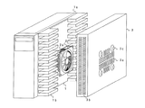
図1において、本発明の冷却構造はパワー素子などの発熱体を取付けた放熱器1と、放熱器1に水平に取付けた軸流ファンモータ2と、放熱器1と軸流ファンモータ2を覆う筐体3とを備えている。
In FIG. 1, the cooling structure of the present invention covers a
放熱器1は、基盤部1aから平行に突出した放熱フィン1bを複数有しており、溶融アルミニウムを押出加工によって得られた後、軸流ファンモータ2を水平に取付けるため、放熱フィン1bの一部を、機械加工によって除去したものである。
The
放熱器1の平面部である基盤部1aおよび加工面には、モータ制御装置の発熱体であるパワー素子として、パワーモジュール(スイッチング素子)、ダイオードモジュール、回生用の巻線抵抗器などがネジにて取付けられる(図示せず)。制御回路部は、放熱フィン1bの反対面である基盤部1aに取付けられる(図示せず)。また、放熱フィン1bの先端部は、放熱器1に水平に取付けたファンモータ2の外側面と同程度になるように設定している。なお、基盤部1aはネジ固定のための強度を確保する厚み以上を備えている。また、軸流ファンモータ2直下の放熱フィン1bを完全に除去せず、排気のための隙間を確保する。
A power module (switching element), a diode module, a regenerative winding resistor, etc. are used as screws as power elements that are heating elements of the motor control device, on the base part 1a that is a flat part of the
軸流ファンモータ2は、環状の枠にスリット2aを備えており、このスリット2aは軸方向の風量を増加させる作用がある。 The axial fan motor 2 is provided with a slit 2a in an annular frame, and this slit 2a has an effect of increasing the air volume in the axial direction.
筐体3は、放熱器1の放熱フィン1bおよび軸流ファンモータ2を覆う箱型の金属製カバーであり、軸流ファンとの対向面に通気孔3aと、少なくとも平行に設けた放熱フィン1bと直交する2面とに通気孔3bを設けて、軸流ファンモータ2の通気路を確保している。
The
上述した冷却構造において、軸流ファンモータ2が回転すると、周囲の空気はスリット2aおよび通気孔3aから流入して、放熱器1の基盤部1a側に排出される。排出された冷風は基盤部1a、放熱フィン1b、および放熱フィン側の発熱体であるパワー素子に直接当たるため、効率よく冷却することができる。
In the cooling structure described above, when the axial fan motor 2 rotates, ambient air flows from the slit 2a and the vent hole 3a and is discharged to the base portion 1a side of the
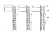
また、軸流ファンモータ2とが対向する筐体3の外面に突起部3cを設けており、図2に示すように、突起部3cによって通気孔3aが塞がれるのを防止して通気路を確保するため、複数台のモータ制御装置を密着して配置でき、省スペースを実現できる。
Further, a projection 3c is provided on the outer surface of the
このように、軸流ファンモータ2を放熱器1の放熱フィン1bの中に水平に配置するため、薄型化が可能となり、筐体3に設けた通気孔3a,3bおよび突起部3cによって軸流ファンモータ2の通気路を確保できるため、省スペースで冷却効率のよいモータ制御装置を提供することができる。
As described above, since the axial fan motor 2 is horizontally disposed in the heat radiating fins 1b of the
本発明のモータ制御装置の冷却構造は、温度上昇を嫌う用途の薄型化に有用である。 The cooling structure of the motor control device of the present invention is useful for reducing the thickness of applications that dislike temperature rise.
1 放熱器
1a 基盤部
1b 放熱フィン
2 軸流ファンモータ
2a スリット
3 筐体
3a,3b 通気孔
3c 突起部
DESCRIPTION OF
Claims (3)
Priority Applications (1)
| Application Number | Priority Date | Filing Date | Title |
|---|---|---|---|
| JP2006022036A JP4725338B2 (en) | 2006-01-31 | 2006-01-31 | Motor drive device cooling structure |
Applications Claiming Priority (1)
| Application Number | Priority Date | Filing Date | Title |
|---|---|---|---|
| JP2006022036A JP4725338B2 (en) | 2006-01-31 | 2006-01-31 | Motor drive device cooling structure |
Publications (2)
| Publication Number | Publication Date |
|---|---|
| JP2007209062A true JP2007209062A (en) | 2007-08-16 |
| JP4725338B2 JP4725338B2 (en) | 2011-07-13 |
Family
ID=38488023
Family Applications (1)
| Application Number | Title | Priority Date | Filing Date |
|---|---|---|---|
| JP2006022036A Active JP4725338B2 (en) | 2006-01-31 | 2006-01-31 | Motor drive device cooling structure |
Country Status (1)
| Country | Link |
|---|---|
| JP (1) | JP4725338B2 (en) |
Cited By (6)
| Publication number | Priority date | Publication date | Assignee | Title |
|---|---|---|---|---|
| JP2010081765A (en) * | 2008-09-29 | 2010-04-08 | Hitachi Industrial Equipment Systems Co Ltd | A plurality of power converters arranged in row, and method of installing the power converters |
| DE112008002146T5 (en) | 2007-08-10 | 2010-06-10 | Toyota Jidosha Kabushiki Kaisha | Cell for fuel cell, and fuel cell |
| JP2010239811A (en) * | 2009-03-31 | 2010-10-21 | Aisin Aw Co Ltd | Inverter device |
| CN104811097A (en) * | 2014-01-24 | 2015-07-29 | 日本电产三协株式会社 | Motor driving device |
| JP2015139357A (en) * | 2014-01-24 | 2015-07-30 | 日本電産サンキョー株式会社 | Motor driver |
| DE102016010409A1 (en) | 2015-09-02 | 2017-03-02 | Fanuc Corporation | An engine operating device assembly that includes a plurality of engine operating devices and an engine operating device that includes a heat sink |
Families Citing this family (1)
| Publication number | Priority date | Publication date | Assignee | Title |
|---|---|---|---|---|
| JP7474868B2 (en) * | 2020-04-29 | 2024-04-25 | ケーエムダブリュ・インコーポレーテッド | Heat dissipation device and antenna assembly using the same |
Citations (3)
| Publication number | Priority date | Publication date | Assignee | Title |
|---|---|---|---|---|
| JPH10295087A (en) * | 1998-05-11 | 1998-11-04 | Hitachi Ltd | Inverter equipment |
| JPH1145967A (en) * | 1997-02-24 | 1999-02-16 | Fujitsu Ltd | Heat sink and information processor on which heat sink is mounted |
| JP2006002707A (en) * | 2004-06-18 | 2006-01-05 | Funai Electric Co Ltd | Mounting structure for fan motor |
Family Cites Families (1)
| Publication number | Priority date | Publication date | Assignee | Title |
|---|---|---|---|---|
| US5484262A (en) * | 1992-10-23 | 1996-01-16 | Nidec Corporation | Low profile fan body with heat transfer characteristics |
-
2006
- 2006-01-31 JP JP2006022036A patent/JP4725338B2/en active Active
Patent Citations (3)
| Publication number | Priority date | Publication date | Assignee | Title |
|---|---|---|---|---|
| JPH1145967A (en) * | 1997-02-24 | 1999-02-16 | Fujitsu Ltd | Heat sink and information processor on which heat sink is mounted |
| JPH10295087A (en) * | 1998-05-11 | 1998-11-04 | Hitachi Ltd | Inverter equipment |
| JP2006002707A (en) * | 2004-06-18 | 2006-01-05 | Funai Electric Co Ltd | Mounting structure for fan motor |
Cited By (12)
| Publication number | Priority date | Publication date | Assignee | Title |
|---|---|---|---|---|
| DE112008002146T5 (en) | 2007-08-10 | 2010-06-10 | Toyota Jidosha Kabushiki Kaisha | Cell for fuel cell, and fuel cell |
| JP2010081765A (en) * | 2008-09-29 | 2010-04-08 | Hitachi Industrial Equipment Systems Co Ltd | A plurality of power converters arranged in row, and method of installing the power converters |
| JP2010239811A (en) * | 2009-03-31 | 2010-10-21 | Aisin Aw Co Ltd | Inverter device |
| CN104811097A (en) * | 2014-01-24 | 2015-07-29 | 日本电产三协株式会社 | Motor driving device |
| JP2015139357A (en) * | 2014-01-24 | 2015-07-30 | 日本電産サンキョー株式会社 | Motor driver |
| JP2015139356A (en) * | 2014-01-24 | 2015-07-30 | 日本電産サンキョー株式会社 | Motor drive device |
| KR20150088725A (en) | 2014-01-24 | 2015-08-03 | 니혼 덴산 산쿄 가부시키가이샤 | Motor driving apparatus |
| KR101718201B1 (en) * | 2014-01-24 | 2017-03-20 | 니혼 덴산 산쿄 가부시키가이샤 | Motor driving apparatus |
| CN104811097B (en) * | 2014-01-24 | 2017-10-03 | 日本电产三协株式会社 | Motor drive |
| DE102016010409A1 (en) | 2015-09-02 | 2017-03-02 | Fanuc Corporation | An engine operating device assembly that includes a plurality of engine operating devices and an engine operating device that includes a heat sink |
| US9966896B2 (en) | 2015-09-02 | 2018-05-08 | Fanuc Corporation | Motor drive device assembly including plurality of motor drive devices, and motor drive device including heatsink |
| DE102016010409B4 (en) * | 2015-09-02 | 2020-03-05 | Fanuc Corporation | Engine operating device assembly that includes multiple engine operating devices and engine operating device that includes a heat sink |
Also Published As
| Publication number | Publication date |
|---|---|
| JP4725338B2 (en) | 2011-07-13 |
Similar Documents
| Publication | Publication Date | Title |
|---|---|---|
| US7812487B2 (en) | Controller for a direct current brushless motor | |
| JP4725338B2 (en) | Motor drive device cooling structure | |
| JP4655987B2 (en) | Electronics | |
| JP3097594U (en) | Combination structure of CPU heat dissipation device and power supply | |
| JP5532623B2 (en) | Air conditioner electrical equipment | |
| US5940268A (en) | Heat sink and electronic device employing the same | |
| JP2010130779A (en) | Motor controller | |
| JP4720688B2 (en) | Electronic control unit cooling system | |
| JP2011034309A (en) | Electronic apparatus | |
| KR100939992B1 (en) | Cooling Apparatus, and Electric-Electronic Equipment with the Cooling Apparatus | |
| KR20040094299A (en) | Heat-Dissipating Fan Module of Electronic Apparatus | |
| JP2005136211A (en) | Cooling device | |
| JP2015040673A (en) | Cooling mechanism of electric component unit in outdoor equipment of air conditioner | |
| JP2002280779A (en) | Cooler for electronic apparatus | |
| JP2008086101A (en) | Motor controller | |
| CN213367586U (en) | Driving integrated machine | |
| JP2002359331A (en) | Slantly attached fan sink | |
| JP2003139352A (en) | Electric device unit for outdoor machine and outdoor machine for air conditioner | |
| JP2010165761A (en) | Electronic component cooling structure | |
| JP2007189869A (en) | Motor control device | |
| JP2006237290A (en) | Radiation module mechanism | |
| JP4442572B2 (en) | Electronic equipment | |
| JP4985390B2 (en) | Heat dissipation device for electronic equipment | |
| JP2021015946A (en) | Heat dissipation structure of heat generating component | |
| US6695045B2 (en) | Bladed heat sink |
Legal Events
| Date | Code | Title | Description |
|---|---|---|---|
| A621 | Written request for application examination |
Free format text: JAPANESE INTERMEDIATE CODE: A621 Effective date: 20080122 |
|
| RD01 | Notification of change of attorney |
Free format text: JAPANESE INTERMEDIATE CODE: A7421 Effective date: 20091127 |
|
| A131 | Notification of reasons for refusal |
Free format text: JAPANESE INTERMEDIATE CODE: A131 Effective date: 20101102 |
|
| A521 | Written amendment |
Free format text: JAPANESE INTERMEDIATE CODE: A523 Effective date: 20101228 |
|
| TRDD | Decision of grant or rejection written | ||
| A01 | Written decision to grant a patent or to grant a registration (utility model) |
Free format text: JAPANESE INTERMEDIATE CODE: A01 Effective date: 20110315 |
|
| A61 | First payment of annual fees (during grant procedure) |
Free format text: JAPANESE INTERMEDIATE CODE: A61 Effective date: 20110328 |
|
| R151 | Written notification of patent or utility model registration |
Ref document number: 4725338 Country of ref document: JP Free format text: JAPANESE INTERMEDIATE CODE: R151 |
|
| FPAY | Renewal fee payment (event date is renewal date of database) |
Free format text: PAYMENT UNTIL: 20140422 Year of fee payment: 3 |