JP2006288076A - Control unit - Google Patents
Control unit Download PDFInfo
- Publication number
- JP2006288076A JP2006288076A JP2005104447A JP2005104447A JP2006288076A JP 2006288076 A JP2006288076 A JP 2006288076A JP 2005104447 A JP2005104447 A JP 2005104447A JP 2005104447 A JP2005104447 A JP 2005104447A JP 2006288076 A JP2006288076 A JP 2006288076A
- Authority
- JP
- Japan
- Prior art keywords
- current command
- command value
- axis current
- output
- motor
- Prior art date
- Legal status (The legal status is an assumption and is not a legal conclusion. Google has not performed a legal analysis and makes no representation as to the accuracy of the status listed.)
- Pending
Links
Images

Classifications
-
- H—ELECTRICITY
- H02—GENERATION; CONVERSION OR DISTRIBUTION OF ELECTRIC POWER
- H02P—CONTROL OR REGULATION OF ELECTRIC MOTORS, ELECTRIC GENERATORS OR DYNAMO-ELECTRIC CONVERTERS; CONTROLLING TRANSFORMERS, REACTORS OR CHOKE COILS
- H02P25/00—Arrangements or methods for the control of AC motors characterised by the kind of AC motor or by structural details
- H02P25/02—Arrangements or methods for the control of AC motors characterised by the kind of AC motor or by structural details characterised by the kind of motor
- H02P25/06—Linear motors
-
- B—PERFORMING OPERATIONS; TRANSPORTING
- B66—HOISTING; LIFTING; HAULING
- B66B—ELEVATORS; ESCALATORS OR MOVING WALKWAYS
- B66B1/00—Control systems of elevators in general
- B66B1/24—Control systems with regulation, i.e. with retroactive action, for influencing travelling speed, acceleration, or deceleration
- B66B1/28—Control systems with regulation, i.e. with retroactive action, for influencing travelling speed, acceleration, or deceleration electrical
- B66B1/30—Control systems with regulation, i.e. with retroactive action, for influencing travelling speed, acceleration, or deceleration electrical effective on driving gear, e.g. acting on power electronics, on inverter or rectifier controlled motor
- B66B1/308—Control systems with regulation, i.e. with retroactive action, for influencing travelling speed, acceleration, or deceleration electrical effective on driving gear, e.g. acting on power electronics, on inverter or rectifier controlled motor with AC powered elevator drive
-
- H—ELECTRICITY
- H02—GENERATION; CONVERSION OR DISTRIBUTION OF ELECTRIC POWER
- H02P—CONTROL OR REGULATION OF ELECTRIC MOTORS, ELECTRIC GENERATORS OR DYNAMO-ELECTRIC CONVERTERS; CONTROLLING TRANSFORMERS, REACTORS OR CHOKE COILS
- H02P21/00—Arrangements or methods for the control of electric machines by vector control, e.g. by control of field orientation
- H02P21/22—Current control, e.g. using a current control loop
Landscapes
- Engineering & Computer Science (AREA)
- Power Engineering (AREA)
- Automation & Control Theory (AREA)
- Control Of Ac Motors In General (AREA)
- Control Of Linear Motors (AREA)
Abstract
Description
本発明は、エレベータ設備などで使用される電動機を制御する制御装置に関する。 The present invention relates to a control device that controls an electric motor used in an elevator installation or the like.
エレベータ設備などで使用される電動機を制御する制御装置の1つとして、従来、図13に示す装置が知られている。 Conventionally, an apparatus shown in FIG. 13 is known as one of control apparatuses for controlling an electric motor used in an elevator facility or the like.
この図に示す制御装置101では、インバータ等の駆動手段108によって、電動機112が駆動される。電動機112の回転角はパルスジェネレータPG等の回転角検出手段111で検出され、検出された回転角は、電動機112の速度を制御する速度制御系(d軸電流指令手段102、q軸電流指令手段103、q軸電流指令値補正手段105によって構成される部分)113に入力される。 In the control device 101 shown in this figure, the electric motor 112 is driven by the driving means 108 such as an inverter. The rotation angle of the motor 112 is detected by a rotation angle detection means 111 such as a pulse generator PG, and the detected rotation angle is a speed control system (d-axis current command means 102, q-axis current command means for controlling the speed of the motor 112. 103, a portion constituted by the q-axis current command value correcting means 105) 113.
速度制御系113では、電動機112の実速度と、その速度指令値との速度偏差信号から、駆動手段119へ駆動信号を出力する電流制御手段106への電流指令値が演算される。 In the speed control system 113, a current command value to the current control means 106 that outputs a drive signal to the drive means 119 is calculated from a speed deviation signal between the actual speed of the motor 112 and its speed command value.
この電流指令値は、電動機112をベクトル制御する場合、直交回転座標系におけるd軸電流指令値“Idc”およびq軸電流指令値“Iqc”である。d軸電流指令値“Idc”は電動機112に磁束を発生させる磁束電流指令値であり、q軸電流指令値“Iqc”は、電動機112にトルクを発生させるトルク電流指令値である。 This current command value is the d-axis current command value “I dc ” and the q-axis current command value “I qc ” in the orthogonal rotation coordinate system when the electric motor 112 is vector-controlled. The d-axis current command value “I dc ” is a magnetic flux current command value that causes the motor 112 to generate a magnetic flux, and the q-axis current command value “I qc ” is a torque current command value that causes the motor 112 to generate torque.
電流制御手段106、2相3相変換手段107では、直交回転座標系におけるd軸電流指令値“Idc”、q軸電流指令値“Iqc”、および回転角検出手段111の電気角(回転角)“θe”、3相2相変換手段110から出力される電流信号“Idf”、“Idf”を取り込み、電流検出手段109から出力される出力電流信号“Iuf”、“Iwf”がd軸電流指令値“Idc”、q電流指令値“Iqc”、および電気角“θe”を満たすような電圧指令値“Vu”、“Vv”、“Vw”が生成されて、駆動手段108に出力される。
In the
すなわち、電流検出手段109によって、電動機112に供給される3相の駆動電流の電流値が各々、検出されて、出力電流信号“Iuf”、“Ivf”、“Iwf”が出力され、3相/2相変換手段110に入力される。この3相/2相変換手段111は次式に示すように、電流検出手段109から出力される静止座標系での3相で示される出力電流信号“Iuf”、“Ivf”、“Iwf”を直交静止座標系の2相で示される電流信号“Iα”、“Iβ”に変換する。この変換された2相の電流信号“Iα”、“Iβ”は、直交回転座標系の電流信号“Idf”、“Iqf”に変換される。すなわち、電気角“θe”に基づき、直交静止座標系の電流信号“Iα”、“Iβ”を直交回転座標系の電流信号“Idf”、“Iqf”に変換され、電流制御手段106に出力される。
![]()

![]()
ここで、添字“d”はd軸成分、“q”はq軸成分を表す。 Here, the suffix “d” represents the d-axis component, and “q” represents the q-axis component.
また、電流指令値補正手段102から出力されるd軸電流指令“Idco”、q軸電流指令値補正手段105から出力されるq軸電流指令“Iqco”と、3相2相変換手段110から出力される電流信号“Idf”、“Iqf”との偏差は、それぞれ電流制御手段106を構成しているPIコントローラ等に入力され、PI演算(比例積分演算)されて、次式に示すように直交回転座標系におけるd軸電圧指令“Vdc”およびq軸電圧指令“Vqc”を出力する。
ここで、“Kp”は比例ゲイン、“Ki”は積分ゲイン、“s”はラプラス演算子である。 Here, “K p ” is a proportional gain, “K i ” is an integral gain, and “s” is a Laplace operator.
このPIコントローラ等からのd軸電圧指令“Vdc”およびq軸電圧指令“Vqc”は、2相/3相変換手段107に入力される。2相/3相変換手段107では、次式に示すようにd軸電圧指令“Vdc”およびq軸電圧指令“Vqc”を、直交静止座標系の電圧指令値“Vα”、“Vβ”に変換する。すなわち、電気角“θe”に基づき、直交回転座標系の電圧指令値“Vdc”、“Vqc”を直交静止座標系の電圧指令値“Vα”、“Vβ”に変換する。この変換された2相で示される直交静止座標系の電圧指令値“Vα”、“Vβ”を3相で示される直交静止座標系の電圧指令値“Vu”、“Vv”、“Vw”に変換し、駆動手段108に出力する。
一般に、永久磁石同期電動機は、誘導電動機に比べ、同じ出力に対し小型に製作できるので、近年いろいろなシステムの駆動部に使われつつある。 In general, a permanent magnet synchronous motor can be manufactured in a smaller size for the same output as an induction motor, and has recently been used in a drive unit of various systems.
ところが、永久磁石同期電動機では、磁極を回転させる電機子磁束の変化が、回転角の正弦波でなく歪を含んでいる。このため、本来ならば正弦波状であるべき磁束変化が、歪を持つため、電動機の発生トルクが脈動し、回転むら等の要因となっている。また、電動機の巻線のアンバランスや電流を検出するセンサ系統の誤差等もトルクリプルの原因となっている。 However, in the permanent magnet synchronous motor, the change in the armature magnetic flux that rotates the magnetic pole includes distortion, not a sine wave of the rotation angle. For this reason, since the magnetic flux change that should be sinusoidally has distortion, the generated torque of the electric motor pulsates, causing uneven rotation. Further, torque ripple is caused by an unbalance of the windings of the motor and an error in a sensor system for detecting current.
また、電機子巻線電流により生成される磁束の空間分布は、理想的には、正弦波状が望ましいが、高調波がのっているため、発生トルクを歪ませる要因となっている。 Also, the spatial distribution of the magnetic flux generated by the armature winding current is ideally a sine wave shape, but since harmonics are present, it is a factor that distorts the generated torque.
この高調波成分の低次成分は、基本波に対する周波数の5倍/7倍であり、この磁束の5次/7次成分は、基本周波数の6倍成分(6f成分)のトルクリプル原因となる。 The low-order component of this harmonic component is 5/7 times the frequency of the fundamental wave, and the 5th / 7th-order component of this magnetic flux causes torque ripple of the 6-fold component (6f component) of the fundamental frequency.
同様に、次式に示すような磁束の11倍/13倍成分は、12f成分のトルクリプルの原因となる。
![]()
![]()
ここで、“Eu”、“Ev”、“Ew”は各相の電機子巻線に誘起する誘起電圧(以下では簡単のため必要に応じて電気角“θe”の巻数表記を省略する)、“ω”は回転速度(回転角の時間微分)、“Ke”は逆起電力定数である。 Here, “E u ”, “E v ”, and “E w ” are induced voltages induced in the armature windings of each phase (hereinafter, the number of turns of the electrical angle “θ e ” is expressed as necessary for simplicity. (Omitted), “ω” is the rotational speed (time derivative of the rotational angle), and “K e ” is the back electromotive force constant.
上式の3相誘起電圧“Eu”、“Ev”、“Ew”を、3相/2相変換すると、下式になる。
また、電動機112が円筒機であれば、トルク“T”は、誘起電圧“Eu”、“Ev”、“Ew”と、各電流“Iu”、“Iv”、“Iw”とから下式となる。
電動機112に対し、スキュー等の対策を行って、トルクリプルを問題のないレベルに抑えることもできるが、コスト上昇を招くことになる。 Although it is possible to suppress the torque ripple to a level at which there is no problem by taking countermeasures such as skew for the electric motor 112, the cost will increase.
また、トルクリプルの低減方法として、例えば、「特許文献1」のようにトルクリプルが電動機の回転と相関性を持つことから、この相関関係を記憶装置に記憶させ、電動機の回転角に基づいて、これと対応するトルクリプルデータを読み出し、トルク指令値からリプル分を差し引いたものを新たなトルク指令値とする方法がある。さらに、「特許文献2」のように電動機回転角“θ”と、調整ゲイン“A”と調整位相“p”とから、トルクリプル補正信号“Tcomp=A×sin(n×θ+p)”を演算し、電動機の回転周期に同期させてフィードフォワード的に目標トルク指令に加算してトルクリプルを打ち消す方法がある。
しかし、従来のトルクリプルの低減方法はトルク指令値(トルク電流指令値)を補正するものであって、(6×n)f成分のトルクリプルを打ち消そうとすると、(6×(n+1))f成分が大きくなるという課題があった。 However, the conventional torque ripple reduction method corrects the torque command value (torque current command value), and when trying to cancel the torque ripple of the (6 × n) f component, (6 × (n + 1)) f There existed a subject that an ingredient became large.
簡単のため、磁束の5次成分のみがある場合について説明する。 For simplicity, the case where only the fifth-order component of the magnetic flux is present will be described.
各相の誘起電圧“Eu”、“Ev”、“Ew”、例えば誘起電圧“Eu”は、下式となる。また、他の各誘起電圧“Ev”、“Ew”も同様な式で示される。
![]()
![]()
上式を、[数13]に代入してトルク“T”を求めると、下式となり、6fトルクリプルがあることがわかる。
一方、公知のトルクリプル補正信号“Tcomp”を用いた場合のd軸電流指令値“Idc”、q軸電流指令値“Iqc”は下式となる。
![]()
![]()
上式の場合のトルク“T”は、[数15]と同様に下式となる。
この[数18]から分かるように、磁束の5次成分でトルクリプルの6f成分が生じるのに対し、従来の低減方法で6f成分を打ち消そうとすると、新たに12f成分が発生する。 As can be seen from [Equation 18], the 6f component of the torque ripple is generated by the fifth-order component of the magnetic flux. On the other hand, if the 6f component is canceled by the conventional reduction method, a 12f component is newly generated.
また、トルクリプルは、電動機112の運転条件に依存する場合も多く、例えば加減速のように運転条件が変化した場合にはトルクリプル低減性能が劣化するという課題もあった。 Further, torque ripple often depends on the operating condition of the electric motor 112, and there has been a problem that torque ripple reduction performance deteriorates when the operating condition changes, for example, acceleration / deceleration.
さらに、電動機112には、半径方向の電磁吸引力の脈動による振動・騒音の課題があった。 Furthermore, the motor 112 has a problem of vibration and noise due to pulsation of the electromagnetic attracting force in the radial direction.
本発明は上記の事情に鑑み、電動機に供給される出力電流の波形を整えて、電動機のトルクリプルを大幅に低減させることできる制御装置を提供することを目的としている。 In view of the above circumstances, an object of the present invention is to provide a control device capable of adjusting the waveform of an output current supplied to an electric motor and greatly reducing torque ripple of the electric motor.
また、リニア電動機に供給される出力電流の波形を整えて、リニア電動機で生じるZ方向の力変動を大幅に低減させつつ、リニア電動機の振動または騒音を検出してパラメータを自動補正でき、リニア電動機の振動・騒音を低減させることができる制御装置を提供することを目的としている。 In addition, by adjusting the waveform of the output current supplied to the linear motor and greatly reducing Z-direction force fluctuations that occur in the linear motor, it is possible to detect the vibration or noise of the linear motor and automatically correct the parameters. An object of the present invention is to provide a control device that can reduce vibration and noise.
上記の目的を達成するために本発明は、電動機の実測回転速度と予め設定されている設定回転速度との偏差に応じて、d軸電流指令およびq軸電流指令を生成するd軸/q軸電流指令手段と、前記電動機の回転を検出して電気角を出力する回転角検出手段と、前記電動機の特性に対応したパラメータが設定される電動機パラメータ設定手段と、前記回転角検出手段から出力される電気角および前記電動機パラメータ設定手段から出力されるパラメータに応じて、前記d軸/q軸電流指令手段から出力されるd軸電流指令およびq軸電流指令に対し、前記電動機が発生するトルクの高調波リプル成分を抑制するのに必要な補正を行い、補正済みのd軸電流指令値およびq軸電流指令値を生成する電流指令値補正手段と、
この電流指令値補正手段から出力される補正済みのd軸電流指令値およびq軸電流指令値並びに前記電流検出手段から出力される電動機の出力電流検出信号に基づき、3相の駆動電圧を生成して前記電動機に供給する3相駆動手段とを具備することを特徴としている。
In order to achieve the above object, the present invention provides a d-axis / q-axis that generates a d-axis current command and a q-axis current command in accordance with a deviation between a measured rotational speed of a motor and a preset rotational speed. Output from the current command means, rotation angle detection means for detecting the rotation of the motor and outputting an electrical angle, motor parameter setting means for setting parameters corresponding to the characteristics of the motor, and the rotation angle detection means. In response to the d-axis current command and the q-axis current command output from the d-axis / q-axis current command means, the torque generated by the motor according to the electrical angle and the parameter output from the motor parameter setting means. Current command value correcting means for performing correction necessary to suppress the harmonic ripple component and generating corrected d-axis current command value and q-axis current command value;
Based on the corrected d-axis current command value and q-axis current command value output from the current command value correction means and the output current detection signal of the motor output from the current detection means, a three-phase drive voltage is generated. And three-phase drive means for supplying to the electric motor.
また、本発明は、リニア電動機の実測速度と予め設定されている設定速度との偏差に応じて、d軸電流指令およびq軸電流指令を生成するd軸/q軸電流指令手段と、前記リニア電動機の速度を検出して電気角を出力する電気角検出手段と、前記リニア電動機の特性に対応したパラメータが設定される電動機パラメータ設定手段と、前記電気角検出手段から出力される電気角および前記電動機パラメータ設定手段から出力されるパラメータに応じて、前記d軸/q軸電流指令手段から出力されるd軸電流指令およびq軸電流指令に対し、前記リニア電動機が発生するZ方向の高調波リプル成分を抑制するのに必要な補正を行い、補正済みのd軸電流指令値およびq軸電流指令値を生成する電流指令値補正手段と、この電流指令値補正手段から出力される補正済みのd軸電流指令値、q軸電流指令値および電流検出手段から出力されるリニア電動機の出力電流検出信号に基づき、3相の駆動電圧を生成して前記リニア電動機に供給する3相駆動手段と、前記リニア電動機の振動または騒音を検出する脈動検出手段と、この脈動検出手段の出力、前記電流指令値補正手段で生成される補正済みのd軸電流指令値およびq軸電流指令値に基づき、前記リニア電動機の振動または騒音を最小にするのに必要なパラメータを求め、前記電流指令値補正手段で使用されるパラメータを補正する処理または報知装置から報知する処理のいずれかを行う補正パラメータ学習手段とを具備することを特徴としている。 The present invention also provides a d-axis / q-axis current command means for generating a d-axis current command and a q-axis current command in accordance with a deviation between a measured speed of the linear motor and a preset set speed, and the linear Electrical angle detection means for detecting the speed of the motor and outputting an electrical angle; motor parameter setting means for setting parameters corresponding to the characteristics of the linear motor; electrical angle output from the electrical angle detection means; and A harmonic ripple in the Z direction generated by the linear motor in response to a d-axis current command and a q-axis current command output from the d-axis / q-axis current command means in accordance with a parameter output from the motor parameter setting means. From the current command value correction means, current command value correction means for performing correction necessary to suppress the component and generating corrected d-axis current command value and q-axis current command value Based on the corrected d-axis current command value to be applied, the q-axis current command value, and the output current detection signal of the linear motor output from the current detection means, a three-phase drive voltage is generated and supplied to the linear motor. Three-phase driving means, pulsation detecting means for detecting vibration or noise of the linear motor, output of the pulsation detecting means, corrected d-axis current command value and q-axis current generated by the current command value correcting means Based on the command value, a parameter necessary for minimizing vibration or noise of the linear motor is obtained, and either a process for correcting the parameter used in the current command value correcting means or a process for notifying from the notification device is performed. And a correction parameter learning means for performing.
本発明によれば、電動機に供給される出力電流の波形を整えることができ、電動機のトルクリプルを大幅に低減させることできる。その結果、電動機の振動・騒音を低減させることができる。 According to the present invention, the waveform of the output current supplied to the electric motor can be adjusted, and the torque ripple of the electric motor can be greatly reduced. As a result, the vibration and noise of the electric motor can be reduced.
また、リニア電動機に供給される出力電流の波形を整えることができ、リニア電動機で生じるZ方向の力変動を大幅に低減させることができる。その結果、リニア電動機の振動・騒音を低減させることができる。 Further, the waveform of the output current supplied to the linear motor can be adjusted, and the force fluctuation in the Z direction generated by the linear motor can be greatly reduced. As a result, the vibration and noise of the linear motor can be reduced.
《第1の実施形態》
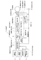
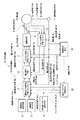
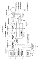
図1は本発明による制御装置の第1の実施形態を示すブロック図である。
<< First Embodiment >>
FIG. 1 is a block diagram showing a first embodiment of a control device according to the present invention.
この図に示す制御装置1aは、d軸電流指令“Idco”を出力するd軸電流指令手段2と、q軸電流指令“Iqco”を出力するq軸電流指令手段3と、電動機10のパラメータ“n”、“ad”、“pd”、“aq”、“pq”などが設定される電動機パラメータ設定手段4とを備えている。 Control device 1a shown in this figure, the d-axis current command means 2 for outputting a d-axis current command "I dco", the q-axis current command means 3 for outputting a q-axis current command "I QCO", the motor 10 And motor parameter setting means 4 for setting parameters “n”, “a d ”, “p d ”, “a q ”, “p q ” and the like.
また、この制御装置1aは、電流指令補正手段5と、電流制御手段6と、2相/3相変換手段7と、駆動手段8と、電流検出手段9と、電動機10の回転角“θe”を検出する回転角検出手段11と、3相/2相変換手段12とを備えている。
In addition, the control device 1a includes a current
ここで、電流指令補正手段5は、電動機パラメータ設定手段4から出力される電動機10のパラメータ“n”、“ad”、“pd”、“aq”、“pq”、回転角検出手段11の検出結果に基づき、d軸電流指令手段2から出力されるd軸電流指令“Idco”、q軸電流指令手段3から出力されるq軸電流指令“Iqco”を補正して、d軸電流指令値“Idc”、q軸電流指令値“Iqc”を出力する。 Here, the current command correction means 5 is a parameter “n”, “a d ”, “p d ”, “a q ”, “p q ”, rotation angle detection of the motor 10 output from the motor parameter setting means 4. Based on the detection result of the means 11, the d-axis current command “I dco ” output from the d-axis current command means 2 and the q-axis current command “I qco ” output from the q-axis current command means 3 are corrected, The d-axis current command value “I dc ” and the q-axis current command value “I qc ” are output.
また、電流制御手段6は、電流指令補正手段5から出力されるd軸電流指令値“Idc”、q軸電流指令値“Iqc”、3相/2相変換手段12から出力される電流信号“Idf”、“Iqf”に基づき、d軸電圧指令“Vdc”、q軸電圧指令“Vqc”を演算する。 Further, the current control means 6 includes a d-axis current command value “I dc ” output from the current command correction means 5, a q-axis current command value “I qc ”, and a current output from the three-phase / two-phase conversion means 12. Based on the signals “I df ” and “I qf ”, a d-axis voltage command “V dc ” and a q-axis voltage command “V qc ” are calculated.
また、2相/3相変換手段7は、電流制御手段6から出力されるd軸電圧指令“Vdc”、q軸電圧指令“Vqc”、回転角検出手段11から出力される回転角“θe”に基づき、3相の電圧指令値“Vu”、“Vv”、“Vw”を演算する。
Further, the two-phase / three-phase conversion unit 7 includes a d-axis voltage command “V dc ” output from the
また、駆動手段8は、2相/3相変換手段7から出力される電圧指令値“Vu”、“Vv”、“Vw”に基づき、3相の駆動電圧を出力して電動機10を駆動する。 The driving means 8 outputs a three-phase driving voltage based on the voltage command values “V u ”, “V v ”, “V w ” output from the two-phase / three-phase conversion means 7, and outputs the electric motor 10. Drive.
電流検出手段9は、電動機10に供給される3相の出力電流を検出して出力電流信号“Iuf”、“Ivf”、“Iwf”を出力する。 The current detection means 9 detects a three-phase output current supplied to the electric motor 10 and outputs output current signals “I uf ”, “I vf ”, “I wf ”.
3相/2相変換手段12は、電流検出手段9から出力される出力電流信号“Iuf”、“Ivf”、“Iwf”、回転角検出手段11から出力される回転角“θe”に基づき、電流信号“Idf”、“Iqf”を演算する。
The three-phase / two-
次に、図1を参照して制御装置1aの全体動作を説明する。 Next, the overall operation of the control device 1a will be described with reference to FIG.
電動機10の回転角は、PG等などによって構成される回転角検出手段11によって、パルス形式で検出されるとともに、検出結果に対応する電気角(回転角)“θe”にされて、速度を制御する速度制御系(d軸電流指令手段2、q軸電流指令手段3、電流指令値補正手段5によって構成される部分)13に入力される。 The rotation angle of the electric motor 10 is detected in a pulse format by the rotation angle detection means 11 constituted by PG or the like, and the electric angle (rotation angle) corresponding to the detection result is set to “θ e ” to increase the speed. It is input to a speed control system 13 (part constituted by the d-axis current command means 2, the q-axis current command means 3 and the current command value correction means 5) to be controlled.
速度制御系13では、回転角検出手段11から入力された電気角“θe”により電動機10の実速度が算出され、その速度と速度指令値との速度偏差信号から、電流制御手段6へのd軸電流指令値“Idc”、q軸電流指令値“Iqc”が演算され、電流制御手段6に出力される。 In the speed control system 13, the actual speed of the electric motor 10 is calculated from the electrical angle “θ e ” input from the rotation angle detection means 11, and the current deviation from the speed and the speed command value is sent to the current control means 6. The d-axis current command value “I dc ” and the q-axis current command value “I qc ” are calculated and output to the current control means 6.
これらd軸電流指令値“Idc”、q軸電流指令値“Iqc”は、下式のような電動機10をベクトル制御する場合の直交回転座標系におけるd軸電流指令値(磁束電流指令値)“Idc”およびq軸電流指令値(トルク電流指令値)“Iqc”である。
ここで、“Idco”、“Iqco”は各々、d軸電流指令手段2から出力されるd軸電流指令値、q軸電流指令手段3から出力されるq軸電流指令値である。また、“dIdc”、“dIqc”は、電動機パラメータ設定手段4に設定されているパラメータ“n”、“ad”、“pd”、“aq”、“pq”である。 Here, “I dco ” and “I qco ” are a d-axis current command value output from the d-axis current command means 2 and a q-axis current command value output from the q-axis current command means 3, respectively. “ DI dc ” and “dI qc ” are parameters “n”, “a d ”, “p d ”, “a q ”, “p q ” set in the motor parameter setting means 4.
また、電流指令値補正手段5では、電動機パラメータ設定手段4から出力されるパラメータ“n”、“ad”、“pd”、“aq”、“pq”、回転角検出手段11から出力される電気角“θe”などに基づき、電動機10で発生するトルクリップルを打ち消すのに必要なd軸電流指令補正信号“dIdco”、q軸電流指令補正信号“dIqco”が生成される。そして、d軸電流指令手段2から出力されるd軸電流指令“Idco”、q軸電流指令手段3から出力されるq軸電流指令“Iqco”を補正して、d軸電流指令値“Idc”、q軸電流指令値“Iqc”が生成され、電流制御手段6に出力される。
Further, in the current command value correction means 5, the parameters “n”, “a d ”, “p d ”, “a q ”, “p q ” output from the motor parameter setting means 4, and the rotation angle detection means 11 Based on the output electrical angle “θ e ” and the like, a d-axis current command correction signal “dI dco ” and a q-axis current command correction signal “dI qco ” necessary to cancel torque ripple generated in the motor 10 are generated. The Then, the d-axis current command “I dco ” output from the d-axis
電流制御手段6、2相3相変換手段7では、直交回転座標系におけるd軸電流指令値“Idc”、q軸電流指令値“Iqc”、3相/2相変換手段12から出力される直交回転座標系の電流信号“Idf”、“Iqf”が入力され、電流検出手段9から出力される出力電流信号“Iuf”、“Iwf”と、d軸電流指令値“Idc”、q軸電流指令値“Iqc”、および電気角“θe”とを対応させるのに必要な電圧指令値“Vu”、“Vv”、“Vw”が演算されて、駆動手段8に出力される。
The
すなわち、出力電流信号“Iuf”、“Iwf”は、電流検出手段9で検出され、3相/2相変換手段12に入力される。この3相/2相変換手段12は電流検出手段9からの静止座標系での3相で示される電流信号“Iuf”、“Iwf”が直交静止座標系の2相で示される電流信号“Iα”、“Iβ”に変換される。この変換された2相の電流信号“Iα”、“Iβ”は、電気角“θe”に基づき、直交回転座標系の電流信号“Idf”、“Iqf”に変換され、電流制御手段6に出力される。
That is, the output current signals “I uf ” and “I wf ” are detected by the current detection unit 9 and input to the three-phase / two-
そして、d軸電流指令値“Idc”、q軸電流指令値“Iqc”と、電流信号“Idf”、“Iqf”との偏差は各々、電流制御手段6を構成しているPIコントローラ等によって、PI演算(比例積分演算)されて、直交回転座標系におけるd軸電圧指令“Vdc”およびq軸電圧指令“Vqc”が生成される。 The deviations between the d-axis current command value “I dc ”, the q-axis current command value “I qc ”, and the current signals “I df ” and “I qf ” are each PI constituting the current control means 6. A PI calculation (proportional integration calculation) is performed by a controller or the like to generate a d-axis voltage command “V dc ” and a q-axis voltage command “V qc ” in the orthogonal rotation coordinate system.
このPIコントローラからのd軸電圧指令“Vdc”およびq軸電圧指令“Vqc”は、2相/3相変換手段7に入力される。2相/3相変換手段7では、d軸電圧指令“Vdc”およびq軸電圧指令“Vqc”が、直交回転座標系の電圧指令値“Vα”、“Vβ”に変換される。すなわち、電気角“θe”に基づき、直交回転座標系のd軸電圧指令“Vdc”、q軸電圧指令“Vqc”が直交静止座標系の電圧指令値“Vα”、“Vβ”に変換される。この変換された2相で示される直交静止座標系の電圧指令値“Vα”、“Vβ”が3相で示される直交静止座標系の電圧指令値“Vu”、“Vv”、“Vw”に変換され、駆動手段8に出力される。 The d-axis voltage command “V dc ” and the q-axis voltage command “V qc ” from the PI controller are input to the 2-phase / 3-phase conversion means 7. In the two-phase / three-phase conversion means 7, the d-axis voltage command “V dc ” and the q-axis voltage command “V qc ” are converted into the voltage command values “V α ” and “V β ” of the orthogonal rotation coordinate system. . That is, based on the electrical angle “θ e ”, the d-axis voltage command “V dc ” and the q-axis voltage command “V qc ” in the orthogonal rotation coordinate system are the voltage command values “V α ” and “V β in the orthogonal stationary coordinate system. To "". The converted voltage command values “V α ” and “V β ” of the orthogonal stationary coordinate system indicated by two phases are the voltage command values “V u ”, “V v ” of the orthogonal stationary coordinate system indicated by three phases, It is converted to “V w ” and output to the driving means 8.
駆動手段8では、2相/3相変換手段7からの電圧指令値“Vu”、“Vv”、“Vw”を使用して、3相の出力電圧が生成され、電動機10が駆動される。 In the driving means 8, three-phase output voltages are generated using the voltage command values “V u ”, “V v ”, “V w ” from the two-phase / three-phase conversion means 7, and the motor 10 is driven. Is done.
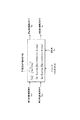
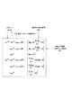
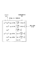
次に、図2を参照して電流指令補正手段5の詳細な動作を説明する。 Next, the detailed operation of the current command correction means 5 will be described with reference to FIG.
電流指令補正手段5では、図2に示すように、電気角“θe”の6×n倍の位相が演算され、得られた電流指令値の位相“6×n×”θeと、正弦波の位相を調整する調整位相“pd”、“pq”が加算されて、正弦波の位相“Pd”、“Pq”が求められる。 In the current command correction means 5, as shown in FIG. 2, the phase of 6 × n times the electrical angle “θ e ” is calculated, and the phase “6 × n ×” θ e of the obtained current command value and the sine Adjustment phases “p d ” and “p q ” for adjusting the phase of the wave are added to obtain sine wave phases “P d ” and “P q ”.
さらに、次式に示すように、d軸電流指令手段2から出力されるd軸電流指令“Idco”、q軸電流指令手段3から出力されるq軸電流指令“Iqco”に対応する電流指令の絶対値“|Ico|”が演算され、得られた電流指令値の絶対値“|Ico|”と、電動機パラメータ設定手段4から得られた磁束の(6×n±1)fの高調波成分比“n”と、正弦波の振幅を調整する調整振幅“ad”、“aq”が各々、乗算されて、振幅値“Ad”、“Aq”が求められる。
Furthermore, as shown in the following equation, the current corresponding to the d-axis current command “I dco ” output from the d-axis
そして、振幅値が“Ad”、“Aq”にされ、位相が“Pd”、“Pq”にされた正弦波は、以下のような電流指令補正信号“dIdc”、“dIqc”が演算される。
ここで、添字“d”はd軸成分、“q”はq軸成分を表す。 Here, the suffix “d” represents the d-axis component, and “q” represents the q-axis component.
そして、電流指令補正信号“dIdc”、“dIqc”に対応して、電動機10のトルク“T”は、下式のような回転角の定数項、(6×n)f正弦成分、(6×n)f余弦成分、(6×(n+1))f正弦成分、(6×(n+1))f余弦成分の和となる。
ここで、“W”は電動機10内部の磁気エネルギー、添字“s”は正弦成分、“c”は余弦成分を表す。なお、“T0”〜“T6(n+1)c”の各成分は、電動機パラメータ設定手段4で設定されたパラメータ“n”、“ad”、“pd”、“aq”、“pq”などの関数となる。 Here, “W” represents the magnetic energy inside the electric motor 10, the subscript “s” represents the sine component, and “c” represents the cosine component. The components “T 0 ” to “T 6 (n + 1) c ” are parameters “n”, “ ad ”, “p d ”, “a q ”, “a” set by the motor parameter setting means 4. p q ″ and the like.
上式に基づき、下式を満たすように、すなわち(6×n)f成分と(6×(n+1)f成分が零となるように、調整振幅“ad”、“aq”と、調整位相“pd”、“pq”の初期値が求められる。
なお、電流制御手段6の応答遅れを考慮するため、下式のようにゲイン降下と位相遅れで近似される。
ここで、“gd(ω)”、“gq(ω)”は電流制御手段6の閉ループゲイン、“Ld(ω)”、“Lq(ω)”は電流制御手段6のむだ時間であり、電動機パラメータ設定手段4で設定される。 Here, “g d (ω)” and “g q (ω)” are closed loop gains of the current control means 6, and “L d (ω)” and “L q (ω)” are dead times of the current control means 6. And is set by the motor parameter setting means 4.
また、上式から、電流制御手段6の応答遅れを下式のように考慮することもできる。
以上のように、[数23]、[数24]などを満たすように、電動機パラメータ設定手段4に設定されるパラメータ“n”、“ad”、“pd”、“aq”、“pq”、閉ループゲイン“gd(ω)”、“gq(ω)”、むだ時間Ld(ω)”、“Lq(ω)”が設定され、d軸電流指令手段2から出力されるd軸電流指令値“Idco”と、q軸電流指令手段3から出力されるq軸電流指令値“Iqco”とが補正されれば、[数22]に示すトルク“T”の(6×n)f正弦成分、(6×n)f余弦成分、(6×(n+1))f正弦成分、(6×(n+1))f余弦成分を零にさせて、電動機10で発生する6×nと6×(n+1)のリプル成分などを大幅に低減することができる。
As described above, the parameters “n”, “a d ”, “p d ”, “a q ”, “a” set in the motor
このように、第1の実施形態では、[数23]などを満たすように、電動機パラメータ設定手段4のパラメータ“n”、“ad”、“pd”、“aq”、“pq”などを設定し、これらパラメータ“n”、“ad”、“pd”、“aq”、“pq”、回転角検出手段11の検出結果などに基づき、d軸電流指令手段2から出力されるd軸電流指令値“Idco”と、q軸電流指令手段3から出力されるq軸電流指令値“Iqco”とを補正し、[数22]に示すトルク“T”の(6×n)f正弦成分、(6×n)f余弦成分、(6×(n+1))f正弦成分、(6×(n+1))f余弦成分を零にしている。このため、電動機10で発生する6×nと6×(n+1)のリプル成分などを抑制でき、電動機10のトルクリプルを大幅に低減することができる。
As described above, in the first embodiment, the parameters “n”, “a d ”, “p d ”, “a q ”, “p q ” of the motor
《第2の実施形態》
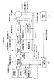
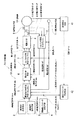
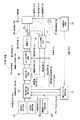
図3は本発明による制御装置の第2の実施形態を示すブロック図である。なお、この図において、図1の各部と対応する部分には同じ符号が付してある。
<< Second Embodiment >>
FIG. 3 is a block diagram showing a second embodiment of the control device according to the present invention. In this figure, parts corresponding to those in FIG. 1 are denoted by the same reference numerals.
この図に示す制御装置1bが図1に示す制御装置1aと異なる点は、電動機10の振動または騒音“dFrf”を検出する脈動検出手段21と、脈動検出手段21の出力に基づいて電流指令補正手段5で使用されるパラメータ“n”、“ad”、“pd”、“aq”、“pq”のうち、電動機10の振動、騒音に関係するパラメータ、例えばパラメータ“ad”、“pd”などを学習する補正パラメータ学習手段22とを設けたことである。
The control device 1b shown in this figure is different from the control device 1a shown in FIG. 1 in that a pulsation detection means 21 that detects vibration or noise “dF rf ” of the electric motor 10 and a current command based on the output of the pulsation detection means 21. Of the parameters “n”, “a d ”, “p d ”, “a q ”, “p q ” used in the
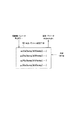
次に、図4を参照して、脈動検出手段21、電流指令補正手段5、補正パラメータ学習手段22の詳細な動作を説明する。
Next, detailed operations of the
電流指令補正手段5では、補正パラメータ学習手段22の学習結果に基づき、振動または騒音“dFrf”を低減させるように、電動機10の半径方向の力“Fr”の脈動が小さくなるように、d軸電流指令手段2から出力されるd軸電流指令値“Idco”と、q軸電流指令手段3から出力されるq軸電流指令値“Iqco”とが補正される。
In the current command correction means 5, based on the learning result of the correction parameter learning means 22, the pulsation of the radial force “F r ” of the electric motor 10 is reduced so as to reduce the vibration or noise “dF rf ”. d-axis current command value outputted from the d-axis
この場合、電流指令補正信号“dIc”に対応する半径方向の力“Fr”は、下式のような回転角の定数項、(6×n)f正弦成分、(6×n)f余弦成分、(6×(n+1))f正弦成分、(6×(n+1))f余弦成分の和となる。
ここで、“W”は電動機10内の磁気エネルギー、“r”は半径方向である。 Here, “W” is the magnetic energy in the electric motor 10, and “r” is the radial direction.
上式より、調整振幅“ad”、“aq”と、調整位相“pd”、“pq”の初期値が下式を満たすように求められる。
一方、脈動検出手段21では、振動または騒音“dFrf”が検出され、補正パラメータ学習手段22に出力される。
On the other hand, the
補正パラメータ学習手段22では、脈動検出手段21で検出した振動または騒音“dFrf”を用いて、電動機10の振動または騒音に影響を与える調整振幅、調整位相、例えば調整振幅“ad”、と、調整位相“pd”が学習される。
The correction
この際、例えば下式のように、電流指令補正信号“dIdc”が“0”(電流指令補正信号が最大または最小)となる時点の振動または騒音“dFrf”を用いて、調整位相“pd”を学習し、電流指令値補正手段5で使用されるパラメータ“pd”が最適化される。
ここで、“gpd”は学習ゲイン、“old”は学習前の値、“new”は学習後の値である。 Here, “g pd ” is a learning gain, “old” is a value before learning, and “new” is a value after learning.
また、例えば下式のように電流指令補正信号“dIc”の時間微分が“0”となる時点の振動または騒音“dFrf”を用いて調整振幅“ad”を学習し、電流指令値補正手段5で使用されるパラメータ“ad”が最適化される。
ここで、“gad”は学習ゲインである。 Here, “ gad ” is a learning gain.
このように、第2の実施形態では、[数27]を満たすように、電動機パラメータ設定手段4のパラメータ“n”、“ad”、“pd”、“aq”、“pq”などを設定させ、これらパラメータ“n”、“ad”、“pd”、“aq”、“pq”、回転角検出手段11の検出結果などに基づき、d軸電流指令手段2から出力されるd軸電流指令値“Idco”と、q軸電流指令手段3から出力されるq軸電流指令値“Iqco”とを補正する。そして、電動機10のトルク“T”に含まれる(6×n)f正弦成分、(6×n)f余弦成分、(6×(n+1))f正弦成分、(6×(n+1))f余弦成分を零にさせなるとともに、電流指令値補正手段5で生成される電流指令補正信号“dIdc”の時間微分が零になるときの脈動“dFrf”に基づき、補正パラメータ学習手段22によって、パラメータ“pd”、“ad”を調整するようにしている。このため、6×nと6×(n+1)のリプル成分などを抑制でき、電動機10のトルクリプルを大幅に低減させつつ、電動機10の振動、騒音を大幅に低減させることができる。
Thus, in the second embodiment, the parameters “n”, “a d ”, “p d ”, “a q ”, “p q ” of the motor
なお、第2の実施形態では、補正パラメータ学習手段22の学習動作によって、電流指令値補正手段5で使用されるパラメータ“pd”、“ad”を直接、調整するようにしているが、補正パラメータ学習手段22によって、表示装置などの報知装置に、学習後のパラメータ“pd”、“ad”を表示して、オペレータなどに確認させた後、オペレータに電動機パラメータ設定手段4を操作させて、この電動機パラメータ設定手段4に設定されているパラメータ“pd”、“ad”を変更するようにしても良い。
In the second embodiment, the parameters “p d ” and “a d ” used in the current command
《第3の実施形態》
図5は本発明による制御装置の第3の実施形態を示すブロック図である。なお、この図において、図1の各部と対応する部分には同じ符号が付してある。
<< Third Embodiment >>
FIG. 5 is a block diagram showing a third embodiment of the control device according to the present invention. In this figure, parts corresponding to those in FIG. 1 are denoted by the same reference numerals.
この図に示す制御装置1cが図1に示す制御装置1aと異なる点は、電流制御手段6から出力されるd軸電圧指令“Vd”、q軸電圧指令“Vq”、電流検出手段9で検出される電流値(3相2相変換手段12から出力される電流信号“Idf”、“Iqf”)、回転角検出手段11で検出される回転角“θe”に対応する回転角“ω”に基づき、電動機10の脈動“dTfdt”を推定する脈動推定手段31と、推定した脈動“dTfdt”から電流指令補正手段5で使用されるパラメータ“n”、“ad”、“pd”、“aq”、“pq”のうち、電動機10の振動、騒音に関係するパラメータ、例えばパラメータ“aq”、“pq”などを学習する補正パラメータ学習手段32とを設けたことである。 The control device 1c shown in this figure is different from the control device 1a shown in FIG. 1 in that a d-axis voltage command “V d ”, a q-axis voltage command “V q ” output from the current control means 6, and a current detection means 9 (The current signals “I df ” and “I qf ” output from the three-phase / two-phase conversion unit 12) detected by the rotation angle detection unit 11, and the rotation corresponding to the rotation angle “θ e ” detected by the rotation angle detection unit 11. Based on the angle “ω”, the pulsation estimating means 31 for estimating the pulsation “dT f dt” of the electric motor 10 and the parameters “n” and “a” used in the current command correcting means 5 from the estimated pulsation “dT f dt”. Correction parameter learning means for learning parameters related to vibration and noise of the motor 10, such as parameters “a q ” and “p q ”, among d ”,“ p d ”,“ a q ”, and“ p q ”. 32.
次に、図6を参照して、脈動推定手段31、電流指令補正手段5、補正パラメータ学習手段32の詳細な動作を説明する。
Next, detailed operations of the
脈動推定手段31では、電流制御手段6から出力されるd軸電圧指令“Vdc”、d軸電圧指令“Vqc”に対応する電圧指令“Vd”、“Vq”と、3相2相変換手段12から出力される電流信号“Idf”、“Iqf”と、回転角検出手段11から出力される回転角“ω”とから電動機10の脈動“dTfdt”が推定される。
In the pulsation estimating means 31, the d-axis voltage command “V dc ” output from the current control means 6, the voltage commands “V d ” and “V q ” corresponding to the d-axis voltage command “V qc ”, and three-
この際、脈動推定手段31では、例えば下式を用いて電圧指令値“Vd”、“Vq”と、電流信号“Idf”、“Iqf”と、回転角“ω”とから、誘導電圧“Edf”、“Eqf”が推定される。
ここで、“Ra”は電機子10の巻線抵抗、“Ld”、“Lq”は各々d軸、q軸のインダクタンスであり、電動機パラメータ設定手段4で設定する。 Here, “Ra” is the winding resistance of the armature 10, “L d ” and “L q ” are the d-axis and q-axis inductances, respectively, which are set by the motor parameter setting means 4.
そして、推定した誘起電圧“Edf”、“Eqf”と、電流信号“Idf”、“Iqf”と、回転角“ω”とから、次式に示す演算を行って、トルクの時間微分形で表される脈動“dTfdt”が推定され、補正パラメータ学習手段32に出力される。
補正パラメータ学習手段32では、脈動推定手段31で推定された脈動“dTfdt”を用いて、調整振幅“aq”と、振幅位相“pq”が学習される。 In the correction parameter learning means 32, the adjustment amplitude “a q ” and the amplitude phase “p q ” are learned using the pulsation “dT f dt” estimated by the pulsation estimation means 31.
この際、例えば電流指令値補正手段5で生成される電流指令補正信号“dIqc”の時間微分が“0”(電流指令補正信号が最大または最小)となる時点の脈動“dTfdt”を用いて、振幅位相“pq”を学習して、電流指令値補正手段5で使用されるパラメータ“pq”が最適化される。
ここで、“gpq”は学習ゲインである。 Here, “g pq ” is a learning gain.
また、例えば電流指令補正信号“dIqc”の時間微分が“0”となる時点の脈動“dTfdt”を用いて、調整振幅“aq”が学習され、電流指令値補正手段5で使用されるパラメータ“aq”が最適化される。
ここで、“gaq”は学習ゲインである。 Here, “g aq ” is a learning gain.
このように、第3の実施形態では、電流制御手段6から出力されるd軸電圧指令“Vd”、q軸電圧指令“Vq”、電流検出手段9で検出される電流値(3相2相変換手段12から出力される電流信号“Idf”、“Iqf”)、回転角検出手段11で検出される回転角“θe”に対応する回転角“ω”に基づき、[数29][数30]、[数31]を使用して、電動機10の脈動“dTfdt”を推定するとともに、電流指令値補正手段5で生成される電流指令補正信号“dIqc”の時間微分が零になるときの脈動“dFrf”に基づき、補正パラメータ学習手段22によって、パラメータ“pq”、“aq”を調整するようにしている。このため、6×nと6×(n+1)のリプル成分などを抑制でき、電動機10のトルクリプルを大幅に低減させつつ、電動機10に脈動検出手段などを取り付けることなく、装置内部の改修作業だけで、電動機10の振動、騒音を大幅に低減させることができる(請求項3の効果)。
Thus, in the third embodiment, the d-axis voltage command “V d ”, the q-axis voltage command “V q ” output from the
《第4の実施形態》
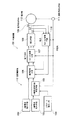
図7は本発明による制御装置の第4の実施形態を示すブロック図である。なお、この図において、図1の各部と対応する部分には同じ符号が付してある。
<< Fourth Embodiment >>
FIG. 7 is a block diagram showing a fourth embodiment of the control device according to the present invention. In this figure, parts corresponding to those in FIG. 1 are denoted by the same reference numerals.
この図に示す制御装置1dが図1に示す制御装置1aと異なる点は、電動機10の温度“temp”を検出する温度検出手段41と、検出された温度“temp”で電流指令補正手段5の各補正パラメータ、例えば補正パラメータ“Ke”、“K5”、…などを変更する補正パラメータ変更手段42とを設けたことである。 The control device 1d shown in this figure is different from the control device 1a shown in FIG. 1 in that the temperature detection means 41 for detecting the temperature “temp” of the electric motor 10 and the current command correction means 5 based on the detected temperature “temp”. The correction parameter changing means 42 for changing each correction parameter, for example, the correction parameters “K e ”, “K 5 ”,...
次に、図8を参照して、温度検出手段41、補正パラメータ変更手段42の詳細な動作を説明する。
Next, detailed operations of the
まず、温度検出手段43では、電動機の温度“temp”が検出され、補正パラメータ変更手段16に出力される。 First, the temperature detecting means 43 detects the temperature “temp” of the electric motor and outputs it to the correction parameter changing means 16.
補正パラメータ変更手段16では、検出された温度“temp”により、温度“temp”に対応する電動機パラメータ“Ke”、“K5”、…などが変更され、これら電動機パラメータ“Ke”、“K5”、…などを含むパラメータ“ad”、“pd”、“aq”、“pq”などが変更される。 The correction parameter changing means 16 changes the electric motor parameters “K e ”, “K 5 ”, etc. corresponding to the temperature “temp” according to the detected temperature “temp”, and these electric motor parameters “K e ”, “ The parameters “a d ”, “p d ”, “a q ”, “p q ”, etc., including K 5 ”,.
この際、[数7]等の誘起電圧“Eu”の係数が温度“temp”の関数であるとすると、下式となる。
![]()
![]()
そして、誘起電圧“Eu”の係数が温度“temp”の関数の場合、トルクリプルを打ち消すようなd軸電流指令値“Idc”、q軸電流指令値“Iqc”を求める際に使用されるパラメータ“ad”、“pd”、“aq”、“pq”なども温度“temp”の関数となることから、検出した温度“temp”に応じて、前記[数23]の導出手順と同様な手順で、パラメータ“ad”、“pd”、“aq”、“pq”が変更される。 When the coefficient of the induced voltage “E u ” is a function of the temperature “temp”, the d-axis current command value “I dc ” and the q-axis current command value “I qc ” that cancel the torque ripple are used. Since the parameters “a d ”, “p d ”, “a q ”, “p q ”, etc. are also functions of the temperature “temp”, according to the detected temperature “temp”, The parameters “a d ”, “p d ”, “a q ”, “p q ” are changed in the same procedure as the derivation procedure.
このように、第4の実施形態では、温度検出手段41によって、電動機10の温度“temp”を検出するとともに、補正パラメータ変更手段42によって、温度“temp”の関数になっているパラメータ“ad”、“pd”、“aq”、“pq”などを変更するようにしている。このため、電動機10の温度“temp”に応じて、パラメータ“ad”、“pd”、“aq”、“pq”などを最適化させて、d軸電流指令値“Idc”、q軸電流指令値“Iqc”を補正させ、電動機10の温度が変化した場合にも、トルクリプルを最少に抑制することができる。
Thus, in the fourth embodiment, the
《第5の実施形態》
図9は本発明による制御装置の第5の実施形態を示すブロック図である。なお、この図において、図1の各部と対応する部分には同じ符号が付してある。
<< Fifth Embodiment >>
FIG. 9 is a block diagram showing a fifth embodiment of the control device according to the present invention. In this figure, parts corresponding to those in FIG. 1 are denoted by the same reference numerals.
この図に示す制御装置1eが図1に示す制御装置1aと異なる点は、運転条件を設定する運転条件設定手段51と、運転条件により電流指令補正手段5のパラメータ“ad”、“pd”、“aq”、“pq”などを切り替える補正パラメータ切替手段52とを設けたことである。
The control device 1e shown in this figure is different from the control device 1a shown in FIG. 1 in that operating condition setting means 51 for setting operating conditions, and parameters “a d ” and “p d ” of the current
次に、図10を参照して、運転条件設定手段51、補正パラメータ切替手段52の詳細な動作を説明する。
Next, detailed operations of the operating
運転条件に応じて、運転条件設定手段51を操作し、補正パラメータ切替手段52に設けられた各接点のいずれか1つをオン状態にされ、電流指令補正手段5で使用されるパラメータ“ad”、“pd”、“aq”、“pq”などが切り替えられる。
Depending on the operating conditions, operating the operation
パラメータ“ad”、“pd”、“aq”、“pq”などの切替は、例えば、運転条件設定手段51で、トルクリプル低減運転、振動・騒音低減運転のうち、いずれかがを指定され、指定内容に対応するようにパラメータ“ad”、“pd”、“aq”、“pq”などが切り替えられる。 The switching of the parameters “ ad ”, “p d ”, “a q ”, “p q ” and the like is performed by, for example, operating condition setting means 51, either torque ripple reducing operation or vibration / noise reducing operation. The parameters “a d ”, “p d ”, “a q ”, “p q ”, etc. are switched so as to correspond to the specified contents.
例えば、トルクリプルを低減させる場合は、下式を満たすようにする。
また、振動・騒音を低減させる場合は、下式を満たすようにする。
これにより、例えば深夜には、主に電動機10の振動・騒音の低減を目標に電動機10を運転し、また日中には、主に電動機10の回転ムラ低減を目標に電動機10を運転することができる。 Thus, for example, at midnight, the motor 10 is operated mainly for the purpose of reducing vibration and noise of the motor 10, and during the day, the motor 10 is operated mainly for the purpose of reducing uneven rotation of the motor 10. Can do.
また、運転条件として、例えば低速ではトルクリプル低減を主とし、高速では振動・騒音低減などを主にするように、回転速度などによって適宜切り替えてもよい。 Further, as operating conditions, for example, torque ripple reduction is mainly performed at a low speed, and vibration and noise reduction are mainly performed at a high speed.
このように、第5の実施形態では、運転条件に応じて、運転条件設定手段51を操作し、補正パラメータ切替手段52に設けられた各接点のいずれか1つをオン状態にし、電流指令補正手段5で使用されるパラメータ“ad”、“pd”、“aq”、“pq”などを切り替えるようにしている。このため、運転内容に応じて、各運転条件に対応する最適なパラメータ“ad”、“pd”、“aq”、“pq”などを選択でき、トルクリプルの低減、振動、騒音の低減などを実現できる。
As described above, in the fifth embodiment, the operating
《第6の実施形態》
図11は本発明による制御装置の第6の実施形態を示すブロック図である。
<< Sixth Embodiment >>
FIG. 11 is a block diagram showing a sixth embodiment of the control device according to the present invention.
この図に示す制御装置1fは、d軸電流指令“Idco”を出力するd軸電流指令手段61と、q軸電流指令“Iqco”を出力するq軸電流指令手段62と、リニア電動機69のパラメータ“n”、“ad”、“pd”、“aq”、“pq”などが設定される電動機パラメータ設定手段63とを備えている。
Control device 1f shown in this figure, the d-axis
また、この制御装置1fは、リニア電動機69の電気角“θe”を検出する電気角検出手段70と、リニア電動機69の3相電流を検出して、出力電流信号“Iuf”、“Ivf”、“Iwf”を出力する電流検出手段68と、電流検出手段68から出力される出力電流信号“Iuf”、“Ivf”、“Iwf”に基づき、d軸電流信号“Idf”、q軸電流信号“Iqf”を演算する3相/2相変換手段71とを備えている。 Further, the control device 1f detects an electrical angle “θ e ” of the linear motor 69 and a three-phase current of the linear motor 69 to detect output current signals “I uf ”, “I vf "," "a current detecting means 68 for outputting a current output current signal outputted from the detection means 68" I wf I uf ", " I vf ","" on the basis of, d-axis current signal" I wf I df "and q-axis current signal" Iqf "are provided.
さらに、この制御装置1fは、電動機パラメータ設定手段63から出力されるリニア電動機69のパラメータ“n”、“ad”、“pd”、“aq”、“pq”、電気角検出手段70の検出結果に基づき、d軸電流指令手段61から出力されるd軸電流指令“Idco”、q軸電流指令手段62から出力されるq軸電流指令“Iqco”を補正して、d軸電流指令値“Idc”、q軸電流指令値“Iqc”を出力する電流指令補正手段64と、電流指令補正手段64から出力されるd軸電流指令値“Idc”、q軸電流指令値“Iqc”、3相/2相変換手段71から出力されるd軸電流信号“Idf”、q軸電流信号“Iqf”に基づき、d軸電圧指令“Vdc”、q軸電圧指令“Vqc”を演算する電流制御手段65と、電流制御手段65から出力されるd軸電圧指令“Vdc”、q軸電圧指令“Vqc”に基づき、3相の電圧指令値“Vu”、“Vv”、“Vw”を演算する2相/3相変換手段66と、2相/3相変換手段66から出力される電圧指令値“Vu”、“Vv”、“Vw”に基づき、駆動電圧を出力してリニア電動機69を駆動する駆動手段67とを備えている。 Further, the control device 1f includes parameters “n”, “a d ”, “p d ”, “a q ”, “p q ”, electrical angle detection means of the linear motor 69 output from the motor parameter setting means 63. Based on the detection result of 70, the d-axis current command “I dco ” output from the d-axis current command means 61 and the q-axis current command “I qco ” output from the q-axis current command means 62 are corrected, and d Current command correction means 64 for outputting an axis current command value “I dc ” and q-axis current command value “I qc ”, d-axis current command value “I dc ” output from the current command correction means 64, q-axis current Based on the command value “I qc ”, the d-axis current signal “I df ” and the q-axis current signal “I qf ” output from the 3-phase / 2-phase conversion means 71, the d-axis voltage command “V dc ”, the q-axis Current control means 65 for calculating the voltage command “V qc ” And three-phase voltage command values “V u ”, “V v ”, “V w ” based on the d-axis voltage command “V dc ” and the q-axis voltage command “V qc ” output from the current control means 65. The driving voltage is output based on the two-phase / three-phase conversion means 66 for calculating the voltage and the voltage command values “V u ”, “V v ”, “V w ” output from the two-phase / three-phase conversion means 66. Drive means 67 for driving the linear motor 69.
さらに、この制御装置1fは、リニア電動機69の振動または騒音を検出して脈動“dFrf”を出力する脈動検出手段72と、脈動検出手段72の出力に基づいて、電流指令補正手段64で使用されるパラメータ“n”、“ad”、“pd”、“aq”、“pq”のうち、リニア電動機69の振動、騒音に関係するパラメータ、例えばパラメータ“ad”、“pd”などを学習する補正パラメータ学習手段73とを備えている。 Further, the control device 1 f is used in the pulsation detecting means 72 for detecting the vibration or noise of the linear motor 69 and outputting the pulsation “dF rf ”, and the current command correcting means 64 based on the output of the pulsation detecting means 72. Of the parameters “n”, “ ad ”, “p d ”, “a q ”, “p q ”, parameters related to vibration and noise of the linear motor 69, for example, parameters “a d ”, “p” correction parameter learning means 73 for learning d ″ and the like.
次に、図11、図12を参照して制御装置1fの動作を説明する。 Next, the operation of the control device 1f will be described with reference to FIGS.
リニア電動機69の電気角“θe”は、リニアスケール等の電気角検出手段70を介して検出され、速度を制御する速度制御系(d軸電流指令手段61、q軸電流指令手段62、電流指令値補正手段64によって構成される部分)74に入力される。 The electrical angle “θ e ” of the linear motor 69 is detected via an electrical angle detection means 70 such as a linear scale, and a speed control system (d-axis current command means 61, q-axis current command means 62, current) that controls the speed. (Part constituted by the command value correcting means 64) 74.
速度制御系64では、電気角検出手段70から出力される電気角“θe”に基づき、リニア電動機69の実速度が算出され、その速度と速度指令値との速度偏差信号から、d軸電流指令値“Idc”、q軸電流指令値“Iqc”が生成されて電流制御手段65に出力される。 In the speed control system 64, the actual speed of the linear motor 69 is calculated based on the electrical angle “θ e ” output from the electrical angle detection means 70, and the d-axis current is calculated from the speed deviation signal between the speed and the speed command value. A command value “I dc ” and a q-axis current command value “I qc ” are generated and output to the current control means 65.
また、電流指令補正手段8は、次に述べる手順で、推力に垂直な方向(Z方向)の振動を低減させるとともに、振動方向の力の脈動“dFrf”が小さくなるように補正される。 Further, the current command correction means 8 is corrected so as to reduce the vibration in the direction perpendicular to the thrust (Z direction) and reduce the pulsation “dF rf ” of the force in the vibration direction in the following procedure.
まず、電流指令補正手段64によって、d軸電流指令手段61から出力されるd軸電流指令“Idco”、q軸電流指令手段62から出力されるq軸電流指令“Iqco”を補正して、電流指令補正信号“dIdc”、d軸電流指令値“Idc”、q軸電流指令値“Iqc”などが生成されるとき、リニア電動機69が発生する振動方向の力“Fz”は、下式のような電気角“θe”の定数項、(6×n)f正弦成分、(6×n)f余弦成分、(6×(n+1))f正弦成分、(6×(n+1))f余弦成分の和となる。
ここで、“z”は振動方向である。 Here, “z” is the vibration direction.
上式より、調整振幅“ad”、“aq”と、調整位相“pd”、“pq”の初期値が下式を満たすように求められる。
また、脈動検出手段72では、振動または騒音“dFrf”が検出され、補正パラメータ学習手段22に出力される。 The pulsation detecting means 72 detects vibration or noise “dF rf ” and outputs it to the correction parameter learning means 22.
補正パラメータ学習手段22では、脈動検出手段21で検出した振動または騒音“dFrf”を用いて、調整振幅“ad”、と、調整位相“pd”が学習される。 The correction parameter learning means 22 learns the adjustment amplitude “a d ” and the adjustment phase “p d ” using the vibration or noise “dF rf ” detected by the pulsation detection means 21.
この際、例えば下式のように、電流指令補正信号“dIdc”が“0”(電流指令補正信号が最大または最小)となる時点の振動または騒音“dFrf”を用いて、調整位相“pd”が学習され、電流指令値補正手段5で使用されるパラメータ“pd”が最適化される。
ここで、“gpd”は学習ゲイン、“old”は学習前の値、“new”は学習後の値である。 Here, “g pd ” is a learning gain, “old” is a value before learning, and “new” is a value after learning.
また、例えば下式のように電流指令補正信号“dIdc”の時間微分が“0”となる時点の振動または騒音“dFrf”を用いて調整振幅“ad”が学習され、電流指令値補正手段5で使用されるパラメータ“ad”が最適化される。
ここで、“gad”は学習ゲインである。 Here, “ gad ” is a learning gain.
このように、第6の実施形態では、[数38]を満たすように、電動機パラメータ設定手段63のパラメータ“n”、“ad”、“pd”、“aq”、“pq”などを設定し、これらパラメータ“n”、“ad”、“pd”、“aq”、“pq”、電気角検出手段70の検出結果などに基づき、d軸電流指令手段61から出力されるd軸電流指令“Idco”と、q軸電流指令手段62から出力されるq軸電流指令“Iqco”とを補正し、リニア電動機69が発生する振動方向の力“Fz”に含まれる(6×n)f正弦成分、(6×n)f余弦成分、(6×(n+1))f正弦成分、(6×(n+1))f余弦成分を零にするとともに、電流指令値補正手段64で生成される電流指令補正信号“dIdc”の時間微分が零になるときの脈動“dFrf”に基づき、補正パラメータ学習手段73によって、パラメータ“pd”、“ad”を調整するようにしている。このため、6×nと6×(n+1)のリプル成分などを抑制でき、リニア電動機69のトルクリプルを大幅に低減させつつ、リニア電動機69の振動、騒音を大幅に低減させることができる。
Thus, in the sixth embodiment, the parameters “n”, “a d ”, “p d ”, “a q ”, “p q ” of the motor parameter setting means 63 are satisfied so as to satisfy [Equation 38]. From the d-axis current command means 61 based on these parameters “n”, “a d ”, “p d ”, “a q ”, “p q ”, the detection result of the electrical angle detection means 70, etc. The d-axis current command “I dco ” output and the q-axis current command “I qco ” output from the q-axis current command means 62 are corrected, and the force “F z ” in the vibration direction generated by the linear motor 69 is corrected. (6 × n) f sine component, (6 × n) f cosine component, (6 × (n + 1)) f sine component, and (6 × (n + 1)) f cosine component included in the time derivative is zero current command correction signal generated by the value correction means 64 "dI dc" Based on the pulse "dF rf" of Rutoki, by the correction
なお、第6の実施形態では、リニア電動機69を制御するようにしているが、このようなリニア電動機69以外の電動機、例えばディスクモータ等、推力に直交する加振力が発生する電動機などを制御するようにしても良い。 In the sixth embodiment, the linear motor 69 is controlled. However, a motor other than such a linear motor 69, for example, a motor that generates an excitation force orthogonal to the thrust, such as a disk motor, is controlled. You may make it do.
1a〜1f:制御装置、2:d軸電流指令手段、3:q軸電流指令手段、4:電動機パラメータ設定手段、5:電流指令補正手段、6:電流制御手段(3相駆動手段)、7:2相/3相変換手段(3相駆動手段)、8:駆動手段(3相駆動手段)、9:電流検出手段、10:電動機、11:回転角検出手段、12:3相/2相変換手段、13:速度制御系、21:脈動検出手段、22:補正パラメータ学習手段、31:脈動推定手段、32:補正パラメータ学習手段、41:温度検出手段、42:補正パラメータ変更手段、51:運転条件設定手段、52:補正パラメータ切替手段、61:d軸電流指令手段、62:q軸電流指令手段、63:電動機パラメータ設定手段、64:電流指令補正手段、65:電流制御手段(3相駆動手段)、66:2相/3相変換手段(3相駆動手段)、67:駆動手段(3相駆動手段)、68:電流検出手段、69:リニア電動機、70:電気角検出手段、71:3相/2相変換手段、72:脈動検出手段、73:補正パラメータ学習手段、74:速度制御系 1a to 1f: control device, 2: d-axis current command means, 3: q-axis current command means, 4: motor parameter setting means, 5: current command correction means, 6: current control means (three-phase drive means), 7 : 2 phase / 3 phase conversion means (3 phase drive means), 8: Drive means (3 phase drive means), 9: Current detection means, 10: Electric motor, 11: Rotation angle detection means, 12: 3 phase / 2 phase Conversion means, 13: Speed control system, 21: Pulsation detection means, 22: Correction parameter learning means, 31: Pulsation estimation means, 32: Correction parameter learning means, 41: Temperature detection means, 42: Correction parameter changing means, 51: Operating condition setting means, 52: correction parameter switching means, 61: d-axis current command means, 62: q-axis current command means, 63: motor parameter setting means, 64: current command correction means, 65: current control means (three-phase Drive means), 6 : 2-phase / 3-phase conversion means (3-phase drive means), 67: Drive means (3-phase drive means), 68: Current detection means, 69: Linear motor, 70: Electrical angle detection means, 71: 3-phase / 2 Phase conversion means, 72: Pulsation detection means, 73: Correction parameter learning means, 74: Speed control system
Claims (6)
前記電動機の回転を検出して電気角を出力する回転角検出手段と、
前記電動機の特性に対応したパラメータが設定される電動機パラメータ設定手段と、
前記回転角検出手段から出力される電気角および前記電動機パラメータ設定手段から出力されるパラメータに応じて、前記d軸/q軸電流指令手段から出力されるd軸電流指令およびq軸電流指令に対し、前記電動機が発生するトルクの高調波リプル成分を抑制するのに必要な補正を行い、補正済みのd軸電流指令値およびq軸電流指令値を生成する電流指令値補正手段と、
この電流指令値補正手段から出力される補正済みのd軸電流指令値およびq軸電流指令値並びに前記電流検出手段から出力される電動機の出力電流検出信号に基づき、3相の駆動電圧を生成して前記電動機に供給する3相駆動手段と、
を具備することを特徴とする制御装置。 D-axis / q-axis current command means for generating a d-axis current command and a q-axis current command in accordance with a deviation between the measured rotational speed of the motor and a preset rotational speed set in advance;
Rotation angle detecting means for detecting rotation of the electric motor and outputting an electric angle;
Motor parameter setting means for setting parameters corresponding to the characteristics of the motor;
Depending on the electrical angle output from the rotation angle detection means and the parameter output from the motor parameter setting means, the d-axis current command and the q-axis current command output from the d-axis / q-axis current command means Current command value correcting means for performing correction necessary to suppress harmonic ripple components of torque generated by the electric motor, and generating corrected d-axis current command value and q-axis current command value;
Based on the corrected d-axis current command value and q-axis current command value output from the current command value correction means and the output current detection signal of the motor output from the current detection means, a three-phase drive voltage is generated. Three-phase driving means for supplying to the electric motor;
A control device comprising:
前記電動機の振動または騒音を検出する脈動検出手段と、
この脈動検出手段の検出結果並びに前記電流指令値補正手段で生成される補正済みのd軸電流指令値およびq軸電流指令値に基づき、前記電動機の振動または騒音を最少にするのに必要なパラメータを求め、前記電流指令値補正手段で使用されるパラメータを補正する処理または報知装置から報知する処理のいずれかを行う補正パラメータ学習手段と、
を具備することを特徴とする制御装置。 The control device according to claim 1,
Pulsation detecting means for detecting vibration or noise of the electric motor;
Parameters necessary for minimizing vibration or noise of the motor based on the detection result of the pulsation detecting means and the corrected d-axis current command value and q-axis current command value generated by the current command value correcting means. Correction parameter learning means for performing either of the process of correcting the parameter used in the current command value correction means or the process of notifying from the notification device;
A control device comprising:
前記3相駆動手段で生成される電圧指令値、前記電流検出手段から出力される電動機の出力電流検出信号および前記回転角検出手段から出力される回転角に基づき、前記電動機の脈動を推定する脈動推定手段と、
前記電流指令値補正手段で生成される補正済みのd軸電流指令値、q軸電流指令値および前記脈動検出手段の推定結果に基づき、前記電動機の振動または騒音を最小にするのに必要なパラメータを求め、前記電流指令値補正手段で使用されるパラメータを補正する処理、または報知装置から報知する処理のいずれかを行う補正パラメータ学習手段と、
を具備することを特徴とする制御装置。 The control device according to claim 1,
Pulsation for estimating the pulsation of the electric motor based on the voltage command value generated by the three-phase driving unit, the output current detection signal of the electric motor output from the current detection unit, and the rotation angle output from the rotation angle detection unit An estimation means;
Parameters necessary for minimizing vibration or noise of the motor based on the corrected d-axis current command value, the q-axis current command value generated by the current command value correcting means, and the estimation result of the pulsation detecting means Correction parameter learning means for performing either of the process for correcting the parameter used in the current command value correction means, or the process for notifying from the notification device,
A control device comprising:
前記電動機の温度を検出する温度検出手段と、
この温度検出手段で検出された電動機の温度、前記電流指令値補正手段で生成される補正済みのd軸電流指令値およびq軸電流指令値に基づき、前記電動機の振動または騒音を最小にするのに必要なパラメータを求め、前記電流指令値補正手段で使用されるパラメータを変更する処理または報知装置から報知する処理のいずれかを行う補正パラメータ変更手段と、
を具備することを特徴とする制御装置。 The control device according to claim 1,
Temperature detecting means for detecting the temperature of the electric motor;
Based on the temperature of the motor detected by the temperature detection means, the corrected d-axis current command value and the q-axis current command value generated by the current command value correction means, the vibration or noise of the motor is minimized. Correction parameter changing means for obtaining a parameter required for the current command value, and performing either a process for changing a parameter used in the current command value correcting means or a process for notifying from a notification device;
A control device comprising:
運転条件が設定される運転条件設定手段と、
この運転条件設定手段に設定されている運転条件に応じて前記電流指令補正手段のパラメータを切り替える補正パラメータ切替手段と、
を具備することを特徴とする制御装置。 The control device according to claim 1,
An operating condition setting means for setting the operating condition;
Correction parameter switching means for switching parameters of the current command correction means according to the operating conditions set in the operating condition setting means;
A control device comprising:
前記リニア電動機の速度を検出して電気角を出力する電気角検出手段と、
前記リニア電動機の特性に対応したパラメータが設定される電動機パラメータ設定手段と、
前記電気角検出手段から出力される電気角および前記電動機パラメータ設定手段から出力されるパラメータに応じて、前記d軸/q軸電流指令手段から出力されるd軸電流指令およびq軸電流指令に対し、前記リニア電動機が発生するZ方向の高調波リプル成分を抑制するのに必要な補正を行い、補正済みのd軸電流指令値およびq軸電流指令値を生成する電流指令値補正手段と、
この電流指令値補正手段から出力される補正済みのd軸電流指令値、q軸電流指令値および電流検出手段から出力されるリニア電動機の出力電流検出信号に基づき、3相の駆動電圧を生成して前記リニア電動機に供給する3相駆動手段と、
前記リニア電動機の振動または騒音を検出する脈動検出手段と、
この脈動検出手段の出力、前記電流指令値補正手段で生成される補正済みのd軸電流指令値およびq軸電流指令値に基づき、前記リニア電動機の振動または騒音を最小にするのに必要なパラメータを求め、前記電流指令値補正手段で使用されるパラメータを補正する処理または報知装置から報知する処理のいずれかを行う補正パラメータ学習手段と、
を具備することを特徴とする制御装置。 D-axis / q-axis current command means for generating a d-axis current command and a q-axis current command according to a deviation between the actually measured speed of the linear motor and a preset set speed;
Electrical angle detection means for detecting the speed of the linear motor and outputting an electrical angle;
Motor parameter setting means for setting parameters corresponding to the characteristics of the linear motor;
Depending on the electrical angle output from the electrical angle detection means and the parameter output from the motor parameter setting means, the d-axis current command and the q-axis current command output from the d-axis / q-axis current command means Current command value correcting means for performing correction necessary to suppress harmonic ripple components in the Z direction generated by the linear motor, and generating corrected d-axis current command value and q-axis current command value;
Based on the corrected d-axis current command value output from the current command value correction means, the q-axis current command value, and the output current detection signal of the linear motor output from the current detection means, a three-phase drive voltage is generated. Three-phase driving means for supplying to the linear motor;
Pulsation detecting means for detecting vibration or noise of the linear motor;
Parameters necessary for minimizing vibration or noise of the linear motor based on the output of the pulsation detecting unit, the corrected d-axis current command value and the q-axis current command value generated by the current command value correcting unit Correction parameter learning means for performing either of the process of correcting the parameter used in the current command value correction means or the process of notifying from the notification device;
A control device comprising:
Priority Applications (4)
| Application Number | Priority Date | Filing Date | Title |
|---|---|---|---|
| JP2005104447A JP2006288076A (en) | 2005-03-31 | 2005-03-31 | Control unit |
| US11/817,421 US7671552B2 (en) | 2005-03-31 | 2006-03-28 | Control device |
| PCT/JP2006/306210 WO2006106642A1 (en) | 2005-03-31 | 2006-03-28 | Control device |
| CN200680006714A CN100576718C (en) | 2005-03-31 | 2006-03-28 | The control device of motor |
Applications Claiming Priority (1)
| Application Number | Priority Date | Filing Date | Title |
|---|---|---|---|
| JP2005104447A JP2006288076A (en) | 2005-03-31 | 2005-03-31 | Control unit |
Publications (1)
| Publication Number | Publication Date |
|---|---|
| JP2006288076A true JP2006288076A (en) | 2006-10-19 |
Family
ID=37073208
Family Applications (1)
| Application Number | Title | Priority Date | Filing Date |
|---|---|---|---|
| JP2005104447A Pending JP2006288076A (en) | 2005-03-31 | 2005-03-31 | Control unit |
Country Status (4)
| Country | Link |
|---|---|
| US (1) | US7671552B2 (en) |
| JP (1) | JP2006288076A (en) |
| CN (1) | CN100576718C (en) |
| WO (1) | WO2006106642A1 (en) |
Cited By (11)
| Publication number | Priority date | Publication date | Assignee | Title |
|---|---|---|---|---|
| JP2010057217A (en) * | 2008-08-26 | 2010-03-11 | Meidensha Corp | Torque pulsation suppression device of electric motor, and suppression method |
| JP2010178586A (en) * | 2009-02-02 | 2010-08-12 | Asmo Co Ltd | Motor control device and method |
| JP2011061910A (en) * | 2009-09-07 | 2011-03-24 | Toshiba Elevator Co Ltd | Motor driver and method for removing torque ripples |
| EP2375564A1 (en) | 2010-04-08 | 2011-10-12 | OMRON Automotive Electronics Co., Ltd. | Motor drive device |
| WO2012056844A1 (en) * | 2010-10-26 | 2012-05-03 | 村田機械株式会社 | Linear motor control apparatus |
| JP2013198221A (en) * | 2012-03-16 | 2013-09-30 | Toshiba Corp | Electric motor controller |
| JP2016019372A (en) * | 2014-07-08 | 2016-02-01 | 多摩川精機株式会社 | Current sensing structure of three-phase motor, current sensing method, motor control system and motor control method |
| JP6063016B1 (en) * | 2015-09-29 | 2017-01-18 | ファナック株式会社 | Machine learning method and machine learning device for learning operation command for electric motor, and machine tool provided with the machine learning device |
| JP2017135855A (en) * | 2016-01-27 | 2017-08-03 | サンデン・オートモーティブコンポーネント株式会社 | Motor controller |
| US9998043B2 (en) | 2013-04-10 | 2018-06-12 | Mitsubishi Electric Corporation | Rotary machine controller |
| KR20190016419A (en) * | 2017-08-08 | 2019-02-18 | 가부시키가이샤 야스카와덴키 | Elevator control system, motor control apparatus, and elevator control method |
Families Citing this family (27)
| Publication number | Priority date | Publication date | Assignee | Title |
|---|---|---|---|---|
| JP4697017B2 (en) * | 2006-04-14 | 2011-06-08 | 株式会社デンソー | Control device for multiphase rotating electrical machine |
| DE102008062515A1 (en) * | 2007-12-21 | 2009-06-25 | Denso Corporation, Kariya | Device for controlling a torque of a rotary electric machine |
| JP2009261121A (en) * | 2008-04-16 | 2009-11-05 | Asmo Co Ltd | Motor control apparatus |
| US7768220B2 (en) * | 2008-04-24 | 2010-08-03 | Gm Global Technology Operations, Inc. | Harmonic torque ripple reduction at low motor speeds |
| CN101383546B (en) * | 2008-10-15 | 2010-06-23 | 南京航空航天大学 | Torque angle sine value linear controlled pole hidden type permanent magnet synchronous motor controlling method |
| CN101599737B (en) * | 2009-04-22 | 2011-05-18 | 南京航空航天大学 | Permanent magnet flux-switching generator voltage control method by space vector modulation |
| US8054084B2 (en) * | 2009-05-19 | 2011-11-08 | GM Global Technology Operations LLC | Methods and systems for diagnosing stator windings in an electric motor |
| US8354817B2 (en) * | 2009-06-18 | 2013-01-15 | GM Global Technology Operations LLC | Methods and systems for diagnosing stator windings in an electric motor |
| US8253365B2 (en) * | 2009-10-20 | 2012-08-28 | GM Global Technology Operations LLC | Methods and systems for performing fault diagnostics for rotors of electric motors |
| US8233295B2 (en) * | 2010-03-09 | 2012-07-31 | GM Global Technology Operations LLC | Methods, systems and apparatus for approximation of peak summed fundamental and third harmonic voltages in a multi-phase machine |
| US8497698B2 (en) | 2010-08-11 | 2013-07-30 | GM Global Technology Operations LLC | Methods and systems for diagnosing faults for rotors of electric motors |
| JP5711493B2 (en) * | 2010-09-30 | 2015-04-30 | Thk株式会社 | Linear motor control device and linear motor device |
| JP5382069B2 (en) * | 2011-07-04 | 2014-01-08 | 株式会社安川電機 | Inverter device and electric motor drive system |
| GB201111602D0 (en) * | 2011-07-06 | 2011-08-24 | Nidec Sr Drives Ltd | Control of electrical machines |
| US8786244B2 (en) * | 2011-09-22 | 2014-07-22 | GM Global Technology Operations LLC | System and method for current estimation for operation of electric motors |
| CN103368474B (en) * | 2012-03-27 | 2015-12-02 | 比亚迪股份有限公司 | A kind of motor speed control method |
| CN102751935B (en) * | 2012-07-03 | 2014-11-05 | 中国东方电气集团有限公司 | Method for suppressing asynchronous motor interference under rotating speed open loop of electric car |
| US9018881B2 (en) | 2013-01-10 | 2015-04-28 | GM Global Technology Operations LLC | Stator winding diagnostic systems and methods |
| JP6279211B2 (en) * | 2013-01-31 | 2018-02-14 | Ntn株式会社 | Control device for synchronous motor for electric vehicle |
| CN103166547B (en) * | 2013-03-14 | 2015-04-15 | 西安交通大学 | Switch magnetism flux permanent magnet motor vibration excitation source for adjusting harmonic torque |
| FI124592B (en) | 2013-06-20 | 2014-10-31 | Kone Corp | Method and apparatus for controlling the electric motor of an elevator |
| EP3014757B1 (en) * | 2013-06-28 | 2023-04-05 | Nissan Motor Co., Ltd. | Variable magnetization machine controller and method |
| KR101539539B1 (en) * | 2014-05-12 | 2015-07-24 | 엘에스산전 주식회사 | Apparatus for controlling induction machine |
| EP3024137B1 (en) * | 2014-11-18 | 2017-05-17 | Siemens Aktiengesellschaft | Linear actuator with vibration damping in all control units |
| US9966890B2 (en) * | 2016-02-16 | 2018-05-08 | Steering Solutions Ip Holding Corporation | Detection of offset errors in phase current measurement for motor control system |
| JP7163223B2 (en) * | 2019-03-14 | 2022-10-31 | 株式会社東芝 | Driving device, driving system, and driving method for electric motor |
| CN111865160A (en) * | 2019-04-23 | 2020-10-30 | 广州汽车集团股份有限公司 | Method and device for controlling vibration or noise of motor |
Citations (3)
| Publication number | Priority date | Publication date | Assignee | Title |
|---|---|---|---|---|
| JPH037081A (en) * | 1989-06-02 | 1991-01-14 | Mitsubishi Electric Corp | Controller of rotating machine |
| JP2003259680A (en) * | 2002-02-28 | 2003-09-12 | Mitsubishi Electric Corp | Synchronous motor driving apparatus, inverter apparatus and control method of synchronous motor |
| JP2005057935A (en) * | 2003-08-06 | 2005-03-03 | Denso Corp | Motor control device |
Family Cites Families (11)
| Publication number | Priority date | Publication date | Assignee | Title |
|---|---|---|---|---|
| JPS60261382A (en) * | 1984-06-07 | 1985-12-24 | Mitsubishi Electric Corp | Controller of elevator |
| JPH07129251A (en) | 1993-10-29 | 1995-05-19 | Yaskawa Electric Corp | Vibration isolation control method |
| JP3236983B2 (en) * | 1995-04-17 | 2001-12-10 | 株式会社日立製作所 | Power converter |
| JP3399156B2 (en) * | 1995-05-29 | 2003-04-21 | 株式会社デンソー | Control device for brushless DC motor |
| JP3336870B2 (en) * | 1996-09-04 | 2002-10-21 | 三菱電機株式会社 | Method and apparatus for controlling rotating magnet type polyphase synchronous motor |
| JPH11299277A (en) | 1998-04-14 | 1999-10-29 | Yaskawa Electric Corp | Motor torque correction device and motor driving device provided with the same |
| JP3396440B2 (en) * | 1999-02-08 | 2003-04-14 | 株式会社日立製作所 | Control device for synchronous motor |
| JP2001031339A (en) * | 1999-07-27 | 2001-02-06 | Toshiba Corp | Elevator controller |
| EP1492223A4 (en) * | 2002-03-22 | 2005-12-14 | Matsushita Electric Ind Co Ltd | Synchronous reluctance motor control device |
| JP2004023804A (en) * | 2002-06-12 | 2004-01-22 | Nissan Motor Co Ltd | Motor controller |
| JP2004215399A (en) * | 2002-12-27 | 2004-07-29 | Yaskawa Electric Corp | Motor control method and controlling equipment |
-
2005
- 2005-03-31 JP JP2005104447A patent/JP2006288076A/en active Pending
-
2006
- 2006-03-28 US US11/817,421 patent/US7671552B2/en not_active Expired - Fee Related
- 2006-03-28 WO PCT/JP2006/306210 patent/WO2006106642A1/en active Application Filing
- 2006-03-28 CN CN200680006714A patent/CN100576718C/en not_active Expired - Fee Related
Patent Citations (3)
| Publication number | Priority date | Publication date | Assignee | Title |
|---|---|---|---|---|
| JPH037081A (en) * | 1989-06-02 | 1991-01-14 | Mitsubishi Electric Corp | Controller of rotating machine |
| JP2003259680A (en) * | 2002-02-28 | 2003-09-12 | Mitsubishi Electric Corp | Synchronous motor driving apparatus, inverter apparatus and control method of synchronous motor |
| JP2005057935A (en) * | 2003-08-06 | 2005-03-03 | Denso Corp | Motor control device |
Cited By (19)
| Publication number | Priority date | Publication date | Assignee | Title |
|---|---|---|---|---|
| JP2010057217A (en) * | 2008-08-26 | 2010-03-11 | Meidensha Corp | Torque pulsation suppression device of electric motor, and suppression method |
| JP2010178586A (en) * | 2009-02-02 | 2010-08-12 | Asmo Co Ltd | Motor control device and method |
| JP2011061910A (en) * | 2009-09-07 | 2011-03-24 | Toshiba Elevator Co Ltd | Motor driver and method for removing torque ripples |
| US8446115B2 (en) | 2010-04-08 | 2013-05-21 | Omron Automotive Electronics Co., Ltd. | Motor drive device |
| EP2375564A1 (en) | 2010-04-08 | 2011-10-12 | OMRON Automotive Electronics Co., Ltd. | Motor drive device |
| JP2011223724A (en) * | 2010-04-08 | 2011-11-04 | Omron Automotive Electronics Co Ltd | Motor drive device |
| JP5578240B2 (en) * | 2010-10-26 | 2014-08-27 | 村田機械株式会社 | Linear motor control device |
| WO2012056844A1 (en) * | 2010-10-26 | 2012-05-03 | 村田機械株式会社 | Linear motor control apparatus |
| JP2013198221A (en) * | 2012-03-16 | 2013-09-30 | Toshiba Corp | Electric motor controller |
| US9998043B2 (en) | 2013-04-10 | 2018-06-12 | Mitsubishi Electric Corporation | Rotary machine controller |
| JP2016019372A (en) * | 2014-07-08 | 2016-02-01 | 多摩川精機株式会社 | Current sensing structure of three-phase motor, current sensing method, motor control system and motor control method |
| JP6063016B1 (en) * | 2015-09-29 | 2017-01-18 | ファナック株式会社 | Machine learning method and machine learning device for learning operation command for electric motor, and machine tool provided with the machine learning device |
| JP2017064837A (en) * | 2015-09-29 | 2017-04-06 | ファナック株式会社 | Machine learning method and machine learning device for learning operation command for electric motor, and machine tool equipped with machine learning device |
| US10082771B2 (en) | 2015-09-29 | 2018-09-25 | Fanuc Corporation | Machine learning method and machine learning apparatus learning operating command to electric motor and machine tool including machine learning apparatus |
| JP2017135855A (en) * | 2016-01-27 | 2017-08-03 | サンデン・オートモーティブコンポーネント株式会社 | Motor controller |
| WO2017130842A1 (en) * | 2016-01-27 | 2017-08-03 | サンデン・オートモーティブコンポーネント株式会社 | Motor control device |
| US10778129B2 (en) | 2016-01-27 | 2020-09-15 | Sanden Automotive Components Corporation | Motor control device |
| KR20190016419A (en) * | 2017-08-08 | 2019-02-18 | 가부시키가이샤 야스카와덴키 | Elevator control system, motor control apparatus, and elevator control method |
| KR102112389B1 (en) * | 2017-08-08 | 2020-05-18 | 가부시키가이샤 야스카와덴키 | Elevator control system, motor control apparatus, and elevator control method |
Also Published As
| Publication number | Publication date |
|---|---|
| US7671552B2 (en) | 2010-03-02 |
| US20090021194A1 (en) | 2009-01-22 |
| CN100576718C (en) | 2009-12-30 |
| CN101133547A (en) | 2008-02-27 |
| WO2006106642A1 (en) | 2006-10-12 |
Similar Documents
| Publication | Publication Date | Title |
|---|---|---|
| JP2006288076A (en) | Control unit | |
| JP5824918B2 (en) | Inverter control device and inverter control method | |
| JP5332400B2 (en) | Torque pulsation suppression device and suppression method for electric motor | |
| JP5800108B2 (en) | Periodic disturbance automatic suppression device | |
| JP2008189225A (en) | Control device for electric power steering apparatus | |
| JP5930052B2 (en) | Inverter control device and inverter control method | |
| JP5795980B2 (en) | Electric motor control device | |
| JP6179389B2 (en) | Electric motor control device | |
| JP2010105763A (en) | Power converter and elevator using the same | |
| JP2019083672A (en) | Inverter, and drive control method for motor | |
| JP2008043058A (en) | Synchronous motor control unit and control method thereof | |
| JP2006204054A (en) | Motor control unit and motor drive system having the same | |
| JP2006158198A (en) | Motor drive control device and electric power steering apparatus | |
| JP2010035351A (en) | Device for estimating rotor position of synchronous electric motor | |
| JP2010035352A (en) | Device for estimating rotor position of synchronous electric motor | |
| JP5050387B2 (en) | Motor control device | |
| JP2008099444A (en) | Synchronous motor controller and control method therefor | |
| JP5262267B2 (en) | Three-phase AC motor drive device | |
| JP2011147272A (en) | Motor control device | |
| JP2017055637A (en) | Motor control apparatus for controlling motor on the basis of counter-electromotive voltage generated in winding of motor | |
| JP4619712B2 (en) | AC motor control device | |
| JP2009278733A (en) | Motor controller | |
| JP2007082380A (en) | Synchronous motor control device | |
| JP3576509B2 (en) | Motor control device | |
| JP2008099472A (en) | Ac motor controller |
Legal Events
| Date | Code | Title | Description |
|---|---|---|---|
| A621 | Written request for application examination |
Free format text: JAPANESE INTERMEDIATE CODE: A621 Effective date: 20080324 |
|
| A131 | Notification of reasons for refusal |
Free format text: JAPANESE INTERMEDIATE CODE: A131 Effective date: 20100720 |
|
| A521 | Written amendment |
Free format text: JAPANESE INTERMEDIATE CODE: A523 Effective date: 20100921 |
|
| A02 | Decision of refusal |
Free format text: JAPANESE INTERMEDIATE CODE: A02 Effective date: 20101207 |