JP2006068070A - Game machine - Google Patents
Game machine Download PDFInfo
- Publication number
- JP2006068070A JP2006068070A JP2004251703A JP2004251703A JP2006068070A JP 2006068070 A JP2006068070 A JP 2006068070A JP 2004251703 A JP2004251703 A JP 2004251703A JP 2004251703 A JP2004251703 A JP 2004251703A JP 2006068070 A JP2006068070 A JP 2006068070A
- Authority
- JP
- Japan
- Prior art keywords
- audio
- image
- sound
- medal
- gaming machine
- Prior art date
- Legal status (The legal status is an assumption and is not a legal conclusion. Google has not performed a legal analysis and makes no representation as to the accuracy of the status listed.)
- Pending
Links
Images


Abstract
Description
本発明は、遊技機に関し、特に、音声を出力する音声出力手段を備えた遊技機に関する。 The present invention relates to a gaming machine, and more particularly to a gaming machine provided with a voice output means for outputting a voice.
従来、複数種類の図柄が描かれた複数の変動表示部(以下、リールという)を備え、各リールの回転及び停止が行われた後、入賞ライン上に表示された図柄の組合せにより、入賞の成立不成立を決定する遊技機が知られている。このような遊技機は、リールの他に、例えば、スピーカといった音声出力手段を備えており、このスピーカから出力される音声によって、遊技状態を演出し、報知している。したがって、遊技機から出力される音声の音質は、良好であることが望ましく、ここで、音響特性を改善するため、例えば、スピーカの背面側と遊技機の裏面側外方との間を連通させる連通孔を形成した遊技機が提案されている(例えば、特許文献1)。
この一方で、スピーカは、遊技機内の限られたスペースに設置されるものであり、設置されるスピーカの選択は、遊技の種類、遊技機全体のデザイン、および演出の構成により異なる。また、スピーカから出力される音声の音響特性は、スピーカそのものだけでなく、遊技機筐体の構造の影響も受けるため、たとえ同一仕様のスピーカを採用しても、遊技機の機種が異なれば、音響特性は異なる。このように、遊技機の音響特性は、遊技機の構造や他の要因の影響を受けるため、音響特性を調整して良好な音質を維持しつつも遊技機のデザイン自由度を確保することは容易ではなかった。 On the other hand, the speaker is installed in a limited space in the gaming machine, and the selection of the speaker to be installed differs depending on the type of game, the overall design of the gaming machine, and the configuration of the effects. In addition, since the acoustic characteristics of the sound output from the speaker are affected not only by the speaker itself but also by the structure of the gaming machine housing, even if the same specification speaker is adopted, if the gaming machine model is different, The acoustic characteristics are different. In this way, the acoustic characteristics of the gaming machine are affected by the structure of the gaming machine and other factors, so it is not possible to adjust the acoustic characteristics and maintain a good sound quality while ensuring the freedom of design of the gaming machine. It was not easy.
また、遊技機の開発段階では、ある機種を設計・試作すると、その音響特性を試作機の視聴や測定により評価し、音響特性が所望の水準まで改善されるまで、試作機の構造の設計・試作を繰り返すのが通常であった。この繰り返しに開発労力を費やしていた。 Also, at the development stage of gaming machines, when a model is designed and prototyped, its acoustic characteristics are evaluated by viewing and measuring the prototype, and the prototype design and design is continued until the acoustic characteristics are improved to the desired level. It was normal to repeat the prototype. This repeated development effort.
本発明は、遊技機の構造のデザインの自由度を高めつつも、良好な音響特性を有する遊技機を提供することを目的とする。 An object of the present invention is to provide a gaming machine having good acoustic characteristics while increasing the degree of freedom in designing the structure of the gaming machine.
上記の課題を解決するため、本発明は以下のものを提供する。 In order to solve the above problems, the present invention provides the following.
(1) 音声信号を受信して音声を出力する音声出力手段と、前記音声出力手段に音声信号を供給する音声信号供給手段と、を備え、前記音声信号供給手段は、さらに、前記音声出力手段から出力される音声の音響特性に基づいて設定された補正情報を記憶する補正情報記憶手段と、前記補正情報記憶手段から読み出した補正情報に応じて、前記音声出力手段に供給する音声信号を補正する音響補正処理手段と、を備える遊技機。 (1) An audio output unit that receives an audio signal and outputs an audio; and an audio signal supply unit that supplies the audio signal to the audio output unit. The audio signal supply unit further includes the audio output unit. Correction information storage means for storing correction information set based on the acoustic characteristics of the sound output from the audio signal, and correcting the audio signal supplied to the audio output means in accordance with the correction information read from the correction information storage means And a sound correction processing means.
(1)によれば、遊技機の音声出力手段に音声信号を供給する音声信号供給手段を、音響特性に基づいて設定された補正情報を記憶する補正情報記憶手段と、補正情報に応じて音声信号を補正する音響補正処理手段とで構成した。このことにより、遊技機の音声信号供給手段は、出力手段から出力される音声の音響特性に基づいて、音声出力手段に供給する音声信号を、予め補正する。したがって、遊技機に固有の音響特性の影響を低減し、内蔵する音源情報をより忠実に出力することができる。 According to (1), the sound signal supply means for supplying the sound signal to the sound output means of the gaming machine, the correction information storage means for storing the correction information set based on the acoustic characteristics, and the sound according to the correction information It is comprised with the acoustic correction process means which correct | amends a signal. Thereby, the sound signal supply means of the gaming machine corrects in advance the sound signal supplied to the sound output means based on the acoustic characteristics of the sound output from the output means. Therefore, it is possible to reduce the influence of the acoustic characteristics unique to the gaming machine and output the built-in sound source information more faithfully.
また、補正手段は、補正情報記憶手段から読み出した補正情報に応じて補正を行うので、補正情報記憶手段に適切な補正情報を記憶することにより、容易に音声信号の補正を行うことができる。遊技機の開発段階では、作成した遊技機の機種に固有の音響特性を測定し、この特性を補正するための補正情報を補正情報記憶手段に記憶させておくだけで、遊技機に固有の音響特性の影響を抑えることができる。したがって、固有の音響特性の影響を低減するために遊技機構造の設計変更を繰り返すといった開発の労力を低減することができる。 Further, since the correction unit performs correction according to the correction information read from the correction information storage unit, it is possible to easily correct the audio signal by storing appropriate correction information in the correction information storage unit. At the development stage of the gaming machine, the acoustic characteristics specific to the machine type created are measured, and the correction information for correcting this characteristic is stored in the correction information storage means. The influence of characteristics can be suppressed. Therefore, it is possible to reduce development effort such as repeated design changes of the gaming machine structure in order to reduce the influence of the inherent acoustic characteristics.
(2) 音声信号を受信して音声を出力する複数の音声出力手段と、前記複数の音声出力手段のそれぞれに音声信号を供給する音声信号供給手段と、を備え、前記音声信号供給手段は、さらに、前記音声出力手段のそれぞれから出力される音声の音響特性に基づいて設定された補正情報を記憶する補正情報記憶手段と、補正情報記憶手段から読み出した補正情報に応じて、前記複数の音声出力手段に供給する音声信号のそれぞれを補正する音響補正処理手段と、を備える遊技機。 (2) a plurality of sound output means for receiving a sound signal and outputting sound; and a sound signal supply means for supplying a sound signal to each of the plurality of sound output means; Further, the correction information storage means for storing correction information set based on the acoustic characteristics of the sound output from each of the sound output means, and the plurality of sounds according to the correction information read from the correction information storage means A game machine comprising: sound correction processing means for correcting each of the audio signals supplied to the output means.
(2)によれば、音声出力手段を複数とし、音響補正処理手段は、複数の音声出力手段に供給する音声信号のそれぞれを補正するよう構成した。これにより、ステレオ音声やサラウンド音声を出力する複数の音声出力手段を備えた遊技機で、それぞれの音声出力手段に供給する音声信号を補正するため、音声出力手段ごとの音響特性の差異を補正により低減することができる。したがって内蔵する音源情報をより忠実に出力することができる。 According to (2), a plurality of sound output means are provided, and the sound correction processing means is configured to correct each of the sound signals supplied to the plurality of sound output means. Thereby, in a gaming machine having a plurality of sound output means for outputting stereo sound and surround sound, the sound signal supplied to each sound output means is corrected, so that the difference in acoustic characteristics for each sound output means is corrected. Can be reduced. Therefore, the built-in sound source information can be output more faithfully.
(3) (2)記載の遊技機であって、前記音響特性補正手段は、前記複数の音声出力手段のそれぞれに供給する音声信号の遅延の調整を行う信号遅延手段を備えることを特徴とする遊技機。 (3) The gaming machine according to (2), wherein the acoustic characteristic correction unit includes a signal delay unit that adjusts a delay of an audio signal supplied to each of the plurality of audio output units. Gaming machine.
(3)によれば、音声出力手段のそれぞれに供給する音声信号の遅延の調整を行う信号遅延手段を備えるよう構成した。これにより、遊技者の位置からみた音声出力手段の設置位置の非対称性による音声到達時間の差といった音響特性をも補正して、音源の情報をより忠実に出力することができる。 According to (3), it is configured to include signal delay means for adjusting the delay of the audio signal supplied to each of the audio output means. As a result, it is possible to correct sound characteristics such as a difference in voice arrival time due to asymmetry of the installation position of the voice output means viewed from the player's position, and to output sound source information more faithfully.
(4) (1)から(3)いずれか記載の遊技機において、複数の識別情報を変動可能な変動表示部を有する変動表示手段と、所定の役を当選役として決定する当選役決定手段と、前記当選役決定手段の決定結果に基づいて変動表示手段の変動を停止する停止制御手段と、を備えることを特徴とする遊技機。 (4) In the gaming machine according to any one of (1) to (3), a variation display unit having a variation display unit capable of varying a plurality of identification information, and a winning combination determining unit that determines a predetermined combination as a winning combination And a stop control means for stopping the fluctuation of the fluctuation display means based on the determination result of the winning combination determination means.
(4)によれば、遊技機は、例えば、パチスロ遊技機、パチンコ遊技機、またはスロットマシンといった、変動表示手段を備える遊技機である。このような遊技機では、遊技者が遊技機の正面前方に着席し、遊技を長時間継続する場合が多い。したがって、遊技者は、音声出力手段から出力される音声を長時間聞くことになる。このような遊技機において、補正手段により遊技機固有の音響特性の影響を低減し、内蔵する音源の情報をより忠実に出力することにより、遊技者にとって遊技を長時間楽しむことができる快適な遊技の環境を提供することができる。 According to (4), the gaming machine is a gaming machine provided with variable display means such as a pachislot gaming machine, a pachinko gaming machine, or a slot machine. In such a gaming machine, the player often sits in front of the gaming machine and continues the game for a long time. Therefore, the player listens to the sound output from the sound output means for a long time. In such a gaming machine, the influence of the acoustic characteristics unique to the gaming machine is reduced by the correcting means, and the information of the built-in sound source is output more faithfully, so that the player can enjoy the game for a long time. Environment can be provided.
本発明によれば、遊技機の音声信号供給手段は、出力手段から出力される音声の音響特性に基づいて、予め、音声出力手段に供給する音声信号を補正する。したがって、遊技機に固有の音響特性の影響を低減し、内蔵する音源情報をより忠実に出力することができる。 According to the present invention, the sound signal supply means of the gaming machine corrects the sound signal supplied to the sound output means in advance based on the acoustic characteristics of the sound output from the output means. Therefore, it is possible to reduce the influence of the acoustic characteristics unique to the gaming machine and output the built-in sound source information more faithfully.
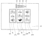
図1は、本発明の一実施例の遊技機1の概観を示す斜視図である。遊技機1は、いわゆるパチスロ機である。この遊技機1は、コイン、メダル、遊技球又はトークンなどの他、遊技者に付与された、もしくは付与される遊技価値の情報を記憶したカード等の遊技媒体を用いて遊技する遊技機であるが、以下ではメダルを用いるものとして説明する。
FIG. 1 is a perspective view showing an overview of a
遊技機1の正面には、液晶表示装置131が設けられている。また、液晶表示装置131の背後には、複数種類の図柄が各々の外周面に描かれた3個のリール3L,3C,3Rが、回転自在に横一列に設けられている。各リール3L,3C,3Rは、一定の速度で回転する(例えば、80回転/分)。
A liquid
液晶表示装置131の下方には、略水平面の台座部4が形成されている。台座部4の右側には、メダルを投入するためのメダル投入口10が設けられている。メダル投入口10の先の遊技機1内部には、メダルセレクタ(図示しない)が設けられ、投入されたメダルは、メダルセレクタ内のメダルセンサ10S(図7)によって検出され、クレジットされるか、ゲームに賭けられる。また、メダルセレクタは、メダルロックアウトソレノイド12(図7)を備え、メダル投入口から投入されるメダルを受け付けるか否かを制御する。
Below the liquid
メダル投入口10の左側には、遊技に関する情報を表示する各種の表示部16,18,19が設けられている。各種の表示部16,18,19は、夫々7セグメントLEDにより構成される。ボーナス遊技情報表示部16は、ボーナス(BB遊技状態やRB遊技状態)中の遊技情報を表示する。払出表示部18は、入賞が成立した際に、入賞役に対応するメダルの払出枚数を表示する。クレジット表示部19は、クレジットされたメダルの枚数を表示する。
On the left side of the
各種の表示部16,18,19の左側には、押下操作により、クレジットされたメダルを賭ける(BETする)ための1−BETスイッチ11及び最大BETスイッチ13が設けられている。1−BETスイッチ11は、1回の押し操作により、クレジットされたメダルのうちの1枚がゲームに賭けられ、最大BETスイッチ13は、1回のゲームに賭けることが可能な最大枚数のメダルが賭けられる。
On the left side of the
遊技機1には、リール3L,3C,3Rの回転が停止した際に、停止した図柄に基づいて、所定の役の入賞が成立したか否かを判定する基準となる入賞ラインが設けられている。例えば、所定の役(例えば、後述のBB)に対応する図柄組合せを構成する図柄(例えば、後述の“コンドル(図柄193)”)がいずれかの入賞ライン8a〜8eに対応する位置に沿って並んで停止表示されることにより、所定の役が入賞することとなる。
In the
入賞ラインとしては、水平方向にトップライン8b、センターライン8c及びボトムライン8d、並びに、斜め方向にクロスアップライン8a及びクロスダウンライン8eが設けられている。前述のメダル投入口10にメダルを投入すること、又は、BETスイッチ11,13を押下操作することにより、これら5本の入賞ラインのうち、それぞれ1本、3本、5本が有効化される(以下、有効化された入賞ラインを「有効ライン」と記載する)。入賞の判定は、この有効ラインに基づいて行われる。ここで、BETスイッチ11,13の操作及びメダル投入口10にメダルを投入する操作(遊技を行うためにメダルを投入する操作)を、以下BET操作という。
As the winning lines, a
また、BETスイッチ11,13の上方には、操作部17が設けられている。操作部17は、液晶表示装置131の液晶表示部2に遊技履歴などの情報を表示するために操作される。
An
台座部4の前面部の左寄りには、遊技者がゲームで獲得したメダルのクレジット/払出しを押しボタン操作で切り換える精算スイッチ14が設けられている。この精算スイッチ14の切り換えにより、正面下部のメダル払出口15からメダルが払出され、払出されたメダルはメダル受け部5に溜められる。
On the left side of the front portion of the
メダル受け部5の上方の左右には、音声信号を受信して音声を出力するスピーカ9L,9Rが設けられている。スピーカ9L,9Rは、遊技の演出に関する効果音などを出力する。
精算スイッチ14の右側には、遊技者の操作により3つのリール3L,3C,3Rを回転させ、リール3L,3C,3Rに外周面上に描かれた複数の図柄の変動表示を開始するためのスタートレバー6が所定の角度範囲で回動自在に取り付けられている。
On the right side of the
台座部4の前面部中央で、スタートレバー6の右側には、3個のリール3L,3C,3Rの回転をそれぞれ停止させるための3個の停止ボタン7L,7C,7Rが設けられている。なお、実施例では、1回のゲームは、基本的にスタートレバー6が操作されることにより開始し、全てのリール3L,3C,3Rが停止したときに終了する。
Three
ここで、実施例では、全てのリールが回転しているときに行われるリールの停止操作(停止ボタンの操作)を第1停止操作、第1停止操作の次に行われる停止操作を第2停止操作、第2停止操作の次に行われる停止操作を第3停止操作という。 In this embodiment, the reel stop operation (stop button operation) performed when all the reels are rotating is the first stop operation, and the stop operation performed after the first stop operation is the second stop. The stop operation performed after the operation and the second stop operation is referred to as a third stop operation.
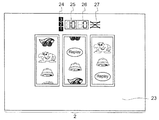
次に、図2を参照して、液晶表示装置131の液晶表示部2について説明する。
Next, the liquid
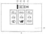
液晶表示部2は、図柄表示領域21L,21C,21R、窓枠表示領域22L,22C,22R、演出表示領域23、投入メダル表示領域24、クレジット表示領域25、払出メダル表示領域26、及び有効ライン表示領域27により構成される。液晶表示部2は、例えば、20インチ程度の大きさで構成される。この液晶表示部2の表示内容は、後述の副制御回路72により制御される液晶表示装置131の動作により変化するようになっている。例えば、リール3L,3C,3Rの回転又は停止、入賞の成否、遊技状態、前述の各種スイッチ(BETスイッチ、メダルセンサ、精算スイッチ、停止ボタン、スタートレバーなど)の検出などに基づいて、表示内容が変化するように制御が行われる。
The liquid
図柄表示領域21L,21C,21Rは、各リール3L,3C,3Rに対応して設けられ、基本的に、リール3L,3C,3Rの外周面上に配置された図柄の一部を視認可能とさせるための表示窓としての機能を有する。また、領域内に表示された図柄上で種々の演出表示などを行う。図柄表示領域21L,21C,21Rは、少なくとも、対応するリール3L,3C,3Rが回転中のとき、及び、対応する停止ボタン7L,7C,7Rが押下操作可能なとき、遊技者がリール3L,3C,3R上の図柄を視認できるように、透過状態となる。
The
窓枠表示領域22L,22C,22Rは、各図柄表示領域21L,21C,21Rを囲むように設けられ、基本的に、図柄を表示する表示窓の窓枠を表示する。
The window
投入メダル表示領域24、クレジット表示領域25、払出メダル表示領域26、及び有効ライン表示領域27は、図柄表示領域21L,21C,21Rの上方に設けられている。
The inserted
投入メダル表示領域24は、遊技機1に投入(BET)されたメダル枚数を表示する。投入メダル表示領域24には、BET数(“1”〜“3”)に対応するメダル画像を表示させる。BET数がない場合、これらのBET数(“1”〜“3”)に対応するメダル画像を白色表示させておく。そして、BET数が1枚の場合、“1”を示すメダル画像の表示色を変化させる(例えば、赤色など)。また、BET数が2枚の場合、“2”を示すメダル画像の表示色を変化させる。また、BET数が3枚の場合、“3”を示すメダル画像の表示色を変化させる。
The inserted
クレジット表示領域25は、遊技機1にクレジットされているメダル枚数を表示する。クレジット表示領域25には、前述したクレジット表示部19のような7セグメントLED表示器を模した画像を表示させ、ここに7セグメントLED表示器により表示される数字を模したクレジット画像を表示させる。クレジットされているメダル枚数がない場合、“00”を示すクレジット画像を表示させる。また、クレジットされているメダル枚数がある場合、クレジットされているメダル枚数に対応するクレジット画像(例えば、“10”など)を表示させる。
The
払出メダル表示領域26は、遊技機1で入賞が成立した場合、入賞役に対応するメダルの払出枚数を表示する。払出メダル表示領域26には、前述した払出表示部18のような7セグメントLED表示器を模した画像を表示させ、ここに7セグメントLED表示器により表示される数字を模した払出枚数画像を表示させる。払出されるメダル枚数がない場合、“00”を示す払出枚数画像を表示させる。また、払出されるメダル枚数がある場合、払出枚数に対応する払出枚数画像(例えば、“08”など)を表示させる。
The payout
有効ライン表示領域27は、遊技機1に投入(BET)されたメダルに応じて有効化された入賞ラインを表示する。有効ライン表示領域27は、投入メダル表示領域24の表示内容の変化に伴って変化する。有効ライン表示領域27には、入賞判定の基準となる5本の入賞ライン8a〜8eに対応する画像を表示させる。BET数がない場合、これら5本の入賞ライン8a〜8eに対応する画像を通常色(例えば白色)に表示させておく。そして、BET数が1枚の場合、センターライン8cに対応する画像の表示色を変化させる(例えば、赤色など)。また、BET数が2枚の場合、トップライン8b及びボトムライン8dに対応する画像の表示色を変化させる。また、BET数が3枚の場合、クロスアップライン8a及びクロスダウンライン8eに対応する画像の表示色を変化させる。
The effective
演出表示領域23は、液晶表示部2の領域のうち、図柄表示領域21L,21C,21R、窓枠表示領域22L,22C,22R、投入メダル表示領域24、クレジット表示領域25、払出メダル表示領域26、及び有効ライン表示領域27以外の表示領域である。この演出表示領域23は、ゲームの興趣を増大するための種々の演出、遊技者がゲームを有利に進めるために必要な情報等の表示を行う。また、これらの演出や情報の表示は、演出表示領域23のみに限らず、図柄表示領域21L,21C,21R、窓枠表示領域22L,22C,22R、投入メダル表示領域24、クレジット表示領域25、払出メダル表示領域26、及び有効ライン表示領域27を含めた液晶表示部2の全体を使用して行われる場合もある。
The
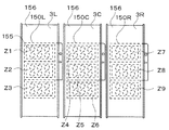
図3及び図4を参照して、リール3L,3C,3Rの内部構造について説明する。図3は、リール3L,3C,3Rの内側にLEDランプ155を配置したリール機構を示す。図4は、左リール3Lと、その内側に設けられたLED収納用回路基板150Lを示す。
The internal structure of the
リール3L,3C,3Rの内部には、リール3L,3C,3Rの回転が停止した場合に各図柄表示領域21L,21C,21Rに現われる縦3列の図柄(合計9個の図柄)の裏側にLED収納用回路基板150L,150C,150Rが設置されている。LED収納用回路基板150L,150C,150Rは、夫々3つ(即ち合計で9つ)のLED収納部Z1〜Z9を有し、ここに複数のLEDランプ155が設けられている。このLEDランプ155は、リール3L,3C,3Rの外周面に沿って装着されたリールシート156(21個の図柄が配置されている)の後面側を白色の光で照明する。より詳細には、前述の図柄表示領域21L,21C,21Rに対応する領域を照明する。このリールシート156は、透光性を有して構成され、LEDランプ155により出射された光は前面側へ透過するようになっている。
Inside the
左リール3Lは、同形の2本の環状フレーム151及び152を所定の間隔(例えばリール幅)だけ離して複数本の連結部材153で連結することで形成された円筒形のフレーム構造と、そのフレーム構造の中心部に設けられたステッピングモータ49Lの駆動力を環状フレーム151,152へ伝達する伝達部材154とにより構成される。また、左リール3Lの外周面に沿ってリールシート156が装着されている。
The
リール3Lの内側に配置されたLED収納用回路基板150Lは、夫々複数のLEDランプ155を収納する3つのLED収納部Z1,Z2,Z3を備えている。LED収納用回路基板150Lは、遊技者が図柄表示領域21Lを通して視認できる図柄(合計3個の図柄)の各々の裏側にLED収納部Z1,Z2,Z3が位置するように設置されている。なお、中央リール3C,右リール3Rについては図示しないが、図示した左リール3Lと同様の構造を有し、各々の内部にLED収納用回路基板150C,150Rが設けられている。
The LED
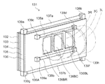
図5を参照して、透過型の液晶表示装置131について説明する。図5は、液晶表示装置131の概略構成を示す斜視図である。
A transmissive liquid
液晶表示装置131は、保護ガラス132、表示板133、液晶パネル134、導光板135、反射フィルム136、白色光源(例えば全ての波長の光を人の目に特定の色彩が目立たない割合で含む)である蛍光ランプ137a,137b,138a,138b、ランプホルダ139a〜139h、液晶パネル駆動用のICを搭載したテーブルキャリアパッケージからなり液晶パネル134の端子部に接続したフレキシブル基板(図示せず)等により構成される。この液晶表示装置131は、リール3L,3C,3Rの表示領域より正面から見て手前側(即ち表示面よりも手前側)に設けられている。また、このリール3L,3C,3Rと液晶表示装置131とは、別体に(例えば所定の間隔をあけて)設けられている。
The liquid
保護ガラス132及び表示板133は、透光性部材で構成されている。保護ガラス132は、液晶パネル134を保護すること等を目的として設けられている。
The
液晶パネル134は、薄膜トランジスタ層が形成されたガラス板などの透明な基板と、これに対向する透明な基板との間隙部に液晶が封入されて形成されている。この液晶パネル134の表示モードは、ノーマリーホワイトに設定されている。ノーマリーホワイトとは、液晶を駆動していない状態(即ち液晶パネル134に電圧を印加していない状態)で白表示となる構成である。即ち、表示面側に光が行く、よって透過した光が外部から視認されることとなる。
The
よって、ノーマリーホワイトに構成された液晶パネル134を採用することにより、液晶を駆動できない事態が生じた場合であっても、図柄表示領域21L,21C,21Rを透してリール3L,3C,3R上に配列された図柄を視認することができ、ゲームを継続することができる。つまり、液晶を駆動できない事態が発生した場合にも、リール3L,3C,3Rの回転及びその停止を中心としたゲームを行うことができる。
Therefore, by adopting the normally white
導光板135は、蛍光ランプ137a,137bからの光を液晶パネル134へ導入する(液晶パネル134を照明する)ために液晶パネル134の裏側に設けられ、例えば2cm程度の厚さを有するアクリル系樹脂などの透光性部材(即ち導光機能を有する部材)で構成されている。
The
反射フィルム136は、例えば白色のポリエステルフィルムやアルミ薄膜に銀蒸着膜を形成したものが用いられ、導光板135に導入された光を正面側に向けて反射させる。これにより液晶パネル134を照明する。この反射フィルム136は、反射領域136A及び非反射領域(即ち透過領域)136BL,136BC,136BRにより構成されている。非反射領域136BL,136BC,136BRは、透明な材料で形成され入射した光を反射することなく透過させる光透過部として形成されている。また、非反射領域136BL,136BC,136BRは、リール3L,3C,3Rの回転が停止した場合に表示させる図柄の各々の前方の位置に設けられている。尚、非反射領域136BL,136BC,136BRの大きさ及び位置は、前述の図柄表示領域21L,21C,21R(図2参照)と一致するように形成されている。また、反射フィルム136では、非反射領域136BL,136BC,136BR以外の領域を反射領域136Aとし、反射領域136Aにより導光板135に導入された光を正面側に向けて反射させる。
The
蛍光ランプ137a,137bは、導光板135の上端部及び下端部に沿って配置され、両端はランプホルダ139a、139b、139c、139dにより支持されている。この蛍光ランプ137a,137bは、導光板135に導入する光を発生する。
The
蛍光ランプ138a,138bは、反射フィルム136の裏側の上方位置及び下方位置に配置されている。この蛍光ランプ138a,138bから発せられた光は、リール3L,3C,3Rの表面で反射され、非反射領域136BL,136BC,136BRへ入射する。そして、入射した光は、非反射領域136BL,136BC,136BRを通過して液晶パネル134を照明する。
The
蛍光ランプ138a,138bから出射された光の一部は、リールシート156により反射される。また、LED収納用回路基板150L,150C,150Rに設けられた前述のLEDランプ155から出射された光の一部は、リールシート156を透過する。これらの光は、非反射領域136BL,136BC,136BR、液晶表示装置131を構成する前述の導光板135及び液晶パネル134を透過するので、遊技者は、リール上に配置された図柄を視認することができる。
A part of the light emitted from the
また、蛍光ランプ137a,137bから出射され、導光板135に向けて導入された光は、液晶パネル134を透過して遊技者の目に入る。つまり、蛍光ランプ137a,137bによって、前述の窓枠表示領域22L,22C,22R及び演出表示領域23に対応する液晶パネル134の領域が照明される。
Further, the light emitted from the
この一方で、図柄表示領域21L,21C,21Rにある液晶を駆動する場合、液晶パネル134の領域のうち、液晶が駆動された領域では、これらの光の一部が反射或いは吸収されたり透過したりするので、遊技者は、図柄表示領域21L,21C,21Rに表示された演出画像等を視認することができる。
On the other hand, when driving the liquid crystal in the
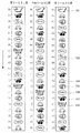
図6を参照して、リール3L,3C,3R上に配列された図柄について説明する。図6には、各リール3L,3C,3Rの外周面上に装着されたリールシートに描かれた複数種類の図柄が21個配列された図柄列が示されている。各図柄には“00”〜“20”のコードナンバーが付され、データテーブルとして後で説明するROM32(図7)に格納(記憶)されている。
The symbols arranged on the
各リール3L,3C,3R上には、“赤7(図柄191)”、“青7(図柄192)”、“コンドル(図柄193)”、“ベル(図柄194)”、“スイカ(図柄195)”、“Replay(図柄196)”及び“チェリー(図柄197)”の図柄で構成される図柄列が表わされている。各リール3L,3C,3Rは、図柄列が図6の矢印方向に移動するように回転駆動される。
On each of the
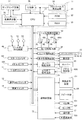
図7は、遊技機1における遊技処理動作を制御する主制御回路71と、主制御回路71に電気的に接続する周辺装置(アクチュエータ)と、主制御回路71から送信される制御指令に基づいて液晶表示装置131、スピーカ9L,9R、LED類101及びランプ類102を制御する副制御回路72とを含む回路構成を示す。
7 is based on a
主制御回路71は、回路基板上に配置されたマイクロコンピュータ30を主たる構成要素とし、これに乱数サンプリングのための回路を加えて構成されている。マイクロコンピュータ30は、予め設定されたプログラム(後述の図14〜図18)に従って制御動作を行うCPU31と、記憶手段であるROM32及びRAM33を含む。
The
CPU31には、基準クロックパルスを発生するクロックパルス発生回路34及び分周器35と、サンプリングされる乱数を発生する乱数発生器36及びサンプリング回路37とが接続されている。尚、乱数サンプリングのための手段として、マイクロコンピュータ30内で、即ちCPU31の動作プログラム上で、乱数サンプリングを実行するように構成してもよい。その場合、乱数発生器36及びサンプリング回路37は省略可能であり、或いは、乱数サンプリング動作のバックアップ用として残しておくことも可能である。
Connected to the
マイクロコンピュータ30のROM32には、スタートレバー6を操作(スタート操作)する毎に行われる乱数サンプリングの判定に用いられる確率抽選テーブル(後述の図13)や停止用当選役決定テーブル、停止ボタンの操作に応じてリールの停止態様を決定するための停止テーブル群などが格納されている。また、副制御回路72へ送信するための各種制御指令(コマンド)等が格納されている。副制御回路72が主制御回路71へコマンド、情報等を入力することはなく、主制御回路71から副制御回路72への一方向で通信が行われる。RAM33には、種々の情報が格納される。例えば、自動投入用メダルカウンタ、クレジットカウンタ、メダルカウンタ、クレジット投入カウンタ、入賞枚数カウンタ、払出枚数カウンタ、メダル投入許可フラグ、精算許可フラグ、ライン減許可フラグ、クレジットからのメダル投入フラグ、入賞フラグ、メダル通過タイマ、クレジット投入用タイマ、メダル通過状態データなどの情報等が格納される。
The
図7の回路において、マイクロコンピュータ30からの制御信号により動作が制御される主要なアクチュエータとしては、ボーナス遊技情報表示部16、払出表示部18、クレジット表示部19などの表示部と、メダルを収納し、ホッパー駆動回路41の命令により所定枚数のメダルを払出すホッパー(払出しのための駆動部を含む)40と、リール3L,3C,3Rを回転駆動するステッピングモータ49L,49C,49Rと、メダルセレクタ内に設けられ、メダル受付不可状態とするために各種部材を駆動するメダルロックアウトソレノイド12とがある。
In the circuit of FIG. 7, the main actuators whose operation is controlled by a control signal from the
更に、ステッピングモータ49L,49C,49Rを駆動制御するモータ駆動回路39、ホッパー40を駆動制御するホッパー駆動回路41、メダルロックアウトソレノイド12を駆動制御するソレノイド駆動回路45、及びボーナス遊技情報表示部16、払出表示部18、クレジット表示部19などの表示部を駆動制御する表示部駆動回路48がCPU31の出力部に接続されている。これらの駆動回路は、それぞれCPU31から出力される駆動指令などの制御信号を受けて、各アクチュエータの動作を制御する。
Furthermore, a
また、マイクロコンピュータ30が制御指令を発生するために必要な入力信号を発生する主な入力信号発生手段としては、スタートスイッチ6S、1−BETスイッチ11、最大BETスイッチ13、精算スイッチ14、メダルセンサ10S、リール停止信号回路46、リール位置検出回路50、払出完了信号回路51がある。
The main input signal generating means for generating an input signal necessary for the
スタートスイッチ6Sは、スタートレバー6の操作を検出する。メダルセンサ10Sは、メダル投入口10に投入されたメダルを検出する。リール停止信号回路46は、各停止ボタン7L,7C,7Rの操作に応じて停止信号を発生する。リール位置検出回路50は、リール回転センサからのパルス信号を受けて各リール3L,3C,3Rの位置を検出するための信号をCPU31へ供給する。払出完了信号回路51は、メダル検出部40Sの計数値(ホッパー40から払出されたメダルの枚数)が指定された枚数データに達した時、メダル払出完了を検知するための信号を発生する。
The
図7の回路において、乱数発生器36は、一定の数値範囲に属する乱数を発生し、サンプリング回路37は、スタートレバー6が操作された後の適宜のタイミングで1個の乱数をサンプリングする。こうしてサンプリングされた乱数を使用することにより、例えばROM32内に格納されている確率抽選テーブル(後述の図13)などに基づいて内部当選役などが決定される。
In the circuit of FIG. 7, the
リール3L,3C,3Rの回転が開始された後、ステッピングモータ49L,49C,49Rの各々に供給される駆動パルスの数が計数され、その計数値はRAM33の所定エリアに書き込まれる。リール3L,3C,3Rからは一回転毎にリセットパルスが得られ、これらのパルスはリール位置検出回路50を介してCPU31に入力される。こうして得られたリセットパルスにより、RAM33で計数されている駆動パルスの計数値が“0”にクリアされる。これにより、RAM33内には、各リール3L,3C,3Rについて一回転の範囲内における回転位置に対応した計数値が格納される。
After the rotation of the
上記のようなリール3L,3C,3Rの回転位置とリール外周面上に描かれた図柄とを対応づけるために、図柄テーブル(図示せず)が、ROM32内に格納されている。この図柄テーブルでは、前述したリセットパルスが発生する回転位置を基準として、各リール3L,3C,3Rの一定の回転ピッチ毎に順次付与されるコードナンバーと、それぞれのコードナンバー毎に対応して設けられた図柄を示す図柄コードとが対応づけられている。
A symbol table (not shown) is stored in the
更に、ROM32内には、入賞図柄組合せテーブル(図示せず)が格納されている。この入賞図柄組合せテーブルでは、入賞となる図柄の組合せと、入賞のメダル配当枚数と、その入賞を表わす入賞判定コードとが対応づけられている。上記の入賞図柄組合せテーブルは、左のリール3L,中央のリール3C,右のリール3Rの停止制御時、及び全リール3L,3C,3Rの停止後の入賞確認を行う場合に参照される。
Furthermore, a winning symbol combination table (not shown) is stored in the
上記乱数サンプリングに基づく抽選処理(確率抽選処理など)により内部当選役を決定した場合には、CPU31は、遊技者が停止ボタン7L,7C,7Rを操作したタイミングでリール停止信号回路46から送られる操作信号、及び決定された停止テーブルに基づいて、リール3L,3C,3Rを停止制御する信号をモータ駆動回路39に送る。
When the internal winning combination is determined by the lottery process (probability lottery process or the like) based on the random number sampling, the
当選した役の入賞を示す停止態様(即ち入賞態様)となれば、CPU31は、払出指令信号をホッパー駆動回路41に供給してホッパー40から所定個数のメダルの払出を行う。その際、メダル検出部40Sは、ホッパー40から払出されるメダルの枚数を計数し、その計数値が指定された数に達した時に、メダル払出完了信号がCPU31に入力される。これにより、CPU31は、ホッパー駆動回路41を介してホッパー40の駆動を停止し、メダル払出処理を終了する。
If it becomes a stop mode (that is, a winning mode) indicating winning of the winning combination, the
図8は、副制御回路72の構成を示すブロック図である。この副制御回路72は、主制御回路71を構成する回路基板とは別の副制御回路基板72a(図9)上に構成されている。
FIG. 8 is a block diagram showing a configuration of the
主制御回路71と副制御回路72との間の通信は、主制御回路71から副制御回路72への一方向で行われ、副制御回路72が主制御回路71へコマンド、情報等を入力することはない。
Communication between the
副制御回路72は、サブマイコン80、カートリッジROM83、ワークRAM84、レンダリングプロセッサ86、画像RAM89、音声信号供給部91を備える。
The
サブマイコン80は、サブCPU81、シリアルポート82、バスIF85a,85b、入出力IF87、および割込コントローラを備えている。サブCPU81、シリアルポート82、バスIF85a,85b、入出力IF87、割込コントローラ、カートリッジROM83、ワークRAM84は共通のバスに接続されているため、サブCPU81は、これらの装置に対し、直接にデータの書き込みおよび読み出しを行うことができる。サブマイコン80に備えられたサブCPU81は、主制御回路71から送信されたコマンドに基づき、カートリッジROM83に格納された制御プログラムに従って各種の処理を行う。尚、副制御回路72は、クロックパルス発生回路、分周器、乱数発生器及びサンプリング回路を備えていないが、サブマイコン80の動作プログラム上で乱数サンプリングを実行するように構成されている。サブマイコン80に備えられたバスIF85aは、専用のバスを介して、サブマイコン80からのデータを、音声信号供給部91が備えるオーディオDSP95に供給する。バスIF85bは、専用のバスを介して、サブマイコン80からのデータを、レンダリングプロセッサ86に供給する。
The
カートリッジROM83は、例えば、ROM、フラッシュメモリといった不揮発性のメモリからなり、サブマイコン80で実行する制御プログラム(後述の図19〜図27)、オーディオDSP95で実行する音声制御プログラム、オーディオDSP95が音声信号を合成するための音源情報、オーディオDSP95が音声信号を補正するための補正情報、および、レンダリングプロセッサ86が画像信号を合成するための画像情報を格納する。このように、カートリッジROM83は、レンダリングプロセッサ86が画像信号を供給するために必要な画像情報、および、オーディオDSP95が音声信号を供給するために必要な音源情報を記憶する兼用記憶装置となっているため、記憶装置がそれぞれ別個のものとなっている場合に比べ、記憶装置の記憶領域を有効活用できる。また、記憶装置が1箇所にまとめられることにより製造の費用を低減することができる。また、遊技機の製造段階において演出内容や遊技の種類を変更する場合、1個のカートリッジROM83の記憶内容を書き換えるか、またはカートリッジROM83そのものを入れ替えることで、液晶表示装置131、およびスピーカ9L,9Rの出力内容を変更することができ、変更の作業をより簡潔にすることができる。
The
カートリッジROM83に記憶された画像情報は、サブマイコン80のリセット割込み処理により読み出されて、レンダリングプロセッサ86に送信され、カートリッジROM83に記憶された音声情報は、サブマイコン80に読み出されて、オーディオDSP95に送信される。このように、サブマイコン80は、情報転送手段として機能する。
The image information stored in the
図9は、副制御回路基板72aを示す斜視図である。カートリッジROM83は、ROMカートリッジ90に内蔵されている。このROMカートリッジ90は、副制御回路72が実装される副制御回路基板72aに、コネクタを介して着脱可能に設置されている。このため、遊技機1の開発において、演出内容や遊技の種類を変更する場合、演出内容が記憶されたカートリッジROM83を付け替えることにより、演出内容の変更を容易にすることができる。また、カートリッジROM83を付け替えることにより、副制御回路基板72aを新機種に対応させることができるため、副制御回路基板72aの再利用が図れる。
FIG. 9 is a perspective view showing the sub
ワークRAM84は、サブマイコン80が前述した制御プログラムを実行する場合の、作業用の一時記憶手段として構成される。ワークRAM84には、種々の情報が格納される。例えば、後述の、主制御回路71から受信した各種コマンド、クレジットカウンタ、メダルカウンタ、払出枚数カウンタ、遊技状態、入賞役などの情報等が格納される。シリアルポート82は、主制御回路71から送信されるコマンド等を受信する。
The
サブマイコン80の入出力IF87には、操作部17が接続されている。この操作部17を遊技場の従業員等が操作することにより各種の設定等が行われるようになっている。
The
レンダリングプロセッサ86は、サブマイコン80により決定された画像情報(後述のメダル画像、クレジット画像、払出枚数画像、有効ライン画像、固定画像、変化画像など)に応じた画像(後述の図30、図31)を生成し、画像信号として、液晶表示装置131に供給する。レンダリングプロセッサ86は、さらに、後述する3次元グラフィック画像を合成するのに必要な、ジオメトリ演算、およびレンダリング処理のためのプロセッサを備え、サブマイコン80により決定された情報(オブジェクト番号、空間位置)に応じた3次元画像を生成し、画像信号として液晶表示装置131に供給する。レンダリングプロセッサ86には、スケーラ回路88と、画像RAM89とが接続されている。
The
スケーラ回路88は、レンダリングプロセッサ86から供給される画像信号を、液晶表示装置131の解像度に適合する拡大された画像信号に変換する。このことにより、レンダリングプロセッサ86が供給する画像信号は、液晶表示装置131に適する大きさの画像として表示される。
The
画像RAM89は、例えば、DDR−SDRAMにより構成され、レンダリングプロセッサ86が、2次元画像を生成するための画像データ、ドットデータ等を格納する他、3次元画像を構成するオブジェクトを合成するために必要な画像情報を格納する。例えば、3次元画像が仮想的に配置される3次元空間を移動するキャラクタの、外形構造を示すモデリング情報、表面の質感を示すテクスチャ情報を格納する。なお、この画像情報は、カートリッジROM83に格納されており、サブマイコン80のリセット直後に、初期化処理としてサブマイコン80がカートリッジROM83から画像情報を読み出し、バスIF85bおよびレンダリングプロセッサ86を介して画像RAM89に書き込むことにより格納される。画像RAM89は、この他、レンダリングプロセッサ86で画像を生成する場合の一時記憶手段として構成される。
The
音声信号供給部91は、オーディオデジタルシグナルプロセッサ95(オーディオDSP95)、オーディオRAM94、およびDAアンプ96を備え、スピーカ9L,9Rに音声信号を供給する。オーディオRAM94およびDAアンプ96は、オーディオDSP95に接続されている。オーディオDSP95は、オーディオRAM94に格納された音声制御プログラムに基づいて、各種処理手段の処理を実行する。具体的には、サブマイコン80により決定された情報(スタートコマンド、位置コマンド、音量補正コマンド)に応じて、オーディオRAM94に格納された音源情報を読み出し音声情報を合成する。そして、オーディオRAM94から読み出した補正情報に応じて、スピーカ9L,9Rに供給する音声信号を補正し、DAアンプ96に出力する。
The audio
オーディオRAM94は、例えば、SDRAMにより構成され、前述の音声制御プログラム、および、音声情報を生成する基の情報である音源情報を記憶し、また、スピーカ9L,9Rから出力される音声の音響特性に基づいて設定された補正情報を記憶している。これら音声制御プログラム、音源情報、および補正情報は、オーディオDSP95のリセット直後に、サブマイコン80からオーディオDSP95に供給される。オーディオDSP95は、このとき、初期化処理であるブート処理によって、供給された音声制御プログラム、音源情報、および補正情報を、オーディオRAM94に記憶し、その後、記憶された音声制御プログラムを実行する。オーディオDSP95は、ブート処理を実行するためのブート回路を備えている。ブート回路は、オーディオDSP95がリセットされた直後に、サブマイコンから供給されるプログラムおよび各種の情報を受信し、オーディオRAM94に格納する。
The
DAアンプ96は、オーディオ帯域信号用デジタル−アナログ(DA)コンバータおよびオーディオ信号用増幅器から構成され、オーディオDSP95から供給されるデジタル信号形式の音声信号をアナログ形式の音声信号に変換した後、増幅してスピーカ9L,9Rに出力する。出力された音声信号はスピーカ9L,9Rから、音声に変換されて出力される。
The
副制御回路72では、サブマイコン80が、ランプの演出の制御も行うこととなっている。サブマイコン80は、決定された演出に基づいて、ランプの種類及び出力タイミングを決定する。そして、サブマイコン80には、入出力IF87を通じて、LED類101及びランプ類102が接続されている。サブマイコン80は、主制御回路71から所定のタイミングで送信されるコマンドに応じて、このLED類101及びランプ類102に出力信号を送信する。これにより、LED類101及びランプ類102が演出に応じた所定の態様で発光することとなる。
In the
また、サブマイコン80には、音量調節部103が接続されている。音量調節部103は、遊技場の従業員等により操作可能となっており、スピーカ9L,9Rから出力される音量の調節が行われる。サブマイコン80は、音量調節部103から送信される入力信号に基づいて、オーディオDSP95に音量補正コマンドを送信し、スピーカ9L,9Rから出力される音を入力された音量に調節する制御を行う。
In addition, a
レンダリングプロセッサ86は、2次元画像だけでなく3次元画像も合成し、画像信号として液晶表示装置131に供給する。すなわち、遊技者が液晶表示装置131を通して見ることができる仮想的な3次元の空間を設定し、この空間内の任意の位置に物体(オブジェクト)があるとした場合に、遊技者から見える画像を液晶表示装置131に表示させることができる。
The
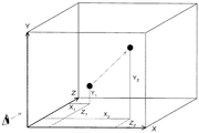
図32は、遊技機1において想定される3次元空間の概要を示す図である。図32の3次元空間において、X軸は、遊技機1に向かう遊技者から見て液晶表示装置131の横方向であり、Y軸は、液晶表示装置131の縦方向であり、Z軸は、遊技者が遊技機1の液晶表示装置131を見る奥行き方向である。レンダリングプロセッサ86は、液晶表示装置131に表示される物体が、図32の3次元空間中に存在するように表示する3次元画像を合成する。
FIG. 32 is a diagram showing an outline of a three-dimensional space assumed in the
レンダリングプロセッサ86は、サブマイコン80から、画像制御情報を受信することにより、画像制御情報に対応する3次元画像を合成し、表示する。サブマイコン80がレンダリングプロセッサ86に送信する画像制御情報は、例えば、複数のオブジェクトのうち特定のものを指定するオブジェクト識別情報、オブジェクトが配置される3次元空間内の位置情報、配置されるオブジェクトの向きを指定するベクトル情報を含む。レンダリングプロセッサ86は、サブマイコン80から画像制御情報を受信すると、画像RAM89に格納された画像情報のうち、オブジェクト識別情報に対応するもののモデリング情報を読み出して、位置情報およびベクトル情報に応じてポリゴン座標の変換、透視変換、光源計算といったジオメトリ演算を行う。また、必要に応じ、テクスチャ情報に基づいたレンダリング処理を行う。処理結果であるオブジェクトの画像情報を所定のフレームバッファに描画する描画処理を行う。
The
このようにして、サブマイコン80が指定するオブジェクトを、サブマイコン80の指定する3次元空間内での位置に配置したように表示する画像が合成される。 In this way, an image to be displayed is synthesized so that the object designated by the sub-microcomputer 80 is arranged at a position in the three-dimensional space designated by the sub-microcomputer 80.
図10は、レンダリングプロセッサ86で行われる画像表示制御のタイミングチャートを示す。
FIG. 10 shows a timing chart of image display control performed by the
実施例では、レンダリングプロセッサ86は、液晶表示装置131に対して画像を表示させる場合に、1秒(s)間に30画面分の画像を連続的に表示させる(即ち1つの画像の表示時間は1/30s)。
In the embodiment, when the image is displayed on the liquid
1/30sごとに表示させる画像を異ならせると、キャラクタ画像等に動きがつけられ、アニメーション画像が表示される。実施例では、1/30sごとに表示させる画像を異なる画像とすることにより表示される画像を、変化画像という。また、1/30sごとに表示させる画像を同一のものとすると、キャラクタ画像等に動きをつけず、静止させた画像が表示される。実施例では、1/30sごとに表示させる画像を同じ画像とすることにより表示される画像を、固定画像という。 If the image to be displayed is changed every 1/30 s, the character image or the like is moved and an animation image is displayed. In the embodiment, an image displayed by setting different images to be displayed every 1/30 s is referred to as a change image. Further, if the images to be displayed every 1/30 s are the same, a stationary image is displayed without moving the character image or the like. In the embodiment, an image displayed by setting an image to be displayed every 1/30 s to be the same image is referred to as a fixed image.
図10のタイミングチャートでは、上段にフレームバッファ1のタイミングチャートを示し、下段にフレームバッファ2のタイミングチャートを示す。
In the timing chart of FIG. 10, the timing chart of the
画像RAM89にはフレームバッファ1とフレームバッファ2の2つのバッファが設けられており、それら2つのバッファのうちのいずれかのバッファのデータを液晶表示装置131に転送することで画像が表示されるように構成されている。フレームバッファ1又はフレームバッファ2において、下段のタイミングチャートは、レンダリングプロセッサ86において画像の描画(即ち表示の準備)を行うタイミングを示すものである。また、上段のタイミングチャートは、描画が行われた画像を液晶表示装置131の液晶表示部2に表示させるタイミングを示すものである。
The
上段の表示を示すタイミングチャートを参照すると、表示は、1/30sの間隔ごとに、1/30s間行われる。また、下段の描画を示すタイミングチャートを参照すると、描画は、表示と表示の間(1/30sの時間内)に行われることとなる。フレームバッファ1とフレームバッファ2との間の矢印は、バッファの切替処理を示す。バッファの切替処理は、画像RAM89に設けられたフレームバッファ1又はフレームバッファ2のうち、液晶表示装置131にデータを転送させるバッファを切り替える処理である。
Referring to the timing chart showing the upper display, the display is performed every 1/30 s for 1/30 s. Further, referring to the timing chart showing the lower drawing, the drawing is performed between the displays (in the time of 1/30 s). An arrow between the
図10のタイミングチャートでは、初めに、フレームバッファ2において、画像1用処理が行われる。画像1用処理では、まず、決定された演出に応じた画像1の描画が行われる。ここで描画は、レンダリングプロセッサ86の画像RAM89への画像データの書き込みが開始されてから、画像RAM89に設けたバッファ(ここでは、フレームバッファ2)への画像データの書き込みが終了されるまでの処理を指している。続いて、描画が行われた画像1の画像データが液晶表示装置131に転送され、画像1が液晶表示部2bに1/30s間表示される。
In the timing chart of FIG. 10, first,
他方、フレームバッファ1では、フレームバッファ2で画像1の表示が行われている間(1/30sの間)に、画像2用処理が開始され、画像2の描画が行われる。1/30sが経過し、フレームバッファ2で画像1の表示が終了すると、バッファの切替処理が行われる。バッファの切替処理が行われると、フレームバッファ1において描画が行われた画像2の画像データが液晶表示装置131に転送され、画像2が液晶表示部2bに1/30s間表示される。このとき、フレームバッファ2では、画像3用処理が開始され、画像3の描画が行われる。
On the other hand, in the
同様に、フレームバッファ1又はフレームバッファ2において、交互に画像処理(フレームバッファ1では画像4用処理及び画像6用処理、フレームバッファ2では画像5用処理及び画像7用処理)が行われることとなる。この場合も、一方のフレームバッファで表示が行われている間(1/30s)、他方のフレームバッファでは、描画が行われる。そして、フレームバッファ1とフレームバッファ2との間で1/30sごとにバッファの切替処理が行われることにより、液晶表示装置131の液晶表示部2に交互に画像が表示される。このように、フレームバッファ1とフレームバッファ2との間でバッファの切替処理を行い、交互に画像を表示させることで、画像表示の高速化を図り、また、画像のちらつきをなくすようにしている。
Similarly, image processing (
ここで、例えば、液晶表示部2の演出表示領域23にキャラクタを表示させる場合において、前述の画像1用処理で3次元空間における座標(x1,y1,z1)の位置に対応してキャラクタを表示させ、画像2用処理で(x2,y2,z2)の位置に対応してキャラクタを表示させる。この場合、1/30sの時間でキャラクタは、3次元空間内を、(x1,y1,z1)から(x2,y2,z2)に移動するように液晶表示部2に表示される。
Here, for example, when displaying a character in the
また、例えば、液晶表示部2のクレジット表示領域25にクレジット画像を表示させる場合において、前述の画像1用処理で“3”を示すクレジット画像を表示させ、画像2用処理で“2”を示すクレジット画像を表示させ、画像3用処理で“1”を示すクレジット画像を表示させ、画像4用処理で“0”を示すクレジット画像を表示させた場合、1/30sの時間ごとに、クレジット画像を“3”から“0”にカウントダウン表示させることができる(変化画像の表示)。
Further, for example, when a credit image is displayed in the
また、例えば、前述の画像1用処理で“0”を示すクレジット画像を表示させ、画像2用処理で“1”を示すクレジット画像を表示させ、画像3用処理で“2”を示すクレジット画像を表示させ、画像4用処理で“3”を示すクレジット画像を表示させた場合、1/30sの時間ごとに、クレジット画像を“0”から“3”にカウントアップ表示させることができる(変化画像の表示)。
Also, for example, a credit image indicating “0” is displayed in the above-described
また、例えば、前述の画像1用処理から画像4用処理のいずれの処理においても、“0”を示すクレジット画像を表示させた場合、“0”を示すクレジット画像を所定時間(4/30s)固定的に表示させることができる(固定画像の表示)。なお、実施例では、1/30sごとに画像を表示させることとしたが、これに限らず、表示させる画像を切り替える時間は任意に変更可能である。
Also, for example, in any of the processes for
[音像処理および音響補正]
図11を参照して、副制御回路72の音声信号供給部91が備えるオーディオDSP95の、各手段の構成を示す図である。
[Sound image processing and acoustic correction]
Referring to FIG. 11, there is shown a configuration of each unit of the
オーディオDSP95は、仮想的な3次元空間内での音像の処理および合成を行う音像処理手段201、および、合成された音声信号に対し、オーディオRAM94から読み出した補正情報に応じて音響的な補正を行う音響補正処理手段202を備える。音響補正処理手段202は、さらに、遅延補正処理手段203、フィルタ処理手段204、および、音量補正処理手段205を備える。
The
音像処理手段201は、オーディオRAM94から音源情報を読み出し、サブマイコン80から供給される3次元空間の位置情報に基づいて、音声情報の合成および音像の処理をおこなう。オーディオRAM94に記憶された音源情報は、具体的には、音声をサンプリングした情報であり、音像処理手段201は、複数の音声についての音声サンプリング情報のうち、サブマイコン80から供給されるスタートコマンドに含まれる音声識別情報に応じた音声サンプリング情報を読み出す。さらに、音像処理手段201は、読み出した音源情報としての音声サンプリング情報と、サブマイコン80から供給される位置コマンドに含まれる位置情報とを変数として、頭部伝達関数に基づく演算を行う。
The sound image processing means 201 reads sound source information from the
ここで、頭部伝達関数とは、遊技機1前方にいる遊技者が遊技機1を臨む方向に3次元空間(図32)を仮想的に設定し、この3次元空間内の特定の位置で発生したと想定された音声が、遊技者の両耳のそれぞれに到達するまでの音響特性を求める関数である。頭部伝達関数は、例えば、遊技機の前方に、遊技者の頭部に見立てた剛球のモデルを配置した場合に、ある位置で発生する音声が、この剛球の両耳の相当位置に到達するまで音圧を、時間および座標位置の関数である近似式として算出するといった、公知の手法を用いることができる(例えば、浜田、「2チャンネルスピーカによる3D再生〜原理から応用まで」JAS journal 1998年4月号臨時増刊)。頭部伝達関数に基く演算結果は、スピーカ9L,9Rのそれぞれに対応する音声信号となる。演算結果の音声信号に基づいてスピーカ9L,9Rから音声が出力されると、この音声を聞いた遊技者には、音源が位置情報で指定された位置にあるように聞こえる。すなわち、音像処理手段201の処理により、3次元空間内の指定位置に音像を定位させることができる。
Here, the head-related transfer function is a virtual setting of a three-dimensional space (FIG. 32) in a direction in which a player in front of the
つづいて、音像処理手段から出力された音声信号は、音声信号の特性を補正する音響補正処理手段に供給される。スピーカ9L,9Rから出力される音声は、遊技機1前方の遊技者の耳に到達するまでに、スピーカ9L,9R自体の出力特性、スピーカ9L,9Rが取り付けられる位置、遊技機1の筐体による共鳴の特性、および、遊技者の耳の位置までの空間伝播特性の影響を受ける。このため、遊技者の耳に到達する音声の特性は、スピーカ9L,9Rに供給される音声信号の特性から変化する。さらに、スピーカ9Lから出力される音声の音響特性と、スピーカ9Rから出力される音声との音響特性は、それぞれ異なる場合がある。例えば、遊技機1の機種において、デザインの関係上、スピーカ9Lを、スピーカ9Rの位置よりも、中心から離れた位置に取り付ける場合には、たとえスピーカ9L,9Rに同一の音声信号が供給されても、スピーカ9Lから遊技者の耳に到達する音声の音量は、スピーカ9Rからのものより小さく、また、スピーカ9Lからの音声は、スピーカ9Rからのものよりも遅れて到達する。さらに、音声の特性は、筐体の構成自体、特に左右のバランスによる影響も受ける。すなわち、スピーカ9L,9Rから出力される音声が、それぞれ筐体で共鳴する仕方の違いにより、スピーカ9Lから遊技者の耳に到達する音声の周波数特性は、スピーカ9Lからのものと異なる。このように、スピーカ9Lから出力される音声は、遊技者の耳に到達するまでに、遊技機の機種に固有の音響特性の影響を受ける。
Subsequently, the audio signal output from the sound image processing unit is supplied to an acoustic correction processing unit that corrects the characteristics of the audio signal. The sound output from the
オーディオDSP95が備える音響補正処理手段202は、スピーカ9L,9Rに供給する音声信号のそれぞれに対し、スピーカ9L,9Rから出力される音声が遊技者の耳に到達するまでの、遊技機の機種に固有の音響特性の影響を予め補正して、この固有の音響特性の影響を低減するようにする。まず、遅延補正処理手段203では、オーディオRAM94を用いて音声信号のバッファリングを行い、この音声信号の読み出しタイミングを調整することにより、音声信号の遅延処理を行う。ここで、遅延の量は、オーディオRAM94に格納された補正情報のうち遅延補正情報に基づいて決定される。また、フィルタ処理手段204は、音声信号に対し、フィルタ演算を行うことにより、音声信号の周波数特性を補正する。補正の特性は、オーディオRAM94に格納された補正情報の周波数特性補正情報に基づいて決定される。フィルタ演算としては、音声情報をサンプリング時間分づつ遅延させたものに重み付け係数を掛けた上で重畳する、FIRフィルタ演算が好ましく、周波数特性補正情報は、例えば、所望のフィルタ特性を実現するための重み付け係数の列の形式となる。また、音量補正処理手段205は、音声信号の音量すなわち減衰量を補正する。補正する特性は、オーディオRAM94に格納された補正情報の音量補正情報、および、サブマイコン80から送信される音量コマンドに基づいて決定される。
The sound correction processing means 202 provided in the
前述の補正を行うための各種補正情報の作成は、遊技機1の開発段階において行われる。まず、遊技機1を無響室に設置し、遊技機1前方の遊技者の位置に測定用マイクを設置する。続いて、前述の補正処理を行わない状態で、スピーカ9Lに、音声信号としてパルス波形信号を供給し、測定用マイクから出力された音声信号により音声の到達時間を測定する。続いて、スピーカ9Rに関して同様に測定を行う。スピーカ9Lおよびスピーカ9Rの音声の到達時間が異なる場合、到達時間の小さいスピーカの音声信号に対し、到達時間を補完する遅延時間を加算して遅延補正情報とする。
Creation of various correction information for performing the above-described correction is performed at the development stage of the
また、補正処理を行わない状態で、スピーカ9L,9Rに対し別々に、音声信号としてピンクノイズ信号を供給し、測定用マイクにから出力された音声信号により周波数特性を測定する。スピーカ9L,9Rのそれぞれについて、測定された周波数特性を補完する特性を実現するFIRフィルタの重み付け係数の列を周波数特性補正情報とする。たとえば、スピーカ9Lについて測定された周波数特性が、500Hz付近でピークを持つ場合には、フィルタ特性として、500Hz付近のゲインが低下するFIRフィルタの係数の列を周波数特性補正情報とする。
In addition, a pink noise signal is separately supplied as an audio signal to the
また、測定用マイクに入力された音声信号により音声の音圧を測定し、スピーカ9Lおよびスピーカ9Rの音圧が異なる場合、音圧の小さいスピーカの音声信号に対し、音圧差を補完する音量を音量補正情報とする。
Further, when the sound pressure of the sound is measured by the sound signal input to the measurement microphone and the sound pressures of the
遊技機1の製造段階で、これらの補正情報は、カートリッジROM83に格納される。このようにして、スピーカ9L,9Rから出力される音声の音響特性に基づいて設定された補正情報が、カートリッジROM83に格納される。
These correction information is stored in the
遊技機1の電源がオフの状態では、補正情報は、カートリッジROM83に格納されている。遊技機1の電源がオンとなり、続いてオーディオDSP95がリセットされると、サブマイコン80は、格納されている補正情報を、音声制御プログラムと共に、カートリッジROM83から読み出し、バスIF85a、およびオーディオDSP95を介してオーディオRAM94に書き込む。このように、サブマイコン80およびオーディオDSP95を介して、カートリッジROM83に格納された補正情報を記憶したオーディオRAM94は、スピーカ9L,9Rから出力される音声の音響特性に基づいて設定された補正情報を記憶することとなる。そして、オーディオDSP95が備える音響補正処理手段202は、オーディオRAM94から読み出した補正情報に応じて、スピーカ9L,9Rに供給する音声信号を補正する。したがって、遊技機1に固有の音響特性の影響を低減し、内蔵する音源情報をより忠実に出力することができる。
When the
また、音響補正処理手段202は、オーディオRAM94から読み出した補正情報に応じて補正を行うので、オーディオRAM94に適切な補正情報を記憶することにより、容易に音声信号の補正を行うことができる。遊技機1の開発段階では、作成した遊技機の機種に固有の音響特性を測定し、この特性を補正するための補正情報をオーディオRAM94に記憶させておくだけで、遊技機1に固有の音響特性の影響を抑えることができる。したがって、固有の音響特性の影響を低減するために遊技機の構造を設計変更するといった労力を低減することができる。
Further, since the acoustic
図12、図13を参照して、前述の主制御回路71のROM32に格納される各種テーブルについて説明する。
Various tables stored in the
図12を参照して、各遊技状態における入賞図柄組合せに対応する役及び払出枚数の関係について説明する。 With reference to FIG. 12, the relationship between the combination corresponding to the winning symbol combination in each gaming state and the number of payouts will be described.
図12に示すように、BBの入賞は、“赤7”、“青7”、又は“コンドル”が何れかの有効ライン8a〜8eに沿って3つ並ぶことにより成立する。BBの入賞に対応する払出枚数は、15枚である。
As shown in FIG. 12, the BB winning is established by arranging three “red 7”, “blue 7”, or “condor” along one of the
BBが入賞した後、遊技状態がBB遊技状態(より詳細には、BB中一般遊技状態)となる。また、実施例のBB遊技状態は、BB中一般遊技状態において30回のゲームを消化したこと、BB中一般遊技状態での入賞による3回目のRB遊技状態の最後のゲームが終了したことにより終了する。尚、BB遊技状態は、獲得枚数(例えば、いわゆる「純増枚数」或いは「払出枚数」)が所定枚数(例えば、461枚)以上となることにより終了することとしても良い。 After BB wins, the gaming state becomes the BB gaming state (more specifically, the general gaming state during BB). In addition, the BB gaming state of the embodiment is terminated when the 30 games have been digested in the BB general gaming state and the last game of the third RB gaming state due to winning in the BB general gaming state has ended. To do. Note that the BB gaming state may be terminated when the acquired number (for example, a so-called “pure increase number” or “paid-out number”) becomes equal to or greater than a predetermined number (for example, 461).
RBの入賞は、一般遊技状態では、“コンドル−コンドル−赤7”又は“コンドル−コンドル−青7”が何れかの有効ライン8a〜8eに沿って並ぶことにより成立する。また、BB中一般遊技状態では、“Replay”が何れかの有効ライン8a〜8eに沿って3つ並ぶことにより成立する。RBの入賞に対応する払出枚数は、15枚である。
The RB winning is established by arranging “condor-condor-red 7” or “condor-condor-blue 7” along any of the
RBが入賞した後、遊技状態がRB遊技状態となる。実施例のRB遊技状態は、メダルを1枚賭けることにより、高確率でJACの小役の入賞が成立する遊技状態である。また、実施例のRB遊技状態は、RB遊技状態で実行されたゲーム回数が12回に達するか、JACの小役の入賞が8回成立することにより終了する。 After the RB wins, the gaming state becomes the RB gaming state. The RB gaming state of the embodiment is a gaming state in which a winning of a JAC small role is established with high probability by betting one medal. In addition, the RB gaming state of the embodiment is ended when the number of games executed in the RB gaming state reaches 12 times or when the winning of JAC small role is established 8 times.
リプレイ(再遊技)の入賞は、一般遊技状態において、“Replay”が何れかの有効ライン8a〜8eに沿って3つ並ぶことにより成立する。リプレイが入賞すると、投入したメダルの枚数と同数のメダルが自動投入される(遊技者に遊技価値が付与される)ので、遊技者はメダルを消費することなく次のゲームを行うことができる。
Replay (replay) winning is established when three “Replays” are arranged along one of the
一般遊技状態又はBB中一般遊技状態では、チェリーの小役、ベルの小役、及びスイカの小役の入賞を成立することが可能である。ベルの小役の入賞は“ベル”が何れかの有効ライン8a〜8eに沿って3つ並ぶことにより成立する。ベルの小役の入賞に対応する払出枚数は、8枚である。スイカの小役は“スイカ”が何れかの有効ライン8a〜8eに沿って3つ並ぶことにより成立する。スイカの小役の入賞に対応する払出枚数は、15枚である。
In the general game state or the general game state during BB, it is possible to win a prize for a cherry small part, a bell small part, and a watermelon small part. The winning of the small role of the bell is established by arranging three “bells” along any of the
チェリーの小役の入賞には2種類がある。“チェリー”が左の図柄表示領域4Lの中段に停止表示することにより成立するものを中チェリーの小役の入賞という。また、“チェリー”が左の図柄表示領域4Lの上段又は下段に停止表示することにより成立するものを角チェリーの小役の入賞という。中チェリーの小役の入賞に対応する払出枚数は、2枚である。角チェリーの小役の入賞では、2本の有効ライン上で入賞が成立するため、払出枚数は中チェリーの小役の倍の4枚である。 There are two types of prizes for cherry small roles. What is established by “cherry” being stopped and displayed in the middle of the left symbol display area 4L is called winning of a small cherry medium role. Also, what is established when “cherry” is stopped and displayed on the upper or lower stage of the left symbol display area 4L is called a winning of a small cherry cherries. The number of payouts corresponding to the winning of the medium cherry small role is two. In the winning of the small cherry small role, winnings are established on two active lines, so the number of payouts is four times that of the medium cherry small size.
JACの小役の入賞は、RB遊技状態において、1つの有効ラインに沿って“Replay”が3つ並ぶか、“コンドル−Replay−Replay”が並ぶことにより成立する。JACの小役の入賞に対応する払出枚数は、15枚である。JACの小役の入賞回数が“8回”となったとき、遊技状態が変化する。ここで、JACの小役の入賞が成立する可能性のあるRB遊技状態のゲームは、一般にJACゲームと称される。 The winning of the JAC small role is established by arranging three “Replay” or “Condor-Replay-Replay” along one active line in the RB gaming state. The number of payouts corresponding to the winning of the JAC small role is fifteen. When the number of winnings of the JAC small role becomes “8”, the gaming state changes. Here, a game in the RB gaming state in which a winning of a JAC small role may be established is generally referred to as a JAC game.
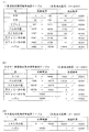
図13を参照して、内部当選役を決定する際に使用する確率抽選テーブルについて説明する。図13に示す確率抽選テーブルは、BET数が“3”の場合に使用される。また、このテーブルでは、“0”〜“16383”の範囲から抽出した乱数の値に基づいて内部当選役が決定される。 The probability lottery table used when determining the internal winning combination will be described with reference to FIG. The probability lottery table shown in FIG. 13 is used when the BET number is “3”. In this table, the internal winning combination is determined based on the random number value extracted from the range of “0” to “16383”.
図13(1)は、一般遊技状態において、当選役を決定する際に用いられる一般遊技状態用確率抽選テーブルを示す。この確率抽選テーブルでは、“0”〜“16383”の範囲から抽出した乱数値が“0”〜“135”の範囲内の値である場合に、当選役がBBと決定される。BBが当選する確率は“136/16384”である。また、乱数値が“136”〜“226”の範囲内の値である場合に当選役がRBと決定される。RBが当選する確率は“91/16384”である。 FIG. 13 (1) shows a general game state probability lottery table used when determining the winning combination in the general game state. In this probability lottery table, if the random value extracted from the range “0” to “16383” is a value within the range “0” to “135”, the winning combination is determined to be BB. The probability that BB wins is “136/16384”. Further, when the random value is a value within the range of “136” to “226”, the winning combination is determined to be RB. The probability of winning the RB is “91/16384”.
また、一般遊技状態において、リプレイが当選する確率は“2245/16384”、ベルの小役が当選する確率は“1775/16384”、スイカの小役が当選する確率は“100/16384”、角チェリーの小役が当選する確率は“100/16384”、中チェリーの小役が当選する確率は“13/16384”であり、上記以外の場合は“11924/16384”の確率でいわゆるハズレ(なし)に当選する。 Also, in the general gaming state, the probability of winning a replay is “2245/16384”, the probability of winning a bell small role is “1775/16384”, the probability of winning a watermelon small role is “100/16384”, corner The probability of winning a cherry small role is “100/16384”, and the probability of winning a medium cherry small role is “13/16384”. In all other cases, the probability of “11924/16384” is the so-called loss (none) ).
ここで、実施例の遊技機1では、確率抽選テーブルを使用してボーナスや小役といった内部当選役が決定されると、CPU31はその内部当選役に応じたリール3L,3C,3Rの停止制御を行う。
Here, in the
遊技機1では、入賞を発生させるためには、確率抽選処理においていずれかの内部当選役に当選すること、内部当選役に対応する図柄を狙った適切なタイミング(いわゆる引き込み可能な位置)で停止ボタン7L,7C,7Rの操作を行うこと、の2つの条件が満たされなければならない。従って、ボーナスや小役が当選したとしても、適切なタイミングで停止ボタン7L,7C,7Rの操作を行うことができなければ、入賞が発生することはない。
In the
つまり、ボーナスや小役の当選役が決定されたとしても、直ちに入賞が発生するわけではなく、有効ライン8a〜8e上に内部当選役に対応する図柄を停止させることができるという許可(即ち、停止許可)を与えるにすぎないということである。
That is, even if a winning combination of a bonus or a small role is determined, a winning does not occur immediately, and permission to stop the symbol corresponding to the internal winning combination on the
例えば、BBの入賞を発生させるためには、BBが内部当選役として決定され、かつ、前述の“赤7”、“白7”又は“コンドル”を有効ライン8a〜8e上に停止させることが必要となる。
For example, in order to generate a BB winning, BB is determined as an internal winning combination, and the above-mentioned “
ここで、内部当選役が小役の場合は、停止許可が与えられた一回のゲームで入賞させることができないと、次回のゲームではその当選は無効となり停止許可が解除される。一方、内部当選役がボーナスの場合は、停止許可が与えられた一回のゲームで入賞させることができない場合、ボーナスが持越役として持ち越される。これにより、ボーナスに入賞するまでの間、複数のゲームにわたってボーナスに入賞する機会が持ち越され、停止許可が継続する。これにより、遊技者にとっては、ボーナスが内部当選役として決定されたゲームで、停止ボタン7L,7C,7Rを適切なタイミングで操作できず、入賞させることができない場合であっても、次以降のゲームで停止ボタン7L,7C,7Rを適切なタイミングで操作できればボーナスを入賞させることができる。
Here, in the case where the internal winning combination is a small combination, if the winning is not made in one game for which the stop permission is given, the winning becomes invalid in the next game and the stop permission is released. On the other hand, when the internal winning combination is a bonus, the bonus is carried over as a carryover combination if it is not possible to win in a single game with permission to stop. Thereby, until the bonus is won, the opportunity to win the bonus is carried over over a plurality of games, and the stop permission continues. As a result, even if the player cannot operate the
図13(2)は、BB中一般遊技状態において、当選役を決定する際に用いられるBB中一般遊技状態用確率抽選テーブルを示す。BB中一般遊技状態では、SRB(BB中一般遊技状態でのRB)、ベルの小役、スイカの小役、角チェリーの小役、中チェリーの小役、ハズレ(なし)に当選する可能性があり、各々の役に当選する確率は図示の通りである。図13(2)に示すように、BB中一般遊技状態では、SRB又はベルの小役に当選する確率が一般遊技状態よりも高く設定されている。 FIG. 13 (2) shows a probability lottery table for the BB general gaming state used when determining the winning combination in the BB general gaming state. Possibility to win SRB (RB in BB general gaming state), Bell small part, Watermelon small part, Horn cherry small part, Medium cherry small part, Loss (none) in BB general gaming state The probability of winning each combination is as shown in the figure. As shown in FIG. 13 (2), in the BB general gaming state, the probability of winning an SRB or a bell small role is set higher than in the general gaming state.
図13(3)は、RB遊技状態において、内部当選役を決定する際に用いられるRB遊技状態用確率抽選テーブルを示す。RB遊技状態では、JACの小役又はハズレ(なし)に当選する可能性がある。JACの小役には、“16383/16384”の確率で当選し、ハズレ(なし)には“1/16384”の確率で当選する。RB遊技状態では、JACの小役が極めて高い確率で当選し、ハズレ(なし)に当選する確率は極めて低い。 FIG. 13 (3) shows an RB gaming state probability lottery table used when determining an internal winning combination in the RB gaming state. In the RB gaming state, there is a possibility of winning a JAC small part or losing (none). The JAC small role will be elected with a probability of “16383/16384”, and the winner will be elected with a probability of “1/16384”. In the RB gaming state, the JAC small role is won with a very high probability, and the probability of winning a loss (none) is very low.
図14〜図18に示すフローチャートを参照して、主制御回路71のCPU31の制御動作について説明する。
The control operation of the
図14〜図16を参照して、メインフローチャートについて説明する。 The main flowchart will be described with reference to FIGS.
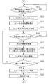
初めに、CPU31は、ゲーム開始時の初期化を行う(ステップS1)。具体的には、RAM33の記憶内容の初期化、通信データの初期化等を行う。続いて、ゲーム終了時のRAM33の所定の記憶内容を消去する(ステップS2)。具体的には、前回のゲームに使用されたRAM33の書き込み可能エリアのデータの消去、RAM33の書き込みエリアへの次のゲームに必要なパラメータの書き込み、次のゲームのシーケンスプログラムの開始アドレスの指定等を行う。
First, the
次に、後で図18を参照して説明するメダル受付、スタートチェック処理を行う(ステップS3)。続いて、後述のステップS6などで使用する抽選用の乱数を抽出し(ステップS4)、ステップS5に移る。 Next, a medal reception and start check process which will be described later with reference to FIG. 18 is performed (step S3). Subsequently, a random number for lottery used in step S6 to be described later is extracted (step S4), and the process proceeds to step S5.
ステップS5では、遊技状態監視処理を行い、ステップS6に移る。ステップS6では、確率抽選処理を行い、ステップS7に移る。この確率抽選処理では、ROM32に格納されている確率抽選テーブル(図13)を使用し、ステップS4の処理で抽出した乱数と遊技状態とに応じて内部当選役の決定を行う。
In step S5, a game state monitoring process is performed, and the process proceeds to step S6. In step S6, a probability lottery process is performed, and the process proceeds to step S7. In this probability lottery process, a probability lottery table (FIG. 13) stored in the
ステップS7では、内部当選役は、BB又はRBであるか否かを判別する。この判別が“YES”の場合、ステップS8に移り、“NO”の場合は、ステップS9に移る。ステップ8では、RAM33に格納された持越役に内部当選役(BB又はRB)をセットし、ステップS9に移る。ステップS9では、停止用当選役決定処理を行う。この停止用当選役決定処理では、ROM32に格納されている停止用当選役決定テーブル(図示せず)を使用し、抽出した乱数とステップS6の処理で決定した内部当選役と遊技状態とに応じて停止用当選役の決定を行う。
In step S7, it is determined whether or not the internal winning combination is BB or RB. If this determination is “YES”, the process proceeds to step S8, and if “NO”, the process proceeds to step S9. In
停止用当選役は、内部当選役、遊技状態、持越役などに基づいて決定され、リール3L,3C,3Rの停止制御に用いられる情報である。停止用当選役が決定された場合には、決定された停止用当選役に対応する図柄の停止態様を図柄表示領域21L,21C,21R内に停止表示するようにリール3L,3C,3Rが停止制御される。また、各停止用当選役には、停止テーブルが対応付けられている。例えば、停止用当選役としてハズレ以外の役が決定された場合、決定した停止用当選役の入賞を成立することが可能な入賞可能停止テーブルが決定される。停止用当選役としてハズレが決定された場合は、いずれの役の入賞も成立することが不可能な入賞不可能停止テーブルが決定される。
The winning combination for stop is information that is determined based on the internal winning combination, the gaming state, the carryover combination and the like, and is used for stop control of the
次に、CPU31は、テーブルライン選択処理を行う(ステップS10)。具体的には、停止用当選役に対応する停止テーブルや停止用当選役に対応する図柄組合せを並べる入賞ラインの決定を行う。停止テーブルには、各リール3L,3C,3Rの停止操作位置と停止制御位置とが示されている。停止操作位置は、各リール3L,3C,3Rに対応して設けられた停止ボタン7L,7C,7Rが操作された場合に、センターライン8cに位置していた図柄(具体的には、図柄の中心がセンターライン8cの上方に位置し、その中心がセンターライン8cの位置に最も近い図柄)のコードナンバーを表わす。停止制御位置とは、停止操作が行われたリールが停止したとき、センターライン8cの位置に停止表示される図柄のコードナンバーを表わす。
Next, the
次に、CPU31は、スタートコマンドをRAM33の所定の領域に格納し(ステップS11)、図15のステップS12に移る。スタートコマンドには、遊技状態、内部当選役、停止用当選役、持越役、ボーナス遊技状態での残りボーナス回数などの情報が含まれている。格納されたスタートコマンドは、後述の定期割込処理(図17)の通信データ送信処理(ステップS51)において、副制御回路72に送信される。
Next, the
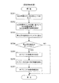
図15のステップS12では、CPU31は、前回のリール3L,3C,3Rの回転が開始してから“4.1秒”経過しているか否かを判別する。この判別が“YES”の場合は、ステップS13に移り、“NO”の場合は“4.1秒”経過するまで以降の処理を待機する。ステップS13では、RAM33に格納された“4.1秒”計時用カウンタをセットし、ステップS14に移る。
In step S12 in FIG. 15, the
ステップS14では、全リールの回転開始要求を行う。具体的には、前述のモータ駆動回路39に駆動信号を出力する。続いて、リール3L,3C,3Rの回転速度が定速回転に到達した場合に、リール停止許可コマンドをRAM33の所定の領域に格納する(ステップS15)。リール停止許可コマンドは、遊技者の停止ボタン7L,7C,7Rの操作が有効になったことを示す情報である。格納されたリール停止許可コマンドは、後述の定期割込処理(図17)の通信データ送信処理(ステップS51)において、副制御回路72に送信される。
In step S14, a rotation start request for all reels is made. Specifically, a drive signal is output to the
次に、CPU31は、停止ボタンが操作されたか否かを判別する(ステップS16)。具体的には、いずれかの停止ボタン7L,7C,7Rが操作され、“オン”となったか否かを判別する。この判別が“YES”の場合は、ステップS17に移り、“NO”の場合は、停止ボタン7L,7C,7Rがオンとなるまで待機する。
Next, the
ステップS17では、CPU31は、滑りコマ数決定処理を行う。具体的には、前述のステップS10で決定された停止テーブル、遊技者の停止ボタン7L,7C,7Rの操作タイミング(停止操作位置)に基づいて、滑りコマ数を決定する。続いて、滑りコマ数分、操作された停止ボタンに対応するリールが回転することを待つ、即ち滑りコマ数分、操作された停止ボタンに対応するリールを回転させてから停止させる(ステップS18)。続いて、リール停止コマンドをRAM33の所定の領域に格納する(ステップS19)。リール停止コマンドには、停止制御の対象となったリールの情報などが含まれる。格納されたリール停止コマンドは、後述の定期割込処理(図17)の通信データ送信処理(ステップS51)において、副制御回路72に送信される。
In step S17, the
次に、CPU31は、全てのリール3L,3C,3Rが停止したかどうかを判別する(ステップS20)。この判別が“YES”の場合は、ステップS21に移り、“NO”の場合は、ステップS16に移る。ステップS21では、全リール停止コマンドをRAM33の所定の領域に格納し、ステップS22に移る。全リール停止コマンドには、全てのリール3L,3C,3Rが停止したことを示す情報などが含まれる。格納された全リール停止コマンドは、後述の定期割込処理(図17)の通信データ送信処理(ステップS51)において、副制御回路72に送信される。
Next, the
ステップS22では、CPU31は、入賞検索処理を行い、図16のステップS23に移る。この入賞検索処理では、図柄表示領域21L,21C,21Rの図柄の停止態様に基づいて入賞役(入賞が成立した役)を識別するための入賞フラグをセットする。具体的には、センターライン8cに沿って並ぶ図柄のコードナンバー及び入賞判定テーブルに基づいて入賞役を識別する。
In step S22, the
図16のステップS23では、CPU31は、入賞役は正常であるか否かを判別する。この判別が“YES”の場合は、ステップS25に移り、“NO”の場合は、イリーガルエラーの表示を行う(ステップS24)。この場合、遊技は中止となる。
In step S23 of FIG. 16, the
ステップS25では、入賞役はBB又はRBであるか否かを判別する。この判別が“YES”の場合は、ステップS26に移り、“NO”の場合は、ステップS27に移る。ステップS26では、持越役をクリアし、ステップS27に移る。 In step S25, it is determined whether or not the winning combination is BB or RB. If this determination is “YES”, the process proceeds to step S26, and if “NO”, the process proceeds to step S27. In step S26, the carryover combination is cleared, and the process proceeds to step S27.
ステップS27では、CPU31は、入賞チェック、メダル払出処理を行い、ステップS28に移る。この処理でCPU31は、RAM33に格納された、入賞役を特定するための情報である入賞フラグに基づいて入賞役に対応する払出枚数を特定し、特定した払出枚数を入賞枚数カウンタにセットする。また、特定した払出枚数に基づいて、ホッパー駆動回路41に駆動信号を送信し、ホッパー40からメダルを払出す。また、入賞コマンドをRAM33の所定の領域に格納する。メダル払い出し終了の場合は、払出終了コマンドを格納する。入賞コマンドおよび払出終了コマンドは、定期割込処理(図17)の通信データ送信処理(ステップS51)において、副制御回路72に送信される。ステップS28では、RAM33の遊技状態の情報をBB一般遊技状態又はRB遊技状態に更新し、BB、RBを発生させ、ステップS29に移る。
In step S27, the
ステップS29では、CPU31は、現在の遊技状態がBB遊技状態又はRB遊技状態であるか否かを判別する。この判別が“YES”の場合は、ステップS30に移り、“NO”の場合は、図14のステップS2に移る。ステップS30では、BB、RBゲーム数チェック処理を行い、ステップS31に移る。この処理では、BB中一般遊技状態において、RB遊技状態に移行した回数、BB中一般遊技状態のゲーム回数、RB遊技状態における入賞回数、及びRB遊技状態におけるゲーム回数をチェックする。
In step S29, the
ステップS31では、CPU31は、BB遊技状態又はRB遊技状態の終了か否かを判別する。この判別が“YES”の場合は、ステップS32に移り、“NO”の場合は、図14のステップS2に移る。ステップS32では、BB、RB終了時処理を行い、図14のステップS2に移る。ここで、BB遊技状態において、“3回目”のRB遊技状態において入賞回数が8回又はゲーム回数が12回である場合、又はBB中一般遊技状態におけるゲーム回数が30回である場合には、ステップS31の判別が“YES”となる。また、RB遊技状態において、入賞回数が8回又はゲーム回数が12回である場合には、ステップS31の判別が“YES”となる。
In step S31, the
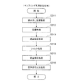
図17を参照して、定期割込処理について説明する。この定期割込処理は、主制御回路71における所定のメイン処理に所定の間隔(例えば、1.8773msec)で割り込む処理である。
With reference to FIG. 17, the periodic interrupt process will be described. This periodic interrupt process is a process of interrupting a predetermined main process in the
初めに、CPU31は、レジスタに記憶されたデータを退避させ(ステップS41)、ステップS42に移る。ステップS42では、RAM33に格納され、リール3L,3C,3Rに関する情報を示すリール識別子に右のリール3Rに関する情報をセットし、ステップS43に移る。
First, the
ステップS43では、右のリール3Rについてのリール制御処理を行い、ステップS44に移る。より具体的には、右のリール3Rの回転開始、加速制御、定速制御、減速制御、停止制御などを行う。ステップS44では、リール識別子に中央のリール3Cに関する情報をセットし、ステップS45に移る。
In step S43, a reel control process for the
ステップS45では、中央のリール3Cについてのリール制御処理を行い、ステップS46に移る。より具体的には、中央のリール3Cの回転開始、加速制御、定速制御、減速制御、停止制御などを行う。ステップS46では、リール識別子に左のリール3Lに関する情報をセットし、ステップS47に移る。
In step S45, a reel control process is performed for the
ステップS47では、左のリール3Lについてのリール制御処理を行い、ステップS48に移る。より具体的には、左のリール3Lの回転開始、加速制御、定速制御、減速制御、停止制御などを行う。
In step S47, a reel control process for the
ステップS48では、電磁カウンタ制御処理を行い、ステップS49に移る。具体的には、メダル投入口10にメダルが投入された場合に、正常なメダルと不正常なメダルとを振り分けるためのメダルセレクタを制御する。
In step S48, an electromagnetic counter control process is performed, and the process proceeds to step S49. Specifically, when a medal is inserted into the
ステップS49では、ランプ点滅制御処理を行い、ステップS50に移る。具体的には、遊技機1の前面に設けられた各種ランプなどを点灯させる制御を行う。
In step S49, a lamp blinking control process is performed, and the process proceeds to step S50. Specifically, control is performed to turn on various lamps and the like provided on the front surface of the
ステップS50では、7SEG駆動制御処理を行い、ステップS51に移る。具体的には、ボーナス遊技情報表示部16、払出表示部18及びクレジット表示部19などにBB遊技状態などでのゲーム回数の情報、入賞による払出枚数の情報、クレジットされているメダル枚数の情報等を表示させる制御を行う。
In step S50, 7SEG drive control processing is performed, and the process proceeds to step S51. Specifically, the bonus game
ステップS51では、通信データ送信処理を行い、ステップS52に移る。具体的には、RAM33の所定の領域に格納された各種コマンドを副制御回路72に送信する。ステップS52では、退避させたレジスタを元に戻す。
In step S51, communication data transmission processing is performed, and the process proceeds to step S52. Specifically, various commands stored in a predetermined area of the
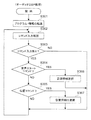
図18を参照して、メダル受付、スタートチェック処理について説明する。 The medal acceptance and start check processing will be described with reference to FIG.
初めに、CPU31は、RAM33に格納された自動投入用メダルカウンタは“0”以外であるか否かを判別する(ステップS61)。自動投入用メダルカウンタは、前回のゲームでリプレイに入賞したか否かを示す情報であって、前回のゲームでのBET数を示す情報である。自動投入用メダルカウンタには、前回のゲームでリプレイが入賞した場合、そのゲームでのBET数(後述のメダルカウンタ)の値(即ち“1”〜“3”)がセットされる。また、前回のゲームでリプレイが入賞していない場合、“0”がセットされる。この判別が“YES”の場合(前回のゲームでリプレイが入賞した場合)は、ステップS62に移り、この判別が“NO”の場合(前回のゲームでリプレイが入賞していない場合)は、ステップS65に移る。
First, the
ステップS62では、メダル投入処理を行い、ステップS63に移る。このメダル投入処理では、自動投入用メダルカウンタの値から“1”づつ、メダルカウンタの値にセットする処理を行う。 In step S62, a medal insertion process is performed, and the process proceeds to step S63. In this medal insertion process, a process of setting “1” from the value of the automatic insertion medal counter to the value of the medal counter is performed.
ステップS63では、自動投入用メダルカウンタからメダル投入分の“1”を減算し、ステップS64に移る。ステップS64では、自動投入用メダルカウンタは“0”に更新されたか否かを判別する。この判別が“YES”の場合(BETが終了した場合)、ステップS66に移り、“NO”の場合(BETが終了していない場合)、ステップS62に移る。 In step S63, "1" corresponding to the medal insertion is subtracted from the automatic insertion medal counter, and the process proceeds to step S64. In step S64, it is determined whether or not the automatic insertion medal counter has been updated to "0". If this determination is “YES” (when the BET is completed), the process proceeds to step S66, and if “NO” (when the BET is not completed), the process proceeds to step S62.
ステップS65では、メダル受付状態をセット(メダル受付許可)し、ステップS66に移る。具体的には、RAM33に格納されている、メダル投入許可フラグ、精算許可フラグ、ライン減許可フラグ、クレジットからのメダル投入フラグをオンにセットする。
In step S65, the medal acceptance state is set (medal acceptance is permitted), and the process proceeds to step S66. Specifically, the medal insertion permission flag, the settlement permission flag, the line reduction permission flag, and the medal insertion flag from credit stored in the
ここで、メダル投入許可フラグは、メダルの投入(BET)が許可されている状態であるか否かを特定するための情報である。メダルの投入(BET)は、メダル投入口10にメダルを投入すること、又は、1−BETスイッチ11、最大BETスイッチ13がオンされることにより行われる。メダルの投入が行われると、投入されたメダル枚数に基づいて後述のメダルカウンタの値が加算される。
Here, the medal insertion permission flag is information for specifying whether or not a medal insertion (BET) is permitted. The medal insertion (BET) is performed by inserting a medal into the
精算許可フラグは、BETされたメダル枚数(後述のメダルカウンタの値)及びクレジットされているメダル枚数(後述のクレジットカウンタの値)の精算が許可されている状態であるか否かを特定するための情報である。精算は、精算スイッチ14がオンされることにより行われる。精算が行われると、BETされたメダル枚数及びクレジットされているメダル枚数がメダル払出口15に払出される。
The settlement allowance flag is used to specify whether or not the settlement of the betted number of medals (a value of a medal counter described later) and the number of medals (a value of a credit counter described later) are permitted. Information. The settlement is performed when the
ライン減許可フラグは、BETされたメダル枚数(後述のメダルカウンタの値)の減少(有効ライン数の減少)が許可されている状態であるか否かを特定するための情報である。実施例のBET数の減少は、BET数が最大BET数(“3”)である場合、1−BETスイッチ11がオンされることにより行われる。この場合、有効ライン数は、5本から1本(センターライン8c)に更新され、減少された分のBET数(“2”)に基づく枚数のメダルがクレジットされる。
The line reduction permission flag is information for specifying whether or not a reduction (decrease in the number of valid lines) of bet medals (a medal counter value described later) is permitted. The reduction of the BET number in the embodiment is performed by turning on the 1-
クレジットからのメダル投入フラグは、クレジットされているメダル枚数からBETを行っている状態であるか否かを特定するための情報である。クレジットからのメダル投入は、クレジットされているメダル枚数が“0”以外の場合に、1−BETスイッチ11又は最大BETスイッチがオンされることにより行われる。
The medal insertion flag from credit is information for specifying whether or not a bet is being made based on the number of credited medals. The medal insertion from the credit is performed by turning on the 1-
ステップS66では、クレジットカウンタ、メダルカウンタが共に“0”であるか否かを判別する。クレジットカウンタは、クレジットされているメダル枚数(“0”〜“50”の範囲)を特定する情報である。メダルカウンタは、1回の遊技に投入(BET)されたメダル枚数(“0”〜“3”の範囲)を特定する情報である。この判別が“YES”の場合(クレジットされたメダルもBETされたメダルも無い場合)、ステップS69に移り、“NO”の場合(クレジットされたメダル又はBETされたメダルがある場合)、ステップS67に移る。 In step S66, it is determined whether or not both the credit counter and the medal counter are “0”. The credit counter is information for specifying the number of medals that are credited (range “0” to “50”). The medal counter is information for specifying the number of medals (between “0” and “3”) inserted (BET) in one game. If this determination is “YES” (when there is neither a credited medal nor a bet medal), the process proceeds to step S69. If “NO” (when there is a credited medal or a bet medal), step S67 is performed. Move on.
ステップS67では、精算許可であるか否かを判別する。具体的には、精算許可フラグがオンであるか否かを判別する。この判別が“YES”の場合、ステップS68に移り、“NO”の場合、ステップS69に移る。ステップS68では、精算スイッチチェック処理を行い、ステップS69に移る。この精算スイッチチェック処理では、精算スイッチ14がオンされたことにより、BETされたメダル枚数(メダルカウンタの値)、クレジットされたメダル枚数(クレジットカウンタの値)に基づく枚数のメダルを払出す処理を行う。
In step S67, it is determined whether or not payment is permitted. Specifically, it is determined whether or not the settlement permission flag is on. If this determination is “YES”, the process proceeds to step S68, and if “NO”, the process proceeds to step S69. In step S68, a settlement switch check process is performed, and the process proceeds to step S69. In the settlement switch check process, when the
ステップS69では、メダル投入許可フラグはオンであるか否かを判別する。この判別が“YES”の場合、ステップS70に移り、“NO”の場合、ステップS71に移る。ステップS70では、メダル投入チェック処理を行い、ステップS71に移る。このメダル投入チェック処理では、メダル投入口10から投入されたメダルをチェックして、副制御回路72にメダル投入コマンドを送信する処理、投入されたメダルに基づいてBETを行う(入賞ライン8a〜8eを有効化する)処理、BET数が最大(“3”)である場合に投入されたメダルをクレジットする処理、BETボタン11,13がオンされたことに基づいてクレジットされたメダルからBETする処理などを行う。
In step S69, it is determined whether or not the medal insertion permission flag is on. If this determination is “YES”, the process proceeds to step S70, and if “NO”, the process proceeds to step S71. In step S70, medal insertion check processing is performed, and the process proceeds to step S71. In this medal insertion check process, medals inserted from the
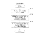
ステップS71では、メダルカウンタの値は上限値であるか否かを判別する。ここで、メダルカウンタの上限値は、基本的に、“3”であり、RB遊技状態では、“1”である。この判別が“YES”の場合(BET数が最大である場合)、ステップS72に移り、“NO”の場合(BET数が最大ではない場合)、ステップS66に移る。 In step S71, it is determined whether or not the value of the medal counter is an upper limit value. Here, the upper limit value of the medal counter is basically “3”, and “1” in the RB gaming state. When this determination is “YES” (when the BET number is the maximum), the process proceeds to step S72, and when “NO” (when the BET number is not the maximum), the process proceeds to step S66.
ステップS72では、スタートスイッチ6Sがオンされたか否かを判別する。この判別が“YES”の場合、ステップS73に移り、“NO”の場合、ステップS66に移る。これにより、実施例では、BET数を最大BET数にする(全ての入賞ラインを有効化する)ことにより遊技を開始させることができる。なお、RB遊技状態での最大BET数は“1”であり、1本の入賞ラインを有効化することにより遊技を開始させることができる。
In step S72, it is determined whether or not the
ステップS73では、メダル受付を禁止し、図14のステップS4に移る。具体的には、メダルロックアウトソレノイド12をオフの状態にする(例えば励磁を停止する)。これにより、スタートスイッチ6Sがオンされて遊技が開始された場合、メダル投入口10から投入されたメダルは、ホッパー40内に導かれることなく、メダル払出口15から払い出される。
In step S73, medal acceptance is prohibited and the process proceeds to step S4 in FIG. Specifically, the
図19〜図27に示すフローチャートを参照して、副制御回路72の制御動作について説明する。
The control operation of the
図19を参照して、RESET割込処理について説明する。 The RESET interrupt process will be described with reference to FIG.
初めに電源が投入され、リセット端子に電圧が印加されることにより、サブマイコン80は、リセット割込を発生させ、その割込の発生に基づいて、カートリッジROM83に記憶されたRESET割込処理を順次行うように構成されている。
When the power is first turned on and a voltage is applied to the reset terminal, the sub-microcomputer 80 generates a reset interrupt, and performs a RESET interrupt process stored in the
初めに、サブマイコン80は、ワークRAM84などの初期化を行い(ステップS201)、ステップS202に移る。
First, the sub-microcomputer 80 initializes the
ステップS202では、レンダリングプロセッサ初期化処理を行い、ステップS203に移る。このレンダリングプロセッサ初期化処理では、サブマイコン80は、カートリッジROM83に格納された、レンダリングプロセッサ86が画像信号を合成するための画像情報を読み出し、レンダリングプロセッサ86を介して画像RAM89に書き込む。
In step S202, a rendering processor initialization process is performed, and the process proceeds to step S203. In this rendering processor initialization process, the sub-microcomputer 80 reads image information stored in the
ステップS203では、オーディオDSP初期化処理を行い、ステップS204に移る。このオーディオDSP初期化処理では、サブマイコン80は、オーディオDSP95にリセットコマンドを送信する。サブマイコン80はカートリッジROM83に格納された、オーディオDSP95で実行する音声制御プログラム、オーディオDSP95が音声信号を合成するための音源情報、オーディオDSP95が音声信号を補正するための補正情報を読み出し、これらを、リセットコマンドの受信によりブート状態となったオーディオDSP95に送信する。オーディオDSP95に送信されたプログラムおよび情報は、オーディオRAM94に書き込まれる。
In step S203, an audio DSP initialization process is performed, and the process proceeds to step S204. In this audio DSP initialization process, the sub-microcomputer 80 transmits a reset command to the
ステップS204では、操作部17などからの入力があるか否かを監視する入力監視処理を行い、ステップS205に移る。ステップS205では、後で図21を参照して説明するコマンド入力処理を行い、ステップS206に移る。ステップS206では、画像描画処理を行いステップS207に移る。この画像描画処理では、クレジット画像、メダル画像、およびライン画像といった画像を表示させるため、画像の位置情報をレンダリングプロセッサ86にコマンドとして送信する。
In step S204, an input monitoring process for monitoring whether there is an input from the
ステップS207では、フィールドカウンタの値が“2”であるか否かを判別する。フィールドカウンタの更新(取り得る値:0,1,2)は、後で図26を参照して説明するレンダリングプロセッサ86からの定期信号受信割込処理で行われる。レンダリングプロセッサ86から1000/60ms毎に送信されてくる信号の受信に起因してフィールドカウンタの値に“1”を加算するようにしている。即ち、1/60s毎にフィールドカウンタの値に“1”が加算される。従って、1/30sが経過する毎にフィールドカウンタの値が“2”になる。この判別が“YES”の場合、ステップS208に移り、“NO”の場合、フィールドカウンタが“2”に更新されるまで以降の処理を行わずに待機する。
In step S207, it is determined whether or not the value of the field counter is “2”. The field counter is updated (possible values: 0, 1, 2) by a periodic signal reception interrupt process from the
ステップS208では、フィールドカウンタに“0”をセットし、ステップS209に移る。ステップS209では、レンダリングプロセッサ86にバッファ切替コマンドを送信し、表示画像データ領域と書込画像データ領域を入れ替えさせ、ステップS210に移る。この処理により、描画処理が行われた画像データが液晶表示装置131に転送され、液晶表示部2bに(1/30s間)表示される。
In step S208, “0” is set in the field counter, and the flow proceeds to step S209. In step S209, a buffer switching command is transmitted to the
ステップS210では、オブジェクト位置情報更新処理を行い、ステップS211に移る。オブジェクト位置情報更新処理では、液晶表示装置131に表示される3次元画像を構成する、例えばキャラクタといったオブジェクトの、3次元空間における位置および向き情報を更新する。更新すべきオブジェクトの位置および向き情報は、ワークRAM84に記憶された現在の位置および向き情報、ならびにオブジェクトの移動情報から演算により決定する。この処理により、3次元画像を構成するオブジェクトの位置および向き情報が更新され、オブジェクトが移動する動画画像すなわちアニメーションを合成することができる。液晶表示装置131に表示させることができる。
In step S210, an object position information update process is performed, and the process proceeds to step S211. In the object position information update process, the position and orientation information in the three-dimensional space of an object such as a character that constitutes the three-dimensional image displayed on the liquid
ステップS211では、レンダリングプロセッサ位置情報送信処理を行い、ステップS212に移る。このレンダリングプロセッサ位置情報送信処理で、サブマイコン80は、ステップS210で決定したオブジェクトの位置および向き情報を、レンダリングプロセッサ86にコマンドとして送信する。この処理により、レンダリングプロセッサ86が液晶表示装置131に表示させる画像内でのオブジェクトの大きさや向きが更新され、オブジェクトが移動する動画画像すなわちアニメーションを表示させることができる。
In step S211, a rendering processor position information transmission process is performed, and the process proceeds to step S212. In this rendering processor position information transmission process, the sub-microcomputer 80 transmits the object position and orientation information determined in step S210 to the
ステップS212では、オーディDSP位置情報送信処理を行い、ステップS204に移る。この処理で、サブマイコン80は、ステップS210で決定したオブジェクトの位置情報を、オーディオDSP95に送信する。この処理により、オーディオDSP95が合成する音声情報において、音源の3次元空間での音像位置が更新され、スピーカ9L,9Rから出力される音声を遊技者が聞いた場合に、音源の位置が移動するようすることができる。しかも、ステップS211およびステップS212の処理により、液晶表示装置131に表示される画像の3次元空間内でのオブジェクトの移動に応じて、スピーカ9L,9Rから出力される音声の3次元空間内での音源の位置が移動し、臨場感のある演出を行うことができる。
In step S212, an audio DSP position information transmission process is performed, and the process proceeds to step S204. In this process, the sub-microcomputer 80 transmits the object position information determined in step S210 to the
図20を参照して、主制御回路71からのコマンド信号受信割込処理について説明する。
With reference to FIG. 20, the command signal reception interrupt process from the
サブマイコン80は、主制御回路71から受信したコマンド信号を未処理コマンドとして、ワークRAM84の所定領域に格納する(ステップS221)。ここで、主制御回路71から受信するコマンド信号として、スタートコマンド(図14のステップS11)、リール停止許可コマンド(図15のステップS15)、リール停止コマンド(図15のステップS19)、全リール停止コマンド(図15のステップS21)などのコマンド信号を受信する。
The sub-microcomputer 80 stores the command signal received from the
図21を参照して、コマンド入力処理について説明する。 The command input process will be described with reference to FIG.
初めに、サブマイコン80は、ワークRAM84の所定領域に未処理コマンドはあるか否かを判別する(ステップS231)。この判別が“YES”の場合、ステップS232に移り、“NO”の場合、図19のステップS206に移る。ステップS232では、未処理コマンドに対応する処理を実行し、ステップS233に移る。未処理コマンドに対応する処理としては、例えば、後で図22を参照して説明するメダル投入処理、後で図23を参照して説明する遊技開始処理、後で図24を参照して説明する入賞処理、後で図25を参照して説明する払出終了処理などを実行する。 First, the sub-microcomputer 80 determines whether or not there is an unprocessed command in a predetermined area of the work RAM 84 (step S231). If this determination is “YES”, the process proceeds to step S232, and if “NO”, the process proceeds to step S206 in FIG. In step S232, a process corresponding to the unprocessed command is executed, and the process proceeds to step S233. As a process corresponding to an unprocessed command, for example, a medal insertion process described later with reference to FIG. 22, a game start process described later with reference to FIG. 23, and later described with reference to FIG. A winning process, a payout end process described later with reference to FIG. 25, and the like are executed.
ステップS233では、ワークRAM84に格納された未処理コマンドを、処理済みを示す情報に設定し、図19のステップS206に移る。
In step S233, the unprocessed command stored in the
図22を参照して、メダル投入処理について説明する。 The medal insertion process will be described with reference to FIG.
メダル投入処理は、主制御回路71からメダル投入コマンド(図18のステップS70)を受信したことに基づいて実行する処理である。
The medal insertion process is a process executed based on the reception of a medal insertion command (step S70 in FIG. 18) from the
初めに、サブマイコン80は、メダル投入コマンドからクレジットカウンタの値を示す情報を抽出し(ステップS241)、ワークRAM84に格納されたクレジットカウンタの値をセットし、ステップS242に移る。ステップS242では、抽出したクレジットカウンタの値に基づいて、クレジット画像としてクレジット固定画像を選択し、ステップS243に移る。
First, the sub-microcomputer 80 extracts information indicating the value of the credit counter from the medal insertion command (step S241), sets the value of the credit counter stored in the
ステップS243では、メダル投入コマンドからメダルカウンタの値を示す情報を抽出し、ワークRAM84に格納されたメダルカウンタの値をセットし、ステップS244に移る。ステップS244では、抽出したメダルカウンタの値に基づいて、メダル画像としてメダル固定画像を選択し、ステップS245に移る。
In step S243, information indicating the value of the medal counter is extracted from the medal insertion command, the value of the medal counter stored in the
ステップS245では、抽出したメダルカウンタの値に基づいて、有効ライン画像として有効ライン固定画像を選択し、図21のステップS243に移る。 In step S245, an effective line fixed image is selected as an effective line image based on the extracted medal counter value, and the process proceeds to step S243 in FIG.
ここで、図30を参照して、前述のメダル投入処理により選択された画像を液晶表示装置131の液晶表示部2に表示させた場合の表示例について説明する。
Here, with reference to FIG. 30, a display example when the image selected by the above-described medal insertion process is displayed on the liquid
ステップS244の処理を行うことにより、メダル投入コマンドから抽出したメダルカウンタの値に応じたメダル固定画像が液晶表示部2の投入メダル表示領域24に表示される。例えば、抽出したメダルカウンタの値が“1”である場合、液晶表示部2の投入メダル表示領域24には、“1”枚のメダルがBETされていることを示すメダル固定画像が表示される。例えば、“1”を示すメダル画像の表示色を変化させる。また、抽出したメダルカウンタの値が“2”である場合、“2”枚のメダルがBETされていることを示すメダル固定画像が表示される。例えば、“1”、“2”を示すメダル画像の表示色を変化させる。また、抽出したメダルカウンタの値が“3”である場合、“3”枚のメダルがBETされていることを示すメダル固定画像が表示される(図30参照)。例えば、“1”、“2”、“3”を示すメダル画像の表示色を変化させる。
By performing the process of step S244, a medal fixed image corresponding to the value of the medal counter extracted from the medal insertion command is displayed in the inserted
このように、メダル投入コマンドが送信されると、メダルカウンタの値が更新(“1”加算)されるごとに、更新された値に応じたメダル固定画像を表示させることができる。また、固定画像を表示させるので、メダルカウンタの値が更新(“1”加算)されるまでは、メダル画像の表示を変化させず、メダル画像の表示を維持することができる。例えば、メダルカウンタの値が“1”であれば、メダルカウンタの値が“2”に更新されるまで、“1”枚のメダルがBETされていることを示すメダル画像の表示を維持することができる。 As described above, when the medal insertion command is transmitted, the medal fixed image corresponding to the updated value can be displayed each time the value of the medal counter is updated ("1" is added). Further, since the fixed image is displayed, the display of the medal image can be maintained without changing the display of the medal image until the value of the medal counter is updated ("1" is added). For example, if the medal counter value is “1”, the display of the medal image indicating that “1” medals have been betted is maintained until the medal counter value is updated to “2”. Can do.
また、ステップS245の処理を行うことにより、メダル投入コマンドから抽出したメダルカウンタの値に応じた有効ライン固定画像が液晶表示部2の有効ライン表示領域27に表示される。例えば、抽出したメダルカウンタの値が“1”である場合、液晶表示部2の有効ライン表示領域27には、1本の入賞ラインが有効化されていることを示す有効ライン固定画像が表示される。例えば、センターライン8cを示す有効ライン画像の表示色を変化させる。また、抽出したメダルカウンタの値が“2”である場合、液晶表示部2の有効ライン表示領域27には、3本の入賞ラインが有効化されていることを示す有効ライン固定画像が表示される。例えば、センターライン8c、トップライン8b、ボトムライン8dを示す有効ライン画像の表示色を変化させる。また、抽出したメダルカウンタの値が“3”である場合、液晶表示部2の有効ライン表示領域27には、5本の入賞ラインが有効化されていることを示す有効ライン固定画像が表示される(図30参照)。例えば、センターライン8c、トップライン8b、ボトムライン8d、クロスアップライン8a、クロスダウンライン8eとを示す有効ライン画像の表示色を変化させる。
Further, by performing the process of step S245, an effective line fixed image corresponding to the value of the medal counter extracted from the medal insertion command is displayed in the effective
このように、メダル投入コマンドが送信されると、メダルカウンタの値が更新(“1”加算)されるごとに、更新された値に応じた有効ライン固定画像を表示させることができる。また、固定画像を表示させるので、メダルカウンタの値が更新(“1”加算)されるまでは、有効ライン画像の表示を変化させず、有効ライン画像の表示を維持することができる。例えば、メダルカウンタの値が“1”であれば、メダルカウンタの値が“2”に更新されるまで、1本の入賞ライン(センターライン8c)が有効化されていることを示す有効ライン画像の表示を維持することができる。
As described above, when the medal insertion command is transmitted, the valid line fixed image corresponding to the updated value can be displayed every time the value of the medal counter is updated (addition of “1”). Further, since the fixed image is displayed, the display of the effective line image can be maintained without changing the display of the effective line image until the value of the medal counter is updated ("1" is added). For example, if the value of the medal counter is “1”, an effective line image indicating that one winning line (
また、ステップS242の処理を行うことにより、メダル投入コマンドから抽出したクレジットカウンタの値に応じたクレジット固定画像が液晶表示部2のクレジット表示領域25に表示される。例えば、抽出したクレジットカウンタの値が“10”である場合、液晶表示部2の投入メダル表示領域24には、“10”枚のメダルがクレジットされていることを示すクレジット固定画像が表示される(図30参照)。例えば、7セグメントLED表示器により表示される数字を模した画像を表示させる。
Further, by performing the process of step S242, a credit fixed image corresponding to the value of the credit counter extracted from the medal insertion command is displayed in the
このように、メダル投入コマンドが送信されると、クレジットカウンタの値が更新(“1”加算)されるごとに、更新された値に応じたクレジット固定画像を表示させることができる。また、固定画像を表示させるので、クレジットカウンタの値が更新(“1”加算)されるまでは、クレジット画像の表示を変化させず、クレジット画像の表示を維持することができる。例えば、クレジットカウンタの値が“10”であれば、クレジットカウンタの値が“11”に更新されるまで、“10”枚のメダルがクレジットされていることを示すクレジット画像の表示を維持することができる。 As described above, when the medal insertion command is transmitted, every time the value of the credit counter is updated ("1" is added), the fixed credit image corresponding to the updated value can be displayed. In addition, since the fixed image is displayed, the display of the credit image can be maintained without changing the display of the credit image until the value of the credit counter is updated (addition of “1”). For example, if the value of the credit counter is “10”, the display of the credit image indicating that “10” medals are credited is maintained until the value of the credit counter is updated to “11”. Can do.
図23を参照して、遊技開始処理について説明する。 The game start process will be described with reference to FIG.
遊技開始処理は、主制御回路71からスタートコマンド(図14のステップS11)を受信したことに基づいて実行する処理である。
The game start process is a process executed based on the reception of the start command (step S11 in FIG. 14) from the
初めに、サブマイコン80は、ワークRAM84に格納された払出枚数カウンタの値に“0”をセットし(ステップS251)、ステップS252に移る。ステップS252では、払出枚数カウンタの値(“0”)に基づいて払出枚数画像として払出枚数固定画像を選択し、ステップS253に移る。 First, the sub-microcomputer 80 sets “0” to the value of the payout number counter stored in the work RAM 84 (step S251), and proceeds to step S252. In step S252, the payout number fixed image is selected as the payout number image based on the value (“0”) of the payout number counter, and the process proceeds to step S253.
ステップS253では、遊技状態をコマンドから抽出する処理を行い、ステップS254に移る。具体的には、主制御回路71から受信したスタートコマンドに含まれている、遊技状態の情報を抽出する。ステップS254では、抽出した遊技状態の情報に基づいて、遊技状態はボーナスであるか否かを判別する。この判別が“YES”の場合(ボーナスである場合)、ステップS255に移り、“NO”の場合(ボーナスでない場合)、図21のステップS243に移る。
In step S253, processing for extracting the gaming state from the command is performed, and the process proceeds to step S254. Specifically, game state information included in the start command received from the
ボーナスである場合に行われるステップS255では、オブジェクトの移動方向決定処理を行い、ステップS256に移る。この処理では、表示するキャラクタの選択や3次元空間での移動方向を、抽選により決定する。ステップS256では、オブジェクトの位置・向き情報初期化処理を行い、ステップS257に移る。この処理では、先のステップS255で決定した移動方向から3次元空間での移動開始位置の座標および1/30秒ごとの移動量を算出する。ステップS257では、オブジェクトの移動情報設定処理を行い、図21のステップS243に移る。具体的には、先のステップS256で算出した移動開始位置の座標に基き、レンダリングプロセッサ86に画像位置コマンドを送信し、オーディオDSP95にスタートコマンドおよび、位置コマンドを送る。
In step S255, which is performed in the case of a bonus, an object moving direction determination process is performed, and the process proceeds to step S256. In this process, selection of a character to be displayed and a moving direction in a three-dimensional space are determined by lottery. In step S256, an object position / orientation information initialization process is performed, and the process proceeds to step S257. In this process, the coordinates of the movement start position in the three-dimensional space and the movement amount per 1/30 second are calculated from the movement direction determined in the previous step S255. In step S257, object movement information setting processing is performed, and the process proceeds to step S243 in FIG. Specifically, based on the coordinates of the movement start position calculated in the previous step S256, an image position command is transmitted to the
図24を参照して、入賞処理について説明する。 The winning process will be described with reference to FIG.
入賞処理は、主制御回路71から入賞コマンド(図16のステップS27)を受信したことに基づいて実行する処理である。
The winning process is a process executed based on the reception of a winning command (step S27 in FIG. 16) from the
初めに、サブマイコン80は、入賞コマンドから遊技状態を示す情報を抽出し(ステップS261)、ステップS262に移る。ステップS262では、入賞コマンドから入賞役を示す情報を抽出し、ステップS263に移る。ステップS263では、抽出した遊技状態の情報および入賞役の情報に基づいて、ワークRAM84に格納された払出枚数カウンタの値をセットし、ステップS264に移る。例えば、遊技状態の情報が一般遊技状態を示す情報であり、入賞役の情報がベルの小役を示す情報であれば、カートリッジROM83に格納された払出枚数決定テーブル(例えば図12参照)に基づいて払出枚数カウンタの値に“8”をセットする。
First, the sub-microcomputer 80 extracts information indicating the gaming state from the winning command (step S261), and proceeds to step S262. In step S262, information indicating a winning combination is extracted from the winning command, and the process proceeds to step S263. In step S263, the value of the payout number counter stored in the
ステップS264では、変化前後の払出枚数カウンタの値に基づいて、払出枚数画像として払出枚数変化画像を選択し、ステップS265に移る。 In step S264, the payout number change image is selected as the payout number image based on the value of the payout number counter before and after the change, and the process proceeds to step S265.
ステップS265では、ワークRAM84に格納されたクレジットカウンタの値および払出枚数カウンタの値に基づいて、クレジットカウンタの値をセットし、ステップS266に移る。
In step S265, the value of the credit counter is set based on the value of the credit counter and the value of the payout number counter stored in the
ステップS266では、変化前後のクレジットカウンタの値に基づいてクレジット画像としてクレジット変化画像を選択し、図21のステップS243に移る。 In step S266, a credit change image is selected as a credit image based on the value of the credit counter before and after the change, and the process proceeds to step S243 in FIG.
図25を参照して、払出終了処理について説明する。 With reference to FIG. 25, the payout end process will be described.
払出終了処理は、主制御回路71から払出終了コマンド(図16のステップS27)を受信したことに基づいて実行する処理である。
The payout end process is a process executed based on the receipt of a payout end command (step S27 in FIG. 16) from the
初めに、サブマイコン80は、払出終了コマンドからクレジットカウンタの値を示す情報を抽出し(ステップS271)、ワークRAM84に格納されたクレジットカウンタの値をセットし、ステップS272に移る。
First, the sub-microcomputer 80 extracts information indicating the value of the credit counter from the payout end command (step S271), sets the value of the credit counter stored in the
ステップS272では、ワークRAM84に格納された払出枚数カウンタの値に基づいて、払出枚数画像として、払出枚数固定画像を選択し、ステップS273に移る。
In step S272, a payout number fixed image is selected as the payout number image based on the value of the payout number counter stored in the
ステップS273では、抽出したクレジットカウンタの値に基づいて、クレジット画像として、クレジット固定画像を選択し、図21のステップS243に移る。 In step S273, a credit fixed image is selected as a credit image based on the extracted value of the credit counter, and the process proceeds to step S243 in FIG.
図26を参照して、レンダリングプロセッサからの定期信号受信割込処理について説明する。 With reference to FIG. 26, the periodic signal reception interrupt process from the rendering processor will be described.
このレンダリングプロセッサからの定期信号受信割込処理は、レンダリングプロセッサ86から1/60s毎に送信されてくる信号の受信に起因して開始する。処理の開始とともにフィールドカウンタの値に“1”を加算する(ステップS281)。フィールドカウンタは、前回サブマイコン80からレンダリングプロセッサ86にバッファ切替コマンドを送信したタイミングから1/30sが経過したか否かを判定(図19のステップS207)するために使用するものである。
The periodic signal reception interrupt process from the rendering processor starts due to reception of a signal transmitted from the
図27を参照して、定期割込処理について説明する。 With reference to FIG. 27, the periodic interrupt process will be described.
初めに、サブマイコン80は、ワークRAM84に格納された乱数カウンタを更新し(ステップS291)、ステップS292に移る。この乱数カウンタは、例えば、演出を決定する場合などに参照するための乱数等である。また、この処理では、複数の乱数カウンタを更新することになる。 First, the sub-microcomputer 80 updates the random number counter stored in the work RAM 84 (step S291), and proceeds to step S292. This random number counter is, for example, a random number for reference when determining the production. In this process, a plurality of random number counters are updated.
ステップS292では、ランプ点灯制御処理を行う。ランプ点灯制御処理では、サブマイコン80は、選択した画像などに基づいてランプの点灯を制御する。例えば、コマンドにより特定される点灯パターンなどに基づいて、LED類101、ランプ類102を点灯させる。
In step S292, a lamp lighting control process is performed. In the lamp lighting control process, the sub-microcomputer 80 controls the lamp lighting based on the selected image or the like. For example, the
図28および図29に示すフローチャートを参照して、オーディオDSP95の制御動作について説明する。
The control operation of the
図28を参照して、リセットにより開始する、オーディオDSP処理について説明する。 With reference to FIG. 28, the audio DSP processing started by reset will be described.
副制御回路72に電源が投入され、リセット端子に電圧が印加されるか、または、サブマイコン80からリセットコマンドを受信すると、オーディオDSP95は、リセット状態となる。リセット状態の直後、オーディオDSP95は、ブート状態となり、専用バスより送信される音声制御プログラムおよび情報をオーディオRAM94に転送・格納し(ステップS301)、格納したプログラムの実行処理の開始として、ステップS302の処理に移る。
When the
ステップS302では、オーディオDSP95はコマンド入力確認処理を行い、ステップS303に移る。この処理では、サブマイコン80から送信されるコマンドを、受信を示すフラグを読み出す。ステップS303では、ステップS302の確認の結果、コマンドの入力があるか否かを判別する。この判別が“YES”の場合、ステップS302に移り、“NO”の場合は、ステップS304に移る。
In step S302, the
コマンドの入力があったとして実行されるステップS304では、入力されたコマンドが音声スタートコマンドであるか否かを判別する。この判別が“YES”の場合、ステップS306に移り、“NO”の場合は、ステップS305に移る。入力されたコマンドが音声スタートコマンドであったとして選択されたステップS306では、音源情報選択処理を行い、ステップS302に移る。この音源情報選択処理では、サブマイコン80から送信されたスタートコマンドにより指定された音源情報を、図29の各種処理の対象となる音源データとして選択する。 In step S304, which is executed when a command is input, it is determined whether or not the input command is a voice start command. If this determination is “YES”, the process proceeds to step S306, and if “NO”, the process proceeds to step S305. In step S306 where the input command is selected as a voice start command, sound source information selection processing is performed, and the process proceeds to step S302. In this sound source information selection process, the sound source information designated by the start command transmitted from the sub-microcomputer 80 is selected as sound source data to be subjected to various processes in FIG.
ステップS305では、入力されたコマンドが位置コマンドであるか否かを判別する。この判別が“YES”の場合、ステップS307に移り、“NO”の場合は、ステップS302に移る。入力されたコマンドが位置コマンドであったとして選択されたステップS307では、位置データの更新処理を行い、ステップS302に移る。この位置データの更新処理では、サブマイコン80から送信された位置コマンドに含まれる音源の3次元空間での位置情報を、後述する音像処理(図29のステップS312)における位置情報として使用するため記憶しておく。 In step S305, it is determined whether or not the input command is a position command. If this determination is “YES”, the process proceeds to step S307, and if “NO”, the process proceeds to step S302. In step S307 where the input command is selected as a position command, position data is updated, and the process proceeds to step S302. In this position data update process, the position information in the three-dimensional space of the sound source included in the position command transmitted from the sub-microcomputer 80 is stored for use as position information in a sound image process (step S312 in FIG. 29) described later. Keep it.
図29を参照して、音声信号のサンプリング周期に基づくタイミングで開始される、サンプリング周期割込処理について説明する。 With reference to FIG. 29, the sampling period interruption process started at the timing based on the sampling period of the audio signal will be described.
まず、音声信号のサンプリング周期に基づくタイミングで割り込みが発生すると、オーディオDSP95は、まず音源情報読み出し処理を行い、ステップS312に移る。この音源情報読み出し処理では、S305でスタートコマンドにより選択された音源データを所定の量だけ、オーディオRAM94から読み出す。割り込みが発生する度に音源データを所定の量ずつ順次読みだし処理を行うことにより、音声信号をリアルタイムで途切れなく出力することができる。
First, when an interrupt occurs at a timing based on the sampling period of the audio signal, the
ステップS312では、音像処理を行い、ステップS313に移る。この音像処理では、ステップS311で読み出した音源情報および前述の位置データの更新処理(ステップS307)で得た音源の位置を用いて、頭部伝達関数の値を演算する。演算結果は、スピーカ9L,9Rに対応する音声情報として、以降のステップの処理に使用する。
ステップS313では、遅延補正処理を行い、ステップS314に移る。この処理では、ステップS312の演算結果である音声情報を、順次、オーディオRAM94に設けたリングバッファに書き込み、所定の時間経過後、書き込んだ順に読み出す。この所定の時間は、オーディオRAM94に記憶された遅延補正情報により決定され、スピーカ9L,9Rについての音声信号のそれぞれに異なる。ステップS313の処理により、スピーカ9L,9Rの設置位置の非対称性による音声到達時間の差といった音響特性を補正し、音源の情報をより忠実に出力することができる。
In step S312, sound image processing is performed, and the process proceeds to step S313. In this sound image processing, the value of the head-related transfer function is calculated using the sound source information read in step S311 and the position of the sound source obtained in the above-described position data update process (step S307). The calculation result is used as audio information corresponding to the
In step S313, a delay correction process is performed, and the process proceeds to step S314. In this process, the audio information as the calculation result of step S312 is sequentially written in the ring buffer provided in the
ステップS314では、フィルタ処理を行い、ステップS315に移る。この処理では、ステップS313で読み出された音声情報に周波数フィルタをかける。フィルタとしては、FIRフィルタ、もしくは複数段のFIRフィルタによる演算が好ましい。フィルタの特性は、オーディオRAM94に記憶された周波数特性補正情報により決定され、スピーカ9L,9Rについての音声信号のそれぞれに対し異なる。ステップS314の処理により、スピーカ9L,9Rから出力される音声が遊技者に到達するまでの周波数特性を補完して、音源の情報をより忠実に出力することができる。
In step S314, filter processing is performed, and the process proceeds to step S315. In this process, a frequency filter is applied to the audio information read in step S313. The filter is preferably an FIR filter or a multistage FIR filter. The characteristics of the filter are determined by the frequency characteristic correction information stored in the
ステップS315では、音量補正処理を行い、ステップS316に移る。この処理では、ステップS314でのフィルタ演算結果の音声情報に対し、係数を掛けることにより音量の調整を行う。係数の値は、オーディオRAM94に記憶された音量補正情報により決定され、スピーカ9L,9Rについての音声信号のそれぞれに対し異なる。ステップS315の処理により、スピーカ9L,9Rから出力される音声が遊技者に到達するまでの音量の差を補完して、音源の情報をより忠実に出力することができる。
In step S315, volume correction processing is performed, and the process proceeds to step S316. In this process, the sound volume is adjusted by multiplying the sound information of the filter operation result in step S314 by a coefficient. The value of the coefficient is determined by the volume correction information stored in the
ステップS316では、音声信号出力処理を行い、割込み処理を終了する。この処理では、ステップS315で音量補正された音声情報を、オーディオDSP95に接続されたDAアンプ96に供給する。
In step S316, an audio signal output process is performed, and the interrupt process ends. In this process, the audio information whose volume has been corrected in step S315 is supplied to the
以上説明した通り、実施例の遊技機1は、遊技機1のスピーカ9Lまたは9Rに音声信号を供給する音声信号供給部91を、音響特性に基づいて設定された補正情報を記憶するオーディオRAM94と、補正情報に応じて音声信号を補正するオーディオDSP95の音響補正処理手段202とで構成した。このことにより、遊技機1の音声信号供給部は、スピーカ9Lまたは9Rから出力される音声の音響特性に基づいて、予め、スピーカ9Lまたは9Rに供給する音声信号を補正する。したがって、遊技機1に固有の音響特性の影響を低減し、内蔵する音源情報をより忠実に出力することができる。また、オーディオDSP95の音響補正処理手段202は、オーディオRAM94から読み出した補正情報に応じて補正を行うため、オーディオRAM94に適切な補正情報を記憶することにより、容易に音声信号の補正を行うことができる。このことにより、遊技機1の開発段階では、作成した遊技機の機種に固有の音響特性を測定し、この特性を補正するための補正情報をオーディオRAM94に記憶させておくだけで、遊技機1に固有の音響特性の影響を抑えることができる。したがって、固有の音響特性の影響を低減するために遊技機の構造を設計変更するといった開発労力を低減することができる。
As described above, the
また、遊技機1は、スピーカ9L,9Rを複数備え、オーディオDSP95の音響補正処理手段202は、これら複数のスピーカ9L,9Rに供給する音声信号のそれぞれを補正するよう構成した。このように、ステレオ音声を出力する複数のスピーカ9L,9Rを備えた遊技機1で、それぞれのスピーカ9L,9Rに供給する音声信号を補正するため、スピーカ9L,9Rごとの音響特性の差異を補正により低減することができる。したがって遊技機1の内蔵する音源情報をより忠実に出力することができる。
The
遊技機1は、スピーカ9L,9Rのそれぞれに供給する音声信号の遅延の調整を行う遅延補正処理手段203を備えるよう構成した。これにより、遊技者の位置からみたスピーカ9L,9Rの設置位置の非対称性による音声到達時間の差といった音響特性をも補正して、音源の情報をより忠実に出力することができる。
The
また、遊技機1は、リールの外周面上に描かれた複数の図柄を変動可能なリール3L,3C,3Rや図柄表示領域21L,21C,21Rを有するパチスロ遊技機である。この遊技機1では、遊技者が遊技機1の正面前方に着席し、遊技を長時間継続する場合が多く、音声出力手段から出力される音声を長時間聞くことになる。遊技機1で、オーディオDSP95の音響補正処理手段202により遊技機1に固有の音響特性の影響を低減し、内蔵する音源の情報をより忠実に出力することにより、遊技者にとって遊技を長時間楽しむことができる快適な遊技の環境を提供することができる。
The
ここで、以上のように説明した実施例の遊技機1は、以下のような構成を備える遊技機であることを特徴とする。
Here, the
音声信号を受信して音声を出力する音声出力手段(例えば、スピーカ9Lまたは9Rなど)と、前記音声出力手段に音声信号を供給する音声信号供給手段(例えば、音声信号供給部91など)と、を備え、前記音声信号供給手段は、さらに、前記音声出力手段から出力される音声の音響特性に基づいて設定された補正情報を記憶する補正情報記憶手段(例えば、オーディオRAM94など)と、前記補正情報記憶手段から読み出した補正情報に応じて、前記音声出力手段に供給する音声信号を補正する音響補正処理手段(例えば、オーディオDSP95、音響補正処理手段202、ステップS313,S314,S315など)と、を備える遊技機。
An audio output means (for example, a
音声信号を受信して音声を出力する複数の音声出力手段(例えば、スピーカ9Lおよび9Rなど)と、前記複数の音声出力手段のそれぞれに音声信号を供給する音声信号供給手段(例えば、音声信号供給部91など)と、を備え、前記音声信号供給手段は、さらに、前記音声出力手段のそれぞれから出力される音声の音響特性に基づいて設定された補正情報を記憶する補正情報記憶手段(例えば、オーディオRAM94など)と、補正情報記憶手段から読み出した補正情報に応じて、前記複数の音声出力手段に供給する音声信号のそれぞれを補正する音響補正処理手段(例えば、オーディオDSP95、音響補正処理手段202、図29のステップS313,S314,S315など)と、を備える遊技機。
A plurality of sound output means (for example,
前記遊技機において、音響特性補正手段は、前記複数の音声出力手段のそれぞれに供給する音声信号の遅延の調整を行う信号遅延手段(例えば、遅延補正処理手段203、図29のステップS313など)を備えることを特徴とする遊技機。 In the gaming machine, the acoustic characteristic correction means includes signal delay means (for example, delay correction processing means 203, step S313 in FIG. 29, etc.) for adjusting the delay of the audio signal supplied to each of the plurality of audio output means. A gaming machine characterized by comprising.
前記遊技機において、複数の識別情報を変動可能な変動表示部(例えば、リール3L,3C,3Rや図柄表示領域21L,21C,21R)を有する変動表示手段(例えば、主制御回路71、モータ駆動回路39、ステッピングモータ49L,49C,49R)と、所定の役を当選役(例えば、内部当選役、停止用当選役など)として決定する当選役決定手段(例えば、主制御回路71、図14のステップS6の処理を行う手段)と、前記当選役決定手段の決定結果に基づいて変動表示手段の変動を停止する停止制御手段(例えば、停止ボタン7L,7C,7R、主制御回路71、図15のステップS17とステップS18の処理)と、を備えることを特徴とする遊技機。
In the gaming machine, a variable display means (for example,
尚、実施例の遊技機1を構成する、各種手段の具体的構成については、前述した実施例の各要素に限らず任意に変更可能である。
In addition, about the specific structure of the various means which comprise the
例えば、実施例の遊技機1では、音声信号供給部91が備える音像処理手段201、音響補正処理手段202、遅延補正処理手段203、フィルタ処理手段204、および、音量補正処理手段205は、オーディオDSP95がオーディオRAM94に記憶された音声制御プログラムに基づいて実行するソフトウェアの処理として説明したが、本発明はこれに限られず、各手段はワイヤードロジックによるハードウェアであっても良い。
For example, in the
また、遊技機1は、音声出力手段として、例えば、2個のスピーカ9L,9Rのいずれか、また、複数の音声出力手段として2個のスピーカ9L,9Rを説明したが、本発明はこれに限られず、複数の音声出力手段として、2個以上のスピーカを備えるものであっても良い。
In addition, the
また、音声出力手段は、例えば、スピーカ9L,9Rとして説明したが、本発明はこれに限られず、例えば、圧電素子、またはヘッドホンといった、音声信号を受信して音声を出力する他の装置であっても良い。
Further, although the audio output means has been described as the
また、補正情報は、例えば、音声制御プログラムとは別の補正情報として説明したが、本発明はこれに限られず、例えば、補正情報が音声制御プログラムの一部として、オーディオRAM94に記憶されているものであっても良い。
The correction information has been described as correction information different from the audio control program, for example. However, the present invention is not limited to this, and for example, the correction information is stored in the
また、補正情報を記憶する補正情報記憶手段は、例えば、音声制御プログラムも記憶されるオーディオRAM94として説明したが、本発明はこれに限られず、例えば、音声制御プログラムも記憶されるメモリとは独立であっても良い。また、補正情報記憶手段は、フラッシュメモリやROM、EPROMといった不揮発性のメモリで構成されても良い。この場合、補正情報は、カートリッジROM83に記憶される必要はなく、副制御回路の電源がOFFの時点から補正情報記憶手段に記憶されていることとなる。
The correction information storage means for storing the correction information has been described as, for example, the
また、実施例の遊技機1で採用した画像などの表示例は一例にすぎず、表示させる態様(例えば、形態、大きさ、色など)、表示させる位置、表示させる情報の種類などは任意に変更可能である。
In addition, the display example of the image and the like adopted in the
尚、本実施例のような遊技機1の他、パチンコ遊技機、スロットマシン等の他の遊技機にも本発明を適用できる。図33は、遊技機1とは別の遊技機の例であるパチンコ遊技機の概観を示す斜視図である。本発明の遊技機としては、例えば、図33に示すパチンコ遊技機であっても良い。
In addition, the present invention can be applied to other gaming machines such as a pachinko gaming machine and a slot machine in addition to the
さらに、前述の遊技機1での動作を家庭用ゲーム機用として擬似的に実行するようなゲームプログラムにおいても、本発明を適用してゲームを実行することができる。その場合、ゲームプログラムを記録する記録媒体は、CD−ROM、FD(フレキシブルディスク)、その他任意の記録媒体を利用できる。
Furthermore, the game can be executed by applying the present invention to a game program that performs the above-described operation of the
更に、本発明の実施の形態に記載された効果は、本発明から生じる最も好適な効果を列挙したに過ぎず、本発明による効果は、本発明の実施の形態に記載されたものに限定されるものではない。 Furthermore, the effects described in the embodiments of the present invention are merely a list of the most preferable effects resulting from the present invention, and the effects of the present invention are limited to those described in the embodiments of the present invention. It is not something.
1 遊技機
2 液晶表示部
3L,3C,3R リール
6 スタートレバー
7L,7C,7R 停止ボタン
9L,9R スピーカ
21L,21C,21R 図柄表示領域
22L,22C,22R 窓枠表示領域
23 演出表示領域
24 投入メダル表示領域
25 クレジット表示領域
26 払出メダル表示領域
27 有効ライン表示領域
30 マイクロコンピュータ
31 CPU
32 ROM
33 RAM
71 主制御回路
72 副制御回路
83 カートリッジROM
84 ワークRAM
91 音声信号供給部
94 オーディオRAM
95 オーディオDSP
131 液晶表示装置
202 音響補正処理手段
203 遅延補正処理手段
DESCRIPTION OF
32 ROM
33 RAM
71
84 Work RAM
91 Audio
95 Audio DSP
131 Liquid
Claims (4)
前記音声出力手段に音声信号を供給する音声信号供給手段と、を備え、
前記音声信号供給手段は、さらに、
前記音声出力手段から出力される音声の音響特性に基づいて設定された補正情報を記憶する補正情報記憶手段と、
前記補正情報記憶手段から読み出した補正情報に応じて、前記音声出力手段に供給する音声信号を補正する音響補正処理手段と、を備える遊技機。 Audio output means for receiving an audio signal and outputting audio;
Audio signal supply means for supplying an audio signal to the audio output means,
The audio signal supply means further includes:
Correction information storage means for storing correction information set based on the acoustic characteristics of the sound output from the sound output means;
A gaming machine comprising: an acoustic correction processing unit that corrects an audio signal supplied to the audio output unit in accordance with the correction information read from the correction information storage unit.
前記複数の音声出力手段のそれぞれに音声信号を供給する音声信号供給手段と、を備え、
前記音声信号供給手段は、さらに、
前記音声出力手段のそれぞれから出力される音声の音響特性に基づいて設定された補正情報を記憶する補正情報記憶手段と、
補正情報記憶手段から読み出した補正情報に応じて、前記複数の音声出力手段に供給する音声信号のそれぞれを補正する音響補正処理手段と、を備える遊技機。 A plurality of sound output means for receiving sound signals and outputting sound;
Audio signal supply means for supplying an audio signal to each of the plurality of audio output means,
The audio signal supply means further includes:
Correction information storage means for storing correction information set based on the acoustic characteristics of the sound output from each of the sound output means;
A gaming machine comprising: an acoustic correction processing unit that corrects each of the audio signals supplied to the plurality of audio output units according to the correction information read from the correction information storage unit.
前記音響特性補正手段は、前記複数の音声出力手段のそれぞれに供給する音声信号の遅延の調整を行う信号遅延手段を備えることを特徴とする遊技機。 A gaming machine according to claim 2,
The gaming machine according to claim 1, wherein the acoustic characteristic correcting means includes signal delay means for adjusting a delay of an audio signal supplied to each of the plurality of audio output means.
複数の識別情報を変動可能な変動表示部を有する変動表示手段と、
所定の役を当選役として決定する当選役決定手段と、
前記当選役決定手段の決定結果に基づいて変動表示手段の変動を停止する停止制御手段と、を備えることを特徴とする遊技機。 In the gaming machine according to any one of claims 1 to 3,
A variation display means having a variation display unit capable of varying a plurality of identification information;
A winning combination determining means for determining a predetermined combination as a winning combination;
A gaming machine comprising: stop control means for stopping fluctuation of the fluctuation display means based on the determination result of the winning combination determination means.
Priority Applications (1)
| Application Number | Priority Date | Filing Date | Title |
|---|---|---|---|
| JP2004251703A JP2006068070A (en) | 2004-08-31 | 2004-08-31 | Game machine |
Applications Claiming Priority (1)
| Application Number | Priority Date | Filing Date | Title |
|---|---|---|---|
| JP2004251703A JP2006068070A (en) | 2004-08-31 | 2004-08-31 | Game machine |
Related Child Applications (3)
| Application Number | Title | Priority Date | Filing Date |
|---|---|---|---|
| JP2006337599A Division JP2007111545A (en) | 2006-12-14 | 2006-12-14 | Game machine |
| JP2006337600A Division JP2007105492A (en) | 2006-12-14 | 2006-12-14 | Game machine |
| JP2006337598A Division JP2007125405A (en) | 2006-12-14 | 2006-12-14 | Game machine |
Publications (2)
| Publication Number | Publication Date |
|---|---|
| JP2006068070A true JP2006068070A (en) | 2006-03-16 |
| JP2006068070A5 JP2006068070A5 (en) | 2007-02-08 |
Family
ID=36149310
Family Applications (1)
| Application Number | Title | Priority Date | Filing Date |
|---|---|---|---|
| JP2004251703A Pending JP2006068070A (en) | 2004-08-31 | 2004-08-31 | Game machine |
Country Status (1)
| Country | Link |
|---|---|
| JP (1) | JP2006068070A (en) |
Cited By (11)
| Publication number | Priority date | Publication date | Assignee | Title |
|---|---|---|---|---|
| JP2013000297A (en) * | 2011-06-15 | 2013-01-07 | Sankyo Co Ltd | Game machine |
| JP2013165890A (en) * | 2012-02-16 | 2013-08-29 | Sankyo Co Ltd | Game machine |
| JP2014094041A (en) * | 2012-11-07 | 2014-05-22 | Sankyo Co Ltd | Game machine |
| JP2014155770A (en) * | 2014-02-10 | 2014-08-28 | Sankyo Co Ltd | Game machine |
| JP2015013151A (en) * | 2014-08-06 | 2015-01-22 | 株式会社三共 | Game machine |
| JP2016135346A (en) * | 2016-04-27 | 2016-07-28 | 株式会社三共 | Game machine |
| JP2017093512A (en) * | 2015-11-18 | 2017-06-01 | 京楽産業.株式会社 | Game machine |
| JP2020203208A (en) * | 2020-10-01 | 2020-12-24 | 株式会社ユニバーサルエンターテインメント | Game machine |
| JP2020203209A (en) * | 2020-10-01 | 2020-12-24 | 株式会社ユニバーサルエンターテインメント | Game machine |
| JP2021083527A (en) * | 2019-11-25 | 2021-06-03 | 株式会社平和 | Game machine |
| JP2022069154A (en) * | 2020-10-23 | 2022-05-11 | 株式会社サンセイアールアンドディ | Game machine |
Citations (6)
| Publication number | Priority date | Publication date | Assignee | Title |
|---|---|---|---|---|
| JPH01319312A (en) * | 1988-06-21 | 1989-12-25 | Hitachi Ltd | Audio equipment with electronic graphic equalizer function |
| JPH0461995U (en) * | 1990-10-05 | 1992-05-27 | ||
| JPH09253277A (en) * | 1996-03-27 | 1997-09-30 | Sankyo Kk | Game machine |
| JPH11289593A (en) * | 1998-04-02 | 1999-10-19 | Nippon Columbia Co Ltd | On-vehicle voice reproducing device |
| JP2000084156A (en) * | 1998-09-16 | 2000-03-28 | Kyoraku Sangyo Kk | Pachinko game machine |
| JP2002186705A (en) * | 2000-12-20 | 2002-07-02 | Konami Parlor Entertainment Kk | Pattern matching game machine and its acoustic control method |
-
2004
- 2004-08-31 JP JP2004251703A patent/JP2006068070A/en active Pending
Patent Citations (6)
| Publication number | Priority date | Publication date | Assignee | Title |
|---|---|---|---|---|
| JPH01319312A (en) * | 1988-06-21 | 1989-12-25 | Hitachi Ltd | Audio equipment with electronic graphic equalizer function |
| JPH0461995U (en) * | 1990-10-05 | 1992-05-27 | ||
| JPH09253277A (en) * | 1996-03-27 | 1997-09-30 | Sankyo Kk | Game machine |
| JPH11289593A (en) * | 1998-04-02 | 1999-10-19 | Nippon Columbia Co Ltd | On-vehicle voice reproducing device |
| JP2000084156A (en) * | 1998-09-16 | 2000-03-28 | Kyoraku Sangyo Kk | Pachinko game machine |
| JP2002186705A (en) * | 2000-12-20 | 2002-07-02 | Konami Parlor Entertainment Kk | Pattern matching game machine and its acoustic control method |
Cited By (15)
| Publication number | Priority date | Publication date | Assignee | Title |
|---|---|---|---|---|
| JP2013000297A (en) * | 2011-06-15 | 2013-01-07 | Sankyo Co Ltd | Game machine |
| JP2013165890A (en) * | 2012-02-16 | 2013-08-29 | Sankyo Co Ltd | Game machine |
| JP2014094041A (en) * | 2012-11-07 | 2014-05-22 | Sankyo Co Ltd | Game machine |
| JP2014155770A (en) * | 2014-02-10 | 2014-08-28 | Sankyo Co Ltd | Game machine |
| JP2015013151A (en) * | 2014-08-06 | 2015-01-22 | 株式会社三共 | Game machine |
| JP2017093512A (en) * | 2015-11-18 | 2017-06-01 | 京楽産業.株式会社 | Game machine |
| JP2016135346A (en) * | 2016-04-27 | 2016-07-28 | 株式会社三共 | Game machine |
| JP2021083527A (en) * | 2019-11-25 | 2021-06-03 | 株式会社平和 | Game machine |
| JP7406961B2 (en) | 2019-11-25 | 2023-12-28 | 株式会社平和 | gaming machine |
| JP2020203208A (en) * | 2020-10-01 | 2020-12-24 | 株式会社ユニバーサルエンターテインメント | Game machine |
| JP2020203209A (en) * | 2020-10-01 | 2020-12-24 | 株式会社ユニバーサルエンターテインメント | Game machine |
| JP7015890B2 (en) | 2020-10-01 | 2022-02-03 | 株式会社ユニバーサルエンターテインメント | Pachinko machine |
| JP7015891B2 (en) | 2020-10-01 | 2022-02-03 | 株式会社ユニバーサルエンターテインメント | Pachinko machine |
| JP2022069154A (en) * | 2020-10-23 | 2022-05-11 | 株式会社サンセイアールアンドディ | Game machine |
| JP7287688B2 (en) | 2020-10-23 | 2023-06-06 | 株式会社サンセイアールアンドディ | game machine |
Similar Documents
| Publication | Publication Date | Title |
|---|---|---|
| JP2007151573A (en) | Game machine | |
| JP2007075133A (en) | Game machine | |
| JP2007125405A (en) | Game machine | |
| JP2006068070A (en) | Game machine | |
| JP2007313194A (en) | Game machine | |
| JP2008132251A (en) | Game machine | |
| JP2006305076A (en) | Game machine | |
| JP2008178586A (en) | Game machine | |
| JP2007117588A (en) | Game machine | |
| JP2008200402A (en) | Game machine | |
| JP2006068071A (en) | Game machine | |
| JP2006006661A (en) | Game machine | |
| JP2006068072A (en) | Game machine | |
| JP2007105492A (en) | Game machine | |
| JP2007111545A (en) | Game machine | |
| JP2008183145A (en) | Game machine and game system | |
| JP2007105493A (en) | Game machine | |
| JP2007069021A (en) | Game machine | |
| JP2008131965A (en) | Game machine | |
| JP2008054753A (en) | Game machine | |
| JP2007007089A (en) | Game machine | |
| JP2008086469A (en) | Game machine | |
| JP2007319301A (en) | Game machine | |
| JP2009022320A (en) | Game machine | |
| JP2006305074A (en) | Game machine |
Legal Events
| Date | Code | Title | Description |
|---|---|---|---|
| A521 | Written amendment |
Free format text: JAPANESE INTERMEDIATE CODE: A523 Effective date: 20061214 |
|
| A621 | Written request for application examination |
Free format text: JAPANESE INTERMEDIATE CODE: A621 Effective date: 20070803 |
|
| A977 | Report on retrieval |
Free format text: JAPANESE INTERMEDIATE CODE: A971007 Effective date: 20100430 |
|
| A131 | Notification of reasons for refusal |
Free format text: JAPANESE INTERMEDIATE CODE: A131 Effective date: 20100525 |
|
| A02 | Decision of refusal |
Free format text: JAPANESE INTERMEDIATE CODE: A02 Effective date: 20101005 |