JP7406961B2 - gaming machine - Google Patents
gaming machine Download PDFInfo
- Publication number
- JP7406961B2 JP7406961B2 JP2019212764A JP2019212764A JP7406961B2 JP 7406961 B2 JP7406961 B2 JP 7406961B2 JP 2019212764 A JP2019212764 A JP 2019212764A JP 2019212764 A JP2019212764 A JP 2019212764A JP 7406961 B2 JP7406961 B2 JP 7406961B2
- Authority
- JP
- Japan
- Prior art keywords
- game
- main control
- information
- diagram showing
- gaming machine
- Prior art date
- Legal status (The legal status is an assumption and is not a legal conclusion. Google has not performed a legal analysis and makes no representation as to the accuracy of the status listed.)
- Active
Links
- 238000000034 method Methods 0.000 claims description 1364
- 230000008569 process Effects 0.000 claims description 1104
- 238000012545 processing Methods 0.000 claims description 708
- 238000010586 diagram Methods 0.000 description 770
- 238000004891 communication Methods 0.000 description 380
- 238000004519 manufacturing process Methods 0.000 description 347
- 230000006870 function Effects 0.000 description 300
- 238000007726 management method Methods 0.000 description 293
- 238000001514 detection method Methods 0.000 description 269
- 238000010304 firing Methods 0.000 description 227
- 230000008859 change Effects 0.000 description 218
- 238000012790 confirmation Methods 0.000 description 203
- 230000000694 effects Effects 0.000 description 191
- 230000009467 reduction Effects 0.000 description 166
- 238000005498 polishing Methods 0.000 description 144
- 230000015654 memory Effects 0.000 description 126
- 239000000243 solution Substances 0.000 description 113
- 230000003936 working memory Effects 0.000 description 110
- 239000000872 buffer Substances 0.000 description 107
- 230000005540 biological transmission Effects 0.000 description 106
- 238000012544 monitoring process Methods 0.000 description 97
- 238000009434 installation Methods 0.000 description 82
- 238000001994 activation Methods 0.000 description 78
- 238000005286 illumination Methods 0.000 description 76
- 230000004913 activation Effects 0.000 description 75
- 230000004044 response Effects 0.000 description 73
- 230000005856 abnormality Effects 0.000 description 71
- 238000004364 calculation method Methods 0.000 description 68
- XEEYBQQBJWHFJM-UHFFFAOYSA-N Iron Chemical compound [Fe] XEEYBQQBJWHFJM-UHFFFAOYSA-N 0.000 description 66
- 239000011295 pitch Substances 0.000 description 62
- 238000007792 addition Methods 0.000 description 57
- 230000007246 mechanism Effects 0.000 description 57
- 238000011084 recovery Methods 0.000 description 57
- 230000002159 abnormal effect Effects 0.000 description 56
- 238000005034 decoration Methods 0.000 description 56
- 230000007704 transition Effects 0.000 description 56
- 238000003860 storage Methods 0.000 description 54
- 238000012806 monitoring device Methods 0.000 description 51
- 239000004973 liquid crystal related substance Substances 0.000 description 50
- 229910052742 iron Inorganic materials 0.000 description 33
- 230000002829 reductive effect Effects 0.000 description 29
- 238000004904 shortening Methods 0.000 description 27
- 239000011521 glass Substances 0.000 description 26
- 238000007781 pre-processing Methods 0.000 description 26
- 238000012360 testing method Methods 0.000 description 26
- 230000001186 cumulative effect Effects 0.000 description 25
- 238000003825 pressing Methods 0.000 description 22
- 230000007423 decrease Effects 0.000 description 21
- 238000003780 insertion Methods 0.000 description 21
- 230000037431 insertion Effects 0.000 description 21
- 239000000463 material Substances 0.000 description 17
- 239000004744 fabric Substances 0.000 description 16
- 230000004397 blinking Effects 0.000 description 15
- PUMGFEMNXBLDKD-UHFFFAOYSA-N 3,6-diaminoacridine-9-carbonitrile Chemical compound C1=CC(N)=CC2=NC3=CC(N)=CC=C3C(C#N)=C21 PUMGFEMNXBLDKD-UHFFFAOYSA-N 0.000 description 14
- 101710190440 Cytotoxin 1 Proteins 0.000 description 14
- 230000001276 controlling effect Effects 0.000 description 14
- 238000013461 design Methods 0.000 description 14
- 238000012546 transfer Methods 0.000 description 13
- 101100420795 Schizosaccharomyces pombe (strain 972 / ATCC 24843) sck1 gene Proteins 0.000 description 11
- 108010021188 Superoxide Dismutase-1 Proteins 0.000 description 11
- 102100038836 Superoxide dismutase [Cu-Zn] Human genes 0.000 description 11
- 238000009826 distribution Methods 0.000 description 11
- 238000000605 extraction Methods 0.000 description 11
- 238000005520 cutting process Methods 0.000 description 10
- 239000003550 marker Substances 0.000 description 10
- 230000001360 synchronised effect Effects 0.000 description 10
- 101100309620 Schizosaccharomyces pombe (strain 972 / ATCC 24843) sck2 gene Proteins 0.000 description 9
- 102100032891 Superoxide dismutase [Mn], mitochondrial Human genes 0.000 description 9
- 108010045815 superoxide dismutase 2 Proteins 0.000 description 9
- 101001005269 Arabidopsis thaliana Ceramide synthase 1 LOH3 Proteins 0.000 description 7
- 101001005312 Arabidopsis thaliana Ceramide synthase LOH1 Proteins 0.000 description 7
- 101000633784 Homo sapiens SLAM family member 7 Proteins 0.000 description 7
- 101000668858 Spinacia oleracea 30S ribosomal protein S1, chloroplastic Proteins 0.000 description 7
- 101000898746 Streptomyces clavuligerus Clavaminate synthase 1 Proteins 0.000 description 7
- 238000006243 chemical reaction Methods 0.000 description 7
- 101000885321 Homo sapiens Serine/threonine-protein kinase DCLK1 Proteins 0.000 description 6
- 102100039758 Serine/threonine-protein kinase DCLK1 Human genes 0.000 description 6
- 230000008901 benefit Effects 0.000 description 6
- 230000004048 modification Effects 0.000 description 6
- 238000010248 power generation Methods 0.000 description 6
- 238000002360 preparation method Methods 0.000 description 6
- 238000005096 rolling process Methods 0.000 description 6
- 101001005314 Arabidopsis thaliana Ceramide synthase LOH2 Proteins 0.000 description 5
- 101000916406 Homo sapiens Calsyntenin-2 Proteins 0.000 description 5
- WHXSMMKQMYFTQS-UHFFFAOYSA-N Lithium Chemical compound [Li] WHXSMMKQMYFTQS-UHFFFAOYSA-N 0.000 description 5
- 101000761220 Streptomyces clavuligerus Clavaminate synthase 2 Proteins 0.000 description 5
- 230000000670 limiting effect Effects 0.000 description 5
- 229910052744 lithium Inorganic materials 0.000 description 5
- 238000012986 modification Methods 0.000 description 5
- 230000001151 other effect Effects 0.000 description 5
- 230000000717 retained effect Effects 0.000 description 5
- 102100036285 25-hydroxyvitamin D-1 alpha hydroxylase, mitochondrial Human genes 0.000 description 4
- 241001463014 Chazara briseis Species 0.000 description 4
- 241000274965 Cyrestis thyodamas Species 0.000 description 4
- 102100040862 Dual specificity protein kinase CLK1 Human genes 0.000 description 4
- 101000875403 Homo sapiens 25-hydroxyvitamin D-1 alpha hydroxylase, mitochondrial Proteins 0.000 description 4
- 230000009471 action Effects 0.000 description 4
- 230000033228 biological regulation Effects 0.000 description 4
- 230000005389 magnetism Effects 0.000 description 4
- 230000007257 malfunction Effects 0.000 description 4
- 239000004033 plastic Substances 0.000 description 4
- 239000011347 resin Substances 0.000 description 4
- 229920005989 resin Polymers 0.000 description 4
- 230000005236 sound signal Effects 0.000 description 4
- 238000012795 verification Methods 0.000 description 4
- 230000000007 visual effect Effects 0.000 description 4
- 238000009825 accumulation Methods 0.000 description 3
- 230000006399 behavior Effects 0.000 description 3
- 230000003247 decreasing effect Effects 0.000 description 3
- 238000007689 inspection Methods 0.000 description 3
- 239000004065 semiconductor Substances 0.000 description 3
- 238000011144 upstream manufacturing Methods 0.000 description 3
- 101100400452 Caenorhabditis elegans map-2 gene Proteins 0.000 description 2
- 101150064138 MAP1 gene Proteins 0.000 description 2
- 241001465754 Metazoa Species 0.000 description 2
- NIXOWILDQLNWCW-UHFFFAOYSA-N acrylic acid group Chemical group C(C=C)(=O)O NIXOWILDQLNWCW-UHFFFAOYSA-N 0.000 description 2
- 230000003213 activating effect Effects 0.000 description 2
- 230000002776 aggregation Effects 0.000 description 2
- 238000004220 aggregation Methods 0.000 description 2
- 238000004458 analytical method Methods 0.000 description 2
- 239000003795 chemical substances by application Substances 0.000 description 2
- 230000006378 damage Effects 0.000 description 2
- 238000013500 data storage Methods 0.000 description 2
- 230000003111 delayed effect Effects 0.000 description 2
- 238000011161 development Methods 0.000 description 2
- 238000005516 engineering process Methods 0.000 description 2
- 230000007613 environmental effect Effects 0.000 description 2
- 238000009499 grossing Methods 0.000 description 2
- 230000001976 improved effect Effects 0.000 description 2
- 238000011068 loading method Methods 0.000 description 2
- 238000012423 maintenance Methods 0.000 description 2
- 239000007769 metal material Substances 0.000 description 2
- 239000000203 mixture Substances 0.000 description 2
- 230000036961 partial effect Effects 0.000 description 2
- 230000002093 peripheral effect Effects 0.000 description 2
- 239000011120 plywood Substances 0.000 description 2
- 230000002441 reversible effect Effects 0.000 description 2
- 238000005070 sampling Methods 0.000 description 2
- 238000010187 selection method Methods 0.000 description 2
- 230000008054 signal transmission Effects 0.000 description 2
- 238000009987 spinning Methods 0.000 description 2
- 230000003068 static effect Effects 0.000 description 2
- 239000012536 storage buffer Substances 0.000 description 2
- 239000000758 substrate Substances 0.000 description 2
- 239000002023 wood Substances 0.000 description 2
- 101150088727 CEX1 gene Proteins 0.000 description 1
- 101100004297 Caenorhabditis elegans bet-1 gene Proteins 0.000 description 1
- 206010012335 Dependence Diseases 0.000 description 1
- 108700025474 F 372 Proteins 0.000 description 1
- 108700041400 F 382 Proteins 0.000 description 1
- 240000007320 Pinus strobus Species 0.000 description 1
- 241000270295 Serpentes Species 0.000 description 1
- 229910000831 Steel Inorganic materials 0.000 description 1
- 241000722921 Tulipa gesneriana Species 0.000 description 1
- 238000013459 approach Methods 0.000 description 1
- 238000004140 cleaning Methods 0.000 description 1
- 239000002131 composite material Substances 0.000 description 1
- 230000006835 compression Effects 0.000 description 1
- 238000007906 compression Methods 0.000 description 1
- 239000013078 crystal Substances 0.000 description 1
- 125000004122 cyclic group Chemical group 0.000 description 1
- 230000007123 defense Effects 0.000 description 1
- 238000006073 displacement reaction Methods 0.000 description 1
- 230000005674 electromagnetic induction Effects 0.000 description 1
- 230000005284 excitation Effects 0.000 description 1
- 230000014509 gene expression Effects 0.000 description 1
- 238000000227 grinding Methods 0.000 description 1
- 238000009413 insulation Methods 0.000 description 1
- 238000005304 joining Methods 0.000 description 1
- 230000009191 jumping Effects 0.000 description 1
- 230000014759 maintenance of location Effects 0.000 description 1
- 230000006386 memory function Effects 0.000 description 1
- NJPPVKZQTLUDBO-UHFFFAOYSA-N novaluron Chemical compound C1=C(Cl)C(OC(F)(F)C(OC(F)(F)F)F)=CC=C1NC(=O)NC(=O)C1=C(F)C=CC=C1F NJPPVKZQTLUDBO-UHFFFAOYSA-N 0.000 description 1
- 230000001681 protective effect Effects 0.000 description 1
- 230000005855 radiation Effects 0.000 description 1
- 230000001105 regulatory effect Effects 0.000 description 1
- 230000002040 relaxant effect Effects 0.000 description 1
- 230000008439 repair process Effects 0.000 description 1
- 230000000630 rising effect Effects 0.000 description 1
- 239000004576 sand Substances 0.000 description 1
- 238000004092 self-diagnosis Methods 0.000 description 1
- 239000007787 solid Substances 0.000 description 1
- 229910001220 stainless steel Inorganic materials 0.000 description 1
- 239000010935 stainless steel Substances 0.000 description 1
- 239000010959 steel Substances 0.000 description 1
- 239000000126 substance Substances 0.000 description 1
- 230000001960 triggered effect Effects 0.000 description 1
Images


Landscapes
- Pinball Game Machines (AREA)
- Slot Machines And Peripheral Devices (AREA)
Description
本発明は、遊技を実行する遊技機に関する。 The present invention relates to a gaming machine for playing games.
特許文献1には、設定値に応じて異なる大当り確率が設定されているパチンコ機が記載されている。
近年では、いずれも似通った遊技機ばかりが提案されており、斬新な遊技機が望まれている。この点は、パチンコ機もスロット機も同様である。 In recent years, many similar gaming machines have been proposed, and a novel gaming machine is desired. This point is the same for pachinko machines and slot machines.
そこで、本発明は、斬新な遊技機を提供することを課題とする。 Therefore, an object of the present invention is to provide a novel gaming machine.
本発明は、上記の課題を解決するため以下の解決手段を採用する。なお、以下の解決手段及び括弧書中の文言はあくまで例示であり、本発明はこれに限定されるものではない。また、本発明は、以下の解決手段に示す各発明特定事項を少なくとも1つ含む発明とすることができる。さらに、以下の解決手段に示す各発明特定事項には、発明特定事項を限定する要素を追加して下位概念化することができ、発明特定事項を限定する要素を削除して上位概念化することもできる。 The present invention employs the following solution to solve the above problems. Note that the following solutions and the words in parentheses are merely examples, and the present invention is not limited thereto. Moreover, the present invention can be an invention that includes at least one of each invention specific matter shown in the following solution means. Furthermore, each invention specifying matter shown in the solution below can be made into a lower concept by adding elements that limit the invention specifying matter, or it can be made into a higher concept by deleting the elements that limit the invention specifying matter. .
〔管理遊技機の基本構成〕
解決手段1:本解決手段の遊技機は、主制御基板と、前記主制御基板と通信可能な枠制御基板と、前記枠制御基板と外部ユニットとの通信を可能にする通信制御手段とを備える遊技機である。
[Basic configuration of managed gaming machines]
Solution 1: The gaming machine of the present solution includes a main control board, a frame control board capable of communicating with the main control board, and a communication control means enabling communication between the frame control board and an external unit. It is a gaming machine.
本解決手段の遊技機は、以下の構成を備えている。
(1)主制御基板が設けられている。主制御基板には、主制御CPUが搭載されている。
The gaming machine of this solution has the following configuration.
(1) A main control board is provided. A main control CPU is mounted on the main control board.
(2)上記(1)の主制御基板と通信可能な枠制御基板が設けられている。枠制御基板には、枠制御CPUが搭載されている。 (2) A frame control board that can communicate with the main control board of (1) above is provided. A frame control CPU is mounted on the frame control board.
(3)枠制御基板と外部ユニット(専用ユニット)との通信を可能にする通信制御手段(専用インターフェース、専用ケーブル、及びこれらに付随する装置、基板、回路、CPU、ソフトウェア、プログラム)を備える。 (3) Equipped with communication control means (dedicated interface, dedicated cable, and associated devices, boards, circuits, CPU, software, and programs) that enable communication between the frame control board and the external unit (dedicated unit).
本解決手段によれば、枠制御基板と外部ユニットとの通信を可能にする通信制御手段を備えているため、枠制御基板が外部ユニットと情報(信号)のやり取りを行うことができ、結果として、斬新な遊技機を提供することができる。 According to this solution, since the frame control board is equipped with a communication control means that enables communication between the frame control board and the external unit, the frame control board can exchange information (signals) with the external unit, and as a result, , it is possible to provide a novel gaming machine.
〔(1)球抜き動作の構成〕
解決手段(1)-1:本解決手段の遊技機は、主制御基板と、前記主制御基板と通信可能な枠制御基板と、前記枠制御基板に接続され、遊技機から遊技媒体を取り出すことが可能な取り出し状態への移行契機となる取り出しボタンと、遊技媒体の数を表示可能な表示装置と、前記取り出しボタンを押下しながら電源を立ち上げ、かつ、前記表示装置の表示内容が特別な表示内容である場合、前記取り出し状態へ移行可能とする取り出し状態移行手段とを備える遊技機である。
[(1) Configuration of ball extraction operation]
Solution (1)-1: The gaming machine of the present solving means includes a main control board, a frame control board that can communicate with the main control board, and a frame control board that is connected to the frame control board and that takes out game media from the gaming machine. an eject button that triggers the transition to an eject state in which game media can be played; a display device that can display the number of game media; and a display device that turns on the power while pressing the eject button, and displays special information on the display device. If the displayed content is displayed, the gaming machine is provided with a take-out state transition means that enables the shift to the take-out state.
本解決手段の遊技機は、以下の構成を備えている。
(1)主制御基板が設けられている。主制御基板には、主制御CPUが搭載されている。
The gaming machine of this solution has the following configuration.
(1) A main control board is provided. A main control CPU is mounted on the main control board.
(2)上記(1)の主制御基板と通信可能な枠制御基板が設けられている。枠制御基板には、枠制御CPUが搭載されている。 (2) A frame control board that can communicate with the main control board of (1) above is provided. A frame control CPU is mounted on the frame control board.
(3)上記(2)の枠制御基板に接続され、遊技機から遊技媒体(遊技球、遊技メダル)を取り出すことが可能な取り出し状態(球抜き動作、メダル抜き動作)への移行契機となる取り出しボタン(球抜きボタン、球抜きスイッチ、メダル抜きボタン、メダル抜きボタン)が設けられている。 (3) Connected to the frame control board in (2) above, which triggers the transition to the take-out state (ball removal operation, medal removal operation) in which game media (game balls, game medals) can be taken out from the game machine. Ejection buttons (ball removal button, ball removal switch, medal removal button, medal removal button) are provided.
(4)遊技媒体の数を表示可能な表示装置(遊技球数等表示装置)が設けられている。
(5)上記(3)の取り出しボタンを押下しながら電源を立ち上げ、かつ、上記(4)の表示装置の表示内容が特別な表示内容(例えば、遊技媒体の数=0、遊技媒体の数=予め定めた固定値、予め定めた範囲内の数値等)である場合、取り出し状態へ移行可能とする取り出し状態移行手段(主制御基板、枠制御基板)が設けられている。
(4) A display device (display device for the number of game balls, etc.) capable of displaying the number of game media is provided.
(5) Turn on the power while pressing the eject button in (3) above, and the display content on the display device in (4) above is special display content (for example, number of game media = 0, number of game media = a predetermined fixed value, a numerical value within a predetermined range, etc.), a take-out state transition means (main control board, frame control board) is provided that enables the transition to the take-out state.
本解決手段によれば、適切な条件で取り出し状態(球抜き動作)へ移行することができ、結果として、斬新な遊技機を提供することができる。 According to this solution, it is possible to shift to the take-out state (ball extracting operation) under appropriate conditions, and as a result, it is possible to provide a novel gaming machine.
〔(2)球抜き動作の構成2〕
解決手段(2)-1:本解決手段の遊技機は、主制御基板と、前記主制御基板と通信可能な枠制御基板と、前記枠制御基板に接続され、遊技機から遊技媒体を取り出すことが可能な取り出し状態への移行契機となる取り出しボタンと、前記取り出しボタンを押下しながら電源を立ち上げた場合、前記取り出し状態へ移行可能とする取り出し状態移行手段とを備え、前記主制御基板は、前記取り出し状態中に、電源投入時における前記枠制御基板との通信により、前記枠制御基板から前記取り出し状態中であることを示す取り出し状態中情報を受信した場合、電源断までの間、遊技を停止する遊技停止状態に移行可能とすることを特徴とする遊技機である。
[(2)
Solution (2)-1: The gaming machine of the present solving means includes a main control board, a frame control board that can communicate with the main control board, and a frame control board that is connected to the frame control board and that takes out game media from the gaming machine. The main control board includes an eject button that triggers a transition to an eject state in which the eject button is enabled, and an eject state transition means that enables the eject state to be shifted when the power is turned on while pressing the eject button, and the main control board If, during the ejecting state, the ejecting state information indicating that the ejecting state is in progress is received from the frame control board through communication with the frame control board when the power is turned on, the game will not be played until the power is turned off. This gaming machine is characterized by being able to shift to a game stop state where the game stops.
本解決手段の遊技機は、以下の構成を備えている。
(1)主制御基板が設けられている。主制御基板には、主制御CPUが搭載されている。
The gaming machine of this solution has the following configuration.
(1) A main control board is provided. A main control CPU is mounted on the main control board.
(2)上記(1)の主制御基板と通信可能な枠制御基板が設けられている。枠制御基板には、枠制御CPUが搭載されている。 (2) A frame control board that can communicate with the main control board of (1) above is provided. A frame control CPU is mounted on the frame control board.
(3)上記(2)の枠制御基板に接続され、遊技機から遊技媒体(遊技球、遊技メダル)を取り出すことが可能な取り出し状態(球抜き動作、メダル抜き動作)への移行契機となる取り出しボタン(球抜きボタン、球抜きスイッチ、メダル抜きボタン、メダル抜きボタン)が設けられている。 (3) Connected to the frame control board in (2) above, which triggers the transition to the take-out state (ball removal operation, medal removal operation) in which game media (game balls, game medals) can be taken out from the game machine. Ejection buttons (ball removal button, ball removal switch, medal removal button, medal removal button) are provided.
(4)上記(3)の取り出しボタンを押下しながら電源を立ち上げた場合、取り出し状態へ移行可能とする取り出し状態移行手段(主制御基板、枠制御基板)が設けられている。 (4) A take-out state transition means (main control board, frame control board) is provided that allows the device to shift to the take-out state when the power is turned on while pressing the take-out button in (3) above.
(5)上記(1)の主制御基板は、取り出し状態中に、電源投入時における上記(2)の枠制御基板との通信により、上記(2)の枠制御基板から取り出し状態中であることを示す取り出し状態中情報を受信した場合、電源断までの間、遊技を停止する遊技停止状態に移行可能とする。 (5) The main control board in (1) above is in the state of being removed from the frame control board in (2) above due to communication with the frame control board in (2) above when the power is turned on. When receiving information indicating that the game is in a take-out state, it is possible to shift to a game stop state in which the game is stopped until the power is turned off.
本解決手段によれば、取り出し状態中(球抜き動作中)において、主制御基板を適切な状態に制御することができ、結果として、斬新な遊技機を提供することができる。 According to the present solution, the main control board can be controlled to an appropriate state during the taking out state (during the ball pulling operation), and as a result, a novel gaming machine can be provided.
〔(3)電文の予備領域と予約領域の構成〕
解決手段(3)-1:本解決手段の遊技機は、主制御基板と、前記主制御基板と所定の電文を用いて通信可能な枠制御基板とを備え、前記所定の電文は、遊技機の情報を示す遊技機情報を含んでおり、前記遊技機情報は、拡張用の予備情報を含んでおり、前記予備情報に関しては、初期値以外の値が格納されていても受信側ではエラーとして扱わないことを特徴とする遊技機である。
[(3) Configuration of spare area and reserved area for messages]
Solution (3)-1: The gaming machine of the present solution includes a main control board and a frame control board that can communicate with the main control board using a predetermined message, and the predetermined message is transmitted to the gaming machine. The game machine information includes preliminary information for expansion, and even if a value other than the initial value is stored in the preliminary information, it is treated as an error on the receiving side. It is a gaming machine that is characterized by the fact that it does not handle games.
本解決手段の遊技機は、以下の構成を備えている。
(1)主制御基板が設けられている。主制御基板には、主制御CPUが搭載されている。
The gaming machine of this solution has the following configuration.
(1) A main control board is provided. A main control CPU is mounted on the main control board.
(2)上記(1)の主制御基板と所定の電文(コマンド、情報、通知)を用いて通信可能な枠制御基板が設けられている。枠制御基板には、枠制御CPUが搭載されている。 (2) A frame control board is provided that can communicate with the main control board in (1) above using predetermined messages (commands, information, notifications). A frame control CPU is mounted on the frame control board.
(3)上記(2)の所定の電文は、遊技機の情報を示す遊技機情報が含んでいる。
(4)上記(3)の遊技機情報は、拡張用の予備情報を含んでいる。
(5)上記(4)の予備情報に関しては、初期値以外の値が格納されていても受信側(主制御基板、枠制御基板の少なくとも一方)ではエラーとして扱わない。
(3) The predetermined message in (2) above includes gaming machine information indicating information about the gaming machine.
(4) The gaming machine information in (3) above includes preliminary information for expansion.
(5) Regarding the preliminary information in (4) above, even if a value other than the initial value is stored, it is not treated as an error on the receiving side (at least one of the main control board and frame control board).
本解決手段によれば、今後の仕様変更に対応できる電文を構成することができ、また、過剰すぎないエラー対応を実行することができ、結果として、斬新な遊技機を提供することができる。 According to this solution, it is possible to configure a message that can accommodate future changes in specifications, and it is also possible to perform error handling that is not too excessive, and as a result, it is possible to provide a novel gaming machine.
〔(4)電文の通番の構成〕
解決手段(4)-1:本解決手段の遊技機は、主制御基板と、前記主制御基板及び外部ユニットと所定の電文を用いて通信可能な枠制御基板とを備え、前記枠制御基板は、前記外部ユニットと通信する際に、前記外部ユニットに対して送信する電文を作成し、前記電文は、電文の種別ごとに独立した通番を含み、前記枠制御基板が前記外部ユニットと通信する際の通番は、電源投入時には0で初期化し、電文が正常に作成された場合には前回通知した同一種類の電文の通番+1の数値とし、前回通知した通番が最大値である場合には通番+2となる1とすることを特徴とする遊技機である。
[(4) Message serial number structure]
Solution (4)-1: The gaming machine of the present solution includes a main control board, and a frame control board that can communicate with the main control board and an external unit using a predetermined message, and the frame control board , creates a message to be sent to the external unit when communicating with the external unit, the message includes an independent serial number for each type of message, and when the frame control board communicates with the external unit, The serial number is initialized to 0 when the power is turned on, and if the message is successfully created, it will be the serial number of the same type of message that was previously notified + 1, and if the previously notified serial number is the maximum value, it will be the serial number + 2. This is a gaming machine characterized by the following.
本解決手段の遊技機は、以下の構成を備えている。
(1)主制御基板が設けられている。主制御基板には、主制御CPUが搭載されている。
The gaming machine of this solution has the following configuration.
(1) A main control board is provided. A main control CPU is mounted on the main control board.
(2)上記(1)の主制御基板及び外部ユニット(専用ユニット)と所定の電文を用いて通信可能な枠制御基板が設けられている。枠制御基板には、枠制御CPUが搭載されている。 (2) A frame control board is provided that can communicate with the main control board and external unit (dedicated unit) of (1) above using a predetermined message. A frame control CPU is mounted on the frame control board.
(3)上記(2)の枠制御基板は、外部ユニットと通信する際に、外部ユニットに対して送信する電文を作成する。
(4)電文は、電文の種別ごとに独立した通番(通しの番号)を含む。
(3) The frame control board in (2) above creates a message to be sent to the external unit when communicating with the external unit.
(4) The message includes an independent serial number (serial number) for each type of message.
(5)枠制御基板が外部ユニットと通信する際の通番は、電源投入時には0で初期化し、電文が正常に作成された場合には前回通知した同一種類の電文の通番+1の数値とし、前回通知した通番が最大値である場合(例えば255である場合)、通番+2となる1とする。
(5) The serial number used when the frame control board communicates with the external unit is initialized to 0 when the power is turned on, and if the message is successfully created, it becomes the serial number of the previously notified message of the
本解決手段によれば、通番は電源投入時のみ「0」となるように構成し、他のタイミングで用いられる通番と区別することができるので、結果として、斬新な遊技機を提供することができる。 According to this solution, the serial number is configured to be "0" only when the power is turned on, and can be distinguished from serial numbers used at other times.As a result, it is possible to provide a novel gaming machine. can.
解決手段(4)-2:本解決手段の遊技機は、上述したいずれかの解決手段において、前記主制御基板は、前記枠制御基板と通信する際に、前記枠制御基板に対して送信する電文を作成し、前記電文は、電文の種別ごとに独立した通番を含み、前記主制御基板が前記枠制御基板と通信する際の通番は、電源投入時には0で初期化し、電文が正常に作成された場合には前回通知した同一種類の電文の通番+1の数値とし、前回通知した通番が最大値である場合には通番+1となる0とすることを特徴とする遊技機である。
Solution (4)-2: In the gaming machine of the present solution, in any of the solution means described above, the main control board transmits data to the frame control board when communicating with the frame control board. A message is created, and the message includes an independent serial number for each type of message, and the serial number used when the main control board communicates with the frame control board is initialized to 0 when the power is turned on, so that the message is created normally. This gaming machine is characterized in that if the serial number of the message of the same type notified last time is notified plus 1, the value is set to 0, and if the serial number notified last time is the maximum value, the serial number is set to 0, which is the
本解決手段では、以下の特徴が追加される。
(1)主制御基板は、枠制御基板と通信する際に、枠制御基板に対して送信する電文を作成する。
(2)電文は、電文の種別ごとに独立した通番を含む。
(3)主制御基板が枠制御基板と通信する際の通番は、電源投入時には0で初期化し、電文が正常に作成された場合には前回通知した同一種類の電文の通番+1の数値とし、前回通知した通番が最大値である場合(例えば255である場合)には通番+1となる0とする。
This solution adds the following features.
(1) When communicating with the frame control board, the main control board creates a message to be sent to the frame control board.
(2) The message includes an independent serial number for each type of message.
(3) The serial number used when the main control board communicates with the frame control board is initialized to 0 when the power is turned on, and if the message is successfully created, it becomes the serial number of the previously notified message of the
本解決手段によれば、通番は電源投入時以外も「0」が用いられるため、より多くの通番を用いることができ、結果として、斬新な遊技機を提供することができる。 According to this solution, since the serial number "0" is used even when the power is turned on, more serial numbers can be used, and as a result, a novel gaming machine can be provided.
〔(5)遊技球数等表示装置の構成〕
解決手段(5)-1:本解決手段の遊技機は、遊技媒体の数を所定のバイト数で記憶可能である記憶手段を備え、前記記憶手段において記憶可能な遊技媒体の数は、所定の上限数が設定されており、前記所定の上限数は、前記所定のバイト数で記憶可能な最大数よりも少ない数であることを特徴とする遊技機である。
[(5) Configuration of display device for number of game balls, etc.]
Solution (5)-1: The gaming machine of the present solution includes a storage means that can store the number of game media in a predetermined number of bytes, and the number of game media that can be stored in the storage means is a predetermined number of bytes. The gaming machine is characterized in that an upper limit number is set, and the predetermined upper limit number is smaller than the maximum number that can be stored in the predetermined number of bytes.
本解決手段の遊技機は、以下の構成を備えている。
(1)遊技媒体(遊技球、遊技メダル)の数を所定のバイト数で記憶可能である記憶手段を備える。なお、遊技媒体や遊技媒体の数は、データとして扱う場合は、遊技価値や遊技価値の量という意味で解釈することができる。
(2)上記(1)の記憶手段において記憶可能な遊技媒体の数は、所定の上限数が設定されている。
(3)上記(2)の所定の上限数は、所定のバイト数で記憶可能な最大数よりも少ない数である。
The gaming machine of this solution has the following configuration.
(1) A storage means capable of storing the number of game media (game balls, game medals) in a predetermined number of bytes is provided. Note that when treated as data, the game media and the number of game media can be interpreted in terms of gaming value or the amount of gaming value.
(2) A predetermined upper limit is set for the number of game media that can be stored in the storage means of (1) above.
(3) The predetermined upper limit number in (2) above is smaller than the maximum number that can be stored in the predetermined number of bytes.
本解決手段によれば、仮にゴトが発生したとしても、最大数よりも少ない上限数の被害で済むため、ゴトの被害を抑制することができ、結果として、斬新な遊技機を提供することができる。 According to this solution, even if a bug occurs, the damage caused by the upper limit number is smaller than the maximum number, so the damage caused by the bug can be suppressed, and as a result, it is possible to provide a novel gaming machine. can.
〔(6)遊技機情報種別の優先順位の設定〕
解決手段(6)-1:本解決手段の遊技機は、主制御基板と、前記主制御基板及び外部ユニットと通信可能な枠制御基板とを備え、前記枠制御基板は、前記外部ユニットに対して異なる周期で異なる情報を送信し、周期が重なる場合には優先度が高い情報を送信することを特徴とする遊技機である。
[(6) Setting priority of gaming machine information type]
Solution (6)-1: The gaming machine of the present solution includes a main control board and a frame control board capable of communicating with the main control board and an external unit, and the frame control board is capable of communicating with the external unit. This gaming machine is characterized in that it transmits different information at different cycles, and when the cycles overlap, it transmits information with a higher priority.
本解決手段の遊技機は、以下の構成を備えている。
(1)主制御基板が設けられている。主制御基板には、主制御CPUが搭載されている。
The gaming machine of this solution has the following configuration.
(1) A main control board is provided. A main control CPU is mounted on the main control board.
(2)上記(1)の主制御基板及び外部ユニット(専用ユニット)と通信可能な枠制御基板が設けられている。枠制御基板には、枠制御CPUが搭載されている。 (2) A frame control board that can communicate with the main control board and external unit (dedicated unit) of (1) above is provided. A frame control CPU is mounted on the frame control board.
(3)上記(2)の枠制御基板は、外部ユニットに対して異なる周期で異なる情報を1つずつ送信し、周期が重なる場合には優先度が高い情報を1つだけ送信する。 (3) The frame control board in (2) above transmits different pieces of information to the external unit one by one at different cycles, and when the cycles overlap, transmits only one piece of information with a high priority.
本解決手段によれば、情報の送信タイミングが重複した場合の不具合を防ぐことができ、結果として、斬新な遊技機を提供することができる。 According to the present solution, it is possible to prevent problems caused by overlapping information transmission timings, and as a result, it is possible to provide a novel gaming machine.
〔(7)性能情報を計算するための処理〕
解決手段(7)-1:本解決手段の遊技機は、主制御基板と、前記主制御基板と通信可能な枠制御基板とを備え、前記主制御基板は、電源投入後の1回目の特定のコマンドで、前記枠制御基板が性能情報を生成するために必要となる性能情報状態通知を前記枠制御基板に送信し、前記枠制御基板は、前記主制御基板から受信した前記性能情報状態通知に基づいて前記性能情報を生成することを特徴とする遊技機である。
[(7) Processing for calculating performance information]
Solution (7)-1: The gaming machine of the present solution includes a main control board and a frame control board that can communicate with the main control board, and the main control board is configured to perform the first identification after power-on. command, the frame control board transmits a performance information status notification necessary for generating performance information to the frame control board, and the frame control board transmits the performance information status notification received from the main control board. The gaming machine is characterized in that the performance information is generated based on.
本解決手段の遊技機は、以下の構成を備えている。
(1)主制御基板が設けられている。主制御基板には、主制御CPUが搭載されている。
The gaming machine of this solution has the following configuration.
(1) A main control board is provided. A main control CPU is mounted on the main control board.
(2)上記(1)の主制御基板と通信可能な枠制御基板が設けられている。枠制御基板には、枠制御CPUが搭載されている。 (2) A frame control board that can communicate with the main control board of (1) above is provided. A frame control CPU is mounted on the frame control board.
(3)上記(1)の主制御基板は、電源投入後の1回目の特定のコマンド(例えば、遊技機情報)で、上記(2)の枠制御基板が性能情報を生成するために必要となる性能情報状態通知を上記(2)の枠制御基板に送信する。 (3) The main control board in (1) above uses the first specific command (for example, gaming machine information) after the power is turned on, which is necessary for the frame control board in (2) above to generate performance information. A performance information status notification is sent to the frame control board in (2) above.
(4)上記(2)の枠制御基板は、上記(1)の主制御基板から受信した性能情報状態通知に基づいて性能情報を生成する。 (4) The frame control board in (2) above generates performance information based on the performance information status notification received from the main control board in (1) above.
本解決手段によれば、電源断復帰直後において、速やかに枠制御基板で性能情報の生成(計算)を行うことができ、結果として、斬新な遊技機を提供することができる。 According to this solution, performance information can be generated (calculated) on the frame control board immediately after the power is restored from a power failure, and as a result, a novel gaming machine can be provided.
〔(8)専用ケーブル断線〕
解決手段(8)-1:本解決手段の遊技機は、外部ユニットから入力される接続確認用電源と、遊技機の起動中に前記接続確認用電源がONからOFFへと切り替わった場合、遊技球の発射を不能とする発射制御手段とを備える遊技機である。
[(8) Dedicated cable disconnection]
Solution (8)-1: The gaming machine of this solution has a connection confirmation power input from an external unit, and when the connection confirmation power is switched from ON to OFF during startup of the gaming machine, the gaming machine stops playing the game. The game machine is equipped with a firing control means that disables the firing of balls.
本解決手段の遊技機は、以下の構成を備えている。
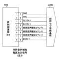
(1)外部ユニット(専用ユニット)から入力される接続確認用電源(VL)が設けられている。
(2)遊技機の起動中に上記(1)の接続確認用電源がONからOFFへと切り替わった場合、遊技球の発射を不能とする発射制御手段(主制御基板、枠制御基板)が設けられている。
The gaming machine of this solution has the following configuration.
(1) A connection confirmation power supply (VL) input from an external unit (dedicated unit) is provided.
(2) A launch control means (main control board, frame control board) is provided that disables the launch of game balls if the power supply for connection confirmation in (1) above switches from ON to OFF while the gaming machine is starting up. It is being
本解決手段によれば、接続確認用電源により外部ユニットとの接続状況を確認し、接続が確認できない場合には遊技球の発射を不能とするため、遊技機と外部ユニットとが正常に接続されていない状態で遊技が実行されることを回避することができ、結果として、斬新な遊技機を提供することができる。 According to this solution, the connection status with the external unit is confirmed using the connection confirmation power supply, and if the connection cannot be confirmed, it is impossible to shoot game balls, so that the game machine and the external unit are properly connected. It is possible to prevent a game from being played in a state where the game machine is not in use, and as a result, a novel game machine can be provided.
解決手段(8)-2:本解決手段の遊技機は、上述したいずれかの解決手段において、遊技機の起動中に前記接続確認用電源がONからOFFへと切り替わり、遊技球の発射が不能とされた状態においても、始動口入賞が行われた場合に図柄の作動記憶を増加させる作動記憶増加手段(主制御基板、枠制御基板、演出制御基板)を備える遊技機である。 Solution (8)-2: In the game machine of this solution, in any of the above-mentioned solutions, the power supply for connection confirmation switches from ON to OFF during startup of the game machine, making it impossible to shoot game balls. Even in this state, this gaming machine is equipped with working memory increasing means (main control board, frame control board, performance control board) that increases the working memory of symbols when a starting opening prize is made.
本解決手段によれば、遊技球の発射が不能とされた状態においても、始動口入賞が行われた場合に図柄の作動記憶(主制御制御基板が表示する保留、演出制御基板が表示する保留)を増加させるため、発射が不能とされる前に発射された遊技球による始動口入賞を保護したり、係員の手入れによる始動口入賞によって遊技機が正常に動作しているか否かを確認したりすることができ、結果として、斬新な遊技機を提供することができる。 According to this solution, even in a state in which it is impossible to launch game balls, when a starting entrance prize is made, the working memory of the symbol (the hold displayed by the main control board, the hold displayed by the performance control board) ) In order to increase the number of game balls that have been fired before firing is disabled, the game machine can be checked to see if it is operating normally due to the start-up winnings caused by the game balls that have been fired by the staff. As a result, a novel gaming machine can be provided.
〔(9)主制御状態1〕
解決手段(9)-1:本解決手段の遊技機は、1ビットを1つのフラグとして扱うビット情報を最大8ビット分保持することが可能な1バイトの情報である特別主制御状態情報を記憶可能な遊技機であって、前記ビット情報の0は、フラグOFFとして扱うことが可能であり、前記ビット情報の1は、フラグONとして扱うことが可能であり、前記特別主制御状態情報は、所定の大当り中にフラグONとなる第1の特定ビット情報と、すべての大当り中にフラグONとなる第2の特定ビット情報と、大当り後に所定の状態へ移行する大当り中にフラグONとなる第3の特定ビット情報とを保持可能であり、前記特別主制御状態情報は、前記第1から第3の特定ビット情報を含む複数の前記ビット情報の組み合せによって255以下の数値として扱うことができ、前記第1の特定ビット情報のみがONとなっている場合には数値の1として、前記第2の特定ビット情報のみがONとなっている場合には数値の2として、前記第3の特定ビット情報のみがONとなっている場合には数値の4として、それぞれ扱うことが可能であり、少なくとも1以上の未使用ビットを有し、前記未使用ビットには0が保持されることを特徴とする遊技機である。
[(9) Main control state 1]
Solution (9)-1: The gaming machine of this solution stores special main control state information, which is 1-byte information that can hold up to 8 bits of bit information, where 1 bit is treated as one flag. The
本解決手段の遊技機は、以下の構成を備えている。
(1)1ビットを1つのフラグとして扱うビット情報を最大8ビット分保持することが可能な1バイトの情報である特別主制御状態情報(主制御状態1)を記憶可能な遊技機である。
The gaming machine of this solution has the following configuration.
(1) This gaming machine is capable of storing special main control state information (main control state 1), which is 1 byte of information that can hold up to 8 bits of bit information in which 1 bit is treated as one flag.
(2)上記(1)のビット情報の0は、フラグOFFとして扱うことが可能である。
(3)上記(1)のビット情報の1は、フラグONとして扱うことが可能である。
(2) 0 in the bit information in (1) above can be treated as a flag OFF.
(3) The
(4)上記(1)の特別主制御状態情報は、所定の大当り中にフラグONとなる第1の特定ビット情報と、すべての大当り中にフラグONとなる第2の特定ビット情報と、大当り後に所定の状態へ移行する大当り中にフラグONとなる第3の特定ビット情報とを保持可能である。 (4) The special main control state information in (1) above includes the first specific bit information that turns on the flag during a predetermined jackpot, the second specific bit information that turns on the flag during all jackpots, and the jackpot. It is possible to hold third specific bit information that turns on the flag during a jackpot that will later transition to a predetermined state.
(5)上記(1)の特別主制御状態情報は、第1から第3の特定ビット情報を含む複数のビット情報の組み合せによって255以下の数値として扱うことができる。なお、第1の特定ビット情報はBit0の情報とすることができ、第2の特定ビット情報はBit1の情報とすることができ、第3の特定ビット情報はBit2の情報とすることができる(以下、同様)。
(5) The special main control state information in (1) above can be handled as a numerical value of 255 or less by combining a plurality of bit information including the first to third specific bit information. Note that the first specific bit information can be
(6)上記(1)の特別主制御状態情報は、第1の特定ビット情報のみがONとなっている場合には数値の1として、第2の特定ビット情報のみがONとなっている場合には数値の2として、第3の特定ビット情報のみがONとなっている場合には数値の4として、それぞれ扱うことが可能であり、少なくとも1以上の未使用ビットを有し、未使用ビットには0が保持される。なお、複数の特定ビット情報がONとなっている場合には数値を加算して扱うことが可能であることが好ましい。
(6) The special main control status information in (1) above will be set to the
本解決手段によれば、大当りの状態や所定の状態等をまとめて管理することによって、管理者からの遊技機の内部状態の把握を容易にし、ビット情報として保持することによって容量の削減となり、結果として、斬新な遊技機を提供することができる。 According to this solution, by collectively managing the jackpot status, predetermined status, etc., the administrator can easily grasp the internal status of the gaming machine, and by retaining it as bit information, the capacity can be reduced. As a result, a novel gaming machine can be provided.
〔(10)主制御状態2〕
解決手段(10)-1:本解決手段の遊技機は、1ビットを1つのフラグとして扱うビット情報を最大8ビット分保持することが可能な1バイトの情報である特殊主制御状態情報を記憶可能な遊技機であって、前記ビット情報の0は、フラグOFFとして扱うことが可能であり、前記ビット情報の1は、フラグONとして扱うことが可能であり、前記特殊主制御状態情報は、少なくとも大当り中にフラグONとなる第1の特定ビット情報と、少なくとも特別図柄抽選の当選確率が高確率状態中にフラグONとなる第2の特定ビット情報と、少なくとも普通図柄又は特別図柄の変動時間が短縮されている時間短縮状態中にフラグONとなる第3の特定ビット情報とを保持可能であり、前記特殊主制御状態情報は、前記第1から第3の特定ビット情報を含む複数の前記ビット情報の組み合せによって255以下の数値として扱うことができ、前記第1の特定ビット情報のみがONとなっている場合には数値の1として、前記第2の特定ビット情報のみがONとなっている場合には数値の2として、前記第3の特定ビット情報のみがONとなっている場合には数値の4として、それぞれ扱うことが可能であり、少なくとも1以上の未使用ビットを有し、前記未使用ビットには0が保持されることを特徴とする遊技機である。
[(10) Main control state 2]
Solution (10)-1: The gaming machine of this solution stores special main control state information, which is 1-byte information that can hold up to 8 bits of bit information, where 1 bit is treated as one flag. The
本解決手段の遊技機は、以下の構成を備えている。
(1)1ビットを1つのフラグとして扱うビット情報を最大8ビット分保持することが可能な1バイトの情報である特殊主制御状態情報(主制御状態2)を記憶可能な遊技機である。
The gaming machine of this solution has the following configuration.
(1) This gaming machine is capable of storing special main control state information (main control state 2), which is 1 byte of information that can hold up to 8 bits of bit information in which 1 bit is treated as one flag.
(2)上記(1)のビット情報の0は、フラグOFFとして扱うことが可能である。
(3)上記(1)のビット情報の1は、フラグONとして扱うことが可能である。
(2) 0 in the bit information in (1) above can be treated as a flag OFF.
(3) The
(4)上記(1)の特殊主制御状態情報は、少なくとも大当り中にフラグONとなる第1の特定ビット情報と、少なくとも特別図柄抽選の当選確率が高確率状態中にフラグONとなる第2の特定ビット情報と、少なくとも普通図柄又は特別図柄の変動時間が短縮されている時間短縮状態中にフラグONとなる第3の特定ビット情報とを保持可能である。 (4) The special main control state information in (1) above includes at least first specific bit information that turns on the flag during a jackpot, and at least second bit information that turns on the flag when the winning probability of the special symbol lottery is high. It is possible to hold the specific bit information and the third specific bit information that turns on the flag during the time reduction state in which the variation time of at least the normal symbol or the special symbol is reduced.
(5)上記(1)の特殊主制御状態情報は、第1から第3の特定ビット情報を含む複数のビット情報の組み合せによって255以下の数値として扱うことができる。 (5) The special main control state information in (1) above can be handled as a numerical value of 255 or less by combining a plurality of bit information including the first to third specific bit information.
(6)上記(1)の特殊主制御状態情報は、第1の特定ビット情報のみがONとなっている場合には数値の1として、第2の特定ビット情報のみがONとなっている場合には数値の2として、第3の特定ビット情報のみがONとなっている場合には数値の4として、それぞれ扱うことが可能であり、少なくとも1以上の未使用ビットを有し、未使用ビットには0が保持される。なお、複数の特定ビット情報がONとなっている場合には数値を加算して扱うことが可能であることが好ましい。
(6) The special main control status information in (1) above is set to 1 when only the first specific bit information is ON, and when only the second specific bit information is ON. If only the third specific bit information is ON, it can be treated as a
本解決手段によれば、各種の内部状態をまとめて管理することによって、管理者からの遊技機の内部状態の把握を容易にし、ビット情報として保持することによって容量の削減となり、結果として、斬新な遊技機を提供することができる。 According to this solution, by collectively managing various internal states, the administrator can easily grasp the internal state of the gaming machine, and by retaining it as bit information, capacity can be reduced, resulting in innovative It is possible to provide gaming machines with
〔(11)遊技球数等表示装置〕
解決手段(11)-1:本解決手段の遊技機は、遊技媒体の数を表示可能な表示装置を備える遊技機において、前記表示装置は、表示可能な最大値として、1回の営業時間で得られる可能性がある遊技媒体の最大数を越える値を表示可能であることを特徴とする遊技機である。
[(11) Display device for number of game balls, etc.]
Solution (11)-1: The gaming machine of this solution is equipped with a display device that can display the number of game media, and the display device can display a maximum value that can be displayed in one business hour. This gaming machine is characterized in that it can display a value that exceeds the maximum number of gaming media that can be obtained.
本解決手段の遊技機は、以下の構成を備えている。
(1)遊技媒体の数を表示可能な表示装置(遊技球等表示装置)を備える遊技機である。
(2)表示可能な最大値として、1回の営業時間(通常営業であれば、12~15時間程度、特殊営業であれば36~40時間程度)で得られる可能性がある遊技媒体の最大数(例えば、平均して1時間に1万発の払い出しがあると仮定すると、最大10000発×最大40時間=400000)を越える値(例えば、500000~999999、好ましくは、990000)を表示可能である。
The gaming machine of this solution has the following configuration.
(1) A gaming machine equipped with a display device (a display device such as a game ball) capable of displaying the number of gaming media.
(2) The maximum value that can be displayed is the maximum amount of gaming media that can be obtained in one business hour (about 12 to 15 hours for normal business hours, about 36 to 40 hours for special business hours). It is possible to display a value (for example, 500,000 to 999,999, preferably 990,000) that exceeds the number (for example, assuming that 10,000 shots are paid out per hour on average, maximum 10,000 shots x maximum 40 hours = 400,000). be.
本解決手段によれば、長時間遊技を行った際に、遊技者が平均的な確率から大きく乖離する遊技利益を得ていた場合であっても、表示装置に表示不可能となる事態を防ぐことができ、結果として、斬新な遊技機を提供することができる。 According to this solution, even if a player has obtained a gaming profit that deviates greatly from the average probability when playing a game for a long time, it is possible to prevent the situation from becoming impossible to display on the display device. As a result, a novel gaming machine can be provided.
〔(12)遊技球(メダル数)クリアスイッチ〕
解決手段(12)-1:本解決手段の遊技機は、主制御基板と、前記主制御基板と通信可能であり、バックアップ情報を記憶可能な枠制御基板と、前記枠制御基板に接続された所定のスイッチと、所定の操作によって前記所定のスイッチが操作された場合、前記バックアップ情報を初期化可能とする初期化手段とを備える遊技機である。
[(12) Game ball (number of medals) clear switch]
Solution (12)-1: The gaming machine of the present solution includes a main control board, a frame control board that can communicate with the main control board and can store backup information, and a frame control board that is connected to the frame control board. This gaming machine includes a predetermined switch and an initialization means that enables the backup information to be initialized when the predetermined switch is operated by a predetermined operation.
本解決手段の遊技機は、以下の構成を備えている。
(1)主制御基板が設けられている。主制御基板には、主制御CPUが搭載されている。
The gaming machine of this solution has the following configuration.
(1) A main control board is provided. A main control CPU is mounted on the main control board.
(2)上記(1)の主制御基板と通信可能であり、遊技媒体に関するバックアップ情報を記憶可能な枠制御基板が設けられている。枠制御基板には、枠制御CPUが搭載されている。 (2) A frame control board is provided that can communicate with the main control board of (1) above and can store backup information regarding game media. A frame control CPU is mounted on the frame control board.
(3)上記(2)の枠制御基板に接続された所定のスイッチ(遊技球クリアスイッチ)が設けられている。所定のスイッチは、遊技情報に関するバックアップ情報をクリアするRAMクリアスイッチ以外のスイッチである。 (3) A predetermined switch (gaming ball clear switch) connected to the frame control board of (2) above is provided. The predetermined switch is a switch other than the RAM clear switch that clears backup information regarding game information.
(4)所定の操作によって所定のスイッチが操作された場合(例えば、遊技球クリアスイッチを押下しながら電源を投入した場合)、遊技媒体に関するバックアップ情報を初期化する初期化処理実行手段(枠制御基板)が設けられている。なお、枠制御基板は、遊技媒体に関するバックアップ情報をバックアップ可能である。 (4) Initialization processing execution means (frame control board) is provided. Note that the frame control board is capable of backing up backup information regarding game media.
本解決手段によれば、所定のスイッチを操作することにより、遊技媒体に関するバックアップ情報を個別に初期化することができ(RAMクリアスイッチを操作しなくても遊技媒体に関するバックアップ情報だけを初期化することができ)、結果として、斬新な遊技機を提供することができる。 According to this solution, backup information related to game media can be initialized individually by operating a predetermined switch (only backup information related to game media can be initialized without operating a RAM clear switch). ), and as a result, a novel gaming machine can be provided.
〔(13)CM起動確認〕
解決手段(13)-1:本解決手段の遊技機は、外部ユニットから入力される接続確認用電源と、遊技機の起動完了後に前記接続確認用電源がONになっていない場合、遊技球の発射を不能とする発射制御手段とを備える遊技機である。
[(13) CM start confirmation]
Solution (13)-1: The game machine of this solution has a connection confirmation power input from an external unit, and if the connection confirmation power is not turned on after the game machine has started up, the game ball This game machine is equipped with a firing control means that disables firing.
本解決手段の遊技機は、以下の構成を備えている。
(1)外部ユニット(専用ユニット)から入力される接続確認用電源(VL)が設けられている。
(2)遊技機の起動完了後に上記(1)の接続確認用電源がONになっていない場合、遊技球の発射を不能とする発射制御手段(主制御基板、枠制御基板)が設けられている。
The gaming machine of this solution has the following configuration.
(1) A connection confirmation power supply (VL) input from an external unit (dedicated unit) is provided.
(2) If the power supply for connection confirmation in (1) above is not turned on after the game machine has started up, a firing control means (main control board, frame control board) is provided that disables the firing of game balls. There is.
本解決手段によれば、外部ユニットが起動していない状態で遊技機が起動状態となった場合には遊技球の発射を不能とするため、外部ユニットが起動していない状態で遊技が実行されることを回避することができ、結果として、斬新な遊技機を提供することができる。 According to this solution, if the game machine enters the activated state with the external unit not activated, the game ball cannot be fired, so the game is executed without the external unit activated. As a result, a novel gaming machine can be provided.
解決手段(13)-2:本解決手段の遊技機は、上述したいずれかの解決手段において、遊技機の起動完了後に前記接続確認用電源がONになっておらず、遊技球の発射が不能とされた状態においても、遊技球が始動口に入賞した場合には図柄の変動を開始させる図柄変動手段(主制御基板、枠制御基板)を備えることを特徴とする遊技機である。 Solution (13)-2: In the gaming machine of this solution, in any of the above-mentioned solutions, the power supply for connection confirmation is not turned on after the startup of the gaming machine is completed, and the game ball cannot be launched. This gaming machine is characterized in that it is equipped with a symbol variation means (main control board, frame control board) that starts variation of the symbols when the game ball enters the starting hole even in this state.
本解決手段によれば、遊技球の発射が不能とされた状態においても、遊技球が始動口に入賞した場合には図柄の変動を開始させるため、発射が不能とされる前に発射された遊技球による始動口入賞によって図柄を変動させたり、係員の手入れによる始動口入賞によって遊技機が正常に動作しているか否かを確認したりすることができ、結果として、斬新な遊技機を提供することができる。 According to this solution, even in a state where the game ball is disabled, if the game ball enters the starting slot, the symbols start changing, so that the game ball is fired before the game ball is disabled. It is possible to change the pattern by winning the starting hole with a game ball, and to check whether the gaming machine is operating normally by checking the starting hole winning by the attendant's care.As a result, a novel gaming machine is provided. can do.
〔(14)遊技情報〕
解決手段(14)-1:本解決手段の遊技機は、主制御基板と、前記主制御基板と所定の電文を用いて通信可能な枠制御基板と、外部ユニットから入力される接続確認用電源とを備え、前記所定の電文には、遊技の情報を示す遊技情報が含まれており、前記遊技情報は、種別情報及び前記種別情報に対応するカウント情報を含み、前記種別情報は、入賞又は通過の発生を表す情報であり、前記カウント情報は、前記種別情報に対応する個数又は回数を表す情報であり、前記種別情報と前記カウント情報は、1対1に対応する情報であり、一方の情報を他方の情報よりも多く保持することはなく、前記遊技情報は、始動口入賞が発生した場合、前記種別情報の上位4ビットに始動口入賞に対応する数値が設定され、前記種別情報の下位4ビットに入賞した始動口の位置に対応する数値が設定され、前記カウント情報の上位4ビットに始動口入賞時の賞球数に対応する数値が設定され、前記カウント情報の下位4ビットに入賞個数に対応する値が設定され、前記遊技情報は、所定期間内に始動口入賞が複数回発生した場合、発生回数に対応して複数作成され、遊技機の起動完了時に前記接続確認用電源がOFFである場合、前記接続確認用電源がONとなるまでは遊技球の発射が行えない状態を維持するが、前記遊技情報を含む電文は周期的に送信し、遊技機の起動完了後に前記接続確認用電源がONからOFFへと切り替わった場合、前記接続確認用電源がONとなるまでは遊技球の発射が行えない状態を維持するが、前記遊技情報を含む前記所定の電文は周期的に送信し、周期的に送信される前記所定の電文の周期は、所定数値以下の周期のずれが許容されていることを特徴とする遊技機である。
[(14) Gaming information]
Solution (14)-1: The gaming machine of this solution includes a main control board, a frame control board that can communicate with the main control board using a predetermined message, and a connection confirmation power supply input from an external unit. The predetermined message includes game information indicating game information, the game information includes type information and count information corresponding to the type information, and the type information includes winning or winning information. The information represents the occurrence of passage, the count information is information representing the number or number of times corresponding to the type information, and the type information and the count information have a one-to-one correspondence; The game information does not hold more information than the other information, and when a starting opening win occurs, a numerical value corresponding to the starting opening winning is set in the upper 4 bits of the type information, and a numerical value corresponding to the starting opening winning is set in the upper 4 bits of the type information. A numerical value corresponding to the position of the winning starting hole is set in the lower 4 bits, a numerical value corresponding to the number of prize balls at the time of winning the starting opening is set in the upper 4 bits of the count information, and a numerical value corresponding to the number of winning balls at the time of winning the starting hole is set in the lower 4 bits of the count information. A value corresponding to the number of winnings is set, and if the starting slot winnings occur multiple times within a predetermined period, multiple pieces of gaming information are created corresponding to the number of occurrences, and when the gaming machine is started, the connection confirmation power supply is set. is OFF, the game ball cannot be fired until the connection confirmation power is turned ON, but the message containing the game information is sent periodically, and the message containing the game information is sent periodically after the game machine is started. When the power supply for connection confirmation is switched from ON to OFF, the state in which game balls cannot be fired is maintained until the power supply for connection confirmation is turned ON, but the predetermined message containing the game information is sent periodically. The gaming machine is characterized in that the cycle of the predetermined message sent periodically is allowed to have a cycle deviation of a predetermined value or less.
本解決手段の遊技機は、以下の構成を備えている。
(1)主制御基板が設けられている。主制御基板には、主制御CPUが搭載されている。
(2)上記(1)の主制御基板と所定の電文を用いて通信可能な枠制御基板が設けられている。枠制御基板には、枠制御CPUが搭載されている。
(3)外部ユニット(専用ユニット)から入力される接続確認用電源が設けられている。
The gaming machine of this solution has the following configuration.
(1) A main control board is provided. A main control CPU is mounted on the main control board.
(2) A frame control board is provided that can communicate with the main control board of (1) above using a predetermined message. A frame control CPU is mounted on the frame control board.
(3) A connection confirmation power source input from an external unit (dedicated unit) is provided.
(4)上記(2)の所定の電文には、遊技の情報を示す遊技情報が含まれている。
(5)上記(4)の遊技情報は、種別情報及び種別情報に対応するカウント情報を含む。
(4) The predetermined message in (2) above includes game information indicating game information.
(5) The game information in (4) above includes type information and count information corresponding to the type information.
(6)上記(5)の種別情報は、入賞(入賞口への入賞)又は通過(始動ゲート、特定領域の通過)の発生を表す情報である。 (6) The type information in (5) above is information representing the occurrence of a winning (winning into a winning opening) or passage (passing through a starting gate or specific area).
(7)上記(5)のカウント情報は、上記(6)の種別情報に対応する個数又は回数を表す情報である。 (7) The count information in (5) above is information representing the number or number of times corresponding to the type information in (6) above.
(8)種別情報とカウント情報は、1対1に対応する情報であり、一方の情報を他方の情報よりも多く保持することはない。 (8) Type information and count information have a one-to-one correspondence, and one type of information is never retained more than the other.
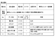
(9)遊技情報は、前回の電文送信以降に始動口入賞が発生している場合、種別情報の上位4ビットに始動口入賞に対応する数値が設定され、種別情報の下位4ビットに入賞した始動口の位置に対応する数値が設定され、カウント情報の上位4ビットに始動口入賞時の賞球数に対応する数値が設定され、カウント情報の下位4ビットには入賞個数に対応する値が設定される。 (9) In the game information, if a starting opening prize has occurred since the previous message transmission, a numerical value corresponding to the starting opening winning is set in the upper 4 bits of the type information, and a value corresponding to the starting opening winning is set in the lower 4 bits of the type information. A numerical value corresponding to the position of the starting hole is set, a numerical value corresponding to the number of winning balls at the time of winning the starting hole is set to the upper 4 bits of the count information, and a value corresponding to the number of winning balls is set to the lower 4 bits of the count information. Set.
(10)遊技情報は、所定期間内に始動口入賞が複数回発生した場合、発生回数に対応して複数作成され、遊技機の起動完了時に接続確認用電源がOFFである場合、接続確認用電源がONとなるまでは遊技球の発射が行えない状態を維持するが、遊技情報を含む電文は周期的に送信し、遊技機の起動完了後に接続確認用電源がONからOFFへと切り替わった場合、接続確認用電源がONとなるまでは遊技球の発射が行えない状態を維持するが、遊技情報を含む所定の電文は周期的に送信する。 (10) If the start-up winnings occur multiple times within a predetermined period, multiple pieces of gaming information will be created corresponding to the number of occurrences, and if the power supply for connection confirmation is OFF when the gaming machine has finished starting up, the game information will be used for connection confirmation. The state in which game balls cannot be fired remains until the power is turned on, but messages containing game information are sent periodically, and the power for connection confirmation switches from ON to OFF after the game machine has started up. In this case, a state in which game balls cannot be fired is maintained until the connection confirmation power source is turned on, but a predetermined message containing game information is periodically transmitted.
(11)周期的に送信される所定の電文の周期は、所定数値以下の周期のずれが許容されている。 (11) For the period of a predetermined message that is periodically transmitted, a deviation of the period of a predetermined value or less is allowed.
本解決手段によれば、遊技機の詳細な遊技情報の把握が可能となり、結果として、斬新な遊技機を提供することができる。 According to this solution, it is possible to grasp detailed game information of a game machine, and as a result, it is possible to provide a novel game machine.
解決手段(14)-2:本解決手段の遊技機は、上述したいずれかの解決手段において、遊技機の起動時に前記接続確認用電源がOFFであっても、始動口入賞が行われた場合に図柄の作動記憶を増加可能とし、遊技機の起動後に前記接続確認用電源がONからOFFに切り替わっても、始動口入賞が行われた場合に図柄の作動記憶を増加可能とする作動記憶増加手段(主制御基板、枠制御基板、演出制御基板)を備えることを特徴とする遊技機である。 Solution (14)-2: In the gaming machine of this solution, in any of the above-mentioned solutions, even if the power supply for connection confirmation is OFF at the time of starting the gaming machine, if a starting gate winning is performed. Increasing the working memory of the symbols, and increasing the working memory of the symbols even if the power supply for connection confirmation is switched from ON to OFF after the gaming machine is started, when a winning start is made. This is a gaming machine characterized by comprising means (main control board, frame control board, performance control board).
本解決手段によれば、遊技機の起動時に接続確認用電源がOFFであっても、始動口入賞が行われた場合に図柄の作動記憶(主制御制御基板が表示する保留、演出制御基板が表示する保留)を増加可能とし、遊技機の起動後に接続確認用電源がONからOFFに切り替わっても、始動口入賞が行われた場合に図柄の作動記憶を増加可能とするため、どのような状況で接続確認用電源がOFFになったとしても、遊技球による始動口入賞を保護したり、係員の手入れによる始動口入賞によって遊技機が正常に動作しているか否かを確認したりすることができ、結果として、斬新な遊技機を提供することができる。 According to this solution, even if the power supply for connection confirmation is OFF when the gaming machine is started, when a start-up winning is made, the working memory of the symbol (the hold displayed by the main control board, the performance control board) In order to make it possible to increase the number of holdings displayed), and to increase the working memory of the symbol in the event that a winning start is made, even if the power supply for connection confirmation is switched from ON to OFF after the gaming machine is started, the working memory of the symbol can be increased. Even if the power supply for connection confirmation is turned off under certain circumstances, it is possible to protect the start-up winnings with game balls, and to check whether the gaming machine is operating normally by checking the starting-up winnings after being maintained by the staff. As a result, a novel gaming machine can be provided.
〔(15)不正検知状態1〕
解決手段(15)-1:本解決手段の遊技機は、1ビットを1つのフラグとして扱うビット情報を最大8ビット分保持することが可能な1バイトの情報である特別不正検知状態情報を記憶可能な遊技機であって、前記ビット情報の0は、フラグOFFとして扱うことが可能であり、前記ビット情報の1は、フラグONとして扱うことが可能であり、前記特別不正検知状態情報は、設定変更中にフラグONとなる第1の特定ビット情報と、設定確認中にフラグONとなる第2の特定ビット情報と、RAMクリア時にフラグONとなる第3の特定ビット情報とを保持可能であり、前記特別不正検知状態情報は、前記第1から第3のビット情報を含む複数の前記ビット情報の組み合せによって255以下の数値として扱うことができ、前記第1の特定ビット情報のみがONとなっている場合には数値の1として、前記第2の特定ビット情報のみがONとなっている場合には数値の2として、前記第3の特定ビット情報のみがONとなっている場合には数値の4として、それぞれ扱うことが可能であり、少なくとも1以上の未使用ビットを有し、前記未使用ビットには0が保持されることを特徴とする遊技機である。
[(15) Fraud detection status 1]
Solution (15)-1: The gaming machine of this solution stores special fraud detection state information, which is 1 byte of information that can hold up to 8 bits of bit information, where 1 bit is treated as one flag. In the case where the bit information is 0, it can be treated as a flag OFF, and the
本解決手段の遊技機は、以下の構成を備えている。
(1)1ビットを1つのフラグとして扱うビット情報を最大8ビット分保持することが可能な1バイトの情報である特別不正検知状態情報(不正検知状態1)を記憶可能な遊技機である。
The gaming machine of this solution has the following configuration.
(1) This gaming machine is capable of storing special fraud detection state information (fraud detection state 1), which is 1 byte of information that can hold up to 8 bits of bit information in which 1 bit is treated as one flag.
(2)上記(1)のビット情報の0は、フラグOFFとして扱うことが可能である。
(3)上記(1)のビット情報の1は、フラグONとして扱うことが可能である。
(2) 0 in the bit information in (1) above can be treated as a flag OFF.
(3) The
(4)上記(1)の特別不正検知状態情報は、設定変更中にフラグONとなる第1の特定ビット情報と、設定確認中にフラグONとなる第2の特定ビット情報と、RAMクリア時にフラグONとなる第3の特定ビット情報とを保持可能である。 (4) The special fraud detection status information in (1) above consists of the first specific bit information that turns on the flag while changing settings, the second specific bit information that turns on the flag while confirming settings, and the second specific bit information that turns on the flag when the RAM is cleared. It is possible to hold third specific bit information that turns on the flag.
(5)上記(1)の特別不正検知状態情報は、第1から第3の特定ビット情報を含む複数のビット情報の組み合せによって255以下の数値として扱うことができる。 (5) The special fraud detection state information in (1) above can be handled as a numerical value of 255 or less by combining a plurality of bit information including the first to third specific bit information.
(6)上記(1)の特別不正検知状態情報は、第1の特定ビット情報のみがONとなっている場合には数値の1として、第2の特定ビット情報のみがONとなっている場合には数値の2として、第3の特定ビット情報のみがONとなっている場合には数値の4として、それぞれ扱うことが可能であり、少なくとも1以上の未使用ビットを有し、未使用ビットには0が保持される。なお、複数の特定ビット情報がONとなっている場合には数値を加算して扱うことが可能であることが好ましい。
(6) The special fraud detection status information in (1) above will be set to 1 if only the first specific bit information is ON, and if only the second specific bit information is ON. If only the third specific bit information is ON, it can be treated as a
本解決手段によれば、設定変更等の状態をまとめて管理することによって、管理者からの遊技機の内部状態の把握を容易にし、ビット情報として保持することによって容量の削減となり、結果として、斬新な遊技機を提供することができる。 According to this solution, by collectively managing the status of settings changes, etc., it is easier for the administrator to understand the internal status of the gaming machine, and by retaining it as bit information, the capacity is reduced, and as a result, A novel gaming machine can be provided.
〔メダルレス遊技機の基本構成〕
解決手段S1:本解決手段の遊技機は、遊技に関する制御を実行可能な主制御部と、前記主制御部と通信可能であり、遊技メダルに関する制御を実行可能なメダル数制御部と、前記メダル数制御部と外部ユニットとの通信を可能にする通信制御手段とを備える遊技機である。
[Basic configuration of medalless gaming machine]
Solving means S1: The gaming machine of the present solving means includes a main control section capable of executing control related to games, a medal number control section capable of communicating with the main control section and capable of executing control related to game medals, and a medal number control section capable of executing control related to game medals. This gaming machine includes a number control section and a communication control means that enables communication with an external unit.
本解決手段の遊技機は、以下の構成を備えている。
(1)遊技に関する制御を実行可能な主制御部(例えば、主制御CPU、主制御ロム)が設けられている。
The gaming machine of this solution has the following configuration.
(1) A main control section (for example, a main control CPU, a main control ROM) that can execute control regarding the game is provided.
(2)上記(1)の主制御部と通信可能であり、遊技メダルに関する制御(遊技メダルの数に関する演算、計算等)を実行可能なメダル数制御部(例えば、メダル数制御CPU、メダル数制御ロム)が設けられている。 (2) A medal number control unit (for example, a medal number control CPU, a medal number control unit, which is capable of communicating with the main control unit in (1) above and can execute control related to game medals (calculations, calculations, etc. related to the number of game medals)) A control ROM) is provided.
主制御部とメダル数制御部とは、それぞれ別の基板(主制御基板、メダル数制御基板)に搭載されていてもよく、同一の基板(主制御基板)に搭載されていてもよい。
主制御部とメダル数制御部とは、それぞれ別のCPU(主制御CPU、メダル数制御CPU)に搭載されていてもよく、同一のCPU(主制御CPU)に搭載されていてもよい。
The main control section and the medal number control section may be mounted on separate boards (main control board, medal number control board), or may be mounted on the same board (main control board).
The main control section and the medal number control section may be installed in separate CPUs (main control CPU, medal number control CPU), or may be installed in the same CPU (main control CPU).
(3)上記(2)のメダル数制御部と外部ユニット(専用ユニット)との通信を可能にする通信制御手段(専用インターフェース、専用ケーブル、及びこれらに付随する装置、基板、回路、CPU、ソフトウェア、プログラム)を備える。 (3) Communication control means (dedicated interface, dedicated cable, and associated devices, boards, circuits, CPUs, software) that enables communication between the medal number control unit in (2) above and an external unit (dedicated unit) , program).
本解決手段によれば、メダル数制御部と外部ユニットとの通信を可能にする通信制御手段を備えているため、メダル数制御部が外部ユニットと情報(信号)のやり取りを行うことができ、結果として、斬新な遊技機を提供することができる。 According to the present solution, since the communication control means that enables communication between the medal number control section and the external unit is provided, the medal number control section can exchange information (signals) with the external unit. As a result, a novel gaming machine can be provided.
〔(T1)メダル数制御基板で投入制御〕
解決手段(T1)-1:本解決手段の遊技機は、遊技に関する制御処理を実行可能な主制御基板と、前記主制御基板及び外部ユニットと通信可能であり、遊技価値(例えば、遊技メダル)の投入に関する投入制御処理を実行可能な遊技価値制御基板(例えば、メダル数制御基板やその他の基板)とを備える遊技機である。
また、本解決手段の遊技機は、遊技に関する制御処理を実行可能な主制御基板と、前記主制御基板及び外部ユニットと通信可能であり、遊技メダルの投入に関する投入制御処理を実行可能なメダル数制御基板とを備える遊技機である。
[(T1) Insertion control using medal number control board]
Solution (T1)-1: The gaming machine of the present solution has a main control board that can execute control processing related to games, and can communicate with the main control board and an external unit, and has a gaming machine that has gaming value (for example, gaming medals). This gaming machine is equipped with a gaming value control board (for example, a medal number control board or other board) that can execute input control processing regarding the input of coins.
In addition, the gaming machine of the present solution has a main control board that can execute control processing related to games, and is capable of communicating with the main control board and an external unit, and has a number of medals that can execute input control processing related to inputting game medals. This gaming machine includes a control board.
本解決手段の遊技機は、以下の構成を備えている。
(1)遊技に関する制御処理(遊技を進行させる制御処理)を実行可能な主制御基板が設けられている。主制御基板には、主制御CPUが搭載されている。
The gaming machine of this solution has the following configuration.
(1) A main control board is provided that can execute control processing related to the game (control processing for advancing the game). A main control CPU is mounted on the main control board.
(2)上記(1)の主制御基板及び外部ユニット(専用ユニット、サンド)と通信可能であり、遊技メダルの投入(例えば、ベット)に関する投入制御処理(遊技メダルの枚数に関する演算処理)を実行可能なメダル数制御基板が設けられている。メダル数制御基板には、メダル数制御CPUが搭載されている。 (2) Can communicate with the main control board and external unit (dedicated unit, sand) mentioned in (1) above, and executes input control processing (calculation processing regarding the number of game medals) regarding input of game medals (for example, bet) A possible medal number control board is provided. A medal number control CPU is mounted on the medal number control board.
本解決手段によれば、メダル数制御基板が投入制御処理を実行可能であるため、主制御基板は投入制御処理を実行する必要がなくなり、その分、主制御基板のプログラム容量を削減したり、主制御基板の処理負担を軽減させたりすることができ、結果として、斬新な遊技機を提供することができる。 According to this solution, since the medal number control board can execute the input control process, the main control board does not need to execute the input control process, and the program capacity of the main control board can be reduced accordingly. The processing load on the main control board can be reduced, and as a result, a novel gaming machine can be provided.
解決手段(T1)-2:本解決手段の遊技機は、上述したいずれかの解決手段において、遊技価値の投入を可能とする遊技価値投入ボタン(例えば、遊技メダル投入ボタン)と、遊技価値の数を記録可能であり、記録されている遊技価値の数を表示可能な遊技価値数表示装置(例えば、遊技メダル数表示装置)とを備え、前記遊技価値制御基板は、前記投入制御処理として、前記遊技価値投入ボタンの操作が検出された場合、前記遊技価値数表示装置に記録されている遊技価値の数を減算し、減算した数の遊技価値を投入する処理を実行可能とすることを特徴とする遊技機である。
また、本解決手段の遊技機は、本解決手段の遊技機は、上述したいずれかの解決手段において、遊技メダルの投入を可能とする遊技メダル投入ボタンと、遊技メダルの枚数を記録可能であり、記録されている遊技メダルの枚数を表示可能な遊技メダル数表示装置とを備え、前記メダル数制御基板は、前記投入制御処理として、前記遊技メダル投入ボタンの操作が検出された場合、前記遊技メダル数表示装置に記録されている遊技メダルの枚数を減算し、減算した枚数の遊技メダルを投入する処理を実行可能とすることを特徴とする遊技機である。
Solution (T1)-2: The gaming machine of the present solution has a gaming value insertion button (for example, a game medal insertion button) that enables the insertion of gaming value, and a gaming machine that enables the insertion of gaming value. and a gaming value number display device (for example, a gaming medal number display device) that can record the number of recorded gaming values and display the number of recorded gaming values, and the gaming value control board may perform the input control process as follows: When the operation of the game value input button is detected, a process of subtracting the number of game values recorded in the game value number display device and inputting the subtracted number of game values can be executed. It is a gaming machine with
In addition, the gaming machine of the present solution means, in any of the above-mentioned solution means, has a game medal insertion button that enables the insertion of game medals, and a game machine that can record the number of game medals. , a game medal number display device capable of displaying the number of recorded game medals, and the medal number control board controls the number of game medals when the operation of the game medal input button is detected as the input control process. This gaming machine is characterized in that it is possible to execute a process of subtracting the number of game medals recorded in a medal number display device and inserting the subtracted number of game medals.
本解決手段では、以下の特徴が追加される。
(1)遊技メダル(遊技媒体、遊技価値)の投入を可能とする遊技メダル投入ボタン(例えば、1ベット用のボタン、MAXベット用のボタン)が設けられている。
(2)遊技メダルの枚数(遊技媒体の量、遊技価値の量)を記録可能であり、記録されている遊技メダルの枚数を表示可能な遊技メダル数表示装置(遊技球数等表示装置)が設けられている。
This solution adds the following features.
(1) A game medal insertion button (for example, a button for 1 bet, a button for MAX bet) is provided that allows the insertion of game medals (game media, game value).
(2) A game medal number display device (game ball number display device) that can record the number of game medals (amount of game media, amount of game value) and can display the number of recorded game medals. It is provided.
(3)メダル数制御基板は、投入制御処理として、遊技メダル投入ボタンの操作が検出された場合(1ベット用のボタンやMAXベット用のボタンの押下が検出された場合)、遊技メダル数表示装置に記録されている遊技メダルの枚数を減算し(-1又は-3の演算を行い)、減算した枚数の遊技メダルを投入する処理(1枚ベット又は3枚ベットする処理)を実行可能とする。 (3) As part of the input control process, the medal number control board displays the number of game medals when the operation of the game medal input button is detected (when the press of the button for 1 bet or the button for MAX bet is detected) It is possible to subtract the number of game medals recorded in the device (perform -1 or -3 calculation) and insert the subtracted number of game medals (process to bet 1 or 3). do.
本解決手段によれば、メダル数制御基板側で、遊技メダルの枚数を減算する処理や遊技メダルを投入する処理を実行することができるので、その分、主制御基板のプログラム容量を削減したり、主制御基板の処理負担を軽減させたりすることができ、結果として、斬新な遊技機を提供することができる。 According to this solution, the process of subtracting the number of game medals and the process of inserting game medals can be executed on the medal number control board side, so the program capacity of the main control board can be reduced accordingly. , the processing load on the main control board can be reduced, and as a result, a novel gaming machine can be provided.
〔(T2)リプレイ抜きやリプレイ込みの投入枚数や払出枚数を専用ユニットへ送信〕
解決手段(T2)-1:本解決手段の遊技機は、所定の有効ライン上に再遊技に対応する図柄の組合せが表示されると、新たな遊技価値の投入を要することなく所定数の遊技価値が設定されることで次回の遊技を可能とする再遊技実行手段と、外部ユニットとの通信を可能にする通信制御手段とを備え、前記通信制御手段は、前記再遊技実行手段によって設定された前記所定数の遊技価値を除いた情報であって電源投入時から累積した遊技価値の投入数に関する総投入数情報(総投入枚数情報)、及び、前記再遊技実行手段によって設定された前記所定数の遊技価値を除いた情報であって電源投入時から累積した遊技価値の払出数に関する総払出数情報(総払出枚数情報)を、前記外部ユニットに送信することを特徴とする遊技機である。
また、本解決手段の遊技機は、所定の有効ライン上に再遊技に対応する図柄の組合せが表示されると、新たな遊技メダルの投入を要することなく所定数の遊技メダルが投入されることで次回の遊技を可能とする再遊技実行手段と、外部ユニットとの通信を可能にする通信制御手段とを備え、前記通信制御手段は、前記再遊技実行手段によって投入された前記所定数の遊技メダルを除いた情報であって電源投入時から累積した遊技メダルの投入枚数に関する総投入枚数情報、及び、前記再遊技実行手段によって投入された前記所定数の遊技メダルを除いた情報であって電源投入時から累積した遊技メダルの払出枚数に関する総払出枚数情報を、前記外部ユニットに送信することを特徴とする遊技機である。
[(T2) Send the number of coins inserted and number of coins paid out, including without replay or including replay, to the dedicated unit]
Solution (T2)-1: The gaming machine of this solution allows a predetermined number of games to be played without requiring the input of new game value when a combination of symbols that corresponds to replay is displayed on a predetermined active line. The player is provided with a replay execution means that enables the next game by setting a value, and a communication control means that enables communication with an external unit, and the communication control means is set by the replay execution means. total input number information (total input number information), which is information excluding the predetermined number of game values that have been inputted since the power was turned on, and the predetermined number set by the replay execution means; The gaming machine is characterized in that total payout number information (total payout number information) regarding the number of payouts of game value accumulated since the power is turned on, which is information excluding the game value of the number, is transmitted to the external unit. .
Furthermore, in the gaming machine of the present solution, when a combination of symbols corresponding to replay is displayed on a predetermined active line, a predetermined number of game medals can be inserted without requiring new game medals to be inserted. and a communication control means that enables communication with an external unit. Total input number information regarding the number of game medals accumulated since the power was turned on, which is information excluding medals, and information excluding the predetermined number of game medals input by the replay execution means, which is information excluding the power supply. This gaming machine is characterized in that information about the total number of game medals to be paid out, which has been accumulated since the time of insertion, is transmitted to the external unit.
本解決手段の遊技機は、以下の構成を備えている。
(1)所定の有効ライン上に再遊技(リプレイ)に対応する図柄の組合せが表示されると、新たな遊技メダルの投入を要することなく所定数の遊技メダルが投入されることで次回の遊技を可能とする(次回の遊技に必要な遊技価値を自動的に投入する)再遊技実行手段が設けられている。
The gaming machine of this solution has the following configuration.
(1) When a symbol combination corresponding to replay is displayed on a predetermined active line, the next game can be started by inserting a predetermined number of game medals without the need to insert new game medals. A re-game execution means is provided that allows the player to play the game again (automatically inputs the game value necessary for the next game).
(2)外部ユニット(専用ユニット)との通信を可能にする通信制御手段(専用インターフェース、専用ケーブル、及びこれらに付随する装置、基板、回路、CPU、ソフトウェア、プログラム)が設けられている。 (2) Communication control means (a dedicated interface, a dedicated cable, and associated devices, boards, circuits, CPUs, software, and programs) that enable communication with an external unit (dedicated unit) is provided.
(3)上記(2)の通信制御手段は、再遊技実行手段によって投入された所定数の遊技メダルを除いた情報であって電源投入時から累積した遊技メダルの投入枚数に関する総投入枚数情報、及び、再遊技実行手段によって投入された所定数の遊技メダルを除いた情報であって電源投入時から累積した遊技メダルの払出枚数に関する総払出枚数情報を、外部ユニットに送信する。 (3) The communication control means in (2) above is information excluding the predetermined number of game medals inserted by the re-game execution means, and the total number of input game medals that has been accumulated since the power was turned on; Then, total payout number information regarding the number of game medals accumulated since power-on, which is information excluding a predetermined number of game medals inserted by the re-game execution means, is transmitted to the external unit.
本解決手段によれば、総投入枚数情報及び総払出枚数情報を、外部ユニットに送信するため、外部ユニットや、外部ユニットに接続されているホールコンピュータ、外部センタにおいて適切に総投入枚数情報及び総払出枚数情報を監視可能となり、結果として、斬新な遊技機を提供することができる。 According to this solution, in order to send the total input number information and the total number of paid coins information to the external unit, the total input number information and the total number of coins are appropriately sent to the external unit, the hall computer connected to the external unit, and the external center. The payout number information can be monitored, and as a result, a novel gaming machine can be provided.
また、総投入枚数情報及び総払出枚数情報は、再遊技実行手段によって投入された所定数の遊技メダルを除いた情報であるため、外部ユニット等では、実際に投入された又は実際に払い出された遊技メダルの情報を正確に把握することができる。 In addition, since the total number of inserted coins information and the total number of coins paid out information are information excluding the predetermined number of game medals inserted by the re-game execution means, external units etc. It is possible to accurately grasp the information on the game medals that have been received.
解決手段(T2)-2:本解決手段の遊技機は、上述したいずれかの解決手段において、前記通信制御手段は、前記再遊技実行手段によって設定された前記所定数の遊技価値を含めた情報であって1回の遊技における遊技価値の投入数(投入枚数)に関する規定数情報、及び、前記再遊技実行手段によって設定された前記所定数の遊技価値を含めた情報であって1回の遊技における遊技価値の払出数(払出枚数)に関する払出数情報(払出枚数情報)を、前記外部ユニットに送信することを特徴とする遊技機。
また、本解決手段の遊技機は、上述したいずれかの解決手段において、前記通信制御手段は、前記再遊技実行手段によって投入された前記所定数の遊技メダルを含めた情報であって1回の遊技における遊技メダルの投入枚数に関する規定数情報、及び、前記再遊技実行手段によって投入された前記所定数の遊技メダルを含めた情報であって1回の遊技における遊技メダルの払出枚数に関する払出枚数情報を、前記外部ユニットに送信し、前記規定数情報及び前記払出枚数情報は、前記外部ユニット用の情報として扱われ、前記外部ユニットに接続されるホールコンピュータ用の情報として扱われることを特徴とする遊技機である。
Solution (T2)-2: In the gaming machine of the present solution, in any of the solution means described above, the communication control means transmits information including the predetermined number of gaming values set by the replay execution means. and information including a specified number of gaming values to be inserted (number of coins inserted) in one game, and the predetermined number of gaming values set by the re-gaming execution means, which can be played in one game. A gaming machine characterized in that payout number information (payout number information) regarding the payout number (payout number of coins) of game value in is transmitted to the external unit.
Further, in the gaming machine of the present solving means, in any of the above-mentioned solving means, the communication control means receives information including the predetermined number of game medals inserted by the re-game execution means, and Prescribed number information regarding the number of game medals inserted in a game, and payout number information regarding the number of game medals paid out in one game, which is information including the predetermined number of game medals inserted by the replay execution means. is transmitted to the external unit, and the prescribed number information and the payout number information are treated as information for the external unit and as information for a hall computer connected to the external unit. It is a gaming machine.
本解決手段では、以下の特徴が追加される。
(1)通信制御手段は、再遊技実行手段によって投入された所定数の遊技メダルを含めた情報であって1回の遊技における遊技メダルの投入枚数に関する規定数情報、及び、再遊技実行手段によって投入された所定数の遊技メダルを含めた情報であって1回の遊技における遊技メダルの払出枚数に関する払出枚数情報を、外部ユニットに送信する。
This solution adds the following features.
(1) The communication control means is configured to provide information including a predetermined number of game medals inserted by the replay execution means, including prescribed number information regarding the number of game medals inserted in one game; Payout number information, which is information including a predetermined number of game medals inserted and is related to the number of game medals paid out in one game, is transmitted to an external unit.
(2)規定数情報及び払出枚数情報は、外部ユニット用の情報として扱われ、外部ユニットに接続されるホールコンピュータ用の情報として扱われることが好ましい。 (2) It is preferable that the prescribed number information and the payout number information be treated as information for an external unit, and as information for a hall computer connected to the external unit.
本解決手段によれば、規定数情報及び払出枚数情報を、外部ユニットに送信するため、外部ユニットや、外部ユニットに接続されているホールコンピュータ、外部センタにおいて適切に規定数情報及び払出枚数情報を監視可能となり、結果として、斬新な遊技機を提供することができる。 According to this solution, in order to send the specified number information and the payout number information to the external unit, the specified number information and the payout number information are appropriately transmitted in the external unit, the hall computer connected to the external unit, and the external center. Monitoring becomes possible, and as a result, a novel gaming machine can be provided.
また、規定数情報及び払出枚数情報は、再遊技実行手段によって投入された所定数の遊技メダルを含めた情報であるため、外部ユニット等では、実際に投入された又は実際に払い出された遊技メダルの情報だけでなく、再遊技を含めた情報を正確に把握することができる。 In addition, since the specified number information and the payout number information include the predetermined number of game medals inserted by the re-game execution means, the external unit etc. It is possible to accurately grasp not only medal information but also information including replays.
さらに、本解決手段によれば、規定数情報及び払出枚数情報は、外部ユニット用の情報として扱われ、外部ユニットに接続されるホールコンピュータ用の情報として扱われるため、規定数情報及び払出枚数情報を、外部ユニットでもホールコンピュータでも同一の情報として扱うことができ、結果として、斬新な遊技機を提供することができる。 Furthermore, according to this solution, the specified number information and the paid-out number information are treated as information for the external unit, and are treated as information for the hall computer connected to the external unit, so the specified number information and the paid-out number information can be handled as the same information in both the external unit and the hall computer, and as a result, a novel gaming machine can be provided.
解決手段(T2)-3:本解決手段の遊技機は、上述したいずれかの解決手段において、前記通信制御手段は、投入した遊技価値の数に関する投入遊技価値数情報(投入メダル数情報)、及び、払い出された遊技価値の数に関する払出遊技価値数情報(払出メダル数情報)を、前記外部ユニットに送信することを特徴とする遊技機である。
また、本解決手段の遊技機は、上述したいずれかの解決手段において、前記通信制御手段は、投入した遊技メダルの枚数に関する投入メダル数情報、及び、払い出された遊技メダルの枚数に関する払出メダル数情報を、前記外部ユニットに送信し、前記投入メダル数情報及び前記払出メダル数情報は、前記外部ユニット用の情報として扱われ、前記外部ユニットに接続されるホールコンピュータ用の情報として扱われないことを特徴とする遊技機である。
Solution (T2)-3: In the gaming machine of the present solution, in any of the above-mentioned solution means, the communication control means inputs information on the number of input gaming values (information on the number of inserted medals), The gaming machine is characterized in that information on the number of paid out game values (information on the number of paid out medals) regarding the number of paid out game values is transmitted to the external unit.
Further, in the gaming machine of the present solving means, in any one of the above-mentioned solving means, the communication control means is configured to transmit input medal number information regarding the number of input game medals and payout medals regarding the number of game medals that have been paid out. number information is transmitted to the external unit, and the input medal number information and the paid medal number information are treated as information for the external unit and not as information for a hall computer connected to the external unit. This gaming machine is characterized by:
本解決手段では、以下の特徴が追加される。
(1)通信制御手段は、投入した遊技メダルの枚数に関する投入メダル数情報、及び、払い出された遊技メダルの枚数に関する払出メダル数情報を、外部ユニットに送信する。
This solution adds the following features.
(1) The communication control means transmits input medal number information regarding the number of input game medals and payout medal number information regarding the number of paid game medals to the external unit.
(2)投入メダル数情報及び払出メダル数情報は、外部ユニット用の情報として扱われ、外部ユニットに接続されるホールコンピュータ用の情報として扱われないことが好ましい。 (2) It is preferable that the information on the number of inserted medals and the information on the number of paid medals be treated as information for the external unit and not as information for the hall computer connected to the external unit.
本解決手段によれば、投入メダル数情報及び払出メダル数情報を、外部ユニットに送信するため、外部ユニットにおいて適切に投入メダル数情報及び払出メダル数情報を監視可能となり、結果として、斬新な遊技機を提供することができる。 According to this solution, information on the number of inserted medals and information on the number of paid out medals is transmitted to the external unit, so it becomes possible to appropriately monitor the information on the number of inserted medals and the number of paid out medals in the external unit, and as a result, an innovative game can be played. machine can be provided.
また、本解決手段によれば、投入メダル数情報及び払出メダル数情報は、外部ユニット用の情報として扱われ、外部ユニットに接続されるホールコンピュータ用の情報として扱われないため、規定数情報及び払出枚数情報を、外部ユニットでは利用しつつ、ホールコンピュータでは利用しないようにすることができ、結果として、斬新な遊技機を提供することができる。 Furthermore, according to the present solution, information on the number of inserted medals and information on the number of paid out medals are treated as information for the external unit and not as information for the hall computer connected to the external unit. The payout number information can be used in the external unit but not used in the hall computer, and as a result, a novel gaming machine can be provided.
本発明によれば、斬新な遊技機を提供することができる。 According to the present invention, a novel gaming machine can be provided.
以下、本発明の実施形態について、図面を参照しながら説明する。
図1は、パチンコ遊技機(以下、「パチンコ機」と略称する。)1の正面図である。また、図2は、パチンコ機1の背面図である。パチンコ機1は、遊技球を遊技媒体として用いるものであり、遊技者は、遊技場運営者から遊技球を借り受けてパチンコ機1による遊技を行う。なお、パチンコ機1における遊技において、遊技球はその1個1個が遊技価値を有した媒体であり、遊技の成果として遊技者が享受する特典(利益)は、例えば遊技者が獲得した遊技球の数に基づいて遊技価値に換算することができる。以下、図1及び図2を参照しつつパチンコ機1の全体構成について説明する。
Embodiments of the present invention will be described below with reference to the drawings.
FIG. 1 is a front view of a pachinko gaming machine (hereinafter abbreviated as "pachinko machine") 1. As shown in FIG. Further, FIG. 2 is a rear view of the
ここで、本明細書では、パチンコ機1に相対するようにして着席した遊技者から見て左側を左とし、遊技者から見て右側を右とし、遊技者から見て上側を上とし、遊技者から見て下側を下とし、遊技者から見て手前側を前とし、遊技者から見て奥側を後として説明している。
Here, in this specification, the left side when viewed from a player seated facing the
〔全体構成〕
パチンコ機1は、その本体として主に外枠ユニット2、一体扉ユニット4及び内枠アセンブリ7(プラ枠、遊技機枠)を備えている。遊技者に相対する正面からみて、その最も前面側には一体扉ユニット4が位置している。一体扉ユニット4の背面側(奥側)には内枠アセンブリ7が位置しており、内枠アセンブリ7の外側を囲むようにして外枠ユニット2が配置されている。
〔overall structure〕
The
外枠ユニット2は、木材及び金属材を縦長の矩形状に組み合わせた構造体であり、この外枠ユニット2は、遊技場内の島設備(図示されていない)に対してねじ等の締結具を用いて固定されるものである。なお、縦長矩形状の外枠ユニット2において、上下の短辺に相当する部位には木材が用いられており、左右の長辺に相当する部位には金属材が用いられている。
The
一体扉ユニット4は、その下部位置に受皿ユニット6が一体化された構造である。一体扉ユニット4及び内枠アセンブリ7は、外枠ユニット2を介して島設備に取り付けられ、これらはそれぞれ図示しないヒンジ機構を介して開閉式に動作する。図示しないヒンジ機構の開閉軸線は、パチンコ機1の正面からみて左側端部に沿って垂直方向に延びている。
The
図1中の正面からみて内枠アセンブリ7の右側縁部(図2では左側縁部)には、その内側に統一錠ユニット9が設けられている。また、これに対応して一体扉ユニット4及び外枠ユニット2の右側縁部(裏側)にも、それぞれ図示しない施錠具が設けられている。図1に示されるように、外枠ユニット2に対して一体扉ユニット4及び内枠アセンブリ7が閉じた状態で、その裏側にある統一錠ユニット9は施錠具とともに一体扉ユニット4及び内枠アセンブリ7の開放を不能にしている。
A
また、受皿ユニット6の右側縁部には鍵穴付きのシリンダ錠6aが設けられている。例えば、遊技場の管理者が専用キーを鍵穴に差し込んでシリンダ錠6aを時計回りに捻ると、統一錠ユニット9が作動して内枠アセンブリ7とともに一体扉ユニット4の開放が可能な状態となる。これら全体を外枠ユニット2から前面側へ開放する(扉のように動かす)と、前面側にてパチンコ機1の裏側が露出することになる。
Furthermore, a cylinder lock 6a with a keyhole is provided on the right side edge of the
一方、シリンダ錠6aを反時計回りに捻ると、内枠アセンブリ7は施錠されたままで一体扉ユニット4の施錠だけが解除され、一体扉ユニット4が開放可能となる。一体扉ユニット4を前面側へ開放すると遊技盤ユニット8が直に露出し、この状態で遊技場の管理者が盤面内での球詰り等の障害を取り除くことができる。また、一体扉ユニット4を開放すると、受皿ユニット6も一緒に前面側へ開放される。
On the other hand, when the cylinder lock 6a is twisted counterclockwise, only the
また、パチンコ機1は、遊技用ユニットとして上記の遊技盤ユニット8を備えている。遊技盤ユニット8は、一体扉ユニット4の背後(内側)で上記の内枠アセンブリ7に支持されている。遊技盤ユニット8は、例えば一体扉ユニット4を前面側へ開放した状態で内枠アセンブリ7に対して着脱可能である。一体扉ユニット4には、その中央部に縦長円形状の窓4aが形成されており、この窓4a内にガラスユニット(参照符号なし)が取り付けられている。ガラスユニットは、例えば窓4aの形状に合わせてカットされた2枚の透明板(ガラス板)を組み合わせたものである。ガラスユニットは、一体扉ユニット4の裏側に図示しない取り付け具を介して取り付けられる。遊技盤ユニット8の前面には遊技領域8a(盤面、遊技盤)が形成されており、この遊技領域8aは窓4aを通じて前面側から遊技者に視認可能である。一体扉ユニット4が閉じられると、ガラスユニットの内面と盤面との間に遊技球が流下できる空間が形成される。
Furthermore, the
受皿ユニット6は、全体的に一体扉ユニット4から前面側へ突出した形状をなしており、その上面に上皿6bが形成されている。この上皿6bには、遊技者に貸し出された遊技球(貸球)や入賞により獲得した遊技球(賞球)を貯留することができる。また、受皿ユニット6には、上皿6bの下段位置に下皿6cが形成されている。この下皿6cには、上皿6bが満杯の状態でさらに払い出された遊技球が貯留される。なお、本実施形態のパチンコ機1はいわゆるCR機(CRユニットに接続する機種)であり、遊技者が借り受けた遊技球は、賞球とは別に裏側の払出装置ユニット172から受皿ユニット6(上皿6b又は下皿6c)に払い出される。
The
受皿ユニット6の上面には貸出操作部14が設けられており、この貸出操作部14には、球貸ボタン10及び返却ボタン12が配置されている。図示しないCRユニットに有価媒体(例えば磁気記録媒体、記憶IC内蔵媒体等)を投入した状態で球貸ボタン10を遊技者が操作すると、予め決められた度数単位(例えば5度数)に対応する個数(例えば125個)分の遊技球が貸し出される。このため貸出操作部14の上面には度数表示部(図示されていない)が配置されており、この度数表示部には、CRユニットに投入されている有価媒体の残存度数が表示される。なお、遊技者は、返却ボタン12を操作することで、度数が残存している有価媒体の返却を受けることができる。本実施形態ではCR機を例に挙げているが、パチンコ機1はCR機とは別の現金機(CRユニットに接続されない機種)であってもよい。
A
また、受皿ユニット6の上面には、上段位置にある上皿6bの手前に上皿球抜きボタン6dが設置されており、そして下皿6cの手前でその中央部には下皿球抜きレバー6eが設置されている。遊技者は上皿球抜きボタン6dを例えば押し込み操作することで、上皿6bに貯留された遊技球を下皿6cへ流下させることができる。また、遊技者は、下皿球抜きレバー6eを例えば左方向へスライドさせることで、下皿6cに貯留された遊技球を下方へ落下させて排出することができる。排出された遊技球は、例えば図示しない球受け箱等に受け止められる。
Further, on the upper surface of the
受皿ユニット6の右下部には、グリップユニット16が設置されている。遊技者はこのグリップユニット16を操作することで発射制御基板セット174を作動させ、遊技領域8aに向けて遊技球を発射する(打ち込む)ことができる(球発射装置)。発射された遊技球は、遊技盤ユニット8の下縁部から左側縁部に沿って上昇し、図示しない外バンドに案内されて遊技領域8a内に放り込まれる。遊技領域8a内には多数の障害釘(遊技くぎ)や風車(図中参照符号なし)等が配置されており、放り込まれた遊技球は障害釘や風車により誘導・案内されながら遊技領域8a内を流下する。なお、遊技領域8a内(盤面、遊技盤)の構成については、別の図面を参照しながらさらに後述する。
A
〔枠前面の構成〕
一体扉ユニット4には、演出用の構成要素として左トップレンズユニット47及び右上電飾ユニット49が設置されている。このうち左トップレンズユニット47にはガラス枠トップランプ46及び左側のガラス枠装飾ランプ48が組み込まれており、右上電飾ユニット49には右側のガラス枠装飾ランプ50が組み込まれている。その他にも一体扉ユニット4には、左トップレンズユニット47及び右上電飾ユニット49の下方にそれぞれ連なるようにして左右のガラス枠装飾ランプ52が設置されており、これらガラス枠装飾ランプ52は、一体扉ユニット4の左右縁部から受皿ユニット6の前面部にまで回り込むようにして延びている。一体扉ユニット4においてガラス枠トップランプ46や左右のガラス枠装飾ランプ50,52等は、ガラスユニットを取り巻くようにして配置されている。
[Configuration of the front of the frame]
A left
上述した各種ランプ46,48,50,52は、例えば内蔵するLEDの発光(点灯や点滅、輝度階調の変化、色調の変化等)により演出を実行する。また、一体扉ユニット4の上部において、左トップレンズユニット47及び右上電飾ユニット49にはそれぞれガラス枠上スピーカ54,55が組み込まれている。一方、外枠ユニット2の左下位置には外枠スピーカ56が組み込まれている。これらスピーカ54,55,56は、効果音やBGM、音声等(音響全般)を出力して演出を実行するものである。
The above-mentioned
また、受皿ユニット6の中央には、上皿6bの手前位置に演出切替ボタン45(操作入力受付手段)が設置されている。演出切替ボタン45は、複数種類の操作(1回押下、複数回押下、連打、長押し等)が可能であり、操作入力を受け付ける。遊技者は、この演出切替ボタン45を押し込み操作(操作入力)することで演出内容(例えば液晶表示器42に表示される背景画面)を切り替えたり、例えば図柄の変動中や大当りの確定表示中、あるいは大当り遊技中に何らかの演出(予告演出、確変昇格演出、大役中の昇格演出等)を発生させたりすることができる。
Further, in the center of the
さらに、演出切替ボタン45の周囲には、演出切替ボタン45を取り囲むようにジョグダイアル45aが設置されている(操作入力受付手段、回転型セレクター)。遊技者は、このジョグダイアル45aを回転させることで、例えば液晶表示器42に表示される演出内容を変化させることができる。
Further, a jog dial 45a is installed around the
〔裏側の構成〕
図2に示されているように、パチンコ機1の裏側には、電源制御ユニット162や主制御基板ユニット170、払出装置ユニット172、流路ユニット173、発射制御基板セット174、払出制御基板ユニット176、裏カバーユニット178等が設置されている。この他にパチンコ機1の裏側には、パチンコ機1の電源系統や制御系統を構成する各種の電子機器類(図示しない制御コンピュータを含む)や外部端子板160、電源コード(電源プラグ)164、アース線(アース端子)166、図示しない接続配線等が設置されている。
[Backside configuration]
As shown in FIG. 2, the back side of the
主制御基板ユニット170には、主制御装置が内蔵されており、主制御装置には、性能表示モニタ200が接続されている。
性能表示モニタ200は、パチンコ機1を裏側から見て、主制御基板ユニット170の左上の領域で視認可能なように主制御装置に配置されており、4つの7セグメントLED201~204を備えている。
The main
The performance display monitor 200 is arranged on the main controller so that it can be seen in the upper left area of the main
性能表示モニタ200(ベース表示装置)は、ベースを表示する。また、性能表示モニタ200は、設定の値(設定値)を表示する。 The performance display monitor 200 (base display device) displays the base. Furthermore, the performance display monitor 200 displays a setting value (setting value).
4つの7セグメントLED201~204は、左右方向に並べて配置されており、それぞれの7セグメントLEDは、10進数のアラビア数字を表示することができる7つのセグメントと、その右下に位置するドットセグメントとによって構成されている。
性能表示モニタ200は、主制御基板ユニット170を覆っている透明ケースを通じて、視認可能である。
The four 7-
The performance display monitor 200 is visible through the transparent case covering the main
また、主制御装置には、RAMクリアスイッチ304及び設定キー用鍵穴306が設けられている。RAMクリアスイッチ304は、RAMクリア(RAM76の初期化)、すなわち、主制御装置内に装備されているRAM(RWM)の初期化を行う際に用いられるスイッチである。また、設定キー用鍵穴306は、設定の変更や設定の参照を行う上で必要とされる設定キーを差し込むための鍵穴である。
The main control device is also provided with a RAM
RAMクリアスイッチ304は、主制御基板ユニット170を覆っている透明ケースに形成された貫通孔を通じて押下可能に設けられている。なお、RAMクリアスイッチ304は、透明ケース外に配置されていてもよい。また、設定キー用鍵穴306は、キーシリンダが透明ケースを貫通した状態(透明ケースがキーシリンダの周囲を囲んだ状態)で設けられている。このため、透明ケースが封止されたままの状態で設定キーを差し込み、回転させることが可能である。
The RAM
RAMクリアスイッチ304は、RAMクリアを行うためのスイッチであり、RAMクリアスイッチ304を押下した状態で電源を投入すると、RAMクリア信号が主制御装置70及び払出制御装置92に入力され、RAMクリア処理が実行される。なお、RAMクリアスイッチ304は、電源制御ユニット162に設けられていてもよい。また、RAMクリア信号を払出制御装置92には入力させず、主制御装置70がRAMクリア信号の入力を受け付けると、主制御装置70が払出制御装置92に対してRAMクリアコマンドを送信する構成としてもよい。
The RAM
なお、図2に示した性能表示モニタ200やRAMクリアスイッチ304、設定キー用鍵穴306の配置位置は、あくまで一例であり、任意の位置に配置することができる。また、性能表示モニタ200やRAMクリアスイッチ304、設定キー用鍵穴306は、主制御装置の外側に設けられて主制御装置に接続される構成としてもよい。
Note that the placement positions of the
上記の払出装置ユニット172は、例えば賞球タンク172a及び賞球ケース(参照符号なし)を有しており、このうち賞球タンク172aは内枠アセンブリ7の上縁部(裏側)に設置された状態で、図示しない補給経路から補給された遊技球を蓄えることができる。賞球タンク172aに蓄えられた遊技球は、図示しない上側賞球樋を通じて賞球ケースに導かれる。流路ユニット173は、払出装置ユニット172から送り出された遊技球を前面側の受皿ユニット6に向けて案内する。
The above-mentioned
また、上記の外部端子板160は、パチンコ機1を外部の電子機器(例えばデータ表示装置、ホールコンピュータ等)に接続するためのものであり、この外部端子板160からは、パチンコ機1の遊技進行状態やメンテナンス状態等を表す各種の外部情報信号(例えば賞球情報、扉開放情報、図柄確定回数情報、大当り情報、始動口情報等)が外部の電子機器に向けて出力されるものとなっている。
The external
電源コード164は、例えば遊技場の島設備に設置された電源装置(例えばAC24V)に接続されることで、パチンコ機1の動作に必要な電源(電力)を確保するものである。また、アース線166は、同じく島設備に設置されたアース端子に接続されることで、パチンコ機1のアース(接地)を確保するものである。
The
図3は、遊技盤ユニット8を単独で示す正面図である。遊技盤ユニット8は、ベースとなる遊技板8bを備えており、この遊技板8bの前面側に遊技領域8aが形成されている。遊技板8bは、例えば透明樹脂板で構成されており、遊技盤ユニット8が内枠アセンブリ7に固定された状態で、遊技板8bの前面はガラスユニットに平行となる。遊技板8bの前面には、略円形状に設置された発射レール(参照符号なし)の内側に上記の遊技領域8aが形成されている。
FIG. 3 is a front view showing the
遊技領域8a内には、その中央位置に比較的大型の演出ユニット40が配置されており、この演出ユニット40を中心として遊技領域8aが左側部分、右側部分及び下部分に大きく分かれている。遊技領域8aの左側部分は、通常遊技状態(低確率非時間短縮状態)又は潜伏確変状態(高確率非時間短縮状態)で使用される第1遊技領域(左打ち領域)であり、遊技領域8aの右側部分は、有利遊技状態(大当り遊技状態、小当り遊技状態、低確率時間短縮状態、高確率時間短縮状態等)で使用される第2遊技領域(右打ち領域、特定の領域)である。また、遊技領域8a内には、演出ユニット40の周辺に中始動入賞口26、始動ゲート20、普通入賞口22,24、可変始動入賞装置28、第1可変入賞装置30、第2可変入賞装置31等が分布して設置されている。
A relatively
このうち、中始動入賞口26は、遊技領域8aの下部分の中央に配置されている。
また、第2可変入賞装置31、始動ゲート20、第1可変入賞装置30及び可変始動入賞装置28は、遊技領域8aの右側部分に、上からこの順番で配置されている。
Among these, the medium
Further, the second variable winning
左側の3つの普通入賞口22は遊技領域8aの左側部分に配置されており、右側の1つの普通入賞口24(所定入賞口)は、始動ゲート20と第1可変入賞装置30との間に配置されている。
The three normal winning holes 22 on the left side are arranged on the left side of the
遊技領域8a内に放り込まれた遊技球は、その流下の過程で中始動入賞口26、普通入賞口22,24に入球したり、開放動作時の第2可変入賞装置31に入球したり、始動ゲート20を通過したり、開放動作時の第1可変入賞装置30に入球したり、開放動作時の可変始動入賞装置28に入球したりする。
The game ball thrown into the
ここで、遊技領域8aの左側領域を流下する遊技球は、主に中始動入賞口26に入球するか、普通入賞口22に入球する可能性がある。一方、遊技領域8aの右側領域を流下する遊技球は、主に、開放動作時の第2可変入賞装置31に入球するか、始動ゲート20を通過するか、普通入賞口24に入球するか、開放動作時の第1可変入賞装置30に入球するか、開放動作時の可変始動入賞装置28に入球する可能性がある。
Here, the game ball flowing down the left side area of the
始動ゲート20を通過した遊技球は続けて遊技領域8a内を流下するが、中始動入賞口26、普通入賞口22,24、可変始動入賞装置28、第1可変入賞装置30、第2可変入賞装置31に入球した遊技球は遊技板(遊技盤ユニット8を構成する合板材、透明板等)に形成された貫通孔を通じて遊技盤ユニット8の裏側へ回収される。
The game ball that has passed through the starting
ここで、本実施形態では、遊技領域8a(盤面)の構成上、中始動入賞口26や普通入賞口22に遊技球を入球させる場合は、遊技領域8a内の左側部分の領域(左打ち領域)に遊技球を打ち込む(いわゆる「左打ち」を実行する)必要がある。
Here, in this embodiment, due to the configuration of the
一方、可変始動入賞装置28や、第1可変入賞装置30、第2可変入賞装置31、普通入賞口24に遊技球を入球させる場合は、遊技領域8a内の右側部分の領域(右打ち領域)に遊技球を打ち込む(いわゆる「右打ち」を実行する)必要がある。
On the other hand, when entering the game ball into the variable
可変始動入賞装置28は、所定の作動条件が満たされた場合(普通図柄が当りの態様で停止表示された場合)に作動し、それに伴って右始動入賞口28a(始動入賞口)への入球を可能にする(普通電動役物)。可変始動入賞装置28は、1つの開閉部材28bを有しており、開閉部材28bは、例えば図示しないソレノイドを用いたリンク機構の働きにより、盤面に沿って左右方向に往復動作する。開閉部材28bは先端が上を向いた状態で閉止位置にあり、このとき右始動入賞口28aへの入球は不能(遊技球が入球できる隙間がない状態)となっている。一方、可変始動入賞装置28が作動すると、開閉部材28bは閉止位置から開放位置に向けて変位し(右方向に倒れこみ)、右始動入賞口28aを開放する。この間に可変始動入賞装置28は遊技球の入球が可能な状態となり、右始動入賞口28aへの入球を発生させることができる(可変始動入賞手段)。なお、このとき開閉部材28bは始動入賞口28aへの遊技球の入球を案内する部材としても機能する。
The variable
第1可変入賞装置30は、規定の条件が満たされた場合(例えば、第1特別図柄が大当りの態様で停止表示された場合、特別図柄が小当りの態様で停止表示された場合、第2特別図柄が「5ラウンド通常図柄」又は「5ラウンド確変図柄」の態様で停止表示された場合)に作動し、第1大入賞口30b(上大入賞口)への入賞を可能にする(特別電動役物、第1特別入賞事象発生手段)。
The first variable winning
第1可変入賞装置30は、1つの開閉部材30aを有しており、開閉部材30aは、例えば図示しないソレノイドを用いたリンク機構の働きにより、盤面に沿って左右方向に往復動作する。開閉部材30aは先端が上を向いた状態で閉止位置にあり、このとき第1大入賞口30bへの入球は不能(遊技球が入球できる隙間がない状態)となっている。一方、第1可変入賞装置30が作動すると、開閉部材30aは閉止位置から開放位置に向けて変位し(左方向に倒れこみ)、第1大入賞口30bを開放する。この間に第1可変入賞装置30は遊技球の入球が可能な状態となり、第1大入賞口30bへの入球を発生させることができる。なお、このとき開閉部材30aは第1大入賞口30bへの遊技球の入球を案内する部材としても機能する。
The first variable
第2可変入賞装置31は、特別な条件が満たされた場合(例えば、第2特別図柄が大当りの態様で停止表示された場合(第2特別図柄が「5ラウンド通常図柄」又は「5ラウンド確変図柄」の態様で停止表示された場合を除く。))に作動し、第2大入賞口31b(下大入賞口)への入賞を可能にする(特別電動役物、第2特別入賞事象発生手段)。
The second variable winning
第2可変入賞装置31は、1つの開閉部材31aを有しており、開閉部材31aは、例えば図示しないソレノイドを用いたリンク機構の働きにより、盤面に沿って左右方向に往復動作する。開閉部材31aは先端が上を向いた状態で閉止位置にあり、このとき第2大入賞口31bへの入球は不能(遊技球が入球できる隙間がない状態)となっている。一方、第2可変入賞装置31が作動すると、開閉部材31aは閉止位置から開放位置に向けて変位し(左方向に倒れこみ)、第2大入賞口31bを開放する。この間に第2可変入賞装置31は遊技球の入球が可能な状態となり、第2大入賞口31bへの入球を発生させることができる。なお、このとき開閉部材31aは第2大入賞口31bへの遊技球の入球を案内する部材としても機能する。
The second variable winning
遊技盤ユニット8に設置されている障害釘の配列や構造物の形状は、基本的に可変始動入賞装置28(開放時の右始動入賞口28a)や第1可変入賞装置30(開放時の第1大入賞口30b)、第2可変入賞装置31(開放時の第2大入賞口31b)へ向かう遊技球の流下を極端に阻害しない態様となっているが、遊技球が開放中の可変始動入賞装置28(右始動入賞口28a)や第1可変入賞装置30(第1大入賞口30b)、第2可変入賞装置31(第2大入賞口31b)に必ず入球するというわけではなく、あくまで入球は無作為に発生する。
The arrangement of the obstacle nails installed in the
遊技盤ユニット8には、その中央位置から右側部分にかけて上記の演出ユニット40が設置されている。演出ユニット40は、その上縁部40aが遊技球の流下方向を変化させる案内部材として機能する他、その内側に各種の装飾部品40b,40cを備えている。装飾部品40b,40cはその立体的な造形により遊技盤ユニット8の装飾性を高めるとともに、例えば内蔵された発光器(LED等)により透過光を発することで、演出的な動作をすることができる。また、演出ユニット40の内側には液晶表示器42(画像表示器)が設置されており、この液晶表示器42には特別図柄に対応させた演出図柄をはじめ、各種の演出画像が表示される。このように遊技盤ユニット8は、その盤面の構成や演出ユニット40の装飾性に基づいて、遊技者にパチンコ機1の特徴を印象付けている。また、遊技板8bが透明樹脂板(例えばアクリル板)である場合、前面側だけでなく遊技板8bの背後に配置された各種の装飾体(可動体や発光体を含む)による装飾性を付加することができる。
The above-mentioned
その他に演出ユニット40の内部には、演出用の可動体40f(例えば動物のキャラクター)とともに駆動源(例えばモータ、ソレノイド等)が付属している。演出用の可動体40fは、液晶表示器42による画像を用いた演出や発光器による演出に加えて、有形物の動作を伴う演出を実行することができる。これら可動体40fを用いた演出により、二次元の画像を用いた演出とは別の訴求力を発揮することができる。
In addition, inside the
また、演出ユニット40の左側縁部には球案内通路40dが形成されており、その下縁部には転動ステージ40eが形成されている。球案内通路40dは遊技領域8a内にて左斜め上方に開口しており、遊技領域8a内を流下する遊技球が無作為に球案内通路40d内に流入すると、その内部を通過して転動ステージ40e上に放出される。転動ステージ40eの上面は滑らかな湾曲面を有しており、ここでは遊技球が左右方向に転動自在である。転動ステージ40e上で転動した遊技球は、やがて下方の遊技領域8a内に流下する。転動ステージ40eの中央位置には球放出路40kが形成されており、転動ステージ40eから球放出路40kに案内された遊技球は、その真下にある中始動入賞口26に流入しやすくなる。
Further, a ball guide passage 40d is formed on the left side edge of the
その他、遊技領域8a内にはアウト口32が形成されており、各種入賞口に入球(入賞)しなかった遊技球は最終的にアウト口32を通じて遊技盤ユニット8の裏側へ回収される。また、普通入賞口22,24や中始動入賞口26、右始動入賞口28a、第1可変入賞装置30、第2可変入賞装置31に入球した遊技球も含めて、遊技領域8a内に打ち込まれた全ての遊技球は遊技盤ユニット8の裏側へ回収される。回収された遊技球は、図示しないアウト通路アセンブリを通じてパチンコ機1の裏側から枠外へ排出され、さらに図示しない島設備の補給経路に合流する。
In addition, an
図4は、遊技盤ユニット8の一部(窓4a内の右側位置)を拡大して示す正面図である。すなわち遊技盤ユニット8には、例えば窓4a内の右側位置に普通図柄表示装置33及び普通図柄作動記憶ランプ33aが設けられている他、第1特別図柄表示装置34、第2特別図柄表示装置35及び遊技状態表示装置38が設けられている。このうち普通図柄表示装置33は、例えば2つのランプ(LED)を交互に点灯させて普通図柄を変動表示し、そしてランプの点灯又は消灯により普通図柄を停止表示する。普通図柄作動記憶ランプ33aは、例えば2つのランプ(LED)の消灯又は点灯、点滅の組み合わせによって0~4個の記憶数を表示する。例えば、2つのランプをともに消灯させた表示態様では記憶数0個を表示し、1つのランプを点灯させた表示態様では記憶数1個を表示し、同じ1つのランプを点滅させた表示態様では記憶数2個を表示し、1つのランプの点滅に加えてもう1つのランプを点灯させた表示態様では記憶数3個を表示し、そして2つのランプをともに点滅させた表示態様では記憶数4個を表示する、といった具合である。なお、ここでは2つのランプ(LED)を使用することとしているが、4つのランプ(LED)を使用して普通図柄作動記憶ランプ33aを構成してもよい。この場合、点灯するランプの個数で作動記憶数を表示することができる。
FIG. 4 is an enlarged front view of a part of the game board unit 8 (the right side position in the window 4a). That is, the
普通図柄作動記憶ランプ33aは、上記の始動ゲート20を遊技球が通過すると、その都度、作動抽選の契機となる通過が発生したことを記憶する意味で1個ずつ増加後の表示態様へと変化していき(最大4個まで)、その通過を契機として普通図柄の変動が開始されるごとに1個ずつ減少後の表示態様へと変化していく。なお、本実施形態では、普通図柄作動記憶ランプ33aが未点灯(記憶数が0個)の場合、普通図柄が既に変動開始可能な状態(停止表示時)で始動ゲート20を遊技球が通過しても表示態様は変化しない。すなわち、普通図柄作動記憶ランプ33aの表示態様によって表される記憶数(最大4個)は、その時点で未だ普通図柄の変動が開始されていない通過の回数を表している。
Each time a game ball passes through the starting
また、第1特別図柄表示装置34及び第2特別図柄表示装置35は、例えばそれぞれ7セグメントLED(ドット付き)により、対応する第1特別図柄又は第2特別図柄の変動状態と停止状態とを表示することができる(図柄表示手段)。なお、第1特別図柄表示装置34や第2特別図柄表示装置35は、複数のドットLEDを幾何学的(例えば円形状)に配列した形態であってもよい。
In addition, the first special
また、第1特別図柄作動記憶ランプ34a及び第2特別図柄作動記憶ランプ35aは、例えばそれぞれ2つのランプ(LED)の消灯又は点灯、点滅の組み合わせで構成される表示態様により、それぞれ0~4個の記憶数を表示する(記憶数表示手段)。例えば、2つのランプをともに消灯させた表示態様では記憶数0個を表示し、1つのランプを点灯させた表示態様では記憶数1個を表示し、同じ1つのランプを点滅させた表示態様では記憶数2個を表示し、1つのランプの点滅に加えてもう1つのランプを点灯させた表示態様では記憶数3個を表示し、そして2つのランプをともに点滅させた表示態様では記憶数4個を表示する、といった具合である。
In addition, the first special symbol
第1特別図柄作動記憶ランプ34aは、中始動入賞口26に遊技球が入球するごとに、中始動入賞口26に遊技球が入球したことを記憶する意味で1個ずつ増加後の表示態様へと変化していき(最大4個まで)、その入球を契機として特別図柄の変動が開始されるごとに1個ずつ減少後の表示態様へと変化していく。また、第2特別図柄作動記憶ランプ35aは、可変始動入賞装置28に遊技球が入球するごとに、右始動入賞口28aに遊技球が入球したことを記憶する意味で1個ずつ増加後の表示態様へと変化し(最大4個まで)、その入球を契機として特別図柄の変動が開始されるごとに1個ずつ減少後の表示態様へと変化する。なお、本実施形態では、第1特別図柄作動記憶ランプ34aが未点灯(記憶数が0個)の場合、第1特別図柄が既に変動開始可能な状態(停止表示時)で中始動入賞口26に遊技球が入球しても表示態様は変化しない。また、第2特別図柄作動記憶ランプ35aが未点灯(記憶数が0個)の場合、第2特別図柄が既に変動開始可能な状態(停止表示時)で可変始動入賞装置28に遊技球が入球しても表示態様は変化しない。すなわち、各特別図柄作動記憶ランプ34a,35aの表示態様により表される記憶数(最大4個)は、その時点で未だ第1特別図柄又は第2特別図柄の変動が開始されていない入球の回数を表している。
The first special symbol
また、遊技状態表示装置38には、例えば大当り種別表示ランプ38a,38b,38c、確率変動状態表示ランプ38d、時短状態表示ランプ38e、発射位置指定ランプ38fにそれぞれ対応するLEDが含まれている。なお、本実施形態では、上述した普通図柄表示装置33や普通図柄作動記憶ランプ33a、第1特別図柄表示装置34、第2特別図柄表示装置35、第1特別図柄作動記憶ランプ34a、第2特別図柄作動記憶ランプ35a及び遊技状態表示装置38が1枚の統合表示基板89に実装された状態で遊技盤ユニット8に取り付けられている。
Further, the game
〔制御上の構成〕
次に、パチンコ機1の制御に関する構成について説明する。
図5は、パチンコ機1に装備された各種の電子機器類を示すブロック図である。パチンコ機1は、制御動作の中枢となる主制御装置70(主制御用コンピュータ)を備えており、この主制御装置70は主に、パチンコ機1における遊技の進行(内容)を制御する機能を有している。なお、主制御装置70は、主制御基板ユニット170に内蔵されている。
[Control configuration]
Next, a configuration related to control of the
FIG. 5 is a block diagram showing various electronic devices installed in the
また、主制御装置70には、中央演算処理装置である主制御CPU72を実装した回路基板(主制御基板)が装備されており、主制御CPU72は、図示しないCPUコアやレジスタとともにROM74、RAM(RWM)76等の半導体メモリを集積したLSIとして構成されている。また、主制御装置70には、乱数回路(乱数発生器)75や割込みコントローラ(割込みCTR)192、パラレルI/Oポート79、タイマ回路(PTC)194、シリアル通信回路(SCU)196が装備されている。このうち乱数回路75は、特別図柄抽選の大当り判定用や普通図柄抽選の当り判定用にハードウェア乱数(例えば10進数表記で0~65535)を発生させるものであり、ここで発生された乱数は主制御CPU72に入力される。また、割込みコントローラ192は、パラレルI/Oポート79、タイマ回路194、シリアル通信回路196から各割込み要求(XINT割込み、PTC割込み、SCU割込み)を受け付け、これらの割込み要求を優先順位に基づき制御する。その他にも主制御装置70には、RAM76の初期化を行うためや設定変更等を行うためのRAMクリアスイッチ71や、パラレルI/Oポート79、図示しないクロック発生回路、様々な状態を監視し必要に応じてリセットを発生させるリセットコントローラ等の周辺ICが装備されており、これらは主制御CPU72とともに回路基板上に実装されている。なお、回路基板上(又は内層部分)には、信号伝送経路や電源供給経路、制御用バス等が配線パターンとして形成されている。なお、主制御装置70のI/Oポートはシリアル形式としてもよい。
The
さらに、主制御装置70には、設定変更装置300、設定キースイッチ302、RAMクリアスイッチ304が設けられている。主制御装置70(主制御CPU72)は、設定変更装置300を動作させることにより設定を変更する。設定変更装置300は、設定(少なくとも特別図柄抽選の当選確率に関する設定)を切り替える装置であり、パチンコ機1に備えられたRAMクリアスイッチ304等の操作により作動する(設定変更手段)。また、設定とは、作動確率の組み合わせをいう。さらに、作動確率とは、条件装置が作動することとなる(大当り遊技が実行されることとなる)特別図柄の組み合わせが表示される確率をいう。設定キースイッチ302は、設定を切り替える上で必須となる設定キーの回転に伴い、その回転状態を示す信号(ON/OFF)を入力する入力装置である。設定の変更の手順は、様々な手法を採用することができるが、例えば、以下の手順で行うことができる。
Furthermore, the
(1)まず、パチンコ機1の電源をOFFにする。
(2)ついで、専用キー(ドアキー)でパチンコ機1の扉を開ける。具体的には、専用キーをシリンダ錠6aの鍵穴に差し込んで右方向に回転し、内枠アセンブリ7とともに一体扉ユニット4を開放する。
(3)パチンコ機1の内部には、設定キーを挿入するための設定キー用鍵穴と、RAMクリアスイッチ304とが設けられているため、設定キー用鍵穴に設定キーを挿入し、設定キーを右方向に回転する。
(4)そして、パチンコ機1の電源をONにする。
(1) First, turn off the power of the
(2) Next, open the door of
(3) Inside the
(4) Then, turn on the power of the
(5)これにより、設定キーが変更位置に回転されたことを示す信号(ON)が設定キースイッチ302により入力され、この入力信号に基づいて設定の変更が可能な状態となる。このとき、図示しないロック機構により安全ロックが掛けられる。したがって、設定キーは、元の位置に戻されない限りは抜き取ることが不可能となる。
(5) As a result, a signal (ON) indicating that the setting key has been rotated to the change position is input by the setting
ここで、設定キーを右方向に回転した状態で、RAMクリアスイッチ304をONにしながら、電源をONにすると、設定の値が変更可能な状態となる(設定変更状態)。一方、設定キーを右方向に回転した状態で、RAMクリアスイッチ304をONにせずに、電源をONにすると、設定の値が確認可能な状態となる(設定確認状態、設定参照状態)。
Here, when the setting key is rotated to the right and the RAM
(6)設定の変更が可能な状態において、RAMクリアスイッチ304を任意の回数だけ押下することにより、例えば、6段階のうちのいずれかの段階に設定を変更することができる。
設定値は、例えば、性能表示モニタ200や、専用の7セグセグメントLED、遊技状態表示装置38(特別図柄表示装置等)に表示することができる。
(6) In a state where the settings can be changed, by pressing the RAM
The set value can be displayed, for example, on the
(7)スロット機の場合、目的の設定に達したら、レバーON処理が必要になるが、パチンコ機1にはレバーが存在しないため、レバーON処理の代わりの代替処理(例えば、設定キーを左方向に回転する処理、不図示の設定変更確定ボタンをONにする処理等)を実行したり、レバーON処理を省略したりしてもよい。本実施形態では、目的の設定に達したら、設定キーを反時計回りに回転させて元の位置に戻す。この操作により、設定キーが元の位置に戻されたことを示す信号(OFF)が設定キースイッチ302により入力され、この入力信号に基づいて設定の変更が確定する。
(7) In the case of a slot machine, when the desired setting is reached, a lever ON process is required, but since
(8)そして、設定の変更が確定すると、設定キーを設定キー用鍵穴から抜き取ることができる状態となる。この動作により、性能表示モニタ200や、専用の7セグセグメントLED、遊技状態表示装置38に設定値を表示している場合には、その表示が消える。
(9)最後に、パチンコ機1の扉を閉める。これにより、設定の変更が完了する。設定の変更が完了すると、通常の遊技が開始される。
(8) When the setting change is confirmed, the setting key can be removed from the setting key keyhole. By this operation, if the setting value is displayed on the
(9) Finally, close the door of
設定が変更された場合、主制御CPU72は、変更後の設定値をRAM76の設定値バッファに記憶する。設定値バッファは、バックアップの対象となるメモリ領域とすることができる。
When the setting is changed, the
〔設定変更の概要〕
設定変更の概要は、以下の通りである。
「設定キーON」、「内枠開放状態」、かつ、「RAMクリアスイッチ押下状態」で電源を投入すると、RAMクリア後、設定変更中の状態(設定変更モード)となる。
設定変更中の状態では、メイン表示器(遊技状態表示装置38に含まれる各種ランプ)の表示はなく、遊技球の発射や遊技球の賞球等は一切できない状態となる。
[Summary of setting changes]
An overview of the setting changes is as follows.
When the power is turned on with the "setting key ON", the "inner frame open state", and the "RAM clear switch pressed state", the RAM is cleared and then the setting is changed (setting change mode).
In the state where the settings are being changed, there is no display on the main display (various lamps included in the game status display device 38), and it becomes impossible to shoot game balls or win game balls at all.
この場合、性能表示モニタ200の左側2つの7セグメントLED(識別セグ)に「rn.」が表示され、右側2つの7セグメントLED(比率セグ)に「-1」のように設定値が表示される。また、RAMクリアスイッチを押下すると、設定値が1~6の範囲で変化する。
In this case, "rn." is displayed on the two 7-segment LEDs (identification segments) on the left side of the
そして、「設定キーOFF」にすると、設定確定となり、比率セグの表示は「空欄(非表示)1」のように「-」のセグが消灯する(非表示となる)。
この状態で、内枠閉鎖となった場合(実際には閉鎖状態が100ms継続した場合)、設定変更中の状態は終了となり、一旦、電源断前の状態に移行してから、遊技可能状態に移行する。
Then, when the setting key is turned OFF, the setting is confirmed, and the "-" segment is turned off (hidden) as shown in "blank (non-display) 1" in the ratio segment display.
In this state, if the inner frame is closed (actually, if the closed state continues for 100ms), the state in which the settings are being changed will end, and the state will return to the state before the power was turned off, and then the state will return to the state where you can play. Transition.
本実施形態では、RAMクリアスイッチ304と設定変更スイッチとを兼用している例で説明しているが、RAMクリアスイッチ304とは別に設定変更スイッチを別途設けてもよい。
In this embodiment, an example is described in which the RAM
〔設定確認の概要〕
設定確認(設定参照)の概要は、以下の通りである。
「設定キーON」、「内枠開放状態」、かつ、「RAMクリアスイッチ押下でない状態」で電源を投入すると、設定確認中の状態(設定確認モード)となる。
設定変更中の状態と同様に、設定確認中の状態では、メイン表示器の表示はなく、遊技球の発射や遊技球の賞球等は一切できない状態となる。
[Overview of setting confirmation]
The outline of setting confirmation (setting reference) is as follows.
When the power is turned on with the "setting key ON", the "inner frame open state", and the "RAM clear switch not pressed", the device enters a state in which settings are being confirmed (setting confirmation mode).
Similar to the state in which the settings are being changed, in the state in which the settings are being confirmed, there is no display on the main display, and it is impossible to fire game balls or win any game balls.
この場合、性能表示モニタの左側2つの7セグメントLED(識別セグ)に「rn.」が表示され、右側2つの7セグメントLED(比率セグ)に「空欄(非表示)1」のように設定値が表示される。また、設定確認中の状態では、RAMクリアスイッチを押下しても、設定値は変化しない。 In this case, "rn." will be displayed on the two 7-segment LEDs (identification segment) on the left side of the performance display monitor, and the setting value will be "blank (non-display) 1" on the two 7-segment LEDs (ratio segment) on the right side. is displayed. Further, while the settings are being confirmed, the set values do not change even if the RAM clear switch is pressed.
この状態で、「設定キーOFF」、かつ、「内枠閉鎖状態」となった場合(実際には閉鎖状態が100ms継続した場合)、設定確認中の状態は終了となり、一旦、電源断前の状態に移行してから、遊技可能状態に移行する。
なお、本実施形態では、遊技可能状態で設定確認を行うことはできないが、遊技可能状態で設定確認を実行可能にしてもよい。
In this state, if the "setting key is OFF" and the "inner frame is closed" (actually, the closed state continues for 100ms), the state in which the settings are being checked will end, and the state, and then shifts to a game-ready state.
In addition, in this embodiment, although it is not possible to confirm the settings in the gaming enabled state, the setting confirmation may be made executable in the gaming enabled state.
上述した始動ゲート20には、遊技球の通過を検出するためのゲートスイッチ78が一体的に設けられている。また、遊技盤ユニット8には、中始動入賞口26、可変始動入賞装置28、第1可変入賞装置30及び第2可変入賞装置31にそれぞれ対応して中始動入賞口スイッチ80、右始動入賞口スイッチ82、第1カウントスイッチ84及び第2カウントスイッチ85が装備されている。各始動入賞口スイッチ80,82は、中始動入賞口26、可変始動入賞装置28(右始動入賞口28a)への遊技球の入球を検出するためのものである。また、第1カウントスイッチ84は、第1可変入賞装置30(第1大入賞口)への遊技球の入球を検出し、その数をカウントするためのものである。さらに、第2カウントスイッチ85は、第2可変入賞装置31(第2大入賞口31b)への遊技球の入球を検出し、その数をカウントするためのものである。
The starting
同様に遊技盤ユニット8には、普通入賞口22への遊技球の入球を検出する第1入賞口スイッチ86と、普通入賞口24への遊技球の入球を検出する第2入賞口スイッチ81とが装備されている。なお、左側の3つの普通入賞口22については、共通の入賞口スイッチ86を用いる構成を例に挙げているが、例えば3つの入賞口スイッチを設置して、各普通入賞口22に対する遊技球の入球を個別に検出してもよい。
Similarly, the
いずれにしても、これらスイッチ類の入賞検出信号は、図示しない入出力ドライバを介して主制御CPU72に入力される。なお、遊技盤ユニット8の構成上、本実施形態ではゲートスイッチ78、第1カウントスイッチ84、第2カウントスイッチ85、第1入賞口スイッチ86、第2入賞口スイッチ81からの入賞検出信号は、パネル中継端子板87を経由して送信され、パネル中継端子板87には、それぞれの入賞検出信号を中継するための配線パターンや接続端子等が設けられている。
In any case, winning detection signals from these switches are input to the
また、遊技盤ユニット8には、アウトスイッチ99が設けられている。遊技盤ユニット8には、普通入賞口22,24、中始動入賞口26、右始動入賞口28a、第1大入賞口30b、第2大入賞口31b、アウト口32を通過した遊技球を合流させる合流通路が形成されており、この合流通路にアウトスイッチ99が設けられている。アウトスイッチ99は、合流通路を通過する遊技球を検出するものであり、遊技球を検出するたびに検出信号が主制御装置70に入力される。主制御装置70は、アウトスイッチ99から入力される検出信号に基づいて、アウト球の数を計数する。ここで、遊技領域8aに発射された遊技球は、必ず、合流通路を通過してパチンコ機1の外部に排出されることから、アウトスイッチ99は、遊技領域8aに発射された発射球数、つまり、遊技領域8aから排出される排出数(アウト球数)を計数する。
Furthermore, the
上述した普通図柄表示装置33や普通図柄作動記憶ランプ33a、第1特別図柄表示装置34、第2特別図柄表示装置35、第1特別図柄作動記憶ランプ34a、第2特別図柄作動記憶ランプ35a及び遊技状態表示装置38は、主制御CPU72からの制御信号に基づいて表示動作を制御されている。主制御CPU72は、遊技の進行状況に応じてこれら表示装置33,34,35,38及びランプ33a,34a,35aに対する制御信号を出力し、各LEDの点灯状態を制御している。また、これら表示装置33,34,35,38及びランプ33a,34a,35aは、上述したように1枚の統合表示基板89に実装された状態で遊技盤ユニット8に設置されており、この統合表示基板89にはパネル中継端子板87を中継して主制御CPU72から制御信号が送信される。
The above-mentioned normal
また、主制御装置70には、パネル中継端子板87を介して、性能表示モニタ200が接続されている。性能表示モニタ200は、主制御CPU72からの制御信号に基づいて表示動作が制御される。主制御CPU72は、ベースの算出状況に応じて性能表示モニタ200に対する制御信号を出力し、7セグメント201~204の点灯状態を制御する。
なお、性能表示モニタ200は、パネル中継端子板87を介して主制御装置70に接続する例で説明しているが、パネル中継端子板87を介さずに主制御装置70に接続してもよく、主制御装置70の内部の構成として性能表示モニタ200を配置してもよい。
Further, a performance display monitor 200 is connected to the
Although the performance display monitor 200 is described as being connected to the
また、遊技盤ユニット8には、可変始動入賞装置28、第1可変入賞装置30及び第2可変入賞装置31にそれぞれ対応して、普通電動役物ソレノイド88、第1大入賞口ソレノイド90及び第2大入賞口ソレノイド97が設けられている。これらソレノイド88,90,97は主制御CPU72からの制御信号に基づいて動作(励磁)し、それぞれ可変始動入賞装置28、第1可変入賞装置30及び第2可変入賞装置31を開閉動作(作動)させる。なお、これらソレノイド88,90,97についてもパネル中継端子板87を中継して主制御CPU72から制御信号が送信される。
In addition, the
その他に一体扉ユニット4にはガラス枠開放スイッチ91が設置されており、また、内枠アセンブリ7にはプラ枠開放スイッチ93が設置されている。一体扉ユニット4が単独で開放されると、ガラス枠開放スイッチ91からの接点信号が主制御装置70(主制御CPU72)に入力され、また、外枠ユニット2から内枠アセンブリ7が開放されると、プラ枠開放スイッチ93からの接点信号が主制御装置70(主制御CPU72)に入力される。主制御CPU72は、これら接点信号から一体扉ユニット4や内枠アセンブリ7の開放状態を検出することができる。なお、主制御CPU72は、一体扉ユニット4や内枠アセンブリ7の開放状態を検出すると、外部情報信号として扉開放情報信号を生成する。
In addition, a glass
パチンコ機1の裏側には、払出制御装置92が装備されている。この払出制御装置92(払出制御コンピュータ)は、上述した払出装置ユニット172の動作を制御する。払出制御装置92には、払出制御CPU94を実装した回路基板(払出制御基板)が装備されており、この払出制御CPU94もまた、図示しないCPUコアとともにROM96、RAM(RAM)98等の半導体メモリを集積したLSIとして構成されている。払出制御装置92(払出制御CPU94)は、主制御CPU72からの賞球指示コマンドに基づいて払出装置ユニット172の動作を制御し、要求された個数の遊技球の払出動作を実行させる。なお、主制御CPU72は賞球指示コマンドとともに、外部情報信号として賞球情報信号を生成する。
A
払出制御装置92は、主制御装置70と通信可能であり、主制御装置70から送信される払出コマンドに基づいて遊技球を払い出す。
The
払出装置ユニット172の図示しない賞球ケース内には、払出モータ102(例えばステッピングモータ)とともに払出装置基板100が設置されており、この払出装置基板100には払出モータ102の駆動回路が設けられている。払出装置基板100は、払出制御装置92(払出制御CPU94)からの払出数指示信号に基づいて払出モータ102の回転角度を具体的に制御し、指示された数の遊技球を賞球ケースから払い出させる。払い出された遊技球は、流路ユニット173内の払出流路を通って受皿ユニット6に送られる。
A
また、例えば賞球ケースの上流位置には払出路球切れスイッチ104が設置されている他、払出モータ102の下流位置には払出計数スイッチ106が設置されている。払出モータ102の駆動により実際に賞球が払い出されると、その都度、払出計数スイッチ106からの計数信号が払出装置基板100に入力される。また、賞球ケースの上流位置で球切れが発生すると、払出路球切れスイッチ104からの接点信号が払出装置基板100に入力される。払出装置基板100は、入力された計数信号や接点信号を払出制御装置92(払出制御CPU94)に送信する。払出制御CPU94は、払出装置基板100から受信した信号に基づき、実際の払出数や球切れ状態を検知することができる。
Further, for example, a payout road ball cut-
また、パチンコ機1には、例えば下皿6cの内部(パチンコ機1の正面からみて奧の位置)に満タンスイッチ161が設置されている。実際に払い出された賞球(遊技球)は流路ユニット173を通じて上皿6bに放出されるが、上皿6bが遊技球で満杯になると、それ以上に払い出された遊技球は上述したように下皿6cへ流れ込む。さらに、下皿6cが遊技球で満杯になると、それによって満タンスイッチ161がONになり、満タン検出信号が払出制御装置92(払出制御CPU94)に入力される。これを受けて払出制御CPU94は、主制御CPU72から賞球指示コマンドを受信してもそれ以上の賞球動作を一旦保留とし、未払出の賞球残数をRAM98に記憶させておく。なお、RAM98の記憶は電源断時にもバックアップが可能であり、遊技中に停電(瞬間的な停電を含む)が発生しても、未払出の賞球残数情報が消失してしまうことはない。
Further, in the
また、パチンコ機1の裏側には、発射制御基板108とともに発射ソレノイド110が設置されている。また、受皿ユニット6内には球送りソレノイド111が設けられている。これら発射制御基板108、発射ソレノイド110及び球送りソレノイド111は上述した発射制御基板セット174を構成しており、このうち発射制御基板108には発射ソレノイド110及び球送りソレノイド111の駆動回路が設けられている。このうち球送りソレノイド111は、受皿ユニット6内に蓄えられた遊技球を1個ずつ、発射機ケース内で所定の発射位置に送り出す動作を行う。また、発射ソレノイド110は、発射位置に送り出された遊技球を打撃し、上述したように遊技領域8aに向けて遊技球を1個ずつ連続的(間欠的)に打ち出す動作を行う。なお、遊技球の発射間隔は、例えば0.6秒程度の間隔(1分間で100個以内)である。
Further, on the back side of the
一方、パチンコ機1の表側に位置するグリップユニット16には、発射レバーボリューム112、タッチセンサ114及び発射停止スイッチ116が設けられている。このうち発射レバーボリューム112は、遊技者による発射ハンドルの操作量(いわゆるストローク)に比例したアナログ信号を生成する。また、タッチセンサ114は、静電容量の変化から遊技者の身体がグリップユニット16(発射ハンドル、球発射装置)に触れていることを検出し、その検出信号を出力する。そして、発射停止スイッチ116は、遊技者の操作に応じて発射停止信号(接点信号)を生成する。
On the other hand, the
受皿ユニット6には発射中継端子板118が設置されており、発射レバーボリューム112やタッチセンサ114、発射停止スイッチ116からの各信号は、発射中継端子板118を経由して発射制御基板108に送信される。また、発射制御基板108からの駆動信号は、発射中継端子板118を経由して球送りソレノイド111に印加される。遊技者が発射ハンドルを操作すると、その操作量に応じて発射レバーボリューム112でアナログ信号(エンコードされたデジタル信号でもよい)が生成され、このときの信号に基づいて発射ソレノイド110が駆動される。これにより、遊技者の操作量に応じて遊技球を打ち出す強さが調整されるものとなっている。なお、発射制御基板108の駆動回路は、タッチセンサ114からの検出信号がオフ(ローレベル)の場合か、もしくは発射停止スイッチ116から発射停止信号が入力された場合は発射ソレノイド110の駆動を停止する。この他に、発射中継端子板118には遊技球等貸出装置接続端子板120が接続されており、この遊技球等貸出装置接続端子板120にCRユニットが接続されていない場合、同じく発射制御基板108の駆動回路は発射ソレノイド110の駆動を停止する。
A firing
また、受皿ユニット6には度数表示基板122及び貸出及び返却スイッチ基板123が内蔵されている。このうち度数表示基板122には、度数表示部の表示器(3桁分の7セグメントLED)が設けられている。また、貸出及び返却スイッチ基板123には球貸ボタン10や返却ボタン12にそれぞれ接続されるスイッチモジュールが実装されており、球貸ボタン10又は返却ボタン12が操作されると、その操作信号が貸出及び返却スイッチ基板123から遊技球等貸出装置接続端子板120を経由してCRユニットに送信される。また、CRユニットからは、有価媒体の残り度数を表す度数信号が遊技球等貸出装置接続端子板120を経由して度数表示基板122に送信される。度数表示基板122上の図示しない表示回路は、度数信号に基づいて表示器を駆動し、有価媒体の残り度数を数値表示する。また、CRユニットに有価媒体が投入されていなかったり、あるいは投入された有価媒体の残り度数が0になったりした場合、度数表示基板122の表示回路は表示器を駆動してデモ表示(有価媒体の投入を促す表示)を行うこともできる。
Further, the
また、パチンコ機1は制御上の構成として、演出制御装置124(演出制御用コンピュータ)を備えている。演出制御装置124は、パチンコ機1の裏側で裏カバーユニット178に覆われる位置に設けられている。この演出制御装置124は、パチンコ機1における遊技の進行に伴う演出の制御を行う。演出制御装置124にもまた、中央演算処理装置である演出制御CPU126が回路基板(複合サブ制御基板)上に装備されている。演出制御CPU126は、図示しないCPUコアとともにRAM(RWM)130やeDRAM131等の半導体メモリを内蔵したLSIとして構成されている。演出制御装置124には、パチンコ機1において演出を実現する上で必要となる様々な機能が搭載されている。例えば、液晶表示器42の画面上で再生される演出画面を描画するためのVDP152や、視覚効果を生み出すランプ46~52、盤面ランプ53や可動体モータ57、ステータスLED58等のデバイスを制御するためのドライバIC132、音声を出力するスピーカ54,55,56を制御するための音声IC134等が装備されている。演出制御装置124の内部の機能構成については、別の図を用いて詳しく後述する。
Moreover, the
演出制御装置124と主制御装置70とは、例えば図示しない通信用ハーネスを介して相互に接続されている。ただし、これらの間の通信は、主制御装置70から演出制御装置124への一方向のみで行われ、逆方向への通信は行われない。なお、通信用ハーネスには、主制御装置70から演出制御装置124に対して送信される各種演出用のコマンド(以下、「サブコマンド」又は「演出コマンド」と称する。)のバス幅に応じてパラレル形式を採用してもよいし、それぞれのドライバ(I/O)のハード構成に合わせてシリアル形式を採用してもよい。
The
本実施形態では一体扉ユニット4の内面にサブ接続基板136が設置されており、ドライバIC132や音声IC134からの駆動信号はサブ接続基板136を経由して各種ランプ46~52やスピーカ54,55,56に印加されている。また、サブ接続基板136には、演出切替ボタン45や図示しない音量調整スイッチが接続されており、遊技者が演出切替ボタン45や音量調整スイッチを操作すると、それらの接点信号がサブ接続基板136を通じて演出制御装置124に入力される。さらに、サブ接続基板136には、ジョグダイアル45aが接続されており、遊技者がジョグダイアル45aを回転させると、その回転信号がサブ接続基板136を通じて演出制御装置124に入力される。なお、ここではサブ接続基板136に演出切替ボタン45及びジョグダイアル45aを接続した例を挙げているが、受け皿電飾基板を設置する場合、演出切替ボタン45及びジョグダイアル45aは受け皿電飾基板に接続されていてもよい。
In this embodiment, a
その他、遊技盤ユニット8にはドライバ基板138が設置されており、このドライバ基板138には盤面ランプ53の他に可動体モータ57、ステータスLED58が接続されている。可動体モータ57は、例えば図示しないリンク機構を介して可動体40fを駆動する。ドライバIC132からの駆動信号は、ドライバ基板138を経由して盤面ランプ53、可動体モータ57及びステータスLED58にそれぞれ印加される。
In addition, a
液晶表示器42は遊技盤ユニット8の裏側に設置されており、遊技盤ユニット8に形成された略矩形の開口を通じてその表示画面が視認可能となっている。また、遊技盤ユニット8の裏側にはインバータ基板158が設置されており、このインバータ基板158は液晶表示器42のバックライト(例えば冷陰極管)に印加される交流電源を生成している。
The
その他、内枠アセンブリ7の裏側には電源制御ユニット162が装備されている。この電源制御ユニット162はスイッチング電源回路を内蔵し、電源コード164を通じて島設備から外部電力(例えばAC24V等)を取り込むと、そこから必要な電力(例えばDC+34V、+12V等)を生成することができる。電源制御ユニット162で生成された電力は、主制御装置70や払出制御装置92、演出制御装置124、インバータ基板158に分配されている。さらに、払出制御装置92を経由して発射制御基板108に電力が供給されている他、遊技球等貸出装置接続端子板120を経由してCRユニットに電力が供給されている。なお、ロジック用の低電圧電力(例えばDC+5V)は、各装置に内蔵された電源用IC(3端子レギュレータ等)で生成される。また、上述したように電源制御ユニット162は、アース線166を通じて島設備にアース(接地)されている。
Additionally, a
外部端子板160は払出制御装置92に接続されており、主制御装置70(主制御CPU72)にて生成された各種の外部情報信号は、払出制御装置92を経由して外部端子板160から外部に出力されるものとなっている。主制御装置70(主制御CPU72)及び払出制御装置92(払出制御CPU94)は、外部端子板160を通じてパチンコ機1の外部に向けて外部情報信号を出力することができる。外部端子板160から出力される信号は、例えば遊技場のホールコンピュータ(図示していない)で集計される。なお、ここでは払出制御装置92を経由する構成を例に挙げているが、主制御装置70からそのまま外部情報信号が外部端子板160に出力される構成であってもよい。
The external
〔演出制御装置の内部構成〕
図6は、演出制御装置124の内部の機能構成を示すブロック図である。
上述したように、演出制御装置124は遊技の進行に伴い演出を制御する演出制御プロセッサとしての役割を有している。そのため演出制御装置124には、演出制御CPU126に加え、演出制御装置124が演出制御プロセッサとして機能する上で必要となる制御ROM180及びウォッチドックタイマIC(WDTIC)188が装備されている。制御ROM180には、演出の制御に関する基本的なプログラムが格納されている。演出制御CPU126は、図示しないCPUバスを介して制御ROM180にアクセスし、制御ROM180に格納されたプログラムを実行することにより演出を制御する。ウォッチドックタイマIC188は、演出制御装置124で実行される制御が正常になされているか(想定時間内に処理が完了しているか)を監視するタイマであり、演出制御CPU126のリセット端子に接続されている。ウォッチドックタイマIC188の監視タイマをクリアするための信号(クリアパルス)が所定時間内に入力されなかった場合、ウォッチドックタイマIC188は演出制御CPU126に対しリセット起動させるための信号(リセットパルス)を出力する。これにより、演出制御装置124が強制的にリセット起動される。
[Internal configuration of production control device]
FIG. 6 is a block diagram showing the internal functional configuration of the
As described above, the
演出制御装置124にはこれらの他にも、演出に関わる機能として、バックアップデータ用の記憶領域であるSRAM182、所定周波数のクロック信号を生成する水晶発振器181、時刻管理を行うリアルタイムクロック(RTC)184、SRAM182及びRTC184に対しバックアップ電源を供給するリチウム電池186、図示しない入出力ドライバやカウンタ/タイマ回路等の周辺IC等が装備されている。リチウム電池186は、電源制御ユニット162から演出制御装置124に対し駆動電力が供給されている間に、この電力を蓄えて自身を充電する。SRAM182及びRTC184は、リチウム電池186に接続されており、電源制御ユニット162からの演出制御装置124への駆動電力の供給が断たれた場合にはリチウム電池186により駆動可能となる。したがって、SRAM182及びRTC184は、電源制御ユニット162からの電力供給が断たれた場合でも、リチウム電池186の充電が切れるまでの期間(例えば、約1か月半)は動作を継続するため、SRAM182は、電源断の状況下においても暫くは格納されている情報を保持することができる。
In addition to these functions, the
なお、演出制御プログラムは、容易に消去されるべきではないセキュリティや監視、不具合等に関する情報をSRAM182に保存するよう構成されている。これにより、例えば、演出制御装置124で何らかの不具合が発生した場合に、パチンコ機1を回収(又は設置状態で点検)し、SRAM182に保持されている情報を解析することにより不具合の要因調査を進めることが可能となる。
Note that the production control program is configured to store information regarding security, monitoring, malfunctions, etc. that should not be easily erased in the
演出制御装置124は、遊技に関する演出の内容を制御する装置である。
RTC184は、シリアル通信等によって演出制御装置124と通信可能であり、現在時刻情報(所定の情報)を保持している装置である。また、RTC184は、遊技機が電断状態であるか否かに関わらずに現在時刻を計時し、現在時刻情報を更新する装置である。
The
The
ところで、演出制御CPU126が制御ROM180に格納されたプログラムに沿って実行する演出の制御には、上述したように液晶表示器42、各種ランプ46~53やスピーカ54,55,56、ステータスLED58等のデバイスを用いた演出の制御が含まれる。この演出制御の流れは、大きくみると「全体制御(再生指示)」と「個別制御(再生制御)」の2つの段階に分けられる。演出制御CPU126は、先ず主制御装置70から送信される演出コマンドを受信し、演出コマンドの内容に応じた演出の再生を各デバイスに対して間接的に指示する(全体制御)。次に、演出制御CPU126は指示内容を各デバイスに適したより具体的な表現に変換した指示データを生成し、演出制御CPU126と各デバイスとの間を中継する各制御デバイス134,152,198,199に送信する(個別制御)。その結果として、各制御デバイス134,152,198,199により指示データに基づく各デバイスの制御がなされ、パチンコ機1における各デバイスを用いた演出再生(画面表示、音声出力、ランプ発光、可動体変位等)が実現される。
By the way, the
このように、演出制御CPU126は、演出制御の段階に応じて異なる機能を有しており、これらの機能は演出制御CPU126のリソースを使い分けることにより実現されている。全体制御の段階では、演出制御CPU126内の演出制御部210が動作主体となる。また、個別制御の段階では、制御対象とされるデバイスに応じて演出制御CPU126内の表示制御部220、音声制御部222、ランプ制御部224、モータ制御部226又はセンサ制御部228が各動作主体となる。なお、演出制御部210が各制御デバイス134,152,198,199を直接的に制御する構成としてもよい。
In this way, the
演出制御装置124は、全体制御の段階では演出制御プロセッサとして機能するのに対し、個別制御の段階では演出再生プロセッサとして機能する。そのため、演出制御装置124にはさらに、VDP152を実装した回路基板(演出表示制御基板)やCGROM(画像・音声ROM)190の他、演出の再生に用いられる各種デバイスを制御するための音声IC134、LEDドライバ198、SMC(シリアル制御コントローラ)199及びドライバIC132が装備されている。
The
CGROM190は、演出画面を構成する描画素材(動画像データ)や演出の進行とともに出力される音声素材(音声データ)を所定の圧縮アルゴリズムにより圧縮された状態で格納している。CGROM190は、図示しないCGバスを介してVDP152や音声IC134に接続されている。
The
VDP152は、演出画像の描画専用のプロセッサであり、演出制御CPU126とともにワンチップに統合されている。また、VDP152には、主に描画素材を展開する際に用いられるVRAM156と、圧縮された状態の描画素材を解凍(復号)する描画素材デコーダ157とが内蔵されている。VDP152は、先ず表示制御部220から送信された指示内容を解析し、CGバスを介してCGROM190から必要な描画素材を読み出しVRAM156に転送する。そして、読み出した描画素材を描画素材デコーダ157で復号してVRAM156上で演出画像の描画を行い、演出画像を1フレーム(単位時間あたりの静止画像)ごとにフレームバッファに展開する。ここでバッファされた画像データに基づき液晶表示器42の各画素(フルカラー画素)を個別に駆動することにより、演出画面の再生を実現する。
The
音声IC134は、演出の実行中に再生される効果音やBGM等の音声を生成するサウンドジェネレータであり、図示しないアンプや外部DRAM、CGバスに接続されている。また、音声IC134には、圧縮された状態の音声素材を解凍(復号)する音声素材デコーダ135が内蔵されている。音声IC134は、先ず音声制御部222から送信された指示内容を解析し、CGバスを介してCGROM190から必要な音声素材を読み出す。そして、読み出した音声素材を外部DRAM上で音声素材デコーダ135を用いて復号する。アンプを経由してガラス枠上スピーカ54,55及び外枠スピーカ56に復号した音声を出力することにより、ステレオ2ch又はモノラル2chの音声再生(より大きなチャンネル数としてもよい)を実現する。また、音声IC134は、音量調整スイッチが操作された場合に入力される接点信号に基づいて、各スピーカ54,55,56の出力音量を調整する。
The
LEDドライバ198は、パチンコ機1の前面側に設けられた各種ランプ46~53、ステータスLED58の点灯パターン及び輝度パターンを制御する。LEDドライバ198においては、アドレス指定同期シリアル方式が採用されている。LEDドライバ198は、先ずランプ制御部224から送信された指示内容に基づいて点灯パターン及び輝度パターンの制御を行い、これに応じた駆動データをドライバIC132に転送する。
The
SMC199は、演出ユニット40の内部に設けられた演出用の可動体40f等の駆動源となる可動体モータ57の駆動パターンを制御する。SMC199においては、クロック同期式シリアル方式が採用されている。SMC199は、先ずモータ制御部226から送信された指示内容に基づいて駆動パターンを生成し、これをドライバIC132に転送する。なお、ここではSMC199をモータの駆動パターン生成にのみ用いているが、SMC199はモータだけでなくランプの点灯パターンや輝度パターンを生成することもできるため、上述したLEDドライバ198に代えてSMC199を適用し、SMC199がランプ及びモータの両方のデータパターンを生成する構成とすることも可能である。
The
ドライバIC132は、LEDドライバ198やSMC199から転送された駆動データに基づいてランプやモータに対し印加する駆動電圧の制御を行う。ドライバIC132は、例えば図示しないPWM(パルス幅変調)ICやMOSFET等のスイッチング素子を備えており、各種ランプ46~53や可動体モータ57、ステータスLED58に印加する駆動電圧をスイッチング(又はデューティ切替)して、その動作を管理することにより、ランプや可動体を用いた演出再生を実現する。なお、各種ランプ46~53のうち盤面ランプ53は、演出ユニット40に内蔵されるLEDや、可変始動入賞装置28、第1可変入賞装置30、第2可変入賞装置31等に内蔵されるLEDに相当するものである。ステータスLED58は、一又は複数のLEDにより構成されており、演出制御装置のステータスの状態(例えば、システム初期化前状態、システム初期化後状態、通常状態等)を点灯パターンによって示すランプである。また、ここではガラス枠装飾ランプ52がサブ接続基板136に接続されている例を挙げているが、受皿ユニット6に受け皿電飾基板を設置し、ガラス枠装飾ランプ52については受け皿電飾基板を介してドライバIC132に接続される構成であってもよい。
The
この他にドライバIC132は、演出切替ボタン45やジョグダイアル45aが操作された場合に入力される接点信号を、センサ制御部228を経由して演出制御部210に転送する。演出制御部210は、転送される接点信号の内容に基づいて、再生する演出内容を適宜変化させる。
In addition, the
図7は、主制御CPU72が用いるメモリ領域のメモリマップを示す図である。
主制御CPU72が用いるメモリ領域は、ROM74に割り当てられたメモリ領域(0000H~2FFFH)と、RAM76に割り当てられたメモリ領域(F000H~F3FFH)とを含んでいる。
FIG. 7 is a diagram showing a memory map of the memory area used by the
The memory area used by the
アドレス0000H~0BFFHの領域(第1領域)は、使用領域のプログラムコード(プログラム)を格納可能な領域である。使用領域のプログラムコードは、遊技の実行に必要となる(遊技の進行を制御するための)第1情報である。
The area from
アドレス0000H~0BFFHの領域(第1領域)には、使用領域のプログラムコード(第1情報)、及び、遊技の実行に必要とならないプログラムコード(第2情報)のうちの一部の情報である特別プログラムコード(特別情報)が格納されている。
The area from
アドレス0C00H~0FFFHの領域は、未使用の領域である。 The area from addresses 0C00H to 0FFFH is an unused area.
アドレス1000H~1BFFHの領域(第1領域)は、使用領域のプログラムデータ(データ)を格納可能な領域である。使用領域のプログラムデータは、遊技の実行に必要となる第1情報である。
アドレス1000H~1BFFHの領域(第1領域)には、使用領域のプログラムデータ(第1情報)、及び、遊技の実行に必要とならないプログラムデータ(第2情報)のうちの一部の情報である特別プログラムデータ(特別情報)が格納されている。
The area from
The area from
アドレス1C00H~1FFFHの領域は、未使用の領域である。 The area from addresses 1C00H to 1FFFH is an unused area.
アドレス2000H~2FFFHの領域(第2領域)は、領域外のプログラムコード・プログラムデータを格納可能な領域である。領域外のプログラムコード・プログラムデータは、遊技の実行に必要とならない(例えば、遊技機規則で定める試験を行うための処理や、性能表示モニタに関連する処理に関する)第2情報である。
アドレス2000H~2FFFHの領域(第2領域)には、遊技の実行に必要とならないプログラムコード・プログラムデータ(第2情報)のうちの残りの情報である非特別プログラムコード・非特別プログラムデータ(非特別情報)が格納されている。
The area from
The area from
アドレス3000H~EFFFHの領域は、未使用の領域である。
The area from
アドレスF000H~F1FFHの領域は、使用領域のワーク領域及びスタックRAMとして用いられる。
アドレスF200H~F3FFHの領域は、領域外のワーク領域及びスタックRAMとして用いられる。
これらの領域は、使用領域のプログラムが実行されている際や領域外のプログラムが実行されている際に、一時的に用いられる領域やデータを一時的に退避させるスタック領域として用いられる。
The area from addresses F000H to F1FFH is used as a working area and stack RAM.
The area from addresses F200H to F3FFH is used as a work area and stack RAM outside the area.
These areas are used as temporary areas and stack areas for temporarily saving data while a program in the used area is being executed or a program outside the area is being executed.
アドレスF400H~FFFFHの領域は、未使用の領域である。 The area from addresses F400H to FFFFH is an unused area.
ROM74のメモリ領域には、使用領域及び領域外以外に、プログラムのタイトル、バージョン等の任意のデータが格納される領域や、主制御CPU72がプログラムを実行するために必要な情報が格納されるプログラム管理領域を設けてもよい。
In addition to the used area and the outside area, the memory area of the
このように、本実施形態のROM74及びRAM76(記憶手段)は、遊技の実行に必要となるプログラムコード・プログラムデータ(第1情報)を格納可能な使用領域(第1領域)、及び、遊技の実行に必要とならないプログラムコード・プログラムデータ(第2情報)を格納可能な領域外(第2領域)を有する。
In this way, the
ここで、使用領域とは、遊技の進行を制御するために使用可能な容量が遊技機規則で定められている領域であり、領域外とは、使用可能な容量の計算に含めない領域である。 Here, the used area is the area whose usable capacity is specified by the gaming machine regulations to control the progress of the game, and the outside area is the area that is not included in the calculation of the usable capacity. .
主制御装置70(主制御CPU72)は、遊技の実行に必要となるプログラムコード・プログラムデータ(第1情報)及び遊技の実行に必要とならないプログラムコード・プログラムデータ(第2情報)に基づいてパチンコ機1(遊技機)を制御する(制御手段)。 The main control device 70 (main control CPU 72) operates a pachinko machine based on program codes and program data (first information) necessary for executing the game and program codes and program data (second information) not necessary for executing the game. Controls machine 1 (gaming machine) (control means).
使用領域(第1領域)には、遊技の実行に必要となるプログラムコード・プログラムデータ(第1情報)、及び、遊技の実行に必要とならないプログラムコード・プログラムデータ(第2情報)のうちの一部の情報である特別プログラムコード・特別プログラムデータ(特別情報)が格納されている。 The usage area (first area) contains program codes and program data (first information) necessary for playing the game, and program codes and program data (second information) that are not necessary for playing the game. Special program code and special program data (special information), which are part of the information, are stored.
領域外(第2領域)には、遊技の実行に必要とならないプログラムコード・プログラムデータ(第2情報)のうちの残りの情報である非特別プログラムコード・非特別プログラムデータ(非特別情報)が格納されている。 Outside the area (second area), non-special program code/non-special program data (non-special information), which is the remaining information of the program code/program data (second information) that is not necessary for the execution of the game, is stored. Stored.
特別プログラムコード・特別プログラムデータ(特別情報)は、遊技の内容が異なる複数種類の機種における各機種で異なる情報であり、非特別プログラムコード・非特別プログラムデータ(非特別情報)は、遊技の内容が異なる複数種類の機種における各機種で共通する情報である。 The special program code and special program data (special information) are different information for each model among multiple types of machines with different game contents, and the non-special program code and non-special program data (non-special information) are the information about the game contents. This information is common to multiple types of models with different values.
このため、遊技機の仕様を変更する場合には、特別プログラムコード・特別プログラムデータを変更する必要がある。一方、非特別プログラムコード・非特別プログラムデータは、遊技機の仕様を変更する場合であっても、変更する必要がない。 Therefore, when changing the specifications of the gaming machine, it is necessary to change the special program code and special program data. On the other hand, the non-special program code and non-special program data do not need to be changed even if the specifications of the gaming machine are changed.
特別プログラムコード・特別プログラムデータ(特別情報)には、ベースを算出する処理のうち、遊技状態に基づいてベースを算出するか否かを判定する判定処理、及び、賞球数の値を確認する確認処理のうち少なくとも一方の処理に関する情報が含まれている。判定処理又は確認処理のいずれかは、非特別プログラムコード・非特別プログラムデータ(非特別情報)としてもよい。 The special program code/special program data (special information) includes a process to determine whether or not to calculate the base based on the gaming state, and a process to check the value of the number of prize balls, among the processes to calculate the base. Contains information regarding at least one of the confirmation processes. Either the determination process or the confirmation process may be a non-special program code/non-special program data (non-special information).
本実施形態では、主制御CPU72の性能上、同一の命令(プログラムコード)を使用する場合であっても、使用領域で使用する場合と、領域外で使用する場合とで処理速度が異なることがある。例えば、使用領域ではLDQ命令(特殊ロード命令)を使用する場合、処理速度は速くなるが、領域外でLDQ命令を使用する場合、処理速度は速くならない。このため、領域外では処理速度が遅いLD命令(通常ロード命令)を使わざるを得ない。この理由は、LDQ命令を領域外で使用する場合、スタックポインタ、Qレジスタの退避、再設定、復帰処理を追加する必要があるため、処理速度がかえって遅くなってしまうからである。
このため、本実施形態では、領域外に関する処理を実行する場合よりも、使用領域に関する処理を実行する場合の方が、処理速度が速い。
In this embodiment, due to the performance of the
Therefore, in this embodiment, the processing speed is faster when executing processing related to the used area than when executing processing related to outside the area.
主制御CPU72は、使用領域(第1領域)に格納されているプログラムコード・プログラムデータを用いることにより(実行することにより)、遊技の実行に必要となる使用領域の処理(第1処理)を実行することができる(第1処理実行手段)。
The
また、主制御CPU72は、領域外(第2領域)に格納されているプログラムコード・プログラムデータを用いることにより(実行することにより)、遊技の実行に必要とならない領域外の処理(第2処理)を実行することができる(第2処理実行手段)。
以上がパチンコ機1の制御に関する構成例である。
In addition, the
The above is an example of the configuration regarding control of the
図8は、設定値と特別図柄抽選の当選確率との関係を示す図である。
設定値が「1」である場合、特別図柄抽選の当選確率(低確率状態)は、「1/319」である。
設定値が「2」である場合、特別図柄抽選の当選確率(低確率状態)は、「1/299」である。
設定値が「3」である場合、特別図柄抽選の当選確率(低確率状態)は、「1/279」である。
設定値が「4」である場合、特別図柄抽選の当選確率(低確率状態)は、「1/259」である。
設定値が「5」である場合、特別図柄抽選の当選確率(低確率状態)は、「1/239」である。
設定値が「6」である場合、特別図柄抽選の当選確率(低確率状態)は、「1/199」である。
FIG. 8 is a diagram showing the relationship between the set value and the winning probability of the special symbol lottery.
When the set value is "1", the probability of winning the special symbol lottery (low probability state) is "1/319".
When the set value is "2", the probability of winning the special symbol lottery (low probability state) is "1/299".
When the set value is "3", the probability of winning the special symbol lottery (low probability state) is "1/279".
When the set value is "4", the probability of winning the special symbol lottery (low probability state) is "1/259".
When the set value is "5", the probability of winning the special symbol lottery (low probability state) is "1/239".
When the set value is "6", the probability of winning the special symbol lottery (low probability state) is "1/199".
設定値が「1」~「6」である場合、特別図柄抽選の当選確率(高確率状態)は、「1/32」である。 When the set value is "1" to "6", the probability of winning the special symbol lottery (high probability state) is "1/32".
このように、設定値が大きい値であるほど、特別図柄抽選の当選確率(低確率状態)は、大きな値となっているため、遊技者にとって有利な状況となる。 In this way, the larger the setting value is, the larger the probability of winning the special symbol lottery (low probability state) becomes, which becomes an advantageous situation for the player.
なお、図示の例では、特別図柄抽選の当選確率は、低確率状態でのみ設定差を設ける例で説明したが、高確率状態でも設定差を設けてもよい。また、設定に関しては、大当り確率だけでなく、小当り確率に設定差を設けてもよい。さらに、その他の項目(例えば、高確率状態への移行率、時間短縮状態への移行率、確変回数、時短回数、特殊変動回数等)に設定差を設けてもよい。 In addition, in the illustrated example, the winning probability of the special symbol lottery is explained as an example in which a setting difference is provided only in a low probability state, but a setting difference may be provided also in a high probability state. Further, regarding the settings, a setting difference may be provided not only for the jackpot probability but also for the small win probability. Further, setting differences may be provided for other items (for example, the rate of transition to a high probability state, the rate of transition to a time reduction state, the number of probability variations, the number of time reductions, the number of special variations, etc.).
図9は、設定キーの状態と、設定変更の可否及び挿抜の可否とを示す図である。
設定キーの状態がONである場合(右方向に回転している場合、設定キースイッチ302からの入力信号がONである場合)、設定変更(設定確認も含む)は可能であり、設定キーを抜くことは不能である。つまり、設定変更中や設定確認中は、設定キーを抜くことはできない。
FIG. 9 is a diagram showing the states of the setting keys, whether the settings can be changed, and whether they can be inserted or removed.
If the setting key is in the ON state (when the setting key is turned to the right or the input signal from the setting
一方、設定キーの状態がOFFである場合(左方向に回転している場合、設定キースイッチ302からの入力信号がOFFである場合)、設定変更(設定確認も含む)は不能であり、設定キーを抜くことは可能である。つまり、設定変更中や設定確認中でなければ、設定キーを抜くことができる。
On the other hand, when the setting key is in the OFF state (when it is rotated to the left, when the input signal from the setting
設定変更及び設定確認について、「設定キー」を用いず、例えばボタン操作のみで設定変更状態や設定確認状態に移行することが可能である場合、設定変更の権限がない者(例えばホールスタッフや悪意のある遊技者等)が、設定変更や設定確認を行うことが可能となり、設定漏洩等の危険がある。
そこで、設定変更及び設定確認に関しては、「設定キー(鍵)」の使用を必須の条件にしている。
Regarding setting changes and setting confirmations, if it is possible to move to the setting change state or setting confirmation state without using a "setting key", for example, by simply operating a button, it is possible for a person who does not have the authority to change the settings (for example, a hall staff member or a malicious person) This makes it possible for a player (such as a certain player) to change or confirm settings, and there is a risk that settings may be leaked.
Therefore, the use of a "setting key" is an essential condition for changing and confirming settings.
「設定キー」の状態は、ON又はOFFの2状態である。「設定キー」の状態は、設定キースイッチ302からの信号により確認することができる。「設定キー」の操作によるON状態やOFF状態を維持する。
The "setting key" has two states: ON and OFF. The state of the “setting key” can be confirmed by a signal from the setting
「設定キー」の状態がOFFである場合のみ、「設定キー」の挿抜が可能である。「設定キー」は、設定キー用鍵穴306に挿入可能である。
設定キー用鍵穴306は、主制御基板ユニット170を覆っている透明ケース内に存在し、透明ケースを開封せず操作可能である。
The "setting key" can be inserted and removed only when the "setting key" is in the OFF state. The “setting key” can be inserted into the setting
The
例えば、主制御装置70のプログラムコード内に、以下の条件分岐を含める。
設定変更中又は設定確認中への移行条件に、設定キーがONであることを含める。
遊技可能状態への移行条件に、設定キーをONからOFFにしたことを含める。あるいは、単に「設定キーがOFF状態であること」を含める。
設定変更中又は設定確認中の終了条件に、設定キーがOFFであることを含める。
For example, the following conditional branch is included in the program code of the
Include the setting key being ON as a transition condition to changing settings or checking settings.
The conditions for transition to the game-enabled state include turning the setting key from ON to OFF. Alternatively, simply include "the setting key is in the OFF state".
Include the fact that the setting key is OFF as a termination condition during setting change or setting confirmation.
これにより、「設定キー」なしには、設定変更中又は設定確認中に移行することができず、また、設定値を確定することができないため、ホール責任者の意図しない設定変更や設定漏洩を防ぐことができる。 As a result, without the "setting key", it is not possible to proceed while changing settings or confirming settings, and the setting values cannot be finalized, thereby preventing unintentional setting changes or leakage of settings by the hall manager. It can be prevented.
続いて、主制御装置70の主制御CPU72により実行される制御上の処理について説明する。
Next, control processing executed by the
〔主制御装置におけるCPU初期化(メイン)処理〕
パチンコ機1に電源が投入されると、主制御装置70においては主制御CPU72がCPU初期化処理を開始する。CPU初期化処理は、前回の電源遮断時に保存されたバックアップ情報を元に遊技状態を復旧(いわゆる復電)したり、逆にバックアップ情報をクリアしたりすることで、パチンコ機1の初期状態を整えるための処理である。また、CPU初期化処理は、初期状態の調整後にパチンコ機1の安定した遊技動作を保証するためのメイン処理(メイン制御プログラム)として位置付けられる。
[CPU initialization (main) processing in the main controller]
When the
図10及び図11は、CPU初期化処理の第1手順例を示すフローチャートである。以下、主制御CPU72が行う処理について、各手順を追って説明する。
10 and 11 are flowcharts showing a first procedure example of CPU initialization processing. Hereinafter, the processing performed by the
ステップS100:主制御CPU72は、先ずスタックポインタにスタック領域の先頭アドレスをセットする。
Step S100: The
ステップS102:続いて主制御CPU72は、割込みベクタテーブルの設定を行う。この処理では、主制御CPU72は割込みベクタテーブルのアドレスを割込み制御に使用するIレジスタ(割込みベクタレジスタ)にセットする。割込みベクタテーブルにはCPU初期化処理の実行中に発生した割込み要求を制御する上で必要となる優先順位が定義されており、主制御CPU72は割込みベクタテーブルに定義された優先順位に基づき複数の割込み要求を順番に実行する。
Step S102: Next, the
ステップS104:主制御CPU72は、RAMクリア信号(RAMクリアスイッチ304からの入力信号)、設定キースイッチ信号(設定キースイッチ302からの入力信号)及び内枠開放信号(プラ枠開放スイッチ93からの接点信号)を退避させる。より具体的には、これらの信号が入力される入力ポートの値を2回連続して取得し、取得した値の論理積(負論理の信号においては論理和)を電源投入時における入力ポート値として退避させておく。なお、内枠開放は、ガラス枠開放スイッチ91や、図示しないその他の内枠開放スイッチ等からの接点信号により確認してもよい。
Step S104: The
ステップS106:主制御CPU72は、ここで待機処理を実行する。この処理は、電源が安定するのを待つ処理であるとともに、演出制御装置124の起動を待つ処理である。主制御CPU72は、電源投入後にある程度の待機時間(例えば数千ms程度、3.1秒程度)を確保しておき、その間に電源断予告信号(電源の遮断が発生しつつあることを示す信号)のチェックを行う。具体的には、主制御CPU72は待機時間分のループカウンタをセットすると、ループカウンタの値をデクリメントしながら電源断予告信号の入力ポートをビットチェックする。電源断予告信号は、駆動電圧の電圧レベルを監視するICにより入力される。そして、ループカウンタが0になる前に電源断予告信号の入力を確認すると、主制御CPU72は先頭から処理を再開する。これにより、例えば図示しない主電源スイッチの投入と切断の操作が短時間(1~2秒程度)内に繰り返し行われた場合のシステム保護を図ることができる。
Step S106: The
ステップS108:次に主制御CPU72は、RAM76のワーク領域に対するアクセスを許可する。具体的には、ワーク領域のRAMプロテクト設定値をリセット(00H)する。これにより、以後はRAM76のワーク領域に対するアクセスが許可された状態となる。
Step S108: Next, the
ステップS109:主制御CPU72は、先のステップS104で退避させた入力ポート値の特定ビットをチェックすることにより、内枠開放、かつ、設定キーがONであったか否かを確認する。
Step S109: The
その結果、内枠開放、かつ、設定キーがONであることを確認した場合(Yes)、主制御CPU72は、ステップS110を実行する。一方、内枠開放、かつ、設定キーがONであることを確認できない場合(No)、主制御CPU72は、ステップS113を実行する(ページ内結合子1→1)。
As a result, if it is confirmed that the inner frame is open and the setting key is ON (Yes), the
ステップS110:主制御CPU72は、先のステップS104で退避させた入力ポート値の特定ビットをチェックすることによりRAMクリア信号を参照し、RAMクリアスイッチ304が押下されていたか否かを確認する。
Step S110: The
その結果、RAMクリアスイッチ304が押下されていたことを確認した場合(Yes)、主制御CPU72は、ステップS112を実行する。一方、RAMクリアスイッチ304が押下されていたことを確認できない場合(No)、主制御CPU72は、ステップS111aを実行する。
As a result, if it is confirmed that the RAM
ステップS111a:主制御CPU72は、遊技機状態フラグの値が「00H(遊技可能状態)」であるか否かを確認する。
Step S111a: The
遊技機状態フラグは、RAM76の設定値バッファに記憶されており、「00H」は遊技可能状態であることを示しており、「01H」は設定変更中を示しており、「02H」は設定確認中を示している。
The gaming machine status flag is stored in the setting value buffer of the
設定値バッファには、設定値も格納されており、設定値バッファは、RAMクリア起動時であってもクリアしない。この理由は、「設定変更中に電源断し、RAMクリア起動した場合であっても、設定変更中の状態を継続する」及び「設定確認条件を満たした場合に遊技機状態フラグを変更しても、チェックサムの値に影響を与えないため」である。 The setting value buffer also stores setting values, and the setting value buffer is not cleared even when RAM clearing is activated. The reasons for this are: ``Even if the power is turned off while the settings are being changed and RAM clear is started, the state in which the settings are being changed continues'' and ``The gaming machine status flag is changed when the settings confirmation conditions are met.'' This is because it does not affect the checksum value.
その結果、遊技機状態フラグの値が「00H(遊技可能状態)」であることを確認した場合(Yes)、主制御CPU72は、ステップS111bを実行する。一方、遊技機状態フラグの値が「00H(遊技可能状態)」であることを確認できない場合(No)、主制御CPU72は、ステップS114を実行する(ページ内結合子2→2)。
As a result, if it is confirmed that the value of the gaming machine state flag is "00H (playable state)" (Yes), the
ステップS111b:主制御CPU72は、遊技機状態フラグに「02H(設定確認中)」をセットする処理を実行する。次に、主制御CPU72は、ステップS114を実行する(ページ内結合子2→2)。
Step S111b: The
このような処理を実行することにより、主制御CPU72は、特別な条件が満たされた場合(設定キースイッチがONかつRAMクリアスイッチがOFFで電源が投入された場合)、設定の値を確認可能な設定確認状態に移行させることができる(設定確認状態移行手段)。
By executing such processing, the
ステップS112:主制御CPU72は、遊技機状態フラグに「01H(設定変更中)」をセットする処理を実行する。次に、主制御CPU72は、ステップS120を実行する(ページ内結合子3→3)。
Step S112: The
そして、このようなステップS112の処理を実行してから、後述するステップS120の処理を実行することにより、主制御CPU72は、特殊な条件が満たされた場合(設定キースイッチがONかつRAMクリアスイッチがONで電源が投入された場合)、規定のRAMの値をクリアするRAMクリア処理を実行するとともに、設定の値を変更可能な設定変更状態に移行させることができる(設定変更状態移行手段)。
Then, by executing the process of step S112 as described above and then executing the process of step S120, which will be described later, the
ステップS113:主制御CPU72は、RAMクリアスイッチ304が押下されていたか否かを確認する。
Step S113: The
その結果、RAMクリアスイッチ304が押下されていたことを確認した場合(Yes)、主制御CPU72は、ステップS120を実行する(ページ内結合子3→3)。一方、RAMクリアスイッチ304が押下されていたことを確認できない場合(No)、主制御CPU72は、ステップS114を実行する。
As a result, if it is confirmed that the RAM
ステップS114:主制御CPU72は、バックアップフラグとチェックサムが正常か否かを確認する処理を実行する。
Step S114: The
バックアップフラグに関して、主制御CPU72は、バックアップフラグがセットされているか否か(RAM76にバックアップ情報が保存されているか否か)を確認する。前回の電源遮断時に実行された処理でバックアップが正常に終了し、バックアップフラグに特定の値(例えば「01H」)がセットされていれば、バックアップフラグが正常であると判断する。なお、バックアップフラグは、正常なバックアップ処理が実行された場合に特定の値がセットされる。
Regarding the backup flag, the
チェックサムに関して、主制御CPU72は、RAM76のバックアップ情報についてチェックサムを実行する。具体的には、主制御CPU72はRAM76のワーク領域のうち、バックアップフラグ及びチェックサムバッファを除く全ての領域をチェックサムする。チェックサムの結果が正常であれば、主制御CPU72はチェックサムが正常であると判断する。
Regarding the checksum, the
その結果、バックアップフラグとチェックサムが正常であることを確認した場合(Yes)、主制御CPU72は、ステップS116を実行する。一方、バックアップフラグとチェックサムが正常であることを確認できない場合(No)、主制御CPU72は、ステップS120を実行する。
As a result, if it is confirmed that the backup flag and checksum are normal (Yes), the
ステップS116:主制御CPU72は、電源復帰時の初期化処理を実行する。具体的には、主制御CPU72は、RAM76の一部領域の記憶内容をクリアする。RAM76の一部領域とは、電源復帰時にクリア対象とするメモリ領域である。
Step S116: The
ステップS117:主制御CPU72は、バックアップの復帰処理を実行する。主制御CPU72は、保存されている有効なバックアップ情報を復帰させる。これにより、主制御CPU72は電源遮断時の状態を復旧させることができる。
Step S117: The
ステップS118:主制御CPU72は、電源復帰時に演出制御装置124に対し送信するべきコマンド(例えば、電源遮断から復帰して起動したことを示す電源復帰指定コマンド)及び払出コマンド(払出制御装置92に対し送信するべきコマンド)をセットする。この処理を終えると、主制御CPU72は、次にステップS125を実行する。
Step S118: The
ステップS120:主制御CPU72は、RAMクリア時の初期化処理(RAMクリア処理)を実行する。具体的には、主制御CPU72は、RAMクリア時にクリア対象となるRAM76の使用領域の記憶内容をクリアする。これにより、RAM76のワーク領域及びスタック領域は初期化され、有効なバックアップ情報が保存されていても、その内容は消去される。なお、RAM76の領域外の記憶内容は、クリアしてもよいし、クリアしなくてもよい。遊技機状態フラグの値に関しても、クリアしてもよいし、クリアしなくてもよい。遊技機状態フラグの値をクリアすると、後述するステップS131aの判定が必ず否定(No)になってしまうため、後述するステップS131aの判定をRAMクリア前の状態に基づいて行う場合には、遊技機状態フラグの値をクリアしないことが好ましい。また、主制御CPU72は、RAM76の初期設定を行う。
Step S120: The
ステップS122:主制御CPU72は、セキュリティ信号出力用タイマに出力時間(例えば128ms)をセーブする処理を実行する(特別情報送信処理実行手段)。セキュリティ信号出力用タイマに出力時間をセーブすることにより、外部情報管理処理(図24のステップS217a)において、ホールコンピュータに対してセキュリティ信号が出力される。
Step S122: The
このような処理を実行することにより、設定変更状態が128ms未満で終了する状況が発生した場合であっても、ホールコンピュータに対してセキュリティ信号を少なくとも128msにわたり継続して送信する特別送信処理を実行することができる。 By executing such processing, even if a situation occurs where the setting change state ends in less than 128 ms, special transmission processing is executed to continuously transmit the security signal to the hall computer for at least 128 ms. can do.
ステップS124:主制御CPU71は、RAMクリア時に演出制御装置124に対し送信するべきコマンド(例えば、RAMクリア起動したことを示すRAMクリア指定コマンド)及び払出コマンド(払出制御装置92に対するコマンド)をセットする。
Step S124: The
ステップS125:主制御CPU71は、RAMクリア時、電源復帰時に共通の初期化処理を実行する。
Step S125: The
ステップS126:次に主制御CPU72は、払出制御出力処理を実行する。この処理では、主制御CPU72は、ステップS118でセットされた払出コマンド(電源復帰指定コマンド)又はステップS124でセットされた払出コマンド(RAMクリア指定コマンド)を、払出コマンドバッファに出力する。
Step S126: Next, the
ステップS128:主制御CPU72は、サブコマンド出力処理を実行する。この処理では、主制御CPU72は先ず、ステップS118でセットされた演出コマンド(電源復帰指定コマンド)又はステップS124でセットされた演出コマンド(RAMクリア指定コマンド)をサブコマンド送信用バッファに出力する。また、主制御CPU72は、演出制御に必要となるその他の各種演出コマンド(例えば、機種指定コマンド、状態指定コマンド、特図先判定演出コマンド、作動記憶数増加時演出コマンド、作動記憶数減少時演出コマンド、回数切りカウンタ値コマンド、普通遊技管理フェーズコマンド、特別遊技管理フェーズコマンド、発射位置指定コマンド等)をセットし、これらをサブコマンド送信用バッファに出力する。このとき、主制御CPU72はこれらの演出コマンドに対し、電源復帰時とRAMクリア時とで異なる値をセットすることもできる。
Step S128: The
例えば、電源復帰時には、バックアップ情報に基づいて各演出コマンドの値をセットする。これらの演出コマンドが後のサブコマンド送信処理(ステップS144)において演出制御装置124に対して送信されることにより、演出制御装置124は、前回の電源遮断時に実行中であった演出状態(例えば、内部確率状態、演出図柄の表示態様、作動記憶数の演出表示態様、音響出力内容、各種ランプの発光状態等)を復帰させることができる。
For example, when the power is restored, the values of each production command are set based on the backup information. By transmitting these production commands to the
ステップS130:主制御CPU72は、入力ポート処理を実行する。この処理では、主制御CPU72は各入力ポートの内容を取得し、その値に対して所定の演算を行った結果を各入力ポートの状態フラグに格納する。この処理を終えると、主制御CPU72は次にステップS131に進む(ページ外結合子A→A)。
Step S130: The
ステップS131:主制御CPU72は、主コマンド許可信号(通信許可信号)をリセットする処理を実行する。主コマンド許可信号は、主制御CPU72(主制御装置70)及び払出制御CPU94(払出制御装置92)がそれぞれ独自に設定可能な信号である。
主制御装置70と払出制御装置92とは2本のラインで接続されており、1つ目のラインは信号用のラインであり、2つ目のラインはコマンド用のラインである。
Step S131: The
The
例えば、主制御CPU72が主コマンド許可信号をセットすると、払出制御CPU94はコマンドの送信が可能となる。一方、払出制御CPU94が主コマンド許可信号をセットすると、主制御CPU72はコマンドの送信が可能となる。
For example, when the
ここでは、主制御CPU72は、主コマンド許可信号をリセットする処理を実行しているため、払出制御CPU94はコマンドの送信が不能な状態となる。
Here, since the
なお、払出制御装置92側の払出コマンド許可信号がリセットされていない場合、主制御装置70はコマンドを送信可能である。ただし、設定変更中や設定確認中は、払出コマンド(賞球コマンド)が生成されないようになっているため、払出制御装置92において遊技球が払い出されることはない。払出制御装置92において主コマンド許可信号を設定可能である場合、払出制御装置92側の払出コマンド許可信号は、払出制御装置92側の主コマンド許可信号であってもよい。
Note that if the payout command permission signal on the
ここで、主制御装置70側の主コマンド許可信号をリセットすると、払出制御装置92は通信エラーとなる。通信エラーを回避するために、払出制御装置92と通信し、設定変更中であることを示すコマンドを送信する方法を採用してもよい。
Here, if the main command permission signal on the
主制御装置70側の主コマンド許可信号をセットせず、払出制御装置92と通信をしない方式を採用する際の利点として、払出制御装置92のソフトの変更が不要であることが挙げられる。
なお、発射許可信号をリセットすることにより、遊技球を発射させないようにすることもできる。
An advantage of adopting a method of not setting the main command permission signal on the
Note that by resetting the launch permission signal, it is also possible to prevent the game ball from being launched.
本実施形態では、主コマンド許可信号は、主制御CPU72(主制御装置70)及び払出制御CPU94(払出制御装置92)がそれぞれ独自に設定可能な信号であるという内容で説明しているが、主コマンド許可信号は、主制御装置70だけが設定可能であり、払出制御装置92は設定することができない信号とすることができる。この場合、払出制御装置92では、主コマンド許可信号の代わりに、払出コマンド許可信号(通信許可信号)を利用する。そして、払出制御装置92が払出コマンド許可信号をセットすることにより、主制御装置70は払出制御装置92に対してコマンドを送信可能な状態となり、払出制御装置92が払出コマンド許可信号をリセットすることにより、主制御装置70は払出制御装置92に対してコマンドを送信不能な状態となる。
なお、主コマンド許可信号や発射許可信号の設定は、ダイナミックポート出力処理で行ってもよい。ダイナミックポート出力処理は、4msに1回のタイマ割込みから呼び出されるため、ダイナミックポート出力処理で主コマンド許可信号等の設定を行うようにすれば、最新の遊技機状態フラグの値を元に、主コマンド許可信号等の設定を行うことができる。
In this embodiment, the main command permission signal is described as a signal that can be independently set by the main control CPU 72 (main control device 70) and the payout control CPU 94 (payout control device 92), but the main command permission signal The command permission signal may be a signal that can be set only by the
Note that the setting of the main command permission signal and the launch permission signal may be performed by dynamic port output processing. Dynamic port output processing is called by a timer interrupt once every 4ms, so if you set the main command permission signal etc. in dynamic port output processing, the main command permission signal will be activated based on the latest gaming machine status flag value. Command permission signals, etc. can be set.
ステップS131a:主制御CPU72は、遊技可能状態であるか否かを確認する。具体的には、遊技機状態フラグの値が「00H」であるか否かを確認する。
Step S131a: The
その結果、遊技可能状態であることを確認した場合(Yes)、主制御CPU72は、ステップS131bを実行する。一方、遊技可能状態であることを確認できない場合(No)、主制御CPU72は、ステップS131bを実行しないでステップS132を実行する。
As a result, if it is confirmed that the game is possible (Yes), the
ステップS131b:主制御CPU72は、出力ポートの特定ビットに主コマンド許可信号をセットする処理を実行する。これにより、払出制御装置92は、主制御装置70に対してコマンドを送信することができる状態となる。これにより、遊技可能状態であれば、遊技球の払い出しが可能となる。
Step S131b: The
このような処理を実行することにより、主制御CPU72は、設定変更中又は設定確認中(設定関連処理の実行中、遊技可能状態でない場合)に、所定の禁止状態を設定することにより、払出制御装置92に遊技球の払い出しを実行させない禁止処理を実行することができる(禁止処理実行手段)。
By executing such processing, the
払出制御装置92は、主制御装置70に対して払出起動コマンド(起動コマンド)を送信し、払出起動コマンドに対する起動確認コマンドを受信することにより払出可能状態となり、払出可能状態において主制御装置70から送信される払出コマンドに基づいて遊技球を払い出す。
The
また、このような処理を実行することにより、主制御CPU72は、所定の禁止状態を設定することにより、払出制御装置92から主制御装置70に対して払出起動コマンドが送信されることを禁止し、払出制御装置92が払出可能状態となることを禁止し、払出制御装置92に遊技球の払い出しを実行させないことができる(禁止処理実行手段)。
Furthermore, by executing such processing, the
さらに、このような処理を実行することにより、主制御CPU72は、主制御装置70側の主コマンド許可信号(通信許可信号)をOFF(通信不許可)に設定することにより、所定の禁止状態(主制御装置70側の主コマンド許可信号がOFFである状態)とすることができる(禁止処理実行手段)。
Furthermore, by executing such processing, the
ステップS132:主制御CPU72は、出力ポートの特定ビットをリセット(OFF)して発射許可信号をクリアする。発射許可信号は電源遮断時におけるバックアップの対象に含まれる。したがって、主制御装置70(パチンコ機1)が電源復帰した場合、発射許可信号も電源遮断時の状態に戻される。
Step S132: The
発射許可信号は、RAM76に記憶されている特定の出力ポートバッファ(例えば、出力ポート3用のバッファ)のうち、特定のビット(例えば、ビット0)にセットされている。
The launch permission signal is set in a specific bit (eg, bit 0) of a specific output port buffer (eg, the buffer for output port 3) stored in the
ステップS133:主制御CPU72は、タイマ割込み周期を設定する。より具体的には、主制御CPU72は所定のタイマ割込み周期(例えば、4ms)に相当する値をタイマ回路194のカウンタ設定レジスタに設定する。
Step S133: The
ステップS134:主制御CPU72は、割込みデイジーチェーンをリセットする。具体的には、主制御CPU72は、割込み処理の事前準備として、この後で説明するメインループ処理の先頭アドレスをバックアップした上でRETI命令を実行する。この処理を行うことにより、これ以降に発生する割込み処理を正常に開始させ、さらに割込み処理の実行後にはメインループ処理から処理を続行することが可能となる。
Step S134: The
CPU初期化処理において以上の手順を実行すると、主制御CPU72は、ステップS135のメインループ処理の実行を開始する。電源制御ユニット162からの電力供給が保たれている限り、主制御CPU72はメインループ処理を終始繰り返して実行する。
After executing the above procedure in the CPU initialization process, the
パチンコ機1に設定の機能(設定変更装置300)を追加すると、電源投入時の状態が増える。このとき、いくつかの操作によって、電源投入時の状態である「通常復帰(復電)」、「RAMクリア復帰(初期化)」、「設定確認モード(設定確認)」、「設定変更モード(設定変更)」を分ける必要がある。
When a setting function (setting change device 300) is added to the
本実施形態では、電源投入時の状態を4つに分けるため、設定キースイッチ302とRAMクリアスイッチ304といった2つの入力装置を用いて移行判定を行うようにしている。
In this embodiment, since the power-on state is divided into four states, two input devices, the setting
4つの状態への移行条件は、以下の通りである。
(1)通常復掃
RAMクリアスイッチ:OFF
設定キースイッチ:OFF
(2)RAMクリア復帰
RAMクリアスイッチ:ON
設定キースイッチ:OFF
(3)設定確認モード
RAMクリアスイッチ:OFF
設定キースイッチ:ON
(4)設定変更モード
RAMクリアスイッチ:ON
設定キースイッチ:ON
The conditions for transition to the four states are as follows.
(1) Normal cleaning RAM clear switch: OFF
Setting key switch: OFF
(2) RAM clear recovery RAM clear switch: ON
Setting key switch: OFF
(3) Setting confirmation mode RAM clear switch: OFF
Setting key switch: ON
(4) Setting change mode RAM clear switch: ON
Setting key switch: ON
このように、設定キースイッチ302とRAMクリアスイッチ304との操作によって4つの状態を分けることができる。
In this way, four states can be distinguished by operating the setting
図12は、CPU初期化処理の第1手順例のコマンド送信タイミングを示す図である。 FIG. 12 is a diagram illustrating command transmission timing in a first procedure example of CPU initialization processing.
〔主制御装置〕
電源が投入されると、主制御装置70は、〔A01〕3.1秒のウエイトを行い、〔A02〕起動方法の判定を行う。
[Main control device]
When the power is turned on, the
起動方法の判定により、主制御装置70は、〔A03〕初期化(RAMクリア)によって起動したり、〔A04〕復電(バックアップ情報の復帰)によって起動したり、〔A05〕設定変更によって起動したり、〔A06〕設定確認によって起動したりする。
Depending on the startup method, the
そして、〔A03〕初期化、〔A04〕復電、〔A05〕設定変更又は〔A06〕設定確認の処理が終了すると、主制御装置70は、〔A07〕主コマンド許可信号をONにセットし、〔A08〕遊技可能状態に移行する。主コマンド許可信号をONにセットした後は、払出制御装置92からのコマンドを受信可能な状態になる。
Then, when the processing of [A03] initialization, [A04] power restoration, [A05] setting change, or [A06] setting confirmation is completed, the
〔払出制御装置〕
電源が投入されると、払出制御装置92は、〔B01〕0.1秒のウエイトを行い、〔B02〕電源投入時処理を実行する。電源投入時処理では、払出制御装置92は、払出制御装置92側の主コマンド許可信号をONにセットすることができる。
[Payout control device]
When the power is turned on, the
次に、払出制御装置92は、〔B03〕払出コマンド許可信号をONにセットし、〔B04〕起動コマンド送信待ち状態に移行する。起動コマンド送信待ち状態は、主制御装置70側で主コマンド許可信号がONにセットされるのを待っている状態であり、主制御装置70に対してコマンドを送信することができない状態である(主制御装置70へのコマンド送信不能状態)。
Next, the
そして、主制御装置70において、主コマンド許可信号がONにセットされると(〔A07〕)、払出制御装置92は、主制御装置70に対してコマンドを送信することができる状態となり(主制御装置70へのコマンド送信可能状態)、〔C01〕払出制御装置92は、主制御装置70に対して払出起動コマンドを送信する。
Then, in the
払出起動コマンドを受信した主制御装置70は、それに応答するコマンドとして、〔C02〕起動確認コマンドを払出制御装置92に対して送信する。
これにより、払出制御装置92は、〔B05〕遊技可能状態に移行し、遊技球の払い出しが可能な状態となる。
The
As a result, the
設定変更中又は設定確認中は、遊技停止状態とすることができるため、払出制御装置92からのコマンド送信を禁止したい。
While changing the settings or checking the settings, it is desirable to prohibit command transmission from the
設定変更中又は設定確認中は、払出制御装置92からのコマンド送信を禁止するために、CPU初期化処理の第1手順例では、以下の方式を採用する。払出制御装置92から主制御装置70へ送信されるコマンドは、以下のように分類される。
In order to prohibit command transmission from the
(1)払出起動コマンド(払出動作許可の確認)
(2)エラー関連コマンド(払い出しに係るエラー(満タンエラー、故障エラー等)を演出制御装置で報知)
(1) Dispense start command (confirmation of dispensing operation permission)
(2) Error-related commands (notify payout-related errors (full tank error, failure error, etc.) using the production control device)
各コマンド受信時の主制御装置70の動作は、以下の通りである。
(3)上記(1)のコマンドを受信後、主制御装置70から払出制御装置92に払出動作許可用のコマンド(起動確認コマンド)を返す。
(4)上記(2)のコマンド受信後、演出制御装置124にエラーコマンドを送信する。
The operation of the
(3) After receiving the command in (1) above, the
(4) After receiving the command in (2) above, send an error command to the
ここで、上記(4)は実行しても問題ないが、上記(3)は設定変更中又は設定確認中に払い出しの動作を行ってしまう可能性がある。
そこで、上記(3)を行わないために、「主コマンド許可信号」を使用し、コマンド送信を行わない方法を採用する。
Here, there is no problem even if the above (4) is executed, but the above (3) may cause a payout operation to be performed while the settings are being changed or settings are being confirmed.
Therefore, in order to avoid performing the above (3), a method is adopted in which a "main command permission signal" is used and no command is transmitted.
主コマンド許可信号の使用方法は、以下の通りである。
払出制御装置92は、コマンド送信前に、主制御装置70側の「主コマンド許可信号」を確認する。主制御装置70側の「主コマンド許可信号」とは、主制御装置70のコマンド受信可能状態を示す信号である。
本実施形態では、設定変更中又は設定確認中は、主制御装置70側で「主コマンド許可信号」をオフ状態に設定し、払出制御装置92がコマンド送信を行わない状態を作る。
The method of using the main command permission signal is as follows.
The
In this embodiment, while changing settings or confirming settings, the
主制御装置70において、主コマンド許可信号をOFFに設定するのみで払い出し不能状態とすることができ、払出制御装置92側についてはソフト修正が不要となる。また、主制御装置70側は、設定変更中又は設定確認中にコマンド受信が発生することを考慮せず設計することができる。
In the
図13は、遊技機状態の一覧を示す図である。
遊技機状態としては、(1)遊技可能状態、(2)設定変更状態、(3)設定確認状態、(4)設定異常状態、(5)RAM異常状態、(6)チェックサム異常状態、といった6つの状態がある。
FIG. 13 is a diagram showing a list of gaming machine states.
The gaming machine states include (1) playable state, (2) setting change state, (3) setting confirmation state, (4) setting abnormal state, (5) RAM abnormal state, and (6) checksum abnormal state. There are six states.
これらの状態は、遊技機状態フラグによって識別することができる。
遊技機状態フラグは、RAM76の遊技機状態フラグ格納バッファに記憶されており、遊技機状態フラグ格納バッファはバックアップの対象となる。
These states can be identified by gaming machine state flags.
The gaming machine status flag is stored in a gaming machine status flag storage buffer of the
遊技機状態フラグには、「00H」~「05H」の値のうちいずれかの値が格納される。各値に対応する状態は、以下の通りである。
遊技機状態フラグ=00H:遊技可能状態
遊技機状態フラグ=01H:設定変更状態
遊技機状態フラグ=02H:設定確認状態
遊技機状態フラグ=03H:設定異常状態
遊技機状態フラグ=04H:RAM異常状態
遊技機状態フラグ=05H:チェックサム異常状態
The gaming machine status flag stores any one of the values "00H" to "05H". The states corresponding to each value are as follows.
Gaming machine status flag = 00H: Game ready status Gaming machine status flag = 01H: Setting change status Gaming machine status flag = 02H: Setting confirmation status Gaming machine status flag = 03H: Setting abnormal status Gaming machine status flag = 04H: RAM abnormal status Game machine status flag = 05H: Checksum abnormal status
〔(1)遊技可能状態〕
遊技可能状態では、遊技は可能(可)であり、設定変更は不能(不可)である。遊技可能状態は、通常の遊技が可能な状態に該当する。ここで、通常の遊技が可能とは、特別図柄抽選、普通図柄抽選、大当り遊技等が実行可能な状態であり、通常の遊技が不能とは、特別図柄抽選、普通図柄抽選、大当り遊技等が実行不能な状態である。
[(1) Game ready state]
In the playable state, games are possible (possible) and settings cannot be changed (impossible). The playable state corresponds to a state where normal games are possible. Here, normal games are possible when special symbol drawings, normal symbol drawings, jackpot games, etc. are possible, and normal games are not possible when special symbol drawings, normal symbol drawings, jackpot games, etc. are possible. It is in an unexecutable state.
〔(2)設定変更状態〕
設定変更状態では、遊技は不能であり、設定変更は可能である。設定変更状態は、設定変更が可能な状態である。
[(2) Setting change status]
In the setting change state, games are not possible, but settings can be changed. The setting change state is a state in which settings can be changed.
〔(3)設定確認状態〕
設定確認状態では、遊技は不能であり、設定変更は不能である。設定確認状態は、設定確認が可能な状態である。
[(3) Setting confirmation status]
In the setting confirmation state, games are not possible and settings cannot be changed. The settings confirmation state is a state in which settings can be confirmed.
〔(4)設定異常状態〕
設定異常状態では、遊技は不能であり、設定変更は不能である。設定異常状態は、設定値が範囲外(例えば、設定値が「0(設定1)」~「5(設定6)」のいずれでもない場合)である状態である。
[(4) Setting abnormal condition]
In an abnormal setting state, games cannot be played and settings cannot be changed. The setting abnormal state is a state in which the setting value is outside the range (for example, when the setting value is not one of "0 (setting 1)" to "5 (setting 6)").
〔(5)RAM異常状態〕
RAM異常状態では、遊技は不能であり、設定変更は不能である。RAM異常状態は、RAMが壊れた状態である。
[(5) RAM abnormal state]
When the RAM is in an abnormal state, games cannot be played and settings cannot be changed. The RAM abnormal state is a state in which the RAM is broken.
RAM異常状態であるか否かは、以下のように判定する。
RAM1つ1つに対し、00Hを書き込んだ後にそのまま読み込み、00Hを取得したか否かを確認し、FFHを書き込んだ後にそのまま読み込み、FFHを取得したか否かを確認する。
つまり、RAMの各ビットに0と1を書き込んで問題ないか否かを確認する。そして、0や1に固定されたビットがあった場合に、RAM異常と判定する。
Whether or not the RAM is in an abnormal state is determined as follows.
For each RAM, 00H is written and then read as it is to check whether 00H has been obtained, and FFH is written and then read as is to check whether FFH has been obtained.
In other words, write 0 and 1 to each bit of the RAM and check whether there is a problem. If there is a bit fixed to 0 or 1, it is determined that the RAM is abnormal.
チェック対象となるRAMは、一部のRAMとしてもよく、全部のRAMとしてもよい。一部のRAMとする場合、領域内のF000H~F1FFH(遊技機規則上使用可能な512バイト分)と、領域外のF300H~F31AH(実際に使用している部分のみ)とすることができる。 The RAM to be checked may be a part of the RAM or all of the RAM. If it is a part of the RAM, it can be F000H to F1FFH within the area (512 bytes that can be used according to gaming machine rules) and F300H to F31AH outside the area (only the part actually used).
RAM異常状態であるか否かの判定は、RAMクリア時の初期化処理(図10のステップS120)の処理において実行することができる。なお、チェック対象となるRAMを一部のRAMとする場合、最初に領域外のメモリ領域のチェックを実行し、次に領域内のメモリ領域のチェックを実行してもよく、最初に領域内のメモリ領域のチェックを実行し、次に領域外のメモリ領域のチェックを実行してもよい。
なお、RAM異常状態であるか否かを判定する際には、先にFFHを書き込んだ後にそのまま読み込み、次に00Hを書き込んだ後にそのまま読み込むようにしてもよい。この場合、RAMに異常がなければチェック済みのRAMはすべて00Hとなるため、別途RAMをクリアする必要がなく、制御処理を簡略化することができる。
Determination as to whether or not the RAM is in an abnormal state can be performed in the initialization process when clearing the RAM (step S120 in FIG. 10). Note that when the RAM to be checked is a part of the RAM, the memory area outside the area may be checked first, and then the memory area within the area may be checked. A check of a memory area may be executed, and then a check of a memory area outside the area may be executed.
Note that when determining whether or not the RAM is in an abnormal state, FFH may be written first and then read as is, and then 00H may be written and then read as is. In this case, if there is no abnormality in the RAM, all checked RAMs become 00H, so there is no need to separately clear the RAM, and the control process can be simplified.
〔(6)チェックサム異常状態〕
チェックサム異常状態では、遊技は不能であり、設定変更は不能である。チェックサム異常状態は、電源断前と電源投入時のチェックサムが一致していない状態である。
[(6) Checksum abnormal condition]
In an abnormal checksum state, it is impossible to play games and it is impossible to change settings. The checksum abnormal state is a state in which the checksums before the power is turned off and when the power is turned on do not match.
図14は、電源投入時の処理の振り分けを示す図である。
設定変更機能を有する遊技機で設定確認を行う場合、特別な条件を満たした状態で電源を投入する必要がある。以下は、電源投入時の処理の振り分けである。
FIG. 14 is a diagram showing the distribution of processing when the power is turned on.
When checking the settings of a gaming machine that has a setting change function, it is necessary to turn on the power while meeting special conditions. The following is the distribution of processing when the power is turned on.
電源投入時に、RAMクリアスイッチが押下されており、内枠開放、かつ、設定キーONである場合、主制御CPU72は、RAMクリアを行い、その後、設定変更を行う(設定変更状態に移行する)。
When the power is turned on, if the RAM clear switch is pressed, the inner frame is open, and the setting key is ON, the
電源投入時に、RAMクリアスイッチが押下されており、内枠閉鎖、又は、設定キーOFFである場合、主制御CPU72は、RAMクリアを行い、その後、遊技可能状態に移行する。
When the power is turned on, if the RAM clear switch is pressed and the inner frame is closed or the setting key is OFF, the
電源投入時に、RAMクリアスイッチが押下されておらず(非押下)、内枠開放、かつ、設定キーONである場合、主制御CPU72は、設定確認を行う(設定確認状態に移行する)。なお、設定確認を行う場合は、電源断前の状態が、遊技可能状態である場合に限るようにしてもよい。
When the power is turned on, if the RAM clear switch is not pressed (not pressed), the inner frame is open, and the setting key is ON, the
電源投入時に、RAMクリアスイッチが押下されておらず(非押下)、内枠閉鎖、又は、設定キーOFFである場合、主制御CPU72は、電源断前の状態を継続させる。
If the RAM clear switch is not pressed (not pressed) and the inner frame is closed or the setting key is OFF when the power is turned on, the
図15及び図16は、CPU初期化処理の第2手順例を示すフローチャートである。
CPU初期化処理の第1手順例と、CPU初期化処理の第2手順例との異なる点は、図11のステップS131~ステップS131bが、図16のステップS181~ステップS181bに変更された点である。なお、ページ外結合子もBに変更されている。
よって、以下の説明では、図16のステップS181~ステップS181bについて説明し、その他の点の説明は省略する。
15 and 16 are flowcharts showing a second procedure example of CPU initialization processing.
The difference between the first procedure example of the CPU initialization process and the second procedure example of the CPU initialization process is that steps S131 to S131b in FIG. 11 are changed to steps S181 to S181b in FIG. 16. be. Note that the off-page connector has also been changed to B.
Therefore, in the following explanation, steps S181 to S181b in FIG. 16 will be explained, and explanation of other points will be omitted.
ステップS181:主制御CPU72は、出力ポートの特定ビットに主コマンド許可信号(通信許可信号)をセットする処理を実行する。これにより、払出制御装置92は、主制御装置70に対してコマンドを送信することができる状態となる。
Step S181: The
ステップS181a:主制御CPU72は、遊技可能状態であるか否かを確認する。具体的には、遊技機状態フラグの値が「00H」であるか否かを確認する。
Step S181a: The
その結果、遊技可能状態であることを確認した場合(Yes)、主制御CPU72は、ステップS181bを実行せずに、ステップS132を実行する。一方、遊技可能状態であるであることを確認できない場合(No)、主制御CPU72は、ステップS181bを実行する。
As a result, if it is confirmed that the game is possible (Yes), the
ステップS181b:主制御CPU72は、払出動作停止コマンドをセットする処理を実行する。払出制御装置92が払出動作停止コマンドを受信すると、払出制御装置92は、遊技球の払い出しができない状態となる。この場合、払出制御装置92は、主制御装置70に対してコマンドを送信することができない状態に移行してもよい。
Step S181b: The
払出動作停止コマンドは、メインループ処理に移行した後のタイマ割込み処理において送信される。
設定変更中又は設定変更中も、タイマ割込み処理を実行するが、遊技可能状態とは異なる処理ルートを実行する。この点は、CPU初期化処理の第1手順例でも同様である。
払出動作開始コマンドは、電源復帰時の電源復帰時初期化処理(CPU初期化処理)又はRAMクリア時の初期化処理(CPU初期化処理)においてセットすることができる。
以上の処理を終えると、主制御CPU72は、ステップS132を実行する。
The payout operation stop command is sent in the timer interrupt process after transitioning to the main loop process.
The timer interrupt process is executed during or during the setting change, but a different process route from that in the game-enabled state is executed. This point also applies to the first procedure example of the CPU initialization process.
The payout operation start command can be set in initialization processing upon power restoration (CPU initialization processing) or initialization processing upon RAM clearing (CPU initialization processing) when the power is restored.
After completing the above processing, the
このような処理を実行することにより、主制御CPU72は、設定変更中又は設定確認中(設定関連処理の実行中、遊技可能状態でない場合)に、払出制御装置92に対して遊技球の払い出しを禁止する払出動作停止コマンド(禁止コマンド)を送信することにより、払出制御装置92に遊技球の払い出しを実行させない禁止処理を実行することができる(禁止処理実行手段)。
By executing such processing, the
払出制御装置92は、主制御装置70に対して払出起動コマンド(起動コマンド)を送信し、払出起動コマンドに対する起動確認コマンドを受信することにより払出不能状態から払出可能状態に移行し、払出可能状態において主制御装置70から送信される払出コマンドに基づいて遊技球を払い出す。
The
また、このような処理を実行することにより、主制御CPU72は、払出制御装置92に対して払出動作停止コマンド(禁止コマンド)を送信することにより、払出制御装置92を払出不能状態に移行させ、払出制御装置92に遊技球の払い出しを実行させないことができる(禁止処理実行手段)。
In addition, by executing such processing, the
図17は、CPU初期化処理の第2手順例のコマンド送信タイミングを示す図である。
なお、図中の点線は、タイマ割込みが可能な時期を示している。
FIG. 17 is a diagram illustrating command transmission timing in a second procedure example of CPU initialization processing.
Note that the dotted line in the figure indicates the time when a timer interrupt is possible.
〔主制御装置〕
電源が投入されると、主制御装置70は、〔D01〕3.1秒のウエイトを行い、〔D02〕起動方法の判定を行う。
[Main control device]
When the power is turned on, the
起動方法の判定により、主制御装置70は、〔D03〕初期化(RAMクリア)によって起動したり、〔D04〕復電(バックアップ情報の復帰)によって起動したりして、〔D05〕主コマンド許可信号をONにセットする。主コマンド許可信号をONにセットした以降は、払出制御装置92からのコマンドを受信可能な状態になる。
また、起動方法の判定により、主制御装置70は、〔D06〕設定変更によって起動したり、〔D07〕設定確認によって起動したりする。
Depending on the startup method, the
Furthermore, depending on the determination of the activation method, the
そして、〔D03〕初期化、〔D04〕復電、〔D06〕設定変更又は〔D07〕設定確認の処理が終了すると、主制御装置70は、〔D08〕遊技可能状態に移行する。
Then, when the processing of [D03] initialization, [D04] power restoration, [D06] setting change, or [D07] setting confirmation is completed, the
主制御装置70は、タイマ割込み処理を実行可能な状態となれば、タイマ割込み処理の中で〔D09〕設定変更、〔D10〕設定確認又は〔D11〕遊技可能状態に関する処理を実行する。
When the
〔払出制御装置〕
電源が投入されると、払出制御装置92は、〔E01〕0.1秒のウエイトを行い、〔E02〕電源投入時処理を実行する。電源投入時処理では、払出制御装置92は、払出制御装置92側の主コマンド許可信号をONにセットすることができる。
[Payout control device]
When the power is turned on, the
次に、払出制御装置92は、〔E03〕払出コマンド許可信号をONにセットし、〔E04〕起動コマンド送信待ち状態に移行する。起動コマンド送信待ち状態は、主制御装置70側で主コマンド許可信号がONにセットされるのを待っている状態であり、主制御装置70に対してコマンドを送信することができない状態である(主制御装置70へのコマンド送信不能状態)。
Next, the
〔F01〕主制御装置70は、払出制御装置92側の主コマンド許可信号を確認し、払出制御装置92側の主コマンド許可信号がONにセットされている場合には、払出制御装置92に対して起動コマンドを送信する。
[F01] The
そして、主制御装置70において、主コマンド許可信号がONにセットされると(〔D05〕)、払出制御装置92は、主制御装置70に対してコマンドを送信することができる状態となり(主制御装置70へのコマンド送信可能状態)、〔F02〕払出制御装置92は、主制御装置70に対して払出起動コマンドを送信する。なお、〔F01〕の起動コマンド送信と、〔F02〕の払出起動コマンドの送信は順番が前後する可能性もある。
Then, in the
払出起動コマンドを受信した主制御装置70は、それに応答するコマンドとして、〔F03〕起動確認コマンドを払出制御装置92に対して送信する。これにより、払出制御装置92は、遊技球の払い出しが可能な状態となる。
The
〔F04〕主制御装置70は、設定変更又は設定確認で起動した場合(〔D06〕又は〔D07〕)、払出制御装置92に対して、払出動作停止コマンドを送信する。これにより、払出制御装置92は、遊技球の払い出しが不能な状態となる。
[F04] When the
〔F05〕主制御装置70は、設定変更又は設定確認に関する処理が終了した場合、払出制御装置92に対して、払出動作開始コマンドを送信する。これにより、払出制御装置92は、遊技球の払い出しが可能な状態となる。
そして、払出制御装置92は、〔E05〕遊技可能状態に移行する。
[F05] When the process related to setting change or setting confirmation is completed, the
Then, the
払出制御装置92は、タイマ割込み処理を実行可能な状態となれば、タイマ割込み処理の中で〔E06〕払い出し許可待ち又は〔E07〕遊技可能状態に関する処理を実行する。
When the
〔G01〕払出制御装置92では、起動確認コマンド受信から5秒間、払い出し動作不可に設定されている。このため、その間に払出動作停止コマンドを受信することにより、払出制御装置92の払い出しが禁止される。つまり、一瞬は、払い出し許可状態になるが、5秒間のウエイトがあるので、この間は、遊技球が払い出されることはない。そして、5秒間のウエイトが終了する前に、払出動作停止コマンドを送信しているため、遊技球は払い出しされない状態になる。そして、この状態で、設定変更又は設定確認が実行される。なお、払出動作開始コマンドに関しては、受信後に2秒間のウエイトが設定される。
[G01] The
このように、払出制御装置92は、起動確認コマンドを受信してから一定時間経過後(5秒経過後、G01の時間経過後)に、払出不能状態から払出可能状態に移行する。
そして、主制御装置70は、起動確認コマンドを送信してから一定時間経過前(5秒経過前、G01の時間経過前)に、払出動作停止コマンド(禁止コマンド)を送信し、払出制御装置92が払出不能状態から払出可能状態に移行することを制限する(禁止処理実行手段)。
In this way, the
Then, the
設定変更中又は設定確認中は、遊技停止状態とすることができるため、払出制御装置92の払出動作を禁止したい。
While the settings are being changed or the settings are being confirmed, the game can be stopped, so it is desirable to prohibit the payout operation of the
設定変更中又は設定確認中は、払出制御装置92の払出動作を禁止するために、CPU初期化処理の第2手順例では、以下の方式を採用する。払出制御装置92から主制御装置70へ送信されるコマンドは、以下のように分類される。
In order to prohibit the payout operation of the
(1)払出起動コマンド(払出動作許可の確認)
(2)エラー関連コマンド(払い出しに係るエラーを演出制御装置で報知)
(1) Dispense start command (confirmation of dispensing operation permission)
(2) Error-related commands (notify errors related to payout via production control device)
各コマンド受信時の主制御装置70の動作は、以下の通りである。
(3)上記(1)のコマンドを受信後、主制御装置70から払出制御装置92に払出動作許可用のコマンド(起動確認コマンド)を返す。
(4)上記(1)のコマンドを受信後、演出制御装置124にエラーコマンドを送信する。
The operation of the
(3) After receiving the command in (1) above, the
(4) After receiving the command in (1) above, send an error command to the
ここで、上記(4)は実行しても問題ないが、上記(3)は設定変更中又は設定確認中に払い出しの動作を行ってしまう可能性がある。
そこで、上記(3)の起動確認コマンドが送信されてから実際に遊技球が払い出される前に、「設定変更・確認開始コマンド」を払出制御装置92に送信し、払出制御装置92が遊技球を払い出さないようにする方法を採用する。
Here, there is no problem even if the above (4) is executed, but the above (3) may cause a payout operation to be performed while the settings are being changed or the settings are being confirmed.
Therefore, after the startup confirmation command in (3) above is sent and before the game balls are actually put out, a "setting change/confirmation start command" is sent to the
設定変更・確認開始コマンド受信後の払出制御装置92側の動作は、以下の通りである。
設定変更・確認開始コマンドを受信した払出制御装置92は、払い出し停止状態とする。払い出し停止状態の解除は、設定変更・確認終了コマンドを契機とする。
The operation of the
The
ここで、「設定変更・確認開始コマンド」や、「設定変更・確認終了コマンド」を新規コマンドとして用意してもよいが、「払出動作開始コマンド」、「払出動作停止コマンド」を使用することもできる。
この場合、「設定変更・確認開始コマンド」=「払出動作停止コマンド」であり、「設定変更・確認終了コマンド」=「払出動作開始コマンド」である。
Here, you may prepare the "setting change/confirmation start command" and the "setting change/confirmation end command" as new commands, but you can also use the "dispensing operation start command" and "dispensing operation stop command". can.
In this case, the "setting change/confirmation start command" = "dispensing operation stop command", and the "setting change/confirmation end command" = "dispensing operation start command".
これにより、設定変更中又は設定確認中に意図しない払い出しを防ぐことができ、「払出動作開始コマンド」や「払出動作停止コマンド」を使用することにより、払出制御装置92のソフト修正が不要となる。
This makes it possible to prevent unintended payouts while changing settings or checking settings, and by using the "start payout operation command" and the "stop command", there is no need to modify the software of the
図18は、メインループ処理の手順例を示すフローチャートである。以下、各手順について説明する。
メインループ処理では、乱数の更新(乱数のかきまぜ等)を行いつつ、以下の3種類の割込みの発生を待つ。
(1)シリアル通信受信割込み(払出制御装置からのコマンド受信時)
(2)タイマ割込み(4msに1回のタイマタイムアップ時)
(3)電源断予告時割込み(電源断による入力電圧降下時)
そして、遊技に係る処理の大半は、タイマ割込み処理にて実行される。
FIG. 18 is a flowchart illustrating an example of the main loop processing procedure. Each procedure will be explained below.
In the main loop processing, random numbers are updated (random numbers are mixed, etc.) and the process waits for the following three types of interrupts to occur.
(1) Serial communication reception interrupt (when receiving a command from the payout control device)
(2) Timer interrupt (when the timer times up once every 4ms)
(3) Interrupt at power outage notice (when input voltage drops due to power outage)
Most of the processing related to the game is executed by timer interrupt processing.
ステップS141:主制御CPU72は、割込み禁止処理を実行する。
ステップS142:主制御CPU72は、初期値乱数更新処理を実行する。この処理では、主制御CPU72は、各種のソフトウェア乱数の初期値を更新(変更)するための乱数をインクリメントする。本実施形態では、大当り決定乱数(ハードウェア乱数)、及び普通図柄に対応する当り決定乱数(ハードウェア乱数)を除く各種の乱数(例えば、当選の種類を決定するための大当り図柄乱数、リーチ判定乱数、変動パターン決定乱数等)をプログラム上で発生させている。これらソフトウェア乱数は、別のタイマ割込み処理(図24中のステップS205)で所定範囲内のループカウンタにより更新されているが、この処理において乱数値が一巡する毎にループカウンタの初期値(全ての乱数が対象でなくてもよい)を変更している。
Step S141: The
Step S142: The
初期値更新用乱数は、この初期値をランダムに変更するために用いられており、ステップS142では、その初期値更新用乱数の更新を行っている。なお、本処理では、大当り図柄乱数の初期値を更新している。ステップS141で割込みを禁止した後にステップS142を実行している理由は、別のタイマ割込み処理(図24中のステップS205)でも同様の処理を実行するため、これとの重複(競合)を防止するためである。なお、大当り決定乱数及び当り決定乱数は、乱数回路75により発生されるハードウェア乱数であり、その更新周期はタイマ割込み周期(例えば数ms)よりもさらに高速(例えば数μs)であるため、大当り決定乱数及び当り決定乱数の初期値を更新する必要はない。
The random number for updating the initial value is used to randomly change this initial value, and in step S142, the random number for updating the initial value is updated. In addition, in this process, the initial value of the jackpot symbol random number is updated. The reason why step S142 is executed after interrupts are prohibited in step S141 is to prevent duplication (conflict) with another timer interrupt process (step S205 in FIG. 24) since the same process is executed. It's for a reason. Note that the jackpot determining random number and the winning determining random number are hardware random numbers generated by the
ステップS143:主制御CPU72は、主コマンド解析処理を実行する。この処理では、シリアル通信受信割込みで保存した払出制御装置92からのコマンドがある場合、払出制御装置92から受信したデータを解析し、その結果に応じた処理を行う。具体的には、主制御CPU72は、受信した主コマンドが払出起動指定コマンドである場合には払出起動確認指定コマンドを払出コマンドバッファに出力する一方、払出起動指定コマンドでない場合は受信した主コマンドが所定範囲内の値であるか(主コマンドとして適切な値であるか)を確認した上で範囲外であれば払出エラー指定コマンドをサブコマンド送信用バッファに出力し、さらに状況に応じて払出電波エラーフラグのセットを行う。
Step S143: The
ステップS144:主制御CPU72は、サブコマンド送信処理を実行する。この処理では、サブコマンド送信用バッファに未送信のサブコマンド(演出コマンド)が残っている場合、主制御CPU72は、演出制御装置124に対して、サブコマンド送信用バッファに格納されているサブコマンドを送信する。
Step S144: The
ステップS145:主制御CPU72は、性能表示モニタ集計除算処理を実行する。この処理は、領域外の処理である。この処理では、主制御CPU72は、性能表示モニタ200に表示するベースを算出する処理を実行する。この処理において、主制御CPU72は、除算タスクを利用することにより、遊技球が各入賞口(始動入賞口、普通入賞口、大入賞口)に入球することによって払い出される賞球数を、遊技領域に発射した遊技球の数を示すアウト数(アウトスイッチで検出された遊技球の数)で除算することによりベースを算出する(ベース算出手段、ベース関連処理実行手段)。性能表示モニタ集計除算処理は、ベース関連処理である。
Step S145: The
ベース関連処理は、ベースの制御に関する処理であり、ベースを算出する際に実行されるベース算出処理又は性能表示モニタ200にベースを表示する際に実行されるベース表示処理の少なくとも一方が含まれる。
The base-related process is a process related to control of the base, and includes at least one of a base calculation process executed when calculating the base or a base display process executed when displaying the base on the
ここで、ベース算出処理とベース表示処理とは明確に区別する必要はなく、ベースの算出に重点を置いている処理はベース算出処理であり、ベースの表示に重点を置いている処理はベース表示処理である。このため、ベース算出処理の一部をベース表示処理の一部と捉えてもよく、ベース表示処理の一部をベース算出処理の一部と捉えてもよい。
なお、性能表示モニタ集計除算処理の詳細は、後述する。
Here, there is no need to clearly distinguish between base calculation processing and base display processing; processing that focuses on calculating the base is base calculation processing, and processing that focuses on displaying the base is base display processing. It is processing. Therefore, a part of the base calculation process may be considered as a part of the base display process, and a part of the base display process may be considered as a part of the base calculation process.
Note that details of the performance display monitor total division process will be described later.
ステップS146,ステップS147:主制御CPU72は割込みを許可し、その他乱数更新処理を実行する。この処理で更新される乱数は、ソフトウェア乱数のうち当選種類(当り種別)の判定に関わらない乱数(リーチ判定乱数、変動パターン決定乱数等)である。
Steps S146 and S147: The
そして、これらの一連の処理は、メインループ処理の実行中に割込み要求が発生し、主制御CPU72が各種割込み処理を実行した場合の残り時間で行われる。
These series of processes are performed in the remaining time when an interrupt request is generated during execution of the main loop process and the
図19は、シリアル通信受信割込みが発生した際に実行される処理の内容を示す図である。
シリアル通信受信割込みが発生した場合には、主制御CPU72は、シリアル通信受信割込み処理を実行する(ステップS136)。シリアル通信受信割込みは、払出制御装置92からのコマンド受信時に発生する。
FIG. 19 is a diagram showing the contents of processing executed when a serial communication reception interrupt occurs.
If a serial communication reception interrupt occurs, the
図20は、タイマ割込みが発生した際に実行される処理の内容を示す図である。
タイマ割込みが発生した場合には、主制御CPU72は、タイマ割込み処理を実行する(ステップS137)。タイマ割込みは、タイマ割込み周期(例えば、4ms)に1回のタイマタイムアップ時に発生する。
FIG. 20 is a diagram showing the contents of processing executed when a timer interrupt occurs.
If a timer interrupt occurs, the
図21は、電源断予告時割込みが発生した際に実行される処理の内容を示す図である。
電源断予告時割込みが発生した場合には、主制御CPU72は、電源断予告時割込み処理を実行する(ステップS138)。電源断予告時割込みは、電源断による入力電圧降下時に発生する。
FIG. 21 is a diagram illustrating the contents of processing executed when a power-off notice interrupt occurs.
If a power-off notice interrupt occurs, the
そして、割込みの優先度は、「シリアル通信受信割込み」が「高」であり、「タイマ割込み」が「中」であり、「電源断予告時割込み」が「低」である。
このため、「タイマ割込み」が発生して「タイマ割込み処理」を実行している最中に、「シリアル通信受信割込み」が発生すると、割込みが禁止されていない限り、「シリアル通信受信割込み処理」を実行する。
一方、「タイマ割込み」が発生して「タイマ割込み処理」を実行している最中に、「電源断予告時割込み」が発生しても、その時点では「電源断予告時割込み処理」を実行せず、「タイマ割込み処理」が終了してから「電源断予告時割込み処理」を実行する。
The priorities of the interrupts are "high" for "serial communication reception interrupt", "medium" for "timer interrupt", and "low" for "power cutoff notice interrupt".
Therefore, if a "serial communication reception interrupt" occurs while a "timer interrupt" occurs and "timer interrupt processing" is being executed, "serial communication reception interrupt processing" will be executed unless interrupts are disabled. Execute.
On the other hand, even if a "power-off notice interrupt" occurs while a "timer interrupt" occurs and "timer interrupt processing" is being executed, "power-off notice interrupt processing" will be executed at that point. Instead, after the "timer interrupt processing" is completed, the "power-off notification interrupt processing" is executed.
なお、シリアル通信受信割込み処理(主コマンド受信割込み処理)、タイマ割込み処理等の各種割込み処理が終了した場合には、割込み元(スタックポインタで指示されるプログラムアドレス)に復帰する。
電源断予告時割込み処理は、特殊な処理であるため、原則として割込み元には戻らない。通常は退避処理(チェックサムの算定、RWM(RAM)アクセスプロテクト等)を行った後、その場で電圧降下に伴うリセット発生を待つ。途中で電源供給が復帰した場合は、プログラムの先頭(例えば、CPU初期化処理)に戻る。なお、処理の先頭で割込み元に戻る場合もあるが、これは例外的な処理である。
Note that when various interrupt processes such as serial communication reception interrupt process (main command reception interrupt process) and timer interrupt process are completed, the process returns to the interrupt source (program address indicated by the stack pointer).
Since the interrupt processing at the time of power failure notice is a special processing, in principle there is no return to the source of the interrupt. Normally, after performing save processing (checksum calculation, RWM (RAM) access protection, etc.), it waits for a reset to occur due to a voltage drop. If the power supply is restored midway, the process returns to the beginning of the program (for example, CPU initialization processing). Note that there are cases where the process returns to the interrupt source at the beginning of the process, but this is an exceptional process.
〔シリアル通信受信割込み処理〕
図22は、シリアル通信受信割込み処理の手順例を示すフローチャートである。
シリアル通信受信割込み処理は、払出制御装置92からコマンドを受信した際に実行される。払出制御装置92は、起動したことを示す払出起動指定のコマンドを主制御装置70に対して送信する他に、遊技の進行に伴い賞球の払い出しに関わる各種装置(例えば、払出装置基板100や満タンスイッチ161等)から主制御装置70に対し送信されるコマンド(エラーコマンド等)の中継送信を行う。払出制御装置92により送信されるこれらのコマンドは、主制御装置70のシリアル通信回路196の特定チャネルの受信データレジスタにより受信される。主制御CPU72は、このコマンド受信(SCU割込み)を契機として、シリアル通信受信割込み処理(SCU割込み処理)を実行する。以下、シリアル通信受信割込み処理の各手順を追って説明する。
[Serial communication reception interrupt processing]
FIG. 22 is a flowchart illustrating an example of a procedure for serial communication reception interrupt processing.
The serial communication reception interrupt process is executed when a command is received from the
ステップS180:先ず主制御CPU72は、メインループ処理の実行中に使用していたAレジスタ(アキュムレータ)とFレジスタ(フラグレジスタ)の値をRAM76の退避領域に退避させる。値を退避させた後の各レジスタには、データ受信割込み処理の実行中に別の値を書き込むことができる。
Step S180: First, the
ステップS182:主制御CPU72は、受信エラーか否かを確認する。具体的には、主制御CPU72は、ステータスレジスタの特定ビットをチェックして受信データレジスタ(受信FIFO)にデータが有るか否かを確認し、データが有る場合には正常なデータであるか否かを確認する。そして、データが無い場合や、データがあっても正常なデータでない場合には、主制御CPU72は、受信エラーであると判断する。
Step S182: The
受信エラーであると判断した場合(Yes)、主制御CPU72はステップS184を実行しない。一方、受信エラーでないと判断した場合(No)、主制御CPU72はステップS184を実行する。
If it is determined that there is a reception error (Yes), the
ステップS184:主制御CPU72は、受信コマンド(主コマンド)をバッファ(受信コマンドバッファ)に保存する処理を実行する。保存した主コマンドは、メインループ処理の主コマンド解析処理で解析される。
Step S184: The
この処理は、RAM76の使用領域のバッファを書き換える処理である。このため、領域外に関する処理を実行している最中に、シリアル通信受信割込みが発生すると、領域外に関する処理を実行しているのにも関わらず、使用領域のバッファを書き換えることになるため、遊技機規則に違反する可能性がある。
This process is a process of rewriting the buffer in the used area of the
そこで、本実施形態では、シリアル通信受信割込み処理を実行する場合には、割込みを禁止してから(シリアル通信受信割込みを禁止してから)、シリアル通信受信割込み処理を実行するようにしている。 Therefore, in this embodiment, when executing serial communication reception interrupt processing, interrupts are prohibited (serial communication reception interrupts are prohibited) and then serial communication reception interrupt processing is executed.
ステップS186,S188:主制御CPU72は、ステップS180で退避させたA,Fレジスタの値を各レジスタに復帰させ、割込みを許可した後、シリアル通信受信割込み処理を終了してメインループ処理(図18)の割込み元に復帰する。
Steps S186 and S188: The
〔電源断予告時割込み処理〕
図23は、電源断予告時割込み処理の手順例を示すフローチャートである。
電源断予告時割込み処理は、電源の遮断(以下、「電源断」と略称する。)が発生した際に実行される。
主制御装置70においては、電源断の発生とリセットの発生とが同一の監視IC(例えば、図示しないリセットコントローラに実装されたIC)によって監視されている。この監視ICは、電源制御ユニット162から供給される駆動電圧を監視し、その電圧レベルが基準電圧を下回った場合に、パラレルI/Oポート79のXINT端子へ電源断予告信号を出力する。主制御CPU72は、XINT端子への電源断予告信号の入力(XINT割込み)を契機として、電源断予告時割込み処理(XINT割込み処理)を実行する。
[Interrupt processing at power outage notice]
FIG. 23 is a flowchart illustrating an example of a procedure for interrupt processing at the time of power failure notice.
The power-off notification interrupt process is executed when a power-off (hereinafter abbreviated as "power-off") occurs.
In the
ステップS151,S152:主制御CPU72は、パラレルI/Oポート79の電源断検出スイッチ入力用ポートを読み込み、特定のビットをチェックして電源断予告信号を検出したか否かを確認する。電源断予告信号を検出したことを確認できない場合(No)、主制御CPU72は、電源断予告時割込み処理を終了してメインループ処理(図18)の割込み元に復帰する。一方、電源断予告信号を検出したことを確認した場合(Yes)、主制御CPU72は次のステップS153を実行する。
Steps S151 and S152: The
ステップS153:主制御CPU72は、全出力ポートをクリアする処理を実行する。具体的には、主制御CPU72は、普通電動役物ソレノイド88や第1大入賞口ソレノイド90、第2大入賞口ソレノイド97に対応する出力ポートに加え、試験信号端子やコマンド制御信号に対応する出力ポートバッファをクリアする。
Step S153: The
ステップS153の処理は、ステップS152において肯定(Yes)と判断された場合、又は、設定変更完了時に(図29のステップS330の実行によって)実行される処理である。 The process of step S153 is a process that is executed when the determination in step S152 is affirmative (Yes) or when the setting change is completed (by executing step S330 in FIG. 29).
ステップS154:主制御CPU72は、チェックサムを算定し、保存する処理を実行する。具体的には、主制御CPU72は、RAM76のバックアップ対象領域のうち、バックアップフラグ及びチェックサムバッファを除く全体の内容を1バイト単位で加算し、全領域について加算を完了するまで繰り返す。そして、全領域についてサムの算出が完了すると、主制御CPU72はチェックサムバッファにサム結果値を保存する。
Step S154: The
ステップS155:主制御CPU72は、バックアップフラグ領域に有効値(例えば「01」)を格納する。
Step S155: The
ステップS156:主制御CPU72は、RAM(RWM)アクセスの禁止処理を実行する。具体的には、主制御CPU72は、RAM76のプロテクト値にアクセス禁止を表す「00H」を格納し、RAM76のワーク領域(使用領域及び領域外を含む)に対するアクセスを禁止する。
Step S156: The
ステップS157:主制御CPU72は、電源断予告信号を検出したか否かを確認する。電源断予告信号の確認方法は、上述したステップS152における方法と同じである。
電源断予告信号を検出したことを確認した場合(Yes)、主制御CPU72は再びステップS157を実行する。一方、電源断予告信号を検出したことを確認できない場合(No)、主制御CPU72は次のステップS158を実行する。
Step S157: The
If it is confirmed that the power-off notice signal has been detected (Yes), the
ステップS158:主制御CPU72は、電源断予告信号を検出していない状態(オフ状態)で所定時間(例えば、10ms)が経過したか否かを確認する。電源断予告信号を検出していない状態で所定時間が経過したことを確認した場合(Yes)、主制御CPU72は、プログラムの先頭に戻る。プログラムの先頭には、CPU初期化処理に関するプログラムが配置されているため、プログラムの先頭に戻るとは、CPU初期化処理を実行することを意味している。一方、電源断予告信号を検出していない状態で所定時間が経過したことを確認できない場合(No)、主制御CPU72は、ステップS157に戻り、これまでの処理を繰り返し実行する。このような処理を実行することにより、電源供給が復帰した(10ms連続で電源断予告信号がオフ状態となった)場合は、電源断予告時割込み処理のプログラム先頭に戻ることができる。
Step S158: The
また、ステップS157,ステップS158の処理は、電源制御ユニット162からの電力供給の遮断に備えて実行される待機処理である。電源断予告信号が継続して検出される場合は、ステップS157,ステップS158が繰り返し実行されるため、電力供給が持続する限り待機状態が継続される。このように、主制御CPU72は、電力供給が完全に断たれる前に先ずチェックサムの計算とその結果の保存を行って待機の態勢に入り、電力供給が遮断されつつある状況下では他の処理を実行させずに待機状態を維持して安全な状態で来るべき電力供給の遮断を迎える(電圧降下によるリセット待ちの状態となる)。
Furthermore, the processing in steps S157 and S158 is a standby process executed in preparation for cutting off the power supply from the power
なお、電源制御ユニット162からの電力供給が遮断されると、主制御装置70への電力供給源は自動的にバックアップ用電源に切り替わる。主制御装置70は、電源断の発生後は図示しないバックアップ用電源回路(例えば、主制御装置70に実装された容量素子を含む回路)からバックアップ用電力が供給されるため、RAM76のバックアップ対象のメモリの内容は電源断後も消失することなく保持される。なお、バックアップ用電源回路は、電源制御ユニット162に内蔵されていてもよい。
Note that when the power supply from the
以上の処理を通じて、バックアップ対象(サム加算対象)となるRAM76のワーク領域に記憶されていた情報は、電源断後も全てRAM76に記憶として保持されることになる。また、保持されていた記憶は、先のCPU初期化処理でチェックサムの正常を確認した上で、電源断発生時のバックアップ情報として復元される。
Through the above processing, all the information stored in the work area of the
〔タイマ割込み処理〕
図24は、タイマ割込み処理の手順例を示すフローチャートである。
主制御CPU72は、タイマ回路194により出力される割込み要求(PTC割込み)に基づき、所定時間(例えば、数ms)毎にタイマ割込み処理(PTC割込み処理)を実行する。以下、タイマ割込み処理の各手順を追って説明する。
[Timer interrupt processing]
FIG. 24 is a flowchart illustrating an example of a procedure for timer interrupt processing.
The
ステップS200:先ず主制御CPU72は、メインループ処理の実行中に使用していたAFレジスタ(アキュムレータとフラグレジスタのペア)、BC,DE,HLレジスタ(汎用レジスタのペア)の値をRAM76の退避領域に退避させる。値を退避させた後の各レジスタには、タイマ割込み処理の実行中に別の値を書き込むことができる。
Step S200: First, the
ステップS201:主制御CPU72は、割込みフラグ初期化処理を実行する。この処理では、タイマ割込みフラグをクリア(=0)にする処理を実行する。タイマ割込みフラグをクリアする理由は、タイマ割込みは、所定のタイマ割込み周期(例えば、4ms)で発生するが、所定のタイマ割込み周期でタイマ割込みフラグがセット(=1)されるからである。なお、タイマ割込みフラグがセットされている状態は、タイマ割込みの発生を許可しない状態となる。
Step S201: The
ステップS201a:主制御CPU72は、割込み許可処理を実行する。ここで割込みが許可されることにより、タイマ割込み処理の次ステップ以降を実行している間に他の割込みが発生することが可能となる。
Step S201a: The
ステップS202:主制御CPU72は、ダイナミックポート出力処理を実行する。この処理では、統合表示基板89及び性能表示モニタ200に実装された各ランプの点灯をダイナミック点灯方式で制御するために、コモン単位でのポート出力を行う。具体的には、主制御CPU72は、出力ポートをクリアした後、選択されたコモンに対応するコモン用のポート出力バッファに、生成されたコモン出力用データを出力する。出力される内容は、前回のタイマ割込みで設定された内容である。
Step S202: The
ここで、各コモン用のポート出力バッファに出力されるデータは、タイマ割込み処理が発生する毎に、このダイナミックポート出力処理において1コモンずつ順繰りにポート出力される。例えば、次回に実行されるタイマ割込み処理ではコモン1用として格納されたデータがポート出力され、次々回に実行されるタイマ割込み処理ではコモン2用として格納されたデータがポート出力される、という具合に各コモン用のポート出力バッファに格納されたデータが1つずつ順番に処理されていく。これにより、所定の表示態様(図柄の変動表示や停止表示、作動記憶数表示、遊技状態表示等を行う態様)や性能表示モニタを構成する各ランプがコモン単位で順繰りに駆動され、ダイナミック点灯方式により点灯制御される。 Here, the data to be output to the port output buffer for each common is sequentially output to each common port in this dynamic port output process every time a timer interrupt process occurs. For example, in the next timer interrupt processing to be executed, the data stored for common 1 will be output to the port, and in the timer interrupt processing to be executed one after another, the data stored for common 2 will be output to the port, and so on. The data stored in the port output buffer for each common is sequentially processed one by one. As a result, each lamp that makes up the predetermined display mode (fluctuating symbol display, stop display, display of working memory number, display of game status, etc.) and the performance display monitor is driven in turn in common units, and the dynamic lighting method The lighting is controlled by.
ステップS203:主制御CPU72は、ポート入力処理を実行する。この処理では、入力ポート情報に基づき最新のスイッチ状態を正確に取得するために、主制御CPU72は、パラレルI/Oポート79から各種スイッチ信号の入力値と前回入力値の反転結果値との論理積を入力ポートオン検出フラグに格納する。この結果、入力ポートオン検出フラグの値(ON/OFF)により、各種スイッチ信号の前回からの変化を踏まえた正確な入力状態を把握することが可能となる。各種スイッチ信号には、ゲートスイッチ78からの通過検出信号や、中始動入賞口スイッチ80、右始動入賞口スイッチ82、第1カウントスイッチ84、第2カウントスイッチ85、第1入賞口スイッチ86、第2入賞口スイッチ81からの入賞検出信号、不図示の不正検出スイッチ(磁気検出スイッチ、電波検出スイッチ、振動検出スイッチ等)からの検出信号等が含まれる。
Step S203: The
ステップS203a:主制御CPU72は、遊技機状態フラグが「00H(遊技可能状態)」であるか否かを確認する。
Step S203a: The
その結果、遊技機状態フラグが「00H(遊技可能状態)」であることを確認した場合(Yes)、主制御CPU72は、ステップS204を実行する。一方、遊技機状態フラグが「00H(遊技可能状態)」であることを確認できない場合(No)、主制御CPU72は、ステップS203bを実行する。
As a result, if it is confirmed that the gaming machine status flag is "00H (playable status)" (Yes), the
このような判断処理を実行している理由は、設定変更中や設定確認中等である場合、通常の遊技に係る処理を実行しないようにするためである。そして、設定変更中や設定確認中等において、タイマ割込み処理内の通常の遊技に係る処理を実行しないことで、主制御装置70のプログラムの負荷を軽減することができる。
The reason why such a determination process is executed is to prevent normal game-related processes from being executed when settings are being changed or settings are being confirmed. By not executing normal game-related processing within the timer interrupt processing during setting changes, setting confirmation, etc., the load on the program of the
ステップS203b:主制御CPU72は、遊技機状態フラグが「03H以上(致命的なエラー状態)」であるか否かを確認する。
Step S203b: The
その結果、遊技機状態フラグが「03H以上(致命的なエラー状態)」であることを確認した場合(Yes)、主制御CPU72は、ステップS203cを実行せずに、ステップS217aを実行する。一方、遊技機状態フラグが「03H以上(致命的なエラー状態)」であることを確認できない場合(No)、主制御CPU72は、ステップS203cを実行する。
As a result, if it is confirmed that the gaming machine status flag is "03H or higher (fatal error state)" (Yes), the
このような判断処理を実行している理由は、致命的なエラー状態が発生している場合には、設定変更中や設定確認中に移行させないためである。 The reason why such a judgment process is executed is to prevent the process from proceeding during setting change or setting confirmation if a fatal error state has occurred.
ステップS203c:主制御CPU72は、設定変更処理(設定関連処理)を実行する。この処理を実行することにより、主制御CPU72は、設定の値を変更する際に実行される設定変更処理又は設定の値を確認する際に実行される設定確認処理の少なくとも一方を含む設定関連処理を実行することができる(設定関連処理実行手段)。なお、処理の詳細は後述する。設定関連処理は、設定変更中又は設定確認中に実行される処理が含まれる。そして、設定変更処理を終えると、主制御CPU72は、ステップS217aを実行する。ステップS217aに移行する理由は、外部情報管理処理において外部信号(セキュリティ信号)を出力するためである。
Step S203c: The
このような処理を実行することにより、主制御CPU72は、設定関連処理及びベース関連処理のうち、一方の処理の実行中には、他方の処理の少なくとも一部の処理の実行を制限することができる(制限手段)。つまり、主制御CPU72は、設定変更中又は設定確認中である場合(ステップS203;Yes)、ベース関連処理の少なくとも一部の処理(ステップS204~ステップS217、特に、ステップS208)を実行しないようにすることができる。
By executing such processing, the
ステップS204:主制御CPU72は、タイマ更新処理を実行する(特別情報継続送信処理実行手段)。この処理では、主制御CPU72は、遊技に用いる各種タイマ(図柄の変動時間・停止時間や電動役物の開放時間・閉鎖時間等を管理するタイマ)の他、外部情報用の各種タイマ、セキュリティ信号出力用タイマ等のカウンタを更新する処理(減算処理等)を実行する。
Step S204: The
ステップS205:主制御CPU72は、初期値乱数更新処理を実行する。処理の内容は、メインループ処理の初期値乱数更新処理(図18のステップS142)と同様である。
Step S205: The
ステップS206:主制御CPU72は、当り図柄乱数更新処理を実行する。この処理では、主制御CPU72は特別図柄及び普通図柄の抽選用の各種乱数を発生させるためのカウンタの値を更新する。各カウンタの値は、RAM76のカウンタ領域にてインクリメントされ、それぞれ規定の範囲内でループする。各種乱数には、例えば大当り図柄乱数等が含まれる。
Step S206: The main control CPU72 executes a winning symbol random number update process. In this process, the
ステップS207:主制御CPU72は、スイッチ管理処理を実行する。この処理では、先のポート入力処理(ステップS203)で入力したスイッチ信号のうち、ゲートスイッチ78、中始動入賞口スイッチ80、右始動入賞口スイッチ82、第1カウントスイッチ84、第2カウントスイッチ85、第1入賞口スイッチ86、第2入賞口スイッチ81からの入賞検出信号に基づいて遊技中に発生した事象の判定を行い、それぞれ発生した事象に応じた処理を実行する。なお、処理の詳細は後述する。
Step S207: The
本実施形態では、中始動入賞口スイッチ80又は右始動入賞口スイッチ82から入賞検出信号(ON)が入力されると、主制御CPU72はそれぞれ第1特別図柄又は第2特別図柄に対応した内部抽選の契機(抽選契機)となる事象が発生したと判定する。また、ゲートスイッチ78から通過検出信号(ON)が入力されると、主制御CPU72は普通図柄に対応した抽選契機となる事象が発生したと判定する。
In this embodiment, when a winning detection signal (ON) is input from the middle start winning
ステップS208:主制御CPU72は、加算数算定処理を実行する(ベース関連処理実行手段)。加算数算定処理は、ベース関連処理である。本処理は、使用領域の処理である。この処理において、主制御CPU72は、遊技状態と、各スイッチ(アウトスイッチ99、中始動入賞口スイッチ80、右始動入賞口スイッチ82、第1入賞口スイッチ86、第2入賞口スイッチ81、第1カウントスイッチ84、第2カウントスイッチ85等)の状態を確認し、ベース計算用に「領域外のRAMに加算すべき値(4msの間に発生した賞球数、アウト数等の加算数)」を算出する。具体的には、主制御CPU72は、発射球数A(通常アウト加算数)、発射球数B(総アウト加算数)、獲得球数(通常賞球加算数)の値を決定する処理を実行する。なお、処理の詳細は後述する。
Step S208: The
ステップS209,ステップS210:主制御CPU72は、特別遊技管理処理及び普通遊技管理処理を実行する。これらの処理は、パチンコ機1における遊技を具体的に進行させるためのものである。
Step S209, Step S210: The
特別遊技管理処理(ステップS209)では、主制御CPU72は、第1特別図柄又は第2特別図柄に対応する内部抽選の実行を制御したり、第1特別図柄表示装置34及び第2特別図柄表示装置35による変動表示や停止表示を決定したり、その表示結果に応じて第1可変入賞装置30及び第2可変入賞装置31の作動を制御したりする。なお、処理の詳細は後述する。
In the special game management process (step S209), the
また、普通遊技管理処理(ステップS210)では、主制御CPU72は、普通図柄表示装置33による変動表示や停止表示を決定したり、その表示結果に応じて可変始動入賞装置28の作動を制御したりする。例えば、主制御CPU72は先のスイッチ管理処理(ステップS207)の中で始動ゲート20の通過を契機として取得した乱数(普通図柄当り決定乱数)を記憶しておき、この普通遊技管理処理の中で記憶から乱数値を読み出し、所定の当り範囲内に該当するか否かの判定を行う。乱数値が当り範囲内に該当する場合、普通図柄表示装置33により普通図柄を変動表示させて所定の当り態様で普通図柄の停止表示を行った後、主制御CPU72は普通電動役物ソレノイド88を励磁して可変始動入賞装置28を作動させる。一方、乱数値が当り範囲外であれば、主制御CPU72は、変動表示の後にはずれの態様で普通図柄の停止表示を行う。
In addition, in the normal game management process (step S210), the
ステップS211:主制御CPU72は、状態管理処理を実行する。この処理では、主制御CPU72は、入賞頻度の異常(中始動入賞口26、普通入賞口22,24への入球数が異常に多い状態)やベース異常(遊技盤ユニット8の裏側へ回収された遊技球数、すなわち遊技領域8a内に打ち込まれた遊技球数より各入賞口22,24,26,28a,30b,31bへの入賞球数の合計の方が多い状態)等のエラー状態が発生していないか否かのチェックを行う。エラー状態を検知した場合、主制御CPU72は、遊技場のホールコンピュータに対してはセキュリティ信号の出力により、また、演出制御装置124に対しては所定のエラーコマンドの送信により、異常が発生したことを通知する。なお、この処理において、主制御CPU72は、扉開放や不正検出(磁石、電波、振動等)に関するエラー処理を実行してもよい。
Step S211: The
ステップS212:主制御CPU72は、入賞口スイッチ処理を実行する。この処理では、先のポート入力処理(ステップS203)において各種スイッチ80,81,82,84,85,86から入力された入賞検出信号に基づき格納した各入力ポートオン検出フラグがONの場合に、それぞれの対象となる賞球制御カウンタを1加算して更新する。
Step S212: The main control CPU72 executes the winning opening switch process. In this process, if each input port on detection flag stored based on the winning detection signal input from
ステップS213:主制御CPU72は、払出制御管理処理を実行する。この処理では、主制御CPU72はまず払出コマンドバッファが空でないか(送信すべき払出コマンドがセットされているか)否かを確認し、空でない(払出コマンドがセットされている)場合は、払出コマンドバッファに出力された各種払出コマンドを払出制御装置92に対して送信する。例えば、電源投入時の起動モードを示す払出コマンドは、CPU初期化処理の過程でセットされ、払出コマンドバッファに出力され、この起動モードを示す払出コマンドがこの処理で送信される。一方、払出コマンドバッファが空である場合は、賞球の払い出しを指示するための処理に進む。主制御CPU72は賞球制御カウンタが0でないか否かを確認し、賞球制御カウンタが0でない場合は、このカウンタに対応する賞球個数を指示する賞球指定の払出コマンドを払出制御装置92に対して送信する。より具体的には、各賞球制御カウンタに対応する賞球指定の払出コマンドがこの処理で送信される。なお、払出コマンドの送信は、払出制御装置92から主制御装置70に対し払出コマンド許可信号が入力されており、かつ、送信データレジスタ(送信FIFO)にセットされている払出コマンドの数が所定数未満である場合(より具体的には、送信FIFOにセットされた払出コマンドが送信済みであるか、又は、現在送信中であって送信FIFOに空きがある場合)に実行される。
Step S213: The
また、特に電源投入時においては、CPU初期化処理の過程でセットされた払出コマンドが正常に送信された場合、主制御CPU72はこれを契機として発射許可信号をオンにする。具体的には、主制御CPU72は電源投入時に出力した払出コマンドバッファをクリアするとともに、出力ポートの特定ビットをセットすることで発射許可信号をオンにする。これにより、電源投入後の正常動作を確認した上で遊技球の発射が許可され、この発射許可信号が払出制御装置92を介して発射制御基板108に送られることにより、遊技球の発射が可能な状態となる。
Moreover, especially when the power is turned on, if the payout command set in the process of CPU initialization processing is transmitted normally, the
また、主制御CPU72は、払出制御管理処理において、演出制御装置124に対して賞球個数の内容を伝達する賞球内容コマンドを出力する。第1可変入賞装置30又は第2可変入賞装置31に対応する第1カウントスイッチ84又は第2カウントスイッチ85から入賞検出信号が入力された場合、第1利益(例えば、遊技球15個分)に対応する賞球内容コマンドを生成する。なお、コマンドを生成するとは、コマンドをサブコマンド送信用バッファに格納することを意味する(以下、同様)。また、普通入賞口24に対応する第2入賞口スイッチ81から入賞検出信号が入力された場合、第2利益(例えば、遊技球10個分)に対応する賞球内容コマンドを生成する。賞球内容コマンドは、メインループ処理のサブコマンド送信処理(図18中のステップS144)において演出制御装置124に送信される。
In addition, the
〔賞球数及び獲得遊技球数について〕
第1特別図柄の始動口の賞球数及び第2特別図柄の始動口の賞球数は、それぞれ1個以上の規定数に設定されている。また、第1特別図柄の始動口と第2特別図柄の始動口とでは、賞球数を異ならせてもよい。さらに、特別図柄の当選確率や、総獲得遊技球数の期待値(初当りから時間短縮状態が終了するまでの一連の期間に得られる平均出球数)に基づいて、最低賞球数を設定してもよい。さらにまた、特別図柄の当選確率、総獲得遊技球数の期待値、大入賞口の開放回数、大入賞口の開放時間、大入賞口の最大入賞数、大入賞口の賞球数が所定の条件を満たした場合、1回の大当りによる獲得遊技球数が最大の獲得遊技球数の1/4未満となる大当りを設定してもよい。
[About the number of prize balls and the number of game balls acquired]
The number of prize balls in the starting hole of the first special symbol and the number of prize balls in the starting hole of the second special symbol are each set to a prescribed number of one or more. Further, the number of prize balls may be made different between the starting hole of the first special symbol and the starting hole of the second special symbol. Furthermore, the minimum number of prize balls is set based on the winning probability of the special symbol and the expected value of the total number of game balls acquired (the average number of balls that come out during the series from the first hit until the end of the time reduction state). You may. Furthermore, the winning probability of the special symbol, the expected value of the total number of game balls won, the number of openings of the grand prize opening, the opening time of the grand prize opening, the maximum number of prizes of the grand prize opening, and the number of prize balls of the grand prize opening are predetermined. If the conditions are met, a jackpot may be set in which the number of game balls acquired in one jackpot is less than 1/4 of the maximum number of game balls acquired.
ステップS215:主制御CPU72は、試験信号管理処理を実行する。この処理は、領域外の処理とすることができる。この処理では、主制御CPU72が自己の内部状態(例えば、普通図柄遊技管理状態、特別図柄遊技管理状態、発射位置指定状態、大当り中、小当り中、確率変動機能作動中、時間短縮機能作動中等)を表す各種の試験信号を生成し、これらをポート出力要求バッファに格納する。この試験信号により、例えば主制御装置70の外部で主制御CPU72の内部状態を試験することができる。
Step S215: The
ステップS216:主制御CPU72は、LED表示設定処理を実行する。この処理では、主制御CPU72は、普通図柄表示装置33、普通図柄作動記憶ランプ33a、第1特別図柄表示装置34、第2特別図柄表示装置35、第1特別図柄作動記憶ランプ34a、第2特別図柄作動記憶ランプ35a、遊技状態表示装置38等に含まれるLEDを点灯制御するためのコモン出力用データを生成する処理を実行する。なお、性能表示モニタ200に関連する処理は、性能表示モニタ制御処理において実行する。
Step S216: The
より詳細には、主制御CPU72は、特別遊技管理処理(ステップS209)や普通遊技管理処理(ステップS210)において決定された図柄の変動表示や停止表示、作動記憶数表示、遊技状態表示等に基づいて、対応する態様で各ランプを点灯させるための駆動信号を、コモン出力用データとして生成する。
More specifically, the
ステップS217:主制御CPU72は、ソレノイドデータ設定処理を実行する。この処理では、主制御CPU72は、特別遊技管理処理(ステップS209)や普通遊技管理処理(ステップS210)等において生成された普通電動役物ソレノイド88、第1大入賞口ソレノイド90及び第2大入賞口ソレノイド97の各駆動信号、試験信号等を合わせて(合成して)ポート出力バッファに格納する。この後、主制御CPU72は、ソレノイドデータポート出力処理を実行する。この処理では、主制御CPU72は各出力バッファ(ポート出力バッファ)に値が格納されているかを確認し、値が格納されている場合はポート出力する。例えば、ポート出力バッファに格納された各ソレノイド88,90,97の各駆動信号をポート出力する。この場合、各駆動信号が対応する各ソレノイド88,90,97に送信され、各ソレノイドは駆動信号に応じた動作を実行する。
Step S217: The
ステップS217a:次に主制御CPU72は、外部情報管理処理を実行する。この処理では、主制御CPU72は外部端子板160を通じて遊技場のホールコンピュータに対して外部情報信号(例えば賞球情報、扉開放情報、図柄確定回数情報、大当り情報、始動口情報、セキュリティ信号等)をポート出力要求バッファに格納する。
外部情報管理処理では、「設定変更中又は設定確認中」等である場合に、外部信号(セキュリティ信号)を出力する。
Step S217a: Next, the
In the external information management process, an external signal (security signal) is output when "settings are being changed or settings are being confirmed" or the like.
より詳細には、主制御CPU72は、設定変更状態(設定変更中)、設定確認状態(設定確認中)、設定異常状態、RAM異常状態、チェックサム異常状態等において、ホールコンピュータ(外部機器)に対してセキュリティ信号(特別情報)を送信するセキュリティ信号送信処理(特別情報送信処理)を実行する(特別情報送信処理実行手段)。セキュリティ信号は、ポート出力要求バッファに、セキュリティ信号に対応するデータを格納することにより、ホールコンピュータに送信することができる。
More specifically, the
ここで、セキュリティ信号とは、何かしらの異常状態が発生した場合、設定変更状態、又は設定確認状態に移行した場合に出力される信号である。 Here, the security signal is a signal that is output when some abnormal state occurs or when the setting change state or setting confirmation state is entered.
主制御CPU72は、遊技機状態フラグ(遊技機状態情報)に格納されている値を参照してセキュリティ信号を送信するか否かを決定する(特別情報送信処理実行手段)。例えば、遊技機状態フラグに、遊技可能状態に対応する値(00H)が格納されている場合、セキュリティ信号を送信しないと判断し、遊技可能状態に対応する値(00H)以外の値(01H~05H)が格納されている場合、セキュリティ信号を送信すると判断する。
The
なお、本実施形態では、各種の外部情報信号のうち、例えば大当り情報として「大当り1」~「大当り5」を外部に出力することで、パチンコ機1に接続された外部の電子機器(データ表示器やホールコンピュータ)に対して多様な大当り情報を提供することができる(外部情報信号出力手段)。すなわち、大当り情報を複数の「大当り1」~「大当り5」に分けて出力することで、これらの組み合わせから大当りの種別(当選種類)を図示しないホールコンピュータで集計・管理したり、内部的な確率状態(低確率状態又は高確率状態)や図柄変動時間の短縮状態の変化を認識したり、非当選以外であっても「大当り」に分類されない小当り(条件装置が作動しない当り)の発生を集計・管理したりすることが可能となる。また、大当り情報に基づき、例えば図示しないデータ表示装置によりパチンコ機1の台ごとに過去数営業日以内の大当り発生回数を計数及び表示したり、台ごとに現在大当り中であるか否かを認識したり、あるいは台ごとに現在図柄変動時間の短縮状態であるか否かを認識したりすることができる。この外部情報管理処理において、主制御CPU72は「大当り1」~「大当り5」のそれぞれの出力状態(ON又はOFFのセット)を詳細に制御する。
In addition, in this embodiment, among various external information signals, for example, "
ステップS218:主制御CPU72は、割込み禁止処理を実行する。
Step S218: The
ステップS218a:主制御CPU72は、レジスタ退避処理を実行する。
Step S218a: The
ステップS219:主制御CPU72は、性能表示モニタ制御処理を実行する(ベース関連処理実行手段)。性能表示モニタ制御処理は、ベース関連処理である。本処理は、領域外の処理である。この処理において、主制御CPU72は、性能表示モニタ200の表示内容の切替等の処理を実行したり、メインループ処理の性能表示モニタ集計除算処理(図18のステップS145)で算出されたベースの値を性能表示モニタ200に表示するための駆動信号を、コモン出力用データとして生成したりする処理を実行する。なお、処理の詳細は、後述する。
Step S219: The
ステップS219a:主制御CPU72は、レジスタ復帰処理を実行する。これにより、ステップS218aの処理で退避されていたレジスタの値が復帰する。
Step S219a: The
ステップS220:主制御CPU72は、割込み許可処理を実行する。ここで割込みが許可されることにより、タイマ割込み処理の次ステップ以降を実行している間に他の割込みが発生することが可能となる。このように、タイマ割込み処理は多重割込みが許可されている。
なお、割込み要求信号の受付や多重割込みの優先制御等は、割込みコントローラ192により実行される。
Step S220: The
Note that reception of interrupt request signals, priority control of multiple interrupts, etc. are executed by the interrupt
ステップS221:主制御CPU72は、発射位置管理処理を実行する。この処理では、主制御CPU72は、遊技の進行状況に応じて遊技球の発射位置を決定する処理を実行する(発射位置決定手段)。なお、本処理は、特別遊技管理処理の中で実行してもよい。また、処理の詳細は後述する。
Step S221: The
ステップS222:主制御CPU72は、ステップS200で退避させたHL,DE,BC,AFレジスタの値を各レジスタに復帰させ、タイマ割込み処理を終了してCPU初期化処理のメインループ処理に復帰する。
Step S222: The
〔割込みコントローラによる割込み管理〕
主制御装置70においては、メイン制御プログラムであるCPU初期化処理の実行中に、XINT割込み(電源断予告時割込み処理の元となるパラレルI/Oポート79により出力される割込み要求)、SCU割込み(シリアル通信受信割込み処理の元となるシリアル通信回路196により出力される割込み要求)、PTC割込み(タイマ割込み処理の元となるタイマ回路194により出力される割込み要求)が発生しうる。これらの割込み要求は、主制御装置70に実装された割込みコントローラ192によって管理されて制御される。割込みコントローラ192は、主制御CPU72の割込み許可命令(EI命令)により割込み要求の受付を許可し、割込み禁止命令(DI命令)により割込み要求の受付を禁止する制御(いわゆるマスカブル割込みの制御)を行っている。
[Interrupt management using interrupt controller]
In the
XINT割込み、SCU割込み、PTC割込みは、いずれも相互依存性のない独立した発生要因に基づいて生じるため、複数の割込み要求が同時期に発生する場合も当然に考えられる。そこで、割込みコントローラ192は、割込み処理の重要度や処理効率等を考慮して予め定められた割込み要求の優先順位に従って各割込み要求を制御する。
Since the XINT interrupt, SCU interrupt, and PTC interrupt are all generated based on independent generation factors with no interdependence, it is natural that multiple interrupt requests may occur at the same time. Therefore, the interrupt
より具体的には、割込み要求(割込み処理)の優先順位は割込みベクタテーブルに定義されており、XINT割込み(電源断予告時割込み処理)の優先度が最も低く、PTC割込み(タイマ割込み処理)の優先度が次に高く、SCU割込み(シリアル通信受信割込み処理)の優先度が最も高く設定されている(図19~図21参照)。 More specifically, the priority of interrupt requests (interrupt processing) is defined in the interrupt vector table, and the XINT interrupt (interrupt processing at the time of power failure notice) has the lowest priority, and the priority of the PTC interrupt (timer interrupt processing) is the lowest. The priority is set to the next highest, and the priority of SCU interrupt (serial communication reception interrupt processing) is set to be the highest (see FIGS. 19 to 21).
割込みベクタテーブルの設定がCPU初期化処理の序盤になされることにより、割込みコントローラ192はこれ以降のタイミングで発生する割込み要求の優先制御を行うことができる。実際には、CPU初期化処理がメインループ処理に遷移した後、割込みが許可されてから割込みが禁止されるまでの間にいずれかの割込み要求が発生すると、割込みコントローラ192は受け付けた割込み要求を割込みベクタテーブルに設定された優先順位に基づいて制御する。例えば、XINT割込みとPTC割込みを同時に受け付けた場合、より優先度の高いPTC割込み(タイマ割込み処理)が先に処理される。タイマ割込み処理が実行されている間、XINT割込みは割込み待ち状態となり、タイマ割込み処理が終了した後でXINT割込み(電源断予告時割込み処理)が実行される。
By setting the interrupt vector table at the beginning of the CPU initialization process, the interrupt
このようにして優先順位に基づく割込み要求の制御を行うことにより、割込みコントローラ192は主制御装置70における多重割込みの実行を可能としている。
By controlling interrupt requests based on priorities in this manner, the interrupt
〔ダイナミックポート出力処理〕
図25は、ダイナミックポート出力処理の手順例を示すフローチャートである。以下、各手順を追って説明する。
[Dynamic port output processing]
FIG. 25 is a flowchart illustrating an example of a procedure for dynamic port output processing. Each step will be explained below.
ステップS160:主制御CPU72は、出力ポート0をクリアする処理を実行する。これにより、メイン表示器の表示がクリアされる。出力ポート0は、メイン表示器に関するデータを出力するポートである。
Step S160: The
ステップS161:主制御CPU72は、出力ポート2をクリアする処理を実行する。これにより、性能表示モニタ200の表示がクリアされる。出力ポート2は、性能表示モニタ200に関するデータを出力するポートである。
Step S161: The
ステップS160及びステップS161の処理を実行する理由は、ダイナミック点灯方式の場合、表示を消去しないと、コモンデータを参照するときに制御処理が暴走する可能性があるからである。 The reason for executing the processing in steps S160 and S161 is that in the case of the dynamic lighting method, if the display is not erased, there is a possibility that the control processing will go out of control when referring to the common data.
なお、ステップS160及びステップS161の処理の後には、ブランキング時間終了待ちの処理を実行することができる。この待ち時間により、表示データを消去して、一定時間が経過してからデータを出力することができる。この待ち時間も、制御処理が暴走することを回避するための待ち時間である。なお、この待ち時間の間に、以下のステップS162及びステップS163の処理を実行してもよい。 Note that after the processing in steps S160 and S161, processing for waiting for the blanking time to end can be executed. This waiting time allows the display data to be erased and the data to be output after a certain period of time has elapsed. This waiting time is also a waiting time to prevent the control processing from going out of control. Note that during this waiting time, the following steps S162 and S163 may be executed.
ステップS162:主制御CPU72は、コモンカウンタを0~3の範囲で更新する処理を実行する。これにより、出力対象のコモン番号が更新される。
Step S162: The
ステップS163:主制御CPU72は、コモンカウンタに対応したコモンデータを取得する処理を実行する。これにより、出力対象のコモンに対応したデータを取得することができる。
Step S163: The
ステップS164:主制御CPU72は、出力ポート1にコモンデータを出力する処理を実行する。出力ポート1にコモンデータを出力することにより、コモンを切り替えながら、コモンデータを出力することができる。出力ポート1は、コモンカウンタに対応したコモン番号(コモン0~3)を指定するデータを出力するポートである。
Step S164: The
ステップS165:主制御CPU72は、コモンカウンタに応じた表示データを取得する処理を実行する。表示データは、使用領域のRAMに格納されている。
Step S165: The
取得する表示データとしては、大きく分けて2つのデータがあり、1つ目のデータは、メイン表示器用のデータであり、2つ目のデータは、性能表示モニタ200用のデータである。
The display data to be acquired can be broadly divided into two types: the first data is data for the main display, and the second data is data for the
1つ目のメイン表示器用のデータは、LED表示設定処理(図63)において、コモン出力用データとして生成される。 The data for the first main display is generated as common output data in the LED display setting process (FIG. 63).
2つ目の性能表示モニタ200用のデータは、性能表示モニタ制御処理(図69)の性能表示モニタ表示処理(ステップS646)においてベースを表示するためのデータとして生成される場合もあり、設定変更処理(図30)のステップS334~ステップS346において設定値を表示するためのデータとして生成される場合もある。 The data for the second performance display monitor 200 may be generated as data for displaying the base in the performance display monitor display process (step S646) of the performance display monitor control process (FIG. 69), and the data for the second performance display monitor 200 may be generated as data for displaying the base. It may also be generated as data for displaying setting values in steps S334 to S346 of the process (FIG. 30).
ここで、2つ目の性能表示モニタ200用のデータに関しては、ベースを表示する場合も、設定値を表示する場合も、共通のコモン0~3バッファに表示データがセットされるため、過去のデータは上書きされる。
Regarding the data for the second
そして、図25のステップS169の処理と図26のステップS173の処理とは、処理としては同一の処理であるが、図25のステップS169の処理を実行する場合には、共通のコモン0~3バッファに設定値に関するデータが格納されているため、性能表示モニタ200には設定値に関する内容が表示される。一方、図26のステップS173の処理を実行する場合には、共通のコモン0~3バッファにベースに関するデータが格納されているため、性能表示モニタ200にベースに関する内容が表示される。 The process in step S169 in FIG. 25 and the process in step S173 in FIG. 26 are the same process, but when executing the process in step S169 in FIG. Since the buffer stores data regarding the set values, the performance display monitor 200 displays the contents regarding the set values. On the other hand, when the process of step S173 in FIG. 26 is executed, the content regarding the base is displayed on the performance display monitor 200 because the data regarding the base is stored in the common common 0 to 3 buffer.
ステップS166:主制御CPU72は、遊技可能状態であるか否かを確認する。具体的には、遊技機状態フラグの値が「00H」であるか否かを確認する。
Step S166: The
その結果、遊技可能状態であることを確認した場合(Yes)、主制御CPU72は、ステップS167aを実行する。一方、遊技可能状態であることを確認できない場合(No)、主制御CPU72は、ステップS169を実行する。
As a result, if it is confirmed that the game is possible (Yes), the
ステップS167a:主制御CPU72は、出力ポート0に出力する処理を実行する。具体的には、メイン表示器の表示をセットする処理を実行する。これにより、指定したコモンで指定したデータが出力される。ここで出力されるデータは、LED表示設定処理により生成されたコモン出力用データであり、コモン出力用データをコモン用のポート出力バッファにセットすることにより、統合表示基板89に実装された各ランプの点灯をダイナミック点灯方式で制御することができる。
Step S167a: The
ステップS167b:主制御CPU72は、割込み禁止処理を実行する。
ステップS167c:主制御CPU72は、レジスタ退避処理を実行する。
Step S167b: The
Step S167c: The
ステップS168a:主制御CPU72は、性能表示モニタ出力処理を実行する(ベース関連処理実行手段)。性能表示モニタ出力処理は、ベース関連処理である。本処理は、領域外の処理である。このため、割込み禁止処理を実行してから本処理を実行する。この処理を実行することにより、指定したコモンで指定したデータが出力される。なお、処理の詳細は、後述する。
Step S168a: The
このような処理を実行することにより、主制御CPU72は、領域外の処理(第2処理)に含まれる処理として、性能表示モニタ200にベースを表示する処理(ベース関連処理)を実行することができる(第2処理実行手段)。
By executing such a process, the
ステップS168b:主制御CPU72は、レジスタ復帰処理を実行する。
ステップS168c:主制御CPU72は、割込み許可処理を実行する。
Step S168b: The
Step S168c: The
ステップS169:主制御CPU72は、出力ポート2に出力する処理を実行する。具体的には、性能表示モニタ200の表示をセットする処理(ステップS165の処理で取得した表示データを出力ポート2に出力する処理)を実行する。本処理は、使用領域の処理である。本処理を実行することにより、設定変更中又は設定確認中において(遊技可能状態でない場合において)、性能表示モニタ200に設定値が表示される。なお、ステップS168aの処理以外の処理は、使用領域の処理とすることができる。
Step S169: The
このような処理を実行することにより、遊技可能状態では、使用領域のバッファ内容をメイン表示器に出力することができ、領域外のバッファ内容を性能表示モニタ200に出力することができる。一方、設定変更中及び設定確認中は(遊技可能状態でない場合には)、使用領域のバッファ内容を性能表示モニタ200に出力することができ、メイン表示器はすべてクリアし何も表示しないようにすることができる。
By executing such processing, in the game-enabled state, the buffer contents in the used area can be output to the main display, and the buffer contents outside the area can be output to the
パチンコ機1において、メイン表示器に7セグメントLEDが存在しない場合(複数のドットLEDを幾何学的に配列している場合)がある。このような状況で、設定値を分かりやすく表示するためには、性能表示モニタ200の7セグメントLEDを使用する必要がある。このとき、領域外で処理を行うことに規則的な懸念(遊技に関する処理であるにも関わらず、使用領域で処理を行っていないという懸念)がある。
In the
性能表示モニタ200に関する処理は、領域外で実行することが認められているので、基本的には、性能表示モニタ200の表示処理は領域外で実行する。
ただし、性能表示モニタの7セグメントLEDの表示処理の中でも、設定値を表示する処理は、遊技に関する処理に該当する可能性があるため、使用領域で実行する。
Since the processing related to the performance display monitor 200 is allowed to be executed outside the area, basically the display processing of the performance display monitor 200 is executed outside the area.
However, among the display processes of the 7-segment LED of the performance display monitor, the process of displaying the setting value may correspond to the process related to the game, so it is executed in the used area.
これにより、性能表示モニタ200に設定値を表示する処理を使用領域で実行することができ、規則的な懸念を回避することができる。 Thereby, the process of displaying the setting value on the performance display monitor 200 can be executed in the used area, and concerns about regularity can be avoided.
このような処理を実行することにより、主制御CPU72は、使用領域の処理(第1処理)に含まれる処理として、性能表示モニタ200に設定値を表示する処理を実行することができる(第1処理実行手段)。
By executing such a process, the
以上の処理を終えると、主制御CPU72は、タイマ割込み処理(図24)に復帰する。
After completing the above processing, the
〔性能表示モニタ出力処理〕
図26は、性能表示モニタ出力処理の手順例を示すフローチャートである。以下、各手順を追って説明する。
[Performance display monitor output processing]
FIG. 26 is a flowchart illustrating an example of a procedure for performance display monitor output processing. Each step will be explained below.
ステップS170:主制御CPU72は、スタックポインタ退避処理を実行する。この処理により、使用領域のスタックポインタが退避される。
Step S170: The
ステップS171:主制御CPU72は、領域外のスタックポインタを設定する処理を実行する。
Step S171: The
ステップS172:主制御CPU72は、レジスタ退避処理を実行する。レジスタの退避は、領域外のスタックポインタを使用する。
Step S172: The
ステップS173:主制御CPU72は、データを出力する処理を実行する。
具体的には、性能表示モニタ200の表示をセットする処理(図25のステップS165の処理で取得した表示データを出力ポート2に出力する処理)を実行する。本処理を実行することにより、遊技可能状態において、性能表示モニタ200にベースが表示される。
Step S173: The
Specifically, a process of setting the display of the performance display monitor 200 (a process of outputting the display data acquired in the process of step S165 in FIG. 25 to the output port 2) is executed. By executing this process, the base is displayed on the performance display monitor 200 in a playable state.
本処理は、図25のステップS169と同様の処理であるが、出力ポート2に出力されるデータの内容(性能表示モニタ200に表示される内容)が異なっている。
本処理(ステップS173)では、図25のステップS165においてベースに関するデータが取得されるため、出力ポート2にベースに関するデータが出力され、性能表示モニタ200にベースに関する内容が表示される。
一方、図25のステップS169では、図25のステップS165において設定値に関するデータが取得されるため、出力ポート2に設定値に関するデータが出力され、性能表示モニタ200に設定値に関する内容が表示される。
This process is similar to step S169 in FIG. 25, but the content of the data output to the output port 2 (the content displayed on the performance display monitor 200) is different.
In this process (step S173), since the data regarding the base is acquired in step S165 of FIG. 25, the data regarding the base is output to the
On the other hand, in step S169 in FIG. 25, since the data related to the set value is acquired in step S165 in FIG. .
コモンの出力は、使用領域に関する処理で実行しているため(共通のコモン番号を使用するため;図25中ステップS164参照)、本処理ではデータのみを出力する処理を実行する。これにより、指定したコモンで指定したデータが出力される。ここで出力されるデータは、性能表示モニタ表示処理により生成されたコモン出力用データであり、コモン出力用データ(ベース表示用データ)をコモン用のポート出力バッファにセットすることにより、性能表示モニタ200に実装された各ランプの点灯をダイナミック点灯方式で制御することができる。 Since the common output is executed in the process related to the used area (because the common common number is used; see step S164 in FIG. 25), in this process, only the data is output. This causes the specified data to be output using the specified common. The data output here is the common output data generated by the performance display monitor display processing, and by setting the common output data (base display data) to the common port output buffer, the performance display monitor The lighting of each lamp mounted in 200 can be controlled using a dynamic lighting method.
具体的には、主制御CPU72は、前回のベース又は今回のベースのいずれか一方を、対応する識別子「bL.」又は「b6.」とともに予め設定された間隔ごとに切り替えて性能表示モニタ200に表示するためのコモン出力用データをポート出力バッファにセットする処理を実行する。ここでセットされたコモン出力用データ(駆動信号)に基づいて、性能表示モニタ200での表示内容が制御される。
Specifically, the
ステップS166:主制御CPU72は、レジスタ復帰処理を実行する。
Step S166: The
ステップS167:主制御CPU72は、スタックポインタ復帰処理を実行する。本処理を実行することにより、使用領域のスタックポインタに復帰後、使用領域に関する処理に戻ることになる。
以上の処理を終えると、主制御CPU72は、ダイナミックポート出力処理(図25)に復帰する。
Step S167: The
After completing the above processing, the
図27は、タイマ割込み処理とダイナミックポート出力処理との関係を示す図である。
タイマ割込みは、シリアル通信受信割込みと比較して、割込み優先度が低い割込みとなっている(図19~図21参照)。
ここで、図中の太字の点線矢印は割込み禁止区間を示しており(点線矢印A1~A3)、図中の太字の実線矢印は割込み許可区間を示している(実線矢印B1~B3)。
FIG. 27 is a diagram showing the relationship between timer interrupt processing and dynamic port output processing.
The timer interrupt has a lower interrupt priority than the serial communication reception interrupt (see FIGS. 19 to 21).
Here, the bold dotted line arrows in the figure indicate interrupt prohibited sections (dotted line arrows A1 to A3), and the bold solid line arrows in the figure indicate interrupt enabled sections (solid line arrows B1 to B3).
タイマ割込み処理では、まず、レジスタ退避処理(S200)、及び、割込みフラグ初期化処理(S201)を実行する。この区間は、割込み禁止区間である(点線矢印A1参照)。 In the timer interrupt processing, first, register saving processing (S200) and interrupt flag initialization processing (S201) are executed. This section is an interrupt prohibited section (see dotted arrow A1).
本実施形態の主制御CPU72(プログラム、アセンブラ)は、割込みが発生すると、自動的に、割込み禁止という命令を使った場合と同じ状態となる。このため、タイマ割込み処理が開始された場合、内部的には(ハードウェアとしては)、割込み禁止状態となっている。よって、割込みを許可するためには、割込み許可処理を実行する必要がある。 When an interrupt occurs, the main control CPU 72 (program, assembler) of this embodiment automatically enters the same state as when an interrupt prohibition instruction is used. Therefore, when timer interrupt processing is started, internally (as hardware), interrupts are disabled. Therefore, in order to permit interrupts, it is necessary to execute interrupt permission processing.
このため、タイマ割込み処理では、つぎに、割込み許可処理(S201a)を実行する。この処理を実行することにより、割込み許可区間が開始される(実線矢印B1参照)。 Therefore, in the timer interrupt processing, interrupt permission processing (S201a) is executed next. By executing this process, an interrupt permission section is started (see solid line arrow B1).
タイマ割込み処理からダイナミックポート出力処理(S202)が呼び出されると、ダイナミックポート出力処理では、出力ポート0をクリアする処理や出力ポート2をクリアする処理等が実行される(S160,S161)。この区間は、割込み許可区間である(実線矢印B1参照)。
When the dynamic port output process (S202) is called from the timer interrupt process, in the dynamic port output process, processes such as clearing the
ダイナミックポート出力処理では、つぎに、割込み禁止処理(S167b)を実行する。この処理を実行することにより、割込み禁止区間が開始される(点線矢印A2参照)。 In the dynamic port output processing, next, interrupt disabling processing (S167b) is executed. By executing this process, an interrupt prohibited section is started (see dotted arrow A2).
ダイナミックポート出力処理では、さらに、レジスタ退避処理(S167c)、性能表示モニタ出力処理(S168a)、及び、レジスタ復帰処理(S168b)を実行する。この区間は、割込み禁止区間である(点線矢印A2参照)。 In the dynamic port output processing, register saving processing (S167c), performance display monitor output processing (S168a), and register restoration processing (S168b) are further executed. This section is an interrupt prohibited section (see dotted arrow A2).
ダイナミックポート出力処理では、最後に、割込み許可処理(S168c)を実行する。この処理を実行することにより、割込み許可区間が開始される(実線矢印B2参照)。 In the dynamic port output process, finally, an interrupt permission process (S168c) is executed. By executing this process, an interrupt permission section is started (see solid line arrow B2).
ダイナミックポート出力処理からタイマ割込み処理に戻り、各種処理を実行する。この区間は、割込み許可区間である(実線矢印B2参照)。 Return from dynamic port output processing to timer interrupt processing and execute various processing. This section is an interrupt permission section (see solid line arrow B2).
タイマ割込み処理では、つぎに、割込み禁止処理(S218)を実行する。この処理を実行することにより、割込み禁止区間が開始される(点線矢印A3参照)。
タイマ割込み処理では、さらに、レジスタ退避処理(S218a)、性能表示モニタ制御処理(S219)、及び、レジスタ復帰処理(S219a)を実行する。この区間は、割込み禁止区間である(点線矢印A3参照)。
In the timer interrupt process, next, an interrupt disabling process (S218) is executed. By executing this process, an interrupt prohibited section is started (see dotted arrow A3).
In the timer interrupt processing, register saving processing (S218a), performance display monitor control processing (S219), and register restoration processing (S219a) are further executed. This section is an interrupt prohibited section (see dotted arrow A3).
そして、タイマ割込み処理では、割込み許可処理(S220)を実行する。この処理を実行することにより、割込み許可区間が開始される(実線矢印B3参照)。 In the timer interrupt process, an interrupt permission process (S220) is executed. By executing this process, an interrupt permission section is started (see solid line arrow B3).
このように、本実施形態では、「タイマ割込み処理」より割込み優先度の高い「シリアル通信受信割込み処理」を設定しているため、「性能表示モニタ制御処理(S219)」及び「性能表示モニタ出力処理(S165)」は、割込み禁止にしてから処理を実行している。 In this way, in this embodiment, since "serial communication reception interrupt processing" is set with a higher interrupt priority than "timer interrupt processing", "performance display monitor control processing (S219)" and "performance display monitor output" are set. Processing (S165) is executed after interrupts are disabled.
このため、「性能表示モニタ制御処理(S219)」及び「性能表示モニタ出力処理(S165)」の実行中は、割込み優先度の高い「シリアル通信受信割込み」が発生した場合でも、割り込まれることなく「性能表示モニタ制御処理(S219)」及び「性能表示モニタ出力処理(S165)」が継続して実行される。
この場合、「性能表示モニタ制御処理」や「性能表示モニタ出力処理」が終了し、割込みが許可されたタイミングで「シリアル通信受信割込み処理」が実行される。割込みに関する受信データは、受信バッファに保存されているため、受信データを取り出すタイミングは遅れても、その後に受信データに関する処理が実行されるため問題は発生しない。
Therefore, even if a "serial communication reception interrupt" with a high interrupt priority occurs, the "performance display monitor control process (S219)" and "performance display monitor output process (S165)" will not be interrupted. "Performance display monitor control processing (S219)" and "performance display monitor output processing (S165)" are continuously executed.
In this case, the "performance display monitor control process" and the "performance display monitor output process" are completed, and the "serial communication reception interrupt process" is executed at the timing when the interrupt is permitted. Since the received data related to the interrupt is stored in the receive buffer, even if the timing of extracting the received data is delayed, no problem will occur because the processing related to the received data will be executed afterwards.
〔主制御CPU72の処理内容〕
主制御CPU72は、タイマ割込み処理(第1処理)を実行する(第1処理実行手段)。また、主制御CPU72は、タイマ割込み処理の実行中にシリアル通信受信割込み(所定の割込み)が発生した場合、タイマ割込み処理の実行を中断して、タイマ割込み処理とは異なるシリアル通信受信割込み処理(第2処理)を実行する(第2処理実行手段)。
[Processing contents of main control CPU 72]
The
タイマ割込み処理(第1処理)は、シリアル通信受信割込みを許可する割込み許可処理、及び、出球履歴を監視する処理であってシリアル通信受信割込みを許可しない割込み非許可処理を含む。 The timer interrupt process (first process) includes an interrupt enable process that allows serial communication reception interrupts, and an interrupt disable process that monitors the ball hitting history and does not allow serial communication reception interrupts.
割込み許可処理は、使用領域に関する処理、例えば、「性能表示モニタ制御処理(S219)」及び「性能表示モニタ出力処理(S165)」を除いた処理(特別遊技管理処理等)である。
割込み非許可処理は、領域外に関する処理、例えば、「性能表示モニタ制御処理(S219)」及び「性能表示モニタ出力処理(S165)」である。
The interrupt permission process is a process (special game management process, etc.) other than the process related to the used area, for example, the "performance display monitor control process (S219)" and the "performance display monitor output process (S165)".
The interrupt disabling process is a process related to outside the area, such as "performance display monitor control process (S219)" and "performance display monitor output process (S165)."
主制御CPU72は、割込み非許可処理を実行する場合、シリアル通信受信割込みを禁止している状態で割込み非許可処理を実行する(第1処理実行手段)。
When executing the interrupt disabling process, the
また、主制御CPU72は、割込み非許可処理を実行する場合、割込み非許可処理を実行する前にシリアル通信受信割込みを禁止する処理を実行し、割込み非許可処理を実行し、割込み非許可処理を実行した後にシリアル通信受信割込みを許可する処理を実行する(第1処理実行手段)。
In addition, when executing the interrupt disabling process, the
割込み非許可処理は、ベースを算出する処理のうちの一部の処理である。ベースを算出する処理のうちの一部の処理は、「性能表示モニタ制御処理(S219)」及び「性能表示モニタ出力処理(S165)」である。 The interrupt disabling process is a part of the base calculation process. Some of the processes for calculating the base are "performance display monitor control process (S219)" and "performance display monitor output process (S165)".
図28は、タイマ割込み処理の変形形態を示す図である。
タイマ割込み処理は、図24に示す処理の順番で説明したが、以下のように変形することもできる。
FIG. 28 is a diagram showing a modified form of timer interrupt processing.
Although the timer interrupt processing has been described in the order of processing shown in FIG. 24, it can also be modified as follows.
タイマ割込み処理の処理順序は、〔1〕ダイナミックポート出力処理、〔2〕加算数算定処理(少なくとも入賞検出及び賞球数の算定)、〔3〕性能表示モニタ制御処理という順序とする。 The processing order of the timer interrupt processing is [1] dynamic port output processing, [2] addition number calculation processing (at least winning detection and calculation of the number of prize balls), and [3] performance display monitor control processing.
〔1〕ダイナミックポート出力処理を最優先の処理としている理由は、コモンの切り替えタイミングとデータの表示時間を一定にするためである。このため、〔1〕ダイナミックポート出力処理は、タイマ割込み処理の前半(序盤)に行っている。 [1] The reason why dynamic port output processing is given the highest priority is to keep common switching timing and data display time constant. Therefore, [1] dynamic port output processing is performed in the first half (beginning) of timer interrupt processing.
〔2〕加算数算定処理を次に優先する処理としている理由は、性能表示モニタ制御処理において、使用する賞球数・アウト数を使用領域内で事前に算出するため、加算数算定処理を性能表示モニタ制御処理よりも前に行う必要があるからである。 [2] The reason why the addition number calculation process is given the next priority is that in the performance display monitor control process, the number of prize balls and the number of outs to be used are calculated in advance within the usage area. This is because it needs to be performed before the display monitor control process.
〔3〕性能表示モニタ制御処理を最後の優先順位としている理由は、性能表示モニタ制御処理は、加算数算定処理の終了後に実行する必要があるからである。 [3] The reason why the performance display monitor control process is given the last priority is that the performance display monitor control process needs to be executed after the addition number calculation process is completed.
図中の〔A〕、〔B〕又は〔C〕に挿入する処理は、図24の配置例に限られずに、任意の処理(入力ポートの更新処理、入力ポートのエッジ検出処理、入賞口の判定処理、特別図柄に係る処理、普通図柄に係る処理、エラーに係る処理、外部出力に係る処理、試験信号出力に係る処理、ポート出力処理等)を挿入することができる。 The process inserted into [A], [B] or [C] in the figure is not limited to the arrangement example in FIG. Judgment processing, processing related to special symbols, processing related to normal symbols, processing related to errors, processing related to external output, processing related to test signal output, port output processing, etc.) can be inserted.
この際、特別図柄に係る処理(特別遊技管理処理)を加算数算定処理より前に行うか後に行うかによって、算出されるベースの値は、異なる値となる。この理由は、加算数算定処理内で大当り中であるか否かの判定を行っているため、ベースの値の分母となるアウト数をカウントする場合とカウントしない場合とが存在するからである。 At this time, the calculated base value will be a different value depending on whether the process related to the special symbol (special game management process) is performed before or after the addition number calculation process. The reason for this is that since it is determined whether or not there is a jackpot in the addition number calculation process, there are cases where the number of outs, which is the denominator of the base value, is counted and cases where it is not counted.
具体的には、特別図柄に係る処理が加算数算定処理より前の場合には、1回の割込み内で、特別図柄に係る処理で大当りとなり、かつ、アウトスイッチを検出していた場合、アウト数のカウントは行わない(アウトスイッチの検出は、大当たり中と判断してベースの計算から除外される)。 Specifically, if the processing related to the special symbol is before the addition calculation processing, if the processing related to the special symbol results in a jackpot within one interrupt, and an out switch is detected, the out The number is not counted (the detection of an out switch is considered to be a jackpot and is excluded from the base calculation).
一方、特別図柄に係る処理が加算数算定処理より後の場合には、1回の割込み内で、特別図柄に係る処理で大当りとなり、かつ、アウトスイッチを検出していた場合、アウト数のカウントは行う(加算数算定処理の時点でまだ大当りとしていないため、アウトスイッチの検出は有効となり、ベースの計算から除外されない)。 On the other hand, if the process related to the special symbol is after the addition calculation process, the number of outs will be counted if a jackpot is achieved in the process related to the special symbol within one interrupt, and an out switch is detected. (Since the jackpot has not yet been determined at the time of the addition calculation process, the detection of the out switch is valid and is not excluded from the base calculation).
このように、特別図柄に係る処理を加算数算定処理より前に配置するか後に配置するかによって、ベースの値は変化することになるが、特別図柄に係る処理は、遊技仕様や算出したいベースの内容に応じて、タイマ割込み処理の中の任意の場所に配置することができる。 In this way, the base value will change depending on whether the process related to the special symbol is placed before or after the addition calculation process, but the process related to the special symbol will depend on the game specifications and the base you want to calculate. It can be placed anywhere in the timer interrupt process depending on the contents of the timer interrupt process.
図29及び図30は、設定変更処理の手順例を示すフローチャートである。
ステップS300:主制御CPU72は、設定値バッファをロードする処理を実行する。これにより、主制御CPU72は、現在の設定値を取得することができる。
29 and 30 are flowcharts illustrating an example of a procedure for setting change processing.
Step S300: The
ステップS302:主制御CPU72は、遊技機状態フラグが「01H(設定変更状態)」であるか否かを確認する。
Step S302: The
その結果、遊技機状態フラグが「01H(設定変更状態)」であることを確認した場合(Yes)、主制御CPU72は、ステップS304を実行する。一方、遊技機状態フラグが「01H(設定変更状態)」であることを確認できない場合(No)、主制御CPU72は、ステップS308を実行する。
As a result, if it is confirmed that the gaming machine status flag is "01H (setting change status)" (Yes), the
ステップS304:主制御CPU72は、RAMクリアスイッチ304が押下されたか否かを確認する。なお、本実施形態では、RAMクリアスイッチ304と設定変更スイッチとを兼用させているため、ここではRAMクリアスイッチ304の押下を確認しているが、RAMクリアスイッチ304と設定変更スイッチとを兼用させておらず、設定変更スイッチを別途設けている場合には、本処理で設定変更スイッチが押下されたか否かを確認する。
Step S304: The
その結果、RAMクリアスイッチ304が押下されたことを確認した場合(Yes)、主制御CPU72は、ステップS306を実行する。一方、RAMクリアスイッチ304が押下されていたことを確認できない場合(No)、主制御CPU72は、ステップS308を実行する。
As a result, if it is confirmed that the RAM
ステップS306:主制御CPU72は、設定値に1を加算する処理を実行する。例えば、ステップS300にてロードした設定値が「0(設定1)」である場合、本処理を実行すると、設定値は「1(設定2)」となる。また、ステップS300にてロードした設定値が「1(設定2)」である場合、本処理を実行すると、設定値は「2(設定3)」となる。なお、ステップS300にてロードした設定値が「5(設定6)」である場合、本処理を実行すると、設定値は元に戻って「0(設定1)」となる。
Step S306: The
ここで、ステップS300にてロードした設定値が「5(設定6)」である場合、本処理を実行することにより、設定値は元に戻らずに「6(範囲外)」とし、次のステップS308及びステップS310で「0(設定1)」に補正する処理を行ってもよい。 Here, if the setting value loaded in step S300 is "5 (setting 6)", by executing this process, the setting value is changed to "6 (out of range)" without returning to the original value, and the next A process of correcting to "0 (setting 1)" may be performed in step S308 and step S310.
ステップS308:主制御CPU72は、設定値が「0(設定1)」~「5(設定6)」の範囲であるか否かを確認する。本処理は、意図しない設定値がセットされることを回避するための処理である。
Step S308: The
その結果、設定値が「0(設定1)」~「5(設定6)」の範囲であることを確認した場合(Yes)、主制御CPU72は、ステップS312を実行する。一方、設定値が「0(設定1)」~「5(設定6)」の範囲であることを確認できない場合(No)、主制御CPU72は、ステップS310を実行する。
As a result, if it is confirmed that the set value is in the range of "0 (setting 1)" to "5 (setting 6)" (Yes), the
ステップS310:主制御CPU72は、「0(設定1)」をセットする処理を実行する。これにより、意図しない設定値がセットされている場合には、「0(設定1)」をセットすることができる。
Step S310: The
ステップS312:主制御CPU72は、遊技機状態フラグが「01H(設定変更状態)」であるか否かを確認する。
Step S312: The
その結果、遊技機状態フラグが「01H(設定変更状態)」であることを確認した場合(Yes)、主制御CPU72は、ステップS314を実行する。一方、遊技機状態フラグが「01H(設定変更状態)」であることを確認できない場合(No)、主制御CPU72は、ステップS322を実行する(ページ内結合子1→1)。
As a result, if it is confirmed that the gaming machine status flag is "01H (setting change status)" (Yes), the
ステップS314:主制御CPU72は、設定キーがONからOFFに変化したか否かを確認する。主制御CPU72は、設定キースイッチ302からの入力信号がONからOFFに変化した場合に、設定キーがONからOFFに変化したと判断することができる。
なお、本判断処理は、設定キー(設定キースイッチ302)がOFFであるかという判断処理であってもよい。
Step S314: The
Note that this determination process may be a process of determining whether the setting key (setting key switch 302) is OFF.
その結果、設定キーがONからOFFに変化したことを確認した場合(Yes)、主制御CPU72は、ステップS316を実行する。一方、設定キーがONからOFFに変化したことを確認できない場合(No)、主制御CPU72は、ステップS334を実行する(ページ外結合子C→C)。
As a result, if it is confirmed that the setting key has changed from ON to OFF (Yes), the
ステップS316:主制御CPU72は、サブコマンドとして、「設定関連終了指定コマンド」を生成する処理を実行する。「設定関連終了指定コマンド」には、設定関連処理(設定変更に関する処理又は設定確認に関する処理)が終了したという情報や、設定値の情報を含ませることができる。
Step S316: The
ステップS317:主制御CPU72は、サブコマンド群セット処理を実行する。この処理を実行することにより、「設定関連終了指定コマンド」を含む各種コマンドがサブコマンド送信用バッファにセットされる。各種コマンドは、電源投入時に送信するコマンドと同様のコマンドとすることができる。ここでセットされたコマンドは、サブコマンド送信処理において、演出制御装置124に送信される。
Step S317: The
ステップS318:主制御CPU72は、セキュリティ信号出力用タイマに出力時間(例えば128ms)をセーブする処理を実行する(特別情報継続送信処理実行手段)。セキュリティ信号出力用タイマに出力時間をセーブすることにより、外部情報管理処理(図24のステップS217a)において、ホールコンピュータに対してセキュリティ信号が出力される。
Step S318: The
本処理は、特別情報継続送信処理の一部の処理(タイマをセットする処理)である。主制御CPU72は、本処理を設定確認状態の終了時だけでなく、設定変更状態の終了時にも実行する(特別情報継続送信処理実行手段)。
This process is part of the special information continuous transmission process (processing to set a timer). The
本処理では、設定確認時のセキュリティ信号出力時間が128ms以上となることを保証するために、設定確認の終了時に128msのセキュリティ信号出力用タイマをセットしている。 In this process, in order to ensure that the security signal output time at the time of setting confirmation is 128 ms or more, a security signal output timer of 128 ms is set at the end of setting confirmation.
設定確認を終了する場合、セキュリティ信号出力用タイマのセットを行い、遊技機状態フラグをクリアする。これにより、次回のタイマ割込みから、設定変更処理(設定関連処理)は呼び出されなくなる。そして、セキュリティ信号出力用タイマがタイムアップするまでセキュリティ信号が送信され続ける。プログラムのコードを削減するために、設定変更の終了時にもセキュリティ信号出力用タイマをセットするが、セキュリティ信号の出力時間が長くなっても問題ないため、そのままとしている。 When finishing the setting confirmation, a timer for outputting a security signal is set and the gaming machine status flag is cleared. As a result, the setting change process (setting-related process) will not be called from the next timer interrupt. The security signal continues to be transmitted until the timer for outputting the security signal times out. In order to reduce the amount of code in the program, a security signal output timer is also set at the end of the configuration change, but there is no problem even if the security signal output time becomes longer, so we leave it as is.
なお、本処理の前に、設定確認状態が終了したか設定確認状態が終了したかの分岐処理を配置して、設定確認状態の終了時にだけ本処理を実行するようにすることもできる。 Note that before this process, a branch process can be arranged to determine whether the setting confirmation state has ended or not, so that this process can be executed only when the setting confirmation state has ended.
ステップS319:主制御CPU72は、遊技機状態フラグをクリアする処理を実行する。具体的には、主制御CPU72は、遊技機状態フラグに「00H」をセットする処理を実行する。これにより、遊技機の状態は、遊技可能状態へ移行する。
本処理を終了すると、主制御CPU72は、次に、ステップS332を実行する(ページ内結合子2→2)。
Step S319: The
After completing this process, the
ステップS322:主制御CPU72は、設定キーがON又は内枠開放であるか否かを確認する。
Step S322: The
その結果、設定キーがON又は内枠開放であることを確認した場合(Yes)、主制御CPU72は、ステップS332を実行する(ページ内結合子2→2)。一方、設定キーがON又は内枠開放であることを確認できない場合(No)、主制御CPU72は、ステップS324を実行する。
As a result, if it is confirmed that the setting key is ON or the inner frame is open (Yes), the
ステップS324:主制御CPU72は、内枠閉鎖タイマを更新する処理を実行する。
この処理では、主制御CPU72は内枠(例えば内枠アセンブリ7)の閉鎖時に内枠閉鎖タイマに初期値を設定し、その後、時間の経過に伴って(本モジュールの呼び出しごとに)タイマをカウントダウンする。
Step S324: The
In this process, the
ステップS324:主制御CPU72は、内枠閉鎖タイマがタイムアップしたか否かを確認する。具体的には、内枠閉鎖タイマの値が未だ0になっていなければ、主制御CPU72は内枠閉鎖タイマがタイムアップしていないと判断する(No)。この場合、主制御CPU72は、ステップS334を実行する(ページ外結合子C→C)。
Step S324: The
この後、時間の経過に伴って内枠閉鎖タイマの値が0になると、主制御CPU72は、内枠閉鎖タイマがタイムアップしたと判断し(Yes)、ステップS328を実行する。
Thereafter, when the value of the inner frame closing timer becomes 0 as time passes, the
ステップS328:主制御CPU72は、遊技機状態フラグをクリアする処理を実行する。具体的には、主制御CPU72は、遊技機状態フラグに「00H」をセットする処理を実行する。これにより、遊技機の状態は、遊技可能状態へ移行する。
Step S328: The
ステップS330:主制御CPU72は、設定変更完了時の処理へ移行する処理を実行する。具体的には、ジャンプ命令によって図23のステップS152a(ステップS153)に移行する処理を実行する(ページ外結合子「設定変更完了時の処理へ移行」→「設定変更完了時」)。
Step S330: The
このような処理を実行することにより、設定変更及び設定確認を終了した場合は、リセット状態へ移行する。具体的には、電源断時の退避処理にジャンプする。そして、ジャンプ先では、チェックサム計算後、電源供給を確認し、プログラムの先頭(CPU初期化処理)に戻る。これにより、プログラムの構成が「初期化→設定変更又は設定確認(仮のメインループ)→設定変更後の初期化→本来のメインループ」となるところを、「初期化→メインループ(遊技可能状態、設定変更及び設定確認)」と簡略化することができる。 By executing such processing, when the setting change and setting confirmation are completed, the system shifts to the reset state. Specifically, the process jumps to the save process when the power is turned off. At the jump destination, after calculating the checksum, power supply is confirmed, and the process returns to the beginning of the program (CPU initialization processing). As a result, the program structure is changed from "initialization → setting change or setting confirmation (temporary main loop) → initialization after setting change → original main loop" to "initialization → main loop (playable state)". , setting change, and setting confirmation).
ここで、パチンコ機1に設定の機能(設定変更装置300)を追加する場合、電源投入時の処理を、(1)初期化処理、(2)設定変更中のメインループ処理、(3)設定変更後の再初期化処理(表示器のクリア処理、RAMの再クリア処理、遊技可能状態への移行処理等)、(4)遊技中のメインループ処理という構成にする必要がある。
このように、設定の機能を追加すると、設定変更処理そのものに加え、設定変更処理の前後の処理も必要となるため、プログラムコード量が大幅に増加する。
Here, when adding a setting function (setting change device 300) to the
In this way, when a setting function is added, in addition to the setting change processing itself, processing before and after the setting change processing is also required, which significantly increases the amount of program code.
そこで、本実施形態では、電源投入時の処理(CPU初期化処理の少なくとも一部の処理)と、電源断予告時の退避処理(電源断予告時割込み処理の少なくとも一部の処理)とを、設定変更終了後の処理として兼用するようにしている。 Therefore, in this embodiment, the processing at power-on (at least part of the CPU initialization processing) and the save processing at the time of power-off notice (at least part of the interrupt processing at the time of power-off notice) are performed as follows. It is also used as a process after changing settings.
具体的には、タイマ割込み中に呼ばれる設定変更処理において、設定変更又は設定確認の終了条件を満たした場合に、タイマ割込み処理に戻らず、電源断予告時の退避処理(電源断予告時割込み処理の途中)へ移行する。 Specifically, in the setting change process that is called during a timer interrupt, if the termination conditions for setting change or setting confirmation are met, the process does not return to the timer interrupt process, but executes the evacuation process at the time of power outage notice (interrupt process at the time of power outage notice). (in the middle of).
電源断予告時の退避処理では、全出力ポートのクリア、チェックサムの算定・保存を行い、その後は電源がONのままであることから、プログラム先頭(CPU初期化処理)に戻り、電源復帰時と同様の初期化処理を通じて通常の遊技状態に移行する。 During the evacuation process at the time of power failure notice, all output ports are cleared, the checksum is calculated and saved, and since the power remains on after that, the process returns to the beginning of the program (CPU initialization process) and when the power is restored. The game enters the normal gaming state through the same initialization process.
このように、設定変更終了後の処理について、電源投入時の処理及び電源断予告時の退避処理を兼用することで、設定変更後の処理を専用のプログラムで行う場合と比較して、プログラムコードの増加量を抑えることができる。 In this way, by combining the processing at power-on and the evacuation processing at the time of power-off notice for processing after setting changes are completed, the program code can be reduced compared to when processing after setting changes is performed using a dedicated program. The amount of increase can be suppressed.
ステップS332:主制御CPU72は、内枠閉鎖タイマをクリアする処理を実行する。そして、本処理を終えると、主制御CPU72は、次に、ステップS334を実行する(ページ外結合子C→C)。
Step S332: The
ステップS334:主制御CPU72は、コモン0,1バッファに表示データ「rn.」をセットする処理を実行する。
Step S334: The
ステップS336:主制御CPU72は、遊技機状態フラグが「01H(設定変更状態)」であるか否かを確認する。
Step S336: The
その結果、遊技機状態フラグが「01H(設定変更状態)」であることを確認した場合(Yes)、主制御CPU72は、ステップS338を実行する。一方、遊技機状態フラグが「01H(設定変更状態)」であることを確認できない場合(No)、主制御CPU72は、ステップS340を実行する。
As a result, if it is confirmed that the gaming machine status flag is "01H (setting change status)" (Yes), the
ステップS338:主制御CPU72は、コモン2バッファに表示データとして「-」に対応するデータをセットする処理を実行する。主制御CPU72は、次に、ステップS342を実行する。
Step S338: The
ステップS340:主制御CPU72は、コモン2バッファに表示データとして「空欄(非表示)」に対応するデータをセットする処理を実行する。主制御CPU72は、次に、ステップS342を実行する。
Step S340: The
ステップS342:主制御CPU72は、設定値バッファをロードする処理を実行する。これにより、主制御CPU72は、設定変更後等の設定値を取得することができる。
Step S342: The
ステップS344:主制御CPU72は、設定値を表示データに変換する処理を実行する。
Step S344: The
ステップS346:主制御CPU72は、コモン3バッファに表示データとして、ステップS344の処理によって変換された表示データをセットする処理を実行する。
Step S346: The
例えば、設定値が「5(設定6)」であり、設定変更中である場合、性能表示モニタ200の4つの7セグメントLED201~204には、左側から順番に、「r」「n.」「-」「6」が表示される。また、設定値が「0(設定1)」であり、設定確認中である場合、性能表示モニタ200の4つの7セグメントLED201~204には、左側から順番に、「r」「n.」「空欄(非表示)」「1」が表示される。
For example, if the setting value is "5 (setting 6)" and the setting is being changed, the four 7-
すなわち、性能表示モニタ200の「r」「n.」「-」「設定値」という表示態様は、設定変更中の表示態様(第1表示態様)であり、性能表示モニタ200の「r」「n.」「空欄(非表示)」「設定値」という表示態様は、設定確認中の表示態様(第2表示態様)である。 That is, the display formats "r", "n.", "-", and "setting value" on the performance display monitor 200 are display formats (first display format) during the setting change, and the display formats "r", "n." The display modes “n.”, “blank (non-display)” and “setting value” are display modes (second display mode) during setting confirmation.
このような処理を実行することにより、性能表示モニタ200は、設定変更中と、設定確認中とでは、異なる表示態様で設定値を表示し、設定値を表示している際には、ベースを表示しないようにすることができる。 By executing such processing, the performance display monitor 200 displays the setting value in different display modes when changing the setting and checking the setting, and when displaying the setting value, the performance display monitor 200 displays the setting value in different display modes. You can choose not to display it.
また、このような処理を実行することにより、性能表示モニタ200は、設定値又はベースを表示可能であり、すなわち、主制御CPU72は、性能表示モニタ200に対して設定値又はベースを表示させることができ、性能表示モニタ200が設定値を表示している際にはベースを表示せず、性能表示モニタ200がベースを表示している際には設定値を表示しないようにすることができる。
以上の処理を終えると、主制御CPU72は、タイマ割込み処理(図24)に復帰する。
Furthermore, by executing such processing, the performance display monitor 200 can display the set value or the base, that is, the
After completing the above processing, the
〔スイッチ管理処理〕
図31は、スイッチ管理処理の手順例を示すフローチャートである。以下、各手順を追って説明する。
[Switch management processing]
FIG. 31 is a flowchart illustrating an example of the procedure of switch management processing. Each step will be explained below.
ステップS10:主制御CPU72は、第1特別図柄に対応する中始動入賞口スイッチ80から入賞検出信号が入力(抽選契機が発生)されたか否かを確認する。この入賞検出信号の入力が確認された場合(Yes)、主制御CPU72は次のステップS12に進んで第1特別図柄記憶更新処理を実行する。具体的な処理の内容については、別のフローチャートを用いてさらに後述する。一方、入賞検出信号の入力がなかった場合(No)、主制御CPU72はステップS14に進む。
Step S10: The
ステップS14:次に主制御CPU72は、第2特別図柄に対応する右始動入賞口スイッチ82から入賞検出信号が入力(抽選契機が発生)されたか否かを確認する。この入賞検出信号の入力が確認された場合(Yes)、主制御CPU72は次のステップS16に進んで第2特別図柄記憶更新処理を実行する。ここでも同様に、具体的な処理の内容については別のフローチャートを用いてさらに後述する。一方、入賞検出信号の入力がなかった場合(No)、主制御CPU72はステップS18に進む。
Step S14: Next, the
ステップS18:主制御CPU72は、第1可変入賞装置30の第1大入賞口に対応する第1カウントスイッチ84から入賞検出信号が入力されたか否かを確認する。この入賞検出信号の入力が確認された場合(Yes)、主制御CPU72は次のステップS20に進んで第1大入賞口カウント処理を実行する。第1大入賞口カウント処理では、主制御CPU72は大当り遊技中に1ラウンドごとの第1可変入賞装置30への入賞球数をカウントする。一方、入賞検出信号の入力がなかった場合(No)、主制御CPU72はステップS21aに進む。
Step S18: The
ステップS21a:主制御CPU72は、第2可変入賞装置31の第2大入賞口に対応する第2カウントスイッチ85から入賞検出信号が入力されたか否かを確認する。この入賞検出信号の入力が確認された場合(Yes)、主制御CPU72は次のステップS21bに進んで第2大入賞口カウント処理を実行する。第2大入賞口カウント処理では、主制御CPU72は大当り遊技中に第2可変入賞装置31への入賞球数をカウントする。一方、入賞検出信号の入力がなかった場合(No)、主制御CPU72はステップS22に進む。
Step S21a: The
ステップS22:主制御CPU72は、普通図柄に対応するゲートスイッチ78から通過検出信号が入力されたか否かを確認する。この通過検出信号の入力が確認された場合(Yes)、主制御CPU72は次のステップS24に進んで普通図柄記憶更新処理を実行する。普通図柄記憶更新処理では、主制御CPU72は現在の普通図柄作動記憶数が上限数(例えば4個)未満であるか否かを確認し、上限数に達していなければ、普通図柄当り乱数を取得する。また、主制御CPU72は、普通図柄作動記憶数を1インクリメントする。そして、主制御CPU72は、取得した普通図柄当り乱数値をRAM76の乱数記憶領域に記憶させる。一方、入賞検出信号の入力がなかった場合(No)、主制御CPU72はタイマ割込み処理(図24)に復帰する。
Step S22: The
〔第1特別図柄記憶更新処理〕
図32は、第1特別図柄記憶更新処理(図31中のステップS12)の手順例を示すフローチャートである。以下、第1特別図柄記憶更新処理の手順について順を追って説明する。
[First special symbol memory update process]
FIG. 32 is a flowchart showing a procedure example of the first special symbol storage update process (step S12 in FIG. 31). Hereinafter, the procedure of the first special symbol storage update process will be explained step by step.
ステップS30:ここでは先ず、主制御CPU72は第1特別図柄作動記憶数カウンタの値を参照し、作動記憶数が最大値(例えば4とする)未満であるか否かを確認する。作動記憶数カウンタは、RAM76の乱数記憶領域に記憶されている大当り決定乱数や大当り図柄乱数等の個数(組数)を表すものである。ここで、RAM76の乱数記憶領域は、第1特別図柄及び第2特別図柄で共通して使用する8つのセクション(例えば各2バイト)に分けられており、各セクションには大当り決定乱数及び大当り図柄乱数を1個ずつセット(組)で記憶可能である。このとき、第1特別図柄に対応する作動記憶数カウンタの値が最大値に達していれば(No)、主制御CPU72はスイッチ管理処理(図31)に復帰する。一方、作動記憶数カウンタの値が最大値未満であれば(Yes)、主制御CPU72は次のステップS31に進む。
Step S30: First, the
ステップS31:主制御CPU72は、第1特別図柄作動記憶数を1つ加算する。第1特別図柄作動記憶数カウンタは、例えばRAM76の作動記憶数領域に記憶されており、主制御CPU72はその値をインクリメント(+1)する。ここで加算されたカウンタの値に基づき、第1特別図柄作動記憶ランプ34aの点灯状態が制御されることになる。
Step S31: The
ステップS32:そして、主制御CPU72は、サンプリング回路77を通じて乱数回路75から第1特別図柄に対応する大当り決定乱数値を取得する(第1抽選要素の取得、抽選要素取得手段)。乱数値の取得は、乱数回路75のピンアドレスを指定して行う。主制御CPU72が8ビット処理の場合、アドレスの指定は上位及び下位で1バイトずつ2回に分けて行われる。主制御CPU72は、指定したアドレスから大当り決定乱数値をリードすると、これを第1特別図柄に対応する大当り決定乱数として転送先のアドレスにセーブする。
Step S32: Then, the
ステップS33:次に主制御CPU72は、RAM76の大当り図柄乱数カウンタ領域から第1特別図柄に対応する大当り図柄乱数値を取得する。この乱数値の取得もまた、大当り図柄乱数カウンタ領域のアドレスを指定して行う。主制御CPU72は、指定したアドレスから大当り図柄乱数値をリードすると、これを第1特別図柄に対応する大当り図柄乱数として転送先のアドレスにセーブする。
Step S33: Next, the
ステップS34:また、主制御CPU72は、RAM76の変動用乱数カウンタ領域から、第1特別図柄の変動条件に関する乱数値として、リーチ判定乱数及び変動パターン決定乱数を順番に取得する(変動パターン決定要素取得手段)。これら乱数値の取得も同様に、変動用乱数カウンタ領域のアドレスを指定して行われる。そして、主制御CPU72は、指定したアドレスからリーチ判定乱数及び変動パターン決定乱数をそれぞれ取得すると、これらを転送先のアドレスにセーブする。
Step S34: Further, the
ステップS35:主制御CPU72は、セーブした大当り決定乱数、大当り図柄乱数、リーチ判定乱数及び変動パターン決定乱数をともに第1特別図柄に対応する乱数記憶領域に転送し、これら乱数を領域内の空きセクションにセットで記憶させる(記憶手段、抽選要素記憶手段)。複数のセクションには順番(例えば第1~第4)が設定されており、現段階で第1~第4の全てのセクションが空きであれば、第1セクションから順に各乱数が記憶される。あるいは、第1セクションが既に埋まっており、その他の第2~第4セクションが空きであれば、第2セクションから順に各乱数が記憶されていく。なお、乱数記憶領域の読み出しはFIFO(First In First Out)形式である。
Step S35: The
ステップS36:次に主制御CPU72は、現在の特別遊技管理ステータス(遊技状態)が大当り中であるか否かを確認する。大当り中以外であれば(No)、主制御CPU72は次以降のステップS37,S38を実行する。大当り中であれば(Yes)、主制御CPU72はステップS37,S38をスキップしてステップS38aに進む。本実施形態においてこの判断を行っているのは、大当り中に発生した入球については先読みによる演出を行わないためである。
Step S36: Next, the
ステップS37:大当り中以外の場合(ステップS36:No)、主制御CPU72は第1特別図柄に関して取得時演出判定処理を実行する。この処理は、先のステップS32~S34でそれぞれ取得した第1特別図柄の大当り決定乱数及び大当り図柄乱数に基づいて、事前(変動開始前)に内部抽選の結果を判定し、それによって演出内容を判定(いわゆる「先読み」)するためのものである。なお、具体的な処理の内容については別のフローチャートを参照しながらさらに後述する。
Step S37: If the jackpot is not in progress (step S36: No), the
ステップS38:取得時演出判定処理から復帰すると、次に主制御CPU72は、第1特別図柄に関して特図先判定演出コマンドの上位バイト分(例えば「B8H」)をセットする。この上位バイトデータは、コマンド種別が「第1特別図柄に関する特図先判定演出用」であることを記述したものである。なお、特図先判定演出コマンドの下位バイト分は、先の取得時演出判定処理(ステップS37)においてセットされているので、ここでは下位バイトに上位バイトを合成することで例えば1ワード長のコマンドが生成されることになる。
Step S38: Upon returning from the performance determination process at the time of acquisition, the
ステップS38a:次に主制御CPU72は、第1特別図柄に関して作動記憶数増加時演出コマンドをセットする。具体的には、コマンドの種別を表す上位バイトの先行値(例えば「BBH」)に対し、増加後の作動記憶数(例えば「01H」~「04H」)を下位バイトに付加した1ワード長の演出コマンドを生成する。このとき下位バイトについては、デフォルトで第2の位を「0」とすることにより、その値が「作動記憶数の増加による結果(変化情報)」であることを表している。つまり、下位バイトが「01H」であれば、それは前回までの作動記憶数「00H」から1つ増加した結果、今回の作動記憶数が「01H」となったことを表している。同様に、下位バイトが「02H」~「04H」であれば、それは前回までの作動記憶数「01H」~「03H」からそれぞれ1つ増加した結果、今回の作動記憶数が「02H」~「04H」となったことを表している。なお、上記の先行値「BBH」は、今回の演出コマンドが第1特別図柄についての作動記憶数コマンドであることを表す値である。
Step S38a: Next, the
ステップS39:そして、主制御CPU72は、第1特別図柄に関して演出コマンド出力設定処理を実行する。この処理は、先のステップS38で生成した特図先判定演出コマンドや、ステップS38aで生成した作動記憶数増加時演出コマンド、始動口入賞音制御コマンドを演出制御装置124に対して送信するためのものである(記憶数通知手段)。
Step S39: Then, the main control CPU72 executes the production command output setting process regarding the first special symbol. This process is for transmitting the special symbol destination judgment effect command generated in the previous step S38, the effect command when the number of working memory increases generated in step S38a, and the starting opening prize sound control command to the
以上の手順を終えるか、もしくは第1特別図柄作動記憶数が4に達していた場合(ステップS30:No)、主制御CPU72はスイッチ管理処理(図31)に復帰する。
When the above procedure is completed or the first special symbol working memory number has reached 4 (step S30: No), the
〔第2特別図柄記憶更新処理〕
図33は、第2特別図柄記憶更新処理(図31中のステップS16)の手順例を示すフローチャートである。以下、第2特別図柄記憶更新処理の手順について順を追って説明する。
[Second special symbol memory update process]
FIG. 33 is a flowchart showing a procedure example of the second special symbol storage update process (step S16 in FIG. 31). Hereinafter, the procedure of the second special symbol storage update process will be explained in order.
ステップS40:主制御CPU72は、第2特別図柄作動記憶数カウンタの値を参照し、作動記憶数が最大値未満であるか否かを確認する。第2特別図柄作動記憶数カウンタについても上記と同様に、RAM76の乱数記憶領域に記憶されている大当り決定乱数や大当り図柄乱数等の個数(組数)を表すものである。このとき第2特別図柄作動記憶数カウンタの値が最大値(例えば4とする)に達していれば(No)、主制御CPU72はスイッチ管理処理(図31)に復帰する。一方、未だ第2特別図柄作動記憶数カウンタの値が最大値未満であれば(Yes)、主制御CPU72は次のステップS41以降に進む。
Step S40: The
ステップS41:主制御CPU72は、第2特別図柄作動記憶数を1つ加算(第2特別図柄作動記憶数カウンタの値をインクリメント)する。先のステップS31(図32)と同様に、ここで加算されたカウンタの値に基づき、第2特別図柄作動記憶ランプ35aの点灯状態が制御されることになる。
Step S41: The
ステップS42:そして、主制御CPU72は、サンプリング回路77を通じて乱数回路75から第2特別図柄に対応する大当り決定乱数値を取得する(第2抽選要素の取得、抽選要素取得手段)。乱数値を取得する手法は、先に説明したステップS32(図32)と同様である。
Step S42: Then, the
ステップS43:次に主制御CPU72は、RAM76の大当り図柄乱数カウンタ領域から第2特別図柄に対応する大当り図柄乱数値を取得する。乱数値を取得する方法は、先に説明したステップS33(図32)と同様である。
Step S43: Next, the
ステップS44:また、主制御CPU72は、RAM76の変動用乱数カウンタ領域から、第2特別図柄の変動条件に関するリーチ判定乱数及び変動パターン決定乱数を順番に取得する(変動パターン決定要素取得手段)。これら乱数値の取得もまた、先に説明したステップS34(図32)と同様に行われる。
Step S44: Further, the
ステップS45:主制御CPU72は、セーブした大当り決定乱数、大当り図柄乱数、リーチ判定乱数及び変動パターン決定乱数をともに第2特別図柄に対応する乱数記憶領域に転送し、これら乱数を領域内の空きセクションにセットで記憶させる(記憶手段)。記憶の手法は、先に説明したステップS35(図32)と同様である。
Step S45: The
ステップS45a:次に主制御CPU72は、現在の遊技管理ステータス(遊技状態)が大当り中であるか否かを確認する。そして、大当り中以外であれば(No)、主制御CPU72は次以降のステップS46,S47を実行する。逆に大当り中であれば(Yes)、主制御CPU72はステップS46,S47をスキップしてステップS48に進む。本実施形態においてこの判断を行っているのは、同じく大当り中に発生した入球については先読みによる演出を行わないためである。
Step S45a: Next, the
ステップS46:大当り中以外である場合(ステップS45a:No)、次に主制御CPU72は、第2特別図柄に関して取得時演出判定処理を実行する。この処理は、先のステップS42~S44でそれぞれ取得した第2特別図柄の大当り決定乱数及び大当り図柄乱数に基づいて、事前(変動開始前)に内部抽選の結果を判定し、それによって演出内容を判定するためのものである。なお、具体的な処理の内容は後述する。
Step S46: If the jackpot is not in progress (step S45a: No), then the
ステップS47:取得時演出判定処理から復帰すると、次に主制御CPU72は特図先判定演出コマンドの上位バイト分(例えば「B9H」)をセットする。この上位バイトデータは、コマンド種別が「第2特別図柄に関する特図先判定演出用」であることを記述したものである。ここでも同様に、特図先判定演出コマンドの下位バイト分は、先の取得時演出判定処理(ステップS46)においてセットされているので、ここでは下位バイトに上位バイトを合成することで例えば1ワード長のコマンドが生成されることになる。
Step S47: Upon returning from the performance determination process at the time of acquisition, the
ステップS48:次に主制御CPU72は、第2特別図柄に関して作動記憶数増加時演出コマンドをセットする。ここでは、コマンドの種別を表す上位バイトの先行値(例えば「BCH」)に対し、増加後の作動記憶数(例えば「01H」~「04H」)を下位バイトに付加した1ワード長の演出コマンドを生成する。第2特別図柄についても同様に、デフォルトで下位バイトの第2の位を「0」とすることにより、その値が「作動記憶数の増加による結果(変化情報)」であることを表すことができる。なお、先行値「BCH」は、今回の演出コマンドが第2特別図柄についての作動記憶数コマンドであることを表す値である。
Step S48: Next, the
ステップS49:そして、主制御CPU72は、第2特別図柄に関して演出コマンド出力設定処理を実行する。これにより、第2特別図柄に関して特図先判定演出コマンドや作動記憶数増加時演出コマンド、始動口入賞音制御コマンド等を演出制御装置124に対して送信する準備が行われる(記憶数通知手段)。また、以上の手順を終えると、主制御CPU72はスイッチ管理処理(図31)に復帰する。
Step S49: Then, the
〔取得時演出判定処理〕
図34は、取得時演出判定処理の手順例を示すフローチャートである。主制御CPU72は、先の第1特別図柄記憶更新処理及び第2特別図柄記憶更新処理(図32中のステップS37,図33中のステップS46)においてこの取得時演出判定処理を実行する(先判定実行手段、先読み処理実行手段)。上記のように、この処理は第1特別図柄(中始動入賞口26への入球時)、第2特別図柄(可変始動入賞装置28への入球時)のそれぞれについて実行される。したがって以下の説明は、第1特別図柄に関する処理に該当する場合と、第2特別図柄に関する処理に該当する場合とがある。以下、各手順に沿って処理の内容を説明する。
[Processing for determining performance upon acquisition]
FIG. 34 is a flowchart illustrating an example of the procedure of the performance determination process at the time of acquisition. The
ステップS50:主制御CPU72は、特図先判定演出コマンド(先判定情報)の下位バイト分(例えば「00H」)をセットする。なお、ここでセットしたバイトデータはコマンドの標準値(はずれ時)を表すものとなる。
Step S50: The
ステップS52:次に主制御CPU72は、先判定用乱数値として大当り決定乱数をロードする。ここでロードする乱数は、先の第1特別図柄記憶更新処理(図32中のステップS35)又は第2特別図柄記憶更新処理(図33中のステップS45)でRAM76に記憶されているものである。
Step S52: Next, the
ステップS54:そして、主制御CPU72は、ロードした乱数が当り値の範囲外(ここでは下限値以下)であるか否かを判定する(抽選結果先判定手段)。具体的には、主制御CPU72は比較値(下限値)をAレジスタにセットし、この比較値からロードした乱数値を減算する。なお、比較値(下限値)は、パチンコ機1における内部抽選の当選確率(設定値に応じた当選確率)に応じて設定される。次に主制御CPU72は、例えばフラグレジスタの値から演算結果が0又は正の値であるか否かを判別する。その結果、ロードした乱数が当り値の範囲外であれば(Yes)、主制御CPU72はステップS80に進む。
Step S54: Then, the
ステップS80:次に主制御CPU72は、はずれ時変動パターン情報事前判定処理を実行する(変動パターン先判定手段)。この処理では、主制御CPU72は、はずれ時の変動時間について変動パターン先判定コマンドを生成する。ここで生成される変動パターン先判定コマンドには、特に「時間短縮機能」の作動時における変動時間(又は変動パターン番号)に関する事前の判定情報が反映される。例えば、現在の状態が「時間短縮機能」の作動時であれば、主制御CPU72はロードしたリーチ判定乱数に基づいて、変動時間が「はずれリーチ変動(非短縮変動時間)」に対応するものであるか否かを判断する。その結果、変動時間が「はずれリーチ変動(非短縮変動時間)」に対応するものである場合、主制御CPU72は「時短中非短縮変動時間」に対応する変動パターン先判定コマンドを生成する。なお、リーチ変動の場合はさらに、リーチモード乱数から「リーチグループ(リーチの種類)」をも判断し、その結果から変動パターン先判定コマンドを生成することとしてもよい。一方、変動時間が「はずれリーチ変動(非短縮変動時間)」に対応するものでない場合、主制御CPU72は「時短中短縮変動時間」に対応する変動パターン先判定コマンドを生成する。あるいは、現在の状態が「時間短縮機能」の非作動時(低確率状態)であれば、主制御CPU72はロードしたリーチ判定乱数に基づいて、変動時間が「通常はずれリーチ変動」に対応するものであるか否かを判断する。その結果、変動時間が「通常はずれリーチ変動」に対応するものである場合、主制御CPU72は「通常はずれリーチ変動時間」に対応する変動パターン先判定コマンドを生成する。一方、変動時間が「通常はずれリーチ変動」に対応するものでない場合、主制御CPU72は「通常はずれ変動時間」に対応する変動パターン先判定コマンドを生成する。また、ここで生成された変動パターン先判定コマンドは、上記のように演出コマンド出力設定処理(ステップS39,S49)で送信バッファにセットされる。なお、この処理において、主制御CPU72は、小当り時の変動パターンについて、上述したはずれ時の処理と同様に変動パターン先判定コマンドを生成してもよい。
Step S80: Next, the
以上の手順を実行すると、主制御CPU72は取得時演出判定処理を終了し、呼び出し元の第1特別図柄記憶更新処理(図31)又は第2特別図柄記憶更新処理(図32)に復帰する。一方、先のステップS54の判断において、ロードした乱数が当り値の範囲外でなく、範囲内であれば(ステップS54:No)、主制御CPU72は次にステップS56に進む。
When the above procedure is executed, the
ステップS56:主制御CPU72は、先判定結果による確率状態予定フラグがセットされているか否かを確認する。先判定結果による確率状態予定フラグは、未だ変動は開始されていないが、これまで記憶されている大当り決定乱数の中に当選値がある場合にセットされるものである。具体的には、これまでに記憶されている大当り決定乱数に当選値があった場合、これと組になる大当り図柄乱数が「いずれかの確変図柄」に該当するものであれば、確率状態予定フラグに例えば「A0H」がセットされる。この値は、この大当り決定乱数よりも後に取得された大当り決定乱数の事前判定(先読み判定)に際して、高確率状態になることを予定として設定するためのフラグ値を表すものである。一方、これまでに記憶されている大当り決定乱数に当選値があった場合であって、これと組になる大当り図柄乱数が「いずれかの通常図柄」に該当するものであれば、確率状態予定フラグに例えば「01H」がセットされる。この値は、この大当り決定乱数よりも後に取得された大当り決定乱数の事前判定(先読み判定)に際して、通常(低)確率状態になることを予定として設定するためのフラグ値を表すものである。なお、これまでに記憶されている大当り決定乱数に当選値が未だ存在しなければ、フラグ値はリセット(00H)されている。また、確率状態予定フラグの値は、例えばRAM76のフラグ領域に格納されている。なお、ここでは「確率状態予定フラグ」を用いて厳密に事前の当り判定を行う例を挙げているが、単純に現在の確率状態に基づいて事前の当り判定を行う場合、このステップS56と以降のステップS58,ステップS60,ステップS62,ステップS76等を省略してもよい。
Step S56: The
主制御CPU72は、未だ確率状態予定フラグがセットされていなければ(ステップS56:No)、次にステップS66を実行する。
If the probability state schedule flag has not yet been set (step S56: No), the
ステップS66:この場合、主制御CPU72は次に低確率時(通常時)用比較値をAレジスタにセットする。なお、低確率時用比較値もまた、パチンコ機1における低確率時の当選確率(設定値に応じた当選確率)に応じて設定される。
Step S66: In this case, the
ステップS68:次に主制御CPU72は、「現在の確率状態フラグ」をロードする。この確率状態フラグは、現在の内部状態が高確率(確変中)であるか否かを表すものであり、RAM76のフラグ領域内に記憶されているものである。現在の確率状態が高確率(確変中)であれば、状態フラグとして値「01H」がセットされており、低確率(通常中)であれば、状態フラグの値はリセットされている(「00H」)。
Step S68: Next, the
ステップS70:そして、主制御CPU72は、ロードした現在の特別図柄確率状態フラグが高確率を表すものでないか否かを確認し(≠01H)、その結果、高確率を表すものであれば(No)、次にステップS64を実行する。
Step S70: Then, the
ステップS64:主制御CPU72は、高確率時用比較値をセットする。これにより、先のステップS66でセットされた低確率時用比較値が書き換えられることになる。なお、高確率時用比較値は、パチンコ機1における高確率時の当選確率(設定値に応じた当選確率)に応じて設定される。
Step S64: The
このように、先判定結果による確率状態予定フラグが未だセットされていない場合であって、現在の内部状態が高確率の場合は、比較値を高確率時用に書き換えた上で次のステップS72を実行することになる。これに対し、先のステップS70で現在の確率状態フラグが高確率を表すものでないことを確認した場合(Yes)、主制御CPU72はステップS64をスキップして次のステップS72を実行する。
In this way, if the probability state schedule flag based on the previous determination result has not been set yet and the current internal state is high probability, the comparison value is rewritten for high probability and then the next step S72 will be executed. On the other hand, if it is confirmed in the previous step S70 that the current probability state flag does not represent a high probability (Yes), the
ステップS72:主制御CPU72は、先のステップS52でロードした乱数が当り値の範囲外であるか否かを判定する(抽選結果先判定手段)。すなわち、主制御CPU72は状態別でセットした比較値から大当り決定乱数値を減算する。そして、主制御CPU72は、同様にフラグレジスタの値から演算結果が負の値(<0)であるか否かを判別し、その結果、ロードした乱数が当り値の範囲外であれば(Yes)、主制御CPU72は上記のはずれ時変動パターン情報事前判定処理(ステップS80)を実行する。これに対し、ロードした乱数が当り値の範囲外でなく、範囲内であれば(No)、主制御CPU72は次にステップS74に進む。
Step S72: The
ステップS74:主制御CPU72は、大当り図柄種別判定処理を実行する。この処理は、大当り決定乱数と組になっている大当り図柄乱数に基づいて、そのときの大当り種別(当選種類)を判定するためのものである。例えば、主制御CPU72は先の第1特別図柄記憶更新処理(図32中のステップS35)又は第2特別図柄記憶更新処理(図33中のステップS45)で記憶した図柄別の大当り図柄乱数をロードすると、上記のステップS54と同様に比較値を用いた演算を実行し、その結果から大当り種別として「確変図柄」又は「通常図柄」のいずれに該当するかを判別する。主制御CPU72は、このときの判別結果を特別図柄先判定値として記憶し、次のステップS76に進む。
Step S74: The main control CPU72 executes jackpot symbol type determination processing. This process is for determining the jackpot type (winning type) at that time based on the jackpot symbol random number paired with the jackpot determination random number. For example, the
ステップS76:そして、主制御CPU72は、先判定結果による確率状態予定フラグの値をセットする。具体的には、先のステップS74で記憶した特別図柄先判定値が「通常図柄」を表す場合、主制御CPU72は確率状態予定フラグに値「01H」をセットする。一方、特別図柄先判定値が「確変図柄」を表す場合、主制御CPU72は確率状態予定フラグに値「A0H」をセットする。これにより、次回以降の処理ではステップS56において「フラグセット済み」と判定されることになる。
Step S76: Then, the
ステップS78:主制御CPU72は、特図先判定演出コマンドの下位バイトとして、先のステップS74で記憶した特別図柄先判定値をセットする。特別図柄先判定値は、例えば「通常図柄」に該当する場合は「01H」がセットされ、「確変図柄」に該当する場合は「A0H」がセットされる。いずれにしても、ここで下位バイト分のデータをセットすることにより、先のステップS50でセットした標準の下位バイトデータ「00H」が書き換えられることになる。
Step S78: The
ステップS79:次に主制御CPU72は、大当り時変動パターン情報事前判定処理を実行する(変動パターン先判定手段)。この処理では、主制御CPU72は大当り時の変動時間について、変動パターン先判定コマンドを生成する。ここで生成される変動パターン先判定コマンドには、例えば大当り時のリーチ変動時間(又は変動パターン番号)に関する事前の判定情報が反映される。また、ここで生成された変動パターン先判定コマンドは、上記のように演出コマンド出力設定処理(ステップS39,S49)で送信バッファにセットされる。
Step S79: Next, the
以上は、先判定結果による確率状態予定フラグがセットされる前(内部初当り前)における手順である。これに対し、先のステップS76を経て確率状態予定フラグがセットされた場合、以下の手順が実行される。ただし、上記のように現在の確率状態だけで事前の当り判定を行う場合、以下のステップS56,ステップS58,ステップS60,ステップS62、及びステップS76を実行する必要はない。 The above is the procedure before the probability state schedule flag is set based on the previous determination result (before the internal initial hit). On the other hand, if the probability state schedule flag is set through the previous step S76, the following procedure is executed. However, if a prior hit determination is made based only on the current probability state as described above, there is no need to execute the following steps S56, S58, S60, S62, and S76.
ステップS56:主制御CPU72は、既に確率状態予定フラグに値がセットされていることを確認すると(Yes)、次にステップS58を実行する。
Step S56: When the
ステップS58:主制御CPU72は、先ず低確率時(通常時)用比較値をAレジスタにセットする。
Step S58: The
ステップS60:次に主制御CPU72は、「確率状態予定フラグ」をロードする。確率状態予定フラグは、上記のように直前の先判定結果に基づきそれ以降の先判定において確率状態を予定的に設定するためのものであり、RAM76のフラグ領域内に記憶されているものである。直前の先判定結果に基づく確率状態が高確率(確変)に移行する予定であれば、上記のように確率状態予定フラグの値として「A0H」がセットされており、逆に直前の先判定結果に基づく確率状態が低確率(通常)に戻る予定であれば、確率状態予定フラグの値として「01H」がセットされている。
Step S60: Next, the
ステップS62:そして、主制御CPU72は、ロードした確率状態予定フラグが高確率の予定を表すものでないか否かを確認し(≠01H)、その結果、高確率の予定を表すものであれば(No)、次にステップS64を実行し、高確率時用比較値をセットする。
Step S62: Then, the
このように、先判定結果による確率状態予定フラグが既にセットされており、その値が高確率を予定するものである場合は、比較値を高確率時用に書き換えた上で次のステップS72以降を実行することになる。これに対し、先のステップS62で確率状態予定フラグが高確率の予定を表すものでなく、通常(低)確率の予定を表すものであることを確認した場合(Yes)、主制御CPU72はステップS64をスキップして次のステップS72以降を実行する。これにより本実施形態では、先判定結果に基づくその後の内部状態の変化(通常確率状態→高確率状態、高確率状態→通常確率状態)を考慮した上で、事前の大当り判定を行うことができる。
In this way, if the probability state schedule flag based on the previous determination result has already been set and the value indicates a high probability, the comparison value is rewritten for high probability and then from the next step S72. will be executed. On the other hand, if it is confirmed in the previous step S62 that the probability state schedule flag does not represent a high probability schedule, but represents a normal (low) probability schedule (Yes), the
以上の手順を終えると、主制御CPU72は第1特別図柄記憶更新処理(図32)又は第2特別図柄記憶更新処理(図33)に復帰する。
After completing the above procedure, the
〔特別遊技管理処理〕
図35は、特別遊技管理処理の構成例を示すフローチャートである。
特別遊技管理処理は、実行選択処理(ステップS1000)、特別図柄変動前処理(ステップS2000)、特別図柄変動中処理(ステップS3000)、特別図柄停止表示中処理(ステップS4000)、大当り時可変入賞装置管理処理(ステップS5000)、小当り時可変入賞装置管理処理(ステップS6000)のサブルーチン(プログラムモジュール)群を含む構成である。ここでは先ず、各処理に沿って特別遊技管理処理の基本的な流れを説明する。
[Special game management processing]
FIG. 35 is a flowchart showing a configuration example of the special game management process.
The special game management process includes an execution selection process (step S1000), a special symbol change pre-process (step S2000), a special symbol change process (step S3000), a special symbol stop display process (step S4000), and a jackpot variable winning device. The configuration includes a group of subroutines (program modules) of management processing (step S5000) and small winning variable prize winning device management processing (step S6000). First, the basic flow of the special game management process will be explained along with each process.
ステップS1000:実行選択処理において、主制御CPU72は次に実行するべき処理(ステップS2000~ステップS5000のいずれか)のジャンプ先を「ジャンプテーブル」から選択する。例えば、主制御CPU72は次に実行するべき処理のプログラムアドレスをジャンプ先のアドレスとし、また、戻り先のアドレスとして特別遊技管理処理の末尾をスタックポインタにセットする。
Step S1000: In the execution selection process, the
いずれの処理を次のジャンプ先として選択するかは、これまでに行われた処理の進行状況(特別図柄遊技管理ステータス)によって異なる。例えば、未だ特別図柄が変動表示を開始していない状況であれば(特別図柄遊技管理ステータス:00H)、主制御CPU72は次のジャンプ先として特別図柄変動前処理(ステップS2000)を選択する。一方、既に特別図柄変動前処理が完了していれば(特別図柄遊技管理ステータス:01H)、主制御CPU72は次のジャンプ先として特別図柄変動中処理(ステップS3000)を選択し、特別図柄変動中処理まで完了していれば(特別図柄遊技管理ステータス:02H)、次のジャンプ先として特別図柄停止表示中処理(ステップS4000)を選択するといった具合である。なお、本実施形態ではジャンプ先のアドレスを「ジャンプテーブル」で指定して処理を選択しているが、このような選択手法とは別に、「プロセスフラグ」や「処理選択フラグ」等を用いてCPUが次に実行するべき処理を選択している公知のプログラミング例もある。このようなプログラミング例では、CPUが一通り各処理をCALLし、その先頭ステップで一々フラグを参照して条件分岐(継続/リターン)することになるが、本実施形態の選択手法では、主制御CPU72が各処理を一々呼び出す手間は不要である。
Which process is selected as the next jump destination depends on the progress of the processes performed so far (special symbol game management status). For example, if the special symbol has not yet started variable display (special symbol game management status: 00H), the
ステップS2000:特別図柄変動前処理では、主制御CPU72は特別図柄の変動表示を開始するための条件を整える作業を行う。なお、具体的な処理の内容は、別のフローチャートを用いて後述する。
Step S2000: In the special symbol variation preprocessing, the
ステップS3000:特別図柄変動中処理では、主制御CPU72は変動タイマをカウントしつつ、第1特別図柄表示装置34又は第2特別図柄表示装置35の駆動制御を行う。具体的には、7セグメントLEDの各セグメント及びドット(0番~7番)に対してON又はOFFの駆動信号(1バイトデータ)を生成する。駆動信号のパターンは時間の経過に伴って変化し、それによって特別図柄の変動表示が行われる。
Step S3000: In the special symbol fluctuation process, the
ステップS4000:特別図柄停止表示中処理では、主制御CPU72は第1特別図柄表示装置34又は第2特別図柄表示装置35の駆動制御を行う。ここでも同様に、7セグメントLEDの各セグメント及びドットに対してON又はOFFの駆動信号を生成するが、駆動信号のパターンは一定であり、これにより特別図柄の停止表示が行われる。
Step S4000: In the special symbol stop display process, the
ステップS5000:大当り時可変入賞装置管理処理は、先の特別図柄停止表示中処理において大当りの態様で特別図柄が停止表示された場合に選択される。例えば、特別図柄が大当りの態様で停止表示されると、それまでの通常状態から大当り遊技状態(遊技者にとって有利な特別遊技状態)に移行する契機が発生する。大当り遊技中は、先の実行選択処理(ステップS1000)においてジャンプ先が大当り時可変入賞装置管理処理にセットされ、特別図柄の変動表示は行われない。大当り時可変入賞装置管理処理においては、第1大入賞口ソレノイド90又は第2大入賞口ソレノイド97が一定時間(例えば29秒間若しくは0.1秒間又は10個の遊技球の入球をカウントするまで)、予め設定された連続作動回数(例えば15回)にわたって励磁され、これにより第1可変入賞装置30又は第2可変入賞装置31が決まったパターンで開閉動作する(特別電動役物の連続作動)。この間に第1可変入賞装置30や第2可変入賞装置31に対して遊技球を集中的に入賞させることで、遊技者には、まとまって多くの賞球を獲得する機会が与えられる(特別遊技実行手段)。なお、このように大当り時に第1可変入賞装置30や第2可変入賞装置31が開閉動作することを「ラウンド」と称し、連続作動回数が全部で15回あれば、これらを「15ラウンド」と総称することがある。
Step S5000: The variable winning device management process at the time of jackpot is selected when the special symbol is stopped and displayed in a jackpot mode in the previous special symbol stop display process. For example, when a special symbol is stopped and displayed in a jackpot mode, an opportunity occurs to shift from the normal state to a jackpot gaming state (a special gaming state advantageous to the player). During the jackpot game, the jump destination is set to the jackpot variable winning device management process in the previous execution selection process (step S1000), and the variable display of special symbols is not performed. In the jackpot variable winning device management process, the first big winning
また、主制御CPU72は大当り時可変入賞装置管理処理において大入賞口開放パターン(ラウンド数と1ラウンドごとの開閉動作の回数、開放時間等)を設定すると、1ラウンド分の第1可変入賞装置30又は第2可変入賞装置31の開閉動作を終了させるごとにラウンド数カウンタの値を1インクリメントする。ラウンド数カウンタの値は、例えば初期値を0としてRAM76のカウント領域に記憶されている。また、主制御CPU72は、ラウンド数カウンタの値を表すラウンド数コマンドを生成する。ラウンド数コマンドは、サブコマンド送信処理(図18中のステップS144)において演出制御装置124に送信される。ラウンド数カウンタの値が設定した連続作動回数に達すると、主制御CPU72はそのラウンド限りで大当り遊技(大役)を終了する。
In addition, when the
そして、大当り遊技を終了すると、主制御CPU72は、設定変更時等に用いる遊技機状態フラグとは別の内部状態に関する遊技状態フラグ(確率変動機能作動フラグ、時間短縮機能作動フラグ)に基づいて大当り遊技終了後の状態(高確率状態、時間短縮状態)を変化させる(高確率時間短縮状態移行手段、有利遊技状態移行手段)。「高確率状態」では確率変動機能が作動し、内部抽選での当選確率が通常よりも例えば10倍程度に高くなる(特定遊技状態移行手段、高確率状態移行手段、高確率状態設定手段)。また、「時間短縮状態」では時間短縮機能が作動し、上記のように普通図柄の作動抽選が高確率になり、また、普通図柄の変動時間が短縮されるとともに可変始動入賞装置28の開放時間が延長されて開放回数が増加する(いわゆる電チューサポートが行われる)。なお、「高確率状態」及び「時間短縮状態」については、制御上でいずれか一方だけに移行する場合もあれば、これら両方に合わせて移行する場合もある。
Then, when the jackpot game ends, the
ステップS6000:小当り時可変入賞装置管理処理は、先の特別図柄停止表示中処理において小当りの態様で特別図柄が停止表示された場合に選択される。例えば、特別図柄が小当りの態様で停止表示されると、それまでの通常状態から小当り遊技状態に移行する契機が発生する。小当り遊技中は、先の実行選択処理(ステップS1000)においてジャンプ先が小当り時可変入賞装置管理処理にセットされ、特別図柄の変動表示は行われない。小当り遊技においては、第1可変入賞装置30が所定の開放時間(例えば、0.1秒)で所定回数(例えば2回)だけ開閉動作するものの、第1大入賞口への入賞はほとんど発生しない。
Step S6000: Small hit variable winning device management process is selected when the special symbol is stopped and displayed in a small win mode in the previous special symbol stop display process. For example, when the special symbol is stopped and displayed in a small winning mode, an opportunity occurs to shift from the normal state to the small winning gaming state. During the small winning game, the jump destination is set to the small winning variable winning device management process in the previous execution selection process (step S1000), and the variable display of special symbols is not performed. In small winning games, although the first variable winning
〔複数の当選種類〕
本実施形態では、例えば複数の当選種類として、以下の当選種類が設けられている。
(1)「11ラウンド確変大当り1~11」
(2)「15ラウンド確変大当り1~6」
(3)「8ラウンド確変大当り」
(4)「6ラウンド確変大当り」
(5)「11ラウンド通常大当り」
(6)「3ラウンド確変大当り」
(7)「5ラウンド確変大当り」
(8)「5ラウンド通常大当り」
[Multiple winning types]
In this embodiment, for example, the following winning types are provided as the plurality of winning types.
(1) “11 rounds guaranteed strange jackpot 1-11”
(2) “15 rounds sure-change jackpot 1-6”
(3) “8 rounds guaranteed strange jackpot”
(4) “6 round guaranteed strange jackpot”
(5) “11th round regular jackpot”
(6) “3 round guaranteed strange jackpot”
(7) “5 round guaranteed strange jackpot”
(8) “5 rounds regular jackpot”
上記の当選種類は、当選時に停止表示される第1特別図柄又は第2特別図柄の種類に対応している。例えば、「11ラウンド確変大当り1~11」は「11ラウンド確変図柄1~11」の大当りに対応し、「11ラウンド通常大当り」は「11ラウンド通常図柄」の大当りに対応する。このため以下では、「当選種類」のことを「当選図柄」として適宜呼称するものとする。
The above-mentioned winning type corresponds to the type of the first special symbol or the second special symbol that is stopped and displayed at the time of winning. For example, "11 round
〔11ラウンド確変図柄1~11〕
上記の特別図柄停止表示中処理において、特別図柄が「11ラウンド確変図柄1~11」の態様で停止表示されると、大当り遊技が実行される(特別遊技実行手段)。この場合、第1可変入賞装置30の第1大入賞口の開放が1回ずつ行われ、これが11ラウンド目まで継続する。「11ラウンド確変図柄1~11」に該当した場合、大当り遊技の終了後に「確率変動機能」及び「時間短縮機能」を作動させることで、「高確率時間短縮状態」に移行する。
[11 rounds
In the above-mentioned special symbol stop display process, when the special symbols are stopped and displayed in the manner of "11 round
ここで、第1可変入賞装置30の第1大入賞口は、1ラウンド内に規定回数(例えば10回=遊技球10個)の入賞が発生すると、最長の開放時間の経過を待たずに閉鎖される。また、第2可変入賞装置31の第2大入賞口も同様に、1ラウンド内に規定回数(例えば10回=遊技球10個)の入賞が発生すると、最長の開放時間の経過を待たずに閉鎖される。
Here, the first big prize opening of the first variable winning
〔15ラウンド確変図柄1~7〕
上記の特別図柄停止表示中処理において、特別図柄が「15ラウンド確変図柄1~7」の態様で停止表示されると、大当り遊技が実行される(特別遊技実行手段)。この場合、第1可変入賞装置30の第1大入賞口30b又は第2可変入賞装置31の第2大入賞口31bの開放が1回ずつ行われ、これが15ラウンド目まで継続する。「15ラウンド確変図柄1~7」に該当した場合、大当り遊技の終了後に「確率変動機能」及び「時間短縮機能」を作動させることで、「高確率時間短縮状態」に移行する。
[15 rounds variable patterns 1-7]
In the above-mentioned special symbol stop display process, when the special symbols are stopped and displayed in the manner of "15 round
〔8ラウンド確変図柄〕
上記の特別図柄停止表示中処理において、特別図柄が「8ラウンド確変図柄」の態様で停止表示されると、大当り遊技が実行される(特別遊技実行手段)。この場合、第1可変入賞装置30の第1大入賞口30bの開放が1回ずつ行われ、これが8ラウンド目まで継続する。「8ラウンド確変図柄」に該当した場合、大当り遊技の終了後に「確率変動機能」及び「時間短縮機能」を作動させることで、「高確率時間短縮状態」に移行する。
[8 rounds variable pattern]
In the above-mentioned special symbol stop display process, when the special symbol is stopped and displayed in the form of "8 round probability variable symbol", a jackpot game is executed (special game execution means). In this case, the first big winning hole 30b of the first variable winning
〔6ラウンド確変図柄〕
上記の特別図柄停止表示中処理において、特別図柄が「6ラウンド確変図柄」の態様で停止表示されると、大当り遊技が実行される(特別遊技実行手段)。この場合、第1可変入賞装置30の第1大入賞口30bの開放が1回ずつ行われ、これが6ラウンド目まで継続する。「6ラウンド確変図柄」に該当した場合、大当り遊技の終了後に「確率変動機能」及び「時間短縮機能」を作動させることで、「高確率時間短縮状態」に移行する。
[6 rounds variable pattern]
In the above-mentioned special symbol stop display process, when the special symbol is stopped and displayed in the form of "6 round probability variable symbol", a jackpot game is executed (special game execution means). In this case, the first big winning hole 30b of the first variable winning
〔11ラウンド通常図柄〕
上記の特別図柄停止表示中処理において、特別図柄が「11ラウンド通常図柄」の態様で停止表示されると、大当り遊技が実行される(特別遊技実行手段)。この場合、第1可変入賞装置30の第1大入賞口30bの開放が1回ずつ行われ、これが11ラウンド目まで継続する。「11ラウンド通常」に該当した場合、大当り遊技の終了後に「時間短縮機能」を作動させることで、「低確率時間短縮状態」に移行する。
[11th round regular symbol]
In the above-mentioned special symbol stop display process, when the special symbol is stopped and displayed in the manner of "11th round normal symbol", a jackpot game is executed (special game execution means). In this case, the first big winning hole 30b of the first variable winning
〔3ラウンド確変図柄〕
上記の特別図柄停止表示中処理において、特別図柄が「3ラウンド確変図柄」の態様で停止表示されると、大当り遊技が実行される(特別遊技実行手段)。この場合、第2可変入賞装置31の第2大入賞口31bの開放が1回ずつ行われ、これが3ラウンド目まで継続する。「3ラウンド確変図柄」に該当した場合、大当り遊技の終了後に「確率変動機能」及び「時間短縮機能」を作動させることで、「高確率時間短縮状態」に移行する。
[3 rounds variable pattern]
In the above-mentioned special symbol stop display process, when the special symbol is stopped and displayed in the form of "3 round probability variable symbol", a jackpot game is executed (special game execution means). In this case, the second big winning hole 31b of the second variable winning
〔5ラウンド確変図柄〕
上記の特別図柄停止表示中処理において、特別図柄が「5ラウンド確変図柄」の態様で停止表示されると、大当り遊技が実行される(特別遊技実行手段)。この場合、第2可変入賞装置31の第2大入賞口31bの開放が1回ずつ行われ、これが5ラウンド目まで継続する。「5ラウンド確変図柄」に該当した場合、大当り遊技の終了後に「確率変動機能」及び「時間短縮機能」を作動させることで、「高確率時間短縮状態」に移行する。
[5 round variable pattern]
In the above-mentioned special symbol stop display process, when the special symbol is stopped and displayed in the form of "5 round probability variable symbol", a jackpot game is executed (special game execution means). In this case, the second big winning hole 31b of the second variable winning
〔5ラウンド通常図柄〕
上記の特別図柄停止表示中処理において、特別図柄が「5ラウンド通常図柄」の態様で停止表示されると、大当り遊技が実行される(特別遊技実行手段)。この場合、第2可変入賞装置31の第2大入賞口31bの開放が1回ずつ行われ、これが5ラウンド目まで継続する。「5ラウンド通常」に該当した場合、大当り遊技の終了後に「時間短縮機能」を作動させることで、「低確率時間短縮状態」に移行する。
[5th round normal symbol]
In the above-mentioned special symbol stop display processing, when the special symbol is stopped and displayed in the manner of "5 round normal symbol", a jackpot game is executed (special game execution means). In this case, the second big winning hole 31b of the second variable winning
いずれにしても、当選図柄がいずれかの「確変図柄」に該当すると、大当り遊技終了後に内部状態を「高確率時間短縮状態」に移行させる特典が遊技者に付与される。一方、当選図柄がいずれかの「通常図柄」に該当すると、大当り遊技終了後に内部状態は「低確率時間短縮状態」に移行する。 In any case, if the winning symbol corresponds to any of the "probability variable symbols", the player is given a privilege to shift the internal state to the "high probability time shortening state" after the end of the jackpot game. On the other hand, if the winning symbol corresponds to one of the "normal symbols", the internal state shifts to the "low probability time shortening state" after the end of the jackpot game.
なお、大当り遊技中のオープニング時間、ラウンド間インターバル時間、エンディング時間は、それぞれ共通の「5.0秒」、「1.5秒」、「7.0秒」となっている。なお、オープニング時間とは、大当り遊技が開始してから大入賞口が開放するまでの待機時間であり、ラウンド間インターバル時間とは、ラウンドとラウンドとの間に設定される待機時間であり、エンディング時間とは、大当り遊技の最終ラウンドが終了した後に設定される待機時間である。 Note that the opening time, inter-round interval time, and ending time during the jackpot game are the same "5.0 seconds," "1.5 seconds," and "7.0 seconds," respectively. The opening time is the waiting time from the start of the jackpot game until the opening of the jackpot, and the inter-round interval time is the waiting time set between rounds. The time is a waiting time set after the final round of the jackpot game ends.
〔小当り〕
また、本実施形態では、非当選以外の当選種類として小当りが設けられている。小当りに当選すると、大当り遊技とは別に小当り遊技が行われて第1可変入賞装置30が開閉動作する(特例遊技実行手段)。すなわち、先の特別図柄停止表示中処理において、第1特別図柄が小当りの態様で停止表示されると、通常確率状態又は高確率状態の中で小当り遊技(第1可変入賞装置30が作動する遊技)が実行される。このような小当り遊技では第1可変入賞装置30が所定回数(例えば2回)だけ開閉動作するものの、第1大入賞口への入賞はほとんど発生しない。また、小当り遊技が終了しても、「確率変動機能」が作動することはなく、「時間短縮機能」が作動することもないので、「高確率状態」や「時間短縮状態」へ移行する特典は付与されない(そのための前提条件とはならない。)。また、「高確率状態」で小当りに当選しても、その小当り遊技終了後に「高確率状態」が終了することはないし、「時間短縮状態」で小当りに当選しても、その小当り遊技終了後に「時間短縮状態」が終了することもない(上限回数に達した場合を除く。)。なお、本実施形態では、小当りを設定する遊技仕様としているが、小当りを設定しない遊技仕様とすることもできる。
[Small win]
Further, in this embodiment, a small win is provided as a winning type other than non-winning. When a small win is won, a small win game is performed separately from the jackpot game, and the first variable winning
〔特別図柄変動前処理〕
図36は、特別図柄変動前処理の手順例を示すフローチャートである。以下、各手順に沿って説明する。
[Special pattern variation pre-processing]
FIG. 36 is a flowchart showing an example of a procedure for special symbol variation pre-processing. Each step will be explained below.
ステップS2100:先ず主制御CPU72は、第1特別図柄作動記憶数又は第2特別図柄作動記憶数が残存しているか(0より大であるか)否かを確認する。この確認は、RAM76に記憶されている作動記憶数カウンタの値を参照して行うことができる。第1特別図柄及び第2特別図柄の両方の作動記憶数が0であった場合(No)、主制御CPU72はステップS2500のデモ設定処理を実行する。
Step S2100: First, the
ステップS2500:この処理では、主制御CPU72はデモ演出用コマンドを生成する。デモ演出用コマンドは、サブコマンド送信処理(図18中のステップS144)において演出制御装置124に出力される。デモ設定処理を実行すると、主制御CPU72は特別遊技管理処理に復帰する。なお、復帰時は、上記のように末尾アドレスに復帰する(以降も同様)。
Step S2500: In this process, the
これに対し、第1特別図柄又は第2特別図柄のいずれかの作動記憶数カウンタの値が0より大きければ(Yes)、主制御CPU72は次にステップS2200を実行する。
On the other hand, if the value of the working memory number counter of either the first special symbol or the second special symbol is greater than 0 (Yes), the
ステップS2200:主制御CPU72は、特別図柄記憶エリアシフト処理を実行する。この処理では、主制御CPU72はRAM76の乱数記憶領域に記憶されている抽選用乱数(大当り決定乱数、大当り図柄乱数)のうち、第2特別図柄に対応する方を優先的に読み出す。このとき2つ以上のセクションに乱数が記憶されていれば、主制御CPU72は先頭のセクションから順に乱数を読み出して消去(消費)した後、残った乱数を1つずつ前のセクションに移動(シフト)させる。読み出した乱数は、例えば別の一時記憶領域に保存される。第2特別図柄に対応する乱数が記憶されていない場合、主制御CPU72は第1特別図柄に対応する乱数を読み出して一時記憶領域に保存する。一時記憶領域に保存された各乱数は、次の大当り判定処理で内部抽選に使用される。その結果、本実施形態では第1特別図柄よりも第2特別図柄の変動表示が優先的に行われることになる。なお、このような特別図柄別の優先順位を設けることなく、単純に記憶された順番で乱数が読み出されるプログラムであってもよい。また、この処理において、主制御CPU72はRAM76に記憶されている作動記憶数カウンタ(第1特別図柄又は第2特別図柄のうち、乱数のシフトを行った方)の値を1つ減算し、減算後の値を「変動開始時作動記憶数」に設定する。これにより、第1特別図柄作動記憶ランプ34a又は第2特別図柄作動記憶ランプ35aによる記憶数の表示態様が変化(1減少)する。ここまでの手順を終えると、主制御CPU72は次にステップS2300を実行する。
Step S2200: The main control CPU72 executes special symbol storage area shift processing. In this process, the
ステップS2300:主制御CPU72は、大当り判定処理(内部抽選)を実行する。この処理では、主制御CPU72は、先ず大当り値の範囲を設定し、この範囲内に読み出した乱数値が含まれるか否かを判断する(抽選実行手段)。このとき設定される大当り値の範囲は、通常確率状態と高確率状態(確率変動機能作動時)とで異なり、高確率状態では通常確率状態よりも大当り値の範囲が約10倍程度に拡大される。そして、このとき読み出した乱数値が大当り値の範囲内に含まれていれば、主制御CPU72は大当りフラグ(01H)をセットし、次にステップS2400に進む。ここで、大当り値の範囲は、設定値に応じて設定される。このため、低設定よりも高設定の方が、大当り値の範囲が広い範囲となる。
Step S2300: The
上記の大当りフラグをセットしない場合、主制御CPU72は同じ大当り判定処理において、次に小当り値の範囲を設定し、この範囲内に読み出した乱数値が含まれるか否かを判断する(抽選実行手段)。ここでいう「小当り」は、非当選(はずれ)以外であるが、「大当り」とは異なる性質のものである。すなわち、「大当り」は上記の「高確率状態」や「時間短縮状態」に移行させる契機(遊技の節目)を発生させるものであるが、「小当り」はそのような契機を発生しない。ただし「小当り」は、「大当り」と同様に第1可変入賞装置30を作動させる条件を満たすものとして位置付けられている。なお、このとき設定される小当り値の範囲は、通常確率状態と高確率状態(確率変動機能作動時)とで異なっていてもよいし、同じでもよい。いずれにしても、読み出した乱数値が小当り値の範囲内に含まれていれば、主制御CPU72は小当りフラグをセットし、次にステップS2400に進む。このように、本実施形態では非当選以外に該当する当り範囲として、大当り値と小当り値の範囲が予めプログラム上で規定されているが、予め状態別の大当り判定テーブル、小当り判定テーブルをそれぞれROM74に書き込んでおき、これを読み出して乱数値と対比しながら大当り判定を行ってもよい。小当りの当選確率に設定差を設ける場合、小当り値の範囲は、設定値に応じて設定される。このため、低設定よりも高設定の方が、小当り値の範囲が広い範囲となる。
If the above-mentioned jackpot flag is not set, the
ステップS2400:主制御CPU72は、先の大当り判定処理で大当りフラグに値(01H)がセットされたか否かを判断する。大当りフラグに値(01H)がセットされていなければ(No)、主制御CPU72は次にステップS2402を実行する。
Step S2400: The
ステップS2402:主制御CPU72は、先の大当り判定処理で小当りフラグに値(01H)がセットされたか否かを判断する。小当りフラグに値(01H)がセットされていなければ(No)、主制御CPU72は次にステップS2404を実行する。なお、主制御CPU72は大当りフラグと小当りフラグとを別々に用意せずに、共通当りフラグの値によって大当り(例えば01Hを設定)又は小当り(例えば0AHを設定)を判別してもよい。
Step S2402: The
ステップS2404:主制御CPU72は、はずれ時停止図柄決定処理を実行する。この処理では、主制御CPU72は、第1特別図柄表示装置34又は第2特別図柄表示装置35によるはずれ時の停止図柄番号データをセットする。また、主制御CPU72は、演出制御装置124に送信するための停止図柄コマンド及び抽選結果コマンド(はずれ時)を生成する。これらコマンドは、サブコマンド送信処理(図18中のステップS144)において演出制御装置124に送信される。
Step S2404: The
なお、本実施形態では、第1特別図柄表示装置34や第2特別図柄表示装置35に7セグメントLEDを用いているため、例えば、はずれ時の停止図柄の表示態様を常に1つのセグメント(中央のバー「-」)の点灯表示だけにしておき、停止図柄番号データを1つの値(例えば64H)に固定することができる。この場合、プログラム上で使用する記憶容量を削減し、主制御CPU72の処理負荷を軽減して処理速度を向上することができる。
In addition, in this embodiment, since a 7-segment LED is used for the first special
ステップS2405:次に主制御CPU72は、はずれ時変動パターン決定処理を実行する。この処理では、主制御CPU72は、特別図柄について、はずれ時の変動パターン番号を決定する(変動パターン選択手段)。変動パターン番号は、特別図柄の変動表示の種類(パターン)を区別したり、変動表示にかかる変動時間に対応したりするものである。はずれ時の変動時間は、上記の「時間短縮状態」であるか否かによって異なってくるため、この処理において主制御CPU72は、遊技状態フラグをロードし、現在の状態が「時間短縮状態」であるか否かを確認する。「時間短縮状態」であれば、基本的にリーチ変動を行う場合を除き、はずれ時の変動時間は短縮された時間(例えば、2.0秒程度)に設定される(短縮時変動時間決定手段)。また、「時間短縮状態」でなくとも、リーチ変動を行う場合を除き、はずれ時の変動時間は例えばステップS2200で設定した「変動表示開始時作動記憶数(0個~3個)」に基づいて短縮される場合がある(例えば、変動表示開始時作動記憶数0個→12.5秒程度、変動表示開始時作動記憶数1個→8秒程度、変動表示開始時作動記憶数2個→5秒程度、変動表示開始時作動記憶数3個→2.5秒程度)。なお、はずれ時の図柄の停止表示時間は変動パターンに関わらず一定(例えば0.5秒程度)である。主制御CPU72は、決定した変動時間(はずれ時)の値を変動タイマにセットするとともに、はずれ時の停止表示時間の値を停止図柄表示タイマにセットする。なお、選択された特別図柄の変動パターンに関する情報は、変動パターンコマンドとして演出制御装置に送信される(当選時も同様)。
Step S2405: Next, the
本実施形態では、内部抽選の結果、非当選に該当した場合、演出上で例えば「リーチ演出」を発生させてはずれとしたり、「リーチ演出」を発生させずにはずれとしたりする制御を行うこととしている。そして、「はずれ時変動パターン選択テーブル」には、予め複数種類の演出、例えば「非リーチ演出」、「リーチ演出」に対応した変動パターンが規定されており、非当選に該当した場合は、その中からいずれかの変動パターンが選択されることになる。なお、リーチ演出には、ノーマルリーチ演出、ロングリーチ演出、スーパーリーチ演出等といった様々なリーチ演出が含まれる。 In the present embodiment, if the internal lottery results in a non-winning result, control is performed such that, for example, a "reach effect" is generated and the winner is determined to be a loser, or a "reach effect" is not generated and the winner is determined to be a loser. It is said that In the "losing time variation pattern selection table", variation patterns corresponding to multiple types of effects, such as "non-reach effects" and "reach effects" are defined in advance, and if it falls under non-winning, the One of the fluctuation patterns will be selected from among them. Note that the reach performance includes various reach performances such as normal reach performance, long reach performance, and super reach performance.
〔はずれ時変動パターン選択テーブルの例〕
図37は、はずれ時変動パターン選択テーブル(低確率・高確率非時間短縮状態)の一例を示す図である。
この選択テーブルは、低確率又は高確率非時間短縮状態でのはずれ時(非当選に該当した場合)に使用するテーブルである(変動パターン規定手段)。また、この選択テーブルは、例えばその先頭アドレスから順番に「比較値」、「変動パターン番号」をそれぞれ1バイトずつセットにして記憶する構造である。「比較値」には、例えば8つの段階的に異なる値「101」,「201」,「211」,「221」,「231」,「241」,「251」,「255(FFH)」が設けられており、それぞれの「比較値」に対して「変動パターン番号」の「1」~「8」が割り当てられている。
[Example of deviation time variation pattern selection table]
FIG. 37 is a diagram showing an example of an off-time variation pattern selection table (low probability/high probability non-time reduction state).
This selection table is a table (fluctuation pattern defining means) used when you lose in a low-probability or high-probability non-time reduction state (in the case of non-winning). Further, this selection table has a structure in which, for example, a "comparison value" and a "variation pattern number" are stored in sets of one byte each in order from the top address. For example, the "comparison value" includes eight stepwise different values "101", "201", "211", "221", "231", "241", "251", and "255 (FFH)". A "variation pattern number" of "1" to "8" is assigned to each "comparison value".
変動パターン番号「1」~「5」は、リーチ演出が行われずに、はずれとなる変動パターンに対応しており、変動パターン番号「6」,「7」は、リーチ後にはずれとなる変動パターンに対応しており、変動パターン番号「8」は、スーパーリーチ後にはずれとなる変動パターンに対応している。なお、変動パターン選択テーブルは、変動開始時作動記憶数に応じて異なるテーブル内容としてもよい(以下、同様)。 Fluctuation pattern numbers "1" to "5" correspond to fluctuation patterns that result in a loss without a reach effect, and fluctuation pattern numbers "6" and "7" correspond to fluctuation patterns that result in a loss after reaching. The variation pattern number “8” corresponds to the variation pattern that results in a loss after super reach. Note that the variation pattern selection table may have different table contents depending on the number of active memories at the start of variation (the same applies hereinafter).
ここで、非リーチ変動パターンとリーチ変動パターンでは、設定される変動時間の長さが大きく異なっている。すなわち、「非リーチ変動パターン」は基本的に短い変動時間(例えば作動記憶数に応じて3.0秒~12.0秒程度)に対応するものであるのに対し、「リーチ変動パターン」はその倍以上の長い変動時間(例えば30秒~150秒程度)に対応するものである。 Here, the length of the set variation time is greatly different between the non-reach variation pattern and the reach variation pattern. In other words, the "non-reach variation pattern" basically corresponds to a short variation time (for example, about 3.0 seconds to 12.0 seconds depending on the number of working memories), whereas the "reach variation pattern" This corresponds to a fluctuation time that is twice as long or longer (for example, about 30 seconds to 150 seconds).
そして、主制御CPU72は、取得した変動パターン決定乱数値を、上記の変動パターン選択テーブル中の「比較値」と順番に比較していき、乱数値が比較値以下であれば、その比較値に対応する変動パターン番号を選択する(変動パターン決定手段)。例えば、そのときの変動パターン決定乱数値が「190」であったとすると、最初の比較値「101」と比較すると、乱数値が比較値を超えているため、主制御CPU72は次の比較値「201」と乱数値を比較する。この場合、乱数値が比較値以下であるため、主制御CPU72は対応する変動パターン番号として「2」を選択する。
Then, the
図38は、はずれ時変動パターン選択テーブル(低確率時間短縮状態)の一例を示す図である。
この選択テーブルは、低確率時間短縮状態でのはずれ時(非当選に該当した場合)に使用するテーブルである(変動パターン規定手段)。また、この選択テーブルは、例えばその先頭アドレスから順番に「比較値」、「変動パターン番号」をそれぞれ1バイトずつセットにして記憶する構造である。「比較値」には、例えば8つの段階的に異なる値「101」,「201」,「211」,「221」,「231」,「241」,「251」,「255(FFH)」が設けられており、それぞれの「比較値」に対して「変動パターン番号」の「21」~「28」が割り当てられている。
FIG. 38 is a diagram showing an example of an off-time variation pattern selection table (low probability time reduction state).
This selection table is a table (fluctuation pattern defining means) used when you lose in a low probability time reduction state (when it falls under non-winning). Further, this selection table has a structure in which, for example, a "comparison value" and a "variation pattern number" are stored in sets of one byte each in order from the top address. For example, the "comparison value" includes eight stepwise different values "101", "201", "211", "221", "231", "241", "251", and "255 (FFH)". "Fluctuation pattern numbers""21" to "28" are assigned to each "comparison value".
変動パターン番号「21」~「25」は、リーチ演出が行われずに、はずれとなる変動パターンに対応しており、変動パターン番号「26」~「28」は、リーチ後にはずれとなる変動パターンに対応している。ただし、変動パターン番号「21」~「25」は、時間短縮変動での非リーチ変動となるため、通常状態の変動時間として短縮した変動時間(例えば、2.0秒程度)が設定されている。 Fluctuation pattern numbers "21" to "25" correspond to fluctuation patterns that result in a loss without a reach effect, and fluctuation pattern numbers "26" to "28" correspond to fluctuation patterns that result in a loss after a reach effect. Compatible. However, since the fluctuation pattern numbers "21" to "25" are non-reach fluctuations due to time shortening fluctuations, a shortened fluctuation time (for example, about 2.0 seconds) is set as the fluctuation time in the normal state. .
主制御CPU72は、取得した変動パターン決定乱数値を、上記の変動パターン選択テーブル中の「比較値」と順番に比較していき、乱数値が比較値以下であれば、その比較値に対応する変動パターン番号を選択する(変動パターン決定手段)。例えば、そのときの変動パターン決定乱数値が「190」であったとすると、最初の比較値「101」と比較すると、乱数値が比較値を超えているため、主制御CPU72は次の比較値「201」と乱数値を比較する。この場合、乱数値が比較値以下であるため、主制御CPU72は対応する変動パターン番号として「22」を選択する。
The
図39は、はずれ時変動パターン選択テーブル(高確率時間短縮状態)の一例を示す図である。
この選択テーブルは、高確率時間短縮状態でのはずれ時(非当選に該当した場合)に使用するテーブルである(変動パターン規定手段)。また、この選択テーブルは、例えばその先頭アドレスから順番に「比較値」、「変動パターン番号」をそれぞれ1バイトずつセットにして記憶する構造である。「比較値」には、例えば8つの段階的に異なる値「101」,「201」,「211」,「221」,「231」,「241」,「251」,「255(FFH)」が設けられており、それぞれの「比較値」に対して「変動パターン番号」の「41」~「48」が割り当てられている。
FIG. 39 is a diagram showing an example of an off-time variation pattern selection table (high probability time reduction state).
This selection table is a table (fluctuation pattern defining means) used when you lose in the high probability time reduction state (when it falls under non-winning). Further, this selection table has a structure in which, for example, a "comparison value" and a "variation pattern number" are stored in sets of one byte each in order from the top address. For example, the "comparison value" includes eight stepwise different values "101", "201", "211", "221", "231", "241", "251", and "255 (FFH)". "Variation pattern numbers" of "41" to "48" are assigned to each "comparison value".
変動パターン番号「41」~「45」は、リーチ演出が行われずに、はずれとなる変動パターンに対応しており、変動パターン番号「46」~「48」は、リーチ後にはずれとなる変動パターンに対応している。ただし、変動パターン番号「41」~「45」は、高確率時間短縮状態での高速変動を実現するために、通常状態の変動時間として極端に短縮した変動時間(例えば、0.5秒程度)が設定されている。 Fluctuation pattern numbers "41" to "45" correspond to fluctuation patterns that result in a loss without a reach effect, and fluctuation pattern numbers "46" to "48" correspond to fluctuation patterns that result in a loss after a reach effect. Compatible. However, fluctuation pattern numbers "41" to "45" are fluctuation times that are extremely shortened (for example, about 0.5 seconds) as fluctuation times in the normal state in order to achieve high-speed fluctuations in high probability time shortening states. is set.
主制御CPU72は、取得した変動パターン決定乱数値を、上記の変動パターン選択テーブル中の「比較値」と順番に比較していき、乱数値が比較値以下であれば、その比較値に対応する変動パターン番号を選択する(変動パターン決定手段)。例えば、そのときの変動パターン決定乱数値が「190」であったとすると、最初の比較値「101」と比較すると、乱数値が比較値を超えているため、主制御CPU72は次の比較値「201」と乱数値を比較する。この場合、乱数値が比較値以下であるため、主制御CPU72は対応する変動パターン番号として「42」を選択する。
The
図40は、はずれ時変動パターン選択テーブル(特殊区間)の一例を示す図である。
この選択テーブルは、高確率時間短縮状態又は低確率時間短縮状態の特殊区間で、非当選に該当した場合に使用するテーブルである(変動パターン規定手段)。なお、特殊区間とは、「11ラウンド確変図柄1~11」又は「11ラウンド通常図柄」に該当した場合の大当り遊技終了後に移行する区間であり、変動パターン選択用カウンタ値が1以上である場合に移行する区間である。
FIG. 40 is a diagram showing an example of an off-time variation pattern selection table (special section).
This selection table is a table used when a non-winning event occurs in a special section of a high probability time reduction state or a low probability time reduction state (variation pattern defining means). In addition, the special section is the section to which the game moves after the end of the jackpot game when it corresponds to "11 round probability
ここで、高確率時間短縮状態又は低確率時間短縮状態の特殊区間でのはずれ時の変動パターンは、後述するお宝チャレンジ演出を実現するため、すべて同一の変動パターン(変動時間は例えば20秒程度)を設定しており、この選択テーブルでは、予め定められた1つの変動パターン(非リーチ特殊変動パターン50)を選択するテーブル構成としている。 Here, the fluctuation pattern at the time of failure in the special section of the high probability time reduction state or the low probability time reduction state is all the same fluctuation pattern (the fluctuation time is about 20 seconds, for example) in order to realize the treasure challenge effect described later. This selection table has a table configuration in which one predetermined variation pattern (non-reach special variation pattern 50) is selected.
したがって、主制御CPU72は、取得した変動パターン決定乱数値がいずれの値であっても、変動パターン番号として「50」を選択する。なお、非リーチ特殊変動パターン50は、変動時間が固定された特殊変動パターンであり、記憶数によって変動時間が短縮されることはない。
Therefore, the
〔図36:特別図柄変動前処理を参照〕
以上のステップS2404,ステップS2405は、大当り判定結果がはずれ時(非当選以外の場合)の制御手順であるが、判定結果が大当り(ステップS2400:Yes)又は小当り(ステップS2402:Yes)の場合、主制御CPU72は以下の手順を実行する。先ず、大当りの場合について説明する。
[See Figure 36: Special symbol variation pre-processing]
The above steps S2404 and S2405 are control procedures when the jackpot determination result is a loss (other than non-winning), but when the determination result is a jackpot (step S2400: Yes) or a small hit (step S2402: Yes) , the
ステップS2410:主制御CPU72は、大当り時停止図柄決定処理を実行する(当選種類決定手段)。この処理では、主制御CPU72は大当り図柄乱数に基づき、特別図柄別(第1特別図柄又は第2特別図柄)に今回の当選図柄の種類(大当り時停止図柄番号)を決定する。大当り図柄乱数値と当選図柄の種類との関係は、予め特別図柄判定データテーブルで規定されている(当選種類規定手段)。このため主制御CPU72は、大当り時停止図柄決定処理において大当り時停止図柄選択テーブルを参照し、その記憶内容から大当り図柄乱数に基づいて当選図柄の種類を決定することができる。
Step S2410: The
〔大当り時の当選図柄〕
本実施形態では大当り時に選択される当選図柄として、「11ラウンド確変図柄1~11」、「15ラウンド確変図柄1~6」、「8ラウンド確変図柄」、「6ラウンド確変図柄」、「11ラウンド通常図柄」、「3ラウンド確変図柄」、「5ラウンド確変図柄」、「5ラウンド通常図柄」が用意されている。なお、各当選図柄は、さらに複数の当選図柄を含んでいてもよい。例えば「11ラウンド確変図柄1」であれば、「11ラウンド確変図柄1a」、「11ラウンド確変図柄1b」、「11ラウンド確変図柄1c」、・・・といった具合である。
[Winning symbol at jackpot]
In this embodiment, the winning symbols selected at the time of jackpot are "11 round
また、本実施形態では、第1特別図柄と第2特別図柄とでは、それぞれに対応する内部抽選の大当り時に選択される当選図柄の選択比率が異なっている。このため主制御CPU72は、今回の大当りの結果が第1特別図柄に対応するものであるか、第2特別図柄に対応するものであるかによって選択する当選図柄を区別している。
Furthermore, in the present embodiment, the first special symbol and the second special symbol have different selection ratios of winning symbols selected at the time of jackpot of the corresponding internal lottery. Therefore, the
〔第1特別図柄大当り時停止図柄選択テーブル〕
図41は、第1特別図柄大当り時停止図柄選択テーブルの構成例を示す図である。主制御CPU72は、今回の大当りの結果が第1特別図柄に対応する場合、この第1特別図柄大当り時停止図柄選択テーブル(当選種類規定手段)を参照して当選図柄の種類を決定する。
[1st special symbol jackpot stop symbol selection table]
FIG. 41 is a diagram showing an example of the structure of the first special symbol jackpot stop symbol selection table. When the result of the current jackpot corresponds to the first special symbol, the
第1特別図柄大当り時停止図柄選択テーブル中、左カラムには当選図柄別の振分値が示されており、各振分値「2」,「3」,「31」,「1」,「10」,「2」,「35」は分母を100とした場合の割合に相当する。また、左から2番目のカラムには、各振分値に対応する「11ラウンド確変図柄1~11」、「15ラウンド確変図柄1」、「8ラウンド確変図柄」、「6ラウンド確変図柄」、「11ラウンド通常図柄」が示されている。すなわち、第1特別図柄に対応する大当り時には、「11ラウンド確変図柄1~9」が選択される割合はそれぞれ100分の2(=2%)であり、「11ラウンド確変図柄10」が選択される割合は100分の3(=3%)であり、「11ラウンド確変図柄11」が選択される割合は100分の31(=31%)であり、「15ラウンド確変図柄1」が選択される割合は100分の1(=1%)であり、「8ラウンド確変図柄」が選択される割合は100分の10(=10%)であり、「6ラウンド確変図柄」が選択される割合は100分の2(=2%)であり、「11ラウンド通常図柄」が選択される割合は100分の35(=35%)である。各振分値の大きさは、大当り図柄乱数を用いた当選図柄別の選択比率に相当する。
In the first special symbol jackpot stop symbol selection table, the left column shows the distribution value for each winning symbol, and each distribution value is "2", "3", "31", "1", " 10'', ``2'', and ``35'' correspond to the ratio when the denominator is 100. In addition, in the second column from the left, "11 round probability
ここで、図中の「実質」とは、大入賞口がショート開放されるラウンド遊技と、大入賞口がロング開放されるラウンド遊技とが含まれる大当り遊技において、ロング開放されるラウンド遊技の回数を示している。ラウンド遊技は、第1大入賞口を用いて実行してもよく、第2大入賞口を用いて実行してもよい。また、図中の「次回」とは、確変回数として「10000回」が設定されることを意味している。なお、ラウンド数と実質数とが一致している大当りは、ショート開放されるラウンド遊技が存在していないこと(ロング開放されるラウンド遊技のみであること)を示している。 Here, "substance" in the figure refers to the number of round games in which the big winning opening is opened long in a jackpot game that includes a round game in which the big winning opening is opened short and a round game in which the big winning opening is opened long. It shows. The round game may be played using the first big winning hole or the second big winning hole. Moreover, "next time" in the figure means that "10,000 times" is set as the number of probability variations. Incidentally, a jackpot in which the number of rounds and the actual number match indicates that there is no round game that opens short (only round games that open long).
いずれにしても、今回の大当りの結果が第1特別図柄に対応する場合、主制御CPU72は大当り図柄乱数に基づいて選択抽選を行い、第1特別図柄大当り時停止図柄選択テーブルに示される選択比率で当選図柄を選択的に決定する。また、第1特別図柄大当り時停止図柄選択テーブルには、左から3番目のカラムに示されるように当選時の停止図柄コマンドとして例えば2バイトのコマンドデータが規定されている。停止図柄コマンドは、例えばMODE値-EVENT値の組み合わせで記述されており、このうち上位バイトのMODE値「B1H」は、今回の当選図柄が第1特別図柄の大当り時に選択されたものであることを表している。また、下位バイトのEVENT値「01H」~「0FH」は、それぞれ選択テーブル中で対応する当選図柄の種類を表している。このため例えば、今回の大当りの結果が第1特別図柄に対応するものであり、当選図柄として「11ラウンド確変図柄1」が選択された場合、当選時の停止図柄コマンドは「B1H01H」で記述されることになる。
In any case, if the current jackpot result corresponds to the first special symbol, the
以上のように、主制御CPU72は第1特別図柄大当り時停止図柄選択テーブルから当選図柄を選択すると、そのときの停止図柄コマンドを生成する。生成した停止図柄コマンドは、サブコマンド送信処理において演出制御装置124に送信される。また、主制御CPU72は、選択した当選図柄に基づいて第1特別図柄についての大当り時停止図柄番号を決定する。
As described above, when the
第1特別図柄大当り時停止図柄選択テーブルの右側の3つのカラムには、大当り遊技の終了後に付与される確変回数、時短回数、特殊変動回数の値が示されている。 The three columns on the right side of the first special symbol jackpot stop symbol selection table show the values of the probability variation number, time saving number, and special variation number that are given after the end of the jackpot game.
〔確変回数〕
本実施形態では、いずれかの確変図柄に該当した場合、確変回数は10000回付与される(確変次回)。一方、いずれかの通常図柄に該当した場合、確変回数は付与されない。
[Number of definite changes]
In this embodiment, if any of the probability variation symbols is applied, the number of probability variation is given 10,000 times (the next probability variation). On the other hand, if it falls under any of the normal symbols, the number of probability changes will not be given.
〔時短回数〕
本実施形態では、「11ラウンド確変図柄1~10」、「15ラウンド確変図柄1」、「8ラウンド確変図柄」、「6ラウンド確変図柄」に該当した場合、時短回数は10000回付与される(確変次回)。また、「11ラウンド確変図柄11」に該当した場合、時短回数は10回付与される。この場合、10変動分の確変(高確率時間短縮状態)が終了すると、潜伏確変状態(高確率非時間短縮状態)に移行する。なお、潜伏確変状態で「11ラウンド確変図柄11」に該当した場合には、時短回数を10000回付与してもよい(いわゆる潜伏継続無し)。さらに、「11ラウンド通常図柄」に該当した場合、時短回数は10回付与される。この場合、10変動分の時短(低確率時間短縮状態)が終了すると、通常状態(低確率非時間短縮状態)に移行する。
[Number of time savings]
In this embodiment, if it corresponds to "11 round probability
〔特殊変動回数〕
本実施形態では、「11ラウンド確変図柄1~11」、「11ラウンド通常図柄」に該当した場合、特殊変動回数が設定される。具体的には、「11ラウンド確変図柄1」に該当した場合には特殊変動回数として「1回」が設定され、「11ラウンド確変図柄2」に該当した場合には特殊変動回数として「2回」が設定され、このような設定が、「11ラウンド確変図柄10」まで続き、「11ラウンド確変図柄11」、「11ラウンド通常図柄」に該当した場合には特殊変動回数として「10回」が設定される。なお、「15ラウンド確変図柄1」、「8ラウンド確変図柄」、「6ラウンド確変図柄」に該当した場合、特殊変動回数は設定されない。
[Special fluctuation number]
In the present embodiment, when it corresponds to "11 round probability
〔第2特別図柄大当り時停止図柄選択テーブル〕
図42は、第2特別図柄大当り時停止図柄選択テーブルの構成例を示す図である。主制御CPU72は、今回の大当りの結果が第2特別図柄に対応する場合、この第2特別図柄大当り時停止図柄選択テーブル(当選種類規定手段)を参照して当選図柄の種類を決定する。
[2nd special symbol jackpot stop symbol selection table]
FIG. 42 is a diagram showing an example of the structure of the second special symbol jackpot stop symbol selection table. When the result of the current jackpot corresponds to the second special symbol, the
第2特別図柄大当り時停止図柄選択テーブルにおいても、その左カラムには当選図柄別の振分値が示されており、各振分値「33」,「4」,「3」,「6」,「8」,「3」,「5」,「35」は分母を100とした場合の割合に相当する。同様に左から2番目のカラムには、振分値に対応する「15ラウンド確変図柄2~7」、「3ラウンド確変図柄」、「5ラウンド確変図柄」、「5ラウンド通常図柄」が示されている。すなわち、第2特別図柄に対応する大当り時においては、「15ラウンド確変図柄2」が選択される割合は100分の33(=33%)であり、「15ラウンド確変図柄4,5」が選択される割合はそれぞれ100分の3(=3%)であり、「15ラウンド確変図柄6」が選択される割合は100分の6(=6%)であり、「15ラウンド確変図柄7」が選択される割合は100分の8(=8%)であり、「3ラウンド確変図柄」が選択される割合は100分の3(=3%)であり、「5ラウンド確変図柄」が選択される割合は100分の5(=5%)であり、「5ラウンド通常図柄」が選択される割合は100分の35(=35%)である。
In the second special symbol jackpot stop symbol selection table, the distribution value for each winning symbol is shown in the left column, and each distribution value is "33", "4", "3", "6". , "8", "3", "5", and "35" correspond to the ratio when the denominator is 100. Similarly, in the second column from the left, "15 round probability
今回の大当りの結果が第2特別図柄に対応する場合、主制御CPU72は大当り図柄乱数に基づいて選択抽選を行い、第2特別図柄大当り時停止図柄選択テーブルに示される選択比率で当選図柄を選択的に決定する。同様に第2特別図柄大当り時停止図柄選択テーブルにも、その左から3番目のカラムに示されるように当選時の停止図柄コマンドとして例えば2バイトのコマンドデータが規定されている。ここでも停止図柄コマンドは、上記のMODE値-EVENT値の組み合わせで記述されており、このうち上位バイトのMODE値「B2H」は、今回の当選図柄が第2特別図柄の大当り時に選択されたものであることを表している。また、下位バイトのEVENT値「01H」~「09H」は、それぞれ選択テーブル中で対応する当選図柄の種類を表している。このため例えば、今回の大当りの結果が第2特別図柄に対応するものであり、当選図柄として「15ラウンド確変図柄2」が選択された場合、停止図柄コマンドは「B2H01H」で記述されることになる。
If the result of the current jackpot corresponds to the second special symbol, the
以上のように、主制御CPU72は第2特別図柄大当り時停止図柄選択テーブルから当選図柄を選択すると、そのときの停止図柄コマンドを生成する。生成した停止図柄コマンドは、サブコマンド送信処理において演出制御装置124に送信される。また、主制御CPU72は、選択した当選図柄に基づいて第2特別図柄についての大当り時停止図柄番号を決定する。
As described above, when the
第2特別図柄大当り時停止図柄選択テーブルの右側の3つのカラムには、大当り遊技の終了後に付与される確変回数、時短回数、特殊変動回数の値が示されている。 The three columns on the right side of the second special symbol jackpot stop symbol selection table show the values of the probability variation number, the time saving number, and the special variation number given after the end of the jackpot game.
〔確変回数〕
本実施形態では、いずれかの確変図柄に該当した場合、確変回数は10000回付与される(確変次回)。一方、いずれかの通常図柄に該当した場合、確変回数は付与されない。
[Number of definite changes]
In this embodiment, if any of the probability variation symbols is applied, the number of probability variation is given 10,000 times (the next probability variation). On the other hand, if it falls under any of the normal symbols, the number of probability changes will not be given.
〔時短回数〕
本実施形態では、「15ラウンド確変図柄2~7」、「3ラウンド確変図柄」、「5ラウンド確変図柄」に該当した場合、時短回数は10000回付与される(確変次回)。一方、「5ラウンド通常図柄」に該当した場合、時短回数は100回付与される(時短100回)。この場合、100変動分の時短(低確率時間短縮状態)が終了すると、通常状態(低確率非時間短縮状態)に移行する。
[Number of time savings]
In this embodiment, when it corresponds to "15 round probability
〔特殊変動回数〕
本実施形態では、第2特別図柄での当選の場合、特殊変動回数は設定されない。
[Special fluctuation number]
In this embodiment, in the case of winning with the second special symbol, the number of special fluctuations is not set.
〔図36:特別図柄変動前処理を参照〕
ステップS2412:次に主制御CPU72は、大当り時変動パターン決定処理を実行する。この処理では、主制御CPU72は先のステップS2200でシフトした変動パターン決定乱数に基づいて第1特別図柄又は第2特別図柄の変動パターン(変動時間と停止表示時間)を決定する。また、主制御CPU72は、決定した変動時間の値を変動タイマにセットするとともに、停止表示時間の値を停止図柄表示タイマにセットする。一般的に大当りリーチ変動の場合、はずれ時よりも長い変動時間が決定される。
[See Figure 36: Special symbol variation pre-processing]
Step S2412: Next, the
本実施形態では、内部抽選の結果、大当りに該当した場合、演出上で例えば「リーチ演出」を発生させて大当りとする制御を行っている。そして、「大当り時変動パターン選択テーブル」には、複数種類の「リーチ演出」に対応した変動パターンが規定されており、大当りに該当した場合は、その中からいずれかの変動パターンが選択されることになる。なお、リーチ演出には、ノーマルリーチ演出、ロングリーチ演出、スーパーリーチ演出等といった様々なリーチ演出が含まれる。基本的には、ノーマルリーチ演出やロングリーチ演出等のリーチ演出よりもスーパーリーチ演出の方が、変動時間が長く当選の期待度も高い。また、時間短縮機能が作動している状態での当選時には、長い変動時間を有する変動パターンを選択せずに、短い変動時間を有する変動パターン(リーチ演出を行わない変動パターン)を選択してもよい。 In this embodiment, when a jackpot is determined as a result of the internal lottery, control is performed to generate, for example, a "reach effect" on the presentation to make it a jackpot. In the "Jackpot Time Variation Pattern Selection Table", variation patterns corresponding to multiple types of "reach effects" are defined, and when a jackpot occurs, one of the variation patterns is selected from among them. It turns out. Note that the reach performance includes various reach performances such as normal reach performance, long reach performance, and super reach performance. Basically, super reach effects have longer fluctuation times and higher expectations for winning than reach effects such as normal reach effects and long reach effects. In addition, when winning with the time reduction function activated, you may select a variation pattern with a short variation time (a variation pattern that does not perform a reach effect) without selecting a variation pattern with a long variation time. good.
〔大当り時変動パターン選択テーブルの例〕
図43は、大当り時変動パターン選択テーブル(低確率・高確率非時間短縮状態)の一例を示す図である。
この選択テーブルは、低確率又は高確率非時間短縮状態での当選時に使用するテーブルである(変動パターン規定手段)。なお、本実施形態では、大当りの種類(当選図柄)によって変動パターンを区別していないが、それぞれの大当りで専用の変動パターン選択テーブルを用いてもよい(以下、同様)。また、この選択テーブルは、例えばその先頭アドレスから順番に「比較値」、「変動パターン番号」をそれぞれ1バイトずつセットにして記憶する構造である。「比較値」には、例えば8つの段階的に異なる値「101」,「201」,「211」,「221」,「231」,「241」,「251」,「255(FFH)」が設けられており、それぞれの「比較値」に対して「変動パターン番号」の「61」~「68」が割り当てられている。
[Example of jackpot time fluctuation pattern selection table]
FIG. 43 is a diagram showing an example of a jackpot time variation pattern selection table (low probability/high probability non-time reduction state).
This selection table is a table used when winning in a low-probability or high-probability non-time reduction state (variation pattern defining means). In this embodiment, the variation patterns are not differentiated depending on the type of jackpot (winning symbol), but a dedicated variation pattern selection table may be used for each jackpot (the same applies hereinafter). Further, this selection table has a structure in which, for example, a "comparison value" and a "variation pattern number" are stored in sets of one byte each in order from the top address. For example, the "comparison value" includes eight stepwise different values "101", "201", "211", "221", "231", "241", "251", and "255 (FFH)". A "variation pattern number" of "61" to "68" is assigned to each "comparison value".
変動パターン番号「61」~「66」は、スーパーリーチ演出が行われて当りとなる変動パターンに対応しており、変動パターン番号「67」,「68」は、リーチ演出(スーパーリーチ演出以外のリーチ演出)が行われて当りとなる変動パターンに対応している。 Variation pattern numbers "61" to "66" correspond to variation patterns that result in a win when a super reach effect is performed, and variation pattern numbers "67" and "68" correspond to the variation patterns that result in a win when a super reach effect is performed. It corresponds to the fluctuating pattern that results in a hit (reach effect).
主制御CPU72は、取得した変動パターン決定乱数値を、上記の変動パターン選択テーブル中の「比較値」と順番に比較していき、乱数値が比較値以下であれば、その比較値に対応する変動パターン番号を選択する(変動パターン決定手段)。例えば、そのときの変動パターン決定乱数値が「190」であったとすると、最初の比較値「101」と比較すると、乱数値が比較値を超えているため、主制御CPU72は次の比較値「201」と乱数値を比較する。この場合、乱数値が比較値以下であるため、主制御CPU72は対応する変動パターン番号として「62」を選択する。
The
図44は、大当り時変動パターン選択テーブル(低確率時間短縮状態)の一例を示す図である。
この選択テーブルは、低確率時間短縮状態での当選時に使用するテーブルである(変動パターン規定手段)。また、この選択テーブルは、例えばその先頭アドレスから順番に「比較値」、「変動パターン番号」をそれぞれ1バイトずつセットにして記憶する構造である。「比較値」には、例えば8つの段階的に異なる値「101」,「201」,「211」,「221」,「231」,「241」,「251」,「255(FFH)」が設けられており、それぞれの「比較値」に対して「変動パターン番号」の「81」~「88」が割り当てられている。
FIG. 44 is a diagram showing an example of a jackpot time variation pattern selection table (low probability time reduction state).
This selection table is a table used when winning in a low probability time reduction state (variation pattern defining means). Further, this selection table has a structure in which, for example, a "comparison value" and a "variation pattern number" are stored in sets of one byte each in order from the top address. For example, the "comparison value" includes eight stepwise different values "101", "201", "211", "221", "231", "241", "251", and "255 (FFH)". "Variation pattern numbers" of "81" to "88" are assigned to each "comparison value".
変動パターン番号「81」~「88」は、いずれもリーチ演出が行われて当りとなる変動パターンに対応している。 Variation pattern numbers "81" to "88" all correspond to variation patterns in which a reach effect is performed and a win is achieved.
主制御CPU72は、取得した変動パターン決定乱数値を、上記の変動パターン選択テーブル中の「比較値」と順番に比較していき、乱数値が比較値以下であれば、その比較値に対応する変動パターン番号を選択する(変動パターン決定手段)。例えば、そのときの変動パターン決定乱数値が「190」であったとすると、最初の比較値「101」と比較すると、乱数値が比較値を超えているため、主制御CPU72は次の比較値「201」と乱数値を比較する。この場合、乱数値が比較値以下であるため、主制御CPU72は対応する変動パターン番号として「82」を選択する。
The
図45は、大当り時変動パターン選択テーブル(高確率時間短縮状態)の一例を示す図である。
この選択テーブルは、高確率時間短縮状態での当選時に使用するテーブルである(変動パターン規定手段)。また、この選択テーブルは、例えばその先頭アドレスから順番に「比較値」、「変動パターン番号」をそれぞれ1バイトずつセットにして記憶する構造である。「比較値」には、例えば8つの段階的に異なる値「101」,「201」,「211」,「221」,「231」,「241」,「251」,「255(FFH)」が設けられており、それぞれの「比較値」に対して「変動パターン番号」の「101」~「108」が割り当てられている。
FIG. 45 is a diagram showing an example of a jackpot time variation pattern selection table (high probability time reduction state).
This selection table is a table used when winning in a high probability time reduction state (variation pattern defining means). Further, this selection table has a structure in which, for example, a "comparison value" and a "variation pattern number" are stored in sets of one byte each in order from the top address. For example, the "comparison value" includes eight stepwise different values "101", "201", "211", "221", "231", "241", "251", and "255 (FFH)". "Variation pattern numbers""101" to "108" are assigned to each "comparison value".
変動パターン番号「101」~「108」は、いずれもリーチ演出が行われて当りとなる変動パターンに対応している。なお、高確率時間短縮状態での当選時には、リーチ演出が行われずに当りとなる変動パターンを設定してもよい。 Variation pattern numbers "101" to "108" all correspond to variation patterns in which a reach effect is performed and a win is achieved. In addition, when winning in a high probability time shortening state, a variation pattern may be set in which a win is achieved without performing a reach effect.
主制御CPU72は、取得した変動パターン決定乱数値を、上記の変動パターン選択テーブル中の「比較値」と順番に比較していき、乱数値が比較値以下であれば、その比較値に対応する変動パターン番号を選択する(変動パターン決定手段)。例えば、そのときの変動パターン決定乱数値が「190」であったとすると、最初の比較値「101」と比較すると、乱数値が比較値を超えているため、主制御CPU72は次の比較値「201」と乱数値を比較する。この場合、乱数値が比較値以下であるため、主制御CPU72は対応する変動パターン番号として「102」を選択する。
The
図46は、大当り時変動パターン選択テーブル(特殊区間)の一例を示す図である。
この選択テーブルは、高確率時間短縮状態又は低確率時間短縮状態の特殊区間で、大当りに該当した場合に使用するテーブルである(変動パターン規定手段)。
FIG. 46 is a diagram showing an example of a jackpot time variation pattern selection table (special section).
This selection table is a table used when a jackpot occurs in a special section of a high probability time reduction state or a low probability time reduction state (variation pattern defining means).
ここで、高確率時間短縮状態又は低確率時間短縮状態の特殊区間での大当り時の変動パターンは、後述するお宝チャレンジ演出にて特別な当選時の演出を実現するため、すべて同一の変動パターン(変動時間は例えば30秒程度)を設定しており、この選択テーブルでは、予め定められた1つの変動パターン(非リーチ当り特殊変動パターン170)を選択するテーブル構成としている。 Here, the fluctuation pattern at the time of jackpot in the special section of high probability time reduction state or low probability time reduction state is the same fluctuation pattern ( The variation time is set to, for example, about 30 seconds), and this selection table has a table configuration in which one predetermined variation pattern (non-reach special variation pattern 170) is selected.
したがって、主制御CPU72は、取得した変動パターン決定乱数値がいずれの値であっても、変動パターン番号として「170」を選択する。なお、非リーチ当り特殊変動パターン170は、変動時間が固定された特殊変動パターンであり、記憶数によって変動時間が短縮されることはない。
Therefore, the
〔図36:特別図柄変動前処理を参照〕
ステップS2414:次に主制御CPU72は、大当り時その他設定処理を実行する。この処理では、主制御CPU72は先のステップS2410で決定した当選図柄の種類(大当り時停止図柄番号)が「いずれかの確変図柄」である場合、遊技状態フラグとして確率変動機能作動フラグの値(01H)をRAM76のフラグ領域にセットする(高確率状態移行手段、確率変動機能作動手段)。また、主制御CPU72は、先のステップS2410で決定した当選図柄の種類が「いずれかの通常図柄」である場合、遊技状態フラグとして確率変動機能作動フラグの値をリセットする(低確率状態設定手段、低確率状態移行手段、確率状態設定手段)。
[See Figure 36: Special symbol variation pre-processing]
Step S2414: Next, the
また、主制御CPU72は、先のステップS2410で決定した当選図柄の種類(大当り時停止図柄番号)が「いずれの当選図柄」であっても、主制御CPU72は遊技状態フラグとして時間短縮機能作動フラグの値(01H)をRAM76のフラグ領域にセットする(時間短縮状態移行手段、時間短縮機能作動手段)。
In addition, even if the type of winning symbol (the jackpot stop symbol number) determined in step S2410 is "any winning symbol," the
また、ステップS2414の処理において、主制御CPU72は大当り時停止図柄番号に基づいて第1特別図柄表示装置34又は第2特別図柄表示装置35による停止図柄(大当り図柄)の表示態様を決定する。合わせて主制御CPU72は、上記の停止図柄コマンド(大当り時)とともに抽選結果コマンド(大当り時)を生成する。これら停止図柄コマンド及び抽選結果コマンドは、サブコマンド送信処理において演出制御装置124に送信される。
In addition, in the process of step S2414, the
次に、小当り時の処理について説明する。
ステップS2407:主制御CPU72は、小当り時停止図柄決定処理を実行する。この処理では、主制御CPU72は大当り図柄乱数に基づき、小当り時の当選図柄の種類(小当り時停止図柄番号)を決定する。ここでも同様に、大当り図柄乱数値と小当り時の当選図柄の種類との関係が予め小当り時特別図柄選択テーブルで規定されている(当選種類規定手段)。なお、本実施形態では、主制御CPU72の負荷を軽減するために大当り図柄乱数を用いて小当り時の当選図柄を決定しているが、別途専用の乱数を用いてもよい。
Next, the process when a small hit occurs will be explained.
Step S2407: The
〔小当り時の当選図柄〕
本実施形態では、小当り時の当選図柄は「2回開放小当り図柄」の1種類だけである。ただし、これ以外に例えば「1回開放小当り図柄」や「3回開放小当り図柄」等の別の種類が用意されていてもよい。上記のように内部抽選の結果としての「小当り」は、その後の状態が「高確率状態」や「時間短縮状態」に変化する契機とはならないため、この種のパチンコ機で必須となる「2ラウンド(2回開放)以上」の規定にとらわれることなく、「1回開放小当り図柄」を設けることができる。
[Winning symbol at small hit]
In this embodiment, there is only one type of winning symbol at the time of a small hit, which is the "two-time open small winning symbol". However, other types may be prepared in addition to these, such as "1-time open small winning symbol" or "3-time open small winning symbol". As mentioned above, the "small win" as a result of the internal lottery does not trigger the subsequent state to change to the "high probability state" or "time reduction state", so the "small win" that is required for this type of pachinko machine It is possible to provide a "single-open small winning symbol" without being bound by the regulation of "two rounds (twice opened) or more".
ステップS2408:次に主制御CPU72は、小当り時変動パターン決定処理を実行する。この処理では、主制御CPU72は先のステップS2200でシフトした変動パターン決定乱数に基づいて第1特別図柄又は第2特別図柄の変動パターン(変動時間と停止表示時間)を決定する(変動パターン選択手段)。また、主制御CPU72は、決定した変動時間の値を変動タイマにセットし、停止表示時間の値を停止図柄表示タイマにセットする。なお、本実施形態では小当りの場合にリーチ変動パターンを選択することもできるし、はずれ通常変動時と同等の変動パターンを選択することもできる。
Step S2408: Next, the
ステップS2409:次に主制御CPU72は、小当り時その他設定処理を実行する。この処理では、主制御CPU72は小当り時停止図柄番号に基づき、第1特別図柄表示装置34又は第2特別図柄表示装置35による停止図柄(小当り図柄)の表示態様を決定する。合わせて主制御CPU72は、演出制御装置124に送信する停止図柄コマンド及び抽選結果コマンド(小当り時)を生成する。これら停止図柄コマンド及び抽選結果コマンドは、サブコマンド送信処理において演出制御装置124に送信される。
Step S2409: Next, the
ステップS2415:次に主制御CPU72は、特別図柄変動開始処理を実行する。この処理では、主制御CPU72は変動パターン番号(はずれ時/当り時)に基づいて変動パターンデータを選択する。合わせて主制御CPU72は、RAM76のフラグ領域に特別図柄の変動開始フラグをセットする。そして、主制御CPU72は、演出制御装置124に送信する変動開始コマンドを生成する。この変動開始コマンドは、サブコマンド送信処理において演出制御装置124に送信される。以上の手順を終えると、主制御CPU72は特別図柄変動中処理(ステップS3000)を次のジャンプ先に設定し、特別遊技管理処理に復帰する。
Step S2415: Next, the main control CPU72 executes special symbol variation start processing. In this process, the
〔図35:特別図柄変動中処理,特別図柄停止表示中処理〕
特別図柄変動中処理では、上記のように主制御CPU72は変動タイマの値をレジスタからタイマカウンタにロードし、その後、時間の経過(クロックパルスのカウント数又は割込みカウンタの値)に応じてタイマカウンタの値をデクリメントする。そして、主制御CPU72は、タイマカウンタの値を参照しつつ、その値が0になるまで上記のように特別図柄の変動表示を制御する。そして、タイマカウンタの値が0になると、主制御CPU72は特別図柄停止表示中処理(ステップS4000)を次のジャンプ先に設定する。
[Figure 35: Special symbol fluctuation processing, special symbol stop display processing]
In the special symbol fluctuation processing, the
また、特別図柄停止表示中処理では、主制御CPU72は停止図柄決定処理(図36中のステップS2404,ステップS2407,ステップS2410)で決定した停止図柄に基づいて特別図柄の停止表示を制御する。また、主制御CPU72は、演出制御装置124に送信する図柄停止コマンドを生成する。図柄停止コマンドは、サブコマンド送信処理において演出制御装置124に送信される。特別図柄停止表示中処理の中で停止図柄を所定時間にわたり表示させると、主制御CPU72は図柄変動中フラグを消去する。
In the special symbol stop display process, the
〔はずれ時変動パターン決定処理〕
図47は、はずれ時変動パターン決定処理の手順例を示すフローチャートである。以下、各手順に沿って説明する。
[Off time fluctuation pattern determination process]
FIG. 47 is a flowchart illustrating an example of a procedure of off-time variation pattern determination processing. Each step will be explained below.
ステップS2600:主制御CPU72は、変動パターン選択用カウンタ値をRAM76からロードして、変動パターン選択用カウンタ値が「0」よりも大きいか否かを確認する。「変動パターン選択用カウンタ値」は、主制御CPU72で管理しているカウンタ値であり、特殊変動を実行する際に参照する変数である。なお、変動パターン選択用カウンタ値は、後述する特殊変動回数設定処理(図57)で設定される。
Step S2600: The
その結果、変動パターン選択用カウンタ値が「0」よりも大きいことを確認した場合(Yes)、主制御CPU72はステップS2606を実行する。これに対して、変動パターン選択用カウンタ値が「0」よりも大きくないことを確認した場合、すなわち、変動パターン選択用カウンタ値が「0」であることを確認した場合(No)、主制御CPU72はステップS2602を実行する。
As a result, if it is confirmed that the variation pattern selection counter value is larger than "0" (Yes), the
なお、変動パターン選択用カウンタ値が「0」よりも大きい場合とは、特殊変動を実行することを意味しており、変動パターン選択用カウンタ値が「0」である場合とは、特殊変動を実行しないことを意味している。 Note that when the variation pattern selection counter value is greater than "0", it means that a special variation is executed, and when the variation pattern selection counter value is "0", it means that a special variation is executed. It means not to execute.
ステップS2602:主制御CPU72は、内部状態が高確率時間短縮状態であるか否かを確認する。内部状態は、確率変動機能作動フラグ及び時間短縮機能作動フラグにより確認することができる(以下、同様)。
Step S2602: The
その結果、内部状態が高確率時間短縮状態であることを確認した場合(Yes)、主制御CPU72はステップS2608を実行する。これに対して、内部状態が高確率時間短縮状態であることを確認できない場合、主制御CPU72はステップS2604を実行する。
As a result, if it is confirmed that the internal state is in a high probability time reduction state (Yes), the
ステップS2604:主制御CPU72は、内部状態が低確率時間短縮状態であるか否かを確認する。
Step S2604: The
その結果、内部状態が低確率時間短縮状態であることを確認した場合(Yes)、主制御CPU72はステップS2610を実行する。これに対して、内部状態が低確率時間短縮状態であることを確認できない場合、主制御CPU72はステップS2612を実行する。
As a result, if it is confirmed that the internal state is in the low probability time reduction state (Yes), the
ステップS2606:主制御CPU72は、特殊区間用のはずれ時変動パターン選択テーブル(図40)を参照して、変動パターンを決定する処理を実行する。
ステップS2608:主制御CPU72は、高確率時間短縮状態用のはずれ時変動パターン選択テーブル(図39)を参照して、変動パターンを決定する処理を実行する。
Step S2606: The
Step S2608: The
ステップS2610:主制御CPU72は、低確率時間短縮状態用のはずれ時変動パターン選択テーブル(図38)を参照して、変動パターンを決定する処理を実行する。
ステップS2612:主制御CPU72は、非時間短縮状態用(低確率・高確率非時間短縮状態)のはずれ時変動パターン選択テーブル(図37)を参照して、変動パターンを決定する処理を実行する。
以上の手順を終えると、主制御CPU72は特別図柄変動前処理(図36)に復帰する。
Step S2610: The
Step S2612: The
After completing the above procedure, the
〔大当り時変動パターン決定処理〕
図48は、大当り時変動パターン決定処理の手順例を示すフローチャートである。以下、各手順に沿って説明する。
[Jackpot time fluctuation pattern determination process]
FIG. 48 is a flowchart illustrating an example of a procedure for determining a jackpot variation pattern. Each step will be explained below.
ステップS2710:主制御CPU72は、変動パターン選択用カウンタ値をRAM76からロードして、変動パターン選択用カウンタ値が「0」よりも大きいか否かを確認する。
Step S2710: The
その結果、変動パターン選択用カウンタ値が「0」よりも大きいことを確認した場合(Yes)、主制御CPU72はステップS2716を実行する。これに対して、変動パターン選択用カウンタ値が「0」よりも大きくないことを確認した場合、すなわち、変動パターン選択用カウンタ値が「0」であることを確認した場合(No)、主制御CPU72はステップS2712を実行する。
As a result, if it is confirmed that the variation pattern selection counter value is larger than "0" (Yes), the
ステップS2712:主制御CPU72は、内部状態が高確率時間短縮状態であるか否かを確認する。
Step S2712: The
その結果、内部状態が高確率時間短縮状態であることを確認した場合(Yes)、主制御CPU72はステップS2718を実行する。これに対して、内部状態が高確率時間短縮状態であることを確認できない場合、主制御CPU72はステップS2714を実行する。
As a result, if it is confirmed that the internal state is a high probability time reduction state (Yes), the
ステップS2714:主制御CPU72は、内部状態が低確率時間短縮状態であるか否かを確認する。
Step S2714: The
その結果、内部状態が低確率時間短縮状態であることを確認した場合(Yes)、主制御CPU72はステップS2720を実行する。これに対して、内部状態が低確率時間短縮状態であることを確認できない場合、主制御CPU72はステップS2722を実行する。
As a result, if it is confirmed that the internal state is in the low probability time reduction state (Yes), the
ステップS2716:主制御CPU72は、特殊区間用の大当り時変動パターン選択テーブル(図46)を参照して、変動パターンを決定する処理を実行する。
ステップS2718:主制御CPU72は、高確率時間短縮状態用の大当り時変動パターン選択テーブル(図45)を参照して、変動パターンを決定する処理を実行する。
Step S2716: The
Step S2718: The
ステップS2720:主制御CPU72は、低確率時間短縮状態用の大当り時変動パターン選択テーブル(図44)を参照して、変動パターンを決定する処理を実行する。
ステップS2720:主制御CPU72は、非時間短縮状態用の大当り時変動パターン選択テーブル(図43)を参照して、変動パターンを決定する処理を実行する。
Step S2720: The
Step S2720: The
以上の手順を終えると、主制御CPU72は特別図柄変動前処理(図36)に復帰する。
After completing the above procedure, the
〔特別図柄記憶エリアシフト処理〕
図49は、特別図柄記憶エリアシフト処理の手順例を示すフローチャートである。先の特別図柄変動前処理において、第1特別図柄又は第2特別図柄に対応する作動記憶カウンタの値が「0」より大であった場合(図36中のステップS2100:Yes)、主制御CPU72はこの特別図柄記憶エリアシフト処理を実行する。以下、各手順に沿って説明する。
[Special symbol storage area shift processing]
FIG. 49 is a flowchart showing a procedure example of special symbol storage area shift processing. In the previous special symbol variation preprocessing, if the value of the working memory counter corresponding to the first special symbol or the second special symbol is greater than "0" (step S2100 in FIG. 36: Yes), the
ステップS2210:主制御CPU72は、第2特別図柄に対応する作動記憶が残存しているか否かを確認する。この確認は、RAM76に記憶されている第2特別図柄作動記憶数カウンタの値を参照して行うことができる。第2特別図柄に対応する作動記憶数カウンタの値が1以上である場合(Yes)、主制御CPU72は次にステップS2212に進む。
Step S2210: The
ステップS2212:主制御CPU72は、記憶エリアをシフトする対象の特別図柄として第2特別図柄を指定する。この指定は、例えば対象図柄指定値として「02H」をセットすることで行われる。
Step S2212: The
ステップS2214:一方、第2特別図柄に対応する作動記憶数カウンタの値が0である場合(ステップS2210:No)、主制御CPU72は記憶エリアをシフトする対象の特別図柄として第1特別図柄を指定する。この場合の指定は、例えば対象図柄指定値として「01H」をセットすることで行われる。
Step S2214: On the other hand, if the value of the working memory number counter corresponding to the second special symbol is 0 (step S2210: No), the
ステップS2216:上記のステップS2212又はステップS2214のいずれかで指定した対象の特別図柄について、主制御CPU72はRAM76の乱数記憶領域をシフトする。なお、具体的な処理の内容については、先の特別図柄変動前処理において既に述べたとおりである。
Step S2216: The
ステップS2218:次いで主制御CPU72は、対象の特別図柄について作動記憶カウンタの値を減算する。例えば、今回の記憶エリアをシフトする対象が第2特別図柄であれば、主制御CPU72は第2特別図柄に対応する作動記憶カウンタの値を減算(-1)する。
Step S2218: Next, the
ステップS2220:そして、主制御CPU72は、減算後の作動記憶カウンタの値から「変動開始時作動記憶数」を設定する。なお、ここでは第1特別図柄と第2特別図柄の両方について、作動記憶カウンタの値を加算した上で「変動開始時作動記憶数」を設定してもよい。
Step S2220: Then, the
ステップS2222:また、主制御CPU72は、今回の記憶エリアをシフトする対象の特別図柄が第2特別図柄であるか否かを確認する。
ステップS2224:対象が第2特別図柄であった場合(ステップS2222:Yes)、主制御CPU72は第2特別図柄に関して作動記憶数減少時演出コマンドをセットする。ここでセットされる演出コマンドもまた、1ワード長のコマンドとして生成されるが、その構成は上述した「作動記憶数増加時演出コマンド」と対照的である。すなわち、作動記憶数減少時演出コマンドは、コマンド種別を表す上位バイトの先行値(例えば「BCH」)に対して、減少後の作動記憶数を表す下位バイトの値(例えば「00H」~「03H」)を付加するとともに、下位バイトの値については、「消費に伴う作動記憶数の減少」を意味する加算値(例えば「10H」)をさらに付加(論理和)したものである。したがって下位バイトについては、加算値「10H」を論理和することでその第2の位が「1」となり、この値によって「作動記憶数の減少による結果(変化情報)」であることを表したものとなる。つまり、コマンドの下位バイトが「13H」であれば、それは前回までの作動記憶数「4」(コマンド表記は「14H」)が1つ減少した結果、今回の作動記憶数が「3」(コマンド表記は「13H」)となったことを表している。同様に、下位バイトが「12H」~「10H」であれば、それは前回までの作動記憶数「3」~「1」(コマンド表記は「13H」~「11H」)がそれぞれ1つ減少した結果、今回の作動記憶数が「2」~「0」(コマンド表記は「12H」~「10H」)となったことを表している。なお、上記の先行値「BCH」は、今回の演出コマンドが第2特別図柄についての作動記憶数コマンドであることを表す値である。
Step S2222: The
Step S2224: If the target is the second special symbol (Step S2222: Yes), the
ステップS2226:なお、今回の対象が第1特別図柄であった場合(ステップS2222:No)、主制御CPU72は第1特別図柄に関して作動記憶数減少時演出コマンドをセットする。この場合のコマンドは、先行値が第1特別図柄についての作動記憶数コマンドであることを表す値(例えば「BBH」)となる以外は上記と同じである。
Step S2226: If the current target is the first special symbol (Step S2222: No), the
ステップS2228:そして、主制御CPU72は、演出コマンド出力処理を実行する。この処理は、先のステップS2224又はステップS2226でセットした作動記憶数減少時演出コマンドを演出制御装置124に対して送信するためのものである(記憶数通知手段)。
以上の手順を終えると、主制御CPU72は特別図柄変動前処理(図36)に復帰する。
Step S2228: Then, the
After completing the above procedure, the
〔特別図柄停止表示中処理〕
図50は、特別図柄停止表示中処理の手順例を示すフローチャートである。以下、各手順に沿って説明する。
[Special symbol stop display processing]
FIG. 50 is a flowchart illustrating an example of the procedure of special symbol stop display processing. Each step will be explained below.
ステップS4100:主制御CPU72は、停止図柄表示タイマの値を減算(割込み周期分だけデクリメント)する。
Step S4100: The
ステップS4200:そして、主制御CPU72は、今回減算した停止図柄表示タイマの値に基づき、停止表示時間が終了したか否かを判断する。具体的には、停止図柄表示タイマの値が0以下でなければ、主制御CPU72は未だ停止表示時間が終了していないと判断する(No)。この場合、主制御CPU72は特別遊技管理処理に復帰し、次の割込み周期においても実行選択処理(図35中のステップS1000)からジャンプして特別図柄停止表示中処理を繰り返し実行する。
Step S4200: Then, the
これに対し、停止図柄表示タイマの値が0以下であれば、主制御CPU72は停止表示時間が終了したと判断する(Yes)。この場合、主制御CPU72は次にステップS4250を実行する。
On the other hand, if the value of the stop symbol display timer is 0 or less, the
ステップS4250:主制御CPU72は、図柄停止コマンド及び停止表示時間終了コマンドを生成する。図柄停止コマンド及び停止表示時間終了コマンドは、サブコマンド送信処理において演出制御装置124に送信される。また、主制御CPU72は、ここで図柄変動中フラグを消去する。なお、「停止表示時間終了コマンド」とは、特別図柄の停止表示時間が終了(経過)したことを示すコマンドである。
Step S4250: The
ステップS4300:ここで主制御CPU72は、大当りフラグの値(01H)がセットされているか否かを確認する。大当りフラグの値(01H)がセットされている場合(Yes)、主制御CPU72は次にステップS4350を実行する。
Step S4300: Here, the
〔当選時〕
ステップS4350:主制御CPU72は、ジャンプテーブルのジャンプ先を「大当り時可変入賞装置管理処理」に設定する。なお、主制御CPU72は、本処理にて各種機能を非作動に設定する処理を実行する。具体的には、確率変動機能を非作動とし、時間短縮機能を非作動とする。これにより、特別遊技(大役)が開始される前には、低確率非時間短縮状態に移行されることになる。
[At the time of election]
Step S4350: The
ステップS4400:そして、主制御CPU72は、制御上の内部状態フラグとして「大役開始(大当り遊技中)」をセットする。また、主制御CPU72は、大当り図柄の種類に応じて連続作動回数ステータスの値をセットする。例えば、大当りの種類が「15ラウンド大当り」である場合、連続作動回数ステータスには「15ラウンド」に対応する値がセットされる。また、大当りの種類が「3ラウンド大当り」である場合、連続作動回数ステータスには「3ラウンド」を表す値がセットされる。また、主制御CPU72は、大当り中を表す状態コマンドを生成する。大当り中を表す状態コマンドは、サブコマンド送信処理において演出制御装置124に送信される。
Step S4400: Then, the
ステップS4500:そして、主制御CPU72は、連続作動回数コマンドを生成する。連続作動回数コマンドは、先の大当り時停止図柄決定処理(図36中のステップS2410)で決定された大当り図柄の種類(停止図柄番号)に基づいて生成することができる。例えば、大当りの種類が「15ラウンド大当り」である場合、連続作動回数コマンドは「15ラウンド」を表す値として生成される。また、大当り種類が「3ラウンド大当り」である場合、連続作動回数コマンドは「3ラウンド」を表す値として生成される。生成された連続作動回数コマンドは、サブコマンド送信処理において演出制御装置124に送信される。
Step S4500: Then, the
大当り時に以上の手順を終えると、主制御CPU72は特別遊技管理処理に復帰する。
When the above procedure is completed at the time of a jackpot, the
〔非当選時〕
これに対し、大当り時以外の場合は以下の手順が実行される。
すなわち主制御CPU72は、ステップS4300において大当りフラグの値(01H)がセットされていないと判断した場合(No)、次にステップS4600を実行する。
[When not elected]
On the other hand, in cases other than the jackpot, the following procedure is executed.
That is, if the
ステップS4600:主制御CPU72は、次に小当りフラグの値(01H)がセットされているか否かを確認する。そして、小当りフラグの値(01H)もセットされておらず、単純にはずれである場合(No)、主制御CPU72は次にステップS4602を実行する。
Step S4600: The
ステップS4602:主制御CPU72は、ジャンプテーブルのジャンプ先アドレスとして特別図柄変動前処理のアドレスをセットする。
Step S4602: The
ステップS4605:これに対し、小当りフラグの値(01H)がセットされていた場合(ステップS4600:Yes)、主制御CPU72はジャンプテーブルのジャンプ先アドレスとして小当り時可変入賞装置管理処理のアドレスをセットする。
Step S4605: On the other hand, if the value of the small hit flag (01H) is set (step S4600: Yes), the
ステップS4606:そして、主制御CPU72は、制御上の内部状態フラグとして「小当り開始(小当り中)」をセットする。また、主制御CPU72は、小当り中を表す状態コマンドを生成する。小当り中を表す状態コマンドは、サブコマンド送信処理において演出制御装置124に送信される。
Step S4606: Then, the
ステップS4608:主制御CPU72は、特殊変動管理処理を実行する。具体的には、主制御CPU72は、大当り遊技の終了後に実行される特殊変動を管理する処理を実行する。なお、特殊変動管理処理の内容については、別の図面を参照しながらさらに後述する。
Step S4608: The
ステップS4610:次に主制御CPU72は、回数切りカウンタの値をロードする。「回数切りカウンタ」は、「高確率状態」や「時間短縮状態」においてそれぞれのカウンタ値がRAM76の確変カウント領域、時短カウント領域にセットされている。なお、ここでは「回数切り」としているが、「高確率状態」の場合の回数切りカウンタの値は、極端に膨大な値(例えば10000回以上)に設定することができる。このような膨大な値を設定することで、実質的に次回の当選が得られるまで「高確率状態」が継続することを確率的に保障することができる。なお、「時間短縮状態」に関する回数切りカウンタは、当選図柄に応じた値(例えば10回、100回、10000回等)が設定される。
Step S4610: Next, the
ステップS4620:主制御CPU72は、ロードしたカウンタ値が0であるか否かを確認する。このとき、既に回数切りカウンタ値が0であれば(Yes)、主制御CPU72は特別遊技管理処理に復帰する。一方、回数切りカウンタ値が0でなかった場合(No)、回数切りカウンタ値コマンドを生成してから、主制御CPU72は次にステップS4630を実行する。
Step S4620: The
ステップS4630:主制御CPU72は、回数切りカウンタ値をデクリメント(1減算)する。
ステップS4640:そして、主制御CPU72は、その減算結果が0でないか否かを判断する。減算の結果、回数切りカウンタの値が0でなかった場合(Yes)、主制御CPU72は特別遊技管理処理に復帰する。これに対し、回数切りカウンタの値が0になった場合(No)、主制御CPU72はステップS4650に進む。
Step S4630: The
Step S4640: Then, the
ステップS4650:ここで主制御CPU72は、回数切り機能作動時のフラグをリセットする。リセットされるのは、確率変動機能作動フラグ又は時間短縮機能作動フラグであるが、「高確率状態」で高確率状態をカウントする回数切りカウンタの値が0になることは実質的にはないため、実際にリセットされるのは時間短縮機能作動フラグである。これにより、特別図柄の停止表示を経て時間短縮状態や高確率状態が終了する。以上の手順を終えると、特別遊技管理処理に復帰する。
Step S4650: Here, the
〔特殊変動管理処理〕
図51は、特殊変動管理処理の手順例を示すフローチャートである。以下、各手順に沿って説明する。
[Special fluctuation management processing]
FIG. 51 is a flowchart illustrating an example of the procedure of special fluctuation management processing. Each step will be explained below.
ステップS4660:主制御CPU72は、変動パターン選択用カウンタ値をRAM76からロードして、変動パターン選択用カウンタ値が「0」よりも大きいか否かを確認する。
Step S4660: The
その結果、変動パターン選択用カウンタ値が「0」よりも大きいことを確認した場合(Yes)、主制御CPU72はステップS4662を実行する。これに対して、変動パターン選択用カウンタ値が「0」よりも大きくないことを確認した場合、すなわち、変動パターン選択用カウンタ値が「0」である場合(No)、主制御CPU72は特別図柄停止表示中処理(図50)に復帰する。
As a result, if it is confirmed that the variation pattern selection counter value is larger than "0" (Yes), the
ステップS4662:主制御CPU72は、変動パターン選択用カウンタ値をデクリメント(1減算)する処理を実行する。これにより、特殊変動を実行する回数(特殊変動の実行可能回数)が1回減る。
以上の手順を終えると、主制御CPU72は特別図柄停止表示中処理(図50)に復帰する。
Step S4662: The
When the above procedure is completed, the
〔大当り時可変入賞装置管理処理〕
図52は、大当り時可変入賞装置管理処理の構成例を示すフローチャートである。
大当り時可変入賞装置管理処理は、大当り時遊技プロセス選択処理(ステップS5100)、大当り時大入賞口開放パターン設定処理(ステップS5200)、大当り時大入賞口開閉動作処理(ステップS5300)、大当り時大入賞口閉鎖処理(ステップS5400)、大当り時終了処理(ステップS5500)のサブルーチン群を含む構成である。
[Variable prize winning device management processing at jackpot]
FIG. 52 is a flowchart showing a configuration example of variable winning device management processing at the time of jackpot.
The variable winning device management process at the time of a jackpot includes a game process selection process at the time of a jackpot (step S5100), a jackpot opening pattern setting process (step S5200), a jackpot opening/closing operation process at the time of a jackpot (step S5300), and a jackpot opening/closing operation process (step S5300). The configuration includes a subroutine group of winning opening closing processing (step S5400) and jackpot termination processing (step S5500).
ステップS5100:大当り時遊技プロセス選択処理において、主制御CPU72は次に実行するべき処理(ステップS5200~ステップS5500のいずれか)のジャンプ先を選択する。すなわち主制御CPU72は、ジャンプテーブルから次に実行するべき処理のプログラムアドレスをジャンプ先のアドレスとして選択し、また、戻り先のアドレスとして大当り時可変入賞装置管理処理の末尾をスタックポインタにセットする。いずれの処理を次のジャンプ先として選択するかは、これまでに行われた処理の進行状況によって異なる。例えば、未だ第1可変入賞装置30又は第2可変入賞装置31の作動(開閉動作)を開始していない状況であれば、主制御CPU72は次のジャンプ先として大当り時大入賞口開放パターン設定処理(ステップS5200)を選択する。一方、既に大当り時大入賞口開放パターン設定処理が完了していれば、主制御CPU72は次のジャンプ先として大当り時大入賞口開閉動作処理(ステップS5300)を選択し、大当り時大入賞口開閉動作処理まで完了していれば、次のジャンプ先として大当り時大入賞口閉鎖処理(ステップS5400)を選択する。また、設定された連続作動回数(ラウンド数)にわたって大当り時大入賞口開閉動作処理及び大当り時大入賞口閉鎖処理が繰り返し実行されると、主制御CPU72は次のジャンプ先として大当り時終了処理(ステップS5500)を選択する。以下、それぞれの処理についてさらに詳しく説明する。
Step S5100: In the jackpot game process selection process, the
〔大当り時大入賞口開放パターン設定処理〕
図53は、大当り時大入賞口開放パターン設定処理の手順例を示すフローチャートである。この処理は、大当り時に第1可変入賞装置30又は第2可変入賞装置31を開閉動作する回数や各開放の時間等の条件を設定するためのものである。以下、各手順に沿って説明する。
[Big prize opening pattern setting process when hitting the jackpot]
FIG. 53 is a flowchart illustrating an example of a procedure for setting a pattern for opening a big prize opening at the time of a big hit. This process is for setting conditions such as the number of opening and closing operations of the first variable winning
ステップS5204:主制御CPU72は、図柄別開放パターン設定処理を実行する。この処理では、主制御CPU72は今回の該当する当選図柄に応じて大入賞口の開放パターン(ラウンドごとの開放回数及び各開放の時間)やラウンド間のインターバル時間、1ラウンド中のカウント数(最大入賞回数)、オープニング時間、エンディング時間等を設定する。なお、1ラウンド中のカウント数(最大入賞回数)は基本的には10個程度であるが、極端な短時間(0.1秒程度)の開放中に入賞が発生することはほとんどない(不能ではないが極めて困難である)。
Step S5204: The
ステップS5206:主制御CPU72は、先の大当り時停止図柄決定処理(図36中のステップS2410)で選択した大当り時の当選図柄に基づき、今回の大当り遊技における実行ラウンド数を設定する。具体的には、大当りの種類として「15ラウンド大当り」を選択していれば、主制御CPU72は実行ラウンド数を15回に設定する。また、大当りの種類として「3ラウンド大当り」を選択していれば、主制御CPU72は実行ラウンド数を3回に設定する。ここで設定した実行ラウンド数は、例えばRAM76のバッファ領域に格納される。
Step S5206: The
ステップS5208:次に主制御CPU72は、先のステップS5204で設定した大入賞口開放パターンに基づき、大当り時の開放タイマを設定する。ここで設定したタイマの値は、第1可変入賞装置30又は第2可変入賞装置31の開放時間となる。なお、大当り時開放タイマの値として29.0秒程度が設定されていれば、その開放時間は1回の開放中に大入賞口への入球が容易に発生する充分な時間(例えば発射制御基板セット174により遊技球が10個以上発射される時間、好ましくは6秒以上)となる。一方、タイマの値として0.1秒が設定されていれば、その開放時間は1回の開放中に大入賞口への入球が不能ではなくとも、ほとんど発生しない(困難となる)短時間(例えば1秒より短い時間、好ましくは発射制御基板セット174による遊技球の発射間隔よりも短い時間)となる。
Step S5208: Next, the
ステップS5210:そして、主制御CPU72は、先のステップS5204で設定した大入賞口開放パターンに基づき、大入賞口インターバルタイマを設定する。ここで設定したタイマの値は、大当り中のラウンド間での待機時間となる。
Step S5210: Then, the
ステップS5212:以上の手順を終えると、主制御CPU72は次のジャンプ先を大当り時大入賞口開閉動作処理に設定し、大当り時可変入賞装置管理処理(図52)に復帰する。
Step S5212: When the above procedure is completed, the
〔大当り時大入賞口開閉動作処理〕
図54は、大当り時大入賞口開閉動作処理の手順例を示すフローチャートである。この処理は、大当り時に第1可変入賞装置30又は第2可変入賞装置31の開閉動作を制御するためのものである。以下、手順に沿って説明する。
[Big prize opening opening/closing operation process when hitting a jackpot]
FIG. 54 is a flowchart illustrating an example of a procedure for opening and closing the jackpot opening when a jackpot is won. This process is for controlling the opening/closing operation of the first variable winning
ステップS5301:主制御CPU72は、大入賞口インターバルタイマがカウントダウン中であるか否かを確認する。具体的には、以下のステップS5314で設定する大入賞口インターバルタイマが既に動作中であるか否かを確認することにより、大入賞口インターバルタイマがカウントダウン中であるか否かを確認することができる。
Step S5301: The
その結果、大入賞口インターバルタイマがカウントダウン中であることを確認した場合(Yes)、主制御CPU72はステップS5314を実行する。一方、大入賞口インターバルタイマがカウントダウン中であることを確認できない場合(No)、主制御CPU72はステップS5302を実行する。
As a result, if it is confirmed that the big winning opening interval timer is counting down (Yes), the
ステップS5302:主制御CPU72は、第1大入賞口又は第2大入賞口を開放させる。具体的には、大当り中の可変入賞装置の動作パターンに基づいて、第1大入賞口ソレノイド90又は第2大入賞口ソレノイド97に対して印加する駆動信号を生成する。これにより、第1可変入賞装置30又は第2可変入賞装置31が作動して閉鎖状態から開放状態に移行する。
Step S5302: The main control CPU72 opens the first big winning hole or the second big winning hole. Specifically, a drive signal to be applied to the first big winning
第1大入賞口又は第2大入賞口を開放させた場合、主制御CPU72は、第1大入賞口開放コマンド又は第2大入賞口開放コマンドを生成する。第1大入賞口開放コマンド及び第2大入賞口開放コマンドは、演出制御装置124に送信される。
When opening the first big winning hole or the second big winning hole, the
ステップS5303:次に主制御CPU72は、開放タイマカウントダウン処理を実行する。この処理では、先の大当り時大入賞口開放パターン設定処理(図53中のステップS5208)で設定した開放タイマのカウントダウンを実行する。
Step S5303: Next, the
ステップS5306:続いて主制御CPU72は、大入賞口開放時間が終了したか否かを確認する。具体的には、カウントダウン処理後の開放タイマの値が0以下であるか否かを確認し、未だ開放タイマの値が0以下になっていなければ(No)、主制御CPU72は次にステップS5308を実行する。
Step S5306: Next, the main control CPU72 confirms whether or not the big winning opening opening time has ended. Specifically, the
ステップS5308:主制御CPU72は、入賞球数カウント処理を実行する。この処理では、開放時間内に第1可変入賞装置30又は第2可変入賞装置31(開放中の第1大入賞口又は第2大入賞口)に入賞した遊技球の個数をカウントする。具体的には、主制御CPU72は開放時間内に第1カウントスイッチ84又は第2カウントスイッチ85から入力された入賞検出信号に基づいて、カウント数の値をインクリメントする。
Step S5308: The
ステップS5310:次に主制御CPU72は、現在のカウント数が所定数(10個)未満であるか否かを確認する。この所定数は、上記のように開放1回(大当り中の1ラウンド)あたりに許容する入賞球数の上限(賞球数の上限)を定めたものである。未だカウント数が所定数に達していなければ(Yes)、主制御CPU72は大当り時可変入賞装置管理処理に復帰する。そして、次に大当り時可変入賞装置管理処理を実行すると、現段階ではジャンプ先が大当り時大入賞口開閉動作処理に設定されているので、主制御CPU72は上記のステップS5301~ステップS5310の手順を繰り返し実行する。
Step S5310: Next, the
上記のステップS5306で大入賞口開放時間が終了したと判断するか(Yes)、もしくはステップS5310でカウント数が所定数に達したことを確認すると(No)、主制御CPU72は次にステップS5312を実行する。
If it is determined in step S5306 that the opening time for the big prize opening has ended (Yes), or if it is confirmed that the count number has reached the predetermined number in step S5310 (No), the
ステップS5312:主制御CPU72は、第1大入賞口又は第2大入賞口を閉鎖させる。具体的には、第1大入賞口ソレノイド90又は第2大入賞口ソレノイド97に印加するための駆動信号の生成を終了する。これにより、第1可変入賞装置30又は第2可変入賞装置31が開放状態から閉鎖状態に移行する。
Step S5312: The main control CPU72 closes the first big winning opening or the second big winning opening. Specifically, the generation of the drive signal to be applied to the first big winning
第1大入賞口又は第2大入賞口を閉鎖させた場合、主制御CPU72は、第1大入賞口閉鎖コマンド又は第2大入賞口閉鎖コマンドを生成する。第1大入賞口閉鎖コマンド及び第2大入賞口閉鎖コマンドは、演出制御装置124に送信される。
When closing the first big winning hole or the second big winning hole, the
ステップS5314:次に主制御CPU72は、インターバルタイマカウントダウン処理を実行する。この処理では、主制御CPU72は上記の大当り時大入賞口開放パターン設定処理(図53中のステップS5210)で設定した大入賞口インターバルタイマのカウントダウンを実行する。
Step S5314: Next, the
ステップS5315:主制御CPU72は、大入賞口インターバル時間が終了したか否かを確認する。具体的には、カウントダウン処理後の大入賞口インターバルタイマの値が0以下であるか否かを確認し、未だ大入賞口インターバルタイマの値が0以下になっていなければ(No)、主制御CPU72は大当り時可変入賞装置管理処理(図52)の末尾アドレスに復帰する。そして、次回の呼び出しで大当り時大入賞口開閉動作処理が実行されると、先頭のステップS5301からジャンプして直にステップS5314を実行する。一方、カウントダウン処理後の大入賞口インターバルタイマの値が0以下になったことを確認した場合(Yes)、主制御CPU72はステップS5318を実行する。
Step S5315: The main control CPU72 confirms whether the big winning opening interval time has ended. Specifically, it is checked whether the value of the big winning opening interval timer after the countdown process is 0 or less, and if the value of the big winning opening interval timer is not yet 0 or less (No), the main control The
ステップS5318:主制御CPU72は、開放回数カウンタの値をインクリメントする。なお、開放回数カウンタの値は、例えば初期値を0としてRAM76のカウント領域に記憶されている。
Step S5318: The
ステップS5320:主制御CPU72は、インクリメント後の開放回数カウンタの値が現ラウンド内で設定した回数に達しているか否かを確認する。ここで、「現ラウンド内で設定した回数」を判断しているのは、例えば「大当り中の1ラウンド内で第1可変入賞装置30又は第2可変入賞装置31を複数回にわたり開放動作させる」という開放パターンに対応するためである。
Step S5320: The
1ラウンド内で複数回の開閉動作を繰り返すパターンを採用していない場合、各ラウンドでの「現ラウンド内で設定した回数」は、各ラウンドで1回ずつに設定される。したがって、各ラウンドでは1回の開閉動作でカウンタ値が設定した回数に達するため(Yes)、主制御CPU72は次にステップS5322に進む。
If a pattern in which opening and closing operations are repeated multiple times within one round is not adopted, the "number of times set within the current round" in each round is set to once in each round. Therefore, in each round, the counter value reaches the set number of times with one opening/closing operation (Yes), so the
一方、1ラウンド内で複数回の開閉動作を繰り返すパターンを採用している場合、1回の開放終了時に未だカウンタ値が設定した回数に達していないことになる(No)。 On the other hand, if a pattern is adopted in which opening and closing operations are repeated multiple times within one round, the counter value has not yet reached the set number of times when one opening is completed (No).
この場合、主制御CPU72は大当り時可変入賞装置管理処理に復帰すると、現段階ではジャンプ先が大当り時大入賞口開閉動作処理に設定されているので、上記のステップS5301~ステップS5320までの手順を繰り返し実行する。その結果、ステップS5318で開放回数カウンタのインクリメントが進み、そして、カウンタ値が設定した回数に達すると(Yes)、主制御CPU72は次にステップS5322に進むことになる。
In this case, when the
ステップS5322:主制御CPU72は次のジャンプ先を大当り時大入賞口閉鎖処理に設定し、大当り時可変入賞装置管理処理に復帰する。そして、次に大当り時可変入賞装置管理処理を実行すると、主制御CPU72は次に大当り時大入賞口閉鎖処理を実行する。
Step S5322: The
〔大当り時大入賞口閉鎖処理〕
図55は、大当り時大入賞口閉鎖処理の手順例を示すフローチャートである。この大当り時大入賞口閉鎖処理は、第1可変入賞装置30又は第2可変入賞装置31の作動を継続したり、その作動を終了したりするためのものである。以下、手順に沿って説明する。
[Big prize opening closing process when hitting the jackpot]
FIG. 55 is a flowchart illustrating an example of the procedure for closing the big winning opening when a big hit is achieved. This jackpot closing process is for continuing or terminating the operation of the first variable winning
ステップS5402:主制御CPU72は、上記のラウンド数カウンタをインクリメントする。これにより、例えば1ラウンド目が終了し、2ラウンド目に向かう段階でラウンド数カウンタの値は「1」となっている。
Step S5402: The
ステップS5404:主制御CPU72は、インクリメント後のラウンド数カウンタの値が設定した実行ラウンド数に達しているか否かを確認する。具体的には、主制御CPU72はインクリメント後のラウンド数カウンタの値(1~15)を参照し、その値が設定した実行ラウンド数(1減算後の1~15)未満であれば(No)、次にステップS5405を実行する。
Step S5404: The
ステップS5405:主制御CPU72は、現在のラウンド数カウンタの値からラウンド数コマンドを生成する。ラウンド数コマンドは、サブコマンド送信処理において演出制御装置124に送信される。演出制御装置124は、受信したラウンド数コマンドに基づいて現在のラウンド数を確認することができる。
Step S5405: The
ステップS5406:主制御CPU72は、次のジャンプ先を大当り時大入賞口開閉動作処理に設定する。
Step S5406: The
ステップS5408:そして、主制御CPU72は、入賞球数カウンタをリセットし、大当り時可変入賞装置管理処理に復帰する。
Step S5408: Then, the
主制御CPU72が次に大当り時可変入賞装置管理処理を実行すると、大当り時遊技プロセス選択処理(図52中のステップS5100)で主制御CPU72は次のジャンプ先である大当り時大入賞口開閉動作処理を実行する。そして、大当り時大入賞口開閉動作処理の実行後は大当り時大入賞口閉鎖処理の実行を経て、主制御CPU72は再び大当り時大入賞口閉鎖処理を実行し、上記のステップS5402~ステップS5408を繰り返し実行する。これにより、実際のラウンド数が設定した実行ラウンド数(15回等)に達するまでの間、第1可変入賞装置30又は第2可変入賞装置31の開閉動作が連続して実行される。
When the
実際のラウンド数が設定した実行ラウンド数に達した場合(ステップS5404:Yes)、主制御CPU72は次にステップS5410を実行する。
If the actual number of rounds reaches the set number of execution rounds (step S5404: Yes), the
ステップS5410,ステップS5412:この場合、主制御CPU72はラウンド数カウンタをリセット(=0)すると、次のジャンプ先を大当り時終了処理に設定する。
Step S5410, Step S5412: In this case, the
ステップS5408:そして、主制御CPU72は、入賞球数カウンタをリセットし、大当り時可変入賞装置管理処理に復帰する。これにより、次に主制御CPU72が大当り時可変入賞装置管理処理を実行すると、今度は大当り時終了処理が選択されることになる。
Step S5408: Then, the
〔大当り時終了処理〕
図56は、大当り時終了処理の手順例を示すフローチャートである。この大当り時終了処理は、大当り時の第1可変入賞装置30又は第2可変入賞装置31の作動を終了する際の条件を整えるためのものである。以下、手順例に沿って説明する。
[End processing when winning a jackpot]
FIG. 56 is a flowchart showing an example of the procedure of the jackpot termination process. This jackpot termination processing is for arranging conditions for terminating the operation of the first variable winning
ステップS5501:主制御CPU72は、大当り時終了時間タイマカウントダウン処理を実行する。この処理では、主制御CPU72は大当り時終了時間タイマに初期値を設定し、その後、時間の経過に伴って(本モジュールの呼び出しごとに)タイマをカウントダウンする。
Step S5501: The
ステップS5502:次に主制御CPU72は、大当り時終了時間が経過したか否かを確認する。具体的には、大当り時終了時間タイマの値が未だ0になっていなければ、主制御CPU72は大当り時終了時間が経過していないと判断する(No)。この場合、主制御CPU72は本モジュールを終了して大当り時可変入賞装置管理処理(図52)に復帰する。
Step S5502: Next, the
この後、時間の経過に伴って大当り時終了時間タイマの値が0になると、主制御CPU72は大当り時終了時間が経過したと判断し(Yes)、ステップS5503以降を実行する。
Thereafter, when the value of the jackpot end time timer becomes 0 as time passes, the
ステップS5503,ステップS5504:主制御CPU72は大当りフラグをリセット(00H)する。これにより、主制御CPU72の制御処理上で大当り遊技状態は終了する。また、主制御CPU72は、ここで内部状態フラグから「大当り中」を消去し、制御処理上で内部状態としての大役終了を宣言する。なお、主制御CPU72は連続作動回数ステータスの値をリセットする。
Steps S5503 and S5504: The
ステップS5506:次に主制御CPU72は、確率変動機能作動フラグの値(01H)がセットされているか否かを確認する。このフラグは、先の特別図柄変動前処理中の大当り時その他設定処理(図36中のステップS2414)でセットされるものである。
Step S5506: Next, the
ステップS5508:確率変動機能作動フラグの値がセットされている場合(ステップS5506:Yes)、主制御CPU72は確率変動回数(例えば10000回)を設定する。設定した確率変動回数の値は、例えばRAM76の確変カウンタ領域に格納されて上記の回数切りカウンタ値となる。ここで設定した確率変動回数は、これ以降の遊技で特別図柄の変動(内部抽選)を高確率状態で行う上限回数となる。ただし、上記のように10000回程度の膨大な回数を設定した場合、そこまで非当選が続くことは確率的にほとんどないので(高確率時の当選確率が例えば32分の1~100分の1程度)、実質的には次回の当選まで高確率状態が続くことになる。これとは逆に、高確率状態に実質的な上限を設ける場合、確率変動回数は現実的な回数(例えば70回程度)に設定される(いわゆる回数切り確変)。なお、確率変動機能作動フラグの値がセットされていなければ(ステップS5506:No)、主制御CPU72はステップS5508を実行しない。
Step S5508: If the value of the probability variation function activation flag is set (Step S5506: Yes), the
ステップS5510:次に主制御CPU72は、時間短縮機能作動フラグの値(01H)がセットされているか否かを確認する。このフラグは、先の特別図柄変動前処理中の大当り時その他設定処理(図36中のステップS2414)でセットされるものである。
Step S5510: Next, the
ステップS5512:そして、時間短縮機能作動フラグの値がセットされている場合(ステップS5510:Yes)、主制御CPU72は時短回数(例えば10回、100回又は10000回)を設定する。設定した時短回数の値は、上記のようにRAM76の時短カウント領域に格納される。ここで設定した時短回数は、これ以降の遊技で特別図柄の変動時間を短縮化する上限回数となる。なお、時間短縮機能作動フラグの値がセットされていなければ(ステップS5510:No)、主制御CPU72はステップS5512を実行しない。
Step S5512: Then, if the value of the time saving function activation flag is set (step S5510: Yes), the
ステップS5514:そして、主制御CPU72は、各種のフラグに基づいて状態指定コマンドを生成する。具体的には、大当りフラグのリセット又は大役終了に伴い、遊技状態として「通常中」を表す状態指定コマンドを生成する。また、確率変動機能作動フラグがセットされていれば、内部状態として「高確率中」を表す状態指定コマンドを生成し、時間短縮機能作動フラグがセットされていれば、内部状態として「時間短縮中」を表す状態指定コマンドを生成する。これら状態指定コマンドは、サブコマンド送信処理において演出制御装置124に送信される。
Step S5514: Then, the
ステップS5515:主制御CPU72は、特殊変動回数設定処理を実行する。具体的には、主制御CPU72は、当選図柄の種類に基づいて変動パターン選択用カウンタ値を設定する処理を実行する。なお、特殊変動回数設定処理の内容については、別の図面を参照しながらさらに後述する。
Step S5515: The
ステップS5516:以上の手順を経ると主制御CPU72は次のジャンプ先を大当り時大入賞口開放パターン設定処理に設定する。
Step S5516: After the above procedure is completed, the
ステップS5518:そして、主制御CPU72は、特別遊技管理処理の中の実行選択処理(図35中のステップS1000)でのジャンプ先を特別図柄変動前処理に設定する。以上の手順を終えると、主制御CPU72は大当り時可変入賞装置管理処理に復帰する。
Step S5518: Then, the main control CPU72 sets the jump destination in the execution selection process (step S1000 in FIG. 35) in the special game management process to the special symbol variation pre-process. When the above procedure is completed, the
〔特殊変動回数設定処理〕
図57は、特殊変動回数設定処理の手順例を示すフローチャートである。以下、各手順に沿って説明する。
[Special fluctuation number setting process]
FIG. 57 is a flowchart illustrating an example of a procedure for setting the number of special fluctuations. Each step will be explained below.
ステップS5600:主制御CPU72は、今回の当選が「11ラウンド確変図柄1~11」又は「11ラウンド通常図柄」のいずれかに該当するか否かを確認する。
Step S5600: The
その結果、今回の当選が「11ラウンド確変図柄1~11」又は「11ラウンド通常図柄」のいずれかに該当することを確認した場合(Yes)、主制御CPU72はステップS5602を実行する。これに対して、今回の当選が「11ラウンド確変図柄1~11」又は「11ラウンド通常図柄」のいずれかに該当することを確認できない場合、主制御CPU72は大当り時終了処理(図56)に復帰する。
As a result, if it is confirmed that the current winning corresponds to either "11 round probability
ステップS5602:主制御CPU72は、変動パターン選択用カウンタ値に当選図柄に応じた値をセットする。当選図柄に応じた値は、図41の特殊変動回数の値に応じてセットされる。これにより、大当り遊技の終了後には、特殊変動が1回~10回実行されることになる。なお、セットされた変動パターン選択用カウンタ値は、特別図柄が1回停止表示されるたびに1ずつ減算される。そして、このような処理を通じて、主制御CPU72は、選択される変動パターンを通常変動としたり、特殊変動としたりすることができる。
以上の手順を終えると、主制御CPU72は大当り時終了処理(図56)に復帰する。
Step S5602: The
After completing the above procedure, the
〔小当り時可変入賞装置管理処理〕
図58は、小当り時可変入賞装置管理処理の構成例を示すフローチャートである。
小当り時可変入賞装置管理処理は、小当り時遊技プロセス選択処理(ステップS6100)、小当り時大入賞口開放パターン設定処理(ステップS6200)、小当り時大入賞口開閉動作処理(ステップS6300)、小当り時大入賞口閉鎖処理(ステップS6400)、小当り時終了処理(ステップS6500)のサブルーチン群を含む構成である。
[Variable prize winning device management processing at small hit]
FIG. 58 is a flowchart showing an example of the configuration of the variable winning device management process at the time of small winning.
The variable winning device management process at the time of a small win includes a game process selection process at the time of a small win (step S6100), a large winning opening opening pattern setting process at the time of a small winning (step S6200), and a large winning opening opening/closing operation process at the time of a small winning (step S6300). The configuration includes a subroutine group of , large winning opening closing process when a small hit (step S6400), and end process when a small winning occurs (step S6500).
ステップS6100:小当り時遊技プロセス選択処理において、主制御CPU72は次に実行するべき処理(ステップS6200~ステップS6500のいずれか)のジャンプ先を選択する。すなわち主制御CPU72は、ジャンプテーブルから次に実行するべき処理のプログラムアドレスをジャンプ先のアドレスとして選択し、また、戻り先のアドレスとして小当り時可変入賞装置管理処理の末尾をスタックポインタにセットする。いずれの処理を次のジャンプ先として選択するかは、これまでに行われた処理の進行状況によって異なる。例えば、未だ第1可変入賞装置30の作動(開閉動作)を開始していない状況であれば、主制御CPU72は次のジャンプ先として小当り時大入賞口開放パターン設定処理(ステップS6200)を選択する。一方、既に小当り時大入賞口開放パターン設定処理が完了していれば、主制御CPU72は次のジャンプ先として小当り時大入賞口開閉動作処理(ステップS6300)を選択し、小当り時大入賞口開閉動作処理まで完了していれば、次のジャンプ先として小当り時大入賞口閉鎖処理(ステップS6400)を選択する。また、設定された連続作動回数にわたって小当り時大入賞口開閉動作処理及び小当り時大入賞口閉鎖処理が繰り返し実行されると、主制御CPU72は次のジャンプ先として小当り時終了処理(ステップS6500)を選択する。以下、それぞれの処理についてさらに詳しく説明する。
Step S6100: In the small winning game process selection process, the
〔小当り時大入賞口開放パターン設定処理〕
図59は、小当り時大入賞口開放パターン設定処理の手順例を示すフローチャートである。この処理は、小当り時に第1可変入賞装置30を開閉動作する回数や各開放の時間等の条件を設定するためのものである。以下、各手順に沿って説明する。
[Small winning big prize opening pattern setting process]
FIG. 59 is a flowchart illustrating an example of a procedure for setting a pattern for opening a large winning opening at the time of a small hit. This process is for setting conditions such as the number of times the first variable winning
ステップS6212:主制御CPU72は、「小当り時開放パターン」を設定する。本実施形態の場合、「小当り時開放パターン」については、例えば1回目と2回目とでそれぞれ「0.1秒開放」の開放パターンが設定される。なお、「小当り」については「ラウンド」という概念がないことから、「開放パターン」についても「1回目の開放」、「2回目の開放」といった表記となる。
Step S6212: The
ステップS6214:主制御CPU72は、先のステップS6212で設定した大入賞口開放パターンに基づき、大入賞口の開放回数を例えば2回に設定する。ここで設定した開放回数は、例えばRAM76のバッファ領域に格納される。
Step S6214: The
ステップS6216:次に主制御CPU72は、小当り時開放タイマを設定する。ここで設定したタイマの値は、第1可変入賞装置30を作動する際の1回あたりの開放時間となる。なお、本実施形態では、上記のように小当り時開放タイマの値として0.1秒が設定されており、このような開放時間は1回の開放中に大入賞口への入賞がほとんど発生しない(困難となる)短時間(例えば1秒より短い時間、好ましくは発射装置ユニットによる遊技球の発射間隔よりも短い時間)となる。
Step S6216: Next, the
ステップS6218:主制御CPU72は、小当り時インターバルタイマを設定する。ここで設定したタイマの値は、小当り時に第1可変入賞装置30を複数回にわたり開閉動作させる際の1回ごとの待機時間となるが、このタイマ値は例えば2秒程度に設定される。
Step S6218: The
ステップS6220:以上の手順を終えると、主制御CPU72は次のジャンプ先を小当り時大入賞口開閉動作処理に設定し、小当り時可変入賞装置管理処理(図58)に復帰する。そして、主制御CPU72は、次に小当り時大入賞口開閉動作処理(ステップS6300)を実行する。
Step S6220: When the above procedure is completed, the
〔小当り時大入賞口開閉動作処理〕
図60は、小当り時大入賞口開閉動作処理の手順例を示すフローチャートである。この処理は、小当り時に第1可変入賞装置30の開閉動作を制御するためのものである。以下、手順に沿って説明する。
[Big prize opening opening/closing operation process when winning a small hit]
FIG. 60 is a flowchart illustrating an example of a procedure for opening and closing the large winning opening when a small hit occurs. This process is for controlling the opening/closing operation of the first variable
ステップS6301:主制御CPU72は、インターバルタイマがカウントダウン中であるか否かを確認する。具体的には、以下のステップS6314で設定するインターバルタイマが既に動作中であるか否かを確認することにより、インターバルタイマがカウントダウン中であるか否かを確認することができる。
Step S6301: The
その結果、インターバルタイマがカウントダウン中であることを確認した場合(Yes)、主制御CPU72はステップS6314を実行する。一方、インターバルタイマがカウントダウン中であることを確認できない場合(No)、主制御CPU72はステップS6302を実行する。
As a result, if it is confirmed that the interval timer is counting down (Yes), the
ステップS6302:主制御CPU72は、第1大入賞口を開放させる。具体的には、第1大入賞口ソレノイド90に対して印加する駆動信号を生成する。これにより、第1可変入賞装置30が作動して閉鎖状態から開放状態に移行する。
Step S6302: The main control CPU72 opens the first big prize opening. Specifically, a drive signal to be applied to the first big
ステップS6304:次に主制御CPU72は、開放タイマカウントダウン処理を実行する。この処理では、先の小当り時大入賞口開放パターン設定処理(図59中のステップS6216)で設定した開放タイマのカウントダウンを実行する。
Step S6304: Next, the
ステップS6306:続いて主制御CPU72は、開放時間が終了したか否かを確認する。具体的には、カウントダウン処理後の開放タイマの値が0以下であるか否かを確認し、未だ開放タイマの値が0以下になっていなければ(No)、主制御CPU72は次にステップS6308を実行する。
Step S6306: Next, the
ステップS6308:主制御CPU72は、入賞球数カウント処理を実行する。この処理では、開放時間内に第1可変入賞装置30(開放中の第1大入賞口)に入賞した遊技球の個数をカウントする。具体的には、主制御CPU72は開放時間内に第1カウントスイッチ84から入力された入賞検出信号に基づいて、カウント数の値をインクリメントする。
Step S6308: The
ステップS6310:次に主制御CPU72は、現在のカウント数が所定数(10個)未満であるか否かを確認する。この所定数は、上記のように開放1回(小当り時の開放1回)あたりに許容する入賞球数の上限(賞球数の上限)を定めたものである。未だカウント数が所定数に達していなければ(Yes)、主制御CPU72は小当り時可変入賞装置管理処理(図58)に復帰する。そして、次に小当り時可変入賞装置管理処理を実行すると、現段階ではジャンプ先が小当り時大入賞口開閉動作処理に設定されているので、主制御CPU72は上記のステップS6301~ステップS6310の手順を繰り返し実行する。
Step S6310: Next, the
上記のステップS6306で開放時間が終了したと判断するか(Yes)、もしくはステップS6310でカウント数が所定数に達したことを確認すると(No)、主制御CPU72は次にステップS6312を実行する。ここで、小当り時の開放は、開放タイマの値が短時間に設定されているので、通常、主制御CPU72はステップS6310でカウント数が所定数に達したことを確認するより先に、ステップS6306で開放時間が終了したと判断する場合がほとんどである。
If it is determined in step S6306 that the open time has ended (Yes), or if it is confirmed that the count number has reached the predetermined number in step S6310 (No), the
ステップS6312:主制御CPU72は、第1大入賞口を閉鎖させる。具体的には、第1大入賞口ソレノイド90に印加するための駆動信号の生成を終了する。これにより、第1可変入賞装置30が開放状態から閉鎖状態に復帰する。
Step S6312: The main control CPU72 closes the first big prize opening. Specifically, the generation of the drive signal to be applied to the first big
ステップS6314:次に主制御CPU72は、インターバルタイマカウントダウン処理を実行する。この処理では、主制御CPU72は上記の小当り時大入賞口開放パターン設定処理(図59中のステップS6218)で設定したインターバルタイマのカウントダウンを実行する。
Step S6314: Next, the
ステップS6315:主制御CPU72は、インターバル時間が終了したか否かを確認する。具体的には、カウントダウン処理後のインターバルタイマの値が0以下であるか否かを確認し、未だインターバルタイマの値が0以下になっていなければ(No)、主制御CPU72は小当り時可変入賞装置管理処理(図58)の末尾アドレスに復帰する。そして、次回の呼び出しで小当り時大入賞口開閉動作処理が実行されると、先頭のステップS6301からジャンプして直にステップS6314を実行する。一方、カウントダウン処理後のインターバルタイマの値が0以下になったことを確認した場合(Yes)、主制御CPU72はステップS6316を実行する。
Step S6315: The
ステップS6316:主制御CPU72は次のジャンプ先を小当り時大入賞口閉鎖処理に設定し、小当り時可変入賞装置管理処理に復帰する。そして、次に小当り時可変入賞装置管理処理を実行すると、主制御CPU72は次に小当り時大入賞口閉鎖処理を実行する。
Step S6316: The
〔小当り時大入賞口閉鎖処理〕
図61は、小当り時大入賞口閉鎖処理の手順例を示すフローチャートである。この小当り時大入賞口閉鎖処理は、第1可変入賞装置30の作動を継続したり、その作動を終了したりするためのものである。以下、手順に沿って説明する。
[Big prize opening closing process when small hit]
FIG. 61 is a flowchart illustrating an example of the procedure for closing the large winning opening when a small hit occurs. This small winning big winning opening closing process is for continuing the operation of the first variable winning
ステップS6412:主制御CPU72は、開放回数カウンタの値をインクリメントする。
Step S6412: The
ステップS6414:次に主制御CPU72は、インクリメント後の開放回数カウンタの値が設定した開放回数に達したか否かを確認する。開放回数は、先の大入賞口開放パターン設定処理(図59中のステップS6214)で設定したものである。未だ開放回数カウンタの値が設定した開放回数に達していなければ(No)、主制御CPU72はステップS6416を実行する。
Step S6414: Next, the
ステップS6416:主制御CPU72は、次のジャンプ先を小当り時大入賞口開閉動作処理に設定する。
ステップS6430:そして、主制御CPU72は、入賞球数カウンタをリセットし、小当り時可変入賞装置管理処理(図58)に復帰する。
Step S6416: The
Step S6430: Then, the
主制御CPU72が次に可変入賞装置管理処理を実行すると、小当り時遊技プロセス選択処理(図58中のステップS6100)で主制御CPU72は次のジャンプ先である小当り時大入賞口開閉動作処理を実行する。そして、小当り時大入賞口開閉動作処理の実行後に、主制御CPU72は再び小当り時大入賞口閉鎖処理を実行し、実際の開放回数が設定した開放回数(2回)に達するまでの間、第1可変入賞装置30の開閉動作が繰り返し実行される。
When the
小当り時の実際の開放回数が設定した開放回数に達した場合(ステップS6414:Yes)、主制御CPU72は次にステップS6418を実行する。
When the actual number of openings at the time of a small hit reaches the set number of openings (step S6414: Yes), the
ステップS6418,ステップS6420:この場合、主制御CPU72は開放回数カウンタをリセット(=0)すると、次のジャンプ先を小当り時終了処理に設定する。
Step S6418, Step S6420: In this case, the
ステップS6430:そして、主制御CPU72は、入賞球数カウンタをリセットし、小当り時可変入賞装置管理処理(図58)に復帰する。これにより、次に主制御CPU72が可変入賞装置管理処理を実行すると、今度は小当り時終了処理が選択されることになる。
Step S6430: Then, the
〔小当り時終了処理〕
図62は、小当り時終了処理の手順例を示すフローチャートである。この小当り時終了処理は、小当り時の第1可変入賞装置30の作動を終了する際の条件を整えるためのものである。以下、手順例に沿って説明する。
[End processing when small hit]
FIG. 62 is a flowchart illustrating an example of the procedure of the small hit termination process. This small win termination process is for arranging the conditions for terminating the operation of the first variable winning
ステップS6502:主制御CPU72は、小当り時終了時間タイマカウントダウン処理を実行する。この処理では、主制御CPU72は小当り時終了時間タイマに初期値を設定し、その後、時間の経過に伴って(本モジュールの呼び出しごとに)タイマをカウントダウンする。
Step S6502: The
ステップS6504:次に主制御CPU72は、小当り時終了時間が経過したか否かを確認する。具体的には、小当り時終了時間タイマの値が未だ0になっていなければ、主制御CPU72は小当り時終了時間が経過していないと判断する(No)。この場合、主制御CPU72は本モジュールを終了して小当り時可変入賞装置管理処理(図58)に復帰する。
Step S6504: Next, the
この後、時間の経過に伴って小当り時終了時間タイマの値が0になると、主制御CPU72は小当り時終了時間が経過したと判断し(Yes)、ステップS6506以降を実行する。
Thereafter, when the value of the small hit end time timer becomes 0 as time passes, the
ステップS6506,ステップS6508:主制御CPU72は小当りフラグの値をリセット(00H)し、また、内部状態フラグから「小当り中」を消去して小当り遊技を終了させる。なお、大当りの場合、内部的な条件装置が作動するが(例えば、条件装置に対応するフラグがONになるが)、小当りの場合、特に内部的な条件装置は作動しないため、このような手順は単にフラグの消去を目的としたものである。
Step S6506, Step S6508: The
ステップS6510:以上の手順を経ると主制御CPU72は次のジャンプ先を小当り時大入賞口開放パターン設定処理に設定する。
Step S6510: After the above procedure is completed, the
ステップS6512:そして、主制御CPU72は、特別遊技管理処理の中の実行選択処理(図35中のステップS1000)でのジャンプ先を特別図柄変動前処理に設定する。以上の手順を終えると、主制御CPU72は小当り時可変入賞装置管理処理に復帰する。
Step S6512: Then, the main control CPU72 sets the jump destination in the execution selection process (step S1000 in FIG. 35) in the special game management process to the special symbol variation pre-process. When the above procedure is completed, the
〔LED表示設定処理〕
図63は、LED表示設定処理の構成例を示すフローチャートである。
LED表示設定処理は、特別図柄表示設定処理(ステップS1200)、普通図柄表示設定処理(ステップS1210)、状態表示設定処理(ステップS1220)、作動記憶表示設定処理(ステップS1230)、連続作動回数表示設定処理(ステップS1240)のサブルーチン群を含む構成である。
[LED display setting process]
FIG. 63 is a flowchart illustrating a configuration example of LED display setting processing.
The LED display setting process includes a special symbol display setting process (step S1200), a normal symbol display setting process (step S1210), a status display setting process (step S1220), an operation memory display setting process (step S1230), and a continuous operation count display setting process. The configuration includes a subroutine group of processing (step S1240).
このうち特別図柄表示設定処理(ステップS1200)、普通図柄表示設定処理(ステップS1210)及び作動記憶表示設定処理(ステップS1230)は、第1特別図柄表示装置34、第2特別図柄表示装置35、普通図柄表示装置33、普通図柄作動記憶ランプ33a、第1特別図柄作動記憶ランプ34a及び第2特別図柄作動記憶ランプ35aの各LEDに対して印加する駆動信号(コモン出力用データ)を生成する処理である。なお、生成されたコモン出力用データ(表示データ)は、使用領域のRAMに格納され、ダイナミックポート出力処理において出力される(以下、同様)。
Among these, the special symbol display setting process (step S1200), the normal symbol display setting process (step S1210), and the working memory display setting process (step S1230) are performed on the first special
状態表示設定処理(ステップS1220)及び連続作動回数表示設定処理(ステップS1240)は、遊技状態表示装置38の各LEDに対して印加する駆動信号(コモン出力用データ)を生成する処理である。先ず状態表示設定処理では、主制御CPU72は、確率変動機能作動フラグ又は時間短縮機能作動フラグの値に応じてそれぞれ確率変動状態表示ランプ38d、時短状態表示ランプ38eの点灯を制御する。例えば、パチンコ機1の電源投入時において確率変動機能作動フラグに値(01H)がセットされていれば、主制御CPU72は確率変動状態表示ランプ38dに対応するLEDに対する点灯信号(コモン出力用データ)を生成する。なお、確率変動状態表示ランプ38dは、特別図柄に関する大当り遊技が開始されるまで、もしくは、特別図柄の変動表示が規定回数行われた後に確率変動機能がOFFにされるまで点灯しつづけ、その後非表示に(消灯)切り替えられる。また、確率変動状態表示ランプ38dは、潜伏確変状態(高確率非時間短縮状態)に移行した場合には点灯しないが、潜伏確変状態で電源断の状態が発生し、RAMクリアされずに電源が復帰された場合には点灯する。一方、時間短縮機能作動フラグに値(01H)がセットされていれば、特に電源投入時であるか否かに関わらず、主制御CPU72は時短状態表示ランプ38eに対応するLEDに対する点灯信号(コモン出力用データ)を生成する。さらに、主制御CPU72は、発射位置指定ステータスに応じて発射位置指定ランプ38fの点灯を制御する。例えば、大当り遊技又は小当り遊技により第1可変入賞装置30又は第2可変入賞装置31が作動状態となる場合(発射位置指定ステータスに「1」が設定されている場合)、主制御CPU72は発射位置指定ランプ38fに対応するLEDする点灯信号(コモン出力用データ)を生成する。一方、低確率非時間短縮状態での通常遊技中となる場合(発射位置指定ステータスに「0」が設定されている場合)、主制御CPU72は発射位置指定ランプ38fに対応するLEDに対する点灯信号(コモン出力用データ)を生成しない。また、時間短縮機能作動フラグに値(01H)がセットされていれば、主制御CPU72は上記の時短状態表示ランプ38eに加えて、発射位置指定ランプ38fに対応するLEDに対する点灯信号(コモン出力用データ)を生成する。なお、発射位置指定ランプ38fは、大当り遊技を経て「時間短縮状態」に移行する場合、大当り遊技開始から「時間短縮状態」が終了するまで点灯し、「時間短縮状態」の終了により非点灯(OFF)となる。
The status display setting process (step S1220) and the continuous operation count display setting process (step S1240) are processes for generating drive signals (common output data) to be applied to each LED of the gaming
確率変動状態表示ランプ38dは、以下のいずれかの点灯方式を採用することができる。
(1)1つ目の点灯方式は、主に潜伏確変の機能を搭載している機種に用いる方式であり、確率変動状態(高確率状態)でも点灯せず、電源投入時に確率変動状態であった場合に点灯させる方式である。例えば、潜伏確変状態が存在している場合、潜伏確変状態に移行した場合には、確率変動状態表示ランプ38dは点灯しないようにすることができ、確変中(高確率時間短縮状態)にも点灯しないようにすることができる。
(2)2つ目の点灯方式は、主に潜伏確変の機能を搭載していない機種に用いる方式であり、確率変動状態である場合には、点灯させる点灯方式である。
これらの点灯方式は、遊技機の機種の仕様等によって、いずれか一方の点灯方式を採用することができる。
The probability fluctuation
(1) The first lighting method is mainly used for models equipped with a latent probability variation function, and does not turn on even in a probability variation state (high probability state), and does not turn on even in a probability variation state (high probability state) when the power is turned on. This is a method to turn on the light when the For example, if a latent probability variable state exists or if the state shifts to a latent probability variable state, the probability variation
(2) The second lighting method is mainly used for models that are not equipped with a latent probability variation function, and is a lighting method in which the light is turned on when the probability variation state is present.
Either one of these lighting methods can be adopted depending on the specifications of the gaming machine model.
また、主制御CPU72は、連続作動回数表示設定処理において大当り種別表示ランプ38a,38b,38cの点灯を制御する。具体的には、主制御CPU72は上記の連続作動回数ステータスの値に基づき、大当り種別表示ランプ38a,38b,38cに対する点灯信号(コモン出力用データ)を生成する。このとき点灯信号を出力する対象となるのは、連続作動回数ステータスの値で指定された大当り図柄に対応する表示ランプ38a,38b,38cの組み合わせである。例えば、連続作動回数ステータスの値が「15ラウンド」を指定するものであれば、主制御CPU72は「15ラウンド」を表す点灯パターンに対応するランプ(例えば、表示ランプ38a,38b,38cの全てのランプ)に対する点灯信号(コモン出力用データ)を生成する。また、連続作動回数ステータスの値が「3ラウンド」を指定するものであれば、主制御CPU72は「3ラウンド」を表す点灯パターンに対応するランプ(例えば、ランプ38aのみ)に対する点灯信号(コモン出力用データ)を生成する。3つの表示ランプ38a,38b,38cでは、6通りの点灯パターンを表示することができるので、本実施形態の6種類の大当りに対応させることができる。なお、ラウンド数に対応する点灯パターンの詳細は、遊技者に明確に伝達しておくために、表示ランプ38a,38b,38cの周辺に表示しておくことが好ましい。
The
図64は、外部情報管理処理の手順例を示すフローチャートである。以下、手順例に沿って説明する。 FIG. 64 is a flowchart illustrating a procedure example of external information management processing. The procedure will be explained below using an example procedure.
ステップS1250:主制御CPU72は、セキュリティ信号管理処理を実行する。この処理では、主制御CPU72は、ホールコンピュータに対して、セキュリティ信号を必要に応じて送信する処理を実行する。なお、処理の詳細は後述する。
Step S1250: The
ステップS1260:主制御CPU72は、その他信号管理処理を実行する。この処理では、主制御CPU72は、ホールコンピュータに対して、セキュリティ信号以外の外部信号(例えば賞球情報、扉開放情報、図柄確定回数情報、大当り情報、始動口情報等)を必要に応じて送信する処理を実行する。
以上の処理を終えると、主制御CPU72は、タイマ割込み処理(図24)に復帰する。
Step S1260: The
After completing the above processing, the
図65は、セキュリティ信号管理処理の手順例を示すフローチャートである。以下、手順例に沿って説明する。 FIG. 65 is a flowchart illustrating a procedure example of security signal management processing. The procedure will be explained below using an example procedure.
ステップS1271:主制御CPU72は、スイッチ異常が発生しているか否かを確認する処理を実行する。主制御CPU72は、盤面に配置された各種スイッチからの信号を監視し、オン状態が一定時間以上継続した場合にスイッチ異常が発生していると判断する。
Step S1271: The
その結果、スイッチ異常が発生していることを確認した場合(Yes)、主制御CPU72は、ステップS1278を実行する。一方、スイッチ異常が発生していることを確認できない場合(No)、主制御CPU72は、ステップS1272を実行する。
As a result, if it is confirmed that a switch abnormality has occurred (Yes), the
ステップS1271:主制御CPU72は、磁気又は電波を検出したか否かを確認する処理を実行する。主制御CPU72は、磁気検出スイッチ又は電波検出スイッチからの信号を監視し、オン状態が一定時間以上継続した場合に、磁気又は電波を検出したと判断する。
Step S1271: The
その結果、磁気又は電波を検出したことを確認した場合(Yes)、主制御CPU72は、ステップS1278を実行する。一方、磁気又は電波を検出したことを確認できない場合(No)、主制御CPU72は、ステップS1273を実行する。
As a result, if it is confirmed that magnetism or radio waves have been detected (Yes), the
ステップS1273:主制御CPU72は、セキュリティ信号出力用タイマが0であるか否かを確認する処理を実行する。セキュリティ信号出力用タイマは、RAMクリア処理の終了時(図10のステップS122)や、設定関連処理の終了時(図29のステップS318)にセットされる。また、セキュリティ信号出力用タイマは、タイマ更新処理で時間の経過とともに更新される。
Step S1273: The
その結果、セキュリティ信号出力用タイマが0であることを確認した場合(Yes)、主制御CPU72は、ステップS1274を実行する。一方、セキュリティ信号出力用タイマが0であることを確認できない場合(No)、つまり、セキュリティ信号出力用タイマがタイムアップしていない場合、主制御CPU72は、ステップS1278を実行する。
As a result, if it is confirmed that the security signal output timer is 0 (Yes), the
ステップS1274:主制御CPU72は、遊技機状態フラグが「00H(遊技可能状態)」であるか否かを確認する。
Step S1274: The
その結果、遊技機状態フラグが「00H(遊技可能状態)」であることを確認した場合(Yes)、主制御CPU72は、ステップS1275を実行する。一方、遊技機状態フラグが「00H(遊技可能状態)」であることを確認できない場合(No)、例えば、「01H(設定変更状態)」や「02H(設定確認状態)」等である場合、主制御CPU72は、ステップS1278を実行する。
As a result, if it is confirmed that the gaming machine status flag is "00H (playable status)" (Yes), the
ステップS1275:主制御CPU72は、領域異常通過が発生しているか否かを確認する処理を実行する。ここで、領域とは、例えば、遊技球が通過することで高確率状態に移行する確変領域や、遊技球が通過することで大当りが発生する特定領域等である。主制御CPU72は、本来通過する状況ではないのに遊技球が領域を通過した場合(例えば、確変領域のショート開放中に遊技球が確変領域を通過した場合、小当り遊技中ではないのに遊技球が特定領域を通過した場合等)、領域異常通過が発生したと判断することができる。
Step S1275: The
その結果、領域異常通過が発生していることを確認した場合(Yes)、主制御CPU72は、ステップS1278を実行する。一方、領域異常通過が発生していることを確認できない場合(No)、主制御CPU72は、ステップS1276を実行する。
As a result, if it is confirmed that abnormal passage through the area has occurred (Yes), the
ステップS1276:主制御CPU72は、不正入賞が発生しているか否かを確認する処理を実行する。ここで、不正入賞とは、不正な入賞のことを意味している。主制御CPU72は、特別電動役物の動作時以外に大入賞口に遊技球が所定個数以上入賞した場合、普通電動役物の当り動作以外に右始動入賞口に遊技球が規定個数以上入賞した場合等に、不正入賞が発生したと判断することができる。
Step S1276: The
その結果、不正入賞が発生していることを確認した場合(Yes)、主制御CPU72は、ステップS1278を実行する。一方、不正入賞が発生していることを確認できない場合(No)、主制御CPU72は、ステップS1277を実行する。
As a result, if it is confirmed that an illegal winning has occurred (Yes), the
ステップS1277:主制御CPU72は、その他遊技に係る異常が発生しているか否かを確認する処理を実行する。ここで、その他遊技に係る異常とは、例えば、振動エラー、大入賞口異常排出エラー、大入賞口入出球不一致エラー、扉開放エラー等のことを意味している。
Step S1277: The
その結果、その他遊技に係る異常が発生していることを確認した場合(Yes)、主制御CPU72は、ステップS1278を実行する。一方、その他遊技に係る異常が発生していることを確認できない場合(No)、主制御CPU72は、外部情報管理処理(図64)に復帰する。
As a result, if it is confirmed that another abnormality related to the game has occurred (Yes), the
ステップS1278:主制御CPU72は、セキュリティ信号出力処理を実行する。具体的には、セキュリティ信号に対応するデータをポート出力要求バッファに格納する処理を実行する。これにより、セキュリティ信号がホールコンピュータに対して出力される。
Step S1278: The
設定変更中又は設定確認中は、「遊技可能状態でない場合」に該当するため(ステップS1274;No)、セキュリティ信号が出力される。RAMクリアを行った場合、設定変更を行うか否かに関わらず、セキュリティ信号出力用タイマに128msに対応する値をセットする。このため、設定変更が128ms未満で終了したとしても、セキュリティ信号の出力時間は少なくとも128msが確保される。一方、設定確認が128ms未満で終了した場合、RAMクリアを実行しないため、セキュリティ信号の出力時間は128ms未満となってしまう。本実施形態では、設定確認時に、セキュリティ信号の出力時間が128ms未満となってしまうことを回避するために、設定確認終了時にセキュリティ信号出力用タイマをセットしている。 While the settings are being changed or the settings are being confirmed, this corresponds to "a case where the game is not possible" (step S1274; No), so a security signal is output. When the RAM is cleared, a value corresponding to 128 ms is set in the security signal output timer, regardless of whether the settings are changed or not. Therefore, even if the setting change is completed in less than 128 ms, at least 128 ms is ensured for the output time of the security signal. On the other hand, if the setting confirmation is completed in less than 128 ms, RAM clearing is not executed, so the output time of the security signal will be less than 128 ms. In this embodiment, in order to avoid the output time of the security signal becoming less than 128 ms at the time of setting confirmation, a security signal output timer is set at the end of setting confirmation.
ステップS1274及びステップS1278等の処理を実行することにより、主制御CPU72は、設定変更状態や設定確認状態においてホールコンピュータ(外部機器)に対してセキュリティ信号(特別情報)を送信する特別情報送信処理を実行することができる(特別情報送信処理実行手段)。
By executing the processes such as step S1274 and step S1278, the
ステップS1273、ステップS1278、図24のステップS204、及び、図29のステップS318の処理等を実行することにより、主制御CPU72は、設定確認状態が128ms未満(一定時間未満)で終了する状況が発生する場合であっても、ホールコンピュータに対してセキュリティ信号を少なくとも128ms(一定時間)にわたり継続して送信する特別情報継続送信処理を実行することができる(特別情報継続送信処理実行手段)。 By executing the processes of step S1273, step S1278, step S204 in FIG. 24, and step S318 in FIG. Even in such a case, it is possible to execute special information continuous transmission processing for continuously transmitting a security signal to the hall computer for at least 128 ms (certain period of time) (special information continuous transmission processing execution means).
また、ステップS1273、ステップS1278、図24のステップS204、及び、図29のステップS318の処理等の処理を実行することにより、主制御CPU72は、設定確認状態が終了した場合、設定確認状態が一定時間未満で終了したか否かに関わらず、一定時間に対応するセキュリティ信号出力用タイマ(所定のタイマ)による時間の計時を開始し、セキュリティ信号出力用タイマがタイムアップするまで、ホールコンピュータに対してセキュリティ信号を送信することができる(特別情報継続送信処理実行手段)。 Furthermore, by executing processes such as step S1273, step S1278, step S204 in FIG. 24, and step S318 in FIG. The security signal output timer (predetermined timer) that corresponds to a certain period of time starts counting time, regardless of whether it ends within the specified time, and the hall computer is (special information continuous transmission processing execution means).
さらに、ステップS1273、ステップS1278、図10のステップS122、図24のステップS204、及び、図29のステップS318等の処理を実行することにより、主制御CPU72は、RAMクリア処理の実行に際してホールコンピュータに対してセキュリティ信号を少なくとも128msにわたり継続して送信することができる(特別情報送信処理実行手段)。 Furthermore, by executing processes such as step S1273, step S1278, step S122 in FIG. 10, step S204 in FIG. 24, and step S318 in FIG. The security signal can be continuously transmitted for at least 128 ms (special information transmission processing execution means).
さらにまた、ステップS1273、ステップS1278、図10のステップS122、図24のステップS204、及び、図29のステップS318等の処理を実行することにより、主制御CPU72は、特別情報継続送信処理(設定確認の終了時にセキュリティ信号出力用タイマをセットし、セキュリティ信号出力用タイマがタイムアウトするまでセキュリティ信号を送信する処理)とは別の処理であり、かつ、設定変更状態が128ms未満で終了する状況が発生した場合であっても、ホールコンピュータに対してセキュリティ信号を少なくとも128msにわたり継続して送信する特別送信処理(RAMクリア処理の終了時にセキュリティ信号出力用タイマをセットし、セキュリティ信号出力用タイマがタイムアウトするまでセキュリティ信号を送信する処理)を実行し、その後、設定変更状態が終了した場合、特別情報継続送信処理(特に、図29のステップS318のセキュリティ信号出力用タイマをセットする処理)を回避することなく実行する(特別情報継続送信処理実行手段)。
以上の処理を終えると、主制御CPU72は、外部情報管理処理(図64)に復帰する。
Furthermore, by executing the processes of step S1273, step S1278, step S122 in FIG. 10, step S204 in FIG. This process is different from the process of setting a security signal output timer at the end of the security signal output timer and transmitting the security signal until the security signal output timer times out, and a situation has occurred where the setting change state ends in less than 128 ms. Even in the case of If the configuration change state ends after that, the special information continuation transmission process (in particular, the process of setting the security signal output timer in step S318 in FIG. 29) is avoided. (special information continuous transmission processing execution means).
After completing the above processing, the
図66は、加算数算定処理の第1手順例を示すフローチャートである。以下、手順例に沿って説明する。 FIG. 66 is a flowchart illustrating a first procedure example of the addition number calculation process. The procedure will be explained below using an example procedure.
ステップS602:主制御CPU72は、通常賞球加算数、通常アウト加算数及び総アウト加算数をクリアする処理を実行する。
通常賞球加算数は、通常賞球数に加算する値を示す変数である。通常アウト加算数は、通常アウト数に加算する値を示す変数である。総アウト加算数は、総アウト数に加算する値を示す変数である。
Step S602: The
The additional number of normal prize balls is a variable that indicates a value to be added to the number of normal prize balls. The normal out addition number is a variable that indicates a value to be added to the normal out number. The total number of outs to be added is a variable indicating a value to be added to the total number of outs.
ステップS604:主制御CPU72は、アウトスイッチ99から検出信号が入力されたか否かを確認する。
Step S604: The
その結果、検出信号が入力されたことを確認した場合(Yes)、主制御CPU72はステップS606を実行する。一方、検出信号が入力されたことを確認できない場合(No)、主制御CPU72はステップS608を実行する。
As a result, if it is confirmed that the detection signal has been input (Yes), the
ステップS606:主制御CPU72は、総アウト加算数を1加算する処理を実行する。例えば、総アウト加算数の値が「0」である場合、総アウト加算数の値は「1」となる。
Step S606: The
ステップS608:主制御CPU72は、特別遊技管理フェーズをロードする処理を実行する。なお、特別遊技管理フェーズの値は、後述する。
Step S608: The
ステップS610:主制御CPU72は、大当り中であるか否かを確認する。大当り中であるか否かは、特別遊技管理フェーズの値(大当り中:特別遊技管理フェーズ=「03H」~「07H」)により確認することができる。
Step S610: The
その結果、大当り中であることを確認した場合(Yes)、主制御CPU72はタイマ割込み処理(図24)に復帰する。一方、大当り中であることを確認できない場合(No)、主制御CPU72はステップS612を実行する。
As a result, if it is confirmed that the jackpot is in progress (Yes), the
ステップS612:主制御CPU72は、時短中であるか否かを確認する。時短中であるか否かは、時間短縮機能作動フラグにより確認することができる。
Step S612: The
その結果、時短中であることを確認した場合(Yes)、主制御CPU72はタイマ割込み処理(図24)に復帰する。一方、時短中であることを確認できない場合(No)、主制御CPU72はステップS614を実行する。
As a result, if it is confirmed that the time is being shortened (Yes), the
ステップS614:主制御CPU72は、右打ち指示中であるか否かを確認する。右打ち指示中であるか否かは、発射位置指定ステータスにより確認することができる。
Step S614: The
その結果、右打ち指示中であることを確認した場合(Yes)、主制御CPU72はタイマ割込み処理(図24)に復帰する。一方、右打ち指示中であることを確認できない場合(No)、主制御CPU72はステップS616を実行する。
As a result, if it is confirmed that the right-handed hit is being instructed (Yes), the
ステップS614の処理を実行することにより、主制御CPU72は、発射位置指定ステータスの内容に基づいて(発射位置決定手段による決定内容に基づいて)、ベースを算出するか否かを決定することができる(ベース算出実行可否決定手段)。
By executing the process of step S614, the
また、ステップS610~ステップS614の処理を実行することにより、主制御CPU72は、大当り遊技の実行中である場合、時間短縮状態である場合、又は、第2遊技領域に遊技球を発射すべきであると決定されている場合のいずれかである場合、ベースを算出しないと決定することができる(ベース算出実行可否決定手段)。
In addition, by executing the processing from step S610 to step S614, the
さらに、ステップS610~ステップS614の処理を実行することにより、主制御CPU72は、大当り遊技の実行中でない場合、非時間短縮状態である場合、又は、第1遊技領域に遊技球を発射すべきであると決定されている場合のいずれかである場合、ベースを算出すると決定することができる(ベース算出実行可否決定手段)。
Furthermore, by executing the processing from step S610 to step S614, the
ステップS616:主制御CPU72は、アウトスイッチ99から検出信号が入力されたか否かを確認する。
Step S616: The
その結果、検出信号が入力されたことを確認した場合(Yes)、主制御CPU72はステップS618を実行する。一方、検出信号が入力されたことを確認できない場合(No)、主制御CPU72はステップS620を実行する。
As a result, if it is confirmed that the detection signal has been input (Yes), the
ステップS618:主制御CPU72は、通常アウト加算数を1加算する処理を実行する。例えば、通常アウト加算数の値が「0」である場合、通常アウト加算数の値は「1」となる。
Step S618: The
ステップS620:主制御CPU72は、各入賞口スイッチ(例えば、中始動入賞口スイッチ80、右始動入賞口スイッチ82、第1入賞口スイッチ86、第2入賞口スイッチ81)から検出信号が入力されたか否かを確認する。
Step S620: The
その結果、検出信号が入力されたことを確認した場合(Yes)、主制御CPU72は、ステップS622を実行する。一方、検出信号が入力されたことを確認できない場合(No)、主制御CPU72は、タイマ割込み処理(図24)に復帰する。
As a result, if it is confirmed that the detection signal has been input (Yes), the
ステップS622:主制御CPU72は、今回の割込みで発生した全ての賞球数を通常賞球加算数に加算する処理を実行する。
例えば、通常アウト加算数の値が「0」であり、今回の割込みで、中始動入賞口26(中始動入賞口スイッチ80:賞球数=4個)、右始動入賞口28a(右始動入賞口スイッチ82:賞球数=1個)、普通入賞口22(第1入賞口スイッチ86:賞球数=3個)にそれぞれ遊技球が1個ずつ入球した場合、通常アウト加算数の値は「8(=4+1+3)」となる。賞球対象のスイッチ及び賞球数は使用領域に格納されている賞球数データに基づいて決定する。賞球対象のスイッチ及び賞球数は機種によって異なることがあるため、本処理は、機種に依存する処理である。
Step S622: The
For example, the value of the normal out addition number is "0", and with this interruption, the middle starting winning hole 26 (medium starting winning hole switch 80: number of prize balls = 4), the right starting winning hole 28a (right starting winning hole 28a) If one game ball enters each of the opening switch 82: number of prize balls = 1) and the normal winning opening 22 (first winning opening switch 86: number of prize balls = 3), the value of the normal out addition number. becomes "8 (=4+1+3)". The switch for prize balls and the number of prize balls are determined based on the prize ball number data stored in the usage area. Since the target switch for award balls and the number of award balls may differ depending on the model, this process is a process that depends on the model.
以上の処理を終えると、主制御CPU72は、タイマ割込み処理(図24)に復帰する。
After completing the above processing, the
図67は、加算数算定処理の第2手順例を示すフローチャートである。以下、手順例に沿って説明する。なお、第1手順例及び第2手順例については、いずれか一方の手順例を採用することができる。 FIG. 67 is a flowchart illustrating a second procedure example of the addition number calculation process. The procedure will be explained below using an example procedure. Note that either one of the first procedure example and the second procedure example can be adopted.
ステップS630:主制御CPU72は、アウトスイッチ99から検出信号が入力されたか否かを確認する。
Step S630: The
その結果、アウトスイッチ99から検出信号が入力されたことを確認した場合(Yes)、主制御CPU72は、ステップS631を実行する。一方、アウトスイッチ99から検出信号が入力されたことを確認できない場合(No)、主制御CPU72はステップS632を実行する。
As a result, if it is confirmed that the detection signal has been input from the out switch 99 (Yes), the
ステップS631:主制御CPU72は、アウトスイッチ99から検出信号が入力されたことを確認した場合、発射球数B(総アウト加算数)に「1」を設定する。
Step S631: When the
ステップS632:主制御CPU72は、アウトスイッチ99から検出信号が入力されたことを確認できない場合、発射球数B(総アウト加算数)に「0」を設定する。
Step S632: If the
ステップS633:主制御CPU72は、遊技状態が特定の遊技状態であるか否かを確認する。特定の遊技状態であるか否かを判断している理由は、特定の遊技状態では、ベースの計算の基礎となる発射球数A及び獲得球数をカウントしないためである。
Step S633: The
ここで、特定の遊技状態には、(1)大当り中、(2)時短中、(3)右打ち指示中のうち少なくとも1つの状態を含ませることができる。また、「(3)右打ち指示中」を含ませている理由は、特定の遊技状態に「小当りラッシュ状態中(第1特別図柄及び第2特別図柄の同時回しを採用しつつ、第2特別図柄の変動により小当りが頻繁に発生する状態中、つまり、高確率非時間短縮状態)」を含ませ、「潜伏確変中(高確率非時間短縮状態中)」を含ませないためである。 Here, the specific gaming state may include at least one of (1) jackpot, (2) time saving, and (3) right-handed instruction. In addition, the reason why "(3) Instructing to hit right" is included is that "during a small hit rush state (while simultaneously turning the first special symbol and the second special symbol)" is included in the specific game state. This is to include the state in which small hits occur frequently due to changes in special symbols (in other words, high probability non-time shortening state), and not include the "latency probability change state" (high probability non-time shortening state). .
その結果、遊技状態が特定の遊技状態であることを確認した場合(Yes)、主制御CPU72は、ステップS634を実行する。一方、遊技状態が特定の遊技状態であることを確認できない場合(No)、主制御CPU72はステップS635を実行する。
As a result, if it is confirmed that the gaming state is a specific gaming state (Yes), the
ステップS634:主制御CPU72は、発射球数A(通常アウト加算数)に「0」を設定し、獲得球数(通常賞球加算数)に「0」を設定する処理を実行する。そして、この処理を終えると、主制御CPU72は、タイマ割込み処理(図24)に復帰する。
Step S634: The
ステップS635:主制御CPU72は、発射球数B(総アウト加算数)の値を、発射球数A(通常アウト加算数)にコピー(代入)する処理を実行する。
Step S635: The
ステップS636:主制御CPU72は、入賞口へ入賞した遊技球による賞球数の合計を、獲得球数(通常賞球加算数)に設定する処理を実行する。賞球対象のスイッチ及び賞球数は使用領域に格納されている賞球数データに基づいて決定する。賞球対象のスイッチ及び賞球数は機種によって異なることがあるため、本処理は、機種に依存する処理である。
ここで、大入賞口については、大当り中がベースの計算から除外されているため、賞球数を算定する必要はないが、通常時の小当り中の賞球数をベースに含めたい場合には、大入賞口についても賞球数を算定することができる。
Step S636: The
Here, regarding the big prize opening, there is no need to calculate the number of prize balls because the jackpot is excluded from the base calculation, but if you want to include the number of prize balls during the normal small hit in the base. can also calculate the number of prize balls for the big prize opening.
なお、「獲得球数」、「発射球数A」及び「発射球数B」は、いずれもRAM76の使用領域に格納されている変数である。
そして、この処理を終えると、主制御CPU72は、タイマ割込み処理(図24)に復帰する。
Note that the "number of pitches acquired", "number of pitches fired A", and "number of pitches fired B" are all variables stored in the used area of the
When this process is finished, the
図68は、遊技状態と発射球数の関係を示す図である。
「遊技状態」が、「大当り中」、「時短中」又は「右打ち指示中」である場合、発射球数の値は、以下に示す値となる。
FIG. 68 is a diagram showing the relationship between the game state and the number of balls fired.
When the "gaming state" is "hitting the jackpot", "time saving", or "instructing to hit right", the value of the number of balls fired will be the value shown below.
「アウトスイッチ検知時」は、「発射球数A」は「0」となり、「発射球数B」は「1」となる。
「アウトスイッチ非検知時」は、「発射球数A」は「0」となり、「発射球数B」は「0」となる。
"When the out switch is detected", the "number of fired balls A" is "0" and the "number of fired balls B" is "1".
"When the out switch is not detected", the "number of fired balls A" is "0" and the "number of fired balls B" is "0".
「遊技状態」が、「通常中」又は「潜伏中(潜伏確変状態)」である場合、発射球数の値は、以下に示す値となる。 When the "gaming state" is "normal" or "hidden (latent probability variable state)", the value of the number of balls fired will be the value shown below.
「アウトスイッチ検知時」は、「発射球数A」は「1」となり、「発射球数B」は「1」となる。
「アウトスイッチ非検知時」は、「発射球数A」は「0」となり、「発射球数B」は「0」となる。
When "out switch is detected", the "number of fired balls A" is "1" and the "number of fired balls B" is "1".
"When the out switch is not detected", the "number of fired balls A" is "0" and the "number of fired balls B" is "0".
図69は、性能表示モニタ制御処理の手順例を示すフローチャートである。以下、手順例に沿って説明する。 FIG. 69 is a flowchart illustrating an example of a procedure for performance display monitor control processing. The procedure will be explained below using an example procedure.
ステップS640:主制御CPU72は、スタックポインタ及び全レジスタを退避する処理を実行する。
Step S640: The
ステップS642:主制御CPU72は、領域外RAMクリアチェック処理を実行する。この処理は、領域外の処理である。具体的には、主制御CPU72は、領域外で使用するRAMが初期化済みであるか否かを判定し、初期化済みでなければ初期化する処理を実行する。
Step S642: The
ステップS643:主制御CPU72は、遊技可能状態であるか否かを確認する。具体的には、遊技機状態フラグの値が「00H」であるか否かを確認する。
Step S643: The
その結果、遊技可能状態であることを確認した場合(Yes)、主制御CPU72は、ステップS644を実行する。一方、遊技可能状態であることを確認できない場合(No)、主制御CPU72は、ステップS648を実行する。
As a result, if it is confirmed that the game is possible (Yes), the
このような処理を実行することにより、メインループ中に呼ばれる領域外の処理と同様に、設定変更中又は設定確認中である場合(遊技可能状態でない場合)、本来の性能表示モニタ200に関する処理を実行しないようにすることができる。 By executing such processing, similar to the processing outside the area called during the main loop, when the settings are being changed or confirmed (when the game is not ready), the original processing related to the performance display monitor 200 can be executed. You can prevent it from running.
設定変更中又は設定確認中は、遊技停止状態とすることができる。この場合、性能表示モニタ200に係る本来の処理は行わない。このため、「設定変更中又は設定確認中は、領域外の処理を呼び出さない。」としてもよいが、使用領域のコード量が増えるので本実施形態では採用していない。つまり、「設定変更中又は設定確認中」であるかの判断処理を領域外で実行することにより、使用領域のコード量を削減することができる。このように、設定変更中又は設定確認中において、性能表示モニタ200に関連する処理を実行しないことでメインプログラムの負荷を軽減することができる。 While the settings are being changed or settings are being confirmed, the game can be stopped. In this case, the original processing related to the performance display monitor 200 is not performed. For this reason, it may be possible to ``do not call processes outside the area while changing settings or checking settings.'' However, this is not adopted in this embodiment because it increases the amount of code in the area to be used. In other words, by executing the process of determining whether "settings are being changed or settings are being confirmed" outside the area, the amount of code in the used area can be reduced. In this way, the load on the main program can be reduced by not executing processing related to the performance display monitor 200 while changing settings or checking settings.
このような処理を実行することにより、主制御CPU72は、設定関連処理及びベース関連処理のうち、一方の処理の実行中には、他方の処理の少なくとも一部の処理の実行を制限することができる(制限手段)。つまり、主制御CPU72は、設定変更中又は設定確認中である場合、すなわち、遊技可能状態でない場合(ステップS643;No)、ベース関連処理の少なくとも一部の処理(ステップS644及びステップS646)を実行しないようにすることができる。
By executing such processing, the
また、このような処理を実行することにより、主制御CPU72は、設定変更中又は設定確認中であるか否か(一方の処理の実行中であるか否か)を判断し、判断結果が肯定である場合にはベース関連処理(他方の処理)の少なくとも一部の処理の実行を制限すると決定し、判断結果が否定である場合にはベース関連処理(他方の処理)の少なくとも一部の処理の実行を制限しないと決定する判断処理(ステップS643の判断処理)を実行することができる(制限手段)。すなわち、主制御CPU72は、遊技可能状態であるか否か(一方の処理の実行中であるか否か)を判断し、判断結果が否定である場合にはベース関連処理(他方の処理)の少なくとも一部の処理の実行を制限すると決定し、判断結果が肯定である場合にはベース関連処理(他方の処理)の少なくとも一部の処理の実行を制限しないと決定する判断処理(ステップS643の判断処理)を実行することができる(制限手段)。
In addition, by executing such processing, the
さらに、このような処理を実行することにより、主制御CPU72は、領域外の処理(第2処理)に含まれる処理として、判断処理(ステップS643の判断処理)を実行することができる(第2処理実行手段)。
Furthermore, by executing such processing, the
ステップS644:主制御CPU72は、球数加算処理を実行する。この処理は、領域外の処理である。具体的には、主制御CPU72は、使用領域の処理として実行される「加算数算定処理」で算定した発射球数A(通常アウト加算数)、発射球数B(総アウト加算数)及び獲得球数(通常賞球加算数)を、RAM76の領域外に配置されている各種カウンタに加算する処理を実行する。
Step S644: The
具体的には、主制御CPU72は、通常アウト数(通常アウトカウンタ)に発射球数A(通常アウト加算数)を加算する処理、総アウト数(総アウトカウンタ)に発射球数B(総アウト加算数)を加算する処理、通常賞球数(通常賞球数カウンタ)に獲得球数(通常賞球加算数)を加算する処理等を実行する。なお、処理の詳細は、後述する。
Specifically, the
ステップS646:主制御CPU72は、性能表示モニタ表示処理を実行する。この処理は、領域外の処理である。具体的には、主制御CPU72は、性能表示モニタ200の点滅、表示内容変更、表示データの設定を行う。表示内容は、例えば、「0.3秒点灯、0.3秒点灯又は消灯(点滅時)」を8回繰り返すと(合計4.8秒が経過すると)、変更される。切り替える内容は、「現在計測中のベース」と「前回の6万発分の区間のベース」である。
Step S646: The
そして、8回目の「点灯又は消灯」となるタイミング(表示開始から4.5秒経過時点)で、除算タスク(除算処理)の開始を設定する。以後、メインループ処理から呼び出される性能表示モニタ集計除算処理を通じて除算タスクが実行される。除算タスクでの計算は、遅くとも表示内容が変更となるタイミング(表示開始から4.8秒後、除算タスク開始から0.3秒後)には終了する処理となる。 Then, the start of the division task (division process) is set at the timing when the light turns on or off for the eighth time (4.5 seconds have elapsed from the start of display). Thereafter, the division task is executed through the performance display monitor aggregation division process called from the main loop process. The calculation in the division task is a process that ends at the latest when the display contents change (4.8 seconds after the start of display, 0.3 seconds after the start of the division task).
また、この処理において、主制御CPU72は、ベースの値に基づいて、性能表示モニタ200に含まれるLEDを点灯制御するためのコモン出力用データを生成する処理を実行する。
In addition, in this process, the
例えば、「現在の区間のベースが30%」である場合、主制御CPU72は、コモン0,1バッファにコモン出力用データ(表示データ)として「bL.」に対応するデータをセットし、コモン2,3バッファにコモン出力用データ(表示データ)として「30」に対応するデータをセットする処理を実行する。
For example, when "the base of the current section is 30%", the
ステップS648:主制御CPU72は、スタックポインタ及び全レジスタを復帰する処理を実行する。
以上の処理を終えると、主制御CPU72は、タイマ割込み処理(図24)に復帰する。
Step S648: The
After completing the above processing, the
図70は、球数加算処理の手順例を示すフローチャートである。
球数加算処理は、領域外の処理である。球数加算処理は、タイマ割込み処理によって呼び出される性能表示モニタ制御処理によって呼び出される。以下、手順例に沿って説明する。
FIG. 70 is a flowchart illustrating an example of a procedure for adding the number of pitches.
The pitch count addition process is a process outside the area. The pitch count addition process is called by the performance display monitor control process called by the timer interrupt process. The procedure will be explained below using an example procedure.
ステップS650:主制御CPU72は、通常賞球数カウンタ(通常賞球数)に獲得球数(通常賞球加算数)を加算する処理を実行する。例えば、通常賞球数カウンタの値が「100」であり、獲得球数の値が「8」である場合、通常賞球数カウンタの値は「108」となる。
Step S650: The
ステップS652:主制御CPU72は、通常アウトカウンタ(通常アウト数)に発射球数A(通常アウト加算数)を加算する処理を実行する。例えば、通常アウトカウンタの値が「299」であり、発射球数Aの値が「0」である場合、通常アウトカウンタの値は「299」となる。
Step S652: The
ステップS654:主制御CPU72は、総アウトカウンタ(総アウト数)に発射球数B(総アウト加算数)を加算する処理を実行する。例えば、総アウトカウンタの値が「299」であり、発射球数Bの値が「1」である場合、総アウトカウンタの値は「300」となる。
Step S654: The
なお、「通常賞球数カウンタ」、「通常アウトカウンタ」及び「総アウトカウンタ」は、領域外のRAMに格納されている変数である。
また、「通常賞球数カウンタ」及び「通常アウトカウンタ」の値は、ベースの計算に使用し、「総アウトカウンタ」の値は、集計区間の更新に使用する。
以上の処理を終えると、主制御CPU72は、性能表示モニタ制御処理(図69)に復帰する。
Note that the "normal award ball count counter", the "normal out counter", and the "total out counter" are variables stored in the RAM outside the area.
Further, the values of the "Normal Award Ball Counter" and the "Normal Out Counter" are used to calculate the base, and the value of the "Total Out Counter" is used to update the total interval.
After completing the above processing, the
図71は、性能表示モニタ集計除算処理の手順例を示すフローチャートである。
性能表示モニタ集計除算処理は、領域外の処理である。性能表示モニタ集計除算処理は、メインループ処理から呼び出される。
FIG. 71 is a flowchart illustrating a procedure example of performance display monitor total division processing.
The performance display monitor total division process is a process outside the area. The performance display monitor total division process is called from the main loop process.
ステップS660:主制御CPU72は、スタックポインタ及び全レジスタを退避する処理を実行する。
Step S660: The
ステップS661:主制御CPU72は、領域外RAMクリアチェック処理を実行する。この処理は、領域外の処理である。具体的には、主制御CPU72は、領域外で使用するRAMが初期化済みであるか否かを判定し、初期化済みでなければ初期化する処理を実行する。
Step S661: The
ステップS662a:主制御CPU72は、遊技可能状態であるか否かを確認する。具体的には、遊技機状態フラグの値が「00H」であるか否かを確認する。
Step S662a: The
その結果、遊技可能状態であることを確認した場合(Yes)、主制御CPU72は、ステップS663を実行する。一方、遊技可能状態であることを確認できない場合(No)、主制御CPU72は、ステップS668を実行する。
As a result, if it is confirmed that the game is possible (Yes), the
設定変更中又は設定確認中(遊技可能状態でない場合)は、遊技停止状態とすることができる。この場合、性能表示モニタ200に係る本来の処理は行わない。このため、「設定変更中又は設定確認中は、領域外の処理を呼び出さない。」としてもよいが、使用領域のコード量が増えるので本実施形態では採用していない。つまり、「設定変更中又は設定確認中」であるかの判断処理を領域外で実行することにより、使用領域のコード量を削減することができる。このように、設定変更中又は設定確認中において、性能表示モニタ200に関連する処理を実行しないことでメインプログラムの負荷を軽減することができる。 While changing the settings or checking the settings (if not in a game-enabled state), the game can be stopped. In this case, the original processing related to the performance display monitor 200 is not performed. For this reason, it may be possible to ``do not call processes outside the area while changing settings or checking settings.'' However, this is not adopted in this embodiment because it increases the amount of code in the area to be used. In other words, by executing the process of determining whether "settings are being changed or settings are being confirmed" outside the area, the amount of code in the used area can be reduced. In this way, the load on the main program can be reduced by not executing processing related to the performance display monitor 200 while changing settings or checking settings.
遊技停止状態は、いわゆる2種系の機種(特定領域を有する遊技機)に搭載されている、「遊技停止フラグ」を1種系の機種にも採用し、設定変更中及び設定確認中は遊技停止フラグをセットすることにより移行させることができる。 For the game stop state, the "gaming stop flag" installed in so-called 2-type machines (gaming machines with a specific area) is also adopted for 1-type machines, and the game is stopped while changing settings or checking settings. The transition can be made by setting the stop flag.
このような処理を実行することにより、主制御CPU72は、設定関連処理及びベース関連処理のうち、一方の処理の実行中には、他方の処理の少なくとも一部の処理の実行を制限することができる(制限手段)。つまり、主制御CPU72は、設定変更中又は設定確認中である場合、すなわち、遊技可能状態でない場合(ステップS662a;No)、ベース関連処理の少なくとも一部の処理(ステップS663~ステップS667)を実行しないようにすることができる。
By executing such processing, the
また、このような処理を実行することにより、主制御CPU72は、設定変更中又は設定確認中であるか否か(一方の処理の実行中であるか否か)を判断し、判断結果が肯定である場合にはベース関連処理(他方の処理)の少なくとも一部の処理の実行を制限すると決定し、判断結果が否定である場合にはベース関連処理(他方の処理)の少なくとも一部の処理の実行を制限しないと決定する判断処理(ステップS662aの判断処理)を実行することができる(制限手段)。すなわち、主制御CPU72は、遊技可能状態であるか否か(一方の処理の実行中であるか否か)を判断し、判断結果が否定である場合にはベース関連処理(他方の処理)の少なくとも一部の処理の実行を制限すると決定し、判断結果が肯定である場合にはベース関連処理(他方の処理)の少なくとも一部の処理の実行を制限しないと決定する判断処理(ステップS662aの判断処理)を実行することができる(制限手段)。
In addition, by executing such processing, the
さらに、このような処理を実行することにより、主制御CPU72は、領域外の処理(第2処理)に含まれる処理として、判断処理(ステップS662aの判断処理)を実行することができる(第2処理実行手段)。
Furthermore, by executing such processing, the
ステップS663:主制御CPU72は、区間変更であるか否か(ベースを表示するための区間が新たな区間に移行したか否か)、すなわち、総アウト数(総アウトカウンタ)の値が、60000にn(整数)を乗じて300を加算した値よりも大きい値であるか否かを確認する。なお、nは、現在の区間を示す値であり、初期値として1が設定される。
Step S663: The
その結果、区間変更であることを確認した場合(Yes)、主制御CPU72は、ステップS664を実行する。一方、区間変更であることを確認できない場合(No)、主制御CPU72はステップS666を実行する。
As a result, if it is confirmed that the section has been changed (Yes), the
ステップS664:主制御CPU72は、通常賞球数の値(通常賞球数カウンタ)と、通常アウト数の値(通常アウトカウンタ)とを専用バッファに保存する処理を実行する。
また、主制御CPU72は、現在の区間を示す値nに1を加算して更新する処理を実行する。
Step S664: The
The
なお、この処理では、ベースの値は保存しないことが好ましい。この理由は、総アウト数が一定の値(60000個)に到達し、ベースの表示区間を切り替えるときに、「通常賞球数÷通常アウト数×100の四捨五入」を計算して、結果を保存することも考えられるが、主制御CPU72でこの演算を行うのは時間がかかりすぎるからである。このため、本処理では、通常賞球数と通常アウト数を保存する処理だけを実行し、後の適切なタイミングで演算を行うのが最適な演算方法となる。これは、「最悪の場合の処理時間を短くする」という考え方に基づく計算方法であり、遊技機、特に、パチンコ機の動作安定上、重要な事項である。ただし、この処理で、主制御CPU72は、ベースの値を保存する処理(例えば、後述するステップS667において算出されていたベースの値を前回の区間のベースの値として記憶する処理)を実行してもよい。
Note that in this process, it is preferable not to save the base value. The reason for this is that when the total number of outs reaches a certain value (60,000) and the base display section is switched, the result is calculated by ``Number of normal prize balls ÷ Number of normal outs x rounded to the nearest 100'' and the result is saved. However, it would take too much time for the
ステップS665:主制御CPU72は、通常賞球数の値と通常アウト数の値とをクリアする処理を実行する。
本処理を終えると、主制御CPU72は、次に、ステップS668の処理を実行する。
Step S665: The
After finishing this process, the
ステップS666:主制御CPU72は、除算タスクの先頭番地を算定する処理を実行する。この処理を実行することにより、主制御CPU72は、除算タスクにおけるベースを算出する演算(除算、減算等の処理)を所定の処理量(例えば1ビット)だけ実行するようにすることができる。
Step S666: The
上述した通り、主制御CPU72で除算処理を実行する場合には時間がかかるので、本実施形態では、除算処理を何回かに分けて実行している。
具体的には、以下に示す先頭番地が格納されたテーブルを用意して、今回実行すべきモジュールの先頭番地を算出し、プログラムカウンタ(PC)にその番地をセットすることにより、除算処理を少しずつ(細切れに、分割して)実行している。
As described above, it takes time for the
Specifically, by preparing a table containing the starting addresses shown below, calculating the starting address of the module to be executed this time, and setting that address in the program counter (PC), the division process can be simplified a little. It is executed piece by piece (piece by piece, divided).
(1)割算実行前の待機処理(の先頭番地)
(2)割算準備処理(の先頭番地)
(3)商の64の位を求める処理(の先頭番地)
(4)商の32の位を求める処理(の先頭番地)
(5)商の16の位を求める処理(の先頭番地)
(6)商の8の位を求める処理(の先頭番地)
(7)商の4の位を求める処理(の先頭番地)
(8)商の2の位を求める処理(の先頭番地)
(9)商の1の位を求める処理(の先頭番地)
(10)四捨五入を行う処理(の先頭番地)
(11)割算終了後の待機処理(の先頭番地)
例えば、上記(1)の「割算実行前の待機処理」は、次回タスク(次回タスク決定ステータス)に「0」が設定されている場合に実行され、上記(2)の「割算準備処理」は、次回タスクに「1」が設定されている場合に実行される。このような制御処理により、以下の除算タスクの内容を少しずつ実行することができる。なお、次回タスクの初期値は0である。
(1) Waiting process before execution of division (starting address)
(2) Division preparation process (starting address)
(3) Process for calculating the 64th place of the quotient (starting address)
(4) Process for calculating the 32nd place of the quotient (starting address)
(5) Process for calculating the 16th place of the quotient (starting address)
(6) Process for finding the 8th place of the quotient (starting address)
(7) Process for finding the 4th place of the quotient (starting address)
(8) Process for calculating the 2nd place of the quotient (starting address of)
(9) Process for calculating the 1st place of the quotient (starting address)
(10) Processing to round off (starting address of)
(11) Waiting process after division (starting address)
For example, the "standby process before execution of division" in (1) above is executed when the next task (next task determination status) is set to "0", and the "preparation process for division" in (2) above is executed when the next task (next task determination status) is set to ” is executed when “1” is set for the next task. Through such control processing, the contents of the following division tasks can be executed little by little. Note that the initial value of the next task is 0.
ステップS667:主制御CPU72は、除算タスクを実行する(呼び出す)処理を実行する。この処理は、領域外の処理である。除算タスクには、11個のタスク(除算タスク0~除算タスク10)があり、除算タスク0から除算タスク10までが順番に呼び出される。なお、除算タスクの内容は、後述する。
Step S667: The
このような処理を実行することにより、主制御CPU72は、領域外の処理(第2処理)に含まれる処理として、性能表示モニタ200に表示するベースを算出する処理(ベース関連処理)を実行することができる(第2処理実行手段)。なお、ベース関連処理は、ベースを算出するのに必要となる処理、ベースを表示するのに必要となる処理のうち少なくとも一方の処理が含まれる。
By executing such processing, the
ステップS668:主制御CPU72は、スタックポインタ及び全レジスタを復帰する処理を実行する。
以上の処理を終えると、主制御CPU72は、メインループ処理(図18)に復帰する。
Step S668: The
After completing the above processing, the
図72は、除算タスク1の処理の手順例を示すフローチャートである。
図73は、除算タスク2~8の処理の手順例を示すフローチャートである。
図74は、除算タスク9の処理の手順例を示すフローチャートである。
除算タスクは、0~10までがあり、除算タスクの先頭番地を算定する処理(S666)において次回タスクの値が参照され、実際に実行する除算タスクの先頭アドレスが指定される。以下、手順例に沿って説明する。
FIG. 72 is a flowchart illustrating an example of a processing procedure for
FIG. 73 is a flowchart illustrating an example of a processing procedure for
FIG. 74 is a flowchart illustrating an example of the processing procedure of
There are division tasks from 0 to 10, and in the process of calculating the start address of the division task (S666), the value of the next task is referred to, and the start address of the division task to be actually executed is specified. The procedure will be explained below using an example procedure.
ここで、以下に説明する除算タスクの処理の内容は、1回の呼び出しでベースを算出する演算を1ビットずつ行う例で説明しているが、1回の呼び出しでベースを算出する演算を完了させてもよい。 Here, the content of the processing of the division task explained below is explained using an example in which the operation to calculate the base is performed bit by bit in one call, but the operation to calculate the base is completed in one call. You may let them.
また、ベースの演算の完了後には、領域外のRAMの値が異常でないかを監視するようにしてもよい。なお、除算タスクの開始(ベースの演算の開始)については、性能表示モニタ表示処理で設定するようにしてもよい。 Furthermore, after the base calculation is completed, it may be possible to monitor whether the values in the RAM outside the area are abnormal. Note that the start of the division task (start of base calculation) may be set in the performance display monitor display process.
次回タスクに「0」が設定されている場合、除算タスク0が実行される。除算タスク0の内容は特に図示していないが、割算実行前の待機処理が実行される。除算タスク0の最後の処理では、次回タスクに「1」が設定される。
If "0" is set in the next task,
次回タスクに「1」が設定されている場合、図72に示す除算タスク1が実行される。
以下、除算タスク1の処理の流れを説明する。
If "1" is set in the next task,
The flow of processing of
ステップS730:主制御CPU72は、整数(変数)を「128(2×64)」に初期化し、「128」を整数バッファにセーブする処理を実行する。
Step S730: The
ステップS732:主制御CPU72は、通常アウト数の値をロードし、ロードした通常アウト数の値に整数「128」を乗算し、乗算した値を除数として除数バッファにセーブする処理を実行する。
Step S732: The
ステップS734:主制御CPU72は、通常賞球数の値をロードし、ロードした通常賞球数の値に「2」及び「100」を乗算し、乗算した値を被除数として被除数バッファにセーブする処理を実行する。
Step S734: The
ステップS736:主制御CPU72は、商を「0」に初期化し、「0」を商バッファにセーブする処理を実行する。
Step S736: The
ステップS738:主制御CPU72は、次回タスクに「2」を設定する。
Step S738: The
以上の処理を終えると、主制御CPU72は、性能表示モニタ集計除算処理(図71)に復帰する。
After completing the above processing, the
次回タスクに「2」~「8」が設定されている場合、図73に示す除算タスク2~8が実行される。
以下、除算タスク2~8の処理の流れを説明する。
If "2" to "8" are set for the next task,
The processing flow of
ステップS740:主制御CPU72は、被除数バッファにセーブされた被除数が、除数バッファにセーブされた除数以上であるか否かを確認する。
Step S740: The
その結果、被除数バッファにセーブされた被除数が、除数バッファにセーブされた除数以上であることを確認した場合(Yes)、主制御CPU72は、ステップS742を実行する。一方、被除数バッファにセーブされた被除数が、除数バッファにセーブされた除数以上であることを確認できない場合(No)、主制御CPU72は、ステップS746を実行する。
As a result, if it is confirmed that the dividend saved in the dividend buffer is greater than or equal to the divisor saved in the divisor buffer (Yes), the
ステップS742:主制御CPU72は、被除数バッファにセーブされた被除数から、除数バッファにセーブされた除数を減算し、減算結果を新たな被除数として被除数バッファにセーブする処理を実行する。
Step S742: The
ステップS744:主制御CPU72は、商バッファにセーブされた商に、整数バッファに記憶された整数を加算し、加算結果を新たな商として商バッファにセーブする処理を実行する。
Step S744: The
ステップS746:主制御CPU72は、除数バッファにセーブされた除数を「2」で除算し(右に1ビットシフトし)、除算結果を新たな除数として除数バッファにセーブする処理を実行する。
Step S746: The
ステップS748:主制御CPU72は、整数バッファにセーブされた整数を「2」で除算し(右に1ビットシフトし)、除算結果を新たな整数として整数バッファにセーブする処理を実行する。
Step S748: The
ステップS750:主制御CPU72は、今回タスク(現在の次回タスクの値)に1を加算した値を、次回タスクに設定する。
Step S750: The
以上の処理を終えると、主制御CPU72は、性能表示モニタ集計除算処理(図71)に復帰する。
After completing the above processing, the
次回タスクに「9」が設定されている場合、図74に示す除算タスク9が実行される。
以下、除算タスク9の処理の流れを説明する。
If "9" is set for the next task,
The flow of processing of
ステップS752:主制御CPU72は、商バッファにセーブされた商の最下位ビットの値が「1」であるか否かを確認する処理を実行する。
Step S752: The
その結果、商バッファにセーブされた商の最下位ビットの値が「1」であることを確認した場合(Yes)、主制御CPU72は、ステップS754を実行する。一方、商バッファにセーブされた商の最下位ビットの値が「1」であることを確認できない場合(No)、主制御CPU72は、ステップS756を実行する。
As a result, if it is confirmed that the value of the least significant bit of the quotient saved in the quotient buffer is "1" (Yes), the
ステップS754:主制御CPU72は、商バッファに記憶された商を「2」で除算し(右に1ビットシフトし)、除算結果に「1」を加算してベースバッファに記憶する処理を実行する。
Step S754: The
ステップS756:主制御CPU72は、商バッファに記憶された商を「2」で除算し(右に1ビットシフトし)、除算結果をベースバッファに記憶する処理を実行する。
Step S756: The
ステップS758:主制御CPU72は、次回タスクに「10(待機処理に対応する値)」を設定する。
Step S758: The
以上の処理を終えると、主制御CPU72は、性能表示モニタ集計除算処理(図71)に復帰する。
After completing the above processing, the
次回タスクに「10」が設定されている場合、除算タスク10が実行される。除算タスク10の内容は特に図示していないが、割算実行後の待機処理が実行される。除算タスク10の最後の処理では、次回タスクに「0」が設定される。
If "10" is set in the next task,
次に、性能表示モニタ200の表示態様及び性能表示モニタ200に表示されるベース(ベース比率)の演算方法について説明する。
Next, the display mode of the
図75は、性能表示モニタ200の表示態様を説明する図である。
主制御装置70は、遊技状態が低確率非時間短縮状態である場合、高確率非時間短縮状態である場合、及び、左打ち指示中である場合のベースを性能表示モニタ200に表示する。ここで、ベースは、予め設定された区間ごと(例えば、総アウト数が60000個ごと)に算出される。ベース(百分率:%)は、ベース=通常賞球数÷通常アウト数×100によって算出することができる。
FIG. 75 is a diagram illustrating the display mode of the
The
図75中(A)(B)に示すように、性能表示モニタ200には、現在の区間のベースと、前回の区間のベースとが、予め設定された間隔(例えば、数秒)ごとに切り替わって表示される。 As shown in (A) and (B) in FIG. 75, the performance display monitor 200 shows that the base of the current section and the base of the previous section are switched at preset intervals (for example, several seconds). Is displayed.
性能表示モニタ200では、7セグメント201,202によって、現在の区間のベースであるか、前回の区間のベースであるかを識別するための識別子「bL.」又は「b6.」が表示される。また、性能表示モニタ200では、7セグメント203,204によって、識別子「bL.」又は「b6.」に対応するベースが2桁の数字情報で表示される。
In the
例えば、現在の区間のベースが30%であるとすると、現在の区間のベースを表示する際には、図75中(A)に示すように、7セグメント201,202に「bL.」が表示され、7セグメント203,204に「30」が表示される。また、前回の区間のベースが38%であるとすると、前回の区間のベースを表示する際には、図75中(B)に示すように、7セグメント201,202に「b6.」が表示され、7セグメント203,204に「38」が表示される。
For example, if the base of the current section is 30%, when displaying the base of the current section, "bL." is displayed in the 7
図76は、性能表示モニタ200に表示されるベースの区間を説明する図である。
ここで、パチンコ機1が製造されてからホール(遊技場)に設置されて遊技者による遊技が行われるまでの間には、製造時における検査や、ホールでの試運転(動作チェック)等が行われる。このような製造時における検査や、ホールでの試運転等でも遊技球が発射、排出されることになるが、この間のアウト球数及び排出数をカウントしてしまうと、遊技者による遊技が行われている間のベースを正確に算出することができなくなってしまうおそれがある。
FIG. 76 is a diagram illustrating base sections displayed on the
Here, after the
そこで、図76中(A)に示すように、アウトスイッチ99によって検出されるアウト球数のトータル(合計数)が0~300の最初の区間(対象外区間)は、製造時における検査や、ホールでの試運転等、遊技者による遊技が行われる以前に検出されたアウト球数であるとみなしてベースを算出する対象から除外する。
Therefore, as shown in (A) in FIG. 76, the first section (excluded section) where the total number of out pitches detected by the
同様に、アウト球数が0~300の区間で払い出された払出数もベースを算出する対象から除外する。この対象外区間中では、図76中(B)に示すように、現在の区間のベースを表示する際には、識別子「bL.」を点滅表示するとともに、ベースの値として「--」を点灯表示する。また、前回の区間は存在しないことから、前回の区間のベースを表示する際には、識別子「b6.」を点滅表示するとともに、ベースの値として「--」を点灯表示する。 Similarly, the number of balls paid out in the range of 0 to 300 out pitches is also excluded from the base calculation. In this non-target section, when displaying the base of the current section, as shown in (B) in Figure 76, the identifier "bL." is displayed blinking, and "--" is displayed as the base value. Lights up to display. Furthermore, since the previous section does not exist, when displaying the base of the previous section, the identifier "b6." is displayed blinking, and "--" is displayed as the base value, lit.
そして、アウト球数が301~60300までを1回目の区間とし、1回目の区間では、ベースを随時(リアルタイムで)算出し、現在の区間のベースを表示する際には、識別子「bL.」を表示するともに、算出したベースの値を点灯表示する。このとき、アウト球数が301~6299までの間(当該区間におけるアウト球数が5999以下の間)は、識別子「bL.」を点滅表示することで、現在の区間のベースを算出する際のサンプルが少なく、ベースが安定していないことを報知する。その後、アウト球数が6300以上になる(当該区間におけるアウト球数が6000以上になる)と、識別子「bL.」を点灯表示することで、現在の区間のベースを算出する際のサンプルが多く、ベースが安定していることを報知する。 The number of out pitches ranges from 301 to 60,300 as the first section, and in the first section, the base is calculated at any time (in real time), and when displaying the base of the current section, the identifier "bL." is displayed, and the calculated base value is also displayed by lighting. At this time, when the number of out pitches is between 301 and 6299 (the number of out pitches in the relevant section is 5999 or less), the identifier "bL." is displayed blinking, so that it can be used when calculating the base of the current section. Notifies that the sample is low and the base is not stable. After that, when the number of out pitches becomes 6,300 or more (the number of out pitches in the section becomes 6,000 or more), the identifier "bL." is displayed by lighting up, so that more samples are used when calculating the base of the current section. , to notify that the base is stable.
また、1回目の区間では、前回の区間は存在しないことから、前回の区間のベースを表示する際には、識別子「b6.」を点滅表示するとともに、ベースの値として「--」を点灯表示する。 In addition, since the previous section does not exist in the first section, when displaying the base of the previous section, the identifier "b6." is displayed blinking, and "--" is lit as the base value. indicate.
また、アウト球数が60301~120300までの2回目の区間では、1回目の区間と同様に、ベースを随時(リアルタイムで)算出し、現在の区間のベースを表示する際には、アウト球数に応じて識別子「bL.」を点灯又は点滅表示するとともに、算出したベースを表示する。また、2回目の区間において、前回の区間のベースを表示する際には、識別子「b6.」を点灯表示するとともに、1回目の区間の最終的なベースを点灯表示する。 In addition, in the second section where the number of out pitches is 60,301 to 120,300, the base is calculated at any time (in real time) as in the first section, and when displaying the base of the current section, the number of out pitches is The identifier "bL." is displayed by lighting or blinking in accordance with the above, and the calculated base is displayed. Further, in the second section, when displaying the base of the previous section, the identifier "b6." is displayed by lighting, and the final base of the first section is displayed by lighting.
このように、アウト球数が最初の300個を除いた60000個ごと(n回目の区間ごと)に、リアルタイムで算出したベースを、現在の区間のベースとして表示するとともに、n-1回目の区間の最終的なベースを、前回の区間のベースとして表示する。 In this way, the base calculated in real time every 60,000 out pitches excluding the first 300 (every nth section) is displayed as the base of the current section, and the base is displayed as the base of the current section. The final base of is displayed as the base of the previous interval.
これにより、製造時における検査や、ホールでの試運転(動作チェック)等、遊技者による遊技が行われる前のアウト球数及び排出数を、ベースを算出する対象から除外することができ、ベースを正確に算出(表示)することができる。 As a result, it is possible to exclude the number of out balls and the number of ejected balls before the player plays the game, such as inspections during manufacturing and trial runs (operation check) in the hole, from the base calculation target, and the base can be calculated. It can be calculated (displayed) accurately.
なお、ベースを算出する際に、ベースが一時的に100%を超える場合もある。例えば、区間の最初の1球が中始動入賞口26に入球した場合、アウト球数は1であるのに対して、払出数は中始動入賞口26に入球したことにより得られる賞球数(例えば4)となり、ベースは400%となる。このような場合、性能表示モニタ200では、ベースを2桁の数字情報でしか表示できないことから、「99.」を点灯表示することで、ベースが100%を超えていることを報知する。
Note that when calculating the base, the base may temporarily exceed 100%. For example, when the first ball in the section enters the medium
図77は、ベースの演算方法を説明する図である。
ここでは、通常賞球数が「3456」、通常アウト数が「10000」であるとしてベースを算出する方法を説明する。
FIG. 77 is a diagram illustrating a base calculation method.
Here, a method of calculating the base will be explained assuming that the number of normal prize pitches is "3456" and the number of normal outs is "10000".
上述したように、ベースは、区間ごとのアウト球数に対する排出数を最終的に百分率に換算した値である。そして、このような百分率の表示を行う場合、除算した結果に対し、小数点以下2桁のみが必要となる。 As mentioned above, the base is a value obtained by finally converting the number of discharged pitches to the number of out pitches in each section into a percentage. When displaying such a percentage, only two digits below the decimal point are required for the division result.
そして、このような百分率の値を算出する処理(「%換算する」処理)が、被乗数「100」を乗じることに相当する。したがって、ベース=通常賞球数÷通常アウト数×100といった式で表すことができる。しかし、通常賞球数≦通常アウト数となる場合、この式の順番通りに演算すると、小数点以下の値となってしまい、例えば、主制御装置70では演算不能となる。
The process of calculating such a percentage value (the process of "converting into %") corresponds to multiplying by the multiplicand "100". Therefore, it can be expressed by the following formula: base = number of normally awarded pitches ÷ number of normally outs x 100. However, when the number of normal prize balls≦the number of normal outs, if the calculation is performed in the order of this formula, the value will be a decimal point and, for example, the
そこで、演算順を変更し、ベース=通常賞球数×100÷通常アウト数といった順(まず、通常賞球数に被乗数を乗じて、その後、通常アウト数で除算する順)で演算を行う。こうすることで、小数点以下の演算を行うことなく、整数のみで演算結果を完結することが可能となる。 Therefore, the calculation order is changed and the calculations are performed in the following order: base = number of normal prize balls x 100 ÷ number of normal outs (first, the number of normal prize balls is multiplied by the multiplicand, and then the order is divided by the number of normal outs). By doing so, it becomes possible to complete the calculation result using only integers without performing calculations below the decimal point.
また、本実施形態では、百分率に換算した場合の小数点以下の値を四捨五入する。
しかし、主制御装置70は小数点以下の数字を扱うことができず、2進数で演算が行われるため、通常賞球数×被乗数「100」及び通常アウト数を先に2倍してベースの2倍の値を求める。そして、求めたベースの2倍の値(2進数)の最下位ビット(小数点以下の値に相当)が「1」であれば(小数点以下が0.5以上であれば)、求めたベースの2倍の値に「1」を加算した後に半分の値(右に1ビットシフト)にすることで小数点以下を切り上げ、求めたベースの2倍の値の最下位ビット(小数点以下の値に相当)が「0」であれば(小数点以下が0.5未満であれば)、求めたベースの2倍の値をそのまま半分の値(右にシフト)にすることで小数点以下を切り捨てる。これにより、小数点以下の値を四捨五入することができる。
Furthermore, in this embodiment, the value after the decimal point when converted into a percentage is rounded off.
However, since the
具体的には、主制御装置70(主制御CPU72)では、除算を減算に置き換え、2×通常賞球数(3456)×100である被除数「691200」から、通常アウト数である除数「10000」に、2の累乗数を2倍した所定の整数「128(2×2の6乗)」を乗じた数を減算し、以降、整数を「64(2×2の5乗)」→「32(2×2の4乗)」→「16(2×2の3乗)」→「8(2×2の2乗)」→「4(2×2の1乗)」→「2(2×2の0乗)」→「1(2×2の-1乗)」の順に変更(右に1ビットシフト)して除数を乗じ、被除数から減算する。ここで、除数に乗じる整数を、2×64から開始しているのは、ベースの表示が0~99の範囲であり、ベースが100%以上の場合には「99.9」を表示する仕様のため、「2×128(2の7乗)」以上の数値を減算する必要がないからである。 Specifically, in the main control device 70 (main control CPU 72), division is replaced with subtraction, and from the dividend "691200" which is 2 x the number of normal prize balls (3456) x 100, the divisor "10000" which is the normal number of outs is obtained. , subtract the number multiplied by a predetermined integer "128 (2 x 2 to the 6th power)" which is twice the power of 2, and then change the integer from "64 (2 x 2 to the 5th power)" → "32 (2 x 2 to the 4th power)" → "16 (2 x 2 to the 3rd power)" → "8 (2 x 2 to the 4th power)" → "4 (2 x 2 to the 1st power)" → "2 (2 ×2 to the 0th power)” → “1 (2×2 to the −1st power)” (shift 1 bit to the right), multiply by the divisor, and subtract from the dividend. Here, the integer to be multiplied by the divisor starts from 2 x 64 because the base display ranges from 0 to 99, and when the base is 100% or more, "99.9" is displayed. Therefore, there is no need to subtract a numerical value greater than "2 x 128 (2 to the 7th power)".
具体的には、図77に示すように、1回目の演算において、被除数<除数なので、次に進む。そして、2回目の演算において、被除数≧除数なので、被除数「691200」から除数「64(2×32)×10000」を減算して被除数を「51200」に更新するとともに、商「0」に「64」を加えて商を「64(2進数で表すと1000000B)」に更新する。3回目~5回目の演算では、被除数<除数なので、次に進む。6回目の演算において、被除数≧除数なので、被除数「51200」から除数「4(2×2)×10000」を減算して被除数を「11200」に更新するとともに、商「64」に「4」を加えて商を「68(2進数で表すと1000100B)」に更新する。7回目の演算において、被除数<除数なので、次に進む。8回目の演算において、被除数≧除数なので、被除数「11200」から除数「1(2×0.5)×10000」を減算して被除数を「1200」に更新するとともに、商「68」に「1」を加えて商を「69(2進数で表すと1000101B)」に更新する。 Specifically, as shown in FIG. 77, in the first calculation, dividend<divisor, so proceed to the next step. Then, in the second calculation, since the dividend ≧ the divisor, the divisor "64 (2 x 32) x 10000" is subtracted from the dividend "691200" to update the dividend to "51200", and the quotient "0" is changed to "64 (2 x 32) x 10000". ” is added to update the quotient to “64 (1000000B in binary)”. In the third to fifth operations, the dividend is less than the divisor, so proceed to the next step. In the 6th operation, since the dividend ≧ the divisor, the divisor "4 (2 x 2) x 10000" is subtracted from the dividend "51200" to update the dividend to "11200", and "4" is added to the quotient "64". In addition, the quotient is updated to "68 (1000100B expressed in binary)". In the seventh operation, dividend<divisor, so proceed to the next step. In the 8th operation, since the dividend ≧ the divisor, the divisor "1 (2 x 0.5) x 10000" is subtracted from the dividend "11200" to update the dividend to "1200", and the quotient "68" is changed to "1". ” is added to update the quotient to “69 (1000101B in binary)”.
その後、9回目の演算では、更新された商「69(2進数で表すと1000101B)」を2で除算(右に1ビットシフト)し、最終的なベースを求めることになる。このとき、単に2で除算すると商は「34.5」となるが、上記したように主制御装置70は小数点以下を扱うことができないので、商の最下位のビットが「1B」である場合、商「69」を右に1ビットシフトした後に、「1」を加算して商を「35(2進数で表すと0100011B)」とする。
Thereafter, in the ninth operation, the updated quotient "69 (1000101B in binary)" is divided by 2 (shifted 1 bit to the right) to obtain the final base. At this time, if you simply divide by 2, the quotient will be "34.5", but as mentioned above, the
かかる演算例により、加算、減算、乗算といった簡易な演算のみで、また、整数のみにより、除算を実現することが可能となる。また、ここでは、演算を9回繰り返せば足りるので、演算処理を迅速に行うことができる。さらに、ベースの小数点以下を四捨五入することができる。 With such calculation examples, it becomes possible to realize division using only simple calculations such as addition, subtraction, and multiplication, and using only integers. Further, since it is sufficient to repeat the calculation nine times, the calculation process can be performed quickly. Additionally, the base can be rounded off to the nearest whole number.
〔設定関連処理基本動作〕
図78~図80は、設定関連処理基本動作を示すタイミングチャートである。
[Basic operation of settings-related processing]
78 to 80 are timing charts showing the basic operation of setting-related processing.
図78は、設定確認(設定を確認するモード)に関する処理が実行される場合の例を示している。
図79は、設定変更(設定を変更するモード)に関する処理が実行される場合の例を示している。
図80は、RAMの異常が発生した場合の例を示している。
FIG. 78 shows an example of a case where processing related to setting confirmation (setting confirmation mode) is executed.
FIG. 79 shows an example in which a process related to setting change (mode for changing settings) is executed.
FIG. 80 shows an example when a RAM abnormality occurs.
また、各図中(A)は、電源のON又はOFFの状態を示している。
各図中(B)は、設定キーのON又はOFFの状態を示している。
各図中(C)は、RAMクリアスイッチ304のON又はOFFの状態を示している。
各図中(D)は、設定スイッチのON又はOFFの状態を示している。なお、RAMクリアスイッチ304と設定変更スイッチとを兼用している場合には、各図中(C)又は各図中(D)のいずれか一方を省略したり、各図中(C)及び各図中(D)を組み合わせたりすることができる。
Further, (A) in each figure indicates the ON or OFF state of the power supply.
(B) in each figure shows the ON or OFF state of the setting key.
(C) in each figure shows the ON or OFF state of the RAM
(D) in each figure indicates the ON or OFF state of the setting switch. In addition, if the RAM
各図中(E)は、性能表示モニタ200に表示される内容を示している。
各図中(F)は、外部情報(例えばセキュリティ信号)のON又はOFFの状態を示している。
各図中(G)は、エラー表示(例えば、液晶表示器42)に表示する内容を示している。
各図中(H)は、遊技状態の変化を示している。
各図中(I)は、スイッチの状態を示している。
(E) in each figure indicates the content displayed on the
(F) in each figure indicates the ON or OFF state of external information (for example, a security signal).
(G) in each figure indicates the content displayed on the error display (for example, the liquid crystal display 42).
(H) in each figure indicates a change in the gaming state.
In each figure, (I) indicates the state of the switch.
〔設定確認〕
図78中(A):時刻t1において電源はOFFであり、時刻t3において電源はONとなる。
[Setting confirmation]
(A) in FIG. 78: The power is OFF at time t1, and the power is ON at time t3.
図78中(B):時刻t2において設定キーはONとなり、時刻t6において設定キーはOFFとなる。時刻t6から時刻t7までは、設定キーはOFFである必要があるが、時刻t7以降は、設定キーはONであってもOFFであってもよい。 (B) in FIG. 78: At time t2, the setting key is turned on, and at time t6, the setting key is turned off. The setting key must be OFF from time t6 to time t7, but after time t7, the setting key may be ON or OFF.
図78中(C):時刻t1から時刻t5までにおいてRAMクリアスイッチはOFFである。時刻t5以降は、RAMクリアスイッチはONであってもOFFであってもよい。 (C) in FIG. 78: The RAM clear switch is OFF from time t1 to time t5. After time t5, the RAM clear switch may be on or off.
図78中(D):時刻t1から時刻t3までにおいて設定スイッチはOFFである。時刻t3以降は、設定スイッチはONであってもOFFであってもよい。 (D) in FIG. 78: The setting switch is OFF from time t1 to time t3. After time t3, the setting switch may be on or off.
図78中(E):時刻t1から時刻t5までにおいて性能表示モニタ200は非表示となる。時刻t5から時刻t7までにおいて性能表示モニタ200は設定値を表示する。時刻t7以降において性能表示モニタ200はベースを表示する。 (E) in FIG. 78: The performance display monitor 200 is not displayed from time t1 to time t5. The performance display monitor 200 displays the set value from time t5 to time t7. After time t7, the performance display monitor 200 displays the base.
図78中(F):時刻t1から時刻t3までにおいて外部情報はOFFである。時刻t3から時刻t6までにおいて外部情報はONである。時刻t6以降において外部情報はOFFである。外部情報のON状態は、時刻t7まで延長してもよい。外部情報は、少なくとも一定時間(50ms)以上出力すればよい。 (F) in FIG. 78: External information is OFF from time t1 to time t3. The external information is ON from time t3 to time t6. The external information is OFF after time t6. The ON state of external information may be extended until time t7. The external information may be output for at least a certain period of time (50 ms).
図78中(G):時刻t1から時刻t5までにおいてエラー表示は非表示である。時刻t5から時刻t6までにおいてエラー表示は設定確認中表示である。設定確認中表示は、例えば、液晶表示器42に「設定確認中。」という文字情報を表示するものである。時刻t6以降おいてエラー表示は非表示である。なお、設定確認中表示は、時刻t7まで延長してもよい。外部情報とエラー表示の期間は、設定確認終了の期間と同じになっているが、一致させる必要はない。設定確認終了の期間は、設定確認終了から遊技可能状態への移行に必要な処理時間である。設定確認終了の最短時間は、0msとすることができる。
(G) in FIG. 78: Error display is not displayed from time t1 to time t5. From time t5 to time t6, the error display is a setting confirmation display. The setting confirmation display is, for example, displaying text information such as "Setting confirmation in progress" on the
図78中(H):時刻t1から時刻t3までにおいて遊技状態は電断である。時刻t3から時刻t4までにおいて遊技状態は起動である。時刻t4から時刻t5までにおいて遊技状態はスイッチ確認である。時刻t5から時刻t6までにおいて遊技状態は設定確認である。時刻t6から時刻t7までにおいて遊技状態は設定確認終了である。時刻t7以降は、遊技状態は遊技可能状態である。 (H) in FIG. 78: The gaming state is power outage from time t1 to time t3. The gaming state is activated from time t3 to time t4. From time t4 to time t5, the gaming state is switch confirmation. From time t5 to time t6, the gaming state is setting confirmation. From time t6 to time t7, the gaming state is the end of setting confirmation. After time t7, the gaming state is a game ready state.
図78中(I):時刻t1から時刻t4までにおいてスイッチの状態は全スイッチ無効である。時刻t4から時刻t7までにおいてスイッチの状態は、設定変更装置に関するスイッチ以外無効である。時刻t7以降は、全スイッチ有効である。 (I) in FIG. 78: All switches are in an invalid state from time t1 to time t4. From time t4 to time t7, the states of the switches are invalid except for the switch related to the setting change device. After time t7, all switches are valid.
〔設定変更〕
図79中(A):時刻t1において電源はOFFであり、時刻t3において電源はONとなる。
〔setting change〕
(A) in FIG. 79: The power is OFF at time t1, and the power is ON at time t3.
図79中(B):時刻t2において設定キーはONとなり、時刻t6において設定キーはOFFとなる。時刻t6から時刻t7までは、設定キーはOFFである必要があるが、時刻t7以降は、設定キーはONであってもOFFであってもよい。 (B) in FIG. 79: At time t2, the setting key is turned on, and at time t6, the setting key is turned off. The setting key must be OFF from time t6 to time t7, but after time t7, the setting key may be ON or OFF.
図79中(C):時刻t1から時刻t3までにおいてRAMクリアスイッチはOFFである。時刻t3から時刻t5までにおいてRAMクリアスイッチはONである。時刻t5以降は、RAMクリアスイッチはONであってもOFFであってもよい。なお、RAMクリアスイッチは、設定キーと同様に時刻t2でONであってもよい(押下されていてもよい)。 (C) in FIG. 79: The RAM clear switch is OFF from time t1 to time t3. The RAM clear switch is ON from time t3 to time t5. After time t5, the RAM clear switch may be on or off. Note that the RAM clear switch may be turned on (or pressed down) at time t2, similarly to the setting key.
図79中(D):時刻t1から時刻t3までにおいて設定スイッチはOFFである。時刻t3から時刻t5までにおいて設定スイッチはONであってもOFFであってもよい。時刻t5から時刻t6までにおいて設定スイッチが押下される度に設定スイッチはONとなる。時刻t6以降は、設定スイッチはONであってもOFFであってもよい。 (D) in FIG. 79: The setting switch is OFF from time t1 to time t3. The setting switch may be ON or OFF from time t3 to time t5. The setting switch is turned ON every time the setting switch is pressed from time t5 to time t6. After time t6, the setting switch may be on or off.
図79中(E):時刻t1から時刻t5までにおいて性能表示モニタ200は非表示となる。時刻t5から時刻t7までにおいて性能表示モニタ200は設定値を表示する。時刻t7以降において性能表示モニタ200はベースを表示する。 (E) in FIG. 79: The performance display monitor 200 is not displayed from time t1 to time t5. The performance display monitor 200 displays the set value from time t5 to time t7. After time t7, the performance display monitor 200 displays the base.
図79中(F):時刻t1から時刻t3までにおいて外部情報はOFFである。時刻t3から時刻t6までにおいて外部情報はONである。時刻t6から時刻t8までにおいて外部情報はOFFである。なお、外部情報のON状態は、時刻t7まで延長してもよい。時刻t8から時刻t9までにおいて外部情報はONである。時刻t9以降において外部情報はOFFである。外部情報は、少なくとも一定時間(50ms)以上出力すればよい。時刻t8から時刻t9までにおいて出力する外部情報(セキュリティ・初期化)は、一定時間(50ms)以上出力すればよく、外部情報の出力タイミングによっては外部情報が連続して出力される可能性がある。 (F) in FIG. 79: External information is OFF from time t1 to time t3. The external information is ON from time t3 to time t6. External information is OFF from time t6 to time t8. Note that the ON state of the external information may be extended until time t7. The external information is ON from time t8 to time t9. The external information is OFF after time t9. The external information may be output for at least a certain period of time (50 ms). The external information (security/initialization) to be output from time t8 to time t9 only needs to be output for a certain period of time (50 ms) or longer, and depending on the external information output timing, external information may be output continuously. .
図79中(G):時刻t1から時刻t5までにおいてエラー表示は非表示である。時刻t5から時刻t6までにおいてエラー表示は設定変更中表示である。設定変更中表示は、例えば、液晶表示器42に「設定変更中。」という文字情報を表示するものである。時刻t6から時刻t7までにおいてエラー表示は非表示である。なお、設定変更中表示は、時刻t7まで延長してもよい。時刻t7から時刻t10までにおいてエラー表示は初期化表示である。初期化表示は、例えば、液晶表示器42に「初期化完了。」という文字情報を表示するものである。時刻t10以降においてエラー表示は非表示である。
外部情報とエラー表示の期間は、設定変更終了の期間と同じになっているが、一致させる必要はない。設定変更終了の期間は、設定変更終了から遊技可能状態への移行に必要な処理時間である。設定変更終了の最短時間は、0msとすることができる。
(G) in FIG. 79: Error display is not displayed from time t1 to time t5. From time t5 to time t6, the error display is a setting change in progress display. The display indicating that the settings are being changed is, for example, displaying text information such as "Settings are being changed" on the
The period for external information and error display is the same as the period for completing the setting change, but they do not need to match. The period for completing the setting change is the processing time required from the end of the setting change to the transition to the playable state. The shortest time to complete the setting change can be 0 ms.
図79中(H):時刻t1から時刻t3までにおいて遊技状態は電断である。時刻t3から時刻t4までにおいて遊技状態は起動である。時刻t4から時刻t5までにおいて遊技状態はスイッチ確認である。時刻t5から時刻t6までにおいて遊技状態は設定変更である。時刻t6から時刻t7までにおいて遊技状態は設定変更終了である。時刻t7以降は、遊技状態は遊技可能状態である。 (H) in FIG. 79: The gaming state is a power outage from time t1 to time t3. The gaming state is activated from time t3 to time t4. From time t4 to time t5, the gaming state is switch confirmation. The gaming state is a setting change from time t5 to time t6. From time t6 to time t7, the gaming state has finished changing the settings. After time t7, the gaming state is a game ready state.
図79中(I):時刻t1から時刻t4までにおいてスイッチの状態は全スイッチ無効である。時刻t4から時刻t7までにおいてスイッチの状態は、設定変更装置に関するスイッチ以外無効である。時刻t7以降は、全スイッチ有効である。
時刻t5から時刻t7までにおいてRAMクリアを実行することが好ましい。
(I) in FIG. 79: All switches are in an invalid state from time t1 to time t4. From time t4 to time t7, the states of the switches are invalid except for the switch related to the setting change device. After time t7, all switches are valid.
It is preferable to execute RAM clearing from time t5 to time t7.
〔RAM異常時〕
図80中(A):時刻t1において電源はOFFであり、時刻t3において電源はONとなる。
[When RAM is abnormal]
(A) in FIG. 80: The power is OFF at time t1, and the power is ON at time t3.
図80中(B):時刻t1において設定キーはOFFである。時刻t1以降は、設定キーはONであってもOFFであってもよい。 (B) in FIG. 80: The setting key is OFF at time t1. After time t1, the setting key may be ON or OFF.
図80中(C):時刻t1においてRAMクリアスイッチはOFFである。時刻t1以降は、RAMクリアスイッチはONであってもOFFであってもよい。
設定キー及びRAMクリアスイッチに関しては、設定変更への移行条件が成立した場合には、設定変更状態に移行させてもよい。
(C) in FIG. 80: At time t1, the RAM clear switch is OFF. After time t1, the RAM clear switch may be on or off.
Regarding the setting key and RAM clear switch, if the conditions for transition to setting change are satisfied, the setting key and RAM clear switch may be changed to a setting change state.
図80中(D):時刻t1において設定スイッチはOFFである。時刻t1以降は、設定スイッチはONであってもOFFであってもよい。 (D) in FIG. 80: The setting switch is OFF at time t1. After time t1, the setting switch may be on or off.
図80中(E):時刻t1から時刻t5までにおいて性能表示モニタ200は非表示となる。時刻t5以降において性能表示モニタ200はエラーに対応する内容を表示する。 (E) in FIG. 80: The performance display monitor 200 is not displayed from time t1 to time t5. After time t5, the performance display monitor 200 displays the content corresponding to the error.
図80中(F):時刻t1から時刻t5までにおいて外部情報はOFFである。時刻t5以降において外部情報はONである。 (F) in FIG. 80: External information is OFF from time t1 to time t5. The external information is ON after time t5.
図80中(G):時刻t1から時刻t5までにおいてエラー表示は非表示である。時刻t5以降においてエラー表示は遊技停止中表示である。遊技停止中表示は、例えば、液晶表示器42に「エラー発生中。」又は「遊技停止中。」という文字情報を表示するものである。
(G) in FIG. 80: Error display is not displayed from time t1 to time t5. After time t5, the error display is a game-stopping display. The display indicating that the game is being stopped is, for example, displaying text information such as "Error is occurring" or "Game is being stopped." on the
図80中(H):時刻t1から時刻t3までにおいて遊技状態は電断である。時刻t3から時刻t4までにおいて遊技状態は起動である。時刻t4から時刻t5までにおいて遊技状態はスイッチ確認である。時刻t5以降において遊技状態は遊技停止である。 (H) in FIG. 80: The gaming state is a power outage from time t1 to time t3. The gaming state is activated from time t3 to time t4. From time t4 to time t5, the gaming state is switch confirmation. After time t5, the gaming state is stopped.
図80中(I):時刻t1から時刻t4までにおいてスイッチの状態は全スイッチ無効である。時刻t4から時刻t7までにおいてスイッチの状態は、設定変更装置に関するスイッチ以外無効である。時刻t5以降は、全スイッチ無効である。 (I) in FIG. 80: All switches are in an invalid state from time t1 to time t4. From time t4 to time t7, the states of the switches are invalid except for the switch related to the setting change device. After time t5, all switches are disabled.
上記のタイミングチャートの基本構成に加えて、以下の変形例も可能である。
(1)設定変更状態(設定変更モード)又は設定確認状態(設定確認モード)への移行条件として、「内枠開放中である」という条件も設定されており、「設定キーOFF、かつ、内枠閉鎖が一定時間継続(100ms継続)で設定変更状態又は設定確認状態を終了する。
(1a)内枠の状態を考慮せず、設定キーOFFの状態が一定時間継続(例えば100ms継続)したことによって、設定変更状態又は設定確認状態を終了してもよい。
In addition to the basic configuration of the timing chart described above, the following modifications are also possible.
(1) As a condition for transitioning to the setting change state (setting change mode) or setting confirmation state (setting confirmation mode), the condition "inner frame is open" is also set, and "the setting key is OFF and the inner frame is open" is also set. The setting change state or setting confirmation state ends when the frame continues to close for a certain period of time (100 ms).
(1a) The setting change state or setting confirmation state may be terminated when the setting key OFF state continues for a certain period of time (for example, 100 ms) without considering the state of the inner frame.
(2)設定キーOFF状態で、RAMクリアスイッチを押下すると、設定変更状態又は設定確認状態を終了する。 (2) When the RAM clear switch is pressed with the setting key in the OFF state, the setting change state or setting confirmation state is ended.
(3)設定確認開始前は、電源復帰処理を行う。チェックサム等の異常時は、RAMクリアを行う。この場合でも、遊技機状態フラグ、設定値、領域外はクリアしない。
(3a)チェックサムの異常時に、遊技機状態フラグ、設定値、領域外のメモリをクリアし、RAM異常エラー状態としてもよい。
(3) Before starting setting confirmation, perform power recovery processing. If there is an abnormality such as a checksum, clear the RAM. Even in this case, the gaming machine status flag, set value, and outside the area are not cleared.
(3a) When the checksum is abnormal, the gaming machine status flag, set value, and memory outside the area may be cleared to make the RAM abnormal error state.
(4)設定変更又は設定確認条件を満たした場合、遊技機状態フラグをセットする。この場合、初期フロー(例えば、CPU初期化処理)において遊技機状態フラグをセットし、メインループに移行してからのタイマ割込み処理の実行中に、遊技機状態フラグの内容に基づいて設定変更又は設定確認の処理を実行する。 (4) If the setting change or setting confirmation conditions are satisfied, set the gaming machine status flag. In this case, the gaming machine status flag is set in the initial flow (for example, CPU initialization processing), and during execution of timer interrupt processing after transitioning to the main loop, settings are changed or changed based on the contents of the gaming machine status flag. Execute the settings confirmation process.
(5)設定変更終了時は、プログラム先頭(例えば、CPU初期化処理)にジャンプし、チェックサムエラーを発生させて設定値以外のRAMをクリアする。 (5) When the setting change is finished, jump to the beginning of the program (for example, CPU initialization processing), generate a checksum error, and clear the RAM other than the set value.
(6)設定変更処理の終了後はただちに遊技可能状態となる。つまり、設定変更処理の終了後にRAMクリアを改めて実行したり、遊技可能状態移行までに所定時間経過したりすることを条件としない。
(6a)演出制御装置の準備等の理由により、所定時間経過のみを条件としてもよい。
(6) Immediately after the setting change process ends, the game becomes ready for play. In other words, it is not required that the RAM be cleared again after the setting change process is finished, or that a predetermined period of time elapse before transition to the playable state.
(6a) For reasons such as preparation of the production control device, only the elapse of a predetermined time may be set as a condition.
(7)設定変更中は、遊技停止フラグをセットし、遊技に係る処理を行わないようにする。
(8)遊技可能状態や設定変更状態、設定確認状態で共通のメインループ処理や、共通のタイマ割込み処理を用いる。
(7) While the settings are being changed, a game stop flag is set to prevent processing related to the game from being performed.
(8) Common main loop processing and common timer interrupt processing are used in the game ready state, setting change state, and setting confirmation state.
(9)遊技可能状態や設定変更状態、設定確認状態で共通のタイマ割込みは、ダイナミックポート出力処理、ポート入力処理、外部情報管理処理、ポート出力処理のうち少なくとも1つの処理とする。 (9) The common timer interrupt in the game enabled state, settings change state, and settings confirmation state is at least one of dynamic port output processing, port input processing, external information management processing, and port output processing.
(10)遊技可能状態や設定変更状態、設定確認状態で別々のメインループ処理、別々のタイマ割込み処理を用いる。
(11)遊技可能状態では、第1のタイマ(タイマ0)によるタイマ割込み、設定変更状態又は設定確認状態では第2のタイマ(タイマ1)によるタイマ割込みを使用する。割込みの周期は、同じであっても、変えてもよい。
(10) Separate main loop processing and separate timer interrupt processing are used in the game ready state, setting change state, and setting confirmation state.
(11) In the game ready state, a timer interrupt by the first timer (timer 0) is used, and in the setting change state or setting confirmation state, a timer interrupt by the second timer (timer 1) is used. The interrupt period may be the same or may be changed.
(12)RAMクリアスイッチと設定変更スイッチは同じものを用いる(兼用させる)。
(13)RAMクリアスイッチと設定変更スイッチは別々のものを用いる(兼用させない)。
(12) Use the same RAM clear switch and setting change switch (use them in common).
(13) Use separate RAM clear switches and setting change switches (do not use them together).
以下は、セキュリティ信号に関する変形例である。
(14)設定変更中のみセキュリティ信号を出力し、設定確認中は出力しない。
(15)設定変更中及び設定確認中にセキュリティ信号を出力し、出力時間を異ならせる。例えば、設定変更中は30秒間セキュリティ信号を出力し、設定確認中は5秒間セキュリティ信号を出力する。
The following is a modification regarding the security signal.
(14) A security signal is output only while changing settings, and not while confirming settings.
(15) A security signal is output during setting changes and setting confirmations, and output times are varied. For example, a security signal is output for 30 seconds while changing settings, and a security signal is output for 5 seconds while confirming settings.
(16)設定変更中は、セキュリティ信号とアウト信号の両方を出力する。
(17)「設定変更信号」を新規に追加し、設定変更中は、新規に追加された「設定変更信号」を出力する。
(16) While changing the settings, both the security signal and the out signal are output.
(17) Add a new "setting change signal" and output the newly added "setting change signal" while changing settings.
(18)既存の信号の1つ(大当り信号4等)を、設定変更信号として使用し、従来の用途では使用しない。
(19)設定変更中は、「セキュリティ信号」と「設定変更信号」を出力する。
(18) One of the existing signals (
(19) During the setting change, a "security signal" and a "setting change signal" are output.
(20)設定変更中に、設定変更スイッチ(RAMクリアスイッチ)が押下される度にセキュリティ信号を出力する。
(21)設定変更が終了して設定が確定した際に、セキュリティ信号の出力を開始する。設定変更が終了して設定が確定した際に、セキュリティ信号の出力を終了する。
(20) While changing the settings, a security signal is output every time the settings change switch (RAM clear switch) is pressed.
(21) When the setting change is completed and the setting is finalized, output of the security signal is started. When the setting change is completed and the setting is finalized, the output of the security signal is ended.
(22)設定変更が終了して設定が確定した際に、設定回数分だけ(例えば、設定変更スイッチの押下回数分だけ、確定後の設定値に対応する回数分だけ)設定変更信号のパルスを出力する。
(23)遊技可能状態で設定キーがONである場合(設定キーが回っていた場合)、セキュリティ信号を出力する。
(22) When the setting change is completed and the setting is confirmed, pulse the setting change signal for the set number of times (for example, the number of presses of the setting change switch, the number of times corresponding to the set value after confirmation). Output.
(23) If the setting key is ON in the gaming enabled state (if the setting key is turned), a security signal is output.
〔電源投入時処理例〕
図81~図83は、電源投入時の処理例を示す図である。
[Example of processing at power-on]
FIGS. 81 to 83 are diagrams showing an example of processing when power is turned on.
図81は、前回の電源断が遊技可能状態であり、かつ、電源復帰時にRAMが正常(バックアップフラグが正常)である場合の第1処理例を示している。
図82は、前回の電源断が設定確認中であり、かつ、電源復帰時にRAMが正常である場合の第2処理例を示している。
図83は、前回の電源断の状況に関わらずに、電源復帰時にRAMが異常(バックアップフラグが異常)である場合の第3処理例を示している。
FIG. 81 shows a first processing example in a case where the previous power-off was in a game-enabled state and the RAM was normal (the backup flag was normal) when the power was restored.
FIG. 82 shows a second processing example in a case where the settings were being checked after the previous power-off, and the RAM was normal when the power was restored.
FIG. 83 shows a third processing example when the RAM is abnormal (the backup flag is abnormal) when the power is restored, regardless of the previous power-off situation.
図81に示すように、設定キーがONであり、かつ、RAMクリアスイッチがONである場合、(1)メモリ(RAM76)の内容は、設定関連処理及び性能表示モニタ関連処理に関するデータ以外をクリアし、(2)電源投入後は設定変更状態に移行し、(3)性能表示モニタ200は、設定値を表示する。 As shown in FIG. 81, when the setting key is ON and the RAM clear switch is ON, (1) the contents of the memory (RAM 76) are cleared except for data related to setting-related processing and performance display monitor-related processing; (2) After the power is turned on, a transition is made to a setting change state, and (3) the performance display monitor 200 displays the setting value.
また、設定キーがONであり、かつ、RAMクリアスイッチがOFFである場合、(4)メモリの内容は変更せず、(5)電源投入後は設定確認状態に移行し、(6)性能表示モニタ200は、設定値を表示する。
In addition, if the setting key is ON and the RAM clear switch is OFF, (4) the contents of the memory will not be changed, (5) after the power is turned on, the state will move to the setting confirmation state, and (6) the performance will be displayed.
さらに、設定キーがOFFであり、かつ、RAMクリアスイッチがONである場合、(7)メモリの内容は、設定関連処理及び性能表示モニタ関連処理に関するデータ以外をクリアし、(8)電源投入後は遊技可能状態に移行し、(9)性能表示モニタ200は、ベースを表示する。 Furthermore, if the setting key is OFF and the RAM clear switch is ON, (7) the contents of the memory are cleared except for data related to setting-related processing and performance display monitor-related processing, and (8) after the power is turned on. (9) The performance display monitor 200 displays the base.
さらにまた、設定キーがOFFであり、かつ、RAMクリアスイッチがOFFである場合、(10)メモリの内容は変更せず、(11)電源投入後は遊技可能状態に移行し、(12)性能表示モニタ200は、ベースを表示する。 Furthermore, if the setting key is OFF and the RAM clear switch is OFF, (10) the contents of the memory will not be changed, (11) the game will be ready after the power is turned on, and (12) the performance Display monitor 200 displays the base.
図82に示すように、設定キーがONであり、かつ、RAMクリアスイッチがONである場合、(1)メモリ(RAM76)の内容は、設定関連処理及び性能表示モニタ関連処理に関するデータ以外をクリアし、(2)電源投入後は設定変更状態に移行し、(3)性能表示モニタ200は、設定値を表示する。 As shown in FIG. 82, when the setting key is ON and the RAM clear switch is ON, (1) the contents of the memory (RAM76) are cleared except for data related to setting-related processing and performance display monitor-related processing; (2) After the power is turned on, a transition is made to a setting change state, and (3) the performance display monitor 200 displays the setting value.
また、設定キーがONであり、かつ、RAMクリアスイッチがOFFである場合、(4)メモリの内容は変更せず、(5)電源投入後は設定確認状態に移行し、(6)性能表示モニタ200は、設定値を表示する。
In addition, if the setting key is ON and the RAM clear switch is OFF, (4) the contents of the memory will not be changed, (5) after the power is turned on, the state will move to the setting confirmation state, and (6) the performance will be displayed.
さらに、設定キーがOFFであり、かつ、RAMクリアスイッチがONである場合、(7)メモリの内容は、設定関連処理及び性能表示モニタ関連処理に関するデータ以外をクリアし、(8)電源投入後は遊技可能状態に移行し、(9)性能表示モニタ200は、ベースを表示する。 Furthermore, if the setting key is OFF and the RAM clear switch is ON, (7) the contents of the memory are cleared except for data related to setting-related processing and performance display monitor-related processing, and (8) after the power is turned on. (9) The performance display monitor 200 displays the base.
さらにまた、設定キーがOFFであり、かつ、RAMクリアスイッチがOFFである場合、(10)メモリの内容は変更せず、(11)電源投入後は設定確認状態又は遊技可能状態に移行し、(12)性能表示モニタ200は、設定値又はベースを表示する。なお、上記(11)において設定確認状態に移行する場合は、上記(12)において設定値を表示することが好ましく、上記(11)において遊技可能状態に移行する場合は、上記(12)においてベースを表示することが好ましい。 Furthermore, if the setting key is OFF and the RAM clear switch is OFF, (10) the contents of the memory will not be changed, (11) after the power is turned on, the state will shift to the setting confirmation state or the game ready state, (12) The performance display monitor 200 displays the set value or base. In addition, when transitioning to the setting confirmation state in (11) above, it is preferable to display the setting value in (12) above, and when transitioning to the playable state in (11) above, the base value is displayed in (12) above. It is preferable to display.
図83に示すように、設定キーがONであり、かつ、RAMクリアスイッチがONである場合、(1)メモリ(RAM76)の内容は、性能表示モニタ関連処理に関するデータ以外をクリアし、(2)電源投入後は設定変更状態に移行し、(3)性能表示モニタ200は、設定値を表示する。上記(1)において、RAMが異常値である場合、性能表示モニタ関連処理に関するデータをクリアしてもよい。 As shown in FIG. 83, when the setting key is ON and the RAM clear switch is ON, (1) the contents of the memory (RAM76) are cleared except for data related to performance display monitor related processing; ) After the power is turned on, a transition is made to a setting change state, and (3) the performance display monitor 200 displays the set value. In (1) above, if the RAM has an abnormal value, data related to performance display monitor related processing may be cleared.
また、設定キーがONであり、かつ、RAMクリアスイッチがOFFである場合、(4)メモリの内容は変更せず、(5)電源投入後は遊技停止状態に移行し、(6)性能表示モニタ200は、エラーコード(例えば「E」の表示)を表示する。
In addition, if the setting key is ON and the RAM clear switch is OFF, (4) the contents of the memory will not be changed, (5) the game will be stopped after the power is turned on, and (6) performance will be displayed. The
さらに、設定キーがOFFであり、かつ、RAMクリアスイッチがONである場合、(7)メモリの内容は変更せず、(8)電源投入後は遊技停止状態に移行し、(9)性能表示モニタ200は、エラーコードを表示する。
Furthermore, if the setting key is OFF and the RAM clear switch is ON, (7) the contents of the memory will not be changed, (8) the game will be stopped after the power is turned on, and (9) performance will be displayed.
さらにまた、設定キーがOFFであり、かつ、RAMクリアスイッチがOFFである場合、(10)メモリの内容は変更せず、(11)電源投入後は遊技停止状態に移行し、(12)性能表示モニタ200は、エラーコードを表示する。 Furthermore, if the setting key is OFF and the RAM clear switch is OFF, (10) the contents of the memory will not be changed, (11) the game will be stopped after the power is turned on, and (12) the performance Display monitor 200 displays the error code.
そして、本実施形態のパチンコ機1は、主制御装置70又は演出制御装置124によって、図78~図83に記載された内容の処理を実行することができる。なお、図78~図83に記載された処理の内容は、機種によっては実行されない内容もある。
The
〔発射位置管理処理〕
図84は、発射位置管理処理の手順例を示すフローチャートである。以下、各手順に沿って説明する。
[Launching position management processing]
FIG. 84 is a flowchart illustrating an example of a procedure for firing position management processing. Each step will be explained below.
ステップS1100:主制御CPU72は普通遊技管理フェーズの値が「03H」~「07H」であるか否かを確認する。
Step S1100: The
〔普通遊技管理フェーズ〕
主制御CPU72は、普通図柄に対応する遊技の進行状況(1)~(8)に応じて普通遊技管理フェーズの値(カギ括弧内)を以下のようにセットする。
(1)普通図柄変動待ち状態:「00H」
(2)普通図柄変動表示中状態:「01H」
(3)普通図柄停止図柄表示中状態:「02H」
(4)可変始動入賞装置(普通電動役物)開放待ち状態:「03H」
(5)可変始動入賞装置(普通電動役物)開放状態:「04H」
(7)可変始動入賞装置(普通電動役物)閉鎖状態:「05H」
(8)可変始動入賞装置(普通電動役物)作動終了時間中状態:「06H」
(9)可変始動入賞装置(普通電動役物)閉鎖後有効状態:「07H」
[Normal game management phase]
The
(1) Normal symbol change waiting state: “00H”
(2) Normal symbol fluctuation display status: “01H”
(3) Normal symbol stop symbol display status: “02H”
(4) Variable start winning device (normal electric accessory) release waiting state: “03H”
(5) Variable starting prize device (normal electric accessory) open state: “04H”
(7) Variable start winning device (normal electric accessory) closed state: “05H”
(8) Variable start winning device (normal electric accessory) status during operation end time: “06H”
(9) Valid state after closing variable start winning device (normal electric accessory): “07H”
ここで、主制御CPU72は、普通遊技管理フェーズの値を設定又は更新した場合、その値を反映させた普通遊技管理フェーズコマンドを生成する。普通遊技管理フェーズコマンドは、サブコマンド送信処理において演出制御装置124に送信される。
Here, when the
その結果、普通遊技管理フェーズの値が「03H」~「07H」であることを確認した場合(Yes)、主制御CPU72はステップS1140を実行する。一方、普通遊技管理フェーズの値が「03H」~「07H」であることを確認できない場合(No)、主制御CPU72はステップS1110を実行する。
As a result, if it is confirmed that the value of the normal game management phase is "03H" to "07H" (Yes), the
ステップS1110:主制御CPU72は特別遊技管理フェーズの値が「03H」~「07H」であるか否かを確認する。
Step S1110: The
〔特別遊技管理フェーズ〕
主制御CPU72は、特別図柄に対応する遊技の進行状況(1)~(8)に応じて特別遊技管理フェーズの値(カギ括弧内)を例えば以下のようにセットする。
(1)特別図柄変動待ち状態:「00H」
(2)特別図柄変動表示中状態:「01H」
(3)特別図柄停止図柄表示中状態:「02H」
(4)可変入賞装置(特別電動役物)開放待ち状態:「03H」
(5)可変入賞装置(特別電動役物)開放状態:「04H」
(6)可変入賞装置(特別電動役物)閉鎖状態:「05H」
(7)可変入賞装置(特別電動役物)作動終了時間中状態:「06H」
(8)可変入賞装置(特別電動役物)閉鎖後有効状態:「07H」
[Special game management phase]
The
(1) Special symbol change waiting state: “00H”
(2) Special symbol fluctuation display status: “01H”
(3) Special symbol stop symbol display status: “02H”
(4) Variable winning device (special electric accessory) waiting state to open: "03H"
(5) Variable winning device (special electric accessory) open state: “04H”
(6) Variable winning device (special electric accessory) closed state: “05H”
(7) Status during operation end time of variable prize winning device (special electric accessory): “06H”
(8) Valid state after closing variable prize winning device (special electric accessory): “07H”
ここで、主制御CPU72は、特別遊技管理フェーズの値を設定又は更新した場合、その値を反映させた特別遊技管理フェーズコマンドを生成する。特別遊技管理フェーズコマンドは、サブコマンド送信処理において演出制御装置124に送信される。
Here, when the
その結果、特別遊技管理フェーズの値が「03H」~「07H」、つまり、大当り遊技中又は小当り遊技中であることを確認した場合(Yes)、主制御CPU72はステップS1140を実行する。一方、特別遊技管理フェーズの値が「03H」~「07H」であることを確認できない場合(No)、つまり、大当り遊技中又は小当り遊技中であることを確認できない場合、主制御CPU72はステップS1120を実行する。
As a result, if it is confirmed that the value of the special game management phase is "03H" to "07H", that is, the jackpot game or the small win game is in progress (Yes), the
ステップS1120:主制御CPU72は、内部状態が時間短縮状態であるか否かを確認する。時間短縮状態であるか否かは、時間短縮機能作動フラグにより確認することができる。
Step S1120: The
その結果、内部状態が時間短縮状態であることを確認した場合(Yes)、主制御CPU72はステップS1140を実行する。一方、内部状態が時間短縮状態であることを確認できない場合(No)、主制御CPU72はステップS1130を実行する。
As a result, if it is confirmed that the internal state is in the time reduction state (Yes), the
ステップS1130:主制御CPU72は、発射位置指定ステータスに左打ちに対応する値(0)をセットする。
Step S1130: The
ここで、「発射位置指定ステータス」とは、現在の遊技状態が左打ちに対応する遊技状態であるか、右打ちに対応する遊技状態であるかを保持する変数である。
具体的には、発射位置指定ステータスに「0」がセットされていれば現在の遊技状態が左打ちに対応する遊技状態(左打ち状態)であること示しており、発射位置指定ステータスに「1」がセットされていれば現在の遊技状態が右打ちに対応する遊技状態(右打ち状態)であること示している。
Here, the "launch position designation status" is a variable that holds whether the current gaming state is a gaming state that corresponds to left-handed hitting or a gaming state that corresponds to right-handed hitting.
Specifically, if the firing position designation status is set to "0", it indicates that the current game state is a game state corresponding to left-handed hitting (left-handed hitting state), and the firing position designation status is set to "1". ” is set, it indicates that the current gaming state is a gaming state corresponding to right-handed hitting (right-handed hitting state).
このため、主制御CPU72は、発射位置指定ステータスの値を参照すれば、現在の遊技状態が左打ちに対応する遊技状態であるか、右打ちに対応する遊技状態であるかを確認することができる。
また、発射位置指定ステータスの値は、RAM76に記憶されており、電源断の状態が発生した場合は、その値がバックアップされる。
Therefore, by referring to the value of the firing position designation status, the
Further, the value of the firing position designation status is stored in the
ステップS1140:主制御CPU72は、発射位置指定ステータスに右打ちに対応する値(1)をセットする。
Step S1140: The
ステップS1150:ステップS1130又はステップS1140にて発射位置指定ステータスをセットすると、主制御CPU72は次に発射位置指定コマンドを生成する(発射位置指定情報通知手段)。ここで、主制御CPU72は、発射位置指定コマンドとして、発射位置指定ステータスの値を反映させたコマンドを生成する。具体的には、発射位置指定ステータスの値が左打ちを示す値(0)である場合、主制御CPU72は、左打ちを示す発射位置指定コマンドを生成する。これに対して、発射位置指定ステータスの値が右打ちを示す値(1)である場合、主制御CPU72は、右打ちを示す発射位置指定コマンドを生成する。ここで生成した発射位置指定コマンドは、サブコマンド送信処理において演出制御装置124に出力される。
Step S1150: After setting the firing position designation status in step S1130 or step S1140, the
以上の手順を終えると、主制御CPU72はタイマ割込み処理(図24)に復帰する。
After completing the above procedure, the
〔非時間短縮状態でのゲームフロー〕
図85は、非時間短縮状態でのゲームフローについて説明する図である。
[Game flow in non-time reduction state]
FIG. 85 is a diagram illustrating a game flow in a non-time reduction state.
パチンコ機で遊技を開始する場合、〔F0〕非時間短縮状態の〔F1〕通常モードから遊技が開始される。「通常モード」は、特別図柄抽選の当選確率は「低確率状態」であり、かつ、普通図柄抽選の当選確率は「低確率状態」である。このように、〔F1〕通常モードは、「低確率非時間短縮状態」となるので、中始動入賞口26に遊技球を入球させることにより、第1特別図柄が変動を開始して遊技が進行する。
When starting a game with a pachinko machine, the game is started from the [F0] non-time reduction state and [F1] normal mode. In the "normal mode", the winning probability of the special symbol lottery is "low probability state", and the winning probability of the normal symbol lottery is "low probability state". In this way, the [F1] normal mode is a "low probability non-time reduction state", so by entering the game ball into the medium
〔F0〕非時間短縮状態としては、〔F1〕通常モードの他に、〔F2〕祭りモードがある。〔F2〕祭りモードは、低確率又は高確率非時間短縮状態である。 [F0] Non-time saving states include [F2] festival mode in addition to [F1] normal mode. [F2] Festival mode is a low probability or high probability non-time saving state.
〔F2〕祭りモードにて、〔F3〕規定条件(例えば、低確率非時間短縮状態で特別図柄が10回変動したという条件)が満たされた場合、〔F1〕通常モードに移行する。 [F2] In the festival mode, if the [F3] specified condition (for example, the condition that the special symbol has changed 10 times in a low probability non-time reduction state) is satisfied, the mode shifts to [F1] normal mode.
〔F1〕通常モード又は〔F2〕祭りモードにて、〔F4〕「11ラウンド通常図柄」又は「11ラウンド確変図柄11」に該当すると、〔F5〕11ラウンド大当り遊技(チャレンジボーナス)が実行され、〔F6〕お宝チャレンジ演出で〔F7〕失敗演出が実行されて、〔F2〕祭りモードに移行する。
[F1] In normal mode or [F2] Festival mode, if [F4] "11 round normal symbol" or "11 round
〔F6〕お宝チャレンジ演出は、大当り遊技の終了後における1回目~10回目の変動を用いて実行される確変昇格ジャッジ演出である。 [F6] The treasure challenge performance is a variable promotion judge performance that is executed using the 1st to 10th variations after the end of the jackpot game.
〔F1〕通常モード又は〔F2〕祭りモードにて、〔F8〕「11ラウンド確変図柄1~10」に該当すると、〔F5〕14ラウンド大当り遊技(チャレンジボーナス)が実行され、〔F6〕お宝チャレンジ演出で〔F9〕成功演出が実行されて、〔F10〕花火ラッシュに移行する。〔F10〕花火ラッシュは、高確率時間短縮状態である。
[F1] In normal mode or [F2] Festival mode, if [F8] "11 round
〔F1〕通常モード又は〔F2〕祭りモードにて、〔F11〕「15ラウンド確変図柄1」に該当すると、〔F12〕15ラウンド大当り遊技(スペシャルボーナス)が実行され、そのまま〔F10〕花火ラッシュに移行する。この場合、〔F6〕お宝チャレンジ演出は実行されない。
[F1] In normal mode or [F2] Festival mode, if [F11] "15 round
〔F1〕通常モード又は〔F2〕祭りモードにて、〔F13〕「6ラウンド確変図柄」又は「8ラウンド確変図柄」に該当すると、6ラウンド大当り遊技又は8ラウンド大当り遊技とともにモード移行演出が実行され、そのまま〔F10〕花火ラッシュに移行する。 In [F1] Normal mode or [F2] Festival mode, if [F13] "6 round probability variable pattern" or "8 round probability variable pattern" corresponds to, a mode transition effect will be executed along with 6 round jackpot game or 8 round jackpot game. , then move on to [F10] fireworks rush.
〔時間短縮状態でのゲームフロー〕
図86は、時間短縮状態でのゲームフローについて説明する図である。
[Game flow in time shortened state]
FIG. 86 is a diagram illustrating the game flow in the time reduction state.
〔G0〕時間短縮状態は、大きく分けて〔G1〕花火ラッシュ(高確率時間短縮状態)と、〔G2〕海岸モード(低確率時間短縮状態)とに分けられる。 The [G0] time reduction state can be broadly divided into [G1] fireworks rush (high probability time reduction state) and [G2] coast mode (low probability time reduction state).
〔G1〕花火ラッシュ又は〔G2〕海岸モードにて、〔G3〕「15ラウンド確変図柄2~7」又は「3ラウンド確変図柄」に該当すると、〔G4〕変動表示中に実行されるバトルリーチ演出において〔G5〕勝利演出が実行され、〔G6〕15ラウンド大当り遊技(花火ボーナス)の終了後に、〔G1〕花火ラッシュに移行する。 In [G1] Fireworks Rush or [G2] Coastal Mode, if [G3] "15 Round Probable Variable Symbols 2-7" or "3 Round Probable Variable Symbols" corresponds to [G4] Battle Reach effect executed during variable display. In [G5], a victory performance is executed, and after [G6] the 15-round jackpot game (fireworks bonus) ends, the game shifts to [G1] fireworks rush.
一方、〔G1〕花火ラッシュ又は〔G2〕海岸モードにて、〔G7〕「5ラウンド通常図柄」に該当すると、〔G4〕変動表示中に実行されるバトルリーチ演出において〔G8〕敗北演出が実行され、〔G9〕5ラウンド大当り遊技(ノーマルボーナス)の終了後に、〔G2〕海岸モードに移行する。 On the other hand, in [G1] Fireworks Rush or [G2] Coastal mode, if [G7] "5 round normal symbol" corresponds to the [G4] battle reach effect that is executed during the variable display, [G8] defeat effect will be executed. After the [G9] 5-round jackpot game (normal bonus) ends, the game shifts to the [G2] coast mode.
また、〔G1〕花火ラッシュ又は〔G2〕海岸モードにて、〔G10〕「5ラウンド確変図柄」に該当すると、〔G4〕変動表示中に実行されるバトルリーチ演出において〔G8〕敗北演出が実行されるが、〔G9〕5ラウンド大当り遊技(ノーマルボーナス)の実行中に、〔G11〕大役昇格演出(逆転演出、復活演出、確変昇格演出が実行され)、大当り遊技の終了後に、〔G1〕花火ラッシュに移行する。
なお、以上のゲームフローに関しては、代表的なゲームフローの一例を示したものであり遊技の流れをすべて網羅しているものではない。
Also, in [G1] Fireworks Rush or [G2] Coastal mode, if [G10] "5 round variable pattern" corresponds to the [G4] battle reach effect that is executed during the variable display, [G8] defeat effect will be executed. However, during the execution of the [G9] 5 round jackpot game (normal bonus), [G11] major role promotion performance (reversal performance, revival performance, and variable promotion performance are executed), and after the end of the jackpot game, [G1] Transition to fireworks rush.
Note that the above game flow is an example of a typical game flow, and does not cover the entire flow of the game.
〔演出画像の例〕
次に、パチンコ機1において実際に液晶表示器42に表示される演出画像について、いくつかの例を挙げて説明する。以上のように、パチンコ機1において大当りの内部抽選が行われると、主制御CPU72による制御の下で変動パターン(変動時間)を決定し、第1特別図柄や第2特別図柄による変動表示が行われる(図柄表示手段)。ただし、上記のように第1特別図柄や第2特別図柄そのものは7セグメントLEDによる点灯・点滅表示であるため、見た目上の訴求力に乏しい。そこでパチンコ機1では、上記のように演出図柄を用いた変動表示演出が行われている。
[Example of produced image]
Next, the effect images actually displayed on the
演出図柄には、例えば左演出図柄、中演出図柄、右演出図柄の3つが含まれており、これらは液晶表示器42の画面上で左・中・右に並んで表示される(図1参照)。各演出図柄は、例えば数字の「1」~「9」とともにキャラクターが付された絵札をデザインしたものとなっている。ここで、左演出図柄、中演出図柄、及び右演出図柄は、いずれも数字が「9」~「1」の降順に並んだ図柄列を構成している。このような図柄列は、画面上の左領域・中領域・右領域でそれぞれ縦方向に流れる(スクロールする)ようにして変動表示される。 The effect patterns include, for example, three effects: a left effect pattern, a middle effect pattern, and a right effect pattern, and these are displayed side by side on the left, middle, and right on the screen of the liquid crystal display 42 (see FIG. 1). ). Each production pattern is, for example, a design of a picture card with characters attached to it along with the numbers "1" to "9". Here, the left performance symbols, the middle performance symbols, and the right performance symbols all form a symbol row in which the numbers are arranged in descending order from "9" to "1". Such symbol rows are displayed variably in a vertically flowing (scrolling) manner in the left area, middle area, and right area of the screen, respectively.
図87は、特別図柄の変動表示及び停止表示に対応させた演出画像の例を示す連続図である。なお、ここでは非当選(はずれ)時の特別図柄の変動について、演出図柄を用いて行われる変動表示演出と停止表示演出(結果表示演出)の一例を表している。この変動表示演出は、特別図柄(ここでは第1特別図柄とするが、第2特別図柄でもよい。)が変動表示を開始してから、停止表示(確定停止を含む)するまでの間に行われる一連の演出に該当する。また、停止表示演出は、特別図柄が停止表示されたことと、そのときの内部抽選の結果を演出図柄の組み合わせとして表す演出である。ここでは先ず、制御処理の具体的な内容を説明する前に、本実施形態で採用されている変動1回ごとの変動表示演出と停止表示演出の基本的な流れについて説明する。 FIG. 87 is a continuous diagram showing an example of an effect image corresponding to a variable display and a static display of special symbols. In addition, here, regarding the fluctuation of the special symbol at the time of non-winning (losing), an example of a variable display performance and a stop display performance (result display performance) performed using performance symbols is shown. This fluctuating display effect is carried out between when the special symbol (here, the first special symbol is used, but it may be the second special symbol) starts to fluctuate until it is displayed as a stop display (including a fixed stop). This corresponds to a series of performances. Further, the stop display performance is a performance that represents the stop display of the special symbol and the result of the internal lottery at that time as a combination of performance symbols. Here, first, before explaining the specific contents of the control processing, the basic flow of the variable display effect and stop display effect for each variation employed in this embodiment will be explained.
〔変動表示前〕
図87中(A):例えば、第1特別図柄が変動を開始する前の状態(デモ演出中でない状態)で、液晶表示器42の画面内には3本の演出図柄の列が大きく表示されている。このとき第1特別図柄又は第2特別図柄の停止表示に合わせて、演出図柄も停止表示された状態にある。
[Before fluctuation display]
(A) in FIG. 87: For example, in a state before the first special symbol starts changing (a state in which a demonstration is not being performed), a row of three performance symbols is displayed in a large size on the screen of the
〔記憶数表示演出〕
また、液晶表示器42の画面下部の変動前表示領域X1には、第1特別図柄及び第2特別図柄それぞれの作動記憶数を表すマーカ(図中に参照符号M1,M2を付す)が表示されている。これらマーカM1,M2は、それぞれの表示個数が第1特別図柄、第2特別図柄の作動記憶数(第1特別図柄作動記憶ランプ34a、第2特別図柄作動記憶ランプ35aの表示数)を表しており、遊技中の作動記憶数の変化に連動して表示個数も増減する。
[Memorized number display performance]
Further, in the pre-change display area X1 at the bottom of the screen of the
また、マーカM1,M2は、視覚的な判別を容易にするため第1特別図柄に対応するマーカM1が例えば円(○)の図形で表示され、第2特別図柄に対応するマーカM2が例えばハートの図形で表示されている。図示の例では、マーカM1が4つとも点灯表示されることで第1特別図柄の作動記憶数が4個であることを表し、マーカM2が全て非表示(破線で示す)となっていることで第2特別図柄の作動記憶数が0個であることを表している。 Furthermore, in order to facilitate visual discrimination of the markers M1 and M2, the marker M1 corresponding to the first special symbol is displayed in the shape of a circle (○), for example, and the marker M2 corresponding to the second special symbol is displayed in the shape of a heart, for example. It is displayed in the shape of In the illustrated example, all four markers M1 are lit to indicate that the number of working memories for the first special symbol is four, and all markers M2 are hidden (indicated by broken lines). This indicates that the number of working memories of the second special symbol is 0.
また、演出図柄の変動表示中、例えば液晶表示器42の画面右上には第4図柄(図中に参照符号Z1,Z2を付す)が表示されている。この第4図柄Z1,Z2は、左・中・右演出図柄に続く「第4の演出図柄」であり、演出図柄の変動表示中はこれに同期して変動表示されている。なお、第4図柄Z1,Z2は、単純なマーク(例えば「□」の図形)に色彩を付しただけのものであり、例えばその表示色を変化させることで変動表示を表現することができる。第4図柄Z1は、第1特別図柄に対応しており、第4図柄Z2は、第2特別図柄に対応している。
Further, while the performance symbols are being displayed in a variable manner, a fourth symbol (indicated by reference numerals Z1 and Z2 in the figure) is displayed, for example, at the upper right of the screen of the
また、第4図柄Z1,Z2については、はずれに対応する態様(例えば白表示色)で停止表示されている。これは、停止表示演出が正しく行われており、パチンコ機1が正常に動作しているということを客観的に明らかにするためのものである。したがって、「はずれ」ではなく、実際に内部抽選の結果が例えば「15ラウンド大当り」であれば、それらに対応する態様(例えば赤表示色等)で第4図柄Z1,Z2は停止表示される。なお、第4図柄Z1,Z2は、液晶画面に表示するのではなく、盤面に配置されたLEDで表示してもよい。
Further, the fourth symbols Z1 and Z2 are stopped and displayed in a manner corresponding to the miss (eg, white display color). This is to objectively clarify that the stop display effect is being performed correctly and that the
〔変動表示演出開始〕
図87中(B):例えば第1特別図柄の変動開始に同期して、液晶表示器42の表示画面上で3本の図柄列がスクロール変動することで変動表示演出が開始される(演出実行手段)。すなわち、第1特別図柄の変動開始に同期して、液晶表示器42の表示画面内で左演出図柄、中演出図柄、右演出図柄の列が縦方向にスクロールする(流れる)ようにして変動表示演出が開始される。また、マーカM1,M2は、変動開始前は、液晶表示器42の下方部分における帯状部分の変動前表示領域X1に表示されているが、変動開始後は、液晶表示器42の左下部分に表示されている台座画像による変動中表示領域X2に移動して、特別図柄(演出図柄)の変動が停止表示されるまで表示され続ける(当該変動中記憶表示演出)。なお、図中、演出図柄の変動表示は単に下向きの矢印で示されている。また、変動表示中、個々の演出図柄が透けた状態で表示(透過表示)されることにより、このとき表示画面内には演出図柄の背景となる画像(背景画像)が視認しやすい状態で表示されている。
[Fluctuating display performance starts]
(B) in FIG. 87: For example, in synchronization with the start of fluctuation of the first special symbol, the three symbol rows scroll and fluctuate on the display screen of the
この場合の背景画像は、例えば浴衣を着こなした女性キャラクターが長椅子に腰掛け、夕涼みでもするかのようにリラックスしている風景を表現したものである。このような背景画像は、演出上での滞在モードが例えば「通常モード」であることを表現している。本実施形態において「通常モード」は、時間短縮機能が非作動であり、また、確率変動機能も非作動である通常状態に対応するものとする。この他にも演出上で各種のモードが設けられており、モードごとに風景や情景の異なる背景画像が用意されている(状態表示演出実行手段)。これらモードの違いは、内部的な「時間短縮状態」に対応するものであったり、「高確率状態」に対応するものであったりする。ここでは特に図示していないが、この後、例えば表示画面内にキャラクターやアイテム等の画像を表示させることで、予告演出が行われる態様であってもよい。 The background image in this case represents, for example, a scene in which a female character wearing a yukata is sitting on a chaise longue and relaxing as if enjoying the cool evening breeze. Such a background image expresses that the stay mode in the presentation is, for example, "normal mode." In this embodiment, the "normal mode" corresponds to a normal state in which the time reduction function is not activated and the probability variation function is also not activated. In addition, various modes are provided for presentation, and background images of different scenery and scenes are prepared for each mode (status display presentation execution means). The difference between these modes may correspond to an internal "time reduction state" or a "high probability state". Although not particularly shown here, a preview effect may be performed by, for example, displaying images of characters, items, etc. on the display screen.
また、演出図柄の変動表示中、液晶表示器42の画面右上では第4図柄Z1が変動表示されており、第4図柄Z1は、その表示色を変化させることで変動表示を表現している。
Further, during the variable display of the performance symbols, the fourth symbol Z1 is displayed in a variable manner at the upper right of the screen of the
〔左図柄停止〕
図87中(C):例えば、ある程度の時間(変動時間の半分程度)が経過すると、最初に左演出図柄が変動を停止する。この例では、画面の左側位置に数字の「8」を表す演出図柄が停止したことを表している。なお、ここでは背景画像の図示を省略している(これ以降も同様)。
[Left pattern stop]
(C) in FIG. 87: For example, after a certain amount of time (about half of the fluctuation time) has elapsed, the left effect symbol first stops fluctuating. This example shows that the effect pattern representing the number "8" has stopped on the left side of the screen. Note that illustration of the background image is omitted here (the same applies hereafter).
〔作動記憶数減少時の演出例〕
ここで、先の図87中(B)に示されているように、変動開始に伴って第1特別図柄の作動記憶数が1個分減少するため、それに連動してマーカM1の表示個数が1個分減少されている。例えば、それまでに作動記憶数が4個あったとすると、マーカM1において最も以前(古い)の記憶数表示が1個だけ変動中表示領域X2に移動され、内部抽選によって消費される演出が合わせて行われる。これにより、第1特別図柄に関して作動記憶数が消費されたということを演出上でも遊技者に教示することができる。
[Example of performance when the number of working memories decreases]
Here, as shown in FIG. 87 (B), the number of working memories of the first special symbol decreases by one with the start of variation, so the number of displayed markers M1 decreases in conjunction with this. It has been decreased by one. For example, if there were 4 working memory numbers up to that point, the earliest (oldest) memory number display in marker M1 is moved by one to the changing display area X2, and the effects consumed by the internal lottery are combined. It will be done. As a result, it is possible to inform the player that the number of working memories for the first special symbol has been consumed.
そして、図87中(C)の例においては、記憶順で先頭にあったマーカM1が変動中表示領域X2に移動することにより、変動前表示領域X1での表示が残り3個になったため、画面上に残った3つのマーカM1がそれぞれ1個分ずつ一方向(ここでは左方向)へずれていく演出が行われている。これにより、作動記憶数の変化の前後関係を正確に演出上で表現するとともに、遊技者に対して「作動記憶が消費されて1つ減った」ということや「作動記憶が消費されて特別図柄が変動中である」ということを直感的に分かりやすく教示することができる。 In the example of (C) in FIG. 87, the marker M1, which was at the beginning in the storage order, moves to the changing display area X2, leaving only 3 markers to be displayed in the pre-changing display area X1. An effect is performed in which the three markers M1 remaining on the screen are each shifted one direction (to the left in this case) by one marker. As a result, the context of changes in the number of working memories is accurately expressed in the performance, and the player is informed that ``the number of working memories has been consumed and the number has decreased by 1'' and that ``the number of working memories has been consumed and the special symbol It is possible to teach in an intuitive and easy-to-understand manner that "the current situation is changing."
〔右演出図柄停止〕
図87中(D):左演出図柄に続いて、その後に右演出図柄が変動を停止する。この例では、画面の中側位置に数字の「3」を表す演出図柄が停止したことを表している。この時点で既にリーチ状態が発生しないことは確定しているので、今回の変動が非リーチ(通常)変動であるということが見た目上でほとんど明らかとなっている。なお、ここではすべりパターン等によるリーチ変動を除くものとする。「すべりパターン」とは、例えば一旦は数字の「7」を表す演出図柄が停止した後、図柄列が1図柄分すべって数字の「8」を表す演出図柄が停止し、それによってリーチに発展するというものである。あるいは、一旦は数字の「9」を表す演出図柄が停止した後、図柄列が逆向きに1図柄分すべって数字の「8」を表す演出図柄が停止し、それによってリーチに発展するパターンもある。また、その他にも例えば「5」等の全くかけ離れた数字を表す演出図柄が一旦停止した後、画面上にキャラクターが出現して右演出図柄列を再変動させると、数字の「8」を表す演出図柄が停止してリーチに発展するといったパターンもある。
[Right production pattern stop]
(D) in FIG. 87: Following the left presentation symbol, the right presentation symbol stops changing. This example shows that the effect pattern representing the number "3" has stopped at the middle position of the screen. At this point, it has already been determined that the reach state will not occur, so it is almost obvious visually that the current fluctuation is a non-reach (normal) fluctuation. Note that reach fluctuations due to slip patterns, etc. are excluded here. A "sliding pattern" is, for example, once the production symbol representing the number "7" stops, then the symbol row slides by one symbol and the production symbol representing the number "8" stops, which develops into a reach. The idea is to do so. Alternatively, there is also a pattern where the performance symbol representing the number "9" stops, and then the symbol row slides in the opposite direction by one symbol, and the performance symbol representing the number "8" stops, which develops into a reach. be. In addition, for example, after a production pattern that represents a completely different number such as "5" stops, a character appears on the screen and the right production pattern row changes again, and the number "8" is displayed. There is also a pattern where the production pattern stops and develops into a reach.
〔停止表示演出〕
図87中(E):第1特別図柄の停止表示に同期して、最後の中演出図柄が停止する。今回の内部抽選の結果が非当選であって、第1特別図柄が非当選(はずれ)の態様で停止表示される場合、演出図柄も同様に非当選(はずれ)の態様で停止表示演出が行われる。すなわち、図示の例では、画面の中段位置に数字の「1」を表す演出図柄が停止したことを表しており、この場合、演出図柄の組み合わせは「8」-「1」-「3」のはずれ目であるため、今回の変動は通常の「はずれ」に該当したことが演出上で表現されている。このとき、第4図柄Z1は、はずれに対応する態様(例えば白表示色)で停止表示される。
[Stop display effect]
(E) in FIG. 87: In synchronization with the stop display of the first special symbol, the last medium effect symbol stops. If the result of this internal lottery is non-winning and the first special symbol is stopped and displayed in a non-winning (losing) manner, the performance symbol will also be stopped and displayed in a non-winning (losing) manner. be exposed. In other words, in the illustrated example, the effect symbol representing the number "1" has stopped at the middle position of the screen, and in this case, the effect symbol combination is "8" - "1" - "3". Because it is a deviation, the production is expressing that this change corresponds to a normal ``deviation.'' At this time, the fourth symbol Z1 is stopped and displayed in a manner corresponding to the miss (eg, white display color).
また、停止表示演出が行われると、変動中表示領域X2に移動して表示を継続していたマーカM1も非表示となる。したがって、遊技者に対して「特別図柄の変動が終了した」ということを直感的に分かりやすく教示することができる。 Further, when the stop display effect is performed, the marker M1 that has been moved to the changing display area X2 and continues to be displayed is also hidden. Therefore, it is possible to intuitively and easily instruct the player that ``the variation of the special symbols has ended''.
以上は、1回の変動ごとに演出図柄を用いて行われる変動表示演出と停止表示演出(非当選時)の一例である。このような演出を通じて、遊技者に当選に対する期待感を抱かせるとともに、最終的に内部抽選の結果を演出上で明確に教示することができる。 The above is an example of a variable display performance and a stop display performance (when not winning) that are performed using a performance symbol for each fluctuation. Through such a performance, it is possible to make the player have a sense of expectation for winning, and finally, the result of the internal lottery can be clearly taught in the performance.
また、上述した例は非当選時についてのものであるが、大当り(当選)時には変動表示演出中にリーチ演出が実行された後、停止表示演出において演出図柄が大当りの態様で停止表示される。このとき演出図柄の停止表示態様は、基本的には主制御CPU72によって内部的に選択された当選図柄(第1特別図柄表示装置34又は第2特別図柄表示装置35の停止表示態様)に対応させて選択される。
Further, the above-mentioned example is for a non-winning time, but when a jackpot (win) is won, after the reach performance is executed during the variable display performance, the performance symbols are stopped and displayed in a jackpot mode in the stop display performance. At this time, the stop display mode of the performance symbols basically corresponds to the winning symbol internally selected by the main control CPU 72 (the stop display mode of the first special
〔大当り時の演出例〕
図88は、大当り(当選)時に実行されるリーチ演出の流れを示す連続図である。なお、大当り時には当選図柄に応じて異なる演出を実行することができる。ここではリーチ演出の他に、変動表示演出や停止表示演出及び予告演出が含まれるものとする。その他にも、変動表示演出中に実行される予告演出(リーチ発生前予告演出、リーチ発生後予告演出)の一例を説明する。
[Example of performance when winning the jackpot]
FIG. 88 is a continuous diagram showing the flow of the reach effect executed at the time of jackpot (winning). In addition, at the time of a jackpot, different effects can be performed depending on the winning symbols. Here, in addition to the reach effect, a variable display effect, a stop display effect, and a preview effect are included. In addition, an example of a preview performance (pre-ready notice performance before reach occurrence, notice performance after reach occurrence) executed during the variable display performance will be described.
以下のリーチ演出は、例えば第1特別図柄表示装置34において大当り時の変動パターンによる変動表示が行われた後、第1特別図柄が大当りの態様(例えば7セグメントLEDの「己」,「ヨ」,「口」,「巳」,「F」,「E」,「L」,「Γ」等)で停止表示されるまでに実行される(リーチ演出実行手段)。なお、図88中、各演出図柄を数字のみに簡略化して示している。また、上記のマーカM1,M2及び第4図柄Z1,Z2については、ここでの図示を省略している。以下、演出の流れに沿って説明する。また、以下のリーチ演出は通常のリーチ演出であるが、選択された変動パターンに応じて、以下のリーチ演出とは別のスーパーリーチ演出(図示は省略)が実行される場合もある。
In the following reach effect, for example, after a variable display is performed in the first special
〔変動表示演出〕
図88中(A):例えば、第1特別図柄の変動開始に略同期して、液晶表示器42の画面上で左演出図柄、中演出図柄、右演出図柄の列が縦方向(例えば上から下)にスクロールするようにして変動表示演出が開始される。
[Fluctuating display performance]
(A) in FIG. 88: For example, approximately in synchronization with the start of fluctuation of the first special symbol, the rows of left performance symbols, middle performance symbols, and right performance symbols are displayed vertically (for example, from top to bottom) on the screen of the
〔リーチ発生前予告演出(1段階目)〕
図88中(B):次に、変動表示演出の比較的初期において、キャラクターの絵柄画像(絵札)を用いた1段階目のリーチ発生前予告演出が行われる。このリーチ発生前予告演出は、予め定められた順序にしたがって1段階から複数段階(例えば2~5段階)まで、段階的に態様の変化が進行していく予告演出である。このリーチ発生前予告演出で用いられる絵柄画像は、画面上で変動表示されている演出図柄の手前に位置し、例えば画面の左端からひょっこりと出現するようにして表示される(その他の出現の態様でもよい。)。なお、ここでいう「リーチ発生前予告」とは、いずれかの演出図柄が停止表示される前にリーチの可能性や大当りの可能性を予告するという意味である。このような「リーチ発生前予告演出」を実行することで、遊技者に対して「リーチに発展するかも知れない=大当りの可能性が高まる」という期待感を抱かせる効果が得られる。
[Pre-release preview performance (1st stage)]
(B) in FIG. 88: Next, at a relatively early stage of the variable display performance, a first-stage pre-ready-to-ready-to-reach performance using character images (picture cards) is performed. This pre-ready-to-reach preview performance is a preview performance in which the appearance changes step by step from 1 stage to multiple stages (for example, 2 to 5 stages) in accordance with a predetermined order. The symbol image used in this pre-reach warning performance is located in front of the performance symbol that is being displayed in a variable manner on the screen, and is displayed, for example, by appearing suddenly from the left edge of the screen (other modes of appearance) ). It should be noted that the "notice before the occurrence of a reach" here means that the possibility of a reach or the possibility of a jackpot is foretold before any of the performance symbols are stopped and displayed. By executing such a "pre-reach event preview performance", it is possible to create a feeling of expectation in the player that "it may develop into a reach event = the possibility of winning the jackpot will increase."
〔リーチ発生前予告演出(2段階目)〕
図88中(C):リーチ発生前予告演出の1段階目の態様が実行された後、続いてリーチ発生前予告演出の態様の変化が2段階目に進行する。ここでは2段階目のリーチ発生前予告演出として、先とは違うキャラクターの絵柄画像を用いた演出が行われている。具体的には、画面の右端から別の絵柄画像が追加で出現し、先に表示されていた絵柄画像の前面に重なって表示される。また、このとき表示される絵柄画像は、先に表示されていた絵柄画像よりもサイズが大きい。そして、絵柄画像で表現されたキャラクターが台詞(例えば「リーチになるよ」等)を発するという、音響出力による演出もあわせて行われる。
[Pre-release preview performance (2nd stage)]
(C) in FIG. 88: After the first stage of the ready-to-reach pre-warning performance is executed, the change in the form of the ready-to-reach pre-warning performance proceeds to the second stage. Here, as a preview performance before the occurrence of the second stage of reaching, a performance using a different character image from the previous stage is performed. Specifically, another pattern image additionally appears from the right end of the screen and is displayed overlappingly in front of the previously displayed pattern image. Further, the pattern image displayed at this time is larger in size than the previously displayed pattern image. In addition, a sound output effect is also performed in which the character represented by the picture image utters a line (for example, ``I'll become a reach'', etc.).
このような2つ目の絵柄画像を用いたリーチ発生前予告演出(2段階目)は、先の図88中(B)で行われたリーチ発生前予告演出(1段階目)からさらに一歩進んだ発展型である。このように発展していく「リーチ発生前予告演出」の態様を称して、一般的に「ステップアップ予告」等と表現することがある。ここではリーチ発生前予告演出で2段階目の絵柄画像が出現する例を挙げているが、3段階目、4段階目、5段階目の絵柄画像が次々と出現して表示される演出態様であってもよい。また、例えば3段階目、4段階目、5段階目の絵柄画像が次々と出現して表示されるごとに、そのサイズが拡大されるものとしてもよい。なお、この段階でも演出図柄の変動表示は継続されている。いずれにしても、リーチ発生前予告演出の態様の変化をより多くの段階まで進行させることにより、今回の変動で大当りになる可能性(期待度)が高いことを遊技者に示唆することができる(例えば、5段階目まで進行すると最大の期待度を示唆する等。)。 The pre-reach warning performance (second stage) using such a second pattern image is one step further from the pre-reach warning performance (first stage) shown in (B) in Figure 88. It is a developed type. The aspect of the "pre-reach advance notice performance" that develops in this way is generally referred to as "step-up notice" or the like. Here, an example is given in which the second-stage pattern image appears in the pre-reach warning effect, but the third, fourth, and fifth-level pattern images may appear one after another and be displayed. There may be. Further, for example, the size may be enlarged each time the pattern images of the third, fourth, and fifth stages appear and are displayed one after another. Incidentally, even at this stage, the fluctuating display of the performance symbols continues. In any case, by advancing the change in the form of the pre-reach warning performance to more stages, it is possible to suggest to the player that there is a high possibility (expectation level) of hitting the jackpot with this change. (For example, progression to stage 5 indicates the highest level of expectation.)
〔左演出図柄の停止〕
図88中(D):変動表示演出の中期にさしかかり、やがて左演出図柄の変動表示が停止される。なお、この時点で画面の左側位置に数字の「5」を表す演出図柄が停止している。
[Stopping of the left production pattern]
(D) in FIG. 88: The middle stage of the variable display effect is reached, and the variable display of the left effect symbol is eventually stopped. Incidentally, at this point, the effect pattern representing the number "5" has stopped on the left side of the screen.
〔リーチ状態の発生〕
図88中(E):そして左演出図柄に続き、例えば右演出図柄の変動表示が停止される。この時点で、画面の右側位置に数字の「5」を表す演出図柄が停止していることから、「5」-「変動中」-「5」のリーチ状態が発生している。そして画面上には、リーチ状態となる1本のラインを強調する画像が合わせて表示される。また、合わせて「リーチ!」等の音声を出力する演出が行われる。
[Occurrence of reach state]
(E) in FIG. 88: Following the left presentation symbol, for example, the variable display of the right presentation symbol is stopped. At this point, since the performance symbol representing the number "5" has stopped on the right side of the screen, a reach state of "5" - "Fluctuating" - "5" has occurred. An image highlighting one line that is in a reach state is also displayed on the screen. In addition, a performance that outputs sounds such as "Reach!" will be performed.
リーチ状態の発生後、当選時のリーチ演出が実行される(ただし、この時点では未だ当選の結果は表出されていない。)。リーチ演出では、テンパイした数字(ここでは「5」)に対応する演出図柄だけが画面上に表示され、それ以外は表示されなくなる。なお、このとき演出図柄が画面の四隅にそれぞれ縮小された状態で表示される場合もある。 After the reach state occurs, the reach effect at the time of winning is executed (however, at this point, the winning result has not yet been displayed). In the reach effect, only the effect pattern corresponding to the highest number (here, "5") is displayed on the screen, and the rest are not displayed. Note that, at this time, the performance symbols may be displayed in a reduced form at each of the four corners of the screen.
〔リーチ発生後予告演出(1回目)〕
図88中(F):リーチ状態が発生して暫くすると、例えば「ハート」の図形を表す画像が群をなして画面上を斜めに過ぎっていくリーチ発生後予告演出(1回目)が行われる。この場合、突然、画面上に「ハート群」の画像が流れていくように表示されるため、これによって遊技者に対する視覚的な訴求力を高めることができる。このような視覚的に賑やかなリーチ予告発生後予告演出を実行することで、遊技者に対してさらに大きな期待感を抱かせる効果が得られる。
[Preview performance after reach occurrence (1st time)]
(F) in Figure 88: After a while after the reach state occurs, a preview effect (first time) is performed after the reach state occurs, in which images representing, for example, a "heart" shape form a group and pass diagonally across the screen. . In this case, images of "hearts" are suddenly displayed on the screen in a flowing manner, thereby increasing the visual appeal to the player. By executing such a visually lively notice performance after the occurrence of a reach notice, it is possible to obtain an effect of creating even greater expectations in the player.
〔リーチ演出の進行〕
図88中(G):1回目のリーチ発生後予告演出に続いて、例えば数字の「2」~「6」を表す画像が画面上で立体的な列を構成した状態で表示され、列の先頭(手前)から「2」、「3」、「4」・・・という順番に画面から数字の画像が消去されていく演出が行われる。このような演出もまた、数字の「5」が最後まで消去されずに残ると「大当り」であることを遊技者に示唆(暗示)したり、想起させたりする目的で行われる。また、数字の「4」まで消去されて「5」が画面手前に残ると「大当り」であり、そして数字の「5」も消去されてしまうと「はずれ」であることを意味する。なお、はずれの場合、数字の「5」が消去された後の画面上に例えば数字の「6」が表示される。したがって、この間、数字の「2」、「3」、「4」と順番に画像が消去されていくに連れて、遊技者の緊張感や期待感も高まっていくことになる。そして、実際に画面上で数字の「4」まで消去され、数字の「5」が画面上に残った状態で演出が進行すると、「大当り」の可能性が高まるため、そこで遊技者の緊張感も一気に高まる。
[Progress of reach performance]
Figure 88 (G): After the first reach occurrence, following the preview effect, images representing the numbers “2” to “6” are displayed in a three-dimensional row on the screen, and the row An effect is performed in which number images are erased from the screen in the order of ``2'', ``3'', ``4'', etc. starting from the beginning (front). Such an effect is also performed for the purpose of suggesting or reminding the player that if the number "5" remains without being erased until the end, it will be a "jackpot". Also, if the number "4" is erased and "5" remains in front of the screen, it means a "jackpot", and if the number "5" is also erased, it means a "miss". In addition, in the case of a miss, the number "6", for example, is displayed on the screen after the number "5" is erased. Therefore, during this time, as the images of numbers "2", "3", and "4" are erased in order, the player's sense of tension and anticipation increases. When the number ``4'' is actually erased on the screen and the production progresses with the number ``5'' remaining on the screen, the possibility of a ``jackpot'' increases, which increases the tension of the player. also increases rapidly.
〔リーチ発生後予告演出(2回目)〕
図88中(H):リーチ演出が終盤に近付いたところで、突然、画面上にキャラクターの画像が大写しに割って入るようにして表示され、そのキャラクターが何らかの台詞を発するという内容(又は、無言で微笑むという内容でもよい)のリーチ発生後予告演出(2回目)が行われる。この時点で例えばリーチ演出の内容は、「数字の「5」が消去されずに残れば、そのまま「5」-「5」-「5」の大当りの可能性が高まる」という展開である。したがって、このタイミングで大きくキャラクターの画像を出現させることにより、遊技者に対して「大当りになるかもしれない」という期待感を抱かせる効果が得られる。
[Preview performance after reach occurs (2nd time)]
Figure 88 (H): As the reach performance approaches the final stage, a character image suddenly appears on the screen, cutting into a close-up shot, and the character is uttering some kind of dialogue (or silently). A preview performance (second time) will be performed after reaching the target (which may include smiling). At this point, for example, the content of the reach effect is, ``If the number ``5'' remains without being erased, the possibility of a jackpot of ``5'' - ``5'' - ``5''increases.'' Therefore, by making a large character image appear at this timing, it is possible to have the effect of making the player feel hopeful that he or she might hit the jackpot.
上記とは別のリーチ演出として、例えば「数字の「2」~「4」までが消去されてしまい、最後に数字の「5」が消去されずに残れば大当りになる」という展開もある。このようなタイミングでキャラクターの画像を出現させると、遊技者に対して「いよいよ大当りが近いかもしれない」という期待感を抱かせる効果が得られる。 Another reach effect other than the above is, for example, ``If the numbers ``2'' to ``4'' are erased, and the number ``5'' remains at the end without being erased, it will be a jackpot.'' Appearing the character image at such timing has the effect of making the player feel hopeful that he or she may finally hit the jackpot soon.
〔中演出図柄停止〕
図88中(I):最後の中演出図柄が停止する。この例では、「5」を表す演出図柄が画面の中央に停止表示されている。
[Medium production pattern stop]
(I) in FIG. 88: The last medium effect symbol stops. In this example, a performance symbol representing "5" is stopped and displayed in the center of the screen.
図88中(J):そして、例えば第1特別図柄の停止表示に略同期して、演出図柄としての停止表示演出についても停止表示が行われる。演出図柄の停止表示演出は、例えば左・中・右演出図柄をそれぞれ初期の大きさに復元した状態で行われる。このような停止表示演出を行うことで、最終的な当選種類が演出上で確定したことを遊技者に対して教示することができる。 (J) in FIG. 88: Then, for example, in approximately synchronization with the stop display of the first special symbol, a stop display is also performed for the stop display performance as a performance symbol. The stop display performance of the performance symbols is performed, for example, with the left, middle, and right performance symbols restored to their initial sizes. By performing such a stop display performance, it is possible to inform the player that the final winning type has been determined in the performance.
また、内部抽選の結果が非当選であれば、今回の変動対象である第1特別図柄がはずれ図柄で停止表示されるため、演出図柄も同様にはずれの態様で停止表示演出が行われる。この場合、画面の中央には「5」以外の数字「4」や「6」を表示することで、残念ながら今回の変動では大当りにならなかったことを知らせる演出が行われる。なお、このような演出は「はずれリーチ演出」として実行されるものである。 Further, if the result of the internal lottery is non-winning, the first special symbol which is the subject of variation this time is stopped and displayed as a losing symbol, so that the performance symbol is similarly stopped and displayed in a losing manner. In this case, numbers other than ``5'' such as ``4'' and ``6'' are displayed in the center of the screen to indicate that unfortunately, this fluctuation did not result in a jackpot. Note that such a performance is executed as a "missing reach performance."
〔チャレンジボーナス演出(大役中演出)〕
図89は、チャレンジボーナス演出の演出例を示す図である。
チャレンジボーナス演出は、「11ラウンド確変図柄1~11」又は「11ラウンド通常図柄」に該当した場合の大当り遊技中に実行される。
[Challenge bonus production (large role production)]
FIG. 89 is a diagram showing an example of the challenge bonus performance.
The challenge bonus performance is executed during the jackpot game when the "11 round probability
〔1ラウンド〕
図89中(A):大当り遊技の1ラウンド目が開始されると、「大当り中」という遊技の進行状況に対応した内容の大役中演出が実行される。大役中演出では、例えば画面内に「ROUND1」のラウンド数に対応する文字情報が表示される。また、画面の右下隅位置には、今回の当選図柄に対応した演出図柄(ここでは数字の「1」)が表示されている。このように、大当り遊技中も引き続き当選図柄(いわゆる「残し目」)を表示しておくことで、遊技者に対して「1の演出図柄で当選した」という情報を引き続き教示することができる。また、表示画面の下側の領域には、「チャレンジボーナス」の文字が表示され、画面の周囲には馬のキャラクターの画像が表示されている。
[1 round]
(A) in FIG. 89: When the first round of the jackpot game is started, a big win effect with contents corresponding to the progress of the game "during jackpot" is executed. In the big role performance, for example, text information corresponding to the number of rounds "
また、大当り遊技中(特別遊技中)は、「右打ち」の文字情報が表示されるとともに、遊技領域8a内の右側部分を指示する矢印記号が表示される(発射位置指定演出)。
Also, during a jackpot game (during a special game), text information of "Right hit" is displayed, and an arrow symbol pointing to the right side in the
〔5ラウンド〕
図89中(B):この後、大当り遊技が順調に進行し、5ラウンドに移行すると、画面内には「ROUND5」のラウンド数に対応する文字情報が表示されるとともに、大当り遊技中に固有の演出画像が表示されている。なお、実際の大当り遊技は11ラウンドまで継続するが、6ラウンド目以降は、各ラウンドにおいて、大入賞口がショート開放(例えば0.1秒の開放)される。このため、この5ラウンド目が実質的な最終ラウンドとなる。
[5 rounds]
(B) in Figure 89: After this, when the jackpot game progresses smoothly and moves to the 5th round, character information corresponding to the number of rounds of “
〔大役終了時〕
図89中(C):大当り遊技が終了するタイミングにおいて、この後に実行される演出内容を伝達する大役終了演出が実行される。この例では、画面内に「お宝チャレンジ突入!」という文字情報が表示されている。
[At the end of the big role]
(C) in FIG. 89: At the timing when the jackpot game ends, a big winning end effect is executed to convey the contents of the effect to be executed thereafter. In this example, the text information "Treasure Challenge Entering!" is displayed on the screen.
〔お宝チャレンジ演出の演出例〕
図90は、お宝チャレンジ演出の演出例を部分的に示す連続図である。
お宝チャレンジ演出は、「11ラウンド確変図柄1~11」又は「11ラウンド通常図柄」に該当した場合の大当り遊技の終了後における1変動目~10変動目を用いて実行される確変昇格ジャッジ演出である。お宝チャレンジ演出では、馬のキャラクターがお宝を探す演出が実行され、お宝を見つけることができれば花火ラッシュに突入する。以下、演出の流れについて順を追って説明する。
[Example of treasure challenge production]
FIG. 90 is a continuous diagram partially showing an example of the treasure challenge performance.
The treasure challenge performance is a fixed variable promotion judge display that is executed using the 1st to 10th variations after the end of the jackpot game when it corresponds to "11 round fixed
図90中(A):「11ラウンド確変図柄1~11」又は「11ラウンド通常図柄」に該当した場合の大当り遊技の終了後、1回目の変動表示が行われることで、「お宝チャレンジ演出」が開始される。演出図柄は、画面の左上隅位置で縮小した状態で変動表示演出が実行されている(「変動中」-「変動中」-「変動中」)。また、液晶表示器42の画面右上では第4図柄Z1が変動表示されている。
(A) in Figure 90: After the end of the jackpot game when it corresponds to “11 round
〔遊技説明演出〕
お宝チャレンジ演出が開始されると、まず遊技説明演出が実行される。図示の例では、画面の左側に仙人のキャラクターが表示され、その仙人のキャラクターが「お宝を見つけることができれば花火ラッシュ突入じゃ!」という台詞を発する演出が実行されている。
[Game explanation performance]
When the treasure challenge performance is started, a game explanation performance is first performed. In the illustrated example, a hermit character is displayed on the left side of the screen, and an effect is being executed in which the hermit character utters the line ``If we can find the treasure, there will be a fireworks rush!''.
また、お宝チャレンジ中(時短中・確変中)は、「右打ち」の文字情報が表示されるとともに、遊技領域8a内の右側部分を指示する矢印記号が表示される(発射位置指定演出)。なお、発射位置指定演出は、お宝チャレンジに成功した場合には、右打ち状態が継続するため、そのまま継続して実行され続けるが(図中(C)(E)参照)、お宝チャレンジに失敗した場合には、左打ち状態になるため、終了となる(図中(F)参照)。
Further, during the treasure challenge (during time saving/probability change), text information "Right hit" is displayed, and an arrow symbol pointing to the right side in the
〔11ラウンド確変図柄1当選時〕
図90中(B):先の大当りが「11ラウンド確変図柄1」に該当していた場合、特殊変動の回数は1回となるため、1回目のお宝チャレンジ演出で成功演出が実行される。具体的には、馬のキャラクターがお宝を見つける演出が実行される。そして、画面の上方に「成功」の文字が表示され、仙人のキャラクターが「お見事!」という台詞を発する演出が実行される。
[When winning 11th round variable pattern 1]
(B) in FIG. 90: If the previous jackpot corresponds to "11 round probability
〔変動終了時〕
図90中(C):大当り遊技終了後から1回目の変動(非当選時)が終了したことにより、すべての演出図柄が停止表示されている(「1」-「2」-「3」)。また、第4図柄Z1は、非当選の態様(例えば白表示色)で停止表示されている。
[At the end of fluctuation]
(C) in Figure 90: All production symbols are stopped and displayed (“1” - “2” - “3”) as the first fluctuation (non-winning) has ended after the end of the jackpot game. . Further, the fourth symbol Z1 is stopped and displayed in a non-winning mode (eg, white display color).
また、このタイミングにおいて、この後に移行する内部状態を遊技者に対して教示する演出が実行される。図示の例では、画面内に「花火ラッシュ突入!」という文字情報が表示されている。このような演出を実行することにより、「高確率時間短縮状態」の花火ラッシュに移行することを遊技者に教示することができる。 Also, at this timing, an effect is executed to teach the player the internal state to which the internal state will be transferred thereafter. In the illustrated example, text information such as "Fireworks rush is in!" is displayed on the screen. By executing such a performance, it is possible to teach the player that the fireworks rush will be in a "high probability time reduction state".
〔11ラウンド確変図柄2~11又は11ラウンド通常図柄当選時〕
図90中(D):一方、「11ラウンド確変図柄2~11」又は「11ラウンド通常図柄」のいずれかでの当選の場合、1回目のお宝チャレンジ演出では失敗演出が実行される。そして、画面の上方に「失敗」の文字が表示され、仙人のキャラクターが「残念」という台詞を発する演出が実行される。
[When winning the 11th round
(D) in FIG. 90: On the other hand, in the case of winning with either "11 round probability
〔変動終了時〕
図90中(E):大当り遊技終了後から1回目の変動(非当選時)が終了したことにより、すべての演出図柄が停止表示されている(「4」-「5」-「6」)。また、第4図柄Z1は、非当選の態様(例えば白表示色)で停止表示されている。
[At the end of fluctuation]
(E) in Figure 90: All production symbols are stopped and displayed ("4" - "5" - "6") because the first fluctuation (when not winning) after the end of the jackpot game has ended. . Further, the fourth symbol Z1 is stopped and displayed in a non-winning mode (eg, white display color).
また、このタイミングにおいて、お宝チャレンジ演出が継続することを遊技者に対して教示する演出が実行される。図示の例では、画面内に「お宝チャレンジ継続!」という文字情報が表示されている。そして、「11ラウンド確変図柄2~10」に該当している場合には、それぞれの当選図柄に設定された特殊変動が終了するまでお宝チャレンジ演出が継続され、最終的には、お宝チャレンジ演出において成功演出が実行される。
Also, at this timing, a performance is performed that instructs the player that the treasure challenge performance will continue. In the illustrated example, the text information "Treasure challenge continues!" is displayed on the screen. Then, if it corresponds to "11 round
〔変動終了時〕
図90中(F):一方、「11ラウンド通常図柄」又は「11ラウンド確変図柄11」に該当している場合、大当り遊技終了後から10回目の変動(非当選時)においても失敗演出が実行される。また、このタイミングにおいて、この後に移行する内部状態を遊技者に対して教示する演出が実行される。図示の例では、画面内に「祭りモード突入!」という文字情報が表示されている。このような演出を実行することにより、「低確率又は高確率非時間短縮状態」の祭りモードに移行することを遊技者に教示することができる。なお、高確率非時間短縮状態において「11ラウンド確変図柄11」に該当した場合には、時短回数が10000回に設定されるため、大当り遊技終了後から10回目の変動において、成功演出を実行することができる。
[At the end of fluctuation]
(F) in Figure 90: On the other hand, if it corresponds to "11 round normal symbol" or "11 round
〔花火ラッシュの演出例〕
図91は、花火ラッシュの演出例を示す連続図である。
花火ラッシュは、高確率時間短縮状態であり、大当り遊技後に当選の結果が得られない限り、特別図柄が10000回変動するまで継続する。以下、演出の流れについて順を追って説明する。
[Example of fireworks rush production]
FIG. 91 is a continuous diagram showing an example of a fireworks rush effect.
The fireworks rush is a high probability time shortening state, and unless a winning result is obtained after the jackpot game, it continues until the special symbol changes 10,000 times. The flow of the production will be explained step by step below.
図91中(A):「花火ラッシュ」の状態で演出図柄の変動表示が行われている。花火ラッシュの背景画像は、遊技者に対して花火のモチーフを深く印象付けるために、「夜空に花火が打ち上げられる情景」が表現された背景画像となっている。また、液晶表示器42の画面右上部では第4図柄Z2が変動表示されている。
(A) in FIG. 91: Variable display of performance symbols is being performed in the "fireworks rush" state. The background image of the fireworks rush is a background image that expresses "a scene of fireworks being launched into the night sky" in order to deeply impress the fireworks motif on the player. Further, a fourth symbol Z2 is displayed in a variable manner at the upper right of the screen of the
また、確変中(高確率時間短縮状態中)は、「右打ち」の文字情報が表示されるとともに、遊技領域8a内の右側部分を指示する矢印記号が表示される(発射位置指定演出)。
In addition, during the probability change (high probability time shortening state), text information of "right-handed shot" is displayed, and an arrow symbol indicating the right side within the
図91中(B):そして、大当り遊技終了後から1回目の変動(非当選時)が終了したことにより、すべての演出図柄が停止表示されている(「3」-「1」-「7」)。また、第4図柄Z2は、非当選の態様(例えば白色表示色)で停止表示されている。 (B) in Figure 91: Since the first variation (when not winning) after the end of the jackpot game has ended, all the production symbols are stopped and displayed ("3" - "1" - "7") ”). Further, the fourth symbol Z2 is stopped and displayed in a non-winning mode (eg, white display color).
図91中(C):次回の変動が開始されると、大当り遊技終了後から2回目の変動表示が行われる。なお、高確率時間短縮状態では、可変始動入賞装置28の作動が高頻度で行われるため、遊技者が右打ちを継続する限り、第2特別図柄の変動表示に伴う演出図柄の変動表示が行われることが多い。
(C) in FIG. 91: When the next variation starts, the second variation display is performed after the end of the jackpot game. In addition, in the high probability time shortening state, the variable
〔花火ボーナス演出〕
図92は、花火ボーナス演出の演出例を部分的に示す連続図である。
花火ボーナス演出は、「15ラウンド確変図柄2~7」又は「3ラウンド確変図柄」等に該当した場合の大当り遊技中に実行される演出である。
[Fireworks bonus performance]
FIG. 92 is a continuous diagram partially showing an example of the fireworks bonus performance.
The fireworks bonus performance is a performance executed during the jackpot game when the "15 round probability
〔1ラウンド〕
図92中(A):大当り遊技の1ラウンド目が開始されると、「大当り中」という遊技の進行状況に対応した内容の大役中演出が実行される。大役中演出では、例えば画面内に「ROUND1」のラウンド数に対応する文字情報が表示される。また、表示画面の右上の領域には、「花火ボーナス」の文字が表示され、画面の中央には馬にまたがる動物のキャラクターの画像が表示される。
[1 round]
(A) in FIG. 92: When the first round of the jackpot game is started, a big win effect with contents corresponding to the progress of the game "during jackpot" is executed. In the big role performance, for example, text information corresponding to the number of rounds "
また、大当り遊技中(特別遊技中)は、「右打ち」の文字情報が表示されるとともに、遊技領域8a内の右側部分を指示する矢印記号が表示される(発射位置指定演出)。
Also, during a jackpot game (during a special game), text information of "Right hit" is displayed, and an arrow symbol pointing to the right side in the
〔最終ラウンド〕
図92中(B):この後、大当り遊技が順調に進行し、最終ラウンドに移行する。例えば、15ラウンド大当りが実行されている場合には、画面内に「ROUND15」のラウンド数に対応する文字情報が表示される。
[Final round]
(B) in FIG. 92: After this, the jackpot game progresses smoothly and moves to the final round. For example, when a 15-round jackpot is being executed, text information corresponding to the number of rounds "
〔大役終了時〕
図92中(C):大当り遊技が終了するタイミングにおいて、この後に移行する内部状態を教示する内容の大役終了演出が実行される。図示の例では、画面内に「花火ラッシュ突入!」という文字情報が表示されている。このような大役終了演出を実行することにより、大当り遊技終了後の特典として「高確率時間短縮状態」の花火ラッシュに移行することを遊技者に教示することができる。
[At the end of the big role]
(C) in FIG. 92: At the timing when the jackpot game ends, a big winning end effect is executed that teaches the internal state to which the game will be transferred thereafter. In the illustrated example, text information such as "Fireworks rush is in!" is displayed on the screen. By executing such a big win end effect, it is possible to teach the player that a transition to a fireworks rush in a "high probability time shortening state" will occur as a benefit after the end of the jackpot game.
〔ノーマルボーナス演出〕
図93は、ノーマルボーナス演出の演出例を部分的に示す連続図である。
ノーマルボーナス演出は、「5ラウンド通常図柄」又は「5ラウンド確変図柄」等に該当した場合の大当り遊技中に実行される演出である。
[Normal bonus performance]
FIG. 93 is a continuous diagram partially showing an example of normal bonus performance.
The normal bonus performance is a performance executed during a jackpot game when a "5 round normal symbol" or "5 round probability variable symbol" or the like is applied.
〔1ラウンド〕
図93中(A):ノーマルボーナス演出における大当り遊技の1ラウンド目が開始されると、画面内に「ROUND1」のラウンド数に対応する文字情報が表示される。また、画面左上には、「ノーマルボーナス」の文字が表示され、画面の中央には犬のキャラクターの画像が表示される。
[1 round]
(A) in FIG. 93: When the first round of the jackpot game in the normal bonus performance starts, text information corresponding to the number of rounds "
また、大当り遊技中(特別遊技中)は、「右打ち」の文字情報が表示されるとともに、遊技領域8a内の右側部分を指示する矢印記号が表示される(発射位置指定演出)。
Also, during a jackpot game (during a special game), text information of "Right hit" is displayed, and an arrow symbol pointing to the right side in the
〔5ラウンド〕
図93中(B):この後、大当り遊技が順調に進行し、最終の5ラウンドに移行すると、画面内には「ROUND5」のラウンド数に対応する文字情報が表示されるとともに、大当り遊技中に固有の演出画像が表示されている。
[5 rounds]
(B) in Figure 93: After this, the jackpot game progresses smoothly and when it moves to the final 5 rounds, text information corresponding to the number of rounds "
〔大役終了時〕
図93中(C):「5ラウンド通常図柄」に該当した際の大当り遊技が終了するタイミング(エンディング時間中)において、この後に移行する内部状態を教示する内容の大役終了演出が実行される。図示の例では、画面内に「海岸モード突入!」という文字情報が表示されている。このような大役終了演出を実行することにより、大当り遊技終了後の特典として「低確率時間短縮状態」の海岸モードに移行することを遊技者に教示することができる。なお、「5ラウンド確変図柄」に該当している場合には、ノーマルボーナス演出の実行中に大役昇格演出が実行され、花火ラッシュに移行する。
[At the end of the big role]
(C) in FIG. 93: At the timing when the jackpot game ends (during the ending time) when the "5th round normal symbol" is applied, a big winning end effect is executed that teaches the internal state to be transferred thereafter. In the illustrated example, the text information "Entering coast mode!" is displayed on the screen. By executing such a big win end effect, it is possible to teach the player that a transition to the "low probability time shortening state" coast mode will be given as a benefit after the end of the jackpot game. In addition, if it corresponds to the "5-round probability variable pattern", a major role promotion performance is performed during the execution of the normal bonus performance, and the transition to a fireworks rush occurs.
〔海岸モードの演出例〕
図94は、海岸モードの演出例を示す連続図である。
海岸モードは、時間短縮状態にて「5ラウンド通常図柄」に該当した場合の大当り遊技の終了後に移行される。海岸モードは、「低確率時間短縮状態」である。以下、演出の流れについて順を追って説明する。
[Example of coast mode production]
FIG. 94 is a continuous diagram showing an example of the effect of the coast mode.
The coast mode is shifted to after the end of the jackpot game when the "5th round normal symbol" corresponds to the time reduction state. The coast mode is a "low probability time reduction state". The flow of the production will be explained step by step below.
図94中(A):「海岸モード」の状態で演出図柄の変動表示が行われている。海岸モードの背景画像は、海岸モードのコンセプトである癒しの印象を表現するために、「砂浜」や「海」、「山」等の画像をモチーフとした背景画像となっている。また、液晶表示器42の画面右上では第4図柄Z2が変動表示されている。
(A) in FIG. 94: Variable display of production symbols is being performed in the "coast mode" state. The background image of the coast mode is a background image with images such as "sandy beach", "sea", and "mountain" as motifs to express the soothing impression that is the concept of the coast mode. Further, a fourth symbol Z2 is displayed in a variable manner at the upper right of the screen of the
また、時短中(低確率時間短縮状態中)は、「右打ち」の文字情報が表示されるとともに、遊技領域8a内の右側部分を指示する矢印記号が表示される(発射位置指定演出)。
In addition, during time saving (during a low probability time saving state), text information of "right-handed shot" is displayed, and an arrow symbol pointing to the right side in the
図94中(B):そして、今回の変動(非当選時)が終了したことにより、すべての演出図柄が停止表示されている(「1」-「1」-「5」)。また、第4図柄Z2は、非当選の態様(例えば白色表示色)で停止表示されている。 (B) in FIG. 94: Since the current variation (non-winning time) has ended, all the production symbols are stopped and displayed ("1" - "1" - "5"). Further, the fourth symbol Z2 is stopped and displayed in a non-winning mode (eg, white display color).
図94中(C):そして、次回の変動が開始される。この海岸モードは、当選の結果が得られずに特別図柄が100回変動すると終了となる。海岸モードが終了すると低確率非時間短縮状態の通常モードに移行する。なお、海岸モードにて当選の結果が得られた場合は、リーチ演出が実行されて大当りとなる。 (C) in FIG. 94: Then, the next variation is started. This coast mode ends when the special symbol changes 100 times without obtaining a winning result. When the coast mode ends, it will transition to the normal mode with a low probability of non-time reduction. In addition, if a winning result is obtained in the coast mode, a reach effect will be executed and it will be a jackpot.
次に、以上の演出を具体的に実現するための制御手法の例について説明する。上述した変動表示演出やリーチ演出、リーチ発生前予告演出、記憶数表示演出、大役中演出等は、いずれも以下の制御処理を通じて制御されている。 Next, an example of a control method for specifically realizing the above effects will be explained. The above-mentioned variable display performance, reach performance, advance notice performance before reach occurrence, memorized number display performance, big win performance, etc. are all controlled through the following control processing.
〔演出制御処理〕
図95は、演出制御CPU126により実行される演出制御処理の手順例を示すフローチャートである。この演出制御処理は、例えば図示しない演出制御装置のリセットスタート処理とは別にタイマ割込み処理の中で実行される。演出制御CPU126は、演出制御装置のリセットスタート処理の実行中に所定の割込み周期(例えば数十μs~数ms周期)でタイマ割込みを発生させ、タイマ割込み処理を実行する。
[Production control processing]
FIG. 95 is a flowchart showing an example of the procedure of the production control process executed by the
演出制御装置のリセットスタート処理では、演出制御装置の初期化処理が実行される。演出制御装置の初期化処理は、所定の時間(例えば数秒程度の時間)で実行され、初期化処理の実行中は主制御装置からのコマンドを受け付けないようにすることもできる。 In the reset start process of the production control device, initialization processing of the production control device is executed. The initialization process of the production control device is executed in a predetermined period of time (for example, about several seconds), and commands from the main control device may not be accepted while the initialization process is being executed.
演出制御処理は、コマンド受信処理(ステップS400)、作動記憶演出管理処理(ステップS401)、演出図柄管理処理(ステップS402)、発射位置指定演出管理処理(ステップS403)、表示出力処理(ステップS404)、ランプ駆動処理(ステップS406)、音響駆動処理(ステップS408)、演出乱数更新処理(ステップS410)及びその他の処理(ステップS412)のサブルーチン群を含む構成である。以下、各処理に沿って演出制御処理の基本的な流れを説明する。 The production control processing includes command reception processing (step S400), working memory production management processing (step S401), production symbol management processing (step S402), firing position specification production management processing (step S403), and display output processing (step S404). , a lamp drive process (step S406), a sound drive process (step S408), a performance random number update process (step S410), and other processes (step S412). The basic flow of the production control process will be explained below along with each process.
ステップS400:コマンド受信処理において、演出制御CPU126は主制御CPU72から送信される演出用のコマンドを受信する。また、演出制御CPU126は受信したコマンドを解析し、それらを種類別にRAM130のコマンドバッファ領域に保存する。なお、主制御CPU72から送信される演出用のコマンドには、例えば特図先判定演出コマンド、(特別図柄)作動記憶数増加時演出コマンド、(特別図柄)作動記憶数減少時演出コマンド、始動口入賞音制御コマンド、デモ演出用コマンド、抽選結果コマンド、変動パターンコマンド、変動開始コマンド、停止図柄コマンド、図柄停止時コマンド、状態指定コマンド、ラウンド数コマンド、エラー通知コマンド、大当り終了演出コマンド、回数切りカウンタ値コマンド、変動パターン先判定コマンド、停止表示時間終了コマンド、賞球内容コマンド、発射位置指定コマンド、普通遊技管理フェーズコマンド、特別遊技管理フェーズコマンド、電源復帰指定コマンド、RAMクリア指定コマンド、設定関連終了指定コマンド等がある。
Step S400: In the command reception process, the
ステップS401:作動記憶演出管理処理では、演出制御CPU126は記憶数表示演出や、マーカM1,M2を用いた先読み予告演出の実行を制御する。なお、作動記憶演出管理処理の内容については、別の図面を参照しながらさらに後述する。
Step S401: In the working memory performance management process, the
ステップS402:演出図柄管理処理では、演出制御CPU126は演出図柄を用いた変動表示演出や停止表示演出の内容を制御したり、第1可変入賞装置30又は第2可変入賞装置31の開閉動作時の演出内容を制御したりする。また、この処理において、演出制御CPU126は各種予告演出(リーチ発生前予告演出、リーチ発生後予告演出等)の演出パターンを選択する。なお、演出図柄管理処理の内容については、別の図面を参照しながらさらに後述する。
Step S402: In the performance symbol management process, the
ステップS403:発射位置指定演出管理処理では、演出制御CPU126は発射位置指定演出の内容を制御する(発射位置指定演出実行手段)。具体的には、発射位置指定コマンドの内容が右打ち示す値である場合、演出制御CPU126は、発射位置指定演出を選択する処理を実行する。
Step S403: In the firing position designation performance management process, the
ステップS404:表示出力処理では、演出制御CPU126はVDP152に対して演出内容の基本的な制御情報(例えば、第1特別図柄及び第2特別図柄それぞれの作動記憶数、作動記憶演出パターン番号、先読み予告演出パターン番号、変動演出パターン番号、変動時予告演出番号、背景パターン番号等)を指示する。これにより、VDP152は指示された演出内容に基づいて液晶表示器42による表示動作を制御する(演出実行手段)。
Step S404: In the display output process, the
ステップS406:ランプ駆動処理では、演出制御CPU126はドライバIC132に対して制御信号を出力する。これを受けてドライバIC132は、制御信号に基づいて各種ランプ46~52や盤面ランプ53等を駆動(点灯又は消灯、点滅、輝度階調変化等)する。
Step S406: In the lamp drive process, the
ステップS408:次の音響駆動処理では、演出制御CPU126は音声IC134に対して演出内容(例えば変動表示演出中やリーチ演出中、モード移行演出中、大当り演出中のBGM、音声データ等)を指示する。これにより、スピーカ54,55,56から演出内容に応じた音が出力される。
Step S408: In the next sound drive process, the
ステップS410:演出乱数更新処理では、演出制御CPU126はRAM130のカウンタ領域において各種の演出乱数を更新する。演出乱数には、例えば予告選択に用いられる乱数や通常の背景チェンジ抽選(演出抽選)に用いられる乱数等がある。
Step S410: In the performance random number update process, the
ステップS412:その他の処理では、例えば演出制御CPU126は可動体40fの駆動用ICに対して制御信号を出力する。可動体40fは可動体モータ57を駆動源として動作し、液晶表示器42による画像の表示と同期して、又は単独で演出を行う。
Step S412: In other processing, for example, the
以上の演出制御処理を通じて、演出制御CPU126はパチンコ機1における演出内容を統括的に制御することができる。次に、演出制御処理の中で実行される作動記憶演出管理処理の内容について説明する。
Through the above performance control processing, the
〔作動記憶演出管理処理〕
図96は、作動記憶演出管理処理の手順例を示すフローチャートである。以下、手順例に沿って内容を説明する。
[Working memory performance management processing]
FIG. 96 is a flowchart illustrating an example of a procedure of working memory performance management processing. The contents will be explained below along with an example procedure.
ステップS700:先ず演出制御CPU126は、主制御CPU72から作動記憶数増加時演出コマンドを受信したか否かを確認する。具体的には、演出制御CPU126はRAM130のコマンドバッファ領域にアクセスし、作動記憶数増加時演出コマンドが保存されているか否かを確認する。作動記憶数増加時演出コマンドが保存されていることを確認した場合(ステップS700:Yes)、演出制御CPU126はステップS702及びステップS703を実行する。なお、作動記憶数増加時演出コマンドが保存されていることを確認できない場合(ステップS700:No)、演出制御CPU126はステップS702及びステップS703を実行しない。
Step S700: First, the
ステップS702:演出制御CPU126は、作動記憶数増加時演出選択処理を実行する。この処理では、演出制御CPU126は、第1特別図柄及び第2特別図柄に対応したマーカM1,M2を表示させる演出を選択する。
Step S702: The
ステップS703:演出制御CPU126は、先読み演出管理処理を実行する(先読み演出実行手段)。この処理では、演出制御CPU126は、先読み演出(マーカ変化演出、ゾーン演出、連続演出等)を実行するか否かについての判定処理を実行し、先読み演出を実行すると決定した場合には、先読み演出の具体的な内容を決定する処理を実行する。
Step S703: The
このような処理を実行することにより、演出制御CPU126は、先読み演出の実行条件が満たされた場合(特別な演出実行条件が満たされた場合)、複数回の特別図柄の変動に跨って実行される先読み演出を実行することができる(先読み演出実行手段)。
By executing such processing, the
ステップS704:演出制御CPU126は、主制御CPU72から作動記憶数減少時演出コマンドを受信したか否かを確認する。具体的には、演出制御CPU126はRAM130のコマンドバッファ領域にアクセスし、作動記憶数減少時演出コマンドが保存されているか否かを確認する。作動記憶数減少時演出コマンドが保存されていることを確認した場合(ステップS704:Yes)、演出制御CPU126はステップS706を実行する。なお、作動記憶数減少時演出コマンドが保存されていることを確認できない場合(ステップS704:No)、演出制御CPU126はステップS706を実行しない。
Step S704: The
ステップS706:演出制御CPU126は、作動記憶数減少時演出選択処理を実行する。この処理では、演出制御CPU126は、第1特別図柄及び第2特別図柄に対応したマーカM1,M2をスライドさせる演出、内部抽選により消費した抽選要素に対応するマーカを変動前表示領域X1から変動中表示領域X2に移動させる演出を選択する。なお、変動中表示領域X2に移動させた記憶マーカは変動終了時に消去する演出を選択する。
以上の手順を終えると、演出制御CPU126は、演出制御処理(図95)に復帰する。
Step S706: The
After completing the above procedure, the
〔演出図柄管理処理〕
図97は、演出図柄管理処理の手順例を示すフローチャートである。演出図柄管理処理は(演出実行手段)、実行選択処理(ステップS500)、演出図柄変動前処理(ステップS502)、演出図柄変動中処理(ステップS504)、演出図柄停止表示中処理(ステップS506)及び可変入賞装置作動時処理(ステップS508)のサブルーチン群を含む構成である。以下、各処理に沿って演出図柄管理処理の基本的な流れを説明する。
[Production design management processing]
FIG. 97 is a flowchart illustrating an example of the procedure of the production symbol management process. The production symbol management process (production execution means) includes execution selection processing (step S500), production symbol variation pre-processing (step S502), production symbol variation processing (step S504), production symbol stop display processing (step S506), and production symbol change processing (step S504). This configuration includes a subroutine group of variable winning device operation processing (step S508). The basic flow of the production symbol management process will be explained below along with each process.
ステップS500:実行選択処理において、演出制御CPU126は次に実行するべき処理(ステップS502~ステップS508のいずれか)のジャンプ先を選択する。例えば、演出制御CPU126は次に実行するべき処理のプログラムアドレスをジャンプ先のアドレスとし、また、戻り先のアドレスとして演出図柄管理処理の末尾を「ジャンプテーブル」にセットする。いずれの処理を次のジャンプ先として選択するかは、これまでに行われた処理の進行状況によって異なる。例えば、未だ変動表示演出を開始していない状況であれば、演出制御CPU126は次のジャンプ先として演出図柄変動前処理(ステップS502)を選択する。一方、既に演出図柄変動前処理が完了していれば、演出制御CPU126は次のジャンプ先として演出図柄変動中処理(ステップS504)を選択し、演出図柄変動中処理まで完了していれば、次のジャンプ先として演出図柄停止表示中処理(ステップS506)を選択する。また、可変入賞装置作動時処理(ステップS508)は、主制御CPU72において大当り時可変入賞装置管理処理(図35中のステップS5000)が選択された場合や小当り時可変入賞装置管理処理(図35中のステップS6000)が選択された場合にジャンプ先として選択される。この場合、ステップS502~ステップS506は実行されない。
Step S500: In the execution selection process, the
ステップS502:演出図柄変動前処理では、演出制御CPU126は演出図柄を用いた変動表示演出を開始するための条件を整える作業を行う。また、この処理において、演出制御CPU126は各種の条件(抽選結果、当選種類、変動パターン等)に応じてリーチ演出の内容を選択したり、予告演出についての演出パターン(先読み予告演出パターン以外のリーチ発生前予告パターン、リーチ発生後予告パターン等)を選択したりする。その他にも演出制御CPU126は、パチンコ機1がいわゆる客待ち状態である場合のデモ演出の制御も行う。なお、具体的な処理の内容は、別のフローチャートを用いて後述する。
Step S502: In the performance symbol variation preprocessing, the
ステップS504:演出図柄変動中処理では、演出制御CPU126は必要に応じてVDP152に指示する制御情報を生成する。例えば、演出図柄を用いた変動表示演出を実行中に演出切替ボタン45を用いた演出を行う場合、遊技者による演出ボタンの操作の有無を演出制御CPU126が監視するとともに、その結果に応じた演出内容(ボタン演出)の制御情報をVDP152に対して指示する。
Step S504: In the performance symbol variation process, the
ステップS506:演出図柄停止表示中処理では、演出制御CPU126は内部抽選の結果に応じた態様で演出図柄や動画像を用いた停止表示演出の内容を制御する。すなわち、演出制御CPU126はVDP152に対して変動表示演出の終了と停止表示演出の実行を指示する。これを受けてVDP152は、実際に液晶表示器42の表示画面内でそれまで実行していた変動表示演出を終了させ、停止表示演出を実行する。これにより、特別図柄の停止表示に略同期して停止表示演出が実行され、遊技者に対して内部抽選の結果を演出的に教示(開示、告知、報知等)することができる(演出実行手段)。小当り時には、はずれと同様か近似した態様で停止表示演出を実行することができる。
Step S506: In the performance symbol stop display process, the
ステップS508:可変入賞装置作動時処理では、演出制御CPU126は小当り中又は大当り中の演出内容を制御する。この処理において、演出制御CPU126は各種の条件(例えば当選種類)に応じて大役中演出の内容を選択する。例えば15ラウンド大当りの場合、演出制御CPU126は液晶表示器42に表示する演出内容として、15ラウンドの大役中演出パターンを選択し、これをVDP152に対して指示する。これにより、液晶表示器42の表示画面では大役中演出の画像が表示されるとともに、ラウンドの進行に伴って演出内容が変化していくことになる。
Step S508: In the variable winning device activation process, the
〔演出図柄変動前処理〕
図98は、上記の演出図柄変動前処理の手順例を示すフローチャートである。以下、手順例に沿って説明する。
[Pre-processing for production pattern variation]
FIG. 98 is a flowchart illustrating an example of the procedure of the above-described production symbol variation pre-processing. The procedure will be explained below using an example procedure.
ステップS600:演出制御CPU126は、主制御CPU72からデモ演出用コマンドを受信したか否かを確認する。具体的には、演出制御CPU126はRAM130のコマンドバッファ領域にアクセスし、デモ演出用コマンドが保存されているか否かを確認する。その結果、デモ演出用コマンドが保存されていることを確認した場合(Yes)、演出制御CPU126はステップS602を実行する。
Step S600: The
ステップS602:演出制御CPU126は、デモ選択処理を実行する。この処理では、演出制御CPU126はデモ演出パターンを選択する。デモ演出パターンは、パチンコ機1がいわゆる客待ち状態であることを表す演出の内容を規定したものである。
Step S602: The
以上の手順を終えると、演出制御CPU126は演出図柄管理処理の末尾のアドレスに復帰する。そして演出制御CPU126はそのまま演出制御処理に復帰し、続く表示出力処理(図95中のステップS404)、ランプ駆動処理(図95中のステップS406)においてデモ演出パターンに基づいてデモ演出の内容を制御する。
When the above procedure is completed, the
一方、ステップS600においてデモ演出用コマンドが保存されていないことを確認すると(No)、演出制御CPU126は次にステップS604を実行する。
On the other hand, if it is confirmed in step S600 that the demonstration production command is not saved (No),
ステップS604:演出制御CPU126は、今回の変動がはずれ(非当選)であるか否かを確認する。具体的には、演出制御CPU126はRAM130のコマンドバッファ領域にアクセスし、非当選時の抽選結果コマンドが保存されているか否かを確認する。その結果、非当選時の抽選結果コマンドが保存されていることを確認した場合(Yes)、演出制御CPU126はステップS612を実行する。逆に、非当選時の抽選結果コマンドが保存されていないことを確認した場合(No)、演出制御CPU126はステップS606を実行する。なお、今回の変動がはずれか否かの確認は、抽選結果コマンドの他に変動パターンコマンドや停止図柄コマンドに基づいて行うことも可能である。すなわち、今回の変動パターンコマンドがはずれ通常変動又ははずれリーチ変動に該当していれば、今回の変動がはずれであると判定することができる。あるいは、今回の停止図柄コマンドが非当選の図柄を指定するものであれば、今回の変動がはずれであると判定することができる。
Step S604: The
ステップS606:抽選結果コマンドが非当選(はずれ)以外であれば(ステップS604:No)、次に演出制御CPU126は、今回の変動が大当りであるか否かを確認する。具体的には、演出制御CPU126はRAM130のコマンドバッファ領域にアクセスし、大当り時の抽選結果コマンドが保存されているか否かを確認する。その結果、大当り時の抽選結果コマンドが保存されていることを確認した場合(Yes)、演出制御CPU126はステップS610を実行する。逆に、大当り時の抽選結果コマンドが保存されていないことを確認した場合(No)、残るは小当り時の抽選結果コマンドだけであるので、この場合、演出制御CPU126はステップS608を実行する。なお、今回の変動が大当りであるか否かの確認もまた、変動パターンコマンドや停止図柄コマンドに基づいて行うことも可能である。すなわち、今回の変動パターンコマンドが大当り変動に該当していれば、今回の変動が大当りであると判定することができる。また、今回の停止図柄コマンドが大当り図柄に該当していれば、今回の変動が大当りであると判定することができる。
Step S606: If the lottery result command is other than non-winning (loss) (Step S604: No), then the
ステップS608:演出制御CPU126は、小当り時変動演出パターン選択処理を実行する。この処理では、演出制御CPU126は主制御CPU72から受信した変動パターンコマンド(例えば、「C0H00H」~「D0H7FH」)に基づいて、そのときの演出パターン番号を決定する。演出パターン番号は、変動パターンコマンドに対応して予め用意されており、演出制御CPU126は図示しない演出パターン選択テーブルを参照して、そのときの変動パターンコマンドに対応した演出パターン番号を選択することができる。なお、演出パターン番号は、変動パターンコマンドと対になって用意されていてもよく、1つの変動パターンコマンドに対して複数のものが用意されていてもよい。
Step S608: The
また、演出パターン番号を選択すると、演出制御CPU126は図示しない演出テーブルを参照し、そのときの変動演出パターン番号に対応する演出図柄の変動スケジュール(変動時間やリーチの種類とリーチ発生タイミング)、停止表示の態様等を決定する。なお、ここで決定される演出図柄の種類は、全て「小当り時の図柄の組み合わせ」に該当するものとなっている。
In addition, when a performance pattern number is selected, the
以上の手順は「小当り」に該当した場合であるが、大当りに該当した場合、演出制御CPU126はステップS606で「大当り」であることを確認する(Yes)。この場合、演出制御CPU126はステップS610を実行する。
The above procedure is for the case where the game corresponds to a "small hit", but when the game corresponds to a jackpot, the
ステップS610:演出制御CPU126は、大当り時変動演出パターン選択処理を実行する。この処理では、演出制御CPU126は主制御CPU72から受信した変動パターンコマンド(例えば、「E0H00H」~「F0H7FH」)に基づいて、そのときの演出パターン番号を決定する。大当り時演出パターン選択処理の中では、さらに大当り時停止図柄別に処理を分岐させてもよい。なお、具体的な処理の内容については、別のフローチャートを用いてさらに後述する。
Step S610: The
また、非当選時の場合は以下の手順が実行される。すなわち、演出制御CPU126はステップS604ではずれであることを確認すると(Yes)、次にステップS612を実行する。
In addition, in the case of non-election, the following procedure is executed. That is, when the
ステップS612:演出制御CPU126は、はずれ時変動演出パターン選択処理を実行する。この処理では、演出制御CPU126は主制御CPU72から受信した変動パターンコマンド(例えば、「A0H00H」~「A6H7FH」)に基づいて、はずれ時の演出パターン番号を決定する。はずれ時の演出パターン番号は、「はずれ通常変動」や「時短はずれ変動」、「はずれリーチ変動」等に分類されており、さらに「はずれリーチ変動」には細かいリーチ変動パターンが規定されている。なお、演出制御CPU126がいずれの演出パターン番号を選択するかは、主制御CPU72から送信された変動パターンコマンドによって決まる。
Step S612: The
はずれ時の演出パターン番号を選択すると、演出制御CPU126は図示しない演出テーブルを参照し、そのときの変動演出パターン番号に対応する演出図柄の変動スケジュール(変動時間やリーチ発生の有無、リーチ発生の場合はリーチ種類とリーチ発生タイミング)、停止表示の態様(例えば「7」-「2」-「4」等)を決定する。なお、具体的な処理の内容については、別のフローチャートを用いてさらに後述する。
When the performance pattern number at the time of a miss is selected, the
以上のステップS608,ステップS610,ステップS612のいずれかの処理を実行すると、演出制御CPU126は次にステップS614を実行する。
After executing any one of the above steps S608, S610, and S612, the
ステップS614:演出制御CPU126は、予告選択処理を実行する(予告演出実行手段)。この処理では、演出制御CPU126は今回の変動表示演出中に実行するべき予告演出の内容を抽選によって選択する。予告演出の内容は、例えば内部抽選の結果(当選又は非当選)や現在の内部状態(通常状態、高確率状態、時間短縮状態)に基づいて決定される。上記のように予告演出は、変動表示演出中にリーチ状態が発生する可能性を遊技者に予告したり、最終的に大当りになる可能性があることを予告したりするものである。したがって、非当選時には予告演出の選択比率は低く設定されているが、当選時には遊技者の期待感を高めるため、予告演出の選択比率は比較的高く設定されている。
Step S614: The
このように、演出制御CPU126は、予告演出を実行するか否かの抽選に当選した場合(規定の演出実行条件が満たされた場合)、変動表示演出(所定の演出)の実行中に当選の態様で演出図柄が停止表示されることを示唆する(所定の演出の成功の可否を示唆する、所定の演出に関する)予告演出を実行する(予告演出実行手段)。
In this way, when the
また、演出制御CPU126は、この予告選択処理において予告演出を実行すると決定した場合には、変動表示中のいずれのタイミングで予告演出を開始するのかを決定する処理を実行する。なお、予告演出には、変動表示中に実行される各種の予告演出(ステップアップ予告演出、会話予告演出、カットイン予告演出、群予告演出、役物落下演出、次回予告演出、タイトル色変更演出)だけでなく、擬似連続予告演出や先読み予告演出、記憶マーカ変化予告演出等も含まれる。
Furthermore, when it is determined in this preview selection process that the preview performance is to be executed, the
ステップS616:演出制御CPU126は、モード演出管理処理を実行する。この処理において、演出制御CPU126は、滞在モードに応じた背景画像を選択する処理を実行する。例えば滞在モードが「通常モード(低確率非時間短縮状態)」である場合、演出制御CPU126は、女性キャラクターが長椅子に腰掛けている背景画像を選択する処理を実行する。また、滞在モードが「花火ラッシュ(高確率時間短縮状態)」である場合、演出制御CPU126は、花火をモチーフとした背景画像を選択する処理を実行する。さらに、滞在モードが「海岸モード(低確率時間短縮状態)」である場合、演出制御CPU126は、海岸をモチーフとした背景画像を選択する処理を実行する。
Step S616:
以上の手順を終えると、演出制御CPU126は演出図柄管理処理(末尾アドレス)に復帰する。これにより、その後の演出図柄変動中処理(図97中のステップS504)において、実際に選択された変動演出パターンに基づいて変動表示演出及び停止表示演出が実行されるとともに(演出実行手段)、各種予告演出パターンに基づいて予告演出が実行される。
When the above procedure is completed, the
〔大当り時変動演出パターン選択処理〕
図99は、大当り時変動演出パターン選択処理の手順例を示すフローチャートである。以下、手順例に沿って説明する。
[Jackpot time-varying production pattern selection process]
FIG. 99 is a flowchart illustrating an example of a procedure for selecting a jackpot time-varying performance pattern. The procedure will be explained below using an example procedure.
ステップS800:演出制御CPU126は、RAM130のコマンドバッファ領域にアクセスし、変動パターンコマンドをロードする。これにより、今回の変動がどのような種類の大当り変動パターンであるかを確認することができる。
Step S800: The
ステップS802:演出制御CPU126は、ロードした変動パターンが特殊変動パターンであるか否かを確認する。
Step S802: The
その結果、今回の変動パターンが特殊変動パターンであることを確認した場合(Yes)、演出制御CPU126はステップS804を実行し、今回の変動パターンが特殊変動パターンであることを確認できない場合(No)、演出制御CPU126はステップS806を実行する。
As a result, if it is confirmed that the current variation pattern is a special variation pattern (Yes), the
ステップS804:演出制御CPU126は、特殊変動パターン当り演出選択処理を実行する。この処理では、演出制御CPU126は主制御CPU72から受信した変動パターンコマンドに基づいて、そのときの演出パターン番号を決定する。具体的には、演出制御CPU126は、お宝チャレンジ演出にて大当りとなる演出パターンを選択する。
Step S804: The
ステップS806:演出制御CPU126は、リーチ後当り演出選択処理を実行する。この処理では、演出制御CPU126は主制御CPU72から受信した変動パターンコマンドに基づいて、そのときの演出パターン番号を決定する。具体的には、演出制御CPU126は、変動パターンの種類(変動時間の長短)に応じてノーマルリーチ演出やスーパーリーチ演出等の演出パターンを選択する。
Step S806: The
そして、ステップS804又はステップS806の処理を終えると、演出制御CPU126は、演出図柄変動前処理(図98)に復帰する。
Then, after completing the processing in step S804 or step S806, the
〔はずれ時変動演出パターン選択処理〕
図100は、はずれ時変動演出パターン選択処理の手順例を示すフローチャートである。以下、手順例に沿って説明する。
[Off-time variation production pattern selection process]
FIG. 100 is a flowchart illustrating an example of a procedure for selecting a variation effect pattern at the time of failure. The procedure will be explained below using an example procedure.
ステップS820:演出制御CPU126は、RAM130のコマンドバッファ領域にアクセスし、変動パターンコマンドをロードする。これにより、今回の変動がどのような種類のはずれ変動パターンであるかを確認することができる。
Step S820: The
ステップS822:演出制御CPU126は、ロードした変動パターンが特殊変動パターンであるか否かを確認する。
Step S822: The
その結果、今回の変動パターンが特殊変動パターンであることを確認した場合(Yes)、演出制御CPU126はステップS826を実行し、今回の変動パターンが特殊変動パターンであることを確認できない場合(No)、演出制御CPU126はステップS824を実行する。
As a result, if it is confirmed that the current variation pattern is a special variation pattern (Yes), the
ステップS824:演出制御CPU126は、ロードした変動パターンがリーチ後はずれ変動パターンであるか否かを確認する。
Step S824: The
その結果、今回の変動パターンがリーチ後はずれ変動パターンであることを確認した場合(Yes)、演出制御CPU126はステップS828を実行し、今回の変動パターンがリーチ後はずれ変動パターンであることを確認できない場合(No)、演出制御CPU126はステップS830を実行する。
As a result, if it is confirmed that the current fluctuation pattern is a fluctuation pattern after reaching and losing (Yes), the
ステップS826:演出制御CPU126は、特殊変動パターンはずれ演出選択処理を実行する。具体的には、演出制御CPU126は、特別図柄の変動中にお宝チャレンジ演出を実行し、前回の当選図柄の種類に基づいてお宝チャレンジ演出を継続させたり、花火ラッシュに移行させたり、祭りモードに移行させたりする演出パターンを選択する。
Step S826: The
ステップS828:演出制御CPU126は、リーチ後はずれ演出選択処理を実行する。具体的には、演出制御CPU126は、主制御CPU72から受信した変動パターンコマンドに基づいて、リーチ演出を実行してはずれとなる演出パターンを選択する。
Step S828: The
ステップS830:演出制御CPU126は、非リーチはずれ演出選択処理を実行する。具体的には、演出制御CPU126は、主制御CPU72から受信した変動パターンコマンドに基づいて、リーチ演出を実行しないではずれとなる演出パターンを選択する。
Step S830: The
そして、ステップS826、ステップS828又はステップS830のいずれかの処理を終えると、演出制御CPU126は、演出図柄変動前処理(図98)に復帰する。
Then, after completing the processing in step S826, step S828, or step S830, the
〔モード演出管理処理〕
図101は、モード演出管理処理の手順例を示すフローチャートである。以下、手順例に沿って説明する。
[Mode performance management processing]
FIG. 101 is a flowchart showing an example of the procedure of mode performance management processing. The procedure will be explained below using an example procedure.
ステップS850:演出制御CPU126は、内部状態が時間短縮状態(低確率時間短縮状態又は高確率時間短縮状態)であるか否かを確認する。具体的には、演出制御CPU126はRAM130のコマンドバッファ領域にアクセスし、状態指定コマンドを確認して内部状態が時間短縮状態であるか否かを確認する。
Step S850: The
その結果、内部状態が時間短縮状態であることを確認できない場合(No)、演出制御CPU126はステップS856を実行する。これに対して、内部状態が時間短縮状態であることを確認した場合(Yes)、演出制御CPU126はステップS852を実行する。
As a result, if it cannot be confirmed that the internal state is in the time reduction state (No), the
ステップS852:演出制御CPU126は、今回の変動が特殊変動パターンに該当する変動パターンであるか否かを確認する。この確認は、変動パターンコマンドを確認することにより実行することができる。
Step S852: The
その結果、今回の変動が特殊変動パターンに該当する変動パターンであることを確認した場合(Yes)、演出制御CPU126はステップS858を実行する。一方、今回の変動が特殊変動パターンに該当する変動パターンであることを確認できない場合(No)、演出制御CPU126はステップS854を実行する。
As a result, if it is confirmed that the current variation is a variation pattern that corresponds to the special variation pattern (Yes), the
ステップS854:演出制御CPU126は、前回の当選図柄が「5ラウンド通常図柄」であるか否かを確認する。前回の当選図柄がいずれの図柄に該当していたか、また前回の内部状態がいずれの状態であったかについての確認は、前回の当選時に当選図柄に関する情報や内部状態に関する情報をRAM130に記憶しておくことにより実現することができる。
Step S854: The
その結果、前回の当選図柄が「5ラウンド通常図柄」であることを確認できない場合(No)、演出制御CPU126はステップS860を実行する。これに対して、前回の当選図柄が「5ラウンド通常図柄」であることを確認した場合(Yes)、演出制御CPU126はステップS862を実行する。
As a result, if it cannot be confirmed that the previous winning symbol is the "5th round normal symbol" (No), the
ステップS856:演出制御CPU126は、非時間短縮状態に対応する背景画像を選択する処理を実行する。具体的には、演出制御CPU126は、「通常モード」の背景画像又は「祭りモード」の背景画像を選択する処理を実行する。例えば、演出制御CPU126は、低確率非時間短縮状態において、基本的には「通常モード」の背景画像を選択する処理を実行する。また、演出制御CPU126は、お宝チャレンジ演出後は、「祭りモード」の背景画像を選択し、低確率非時間短縮状態で特別図柄が規定回数(例えば10回)変動した場合には、「通常モード」の背景画像を選択する処理を実行する。
Step S856: The
ステップS858:演出制御CPU126は、お宝チャレンジ演出用の背景画像を選択する処理を実行する。
Step S858: The
ステップS860:演出制御CPU126は、花火ラッシュ用の背景画像を選択する処理を実行する。
Step S860: The
ステップS862:演出制御CPU126は、海岸モード用の背景画像を選択する処理を実行する。
Step S862: The
そして、ステップS856~ステップS862のいずれかの処理を終えると、演出制御CPU126は演出図柄変動前処理(図98)に復帰する。
Then, after completing any of the processes from step S856 to step S862, the
〔可変入賞装置作動時処理〕
図102は、可変入賞装置作動時処理の構成例を示すフローチャートである。可変入賞装置作動時処理は、実行選択処理(ステップS902)、可変入賞装置作動前処理(ステップS904)、可変入賞装置作動中処理(ステップS906)、可変入賞装置作動後処理(ステップS908)のサブルーチン(プログラムモジュール)群を含む構成である。ここでは先ず、各処理に沿って可変入賞装置作動時処理の基本的な流れを説明する。
[Processing when variable prize winning device is activated]
FIG. 102 is a flowchart illustrating a configuration example of processing when the variable prize winning device is activated. The variable winning device operation process includes subroutines of execution selection process (step S902), variable winning device pre-operation process (step S904), variable winning device operation process (step S906), and variable winning device post-operation process (step S908). The configuration includes a group of (program modules). Here, first, the basic flow of the process when the variable prize winning device is activated will be explained along with each process.
ステップS902:実行選択処理において、演出制御CPU126は次に実行するべき処理(ステップS904~ステップS908のいずれか)のジャンプ先を「ジャンプテーブル」から選択する。例えば、演出制御CPU126は次に実行するべき処理のプログラムアドレスをジャンプ先のアドレスとし、また戻り先のアドレスとして可変入賞装置作動時処理の末尾をスタックポインタにセットする。
Step S902: In the execution selection process, the
いずれの処理を次のジャンプ先として選択するかは、これまでに行われた処理の進行状況によって異なる。例えば、未だ可変入賞装置作動前処理を開始していない状況であれば、演出制御CPU126は次のジャンプ先として可変入賞装置作動前処理(ステップS904)を選択する。また、既に可変入賞装置作動前処理が完了していれば、演出制御CPU126は次のジャンプ先として可変入賞装置作動中処理(ステップS906)を選択する。さらに、可変入賞装置作動中処理が完了していれば、演出制御CPU126は次のジャンプ先として可変入賞装置作動後処理(ステップS908)を選択する。
Which process is selected as the next jump destination depends on the progress of the processes performed so far. For example, if the variable winning device pre-operation process has not yet started, the
ステップS904:可変入賞装置作動前処理では、演出制御CPU126は大当り遊技中や小当り遊技中に実行する演出の内容を選択する処理を実行する。
Step S904: In the variable winning device pre-operation process, the
例えば、「11ラウンド通常図柄」、「11ラウンド確変図柄1~11」に該当した場合は、チャレンジボーナス演出を選択する処理を実行する。
また、「15ラウンド確変図柄1」に該当した場合は、スペシャルボーナス演出を選択する処理を実行する。
さらに、「6ラウンド確変図柄」又は「8ラウンド確変図柄」に該当した場合は、突発的に花火ラッシュに移行する大役中演出(モード移行演出)を選択する処理を実行する。
For example, if it corresponds to "11th round normal symbol" or "11th round
Further, when it corresponds to "15 round probability
Furthermore, if it corresponds to the "6 round probability variable pattern" or the "8 round probability variable pattern", a process is executed to select a performance (mode transition performance) during a big win that suddenly shifts to a fireworks rush.
一方、「15ラウンド確変図柄2~7」又は「3ラウンド確変図柄」に該当した場合は、花火ボーナス演出を選択する処理を実行する。また、「5ラウンド確変図柄」に該当した場合は、ノーマルボーナス演出(5ラウンド大当り演出)の実行中に、大役昇格演出を実行する演出を選択する処理を実行する。さらに、「5ラウンド通常図柄」に該当した場合は、ノーマルボーナス演出(5ラウンド大当り演出)を実行する演出を選択する処理を実行する。
On the other hand, if it corresponds to "15 round probability
ステップS906:可変入賞装置作動中処理では、演出制御CPU126は必要に応じてVDP152に指示する制御情報を生成する。例えば、大当り演出の実行中に演出切替ボタン45を用いた演出を行う場合、遊技者による演出ボタンの操作の有無を演出制御CPU126が監視するとともに、その結果に応じた演出内容(ボタン演出)の制御情報をVDP152に対して指示する。
Step S906: In the variable winning device operation process, the
ステップS908:可変入賞装置作動後処理では、演出制御CPU126は、可変入賞装置の終了時間の間に移行先のモードを遊技者に対して伝達する演出を実行する。
Step S908: In the variable winning device activation process, the
演出制御CPU126は、当選図柄に応じて海岸モード突入演出を実行したり、花火ラッシュ突入演出を実行したりする。具体的には、当選時に「11ラウンド通常図柄」、「11ラウンド確変図柄1~11」に該当している場合には、「お宝チャレンジ」に突入することを示す演出を選択する処理を実行し、「15ラウンド確変図柄1」、「15ラウンド確変図柄2~7」、「3ラウンド確変図柄」、「5ラウンド確変図柄」に該当している場合には、花火ラッシュに突入することを示す演出を選択する処理を実行し、「5ラウンド通常図柄」に該当している場合には、海岸モードに突入することを示す演出を選択する処理を実行する。
The
以上説明したように、本実施形態によれば、以下のような効果がある。
(1)本実施形態によれば、設定確認状態が128ms未満で終了した場合であっても、ホールコンピュータに対してセキュリティ信号を128msにわたり継続して送信する特別情報継続送信処理を実行するため、設定確認状態が即終了となった場合でも、セキュリティ信号を128msにわたり継続して送信することができる。これにより、セキュリティ信号が128msよりも短い時間しか送信されない(出力されない)という状況を回避することができ、結果として、設定に関する効率の良い制御処理を実行することができる。
As explained above, the present embodiment has the following effects.
(1) According to the present embodiment, even if the setting confirmation state ends in less than 128 ms, special information continuous transmission processing is executed to continuously transmit a security signal to the hall computer for 128 ms. Even if the setting confirmation state ends immediately, the security signal can be continuously transmitted for 128 ms. This makes it possible to avoid a situation where the security signal is only transmitted (not output) for a period shorter than 128 ms, and as a result, efficient control processing regarding settings can be executed.
(2)本実施形態によれば、設定確認状態が128ms未満で終了したか否かに関わらず、セキュリティ信号出力用タイマよる時間の計時を開始するため、設定確認状態が128ms未満で終了したか否かを判断する処理が不要となり、設定確認状態が128ms未満で終了した場合に限ってセキュリティ信号出力用タイマによる時間の計時を開始する方式と比較して、プログラム量を減少させることができる。 (2) According to the present embodiment, the security signal output timer starts counting time regardless of whether the setting confirmation state ends in less than 128 ms, so whether the setting confirmation state ends in less than 128 ms or not. This eliminates the need for processing to determine whether or not the setting is confirmed, and the amount of programs can be reduced compared to a method in which a security signal output timer starts measuring time only when the setting confirmation state ends in less than 128 ms.
(3)本実施形態によれば、セキュリティ信号出力用タイマがタイムアップするまで、ホールコンピュータに対してセキュリティ信号を送信するため、設定確認状態が128ms未満で即終了した場合であっても、少なくとも128msは、確実に、ホールコンピュータに対してセキュリティ信号を送信することができる。 (3) According to the present embodiment, the security signal is transmitted to the hall computer until the timer for outputting the security signal times out, so even if the setting confirmation state ends immediately in less than 128 ms, at least 128ms can reliably send the security signal to the hall computer.
(4)本実施形態では、設定変更状態が終了した場合、あえて、設定確認状態が終了した場合と同様に、セキュリティ信号出力用タイマをセットする処理を実行している。これにより、設定変更状態が終了したか設定確認状態が終了したかを判断する処理は不要となり、プログラム量を減少させることができる。 (4) In the present embodiment, when the setting change state ends, the process of setting the security signal output timer is intentionally executed in the same way as when the setting confirmation state ends. This eliminates the need for processing to determine whether the setting change state or setting confirmation state has ended, and the amount of programs can be reduced.
(5)設定確認を行う場合、セキュリティ信号を一定時間にわたり出力する必要がある。一定時間は、50ms以上であることが好ましく、128ms以上であることがより好ましい。設定確認中はセキュリティ信号を出力するが、設定確認処理が最短で終了(即終了)した場合に、セキュリティ信号の出力時間が一定時間未満となってしまう。設定確認中に設定キーをオフ状態にすると、設定確認は終了し、遊技可能状態となるが、このときに、一定時間に対応するセキュリティ信号出力用タイマをセットしている。そして、セキュリティ信号出力用タイマがタイムアップするまでセキュリティ信号が出力され続ける。これにより、設定確認が最短で終了した場合であっても、セキュリティ信号の出力時間が一定時間以上となる。 (5) When confirming settings, it is necessary to output a security signal for a certain period of time. The certain period of time is preferably 50 ms or more, more preferably 128 ms or more. A security signal is output during setting confirmation, but if the setting confirmation process ends at the earliest (immediate end), the output time of the security signal becomes less than a certain time. If the setting key is turned off during the setting confirmation, the setting confirmation ends and the game becomes possible, but at this time, a security signal output timer corresponding to a certain period of time is set. The security signal continues to be output until the timer for outputting the security signal times out. As a result, even if the setting confirmation is completed in the shortest possible time, the output time of the security signal is longer than a certain period of time.
本発明は上述した一実施形態に制約されることなく、種々に変形して実施することができる。一実施形態で挙げた演出の態様は例示であり、上述した演出の態様に限定されるものではない。 The present invention is not limited to the above-described embodiment, and can be implemented with various modifications. The mode of presentation mentioned in one embodiment is an example, and is not limited to the mode of presentation described above.
上述した実施形態では、いわゆるループタイプ(確変回数に実質的な上限を設定しないタイプ)の遊技機に本発明を適用する例で説明したが、STタイプ(確変回数に実質的な上限を設定するタイプ)の遊技機に本発明を適用してもよい。 In the above-described embodiment, the present invention is applied to a so-called loop type gaming machine (a type that does not set a practical upper limit on the number of fixed variations), but the present invention is applied to an ST type (a type that does not set a practical upper limit on the number of fixed variations). The present invention may be applied to gaming machines of the following types.
上述した実施形態では、確変領域を有しない遊技機に本発明を適用する例で説明したが、確変領域を有する遊技機に本発明を適用してもよい。 In the embodiment described above, an example was explained in which the present invention is applied to a gaming machine that does not have a variable probability area, but the present invention may also be applied to a gaming machine that has a variable probability area.
上述した実施形態では、第1処理はタイマ割込み処理とし、第2処理はシリアル通信受信割込み処理とする例で説明したが、第1処理は割込み処理でなくてもよい。例えば、第1処理がメインループ処理であり、第2処理がタイマ割込み処理やシリアル通信受信割込み処理であってもよい。 In the embodiment described above, the first process is a timer interrupt process and the second process is a serial communication reception interrupt process. However, the first process does not have to be an interrupt process. For example, the first process may be a main loop process, and the second process may be a timer interrupt process or a serial communication reception interrupt process.
上述した実施形態では、割込み非許可処理を実行する場合、割込み非許可処理を実行する前に割込み禁止処理を実行する例で説明したが、既に割込みが禁止されている状態である場合には、割込み禁止処理を実行しないで割込み非許可処理を実行してもよい。
例えば、割込み許可処理(ステップS201a)及び割込み禁止処理(ステップS163)の処理を実行しないようにしてもよい。
In the above-described embodiment, when executing the interrupt disabling process, the interrupt disabling process is executed before the interrupt disabling process is executed. However, if interrupts are already disabled, Interrupt disabling processing may be executed without executing interrupt disabling processing.
For example, the interrupt permission process (step S201a) and the interrupt prohibition process (step S163) may not be executed.
上述した実施形態では、使用領域に配置する特別情報(特別プログラムコード・特別プログラムデータ)として、ベースを算出する処理のうち、遊技状態に基づいてベースを算出するか否かを判定する判定処理、及び、賞球数の値を確認する確認処理のうち少なくとも一方の処理に関する情報を含ませる例で説明したが、特別情報には、ベースを算出する処理のうち、判定処理及び確認処理以外の処理を含ませてもよく、特別情報には、判定処理に関する情報だけ、又は、確認処理に関する情報だけを含ませてもよい。 In the embodiment described above, the special information (special program code/special program data) placed in the usage area includes, among the processes for calculating the base, a determination process for determining whether or not to calculate the base based on the gaming state; In addition, although we have explained the example of including information related to at least one of the confirmation processes to confirm the value of the number of prize balls, the special information may also include processes other than the judgment process and the confirmation process among the processes to calculate the base. may be included, and the special information may include only information regarding the determination process or only information regarding the confirmation process.
上述した実施形態では、「第1特別図柄及び第2特別図柄の同時回し」を採用していない遊技機に本発明を適用する例で説明したが、同時回しを採用している遊技機に対しても本発明を適用することができる。この場合、小当りラッシュの遊技性(第2特別図柄抽選において頻繁に小当り当選が発生する遊技性)を追加することもできる。 In the embodiment described above, the present invention is applied to a gaming machine that does not adopt "simultaneous spinning of the first special symbol and the second special symbol", but the present invention is applied to a gaming machine that adopts simultaneous spinning. The present invention can also be applied to In this case, a small win rush game feature (a game feature where small win wins frequently occur in the second special symbol lottery) can be added.
同時回しを採用する場合は、例えば、以下の構成の少なくとも1つを備える遊技機とすることができる。
(1)第1特別図柄が変動している期間中に、第2特別図柄も変動することが可能である。
(2)遊技状態に応じて、第1特別図柄又は第2特別図柄の平均変動時間を長い時間又は短い時間に設定可能である。
(3)潜伏確変状態(高確率非時間短縮状態)において、第2特別図柄の平均変動時間を他の遊技状態時(例えば通常状態、低確率非時間短縮状態等)よりも短い時間に設定可能であり、かつ、第2特別図柄抽選での小当り当選確率を高く設定(大当りでない場合は略100%もしくはそれに近い確率で小当りに当選)し、小当り遊技中の大入賞口への入賞により、潜伏確変状態時は大当り遊技が実行されなくても出球が増加するように設定可能である。
(4)潜伏確変状態では、右打ち状態にて遊技を進行する。
If simultaneous play is adopted, the gaming machine may include at least one of the following configurations, for example.
(1) During the period when the first special symbol is changing, the second special symbol can also change.
(2) Depending on the gaming state, the average fluctuation time of the first special symbol or the second special symbol can be set to a long time or a short time.
(3) In the latent probability variable state (high probability non-time reduction state), the average variation time of the second special symbol can be set to a shorter time than in other game states (e.g. normal state, low probability non-time reduction state, etc.) , and the probability of winning the small win in the second special symbol drawing is set high (if it is not a jackpot, the probability of winning the small win is approximately 100% or close to that), and winning the large prize opening during the small winning game. Therefore, it is possible to set the number of balls to be increased even if the jackpot game is not executed when the latency probability is changed.
(4) In the latent probability variable state, the game proceeds in the right-handed state.
上述した実施形態では、性能表示モニタ及び設定変更装置を備える遊技機の例で説明したが、この場合、以下の構成の少なくとも1つを備える遊技機とすることができる。
(1)設定を設ける場合に、性能表示モニタで設定値を表示することができる。
(2)特別図柄抽選の当選確率(例えば、大当り抽選の当選確率)を複数種類記憶し、所定の操作部材等の操作によっていずれかの確率を設定可能にする。
(3)いずれの確率が設定してあるか(いずれの設定であるか)を、性能表示モニタ200に表示することができる。この場合、例えば、ベース値を表示した後に設定値の表示に周期的に切り替わるようにしたり、設定値に応じて点灯する箇所(設定値に応じたLEDの点灯箇所)を設けたり、設定値を識別する情報を表示したりすることができる。
In the embodiment described above, an example of a gaming machine including a performance display monitor and a setting change device has been described, but in this case, the gaming machine may include at least one of the following configurations.
(1) When setting is provided, the setting value can be displayed on the performance display monitor.
(2) A plurality of types of winning probabilities for special symbol drawings (for example, winning probabilities for jackpot drawings) are stored, and any one of the probabilities can be set by operating a predetermined operating member or the like.
(3) Which probability has been set (which setting) can be displayed on the
アウトスイッチ99(アウトセンサ)に関しては、以下の変形が可能である。
(1)アウトスイッチ99は、遊技盤ユニット8の合流通路(総排出通路)に1つ配置する例で説明したが、遊技盤ユニット8ではなく本体枠側の総排出通路に配置してもよい。このようにすれば、本体枠は、遊技盤ユニット8を入れ替えても、そのまま使用することがあるため(再利用することがあるため)、遊技盤ユニット8にアウトスイッチ99を搭載するよりもコスト削減に繋げることができる。
Regarding the out switch 99 (out sensor), the following modifications are possible.
(1) Although the example in which one out
(2)遊技盤ユニット8側で、各入賞口、各アウト口の内部もしくはその付近にそれぞれアウトスイッチを設け、各アウトスイッチで検出した値を合算することで、アウト球数を算出してもよい。
(2) On the
(3)遊技盤ユニット8上で、発射レールの出口付近や右打ち領域への入口付近にアウトセンサを設け、入賞やアウトになる前の遊技領域に打ち込まれた遊技球を検出してアウト球数を求めてもよい。また、アウトスイッチ99は、1つではなく複数設けてもよく、遊技盤ユニット8上(遊技領域上)にゲートのように設けてもよい。
(3) On the
上述した実施形態では、大当り遊技の実行中であるか否か、時間短縮状態であるか否か、発射位置指定ステータスの値が「1」であるか否か(右打ち指示中であるか否か)といった3つの項目によって、ベースを算出するか否かを決定する例で説明したが、発射位置指定ステータスの値が「1」であるか否か(右打ち指示中であるか否か)といった1つの項目だけによって、ベースを算出するか否かを決定してもよい。 In the embodiment described above, it is determined whether or not a jackpot game is being executed, whether or not the time is shortened, and whether the value of the firing position designation status is "1" (whether or not a right-handed shot is being instructed). We explained the example in which it is determined whether or not to calculate the base based on three items such as (or not), but whether or not the value of the firing position designation status is "1" (whether or not right-handed firing is being instructed) It may be determined whether or not to calculate the base based on only one item.
また、遊技仕様によっては上記の3つの項目のうちのいずれか2つの項目又はいずれか1つの項目だけを判断する等その組み合わせは自由に設定することができる。例えば、時間短縮状態や右打ち状態が無い遊技仕様の場合は「大当り遊技の実行中であるか否か」の1つの項目だけの判定をすることも可能であるし、時間短縮状態や右打ち状態を備えていても「大当り遊技の実行中であるか否か」の1つの項目だけでベースを算出するか否かを判定することも可能である。 Furthermore, depending on the game specifications, the combinations thereof can be freely set, such as determining only any two items or any one of the above three items. For example, in the case of a game specification that does not include a time-saving state or a right-hand hitting state, it is possible to judge only one item, ``whether or not a jackpot game is being executed,'' or Even if the state is provided, it is possible to determine whether or not to calculate the base based on only one item, ``whether or not a jackpot game is being executed.''
上述した実施形態では、性能表示モニタ200に表示するベースとして、通常賞球数を通常アウト数で除算した値を表示する例で説明したが、例えば、大当り遊技中に獲得した賞球数を大当り遊技中のアウト数で除算した値を表示してもよい。
In the above-described embodiment, an example was explained in which a value obtained by dividing the number of normal prize balls by the number of normal outs is displayed as the base to be displayed on the
上述した実施形態では、ベースを算出する演算方法として、通常アウト数の2倍の値(商)を求めてから、商を右に1ビットシフトすることでベースを算出するようにしたが、他の方法でベースを算出してもよい。 In the embodiment described above, the calculation method for calculating the base is to calculate the base by calculating the value (quotient) that is twice the number of normal outs and then shifting the quotient to the right by 1 bit. The base may be calculated using the following method.
上述した実施形態では、最終的なベースを求める際に、商の最下位のビットが「1B」である場合、商を右に1ビットシフトした後に、「1」を加算してベースを算出したが、商の最下位のビットが「1B」である場合、商に「1」を加算した後に右に1ビットシフトすることでベースを算出してもよい。 In the embodiment described above, when calculating the final base, if the lowest bit of the quotient is "1B", the base is calculated by shifting the quotient by 1 bit to the right and then adding "1". However, if the least significant bit of the quotient is "1B", the base may be calculated by adding "1" to the quotient and then shifting it one bit to the right.
主制御装置70は、電源投入時に、性能表示モニタ200に対して電源投入時動作を行わせてもよい。
電源投入時動作は、電源投入してからベースの表示を開始するまでにおいて、動作確認のために、性能表示モニタ200の4つの7セグメントLED201~204(ドットセグメントを含めてもよい)を所定パターン(全点滅、全点灯、順次点灯等)で所定時間にわたり点灯させる動作である。
The
During the power-on operation, the four 7-
また、このような所定パターンでの点灯は、ベースを表示する前であれば、設定値を表示する前に行ってもよいし、設定値を表示した後に行ってもよい。
そして、設定値を表示する前に所定パターンでの点灯を行う場合は、所定パターンでの点灯が終了するまで設定値を表示できないが、設定値を表示した後に所定パターンでの点灯を行う場合は、早期に設定値を確認することができるというメリットがある。
Furthermore, lighting in such a predetermined pattern may be performed before displaying the base, before displaying the set value, or after displaying the set value.
When lighting in a predetermined pattern before displaying the set value, the set value cannot be displayed until the lighting in the predetermined pattern is finished; however, when lighting in the predetermined pattern after displaying the set value, , there is an advantage that the set value can be checked at an early stage.
性能表示モニタ200は、ベースを表示する場合、現在の区間のベースと、前回の区間のベースとを切り替えて表示する例で説明したが、表示パターンはこれに限定されるものではなく、現在の区間のベース、前回の区間のベース、前々回の区間のベースといったように、2区間よりも多い数の区間のベースを記憶しておき、それを切り替えて表示してもよい。 The performance display monitor 200 has been described with an example in which when displaying the base, the base of the current section and the base of the previous section are switched and displayed, but the display pattern is not limited to this, and the base of the current section is displayed. The bases of more than two sections may be stored, such as the base of the section, the base of the previous section, and the base of the section before the previous time, and may be switched and displayed.
その他の演出例であげた画像はあくまで一例であり、これらは適宜に変形することができる。また、パチンコ機1の構造や盤面構成、具体的な数値等は図示のものも含めて好ましい例示であり、これらを適宜に変形可能であることはいうまでもない。
The images listed as other examples of effects are just examples, and can be modified as appropriate. Further, the structure, board configuration, specific numerical values, etc. of the
上述した実施形態からは、以下の技術的思想を抽出することができる。
(1)1つ目の技術的思想は、操作によって「通常復帰」「RAMクリア復帰」「設定確認モード」「設定変更モード」のいずれかを行う構成である。
遊技機は、設定変更装置及び2つの入力装置(スイッチ)を備え、電断復帰時には、4状態(通常復帰、RAMクリア復帰、設定確認モード、設定変更モード)のいずれかに移行する。4状態を2つの入力装置の組み合わせ(ON・OFFの組み合わせの4通り)で決定する。
The following technical idea can be extracted from the embodiment described above.
(1) The first technical concept is a configuration in which one of "normal return", "RAM clear return", "setting confirmation mode", and "setting change mode" is performed by operation.
The gaming machine includes a setting change device and two input devices (switches), and upon recovery from a power failure, shifts to one of four states (normal return, RAM clear recovery, setting confirmation mode, and setting change mode). The four states are determined by combinations of two input devices (four combinations of ON and OFF).
一方の入力装置は、設定キースイッチであることが好ましい。他方の入力装置は、設定スイッチ、RAMクリアスイッチ、その他のスイッチ等を適用することができる。
設定変更中に、一方の入力装置がOFFになると設定が確定する。従来の技術は、レバーONで設定が確定するため、一方の入力装置がOFFになると設定が確定するという技術は存在しない。
設定変更中における設定は、別の操作(例えば、別途設けた確定スイッチの押下やその他の処理等)で確定させてもよい。
Preferably, one input device is a settings key switch. As the other input device, a setting switch, a RAM clear switch, other switches, etc. can be applied.
When one input device is turned off while changing settings, the settings are finalized. In the conventional technology, the settings are determined when the lever is turned on, so there is no technology in which the settings are determined when one input device is turned off.
Settings that are being changed may be confirmed by another operation (for example, pressing a separately provided confirmation switch or other processing).
遊技機は、設定変更に関するON/OFFが可能な第1入力装置(設定キーの操作状態を検出するスイッチ)と、設定変更に関するON/OFFが可能な第2入力装置(RAMクリアスイッチの押下状態を検出するスイッチ)と、第1入力装置と第2入力装置との組み合わせにより4状態(通常復帰状態、RAMクリア復帰状態、設定確認モード状態、設定変更モード状態)を設定する手段とを備える。 The gaming machine has a first input device (a switch that detects the operating state of a setting key) that can be turned ON/OFF regarding setting changes, and a second input device (a switch that detects the pressed state of a RAM clear switch) that can be turned ON/OFF regarding setting changes. and a means for setting four states (normal return state, RAM clear return state, setting confirmation mode state, and setting change mode state) by a combination of the first input device and the second input device.
(2)2つ目の技術的思想は、設定値を性能表示モニタに表示する際、使用領域内で表示を行う構成である。
遊技機は、ベースを表示可能な性能表示モニタと、設定値を変更可能な設定変更装置とを備え、性能表示モニタに設定値を表示する。
また、性能表示モニタに設定値を表示する処理は、領域外で実行する。
(2) The second technical concept is a configuration in which setting values are displayed within the usage area when displaying them on the performance display monitor.
The gaming machine includes a performance display monitor capable of displaying the base and a setting change device capable of changing set values, and displays the set values on the performance display monitor.
Further, the process of displaying the setting value on the performance display monitor is executed outside the area.
(3)3つ目の技術的思想は、設定変更(設定確認)中は、性能表示モニタに関する本来の処理を行わない構成である。
遊技機は、性能表示モニタに関する第1の処理と、設定変更に関する第2の処理とを実行し、一方の処理の実行中は、他方の処理の実行の少なくとも一部を制限する。
また、制限するか否かの判断処理は、領域外で実行する。
(3) The third technical idea is a configuration in which the original processing related to the performance display monitor is not performed during setting changes (setting confirmation).
The gaming machine executes a first process related to the performance display monitor and a second process related to setting change, and while one process is being executed, at least part of the execution of the other process is restricted.
Furthermore, the process of determining whether or not to restrict is performed outside the area.
(4)4つ目の技術的思想は、メインコマンド許可のリセット処理である。
遊技機は、設定変更中又は設定確認中は、主制御装置70側で主コマンド許可信号をセットしないことにより、払出制御装置92からコマンドを受信しないようにして、払出制御装置92の払い出しを禁止している。
(4) The fourth technical idea is main command permission reset processing.
During the setting change or setting confirmation, the gaming machine does not set the main command permission signal on the
(5)5つ目の技術的思想は、設定変更中であることを示すコマンドを主制御から払出制御に送信する構成である。
遊技機は、設定変更中又は設定確認中は、主制御装置70側から、払出動作停止コマンドを送信し、払出制御装置92の払い出しを禁止している。
(5) The fifth technical idea is a configuration in which a command indicating that settings are being changed is sent from the main control to the payout control.
During the setting change or setting confirmation, the gaming machine transmits a payout operation stop command from the
(6)6つ目の技術的思想は、設定変更完了時は電断時の退避処理に移行する構成である。
遊技機は、設定変更に関連しない第1の処理と、設定変更に関連する第2の処理とを実行し、第2の処理が終了した後に、第1の処理の少なくとも一部を実行する。
また、遊技機は、電源復帰時の処理を実行する手段と、設定変更又は設定確認に関する設定関連処理を実行する手段とを備え、設定関連処理の実行後には、電源復帰時の処理の少なくとも一部を実行する。
(6) The sixth technical idea is a configuration in which when the setting change is completed, the process shifts to the evacuation process at the time of power outage.
The gaming machine executes a first process not related to a setting change and a second process related to a setting change, and executes at least a part of the first process after the second process is completed.
In addition, the gaming machine includes means for executing a process when the power is restored, and a means for executing a setting-related process related to setting change or setting confirmation, and after executing the setting-related process, at least one of the processes when the power is restored. Execute part.
(7)7つ目の技術的思想は、「設定変更状態」や「設定確認状態」へ移行するスイッチとしての設定キーに関する構成である。
遊技機は、設定キーを用いて設定変更が可能であり、設定キーを挿入する挿入部があり、設定キーにはON・OFFがあり、設定キーがONである場合、設定キーは挿入部から抜けずに設定変更可能であり、設定キーがOFFである場合、設定キーは挿入部から抜けて設定変更不可能である。
また、遊技機は、設定変更中に設定キーをOFFにすると、設定が確定する。
(7) The seventh technical idea is a configuration regarding a setting key as a switch for transitioning to a "setting change state" or "setting confirmation state."
The settings of the gaming machine can be changed using the setting key, and there is an insertion part into which the setting key is inserted.The setting key has an ON/OFF setting, and when the setting key is ON, the setting key can be changed from the insertion part. Settings can be changed without coming out, and when the setting key is OFF, the setting key cannot be removed from the insertion portion and changing settings.
Further, in the gaming machine, when the setting key is turned OFF while changing the settings, the settings are finalized.
上述した実施形態は、以下の変形が可能である。
(1)設定キーをオフにした際に、設定変更・設定確認を終了するようにしてもよい。
(2)内枠の状態に関係なく、設定変更・設定確認を終了する場合、内枠閉鎖タイマを廃止して、内枠閉鎖タイマに関する処理を実行しないようにしてもよい。つまり、内枠の状態に関わらず、設定キーがオフとなった場合、ただちに設定変更・設定確認を終了し、性能表示モニタに表示されていた設定で遊技を開始してもよい。
The embodiment described above can be modified as follows.
(1) When the setting key is turned off, the setting change/setting confirmation may be ended.
(2) Regardless of the state of the inner frame, when changing the settings and confirming the settings, the inner frame closing timer may be abolished and processing related to the inner frame closing timer may not be executed. In other words, regardless of the state of the inner frame, if the setting key is turned off, the setting change/setting confirmation may be immediately finished and the game may be started with the settings displayed on the performance display monitor.
(3)「設定変更中」は、「設定変更中・確定前」と「設定変更中・確定後」といった別の状態に分けてもよい。
(4)設定変更終了時に電源断時の退避処理に移行(ジャンプ)するのではなく、そのまま遊技を開始してもよい。
(3) "Settings changing" may be divided into different states such as "Settings changing/before finalization" and "Settings changing/after finalization".
(4) When the setting change is completed, the game may be started directly instead of proceeding (jumping) to the evacuation process when the power is turned off.
上述した実施形態では、設定確認状態の終了時にセキュリティ信号出力用タイマを設定する例で説明したが、設定確認状態の開始時にセキュリティ信号出力用タイマを設定してもよい。この場合、タイマ更新処理の実行場所を設定変更中や設定確認中にも実行される場所に移動することもできる。 In the above-described embodiment, the security signal output timer is set at the end of the setting confirmation state, but the security signal output timer may be set at the start of the setting confirmation state. In this case, the execution location of the timer update process can also be moved to a location where it is executed while changing settings or confirming settings.
上述した実施形態では、設定確認状態の終了時にセキュリティ信号出力用タイマを設定する例で説明したが、一定時間以内に設定確認状態が終了するような状況が発生した場合には、その時点で設定確認状態を終了させずに、その時点又は設定確認状態の開始から一定時間が経過した後に設定確認状態を終了する(設定確認状態の終了を遅延させる)ようにしてもよい。 In the above embodiment, an example was explained in which the timer for outputting a security signal is set at the end of the setting confirmation state, but if a situation occurs where the setting confirmation state ends within a certain period of time, the timer for outputting the security signal is set at that point. Instead of ending the checking state, the setting checking state may be ended at that point or after a certain period of time has elapsed from the start of the setting checking state (ending of the setting checking state is delayed).
外部機器は、ホールコンピュータ以外の装置(試験装置、演出制御装置、払出制御装置等)であってもよい。
特別情報は、セキュリティ信号以外の情報(試験信号、サブコマンド等)であってもよい。
The external device may be a device other than the hall computer (testing device, production control device, payout control device, etc.).
The special information may be information other than the security signal (test signal, subcommand, etc.).
上述したパチンコ機1は、通常の遊技機であるが、上述したパチンコ機1を以下に説明する管理遊技機に変形することも可能である。以下、管理遊技機の内容について、第1章~第9章により説明する。
The
以下に説明する第1章~第9章は、各章に記載されている内容を単独で用いることもでき、各章に記載されている内容を組み合わせて用いることもできる。また、各章に記載されている内容は、通常の遊技機(非管理遊技機)と組み合わせて用いることもできる。なお、以下の各章においては、同一の機能を有する部品であっても、各章ごとに異なる符号を付して説明している場合もある。また、上述した通常の遊技機と同一の機能を有しているか否かに関わらず、上述した通常の遊技機と同一の符号を付して説明している場合もある。一の章の内容が他の章の内容と異なる場合は、いずれかの章の内容を採用することができ、各章の内容によって説明の内容が不足している場合は、別の章の内容又は上述した通常の遊技機(非管理遊技機)の説明によって補うことができる。
以下、第1章から第9章まで順番に説明する。
In
Below,
〔第1章 管理遊技機〕
〔第1 管理遊技システムの概要〕
〔1.はじめに〕
〔(1)管理遊技機の目的〕
管理遊技機は、不正対策並びに不法投棄による環境問題等の市場要求に対応した新しいパチンコ機を低価格で市場投入することを目的にしている。
[
[First Overview of managed gaming system]
[1. Introduction]
[(1) Purpose of managed gaming machines]
The purpose of the managed game machine is to introduce new pachinko machines to the market at low prices that meet market demands such as anti-fraud measures and environmental issues caused by illegal dumping.
〔(2)管理遊技機の概要〕
管理遊技機とは、管理遊技機枠と管理遊技機遊技盤とで構成され、機械単体内で一定数の遊技球を循環させ、遊技に用いる遊技球や遊技者に遊技球を直接払い出すことを不要とした遊技機である。
[(2) Overview of managed gaming machines]
A managed game machine is composed of a managed game machine frame and a managed game machine game board, and circulates a certain number of game balls within the machine itself, and pays out the game balls used in the game and the game balls directly to the player. This is a gaming machine that eliminates the need for
従来のICカードユニットの機能に、管理遊技機の不正監視機能や遊技の出球情報を遊技者に分かり易く表示する機能を追加した管理遊技機専用のICカードユニット(以下「専用ユニット」という。)と管理遊技機とを接続することで遊技が可能になる。 An IC card unit dedicated to managed gaming machines (hereinafter referred to as a "dedicated unit") that has added functions to the functions of conventional IC card units, such as a fraud monitoring function of managed gaming machines and a function of displaying ball hitting information in games in an easy-to-understand manner to players. ) and the managed game machine, games can be played.
〔2.遊技機管理システム全体概要〕
〔(1)遊技機管理システム全体概要〕
本システムは、図103のように構成して、後述する目的を達成する。
図103は、遊技機管理システムの全体概要を示す図である。
[2. Overall overview of gaming machine management system〕
[(1) Overall overview of gaming machine management system]
This system is configured as shown in FIG. 103 to achieve the purpose described below.
FIG. 103 is a diagram showing an overall outline of the gaming machine management system.
ホール400には、遊技場に、管理遊技機500及び専用ユニット700が配置されている。
ホール400の事務所410には、管理コンピュータ800が配置されている。
In the
A
管理遊技機500と専用ユニット700とは、専用ケーブル600で接続されている。
専用ユニット700と管理コンピュータ800とは、LANで接続されている。
管理コンピュータ800は、カード会社管理センタ420と接続されている。
The managed
The
遊技機総合管理センタ430は、セキュリティ管理システム440及び機歴管理システム450を備えている。
遊技機総合管理センタ430は、複数の遊技機製造会社による組合451、遊技機製造会社452、管理遊技機用制御CPU供給会社453、通信制御IC供給会社454、CM基板供給会社455、第1協会456、第2協会457、カード会社管理センタ420と接続されている。第1協会456、第2協会457は、例えば、遊技機や部品の認証を行う。
The game machine
The gaming machine
ここで、図中の実線(太線)は、閉域網を利用したVPNによる接続を意味しており、図中の点線(細線)は、各社が選択するネットワークによる接続を意味している。
なお、接続とは、コンピュータ同士の接続である(以下、同様)。
Here, the solid line (thick line) in the figure means a connection by a VPN using a closed network, and the dotted line (thin line) in the figure means a connection by a network selected by each company.
Note that a connection is a connection between computers (the same applies hereinafter).
〔(2)管理遊技機〕
(i)上述したパチンコ機1と同一の分類に属し、遊技者は、遊技球を管理遊技機遊技盤面に打ち出すことにより、遊技を行う。
(ii)構造的に上・下皿が無くなり、遊技者が直接遊技球に触れない。
(iii)管理遊技機の発射に必要な最小数の遊技球を管理遊技機内で循環させ、循環途中には、発射装置、球磨き装置、及び、遊技球循環装置が設けられている。
(iv)発射装置は、現行遊技機の発射性能を有している。
(v)球磨き装置は、遊技球の汚れを落とすための研磨布がカセット内に収納されており、一定期間毎に交換する。
(vi)遊技球数や獲得遊技球数は、数値データとして管理遊技機で管理して、表示する。
(vii)遊技終了時は、管理遊技機に設けてある計数スイッチを押下することで管理遊技機が管理していた遊技球数を専用ユニットに移行して管理する。
(viii)管理遊技機の主制御基板と枠制御基板には、不正対策のために新たなCPUを採用し、主基板間の通信を暗号化する。
(ix)外部情報端子板は、管理遊技機では廃止する。
[(2) Managed gaming machines]
(i) It belongs to the same classification as the
(ii) Structurally, there are no upper and lower plates, and the player does not touch the game balls directly.
(iii) The minimum number of game balls necessary for firing the managed game machine is circulated within the managed game machine, and a firing device, a ball polishing device, and a game ball circulating device are provided during the circulation.
(iv) The firing device has the firing performance of current gaming machines.
(v) In the ball polishing device, a polishing cloth for removing dirt from game balls is stored in a cassette, and is replaced at regular intervals.
(vi) The number of game balls and the number of acquired game balls are managed and displayed as numerical data by the management game machine.
(vii) When the game ends, by pressing a counting switch provided on the managed gaming machine, the number of game balls managed by the managed gaming machine is transferred to a dedicated unit and managed.
(viii) A new CPU is adopted for the main control board and frame control board of the managed gaming machine to prevent fraud, and communication between the main boards is encrypted.
(ix) External information terminal boards will be abolished in managed game machines.
〔(3)専用ユニット〕
(i)専用ユニットと管理遊技機(特に、外部ユニットとしての専用ユニットと枠制御基板)は、専用ケーブルで接続し、新しい管理遊技機枠の枠制御基板-専用ユニットインターフェース(以下「専用インターフェース」という。)を用いて、遊技機に関わるデータを暗号化通信する。専用インターフェース、専用ケーブル、及びこれらに付随する装置、基板、回路、CPU、ソフトウェア、プログラム等の少なくとも一部は、通信制御手段である。
[(3) Dedicated unit]
(i) The dedicated unit and the managed game machine (in particular, the dedicated unit and frame control board as an external unit) are connected with a dedicated cable, and the frame control board of the new managed game machine frame - dedicated unit interface (hereinafter referred to as the "dedicated interface") ) to encrypt and communicate data related to gaming machines. At least some of the dedicated interface, dedicated cable, and accompanying devices, boards, circuits, CPUs, software, programs, etc. are communication control means.
(ii)また、専用ユニットは、管理遊技機で管理された遊技球に関わるデータの詳細表示、のめり込み防止や遊技客への注意喚起情報及び専用ユニットが管理する各種情報を表示するためのタッチパネル式液晶表示器を装備している。 (ii) In addition, the dedicated unit is a touch panel type for displaying detailed data related to the game balls managed by the managed gaming machine, information to prevent addiction and alerting players, and various information managed by the dedicated unit. Equipped with a liquid crystal display.
(iii)外部情報端子板から出力していた信号は、管理遊技機から出力するのではなく、専用ユニットが専用インターフェースを介して受信し、ホールの外部機器に出力する。 (iii) The signal output from the external information terminal board is not output from the managed game machine, but is received by the dedicated unit via the dedicated interface and output to the external equipment in the hall.
(iv)専用ユニットには、CM(セキュリティ)基板を設け、管理遊技機内の主制御CPUや枠制御CPUのセキュリティ情報を受け取り、遊技機総合管理センタへ送信する。 (iv) The dedicated unit is provided with a CM (security) board, which receives security information from the main control CPU and slot control CPU in the managed gaming machine, and transmits it to the gaming machine general management center.
(v)管理遊技機からの遊技機球情報を受信して計数管理を行い、遊技球の監視を行っている。 (v) Receives gaming machine ball information from managed gaming machines, performs counting management, and monitors gaming balls.
〔(4)遊技機総合管理センタ〕
遊技機総合管理センタ430は、機歴管理システム450及びセキュリティ管理システム440で構成されている。遊技機総合管理センタは、組合451、第1協会456及び第2協会457へ業務端末を設置して機器の状態を常に監視可能にしている。
[(4) Gaming machine general management center]
The gaming machine
機歴管理システム450及びセキュリティ管理システム440は、それぞれ遊技機製造会社452、管理遊技機用制御CPU供給会社453、通信制御IC供給会社454並びにCM基板供給会社455と連結して出荷情報を登録している。
The machine
ホール400に設置された管理遊技機500並びに専用ユニット700の設置情報等は、カード会社管理センタ420を介して遊技機総合管理センタ430へ送信している。
遊技機総合管理センタ430と接続される遊技機製造会社452、管理遊技機用制御CPU供給会社453、通信制御IC供給会社454、CM基板供給会社455、及び、組合451は、閉域網を利用してVPN回線で接続されている。
Installation information of the managed
A game
〔(i)機歴管理システム〕
図104は、遊技機管理システムの概略図(機歴管理の流れ)を示す図である。
ここで、図中の実線は、物の流れを示しており、図中の点線は、情報の流れや設置情報の流れ(図中※1)を示している。
機歴管理システム450は、遊技機製造会社452の出荷情報とホール内に設置される管理遊技機500の設置情報を管理して、出荷、設置、移動、廃棄を監視する機能を有している。
(a)組合451に加盟している遊技機製造会社452から管理遊技機500の出荷情報及び廃棄情報を受信し登録する。
(b)管理遊技機用制御CPU供給会社453から制御CPU情報を受信し登録する。
(c)ホール内で設置されている管理遊技機500及び専用ユニット700の設置情報は、カード会社管理センタ420を介してセキュリティ管理システム440に一旦蓄積された後に、認証結果情報及び設置情報を受信して組合451の業務端末で管理・監視する。
[(i) Machine history management system]
FIG. 104 is a diagram showing a schematic diagram (flow of machine history management) of the gaming machine management system.
Here, the solid lines in the figure indicate the flow of objects, and the dotted lines in the figure indicate the flow of information and installation information (*1 in the figure).
The machine
(a) Receiving and registering shipping information and disposal information of the managed
(b) Receive and register control CPU information from the control
(c) Management The installation information of the
〔(ii)セキュリティ管理システム〕
図105は、遊技機管理システムの概略図(セキュリティ管理の流れ)を示す図である。
ここで、図中の実線は、物の流れを示しており、図中の点線は、情報の流れを示している。
セキュリティ管理システム440は、ホール内に設置された管理遊技機500や専用ユニット700の機器認証、及び、管理遊技機500の状態変化情報を受信してセキュリティ監視すると共に初期設定値を送信する機能を有している。
[(ii) Security management system]
FIG. 105 is a diagram showing a schematic diagram (flow of security management) of the gaming machine management system.
Here, solid lines in the figure indicate the flow of objects, and dotted lines in the figure indicate the flow of information.
The
(a)ホール内に設置された管理遊技機500、専用ユニット700、管理コンピュータ800、カード会社管理センタ420とセキュリティ管理システム440の通信を暗号化・復号化するために鍵を生成して配信する。この配信は、定期的に行われる。
(a) Generate and distribute keys to encrypt and decrypt communications between the managed
(b)セキュリティ管理システム440で受信した情報及び機器認証結果など、必要に応じて機歴管理システム450と情報共有している。
(b) Information received by the
〔(5)管理コンピュータ〕
(i)管理コンピュータ800は、ホール内に設置され、LANで、ホール内の専用ユニット700と暗号化通信にて接続している。
(ii)管理コンピュータ800は、カード会社管理センタ420とネットワークにより接続している。
(iii)暗号化された管理遊技機500と専用ユニット700の認証情報を受信し、カード会社管理センタ420へ送信している。
[(5) Management computer]
(i) The
(ii) The
(iii) The encrypted authentication information of the managed
図106は、管理遊技機と専用ユニットの接続イメージを示す図である。
管理遊技機500と専用ユニット700とは、専用ケーブル600で接続される。
管理遊技機500は、ハンドル510、遊技球数等表示装置520、計数スイッチ530、及び、その他演出用装置540等を備えている。
FIG. 106 is a diagram showing an image of the connection between the managed gaming machine and the dedicated unit.
The managed
The managed
専用ユニット700は、紙幣挿入口711、カード挿入口720及びタッチパネル式液晶表示器730等を備えている。
タッチパネル式液晶表示器730には、球貸・返却表示731や残高表示732等が表示可能である。
The
The touch panel type
〔4.セキュリティについて〕
〔(1)セキュリティ強化項目〕
図107~図110は、セキュリティ強化項目について示す図である。
管理遊技機等では、以下に示すセキュリティ対策を施している。
[4. About security]
[(1) Security enhancement items]
FIGS. 107 to 110 are diagrams showing security enhancement items.
The following security measures are taken for managed gaming machines, etc.
〔No.1〕
ゴト名称:球の持ち込みゴト
ゴト内容:低料金で借りた遊技球を高料金の管理遊技機に持ち込み、金額差異にて不正に景品を摂取する行為
管理遊技機:(1)封入式を採用
専用ユニット:該当なし
[No. 1]
Goto Name: Ball Bringing Goto Goto Details: The act of bringing game balls borrowed at a low price to a managed game machine with a high price and illegally receiving prizes based on the difference in price Managed game machine: (1) Adopts an enclosed type Exclusive Unit: Not applicable
〔No.2〕
ゴト名称:磁石ゴト
ゴト内容:強力な磁石で、遊技球を操り不正に球を得る行為
管理遊技機:(1)磁石に付かないオースティナイト鋼(特殊ステンレス鋼)製の遊技球を採用する。(2)磁石に反応する遊技球の検出機能を搭載する。
専用ユニット:該当なし
[No. 2]
Goto name: Magnet Goto Goto content: The act of manipulating game balls with a strong magnet to illegally obtain balls Managed game machine: (1) Adopts game balls made of Austinite steel (special stainless steel) that do not stick to magnets . (2) Equipped with a game ball detection function that responds to magnets.
Dedicated unit: Not applicable
〔No.3〕
ゴト名称:センサ騙しゴト(赤外線、電磁波、電磁誘導等)
ゴト内容:赤外ストロボ、無線機等を用い、センサを誤作動させて不正に球を得る行為
管理遊技機:(1)センサの入賞信号数とセンサ通過後の実球数を比較する監視機能を搭載する。(2)管理遊技機遊技盤面に発射された球と、アウト口を通過した球の差異監視機能を搭載する。(3)電磁波対策は、電磁波感知センサを設け、また鉄板により防御する。(4)異なる原理のセンサを併用して防御する。(5)専用の監視ICで近接センサを監視して、特性が異なるセンサの交換を防御する。
専用ユニット:該当なし
[No. 3]
Goto name: Sensor deception Goto (infrared rays, electromagnetic waves, electromagnetic induction, etc.)
Goto details: Using infrared strobes, radios, etc., to malfunction sensors and illegally obtain balls Managed gaming machines: (1) Monitoring function that compares the number of winning signals from the sensor and the number of actual balls after passing through the sensor Equipped with. (2) Equipped with a function to monitor the difference between the ball fired onto the game board surface of the managed game machine and the ball that passed through the exit port. (3) Measures against electromagnetic waves include installing electromagnetic wave detection sensors and using iron plates to protect against electromagnetic waves. (4) Protect by using sensors with different principles together. (5) Monitor the proximity sensor with a dedicated monitoring IC to prevent replacement of sensors with different characteristics.
Dedicated unit: Not applicable
〔No.4〕
ゴト名称:セルゴト、ピアノ線ゴト
ゴト内容:管理遊技機の隙間からセル、ピアノ線を挿入させて、大入賞口、電動チューリップなどを開放させて、不正に球を得る行為
管理遊技機:(1)前飾り、操作部、裏機構部との結合部分にネズミ返し構造を設けて防御する。(2)裏機構部と外枠の合わせにネズミ返し構造を設けて防御する。(3)専用ユニットと外枠の隙間を埋める構造により防御する。
専用ユニット:該当なし
[No. 4]
Goto Name: Cell Goto, Piano Wire Goto Goto Contents: The act of illegally obtaining balls by inserting a cell or piano wire through a gap in a managed gaming machine to open the big prize opening, electric tulip, etc. Managed gaming machine: (1 ) A ratchet structure is provided at the joint between the front decoration, the operation section, and the back mechanism section to protect it. (2) Provide protection by providing a ratchet structure at the alignment of the back mechanism and outer frame. (3) Defend with a structure that fills the gap between the dedicated unit and the outer frame.
Dedicated unit: Not applicable
〔No.5〕
ゴト名称:糸引き球ゴト、大球ゴト、小球ゴト
ゴト内容:球に糸を付けて発射し、糸を操り不正に球を得る行為。大きな球を発射し、球を詰まらせ不正に球を得る行為。小さな球を発射し、入賞率を高め不正に球を得る行為。
管理遊技機:(1)封入式を採用することで、遊技球の出入口を削除
専用ユニット:該当なし
[No. 5]
Goto names: String ball goto, large ball goto, small ball goto Goto details: The act of attaching a string to a ball and firing it, then manipulating the string to illegally obtain the ball. The act of firing a large ball, jamming the ball, and illegally obtaining the ball. The act of firing small balls to increase the winning rate and fraudulently obtain balls.
Management game machine: (1) Adopting an enclosed type eliminates the entrance and exit for game balls Dedicated unit: Not applicable
〔No.6〕
ゴト名称:なりすまし基板ゴト
ゴト内容:正規の主基板は認証用に動かし、遊技の制御は主基板に代わり、他の基板にて制御する行為
管理遊技機:(1)主制御CPUと、枠制御CPUの認証によるチェック機能を搭載する。(2)暗号化通信機能を搭載する。
専用ユニット:該当なし
[No. 6]
Goto name: Spoofing board Goto Goto contents: Act of moving the regular main board for authentication and controlling the game with another board instead of the main board Management game machine: (1) Main control CPU and frame control Equipped with a check function based on CPU authentication. (2) Equipped with encrypted communication function.
Dedicated unit: Not applicable
〔No.7〕
ゴト名称:専用ユニットとの通信インターフェース騙しゴト
ゴト内容:専用ユニットと管理遊技機の通信信号を改竄し、貸し球を不正に摂取する行為
管理遊技機:(1)相互監視機能の採用により、認証機能、暗号化通信機能の追加
専用ユニット:該当なし
[No. 7]
Goto name: Communication interface deception with the dedicated unit Goto content: Act of tampering with the communication signal between the dedicated unit and the managed game machine to illegally take rental balls Managed game machine: (1) Authentication by adopting a mutual monitoring function Addition of functions and encrypted communication functions Dedicated unit: Not applicable
〔No.8〕
ゴト名称:遠隔操作ゴト
ゴト内容:ホールが行う不正で、遊技客の顔色を見て出球をコントロールする手法である。管理遊技機への命令信号は、情報端子盤を改造し接続される。
管理遊技機:(1)遊技管理機に接続する配線を排除する。(2)遊技情報は専用ユニット側から出力する。なお、管理遊技機には、商用電源(100V)、専用インターフェース(専用ユニットとの通信線のみ)接続する。
専用ユニット:該当なし
[No. 8]
Goto name: Remote control Goto Goto details: This is a method of fraud carried out by the hall that controls the ball launch by looking at the complexion of the player. Command signals to the managed gaming machines are connected by modifying the information terminal board.
Management game machine: (1) Eliminate the wiring connected to the game management machine. (2) Game information is output from the dedicated unit. The managed gaming machine is connected to a commercial power source (100V) and a dedicated interface (only a communication line with the dedicated unit).
Dedicated unit: Not applicable
〔No.9〕
ゴト名称:遊技球(持ち球)の担保
ゴト内容:電源遮断時の記憶の確保
管理遊技機:(1)枠制御CPUに不揮発性メモリの採用
専用ユニット:該当なし
[No. 9]
Goto name: Security of game balls (held balls) Goto contents: Securing memory when power is cut off Management gaming machine: (1) Adoption of non-volatile memory in frame control CPU Dedicated unit: Not applicable
〔No.10〕
ゴト名称:電源遮断中のゴト
ゴト内容:夜間など管理遊技機の裏機構部を開放して、不正部品を取り付ける行為
管理遊技機:(1)電源遮断中の管理遊技機の開閉を記憶監視する機能を搭載
専用ユニット:該当なし
[No. 10]
Goto name: Goto when the power is cut off Goto content: The act of opening the back mechanism of a managed game machine at night and installing unauthorized parts Managed game machine: (1) Memorizing and monitoring the opening and closing of the managed game machine while the power is cut off Equipped with functions Dedicated unit: Not applicable
〔No.11〕
ゴト名称:管理遊技機内の自己診断機能による警報
ゴト内容:遊技の内容により異なるが、現行機にて行っているエラーの出力
管理遊技機:(1)エラー情報の出力
専用ユニット:該当なし
[No. 11]
Goto name: Alarm by the self-diagnosis function within the managed game machine Goto content: Output of errors performed in the current machine, although it varies depending on the content of the game Managed game machine: (1) Output of error information Dedicated unit: Not applicable
〔No.12〕
ゴト名称:ぶら下がり基板ゴト
ゴト内容:主制御基板や枠制御基板に不正基板をぶら下げて出球を制御する行為
管理遊技機:(1)枠制御基板と主制御基板との間でぶら下がりをすると復号異常又は認識異常を専用ユニット認証部へ通知する機能を搭載
専用ユニット:(1)枠制御基板と主制御基板との間でぶら下がりをすると復号異常又は認識異常を検知し、通信停止、異常を報知する機能を搭載
[No. 12]
Goto name: Hanging board Goto Goto content: The act of controlling the ball output by hanging an illegal board from the main control board or frame control board Managed game machine: (1) Decryption when hanging between the frame control board and the main control board Equipped with a function to notify the dedicated unit authentication section of abnormalities or recognition abnormalities Dedicated unit: (1) If it is hanging between the frame control board and the main control board, it will detect a decoding abnormality or recognition abnormality, stop communication, and notify the abnormality. Equipped with the function to
〔No.13〕
ゴト名称:不正基板、不正ROM交換ゴト
ゴト内容:正規のROMと入れ替えて不正に出球を制御する行為
管理遊技機:(1)CPU間の自己認識機能により、CPUが正規品でなかった場合、通信停止し、異常を報知する機能を搭載する。(2)専用ユニット認証部を不正品と交換すると枠制御CPUで認証異常検知し、通信停止し異常報知する機能を搭載する。
専用ユニット:(1)専用ユニット認証部により、CPUが遊技機総合管理センタ(機歴管理システム)に登録されていない場合、異常を報知する機能を搭載する。(2)専用ユニット認証部を不正品に交換すると、専用ユニット制御部で認証異常となり、通信停止し、異常報知する機能を搭載する。(3)不正ユニット制御部を接続すると、専用ユニット認証部で認証異常検知し、通信停止する機能を搭載する。(4)不正CPU搭載管理遊技機を接続すると、専用ユニット認証部でCPU認証異常検知し、通信停止し、異常報知する機能を搭載する。
[No. 13]
Goto name: Unauthorized board, unauthorized ROM exchange Goto content: Act of illegally controlling the ball output by replacing the ROM with a legitimate ROM Managed game machine: (1) If the CPU is not a genuine product due to the self-recognition function between the CPUs Equipped with a function to stop communication and notify abnormalities. (2) Equipped with a function that detects an authentication abnormality in the frame control CPU when the dedicated unit authentication section is replaced with a fraudulent one, stops communication, and reports the abnormality.
Dedicated unit: (1) A dedicated unit authentication section is equipped with a function to notify an abnormality if the CPU is not registered in the game machine comprehensive management center (machine history management system). (2) If the dedicated unit authentication unit is replaced with a fraudulent one, an authentication error will occur in the dedicated unit control unit, communication will be stopped, and a function will be installed to notify the user of the error. (3) Equipped with a function that detects an authentication error in the dedicated unit authentication section and stops communication when an unauthorized unit control section is connected. (4) When an unauthorized CPU-equipped management game machine is connected, a dedicated unit authentication section detects an abnormality in CPU authentication, stops communication, and reports an abnormality.
〔No.14〕
ゴト名称:暗号の解読
ゴト内容:管理遊技機の制御基板及び管理遊技機と専用ユニット間の暗号通信を解読して出球を不正に制御する行為
管理遊技機:(1)暗号鍵の解析時間は理論上数百万年以上かかるため、ホールの営業時間内に解析し電文を改竄することは不可能
専用ユニット:(1)暗号鍵の解析時間は理論上数百万年以上かかるため、ホールの営業時間内に解析し電文を改竄することは不可能
[No. 14]
Goto name: Decoding the code Goto content: The act of decoding the control board of the managed gaming machine and the encrypted communication between the managed gaming machine and the dedicated unit to illegally control the ball output Managed gaming machine: (1) Time to analyze the encryption key Since it theoretically takes several million years or more, it is impossible to analyze and falsify the message during hall business hours.Dedicated unit: (1) Because it theoretically takes several million years or more to analyze the encryption key, hall It is impossible to analyze and falsify the message during business hours.
〔No.15〕
ゴト名称:遊技球数不正改竄(管理遊技機にアタック)
ゴト内容:上記の不正行為により、結果として不正に球を得る行為
管理遊技機:(1)カード挿入状態を監視し、挿入状態以外で球貸(加算要求)があった場合、加算せず、異常を報知する。(2)不揮発性メモリを採用し、複数のエリアに遊技球数を保持し、整合を確認する。
専用ユニット:(1)専用ユニットは保持している遊技球数と管理遊技機で保持している遊技球数を常時監視し、遊技球数に差異が発生すると遊技球異常を報知し、異常停止する機能を搭載する。(2)専用ユニットはリカバリ後、リカバリ前との遊技球数の差異が大きいと異常報知し異常停止する機能を搭載する。(3)専用ユニットから管理遊技機に球貸が連続で閾値(指示回数、貸球数)を超える要求を出した場合は専用ユニット認証部から異常をセンタに報知する機能を搭載する。
[No. 15]
Goto name: Unauthorized falsification of game ball count (attack on managed gaming machines)
Goto content: Act of fraudulently obtaining balls as a result of the above-mentioned fraudulent acts Managed gaming machines: (1) Monitor the state of card insertion, and if a ball is borrowed (addition request) in a state other than the inserted state, no addition will be made. Notify abnormality. (2) Adopts non-volatile memory to store the number of game balls in multiple areas and confirm consistency.
Dedicated unit: (1) The dedicated unit constantly monitors the number of game balls held and the number of game balls held by the managed gaming machine, and if a discrepancy occurs in the number of game balls, it notifies you of a game ball abnormality and stops the abnormality. Equipped with a function to (2) The dedicated unit is equipped with a function that will notify an abnormality and stop the game if there is a large difference in the number of game balls after recovery from before recovery. (3) If the dedicated unit issues a request to the managed gaming machine for ball lending that exceeds a threshold value (number of instructions, number of balls rented) consecutively, a function is installed in which the dedicated unit authentication section notifies the center of the abnormality.
〔No.16〕
ゴト名称:遊技球数不正改竄(専用ユニットにアタック)
ゴト内容:遊技管理機から送られてきた球数と専用ユニット側で改竄させる行為
管理遊技機:該当なし
専用ユニット:(1)専用ユニットは保持している遊技球数と管理遊技機で保持している遊技球数を常時監視し、遊技球数に差異が発生すると保球数異常を報知する機能を搭載
[No. 16]
Goto name: Unauthorized tampering with the number of game balls (attack on dedicated unit)
Details of the incident: The act of tampering with the number of balls sent from the game management machine and the dedicated unit. Managed game machine: Not applicable. Dedicated unit: (1) The dedicated unit maintains the number of game balls and the number of balls sent by the managed game machine. Equipped with a function that constantly monitors the number of game balls being played and notifies you of an abnormality in the number of balls held if a discrepancy occurs in the number of game balls played.
〔No.17〕
ゴト名称:カード不正
ゴト内容:カードに直接持球数を不正に書き込む行為
管理遊技機:該当なし
専用ユニット:(1)強固なセキュリティを担保したICを搭載して防御する。(2)不正されると上位サーバと照会し、整合性チェックで異常検知する。
[No. 17]
Goto name: Card fraud Goto details: Act of illegally writing the number of balls held directly on the card Managed gaming machine: Not applicable Dedicated unit: (1) Equipped with an IC that ensures strong security for defense. (2) If there is an unauthorized attempt, the host server will be contacted and an error will be detected through a consistency check.
〔No.18〕
ゴト名称:専用ケーブル不正
ゴト内容:管理遊技機と専用ユニットを結ぶケーブル間、もしくはコネクタ部に不正基板を取り付けて不正に球を得る行為
管理遊技機:該当なし
専用ユニット:(1)専用ケーブルにぶらさがりされると、専用ユニット認証部で復号異常検知し、通信停止し、異常報知する機能を搭載する。(2)専用ケーブルにぶらさがりされると、専用ユニット認証部で認証異常検知し、通信停止し、異常報知する機能を搭載する。
[No. 18]
Goto name: Dedicated cable fraud Goto details: Act of illegally obtaining balls by attaching a fraudulent board to the connector or between the cable connecting the managed game machine and the dedicated unit Managed game machine: Not applicable Dedicated unit: (1) To the dedicated cable If it is left dangling, a dedicated unit authentication section detects a decryption error, stops communication, and reports an error. (2) Equipped with a function that detects an authentication error in the dedicated unit authentication section, stops communication, and reports an error when the device is hung from a dedicated cable.
〔(2)監視情報の流れ〕
図111は、監視情報の流れについて示す図である。
遊技機総合管理センタ430及びカード会社管理センタ420は、ホール外に配置されている。
一方、管理コンピュータ800、専用ユニット制御基板710、専用ユニットCM基板720、枠制御基板550(管理遊技機枠制御基板)及び主制御基板560(管理遊技機主制御基板)は、ホールに配置されている。
[(2) Flow of monitoring information]
FIG. 111 is a diagram showing the flow of monitoring information.
The gaming machine integrated
On the other hand, the
〔認証フェーズ〕
認証フェーズ(認証処理)は、遊技機総合管理センタ430と専用ユニットCM基板720との間で行われる。
また、認証フェーズは、専用ユニットCM基板720と枠制御基板550との間で行われる。
さらに、認証フェーズは、枠制御基板550と主制御基板560との間で行われる。
[Authentication phase]
The authentication phase (authentication process) is performed between the game machine integrated
Further, the authentication phase is performed between the dedicated
Furthermore, an authentication phase is performed between
〔リカバリフェーズ〕
リカバリフェーズ(修復処理)は、専用ユニット制御基板710が枠制御基板550に対して、リカバリ要求を送信することにより実行される。
主制御基板560は、枠制御基板550に対して、リカバリ通知を送信する。
[Recovery phase]
The recovery phase (repair process) is executed by the dedicated
The
〔状態通信フェーズ〕
状態通信フェーズ(状態を通知する処理)は、以下の通りである。
[Status communication phase]
The status communication phase (processing to notify the status) is as follows.
(1)ユニット状態情報については、専用ユニット制御基板710が枠制御基板550に対して、ユニット状態通知を送信する。
(1) Regarding unit status information, the dedicated
(2)球貸情報については、専用ユニット制御基板710が専用ユニットCM基板720に対して球貸球数を送信し、専用ユニットCM基板720が枠制御基板550に対して球貸球数通知を送信する。
(2) Regarding ball rental information, the dedicated
(3)計数情報については、枠制御基板550が専用ユニットCM基板720に対して計数球数通知を送信し、専用ユニットCM基板720が専用ユニット制御基板710に対して計数球数を送信する。
(3) Regarding counting information, the
(4)遊技球数については、枠制御基板550が専用ユニットCM基板720に対して遊技球数通知を送信し、専用ユニットCM基板720が専用ユニット制御基板710に対して遊技球数を送信する。
(4) Regarding the number of game balls, the
(5)発射球数情報については、枠制御基板550が専用ユニットCM基板720に対して発射球数通知を送信し、専用ユニットCM基板720が専用ユニット制御基板710に対して発射球数を送信する。
(5) Regarding the number of fired balls information, the
(6)アウト口通過球数情報については、枠制御基板550が専用ユニットCM基板720に対してアウト口通過球数通知を送信し、専用ユニットCM基板720が専用ユニット制御基板710に対してアウト口通過球数を送信する。
(6) Regarding the information on the number of balls passing through the outlet, the
(7)賞球数情報については、主制御基板560が枠制御基板550に対して賞球数通知を送信し、枠制御基板550が専用ユニットCM基板720に対して賞球数を送信し、専用ユニットCM基板720が専用ユニット制御基板710に対して賞球数を送信する。
(7) Regarding the prize ball number information, the
(8)発射強度情報については、枠制御基板550が専用ユニットCM基板720に対して発射強度通知を送信し、専用ユニットCM基板720が専用ユニット制御基板710に対して発射強度を送信する。
(8) Regarding the firing intensity information, the
(9)枠状態情報については、枠制御基板550が専用ユニットCM基板720に対して枠状態通知を送信し、専用ユニットCM基板720が専用ユニット制御基板710に対して枠状態を送信する。
(9) Regarding the frame status information, the
(10)外端情報については、主制御基板560が専用ユニット制御基板710に対して外端情報を送信し、専用ユニット制御基板710がカード会社管理センタ420に対して外端情報を送信する。
(10) Regarding the outer end information, the
(11)エラー情報については、主制御基板560が枠制御基板550に対して遊技盤エラー通知を送信し、枠制御基板550が専用ユニットCM基板720に対して枠エラー及び遊技盤エラー通知を送信し、専用ユニットCM基板720が専用ユニット制御基板710に対して枠エラー及び遊技盤エラーを送信し、専用ユニット制御基板710が遊技機総合管理センタ430に対してエラー情報を送信する。
(11) Regarding error information, the
(12)不正検知情報については、主制御基板560が枠制御基板550に対して不正検知情報通知を送信し、枠制御基板550が専用ユニットCM基板720に対して不正検知情報を送信し、専用ユニットCM基板720が専用ユニット制御基板710に対して不正検知情報を送信し、専用ユニット制御基板710が管理コンピュータ800に対して不正検知情報を送信し、管理コンピュータ800が遊技機総合管理センタ430に対して不正検知情報を送信する。
(12) Regarding the fraud detection information, the
(13)カード挿入情報については、専用ユニット制御基板710が枠制御基板550に対して、カード挿入通知を送信する。
(13) Regarding the card insertion information, the dedicated
(14)カード返却情報については、専用ユニット制御基板710が枠制御基板550に対して、カード返却通知を送信し、枠制御基板550が主制御基板560に対して、カード忘れ報知要求を送信する。
(14) Regarding card return information, the dedicated
〔第2 管理遊技機の基本構成〕
〔1.管理遊技機について〕
〔(1)管理遊技機の概要〕
管理遊技機とは、管理遊技機枠と管理遊技機遊技盤とで構成され、機械単体内で一定数の遊技球を循環させ、遊技に用いる遊技球や遊技者に遊技球を直接払い出すことを不要とした遊技機である。
従来のICカードユニットの機能に、管理遊技機の不正監視機能や遊技の出球情報を遊技者に分かり易く表示する機能を追加した管理遊技機専用のICカードユニット(以下「専用ユニット」という。)と管理遊技機とを接続することで遊技が可能になる。
[Second Basic configuration of managed gaming machine]
[1. About managed gaming machines]
[(1) Overview of managed gaming machines]
A managed game machine is composed of a managed game machine frame and a managed game machine game board, and circulates a certain number of game balls within the machine itself, and pays out the game balls used in the game and the game balls directly to the player. This is a gaming machine that eliminates the need for
An IC card unit dedicated to managed gaming machines (hereinafter referred to as a "dedicated unit") that has added functions to the functions of conventional IC card units, such as a fraud monitoring function of managed gaming machines and a function of displaying ball hitting information in games in an easy-to-understand manner to players. ) and the managed game machine, games can be played.
〔(2)管理遊技機のモデル例〕
管理遊技機のモデル例は、管理遊技機500と専用ユニット700とを接続することにより実現される(図106参照)。
[(2) Model example of managed game machine]
The model example of the managed gaming machine is realized by connecting the managed
〔(3)管理遊技機の特徴〕
(i)管理遊技機内に遊技球を循環させる機能を搭載している。
(ii)従来遊技機の上皿と下皿はない。
(iii)高度なセキュリティ機能を搭載している。
(iv)非磁性体の遊技球を使用する。
(v)遊技球を自動で研磨する機能を搭載している。
(vi)ハンドルにロック機構を搭載している。
(vii)遊技者の有無による節電監視・通知機能を搭載している。
(viii)管理遊技機には、外部情報端子板が装着されておらず、外部への情報出力先は専用ユニットのみである。
(ix)管理遊技機の電源は、商用電源(100V)を使用する。
(x)管理遊技機は、専用ケーブルにて専用ユニットと接続する。
(xi)遊技中の持ち球は、管理遊技機にて管理し、その球数を表示する機能を有する。
(xii)その持ち球数は、計数スイッチを押下することにより、その管理を専用ユニットへ移管する機能を有する。
[(3) Features of managed gaming machines]
(i) Equipped with a function to circulate game balls within the managed game machine.
(ii) Conventional gaming machines do not have upper and lower trays.
(iii) Equipped with advanced security functions.
(iv) Use non-magnetic game balls.
(v) Equipped with a function to automatically polish game balls.
(vi) The handle is equipped with a locking mechanism.
(vii) Equipped with a power saving monitoring and notification function based on the presence or absence of players.
(viii) The managed game machine is not equipped with an external information terminal board, and the only destination for outputting information to the outside is a dedicated unit.
(ix) The managed gaming machine uses a commercial power source (100V).
(x) The managed game machine is connected to the dedicated unit using a dedicated cable.
(xi) The management game machine has a function to manage the balls held during the game and display the number of balls.
(xii) The ball count has a function of transferring its management to a dedicated unit by pressing the counting switch.
〔管理遊技機の構造図〕
図112は、管理遊技機の分解斜視図を示す図である。
管理遊技機500は、遊技者から見て最も手前側の上部に、前飾り512が配置されており、遊技者から見て最も手前側の下部に、操作部511が配置されている。
[Structure diagram of managed gaming machine]
FIG. 112 is a diagram showing an exploded perspective view of the managed gaming machine.
In the managed
前飾り512の後方にはガラス板513が配置され、ガラス板513の後方には管理遊技機遊技盤514が配置され、管理遊技機遊技盤514の後方には裏機構部515が配置され、裏機構部515の後方には外枠516が配置されている。
A
図113は、管理遊技機の正面図を示す図である。
管理遊技機500の前飾り512の上部にはスピーカ518が配置されている。
また、管理遊技機500の前飾り512の下部左側には、その他演出スイッチ540(外部入力スイッチ、プッシュボタン等)が配置されている。
FIG. 113 is a diagram showing a front view of the managed gaming machine.
A
Further, on the lower left side of the
一方、管理遊技機500の操作部511の右側には、遊技球を発射するためのハンドル510が配置されている。
また、管理遊技機500の操作部511の上部中央には、6桁の7セグメントLEDにより構成された遊技球数等表示装置520が配置されている。
さらに、管理遊技機500の操作部511の上部左側には、計数スイッチ530が配置されている。
On the other hand, on the right side of the
Further, in the upper center of the
Further, a counting
図114は、管理遊技機の斜視図を示す図である。
管理遊技機500では、前飾り512を開放状態にすることが可能となっている。
前飾り512を開放状態にすると、前飾り512及びガラス板513が開放し、ガラス板513の後方に配置されている管理遊技機遊技盤が露出する。
裏機構部515の上部左上には、遊技球を発射する発射装置が配置されている。なお、ここでは、発射装置517を上方左側に配置した上部発射としているが、発射装置517を操作部511の後方に配置した下部発射としてもよい。
FIG. 114 is a diagram showing a perspective view of the managed gaming machine.
In the managed
When the
At the top left of the
図115は、管理遊技機の裏面図(裏カバー有りの状態)を示す図である。
外枠516の内側には、裏機構部515が配置されており、裏機構部515の左上(図中では右上)には、発射装置517が配置されており、裏機構部515の左側(図中では右側)には、遊技球循環装置551Aが配置されている。
FIG. 115 is a diagram showing a back view of the managed gaming machine (with a back cover).
A
管理遊技機500の中央には、主制御基板560が配置されており、管理遊技機500の下部には裏カバー552Aが配置されている。
裏カバー552Aの中央には、枠制御基板550が配置されており、枠制御基板550の左側(図中では右側)には、サブ接続基板553及び遊技球等貸出装置接続端子板554が配置されている。
A
A
図116は、管理遊技機の裏面図(裏カバー無しの状態)を示す図である。
管理遊技機500の下部右側(図中では下部左側)には、電源装置570が配置されており、管理遊技機500の下部中央には、鉄の遊技球を検出する鉄球検出装置571、及び、遊技球を研磨する球磨き装置572が配置されている。
FIG. 116 is a diagram showing a back view of the managed gaming machine (without the back cover).
A
〔3.管理遊技機の基本仕様〕
〔(1)管理遊技機に搭載する装置〕
図117は、管理遊技機に搭載する装置を示す図である。
管理遊技機500は、管理遊技機遊技盤580及び管理遊技機枠590を備えている。
なお、管理遊技機枠590は、主に、裏機構部515や外枠516及びこれに付随する部品や装置により構成される。
[3. Basic specifications of managed gaming machines〕
[(1) Device installed in managed game machine]
FIG. 117 is a diagram showing a device installed in a managed gaming machine.
The managed
The managed
管理遊技機遊技盤580は、遊技板(アクリル板)、図柄表示装置(特別図柄表示装置、普通図柄表示装置)、入賞検知機構(各種スイッチ)、風車、遊技くぎ、その他の演出用装置(演出用可動体、液晶表示器、情報表示装置、演出用ランプ、スピーカ)、入賞表示装置、落下の方向に変化を与える装置(可動部材、蓋部材)等により構成されている。
The managed game
一方、管理遊技機枠590は、遊技球、発射装置、電源装置、球磨き装置、遊技球循環装置、遊技球数等表示装置、ガラス板、夜間監視装置、その他演出用装置、鉄球検出装置等により構成されている。
On the other hand, the management
管理遊技機500に搭載する装置は本図に示すような構成となる。
管理遊技機500には遊技球を払い出す機能が不要となり、従来のパチンコ機にはない新たな装置を管理遊技機枠に搭載している。
The device installed in the managed
The managed
〔管理遊技機枠に搭載する装置の規格〕
管理遊技機枠に搭載する装置の規格は、以下の通りである。
[Standards for equipment installed in managed gaming machine frame]
The specifications of the equipment installed in the managed gaming machine frame are as follows.
(i)遊技球について
(A)性能
(a)著しく磁力の影響を受けないものであること。
(b)百万回の発射を行われた場合でも、形状が不変であること。
(i) Regarding game balls (A) Performance (a) Must not be significantly affected by magnetic force.
(b) The shape remains unchanged even after a million firings.
(B)構造
(a)遊技球の直径は、11mmであること。
(b)遊技球の質量は、5.4g以上5.7g以下であること。
(c)遊技球の材質は、SUS316相当(硬化処理)であること。
(B) Structure (a) The diameter of the game ball shall be 11 mm.
(b) The mass of the game ball shall be 5.4g or more and 5.7g or less.
(c) The material of the game ball must be equivalent to SUS316 (hardened).
(ii)発射装置について
(A)性能
(a)遊技球を1個ずつ発射することができるものであること。
(b)1分間に100個を超える遊技球を発射することができるものでないこと。
(ii) Regarding the firing device (A) Performance (a) It must be capable of firing game balls one by one.
(b) It must not be capable of firing more than 100 game balls per minute.
(B)構造について
(a)発射装置の数は、1個であること。
(b)発射装置は、遊技者が直接操作する場合のほか、遊技球を発射することができない構造を有するものであること。
(B) Regarding the structure (a) The number of launching devices shall be one.
(b) The firing device must have a structure that does not allow it to fire game balls unless it is directly operated by the player.
(iii)電源装置について
(A)性能
(a)入力電源は、AC100V±10%であること。
(iii) Regarding the power supply device (A) Performance (a) Input power must be AC100V±10%.
(B)構造
(a)電源装置を樹脂ケースで覆い、安全性が保たれる構造とすること。
(B) Structure (a) The power supply device should be covered with a resin case to ensure safety.
(iv)球磨き装置について
(A)性能
(a)遊技球の汚れを自動的に磨けること。
(iv) About the ball polishing device (A) Performance (a) Ability to automatically polish dirt on game balls.
(B)構造について
(a)遊技球の磨きと同時に自動拭き取り部を巻き取る構造とすること。
(b)寿命などにより交換が必要なため、装置の交換は容易とすること。
(B) Structure (a) The automatic wiping part should be wound up at the same time as the game balls are polished.
(b) Since replacement is required due to lifespan, etc., equipment should be easily replaced.
(v)遊技球循環装置について
(A)性能
(a)一定個数の遊技球を循環させる機能を有すること。
(v) Regarding the game ball circulation device (A) Performance (a) It must have the function of circulating a certain number of game balls.
(B)構造
(a)発射装置に遊技球を1個ずつ送る機能を有すること。
(b)遊技者が遊技球を取り出せない構造とすること。
(B) Structure (a) Must have a function of sending game balls one by one to the firing device.
(b) The structure should be such that the player cannot take out the game ball.
(vi)遊技球数等表示装置について
(A)性能
(a)遊技球の数を1個単位で表示できるものとすること。
(b)桁数は6桁まで表示できるものとすること。
(vi) Regarding the display device for the number of game balls, etc. (A) Performance (a) It should be able to display the number of game balls in units of one.
(b) The number of digits must be able to be displayed up to 6 digits.
(B)構造
(a)遊技者が容易に表示内容を確認できること。
(B) Structure (a) The player can easily check the displayed content.
(vii)ガラス板について
(A)性能
(a)無色、透明であること。
(vii) Regarding the glass plate (A) Performance (a) It should be colorless and transparent.
(B)構造
(a)管理遊技機遊技盤の全体の構造の見通しを防げるものでないこと。
(b)管理遊技機遊技盤上の遊技球の位置を確認することができるものであること。
(B) Structure (a) Managed gaming machine The overall structure of the gaming board cannot be prevented from being seen.
(b) The managed gaming machine shall be capable of confirming the position of the game ball on the gaming board.
(viii)夜間監視装置について
(A)性能
(a)電源OFF中に裏機構部が開放されたことを、電源投入時に通知する機能を有すること。
(B)構造について
(a)裏機構部の開放を検知できる構造であること。
(viii) Regarding the night monitoring device (A) Performance (a) It has a function to notify when the power is turned on that the back mechanism section is opened while the power is turned off.
(B) Structure (a) The structure must be capable of detecting opening of the back mechanism.
(ix)その他演出用装置について
(A)性能
(a)演出用途以外に、不正の報知を音及びランプにより行う機能を有すること。
(ix) Regarding other performance devices (A) Performance (a) In addition to performance purposes, the device must have the function of notifying fraud using sound and lamps.
(B)構造
(a)スピーカは容易に外部から壊されない構造とすること。
(B) Structure (a) The speaker shall have a structure that cannot be easily damaged from the outside.
(x)鉄球検出装置について
(A)性能
(a)鉄球を循環させず、検出し報知する機能を有すること。
(x) Regarding the iron ball detection device (A) Performance (a) It must have the function of detecting and notifying iron balls without circulating them.
(B)構造
(a)遊技者が操作できない構造とすること。
(B) Structure (a) A structure that cannot be operated by the player.
〔(3)管理遊技機の機能〕
〔(i)主制御機能〕
〔(A)ブロック図〕
図118は、主制御機能のブロック図を示す図である。
管理遊技機枠590は、通信制御回路551を有する枠制御基板550を備えている。
管理遊技機遊技盤580は、通信制御回路561、センサ検出回路562及び入賞表示データ送信回路563を有する主制御基板560を備えている。
主制御基板560には、各入賞口センサ564、不正検出センサ565、入賞表示装置566が接続されている。
[(3) Functions of managed gaming machines]
[(i) Main control function]
[(A) Block diagram]
FIG. 118 is a diagram showing a block diagram of the main control function.
The managed
The managed game
The
枠制御基板550と主制御基板560とは、通信制御回路551、通信制御回路561を介して通信可能である。
The
各入賞口センサ564(普通図柄や特別図柄に対応する入賞口、大入賞口等)及び不正検出センサ565(磁気センサ、電波センサ、振動センサ等)からの情報は、センサ検出回路562を介して主制御基板560に送信可能である。
主制御基板560からの情報は、入賞表示データ送信回路563を介して入賞表示装置566に送信可能である。
Information from each winning opening sensor 564 (winning opening corresponding to normal symbols and special symbols, big winning opening, etc.) and fraud detection sensor 565 (magnetic sensor, radio wave sensor, vibration sensor, etc.) is sent via the
Information from the
〔(B)機能説明〕
主制御基板560は、入賞球の検出を行い、枠制御基板550にコマンドデータを送信する。また、不正を検出した際にも同様にコマンドデータの送信を行う。
[(B) Functional explanation]
The
〔(a)入賞球検出機能〕
主制御基板560は、各入賞口に入賞した遊技球の個数と入賞口毎に設定された獲得遊技球数を枠制御基板550に一定間隔毎にシリアル信号(コマンド形式)として出力する。
[(a) Winning ball detection function]
The
〔(b)入賞表示機能〕
主制御基板560は、遊技球が各入賞口に入賞し検出したとき、入賞口毎に設定された獲得遊技球数を入賞表示装置566に表示する。
[(b) Prize display function]
The
〔(c)不正検出機能〕
図119は、管理遊技機主制御基板で検出する不正の一覧を示す図である。
主制御基板560で検出する不正は、以下の通りである。
[(c) Fraud detection function]
FIG. 119 is a diagram showing a list of frauds detected by the managed gaming machine main control board.
The fraud detected by the
名称:盤面不正1
内容:盤面不正1を検出した。
Name:
Details: Detected
名称:盤面不正2
内容:盤面不正2を検出した。
Name:
Details: Detected
名称:盤面不正3
内容:盤面不正3を検出した。
Name:
Details: Detected
名称:盤面不正4
内容:盤面不正4を検出した。
Name:
Details: Detected
名称:盤面不正5
内容:盤面不正5を検出した。
Name:
Details: Detected
〔(ii)賞球制御機能〕
〔(A)ブロック図〕
図120は、賞球制御機能のブロック図を示す図である。
専用ユニット700は、通信制御回路702を有する遊技機接続基板701を備えている。
管理遊技機枠590は、通信制御回路551を有する枠制御基板550を備えている。
[(ii) Prize ball control function]
[(A) Block diagram]
FIG. 120 is a diagram showing a block diagram of the prize ball control function.
The
The managed
枠制御基板550からの情報は、通信制御回路551、通信制御回路702を介して遊技機接続基板701に送信可能である。
Information from the
管理遊技機遊技盤580は、通信制御回路561を有する主制御基板560を備えている。
各入賞口センサ564からの情報は、通信制御回路561、通信制御回路551を介して枠制御基板550に送信可能である。
The managed game
Information from each winning
管理遊技機枠590は、内枠中継基板552、発射中継基板553C、及び、操作部中継基板554Cを備えている。
入賞センサ555及び非入賞センサ556からの情報は、内枠中継基板552、通信制御回路551を介して枠制御基板550に送信可能である。
また、減算センサ557からの情報は、発射中継基板553C、通信制御回路551を介して枠制御基板550に送信可能である。
さらに、計数スイッチ530からの情報は、操作部中継基板554C、通信制御回路551を介して枠制御基板550に送信可能である。
一方、枠制御基板550からの情報は、通信制御回路551、操作部中継基板554Cを介して遊技球数等表示装置520に情報を送信可能である。
The management
Information from the winning
Further, information from the
Further, information from the counting
On the other hand, information from the
〔(B)機能説明〕
賞球制御機能は、以下の機能により、遊技球数の制御を行う。
〔(a)獲得遊技球数受信機能〕
枠制御基板550は、主制御基板560から獲得遊技球数の要求を受信した場合、要求された獲得遊技球数を遊技球数へ加算し、遊技球数等表示装置520に表示する。
[(B) Functional explanation]
The prize ball control function controls the number of game balls using the following functions.
[(a) Acquired game ball count reception function]
When
〔(b)発射球検出機能〕
減算センサが遊技球の発射を検出した場合、遊技球数を1減算し、遊技球数等表示装置に表示する。
[(b) Launch ball detection function]
When the subtraction sensor detects the firing of game balls, the number of game balls is subtracted by 1 and displayed on the display device for the number of game balls, etc.
〔(c)計数球送信機能〕
計数スイッチが押下された場合、計数球数を専用ユニットへ送信し、遊技球数から計数球数を減算する。減算後の遊技球数は、遊技球数等表示装置520に表示する。
[(c) Counting ball transmission function]
When the counting switch is pressed, the counted number of balls is transmitted to a dedicated unit, and the counted number of balls is subtracted from the number of game balls. The number of game balls after the subtraction is displayed on the game ball
〔(d)アウト球検出機能〕
入賞センサ555、非入賞センサ556が遊技球を検出した場合、アウト球数として加算する。アウト球数及び発射球数により、球循環の管理を行う。
[(d) Out ball detection function]
When the winning
〔(e)エラー検出機能〕
図121は、賞球制御機能で検出するエラーを示す図である。
賞球制御機能で検出するエラーは以下の通りである。
[(e) Error detection function]
FIG. 121 is a diagram showing errors detected by the prize ball control function.
The errors detected by the prize ball control function are as follows.
名称:遊技球数表示オーバーフロー
内容:遊技球数等表示装置の桁数がオーバーした(99万球以上)。
Name: Game ball count display overflow Contents: The number of digits on the display device, such as the number of game balls, has exceeded (more than 990,000 balls).
名称:減算センサエラー
内容:減算センサが球詰りを検出している時又は減算センサの故障を検知した。
Name: Subtraction sensor error Contents: When the subtraction sensor detects a ball blockage or a failure of the subtraction sensor is detected.
名称:排出球通路異常
内容:排出球通路から球磨き装置間で球詰りを検知した。
Name: Abnormality in the ejection bulb passageway Contents: A clogging of balls was detected between the ejection bulb passageway and the ball polishing device.
名称:入賞球通路異常
内容:入賞球通路から球磨き装置間で球詰りを検知した。
Name: Winning ball path abnormality Contents: Ball clogging was detected between the winning ball path and the ball polishing device.
〔(iii)球貨制御機能〕
〔(A)ブロック図〕
図122は、球貨制御機能のブロック図を示す図である。
専用ユニット700は、通信制御回路702を有する遊技機接続基板701、及び、タッチパネル式液晶表示器730を備えている。
また、管理遊技機枠590は、遊技球等貸出装置接続端子板554、通信制御回路551を有する枠制御基板550、操作部中継基板554C、計数スイッチ530、及び、遊技球数等表示装置520を備えている。
[(iii) Ball coin control function]
[(A) Block diagram]
FIG. 122 is a diagram showing a block diagram of the ball coin control function.
The
In addition, the management
計数スイッチ530からの情報は、操作部中継基板554C、通信制御回路551、遊技球等貸出装置接続端子板554、通信制御回路702を介して遊技機接続基板701に送信可能である。
遊技機接続基板701からの情報は、通信制御回路702、遊技球等貸出装置接続端子板554、通信制御回路551、操作部中継基板554Cを介して遊技球数等表示装置520に送信可能である。
タッチパネル式液晶表示器730からの情報(球貸及び返却に関する情報)は、通信制御回路702を介して遊技機接続基板701に送信可能である。
Information from the counting
Information from the game
Information from the touch panel liquid crystal display 730 (information regarding ball rental and return) can be transmitted to the gaming
〔(B)機能説明〕
球貸制御機能は、以下の機能により、遊技球数の管理を行う。
(a)遊技球加算受信機能
枠制御基板550は、専用ユニット700から貸球数の加算要求を受信した場合、要求された貸球数を遊技球数へ加算し、遊技球数等表示装置に表示する。
[(B) Functional explanation]
The ball rental control function manages the number of game balls using the following functions.
(a) Game ball addition reception function When the
(b)エラー検出機能
図123は、球貸制御機能で検出するエラーの一覧を示す図である。
球貸制御機能で検出するエラーは、以下の通りである。
(b) Error Detection Function FIG. 123 is a diagram showing a list of errors detected by the ball lending control function.
The errors detected by the ball rental control function are as follows.
名称:不正球貸検知
内容:カード挿入中以外に貸球数の加算要求を受信した。
Name: Illegal ball rental detection Content: A request to add the number of rental balls was received while the card was not being inserted.
〔(iv)計数機能〕
〔(A)ブロック図〕
図124は、計数機能のブロック図を示す図である。
専用ユニット700は、通信制御回路702を有する遊技機接続基板701を備えている。
また、管理遊技機枠590は、遊技球等貸出装置接続端子板554、通信制御回路551を有する枠制御基板550、操作部中継基板554C、及び、計数スイッチ530を備えている。
[(iv) Counting function]
[(A) Block diagram]
FIG. 124 is a diagram showing a block diagram of the counting function.
The
In addition, the managed
計数スイッチ530からの情報は、操作部中継基板554C、通信制御回路551、遊技球等貸出装置接続端子板554、通信制御回路702を介して遊技機接続基板701に送信可能である。
Information from the counting
〔(B)機能説明〕
計数機能は、以下の機能により枠制御基板550で管理している遊技球を専用ユニット700へ送信する。
[(B) Functional explanation]
The counting function transmits the game balls managed by the
〔(a)計数球送信機能〕
計数スイッチ530が押下されると、規定された(規定の)計数球数を専用ユニット700へ送信し、遊技球数から減算する。
[(a) Counting ball transmission function]
When the counting
図125は、計数球数の条件を示す図である。
計数球数は、以下の条件により決定される。
FIG. 125 is a diagram showing conditions for counting the number of pitches.
The number of pitches counted is determined by the following conditions.
〔条件〕計数スイッチ押下時
〔計数球数〕押下時間の長さに応じて加速的に計数球数が増加する。
[Condition] When the counting switch is pressed [Number of balls counted] The number of balls counted increases at an accelerated rate according to the length of time the switch is pressed.
〔(v)遊技球数等表示機能〕
〔(A)ブロック図〕
図126は、遊技球数等表示機能のブロック図を示す図である。
専用ユニット700は、通信制御回路702を有する遊技機接続基板701を備えている。
また、管理遊技機枠590は、遊技球等貸出装置接続端子板554、通信制御回路551を有する枠制御基板550、操作部中継基板554C、遊技球数等表示装置520を備えている。
[(v) Display function for number of game balls, etc.]
[(A) Block diagram]
FIG. 126 is a diagram showing a block diagram of a display function such as the number of game balls.
The
In addition, the managed
遊技機接続基板701からの情報は、通信制御回路702、遊技球等貸出装置接続端子板554を介して枠制御基板550に送信可能である。
操作部中継基板554Cからの情報は、通信制御回路551を介して枠制御基板550に送信可能である。
操作部中継基板554Cからの情報は、遊技球数等表示装置520に送信可能である。
Information from the game
Information from the operation
Information from the operation
〔(B)機能説明〕
遊技球数等表示装置520は、以下の機能により、遊技球数等を表示する。
[(B) Functional explanation]
The number of game balls etc.
(a)遊技球数表示機能
専用ユニット700から受信した遊技球数を表示する。
また、枠制御基板550にて発射球数や獲得球を加減算した遊技球数を表示する。
(a) Game ball number display function Displays the number of game balls received from the
Further, the
(b)エラー表示機能
枠制御基板550は、異常に応じて、予め用意しているエラーコードを表示する。
(b) Error display function The
〔(vi)セキュリティ機能〕
〔ブロック図〕
図127は、セキュリティ機能のブロック図を示す図である。
専用ユニット700は、認証・通信制御回路702Aを有する遊技機接続基板701を備えている。
また、管理遊技機枠590は、遊技球等貸出装置接続端子板554、及び、認証・通信制御回路551Bを有する枠制御基板550を備えている。
さらに、管理遊技機遊技盤580は、認証・通信制御回路561Aを有する主制御基板560を備えている。
[(vi) Security function]
〔Block Diagram〕
FIG. 127 is a diagram showing a block diagram of the security function.
The
Furthermore, the managed
Furthermore, the managed game
遊技機接続基板701からの情報は、認証・通信制御回路702A、遊技球等貸出装置接続端子板554、認証・通信制御回路551Bを介して枠制御基板550に送信可能である。
主制御基板560からの情報は、認証・通信制御回路561A、認証・通信制御回路551Bを介して枠制御基板550に送信可能である。
Information from the gaming
Information from the
枠制御基板550からの情報は、認証・通信制御回路551B、認証・通信制御回路561Aを介して主制御基板560に送信可能である。
枠制御基板550からの情報は、認証・通信制御回路551B、遊技機等貸出装置接続端子板554、認証・通信制御回路702Aを介して遊技機接続基板701に送信可能である。
Information from the
Information from the
〔(B)機能説明〕
管理遊技機と専用ユニットとの間で監視通信を行い、正規な管理遊技機の判定及び通信データの整合性を確認する。これにより、不正改造された管理遊技機の発見が容易になり、専用ユニットとのインターフェースを狙った不正も不可能になる。
[(B) Functional explanation]
Monitoring communication is performed between the managed gaming machine and the dedicated unit to determine whether the managed gaming machine is legitimate and to confirm the consistency of communication data. This makes it easier to discover managed game machines that have been tampered with, and also makes it impossible to illicitly target the interface with a dedicated unit.
〔(a)認証機能〕
管理遊技機の主制御CPUと枠制御CPUに記憶された固有のID情報を、カードユニットの通信網を経由し、セキュリティ管理システム440(図103参照)に送り、機歴管理システム450(図103参照)に登録されたID情報と照合して正規な管理遊技機であるかの判定を行う。認証が失敗した場合には、管理遊技機は動作することなく、その情報が専用ユニット700に出力される。認証時の情報は、全て暗号化にて送受信される。
[(a) Authentication function]
The unique ID information stored in the main control CPU and frame control CPU of the managed gaming machine is sent to the security management system 440 (see FIG. 103) via the communication network of the card unit, and is sent to the machine history management system 450 (see FIG. 103). It is determined whether it is a legitimate managed gaming machine by comparing it with the ID information registered in (see). If the authentication fails, the managed gaming machine does not operate and its information is output to the
〔(B)暗号機能〕
管理遊技機の主制御CPUと枠制御CPUと専用ユニットの通信用ICで使用する暗号化用の鍵は、接続する度に自動生成し、生成した鍵は管理遊技機毎に違うため、電文内容が固有なもの(ユニークなもの)となり、データ解析や改竄は不可能である。暗号化の仕様は、所定の方式を用いる。
[(B) Encryption function]
The encryption key used by the communication IC between the main control CPU, frame control CPU, and dedicated unit of the managed gaming machine is automatically generated each time a connection is made, and the generated key is different for each managed gaming machine, so the message content cannot be changed. is unique and cannot be analyzed or tampered with. A predetermined method is used for the encryption specifications.
〔(C)セキュリティデータ出力機能〕
認証判定及び暗号化の通信を行うことで、データのセキュリティの耐タンパ性が格段に向上する。生成される暗号鍵が管理遊技機毎に異なるため、電文内容が固有なものとなりデータの解析や改竄は不可能である。
[(C) Security data output function]
By performing authentication determination and encrypted communication, data security and tamper resistance are significantly improved. Since the generated encryption key is different for each managed gaming machine, the message contents are unique and it is impossible to analyze or tamper with the data.
〔(vii)情報出力機能〕
〔(A)ブロック図〕
図128は、情報出力機能のブロック図を示す図である。
専用ユニット700は、通信制御回路702を有する遊技機接続基板701、及び、外部端子558を備えている。
また、管理遊技機枠590は、遊技球等貸出装置接続端子板554、及び、通信制御回路551を有する枠制御基板550を備えている。
さらに、管理遊技機遊技盤580は、通信制御回路561を有する主制御基板560を備えている。
[(vii) Information output function]
[(A) Block diagram]
FIG. 128 is a diagram showing a block diagram of the information output function.
The
Furthermore, the managed
Furthermore, the managed game
主制御基板560からの情報は、通信制御回路561、通信制御回路551、遊技球等貸出装置接続端子板554、通信制御回路702、外部端子558を介してホールコンピュータHCに送信可能である。
Information from the
〔(B)機能説明〕
管理遊技機は、ホールコンピュータHCへ出力する情報を専用ユニット700へ送信する。
専用ユニット700は、管理遊技機から送信された情報をホールコンピュータHCへ出力する。
[(B) Functional explanation]
The managed gaming machine transmits information to be output to the hall computer HC to the
The
〔(a)情報出力内容〕
図129は、専用ユニットがホールコンピュータへ出力する内容を示す図である。
管理遊技機からの情報により、専用ユニットがホールコンピュータへ出力する内容は、以下の通りである。
[(a) Information output content]
FIG. 129 is a diagram showing the contents outputted by the dedicated unit to the hall computer.
The contents that the dedicated unit outputs to the hall computer based on the information from the managed gaming machine are as follows.
〔順番1〕
名称:発射数
内容:発射数を出力する。
[Order 1]
Name: Number of shots Content: Outputs the number of shots.
〔順番2〕
名称:賞球
内容:総賞球数を出力する。
[Order 2]
Name: Prize balls Content: Outputs the total number of prize balls.
〔順番3〕
名称:不正
内容:不正を検知した時に出力する。
[Order 3]
Name: Fraud Content: Output when fraud is detected.
〔順番4〕
名称:管理遊技機エラー
内容:管理遊技機のエラー時に出力する。
[Order 4]
Name: Managed game machine error Content: Output when a managed game machine error occurs.
〔順番5〕
名称:図柄変動回数1
内容:特別図柄1(第1特別図柄)が停止する毎に出力する。
[Order 5]
Name: Number of
Contents: Output every time special symbol 1 (first special symbol) stops.
〔順番6〕
名称:始動口1
内容:始動口1(第1特別図柄に対応する始動口)に入賞する毎に出力する。
[Order 6]
Name: Starting
Contents: Output every time a prize is won in starting hole 1 (starting hole corresponding to the first special symbol).
〔順番7〕
名称:大当り1
内容:全ての大当り中に出力する。
[Order 7]
Name:
Contents: Output during every jackpot.
〔順番8〕
名称:大当り2
内容:大当りと小当り中に出力する。普通電動役物作動時に出力する。
[Order 8]
Name:
Contents: Output during jackpot and small jackpot. Outputs when normal electric accessories are activated.
〔順番9〕
名称:大当り+時短
内容:大当り中及び時短中に出力する。
[Order 9]
Name: Jackpot + Time Saving Contents: Output during jackpot and time saving.
〔順番10〕
名称:高確率中
内容:高確率中(高確率非時間短縮状態又は高確率時間短縮状態)に出力する。
[Order 10]
Name: High probability medium Content: Output in high probability medium (high probability non-time reduction state or high probability time reduction state).
〔順番11〕
名称:時短中
内容:時短中(低確率時間短縮状態又は高確率時間短縮状態)に出力する。
[Order 11]
Name: During time reduction Content: Output during time reduction (low probability time reduction state or high probability time reduction state).
〔順番12〕
名称:扉開放
内容:前飾り又は裏機構部が開放時に出力する。
[Order 12]
Name: Door open Contents: Output when the front decoration or back mechanism is opened.
〔順番13〕
名称:図柄変動回数2
内容:特別図柄2(第2特別図柄)が停止する毎に出力する。
[Order 13]
Name: Number of
Contents: Output every time special symbol 2 (second special symbol) stops.
〔順番14〕
名称:始動口2
内容:始動口2(第2特別図柄に対応する始動口)に入賞する毎に出力する。
[Order 14]
Name: Starting
Contents: Output every time a prize is won in starting hole 2 (starting hole corresponding to the second special symbol).
〔順番15〕
名称:通過ゲート1
内容:通過ゲート1(例えば普通図柄に対応する第1の始動ゲート)を通過する毎に出力する。
[Order 15]
Name:
Contents: Output every time passing gate 1 (for example, the first starting gate corresponding to a normal symbol) is passed.
〔順番16〕
名称:大当り3
内容:時短(変動時間短縮)となる大当りの時に出力する。
[Order 16]
Name:
Contents: Output when there is a jackpot that saves time (shortens fluctuation time).
〔順番17〕
名称:通過ゲート2
内容:通過ゲート2(例えば普通図柄に対応する第2の始動ゲート)を通過する毎に出力する。
[Order 17]
Name:
Contents: Output every time passing gate 2 (for example, the second starting gate corresponding to the normal symbol) is passed.
〔順番18〕
名称:役物回数(大入賞口開放回数)
内容:役物(特別電動役物)が開放する毎に出力する。
[Order 18]
Name: Number of accessories (number of times the big prize opening is opened)
Contents: Output every time the accessory (special electric accessory) is released.
〔順番19〕
名称:役物入賞個数(大入賞口入賞個数)
内容:役物(特別電動役物、大入賞口)に入賞する毎に出力する。
[Order 19]
Name: Number of winning prizes (number of winning prizes in the grand prize opening)
Contents: Output every time you win a prize (special electric accessory, big prize opening).
〔順番20〕
名称:特定領域通過
内容:特定領域通過(特定領域又は確変領域)を通過する毎に出力する。
[Order 20]
Name: Specific area passage Content: Output each time a specific area passage (specific area or variable probability area) is passed.
〔(viii)電源供給機能〕
〔(A)ブロック図〕
図130は、電源供給機能のブロック図を示す図である。
管理遊技機枠590は、電源装置570、枠制御基板550、前飾り512、操作部511、及び、サブ接続基板553を備えている。
電源装置570は、メインスイッチ、5V生成回路1、12V生成回路1、24V生成回路1、電源断検出回路A、電源断検出回路B、12V生成回路2、12V生成回路3、24V生成回路2を備えている。
[(viii) Power supply function]
[(A) Block diagram]
FIG. 130 is a diagram showing a block diagram of the power supply function.
The managed
The
枠制御基板550は、3.3V生成回路、遊技球クリアスイッチ、RAMクリアスイッチを備えている。
The
管理遊技機遊技盤580は、バックアップ電源を有する主制御基板560、及び、演出制御基板900を備えている。
The managed game
AC100Vが電源装置570に供給される。
電源装置570は、各種回路を利用して、DC5V-1、DC12V-1、DC24V-1を枠制御基板550に供給する。
また、電源装置570は、電源断検出A、電源断検出Bに関する情報を、枠制御基板550に送信する。
さらに、電源装置570は、各種回路を利用して、DC12V-2、DC12V-3、DC24V-2をサブ接続基板553に供給する。
The
Further, the
Furthermore, the
枠制御基板550は、各種回路を利用して、DC5V-1、DC12V-1、DC24V-1を主制御基板560(バックアップ電源)に供給する。
また、枠制御基板550は、電源断検出A、RAMクリアスイッチに関する情報を、主制御基板560に送信する。
The
Further, the
サブ接続基板553は、DC12V-3を前飾り512及び操作部511に供給する。
また、サブ接続基板553は、DC12V-2、DC12V-3、DC24V-2を演出制御基板900に供給する。
The
Further, the
〔(B)機能説明〕
AC100Vから管理遊技機に必要な電源を生成する。
[(B) Functional explanation]
Generates the power necessary for the managed gaming machines from AC100V.
〔(a)メイン系電源生成機能〕
整流平滑した電源をスイッチング方式でメイン系電源(DC24V、DC12V、DC5V)として生成する。生成した電源は、枠制御基板550に供給され、主制御基板560へは、枠制御基板550を経由して電源が供給される。また、DC3.3Vは、枠制御基板550の内部で生成する。
[(a) Main system power generation function]
A rectified and smoothed power source is generated as a main system power source (DC24V, DC12V, DC5V) using a switching method. The generated power is supplied to the
〔(b)サブ系電源生成機能〕
メイン系電源系統とは別系統となる構成で、サブ系電源系統(DC24V、DC12V)として生成する。DC12Vは、大容量(主に管理遊技機遊技盤で使用)と小容量(主に管理遊技機枠で使用)の2系統を生成している。
[(b) Sub-system power generation function]
It has a configuration that is separate from the main power system, and is generated as a sub-system power system (DC24V, DC12V). DC12V generates two systems: large capacity (mainly used in managed game machine game boards) and small capacity (mainly used in managed game machine slots).
生成した電源は、サブ接続基板553を経由して、前飾り512、操作部511、演出制御基板900へ電源が供給される。
The generated power is supplied to the
〔(c)バックアップ機能〕
バックアップ機能は、バックアップ電源、及び、電源断検出回路で構成しており、電源遮断時に遊技状態を主制御基板560及び枠制御基板550のRAMに記憶する。
主制御用のバックアップ電源は、管理遊技機遊技盤580に搭載する構成となっている。
枠制御基板550は、不揮発生RAMを使用しているため、バックアップ電源を使用しない。電源断検出回路は、電源装置内のAC100Vを監視している。電源遮断時に、主制御基板用、枠制御基板用の電源断信号を2系統生成し出力する。
[(c) Backup function]
The backup function is composed of a backup power supply and a power-off detection circuit, and stores the gaming state in the RAM of the
The backup power supply for main control is configured to be mounted on the managed game
Since the
〔(c)スイッチ機能〕
メインスイッチは、電源装置570に搭載しており、AC100Vの供給、遮断の切替を行う。
遊技球クリアスイッチ、RAMクリアスイッチは、枠制御基板に搭載している。
遊技球クリアスイッチは、遊技球に関するデータの初期化を行い、RAMクリアスイッチは、遊技球に関するデータを除くRAMデータの初期化を行う。
枠制御基板550から主制御基板560へはRAMクリアスイッチに関する信号のみ出力する。
[(c) Switch function]
The main switch is mounted on the
The game ball clear switch and RAM clear switch are mounted on the frame control board.
The game ball clear switch initializes data related to game balls, and the RAM clear switch initializes RAM data excluding data related to game balls.
Only signals related to the RAM clear switch are output from the
〔(ix)発射機能〕
〔ブロック図〕
図131は、発射機能のブロック図を示す図である。
専用ユニット700は、通信制御回路702を有する遊技機接続基板701を備えている。
また、管理遊技機枠590は、遊技球等貸出装置接続端子板554、通信制御回路551及び発射制御回路902を有する枠制御基板550、操作部中継基板554C、研磨中継基板904、及び、発射中継基板906を備えている。
[(ix) Launch function]
〔Block Diagram〕
FIG. 131 is a diagram showing a block diagram of the firing function.
The
In addition, the management
操作部中継基板554Cには、ハンドルボリューム910、発射停止スイッチ912、タッチセンサ914が接続されている。
発射中継基板906には、発射ソレノイド916、球送りソレノイド918、減算センサ920、発射入口センサ922が接続されている。
A
A firing
ハンドルボリューム910、発射停止スイッチ912、タッチセンサ914からの情報は、操作部中継基板554C、発射制御回路902、通信制御回路551、遊技球等貸出装置接続端子板554、通信制御回路702を介して遊技機接続基板701に送信可能である。
また、遊技機接続基板701からの情報は、通信制御回路702、遊技球等貸出装置接続端子板554、通信制御回路551、発射制御回路902、研磨中継基板904、発射中継基板906を介して発射ソレノイド916又は球送りソレノイド918に送信可能である。
Information from the
Information from the game
発射制御回路902からの情報は、研磨中継基板904、発射中継基板906を介して発射ソレノイド916又は球送りソレノイド918に送信可能である。
また、減算センサ920又は発射入口センサ922からの情報は、発射中継基板906、研磨中継基板904、発射制御回路902、通信制御回路551、遊技球等貸出装置接続端子板554、通信制御回路702を介して遊技機接続基板701に送信可能である。
Information from firing
In addition, the information from the
〔(B)機能説明〕
枠制御基板550は、発射装置内にある発射ソレノイド916の駆動により、遊技球の発射を行う。
[(B) Functional explanation]
The
〔(a)タッチ検出機能〕
タッチセンサ914により、遊技者がハンドルを触っているかの検出を行う。
[(a) Touch detection function]
A
〔(b)発射停止機能〕
タッチセンサ914がタッチ状態を検出していない場合、発射停止スイッチ912が押されている場合、ハンドルが一定角以上回されていない場合、発射停止になるエラー検出時(対象エラーは、エラー検出機能を参照。)の場合は、発射を停止する。
[(b) Launch stop function]
If the
〔(c)発射強弱調整機能〕
ハンドル操作することにより、ハンドル内部に設けられたハンドルボリューム910の強度を調整し、遊技球を管理遊技機の遊技盤面の任意の位置への発射を行う。
[(c) Firing strength adjustment function]
By operating the handle, the strength of a
〔(d)球送り機能〕
球送りソレノイド918を動作させて、遊技球を発射位置に送り出す。その際、発射装置ユニット内に設けられた減算センサ920により、発射可能な遊技球数を1減算する。
[(d) Ball feeding function]
The
〔(x)遊技球循環機能〕
〔(A)ブロック図〕
図132は、遊技球循環機能のブロック図を示す図である。
専用ユニット700は、通信制御回路702を有する遊技機接続基板701を備えている。
また、管理遊技機枠590は、遊技球等貸出装置接続端子板554、通信制御回路551、モータ制御回路924及びセンサ回路926を有する枠制御基板550、研磨中継基板904、揚上中継基板928、発射中継基板906、内枠中継基板930を備えている。
[(x) Game ball circulation function]
[(A) Block diagram]
FIG. 132 is a diagram showing a block diagram of the game ball circulation function.
The
In addition, the managed
揚上中継基板928には、揚上モータ932、揚上入口センサ934、揚上モータセンサ936が接続されている。
発射中継基板906には、発射入口センサ922が接続されている。
内枠中継基板930には、球詰りセンサ938、入賞センサ555、非入賞センサ556が接続されている。
A lifting
A
A
枠制御基板550からの情報は、通信制御回路551、遊技球等貸出装置接続端子板554、通信制御回路702を介して遊技機接続基板701に送信可能である。
遊技機接続基板701からの情報は、通信制御回路702、遊技球等貸出装置接続端子板554、通信制御回路551を介して、枠制御基板550に送信可能である。
Information from the
Information from the game
枠制御基板550からの情報は、通信制御回路551、モータ制御回路924、研磨中継基板904、揚上中継基板928を介して揚上モータ932に送信可能である。
また、揚上入口センサ934及び揚上モータセンサ936からの情報は、揚上中継基板928、研磨中継基板904、センサ回路926、通信制御回路551を介して枠制御基板550に送信可能である。
さらに、発射入口センサ922からの情報は、発射中継基板906、研磨中継基板904、センサ回路926、通信制御回路551を介して枠制御基板550に送信可能である。
さらにまた、球詰りセンサ938、入賞センサ555及び非入賞センサ556からの情報は、内枠中継基板930、センサ回路926、通信制御回路551を介して枠制御基板550に送信可能である。
Information from the
Further, information from the lifting
Further, information from the
Furthermore, information from the
〔(B)機能説明〕
枠制御基板550は、揚上モータ932を動作させ、遊技球を発射位置に移動し、遊技球の循環を行う。
[(B) Functional explanation]
The
〔(a)揚送機能〕
枠制御基板550は、揚上モータ932を使用して、遊技球を発射ユニットに移動させる。
枠制御基板550は、揚上入口センサ934、発射入口センサ922により、揚上モータ932の入口及び発射入口に遊技球が存在するかを検出して、揚上モータ932の駆動及び停止を行う。
また、揚上モータセンサ936にて、揚上モータ932が正常に回転しているかの検出を行う。
[(a) Lifting function]
The
The
Further, a lifting
〔(b)遊技球管理機能〕
枠制御基板550は、球詰りセンサ938、入賞センサ555、非入賞センサ556により、循環に必要な遊技球数を管理し、過不足時に報知を行う。
[(b) Game ball management function]
The
〔(c)エラー検出機能〕
図133は、遊技球循環機能で検出するエラーを示す図である。
遊技球循環機能で検出するエラーは、以下の通りである。なお、エラー要因を除去後、エラー解除スイッチを押下することにより、枠制御基板550は、エラーを解除する。
[(c) Error detection function]
FIG. 133 is a diagram showing errors detected by the game ball circulation function.
The errors detected by the game ball circulation function are as follows. Note that after removing the cause of the error, by pressing the error release switch, the
名称:遊技球循環装置異常
内容:揚上モータが回転しないことを検知した。
Name: Game ball circulation device error Contents: It was detected that the lifting motor did not rotate.
名称:遊技球循環装置通路異常
内容:遊技球循環装置内で球詰りを検知した。
Name: Game ball circulation device passage error Contents: Ball clogging was detected in the game ball circulation device.
〔(xi)〕
〔(A)ブロック図〕
図134は、球磨き機能のブロック図を示す図である。
管理遊技機枠590は、モータ制御回路924及びセンサ回路926を有する枠制御基板550、研磨中継基板904を備えている。
[(xi)]
[(A) Block diagram]
FIG. 134 is a diagram showing a block diagram of the ball polishing function.
The managed
研磨中継基板904には、カセットモータ940、研磨モータ942、カセットスイッチ944、研磨モータセンサ946が接続されている。
A
枠制御基板550からの情報は、モータ制御回路924、研磨中継基板904を介してカセットモータ940、研磨モータ942に送信可能である。
カセットスイッチ944、研磨モータセンサ946からの情報は、研磨中継基板904、センサ回路926を介して枠制御基板550に送信可能である。
Information from the
Information from the
〔(B)機能説明〕
枠制御基板550は、研磨布を搭載したカセットを使用し、遊技球の研磨を行う。また、枠制御基板550は、研磨布を搭載したカセットの検知を行う。
[(B) Functional explanation]
The
〔(a)球磨き機能〕
研磨モータ942を動作させて、遊技球を研磨布に押し付けるように動かすことにより、遊技球の研磨を行う。研磨布は、カセットに搭載した構造で交換可能となっており、カセットモータ940を使用して、一定周期で布を巻き取るように動かす。
[(a) Ball polishing function]
The game ball is polished by operating the polishing
〔(b)カセット検知機能〕
カセットスイッチ944により、研磨布を搭載したカセットの有無を検知する。
[(b) Cassette detection function]
A
〔(c)エラー検出機能〕
図135は、球磨き機能で検出するエラーを示す図である。
球磨き機能で検出するエラーは、以下の通りである。エラー要因を除去後、エラー解除スイッチを押下することにより、枠制御基板550は、エラーを解除する。なお、カセット末装着は、カセットを装着すると自動でエラーを解除する。
[(c) Error detection function]
FIG. 135 is a diagram showing errors detected by the ball polishing function.
The errors detected by the ball polishing function are as follows. After removing the error cause, by pressing the error release switch, the
名称:球磨き装置異常
内容:研磨モータが回転しないことを検知した。
Name: Ball polishing device error Contents: It was detected that the polishing motor did not rotate.
名称:球磨き装置通路異常
内容:球磨き装置内で球詰りを検知した。
Name: Ball polishing device passage error Contents: Ball clogging was detected in the ball polishing device.
名称:カセット未装着
内容:球磨き装置のカセット未装着を検知した。
Name: Cassette not installed Contents: Detected that the cassette was not installed in the ball polishing device.
〔(xii)〕
〔(A)ブロック図〕
図136は、省電力機能のブロック図を示す図である。
専用ユニット700は、通信制御回路702を有する遊技機接続基板701を備えている。
管理遊技機枠590は、遊技球等貸出装置接続端子板554、通信制御回路702及び発射制御回路902を有する枠制御基板550、操作部中継基板554Cを備えている。
操作部中継基板554Cには、タッチセンサ914が接続されている。
[(xii)]
[(A) Block diagram]
FIG. 136 is a diagram showing a block diagram of the power saving function.
The
The managed
A
管理遊技機遊技盤580は、通信制御回路561を有する主制御基板560、及び、通信制御回路901を有する演出制御基板900を備えている。
演出制御基板900には、その他演出用装置540Aが接続されている。
The managed game
主制御基板560からの情報は、通信制御回路561、通信制御回路551、遊技球等貸出装置接続端子板554、通信制御回路702を介して遊技機接続基板701に送信可能である。
遊技機接続基板701からの情報は、通信制御回路702、遊技球等貸出装置接続端子板554、通信制御回路551、通信制御回路556を介して主制御基板560に送信可能である。
主制御基板560からの情報は、通信制御回路561、通信制御回路901を介して演出制御基板900及びその他演出用装置540Aに送信可能である。
タッチセンサ914からの情報は、操作部中継基板554C、発射制御回路902、通信制御回路551を介して枠制御基板550に送信可能である。
Information from the
Information from the game
Information from the
Information from the
〔(B)機能説明〕
枠制御基板550が非遊技状態を判断し、主制御基板560へ通知して、その他演出用装置540Aを省電力状態に移行させる。
[(B) Functional explanation]
The
〔(a)省電力機能〕
枠制御基板550による主制御基板560へ省電力状態移行を促す機能である。
[(a) Power saving function]
This is a function that prompts the
〔(b)省電力機能の動作要求〕
タッチ末検出、及び、遊技球「0」、ICカード末挿入、変動停止中となった場合に、枠制御基板550が作動要求を行う。
[(b) Operation request for power saving function]
The
〔(xiii)夜間監視機能〕
〔(A)ブロック図〕
図137は、夜間監視機能のブロック図を示す図である。
専用ユニット700は、通信制御回路702を有する遊技機接続基板701を備えている。
管理遊技機枠590は、通信制御回路551を有する枠制御基板550、内枠中継基板930を備えている。
内枠中継基板930には、夜間監視装置948が接続されている。
[(xiii) Night monitoring function]
[(A) Block diagram]
FIG. 137 is a diagram showing a block diagram of the nighttime monitoring function.
The
The managed
A
管理遊技機遊技盤580は、メインドロワ基板950、通信制御回路561を有する主制御基板560を備えている。
The managed game
主制御基板560からの情報は、通信制御回路561、メインドロワ基板950、通信制御回路551、通信制御回路702を介して専用ユニット700に送信可能である。
枠制御基板550からの情報は、通信制御回路551、メインドロワ基板950、通信制御回路561を介して主制御基板560に送信可能である。
Information from the
Information from the
枠制御基板550からの情報は、通信制御回路551、内枠中継基板930を介して夜間監視装置948に送信可能である。
夜間監視装置948からの情報は、内枠中継基板930、通信制御回路551を介して枠制御基板550に送信可能である。
Information from the
Information from the
〔(B)機能説明〕
夜間監視機能は、以下の機能により、夜間時の扉開放を伴う不正を抑止する。
[(B) Functional explanation]
The night surveillance function uses the following functions to deter fraud that involves opening doors at night.
〔(a)裏機構部開放監視機能〕
夜間監視装置948に搭載された夜間監視用電源により、電源OFF時の状態でも裏機構部の開放を監視する。
[(a) Back mechanism opening monitoring function]
The nighttime monitoring power supply installed in the
〔(b)開放回数記憶機能〕
複数回の裏機構部の開放が行われたとしても、開放回数を記憶する。
[(b) Opening number memory function]
Even if the back mechanism section is opened a plurality of times, the number of times of opening is stored.
〔(c)断線監視機能〕
夜間監視装置948と主制御基板560との間で、夜間監視装置948の夜間監視用電源をループバックさせており、基板交換や管理遊技機遊技盤の取り外しが起きた場合は夜間監視装置948が検知し、次回に監視情報を送る際に報知する。
[(c) Disconnection monitoring function]
The power supply for night monitoring of the
〔(d)開放情報出力機能〕
枠制御基板550から送信要求がきた際に、裏機構部の開放情報を出力する。
[(d) Release information output function]
When a transmission request is received from the
〔(xiv)鉄球検出機能〕
〔(A)ブロック図〕
図138は、鉄球検出機能のブロック図を示す図である。
管理遊技機枠590は、センサ回路926を有する枠制御基板550、内枠中継基板930及び研磨中継基板904を備えている。
内枠中継基板930には、球詰りセンサ938が接続されており、研磨中継基板904には、研磨入口センサ952が接続されている。
[(xiv) Iron ball detection function]
[(A) Block diagram]
FIG. 138 is a diagram showing a block diagram of the iron ball detection function.
The managed
A
球詰りセンサ938からの情報は、内枠中継基板930、センサ回路926を介して枠制御基板550に送信可能である。
研磨入口センサ952からの情報は、研磨中継基板904、センサ回路926を介して枠制御基板550に送信可能である。
Information from the
Information from the polishing
〔(B)機能説明〕
鉄球検出機能は、以下の機能により鉄球を検知する。
[(B) Functional explanation]
The iron ball detection function detects iron balls using the following functions.
〔(a)鉄球検知機能〕
研磨装置入口にある解除レバーの操作により、検知磁石を検知方向にセットする。
鉄球が混入した場合、磁石へ吸着されストッパーの役割となり、研磨装置へ遊技球の供給が停止する。
枠制御基板550は、供給停止と球詰りセンサ938を監視することにより鉄球を検知する。
[(a) Iron ball detection function]
Set the detection magnet in the detection direction by operating the release lever at the entrance of the polishing device.
If an iron ball gets mixed in, it will be attracted to the magnet and act as a stopper, stopping the supply of game balls to the polishing device.
The
〔(b)検知解除機能〕
研磨装置入口にある解除レバーの操作により、検知磁石を非検知方向にセットする。これにより、検知磁石への吸着が解除され、検知解除となる。
[(b) Detection release function]
Set the detection magnet in the non-detection direction by operating the release lever at the entrance of the polishing device. As a result, the attraction to the detection magnet is released, and detection is canceled.
〔(xv)球抜き機能〕
〔(A)ブロック図〕
図139は、球抜き機能のブロック図を示す図である。
管理遊技機枠590は、発射制御回路902、モータ制御回路924、センサ回路926を有する枠制御基板550を備えている。
発射制御回路902には、発射装置517が接続されている。
モータ制御回路924には、球磨き装置572及び遊技球循環装置551Aが接続されている。
センサ回路926には、球抜きスイッチ954が接続されている。
[(xv) Ball removal function]
[(A) Block diagram]
FIG. 139 is a diagram showing a block diagram of the ball extraction function.
The managed
A
A
A
枠制御基板550からの情報は、発射制御回路902を介して発射装置517に送信可能である。
発射装置517からの情報は、発射制御回路902を介して枠制御基板550に送信可能である。
Information from the
Information from the
枠制御基板550からの情報は、モータ制御回路924を介して球磨き装置572及び遊技球循環装置551Aに送信可能である。
球磨き装置572及び遊技球循環装置551Aからの情報は、モータ制御回路924を介して枠制御基板550に送信可能である。
Information from the
Information from the
球抜きスイッチ954からの情報は、センサ回路926を介して枠制御基板550に送信可能である。
Information from the
〔(B)機能説明〕
球抜き機能は、管理遊技機に使用している遊技球の排出を行う。
[(B) Functional explanation]
The ball removal function discharges the game balls used in the managed game machine.
〔(a)球抜き機能への移行〕
遊技球数が「0」の状態で裏機構部を開放し、球抜きスイッチを押下しながら電源を投入すると球抜き機能へ移行する。
本機能の動作中は、専用ユニット及び管理遊技機遊技盤との通信を行わない。
また、遊技球数が「0」以外の場合は、球抜き機能へ移行しない。
[(a) Transition to ball extraction function]
When the number of game balls is "0", open the back mechanism section and turn on the power while pressing the ball ejecting switch to shift to the ball ejecting function.
While this function is in operation, there is no communication with the dedicated unit or the managed game machine game board.
Further, if the number of game balls is other than "0", the game does not shift to the ball removal function.
〔(b)遊技球排出機能〕
研磨装置の球抜きレバーを排出方向にセットする。
遊技球を発射させることにより遊技球が循環し、排出口よりすべての遊技球が排出される。
[(b) Game ball ejection function]
Set the ball removal lever of the polishing device in the ejection direction.
By firing the game balls, the game balls circulate, and all the game balls are discharged from the discharge port.
〔(xvi)一時停止機能〕
〔(A)ブロック図〕
図140は、一時停止機能のブロック図を示す図である。
専用ユニット700は、通信制御回路702を有する遊技機接続基板701を備えている。
また、管理遊技機枠590は、通信制御回路551を有する枠制御基板550を備えている。
通信制御回路551には、エラー解除スイッチ956が接続されている。
[(xvi) Pause function]
[(A) Block diagram]
FIG. 140 is a diagram showing a block diagram of the pause function.
The
Furthermore, the managed
An
管理遊技機遊技盤580は、通信制御回路561を有する主制御基板560を備えている。
The managed game
枠制御基板550からの情報は、通信制御回路551、通信制御回路702を介して遊技機接続基板701に送信可能である。
枠制御基板550からの情報(一時停止要求等の情報)は、通信制御回路551、通信制御回路561を介して主制御基板560に送信可能である。
エラー解除スイッチ956からの情報は、通信制御回路551を介して枠制御基板550に送信可能である。
Information from the
Information from the frame control board 550 (information such as a temporary stop request) can be transmitted to the
Information from the
〔(B)機能説明〕
一時停止機能は、枠制御基板550が遊技を継続できない状態を判断して主制御基板560を一時停止状態に移行させる。
[(B) Functional explanation]
The temporary stop function determines a state in which the
〔(a)一時停止機能〕
枠制御基板550は、遊技を継続できないエラーが発生した場合、発射を停止し主制御基板560へ一時停止要求を出力する。
主制御基板560は一時停止要求を検知し、かつ、大当り状態の場合に遊技を一時停止する。
一時停止要求は、管理遊技機枠情報レジスタに一時停止要求に関するデータを格納することにより、主制御基板560へ通知される。
[(a) Pause function]
If an error that prevents the game from being continued occurs,
The
The temporary stop request is notified to the
〔(b)一時停止解除機能〕
エラー要因を除去後、エラー解除スイッチ956を押下することにより、枠制御基板550は、一時停止要求を解除する。
[(b) Pause release function]
After removing the error factor, by pressing the
〔(xvii)エラー検出機能〕
図141~図146は、エラー検出機能について示す図である。
エラー検出は、本図に記載されている内容で実行する。
[(xvii) Error detection function]
141 to 146 are diagrams showing the error detection function.
Error detection is performed according to the contents described in this figure.
〔No.1〕
エラーコード:H01
エラー名称:管理遊技機内証明不整合
エラー検知内容:管理遊技機枠と管理遊技機遊技盤の認証不整合を検知した。
[No. 1]
Error code: H01
Error name: Inconsistency of certificates within managed gaming machines Error detection details: An authentication mismatch between the managed gaming machine frame and the managed gaming machine game board was detected.
〔報知手段〕
管理遊技機枠の遊技球数等表示装置:○
管理遊技機枠の遊技停止:○
管理遊技機遊技盤の音声出力:×
管理遊技機遊技盤の電飾点灯:×
専用ユニット及びホールコンピュータの専用ユニット:○
専用ユニット及びホールコンピュータの情報出力1(管理遊技機エラー):×
専用ユニット及びホールコンピュータの情報出力2(不正):×
エラー解除:電源OFF/ON(電源を遮断して再投入でエラー解除となる)
なお、図中の「○(丸印)」は、その項目を実行することを意味しており、「×(バツ印)」は、その項目を実行しないことを意味している。
[Notification means]
Display device for the number of game balls etc. in the managed gaming machine frame: ○
Stopping gaming of managed gaming machine slots: ○
Managed game machine game board audio output: ×
Illumination lighting of managed game machine game board: ×
Dedicated unit and hall computer dedicated unit:○
Dedicated unit and hall computer information output 1 (managed game machine error): ×
Dedicated unit and hall computer information output 2 (incorrect): ×
Error cancellation: Power OFF/ON (Error will be canceled by turning off the power and then turning it on again)
In addition, "○ (circle mark)" in the figure means that the item is executed, and "x (cross mark)" means that the item is not executed.
〔No.2〕
エラーコード:H02
エラー名称:管理遊技機、専用ユニット間認証不整合
エラー検知内容:管理遊技機枠と専用ユニット制御部間の認証不整合を検知した。
[No. 2]
Error code: H02
Error name: Authentication mismatch between managed gaming machine and dedicated unit Error detection details: An authentication mismatch between the managed gaming machine frame and the dedicated unit control section was detected.
〔報知手段〕
管理遊技機枠の遊技球数等表示装置:○
管理遊技機枠の遊技停止:○
管理遊技機遊技盤の音声出力:×
管理遊技機遊技盤の電飾点灯:×
専用ユニット及びホールコンピュータの専用ユニット:○
専用ユニット及びホールコンピュータの情報出力1(管理遊技機エラー):×
専用ユニット及びホールコンピュータの情報出力2(不正):×
エラー解除:電源OFF/ON
[Notification means]
Display device for the number of game balls etc. in the managed gaming machine frame: ○
Stopping gaming of managed gaming machine slots: ○
Managed game machine game board audio output: ×
Illumination lighting of managed game machine game board: ×
Dedicated unit and hall computer dedicated unit:○
Dedicated unit and hall computer information output 1 (managed game machine error): ×
Dedicated unit and hall computer information output 2 (incorrect): ×
Error release: Power OFF/ON
〔No.3〕
エラーコード:H03
エラー名称:専用ユニット内認証不整合
エラー検知内容:専用ユニット制御部の内部の認証不整合を検知した。
[No. 3]
Error code: H03
Error name: Authentication mismatch within the dedicated unit Error detection details: An authentication mismatch inside the dedicated unit control section was detected.
〔報知手段〕
管理遊技機枠の遊技球数等表示装置:○
管理遊技機枠の遊技停止:○
管理遊技機遊技盤の音声出力:×
管理遊技機遊技盤の電飾点灯:×
専用ユニット及びホールコンピュータの専用ユニット:○
専用ユニット及びホールコンピュータの情報出力1(管理遊技機エラー):×
専用ユニット及びホールコンピュータの情報出力2(不正):×
エラー解除:電源OFF/ON
[Notification means]
Display device for the number of game balls etc. in the managed gaming machine frame: ○
Stopping gaming of managed gaming machine slots: ○
Managed game machine game board audio output: ×
Illumination lighting of managed game machine game board: ×
Dedicated unit and hall computer dedicated unit:○
Dedicated unit and hall computer information output 1 (managed game machine error): ×
Dedicated unit and hall computer information output 2 (incorrect): ×
Error release: Power OFF/ON
〔No.4〕
エラーコード:H04
エラー名称:専用ケーブル断線
エラー検知内容:専用ユニットと管理遊技機枠の未接続を検知した。
[No. 4]
Error code: H04
Error name: Dedicated cable disconnection Error detection details: Disconnection between the dedicated unit and the managed game machine frame was detected.
〔報知手段〕
管理遊技機枠の遊技球数等表示装置:○
管理遊技機枠の遊技停止:○
管理遊技機遊技盤の音声出力:×
管理遊技機遊技盤の電飾点灯:×
専用ユニット及びホールコンピュータの専用ユニット:○
専用ユニット及びホールコンピュータの情報出力1(管理遊技機エラー):×
専用ユニット及びホールコンピュータの情報出力2(不正):×
エラー解除:自動復帰
[Notification means]
Display device for the number of game balls etc. in the managed gaming machine frame: ○
Stopping gaming of managed gaming machine slots: ○
Managed game machine game board audio output: ×
Illumination lighting of managed game machine game board: ×
Dedicated unit and hall computer dedicated unit:○
Dedicated unit and hall computer information output 1 (managed game machine error): ×
Dedicated unit and hall computer information output 2 (incorrect): ×
Error release: automatic recovery
〔No.5〕
エラーコード:H05
エラー名称:管理遊技機、専用ユニット通信無応答
エラー検知内容:専用ユニットと管理遊技機枠間の通信無応答を検知した。
[No. 5]
Error code: H05
Error name: Controlled gaming machine, dedicated unit communication no response Error detection details: Communication nonresponse between the dedicated unit and managed gaming machine frame was detected.
〔報知手段〕
管理遊技機枠の遊技球数等表示装置:○
管理遊技機枠の遊技停止:○
管理遊技機遊技盤の音声出力:×
管理遊技機遊技盤の電飾点灯:×
専用ユニット及びホールコンピュータの専用ユニット:○
専用ユニット及びホールコンピュータの情報出力1(管理遊技機エラー):×
専用ユニット及びホールコンピュータの情報出力2(不正):×
エラー解除:自動復帰
[Notification means]
Display device for the number of game balls etc. in the managed gaming machine frame: ○
Stopping gaming of managed gaming machine slots: ○
Managed game machine game board audio output: ×
Illumination lighting of managed game machine game board: ×
Dedicated unit and hall computer dedicated unit:○
Dedicated unit and hall computer information output 1 (managed game machine error): ×
Dedicated unit and hall computer information output 2 (incorrect): ×
Error release: automatic recovery
〔No.6〕
エラーコード:H06
エラー名称:管理遊技機内通信異常
エラー検知内容:管理遊技機遊技盤と管理遊技機枠間の通信無応答又は未接続を検知した。
[No. 6]
Error code: H06
Error name: Communication error within the managed gaming machine Error detection details: No response or no connection in communication between the managed gaming machine game board and the managed gaming machine frame was detected.
〔報知手段〕
管理遊技機枠の遊技球数等表示装置:○
管理遊技機枠の遊技停止:○
管理遊技機遊技盤の音声出力:×
管理遊技機遊技盤の電飾点灯:×
専用ユニット及びホールコンピュータの専用ユニット:○
専用ユニット及びホールコンピュータの情報出力1(管理遊技機エラー):×
専用ユニット及びホールコンピュータの情報出力2(不正):×
エラー解除:自動復帰
[Notification means]
Display device for the number of game balls etc. in the managed gaming machine frame: ○
Stopping gaming of managed gaming machine slots: ○
Managed game machine game board audio output: ×
Illumination lighting of managed game machine game board: ×
Dedicated unit and hall computer dedicated unit:○
Dedicated unit and hall computer information output 1 (managed game machine error): ×
Dedicated unit and hall computer information output 2 (incorrect): ×
Error release: automatic recovery
〔No.7〕
エラーコード:H07
エラー名称:主制御基板起動異常
エラー検知内容:主制御基板が規定時間を経過しても起動しないことを検知した。
[No. 7]
Error code: H07
Error name: Main control board startup error Error detection details: It was detected that the main control board did not start up even after the specified time.
〔報知手段〕
管理遊技機枠の遊技球数等表示装置:○
管理遊技機枠の遊技停止:○
管理遊技機遊技盤の音声出力:×
管理遊技機遊技盤の電飾点灯:×
専用ユニット及びホールコンピュータの専用ユニット:○
専用ユニット及びホールコンピュータの情報出力1(管理遊技機エラー):×
専用ユニット及びホールコンピュータの情報出力2(不正):×
エラー解除:自動復帰
[Notification means]
Display device for the number of game balls etc. in the managed gaming machine frame: ○
Stopping gaming of managed gaming machine slots: ○
Managed game machine game board audio output: ×
Illumination lighting of managed game machine game board: ×
Dedicated unit and hall computer dedicated unit:○
Dedicated unit and hall computer information output 1 (managed game machine error): ×
Dedicated unit and hall computer information output 2 (incorrect): ×
Error release: automatic recovery
〔No.8〕
エラーコード:H08
エラー名称:通番不整合
エラー検知内容:専用ユニットと管理遊技機枠間のコマンドの通信通番不整合を検知した。
[No. 8]
Error code: H08
Error name: Serial number mismatch Error detection details: A command communication serial number mismatch between the dedicated unit and the managed gaming machine frame was detected.
〔報知手段〕
管理遊技機枠の遊技球数等表示装置:○
管理遊技機枠の遊技停止:○
管理遊技機遊技盤の音声出力:×
管理遊技機遊技盤の電飾点灯:×
専用ユニット及びホールコンピュータの専用ユニット:○
専用ユニット及びホールコンピュータの情報出力1(管理遊技機エラー):×
専用ユニット及びホールコンピュータの情報出力2(不正):×
エラー解除:電源OFF/ON
[Notification means]
Display device for the number of game balls etc. in the managed gaming machine frame: ○
Stopping gaming of managed gaming machine slots: ○
Managed game machine game board audio output: ×
Illumination lighting of managed game machine game board: ×
Dedicated unit and hall computer dedicated unit:○
Dedicated unit and hall computer information output 1 (managed game machine error): ×
Dedicated unit and hall computer information output 2 (incorrect): ×
Error release: Power OFF/ON
〔No.9〕
エラーコード:H09
エラー名称:加算通番不整合
エラー検知内容:専用ユニットからの球貸時に加算要求コマンドの加算通番不整合を検知した。
[No. 9]
Error code: H09
Error name: Addition sequence number mismatch Error detection details: An addition sequence number mismatch in the addition request command was detected when lending balls from a dedicated unit.
〔報知手段〕
管理遊技機枠の遊技球数等表示装置:○
管理遊技機枠の遊技停止:○
管理遊技機遊技盤の音声出力:×
管理遊技機遊技盤の電飾点灯:×
専用ユニット及びホールコンピュータの専用ユニット:○
専用ユニット及びホールコンピュータの情報出力1(管理遊技機エラー):×
専用ユニット及びホールコンピュータの情報出力2(不正):○
エラー解除:自動復帰
[Notification means]
Display device for the number of game balls etc. in the managed gaming machine frame: ○
Stopping gaming of managed gaming machine slots: ○
Managed game machine game board audio output: ×
Illumination lighting of managed game machine game board: ×
Dedicated unit and hall computer dedicated unit:○
Dedicated unit and hall computer information output 1 (managed game machine error): ×
Dedicated unit and hall computer information output 2 (incorrect):○
Error release: automatic recovery
〔No.10〕
エラーコード:H14
エラー名称:減算センサ異常
エラー検知内容:減算センサが球詰りを検出している時又は減算センサの故障を検知した。
[No. 10]
Error code: H14
Error name: Subtraction sensor abnormality Error detection details: When the subtraction sensor detects a ball clogging or a failure of the subtraction sensor is detected.
〔報知手段〕
管理遊技機枠の遊技球数等表示装置:○
管理遊技機枠の遊技停止:○
管理遊技機遊技盤の音声出力:×
管理遊技機遊技盤の電飾点灯:×
専用ユニット及びホールコンピュータの専用ユニット:○
専用ユニット及びホールコンピュータの情報出力1(管理遊技機エラー):○
専用ユニット及びホールコンピュータの情報出力2(不正):×
エラー解除:解除スイッチ
[Notification means]
Display device for the number of game balls etc. in the managed gaming machine frame: ○
Stopping gaming of managed gaming machine slots: ○
Managed game machine game board audio output: ×
Illumination lighting of managed game machine game board: ×
Dedicated unit and hall computer dedicated unit:○
Dedicated unit and hall computer information output 1 (managed game machine error):○
Dedicated unit and hall computer information output 2 (incorrect): ×
Error release: release switch
〔No.11〕
エラーコード:H15
エラー名称:遊技球数等表示装置異常
エラー検知内容:遊技球数等表示装置の表示部異常を検知した。
[No. 11]
Error code: H15
Error name: Abnormality in the display device for the number of game balls, etc. Error detection details: An abnormality in the display section of the display device for the number of game balls, etc. was detected.
〔報知手段〕
管理遊技機枠の遊技球数等表示装置:×
管理遊技機枠の遊技停止:×
管理遊技機遊技盤の音声出力:×
管理遊技機遊技盤の電飾点灯:×
専用ユニット及びホールコンピュータの専用ユニット:○
専用ユニット及びホールコンピュータの情報出力1(管理遊技機エラー):×
専用ユニット及びホールコンピュータの情報出力2(不正):×
エラー解除:自動復帰
[Notification means]
Display device for number of game balls etc. in managed gaming machine frame: ×
Stopping gaming of managed gaming machine slots: ×
Managed game machine game board audio output: ×
Illumination lighting of managed game machine game board: ×
Dedicated unit and hall computer dedicated unit:○
Dedicated unit and hall computer information output 1 (managed game machine error): ×
Dedicated unit and hall computer information output 2 (incorrect): ×
Error release: automatic recovery
〔No.12〕
エラーコード:H16
エラー名称:球磨き装置部異常
エラー検知内容:研磨モータが回転しないことを検知した。
[No. 12]
Error code: H16
Error name: Abnormality in the ball polishing device Error detection details: It was detected that the polishing motor did not rotate.
〔報知手段〕
管理遊技機枠の遊技球数等表示装置:○
管理遊技機枠の遊技停止:○
管理遊技機遊技盤の音声出力:×
管理遊技機遊技盤の電飾点灯:×
専用ユニット及びホールコンピュータの専用ユニット:○
専用ユニット及びホールコンピュータの情報出力1(管理遊技機エラー):○
専用ユニット及びホールコンピュータの情報出力2(不正):×
エラー解除:解除スイッチ
[Notification means]
Display device for the number of game balls etc. in the managed gaming machine frame: ○
Stopping gaming of managed gaming machine slots: ○
Managed game machine game board audio output: ×
Illumination lighting of managed game machine game board: ×
Dedicated unit and hall computer dedicated unit:○
Dedicated unit and hall computer information output 1 (managed game machine error):○
Dedicated unit and hall computer information output 2 (incorrect): ×
Error release: release switch
〔No.13〕
エラーコード:H17
エラー名称:遊技球循環装置異常
エラー検知内容:揚上モータが回転しないことを検知した。
[No. 13]
Error code: H17
Error name: Game ball circulation device abnormality Error detection details: It was detected that the lifting motor did not rotate.
〔報知手段〕
管理遊技機枠の遊技球数等表示装置:○
管理遊技機枠の遊技停止:○
管理遊技機遊技盤の音声出力:×
管理遊技機遊技盤の電飾点灯:×
専用ユニット及びホールコンピュータの専用ユニット:○
専用ユニット及びホールコンピュータの情報出力1(管理遊技機エラー):○
専用ユニット及びホールコンピュータの情報出力2(不正):×
エラー解除:解除スイッチ
[Notification means]
Display device for the number of game balls etc. in the managed gaming machine frame: ○
Stopping gaming of managed gaming machine slots: ○
Managed game machine game board audio output: ×
Illumination lighting of managed game machine game board: ×
Dedicated unit and hall computer dedicated unit:○
Dedicated unit and hall computer information output 1 (managed game machine error):○
Dedicated unit and hall computer information output 2 (incorrect): ×
Error release: release switch
〔No.14〕
エラーコード:H18
エラー名称:排出球通路異常
エラー検知内容:排出球通路から球磨き装置間で球詰りを検知した。
[No. 14]
Error code: H18
Error name: Abnormality in the ejected bulb passageway Error detection details: A ball clogging was detected between the ejected bulb passageway and the ball polishing device.
〔報知手段〕
管理遊技機枠の遊技球数等表示装置:○
管理遊技機枠の遊技停止:○
管理遊技機遊技盤の音声出力:×
管理遊技機遊技盤の電飾点灯:×
専用ユニット及びホールコンピュータの専用ユニット:○
専用ユニット及びホールコンピュータの情報出力1(管理遊技機エラー):○
専用ユニット及びホールコンピュータの情報出力2(不正):×
エラー解除:解除スイッチ
[Notification means]
Display device for the number of game balls etc. in the managed gaming machine frame: ○
Stopping gaming of managed gaming machine slots: ○
Managed game machine game board audio output: ×
Illumination lighting of managed game machine game board: ×
Dedicated unit and hall computer dedicated unit:○
Dedicated unit and hall computer information output 1 (managed game machine error):○
Dedicated unit and hall computer information output 2 (incorrect): ×
Error release: release switch
〔No.15〕
エラーコード:H19
エラー名称:入賞球通路異常
エラー検知内容:入賞球通路から球磨き装置間で球詰りを検知した。
[No. 15]
Error code: H19
Error name: Winning ball path abnormality Error detection details: Ball clogging was detected between the winning ball path and the ball polishing device.
〔報知手段〕
管理遊技機枠の遊技球数等表示装置:○
管理遊技機枠の遊技停止:○
管理遊技機遊技盤の音声出力:×
管理遊技機遊技盤の電飾点灯:×
専用ユニット及びホールコンピュータの専用ユニット:○
専用ユニット及びホールコンピュータの情報出力1(管理遊技機エラー):○
専用ユニット及びホールコンピュータの情報出力2(不正):×
エラー解除:解除スイッチ
[Notification means]
Display device for the number of game balls etc. in the managed gaming machine frame: ○
Stopping gaming of managed gaming machine slots: ○
Managed game machine game board audio output: ×
Illumination lighting of managed game machine game board: ×
Dedicated unit and hall computer dedicated unit:○
Dedicated unit and hall computer information output 1 (managed game machine error):○
Dedicated unit and hall computer information output 2 (incorrect): ×
Error release: release switch
〔No.16〕
エラーコード:H20
エラー名称:球磨き装置部通路異常
エラー検知内容:球磨き装置内で球詰りを検知した。
[No. 16]
Error code: H20
Error name: Abnormality in the passageway of the ball polishing device Error detection details: Ball clogging was detected in the ball polishing device.
〔報知手段〕
管理遊技機枠の遊技球数等表示装置:○
管理遊技機枠の遊技停止:○
管理遊技機遊技盤の音声出力:×
管理遊技機遊技盤の電飾点灯:×
専用ユニット及びホールコンピュータの専用ユニット:○
専用ユニット及びホールコンピュータの情報出力1(管理遊技機エラー):○
専用ユニット及びホールコンピュータの情報出力2(不正):×
エラー解除:解除スイッチ
[Notification means]
Display device for the number of game balls etc. in the managed gaming machine frame: ○
Stopping gaming of managed gaming machine slots: ○
Managed game machine game board audio output: ×
Illumination lighting of managed game machine game board: ×
Dedicated unit and hall computer dedicated unit:○
Dedicated unit and hall computer information output 1 (managed game machine error):○
Dedicated unit and hall computer information output 2 (incorrect): ×
Error release: release switch
〔No.17〕
エラーコード:H21
エラー名称:遊技球循環装置
エラー検知内容:遊技球循環装置内で球詰りを検知した。
[No. 17]
Error code: H21
Error name: Game ball circulation device Error detection details: Ball clogging was detected in the game ball circulation device.
〔報知手段〕
管理遊技機枠の遊技球数等表示装置:○
管理遊技機枠の遊技停止:○
管理遊技機遊技盤の音声出力:×
管理遊技機遊技盤の電飾点灯:×
専用ユニット及びホールコンピュータの専用ユニット:○
専用ユニット及びホールコンピュータの情報出力1(管理遊技機エラー):○
専用ユニット及びホールコンピュータの情報出力2(不正):×
エラー解除:解除スイッチ
[Notification means]
Display device for the number of game balls etc. in the managed gaming machine frame: ○
Stopping gaming of managed gaming machine slots: ○
Managed game machine game board audio output: ×
Illumination lighting of managed game machine game board: ×
Dedicated unit and hall computer dedicated unit:○
Dedicated unit and hall computer information output 1 (managed game machine error):○
Dedicated unit and hall computer information output 2 (incorrect): ×
Error release: release switch
〔No.18〕
エラーコード:H22
エラー名称:カセット未装着
エラー検知内容:球磨き装置のカセット未装着を検知した。
[No. 18]
Error code: H22
Error name: Cassette not installed Error detection details: It was detected that the cassette was not installed in the ball polishing device.
〔報知手段〕
管理遊技機枠の遊技球数等表示装置:○
管理遊技機枠の遊技停止:×
管理遊技機遊技盤の音声出力:×
管理遊技機遊技盤の電飾点灯:×
専用ユニット及びホールコンピュータの専用ユニット:○
専用ユニット及びホールコンピュータの情報出力1(管理遊技機エラー):×
専用ユニット及びホールコンピュータの情報出力2(不正):×
エラー解除:自動復帰
[Notification means]
Display device for the number of game balls etc. in the managed gaming machine frame: ○
Stopping gaming of managed gaming machine slots: ×
Managed game machine game board audio output: ×
Illumination lighting of managed game machine game board: ×
Dedicated unit and hall computer dedicated unit:○
Dedicated unit and hall computer information output 1 (managed game machine error): ×
Dedicated unit and hall computer information output 2 (incorrect): ×
Error release: automatic recovery
〔No.19〕
エラーコード:H23
エラー名称:遊技球数表示オーバーフロー
エラー検知内容:遊技球数等表示装置の桁数がオーバーした(99万発以上)
[No. 19]
Error code: H23
Error name: Game ball count display overflow Error detection details: The number of digits on the display device, such as the number of game balls, has exceeded (more than 990,000 shots)
〔報知手段〕
管理遊技機枠の遊技球数等表示装置:○
管理遊技機枠の遊技停止:○
管理遊技機遊技盤の音声出力:○
管理遊技機遊技盤の電飾点灯:×
専用ユニット及びホールコンピュータの専用ユニット:○
専用ユニット及びホールコンピュータの情報出力1(管理遊技機エラー):○
専用ユニット及びホールコンピュータの情報出力2(不正):×
エラー解除:自動復帰
[Notification means]
Display device for the number of game balls etc. in the managed gaming machine frame: ○
Stopping gaming of managed gaming machine slots: ○
Managed game machine game board audio output:○
Illumination lighting of managed game machine game board: ×
Dedicated unit and hall computer dedicated unit:○
Dedicated unit and hall computer information output 1 (managed game machine error):○
Dedicated unit and hall computer information output 2 (incorrect): ×
Error release: automatic recovery
〔No.20〕
エラーコード:H24
エラー名称:循環球数過少
エラー検知内容:循環球数過少を検知した。
[No. 20]
Error code: H24
Error name: Insufficient number of circulating balls Error detection details: An insufficient number of circulating balls was detected.
〔報知手段〕
管理遊技機枠の遊技球数等表示装置:○
管理遊技機枠の遊技停止:×
管理遊技機遊技盤の音声出力:×
管理遊技機遊技盤の電飾点灯:×
専用ユニット及びホールコンピュータの専用ユニット:○
専用ユニット及びホールコンピュータの情報出力1(管理遊技機エラー):×
専用ユニット及びホールコンピュータの情報出力2(不正):×
エラー解除:自動復帰
[Notification means]
Display device for the number of game balls etc. in the managed gaming machine frame: ○
Stopping gaming of managed gaming machine slots: ×
Managed game machine game board audio output: ×
Illumination lighting of managed game machine game board: ×
Dedicated unit and hall computer dedicated unit:○
Dedicated unit and hall computer information output 1 (managed game machine error): ×
Dedicated unit and hall computer information output 2 (incorrect): ×
Error release: automatic recovery
〔No.21〕
エラーコード:H25
エラー名称:循環球数過多
エラー検知内容:循環球数過多を検知した。
[No. 21]
Error code: H25
Error name: Excessive number of circulating balls Error detection details: Excessive number of circulating balls was detected.
〔報知手段〕
管理遊技機枠の遊技球数等表示装置:○
管理遊技機枠の遊技停止:×
管理遊技機遊技盤の音声出力:×
管理遊技機遊技盤の電飾点灯:×
専用ユニット及びホールコンピュータの専用ユニット:○
専用ユニット及びホールコンピュータの情報出力1(管理遊技機エラー):×
専用ユニット及びホールコンピュータの情報出力2(不正):×
エラー解除:自動復帰
[Notification means]
Display device for the number of game balls etc. in the managed gaming machine frame: ○
Stopping gaming of managed gaming machine slots: ×
Managed game machine game board audio output: ×
Illumination lighting of managed game machine game board: ×
Dedicated unit and hall computer dedicated unit:○
Dedicated unit and hall computer information output 1 (managed game machine error): ×
Dedicated unit and hall computer information output 2 (incorrect): ×
Error release: automatic recovery
〔No.22〕
エラーコード:H64
エラー名称:前飾り開放
エラー検知内容:前飾り開放を検知した。
[No. 22]
Error code: H64
Error name: Front cover open Error detection details: Front cover open was detected.
〔報知手段〕
管理遊技機枠の遊技球数等表示装置:○
管理遊技機枠の遊技停止:○
管理遊技機遊技盤の音声出力:○
管理遊技機遊技盤の電飾点灯:○
専用ユニット及びホールコンピュータの専用ユニット:○
専用ユニット及びホールコンピュータの情報出力1(管理遊技機エラー):×
専用ユニット及びホールコンピュータの情報出力2(不正):○
エラー解除:自動復帰
[Notification means]
Display device for the number of game balls etc. in the managed gaming machine frame: ○
Stopping gaming of managed gaming machine slots: ○
Managed game machine game board audio output:○
Illumination lighting of managed game machine game board: ○
Dedicated unit and hall computer dedicated unit:○
Dedicated unit and hall computer information output 1 (managed game machine error): ×
Dedicated unit and hall computer information output 2 (incorrect):○
Error release: automatic recovery
〔No.23〕
エラーコード:H65
エラー名称:裏機構部開放
エラー検知内容:裏機構部開放を検知した。
[No. 23]
Error code: H65
Error name: Opening of back mechanism section Error detection details: Opening of back mechanism section was detected.
〔報知手段〕
管理遊技機枠の遊技球数等表示装置:○
管理遊技機枠の遊技停止:○
管理遊技機遊技盤の音声出力:○
管理遊技機遊技盤の電飾点灯:○
専用ユニット及びホールコンピュータの専用ユニット:○
専用ユニット及びホールコンピュータの情報出力1(管理遊技機エラー):×
専用ユニット及びホールコンピュータの情報出力2(不正):○
エラー解除:自動復帰
[Notification means]
Display device for the number of game balls etc. in the managed gaming machine frame: ○
Stopping gaming of managed gaming machine slots: ○
Managed game machine game board audio output:○
Illumination lighting of managed game machine game board: ○
Dedicated unit and hall computer dedicated unit:○
Dedicated unit and hall computer information output 1 (managed game machine error): ×
Dedicated unit and hall computer information output 2 (incorrect):○
Error release: automatic recovery
〔No.24〕
エラーコード:H66
エラー名称:不正電波検知
エラー検知内容:管理遊技機枠での異常な電波を検知した。
[No. 24]
Error code: H66
Error name: Unauthorized radio wave detection Error detection details: Abnormal radio waves were detected in the managed gaming machine frame.
〔報知手段〕
管理遊技機枠の遊技球数等表示装置:○
管理遊技機枠の遊技停止:×
管理遊技機遊技盤の音声出力:○
管理遊技機遊技盤の電飾点灯:○
専用ユニット及びホールコンピュータの専用ユニット:○
専用ユニット及びホールコンピュータの情報出力1(管理遊技機エラー):×
専用ユニット及びホールコンピュータの情報出力2(不正):○
エラー解除:電源OFF/ON
[Notification means]
Display device for the number of game balls etc. in the managed gaming machine frame: ○
Stopping gaming of managed gaming machine slots: ×
Managed game machine game board audio output:○
Illumination lighting of managed game machine game board: ○
Dedicated unit and hall computer dedicated unit:○
Dedicated unit and hall computer information output 1 (managed game machine error): ×
Dedicated unit and hall computer information output 2 (incorrect):○
Error release: Power OFF/ON
〔No.25〕
エラーコード:H67
エラー名称:管理遊技機枠の近接センサ異常
エラー検知内容:管理遊技機枠の近接センサ異常を検知した。
[No. 25]
Error code: H67
Error name: Proximity sensor error of managed gaming machine frame Error detection details: An abnormality of the proximity sensor of the managed gaming machine frame was detected.
〔報知手段〕
管理遊技機枠の遊技球数等表示装置:○
管理遊技機枠の遊技停止:×
管理遊技機遊技盤の音声出力:○
管理遊技機遊技盤の電飾点灯:○
専用ユニット及びホールコンピュータの専用ユニット:○
専用ユニット及びホールコンピュータの情報出力1(管理遊技機エラー):×
専用ユニット及びホールコンピュータの情報出力2(不正):○
エラー解除:電源OFF/ON
[Notification means]
Display device for the number of game balls etc. in the managed gaming machine frame: ○
Stopping gaming of managed gaming machine slots: ×
Managed game machine game board audio output:○
Illumination lighting of managed game machine game board: ○
Dedicated unit and hall computer dedicated unit:○
Dedicated unit and hall computer information output 1 (managed game machine error): ×
Dedicated unit and hall computer information output 2 (incorrect):○
Error release: Power OFF/ON
〔No.26〕
エラーコード:H68
エラー名称:入賞球数異常1
エラー検知内容:主制御基板が検出した入賞球数と枠制御基板が検出した入賞球数の差が100球以上となった。
[No. 26]
Error code: H68
Error name: Abnormal number of winning
Error detection details: The difference between the number of winning balls detected by the main control board and the number of winning balls detected by the frame control board is 100 balls or more.
〔報知手段〕
管理遊技機枠の遊技球数等表示装置:○
管理遊技機枠の遊技停止:×
管理遊技機遊技盤の音声出力:○
管理遊技機遊技盤の電飾点灯:○
専用ユニット及びホールコンピュータの専用ユニット:○
専用ユニット及びホールコンピュータの情報出力1(管理遊技機エラー):×
専用ユニット及びホールコンピュータの情報出力2(不正):○
エラー解除:電源OFF/ON
[Notification means]
Display device for the number of game balls etc. in the managed gaming machine frame: ○
Stopping gaming of managed gaming machine slots: ×
Managed game machine game board audio output:○
Illumination lighting of managed game machine game board: ○
Dedicated unit and hall computer dedicated unit:○
Dedicated unit and hall computer information output 1 (managed game machine error): ×
Dedicated unit and hall computer information output 2 (incorrect):○
Error release: Power OFF/ON
〔No.27〕
エラーコード:H69
エラー名称:入賞球数異常2
エラー検知内容:発射球数と総戻り級数(入賞級数+非入賞球)の差が100球以上となった。
[No. 27]
Error code: H69
Error name: Abnormal number of winning
Error detection details: The difference between the number of balls fired and the total return series (winning series + non-winning balls) is 100 balls or more.
〔報知手段〕
管理遊技機枠の遊技球数等表示装置:○
管理遊技機枠の遊技停止:×
管理遊技機遊技盤の音声出力:○
管理遊技機遊技盤の電飾点灯:○
専用ユニット及びホールコンピュータの専用ユニット:○
専用ユニット及びホールコンピュータの情報出力1(管理遊技機エラー):×
専用ユニット及びホールコンピュータの情報出力2(不正):○
エラー解除:電源OFF/ON
[Notification means]
Display device for the number of game balls etc. in the managed gaming machine frame: ○
Stopping gaming of managed gaming machine slots: ×
Managed game machine game board audio output:○
Illumination lighting of managed game machine game board: ○
Dedicated unit and hall computer dedicated unit:○
Dedicated unit and hall computer information output 1 (managed game machine error): ×
Dedicated unit and hall computer information output 2 (incorrect):○
Error release: Power OFF/ON
〔No.28〕
エラーコード:H70
エラー名称:不正球貸検知
エラー検知内容:カード挿入中以外に球貸数の加算要求を受信した。
[No. 28]
Error code: H70
Error name: Illegal ball loan detection Error detection details: A request to add the number of balls loaned was received while the card was not being inserted.
〔報知手段〕
管理遊技機枠の遊技球数等表示装置:○
管理遊技機枠の遊技停止:○
管理遊技機遊技盤の音声出力:○
管理遊技機遊技盤の電飾点灯:○
専用ユニット及びホールコンピュータの専用ユニット:○
専用ユニット及びホールコンピュータの情報出力1(管理遊技機エラー):×
専用ユニット及びホールコンピュータの情報出力2(不正):○
エラー解除:電源OFF/ON
[Notification means]
Display device for the number of game balls etc. in the managed gaming machine frame: ○
Stopping gaming of managed gaming machine slots: ○
Managed game machine game board audio output:○
Illumination lighting of managed game machine game board: ○
Dedicated unit and hall computer dedicated unit:○
Dedicated unit and hall computer information output 1 (managed game machine error): ×
Dedicated unit and hall computer information output 2 (incorrect):○
Error release: Power OFF/ON
〔No.29〕
エラーコード:H71
エラー名称:夜間裏機構部開放検知
エラー検知内容:電源OFF中に裏機構部開放を検知した。
[No. 29]
Error code: H71
Error name: Back mechanism opening detected at night Error detection details: Opening of the back mechanism was detected while the power was off.
〔報知手段〕
管理遊技機枠の遊技球数等表示装置:×
管理遊技機枠の遊技停止:×
管理遊技機遊技盤の音声出力:×
管理遊技機遊技盤の電飾点灯:○
専用ユニット及びホールコンピュータの専用ユニット:×
専用ユニット及びホールコンピュータの情報出力1(管理遊技機エラー):×
専用ユニット及びホールコンピュータの情報出力2(不正):×
エラー解除:電源OFF/ON
[Notification means]
Display device for number of game balls etc. in managed gaming machine frame: ×
Stopping gaming of managed gaming machine slots: ×
Managed game machine game board audio output: ×
Illumination lighting of managed game machine game board: ○
Dedicated unit and hall computer dedicated unit: ×
Dedicated unit and hall computer information output 1 (managed game machine error): ×
Dedicated unit and hall computer information output 2 (incorrect): ×
Error release: Power OFF/ON
〔No.30〕
エラーコード:H80
エラー名称:残球データ検知
エラー検知内容:店舗移動設置した際の残球データを検知した。
[No. 30]
Error code: H80
Error name: Remaining ball data detected Error detection details: Remaining ball data was detected when the store was moved and installed.
〔報知手段〕
管理遊技機枠の遊技球数等表示装置:○
管理遊技機枠の遊技停止:○
管理遊技機遊技盤の音声出力:×
管理遊技機遊技盤の電飾点灯:×
専用ユニット及びホールコンピュータの専用ユニット:○
専用ユニット及びホールコンピュータの情報出力1(管理遊技機エラー):×
専用ユニット及びホールコンピュータの情報出力2(不正):○
エラー解除:電源OFF/ON
[Notification means]
Display device for the number of game balls etc. in the managed gaming machine frame: ○
Stopping gaming of managed gaming machine slots: ○
Managed game machine game board audio output: ×
Illumination lighting of managed game machine game board: ×
Dedicated unit and hall computer dedicated unit:○
Dedicated unit and hall computer information output 1 (managed game machine error): ×
Dedicated unit and hall computer information output 2 (incorrect):○
Error release: Power OFF/ON
〔No.31〕
エラーコード:H82
エラー名称:管理遊技機遊技盤交換検知
エラー検知内容:電源OFF中に管理遊技機遊技盤又は夜間監視装置交換を検知した。
[No. 31]
Error code: H82
Error name: Detection of replacement of game board of managed game machine Error detection details: Replacement of game board of managed game machine or night monitoring device was detected while the power was off.
〔報知手段〕
管理遊技機枠の遊技球数等表示装置:×
管理遊技機枠の遊技停止:×
管理遊技機遊技盤の音声出力:×
管理遊技機遊技盤の電飾点灯:○
専用ユニット及びホールコンピュータの専用ユニット:×
専用ユニット及びホールコンピュータの情報出力1(管理遊技機エラー):×
専用ユニット及びホールコンピュータの情報出力2(不正):×
エラー解除:電源OFF/ON
[Notification means]
Display device for number of game balls etc. in managed gaming machine frame: ×
Stopping gaming of managed gaming machine slots: ×
Managed game machine game board audio output: ×
Illumination lighting of managed game machine game board: ○
Dedicated unit and hall computer dedicated unit: ×
Dedicated unit and hall computer information output 1 (managed game machine error): ×
Dedicated unit and hall computer information output 2 (incorrect): ×
Error release: Power OFF/ON
〔No.32〕
エラーコード:H83
エラー名称:夜間監視装置電池残量不足検知
エラー検知内容:夜間監視装置の電池残量少(残り10%)を検知した。
[No. 32]
Error code: H83
Error name: Detection of low remaining battery power of night monitoring device Error detection details: Detection of low battery power (10% remaining) of night monitoring device.
〔報知手段〕
管理遊技機枠の遊技球数等表示装置:×
管理遊技機枠の遊技停止:×
管理遊技機遊技盤の音声出力:×
管理遊技機遊技盤の電飾点灯:×
専用ユニット及びホールコンピュータの専用ユニット:×
専用ユニット及びホールコンピュータの情報出力1(管理遊技機エラー):×
専用ユニット及びホールコンピュータの情報出力2(不正):×
エラー解除:電源OFF/ON
[Notification means]
Display device for number of game balls etc. in managed gaming machine frame: ×
Stopping gaming of managed gaming machine slots: ×
Managed game machine game board audio output: ×
Illumination lighting of managed game machine game board: ×
Dedicated unit and hall computer dedicated unit: ×
Dedicated unit and hall computer information output 1 (managed game machine error): ×
Dedicated unit and hall computer information output 2 (incorrect): ×
Error release: Power OFF/ON
〔No.33〕
エラーコード:H84
エラー名称:夜間監視装置断線検知
エラー検知内容:夜間監視装置の断線を検知した。
[No. 33]
Error code: H84
Error name: Night monitoring device disconnection detected Error detection details: A disconnection in the night monitoring device was detected.
〔報知手段〕
管理遊技機枠の遊技球数等表示装置:○
管理遊技機枠の遊技停止:×
管理遊技機遊技盤の音声出力:×
管理遊技機遊技盤の電飾点灯:○
専用ユニット及びホールコンピュータの専用ユニット:○
専用ユニット及びホールコンピュータの情報出力1(管理遊技機エラー):×
専用ユニット及びホールコンピュータの情報出力2(不正):○
エラー解除:電源OFF/ON
[Notification means]
Display device for the number of game balls etc. in the managed gaming machine frame: ○
Stopping gaming of managed gaming machine slots: ×
Managed game machine game board audio output: ×
Illumination lighting of managed game machine game board: ○
Dedicated unit and hall computer dedicated unit:○
Dedicated unit and hall computer information output 1 (managed game machine error): ×
Dedicated unit and hall computer information output 2 (incorrect):○
Error release: Power OFF/ON
〔No.34〕
エラーコード:H85
エラー名称:小球検知
エラー検知内容:10.7mm以下の球を検知した。
[No. 34]
Error code: H85
Error name: Small ball detection Error detection details: A ball smaller than 10.7 mm was detected.
〔報知手段〕
管理遊技機枠の遊技球数等表示装置:○
管理遊技機枠の遊技停止:○
管理遊技機遊技盤の音声出力:×
管理遊技機遊技盤の電飾点灯:×
専用ユニット及びホールコンピュータの専用ユニット:○
専用ユニット及びホールコンピュータの情報出力1(管理遊技機エラー):×
専用ユニット及びホールコンピュータの情報出力2(不正):○
エラー解除:電源OFF/ON
[Notification means]
Display device for the number of game balls etc. in the managed gaming machine frame: ○
Stopping gaming of managed gaming machine slots: ○
Managed game machine game board audio output: ×
Illumination lighting of managed game machine game board: ×
Dedicated unit and hall computer dedicated unit:○
Dedicated unit and hall computer information output 1 (managed game machine error): ×
Dedicated unit and hall computer information output 2 (incorrect):○
Error release: Power OFF/ON
〔No.35〕
エラーコード:H86
エラー名称:鉄球検知
エラー検知内容:鉄球を検知した。
[No. 35]
Error code: H86
Error name: Iron ball detected Error detection details: An iron ball was detected.
〔報知手段〕
管理遊技機枠の遊技球数等表示装置:○
管理遊技機枠の遊技停止:○
管理遊技機遊技盤の音声出力:×
管理遊技機遊技盤の電飾点灯:×
専用ユニット及びホールコンピュータの専用ユニット:○
専用ユニット及びホールコンピュータの情報出力1(管理遊技機エラー):×
専用ユニット及びホールコンピュータの情報出力2(不正):○
エラー解除:電源OFF/ON
[Notification means]
Display device for the number of game balls etc. in the managed gaming machine frame: ○
Stopping gaming of managed gaming machine slots: ○
Managed game machine game board audio output: ×
Illumination lighting of managed game machine game board: ×
Dedicated unit and hall computer dedicated unit:○
Dedicated unit and hall computer information output 1 (managed game machine error): ×
Dedicated unit and hall computer information output 2 (incorrect):○
Error release: Power OFF/ON
〔No.36〕
エラーコード:H89
エラー名称:球単価不整合検知
エラー検知内容:球単価が違う専用ユニットの接続を検知した。
[No. 36]
Error code: H89
Error name: Detection of bulb unit price mismatch Error detection details: Connection of dedicated units with different bulb unit prices was detected.
〔報知手段〕
管理遊技機枠の遊技球数等表示装置:○
管理遊技機枠の遊技停止:○
管理遊技機遊技盤の音声出力:×
管理遊技機遊技盤の電飾点灯:×
専用ユニット及びホールコンピュータの専用ユニット:○
専用ユニット及びホールコンピュータの情報出力1(管理遊技機エラー):×
専用ユニット及びホールコンピュータの情報出力2(不正):○
エラー解除:自動復帰
[Notification means]
Display device for the number of game balls etc. in the managed gaming machine frame: ○
Stopping gaming of managed gaming machine slots: ○
Managed game machine game board audio output: ×
Illumination lighting of managed game machine game board: ×
Dedicated unit and hall computer dedicated unit:○
Dedicated unit and hall computer information output 1 (managed game machine error): ×
Dedicated unit and hall computer information output 2 (incorrect):○
Error release: automatic recovery
〔報知手段について〕
遊技球表示:遊技球数等表示装置でエラーコードを表示する。
遊技停止:球送り機能が停止し、遊技ができない状態になる。
情報出力:専用ユニットが情報出力(コールコンピュータへ出力)するために、管理遊技機エラー及び不正情報を専用ユニットへ通知する。情報出力1は、管理遊技機エラーとして通知する。情報出力2は、不正として通知する。
[About notification means]
Game ball display: Display the error code on the display device for the number of game balls, etc.
Game stop: The ball feeding function stops, making it impossible to play.
Information output: In order for the dedicated unit to output information (output to the call computer), the managed game machine error and fraudulent information are notified to the dedicated unit.
音声出力:その他の演出用装置であるスピーカより異常内容をアナウンスする。
電飾点灯:外部より異常が容易に分かるように、その他の演出用装置である電飾を点灯させる。
専用ユニット:専用ユニットのタッチパネル式液晶表示器で、異常内容を表示する。
Audio output: Announcing the content of the abnormality from the speaker, which is another production device.
Lighting: Turn on lights, which are other performance devices, so that abnormalities can be easily seen from the outside.
Dedicated unit: The details of the error are displayed on the touch panel LCD display of the dedicated unit.
〔(xviii)光量・音量調整機能〕
〔(A)ブロック図〕
図147は、光量・音量調整機能のブロック図を示す図である。
管理遊技機枠590は、サブ接続基板553及び操作部サブ接続基板553Aを備えている。
操作部サブ接続基板553Aには、光量調整スイッチ958、音量調整スイッチ960A、電飾基板962A、スピーカ964が接続されている。
管理遊技機遊技盤580は、サブドロワ基板966及び制御回路969を有する演出制御基板900を備えている。
[(xviii) Light intensity/volume adjustment function]
[(A) Block diagram]
FIG. 147 is a diagram showing a block diagram of the light amount/volume adjustment function.
The management
A light
The managed game
サブ接続基板553からの情報は、サブドロワ基板966、制御回路969を介して演出制御基板900に送信可能である。
演出制御基板900からの情報は、制御回路969、サブドロワ基板966を介してサブ接続基板553に送信可能である。
Information from the
Information from the
サブ接続基板553からの情報は、操作部サブ接続基板553Aを介して電飾基板962A及びスピーカ964に送信可能である。
光量調整スイッチ958及び音量調整スイッチ960Aからの情報は、操作部サブ接続基板553Aを介してサブ接続基板553に送信可能である。
Information from the
Information from the light
〔(B)機能説明〕
光量・音量調整機能は、以下の機能により、管理遊技機の光量・音量を調整する。
[(B) Functional explanation]
The light intensity/volume adjustment function adjusts the light intensity/volume of the managed gaming machine using the following functions.
〔(a)光量調整機能〕
操作部に搭載された光量調整スイッチのアップ又はダウン押下に伴い、管理遊技機の光量を調整(アップ又はダウン)する。
[(a) Light intensity adjustment function]
The light intensity of the managed game machine is adjusted (up or down) as the light intensity adjustment switch mounted on the operation unit is pressed up or down.
〔(b)音量調整機能〕
操作部に搭載された音量調整スイッチのアップ又はダウン押下に伴い、管理遊技機の音量を調整(アップ又はダウン)する。
[(b) Volume adjustment function]
The volume of the managed gaming machine is adjusted (up or down) as the volume adjustment switch mounted on the operation unit is pressed up or down.
〔(4)管理遊技機遊技盤寸法〕
図148は、遊技板外形及び管理遊技機枠との位置合せ孔を示す図である。
遊技板8bの縦の長さL1は、例えば、530mmである。
遊技板8bの横の長さL2は、例えば、479mmである。
遊技板8bの厚みL3は、例えば、19.2mmである。
[(4) Managed gaming machine game board dimensions]
FIG. 148 is a diagram showing the outer shape of the game board and the alignment holes with the management game machine frame.
The vertical length L1 of the
The horizontal length L2 of the
The thickness L3 of the
遊技板8bの上部右側の位置には、第1位置合せ孔H1が形成されており、遊技板8bの下部中央右寄りの位置には、第2位置合せ孔H2が形成されている。いずれの位置合せ孔も、直径Rは、例えば、8.1mmである。
A first alignment hole H1 is formed at the upper right side of the
第1位置合せ孔H1と第2位置合せ孔H2との横方向の長さL4は、例えば、110mmである。
第1位置合せ孔H1と第2位置合せ孔H2との縦方向の長さL5は、例えば、505mmである。
The lateral length L4 of the first alignment hole H1 and the second alignment hole H2 is, for example, 110 mm.
The length L5 in the vertical direction of the first alignment hole H1 and the second alignment hole H2 is, for example, 505 mm.
第2位置合せ孔H2から遊技板8bの左端部までの長さL6は、例えば、286mmである。
第2位置合せ孔H2から遊技板8bの下端部までの長さL7は、例えば、9mmである。
The length L6 from the second alignment hole H2 to the left end of the
The length L7 from the second alignment hole H2 to the lower end of the
図149は、遊技領域の寸法を示す図である。
遊技領域8aの縦方向の最大の長さL10は、例えば、499mmである。
遊技領域8aの横方向の最大の長さL11は、例えば、471mmである。
FIG. 149 is a diagram showing the dimensions of the game area.
The maximum length L10 of the
The maximum horizontal length L11 of the
図150は、裏面有効領域の寸法を示す図である。なお、図中(A)は遊技板8bの平面図を示しており、図中(B)は遊技板8bの裏面図を示している。
図中(A)に示すように、遊技板8bの正面における遊技球が流下可能な領域の幅L20は、例えば、18.5mmである。
遊技板8bの後方における右端部(図中では左端部)の突出している部分の前後方向の長さL21は、例えば、68.9mmである。
FIG. 150 is a diagram showing the dimensions of the back surface effective area. Note that (A) in the figure shows a plan view of the
As shown in (A) in the figure, the width L20 of the area in the front of the
The length L21 in the front-back direction of the protruding portion of the right end (left end in the figure) at the rear of the
図中(B)に示すように、遊技板8bの右端部(図中では左端部)から、遊技板8bの左端部(図中では右端部)の突出部分を除いた箇所までの長さL22は、例えば、442mmである。
第1位置合せ孔H1から、遊技板8bのアウト口32の上端部までの長さL23は、例えば、475.5mmである。
遊技板8bのアウト口32の上端部から、遊技板8bの下端部までの長さL24は、例えば、37.5mmである。
遊技板8bの左端部(図中では右端部)の突出部分の横方向の長さL25は、例えば、36mmである。
As shown in (B) in the figure, the length L22 from the right end (left end in the figure) of the
The length L23 from the first alignment hole H1 to the upper end of the
The length L24 from the upper end of the
The lateral length L25 of the protruding portion at the left end (right end in the figure) of the
〔4.管理遊技機の動作原理〕
〔(1)発射装置〕
図151は、発射装置の構成を示す図である。図中(A)は平面図を示しており、図中(B)は正面図を示しており、図中(C)は右側面図を示しており、図中(D)は裏面図を示している。
発射装置517は、発射ソレノイド916、杵960、発射台961、球通路962、減算センサ920、球監視センサ963、発射中継基板906、球送りソレノイド918、リンク964、支点965、発射入口センサ922、入口966A、リング967、ハンドル510、ハンドルボリューム910、発射停止スイッチ912、タッチセンサ914及び弁968を備えている。
[4. Operating principle of managed gaming machines]
[(1) Launch device]
FIG. 151 is a diagram showing the configuration of the launcher. (A) in the figure shows a plan view, (B) in the figure shows a front view, (C) in the figure shows a right side view, and (D) in the figure shows a back view. ing.
The
図152は、発射装置(ハンドル)の構成を示す図である。図中(A)は平面図を示しており、図中(B)は正面図を示しており、図中(C)は右側面図を示している。
ハンドル510は、発射停止スイッチ912、タッチセンサ914及びリング967を備えている。
FIG. 152 is a diagram showing the configuration of the firing device (handle). (A) in the figure shows a plan view, (B) in the figure shows a front view, and (C) in the figure shows a right side view.
The
図153は、発射装置の動作原理を示す図である。
枠制御基板550は、遊技者によるタッチセンサ914の検出、発射停止スイッチ912の検出、及び、ハンドルボリューム910の値を検出する。タッチセンサ914及びハンドルボリューム910の値を検出した枠制御基板550は、球送りソレノイド918を駆動させ、遊技球を1球発射台961へ送る。
FIG. 153 is a diagram showing the operating principle of the launcher.
The
発射台961へ送られた遊技球は、球通路962内の減算センサ920を通過する。このとき、枠制御基板550は、管理遊技機の持ち球数を減算する。
遊技球は、発射台961で停止し、枠制御基板550は、発射ソレノイド916を駆動させ、図中矢印A方向に杵960を引き遊技球を発射する。発射された遊技球は、弁968を矢印A-1及び矢印A-2方向へ押し上げる。弁968は、遊技球が通過後に定位置に戻る。発射の強弱は、ハンドルボリューム910の値によって発射ソレノイド916の吸引力を変化させ制御する。
また、枠制御基板550は、発射停止スイッチ912を検出すると、球送りソレノイド918及び発射ソレノイド916を停止する(OFFにする)。
The game ball sent to the
The game ball stops at the
Moreover, when the
図154~図156は、球送りソレノイドが遊技球を繰出す動作原理を説明する図である。 FIGS. 154 to 156 are diagrams illustrating the principle of operation of the ball feed solenoid to feed out game balls.
図154に示すように、遊技球は、入口966Bから進入し、球通路962の内部に整列する。枠制御基板550により駆動された球送りソレノイド918は、リンク964を吸引し、リンク964は、図154の矢印a方向へ、支点965を中心として回転する。リンク964が、球送りソレノイド918に吸引されると、遊技球は、矢印b方向へ移動する。リンク964は、遊技球と接する部位が吸引されると、1球入り込む形状となっている。
リンク964の内部に進入した遊技球は、枠制御基板550が球送りソレノイド918の駆動を解除することによって、図155に示す状態となる。リンク964は、支点965を中心として、矢印c方向に回転し、遊技球は、矢印d方向に移動する。
As shown in FIG. 154, the game balls enter from the
The game ball that has entered the inside of the
そして、矢印d方向に移動した遊技球は、発射台961(図151参照)に移動し、発射ソレノイド916が駆動することにより発射される。
Then, the game ball that has moved in the direction of arrow d moves to the launch pad 961 (see FIG. 151), and is launched by driving the
〔(i)ハンドルにおける上下左右方向スイング移動の構造及び動作原理〕
ハンドルを構成するハンドル本体に、操作性向上を目的とした上下左右方向スイング移動を可能とする機構を搭載することができる。
スイング移動の機構は、複数の回転板、ラッチ用バネ、ラッチカバー、ラッチ、及び固定ガイド等によって構成することができる。
[(i) Structure and operating principle of vertical and horizontal swing movement of the handle]
The handle body that constitutes the handle can be equipped with a mechanism that enables swing movement in vertical and horizontal directions for the purpose of improving operability.
The swing movement mechanism can be configured by a plurality of rotary plates, latch springs, latch covers, latches, fixed guides, and the like.
上下方向のスイング移動に関しては、第1支点を回転軸としてハンドル本体が移動する。また、左右方向のスイング移動に関しては、第2支点を回転軸としてハンドル本体が移動する。
移動の間隔として、通常状態を含め、上に1段階、下に1段階、左に1段階、右に1段階の合計9段階の移動ポイントがある。9段階の移動ポイントは、(1)通常位置、(2)上位置、(3)右位置、(4)下位置、(5)左位置、(6)右上位置、(7)右下位置、(8)左下位置、(9)左上位置である。
Regarding the swing movement in the vertical direction, the handle body moves about the first fulcrum as the rotation axis. Further, regarding the swing movement in the left and right direction, the handle body moves with the second fulcrum as the rotation axis.
As for movement intervals, there are a total of nine movement points, including the normal state, one step up, one step down, one step to the left, and one step to the right. The nine movement points are (1) normal position, (2) upper position, (3) right position, (4) lower position, (5) left position, (6) upper right position, (7) lower right position, (8) lower left position, and (9) upper left position.
各移動ポイントにおいて、ラッチがラッチ用バネの力により固定ガイドへ嵌り合い、ラッチが固定ガイドへ掛かる。
ラッチが外れる力にて、ハンドル本体をスイング移動させると、ラッチが固定ガイドから外れ、ハンドル本体が移動する。
各移動ポイント以外の範囲に関しては、ラッチカバーが固定ガイドへ突き当り、移動はできない。また、移動後はその状態を維持する。
At each point of movement, the latch engages the fixed guide by the force of the latch spring, and the latch engages the fixed guide.
When the handle body is swung with the force that releases the latch, the latch comes off the fixed guide and the handle body moves.
Regarding the range other than each movement point, the latch cover hits the fixed guide and cannot be moved. Also, after moving, the state will be maintained.
〔(ii)ハンドルレバーにおけるハンドルレバー位置保持の構造及び動作原理〕
ハンドルを構成するハンドルレバーにおいて、操作性向上を目的としたハンドルレバー保持の機能を搭載することができる。
ハンドルレバー保持の構造は、保持レバー及び保持リンクにて構成される。ハンドルにおいて、発射を開始する際、ハンドルレバーを時計回りに回転させ、発射強度の調整及び発射を行う。
ハンドルレバーから手を放すと、ハンドルレバーは、ハンドルレバースプリングの反力により反時計回りに自動的に回転し、通常位置までハンドルが戻り、発射が停止する。
保持レバーを所定の方向へ移動させると、第1支点を中心に保持レバーが回転し、接合する保持リンクが第2支点を中心に規定の方向へ回転する。保持リンクが回転することにより、保持リンクとハンドルレバーが接触し、更に保持リンクが弾性域での変形をし、ハンドルレバーへ力を与える。この力により、ハンドルを回転させる際、ハンドルレバーと保持リンクとの接触部にて摩擦力が発生し、ハンドルを回転させる動作に対し、回転を妨げる力が作用する。この力をハンドルレバースプリングの反力以上とすることにより、手を放した状態とした場合、ハンドルレバーがその状態を維持し、通常位置へと戻らなくなる。この時、手動による回転においては、摩擦力以上の力にて発射強度の調整は可能となる。
保持レバーを所定の方向に対し逆方向へ回転させると、第1支点を中心に保持レバーが回転し、接合する保持リンクが第2支点を中心に規定の方向に対し逆方向へ回転し、ハンドルレバーと隙間の空いた状態へと戻る。
[(ii) Structure and operating principle of handle lever position retention in the handle lever]
The handle lever constituting the handle can be equipped with a handle lever holding function for the purpose of improving operability.
The handle lever holding structure is composed of a holding lever and a holding link. At the handle, when starting firing, rotate the handle lever clockwise to adjust the firing strength and fire.
When you release your hand from the handle lever, the handle lever automatically rotates counterclockwise due to the reaction force of the handle lever spring, returning the handle to its normal position and stopping firing.
When the holding lever is moved in a predetermined direction, the holding lever rotates around the first fulcrum, and the joining holding link rotates in the prescribed direction around the second fulcrum. As the holding link rotates, the holding link and the handle lever come into contact with each other, and the holding link further deforms in its elastic range and applies force to the handle lever. Due to this force, when the handle is rotated, a frictional force is generated at the contact portion between the handle lever and the holding link, and a force that prevents rotation is applied to the operation of rotating the handle. By making this force greater than the reaction force of the handle lever spring, when the handle lever is released, the handle lever maintains that state and does not return to its normal position. At this time, during manual rotation, the firing strength can be adjusted using a force greater than the frictional force.
When the holding lever is rotated in the opposite direction to the predetermined direction, the holding lever rotates around the first fulcrum, and the connecting retaining link rotates in the opposite direction to the specified direction around the second fulcrum, and the handle Return to the state where there is a gap between the lever and the gap.
〔(2)電源装置〕
〔概略図〕
図157は、管理遊技機で使用する管理遊技機で使用する電源装置の構成を示す概略図である。
商用電源(AC100V)からの電力は、整流回路1、平滑回路1を経由して、(1)DC24V生成回路1、(2)DC12V生成回路1、(3)DC5V生成回路、(4)電源断検出回路(A)、(5)電源断検出回路(B)に分配され、整流回路2、平滑回路2を経由して、(9)DC24V生成回路2、(10)DC12V生成回路2、(11)DC12V生成回路3に分配される。
[(2) Power supply device]
〔Schematic〕
FIG. 157 is a schematic diagram showing the configuration of a power supply device used in a managed gaming machine.
Power from the commercial power supply (AC100V) passes through a
上記(1)~(5)の電力及び信号は、枠制御基板550に送信される。送信された電力は、(6)RAMクリアスイッチ回路、(7)遊技球クリアスイッチ回路、(8)DC3.3V生成回路に分配される。
上記(1)~(4)の電力及び(6)の信号は、主制御基板560に送信される。
The power and signals in (1) to (5) above are transmitted to the
The power in (1) to (4) and the signal in (6) above are transmitted to the
上記(9)~(11)の電力は、サブ接続基板553及び操作部サブ接続基板553Aに送信される。送信された電力(9)~(11)は、演出制御基板900に送信され、電力(9)~(11)は、前飾り512及び操作部511に送信される。
The power in (9) to (11) above is transmitted to the
図158は、電源及び信号の使用用途を示す図である。
図157に番号(1)~(11)で記載されている電源及び信号の使用用途は、以下の通りである。
FIG. 158 is a diagram showing usage of power supplies and signals.
The uses of the power supplies and signals indicated by numbers (1) to (11) in FIG. 157 are as follows.
番号:(1)
信号名:DC24V-1
使用用途(管理遊技機枠):研磨モータ、カセットモータ
使用用途(管理遊技機遊技盤):モータ、ソレノイド
Number: (1)
Signal name: DC24V-1
Purpose of use (managed game machine frame): Polishing motor, cassette motor Purpose of use (managed game machine board): Motor, solenoid
番号:(2)
信号名:DC12V-1
使用用途(管理遊技機枠):センサ、揚上モータ、発射ソレノイド、球送りソレノイド
使用用途(管理遊技機遊技盤):センサ、モータ、ソレノイド
Number: (2)
Signal name: DC12V-1
Purpose of use (managed game machine frame): Sensor, lifting motor, firing solenoid, ball feed solenoid Purpose of use (managed game machine board): Sensor, motor, solenoid
番号:(3)
信号名:DC5V-1
使用用途(管理遊技機枠):IC電源
使用用途(管理遊技機遊技盤):IC電源、CPU電源
Number: (3)
Signal name: DC5V-1
Purpose of use (managed game machine frame): IC power supply Purpose of use (managed game machine board): IC power supply, CPU power supply
番号:(4)
信号名:電源断検出信号A
使用用途(管理遊技機枠):無し
使用用途(管理遊技機遊技盤):電源断検出
Number: (4)
Signal name: Power-off detection signal A
Purpose of use (managed game machine frame): None Purpose of use (managed game machine board): Power outage detection
番号:(5)
信号名:電源断検出信号B
使用用途(管理遊技機枠):電源断検出
使用用途(管理遊技機遊技盤):無し
Number: (5)
Signal name: Power-off detection signal B
Purpose of use (managed game machine frame): Power outage detection Purpose of use (managed game machine board): None
番号:(6)
信号名:RAMクリアスイッチ信号
使用用途(管理遊技機枠):RAMクリア
使用用途(管理遊技機遊技盤):RAMクリア
Number: (6)
Signal name: RAM clear switch signal Purpose of use (managed game machine frame): RAM clear Purpose of use (managed game machine board): RAM clear
番号:(7)
信号名:遊技球クリアスイッチ信号
使用用途(管理遊技機枠):遊技球クリア
使用用途(管理遊技機遊技盤):無し
Number: (7)
Signal name: Game ball clear switch signal Purpose of use (managed game machine frame): Game ball clear Purpose of use (managed game machine board): None
番号:(8)
信号名:DC3.3V
使用用途(管理遊技機枠):CPU電源
使用用途(管理遊技機遊技盤):無し
Number: (8)
Signal name: DC3.3V
Purpose of use (managed game machine frame): CPU power supply Purpose of use (managed game machine board): None
番号:(9)
信号名:DC24V-2
使用用途(管理遊技機枠):無し
使用用途(管理遊技機遊技盤):電飾、モータ、その他電源生成
Number: (9)
Signal name: DC24V-2
Purpose of use (managed game machine frame): None Purpose of use (managed game machine board): Illumination, motors, other power generation
番号:(10)
信号名:DC12V-2
使用用途(管理遊技機枠):無し
使用用途(管理遊技機遊技盤):電飾、モータ、その他電源生成
Number: (10)
Signal name: DC12V-2
Purpose of use (managed game machine frame): None Purpose of use (managed game machine board): Illumination, motors, other power generation
番号:(11)
信号名:DC12V-3
使用用途(管理遊技機枠):電飾、その他電源生成
使用用途(管理遊技機遊技盤):電飾、モータ、その他電源生成
Number: (11)
Signal name: DC12V-3
Usage (managed game machine frame): Illuminations, other power generation Usage (managed game machine game board): Illumination, motors, other power generation
〔(i)電源仕様〕
〔(A)コネクタ及びピン配置仕様〕
図159は、コネクタ及びピン配置仕様を示す図である。
(A)メイン系出力の詳細は、以下の通りである。
〔ピンNo1,2〕
信号:GND
内容:GND
[(i) Power supply specifications]
[(A) Connector and pin arrangement specifications]
FIG. 159 is a diagram showing the connector and pin arrangement specifications.
(A) Details of the main system output are as follows.
[Pin No. 1, 2]
Signal: GND
Contents: GND
〔ピンNo3,4〕
信号:DC24V-1
内容:24V電源
[Pin No. 3, 4]
Signal: DC24V-1
Contents: 24V power supply
〔ピンNo5,6〕
信号:GND
内容:GND
[Pin No. 5, 6]
Signal: GND
Contents: GND
〔ピンNo7,8,9,10〕
信号:DC12V-1
内容:12V電源
[Pin No. 7, 8, 9, 10]
Signal: DC12V-1
Contents: 12V power supply
〔ピンNo11,12〕
信号:GND
内容:GND
[Pin No. 11, 12]
Signal: GND
Contents: GND
〔ピンNo13,14〕
信号:DC15V-1
内容:5V電源
[Pin No. 13, 14]
Signal: DC15V-1
Contents: 5V power supply
〔ピンNo15,16〕
信号:GND
内容:GND
[Pin No. 15, 16]
Signal: GND
Contents: GND
〔ピンNo17〕
信号:電源断検出信号A
内容:主制御基板用電源断検出信号
[Pin No. 17]
Signal: Power-off detection signal A
Contents: Main control board power-off detection signal
〔ピンNo18〕
信号:電源断検出信号B
内容:枠制御基板用電源断検出信号
[Pin No. 18]
Signal: Power-off detection signal B
Contents: Power-off detection signal for frame control board
〔ピンNo19,20〕
信号:GND
内容:GND
[Pin No. 19, 20]
Signal: GND
Contents: GND
(B)サブ系出力の詳細は、以下の通りである。
〔ピンNo1,2〕
信号:GND
内容:GND
(B) Details of the subsystem output are as follows.
[Pin No. 1, 2]
Signal: GND
Contents: GND
〔ピンNo3,4,5,6〕
信号:DC24V-2
内容:24V電源
[Pin No. 3, 4, 5, 6]
Signal: DC24V-2
Contents: 24V power supply
〔ピンNo7,8,9,10〕
信号:GND
内容:GND
[Pin No. 7, 8, 9, 10]
Signal: GND
Contents: GND
〔ピンNo11~16〕
信号:DC12V-2
内容:12V電源(大容量:管理遊技機遊技基板用)
[Pin No. 11 to 16]
Signal: DC12V-2
Contents: 12V power supply (large capacity: for managed game machine game board)
〔ピンNo17~20〕
信号:GND
内容:GND
[Pin No. 17-20]
Signal: GND
Contents: GND
〔ピンNo21~24〕
信号:DC12V-3
内容:12V電源(小容量:管理遊技機枠用)
[Pin No.21-24]
Signal: DC12V-3
Contents: 12V power supply (small capacity: for managed game machine frame)
〔ピンNo25,26〕
信号:GND
内容:GND
[Pin No. 25, 26]
Signal: GND
Contents: GND
(C)FG(フレームグランド)の詳細は、以下の通りである。
信号はFGであり、内容はフレームGNDである。
(C) Details of FG (frame ground) are as follows.
The signal is FG and the content is frame GND.
〔(B)出力電源仕様〕
〔(a)メイン系出力〕
メイン系電源として3種類3系統(DC5V-1、DC12V-1、DC24V-1)を出力しており、出力する電源電圧及び系統数は使用頻度の多い電圧を考慮して選定している。
[(B) Output power supply specifications]
[(a) Main system output]
Three types and three systems (DC5V-1, DC12V-1, DC24V-1) are output as the main system power supply, and the power supply voltage and number of systems to be output are selected in consideration of the frequently used voltage.
各電源の個別の最大電流値は、DC5V-1が3A、DCl2V-1が6A、DC24V-1が3.5Aとなっている。ただし、メイン系合計出力90VA以内、電源ユニット合計180VA以内で使用する必要がある。 The individual maximum current values of each power supply are 3A for DC5V-1, 6A for DC12V-1, and 3.5A for DC24V-1. However, it is necessary to use the main system total output within 90VA and the power supply unit total output within 180VA.
最大電流値は、管理遊技機遊技盤及び管理遊技機枠の合計値となっており、管理遊技機枠で使用している各電源の値は、DC24V-1が平均電流0.70A、最大電流1.82A、DC12V-1が平均電流0.91A、最大電流3.20A、DC5V-1が平均電流0.50A、最大電流0.90Aとなっている。 The maximum current value is the total value of the managed game machine game board and the managed game machine frame, and the value of each power supply used in the managed game machine frame is DC24V-1, average current 0.70A, maximum current 1.82A, DC12V-1 has an average current of 0.91A and a maximum current of 3.20A, and DC5V-1 has an average current of 0.50A and a maximum current of 0.90A.
図160は、メイン系電源容量の仕様を示す図である。
〔DC24V-1〕
連続定格負荷最大電流:3.5A
過電流動作:5.5A
精度:±10%
リップルノイズ:250mV
FIG. 160 is a diagram showing the specifications of the main system power supply capacity.
[DC24V-1]
Continuous rated load maximum current: 3.5A
Overcurrent operation: 5.5A
Accuracy: ±10%
Ripple noise: 250mV
〔DC12V-1〕
連続定格負荷最大電流:6.0A
過電流動作:8.0A
精度:±10%
リップルノイズ:200mV
[DC12V-1]
Continuous rated load maximum current: 6.0A
Overcurrent operation: 8.0A
Accuracy: ±10%
Ripple noise: 200mV
〔DC5V-1〕
連続定格負荷最大電流:3.0A
過電流動作:4.0A
精度:±5%
リップルノイズ:150mV
[DC5V-1]
Continuous rated load maximum current: 3.0A
Overcurrent operation: 4.0A
Accuracy: ±5%
Ripple noise: 150mV
〔(b)サブ系出力〕
サブ系電源として2種類3系統(DC12V-2、DC12V-3、DC24V-2)を出力しており、出力する電源電圧及び系統数は、使用頻度の多い電圧を考慮して選定している。
DC12Vを2系統設け、管理遊技機遊技盤でDC24V-2及びDC12V-2、管理遊技機枠でDC12V-3を使用する構成としている。
ただし、DC12Vは、管理遊技機遊技盤にも供給しており、容量範囲内で管理遊技機遊技盤側でも使用可能である。
また、電源装置でDC5Vの生成回路を設けないことにより、各電源の出力容量を大きくすることが可能となっている。
各電源の最大電流値は、DC12V-2が8A、DC12V-3が2A、DC24V-2が5Aとなっており、これらの電圧は、合計120VA以下の範囲で、単独での使用又は組み合せての使用が可能となっている。
[(b) Sub system output]
Two types and three systems (DC12V-2, DC12V-3, DC24V-2) are output as sub-system power supplies, and the power supply voltage and number of systems to be output are selected taking into consideration the voltages that are frequently used.
Two DC12V systems are provided, and the managed game machine game board uses DC24V-2 and DC12V-2, and the managed game machine frame uses DC12V-3.
However, DC12V is also supplied to the managed game machine game board, and can be used on the managed game machine game board side within the capacity range.
Furthermore, by not providing a DC5V generation circuit in the power supply device, it is possible to increase the output capacity of each power supply.
The maximum current value of each power supply is 8A for DC12V-2, 2A for DC12V-3, and 5A for DC24V-2.These voltages can be used alone or in combination within a total range of 120VA or less. It is available for use.
図161は、サブ系電源容量の仕様を示す図である。
〔DC24V-2〕
連続定格負荷(周囲温度50℃):5.0A
過電流動作:8.0A
精度:±10%
リップルノイズ:250mV
FIG. 161 is a diagram showing the specifications of the sub-system power supply capacity.
[DC24V-2]
Continuous rated load (
Overcurrent operation: 8.0A
Accuracy: ±10%
Ripple noise: 250mV
〔DC12V-2〕
連続定格負荷(周囲温度50℃):8.0A
過電流動作:11.0A
精度:±10%
リップルノイズ:200mV
[DC12V-2]
Continuous rated load (
Overcurrent operation: 11.0A
Accuracy: ±10%
Ripple noise: 200mV
〔DC12V-3〕
連続定格負荷(周囲温度50℃):2.0A
過電流動作:4.0A
精度:±10%
リップルノイズ:200mV
[DC12V-3]
Continuous rated load (
Overcurrent operation: 4.0A
Accuracy: ±10%
Ripple noise: 200mV
〔(ii)バックアップについて〕
(A)主制御基板用のバックアップ電源は、主制御基板に搭載する。枠制御基板は、不揮発性RAMを使用しているため、バックアップ電源を使用していない。
(B)電源装置は、AC電源を監視し、電源の降下を検出した場合は電源断検出信号を主制御基板と枠制御基板に送信する。
[(ii) About backup]
(A) A backup power supply for the main control board is mounted on the main control board. Since the frame control board uses non-volatile RAM, it does not use a backup power source.
(B) The power supply device monitors the AC power supply, and when detecting a drop in the power supply, transmits a power-off detection signal to the main control board and the frame control board.
(C)電源断信号を受信した時に、主制御基板及び枠制御基板は遊技状態をRAMに記憶する。
(D)電源投入時に枠制御基板に搭載されている遊技球クリアスイッチ、RAMクリアスイッチの押下状態に応じて復旧処理を行う。RAMクリアスイッチ信号のみ、枠制御基板から主制御基板へ出力する。
(C) When receiving the power-off signal, the main control board and frame control board store the gaming state in the RAM.
(D) When the power is turned on, recovery processing is performed depending on the pressed state of the game ball clear switch and RAM clear switch mounted on the frame control board. Only the RAM clear switch signal is output from the frame control board to the main control board.
図162は、バックアップを行う項目を示す図である。
〔遊技球クリアスイッチ〕
押下時:遊技球数情報、カード情報を初期状態にする。
非押下時:RAMに記憶された情報により、遊技球数情報を電源が遮断される前の状態に戻す。
FIG. 162 is a diagram showing items to be backed up.
[Game ball clear switch]
When pressed: Initializes game ball count information and card information.
When not pressed: Using the information stored in the RAM, the game ball number information is returned to the state before the power was cut off.
〔RAMクリアスイッチ〕
押下時:管理遊技機を初期状態にする(遊技機情報、カード情報を除く)。
非押下時:RAMに記憶された情報により、遊技状態を電源が遮断される前の状態に戻す。
[RAM clear switch]
When pressed: Returns the managed gaming machine to its initial state (excluding gaming machine information and card information).
When not pressed: Information stored in RAM returns the gaming state to the state before the power was cut off.
〔主制御基板のバックアップ項目〕
(a)大当り状態(ラウンド回数も含む)
(b)高確率・時短状態
(c)保留メモリ(特別図柄、普通図柄)の乱数値
(d)エラー状態
(e)未送信コマンド
(f)普通電動役物、第1種特別電動役物
[Main control board backup items]
(a) Jackpot status (including number of rounds)
(b) High probability/time saving state (c) Random value of reserved memory (special symbol, normal symbol) (d) Error state (e) Unsent command (f) Ordinary electric accessory, first class special electric accessory
〔枠制御基板のバックアップ項目〕
(a)遊技球数情報
(b)可動情報
(c)遊技情報(インターフェース仕様を参照)
(d)カード情報
[Backup items for frame control board]
(a) Game ball number information (b) Movement information (c) Game information (see interface specifications)
(d) Card information
〔(3)球磨き装置〕
図163は、球磨き装置の構造を示す図である。
球磨き装置572は、研磨モータ970、カセットモータ971、研磨カセット972、球入口973、球出口974、カセットスイッチ944、研磨モータセンサ946、研磨中継基板904、可動片975、球抜きレバー976、排出通路977及び球排出口978を備えている。
[(3) Ball polishing device]
FIG. 163 is a diagram showing the structure of a ball polishing device.
The
枠制御基板は、研磨中継基板904と接続された研磨モータ970及びカセットモータ940を制御し、カセットスイッチ944及び研磨モータセンサ946からの情報を検知する。
球入口973から遊技球が進入すると、研磨入口センサ952により遊技球を検知し、研磨モータ942を駆動する。
また、押板979がカセットスイッチ944を押すことにより、研磨カセット972が取り付けられていることを検出する。
The frame control board controls the polishing
When a game ball enters from the
Further, when the
図164~図167は、球磨き装置の動作原理を示す図である。
図164に示すように、枠制御基板550により研磨モータ942が駆動すると、研磨モータ942に備えられたモータギア980が矢印Aの方向に回転する。ギア1は2段ギアとなっており、モータギアと連結するギア1-1を矢印B方向に回転し、ギア1-2によってギア2を矢印C方向に回転させる。ギア2の回転軸上には、スクリュー981が設けられ、矢印C方向に回転することで遊技球を矢印D方向に搬送する。また、ギア2の回転軸上には回転板982が設けられ、研磨モータセンサ946は研磨モータ942の駆動を検知する。
164 to 167 are diagrams showing the operating principle of the ball polishing device.
As shown in FIG. 164, when the polishing
図165に示すように、枠制御基板550によりカセットモータ940が駆動すると、カセットモータ940に設けられたモータギアAが矢印a方向へ回転する。モータギアA及びギアBはウォームギアで連結されている。モータギアAが矢印a方向へ回転すると、ギアBが矢印b方向へ回転する。ギアBが回転すると回転軸上に設けられたギアCが連動して矢印b方向へ回転する。ギアCが回転することにより、連結されたカセットギア983が矢印c方向へ回転する。
As shown in FIG. 165, when the
図166に示すように、カセットモータ940により矢印c方向へ回転したカセットギア983は、回転軸上に固定された布送りギアG1を矢印d方向へ回転させる。布送りギア1は、研磨カセット972の内部に封入された研磨布984を挟んで布送りギア2と連結されている。布送りギア1が矢印d方向へ回転することで、布送りギア2が矢印e方向へ回転し、研磨布は矢印f方向へ移動する。研磨布984は、切り目がなく繋がっているため、カセット内を循環する。
そして、図164で示したスクリュー981が回転することで、遊技球は、研磨カセット972の研磨領域を研磨布984と擦られながら搬送されることで研磨される。
As shown in FIG. 166, the
Then, as the
図167に示すように、球抜きレバー976を矢印α方向へ回転させると、遊技球は可動片975により排出通路977へ誘導され球排出口978より排出される。
As shown in FIG. 167, when the
〔(4)遊技球循環装置〕
図168は、遊技球循環装置の構成を示す図である。
遊技球循環装置551Aは、球入口985、揚上入口センサ934、揚上モータ986A、スクリュー981、揚上中継基板928、揚上モータセンサ基板929及び球出口930Aを備えている。
[(4) Game ball circulation device]
FIG. 168 is a diagram showing the configuration of the game ball circulation device.
The game
図169~図171は、遊技球循環装置の動作原理を示す図である。
枠制御基板550は、揚上中継基板928と接続された揚上モータ932を制御し、揚上モータセンサ基板929及び揚上入口センサ934を検知する。球入口から遊技球が進入すると揚上入口センサ934を検知し、揚上モータ932を駆動する。揚上モータ932が回転すると揚上モータセンサ基板929は、ギアG2のスリットSによりモータの回転を検知する。
169 to 171 are diagrams showing the operating principle of the game ball circulating device.
The
揚上モータ932が駆動すると、揚上モータ932に備えられたモータギアMGが矢印A方向へ回転する。
モータギアMGが回転すると、連動してギアG2が矢印Aと反対方向に回転し、スクリューギアSGが矢印A方向に回転する。スクリューギアSGには、スクリュー981が備えられ、スクリューギアSGが回転すると、スクリュー981が矢印A方向に回転する。遊技球は、スクリュー981が回転することによって矢印B(管理遊技機上部)方向へ搬送される。遊技球は、矢印B方向に搬送された後、排出口により排出され、発射装置に受け渡される。
When the lifting
When motor gear MG rotates, gear G2 rotates in the direction opposite to arrow A, and screw gear SG rotates in the direction of arrow A. The screw gear SG is equipped with a
球入口985から入った遊技球は、図170に示すように矢印Aのように転がり整列する。揚上モータ932が駆動することにより、球送りカムが矢印Bの方向に回転する。
球送りカム931が、図171に示す位置まで回転すると、遊技球は球送りカム931内に取り込まれ、矢印C方向に搬送される。搬送された遊技球は、図169に示すスクリュー981に受け渡される。
The game balls entering from the
When the
〔(5)球貸及び返却装置〕
図172は、タッチパネル式液晶表示器を示す図である。
管理遊技機の球貸し及び返却は、専用ユニット700に設けられている球貸及び返却装置(操作部装置)で操作する。
専用ユニットの操作部装置は、タッチパネル式液晶表示器730で構成されている。
タッチパネル式液晶表示器は、遊技台情報等を表示する機能の他に、球貸機能・返却機能を有している。
[(5) Ball rental and return device]
FIG. 172 is a diagram showing a touch panel type liquid crystal display.
Ball lending and returning of the managed gaming machine is performed using a ball lending and returning device (operation unit device) provided in the
The operation unit of the dedicated unit is composed of a touch panel type
The touch panel type liquid crystal display has a ball lending function and a ball return function in addition to the function of displaying game machine information and the like.
〔(i)球貸表示領域タッチ時〕
球貸表示部分A1をタッチすることにより、専用ユニットから貸球数の個数情報が送信され、枠制御基板は、その個数情報と遊技球数を加算した個数を遊技球数として遊技球数等表示装置に表示する。
また、残高の情報も受信し、タッチパネル式液晶表示器内の残高表示領域A2に表示する。
球貸表示部分A1は、球貸可の時には表示部分が光っており、球貸不可の場合は暗くなっている。
[(i) When touching the ball rental display area]
By touching the ball rental display area A1, the number information of the number of rental balls is transmitted from the dedicated unit, and the frame control board displays the number of game balls, etc. as the number of game balls, which is the sum of the number information and the number of game balls. Display on the device.
The balance information is also received and displayed in the balance display area A2 in the touch panel liquid crystal display.
The ball rental display portion A1 lights up when balls can be rented, and is dark when balls cannot be rented.
〔(ii)返却表示領域タッチ時〕
返却表示部分A3をタッチすることにより、専用ユニットから遊技終了の情報が送信され、枠制御基板は、遊技球数の情報を専用ユニットに送信する。
[(ii) When touching the return display area]
By touching the return display area A3, information on the end of the game is transmitted from the dedicated unit, and the frame control board transmits information on the number of game balls to the dedicated unit.
〔(6)外枠防犯装置〕
図173及び図174は、外枠防犯装置を示す図である。
外枠防犯装置985Aは、管理遊技機と専用ユニットなどの隙聞から異物を挿入されることを防ぐ構造物である。
外枠防犯装置985Aは、外枠内の右板986、左板987、右防犯板988、左防犯板989及び固定用ネジNを備えている。
固定用ネジNを緩め、図174に示す矢印方向へ右防犯板988及び左防犯板989を調整可能な範囲まで移動させる。この時、周辺環境と突き当たるか、右防犯板988及び左防犯板989の穴における移動範囲まで移動可能となる。移動後は、固定用ネジNを締め、右防犯板988及び左防犯板989を固定する。
[(6) Outer frame security device]
173 and 174 are diagrams showing the outer frame security device.
The outer
The outer
Loosen the fixing screw N and move the
〔(7)鉄球検出装置〕
図175は、鉄球検出装置を示す図である。
鉄球検出装置571は、球通路962、球詰りセンサ938、解除レバー990及び磁石991を備えている。
管理遊技機内に鉄球が混入すると、解除レバー990の先端に装着されている磁石991により鉄球を保持する。
球通路内の遊技球及び鉄球は、球通路962内で滞留し、枠制御基板550は、球詰りセンサ938にて検知する。
解除レバー990を矢印解除方向Aに可動させることにより、磁石991から鉄球が離れ、球詰り状態は解除される。
[(7) Iron ball detection device]
FIG. 175 is a diagram showing an iron ball detection device.
The iron
When an iron ball enters the managed gaming machine, a
The game balls and iron balls in the ball path stay in the
By moving the
〔5.ハードウェア構成〕
〔(1)全体ブロック図〕
図176~図178は、管理遊技機のブロック図を示す図である。
電源装置570は、メインスイッチ310を備えている。
枠制御基板550(管理遊技機枠制御基板)は、遊技球数表示7セグ311、球抜きスイッチ954、エラー解除スイッチ956、遊技球クリアスイッチ312、RAMクリアスイッチ304、発射強度ボリューム313、ハンドル開始回転角調整ボリューム314を備えている。
[5. Hardware configuration]
[(1) Overall block diagram]
176 to 178 are diagrams showing block diagrams of managed gaming machines.
The
The frame control board 550 (management game machine frame control board) includes a 7-seg game
枠制御基板550には、管理遊技機枠用電波センサ315、前飾り開放スイッチ316、夜間監視装置948、球詰りセンサ938、入賞センサ555、非入賞センサ556、ハンドルボリューム910、発射停止スイッチ912、タッチセンサ914、球監視センサ963、発射入口センサ922、減算センサ920、揚上入口センサ934、揚上モータセンサ基板929、カセットスイッチ944、研磨モータセンサ946、研磨入口センサ952が接続されている。
これらの部材からは、枠制御基板550に対して、SW信号(スイッチ信号)又はVL信号(ボリューム信号、接続確認用電源)が送信される。
The
These members transmit an SW signal (switch signal) or a VL signal (volume signal, connection confirmation power supply) to the
また、枠制御基板550には、球送りソレノイド918、発射ソレノイド916、揚上モータ932、カセットモータ940、研磨モータ942、遊技球数等表示装置520が接続されている。
これらの部材に対して、枠制御基板550は、ソレノイド制御信号、モータ制御信号、LED制御信号を送信する。
Also connected to the
The
さらに、枠制御基板550には、計数スイッチ530が接続されている。
計数スイッチ530からは、枠制御基板550に対して、SW信号が送信される。
計数スイッチ530に対して、枠制御基板550は、LED制御信号を送信する。
Further, a
A SW signal is transmitted from the
The
さらにまた、枠制御基板550には、遊技球等貸出装置接続端子板554が接続されている。
枠制御基板550と遊技球等貸出装置接続端子板554とは、暗号化された制御コマンドを送受信することができる。
Furthermore, the
The
枠制御基板550と主制御基板560(管理遊技機主制御基板)とは、暗号化された制御コマンドを送受信することができる。
主制御基板560には、各入賞センサ555、磁石センサ317及び電波センサ318が接続されている。
これらの部材からは、主制御基板560に対して、SW信号が送信される。
主制御基板560は、演出制御基板900に対して、制御コマンドを送信する。
The
The
SW signals are transmitted from these members to the
The
演出制御基板900には、光量・音量調整基板319、その他演出スイッチ320及び管理遊技機遊技盤演出用センサ321が接続されている。
これらの部材からは、演出制御基板900に対して、SW信号が送信される。
また、演出制御基板900には、管理遊技機遊技盤用の液晶表示器42が接続されている。
管理遊技機遊技盤用の液晶表示器42に対して、演出制御基板900は、LED制御信号を送信する。
A light amount/
SW signals are transmitted from these members to the
Furthermore, a
The
演出制御基板900には、管理遊技機枠演出用LED基板322が接続されている。
管理遊技機枠演出用LED基板322に対して、演出制御基板900は、LED信号を送信する。
A management gaming machine frame
The
演出制御基板900には、スピーカ964が接続されている。
スピーカ964に対して、演出制御基板900は、音声出力信号を送信する。
A
The
演出制御基板900には、管理遊技機遊技盤演出用LED基板323が接続されている。
管理遊技機遊技盤演出用LED基板323に対して、演出制御基板900は、LED信号を送信する。
A managed game machine game board
The
演出制御基板900には、管理遊技機遊技盤遊技用アクチュエータ324が接続されている。
管理遊技機遊技盤遊技用アクチュエータ324に対して、演出制御基板900は、アクチュエータ制御信号を送信する。
A management game machine game
The
主制御基板560には、普通電動役物ソレノイド88、大入賞口ソレノイド90,97が接続されている。
これらの部材に対して、主制御基板560は、ソレノイド制御信号を送信する。
The
主制御基板560には、メイン表示・入賞表示基板325が接続されている。
メイン表示・入賞表示基板325に対して、主制御基板560は、LED制御信号を送信する。
A main display/winning
The
遊技球等貸出装置接続端子板554には、専用ユニット700が接続されている。
遊技球等貸出装置接続端子板554と専用ユニット700とは、暗号化された制御コマンドを送受信することができる。
A
The game ball etc. lending device
主要電源は、電源装置570から枠制御基板550及び演出制御基板900に対して供給される。また、主要電源は、枠制御基板550から主制御基板560に対して供給される。
The main power is supplied from the
〔(2)全体回路図〕
〔管理遊技機メイン系1〕
図179~図184は、管理遊技機メイン系1の全体回路図を示す図である。
〔図179〕
遊技球等貸出装置接続端子板554と枠制御基板550とは、基板対基板接続コネクタにより接続される。基板対基板接続コネクタの内容は、以下の通りである。
[(2) Overall circuit diagram]
[Managed gaming machine main system 1]
179 to 184 are diagrams showing overall circuit diagrams of the managed gaming machine
[Figure 179]
The game ball etc. lending device
〔基板対基板接続コネクタ〕
ピンNo1:GND
ピンNo2:GND
ピンNo3:DC5V-1
ピンNo4:DC5V-1
ピンNo5:暗号送信(+)
ピンNo6:暗号送信(-)
ピンNo7:暗号受信(+)
ピンNo8:暗号受信(-)
ピンNo9:接続確認信号
[Board to board connector]
Pin No.1: GND
Pin No.2: GND
Pin No.3: DC5V-1
Pin No.4: DC5V-1
Pin No. 5: Encrypted transmission (+)
Pin No. 6: Encrypted transmission (-)
Pin No. 7: Encryption reception (+)
Pin No. 8: Encryption reception (-)
Pin No. 9: Connection confirmation signal
遊技球等貸出装置接続端子板554は、その他に、9ピンコネクタを備えている。9ピンコネクタの内容は、以下の通りである。
The game ball rental device
〔9ピンコネクタ〕
ピンNo1:GND
ピンNo2:暗号送信(-)
ピンNo3:暗号受信(-)
ピンNo4:PSI
ピンNo5:GND
ピンNo6:暗号送信(+)
ピンNo7:暗号受信(+)
ピンNo8:5V
ピンNo9:5V
[9 pin connector]
Pin No.1: GND
Pin No. 2: Encrypted transmission (-)
Pin No. 3: Encryption reception (-)
Pin No. 4: PSI
Pin No.5: GND
Pin No. 6: Encrypted transmission (+)
Pin No. 7: Encryption reception (+)
Pin No. 8: 5V
Pin No9: 5V
遊技球等貸出装置接続端子板554と電源装置570とは、裏機構部アースハーネスにより接続される。また、電源装置570と研磨中継基板904とは、裏機構部アースハーネスにより接続される。裏機構部アースハーネスの内容は、以下の通りである。なお、ハーネスは、その他の接続部品(接続線等)であってもよい(以下、同様)。
The game ball rental device
〔裏機構部アースハーネス〕
ピンNo1:FG
ピンNo2:FG
[Back mechanism ground harness]
Pin No.1: FG
Pin No.2: FG
電源装置570と管理遊技機枠590とは、電源アースハーネスにより接続される。電源アースハーネスの内容は以下の通りである。
The
〔電源アースハーネス〕
ピンNo1:FG
[Power ground harness]
Pin No.1: FG
電源装置570と商用電源とは、主電源ハーネスにより接続される。主電源ハーネスの内容は以下の通りである。
〔主電源ハーネス〕
ピンNo1:AC100VA
ピンNo2:AC100VB
ピンNo3:FG
[Main power harness]
Pin No.1: AC100VA
Pin No.2: AC100VB
Pin No. 3: FG
〔図180〕
電源装置570と枠制御基板550とは、枠制御ハーネスにより接続される。枠制御ハーネスの内容は以下の通りである。
[Figure 180]
〔枠制御ハーネス〕
ピンNo1:GND
ピンNo2:GND
ピンNo3:DC24V-1
ピンNo4:DC24V-1
ピンNo5:GND
ピンNo6:GND
ピンNo7:DC12V-1
ピンNo8:DC12V-1
ピンNo9:DC12V-1
ピンNo10:DC12V-1
ピンNo11:GND
ピンNo12:GND
ピンNo13:DC5V-1
ピンNo14:DC5V-1
ピンNo15:GND
ピンNo16:GND
ピンNo17:電源断検出信号A
ピンNo18:電源断検出信号B
ピンNo19:GND
ピンNo20:GND
[Frame control harness]
Pin No.1: GND
Pin No.2: GND
Pin No.3: DC24V-1
Pin No.4: DC24V-1
Pin No.5: GND
Pin No. 6: GND
Pin No.7: DC12V-1
Pin No. 8: DC12V-1
Pin No.9: DC12V-1
Pin No.10: DC12V-1
Pin No. 11: GND
Pin No. 12: GND
Pin No.13: DC5V-1
Pin No.14: DC5V-1
Pin No. 15: GND
Pin No. 16: GND
Pin No. 17: Power-off detection signal A
Pin No. 18: Power-off detection signal B
Pin No. 19: GND
Pin No.20: GND
〔図181〕
電源装置570とサブ接続基板553とは、サブ接続ハーネスにより接続される。サブ接続ハーネスの内容は以下の通りである。
[Figure 181]
〔サブ接続ハーネス〕
ピンNo1:GND
ピンNo2:GND
ピンNo3:DC24V-2
ピンNo4:DC24V-2
ピンNo5:DC24V-2
ピンNo6:DC24V-2
ピンNo7:GND
ピンNo8:GND
ピンNo9:GND
ピンNo10:GND
ピンNo11:DC12V-2
ピンNo12:DC12V-2
ピンNo13:DC12V-2
ピンNo14:DC12V-2
ピンNo15:DC12V-2
ピンNo16:DC12V-2
ピンNo17:GND
ピンNo18:GND
ピンNo19:GND
ピンNo20:GND
ピンNo21:DC12V-3
ピンNo22:DC12V-3
ピンNo23:DC12V-3
ピンNo24:DC12V-3
ピンNo25:GND
ピンNo26:GND
[Sub connection harness]
Pin No.1: GND
Pin No.2: GND
Pin No.3: DC24V-2
Pin No.4: DC24V-2
Pin No.5: DC24V-2
Pin No. 6: DC24V-2
Pin No.7: GND
Pin No. 8: GND
Pin No.9: GND
Pin No. 10: GND
Pin No.11: DC12V-2
Pin No.12: DC12V-2
Pin No. 13: DC12V-2
Pin No. 14: DC12V-2
Pin No. 15: DC12V-2
Pin No. 16: DC12V-2
Pin No. 17: GND
Pin No. 18: GND
Pin No. 19: GND
Pin No.20: GND
Pin No.21: DC12V-3
Pin No.22: DC12V-3
Pin No.23: DC12V-3
Pin No.24: DC12V-3
Pin No.25: GND
Pin No. 26: GND
〔図182〕
枠制御基板550と操作部中継基板554Cとは、操作部中継ハーネスにより接続される。操作部中継ハーネスの内容は以下の通りである。
[Figure 182]
The
〔操作部中継ハーネス〕
ピンNo1:GND
ピンNo2:DC5V-1
ピンNo3:DC5V-1
ピンNo4:UART送信
ピンNo5:UART受信
ピンNo6:計数チェック
ピンNo7:計数LEDRデータ
ピンNo8:計数LEDGデータ
ピンNo9:計数LEDBデータ
ピンNo10:管理遊技機枠用電波センサ
ピンNo11:発射停止スイッチ
ピンNo12:タッチセンサ
ピンNo13:VR1
ピンNo14:VR2
ピンNo15:VR3(GND)
ピンNo16:DC12V-1
[Operation unit relay harness]
Pin No.1: GND
Pin No.2: DC5V-1
Pin No.3: DC5V-1
Pin No. 4: UART transmission Pin No. 5: UART reception Pin No. 6: Counting check Pin No. 7: Counting LEDR data Pin No. 8: Counting LEDG data Pin No. 9: Counting LEDB data Pin No. 10: Radio wave sensor for management gaming machine frame Pin No. 11: Firing stop switch pin No. 12: Touch sensor Pin No. 13: VR1
Pin No.14: VR2
Pin No.15: VR3 (GND)
Pin No. 16: DC12V-1
〔図183〕
枠制御基板550とメインドロワ基板950とは、メインドロワコネクタハーネスにより接続される。メインドロワコネクタハーネスの内容は以下の通りである。
[Figure 183]
The
〔メインドロワコネクタハーネス〕
ピンNo1:GND
ピンNo2:GND
ピンNo3:DC24V-1
ピンNo4:DC24V-1
ピンNo5:DC24V-1
ピンNo6:DC24V-1
ピンNo7:DC5V-1
ピンNo8:DC5V-1
ピンNo9:GND
ピンNo10:GND
ピンNo11:CEX1(+)
ピンNo12:CTX1(+)
ピンNo13:CRX1(-)
ピンNo14:CTX1(-)
ピンNo15:GND
ピンNo16:RAMクリア信号
ピンNo17:電源断検出信号A
ピンNo18:電源断検出信号A
ピンNo19:夜間監視装置電源B
ピンNo20:夜間監視装置電源B
ピンNo21:夜間監視装置電源A
ピンNo22:夜間監視装置電源A
ピンNo23:GND
ピンNo24:GND
[Main drawer connector harness]
Pin No.1: GND
Pin No.2: GND
Pin No.3: DC24V-1
Pin No.4: DC24V-1
Pin No.5: DC24V-1
Pin No.6: DC24V-1
Pin No.7: DC5V-1
Pin No. 8: DC5V-1
Pin No.9: GND
Pin No. 10: GND
Pin No.11: CEX1 (+)
Pin No. 12: CTX1 (+)
Pin No. 13: CRX1 (-)
Pin No. 14: CTX1 (-)
Pin No. 15: GND
Pin No. 16: RAM clear signal Pin No. 17: Power-off detection signal A
Pin No. 18: Power-off detection signal A
Pin No. 19: Night monitoring device power supply B
Pin No. 20: Night monitoring device power supply B
Pin No. 21: Night monitoring device power supply A
Pin No. 22: Night monitoring device power supply A
Pin No. 23: GND
Pin No. 24: GND
電源装置570とメインドロワ基板950とは、所定のハーネスにより接続される。所定のハーネスの内容は以下の通りである。
〔所定のハーネス〕
ピンNo1:FG
ピンNo2:FG
[Prescribed harness]
Pin No.1: FG
Pin No.2: FG
〔図184〕
操作部中継基板554Cと管管理遊技機枠用電波センサ315とは、電波センサハーネスにより接続される。電波センサハーネスの内容は以下の通りである。
[Figure 184]
The operation
〔電波センサハーネス〕
ピンNo1:DC12V-1
ピンNo2:管理遊技機用枠用電波センサ
ピンNo3:GND
[Radio wave sensor harness]
Pin No.1: DC12V-1
Pin No. 2: Radio wave sensor for control gaming machine frame Pin No. 3: GND
操作部中継基板554Cと遊技球数等表示装置520とは、遊技球数等表示装置ハーネスにより接続される。遊技球数等表示装置ハーネスの内容は以下の通りである。
The operation
〔電波センサハーネス〕
ピンNo1:GND
ピンNo2:DC5V-1
ピンNo3:DC5V-1
ピンNo4:UART送信
ピンNo5:UART受信
ピンNo6:GND
[Radio wave sensor harness]
Pin No.1: GND
Pin No.2: DC5V-1
Pin No.3: DC5V-1
Pin No. 4: UART transmission Pin No. 5: UART reception Pin No. 6: GND
操作部中継基板554Cと計数スイッチ530とは、計数スイッチハーネスにより接続される。計数スイッチハーネスの内容は以下の通りである。
The operation
〔計数スイッチハーネス〕
ピンNo1:GND
ピンNo2:DC5V-1
ピンNo3:計数スイッチ
ピンNo4:計数LEDRデータ
ピンNo5:計数LEDGデータ
ピンNo6:計数LEDBデータ
ピンNo7:DC12V-1
[Counting switch harness]
Pin No.1: GND
Pin No.2: DC5V-1
Pin No. 3: Counting switch Pin No. 4: Counting LEDR data Pin No. 5: Counting LEDG data Pin No. 6: Counting LEDB data Pin No. 7: DC12V-1
操作部中継基板554Cと、発射停止スイッチ912、タッチセンサ914及びハンドルボリューム910とは、ハンドル中継ハーネスにより接続される。ハンドル中継ハーネスの内容は以下の通りである。
The operation
〔ハンドル中継ハーネス〕
ピンNo1:GND
ピンNo2:発射停止スイッチ
ピンNo3(ピンNo1):GND
ピンNo4(ピンNo2):タッチセンサ
ピンNo5(ピンNo3):DC12V-1
ピンNo6(ピンNo1):VR1
ピンNo7(ピンNo2):VR2
ピンNo8(ピンNo3):VR3
[Handle relay harness]
Pin No.1: GND
Pin No. 2: Firing stop switch Pin No. 3 (Pin No. 1): GND
Pin No. 4 (Pin No. 2): Touch sensor Pin No. 5 (Pin No. 3): DC12V-1
Pin No. 6 (Pin No. 1): VR1
Pin No. 7 (Pin No. 2): VR2
Pin No. 8 (Pin No. 3): VR3
〔管理遊技機メイン系2〕
図185~図192は、管理遊技機メイン系2の全体回路図を示す図である。
〔図185〕
前飾り開放スイッチ316と内枠中継基板930とは、電波センサハーネスにより接続される。電波センサハーネスの内容は、以下の通りである。
[Managed gaming machine main system 2]
185 to 192 are diagrams showing overall circuit diagrams of the managed gaming machine
[Figure 185]
The front
〔電波センサハーネス〕
ピンNo1:GND
ピンNo2:前飾り開放スイッチ
[Radio wave sensor harness]
Pin No.1: GND
Pin No. 2: Front decoration release switch
夜間監視装置948と内枠中継基板930とは、夜間監視装置ハーネスにより接続される。夜間監視装置ハーネスの内容は、以下の通りである。
The
〔夜間監視装置ハーネス〕
ピンNo1:DC5V-1
ピンNo2:夜間監視装置電源B
ピンNo3:裏機構部開放スイッチ
ピンNo4:夜間監視CS
ピンNo5:夜間監視CLK
ピンNo6:夜間監視DATA
ピンNo7:夜間監視装置電源A
ピンNo8:GND
[Night monitoring device harness]
Pin No.1: DC5V-1
Pin No. 2: Night monitoring device power supply B
Pin No. 3: Back mechanism release switch Pin No. 4: Night surveillance CS
Pin No. 5: Night monitoring CLK
Pin No. 6: Night monitoring DATA
Pin No. 7: Night monitoring device power supply A
Pin No. 8: GND
非入賞センサ556と内枠中継基板930とは、非入賞センサハーネスにより接続される。非入賞センサハーネスの内容は、以下の通りである。
The
〔非入賞センサハーネス〕
ピンNo1:GND
ピンNo2:非入賞センサ
[Non-winning sensor harness]
Pin No.1: GND
Pin No. 2: Non-winning sensor
入賞センサ555と内枠中継基板930とは、入賞センサハーネスにより接続される。入賞センサハーネスの内容は、以下の通りである。
The winning
〔入賞センサハーネス〕
ピンNo1:GND
ピンNo2:入賞センサ
[Winning sensor harness]
Pin No.1: GND
Pin No. 2: Prize sensor
球詰りセンサ938と内枠中継基板930とは、球詰りセンサハーネスにより接続される。球詰りセンサハーネスの内容は、以下の通りである。
The
〔球詰りセンサハーネス〕
ピンNo1:GND
ピンNo2:球詰りセンサ
[Clogged ball sensor harness]
Pin No.1: GND
Pin No. 2: Ball jam sensor
〔図186〕
内枠中継基板930と枠制御基板550とは、内枠中継ハーネスにより接続される。内枠中継ハーネスの内容は、以下の通りである。
[Figure 186]
The inner
〔内枠中継ハーネス〕
ピンNo1:GND
ピンNo2:夜間監視装置電源B
ピンNo3:夜間監視装置電源A
ピンNo4:DC5V-1
ピンNo5:前飾り開放スイッチ
ピンNo6:裏機構部開放スイッチ
ピンNo7:夜間監視CS
ピンNo8:夜間監視CLK
ピンNo9:夜間監視DATA
ピンNo10:非入賞センサ
ピンNo11:入賞センサ
ピンNo12:球詰りセンサ
[Inner frame relay harness]
Pin No.1: GND
Pin No. 2: Night monitoring device power supply B
Pin No. 3: Night monitoring device power supply A
Pin No.4: DC5V-1
Pin No. 5: Front decoration release switch Pin No. 6: Back mechanism release switch Pin No. 7: Night surveillance CS
Pin No. 8: Night monitoring CLK
Pin No. 9: Night monitoring DATA
Pin No. 10: Non-winning sensor Pin No. 11: Winning sensor Pin No. 12: Ball jam sensor
枠制御基板550は、その他に、4ピンコネクタ及び10ピンコネクタを備えている。4ピンコネクタ及び10ピンコネクタの内容は、以下の通りである。
The
〔4ピンコネクタ〕
ピンNo1:GND
ピンNo2:照会同期信号
ピンNo3:照会データ信号
ピンNo4:GND
[4 pin connector]
Pin No.1: GND
Pin No. 2: Inquiry synchronization signal Pin No. 3: Inquiry data signal Pin No. 4: GND
〔10ピンコネクタ〕
ピンNo1:試射試験の試験データ1
ピンNo2:試射試験の試験データ2
ピンNo3:試射試験の試験データ3
ピンNo4:試射試験の試験データ4
ピンNo5:試射試験の試験データ5
ピンNo6:試射試験の試験データ6
ピンNo7:試射試験の試験データ7
ピンNo8:試射試験の試験データ8
ピンNo9:GND
ピンNo10:GND
[10 pin connector]
Pin No. 1:
Pin No. 2:
Pin No. 3:
Pin No. 4:
Pin No. 5:
Pin No. 6:
Pin No. 7:
Pin No. 8:
Pin No.9: GND
Pin No. 10: GND
〔図187〕
内枠中継基板930と研磨中継基板904とは、研磨中継ハーネスにより接続される。研磨中継ハーネスの内容は、以下の通りである。
[Figure 187]
The inner
〔研磨中継ハーネス〕
ピンNo1:GND
ピンNo2:GND
ピンNo3:GND_B
ピンNo4:DC5V-1
ピンNo5:DC12V-1A
ピンNo6:DC12V-1A
ピンNo7:DC12V-1B
ピンNo8:研磨入口センサ
ピンNo9:カセットスイッチ
ピンNo10:研磨モータセンサ
ピンNo11:揚上モータセンサ
ピンNo12:揚上入口センサ
ピンNo13:発射入口センサ
ピンNo14:減算センサ
ピンNo15:球監視センサ
ピンNo16:研磨モータA相(+)
ピンNo17:研磨モータA相(-)
ピンNo18:研磨モータB相(+)
ピンNo19:研磨モータB相(-)
ピンNo20:カセットモータA相(+)
ピンNo21:カセットモータA相(-)
ピンNo22:カセットモータB相(+)
ピンNo23:カセットモータB相(-)
ピンNo24:揚上モータA相
ピンNo25:揚上モータB相
ピンNo26:揚上モータC相
ピンNo27:揚上モータD相
ピンNo28:球送りソレノイド
ピンNo29:発射ソレノイド(+)
ピンNo30:発射ソレノイド(+)
ピンNo31:発射ソレノイド(-)
ピンNo32:発射ソレノイド(-)
[Polishing relay harness]
Pin No.1: GND
Pin No.2: GND
Pin No.3: GND_B
Pin No.4: DC5V-1
Pin No.5: DC12V-1A
Pin No.6: DC12V-1A
Pin No.7: DC12V-1B
Pin No. 8: Polishing entrance sensor Pin No. 9: Cassette switch Pin No. 10: Polishing motor sensor Pin No. 11: Lifting motor sensor Pin No. 12: Lifting entrance sensor Pin No. 13: Firing entrance sensor Pin No. 14: Subtraction sensor Pin No. 15: Ball monitoring sensor Pin No. 16 : Polishing motor A phase (+)
Pin No. 17: Polishing motor A phase (-)
Pin No. 18: Polishing motor B phase (+)
Pin No. 19: Polishing motor B phase (-)
Pin No.20: Cassette motor A phase (+)
Pin No. 21: Cassette motor A phase (-)
Pin No. 22: Cassette motor B phase (+)
Pin No. 23: Cassette motor B phase (-)
Pin No. 24: Lifting motor A phase Pin No. 25: Lifting motor B phase Pin No. 26: Lifting motor C phase Pin No. 27: Lifting motor D phase Pin No. 28: Ball feeding solenoid Pin No. 29: Firing solenoid (+)
Pin No. 30: Firing solenoid (+)
Pin No. 31: Firing solenoid (-)
Pin No. 32: Firing solenoid (-)
〔図188〕
研磨入口センサ952と研磨中継基板904とは、研磨入口センサハーネスにより接続される。研磨入口センサハーネスの内容は、以下の通りである。
[Figure 188]
The polishing
〔研磨入口センサハーネス〕
ピンNo1:GND
ピンNo2:研磨入口センサ
[Polishing inlet sensor harness]
Pin No.1: GND
Pin No.2: Polishing inlet sensor
カセットスイッチ944と研磨中継基板904とは、カセットスイッチハーネスにより接続される。カセットスイッチハーネスの内容は、以下の通りである。
The
〔カセットスイッチハーネス〕
ピンNo1:GND
ピンNo2:カセットスイッチ
[Cassette switch harness]
Pin No.1: GND
Pin No.2: Cassette switch
研磨モータセンサ946と研磨中継基板904とは、研磨モータセンサハーネスにより接続される。研磨モータセンサハーネスの内容は、以下の通りである。
The polishing
〔研磨モータセンサハーネス〕
ピンNo1:DC5V-1
ピンNo2:GND
ピンNo3:研磨モータセンサ
[Grinding motor sensor harness]
Pin No.1: DC5V-1
Pin No.2: GND
Pin No.3: Polishing motor sensor
電源装置570と研磨中継基板904とは、裏機構部アースハーネスにより接続される。裏機構部アースハーネスの内容は、以下の通りである。
The
〔裏機構部アースハーネス〕
ピンNo1:FG
[Back mechanism ground harness]
Pin No.1: FG
〔図189〕
研磨中継基板904と発射中継基板906とは、発射中継ハーネスにより接続される。発射中継ハーネスの内容は、以下の通りである。
[Figure 189]
The polishing
〔発射中継ハーネス〕
ピンNo1:GND_B
ピンNo2:発射入口センサ
ピンNo3:減算センサ
ピンNo4:球監視センサ
ピンNo5:DC12V-1A
ピンNo6:DC12V-1B
ピンNo7:球送りソレノイド
ピンNo8:発射ソレノイド(+)
ピンNo9:発射ソレノイド(-)
[Launching relay harness]
Pin No.1: GND_B
Pin No. 2: Launch entrance sensor Pin No. 3: Subtraction sensor Pin No. 4: Ball monitoring sensor Pin No. 5: DC12V-1A
Pin No.6: DC12V-1B
Pin No. 7: Ball feed solenoid Pin No. 8: Firing solenoid (+)
Pin No. 9: Firing solenoid (-)
研磨中継基板904と揚上中継基板928とは、揚上中継ハーネスにより接続される。揚上中継ハーネスの内容は、以下の通りである。
The polishing
〔揚上中継ハーネス〕
ピンNo1:GND
ピンNo2:揚上入口センサ
ピンNo3:揚上モータセンサ
ピンNo4:DC5V-1
ピンNo5:揚上モータD相
ピンNo6:揚上モータC相
ピンNo7:DC12V-1A
ピンNo8:DC12V-1A
ピンNo9:揚上モータB相
ピンNo10:揚上モータA相
[Lifting relay harness]
Pin No.1: GND
Pin No. 2: Lifting inlet sensor Pin No. 3: Lifting motor sensor Pin No. 4: DC5V-1
Pin No. 5: Lifting motor D phase Pin No. 6: Lifting motor C phase Pin No. 7: DC12V-1A
Pin No.8: DC12V-1A
Pin No. 9: Lifting motor B phase Pin No. 10: Lifting motor A phase
研磨中継基板904とカセットモータ940とは、カセットモータハーネスにより接続される。カセットモータハーネスの内容は、以下の通りである。
The polishing
〔カセットモータハーネス〕
ピンNo1:カセットモータA相(+)
ピンNo2:カセットモータA相(-)
ピンNo3:カセットモータB相(+)
ピンNo4:カセットモータB相(-)
[Cassette motor harness]
Pin No. 1: Cassette motor A phase (+)
Pin No. 2: Cassette motor A phase (-)
Pin No. 3: Cassette motor B phase (+)
Pin No. 4: Cassette motor B phase (-)
研磨中継基板904と研磨モータ942とは、研磨モータハーネスにより接続される。研磨モータハーネスの内容は、以下の通りである。
The polishing
〔研磨モータハーネス〕
ピンNo1:研磨モータA相(+)
ピンNo2:研磨モータA相(-)
ピンNo3:研磨モータB相(+)
ピンNo4:研磨モータB相(-)
[Polishing motor harness]
Pin No. 1: Polishing motor A phase (+)
Pin No. 2: Polishing motor A phase (-)
Pin No. 3: Polishing motor B phase (+)
Pin No. 4: Polishing motor B phase (-)
研磨中継基板904と研磨モータ942とは、研磨アースハーネスにより接続される。研磨アースハーネスの内容は、以下の通りである。
The polishing
〔研磨アースハーネス〕
ピンNo1:FG(基板留ネジ部に接続されている。)
[Polished earth harness]
Pin No. 1: FG (Connected to the board fixing screw.)
〔図191〕
発射中継基板906と発射入口センサ922とは、発射入口センサハーネスにより接続される。発射入口センサハーネスの内容は、以下の通りである。
[Figure 191]
The firing
〔発射入口センサハーネス〕
ピンNo1:DC12V-1B
ピンNo2:発射入口センサ
ピンNo3:GND_B
[Launch inlet sensor harness]
Pin No.1: DC12V-1B
Pin No. 2: Launch entrance sensor Pin No. 3: GND_B
発射中継基板906と球監視センサ963とは、球監視センサハーネスにより接続される。球監視センサハーネスの内容は、以下の通りである。
The firing
〔球監視センサハーネス〕
ピンNo1:DC12V-1B
ピンNo2:球監視センサ
ピンNo3:GND_B
[Ball monitoring sensor harness]
Pin No.1: DC12V-1B
Pin No. 2: Ball monitoring sensor Pin No. 3: GND_B
発射中継基板906と減算センサ920とは、減算センサハーネスにより接続される。減算センサハーネスの内容は、以下の通りである。
The
〔減算センサハーネス〕
ピンNo1:DC12V-1B
ピンNo2:減算センサ
ピンNo3:GND_B
[Subtraction sensor harness]
Pin No.1: DC12V-1B
Pin No.2: Subtraction sensor Pin No.3: GND_B
発射中継基板906と球送りソレノイド918とは、球送りソレノイドハーネスにより接続される。球送りソレノイドハーネスの内容は、以下の通りである。
The firing
〔球送りソレノイドハーネス〕
ピンNo1:DC12V-1A
ピンNo2:球送りソレノイド
[Ball feed solenoid harness]
Pin No.1: DC12V-1A
Pin No.2: Ball feed solenoid
発射中継基板906と発射ソレノイド916とは、発射ソレノイドハーネスにより接続される。発射ソレノイドハーネスの内容は、以下の通りである。
The firing
〔発射ソレノイドハーネス〕
ピンNo1:発射ソレノイド(+)
ピンNo2:発射ソレノイド(-)
[Fire solenoid harness]
Pin No. 1: Firing solenoid (+)
Pin No.2: Firing solenoid (-)
〔図192〕
揚上中継基板928と揚上入口センサ934とは、揚上入口センサハーネスにより接続される。揚上入口センサハーネスの内容は、以下の通りである。
[Figure 192]
The lifting
〔揚上入口センサハーネス〕
ピンNo1:DC12V-1B
ピンNo2:揚上入口センサ
[Lifting inlet sensor harness]
Pin No.1: DC12V-1B
Pin No.2: Lifting inlet sensor
揚上中継基板928と揚上モータセンサ基板929とは、揚上モータセンサ基板ハーネスにより接続される。揚上モータセンサ基板ハーネスの内容は、以下の通りである。
The lifting
〔揚上モータセンサ基板ハーネス〕
ピンNo1:DC5V-1
ピンNo2:揚上モータセンサ
ピンNo3:GND
[Lifting motor sensor board harness]
Pin No.1: DC5V-1
Pin No. 2: Lifting motor sensor Pin No. 3: GND
揚上中継基板928と揚上モータ932とは、揚上モータハーネスにより接続される。揚上モータハーネスの内容は、以下の通りである。
The lifting
〔揚上モータハーネス〕
ピンNo1:揚上モータA相
ピンNo2:揚上モータB相
ピンNo3:DC12V-1A
ピンNo4:DC12V-1A
ピンNo5:揚上モータC相
ピンNo6:揚上モータD相
[Lifting motor harness]
Pin No. 1: Lifting motor A phase Pin No. 2: Lifting motor B phase Pin No. 3: DC12V-1A
Pin No.4: DC12V-1A
Pin No. 5: Lifting motor C phase Pin No. 6: Lifting motor D phase
揚上中継基板928と揚上モータ932とは、揚上アースハーネスにより接続される。揚上アースハーネスの内容は、以下の通りである。
The lifting
〔揚上アースハーネス〕
ピンNo1:FG(基板留ネジ部に接続されている。)
[Lifting earth harness]
Pin No. 1: FG (Connected to the board fixing screw.)
〔サブ系〕
図193~図197は、管理遊技機サブ系の全体回路図を示す図である。
〔図193〕
主制御基板560と演出制御基板900とは、所定のハーネスにより接続される。所定のハーネスの内容は、以下の通りである。
[Sub-type]
193 to 197 are diagrams showing the overall circuit diagrams of the managed game machine subsystem.
[Figure 193]
The
〔所定のハーネス〕
ピンNo1:GND
ピンNo2:演出制御信号TXB
ピンNo3:GND
[Prescribed harness]
Pin No.1: GND
Pin No. 2: Production control signal TXB
Pin No.3: GND
演出制御基板900と管理遊技機遊技盤電飾及びスピーカ326(その他演出用装置)とは、管理遊技機遊技盤電飾及びスピーカハーネスにより接続される。
The
演出制御基板900と管理遊技機遊技盤液晶表示器42(その他演出用装置)とは、管理遊技機遊技盤液晶表示器ハーネス(その他演出用装置)により接続される。
The
演出制御基板900とサブドロワ基板966とは、サブドロワハーネスにより接続される。
The
〔図194〕
電源装置570とサブ接続基板553とは、サブ接続ハーネスにより接続される。サブ接続ハーネスの内容は、以下の通りである。
[Figure 194]
〔サブ接続ハーネス〕
ピンNo1:GND
ピンNo2:GND
ピンNo3:DC24V-2
ピンNo4:DC24V-2
ピンNo5:DC24V-2
ピンNo6:DC24V-2
ピンNo7:GND
ピンNo8:GND
ピンNo9:GND
ピンNo10:GND
ピンNo11:DC12V-2
ピンNo12:DC12V-2
ピンNo13:DC12V-2
ピンNo14:DC12V-2
ピンNo15:DC12V-2
ピンNo16:DC12V-2
ピンNo17:GND
ピンNo18:GND
ピンNo19:GND
ピンNo20:GND
ピンNo21:DC12V-3
ピンNo22:DC12V-3
ピンNo23:DC12V-3
ピンNo24:DC12V-3
ピンNo25:GND
ピンNo26:GND
[Sub connection harness]
Pin No.1: GND
Pin No.2: GND
Pin No.3: DC24V-2
Pin No.4: DC24V-2
Pin No.5: DC24V-2
Pin No. 6: DC24V-2
Pin No.7: GND
Pin No. 8: GND
Pin No.9: GND
Pin No. 10: GND
Pin No.11: DC12V-2
Pin No.12: DC12V-2
Pin No. 13: DC12V-2
Pin No. 14: DC12V-2
Pin No. 15: DC12V-2
Pin No. 16: DC12V-2
Pin No. 17: GND
Pin No. 18: GND
Pin No. 19: GND
Pin No.20: GND
Pin No.21: DC12V-3
Pin No.22: DC12V-3
Pin No.23: DC12V-3
Pin No.24: DC12V-3
Pin No.25: GND
Pin No. 26: GND
〔図195〕
サブドロワ基板966とサブ接続基板553とは、サブドロワコネクタハーネスにより接続される。サブドロワコネクタハーネスの内容は、以下の通りである。
[Figure 195]
The
〔サブドロワコネクタハーネス〕
ピンNo1:GND
ピンNo2:GND
ピンNo3:DC24V-2
ピンNo4:DC24V-2
ピンNo5:DC24V-2
ピンNo6:DC24V-2
ピンNo7:GND
ピンNo8:GND
ピンNo9:DC12V-2
ピンNo10:DC12V-2
ピンNo11:DC12V-2
ピンNo12:DC12V-2
ピンNo13:DC12V-2
ピンNo14:DC12V-2
ピンNo15:GND
ピンNo16:GND
ピンNo17:DC12V-3
ピンNo18:DC12V-3
ピンNo19:GND
ピンNo20:GND
ピンNo21:GND
ピンNo22:CS1
ピンNo23:SCK1
ピンNo24:SOD1
ピンNo25:GND
ピンNo26:CS2
ピンNo27:SCK2
ピンNo28:SOD2
ピンNo29:GND
ピンNo30:CLK
ピンNo31:RXD
ピンNo32:LOAD
ピンNo33:SP3(+)
ピンNo34:SP3(-)
ピンNo35:SP2(+)
ピンNo36:SP2(-)
ピンNo37:SP1(+)
ピンNo38:SP1(-)
ピンNo39:GND
ピンNo40:GND
[Sub drawer connector harness]
Pin No.1: GND
Pin No.2: GND
Pin No.3: DC24V-2
Pin No.4: DC24V-2
Pin No.5: DC24V-2
Pin No. 6: DC24V-2
Pin No.7: GND
Pin No. 8: GND
Pin No.9: DC12V-2
Pin No.10: DC12V-2
Pin No.11: DC12V-2
Pin No.12: DC12V-2
Pin No. 13: DC12V-2
Pin No. 14: DC12V-2
Pin No. 15: GND
Pin No. 16: GND
Pin No.17: DC12V-3
Pin No. 18: DC12V-3
Pin No. 19: GND
Pin No.20: GND
Pin No.21: GND
Pin No.22: CS1
Pin No.23: SCK1
Pin No.24: SOD1
Pin No.25: GND
Pin No. 26: CS2
Pin No.27: SCK2
Pin No.28: SOD2
Pin No. 29: GND
Pin No. 30: CLK
Pin No. 31: RXD
Pin No. 32: LOAD
Pin No. 33: SP3 (+)
Pin No. 34: SP3 (-)
Pin No. 35: SP2 (+)
Pin No. 36: SP2 (-)
Pin No. 37: SP1 (+)
Pin No. 38: SP1 (-)
Pin No. 39: GND
Pin No. 40: GND
〔図196〕
サブ接続基板553と操作部サブ接続基板553Aとは、操作部サブ接続ハーネスにより接続される。操作部サブ接続ハーネスの内容は、以下の通りである。
[Figure 196]
The
〔操作部サブ接続ハーネス〕
ピンNo1:GND
ピンNo2:GND
ピンNo3:DC12V-3
ピンNo4:DC12V-3
ピンNo5:GND
ピンNo6:GND
ピンNo7:GND
ピンNo8:CS1
ピンNo9:SCK1
ピンNo10:SOD1
ピンNo11:GND
ピンNo12:CS2
ピンNo13:SCK2
ピンNo14:SOD2
ピンNo15:GND
ピンNo16:CLK
ピンNo17:RXD
ピンNo18:LOAD
ピンNo19:SP3(+)
ピンNo20:SP3(-)
ピンNo21:SP2(+)
ピンNo22:SP2(-)
ピンNo23:SP1(+)
ピンNo24:SP1(-)
ピンNo25:GND
ピンNo26:GND
ピンNo27:GND
ピンNo28:GND
[Operation unit sub connection harness]
Pin No.1: GND
Pin No.2: GND
Pin No.3: DC12V-3
Pin No.4: DC12V-3
Pin No.5: GND
Pin No. 6: GND
Pin No.7: GND
Pin No.8: CS1
Pin No.9: SCK1
Pin No.10: SOD1
Pin No. 11: GND
Pin No. 12: CS2
Pin No.13: SCK2
Pin No. 14: SOD2
Pin No. 15: GND
Pin No. 16: CLK
Pin No. 17: RXD
Pin No. 18: LOAD
Pin No. 19: SP3 (+)
Pin No. 20: SP3 (-)
Pin No. 21: SP2 (+)
Pin No. 22: SP2 (-)
Pin No. 23: SP1 (+)
Pin No. 24: SP1 (-)
Pin No. 25: GND
Pin No. 26: GND
Pin No.27: GND
Pin No. 28: GND
〔図197〕
操作部サブ接続基板553Aと前飾り電飾、ドット及びスピーカ327(その他演出用装置)とは、前飾り電飾ハーネスにより接続される。
[Figure 197]
The operation
操作部サブ接続基板553Aと光量・音量調整基板319とは、光量・音量調整ハーネスにより接続される。
The operation
操作部サブ接続基板553Aとその他演出用スイッチ328(その他演出用装置)とは、その他演出スイッチハーネスにより接続される。
The operation
〔管理遊技機遊技盤メイン系〕
図198~図203は、管理遊技機遊技盤メイン系の全体回路図を示す図である。
[Managed game machine game board main system]
FIGS. 198 to 203 are diagrams showing overall circuit diagrams of the main system of the game board of the managed game machine.
〔図198〕
カウントスイッチ1とスイッチ中継基板330とは、カウントスイッチ1ハーネスにより接続される。カウントスイッチ1ハーネスの内容は、以下の通りである。
[Figure 198]
The
〔カウントスイッチ1ハーネス〕
ピンNo1:GND
ピンNo2:カウントスイッチ1
[
Pin No.1: GND
Pin No.2:
カウントスイッチ2とスイッチ中継基板330とは、カウントスイッチ2ハーネスにより接続される。カウントスイッチ2ハーネスの内容は、以下の通りである。
The
〔カウントスイッチ2ハーネス〕
ピンNo1:GND
ピンNo2:カウントスイッチ2
[
Pin No.1: GND
Pin No.2:
ゲートスイッチ1とスイッチ中継基板330とは、ゲートスイッチ1ハーネスにより接続される。ゲートスイッチ1ハーネスの内容は、以下の通りである。
The
〔ゲートスイッチ1ハーネス〕
ピンNo1:GND
ピンNo2:ゲートスイッチ1
[
Pin No.1: GND
Pin No.2:
普通入賞口スイッチ1とスイッチ中継基板330とは、普通入賞口スイッチ1ハーネスにより接続される。普通入賞口スイッチ1ハーネスの内容は、以下の通りである。
The normal
〔普通入賞口スイッチ1ハーネス〕
ピンNo1:GND
ピンNo2:普通入賞口スイッチ1
ピンNo3:DC5V-1
[Normal winning
Pin No.1: GND
Pin No. 2: Ordinary winning
Pin No.3: DC5V-1
普通入賞口スイッチ2とスイッチ中継基板330とは、普通入賞口スイッチ2ハーネスにより接続される。普通入賞口スイッチ2ハーネスの内容は、以下の通りである。
The normal
〔普通入賞口スイッチ2ハーネス〕
ピンNo1:GND
ピンNo2:普通入賞口スイッチ2
ピンNo3:DC5V-1
[Normal winning
Pin No.1: GND
Pin No. 2: Ordinary winning
Pin No.3: DC5V-1
〔図199〕
磁気センサとスイッチ中継基板330とは、磁気センサ1ハーネスにより接続される。磁気センサ1ハーネスの内容は、以下の通りである。
[Figure 199]
The magnetic sensor and switch
〔磁気センサ1ハーネス〕
ピンNo1:DC5V-1
ピンNo2:磁気センサ信号1
ピンNo3:SELECT1
ピンNo4:SELECT2
ピンNo5:GND
[
Pin No.1: DC5V-1
Pin No.2:
Pin No.3: SELECT1
Pin No.4: SELECT2
Pin No.5: GND
電波センサ1とスイッチ中継基板330とは、電波センサ信号1ハーネスにより接続される。電波センサ信号1ハーネスの内容は、以下の通りである。
The
〔電波センサ信号1ハーネス〕
ピンNo1:GND
ピンNo2:電波センサ信号1
[Radio
Pin No.1: GND
Pin No.2: Radio
大入賞口ソレノイドとスイッチ中継基板330とは、所定のハーネスにより接続される。所定のハーネスの内容は、以下の通りである。
The big prize opening solenoid and the
〔所定のハーネス〕
ピンNo1:大入賞口ソレノイド
ピンNo2:DC12V-1
[Prescribed harness]
Pin No. 1: Big prize opening solenoid Pin No. 2: DC12V-1
普通電動役物ソレノイドとスイッチ中継基板330とは、規定のハーネスにより接続される。規定のハーネスの内容は、以下の通りである。
The normal electric accessory solenoid and the
〔規定のハーネス〕
ピンNo1:普通電動役物ソレノイド
ピンNo2:DC12V-1
[Regulated harness]
Pin No. 1: Ordinary electric accessory solenoid Pin No. 2: DC12V-1
〔図200〕
始動口スイッチ1と主制御基板560とは、始動口スイッチ1ハーネスにより接続される。始動口スイッチ1ハーネスの内容は、以下の通りである。
[Figure 200]
The starting
〔始動口スイッチ1ハーネス〕
ピンNo1:始動口スイッチ1
ピンNo2:DC5V-1
[Starting
Pin No. 1: Starting
Pin No.2: DC5V-1
始動口スイッチ2と主制御基板560とは、始動口スイッチ2ハーネスにより接続される。始動口スイッチ2ハーネスの内容は、以下の通りである。
The starting
〔始動口スイッチ2ハーネス〕
ピンNo1:始動口スイッチ2
ピンNo2:DC5V-1
[Starting
Pin No. 1: Starting
Pin No.2: DC5V-1
スイッチ中継基板330と主制御基板560とは、スイッチ中継ハーネスにより接続される。スイッチ中継ハーネスの内容は、以下の通りである。
〔スイッチ中継ハーネス〕
ピンNo1:DC5V-1
ピンNo2:カウントスイッチ1
ピンNo3:カウントスイッチ2
ピンNo4:ゲートスイッチ1
ピンNo5:普通入賞口スイッチ1
ピンNo6:普通入賞口スイッチ2
ピンNo7:DC12V-1
ピンNo8:普通電動役物ソレノイド
ピンNo9:大入賞口ソレノイド
ピンNo10:磁石センサ信号1
ピンNo11:電波センサ信号1
ピンNo12:GND
[Switch relay harness]
Pin No.1: DC5V-1
Pin No.2:
Pin No. 3:
Pin No. 4:
Pin No. 5: Ordinary winning
Pin No. 6: Ordinary winning
Pin No.7: DC12V-1
Pin No. 8: Ordinary electric accessory solenoid Pin No. 9: Big prize opening solenoid Pin No. 10:
Pin No. 11: Radio
Pin No. 12: GND
〔図201〕
主制御基板560と演出制御基板900とは、演出コマンドハーネスにより接続される。演出コマンドハーネスの内容は、以下の通りである。
[Figure 201]
The
〔演出コマンドハーネス〕
ピンNo1:GND
ピンNo2:演出制御信号TXB
ピンNo3:GND
[Direction command harness]
Pin No.1: GND
Pin No. 2: Production control signal TXB
Pin No.3: GND
主制御基板560とメイン表示・入賞表示基板325とは、メイン表示・入賞表示ハーネスにより接続される。メイン表示・入賞表示ハーネスの内容は、以下の通りである。
The
〔メイン表示・入賞表示ハーネス〕
ピンNo1:メイン表示データ0
ピンNo2:メイン表示データ1
ピンNo3:メイン表示データ2
ピンNo4:メイン表示データ3
ピンNo5:メイン表示データ4
ピンNo6:メイン表示データ5
ピンNo7:メイン表示データ6
ピンNo8:メイン表示データ7
ピンNo9:メイン表示コモン0
ピンNo10:メイン表示コモン1
ピンNo11:メイン表示コモン2
ピンNo12:メイン表示コモン3
ピンNo13:入賞表示データ1
ピンNo14:入賞表示データ2
ピンNo15:入賞表示データ3
ピンNo16:DC12V-1
[Main display/winning display harness]
Pin No. 1:
Pin No. 2:
Pin No. 3:
Pin No. 4:
Pin No. 5:
Pin No. 6:
Pin No. 7:
Pin No. 8:
Pin No. 9: Main display common 0
Pin No. 10: Main display common 1
Pin No. 11: Main display common 2
Pin No. 12: Main display common 3
Pin No. 13: Winning
Pin No. 14: Winning
Pin No. 15: Winning
Pin No. 16: DC12V-1
〔図202〕
主制御基板560とメインドロワ基板950とは、主制御ハーネスにより接続される。主制御ハーネスの内容は、以下の通りである。
[Figure 202]
〔主制御ハーネス〕
ピンNo1:GND
ピンNo2:GND
ピンNo3:DC24V-1
ピンNo4:DC24V-1
ピンNo5:DC12V-1
ピンNo6:DC12V-1
ピンNo7:DC5V-1
ピンNo8:DC5V-1
ピンNo9:GND
ピンNo10:GND
ピンNo11:CRX1(+)
ピンNo12:CTX1(+)
ピンNo13:CRX1(-)
ピンNo14:CTX1(-)
ピンNo15:GND
ピンNo16:RAMクリア信号
ピンNo17:電源断検出信号A
ピンNo18:電源断検出信号A
ピンNo19:夜間監視装置電源B
ピンNo20:夜間監視装置電源B
ピンNo21:夜間監視装置電源A
ピンNo22:夜間監視装置電源A
ピンNo23:GND
ピンNo24:GND
[Main control harness]
Pin No.1: GND
Pin No.2: GND
Pin No.3: DC24V-1
Pin No.4: DC24V-1
Pin No.5: DC12V-1
Pin No. 6: DC12V-1
Pin No.7: DC5V-1
Pin No. 8: DC5V-1
Pin No.9: GND
Pin No. 10: GND
Pin No. 11: CRX1 (+)
Pin No. 12: CTX1 (+)
Pin No. 13: CRX1 (-)
Pin No. 14: CTX1 (-)
Pin No. 15: GND
Pin No. 16: RAM clear signal Pin No. 17: Power-off detection signal A
Pin No. 18: Power-off detection signal A
Pin No. 19: Night monitoring device power supply B
Pin No. 20: Night monitoring device power supply B
Pin No. 21: Night monitoring device power supply A
Pin No. 22: Night monitoring device power supply A
Pin No. 23: GND
Pin No. 24: GND
〔図203〕
メインドロワ基板950とメインドロワコネクタ326とは、メインドロワハーネスにより接続される。メインドロワハーネスの内容は、以下の通りである。
[Figure 203]
〔メインドロワハーネス〕
ピンNo1:GND
ピンNo2:GND
ピンNo3:DC24V-1
ピンNo4:DC24V-1
ピンNo5:DC12V-1
ピンNo6:DC12V-1
ピンNo7:DC5V-1
ピンNo8:DC5V-1
ピンNo9:GND
ピンNo10:GND
ピンNo11:CRX1(+)
ピンNo12:CTX1(+)
ピンNo13:CRX1(-)
ピンNo14:CTX1(-)
ピンNo15:GND
ピンNo16:RAMクリア信号
ピンNo17:電源断検出信号A
ピンNo18:電源断検出信号A
ピンNo19:夜間監視装置電源B
ピンNo20:夜間監視装置電源B
ピンNo21:夜間監視装置電源A
ピンNo22:夜間監視装置電源A
ピンNo23:GND
ピンNo24:GND
[Main drawer harness]
Pin No.1: GND
Pin No.2: GND
Pin No.3: DC24V-1
Pin No.4: DC24V-1
Pin No.5: DC12V-1
Pin No. 6: DC12V-1
Pin No.7: DC5V-1
Pin No. 8: DC5V-1
Pin No.9: GND
Pin No. 10: GND
Pin No. 11: CRX1 (+)
Pin No. 12: CTX1 (+)
Pin No. 13: CRX1 (-)
Pin No. 14: CTX1 (-)
Pin No. 15: GND
Pin No. 16: RAM clear signal Pin No. 17: Power-off detection signal A
Pin No. 18: Power-off detection signal A
Pin No. 19: Night monitoring device power supply B
Pin No. 20: Night monitoring device power supply B
Pin No. 21: Night monitoring device power supply A
Pin No. 22: Night monitoring device power supply A
Pin No. 23: GND
Pin No. 24: GND
管理遊技機遊技盤580とメインドロワコネクタ326とは、管理遊技機遊技盤アースハーネスにより接続される。
The managed game
〔(3)インターフェース仕様〕
〔(i)主制御基板-枠制御基板インターフェース〕
管理遊技機遊技盤と管理遊技機枠のメイン系となる主制御基板-枠制御基板間は26ピンのドロワコネクタで接続している。コネクタのピン配置仕様と構成は、以下の通りである。
[(3) Interface specifications]
[(i) Main control board-frame control board interface]
A 26-pin drawer connector connects the main control board and frame control board, which is the main system of the managed game machine game board and the managed game machine frame. The pin layout specifications and configuration of the connector are as follows.
〔(A)コネクタピン配置仕様〕
図204は、コネクタピン配置仕様を示す図である。
〔ピンNo1,2〕
信号:GND
内容:GND
アクティブ:-
仕様:-
[(A) Connector pin arrangement specifications]
FIG. 204 is a diagram showing connector pin arrangement specifications.
[Pin No. 1, 2]
Signal: GND
Contents: GND
Active:-
specification:-
〔ピンNo3,4〕
信号:DC24V-1
内容:24V電源
アクティブ:-
仕様:-
[Pin No. 3, 4]
Signal: DC24V-1
Contents: 24V power supply Active: -
specification:-
〔ピンNo5,6〕
信号:DC12V-1
内容:12V電源
アクティブ:-
仕様:-
[Pin No. 5, 6]
Signal: DC12V-1
Contents: 12V power supply Active: -
specification:-
〔ピンNo7,8〕
信号:DC5V-1
内容:5V電源
アクティブ:-
仕様:-
[Pin No. 7, 8]
Signal: DC5V-1
Contents: 5V power supply Active: -
specification:-
〔ピンNo9,10〕
信号:GND
内容:GND
アクティブ:-
仕様:-
[Pin No. 9, 10]
Signal: GND
Contents: GND
Active:-
specification:-
〔ピンNo11〕
信号:CRX1(+)(※1)
内容:主制御基板から枠制御基板へ送信する正相信号
アクティブ:L(※2)
仕様:4.7KΩで5Vにプルアップ
[Pin No. 11]
Signal: CRX1 (+) (*1)
Contents: Positive phase signal sent from main control board to frame control board Active: L (*2)
Specifications: Pull up to 5V with 4.7KΩ
〔ピンNo12〕
信号:CTX1(+)(※1)
内容:枠制御基板から主制御基板へ送信する正相信号
アクティブ:L(※2)
仕様:オープコレクタ出力(※5)
[Pin No. 12]
Signal: CTX1 (+) (*1)
Contents: Positive phase signal sent from frame control board to main control board Active: L (*2)
Specifications: Open collector output (*5)
〔ピンNo13〕
信号:CRX1(-)(※1)
内容:主制御基板から枠制御基板へ送信する逆相信号
アクティブ:H(※2)
仕様:4.7KΩで5Vにプルアップ
[Pin No. 13]
Signal: CRX1 (-) (*1)
Contents: Reverse phase signal sent from main control board to frame control board Active: H (*2)
Specifications: Pull up to 5V with 4.7KΩ
〔ピンNo14〕
信号:CTX1(-)(※1)
内容:枠制御基板から主制御基板へ送信する逆相信号
アクティブ:H(※2)
仕様:オープコレクタ出力(※5)
[Pin No. 14]
Signal: CTX1 (-) (*1)
Contents: Reverse phase signal sent from frame control board to main control board Active: H (*2)
Specifications: Open collector output (*5)
〔ピンNo15〕
信号:GND
内容:GND
アクティブ:-
仕様:-
[Pin No. 15]
Signal: GND
Contents: GND
Active:-
specification:-
〔ピンNo16〕
信号:RAMクリア信号
内容:主制御用RAMクリア信号
アクティブ:L(※2)
仕様:オープコレクタ出力(※5)
[Pin No. 16]
Signal: RAM clear signal Contents: RAM clear signal for main control Active: L (*2)
Specifications: Open collector output (*5)
〔ピンNo17,18〕
信号:電源断出力信号A(※4)
内容:主制御基板用電源断検出信号
アクティブ:L
仕様:5VのCMOS出力
[Pin No. 17, 18]
Signal: Power-off output signal A (*4)
Contents: Power-off detection signal for main control board Active: L
Specifications: 5V CMOS output
〔ピンNo19,20〕
信号:夜間監視装置電源B(※3)
内容:管理遊技機遊技機基板から管理遊技機枠へ返す夜間監視装置電源
アクティブ:-
仕様:-
[Pin No. 19, 20]
Signal: Night monitoring device power supply B (*3)
Contents: Night monitoring device power returned from the managed game machine board to the managed game machine frame Active: -
specification:-
〔ピンNo21,22〕
信号:夜間監視装置電源A(※3)
内容:管理遊技機遊技機基板から管理遊技機枠へ送る夜間監視装置電源
アクティブ:-
仕様:-
[Pin No. 21, 22]
Signal: Night monitoring device power supply A (*3)
Contents: Night monitoring device power sent from the managed game machine board to the managed game machine frame Active: -
specification:-
〔ピンNo23,24〕
信号:GND
内容:GND
アクティブ:-
仕様:-
[Pin No. 23, 24]
Signal: GND
Contents: GND
Active:-
specification:-
〔ピンNo25,26〕
信号:FG
内容:フレームGND
アクティブ:-
仕様:-
[Pin No. 25, 26]
Signal: FG
Contents: Frame GND
Active:-
specification:-
(※1)アクティブの規定は、枠制御基板入力部(プルアップ抵抗)となる。
(※2)アクティブの規定は、主制御基板入力部となる。
(※3)夜間監視装置用の電源は、管理遊技機遊技盤(主制御基板側)で、ループする接続となる。夜間監視装置用の電源は、管理遊技機遊技盤では使用できない。
(*1) The active specification is the frame control board input section (pull-up resistor).
(*2) The active specification is the main control board input section.
(*3) The power supply for the night monitoring device is connected in a loop at the managed game machine game board (main control board side). The power supply for the night monitoring device cannot be used on the managed game machine game board.
(※4)CRX1(+)、CTX1(+)、CRX1(一)、CTX1(-)は、CPU内蔵の差動インターフェースを使用している。
CPU出力端子部での差動信号は、少なくとも片側をプルダウン又はオープンとする必要がある。
CPU入力端子部での差動信号のズレは、通信速度(38461.53bps)の20%未満とする必要がある。
(※5)主制御基板側でプルアップする場合、電源電圧は5Vにする必要があり、プルアップ抵抗は1KΩ以上である必要がある。
(*4) CRX1 (+), CTX1 (+), CRX1 (1), and CTX1 (-) use a differential interface built into the CPU.
The differential signal at the CPU output terminal needs to have at least one side pulled down or open.
The difference in differential signals at the CPU input terminal must be less than 20% of the communication speed (38461.53 bps).
(*5) When pulling up on the main control board side, the power supply voltage needs to be 5V, and the pull-up resistance needs to be 1KΩ or more.
図205は、リセット信号について示す図である。
時刻tにおいて、枠制御基板の電源断検出信号BがONになると、所定時間T1(最小:150ms、最大:250ms)経過後に、枠制御CPUリセット信号がONになる。
時刻tにおいて、主制御基板の電源断検出信号AがONになると、所定時間T2(最小:300ms、最大:600ms)経過後に、主制御CPUリセット信号がONになる。
FIG. 205 is a diagram showing the reset signal.
At time t, when the power-off detection signal B of the frame control board turns ON, the frame control CPU reset signal turns ON after a predetermined time T1 (minimum: 150 ms, maximum: 250 ms) has elapsed.
At time t, when the power-off detection signal A of the main control board turns ON, the main control CPU reset signal turns ON after a predetermined time T2 (minimum: 300 ms, maximum: 600 ms) has elapsed.
(※6)主制御CPUのリセット解除は、電源断検出信号の立上りから300ms~600msの間で行う必要がある。CPUの制限事項により、主制御CPUのリセット解除タイミングは、枠制御CPUのリセット解除タイミングから500ms未満で行う必要がある。枠制御CPUリセット信号は、電源断検出信号から150ms~250ms後に生成している。 (*6) It is necessary to release the reset of the main control CPU between 300ms and 600ms from the rise of the power-off detection signal. Due to the limitations of the CPU, the reset release timing of the main control CPU must be performed within 500 ms from the reset release timing of the frame control CPU. The frame control CPU reset signal is generated 150ms to 250ms after the power-off detection signal.
〔(B)回路構成〕
主制御基板-枠制御基板間インターフェースの構成は以下の通りである。
図206は、管理遊技機遊技盤のFGをメインドロワ基板から主制御基板を経由しないで接続する場合の回路構成を示す図である。
主制御基板560は、オープンコレクタ出力により、CRX1(+)、CRX1(-)を、メインドロワ基板950、所定抵抗、正転バッファを経由して、枠制御基板550のCPUに送信する。
[(B) Circuit configuration]
The configuration of the interface between the main control board and the frame control board is as follows.
FIG. 206 is a diagram showing a circuit configuration when connecting the FG of the managed game machine game board from the main drawer board without going through the main control board.
The
枠制御基板550のCPUは、CTX1(+)、CTX1(-)を、所定の回路(増幅器等)、所定の回路、メインドロワ基板950を経由して、主制御基板560に送信する。
The CPU of the
枠制御基板550のRAMクリアスイッチ304からのRAMクリア信号は、所定抵抗、所定の回路、メインドロワ基板950を経由して、主制御基板560に送信される。
A RAM clear signal from the RAM
夜間監視装置948の夜間監視装置電源949からの夜間監視装置A、夜間監視装置Bは、メインドロワ基板950を経由して、主制御基板560に送信され、メインドロワ基板950を経由して、夜間監視装置948に送信される。
Night monitoring device A and night monitoring device B from the night monitoring
電源装置570は、正転バッファ、及び、所定抵抗により、電源断検出信号を、メインドロワ基板950を経由して、主制御基板560に送信する。
電源装置570は、DC24V-1を、メインドロワ基板950を経由して、主制御基板560に送信する。
電源装置570は、DC12V-1を、メインドロワ基板950を経由して、主制御基板560に送信する。
電源装置570は、DC5V-1を、メインドロワ基板950を経由して、主制御基板560に送信する。
電源装置570とメインドロワ基板950と主制御基板560とは、GNDにより接続されている。
電源装置570とメインドロワ基板950と管理遊技機遊技盤FG接続部568とは、FGにより接続されている。
管理遊技機遊技盤FG接続部568とメインドロワ基板950とは、FG用ハーネスにより接続される。
管理遊技機遊技盤と管理遊技機枠のFG接続は、ハーネス接続であってもよく、ハーネス接続以外の構造で接続できる構成であってもよい。
The
The
The
The managed game machine game board
The FG connection between the managed game machine game board and the managed game machine frame may be a harness connection, or may be configured to allow connection using a structure other than a harness connection.
図207は、管理遊技機遊技盤のFGをメインドロワ基板から主制御基板経由で接続する場合の回路構成を示す図である。
主制御基板560は、オープンコレクタ出力により、CRX1(+)、CRX1(-)を、メインドロワ基板950、所定抵抗、正転バッファを経由して、枠制御基板550のCPUに送信する。
FIG. 207 is a diagram showing a circuit configuration when the FG of the managed game machine game board is connected from the main drawer board via the main control board.
The
枠制御基板550のCPUは、CTX1(+)、CTX1(-)を、所定の回路(増幅器等)、所定の回路、HC07相当の回路、メインドロワ基板950を経由して、主制御基板560に送信する。
The CPU of the
枠制御基板550のRAMクリアスイッチ304からのRAMクリア信号は、所定抵抗、HC07相当の回路、メインドロワ基板950を経由して、主制御基板560に送信される。
A RAM clear signal from the RAM
夜間監視装置948の夜間監視装置電源949からの夜間監視装置A、夜間監視装置Bは、メインドロワ基板950を経由して、主制御基板560に送信され、メインドロワ基板950を経由して、夜間監視装置948に送信される。
Night monitoring device A and night monitoring device B from the night monitoring
電源装置570は、正転バッファ、及び、所定抵抗により、電源断検出信号を、メインドロワ基板950を経由して、主制御基板560に送信する。
電源装置570は、DC24V-1を、メインドロワ基板950を経由して、主制御基板560に送信する。
電源装置570は、DC12V-1を、メインドロワ基板950を経由して、主制御基板560に送信する。
電源装置570は、DC5V-1を、メインドロワ基板950を経由して、主制御基板560に送信する。
電源装置570とメインドロワ基板950と主制御基板560とは、GNDにより接続されている。
電源装置570とメインドロワ基板950と主制御基板560と管理遊技機遊技盤FG接続部568とは、FGにより接続されている。
電源装置570とメインドロワ基板950とは、主制御基板560で管理遊技機遊技盤FG接続部568に接続されている。
管理遊技機遊技盤と管理遊技機枠のFG接続は、ハーネス接続であってもよく、ハーネス接続以外の構造で接続できる構成であってもよい。
The
The
The
The
The FG connection between the managed game machine game board and the managed game machine frame may be a harness connection, or may be configured to allow connection using a structure other than a harness connection.
〔(ii)演出制御基板-その他演出用装置インターフェース〕
管理遊技機遊技盤と管理遊技機枠のサブ系となる演出制御基板-その他演出用装置間は、40ピンのドロワコネクタで接続している。管理遊技機枠側のコネクタのピン配置仕様と構成は、以下の通りである。
[(ii) Performance control board-other performance equipment interface]
A 40-pin drawer connector connects the management game machine game board and the performance control board, which is a subsystem of the management game machine frame, to other performance devices. The pin layout specifications and configuration of the connector on the managed gaming machine frame side are as follows.
〔(A)コネクタピン配置仕様〕
図208は、コネクタピン配置仕様を示す図である。
〔ピンNo1,2〕
信号:GND
内容:GND
アクティブ:-
仕様:-
[(A) Connector pin arrangement specifications]
FIG. 208 is a diagram showing connector pin arrangement specifications.
[Pin No. 1, 2]
Signal: GND
Contents: GND
Active:-
specification:-
〔ピンNo3,4,5,6〕
信号:DC24V-2
内容:24V電源
アクティブ:-
仕様:-
[Pin No. 3, 4, 5, 6]
Signal: DC24V-2
Contents: 24V power supply Active: -
specification:-
〔ピンNo7,8〕
信号:GND
内容:GND
アクティブ:-
仕様:-
[Pin No. 7, 8]
Signal: GND
Contents: GND
Active:-
specification:-
〔ピンNo9,10,11,12,13,14〕
信号:DC12V-2
内容:12V電源(大容量:管理遊技機遊技盤用)
アクティブ:-
仕様:-
[Pin No. 9, 10, 11, 12, 13, 14]
Signal: DC12V-2
Contents: 12V power supply (large capacity: for managed game machine game boards)
Active:-
specification:-
〔ピンNo15,16〕
信号:GND
内容:GND
アクティブ:-
仕様:-
[Pin No. 15, 16]
Signal: GND
Contents: GND
Active:-
specification:-
〔ピンNo17,18〕
信号:DC12V-3
内容:12V電源(小容量:管理遊技機枠用)
アクティブ:-
仕様:-
[Pin No. 17, 18]
Signal: DC12V-3
Contents: 12V power supply (small capacity: for managed game machine frame)
Active:-
specification:-
〔ピンNo19,20〕
信号:GND
内容:GND
アクティブ:-
仕様:-
[Pin No. 19, 20]
Signal: GND
Contents: GND
Active:-
specification:-
〔ピンNo21〕
信号:GND
内容:GND
アクティブ:-
仕様:-
[Pin No. 21]
Signal: GND
Contents: GND
Active:-
specification:-
〔ピンNo22〕
信号:CS1
内容:前飾り電飾用チップセレクト信号
アクティブ:L
仕様:5VCMOS
[Pin No. 22]
Signal: CS1
Contents: Front decoration chip select signal Active: L
Specifications: 5VCMOS
〔ピンNo23〕
信号:SCK1
内容:前飾り電飾用クロック信号
アクティブ:L
仕様:5VCMOS
[Pin No. 23]
Signal: SCK1
Contents: Clock signal for front decoration Active: L
Specifications: 5VCMOS
〔ピンNo24〕
信号:SOD1
内容:前飾り電飾用データ信号
アクティブ:L
仕様:5VCMOS
[Pin No. 24]
Signal: SOD1
Contents: Front decoration data signal Active: L
Specifications: 5VCMOS
〔ピンNo25〕
信号:GND
内容:GND
アクティブ:-
仕様:-
[Pin No. 25]
Signal: GND
Contents: GND
Active:-
specification:-
〔ピンNo26〕
信号:CS2
内容:前飾りドット用チップセレクト信号
アクティブ:L
仕様:5VCMOS
[Pin No. 26]
Signal: CS2
Contents: Chip select signal for front decoration dot Active: L
Specifications: 5VCMOS
〔ピンNo27〕
信号:SCK2
内容:前飾りドット用クロック信号
アクティブ:L
仕様:5VCMOS
[Pin No. 27]
Signal: SCK2
Contents: Clock signal for front decoration dot Active: L
Specifications: 5VCMOS
〔ピンNo28〕
信号:SOD2
内容:前飾りドット用データ信号
アクティブ:L
仕様:5VCMOS
[Pin No. 28]
Signal: SOD2
Contents: Data signal for front decoration dot Active: L
Specifications: 5VCMOS
〔ピンNo29〕
信号:GND
内容:GND
アクティブ:-
仕様:-
[Pin No. 29]
Signal: GND
Contents: GND
Active:-
specification:-
〔ピンNo30〕
信号:CLK
内容:その他演出用装置クロック信号
アクティブ:H
仕様:5VCMOS
[Pin No. 30]
Signal: CLK
Contents: Other performance equipment clock signal Active: H
Specifications: 5VCMOS
〔ピンNo31〕
信号:RXD
内容:その他演出用装置受信信号
アクティブ:H
仕様:5VCMOS
[Pin No. 31]
Signal: RXD
Contents: Other production equipment reception signal Active: H
Specifications: 5VCMOS
〔ピンNo32〕
信号:LOAD
内容:その他演出用装置ロード信号
アクティブ:H
仕様:5VCMOS
[Pin No. 32]
Signal: LOAD
Contents: Other performance equipment load signal Active: H
Specifications: 5VCMOS
〔ピンNo33〕
信号:SP3(+)(※1)
内容:予備端子(音声)
アクティブ:-
仕様:-
[Pin No. 33]
Signal: SP3 (+) (*1)
Contents: Spare terminal (audio)
Active:-
specification:-
〔ピンNo34〕
信号:SP3(-)(※1)
内容:予備端子(音声)
アクティブ:-
仕様:-
[Pin No. 34]
Signal: SP3 (-) (*1)
Contents: Spare terminal (audio)
Active:-
specification:-
〔ピンNo35〕
信号:SP2(+)(※2)
内容:その他演出用装置音声信号左(+側)
アクティブ:-
仕様:-
[Pin No. 35]
Signal: SP2 (+) (*2)
Contents: Other production equipment audio signal left (+ side)
Active:-
specification:-
〔ピンNo36〕
信号:SP2(-)(※2)
内容:その他演出用装置音声信号左(-側)
アクティブ:-
仕様:-
[Pin No. 36]
Signal: SP2 (-) (*2)
Contents: Other production equipment audio signal left (- side)
Active:-
specification:-
〔ピンNo37〕
信号:SP1(+)(※2)
内容:その他演出用装置音声信号右(+側)
アクティブ:-
仕様:-
[Pin No. 37]
Signal: SP1 (+) (*2)
Contents: Other production equipment audio signal right (+ side)
Active:-
specification:-
〔ピンNo38〕
信号:SP1(-)(※2)
内容:その他演出用装置音声信号右(-側)
アクティブ:-
仕様:-
[Pin No. 38]
Signal: SP1 (-) (*2)
Contents: Other production equipment audio signal right (- side)
Active:-
specification:-
〔ピンNo39,40〕
信号:GND
内容:GND
アクティブ:-
仕様:-
[Pin No. 39, 40]
Signal: GND
Contents: GND
Active:-
specification:-
(※1)拡張用として準備している場合、未使用となることもある。この場合、管理遊技機遊技盤側では、空き端子処理が必要である。
(※2)SP1が音声右であり、SP2が音声左である。
(*1) If it is being prepared for expansion, it may become unused. In this case, empty terminal processing is required on the game board side of the managed game machine.
(*2) SP1 is the audio right, and SP2 is the audio left.
〔(B)回路構成〕
図209は、演出制御基板-その他演出用装置間インターフェースの回路構成を示す図である。
演出制御基板-その他演出用装置間インターフェースの構成は、以下の通りである。
演出制御基板900の音声アンプの回路は、SP1+、SP1-を、ドロワコネクタ中継基板280、管理遊技機枠サブ系中継基板281を経由して、前飾り512及び操作部511のスピーカ1に送信する。
[(B) Circuit configuration]
FIG. 209 is a diagram showing the circuit configuration of the interface between the production control board and other production devices.
The configuration of the interface between the production control board and other production devices is as follows.
The audio amplifier circuit of the
演出制御基板900の音声アンプの回路は、SP2+、SP2-を、ドロワコネクタ中継基板280、管理遊技機枠サブ系中継基板281を経由して、前飾り512及び操作部511のスピーカ2に送信する。
The audio amplifier circuit of the
演出制御基板900の所定の回路は、SOD1、SCK1、CS1を、ドロワコネクタ中継基板280、管理遊技機枠サブ系中継基板281を経由して、前飾り512及び操作部511のLEDドライバに送信する。
A predetermined circuit of the
演出制御基板900の所定の回路は、SOD2、SCK2、CS2を、ドロワコネクタ中継基板280、管理遊技機枠サブ系中継基板281を経由して、前飾り512及び操作部511のドット表示部(LEDドライバ)に送信する。
A predetermined circuit of the
演出制御基板900の所定の回路は、LOAD、RXD、CLKを、ドロワコネクタ中継基板280、管理遊技機枠サブ系中継基板281を経由して、前飾り512及び操作部511のその他演出スイッチ、光量・音量調整スイッチに送信する。
A predetermined circuit of the
電源装置570は、DC12V-3を、管理遊技機枠サブ系中継基板281を経由して、前飾り512及び操作部511に送信する。
電源装置570は、DC12V-3を、管理遊技機枠サブ系中継基板281、ドロワコネクタ中継基板280を経由して、演出制御基板900に送信する。
電源装置570は、DC12V-2を、管理遊技機枠サブ系中継基板281、ドロワコネクタ中継基板280を経由して、演出制御基板900に送信する。
電源装置570は、DC24V-2を、管理遊技機枠サブ系中継基板281、ドロワコネクタ中継基板280を経由して、演出制御基板900に送信する。
演出制御基板900とドロワコネクタ中継基板280と管理遊技機枠サブ系中継基板281と電源装置570とは、GNDにより接続されている。
The
The
The
The
The
〔(C)光量、音量調整及びその他演出用スイッチ機能概要〕
(a)仕様
光量、音量調整及びその他演出用スイッチは、演出制御基板-その他演出用装置インターフェースのコネクタピン配置仕様の30ピン(CLK)31ピン(RXD)、32ピン(LOAD)の信号に対応している。
[(C) Overview of light intensity, volume adjustment, and other production switch functions]
(a) Specifications The light intensity, volume adjustment, and other production switches correspond to the 30-pin (CLK), 31-pin (RXD), and 32-pin (LOAD) signals of the connector pin layout specifications of the production control board - other production equipment interface. are doing.
操作部サブ接続基板内のパラレル・シリアル変換ICにて、光量アップ、音量ダウン、光量アップ、音量ダウンの4つのプッシュスイッチ及びその他演出用スイッチをシリアル信号に変換し、サブドロワ基板を介し演出制御基板へ送信している。 The parallel/serial conversion IC in the sub-connection board of the operation section converts the four push switches for light intensity up, volume down, light intensity up, and volume down, as well as other effects switches, into serial signals, which are sent to the effect control board via the sub-drawer board. is being sent to.
動作概要は、RXD=「L」にて、光量アップ、音量ダウン、光量アップ、音量ダウン及び、その他演出用スイッチの状態がパラレル・シリアル変換ICのレジスタに蓄えられる。一方、RXD=「H」にて、レジスタ情報をCLKの立上りで順次LOADから出力される。電気的特性及びタイミング等の詳細は、パラレル・シリアル変換IC(TC74VHC165)に依存する。シリアルデータの順序は、MSB側から光量アップ、音量ダウン、光量アップ、音量ダウン、その他演出スイッチとなり、残り3ビットは未使用としている。 The operation outline is that when RXD = "L", the states of light intensity up, volume down, light intensity up, volume down, and other performance switches are stored in the register of the parallel/serial conversion IC. On the other hand, when RXD="H", register information is sequentially output from LOAD at the rising edge of CLK. Details such as electrical characteristics and timing depend on the parallel-to-serial conversion IC (TC74VHC165). The order of the serial data is from the MSB side to light intensity up, volume down, light intensity up, volume down, and other effect switches, and the remaining 3 bits are unused.
(b)ブロック図
図210は、各種スイッチ等を含むブロック図を示す図である。
管理遊技機枠590は、サブ接続基板553、パラレル・シリアル変換回路553Bを有する操作部サブ接続基板553Aを備えている。
操作部サブ接続基板553Aには、光量アップスイッチ291、音量アップスイッチ292、光量ダウンスイッチ293、音量ダウンスイッチ294、その他演出用スイッチ295が接続されている。
(b) Block Diagram FIG. 210 is a diagram showing a block diagram including various switches and the like.
The managed
A light amount up
管理遊技機遊技盤580は、サブドロワ基板966及び制御回路969(CPU)を有する演出制御基板900を備えている。
The managed game
光量アップスイッチ291、音量アップスイッチ292、光量ダウンスイッチ293、音量ダウンスイッチ294、その他演出用スイッチ295からの信号(スイッチ入力)は、操作部サブ接続基板553A、サブ接続基板553、サブドロワ基板966を経由して、演出制御基板900に送信される。
Signals (switch inputs) from the light intensity up
〔(D)前飾り電飾LED制御概要〕
(a)仕様
管理遊技機の前飾りでは、電飾部58個、ドット表示部で192個、全体で240個のフルカラーLEDを搭載している。フルカラーLEDは、RGBを独立で制御することが可能となっており、系統数は、電飾部で114系統、ドット表示部で576系統となる。
[(D) Front decoration LED control overview]
(a) Specifications The front decoration of the managed gaming machine is equipped with 58 full-color LEDs in the illumination section and 192 in the dot display section, for a total of 240 full-color LEDs. The full-color LED can control RGB independently, and the number of systems is 114 in the illumination section and 576 in the dot display section.
LED制御は、アドレス設定可能なLEDドライバICで行っており、電飾部6個、ドット表示部で4個、LEDドライバICを使用している。 LED control is performed by address-settable LED driver ICs, and six LED driver ICs are used for the illumination section and four for the dot display section.
電飾部は、演出制御基板-その他演出用装置インターフェースのコネクタピン仕様の22ピン(CS1)、23ピン(SCK1)、24ピン(SOD1)、ドット表示部は26ピン(CS2)、27ピン(SCK2)、28ピン(SOD2)の信号に対応している。 The illumination part has 22 pins (CS1), 23 pins (SCK1), and 24 pins (SOD1) of the connector pin specifications for the production control board - other production equipment interface, and the dot display part has 26 pins (CS2) and 27 pins ( SCK2) and 28-pin (SOD2) signals.
図211は、前飾りの電飾部及びドット表示部の仕様概要を示す図である。
搭載LEDは、全体で240個(フルカラーLED)である。
そのうち、電飾部には、58個(フルカラーLED)が配置されており、ドット表示部には、192個(フルカラーLED:縦8列、横24列)が配置されている。
FIG. 211 is a diagram showing an outline of the specifications of the illumination section and dot display section of the front decoration.
There are a total of 240 installed LEDs (full color LEDs).
Of these, 58 (full color LEDs) are arranged in the illumination section, and 192 (full color LEDs: 8 columns vertically and 24 columns horizontally) are arranged in the dot display section.
LED系統数は、電飾部が114系統(38系統×3系統)であり、ドット表示部が576系統(8系統×72系統:ダイナミック制御)である。 The number of LED systems is 114 systems (38 systems x 3 systems) in the illumination section and 576 systems (8 systems x 72 systems: dynamic control) in the dot display section.
LEDドライバ使用個数は、電飾部が6個であり、ドット表示部が4個(ソース1個、シンク3個)である。 The number of LED drivers used is 6 for the illumination section and 4 for the dot display section (1 source, 3 sink).
通信方式は、電飾部及びドット表示部が、SPI通信(すれームアドレス設定有)を用いている。 As for the communication method, the illumination section and dot display section use SPI communication (with flash address setting).
アドレス値とLED系統は、以下の通りである。
〔電飾部〕
11H、中央左、1-(1)~(8)
12H、上部左右、2-(1)~(4)
13H、上部中央、3-(1)~(8)
14H、中央右、4-(1)~(8)
15H、下部中央、5-(1)~(2)
16H、下部左、6-(1)~(8)
The address value and LED system are as follows.
[Illumination section]
11H, center left, 1-(1) to (8)
12H, upper left and right, 2-(1) to (4)
13H, upper center, 3-(1) to (8)
14H, center right, 4-(1) to (8)
15H, bottom center, 5-(1)-(2)
16H, bottom left, 6-(1) to (8)
〔ドット表示部〕
21H、ソース側、11-(1)~(8)
22H、シンク側左、12-(1)~(24)
23H、シンク側中、13-(1)~(24)
24H、シンク側右、14-(1)~(24)
なお、図中に示されている数字(例1-(1))は、後述する(b)LED配置及び系統図等に対応している。
[Dot display]
21H, source side, 11-(1) to (8)
22H, sink side left, 12-(1) to (24)
23H, sink side middle, 13-(1) to (24)
24H, sink side right, 14-(1) to (24)
Note that the numbers shown in the figure (Example 1-(1)) correspond to (b) LED arrangement and system diagram, etc., which will be described later.
(※1)LEDドライバ出力は、LED0が1-(1)B、LED1が1-(1)G、LED2が1-(1)Rのように下位ビットからBGRの順で割り当てている。
(※2)LEDドライバ出力は、LED0が12-(1)B、LED1が12-(2)R、LED2が12-(3)Gのように下位ビットからBRGの順で割り当てている。
(*1) The LED driver output is assigned in the order of BGR from the lower bit, such as 1-(1)B for LED0, 1-(1)G for LED1, and 1-(1)R for LED2.
(*2) The LED driver output is assigned in order from the lower bit to BRG, such as 12-(1)B for LED0, 12-(2)R for LED1, and 12-(3)G for LED2.
〔(b)LED配置及び系統図〕
図212は、前飾り電飾部のLED配置及び系統図を示す図である。
前飾り電飾部のLED配置及び系統図は、以下の通りである。
各LEDに示されている数字(例1-(1))は、(a)仕様の表にある「アドレスイ直とLED系統」に対応している。
[(b) LED arrangement and system diagram]
FIG. 212 is a diagram showing the LED arrangement and system diagram of the front decoration part.
The LED arrangement and system diagram of the front decoration part are as follows.
The numbers shown for each LED (Example 1-(1)) correspond to the "address direct and LED system" in the table of (a) specifications.
前飾り電飾部の左部材461には、LED1-(1)~(8)が配置されている。
LED1-(1) to (8) are arranged on the
前飾り電飾部の上左部材462には、LED2-(1)(2)、LED3-(1)~(8)が配置されている。
前飾り電飾部の上右部材463には、LED2-(3)(4)が配置されている。
前飾り電飾部の右部材464には、LED4-(1)~(8)が配置されている。
LED2-(1)(2) and LED3-(1) to (8) are arranged on the upper
LED2-(3)(4) is arranged on the upper
LEDs 4-(1) to (8) are arranged on the
前飾り電飾部の下右部材465には、LED5-(1)(2)が配置されている。
前飾り電飾部の下右部材466には、LED6-(1)~(8)が配置されている。
前飾りドット表示部467のLED配置及び系統図は後述する。
LEDs 5-(1) and (2) are arranged on the lower
LEDs 6-(1) to (8) are arranged on the lower
The LED arrangement and system diagram of the front decoration
図213は、前飾りドット表示部のLED配置及び系統図を示す図である。
前飾りドット表示部のLED配置及び系統は、以下の通りである。
なお、LEDの配置は、前飾りを正面から見た配置である。
系統図に示されている数字(例11-(1))は、(A)仕様の表にある「アドレス値とLED系統」に対応している。
FIG. 213 is a diagram showing the LED arrangement and system diagram of the front decoration dot display section.
The LED arrangement and system of the front decoration dot display section are as follows.
Note that the arrangement of the LEDs is the arrangement when the front decoration is viewed from the front.
The numbers shown in the system diagram (Example 11-(1)) correspond to the "address value and LED system" in the table of (A) specifications.
前飾りドット表示部467には、最も左側の列にLED1~LED8が配置され、次の列にLED9~LED16が配置されている。そして、最も右側の列には、LED185~LED192が配置されている(図中(A)(B)参照)。
In the front decoration
図中(C)に示すように、例えば、LED1を点灯させたい場合には、アドレス値とLED系統との組み合わせ(11-(1)と12-(2))との組み合わせでLED1を指定する。また、例えば、LED192を点灯させたい場合には、アドレス値とLED系統との組み合わせ(11-(8)と14-(24))との組み合わせでLED192を指定する。
As shown in (C) in the figure, for example, if you want to light up LED1, specify LED1 using the combination of address value and LED system (11-(1) and 12-(2)). . Further, for example, when it is desired to light up the
(c)ブロック図
図214及び図215は、前飾りの電飾部とドット表示部のブロック図を示す図である。
図中に示されている数字(例1-(1))は、(A)仕様の表にある「アドレス値とLED系統」に対応している。
(c) Block Diagram FIGS. 214 and 215 are block diagrams of the illumination section and dot display section of the front decoration.
The numbers shown in the figure (Example 1-(1)) correspond to the "address value and LED system" in the table of (A) specifications.
管理遊技機遊技盤580は、演出制御CPU126を備えている。
管理遊技機枠590(前飾り512)は、各種LEDドライバ、電飾部468及びドット表示部467を備えている。
The managed game
The managed gaming machine frame 590 (front decoration 512) includes various LED drivers, an
演出制御CPU126からのCS1、SCK1、SOD1は、LEDドライバ1(シンクドライバ、CSアドレス(11H))に送信される。このLEDドライバ1は、LED系統1-(1)~(8)を制御して、電飾部468のLEDを点灯させる。
CS1, SCK1, and SOD1 from the
演出制御CPU126からのCS1、SCK1、SOD1は、LEDドライバ2(シンクドライバ、CSアドレス(12H))に送信される。このLEDドライバ2は、LED系統1-(1)~(4)を制御して、電飾部468のLEDを点灯させる。
CS1, SCK1, and SOD1 from the
演出制御CPU126からのCS1、SCK1、SOD1は、LEDドライバ3(シンクドライバ、CSアドレス(13H))に送信される。このLEDドライバ3は、LED系統1-(1)~(4)を制御して、電飾部468のLEDを点灯させる。
CS1, SCK1, and SOD1 from the
演出制御CPU126からのCS1、SCK1、SOD1は、LEDドライバ4(シンクドライバ、CSアドレス(14H))に送信される。このLEDドライバ4は、LED系統1-(1)~(8)を制御して、電飾部468のLEDを点灯させる。
CS1, SCK1, and SOD1 from the
演出制御CPU126からのCS1、SCK1、SOD1は、LEDドライバ5(シンクドライバ、CSアドレス(15H))に送信される。このLEDドライバ5は、LED系統1-(1)~(2)を制御して、電飾部468のLEDを点灯させる。
CS1, SCK1, and SOD1 from the
演出制御CPU126からのCS1、SCK1、SOD1は、LEDドライバ6(シンクドライバ、CSアドレス(16H))に送信される。このLEDドライバ6は、LED系統1-(1)~(8)を制御して、電飾部468のLEDを点灯させる。
CS1, SCK1, and SOD1 from the
演出制御CPU126からのCS2、SCK2、SOD2は、LEDドライバ1(所定ドライバ+FETバッファ、ソースドライバ、CSアドレス(21H))に送信される。このLEDドライバ1は、LED系統11-(1)~(8)を制御して、ドット表示部467のLEDを点灯させる。
CS2, SCK2, and SOD2 from the
演出制御CPU126からのCS2、SCK2、SOD2は、LEDドライバ2(シンクドライバ、CSアドレス(22H))に送信される。このLEDドライバ2は、LED系統12-(1)~(24)を制御して、ドット表示部467のLEDを点灯させる。
CS2, SCK2, and SOD2 from the
演出制御CPU126からのCS2、SCK2、SOD2は、LEDドライバ3(シンクドライバ、CSアドレス(23H))に送信される。このLEDドライバ3は、LED系統13-(1)~(24)を制御して、ドット表示部467のLEDを点灯させる。
CS2, SCK2, and SOD2 from the
演出制御CPU126からのCS2、SCK2、SOD2は、LEDドライバ4(シンクドライバ、CSアドレス(24H))に送信される。このLEDドライバ4は、LED系統13-(1)~(24)を制御して、ドット表示部467のLEDを点灯させる。
CS2, SCK2, and SOD2 from the
〔(4)CPU仕様〕
〔(i)主制御CPU〕
〔(A)主制御CPU概略仕様〕
図216は、主制御CPUの概略仕様を示す図である。
〔No1〕
項目:プロセッサ
詳細:所定のプロセッサ
[(4) CPU specifications]
[(i) Main control CPU]
[(A) Main control CPU general specifications]
FIG. 216 is a diagram showing the general specifications of the main control CPU.
[No1]
Item: Processor Details: Predetermined processor
〔No2〕
項目:パッケージ
詳細:71ピン
[No.2]
Item: Package Details: 71 pins
〔No3〕
項目:電源電圧
詳細:5V(4.0V~5.5V)
[No.3]
Item: Power supply voltage Details: 5V (4.0V to 5.5V)
〔No4〕
項目:メモリ
詳細:ユーザROM:12Kbyte、ユーザRAM:1KByte(バックアップ)
[No.4]
Item: Memory Details: User ROM: 12KByte, User RAM: 1KByte (backup)
〔No5〕
項目:タイマ
詳細:8bitタイマ(PTC):3ch、ウォッチドックタイマ:1ch
[No.5]
Item: Timer Details: 8-bit timer (PTC): 3ch, watchdog timer: 1ch
〔No6〕
項目:通信ポート
詳細:非同期シリアル:送信2ch、受信1ch、同期シリアル:送信1ch、受信1ch、暗号非同期シリアル:送信1ch、受信1ch
[No.6]
Item: Communication port Details: Asynchronous serial: 2ch sending, 1ch receiving, synchronous serial: 1ch sending, 1ch receiving, Encryption asynchronous serial: 1ch sending, 1ch receiving
〔No7〕
項目:入出力ポート
詳細:入力ポート:6bit、出力ポート:8bit
[No.7]
Item: Input/output port Details: Input port: 6 bits, Output port: 8 bits
〔No8〕
項目:外部チップセレクト
詳細:個別:12本、拡張:2本
[No.8]
Item: External chip selection Details: Individual: 12, Expansion: 2
〔No9〕
項目:割込み
詳細:マスカブル割込み:10(内1本は外部XINT)、ノンマスカブル割込み:1(外部XNMI)
[No.9]
Item: Interrupt Details: Maskable interrupts: 10 (including 1 external XINT), non-maskable interrupts: 1 (external XNMI)
〔No10〕
項目:システムロック
詳細:最大動作周波数:16MHz(外部入力クロック32MHz時)
[No10]
Item: System lock Details: Maximum operating frequency: 16MHz (when external input clock is 32MHz)
〔No11〕
項目:外部出力クロック
詳細:ESCK:1本、DCLK:1本
[No.11]
Item: External output clock Details: ESCK: 1, DCLK: 1
〔No12〕
項目:フリーランカウンタ
詳細:8bit:4ch
[No.12]
Item: Free run counter Details: 8bit: 4ch
〔No13〕
項目:乱数回路
詳細:16bit乱数:4ch、8bit乱数:6ch
[No.13]
Item: Random number circuit Details: 16bit random number: 4ch, 8bit random number: 6ch
〔No14〕
項目:演算回路
詳細:乗算:16bit×16bit=32bit、除算:32bit÷32bit=32bit(商)、除算:32bit÷32bit=32bit(剰余)
[No.14]
Item: Arithmetic circuit Details: Multiplication: 16 bits x 16 bits = 32 bits, Division: 32 bits ÷ 32 bits = 32 bits (quotient), Division: 32 bits ÷ 32 bits = 32 bits (remainder)
〔No15〕
項目:固有情報
詳細:ROMコード:4Byte×4、チップ個別ナンバー:4Byte、IDナンバー:8Byte
[No15]
Item: Unique information Details: ROM code: 4 Byte x 4, chip individual number: 4 Byte, ID number: 8 Byte
〔No16〕
項目:その他
詳細:バックアップ電源端子:有、セキュリティモードの時間を延長することが可能
[No.16]
Item: Others Details: Backup power terminal: Yes, security mode time can be extended
〔(B)主制御CPU端子接続図〕
図217は、主制御CPU端子接続図を示す図である。
各端子の詳細は、以下の通りである。
端子1:A8を出力する。
端子2:TX0/XCS7を出力する。
端子3:A9を出力する。
端子4:DCLK/XCS6を出力する。
端子5:A10を出力する。
端子6:ESCK/XCS5を出力する。
端子7:A11を出力する。
端子8:VDD3に対応する。
端子9:A12を出力する。
端子10:CTX_Nを出力する。
端子11:A13を出力する。
端子12:CTX_Pを出力する。
端子13:A14を出力する。
端子14:CRX_Nが入力される。
端子15:A15を出力する。
端子16:CRX_Pが入力される。
端子17:VSS1に対応する。
[(B) Main control CPU terminal connection diagram]
FIG. 217 is a diagram showing a main control CPU terminal connection diagram.
Details of each terminal are as follows.
Terminal 1: Outputs A8.
Terminal 2: Outputs TX0/XCS7.
Terminal 3: Output A9.
Terminal 4: Outputs DCLK/XCS6.
Terminal 5: Outputs A10.
Terminal 6: Outputs ESCK/XCS5.
Terminal 7: Outputs A11.
Terminal 8: Corresponds to VDD3.
Terminal 9: Outputs A12.
Terminal 10: Outputs CTX_N.
Terminal 11: Outputs A13.
Terminal 12: Outputs CTX_P.
Terminal 13: Outputs A14.
Terminal 14: CRX_N is input.
Terminal 15: Outputs A15.
Terminal 16: CRX_P is input.
Terminal 17: Corresponds to VSS1.
端子18:EXが入力される。
端子19:VDD1に対応する。
端子20:VBBに対応する。
端子21:RCKが入力される。
端子22:TX1/XCS4を出力する。
端子23:XM1を出力する。
端子24:P05/XCS3を出力する。
端子25:XMREQを出力する。
端子26:P04/XCS2を出力する。
端子27:XIORQを出力する。
端子28:P03/XCS1を出力する。
端子29:XRDを出力する。
端子30:P02/XCS0を出力する。
端子31:XWRを出力する。
端子32:P01/XCSE1を出力する。
端子33:P00/XCSE0を出力する。
端子34:XSRSTが入力される。
端子35:VSS2に対応する。
Terminal 18: EX is input.
Terminal 19: Corresponds to VDD1.
Terminal 20: corresponds to VBB.
Terminal 21: RCK is input.
Terminal 22: Outputs TX1/XCS4.
Terminal 23: Outputs XM1.
Terminal 24: Outputs P05/XCS3.
Terminal 25: Outputs XMREQ.
Terminal 26: Outputs P04/XCS2.
Terminal 27: Outputs XIORQ.
Terminal 28: Outputs P03/XCS1.
Terminal 29: Outputs XRD.
Terminal 30: Outputs P02/XCS0.
Terminal 31: Outputs XWR.
Terminal 32: Outputs P01/XCSE1.
Terminal 33: Outputs P00/XCSE0.
Terminal 34: XSRST is input.
Terminal 35: Corresponds to VSS2.
端子71:VSS5に対応する。
端子70:PI0/RX0が入力される。
端子69:A0を出力する。
端子68:PI1/XNMIが入力される。
端子67:A1を出力する。
端子66:PI2/XINTが入力される。
端子65:A2を出力する。
端子64:PI3/SDIが入力される。
端子63:A3を出力する。
端子62:PI4が入力される。
端子61:A4を出力する。
端子60:PI5が入力される。
端子59:A5を出力する。
端子58:P07/XCS11を出力する。
端子57:A6を出力する。
端子56:P06/XCS10を出力する。
端子55:A7を出力する。
端子54:VSS4に対応する。
Terminal 71: Corresponds to VSS5.
Terminal 70: PI0/RX0 is input.
Terminal 69: Outputs A0.
Terminal 68: PI1/XNMI is input.
Terminal 67: Outputs A1.
Terminal 66: PI2/XINT is input.
Terminal 65: Outputs A2.
Terminal 64: PI3/SDI is input.
Terminal 63: Outputs A3.
Terminal 62: PI4 is input.
Terminal 61: Outputs A4.
Terminal 60: PI5 is input.
Terminal 59: Outputs A5.
Terminal 58: Outputs P07/XCS11.
Terminal 57: Outputs A6.
Terminal 56: Outputs P06/XCS10.
Terminal 55: Outputs A7.
Terminal 54: Corresponds to VSS4.
端子53:VDD25に対応する。
端子52:VDD2に対応する。
端子51:BRCが入力される。
端子50:XRST0を出力する。
端子49:SCが入力される。
端子48:SD0/XCS9を出力する。
端子47:PRGが入力される。
端子46:SCK/XCS8を出力する。
端子45:CLK0を出力する。
端子44:VSS3に対応する。
端子43:D0を送受信する。
端子42:D1を送受信する。
端子41:D2を送受信する。
端子40:D3を送受信する。
端子39:D4を送受信する。
端子38:D5を送受信する。
端子37:D6を送受信する。
端子36:D7を送受信する。
本図は、ユーザーモード時の端子接続図である。
VDD25は、内部電源のモニタ出力である。
Terminal 53: Corresponds to VDD25.
Terminal 52: Corresponds to VDD2.
Terminal 51: BRC is input.
Terminal 50: Outputs XRST0.
Terminal 49: SC is input.
Terminal 48: Outputs SD0/XCS9.
Terminal 47: PRG is input.
Terminal 46: Outputs SCK/XCS8.
Terminal 45: Outputs CLK0.
Terminal 44: Corresponds to VSS3.
Terminal 43: Sends and receives D0.
Terminal 42: Sends and receives D1.
Terminal 41: Sends and receives D2.
Terminal 40: Sends and receives D3.
Terminal 39: Sends and receives D4.
Terminal 38: Sends and receives D5.
Terminal 37: Sends and receives D6.
Terminal 36: Sends and receives D7.
This figure is a terminal connection diagram in user mode.
VDD25 is a monitor output of the internal power supply.
〔(C)主制御CPU端子機能一覧〕
図218及び図219は、主制御CPUの端子機能一覧を示す図である。
端子名:A0-A15
入出力:出力
説明:16ビットアドレスバス
[(C) Main control CPU terminal function list]
218 and 219 are diagrams showing a list of terminal functions of the main control CPU.
Terminal name: A0-A15
Input/output: Output Description: 16-bit address bus
端子名:D0-D7
入出力:入出力
説明:8ビットデータ入出力バス
Terminal name: D0-D7
Input/output: Input/output Description: 8-bit data input/output bus
端子名:XM1
入出力:出力
説明:マシンサイクル1(M1サイクル)を示す出力端子
Terminal name: XM1
Input/output: Output Description: Output terminal indicating machine cycle 1 (M1 cycle)
端子名:XMREQ
入出力:出力
説明:メモリ空間へのリクエスト信号出力端子
Terminal name: XMREQ
Input/output: Output Description: Request signal output terminal to memory space
端子名:XIORQ
入出力:出力
説明:I/O空間へのリクエスト信号出力端子
Terminal name: XIORQ
Input/output: Output Description: Request signal output terminal to I/O space
端子名:XRD
入出力:出力
説明:リードサイクルであることを示す出力端子
Terminal name: XRD
Input/output: Output Description: Output terminal indicating read cycle
端子名:XWR
入出力:出力
説明:ライトサイクルであることを示す出力端子
Terminal name: XWR
Input/output: Output Description: Output terminal indicating write cycle
端子名:RCK
入出力:入力
説明:乱数用外部クロック入力端子
Terminal name: RCK
Input/output: Input Description: External clock input terminal for random numbers
端子名:PI0/RX0、PI1/XNMI、PI2/XINT、PI3/SDI、PI4-PI5
入出力:入力
説明:6ビットパラレル入力ポート端子。ただし、次の4ビットは機能兼用端子。PI0/RX0端子は入力ポート、非同期シリアル通信ch0受信端子と兼用。PI1/XNMI端子は入力ポート、ノンマスカブル割込み要求入力と兼用。PI2/XINT端子は入力ポート、外部マスカブル割込み要求入力と兼用。PI3/SDI端子は入力ポート、同期シリアル通信受信端子と兼用。
Terminal name: PI0/RX0, PI1/XNMI, PI2/XINT, PI3/SDI, PI4-PI5
Input/output: Input Description: 6-bit parallel input port terminal. However, the next 4 bits are dual-purpose pins. The PI0/RX0 terminal is also used as an input port and asynchronous serial communication ch0 reception terminal. The PI1/XNMI pin is also used as an input port and non-maskable interrupt request input. The PI2/XINT pin is also used as an input port and external maskable interrupt request input. The PI3/SDI terminal is also used as an input port and synchronous serial communication reception terminal.
端子名:P00/XCSE0、P01/XCSE1、P02/XCS0、P03/XCS1、P04/XCS2、P05/XCS3、P06/XCS10、P07/XCS11
入出力:出力
説明:8ビットパラレル出力ポート端子。ただし、機能兼用端子のため、出力ポートと外部デバイスへのチップセレクト出力との機能選択。
Terminal name: P00/XCSE0, P01/XCSE1, P02/XCS0, P03/XCS1, P04/XCS2, P05/XCS3, P06/XCS10, P07/XCS11
Input/output: Output Description: 8-bit parallel output port terminal. However, since it is a dual-purpose pin, the function can be selected between the output port and chip select output to an external device.
端子名:TX0/XCS7、TX1/XCS4
入出力:出力
説明:非同期シリアル通信ch0-1の送信端子。ただし、機能兼用端子のため、非同期シリアル端子と外部デバイスへのチップセレクト出力との機能選択。
Terminal name: TX0/XCS7, TX1/XCS4
Input/output: Output Description: Transmission terminal of asynchronous serial communication ch0-1. However, since it is a dual-purpose pin, the function can be selected between an asynchronous serial pin and chip select output to an external device.
端子名:SCK/XCS8、SD0/XCS9
入出力:出力
説明:同期シリアル通信端子。ただし、機能兼用端子のため、同期シリアル送信と外部デバイスのチップセレクト出力との機能選択。
Terminal name: SCK/XCS8, SD0/XCS9
Input/output: Output Description: Synchronous serial communication terminal. However, since it is a dual-purpose pin, the function can be selected between synchronous serial transmission and external device chip select output.
端子名:ESCK/XCS5、DCLK/XCS6
入出力:出力
説明:外部へのクロック出力端子。ただし、機能兼用端子のため、クロック出力と外部デバイスへのチップセレクト出力との機能選択。
Terminal name: ESCK/XCS5, DCLK/XCS6
Input/output: Output Description: Clock output terminal to the outside. However, since it is a dual-purpose pin, the function can be selected between clock output and chip select output to an external device.
端子名:CTX_N、CTX_P
入出力:出力
説明:非同期シリアル暗号通信の送信端子
Terminal name: CTX_N, CTX_P
Input/output: Output Description: Transmission terminal for asynchronous serial encrypted communication
端子名:CRX_N、CRX_P
入出力:入力
説明:非同期シリアル暗号通信の受信端子
Terminal name: CRX_N, CRX_P
Input/output: Input Description: Receive terminal for asynchronous serial encrypted communication
端子名:XSRST
入出力:入力
説明:システムリセット入力端子
Terminal name: XSRST
Input/output: Input Description: System reset input terminal
端子名:XRST0
入出力:出力
説明:リセット出力端子
Terminal name: XRST0
Input/output: Output Description: Reset output terminal
端子名:PRG
入出力:入力
説明:PROMモードに設定するための入力端子
Terminal name: PRG
Input/output: Input Description: Input terminal for setting PROM mode
端子名:EX
入出力:入力
説明:クロック入力端子
Terminal name: EX
Input/output: Input Description: Clock input terminal
端子名:CLK0
入出力:出力
説明:システムクロック出力端子
Terminal name: CLK0
Input/output: Output Description: System clock output terminal
端子名:VDD1、VDD2、VDD3
入出力:-
説明:正電源端子
Terminal name: VDD1, VDD2, VDD3
Input/output:-
Description: Positive power terminal
端子名:VDD25
入出力:-
説明:内部電源端子
Terminal name: VDD25
Input/output:-
Description: Internal power terminal
端子名:VBB
入出力:-
説明:内蔵RAMのバックアップ用電源端子
Terminal name: VBB
Input/output:-
Description: Built-in RAM backup power supply terminal
端子名:VSS1、VSS2、VSS3、VSS4、VSS5
入出力:-
説明:グランド電位端子
Terminal name: VSS1, VSS2, VSS3, VSS4, VSS5
Input/output:-
Description: Ground potential terminal
端子名:SC
入出力:入出力
説明:照合用端子
Terminal name: SC
Input/output: Input/output Description: Verification terminal
端子名:BRC
入出力:入力
説明:照合用端子
なお、量産用CPUと開発用CPUとでは、動作が異なる場合がある。
Terminal name: BRC
Input/output: Input Description: Verification terminal Note that the operation may differ between the mass production CPU and the development CPU.
〔(ii)枠制御CPU〕
〔(A)枠制御CPU概略仕様〕
図220は、枠制御CPUの概略仕様を示す図である。
〔No1〕
項目:プロセッサ
詳細:所定のプロセッサ
[(ii) Frame control CPU]
[(A) Frame control CPU outline specifications]
FIG. 220 is a diagram showing the general specifications of the frame control CPU.
[No1]
Item: Processor Details: Predetermined processor
〔No2〕
項目:パッケージ
詳細:71ピン
[No.2]
Item: Package Details: 71 pins
〔No3〕
項目:電源電圧
詳細:2.85V~3.6V
[No.3]
Item: Power supply voltage Details: 2.85V to 3.6V
〔No4〕
項目:メモリ
詳細:ユーザROM:8Kbyte、ユーザRAM:1KByte(不揮発性RAM)
[No.4]
Item: Memory Details: User ROM: 8KByte, User RAM: 1KByte (non-volatile RAM)
〔No5〕
項目:タイマ
詳細:8bitタイマ(PTC):3ch、ウォッチドックタイマ:1ch
[No.5]
Item: Timer Details: 8-bit timer (PTC): 3ch, watchdog timer: 1ch
〔No6〕
項目:通信ポート
詳細:非同期シリアル:送信2ch、受信2ch、同期シリアル:送信1ch、受信1ch、暗号非同期シリアル:送信1ch、受信1ch
[No.6]
Item: Communication port Details: Asynchronous serial: 2ch sending, 2ch receiving, synchronous serial: 1ch sending, 1ch receiving, Encryption asynchronous serial: 1ch sending, 1ch receiving
〔No7〕
項目:入出力ポート
詳細:入力ポート:4bit、出力ポート:4bit
[No.7]
Item: Input/output port Details: Input port: 4bit, Output port: 4bit
〔No8〕
項目:外部チップセレクト
詳細:個別:10本、拡張:2本
[No.8]
Item: External chip selection Details: Individual: 10, Expansion: 2
〔No9〕
項目:割込み
詳細:マスカブル割込み:11(内1本は外部XINT)、ノンマスカブル割込み:1(外部XNMI)
[No.9]
Item: Interrupt Details: Maskable interrupts: 11 (of which 1 is external XINT), non-maskable interrupts: 1 (external XNMI)
〔No10〕
項目:システムロック
詳細:最大動作周波数:16MHz(外部入力クロック32MHz時)
[No10]
Item: System lock Details: Maximum operating frequency: 16MHz (when external input clock is 32MHz)
〔No11〕
項目:外部出力クロック
詳細:ESCK:3本、DCLK:1本
[No.11]
Item: External output clock Details: ESCK: 3, DCLK: 1
〔No12〕
項目:演算回路
詳細:加算:32bit+32bit=32bit、減算:32bit-32bit=32bit、乗算:16bit×16bit=32bit、除算:32bit÷32bit=32bit(商)、除算:32bit÷32bit=32bit(剰余)
[No.12]
Item: Arithmetic circuit Details: Addition: 32 bits + 32 bits = 32 bits, Subtraction: 32 bits - 32 bits = 32 bits, Multiplication: 16 bits x 16 bits = 32 bits, Division: 32 bits ÷ 32 bits = 32 bits (quotient), Division: 32 bits ÷ 32 bits = 32 bits (remainder)
〔No13〕
項目:固有情報
詳細:ROMコード:4Byte×4、チップ個別ナンバー:4Byte、IDナンバー:8Byte
[No.13]
Item: Unique information Details: ROM code: 4 Byte x 4, chip individual number: 4 Byte, ID number: 8 Byte
〔No16〕
項目:その他
詳細:バックアップ電源端子:なし
[No.16]
Item: Others Details: Backup power terminal: None
〔(B)枠制御CPU端子接続図〕
図221は、枠制御CPU端子接続図を示す図である。
各端子の詳細は、以下の通りである。
端子1:A8を出力する。
端子2:TX0/XCS7を出力する。
端子3:A9を出力する。
端子4:DCLK/XCS6を出力する。
端子5:A10を出力する。
端子6:ESCK/XCS5を出力する。
端子7:A11を出力する。
端子8:VDD3に対応する。
端子9:A12を出力する。
端子10:CTX_Nを出力する。
端子11:A13を出力する。
端子12:CTX_Pを出力する。
端子13:A14を出力する。
端子14:CRX_Nが入力される。
端子15:A15を出力する。
端子16:CRX_Pが入力される。
端子17:VSS1に対応する。
[(B) Frame control CPU terminal connection diagram]
FIG. 221 is a diagram showing a frame control CPU terminal connection diagram.
Details of each terminal are as follows.
Terminal 1: Outputs A8.
Terminal 2: Outputs TX0/XCS7.
Terminal 3: Output A9.
Terminal 4: Outputs DCLK/XCS6.
Terminal 5: Outputs A10.
Terminal 6: Outputs ESCK/XCS5.
Terminal 7: Outputs A11.
Terminal 8: Corresponds to VDD3.
Terminal 9: Outputs A12.
Terminal 10: Outputs CTX_N.
Terminal 11: Outputs A13.
Terminal 12: Outputs CTX_P.
Terminal 13: Outputs A14.
Terminal 14: CRX_N is input.
Terminal 15: Outputs A15.
Terminal 16: CRX_P is input.
Terminal 17: Corresponds to VSS1.
端子18:EXが入力される。
端子19:VDD1に対応する。
端子20:NCに対応する。
端子21:RX1が入力される。
端子22:TX1/XCS4を出力する。
端子23:XM1を出力する。
端子24:P05/XCS3を出力する。
端子25:XMREQを出力する。
端子26:P04/XCS2を出力する。
端子27:XIORQを出力する。
端子28:P03/XCS1を出力する。
端子29:XRDを出力する。
端子30:P02/XCS0を出力する。
端子31:XWRを出力する。
端子32:P01/XCSE1を出力する。
端子33:P00/XCSE0を出力する。
端子34:XSRSTが入力される。
端子35:VSS2に対応する。
Terminal 18: EX is input.
Terminal 19: Corresponds to VDD1.
Terminal 20: corresponds to NC.
Terminal 21: RX1 is input.
Terminal 22: Outputs TX1/XCS4.
Terminal 23: Outputs XM1.
Terminal 24: Outputs P05/XCS3.
Terminal 25: Outputs XMREQ.
Terminal 26: Outputs P04/XCS2.
Terminal 27: Outputs XIORQ.
Terminal 28: Outputs P03/XCS1.
Terminal 29: Outputs XRD.
Terminal 30: Outputs P02/XCS0.
Terminal 31: Outputs XWR.
Terminal 32: Outputs P01/XCSE1.
Terminal 33: Outputs P00/XCSE0.
Terminal 34: XSRST is input.
Terminal 35: Corresponds to VSS2.
端子71:VSS5に対応する。
端子70:PI0/RX0が入力される。
端子69:A0を出力する。
端子68:PI1/XNMIが入力される。
端子67:A1を出力する。
端子66:PI2/XINTが入力される。
端子65:A2を出力する。
端子64:PI3/SDIが入力される。
端子63:A3を出力する。
端子62:CRX1_Pが入力される。
端子61:A4を出力する。
端子60:CRX1_Nが入力される。
端子59:A5を出力する。
端子58:CTX1_Pを出力する。
端子57:A6を出力する。
端子56:CTX1_Nを出力する。
端子55:A7を出力する。
端子54:VSS4に対応する。
Terminal 71: Corresponds to VSS5.
Terminal 70: PI0/RX0 is input.
Terminal 69: Outputs A0.
Terminal 68: PI1/XNMI is input.
Terminal 67: Outputs A1.
Terminal 66: PI2/XINT is input.
Terminal 65: Outputs A2.
Terminal 64: PI3/SDI is input.
Terminal 63: Outputs A3.
Terminal 62: CRX1_P is input.
Terminal 61: Outputs A4.
Terminal 60: CRX1_N is input.
Terminal 59: Outputs A5.
Terminal 58: Outputs CTX1_P.
Terminal 57: Outputs A6.
Terminal 56: Outputs CTX1_N.
Terminal 55: Outputs A7.
Terminal 54: Corresponds to VSS4.
端子53:NCに対応する。
端子52:VDD2に対応する。
端子51:BRCが入力される。
端子50:XRST0を出力する。
端子49:SCが入力される。
端子48:SD0/XCS9を出力する。
端子47:PRGが入力される。
端子46:SCK/XCS8を出力する。
端子45:CLK0を出力する。
端子44:VSS3に対応する。
端子43:D0を送受信する。
端子42:D1を送受信する。
端子41:D2を送受信する。
端子40:D3を送受信する。
端子39:D4を送受信する。
端子38:D5を送受信する。
端子37:D6を送受信する。
端子36:D7を送受信する。
本図は、ユーザーモード時の端子接続図である。
Terminal 53: corresponds to NC.
Terminal 52: Corresponds to VDD2.
Terminal 51: BRC is input.
Terminal 50: Outputs XRST0.
Terminal 49: SC is input.
Terminal 48: Outputs SD0/XCS9.
Terminal 47: PRG is input.
Terminal 46: Outputs SCK/XCS8.
Terminal 45: Outputs CLK0.
Terminal 44: Corresponds to VSS3.
Terminal 43: Sends and receives D0.
Terminal 42: Sends and receives D1.
Terminal 41: Sends and receives D2.
Terminal 40: Sends and receives D3.
Terminal 39: Sends and receives D4.
Terminal 38: Sends and receives D5.
Terminal 37: Sends and receives D6.
Terminal 36: Sends and receives D7.
This figure is a terminal connection diagram in user mode.
〔(C)枠制御CPU端子機能一覧〕
図222及び図223は、枠制御CPUの端子機能一覧を示す図である。
端子名:A0-A15
入出力:出力
説明:16ビットアドレスバス
[(C) List of frame control CPU terminal functions]
222 and 223 are diagrams showing a list of terminal functions of the frame control CPU.
Terminal name: A0-A15
Input/output: Output Description: 16-bit address bus
端子名:D0-D7
入出力:入出力
説明:8ビットデータ入出力バス
Terminal name: D0-D7
Input/output: Input/output Description: 8-bit data input/output bus
端子名:XM1
入出力:出力
説明:マシンサイクル1(M1サイクル)を示す出力端子
Terminal name: XM1
Input/output: Output Description: Output terminal indicating machine cycle 1 (M1 cycle)
端子名:XMREQ
入出力:出力
説明:メモリ空間へのリクエスト信号出力端子
Terminal name: XMREQ
Input/output: Output Description: Request signal output terminal to memory space
端子名:XIORQ
入出力:出力
説明:I/O空間へのリクエスト信号出力端子
Terminal name: XIORQ
Input/output: Output Description: Request signal output terminal to I/O space
端子名:XRD
入出力:出力
説明:リードサイクルであることを示す出力端子
Terminal name: XRD
Input/output: Output Description: Output terminal indicating read cycle
端子名:XWR
入出力:出力
説明:ライトサイクルであることを示す出力端子
Terminal name: XWR
Input/output: Output Description: Output terminal indicating write cycle
端子名:PI0/RX0、PI1/XNMI、PI2/XINT、PI3/SDI
入出力:入力
説明:4ビットパラレル入力ポート端子。ただし、機能兼用端子。PI0/RX0端子は入力ポート、非同期シリアル通信ch0受信端子と兼用。PI1/XNMI端子は入力ポート、ノンマスカブル割込み要求入力と兼用。PI2/XINT端子は入力ポート、外部マスカブル割込み要求入力と兼用。PI3/SDI端子は入力ポート、同期シリアル通信受信端子と兼用。
Terminal name: PI0/RX0, PI1/XNMI, PI2/XINT, PI3/SDI
Input/output: Input Description: 4-bit parallel input port terminal. However, it is a dual-purpose terminal. The PI0/RX0 terminal is also used as an input port and asynchronous serial communication ch0 reception terminal. The PI1/XNMI pin is also used as an input port and non-maskable interrupt request input. The PI2/XINT pin is also used as an input port and external maskable interrupt request input. The PI3/SDI terminal is also used as an input port and synchronous serial communication reception terminal.
端子名:P00/XCSE0、P01/XCSE1、P02/XCS0、P03/XCS1
入出力:出力
説明:4ビットパラレル出力ポート端子。ただし、機能兼用端子のため、出力ポートと外部デバイスへのチップセレクト出力との機能選択。
Terminal name: P00/XCSE0, P01/XCSE1, P02/XCS0, P03/XCS1
Input/output: Output Description: 4-bit parallel output port terminal. However, since it is a dual-purpose pin, the function can be selected between the output port and chip select output to an external device.
端子名:RX1
入出力:入力
説明:非同期シリアル通信ch0-1の受信端子
Terminal name: RX1
Input/output: Input Description: Receive terminal of asynchronous serial communication ch0-1
端子名:TX0/XCS7、TX1/XCS4
入出力:出力
説明:非同期シリアル通信ch0-1の送信端子。ただし、機能兼用端子のため、非同期シリアル端子と外部デバイスへのチップセレクト出力との機能選択。
Terminal name: TX0/XCS7, TX1/XCS4
Input/output: Output Description: Transmission terminal of asynchronous serial communication ch0-1. However, since it is a dual-purpose pin, the function can be selected between an asynchronous serial pin and chip select output to an external device.
端子名:SCK/XCS8、SD0/XCS9
入出力:出力
説明:同期シリアル通信端子。ただし、機能兼用端子のため、同期シリアル送信と外部デバイスのチップセレクト出力との機能選択。
Terminal name: SCK/XCS8, SD0/XCS9
Input/output: Output Description: Synchronous serial communication terminal. However, since it is a dual-purpose pin, the function can be selected between synchronous serial transmission and external device chip select output.
端子名:ESCK0/XCS2、ESCK1/XCS3、ESCK2/XCS5、DCLK/XCS6
入出力:出力
説明:外部へのクロック出力端子。ただし、機能兼用端子のため、クロック出力と外部デバイスへのチップセレクト出力との機能選択。
Terminal name: ESCK0/XCS2, ESCK1/XCS3, ESCK2/XCS5, DCLK/XCS6
Input/output: Output Description: Clock output terminal to the outside. However, since it is a dual-purpose pin, the function can be selected between clock output and chip select output to an external device.
端子名:CTX0_N、CTX1_N、CTX0_P、CTX1_P
入出力:出力
説明:非同期シリアル暗号通信ch0-1の送信端子
Terminal name: CTX0_N, CTX1_N, CTX0_P, CTX1_P
Input/output: Output Description: Transmission terminal of asynchronous serial encrypted communication ch0-1
端子名:CRX0_N、CRX1_N、CRX0_P、CRX1_P
入出力:入力
説明:非同期シリアル暗号通信ch0-1の受信端子
Terminal name: CRX0_N, CRX1_N, CRX0_P, CRX1_P
Input/output: Input Description: Receive terminal of asynchronous serial encrypted communication ch0-1
端子名:XSRST
入出力:入力
説明:システムリセット入力端子
Terminal name: XSRST
Input/output: Input Description: System reset input terminal
端子名:XRST0
入出力:出力
説明:リセット出力端子
Terminal name: XRST0
Input/output: Output Description: Reset output terminal
端子名:PRG
入出力:入力
説明:PROMモードに設定するための入力端子
Terminal name: PRG
Input/output: Input Description: Input terminal for setting PROM mode
端子名:EX
入出力:入力
説明:クロック入力端子
Terminal name: EX
Input/output: Input Description: Clock input terminal
端子名:CLK0
入出力:出力
説明:システムクロック出力端子
Terminal name: CLK0
Input/output: Output Description: System clock output terminal
端子名:VDD1、VDD2、VDD3
入出力:-
説明:正電源端子
Terminal name: VDD1, VDD2, VDD3
Input/output:-
Description: Positive power terminal
端子名:VSS1、VSS2、VSS3、VSS4、VSS5
入出力:-
説明:グランド電位端子
Terminal name: VSS1, VSS2, VSS3, VSS4, VSS5
Input/output:-
Description: Ground potential terminal
端子名:SC
入出力:入出力
説明:照合用端子
Terminal name: SC
Input/output: Input/output Description: Verification terminal
端子名:BRC
入出力:入力
説明:照合用端子
Terminal name: BRC
Input/output: Input Description: Verification terminal
端子名:NC
入出力:-
説明:ノンコネクション端子
なお、量産用CPUと開発用CPUとでは、動作が異なりる場合がある。
Terminal name: NC
Input/output:-
Description: Non-connection terminal Note that the operation may differ between a mass production CPU and a development CPU.
〔6.ソフトウェア構成〕
〔(1)主制御プログラム〕
図224は、主制御プログラムの構成を示す図である。
主制御プログラムは、システム処理プログラムP10、I/O処理プログラムP20、乱数更新処理プログラムP30、特別図柄・特別電動役物処理プログラムP40、普通図柄・普通電動役物処理プログラムP50、枠制御処理プログラムP60を備えている。主制御プログラムは、主制御CPUによって実行される。
[6. Software configuration]
[(1) Main control program]
FIG. 224 is a diagram showing the configuration of the main control program.
The main control programs are system processing program P10, I/O processing program P20, random number update processing program P30, special symbol/special electric accessory processing program P40, normal symbol/normal electric accessory processing program P50, and frame control processing program P60. It is equipped with The main control program is executed by the main control CPU.
システム処理プログラムP10は、システム処理プログラム電源断処理、停電復旧処理初期化処理を実行可能である。 The system processing program P10 can execute system processing program power-off processing, power failure recovery processing, and initialization processing.
I/O処理プログラムP20は、スイッチ入力(始動口スイッチ入力、ゲートスイッチ入力、カウントスイッチ入力、普通入賞口スイッチ入力)、ソレノイド出力(ソレノイド制御)、ダイナミック点灯LED制御(特別図柄表示制御、普通図柄表示制御、特別図柄作動保留球数表示制御、普通図柄作動保留球数表示制御、入賞表示制御、遊技状態表示制御、連続作動回数表示制御)、試験端子信号出力制御、不正遊技監視制御(不正入賞監視、電波監視、磁石監視)に関する処理を実行可能である。 The I/O processing program P20 includes switch input (starting port switch input, gate switch input, count switch input, normal winning port switch input), solenoid output (solenoid control), dynamic lighting LED control (special symbol display control, normal symbol Display control, special symbol activation pending ball number display control, normal symbol activation pending ball number display control, winning display control, game status display control, continuous operation count display control), test terminal signal output control, illegal game monitoring control (unauthorized winning It is possible to execute processing related to monitoring, radio wave monitoring, magnet monitoring).
乱数更新処理プログラムP30は、判定用乱数更新、初期値決定用乱数更新、表示図柄乱数更新に関する処理を実行可能である。 The random number update processing program P30 can execute processes related to updating random numbers for determination, updating random numbers for initial value determination, and updating display pattern random numbers.
特別図柄・特別電動役物処理プログラムP40は、特別図柄・特別電動役物制御、特別図柄制御、特別電動役物制御に関する処理を実行可能である。 The special symbol/special electric accessory processing program P40 can execute processing related to special symbol/special electric accessory control, special symbol control, and special electric accessory control.
普通図柄・普通電動役物処理プログラムP50は、普通図柄・普通電動役物制御、普通図柄制御、普通電動役物制御に関する処理を実行可能である。 The normal symbol/normal electric accessory processing program P50 can execute processing related to normal symbol/normal electric accessory control, normal symbol control, and normal electric accessory control.
枠制御処理プログラムP60は、枠制御、送信コマンド編集、受信コマンド正常判定に関する処理を実行可能である。 The frame control processing program P60 can execute processes related to frame control, transmission command editing, and reception command normality determination.
〔(2)枠制御プログラム〕
図225は、枠制御プログラムの構成を示す図である。
枠制御プログラムは、システム処理プログラムP70、I/O処理プログラムP80、通信処理プログラムP90、装置制御プログラムP100を備えている。枠制御プログラムは、枠制御CPUによって実行される。
[(2) Frame control program]
FIG. 225 is a diagram showing the configuration of the frame control program.
The frame control program includes a system processing program P70, an I/O processing program P80, a communication processing program P90, and a device control program P100. The frame control program is executed by the frame control CPU.
システム処理プログラムP70は、電源断処理、停電復旧処理、初期化処理を実行可能である。 The system processing program P70 can execute power-off processing, power failure recovery processing, and initialization processing.
I/O処理プログラムP80は、モータ制御(研磨モータ制御、カセットモータ制御、揚上モータ制御)、ソレノイド出力(発射ソレノイド制御、球送りソレノイド制御)、スイッチ入力(発射停止スイッチ入力、発射入口センサ入力、非入賞センサ入力、入賞センサ入力、減算センサ入力、球詰りセンサ入力、揚上モータセンサ入力、揚上入口センサ入力、研磨モータセンサ入力、研磨入口センサ入力、カセットスイッチ入力、電波センサ入力、前飾り・裏機構部開放スイッチ、計数スイッチ、球抜きスイッチ、エラー解除スイッチ、夜間監視装置)、遊技球数等表示出力に関する処理を実行可能である。 The I/O processing program P80 includes motor control (polishing motor control, cassette motor control, lifting motor control), solenoid output (firing solenoid control, ball feeding solenoid control), switch input (firing stop switch input, firing entrance sensor input) , non-winning sensor input, winning sensor input, subtraction sensor input, ball jam sensor input, lifting motor sensor input, lifting entrance sensor input, polishing motor sensor input, polishing entrance sensor input, cassette switch input, radio sensor input, front It is possible to execute processing related to display output such as decoration/back mechanism opening switch, counting switch, ball removal switch, error release switch, night monitoring device), number of game balls, etc.
通信処理プログラムP90は、主制御基板コマンド送受信、専用ユニットコマンド送受信に関する処理を実行可能である。 The communication processing program P90 can execute processing related to main control board command transmission/reception and dedicated unit command transmission/reception.
装置制御プログラムP100は、発射装置制御、球磨き装置制御、遊技球循環装置制御遊技球数等表示制御、遊技球数計数制御、不正監視、球抜き制御に関する処理を実行可能である。 The device control program P100 is capable of executing processes related to firing device control, ball polishing device control, game ball circulation device control, game ball number display control, game ball number counting control, fraud monitoring, and ball removal control.
〔(3)インターフェース仕様〕
〔(i)主制御基板-枠制御基板インターフェース〕
〔(A)通信フォーマット〕
〔(a)通信条件〕
図226は、主制御基板-枠制御基板インターフェースの通信条件を示す図である。
信号レベルは、オープンコレクタである。
通信速度は、38461.53BPSである。
ビット構成は、「スタートビット:1、データビット:8、ストップビット:1、パリティ:無」である。
通信方式は、相互監視通信である。
通信制御は、半二重通信(コマンド/レスポンス方式)であり、通信周期は200msである。
暗号化制御は、「有」である。
[(3) Interface specifications]
[(i) Main control board-frame control board interface]
[(A) Communication format]
[(a) Communication conditions]
FIG. 226 is a diagram showing the communication conditions of the main control board-frame control board interface.
The signal level is open collector.
The communication speed is 38461.53 BPS.
The bit configuration is "start bit: 1, data bit: 8, stop bit: 1, parity: none."
The communication method is mutual monitoring communication.
Communication control is half-duplex communication (command/response method), and the communication cycle is 200 ms.
Encryption control is "Yes".
〔(B)通信データ〕
〔(a)ユーザプログラムインターフェースのブロック図〕
図227は、ユーザプログラムインターフェースのブロック図を示す図である。
主制御と枠制御開通信は、CPU内部の通信機能により主制御CPUと枠制御CPUで自動的にデータの送受信を行う。
ユーザプログラムとのインターフェースは、CPU専用レジスタにより行う。
レジスタが扱う情報は、遊技情報、遊技状態情報、管理遊技機枠情報がある。
[(B) Communication data]
[(a) Block diagram of user program interface]
FIG. 227 is a block diagram of a user program interface.
In main control and frame control open communication, data is automatically sent and received between the main control CPU and frame control CPU using the communication function inside the CPU.
The interface with the user program is performed using CPU-dedicated registers.
The information handled by the register includes gaming information, gaming status information, and managed gaming machine slot information.
主制御CPU72の主制御CPUユーザプログラムP200は、ステータスレジスタSLを用いて暗号通信制御部P210と認証を行う。
The main control CPU user program P200 of the
主制御CPU72の主制御CPUユーザプログラムP200は、遊技情報を、主制御→枠制御送信データFIFO(128byte)、暗号通信制御部P210を経由して、枠制御CPUに送信する。
The main control CPU user program P200 of the
主制御CPU72の主制御CPUユーザプログラムP200は、遊技状態情報を、遊技状態情報レジスタL100(レジスタ0~7)、暗号通信制御部P210を経由して、枠制御CPUに送信する。 The main control CPU user program P200 of the main control CPU72 transmits the gaming state information to the slot control CPU via the gaming state information register L100 (registers 0 to 7) and the encrypted communication control unit P210.
枠制御CPUは、管理遊技機枠情報を、暗号通信制御部P210、管理遊技機枠情報レジスタL200(レジスタ0~7)を経由して、主制御CPU72の主制御CPUユーザプログラムP200に送信する。
The frame control CPU transmits the managed gaming machine frame information to the main control CPU user program P200 of the
暗号通信制御部P210は、リカバリステータスレジスタL300を経由してリカバリ完了情報を主制御CPU72の主制御CPUユーザプログラムP200に送信する。
Encrypted communication control unit P210 transmits recovery completion information to main control CPU user program P200 of
〔(B)遊技情報(主制御→枠制御)〕
遊技情報は、主制御CPUから枠制御CPUへ送信する賞球、図柄停止等の稼動情報である。
遊技情報は、主制御→枠制御送信データFIFOを使用して送信を行う。
主制御ユーザプログラムから、主制御→枠制御送信データFIFOへの書込み後、内部通信機能により枠制御CPUへデータが送信される。
遊技情報は、種別情報1バイト、カウント情報1バイトの計2バイトで構成され、2バイト毎に書き込みを行う。
[(B) Game information (main control → frame control)]
The game information is operating information such as prize balls and symbol stops transmitted from the main control CPU to the slot control CPU.
Game information is transmitted using the main control→frame control transmission data FIFO.
After writing from the main control user program to the main control → frame control transmission data FIFO, the data is transmitted to the frame control CPU by the internal communication function.
The game information consists of 2 bytes, 1 byte for type information and 1 byte for count information, and is written every 2 bytes.
図228は、遊技情報の詳細を示す図である。
遊技情報は、2バイトであり、1バイトの種別情報と、1バイトのカウント情報により構成される。
FIG. 228 is a diagram showing details of game information.
The game information is 2 bytes and consists of 1 byte of type information and 1 byte of count information.
図229は、種別情報の詳細を示す図である。
種別情報のBit4-7は、データ種別を示している。
遊技情報のデータ種別の詳細は、以下の通りである。
0=情報無
1=始動口
2=大入賞口
3=入賞口
4=図柄停止回数
5=大当り
6=小当り
7=ゲート通過
8=役物回数
9=特定領域通過
FIG. 229 is a diagram showing details of type information.
Bits 4-7 of the type information indicate the data type.
Details of the data types of game information are as follows.
0=No
種別情報のBit0-3は、データ番号を示している。
遊技情報データ種別毎のデータ番号の詳細は、「1~15=データ番号」である。
Bits 0-3 of the type information indicate the data number.
The details of the data number for each game information data type are "1 to 15=data number".
(※1)大当りのデータ番号は、「1=出球大、2=出球小、3=出球中、4~6=予備」とする。
(※2)小当りのデータ番号は、「1=小当り、2~15=予備」とする。
(※3)区分に関しては、単発でコマンド送信するものを「コマンド」としている。ON(1)、OFF(0)の状態の切り替わりを送信するものを「状態」としている(以下、同様)。
(*1) The data numbers for jackpots are "1 = Large ball, 2 = Small ball, 3 = Current ball, 4-6 = Reserve."
(*2) The data number for small winnings is "1 = small winning, 2 to 15 = reserve".
(*3) Regarding classification, one-shot commands are referred to as "commands." The state that transmits the switching between ON (1) and OFF (0) is referred to as a "state" (hereinafter, the same applies).
図230は、カウント情報の詳細を示す図である。
カウント情報は、データ種別毎に異なり、種別毎に詳細を示す。
FIG. 230 is a diagram showing details of count information.
The count information differs depending on the data type, and details are shown for each type.
〔(A)データ種別が1=始動口、2=大入賞口、3=入賞口の場合〕
〔Bit4~7〕
名称:賞球球数
詳細:遊技情報・種別情報毎の入賞時の賞球球数、1~15=賞球球数
区分:コマンド
[(A) When the data type is 1 = starting opening, 2 = big winning opening, 3 = winning opening]
[Bit4-7]
Name: Number of prize balls Details: Number of prize balls at the time of winning for each game information/type information, 1 to 15 = Number of prize balls Classification: Command
〔Bit0~3〕
名称:入賞個数
詳細:遊技台情報・種別情報毎の入賞個数(累計)、1~15=入賞個数
区分:コマンド
[Bit0-3]
Name: Number of winnings Details: Number of winnings for each game machine information/type information (cumulative total), 1 to 15 = Number of winnings Classification: Command
〔(B)データ種別が 4 = 図柄停止回数の場合〕
〔Bit4~7〕
名称:予備
詳細:0固定とする
区分:コマンド
[(B) When the data type is 4 = number of symbol stops]
[Bit4-7]
Name: Reserve Details: Fixed to 0 Category: Command
〔Bit0~3〕
名称:図柄停止回数
詳細:1(回)
区分:コマンド
[Bit0-3]
Name: Number of symbol stops Details: 1 (times)
Category: Command
〔(C)データ種別が5=大当り、6=小当りの場合〕
〔Bit4~7〕
名称:予備
詳細:0固定とする
区分:コマンド
[(C) When the data type is 5 = jackpot, 6 = small win]
[Bit4-7]
Name: Reserve Details: Fixed to 0 Category: Command
〔Bit0~3〕
名称:当り回数
詳細:1(回)
区分:コマンド
[Bit0-3]
Name: Number of hits Details: 1 (times)
Category: Command
〔(D)データ種別が7=ゲート通過の場合〕
〔Bit4~7〕
名称:予備
詳細:0固定とする
区分:コマンド
[(D) When data type is 7 = gate passing]
[Bit4-7]
Name: Reserve Details: Fixed to 0 Category: Command
〔Bit0~3〕
名称:ゲート通過回数
詳細:1(回)
区分:コマンド
[Bit0-3]
Name: Gate passing count Details: 1 (times)
Category: Command
〔(E)データ種別が8=役物回数の場合〕
〔Bit4~7〕
名称:予備
詳細:0固定とする
区分:コマンド
[(E) When the data type is 8 = number of accessories]
[Bit4-7]
Name: Reserve Details: Fixed to 0 Category: Command
〔Bit0~3〕
名称:役物回数
詳細:1(回)
区分:コマンド
[Bit0-3]
Name: Yakubutsu number of times Details: 1 (times)
Category: Command
〔(F)データ種別が9 =特定領域通過の場合〕
〔Bit4~7〕
名称:予備
詳細:0固定とする
区分:コマンド
[(F) When the data type is 9 = passing through a specific area]
[Bit4-7]
Name: Reserve Details: Fixed to 0 Category: Command
〔Bit0~3〕
名称:特定領域通過回数
詳細:1(回)
区分:コマンド
[Bit0-3]
Name: Number of times passing through a specific area Details: 1 (times)
Category: Command
〔(C)遊技状態情報(主制御→枠制御)〕
図231は、遊技状態情報の詳細を示す図である。
遊技状態情報は、主制御CPUから枠制御CPUへ送信する状態情報である。
遊技状態情報は、遊技状態情報レジスタ0~7を使用して送信する。
本レジスタは、主制御ユーザプログラムが書込み後、内部通信機能により枠制御CPUへデータが送信される。
以下に、各レジスタのビット配置を示す。
[(C) Game status information (main control → frame control)]
FIG. 231 is a diagram showing details of the gaming state information.
The game status information is status information sent from the main control CPU to the slot control CPU.
Gaming status information is transmitted using gaming status information registers 0-7.
After the main control user program writes data to this register, the data is transmitted to the frame control CPU by the internal communication function.
The bit arrangement of each register is shown below.
〔No1〕
名称:遊技状態情報レジスタ0
詳細:D0:大当り1(全ての大当り)、D1:大当り2(特定の当り、大当り、小当り)、D2:大当り3(時短の大当り)、D3~D7:予備
区分:状態
[No1]
Name: Game
Details: D0: Jackpot 1 (all jackpots), D1: Jackpot 2 (specific hit, jackpot, small hit), D2: Jackpot 3 (time-saving jackpot), D3 to D7: Reserve Classification: Condition
〔No2〕
名称:遊技状態情報レジスタ1
詳細:D0:大当り中+時短中、D1:高確率中、D2:時短中、D3:変動中、D4~D7:予備
区分:状態
[No.2]
Name: Game
Details: D0: Medium jackpot + time saving medium, D1: High probability medium, D2: Time saving medium, D3: Fluctuation, D4 to D7: Preliminary Classification: Condition
〔No3〕
名称:遊技状態情報レジスタ2
詳細:D0:盤面不正1、D1:盤面不正2、D2:盤面不正3、D3:盤面不正4、D4:盤面不正5、D5:盤面不正6
区分:状態
[No.3]
Name: Game
Details: D0:
Classification: Condition
〔No4〕
名称:遊技状態情報レジスタ3
詳細:D0:遊技停止、D1~D7:予備
区分:状態
[No.4]
Name: Game
Details: D0: Game stopped, D1-D7: Reserve Classification: Condition
〔No5〕
名称:遊技状態情報レジスタ4
詳細:D0:遊技状態情報取得許可フラグ、D1~D7:予備
区分:状態
[No.5]
Name: Game
Details: D0: Game status information acquisition permission flag, D1 to D7: Reserve Classification: Status
〔No6〕
名称:遊技状態情報レジスタ5
詳細:エラー発生時(D0~D5:エラーコード(1~63)、D6:エラー発生時1固定、D7=1(ホールコン出力時))、エラー未発生時(D0~D5:0でエラー未発生とする)
区分:状態
[No.6]
Name: Game
Details: When an error occurs (D0 to D5: Error code (1 to 63), D6: Fixed to 1 when an error occurs, D7 = 1 (when outputting a hall controller)), When no error occurs (D0 to D5: No error at 0) occurrence)
Classification: Condition
〔No7〕
名称:遊技状態情報レジスタ6
詳細:予備
区分:状態
[No.7]
Name: Game
Details: Reserve Classification: Condition
〔No8〕
名称:遊技状態情報レジスタ7
詳細:予備
区分:状態
[No.8]
Name: Game
Details: Reserve Classification: Condition
〔(D)管理遊技機枠情報(枠制御→主制御)〕
図232は、管理遊技機枠情報の詳細を示す図である。
管理遊技機枠情報は、主制御CPUが、枠制御CPUから受信する状態情報である。
管理遊技機枠情報は、管理遊技機枠情報レジスタ0~7を使用して状態を取得する。
本レジスタは、枠制御ユーザプログラムが書込み後、内部通信機能により主制御CPUへデータが送信される。
以下に、各レジスタのビット配置を示す。
[(D) Management gaming machine slot information (frame control → main control)]
FIG. 232 is a diagram showing details of managed gaming machine slot information.
The management gaming machine slot information is status information that the main control CPU receives from the slot control CPU.
The status of the managed gaming machine slot information is obtained using the managed gaming machine slot information registers 0 to 7.
After the frame control user program writes data to this register, the data is transmitted to the main control CPU by the internal communication function.
The bit arrangement of each register is shown below.
〔No1〕
名称:管理遊技機枠情報レジスタ0
詳細:D0:前飾り・裏機構部開放、D1:不正電波検知、D2:近接センサ異常、D3:入賞数異常、D4:不正球貸検知、D5:夜間監視機能による異常検知、D6~D7:予備
区分:状態
[No1]
Name: Management gaming machine
Details: D0: Front decoration/back mechanism open, D1: Unauthorized radio wave detection, D2: Proximity sensor abnormality, D3: Abnormal number of prizes won, D4: Unauthorized ball lending detection, D5: Abnormality detection by night monitoring function, D6-D7: Reserve Classification: Condition
〔No2〕
名称:管理遊技機枠情報レジスタ1
詳細:D0:遊技球数表示オーバーフロー、D1~D7:予備
区分:状態
[No.2]
Name: Management gaming machine
Details: D0: Game ball count display overflow, D1-D7: Reserve Classification: Condition
〔No3〕
名称:管理遊技機枠情報レジスタ2
詳細:D0:省電力移行要求、D1~D7:予備
区分:状態
[No.3]
Name: Management gaming machine
Details: D0: Power saving transition request, D1 to D7: Reserve Classification: Status
〔No4〕
名称:管理遊技機枠情報レジスタ3
詳細:D0:カード取り忘れ報知要求、D1~D7:予備
区分:状態
[No.4]
Name: Management gaming machine
Details: D0: Card forgotten notification request, D1-D7: Reserve Classification: Status
〔No5〕
名称:管理遊技機枠情報レジスタ4
詳細:D0:一時停止要求、D1~D7:予備
区分:状態
[No.5]
Name: Management gaming machine
Details: D0: Temporary stop request, D1 to D7: Reserve Classification: Status
〔No6〕
名称:管理遊技機枠情報レジスタ5
詳細:予備
区分:状態
[No.6]
Name: Management gaming machine
Details: Reserve Classification: Condition
〔No7〕
名称:管理遊技機枠情報レジスタ6
詳細:予備
区分:状態
[No.7]
Name: Management gaming machine
Details: Reserve Classification: Condition
〔No8〕
名称:管理遊技機枠情報レジスタ7
詳細:予備
区分:状態
[No.8]
Name: Management gaming machine
Details: Reserve Classification: Condition
〔処理フロー〕
〔(A)電源投入時処理〕
図233は、電源投入時処理の手順例を示すフローチャートである。
電源投入時処理は、RAMクリア処理を実施し、認証完了及びリカバリ完了を確認後、遊技状態情報を設定し、遊技を開始する。
以下に、動作フローを示す。
主制御CPUは、RAMクリアを実行するか否かを確認し(S7000)、RAMクリアを実行すると判断した場合(S7000;Yes)、RAMクリアを実行する(S7001)。RAMクリアは、認証完了の確認前に実行する。
[Processing flow]
[(A) Processing when power is turned on]
FIG. 233 is a flowchart illustrating a procedure example of power-on processing.
In the power-on process, a RAM clear process is performed, and after confirming completion of authentication and completion of recovery, game status information is set and the game is started.
The operation flow is shown below.
The main control CPU checks whether or not to execute RAM clear (S7000), and when it is determined to execute RAM clear (S7000; Yes), executes RAM clear (S7001). RAM clearing is executed before confirming the completion of authentication.
主制御CPUは、認証完了及びリカバリ完了を確認すると(S7002;Yes、S7003;Yes)、遊技状態情報レジスタ0~3を設定することにより遊技情報の設定を行い(S7004)、遊技状態情報レジスタ4へ遊技状態情報取得許可フラグを設定し(S7005)、遊技開始状態に移行する。
When the main control CPU confirms the completion of authentication and the completion of recovery (S7002; Yes, S7003; Yes), the main control CPU sets gaming information by setting gaming status information registers 0 to 3 (S7004), and sets gaming
CPUのステータスレジスタからのフラグ情報が認証OKとなった場合、認証完了と判断する。 When the flag information from the CPU status register indicates that authentication is OK, it is determined that authentication is complete.
〔認証完了の判断〕
CPUのステータスレジスタにて、管理遊技機遊技盤と管理遊技機枠間、専用ユニットと管理遊技機枠間、それぞれの認証確認がされ、さらに管理遊技機遊技盤と管理遊技機枠の通信状態が通信許可となった場合に認証完了とする。
[Judgment of completion of authentication]
The status register of the CPU checks the authentication between the managed game machine board and the managed game machine frame, and between the dedicated unit and the managed game machine frame, and also checks the communication status between the managed game machine board and the managed game machine frame. Authentication is complete when communication is permitted.
CPUのリカバリステータスレジスタからのフラグ情報がリカバリ完了となった場合、リカバリ完了と判断する。 When the flag information from the recovery status register of the CPU indicates that recovery is complete, it is determined that recovery is complete.
〔リカバリ〕
リカバリとは、電源断、通信断等の通信異常が発生し、未送信データがあった場合、CPUが未送信データを自動的にリトライする機能である。
〔recovery〕
Recovery is a function in which the CPU automatically retries unsent data when a communication abnormality such as a power outage or communication outage occurs and there is unsent data.
〔(B)一時停止処理〕
図234は、一時停止処理の手順例を示すフローチャートである。
主制御CPUは、一時停止要求を検知し(S7010;Yes)、かつ、大当り状態の場合に(S7011;Yes)、遊技を一時停止する。
一時停止要求は、管理遊技機枠情報レジスタ4のD0(一時停止要求)にて通知される。
[(B) Temporary stop processing]
FIG. 234 is a flowchart illustrating an example of a procedure for temporary stop processing.
The main control CPU detects a temporary stop request (S7010; Yes) and, in the case of a jackpot state (S7011; Yes), temporarily stops the game.
The temporary stop request is notified by D0 (temporary stop request) of the managed gaming machine
〔(C)一時停止からの復帰処理〕
図235は、一時停止からの復帰処理の手順例を示すフローチャートである。
一時停止からの復帰検知は、主制御CPUが、一時停止要求OFFを確認後(S7020;Yes)、遊技を開始する。
[(C) Return processing from temporary stop]
FIG. 235 is a flowchart illustrating an example of a procedure for returning from a pause.
To detect return from a pause, the main control CPU starts the game after confirming that the pause request is OFF (S7020; Yes).
〔(D)通信異常検知時処理〕
図236は、通信異常検知時処理の手順例を示す図である。
主制御CPUは、通信タイムアウトを検知した場合(S7030;Yes)、入賞保護ウエイトの経過を確認し(S7031;Yes)、大当り状態であれば(S7032;Yes)、通信異常として遊技一時停止とし、大当り状態でなければ(S7032;No)、通信異常として入賞無効とする。
[(D) Processing when communication abnormality is detected]
FIG. 236 is a diagram illustrating an example of a procedure for processing when a communication abnormality is detected.
When the main control CPU detects a communication timeout (S7030; Yes), it checks the progress of the winning protection weight (S7031; Yes), and if it is in a jackpot state (S7032; Yes), it considers the communication abnormality and suspends the game. If it is not a jackpot (S7032; No), the prize is invalidated as a communication error.
CPUステータスレジスタのフラグ情報からタイムアウトが通知された場合、通信タイムアウトと判断する。通信タイムアウト時間は、CPUの内部機能となっており3秒を設定している。
入賞保護の為、規定時間のウエイトを行っている。規定時間は、管理遊技機遊技盤構成により異なるため、機種により任意の時間とすることができる。入賞保護ウエイト中に復帰検知した場合は、遊技継続とすることができる。
大当り状態の場合は、遊技を一時停止し、大当り状態以外の場合は、入賞無効とする。
When a timeout is notified from the flag information of the CPU status register, it is determined that the communication timeout has occurred. The communication timeout period is an internal function of the CPU and is set to 3 seconds.
In order to protect winnings, we will wait for a specified amount of time. The prescribed time varies depending on the game board configuration of the managed game machine, and therefore can be set to any time depending on the model. If a return is detected during the winning protection wait, the game can be continued.
If the game is in a jackpot state, the game will be temporarily stopped, and if it is not a jackpot state, the prize will be invalidated.
〔(E)通信異常からの復帰処理〕
図237は、通信異常からの復帰処理の手順例を示す図である。
通信異常からの復帰検知は、認証完了、リカバリ完了及び一時停止要求OFFを確認後(S7040;Yes、S7041;Yes、S7042;Yes)、遊技を開始する。
[(E) Recovery process from communication error]
FIG. 237 is a diagram illustrating an example of a procedure for recovery processing from a communication abnormality.
To detect recovery from communication abnormality, after confirming completion of authentication, completion of recovery, and OFF of temporary stop request (S7040; Yes, S7041; Yes, S7042; Yes), the game is started.
CPUのステータスレジスタからのフラグ情報が認証OKとなった場合、認証完了と判断する。
CPUのリカバリステータスレジスタからのフラグ情報がリカバリ完了となった場合、リカバリ完了と判断する。
一時停止要求OFFを確認後、遊技を開始する。
When the flag information from the CPU status register indicates that authentication is OK, it is determined that authentication is complete.
When the flag information from the recovery status register of the CPU indicates that recovery is complete, it is determined that recovery is complete.
After confirming that the temporary stop request is OFF, the game starts.
〔第2章 下発射管理遊技機〕
〔1.遊技盤仕様〕
〔1.1 遊技盤サイズ〕
図238は、遊技盤サイズを示す図である。
管理遊技機には、縦の長さL1(縦:570mm)であり、横の長さL2(幅:494mm)であり、厚みL3(厚さ:19mm)であり、流下領域の長さL4(厚さ:18.5mm)の遊技板8bが搭載可能である。
[
[1. Game board specifications]
[1.1 Game board size]
FIG. 238 is a diagram showing the game board size.
The managed gaming machine has a vertical length L1 (height: 570 mm), a horizontal length L2 (width: 494 mm), a thickness L3 (thickness: 19 mm), and a flowing area length L4 ( A
〔1.2 遊技領域〕
図239は、遊技領域を示す図である。
管理遊技機では、縦の長さL11(高さ499mm)であり、横の長さL12(幅:467.5mm)の遊技領域8aが形成可能である。これは、左内バンドの幅が2.5mmのモデルの場合である。左内バンドをSUS板0.8mmで作ると、1.7mm 遊技領域が増えて469.2mmの領域が取れる。
発射性能に影響を与えないようにするために、ラインXで示した形状と、バンド形状とは同じ形状にすることが好ましい。
[1.2 Gaming area]
FIG. 239 is a diagram showing the game area.
In the managed gaming machine, a
In order to avoid affecting the firing performance, it is preferable that the shape shown by line X and the band shape are the same shape.
〔2.遊技機枠仕様〕
〔2.1 主要寸法〕
図240は、遊技機枠の主要寸法を示す図である。
遊技機枠2000の縦の長さL21は、例えば、809mmである。
遊技機枠2000の横の長さL22は、例えば、520mmである。
遊技機枠2000の内枠の厚みの長さL23は、例えば、91mmである。
遊技機枠2000の後方の突出部分の長さL24は、例えば、196mmである。
遊技機枠2000の前方の突出部分の長さL25は、例えば、191.5mmである。
[2. Game machine frame specifications]
[2.1 Main dimensions]
FIG. 240 is a diagram showing the main dimensions of the gaming machine frame.
The vertical length L21 of the
The horizontal length L22 of the
The thickness length L23 of the inner frame of the
The length L24 of the rear protruding portion of the
The length L25 of the front protruding portion of the
図241は、排出通路の寸法を示す図である。
遊技盤から排出される遊技球の排出通路寸法は、以下の通りである。
入賞口通路2001及び非入賞口通路2002の横方向の長さL31は、例えば、233mmである。
入賞口通路2001及び非入賞口通路2002の前後方向の長さL32は、例えば、13mmである。
FIG. 241 is a diagram showing the dimensions of the discharge passage.
The dimensions of the discharge passage for game balls discharged from the game board are as follows.
The lateral length L31 of the winning
The length L32 in the front-rear direction of the winning
〔2.2 新機能〕
〔(1)戻り球検出〕
図242は、戻り球検出の仕組みを示す図である。
発射機2004の発射部2003から発射されたものの、ファールにて発射機2004に戻った球は、回収孔2005により裏側に回収され、ファール球センサ2006にて検出され、遊技球数等表示装置の表示値に加算される。矢印A1が発射球ルートであり、矢印A2がファール球ルートである。
[2.2 New features]
[(1) Return ball detection]
FIG. 242 is a diagram showing a mechanism for detecting a return ball.
Balls fired from the
〔(2)電源遮断(遊技盤活線挿抜対策)〕
図243は、電源遮断の仕組みを示す図である。
遊技板8bを抑えているベニヤ抑えを解除すると(F1)、電源遮断スイッチが作動し(F2)、全電源が遮断される(F3)。
[(2) Power cutoff (measures against game board hot insertion/removal)]
FIG. 243 is a diagram illustrating a power cutoff mechanism.
When the plywood retainer holding down the
〔(3)球抜き〕
図244は、球抜きの仕組みを示す図である。
遊技盤が無い状態では、発射覆い2007が発射口2008を塞ぐ。この状態で発射を行うと、全てファール球通路へ球が流れ、球抜き時の処理時間が短縮できる。球抜き時は、球抜きレバー2009を可動させて発射をさせることで遊技機内の遊技球は、球受け2010へ流れ込む。
[(3) Ball removal]
FIG. 244 is a diagram showing a mechanism for removing balls.
When there is no game board, the
〔(4)スピーカ〕
図245は、スピーカを示す図である。
スピーカ2011は、上部に2つ、下部に1つの合計3つのスピーカを搭載する。スピーカ2011のインピーダンスは、8Ωである。
[(4) Speaker]
FIG. 245 is a diagram showing a speaker.
The
〔2.3 メンテナンス〕
〔(1)発射機〕
図246は、発射機を示す図である。
発射機2004は、カバー2012を開けて、発射部2003(杵)の先付近の開口孔2014から発射部2003(杵)の先端の清掃ができる。
[2.3 Maintenance]
[(1) Launcher]
FIG. 246 is a diagram showing a launcher.
In the
〔(2)研磨機〕
図247は、研磨機を示す図である。
発射機2004のカバー2012を開け、研磨レバー2015を上へ引き上げると、研磨剤2016が取り出せる。研磨剤2016には、交換材2017がワンタッチで取り付けられている。交換材2017は、上下の嵌め換えと、表裏の嵌め換えにて合計4回使用することが可能である。
[(2) Polishing machine]
FIG. 247 is a diagram showing a polishing machine.
When the
〔(3)鉄球検出〕
図248は、鉄球検出の仕組みを示す図である。
球抜きレバー2009の内部には磁石が搭載されており、鉄球が吸着される仕組みとなっている。鉄球検出の際は、球抜きレバー2009を可動させて取り除く。磁石よりも上流に整列している遊技球は球受け2010へ流れ込む。
[(3) Iron ball detection]
FIG. 248 is a diagram showing the mechanism of iron ball detection.
A magnet is mounted inside the
〔第3章〕
〔主制御基板-枠制御基板間のインターフェースの仕様〕
〔1.用語説明〕
以下、本章で使用する用語について説明する。
[Chapter 3]
[Interface specifications between main control board and frame control board]
[1. Glossary〕
The terms used in this chapter are explained below.
〔No1〕
管理遊技機とは、遊技機情報センタに遊技機の各種情報を出力可能な機能を有する遊技機である(以下、単に遊技機という場合もある)。
[No1]
A managed gaming machine is a gaming machine that has a function of outputting various information about the gaming machine to a gaming machine information center (hereinafter sometimes simply referred to as a gaming machine).
〔No2〕
主制御CPUとは、遊技機の主制御基板に搭載されたCPUである(以下、単に主制御という場合もある)。
[No.2]
The main control CPU is a CPU mounted on the main control board of the gaming machine (hereinafter sometimes simply referred to as main control).
〔No3〕
枠制御CPUとは、遊技機の枠制御基板に搭載されたCPUである(以下、単に枠制御という場合もある)。
[No.3]
The frame control CPU is a CPU mounted on the frame control board of the gaming machine (hereinafter sometimes simply referred to as frame control).
〔No4〕
専用ユニットとは、遊技機専用のユニットである。
[No.4]
The dedicated unit is a unit dedicated to the gaming machine.
〔No5〕
専用ユニットメイン基板とは、専用ユニットのメイン基板である(以下、DM(Dedicated unit Main substrate)という場合もある)。
[No.5]
The dedicated unit main board is the main board of the dedicated unit (hereinafter sometimes referred to as DM (Dedicated unit Main substrate)).
〔No6〕
制御マイコンとは、専用ユニット制御CPUである(以下、DC(Dedicated unit control CPU)という場合もある)。
[No.6]
The control microcomputer is a dedicated unit control CPU (hereinafter sometimes referred to as DC (Dedicated unit control CPU)).
〔No7〕
CM基板(Communication security Monitoring)とは、DMに搭載されて、遊技機との通信及びDMを介して遊技機情報センタと通信するためのセキュリティ監視基板である。
[No.7]
A CM board (Communication security monitoring) is a security monitoring board that is installed in the DM and is used to communicate with gaming machines and to communicate with the gaming machine information center via the DM.
〔No8〕
CMマイコンとは、CM基板に搭載されたセキュリティマイコンである(以下、CMという場合もある)。
[No.8]
The CM microcomputer is a security microcomputer mounted on a CM board (hereinafter sometimes referred to as CM).
〔No9〕
専用インターフェースとは、遊技機と専用ユニット間の通信仕様を規定するためのインターフェースである。
[No.9]
The dedicated interface is an interface for defining communication specifications between the gaming machine and the dedicated unit.
〔No10〕
遊技機情報センタとは、遊技機から出力される各種情報を収集するセンタである。
[No10]
The gaming machine information center is a center that collects various information output from gaming machines.
〔No11〕
カード会社データセンタとは、遊技機情報センタと接続するカード会社のセンタである(以下、各社センタという場合もある)。
[No.11]
The card company data center is a card company center that is connected to the gaming machine information center (hereinafter sometimes referred to as each company's center).
〔No12〕
管理コンピュータとは、専用ユニットと接続するコンピュータである。
[No.12]
A management computer is a computer connected to a dedicated unit.
〔No13〕
ホールコンピュータとは、ホールコン出力BOXから出力される各種情報を収集するコンピュータ(以下、HCという場合もある)。
[No.13]
A hall computer is a computer (hereinafter sometimes referred to as HC) that collects various information output from the hall console output box.
〔No14〕
ホールコン出力BOXとは、専用ユニットと接続して、HCへ各種情報を出力するためのシリアル/パルス変換機器である(以下、HCBOXという場合もある)。
[No.14]
The hall controller output box is a serial/pulse conversion device that is connected to a dedicated unit and outputs various information to the HC (hereinafter sometimes referred to as HCBOX).
〔No15〕
主制御チップID番号とは、遊技機の主制御チップID番号である。ID番号は、製造メーカにより呼称が異なる。例えば、V5世代チップの呼称は、チップ個別ナンバーという場合もあれば、チップコードという場合もある。V6世代チップの呼称は、IDナンバーである。
[No15]
The main control chip ID number is the main control chip ID number of the gaming machine. The ID number has different names depending on the manufacturer. For example, the V5 generation chip is sometimes referred to as a chip individual number, and sometimes as a chip code. The name of the V6 generation chip is an ID number.
〔No16〕
枠制御チップID番号とは、遊技機の枠制御チップID番号である。ID番号は、製造メーカにより呼称が異なる。例えば、V5世代チップの呼称は、チップ個別ナンバーという場合もあれば、チップコードという場合もある。V6世代チップの呼称は、IDナンバーである。
[No.16]
The frame control chip ID number is the frame control chip ID number of the gaming machine. The ID number has different names depending on the manufacturer. For example, the V5 generation chip is sometimes referred to as a chip individual number, and sometimes as a chip code. The name of the V6 generation chip is an ID number.
〔No17〕
遊技球数とは、遊技機で発射可能な球数である。
[No.17]
The number of game balls is the number of balls that can be fired by the game machine.
〔No18〕
計数球数とは、遊技機が送信した計数球数である。
[No.18]
The counted number of balls is the number of counted balls transmitted by the gaming machine.
〔No19〕
貸出球数とは、専用ユニットが送信した貸出球数である。
[No19]
The number of rental balls is the number of rental balls transmitted by the dedicated unit.
〔No20〕
持ち球数とは、専用ユニットが受信した計数球数、及び、カード会社で管理する球数である。
[No20]
The number of pitches held is the counted number of pitches received by the dedicated unit and the number of pitches managed by the card company.
〔No21〕
遊技機情報とは、遊技機設置情報、遊技機性能情報、ホールコン・不正監視情報の総称である。
[No.21]
Gaming machine information is a general term for gaming machine installation information, gaming machine performance information, and hole control/fraud monitoring information.
〔No22〕
遊技機設置情報とは、遊技機種類、主/枠制御のメーカコード、製品コード、チップID番号である。
[No.22]
The gaming machine installation information includes the gaming machine type, main/frame control manufacturer code, product code, and chip ID number.
〔No23〕
遊技機性能情報とは、分間獲得遊技球数(ベース)、役物比率、連続役物比率等である。
[No.23]
The gaming machine performance information includes the number of game balls acquired per minute (base), the ratio of accessory objects, the ratio of consecutive accessory objects, and the like.
〔No24〕
ホールコン情報とは、大当り、確率変動、変動時間短縮、各入賞口の入賞球数等である。
[No.24]
Hole con information includes jackpot, probability fluctuation, fluctuation time reduction, number of winning balls in each winning hole, etc.
〔No25〕
不正監視情報とは、不正検知状態1を示す情報である。
[No.25]
Fraud monitoring information is information indicating
〔No26〕
エラー情報とは、遊技機エラー状態を示す情報である。
[No.26]
Error information is information indicating an error state of a gaming machine.
〔2.適用範囲〕
以下に示す構成は、主制御基板と枠制御基板間のインターフェースの仕様に適用可能である(図249のA参照)。
[2. Scope of application〕
The configuration shown below is applicable to the specifications of the interface between the main control board and the frame control board (see A in FIG. 249).
〔3.システム構成図〕
図249は、管理遊技機のシステム構成図を示す図である。
図中の二重線は、ハードインターフェースを示しており、実線はソフトインターフェース(通信電文)を示している。
[3. system configuration diagram〕
FIG. 249 is a diagram showing a system configuration diagram of the managed gaming machine.
The double line in the figure indicates a hard interface, and the solid line indicates a soft interface (communication message).
〔ハードインターフェース〕
遊技機情報センタ3010、各社センタ3020、管理コンピュータ3030、専用ユニット3040、HCBOX3090、HC3100は、ハードインターフェースにより接続されている。
専用ユニット3040、遊技機3120は、ハードインターフェースにより接続されている。
[Hard interface]
The game
The
専用ユニット3040は、DM3050を備えている。
DM3050は、DC3060、CM3072を有するCM基板3070、専用回路3080を備えている。
DC3060、CM3072、専用回路3080は、ハードインターフェースにより接続されている。
The
The
The
遊技機3120は、計数スイッチ3130、専用回路3140、枠制御3150、主制御3160を備えている。
計数スイッチ3130、専用回路3140、枠制御3150、主制御3160は、ハードインターフェースにより接続されている。
専用ユニット3040、遊技機3120は、専用回路3080及び専用回路3140を接続する専用ケーブル3110によるハードインターフェースにより接続されている。
The
The
The
〔ソフトインターフェース〕
管理コンピュータ3030、各社センタ3020、遊技機情報センタ3010は、ソフトインターフェースにより接続されている。
管理コンピュータ3030、専用ユニット3040は、ソフトインターフェースにより接続されている。
DC3060、HCBOX3090、CM3072は、専用回路3080、専用回路3140、枠制御3150、主制御3160は、ソフトインターフェースにより接続されている。
[Soft interface]
The
The
The
〔4.概要〕
主制御基板と枠制御基板間のインターフェースは、遊技機設置情報、遊技機情報を非同期シリアルポートで電文方式による通信を行う。
遊技機設置情報は、遊技機種類、主制御チップID番号・メーカコード・製品コードを電源投入時に一電文で送信する。
遊技機情報は、ホールコン情報、不正監視情報、遊技機性能を算出するための情報を一定時間毎に一電文で送信する。
[4. overview〕
The interface between the main control board and the frame control board communicates gaming machine installation information and gaming machine information using an asynchronous serial port using a telegram method.
The gaming machine installation information includes the gaming machine type, main control chip ID number, manufacturer code, and product code, which are transmitted in a single message when the power is turned on.
The gaming machine information includes hole control information, fraud monitoring information, and information for calculating gaming machine performance, which is sent in one telegram at regular intervals.
〔5.通信条件〕
図250は、通信条件を示す図である。
通信速度は、31250bpsである。
ビット構成は、「スタートビット:1」であり、「データビット:8」であり、「ストップビット:1」であり、「パリティ:無」である。
通信方式は、非同期シリアル通信である。
通信制御は、全二重通信であり、通信周期は108msである。
[5. Communication conditions〕
FIG. 250 is a diagram showing communication conditions.
The communication speed is 31250 bps.
The bit configuration is "start bit: 1", "data bit: 8", "stop bit: 1", and "parity: none".
The communication method is asynchronous serial communication.
Communication control is full-duplex communication, and the communication cycle is 108 ms.
〔6.データ構成〕
図251は、データ構成の概要を示す図である。
データの先頭から順番に、「電文長」、「コマンド」、「通番」、「データ部」、「チェックサム」が並ぶ。データの先頭から最後までが電文範囲である。
電文は、必ず1フレームで完結させ、分割送信しないことが好ましい。
また、「電文長」を受信後、20ms以内に「チェックサム」まで受信できなかった場合、それまでの受信データをキャンセルし、再度、「電文長」から受信する。
[6. Data structure]
FIG. 251 is a diagram showing an overview of the data structure.
``Message length'', ``command'', ``serial number'', ``data section'', and ``checksum'' are arranged in order from the beginning of the data. The message range is from the beginning to the end of the data.
It is preferable that the message be completed in one frame and not transmitted in parts.
Furthermore, if the "checksum" cannot be received within 20 ms after receiving the "telegram length", the received data up to that point is canceled and the data is received again from the "telegram length".
図252は、データ構成の詳細を示す図である。
〔No1〕
名称:電文長
データ長:1バイト
データ形式:HEX(16進数)
意味:電文長~チェックサムまでの電文の長さ(範囲:5~25)
FIG. 252 is a diagram showing details of the data structure.
[No1]
Name: Message length Data length: 1 byte Data format: HEX (hexadecimal)
Meaning: Message length from message length to checksum (range: 5 to 25)
〔No2〕
名称:コマンド
データ長:1バイト
データ形式:HEX(16進数)
意味:電文のコマンドコード
[No.2]
Name: Command Data length: 1 byte Data format: HEX (hexadecimal)
Meaning: Message command code
〔No3〕
名称:通番
データ長:1バイト
データ形式:HEX(16進数)
意味:通信通番を意味する。通番のシーケンス番号である(範囲:0~255(サイクリック))。
[No.3]
Name: Serial number Data length: 1 byte Data format: HEX (hexadecimal)
Meaning: Means communication serial number. This is the sequence number of the serial number (range: 0 to 255 (cyclic)).
〔No4〕
名称:データ部
データ長:1~21バイト
データ形式:HEX(16進数)
意味:電文のデータ
[No.4]
Name: Data section Data length: 1 to 21 bytes Data format: HEX (hexadecimal)
Meaning: Telegram data
〔No5〕
名称:チェックサム
データ長:1バイト
データ形式:HEX(16進数)
意味:電文長からデータ部までの加算した結果
[No.5]
Name: Checksum Data length: 1 byte Data format: HEX (hexadecimal)
Meaning: Result of addition from message length to data part
〔6.1.主制御基板-枠制御基板間バイトオーダ〕
本章のバイトオーダは、Bをビックエンディアン、Lをリトルエンディアンと定義する。
[6.1. Byte order between main control board and frame control board]
The byte order in this chapter is defined as B as big endian and L as little endian.
〔7.主制御基板-枠制御基板間業務電文〕
〔7.1.主制御基板-枠制御基板間電文一覧〕
図253は、主制御基板-枠制御基板間電文一覧を示す図である。
〔No1〕
電文名:遊技機設置情報通知
送信方向:主制御基板→枠制御基板
コマンド:0x01
概要:遊技機設置情報を通知する。
[7. Business message between main control board and frame control board]
[7.1. List of messages between main control board and frame control board]
FIG. 253 is a diagram showing a list of messages between the main control board and the frame control board.
[No1]
Message name: Game machine installation information notification Transmission direction: Main control board → frame control board Command: 0x01
Overview: Notify gaming machine installation information.
〔No2〕
電文名:遊技機設置情報応答
送信方向:枠制御基板→主制御基板
コマンド:0x11
概要:遊技機設置情報受領結果を応答する。
[No.2]
Message name: Game machine installation information response Transmission direction: Frame control board → main control board Command: 0x11
Overview: Reply with the result of receiving gaming machine installation information.
〔No3〕
電文名:遊技機情報通知
送信方向:主制御基板→枠制御基板
コマンド:0x02
概要:遊技機情報を通知する。
[No.3]
Message name: Game machine information notification Transmission direction: Main control board → frame control board Command: 0x02
Overview: Notify gaming machine information.
〔No4〕
電文名:遊技機情報応答
送信方向:枠制御基板→主制御基板
コマンド:0x12
概要:遊技機情報受領結果と枠制御状態を応答する。
[No.4]
Message name: Game machine information response Transmission direction: Frame control board → Main control board Command: 0x12
Overview: Responds with gaming machine information reception results and slot control status.
〔7.2.主制御基板-枠制御基板間電文詳細〕
〔7.2.1.遊技機設置情報通知〕
図254は、遊技機設置情報通知の詳細を示す図である。
電文名:遊技機設置情報通知
電文方向:主制御基板→枠制御基板
電文概要:主制御基板は枠制御基板に対して遊技機設置情報を通知する。
[7.2. Message details between main control board and frame control board]
[7.2.1. Game machine installation information notification]
FIG. 254 is a diagram showing details of the gaming machine installation information notification.
Message name: Notification of gaming machine installation information Message direction: Main control board → frame control board Message summary: The main control board notifies the frame control board of gaming machine installation information.
〔No1〕
データ名:電文長
データ長:1バイト
バイトオーダ:-
内容:0x19
[No1]
Data name: Message length Data length: 1 byte Byte order: -
Contents: 0x19
〔No2〕
データ名:コマンド
データ長:1バイト
バイトオーダ:-
内容:0x01
[No.2]
Data name: Command Data length: 1 byte Byte order: -
Contents: 0x01
〔No3〕
データ名:通信通番
データ長:1バイト
バイトオーダ:-
内容:0固定
[No.3]
Data name: Communication serial number Data length: 1 byte Byte order: -
Contents: 0 fixed
〔No4〕
データ名:遊技機設置情報の遊技機種類
データ長:1バイト
バイトオーダ:-
内容:(注1)
[No.4]
Data name: Game machine type of game machine installation information Data length: 1 byte Byte order: -
Contents: (Note 1)
〔No5〕
データ名:遊技機設置情報の主制御チップID番号
データ長:9バイト
バイトオーダ:B
内容:(注2)
[No.5]
Data name: Main control chip ID number of gaming machine installation information Data length: 9 bytes Byte order: B
Contents: (Note 2)
〔No6〕
データ名:遊技機設置情報の主制御チップメーカコード
データ長:3バイト
バイトオーダ:B
内容:主制御チップの管理エリアに記載したメーカコード
[No.6]
Data name: Main control chip manufacturer code for gaming machine installation information Data length: 3 bytes Byte order: B
Contents: Manufacturer code written in the management area of the main control chip
〔No7〕
データ名:遊技機設置情報の主制御チップ製品コード
データ長:8バイト
バイトオーダ:B
内容:主制御チップの管理エリアに記載した製品コード
[No.7]
Data name: Main control chip product code for gaming machine installation information Data length: 8 bytes Byte order: B
Contents: Product code written in the management area of the main control chip
〔No8〕
データ名:チェックサム
データ長:1バイト
バイトオーダ:-
内容:チェックサムのデータ
[No.8]
Data name: Checksum Data length: 1 byte Byte order: -
Contents: Checksum data
〔7.2.1.1.電源投入時の通知処理〕
主制御基板は、電源投入時に遊技機設置情報を通知する。なお、主制御基板は遊技機設置情報応答を受信するまで通常遊技を不可とする。
[7.2.1.1. Notification processing when power is turned on〕
The main control board notifies gaming machine installation information when the power is turned on. Note that the main control board disables normal gaming until it receives the gaming machine installation information response.
〔主制御基板→枠制御基板のコマンドがノイズ影響等で正常な値でない場合の挙動について〕
正常な値でない場合としては、例えば、以下の場合が挙げられる。
(1)主制御基板から枠制御基板に送信される「遊技機設置情報通知」の遊技機種類の中身が予備を示す内容である場合(bit4~6が2~7の予備の値になっている場合、bit0~3が5~15の予備の値になっている場合)
(2)主制御基板から枠制御基板に送信される「遊技機情報通知」の未使用部分(主制御状態1のbit7、主制御状態2のbit3~7等)に値が入っていた場合
(3)主制御基板から枠制御基板に送信される「遊技機情報通知」において、主制御状態1で大当り中を示しているが、主制御状態2では大当り中+時短を示していない等、整合がとれていないコマンドを受信した場合
[About behavior when the command from the main control board → frame control board is not a normal value due to noise, etc.]
Examples of cases where the value is not normal include the following cases.
(1) When the content of the gaming machine type in the "gaming machine installation information notification" sent from the main control board to the frame control board indicates a reserve (
(2) If the unused part (
上記の(1)~(3)の場合において、枠制御基板は、正常時と同様の挙動を実行する。「遊技機情報応答」の遊技機情報受領結果も「0x00=受領OK」の値で主制御基板に送信する。
これにより、枠制御基板側でコマンド内容のチェックを実行しないようにすることができ、枠制御基板の処理負荷を軽減することができる。
In cases (1) to (3) above, the frame control board performs the same behavior as in normal times. The gaming machine information reception result of "gaming machine information response" is also transmitted to the main control board with a value of "0x00=reception OK".
Thereby, it is possible to avoid checking the command contents on the frame control board side, and it is possible to reduce the processing load on the frame control board.
また、枠制御基板側は主制御基板から上記のような誤ったコマンドを受信したとしても、それに基づいた内容で枠制御基板からCMへ遊技機状態通知を送信する。
例えば、上記の(1)に示すように、主制御基板から枠制御基板に送信される「遊技機設置情報通知」の遊技機種類の中身が予備を示す内容である場合(bit4~6が2~7の予備の値になっている場合、bit0~3が5~15の予備の値になっている場合)、枠制御基板からCMに送られる「遊技機情報通知」の遊技機種類の中身も予備を示す内容(bit4~6が2~7の予備の値、bit0~3が5~15の予備の値)となる。
これにより、処理容量に規定(制限、上限)がないCM側に、コマンド内容の不整合の判定を任せることができる。
Further, even if the frame control board side receives an erroneous command as described above from the main control board, the frame control board transmits a gaming machine status notification to the CM with contents based on the command.
For example, as shown in (1) above, if the content of the gaming machine type in the "gaming machine installation information notification" sent from the main control board to the frame control board indicates a spare (
This allows the CM, which has no regulations (limitations, upper limits) on processing capacity, to be entrusted with determining inconsistencies in command contents.
図255は、(注1)遊技機種類のコード体系(1バイト)を示す図である。
Bit7:管理媒体(0=遊技球、1=遊技メダル)
Bit6~Bit4:団体区分(0=A組合、1=B組合、2~7=予備)
Bit3~Bit0:遊技機種類(1=ぱちんこ遊技機、2=回胴式遊技機、3=アレンジボール遊技機、4=じやん球遊技機、5~15=予備、0=未使用)
FIG. 255 is a diagram showing (Note 1) the code system (1 byte) of gaming machine types.
Bit 7: Management medium (0 = game ball, 1 = game medal)
Bit6~Bit4: Group classification (0=A union, 1=B union, 2~7=reserve)
図256は、遊技機種類一覧表の一例を示す図である。
コード:0x01
遊技機:ぱちんこ遊技機
団体:A組合
管理媒体:遊技球
FIG. 256 is a diagram showing an example of a gaming machine type list.
Code: 0x01
Game machine: Pachinko game machine Group: Association A Management medium: Game ball
コード:0x82
遊技機:回胴式遊技機
団体:A組合
管理媒体:遊技メダル
Code: 0x82
Game machine: Reel-type game machine Group: Association A Management medium: Game medals
コード:0x83
遊技機:アレンジボール遊技機
団体:A組合
管理媒体:遊技メダル
Code: 0x83
Game machine: Arrange ball game machine Group: Association A Management medium: Game medals
コード:0x84
遊技機:じやん球遊技機
団体:A組合
管理媒体:遊技メダル
Code: 0x84
Game machine: Jiyanball game machine Group: Association A Management medium: Game medals
コード:0x92
遊技機:回胴式遊技機
団体:B組合
管理媒体:遊技メダル
Code: 0x92
Game machine: Reel-type game machine Group: B Association Management medium: Game medals
図257は、(注2)主制御チップID番号の生成方法を示す図である(第1チップの場合)。
CPUのチップ個別ナンバーをアドレスの若い順からリードする。
このナンバーの上位4バイトを0埋めし、下位1バイトに識別コードを付加して9バイトとする。
例えば、チップ個別ナンバーが0x12345678の場合、0埋めは、4バイトであり(0x00000000)、チップ個別ナンバーは4バイトであり(0x12345678)、識別コード(※)は、1バイトである(0x21)。
FIG. 257 is a diagram showing (Note 2) a method of generating a main control chip ID number (in the case of the first chip).
Read the CPU chip individual numbers starting from the lowest address.
The upper 4 bytes of this number are padded with 0, and the lower 1 byte is added with an identification code to make 9 bytes.
For example, when the chip individual number is 0x12345678, 0 padding is 4 bytes (0x00000000), the chip individual number is 4 bytes (0x12345678), and the identification code (*) is 1 byte (0x21).
図258は、(注2)主制御チップID番号の生成方法を示す図である(第2チップの場合)。
CPUのチップコードをアドレスの若い順からリードする。
このコードの上位4バイトを0埋めし、下位1バイトに識別コードを付加して9バイトとする。
例えば、チップコードが0x34567812の場合、0埋めは、4バイトであり(0x00000000)、チップコードは、4バイトであり(0x34567812)、識別コード(※)は、1バイトである(0x41)。
FIG. 258 is a diagram showing (Note 2) a method of generating the main control chip ID number (in the case of the second chip).
Read the CPU chip code starting from the lowest address.
The upper 4 bytes of this code are padded with 0, and the lower 1 byte is added with an identification code to make 9 bytes.
For example, when the chip code is 0x34567812, the zero padding is 4 bytes (0x00000000), the chip code is 4 bytes (0x34567812), and the identification code (*) is 1 byte (0x41).
図259は、(※)主制御チップID番号の識別コードを示す図である。
識別コードは、1バイトである。
CPUメーカは、Bit5~7で識別する。
CPU種別は、Bit0~4で識別する。
Bit5~7が「1」である場合、CPUメーカは「第1メーカ」である。
Bit5~7が「2」である場合、CPUメーカは「第2メーカ」である。
Bit5~7が「3~7、0」である場合は未使用であり、予備である。
FIG. 259 is a diagram showing the identification code of the (*) main control chip ID number.
The identification code is 1 byte.
The CPU manufacturer is identified using
The CPU type is identified by
When
When
If
Bit5~7が「1」であり、かつ、Bit0~4が「1」である場合、CPU種別は「第1チップ」である。
Bit5~7が「1」であり、かつ、Bit0~4が「2~31、0」である場合は未使用であり、予備である。
When
If
Bit5~7が「2」であり、かつ、Bit0~4が「1」である場合、CPU種別は「第2チップA」である。
Bit5~7が「2」であり、かつ、Bit0~4が「2」である場合、CPU種別は「第2チップB」である。
Bit5~7が「2」であり、かつ、Bit0~4が「3」である場合、CPU種別は「第2チップC」である。
Bit5~7が「2」であり、かつ、Bit0~4が「4~31、0」である場合は未使用であり、予備である。
When
When
When
If
Bit5~7が「3~7」であり、かつ、Bit0~4が「1~31、0」である場合は未使用であり、予備である。
Bit5~7=0、Bit0~4=0は、未使用である。
If
〔7.2.2.遊技機設置情報応答〕
図260は、遊技機設置情報応答の詳細を示す図である。
電文名:遊技機設置情報応答
電文方向:枠制御基板→主制御基板
電文概要:枠制御基板は主制御基板に対して遊技機設置情報通知の受領結果を応答する。
[7.2.2. Game machine installation information response]
FIG. 260 is a diagram showing details of the gaming machine installation information response.
Message name: Game machine installation information response Message direction: Frame control board → main control board Message summary: The frame control board responds to the main control board with the result of receiving the gaming machine installation information notification.
〔No1〕
データ名:電文長
データ長:1バイト
バイトオーダ:-
内容:0x05
[No1]
Data name: Message length Data length: 1 byte Byte order: -
Content: 0x05
〔No2〕
データ名:コマンド
データ長:1バイト
バイトオーダ:-
内容:0x11
[No.2]
Data name: Command Data length: 1 byte Byte order: -
Contents: 0x11
〔No3〕
データ名:通信通番
データ長:1バイト
バイトオーダ:-
内容:0固定。(※注1)枠制御基板は、遊技機設置情報通知で受信した通信通番をそのまま応答する。なお、0以外の通信通番を受信した場合、無応答とする。
[No.3]
Data name: Communication serial number Data length: 1 byte Byte order: -
Contents: Fixed at 0. (*Note 1) The frame control board responds with the communication serial number received in the gaming machine installation information notification. Note that if a communication serial number other than 0 is received, it is assumed that there is no response.
〔No4〕
データ名:遊技機設置情報受領結果
データ長:1バイト
バイトオーダ:-
内容:受領結果。0x00=受領OK、0x01=球抜き状態。
[No.4]
Data name: Game machine installation information reception result Data length: 1 byte Byte order: -
Contents: Received results. 0x00=Reception OK, 0x01=Ball removed.
〔No5〕
データ名:チェックサム
データ長:1バイト
バイトオーダ:-
内容:電文長からデータ部までの加算した結果
[No.5]
Data name: Checksum Data length: 1 byte Byte order: -
Content: Result of addition from message length to data part
〔7.2.3.遊技機情報通知〕
図261及び図262は、遊技機情報通知の詳細を示す図である。
電文名:遊技機情報通知
電文方向:主制御基板→枠制御基板
電文概要:主制御基板は枠制御基板に対して遊技機情報(ホールコン情報、不正監視情報)を通知する。なお、遊技機情報通知は、設定確認時(設定確認中)に送信可能である。これにより、バックアップされていた賞球等に関する情報は、設定確認時(設定確認中)に、主制御基板から枠制御基板に対して送信される。
[7.2.3. Game machine information notification〕
261 and 262 are diagrams showing details of gaming machine information notification.
Message name: Game machine information notification Message direction: Main control board → frame control board Message summary: The main control board notifies the frame control board of gaming machine information (hole control information, fraud monitoring information). Note that the gaming machine information notification can be sent at the time of setting confirmation (during setting confirmation). As a result, information regarding the backed-up prize balls, etc. is transmitted from the main control board to the frame control board at the time of setting confirmation (during setting confirmation).
〔No1〕
データ名:電文長
データ長:1バイト
バイトオーダ:-
内容:0x09~0x13
[No1]
Data name: Message length Data length: 1 byte Byte order: -
Contents: 0x09 to 0x13
〔No2〕
データ名:コマンド
データ長:1バイト
バイトオーダ:-
内容:0x02
[No.2]
Data name: Command Data length: 1 byte Byte order: -
Contents: 0x02
〔No3〕
データ名:通信通番
データ長:1バイト
バイトオーダ:-
内容:シーケンス番号(0~255)(注1)
[No.3]
Data name: Communication serial number Data length: 1 byte Byte order: -
Contents: Sequence number (0 to 255) (Note 1)
〔No4〕
データ名:主制御状態1(注2)
データ長:1バイト
バイトオーダ:-
内容:Bit0:大当り1、Bit1:大当り2、Bit2:大当り3、Bit3:遊技機状態信号1、Bit4:遊技機状態信号2、Bit5:遊技機状態信号3、Bit6:遊技機状態信号4、Bit7:未使用。
[No.4]
Data name: Main control status 1 (Note 2)
Data length: 1 byte Byte order: -
Contents: Bit 0:
〔No5〕
データ名:主制御状態2(注3)
データ長:1バイト
バイトオーダ:-
内容:Bit0:大当り中+時短(変動時間短縮)中又は有利状態中、Bit1:高確率中、Bit2:時短(変動時間短縮)又は有利状態中、Bit3:未使用、Bit4:未使用、Bit5:未使用、Bit6:未使用、Bit7:未使用。
[No.5]
Data name: Main control state 2 (Note 3)
Data length: 1 byte Byte order: -
Contents: Bit 0: During jackpot + time saving (fluctuating time shortened) or in advantageous state, Bit 1: High probability, Bit 2: time saving (fluctuating time shortening) or in advantageous state, Bit 3: Unused, Bit 4: Unused, Bit 5: Unused, Bit 6: Unused, Bit 7: Unused.
〔No6〕
データ名:遊技機エラー状態
データ長:1バイト
バイトオーダ:-
内容:遊技機で発生中のエラーコード。Bit0~5:エラーコード(000000(B)=エラー無)、Bit6:0=枠制御、1=主制御、Bit7:0=発報のみ、1=発報+ホールコン出力、Bit0~7:0=エラー未発生。
[No.6]
Data name: Game machine error status Data length: 1 byte Byte order: -
Contents: Error code occurring in the gaming machine.
〔No7〕
データ名:不正検知状態1(注4)
データ長:1バイト
バイトオーダ:-
内容:Bit0:設定変更中信号、Bit1:設定確認中信号、Bit2:RWMクリア信号、Bit3:不正検知信号1、Bit4:不正検知信号2、Bit5:不正検知信号3、Bit6:未使用、Bit7:未使用。
[No.7]
Data name: Fraud detection status 1 (Note 4)
Data length: 1 byte Byte order: -
Contents: Bit 0: Settings changing signal, Bit 1: Settings confirmation signal, Bit 2: RWM clear signal, Bit 3:
〔No8〕
データ名:遊技情報(注5)の遊技情報数
データ長:1バイト
バイトオーダ:-
内容:種別情報・カウント情報の個数(n)、n=0~5(可変長)
[No.8]
Data name: Game information number of game information (Note 5) Data length: 1 byte Byte order: -
Contents: Number of type information/count information (n), n = 0 to 5 (variable length)
〔No9〕
データ名:遊技情報の種別情報1
データ長:1バイト
バイトオーダ:-
内容:種別情報1
[No.9]
Data name: Game
Data length: 1 byte Byte order: -
Contents:
〔No10〕
データ名:遊技情報のカウント情報1
データ長:1バイト
バイトオーダ:-
内容:カウント1
[No10]
Data name: Game information count
Data length: 1 byte Byte order: -
Contents:
〔No11〕
データ名:遊技情報の種別情報n
データ長:1バイト
バイトオーダ:-
内容:種別情報n
[No.11]
Data name: Game information type information n
Data length: 1 byte Byte order: -
Contents: Type information n
〔No12〕
データ名:遊技情報のカウント情報n
データ長:1バイト
バイトオーダ:-
内容:カウント情報n
[No.12]
Data name: Game information count information n
Data length: 1 byte Byte order: -
Contents: Count information n
〔No13〕
データ名:チェックサム
データ長:1バイト
バイトオーダ:-
内容:電文長からデータ部までの加算した結果
[No.13]
Data name: Checksum Data length: 1 byte Byte order: -
Content: Result of addition from message length to data part
(注1)通信通番
主制御基板は、遊技機情報通知時に通信通番を1加算する。なお、通信通番は、255の次を0とする。
(Note 1) Communication serial number The main control board adds 1 to the communication serial number when notifying gaming machine information. Note that the communication serial number is 0 after 255.
図263は、(注2)主制御状態1を示す図である。
(注2)主制御状態1は、以下の通りとする。
Bit:0
名称:大当り1
詳細:大当り1情報、報知する大当り中(大当り中であることを明確に報知する大当り中、所定の大当り中)に「1」をセット
FIG. 263 is a diagram showing (Note 2)
(Note 2)
Bit: 0
Name:
Details:
Bit:1
名称:大当り2
詳細:大当り2情報、全ての大当り中に「1」をセット
Bit: 1
Name:
Details:
Bit:2
名称:大当り3
詳細:大当り3情報、時短(変動時間短縮)又は有利状態へ移行する大当り中に「1」をセット
Bit: 2
Name:
Details:
Bit:3
名称:遊技機状態信号1(※1)
詳細:遊技機状態信号、遊技機状態信号1がON中に「1」をセット
Bit: 3
Name: Game machine status signal 1 (*1)
Details: Game machine status signal, set to "1" while game
Bit:4
名称:遊技機状態信号2(※1)
詳細:遊技機状態信号、遊技機状態信号2がON中に「1」をセット
Bit: 4
Name: Game machine status signal 2 (*1)
Details: Set "1" while the gaming machine status signal and gaming
Bit:5
名称:遊技機状態信号3(※1)
詳細:遊技機状態信号、遊技機状態信号3がON中に「1」をセット
Bit: 5
Name: Game machine status signal 3 (*1)
Details: Set "1" while the gaming machine status signal and gaming
Bit:6
名称:遊技機状態信号4(※1)
詳細:遊技機状態信号、遊技機状態信号4がON中に「1」をセット
Bit: 6
Name: Game machine status signal 4 (*1)
Details: Set "1" while the gaming machine status signal and gaming
Bit:7
名称:未使用
詳細:0固定
Bit: 7
Name: Unused Details: Fixed at 0
(※1)遊技機状態信号は、専用ユニットの拡張外部端子板から状態を出力するために使用する。また、遊技機状態信号1~4は、専用ユニットの拡張外部端子板から出力される「外部端子板状態出力信号端子1~4」に対応する。
(*1) The gaming machine status signal is used to output the status from the extended external terminal board of the dedicated unit. Furthermore, gaming machine status signals 1 to 4 correspond to "external terminal board status
図264は、(注3)主制御状態2を示す図である。
(注3)主制御状態2は、以下の通りとする。
Bit:0
名称:大当り+時短(変動時間短縮)中又は有利状態中
詳細:遊技状態情報、大当り中、及び、時短(変動時間短縮)又は有利状態中に「1」をセット
FIG. 264 is a diagram showing (Note 3)
(Note 3)
Bit: 0
Name: Jackpot + time saving (fluctuating time shortening) or advantageous state Details: Game status information, set "1" during jackpot and time saving (fluctuating time shortening) or advantageous state
Bit:1
名称:高確率中(※2)
詳細:遊技状態情報、高確率中に「1」をセット
Bit: 1
Name: High probability medium (*2)
Details: Game status information, set to "1" during high probability
Bit:2
名称:時短(変動時間短縮)中又は有利状態中
詳細:遊技状態情報、時短(変動時間短縮)又は有利状態中に「1」をセット
Bit: 2
Name: Time saving (fluctuating time shortening) or advantageous state Details: Game status information, set "1" during time saving (fluctuating time shortening) or advantageous state
Bit:3~7
名称:未使用
詳細:0固定
(※2)確率変動機能が作動していることを報知しない遊技機の場合は出力しない。
Bit: 3-7
Name: Unused Details: Fixed at 0 (*2) Not output for gaming machines that do not notify that the probability variation function is activated.
図265は、(注4)不正検知状態を示す図である。
(注4)不正検知状態は、以下の通りとする。
Bit:0
名称:設定変更中信号(※1)
詳細:設定変更中を示す。0=正常、1=設定変更中。
FIG. 265 is a diagram showing (Note 4) fraud detection state.
(Note 4) The fraud detection status is as follows.
Bit: 0
Name: Setting change signal (*1)
Details: Indicates that settings are being changed. 0 = Normal, 1 = Settings are being changed.
Bit:1
名称:設定確認中信号(※1)
詳細:設定確認中を示す。0=正常、1=設定確認中。
Bit: 1
Name: Setting confirmation signal (*1)
Details: Indicates that the settings are being checked. 0 = normal, 1 = checking settings.
Bit:2
名称:RWM(RAM)クリア信号
詳細:RWMが初期化されたことを示す。0=正常、1=RWMクリア発生。
Bit: 2
Name: RWM (RAM) clear signal Details: Indicates that RWM has been initialized. 0=normal, 1=RWM clear occurred.
主制御基板は、RWMクリア信号の情報(Bit2の情報)を電源断まで保持することができる。これにより、主制御基板の処理負担やプログラム容量を削減することができる。
The main control board can hold the RWM clear signal information (
Bit:3
名称:不正検知信号1(※2)
詳細:上記の他、不正のおそれがあることを示す。(緊急度:弱)(※3)0=正常、1=異常発生。
Bit: 3
Name: Fraud detection signal 1 (*2)
Details: In addition to the above, indicates that there is a risk of fraud. (Urgency: Weak) (*3) 0 = Normal, 1 = Abnormal occurrence.
Bit:4
名称:不正検知信号2(※2)
詳細:上記の他、不正のおそれがあることを示す。(緊急度:中)(※3)0=正常、1=異常発生。
Bit: 4
Name: Fraud detection signal 2 (*2)
Details: In addition to the above, indicates that there is a risk of fraud. (Urgency: Medium) (*3) 0 = Normal, 1 = Abnormal occurrence.
Bit:5
名称:不正検知信号3(※2)
詳細:上記の他、不正のおそれがあることを示す。(緊急度:強)(※3)0=正常、1=異常発生。
Bit: 5
Name: Fraud detection signal 3 (*2)
Details: In addition to the above, indicates that there is a risk of fraud. (Urgency level: Strong) (*3) 0 = Normal, 1 = Abnormal occurrence.
Bit:6~7
名称:未使用
詳細:0固定
Bit: 6-7
Name: Unused Details: Fixed at 0
(※1)枠制御基板が記憶を行い、発射又は計数まで信号オンを継続し、その後30秒で信号をオフする。
(※2)遊技機の種類によって検知する不正の内容が異なる。また、各種不正を検知する機能を有している遊技機に限る。
(※3)緊急度は、機歴サーバにて報知されるレベルとなるので、不正として軽いものから順に「弱」、「中」、「強」として出力する。
(*1) The frame control board memorizes and keeps the signal on until firing or counting, then turns off the
(*2) The type of fraud detected differs depending on the type of gaming machine. Additionally, this is limited to gaming machines that have a function to detect various types of fraud.
(*3) The degree of urgency is the level reported on the aircraft history server, so it is output as "weak,""medium," and "strong" in descending order of fraud.
〔不正検知信号1,2,3の内容について〕
不正検知信号1,2,3は、例えば以下の情報を対応させることができる。
(1)不正検知信号1(緊急度:弱)
不正入賞(普通電動役物非開放時の入賞、特別電動役物非開放時の入賞)
振動エラー(意図せず発生する場合もあるので弱とする)
[About the contents of
The
(1) Fraud detection signal 1 (urgency: weak)
Unauthorized prize winning (winning when normal electric accessory is not released, winning when special electric accessory is not released)
Vibration error (as it may occur unintentionally, it is set as weak)
(2)不正検知信号2(緊急度:中)
電波エラー、確変領域異常通過
(2) Fraud detection signal 2 (urgency level: medium)
Radio wave error, abnormal passage of variable area
(3)不正検知信号3(緊急度:強)
遊技不可状態(RWM異常、設定値異常(例えば、設定値が7以上の場合等))
(3) Fraud detection signal 3 (urgency: strong)
Game not possible (RWM abnormality, setting value abnormality (for example, when the setting value is 7 or more))
図266は、(注5)遊技情報の詳細を示す図である。
遊技情報は、主制御基板で発生した始動口入賞、大入賞口入賞、図柄確定回数等を枠制御基板へ通知する。以下に遊技情報の詳細を示す。
遊技情報(2バイト)は、(1)種別情報(上位1バイト)と、(2)カウント情報(下位1バイト)の合計2バイトで構成される。
FIG. 266 is a diagram showing details of (Note 5) game information.
The game information notifies the frame control board of starting opening winnings, big winning opening winnings, number of symbol confirmations, etc. that occur on the main control board. Details of the game information are shown below.
The game information (2 bytes) is composed of (1) type information (upper 1 byte) and (2) count information (lower 1 byte), a total of 2 bytes.
〔(1)種別情報〕
図267は、種別情報の詳細を示す図である。
種別情報(1バイト)は、データ種別(上位4Bit、Bit4~7)と、データ番号(下位4Bit、Bit0~3)で構成され、データ種別毎にデータ番号が設定される。
[(1) Type information]
FIG. 267 is a diagram showing details of type information.
The type information (1 byte) is composed of a data type (upper 4 Bits,
図268は、種別情報のデータ種別の詳細を示す図である。
種別情報のデータ種別(Bit4~7)は、以下の通りとする。
Bit4~7:0
種別名称:未使用
内容:-
FIG. 268 is a diagram showing details of data types of type information.
The data types (
Bit4~7:0
Type name: Unused Contents: -
Bit4~7:1
種別名称:始動口入賞
内容:始動口に入賞したことを通知する。
Bit4~7:1
Type name: Starting gate prize Content: Notification of winning the starting gate.
Bit4~7:2
種別名称:特別電動役物作動による大入賞口入賞
内容:大入賞口に入賞したことを通知する。
Bit4~7:2
Type name: Grand prize opening won by special electric accessory activation Content: Notification of winning in the grand prize opening.
Bit4~7:3
種別名称:入賞口入賞
内容:入賞口に入賞したことを通知する。
Bit4~7:3
Type name: Winning slot prize Content: Notification of winning the winning slot.
Bit4~7:4
種別名称:ゲート通過又は普図作動口入賞
内容:ゲート通過又は普図作動口に入賞したことを通知する。
Bit4~7:4
Type name: Passing through a gate or winning a prize at the opening of a common drawing.Contents: Notification of passing through a gate or winning a prize at the opening of a common drawing.
Bit4~7:5
種別名称:普通電動役物作動による始動口入賞
内容:普通電動役物作動により始動口へ入賞したことを通知する。
Bit4~7:5
Type name: Winning a prize at the starting gate due to normal electric accessory activation Content: Notification of winning at the starting opening through normal electric accessory activation.
Bit4~7:6
種別名称:役物連続作動装置作動による大入賞口入賞
内容:役物連続作動装置作動により大入賞口へ入賞したことを通知する。
Bit4~7:6
Type name: Winning a prize in the grand prize opening due to the operation of the accessory continuous operating device Content: Notification of winning in the grand prize opening due to the operation of the accessory continuous operating device.
Bit4~7:7
種別名称:普通電動役物作動による入賞
内容:普通電動役物作動により入賞口へ入賞したことを通知する。
Bit4~7:7
Type name: Winning by normal electric accessory activation Content: Notification of winning in the prize opening by ordinary electric accessory activation.
Bit4~7:8
種別名称:その他役物作動による入賞
内容:非電動役物作動により入賞口へ入賞したことを通知する。
Bit4~7:8
Type Name: Winning by activating other accessory Contents: Notification of winning in the prize opening by activating non-electric accessory.
Bit4~7:9
種別名称:図柄確定回数
内容:特別図柄又は普通図柄の変動回数を通知する。
Bit4~7:9
Type name: Number of confirmed symbols Content: Notifies the number of variations of special or normal symbols.
Bit4~7:10
種別名称:特別図柄当り
内容:役物連続作動装置が作動又は役物連続作動装置が未作動の場合に特別電動役物が作動したことを通知する。
Bit4~7:10
Type name: Per special symbol Contents: Notifies that the special electric accessory has been activated when the accessory continuous activation device is activated or the accessory continuous activation device is not activated.
Bit4~7:11
種別名称:普通図柄当り
内容:普通図柄の当りを通知する。
Bit4~7:11
Type name: Normal symbol hit Content: Notifies the hit of a normal symbol.
Bit4~7:12
種別名称:役物回数(大入賞口開放回数)
内容:役物連続作動装置が未作動時の大入賞口の開放を通知する。
Bit4~7:12
Type name: Number of accessories (number of times the big prize opening is opened)
Contents: Notifies the opening of the grand prize opening when the continuous activation device is not activated.
Bit4~7:13
種別名称:特定領域通過
内容:遊技球が特定の領域を通過したことを通知する。
Bit4~7:13
Type name: Passing through a specific area Content: Notifies that the game ball has passed through a specific area.
Bit4~7:14
種別名称:外部端子板パルス出力
内容:専用ユニットからパルス出力することを指示する。
Bit4~7:14
Type name: External terminal board pulse output Content: Instructs pulse output from the dedicated unit.
Bit4~7:15
種別名称:性能情報状態通知
内容:枠制御基板が性能情報を計算するために必要となる状態を通知する。
Bit4~7:15
Type name: Performance information status notification Content: Notifies the status required for the frame control board to calculate performance information.
〔遊技機情報通知のデータ種別の優先度について〕
図268におけるBit4~7の0~15までのデータ種別については、同時に情報を記憶していた場合に送信する優先度を予め定めておいてもよい。
優先度は、例えば、以下の順番である。
「15(性能情報状態通知)」>「1(始動口入賞)」>「2(特別電動役物作動による大入賞口入賞)」>「3(入賞口入賞)」>・・・>「14(外部端子板パルス出力)」
[About the priority of data types for gaming machine information notifications]
Regarding the data types from 0 to 15 in
For example, the priority is in the following order.
“15 (Performance information status notification)” > “1 (Start-up opening prize)” > “2 (Big prize opening prize by special electric accessory operation)” > “3 ( Prize opening prize winning)” > … > “14 (External terminal board pulse output)
そのため、例えば始動口入賞が5回発生し、入賞口に2回入賞し、普通図柄当りも1回発生したという情報を記憶している場合において電断して復帰した場合、1回の遊技機情報通知を送信する場合には、
(15)性能情報状態通知
(1)始動口入賞
(1)始動口入賞
(1)始動口入賞
(1)始動口入賞
といった順番で、5つのデータ種別を含んだ遊技機情報通知が送信される。なお、この例は、遊技状態通知の1回の送信で含ませられるデータ種別の上限が5つである場合の例である。
Therefore, for example, if the machine remembers the information that a winning opening has occurred 5 times, a winning opening has been won twice, and a normal symbol has been won once, and the power is cut off and the gaming machine is restored, the gaming machine When sending information notices,
(15) Performance information status notification (1) Starting slot win (1) Starting slot winning (1) Starting slot winning (1) Starting slot winning Game machine information notifications containing five data types are sent in the following order. . Note that this example is an example in which the upper limit of data types that can be included in one transmission of gaming status notification is five.
また、その後の遊技機情報通知において残りの情報が送信される。今回のケースであれば、
(1)始動口入賞
(3)入賞口入賞
(3)入賞口入賞
(11)普通図柄当り
といった順番で、残りの4つのデータ種別を含んだ遊技機情報通知が送信される。
そのため、電断復帰時及び遊技状態の切り替え時(例えば、通常遊技状態から大当り遊技状態に移行する場合、高確率状態から低確率状態に移行する場合、時間短縮状態から非時間短縮状態に移行する場合等)においては、遊技機情報通知のデータ種別は常に(15)性能情報状態通知が先頭で送信される。
Further, the remaining information will be transmitted in subsequent gaming machine information notifications. In this case,
Gaming machine information notifications including the remaining four data types are transmitted in the following order: (1) Starting hole win (3) Winning hole win (3) Winning hole win (11) Normal symbol win.
Therefore, when recovering from a power outage or switching gaming states (for example, when transitioning from a normal gaming state to a jackpot gaming state, when transitioning from a high probability state to a low probability state, from a time reduction state to a non-time reduction state. In such case, the data type of gaming machine information notification is always (15) Performance information status notification is transmitted first.
図269及び図270は、種別情報のデータ番号を示す図である。
種別情報のデータ番号(Bit0~3)は、以下の通りとする。
種別情報(1バイト)には、データ種別(Bit4~7;種別名称)とデータ番号(Bit0~3;内容)が含まれる。
269 and 270 are diagrams showing data numbers of type information.
The data number (
The type information (1 byte) includes the data type (
Bit4~7:1
種別名称:始動口入賞
内容:始動口番号を示す。1=始動口1、2=始動口2、3=始動口3、4=その他役物作動による始動口1、5=その他役物作動による始動口2、6=その他役物作動による始動口3、0と7~15は未使用。
Bit4~7:1
Type name: Starting gate prize Content: Indicates the starting gate number. 1 = Starting
Bit4~7:2
種別名称:特別電動役物作動による大入賞口入賞
内容:大入賞口番号を示す。1=大入賞口1、2=大入賞口2、0と3~15は未使用。
Bit4~7:2
Type name: Grand prize opening won by special electric accessory activation Contents: Indicates the grand prize opening number. 1 =
Bit4~7:3
種別名称:入賞口入賞
内容:入賞口番号を示す。1~15=入賞口1~15、0は未使用。
Bit4~7:3
Type name: Winning slot prize Content: Indicates the winning slot number. 1-15 = Prize openings 1-15, 0 is unused.
Bit4~7:4
種別名称:ゲート通過又は普図作動口入賞
内容:通過ゲート番号又は普図作動口番号を示す。1~15=通過ゲート又は普図作動口1~15、0は未使用。
Bit4~7:4
Type name: Passing through gate or winning the general operation gate Contents: Indicates the passing gate number or the general operation opening number. 1 to 15 = Passage gate or
Bit4~7:5
種別名称:普通電動役物作動による始動口入賞
内容:始動口番号を示す。1=始動口1、2=始動口2、3=始動口3、0と4~15は未使用。
Bit4~7:5
Type name: Starting gate prize by normal electric accessory operation Contents: Indicates the starting gate number. 1 = Starting
Bit4~7:6
種別名称:役物連続作動装置作動による大入賞口入賞
内容:大入賞口番号を示す。1=大入賞口1、2=大入賞口2、0と3~15は未使用。
Bit4~7:6
Type name: Grand prize opening won by the operation of the accessory continuous operation device Contents: Indicates the grand prize opening number. 1 =
Bit4~7:7
種別名称:普通電動役物作動による入賞
内容:入賞口番号を示す。1~15=入賞口1~15、0は未使用。
Bit4~7:7
Type name: Winning by normal electric accessory operation Contents: Indicates the winning slot number. 1-15 = Prize openings 1-15, 0 is unused.
Bit4~7:8
種別名称:その他役物作動による入賞
内容:入賞口番号を示す。1~15=入賞口1~15、0は未使用。
Bit4~7:8
Type name: Winning by operating other accessories Content: Indicates the winning slot number. 1-15 = Prize openings 1-15, 0 is unused.
Bit4~7:9
種別名称:図柄確定回数
内容:特図番号、普図番号を示す。1=特図1、2=特図2、3=普図1、4=普図2、5=普図3、6=普図4、0と7~15は未使用。
Bit4~7:9
Type name: Number of confirmed symbols Contents: Indicates the special symbol number and regular symbol number. 1=
Bit4~7:10
種別名称:特別図柄当り
内容:特別図柄当り種別を示す。1=役物連続作動装置が作動(大当り)、2=役物連続作動装置が未作動の場合に特別電動役物が作動(小当り)、0と3~15は未使用。
Bit4~7:10
Type name: Per special symbol Contents: Indicates the type of per special symbol. 1 = The accessory continuous actuation device is activated (jackpot), 2 = Special electric accessory is activated when the accessory continuous activation device is not activated (small hit), 0 and 3 to 15 are not used.
Bit4~7:11
種別名称:普通図柄当り
内容:当り普図番号を示す。1=普図1、2=普図2、3=普図3、4=普図4、0と5~15は未使用。
Bit4~7:11
Type name: Normal symbol hit Contents: Indicates the winning symbol number. 1 = Ordinary Figure 1, 2 = Ordinary Figure 2, 3 = Ordinary Figure 3, 4 = Ordinary Figure 4, 0 and 5 to 15 are unused.
Bit4~7:12
種別名称:役物回数(大入賞口開放回数)
内容:役物番号を示す。1=役物1、0と2~15は未使用。
Bit4~7:12
Type name: Number of accessories (number of times the big prize opening is opened)
Contents: Indicates the accessory number. 1 =
Bit4~7:13
種別名称:特定領域通過
内容:1=特定領域1、0と2~15は未使用。
Bit4~7:13
Type name: Pass through specific area Contents: 1 =
Bit4~7:14
種別名称:外部端子板パルス出力
内容:専用ユニットの外部端子板パルス出力信号端子を示す(※1)。
Bit4~7:14
Type name: External terminal board pulse output Contents: Indicates the external terminal board pulse output signal terminal of the dedicated unit (*1).
Bit4~7:15
種別名称:性能情報状態通知
内容:1固定、0と2~15は未使用。
Bit4~7:15
Type name: Performance information status notification Contents: 1 fixed, 0 and 2 to 15 are unused.
図271は、(※1)外部端子板パルス出力のデータ番号について示す図である。
外部端子板パルス出力は、専用ユニットの拡張外部端子板からパルス出力を指示するために使用し、データ番号で専用ユニットの出力信号端子を指定する。
データ番号と出力信号端子は、以下の通りとする。
FIG. 271 is a diagram showing (*1) the data number of the external terminal board pulse output.
The external terminal board pulse output is used to instruct pulse output from the extended external terminal board of the dedicated unit, and the data number specifies the output signal terminal of the dedicated unit.
The data numbers and output signal terminals are as follows.
種別情報には、データ種別(Bit4~7)とデータ番号(Bit0~3)が含まれる。
データ種別(Bit4~7):外部端子板パルス出力(Bit4~7=14)
データ番号(Bit0~3):0
専用ユニット外部端子板パルス出力信号端子:未使用
The type information includes data type (
Data type (
Data number (Bit0-3): 0
Dedicated unit external terminal board pulse output signal terminal: Unused
データ種別(Bit4~7):外部端子板パルス出力(Bit4~7=14)
データ番号(Bit0~3):1
専用ユニット外部端子板パルス出力信号端子:外部端子板パルス出力信号端子1
Data type (
Data number (Bit0-3): 1
Dedicated unit external terminal board pulse output signal terminal: External terminal board pulse
データ種別(Bit4~7):外部端子板パルス出力(Bit4~7=14)
データ番号(Bit0~3):2
専用ユニット外部端子板パルス出力信号端子:外部端子板パルス出力信号端子2
Data type (
Data number (Bit 0-3): 2
Dedicated unit external terminal board pulse output signal terminal: External terminal board pulse
データ種別(Bit4~7):外部端子板パルス出力(Bit4~7=14)
データ番号(Bit0~3):3
専用ユニット外部端子板パルス出力信号端子:外部端子板パルス出力信号端子3
Data type (
Data number (Bit0-3): 3
Dedicated unit external terminal board pulse output signal terminal: External terminal board pulse
データ種別(Bit4~7):外部端子板パルス出力(Bit4~7=14)
データ番号(Bit0~3):4
専用ユニット外部端子板パルス出力信号端子:外部端子板パルス出力信号端子4
Data type (
Data number (Bit0-3): 4
Dedicated unit external terminal board pulse output signal terminal: External terminal board pulse
データ種別(Bit4~7):外部端子板パルス出力(Bit4~7=14)
データ番号(Bit0~3):5~15
専用ユニット外部端子板パルス出力信号端子:未使用
Data type (
Data number (Bit0-3): 5-15
Dedicated unit external terminal board pulse output signal terminal: Unused
〔(2)カウント情報〕
カウント情報は、データ種別毎に異なる回数情報が設定される。
以下に、データ種別毎のカウント情報詳細とデータ格納例を示す。
[(2) Count information]
As for the count information, different number of times information is set for each data type.
Details of count information and data storage examples for each data type are shown below.
(a)データ種別が1=始動口入賞、2=特別電動役物作動による大入賞口入賞、3=入賞口入賞、4=ゲート通過又は普図作動口入賞、5=普通電動役物作動による始動口入賞、6=役物連続作動装置作動による大入賞口入賞、7=普通電動役物作動による入賞、8=その他役物作動による入賞の場合
図272は、カウント情報の詳細を示す図である。
カウント情報は賞球球数(上位4Bit、Bit4~7)と入賞個数(下位4Bit、Bit0~3)で構成されている。
賞球球数(Bit4~7)は、1~15(個)である。4=ゲート通過は賞球球数を0とする。また、普図作動口入賞は賞球球数を1~15(個)とする。
入賞個数(Bit0~3)は、1(個)であり、0と2~15は未使用である。
(a) Data type is 1 = Start-up entrance prize, 2 = Big prize entrance prize due to special electric accessory activation, 3 = Prize entrance prize, 4 = Gate passage or common figure activation entrance prize, 5 = Normal electric accessory activation. In the case of starting opening prize, 6 = big prize opening prize due to the activation of the accessory continuous actuation device, 7 = winning due to normal electric accessory activation, 8 = winning due to other accessory activation. Figure 272 is a diagram showing details of the count information. be.
The count information consists of the number of prize balls (upper 4 Bits,
The number of prize balls (
The number of winnings (
図273は、(例1)1=始動口入賞において、3個賞球の始動口1に2個入賞した場合の例を示す図である。
遊技情報:0x1131
種別情報(1バイト)のデータ種別(Bit4~7):1=始動口
種別情報(1バイト)のデータ番号(Bit0~3):1=始動口1
カウント情報(1バイト)の賞球球数(Bit4~7):3=3個賞球
カウント情報(1バイト)の入賞個数(Bit0~3):1=1個入賞
FIG. 273 is a diagram showing an example in which (Example 1) 1=starting hole winning, two balls are won in starting
Game information: 0x1131
Data type (
Count information (1 byte) Number of prize balls (Bit4-7): 3 = 3 prize balls Number of count information (1 byte) Prize balls (Bit 0-3): 1 = 1 prize ball
遊技情報:0x1131
種別情報(1バイト)のデータ種別(Bit4~7):1=始動口
種別情報(1バイト)のデータ番号(Bit0~3):1=始動口1
カウント情報(1バイト)の賞球球数(Bit4~7):3=3個賞球
カウント情報(1バイト)の入賞個数(Bit0~3):1=1個入賞
遊技情報は、0x1131が2データとなる。
Game information: 0x1131
Data type (
Number of prize balls (
図274は、(例2)2=特別電動役物作動による大入賞口入賞において、15個賞球の大入賞口2に3個入賞した場合の例を示す図である。
FIG. 274 is a diagram showing an example in which 3 balls are won in the
遊技情報:0x22F1
種別情報(1バイト)のデータ種別(Bit4~7):2=大入賞口
種別情報(1バイト)のデータ番号(Bit0~3):2=大入賞口2
カウント情報(1バイト)の賞球球数(Bit4~7):15=15個賞球
カウント情報(1バイト)の入賞個数(Bit0~3):1=1個入賞
Game information: 0x22F1
Data type (
Count information (1 byte) Number of prize balls (
遊技情報:0x22F1
種別情報(1バイト)のデータ種別(Bit4~7):2=大入賞口
種別情報(1バイト)のデータ番号(Bit0~3):2=大入賞口2
カウント情報(1バイト)の賞球球数(Bit4~7):15=15個賞球
カウント情報(1バイト)の入賞個数(Bit0~3):1=1個入賞
Game information: 0x22F1
Data type (
Count information (1 byte) Number of prize balls (
遊技情報:0x22F1
種別情報(1バイト)のデータ種別(Bit4~7):2=大入賞口
種別情報(1バイト)のデータ番号(Bit0~3):2=大入賞口2
カウント情報(1バイト)の賞球球数(Bit4~7):15=15個賞球
カウント情報(1バイト)の入賞個数(Bit0~3):1=1個入賞
遊技情報は、0x22F1が3データとなる。
Game information: 0x22F1
Data type (
Number of prize balls (
図275は、(例3)3=入賞口入賞において、1個賞球の入賞口2に1個入賞した場合の例を示す図である。
遊技情報:0x3211
種別情報(1バイト)のデータ種別(Bit4~7):3=入賞口
種別情報(1バイト)のデータ番号(Bit0~3):2=入賞口2
カウント情報(1バイト)の賞球球数(Bit4~7):1=1個賞球
カウント情報(1バイト)の入賞個数(Bit0~3):1=1個入賞
遊技情報は、0x3211が1データとなる。
FIG. 275 is a diagram illustrating an example where (Example 3) 3=winning hole winning, one ball is won in the winning
Game information: 0x3211
Type information (1 byte) Data type (
Count information (1 byte) Number of prize balls (
図276は、(例4)4=ゲート通過において、通過ゲート1を1回通過した場合の例を示す図である。
遊技情報:0x4101
種別情報(1バイト)のデータ種別(Bit4~7):4=ゲート通過又は普図作動口入賞
種別情報(1バイト)のデータ番号(Bit0~3):1=通過ゲート1
カウント情報(1バイト)の賞球球数(Bit4~7):0=0個賞球
カウント情報(1バイト)の入賞個数(Bit0~3):1=1回通過
遊技情報は、0x4101が1データとなる。
FIG. 276 is a diagram illustrating an example of passing through the passing
Game information: 0x4101
Data type (
Count information (1 byte) Prize ball number (Bit 4-7): 0 = 0 Prize balls Count information (1 byte) Prize ball number (Bit 0-3): 1 = 1 pass Game information, 0x4101 is 1 It becomes data.
図277は、(例5)4=普図作動口入賞において、3個賞球の普図作動口2に1個入賞した場合の例を示す図である。
遊技情報:0x4231
種別情報(1バイト)のデータ種別(Bit4~7):4=ゲート通過又は普図作動口入賞
種別情報(1バイト)のデータ番号(Bit0~3):2=作動口2
カウント情報(1バイト)の賞球球数(Bit4~7):3=3個賞球
カウント情報(1バイト)の入賞個数(Bit0~3):1=1個入賞
遊技情報は、0x4231が1データとなる。
FIG. 277 is a diagram illustrating an example where (Example 5) 4=Public pattern actuation opening won, one ball is won in the basic
Game information: 0x4231
Type information (1 byte) Data type (
Number of prize balls (
図278は、(例6)5=普通電動役物作動による始動口入賞において、普通電動役物作動による3個賞球の入賞口に1個入賞した場合の例を示す図である。
遊技情報:0x5131
種別情報(1バイト)のデータ種別(Bit4~7):5=普通電動役物作動による始動口入賞
種別情報(1バイト)のデータ番号(Bit0~3):1=始動口1
カウント情報(1バイト)の賞球球数(Bit4~7):3=3個賞球
カウント情報(1バイト)の入賞個数(Bit0~3):1=1個入賞
遊技情報は、0x5131が1データとなる。
FIG. 278 is a diagram showing an example in which (Example 6) 5=starting hole winning due to normal electric accessory activation, one prize is won in the winning opening of three prize balls due to normal electric accessory activation.
Game information: 0x5131
Data type (
Count information (1 byte) Number of prize balls (
図279は、(例7)6=役物連続作動装置作動による大入賞口入賞において、役物連続作動装置作動による15個賞球の大入賞口1に1個入賞した場合の例を示す図である。
遊技情報:0x61F1
種別情報(1バイト)のデータ種別(Bit4~7):6=役物連続作動装置作動による大入賞口入賞
種別情報(1バイト)のデータ番号(Bit0~3):1=大入賞口1
カウント情報(1バイト)の賞球球数(Bit4~7):15=15個賞球
カウント情報(1バイト)の入賞個数(Bit0~3):1=1個入賞
遊技情報は、0x61F1が1データとなる。
FIG. 279 is a diagram showing an example of a case where (Example 7) 6 = Big winning hole won by the operation of the accessory continuous actuator, one prize is won in the
Game information: 0x61F1
Data type (
Number of prize balls (
図280は、(例8)7=普通電動役物作動による入賞において、普通電動役物作動による10個賞球の入賞口2に1個入賞した場合の例を示す図である。
遊技情報:0x72A1
種別情報(1バイト)のデータ種別(Bit4~7):7=普通電動役物作動による入賞
種別情報(1バイト)のデータ番号(Bit0~3):2=入賞口2
カウント情報(1バイト)の賞球球数(Bit4~7):10=10個賞球
カウント情報(1バイト)の入賞個数(Bit0~3):1=1個入賞
遊技情報は、0x72A1が1データとなる。
FIG. 280 is a diagram showing an example where (Example 8) 7 = Winning by normal electric accessory actuation, one prize is won in the
Game information: 0x72A1
Data type (
Number of prize balls (
図281は、(例9)8=その他役物作動による入賞において、その他役物作動による10個賞球の入賞口1に1個入賞した場合の例を示す図である。
遊技情報:0x81A1
種別情報(1バイト)のデータ種別(Bit4~7):8=その他役物作動による入賞
種別情報(1バイト)のデータ番号(Bit0~3):1=入賞口1
カウント情報(1バイト)の賞球球数(Bit4~7):10=10個賞球
カウント情報(1バイト)の入賞個数(Bit0~3):1=1個入賞
遊技情報は、0x81A1が1データとなる。
FIG. 281 is a diagram showing an example where (Example 9) 8 = Winning by other accessory action, one ball is won in the winning
Game information: 0x81A1
Type information (1 byte) Data type (
Number of prize balls (
(b)データ種別が9=図柄確定回数の場合
図282は、カウント情報の詳細を示す図である。
カウント情報は未使用(上位4Bit、Bit4~7)と図柄確定回数(下位4Bit、Bit0~3)で構成されている。
未使用(Bit4~7)は、0固定である。
図柄確定回数(Bit0~3)は、1(回)であり、0と2~15は未使用である。
(b) When the data type is 9=number of symbols confirmed. FIG. 282 is a diagram showing details of the count information.
The count information is composed of unused data (upper 4 Bits,
Unused bits (
The symbol confirmation number (
図283は、(例1)図柄確定回数において、特別図柄1が1回停止した場合の例を示す図である。
遊技情報:0x9101
種別情報(1バイト)のデータ種別(Bit4~7):9=図柄確定回数
種別情報(1バイト)のデータ番号(Bit0~3):1=特別図柄1
カウント情報(1バイト)の未使用(Bit4~7):0固定
カウント情報(1バイト)の図柄確定回数(Bit0~3):1=1回停止
遊技情報は、0x9101となる。
FIG. 283 is a diagram showing an example in which the
Game information: 0x9101
Data type (
Count information (1 byte) unused (
図284は、(例2)図柄確定回数において、普通図柄1が1回停止した場合の例を示す図である。
遊技情報:0x9301
種別情報(1バイト)のデータ種別(Bit4~7):9=図柄確定回数
種別情報(1バイト)のデータ番号(Bit0~3):3=普通図柄1
カウント情報(1バイト)の未使用(Bit4~7):0固定
カウント情報(1バイト)の図柄確定回数(Bit0~3):1=1回停止
遊技情報は、0x9301となる。
FIG. 284 is a diagram showing an example where the
Game information: 0x9301
Data type (
Count information (1 byte) unused (
(c)データ種別が10=特別図柄当りの場合
図285は、カウント情報の詳細を示す図である。
カウント情報は未使用(上位4Bit、Bit4~7)と当り回数(下位4Bit、Bit0~3)で構成されている。
未使用(Bit4~7)は、0固定である。
当り回数(Bit0~3)は、1(回)であり、0と2~15は未使用である。
(c) When the data type is 10=per special symbol FIG. 285 is a diagram showing details of the count information.
The count information consists of unused information (upper 4 Bits,
Unused bits (
The number of hits (
図286は、(例1)役物連続作動装置が作動(大当り)において、役物連続作動装置が1回作動(大当り)した場合の例を示す図である。
遊技情報:0xA101
種別情報(1バイト)のデータ種別(Bit4~7):10=特別図柄当り
種別情報(1バイト)のデータ番号(Bit0~3):1=大当り
カウント情報(1バイト)の未使用(Bit4~7):0固定
カウント情報(1バイト)の当り回数(Bit0~3):1=1回発生
遊技情報は、0xA101となる。
FIG. 286 is a diagram showing an example where the accessory continuous operating device operates (jackpot) once in (Example 1) the accessory continuous operating device operates (jackpot).
Game information: 0xA101
Data type (
図287は、(例2)役物連続作動装置が未作動の場合に特別電動役物が作動(小当り)において、役物連続作動装置が未作動の場合に特別電動役物が1回作動(小当り)した場合の例を示す図である。
遊技情報:0xA201
種別情報(1バイト)のデータ種別(Bit4~7):10=特別図柄当り
種別情報(1バイト)のデータ番号(Bit0~3):2=小当り
カウント情報(1バイト)の未使用(Bit4~7):0固定
カウント情報(1バイト)の当り回数(Bit0~3):1=1回発生
遊技情報は、0xA201となる。
Figure 287 shows (Example 2) When the special electric accessory is activated (small win) when the accessory continuous activation device is not activated, the special electric accessory is activated once when the accessory continuous activation device is not activated. It is a figure showing an example when (small hit) is made.
Game information: 0xA201
Data type (
(d)データ種別が11=普通図柄当りの場合
図288は、カウント情報の詳細を示す図である。
カウント情報は未使用(上位4Bit、Bit4~7)と当り回数(下位4Bit、Bit0~3)で構成されている。
未使用(Bit4~7)は、0固定である。
当り回数(Bit0~3)は、1(回)であり、0と2~15は未使用である。
(d) When the data type is 11=per normal symbol. FIG. 288 is a diagram showing details of the count information.
The count information consists of unused information (upper 4 Bits,
Unused bits (
The number of hits (
図289は、(例1)普通図柄当りにおいて、普通図柄当りが1回発生した場合の例を示す図である。
遊技情報:0xB101
種別情報(1バイト)のデータ種別(Bit4~7):11=普通図柄当り
種別情報(1バイト)のデータ番号(Bit0~3):1=普通図柄1
カウント情報(1バイト)の未使用(Bit4~7):0固定
カウント情報(1バイト)の当り回数(Bit0~3):1=1回発生
遊技情報は、0xB101となる。
FIG. 289 is a diagram showing an example where (Example 1) normal symbol hits occur once in normal symbol hits.
Game information: 0xB101
Data type (
Unused count information (1 byte) (
(e)データ種別が12=役物回数(大入賞口開放回数)の場合
図290は、カウント情報の詳細を示す図である。
カウント情報は未使用(上位4Bit、Bit4~7)と役物回数(下位4Bit、Bit0~3)で構成されている。
未使用(Bit4~7)は、0固定である。
役物回数(Bit0~3)は、1(回)であり、0と2~15は未使用である。
(e) When the data type is 12 = number of accessories (number of times the big winning hole is opened) FIG. 290 is a diagram showing details of the count information.
The count information consists of unused items (upper 4 Bits,
Unused bits (
The number of times the accessory is used (
図291は、(例1)役物回数において、役物1が1回開放した場合の例を示す図である。
遊技情報:0xC101
種別情報(1バイト)のデータ種別(Bit4~7):12=役物回数
種別情報(1バイト)のデータ番号(Bit0~3):1=役物1
カウント情報(1バイト)の未使用(Bit4~7):0固定
カウント情報(1バイト)の回数(Bit0~3):1=1回開放
遊技情報は、0xC101となる。
FIG. 291 is a diagram showing an example in which the
Game information: 0xC101
Data type (
Unused count information (1 byte) (
(f)データ種別が13=特定領域通過の場合
図292は、カウント情報の詳細を示す図である。
カウント情報は未使用(上位4Bit、Bit4~7)と特定領域通過数(下位4Bit、Bit0~3)で構成されている。
未使用(Bit4~7)は、0固定である。
特定領域通過数(Bit0~3)は、1(回)であり、0と2~15は未使用である。
(f) When the data type is 13 = passing through a specific area FIG. 292 is a diagram showing details of the count information.
The count information is composed of unused data (upper 4 Bits,
Unused bits (
The number of passes through the specific area (
図293は、(例1)特定領域通過において、特定領域1を1回通過した場合の例を示す図である。
遊技情報:0xD101
種別情報(1バイト)のデータ種別(Bit4~7):13=特定領域通過
種別情報(1バイト)のデータ番号(Bit0~3):1=特定領域1
カウント情報(1バイト)の未使用(Bit4~7):0固定
カウント情報(1バイト)の回数(Bit0~3):1=1回通過
遊技情報は、0xD101となる。
FIG. 293 is a diagram showing an example of passing through
Game information: 0xD101
Data type (
Unused (
(g)データ種別が14=外部端子板パルス出力の場合
図294は、カウント情報の詳細を示す図である。
カウント情報は未使用(上位4Bit、Bit4~7)とパルス出力回数(下位4Bit、Bit0~3)で構成されている。
未使用(Bit4~7)は、0固定である。
パルス出力回数(Bit0~3)は、1(回)であり、0と2~15は未使用である。
(g) When data type is 14=external terminal board pulse output FIG. 294 is a diagram showing details of count information.
The count information is composed of unused information (upper 4 Bits,
Unused bits (
The number of pulse outputs (
図295は、(例1)外部端子板パルス出力において、専用ユニットの外部端子板パルス出力信号端子1から1回パルス出力する場合の例を示す図である。
遊技情報:0xE101
種別情報(1バイト)のデータ種別(Bit4~7):14=外部端子板パルス出力
種別情報(1バイト)のデータ番号(Bit0~3):1=外部端子板パルス出力信号端子1
カウント情報(1バイト)の未使用(Bit4~7):0固定
カウント情報(1バイト)の回数(Bit0~3):1=1回パルス出力
遊技情報は、0xE101となる。
FIG. 295 is a diagram showing an example in which a pulse is output once from the external terminal board pulse
Game information: 0xE101
Type information (1 byte) Data type (
Unused count information (1 byte) (
(h)データ種別が15=性能情報状態通知の場合
図296は、カウント情報の詳細を示す図である。
カウント情報は未使用(上位4Bit、Bit4~7)と状態フラグ(下位4Bit、Bit0~3)で構成されている。
本通知は、遊技中の状態変化時、電源投入時及び設定変更又は設定確認中から遊技可能状態に移行したときに通知する。
未使用(Bit4~7)は、0固定である。
状態フラグ(Bit0~3)は、Bit0:ベース(0=低ベース中、1=高ベース中)、Bit1:大当り中(0=通常時、1=大当り中)、Bit2:高確率中(0=低確率、1=高確率)、Bit3:未使用である。
(h) When the data type is 15 = performance information status notification FIG. 296 is a diagram showing details of the count information.
The count information consists of unused (upper 4 Bits,
This notification is given when the state changes during a game, when the power is turned on, and when the game transitions from a setting change or setting confirmation to a playable state.
Unused bits (
The status flags (
図297は、(例1)性能情報状態通知において、高ベース中へ状態変化した場合の例を示す図である。
遊技情報:0xF101
種別情報(1バイト)のデータ種別(Bit4~7):15=性能情報状態通知
種別情報(1バイト)のデータ番号(Bit0~3):1固定
カウント情報(1バイト)の未使用(Bit4~7):0固定
カウント情報(1バイト)の状態フラグ(Bit0~3):Bit0:ベース(1=高ベース中)、Bit1:大当り中(0=通常時)、Bit2:高確率中(0=低確率)、Bit3:0固定
遊技情報は、0xF101となる。
FIG. 297 is a diagram showing an example of a case where the state changes to high base in (Example 1) performance information state notification.
Game information: 0xF101
Data type (
〔7.2.4.遊技機情報応答〕
図298は、遊技機情報応答の詳細を示す図である。
電文名:遊技機情報応答
電文方向:枠制御基板→主制御基板
電文概要:枠制御基板は主制御基板に対して遊技機情報通知の受領結果と枠制御状態を応答する。
[7.2.4. Game machine information response〕
FIG. 298 is a diagram showing details of the gaming machine information response.
Message name: Game machine information response Message direction: Frame control board → main control board Message summary: The frame control board responds to the main control board with the result of receiving the gaming machine information notification and the frame control status.
〔No1〕
データ名:電文長
データ長:1バイト
バイトオーダ:-
内容:0x05
[No1]
Data name: Message length Data length: 1 byte Byte order: -
Content: 0x05
〔No2〕
データ名:コマンド
データ長:1バイト
バイトオーダ:-
内容:0x12
[No.2]
Data name: Command Data length: 1 byte Byte order: -
Contents: 0x12
〔No3〕
データ名:通信番号
データ長:1バイト
バイトオーダ:-
内容:通信用シーケンス番号(0~255)。枠制御基板は、遊技機情報通知で受信した通信通番をそのまま応答する。
[No.3]
Data name: Communication number Data length: 1 byte Byte order: -
Contents: Communication sequence number (0 to 255). The frame control board responds with the communication serial number received in the game machine information notification as is.
〔No4〕
データ名:遊技機情報受領結果
データ長:1バイト
バイトオーダ:-
内容:受領結果(0x00=受領OK)
[No.4]
Data name: Game machine information reception result Data length: 1 byte Byte order: -
Contents: Reception result (0x00 = reception OK)
〔No5〕
データ名:チェックサム
データ長:1バイト
バイトオーダ:-
内容:電文長からデータ部までの加算した結果。
[No.5]
Data name: Checksum Data length: 1 byte Byte order: -
Content: Result of addition from message length to data part.
〔8.主制御基板と枠制御基板間通信手順〕
〔8.1.通信手順〕
〔8.1.1.電源投入からの通信手順〕
図299は、電源投入からの通信手順を示す図である。
〔F100〕主制御基板560及び枠制御基板550に電源が投入される。
〔F101〕主制御基板560は、起動時間3分で起動する(※1)。
[8. Communication procedure between main control board and frame control board]
[8.1. Communication procedure]
[8.1.1. Communication procedure from power on]
FIG. 299 is a diagram showing the communication procedure from power-on.
[F100] Power is turned on to the
[F101] The
〔F102〕主制御基板560は、遊技機設置情報通知(通信番号=0)を、枠制御基板550に送信する。
〔F103〕枠制御基板550は、遊技機設置情報応答(通信番号=0)を、主制御基板560に送信する。この際、主制御基板560は、発射を許可する。
[F102] The
[F103] The
〔F104〕主制御基板560は、遊技機情報通知(通信番号=1)を、枠制御基板550に送信する。
〔F105〕枠制御基板550は、遊技機情報応答(通信番号=1)を、主制御基板560に送信する。
[F104] The
[F105] The
〔F106〕主制御基板560は、遊技機情報通知(通信番号=2)を、枠制御基板550に送信する。
〔F107〕枠制御基板550は、遊技機情報応答(通信番号=2)を、主制御基板560に送信する。
[F106] The
[F107] The
〔F108〕主制御基板560は、遊技機情報通知(通信番号=3)を、枠制御基板550に送信する。
〔F109〕枠制御基板550は、遊技機情報応答(通信番号=3)を、主制御基板560に送信する。
なお、主制御基板560が各情報を送信する間隔は、108msである。
[F108] The
[F109] The
Note that the interval at which the
(1)主制御基板560は、電源投入後、遊技機設置情報を通知する。
(2)主制御基板560は、遊技機設置情報応答を正常受信後、遊技可能状態になると、発射を許可し、一定周期(108ms)で遊技機情報を通知する。
なお、枠制御基板550が性能情報(遊技機性能情報)を計算(生成)するため、遊技機情報通知(通信通番=1)は、性能情報状態通知(データ種別15)を先頭で通知する。電断復帰時にバッファされている遊技情報より先に通知する。
(※1)枠制御基板550は、起動から3分以内に遊技機設置情報通知を受信できなかった場合、通信回線断としてエラーを報知する。なお、通信回線断後、遊技機設置情報通知を正常受信した場合、エラー報知を解除する。
(1) After the power is turned on, the
(2) After normally receiving the game machine installation information response, the
Note that since the
(*1) If the
〔8.1.2.設定変更又は設定確認時の通信手順〕
図300は、設定変更又は設定確認時の通信手順を示す図である。
〔F110〕主制御基板560及び枠制御基板550に電源が投入される。
〔F111〕主制御基板560は、起動時間3分で起動する(※1)。
[8.1.2. Communication procedure when changing or confirming settings]
FIG. 300 is a diagram showing a communication procedure when changing settings or confirming settings.
[F110] Power is turned on to the
[F111] The
〔F112〕主制御基板560は、遊技機設置情報通知(通信番号=0)を、枠制御基板550に送信する。
〔F113〕枠制御基板550は、遊技機設置情報応答(通信番号=0)を、主制御基板560に送信する。
[F112] The
[F113] The
〔F114〕主制御基板560は、遊技機情報通知(通信番号=1)を、枠制御基板550に送信する。
〔F115〕枠制御基板550は、遊技機情報応答(通信番号=1)を、主制御基板560に送信する。
[F114] The
[F115] The
〔F116〕主制御基板560は、遊技機情報通知(通信番号=n)を、枠制御基板550に送信する。
〔F117〕枠制御基板550は、遊技機情報応答(通信番号=n)を、主制御基板560に送信する。この際、主制御基板560は、発射を許可する。
[F116] The
[F117] The
〔F118〕主制御基板560は、遊技機情報通知(通信番号=n+1)を、枠制御基板550に送信する。
〔F119〕枠制御基板550は、遊技機情報応答(通信番号=n+1)を、主制御基板560に送信する。
なお、主制御基板560が各情報を送信する間隔は、108msである。
図中、点線で囲んでいる部分は、設定変更状態又は設定確認状態である。
[F118] The
[F119] The
Note that the interval at which the
In the figure, the part surrounded by a dotted line is a setting change state or a setting confirmation state.
(1)主制御基板560は、電源投入後、遊技機設置情報を通知する。
(2)主制御基板560は、遊技機設置情報応答を正常受信後、設定変更状態又は設定確認状態に移行し、一定周期(108ms)で遊技機情報を通知する。遊技機情報は、主制御状態1、主制御状態2、遊技機エラー状態に0をセットし、不正検知状態1のみ該当するフラグをセットし通知する。
(3)設定変更又は設定確認が終了後、遊技可能状態になると、発射を許可し、遊技機情報を通知する。
なお、枠制御基板550が性能情報を計算するため、遊技機情報通知(通信通番=n+1)は、性能情報状態通知(データ種別15)を先頭で通知する。電断復帰時にバッファされている遊技情報より先に通知する。
(※1)枠制御基板550は、起動から3分以内に遊技機設置情報通知を受信できなかった場合、通信回線断としてエラーを報知する。
なお、通信回線断後、遊技機設置情報通知を正常受信した場合、エラー報知を解除する。
(1) After the power is turned on, the
(2) After normally receiving the gaming machine installation information response, the
(3) After the settings have been changed or confirmed, when the game becomes ready for play, firing is permitted and game machine information is notified.
Note that since the
(*1) If the
Note that if the gaming machine installation information notification is normally received after the communication line is disconnected, the error notification is canceled.
〔8.2.通信回線断検知1〕
図301は、通信回線断検知1の手順を示す図である。
〔F120〕主制御基板560は、通知電文(通信番号=n)を、枠制御基板550に送信する。
〔F121〕枠制御基板550は、応答電文(通信番号=n)を、主制御基板560に送信する。しかし、主制御基板560には到達しない。
[8.2. Communication line disconnection detection 1]
FIG. 301 is a diagram showing the procedure of communication
[F120] The
[F121] The
〔F122〕主制御基板560は、通知電文(通信番号=n+1)を、枠制御基板550に送信する。
〔F123〕枠制御基板550は、応答電文(通信番号=n+1)を、主制御基板560に送信する。しかし、主制御基板560には到達しない。
[F122] The
[F123] The
〔F124〕主制御基板560は、通知電文(通信番号=n+2)を、枠制御基板550に送信する。
〔F125〕枠制御基板550は、応答電文(通信番号=n+2)を、主制御基板560に送信する。しかし、主制御基板560には到達しない。
[F124] The
[F125] The
〔F126〕主制御基板560は、応答未受信が10回発生すると、通信回線が断線していると判断する。
[F126] The
このように、主制御基板560は、10回累積で応答を受信できなかった場合、通信回線断としてエラー報知を行う。なお、通信回線断後、電源のオフ/オンにより通信回線断から復帰する。
In this way, if the
〔8.3.通信回線断検知2〕
図302は、通信回線断検知2の手順を示す図である。
〔F130〕主制御基板560は、通知電文(通信番号=n)を、枠制御基板550に送信する。
〔F131〕枠制御基板550は、応答電文(通信番号=n)を、主制御基板560に送信する。
[8.3. Communication line disconnection detection 2]
FIG. 302 is a diagram showing the procedure of communication
[F130] The
[F131] The
〔F132〕主制御基板560は、通知電文(通信番号=n+1)を、枠制御基板550に送信する。しかし、枠制御基板550には到達しない。
[F132] The
〔F133〕主制御基板560は、通知電文(通信番号=n+2)を、枠制御基板550に送信する。しかし、枠制御基板550には到達しない。
[F133] The
〔F134〕枠制御基板550は、最初の通知電文受信から100msが経過しても通知電文を受信しない場合、通信回線が断線していると判断する。
[F134] If the
このように、枠制御基板550は、通知電文を受信してから1000ms間、次の通知を受信できなかった場合、通信回線断としてエラーを報知する。なお、通信回線断後、通知電文を正常受信した場合、エラー報知を解除する。
In this way, if the
〔8.4.球抜き状態〕
図303は、球抜き状態の手順を示す図である。
〔F140〕主制御基板560及び枠制御基板550に電源が投入される。
〔F141〕主制御基板560は、遊技機設置情報通知(通信番号=0)を、枠制御基板550に送信する。
〔F103〕枠制御基板550は、遊技機設置情報応答(通信番号=0)を、主制御基板560に送信する(※1球抜き状態)。
[8.4. Ball removed state]
FIG. 303 is a diagram showing the procedure for the ball removal state.
[F140] Power is turned on to the
[F141] The
[F103] The
枠制御基板550は、電源投入時の遊技機設置情報応答で球抜き状態を通知する。
(※1)主制御基板560及び枠制御基板550は、球抜き状態の送受信を行ったあとは通信を行わない。なお、「球抜き状態」は、電源投入から電源オフまで動作を継続する。
The
(*1) The
主制御基板560が遊技機設置情報応答を受信し、枠制御基板550が受信OKの場合、主制御基板560は、発射を許可し通常遊技へ移行する。球抜き状態の場合、発射を許可し、無限ループ処理に移行する。無限ループ処理は、普通図柄や特別図柄の変動、普通電動役物や特別電動役物の作動が行えない遊技停止状態である。
When the
〔遊技球の発射可の条件〕
遊技球の発射可の条件は、以下の通りである。
〔設定変更〕
球抜き状態 :発射可
球抜き状態でない:発射不可
[Conditions for shooting game balls]
The conditions under which game balls can be fired are as follows.
〔setting change〕
Ball removed: Can be fired. Ball not removed: Cannot be fired.
〔設定確認〕
球抜き状態 :発射可
球抜き状態でない:発射不可
[Setting confirmation]
Ball removed: Can be fired. Ball not removed: Cannot be fired.
〔通常遊技(遊技可能状態)〕
球抜き状態 :発射可
球抜き状態でない:発射可
[Normal game (playable state)]
Ball removed: Can be fired Not ball removed: Can be fired
〔RWM(RAM)異常〕
球抜き状態 :発射可
球抜き状態でない:発射不可
[RWM (RAM) abnormality]
Ball removed: Can be fired. Ball not removed: Cannot be fired.
〔9.外部端子板出力〕
〔9.1.出力構成図〕
図304は、出力構成図を示す図である。
主制御基板560は、遊技盤の遊技仕様から出力すべき信号を選定し、遊技情報(コマンド)と状態フラグにより、ホールコン出力BOXの外部端子板から信号を出力する。
[9. External terminal board output]
[9.1. Output configuration diagram]
FIG. 304 is a diagram showing an output configuration diagram.
The
遊技盤の主制御基板560は、パルス出力(遊技情報(コマンド))(個数/回数情報)が可能である。主制御基板560は、遊技情報(コマンド)でパルス出力する。
出力例は、図柄確定回数、始動口、外部端子板パルス出力信号1~4等である。
The
Output examples include the number of symbol confirmations, the starting port, external terminal board
また、遊技盤の主制御基板560は、状態出力(状態フラグ)(ON/OFF信号)が可能である。主制御基板560は、主制御状態1、主制御状態2で状態を設定する。
出力例は、大当り1、大当り2、外部端子板状態出力信号1~4等である。
Further, the
Output examples include
遊技盤の主制御基板560と、遊技機枠の枠制御基板550とは、シリアル通信可能である。
主制御基板560からのパルス出力(遊技情報)及び状態出力(状態フラグ)は、専用ユニット3040、ホールコン出力BOX790、ホールコンピュータ又はデータランプ792等に送信可能である。
The
The pulse output (gaming information) and status output (status flag) from the
遊技機枠の枠制御基板550と、専用ユニット700とは、シリアル通信可能である。
専用ユニット700と、ホールコン出力BOX790とは、シリアル通信可能である。
The
Serial communication is possible between the
ホールコン出力BOX790は、大当り1、大当り2、外部端子板状態出力信号1~4(拡張ポート)等の状態出力(13ポート)や、図柄確定回数、始動口、外部端子板パルス出力信号端子1~4(拡張ポート)等のパルス出力(15ポート)をホールコンピュータ又はデータランプ792等に送信可能である。
Hall
〔9.2.ホールコン出力BOX 外部端子板出力信号一覧〕
〔9.2.1 標準20ポート〕
図305及び図306は、標準20ポートを示す図である。
標準20ポートは、以下に示す遊技情報(コマンド)の送信と状態フラグの設定により、ホールコン出力BOXの外部端子板から信号が出力される。
[9.2. Hall controller output box External terminal board output signal list]
[9.2.1
Figures 305 and 306 are diagrams showing standard 20 ports.
With the standard 20 ports, signals are output from the external terminal board of the hall console output box by transmitting game information (commands) and setting status flags as shown below.
項番:1
ホールコン出力信号名称:発射数
ホールコン出力信号内容:発射球データ10球で1パルス出力
パルス出力対象となる主制御からの遊技情報(コマンド):(※1)
状態出力対象となる主制御からの状態フラグ:-
信号種別:パルス
Item number: 1
Hole controller output signal name: Number of shots Hole controller output signal content: 1 pulse output for 10 balls fired Game information (command) from the main control subject to pulse output: (*1)
Status flag from main control subject to status output: -
Signal type: Pulse
項番:2
ホールコン出力信号名称:賞球
ホールコン出力信号内容:枠制御で管理している賞球データ10球で1パルス出力
パルス出力対象となる主制御からの遊技情報(コマンド):(※1)
状態出力対象となる主制御からの状態フラグ:-
信号種別:パルス
Item number: 2
Hole controller output signal name: Prize ball Hole controller output signal content: 1 pulse output for 10 prize ball data managed by frame control Game information (command) from the main control to be pulse output: (*1)
Status flag from main control subject to status output: -
Signal type: Pulse
項番:3
ホールコン出力信号名称:図柄確定回数1
ホールコン出力信号内容:特図1(第1特別図柄)停止1回で1パルス出力
パルス出力対象となる主制御からの遊技情報(コマンド):9101H
状態出力対象となる主制御からの状態フラグ:-
信号種別:パルス
Item number: 3
Hole controller output signal name: Symbol confirmed number of
Hole controller output signal content: 1 pulse is output when special symbol 1 (first special symbol) is stopped Game information (command) from the main control that is subject to pulse output: 9101H
Status flag from main control subject to status output: -
Signal type: Pulse
項番:4
ホールコン出力信号名称:図柄確定回数2
ホールコン出力信号内容:特図2(第2特別図柄)停止1回で1パルス出力
パルス出力対象となる主制御からの遊技情報(コマンド):9201H
状態出力対象となる主制御からの状態フラグ:-
信号種別:パルス
Item number: 4
Hole controller output signal name: Symbol confirmed number of
Hole controller output signal content: 1 pulse output per stop of special symbol 2 (second special symbol) Game information (command) from the main control subject to pulse output: 9201H
Status flag from main control subject to status output: -
Signal type: Pulse
項番:5
ホールコン出力信号名称:始動口1
ホールコン出力信号内容:始動口1通過1球で1パルス出力
パルス出力対象となる主制御からの遊技情報(コマンド):1111H~11F1H、1411H~14F1H、5111H~51F1H
状態出力対象となる主制御からの状態フラグ:-
信号種別:パルス
Item number: 5
Hall control output signal name: Starting
Hall controller output signal content: 1 pulse output for 1 ball passing through the starting port Game information (command) from the main control subject to pulse output: 1111H to 11F1H, 1411H to 14F1H, 5111H to 51F1H
Status flag from main control subject to status output: -
Signal type: Pulse
項番:6
ホールコン出力信号名称:始動口2
ホールコン出力信号内容:始動口2通過1球で1パルス出力
パルス出力対象となる主制御からの遊技情報(コマンド):1211H~12F1H、1511H~15F1H、5211H~52F1H
状態出力対象となる主制御からの状態フラグ:-
信号種別:パルス
Item number: 6
Hall control output signal name: Starting
Hole controller output signal content: 1 pulse output for each ball passing through the starting
Status flag from main control subject to status output: -
Signal type: Pulse
項番:7
ホールコン出力信号名称:通過ゲート1
ホールコン出力信号内容:ゲート1通過1球で1パルス出力
パルス出力対象となる主制御からの遊技情報(コマンド):4101H
状態出力対象となる主制御からの状態フラグ:-
信号種別:パルス
Item number: 7
Hall control output signal name: Passing
Hole controller output signal content: 1 pulse output for 1
Status flag from main control subject to status output: -
Signal type: Pulse
項番:8
ホールコン出力信号名称:通過ゲート2
ホールコン出力信号内容:ゲート2通過1球で1パルス出力
パルス出力対象となる主制御からの遊技情報(コマンド):4201H
状態出力対象となる主制御からの状態フラグ:-
信号種別:パルス
Item number: 8
Hall control output signal name: Passing
Hole controller output signal content: 1 pulse output for each ball passing through
Status flag from main control subject to status output: -
Signal type: Pulse
項番:9
ホールコン出力信号名称:役物回数(大入賞口開放回数)
ホールコン出力信号内容:役物連続作動装置が未作動時の大入賞口の開放1回で1パルス出力
パルス出力対象となる主制御からの遊技情報(コマンド):C101H
状態出力対象となる主制御からの状態フラグ:-
信号種別:パルス
Item number: 9
Hole controller output signal name: Number of accessories (number of times the big winning hole is opened)
Hole controller output signal content: 1 pulse is output every time the big prize opening is opened when the accessory continuous operation device is not activated Game information (command) from the main control that is subject to pulse output: C101H
Status flag from main control subject to status output: -
Signal type: Pulse
項番:10
ホールコン出力信号名称:役物入賞個数(大入賞口入賞個数)
ホールコン出力信号内容:役物(大入賞口)内の各カウント口通過1球で1パルス出力
パルス出力対象となる主制御からの遊技情報(コマンド):2111H~21F1H、2211H~22F1H、6111H~61F1H、6211H~62F1H
状態出力対象となる主制御からの状態フラグ:-
信号種別:パルス
Item number: 10
Hole controller output signal name: Number of prizes won in the yakuza (number of prizes won in the grand prize opening)
Hole controller output signal content: 1 pulse is output for each ball passing through each counting hole in the accessory (big winning hole) Game information (command) from the main control that is subject to pulse output: 2111H ~ 21F1H, 2211H ~ 22F1H, 6111H ~ 61F1H, 6211H to 62F1H
Status flag from main control subject to status output: -
Signal type: Pulse
項番:11
ホールコン出力信号名称:特定領域通過
ホールコン出力信号内容:特定の領域通過1球で1パルス出力
パルス出力対象となる主制御からの遊技情報(コマンド):D101H
状態出力対象となる主制御からの状態フラグ:-
信号種別:パルス
Item number: 11
Hall control output signal name: Passing through a specific area Hall control output signal content: 1 pulse output for each ball passing through a specific area Game information (command) from the main control that is subject to pulse output: D101H
Status flag from main control subject to status output: -
Signal type: Pulse
項番:12
ホールコン出力信号名称:大当り1
ホールコン出力信号内容:報知する大当りの時に「ON」出力
パルス出力対象となる主制御からの遊技情報(コマンド):-
状態出力対象となる主制御からの状態フラグ:主制御状態1のBit0が「1」の時ON
信号種別:状態
Item number: 12
Hole con output signal name:
Hole controller output signal content: “ON” output when a jackpot is announced Game information (command) from the main control that is subject to pulse output: -
Status flag from main control that is subject to status output: ON when
Signal type: Status
項番:13
ホールコン出力信号名称:大当り2
ホールコン出力信号内容:全ての大当りの時に「ON」出力
パルス出力対象となる主制御からの遊技情報(コマンド):-
状態出力対象となる主制御からの状態フラグ:主制御状態1のBit1が「1」の時ON
信号種別:状態
Item number: 13
Hole con output signal name:
Hole controller output signal content: "ON" output at all jackpots Game information (command) from the main control subject to pulse output: -
Status flag from main control that is subject to status output: ON when
Signal type: Status
項番:14
ホールコン出力信号名称:大当り3
ホールコン出力信号内容:時短又は有利状態となる大当りの時に「ON」出力
パルス出力対象となる主制御からの遊技情報(コマンド):-
状態出力対象となる主制御からの状態フラグ:主制御状態1のBit2が「1」の時ON
信号種別:状態
Item number: 14
Hole con output signal name:
Hole controller output signal content: “ON” output when there is a jackpot that saves time or gives an advantage Game information (command) from the main control that is subject to pulse output: -
Status flag from main control that is subject to status output: ON when
Signal type: Status
項番:15
ホールコン出力信号名称:大当り中+時短
ホールコン出力信号内容:大当り、時短又は有利状態中に「ON」出力
パルス出力対象となる主制御からの遊技情報(コマンド):-
状態出力対象となる主制御からの状態フラグ:主制御状態2のBit0が「1」の時ON
信号種別:状態
Item number: 15
Hall controller output signal name: During jackpot + time saving Hall controller output signal content: "ON" output during jackpot, time saving or advantageous state Game information (command) from main control subject to pulse output: -
Status flag from main control that is subject to status output: ON when
Signal type: Status
項番:16
ホールコン出力信号名称:高確率中
ホールコン出力信号内容:高確率中に「ON」出力
パルス出力対象となる主制御からの遊技情報(コマンド):-
状態出力対象となる主制御からの状態フラグ:主制御状態2のBit1が「1」の時ON
信号種別:状態
Item number: 16
Hall control output signal name: High probability (medium) Hall control output signal content: "ON" output during high probability Game information (command) from the main control subject to pulse output: -
Status flag from main control that is subject to status output: ON when
Signal type: Status
項番:17
ホールコン出力信号名称:時短中
ホールコン出力信号内容:時短又は有利状態中に「ON」出力
パルス出力対象となる主制御からの遊技情報(コマンド):-
状態出力対象となる主制御からの状態フラグ:主制御状態2のBit2が「1」の時ON
信号種別:状態
Item number: 17
Hall control output signal name: During time saving Hall control output signal content: "ON" output during time saving or advantageous state Game information (command) from the main control subject to pulse output: -
Status flag from main control that is subject to status output: ON when
Signal type: Status
項番:18
ホールコン出力信号名称:扉開放
ホールコン出力信号内容:前飾り又は裏機構部が開放状態の時に「ON」出力
パルス出力対象となる主制御からの遊技情報(コマンド):-
状態出力対象となる主制御からの状態フラグ:(※1)
信号種別:状態
Item number: 18
Hall controller output signal name: Door open Hall controller output signal content: "ON" output when the front decoration or back mechanism is open Game information (command) from the main control subject to pulse output: -
Status flag from main control subject to status output: (*1)
Signal type: Status
項番:19
ホールコン出力信号名称:不正
ホールコン出力信号内容:主制御及び枠制御で不正検出時に「ON」出力
パルス出力対象となる主制御からの遊技情報(コマンド):-
状態出力対象となる主制御からの状態フラグ:不正検知状態1のBit0~Bit5のいずれかが「1」の時ON
信号種別:状態
Item number: 19
Hole controller output signal name: Fraud Hole controller output signal content: Outputs “ON” when fraud is detected in main control and frame control Game information (command) from main control that is subject to pulse output: -
Status flag from main control subject to status output: ON when any of
Signal type: Status
項番:20
ホールコン出力信号名称:遊技機エラー
ホールコン出力信号内容:主制御及び枠制御でエラー検出時に「ON」出力
パルス出力対象となる主制御からの遊技情報(コマンド):-
状態出力対象となる主制御からの状態フラグ:遊技機エラー状態にエラーコードがセットされかつBit7が「1」の時ON
信号種別:状態
Item number: 20
Hall control output signal name: Game machine error Hall control output signal content: "ON" output when error is detected in main control and frame control Game information (command) from main control subject to pulse output: -
Status flag from the main control that is subject to status output: ON when the error code is set in the gaming machine error status and
Signal type: Status
(※1)枠制御から専用ユニットへ通知される情報である。主制御が生成する情報ではない。 (*1) Information notified from frame control to the dedicated unit. This information is not generated by the main control.
〔9.2.2 拡張ポート〕
図307は、拡張ポートを示す図である。
標準20ポート以外の信号を出力する場合、拡張ポートを使用し、ホールコン出力BOXの外部端子板から信号を出力する。
以下に示す遊技情報(コマンド)の送信と状態フラグの設定により、ホールコン出力BOXの外部端子板から信号が出力される。
[9.2.2 Expansion port]
FIG. 307 is a diagram showing an expansion port.
When outputting a signal other than the standard 20 ports, use the expansion port and output the signal from the external terminal board of the Hall control output box.
By transmitting game information (commands) and setting status flags as described below, a signal is output from the external terminal board of the hall console output box.
項番:21
ホールコン出力信号名称:外部端子板パルス出力信号端子1
ホールコン出力信号内容:外部端子板パルス出力信号端子1のコマンド指示で1パルス出力
パルス出力対象となる主制御からの遊技情報(コマンド):E101H
状態出力対象となる主制御からの状態フラグ:-
信号種別:パルス
Item number: 21
Hall controller output signal name: External terminal board pulse
Hall controller output signal content: 1 pulse output according to command instruction from external terminal board pulse
Status flag from main control subject to status output: -
Signal type: Pulse
項番:22
ホールコン出力信号名称:外部端子板パルス出力信号端子2
ホールコン出力信号内容:外部端子板パルス出力信号端子2のコマンド指示で1パルス出力
パルス出力対象となる主制御からの遊技情報(コマンド):E201H
状態出力対象となる主制御からの状態フラグ:-
信号種別:パルス
Item number: 22
Hall controller output signal name: External terminal board pulse
Hall controller output signal content: 1 pulse output according to command instruction from external terminal board pulse
Status flag from main control subject to status output: -
Signal type: Pulse
項番:23
ホールコン出力信号名称:外部端子板パルス出力信号端子3
ホールコン出力信号内容:外部端子板パルス出力信号端子3のコマンド指示で1パルス出力
パルス出力対象となる主制御からの遊技情報(コマンド):E301H
状態出力対象となる主制御からの状態フラグ:-
信号種別:パルス
Item number: 23
Hall controller output signal name: External terminal board pulse
Hall controller output signal content: 1 pulse output according to command instruction from external terminal board pulse
Status flag from main control subject to status output: -
Signal type: Pulse
項番:24
ホールコン出力信号名称:外部端子板パルス出力信号端子4
ホールコン出力信号内容:外部端子板パルス出力信号端子4のコマンド指示で1パルス出力
パルス出力対象となる主制御からの遊技情報(コマンド):E401H
状態出力対象となる主制御からの状態フラグ:-
信号種別:パルス
Item number: 24
Hall controller output signal name: External terminal board pulse
Hall controller output signal content: 1 pulse output according to command instruction from external terminal board pulse
Status flag from main control subject to status output: -
Signal type: Pulse
項番:25
ホールコン出力信号名称:外部端子板状態出力信号端子1
ホールコン出力信号内容:遊技機状態信号1が「1」の時「ON」出力
パルス出力対象となる主制御からの遊技情報(コマンド):-
状態出力対象となる主制御からの状態フラグ:主制御状態1のBit3が「1」の時ON
信号種別:状態
Item number: 25
Hall controller output signal name: External terminal board status
Hall controller output signal content: “ON” output when gaming
Status flag from main control that is subject to status output: ON when
Signal type: Status
項番:26
ホールコン出力信号名称:外部端子板状態出力信号端子2
ホールコン出力信号内容:遊技機状態信号2が「1」の時「ON」出力
パルス出力対象となる主制御からの遊技情報(コマンド):-
状態出力対象となる主制御からの状態フラグ:主制御状態1のBit4が「1」の時ON
信号種別:状態
Item number: 26
Hall controller output signal name: External terminal board status
Hall controller output signal content: “ON” output when gaming
Status flag from main control that is subject to status output: ON when
Signal type: Status
項番:27
ホールコン出力信号名称:外部端子板状態出力信号端子3
ホールコン出力信号内容:遊技機状態信号3が「1」の時「ON」出力
パルス出力対象となる主制御からの遊技情報(コマンド):-
状態出力対象となる主制御からの状態フラグ:主制御状態1のBit5が「1」の時ON
信号種別:状態
Item number: 27
Hall controller output signal name: External terminal board status
Hall controller output signal content: “ON” output when gaming
Status flag from main control that is subject to status output: ON when
Signal type: Status
項番:28
ホールコン出力信号名称:外部端子板状態出力信号端子4
ホールコン出力信号内容:遊技機状態信号4が「1」の時「ON」出力
パルス出力対象となる主制御からの遊技情報(コマンド):-
状態出力対象となる主制御からの状態フラグ:主制御状態1のBit6が「1」の時ON
信号種別:状態
Item number: 28
Hall controller output signal name: External terminal board status
Hall controller output signal content: “ON” output when gaming
Status flag from main control that is subject to status output: ON when
Signal type: Status
〔第4章〕
〔専用インターフェース仕様〕
〔1.用語説明〕
基本的には、第3章で説明した内容と同様である。
ただし、以下の用語は、別の意味で用いる場合もある。
「遊技機情報」とは、遊技機設置情報、遊技機性能情報、ホールコン・不正監視情報の総称でる。
「遊技機設置情報」とは、主/枠制御のメーカコード、製品コード、チップID番号である。
「不正監視情報」とは、遊技球数、不正検知状態1、不正検知状態2、不正検知状態3を示す。遊技球数については、CMで遊技機の遊技球数、遊技機が送信した計数球数を監視し不正を検知する。
[Chapter 4]
[Dedicated interface specifications]
[1. Glossary〕
Basically, the contents are the same as those explained in
However, the following terms may be used with different meanings.
"Game machine information" is a general term for game machine installation information, game machine performance information, hole control/fraud monitoring information.
"Game machine installation information" is the manufacturer code, product code, and chip ID number of the main/frame control.
The "fraud monitoring information" indicates the number of game balls,
〔2.適用範囲〕
以下に示す構成は、遊技機情報ネットワークシステムの専用インターフェースの仕様に適用可能である(図308のB参照)。
[2. Scope of application〕
The configuration shown below is applicable to the specifications of the dedicated interface of the gaming machine information network system (see B in FIG. 308).
〔3.システム構成図〕
図308は、管理遊技機のシステム構成図を示す図である。
なお、図中B以外の内容は、図249の内容と同様であるため、説明は省略する。
[3. system configuration diagram〕
FIG. 308 is a diagram showing a system configuration diagram of the managed gaming machine.
Note that the contents other than B in the figure are the same as the contents of FIG. 249, so the explanation will be omitted.
〔4.概要〕
専用インターフェースは、遊技球を貸出する情報、遊技球を計数する情報、遊技機情報を非同期シリアルポートで電文方式による通信を行う。
遊技球を貸出する情報は、CMと枠制御間で球数を単位とした電文で送受信する。
遊技球を計数する情報は、枠制御が球数を単位とした電文で送信する。
遊技機情報は、遊技機設置情報、遊技機性能情報、ホールコン・不正監視情報の3つがあり、通知条件に応じて、枠制御がいずれか1つを電文で通知する。
[4. overview〕
The dedicated interface communicates information for renting game balls, information for counting game balls, and game machine information using a telegraphic method using an asynchronous serial port.
Information about lending game balls is transmitted and received between the CM and the frame control in telegrams in units of the number of balls.
Information for counting game balls is transmitted by the frame control in the form of a message with the number of balls as a unit.
There are three types of gaming machine information: gaming machine installation information, gaming machine performance information, and hole control/fraud monitoring information, and frame control notifies any one of them by telegram according to notification conditions.
〔5.枠制御-CM間通信条件〕
図309は、枠制御-CM間通信条件を示す図である。
通信方式は、非同期シリアル通信である。
通信速度は、62500bpsである。
ビット構成は、「スタートビット:1」であり、「データビット:8」であり、「ストップビット:1」であり、「パリティ:無し」である。
通信制御は、全二重通信であり、一次局は枠制御であり、二次局はCMである。
[5. Communication conditions between frame control and CM]
FIG. 309 is a diagram showing frame control-CM communication conditions.
The communication method is asynchronous serial communication.
The communication speed is 62500 bps.
The bit configuration is "start bit: 1", "data bit: 8", "stop bit: 1", and "parity: none".
Communication control is full-duplex communication, the primary station is frame control, and the secondary station is CM.
〔6.枠制御-CM間データ構成〕
枠制御-CM間データ構成は、図251に示す構成と同様である。このため、説明は省略する。
[6. Frame control-CM data structure]
The data structure between frame control and CM is similar to the structure shown in FIG. 251. Therefore, the explanation will be omitted.
図310は、枠制御-CM間データ構成の詳細を示す図である。
〔No1〕
名称:電文長
データ長:1バイト
データ形式:HEX(16進数)
内容:電文長からチェックサムまでの電文の長さを格納する(範囲:0x05~0x39(5~57))。
FIG. 310 is a diagram showing details of the frame control-CM data structure.
[No1]
Name: Message length Data length: 1 byte Data format: HEX (hexadecimal)
Contents: Stores the length of the message from the message length to the checksum (range: 0x05 to 0x39 (5 to 57)).
〔No2〕
名称:コマンド
データ長:1バイト
データ形式:HEX(16進数)
内容:電文のコマンドコードを格納する。
[No.2]
Name: Command Data length: 1 byte Data format: HEX (hexadecimal)
Contents: Stores the message command code.
〔No3〕
名称:通番
データ長:1バイト
データ形式:HEX(16進数)
内容:通番、計数通番、貸出通番を格納する。通番のシーケンス番号の範囲は、0x00~0xFF(0~255)である。
[No.3]
Name: Serial number Data length: 1 byte Data format: HEX (hexadecimal)
Contents: Stores the serial number, counting serial number, and lending serial number. The range of the serial number is 0x00 to 0xFF (0 to 255).
〔No4〕
名称:データ部
データ長:1~53バイト
データ形式:HEX(16進数)
内容:電文のデータを格納する。
[No.4]
Name: Data section Data length: 1 to 53 bytes Data format: HEX (hexadecimal)
Contents: Stores message data.
〔No5〕
名称:チェックサム
データ長:1バイト
データ形式:HEX(16進数)
意味:電文長からデータ部までのデータを加算し、総計の下位1バイトを格納する。
[No.5]
Name: Checksum Data length: 1 byte Data format: HEX (hexadecimal)
Meaning: Add the data from the message length to the data part and store the lower 1 byte of the total.
〔6.1.枠制御-CM間バイトオーダ〕
本章のバイトオーダは、Bをビックエンディアアンと定義し、Lをリトルエンディアンと定義する。
[6.1. Frame control - CM byte order]
Regarding the byte order in this chapter, B is defined as big endian, and L is defined as little endian.
〔7.枠制御-CM間業務電文〕
〔7.1.枠制御-CM間電文一覧〕
図311は、枠制御-CM間電文一覧を示す図である。
〔No1〕
電文名:遊技機情報通知
送信方向:枠制御→CM
コマンド:0x01
概要:枠制御は、CMに対して遊技機情報を通知する。
[7. Frame control - CM business message]
[7.1. List of messages between frame control and CM]
FIG. 311 is a diagram showing a list of frame control-CM messages.
[No1]
Message name: Game machine information notification Transmission direction: Frame control → CM
Command: 0x01
Overview: Frame control notifies the CM of gaming machine information.
〔No2〕
電文名:計数通知
送信方向:枠制御→CM
コマンド:0x02
概要:枠制御は、CMに対して計数情報を通知する。
[No.2]
Message name: Count notification Transmission direction: Frame control → CM
Command: 0x02
Overview: Frame control notifies the CM of counting information.
〔No3〕
電文名:貸出通知
送信方向:CM→枠制御
コマンド:0x13
概要:CMは、枠制御に対して貸出情報を通知する。
[No.3]
Message name: Rental notification Transmission direction: CM → Frame control Command: 0x13
Summary: CM notifies lending information to slot control.
〔No4〕
電文名:貸出受領結果応答
送信方向:枠制御→CM
コマンド:0x03
概要:枠制御は、CMに対して貸出情報の受領結果を応答する。
[No.4]
Message name: Loan receipt result response Transmission direction: Frame control → CM
Command: 0x03
Summary: The frame control responds to the CM with the result of receiving lending information.
〔7.2.枠制御-CM間電文詳細〕
〔7.2.1.遊技機情報通知〕
図312は、遊技機情報通知の詳細を示す図である。
電文名:遊技機情報通知
電文長:18~57バイト(可変長)
送信方向:枠制御→CM
電文概要:枠制御は、CMに対して本電文で遊技機情報を通知する。遊技機情報は、遊技機設置情報、遊技機性能情報、ホールコン・不正監視情報の3つがあり、各情報の通知条件に応じて、いずれか1つを通知する。
[7.2. Frame control - CM message details]
[7.2.1. Game machine information notification〕
FIG. 312 is a diagram showing details of gaming machine information notification.
Message name: Game machine information notification Message length: 18 to 57 bytes (variable length)
Transmission direction: Frame control → CM
Message summary: Frame control notifies the CM of gaming machine information using the main message. There are three types of gaming machine information: gaming machine installation information, gaming machine performance information, and hall con/fraud monitoring information, and one of these is notified according to the notification conditions of each information.
〔No1〕
データ名:電文長
データ長:1バイト
バイトオーダ:-
内容:0x12~0x39
[No1]
Data name: Message length Data length: 1 byte Byte order: -
Content: 0x12 to 0x39
〔No2〕
データ名:コマンド
データ長:1バイト
バイトオーダ:-
内容:0x01
[No.2]
Data name: Command Data length: 1 byte Byte order: -
Contents: 0x01
〔No3〕
データ名:通番
データ長:1バイト
バイトオーダ:-
内容:シーケンス番号:0x00~0xFF(0~255)
[No.3]
Data name: Serial number Data length: 1 byte Byte order: -
Contents: Sequence number: 0x00 to 0xFF (0 to 255)
〔No4〕
データ名:遊技機種類
データ長:1バイト
バイトオーダ:-
内容:遊技機の種類を示す
[No.4]
Data name: Game machine type Data length: 1 byte Byte order: -
Contents: Indicates the type of gaming machine
〔No5〕
データ名:遊技機情報種別
データ長:1バイト
バイトオーダ:-
内容:0x00:遊技機性能情報、0x01:遊技機設置情報、0x02:ホールコン・不正監視情報
[No.5]
Data name: Game machine information type Data length: 1 byte Byte order: -
Contents: 0x00: Gaming machine performance information, 0x01: Gaming machine installation information, 0x02: Hole console/fraud monitoring information
〔No6〕
データ名:遊技機情報遊技機情報(種別コードで設定された下記のいずれかひとつを通知する)の遊技機性能情報(詳細は7.2.1.4に示す)
データ長:51バイト
バイトオーダ:-
内容:総発射遊技球数、総獲得遊技球数、出球率、分間獲得遊技球数(低ベース)、役物比率、連続役物比率など
[No.6]
Data name: Gaming machine information Gaming machine performance information (notifies one of the following set by type code) (details are shown in 7.2.1.4)
Data length: 51 bytes Byte order: -
Contents: Total number of game balls fired, total number of game balls acquired, ball release rate, number of game balls acquired per minute (low base), ratio of game balls, ratio of consecutive game balls, etc.
データ名:遊技機情報遊技機情報の遊技機設置情報(詳細は7.2.1.5に示す)
データ長:40バイト
バイトオーダ:-
内容:主/枠制御CPUのメーカコード、製品コード、チップID番号
Data name: Game machine information Game machine installation information (details are shown in 7.2.1.5)
Data length: 40 bytes Byte order: -
Contents: Manufacturer code, product code, chip ID number of main/frame control CPU
データ名:遊技機情報遊技機情報のホールコン・不正監視情報(詳細は7.2.1.6に示す)
データ長:12~42バイト
バイトオーダ:-
内容:大当り、確率変動、時間短縮、各入賞口の入賞球数、遊技球数など
Data name: Game machine information Game machine information hole control/fraud monitoring information (details are shown in 7.2.1.6)
Data length: 12 to 42 bytes Byte order: -
Contents: Jackpot, probability fluctuation, time reduction, number of winning balls for each winning hole, number of game balls, etc.
〔No7〕
データ名:チェックサム
データ長:1バイト
バイトオーダ:-
内容:チェックサムのデータ
[No.7]
Data name: Checksum Data length: 1 byte Byte order: -
Contents: Checksum data
〔7.2.1.1.通番(7.2.1.No3)について〕
枠制御は、CMに対して以下の制御で通番を通知する。
(1)電源投入時は、通番「0x00(0)」を通知する。
(2)電源投入以降は、通知する毎に通番を更新(+1)する。
(3)通番「0xFF(255)」の次の値は「0x01(1)」に更新(+2)する。
[7.2.1.1. About the serial number (7.2.1.No3)]
Frame control notifies the CM of the serial number using the following control.
(1) When the power is turned on, the serial number "0x00(0)" is notified.
(2) After the power is turned on, the serial number is updated (+1) every time a notification is sent.
(3) The next value of the serial number "0xFF (255)" is updated (+2) to "0x01 (1)".
〔7.2.1.2.遊技機種類(7.2.1.No.No4)について〕
コード体系と、遊技機種一覧は、以下に示す通りである。
図313は、遊技機種類のコード体系(1バイト)を示す図である。
Bit7:管理媒体(0=遊技球、1=遊技メダル)
Bit6~Bit4:団体区分(0=A組合、1=B組合、2~7=予備)
Bit3~Bit0:遊技機種類(1=ぱちんこ遊技機、2=回胴式遊技機、3=アレンジボール遊技機、4=じやん球遊技機、5~15=予備、0=未使用)
[7.2.1.2. Regarding gaming machine types (7.2.1.No.No.4)]
The code system and list of gaming machines are as shown below.
FIG. 313 is a diagram showing the code system (1 byte) of gaming machine types.
Bit 7: Management medium (0 = game ball, 1 = game medal)
Bit6~Bit4: Group classification (0=A union, 1=B union, 2~7=reserve)
図314は、遊技機種類一覧表の一例を示す図である。
コード:0x01
遊技機:ぱちんこ遊技機
団体:A組合
管理媒体:遊技球
FIG. 314 is a diagram showing an example of a gaming machine type list.
Code: 0x01
Game machine: Pachinko game machine Group: Association A Management medium: Game ball
コード:0x82
遊技機:回胴式遊技機
団体:A組合
管理媒体:遊技メダル
Code: 0x82
Game machine: Reel-type game machine Group: Association A Management medium: Game medals
コード:0x83
遊技機:アレンジボール遊技機
団体:A組合
管理媒体:遊技メダル
Code: 0x83
Game machine: Arrange ball game machine Group: Association A Management medium: Game medals
コード:0x84
遊技機:じやん球遊技機
団体:A組合
管理媒体:遊技メダル
Code: 0x84
Game machine: Jiyanball game machine Group: Association A Management medium: Game medals
コード:0x92
遊技機:回胴式遊技機
団体:B組合
管理媒体:遊技メダル
Code: 0x92
Game machine: Reel-type game machine Group: B Association Management medium: Game medals
〔7.2.1.3.遊技機情報種別(7.2.1.No5)について〕
枠制御は、以下に示すコードで遊技機情報の種別を通知する。
(1)種別コード0x00:遊技機性能情報
総発射遊技球数、総獲得遊技球数、出球率、分間獲得遊技球数(低ベース)、役物比率、連続役物比率などを通知する。
(2)種別コード0x01:遊技機設置情報
主/枠制御CPUのメーカコード、製品コード、チップID番号を通知する。
(3)種別コード0x02:ホールコン・不正監視情報
大当り、確率変動、時間短縮、各入賞口の入賞球数、遊技球数、不正監視情報などを通知する。
[7.2.1.3. Regarding gaming machine information type (7.2.1.No.5)]
Frame control notifies the type of gaming machine information using the code shown below.
(1) Type code 0x00: Game machine performance information Notifies the total number of game balls fired, total number of game balls acquired, ball release rate, number of game balls acquired per minute (low base), role item ratio, continuous role item ratio, etc.
(2) Type code 0x01: Gaming machine installation information Notifies the manufacturer code, product code, and chip ID number of the main/frame control CPU.
(3) Type code 0x02: Hole con/fraud monitoring information Notifies jackpot, probability fluctuation, time reduction, number of winning balls for each winning hole, number of game balls, fraud monitoring information, etc.
〔7.2.1.4.遊技機情報種別に「0x00:遊技機性能情報」を設定した場合の電文〕
図315は、遊技機情報種別に「0x00:遊技機性能情報」を設定した場合の電文を示す図である。
[7.2.1.4. Message when “0x00: Gaming machine performance information” is set for the gaming machine information type]
FIG. 315 is a diagram showing a message when "0x00: gaming machine performance information" is set as the gaming machine information type.
データ名:遊技機情報(遊技機性能情報)の総発射遊技球数
データ長:3バイト
バイトオーダ:L
内容:0x000000~0xFFFFFF(0球~16777215球)。格納例は、総発射遊技球数10000球の場合、0x102700である。
Data name: Total number of game balls fired in game machine information (game machine performance information) Data length: 3 bytes Byte order: L
Contents: 0x000000 to 0xFFFFFF (0 balls to 16777215 balls). A storage example is 0x102700 when the total number of game balls fired is 10,000 balls.
データ名:遊技機情報(遊技機性能情報)の総獲得遊技球数
データ長:3バイト
バイトオーダ:L
内容:0x000000~0xFFFFFF(0球~16777215球)。格納例は、総獲得遊技球数10000球の場合、0x102700である。
Data name: Total number of game balls acquired for gaming machine information (gaming machine performance information) Data length: 3 bytes Byte order: L
Contents: 0x000000 to 0xFFFFFF (0 balls to 16777215 balls). A storage example is 0x102700 when the total number of game balls acquired is 10,000 balls.
データ名:遊技機情報(遊技機性能情報)の出球率
データ長:2バイト
バイトオーダ:L
内容:0x0000~0xFFFF(0%~65535%)(小数点切り捨て)。格納例は、出球率125%の場合、0x7D00である。
Data name: Game machine information (game machine performance information) ball launch rate Data length: 2 bytes Byte order: L
Contents: 0x0000 to 0xFFFF (0% to 65535%) (decimal point truncated). An example of storage is 0x7D00 when the ball launch rate is 125%.
データ名:遊技機情報(遊技機性能情報)の分間獲得遊技球数(低ベース)
データ長:2バイト
バイトオーダ:L
内容:0x00~0xFFFF(0球~65535球)(小数点切り捨て)。格納例は、分間獲得遊技球数100球の場合、0x6400である。
Data name: Number of game balls acquired per minute of game machine information (game machine performance information) (low base)
Data length: 2 bytes Byte order: L
Contents: 0x00 to 0xFFFF (0 balls to 65535 balls) (rounded down to the nearest decimal point). An example of storage is 0x6400 if the number of game balls acquired per minute is 100 balls.
データ名:遊技機情報(遊技機性能情報)の役物比率
データ長:1バイト
バイトオーダ:-
内容:0x00~0x64(0%~100%)(小数点切り捨て)。
Data name: Game machine information (gaming machine performance information) role ratio Data length: 1 byte Byte order: -
Contents: 0x00 to 0x64 (0% to 100%) (decimal point truncated).
データ名:遊技機情報(遊技機性能情報)の連続役物比率
データ長:1バイト
バイトオーダ:-
内容:0x00~0x64(0%~100%)(小数点切り捨て)。
Data name: Consecutive role ratio of gaming machine information (gaming machine performance information) Data length: 1 byte Byte order: -
Contents: 0x00 to 0x64 (0% to 100%) (decimal point truncated).
データ名:遊技機情報(遊技機性能情報)の役物連続作動装置の作動回数
データ長:2バイト
バイトオーダ:L
内容:0x0000~0xFFFF(0回~65535回)。格納例は、役物連続作動装置の作動回数100回の場合、0x6400である。
Data name: Game machine information (gaming machine performance information) number of times the accessory continuous operation device operates Data length: 2 bytes Byte order: L
Content: 0x0000 to 0xFFFF (0 times to 65535 times). An example of storage is 0x6400 when the accessory continuous actuation device operates 100 times.
データ名:遊技機情報(遊技機性能情報)の最大差球
データ長:3バイト
バイトオーダ:L
内容:0x000000~0xFFFFFF(0球~16777215球)。格納例は、最大差球10000球の場合、0x102700である。
Data name: Maximum difference ball of gaming machine information (gaming machine performance information) Data length: 3 bytes Byte order: L
Contents: 0x000000 to 0xFFFFFF (0 balls to 16777215 balls). A storage example is 0x102700 when the maximum difference is 10,000 balls.
データ名:遊技機情報(遊技機性能情報)の予備
データ長:31バイト
バイトオーダ:-
内容:予備(使用しない場合は0x00固定)。
Data name: Reserved gaming machine information (gaming machine performance information) Data length: 31 bytes Byte order: -
Contents: Reserved (fixed at 0x00 if not used).
データ名:遊技機情報(遊技機性能情報)の予約
データ長:3バイト
バイトオーダ:-
内容:CMで使用する(遊技機は0x00固定)(CMで算出する最大MY)。
Data name: Reservation of gaming machine information (gaming machine performance information) Data length: 3 bytes Byte order: -
Contents: Used in commercials (fixed at 0x00 for gaming machines) (maximum MY calculated in commercials).
〔7.2.1.5.遊技機情報種別に「0x01:遊技機設置情報」を設定した場合の電文〕
図316は、遊技機情報種別に「0x01:遊技機設置情報」を設定した場合の電文を示す図である。
データ名:遊技機情報(遊技機設置情報)の主制御チップID番号
データ長:9バイト
バイトオーダ:B
内容:遊技機の主制御チップID番号
[7.2.1.5. Message when “0x01: Gaming machine installation information” is set for the gaming machine information type]
FIG. 316 is a diagram showing a message when "0x01: gaming machine installation information" is set as the gaming machine information type.
Data name: Main control chip ID number of gaming machine information (gaming machine installation information) Data length: 9 bytes Byte order: B
Contents: Main control chip ID number of the gaming machine
データ名:遊技機情報(遊技機設置情報)の主制御チップメーカコード
データ長:3バイト
バイトオーダ:B
内容:主制御チップの管理エリアに記載したメーカコード
Data name: Main control chip manufacturer code of gaming machine information (gaming machine installation information) Data length: 3 bytes Byte order: B
Contents: Manufacturer code written in the management area of the main control chip
データ名:遊技機情報(遊技機設置情報)の主制御チップ製品コード
データ長:8バイト
バイトオーダ:B
内容:主制御チップの管理エリアに記載した製品コード
Data name: Main control chip product code for gaming machine information (gaming machine installation information) Data length: 8 bytes Byte order: B
Contents: Product code written in the management area of the main control chip
データ名:遊技機情報(遊技機設置情報)の枠制御チップID番号
データ長:9バイト
バイトオーダ:B
内容:遊技機の枠制御チップID番号
Data name: Frame control chip ID number of gaming machine information (gaming machine installation information) Data length: 9 bytes Byte order: B
Contents: Game machine frame control chip ID number
データ名:遊技機情報(遊技機設置情報)の枠制御チップメーカコード
データ長:3バイト
バイトオーダ:B
内容:枠制御チップの管理エリアに記載しメーカコード
Data name: Game machine information (gaming machine installation information) frame control chip manufacturer code Data length: 3 bytes Byte order: B
Contents: Manufacturer code written in the management area of the frame control chip
データ名:遊技機情報(遊技機設置情報)の枠制御チップ製品コード
データ長:8バイト
バイトオーダ:B
内容:枠制御チップの管理エリアに記載した製品コード
Data name: Game machine information (game machine installation information) frame control chip product code Data length: 8 bytes Byte order: B
Contents: Product code written in the management area of the frame control chip
〔7.2.1.5.1.主制御チップID番号〕
主制御チップID番号の生成方法は、図258及び図259で示した内容と同様である。このため、説明は省略する。
[7.2.1.5.1. Main control chip ID number]
The method of generating the main control chip ID number is the same as that shown in FIGS. 258 and 259. Therefore, the explanation will be omitted.
〔7.2.1.5.2.枠制御チップID番号〕
図317は、枠制御チップID番号の生成方法を示す図である(第1チップの場合)。
CPUのチップ個別ナンバーをアドレスの若い順からリードする。
このナンバーの上位4バイトを0埋めし、下位1バイトに識別コードを付加して9バイトとする。
例えば、チップ個別ナンバーが0x87654321の場合、0埋めは、4バイトであり(0x00000000)、チップ個別ナンバーは4バイトであり(0x87654321)、識別コード(※)は、1バイトである(0x21)。
[7.2.1.5.2. Frame control chip ID number]
FIG. 317 is a diagram showing a method of generating a frame control chip ID number (in the case of the first chip).
Read the CPU chip individual numbers starting from the lowest address.
The upper 4 bytes of this number are padded with 0, and the lower 1 byte is added with an identification code to make 9 bytes.
For example, when the chip individual number is 0x87654321, the 0 padding is 4 bytes (0x00000000), the chip individual number is 4 bytes (0x87654321), and the identification code (*) is 1 byte (0x21).
図318は、枠制御チップID番号の生成方法を示す図である(第2チップの場合)。
CPUのチップコードをアドレスの若い順からリードする。
このコードの上位4バイトを0埋めし、下位1バイトに識別コードを付加して9バイトとする。
例えば、チップコードが0x21876543の場合、0埋めは、4バイトであり(0x00000000)、チップコードは4バイトであり(0x21876543)、識別コード(※)は1バイトである(0x41)。
(※)識別コードの内容は、図259と同様である。このため、説明を省略する。
FIG. 318 is a diagram showing a method of generating a frame control chip ID number (in the case of the second chip).
Read the CPU chip code starting from the lowest address.
The upper 4 bytes of this code are padded with 0, and the lower 1 byte is added with an identification code to make 9 bytes.
For example, when the chip code is 0x21876543, the zero padding is 4 bytes (0x00000000), the chip code is 4 bytes (0x21876543), and the identification code (*) is 1 byte (0x41).
(*) The contents of the identification code are the same as in FIG. 259. Therefore, the explanation will be omitted.
〔7.2.1.6.遊技機情報種別に「0x02:ホールコン・不正監視情報」を設定した場合の電文〕
図319~図321は、遊技機情報種別に「0x02:ホールコン・不正監視情報」を設定した場合の電文を示す図である。
[7.2.1.6. Message when “0x02: Hole console/fraud monitoring information” is set for the gaming machine information type]
FIGS. 319 to 321 are diagrams showing messages when "0x02: Hole con/fraud monitoring information" is set as the gaming machine information type.
データ名:遊技機情報(ホールコン・不正監視情報)の遊技球数
データ長:3バイト
バイトオーダ:L
内容:現在の遊技球数、0x000000~0x301B0F(0球~990000球)。格納例は、遊技球数10000球の場合、0x102700である。
Data name: Game ball count of gaming machine information (hole control/fraud monitoring information) Data length: 3 bytes Byte order: L
Contents: Current number of game balls, 0x000000 to 0x301B0F (0 balls to 990000 balls). A storage example is 0x102700 when the number of game balls is 10,000.
データ名:遊技機情報(ホールコン・不正監視情報)の発射球数
データ長:1バイト
バイトオーダ:-
内容:発射した球の個数:0x80~0x7F(-128個~127個)。上位1Bitを符号(+/-)ビットとする。バック球がある場合は、バック球数分を減算する(送信時に複数発射された球がある場合は合算する)。
Data name: Number of balls fired for gaming machine information (hole control/fraud monitoring information) Data length: 1 byte Byte order: -
Contents: Number of balls fired: 0x80 to 0x7F (-128 to 127). The upper 1 bit is the sign (+/-) bit. If there are back balls, subtract the number of back balls (if there are multiple balls fired at the time of transmission, add them up).
データ名:遊技機情報(ホールコン・不正監視情報)の総賞球球数
データ長:1バイト
バイトオーダ:-
内容:遊技情報・カウント情報1~nの賞球球数×入賞個数の合計:0x00~0xFF(0個~255個)。
Data name: Total number of balls awarded for gaming machine information (hole con/fraud monitoring information) Data length: 1 byte Byte order: -
Contents: Game information/count information Total number of prize balls x number of prize balls for 1 to n: 0x00 to 0xFF (0 to 255).
データ名:遊技機情報(ホールコン・不正監視情報)の主制御状態1
データ長:1バイト
バイトオーダ:-
内容:Bit0:大当り1、Bit1:大当り2、Bit2:大当り3、Bit3:遊技機状態信号1、Bit4:遊技機状態信号2、Bit5:遊技機状態信号3、Bit6:遊技機状態信号4、Bit7:未使用。
Data name:
Data length: 1 byte Byte order: -
Contents: Bit 0:
データ名:遊技機情報(ホールコン・不正監視情報)の主制御状態2
データ長:1バイト
バイトオーダ:-
内容:Bit0:大当り中+時短(変動時間短縮)中又は有利状態中、Bit1:高確率中、Bit2:時短(変動時間短縮)又は有利状態中、Bit3:未使用、Bit4:未使用、Bit5:未使用、Bit6:未使用、Bit7:未使用。
Data name:
Data length: 1 byte Byte order: -
Contents: Bit 0: During jackpot + time saving (fluctuating time shortened) or in advantageous state, Bit 1: High probability, Bit 2: time saving (fluctuating time shortening) or in advantageous state, Bit 3: Unused, Bit 4: Unused, Bit 5: Unused, Bit 6: Unused, Bit 7: Unused.
データ名:遊技機情報(ホールコン・不正監視情報)の遊技機エラー状態
データ長:1バイト
バイトオーダ:-
内容:遊技機で発生中のエラーコード、Bit0~5:エラーコード、000000=エラー無、Bit6:0=枠制御、1=主制御、Bit7:0=発報のみ、1=発報+ホールコン出力、Bit0~7:0=エラー未発生。
Data name: Gaming machine error status of gaming machine information (hole control/fraud monitoring information) Data length: 1 byte Byte order: -
Contents: Error code occurring in the gaming machine,
データ名:遊技機情報(ホールコン・不正監視情報)の不正検知状態1(主制御)
データ長:1バイト
バイトオーダ:-
内容:Bit0:設定変更中信号、Bit1:設定確認中信号、Bit2:RWMクリア信号、Bit3:不正検知信号1、Bit4:不正検知信号2、Bit5:不正検知信号3、Bit6:未使用、Bit7:未使用。
Data name: Fraud detection status 1 (main control) of gaming machine information (hole control/fraud monitoring information)
Data length: 1 byte Byte order: -
Contents: Bit 0: Settings changing signal, Bit 1: Settings confirmation signal, Bit 2: RWM clear signal, Bit 3:
データ名:遊技機情報(ホールコン・不正監視情報)の不正検知状態2(枠制御)
データ長:1バイト
バイトオーダ:-
内容:Bit0:前飾り開放、Bit1:裏機構部開放、Bit2:不正電波検知、Bit3:遊技球数クリア検知、Bit4:入賞球数異常1検知、Bit5:入賞球数異常2検知、Bit6:未使用、Bit7:未使用。
Data name: Fraud detection status 2 (frame control) of gaming machine information (hole control/fraud monitoring information)
Data length: 1 byte Byte order: -
Contents: Bit 0: Front decoration opened, Bit 1: Back mechanism opened, Bit 2: Unauthorized radio waves detected, Bit 3: Number of game balls cleared detected, Bit 4: Number of winning
データ名:遊技機情報(ホールコン・不正監視情報)の不正検知状態3(枠制御)
データ長:1バイト
バイトオーダ:-
内容:Bit0:小球検知、Bit1:鉄球検知、Bit2:未使用、Bit3:未使用、Bit4:未使用、Bit5:未使用、Bit6:未使用、Bit7:未使用。
Data name: Fraud detection status 3 (frame control) of gaming machine information (hole control/fraud monitoring information)
Data length: 1 byte Byte order: -
Contents: Bit 0: Small ball detection, Bit 1: Iron ball detection, Bit 2: Unused, Bit 3: Unused, Bit 4: Unused, Bit 5: Unused, Bit 6: Unused, Bit 7: Unused.
データ名:遊技情報の遊技情報数
データ長:1バイト
バイトオーダ:-
内容:種別情報・カウント情報の個数(n)、n=0x00~0x0F(0個~15個)。
Data name: Game information number of game information Data length: 1 byte Byte order: -
Contents: Number of type information/count information (n), n = 0x00 to 0x0F (0 to 15).
データ名:遊技情報の種別情報1
データ長:1バイト
バイトオーダ:-
内容:種別情報1
Data name: Game
Data length: 1 byte Byte order: -
Contents:
データ名:遊技情報のカウント情報1
データ長:1バイト
バイトオーダ:-
内容:カウント情報1
Data name: Game information count
Data length: 1 byte Byte order: -
Contents:
データ名:遊技情報の種別情報n
データ長:1バイト
バイトオーダ:-
内容:種別情報n
Data name: Game information type information n
Data length: 1 byte Byte order: -
Contents: Type information n
データ名:遊技情報のカウント情報n
データ長:1バイト
バイトオーダ:-
内容:カウント情報n
Data name: Game information count information n
Data length: 1 byte Byte order: -
Contents: Count information n
〔7.2.1.6.1 主制御状態1〕
主制御状態1の各ビット詳細は、図263に示す内容と同様である。このため、説明は省略する。
遊技機状態信号1~4は、大当り1、大当り2、大当り3以外の遊技機状態を設定する場合に使用する。なお、遊技機状態信号1~4の信号は、遊技機の機種によって使用用途が異なる。
[7.2.1.6.1 Main control state 1]
The details of each bit in
Gaming machine status signals 1 to 4 are used to set gaming machine statuses other than
〔7.2.1.6.2 主制御状態2〕
主制御状態2の各ビットの詳細は、図264に示す内容と同様である。このため、説明は省略する。
[7.2.1.6.2 Main control state 2]
The details of each bit of
〔7.2.1.6.3 不正検知状態1〕
図322は、不正検知状態1を示す図である。
不正検知状態1の詳細は、以下の通りである。
Bit:0
名称:設定変更中信号
詳細:設定変更中及び設定変更が行われたことを示す。なお、設定変更中~設定変更後の発射又は計数まで信号のオンを継続し、その後30秒で信号をオフする。0=正常、1=設定変更中及び設定変更後。
[7.2.1.6.3 Fraud detection status 1]
FIG. 322 is a diagram showing
Details of
Bit: 0
Name: Settings changing signal Details: Indicates that settings are being changed or that settings have been changed. Note that the signal continues to be on during the setting change until firing or counting after the setting change, and then the signal is turned off 30 seconds later. 0 = normal, 1 = changing settings and after changing settings.
Bit:1
名称:設定確認中信号
詳細:設定確認中及び設定確認が行われたことをを示す。なお、設定確認中~設定確認後の発射又は計数までは信号のオンを継続し、その後30秒で信号をオフする。0=正常、1=設定確認中及び設定確認後。
Bit: 1
Name: Setting confirmation signal Details: Indicates that the settings are being confirmed or that the settings have been confirmed. Note that the signal remains on during the setting confirmation until firing or counting after setting confirmation, and then turns off after 30 seconds. 0 = normal, 1 = checking settings and after checking settings.
Bit:2
名称:RWMクリア信号
詳細:RWMが初期化されたことを示す。0=正常、1=RWMクリア発生
Bit: 2
Name: RWM clear signal Details: Indicates that RWM has been initialized. 0=normal, 1=RWM clear occurred
Bit:3
名称:不正検知信号1(※)
詳細:上記の他、不正のおそれがあることを示す。0=正常、1=異常発生。
Bit: 3
Name: Fraud detection signal 1 (*)
Details: In addition to the above, indicates that there is a risk of fraud. 0=normal, 1=abnormal occurrence.
Bit:4
名称:不正検知信号2(※)
詳細:上記の他、不正のおそれがあることを示す。0=正常、1=異常発生。
Bit: 4
Name: Fraud detection signal 2 (*)
Details: In addition to the above, indicates that there is a risk of fraud. 0=normal, 1=abnormal occurrence.
Bit:5
名称:不正検知信号3(※)
詳細:上記の他、不正のおそれがあることを示す。0=正常、1=異常発生。
Bit: 5
Name: Fraud detection signal 3 (*)
Details: In addition to the above, indicates that there is a risk of fraud. 0=normal, 1=abnormal occurrence.
Bit:6~7
名称:未使用
詳細:0固定
Bit: 6-7
Name: Unused Details: Fixed at 0
(※)遊技機の種類によって検知する不正の内容が異なる。また、各種不正を検知する機能を有している遊技機に限る。 (*) The type of fraud detected varies depending on the type of gaming machine. Additionally, this is limited to gaming machines that have a function to detect various types of fraud.
〔7.2.1.6.4 不正検知状態2〕
図323は、不正検知状態2を示す図である。
不正検知状態2の詳細の詳細は、以下の通りである。
Bit:0
名称:前飾り開放
詳細:前飾り開放を検知したことを示す。0=正常、1=前飾り開放検知。
[7.2.1.6.4 Fraud detection status 2]
FIG. 323 is a diagram showing
Details of
Bit: 0
Name: Front cover release Details: Indicates that front cover release has been detected. 0 = Normal, 1 = Front decoration open detection.
Bit:1
名称:裏機構部開放
詳細:裏機構部開放を検知したことを示す。0=正常、1=裏機構部開放検知。
Bit: 1
Name: Back mechanism part open Details: Indicates that back mechanism part opening was detected. 0=normal, 1=back mechanism part open detection.
Bit:2
名称:不正電波検知
詳細:管理遊技機枠で不正な電波を検知したことを示す。0=正常、1=不正電波検知。
Bit: 2
Name: Unauthorized radio waves detected Details: Indicates that unauthorized radio waves were detected in the managed gaming machine frame. 0 = Normal, 1 = Unauthorized radio wave detected.
Bit:3
名称:遊技球数クリア検知
詳細:遊技球数クリアを検知したことを示す。なお、遊技球数クリア後の発射又は計数まで信号のオンを継続し、その後30秒で信号をオフする。0=正常、1=遊技球数クリア検知。
Bit: 3
Name: Detection of clear number of game balls Details: Indicates that the number of game balls cleared has been detected. Note that the signal is kept on until the game balls are fired or counted after the number of game balls is cleared, and then the signal is turned off 30 seconds later. 0 = Normal, 1 = Detection of clear number of game balls.
Bit:4
名称:入賞球数異常1検知
詳細:主制御が検出した入賞個数と枠制御が検出した入賞個数の差が100球以上となったことを示す。0=正常、1=入賞球数異常1検知。
Bit: 4
Name: Abnormal number of winning
Bit:5
名称:入賞球数異常2検知
詳細:発射球数と総戻り球数(入賞個数+非入賞個数)の差が100球以上となったことを示す。0=正常、1=入賞球数異常2検知
Bit: 5
Name: Abnormal number of winning
Bit:6,7
名称:未使用
詳細:0固定
Bit:6,7
Name: Unused Details: Fixed at 0
〔7.2.1.6.5 不正検知状態3〕
図324は、不正検知状態3を示す図である。
不正検知状態3の詳細の詳細は、以下の通りである。
Bit:0
名称:小球検知
詳細:10.7mm以下の球を検知したことを示す。0=正常、1=小球検知。
[7.2.1.6.5 Fraud detection status 3]
FIG. 324 is a diagram showing
Details of
Bit: 0
Name: Small ball detection Details: Indicates that a ball of 10.7 mm or less was detected. 0 = normal, 1 = small ball detected.
Bit:1
名称:鉄球検知
詳細:鉄球を検知したことを示す。0=正常、1=鉄球検知。
Bit: 1
Name: Iron ball detection Details: Indicates that an iron ball was detected. 0=normal, 1=iron ball detected.
Bit:2~7
名称:未使用
詳細:0固定
Bit: 2-7
Name: Unused Details: Fixed at 0
〔7.2.1.6.6 遊技情報〕
遊技情報は、種別情報(上位1バイト)とカウント情報(下位1バイト)の計2バイトで構成される。種別情報は、遊技機で発生した入賞口入賞等の情報である。また、カウント情報は種別情報で発生した個数情報である。
遊技情報の詳細は、図266の内容と同様である。このため、説明を省略する。
[7.2.1.6.6 Game information]
The game information consists of two bytes: type information (upper 1 byte) and count information (lower 1 byte). The type information is information such as winnings from winning holes that occur in the gaming machine. Further, the count information is information on the number of occurrences in the type information.
The details of the game information are the same as those shown in FIG. 266. Therefore, the explanation will be omitted.
〔(1)種別情報〕
種別情報の詳細は、図267の内容と同様である。このため、説明を省略する。
[(1) Type information]
The details of the type information are the same as those in FIG. 267. Therefore, the explanation will be omitted.
〔(a)データ種別(上位4Bit)の詳細〕
図325は、データ種別(上位4Bit)の詳細を示す図である。
Bit4~7:0
種別名称:未使用
内容:-
[(a) Details of data type (upper 4 bits)]
FIG. 325 is a diagram showing details of the data type (upper 4 bits).
Bit4~7:0
Type name: Unused Contents: -
Bit4~7:1
種別名称:始動口入賞
内容:始動口に入賞したことを通知する。
Bit4~7:1
Type name: Starting gate prize Content: Notification of winning the starting gate.
Bit4~7:2
種別名称:大入賞口入賞
内容:大入賞口に入賞したことを通知する。
Bit4~7:2
Type name: Grand Prize Winner Content: Notification of winning the Grand Prize Winner.
Bit4~7:3
種別名称:入賞口入賞
内容:入賞口に入賞したことを通知する。
Bit4~7:3
Type name: Winning slot prize Content: Notification of winning the winning slot.
Bit4~7:4
種別名称:ゲート通過
内容:ゲート通過したことを通知する。
Bit4~7:4
Type name: Passing through the gate Content: Notifies that the person has passed through the gate.
Bit4~7:5~8
種別名称:未使用
内容:-
Bit 4-7: 5-8
Type name: Unused Contents: -
Bit4~7:9
種別名称:図柄確定回数
内容:特別図柄の変動回数を通知する。
Bit4~7:9
Type name: Number of confirmed symbols Content: Notifies the number of changes in the special symbol.
Bit4~7:10
種別名称:特別図柄当り
内容:役物連続作動装置が作動又は役物連続作動装置が未作動の場合に特別電動役物が作動したことを通知する。
Bit4~7:10
Type name: Per special symbol Contents: Notifies that the special electric accessory has been activated when the accessory continuous activation device is activated or the accessory continuous activation device is not activated.
Bit4~7:11
種別名称:未使用
内容:-
Bit4~7:11
Type name: Unused Contents: -
Bit4~7:12
種別名称:役物回数(大入賞口開放回数)
内容:役物連続作動装置が未作動時の大入賞口の開放を通知する。
Bit4~7:12
Type name: Number of accessories (number of times the big prize opening is opened)
Contents: Notifies the opening of the grand prize opening when the continuous activation device is not activated.
Bit4~7:13
種別名称:特定領域通過
内容:特定領域を通過したことを通知する。
Bit4~7:13
Type name: Passing through a specific area Content: Notifies that a specific area has been passed.
Bit4~7:14
種別名称:予備
内容:データ種別「1~4、9、10、12、13」以外のデータを通知する場合に使用する。予備は、遊技機の機種によって使用用途が異なる。
Bit4~7:14
Type name: Reserve Content: Used when reporting data other than data types "1-4, 9, 10, 12, 13". The use of spares varies depending on the model of gaming machine.
Bit4~7:15
種別名称:未使用
内容:-
Bit4~7:15
Type name: Unused Contents: -
〔(b)データ種別毎に設定するデータ番号(下位4Bit)の詳細〕
図326は、データ種別毎に設定するデータ番号(下位4Bit)の詳細を示す図である。
種別情報(1バイト)には、データ種別(Bit4~7)とデータ番号(Bit0~3)が含まれる。
[(b) Details of data number (lower 4 bits) set for each data type]
FIG. 326 is a diagram showing details of the data number (lower 4 bits) set for each data type.
The type information (1 byte) includes the data type (
データ種別(Bit4~7):0=未使用
データ番号(Bit0~3):0~15=未使用
Data type (
データ種別(Bit4~7):1=始動口入賞
データ番号(Bit0~3):始動口番号を示す。1=始動口1、2=始動口2、3=始動口3、0と4~15は未使用。
Data type (
データ種別(Bit4~7):2=大入賞口入賞
データ番号(Bit0~3):大入賞口番号を示す。1=大入賞口1、2=大入賞口2、0と3~15=未使用。
Data type (
データ種別(Bit4~7):3=入賞口入賞
データ番号(Bit0~3):入賞口番号を示す。1~15=入賞口番号1~15、0=未使用。
Data type (
データ種別(Bit4~7):4=ゲート通過
データ番号(Bit0~3):通過ゲート番号を示す。1=通過ゲート1、2=通過ゲート2、0と3~15=未使用。
Data type (
データ種別(Bit4~7):5~8=未使用
データ番号(Bit0~3):-
Data type (
データ種別(Bit4~7):9=図柄確定回数
データ番号(Bit0~3):特図番号(特別図柄の番号)を示す。1=特図1(第1特別図柄)、2=特図2(第2特別図柄)、0と3~15は未使用。
Data type (
データ種別(Bit4~7):10=特別図柄当り
データ番号(Bit0~3):特別図柄当り種別を示す。1=役物連続作動装置が作動(大当り)、2=役物連続作動装置が未作動の場合に特別電役物が作動(小当り)、0と3~15は未使用。
Data type (Bit 4-7): 10 = per special symbol Data number (Bit 0-3): Indicates the type per special symbol. 1 = The accessory continuous operation device is activated (jackpot), 2 = The special electric accessory is activated when the accessory continuous operation device is not activated (small hit), 0 and 3 to 15 are not used.
データ種別(Bit4~7):11=未使用
データ番号(Bit0~3):-
Data type (
データ種別(Bit4~7):12=役物回数(大入賞口開放回数)
データ番号(Bit0~3):役物番号を示す。1=役物1、0と2~15は未使用。
Data type (
Data number (
データ種別(Bit4~7):13=特定領域通過
データ番号(Bit0~3):1=特定領域1、0と2~15=未使用。
Data type (
データ種別(Bit4~7):14=予備
データ番号(Bit0~3):1~4=予備番号、0と5~15=未使用。
Data type (
データ種別(Bit4~7):15=未使用
データ番号(Bit0~3):0~15=未使用
Data type (Bit 4-7): 15 = unused Data number (Bit 0-3): 0-15 = unused
〔(2)カウント情報〕
カウント情報は、データ種別毎に設定内容が異なる。
以下に、データ種別毎の詳細内容とデータ格納例を示す。
[(2) Count information]
The setting contents of the count information differ depending on the data type.
Detailed contents and data storage examples for each data type are shown below.
(a)データ種別が始動口入賞、大入賞口入賞、入賞口入賞の場合
図327は、カウント情報の詳細を示す図である。
カウント情報は賞球球数(上位4Bit、Bit4~7)と入賞個数(下位4Bit、Bit0~3)で構成されている。
賞球球数(Bit4~7)は、種別情報毎の入賞時の賞球球数を示しており、1~15=賞球球数(1(個)~15(個))である。
入賞個数(Bit0~3)は、種別情報毎の入賞個数を示しており、1(個)固定である。
(a) When the data type is a starting opening prize, a big winning opening prize, or a winning opening prize. FIG. 327 is a diagram showing details of the count information.
The count information consists of the number of prize balls (upper 4 Bits,
The number of prize balls (
The number of prizes won (
図328は、(例1)始動口入賞において、3個賞球の始動口1に2個入賞した場合の例を示す図である。
遊技情報:遊技情報1
種別情報(1バイト)のデータ種別(Bit4~7):1=始動口入賞
種別情報(1バイト)のデータ番号(Bit0~3):1=始動口1
カウント情報(1バイト)の賞球球数(Bit4~7):3=3個賞球
カウント情報(1バイト)の入賞個数(Bit0~3):1=1個入賞
FIG. 328 is a diagram showing an example of a case where two balls are won in the
Game information:
Data type (
Count information (1 byte) Number of prize balls (Bit4-7): 3 = 3 prize balls Number of count information (1 byte) Prize balls (Bit 0-3): 1 = 1 prize ball
遊技情報:遊技情報2
種別情報(1バイト)のデータ種別(Bit4~7):1=始動口入賞
種別情報(1バイト)のデータ番号(Bit0~3):1=始動口1
カウント情報(1バイト)の賞球球数(Bit4~7):3=3個賞球
カウント情報(1バイト)の入賞個数(Bit0~3):1=1個入賞
なお、遊技情報は、0x1131が2データ(遊技情報1、遊技情報2)設定される。
Game information:
Data type (
Number of prize balls (
図329は、(例2)大入賞口入賞において、15個賞球の大入賞口2に3個入賞した場合の例を示す図である。
FIG. 329 is a diagram showing an example where three balls are won in the
遊技情報:遊技情報1
種別情報(1バイト)のデータ種別(Bit4~7):2=大入賞口
種別情報(1バイト)のデータ番号(Bit0~3):2=大入賞口2
カウント情報(1バイト)の賞球球数(Bit4~7):15=15個賞球
カウント情報(1バイト)の入賞個数(Bit0~3):1=1個入賞
Game information:
Data type (
Count information (1 byte) Number of prize balls (
遊技情報:遊技情報2
種別情報(1バイト)のデータ種別(Bit4~7):2=大入賞口
種別情報(1バイト)のデータ番号(Bit0~3):2=大入賞口2
カウント情報(1バイト)の賞球球数(Bit4~7):15=15個賞球
カウント情報(1バイト)の入賞個数(Bit0~3):1=1個入賞
Game information:
Data type (
Count information (1 byte) Number of prize balls (
遊技情報:遊技情報3
種別情報(1バイト)のデータ種別(Bit4~7):2=大入賞口
種別情報(1バイト)のデータ番号(Bit0~3):2=大入賞口2
カウント情報(1バイト)の賞球球数(Bit4~7):15=15個賞球
カウント情報(1バイト)の入賞個数(Bit0~3):1=1個入賞
なお、遊技情報は、0x22F1が3データ(遊技情報1、遊技情報2、遊技情報3)設定される。
Game information:
Data type (
Number of prize balls (
図330は、(例3)入賞口入賞において、1個賞球の入賞口2に1個入賞した場合の例を示す図である。
遊技情報:遊技情報1
種別情報(1バイト)のデータ種別(Bit4~7):3=入賞口
種別情報(1バイト)のデータ番号(Bit0~3):2=入賞口2
カウント情報(1バイト)の賞球球数(Bit4~7):1=1個賞球
カウント情報(1バイト)の入賞個数(Bit0~3):1=1個入賞
遊技情報は、0x3211が1データ(遊技情報1)設定される。
FIG. 330 is a diagram showing an example in which one ball is won in the winning
Game information:
Type information (1 byte) Data type (
Count information (1 byte) Number of prize balls (
(b)データ種別がゲート通過の場合
図331は、カウント情報の詳細を示す図である。
カウント情報は未使用(上位4Bit、Bit4~7)とゲート通過(下位4Bit、Bit0~3)で構成されている。
賞球球数(Bit4~7)は、未使用であり、0固定である。
入賞個数(Bit0~3)は、ゲート通過を示しており、1(回)固定である。
(b) When the data type is gate passing FIG. 331 is a diagram showing details of count information.
The count information consists of unused data (upper 4 Bits,
The number of prize pitches (
The number of winnings (
図332は、(例1)ゲート通過において、通過ゲート1を1回通過した場合の例を示す図である。
遊技情報:遊技情報1
種別情報(1バイト)のデータ種別(Bit4~7):4=ゲート通過
種別情報(1バイト)のデータ番号(Bit0~3):1=通過ゲート1
カウント情報(1バイト)の未使用(Bit4~7):0固定
カウント情報(1バイト)のゲート通過(Bit0~3):1=1回通過
遊技情報は、0x4101が1データ(遊技情報1)設定される。
FIG. 332 is a diagram illustrating an example of passing through
Game information:
Data type (
Unused count information (1 byte) (
(c)データ種別が図柄確定回数の場合
図333は、カウント情報の詳細を示す図である。
カウント情報は未使用(上位4Bit、Bit4~7)と図柄確定回数(下位4Bit、Bit0~3)で構成されている。
賞球球数(Bit4~7)は、未使用であり、0固定である。
入賞個数(Bit0~3)は、図柄確定回数を示しており、1(回)固定である。
(c) When the data type is the number of confirmed symbols. FIG. 333 is a diagram showing details of the count information.
The count information is composed of unused data (upper 4 Bits,
The number of prize pitches (
The number of winnings (
図334は、(例1)図柄確定回数において、特別図柄1が1回停止した場合の例を示す図である。
遊技情報:遊技情報1
種別情報(1バイト)のデータ種別(Bit4~7):9=図柄確定回数
種別情報(1バイト)のデータ番号(Bit0~3):1=特別図柄1
カウント情報(1バイト)の未使用(Bit4~7):0固定
カウント情報(1バイト)の図柄確定回数(Bit0~3):1=1回停止
なお、遊技情報は、0x9101が1データ(遊技情報1)設定される。
FIG. 334 is a diagram showing an example where the
Game information:
Data type (
Count information (1 byte) unused (
(d)データ種別が特別図柄当りの場合
図335は、カウント情報の詳細を示す図である。
カウント情報は未使用(上位4Bit、Bit4~7)と当り回数(下位4Bit、Bit0~3)で構成されている。
賞球球数(Bit4~7)は、未使用であり、0固定である。
入賞個数(Bit0~3)は、当り回数を示しており、1(回)固定である。
(d) When the data type is per special symbol FIG. 335 is a diagram showing details of the count information.
The count information consists of unused information (upper 4 Bits,
The number of prize pitches (
The number of winnings (
図336は、(例1)役物連続作動装置が作動(大当り)において、役物連続作動装置が1回作動(大当り)した場合の例を示す図である。
遊技情報:遊技情報1
種別情報(1バイト)のデータ種別(Bit4~7):10=特別図柄当り
種別情報(1バイト)のデータ番号(Bit0~3):1=大当り
カウント情報(1バイト)の未使用(Bit4~7):0固定
カウント情報(1バイト)の当り回数(Bit0~3):1=1回発生
なお、遊技情報は、0xA101が1データ(遊技情報1)設定される。
FIG. 336 is a diagram showing an example in which the accessory continuous operating device operates (jackpot) once in (Example 1) the accessory continuous operating device operates (jackpot).
Game information:
Data type (
図337は、(例2)役物連続作動装置が未作動の場合に特別電動役物が作動(小当り)において、役物連続作動装置が未作動の場合に特別電動役物が1回作動(小当り)した場合の例を示す図である。
遊技情報:遊技情報1
種別情報(1バイト)のデータ種別(Bit4~7):10=特別図柄当り
種別情報(1バイト)のデータ番号(Bit0~3):2=小当り
カウント情報(1バイト)の未使用(Bit4~7):0固定
カウント情報(1バイト)の当り回数(Bit0~3):1=1回発生
なお、遊技情報は、0xA201が1データ(遊技情報1)設定される。
Figure 337 shows (Example 2) When the special electric accessory is activated (small win) when the accessory continuous operation device is not activated, the special electric accessory is activated once when the accessory continuous activation device is not activated. It is a figure showing an example when (small hit) is made.
Game information:
Data type (
(e)データ種別が役物回数(大入賞口開放回数)の場合
図338は、カウント情報の詳細を示す図である。
カウント情報は未使用(上位4Bit、Bit4~7)と役物回数(下位4Bit、Bit0~3)で構成されている。
賞球球数(Bit4~7)は、未使用であり、0固定である。
入賞個数(Bit0~3)は、役物回数を示しており、1(回)固定である。
(e) When the data type is the number of accessory items (the number of times the big winning hole is opened) FIG. 338 is a diagram showing details of the count information.
The count information consists of unused items (upper 4 Bits,
The number of prize pitches (
The number of winnings (
図339は、(例1)役物回数において、役物1が1回開放した場合の例を示す図である。
遊技情報:遊技情報1
種別情報(1バイト)のデータ種別(Bit4~7):12=役物回数
種別情報(1バイト)のデータ番号(Bit0~3):1=役物1
カウント情報(1バイト)の未使用(Bit4~7):0固定
カウント情報(1バイト)の役物回数(Bit0~3):1=1回開放
なお、遊技情報は、0xC101が1データ(遊技情報1)設定される。
FIG. 339 is a diagram showing an example where the
Game information:
Data type (
Unused (
(f)データ種別が特定領域通過の場合
図340は、カウント情報の詳細を示す図である。
カウント情報は未使用(上位4Bit、Bit4~7)と特定領域通過(下位4Bit、Bit0~3)で構成されている。
賞球球数(Bit4~7)は、未使用であり、0固定である。
入賞個数(Bit0~3)は、特定領域通過を示しており、1(回)固定である。
(f) When the data type is passing through a specific area FIG. 340 is a diagram showing details of the count information.
The count information is composed of unused data (upper 4 Bits,
The number of prize pitches (
The number of winnings (
図341は、(例1)特定領域通過において、特定領域通過1を1回通過した場合の例を示す図である。
遊技情報:遊技情報1
種別情報(1バイト)のデータ種別(Bit4~7):13=特定領域通過
種別情報(1バイト)のデータ番号(Bit0~3):1=特定領域1
カウント情報(1バイト)の未使用(Bit4~7):0固定
カウント情報(1バイト)の役物回数(Bit0~3):1=1回通過
なお、遊技情報は、0xD101が1データ(遊技情報1)設定される。
FIG. 341 is a diagram illustrating an example in which specific area passing 1 is passed once in (Example 1) specific area passing.
Game information:
Data type (
Unused (
(g)データ種別が特定領域通過の場合
図342は、カウント情報の詳細を示す図である。
カウント情報は未使用(上位4Bit、Bit4~7)と回数(下位4Bit、Bit0~3)で構成されている。
賞球球数(Bit4~7)は、未使用であり、0固定である。
入賞個数(Bit0~3)は、回数を示しており、1(回)固定である。
(g) When the data type is passing through a specific area FIG. 342 is a diagram showing details of the count information.
The count information consists of unused (upper 4 Bits,
The number of prize pitches (
The number of winnings (
図343は、(例1)予備において、予備1が1回発生した場合の例を示す図である。
遊技情報:遊技情報1
種別情報(1バイト)のデータ種別(Bit4~7):14=予備
種別情報(1バイト)のデータ番号(Bit0~3):1=予備1
カウント情報(1バイト)の未使用(Bit4~7):0固定
カウント情報(1バイト)の役物回数(Bit0~3):1=1回発生
なお、遊技情報は、0xE101が1データ(遊技情報1)設定される。
FIG. 343 is a diagram illustrating an example where (Example 1)
Game information:
Data type (
Unused (
〔7.2.2.計数通知〕
図344は、計数通知の詳細を示す図である。
電文名:計数通知
電文長:7バイト
送信方向:枠制御→CM
電文概要:枠制御は、CMに対して本電文で計数情報を通知する。
[7.2.2. Counting notification〕
FIG. 344 is a diagram showing details of the count notification.
Message name: Count notification Message length: 7 bytes Transmission direction: Frame control → CM
Message summary: Frame control notifies the CM of counting information in the main message.
〔No1〕
データ名:電文長
データ長:1バイト
バイトオーダ:-
内容:0x07
[No1]
Data name: Message length Data length: 1 byte Byte order: -
Contents: 0x07
〔No2〕
データ名:コマンド
データ長:1バイト
バイトオーダ:-
内容:0x02
[No.2]
Data name: Command Data length: 1 byte Byte order: -
Contents: 0x02
〔No3〕
データ名:計通通番
データ長:1バイト
バイトオーダ:-
内容:シーケンス番号(0x00~0xFF(0~255))
[No.3]
Data name: Total serial number Data length: 1 byte Byte order: -
Contents: Sequence number (0x00 to 0xFF (0 to 255))
〔No4〕
データ名:計数球数
データ長:1バイト
バイトオーダ:-
内容:計数球数(0x00~0xFA(0球~250球))
[No.4]
Data name: Number of pitches counted Data length: 1 byte Byte order: -
Contents: Counted pitch count (0x00 to 0xFA (0 balls to 250 balls))
〔No5〕
データ名:計数累積球数
データ長:2バイト
バイトオーダ:L
内容:計数累積球数(0x00~0xFFFF(0球~65535球))。格納例は、計数累積球数10000球の場合、0x1027である。
[No.5]
Data name: Cumulative pitch count Data length: 2 bytes Byte order: L
Contents: Cumulative number of balls counted (0x00 to 0xFFFF (0 balls to 65535 balls)). An example of storage is 0x1027 when the cumulative number of balls counted is 10,000 balls.
〔No6〕
データ名:チェックサム
データ長:1バイト
バイトオーダ:-
内容:チェックサムのデータ
[No.6]
Data name: Checksum Data length: 1 byte Byte order: -
Contents: Checksum data
〔7.2.2.1.計数通番(計数通番7.2.2.No3)通知について)〕
枠制御は、CMに対して以下の制御で計数通番(7.2.2.No3)を通知する。
(1)電源投入時は、通番「0x00(0)」を通知する。
(2)電源投入以降は、通知する毎に通番を更新(+1)する。
(3)計数通番「0xFF(255)」の次の値は「0x01(1)」に更新(+2)する。
[7.2.2.1. Regarding the counting serial number (counting serial number 7.2.2.No3) notification)]
The frame control notifies the CM of the counting sequence number (7.2.2.No3) using the following control.
(1) When the power is turned on, the serial number "0x00(0)" is notified.
(2) After the power is turned on, the serial number is updated (+1) every time a notification is sent.
(3) The next value of the counting serial number "0xFF (255)" is updated (+2) to "0x01 (1)".
〔7.2.2.2.計数累積球(計数累積球(計数累積球(7.2.2.No5)通知について)〕
枠制御は、CMに対して以下の制御で計数累積球数(7.2.2.No5)を通知する。
(1)計数累積球数が「0xFFFF(65535球)」の次の値は「0x0000(0球)」に更新する。
(2)遊技機の電源投入時は、計数累積球数を「0」クリアする。
[7.2.2.2. Counting accumulation ball (Counting accumulation ball (About counting accumulation ball (7.2.2.No.5) notification)]
The frame control notifies the CM of the cumulative pitch count (7.2.2.No.5) using the following control.
(1) The next value of the counted cumulative number of pitches "0xFFFF (65535 pitches)" is updated to "0x0000 (0 pitches)".
(2) When the gaming machine is powered on, the cumulative number of pitches counted is cleared to "0".
〔7.2.3.貸出通知〕
図345は、貸出通知の詳細を示す図である。
電文名:貸出通知
電文長:5バイト
送信方向:CM→枠制御
電文概要:CMは、枠制御に対して本電文で貸出情報を通知する。
[7.2.3. Rental notice〕
FIG. 345 is a diagram showing details of the lending notification.
Message name: Rental notification Message length: 5 bytes Transmission direction: CM → Frame control Message summary: CM notifies the frame control of lending information in this message.
〔No1〕
データ名:電文長
データ長:1バイト
バイトオーダ:-
内容:0x05
[No1]
Data name: Message length Data length: 1 byte Byte order: -
Content: 0x05
〔No2〕
データ名:コマンド
データ長:1バイト
バイトオーダ:-
内容:0x13
[No.2]
Data name: Command Data length: 1 byte Byte order: -
Contents: 0x13
〔No3〕
データ名:貸出通番
データ長:1バイト
バイトオーダ:-
内容:シーケンス番号(0x00~0xFF(0~255))
[No.3]
Data name: Loan serial number Data length: 1 byte Byte order: -
Contents: Sequence number (0x00 to 0xFF (0 to 255))
〔No4〕
データ名:貸出球数
データ長:1バイト
バイトオーダ:-
内容:遊技球の貸出球数(0x00~0xFF(0球~255球))
[No.4]
Data name: Number of rental balls Data length: 1 byte Byte order: -
Contents: Number of rental game balls (0x00 to 0xFF (0 balls to 255 balls))
〔No5〕
データ名:チェックサム
データ長:1バイト
バイトオーダ:-
内容:チェックサムのデータ
[No.5]
Data name: Checksum Data length: 1 byte Byte order: -
Contents: Checksum data
〔「CM→枠制御」のコマンド「貸出通知」を受信した場合の枠制御に挙動について〕
例えば、遊技球数が989999球の状況で10球の貸出球数を受信した場合に990000球までの加算は行い残りの球数の情報は破棄するということは行わず、遊技球数を989999球までの情報で維持し10球の貸出球数の情報を破棄することができる。
このように構成することで、枠制御→CMへは貸出球数受領結果「異常(0x01)」を応答し、受信した情報は全て受け付けていないことを示すことができる。
1球分を加算し9球分を破棄する処理を行うと、CMへ向けてその情報を通達する必要があるため処理が煩雑になるが、全ての情報を破棄することによりそのような煩雑な処理を設けなくてもよくなる。
[About the behavior of frame control when receiving the command “Rent Notification” of “CM → Frame Control”]
For example, if the number of rental balls is 989,999 balls and the number of rental balls is received for 10 balls, the information on the remaining number of balls will not be added up to 990,000 balls but the number of balls to be played will be changed to 989,999 balls. You can maintain the information up to this point and discard the information on the number of rental balls of 10 balls.
By configuring in this way, it is possible to respond to the frame control → CM with the result of receiving the number of rental balls "abnormality (0x01)", indicating that all the received information has not been accepted.
If you add up one pitch and discard nine pitches, the process becomes complicated because it is necessary to notify the CM of that information, but by discarding all the information, you can avoid such complication. There is no need to provide any processing.
〔7.2.3.1.貸出通知(7.2.3.)について〕
CMは、計数通知を受信した場合に枠制御に対して貸出通知を通知する。
ただし、以下のいずれかに該当する場合は、貸出球数「0」で通知する。
(1)遊技機情報通知が未受信の場合
(2)遊技機情報種別「0x02:ホールコン・不正監視情報」以外で通知された場合
(3)計数通知の計数球数が「1」以上で通知された場合
上記に該当しない場合限り、CMは枠制御に対して貸出球数「1」以上を通知可能とする。
[7.2.3.1. Regarding lending notice (7.2.3.)]
When the CM receives the counting notification, the CM notifies the slot control of the lending notification.
However, if any of the following apply, the number of rental pitches will be notified as "0".
(1) If the gaming machine information notification has not been received (2) If the gaming machine information type is other than "0x02: Hole con/fraud monitoring information" (3) If the number of balls counted in the counting notification is "1" or more When notified: Unless the above applies, the CM can notify the frame control that the number of pitches being loaned is "1" or more.
〔7.2.3.2.貸出通番(7.2.3.No3)について〕
CMは、枠制御に対して以下の制御で貸出通番を通知する。
(1)枠制御と通信開始時は、通番を「0」で通知する。
(2)貸出受領結果応答で受信した貸出通番を更新(+1)して次回の貸出通知で通知する。
(3)貸出通番「0xFF(255)」の次の値は「0x01(1)」に更新(+2)する。
[7.2.3.2. About the rental serial number (7.2.3.No3)]
The CM notifies the slot control of the lending serial number using the following control.
(1) At the time of frame control and communication start, the serial number is notified as "0".
(2) The lending serial number received in the lending reception result response is updated (+1) and notified in the next lending notification.
(3) The next value of the lending serial number "0xFF (255)" is updated (+2) to "0x01 (1)".
〔7.2.4.貸出通知受領結果応答〕
図346は、貸出通知受領結果応答の詳細を示す図である。
電文名:貸出通知受領結果応答
電文長:5バイト
送信方向:枠制御→CM
電文概要:枠制御は、CMに対して貸出情報の受領結果を応答する。
[7.2.4. Loan notice receipt result response〕
FIG. 346 is a diagram showing details of the lending notification reception result response.
Message name: Loan notification receipt result response Message length: 5 bytes Transmission direction: Frame control → CM
Message summary: The slot control responds to the CM with the result of receiving lending information.
〔No1〕
データ名:電文長
データ長:1バイト
バイトオーダ:-
内容:0x05
[No1]
Data name: Message length Data length: 1 byte Byte order: -
Content: 0x05
〔No2〕
データ名:コマンド
データ長:1バイト
バイトオーダ:-
内容:0x03
[No.2]
Data name: Command Data length: 1 byte Byte order: -
Contents: 0x03
〔No3〕
データ名:貸出通番
データ長:1バイト
バイトオーダ:-
内容:シーケンス番号(0x00~0xFF(0~255))
[No.3]
Data name: Loan serial number Data length: 1 byte Byte order: -
Contents: Sequence number (0x00 to 0xFF (0 to 255))
〔No4〕
データ名:貸出球数受領結果
データ長:1バイト
バイトオーダ:-
内容:貸出球数受領結果、0x00=正常、0x01=異常、上記以外の値が通知された場合は、異常とする。
[No.4]
Data name: Rental ball number reception result Data length: 1 byte Byte order: -
Contents: Result of receipt of number of rental balls, 0x00 = normal, 0x01 = abnormal, if a value other than the above is notified, it is considered abnormal.
〔No5〕
データ名:チェックサム
データ長:1バイト
バイトオーダ:-
内容:チェックサムのデータ
[No.5]
Data name: Checksum Data length: 1 byte Byte order: -
Contents: Checksum data
〔7.2.4.1.貸出通番(7.2.4.No3)について〕
枠制御は、CMに対して以下の制御で貸出通番を応答する。
(1)貸出球数受領結果が正常(0x00)の時は、CMから受信した貸出通番を応答する。
(2)貸出球数受領結果が異常(0x01)の時は、貸出受領結果が正常(0x00)の時にCMから受信した貸出通番を応答する。
(3)遊技機の電源投入時は、貸出通番を「0」クリアする。
[7.2.4.1. About the rental serial number (7.2.4.No3)]
The frame control responds to the CM with the lending serial number using the following control.
(1) When the result of receiving the number of rental balls is normal (0x00), the rental serial number received from the CM is responded.
(2) When the reception result for the number of rental balls is abnormal (0x01), the rental serial number received from the CM when the rental reception result is normal (0x00) is responded.
(3) When the gaming machine is powered on, the rental serial number is cleared to "0".
〔7.2.4.2.貸出球数受領結果(7.2.4.No4)について〕
枠制御は、以下の場合に貸出球数受領結果「異常(0x01)」を応答する。
(1)CMから通知された貸出通番(7.2.3.No3)が連続していない場合
(2)遊技機が球抜き動作中の場合
(3)遊技球数に貸出球数を加算した結果が990000球を超える場合
[7.2.4.2. Regarding the result of receiving the number of loaned balls (7.2.4.No.4)]
The frame control responds with an "abnormality (0x01)" as a result of receipt of the number of rental pitches in the following cases.
(1) When the rental serial numbers (7.2.3.No. 3) notified by the CM are not consecutive. (2) When the gaming machine is in the process of extracting balls. (3) When the number of rental balls is added to the number of game balls. If the result exceeds 990,000 balls
〔8.枠制御とCM間通信シーケンス〕
〔8.1.基本通信シーケンス〕
図347は、基本通信シーケンスを示す図である。
枠制御3150は、1次局であり、CM3072は、2次局である。
〔F200〕枠制御3150は、遊技機情報通知(通番=n)を、CM3072に送信する。
〔F201〕枠制御3150は、計数通知(計数通番=m)を、CM3072に送信する。
[8. Frame control and inter-CM communication sequence]
[8.1. Basic communication sequence]
FIG. 347 is a diagram showing a basic communication sequence.
The
[F200] The
[F201] The
〔F202〕CM3072は、貸出通知(貸出通番=k)を、枠制御3150に送信する。
〔F203〕枠制御3150は、貸出受領結果応答(貸出通番=k)を、CM3072に送信する。
〔F204〕枠制御3150は、遊技機情報通知(通番=n+1)を、CM3072に送信する。
[F202] The
[F203] The
[F204] The
枠制御3150は、CM3072に対して300ms(※1)の周期で遊技機情報通知(7.2.1.)を通知し、遊技機情報通知(7.2.1.)から100ms(※2)経過後に計数通知(7.2.2.)を通知する。
CM3072は、計数通知(7.2.2.)を受信してから枠制御3150に対して170ms以内に貸出通知(7.2.3.)を通知する。
The
The
枠制御3150は、CM3072からの貸出通知(7.2.3.)に対して10ms以内に貸出受領結果応答(7.2.4.)を応答する。
The
(※1)枠制御3150は、遊技機情報通知を300ms以上310ms以内の範囲で通知する。
(※2)枠制御3150は、計数通知を90ms以上100ms以内の範囲で通知する。
(*1) The
(*2) The
〔8.2.起動シーケンス〕
〔8.2.1.遊技機が先に起動した場合のシーケンス〕
図348は、遊技機が先に起動した場合のシーケンスを示す図である。
〔F210〕電源オフの状態で、〔F211〕枠制御3150のVLはOFFであり、〔F212〕CM3072のVLとPSIはOFFである。
[8.2. Startup sequence]
[8.2.1. Sequence when the gaming machine starts up first]
FIG. 348 is a diagram showing the sequence when the gaming machine is activated first.
[F210] In the power off state, [F211] VL of the
〔F213〕電源オンとなり、枠制御3150及びCM3072に電源が供給される。
〔F214〕枠制御3150のVLはOFFであり、〔F215〕CM3072のVLとPSIはOFFである。CM3072は、起動完了までVL=OFFとする。
[F213] The power is turned on, and power is supplied to the
[F214] VL of the
〔F216〕遊技機起動中の状態から〔F217〕遊技機起動完了の状態に移行する。〔F218〕枠制御3150は、遊技機情報通知(通番=0)を、CM3072に送信する。〔F219〕枠制御3150は、計数通知(計数通番=0)を、CM3072に送信する。遊技機は、CM3072の起動完了に関係なく、電文を送信し、通番も更新して通知する。ただし、CM3072は、〔F220〕CM起動中の状態であるため、遊技機からの電文は受信できない。
[F216] Transition from the gaming machine starting state to [F217] gaming machine starting completion state. [F218] The
〔F221〕CM3072の起動が完了する。
これにより、〔F222〕遊技球の発射が可能となり(VL=ON)、計数ボタンが有効となる(PSI=ON)。
[F221] CM3072 startup is completed.
As a result, [F222] the game ball can be launched (VL=ON), and the counting button becomes valid (PSI=ON).
〔F223〕枠制御3150は、遊技機情報通知(通番=n)を、CM3072に送信する。
〔F224〕枠制御3150は、計数通知(計数通番=m)を、CM3072に送信する。
起動が完了したCM3072は、これらの通知を受信可能である。
CM3072は、起動完了後、遊技機から通知された電文の受信を開始する。通知された通番から管理する。
[F223] The
[F224] The
The
After the activation is completed, the
〔8.2.2.CMが先に起動した場合のシーケンス〕
図349は、CMが先に起動した場合のシーケンスを示す図である。
〔F230〕枠制御3150が電源オフの状態で、〔F231〕CM3072が電源オンとなる。
〔F232〕CM3072では、VL=OFF、PSI=OFFである。
CM3072が、〔F233〕CM起動中の状態から、〔F234〕CM起動完了の状態に移行すると、〔F235〕CM3072では、VL=ON、PSI=ONとなる。CM3072は、これ以降は、遊技機情報通知を受信するまで、〔F236〕遊技機接続待ちの状態となる。
[8.2.2. Sequence when CM starts first]
FIG. 349 is a diagram showing the sequence when the CM is activated first.
[F230] While the
[F232] In CM3072, VL=OFF and PSI=OFF.
When the
〔F237〕枠制御3150の電源がオンとなり、〔F238〕遊技機起動中の状態から、〔F239〕遊技機起動完了の状態に移行すると、〔F240〕枠制御3150及びCM3072では、VL=ON、PSI=ONとなる。
[F237] When the power of the
〔F241〕枠制御3150は、遊技機情報通知(通番=0)を、CM3072に送信する。
〔F242〕枠制御3150は、計数通知(計数通番=0)を、CM3072に送信する。
遊技機は、起動完了後、CM3072に対して電文を通知する。電源ON後は、通番0から開始する。
CM3072は、遊技機から通知された電文の受信を開始する。通知された通番から管理する。
[F241] The
[F242] The
After the gaming machine completes startup, it notifies the
The
〔F243〕枠制御3150は、遊技機情報通知(通番=n)を、CM3072に送信する。
〔F244〕枠制御3150は、計数通知(計数通番=m)を、CM3072に送信する。
[F243] The
[F244] The
〔8.3.遊技機情報通知シーケンス〕
図350は、遊技機情報通知シーケンスにおいて適用する通知条件を示す図である。
枠制御は、CMに対して以下の通知条件で遊技機情報を通知する。なお、通知条件が重なった場合は、優先順位に応じて通知する。
[8.3. Game machine information notification sequence]
FIG. 350 is a diagram showing notification conditions applied in the gaming machine information notification sequence.
Frame control notifies the CM of gaming machine information under the following notification conditions. Note that if the notification conditions overlap, notification will be made according to the priority order.
遊技機情報種別:(1)ホールコン・不正監視情報(遊技情報あり)
通知条件:遊技機起動完了から300ms(※1)の周期で通知する。
優先順位:1
Gaming machine information type: (1) Hole con/fraud monitoring information (with gaming information)
Notification conditions: Notifications will be sent at a cycle of 300ms (*1) from the completion of startup of the gaming machine.
Priority: 1
遊技機情報種別:(2)遊技機設置情報
通知条件:遊技機起動完了から60s(※2)経過後に通知する。その後、60s(※2)周期で通知する。
優先順位:2
Gaming machine information type: (2) Gaming machine installation information Notification condition: Notification will be given after 60 seconds (*2) have passed since the gaming machine startup is completed. After that, notifications will be sent every 60 seconds (*2).
Priority: 2
遊技機情報種別:(3)遊技機性能情報
通知条件:遊技機起動完了から180s(※3)経過後に通知する。その後、180s(※3)周期で通知する。
優先順位:3
Gaming machine information type: (3) Gaming machine performance information Notification conditions: Notification will be made after 180 seconds (*3) have passed since the gaming machine has been started. After that, notifications will be sent every 180 seconds (*3).
Priority: 3
遊技機情報種別:(4)ホールコン・不正監視情報(遊技情報なし)
通知条件:遊技機起動完了から300ms(※1)周期で通知する。その後、300ms(※1)周期で通知する。
優先順位:4
Gaming machine information type: (4) Hole con/fraud monitoring information (no gaming information)
Notification conditions: Notifications will be sent at intervals of 300ms (*1) from the completion of startup of the gaming machine. After that, notifications will be sent at intervals of 300ms (*1).
Priority: 4
〔8.3.1.遊技機情報通知の基本シーケンス(遊技情報なし)〕
図351は、遊技機情報通知の基本シーケンス(遊技情報なし)を示す図である。
〔F250〕遊技機の起動が完了すると、〔F251〕枠制御3150は、遊技機情報通知(ホールコン・不正監視情報(遊技情報なし))を、CM3072に送信する。
この情報を受信するまでは、CM3072は、〔F252〕遊技機接続待ちの状態である。
[8.3.1. Basic sequence of gaming machine information notification (no gaming information)]
FIG. 351 is a diagram showing the basic sequence of gaming machine information notification (no gaming information).
[F250] When the startup of the gaming machine is completed, [F251] The
Until this information is received, the
〔F253〕枠制御3150は、計数通知を、CM3072に送信する。
〔F254〕CM3072は、貸出通知を、枠制御3150に送信する。
〔F255〕枠制御3150は、貸出受領結果応答を、CM3072に送信する。
〔F256〕枠制御3150は、遊技機情報通知(ホールコン・不正監視情報(遊技情報なし))を、CM3072に送信する。
[F253] The
[F254] The
[F255] The
[F256] The
〔F257〕枠制御3150は、遊技機情報通知(ホールコン・不正監視情報(遊技情報なし))を、CM3072に送信する。
〔F258〕枠制御3150は、計数通知を、CM3072に送信する。
〔F259〕CM3072は、貸出通知を、枠制御3150に送信する。
〔F260〕枠制御3150は、貸出受領結果応答を、CM3072に送信する。
〔F261〕枠制御3150は、遊技機情報通知(遊技機設置情報)を、CM3072に送信する。
[F257] The
[F258] The
[F259] The
[F260] The
[F261] The
〔F262〕枠制御3150は、遊技機情報通知(遊技機設置情報)を、CM3072に送信する。ここでは、遊技機設置情報と遊技機性能情報の通知タイミングが重なったため、優先順位が高い遊技機設置情報を先に通知する。
〔F263〕枠制御3150は、計数通知を、CM3072に送信する。
〔F264〕CM3072は、貸出通知を、枠制御3150に送信する。
〔F265〕枠制御3150は、貸出受領結果応答を、CM3072に送信する。
〔F266〕枠制御3150は、遊技機情報通知(遊技機性能情報)を、CM3072に送信する。ここでは、遊技機設置情報を通知後、遊技機性能情報を通知している。
[F262] The
[F263] The
[F264] The
[F265] The
[F266] The
(※1)枠制御3150は、ホールコン・不正監視情報を300ms以上310ms以内の範囲で通知する。
(※2)枠制御3150は、遊技機設置情報を60s以上62s以内の範囲で通知する。
(※3)枠制御3150は、遊技機性能情報を180s以上186s以内の範囲で通知する。
(*1) The
(*2) The
(*3) The
〔8.3.2.ホールコン・不正監視情報(遊技情報あり)と遊技機設置情報/遊技機性能情報が重なった場合〕
図352及び図353は、ホールコン・不正監視情報(遊技情報あり)と遊技機設置情報/遊技機性能情報が重なった場合のシーケンスを示す図である。
〔F270〕遊技機の起動が完了すると、〔F271〕枠制御3150は、遊技機情報通知(ホールコン・不正監視情報(遊技情報なし))を、CM3072に送信する。
この情報を受信するまでは、CM3072は、〔F272〕遊技機接続待ちの状態である。
[8.3.2. If hole console/fraud monitoring information (with gaming information) and gaming machine installation information/gaming machine performance information overlap]
FIG. 352 and FIG. 353 are diagrams showing a sequence when hall console/fraud monitoring information (with gaming information) and gaming machine installation information/gaming machine performance information overlap.
[F270] When the startup of the gaming machine is completed, [F271] The
Until this information is received, the
〔F273〕枠制御3150は、計数通知を、CM3072に送信する。
〔F274〕CM3072は、貸出通知を、枠制御3150に送信する。
〔F275〕枠制御3150は、貸出受領結果応答を、CM3072に送信する。
〔F276〕枠制御3150は、遊技機情報通知(ホールコン・不正監視情報(遊技情報なし))を、CM3072に送信する。
[F273] The
[F274] The
[F275] The
[F276] The
〔F277〕枠制御3150は、遊技機情報通知(ホールコン・不正監視情報(遊技情報あり))を、CM3072に送信する。遊技機設置情報を通知するタイミングで、遊技情報を保持している場合は、ホールコン・不正監視情報を先に通知する。
〔F278〕枠制御3150は、計数通知を、CM3072に送信する。
〔F279〕CM3072は、貸出通知を、枠制御3150に送信する。
〔F280〕枠制御3150は、貸出受領結果応答を、CM3072に送信する。
〔F281〕枠制御3150は、遊技機情報通知(遊技機設置情報)を、CM3072に送信する。保持している遊技情報がなくなったタイミングで、遊技機設置情報を通知する。
[F277] The
[F278] The
[F279] The
[F280] The
[F281] The
〔F282〕枠制御3150は、遊技機情報通知(ホールコン・不正監視情報(遊技情報なし))を、CM3072に送信する。
〔F283〕枠制御3150は、計数通知を、CM3072に送信する。
〔F284〕CM3072は、貸出通知を、枠制御3150に送信する。
〔F285〕枠制御3150は、貸出受領結果応答を、CM3072に送信する。
〔F286〕枠制御3150は、遊技機情報通知(ホールコン・不正監視情報(遊技情報あり))を、CM3072に送信する。遊技機性能情報を通知するタイミングで、遊技情報を保持している場合は、ホールコン・不正監視情報を通知する。
[F282] The
[F283] The
[F284] The
[F285] The
[F286] The
〔F287〕枠制御3150は、計数通知を、CM3072に送信する。
〔F288〕CM3072は、貸出通知を、枠制御3150に送信する。
〔F289〕枠制御3150は、貸出受領結果応答を、CM3072に送信する。
〔F290〕枠制御3150は、遊技機情報通知(遊技機性能情報)を、CM3072に送信する。保持している遊技情報がなくなったタイミングで、遊技機性能情報を通知する。
[F287] The
[F288] The
[F289] The
[F290] The
(※1)枠制御3150は、ホールコン・不正監視情報を300ms以上310ms以内の範囲で通知する。
(※2)枠制御3150は、遊技機設置情報を60s以上62s以内の範囲で通知する。
(※3)枠制御3150は、遊技機性能情報を180s以上186s以内の範囲で通知する。
(*1) The
(*2) The
(*3) The
〔8.4.計数通知シーケンス〕
図354及び図355は、計数通知シーケンスを示す図である。
〔F300〕枠制御3150において、計数ボタン押下を検知したものとする。
この時点で、〔F301〕遊技球数=1000であり、〔F302〕持ち球数=100である。
[8.4. Counting notification sequence〕
354 and 355 are diagrams showing the count notification sequence.
[F300] In the
At this point, [F301] Number of game balls=1000, and [F302] Number of balls held=100.
〔F303〕枠制御3150は、遊技機情報通知(通番=n、遊技球数=1000)を、CM3072に送信する。
〔F304〕枠制御3150は、計数通知(計数通番=m、計数球数=250、計数累積球数=250)を、CM3072に送信する。枠制御3150は、計数を通知する(計数通番=m、計数球数=250、計数累積球数=250)。CM3072は、持ち球数に計数球数を加算する(持ち球数=100+250)。
この時点で、〔F305〕遊技球数=750であり、〔F306〕持ち球数=350である。
[F303] The
[F304] The
At this point, [F305] Number of game balls=750, and [F306] Number of balls held=350.
〔F307〕CM3072は、貸出通知(貸出通番=k、貸出球数=0)を、枠制御3150に送信する。
〔F308〕枠制御3150は、貸出受領結果応答(貸出通番=k、貸出球数受領結果=正常)を、CM3072に送信する。
[F307] The
[F308] The
〔F309〕枠制御3150は、遊技機情報通知(通番=n+1、遊技球数=750)を、CM3072に送信する。
〔F310〕枠制御3150は、計数通知(計数通番=m+1、計数球数=250、計数累積球数=500)を、CM3072に送信する。枠制御3150は、計数を通知する(計数通番=m+1、計数球数=250、計数累積球数=500)。CM3072は、持ち球数に計数球数を加算する(持ち球数=350+250)。
この時点で、〔F311〕遊技球数=500であり、〔F312〕持ち球数=600である。
[F309] The
[F310] The
At this point, [F311] Number of game balls=500, and [F312] Number of balls held=600.
〔F313〕CM3072は、貸出通知(貸出通番=k+1、貸出球数=0)を、枠制御3150に送信する。
〔F314〕枠制御3150は、貸出受領結果応答(貸出通番=k+1、貸出球数受領結果=正常)を、CM3072に送信する。
[F313] The
[F314] The
〔F315〕枠制御3150において、計数ボタン離す(非押下)を検知したものとする。
〔F316〕枠制御3150は、遊技機情報通知(通番=n+2、遊技球数=500)を、CM3072に送信する。
〔F317〕枠制御3150は、計数通知(計数通番=m+2、計数球数=0、計数累積球数=500)を、CM3072に送信する。
この時点で、〔F318〕遊技球数=500であり、〔F319〕持ち球数=600である。
[F315] In the
[F316] The
[F317] The
At this point, [F318] Number of game balls=500, and [F319] Number of balls held=600.
〔F320〕CM3072は、貸出通知(貸出通番=k+2、貸出球数=0)を、枠制御3150に送信する。
〔F321〕枠制御3150は、貸出受領結果応答(貸出通番=k+2、貸出球数受領結果=正常)を、CM3072に送信する。
〔F322〕枠制御3150は、遊技機情報通知(通番=n+3、遊技球数=500)を、CM3072に送信する。
(※1)枠制御3150は、計数通知を90ms以上100ms以内の範囲で通知する。
[F320] The
[F321] The
[F322] The
(*1) The
〔8.5.貸出通知シーケンス〕
図356は、貸出通知シーケンスを示す図である。
〔F330〕CM3072において、貸出ボタン押下を検知したものとする。
この時点で、〔F331〕遊技球数=50である。貸出ボタンは、管理遊技機の場合は球貸ボタンとすることができ、メダルレス遊技機の場合はメダル貸ボタンとすることができる。
[8.5. Loan notification sequence〕
FIG. 356 is a diagram showing a lending notification sequence.
[F330] It is assumed that pressing of the lending button is detected in CM3072.
At this point, [F331] Number of game balls=50. The lending button can be a ball lending button in the case of a managed gaming machine, and can be a medal lending button in the case of a medalless gaming machine.
〔F332〕枠制御3150は、遊技機情報通知(通番=n、遊技球数=50)を、CM3072に送信する。
〔F333〕枠制御3150は、計数通知(計数通番=m、計数球数=0、計数累積球数=0)を、CM3072に送信する。
[F332] The
[F333] The
〔F334〕CM3072は、貸出通知(貸出通番=k、貸出球数=125)を、枠制御3150に送信する。CM3072は、貸出を通知する(貸出通番=k、貸出球数=125)。DCは、1球~125球の範囲で通知する。
〔F335〕枠制御3150は、貸出受領結果応答(貸出通番=k、貸出球数受領結果=正常)を、CM3072に送信する。枠制御3150は、貸出球数を遊技球数へ加算し(遊技球数=50+125)、貸出球数受領結果を応答する(貸出通番=k、貸出球数受領結果=正常)。CM3072は、貸出球数受領結果を確認する。
[F334] The
[F335] The
〔F336〕枠制御3150は、遊技機情報通知(通番=n+1、遊技球数=175)を、CM3072に送信する。
この時点で、〔F337〕遊技球数=175である。
(※1)枠制御3150は、遊技機情報通知を300ms以上310ms以内の範囲で通知する。
[F336] The
At this point, [F337] Number of game balls=175.
(*1) The
〔8.6.専用ケーブル断線時の復旧シーケンス〕
図357及び図358は、専用ケーブル断線時の復旧シーケンスを示す図である。
最初の時点で、〔F340〕遊技球数=175である。
〔F341〕枠制御3150は、遊技機情報通知(通番=n、遊技球数=1000)を、CM3072に送信する。
〔F342〕枠制御3150は、計数通知(計数通番=m、計数球数=0、計数累積球数=0)を、CM3072に送信する。
[8.6. Recovery sequence when dedicated cable is disconnected]
357 and 358 are diagrams showing a recovery sequence when a dedicated cable is disconnected.
At the beginning, [F340] number of game balls=175.
[F341] The
[F342] The
〔F343〕CM3072は、貸出通知(貸出通番=k、貸出球数=0)を、枠制御3150に送信する。
〔F344〕枠制御3150は、貸出受領結果応答(貸出通番=k、貸出球数受領結果=正常)を、CM3072に送信する。
〔F345〕枠制御3150は、遊技機情報通知(通番=n+1、遊技球数=1000)を、CM3072に送信する。
[F343] The
[F344] The
[F345] The
〔F346〕ここで、専用ケーブル3110が断線したものとする。CM3072は、DCに専用ケーブル断線を通知し、VL=OFFとする。
[F346] Here, it is assumed that the
これにより、〔F347〕枠制御3150では、VL=OFF(発射不能状態)となり、〔F348〕CM3072では、VL=OFF(発射不能状態)、PSI=OFF(計数ボタン無効状態)となる。
As a result, in [F347]
〔F349〕枠制御3150は、計数通知(計数通番=m+1、計数球数=0、計数累積球数=0)を、CM3072に送信する。計数ボタン無効となるため、計数球数0球を通知する(計数通番=m+1、計数球数=0、計数累積球数=0)。ただし、この通知は、CM3072に到達しない。
[F349] The
〔F350〕枠制御3150は、遊技機情報通知(通番=n+2、遊技球数=1000)を、CM3072に送信する。ただし、この通知は、CM3072に到達しない。
この時点で、〔F351〕遊技球数=1000である。
[F350] The
At this point, [F351] Number of game balls=1000.
〔F351〕枠制御3150は、計数通知(計数通番=m+2、計数球数=0、計数累積球数=0)を、CM3072に送信する。ただし、この通知は、CM3072に到達しない。
[F351] The
〔F353〕ここで、専用ケーブル3110が復旧したものとする。枠制御3150及びCM3072では、VL=ON(遊技球の発射許可状態)となり、PSI=ON(計数ボタン有効状態)となる。店員処理で遊技球数を確認し、エラーを復帰させる。CM3072は、VL=ON後に専用ケーブル接続状況を確認する。
[F353] Here, it is assumed that the
〔F354〕枠制御3150は、遊技機情報通知(通番=n+3、遊技球数=1000)を、CM3072に送信する。
〔F355〕枠制御3150は、計数通知(計数通番=m+3、計数球数=0、計数累積球数=0)を、CM3072に送信する。
[F354] The
[F355] The
〔F356〕CM3072は、貸出通知(貸出通番=0、貸出球数=0)を、枠制御3150に送信する。遊技機との接続開始時に貸出通番0を通知する。
この時点で、〔F357〕遊技球数=1000である。
〔F358〕枠制御3150は、貸出受領結果応答(貸出通番=k、貸出球数受領結果=異常)を、CM3072に送信する。
[F356] The
At this point, [F357] Number of game balls=1000.
[F358] The
〔F359〕枠制御3150は、遊技機情報通知(通番=n+4、遊技球数=1000)を、CM3072に送信する。
〔F360〕枠制御3150は、計数通知(計数通番=m+4、計数球数=0、計数累積球数=0)を、CM3072に送信する。
[F359] The
[F360] The
〔F361〕CM3072は、貸出通知(貸出通番=k+1(=1)、貸出球数=0)を、枠制御3150に送信する。貸出受領結果応答の貸出である。通番を更新して通知する。
〔F362〕枠制御3150は、貸出受領結果応答(貸出通番=k+1、貸出球数受領結果=正常)を、CM3072に送信する。
[F361] The
[F362] The
〔8.7.計数中の通信異常〕
図359及び図360は、計数中の通信異常を示す図である。
〔F370〕枠制御3150において、計数ボタン押下を検知したものとする。
この時点で、〔F371〕遊技球数=1000であり、〔F372〕持ち球数=100である。
[8.7. Communication error during counting]
FIGS. 359 and 360 are diagrams showing communication abnormalities during counting.
[F370] In the
At this point, [F371] Number of game balls=1000, and [F372] Number of balls held=100.
〔F373〕枠制御3150は、遊技機情報通知(通番=n、遊技球数=1000)を、CM3072に送信する。
〔F374〕枠制御3150は、計数通知(計数通番=m、計数球数=250、計数累積球数=250)を、CM3072に送信する。枠制御3150は、計数を通知する(計数通番=m、計数球数=250)。CM3072は、持ち球数に計数球数を加算する(持ち球数=100+250)。
この時点で、〔F375〕遊技球数=750であり、〔F376〕持ち球数=350である。
[F373] The
[F374] The
At this point, [F375] Number of game balls=750, and [F376] Number of balls held=350.
〔F377〕CM3072は、貸出通知(貸出通番=k、貸出球数=0)を、枠制御3150に送信する。
〔F378〕枠制御3150は、貸出受領結果応答(貸出通番=k、貸出球数受領結果=正常)を、CM3072に送信する。
[F377] The
[F378] The
〔F379〕枠制御3150は、遊技機情報通知(通番=n+1、遊技球数=750)を、CM3072に送信する。
〔F380〕枠制御3150は、計数通知(計数通番=m+1、計数球数=250、計数累積球数=500)を、CM3072に送信する。枠制御3150は、計数を通知する(計数通番=m+1、計数球数=250)。しかし、この通知は、CM3072に到達しない。
この時点で、〔F381〕遊技球数=500であり、〔F382〕持ち球数=350である。
[F379] The
[F380] The
At this point, [F381] Number of game balls=500, and [F382] Number of balls held=350.
〔F383〕枠制御3150は、遊技機情報通知(通番=n+2、遊技球数=500)を、CM3072に送信する。しかし、この通知は、CM3072に到達しない。CM3072は、遊技機情報通知の通信異常を検知し、最大300ms後にVL=OFFとする。
[F383] The
〔F384〕枠制御3150では、VL=OFF(発射不能状態)となり、〔F385〕CM3072では、VL=OFF(発射不能状態)、PSI=OFF(計数ボタン無効状態)となる。
[F384] In
この時点で、〔F386〕遊技球数=500である。
〔F387〕枠制御3150は、計数通知(計数通番=m+2、計数球数=0、計数累積球数=500)を、CM3072に送信する。計数ボタンが無効となるため、計数球数0球を通知する(計数通番=m+2、計数球数=0、計数累積球数=500)。しかし、この通知は、CM3072に到達しない。
At this point, [F386] Number of game balls=500.
[F387] The
〔F388〕CM3072は、DCのエラー復旧待ちの状態となる。店員処理で遊技球数及び持ち球数を確認し、エラーを復旧させる。CMは、DCがエラー復旧してからVL=ONとする。
[F388] The
(※1)枠制御3150は、遊技機情報通知を300ms以上310ms以内の範囲で通知する。
(※2)枠制御3150は、計数通知を90ms以上100ms以内の範囲で通知する。
(*1) The
(*2) The
〔8.8.貸出時の通信異常〕
図361は、貸出時の通信異常を示す図である。
〔F400〕CM3072において、貸出ボタン押下を検知したものとする。
この時点で、〔F401〕遊技球数=50である。
[8.8. Communication error during rental]
FIG. 361 is a diagram showing a communication abnormality at the time of lending.
[F400] It is assumed that pressing of the lending button is detected in CM3072.
At this point, [F401] Number of game balls=50.
〔F402〕枠制御3150は、遊技機情報通知(通番=n、遊技球数=50)を、CM3072に送信する。
〔F403〕枠制御3150は、計数通知(計数通番=m、計数球数=0、計数累積球数=0)を、CM3072に送信する。
[F402] The
[F403] The
〔F404〕CM3072は、貸出通知(貸出通番=k、貸出球数=125)を、枠制御3150に送信する。CM3072は、貸出を通知する(貸出通番=k、貸出球数=125)。DCは、貸球単価・貸出金額により1球~125球の範囲で通知する。貸出通知は、計数通知を受信してから170ms以内に送信することが好ましい。
この時点で、〔F405〕遊技球数=175である。
[F404] The
At this point, [F405] Number of game balls=175.
〔F406〕枠制御3150は、貸出受領結果応答(貸出通番=k、貸出球数受領結果=正常)を、CM3072に送信する。しかし、この応答は、CM3072に到達しない。CM3072は、所定時間以内(例えば、10ms以内)において、貸出受領結果応答未受信のため、貸出未完了と判断する。
[F406] The
〔F407〕枠制御3150は、遊技機情報通知(通番=n+1、遊技球数=175)を、CM3072に送信する。
〔F408〕枠制御3150は、計数通知(計数通番=m+1、計数球数=0、計数累積球数=0)を、CM3072に送信する。
[F407] The
[F408] The
〔F409〕CM3072は、貸出通知(貸出通番=k、貸出球数=125)を、枠制御3150に送信する。前回通知した貸出通知が枠制御に届いているか分からないため、再送する。貸出通知は、計数通知を受信してから170ms以内に送信することが好ましい。
この時点で、〔F410〕遊技球数=175である。
[F409] The
At this point, [F410] number of game balls=175.
〔F411〕枠制御3150は、貸出受領結果応答(貸出通番=k、貸出球数受領結果=異常)を、CM3072に送信する。枠制御3150は、貸出通知の貸出通番の連続性をチェックし、連続していない場合は、異常を応答する。CM3072は、前回の貸出通知と通番が一致している場合、貸出通知が枠制御に届いていると判断し、貸出を完了する。
[F411] The
この時点で、〔F412〕遊技球数=175である。
〔F413〕枠制御3150は、遊技機情報通知(通番=n+2、遊技球数=175)を、CM3072に送信する。
(※1)枠制御3150は、遊技機情報通知を300ms以上310ms以内の範囲で通知する。
At this point, [F412] Number of game balls=175.
[F413] The
(*1) The
〔第5章〕
〔下発射管理遊技機用電源ユニット〕
〔1 概要・適用範囲〕
本章では、下発射管理遊技機の電源ユニットの性能・機能について説明する。
電源ユニットは、放熱穴を設けた有色樹脂ケースを使用する。
[Chapter 5]
[Power supply unit for downward firing management game machines]
[1 Overview/Scope of application]
This chapter explains the performance and functions of the power supply unit of the downward firing management game machine.
The power supply unit uses a colored resin case with heat radiation holes.
〔2 外形寸法・重量〕
図362は、電源ユニットの外形寸法・重量を示す図である。
外形寸法は、電源ユニットの製品(ケースを含む全体)が、縦Ymm、横Xmm、高Zmmであり、電源ユニットの基板が、縦162mm、横179mmである。XYZは、少なくとも基板が収納可能な値とする。(注1)ケース設計により可変となる。
重量は、Ag(エーグラム)である。Aは、ケースを含む製品の重量である。
[2 External dimensions/weight]
FIG. 362 is a diagram showing the external dimensions and weight of the power supply unit.
Regarding the external dimensions, the power supply unit product (the entire product including the case) has a length of Y mm, a width of X mm, and a height of Z mm, and the board of the power supply unit has a length of 162 mm and a width of 179 mm. XYZ is set to a value that can accommodate at least the board. (Note 1) Varies depending on case design.
Weight is Ag (Ag). A is the weight of the product including the case.
〔3 入力仕様〕
〔3.1 入力電源仕様〕
図363は、電源ユニットの入力電源仕様を示す図である。
入力電圧は、AC85V~115Vである。
周波数は、47Hz~63Hzである。
突入電流は、28Aである。
効率は、86%以上である。
[3 Input specifications]
[3.1 Input power supply specifications]
FIG. 363 is a diagram showing the input power specifications of the power supply unit.
The input voltage is AC85V to 115V.
The frequency is 47Hz to 63Hz.
The rush current is 28A.
Efficiency is over 86%.
(注1)AC200V入力保護機能あり。
保護機能動作時、保護部品劣化の懸念のため、自動復帰ではなく、部品交換にて復帰する。
(注2)AC100V入力、Duty100%の定格負荷(DC36V生成部の出力で200VA)、コールドスタートでの数値。
電源再投入(OFF/ON)については、ON時間3秒、OFF時間1秒で規定する。
(注3)AC100V入力、Duty100%の定格負荷(DC36V生成部の出力部で200VA)の数値である。効率(%)=全出力電力÷有効電力×100で規定する。
(Note 1) Equipped with AC200V input protection function.
When the protection function is activated, there is a concern that the protective parts may deteriorate, so instead of automatic recovery, recovery will be done by replacing the parts.
(Note 2) Values at 100V AC input, 100% duty rated load (200VA output from 36V DC generator), and cold start.
Regarding power-on again (OFF/ON), the ON time is 3 seconds and the OFF time is 1 second.
(Note 3) Values are for 100V AC input, 100% duty, rated load (200VA at the output of the 36V DC generator). Efficiency (%) = Total output power ÷
〔3.2 入力信号仕様〕
図364は、電源ユニットの入力信号仕様を示す図である。
電源遮断スイッチは、遮断を検出時、全電源出力を停止する。その後遮断解除を検出しても、電源は出力せず、電源OFF状態を保持する。電源スイッチがON時のみ有効である。電源OFF状態の解除は、電源スイッチのON/OFFで行う。
[3.2 Input signal specifications]
FIG. 364 is a diagram showing the input signal specifications of the power supply unit.
The power cutoff switch stops all power output when a cutoff is detected. Thereafter, even if the release of the cutoff is detected, the power is not output and the power OFF state is maintained. Valid only when the power switch is ON. The power OFF state is canceled by turning the power switch ON/OFF.
〔4 出力仕様〕
〔4.1 出力電源仕様〕
図365及び図366は、電源ユニットの出力電源仕様を示す図である。
出力電圧は、DC5V-1、DC12V-1、DC36V-1、DC12V-2、DC36V-2である。
出力変動(注1)は、±5%、±5%、±5%、±5%、±7%である。
リップル電圧(注1)は、出力電圧の1%以下、出力電圧の2%以下である。
最小出力電流は、0Aである。
定格出力電流(注2)は、2.0A、4.0A、2.5A、10.0A、6.0Aである。
最大出力電流(注3)は、2.5A、5.0A、4.0A、10.0A、6.0Aである。
定格出力電力(注4)は、200VAである。
最大出力電力(注5)は、300VAである。
[4 Output specifications]
[4.1 Output power supply specifications]
365 and 366 are diagrams showing the output power specifications of the power supply unit.
The output voltages are DC5V-1, DC12V-1, DC36V-1, DC12V-2, and DC36V-2.
Output fluctuation (Note 1) is ±5%, ±5%, ±5%, ±5%, ±7%.
The ripple voltage (Note 1) is 1% or less of the output voltage and 2% or less of the output voltage.
The minimum output current is 0A.
The rated output currents (Note 2) are 2.0A, 4.0A, 2.5A, 10.0A, and 6.0A.
The maximum output current (Note 3) is 2.5A, 5.0A, 4.0A, 10.0A, 6.0A.
The rated output power (Note 4) is 200VA.
The maximum output power (Note 5) is 300VA.
回路形式は、DC-DCコンバータ、DC-DCコンバータ、AC-DCコンバータ、DC-DCコンバータ、DC36V-1と分離である。
過電流保護(短絡保護を含む)は、有(注6)2.6A超、有(注6)5.1A超、有(注6)8A、有(注6)10.1A超、有(注6)8Aである。
過電圧保護は、有(注7)である。
過熱保護は、有(注8)である。
瞬停保持時間(AC遮断検知時間)は、25msである。
出力保持時間、立上り時間、立下り時間の詳細は、〔4.2タイミングチャート〕を参照である。
The circuit formats are DC-DC converter, DC-DC converter, AC-DC converter, DC-DC converter, and DC36V-1.
Overcurrent protection (including short circuit protection): Yes (Note 6) Over 2.6A, Yes (Note 6) Over 5.1A, Yes (Note 6) 8A, Yes (Note 6) Over 10.1A, Yes ( Note 6) 8A.
Overvoltage protection is available (Note 7).
Overheat protection is provided (Note 8).
The momentary power failure holding time (AC cutoff detection time) is 25 ms.
For details of the output holding time, rise time, and fall time, see [4.2 Timing Chart].
(注1)各電源系統単独でDuty100%の定格出力時の数値である。急激な負荷変化は50-100%の範囲とする。
(注2)各電源系統単独でDuty100%の定格出力時の数値である。
(注3)各電源系統単独の数値である。
(注4)AC100V入力、DUTY100%でDC36V生成部の出力での数値である。
(注5)AC100V入力でDC36V生成部の出力での数値である。ただし、一定条件を超えた場合、過負荷保護機能によりDC12V-2/DC36V-2を停止する。出力電力(AC100V入力でDC36V生成部の出力)の動作は以下の通りである。
(1)200VA以下では、Duty100%で出力可能であり保護機能は動作しない(グラフのA点)。
(2)300VAを連続X秒以上出力した場合、保護機能によりDC12V-2/DC36V-2を停止する。
(3)201VA-300VAの範囲では、図366に示すグラフのA点と同等の発熱量(検出はDC36V生成部の電流値)になるようにDuty調整が必要である。Duty調整を行わず(ii)同等の発熱量に至った場合は、保護機能によりDC12V-2/DC36V-2を停止する。
(注6)IC、保護素子又は保護回路を搭載する。DC5V-1/DC12V-1/DC12V-2の過電流値は、最大出力電流値よりも確実に大きい値で設定する(最大出力電流値では過電流保護が動作しない)。過電流保護機能のIC/回路を設けた場合でも、短絡保護機能を搭載する。
(注7)保護素子又は保護回路を搭載する。
(注8) サーマルスイッチ等でAC-DCコンバータを停止する保護機能を搭載する。
(Note 1) This is the value when each power supply system is rated at 100% duty. Sudden load changes should be in the range of 50-100%.
(Note 2) This is the value when each power supply system is rated at 100% duty.
(Note 3) Figures are for each power supply system alone.
(Note 4) This is the value at the output of the
(Note 5) This is the value at the output of the
(1) At 200VA or less, output is possible at 100% duty and the protection function does not operate (point A on the graph).
(2) If 300VA is continuously output for more than X seconds, the protection function will stop DC12V-2/DC36V-2.
(3) In the range of 201VA to 300VA, it is necessary to adjust the duty so that the amount of heat generated is equivalent to point A in the graph shown in FIG. 366 (detected by the current value of the
(Note 6) Equipped with an IC, protection element, or protection circuit. Make sure to set the overcurrent value of DC5V-1/DC12V-1/DC12V-2 to a value larger than the maximum output current value (overcurrent protection does not operate at the maximum output current value). Even if an IC/circuit with an overcurrent protection function is installed, it is equipped with a short circuit protection function.
(Note 7) Equipped with a protection element or protection circuit.
(Note 8) Equipped with a protection function that stops the AC-DC converter using a thermal switch, etc.
〔4.2 電源及び信号タイミングチャート〕
図367は、電源及び信号タイミングチャートを示す図である。
DC5V-1/DC12V-1/DC36V-1、DC12V-2/DC36V-2、電源断検出信号(注1)、リセット信号(注1)は、以下に示す(1)~(4)のタイミングチャートを参照する。数値はAC100V入力、Duty100%の定格負荷(DC36V生成部の出力で200VA)である。
(注1)電源断検出信号及びリセット信号は枠制御基板で生成しているが、DC5V-1の保持時間と関連があるため、参考用として記載している。検出電圧値及び規定時間は、設計値を記載している。
[4.2 Power supply and signal timing chart]
FIG. 367 is a diagram showing a power supply and signal timing chart.
DC5V-1/DC12V-1/DC36V-1, DC12V-2/DC36V-2, power-off detection signal (Note 1), and reset signal (Note 1) are based on the timing charts (1) to (4) shown below. See. The numerical values are
(Note 1) The power-off detection signal and reset signal are generated by the frame control board, but they are listed for reference as they are related to the DC5V-1 holding time. The detected voltage value and specified time are the designed values.
〔(1)立上り特性(電源起動時)〕
図368は、立上り特性(電源起動時)を示す図である。
AC-IN(100V)(50Hz/60Hz)は、正弦波状に立上り、電源起動時から立上る。
DC36V-1、DC36V-2は、放物線状に立上り、立上り200ms以下では、10%→90%となる。
DC12V-1、DC12V-2は、直線状に立上り、立上り200ms以下では、10%→90%となる。
DC5V-1は、直線状に立上り、立上り35ms以下では、10%→90%となる。
電源断検出信号は、DC36V-1、DC36V-2が28.6Vを超えた後、所定時間経過後(typ:130ms、100~200ms)に、垂直に立上る。
リセット信号は、電源断検出信号が「H(ON)」となった後、所定時間経過後(typ:380ms、300~500ms)に、垂直に立上る。
[(1) Rise characteristics (when power is started)]
FIG. 368 is a diagram showing the rise characteristics (at power-on).
AC-IN (100V) (50Hz/60Hz) rises in the form of a sine wave and starts when the power is turned on.
DC36V-1 and DC36V-2 rise in a parabolic manner, and change from 10% to 90% when the rising time is 200 ms or less.
DC12V-1 and DC12V-2 rise linearly, and change from 10% to 90% when the rising time is 200ms or less.
DC5V-1 rises linearly and changes from 10% to 90% within 35ms of rising.
The power-off detection signal rises vertically after a predetermined period of time (typ: 130 ms, 100 to 200 ms) has passed after DC36V-1 and DC36V-2 exceed 28.6V.
The reset signal rises vertically after a predetermined time has elapsed (typ.: 380 ms, 300 to 500 ms) after the power-off detection signal becomes "H (ON)".
このように、DC36V-1等の電圧値が28.6Vを超えると、電源断検出信号及びリセット信号が、規定時間経過で、解除「H」となる。 In this way, when the voltage value of DC36V-1 or the like exceeds 28.6V, the power-off detection signal and the reset signal become reset "H" after a specified period of time has elapsed.
〔(2)立下り特性(電源遮断時)〕
図369は、立下り特性(電源遮断時)を示す図である。
AC-IN(100V)(50Hz/60Hz)は、電源遮断時に立下る。
DC36V-1は、電源遮断時から25~35ms経過後に、直線状に立下る。
DC12V-1は、DC36V-1が立下り始めた後に、直線状に立下る。
DC5V-1は、DC36V-1が28Vまで降下した後、10ms以上経過後に、直線状に立下る。
DC36V-2は、DC36V-1と同様に、直線状に立下る。
DC12V-2は、DC12V-1と同様に、直線状に立下る。
電源断検出信号は、DC36V-1が28Vまで降下したときに、垂直に立下る。
リセット信号は、電源断検出信号が立下った後、規定時間経過後(typ:170ms、120~250ms)又はDC5V-1の降下後に、垂直に立下る。
[(2) Fall characteristics (when power is cut off)]
FIG. 369 is a diagram showing the falling characteristic (when power is cut off).
AC-IN (100V) (50Hz/60Hz) falls when the power is cut off.
DC36V-1 falls in a
DC12V-1 falls linearly after DC36V-1 starts falling.
DC5V-1 falls linearly after 10ms or more after DC36V-1 falls to 28V.
DC36V-2 falls in a straight line like DC36V-1.
DC12V-2 falls in a straight line like DC12V-1.
The power-off detection signal falls vertically when DC36V-1 drops to 28V.
The reset signal falls vertically after a specified time has elapsed (typ: 170 ms, 120 to 250 ms) after the power-off detection signal falls, or after a drop of DC5V-1.
瞬停保持時間(25ms~35ms)経過後、DC36V-1の電圧が降下する。
DC36V-1の電圧値が28Vまで降下すると、電源断の状態と判断する電源断検出信号がアクティブ(GND)となる。
DC5V-1は、電源断検出信号の検出(アクティブ)後、10ms以上の電圧の保持を行う。
DC12V-1及びDC12V-2は、DC5V-1とは異なり、電圧の保持を行わない。
リセット信号は、電源断検出信号の検出後、規定時間経過又は5V電源の降下でGNDとなる。
After the momentary power failure holding time (25ms to 35ms) has elapsed, the voltage of DC36V-1 drops.
When the voltage value of DC36V-1 drops to 28V, a power-off detection signal that determines a power-off state becomes active (GND).
DC5V-1 holds the voltage for 10 ms or more after the power-off detection signal is detected (active).
Unlike DC5V-1, DC12V-1 and DC12V-2 do not hold voltage.
The reset signal becomes GND after a predetermined time elapses or when the 5V power drops after the detection of the power-off detection signal.
〔(3)瞬間停電時-1(25ms未満の時)〕
全電源出力(DC5V-1、DC12V-1、DC36V-1、DC12V-2、DC36V-2)を保持する。
[(3) Momentary power outage -1 (when less than 25ms)]
All power outputs (DC5V-1, DC12V-1, DC36V-1, DC12V-2, DC36V-2) are maintained.
〔(4)瞬間停電時-2(25ms以上でDC36V-1が低下しきれず、DC5V-1が保持された時)〕
図370は、瞬間停電時-2(25ms以上でDC36V-1が低下しきれず、DC5V-1が保持された時)を示す図である。
AC-IN(100V)(50Hz/60Hz)は、瞬間停電時に立下る。瞬間停電が解除されると、余弦波状に立上る。
DC36V-1は、瞬間停電時から25~35ms経過後に、直線状に立下る。瞬間停電が解除されると、直線状に立上る。
DC12V-1は、DC36V-1が立下り始めた後に、直線状に少しだけ立下る。瞬間停電が解除されると、直線状に立上る。
DC5V-1は、立下らない。
DC36V-2は、DC36V-1と同様に、直線状に立下る。瞬間停電が解除されると、余弦波状に立上る。瞬間停電が解除されると、余弦波状に立上る。
DC12V-2は、DC12V-1と同様に、直線状に少しだけ立下る。瞬間停電が解除されると、直線状に立上る。
電源断検出信号は、DC36V-1が28Vまで降下したときに、垂直に立下る。瞬間停電が解除され、DC36V-1が28.6Vを超えた後、所定時間経過後(typ:130ms、100~200ms)に、垂直に立上る。
リセット信号は、電源断検出信号が立下った後、規定時間経過後(typ:170ms、120~250ms)又はDC5V-1の降下後に、垂直に立下る。瞬間停電が解除され、電源断検出信号が「H(ON)」となった後、所定時間経過後(typ:380ms、300~500ms)に、垂直に立上る。
[(4) Momentary power outage -2 (when DC36V-1 cannot be lowered completely for 25ms or more and DC5V-1 is maintained)]
FIG. 370 is a diagram showing momentary power outage -2 (when DC36V-1 cannot be lowered completely for 25 ms or more and DC5V-1 is maintained).
AC-IN (100V) (50Hz/60Hz) falls during a momentary power outage. When the momentary power outage is lifted, it rises in the form of a cosine wave.
DC36V-1 falls in a straight line after 25 to 35 ms have elapsed from the instantaneous power outage. When the momentary power outage is lifted, it rises in a straight line.
DC12V-1 falls a little linearly after DC36V-1 starts falling. When the momentary power outage is lifted, it rises in a straight line.
DC5V-1 does not fall.
DC36V-2 falls in a straight line like DC36V-1. When the momentary power outage is lifted, it rises in the form of a cosine wave. When the momentary power outage is lifted, it rises in the form of a cosine wave.
DC12V-2, like DC12V-1, falls slightly in a straight line. When the momentary power outage is lifted, it rises in a straight line.
The power-off detection signal falls vertically when DC36V-1 drops to 28V. After the momentary power outage is canceled and DC36V-1 exceeds 28.6V, it rises vertically after a predetermined period of time (typ: 130ms, 100-200ms).
The reset signal falls vertically after a specified time (typ: 170 ms, 120 to 250 ms) has elapsed after the power-off detection signal has fallen, or after a drop in DC5V-1. After the instantaneous power outage is canceled and the power outage detection signal becomes "H (ON)", it rises vertically after a predetermined period of time (typ.: 380ms, 300 to 500ms).
瞬停保持時間(25ms~35ms)経過後、DC36V-1の電圧が降下する。
DC36V-1の電圧値が28Vまで降下すると、電源断検出信号がアクティブ(GND)となる。
リセット信号は、電源断検出信号の検出後、規定時間経過でGNDとなる。
AC入力復帰後、降下していたDC36V-1の電圧値が28.6Vを超えると、電源断検出信号及びリセット信号が、規定時間経過で、解除「H」となる。
After the momentary power failure holding time (25ms to 35ms) has elapsed, the voltage of DC36V-1 drops.
When the voltage value of DC36V-1 drops to 28V, the power-off detection signal becomes active (GND).
The reset signal becomes GND after a predetermined time has elapsed after the detection of the power-off detection signal.
After the AC input is restored, when the voltage value of DC36V-1, which had dropped, exceeds 28.6V, the power-off detection signal and the reset signal become reset "H" after a specified time has elapsed.
〔(5)瞬間停電時-2(25ms以上でDC36V-1が低下し、DC5V-1が保持されなかった時)〕
上記(2)の立下り特性後、上記(1)の立上り特性となる。
[(5) Momentary power outage -2 (when DC36V-1 drops for 25ms or more and DC5V-1 is not maintained)]
After the falling characteristic in (2) above, the rising characteristic in (1) above is obtained.
〔5 コネクタ仕様〕
〔5.1 CN1:接続部品1〕
図371は、CN1:接続部品1の仕様を示す図である。
ピンNo:1
信号名:AC100V-N
信号内容:AC100V入力(接地側)
備考:-
[5 Connector specifications]
[5.1 CN1: Connection parts 1]
FIG. 371 is a diagram showing the specifications of CN1:
Pin No.: 1
Signal name: AC100V-N
Signal content: AC100V input (ground side)
remarks:-
ピンNo:2
信号名:AC100V-L
信号内容:AC100V入力(非接地側)
備考:-
Pin No.: 2
Signal name: AC100V-L
Signal content: AC100V input (non-grounded side)
remarks:-
ピンNo:3
信号名:FG
信号内容:フレームGND
備考:-
Pin No.: 3
Signal name: FG
Signal content: Frame GND
remarks:-
〔5.2 CN2:接続部品2〕
図372は、CN2:接続部品2の仕様を示す図である。
ピンNo:1,2
信号名:GND
信号内容:GND
備考:-
[5.2 CN2: Connection parts 2]
FIG. 372 is a diagram showing the specifications of CN2:
Pin No.: 1, 2
Signal name: GND
Signal content: GND
remarks:-
ピンNo:3,4
信号名:DC36V-1
信号内容:メイン系36V電源
備考:-
Pin No.: 3, 4
Signal name: DC36V-1
Signal content:
ピンNo:5,6
信号名:GND
信号内容:GND
備考:-
Pin No.: 5, 6
Signal name: GND
Signal content: GND
remarks:-
ピンNo:7,8,9,10
信号名:DC12V-1
信号内容:メイン系12V電源
備考:-
Pin No.: 7, 8, 9, 10
Signal name: DC12V-1
Signal content:
ピンNo:11,12
信号名:GND
信号内容:GND
備考:-
Pin No.: 11, 12
Signal name: GND
Signal content: GND
remarks:-
ピンNo:13,14
信号名:DC5V-1
信号内容:メイン系5V電源
備考:-
Pin No.: 13, 14
Signal name: DC5V-1
Signal content:
ピンNo:15,16
信号名:GND
信号内容:GND
備考:-
Pin No.: 15, 16
Signal name: GND
Signal content: GND
remarks:-
〔5.3 CN3:接続部品3〕
図373は、CN3:接続部品3の仕様を示す図である。
ピンNo:1,2
信号名:GND
信号内容:GND
備考:遊技盤に供給
[5.3 CN3: Connection parts 3]
FIG. 373 is a diagram showing the specifications of CN3:
Pin No.: 1, 2
Signal name: GND
Signal content: GND
Notes: Supplied to the game board
ピンNo:3,4,5,6
信号名:DC36V-2
信号内容:サブ系36V電源
備考:遊技盤に供給
Pin No.: 3, 4, 5, 6
Signal name: DC36V-2
Signal content:
ピンNo:7,8,9,10
信号名:GND
信号内容:GND
備考:遊技盤に供給
Pin No.: 7, 8, 9, 10
Signal name: GND
Signal content: GND
Notes: Supplied to the game board
ピンNo:11,12,13,14
信号名:DC12V-2
信号内容:サブ系12V電源(注1)
備考:遊技盤に供給
Pin No.: 11, 12, 13, 14
Signal name: DC12V-2
Signal content:
Notes: Supplied to the game board
ピンNo:15,16
信号名:GND
信号内容:GND
備考:遊技盤に供給
Pin No.: 15, 16
Signal name: GND
Signal content: GND
Notes: Supplied to the game board
ピンNo:17,18
信号名:GND
信号内容:GND
備考:遊技機枠に供給
Pin No.: 17, 18
Signal name: GND
Signal content: GND
Notes: Supplied to the gaming machine slot
ピンNo:19,20,21,22
信号名:DC12V-2
信号内容:サブ系12V電源(注1)
備考:遊技機枠に供給
Pin No.: 19, 20, 21, 22
Signal name: DC12V-2
Signal content:
Notes: Supplied to the gaming machine slot
ピンNo:23,24
信号名:GND
信号内容:GND
備考:遊技機枠に供給
(注1)同一電源を遊技盤と遊技機枠の両方に供給する。
Pin No.: 23, 24
Signal name: GND
Signal content: GND
Notes: Supplied to the gaming machine frame (Note 1) The same power supply is supplied to both the gaming board and the gaming machine frame.
〔5.4 CN4:接続部品4〕
図374は、CN4:接続部品4の仕様を示す図である。
ピンNo:1,2
信号名:FG2
信号内容:フレームGND
備考:メインドロワコネクタと接続
[5.4 CN4: Connection parts 4]
FIG. 374 is a diagram showing the specifications of CN4:
Pin No.: 1, 2
Signal name: FG2
Signal content: Frame GND
Remarks: Connected to main drawer connector
〔5.5 CN5:接続部品5〕
図375は、CN5:接続部品5の仕様を示す図である。
ピンNo:1
信号名:FG3
信号内容:フレームGND
備考:遊技機枠の金属部と接続
[5.5 CN5: Connection parts 5]
FIG. 375 is a diagram showing the specifications of CN5:
Pin No.: 1
Signal name: FG3
Signal content: Frame GND
Note: Connected to the metal part of the gaming machine frame
〔5.6 CN6:接続部品6〕
図376は、CN6:接続部品6の仕様を示す図である。
ピンNo:1
信号名:FG1
信号内容:フレームGND
備考:遊技機枠の金属部と接続
[5.6 CN6: Connection parts 6]
FIG. 376 is a diagram showing the specifications of CN6:
Pin No.: 1
Signal name: FG1
Signal content: Frame GND
Note: Connected to the metal part of the gaming machine frame
〔5.7 CN7:接続部品7〕
図377は、CN7:接続部品7の仕様を示す図である。
ピンNo:1
信号名:GND
信号内容:GND
備考:電源遮断スイッチと接続
[5.7 CN7: Connection parts 7]
FIG. 377 is a diagram showing the specifications of CN7:
Pin No.: 1
Signal name: GND
Signal content: GND
Remarks: Connection with power cutoff switch
ピンNo:2
信号名:電源遮断スイッチ
信号内容:電源遮断スイッチ(「L」:電源出力、「H」:電源OFF)
備考:電源遮断スイッチと接続
Pin No.: 2
Signal name: Power cutoff switch Signal content: Power cutoff switch (“L”: power output, “H”: power OFF)
Remarks: Connection with power cutoff switch
〔6 絶縁仕様〕
図378は、電源ユニットの絶縁仕様を示す図である。
絶縁耐圧(入力-FG間)は、「AC1000Vを1分間印加で異常がないこと」である。
絶縁耐圧(入力-出力間)は、「AC1000Vを1分間印加で異常がないこと」である。
絶縁耐圧の備考は、50/60Hz、カットオフ電流20mAである。
絶縁抵抗は、DC500V印加で1MΩ以上である。
漏洩電流は、AC100V入力で1mA以下である。漏洩電流の備考は、50/60Hzである。
[6 Insulation specifications]
FIG. 378 is a diagram showing the insulation specifications of the power supply unit.
The dielectric strength voltage (between input and FG) is ``no abnormality when AC 1000V is applied for 1 minute''.
The dielectric strength voltage (between input and output) is ``no abnormality when AC 1000V is applied for 1 minute''.
Notes on dielectric strength are 50/60Hz and cutoff current 20mA.
The insulation resistance is 1 MΩ or more when DC 500 V is applied.
Leakage current is 1 mA or less at
〔7 環境仕様〕
図379は、電源ユニットの環境仕様を示す図である。
使用環境温度は、0~50℃である。
使用環境湿度は、20~90%である。使用環境湿度の備考は、「結露なきこと」、「高温時は50%とする」である。
保存環境温度は、-10~60℃である。
保存環境湿度は、20~90%である。保存環境湿度のの備考は、「結露なきこと」、「高温時は50%とする」である。
[7 Environmental specifications]
FIG. 379 is a diagram showing the environmental specifications of the power supply unit.
The operating environment temperature is 0 to 50°C.
The usage environment humidity is 20 to 90%. Notes regarding the usage environment humidity are ``no condensation'' and ``50% at high temperatures.''
The storage environment temperature is -10 to 60°C.
Storage environment humidity is 20-90%. Notes regarding storage environment humidity are ``no condensation'' and ``50% at high temperatures.''
〔8 規格〕
図380は、電源ユニットの規格を示す図である。
安全規格は、「電気用品安全法 準拠」である。
雑音端子電圧は、「電気用品安全法 準拠」である。
不要輻射は、「VCCIクラスA準拠」である。
静電気は、「単体:IEC61000-4-2 準拠」、「組込:遊技機での静電気試験に準拠」である。静電気の備考は、「単体:接触8kV、気中15kV、間接15kV」、「組込:接触20kV、気中20kV、間接20kV」である。
[8 Standards]
FIG. 380 is a diagram showing the specifications of the power supply unit.
The safety standard is ``Compliant with the Electrical Appliance and Material Safety Law.''
Noise terminal voltage is ``compliant with the Electrical Appliance and Material Safety Law.''
Unnecessary radiation is "VCCI class A compliant".
Static electricity is ``Standalone: Compliant with IEC61000-4-2'' and ``Incorporated: Compliant with static electricity test in gaming machines.'' Notes on static electricity are: "Single unit: 8 kV contact, 15 kV air, 15 kV indirect";"Integrated: 20 kV contact, 20 kV air, 20 kV indirect".
〔9 電源構成図〕
図381は、電源ユニットの電源構成図を示す図である。
電源ユニット5000は、AC100V及び信号入力部・接地処理部出力部5100、DC36V生成部5200、主制御基板用電源生成部5300、演出基板用電源生成部5400及びその他出力部5500を備えている。
[9 Power supply configuration diagram]
FIG. 381 is a diagram showing a power supply configuration diagram of the power supply unit.
The power supply unit 5000 includes an
AC100V及び信号入力部・接地処理部出力部5100は、電源スイッチ5101、ヒューズ5102、フィルタ5103、突入電力保護5104、サージ/過電圧保護5105、ノイズフィルタ5106、ノイズフィルタ5107及び電源遮断スイッチ5108を備えている。
The
DC36V生成部5200は、入力整流平滑5201、AC/DC通電流保護過電圧保護DC出力停止5202、絶縁トランス5203、出力整流平滑5204、及び、フィードバック回路5205を備えている。
DC36V生成部5200には、過電圧保護5206、過熱保護サーマルスイッチ5207、過負荷保護電源出力遮断5208が接続されている。
The
An overvoltage protection 5206, an overheat protection thermal switch 5207, and an overload protection power output cutoff 5208 are connected to the
主制御基板用電源生成部5300は、短絡保護5301、短絡保護5302、12V生成1DC/DC通電流保護5306、及び、サージ/過電圧保護5307を備えている。
The main control board power generation unit 5300 includes short circuit protection 5301,
演出基板用電源生成部5400は、短絡保護5401、36V生成2分離回路5402、短絡保護5403、及び、12V生成2DC/DC過電流保護5404、及び、サージ/過電圧保護5405を備えている。
The performance board power generation unit 5400 includes a short circuit protection 5401, a
その他出力部5500は、DC36V-1(2.5A)LED5501、DC12V-1(4A)LED5502、DC5V-1(2A)LED5503、DC36V-2(6A)LED5504、及び、DC12V-2(10A)LED5505を備えている。 Other output section 5500 includes DC36V-1 (2.5A) LED5501, DC12V-1 (4A) LED5502, DC5V-1 (2A) LED5503, DC36V-2 (6A) LED5504, and DC12V-2 (10A) LED5505. We are prepared.
AC100V-L、AC100V-Nからの電力は、電源スイッチ5101、ヒューズ5102、フィルタ5103、突入電源保護5104を経由して、入力整流平滑5201及び過電圧保護5206に送信される。
ヒューズ5102とフィルタ5103の間には、サージ/過電圧保護5105、ノイズフィルタ5106、ノイズフィルタ5107、FG(AC100V)、FG1、FG2、FG3が接続されている。
Power from
Connected between the fuse 5102 and the filter 5103 are a surge/overvoltage protection 5105, a noise filter 5106, a noise filter 5107, FG (
入力整流平滑5201及び過電圧保護5206に送信された電力は、AC/DC通電流保護過電圧保護DC出力停止5202、絶縁トランス5203、出力整流平滑5204を経由して、フィードバック回路5205、過電流保護過電圧保護5206、過負荷保護電源出力遮断5208、短絡保護5301、短絡保護5302、短絡保護5305、短絡保護5401、短絡保護5403に送信される。 The power sent to the input rectification and smoothing 5201 and overvoltage protection 5206 is passed through the AC/DC current protection overvoltage protection DC output stop 5202, isolation transformer 5203, and output rectification and smoothing 5204 to the feedback circuit 5205, overcurrent protection and overvoltage protection. 5206, overload protection power output cutoff 5208, short circuit protection 5301, short circuit protection 5302, short circuit protection 5305, short circuit protection 5401, short circuit protection 5403.
フィードバック回路5205、過電流保護過電圧保護5206、過熱保護サーマルスイッチ5207、電源遮断スイッチ5108からの電力又は信号は、AC/DC通電流保護過電圧保護DC出力停止5202に送信される。 Power or signals from the feedback circuit 5205, overcurrent protection overvoltage protection 5206, overheating protection thermal switch 5207, and power cutoff switch 5108 are sent to AC/DC current carrying protection overvoltage protection DC output stop 5202.
短絡保護5301に送信された電力は、DC36V-1(2.5A)LED5501に送信される。
短絡保護5302に送信された電力は、12V生成1DC/DC過電流保護5303、サージ/過電圧保護5304を経由して、DC12V-1(4A)LED5502に送信される。
短絡保護5305に送信された電力は、SV生成1DC/DC過電流保護5306、サージ/過電圧保護5307を経由して、DC5V-1(2A)LED5503に送信される。
The power sent to short circuit protection 5301 is sent to DC36V-1 (2.5A) LED 5501.
The power transmitted to the short circuit protection 5302 is transmitted to the DC12V-1 (4A) LED 5502 via the 12V generation 1DC/DC overcurrent protection 5303 and the surge/overvoltage protection 5304.
The power transmitted to the short circuit protection 5305 is transmitted to the DC5V-1 (2A) LED 5503 via the
短絡保護5401に送信された電力、及び、過負荷保護電源出力遮断5209に送信された電力は、36V生成2分離回路5402を経由して、DC36V-2(6A)LED5504に送信される。
短絡保護5403に送信された電力、及び、過負荷保護電源出力遮断5209に送信された電力は、12V生成2DC/DC過電流保護5604、及び、サージ/過電圧保護5405を経由して、DC12V-2(10A)LED5505に送信される。
The power transmitted to the short circuit protection 5401 and the power transmitted to the overload protection power output cutoff 5209 are transmitted to the
The power sent to the short circuit protection 5403 and the power sent to the overload protection power output cutoff 5209 are converted to DC12V-2 via the 12V generation 2DC/
〔10 コネクタ及びスイッチの部品配置図〕
図382は、電源ユニットのコネクタ及びスイッチの部品配置図を示す図である。
図中の上側は、遊技機裏面上部であり、図中の右側は、遊技機裏面ヒンジ側であり、図中の下側は、遊技機裏面下部であり、図中の左側は、遊技機裏面開閉側である。
電源ユニットの基板の縦の長さAは、例えば、162mmである。
電源ユニットの基板の横の長さBは、例えば、179mmである。
[10 Parts layout diagram of connectors and switches]
FIG. 382 is a diagram showing a component layout of the connector and switch of the power supply unit.
The upper side of the figure is the upper part of the back of the gaming machine, the right side of the figure is the hinge side of the back of the gaming machine, the lower side of the figure is the lower part of the back of the gaming machine, and the left side of the figure is the back of the gaming machine. This is the opening/closing side.
The vertical length A of the board of the power supply unit is, for example, 162 mm.
The horizontal length B of the board of the power supply unit is, for example, 179 mm.
電源ユニットの基板の上部には、7個のコネクタが配置されている。
図中左側から順番に、CN6、CN1、CN4、CN5、CN7、CN2、CN3が並んでいる。
7個のコネクタの詳細は、以下の通りである。
CN1:AC100V電源プラグ用コネクタ5601
CN2:メイン系電源出力用コネクタ5602
CN3:サブ系電源出力用コネクタ5603
CN4:メインドロワコネクタと接続するFG用コネクタ5604
CN5:揚上ユニット金属部と接続するFG用コネクタ5605
CN6:遊技機枠金属部と接続するFG用コネクタ5606
CN7:電源遮断スイッチと接続するコネクタ5607
Seven connectors are arranged on the top of the board of the power supply unit.
CN6, CN1, CN4, CN5, CN7, CN2, and CN3 are lined up in order from the left side in the figure.
Details of the seven connectors are as follows.
CN1: AC100V
CN2: Main system
CN3: Sub system
CN4:
CN5:
CN6:
CN7:
〔第6章〕
〔ハードインターフェース仕様〕
〔(1)主制御基板―枠制御基板インターフェース〕
下発射管理遊技機の遊技盤と遊技機枠のメイン系となる主制御基板-枠制御基板間は、ドロワコネクタ36ピンで接続している。
コネクタのピン配置仕様と回路構成は、以下の通りである。
[Chapter 6]
[Hard interface specifications]
[(1) Main control board-frame control board interface]
A 36-pin drawer connector connects the main control board and frame control board, which is the main system between the game board of the downward firing management game machine and the game machine frame.
The pin layout specifications and circuit configuration of the connector are as follows.
〔(A)コネクタピン配置仕様〕
図383は、ドロワコネクタ36ピンのコネクタピン配置仕様を示す図である。
ピンNo:1,2
信号:GND
内容:GND
方向:-
アクティブ:-
備考:-
[(A) Connector pin arrangement specifications]
FIG. 383 is a diagram showing connector pin layout specifications for a 36-pin drawer connector.
Pin No.: 1, 2
Signal: GND
Contents: GND
direction:-
Active:-
remarks:-
ピンNo:3,4,5
信号:DC36V-1
内容:メイン系36V電源
方向:枠→盤(枠制御基板→主制御基板)
アクティブ:-
備考:-
Pin No.: 3, 4, 5
Signal: DC36V-1
Contents:
Active:-
remarks:-
ピンNo:6,7,8
信号:GND
内容:GND
方向:-
アクティブ:-
備考:-
Pin No.: 6, 7, 8
Signal: GND
Contents: GND
direction:-
Active:-
remarks:-
ピンNo:9,10
信号:BU電源
内容:主制御基板で使用するバックアップ電源(5V)
方向:枠→盤
アクティブ:-
備考:-
Pin No.:9,10
Signal: BU power supply Contents: Backup power supply (5V) used on the main control board
Direction: Frame → Board Active: -
remarks:-
ピンNo:11,12
信号:GND
内容:GND
方向:-
アクティブ:-
備考:-
Pin No.: 11, 12
Signal: GND
Contents: GND
direction:-
Active:-
remarks:-
ピンNo:13,14,15,16
信号:DC12V-1
内容:メイン系12V電源
方向:枠→盤
アクティブ:-
備考:-
Pin No.: 13, 14, 15, 16
Signal: DC12V-1
Contents:
remarks:-
ピンNo:17,18
信号:GND
内容:GND
方向:-
アクティブ:-
備考:-
Pin No.: 17, 18
Signal: GND
Contents: GND
direction:-
Active:-
remarks:-
ピンNo:19
信号:枠上部開放スイッチ信号
内容:枠上部(前枠)の開放を検知する信号
方向:枠→盤
アクティブ:H:開放、L:閉
備考:(※1)
Pin No.: 19
Signal: Frame top open switch signal Contents: Signal that detects opening of the top frame (front frame) Direction: Frame → Panel Active: H: Open, L: Closed Notes: (*1)
ピンNo:20
信号:枠下部開放スイッチ信号
内容:枠下部(前枠又は裏機構部)の開放を検知する信号
方向:枠→盤
アクティブ:H:開放、L:閉
備考:(※1)
Pin No.: 20
Signal: Frame bottom open switch signal Contents: Signal that detects opening of the frame bottom (front frame or back mechanism) Direction: Frame → Panel Active: H: Open, L: Closed Notes: (*1)
ピンNo:21,22
信号:電源断検出信号(※4)
内容:電源断を検知する信号
方向:枠→盤
アクティブ:H:解除、L:検知
備考:(※1)
Pin No.: 21, 22
Signal: Power outage detection signal (*4)
Contents: Signal to detect power outage Direction: Frame → Panel Active: H: Release, L: Detection Notes: (*1)
ピンNo:23
信号:CTX1
内容:主制御基板が送信する非同期シリアル信号
方向:盤→枠(主制御基板→枠制御基板)
アクティブ:(※2)
備考:(※3)
Pin No.: 23
Signal: CTX1
Contents: Asynchronous serial signal sent by the main control board Direction: Panel → frame (main control board → frame control board)
Active: (*2)
Notes: (*3)
ピンNo:24
信号:CRX1
内容:主制御基板が受信する非同期シリアル信号
方向:枠→盤
アクティブ:(※2)
備考:(※1)
Pin No.: 24
Signal: CRX1
Contents: Asynchronous serial signal received by the main control board Direction: Frame → Panel Active: (*2)
Notes: (*1)
ピンNo:25
信号:RAMクリア信号
内容:主制御用RAMクリア信号
方向:枠→盤
アクティブ:H:非押下、L:押下
備考:(※1)
Pin No.: 25
Signal: RAM clear signal Contents: RAM clear signal for main control Direction: Frame → Panel Active: H: Not pressed, L: Pressed Notes: (*1)
ピンNo:26
信号:発射停止信号
内容:主制御基板で発射を停止する信号
方向:盤→枠
アクティブ:H:発射可、L:停止
備考:(※3)
Pin No.: 26
Signal: Firing stop signal Contents: Signal to stop firing on the main control board Direction: Panel → frame Active: H: Can fire, L: Stop Notes: (*3)
ピンNo:27,28
信号:GND
内容:GND
方向:-
アクティブ:-
備考:-
Pin No.: 27, 28
Signal: GND
Contents: GND
direction:-
Active:-
remarks:-
ピンNo:29,30
信号:DC5V-1
内容:メイン系5V電源
方向:枠→盤
アクティブ:-
備考:-
Pin No.: 29, 30
Signal: DC5V-1
Contents:
remarks:-
ピンNo:31,32
信号:GND
内容:GND
方向:-
アクティブ:-
備考:-
Pin No.: 31, 32
Signal: GND
Contents: GND
direction:-
Active:-
remarks:-
ピンNo:33,34
信号:FG
内容:フレームGND
方向:-
アクティブ:-
備考:-
Pin No.: 33, 34
Signal: FG
Contents: Frame GND
direction:-
Active:-
remarks:-
ピンNo:35,36
信号:GND
内容:GND
方向:-
アクティブ:-
備考:-
Pin No.: 35, 36
Signal: GND
Contents: GND
direction:-
Active:-
remarks:-
(※1)アクティブの規定は、抵抗でプルアップした主制御基板入力部となる。信号は、枠制御基板からトランジスタアレイ等で出力する。
(※2)ソフトウェアのインターフェース仕様のコマンドに準じる。
(※3)アクティブの規定は、抵抗でプルアップした枠制御基板入力部となる。信号は、主制御基板からオープンコレクタ(ドレイン)で出力する。
(※4)電源断検出信号の解除(立上り)から300~500ms以内に、枠制御CPUのリセット解除を行う。
(*1) The active specification is the main control board input section pulled up with a resistor. The signal is output from the frame control board using a transistor array or the like.
(*2) According to the commands of the software interface specifications.
(*3) The active specification is the frame control board input section pulled up with a resistor. Signals are output from the main control board through an open collector (drain).
(*4) The frame control CPU is reset and released within 300 to 500ms after the power-off detection signal is released (rise).
〔(B)回路構成〕
図384は、主制御基板-枠制御基板間インターフェースの回路構成を示す図である。
主制御基板-枠制御基板間インターフェースの回路構成は、以下の通りである。
枠制御基板6200のCPU6201(枠制御基板CPU)は、CRX1を、IC2(反転バッファ)、IC3、メインドロワコネクタ・ハーネス・基板6300を経由して、主制御基板6400に送信する。
[(B) Circuit configuration]
FIG. 384 is a diagram showing the circuit configuration of the main control board-frame control board interface.
The circuit configuration of the interface between the main control board and the frame control board is as follows.
The CPU 6201 (frame control board CPU) of the frame control board 6200 transmits CRX1 to the main control board 6400 via IC2 (inverted buffer), IC3, and main drawer connector/harness/board 6300.
主制御基板6400のトランジスタ6401は、CTX1を、メインドロワコネクタ・ハーネス・基板6300、R1、TC4/R2/C1(CRフィルタ正転バッファ)、IC1(UART拡張IC)を経由して、CPU6201に送信する。 The transistor 6401 of the main control board 6400 sends CTX1 to the CPU 6201 via the main drawer connector/harness/board 6300, R1, TC4/R2/C1 (CR filter normal rotation buffer), and IC1 (UART expansion IC). do.
主制御基板6400のトランジスタ6402は、発射停止信号を、メインドロワコネクタ・ハーネス・基板6300、R1、IC2/R3/C2(CRフィルタ反転バッファ)に送信する。 Transistor 6402 of main control board 6400 sends a firing stop signal to main drawer connector harness board 6300, R1, IC2/R3/C2 (CR filter inverting buffer).
枠制御基板6200のRAMクリアスイッチ6207からのRAMクリア信号は、R1、IC2/R3/C2(CRフィルタ反転バッファ)を経由して枠制御基板CPUに送信され、さらに、IC3、メインドロワコネクタ・ハーネス・基板6300を経由して、主制御基板6400に送信される。 The RAM clear signal from the RAM clear switch 6207 of the frame control board 6200 is sent to the frame control board CPU via R1, IC2/R3/C2 (CR filter inversion buffer), and further sent to the frame control board CPU, IC3, and main drawer connector/harness. - Sent to the main control board 6400 via the board 6300.
枠上部開放スイッチ6210からの枠上部開放スイッチ信号は、中継基板6212、R1、IC2/R3/C2(CRフィルタ反転バッファ)を経由して枠制御基板CPUに送信され、さらに、IC3、メインドロワコネクタ・ハーネス・基板6300を経由して、主制御基板6400に送信される。 The frame top open switch signal from the frame top open switch 6210 is sent to the frame control board CPU via the relay board 6212, R1, and IC2/R3/C2 (CR filter inversion buffer), and further sent to the frame control board CPU, IC3, and the main drawer connector. - Transmitted to the main control board 6400 via the harness board 6300.
枠下部開放スイッチ6211からの枠下部開放スイッチ信号は、中継基板6212、R1、IC2/R3/C2(CRフィルタ反転バッファ)を経由して枠制御基板CPUに送信され、さらに、IC3、メインドロワコネクタ・ハーネス・基板6300を経由して、主制御基板6400に送信される。 The frame bottom open switch signal from the frame bottom open switch 6211 is sent to the frame control board CPU via the relay board 6212, R1, and IC2/R3/C2 (CR filter inversion buffer), and further sent to the frame control board CPU, IC3, and the main drawer connector. - Transmitted to the main control board 6400 via the harness board 6300.
枠制御基板6200の電源断検出部6203からの電源断検出信号は、IC2(反転バッファ)、IC3、メインドロワコネクタ・ハーネス・基板6300を経由して、主制御基板6400に送信される。 A power-off detection signal from the power-off detection section 6203 of the frame control board 6200 is transmitted to the main control board 6400 via the IC2 (inverted buffer), IC3, and the main drawer connector/harness/board 6300.
電源ユニット6100からのDC36V-1は、メインドロワコネクタ・ハーネス・基板6300を経由して、主制御基板6400に送信される。
電源ユニット6100からのDC12V-1は、メインドロワコネクタ・ハーネス・基板6300を経由して、主制御基板6400に送信される。
電源ユニット6100からのDC5V-1は、メインドロワコネクタ・ハーネス・基板6300を経由して、主制御基板6400に送信される。また、電源ユニット6100からのDC5V-1は、枠制御基板6200のD1、C3(バックアップ電源生成)、D1を経由して、枠制御基板CPUに送信され、さらに、メインドロワコネクタ・ハーネス・基板6300を経由して、主制御基板6400に送信される。
電源ユニット6100のGNDは、メインドロワコネクタ・ハーネス・基板6300を経由して、主制御基板6400と接続されている。
電源ユニット6100のFGは、メインドロワコネクタ・ハーネス・基板6300、主制御基板6400のFG用ハーネスを経由して、遊技盤FG接続部6500と接続されている。
DC36V-1 from the
DC5V-1 from the
GND of the
The FG of the
図385は、主制御基板-枠制御基板間インターフェースの回路構成において使用する部品の定数、型名を示す図である。
部品番号:IC1
定数又は部品名:所定部品1
FIG. 385 is a diagram showing constants and model names of parts used in the circuit configuration of the interface between the main control board and the frame control board.
Part number: IC1
Constant or part name:
部品番号:IC2
定数又は部品名:所定部品2
Part number: IC2
Constant or part name:
部品番号:IC3
定数又は部品名:所定部品3
Part number: IC3
Constant or part name:
部品番号:IC4
定数又は部品名:所定部品4(所定部品2と同一の部品であってもよい。)
Part number: IC4
Constant or part name: Predetermined part 4 (may be the same part as predetermined part 2)
部品番号:R1
定数又は部品名:4.7kΩ
Part number: R1
Constant or part name: 4.7kΩ
部品番号:R2
定数又は部品名:100Ω
Part number: R2
Constant or part name: 100Ω
部品番号:R3
定数又は部品名:1kΩ
Part number: R3
Constant or part name: 1kΩ
部品番号:C1
定数又は部品名:100pF
Part number: C1
Constant or part name: 100pF
部品番号:C2
定数又は部品名:0.1μF
Part number: C2
Constant or part name: 0.1μF
部品番号:C3
定数又は部品名:0.47F
Part number: C3
Constant or part name: 0.47F
部品番号:D1
定数又は部品名:所定部品5
Part number: D1
Constant or part name:
(※1)枠制御基板側は、5Vに抵抗R1でプルアップをしている。また、抵抗R2とコンデンサC1でCRフィルタを構成し、正転バッファ等(IC4)を挿入している。 (*1) The frame control board side is pulled up to 5V with resistor R1. Further, a CR filter is configured by a resistor R2 and a capacitor C1, and a normal rotation buffer (IC4) is inserted.
(※2)枠制御基板側は、5Vに抵抗R1でプルアップをしている。また、抵抗R3とコンデンサC2でCRフィルタを構成し、反転バッファ(IC2)を挿入している。 (*2) The frame control board side is pulled up to 5V with resistor R1. Further, a CR filter is configured by a resistor R3 and a capacitor C2, and an inverting buffer (IC2) is inserted.
(※3)バックアップ電源生成用として電気二重層コンデンサC3を使用している。枠制御CPUと主制御CPUで、バックアップ電源を共用しているが、ダイオードD1を枠制御CPU側に挿入して、バックアップ電源の分離を行っている。 (*3) Electric double layer capacitor C3 is used for backup power generation. Although the frame control CPU and the main control CPU share a backup power source, a diode D1 is inserted on the frame control CPU side to separate the backup power sources.
(※4)枠制御基板からトランジスタアレイIC3で出力しているので、主制御基板側の抵抗値は、5Vの場合、4.7k~10kΩであることが好ましい。他の電源を使用する場合、電流値0.5~1mAとなる抵抗値であることが好ましい。 (*4) Since the transistor array IC3 outputs from the frame control board, the resistance value on the main control board side is preferably 4.7k to 10kΩ in the case of 5V. When using another power source, it is preferable that the resistance value is such that the current value is 0.5 to 1 mA.
(※5)オープンコレクタ(ドレイン)出力のトランジスタ又はFET(ネットワーク品を含む)であることが好ましい。 (*5) It is preferable to use an open collector (drain) output transistor or FET (including network products).
(※6)遊技盤のFG接続は、メインドロワコネクタ基板から直接、遊技盤の金属部に接続する構成であってもよい。 (*6) The FG connection of the game board may be configured to connect directly from the main drawer connector board to the metal part of the game board.
〔第7章〕
〔(2)演出制御基板-その他演出用装置インターフェース〕
管理遊技機の遊技盤と遊技機枠のサブ系の演出制御基板-その他演出用装置間はドロワコネクタ40ピンで接続している。
コネクタのピン配置仕様と回路構成は、以下の通りである。
[Chapter 7]
[(2) Performance control board-other performance equipment interface]
A 40-pin drawer connector connects the game board of the managed game machine, the sub-system performance control board of the game machine frame, and other performance devices.
The pin layout specifications and circuit configuration of the connector are as follows.
〔(A)コネクタピン配置仕様〕
図386は、ドロワコネクタ40ピンのコネクタピン配置仕様を示す図である。
ピンNo:1,2
信号:GND
内容:GND
方向:-
アクティブ:-
備考:-
[(A) Connector pin arrangement specifications]
FIG. 386 is a diagram showing connector pin layout specifications for a 40-pin drawer connector.
Pin No.: 1, 2
Signal: GND
Contents: GND
direction:-
Active:-
remarks:-
ピンNo:3,4,5,6
信号:DC36V-2
内容:サブ系36V電源(遊技盤用)
方向:枠→盤(枠制御基板→主制御基板)
アクティブ:-
備考:-
Pin No.: 3, 4, 5, 6
Signal: DC36V-2
Contents:
Direction: Frame → Board (Frame control board → Main control board)
Active:-
remarks:-
ピンNo:7,8,9,10
信号:GND
内容:GND
方向:-
アクティブ:-
備考:-
Pin No.: 7, 8, 9, 10
Signal: GND
Contents: GND
direction:-
Active:-
remarks:-
ピンNo:11,12,13,14
信号:DC12V-2
内容:サブ系12V電源(遊技盤用)
方向:枠→盤
アクティブ:-
備考:-
Pin No.: 11, 12, 13, 14
Signal: DC12V-2
Contents:
Direction: Frame → Board Active: -
remarks:-
ピンNo:15,16,17,18
信号:GND
内容:GND
方向:-
アクティブ:-
備考:-
Pin No.: 15, 16, 17, 18
Signal: GND
Contents: GND
direction:-
Active:-
remarks:-
ピンNo:19
信号:CS1
内容:チップセレクト信号
方向:盤→枠(主制御基板→枠制御基板)
アクティブ:H
備考:※1
Pin No.: 19
Signal: CS1
Contents: Chip select signal Direction: Panel → Frame (Main control board → Frame control board)
Active: H
Notes: *1
ピンNo:20
信号:CLK1
内容:クロック信号
方向:盤→枠
アクティブ:立上り
備考:※1
Pin No.: 20
Signal: CLK1
Contents: Clock signal Direction: Panel → Frame Active: Rise Notes: *1
ピンNo:21
信号:SOD1
内容:シリアル出力データ信号
方向:盤→枠
アクティブ:H
備考:※1
Pin No: 21
Signal: SOD1
Contents: Serial output data signal Direction: Panel → Frame Active: H
Notes: *1
ピンNo:22
信号:SID1
内容:シリアル入力データ信号
方向:枠→盤
アクティブ:H
備考:※3
Pin No: 22
Signal: SID1
Contents: Serial input data signal Direction: Frame → Panel Active: H
Notes: *3
ピンNo:23
信号:GND
内容:GND
方向:-
アクティブ:-
備考:-
Pin No.: 23
Signal: GND
Contents: GND
direction:-
Active:-
remarks:-
ピンNo:24
信号:CS2
内容:チップセレクト信号
方向:盤→枠
アクティブ:L
備考:※2
Pin No.: 24
Signal: CS2
Contents: Chip select signal Direction: Panel → Frame Active: L
Notes: *2
ピンNo:25
信号:CLK2
内容:クロック信号
方向:盤→枠
アクティブ:立上り
備考:※2
Pin No.: 25
Signal: CLK2
Contents: Clock signal Direction: Panel → Frame Active: Rise Notes: *2
ピンNo:26
信号:SOD2
内容:シリアル出力データ信号
方向:盤→枠
アクティブ:H
備考:※2
Pin No.: 26
Signal: SOD2
Contents: Serial output data signal Direction: Panel → Frame Active: H
Notes: *2
ピンNo:27
信号:SID2
内容:シリアル入力データ信号
方向:枠→盤
アクティブ:H
備考:※3
Pin No: 27
Signal: SID2
Contents: Serial input data signal Direction: Frame → Panel Active: H
Notes: *3
ピンNo:28
信号:GND
内容:GND
方向:-
アクティブ:-
備考:-
Pin No.: 28
Signal: GND
Contents: GND
direction:-
Active:-
remarks:-
ピンNo:29
信号:PIO1
内容:パラレル入出力データ信号
方向:枠→盤、盤→枠
アクティブ:-
備考:※4
Pin No.: 29
Signal: PIO1
Contents: Parallel input/output data signal Direction: Frame → board, board → frame Active: -
Notes: *4
ピンNo:30
信号:PIO2
内容:パラレル入出力データ信号
方向:枠→盤、盤→枠
アクティブ:-
備考:※4
Pin No.: 30
Signal: PIO2
Contents: Parallel input/output data signal Direction: Frame → board, board → frame Active: -
Notes: *4
ピンNo:31,32
信号:GND
内容:GND
方向:-
アクティブ:-
備考:-
Pin No.: 31, 32
Signal: GND
Contents: GND
direction:-
Active:-
remarks:-
ピンNo:33
信号:SP3+
内容:下スピーカ用音声信号+側
方向:盤→枠
アクティブ:-
備考:※5
Pin No.: 33
Signal: SP3+
Contents: Lower speaker audio signal + side Direction: Panel → frame Active: -
Notes: *5
ピンNo:34
信号:SP3-
内容:下スピーカ用音声信号-側
方向:盤→枠
アクティブ:-
備考:※5
Pin No: 34
Signal: SP3-
Contents: Lower speaker audio signal - side Direction: Panel → frame Active: -
Notes: *5
ピンNo:35
信号:SP2+
内容:左スピーカ用音声信号+側
方向:盤→枠
アクティブ:-
備考:※5
Pin No.: 35
Signal: SP2+
Contents: Audio signal + side for left speaker Direction: Panel → frame Active: -
Notes: *5
ピンNo:36
信号:SP2-
内容:左スピーカ用音声信号-側
方向:盤→枠
アクティブ:-
備考:※5
Pin No: 36
Signal: SP2-
Contents: Audio signal for left speaker - side Direction: Panel → frame Active: -
Notes: *5
ピンNo:37
信号:SP1+
内容:右スピーカ用音声信号+側
方向:盤→枠
アクティブ:-
備考:※5
Pin No: 37
Signal: SP1+
Contents: Audio signal + side for right speaker Direction: Panel → frame Active: -
Notes: *5
ピンNo:38
信号:SP1-
内容:右スピーカ用音声信号-側
方向:盤→枠
アクティブ:-
備考:※5
Pin No.: 38
Signal: SP1-
Contents: Audio signal for right speaker - side Direction: Panel → frame Active: -
Notes: *5
ピンNo:39,40
信号:GND
内容:GND
方向:-
アクティブ:-
備考:-
Pin No.: 39, 40
Signal: GND
Contents: GND
direction:-
Active:-
remarks:-
(※1)アクティブの規定は、抵抗でプルアップした下ユニット基板入力部となる。信号は、遊技盤からCMOS5Vで出力する。
(※2)アクティブの規定は、抵抗でプルダウンした下ユニット基板入力部となる。信号は、遊技盤からCMOS5Vで出力する。
(※3)アクティブの規定は、遊技盤の演出制御基板入力部とる。信号は、下ユニット基板からCMOS5Vで出力する。
(※4)シリアル入出力で制御しないパラレル入出力信号となる。
(※5)遊技機を正面から見た場合の配置となる。
(*1) The active specification is the lower unit board input section pulled up with a resistor. The signal is output from the game
(*2) The active specification is the lower unit board input section pulled down with a resistor. The signal is output from the game
(*3) Active regulations apply to the production control board input section of the game board. The signal is output as
(*4) This is a parallel input/output signal that is not controlled by serial input/output.
(*5) This is the layout when looking at the gaming machine from the front.
〔(B)回路構成〕
図387は、演出制御基板-その他演出用装置間インターフェースの回路構成を示す図である。
演出制御基板-その他演出用装置間インターフェースの回路構成は、以下の通りである。
演出制御基板7100(演出制御基板CPU)は、バッファ7901に格納されているCS1/CLK1/SOD1を、サブドロワコネクタ・ハーネス・基板7200、前枠サブ中継基板7300、演出制御基板7100のR1を経由して、演出制御基板7100の下ユニット基板7401のIC3/D1(ESD保護極性切替)に送信する。
[(B) Circuit configuration]
FIG. 387 is a diagram showing the circuit configuration of the interface between the production control board and other production devices.
The circuit configuration of the interface between the performance control board and other performance devices is as follows.
The production control board 7100 (production control board CPU) sends CS1/CLK1/SOD1 stored in the buffer 7901 via the sub-drawer connector/harness/
下ユニット基板7401のIC3/D1(ESD保護極性切替)からの情報は、上ユニット基板7402のR1、上ユニット基板7402のIC3/D1(ESD保護バッファ)を経由して、上ユニット基板7402のIC2(LEDドライバ)に送信される。
上ユニット基板7402のIC3/D1(ESD保護バッファ)からの情報は、演出制御基板7100のIC3/D1(ESD保護極性切替)に送信される。
左ユニット基板7403及び右ユニット基板7404についても同様の制御が実行される。
Information from IC3/D1 (ESD protection polarity switching) of the
Information from IC3/D1 (ESD protection buffer) of the
Similar control is performed for the
下ユニット基板7401のIC3/D1(ESD保護極性切替)からの情報(CS1、CLK1、SOL1)は、IC2(LEDドライバ)を経由して、演出スイッチユニット7405に送信される。
Information (CS1, CLK1, SOL1) from IC3/D1 (ESD protection polarity switching) of
下ユニット基板7401のIC3/D1(ESD保護極性切替)からの情報(否定CS1、CLK1、SOL1)は、IC1(I/Oエキスパンダ)、IC4/IC5(振動回路)を経由して、演出スイッチユニット7405に送信される。
Information (negative CS1, CLK1, SOL1) from IC3/D1 (ESD protection polarity switching) on the
十字キースイッチユニット7406からの情報(SID1)は、IC1(I/Oエキスパンダ)を経由して、下ユニット基板7401のIC3/D1(ESD保護極性切替)に送信される。
Information (SID1) from the cross key switch unit 7406 is transmitted to IC3/D1 (ESD protection polarity switching) of the
下ユニット基板7401のIC3/D1(ESD保護極性切替)からの情報(SOD1)は、サブドロワコネクタ・ハーネス・基板7200を経由してバッファ7902に送信される。
Information (SOD1) from IC3/D1 (ESD protection polarity switching) of the
サブドロワコネクタ・ハーネス・基板7200からのCS2/CLK2/SOD2は、下ユニット基板7401を経由して、上ユニット基板7402に送信される。
上ユニット基板7402からのSID2は、下ユニット基板7401を経由して、サブドロワコネクタ・ハーネス・基板7200に送信される。
CS2/CLK2/SOD2 from the sub-drawer
SID2 from the
サブドロワコネクタ・ハーネス・基板7200からのPI01/PI02は、下ユニット基板7401を経由して、上ユニット基板7402に送信される。
サブドロワコネクタ・ハーネス・基板7200からのPI01/PI02は、演出制御基板7100のバッファ7903に送信される。
PI01/PI02 from the sub-drawer
PI01/PI02 from the sub drawer
演出制御基板7100の音声アンプ7104からのSP1+/SP1-は、サブドロワコネクタ・ハーネス・基板7200、下ユニット基板7401、上ユニット基板7402を経由して、右スピーカ7407に送信される。
SP1+/SP1- from the audio amplifier 7104 of the
演出制御基板7100の音声アンプ7104からのSP2+/SP2-は、サブドロワコネクタ・ハーネス・基板7200、下ユニット基板7401、上ユニット基板7402を経由して、左スピーカ7408に送信される。
SP2+/SP2- from the audio amplifier 7104 of the
演出制御基板7100の音声アンプ7104からのSP3+/SP3-は、サブドロワコネクタ・ハーネス・基板7200を経由して、下スピーカ7409に送信される。
SP3+/SP3- from the audio amplifier 7104 of the
電源ユニット7500からのDC38V-2は、サブドロワコネクタ・ハーネス・基板7200を経由して、演出制御基板7100に送信される。
電源ユニット7500からのDC12V-2は、サブドロワコネクタ・ハーネス・基板7200を経由して、演出制御基板7100に送信される。
電源ユニット7500と演出制御基板7100とは、GNDにより接続されている。
DC38V-2 from the power supply unit 7500 is transmitted to the
DC12V-2 from the power supply unit 7500 is transmitted to the
The power supply unit 7500 and the
図388は、演出制御基板-その他演出用装置間インターフェースの回路構成において使用する部品の定数、型名を示す図である。
部品番号:IC1
定数又は部品名:所定部品A
FIG. 388 is a diagram showing constants and model names of parts used in the circuit configuration of the interface between the production control board and other production devices.
Part number: IC1
Constant or part name: Predetermined part A
部品番号:IC2
定数又は部品名:所定部品B
Part number: IC2
Constant or part name: Predetermined part B
部品番号:IC3
定数又は部品名:シュミットバッファ
Part number: IC3
Constant or part name: Schmitt buffer
部品番号:IC4
定数又は部品名:任意
Part number: IC4
Constant or part name: Any
部品番号:IC5
定数又は部品名:任意
Part number: IC5
Constant or part name: Any
部品番号:D1
定数又は部品名:ESD素子
Part number: D1
Constant or part name: ESD element
部品番号:R1
定数又は部品名:4.7kΩ
Part number: R1
Constant or part name: 4.7kΩ
(※1)遊技盤からCMOS5Vで出力し、下ユニット基板側は、GNDに4.7kΩでプルダウンする。また、ノイズ対策用のESD素子、バッファを挿入している。
(※2)IC3で後段のLEDドライバとI/Oエキスパンダの入力論理に合わせている。
(※3)下ユニット基板及び拡張用の基板からシリアル出力している。遊技盤の演出制御基板側は、プルアップすることが好ましい。
(*1) Output from the game board as
(*2) IC3 matches the input logic of the subsequent LED driver and I/O expander.
(*3) Serial output is from the lower unit board and expansion board. It is preferable that the performance control board side of the game board be pulled up.
(※4)拡張用のパラレル入出力信号には、部品の接続はない。
(※5)スピーカ信号には、部品の接続はない。
(※6)各ユニット基板に、入出力拡張用のSPI信号とパラレル入出力信号を配線している。
(*4) There are no component connections for parallel input/output signals for expansion.
(*5) There are no component connections for speaker signals.
(*6) SPI signals and parallel input/output signals for input/output expansion are wired to each unit board.
(※7)5Vは、拡張性を考慮して、各ユニット基板でDC12V-2から生成している。
(※8)左ユニットと右ユニットとは、上ユニットと構成が同様なため、記載内容は省略している。
(*7) 5V is generated from DC12V-2 on each unit board considering expandability.
(*8) The left and right units have the same configuration as the upper unit, so the description is omitted.
〔(B)未使用時の端子処理について〕
SPI信号(CS2、CLK2、SOD2、SID2)とパラレル入出力信号(PIO1、PIO2)については、前枠の装飾基板端にて電源とGNDにダイオードで接続している。
未使用時及び使用時は、それぞれ遊技盤側の終端部にてプルダウン処理を実行する。
[(B) About terminal treatment when not in use]
The SPI signals (CS2, CLK2, SOD2, SID2) and parallel input/output signals (PIO1, PIO2) are connected to the power supply and GND by diodes at the end of the decorative board of the front frame.
When not in use and when in use, pull-down processing is executed at the terminal end on the game board side.
図389は、未使用時及び使用時のプルダウン処理の概要を示す図である。
図中(A)に示すように、サブドロワ基板7202の未使用時は、サブドロワ基板7202をGNDとし、上ユニット基板7402及び左ユニット基板7403においてプルダウン処理(プルダウン抵抗を設置する処理)を行う。
一方、図中(B)に示すように、サブドロワ基板7202の使用時であり、右ユニット基板7404が送信端及び受信端となる場合には、上ユニット基板7402及び左ユニット基板7403においてプルダウン処理を行うとともに、送信端及び受信端となる右ユニット基板7404をGNDとする。
FIG. 389 is a diagram showing an overview of pull-down processing when not in use and when in use.
As shown in (A) in the figure, when the
On the other hand, as shown in (B) in the figure, when the
〔(C)調整スイッチ及び演出スイッチの入力機能概要〕
(a)仕様
調整スイッチ及び演出スイッチは、演出制御基板-その他演出用装置インターフェースのコネクタピン配置仕様の19ピン「CS1」、20ピン「CLK1」、22ピン「SID1」のSPI信号に対応している。
下ユニット基板内のアドレス設定可能なシリアルインターフェース内蔵I/Oエキスパンダにて、上下左右の4つの調整スイッチ及び演出スイッチをシリアル信号に変換し、サブドロワコネクタを介して演出制御基板へ送信している。
電気的特性、タイミング及びシリアルデータの配列等の詳細は、I/Oエキスパンダに依存する。
[(C) Overview of input functions of adjustment switch and production switch]
(a) Specifications The adjustment switch and production switch correspond to the SPI signals of 19 pin "CS1", 20 pin "CLK1", and 22 pin "SID1" of the connector pin layout specifications of the production control board - other production equipment interface. There is.
The I/O expander with a built-in addressable serial interface on the lower unit board converts the four adjustment switches (up, down, left and right) and the production switch into serial signals, which are then sent to the production control board via the sub-drawer connector. There is.
Details such as electrical characteristics, timing, and serial data arrangement depend on the I/O expander.
(b)ブロック図
図390は、調整スイッチ等を含むブロック図を示す図である。
管理遊技機500は、制御回路7101(演出制御CPU等)を有する演出制御基板7100、サブドロワコネクタ基板の前枠サブ中継基板7300、I/Oエキスパンダ7430を有する下ユニット基板7401を備えている。
下ユニット基板7401には、調整スイッチ上7421、調整スイッチ下7422、調整スイッチ左7423、調整スイッチ右7424、演出スイッチ7425が接続されている。
(b) Block Diagram FIG. 390 is a diagram showing a block diagram including adjustment switches and the like.
The managed
An
調整スイッチ上7421、調整スイッチ下7422、調整スイッチ左7423、調整スイッチ右7424、演出スイッチ7425からの信号(GPA0、GPA1、GPA2、GPA3、GPA4)は、I/Oエキスパンダ7430に送信され、下ユニット基板7401、サブドロワコネクタ基板の前枠サブ中継基板7300、演出制御基板7100を経由して、制御回路7101に送信される。
Signals (GPA0, GPA1, GPA2, GPA3, GPA4) from the
〔(D)演出スイッチユニットの振動機能概要〕
(a)仕様
演出スイッチユニットは、演出制御基板-その他演出用装置インターフェースのコネクタピン配置仕様の19ピン「CS1」、20ピン「CLK1」、21ピン「SOD1」のSPI信号に対応している。
遊技盤の演出制御基板からのSPI信号により、下ユニット基板内のアドレス設定可能なシリアルインターフェース内蔵I/Oエキスパンダにて、振動モータのON/OFF、振動の強弱を制御している。
電気的特性、タイミング及びシリアルデータの配列等の詳細は、I/Oエキスパンダに依存する。
強弱のデューティ比、一日あたりの動作時間は、遊技機枠側で固定値を設定する。
[(D) Overview of the vibration function of the production switch unit]
(a) Specifications The production switch unit is compatible with the SPI signals of the 19-pin "CS1", 20-pin "CLK1", and 21-pin "SOD1" of the connector pin layout specifications of the production control board-other production device interface.
The ON/OFF of the vibration motor and the strength of vibration are controlled by the SPI signal from the performance control board of the game board using the I/O expander with a built-in addressable serial interface in the lower unit board.
Details such as electrical characteristics, timing, and serial data arrangement depend on the I/O expander.
The duty ratio of strength and weakness and the operating time per day are set to fixed values on the gaming machine frame side.
(b)ブロック図
図391は、演出スイッチユニット等を含むブロック図を示す図である。
管理遊技機500は、制御回路7101(演出制御CPU等)を有する演出制御基板7100、サブドロワコネクタ基板の前枠サブ中継基板7300、I/Oエキスパンダ7430及び振動モータの制御回路7431を有する下ユニット基板7401を備えている。
下ユニット基板7401には、演出スイッチ基板7441及び振動モータ7442を有する演出スイッチユニット7440が接続されている。
(b) Block Diagram FIG. 391 is a diagram showing a block diagram including the production switch unit and the like.
The managed
A
演出制御基板7100の制御回路7101からの信号(GPB0(モータのON/OFF)、GPB1(振動の強弱))は、サブドロワコネクタ基板の前枠サブ中継基板7300、I/Oエキスパンダ7430、振動モータの制御回路7431、演出スイッチ基板7441を経由して、振動モータ7442に送信される。
Signals (GPB0 (motor ON/OFF), GPB1 (vibration strength)) from the
〔(E)前枠及び演出スイッチユニットのLED制御概要〕
(a)仕様
管理遊技機では、前枠に161個のフルカラーLEDと17個の白色LEDを搭載している。フルカラーLEDは、RGBを独立で制御することが可能となっており、系統数は、フルカラーLEDで171系統、白色LEDで6系統、全体で177系統となっている。
[(E) Overview of LED control of front frame and production switch unit]
(a) Specifications The managed game machine is equipped with 161 full-color LEDs and 17 white LEDs on the front frame. Full-color LEDs can control RGB independently, and the number of systems is 171 systems for full-color LEDs and 6 systems for white LEDs, 177 systems in total.
LED制御は、アドレス設定可能なLEDドライバICで行っており、前枠で8個のLEDドライバICを使用している。
LEDの制御信号は、演出制御基板-その他演出用装置インタフェ-スのコネクタピン仕様の19ピン「CS1」、20ピン「CLK1」、21ピン「SOD1」の信号に対応している。
LED control is performed by addressable LED driver ICs, and eight LED driver ICs are used in the front frame.
The control signals of the LED correspond to the signals of the 19-pin "CS1", 20-pin "CLK1", and 21-pin "SOD1" of the connector pin specifications of the production control board-other production device interface.
フルカラーLEDの白色混色比率(R=26mA、G=22mA、B=12mA)の調整に関して、おおよその混色比率として、R:G:B=2:2:1を外付けの電流制限抵抗にて設定している。使用するLEDドライバが定電流駆動方式のため、出力のデューティ制御が可能である。 Regarding the adjustment of the white color mixing ratio (R = 26mA, G = 22mA, B = 12mA) of full color LED, set the approximate color mixing ratio to R:G:B = 2:2:1 using an external current limiting resistor. are doing. Since the LED driver used is a constant current drive type, it is possible to control the output duty.
図392は、LED及び制御仕様の一覧を示す図である。
LED及び制御仕様の一覧は、以下の通りである。
搭載LEDは、全体で178個である。
そのうち、フルカラーLEDは、161個であり、白色LEDは、17個である。
FIG. 392 is a diagram showing a list of LED and control specifications.
A list of LED and control specifications is as follows.
There are a total of 178 LEDs installed.
Of these, 161 are full-color LEDs and 17 are white LEDs.
LED系統数は、フルカラーLEDが171系統(57系統×3:RGB)であり、白色LEDが6系統(6系統×1:W)である。 The number of LED systems is 171 full-color LED systems (57 systems x 3: RGB) and 6 white LED systems (6 systems x 1: W).
LEDドライバ使用個数は、全体で8個である。
通信方式は、全体でSPI通信(アドレス設定有)を用いている。
The total number of LED drivers used is eight.
The communication method uses SPI communication (with address setting) throughout.
図393は、前枠のLED制御のブロック図を示す図である。
(b)ブロック図
前枠のLED制御のブロック図は、以下の通りである。
前枠は、下ユニット基板7401、左ユニット基板7403、右ユニット基板7404、上ユニット基板7402及び演出スイッチ基板7441を備えており、それぞれの基板にLEDが搭載されている。
なお、図中に示されている数字(例1-(1))は、後述する(c)LED配置及び系統図に対応している。
FIG. 393 is a diagram showing a block diagram of LED control of the front frame.
(b) Block diagram A block diagram of the front frame LED control is as follows.
The front frame includes a
Note that the numbers shown in the figure (Example 1-(1)) correspond to (c) LED arrangement and system diagram described later.
演出制御基板7100からのCS1、CLK1、SOD1は、下ユニット基板7401のLEDドライバ1に送信される。下ユニット基板7401のLEDドライバ1は、演出スイッチ基板7441のLED8個(1-(1)~(3))、下ユニット基板7401のLED13個(1-(4)~(8))を制御する。
CS1, CLK1, and SOD1 from the
演出制御基板7100からのCS1、CLK1、SOD1は、下ユニット基板7401のLEDドライバ2に送信される。下ユニット基板7401のLEDドライバ2は、下ユニット基板7401のLED22個(2-(1)~(8))を制御する。
CS1, CLK1, and SOD1 from the
演出制御基板7100からのCS1、CLK1、SOD1は、左ユニット基板7403のLEDドライバ3に送信される。左ユニット基板7403のLEDドライバ3は、左ユニット基板7403のLED22個(3-(1)~(8))を制御する。
CS1, CLK1, and SOD1 from the
演出制御基板7100からのCS1、CLK1、SOD1は、左ユニット基板7403のLEDドライバ4に送信される。左ユニット基板7403のLEDドライバ4は、左ユニット基板7403のLED18個(4-(1)~(6))を制御する。
CS1, CLK1, and SOD1 from the
演出制御基板7100からのCS1、CLK1、SOD1は、右ユニット基板7404のLEDドライバ5に送信される。右ユニット基板7404のLEDドライバ5は、右ユニット基板7404のLED22個(5-(1)~(8))を制御する。
CS1, CLK1, and SOD1 from the
演出制御基板7100からのCS1、CLK1、SOD1は、右ユニット基板7404のLEDドライバ6に送信される。右ユニット基板7404のLEDドライバ6は、右ユニット基板7404のLED18個(6-(1)~(6))、及び、右ユニット基板7404のLED17個(6-(7)~(12))を制御する。
CS1, CLK1, and SOD1 from the
演出制御基板7100からのCS1、CLK1、SOD1は、下ユニット基板7401のLEDドライバ7に送信される。下ユニット基板7401のLEDドライバ7は、下ユニット基板7401のLED20個(7-(1)~(7))を制御する。
CS1, CLK1, and SOD1 from the
演出制御基板7100からのCS1、CLK1、SOD1は、下ユニット基板7401のLEDドライバ8に送信される。下ユニット基板7401のLEDドライバ8は、下ユニット基板7401のLED18個(8-(1)~(6))を制御する。
CS1, CLK1, and SOD1 from the
(※1)LED0~LED23は、LEDドライバの出力信号名である。
(※2)LEDドライバ6のみ、定電流制御(フルカラーLED)と、定電圧制御(白色LED)が混在している。
(*1) LED0 to LED23 are the output signal names of the LED driver.
(*2) Only the
〔(c)LED配置及び系統図〕
図394は、LED配置及び系統図を示す図である。
前枠のLED配置及び系統図は、以下の通りである。
各LEDに示されている数字(例1-(1))は、後述する(d)のLEDドライバ出力に割当てている。
[(c) LED arrangement and system diagram]
FIG. 394 is a diagram showing the LED arrangement and system diagram.
The LED arrangement and system diagram of the front frame are as follows.
The number shown on each LED (Example 1-(1)) is assigned to the LED driver output in (d), which will be described later.
前枠の中央部材7600には、左側から順番に、LED1-(1)、LED1-(2)、LED1-(3)が配置されている。
In the
前枠の下部材7601には、左側に、LED1-(4)~LED1-(8)が配置され、中央及び右側に、LED2-(1)~LED2-(8)が配置されている。
In the
前枠の左部材7602には、下側に、LED3-(1)~LED3-(7)が配置され、上側に、LED4-(1)~LED4-(6)が配置されている。
In the
前枠の右部材7603には、下側に、LED5-(1)~LED5-(8)が配置され、上側に、LED6-(1)~LED6-(12)が配置されている。なお、LED6は、下側に配置されているLEDもある。
On the
前枠の上部材7604には、左側に、LED8-(1)~LED1-(6)が配置され、右側に、LED7-(1)~LED7-(7)が配置されている。
On the
〔(d)LEDの系統図とLEDドライバの対応〕
図395は、LEDの系統図とLEDドライバの対応を示す図である。
LED系統図に対するドライバのアドレス値、出力の割当は、以下の通りである。
下ユニット基板及び演出スイッチ基板は、ドライバ1及びドライバ2を備えている。
LEDアドレスは、それぞれ11Hと12Hである。
[(d) Correspondence between LED system diagram and LED driver]
FIG. 395 is a diagram showing the correspondence between the LED system diagram and the LED driver.
The driver address values and output assignments for the LED system diagram are as follows.
The lower unit board and the production switch board are provided with a
The LED addresses are 11H and 12H, respectively.
左ユニット基板は、ドライバ3及びドライバ4を備えている。
LEDアドレスは、それぞれ13Hと14Hである。
The left unit board includes a
The LED addresses are 13H and 14H, respectively.
右ユニット基板は、ドライバ5及びドライバ6を備えている。
LEDアドレスは、それぞれ15Hと16Hである。
The right unit board includes a
The LED addresses are 15H and 16H, respectively.
上ユニット基板は、ドライバ7及びドライバ8を備えている。
LEDアドレスは、それぞれ17Hと18Hである。
The upper unit board includes a
The LED addresses are 17H and 18H, respectively.
〔LEDドライバ出力〕
LED0をドライバ1に送信すると、1-(1)Bが点灯する。
LED0をドライバ2に送信すると、2-(1)Bが点灯する。
LED0をドライバ3に送信すると、3-(1)Bが点灯する。
LED0をドライバ4に送信すると、4-(1)Bが点灯する。
LED0をドライバ5に送信すると、5-(1)Bが点灯する。
LED0をドライバ6に送信すると、6-(1)Bが点灯する。
LED0をドライバ7に送信すると、7-(1)Bが点灯する。
LED0をドライバ8に送信すると、8-(1)Bが点灯する。
[LED driver output]
When LED0 is sent to
When LED0 is sent to
When LED0 is sent to
When LED0 is sent to
When LED0 is sent to
When LED0 is sent to
When LED0 is sent to
When LED0 is sent to
LED1をドライバ1に送信すると、1-(1)Gが点灯する。
LED1をドライバ2に送信すると、2-(1)Gが点灯する。
LED1をドライバ3に送信すると、3-(1)Gが点灯する。
LED1をドライバ4に送信すると、4-(1)Gが点灯する。
LED1をドライバ5に送信すると、5-(1)Gが点灯する。
LED1をドライバ6に送信すると、6-(1)Gが点灯する。
LED1をドライバ7に送信すると、7-(1)Gが点灯する。
LED1をドライバ8に送信すると、8-(1)Gが点灯する。
When LED1 is sent to
When LED1 is sent to
When LED1 is sent to
When LED1 is sent to
When LED1 is sent to
When LED1 is sent to
When LED1 is sent to
When LED1 is sent to
LED2をドライバ1に送信すると、1-(1)Rが点灯する。
LED2をドライバ2に送信すると、2-(1)Rが点灯する。
LED2をドライバ3に送信すると、3-(1)Rが点灯する。
LED2をドライバ4に送信すると、4-(1)Rが点灯する。
LED2をドライバ5に送信すると、5-(1)Rが点灯する。
LED2をドライバ6に送信すると、6-(1)Rが点灯する。
LED2をドライバ7に送信すると、7-(1)Rが点灯する。
LED2をドライバ8に送信すると、8-(1)Rが点灯する。
When LED2 is sent to
When LED2 is sent to
When LED2 is sent to
When LED2 is sent to
When LED2 is sent to
When LED2 is sent to
When LED2 is sent to
When LED2 is sent to
LED3をドライバ1に送信すると、1-(2)Bが点灯する。
LED3をドライバ2に送信すると、2-(2)Bが点灯する。
LED3をドライバ3に送信すると、3-(2)Bが点灯する。
LED3をドライバ4に送信すると、4-(2)Bが点灯する。
LED3をドライバ5に送信すると、5-(2)Bが点灯する。
LED3をドライバ6に送信すると、6-(2)Bが点灯する。
LED3をドライバ7に送信すると、7-(2)Bが点灯する。
LED3をドライバ8に送信すると、8-(2)Bが点灯する。
When LED3 is sent to
When LED3 is sent to
When LED3 is sent to
When LED 3 is sent to
When LED 3 is sent to
When LED 3 is sent to
When LED 3 is sent to
When LED 3 is sent to
LED4をドライバ1に送信すると、1-(2)Gが点灯する。
LED4をドライバ2に送信すると、2-(2)Gが点灯する。
LED4をドライバ3に送信すると、3-(2)Gが点灯する。
LED4をドライバ4に送信すると、4-(2)Gが点灯する。
LED4をドライバ5に送信すると、5-(2)Gが点灯する。
LED4をドライバ6に送信すると、6-(2)Gが点灯する。
LED4をドライバ7に送信すると、7-(2)Gが点灯する。
LED4をドライバ8に送信すると、8-(2)Gが点灯する。
When LED 4 is sent to
When LED4 is sent to
When LED4 is sent to
When LED4 is sent to
When LED 4 is sent to
When LED 4 is sent to
When LED 4 is sent to
When LED 4 is sent to
LED5をドライバ1に送信すると、1-(2)Rが点灯する。
LED5をドライバ2に送信すると、2-(2)Rが点灯する。
LED5をドライバ3に送信すると、3-(2)Rが点灯する。
LED5をドライバ4に送信すると、4-(2)Rが点灯する。
LED5をドライバ5に送信すると、5-(2)Rが点灯する。
LED5をドライバ6に送信すると、6-(2)Rが点灯する。
LED5をドライバ7に送信すると、7-(2)Rが点灯する。
LED5をドライバ8に送信すると、8-(2)Rが点灯する。
When LED5 is sent to
When LED5 is sent to
When LED5 is sent to
When LED5 is sent to
When LED5 is sent to
When LED 5 is sent to
When LED 5 is sent to
When LED 5 is sent to
以下、同様に、LEDの出力信号をドライバに送信すると、図中に示す内容でLEDが点灯する。なお、LED0~23は、LEDドライバの出力信号名である。LED0~23とドライバによっては、未使用の組み合わせもある。
Similarly, when the output signal of the LED is transmitted to the driver, the LED lights up as shown in the figure. Note that LED0 to 23 are the output signal names of the LED driver. Some combinations of
〔(F)音声出力機能概要〕
(a)仕様
管理遊技機では、前枠の下部に防磁型スピーカを1個搭載し、前枠の左右に1個ずつ(合計2個)スピーカを搭載している。音声(スピーカ)信号は、演出制御基板-その他演出用装置インターフェースのコネクタピン配置仕様の33ピン「SP3+」、34ピン「SP3-」、35ピン「SP2+」、36ピン「SP2-」、37ピン「SP1+」、38ピン「SP7-」に対応し、遊技機を正面から見て、SP3が下スピーカ、SP2が左スピーカ、SP1が右スピーカとなる。また、遊技機枠側の基板では、音声信号には部品、回路の追加を行わず、スピーカに接続する。
スピーカの仕様は、以下の通りである。
[(F) Audio output function overview]
(a) Specifications The managed gaming machine is equipped with one magnetically shielded speaker at the bottom of the front frame, and one speaker each on the left and right sides of the front frame (two speakers in total). The audio (speaker) signal is the connector pin layout specification of the performance control board - other performance equipment interface: 33 pin "SP3+", 34 pin "SP3-", 35 pin "SP2+", 36 pin "SP2-", 37 pin Corresponding to "SP1+" and 38-pin "SP7-", when looking at the gaming machine from the front, SP3 is the lower speaker, SP2 is the left speaker, and SP1 is the right speaker. Furthermore, on the board on the side of the gaming machine frame, audio signals are connected to speakers without adding any parts or circuits.
The specifications of the speaker are as follows.
図396は、下スピーカの仕様を示す図である。
インピーダンスは、8±1.2Ωである。
許容入力は、定格が15Wであり、最大が20Wである。
共振周波数は、110±22Hzである。
音圧は、82.5±2dB(測定距離:1m)である。
形状は、77φである。
FIG. 396 is a diagram showing the specifications of the lower speaker.
Impedance is 8±1.2Ω.
The allowable input has a rating of 15W and a maximum of 20W.
The resonant frequency is 110±22Hz.
The sound pressure was 82.5±2 dB (measurement distance: 1 m).
The shape is 77φ.
図397は、左スピーカ及び右スピーカの仕様を示す図である。
インピーダンスは、8±1.2Ωである。
許容入力は、定格が10Wであり、最大が15Wである。
共振周波数は、145±29Hzである。
音圧は、82.5±2dB(測定距離:0.5m)である。
形状は、66φである。
FIG. 397 is a diagram showing specifications of a left speaker and a right speaker.
Impedance is 8±1.2Ω.
The allowable input has a rating of 10W and a maximum of 15W.
The resonant frequency is 145±29Hz.
The sound pressure was 82.5±2 dB (measurement distance: 0.5 m).
The shape is 66φ.
(b)ブロック図
図398は、上スピーカ、左スピーカ及び右スピーカ等を含むブロック図を示す図である。
管理遊技機500は、音声アンプ制御回路7110を有する演出制御基板7100、サブドロワコネクタ基板7200、前枠サブ中継基板7300、下ユニット基板7401、右ユニット基板7404、上ユニット基板7402、下スピーカ7409、左スピーカ7408、右スピーカ7407を備えている。
(b) Block Diagram FIG. 398 is a diagram showing a block diagram including an upper speaker, a left speaker, a right speaker, etc.
The managed
演出制御基板7100の音声アンプ制御回路7110からの信号は、サブドロワコネクタ基板7200、前枠サブ中継基板7300を経由して、下スピーカ7409に送信され、さらに、下ユニット基板7401、右ユニット基板7404、上ユニット基板7402を経由して、左スピーカ7408、右スピーカ7407に送信される。
The signal from the audio
〔第8章〕
本章では、管理遊技機の全体回路の構成について説明する。
図399~図423は、管理遊技機の全体回路図を示す図である。
[Chapter 8]
This chapter describes the overall circuit configuration of the managed gaming machine.
399 to 423 are diagrams showing the overall circuit diagram of the managed gaming machine.
〔図399〕
遊技球等貸出装置接続端子板554と枠制御基板550とは、所定のハーネスにより接続される。所定のハーネスの内容は、以下の通りである。
[Figure 399]
The game ball rental device
〔所定のハーネス〕
ピンNo1:DC5V-1
ピンNo2:GND
ピンNo3:計数5V
ピンNo4:GND
ピンNo5:枠制御TX
ピンNo6:枠制御RX
ピンNo7:接続信号
[Prescribed harness]
Pin No.1: DC5V-1
Pin No.2: GND
Pin No. 3:
Pin No. 4: GND
Pin No. 5: Frame control TX
Pin No. 6: Frame control RX
Pin No. 7: Connection signal
上記ハーネスの参考電流値は、以下の通りである。
DC5V-1:0.1A以下
計数5V :0.1A以下
その他信号 :0.1A以下
The reference current values of the above harness are as follows.
DC5V-1: 0.1A or
枠制御基板550は、その他に、7ピンコネクタを備えている。7ピンコネクタの内容は、以下の通りである。
The
〔7ピンコネクタ〕
ピンNo1:試射試験データ1
ピンNo2:試射試験データ2
ピンNo3:試射試験データ3
ピンNo4:GND
ピンNo5:GND
ピンNo6:GND
ピンNo7:GND
[7 pin connector]
Pin No. 1: Test firing
Pin No. 2: Test firing
Pin No. 3: Test firing
Pin No. 4: GND
Pin No.5: GND
Pin No. 6: GND
Pin No.7: GND
上記の参考電流値は、以下の通りである。
その他信号 :0.1A以下
The above reference current values are as follows.
Other signals: 0.1A or less
枠制御基板550は、その他に、4ピンコネクタを備えている。4ピンコネクタ(L01)の内容は、以下の通りである。
The
〔4ピンコネクタ〕
ピンNo1:GND
ピンNo2:照合同期確認
ピンNo3:照合データ信号
ピンNo4:GND
[4 pin connector]
Pin No.1: GND
Pin No. 2: Verification synchronization confirmation Pin No. 3: Verification data signal Pin No. 4: GND
上記の参考電流値は、以下の通りである。
その他信号 :0.1A以下
The above reference current values are as follows.
Other signals: 0.1A or less
〔図400〕
メインドロワコネクタ基板591(遊技盤)と枠制御基板550とは、遊技盤供給電源及び信号を送信可能な所定のハーネスにより接続される。所定のハーネスの内容は、以下の通りである。
[Figure 400]
The main drawer connector board 591 (gaming board) and the
〔所定のハーネス〕
ピンNo1,2:GND
ピンNo3~5:DC36V-2
ピンNo6~8:GND
ピンNo9,10:BU電源
ピンNo11,12:GND
ピンNo13~16:DC12V-1
ピンNo17,18:GND
ピンNo19,20:枠上部開放スイッチ信号
ピンNo21,22:電源断検出信号
ピンNo23:CTX1(MW)
ピンNo24:CRX1(WM)
ピンNo25:RAMクリア信号
ピンNo26:発射停止信号
ピンNo27,28:GND
ピンNo29,30:DC5V-1
ピンNo31,32:GND
メインドロワコネクタ基板591のピンNo33,34、電源ユニット6100のピンNo1,2:FG
メインドロワコネクタ基板591のピンNo35,36、枠制御基板550のピンNo33,34:GND
[Prescribed harness]
Pin No. 1, 2: GND
Pin No.3~5: DC36V-2
Pin No. 6-8: GND
Pin No. 9, 10: BU power supply Pin No. 11, 12: GND
Pin No.13-16: DC12V-1
Pin No. 17, 18: GND
Pin No. 19, 20: Frame top open switch signal Pin No. 21, 22: Power-off detection signal Pin No. 23: CTX1 (MW)
Pin No. 24: CRX1 (WM)
Pin No. 25: RAM clear signal Pin No. 26: Firing stop signal Pin No. 27, 28: GND
Pin No. 29, 30: DC5V-1
Pin No. 31, 32: GND
Main drawer connector board 591 pin No. 33, 34,
Pin No. 35, 36 of main drawer connector board 591, pin No. 33, 34 of frame control board 550: GND
上記ハーネスの参考電流値は、以下の通りである。
1極辺り2Aである。
The reference current values of the above harness are as follows.
It is 2A per pole.
〔図401〕
電源ユニット6100と、電源遮断スイッチとは、所定のハーネスにより接続される。所定のハーネスの内容は以下の通りである。
[Figure 401]
The
〔所定のハーネス〕
ピンNo1:GND
ピンNo2:電源遮断スイッチ
[Prescribed harness]
Pin No.1: GND
Pin No.2: Power cutoff switch
電源ユニット6100のFGは、遊技機本体に接続される。
電源ユニット6100のFGは、揚上ユニットに接続される。
FG of the
FG of the
〔図402〕
電源ユニット6100と枠制御基板550とは、所定のハーネスにより接続される。所定のハーネスの内容は、以下の通りである。
[Figure 402]
〔所定のハーネス〕
ピンNo1,2:GND
ピンNo3,4:DC36V-2
ピンNo5,6:GND
ピンNo7~10:DC12V-1
ピンNo11,12:GND
ピンNo13,14:DC5V-1
ピンNo15,16:GND
[Prescribed harness]
Pin No. 1, 2: GND
Pin No. 3, 4: DC36V-2
Pin No. 5, 6: GND
Pin No.7~10: DC12V-1
Pin No. 11, 12: GND
Pin No. 13, 14: DC5V-1
Pin No. 15, 16: GND
上記ハーネスの参考電流値は、以下の通りである。
1極辺り3Aである。
The reference current values of the above harness are as follows.
It is 3A per pole.
〔図403〕
電源ユニット6100とサブドロワコネクタ基板7206とは、枠用サブ電源等を送信可能な所定のハーネスにより接続される。所定のハーネスの内容は、以下の通りである。
[Figure 403]
The
〔所定のハーネス〕
ピンNo1,2:GND
ピンNo3~6:DC36V-2
ピンNo7~10:GND
ピンNo11~14:DC12V-2
ピンNo15,16:GND
[Prescribed harness]
Pin No. 1, 2: GND
Pin No.3~6: DC36V-2
Pin No.7~10: GND
Pin No.11-14: DC12V-2
Pin No. 15, 16: GND
電源ユニット6100と前枠サブ中継基板7300とは、所定のハーネスにより接続される。所定のハーネスの内容は、以下の通りである。
ピンNo17,18(前枠サブ中継基板7300では、ピンNo1,2):GND
ピンNo18~22(前枠サブ中継基板7300では、ピンNo3~6):DC12V-2
ピンNo23,24(前枠サブ中継基板7300では、ピンNo7,8):GND
Pin No. 17, 18 (pin No. 1, 2 in front frame sub-relay board 7300): GND
Pin No. 18 to 22 (pin No. 3 to 6 in front frame sub relay board 7300): DC12V-2
Pin No. 23, 24 (pin No. 7, 8 in front frame sub-relay board 7300): GND
〔図404〕
サブドロワコネクタ基板7206と遊技盤とは、遊技盤側サブコネクタにより接続される。
サブドロワコネクタ基板7206と、電源ユニット5000及び前枠サブ中継基板7300とは、所定のハーネス(サブドロワコネクタ)等により接続される。所定のハーネスの内容は、以下の通りである。
[Figure 404]
The sub
The
〔所定のハーネス〕
ピンNo1,2:GND
ピンNo3~6:DC36V-2
ピンNo7~10:GND
ピンNo11~14:DC12V-2
ピンNo15,16:GND
ピンNo17,18(前枠サブ中継基板7300では、ピンNo9,10):GND
ピンNo19(前枠サブ中継基板7300では、ピンNo11):CS1
ピンNo20(前枠サブ中継基板7300では、ピンNo12):CLK1
ピンNo21(前枠サブ中継基板7300では、ピンNo13):SOD1
ピンNo22(前枠サブ中継基板7300では、ピンNo14):SID1
ピンNo23(前枠サブ中継基板7300では、ピンNo15):GND
ピンNo24(前枠サブ中継基板7300では、ピンNo16):CS2
ピンNo25(前枠サブ中継基板7300では、ピンNo17):CLK2
ピンNo26(前枠サブ中継基板7300では、ピンNo18):SOD2
ピンNo27(前枠サブ中継基板7300では、ピンNo19):SID2
ピンNo28(前枠サブ中継基板7300では、ピンNo20):GND
ピンNo29(前枠サブ中継基板7300では、ピンNo21):PIO1
ピンNo30(前枠サブ中継基板7300では、ピンNo22):PIO2
ピンNo31,32(前枠サブ中継基板7300では、ピンNo23,24):GND
ピンNo33(前枠サブ中継基板7300では、ピンNo25):SP3(+)
ピンNo34(前枠サブ中継基板7300では、ピンNo26):SP3(-)
ピンNo35(前枠サブ中継基板7300では、ピンNo27):SP2(+)
ピンNo36(前枠サブ中継基板7300では、ピンNo28):SP2(-)
ピンNo37(前枠サブ中継基板7300では、ピンNo29):SP1(+)
ピンNo38(前枠サブ中継基板7300では、ピンNo30):SP1(-)
ピンNo39,40(前枠サブ中継基板7300では、ピンNo31,32):GND
[Prescribed harness]
Pin No. 1, 2: GND
Pin No.3~6: DC36V-2
Pin No.7~10: GND
Pin No.11-14: DC12V-2
Pin No. 15, 16: GND
Pin No. 17, 18 (pin No. 9, 10 in front frame sub-relay board 7300): GND
Pin No. 19 (pin No. 11 in the front frame sub-relay board 7300): CS1
Pin No. 20 (pin No. 12 on the front frame sub-relay board 7300): CLK1
Pin No. 21 (pin No. 13 in the front frame sub-relay board 7300): SOD1
Pin No. 22 (pin No. 14 in the front frame sub-relay board 7300): SID1
Pin No. 23 (pin No. 15 in the front frame sub-relay board 7300): GND
Pin No. 24 (pin No. 16 in the front frame sub-relay board 7300): CS2
Pin No. 25 (pin No. 17 on the front frame sub-relay board 7300): CLK2
Pin No. 26 (pin No. 18 in the front frame sub-relay board 7300): SOD2
Pin No. 27 (pin No. 19 in the front frame sub-relay board 7300): SID2
Pin No. 28 (pin No. 20 on the front frame sub-relay board 7300): GND
Pin No. 29 (pin No. 21 on the front frame sub-relay board 7300): PIO1
Pin No. 30 (pin No. 22 on the front frame sub-relay board 7300): PIO2
Pin No. 31, 32 (pin No. 23, 24 in front frame sub-relay board 7300): GND
Pin No. 33 (pin No. 25 on the front frame sub-relay board 7300): SP3 (+)
Pin No. 34 (pin No. 26 on the front frame sub-relay board 7300): SP3 (-)
Pin No. 35 (pin No. 27 on the front frame sub-relay board 7300): SP2 (+)
Pin No. 36 (pin No. 28 on the front frame sub-relay board 7300): SP2 (-)
Pin No. 37 (pin No. 29 on the front frame sub-relay board 7300): SP1 (+)
Pin No. 38 (pin No. 30 on the front frame sub-relay board 7300): SP1 (-)
Pin No. 39, 40 (pin No. 31, 32 in front frame sub-relay board 7300): GND
〔図405〕
電源ユニット6100、サブドロワコネクタ基板7206及び枠制御基板550と、前枠サブ中継基板7300とは所定のハーネスにより接続される。所定のハーネスの内容は、以下の通りである。
[Figure 405]
The
〔所定のハーネス〕
ピンNo1,2(電源ユニット6100では、ピンNo17,18):GND
ピンNo3~6(電源ユニット6100では、ピンNo19~22):DC12V-2
ピンNo7,8(電源ユニット6100では、ピンNo23,24):GND
ピンNo9,10(サブドロワコネクタ基板7206では、ピンNo17,18):GND
ピンNo11(サブドロワコネクタ基板7206では、ピンNo19):CS1
ピンNo12(サブドロワコネクタ基板7206では、ピンNo20):CLK1
ピンNo13(サブドロワコネクタ基板7206では、ピンNo21):SOD1
ピンNo14(サブドロワコネクタ基板7206では、ピンNo22):SID1
ピンNo15(サブドロワコネクタ基板7206では、ピンNo23):GND
ピンNo16(サブドロワコネクタ基板7206では、ピンNo24):CS2
ピンNo17(サブドロワコネクタ基板7206では、ピンNo25):CLK2
ピンNo18(サブドロワコネクタ基板7206では、ピンNo26):SOD2
ピンNo19(サブドロワコネクタ基板7206では、ピンNo27):SID2
ピンNo20(サブドロワコネクタ基板7206では、ピンNo28):GND
ピンNo21(サブドロワコネクタ基板7206では、ピンNo29):PIO1
ピンNo22(サブドロワコネクタ基板7206では、ピンNo30):PIO2
ピンNo23,24(サブドロワコネクタ基板7206では、ピンNo31,32):GND
ピンNo25(サブドロワコネクタ基板7206では、ピンNo33):SP3(+)
ピンNo26(サブドロワコネクタ基板7206では、ピンNo34):SP3(-)
ピンNo27(サブドロワコネクタ基板7206では、ピンNo35):SP2(+)
ピンNo28(サブドロワコネクタ基板7206では、ピンNo36):SP2(-)
ピンNo29(サブドロワコネクタ基板7206では、ピンNo37):SP1(+)
ピンNo30(サブドロワコネクタ基板7206では、ピンNo38):SP1(-)
ピンNo31,32(サブドロワコネクタ基板7206では、ピンNo39,40):GND
[Prescribed harness]
Pin No. 1, 2 (pin No. 17, 18 in power supply unit 6100): GND
Pin No. 3 to 6 (Pin No. 19 to 22 for power supply unit 6100): DC12V-2
Pin No. 7, 8 (pin No. 23, 24 in the power supply unit 6100): GND
Pin No. 9, 10 (pin No. 17, 18 on sub-drawer connector board 7206): GND
Pin No. 11 (pin No. 19 on the sub-drawer connector board 7206): CS1
Pin No. 12 (pin No. 20 on the sub-drawer connector board 7206): CLK1
Pin No. 13 (pin No. 21 on the sub-drawer connector board 7206): SOD1
Pin No. 14 (pin No. 22 on the sub-drawer connector board 7206): SID1
Pin No. 15 (pin No. 23 on the sub-drawer connector board 7206): GND
Pin No. 16 (pin No. 24 on the sub-drawer connector board 7206): CS2
Pin No. 17 (pin No. 25 on the sub-drawer connector board 7206): CLK2
Pin No. 18 (pin No. 26 on the sub-drawer connector board 7206): SOD2
Pin No. 19 (pin No. 27 on the sub drawer connector board 7206): SID2
Pin No. 20 (pin No. 28 on the sub-drawer connector board 7206): GND
Pin No. 21 (pin No. 29 on the sub drawer connector board 7206): PIO1
Pin No. 22 (pin No. 30 on the sub-drawer connector board 7206): PIO2
Pin No. 23, 24 (pin No. 31, 32 on the sub-drawer connector board 7206): GND
Pin No. 25 (pin No. 33 on the sub-drawer connector board 7206): SP3 (+)
Pin No. 26 (pin No. 34 on the sub-drawer connector board 7206): SP3 (-)
Pin No. 27 (pin No. 35 on the sub-drawer connector board 7206): SP2 (+)
Pin No. 28 (pin No. 36 on the sub-drawer connector board 7206): SP2 (-)
Pin No. 29 (pin No. 37 on the sub-drawer connector board 7206): SP1 (+)
Pin No. 30 (pin No. 38 on the sub-drawer connector board 7206): SP1 (-)
Pin No. 31, 32 (Pin No. 39, 40 on sub-drawer connector board 7206): GND
ピンNo33,34(枠制御基板550では、ピンNo1,2):GND
ピンNo35,36(枠制御基板550では、ピンNo3,4):DC12V-1
ピンNo37(枠制御基板550では、ピンNo5):枠用音声報知器コマンド1
ピンNo38(枠制御基板550では、ピンNo6):枠用音声報知器コマンド2
ピンNo39(枠制御基板550では、ピンNo7):枠用音声報知器コマンド3
ピンNo40(枠制御基板550では、ピンNo8):DC5V-1
Pin No. 33, 34 (pin No. 1, 2 on the frame control board 550): GND
Pin No. 35, 36 (pin No. 3, 4 on the frame control board 550): DC12V-1
Pin No. 37 (Pin No. 5 in the frame control board 550): Frame
Pin No. 38 (pin No. 6 in the frame control board 550): Frame
Pin No. 39 (pin No. 7 in the frame control board 550): Frame
Pin No. 40 (pin No. 8 on the frame control board 550): DC5V-1
〔図406〕
枠制御基板550とメイン中継基板8000とは、所定のハーネスにより接続される。所定のハーネスの内容は、以下の通りである。
[Figure 406]
〔所定のハーネス〕
ピンNo1,2:DC12V-1S
ピンNo3,4:GND
ピンNo5,6:DC5V-1
ピンNo7:GND
ピンNo8:枠上部開放スイッチ
ピンNo9:枠下部開放スイッチ
ピンNo10:枠用電波センサA
ピンNo11:入賞通路カウントセンサ
ピンNo12:非入賞通路カウントセンサ
ピンNo13:球通路球詰り監視センサ
ピンNo14:揚上入口センサ
ピンNo15:揚上出口センサ
ピンNo16:揚上モータセンサ
ピンNo17:揚上モータA1相(OUT1)
ピンNo18:揚上モータB3相(OUT2)
ピンNo19:揚上モータA3相(OUT3)
ピンNo20:揚上モータB1相(OUT4)
[Prescribed harness]
Pin No. 1, 2: DC12V-1S
Pin No. 3, 4: GND
Pin No. 5, 6: DC5V-1
Pin No.7: GND
Pin No. 8: Frame top release switch Pin No. 9: Frame bottom release switch Pin No. 10: Frame radio wave sensor A
Pin No. 11: Winning path count sensor Pin No. 12: Non-winning path count sensor Pin No. 13: Ball clogging monitoring sensor Pin No. 14: Lifting entrance sensor Pin No. 15: Lifting exit sensor Pin No. 16: Lifting motor sensor Pin No. 17: Lifting Motor A1 phase (OUT1)
Pin No. 18: Lifting motor B3 phase (OUT2)
Pin No. 19: Lifting motor A3 phase (OUT3)
Pin No.20: Lifting motor B1 phase (OUT4)
上記ハーネスの参考電流値は、以下の通りである。
DC12V-1S:1.0A以下
DC5V-1 :0.1A以下
揚上モータ各相 :0.5A以下
その他信号 :0.1A以下
The reference current values of the above harness are as follows.
DC12V-1S: 1.0A or less DC5V-1: 0.1A or less Lifting motor each phase: 0.5A or less Other signals: 0.1A or less
〔図407〕
枠制御基板550と発射制御基板8010とは、所定のハーネスにより接続される。所定のハーネスの内容は、以下の通りである。
[Figure 407]
〔所定のハーネス〕
ピンNo1:DC12V-1
ピンNo2:DC12V-1S
ピンNo3,4:GND
ピンNo5,6:DC36V-1
ピンNo7,8:GND
ピンNo9:DC5V-1
ピンNo10,11:GND
ピンNo12:減算機構入口センサ
ピンNo13:減算機構出口センサ
ピンNo14:ファール球センサ
ピンNo15:減算ソレノイド
ピンNo16:発射許可信号
ピンNo17:減算基準信号
ピンNo18:発射停止スイッチ
ピンNo19:タッチセンサ
ピンNo20:VR1
ピンNo21:VR2
ピンNo22:VR3
[Prescribed harness]
Pin No.1: DC12V-1
Pin No.2: DC12V-1S
Pin No. 3, 4: GND
Pin No. 5, 6: DC36V-1
Pin No. 7, 8: GND
Pin No.9: DC5V-1
Pin No. 10, 11: GND
Pin No. 12: Subtraction mechanism inlet sensor Pin No. 13: Subtraction mechanism exit sensor Pin No. 14: Foul ball sensor Pin No. 15: Subtraction solenoid Pin No. 16: Firing permission signal Pin No. 17: Subtraction reference signal Pin No. 18: Firing stop switch Pin No. 19: Touch sensor Pin No. 20 :VR1
Pin No.21: VR2
Pin No.22: VR3
上記ハーネスの参考電流値は、以下の通りである。
DC12V-1 :0.3A以下
DC12V-1S:1.0A以下
DC36V-1 :4.0A以下(30/600msDUTY)
減算ソレノイド :1.0A以下
その他信号 :0.1A以下
The reference current values of the above harness are as follows.
DC12V-1: 0.3A or less DC12V-1S: 1.0A or less DC36V-1: 4.0A or less (30/600msDUTY)
Subtraction solenoid: 1.0A or less Other signals: 0.1A or less
〔図408〕
枠制御基板550と前枠メイン中継基板8020とは、所定のハーネスにより接続される。所定のハーネスの内容は、以下の通りである。
[Figure 408]
The
〔所定のハーネス〕
ピンNo1:DC12V-1
ピンNo2:DC12V-1S
ピンNo3,4:GND
ピンNo5:発射停止スイッチ
ピンNo6:タッチセンサ
ピンNo7:VR1
ピンNo8:VR2
ピンNo9:VR3
ピンNo10:枠用電波センサB
ピンNo11:計数5V
ピンNo12:計数スイッチ
ピンNo13:計数LEDRデータ
ピンNo14:計数LEDGデータ
ピンNo15:計数LEDBデータ
ピンNo16~22:遊技球数表示セグ1~6
ピンNo23~28:遊技球数表示桁R1~R6
ピンNo29~34:遊技球数表示桁G1~G6
[Prescribed harness]
Pin No.1: DC12V-1
Pin No.2: DC12V-1S
Pin No. 3, 4: GND
Pin No. 5: Fire stop switch Pin No. 6: Touch sensor Pin No. 7: VR1
Pin No.8: VR2
Pin No.9: VR3
Pin No. 10: Frame radio sensor B
Pin No.11:
Pin No. 12: Counting switch Pin No. 13: Counting LEDR data Pin No. 14: Counting LEDG data Pin No. 15: Counting LEDB data Pin No. 16 to 22: Game ball
Pin No. 23 to 28: Game ball number display digits R1 to R6
Pin No. 29 to 34: Game ball number display digits G1 to G6
上記ハーネスの参考電流値は、以下の通りである。
DC12V-1:0.2A以下
計数5V :0.1A以下
その他信号 :0.1A以下
The reference current values of the above harness are as follows.
DC12V-1: 0.2A or
〔図409〕
枠制御基板550と前枠サブ中継基板7300とは、枠用音声報知電源及び信号を送信可能な所定のハーネスにより接続される。所定のハーネスの内容は、以下の通りである。
[Figure 409]
The
〔所定のハーネス〕
ピンNo1,2(前枠サブ中継基板7300では、ピンNo33,34):GND
ピンNo3,4(前枠サブ中継基板7300では、ピンNo35,36):DC12V-1
ピンNo5(前枠サブ中継基板7300では、ピンNo37):枠用音声報知器コマンド1
ピンNo6(前枠サブ中継基板7300では、ピンNo38):枠用音声報知器コマンド2
ピンNo7(前枠サブ中継基板7300では、ピンNo39):枠用音声報知器コマンド3
ピンNo8(前枠サブ中継基板7300では、ピンNo40):DC5V-1
[Prescribed harness]
Pin No. 1, 2 (pin No. 33, 34 in front frame sub-relay board 7300): GND
Pin No. 3, 4 (Pin No. 35, 36 in front frame sub-relay board 7300): DC12V-1
Pin No. 5 (Pin No. 37 in the front frame sub-relay board 7300): Frame
Pin No. 6 (Pin No. 38 in the front frame sub-relay board 7300): Frame
Pin No. 7 (Pin No. 39 in the front frame sub-relay board 7300): Frame
Pin No. 8 (Pin No. 40 on the front frame sub-relay board 7300): DC5V-1
上記ハーネスの参考電流値は、以下の通りである。
その他信号 :0.1A以下
The reference current values of the above harness are as follows.
Other signals: 0.1A or less
〔図410〕
メイン中継基板8000と枠上部開放スイッチ8001とは、所定のハーネスにより接続される。所定のハーネスの内容は、以下の通りである。
[Figure 410]
The
〔所定のハーネス〕
ピンNo1:GND
ピンNo2:枠上部開放スイッチ
[Prescribed harness]
Pin No.1: GND
Pin No. 2: Frame top release switch
メイン中継基板8000と枠下部開放スイッチ8002とは、所定のハーネスにより接続される。所定のハーネスの内容は、以下の通りである。
The
〔所定のハーネス〕
ピンNo1:GND
ピンNo2:枠下部開放スイッチ
[Prescribed harness]
Pin No.1: GND
Pin No. 2: Frame bottom release switch
メイン中継基板8000と管理遊技機枠用電波センサ8003とは、所定のハーネスにより接続される。所定のハーネスの内容は、以下の通りである。
The
〔所定のハーネス〕
ピンNo1:DC12V-1S
ピンNo2:枠用電波センサA
ピンNo2:GND
[Prescribed harness]
Pin No.1: DC12V-1S
Pin No. 2: Frame radio wave sensor A
Pin No.2: GND
メイン中継基板8000と入賞通路カウントセンサ8004(貫通型近接センサ等)とは、所定のハーネスにより接続される。所定のハーネスの内容は、以下の通りである。
The
〔所定のハーネス〕
ピンNo1:GND
ピンNo2:入賞通路カウントセンサ
[Prescribed harness]
Pin No.1: GND
Pin No. 2: Winning passage count sensor
メイン中継基板8000と非入賞通路カウントセンサ8005(貫通型近接センサ等)とは、所定のハーネスにより接続される。所定のハーネスの内容は、以下の通りである。
The
〔所定のハーネス〕
ピンNo1:GND
ピンNo2:非入賞通路カウントセンサ
[Prescribed harness]
Pin No.1: GND
Pin No. 2: Non-winning passage count sensor
メイン中継基板8000と球通路球詰り監視センサ8006とは、所定のハーネスにより接続される。所定のハーネスの内容は、以下の通りである。
The
〔所定のハーネス〕
ピンNo1:GND
ピンNo2:球通路球詰り監視センサ
[Prescribed harness]
Pin No.1: GND
Pin No. 2: Ball passage ball clogging monitoring sensor
〔図411〕
メイン中継基板8000と揚上中継基板8030は、所定のハーネスにより接続される。所定のハーネスの内容は、以下の通りである。
[Figure 411]
The
〔所定のハーネス〕
ピンNo1,2:DC12V-1S
ピンNo3:揚上モータB1相
ピンNo4:揚上モータA3相
ピンNo5:揚上モータA1相
ピンNo6:揚上モータB3相
ピンNo7:揚上入口センサ
ピンNo8:揚上出口センサ
ピンNo9:揚上モータセンサ
ピンNo10:DC5V-1
ピンNo11,12:GND
[Prescribed harness]
Pin No. 1, 2: DC12V-1S
Pin No.3: Lifting motor B1 phase Pin No.4: Lifting motor A3 phase Pin No.5: Lifting motor A1 phase Pin No.6: Lifting motor B3 phase Pin No.7: Lifting inlet sensor Pin No.8: Lifting outlet sensor Pin No.9: Lifting motor B3 phase Upper motor sensor pin No. 10: DC5V-1
Pin No. 11, 12: GND
上記ハーネスの参考電流値は、以下の通りである。
DC12V-1S:1.0A以下
DC5V-1:0.1A以下
揚上モータ各相:0.5A以下
その他信号 :0.1A以下
The reference current values of the above harness are as follows.
DC12V-1S: 1.0A or less DC5V-1: 0.1A or less Lifting motor each phase: 0.5A or less Other signals: 0.1A or less
〔図412〕
発射制御基板8010と発射中継基板8040は、所定のハーネスにより接続される。所定のハーネスの内容は、以下の通りである。
[Figure 412]
The
〔所定のハーネス〕
ピンNo1:GND
ピンNo2:減算機構入口センサ
ピンNo3:減算機構出口センサ
ピンNo4:ファール球センサ
ピンNo5:GND
ピンNo6:DC12V-1S
ピンNo7:減算ソレノイド
ピンNo8:発射ソレノイド+
ピンNo9:発射ソレノイド-
[Prescribed harness]
Pin No.1: GND
Pin No. 2: Subtraction mechanism inlet sensor Pin No. 3: Subtraction mechanism exit sensor Pin No. 4: Foul ball sensor Pin No. 5: GND
Pin No.6: DC12V-1S
Pin No. 7: Subtraction solenoid Pin No. 8: Firing solenoid +
Pin No. 9: Firing solenoid
上記ハーネスの参考電流値は、以下の通りである。
DC12V-1S:1.0A以下
減算ソレノイド :1.0A以下
発射ソレノイド±:4.0A以下(30/600msDUTY)
その他信号 :0.1A以下
The reference current values of the above harness are as follows.
DC12V-1S: 1.0A or less Subtraction solenoid: 1.0A or less Firing solenoid ±: 4.0A or less (30/600msDUTY)
Other signals: 0.1A or less
〔図413〕
前枠メイン中継基板8020とハンドル中継基板8050は、所定のハーネスにより接続される。所定のハーネスの内容は、以下の通りである。
[Figure 413]
The front frame
〔所定のハーネス〕
ピンNo1:GND
ピンNo2:発射停止スイッチ
ピンNo3:タッチセンサ
ピンNo4:GND
ピンNo5:DC12V-1
ピンNo6:VR1
ピンNo7:VR2
ピンNo8:VR3
[Prescribed harness]
Pin No.1: GND
Pin No. 2: Firing stop switch Pin No. 3: Touch sensor Pin No. 4: GND
Pin No.5: DC12V-1
Pin No.6: VR1
Pin No.7: VR2
Pin No.8: VR3
ハンドル中継基板8050と、発射停止スイッチ8051、タッチセンサ8052及びハンドルボリューム8053とは、所定のハーネスにより接続される。所定のハーネスの内容は、以下の通りである。
The
〔所定のハーネス〕
ピンNo1:GND
ピンNo2:発射停止スイッチ
ピンNo3(ピンNo1):タッチセンサ
ピンNo4(ピンNo2):GND
ピンNo5(ピンNo3):DC12V-1
ピンNo6(ピンNo1):VR1
ピンNo7(ピンNo2):VR2
ピンNo8(ピンNo3):VR3
[Prescribed harness]
Pin No.1: GND
Pin No. 2: Firing stop switch Pin No. 3 (Pin No. 1): Touch sensor Pin No. 4 (Pin No. 2): GND
Pin No. 5 (Pin No. 3): DC12V-1
Pin No. 6 (Pin No. 1): VR1
Pin No. 7 (Pin No. 2): VR2
Pin No. 8 (Pin No. 3): VR3
前枠メイン中継基板8020と管理遊技機枠用電波センサ8060は、所定のハーネスにより接続される。所定のハーネスの内容は、以下の通りである。
The front frame
〔所定のハーネス〕
ピンNo1:DC12V-1S
ピンNo2:枠用電波センサB
ピンNo3:GND
[Prescribed harness]
Pin No.1: DC12V-1S
Pin No. 2: Frame radio wave sensor B
Pin No.3: GND
〔図414〕
前枠メイン中継基板8020と遊技球数表示器8070は、所定のハーネスにより接続される。所定のハーネスの内容は、以下の通りである。
[Figure 414]
The front frame
〔所定のハーネス〕
ピンNo1:GND
ピンNo2~8:遊技球数表示セグ1~7
ピンNo9~14:遊技球数表示桁R1~R6
ピンNo15~20:遊技球数表示桁G1~G6
[Prescribed harness]
Pin No.1: GND
Pin No. 2 to 8: Game ball
Pin No. 9 to 14: Game ball number display digits R1 to R6
Pin No. 15-20: Game ball number display digit G1-G6
前枠メイン中継基板8020と計数スイッチ530は、所定のハーネスにより接続される。所定のハーネスの内容は、以下の通りである。
The front frame
〔所定のハーネス〕
ピンNo1:GND
ピンNo2:計数5V
ピンNo3:計数スイッチ
ピンNo4:計数LEDRデータ
ピンNo5:計数LEDGデータ
ピンNo6:計数LEDBデータ
ピンNo7:DC12V-1
[Prescribed harness]
Pin No.1: GND
Pin No.2:
Pin No. 3: Counting switch Pin No. 4: Counting LEDR data Pin No. 5: Counting LEDG data Pin No. 6: Counting LEDB data Pin No. 7: DC12V-1
〔図415〕
揚上中継基板8030と揚上入口センサ8031とは、所定のハーネスにより接続される。所定のハーネスの内容は、以下の通りである。
[Figure 415]
The lifting
〔所定のハーネス〕
ピンNo1:GND
ピンNo2:揚上入口センサ
[Prescribed harness]
Pin No.1: GND
Pin No.2: Lifting inlet sensor
揚上中継基板8030と揚上出口センサ8032とは、所定のハーネスにより接続される。所定のハーネスの内容は、以下の通りである。
The lifting
〔所定のハーネス〕
ピンNo1:DC12V-1S
ピンNo2:揚上出口センサ
ピンNo2:GND
[Prescribed harness]
Pin No.1: DC12V-1S
Pin No. 2: Lifting outlet sensor Pin No. 2: GND
揚上中継基板8030と揚上モータセンサ8033とは、所定のハーネスにより接続される。所定のハーネスの内容は、以下の通りである。
The lifting
〔所定のハーネス〕
ピンNo1:DC5V-1
ピンNo2:揚上モータセンサ
ピンNo3:GND
[Prescribed harness]
Pin No.1: DC5V-1
Pin No. 2: Lifting motor sensor Pin No. 3: GND
揚上中継基板8030と揚上モータセンサ8034とは、所定のハーネスにより接続される。所定のハーネスの内容は、以下の通りである。
The lifting
〔所定のハーネス〕
ピンNo1:揚上モータB3相
ピンNo2:揚上モータA3相
ピンNo3,4:DC12V-1S
ピンNo5:揚上モータB1相
ピンNo6:揚上モータA1相
[Prescribed harness]
Pin No.1: Lifting motor B3 phase Pin No.2: Lifting motor A3 phase Pin No.3, 4: DC12V-1S
Pin No. 5: Lifting motor B1 phase Pin No. 6: Lifting motor A1 phase
〔図416〕
発射中継基板8040と減算機構入口センサ8041とは、所定のハーネスにより接続される。所定のハーネスの内容は、以下の通りである。
[Figure 416]
The
〔所定のハーネス〕
ピンNo1:DC12V-1S
ピンNo2:減算機構入口センサ
ピンNo3:GND
[Prescribed harness]
Pin No.1: DC12V-1S
Pin No. 2: Subtraction mechanism entrance sensor Pin No. 3: GND
発射中継基板8040と減算機構出口センサ8042とは、所定のハーネスにより接続される。所定のハーネスの内容は、以下の通りである。
The
〔所定のハーネス〕
ピンNo1:DC12V-1S
ピンNo2:減算機構出口センサ
ピンNo3:GND
[Prescribed harness]
Pin No.1: DC12V-1S
Pin No. 2: Subtraction mechanism exit sensor Pin No. 3: GND
発射中継基板8040とファール球センサ8043とは、所定のハーネスにより接続される。所定のハーネスの内容は、以下の通りである。
The firing
〔所定のハーネス〕
ピンNo1:DC12V-1S
ピンNo2:ファール球センサ
ピンNo3:GND
[Prescribed harness]
Pin No.1: DC12V-1S
Pin No. 2: Foul ball sensor Pin No. 3: GND
発射中継基板8040と減算ソレノイド8044とは、所定のハーネスにより接続される。所定のハーネスの内容は、以下の通りである。
The
〔所定のハーネス〕
ピンNo1:DC12V-1S
ピンNo2:減算ソレノイド
[Prescribed harness]
Pin No.1: DC12V-1S
Pin No.2: Subtraction solenoid
発射中継基板8040と発射ソレノイド8045とは、所定のハーネスにより接続される。所定のハーネスの内容は、以下の通りである。
The firing
〔所定のハーネス〕
ピンNo1:発射ソレノイド+
ピンNo2:発射ソレノイド-
[Prescribed harness]
Pin No. 1: Firing solenoid +
Pin No. 2: Firing solenoid
〔図417〕
十字キー基板8080と下ユニット基板7401は、所定のハーネスにより接続される。所定のハーネスの内容は、以下の通りである。
[Figure 417]
The cross
〔所定のハーネス〕
ピンNo1:GND
ピンNo2:調整スイッチ1
ピンNo3:調整スイッチ2
ピンNo4:調整スイッチ3
ピンNo5:調整スイッチ4
[Prescribed harness]
Pin No.1: GND
Pin No.2:
Pin No. 3:
Pin No. 4:
Pin No. 5:
前枠サブ中継基板7300と下ユニット基板7401は、所定のハーネスにより接続される。所定のハーネスの内容は、以下の通りである。
The front
〔所定のハーネス〕
ピンNo1,2:GND
ピンNo3,4:DC12V-2
ピンNo5,6:GND
ピンNo7:CS1
ピンNo8:CLK1
ピンNo9:SOD1
ピンNo10:SID1
ピンNo11:CS2
ピンNo12:CLK2
ピンNo13:SOD2
ピンNo14:SID2
ピンNo15:PIO1
ピンNo16:PIO2
ピンNo17,18:GND
ピンNo19:SP2+
ピンNo20:SP2-
ピンNo21:SP1+
ピンNo22:SP1-
[Prescribed harness]
Pin No. 1, 2: GND
Pin No. 3, 4: DC12V-2
Pin No. 5, 6: GND
Pin No.7: CS1
Pin No. 8: CLK1
Pin No.9: SOD1
Pin No.10: SID1
Pin No. 11: CS2
Pin No.12: CLK2
Pin No. 13: SOD2
Pin No.14: SID2
Pin No.15: PIO1
Pin No. 16: PIO2
Pin No. 17, 18: GND
Pin No. 19: SP2+
Pin No.20: SP2-
Pin No.21: SP1+
Pin No.22: SP1-
〔図418〕
前枠サブ中継基板7300と下スピーカ7409は、所定のハーネスにより接続される。所定のハーネスの内容は、以下の通りである。
[Figure 418]
Front
〔所定のハーネス〕
ピンNo1:SP3+
ピンNo2:SP3-
[Prescribed harness]
Pin No.1: SP3+
Pin No.2: SP3-
前枠サブ中継基板7300と枠用音声報知基板7301は、所定のハーネスにより接続される。所定のハーネスの内容は、以下の通りである。
The front
〔所定のハーネス〕
ピンNo1,2:GND
ピンNo3,4:DC12V-1
ピンNo5:枠用音声報知器コマンド1
ピンNo6:枠用音声報知器コマンド2
ピンNo7:枠用音声報知器コマンド3
ピンNo8:DC5V-1
[Prescribed harness]
Pin No. 1, 2: GND
Pin No. 3, 4: DC12V-1
Pin No. 5: Frame
Pin No. 6: Frame
Pin No. 7: Frame
Pin No. 8: DC5V-1
枠用音声報知基板7301と枠スピーカ7302は、所定のハーネスにより接続される。所定のハーネスの内容は、以下の通りである。
The frame
〔所定のハーネス〕
ピンNo1:枠SP+
ピンNo2:枠SP-
[Prescribed harness]
Pin No. 1: Frame SP+
Pin No. 2: Frame SP-
〔図419〕
下ユニット基板7401と右ユニット基板7404とは、所定のハーネスにより接続される。所定のハーネスの内容は、以下の通りである。
[Figure 419]
The
〔所定のハーネス〕
ピンNo1,2:GND
ピンNo3,4:DC12V-2
ピンNo5,6:GND
ピンNo7:CS1
ピンNo8:CLK1
ピンNo9:SOD1
ピンNo10:SID1
ピンNo11:CS2
ピンNo12:CLK2
ピンNo13:SOD2
ピンNo14:SID2
ピンNo15:PIO1
ピンNo16:PIO2
ピンNo17,18:GND
ピンNo19:SP2+
ピンNo20:SP2-
ピンNo21:SP1+
ピンNo22:SP1-
[Prescribed harness]
Pin No. 1, 2: GND
Pin No. 3, 4: DC12V-2
Pin No. 5, 6: GND
Pin No.7: CS1
Pin No. 8: CLK1
Pin No.9: SOD1
Pin No.10: SID1
Pin No. 11: CS2
Pin No.12: CLK2
Pin No. 13: SOD2
Pin No.14: SID2
Pin No.15: PIO1
Pin No. 16: PIO2
Pin No. 17, 18: GND
Pin No. 19: SP2+
Pin No.20: SP2-
Pin No.21: SP1+
Pin No.22: SP1-
〔図420〕
下ユニット基板7401と左ユニット基板7403とは、所定のハーネスにより接続される。所定のハーネスの内容は、以下の通りである。
[Figure 420]
The
〔所定のハーネス〕
ピンNo1,2:GND
ピンNo3,4:DC12V-2
ピンNo5,6:GND
ピンNo7:CS1
ピンNo8:CLK1
ピンNo9:SOD1
ピンNo10:SID1
ピンNo11:CS2
ピンNo12:CLK2
ピンNo13:SOD2
ピンNo14:SID2
ピンNo15:PIO1
ピンNo16:PIO2
ピンNo17,18:GND
ピンNo19:SP2+
ピンNo20:SP2-
ピンNo21:SP1+
ピンNo22:SP1-
[Prescribed harness]
Pin No. 1, 2: GND
Pin No. 3, 4: DC12V-2
Pin No. 5, 6: GND
Pin No.7: CS1
Pin No. 8: CLK1
Pin No.9: SOD1
Pin No.10: SID1
Pin No. 11: CS2
Pin No.12: CLK2
Pin No. 13: SOD2
Pin No.14: SID2
Pin No.15: PIO1
Pin No. 16: PIO2
Pin No. 17, 18: GND
Pin No. 19: SP2+
Pin No.20: SP2-
Pin No.21: SP1+
Pin No.22: SP1-
〔図421〕
下ユニット基板7401と演出スイッチ基板7441とは、所定のハーネスにより接続される。所定のハーネスの内容は、以下の通りである。
[Figure 421]
The
〔所定のハーネス〕
ピンNo1,2:DC12V-2
ピンNo3:LED1-B
ピンNo4:LED1-G
ピンNo5:LED1-R
ピンNo6:LED2-B
ピンNo7:LED2-G
ピンNo8:LED2-R
ピンNo9:LED3-B
ピンNo10:LED3-G
ピンNo11:LED3-R
ピンNo12:PWM
ピンNo13,14:GND
ピンNo15:VCL
ピンNo16:演出スイッチ
[Prescribed harness]
Pin No. 1, 2: DC12V-2
Pin No.3: LED1-B
Pin No.4: LED1-G
Pin No.5: LED1-R
Pin No.6: LED2-B
Pin No.7: LED2-G
Pin No.8: LED2-R
Pin No.9: LED3-B
Pin No.10: LED3-G
Pin No.11: LED3-R
Pin No. 12: PWM
Pin No. 13, 14: GND
Pin No. 15: VCL
Pin No. 16: Production switch
演出スイッチ基板7441と振動モータ7442は、所定のハーネスにより接続される。所定のハーネスの内容は、以下の通りである。
The
〔所定のハーネス〕
ピンNo1:GND
ピンNo2:DC12V-2
ピンNo3:PG
ピンNo4:PWM
ピンNo5:FR
[Prescribed harness]
Pin No.1: GND
Pin No.2: DC12V-2
Pin No. 3: PG
Pin No. 4: PWM
Pin No. 5: FR
〔図422〕
右ユニット基板7404と上ユニット基板7402とは、所定のハーネスにより接続される。所定のハーネスの内容は、以下の通りである。
[Figure 422]
The
〔所定のハーネス〕
ピンNo1,2:GND
ピンNo3,4:DC12V-2
ピンNo5,6:GND
ピンNo7:CS1
ピンNo8:CLK1
ピンNo9:SOD1
ピンNo10:SID1
ピンNo11:CS2
ピンNo12:CLK2
ピンNo13:SOD2
ピンNo14:SID2
ピンNo15:PIO1
ピンNo16:PIO2
ピンNo17,18:GND
ピンNo19:SP2+
ピンNo20:SP2-
ピンNo21:SP1+
ピンNo22:SP1-
[Prescribed harness]
Pin No. 1, 2: GND
Pin No. 3, 4: DC12V-2
Pin No. 5, 6: GND
Pin No.7: CS1
Pin No. 8: CLK1
Pin No.9: SOD1
Pin No.10: SID1
Pin No. 11: CS2
Pin No.12: CLK2
Pin No. 13: SOD2
Pin No.14: SID2
Pin No.15: PIO1
Pin No. 16: PIO2
Pin No. 17, 18: GND
Pin No. 19: SP2+
Pin No.20: SP2-
Pin No.21: SP1+
Pin No.22: SP1-
〔図423〕
上ユニット基板7402と左スピーカ7408は、所定のハーネスにより接続される。所定のハーネスの内容は、以下の通りである。
[Figure 423]
The
〔所定のハーネス〕
ピンNo1:SP2+
ピンNo2:SP2-
[Prescribed harness]
Pin No.1: SP2+
Pin No.2: SP2-
上ユニット基板7402と右スピーカ7407は、所定のハーネスにより接続される。所定のハーネスの内容は、以下の通りである。
The
〔所定のハーネス〕
ピンNo1:SP1+
ピンNo2:SP1-
[Prescribed harness]
Pin No.1: SP1+
Pin No.2: SP1-
下ユニットには、十字キー基板8080、下ユニット基板7401、演出スイッチ基板7441、振動モータ7442等が含まれている。
右ユニットには、右ユニット基板7404が含まれている。
左ユニットには、左ユニット基板7403が含まれている。
上ユニットには、上ユニット基板7402、左スピーカ7408、右スピーカ7407が含まれている。
The lower unit includes a cross
The right unit includes a
The left unit includes a
The upper unit includes an
(注1)BU電源は、DC5V-1を枠制御基板内の電気2重層コンデンサで充電した電源とする。CTX及びCRXは、枠制御基板と遊技盤とのシリアル通信信号である。
(注2)部品は任意である。
(注3)枠用音声報知1~8は、サブ系の信号として統合する。例えば、電源及び信号で8本使用する設計である。
(Note 1) The BU power source is a DC5V-1 power source charged with an electric double layer capacitor inside the frame control board. CTX and CRX are serial communication signals between the frame control board and the game board.
(Note 2) Parts are optional.
(Note 3)
(注4)枠用サブ12V電源は、電源ユニットから直接供給し、信号本数及びコネクタは使用電源容量により任意とする。
(注5)サブドロワコネクタの1~16番ピンまでは固定し、19~40番ピンは使用する前飾りにより変更可能とする。IF仕様は、2系統の双方向のSPI通信(4線式)を記載例としているが、通信方式を含めて変更可能である。ただし、サブドロワコネクタのコンタクトの最大定格電流2.0A(AWG24使用時)を順守することが好ましい。
(注6)遊技盤側サブコネクタは、遊技盤側の構成、使用コネクタにより自由に選定可能である。
(Note 4) The sub-12V power supply for the frame is supplied directly from the power supply unit, and the number of signals and connectors are arbitrary depending on the power supply capacity used.
(Note 5) Pins 1 to 16 of the sub-drawer connector are fixed, and pins 19 to 40 can be changed depending on the front decoration used. The IF specifications include two systems of bidirectional SPI communication (4-wire system) as an example, but can be changed including the communication method. However, it is preferable to comply with the maximum rated current of 2.0 A (when using AWG24) of the contacts of the sub-drawer connector.
(Note 6) The sub-connector on the game board side can be freely selected depending on the configuration of the game board side and the connector used.
(注7)例として、ジョイコ汎用枠の上下左右の各ユニット基板の信号を記載している(5Vは各ユニット基板で生成する)。
(注8)演出スイッチは、下ユニット基板を通してもよく、前枠サブ中継基板に直接接続してもよい。
(注9)枠制御基板、発射制御基板、遊技球等貸出接続端子版は、メーカが製造する基板となる。
(Note 7) As an example, the signals for each unit board on the top, bottom, left and right sides of the Joico general-purpose frame are listed (5V is generated on each unit board).
(Note 8) The production switch may be connected through the lower unit board or directly to the front frame sub-relay board.
(Note 9) Rental connection terminal versions such as frame control boards, launch control boards, game balls, etc. are manufactured by manufacturers.
〔第9章〕
〔意匠ユニット交換構造に関して〕
図424は、管理遊技機の意匠ユニット交換範囲を示す図である。
管理遊技機500は、下部に操作ユニット9000が配置され、操作ユニット9000の上部に意匠ユニット9100が配置される。意匠ユニット交換範囲は、図中Aで示す範囲である。
[Chapter 9]
[Regarding the design unit replacement structure]
FIG. 424 is a diagram showing the design unit exchange range of the managed game machine.
In the managed
図425は、意匠ユニットを示す図である。
意匠ユニット9100は、右部ユニット9101、上部ユニット9102、左部ユニット9103、下部ユニット9104を備えている。
右部ユニット9101は、表枠ベース9200の右側に取り付け可能である。
上部ユニット9102は、表枠ベース9200の上側に取り付け可能である。
左部ユニット9103は、表枠ベース9200の左側に取り付け可能である。
下部ユニット9104は、表枠ベース9200の下側に取り付け可能である。
FIG. 425 is a diagram showing a design unit.
The
The
The
The
The
各意匠ユニットの参考重量は、例えば、以下の通りである。
右部ユニット9101:5kg
上部ユニット9102:5kg
左部ユニット9103:5kg
下部ユニット9104:5kg
なお、合計重量は、15kg以下とすることが好ましい。
The reference weight of each design unit is, for example, as follows.
Right unit 9101: 5kg
Upper unit 9102: 5kg
Left unit 9103: 5kg
Lower unit 9104: 5kg
Note that the total weight is preferably 15 kg or less.
操作ユニット9000より上の意匠ユニット9100は交換可能な構造となっている。
意匠ユニットの重量は、各5kg以下でかつ合計15kgを超えないよう設定することが好ましい。
意匠ユニットの分割は、表枠ベース9200の固定部を利用して取り付け可能な範囲内で、任意に設定可能である。
The
It is preferable that the weight of each design unit is 5 kg or less and the total weight does not exceed 15 kg.
The division of the design unit can be set arbitrarily within the range that can be attached using the fixing part of the
図426は、意匠ユニットの着脱方法を示す図である。
意匠ユニットの着脱は表枠(ドア)を開放してから行う。
表枠(ドア)裏面のツマミねじを緩め、各意匠ユニットに対応したロックレバーを操作することにより、意匠ユニットは交換可能になる。
意匠ユニットは、ツマミねじ及びフックにて表枠ベースに固定される。
FIG. 426 is a diagram showing a method for attaching and detaching the design unit.
The design unit can be installed and removed after opening the front frame (door).
Design units can be replaced by loosening the knob screw on the back of the front frame (door) and operating the lock lever corresponding to each design unit.
The design unit is fixed to the front frame base with knob screws and hooks.
〔フックの配置〕
図中(A)に示すように、表枠ベース9200の左側には3箇所にフックが設けられており、上側には7箇所にフックが設けられており、右側には3箇所にフックが設けられており、下側には5箇所にフックが設けられている。
[Hook placement]
As shown in (A) in the figure, hooks are provided at three locations on the left side of the
〔解除動作〕
図中(B)に示すように、ロックレバー(A部用ロックレバー9300A、B部用ロックレバー9300B、C部用ロックレバー9300C、D部用ロックレバー9300D)を操作すると、それに対応したロックバー9400(4本のうちいずれか)が作動し、ロックが解除される。
[Release operation]
As shown in (B) in the figure, when the lock levers (lock
〔ツマねじの配置〕
図中(C)に示すように、ツマねじは、上部に4箇所(9500B)、左に1箇所(9500A)、中央に3箇所(9500D)、右側に1箇所(9500C)配置されている。
[Placement of thumb screw]
As shown in (C) in the figure, the thumb screws are arranged in four places at the top (9500B), one place on the left (9500A), three places in the center (9500D), and one place on the right side (9500C).
〔意匠ユニットの電気的接続に関して〕
図427及び図428は、意匠ユニットの電気的接続方法を示す図である。
表枠(ドア)に搭載される意匠ユニット9100と盤面(パネル)との電気的接続は、ドロワコネクタを介して前枠サブ中継基板7300を経由して各意匠ユニットへ接続する。
標準仕様としては、下部ユニット9104からのハーネスを、前枠サブ中継基板用貫通孔7300Hを通して前枠サブ中継基板7300に接続した上で、隣り合う意匠ユニット同士は表側より直接ハーネス接続する。
[Regarding the electrical connection of the design unit]
427 and 428 are diagrams showing a method of electrically connecting a design unit.
The electrical connection between the
As a standard specification, the harness from the
〔拡張用中継基板〕
図429は、拡張用中継基板を示す図である。
表枠ベース9200の裏面に、拡張用中継基板9710(拡張用前枠サブ中継基板9710A、拡張用中央中継基板9710B、拡張用上部中継基板9710C)を搭載することが可能である。
各意匠ユニットからのハーネスをハーネス用開口部9720(7箇所)から、表枠ベース9200の裏面に通すことにより、拡張用中継基板9710にそれぞれ接続することが可能である。拡張用左上中継基板を搭載することにより、直接盤面(パネル)に接続することも可能である。
[Expansion relay board]
FIG. 429 is a diagram showing an expansion relay board.
On the back side of the
By passing the harnesses from each design unit through the harness openings 9720 (seven locations) through the back surface of the
上述した実施形態には、少なくとも以下に示す15個の技術的特徴が含まれている。
(1)球抜き動作の構成
(2)球抜き動作の構成2
(3)電文の予備領域と予約領域の構成
(4)電文の通番の構成
(5)遊技球数等表示装置の構成
(6)遊技機情報種別の優先順位の設定
(7)性能情報を計算するための処理
(8)専用ケーブル断線
(9)主制御状態1
(10)主制御状態2
(11)遊技球数等表示装置
(12)遊技球(メダル数)クリアスイッチ
(13)CM起動確認
(14)遊技情報
(15)不正検知状態1
以下、各技術的特徴について説明する。なお、以下の技術的特徴において記載している課題や効果はあくまで副次的なものであり、主となる課題や効果はあくまで「斬新な遊技機の提供」である。また、以下の技術的特徴は、パチンコ機だけでなく、スロット機に適用することができる。この場合、遊技球は遊技メダルに変更することができる。
The embodiment described above includes at least the following 15 technical features.
(1) Configuration of ball extraction operation (2) Configuration of
(3) Configuration of spare area and reserved area of message (4) Configuration of serial number of message (5) Configuration of display device for number of game balls, etc. (6) Setting priority of gaming machine information type (7) Calculating performance information (8) Dedicated cable disconnection (9)
(10)
(11) Display device for number of game balls, etc. (12) Clear switch for game balls (number of medals) (13) CM activation confirmation (14) Game information (15)
Each technical feature will be explained below. The problems and effects described in the following technical features are only secondary, and the main problem and effect is "providing a novel gaming machine." Further, the following technical features can be applied not only to pachinko machines but also to slot machines. In this case, the game balls can be changed to game medals.
〔(1)球抜き動作の構成〕
本技術的特徴は、以下の通りである。
球抜き動作のための制御は、枠制御基板に搭載した「球抜きボタン(球抜きスイッチ)」を押下しながら電源を立ち上げ、かつ、遊技球数等表示装置の遊技球数が「0」の場合のみ球抜き動作へ移行する。
本技術的特徴の課題は、球抜き動作へ移行する際に適切な条件を提案することである。
[(1) Configuration of ball extraction operation]
The technical features of this invention are as follows.
To control the ball extraction operation, turn on the power while pressing the "ball extraction button (ball extraction switch)" mounted on the frame control board, and set the number of game balls on the game ball number display device to "0". Only in this case will the ball be removed.
The objective of this technical feature is to propose appropriate conditions when transitioning to a ball extraction operation.
〔球抜き動作中の主制御基板の遊技停止について〕
管理遊技機本体のメンテナンスのために、管理遊技機内の遊技球を外部に取り出す動作(球抜き動作)を行う必要がある。その際、遊技盤面上へ遊技球の発射が行われることになるが、あくまでもメンテナンス中のため、入賞口へ遊技球が入賞しても賞球しない仕様とすることができる。
[About stopping the game on the main control board during ball extraction operation]
For maintenance of the managed gaming machine main body, it is necessary to perform an operation to take out the game balls inside the managed gaming machine to the outside (ball removal operation). At that time, game balls will be fired onto the game board surface, but since this is only during maintenance, it can be designed so that even if a game ball enters the prize opening, it will not be awarded.
このとき、電源投入時の主制御基板と枠制御基板との通信により、主制御基板が枠制御基板からの「球抜き動作中」という情報を受け取った場合、主制御基板は電源断までの間、遊技停止を行うことができる。
球抜き動作中は、管理遊技機内に残った遊技球を全て取り除くために、発射を行うことができる状態とすることが好ましい。
At this time, if the main control board receives information from the frame control board that "bulb removal operation is in progress" through communication between the main control board and the frame control board when the power is turned on, the main control board will continue to operate until the power is turned off. , the game can be stopped.
During the ball extraction operation, it is preferable to be in a state where firing can be performed in order to remove all the game balls remaining in the managed game machine.
本技術的特徴によれば、適切な条件で球抜き動作へ移行することができる。
なお、従来の技術として、球抜き動作が可能となる条件を示している技術は一切存在しない。
According to the present technical feature, it is possible to shift to the ball extraction operation under appropriate conditions.
Note that, as a conventional technique, there is no technique that indicates the conditions under which the ball extraction operation is possible.
〔(2)球抜き動作の構成2〕
本技術的特徴は、以下の通りである。
球抜き動作のとき、電源投入時の主制御基板と枠制御基板との通信により、主制御基板が枠制御基板からの「球抜き動作中」という情報を受け取った場合、主制御基板は電源断までの間、遊技停止を行う。
本技術的特徴の課題は、球抜き動作中において、不具合が発生しないように主制御を制御する構成を提案することである。
[(2)
The technical features of this invention are as follows.
During bulb removal operation, if the main control board receives information from the frame control board that "bulb removal operation is in progress" through communication between the main control board and the frame control board when the power is turned on, the main control board will turn off the power. Until then, the game will be suspended.
The objective of this technical feature is to propose a configuration for controlling the main control so that no malfunction occurs during the ball extraction operation.
本技術的特徴によれば、球抜き動作中において、主制御を適切な状態に制御することができる。
なお、従来の技術として、球抜き動作が可能となる条件、球抜き動作中の主制御の状態、球抜き動作中の発射制御について示している技術は一切存在しない。
According to the present technical feature, the main control can be controlled to an appropriate state during the ball extraction operation.
It should be noted that, as a conventional technique, there is no technology that describes the conditions under which the ball extraction operation is possible, the state of the main control during the ball extraction operation, and the firing control during the ball extraction operation.
〔(3)電文の予備領域と予約領域の構成〕
本技術的特徴は、以下の通りである。
電文のデータ部について今後の拡張用の予備領域と、遊技機側では使用しない予約領域が設けられている。予備領域に関しては、初期値以外の値が入っていても受信側はエラー報知を行わない構成になっている。
本技術的特徴の課題は、管理遊技機における適切なコマンド構成を提案することである。
[(3) Configuration of spare area and reserved area for messages]
The technical features of this invention are as follows.
A spare area for future expansion and a reserved area that is not used by the gaming machine are provided for the data portion of the message. Regarding the reserve area, the receiving side is configured not to issue an error notification even if a value other than the initial value is contained.
The problem of this technical feature is to propose an appropriate command structure for managed gaming machines.
管理遊技において、枠制御-CM間は「電文長/コマンド/通番/データ都/チェックサム」で構成される電文で各情報を通知する。
この「データ部」について、今後の拡張用の予備領域と、遊技機側では使用しない予約領域が設けられている(図315参照)。
In the management game, each piece of information is notified between the frame control and the CM using a message consisting of "message length/command/serial number/data capital/checksum".
This "data section" has a spare area for future expansion and a reserved area that is not used by the gaming machine (see FIG. 315).
予備領域に関しては、初期値以外の値が格納されていても受信側(CM側)はエラー報知を行わないようにすることができる。なお、初期値以外の値が格納されている場合、受信側(CM側)はエラー報知を行うようにしてもよい。 Regarding the reserve area, even if a value other than the initial value is stored, the receiving side (CM side) can prevent error notification from being performed. Note that if a value other than the initial value is stored, the receiving side (CM side) may notify an error.
本技術的特徴によれば、今後の仕様変更に対応できる電文を構成できる。また、本技術的特徴によれば、過剰すぎないエラー構成を実現することができる。
なお、従来の技術として、予備領域がどういったものか具体的に示している技術や、具体的にどのような値を設定するか、デフォルトではない値が格納されていた場合にどのような制御を行うかという点まで示す技術は一切存在しない。
According to this technical feature, it is possible to configure a message that can accommodate future changes in specifications. Further, according to the present technical feature, it is possible to realize an error configuration that is not too excessive.
In addition, as a conventional technique, there is a technique that specifies what the reserve area is, what specific value to set, and what to do if a value other than the default is stored. There is no technology that shows how to control it.
枠制御→CMを対象にCM側でエラー処理をしない構成の他、主制御→枠制御のコマンド(電文)を対象にコマンドの予備領域が初期値以外でも枠制御がエラー処理をしないような構成であってもよい。 In addition to a configuration in which error processing is not performed on the CM side for frame control → CM, a configuration in which frame control does not process errors even if the command reserve area is other than the initial value for main control → frame control commands (telegrams). It may be.
〔(4)電文の通番の構成〕
本技術的特徴は、以下の通りである。
(i)外部(専用ユニット)と通信を行う際に送信する電文を作成する。電文は、電文種別ごとに独立した通番を含む。電文が正常に作成された場合、通知した同一種類の電文の通番+1の数値であり、前回通知した通番が最大値である255であった場合には、通番+2となる1が保持される。通番は電源投入時には0で初期化される。
(ii)上記(i)において、遊技機内部(主制御→枠制御)においてやり取りする電文にも通番が含まれる。遊技機内部(主制御→枠制御)においてやり取りする電文は、前回の通番が最大値である255であった場合には、通番+2の1になるようにしてもよく、通番+1の0になるようにしてもよい。
本技術的特徴の課題は、管理遊技機における適切なコマンド構成を提案することである。
[(4) Message serial number structure]
The technical features of this invention are as follows.
(i) Create a message to be sent when communicating with the outside (dedicated unit). The message includes an independent serial number for each message type. If the message is created normally, the value is the serial number of the notified message of the same type +1, and if the previously notified serial number was the maximum value of 255, 1, which is the
(ii) In (i) above, the serial number is also included in the messages exchanged within the gaming machine (main control→frame control). If the previous serial number was 255, which is the maximum value, the message exchanged inside the gaming machine (main control → frame control) may be set to 1 of
The problem of this technical feature is to propose an appropriate command structure for managed gaming machines.
管理遊技機において、枠制御-CM間は「電文長/コマンド/通番/データ部/チェックサム」で構成される電文で各情報を通知する。
この「通番」は、0~255の範囲で電文を送信する毎に更新される値であり、電文が正常に作成された場合、前回通知した同一種類の電文の通番+1の値になる。通番は、電源投入時には0で初期化される。通番は、基本的には前回+1の値になるが、前回通知した通番が最大値である255であった場合には、通番+2となる1が保持される。通番は、電源投入時のみ「0」となる構成であり、他のタイミングでの通番と区別できる(図309~図312参照)。
In the managed gaming machine, each piece of information is notified between the frame control and the CM using a message consisting of "message length/command/serial number/data section/checksum".
This "serial number" is a value in the range of 0 to 255 that is updated every time a message is sent, and if the message is created normally, it becomes the value of the previously notified message of the
本技術的特徴によれば、通番は電源投入時のみ「0」となるように構成し、他のタイミングでの通番と区別できる。
なお、従来技術として、少なくとも「前回通知した通番が最大値である255であった場合には、通番+2となる1が保持される」という構成を示す技術は一切存在しない。
According to this technical feature, the serial number is configured to be "0" only when the power is turned on, and can be distinguished from serial numbers at other timings.
It should be noted that, as a prior art, there is at least no technology that shows a configuration such that "if the previously notified serial number is the maximum value of 255, 1, which is the
〔(5)遊技球数等表示装置の構成〕
本技術的特徴は、以下の通りである。
遊技媒体(メダル・遊技球)の数を所定バイトで記憶する。
記憶できる遊技媒体の数には上限数を設けており、上限数は所定バイト数で記憶可能な数よりも少ない数である。
本技術的特徴の課題は、遊技媒体(遊技球、遊技メダル)の数の上限値を適切な数値に設定することである。
[(5) Configuration of display device for number of game balls, etc.]
The technical features of this invention are as follows.
The number of game media (medals, game balls) is stored in a predetermined byte.
An upper limit is set for the number of game media that can be stored, and the upper limit is a number smaller than the number that can be stored in a predetermined number of bytes.
The problem of this technical feature is to set the upper limit of the number of game media (game balls, game medals) to an appropriate value.
遊技媒体として遊技メダルを用いるスロット機(メダルレス遊技機であってもよい。)においては、遊技メダル数は2バイトで記憶するが上限数を16383枚までに設定する(65535枚ではない)。これによりゴトが発生した場合に発生しうる被害を少なくできる(65535枚の被害を受けない)。
また、遊技媒体として遊技機を用いる管理遊技機も同様に、遊技球数を3バイトで記憶するが、0~16777215よりも少ない範囲の0~990000個までが記憶可能な範囲に設定されている(図315参照)。
In a slot machine (or a medalless gaming machine) that uses game medals as game media, the number of game medals is stored in 2 bytes, but the upper limit is set to 16,383 (not 65,535). As a result, damage that may occur when a goto occurs can be reduced (65535 sheets will not be damaged).
In addition, managed gaming machines that use gaming machines as gaming media similarly store the number of game balls in 3 bytes, but the storable range is 0 to 990,000, which is smaller than 0 to 1,677,7215. (See Figure 315).
本技術的特徴によれば、ゴトが発生した場合の被害を抑制することができる。
なお、従来の技術として、2バイト構成で記憶するにも関らず、記憶可能な数の上限を65535未満の値に設定する点を示す技術は一切存在しない。
According to the present technical feature, it is possible to suppress damage when a goto occurs.
It should be noted that, as a conventional technique, there is no technique that indicates that the upper limit of the number that can be stored is set to a value less than 65,535, although it is stored in a 2-byte configuration.
〔媒体という用語について〕
管理遊技機やメダルレス遊技機においては、「媒体」という文言がなじまないケースがある。これは、遊技球数等表示装置(遊技球数表示装置や遊技メダル数表示装置)で表示する数値は、データであるからである。このような場合には、記憶されるデータは、「遊技媒体」から「遊技価値」という文言に置き換えることができる。
[About the term “medium”]
For managed gaming machines and medalless gaming machines, there are cases where the word "medium" is not appropriate. This is because the numerical values displayed on the game ball number display device (game ball number display device or game medal number display device) are data. In such a case, the stored data can be replaced with the words "gaming value" instead of "gaming media."
その上で、管理遊技機においては、現物の遊技球を示す場合とデータを示す場合があるが、その両方の場合を従来のパチンコ機(払い出しに遊技球を用いる遊技機)になぞらえて、便宜上「遊技球」として統一して呼ぶこととし、メダルレス遊技機における遊技メダルは、現物のメダルが一切遊技に用いられることはないため、データとして扱われるのみであるが、従来のパチスロ機(メダル使用遊技機)になぞらえて、便宜上遊技メダルとして呼ぶ場合もある。 In addition, for managed gaming machines, there are cases where actual game balls are shown and data are shown, but for convenience, we liken both cases to conventional pachinko machines (gaming machines that use game balls for payout). Game medals in medal-less game machines are treated as data only, as the actual medals are never used in games, but they are treated as data only in conventional pachi-slot machines (medals used). For convenience, they are sometimes referred to as game medals, likening them to game machines.
同様に、「○○メダル(獲得メダル等)」や「△△枚数(払出枚数等)」は、データを示すには不適当な文言ではある可能性もあるが、実際はデータであっても、従来のメダル使用遊技機におけるメダルになぞらえて表現している場合もある。 Similarly, "○○ medals (obtained medals, etc.)" and "△△ number of medals (number of paid out medals, etc.)" may be inappropriate words to indicate data, but even if they are actually data, In some cases, it is compared to medals in conventional medal-using game machines.
〔(6)遊技機情報種別の優先順位の設定〕
本技術的特徴は、以下の通りである。
枠制御からCM基板(専用ユニット)へ送信されるコマンドにおいて、異なる周期で送信される異なる情報がある(例えば、不正監視情報のコマンド、遊技機設置情報のコマンド)。周期が重なる場合には、不正監視情報のコマンドの方を優先する。
[(6) Setting priority of gaming machine information type]
The technical features of this invention are as follows.
Among the commands sent from frame control to the CM board (dedicated unit), there are different pieces of information that are sent at different cycles (for example, commands for fraud monitoring information and commands for gaming machine installation information). If the periods overlap, priority is given to the command of the fraud monitoring information.
本技術的特徴の課題は、管理遊技機における適切なコマンド構成を提案することである。
〔前提〕
枠制御は、CMに対して遊技機情報を通知する。
遊技機情報は、遊技機設置情報、遊技機性能情報、ホールコン・不正監視情報の3つがあり、各情報の通知条件に応じて、いずれか1つを通知する。
The problem of this technical feature is to propose an appropriate command structure for managed gaming machines.
[Premise]
Frame control notifies the CM of gaming machine information.
There are three types of gaming machine information: gaming machine installation information, gaming machine performance information, and hall con/fraud monitoring information, and one of these is notified according to the notification conditions of each information.
〔特微〕
遊技機情報通知には次の優先順位が設定されており、通知条件が重なった場合は、優先順位に応じて通知する(図350参照)。
[優先順位:1]ホールコン・不正監視情報(遊技情報あり)
(遊技機起動完了から300msの周期で通知)
[優先順位:2]遊技機設置情報
(遊技機起動完了から60s経過後に通知。その後60s周期で通知)
[優先順位:3]遊技機性能情報
(遊技機起動完了から180s経過後に通知。その後180s周期で通知)
[優先順位:4]ホールコン・不正監視情報(遊技情報なし)
(遊技機起動完了300msの周期で通知。その後300ms周期で通知)
[Features]
The following priorities are set for gaming machine information notifications, and if the notification conditions overlap, notifications are made according to the priorities (see FIG. 350).
[Priority: 1] Hole con/fraud monitoring information (with gaming information)
(Notification at a cycle of 300ms after the gaming machine has started up)
[Priority: 2] Gaming machine installation information
(Notified after 60 seconds have passed since gaming machine startup is completed. Notified every 60 seconds thereafter)
[Priority: 3] Game machine performance information
(Notified after 180 seconds have passed since the gaming machine has started up. After that, notifications are made at 180 second intervals)
[Priority: 4] Hole con/fraud monitoring information (no gaming information)
(Notification at 300ms cycle when game machine startup complete. After that, notification at 300ms cycle)
本技術的特徴によれば、コマンド(電文)の送信タイミング重複による不具合を防ぐことができる。また、本技術的特徴によれば、異なる周期で送信される各情報を備える場合のタイミング重複による不具合を回避することができる。
なお、従来の技術として、複数の情報を異なる周期で送信する事を前提に、タイミングが重なる場合の優先順位が定められている構成を示す技術は一切存在しない。
また、従来の技術として、仮に、送信するコマンドが複数ある場合に優先順位が高い方を送信する構成を示す技術が存在していたとしても、コマンドの内容まで含めると、本技術的特徴の優先順位を設定する構成までは従来技術からは導くことができない構成である。
According to the present technical feature, it is possible to prevent problems caused by duplication of transmission timing of commands (telegrams). Further, according to the present technical feature, it is possible to avoid problems caused by timing overlap when each piece of information is transmitted at different cycles.
Note that, as a conventional technique, there is no technique that shows a configuration in which a priority order is determined when the timings overlap on the premise that a plurality of pieces of information are transmitted at different cycles.
In addition, even if there is a conventional technology that shows a configuration in which when there are multiple commands to send, the one with the highest priority is sent, if the contents of the commands are included, the priority of this technical feature is The configuration for setting the ranking cannot be derived from the conventional technology.
〔(7)性能情報を計算するための処理〕
本技術的特徴は、以下の通りである。
枠制御基板が性能情報を計算(生成)する。枠制御基板は、主制御から送信される「性能情報状態通知」を基に計算を行う。主制御から送信される「遊技機情報」の中に「性能情報状態通知」が含まれており、少なくとも電断復帰の1回目で送信される「遊技機情報」において「性能情報状態通知」は先頭(一連の電文のセットの中の最初)で送信される(図299、図300参照)。
本技術的特徴の課題は、管理遊技機における性能情報を計算するための適切な手法の提案である。
[(7) Processing for calculating performance information]
The technical features of this invention are as follows.
The frame control board calculates (generates) performance information. The frame control board performs calculations based on the "performance information status notification" sent from the main control. "Performance information status notification" is included in the "gaming machine information" sent from the main control, and at least the "performance information status notification" is included in the "gaming machine information" sent the first time after a power outage recovery. It is transmitted at the beginning (first in a series of messages) (see FIGS. 299 and 300).
The objective of this technical feature is to propose an appropriate method for calculating performance information in managed gaming machines.
本技術的特徴によれば、電断復帰直後において、速やかに枠制御で性能情報の計算を行うことができる。
なお、従来の技術として、枠制御基板が算出するために必要な情報が、主制御から送信される点やその情報が主制御からどのように送信されるかといった点まで含めて示す技術は一切存在しない。
According to the present technical feature, performance information can be quickly calculated using frame control immediately after the power is restored.
In addition, as a conventional technology, there is no technology that includes the point that the information necessary for calculation by the frame control board is sent from the main control, and how that information is sent from the main control. not exist.
電断復帰時に限らず、常に「遊技機情報」において「性能情報状態通知」が先頭で送信されるようにしてもよい。このような構成にした場合、例えば大当り状態に移行する直前に入賞した遊技球は、大当り状態が先頭で通知され、大当り中に入賞した遊技球であると扱われてしまうが、誤差の範囲であるため問題ない。このように、常に先頭で「性能情報状態通知」を送信することで、状態によって送信順番を切り替えないで済むので、処理や設計が簡略化される。 The "performance information status notification" may always be sent at the beginning of the "gaming machine information", not only when the power is restored. If such a configuration is adopted, for example, a game ball that won a prize just before transitioning to a jackpot state will be notified of the jackpot state at the beginning, and will be treated as a game ball that won a prize during the jackpot, but within the margin of error. There is no problem because there is. In this way, by always transmitting the "performance information status notification" at the beginning, there is no need to change the transmission order depending on the status, which simplifies processing and design.
〔(8)専用ケーブル断線〕
本技術的特徴は、以下の通りである。
(i)専用ユニットから入力される接続確認用電源(VL)を備える。遊技機の起動中に接続確認用電源(VL)がONからOFFへと切り替わった場合、遊技球の発射を行うことができない(図348参照)。
(ii)上記(i)において、遊技機の起動中に接続確認用電源(VL)がONからOFFへと切り替わり、遊技球の発射が停止された状態にある場合においても、始動口入賞が行われた場合に保留(主制御装置が表示する保留、又は、演出制御装置が表示する保留)が増加する。
[(8) Dedicated cable disconnection]
The technical features of this invention are as follows.
(i) A connection confirmation power supply (VL) input from a dedicated unit is provided. If the connection confirmation power supply (VL) is switched from ON to OFF while the game machine is being started, the game ball cannot be fired (see FIG. 348).
(ii) In (i) above, even if the power supply for connection confirmation (VL) switches from ON to OFF while the gaming machine is starting up, and the firing of game balls is stopped, the starting slot winnings will not be made. When this occurs, the number of holds (the hold displayed by the main control device or the hold displayed by the production control device) increases.
本技術的特徴の課題は、専用ケーブル断線時の適切な制御を実施することである。
〔具体的構成〕
遊技中に専用ケーブル断線が生じる際は、CMから遊技機へ専用ケーブル断線を通知し、接続確認用電源(VL)をOFFとし、専用ケーブル復旧の際に接続確認用電源(VL)をONとする。接続確認用電源(VL)がOFFの場合には遊技球発射不可、計数ボタン無効状態となるが、周期送信を行う電文については、接続確認用電源(VL)がONのときと同様に送信を行う。
The problem with this technical feature is to implement appropriate control when a dedicated cable is disconnected.
[Specific configuration]
If a dedicated cable disconnection occurs during gaming, the CM will notify the game machine of the dedicated cable disconnection, turn off the connection confirmation power (VL), and turn on the connection confirmation power (VL) when the dedicated cable is restored. do. If the power supply for connection confirmation (VL) is OFF, game balls cannot be fired and the counting button is disabled, but messages for periodic transmission can be sent in the same way as when the power supply for connection confirmation (VL) is ON. conduct.
本技術的特徴によれば、接続確認用電源(VL)により専用ユニットとの接続状況を確認し、接続が確認できない場合には遊技球の発射を不能とするため、遊技機と専用ユニットとが正常に接続されていない状態で遊技が実行されることを回避することができる。
また、本技術的特徴によれば、専用ケーブル断線から復旧した場合に、遊技機と専用ユニットとの間で行う通信時の情報欠落や矛盾の発生率を低減させることができる。
なお、従来の技術として、接続確認用電源(VL)がOFFの場合に、電文の周期送信を継続する技術や、演出面に関する内容を示す技術は一切存在しない。
According to this technical feature, the connection status between the gaming machine and the dedicated unit is confirmed using the connection confirmation power supply (VL), and if the connection cannot be confirmed, it is impossible to launch game balls. It is possible to avoid playing a game without being properly connected.
Further, according to the present technical feature, when the dedicated cable is recovered from a disconnection, it is possible to reduce the occurrence rate of information loss or contradiction during communication between the gaming machine and the dedicated unit.
It should be noted that, as a conventional technique, there is no technique for continuing periodic transmission of a message when the connection confirmation power source (VL) is OFF, or technique for indicating contents related to the performance aspect.
〔具体例〕
接続確認用電源(VL)OFF状態においては、保留増減・図柄変動開始(演出図柄変動開始)・演出実施・図柄停止(演出図柄停止)・大役遊技・エラー報知・各種操作手段の操作・機種カスタム変更・節電モードなどのうち少なくとも1つを実施可能としてもよいし、少なくとも1つを実施不可能としてもよい。
〔Concrete example〕
When the power supply (VL) for connection confirmation is OFF, hold increase/decrease, symbol variation start (production symbol variation start), production execution, symbol stop (production symbol stop), big role game, error notification, operation of various operation means, model customization are possible. At least one of the changes, power saving modes, etc. may be enabled, or at least one may be disabled.
〔(9)主制御状態1〕
本技術的特徴は、以下の通りである。
1ビットを1つのフラグとして扱うビット情報を最大8ビット分保持することが可能な1バイトの領域(情報)である主制御状態1を設ける。
ビット情報の0はフラグOFF、1はフラグONとして扱うことが可能である。
主制御状態1は、所定の大当り中にフラグONとなる第1の特定ビット情報と、すべての大当り中にフラグONとなる第2の特定ビット情報と、大当り後に所定の状態へ移行する大当り中にフラグONとなる第3の特定ビット情報とを保持する。
第1から第3の特定ビット情報を含む複数のビット情報の組み合せによって主制御状態1は255以下の数値として扱うことができる。
第1の特定ビット情報のみがONとなっている場合には数値の1として、第2の特定ビット情報のみがONとなっている場合には数値の2として、第3の特定ビット情報のみがONとなっている場合には数値の4として、それぞれ扱うことが可能である。複数の特定ビット情報がONとなっている場合には数値を加算して扱うことが好ましい。
少なくとも1以上の未使用ビットを有し、未使用ビットには0が保持される(図263参照)。
[(9) Main control state 1]
The technical features of this invention are as follows.
A
The
If only the first specific bit information is ON, the value is 1, if only the second specific bit information is ON, the value is 2, and only the third specific bit information is If it is ON, it can be treated as the
It has at least 1 or more unused bits, and 0 is held in the unused bits (see FIG. 263).
本技術的特徴の課題は、遊技機の内部状態管理のしやすさを向上させることである。
〔具体的構成〕
大当り中の内部状態に係る情報と内部状態に係る信号の出力状態をビット情報として保持し、ビット情報の組み合せによって最大256種類の情報を識別可能な1バイトの主制御状態1として扱う。
The objective of this technical feature is to improve the ease of managing the internal state of a gaming machine.
[Specific configuration]
Information related to the internal state during a jackpot and the output state of a signal related to the internal state are held as bit information, and a maximum of 256 types of information are handled as a 1-byte
本技術的特徴によれば、特別図柄に係る内部状態及び信号出力状態をまとめて管理することによって、管理者からの遊技機の内部状態の把握を容易にし、ビット情報として保持することによって容量の削減となる。
なお、従来の技術として、本技術的特徴のBit0とBit1の内容が同一であり、かつ、bit8を今後の拡張用領域として未使用(0固定)としていることを示す技術は一切存在しない。
未使用bitを保持することによって、今後の仕様追加などによる拡張の余地を残すことができる。
According to the present technical feature, by collectively managing the internal state and signal output state related to special symbols, it is easy for the administrator to understand the internal state of the gaming machine, and by storing it as bit information, the capacity can be reduced. This will result in a reduction.
Note that there is no conventional technology that indicates that the contents of
By retaining unused bits, it is possible to leave room for expansion due to future additions to specifications.
〔(10)主制御状態2〕
本技術的特徴は、以下の通りである。
1ビットを1つのフラグとして扱うビット情報を最大8ビット分保持することが可能な1バイトの領域(情報)である主制御状態2を設ける。
ビット情報の0はフラグOFF、1はフラグONとして扱うことが可能である。
主制御状態2は、大当り中、普通図柄抽選の当選確率が高確率状態中、又は、小当りラッシュ状態中(普通図柄抽選の当選確率が低確率状態中かつ特別図柄抽選の当選確率が高確率状態中)にフラグONとなる第1の特定ビット情報と、特別図柄抽選の当選確率が高確率状態中にフラグONとなる第2の特定ビット情報と、普通図柄抽選の当選確率が高確率状態中(普通図柄又は特別図柄の変動時間が短縮された時間短縮状態中)、又は、小当りラッシュ状態中にフラグONとなる第3の特定ビット情報とを保持する。
第1から第3の特定ビット情報を含む複数のビット情報の組み合せによって主制御状態2は255以下の数値として扱うことができる。
第1の特定ビット情報のみがONとなっている場合には数値の1として、第2の特定ビット情報のみがONとなっている場合には数値の2として、第3の特定ビット情報のみがONとなっている場合には数値の4として、それぞれ扱うことが可能である。複数の特定ビット情報がONとなっている場合には数値を加算して扱うことが好ましい。
少なくとも1以上の未使用ビットを有し、未使用ビットには0が保持される(図264参照)。
[(10) Main control state 2]
The technical features of this invention are as follows.
A
The
If only the first specific bit information is ON, the value is 1, if only the second specific bit information is ON, the value is 2, and only the third specific bit information is If it is ON, it can be treated as the
It has at least 1 or more unused bits, and 0 is held in the unused bits (see FIG. 264).
本技術的特徴の課題は、遊技機の内部状態管理のしやすさを向上させることである。
〔具体的構成〕
時短・高確状態中の内部状態に係る情報をビット情報として保持し、ビット情報の組み合せによって最大256種類の情報を識別可能な1バイトの主制御状態2として扱う。
The objective of this technical feature is to improve the ease of managing the internal state of a gaming machine.
[Specific configuration]
Information related to the internal state during the time-saving/high-accuracy state is held as bit information, and a maximum of 256 types of information can be identified by combining the bit information as a 1-byte
本技術的特徴によれば、各種の内部状態をまとめて管理することによって、管理者からの遊技機の内部状態の把握を容易にし、ビット情報として保持することによって容量の削減となる。
なお、従来の技術として、本技術的特徴のようにBit3以降が未使用領域となっており、本技術的特徴ではbit2が時短又は有利状態中であることを示す技術は一切存在しない。本技術的特徴では、bit0~3の組み合せによって、時短・高確・SKR(小当りラッシュ)の3種類を識別可能(高確とSKRとでbit0~3の設定内容に差がなければ3種類を識別不可)である。
According to the present technical feature, by collectively managing various internal states, the administrator can easily understand the internal state of the gaming machine, and by holding it as bit information, the capacity can be reduced.
Note that in the conventional technology, as in the present technical feature,
〔具体例〕
「高確率中」は確率変動(特別図柄抽選が高確率状態)である。
「時短中」は電サポあり(普通図柄抽選が高確率状態)+非確率変動(特別図柄抽選が低確率状態)である。
「有利状態」は電サポあり(普通図柄抽選が高確率状態)である。
〔Concrete example〕
"High probability medium" is a probability fluctuation (special symbol lottery is in a high probability state).
"Time saving medium" has electric support (normal symbol lottery is high probability state) + non-probability fluctuation (special symbol lottery is low probability state).
The "advantageous state" is a state with electric support (normal symbol lottery is a high probability state).
よって、ビット情報は、以下のようになるため、時短・高確・SKRを識別することが可能である。
時短 高確 SKR
第1ビット情報 : 1 1 1
第2ビット情報 : 0 1 1
第3ビット情報 : 1 1 0
二進数表記 : 101 111 011
十進数として扱う場合: 4 6 3
Therefore, since the bit information is as follows, it is possible to identify time saving, high accuracy, and SKR.
Time saving High accuracy SKR
1st bit information: 1 1 1
2nd bit information: 0 1 1
3rd bit information: 1 1 0
Binary notation: 101 111 011
When treated as a decimal number: 4 6 3
〔(11)遊技球数等表示装置〕
本技術的特徴は、表示装置(遊技球数等表示装置)に表示可能な最大数値は999999以下の所定の数値を上限としている。
[(11) Display device for number of game balls, etc.]
The technical feature of the present invention is that the maximum numerical value that can be displayed on the display device (display device for the number of game balls, etc.) is set at a predetermined numerical value of 999999 or less.
本技術的特徴の課題は、長時間の遊技に耐えうる最大表示可能球数を用いることである。 The problem with this technical feature is to use the maximum number of balls that can be displayed to withstand long-term gaming.
〔具体的構成〕
表示装置に表示可能な最大数値は長時間の継続遊技に耐えうる数値として、990000を上限とする。
[Specific configuration]
The maximum numerical value that can be displayed on the display device is set at 990,000 as a numerical value that can withstand continuous gaming for a long time.
本技術的特徴によれば、長時間遊技を行った際に、遊技者が平均的な確率から大きく乖離する遊技利益を得ていた場合において、表示装置に表示不可能となる事態を防ぐことができる。
なお、従来の技術として、遊技球数等表示装置の表示上限に関する内容を示す技術は一切存在しない。
According to the present technical feature, when a player plays a game for a long time and the player obtains a gaming profit that greatly deviates from the average probability, it is possible to prevent a situation in which the display cannot be displayed on the display device. can.
Note that, as a conventional technique, there is no technique that indicates contents regarding the display upper limit of the display device, such as the number of game balls.
〔具体例〕
表示装置に表示可能な最大数値は10時間の継続遊技に耐えうる数値として、990000を上限としている(図319参照)。
表示装置へ記憶する遊技媒体の個数が40000を超過した場合、遊技者に記憶された遊技媒体を計数することを通知するためのエラー報知を行い、かつ、遊技機外への機械や装置へエラー信号を出力するが、遊技は続行可能である。
〔Concrete example〕
The maximum numerical value that can be displayed on the display device is set at 990,000, which is a numerical value that can last for 10 hours of continuous gaming (see FIG. 319).
If the number of gaming media stored in the display device exceeds 40,000, an error notification will be sent to notify the player that the stored gaming media will be counted, and an error message will be sent to machines and devices outside the gaming machine. A signal is output, but the game can continue.
〔(12)遊技球(メダル数)クリアスイッチ〕
本技術的特徴は、枠制御基板のRAMに記憶されたバックアップ情報(例えば、遊技球の数に関する情報)を初期化するためのスイッチ(遊技球クリアスイッチ)を有し、所定の操作によって(例えば、遊技球クリアスイッチを押下しながら電源を投入することによって)バックアップ情報を初期化することが可能な遊技機である(図130参照)。
本技術的特徴の課題は、枠制御基板のRAMに記憶されたバックアップ情報をクリアすることである。
[(12) Game ball (number of medals) clear switch]
The present technical feature has a switch (game ball clear switch) for initializing backup information (for example, information regarding the number of game balls) stored in the RAM of the frame control board, and by a predetermined operation (for example, This is a gaming machine in which backup information can be initialized (by turning on the power while pressing the game ball clear switch) (see FIG. 130).
The problem of this technical feature is to clear the backup information stored in the RAM of the frame control board.
〔具体的構成〕
枠制御基板のRAMに記憶されたバックアップ情報をクリアするためのスイッチを有する。
[Specific configuration]
It has a switch for clearing backup information stored in the RAM of the frame control board.
本技術的特徴によれば、枠制御基板のRAMに記憶されたバックアップ情報と、主制御基盤のRAMに記憶されたバックアップ情報とを個別に初期化することが可能となる。
なお、従来の技術として、枠制御基板のRAMに記憶されたバックアップ情報を初期化することを示す技術は一切存在しない。
According to the present technical feature, it is possible to individually initialize the backup information stored in the RAM of the frame control board and the backup information stored in the RAM of the main control board.
Note that, as a conventional technique, there is no technique that indicates how to initialize the backup information stored in the RAM of the frame control board.
〔(13)CM起動確認〕
本技術的特徴は、以下の通りである。
(1)専用ユニットから入力される接続確認用電源(VL)を備える。遊技機の起動完了後に接続確認用電源(VL)がONになっていない場合、遊技球の発射を行うことができない。
(2)上記(1)において、遊技機の起動完了後に接続確認用電源(VL)がONになっておらず遊技球の発射が停止された状態にある場合においても、始動口入賞が行われた場合に変動開始を行うことが可能である。
[(13) CM start confirmation]
The technical features of this invention are as follows.
(1) Equipped with a connection confirmation power supply (VL) input from a dedicated unit. If the connection confirmation power supply (VL) is not turned on after the game machine has started up, game balls cannot be fired.
(2) In (1) above, even if the power supply for connection confirmation (VL) is not turned on after the gaming machine has started up and the firing of game balls is stopped, the starting slot prize will not be awarded. It is possible to start the fluctuation when the
本技術的特徴の課題は、接続確認用電源(VL)によるCMの起動状態確認及び未起動時の適切な処理を実行することである。 The problem of this technical feature is to confirm the activation state of the CM using the connection confirmation power source (VL) and to perform appropriate processing when the CM is not activated.
〔具体的構成〕
遊技機の起動完了時にCMが起動完了していない場合、接続確認用電源(VL)をOFFとし、CM起動完了後に接続確認用電源(VL)をONとする。OFFの場合には遊技球発射不可、計数ボタン無効状態となるが、周期送信を行う電文についてはONのときと同様に送信を行う(図348参照)。
[Specific configuration]
If the CM has not completed starting when the game machine has started, the connection checking power (VL) is turned OFF, and after the CM starting is completed, the connection checking power (VL) is turned ON. If it is OFF, game balls cannot be fired and the counting button is disabled, but messages that are sent periodically are sent in the same way as when it is ON (see FIG. 348).
本技術的特徴によれば、専用ユニットが起動していない状態で遊技機が起動状態となった場合には遊技球の発射を不能とするため、専用ユニットが起動していない状態で遊技が実行されることを回避することができる。
また、本技術的特徴によれば、専用ユニットが起動していない状態から専用ユニットが起動状態となった場合に、遊技機と専用ユニットとの間で行う通信時の情報欠落や矛盾の発生率を低減させることができる。
According to the present technical feature, if the game machine is activated while the dedicated unit is not activated, it will be impossible to fire the game ball, so the game will be executed without the dedicated unit activated. This can be avoided.
In addition, according to this technical feature, when the dedicated unit changes from an inactive state to an activated state, the incidence of information loss or inconsistency during communication between the gaming machine and the dedicated unit is determined. can be reduced.
なお、従来の技術として、遊技機の起動時にすでにVLがOFFであった場合の挙動について示す技術は一切存在しない。 Note that, as a conventional technique, there is no technique that describes the behavior when the VL is already OFF when the gaming machine is started.
〔具体例〕
接続確認用電源(VL)OFF状態においては、保留増減・図柄変動開始(演出図柄変動開始)・演出実施・図柄停止(演出図柄停止)・大役遊技・エラー報知・各種操作手段の操作・機種カスタム変更・節電モードなどのうち少なくとも1つを実施可能としてもよいし、少なくとも1つを実施不可能としてもよい。
〔Concrete example〕
When the power supply (VL) for connection confirmation is OFF, hold increase/decrease, symbol variation start (production symbol variation start), production execution, symbol stop (production symbol stop), big role game, error notification, operation of various operation means, model customization are possible. At least one of the changes, power saving modes, etc. may be enabled, or at least one may be disabled.
〔(14)遊技情報〕
本技術的特徴は、以下の通りである。
(i)複数の種別情報と、種別情報に対応する複数のカウント情報と、種別情報及びカウント情報の個数である遊技情報個数とを少なくとも1つ含む遊技情報を設ける(図266~図298、図319~図321参照)。
種別情報は、入賞口入賞や特定領域通過等の発生を表す情報である。
カウント情報は、種別情報に対応する個数又は回数を表す情報である。
種別情報とカウント情報は1対1の対応であり、一方の情報をもう他方の情報よりも多く保持することはない。
遊技情報個数は、種別情報及びカウント情報の個数であり、最大15となる。
遊技情報は、前回の電文送信以降に始動口入賞が発生している場合、種別情報の上位4ビットに始動口入賞に対応する数値が設定され、種別情報の下位4ビットに入賞した始動口の位置に対応する数値が設定され、カウント情報の上位4ビットに始動口入賞時の賞球数に対応する数値が設定され、カウント情報の下位4ビットには1が設定される。
[(14) Gaming information]
The technical features of this invention are as follows.
(i) Provide game information that includes at least one piece of type information, a plurality of count information corresponding to the type information, and a number of pieces of game information that is the number of pieces of type information and count information (Figs. 266 to 298, 319 to 321).
The type information is information representing the occurrence of a winning opening, passing through a specific area, etc.
The count information is information representing the number or number of times corresponding to the type information.
Type information and count information have a one-to-one correspondence, and one piece of information is never held more than the other piece of information.
The number of game information is the number of type information and count information, and is 15 at maximum.
In the gaming information, if a winning start has occurred since the last message was sent, a numerical value corresponding to the starting winning has been set in the upper 4 bits of the type information, and a value corresponding to the starting winning has been set in the lower 4 bits of the type information. A numerical value corresponding to the position is set, a numerical value corresponding to the number of prize balls at the time of starting opening winning is set to the upper four bits of the count information, and 1 is set to the lower four bits of the count information.
所定期間内に始動口入賞が2回以上発生した場合、種別情報とカウント情報は、複数作成され、それぞれ最大15個まで作成可能である。
接続確認用電源(VL)を備える。
遊技機の起動完了時にVLがOFF状態の場合、専用ユニットが起動していない可能性があるものと判断し、VLがONとなるまでは遊技球の発射が行えない状態を維持するが、遊技情報を含む電文は周期的に送信される。
遊技機の起動完了後にVLがON状態からOFF状態へと切り替わった場合、専用ユニットとの接続が行われていないものと判断し、VLがONとなるまでは遊技球の発射が行えない状態を維持するが、遊技情報を含む電文は周期的に送信される。
周期的に送信される電文の周期は、所定数値以下の周期のズレが許容されている。例えば、枠制御3150は、CM3072に対して、ホールコン・不正監視情報を300ms以上310ms以内の範囲で通知し、遊技機設置情報を60s以上62s以内の範囲で通知し、遊技機性能情報を180s以上186s以内の範囲で通知する(図351及び図352参照)。
If a starting slot win occurs twice or more within a predetermined period, a plurality of type information and count information are created, and up to 15 pieces of each type information can be created.
Equipped with a power supply (VL) for connection confirmation.
If the VL is OFF when the game machine has started up, it is determined that the dedicated unit may not have started, and the game ball will not be able to be fired until the VL is turned ON. Messages containing information are sent periodically.
If the VL switches from the ON state to the OFF state after the game machine has started up, it is assumed that the connection with the dedicated unit is not established, and game balls cannot be fired until the VL is turned ON. However, messages containing gaming information are sent periodically.
The period of the message that is periodically transmitted is allowed to deviate by a predetermined value or less. For example, the
(ii)上記(i)において、起動時にVLがOFFの状態であっても、始動口入賞による保留増加が発生可能である。起動後にVLがONからOFFの状態に切り替わっても、始動口入賞による保留増加が発生可能である。 (ii) In (i) above, even if the VL is in the OFF state at the time of startup, an increase in reservations due to winnings at the starting opening can occur. Even if the VL switches from ON to OFF after startup, an increase in reservations due to winnings in the starting slot can occur.
本技術的特徴の課題は、遊技機の内部状態管理のしやすさを向上させることである。
〔具体的構成〕
所定の期間で発生した始動口入賞や大当りなどの遊技情報を専用ユニットへ周期的に送信する。
本技術的特徴によれば、管理者からの遊技機の詳細な遊技情報の把握が可能となる。
The objective of this technical feature is to improve the ease of managing the internal state of a gaming machine.
[Specific configuration]
Game information such as starting winnings and jackpots that occur during a predetermined period is periodically transmitted to a dedicated unit.
According to this technical feature, it becomes possible for the administrator to grasp detailed gaming information of gaming machines.
〔(15)不正検知状態1〕
本技術的特徴は、以下の通りである。
1ビットを1つのフラグとして扱うビット情報を最大8ビット分保持することが可能な1バイトの領域(情報)である不正検知状態1を設ける。
ビット情報の0はフラグOFF、1はフラグONとして扱うことが可能である。
不正検知状態1は、設定変更中にフラグONとなる第1の特定ビット情報、設定確認中にフラグONとなる第2の特定ビット情報、RWMクリア時にフラグONとなる第3の特定ビット情報を保持する。
第1から第3のビット情報を含む複数のビット情報の組み合せによって不正検知状態1は255以下の数値として扱うことができる。
第1の特定ビット情報のみがONとなっている場合には数値の1として、第2の特定ビット情報のみがONとなっている場合には数値の2として、第3の特定ビット情報のみがONとなっている場合には数値の4として、それぞれ扱うことが可能である。複数の特定ビット情報がONとなっている場合には数値を加算して扱うことが好ましい。
少なくとも1以上の未使用ビットを有し、未使用ビットには0が保持される。
[(15) Fraud detection status 1]
The technical features of this invention are as follows.
A
If only the first specific bit information is ON, the value is 1, if only the second specific bit information is ON, the value is 2, and only the third specific bit information is If it is ON, it can be treated as the
It has at least 1 or more unused bits, and 0 is held in the unused bits.
本技術的特徴の課題は、遊技機の内部状態管理のしやすさを向上させることである。
〔具体的構成〕
主制御が検知する不正に係る信号出力情報をビット情報として保持し、ビット情報の組み合せによって最大256種類の情報を識別可能な1バイトの不正検知状態1として扱う(図322参照)。
The objective of this technical feature is to improve the ease of managing the internal state of a gaming machine.
[Specific configuration]
Signal output information related to fraud detected by the main control is held as bit information, and handled as a 1-byte
本技術的特徴によれば、主制御が検知する不正に係る信号出力情報をまとめて管理することによって、管理者からの遊技機の不正検知状態の把握を容易にし、ビット情報として保持することによって容量の削減となる。
なお、従来の技術として、主制御検知の不正に係る信号出力情報を保持する構成を示す技術は一切存在しない。
According to the present technical feature, by collectively managing the signal output information related to fraud detected by the main control, it is easy for the administrator to grasp the fraud detection state of the gaming machine, and by retaining it as bit information. This results in a reduction in capacity.
Note that, as a conventional technique, there is no technique that shows a configuration for holding signal output information related to fraud in main control detection.
図430は、回胴式遊技機の一例であるスロットマシン1を示す斜視図である。
また、図431は、スロットマシン1の内部構成を示す図である。
なお、上述したパチンコ機と同一の符号を用いて説明している箇所もあるが、同一の符号であっても異なる機能を有することもある。
スロットマシン1は、例えば遊技メダルを媒体として遊技を行うタイプのものであり、いわゆる「パチスロ機」である。
FIG. 430 is a perspective view showing a
Further, FIG. 431 is a diagram showing the internal configuration of the
Note that although some parts are described using the same reference numerals as those of the pachinko machine described above, even the same reference numerals may have different functions.
The
スロットマシン1は箱形状の筐体2を備え、スロットマシン1は、この筐体2を介して遊技場(ホール)の島設備に釘打ち等によって設置される。図430中、左斜め下方はスロットマシン1の正面に相当し、通常、ホール内で遊技者はスロットマシン1に正面から相対するようにして着席する。
The
ここで、本明細書では、スロットマシン1に相対するようにして着席した遊技者から見て左側を左とし、遊技者から見て右側を右とし、遊技者から見て上側を上とし、遊技者から見て下側を下とし、遊技者から見て手前側を前とし、遊技者から見て奥側を後として説明している。
Here, in this specification, the left side when viewed from a player seated facing the
筐体2は正面側が開口しており、この開口は前面扉4により開閉可能となっている。図430には前面扉4が閉じた状態のスロットマシン1が表示されており、図431には前面扉4が開いた状態のスロットマシン1が表示されている。
The
前面扉4は、その左側端部が不図示のヒンジ機構を介して筐体2に連結されている。
また、前面扉4の右側端部には、その内側(裏側)に施錠装置が設けられており、これに対応して筐体2の右側の内壁面にも施錠具が設けられている。図430に示すように、前面扉4が閉じた状態で、その施錠装置は筐体2の施錠具とともに前面扉4の開放を不能にしている。一方、前面扉4の右側縁部にはシリンダ錠4aが設けられており、遊技場の店員が専用キーを用いてシリンダ錠4aを時計回りに捻ると、施錠装置が作動して前面扉4の開放が可能な状態となる。このように、前面扉4は、専用キーを用いることにより、開放したり閉鎖したりすることができる。
The left end of the
Further, a locking device is provided on the inside (back side) of the right end portion of the
前面扉4の右上部分には表示窓14が形成されており、表示窓14の内部には、3つのリール6,8,10が設置されている。
3つのリール6,8,10は、いずれも円環状に成形されており、その周囲には不図示の複数の図柄が間隔をおいて一列に付されたリール帯が巻かれている。具体的には、3つのリール6,8,10は、それぞれ外周面が一定の間隔で複数の領域(各領域は「コマ」ともいう。)に区画されており、各コマに複数種類の図柄のいずれかが配列されている。3つのリール6,8,10は、それぞれ3つのリール6,8,10に対応するステッピングモータに接続されており、ステッピングモータの軸周りに回転し、ステッピングモータの駆動パルスのパルス数やパルス幅等を制御することによって、コマ単位(所定の回転角度単位、所定の回転量単位)で停止可能である。
A
The three
リール6,8,10には、例えばビッグボーナス役に対応付けられた図柄の組合せや、レギュラーボーナス役に対応付けられた図柄の組合せ、ベル役(小役)に対応付けられた図柄の組合せ、チェリー役(小役)に対応付けられた図柄の組合せ、スイカ役(小役)に対応付けられた図柄の組合せ、当選役の1つである「リプレイ役」に対応付けられた図柄の組合せ等が表示される可能性がある。図柄の組合せは、各リールに表示された図柄で構成されている。ただし、本実施形態では、図柄の組合せを構成する各種図柄の一部が、相対的に図柄同士の相違が遊技者に認識困難な記号や図形によって表示されている。
On the
3つのリール6,8,10においては、例えば水平方向の有効ライン及び斜め方向の有効ラインが設定されている。水平方向の有効ラインは、遊技者が表示窓14を通して見たときの3つのリール6,8,10の上段位置・中段位置・下段位置の各位置に設定されるラインである。また、斜め方向の有効ラインは、遊技者が表示窓14を通して見たときの3つのリール6,8,10について、左リール6の上段位置、中リール8の中段位置、右リール10の下段位置に設定されるラインであったり、左リール6の下段位置、中リール8の中段位置、右リール10の上段位置に設定されるラインであったりする。なお、有効ラインは、水平方向と斜め方向とを合成した方向の不規則ラインとすることもできる。不規則ラインとしては、例えば、左リール6の下段位置、中リール8の中段位置、右リール10の中段位置に設定されるライン等が挙げられる。本実施形態では、表示窓14の上段位置・中段位置・下段位置に有効ラインを設定している。
For the three
前面扉4の右端側には、メダル投入口16が設けられている。遊技者が投入したメダルはメダル投入口16を通じて1枚ずつ受け入れられ、遊技に投じた枚数として計上される。なお、1回の遊技に投じることができる最大枚数(例えば3枚)を超えてメダルが投入されると、その分はクレジットとして貯留される。
A
メダル投入口16の右側には、クレジット表示部12aが設けられており、クレジットとして貯留されたメダルの枚数は、このクレジット表示部12aにて数値表示される。なお、クレジットは、例えば最大で50まで貯留することができる。
A credit display section 12a is provided on the right side of the
前面扉4の下端部にはメダル受皿28が形成されており、メダルの投入が受け付けられない状態であれば、メダル投入口16から投入されたメダルはメダル受皿28に返却される。
A
また、前面扉4の左端部側には、スタートレバー18が設置されている。このスタートレバー18は、各リール6,8,10の回転を開始(始動)させるために遊技者によって操作(押下)される。1回の遊技で必要なメダルを投じた状態でスタートレバー18が操作されると、各リール6,8,10が一斉に回転を始める。また、スタートレバー18が操作されると、後述する抽選処理が実行される。
Further, a
メダル投入口16の後側には、メダル投入口16から筐体2の内部に延びる不図示の案内路が配置されており、投入されたメダルは案内路によって1枚ずつスロットマシン1の内部に案内される。メダルの投入を受け付け可能な状態であれば、投入されたメダルは案内路を通過して筐体2の内部の払出制御装置94(図431参照)のホッパに受け止められる。メダルの投入を受け付け不能な状態であれば(例えば、クレジット数が上限に達していれば)、メダルを投入してもメダルの投入は受け付けられない。具体的には、案内路の上流位置に、不図示の切り替え機構が設けられており、この切り替え機構は、例えばソレノイドを用いてメダルの案内先を案内路又はメダル受皿28のいずれかに切り替える動作を行う。クレジット数が上限に達していない状態では、切り替え機構が作動せず、メダルの案内先を払出制御装置94(図431参照)の方向とする。一方、クレジット数が上限に達している場合は、切り替え機構が作動してメダルの案内先をメダル受皿28の方向に切り替え、それ以上のメダルの投入を受け付けなくする。また、1回の遊技でスタートレバー18が操作されると、リール6,8,10が停止するまで切り替え機構が作動し、それ以上のメダルの受け付けを不能にする。
On the rear side of the
前面扉4には、スタートレバー18の右側に3つの停止ボタン20,22,24が横並びに配置されている。これら停止ボタン20,22,24は、順番にそれぞれ左・中・右のリール6,8,10に対応している。リール6,8,10が一定速度で回転している状態で遊技者が停止ボタン20,22,24を1つずつ操作(押下)すると、対応するリール6,8,10の回転が個別に停止する。
On the
遊技者により停止ボタン20,22,24が操作され、全てのリール6,8,10が回転を停止すると、有効ライン上に表示された図柄の組合せに基づいて遊技の結果が判定される(後述する結果判定処理が実行される)。
When the player operates the
クレジット表示部12aの右側には、払出枚数表示部12bが設けられており、ここには1回ごとの入賞時に払い出されたメダルの枚数が表示される。 A payout number display section 12b is provided on the right side of the credit display section 12a, and the number of medals paid out for each winning is displayed here.
また、クレジット表示部12a及び払出枚数表示部12bの上側には、その他表示部12cが設けられており、スロットマシン1の遊技の状態等を示す各種ランプが配置されている。
Further, above the credit display section 12a and the payout number display section 12b, there is provided another display section 12c, in which various lamps indicating the gaming status of the
スタートレバー18の上部には、MAXベットボタン32が設置されており、遊技者はMAXベットボタン32を操作することで、クレジットの残数を用いて今回の遊技で必要となる最大枚数(例えば3枚)をベットすることができる。充分なクレジットの残数(例えば3以上)があれば、遊技者がMAXベットボタン32を1回操作することで、その回の遊技に投じることができる最大枚数(例えば3枚)をクレジット残数から差し引き、その分を遊技に投じたメダルの枚数として充当することができる。特に図示はしていないが、1枚ベットが可能な通常のベットボタン(1ベットボタン)を配置してもよい。通常のベットボタンは、1回押下されるとクレジットの数が1ずつ減り、その分が遊技に投じたメダルの枚数として充当される。最大枚数に達するまで繰り返しベットボタンが押下されると、それぞれ押下された回数分だけクレジット数が減り、代わりにベット数が加算される。
A
スロットマシン1による遊技を終了する場合、遊技者は次回の遊技に投じるメダルの枚数を決定する必要はない。スタートレバー18の上方には精算ボタン34が設けられており、クレジットの残数がある場合、遊技者が精算ボタン34を操作することにより、その残数を精算してメダルの返却を受けることができる。精算ボタン34が押下されると、メダル受皿28にメダルが返却される。なお、精算ボタン34を長押しすると精算ボタンとして機能させ、精算ボタン34を短く1回だけ押下すると通常のベットボタンとして機能させるようにして、精算ボタン34と図示しない通常のベットボタン(1ベットボタン)とを兼用させてもよい。
When ending a game using the
前面扉4の下部分で、メダル受皿28よりも上側には装飾パネル36が設置されている。この装飾パネル36には、スロットマシン1の機種名が表示されているほか、そのゲームコンセプトに基づく装飾が施されている。なお、装飾パネル36は、液晶表示器であってもよく、以下の演出切替ボタン45として機能させてもよい。
A
前面扉4の中央には、演出切替ボタン45が設置されている。遊技者は、この演出切替ボタン45を押し込み操作(操作入力)することで演出内容を切り替えたり、音量や輝度を変更したりすることができる。
A
また、前面扉4には、上端部や左右の端部に、トップランプ38及びサイドランプ40等が設置されている。トップランプ38及びサイドランプ40は、内蔵するLEDから発する光を拡散して発光し、遊技に伴う演出を実行することができる。なお、サイドランプ40は左右に可動する(羽根のように開閉する)可動体とすることもできる。
Further, the
また、前面扉4の中央部分には、大型の液晶表示器42(表示装置)が設置されている。この液晶表示器42は、画像や文字等を表示することで遊技に伴う演出を表示することができる。
液晶表示器42は、低更新レート(30FPS)又は高更新レート(60FPS)で画像を表示することができる。
Furthermore, a large liquid crystal display 42 (display device) is installed in the center of the
The
前面扉4の裏側には、下端部にスピーカ54が設置されており(図431参照)、スピーカ54は、効果音や音声、BGM等を出力することで遊技に伴う演出を実行する。
また、前面扉4の裏側には、メダル受皿28にメダルを払い出すための払出制御装置94(図431参照)が設けられている。
A
Further, on the back side of the
図432は、スロットマシン1に装備された各種の電子機器類を示すブロック図である。
スロットマシン1は主制御装置70を備え、この主制御装置70は主に、スロットマシン1における遊技の進行を制御する。主制御装置70には、中央演算処理装置である主制御CPU72を実装した回路基板が装備されており、主制御CPU72は、不図示のCPUコアとともにROM74、RAM76等の半導体メモリを集積したLSIパッケージとして構成されている。
FIG. 432 is a block diagram showing various electronic devices installed in the
The
特に図示はしていないが、主制御装置70には主制御CPU72の他に、入出力ドライバ(インターフェース)や乱数発生用カウンタ、各種IC等が装備されており、これらは主制御CPU72とともに回路基板上に実装されている。また回路基板上には、信号伝送経路や電源供給経路、制御用バス等が配線パターンとして形成されている。
Although not particularly shown, the
上述したスタートレバー18や停止ボタン20,22,24には、それぞれの操作を検出する始動操作センサ80や停止操作センサ82が装備されている。遊技者により行われるスタートレバー18の操作(始動操作)や停止ボタン20,22,24の操作(停止操作)は、それぞれ始動操作センサ80、停止操作センサ82を用いて検出される。なお、停止操作センサ82は、3つの停止ボタン20,22,24ごとに設けられている。始動操作センサ80及び停止操作センサ82の検出信号は主制御CPU72に入力され、主制御CPU72は入力された検出信号に基づいて、遊技者による始動操作又は停止操作を受け付ける。
The
これと同様に、MAXベットボタン32にも、ベットボタンセンサ86が装備されており、遊技者によるMAXベットボタン32を用いて遊技にメダルを投じる操作(投入操作)は、ベットボタンセンサ86を用いて検出される。また、メダル投入口16の後方に配置されたメダルの案内路にも投入メダルセンサ88が装備されており、遊技者がメダル投入口16を通じて遊技にメダルを投じる操作(投入操作)は、投入メダルセンサ88を用いて検出される。ベットボタンセンサ86及び投入メダルセンサ88の検出信号は、主制御CPU72に入力される。主制御CPU72は、入力された検出信号に基づいて、遊技者による投入操作を受け付けたり、クレジットの貯留数を加減算したりする処理を行う。
Similarly, the
クレジット表示部12a及び払出枚数表示部12bや、その他表示部12c等は、遊技情報表示装置90として一括して制御している。遊技情報表示装置90は、LEDや7セグメントLED及びその駆動回路で構成されており、主制御CPU72は、遊技の進行状況に応じて遊技情報表示装置90を制御し、各種表示部を動作させる。
The credit display section 12a, the payout number display section 12b, and other display sections 12c are collectively controlled as a game
リール6,8,10は、リール駆動装置92によって回転及び停止される。リール駆動装置92は、各リール6,8,10に対応した3つのステッピングモータと、各リール6,8,10の回転位置を検出するインデックスセンサとを備えている。主制御CPU72は、出力ドライバを通じて各ステッピングモータに駆動パルスを出力し、リール6,8,10を回転させたり、所定の位置で停止させたりする制御を行う。
The
リール駆動装置92からは、インデックスセンサの検出信号が主制御CPU72に出力される。主制御CPU72は、インデックスセンサの検出信号に基づいて各リール6,8,10の回転に関する位置(例えば、基準位置からのステップ数)を検出することができる。
The
払出制御装置94は、実際にメダルを払い出すための機構(モータ及び駆動回路)や実際に払い出したメダルを検出する払出センサを備える他、投入されたメダルを蓄えるホッパとしての機能を備えている。払出制御装置94は、筐体2の内部に設置されており(図431参照)、メダルを蓄えるホッパ部分は上面が大きく開口しており、メダル投入口16に投入されたメダルは、前面扉4の後方で払出制御装置94のホッパ部分に投下される。
The
また、払出制御装置94は、そのモータを回転させてメダルを1枚ずつ、連続的に射出することができる。射出されたメダルは前面扉4の裏側からメダル受皿28に払い出される。主制御CPU72は払出制御装置94のモータに駆動信号を出力し、メダルの払い出しやクレジットの精算等を実行する。
Further, the
また、主制御CPU72は不図示の外部端子板を通じてスロットマシン1の外部(例えば、データランプやホールコンピュータ)に信号(メダルイン信号、メダルアウト信号、遊技ステータス信号等)を出力することができる。
Further, the
上記の主制御装置70とは別に、スロットマシン1は制御上の構成として演出制御装置124を備えている。演出制御装置124は、スロットマシン1における遊技の進行に伴う演出の制御を行う。演出制御装置124にもまた、中央演算処理装置である演出制御CPU126を実装した回路基板が装備されている。演出制御CPU126もまた、制御ROM180やRAM130等の半導体メモリを集積したLSIパッケージとして構成されている。演出制御CPU126は、主制御CPU72から送信される演出用のコマンドに基づいて演出の制御を行う。
In addition to the
演出制御CPU126は、図示しないCPUコアとともにRAM(RWM)130やeDRAM131(図433参照)等の半導体メモリを内蔵したLSIとして構成されている。演出制御装置124には、スロットマシン1において演出を実現する上で必要となる様々な機能が搭載されている。例えば、液晶表示器42の画面上で再生される演出画面を描画するためのVDP152や、視覚効果を生み出す各種ランプ38,40等のデバイスを制御するためのドライバIC132、音声を出力するスピーカ54を制御するための音声IC134等が装備されている。演出制御装置124の内部の機能構成については、別の図を用いて詳しく後述する。
The
演出制御装置124と主制御装置70とは、例えば図示しない通信用ハーネスを介して相互に接続されている。ただし、これらの間の通信は、主制御装置70から演出制御装置124への一方向のみで行われ、逆方向への通信は行われない。なお、通信用ハーネスには、主制御装置70から演出制御装置124に対して送信される各種演出用のコマンド(以下、「演出コマンド」と称する。)のバス幅に応じてパラレル形式を採用してもよいし、それぞれのドライバ(I/O)のハード構成に合わせてシリアル形式を採用してもよい。
The
演出制御装置124には、サブ接続基板136が接続されており、ドライバIC132や音声IC134からの駆動信号はサブ接続基板136を経由して各種ランプ38,40やスピーカ54に送信される。また、サブ接続基板136には、演出切替ボタン45が接続されており、遊技者が演出切替ボタン45を操作すると、演出切替ボタン45の接点信号がサブ接続基板136を通じて演出制御装置124に入力される。
A
その他、演出制御装置124には、ドライバ基板138が設置されており、このドライバ基板138には可動体モータ57が接続されている。本実施形態において、サイドランプ40を可動体とする場合、可動体モータ57は、例えば図示しないリンク機構を介して可動体を駆動する。ドライバIC132からの駆動信号は、ドライバ基板138を経由して可動体モータ57にそれぞれ送信される。
In addition, a
演出制御装置124には、液晶表示器42が接続されており、前面扉4に形成された略矩形の開口を通じてその表示画面が視認可能となっている。また、演出制御装置124には、インバータ基板158が接続されており、このインバータ基板158は液晶表示器42のバックライト(例えば冷陰極管)に印加される交流電源を生成している。
A
その他、スロットマシン1の内部には不図示の電源制御ユニットが装備されている。この電源制御ユニットはスイッチング電源回路を内蔵し、電源コード等を通じて島設備から外部電力(例えばAC100V等)を取り込むと、そこから必要な電力(例えばDC+12V、+5V等)を生成することができる。電源制御ユニットで生成された電力は、主制御装置70や演出制御装置124等の電力を必要とする装置に供給される。また、電源ユニットは、スロットマシン1の設定を変更したり、主制御CPU72のRAM76をリセットしたりする際にも用いられる。「設定」は、予め定められたスロットマシン1の機械割を複数段階に変更するためのものであり、「設定」には例えば1から6までの段階が用意されている。「設定」やその変更、リセット等は、設定変更装置(設定変更手段)により実行可能である。
Additionally, the
〔演出制御装置の内部構成〕
図433は、演出制御装置124の内部の機能構成を示すブロック図である。
上述したように、演出制御装置124は遊技の進行に伴い演出を制御する演出制御プロセッサとしての役割を有している。そのため演出制御装置124には、演出制御CPU126に加え、演出制御装置124が演出制御プロセッサとして機能する上で必要となる制御ROM180及びウォッチドックタイマIC(WDTIC)188が装備されている。制御ROM180には、演出の制御に関する基本的なプログラムが格納されている。演出制御CPU126は、図示しないCPUバスを介して制御ROM180にアクセスし、制御ROM180に格納されたプログラムを実行することにより演出を制御する。ウォッチドックタイマIC188は、演出制御装置124で実行される制御が正常になされているか(想定時間内に処理が完了しているか)を監視するタイマであり、演出制御CPU126のリセット端子に接続されている。ウォッチドックタイマIC188の監視タイマをクリアするための信号(クリアパルス)が所定時間内に入力されなかった場合、ウォッチドックタイマIC188は演出制御CPU126に対しリセット起動させるための信号(リセットパルス)を出力する。これにより、演出制御装置124が強制的にリセット起動されることとなる。
[Internal configuration of production control device]
FIG. 433 is a block diagram showing the internal functional configuration of the
As described above, the
演出制御装置124にはこれらの他にも、演出に関わる機能として、バックアップデータ用の記憶領域であるSRAM182、所定周波数のクロック信号を生成する水晶発振器181、時刻管理を行うリアルタイムクロック(RTC)184、SRAM182及びリアルタイムクロック184に対しバックアップ電源を供給するリチウム電池186、図示しない入出力ドライバやカウンタ/タイマ回路等の周辺IC等が装備されている。リチウム電池186は、電源制御ユニット162から演出制御装置124に対し駆動電力が供給されている間に、この電力を蓄えて自身を充電する。SRAM182及びリアルタイムクロック184は、リチウム電池186に接続されており、電源制御ユニット162からの演出制御装置124への駆動電力の供給が断たれた場合にはリチウム電池186により駆動可能となる。したがって、SRAM182及びリアルタイムクロック184は、電源制御ユニット162からの電力供給が断たれた場合でも、リチウム電池186の充電が切れるまでの期間(例えば、約1か月半)は動作を継続するため、SRAM182は、電源断の状況下においても暫くは格納されている情報を保持することができる。
In addition to these functions, the
なお、演出制御プログラムは、容易に消去されるべきではないセキュリティや監視、不具合等に関する情報をSRAM182に保存するよう構成されている。これにより、例えば、演出制御装置124で何らかの不具合が発生した場合に、スロットマシン1を回収(又は設置状態で点検)し、SRAM182に保持されている情報を解析することにより不具合の要因調査を進めることが可能となる。
Note that the production control program is configured to store information regarding security, monitoring, malfunctions, etc. that should not be easily erased in the
ところで、演出制御CPU126が制御ROM180に格納されたプログラムに沿って実行する演出の制御には、上述したように液晶表示器42、各種ランプ38,40やスピーカ54等のデバイスを用いた演出の制御が含まれる。この演出制御の流れは、大きくみると「全体制御(再生指示)」と「個別制御(再生制御)」の2つの段階に分けられる。演出制御CPU126は、先ず主制御装置70から送信される演出コマンドを受信し、演出コマンドの内容に応じた演出の再生を各デバイスに対して間接的に指示する(全体制御)。次に、演出制御CPU126は指示内容を各デバイスに適したより具体的な表現に変換した指示データを生成し、演出制御CPU126と各デバイスとの間を中継する各制御デバイス134,152,198,199に送信する(個別制御)。その結果として、各制御デバイス134,152,198,199により指示データに基づく各デバイスの制御がなされ、スロットマシン1における各デバイスを用いた演出再生(画面表示、音声出力、ランプ発光、可動体変位等)が実現される。
By the way, as described above, the
このように、演出制御CPU126は、演出制御の段階に応じて異なる機能を有しており、これらの機能は演出制御CPU126のリソースを使い分けることにより実現されている。全体制御の段階では、演出制御CPU126内の演出制御部210が動作主体となる。また、個別制御の段階では、制御対象とされるデバイスに応じて演出制御CPU126内の表示制御部220、音声制御部222、ランプ制御部224、モータ制御部226又はセンサ制御部228が各動作主体となる。なお、演出制御部210が各制御デバイス134,152,198,199を直接的に制御する構成としてもよい。
In this way, the
演出制御装置124は、全体制御の段階では演出制御プロセッサとして機能するのに対し、個別制御の段階では演出再生プロセッサとして機能する。そのため、演出制御装置124にはさらに、VDP152を実装した回路基板(演出表示制御基板)やCGROM(画像・音声ROM)190の他、演出の再生に用いられる各種デバイスを制御するための音声IC134、LEDドライバ198、SMC(シリアル制御コントローラ)199及びドライバIC132が装備されている。
The
CGROM190は、演出画面を構成する描画素材(動画像データ)や演出の進行とともに出力される音声素材(音声データ)を所定の圧縮アルゴリズムにより圧縮された状態で格納している。CGROM190は、図示しないCGバスを介してVDP152や音声IC134に接続されている。
The
VDP152は、演出画像の描画専用のプロセッサであり、演出制御CPU126とともにワンチップに統合されている。また、VDP152には、主に描画素材を展開する際に用いられるVRAM156(ビデオメモリ)と、圧縮された状態の描画素材を解凍(復号)する描画素材デコーダ157とが内蔵されている。VDP152は、先ず表示制御部220から送信された指示内容を解析し、CGバスを介してCGROM190から必要な描画素材を読み出しVRAM156に転送する。そして、読み出した描画素材を描画素材デコーダ157で復号してVRAM156上で演出画像の描画を行い、演出画像を1フレーム(単位時間あたりの静止画像)ごとにフレームバッファ(ビデオメモリ)に展開する。ここでバッファされた画像データに基づき液晶表示器42の各画素(フルカラー画素)を個別に駆動することにより、演出画面の再生を実現する。
The
VRAM156(フレームバッファ)は、低更新レート(30FPS)で画像を表示する場合と高更新レート(60FPS)で画像を表示する場合とで共通に用いられるメモリであって、液晶表示器42に画像を表示するための画像データを格納するビデオメモリである。
The VRAM 156 (frame buffer) is a memory that is commonly used when displaying images at a low update rate (30 FPS) and when displaying images at a high update rate (60 FPS), and is used to display images on the
音声IC134は、演出の実行中に再生される効果音やBGM等の音声を生成するサウンドジェネレータであり、図示しないアンプや外部DRAM、CGバスに接続されている。また、音声IC134には、圧縮された状態の音声素材を解凍(復号)する音声素材デコーダ135が内蔵されている。音声IC134は、先ず音声制御部222から送信された指示内容を解析し、CGバスを介してCGROM190から必要な音声素材を読み出す。そして、読み出した音声素材を外部DRAM上で音声素材デコーダ135を用いて復号する。アンプを経由してスピーカ54に復号した音声を出力することにより、ステレオ2ch又はモノラル2chの音声再生(より大きなチャンネル数としてもよい)を実現する。
The
LEDドライバ198は、スロットマシン1の前面側に設けられた各種ランプ38,40の演出の実行にともなう点灯パターン及び輝度パターンを制御する。LEDドライバ198においては、アドレス指定同期シリアル方式が採用されている。LEDドライバ198は、先ずランプ制御部224から送信された指示内容に基づいて点灯パターン及び輝度パターンの制御を行い、これに応じた駆動データをドライバIC132に転送する。
The
SMC199は、演出用の可動体を配置している場合、その可動体の駆動源となる可動体モータ57の駆動パターンを制御する。SMC199においては、クロック同期式シリアル方式が採用されている。SMC199は、先ずモータ制御部226から送信された指示内容に基づいて駆動パターンを生成し、これをドライバIC132に転送する。なお、ここではSMC199をモータの駆動パターン生成にのみ用いているが、SMC199はモータだけでなくランプの点灯パターンや輝度パターンを生成することもできるため、上述したLEDドライバ198に代えてSMC199を適用し、SMC199がランプ及びモータの両方のデータパターンを生成する構成とすることも可能である。
When a movable body for performance is arranged, the SMC 199 controls the drive pattern of the
ドライバIC132は、LEDドライバ198やSMC199から転送された駆動データに基づいてランプやモータに対し印加する駆動電圧の制御を行う。ドライバIC132は、例えば図示しないPWM(パルス幅変調)ICやMOSFET等のスイッチング素子を備えており、各種ランプ38,40に印加する駆動電圧をスイッチング(又はデューティ切替)して、その動作を管理することにより、ランプや可動体を用いた演出再生を実現する。
The
この他にドライバIC132は、演出切替ボタン45が操作された場合に入力される接点信号を、センサ制御部228を経由して演出制御部210に転送する。演出制御部210は、転送される接点信号の内容に基づいて、再生する演出内容を適宜変化させる。
In addition, the
以上がスロットマシン1の制御に関する構成例である。続いて、主制御装置70の主制御CPU72により実行される制御上の処理について説明する。
The above is an example of the configuration regarding the control of the
〔メイン処理〕
図434は、主制御CPU72により実行されるメイン処理の手順を示すフローチャートである。以下、各手順に沿って説明する。
[Main processing]
FIG. 434 is a flowchart showing the procedure of main processing executed by the
ステップS10:メダル投入処理では、主制御CPU72は投入メダルセンサ88又はベットボタンセンサ86からの検出信号を確認する。いずれかの検出信号を受け取ると、主制御CPU72は例えばRAM76上でベット数カウンタをインクリメントする。ベット数カウンタが上限(例えば3)に達すると、主制御CPU72はMAXベットボタン32の操作を無効にする。
Step S10: In the medal insertion process, the
また、主制御CPU72は投入メダルセンサ88からの検出信号を確認し、その検出信号をベット数カウンタが上限(例えば3)に達している状態で受け取ると、例えばRAM76上でクレジット数カウンタをインクリメントする。これにより、クレジット表示部12aにてクレジット数カウンタに応じた数値表示が行われる。
Further, the
主制御CPU72は、投入メダルセンサ88又はベットボタンセンサ86からの検出信号を受け取ると、その都度、演出制御CPU126に投入処理コマンドを送信する。投入処理コマンドには、遊技者による投入操作やクレジットを追加する操作が受け付けられた旨の情報が含まれる他、例えばそのときのベット数カウンタの値やクレジット数カウンタの値等の情報が含まれている。
When the
ステップS12:スタートレバー処理では、ベット数カウンタの値が必要枚数(例えば3)に達していると、主制御CPU72はスタートレバー18の操作を受け付け可能にする。
Step S12: In the start lever process, when the value of the bet number counter reaches the required number (for example, 3), the
ステップS14:主制御CPU72は、今回の遊技に必要となる枚数分のメダルが投入済みであり、かつ、スタートレバー18が操作されたか否かを判断する。これらの条件は、ベット数カウンタの値と始動操作センサ80からの検出信号に基づいて判断することができる。主制御CPU72はベット数カウンタの値を参照しつつ、始動操作センサ80からの検出信号が入力されたか否かを確認し、いずれかの条件が満たされていないと判断した場合(No)、ステップS10からステップS14までの処理を繰り返す。
Step S14: The
一方、今回の遊技に必要となる枚数分のメダルが投入済みであり、かつ、始動操作センサ80からの検出信号を受け取った場合(Yes)、主制御CPU72はスタートレバー18の操作を受け付け不能にする。なお、主制御CPU72は上述した切り替え機構を作動させ、メダル投入口16に投入されたメダルの案内方向をメダル受皿28の方向に切り替える。
On the other hand, if the number of medals required for the current game has been inserted and a detection signal from the
また、主制御CPU72は、始動操作センサ80からの検出信号を受け取った場合、始動操作コマンドを演出制御CPU126に送信する。始動操作コマンドは、遊技者によるスタートレバー18の操作が受け付けられた旨の情報が含まれる。合わせて主制御CPU102は、不図示の外部端子板を通じて枚数分のメダルイン信号を出力する。
Moreover, when the
ステップS16:主制御CPU72は抽選処理を実行する。抽選処理では、主制御CPU72は乱数発生カウンタ(乱数発生器等)から乱数(例えば10進数表記で0~65535のいずれか)を取得する。そして主制御CPU72は、ROM74から読み出した抽選テーブルを参照し、取得した乱数値がいずれかの当り値と一致しているか否かを判断する。抽選テーブルには、全乱数値(0~65535)に対する当選範囲(当選エリア)及び非当選範囲(非当選エリア)が定められている。また、当選範囲に対しては、少なくとも1つの当選役又ははずれが割り当てられている。
Step S16: The
いずれにしても、全乱数値の数(65536)に占める当り値の数(N)で当選の確率(N/65536)が決められている。なお、抽選テーブルは、「設定1」~「設定6」ごとに用意されており、一般的に「設定1」で最も当選の確率が低く、「設定6」で最も当選の確率が高い。 In any case, the probability of winning (N/65536) is determined by the number (N) of winning values out of the total number of random numbers (65536). Note that the lottery table is prepared for each of "Setting 1" to "Setting 6", and generally "Setting 1" has the lowest probability of winning, and "Setting 6" has the highest probability of winning.
主制御CPU72は、抽選の結果に基づいてRAM76上に抽選結果フラグをセットする。抽選結果フラグは、今回の遊技で抽選の結果を判別するために用いる内部情報であり、非当選であればデフォルトのままであり、当選であれば当選役に応じた当選フラグがそれぞれセットされる。
The
より詳細には、主制御CPU72は、抽選の結果に基づいて、当選したと判定された当選役に対応する当選フラグを非当選状態(オフ状態)から当選状態(オン状態)に設定する。なお、2種類以上の当選役が重複して当選した場合には、重複して当選した2種類以上の当選役のそれぞれに対応する当選フラグが当選状態に設定される。
More specifically, the
主制御CPU72は、抽選処理を実行すると、演出制御CPU126に当選番号コマンドを送信する。当選番号コマンドには、抽選の結果が非当選であるか、当選であればいずれの当選役に該当するかの情報が含まれる。
When the
ステップS17:主制御CPU72は状態移行判定処理を実行する。状態移行判定処理では、主制御CPU72は、リセット後に移行する通常遊技状態(通常モード)に滞在している場合には、抽選の結果に基づいてチャンスゾーン(花火ゾーン)に移行させるか否かを判定する。
Step S17: The
また、チャンスゾーンに滞在している場合には、抽選の結果に基づいてAT(アシストタイム)状態に移行させるか否か、チャンスゾーンを終了させて通常遊技状態に移行させるか否かを判定する。なお、判定結果に基づく遊技状態の移行処理は、後述する結果判定処理において実行する。 In addition, when staying in the chance zone, it is determined based on the result of the lottery whether or not to transition to the AT (assist time) state, or whether to end the chance zone and transition to the normal gaming state. . Note that the gaming state transition process based on the determination result is executed in the result determination process described later.
通常遊技状態(通常モード)に滞在している場合、主制御CPU72は、例えば、リプレイ役当選の0.1%でチャンスゾーンに移行させ、チェリー役当選の20%等でチャンスゾーンに移行させると判定する。
チャンスゾーンに滞在している場合、主制御CPU72は、例えば、リプレイ役当選の10%でAT状態に移行させ、チェリー役当選の45%等でAT状態に移行させると判定する。
なお、主制御CPU72は、チャンスゾーンを規定のゲーム数の消化等で終了させると判定する。
When staying in the normal gaming state (normal mode), the
When staying in the chance zone, the
Note that the
主制御CPU72は、状態移行判定処理を実行すると、演出制御CPU126に内部状態コマンドを送信する。内部状態コマンドには、通常遊技状態に滞在していることを示す通常モード中、チャンスゾーンに滞在していることを示すチャンスゾーン中、ART(アシストリプレイタイム)状態であることを示すART状態中、通常遊技状態に移行することを示す通常モード移行、チャンスゾーンに移行することを示すチャンスゾーン移行、AT状態に移行することを示すAT状態移行、ART状態に移行することを示すART状態移行等の情報が含まれる。
When the
ステップS18:次に主制御CPU72は、回胴回転処理を実行する。所定の回転開始条件が満たされていれば、主制御CPU72は、リール駆動装置92に駆動パルスを出力する。これにより、3つのリール6,8,10が回転を開始する。主制御CPU72は回胴回転処理を実行すると、演出制御CPU126に回胴回転コマンドを送信する。
Step S18: Next, the
また、主制御CPU72はリール6,8,10の回転速度が一定になったことを確認すると、各停止ボタン20,22,24について停止操作センサ82の機能を有効にする。
Further, when the
さらに、主制御CPU72は、抽選結果フラグに対応するリール制御テーブルをROM74から読み出してRAM76上に格納する。リール制御テーブルには、予め各リール6,8,10の停止位置を個別に制御するための情報が記録されている。具体的には、主制御CPU72が停止操作センサ82からの検出信号を受け付けた時点から、各リール6,8,10のステッピングモータを停止させるまでのステップ数(駆動パルスの出力回数)が記録されている。これにより、有効ライン上に表示してはならない図柄の組合せが追い出されたり、逆に有効ライン上に表示してよい図柄の組合せが引き込まれたり(いわゆる「滑り」が発生)する。
Further, the
ステップS20:リール6,8,10を回転させると、次に主制御CPU72は回胴停止処理を実行する。この処理は、いわゆる「リール制御」に相当するものである。主制御CPU72は、いずれかの停止ボタン20,22,24について停止操作センサ106からの検出信号を受け取ると、リール制御テーブルに基づいてリール駆動装置92の動作を制御する。合わせて主制御CPU72は、停止操作センサ82から検出信号を受け取った順に第1停止フラグ、第2停止フラグ、第3停止フラグをそれぞれRAM76上にセットするとともに、既に停止済みのリール6,8,10については、それぞれについて停止済みフラグをセットする。
Step S20: After rotating the
主制御CPU72は回胴停止処理を実行すると、演出制御CPU126に操作回胴コマンド、押下位置コマンド、停止位置コマンド及び回胴停止後コマンドを送信する。このうち操作回胴コマンドには、左リール6、中リール8、右リール10のいずれについて停止操作がなされたかを表す情報が含まれる。また押下位置コマンドには、各リール6,8,10について、表示窓14内にいずれの図柄の組合せが位置する状態で停止ボタン20,22,24が押下されたかを表す情報が含まれる。そして停止位置コマンドには、各リール6,8,10の停止位置、つまり、表示窓14内の上段・中段・下段の各位置に表示された図柄の組合せ(いわゆる「出目」)を表す情報が含まれる。回胴停止後コマンドは、全てのリール6,8,10が停止したことを表すコマンドである。
When the
回胴停止処理では、主制御CPU72がリール制御テーブルに基づいて各リール6,8,10の停止位置を個別に制御する結果、可能な限り当選役に対応付けられた図柄の組合せが有効ライン上に停止する。例えば、当選役が「スイカ役」である場合、たとえ「スイカ役」に対応付けられた図柄の組合せが有効ライン上に位置しないタイミングで停止ボタン20,22,24が操作されたとしても、有効ライン上に「スイカ役」に対応付けられた図柄の組合せを表示させるべく、主制御CPU72はリール6,8,10を所定コマ数だけ余計に回転させた位置で停止させる。なお、リール制御テーブルによって余計に回転させる(滑らせる)範囲は予め決まっている(例えば最大で4コマ分)ため、停止ボタン20,22,24が操作されたタイミングによっては有効ライン上に「スイカ役」に対応付けられた図柄の組合せが停止しないこともある。
In the spinning reel stop process, the
ステップS22:主制御CPU72は、3つのリール6,8,10の全てが停止済みか否かを判断する。未だいずれかのリール6,8,10が回転中であれば(No)、主制御CPU102はステップS20の回胴停止処理を実行する。3つのリール6,8,10が全て停止したと判断すると(Yes)、主制御CPU72は次のステップS24に進む。
Step S22: The
ステップS24:3つのリール6,8,10が全て停止済みになると、主制御CPU72は、結果判定処理を行う。この処理では、主制御CPU72は表示窓14内の有効ライン上に停止した図柄の組合せに基づいて遊技の結果を判定する。例えば、有効ライン上に「スイカ役」に対応付けられた図柄の組合せが表示されていると、主制御CPU72は「スイカ役」という小役に入賞したと判定する。これ以外にも、「ベル役」に対応付けられた図柄の組合せが表示されていたり、「チェリー役」に対応付けられた図柄の組合せが表示されていたりした場合、主制御CPU72はそれぞれ「ベル役」、「チェリー役」という小役に入賞したと判定する。
Step S24: When all three
例えば、有効ライン上に「チェリー役」や「ベル役」、「スイカ役」等に対応付けられた図柄の組合せが表示された場合、それぞれ「チェリー役」、「ベル役」又は「スイカ役」という小役に入賞したと判定される。小役に対応付けられた図柄の組合せには、有効ライン上に同種の図柄を組合せて表示するもの(例えば「スイカ図柄」-「スイカ図柄」-「スイカ図柄」)の他、例えば有効ライン上に異種の図柄を組合せて表示するものもある(例えば「チェリー図柄」-「ANY図柄」-「ANY図柄」)。 For example, if a combination of symbols associated with "Cherry", "Bell", "Watermelon", etc. is displayed on the active line, "Cherry", "Bell", or "Watermelon" will be displayed, respectively. It was determined that he had won a small role. Symbol combinations associated with small roles include combinations of symbols of the same type displayed on the active line (for example, "watermelon symbol" - "watermelon symbol" - "watermelon symbol"), as well as those that display a combination of symbols of the same type on the active line. Some display a combination of different types of symbols (for example, "cherry pattern" - "ANY pattern" - "ANY pattern").
この他、有効ライン上に「リプレイ役」に対応付けられた図柄の組合せが表示されていれば、その遊技の結果は再遊技と判定される。遊技の結果が再遊技であれば、新たにメダルを投じることなく、次回の遊技を実行することができる。
このように、主制御CPU72(再遊技実行手段)は、所定の有効ライン上に再遊技に対応する図柄の組合せが表示されると、遊技メダルの投入を要することなく次回の遊技を可能とする。
In addition, if a combination of symbols associated with a "replay combination" is displayed on the active line, the result of the game is determined to be a replay. If the result of the game is a replay, it is possible to play the next game without casting new medals.
In this way, the main control CPU 72 (replay execution means) enables the next game without requiring the insertion of game medals when a symbol combination corresponding to replay is displayed on a predetermined active line. .
一方、有効ライン上に、「ビッグボーナス役」に対応付けられた図柄の組合せ(例えば「7図柄」-「7図柄」-「7図柄」等)が表示されると、いわゆる「ビッグボーナスゲーム」等の特別遊技状態(特別遊技状態中処理)に移行する。また、有効ライン上に、「レギュラーボーナス役」に対応付けられた図柄の組合せ(例えば「BAR図柄」-「BAR図柄」-「BAR図柄」等)が表示されると、いわゆる「レギュラーボーナスゲーム」等の特別遊技状態(特別遊技状態中処理)に移行する。 On the other hand, when a combination of symbols associated with a "big bonus role" (for example, "7 symbols" - "7 symbols" - "7 symbols", etc.) is displayed on the active line, it is called a "big bonus game". The game moves to a special gaming state (special gaming state processing). Also, when a combination of symbols associated with a "regular bonus role" (for example, "BAR symbol" - "BAR symbol" - "BAR symbol", etc.) is displayed on the active line, it is called a "regular bonus game". The game moves to a special gaming state (special gaming state processing).
特別遊技状態に移行すると、遊技者に有利な条件で遊技が進行し、例えば、通常遊技状態よりも高頻度に「ベル役」や「スイカ役」等の小役に入賞する機会が得られたり、入賞に対する払い出し枚数が増加したり、通常遊技状態では入賞することがない種類の小役に入賞したりすることが可能になる。 When transitioning to the special gaming state, the game progresses under conditions that are advantageous to the player, and for example, the player may have the opportunity to win small prizes such as "Bell" or "Watermelon" more frequently than in the normal gaming state. , it becomes possible to increase the number of coins paid out for winnings, and to win small prizes of a type that cannot be won in the normal game state.
一方、有効ライン上に表示された図柄の組合せが、所定の当選役や再遊技に該当していなければ、主制御CPU72は遊技の結果を「その他」と判定する。「その他」と判定されるのは、抽選で非当選であった場合か、もしくは当選していても、ステップS20の回胴停止処理において当選役に対応付けられた図柄の組合せを表示することができなかった場合である。非当選の場合は「はずれ」に該当するが、回胴停止処理において当選役に対応付けられた図柄の組合せを表示することができなかった場合は遊技者が停止ボタン20,22,24を操作するタイミングがリール制御テーブルの条件に合わなかったことに起因するため、当選役の「取りこぼし」か、もしくは意図的な「はずし」に該当する。
On the other hand, if the combination of symbols displayed on the active line does not correspond to a predetermined winning combination or replay, the
なお、結果判定処理で小役に入賞したと判定した場合、主制御CPU72は対応する払出予定数の値(例えば10,15等)をRAM76上に書き込む。それ以外の場合、主制御CPU72は払出予定数の値を0(デフォルト)のままとする。
In addition, when it is determined in the result determination process that a small winning combination has been won, the
特に図示しないが、上記の特別遊技状態中処理に移行すると、主制御CPU72は例えば「ビッグボーナスゲーム」や「レギュラーボーナスゲーム」等と称する特別遊技状態で遊技の進行を制御する。合わせて主制御CPU72は、不図示の外部端子板を通じて遊技ステータス信号を出力する。この場合、主制御CPU72はRAM130上の当選フラグを消去し、また基本的な遊技情報(必要枚数、抽選テーブル等)を特別遊技中のものに書き換える。これにより、特別遊技状態に移行する前の通常遊技状態とは異なる条件で遊技が進行する。特に抽選テーブルは、通常遊技状態よりも小役の当選確率が高く設定されているため、毎回の遊技において高確率で小役に当選し、その結果、高い頻度で入賞によるメダルの払い出しを受ける機会が遊技者に与えられる。なお、特別遊技状態は、その間の払出枚数が規定枚数に達したときの遊技で終了となるものであったり、規定回数の遊技で終了となったりするものである。
Although not particularly illustrated, when the process shifts to the above-mentioned special game state, the
また、チャンスゾーンに滞在している場合において、AT状態に移行させる条件が満たされた場合、遊技状態はAT状態(AT状態中処理)に移行する。AT状態は、小役やリプレイの当選確率は変化していないが、当選役に対応付けられた図柄の組合せが有効ライン上に表示されることを補助するナビゲーション演出が実行される状態である。AT状態に移行させる条件は、例えば小役やリプレイ等に当選した際に実行されるAT抽選に当選することという条件とすることができる。また、AT状態は、RT(リプレイタイム)状態に移行させるためのRT準備状態となっている。RT状態は、通常遊技状態(非RT状態)のリプレイ役の当選確率(約1/7.3)よりもリプレイ役の当選確率が変動させられている(高く設定されている)状態である。RT準備状態は、通常状態とリプレイ役の当選確率が同じであるが、後述の「RT状態突入リプレイ役」が当選可能な遊技状態である。そして、AT状態によるナビゲーションによって押し順に正解することにより、RT状態に移行するための条件の1つである「RT状態突入リプレイ役」に対応付けられた図柄の組合せが有効ライン上に表示されやすい状態となる。なお、AT状態は、AT準備状態を経てAT状態に移行させる状態としてもよい。 Further, when staying in the chance zone, if the conditions for transitioning to the AT state are met, the gaming state shifts to the AT state (processing during AT state). The AT state is a state in which the winning probability of a small winning combination or a replay does not change, but a navigation effect is executed to assist in displaying a combination of symbols associated with a winning combination on an active line. The condition for shifting to the AT state can be, for example, the condition of winning an AT lottery that is executed when winning a small winning combination, replay, etc. Further, the AT state is an RT preparation state for transitioning to the RT (replay time) state. The RT state is a state in which the probability of winning a replay combination is varied (set higher) than the probability of winning a replay combination (approximately 1/7.3) in the normal gaming state (non-RT state). The RT preparation state is a gaming state in which the probability of winning a replay combination is the same as the normal state, but a "RT state entry replay combination" described later can be won. Then, by correctly answering in the order of presses through navigation using the AT state, the combination of symbols associated with the "RT state entry replay role", which is one of the conditions for transitioning to the RT state, is likely to be displayed on the active line. state. Note that the AT state may be a state in which the AT state is transferred through the AT preparation state.
そして、「RT状態突入リプレイ役」に対応付けられた図柄の組合せが有効ライン上に表示されると、通常遊技状態や特別遊技状態とは別のRT状態(RT状態中処理)に移行する。RT状態は、通常遊技状態よりも高確率で「リプレイ役」に当選する状態である。RT状態への移行条件は、1つの条件が定められていてもよく、複数の条件が定められていてもよい。複数の条件が定められている場合には、複数の予め定められた条件のうち少なくとも1つの条件が成立したことに基づいてRT状態へ移行させることができる。なお、RT状態として、複数のRT状態を設定することもできる。 Then, when the symbol combination associated with the "RT state entry replay combination" is displayed on the active line, the game shifts to an RT state (processing during the RT state) that is different from the normal gaming state and the special gaming state. The RT state is a state in which the "replay combination" is won with a higher probability than in the normal gaming state. As the transition condition to the RT state, one condition may be determined, or a plurality of conditions may be determined. If a plurality of conditions are defined, the transition to the RT state can be made based on the fulfillment of at least one of the plurality of predetermined conditions. Note that a plurality of RT states can also be set as the RT state.
そして、上記のRT状態とAT状態とが同時に発生している状態となることにより、ART(アシストリプレイタイム)状態(ART状態中処理)に移行することになる。なお、AT状態、RT状態、ART状態は、所定の終了条件が満たされた場合に終了する。 Then, when the above-mentioned RT state and AT state occur simultaneously, a transition is made to the ART (assisted replay time) state (processing during the ART state). Note that the AT state, RT state, and ART state end when a predetermined end condition is met.
ステップS26:遊技の結果を判定すると、主制御CPU72は次に払出処理を行う。この処理では、主制御CPU72はRAM102に記録された払出予定数の値を参照して払出制御装置94の動作を制御する。払出を貯留するクレジットモードの場合、払出予定数に0以外の値が記録されていれば、主制御CPU72はクレジット数カウンタの値を参照し、最大数に達していなければ、払出予定数の値をクレジット数カウンタの値に加算し、その分を払出予定数から減算する。クレジット数カウンタの値が最大数に達すると、主制御CPU72は払出制御装置94のモータに駆動信号を出力し、実際にメダルの払出動作を実行させる。そして主制御CPU72は、払出制御装置94の払出センサから検出信号を受け取ると、その分を払出予定数から減算し、値が0になると払出制御装置94のモータを停止させる。
Step S26: After determining the game result, the
また、主制御CPU72は払出処理を実行すると、演出制御CPU126に回胴停止後コマンドを送信する。回胴停止後コマンドには、全てのリール6,8,10が停止した旨を表す情報が含まれる。なお、メダルの払い出しがある場合、主制御CPU72は、不図示の外部端子板を通じて枚数分のメダルアウト信号を出力する。
Moreover, when the
なお、結果判定処理で再遊技と判定した場合、主制御CPU72は今回の遊技で記憶したベット数カウンタの値を保持(又は復元)して、又は、次回の遊技で必要となるベット数カウンタの値を設定してステップS10に移行する。また、結果判定処理で特別遊技状態へ移行させる場合、主制御CPU72はRAM76上に特別遊技状態フラグをセットし、例えばメイン処理とは別の特別遊技状態中処理に移行して、特別遊技状態中の処理を実行する。さらに、結果判定処理でAT状態、RT状態、ART状態等へ移行させる場合、主制御CPU72はRAM76上に、AT状態フラグ、RT状態フラグ、ART状態フラグ等をセットし、例えばメイン処理とは別のAT状態中処理、RT状態中処理、ART状態中処理に移行して、それぞれの状態中の処理を実行する。
それ以外の場合、主制御CPU72は当選フラグを消去して払出処理を終了し、ステップS10に戻る。ただし、特別遊技状態への移行に該当する当選フラグ(例えばビッグボーナス役やレギュラーボーナス役に対応するもの)がセットされていた場合であって、結果判定処理でビッグボーナス役やレギュラーボーナス役に対応付けられた図柄の組合せが表示されていないと判定した場合、主制御CPU72は当選フラグを消去することなく払出処理を終了し、ステップS10に戻る。
In addition, if it is determined to be a replay in the result determination process, the
In other cases, the
〔演出画像の例〕
次に、スロットマシン1において実際に液晶表示器42に表示される演出画像について、いくつかの例を挙げて説明する。
[Example of produced image]
Next, the effect images actually displayed on the
図435は、通常演出及び特別演出の演出例を示す図である。 FIG. 435 is a diagram showing examples of normal effects and special effects.
〔通常モード〕
図435中(A)に示すように、通常モード(通常演出)では、女性キャラクターが歩行している背景画像が表示される。
また、通常モードでは、画面の下部分に、一般的なパチスロ機のメインリールに表示された図柄を模した演出用図柄を変動表示するための1行3列の通常画像表示領域R1が表示されている。遊技者が表示窓14を見ると、3つのリール6,8,10における3行3列分の領域を確認することができるが、この通常モードでは、その中の1行3列分の領域(例えば表示窓14の中段位置の領域)を見ているかのような演出、すなわち、一般的なパチスロ機のメインリールの1行3列分の領域を見ているかのような演出を実行することができる。
[Normal mode]
As shown in FIG. 435 (A), in the normal mode (normal effect), a background image in which a female character is walking is displayed.
In addition, in the normal mode, a normal image display area R1 of 1 row and 3 columns is displayed at the bottom of the screen to display fluctuating production symbols that imitate the symbols displayed on the main reel of a general pachislot machine. ing. When the player looks at the
通常画像表示領域R1には、表示窓14から視認することができる3つのリール6,8,10に表示された図柄の組合せに対応する演出用図柄の組合せが表示されることもあれば、表示窓14から視認することができる3つのリール6,8,10に表示された図柄の組合せに対応する演出用図柄の組合せが表示されないこともある。
具体的には、表示窓14から視認することができる3つのリール6,8,10の有効ライン上に、「リプレイ役」に対応する図柄の組合せが表示された場合、通常画像表示領域R1に「リプレイ役」に対応する演出用図柄の組合せが表示されることもあれば、通常画像表示領域R1に「ベル役」に対応する演出用図柄の組合せが表示されることもある。
In the normal image display area R1, a combination of presentation symbols corresponding to the combination of symbols displayed on the three
Specifically, when a combination of symbols corresponding to a "replay combination" is displayed on the active lines of the three
そして、遊技者は、この通常モードにおいて、「ビッグボーナスゲーム」又は「レギュラーボーナスゲーム」の当選を目指して遊技を行う。
また、この通常モードにおいて、特定の小役が成立した場合、以下に示す「花火ゾーン」に突入することがある。例えば、チェリー役当選時の20%等でチャンスゾーンとしての「花火ゾーン」に突入する。
In this normal mode, the player plays a game with the aim of winning the "big bonus game" or the "regular bonus game".
In addition, in this normal mode, if a specific small winning combination is established, the game may enter the "fireworks zone" described below. For example, 20% of the time when the cherry winning combination enters the "fireworks zone" as a chance zone.
〔花火ゾーン〕
図435中(B)に示すように、花火ゾーン(特別演出)では、夜空に花火が打ち上げられる情景が表現された背景画像が表示される。
また、花火ゾーンでは、画面の中央部分に、上述した演出用図柄を変動表示するための3行3列の特別画像表示領域R2が表示されている。遊技者が表示窓14を見ると、3つのリール6,8,10における3行3列分の領域を確認することができるが、この花火ゾーンでは、その3行3列分の領域に対応する領域を見ているかのような演出、すなわち、一般的なパチスロ機のメインリールの3行3列分の領域を見ているかのような演出を実行することができる。
[Fireworks Zone]
As shown in FIG. 435 (B), in the fireworks zone (special effect), a background image representing a scene of fireworks being launched into the night sky is displayed.
Further, in the fireworks zone, a special image display area R2 of 3 rows and 3 columns for displaying the above-described performance symbols in a variable manner is displayed in the center of the screen. When the player looks at the
特別画像表示領域R2には、通常モードと同様に、表示窓14から視認することができる3つのリール6,8,10に表示された図柄の組合せに対応する演出用図柄の組合せが表示されることもあれば、表示窓14から視認することができる3つのリール6,8,10に表示された図柄の組合せに対応する演出用図柄の組合せが表示されないこともある。
Similar to the normal mode, the special image display area R2 displays a combination of presentation symbols corresponding to the combination of symbols displayed on the three
このように、花火ゾーン(特別演出)の実行中には、特別画像表示領域R2を利用した擬似リール演出(リールの動きを再現した演出)が実行され、この擬似リール演出は、演出用図柄を変動表示する演出であって通常モード(通常演出)よりも多くの演出用図柄を表示する演出である。 In this way, while the fireworks zone (special performance) is being executed, a pseudo reel performance (a performance that reproduces the movement of the reels) using the special image display area R2 is performed, and this pseudo reel performance uses the design for the performance. This is a performance that is displayed in a variable manner, and is a performance that displays more performance symbols than the normal mode (normal performance).
そして、遊技者は、この花火ゾーンにおいて、「ART状態」へと繋がる「AT状態」の移行条件の成立を目指して遊技を行う。花火ゾーンは、例えば10ゲーム限定のチャンスゾーンとなっている。
この花火ゾーンにおいて、特定の小役が成立した場合、不図示の「AT状態」に突入することがある。例えば、チェリー役当選時の45%等で「AT状態」に突入する。「AT状態」に突入すると、ナビゲーション演出が実行され、そのナビゲーション演出に従って遊技を行っていると、「RT状態」に移行するようになっており、最終的には「AT状態」と「RT状態」とが同時に発生している「ART状態」に移行する。
Then, the player plays a game in this fireworks zone, aiming to satisfy the transition condition for the "AT state" that leads to the "ART state". The fireworks zone is, for example, a chance zone limited to 10 games.
In this fireworks zone, if a specific small winning combination is achieved, the game may enter an "AT state" (not shown). For example, in 45% of cases when a cherry winning combination is won, the "AT state" is entered. When entering the "AT state", a navigation effect is executed, and if you play the game according to the navigation effect, it will shift to the "RT state", and eventually the "AT state" and the "RT state" ” is occurring at the same time.
「ART状態」の内容は、ART状態の開始時から所定ゲーム数でART状態が終了するゲーム数管理によるゲーム性であってもよく、ART状態の開始時から所定枚数のメダルの払い出しによってART状態が終了する枚数管理によるゲーム性であってもよく、1セットのゲーム数が予め定められており1セットの開始時又は終了時に継続抽選を実行し継続抽選に当選していれば次セットに移行する継続抽選のセット数管理によるゲーム性であってもよい。また、花火ゾーンから突入する最終的な遊技状態の内容は、「ART状態」に限定されるものではなく、「AT状態」や「RT状態」であってもよい。 The content of the "ART state" may be the game quality by managing the number of games in which the ART state ends after a predetermined number of games from the start of the ART state, or the ART state is achieved by paying out a predetermined number of medals from the start of the ART state. The game may be based on managing the number of cards until the end of the set, and the number of games in one set is predetermined, and a continuous lottery is executed at the start or end of one set, and if the continuous lottery is won, the game moves to the next set. The game may be based on the management of the number of consecutive lottery sets. Further, the content of the final game state entered from the fireworks zone is not limited to the "ART state", but may be an "AT state" or an "RT state".
ここで、通常演出(通常モード)の実行中は、30FPSで画像が表示され、特別演出(花火ゾーン)の実行中は、60FPSで画像が表示される。 Here, while the normal effect (normal mode) is being executed, the image is displayed at 30 FPS, and while the special effect (fireworks zone) is being executed, the image is displayed at 60 FPS.
図436は、通常演出の演出例を示す図である。
図436中(A):通常演出の一例である通常モードの状態で演出が実行されている。
リール6,8,10は回転しておらず、通常画像表示領域R1に表示されている演出用図柄も回転していない(変動表示されていない)。
FIG. 436 is a diagram showing an example of normal performance.
(A) in FIG. 436: A performance is being executed in a normal mode, which is an example of a normal performance.
The
図436中(B):ここで、遊技者がスタートレバー18を押下し、いずれの当選役にも当選しなかったものとする。この場合、リール6,8,10の回転に伴って、通常画像表示領域R1に表示されている演出用図柄が回転する(変動表示される)。
(B) in FIG. 436: Here, it is assumed that the player presses the
図436中(C):ここで、遊技者が停止ボタン20,22,24を左側から順番に押下したものとする。この場合、通常画像表示領域R1には、はずれの態様で演出用図柄が表示される(「スイカ図柄」-「ベル図柄」-「リプレイ図柄」)。
(C) in FIG. 436: Here, it is assumed that the player presses the
図437及び図438は、特別演出の演出例を示す図である。 437 and 438 are diagrams showing examples of special effects.
図437中(A):特別演出の一例である花火ゾーンの状態で演出が実行されている。
リール6,8,10は回転しておらず、特別画像表示領域R2に表示されている演出用図柄も回転していない。
(A) in FIG. 437: A performance is being performed in a fireworks zone state, which is an example of a special performance.
The
図437中(B):ここで、遊技者がスタートレバー18を押下し、いずれの当選役にも当選しなかったものとする。この場合、リール6,8,10の回転に伴って、特別画像表示領域R2に表示されている演出用図柄が回転する。
(B) in FIG. 437: Here, it is assumed that the player presses the
図437中(C):ここで、遊技者が停止ボタン20,22,24を左側から順番に押下したものとする。この場合、特別画像表示領域R2には、はずれの態様で演出用図柄が表示される(例えば、上段位置には「ベル図柄」-「チェリー図柄」-「スイカ図柄」が表示され、中段位置には「リプレイ図柄」-「ベル図柄」-「ベル図柄」が表示され、下段位置には「バー図柄」-「リプレイ図柄」-「リプレイ図柄」が表示される)。
(C) in FIG. 437: Here, it is assumed that the player presses the
図437中(D):ここで、遊技者がスタートレバー18を押下し、リプレイ役に当選し、かつ、チャンスゾーンのクリア条件が満たされたものとする(AT状態に移行する条件が満たされたものとする)。この場合、リール6,8,10の回転に伴って、特別画像表示領域R2に表示されている演出用図柄が回転する。
(D) in FIG. 437: Here, it is assumed that the player presses the
図438中(E):この場合、特別画像表示領域R2には、「チェリーを狙え!」という情報が表示される。 (E) in FIG. 438: In this case, the information “Aim for the cherry!” is displayed in the special image display area R2.
図438中(F):ここでは、リール6,8,10の回転に伴って、特別画像表示領域R2に表示されている演出用図柄が回転し続けている。特別演出(花火ゾーン)の実行中は、60FPSで画像が表示されるため、通常遊技状態よりも演出用図柄の表示が滑らかとなり、いわゆる「目押し」が行いやすい状態(停止ボタンを押下するタイミングが取りやすい状態)となっている。なお、特別画像表示領域R2に表示されている演出用図柄は、リール6,8,10と同様に、所定コマ数(例えば最大で4コマ分)滑らせることもできる。
(F) in FIG. 438: Here, as the
図438中(G):そして、遊技者が液晶表示器42に表示されている演出用図柄としてのチェリー図柄を狙って、停止ボタン20,22,24を押下したものとする。特別画像表示領域R2の表示領域には、左リールの下段位置に対応する位置に、演出用図柄としてのチェリー図柄が表示されている。
(G) in FIG. 438: Then, assume that the player presses the
図438中(H):そして、特別画像表示領域R2の表示領域には、「お見事!」という情報が表示される。そして、これ以降は、「AT状態」に移行し、最終的には、「ART状態」に突入する。 (H) in FIG. 438: Then, the information "Great job!" is displayed in the display area of the special image display area R2. From this point on, the state shifts to the "AT state" and finally enters the "ART state."
次に、以上の演出を具体的に実現するための制御手法の例について説明する。上述した通常演出や特別演出等は、いずれも演出制御装置124において実行される制御処理を通じて制御されている。
Next, an example of a control method for specifically realizing the above effects will be explained. The above-mentioned normal performance, special performance, etc. are all controlled through control processing executed by the
〔演出制御装置におけるCPU初期化処理(メイン)処理〕
図439は、演出制御装置124において実行されるCPU初期化処理の手順例を示すフローチャートである。図439中(A)はCPU初期化処理全体を示し、図439中(B)はCPU初期化処理のうちメインループの中で実行される処理を示している。
[CPU initialization processing (main) processing in the production control device]
FIG. 439 is a flowchart showing a procedure example of CPU initialization processing executed in the
CPU初期化処理は、演出制御装置124内の各種情報のクリア等を行ってスロットマシン1の初期状態を整える処理であり、演出制御装置124の起動時(より具体的には、スロットマシン1への電源投入時や、何らかの要因により演出制御装置124が再起動された場合等)に演出制御CPU126により実行される。CPU初期化処理が実行されることにより、スロットマシン1における安定した演出の実現が保証される。
The CPU initialization process is a process that prepares the initial state of the
図439中(A)は、演出制御装置124において実行されるCPU初期化処理の手順例を示すフローチャートである。以下、演出制御CPU126が実行する処理について、各手順を追って説明する。
(A) in FIG. 439 is a flowchart showing a procedure example of CPU initialization processing executed in the
ステップS300:演出制御CPU126は、CPUのリセットを解除する。演出制御CPU126は、演出制御装置124における正常な動作を保証するために、演出制御装置124への電源投入後にCPUにリセットをかけ、出力電圧が動作保証レベルまで正常に立ち上がり周辺回路が安定するまでの間、リセット状態を継続させる。こうすることにより、演出制御装置124が安定していない状態でプログラムが作動するのを回避することができる。CPUのリセットが解除されると、これを契機として演出制御装置124における制御プログラムの実行が開始される。
Step S300: The
ステップS310:演出制御CPU126は、システム初期化処理を実行する。システム初期化処理においては、演出制御の実体に相当する各種の割込処理が開始される前に必要となる初期設定として、ハードウェアに関する初期設定やシステムの動作設定等が行われる。システム初期化処理では、例えば、演出制御CPU126の各レジスタやI/Oポート、演出制御CPU126に接続される各デバイスへのアクセスに関する設定の他、RAM130(メインメモリ)やコマンドバッファのクリア等が行われる。
Step S310: The
なお、システム初期化処理においてクリアされるRAM130の領域は一定ではなく、演出制御装置124の起動時の状況により異なる。例えば、遊技の実行中に一時的な電源断が発生した後で電源復帰した場合には、SRAM182に保存されている電源断の発生時に算出されたチェックサム値を用いてチェックサムの正常性が確認され、チェックサムが正常である(バックアップが成功している)場合には、チェックサムの対象領域はクリアされない。チェックサムの対象領域には遊技に関する情報が記憶されているため、この領域がRAM130のクリア対象から除外されることにより電源断時と同じ状態で演出が再開されることとなる。また、制御プログラムの暴走等を検知してウォッチドックタイマが発動したことにより演出制御装置124が再起動(リセット起動)された場合には、データに不完全な部分が生じている虞があるため、チェックサムの対象領域も含めてRAM130のクリアが行われる。これにより、再起動前に再生されていた演出は一旦クリアされ、再起動後に主制御装置70から送信された演出コマンドに基づいて演出が一から構築されることとなる。さらに、チェックサムが正常でない(バックアップに失敗している)ことが確認された場合や、RAM130のデータ化けが検出された場合には、深刻な問題が発生している可能性があるため、上述した何れの場合よりも広範な領域がクリアされることとなる。
Note that the area of the
ステップS320:演出制御CPU126は、タスク実行前処理を実行する。ここで「タスク」とは、割込の発生に起因して実行される個々の処理のことをいう。タスク実行前処理では、タスクを実行するための事前準備が行われる。例えば、演出制御装置124にはスロットマシン1の裏側から視認可能な複数のLEDランプ(以下、「ステータスLED」と称する。)が設けられており、これらのLEDランプを用いて演出制御装置124の内部状態が複数の点灯パターンにより報知されるが、このステータスLEDの初期状態の設定はタスク実行前処理の中で行われる。その他にも、主制御装置70から送信される演出コマンドを受信する上で必要となるコマンド入出力ポートに対する周波数の設定や、RTC184のセットアップ、割込の許可等が行われる。タスク実行前処理が終了すると、ステータスLEDが初期化処理の完了を示す態様で点灯し、各種演出コマンドの受信が可能となるとともに、各種の割込が発生し得る状態に移行する。
Step S320: The
なお、演出制御装置124では、一定の間隔で定期的に実行されるタイマ割込や、演出制御装置124上で所定のイベントが発生したことに起因して発生するイベント割込等、種類の異なる多様な割込が発生し得る。個々の割込には優先順位が予め設定されており、割込が発生すると、演出制御CPU126はこれを優先順位に従って制御しつつ対応する割込処理を実行することとなる。
Note that the
ステップS330:演出制御CPU126は、演出制御メイン処理を実行する。演出制御メイン処理においては、遊技の進行に伴い実行される制御のうち、各種タスクでは実行されないその他の処理が行なわれる。なお、演出制御メイン処理の内容については、さらに後述する。
Step S330: The
図439中(A)に示されるように、演出制御メイン処理は無限ループの中に組み込まれており、演出制御CPU126は、演出制御メイン処理を1回実行し終えると所定の実行間隔を置いてから次の演出制御メイン処理の実行を再び開始する。したがって、スロットマシン1への電力供給が維持されており、かつ演出制御装置124が再起動されない限り、演出制御CPU126は演出制御メイン処理を繰り返し実行し続ける。また、演出制御メイン処理の実行中には、様々な要因を契機として各種の割込が発生し、演出制御CPU126は発生した個々の割込に応じた処理を実行する。これらの処理において、液晶表示器42への画像表示制御、スピーカ54への音声出力制御、各種ランプ38,40の駆動制御等が行われて演出制御装置124に直接的又は間接的に接続された各デバイスが制御されることにより、演出内容が構築され演出が具現化される。
As shown in (A) in FIG. 439, the production control main process is incorporated into an infinite loop, and after completing the production control main process once, the
このように、図439中(A)の無限ループは演出制御装置124におけるメインループに相当し、演出制御メイン処理は文字通り、演出制御装置124において実行されるメイン処理として位置づけられる。
In this way, the infinite loop in (A) in FIG. 439 corresponds to the main loop in the
図439中(B)は、演出制御装置124において実行される演出制御メイン処理の手順例を示すフローチャートである。以下、演出制御CPU126が実行する処理について、各手順を追って説明する。
(B) in FIG. 439 is a flowchart showing a procedure example of the production control main process executed in the
ステップS340:演出制御CPU126は、電圧制御監視処理を実行する。電圧制御監視処理においては、演出制御CPU126は、外部ドライバに供給している5V信号の遮断を一定時間で解除するための監視処理を行う。ランプや可動体等に対し同時に電圧が印可されると、突入電流によりランプや可動体等が過剰に発熱して誤作動や故障につながる虞がある。そこで、電圧を印加するタイミング(信号の解除タイミング)をずらして突入電流を分散させ、ランプや可動体等を発熱から保護している。
Step S340: The
ステップS350:演出制御CPU126は、ウォッチドッククリア処理を実行する。演出制御装置124には、演出制御CPU126に接続されたウォッチドックタイマIC188及び演出制御CPU126の内蔵機能を利用したウォッチドックタイマが装備されているのに加え、制御プログラムによりウォッチドックタイマが実装されている。つまり、演出制御装置124では、ハードウェア上の2つのウォッチドックタイマとソフトウェア上の1つのウォッチドックタイマを合わせた合計3つのウォッチドックタイマが作動しており、各ウォッチドックタイマが異なる監視時間により、タイマ割込が正常に発生しているか(タイマ割込を契機として実行されるタイマ割込処理が正常に実行されているか)否かを監視している。
Step S350: The
以上の手順を終えると、演出制御CPU126は、CPU初期化処理のメインループ(図439中(A))に復帰して、再び演出制御メイン処理を実行する。なお、演出制御メイン処理は、演出制御装置124が正常な状態においては、ほぼ一定の間隔で実行される。例えば、正常時には演出制御メイン処理が33.3ms毎(別途実行されるタイマ割込処理から復帰している間)に呼び出され、その間に各ステップの処理が一巡する。したがって、演出制御メイン処理の各ステップS340,S350が遅滞なく一巡した場合には、演出制御CPU126は、次に演出制御メイン処理を呼び出すまでの残り時間に待機処理を行い、その間はスタート処理を待機(スリープ)状態に遷移させる。残り時間の消化に伴い、演出制御CPU126は待機処理を終了してメインループに復帰し、次の演出制御メイン処理を呼び出すこととなる。
After completing the above procedure, the
〔演出制御装置におけるタイマ割込処理〕
図440は、演出制御装置124において一定の間隔で定期的に実行される各種タイマ割込処理(VSYNC割込処理、フレーム割込処理、フェーズ割込処理)の手順例を示すフローチャートである。演出制御部210は、図439中(A)のメインループの実行中に、所定の割込周期(例えば512μs~33.3ms周期)で各種のタイマ割込を発生させ、これに応じたタイマ割込処理を一定間隔毎に実行する。
以下、演出制御CPU126が実行する処理について、各手順を追って説明する。
[Timer interrupt processing in production control device]
FIG. 440 is a flowchart showing a procedure example of various timer interrupt processes (VSYNC interrupt process, frame interrupt process, phase interrupt process) that are periodically executed at fixed intervals in the
Hereinafter, the processing executed by the
図440中(A):VSYNC割込処理の手順例を示すフローチャートである。VSYNC割込は、液晶表示器42に表示される演出画像を切り替えるタイミングで発生する画像信号の割込であり、16.6ms間隔で1回ずつ(1秒間に60回)発生する。演出制御CPU126は、VSYNC割込の発生を契機としてVSYNC割込処理を実行する。
なお、VSYNC割込は、演出制御装置124のVDPから演出制御CPU126に対して通知される割込である。
(A) in FIG. 440 is a flowchart showing an example of a procedure for VSYNC interrupt processing. The VSYNC interrupt is an image signal interrupt that occurs at the timing of switching the effect image displayed on the
Note that the VSYNC interrupt is an interrupt that is notified from the VDP of the
ステップS1300:演出制御CPU126は、VSYNC割込監視フラグをセットする(フラグ値を「1」にする)。VSYNC割込監視フラグは、VCYNC割込が正常に発生しているか否かを確認するために用いるフラグであり、RAM130に記憶される。
ステップS1302:演出制御CPU126は、VSYNC割込制御処理を実行する。VSYNC割込制御処理においては、VSYNC割込に起因して実行される様々なタスクの制御が行われる。
Step S1300: The
Step S1302: The
ステップS1304:演出制御CPU126は、上位側制御部を起床させる処理(上位側制御部管理処理を呼び出す処理)を実行する。この処理を実行することにより、上位側制御部の動作が開始する(上位側制御部管理処理のプログラムが実行され始める)。VSYNC割込は、16.6ms毎に発生しているため、上位側制御部は、16.6ms毎に起床される。なお、上位側制御部管理処理の詳細は後述する。
以上の手順を終えると、演出制御CPU126はメインループ(図439中(A))に復帰する。
Step S1304: The
After completing the above procedure, the
図440中(B):フレーム割込処理の手順例を示すフローチャートである。フレーム割込は、上述したVSYNC割込の2倍の頻度、すなわち16.6ms間隔で1回ずつ(1分間に60回)発生する割込である。演出制御CPU126は、フレーム割込の発生を契機としてフレーム割込処理を実行する。
(B) in FIG. 440: A flowchart illustrating an example of a procedure for frame interrupt processing. The frame interrupt is an interrupt that occurs twice as frequently as the VSYNC interrupt described above, that is, once every 16.6 ms (60 times per minute). The
ステップS1310:演出制御CPU126は、フレーム割込監視フラグをセットする(フラグ値を「1」にする)。フレーム割込監視フラグは、フレーム割込が正常に発生しているか否かを確認するために用いるフラグであり、RAM130に記憶される。
ステップS1312:演出制御CPU126は、フレーム割込制御処理を実行する。フレーム割込制御処理においては、フレーム割込処理に起因して実行される様々なタスクの制御が行なわれる。
以上の手順を終えると、演出制御CPU126はメインループ(図439中(A))に復帰する。
Step S1310: The
Step S1312: The
After completing the above procedure, the
図440中(C):フェーズ割込処理の手順例を示すフローチャートである。フェーズ割込処理は、演出制御装置124の内部デバイスを制御するための割込であり、512μs間隔で1回ずつ(1分間に1920回)発生する。演出制御CPU126は、フェーズ割込の発生を契機としてフェーズ割込処理を実行する。
(C) in FIG. 440: A flowchart illustrating an example of a procedure for phase interrupt processing. The phase interrupt process is an interrupt for controlling internal devices of the
ステップS1320:演出制御CPU126は、フェーズ割込監視フラグをセットする(フラグ値を「1」にする)。フェーズ割込監視フラグは、フェーズ割込が正常に発生しているか否かを確認するために用いるフラグであり、RAM130に記憶される。
ステップS1322:演出制御CPU126は、フェーズ割込制御処理を実行する。フェーズ割込制御処理においては、フェーズ割込に起因して実行される様々なタスクの制御が行われる。
以上の手順を終えると、演出制御CPU126はメインループ(図439中(A))に復帰する。
Step S1320: The
Step S1322: The
After completing the above procedure, the
このように、いずれのタイマ割込処理においても、先ず各タイマ割込用の割込監視フラグをセットした上で割込に起因して実行される各種タスクの制御が行われる。 In this manner, in any timer interrupt process, the interrupt monitoring flag for each timer interrupt is first set, and then various tasks executed due to the interrupt are controlled.
〔演出制御処理〕
演出制御装置124は、上述したように演出制御プロセッサとしての機能と演出表示プロセッサとしての機能を有しており、各々に演出制御CPU126の異なるリソースを割り当てることによりこれら2つの機能を実現している。演出制御プロセッサとしての演出制御CPU126は、主制御装置70から送信される演出コマンドを受信し、この内容に応じて演出の再生を指示する演出再生コマンドを送信する。また、演出再生プロセッサとしての演出制御CPU126は、演出制御プロセッサから送信された演出再生コマンドの内容に基づき各デバイスに向けてより具体的な指示を行うことにより各デバイスの動作(液晶表示器42による画面表示、スピーカ54による音声出力、各種ランプ38,40による発光等)を制御し、スロットマシン1での演出再生を実現させる。
[Production control processing]
As described above, the
そこで、説明の便宜のため、これ以降の説明においては、演出制御CPU126が演出制御プロセッサとして機能する場合の動作主体を「演出制御部210」と表現し、演出制御CPU126が演出表示プロセッサとして機能する場合の動作主体を内容に応じて適宜「表示制御部220」、「音声制御部222」、「ランプ制御部224」又は「モータ制御部226」と表現することとする。
Therefore, for convenience of explanation, in the following explanation, when the
図441は、演出制御処理の手順例を示すフローチャートである。この演出制御処理は、例えば、図440中(A)のVSYNC割込制御処理(ステップS1302)の中の一部の処理として実行される。 FIG. 441 is a flowchart showing an example of the procedure of the production control process. This effect control process is executed as a part of the VSYNC interrupt control process (step S1302) in FIG. 440 (A), for example.
演出制御処理は、コマンド受信処理(ステップS400)、表示演出管理処理(ステップS402)、ランプ演出管理処理(ステップS404)、音響演出管理処理(ステップS406)、演出乱数更新処理(ステップS408)及びその他演出管理処理(ステップS410)のサブルーチン群を含む構成である。以下、各処理に沿って演出制御処理の基本的な流れを説明する。 The production control process includes a command reception process (step S400), a display production management process (step S402), a lamp production management process (step S404), a sound production management process (step S406), a production random number update process (step S408), and others. This configuration includes a subroutine group of performance management processing (step S410). The basic flow of the production control process will be explained below along with each process.
ステップS400:コマンド受信処理において、演出制御部210は主制御CPU72から送信される演出コマンドを受信する。また、演出制御部210は受信した演出コマンドを解析し、それらを種類別にRAM130のコマンドバッファ領域に保存する。なお、主制御CPU72から送信される演出コマンドには、例えば投入処理コマンド、始動操作コマンド、当選番号コマンド、回胴回転コマンド、操作回胴コマンド、押下位置コマンド、停止位置コマンド、回胴停止後コマンド、内部状態コマンド等がある。
Step S400: In the command reception process, the
ステップS402:表示演出管理処理では、演出制御部210(演出実行手段)は、主制御CPU72から送信される演出コマンドに基づいて、液晶表示器42に表示する画像の内容を制御する。具体的には、演出制御部210が、表示制御部220に対して演出内容を指示する演出再生コマンド(例えば、演出パターン番号、背景パターン番号等)を送信する。これを受けて表示制御部220は、受信した演出再生コマンドの内容に基づいてVDP152に対し具体的な描画の指示を行い、液晶表示器42による表示動作を制御する。
Step S402: In the display effect management process, the effect control unit 210 (effect execution means) controls the content of the image displayed on the
例えば、「通常モード中」を示す内部状態コマンドを受信した場合、演出制御部210は、通常モードに対応する表示演出(例えば、図435中(A)に示す演出)を選択する処理を実行する。
また、「チャンスゾーン中」を示す内部状態コマンドを受信した場合、演出制御部210は、花火ゾーンに対応する表示演出(例えば、図435中(B)に示す演出)を選択する処理を実行する。
さらに、「ART状態中」を示す内部状態コマンドを受信した場合、演出制御部210は、ART状態に対応する表示演出を選択する処理を実行する。
For example, when receiving an internal state command indicating "in normal mode", the
Further, when receiving an internal status command indicating "in the chance zone", the
Further, when receiving an internal state command indicating "in ART state", the
また、「通常モード移行」を示す内部状態コマンドを受信した場合、演出制御部210は、「花火ゾーン」から「通常モード」に移行させる表示演出を選択する処理を実行する。
さらに、「チャンスゾーン移行」を示す内部状態コマンドを受信した場合、演出制御部210は、「通常モード」から「花火ゾーン」に移行させる表示演出を選択する処理を実行する。
そして、「AT状態移行」を示す内部状態コマンドを受信した場合、演出制御部210は、「花火ゾーン」から「AT状態」に移行させる表示演出(例えば、図437中(D)、図438等に示す演出)を選択する処理を実行する。
なお、「ART状態移行」を示す内部状態コマンドを受信した場合、演出制御部210は、「AT状態」から「ART状態」に移行させる表示演出(例えば、ART状態突入演出)を選択する処理を実行する。
Further, when receiving an internal state command indicating "transition to normal mode", the
Further, when receiving an internal state command indicating "move to chance zone", the
When an internal state command indicating "AT state transition" is received, the
In addition, when receiving an internal state command indicating "ART state transition", the
このような処理を実行することにより、演出制御部210(演出実行手段)は、花火ゾーンの演出実行条件(特別な演出実行条件)が満たされない場合には液晶表示器42を用いて通常モード中の演出(通常演出)を実行し、花火ゾーンの演出実行条件(特別な演出実行条件)が満たされた場合には液晶表示器42を用いて通常モード中の演出とは異なる花火ゾーン中の演出(特別演出)を実行することができる。
By executing such processing, the effect control unit 210 (effect execution means) uses the
ステップS404:ランプ演出管理処理では、先ず演出制御部210が、ランプ制御部224に対して演出内容を指示する演出再生コマンドを送信する。これを受けてランプ制御部224は、受信した演出再生コマンドの内容に基づいてLEDドライバ198を中継しドライバIC132に対して具体的な駆動信号を出力し、各種ランプ38,40等を駆動(点灯又は消灯、点滅、輝度階調変化等)させる。
Step S404: In the lamp effect management process, first, the
ステップS406:音響演出管理処理では、先ず演出制御部210が、音声制御部222に対して演出内容を指示する演出再生コマンドを送信する。これを受けて音声制御部222は、受信した演出再生コマンドの内容に基づいて音声IC134に対し具体的な出力内容の指示を行い、スピーカ54から演出内容に応じた音(効果音、BGM等)を出力させる。
Step S406: In the sound performance management process, first, the
ステップS408:演出乱数更新処理では、演出制御部210はRAM130のカウンタ領域において各種の演出乱数を更新する。演出乱数には、例えば演出選択や予告選択に用いられる乱数や通常の背景チェンジ抽選(演出抽選)に用いられる乱数等がある。
Step S408: In the performance random number update process, the
ステップS412:その他の処理では、例えば、先ず演出制御部210が、モータ制御部226に対して演出内容を指示する演出再生コマンドを送信する。これを受けてモータ制御部226は、受信した演出再生コマンドの内容に基づいてSMC199に対し具体的な制御内容の指示を行う。さらにSMC199は、モータ制御部226からの指示に基づいて演出用の可動体の作動パターンを作成し、これに応じた制御信号をドライバICに出力し、演出用の可動体を駆動させる。演出用の可動体は可動体モータ57を駆動源として動作し、液晶表示器42による画像の表示と同期して、又は単独で演出を行う。
Step S412: In other processing, for example, first, the
以上の演出制御処理を通じて、演出制御部210はスロットマシン1における演出内容を統括的に制御することができる。
Through the above-described performance control processing, the
〔上位側制御部管理処理〕
図442は、上位側制御部管理処理の手順例を示すフローチャートである。以下、各手順に沿って説明する。
[Upper-side control unit management processing]
FIG. 442 is a flowchart illustrating an example of a procedure for upper-level control unit management processing. Each step will be explained below.
ここで、上位側制御部及び下位側制御部について説明する。
上位側制御部は、演出制御CPU126(演出制御部210)における上位側の処理を担当する部分であり、所定の割込(VSYNC割込)を契機として起動される。
一方、下位側制御部は、演出制御CPU126(演出制御部210)における下位側の処理を担当する部分であり、上位側制御部によって起動される。
Here, the upper control section and the lower control section will be explained.
The higher-level control unit is a part in charge of higher-level processing in the performance control CPU 126 (performance control unit 210), and is activated in response to a predetermined interrupt (VSYNC interrupt).
On the other hand, the lower side control section is a part in charge of lower side processing in the effect control CPU 126 (effect control section 210), and is activated by the upper side control section.
また、上位側制御部及び下位側制御部の詳細は、以下の通りである。
上位側制御部は、液晶表示器に演出画像・動画を表示させるための設定をVDP152に対して行う処理を実行する。
下位側制御部は、液晶表示器にどのような演出画像・動画を表示させる決定し、決定された演出画像・動画に関する情報(描画コマンド・動画情報)を設定する処理を実行する。
Further, details of the upper-level control section and the lower-level control section are as follows.
The higher-level control unit executes processing for setting the
The lower control unit executes a process of determining what kind of effect image/video is to be displayed on the liquid crystal display and setting information (drawing command/video information) regarding the determined effect image/video.
ステップS910:演出制御CPU126の上位側制御部は、液晶表示更新周期か否かを確認する。本処理は、フレームレート(FPS)を切り替える処理を採用している場合には判定内容が異なる。例えば、フレームレート切替処理(FPS切替処理)で設定したフレームレートの値が30FPSであれば、16.6ms×2(33.3ms)で肯定(Yes)と判定し、フレームレートの値が60FPSであれば16.6ms×1で肯定(Yes)と判定する。なお、フレームレート(FPS)を切り替えない処理を採用している場合には、フレームレートの初期値が例えば30FPSであれば、16.6ms×2(33.3ms)で肯定(Yes)と判定する。
Step S910: The higher-level control unit of the
その結果、液晶表示更新周期であることを確認した場合(Yes)、演出制御CPU126の上位側制御部はステップS912を実行する。一方、液晶表示更新周期であることを確認できない場合(No)、演出制御CPU126の上位側制御部はVSYNC割込処理(図440中(A))に復帰する。
As a result, if it is confirmed that it is the liquid crystal display update period (Yes), the upper control unit of the
ステップS912:演出制御CPU126の上位側制御部は、コマンド構築が完了したか否かを確認する。具体的に、本処理では、コマンドバッファのうち、下位側制御部に対して送信する(通知する)ためのコマンドバッファに、コマンドが保存されているか否かを判定している。なお、フレームレートを変更する場合、選択したフレームレートが60FPSである場合には16.6msでコマンド構築しているため、前回の16.6msで構築されたコマンドを参照する。一方、選択したフレームレートが30FPSである場合には33.3msでコマンドを構築しているために2回前の16.6msで構築されたコマンドを参照する。
Step S912: The higher-level control unit of the
その結果、コマンド構築が完了したことを確認した場合(Yes)、演出制御CPU126の上位側制御部はステップS914を実行する。一方、コマンド構築が完了したことを確認できない場合(No)、演出制御CPU126の上位側制御部はVSYNC割込処理(図440中(A))に復帰する。
As a result, if it is confirmed that the command construction is completed (Yes), the higher-level control section of the
ステップS914:演出制御CPU126の上位側制御部は、描画が完了したか否かを確認する。具体的には、演出制御CPU126の上位側制御部は、VDPによる描画が完了したか否か(描画中であるか否か)を確認する。
Step S914: The higher-level control unit of the
その結果、描画が完了したことを確認した場合、すなわち、描画中でないことを確認した場合(Yes)、演出制御CPU126の上位側制御部はステップS916を実行する。一方、描画が完了したことを確認できない場合、すなわち、描画中であることを確認した場合(No)、演出制御CPU126の上位側制御部はVSYNC割込処理(図440中(A))に復帰する。
As a result, if it is confirmed that the drawing is completed, that is, if it is confirmed that the drawing is not in progress (Yes), the higher-level control unit of the
ステップS916:演出制御CPU126の上位側制御部は、表示切替処理を実行する。表示切替処理の具体的な内容は、以下の通りである。
Step S916: The higher-level control unit of the
VDPは、VRAMの何番地から始まる領域を液晶表示器42(液晶パネル)に出力するかを決めるレジスタを備えており、ここでの表示切替処理は、そのレジスタを書き換える処理である。 The VDP is equipped with a register that determines the starting address of the VRAM to output to the liquid crystal display 42 (liquid crystal panel), and the display switching process here is a process of rewriting the register.
液晶表示器42に表示するための画像を保存するフレームバッファは、「描画用」と「表示用」として2面の領域をVRAMに確保しており、描画が完了していない画像が表示されてしまうのを防止している。
The frame buffer that stores images to be displayed on the
そして、表示切替処理は、具体的には、上記の「描画用」と「表示用」を切り替える処理である。
例えば、VRAMの「0番地」から始まる領域を「1番」のフレームバッファとし、「100番地」から始まる領域を「2番」のフレームバッファとしてVRAMに確保していた場合、まず、「1番」の「0番地」を表示用にレジスタに設定し、「2番」の「100番地」に描画を行う。そして、「2番」の描画が完了したら、「2番」の「100番地」を表示用にレジスタに設定し、「1番」の「0番地」に描画を行う。
The display switching process is specifically a process of switching between the above-mentioned "for drawing" and "for display".
For example, if the area starting from
ステップS922:演出制御CPU126の上位側制御部は、描画コマンドをVDPに転送する処理を実行する。転送する描画コマンドは、下位側制御部管理処理(図443)の描画コマンド構築の処理(ステップS932)において生成された描画コマンドである。
Step S922: The upper control unit of the
ステップS924:演出制御CPU126の上位側制御部は、描画開始指示を送信する処理を実行する。この指示により、VDPが描画を開始し、液晶表示器42では動画が再生される。
Step S924: The upper control unit of the
ステップS926:演出制御CPU126の上位側制御部は、下位側制御部を起床させる処理(下位側制御部管理処理を呼び出す処理)を実行する。この処理を実行することにより、下位側制御部の動作が開始する(下位側制御部管理処理のプログラムが実行され始める)。なお、下位側制御部管理処理の詳細は後述する。
以上の手順を終えると、演出制御CPU126の上位側制御部は、待機(スリープ)状態に遷移して、VSYNC割込処理(図440中(A))に復帰する。
Step S926: The higher-level control unit of the
When the above procedure is completed, the upper control section of the
〔下位側制御部管理処理〕
図443は、下位側制御部管理処理の手順例を示すフローチャートである。以下、各手順に沿って説明する。
[Lower side control unit management processing]
FIG. 443 is a flowchart illustrating an example of a procedure for lower-level control unit management processing. Each step will be explained below.
ステップS930:演出制御CPU126の下位側制御部は、液晶表示器42に表示する演出内容を決定する処理を実行する。演出内容は、演出制御処理(図441)によって既に決定されているため、演出制御CPU126の下位側制御部は、演出制御処理(図441)によって決定されている内容に基づいて液晶表示器42に表示する演出内容を決定する。
Step S930: The lower control section of the
ここで、演出制御CPU126の下位側制御部は、演出内容として、通常モードから花火ゾーンに移行させる内容を決定した場合、あるいは、花火ゾーンから通常モード又はAT状態に移行させる内容を決定した場合、FPS切替要求を発行すると決定する。
Here, when the lower side control unit of the
ステップS932:演出制御CPU126の下位側制御部は、描画コマンドを構築する処理を実行する。描画コマンドとしては、ステップS930によって決定された演出内容に対応する描画コマンドが制御ROM180等に予め格納されており、演出制御CPU126の下位側制御部は、制御ROM180から対応する描画コマンドを読み出して描画コマンドを構築する。
Step S932: The lower control unit of the
ステップS934:演出制御CPU126の下位側制御部は、FPS切替要求があるか否かを確認する。具体的には、ステップS930の演出決定において、FPS切替要求を発行すると決定したか否かを確認する。
Step S934: The lower control unit of the
その結果、FPS切替要求があることを確認した場合(Yes)、演出制御CPU126の下位側制御部はステップS936を実行する。一方、FPS切替要求があることを確認できない場合(No)、演出制御CPU126の下位側制御部は、待機(スリープ)状態に遷移する。
As a result, if it is confirmed that there is an FPS switching request (Yes), the lower control unit of the
ステップS936:演出制御CPU126の下位側制御部は、上位側制御部に対してFPS切替要求を発行する処理を実行する。例えば、演出制御CPU126の下位側制御部は、RAM130のFPS切替要求フラグをONにする処理を実行する。
Step S936: The lower control section of the
以上の手順を終えると、演出制御CPU126の下位側制御部は、待機(スリープ)状態に遷移する。
When the above procedure is completed, the lower control section of the
〔描画完了割込処理〕
図444は、描画完了割込処理の手順例を示すフローチャートである。描画完了割込処理は、VDPによる描画処理が完了した際に実行される割込処理であり、演出制御CPU126の上位側制御部によって実行される。以下、各手順に沿って説明する。
[Drawing completion interrupt processing]
FIG. 444 is a flowchart illustrating a procedure example of drawing completion interrupt processing. The drawing completion interrupt process is an interrupt process that is executed when the drawing process by the VDP is completed, and is executed by the upper control unit of the
ステップS940:演出制御CPU126の上位側制御部は、FPS切替要求があるか否かを確認する。例えば、演出制御CPU126の上位側制御部は、RAM130のFPS切替要求フラグがONである場合に、FPS切替要求があると判断することができる。
Step S940: The upper control unit of the
その結果、FPS切替要求があることを確認した場合(Yes)、演出制御CPU126の上位側制御部はステップS942を実行する。一方、FPS切替要求があることを確認できない場合(No)、演出制御CPU126の上位側制御部は、呼び出し元に復帰する。
As a result, if it is confirmed that there is an FPS switching request (Yes), the upper control unit of the
ステップS942:演出制御CPU126の上位側制御部は、FPS切替処理を実行する。具体的には、演出制御CPU126の上位側制御部は、現在のフレームレートが30FPSである場合にはフレームレートを60FPSに設定し、現在のフレームレートが60FPSである場合にはフレームレートを30FPSに設定する処理を実行する。なお、この処理において、演出制御CPU126の上位側制御部は、RAM130のFPS切替要求フラグをOFFにする処理を実行する。
Step S942: The upper control unit of the
以上の手順を終えると、演出制御CPU126の上位側制御部は、呼び出し元に復帰する。
When the above procedure is completed, the higher-level control section of the
このような処理を実行することにより、演出制御CPU126(上位側制御部、更新レート設定処理実行手段)は、通常演出の実行中(通常モード中等)には30FPS(低更新レート)を設定し、特別演出の実行中(花火ゾーン中)には60FPS(高更新レート)を設定する更新レート設定処理を実行することができる。そして、更新レート設定処理を実行することにより、花火ゾーンにおいては、演出用の画像が60FPSで表示され、花火ゾーン以外では、演出用の画像が30FPSで表示される。 By executing such processing, the production control CPU 126 (upper control unit, update rate setting processing execution means) sets 30 FPS (low update rate) during the execution of the normal production (normal mode etc.), During execution of the special performance (during the fireworks zone), an update rate setting process for setting 60 FPS (high update rate) can be executed. By executing the update rate setting process, images for presentation are displayed at 60 FPS in the fireworks zone, and images for presentation are displayed at 30 FPS outside the fireworks zone.
また、演出制御CPU126(上位側制御部、更新レート設定処理実行手段)は、30FPSから60FPSに、又は、60FPSから30FPSに更新レートを切り替える場合、液晶表示器42に表示する画像の描画処理が終了した後に(1フレーム分の描画処理が終了した後に)、更新レートを切り替える。
In addition, when the production control CPU 126 (upper-level control unit, update rate setting processing execution means) switches the update rate from 30 FPS to 60 FPS or from 60 FPS to 30 FPS, the rendering process of the image to be displayed on the
さらに、このような処理を実行することにより、演出制御CPU126(下位側制御部)は、どのような種類の画像を液晶表示器42に表示させるかを決定し、決定した内容に基づいた描画コマンド(描画情報)を生成する処理(描画コマンド構築処理)を実行し、演出制御CPU126(上位側制御部)は、更新レート設定処理を実行するとともに、下位側制御部によって生成された描画コマンドを、VDP(液晶表示器42を制御する装置)に転送する転送処理を実行する。
Furthermore, by executing such processing, the production control CPU 126 (lower side control unit) determines what kind of image is to be displayed on the
〔メダルレス遊技機〕
上述したスロットマシン1は、遊技メダルを使用するメダル使用遊技機であるが、上述したスロットマシン1を以下に説明するメダルレス遊技機(遊技メダルを使用しない遊技機)に変形することも可能である。以下、メダルレス遊技機の内容について、第S1章~第S6章により説明する。
[Medalless gaming machine]
The above-mentioned
以下に説明する第S1章~第S6章は、各章に記載されている内容を単独で用いることもでき、各章に記載されている内容を組み合わせて用いることもできる。また、各章に記載されているメダルレス遊技機の内容は、メダル使用遊技機の内容と組み合わせて用いることもできる。なお、以下の各章においては、同一の機能を有する部品であっても、各章ごとに異なる符号を付して説明している場合もある。また、上述したメダル使用遊技機と同一の機能を有しているか否かに関わらず、上述したメダル使用遊技機と同一の符号を付して説明している場合もある。一の章の内容が他の章の内容と異なる場合は、いずれかの章の内容を採用することができ、各章の内容によって説明の内容が不足している場合は、別の章の内容、上述したメダル使用遊技機の内容、上述したパチンコ機(通常遊技機、管理遊技機)の内容によって補うことができる。
以下、第S1章から第S6章まで順番に説明する。
In Chapters S1 to S6 described below, the contents described in each chapter can be used alone, or the contents described in each chapter can be used in combination. Further, the contents of the medalless gaming machine described in each chapter can be used in combination with the contents of the medal-using gaming machine. Note that in the following chapters, even parts having the same function may be described with different symbols in each chapter. Furthermore, regardless of whether or not the machine has the same functions as the above-described medal-based gaming machine, the same reference numerals as those of the above-mentioned medal-based gaming machine may be used for explanation. If the content of one chapter is different from the content of another chapter, the content of either chapter can be adopted, and if the content of the explanation is insufficient due to the content of each chapter, the content of another chapter can be adopted. This can be supplemented by the contents of the above-mentioned medal-using gaming machines and the contents of the above-mentioned pachinko machines (regular gaming machines, managed gaming machines).
Below, Chapters S1 to S6 will be explained in order.
〔第S1章 メダルレス遊技機-専用ユニットの接続仕様〕
〔1.用語説明〕
以下、本章で使用する用語について説明する。
[Chapter S1 Medalless gaming machine - Connection specifications for dedicated unit]
[1. Glossary〕
The terms used in this chapter are explained below.
〔No1〕
遊技機情報センタとは、遊技機から出力される出球情報等を収集するセンタである。
[No1]
The gaming machine information center is a center that collects ball hitting information etc. output from gaming machines.
〔No2〕
メダルレス遊技機とは、遊技メダル数表示装置(遊技球数等表示装置)を備え、遊技機情報センタに遊技機の各種情報を出力可能な機能を有する遊技機である(以下、単に遊技機という場合もある)。メダルレス遊技機は、遊技メダルを使用しない遊技機であり、専用ユニットから送信されてきた情報に基づいて遊技を実行可能である。このため、遊技者は、遊技メダルを投入する動作が不要となる。また、メダルレス遊技機においては、クレジットの概念がなくなるため、「クレジット表示部」を設けていない。
[No.2]
A medalless gaming machine is a gaming machine that is equipped with a display device for the number of game medals (display device for the number of game balls, etc.) and has the function of outputting various information about the gaming machine to a gaming machine information center (hereinafter simply referred to as the gaming machine). In some cases). A medalless gaming machine is a gaming machine that does not use gaming medals, and can execute games based on information transmitted from a dedicated unit. Therefore, the player does not need to insert game medals. Furthermore, since the concept of credits disappears in medalless gaming machines, a "credit display section" is not provided.
〔No3〕
主制御CPUとは、ロム及びリードライトメモリに係る遊技機の主基板(主制御基板)に搭載されるCPUである(以下、単に主制御という場合もある)。
[No.3]
The main control CPU is a CPU mounted on the main board (main control board) of the gaming machine related to the ROM and read/write memory (hereinafter, sometimes simply referred to as main control).
〔No4〕
メダル数制御CPUとは、ロム及びリードライトメモリに係る遊技機の主基板又はメダル数制御基板に搭載されるCPU(以下、単にメダル数制御という場合もある)。
[No.4]
The medal number control CPU is a CPU (hereinafter sometimes simply referred to as medal number control) that is mounted on the main board or medal number control board of a gaming machine related to the ROM and read/write memory.
〔No5〕
専用ユニットとは、遊技機専用のユニット(外部ユニット)である。
[No.5]
The dedicated unit is a unit (external unit) dedicated to the gaming machine.
〔No6〕
専用インターフェースとは、遊技機と専用ユニット間の通信仕様を規定するためのインターフェースである。専用インターフェース、専用ケーブル、及びこれらに付随する装置、基板(主制御基板、メダル数制御基板)、回路、CPU、ソフトウェア、プログラム等の少なくとも一部は、通信制御手段である。
[No.6]
The dedicated interface is an interface for defining communication specifications between the gaming machine and the dedicated unit. At least some of the dedicated interface, dedicated cable, and associated devices, boards (main control board, medal number control board), circuits, CPU, software, programs, etc. are communication control means.
〔No7〕
ホールコンピュータとは、ホールコン・不正監視情報を収集するコンピュータ(以下、HCという場合もある)。
[No.7]
Hall computer is a computer (hereinafter sometimes referred to as HC) that collects hole control/fraud monitoring information.
〔No8〕
カード会社データセンタとは、遊技機情報センタと接続するカードユニット団体又はカード会社のセンタである(以下、各社センタという場合もある)。
[No.8]
The card company data center is a center of a card unit organization or a card company that is connected to the gaming machine information center (hereinafter sometimes referred to as each company's center).
〔No9〕
管理コンピュータとは、専用ユニットと接続するコンピュータである。
[No.9]
A management computer is a computer connected to a dedicated unit.
〔No10〕
主制御チップID番号とは、遊技機の主制御のID番号である。主制御のID番号は、製造メーカにより呼称が異なる。例えば、第1メーカ製であれば、チップ個別ナンバーという場合もあり、第2メーカ製であれば、チップコードという場合もある。
[No10]
The main control chip ID number is the ID number of the main control of the gaming machine. The main control ID number has different names depending on the manufacturer. For example, if it is made by a first manufacturer, it may be called a chip individual number, and if it is made by a second manufacturer, it may be called a chip code.
〔No11〕
メダル数制御チップID番号とは、遊技機のメダル数制御のID番号である。メダル数制御のID番号は、製造メーカにより呼称が異なる。例えば、第1メーカ製であれば、チップ個別ナンバーという場合もあり、第2メーカ製であれば、チップコードという場合もある。
[No.11]
The medal number control chip ID number is an ID number for controlling the number of medals of the gaming machine. The ID number for controlling the number of medals has different names depending on the manufacturer. For example, if it is made by a first manufacturer, it may be called a chip individual number, and if it is made by a second manufacturer, it may be called a chip code.
〔No12〕
遊技メダル数とは、遊技機への投入が可能なメダル数(遊技メダル数表示装置に記録されたメダル数)である。
[No.12]
The number of game medals is the number of medals that can be inserted into the game machine (the number of medals recorded on the game medal number display device).
〔No13〕
計数メダル数とは、遊技機が、例えば専用ユニット等に、送信した計数メダル数である。
[No.13]
The counted number of medals is the number of counted medals transmitted by the gaming machine to, for example, a dedicated unit.
〔No14〕
貸出メダル数とは、専用ユニットが、例えば遊技機等に、送信した貸出メダル数である。
[No.14]
The number of loaned medals is the number of loaned medals transmitted by the dedicated unit to, for example, a gaming machine.
〔No15〕
持ちメダル数とは、専用ユニットが、例えば遊技機等から受信した計数メダル数、及び、カード会社で管理するメダル数である。
[No15]
The number of medals held is the number of counted medals received by the dedicated unit from, for example, a gaming machine, and the number of medals managed by the card company.
〔No16〕
遊技機情報とは、遊技機設置情報、遊技機性能情報、ホールコン・不正監視情報の総称である。
[No.16]
Gaming machine information is a general term for gaming machine installation information, gaming machine performance information, and hole control/fraud monitoring information.
〔No17〕
遊技機設置情報とは、主制御及びメダル数制御のメーカコード、製品コード、チップID番号等の情報であり、遊技機情報センタへ送信される情報である。
[No.17]
The gaming machine installation information is information such as the manufacturer code, product code, and chip ID number for the main control and medal number control, and is information sent to the gaming machine information center.
〔No18〕
遊技機性能情報とは、MY(最大差枚数)、役物比率(払い出された遊技機メダルの総数のうち役物による払い出しの割合)、連続役物比率(払い出された遊技メダルのうち連続役物による払い出しの割合)等の情報であり、遊技機情報センタへ送信される情報である。
[No.18]
The gaming machine performance information includes MY (maximum difference number), accessory ratio (ratio of payouts due to accessory objects out of the total number of gaming machine medals paid out), consecutive accessory ratio (out of the total number of gaming machine medals paid out), This is information such as the payout rate for consecutive accessories) and the like, and is information sent to the gaming machine information center.
〔No19〕
ホールコン・不正監視情報とは、IN、OUT、大当り情報等の遊技結果や、各種エラー等の情報である。
[No19]
The hole con/fraud monitoring information is information such as game results such as IN, OUT, and jackpot information, and various errors.
〔2.適用範囲〕
以下に示す構成は、以下のシステム構成図に示すメダルレス遊技機と専用ユニット間のソフト・ハードインターフェースに適用可能である(図445のC参照)。
[2. Scope of application〕
The configuration shown below can be applied to the software/hardware interface between the medalless gaming machine and the dedicated unit shown in the system configuration diagram below (see C in FIG. 445).
〔3.システム構成図〕
図445は、メダルレス遊技機のシステム構成図を示す図である。
遊技機9800(メダルレス遊技機)は、本章に記載された仕様に準じて「ホールコン・不正監視情報」を専用ユニット9802に送信し、専用ユニット9802は、当該情報をHC9804に出力する機能を有する。
[3. system configuration diagram〕
FIG. 445 is a diagram showing a system configuration diagram of a medalless gaming machine.
The gaming machine 9800 (medalless gaming machine) has the function of transmitting "hole con/fraud monitoring information" to the
〔4.ハードウェア概要〕
専用インターフェースのハードウエアは、遊技機9800と専用ユニット9802間の専用インターフェース回路9801,9803で構成される。
[4. Hardware overview〕
The dedicated interface hardware is composed of
〔4.1.遊技機-専用ユニット間の専用インターフェース回路概要〕
専用インターフェース回路9801,9803は、非同期シリアルポートを使用し、フォトカプラによる絶縁方式により通信を行う。
専用インターフェース回路9801,9803は、電文方式により遊技機9800から専用ユニット9802に対してホールコン・不正監視情報と計数通知の送信を行い、専用ユニット9802から遊技機9800に対して貸出通知の受信を行う。
[4.1. Outline of dedicated interface circuit between gaming machine and dedicated unit]
The
The
〔4.2.専用ユニット概要〕
専用ユニット9802は、遊技機情報センタ9807との通信機能を有する。
専用ユニット9802は、遊技機に係る各種情報を遊技機情報センタ9807へ通知する。
[4.2. Dedicated unit overview〕
The
The
〔5.専用インターフェースハードウェア仕様〕
〔5.1.専用インターフェース入出力コネクタ〕
図446は、専用インターフェース入出力コネクタのコネクタピンの割り当てを示す図である。
〔ピン番号1〕
信号名:LG
方向:専用ユニット→遊技機
信号内容:絶縁GND
[5. Dedicated interface hardware specifications]
[5.1. Dedicated interface input/output connector〕
FIG. 446 is a diagram showing the assignment of connector pins of the dedicated interface input/output connector.
[Pin number 1]
Signal name: LG
Direction: Dedicated unit → Game machine Signal content: Insulated GND
〔ピン番号2〕
信号名:LG
方向:専用ユニット→遊技機
信号内容:専用ユニット側でLGと接続し、送信信号のGNDとして使用する。
[Pin number 2]
Signal name: LG
Direction: Dedicated unit → gaming machine Signal content: Connect to LG on the dedicated unit side and use as GND for transmission signals.
〔ピン番号3〕
信号名:LG
方向:専用ユニット→遊技機
信号内容:専用ユニット側でLGと接続し、受信信号のGNDとして使用する。
[Pin number 3]
Signal name: LG
Direction: Dedicated unit → gaming machine Signal content: Connect to LG on the dedicated unit side and use as GND for received signals.
〔ピン番号4〕
信号名:PSI
方向:遊技機→専用ユニット
信号内容:接続確認信号(専用ユニットがメダルレス遊技機と接続していることを確認する信号)
[Pin number 4]
Signal name: PSI
Direction: Gaming machine → dedicated unit Signal content: Connection confirmation signal (signal to confirm that the dedicated unit is connected to the medalless gaming machine)
〔ピン番号5〕
信号名:LG
方向:専用ユニット→遊技機
信号内容:絶縁GND
[Pin number 5]
Signal name: LG
Direction: Dedicated unit → Game machine Signal content: Insulated GND
〔ピン番号6〕
信号名:送信信号
方向:遊技機→専用ユニット
信号内容:遊技機が専用ユニットに送信する信号
[Pin number 6]
Signal name: Transmission signal Direction: Game machine → dedicated unit Signal content: Signal sent from the game machine to the dedicated unit
〔ピン番号7〕
信号名:受信信号
方向:専用ユニット→遊技機
信号内容:遊技機が専用ユニットから受信する信号
[Pin number 7]
Signal name: Received signal Direction: Dedicated unit → Game machine Signal content: Signal received by the game machine from the dedicated unit
〔ピン番号8,9〕
信号名:VL
方向:専用ユニット→遊技機
信号内容:絶縁5V
[
Signal name: VL
Direction: Dedicated unit → Game machine Signal content:
〔ピン番号-〕
信号名:FG_U
方向:-(※1)
信号内容:専用ユニット側フレームGND
(※1)メダルレス遊技機内のFGとは接続しないようにすることが好ましい。
[Pin number-]
Signal name: FG_U
Direction: - (*1)
Signal content: Dedicated unit side frame GND
(*1) It is preferable not to connect to the FG in the medalless gaming machine.
図447は、専用ケーブルの接続例を示す図である。
遊技機9800と専用ユニット9802とは、専用ケーブル9810により接続される。専用ケーブル9810の長さは、1.5m~2.0mであることが好ましい。
専用ケーブル9810は、DSUB9ピン(ピンタイプ)のコネクタ9811を両端に有する。
FIG. 447 is a diagram illustrating an example of a connection of a dedicated cable.
The
The
遊技機9800側には、遊技機9800の遊技球等貸出装置接続端子板9812に、DSUB9ピン(ソケットタイプ、スプリングユニット付き)のコネクタ9813が設置されており、専用ケーブル9810のDSUB9ピン(ピンタイプ)のコネクタ9811と接続される。
専用ユニット9802側には、図示しない所定のコネクタが設置されており、専用ケーブル9810のDSUB9ピン(ピンタイプ)のコネクタ9811と接続される。
On the
A predetermined connector (not shown) is installed on the
図448は、専用ケーブルのコネクタ図を示す図である。
専用ケーブル9810のコネクタ9811の種類は、DSUB9ピン(ピンタイプ、ロックプレート付き)である。
コネクタ9811の横方向の最大長さX1は、例えば、39.99mmである。
コネクタ9811の横方向のピン配置領域の長さX2は、例えば、16.89mmである。
コネクタ9811の縦方向の最大長さY1は、例えば、14.15mmである。
コネクタ9811の縦方向の上端・下端の突出部分を除いた長さY2は、例えば、12.4mmである。
コネクタ9811の縦方向のピン配置領域の長さY3は、例えば、8.35mmである。
FIG. 448 is a diagram showing a connector diagram of the dedicated cable.
The type of
The maximum horizontal length X1 of the
The length X2 of the horizontal pin arrangement area of the
The maximum vertical length Y1 of the
The length Y2 of the
The length Y3 of the vertical pin arrangement area of the
〔5.2.専用ケーブル〕
専用ケーブル9810は、6番ピンと2番ピン、7番ピンと3番ピンをツイスト処理することが好ましい。
専用ケーブル9810に用いるケーブルは、シールド処理を行い、両側のDSUBコネクタの金属部分と接続することが好ましい。
[5.2. Dedicated cable〕
In the
The cable used for the
〔5.3.専用インターフェース信号仕様〕
〔5.3.1.入出力方式〕
入出力方式は、フォトカプラによる絶縁方式である。
[5.3. Dedicated interface signal specifications〕
[5.3.1. Input/output method]
The input/output method is an isolation method using a photocoupler.
〔5.3.2.インターフェース信号共用電源(VL)〕
インターフェース信号共用電源は、専用ユニットから供給されるVL(絶縁5V)を使用する。供給電源は、絶縁したDC5Vである。消費電流は、最大150mAである。
[5.3.2. Interface signal common power supply (VL)]
The interface signal common power supply uses VL (insulated 5V) supplied from a dedicated unit. The power supply is an isolated DC5V. The maximum current consumption is 150mA.
〔5.3.3.インターフェース信号論理〕
図449は、専用ケーブルのコネクタ上での送信信号、受信信号の論理を示す図である。
最初に、スタートビットを送信(又は受信)すると、信号は、HレベルからLレベルとなり、次に、1byte分の8個の信号が送信され、最後にストップビットを送信すると、信号は、LレベルからHレベルとなる。
[5.3.3. Interface signal logic]
FIG. 449 is a diagram showing the logic of transmission signals and reception signals on the connector of the dedicated cable.
First, when a start bit is transmitted (or received), the signal goes from H level to L level, then eight signals of 1 byte are transmitted, and finally when a stop bit is transmitted, the signal goes to L level. to H level.
〔5.4.入出力回路〕
図450は、専用ユニット及び遊技機の入出力回路の例を示す図である。
専用ユニット9802は、ユニット制御部9821を有するユニット基板9820を備えている。
遊技機9800は、遊技球等貸出装置接続端子板9812を備えている。
ユニット基板9820と遊技球等貸出装置接続端子板9812とは、FG及び9ピンの専用ケーブル9810により接続される。
[5.4. Input/output circuit]
FIG. 450 is a diagram showing an example of an input/output circuit of a dedicated unit and a gaming machine.
The
The
The unit board 9820 and the game ball rental device
〔専用ユニット9802側のピン番号8,9〕
専用ユニット9802側のピン番号8,9は、VL、VL(絶縁5V)を経由して、ICa(+VOUT)に接続されている。
〔専用ユニット9802側のピン番号1,5〕
専用ユニット9802側のピン番号1,5は、LG、LG(絶縁GND)を経由して、ICa(-VOUT)に接続されている。
VL(絶縁5V)とLG(絶縁GND)との間には、Cbが配置されている。
[
[
Cb is arranged between VL (insulated 5V) and LG (insulated GND).
ICa(+VIN)は、ユニット5Vに接続されている。
ICa(-VIN)は、ユニットGNDに接続されている。
ユニット5VとユニットGNDとの間には、Caが配置されている。
ICa(ON/OFF)は、ユニット制御部9821に接続されている。
ICa (+VIN) is connected to
ICa (-VIN) is connected to unit GND.
Ca is arranged between the
ICa (ON/OFF) is connected to the unit control section 9821.
〔遊技機9800側のピン番号8,9〕
遊技機9800側のピン番号8,9は、VLに接続されている。
〔遊技機9800側のピン番号1,5〕
遊技機9800側のピン番号1,5は、LGに接続されている。
VLとLGとの間には、C1、Z1が配置されている。
[
[
C1 and Z1 are arranged between VL and LG.
〔専用ユニット9802側のピン番号4〕
専用ユニット9802側のピン番号4は、VL、Ra、LG、Rcを経由して、ICbに接続されている。
VLとLGとの間には、Da、Dbが配置されている。
RaとRcとの間には、Rb、Dcが配置されている。
[
Da and Db are arranged between VL and LG.
Rb and Dc are arranged between Ra and Rc.
ICbは、Rdを有するユニット5Vを経由して、ユニット制御部9821に接続されている。
ICbは、ユニットGNDに接続されている。
ICb is connected to the unit control section 9821 via the
ICb is connected to unit GND.
〔遊技機9800側のピン番号4〕
遊技機9800側のピン番号4は、LGに接続されている。
[
〔専用ユニット9802側のピン番号6〕
専用ユニット9802側のピン番号6は、VL、Re、LG、Rgを経由して、ICcに接続されている。
VLとLGとの間には、Dd、Deが配置されている。
ReとRgとの間には、Rf、Dfが配置されている。
[
Dd and De are arranged between VL and LG.
Rf and Df are arranged between Re and Rg.
ICcは、ユニット5V、ユニット制御部9821及びユニットGNDに接続されている。
ユニット5VとユニットGNDとの間にはCcが配置されている。
ICc is connected to the
Cc is arranged between the
〔遊技機9800側のピン番号6〕
遊技機9800側のピン番号6は、R2、LG、VL、VLを経由して、IC2に接続されている。
VL(図中左側)とLGとの間には、D1、D2、R3が配置されている。
[
D1, D2, and R3 are arranged between VL (left side in the figure) and LG.
〔専用ユニット9802側のピン番号2〕
専用ユニット9802側のピン番号2は、LGに接続されている。
〔遊技機9800側のピン番号2〕
遊技機9800側のピン番号2は、IC2に接続されている。
VL(図中右側)と遊技機9800側のピン番号2との間には、C2が配置されている。
IC2は、遊技機5V及び送信信号に接続されている。
[
[
C2 is arranged between VL (on the right side in the figure) and
IC2 is connected to the
〔専用ユニット9802側のピン番号7〕
専用ユニット9802側のピン番号7は、Rh、VL、LGを経由して、ICdに接続されている。
VLとLGとの間には、Dg、Dhが配置されている。
VLとICdとの間には、Ri、Di、Cdが配置されている。
[
Dg and Dh are arranged between VL and LG.
Ri, Di, and Cd are arranged between VL and ICd.
ICdは、ユニット5V及びユニット制御部9821に接続されている。
ユニット5Vとユニット制御部9821との間にはDj、Rjが配置されている。
ICd is connected to
Dj and Rj are arranged between the
〔遊技機9800側のピン番号7〕
遊技機9800側のピン番号7は、LG、VL、R5、R4を経由して、IC3に接続されている。
VLとLGとの間には、D3、D4が配置されている。
IC3は、遊技機5V、受信信号及び遊技機GNDに接続されている。
[
D3 and D4 are arranged between VL and LG.
IC3 is connected to the
〔専用ユニット9802側のピン番号3〕
専用ユニット9802側のピン番号3は、LGに接続されている。
〔遊技機9800側のピン番号3〕
遊技機9800側のピン番号3は、R6を経由して、IC3に接続されている。
VLと遊技機9800側のピン番号3との間には、R5が配置されている。
[
[
R5 is arranged between VL and
IC1は、R1を有するVL及びLGに接続されている。また、IC1は、VL接続及び遊技機GNDに接続されている。
IC2は、遊技機5Vに接続されており、送信信号(遊技機から専用ユニットに送信する信号)が入力される。
IC3は、遊技機5V及び遊技機GNDに接続されており、受信信号(遊技機が専用ユニットから受信する信号)が入力される。
IC1 is connected to VL and LG with R1. Further, IC1 is connected to the VL connection and the gaming machine GND.
The IC2 is connected to the
The IC3 is connected to the
〔5.5.インターフェース回路抵抗定数〕
〔5.5.1.遊技機側インターフェース回路抵抗定数〕
図451は、遊技機側インターフェースの回路抵抗定数等を示す図である。
部品番号:IC1
定数又は部品名:規定部品1(例えばフォトカプラ)
[5.5. Interface circuit resistance constant]
[5.5.1. Game machine side interface circuit resistance constant]
FIG. 451 is a diagram showing circuit resistance constants, etc. of the gaming machine side interface.
Part number: IC1
Constant or component name: Specified component 1 (e.g. photocoupler)
部品番号:IC2、IC3
定数又は部品名:規定部品2(例えばフォトカプラ)
Part number: IC2, IC3
Constant or component name: Specified component 2 (e.g. photocoupler)
部品番号:R1
定数又は部品名:330Ω
Part number: R1
Constant or part name: 330Ω
部品番号:R2
定数又は部品名:100Ω
Part number: R2
Constant or part name: 100Ω
部品番号:R3、R5
定数又は部品名:1kΩ
Part number: R3, R5
Constant or part name: 1kΩ
部品番号:R4、R6
定数又は部品名:330Ω
Part number: R4, R6
Constant or part name: 330Ω
部品番号:C1
定数又は部品名:1μF
Part number: C1
Constant or part name: 1μF
部品番号:C2
定数又は部品名:0.1μF
Part number: C2
Constant or part name: 0.1μF
部品番号:D1、D2、D3、D4
定数又は部品名:規定部品3(例えばダイオード)
Part number: D1, D2, D3, D4
Constant or component name: Specified component 3 (e.g. diode)
部品番号:Z1
定数又は部品名:規定部品4(例えばサージアブソーバ)
Part number: Z1
Constant or part name: Specified part 4 (e.g. surge absorber)
〔5.5.1.専用ユニット側インターフェース回路抵抗定数〕
図452は、専用ユニット側インターフェースの回路抵抗定数等を示す図である。
部品番号:ICa
定数又は部品名:規定部品5(例えば回路又はコンバータ)(※1)
[5.5.1. Dedicated unit side interface circuit resistance constant]
FIG. 452 is a diagram showing circuit resistance constants, etc. of the dedicated unit side interface.
Part number: ICa
Constant or component name: Specified component 5 (e.g. circuit or converter) (*1)
部品番号:ICb
定数又は部品名:規定部品6(例えばフォトカプラ)(※2)
Part number: ICb
Constant or component name: Specified component 6 (e.g. photocoupler) (*2)
部品番号:ICc、ICd
定数又は部品名:規定部品7(例えばフォトカプラ)(※2)
Part number: ICc, ICd
Constant or component name: Specified component 7 (e.g. photocoupler) (*2)
部品番号:Ra、Rc
定数又は部品名:300Ω
Part number: Ra, Rc
Constant or part name: 300Ω
部品番号:Rb
定数又は部品名:10kΩ
Part number: Rb
Constant or part name: 10kΩ
部品番号:Rd
定数又は部品名:1kΩ
Part number: Rd
Constant or part name: 1kΩ
部品番号:Re、Rg
定数又は部品名:270Ω
Part number: Re, Rg
Constant or part name: 270Ω
部品番号:Rf、Ri
定数又は部品名:820Ω
Part number: Rf, Ri
Constant or part name: 820Ω
部品番号:Rh
定数又は部品名:100Ω
Part number: Rh
Constant or part name: 100Ω
部品番号:Rj
定数又は部品名:150Ω
Part number: Rj
Constant or part name: 150Ω
部品番号:Ca
定数又は部品名:10~100μF
Part number: Ca
Constant or part name: 10 to 100μF
部品番号:Cb
定数又は部品名:1~100μF
Part number: Cb
Constant or part name: 1 to 100μF
部品番号:Cc、Cd
定数又は部品名:0.1μF
Part number: Cc, Cd
Constant or part name: 0.1μF
部品番号:Da~Dj
定数又は部品名:規定部品8(例えば、ダイオード)(※3)
Part number: Da~Dj
Constant or component name: Specified component 8 (e.g. diode) (*3)
(※1)〔5.3.2.インターフェース信号共用電源(VL)〕の仕様を満足し、ON/OFF可能なレギュータ回路又はDC-DCコンバータであることが好ましい。また、レギュータ回路又はDC-DCコンバータをOFFとしたときは、ICb、ICc、ICdのインターフェース信号共用電源もOFFとなるように配置することが好ましい。
(※2)使用する部品は、任意の部品とすることができる。
(※3)静電気対策やその他の対策(ノイズ対策等)が可能である部品であることが好ましい。なお、使用している部品が生産中止となった場合、同等品を適宜選定することができる。
(*1) [5.3.2. It is preferably a regulator circuit or a DC-DC converter that satisfies the specifications of the interface signal common power source (VL) and can be turned on/off. Further, it is preferable to arrange the power supply unit so that when the regulator circuit or the DC-DC converter is turned off, the common power supply for the interface signals of ICb, ICc, and ICd is also turned off.
(*2) Any parts can be used.
(*3) Preferably, it is a component that can take measures against static electricity and other measures (such as noise measures). In addition, if the production of the parts being used is discontinued, equivalent products can be selected as appropriate.
〔6.ソフトウェア概要〕
(1)専用インターフェースのソフトインターフェースは、遊技メダルを貸出する情報、遊技メダルを計数する情報、及び、遊技機情報を、非同期シリアルポートで電文方式による通信を行う。
(2)遊技メダルを貸出する情報は、専用ユニットと遊技機間で遊技メダル数を単位とした電文で送受信する。
(3)遊技メダルを計数する情報は、遊技機が遊技メダル数を単位とした電文で送信する。
(4)遊技機情報は、遊技機設置情報、遊技機性能情報、ホールコン・不正監視情報の3つがあり、通知条件に応じて、遊技機がいずれか1つを電文で通知する。
[6. Software overview〕
(1) The software interface of the dedicated interface communicates information for loaning game medals, information for counting game medals, and game machine information using a telegraphic method using an asynchronous serial port.
(2) Information regarding lending game medals is transmitted and received between the dedicated unit and the gaming machine in the form of a message in units of the number of game medals.
(3) Information for counting game medals is transmitted by the gaming machine in the form of a message in units of the number of game medals.
(4) There are three types of gaming machine information: gaming machine installation information, gaming machine performance information, and hole control/fraud monitoring information, and the gaming machine notifies you of any one of them by telegram according to notification conditions.
〔7.遊技機-専用ユニット間通信条件〕
図453は、遊技機-専用ユニット間通信条件を示す図である。
通信方式は、非同期シリアル通信である。
通信速度は、62500bpsである。
ビット構成は、「スタートビット:1、データビット:8、ストップビット:1:パリティ:無し」である。
通信制御は、全二重通信であり、一次局は遊技機であり、二次局は専用ユニットである。
[7. Communication conditions between gaming machines and dedicated units]
FIG. 453 is a diagram showing communication conditions between a gaming machine and a dedicated unit.
The communication method is asynchronous serial communication.
The communication speed is 62500 bps.
The bit configuration is "start bit: 1, data bit: 8, stop bit: 1: parity: none".
Communication control is full-duplex communication, the primary station is a gaming machine, and the secondary station is a dedicated unit.
〔8.遊技機-専用ユニット間データ構成〕
図454は、遊技機-専用ユニット間データ構成を示す図である。
データ構成は、データの先頭から順番に、「電文長」、「コマンド」、「通番」、「データ部」、「チェックサム」が並ぶ。データの先頭から最後までが電文範囲である。
電文は、必ず1フレームで送信し、分割送信しないことが好ましい。
[8. Data structure between gaming machine and dedicated unit]
FIG. 454 is a diagram showing the data structure between the gaming machine and the dedicated unit.
The data structure includes ``telegram length'', ``command'', ``serial number'', ``data section'', and ``checksum'' in order from the beginning of the data. The message range is from the beginning to the end of the data.
It is preferable that the message is always transmitted in one frame and not transmitted in parts.
図455は、遊技機-専用ユニット間データ構成の詳細を示す図である。
〔No1〕
名称:電文長
データ長:1バイト
データ形式:HEX(十六進)
内容:電文長~チェックサムまでの電文の長さを格納する。範囲は、0x05~0x39(5~57)である。
FIG. 455 is a diagram showing details of the data structure between the gaming machine and the dedicated unit.
[No1]
Name: Message length Data length: 1 byte Data format: HEX (hexadecimal)
Contents: Stores the length of the message from message length to checksum. The range is 0x05 to 0x39 (5 to 57).
〔No2〕
名称:コマンド
データ長:1バイト
データ形式:HEX(十六進)
内容:電文のコマンドコードを格納する。
[No.2]
Name: Command Data length: 1 byte Data format: HEX (hexadecimal)
Contents: Stores the message command code.
〔No3〕
名称:通番
データ長:1バイト
データ形式:HEX(十六進)
内容:通番、計数通番、貸出通番を格納する。通番のシーケンス番号である。範囲は、0x00~0xFF(0~255)である。
[No.3]
Name: Serial number Data length: 1 byte Data format: HEX (hexadecimal)
Contents: Stores the serial number, counting serial number, and lending serial number. This is the sequence number of the serial number. The range is 0x00 to 0xFF (0 to 255).
〔No4〕
名称:データ部
データ長:1~53バイト
データ形式:HEX(十六進)
内容:電文のデータを格納する。
[No.4]
Name: Data section Data length: 1 to 53 bytes Data format: HEX (hexadecimal)
Contents: Stores message data.
〔No5〕
名称:チェックサム
データ長:1バイト
データ形式:HEX(十六進)
内容:電文長~データ部までのデータを加算し、総計の下位1バイトを格納する。
[No.5]
Name: Checksum Data length: 1 byte Data format: HEX (hexadecimal)
Contents: Add the data from message length to data part and store the lower 1 byte of the total.
〔8.1.遊技機-専用ユニット間バイトオーダ〕
本章のバイトオーダは、Bをビックエンディアン、Lをリトルエンディアンと定義する。
[8.1. Byte order between gaming machines and dedicated units]
The byte order in this chapter is defined as B as big endian and L as little endian.
〔9.遊技機-専用ユニット間業務電文〕
〔9.1.遊技機-専用ユニット間電文一覧〕
図456は、遊技機-専用ユニット間電文一覧を示す図である。
〔No1〕
電文名:遊技機情報通知
送信方向:遊技機→専用ユニット
コマンド:0x01
概要:遊技機は、専用ユニットに対して遊技機情報を通知する。
[9. Business telegram between gaming machine and dedicated unit]
[9.1. List of messages between gaming machines and dedicated units]
FIG. 456 is a diagram showing a list of messages between the gaming machine and the dedicated unit.
[No1]
Message name: Game machine information notification Transmission direction: Game machine → dedicated unit Command: 0x01
Overview: A gaming machine notifies a dedicated unit of gaming machine information.
〔No2〕
電文名:計数通知
送信方向:遊技機→専用ユニット
コマンド:0x02
概要:遊技機は、専用ユニットに対して計数情報を通知する。
[No.2]
Message name: Count notification Transmission direction: Game machine → dedicated unit Command: 0x02
Overview: The gaming machine notifies the dedicated unit of counting information.
〔No3〕
電文名:貸出通知
送信方向:専用ユニット→遊技機
コマンド:0x13
概要:専用ユニットは、遊技機に対して貸出情報を通知する。
[No.3]
Message name: Rental notification Transmission direction: Dedicated unit → Game machine Command: 0x13
Overview: The dedicated unit notifies gaming machines of rental information.
〔No4〕
電文名:貸出受領結果応答
送信方向:遊技機→専用ユニット
コマンド:0x03
概要:遊技機は、専用ユニットに対して貸出情報の受領結果を応答する。
[No.4]
Message name: Loan receipt result response Transmission direction: Game machine → dedicated unit Command: 0x03
Summary: The gaming machine responds to the dedicated unit with the result of receiving lending information.
〔9.2.遊技機-専用ユニット間電文詳細〕
〔9.2.1.遊技機情報通知〕
図457は、遊技機情報通知の詳細を示す図である。
電文名:遊技機情報通知
電文長:18~57バイト(可変長)
送信方向:遊技機→専用ユニット
電文概要:遊技機は、専用ユニットに対して本電文で遊技機情報を通知する。遊技機情報は、遊技機設置情報、遊技機性能情報、ホールコン・不正監視情報の3つがあり、各情報の通知条件に応じて、いずれか1つを通知する。
[9.2. Details of telegram between gaming machine and dedicated unit]
[9.2.1. Game machine information notification〕
FIG. 457 is a diagram showing details of gaming machine information notification.
Message name: Game machine information notification Message length: 18 to 57 bytes (variable length)
Transmission direction: Gaming machine → dedicated unit Message summary: The gaming machine notifies the dedicated unit of gaming machine information using this message. There are three types of gaming machine information: gaming machine installation information, gaming machine performance information, and hall con/fraud monitoring information, and one of these is notified according to the notification conditions of each information.
〔No1〕
データ名:電文長
データ長:1バイト
バイトオーダ:-
内容:0x12~0x39
[No1]
Data name: Message length Data length: 1 byte Byte order: -
Content: 0x12 to 0x39
〔No2〕
データ名:コマンド
データ長:1バイト
バイトオーダ:-
内容:0x01
[No.2]
Data name: Command Data length: 1 byte Byte order: -
Contents: 0x01
〔No3〕
データ名:通番
データ長:1バイト
バイトオーダ:-
内容:シーケンス番号(0x00~0xFF(0~255))
[No.3]
Data name: Serial number Data length: 1 byte Byte order: -
Contents: Sequence number (0x00 to 0xFF (0 to 255))
〔No4〕
データ名:遊技機種類
データ長:1バイト
バイトオーダ:-
内容:遊技機の種類を示す。
[No.4]
Data name: Game machine type Data length: 1 byte Byte order: -
Contents: Indicates the type of gaming machine.
〔No5〕
データ名:遊技機情報種別
データ長:1バイト
バイトオーダ:-
内容:0x00:遊技機性能情報、0x01:遊技機設置情報、0x02:ホールコン・不正監視情報
[No.5]
Data name: Game machine information type Data length: 1 byte Byte order: -
Contents: 0x00: Gaming machine performance information, 0x01: Gaming machine installation information, 0x02: Hole console/fraud monitoring information
遊技機情報は、種別コードで設定された下記のいずれかひとつを通知する。
〔No6〕
データ名:遊技機情報の遊技機性能情報(詳細は9.2.1.4に示す)
データ長:51バイト
バイトオーダ:-
内容:総投入枚数、総払出枚数、MYなど
The gaming machine information notifies one of the following set by the type code.
[No.6]
Data name: Game machine performance information of game machine information (details are shown in 9.2.1.4)
Data length: 51 bytes Byte order: -
Contents: total number of input coins, total number of withdrawal coins, MY, etc.
〔No6〕
データ名:遊技機情報の遊技機設置情報(詳細は9.2.1.5に示す)
データ長:40バイト
バイトオーダ:-
内容:主制御/メダル数制御のメーカコード、製品コード、チップID番号
[No.6]
Data name: Game machine installation information of game machine information (details are shown in 9.2.1.5)
Data length: 40 bytes Byte order: -
Contents: Main control/medal number control manufacturer code, product code, chip ID number
〔No6〕
データ名:遊技機情報のホールコン・不正監視情報(詳細は9.2.1.6に示す)
データ長:12~16バイト
バイトオーダ:-
内容:IN(入力メダル数)、OUT(出力メダル数)、BB(ビッグボーナス)、RB(レギュラーボーナス)、AT(アシストタイム)、ドアオープン信号、セキュリティ信号など
[No.6]
Data name: Game machine information hole control/fraud monitoring information (details are shown in 9.2.1.6)
Data length: 12 to 16 bytes Byte order: -
Contents: IN (number of input medals), OUT (number of output medals), BB (big bonus), RB (regular bonus), AT (assist time), door open signal, security signal, etc.
〔No7〕
データ名:チェックサム
データ長:1バイト
バイトオーダ:-
内容:チェックサムのデータ
[No.7]
Data name: Checksum Data length: 1 byte Byte order: -
Contents: Checksum data
〔9.2.1.1.通番(9.2.1.No3)について〕
遊技機は、専用ユニットに対して以下の制御で通番を通知する。
(1)電源投入時は、通番「0x00(0)」を通知する。
(2)電源投入以降は、通知する毎に通番(9.2.1.No3)を更新(+1)する。
(3)通番「0xFF(255)」の次の値は「0x01(1)」に更新(+2)する。
[9.2.1.1. About the serial number (9.2.1.No3)]
The gaming machine notifies the dedicated unit of the serial number using the following control.
(1) When the power is turned on, the serial number "0x00(0)" is notified.
(2) After the power is turned on, the serial number (9.2.1.No3) is updated (+1) every time a notification is sent.
(3) The next value of the serial number "0xFF (255)" is updated (+2) to "0x01 (1)".
〔9.2.1.2.遊技機種類(9.2.1.No4)について〕
図458は、遊技機種類のコード体系(1バイト)を示す図である。
Bit7:管理媒体(0=遊技球、1=遊技メダル)
Bit6~Bit4:団体区分(0=A組合、1=B組合、2~7=予備)
Bit3~Bit0:遊技機種類(1=ぱちんこ遊技機、2=回胴式遊技機、3=アレンジボール遊技機、4=じやん球遊技機、5~15=予備、0=未使用)
[9.2.1.2. Regarding gaming machine types (9.2.1.No.4)]
FIG. 458 is a diagram showing the code system (1 byte) of gaming machine types.
Bit 7: Management medium (0 = game ball, 1 = game medal)
Bit6~Bit4: Group classification (0=A union, 1=B union, 2~7=reserve)
図459は、遊技機種類一覧表の一例を示す図である。
コード:0x01
遊技機:ぱちんこ遊技機
団体:A組合
管理媒体:遊技球
FIG. 459 is a diagram showing an example of a gaming machine type list.
Code: 0x01
Game machine: Pachinko game machine Group: Association A Management medium: Game ball
コード:0x82
遊技機:回胴式遊技機
団体:A組合
管理媒体:遊技メダル
Code: 0x82
Game machine: Reel-type game machine Group: Association A Management medium: Game medals
コード:0x83
遊技機:アレンジボール遊技機
団体:A組合
管理媒体:遊技メダル
Code: 0x83
Game machine: Arrange ball game machine Group: Association A Management medium: Game medals
コード:0x84
遊技機:じやん球遊技機
団体:A組合
管理媒体:遊技メダル
Code: 0x84
Game machine: Jiyanball game machine Group: Association A Management medium: Game medals
コード:0x92
遊技機:回胴式遊技機
団体:B組合
管理媒体:遊技メダル
Code: 0x92
Game machine: Reel-type game machine Group: B Association Management medium: Game medals
〔9.2.1.3.遊技機情報種別(9.2.1.No5)について〕
遊技機は、下記コードで遊技機情報の種別を通知する。
(1)種別コード0x00:遊技機性能情報
総投入枚数、総払出枚数、MYなどを通知する。
(2)種別コード0x01:遊技機設置情報
主制御/メダル数制御のメーカコード、製品コード、チップID番号を通知する。
(3)種別コード0x02:ホールコン・不正監視情報
IN、OUT、BB、RB、AT、ドアオープン信号、セキュリティ信号などを通知する。
[9.2.1.3. Regarding gaming machine information type (9.2.1.No.5)]
The gaming machine notifies the type of gaming machine information using the code below.
(1) Type code 0x00: Gaming machine performance information Notifies the total number of coins inserted, total number of coins paid out, MY, etc.
(2) Type code 0x01: Gaming machine installation information Notifies the manufacturer code, product code, and chip ID number of the main control/medal number control.
(3) Type code 0x02: Hall control/unauthorized monitoring information Notifies IN, OUT, BB, RB, AT, door open signal, security signal, etc.
〔9.2.1.4.遊技機情報種別に「0x00:遊技機性能情報」を設定した場合の電文〕
図460は、遊技機情報種別に「0x00:遊技機性能情報」を設定した場合の電文を示す図である。
データ名:遊技機情報(遊技機性能情報)の総投入枚数
データ長:3バイト
バイトオーダ:L
内容:電源ONから累積した投入枚数(再遊技は含まない)
なお、この総投入枚数のように、電源ONからの情報を記憶するものについては、電源OFF時又は電源ON時に値をクリア(リセット)する。例えば、以下に示す総払出枚数、MY、役物総払出枚数等の情報についても、電源ONからの情報を記憶するものについては、同様である。
[9.2.1.4. Message when “0x00: Gaming machine performance information” is set for the gaming machine information type]
FIG. 460 is a diagram showing a message when "0x00: gaming machine performance information" is set as the gaming machine information type.
Data name: Total number of input coins for gaming machine information (gaming machine performance information) Data length: 3 bytes Byte order: L
Contents: Accumulated number of coins inserted since the power was turned on (does not include replays)
Note that for information such as the total number of inserted sheets that is stored from when the power is turned on, the value is cleared (reset) when the power is turned off or turned on. For example, the same applies to information such as the total number of coins to be paid out, MY, and the total number of coins to be paid out for accessory items shown below, as well as those that store information from the time when the power is turned on.
データ名:遊技機情報(遊技機性能情報)の総払出枚数
データ長:3バイト
バイトオーダ:L
内容:電源ONから累積した払出枚数(再遊技は含まない)
ここでの総払出枚数は、「ベル役」「スイカ役」「チェリー役」等の「小役」の入賞によって遊技者に対して払い出された遊技価値の数のみを示す。
Data name: Total number of coins paid out for gaming machine information (gaming machine performance information) Data length: 3 bytes Byte order: L
Contents: Accumulated number of payouts since power on (does not include replays)
The total number of coins paid out here indicates only the number of gaming values paid out to the player due to winning of "small winning combinations" such as "bell winning combination", "watermelon winning winning", and "cherry winning winning".
このように、メダルレス遊技機(メダル数制御基板、通信制御手段)は、再遊技実行手段によって投入された所定数の遊技メダルを除いた情報であって電源投入時から累積した遊技メダルの投入枚数に関する総投入枚数(総投入枚数情報)、及び、再遊技実行手段によって投入された所定数の遊技メダルを除いた情報であって電源投入時から累積した遊技メダルの払出枚数に関する総払出枚数(総払出枚数情報)を、専用ユニットに送信する。 In this way, the medalless gaming machine (medal count control board, communication control means) is information excluding the predetermined number of gaming medals inserted by the replay execution means, and the number of gaming medals accumulated since the power was turned on. The total number of coins inserted (total input number information), and the total number of coins to be paid out (total number of coins), which is information excluding the predetermined number of game medals inserted by the re-game execution means and related to the number of game medals accumulated since the power was turned on. information on the number of coins to be paid out) to the dedicated unit.
データ名:遊技機情報(遊技機性能情報)のMY
データ長:3バイト
バイトオーダ:L
内容:電源ON以降算出される最大MY
Data name: MY of gaming machine information (gaming machine performance information)
Data length: 3 bytes Byte order: L
Contents: Maximum MY calculated after power on
データ名:遊技機情報(遊技機性能情報)の役物総払出枚数
データ長:3バイト
バイトオーダ:L
内容:電源ONから累積した役物の作動による払出枚数
Data name: Total number of coins paid out for gaming machine information (gaming machine performance information) Data length: 3 bytes Byte order: L
Contents: The number of coins paid out by the operation of the accessory accumulated since the power was turned on.
データ名:遊技機情報(遊技機性能情報)の連続役物総払出枚数
データ長:3バイト
バイトオーダ:L
内容:電源ONから累積した第一種特別役物の作動による払出枚数
Data name: Total number of continuous role payouts of gaming machine information (gaming machine performance information) Data length: 3 bytes Byte order: L
Contents: Number of coins paid out due to the operation of the first class special accessory accumulated since the power was turned on
データ名:遊技機情報(遊技機性能情報)の役物比率
データ長:1バイト
バイトオーダ:-
内容:役比モニタの情報(規定遊技数未達時はFFh)。なお、役比モニタとは、役物比率や連続役物比率、有利区間比率、指示込役物比率(指示発生時に獲得した遊技メダルを含めた役物比率)、役物等状態比率(すべての遊技回数のうち、役物作動時及び役物連続作動装置作動時における役物非作動時の遊技回数を加算したものの割合)等を表示する表示装置である。有利区間とは、小役の入賞を指示する指示演出が実行可能な区間である。
Data name: Game machine information (gaming machine performance information) role ratio Data length: 1 byte Byte order: -
Contents: Information on the role ratio monitor (FFh when the specified number of games is not reached). Note that the role ratio monitor refers to the role ratio, continuous role rate, advantageous section ratio, instruction-inclusive role rate (the role rate including the game medals acquired when the instruction is issued), role rate, etc. status ratio (all This is a display device that displays the ratio of the number of games played when the accessory is activated, the number of games played when the accessory is not activated, and the number of games when the accessory is not activated. The advantageous section is a section in which an instruction performance that instructs winning of a small role can be executed.
データ名:遊技機情報(遊技機性能情報)の連続役物比率
データ長:1バイト
バイトオーダ:-
内容:役比モニタの情報(規定遊技数未達時はFFh)
Data name: Consecutive role ratio of gaming machine information (gaming machine performance information) Data length: 1 byte Byte order: -
Contents: Information on the role ratio monitor (FFh when the specified number of games is not reached)
データ名:遊技機情報(遊技機性能情報)の有利区間比率
データ長:1バイト
バイトオーダ:-
内容:役比モニタの情報(非該当/規定遊技数未達時はFFh)
Data name: Advantageous section ratio of gaming machine information (gaming machine performance information) Data length: 1 byte Byte order: -
Contents: Information on role ratio monitor (FFh if not applicable / specified number of games not reached)
データ名:遊技機情報(遊技機性能情報)の指示込役物比率
データ長:1バイト
バイトオーダ:-
内容:役比モニタの情報(非該当/規定遊技数未達時はFFh)
Data name: Game machine information (gaming machine performance information) accessory ratio including instructions Data length: 1 byte Byte order: -
Contents: Information on role ratio monitor (FFh if not applicable / specified number of games not reached)
データ名:遊技機情報(遊技機性能情報)の役物等状態比率
データ長:1バイト
バイトオーダ:-
内容:役比モニタの情報(規定遊技数未達時はFFh)
Data name: Game machine information (gaming machine performance information) accessory status ratio Data length: 1 byte Byte order: -
Contents: Information on the role ratio monitor (FFh when the specified number of games is not reached)
データ名:遊技機情報(遊技機性能情報)の遊技回数
データ長:2バイト
バイトオーダ:L
内容:電源ONから累積した遊技回数
Data name: Number of games of gaming machine information (gaming machine performance information) Data length: 2 bytes Byte order: L
Contents: Number of games accumulated since power on
データ名:遊技機情報(遊技機性能情報)の予備
データ長:24バイト
バイトオーダ:-
内容:予備(1バイト×24、使用しない場合00h固定)
Data name: Reserved gaming machine information (gaming machine performance information) Data length: 24 bytes Byte order: -
Contents: Reserve (1 byte x 24, fixed at 00h when not used)
データ名:遊技機情報(遊技機性能情報)の予約1
データ長:3バイト
バイトオーダ:-
内容:専用ユニットで使用する(00h固定)(専用ユニットで算出される最大MY)。
Data name: Game machine information (gaming machine performance information)
Data length: 3 bytes Byte order: -
Contents: Used with a dedicated unit (fixed at 00h) (maximum MY calculated with the dedicated unit).
データ名:遊技機情報(遊技機性能情報)の予約2
データ長:2バイト
バイトオーダ:-
内容:専用ユニットで使用する(00h固定)(専用ユニットで算出される遊技回数)。
なお、遊技機性能情報は、専用ユニットから遊技機情報センタに送信する情報である。
Data name: Game machine information (gaming machine performance information)
Data length: 2 bytes Byte order: -
Contents: Used with a dedicated unit (fixed at 00h) (number of games calculated with the dedicated unit).
Note that the gaming machine performance information is information sent from the dedicated unit to the gaming machine information center.
〔9.2.1.5.遊技機情報種別に「0x01:遊技機設置情報」を設定した場合の電文〕
図461は、遊技機情報種別に「0x01:遊技機設置情報」を設定した場合の電文を示す図である。
データ名:遊技機情報(遊技機設置情報)の主制御チップID番号
データ長:9バイト
バイトオーダ:B
内容:遊技機の主制御チップID番号
[9.2.1.5. Message when “0x01: Gaming machine installation information” is set for the gaming machine information type]
FIG. 461 is a diagram showing a message when "0x01: gaming machine installation information" is set as the gaming machine information type.
Data name: Main control chip ID number of gaming machine information (gaming machine installation information) Data length: 9 bytes Byte order: B
Contents: Main control chip ID number of the gaming machine
データ名:遊技機情報(遊技機設置情報)の主制御チップメーカコード
データ長:3バイト
バイトオーダ:B
内容:主制御の管理エリアに記載したメーカコード
Data name: Main control chip manufacturer code of gaming machine information (gaming machine installation information) Data length: 3 bytes Byte order: B
Contents: Manufacturer code written in the main control management area
データ名:遊技機情報(遊技機設置情報)の主制御チップ製品コード
データ長:8バイト
バイトオーダ:B
内容:主制御の管理エリアに記載した製品コード
Data name: Main control chip product code for gaming machine information (gaming machine installation information) Data length: 8 bytes Byte order: B
Contents: Product code written in the management area of the main control
データ名:メダル数制御チップID番号
データ長:9バイト
バイトオーダ:B
内容:遊技機のメダル数制御チップID番号(非搭載時は0)
Data name: Medal number control chip ID number Data length: 9 bytes Byte order: B
Contents: ID number for controlling the number of medals in the gaming machine (0 when not installed)
データ名:メダル数制御チップメーカコード
データ長:3バイト
バイトオーダ:B
内容:メダル数制御の管理エリアに記載したメーカコード(非搭載時は0)
Data name: Medal number control chip manufacturer code Data length: 3 bytes Byte order: B
Contents: Manufacturer code written in the management area for controlling the number of medals (0 when not installed)
データ名:メダル数制御チップ製品コード
データ長:8バイト
バイトオーダ:B
内容:メダル数制御の管理エリアに記載した製品コード(非搭載時は0)
なお、遊技機設置情報は、専用ユニットから遊技機情報センタへ送信する情報である。
Data name: Medal number control chip product code Data length: 8 bytes Byte order: B
Contents: Product code written in the management area for controlling the number of medals (0 when not installed)
Note that the gaming machine installation information is information sent from the dedicated unit to the gaming machine information center.
〔9.2.1.5.1.主制御チップID番号〕
図462は、主制御チップID番号の生成方法を示す図である(第1チップの場合)。
CPUのチップ個別ナンバーをアドレスの若い順からリードする。
このナンバーの上位4バイトを0埋めし、下位1バイトに識別コードを付加して9バイトとする。
例えば、チップ個別ナンバーが0x12345678の場合、0埋めは、4バイトであり(0x00000000)、チップ個別ナンバーは4バイトであり(0x12345678)、識別コード(※)は、1バイトである(0x21)。
[9.2.1.5.1. Main control chip ID number]
FIG. 462 is a diagram showing a method of generating a main control chip ID number (in the case of the first chip).
Read the CPU chip individual numbers starting from the lowest address.
The upper 4 bytes of this number are padded with 0, and the lower 1 byte is added with an identification code to make 9 bytes.
For example, when the chip individual number is 0x12345678, 0 padding is 4 bytes (0x00000000), the chip individual number is 4 bytes (0x12345678), and the identification code (*) is 1 byte (0x21).
図463は、主制御チップID番号の生成方法を示す図である(第2チップの場合)。
CPUのチップコードをアドレスの若い順からリードする。
このコードの上位4バイトを0埋めし、下位1バイトに識別コードを付加して9バイトとする。
例えば、チップコードが0x34567812の場合、0埋めは、4バイトであり(0x00000000)、チップコードは、4バイトであり(0x34567812)、識別コード(※)は、1バイトである(0x41)。
FIG. 463 is a diagram showing a method of generating a main control chip ID number (for the second chip).
Read the CPU chip code starting from the lowest address.
The upper 4 bytes of this code are padded with 0, and the lower 1 byte is added with an identification code to make 9 bytes.
For example, when the chip code is 0x34567812, the zero padding is 4 bytes (0x00000000), the chip code is 4 bytes (0x34567812), and the identification code (*) is 1 byte (0x41).
〔9.2.1.5.2.メダル数制御チップID番号〕
図464は、メダル数制御チップID番号の生成方法を示す図である(第1チップの場合)。
CPUのチップ個別ナンバーをアドレスの若い順からリードする。
このナンバーの上位4バイトを0埋めし、下位1バイトに識別コードを付加して9バイトとする。
例えば、チップ個別ナンバーが0x87654321の場合、0埋めは、4バイトであり(0x00000000)、チップ個別ナンバーは4バイトであり(0x87654321)、識別コード(※)は、1バイトである(0x21)。
[9.2.1.5.2. Medal number control chip ID number]
FIG. 464 is a diagram showing a method of generating a medal number control chip ID number (in the case of the first chip).
Read the CPU chip individual numbers starting from the lowest address.
The upper 4 bytes of this number are padded with 0, and the lower 1 byte is added with an identification code to make 9 bytes.
For example, when the chip individual number is 0x87654321, the 0 padding is 4 bytes (0x00000000), the chip individual number is 4 bytes (0x87654321), and the identification code (*) is 1 byte (0x21).
図465は、メダル数制御チップID番号の生成方法を示す図である(第2チップの場合)。
CPUのチップコードをアドレスの若い順からリードする。
このコードの上位4バイトを0埋めし、下位1バイトに識別コードを付加して9バイトとする。
例えば、チップコードが0x21876543の場合、0埋めは、4バイトであり(0x00000000)、チップコードは4バイトであり(0x21876543)、識別コード(※)は、1バイトである(0x41)。
FIG. 465 is a diagram showing a method of generating a medal number control chip ID number (in the case of the second chip).
Read the CPU chip code starting from the lowest address.
The upper 4 bytes of this code are padded with 0, and the lower 1 byte is added with an identification code to make 9 bytes.
For example, when the chip code is 0x21876543, the zero padding is 4 bytes (0x00000000), the chip code is 4 bytes (0x21876543), and the identification code (*) is 1 byte (0x41).
図466は、メダル数制御チップID番号の生成方法を示す図である(メダル数制御非搭載の場合)。
上位8バイトを0埋めし、下位1バイトに識別コード(非搭載)を付加して9バイトとする。
この場合、0埋めは、8バイトであり(0x0000000000000000)、識別コード(※)は、1バイトである(0x00)。
FIG. 466 is a diagram showing a method of generating a medal number control chip ID number (in the case where medal number control is not installed).
Fill the upper 8 bytes with 0 and add an identification code (not installed) to the lower 1 byte to make 9 bytes.
In this case, the zero padding is 8 bytes (0x0000000000000000), and the identification code (*) is 1 byte (0x00).
図467は、主制御/メダル数制御チップID番号の識別コードを示す図である。
識別コードは、1バイトである。
CPUメーカは、Bit5~7で識別する。
CPU種別は、Bit0~4で識別する。
FIG. 467 is a diagram showing the identification code of the main control/medal number control chip ID number.
The identification code is 1 byte.
The CPU manufacturer is identified using
The CPU type is identified by
Bit5~7が「0」である場合、CPUメーカは「メダル数制御チップ非搭載又は未使用」である。
Bit5~7が「1」である場合、CPUメーカは「第1メーカ」である。
Bit5~7が「2」である場合、CPUメーカは「第2メーカ」である。
Bit5~7が「3~7」である場合は、予備である。
If
When
When
If
Bit5~7が「0」であり、かつ、Bit0~4が「0」である場合、CPU種別は「メダル数制御非搭載」である。
Bit5~7が「0」であり、かつ、Bit0~4が「1~31」である場合、CPU種別は「未使用」である。
When
When
Bit5~7が「1」であり、かつ、Bit0~4が「0」である場合は、未使用である。
Bit5~7が「1」であり、かつ、Bit0~4が「1」である場合、CPU種別は「第1チップA」である。
Bit5~7が「1」であり、かつ、Bit0~4が「2」である場合、CPU種別は「第1チップB」である。
Bit5~7が「1」であり、かつ、Bit0~4が「3~31」である場合は、予備である。
If
When
When
If
Bit5~7が「2」であり、かつ、Bit0~4が「0」である場合は、未使用である。
Bit5~7が「2」であり、かつ、Bit0~4が「1」である場合、CPU種別は「第2チップA」である。
Bit5~7が「2」であり、かつ、Bit0~4が「2」である場合、CPU種別は「第2チップB」である。
Bit5~7が「2」であり、かつ、Bit0~4が「3」である場合、CPU種別は「第2チップC」である。
Bit5~7が「2」であり、かつ、Bit0~4が「4~31」である場合は、予備である。
If
When
When
When
If
Bit5~7が「3~7」であり、かつ、Bit0~4が「0」である場合は、未使用である。
Bit5~7が「3~7」であり、かつ、Bit0~4が「1~31」である場合は、予備である。
If
If
〔9.2.1.6.遊技機情報種別に「0x02:ホールコン・不正監視情報」を設定した場合の電文〕
図468~図470は、遊技機情報種別に「0x02:ホールコン・不正監視情報」を設定した場合の電文を示す図である。
[9.2.1.6. Message when “0x02: Hole console/fraud monitoring information” is set for the gaming machine information type]
FIGS. 468 to 470 are diagrams showing messages when "0x02: Hole con/fraud monitoring information" is set as the gaming machine information type.
〔図468〕
データ名:遊技機情報(ホールコン・不正監視情報)の遊技メダル数(※1)
データ長:3バイト
バイトオーダ:L
内容:遊技メダル数表示装置(遊技球数等表示装置)に記録(表示)されている現在の遊技メダル数(0x000000~0xFF3F00(0枚~16383枚))。格納例は、遊技メダル数2000枚の場合、0xD00700である。
[Figure 468]
Data name: Number of gaming medals (*1) of gaming machine information (hole console/fraud monitoring information)
Data length: 3 bytes Byte order: L
Contents: The current number of game medals (0x000000 to 0xFF3F00 (0 to 16383)) recorded (displayed) on the game medal number display device (game ball number display device). An example of storage is 0xD00700 when the number of game medals is 2000.
データ名:遊技機情報(ホールコン・不正監視情報)の投入メダル数
データ長:1バイト
バイトオーダ:-
内容:投入したメダルの枚数(0xFD~0x03(-3枚~3枚))。上位1Bitを符号(+/-)ビットとする。精算ボタンによる戻りメダルがある場合は、減算する。HC用信号(外部信号CN2-1)としては扱わない。
Data name: Number of inserted medals for gaming machine information (hole control/fraud monitoring information) Data length: 1 byte Byte order: -
Contents: Number of medals inserted (0xFD to 0x03 (-3 to 3)). The upper 1 bit is the sign (+/-) bit. If there are medals returned by the payment button, they will be subtracted. It is not treated as an HC signal (external signal CN2-1).
データ名:遊技機情報(ホールコン・不正監視情報)の払出メダル数
データ長:1バイト
バイトオーダ:-
内容:払い出されたメダルの枚数(0x00~0x0F(0枚~15枚))。HC用信号(外部信号CN2-2)としては扱わない。
Data name: Number of medals paid out for gaming machine information (hole control/fraud monitoring information) Data length: 1 byte Byte order: -
Content: Number of medals paid out (0x00 to 0x0F (0 to 15)). It is not treated as an HC signal (external signal CN2-2).
このように、メダルレス遊技機(メダル数制御基板、通信制御手段)は、投入した遊技メダルの枚数に関する投入メダル数(投入メダル数情報)、及び、払い出された遊技メダルの枚数に関する払出メダル数(払出メダル数情報)を、専用ユニットに送信する。
投入メダル数及び払出メダル数は、専用ユニット用の情報として扱われ、専用ユニットに接続されるホールコンピュータ用の情報として扱われない。
In this way, the medalless gaming machine (medal number control board, communication control means) can control the number of inserted medals (input medal number information) related to the number of inserted game medals, and the number of paid out medals related to the number of paid out game medals. (Information on the number of paid medals) is sent to the dedicated unit.
The number of inserted medals and the number of paid out medals are treated as information for the dedicated unit and not as information for the hall computer connected to the dedicated unit.
データ名:遊技機情報(ホールコン・不正監視情報)の主制御状態1
データ長:1バイト
バイトオーダ:-
内容:Bit0:RB(外部信号CN2-3)、Bit1:BB(外部信号CN2-4)、Bit2:AT(外部信号CN2-5)、Bit3:遊技機状態信号1、Bit4:遊技機状態信号2、Bit5:遊技機状態信号3、Bit6:遊技機状態信号4、Bit7:未使用
Data name:
Data length: 1 byte Byte order: -
Contents: Bit0: RB (external signal CN2-3), Bit1: BB (external signal CN2-4), Bit2: AT (external signal CN2-5), Bit3: Gaming
データ名:遊技機情報(ホールコン・不正監視情報)の主制御状態2
データ長:1バイト
バイトオーダ:-
内容:Bit0:遊技機状態信号5、Bit1:遊技機状態信号6、Bit2:遊技機状態信号7、Bit3:未使用、Bit4:未使用、Bit5:未使用、Bit6:未使用、Bit7:未使用
Data name:
Data length: 1 byte Byte order: -
Contents: Bit 0: Gaming
〔図469〕
データ名:遊技機情報(ホールコン・不正監視情報)の遊技機エラー状態
データ長:1バイト
バイトオーダ:-
内容:遊技機で発生中のエラーコード。Bit0~5:エラーコード(000000=エラー無)、Bit6:0=メダル数制御、1=主制御、Bit7:0=発報のみ、1=発報+HC(ホールコン)出力。Bit0~7:0=エラー未発生。発報とは専用ユニットによる発報(例えばエラー表示又は警告音の出力)を示す。エラー毎のHC出力有無は、遊技機が任意に定める。
[Figure 469]
Data name: Gaming machine error status of gaming machine information (hole control/fraud monitoring information) Data length: 1 byte Byte order: -
Contents: Error code occurring in the gaming machine.
データ名:遊技機情報(ホールコン・不正監視情報)の遊技機不正1(主制御)
データ長:1バイト
バイトオーダ:-
内容:Bit0:設定変更中信号、Bit1:設定確認中信号、Bit2:不正検知信号1、Bit3:不正検知信号2、Bit4:不正検知信号3、Bit5:セキュリティ信号(外部信号CN2-7)、Bit6:未使用、Bit7:未使用
Data name: Gaming machine fraud 1 (main control) of gaming machine information (hole control/fraud monitoring information)
Data length: 1 byte Byte order: -
Contents: Bit 0: Settings changing signal, Bit 1: Settings confirmation signal, Bit 2:
データ名:遊技機情報(ホールコン・不正監視情報)の遊技機不正2(主制御又はメダル数制御)
データ長:1バイト
バイトオーダ:-
内容:Bit0:設定ドアオープン信号、Bit1:ドアオープン信号(外部信号CN2-8)、Bit2:未使用、Bit3:遊技メダル数クリア検知、Bit4:未使用、Bit5:未使用、Bit6:未使用、Bit7:未使用
Data name: Gaming machine fraud 2 (main control or medal number control) of gaming machine information (hole control/fraud monitoring information)
Data length: 1 byte Byte order: -
Contents: Bit 0: Set door open signal, Bit 1: Door open signal (external signal CN2-8), Bit 2: Unused, Bit 3: Game medal number clear detection, Bit 4: Unused, Bit 5: Unused, Bit 6: Unused, Bit7: Unused
データ名:遊技機情報(ホールコン・不正監視情報)の遊技機不正3(主制御又はメダル数制御)
データ長:1バイト
バイトオーダ:-
内容:Bit0~7:未使用
Data name: Gaming machine fraud 3 (main control or medal number control) of gaming machine information (hole control/fraud monitoring information)
Data length: 1 byte Byte order: -
Contents: Bit0-7: Unused
データ名:遊技情報(外部信号CN2-1,2)の遊技情報数
データ長:1バイト
バイトオーダ:-
内容:種別情報・カウント情報の個数(n)。n=0x00~0x02(0個~2個)。遊技情報数が0のときは、以下の種別情報及びカウント情報は送信しない。
Data name: Number of game information of game information (external signal CN2-1, 2) Data length: 1 byte Byte order: -
Contents: Number of type information/count information (n). n=0x00 to 0x02 (0 to 2). When the number of game information is 0, the following type information and count information are not transmitted.
データ名:遊技情報(外部信号CN2-1,2)の種別情報1
データ長:1バイト
バイトオーダ:-
内容:種別情報1
Data name: Game information (external signal CN2-1, 2)
Data length: 1 byte Byte order: -
Contents:
データ名:遊技情報(外部信号CN2-1,2)のカウント情報1
データ長:1バイト
バイトオーダ:-
内容:カウント情報1
Data name: Game information (external signal CN2-1, 2)
Data length: 1 byte Byte order: -
Contents:
データ名:遊技情報(外部信号CN2-1,2)の種別情報2
データ長:1バイト
バイトオーダ:-
内容:種別情報2
Data name: Game information (external signal CN2-1, 2)
Data length: 1 byte Byte order: -
Contents:
データ名:遊技情報(外部信号CN2-1,2)のカウント情報2
データ長:1バイト
バイトオーダ:-
内容:カウント情報2
Data name: Game information (external signal CN2-1, 2)
Data length: 1 byte Byte order: -
Contents:
(※1)本電文で送信する「遊技メダル数」、「投入メダル数」、「払出メダル数」は、以下の関係になる。
これにより、専用ユニットでは、「遊技メダル数」の異常検知を行う。
「遊技メダル数」=前回送信した「遊技メダル数」-「投入メダル数」+「払出メダル数」
+前回送信した「遊技メダル数」の後に受信した「貸出メダル数」
-前回送信した「遊技メダル数」の後に送信した「計数メダル数(※2)」
(※2)遊技機情報(ホールコン・不正監視情報)以外の場合でも「計数メダル」は送信される。
(*1) The “number of gaming medals”, “number of inserted medals”, and “number of paid out medals” transmitted in this message have the following relationship.
As a result, the dedicated unit detects an abnormality in the "number of game medals".
"Number of game medals" = "Number of game medals sent last time" - "Number of inserted medals" + "Number of paid out medals"
+ “Number of loaned medals” received after “Number of game medals” sent last time
- "Number of counted medals (*2)" sent after the "Number of game medals" sent last time
(*2) "Counted medals" are sent even in cases other than gaming machine information (hole control/fraud monitoring information).
〔9.2.1.6.1.主制御状態1〕
図471は、主制御状態1の各ビット詳細を示す図である。
主制御状態1の各信号は、HC用信号として扱う。遊技機から出力された各信号を、専用ユニットからそのままHC側へ出力する。
〔Bit0〕
名称:RB(外部信号CN2-3)
詳細:RB作動中情報。RB相当のボーナス作動中「1」をセット。
[9.2.1.6.1. Main control state 1]
FIG. 471 is a diagram showing details of each bit of
Each signal in
[Bit0]
Name: RB (external signal CN2-3)
Details: RB operation information. Set "1" when a bonus equivalent to RB is activated.
〔Bit1〕
名称:BB(外部信号CN2-4)
詳細:BB作動中情報。BB相当のボーナス作動中「1」をセット。
[Bit1]
Name: BB (external signal CN2-4)
Details: BB operation information. Set "1" when a bonus equivalent to BB is activated.
〔Bit2〕
名称:AT(外部信号CN2-5)
詳細:AT作動中情報。AT相当のボーナス作動中「1」をセット。
[Bit2]
Name: AT (external signal CN2-5)
Details: AT operation information. Set "1" when bonus equivalent to AT is activated.
〔Bit3〕
名称:遊技機状態信号1(※1)
詳細:遊技機状態信号。遊技機状態信号1がON中「1」をセット。
[Bit3]
Name: Game machine status signal 1 (*1)
Details: Game machine status signal. Set "1" when gaming
〔Bit4〕
名称:遊技機状態信号2(※1)
詳細:遊技機状態信号。遊技機状態信号2がON中「1」をセット。
[Bit4]
Name: Game machine status signal 2 (*1)
Details: Game machine status signal. Set "1" when gaming
〔Bit5〕
名称:遊技機状態信号3(※1)
詳細:遊技機状態信号。遊技機状態信号3がON中「1」をセット。
[Bit5]
Name: Game machine status signal 3 (*1)
Details: Game machine status signal. Set "1" while gaming
〔Bit6〕
名称:遊技機状態信号4(※1)
詳細:遊技機状態信号。遊技機状態信号4がON中「1」をセット。
[Bit6]
Name: Game machine status signal 4 (*1)
Details: Game machine status signal. Set "1" when the gaming
〔Bit7〕
名称:未使用
詳細:0固定
[Bit7]
Name: Unused Details: Fixed at 0
(※1)遊技機状態信号1~4は、RB、BB、AT以外の遊技機状態を設定する場合に使用する。なお、遊技機状態信号1~4の信号は、遊技機の機種によって使用用途が異なる。 (*1) Gaming machine status signals 1 to 4 are used to set gaming machine statuses other than RB, BB, and AT. Note that the usage of the game machine status signals 1 to 4 differs depending on the model of the game machine.
〔9.2.1.6.2.主制御状態2〕
図472は、主制御状態2の各ビット詳細を示す図である。
主制御状態2の各信号は、HC用信号として扱う。遊技機から出力された各信号を、専用ユニットらそのままHC側へ出力する。
〔Bit0〕
名称:遊技機状態信号5(※2)
詳細:遊技機状態信号。遊技機状態信号5がON中「1」をセット。
[9.2.1.6.2. Main control state 2]
FIG. 472 is a diagram showing details of each bit of
Each signal in
[Bit0]
Name: Game machine status signal 5 (*2)
Details: Game machine status signal. Set "1" when the gaming
〔Bit1〕
名称:遊技機状態信号6(※2)
詳細:遊技機状態信号。遊技機状態信号6がON中「1」をセット。
[Bit1]
Name: Game machine status signal 6 (*2)
Details: Game machine status signal. Set "1" when the gaming
〔Bit2〕
名称:遊技機状態信号7(※2)
詳細:遊技機状態信号。遊技機状態信号7がON中「1」をセット。
[Bit2]
Name: Game machine status signal 7 (*2)
Details: Game machine status signal. Set "1" when the gaming
〔Bit3~7〕
名称:未使用
詳細:0固定
[Bit3-7]
Name: Unused Details: Fixed at 0
(※2)遊技機状態信号5~7は、RB、BB、AT以外の遊技機状態を設定する場合に使用する。なお、遊技機状態信号5~7の信号は、遊技機の機種によって使用用途が異なる。 (*2) Gaming machine status signals 5 to 7 are used to set gaming machine statuses other than RB, BB, and AT. Note that the usage of the game machine status signals 5 to 7 differs depending on the model of the game machine.
〔9.2.1.6.3.遊技機不正1〕
図473は、遊技機不正1の詳細を示す図である。
遊技機不正1の各信号は、HC用信号として扱う。遊技機から出力された各信号を、専用ユニットからそのままHC側へ出力する。
〔Bit0〕
名称:設定変更中信号
詳細:設定変更中及び設定変更が行われたことを示す。なお、本信号は、設定変更中~設定変更後の1遊技終了時まで継続して出力する。0=正常、1=設定変更中及び設定変更後。
[9.2.1.6.3. Game machine fraud 1]
FIG. 473 is a diagram showing details of
Each signal of
[Bit0]
Name: Settings changing signal Details: Indicates that settings are being changed or that settings have been changed. Note that this signal is continuously output from the time the settings are being changed until the end of one game after the settings are changed. 0 = normal, 1 = changing settings and after changing settings.
〔Bit1〕
名称:設定確認中信号
詳細:設定確認中を示す。0=正常、1=設定確認中。
[Bit1]
Name: Settings checking signal Details: Indicates settings are being checked. 0 = normal, 1 = checking settings.
〔Bit2〕
名称:不正検知信号1(※3)
詳細:上記の他、不正のおそれがあることを示す。0=正常、1=異常発生中。
[Bit2]
Name: Fraud detection signal 1 (*3)
Details: In addition to the above, indicates that there is a risk of fraud. 0=normal, 1=abnormality occurring.
〔Bit3〕
名称:不正検知信号2(※3)
詳細:上記の他、不正のおそれがあることを示す。0=正常、1=異常発生中。
[Bit3]
Name: Fraud detection signal 2 (*3)
Details: In addition to the above, indicates that there is a risk of fraud. 0=normal, 1=abnormality occurring.
〔Bit4〕
名称:不正検知信号3(※3)
詳細:上記の他、不正のおそれがあることを示す。0=正常、1=異常発生中。
[Bit4]
Name: Fraud detection signal 3 (*3)
Details: In addition to the above, indicates that there is a risk of fraud. 0=normal, 1=abnormality occurring.
〔Bit5〕
名称:セキュリティ信号(外部信号CN2-7)
詳細:不正検知信号1~3のいずれかがON中、設定変更中又は設定確認中であることを示す(論理和出力)。なお、本信号中における設定変更中信号は、設定変更中~設定変更後の1遊技終了時まで継続して出力する。0=正常、1=不正検知中。
[Bit5]
Name: Security signal (external signal CN2-7)
Details: Indicates that any of
〔Bit6,7〕
名称:未使用
詳細:0固定
[
Name: Unused Details: Fixed at 0
(※3)不正検知信号1~3は、遊技機の機種や仕様によって検知する不正の内容が異なる。また、各種不正を検知する機能を有している遊技機に限る。 (*3) Fraud detection signals 1 to 3 detect different types of fraud depending on the model and specifications of the gaming machine. Additionally, this is limited to gaming machines that have a function to detect various types of fraud.
〔9.2.1.6.4.遊技機不正2〕
図474は、遊技機不正2の詳細を示す図である。
遊技機不正2の各信号は、HC用信号として扱う。遊技機から出力された各信号を、専用ユニットからそのまそのまHC側へ出力する。
〔Bit0〕
名称:設定ドアオープン信号(※4)
詳細:設定変更装置の扉の開放を検知したことを示す。0=正常、1=設定変更装置の扉が開放中。
[9.2.1.6.4. Game machine fraud 2]
FIG. 474 is a diagram showing details of
Each signal of
[Bit0]
Name: Setting door open signal (*4)
Details: Indicates that the opening of the door of the setting change device was detected. 0 = Normal, 1 = Setting change device door is open.
〔Bit1〕
名称:ドアオープン信号(外部信号CN2-8)
詳細:遊技機の扉の開放を検知したことを示す。0=正常、1=遊技機の扉が開放中。
[Bit1]
Name: Door open signal (external signal CN2-8)
Details: Indicates that the opening of the gaming machine door has been detected. 0 = Normal, 1 = The door of the gaming machine is open.
〔Bit2〕
名称:未使用
詳細:0固定
[Bit2]
Name: Unused Details: Fixed at 0
〔Bit3〕
名称:遊技メダル数クリア検知(※5)
詳細:遊技メダル数クリアを検知したことを示す。なお、本信号は、遊技メダル数をクリアした後の1遊技終了時まで継続して出力する。0=正常、1=遊技メダル数クリア検知。
[Bit3]
Name: Game medal count clear detection (*5)
Details: Indicates that the number of game medals has been cleared. Note that this signal is continuously outputted until the end of one game after the number of game medals has been cleared. 0 = Normal, 1 = Detection of clear number of game medals.
〔Bit4~7〕
名称:未使用
詳細:0固定
[Bit4-7]
Name: Unused Details: Fixed at 0
(※4)設定ドアオープン信号は、設定変更装置の扉の開放を検知する機能を有している遊技機に限る。
(※5)遊技メダル数をクリアする機能は、電源投入時に当該機能に係るボタン等が操作されている場合に作動する。
(*4) The setting door open signal is limited to gaming machines that have a function to detect the opening of the door of the setting change device.
(*5) The function to clear the number of game medals operates when the button related to the function is operated when the power is turned on.
〔9.2.1.6.5.遊技機不正3〕
図475は、遊技機不正3の詳細を示す図である。
〔Bit0~7〕
名称:未使用
詳細:0固定
[9.2.1.6.5. Game machine fraud 3]
FIG. 475 is a diagram showing details of
[Bit0-7]
Name: Unused Details: Fixed at 0
〔9.2.1.6.6.遊技情報〕
図476は、遊技情報の詳細を示す図である。
遊技情報は、種別情報(上位1バイト)とカウント情報(下位1バイト)の合計2バイトで構成される。
種別情報は、遊技機で発生した規定数又は払出枚数の別を示す情報である。規定数は、1回の遊技を行うのに必要な遊技メダルの数を示す。
また、カウント情報は、種別情報で発生した枚数を示す情報である。
なお、遊技情報数が0のときは、上記種別情報及びカウント情報は送信しない。
遊技情報は、HC用信号として扱う。遊技機から出力された遊技情報を、専用ユニットからそのままHC側へ出力する。
[9.2.1.6.6. Game information〕
FIG. 476 is a diagram showing details of game information.
The game information consists of a total of 2 bytes, including type information (upper 1 byte) and count information (lower 1 byte).
The type information is information indicating whether the prescribed number or the number of paid out coins is generated in the gaming machine. The prescribed number indicates the number of game medals required to play one game.
Further, the count information is information indicating the number of sheets generated according to the type information.
Note that when the number of game information is 0, the type information and count information are not transmitted.
Game information is treated as a HC signal. Game information output from a game machine is directly output from a dedicated unit to the HC side.
〔(1)種別情報〕
図477は、種別情報の詳細を示す図である。
種別情報(1バイト)は、データ種別(上位4Bit、Bit4~7)とデータ番号(下位4Bit、Bit0~3)で構成される。
[(1) Type information]
FIG. 477 is a diagram showing details of type information.
Type information (1 byte) is composed of data type (upper 4 Bits,
〔(a)データ種別(上位4Bit)の詳細〕
図478は、(a)データ種別(上位4Bit)の詳細を示す図である。
Bit4~7:0
種別名称:未使用
内容:-
[(a) Details of data type (upper 4 bits)]
FIG. 478 is a diagram showing details of (a) data type (upper 4 bits).
Bit4~7:0
Type name: Unused Contents: -
Bit4~7:1
種別名称:規定数(IN、入力枚数)
内容:当該遊技の規定数を通知する。スタートレバー受付時に当該遊技の規定数を通知する。例えば、外部信号CN2-1のIN信号に該当する。なお、「スタートレバー受付時」とは、遊技に必要なメダル数である規定数が投入された状態で、スタートレバーの操作が行われたときである。
Bit4~7:1
Type name: Specified number (IN, number of input sheets)
Contents: Notify the specified number of games. When accepting the start lever, the specified number of games will be notified. For example, this corresponds to the IN signal of the external signal CN2-1. Note that "when the start lever is accepted" is when the start lever is operated with the specified number of medals required for the game being inserted.
Bit4~7:2
種別名称:払出枚数(OUT、出力枚数)
内容:遊技終了時に払出枚数を通知する。入賞(小役の入賞)による獲得メダル数及び再遊技作動時の規定数を通知する。例えば、外部信号CN2-2のOUT信号に該当する。
ここでの払出枚数は、遊技の結果として遊技者が獲得した遊技価値を示す。より具体的には、ここでの払出枚数は、「ベル役」「スイカ役」「チェリー役」等の「小役」の入賞によって遊技者に対して払い出された遊技価値の数のみならず、これに加え、再遊技作動時に獲得した遊技価値も含める。
また、「再遊技作動時」とは、遊技の結果、「リプレイ役」等の「再遊技(リプレイ)」の入賞(有効ライン上での再遊技役に対応する図柄組合せの表示)を示し、再遊技が作動すると、次回の遊技に必要な遊技価値が自動的に投入される。
Bit4~7:2
Type name: Number of sheets to be paid out (OUT, number of output sheets)
Contents: The number of coins paid out will be notified at the end of the game. The number of medals obtained by winning a prize (winning a small role) and the specified number when replaying is activated are notified. For example, this corresponds to the OUT signal of the external signal CN2-2.
The number of coins paid out here indicates the gaming value acquired by the player as a result of the game. More specifically, the number of coins paid out here includes not only the number of gaming values paid out to the player by winning "small prizes" such as "bell prize,""watermelonprize," and "cherry prize." , In addition to this, the game value acquired during the replay operation is also included.
In addition, "when a replay is activated" refers to a winning result of a "replay" such as a "replay combination" (display of a symbol combination corresponding to a replay combination on the active line), When the re-game is activated, the game value necessary for the next game is automatically input.
このように、メダルレス遊技機(メダル数制御基板、通信制御手段)は、再遊技実行手段によって投入された所定数の遊技メダルを含めた情報であって1回の遊技における遊技メダルの投入枚数に関する規定数(規定数情報)、及び、再遊技実行手段によって投入された所定数の遊技メダルを含めた情報であって1回の遊技における遊技メダルの払出枚数に関する払出枚数(払出枚数情報)を、専用ユニットに送信する。
規定数及び払出枚数は、専用ユニット用の情報として扱われ、専用ユニットに接続されるホールコンピュータ用の情報として扱われる。
In this way, the medalless gaming machine (medal number control board, communication control means) provides information including a predetermined number of gaming medals inserted by the replay execution means, and is related to the number of gaming medals inserted in one game. Information including a prescribed number (regular number information) and a predetermined number of game medals inserted by the re-game execution means, and the number of coins to be paid out (number of coins to be paid out information) regarding the number of game medals to be paid out in one game, Send to a dedicated unit.
The prescribed number and the number of coins to be paid out are treated as information for the dedicated unit, and are treated as information for the hall computer connected to the dedicated unit.
Bit4~7:3~15
種別名称:未使用
内容:-
Bit 4-7: 3-15
Type name: Unused Contents: -
〔(b)データ種別毎に設定するデータ番号(下位4Bit)の詳細〕
図479は、(b)データ種別毎に設定するデータ番号(下位4Bit)の詳細を示す図である。
種別情報(1バイト)には、データ種別(Bit4~7)とデータ番号(Bit0~3)が含まれる。
[(b) Details of data number (lower 4 bits) set for each data type]
FIG. 479 is a diagram showing details of the data number (lower 4 bits) set for each data type (b).
The type information (1 byte) includes the data type (
データ種別(Bit4~7):0=未使用
データ番号(Bit0~3):0~15=未使用
Data type (
データ種別(Bit4~7):1=規定数(IN)
データ番号(Bit0~3):1固定。0と2~15=未使用。
Data type (
Data number (
データ種別(Bit4~7):2=払出枚数(OUT)
データ番号(Bit0~3):1固定。0と2~15=未使用。
Data type (
Data number (
データ種別(Bit4~7):3~15=未使用
データ番号(Bit0~3):0~15=未使用
Data type (
〔(2)カウント情報〕
カウント情報は、データ種別毎に設定内容が異なる。
以下に、データ種別毎の詳細内容とデータ格納例を示す。
(a)データ種別が規定数の場合
図480は、データ種別が規定数の場合のカウント情報の詳細を示す図である。
カウント情報は未使用(上位4Bit、Bit4~7)と規定数(下位4Bit、Bit0~3)で構成されている。
[(2) Count information]
The setting contents of the count information differ depending on the data type.
Detailed contents and data storage examples for each data type are shown below.
(a) When the data type is a specified number FIG. 480 is a diagram showing details of count information when the data type is a specified number.
The count information is composed of unused (upper 4 Bits,
〔Bit4~7〕
名称:未使用
詳細:0固定
[Bit4-7]
Name: Unused Details: Fixed at 0
〔Bit0~3〕
名称:規定数
詳細:当該遊技の規定数。1~3=規定数(1(枚)~3(枚))。
[Bit0-3]
Name: Regulation number Details: Regulation number of the game. 1 to 3 = specified number (1 (sheets) to 3 (sheets)).
図481は、規定数3枚遊技の場合における遊技情報の具体例を示す図である。
種別情報(1バイト)のデータ種別(Bit4~7):1=規定数(IN)
種別情報(1バイト)のデータ番号(Bit0~3):1固定
カウント情報(1バイト)の未使用(Bit4~7):0固定
カウント情報(1バイト)の規定数(Bit0~3):3=規定数3枚
遊技情報は、0x1103が設定される。
FIG. 481 is a diagram showing a specific example of game information in the case of a game with a specified number of three coins.
Data type (
Data number (
(b)データ種別が払出枚数の場合
図482は、データ種別が払出枚数の場合のカウント情報の詳細を示す図である。
カウント情報は未使用(上位4Bit、Bit4~7)と払出枚数(下位4Bit、Bit0~3)で構成されている。
(b) When the data type is the number of coins to be paid out FIG. 482 is a diagram showing details of the count information when the data type is the number of coins to be paid out.
The count information is composed of unused coins (upper 4 Bits,
〔Bit4~7〕
名称:未使用
詳細:0固定
[Bit4-7]
Name: Unused Details: Fixed at 0
〔Bit0~3〕
名称:払出枚数
詳細:当該遊技の払出枚数(再遊技作動時は当該遊技の規定数)。1~15=払出枚数(1(枚)~15(枚))。
[Bit0-3]
Name: Number of coins to be paid out Details: Number of coins to be paid out for the relevant game (when replaying is activated, the specified number for the relevant game). 1 to 15 = Number of coins to be paid out (1 (coins) to 15 (copies)).
図483は、入賞により10枚のメダルが払出された場合における遊技情報の具体例を示す図である。
種別情報(1バイト)のデータ種別(Bit4~7):2=払出枚数(OUT)
種別情報(1バイト)のデータ番号(Bit0~3):1固定
カウント情報(1バイト)の未使用(Bit4~7):0固定
カウント情報(1バイト)の払出枚数(Bit0~3):10=10枚払出
遊技情報は、0x210Aが設定される。
FIG. 483 is a diagram showing a specific example of game information when 10 medals are paid out due to winning.
Data type (
Data number (Bit 0-3) of type information (1 byte): Fixed at 1 Unused (Bit 4-7) of count information (1 byte): Fixed at 0 Number of coins paid out (Bit 0-3) of count information (1 byte): 10 =10 coins paid out Game information is set to 0x210A.
〔9.2.2.計数通知〕
図484は、計数通知の詳細を示す図である。
電文名:計数通知
電文長:7バイト
送信方向:遊技機→専用ユニット
電文概要:遊技機は、専用ユニットに対して計数情報を通知する。
[9.2.2. Counting notification〕
FIG. 484 is a diagram showing details of count notification.
Message name: Count notification Message length: 7 bytes Transmission direction: Gaming machine → dedicated unit Message summary: The gaming machine notifies the dedicated unit of counting information.
〔No1〕
データ名:電文長
データ長:1バイト
バイトオーダ:-
内容:0x07
[No1]
Data name: Message length Data length: 1 byte Byte order: -
Contents: 0x07
〔No2〕
データ名:コマンド
データ長:1バイト
バイトオーダ:-
内容:0x02
[No.2]
Data name: Command Data length: 1 byte Byte order: -
Contents: 0x02
〔No3〕
データ名:計数通番
データ長:1バイト
バイトオーダ:-
内容:シーケンス番号(0x00~0xFF(0~255))
[No.3]
Data name: Counting serial number Data length: 1 byte Byte order: -
Contents: Sequence number (0x00 to 0xFF (0 to 255))
〔No4〕
データ名:計数メダル数
データ長:1バイト
バイトオーダ:-
内容:計数メダル数(0x00~0x32(0枚~50枚))
[No.4]
Data name: Number of medals counted Data length: 1 byte Byte order: -
Contents: Number of counted medals (0x00 to 0x32 (0 to 50 pieces))
〔No5〕
データ名:計数累積メダル数
データ長:2バイト
バイトオーダ:L
内容:計数累積メダル数(0x0000~0xFFFF(0枚~65535枚))。格納例は、計数累積メダル数2000枚の場合、0xD007である。
[No.5]
Data name: Cumulative number of medals counted Data length: 2 bytes Byte order: L
Contents: Cumulative number of counted medals (0x0000 to 0xFFFF (0 to 65535)). An example of storage is 0xD007 when the cumulative number of medals is 2000.
〔No6〕
データ名:チェックサム
データ長:1バイト
バイトオーダ:-
内容:チェックサムのデータ
[No.6]
Data name: Checksum Data length: 1 byte Byte order: -
Contents: Checksum data
〔9.2.2.1.計数通番(9.2.2.No3)について〕
遊技機は、専用ユニットに対して以下の制御で計数通番(9.2.2.No3)を通知する。
(1)電源投入時は、通番「0x00(0)」を通知する。
(2)電源投入以降は、通知する毎に通番を更新(+1)する。
(3)計数通番「0xFF(255)」の次の値は「0x01(1)」に更新(+2)する。
[9.2.2.1. Regarding the counting serial number (9.2.2.No3)]
The gaming machine notifies the dedicated unit of the counting serial number (9.2.2.No.3) using the following control.
(1) When the power is turned on, the serial number "0x00(0)" is notified.
(2) After the power is turned on, the serial number is updated (+1) every time a notification is sent.
(3) The next value of the counting serial number "0xFF (255)" is updated (+2) to "0x01 (1)".
〔9.2.2.2.計数累積メダル(9.2.2.No5)について〕
遊技機は、専用ユニットに対して以下の制御で計数累積メダル数(9.2.2.No5)を通知する。
(1)計数累積メダル数が「0xFFFF(65535枚)」の次の値は「0x0000(0枚)」に更新する。
(2)遊技機の電源投入時は、計数累積メダル数を「0」クリアする。
[9.2.2.2. Regarding cumulative medals (9.2.2.No.5)]
The gaming machine notifies the dedicated unit of the cumulative number of medals (9.2.2.No.5) under the following control.
(1) The next value after the cumulative number of counted medals is "0xFFFF (65535 medals)" is updated to "0x0000 (0 medals)".
(2) When the gaming machine is powered on, the cumulative number of medals is cleared to "0".
〔9.2.3.貸出通知〕
図485は、貸出通知の詳細を示す図である。
電文名:貸出通知
電文長:5バイト
送信方向:専用ユニット→遊技機
電文概要:専用ユニットは、遊技機に対して本電文で貸出情報を通知する。
[9.2.3. Rental notice〕
FIG. 485 is a diagram showing details of the lending notification.
Message name: Rental notification Message length: 5 bytes Transmission direction: Dedicated unit → gaming machine Message summary: The dedicated unit notifies the gaming machine of rental information using this message.
〔No1〕
データ名:電文長
データ長:1バイト
バイトオーダ:-
内容:0x05
[No1]
Data name: Message length Data length: 1 byte Byte order: -
Content: 0x05
〔No2〕
データ名:コマンド
データ長:1バイト
バイトオーダ:-
内容:0x13
[No.2]
Data name: Command Data length: 1 byte Byte order: -
Contents: 0x13
〔No3〕
データ名:貸出通番
データ長:1バイト
バイトオーダ:-
内容:シーケンス番号(0x00~0xFF(0~255))
[No.3]
Data name: Loan serial number Data length: 1 byte Byte order: -
Contents: Sequence number (0x00 to 0xFF (0 to 255))
〔No4〕
データ名:貸出メダル数
データ長:1バイト
バイトオーダ:-
内容:遊技メダルの貸出メダル数(0x00~0x32(0枚~50枚))
[No.4]
Data name: Number of loaned medals Data length: 1 byte Byte order: -
Contents: Number of rental game medals (0x00 to 0x32 (0 to 50 pieces))
〔No5〕
データ名:チェックサム
データ長:1バイト
バイトオーダ:-
内容:チェックサムのデータ
[No.5]
Data name: Checksum Data length: 1 byte Byte order: -
Contents: Checksum data
〔9.2.3.1.貸出通知(9.2.3.)について〕
専用ユニットは、計数通知を受信した場合に遊技機に対して貸出通知を通知する。ただし、以下のいずれかに該当する場合は、貸出メダル数「0」で通知する。
(1)遊技機情報通知が未受信の場合
(2)遊技機情報種別「0x02:ホールコン・不正監視情報」以外で通知された場合
(3)計数通知の計数メダル数が「1」以上で通知された場合
上記に該当しない場合に限り、専用ユニットは遊技機に対して貸出メダル数「1」以上を通知可能である。
[9.2.3.1. About lending notice (9.2.3.)]
When the dedicated unit receives the counting notification, it notifies the gaming machine of the lending notification. However, if any of the following applies, the number of loaned medals will be notified as "0".
(1) If the gaming machine information notification has not been received (2) If the gaming machine information type is other than "0x02: Hole con/fraud monitoring information" (3) If the number of medals counted in the counting notification is "1" or more When Notified Only in cases where the above does not apply, the dedicated unit can notify the gaming machine of the number of loaned medals "1" or more.
〔9.2.3.2.貸出通番(9.2.3.No3)について〕
専用ユニットは、遊技機に対して以下の制御で貸出通番を通知する。
(1)遊技機と通信開始時は、通番を「0」で通知する。
(2)貸出受領結果応答で受信した貸出通番を更新(+1)して次回の貸出通知で通知する。
(3)貸出通番「0xFF(255)」の次の値は「0x01(1)」に更新(+2)する。
[9.2.3.2. About the rental serial number (9.2.3.No3)]
The dedicated unit notifies the gaming machine of the lending serial number using the following control.
(1) When starting communication with the gaming machine, notify the serial number as "0".
(2) The lending serial number received in the lending reception result response is updated (+1) and notified in the next lending notification.
(3) The next value of the lending serial number "0xFF (255)" is updated (+2) to "0x01 (1)".
〔9.2.4.貸出受領結果応答〕
図486は、貸出受領結果応答の詳細を示す図である。
電文名:貸出受領結果応答
電文長:5バイト
送信方向:遊技機→専用ユニット
電文概要:遊技機は、専用ユニットに対して貸出情報の受領結果を応答する。
[9.2.4. Loan receipt result response〕
FIG. 486 is a diagram showing details of the loan receipt result response.
Message name: Response to rental reception result Message length: 5 bytes Transmission direction: Game machine → dedicated unit Message summary: The gaming machine responds to the dedicated unit with the result of receiving rental information.
〔No1〕
データ名:電文長
データ長:1バイト
バイトオーダ:-
内容:0x05
[No1]
Data name: Message length Data length: 1 byte Byte order: -
Content: 0x05
〔No2〕
データ名:コマンド
データ長:1バイト
バイトオーダ:-
内容:0x03
[No.2]
Data name: Command Data length: 1 byte Byte order: -
Contents: 0x03
〔No3〕
データ名:貸出通番
データ長:1バイト
バイトオーダ:-
内容:シーケンス番号(0x00~0xFF(0~255))
[No.3]
Data name: Loan serial number Data length: 1 byte Byte order: -
Contents: Sequence number (0x00 to 0xFF (0 to 255))
〔No4〕
データ名:貸出メダル数受領結果
データ長:1バイト
バイトオーダ:-
内容:貸出メダル数受領結果。0x00=正常、0x01=異常。上記以外の値が通知された場合は、異常とする。
[No.4]
Data name: Result of receipt of number of loaned medals Data length: 1 byte Byte order: -
Contents: Results of receiving the number of loaned medals. 0x00=normal, 0x01=abnormal. If a value other than the above is notified, it is considered abnormal.
〔No5〕
データ名:チェックサム
データ長:1バイト
バイトオーダ:-
内容:チェックサムのデータ
[No.5]
Data name: Checksum Data length: 1 byte Byte order: -
Contents: Checksum data
〔9.2.4.1.貸出通番(9.2.4.No3)について〕
遊技機は、専用ユニットに対して以下の制御で貸出通番を応答する。
(1)貸出メダル数受領結果が正常(0x00)のときは、専用ユニットから受信した貸出通番を応答する。
(2)貸出メダル数受領結果が異常(0x01)のときは、貸出受領結果が正常(0x00)のときに専用ユニットから受信した貸出通番を応答する。
(3)遊技機の電源投入時は、貸出通番を「0」クリアする。
[9.2.4.1. About the rental serial number (9.2.4.No3)]
The gaming machine responds with the lending serial number to the dedicated unit under the following control.
(1) When the reception result of the number of loaned medals is normal (0x00), the loan serial number received from the dedicated unit is responded.
(2) When the result of receiving the number of loaned medals is abnormal (0x01), the lending serial number received from the dedicated unit when the result of receiving the loaned medals is normal (0x00) is returned.
(3) When the gaming machine is powered on, the rental serial number is cleared to "0".
〔9.2.4.2.貸出メダル数受領結果(9.2.4.No4)について〕
遊技機は、以下の場合に貸出メダル数受領結果「異常(0x01)」を応答する。
(1)専用ユニットから通知された貸出通番(9.2.3.No3)が連続していない場合
(2)貸出通知の貸出メダル数が規定の範囲(0枚~50枚)以外の場合
(3)遊技メダル数に貸出メダル数を加算した結果が16383枚を超える場合
遊技機は、貸出メダル数受領結果の正常を送信した後に、遊技メダル数表示装置に当該貸出メダル数を加算する。
[9.2.4.2. Regarding the result of receiving the number of loaned medals (9.2.4.No.4)]
The gaming machine responds with an "abnormality (0x01)" as a result of receipt of the number of loaned medals in the following cases.
(1) If the lending serial numbers (9.2.3.No.3) notified from the dedicated unit are not consecutive (2) If the number of lending medals in the lending notification is outside the specified range (0 to 50) ( 3) When the result of adding the number of loaned medals to the number of game medals exceeds 16,383 After the gaming machine transmits the normal result of receiving the number of loaned medals, it adds the number of loaned medals to the number of game medals display device.
〔10.遊技機-専用ユニット間通信シーケンス〕
〔10.1.基本通信シーケンス〕
図487は、基本通信シーケンスを示す図である。
遊技機9800は、1次局であり、専用ユニット9802は、2次局である。
〔G200〕遊技機9800は、遊技機情報通知(通番=n)を、専用ユニット9802に送信する。
〔G201〕遊技機9800は、計数通知(計数通番=m)を、専用ユニット9802に送信する。
[10. Communication sequence between gaming machine and dedicated unit]
[10.1. Basic communication sequence]
FIG. 487 is a diagram showing a basic communication sequence.
[G200] The
[G201] The
〔G202〕専用ユニット9802は、貸出通知(貸出通番=k)を、遊技機9800に送信する。
〔G203〕遊技機9800は、貸出受領結果応答(貸出通番=k)を、専用ユニット9802に送信する。
〔G204〕遊技機9800は、遊技機情報通知(通番=n+1)を、専用ユニット9802に送信する。
[G202] The
[G203] The
[G204] The
遊技機9800は、専用ユニット9802に対して300ms(※1)の周期で遊技機情報通知(9.2.1.)を通知し、遊技機情報通知(9.2.1.)から100ms(※2)経過後に計数通知(9.2.2.)を通知する。
専用ユニット9802は、計数通知(9.2.2.)を受信してから遊技機9800に対して170ms以内に貸出通知(9.2.3.)を通知する。遊技機9800は、専用ユニット9802からの貸出通知(9.2.3.)に対して10ms以内に貸出受領結果応答(9.2.4.)を応答する。
The
The
(※1)遊技機9800は、遊技機情報通知開始から300ms以上310ms以内の範囲で次の遊技機情報通知を通知する。
(※2)遊技機9800は、遊技機情報通知開始から90ms以上100ms以内の範囲で計数通知を通知する。
(※3)専用ユニット9802は、計数通知の受信開始から170ms以内に貸出通知を遊技機9800に通知する。ただし、本規定の範囲外に受信した貸出通知は破棄し、貸出受領結果応答も通知しない。
(※4)遊技機9800は、貸出通知の受信完了後、10ms以内の範囲で貸出受領結果応答を通知する。
(*1) The
(*2) The
(*3) The
(*4) The
〔10.2.起動シーケンス〕
〔10.2.1.遊技機が先に起動した場合のシーケンス〕
図488は、遊技機が先に起動した場合のシーケンスを示す図である。
〔G210〕電源オフの状態で、〔G211〕遊技機9800のVLはOFFであり、〔G212〕専用ユニット9802のVLとPSIはOFFである。
[10.2. Startup sequence]
[10.2.1. Sequence when the gaming machine starts up first]
FIG. 488 is a diagram showing the sequence when the gaming machine is activated first.
[G210] In the power off state, [G211] VL of the
〔G213〕電源オンとなり、遊技機9800及び専用ユニット9802に電源が供給される。
〔G214〕遊技機9800のVLはOFFであり、〔G215〕専用ユニット9802のVLとPSIはOFFである。専用ユニット9802は、起動完了までVL=OFFとする。
[G213] The power is turned on, and power is supplied to the
[G214] VL of
〔G216〕遊技機起動中の状態から〔G217〕遊技機起動完了の状態に移行する。〔G218〕遊技機9800は、遊技機情報通知(通番=0)を、専用ユニット9802に送信する。〔G219〕遊技機9800は、計数通知(計数通番=0)を、専用ユニット9802に送信する。遊技機9800は、専用ユニット9802の起動完了に関係なく、電文を送信し、通番も更新して通知する。ただし、専用ユニット9802は、〔G220〕専用ユニット起動中の状態であるため、遊技機9800からの電文は受信できない。
[G216] Transition from the gaming machine startup state to the gaming machine startup completion state [G217]. [G218] The
〔G221〕専用ユニット9802の起動が完了する。
これにより、〔F222〕遊技メダル投入可能な状態となり(VL=ON)、計数ボタン(計数スイッチ)が有効となる(PSI=ON)。
[G221] The activation of the
As a result, [F222] game medals can be inserted (VL=ON), and the counting button (counting switch) becomes valid (PSI=ON).
〔G223〕遊技機9800は、遊技機情報通知(通番=n)を、専用ユニット9802に送信する。
〔G224〕遊技機9800は、計数通知(計数通番=m)を、専用ユニット9802に送信する。
起動が完了した専用ユニット9802は、これらの通知を受信可能である。
専用ユニット9802は、起動完了後、遊技機9800から通知された電文の受信を開始する。専用ユニット9802は、通知された通番から管理する。
[G223] The
[G224] The
The
After the
〔10.2.2.専用ユニットが先に起動した場合のシーケンス〕
図489は、専用ユニットが先に起動した場合のシーケンスを示す図である。
〔G230〕遊技機9800が電源オフの状態で、〔G231〕専用ユニット9802が電源オンとなる。
〔G232〕専用ユニット9802では、VL=OFF、PSI=OFFである。
専用ユニット9802が、〔G233〕専用ユニット起動中の状態から、〔G234〕専用ユニット起動完了の状態に移行すると、〔G235〕専用ユニット9802では、VL=ON、PSI=ONとなる。専用ユニット9802は、これ以降は、遊技機情報通知を受信するまで、〔G236〕遊技機接続待ちの状態となる。
[10.2.2. Sequence when the dedicated unit starts up first]
FIG. 489 is a diagram showing the sequence when the dedicated unit is activated first.
[G230] While the
[G232] In the
When the
〔G237〕遊技機9800の電源がオンとなり、〔G238〕遊技機起動中の状態から、〔G239〕遊技機起動完了の状態に移行すると、〔G240〕遊技機9800及び専用ユニット9802では、VL=ON、PSI=ONとなる。
[G237] When the power of the
〔G241〕遊技機9800は、遊技機情報通知(通番=0)を、専用ユニット9802に送信する。
〔G242〕遊技機9800は、計数通知(計数通番=0)を、専用ユニット9802に送信する。
遊技機9800は、起動完了後、専用ユニット9802に対して電文を通知する。電源ON後は、通番0から開始する。
専用ユニット9802は、遊技機9800から通知された電文の受信を開始する。専用ユニット9802は、通知された通番から管理する。
[G241] The
[G242] The
After the
The
〔G243〕遊技機9800は、遊技機情報通知(通番=n)を、専用ユニット9802に送信する。
〔G244〕遊技機9800は、計数通知(計数通番=m)を、専用ユニット9802に送信する。
[G243] The
[G244] The
〔10.3.遊技機情報通知シーケンス〕
図490は、遊技機情報通知シーケンスにおいて適用する通知条件を示す図である。
遊技機は、専用ユニットに対して以下の通知条件で遊技機情報を通知する。なお、通知条件が重なった場合は、優先順位に応じて通知する。
[10.3. Game machine information notification sequence]
FIG. 490 is a diagram showing notification conditions applied in the gaming machine information notification sequence.
The gaming machine notifies the dedicated unit of gaming machine information under the following notification conditions. Note that if the notification conditions overlap, notification will be made according to the priority order.
遊技機情報種別:(1)遊技機設置情報
通知条件:遊技機起動完了から60s(※1)経過後に通知する。その後、60s(※1)周期で通知する。
優先順位:1
Gaming machine information type: (1) Gaming machine installation information Notification conditions: Notification will be given after 60 seconds (*1) have passed since the gaming machine has been started. After that, notifications will be sent every 60 seconds (*1).
Priority: 1
遊技機情報種別:(2)遊技機性能情報
通知条件:遊技機起動完了から180s(※2)経過後に通知する。その後、180s(※2)周期で通知する。
優先順位:2
Gaming machine information type: (2) Gaming machine performance information Notification conditions: Notification will be made after 180 seconds (*2) have passed since the gaming machine has been started. After that, notifications will be sent every 180 seconds (*2).
Priority: 2
遊技機情報種別:(3)ホールコン・不正監視情報
通知条件:遊技機起動完了から300ms(※3)経過後に通知する。その後、300ms(※3)周期で通知する。
優先順位:3
Gaming machine information type: (3) Hole con/fraud monitoring information Notification conditions: Notification will be sent after 300ms (*3) have passed from the completion of gaming machine startup. After that, notifications will be sent at intervals of 300ms (*3).
Priority: 3
〔10.3.1.遊技機情報通知の基本シーケンス〕
図491は、遊技機情報通知の基本シーケンスを示す図である。
〔G250〕遊技機9800の起動が完了すると、〔G251〕遊技機9800は、遊技機情報通知(ホールコン・不正監視情報)を、専用ユニット9802に送信する。
この情報を受信するまでは、専用ユニット9802は、〔G252〕遊技機接続待ちの状態である。
[10.3.1. Basic sequence of gaming machine information notification]
FIG. 491 is a diagram showing the basic sequence of gaming machine information notification.
[G250] When the startup of the
Until this information is received, the
〔G253〕遊技機9800は、計数通知を、専用ユニット9802に送信する。
〔G254〕専用ユニット9802は、貸出通知を、遊技機9800に送信する。
〔G255〕遊技機9800は、貸出受領結果応答を、専用ユニット9802に送信する。
〔G256〕遊技機9800は、遊技機情報通知(ホールコン・不正監視情報)を、専用ユニット9802に送信する。
[G253] The
[G254] The
[G255] The
[G256] The
〔G257〕遊技機9800は、遊技機情報通知(ホールコン・不正監視情報)を、専用ユニット9802に送信する。
〔G258〕遊技機9800は、計数通知を、専用ユニット9802に送信する。
〔G259〕専用ユニット9802は、貸出通知を、遊技機9800に送信する。
〔G260〕遊技機9800は、貸出受領結果応答を、専用ユニット9802に送信する。
〔G261〕遊技機9800は、遊技機情報通知(遊技機設置情報)を、専用ユニット9802に送信する。
[G257] The
[G258] The
[G259] The
[G260] The
[G261] The
〔G262〕遊技機9800は、遊技機情報通知(遊技機設置情報)を、専用ユニット9802に送信する。ここでは、遊技機設置情報と遊技機性能情報の通知タイミングが重なったため、優先順位が高い遊技機設置情報を先に通知する。
〔G263〕遊技機9800は、計数通知を、専用ユニット9802に送信する。
〔G264〕専用ユニット9802は、貸出通知を、遊技機9800に送信する。
〔G265〕遊技機9800は、貸出受領結果応答を、専用ユニット9802に送信する。
〔G266〕遊技機9800は、遊技機情報通知(遊技機性能情報)を、専用ユニット9802に送信する。ここでは、遊技機設置情報を通知後、遊技機性能情報を通知している。
[G262] The
[G263] The
[G264] The
[G265] The
[G266] The
(※1)遊技機9800は、遊技機設置情報を60s以上62s以内の範囲で通知する。
(※2)遊技機9800は、遊技機性能情報を180s以上186s以内の範囲で通知する。
(※3)遊技機9800は、ホールコン・不正監視情報を300ms以上310ms以内の範囲で通知する。
(*1) The
(*2) The
(*3) The
〔10.4.計数通知シーケンス〕
図492及び図493は、計数通知シーケンスを示す図である。
〔G300〕遊技機9800において、計数ボタン押下を検知したものとする。
この時点で、〔G301〕遊技メダル数=200であり、〔G302〕持ちメダル数=20である。
[10.4. Counting notification sequence〕
492 and 493 are diagrams showing the count notification sequence.
[G300] In the
At this point, [G301] the number of game medals=200, and [G302] the number of held medals=20.
〔G303〕遊技機9800は、遊技機情報通知(通番=n、遊技メダル数=200)を、専用ユニット9802に送信する。
〔G304〕遊技機9800は、計数通知(計数通番=m、計数メダル数=50、計数累積メダル数=50)を、専用ユニット9802に送信する。遊技機9800は、計数を通知する(計数通番=m、計数メダル数=50、計数累積メダル数=50)。専用ユニット9802は、持ちメダル数に計数メダル数を加算する(持ちメダル数=20+50)。
この時点で、〔G305〕遊技メダル数=150であり、〔G306〕持ちメダル数=70である。
[G303] The
[G304] The
At this point, [G305] the number of game medals=150, and [G306] the number of held medals=70.
〔G307〕専用ユニット9802は、貸出通知(貸出通番=k、貸出メダル数=0)を、遊技機9800に送信する。
〔G308〕遊技機9800は、貸出受領結果応答(貸出通番=k、貸出メダル数受領結果=正常)を、専用ユニット9802に送信する。
[G307] The
[G308] The
〔G309〕遊技機9800は、遊技機情報通知(通番=n+1、遊技メダル数=150)を、専用ユニット9802に送信する。
〔G310〕遊技機9800は、計数通知(計数通番=m+1、計数メダル数=50、計数累積メダル数=100)を、専用ユニット9802に送信する。遊技機9800は、計数を通知する(計数通番=m+1、計数メダル数=50、計数累積メダル数=100)。専用ユニット9802は、持ちメダル数に計数メダル数を加算する(持ちメダル数=70+50)。
この時点で、〔G311〕遊技メダル数=100であり、〔G312〕持ちメダル数=120である。
[G309] The
[G310] The
At this point, [G311] the number of game medals=100, and [G312] the number of held medals=120.
〔G313〕専用ユニット9802は、貸出通知(貸出通番=k+1、貸出メダル数=0)を、遊技機9800に送信する。
〔G314〕遊技機9800は、貸出受領結果応答(貸出通番=k+1、貸出メダル数受領結果=正常)を、専用ユニット9802に送信する。
[G313] The
[G314] The
〔図493〕
〔G315〕遊技機9800において、計数ボタン離す(非押下)を検知したものとする。
〔G316〕遊技機9800は、遊技機情報通知(通番=n+2、遊技メダル数=100)を、専用ユニット9802に送信する。
〔G317〕遊技機9800は、計数通知(計数通番=m+2、計数メダル数=0、計数累積メダル数=100)を、専用ユニット9802に送信する。
この時点で、〔G318〕遊技メダル数=100であり、〔G319〕持ちメダル数=120である。
[Figure 493]
[G315] It is assumed that in the
[G316] The
[G317] The
At this point, [G318] the number of game medals=100, and [G319] the number of held medals=120.
〔G320〕専用ユニット9802は、貸出通知(貸出通番=k+2、貸出メダル数=0)を、遊技機9800に送信する。
〔G321〕遊技機9800は、貸出受領結果応答(貸出通番=k+2、貸出メダル数受領結果=正常)を、専用ユニット9802に送信する。
〔G322〕遊技機9800は、遊技機情報通知(通番=n+3、遊技メダル数=100)を、専用ユニット9802に送信する。
(※1)遊技機9800は、遊技機情報通知開始から90ms以上100ms以内の範囲で計数通知を通知する。
[G320] The
[G321] The
[G322] The
(*1) The
〔10.5.貸出通知シーケンス〕
図494は、貸出通知シーケンスを示す図である。
〔G330〕専用ユニット9802において、貸出ボタン押下を検知したものとする。
この時点で、〔G331〕遊技メダル数=10である。
[10.5. Loan notification sequence〕
FIG. 494 is a diagram showing a lending notification sequence.
[G330] It is assumed that the
At this point, [G331] Number of game medals=10.
〔G332〕遊技機9800は、遊技機情報通知(通番=n、遊技メダル数=10)を、専用ユニット9802に送信する。
〔G333〕遊技機9800は、計数通知(計数通番=m、計数メダル数=0、計数累積メダル数=0)を、専用ユニット9802に送信する。
[G332] The
[G333] The
〔G334〕専用ユニット9802は、貸出通知(貸出通番=k、貸出メダル数=47)を、遊技機9800に送信する。専用ユニット9802は、貸出を通知する(貸出通番=k、貸出メダル数=47)。専用ユニット9802は、1枚~50枚の範囲で通知する。
〔G335〕遊技機9800は、貸出受領結果応答(貸出通番=k、貸出メダル数受領結果=正常)を、専用ユニット9802に送信する。遊技機9800は、貸出メダル数を遊技メダル数へ加算し(遊技メダル数=10+47)、貸出メダル数受領結果を応答する(貸出通番=k、貸出メダル数受領結果=正常)。専用ユニット9802は、貸出メダル数受領結果を確認する。
[G334] The
[G335] The
〔G336〕遊技機9800は、遊技機情報通知(通番=n+1、遊技メダル数=57)を、専用ユニット9802に送信する。
この時点で、〔G337〕遊技メダル数=57である。
(※1)遊技機9800は、遊技機情報通知開始から300ms以上310ms以内の範囲で次の遊技機情報通知を通知する。
(※2)専用ユニット9802は、計数通知の受信開始から170ms以内に貸出通知を遊技機9800に通知する。ただし、本規定の範囲外に受信した貸出通知は破棄し、貸出受領結果応答も通知しない。
(※3)遊技機9800は、貸出通知の受信完了後、10ms以内の範囲で貸出受領結果応答を通知する。
[G336] The
At this point, [G337] Number of game medals=57.
(*1) The
(*2) The
(*3) The
〔10.6.専用ケーブル断線時の復旧シーケンス〕
図495及び図496は、専用ケーブル断線時の復旧シーケンスを示す図である。
最初の時点で、〔G340〕遊技メダル数=200である。
〔G341〕遊技機9800は、遊技機情報通知(通番=n、遊技メダル数=200)を、専用ユニット9802に送信する。
〔G342〕遊技機9800は、計数通知(計数通番=m、計数メダル数=0、計数累積メダル数=0)を、専用ユニット9802に送信する。
[10.6. Recovery sequence when dedicated cable is disconnected]
495 and 496 are diagrams showing a recovery sequence when a dedicated cable is disconnected.
At the beginning, [G340] number of game medals=200.
[G341] The
[G342] The
〔G343〕専用ユニット9802は、貸出通知(貸出通番=k、貸出メダル数=0)を、遊技機9800に送信する。
〔G344〕遊技機9800は、貸出受領結果応答(貸出通番=k、貸出メダル数受領結果=正常)を、専用ユニット9802に送信する。
〔G345〕遊技機9800は、遊技機情報通知(通番=n+1、遊技メダル数=200)を、専用ユニット9802に送信する。
[G343] The
[G344] The
[G345] The
〔G346〕ここで、専用ケーブル9810が断線したものとする。この場合、専用ユニット9802は、VL=OFFとする。
[G346] Here, it is assumed that the
これにより、〔G347〕遊技機9800では、VL=OFF(遊技メダル投入受付不可状態、計数ボタン無効状態)となり、〔G348〕専用ユニット9802では、VL=OFF、PSI=OFFとなる。
As a result, [G347] In the
〔G349〕遊技機9800は、計数通知(計数通番=m+1、計数メダル数=0、計数累積メダル数=0)を、専用ユニット9802に送信する。計数ボタン無効となるため、計数メダル数0枚を通知する(計数通番=m+1、計数メダル数=0、計数累積メダル数=0)。ただし、この通知は、専用ユニット9802に到達しない。
[G349] The
〔G350〕遊技機9800は、遊技機情報通知(通番=n+2、遊技メダル数=200)を、専用ユニット9802に送信する。ただし、この通知は、専用ユニット9802に到達しない。
この時点で、〔G351〕遊技メダル数=200である。
[G350] The
At this point, [G351] Number of game medals=200.
〔G351〕遊技機9800は、計数通知(計数通番=m+2、計数メダル数=0、計数累積メダル数=0)を、専用ユニット9802に送信する。ただし、この通知は、専用ユニット9802に到達しない。
[G351] The
〔図496〕
〔G353〕ここで、専用ケーブル3110の断線が復旧したものとする。遊技機9800及び専用ユニット9802では、VL=ON、PSI=ON(遊技メダル投入受付可能状態、計数ボタン有効状態)となる。店員処理で遊技メダル数を確認し、エラーを復帰させる。専用ユニット9802は、VL=ON後に専用ケーブル接続状況を確認する。
[Figure 496]
[G353] Here, it is assumed that the disconnection of the
〔G354〕遊技機9800は、遊技機情報通知(通番=n+3、遊技メダル数=200)を、専用ユニット9802に送信する。
〔G355〕遊技機9800は、計数通知(計数通番=m+3、計数メダル数=0、計数累積メダル数=0)を、専用ユニット9802に送信する。
[G354] The
[G355] The
〔G356〕専用ユニット9802は、貸出通知(貸出通番=0、貸出メダル数=0)を、遊技機9800に送信する。遊技機との接続開始時には、貸出通番0を通知する。
この時点で、〔G357〕遊技メダル数=200である。
〔G358〕遊技機9800は、貸出受領結果応答(貸出通番=k、貸出メダル数受領結果=異常)を、専用ユニット9802に送信する。
[G356] The
At this point, [G357] Number of game medals=200.
[G358] The
〔G359〕遊技機9800は、遊技機情報通知(通番=n+4、遊技メダル数=200)を、専用ユニット9802に送信する。
〔G360〕遊技機9800は、計数通知(計数通番=m+4、計数メダル数=0、計数累積メダル数=0)を、専用ユニット9802に送信する。
[G359] The
[G360] The
〔G361〕専用ユニット9802は、貸出通知(貸出通番=k+1(=1)、貸出メダル数=0)を、遊技機9800に送信する。貸出受領結果応答の貸出通番を更新して通知する。
〔G362〕遊技機9800は、貸出受領結果応答(貸出通番=k+1、貸出メダル数受領結果=正常)を、専用ユニット9802に送信する。
[G361] The
[G362] The
〔10.7.計数中の通信異常〕
図497及び図498は、計数中の通信異常を示す図である。
〔G370〕遊技機9800において、計数ボタン押下を検知したものとする。
この時点で、〔G371〕遊技メダル数=200であり、〔G372〕持ちメダル数=20である。
[10.7. Communication error during counting]
497 and 498 are diagrams showing communication abnormalities during counting.
[G370] It is assumed that the press of the counting button is detected in the
At this point, [G371] the number of game medals=200, and [G372] the number of held medals=20.
〔G373〕遊技機9800は、遊技機情報通知(通番=n、遊技メダル数=200)を、専用ユニット9802に送信する。
〔G374〕遊技機9800は、計数通知(計数通番=m、計数メダル数=50、計数累積メダル数=50)を、専用ユニット9802に送信する。遊技機9800は、計数を通知する(計数通番=m、計数メダル数=50)。専用ユニット9802は、持ちメダル数に計数メダル数を加算する(持ちメダル数=20+50)。
この時点で、〔G375〕遊技メダル数=150であり、〔G376〕持ちメダル数=70である。
[G373] The
[G374] The
At this point, [G375] the number of game medals=150, and [G376] the number of held medals=70.
〔G377〕専用ユニット9802は、貸出通知(貸出通番=k、貸出メダル数=0)を、遊技機9800に送信する。
〔G378〕遊技機9800は、貸出受領結果応答(貸出通番=k、貸出メダル数受領結果=正常)を、専用ユニット9802に送信する。
[G377] The
[G378] The
〔G379〕遊技機9800は、遊技機情報通知(通番=n+1、遊技メダル数=150)を、専用ユニット9802に送信する。
〔G380〕遊技機9800は、計数通知(計数通番=m+1、計数メダル数=50、計数累積メダル数=100)を、専用ユニット9802に送信する。遊技機9800は、計数を通知する(計数通番=m+1、計数メダル数=50)。しかし、この通知は、専用ユニット9802に到達しない。
この時点で、〔G381〕遊技メダル数=100であり、〔G382〕持ちメダル数=70である。
[G379] The
[G380] The
At this point, [G381] Number of game medals=100, and [G382] Number of held medals=70.
〔G383〕遊技機9800は、遊技機情報通知(通番=n+2、遊技メダル数=100)を、専用ユニット9802に送信する。しかし、この通知は、専用ユニット9802に到達しない。専用ユニット9802は、遊技機情報通知の通信異常を検知し、最大300ms後にVL=OFFとする。
[G383] The
〔G384〕遊技機9800では、VL=OFF(遊技メダル投入受付不可状態、計数ボタン無効状態)となり、〔G385〕専用ユニット9802では、VL=OFF、PSI=OFFとなる。
[G384] In the
〔図498〕
この時点で、〔G386〕遊技メダル数=100である。
〔G387〕遊技機9800は、計数通知(計数通番=m+2、計数メダル数=0、計数累積メダル数=100)を、専用ユニット9802に送信する。計数ボタンが無効となるため、計数メダル数0枚を通知する(計数通番=m+2、計数メダル数=0、計数累積メダル数=100)。しかし、この通知は、専用ユニット9802に到達しない。
[Figure 498]
At this point, [G386] Number of game medals=100.
[G387] The
〔G388〕専用ユニット9802は、専用ユニット9802のエラー復旧待ちの状態となる。店員処理で遊技メダル数及び持ちメダル数を確認し、エラーを復旧させる。専用ユニット9802は、エラー復旧してからVL=ONとする。
[G388] The
(※1)遊技機9800は、遊技機情報通知開始から300ms以上310ms以内の範囲で次の遊技機情報通知を通知する。
(※2)遊技機9800は、遊技機情報通知開始から90ms以上100ms以内の範囲で計数通知を通知する。
(*1) The
(*2) The
〔10.8.貸出時の通信異常〕
図499は、貸出時の通信異常を示す図である。
〔G400〕専用ユニット9802において、貸出ボタン押下を検知したものとする。
この時点で、〔G401〕遊技メダル数=10である。
[10.8. Communication error during rental]
FIG. 499 is a diagram showing a communication abnormality at the time of lending.
[G400] It is assumed that the
At this point, [G401] Number of game medals=10.
〔G402〕遊技機9800は、遊技機情報通知(通番=n、遊技メダル数=10)を、専用ユニット9802に送信する。
〔G403〕遊技機9800は、計数通知(計数通番=m、計数メダル数=0、計数累積メダル数=0)を、専用ユニット9802に送信する。
[G402] The
[G403] The
〔G404〕専用ユニット9802は、貸出通知(貸出通番=k、貸出メダル数=47)を、遊技機9800に送信する。専用ユニット9802は、貸出を通知する(貸出通番=k、貸出メダル数=47)。専用ユニット9802は、貸メダル単価・貸出金額により1枚~50枚の範囲で通知する。
この時点で、〔G405〕遊技メダル数=57である。
[G404] The
At this point, [G405] Number of game medals=57.
〔G406〕遊技機9800は、貸出受領結果応答(貸出通番=k、貸出メダル数受領結果=正常)を、専用ユニット9802に送信する。しかし、この応答は、専用ユニット9802に到達しない。専用ユニット9802は、貸出受領結果応答未受信のため、貸出未完了と判断する。
[G406] The
〔G407〕遊技機9800は、遊技機情報通知(通番=n+1、遊技メダル数=57)を、専用ユニット9802に送信する。
〔G408〕遊技機9800は、計数通知(計数通番=m+1、計数メダル数=0、計数累積メダル数=0)を、専用ユニット9802に送信する。
[G407] The
[G408] The
〔G409〕専用ユニット9802は、貸出通知(貸出通番=k、貸出メダル数=47)を、遊技機9800に送信する。前回通知した貸出通知が枠制御に届いているか分からないため、再送する。
この時点で、〔G410〕遊技メダル数=57である。
[G409] The
At this point, [G410] Number of game medals=57.
〔G411〕遊技機9800は、貸出受領結果応答(貸出通番=k、貸出メダル数受領結果=異常)を、専用ユニット9802に送信する。遊技機9800は、貸出通知の貸出通番の連続性をチェックし、連続していない場合は、異常を応答する。専用ユニット9802は、前回の貸出通知と通番が一致している場合、貸出通知が遊技機に届いていると判断し、貸出を完了する。
[G411] The
この時点で、〔G412〕遊技メダル数=57である。
〔G413〕遊技機9800は、遊技機情報通知(通番=n+2、遊技メダル数=57)を、専用ユニット9802に送信する。
At this point, [G412] Number of game medals=57.
[G413] The
(※1)遊技機9800は、遊技機情報通知開始から300ms以上310ms以内の範囲で次の遊技機情報通知を通知する。
(※2)専用ユニット9802は、計数通知の受信開始から170ms以内に貸出通知を遊技機9800に通知する。ただし、本規定の範囲外に受信した貸出通知は破棄し、貸出受領結果応答も通知しない。
(※3)遊技機9800は、貸出通知の受信完了後、10ms以内の範囲で貸出受領結果応答を通知する。
(*1) The
(*2) The
(*3) The
〔第S2章〕
〔遊技機性能情報の算出処理について(その1)〕
図500は、遊技機性能情報の詳細を示す図である。
遊技機性能情報は、情報種類として、「特別情報」及び「役比モニタに関する情報」を含んでいる。
「特別情報」の内容は、「総投入枚数」、「総払出枚数」、「役物作動中の総払出枚数」、「連続役物作動中の総払出枚数」及び「MY(※1)」である。
「役比モニタに関する情報」の内容は、「有利区間比率(※2)」、「指示込役物比率(※3)」、「役物比率」、「連続役物比率」及び「役物等状態比率(※4)」である。
[Chapter S2]
[About the calculation process of gaming machine performance information (Part 1)]
FIG. 500 is a diagram showing details of gaming machine performance information.
The gaming machine performance information includes "special information" and "information regarding the role ratio monitor" as information types.
The contents of "special information" are "total number of coins inserted", "total number of coins paid out", "total number of coins paid out during accessory object operation", "total number of coins paid out during continuous accessory operation", and "MY (*1)" It is.
The contents of "Information about role ratio monitor" are "Advantageous section ratio (*2)", "Instruction-inclusive role ratio (*3)", "Yakuza ratio", "Continuous role ratio", and "Yakuza ratio". state ratio (*4).
(※1)MYとは、遊技の結果が得られたときの遊技メダルが最も減少したときを基準として、当該基準からの遊技メダルの増加数(獲得総数から投入総数を差し引いた数)をいう。
(※2)有利区間比率とは、全ての遊技回数に対する有利区間(指示機能に係る性能を有する区間)の遊技回数の割合をいう。
(※3)役物等状態比率とは、獲得する全ての遊技メダルの数のうち、役物作動時の獲得数及び指示機能作動時の獲得数を加算したものの割合をいう。
(※4)全ての遊技回数に対する、役物連続作動装置作動時の遊技回数と役物連続作動装置非作動時の役物の遊技回数を合算したものの割合をいう。
(*1) MY refers to the number of increase in game medals from the standard (total number acquired minus total number inserted) based on the time when the number of game medals decreased the most when the game result was obtained. .
(*2) Advantageous section ratio refers to the ratio of the number of games played in the advantageous section (section having performance related to the instruction function) to the total number of games played.
(*3) The state ratio of accessories, etc. refers to the ratio of all the game medals acquired by adding the number obtained when the accessory is activated and the number obtained when the instruction function is activated.
(*4) This refers to the ratio of the total number of games played when the accessory continuous operation device is activated and the number of times the accessory is played when the accessory continuous operation device is not activated, to the total number of games played.
遊技メダル数表示装置を搭載した回胴式遊技機(メダルレス遊技機)においては、特別情報(例えば、依存対策に資するための情報)を監視するための処理を搭載することができる。メダルレス遊技機は、遊技機内において特別情報を算出し、遊技球等貸出装置接続端子板を介して専用ユニット(貸出ユニット)へ送信する。 A reel-type gaming machine (medalless gaming machine) equipped with a game medal number display device can be equipped with processing for monitoring special information (for example, information that contributes to measures against addiction). A medalless gaming machine calculates special information within the gaming machine and transmits it to a dedicated unit (rental unit) via a terminal board connecting a rental device such as game balls.
〔算出処理の実行箇所(算出主体)〕
図501は、メダルレス遊技機の簡易的なブロック図を示す図である。
メダルレス遊技機は、主制御基板9830及びメダル数制御基板9832を備えており、専用ユニット9802に接続されている。
主制御基板9830とメダル数制御基板9832とは通信可能であり、メダル数制御基板9832と専用ユニット9802とは通信可能である。
[Point where calculation processing is executed (calculation subject)]
FIG. 501 is a diagram showing a simple block diagram of a medalless gaming machine.
The medalless gaming machine includes a
The
主制御基板9830は、遊技に関する制御処理を実行可能である。
メダル数制御基板9832は、主制御基板9830及び専用ユニット9802と通信可能であり、遊技メダルの投入に関する投入制御処理を実行可能である。
The
The medal
主制御基板9830は、投入枚数、払出枚数、遊技情報等の情報をメダル数制御基板9832に送信する。
メダル数制御基板9832は、主制御基板9830から送信されてきた情報に基づいて、遊技機性能情報を算出(生成、計算)する。
メダル数制御基板9832は、算出した遊技機性能情報を専用ユニット9802に送信する。
なお、「メダル数制御基板」とは、メダル数制御ロムを搭載したロムを搭載した主基板をいう。
The
The medal
The medal
Note that the "medal number control board" refers to a main board on which a ROM equipped with a medal number control ROM is mounted.
遊技機性能情報は、遊技の結果に影響を及ぼすおそれがなく、また、専ら払出に関する項目であることから、以下に示す技術上の規格に定めるロム(メダル数制御ロム)にて、遊技機性能情報の算出処理を行うことができる。なお、遊技機性能情報の算出処理は、主制御基板9830で行ってもよい。
Since gaming machine performance information has no risk of affecting gaming results and is exclusively related to payouts, gaming machine performance information is Information calculation processing can be performed. Note that the calculation process of gaming machine performance information may be performed by the
〔技術上の規格〕
遊技機外の機械又は装置に対し、遊技の結果に影響を及ぼすおそれのある信号を送信することができるものでないこと。
[Technical standards]
It must not be capable of transmitting signals that may affect the outcome of the game to machines or devices outside the gaming machine.
「遊技の結果に影響を及ぼすおそれのある信号」についての解釈は、「遊技の結果に影響を及ぼすおそれのある機能」の「機能」を「信号」に読み替えたものとする。ただし、以下の(1)~(3)を除く。
(1)入賞、再遊技、役物及び役物連続作動装置を作動させたという結果を、遊技球等貸出装置接続端子板又は外部端子板を通して遊技機外に送信する信号
(2)遊技球又は遊技メダルの貸出を行ったという結果を、遊技球等貸出装置接続端板を通して遊技機外に送信する信号及び投入、発射及び払出を行ったという結果を遊技球等貸出装置接続端板又は外部端子板を通じて遊技機外に送信する信号
(3)図柄の表示を行ったという結果を遊技球等貸出装置接続端子板又は外部端子板を通じて遊技機外に送信する信号
Regarding the interpretation of "signal that may affect the outcome of the game," the "function" in "function that may affect the outcome of the game" is read as "signal." However, the following (1) to (3) are excluded.
(1) A signal that transmits the results of winning, replaying, and activating the accessory and the accessory continuous activation device to the outside of the gaming machine through the game ball rental device connection terminal board or external terminal board. (2) Game ball or A signal that transmits the result that game medals have been lent out to the outside of the game machine through the connection end plate of the game ball rental device, and a signal that transmits the results of the insertion, firing, and payout to the connection end plate of the game ball rental device or the external terminal. Signal sent to the outside of the game machine through the board (3) A signal that sends the result of displaying the pattern to the outside of the game machine through the terminal board connecting the game ball rental device or the external terminal board
主基板に装着されるロム及びリードライトメモリであって、貸し出され若しくは入賞により獲得された遊技メダル等を受け皿に送出し、又は貸し出され若しくは入賞により獲得された遊技メダル等の数を示す信号を遊技球数等表示装置若しくは遊技メダル数表示装置に送信するためのものの総数は、すべての主基板を通じてそれぞれ一個を超えるものでないことが好ましい。 A ROM and read/write memory installed on the main board, which sends out game medals, etc. lent out or won by winning a prize, to a receiving tray, or sends a signal indicating the number of game medals, etc. lent out or won by winning a prize. It is preferable that the total number of items to be transmitted to the display device for the number of game balls etc. or the display device for the number of game medals does not exceed one for each of all the main boards.
〔第S3章〕
〔遊技機性能情報の算出処理について(その2)〕
遊技機性能情報は、その監視運用において異常な数値が発見された場合に、該当する遊技機が設置されている営業所(ホール等)にて点検・確認を行うことを想定しており、不正防止にも繋がる。
遊技機性能情報のうち「役比モニタに関する情報」については、不正防止に関する項目として、以下に示す技術上の規格に定めるロム(主制御ロム)の使用領域とは別の領域(使用領域外、領域外、使用領域以外の領域)にて算出処理することができる。
[Chapter S3]
[About the calculation process of gaming machine performance information (Part 2)]
Game machine performance information assumes that if an abnormal value is discovered during its monitoring operation, it will be inspected and confirmed at the business office (hall, etc.) where the relevant game machine is installed. It also leads to prevention.
Among the gaming machine performance information, "information regarding the role ratio monitor" is an item related to fraud prevention, and is stored in an area (outside the usage area, Calculation processing can be performed outside the area (outside the area, area other than the used area).
遊技機性能情報として専用ユニット(貸出ユニット)に送信することとなる「特別情報」も不正防止に関する項目であるため、主制御ロムの使用領域外にて算出処理することができる。なお、この場合、プログラムに際しての条件は、以下の(1)~(9)の少なくとも1つを満たすことが好ましく、全部を満たすことがより好ましい。 The "special information" to be sent to the dedicated unit (rental unit) as gaming machine performance information is also an item related to fraud prevention, so it can be calculated outside the usage area of the main control ROM. In this case, the conditions for programming preferably satisfy at least one of the following (1) to (9), more preferably all of them.
(1)使用領域外に配置するプログラムについては、遊技機性能情報の算出(不正防止)を目的として使用され、遊技の公正を害さないものであること。
(2)使用領域と使用領域外の制御領域及びデータ領域については、それぞれを明示的に区別された領域に配置すること。
(3)使用領域外に配置するプログラムは、使用領域のプログラムから静的に呼び出されたうえで実行されること。また、その際はプログラムリストにおいて呼び出し先アドレスが明らかに記載されていること。
(4)プログラムは、機能毎にモジュール化し、呼び出された際には使用領域で利用している全レジスタを保護すること。
(5)使用領域又は使用領域外から互いの領域にあるRWMへのアクセスは参照のみ可能とし、更新は不可とする。
(6)使用領域外の制御領域から使用領域の制御領域にあるサブルーチンを呼び出すことは不可とする。
(7)使用領域外に共通の汎用サブルーチンを設けないこと。
(8)モジュールは、必ずサブルーチン形式で呼び出し、サブルーチン終了後はRET命令により呼び出し直後へ戻ること。
(9)モジュールは目的ごとに1つとすること。
(1) Programs placed outside the usage area must be used for the purpose of calculating gaming machine performance information (prevention of fraud) and must not harm the fairness of gaming.
(2) The used area and the control area and data area outside the used area shall be placed in clearly separated areas.
(3) Programs located outside the used area must be statically called from programs in the used area and then executed. Also, in that case, the call destination address must be clearly stated in the program list.
(4) Programs should be modularized for each function, and all registers used in the used area should be protected when called.
(5) Access to RWMs in each other's areas from the used area or outside the used area is only possible for reference, and updating is not possible.
(6) It is not possible to call a subroutine in the control area of the used area from a control area outside the used area.
(7) Do not provide common general-purpose subroutines outside the usage area.
(8) Modules must be called in subroutine format, and after the subroutine ends, use the RET command to return to the point immediately after the call.
(9) There should be one module for each purpose.
図502は、主制御ロムの使用領域外で行う処理の一覧を示す図である。
主制御ロムの使用領域外で行う処理の内容としては、以下のようなものがある。
主制御ロムの使用領域外で行う処理は、以下の処理を少なくとも1つ含むことが好ましく、以下の処理を全部含むことがより好ましい。なお、以下の処理の少なくとも1つは、使用領域で実行してもよい。
(1)遊技機内部を攻撃する異物の検知に係る処理
(2)ドアセンサ―処理
(3)乱数異常確認処理
(4)設定値異常確認処理
(5)主制御RWM異常確認処理
(6)主制御RWMバックアップ異常確認処理
(7)試験機接続用信号に係る処理
(8)遊技機性能情報の算出処理
FIG. 502 is a diagram showing a list of processes performed outside the usage area of the main control ROM.
The contents of the processing performed outside the area used by the main control ROM include the following.
The processing performed outside the main control ROM usage area preferably includes at least one of the following processes, and more preferably includes all of the following processes. Note that at least one of the following processes may be executed in the used area.
(1) Processing related to the detection of foreign objects attacking the inside of the gaming machine (2) Door sensor processing (3) Random number abnormality confirmation processing (4) Setting value abnormality confirmation processing (5) Main control RWM abnormality confirmation processing (6) Main control RWM backup abnormality confirmation processing (7) Processing related to test machine connection signals (8) Gaming machine performance information calculation processing
図503は、メダル数制御ロムの使用領域外で行う処理の一覧を示す図である。
以下に示す技術上の規格に定めるロム(メダル数制御)の使用領域外にて、本図に掲げる(1)~(6)の各処理を実装することができる。
メダル数制御ロムの使用領域外で行う処理は、以下の処理を少なくとも1つ含むことが好ましく、以下の処理を全部含むことがより好ましい。なお、以下の処理の少なくとも1つは、使用領域で実行してもよい。
主制御ロムとメダル数制御ロムとで実行する処理が重複する場合には、いずれか一方のロムで実行することができる。また、プログラムに際しての条件は、上記の条件と同様である。
FIG. 503 is a diagram showing a list of processes performed outside the usage area of the medal number control ROM.
Each of the processes (1) to (6) listed in this figure can be implemented outside the usage area of ROM (medal number control) defined in the technical standards shown below.
The processing performed outside the usage area of the medal number control ROM preferably includes at least one of the following processes, and more preferably includes all of the following processes. Note that at least one of the following processes may be executed in the used area.
If the main control ROM and the medal number control ROM overlap in processing, either one of the ROMs can perform the processing. Furthermore, the conditions for programming are the same as those described above.
(1)遊技機内部を攻撃する異物の検知に係る処理
(2)ドアセンサ―処理
(3)メダル数制御RWM異常確認処理
(4)メダル数制御RWMバックアップ異常確認処理
(5)試験機接続用信号に係る処理
(6)遊技機性能情報の算出処理
(1) Processing related to the detection of foreign objects attacking the inside of the gaming machine (2) Door sensor processing (3) Medal number control RWM abnormality confirmation processing (4) Medal number control RWM backup abnormality confirmation processing (5) Test machine connection signal (6) Processing for calculating gaming machine performance information
〔技術上の規格〕
(1)制御領域(使用領域(不正な改造その他の変更を防止するために必要な情報以外の情報が記憶され、又は記憶されることとなるロム又はリードライトメモリの記憶領域をいう。)のうちデータ領域(使用領域のうち、プログラム以外の情報のみが記憶され、又は記憶されることとなる記憶領域をいう。)以外の記憶領域をいう。)とデータ領域とが区分されているものであることが好ましい。
[Technical standards]
(1) Control area (Used area (referring to the storage area of ROM or read/write memory where information other than information necessary to prevent unauthorized modification or other changes is or will be stored) Of these, the data area is divided into the data area (storage area other than the used area where only information other than programs is stored or will be stored) and the data area. It is preferable that there be.
(2)回胴式遊技機に係るロム(以下の(3)のものを除く。)は、制御領域の容量が四・五KBを超えず、かつ、データ領域の容量が三KBを超えないものであることが好ましい。 (2) For ROMs related to reel-type gaming machines (excluding those in (3) below), the control area capacity does not exceed 4.5 KB, and the data area capacity does not exceed 3 KB. Preferably.
(3)主基板に装着されるロム及びリードライトメモリであって、貸し出され若しくは入賞により獲得された遊技メダル等を受け皿に送出し、又は貸し出され若しくは入賞により獲得された遊技メダル等の数を示す信号を遊技球数等表示装置若しくは遊技メダル数表示装置に送信するためのものの総数は、すべての主基板を通じてそれぞれ一個を超えるものでないことが好ましい。 (3) The ROM and read/write memory installed on the main board sends game medals, etc. lent out or won by winning a prize to a receiving tray, or records the number of game medals, etc. lent out or won by winning a prize. It is preferable that the total number of devices for transmitting signals indicating the number of game balls etc. to the game ball number display device or the game medal number display device does not exceed one through all the main boards.
〔第S4章〕
〔計数ボタンを無効とする処理の方法について〕
図504は、計数ボタンを含むブロック図を示す図である。
遊技機9800(メダルレス遊技機)は、メダル数制御基板9832、遊技球等貸出装置接続端子板9834、計数ボタン9836(計数スイッチ)、及び、遊技メダル数表示装置9838を備えている。
メダル数制御基板9832と専用ユニット9802(貸出ユニット、外部ユニット)とは、VL電源の接続線により接続されている。なお、VL電源の接続線は、遊技球等貸出装置接続端子板9834を経由していても、経由していなくてもよい。
[Chapter S4]
[About how to disable the counting button]
FIG. 504 is a diagram showing a block diagram including counting buttons.
The gaming machine 9800 (medalless gaming machine) includes a medal
The medal
遊技メダル数表示装置9838を搭載した遊技機9800において、専用ユニット9802と正常に接続されていない状態で計数ボタン9836を操作した場合の遊技メダル滅失のトラブル等を防止することを目的として、専用ユニット9802と接続されていることが確認できない場合、主基板(メダル数制御基板9832又は主制御基板)で計数ボタンを無効とすることができる。
In a
図505は、計数ボタンを無効とする処理手順について示すフローチャートである。
メダル数制御基板9832のCPUは、VL電源を認識しているか否か(VL=ONであるか否か)を確認し(S8000)、VL電源を認識している場合には(S8000;Yes)、計数ボタンが押下されたか否かを確認し(S8001)、計数ボタンが押下された場合には(S8001;Yes)、計数処理(遊技メダルの数に関する処理)を実行する(S8002)。
FIG. 505 is a flowchart showing the processing procedure for disabling the counting button.
The CPU of the medal
〔関連する技術上の規格〕
(1)遊技者が記録された遊技メダルの数を示す信号を自由に送信することができる性能を有するものであること。
(2)「自由に送信することができる」とは、いついかなるときでも遊技者の意思により、記録された遊技メダルの数のうちから全部又は一部の遊技メダルの数を示す信号を自由に送信することができるものであること。
[Related technical standards]
(1) It must have the ability to freely transmit a signal indicating the number of game medals recorded by the player.
(2) "Can be freely transmitted" means that a signal indicating the number of all or part of the recorded number of game medals can be freely transmitted at any time according to the player's will. It must be something that can be sent.
〔第S5章〕
〔遊技メダル数表示装置を搭載した遊技機(メダルレス遊技機)について〕
〔前提条件〕
「専用ユニット」とは、メダルレス遊技機から送信された遊技メダルの数を受信することができる遊技球数等貸出装置のことをいう。
「計数処理」とは、専用ユニットに遊技メダル数表示装置に記録している遊技メダルの数を送信することをいう。
「主制御基板」とは、ロム及びリードライトメモリが搭載された基板のことをいう。
「メダル数制御基板」とは、遊技メダル数表示装置を管理し、計数処理を行うことを目的としたロム及びリードライトメモリが搭載された基板のことをいう。
[Chapter S5]
[About gaming machines equipped with a game medal number display device (medalless gaming machines)]
[Prerequisites]
The "dedicated unit" refers to a game ball number lending device that can receive the number of game medals transmitted from a medalless gaming machine.
"Counting process" refers to transmitting the number of game medals recorded in the game medal number display device to a dedicated unit.
"Main control board" refers to a board on which ROM and read/write memory are mounted.
"Medal number control board" refers to a board on which a ROM and read/write memory are mounted for the purpose of managing the game medal number display device and performing counting processing.
図506は、メダル数制御基板を搭載した遊技機(メダルレス遊技機)のブロック図を示す図である。
遊技機(メダルレス遊技機)は、主制御基板9830、メダル数制御基板9832、遊技球等貸出装置接続端子板9834を備えている。
メダル数制御基板9832と専用ユニット9802とは、VL電源の接続線により接続されている。なお、VL電源の接続線やその他の通信線は、遊技球等貸出装置接続端子板9834を経由していても、経由していなくてもよい。
FIG. 506 is a diagram showing a block diagram of a gaming machine (medalless gaming machine) equipped with a medal number control board.
The gaming machine (medalless gaming machine) includes a
The medal
主制御基板9830は、主制御ロム9831(主制御CPU)を備えている。
メダル数制御基板9832は、メダル数制御ロム9833(メダル数制御CPU)を備えている。
主制御ロム9831とメダル数制御ロム9833とは、「主制御-メダル数制御間通信」により通信可能である。
メダル数制御ロム9833と専用ユニット9802とは、「メダル数制御-専用ユニット間通信」により通信可能である。
The
The medal
The
The medal
清算ボタン9841、スタートレバー9842、停止ボタン9843(3個)、遊技メダル投入ボタン9844(1ベット、MAXベット)からの情報(信号)は、主制御ロム9831に入力される。
計数ボタン9836からの情報(信号)は、メダル数制御ロム9833に入力される。
Information (signals) from the
Information (signal) from the
主制御ロム9831は、遊技メダル投入ボタン9844等からの情報に基づいて、副基板9840(演出制御基板、演出制御装置等)の遊技メダル投入表示用LED9839を点灯・消灯を制御する情報を送信する。
The
メダル数制御ロム9833は、主制御ロム9831、計数ボタン9836、専用ユニット9802等からの情報に基づいて、副基板9840の遊技メダル数表示装置9838の表示内容を制御する情報を送信する。
「VL」は、専用ユニットから供給される電源である。
The medal
"VL" is a power supply supplied from a dedicated unit.
〔遊技機と専用ユニットの接続の確認方法について〕
遊技機(メダルレス遊技機)と専用ユニットとが接続されていないことを確認する方法は、以下のいずれかを検知した場合とすることができる。
(a)VLがOFFの場合
(b)専用ユニットから送信されるコマンド(例えば、貸出通知コマンド)が一定期間無かった場合
遊技機と専用ユニットとが接続されていることが確認できない場合、遊技機は、エラー状態にすることができる。
[How to check the connection between the gaming machine and the dedicated unit]
A method of confirming that the gaming machine (medalless gaming machine) and the dedicated unit are not connected can be by detecting any of the following.
(a) When VL is OFF (b) When there is no command sent from the dedicated unit (for example, rental notification command) for a certain period If it cannot be confirmed that the gaming machine and the dedicated unit are connected, the gaming machine can be put into an error state.
〔専用ユニット未接続時の遊技メダルの投入について〕
遊技機と専用ユニットとが接続されていることが確認できない場合は、主制御基板によって遊技メダルの投入を不可とする処理を行うことができる。なお、遊技機と専用ユニットとが接続されていることが確認できない場合であっても、主制御基板によって遊技メダルの投入を可能とする処理を行ってもよい。
なお、メダル数制御基板を搭載した遊技機にあっては、メダル数制御基板から専用ユニット未接続である信号を主制御基板に送信し、主制御基板が遊技メダルの投入を不可とする処理を行うことができる。
遊技機と専用ユニットとが接続されていることが確認できない場合は、計数処理が行えないため、専用ユニットと正常に接続できることを確認できるまでの間は、遊技をできないように(遊技不能状態に)することができる。
[About inserting game medals when the dedicated unit is not connected]
If it cannot be confirmed that the gaming machine and the dedicated unit are connected, the main control board can perform processing to disable the insertion of gaming medals. Note that even if it cannot be confirmed that the gaming machine and the dedicated unit are connected, the main control board may perform processing to enable the insertion of gaming medals.
In addition, for gaming machines equipped with a medal number control board, the medal number control board sends a signal indicating that the dedicated unit is not connected to the main control board, and the main control board performs processing to disable the insertion of game medals. It can be carried out.
If it cannot be confirmed that the gaming machine and the dedicated unit are connected, the counting process cannot be performed, so until it is confirmed that the gaming machine can be properly connected to the dedicated unit, you will not be able to play (the game will be disabled). )can do.
〔計数処理中におけるその他処理について〕
計数処理を行っている場合において、主制御基板によって以下の処理を行うことができる。なお、メダル数制御基板を搭載した遊技機にあっては、メダル数制御基板から計数処理中である信号を主制御基板に送信し、主制御基板が以下の(a)~(d)の処理を行うことができる。なお、以下の(a)~(d)の処理は、少なくとも1つの処理を実行すればよく、複数の処理を行うことが好ましく、全ての処理を行うことがより好ましい。
[About other processing during counting process]
When performing counting processing, the following processing can be performed by the main control board. In addition, in a gaming machine equipped with a medal number control board, the medal number control board sends a signal indicating that counting is being processed to the main control board, and the main control board performs the following processes (a) to (d). It can be performed. Note that it is sufficient to perform at least one of the following processes (a) to (d), preferably a plurality of processes, and more preferably all processes.
(a)遊技メダル投入可能状態時において、計数処理を行った場合、遊技メダルの投入を不可とする。
(b)回胴回転作動装置が作動可能時において、計数処理を行った場合、スタートレバーを無効とする。なお、明細書全体において「回胴」とは「リール」のことである。また、「回胴回転作動装置」とは、「スタートレバー」のことである。「回胴回転作動装置が作動可能」であるとは、遊技に必要なメダル数である規定数が投入された状態である。
(c)回胴回転中において、計数処理を行った場合、停止ボタンを無効とする。
計数処理中は、遊技者に遊技をさせる必要性がないことから、不要な割り込み処理をブロックすることで、予期せぬイレギュラー処理を発生させないようにすることができる。
(d)小役等の払い出しのある役の入賞に基づく遊技メダルの払い出しやリプレイ役等の入賞(表示)に基づく次回の遊技に必要な規定数の遊技メダルの投入を無効とすることができる。
(a) If counting processing is performed in a state in which game medals can be inserted, game medals cannot be inserted.
(b) If the counting process is performed when the drum rotation operating device is operable, the start lever will be disabled. Note that throughout the specification, the term "spin drum" refers to a "reel." In addition, the "reel rotation actuating device" refers to the "start lever." ``The drum rotation operating device is operable'' means that a prescribed number of medals, which is the number of medals required for the game, has been inserted.
(c) If counting is performed while the drum is rotating, the stop button will be disabled.
During the counting process, there is no need for the player to play the game, so by blocking unnecessary interrupt processes, it is possible to prevent unexpected irregular processes from occurring.
(d) It is possible to invalidate the payout of game medals based on the winning of a winning role such as a small role, or the insertion of the specified number of game medals required for the next game based on the winning (display) of a replay role, etc. .
〔特定の状態における計数処理について〕
主制御基板が、計数処理を行える状態(計数ボタンが有効な状態)にするか否かについて、以下の状態にあっては、予め定めていれば任意としてもよい。
なお、メダル数制御基板を搭載した遊技機にあっては、主制御基板から計数処理不可とする信号をメダル数制御基板に送信し、メダル数制御基板が計数処理を不可とする処理を行うことができる。
[About counting processing in specific conditions]
Whether or not the main control board is placed in a state where counting processing can be performed (counting button is enabled) may be arbitrary as long as it is predetermined in the following states.
In addition, in the case of a gaming machine equipped with a medal number control board, the main control board may send a signal to the medal number control board to disable counting processing, and the medal number control board may perform processing to disable counting processing. Can be done.
(a)規定数の遊技メダルが遊技機に投入されている状態において、計数処理を無効とする。
(b)回胴回転作動装置が作動してから、次の遊技メダルが投入可能となるまでの間において、計数処理を無効とする。
(c)主基板(主制御基板及びメダル数制御基板を含む。)が定めたエラー状態により、遊技が行えない間において、計数処理を無効とする。
これにより、遊技者が遊技を行っている間及び遊技不可能な状態において、予期せぬイレギュラー処理を発生させないようにすることができる。
(a) In a state where a specified number of game medals have been inserted into the gaming machine, the counting process is disabled.
(b) The counting process is invalidated after the drum rotation operating device is activated until the next game medal can be inserted.
(c) Disable the counting process while the game cannot be played due to an error condition determined by the main board (including the main control board and the medal number control board).
Thereby, it is possible to prevent unexpected irregular processing from occurring while the player is playing the game or in a state where the player cannot play the game.
〔関連規則等〕
(1)遊技者が記録された遊技メダルの数を示す信号を自由に送信させることができる性能を有するものであること。
(2)「自由に送信することができる。」とは、いついかなるときでも遊技者の意思により、記録された遊技メダルの数のうちから全部又は一部の遊技メダルの数を示す信号を自由に送信することができるものであること。
[Related rules, etc.]
(1) The player must have the ability to freely transmit a signal indicating the number of game medals recorded.
(2) "Can freely transmit" means that the player is free to transmit a signal indicating the number of all or part of the recorded number of game medals at any time according to the player's will. be capable of being sent to.
〔メダル数制御基板における遊技メダル投入処理について〕
図507は、遊技メダル投入処理を実行可能なメダル数制御基板を搭載した遊技機(メダルレス遊技機)のブロック図を示す図である。
図506との相違点は、遊技メダル投入ボタン9844からの情報(信号)が、メダル数制御ロム9833に入力され、この情報に基づいて、メダル数制御ロム9833が遊技メダル投入表示用LED9838を制御する点である。その他の構成は、同一であるため、説明は省略する。
このような構成を採用することにより、メダル数制御基板(メダル数制御ロム)で以下の処理を行うことができる。
(a)遊技メダル投入ボタンの受け付けに係る制御を行う
(b)遊技メダル数表示装置に記録されている遊技メダル数を減算し、遊技メダルの投入に係る制御を行う
メダル数制御基板においては、遊技メダル数表示装置に係る制御を行うことが可能であるため、遊技メダル数表示装置から遊技メダルを投入する処理を行うことも可能である。
[About the game medal insertion process on the medal number control board]
FIG. 507 is a diagram showing a block diagram of a gaming machine (medalless gaming machine) equipped with a medal number control board capable of executing a game medal insertion process.
The difference from FIG. 506 is that the information (signal) from the game
By adopting such a configuration, the following processes can be performed by the medal number control board (medal number control ROM).
(a) Performs control related to acceptance of the game medal input button (b) Subtracts the number of game medals recorded in the game medal number display device and performs control related to input of game medals In the medal number control board, Since it is possible to control the game medal number display device, it is also possible to perform processing for inserting game medals from the game medal number display device.
遊技メダル投入ボタンは、遊技メダルの投入を可能とする。
遊技メダル数表示装置は、遊技メダルの枚数を記録可能であり、記録されている遊技メダルの枚数を表示可能である。
メダル数制御基板は、投入制御処理として、遊技メダル投入ボタンの操作が検出された場合、遊技メダル数表示装置に記録されている遊技メダルの枚数を減算し、減算した枚数の遊技メダルを投入する処理を実行可能とする。
The game medal insertion button enables the insertion of game medals.
The game medal number display device can record the number of game medals and can display the number of recorded game medals.
As part of the input control process, when the operation of the game medal input button is detected, the medal number control board subtracts the number of game medals recorded in the game medal number display device, and inputs the subtracted number of game medals. Make the process executable.
〔第S6章〕
図508は、メダルレス遊技機-専用ユニット間の通信タイミングチャートを示す図である。
メダルレス遊技機は、遊技機情報通知開始から第1時間T1(例えば、300ms以上~310ms以内の範囲)で次の遊技機情報通知を専用ユニットへ通知する。
メダルレス遊技機は、遊技機情報通知開始から第2時間T2(例えば、90ms以上~100ms以内の範囲)で計数通知を専用ユニットへ通知する。
専用ユニットは、計数通知を受信してから第3時間T3(例えば、170ms以内)に貸出通知をメダルレス遊技機へ通知する。
メダルレス遊技機は、貸出通知を受信完了後、第4時間T4(例えば、10ms以内の範囲)で貸出受領結果応答を専用ユニットへ通知する。
なお、時間TBは、1電文を送信する時間である。
[Chapter S6]
FIG. 508 is a diagram showing a communication timing chart between the medalless gaming machine and the dedicated unit.
The medalless gaming machine notifies the next gaming machine information notification to the dedicated unit at a first time T1 (for example, within a range of 300 ms or more to 310 ms) from the start of the gaming machine information notification.
The medalless gaming machine notifies the dedicated unit of a count notification at a second time T2 (for example, within a range of 90 ms or more to 100 ms) from the start of notification of gaming machine information.
The dedicated unit notifies the medalless gaming machine of the lending notification at a third time T3 (for example, within 170 ms) after receiving the counting notification.
After the medalless gaming machine completes receiving the lending notification, it notifies the dedicated unit of a lending reception result response at a fourth time T4 (for example, within a range of 10 ms).
Note that the time TB is the time for transmitting one message.
上述したメダルレス遊技機の実施形態には、少なくとも以下に示す2個の技術的特徴が含まれている。
(T1)メダル数制御基板で投入制御
(T2)リプレイ抜きやリプレイ込みの投入枚数や払出枚数を専用ユニットへ送信
以下、各技術的特徴について説明する。なお、以下の技術的特徴において記載している課題や効果はあくまで副次的なものであり、主となる課題や効果はあくまで「斬新な遊技機の提供」である。また、以下の技術的特徴は、メダルレス遊技機だけでなく、パチンコ機に適用することができる。
The embodiment of the medalless gaming machine described above includes at least the following two technical features.
(T1) Insertion control using the medal number control board (T2) Sending the number of input and payout without replay or including replay to the dedicated unit.Each technical feature will be explained below. The problems and effects described in the following technical features are only secondary, and the main problem and effect is "providing a novel gaming machine." Further, the following technical features can be applied not only to medalless gaming machines but also to pachinko machines.
〔(T1)メダル数制御基板で投入制御〕
本技術的特徴の課題は、メダルレス遊技機において、主制御基板の使用する容量を削減することである。
[(T1) Insertion control using medal number control board]
The objective of this technical feature is to reduce the capacity used by the main control board in a medalless gaming machine.
本技術的特徴は、以下の通りである。
主制御基板9830の他にメダル数制御基板9832を設け、メダル数制御基板9832で投入制御を行う(図507参照)。
投入制御の内容は以下の通りである。
(a)遊技メダル投入ボタン9844の受け付けに係る制御を行う。
(b)遊技メダル数表示装置9840に記録されている遊技メダル数を減算し、遊技メダルの投入に係る制御(例えば、ベット枚数に応じて遊技メダル投入表示用LED9839を点灯させる処理)を行う。
The technical features of this invention are as follows.
In addition to the
The contents of the input control are as follows.
(a) Performs control related to acceptance of game
(b) The number of game medals recorded in the game medal
本技術的特徴によれば、メダルレス遊技機において、主制御基板の使用する容量の削減することが可能となる。 According to the present technical feature, it is possible to reduce the capacity used by the main control board in a medalless gaming machine.
〔(T2)リプレイ抜きやリプレイ込みの投入枚数や払出枚数を専用ユニットへ送信〕
本技術的特徴の課題は、ホールコンピュータ及びホール外部(各種センタ)で適切に出球惰報を監視可能とすることである。
[(T2) Send the number of coins inserted and number of coins paid out, including without replay or including replay, to the dedicated unit]
The problem with this technical feature is to enable the ball exit information to be appropriately monitored by the hall computer and outside the hall (various centers).
本技術的特徴は、以下の通りである。
遊技機情報のうちの遊技機性能情報として、リプレイ抜き投入枚数(総投入枚数)及びリプレイ抜き払出枚数(総払出枚数)を専用ユニット(サンド)へ送信する(図460参照)。
また、遊技機情報のうちのホールコン・不正監視情報(の中の「遊技情報」)として、規定数(IN:リプレイ込み投入枚数)及び払出枚数(OUT:リプレイ込み払出枚数)を専用ユニット(サンド)へ送信する(外部信号CN2-1(IN信号)、CN2-2(OUT信号)として扱う。図478参照)。
さらに、遊技機情報のうちのホールコン・不正監視惰報として、投入メダル数及び払出メダル数を専用ユニット(サンド)へ送信する(図468参照)。ただし、投入メダル数及び払出メダル数は、外部信号CN2-1、CN2-2としては扱わない。
The technical features of this invention are as follows.
As gaming machine performance information of the gaming machine information, the number of coins inserted without replay (total number of coins inserted) and the number of coins paid out without replay (total number of coins paid out) are transmitted to the dedicated unit (Sand) (see FIG. 460).
In addition, as hole con/fraud monitoring information (``gaming information'') in the gaming machine information, the specified number (IN: number of coins inserted including replay) and the number of coins to be paid out (OUT: number of coins paid out including replay) is determined by the dedicated unit ( (handled as external signals CN2-1 (IN signal) and CN2-2 (OUT signal); see Figure 478).
Furthermore, the number of inserted medals and the number of paid out medals are transmitted to the dedicated unit (SAND) as the hole con/fraud monitoring information of the gaming machine information (see FIG. 468). However, the number of inserted medals and the number of paid out medals are not treated as external signals CN2-1 and CN2-2.
本技術的特徴によれば、ホールコンピュータ及びホール外部(各種センタ)で適切に出球情報を監視可能となる。 According to this technical feature, it becomes possible to appropriately monitor ball hitting information on the hall computer and outside the hall (various centers).
〔変形形態〕
管理遊技機又はメダルレス遊技機は、以下の変形が可能である。以下の内容は、上述した管理遊技機にも適用することができ、メダルレス遊技機にも適用することができる。
以下の変形形態は、いずれについても、管理遊技機でもメダルレス遊技機でも矛盾しない範囲で適用可能である。以下の変形形態の記載において、管理遊技機のみを対象とした記載である場合は、原則として、管理遊技機のみを対象とした変形形態である。ただし、管理遊技機のみを対象とした記載であっても、「遊技球」を「遊技メダル」と読み替え、「枠制御基板」を「メダル数制御基板」と読み替えても変形形態の内容が成立する場合には、メダルレス遊技機に適用することも可能である。
[Deformed form]
The managed gaming machine or the medalless gaming machine can be modified as follows. The following content can be applied to the above-mentioned managed gaming machine, and can also be applied to a medalless gaming machine.
The following modifications can be applied to both managed gaming machines and medalless gaming machines to the extent that they are consistent. In the following description of the modified form, if it is a description that targets only managed gaming machines, it is, in principle, a modified form that targets only managed gaming machines. However, even if the description is for managed game machines only, the content of the modified form is valid even if "game balls" are read as "game medals" and "frame control board" is read as "medal number control board". In this case, it is also possible to apply it to a medalless gaming machine.
〔遊技球数等表示装置の性能について〕
遊技球数等表示装置を搭載した遊技機(管理遊技機又はメダルレス遊技機)において、専用ニットが未接続又は専用ユニットに電源が入っていない場合などの特殊な状況下で、遊技者が計数ボタンを押下し記録された遊技球(遊技メダル)の数のうちから全部又は一部の遊技球の数を示す信号を自由に送信してしまうと、記憶されていた遊技球の数を消失するおそれがある。このような場合を回避するため、専用ユニットから接続確認用電源(VL)が供給されていないときや、専用ユニットと接続されていない場合等には、遊技者が計数ボタンを押下できないようにする技術的手段を設けることができる。このため、「いついかなるときでも遊技者の意思により、記録された遊技球の数のうちから全部又は一部の遊技球の数を示す信号を自由に送信することができるものである。」という解釈は、あくまで原則であり、専用ユニットから接続確認用電源(VL)が供給されていないときや専用ユニットと接続されていない場合は、例外として、この限りではないと解釈することが可能である。
[About the performance of the display device for the number of game balls, etc.]
In a gaming machine (managed gaming machine or medalless gaming machine) equipped with a device to display the number of balls played, a player may press the counting button under special circumstances such as when the dedicated unit is not connected or the dedicated unit is not powered on. If you press the button and freely transmit a signal indicating the number of all or part of the recorded game balls (game medals), there is a risk that the stored number of game balls may be lost. There is. In order to avoid such cases, the player will not be able to press the counting button when the connection confirmation power (VL) is not supplied from the dedicated unit or when the dedicated unit is not connected. Technical measures may be provided. For this reason, "a signal indicating the number of all or part of the recorded number of game balls can be freely transmitted at any time according to the player's will." The interpretation is just a general rule, and it can be interpreted that this does not apply as an exception when the connection confirmation power (VL) is not supplied from the dedicated unit or when it is not connected to the dedicated unit. .
管理遊技機において、計数スイッチが搭載された基板へ供給する計数スイッチ電源を、接続確認用電源(VL)を監視した結果でON又はOFFが可能になるようにする。
遊技者は、記録された遊技球の数を目視にて遊技球数等表示装置で確認することができる。計数スイッチを押下することにより、記録された遊技球の数を遊技機から専用ユニットに送信するが、このときに遊技機と専用ユニット間の通信事故等にともない、専用ユニットが遊技球の数を受信できないことが想定される。専用ユニットが遊技球の数を受信できないと遊技球数等表示装置に表示されていた遊技球の数と専用ユニットに加算表示される遊技球の数とで整合性がとれなくなり、ホール営業者と遊技者との間でトラブルが発生することが考えられるので、上記の技術的手段は、このような問題を回避するための手段である。
In a managed game machine, a counting switch power supply supplied to a board on which a counting switch is mounted can be turned on or off based on the result of monitoring a connection confirmation power supply (VL).
The player can visually check the number of game balls recorded on the game ball number display device. By pressing the counting switch, the recorded number of game balls is sent from the game machine to the dedicated unit, but at this time, due to a communication error between the game machine and the dedicated unit, the dedicated unit may It is assumed that it cannot be received. If the dedicated unit cannot receive the number of game balls, the number of game balls displayed on the game ball number display device will not be consistent with the number of game balls added and displayed on the dedicated unit, and the hall operators will Since it is conceivable that troubles may occur between players, the above-mentioned technical means are means for avoiding such problems.
〔遊技球等貸出装置接続端子板に実装するコンデンサについて〕
横置き装着タイプのコンデンサ・三端子レギュレータ等は、以下の技術上の規格等を満たすものであれば、主基板、遊技機端子板又は遊技盤に使用することができる。
[About the capacitor mounted on the connection terminal board for rental equipment such as game balls]
Horizontal mounting type capacitors, three-terminal regulators, etc. can be used on main boards, game machine terminal boards, or game boards as long as they meet the following technical standards.
〔技術上の規格等〕
「遊技機端子板」とは、配線を相互に接続するための電子部品のみが装着された基板をいう。
「配線を相互に接続するための電子部品」は、ノイズの消去その他の配線を相互に接続する上で必要な機能を有する電子部品を含む(ただし、当該機能以外に機能を併せ持つものを除く。)ものである。
「配線を相互に接続するための電子部品」とは、コネクタ、ヒューズ、フォトカプラ、リレー、抵抗、バリスタ、ダイオード、フィルタのうち、当該電子部品の性能による信号の流入、流出の制御以外の動作のために使用されていないものであると解する。
「遊技球等貸出装置接続端子板」とは、遊技機端子板のうち、遊技機外の遊技メダル又は遊技球を貸し出すための信号を送信する機械又は装置と遊技機との間の配線と、遊技機内の配線とを接続するためのものをいう。
[Technical standards, etc.]
"Game machine terminal board" refers to a board on which only electronic components for interconnecting wiring are mounted.
"Electronic components for interconnecting wires" includes electronic components that have functions such as noise cancellation and other functions necessary for interconnecting wires (however, this excludes electronic components that also have functions other than those functions. ) is a thing.
"Electronic components for interconnecting wiring" refers to connectors, fuses, photocouplers, relays, resistors, varistors, diodes, and filters that operate other than controlling signal inflow and outflow depending on the performance of the electronic component. It is understood that it is not used for this purpose.
"Game ball rental device connection terminal board" refers to the wiring between the game machine and the machine or device that transmits the signal for renting game medals or game balls outside the game machine on the game machine terminal board; A device for connecting to the wiring inside a gaming machine.
管理遊技機又はメダルレス遊技機は、以下の変形も可能である。
(1)枠制御基板より遊技球等貸出装置接続端子板を介して遊技機外の機械又は装置に対して、貸出しに係る信号、計数に係る信号、遊技機情報に係る信号を共通の非同期シリアル通信ポートにて通信を行ってもよい。
The managed gaming machine or the medalless gaming machine can also be modified as follows.
(1) The frame control board sends signals related to lending, signals related to counting, and signals related to gaming machine information to machines or devices outside the game machine via the terminal board for connecting game balls, etc. to the rental device using a common asynchronous serial Communication may also be performed using a communication port.
(2)枠制御基板より遊技球等貸出装置接続端子板を介して遊技機外の機械又は装置に対して、遊技球の情報と遊技機の情報を区分し、貸出しに係る信号と計数に係る信号を、遊技機情報に係る信号とは別の非同期シリアル通信ポートに分けることができる。
貸出しに係る信号と計数に係る信号を共通の非同期シリアル通信ポートにて通信を行ってもよい。
(2) The frame control board separates game ball information and gaming machine information from the machine or device outside the game machine via the game ball rental device connection terminal board, and sends signals and counts related to rental. The signals can be separated into a separate asynchronous serial communication port from the signals related to gaming machine information.
Signals related to lending and signals related to counting may be communicated through a common asynchronous serial communication port.
(3)枠制御基板より遊技球等貸出装置接続端子板を介して遊技機外の機械又は装置に対して、双方向通信と片方向通信とを区分し、貸出しに係る信号を、計数に係る信号と遊技機情報に係る信号とは別の非同期シリアル通信ポートに分けることができる。
計数に係る信号と遊技機情報に係る信号を共通の非同期シリアル通信ポートにて通信を行ってもよい。
(3) Two-way communication and one-way communication are separated from the frame control board to machines or devices outside the gaming machine via the game ball rental device connection terminal board, and signals related to lending are sent to machines or devices outside the game machine, and signals related to lending are transmitted to machines or devices outside the game machine via the connection terminal board for rental devices such as game balls. The signals and the signals related to game machine information can be separated into separate asynchronous serial communication ports.
Signals related to counting and signals related to game machine information may be communicated through a common asynchronous serial communication port.
(4)性能表示モニタ又は役比モニタにて使用する7セグメント表示器で、以下の内容を表示してもよい。
(i)遊技機性能情報
(ii)遊技球数表示装置に記録、表示されている遊技球の数
(iii)エラーコード
(4) The following contents may be displayed on the 7-segment display used in the performance display monitor or role ratio monitor.
(i) Game machine performance information (ii) Number of game balls recorded and displayed on the game ball count display device (iii) Error code
(5)枠制御基板に「遊技球数」を記録しているRWM領域をクリアするスイッチを搭載してもよい。なお、このスイッチを使用して遊技球数をクリアしたことが明確に分かるよう、不正を検知したときと同様に音声等による報知と遊技機外の機械又は装置へ不正情報信号を出力することができる。 (5) A switch for clearing the RWM area in which the "number of game balls" is recorded may be mounted on the frame control board. In addition, in order to make it clear that the number of game balls has been cleared using this switch, it is possible to notify by voice etc. and output a fraud information signal to a machine or device outside the gaming machine in the same way as when fraud is detected. can.
(6)遊技球数表示装置として使用する7セグメント表示器に記録した遊技球数(遊技メダル数)の他に、エラーコードを表示してもよい。なお、表示に関しては、通常時は遊技球数を常に表示するが、エラーが発生した場合のみ遊技球数(遊技メダル数)とエラーコードを交互に表示することができる。 (6) In addition to the number of game balls (number of game medals) recorded on the 7-segment display used as a game ball number display device, an error code may be displayed. Regarding the display, normally the number of game balls is always displayed, but only when an error occurs, the number of game balls (number of game medals) and an error code can be displayed alternately.
(7)遊技球等貸出装置接続端子板に遊技球や遊技メダル等を貸し出すための信号を送信する機械又は装置が接続されていないときに(専用ユニットが接続されていないときに)、発射装置を停止させたり、遊技を実行不可能としたりしてもよい。 (7) When the machine or device that transmits the signal for renting out game balls, game medals, etc. is not connected to the game ball rental device connection terminal board (when the dedicated unit is not connected), the firing device The game may be stopped or the game may be made impossible.
(8)管理遊技機と遊技機外の機械又は装置との通信方法について
管理遊技機においては、枠制御基板で遊技者が発射させることができる遊技球の総数(以下、「遊技球数」という)を電磁的方法により記録するが、貸し出された遊技球数、「遊技球数表示装置」に表示された遊技球数の計数情報及び性能情報や遊技状態などの遊技機情報を専用ユニットと通信する必要があるために、以下のような構成を採用することができる。
(8) Regarding communication methods between managed gaming machines and machines or devices outside the gaming machines In managed gaming machines, the total number of game balls that a player can fire using the frame control board (hereinafter referred to as the "number of game balls") ) is recorded by an electromagnetic method, but the number of game balls lent out, counting information on the number of game balls displayed on the "game ball number display device", and game machine information such as performance information and gaming status are communicated with a dedicated unit. Therefore, the following configuration can be adopted.
〔遊技機が送受信を行う信号の種類〕
(i)貸出しに係る信号
貸出球数と通信管理をするための貸出通番を受信し、受信結果を応答するために、貸出球数受領結果と貸出通番を送信する(双方向通信)。
専用ユニット→枠制御基板
専用ユニット←枠制御基板
[Types of signals sent and received by gaming machines]
(i) Signal related to rental The number of rental balls and the rental serial number for communication management are received, and in order to respond with the reception result, the result of receiving the number of rental balls and the rental serial number are transmitted (two-way communication).
Dedicated unit → Frame control board Dedicated unit ← Frame control board
(ii)計数に係る信号
計数球数と通信管理をするための計数通番を送信する。
なお、送信結果を確認するための信号は受信しない(単方向通信)。
専用ユニット←枠制御基板
(ii) Signal related to counting The number of balls counted and the counting serial number for communication management are transmitted.
Note that a signal for confirming the transmission result is not received (unidirectional communication).
Dedicated unit ← Frame control board
(iii)遊技機情報に係る信号
遊技機設置情報、遊技機性能情報、専用ユニットの外部端子板から出力する外部出力信号、遊技球数、及び、通信管理をするための遊技球数通番を送信する。
なお、送信結果を確認するための信号は受信しない(単方向通信)。
専用ユニット←枠制御基板
(iii) Signals related to gaming machine information Transmits gaming machine installation information, gaming machine performance information, external output signal output from the external terminal board of the dedicated unit, number of gaming balls, and serial number of gaming balls for communication management. do.
Note that a signal for confirming the transmission result is not received (unidirectional communication).
Dedicated unit ← Frame control board
管理遊技機では、通信の情報量が従来の遊技機に比べて多く、通信セキュリティを高めることから、1つの配線が1つの意味を持つ従来の方法の採用をやめ、1つの配線で複数の情報を伝達する電文通信方法を採用することができる。 In managed gaming machines, the amount of information communicated is larger than in conventional gaming machines, and in order to improve communication security, we have stopped using the conventional method where one wiring has one meaning, and instead use one wiring to carry multiple pieces of information. A telegraphic communication method that conveys the information may be adopted.
図509は、信号の種類を示す図である。
(1)貸出しに係る信号
〔No1〕
方向:専用ユニット→枠制御基板
信号名:貸出球数、貸出通番
内容:貸出に係る遊技球数、貸出に係る通信の通番
目的:A
FIG. 509 is a diagram showing types of signals.
(1) Signal related to rental [No. 1]
Direction: Dedicated unit → frame control board Signal name: Number of rental balls, rental serial number Contents: Number of gaming balls related to rental, serial number of communication related to rental Purpose: A
〔No2〕
方向:枠制御基板→専用ユニット
信号名:貸出球数受領結果、貸出通番
内容:貸出球数受領結果、貸出に係る通信の通番
目的:A
[No.2]
Direction: Frame control board → dedicated unit Signal name: Receipt result of number of loaned balls, rental serial number Contents: Receipt result of number of loaned balls, serial number of communication related to lending Purpose: A
(2)計数に係る信号
〔No1〕
方向:枠制御基板→専用ユニット
信号名:計数球数、計数通番
内容:計数球数、計数に係る通信の通番
目的:B
(2) Signal related to counting [No1]
Direction: Frame control board → dedicated unit Signal name: Number of balls counted, counting serial number Contents: Number of balls counted, serial number of communication related to counting Purpose: B
(3)遊技機情報に係る信号
〔No1〕
方向:枠制御基板→専用ユニット
信号名:遊技機設置情報
内容:主/枠制御CPUのメーカコード、型式コード、チップID番号
目的:C
(3) Signal related to gaming machine information [No. 1]
Direction: Frame control board → dedicated unit Signal name: Game machine installation information Contents: Manufacturer code, model code, chip ID number of main/frame control CPU Purpose: C
〔No2〕
方向:枠制御基板→専用ユニット
信号名:遊技機性能情報
内容:分間獲得遊技球数(低ベース)、役物比率、連続役物比率など
目的:D
[No.2]
Direction: Frame control board → dedicated unit Signal name: Game machine performance information Contents: Number of game balls acquired per minute (low base), role object ratio, continuous role object ratio, etc. Purpose: D
〔No3〕
方向:枠制御基板→専用ユニット
信号名:ホールコン情報
内容:大当り、確率変動、時間短縮、各入賞口の入賞球数など
目的:E
[No.3]
Direction: Frame control board → dedicated unit Signal name: Hole controller information Contents: Jackpot, probability fluctuation, time reduction, number of winning balls in each winning hole, etc. Purpose: E
〔No4〕
方向:枠制御基板→専用ユニット
信号名:不正監視情報
内容:遊技球数(現在の持ち球数)、遊技球数通番
目的:F
[No.4]
Direction: Frame control board → dedicated unit Signal name: Fraud monitoring information Contents: Number of game balls (current number of balls held), number of game balls serial number Purpose: F
なお、目的の内容は、A:遊技球の貸出、B:遊技球の計数、C:機歴管理、D:性能情報の集計、E:ホールコンの情報集計、F:専用ユニットによる不正監視である。 The objectives are: A: Rental of game balls, B: Counting of game balls, C: Machine history management, D: Aggregation of performance information, E: Aggregation of hole controller information, F: Fraud monitoring using a dedicated unit. be.
図510は、通信ポートの構成を示す図である。
通信ポートの構成は、図中(A)(B)(C)の構成のうち、いずれかの構成を採用することができる。なお、図中の(1)~(3)は、図509の(1)~(3)に対応している。
FIG. 510 is a diagram showing the configuration of a communication port.
As the configuration of the communication port, any one of the configurations (A), (B), and (C) in the figure can be adopted. Note that (1) to (3) in the figure correspond to (1) to (3) in FIG. 509.
図中(A)に示すように、枠制御基板550より遊技球等貸出装置接続端子板を介して専用ユニット700(遊技機外の機械又は装置)に対して、貸出しに係る信号、計数に係る信号、遊技機情報に係る信号を共通の非同期シリアル通信ポートにて通信を行う。
As shown in (A) in the figure, the
具体的には、(1)の〔No2〕、(2)の〔No1〕、(3)の〔No1〕~〔No4〕は、非同期シリアルの通信により、枠制御基板550から専用ユニット700に送信する。(1)の〔No1〕は、非同期シリアルの通信により、専用ユニット700から枠制御基板550に送信する。
Specifically, (1) [No2], (2) [No1], and (3) [No1] to [No4] are transmitted from the
図中(B)に示すように、枠制御基板550より遊技球等貸出装置接続端子板を介して専用ユニット700に対して、遊技球の情報と遊技機の情報を区分し、貸出しに係る信号と計数に係る信号を、遊技機情報に係る信号とは別の非同期シリアル通信ポートに分ける。
貸出しに係る信号と計数に係る信号を共通の非同期シリアル通信ポートにて通信を行う。
As shown in (B) in the figure, the
Signals related to lending and signals related to counting are communicated through a common asynchronous serial communication port.
具体的には、(1)の〔No1〕は、非同期シリアルの通信により、専用ユニット700から枠制御基板550に送信する。(1)の〔No2〕、(2)の〔No1〕は、非同期シリアルの通信により、枠制御基板550から専用ユニット700に送信する。この場合、(1)貸出しに係る信号と(2)計数に係る信号を共通としたポートを用いる。
(3)の〔No1〕~〔No4〕は、非同期シリアルの通信により、枠制御基板550から専用ユニット700に送信する。この場合、(3)遊技機情報に係る信号ポートを用いる。
Specifically, [No. 1] in (1) is transmitted from the
[No. 1] to [No. 4] in (3) are transmitted from the
図中(C)に示すように、枠制御基板550より遊技球等貸出装置接続端子板を介して専用ユニット700に対して、双方向通信と片方向通信とを区分けし、貸出しに係る信号と遊技機情報に係る信号とは別の非同期シリアル通信ポートに分ける。
計数に係る信号と遊技機情報に係る信号とを共通の非同期シリアル通信ポートにて通信を行う。
As shown in (C) in the figure, two-way communication and one-way communication are separated from the
Signals related to counting and signals related to game machine information are communicated through a common asynchronous serial communication port.
具体的には、(1)の〔No1〕は、非同期シリアルの通信により、専用ユニット700から枠制御基板550に送信する。(1)の〔No2〕は、非同期シリアルの通信により、枠制御基板550から専用ユニット700に送信する。この場合、(1)貸出しに係る信号ポートを用いる。
(2)の〔No1〕、(3)の〔No1〕~〔No4〕は、非同期シリアルの通信により、枠制御基板550から専用ユニット700に送信する。この場合、(2)計数に係る信号と(3)遊技機情報に係る信号を共通としたポートを用いる。
Specifically, [No. 1] in (1) is transmitted from the
[No. 1] in (2) and [No. 1] to [No. 4] in (3) are transmitted from the
(9)管理遊技機においては、枠制御基板で遊技者が発射させることができる遊技球の総数(以下、「遊技球数」という)を電磁的方法により記録するが、貸し出された遊技球数、「遊技球数表示装置」に表示された遊技球数の計数情報及び性能情報や遊技状態などの遊枝機情報を専用ユニットと通信する必要がる。
しかし、計数情報及び遊技機情報の通信ができなくなった場合(未接続及び無応答)には、以下の影響を受けるため発射装置を停止させ遊技を制限することが好ましい。
計数情報については、通信ができなくなった後、遊技継続したまま復旧するまでに時間を要する場合、遊技機が記録している遊技球数と専用ユニットが記録している遊技球数に大きな差が生じる可能性があり、結果として正常な遊技球数であるか否かの判断ができなくなること、遊技機情報においては通信ができなくなった後、遊技継続したまま復旧するまでに時間を要する場合、枠制御基板のRWMに記憶する遊枝機情報に限りがあることから、その上限を超える情報に関しては消失する恐れがある。
(9) In managed gaming machines, the total number of game balls that can be fired by the player on the frame control board (hereinafter referred to as the "number of game balls") is recorded by an electromagnetic method, but the number of game balls lent out is It is necessary to communicate the counting information of the number of game balls displayed on the "game ball number display device" and the machine information such as performance information and gaming status with the dedicated unit.
However, if communication of counting information and game machine information becomes impossible (no connection or no response), it is preferable to stop the firing device and limit the game because the following effects occur.
Regarding counting information, if it takes time to recover while gaming continues after communication is lost, there may be a large difference between the number of game balls recorded by the gaming machine and the number of game balls recorded by the dedicated unit. As a result, it may become impossible to determine whether or not the number of game balls is normal, and it may take time to recover while gaming continues after communication is lost in the gaming machine information. Since there is a limit to the branch machine information stored in the RWM of the frame control board, there is a risk that information exceeding the upper limit will be lost.
このため、遊技球等貸出装置接続端子板に専用ユニットが接続されていないときに発射装置を停止させたり、遊技を停止させたりするようにしてもよい。
なお、遊技球等貸出装置接続端子板に専用ユニットが接続されていないときに発射装置を停止させる制御は以下の通りである。
For this reason, the firing device may be stopped or the game may be stopped when the dedicated unit is not connected to the connection terminal board for the rental device such as game balls.
Note that the control for stopping the firing device when the dedicated unit is not connected to the connection terminal board for the rental device such as game balls is as follows.
〔発射装置を停止させる制御〕
枠制御基板は、専用ユニットから供給される接続確認用の電源(VL)を監視し、VLが供給されていない時に、未接続と判断し発射装置を停止する。
[Control to stop the launcher]
The frame control board monitors the connection confirmation power (VL) supplied from the dedicated unit, and when VL is not supplied, determines that the connection is disconnected and stops the launcher.
図511は、遊技球等貸出装置接続端子板に専用ユニットが接続されていないときの通信タイミングチャートを示す図である。
(i)専用ユニット700は、遊技球の貸出が可能になると、300ms周期で貸出しに係る準備信号を送信する。また、300ms周期内に貸出スイッチ(貸出ボタン)が押下された場合は、貸出球数を125として貸出しに係る信号を送信する。
FIG. 511 is a diagram showing a communication timing chart when the dedicated unit is not connected to the connection terminal board for the rental device such as game balls.
(i) When the
(ii)枠制御基板550は、10ms以内に貸出しに係る準備信号及び貸出しに係る信号の受領結果応答を送信する。
(iii)枠制御基板550は、貸出しに係る準備信号及び貸出しに係る信号の受信から100ms経過後に計数に係る信号を送信する。また、300ms周期内に計数スイッチが押下された場合は、計数球数を250として計数に係る信号を送信する。
(ii) The
(iii) The
(iv)枠制御基板550は、貸出しに係る準備信号及び貸出しに係る信号の受信から200ms経過後に遊技機情報に係る信号を送信する。
(v)以後、300msの周期で同じ動作を繰り返す。
(iv) The
(v) Thereafter, the same operation is repeated at a cycle of 300 ms.
(vi)専用ケーブル抜け等の未接続が発生する。この場合、VLが供給されなくなるため、枠制御基板550は、未接続が発生したと判断して発射を停止する。また、貸出しに係る準備信号及び貸出しに係る信号の受領結果応答、計数に係る信号、及び、遊技機情報に係る信号の送信を停止する。
(vi) Disconnections such as disconnection of the dedicated cable occur. In this case, since VL is no longer supplied, the
図512~図515は、エラー及び不正検知後の動作を示す図である。
管理遊技機(主制御又は枠制御)やメダルレス遊技機(主制御又はメダル数制御)においては、以下に示す処理を実行することができる。
〔No1〕~〔No5〕に関する処理は、領域内で実行することができ、〔No6〕~〔No23〕に関する処理は、領域外で実行することができる。また、エラーコードは、飛び番号が発生しないように(例えばH01、H02、H03等といったように)設定してもよい。
512 to 515 are diagrams showing operations after an error and fraud are detected.
In a managed gaming machine (main control or frame control) or a medalless gaming machine (main control or medal number control), the following processing can be executed.
Processes related to [No. 1] to [No. 5] can be executed within the area, and processes related to [No. 6] to [No. 23] can be executed outside the area. Further, the error code may be set so that no consecutive numbers occur (for example, H01, H02, H03, etc.).
図中の「○」は「枠制御で検知し報知又は機能停止を必須とする」ことを意味しており、「□」は「枠制御で検知後主制御へ通知し、報知又は機能停止を必須とする」ことを意味しており、「◎」は「主制御で検知し報知又は機能停止を必須とする」ことを意味しており、「△」は「主制御で検知し報知又は機能停止を推奨とする」ことを意味している。なお、メダルレス遊技機においては、「枠制御」や「管理遊技機枠(遊技機枠)」を、「主制御又はメダル数制御」と読み替え、「球」を「メダル」と読み替えることができる。 "○" in the diagram means "Detected by frame control and notification or function stop required", and "□" means "After detection by frame control, notify main control and notify or stop function." "◎" means "It is mandatory to detect by the main control and notify or stop the function," and "△" means "to detect by the main control and notify or stop the function." This means that suspension is recommended. In addition, in a medalless gaming machine, "frame control" and "managed gaming machine frame (gaming machine frame)" can be read as "main control or medal number control", and "ball" can be read as "medal".
〔図512〕
〔No1〕
エラーコード:H04
エラー名称:専用ケーブル断線
エラー及び不正検知内容:専用ユニットと管理遊技機枠の未接続を検知した
[Figure 512]
[No1]
Error code: H04
Error name: Dedicated cable disconnection Error and fraud detection details: Disconnection between the dedicated unit and the managed game machine frame was detected.
〔エラー及び不正検知後の動作〕
遊技機枠の報知の音声出力:-
遊技機枠の報知の遊技球数等表示装置:○
遊技機枠の機能停止の発射停止:○
遊技機枠の機能停止の計数停止:○
[Operation after error and fraud detection]
Audio output for notification of gaming machine slot: -
Display device for game ball number etc. for notification of gaming machine slot:○
Stop firing when gaming machine frame stops functioning:○
Stop counting of gaming machine frame outages: ○
遊技盤の報知の音声出力:-
遊技盤の報知の液晶演出(LCD):-
遊技盤の報知の電飾(LED):-
遊技機枠の機能停止の発射停止:-
Game board notification audio output: -
Liquid crystal display (LCD) for game board notifications:-
Game board notification illumination (LED):-
Stop firing when gaming machine frame stops functioning:-
専用ユニットのVL:L(Low)
専用ユニットの球貸ボタン無効:○
専用ユニットのカード返却ボタン無効:-
ホールコンのエラー情報出力:○
ホールコンの不正情報出力:-
Dedicated unit VL:L (Low)
Dedicated unit's ball rental button disabled:○
Dedicated unit card return button disabled: -
Hall controller error information output:○
Incorrect information output of Hallcon: -
〔No2〕
エラーコード:H05
エラー名称:管理遊技機、専用ユニット通信無応答
エラー及び不正検知内容:専用ユニットと管理遊技機枠間の通信無応答を検知した
[No.2]
Error code: H05
Error name: Controlled gaming machine, dedicated unit communication no response Error and fraud detection details: Communication nonresponse between the dedicated unit and managed gaming machine frame was detected.
〔エラー及び不正検知後の動作〕
遊技機枠の報知の音声出力:○
遊技機枠の報知の遊技球数等表示装置:○
遊技機枠の機能停止の発射停止:○
遊技機枠の機能停止の計数停止:○
[Operation after error and fraud detection]
Audio output for notification of gaming machine slot:○
Display device for game ball number etc. for notification of gaming machine slot:○
Stop firing when gaming machine frame stops functioning:○
Stop counting of gaming machine frame outages: ○
遊技盤の報知の音声出力:-
遊技盤の報知の液晶演出:-
遊技盤の報知の電飾:-
遊技機枠の機能停止の発射停止:-
Game board notification audio output: -
LCD display of game board notifications:-
Announcement illumination on game board:-
Stop firing when gaming machine frame stops functioning:-
専用ユニットのVL:H(High)
専用ユニットの球貸ボタン無効:○
専用ユニットのカード返却ボタン無効:-
ホールコンのエラー情報出力:○
ホールコンの不正情報出力:-
Dedicated unit VL:H (High)
Dedicated unit's ball rental button disabled:○
Dedicated unit card return button disabled: -
Hall controller error information output:○
Incorrect information output of Hallcon: -
〔No3〕
エラーコード:H06
エラー名称:管理遊技機内通信異常
エラー及び不正検知内容:管理遊技機遊技盤と管理遊技機枠間の通信無応答又は未接続を検知した
[No.3]
Error code: H06
Error name: Communication error within the managed gaming machine Error and fraud detection details: No response or no connection in communication between the managed gaming machine game board and the managed gaming machine frame was detected.
〔エラー及び不正検知後の動作〕
遊技機枠の報知の音声出力:-
遊技機枠の報知の遊技球数等表示装置:○
遊技機枠の機能停止の発射停止:-
遊技機枠の機能停止の計数停止:-
[Operation after error and fraud detection]
Audio output for notification of gaming machine slot: -
Display device for game ball number etc. for notification of gaming machine slot:○
Stop firing when gaming machine frame stops functioning:-
Stop counting of gaming machine frame outages: -
遊技盤の報知の音声出力:◎
遊技盤の報知の液晶演出:◎
遊技盤の報知の電飾:◎
遊技機枠の機能停止の発射停止:-
Game board notification audio output: ◎
LCD display of game board notification: ◎
Announcement illumination on game board: ◎
Stop firing when gaming machine frame stops functioning:-
専用ユニットのVL:H
専用ユニットの球貸ボタン無効:-
専用ユニットのカード返却ボタン無効:-
ホールコンのエラー情報出力:○
ホールコンの不正情報出力:-
Dedicated unit VL:H
Dedicated unit's ball rental button disabled: -
Dedicated unit card return button disabled: -
Hall controller error information output:○
Incorrect information output of Hallcon: -
〔図513〕
〔No4〕
エラーコード:H14
エラー名称:減算機構入口センサ(減算センサ)異常
エラー及び不正検知内容:減算機構入口センサが球詰りを検出している時又は減算機構入口センサの故障を検知した
[Figure 513]
[No.4]
Error code: H14
Error name: Subtraction mechanism entrance sensor (subtraction sensor) abnormality Error and fraud detection details: When the subtraction mechanism entrance sensor detects a ball clogging or a failure of the subtraction mechanism entrance sensor is detected.
〔エラー及び不正検知後の動作〕
遊技機枠の報知の音声出力:○
遊技機枠の報知の遊技球数等表示装置:○
遊技機枠の機能停止の発射停止:○
遊技機枠の機能停止の計数停止:-
[Operation after error and fraud detection]
Audio output for notification of gaming machine slot:○
Display device for game ball number etc. for notification of gaming machine slot:○
Stop firing when gaming machine frame stops functioning:○
Stop counting of gaming machine frame outages: -
遊技盤の報知の音声出力:-
遊技盤の報知の液晶演出:-
遊技盤の報知の電飾:-
遊技機枠の機能停止の発射停止:-
Game board notification audio output: -
LCD display of game board notifications:-
Announcement illumination on game board:-
Stop firing when gaming machine frame stops functioning:-
専用ユニットのVL:H
専用ユニットの球貸ボタン無効:-
専用ユニットのカード返却ボタン無効:-
ホールコンのエラー情報出力:○
ホールコンの不正情報出力:-
Dedicated unit VL:H
Dedicated unit's ball rental button disabled: -
Dedicated unit card return button disabled: -
Hall controller error information output:○
Incorrect information output of Hallcon: -
〔No5〕
エラーコード:H23
エラー名称:遊技球数オーバー
エラー及び不正検知内容:遊技球が40000球をオーバーした
[No.5]
Error code: H23
Error name: Number of game balls exceeded Error and fraud detection details: Game balls exceeded 40,000 balls
〔エラー及び不正検知後の動作〕
遊技機枠の報知の音声出力:-
遊技機枠の報知の遊技球数等表示装置:○
遊技機枠の機能停止の発射停止:-
遊技機枠の機能停止の計数停止:-
[Operation after error and fraud detection]
Audio output for notification of gaming machine slot: -
Display device for game ball number etc. for notification of gaming machine slot:○
Stop firing when gaming machine frame stops functioning:-
Stop counting of gaming machine frame outages: -
遊技盤の報知の音声出力:□
遊技盤の報知の液晶演出:□
遊技盤の報知の電飾:□
遊技機枠の機能停止の発射停止:-
Game board notification audio output: □
LCD display of game board notifications: □
Announcement illumination on game board: □
Stop firing when gaming machine frame stops functioning:-
専用ユニットのVL:H
専用ユニットの球貸ボタン無効:-
専用ユニットのカード返却ボタン無効:-
ホールコンのエラー情報出力:○
ホールコンの不正情報出力:-
Dedicated unit VL:H
Dedicated unit's ball rental button disabled: -
Dedicated unit card return button disabled: -
Hall controller error information output:○
Incorrect information output of Hallcon: -
〔No6〕
エラーコード:H16
エラー名称:球磨き装置部異常
エラー及び不正検知内容:研磨モータが回転しないことを検知した
[No.6]
Error code: H16
Error name: Abnormality in the ball polishing device Error and unauthorized detection details: It was detected that the polishing motor did not rotate.
〔エラー及び不正検知後の動作〕
遊技機枠の報知の音声出力:○
遊技機枠の報知の遊技球数等表示装置:○
遊技機枠の機能停止の発射停止:-
遊技機枠の機能停止の計数停止:-
[Operation after error and fraud detection]
Audio output for notification of gaming machine slot:○
Display device for game ball number etc. for notification of gaming machine slot:○
Stop firing when gaming machine frame stops functioning:-
Stop counting of gaming machine frame outages: -
遊技盤の報知の音声出力:-
遊技盤の報知の液晶演出:-
遊技盤の報知の電飾:-
遊技機枠の機能停止の発射停止:-
Game board notification audio output: -
LCD display of game board notifications:-
Announcement illumination on game board:-
Stop firing when gaming machine frame stops functioning:-
専用ユニットのVL:H
専用ユニットの球貸ボタン無効:-
専用ユニットのカード返却ボタン無効:-
ホールコンのエラー情報出力:○
ホールコンの不正情報出力:-
Dedicated unit VL:H
Dedicated unit's ball rental button disabled: -
Dedicated unit card return button disabled: -
Hall controller error information output:○
Incorrect information output of Hallcon: -
〔No7〕
エラーコード:H17
エラー名称:遊技球循環装置異常
エラー及び不正検知内容:揚上モータが回転しないことを検知した
[No.7]
Error code: H17
Error name: Game ball circulation device abnormality Error and fraud detection details: It was detected that the lifting motor did not rotate.
〔エラー及び不正検知後の動作〕
遊技機枠の報知の音声出力:○
遊技機枠の報知の遊技球数等表示装置:○
遊技機枠の機能停止の発射停止:-
遊技機枠の機能停止の計数停止:-
[Operation after error and fraud detection]
Audio output for notification of gaming machine slot:○
Display device for game ball number etc. for notification of gaming machine slot:○
Stop firing when gaming machine frame stops functioning:-
Stop counting of gaming machine frame outages: -
遊技盤の報知の音声出力:-
遊技盤の報知の液晶演出:-
遊技盤の報知の電飾:-
遊技機枠の機能停止の発射停止:-
Game board notification audio output: -
LCD display of game board notifications:-
Announcement illumination on game board:-
Stop firing when gaming machine frame stops functioning:-
専用ユニットのVL:H
専用ユニットの球貸ボタン無効:-
専用ユニットのカード返却ボタン無効:-
ホールコンのエラー情報出力:○
ホールコンの不正情報出力:-
Dedicated unit VL:H
Dedicated unit's ball rental button disabled: -
Dedicated unit card return button disabled: -
Hall controller error information output:○
Incorrect information output of Hallcon: -
〔No8〕
エラーコード:H18
エラー名称:排出球通路異常
エラー及び不正検知内容:排出球通路から球磨き装置間で球詰りを検知した
[No.8]
Error code: H18
Error name: Abnormality in the ejecting ball path Error and unauthorized detection details: Ball clogging was detected between the ejecting ball path and the ball polishing device.
〔エラー及び不正検知後の動作〕
遊技機枠の報知の音声出力:○
遊技機枠の報知の遊技球数等表示装置:○
遊技機枠の機能停止の発射停止:-
遊技機枠の機能停止の計数停止:-
[Operation after error and fraud detection]
Audio output for notification of gaming machine slot:○
Display device for game ball number etc. for notification of gaming machine slot:○
Stop firing when gaming machine frame stops functioning:-
Stop counting of gaming machine frame outages: -
遊技盤の報知の音声出力:-
遊技盤の報知の液晶演出:-
遊技盤の報知の電飾:-
遊技機枠の機能停止の発射停止:-
Game board notification audio output: -
LCD display of game board notifications:-
Announcement illumination on game board:-
Stop firing when gaming machine frame stops functioning:-
専用ユニットのVL:H
専用ユニットの球貸ボタン無効:-
専用ユニットのカード返却ボタン無効:-
ホールコンのエラー情報出力:○
ホールコンの不正情報出力:-
Dedicated unit VL:H
Dedicated unit's ball rental button disabled: -
Dedicated unit card return button disabled: -
Hall controller error information output:○
Incorrect information output of Hallcon: -
〔No9〕
エラーコード:H19
エラー名称:入賞球通路異常
エラー及び不正検知内容:入賞球通路から球磨き装置で球詰りを検知した
[No.9]
Error code: H19
Error name: Winning ball path abnormality Error and fraud detection details: A ball clogging was detected in the ball polishing device from the winning ball path.
〔エラー及び不正検知後の動作〕
遊技機枠の報知の音声出力:○
遊技機枠の報知の遊技球数等表示装置:○
遊技機枠の機能停止の発射停止:-
遊技機枠の機能停止の計数停止:-
[Operation after error and fraud detection]
Audio output for notification of gaming machine slot:○
Display device for game ball number etc. for notification of gaming machine slot:○
Stop firing when gaming machine frame stops functioning:-
Stop counting of gaming machine frame outages: -
遊技盤の報知の音声出力:-
遊技盤の報知の液晶演出:-
遊技盤の報知の電飾:-
遊技機枠の機能停止の発射停止:-
Game board notification audio output: -
LCD display of game board notifications:-
Announcement illumination on game board:-
Stop firing when gaming machine frame stops functioning:-
専用ユニットのVL:H
専用ユニットの球貸ボタン無効:-
専用ユニットのカード返却ボタン無効:-
ホールコンのエラー情報出力:○
ホールコンの不正情報出力:-
Dedicated unit VL:H
Dedicated unit's ball rental button disabled: -
Dedicated unit card return button disabled: -
Hall controller error information output:○
Incorrect information output of Hallcon: -
〔No10〕
エラーコード:H20
エラー名称:球磨き装置部通路異常
エラー及び不正検知内容:球磨き装置内で球詰りを検知した
[No10]
Error code: H20
Error name: Abnormal passage in the ball polishing device Error and unauthorized detection details: Ball clogging was detected in the ball polishing device
〔エラー及び不正検知後の動作〕
遊技機枠の報知の音声出力:○
遊技機枠の報知の遊技球数等表示装置:○
遊技機枠の機能停止の発射停止:-
遊技機枠の機能停止の計数停止:-
[Operation after error and fraud detection]
Audio output for notification of gaming machine slot:○
Display device for game ball number etc. for notification of gaming machine slot:○
Stop firing when gaming machine frame stops functioning:-
Stop counting of gaming machine frame outages: -
遊技盤の報知の音声出力:-
遊技盤の報知の液晶演出:-
遊技盤の報知の電飾:-
遊技機枠の機能停止の発射停止:-
Game board notification audio output: -
LCD display of game board notifications:-
Announcement illumination on game board:-
Stop firing when gaming machine frame stops functioning:-
専用ユニットのVL:H
専用ユニットの球貸ボタン無効:-
専用ユニットのカード返却ボタン無効:-
ホールコンのエラー情報出力:○
ホールコンの不正情報出力:-
Dedicated unit VL:H
Dedicated unit's ball rental button disabled: -
Dedicated unit card return button disabled: -
Hall controller error information output:○
Incorrect information output of Hallcon: -
〔No11〕
エラーコード:H21
エラー名称:遊技球循環装置通路異常
エラー及び不正検知内容:遊技球循環装置内で球詰りを検知した
[No.11]
Error code: H21
Error name: Game ball circulation device path abnormality Error and fraud detection details: Ball clogging was detected in the game ball circulation device.
〔エラー及び不正検知後の動作〕
遊技機枠の報知の音声出力:○
遊技機枠の報知の遊技球数等表示装置:○
遊技機枠の機能停止の発射停止:-
遊技機枠の機能停止の計数停止:-
[Operation after error and fraud detection]
Audio output for notification of gaming machine slot:○
Display device for game ball number etc. for notification of gaming machine slot:○
Stop firing when gaming machine frame stops functioning:-
Stop counting of gaming machine frame outages: -
遊技盤の報知の音声出力:-
遊技盤の報知の液晶演出:-
遊技盤の報知の電飾:-
遊技機枠の機能停止の発射停止:-
Game board notification audio output: -
LCD display of game board notifications:-
Announcement illumination on game board:-
Stop firing when gaming machine frame stops functioning:-
専用ユニットのVL:H
専用ユニットの球貸ボタン無効:-
専用ユニットのカード返却ボタン無効:-
ホールコンのエラー情報出力:○
ホールコンの不正情報出力:-
Dedicated unit VL:H
Dedicated unit's ball rental button disabled: -
Dedicated unit card return button disabled: -
Hall controller error information output:○
Incorrect information output of Hallcon: -
〔No12〕
エラーコード:H22
エラー名称:カセット未装着
エラー及び不正検知内容:球磨き装置のカセット未装着を検知した
[No.12]
Error code: H22
Error name: Cassette not installed Error and unauthorized detection details: Detected that the cassette was not installed in the ball polishing device
〔エラー及び不正検知後の動作〕
遊技機枠の報知の音声出力:○
遊技機枠の報知の遊技球数等表示装置:○
遊技機枠の機能停止の発射停止:-
遊技機枠の機能停止の計数停止:-
[Operation after error and fraud detection]
Audio output for notification of gaming machine slot:○
Display device for game ball number etc. for notification of gaming machine slot:○
Stop firing when gaming machine frame stops functioning:-
Stop counting of gaming machine frame outages: -
遊技盤の報知の音声出力:-
遊技盤の報知の液晶演出:-
遊技盤の報知の電飾:-
遊技機枠の機能停止の発射停止:-
Game board notification audio output: -
LCD display of game board notifications:-
Announcement illumination on game board:-
Stop firing when gaming machine frame stops functioning:-
専用ユニットのVL:H
専用ユニットの球貸ボタン無効:-
専用ユニットのカード返却ボタン無効:-
ホールコンのエラー情報出力:○
ホールコンの不正情報出力:-
Dedicated unit VL:H
Dedicated unit's ball rental button disabled: -
Dedicated unit card return button disabled: -
Hall controller error information output:○
Incorrect information output of Hallcon: -
〔図514〕
〔No13〕
エラーコード:H24
エラー名称:循環球数過少
エラー及び不正検知内容:循環球数過少を検知した
[Figure 514]
[No.13]
Error code: H24
Error name: Insufficient number of circulating balls Error and fraud detection details: An insufficient number of circulating balls was detected.
〔エラー及び不正検知後の動作〕
遊技機枠の報知の音声出力:○
遊技機枠の報知の遊技球数等表示装置:○
遊技機枠の機能停止の発射停止:-
遊技機枠の機能停止の計数停止:-
[Operation after error and fraud detection]
Audio output for notification of gaming machine slot:○
Display device for game ball number etc. for notification of gaming machine slot:○
Stop firing when gaming machine frame stops functioning:-
Stop counting of gaming machine frame outages: -
遊技盤の報知の音声出力:-
遊技盤の報知の液晶演出:-
遊技盤の報知の電飾:-
遊技機枠の機能停止の発射停止:-
Game board notification audio output: -
LCD display of game board notifications:-
Announcement illumination on game board:-
Stop firing when gaming machine frame stops functioning:-
専用ユニットのVL:H
専用ユニットの球貸ボタン無効:-
専用ユニットのカード返却ボタン無効:-
ホールコンのエラー情報出力:○
ホールコンの不正情報出力:-
Dedicated unit VL:H
Dedicated unit's ball rental button disabled: -
Dedicated unit card return button disabled: -
Hall controller error information output:○
Incorrect information output of Hallcon: -
〔No14〕
エラーコード:H25
エラー名称:循環球数過多
エラー及び不正検知内容:循環球数過多を検知した
[No.14]
Error code: H25
Error name: Excessive number of circulating balls Error and fraud detection details: Excessive number of circulating balls was detected
〔エラー及び不正検知後の動作〕
遊技機枠の報知の音声出力:○
遊技機枠の報知の遊技球数等表示装置:○
遊技機枠の機能停止の発射停止:-
遊技機枠の機能停止の計数停止:-
[Operation after error and fraud detection]
Audio output for notification of gaming machine slot:○
Display device for game ball number etc. for notification of gaming machine slot:○
Stop firing when gaming machine frame stops functioning:-
Stop counting of gaming machine frame outages: -
遊技盤の報知の音声出力:-
遊技盤の報知の液晶演出:-
遊技盤の報知の電飾:-
遊技機枠の機能停止の発射停止:-
Game board notification audio output: -
LCD display of game board notifications:-
Announcement illumination on game board:-
Stop firing when gaming machine frame stops functioning:-
専用ユニットのVL:H
専用ユニットの球貸ボタン無効:-
専用ユニットのカード返却ボタン無効:-
ホールコンのエラー情報出力:○
ホールコンの不正情報出力:-
Dedicated unit VL:H
Dedicated unit's ball rental button disabled: -
Dedicated unit card return button disabled: -
Hall controller error information output:○
Incorrect information output of Hallcon: -
〔No15〕
エラーコード:H26
エラー名称:管理遊技機枠の近接センサ異常
エラー及び不正検知内容:入賞通路カウンタセンサ(入賞センサ)、非入賞通路カウンタセンサ(非入賞センサ)、球詰りセンサ、研磨入口センサ又は揚上入口センサの異常を検知した
[No15]
Error code: H26
Error name: Proximity sensor abnormality of managed gaming machine frame Error and fraud detection details: Winning passage counter sensor (winning sensor), non-winning passage counter sensor (non-winning sensor), ball jam sensor, polishing entrance sensor or lifting entrance sensor An abnormality was detected
〔エラー及び不正検知後の動作〕
遊技機枠の報知の音声出力:○
遊技機枠の報知の遊技球数等表示装置:○
遊技機枠の機能停止の発射停止:-
遊技機枠の機能停止の計数停止:-
[Operation after error and fraud detection]
Audio output for notification of gaming machine slot:○
Display device for game ball number etc. for notification of gaming machine slot:○
Stop firing when gaming machine frame stops functioning:-
Stop counting of gaming machine frame outages: -
遊技盤の報知の音声出力:-
遊技盤の報知の液晶演出:-
遊技盤の報知の電飾:-
遊技機枠の機能停止の発射停止:-
Game board notification audio output: -
LCD display of game board notifications:-
Announcement illumination on game board:-
Stop firing when gaming machine frame stops functioning:-
専用ユニットのVL:H
専用ユニットの球貸ボタン無効:-
専用ユニットのカード返却ボタン無効:-
ホールコンのエラー情報出力:○
ホールコンの不正情報出力:-
Dedicated unit VL:H
Dedicated unit's ball rental button disabled: -
Dedicated unit card return button disabled: -
Hall controller error information output:○
Incorrect information output of Hallcon: -
〔No16〕
エラーコード:H64
エラー名称:前飾り開放
エラー及び不正検知内容:前飾り開放を検知した
[No.16]
Error code: H64
Error name: Front cover opened Error and fraud detection details: Front cover opened was detected
〔エラー及び不正検知後の動作〕
遊技機枠の報知の音声出力:-
遊技機枠の報知の遊技球数等表示装置:○
遊技機枠の機能停止の発射停止:-
遊技機枠の機能停止の計数停止:-
[Operation after error and fraud detection]
Audio output for notification of gaming machine slot: -
Display device for game ball number etc. for notification of gaming machine slot:○
Stop firing when gaming machine frame stops functioning:-
Stop counting of gaming machine frame outages: -
遊技盤の報知の音声出力:◎
遊技盤の報知の液晶演出:◎
遊技盤の報知の電飾:◎
遊技機枠の機能停止の発射停止:◎
Game board notification audio output: ◎
LCD display of game board notification: ◎
Announcement illumination on game board: ◎
Stop firing when gaming machine frame stops functioning: ◎
専用ユニットのVL:H
専用ユニットの球貸ボタン無効:-
専用ユニットのカード返却ボタン無効:-
ホールコンのエラー情報出力:-
ホールコンの不正情報出力:○
Dedicated unit VL:H
Dedicated unit's ball rental button disabled: -
Dedicated unit card return button disabled: -
Hall controller error information output:-
Hole con fraud information output:○
〔No17〕
エラーコード:H65
エラー名称:裏機構部開放
エラー及び不正検知内容:裏機構部開放を検知した
[No.17]
Error code: H65
Error name: Opening of back mechanism section Error and unauthorized detection details: Opening of back mechanism section was detected.
〔エラー及び不正検知後の動作〕
遊技機枠の報知の音声出力:-
遊技機枠の報知の遊技球数等表示装置:○
遊技機枠の機能停止の発射停止:-
遊技機枠の機能停止の計数停止:-
[Operation after error and fraud detection]
Audio output for notification of gaming machine slot: -
Display device for game ball number etc. for notification of gaming machine slot:○
Stop firing when gaming machine frame stops functioning:-
Stop counting of gaming machine frame outages: -
遊技盤の報知の音声出力:◎
遊技盤の報知の液晶演出:◎
遊技盤の報知の電飾:◎
遊技機枠の機能停止の発射停止:-
Game board notification audio output: ◎
LCD display of game board notification: ◎
Announcement illumination on game board: ◎
Stop firing when gaming machine frame stops functioning:-
専用ユニットのVL:H
専用ユニットの球貸ボタン無効:-
専用ユニットのカード返却ボタン無効:-
ホールコンのエラー情報出力:-
ホールコンの不正情報出力:○
Dedicated unit VL:H
Dedicated unit's ball rental button disabled: -
Dedicated unit card return button disabled: -
Hall controller error information output:-
Hole con fraud information output:○
〔No18〕
エラーコード:H66
エラー名称:不正電波検知
エラー及び不正検知内容:管理遊技機枠で異常な電波を検知した
[No.18]
Error code: H66
Error name: Unauthorized radio wave detection Error and fraud detection details: Abnormal radio waves were detected in the managed gaming machine frame
〔エラー及び不正検知後の動作〕
遊技機枠の報知の音声出力:○
遊技機枠の報知の遊技球数等表示装置:○
遊技機枠の機能停止の発射停止:-
遊技機枠の機能停止の計数停止:-
[Operation after error and fraud detection]
Audio output for notification of gaming machine slot:○
Display device for game ball number etc. for notification of gaming machine slot:○
Stop firing when gaming machine frame stops functioning:-
Stop counting of gaming machine frame outages: -
遊技盤の報知の音声出力:-
遊技盤の報知の液晶演出:-
遊技盤の報知の電飾:-
遊技機枠の機能停止の発射停止:-
Game board notification audio output: -
LCD display of game board notifications:-
Announcement illumination on game board:-
Stop firing when gaming machine frame stops functioning:-
専用ユニットのVL:H
専用ユニットの球貸ボタン無効:○
専用ユニットのカード返却ボタン無効:○
ホールコンのエラー情報出力:-
ホールコンの不正情報出力:○
Dedicated unit VL:H
Dedicated unit's ball rental button disabled:○
Dedicated unit card return button disabled:○
Hall controller error information output:-
Hole con fraud information output:○
〔No19〕
エラーコード:H67
エラー名称:遊技球数クリア
エラー及び不正検知内容:遊技球数クリアを検知した
[No19]
Error code: H67
Error name: Clearing the number of game balls Error and fraud detection details: Detecting the number of game balls clearing
〔エラー及び不正検知後の動作〕
遊技機枠の報知の音声出力:○
遊技機枠の報知の遊技球数等表示装置:○
遊技機枠の機能停止の発射停止:-
遊技機枠の機能停止の計数停止:-
[Operation after error and fraud detection]
Audio output for notification of gaming machine slot:○
Display device for game ball number etc. for notification of gaming machine slot:○
Stop firing when gaming machine frame stops functioning:-
Stop counting of gaming machine frame outages: -
遊技盤の報知の音声出力:-
遊技盤の報知の液晶演出:-
遊技盤の報知の電飾:-
遊技機枠の機能停止の発射停止:-
Game board notification audio output: -
LCD display of game board notifications:-
Announcement illumination on game board:-
Stop firing when gaming machine frame stops functioning:-
専用ユニットのVL:H
専用ユニットの球貸ボタン無効:-
専用ユニットのカード返却ボタン無効:-
ホールコンのエラー情報出力:-
ホールコンの不正情報出力:○
Dedicated unit VL:H
Dedicated unit's ball rental button disabled: -
Dedicated unit card return button disabled: -
Hall controller error information output:-
Hole con fraud information output:○
〔No20〕
エラーコード:H68
エラー名称:入賞球数異常1
エラー及び不正検知内容:主制御基板が検出した入賞球数と枠制御基板が検出した入賞球数の差が100球以上となった
[No20]
Error code: H68
Error name: Abnormal number of winning
Error and fraud detection details: The difference between the number of winning balls detected by the main control board and the number of winning balls detected by the frame control board is 100 balls or more.
〔エラー及び不正検知後の動作〕
遊技機枠の報知の音声出力:○
遊技機枠の報知の遊技球数等表示装置:○
遊技機枠の機能停止の発射停止:-
遊技機枠の機能停止の計数停止:-
[Operation after error and fraud detection]
Audio output for notification of gaming machine slot:○
Display device for game ball number etc. for notification of gaming machine slot:○
Stop firing when gaming machine frame stops functioning:-
Stop counting of gaming machine frame outages: -
遊技盤の報知の音声出力:-
遊技盤の報知の液晶演出:-
遊技盤の報知の電飾:-
遊技機枠の機能停止の発射停止:-
Game board notification audio output: -
LCD display of game board notifications:-
Announcement illumination on game board:-
Stop firing when gaming machine frame stops functioning:-
専用ユニットのVL:H
専用ユニットの球貸ボタン無効:○
専用ユニットのカード返却ボタン無効:○
ホールコンのエラー情報出力:-
ホールコンの不正情報出力:○
Dedicated unit VL:H
Dedicated unit's ball rental button disabled:○
Dedicated unit card return button disabled:○
Hall controller error information output:-
Hole con fraud information output:○
〔図515〕
〔No21〕
エラーコード:H69
エラー名称:入賞球数異常2
エラー及び不正検知内容:発射球数と総戻り球数(入賞通路カウントセンサ+非入賞通路カウントセンサ)の差が100球以上となった
[Figure 515]
[No.21]
Error code: H69
Error name: Abnormal number of winning
Error and fraud detection details: The difference between the number of balls fired and the total number of balls returned (winning passage count sensor + non-winning passage counting sensor) is 100 balls or more.
〔エラー及び不正検知後の動作〕
遊技機枠の報知の音声出力:○
遊技機枠の報知の遊技球数等表示装置:○
遊技機枠の機能停止の発射停止:-
遊技機枠の機能停止の計数停止:-
[Operation after error and fraud detection]
Audio output for notification of gaming machine slot:○
Display device for game ball number etc. for notification of gaming machine slot:○
Stop firing when gaming machine frame stops functioning:-
Stop counting of gaming machine frame outages: -
遊技盤の報知の音声出力:-
遊技盤の報知の液晶演出:-
遊技盤の報知の電飾:-
遊技機枠の機能停止の発射停止:-
Game board notification audio output: -
LCD display of game board notifications:-
Announcement illumination on game board:-
Stop firing when gaming machine frame stops functioning:-
専用ユニットのVL:H
専用ユニットの球貸ボタン無効:○
専用ユニットのカード返却ボタン無効:○
ホールコンのエラー情報出力:-
ホールコンの不正情報出力:○
Dedicated unit VL:H
Dedicated unit's ball rental button disabled:○
Dedicated unit card return button disabled:○
Hall controller error information output:-
Hole con fraud information output:○
〔No22〕
エラーコード:H85
エラー名称:小球検知
エラー及び不正検知内容:小球検知10.7mm以下の球を検知した
[No.22]
Error code: H85
Error name: Small ball detection Error and unauthorized detection details: Small ball detection A ball with a diameter of 10.7 mm or less was detected.
〔エラー及び不正検知後の動作〕
遊技機枠の報知の音声出力:○
遊技機枠の報知の遊技球数等表示装置:○
遊技機枠の機能停止の発射停止:-
遊技機枠の機能停止の計数停止:-
[Operation after error and fraud detection]
Audio output for notification of gaming machine slot:○
Display device for game ball number etc. for notification of gaming machine slot:○
Stop firing when gaming machine frame stops functioning:-
Stop counting of gaming machine frame outages: -
遊技盤の報知の音声出力:-
遊技盤の報知の液晶演出:-
遊技盤の報知の電飾:-
遊技機枠の機能停止の発射停止:-
Game board notification audio output: -
LCD display of game board notifications:-
Announcement illumination on game board:-
Stop firing when gaming machine frame stops functioning:-
専用ユニットのVL:H
専用ユニットの球貸ボタン無効:○
専用ユニットのカード返却ボタン無効:○
ホールコンのエラー情報出力:-
ホールコンの不正情報出力:○
Dedicated unit VL:H
Dedicated unit's ball rental button disabled:○
Dedicated unit card return button disabled:○
Hall controller error information output:-
Hole con fraud information output:○
〔No23〕
エラーコード:H86
エラー名称:鉄球検知
エラー及び不正検知内容:鉄球を検知した
[No.23]
Error code: H86
Error name: Iron ball detected Error and unauthorized detection details: Iron ball was detected
〔エラー及び不正検知後の動作〕
遊技機枠の報知の音声出力:○
遊技機枠の報知の遊技球数等表示装置:○
遊技機枠の機能停止の発射停止:-
遊技機枠の機能停止の計数停止:-
[Operation after error and fraud detection]
Audio output for notification of gaming machine slot:○
Display device for game ball number etc. for notification of gaming machine slot:○
Stop firing when gaming machine frame stops functioning:-
Stop counting of gaming machine frame outages: -
遊技盤の報知の音声出力:-
遊技盤の報知の液晶演出:-
遊技盤の報知の電飾:-
遊技機枠の機能停止の発射停止:-
Game board notification audio output: -
LCD display of game board notifications:-
Announcement illumination on game board:-
Stop firing when gaming machine frame stops functioning:-
専用ユニットのVL:H
専用ユニットの球貸ボタン無効:○
専用ユニットのカード返却ボタン無効:○
ホールコンのエラー情報出力:-
ホールコンの不正情報出力:○
Dedicated unit VL:H
Dedicated unit's ball rental button disabled:○
Dedicated unit card return button disabled:○
Hall controller error information output:-
Hole con fraud information output:○
〔管理遊技機・メダルレス遊技機における試験について〕
〔要求仕様〕
試射試験中は、人為的操作(貸出、計数)が必要最小限であることが好ましい。
遊技球(メダル)数表示装置において、十分な数が表示可能であれば、人為的操作は不要である可能性がある。
[About tests for managed gaming machines and medalless gaming machines]
〔Required specifications〕
During the sight-firing test, it is preferable that human operations (loaning, counting) be kept to a minimum.
In the game ball (medal) number display device, if a sufficient number can be displayed, there is a possibility that no human operation is necessary.
〔技術的手段〕
〔管理遊技機〕
管理遊技機では、遊技球数等表示装置に電磁的方法により記録される遊技球の数(以下、「持ち球数」という。)の上限値を990,000個までとすることができる。なお、持ち球数の値が40,000個に達したときは遊技機のエラー状態とし、遊技者に遊技球数等表示装置に記録された遊技球を精算(計数)することを通知するため周辺基板による音声の報知を行うとともに遊技機外の機械及び装置へエラー状態信号を出力するが、遊技を停止することはない。したがって、遊技球の試射試験を10時間行う場合、試験開始時に10時間分の発射遊技球数(60,000個)を遊技球数等表示装置に記録して、試射試験を行っても上限値に達することはない。また、持ち球数が40,000個に達したときに発生するエラーを抑止する方法は、遊技機から出力される持ち球数の信号を確認して「0に近づいたときに自動的に貸出を行う機能」あるいは「上限(40,000個)に近づいたときに自動的に計数を行う機能」が必要となる。
[Technical means]
[Managed gaming machine]
In the managed gaming machine, the upper limit of the number of game balls (hereinafter referred to as the "number of balls held") that is recorded by an electromagnetic method on the display device for the number of game balls, etc. can be set to 990,000. Furthermore, when the value of the number of balls in possession reaches 40,000, the game machine is placed in an error state and the player is notified to settle (count) the game balls recorded on the display device such as the number of game balls. Although the peripheral board provides audio notification and outputs an error status signal to machines and devices outside the game machine, the game does not stop. Therefore, when conducting a test shooting test of game balls for 10 hours, the number of game balls fired for 10 hours (60,000 pieces) is recorded on the display device for the number of game balls etc. at the start of the test, and even if the test shooting test is conducted, the upper limit will never reach. In addition, a method to prevent the error that occurs when the number of balls in possession reaches 40,000 is to check the signal of the number of balls in possession output from the gaming machine and to automatically check the number of balls in possession when the number approaches 0. A function to automatically perform counting when the upper limit (40,000 pieces) is approached is required.
〔メダルレス遊技機〕
遊技メダル数表示装置に表示できる最大枚数は、16,383枚であるため、試験開始時に最大枚数を一括で貸出したとしても、17,500回(52,500枚)の試験では枚数が不足する可能性がある。したがって、この場合は、人的操作が必要となる。
[Medalless gaming machine]
The maximum number of game medals that can be displayed on the game medal number display device is 16,383, so even if the maximum number of medals is lent out at once at the start of the test, there will not be enough medals for the 17,500th (52,500th) test. there is a possibility. Therefore, in this case, manual operation is required.
〔要求仕様〕
遊技球(メダル)数表示装置において、表示可能数によっては、0又は上限に近づいたときに「遊技機エラー状態信号の出力(管理遊技機:投入要求ランプ信号)の出力停止(メダルレス遊技機)」が必要となる可能性がある。これにより人為的操作を行う。
遊技球(メダル)数表示装置において、表示可能数によっては、「0に近づいたときに自動的に貸出を行う機能」や「上限に近づいたときに自動的に計数を行う機能」が必要となる可能性がある。
〔Required specifications〕
Depending on the number of game balls (medals) that can be displayed, depending on the number of game balls (medals) that can be displayed, when the number approaches 0 or the upper limit, the output of the game machine error status signal (management game machine: input request lamp signal) will be stopped (medalless game machine). ” may be required. This allows for artificial manipulation.
Depending on the number of game balls (medals) that can be displayed, a device that displays the number of game balls (medals) may require a function that automatically lends out the ball when it approaches 0 or a function that automatically counts when it approaches the upper limit. There is a possibility that it will happen.
〔技術的手段〕
〔メダルレス遊技機〕
「0に近づいたときに自動的に貸出を行う機能」や「上限に近づいたときに自動的に計数を行う機能」を有する「試験用ユニット」を製作することにより、人的操作を不要とすることができる。
[Technical means]
[Medalless gaming machine]
By producing a ``test unit'' that has ``a function that automatically lends out data when it approaches 0'' and ``a function that automatically performs counting when it approaches the upper limit,'' human operations are no longer required. can do.
〔メダルレス遊技機のクリア処理〕
メダルレス遊技機において、複数のRWM(RAM)を備えている場合には、電断復帰時の状態に応じてクリアするRWM(RAM)を異ならせるようにしてもよい。
メダルレス遊技機において、遊技メダル数は、設定変更やRAMクリアではクリアしないようにしてもよい。
メダルレス遊技機において、遊技機性能情報は、遊技メダル数クリアとともにクリアするようにしてもよい。
メダルレス遊技機において、設定変更又はRAMクリアでは、投入メダルはクリアするが遊技メダル数はクリアしないようにしてもよい。
メダルレス遊技機において、遊技メダル数クリアでは、遊技メダル数はクリアするが投入メダル数はクリアしないようにしてもよい。
メダルレス遊技機において、遊技メダル数クリアでは、遊技メダル数クリアステータスをONとし、1遊技終了時までONの状態を保持していてもよい。
[Clearing process for medalless gaming machines]
If the medalless gaming machine is equipped with a plurality of RWMs (RAMs), the RWMs (RAMs) to be cleared may be different depending on the state at the time of recovery from power outage.
In a medalless gaming machine, the number of game medals may not be cleared by changing settings or clearing the RAM.
In a medalless gaming machine, the gaming machine performance information may be cleared when the number of gaming medals is cleared.
In a medalless gaming machine, when changing the settings or clearing the RAM, the inserted medals may be cleared but the number of game medals may not be cleared.
In a medalless gaming machine, when clearing the number of game medals, the number of game medals may be cleared but the number of inserted medals may not be cleared.
In a medalless gaming machine, when the number of game medals is cleared, the number of game medals clear status may be set to ON and kept in the ON state until the end of one game.
〔メイン系制御基板のバックアップ電源〕
メダル数制御基板に、自身のバックアップ電源(電池)と主制御基板用のバックアップ電源を搭載してもよい。
主制御基板ではない1つの基板(メダル数制御基板又はその他の基板)で、主制御基板もメダル数制御基板もバックアップするための電源を搭載するようにしてもよい。
メダル数制御基板で自身のバックアップ電源(電池)を搭載し、その他の基板(例えばリールを制御する基板)に、主制御基板用のバックアップ電源を搭載するようにしてもよい。
[Backup power supply for main system control board]
The medal number control board may be equipped with its own backup power source (battery) and a backup power source for the main control board.
A power source for backing up both the main control board and the medal number control board may be mounted on one board (the medal number control board or another board) other than the main control board.
The medal number control board may be equipped with its own backup power source (battery), and another board (for example, a board that controls the reels) may be equipped with a backup power source for the main control board.
〔遊技機が専用ユニットよりも先に起動した場合の対応〕
遊技機が専用ユニットよりも先に起動した場合におけるVLがONになるまでの間については、遊技機が起動完了した時点から、周期的に各種「通知」を専用ユニットに送信している。ただし、遊技機が、VLを監視してVLがONになるまで、各種「通知」を送らない、という制御方法に変更してもよい。
遊技機と専用ユニットとが双方向通信でない場合、遊技機がVLを確認するのは問題ないが、専用ユニットからの信号を契機として遊技機が何かの動作を行う契機となるのは問題がある。このため、遊技機が、専用ユニットから、起動完了信号を受信することで各種「通知」を送信し始めることはできない。このため、遊技機は、専用ユニットからの信号によらずに独自に動作する必要がある。なお、双方向通信でないという前提がある場合、専用ユニット側からの貸出通知に対しては、遊技機が応答結果を返信するが、遊技機側が送信する計数通知に対しては応答がないことになる。
[What to do if the gaming machine starts up before the dedicated unit]
When the gaming machine is started up before the dedicated unit, various "notifications" are periodically sent to the dedicated unit from the time when the gaming machine is started up until the VL is turned on. However, the control method may be changed to such that the gaming machine monitors the VL and does not send various "notifications" until the VL is turned on.
If there is no two-way communication between the gaming machine and the dedicated unit, there is no problem for the gaming machine to check the VL, but it is a problem for the gaming machine to use a signal from the dedicated unit as an opportunity to perform some operation. be. Therefore, the gaming machine cannot start transmitting various "notifications" by receiving a start-up completion signal from the dedicated unit. Therefore, the gaming machine needs to operate independently without relying on signals from a dedicated unit. Furthermore, if it is assumed that there is no two-way communication, the gaming machine will reply with a response result to the lending notification from the dedicated unit side, but there will be no response to the counting notification sent by the gaming machine side. Become.
〔複数の遊技機情報通知の送信タイミングが同時になった場合の対応〕
3つの周期が重なった場合の対応は、以下の内容にすることができる。
優先順位1の遊技機設置情報(60S)、優先順位2の遊技機性能情報(180S)、及び、優先順位3のホールコン・不正監視情報(300ms)といった3つの信号は、同タイミングで送信タイミングが到来する場合がある。
[What to do when multiple gaming machine information notifications are sent at the same time]
The following actions can be taken when three cycles overlap.
Three signals such as gaming machine installation information (60S) with
この場合、以下の(a)~(c)のいずれかの制御方法を採用することができる。
(a)優先順位に従って送信するだけ。結果として、遊技機設置情報が送信され、次に、300msの時間経過後に遊技機性能情報が送信され、次の300ms経過後にホールコン・不正監視情報が送信される。つまり、ホールコン・不正監視情報については、2周期分遅れて送信されることとなる。この場合、900ms近い時間、ホールコン・不正監視情報が送られないことが、600回に1回起きる。
In this case, any of the following control methods (a) to (c) can be adopted.
(a) Just send according to priority. As a result, gaming machine installation information is transmitted, then gaming machine performance information is transmitted after 300 ms has elapsed, and hall console/fraud monitoring information is transmitted after the next 300 ms has elapsed. In other words, the hole control/fraud monitoring information will be transmitted with a delay of two cycles. In this case, it happens once every 600 times that the hole control/fraud monitoring information is not sent for nearly 900 ms.
(b)優先順位に従うものの、優先順1と2の送信周期を途中からずらす。遊技機設置情報が送信され、次に、300msの時間経過後に遊技機性能情報が送信されるが、遊技機性能情報の送信周期が、以降は送信したタイミングを基点として60Sごと、とする。これにより、遊技機設置情報と遊技機性能情報とが、以降は同タイミングで送信タイミングが発生することがなくなる。結果、遊技機設置情報とホールコン・不正監視情報が同タイミングになることと、遊技機性能情報とホールコン・不正監視情報が同タイミングになることは発生するものの、ホールコン・不正監視情報の遅れは最大でも1周期分にしかならない。
(b) Although the priority order is followed, the transmission cycles of
(c)そもそも、優先順1と2の送信周期を最初から300msずらす、という制御方法も考えられる。ただし、最初の送信周期をずらすための処理やタイマが必要になる可能性がある。なお、優先順位1、2、3の全ての送信周期をずらす方法も考えられる。
(c) In the first place, a control method may be considered in which the transmission cycles of
1 パチンコ機
8 遊技盤ユニット
8a 遊技領域
20 始動ゲート
28 可変始動入賞装置
33 普通図柄表示装置
33a 普通図柄作動記憶ランプ
34 第1特別図柄表示装置
35 第2特別図柄表示装置
34a 第1特別図柄作動記憶ランプ
35a 第2特別図柄作動記憶ランプ
38 遊技状態表示装置
42 液晶表示器
45 演出切替ボタン
70 主制御装置
72 主制御CPU
74 ROM
76 RAM
124 演出制御装置
126 演出制御CPU
500 管理遊技機
9800 メダルレス遊技機
1
74 ROM
76 RAM
124
500
Claims (2)
外部ユニットに信号を送信可能な遊技価値制御手段と、を備え、
前記主制御手段は、遊技価値を投入するための操作手段の操作がされると、遊技価値を投入する処理、及び、前記遊技価値制御手段に第1の信号を送信する処理を行い、
前記遊技価値制御手段は、前記第1の信号を受信すると、記憶している遊技価値の数を減算する処理を行い、
前記遊技価値制御手段は、前記外部ユニットと接続されていることが確認できない場合、前記主制御手段に第2の信号を送信する処理を行い、
前記主制御手段は、前記第2の信号を受信すると、遊技価値の投入を不可とする処理を行い、
前記遊技価値制御手段は、遊技価値を計数する処理を行っている場合、前記主制御手段に第3の信号を送信する処理を行い、
前記主制御手段は、前記第3の信号を受信すると、計数処理中に応じた所定の処理を行う
遊技機。 main control means;
A gaming value control means capable of transmitting a signal to an external unit,
The main control means performs processing for inserting gaming value and processing for transmitting a first signal to the gaming value control means when the operating means for inserting gaming value is operated,
Upon receiving the first signal, the gaming value control means performs a process of subtracting the number of stored gaming values;
The gaming value control means performs a process of transmitting a second signal to the main control means if connection with the external unit cannot be confirmed;
Upon receiving the second signal, the main control means performs a process of disabling the input of gaming value;
When the game value control means is performing the process of counting the game value, the game value control means performs a process of transmitting a third signal to the main control means,
The main control means, upon receiving the third signal, performs a predetermined process according to the counting process.
外部ユニットに信号を送信可能な遊技価値制御手段と、を備え、
前記主制御手段は、遊技価値を精算するための操作手段の操作がされると、遊技価値を精算する処理、及び、前記遊技価値制御手段に第1の信号を送信する処理を行い、
前記遊技価値制御手段は、前記第1の信号を受信すると、記憶している遊技価値の数を加算する処理を行い、
前記遊技価値制御手段は、前記外部ユニットと接続されていることが確認できない場合、前記主制御手段に第2の信号を送信する処理を行い、
前記主制御手段は、前記第2の信号を受信すると、遊技価値の投入を不可とする処理を行い、
前記遊技価値制御手段は、遊技価値を計数する処理を行っている場合、前記主制御手段に第3の信号を送信する処理を行い、
前記主制御手段は、前記第3の信号を受信すると、計数処理中に応じた所定の処理を行う
遊技機。 main control means;
A gaming value control means capable of transmitting a signal to an external unit,
When the operating means for settling the gaming value is operated, the main control means performs processing for settling the gaming value and processing for transmitting a first signal to the gaming value control means,
Upon receiving the first signal, the gaming value control means performs a process of adding up the number of stored gaming values;
The gaming value control means performs a process of transmitting a second signal to the main control means if connection with the external unit cannot be confirmed;
Upon receiving the second signal, the main control means performs a process of disabling the input of gaming value;
When the game value control means is performing the process of counting the game value, the game value control means performs a process of transmitting a third signal to the main control means,
The main control means, upon receiving the third signal, performs a predetermined process according to the counting process.
Priority Applications (1)
| Application Number | Priority Date | Filing Date | Title |
|---|---|---|---|
| JP2019212764A JP7406961B2 (en) | 2019-11-25 | 2019-11-25 | gaming machine |
Applications Claiming Priority (1)
| Application Number | Priority Date | Filing Date | Title |
|---|---|---|---|
| JP2019212764A JP7406961B2 (en) | 2019-11-25 | 2019-11-25 | gaming machine |
Publications (3)
| Publication Number | Publication Date |
|---|---|
| JP2021083527A JP2021083527A (en) | 2021-06-03 |
| JP2021083527A5 JP2021083527A5 (en) | 2022-08-15 |
| JP7406961B2 true JP7406961B2 (en) | 2023-12-28 |
Family
ID=76088619
Family Applications (1)
| Application Number | Title | Priority Date | Filing Date |
|---|---|---|---|
| JP2019212764A Active JP7406961B2 (en) | 2019-11-25 | 2019-11-25 | gaming machine |
Country Status (1)
| Country | Link |
|---|---|
| JP (1) | JP7406961B2 (en) |
Citations (7)
| Publication number | Priority date | Publication date | Assignee | Title |
|---|---|---|---|---|
| JP2006068070A (en) | 2004-08-31 | 2006-03-16 | Aruze Corp | Game machine |
| JP2006149543A (en) | 2004-11-26 | 2006-06-15 | Daito Giken:Kk | Game stand and management device |
| JP2012040265A (en) | 2010-08-21 | 2012-03-01 | Fujishoji Co Ltd | Reel-type game machine |
| JP2015134009A (en) | 2014-01-16 | 2015-07-27 | サミー株式会社 | slot machine |
| JP2015204955A (en) | 2014-04-18 | 2015-11-19 | 山佐株式会社 | Medal detector |
| JP2019063330A (en) | 2017-10-03 | 2019-04-25 | 株式会社高尾 | Reel type game machine |
| JP2019180816A (en) | 2018-04-10 | 2019-10-24 | 株式会社高尾 | Reel type game machine |
-
2019
- 2019-11-25 JP JP2019212764A patent/JP7406961B2/en active Active
Patent Citations (7)
| Publication number | Priority date | Publication date | Assignee | Title |
|---|---|---|---|---|
| JP2006068070A (en) | 2004-08-31 | 2006-03-16 | Aruze Corp | Game machine |
| JP2006149543A (en) | 2004-11-26 | 2006-06-15 | Daito Giken:Kk | Game stand and management device |
| JP2012040265A (en) | 2010-08-21 | 2012-03-01 | Fujishoji Co Ltd | Reel-type game machine |
| JP2015134009A (en) | 2014-01-16 | 2015-07-27 | サミー株式会社 | slot machine |
| JP2015204955A (en) | 2014-04-18 | 2015-11-19 | 山佐株式会社 | Medal detector |
| JP2019063330A (en) | 2017-10-03 | 2019-04-25 | 株式会社高尾 | Reel type game machine |
| JP2019180816A (en) | 2018-04-10 | 2019-10-24 | 株式会社高尾 | Reel type game machine |
Also Published As
| Publication number | Publication date |
|---|---|
| JP2021083527A (en) | 2021-06-03 |
Similar Documents
| Publication | Publication Date | Title |
|---|---|---|
| JP7341068B2 (en) | gaming machine | |
| JP2021118833A (en) | Game machine | |
| JP2021058364A (en) | Game machine | |
| JP2021094142A (en) | Game machine | |
| JP2022127468A (en) | game machine | |
| JP2022127516A (en) | game machine | |
| JP2021083528A (en) | Game machine | |
| JP2021083517A (en) | Game machine | |
| JP2020000520A (en) | Game machine | |
| JP7421915B2 (en) | gaming machine | |
| JP7431562B2 (en) | gaming machine | |
| JP7426807B2 (en) | gaming machine | |
| JP7421911B2 (en) | gaming machine | |
| JP7421914B2 (en) | gaming machine | |
| JP7406961B2 (en) | gaming machine | |
| JP7344774B2 (en) | gaming machine | |
| JP7344775B2 (en) | gaming machine | |
| JP7421912B2 (en) | gaming machine | |
| JP7344773B2 (en) | gaming machine | |
| JP7431561B2 (en) | gaming machine | |
| JP7402664B2 (en) | gaming machine | |
| JP7421913B2 (en) | gaming machine | |
| JP7382817B2 (en) | gaming machine | |
| JP7379132B2 (en) | gaming machine | |
| JP7339136B2 (en) | game machine |
Legal Events
| Date | Code | Title | Description |
|---|---|---|---|
| A521 | Request for written amendment filed |
Free format text: JAPANESE INTERMEDIATE CODE: A523 Effective date: 20220803 |
|
| A621 | Written request for application examination |
Free format text: JAPANESE INTERMEDIATE CODE: A621 Effective date: 20220803 |
|
| A977 | Report on retrieval |
Free format text: JAPANESE INTERMEDIATE CODE: A971007 Effective date: 20230428 |
|
| A131 | Notification of reasons for refusal |
Free format text: JAPANESE INTERMEDIATE CODE: A131 Effective date: 20230516 |
|
| A521 | Request for written amendment filed |
Free format text: JAPANESE INTERMEDIATE CODE: A523 Effective date: 20230706 |
|
| A131 | Notification of reasons for refusal |
Free format text: JAPANESE INTERMEDIATE CODE: A131 Effective date: 20231010 |
|
| A521 | Request for written amendment filed |
Free format text: JAPANESE INTERMEDIATE CODE: A523 Effective date: 20231020 |
|
| TRDD | Decision of grant or rejection written | ||
| A01 | Written decision to grant a patent or to grant a registration (utility model) |
Free format text: JAPANESE INTERMEDIATE CODE: A01 Effective date: 20231212 |
|
| A61 | First payment of annual fees (during grant procedure) |
Free format text: JAPANESE INTERMEDIATE CODE: A61 Effective date: 20231218 |
|
| R150 | Certificate of patent or registration of utility model |
Ref document number: 7406961 Country of ref document: JP Free format text: JAPANESE INTERMEDIATE CODE: R150 |