JP2005296981A - Laser processing machine for sheet workpieces - Google Patents
Laser processing machine for sheet workpieces Download PDFInfo
- Publication number
- JP2005296981A JP2005296981A JP2004114508A JP2004114508A JP2005296981A JP 2005296981 A JP2005296981 A JP 2005296981A JP 2004114508 A JP2004114508 A JP 2004114508A JP 2004114508 A JP2004114508 A JP 2004114508A JP 2005296981 A JP2005296981 A JP 2005296981A
- Authority
- JP
- Japan
- Prior art keywords
- sheet
- workpiece
- winding
- laser beam
- processing
- Prior art date
- Legal status (The legal status is an assumption and is not a legal conclusion. Google has not performed a legal analysis and makes no representation as to the accuracy of the status listed.)
- Granted
Links
Images
Classifications
-
- B—PERFORMING OPERATIONS; TRANSPORTING
- B23—MACHINE TOOLS; METAL-WORKING NOT OTHERWISE PROVIDED FOR
- B23K—SOLDERING OR UNSOLDERING; WELDING; CLADDING OR PLATING BY SOLDERING OR WELDING; CUTTING BY APPLYING HEAT LOCALLY, e.g. FLAME CUTTING; WORKING BY LASER BEAM
- B23K26/00—Working by laser beam, e.g. welding, cutting or boring
- B23K26/08—Devices involving relative movement between laser beam and workpiece
- B23K26/083—Devices involving movement of the workpiece in at least one axial direction
- B23K26/0838—Devices involving movement of the workpiece in at least one axial direction by using an endless conveyor belt
- B23K26/0846—Devices involving movement of the workpiece in at least one axial direction by using an endless conveyor belt for moving elongated workpieces longitudinally, e.g. wire or strip material
-
- B—PERFORMING OPERATIONS; TRANSPORTING
- B23—MACHINE TOOLS; METAL-WORKING NOT OTHERWISE PROVIDED FOR
- B23K—SOLDERING OR UNSOLDERING; WELDING; CLADDING OR PLATING BY SOLDERING OR WELDING; CUTTING BY APPLYING HEAT LOCALLY, e.g. FLAME CUTTING; WORKING BY LASER BEAM
- B23K26/00—Working by laser beam, e.g. welding, cutting or boring
- B23K26/08—Devices involving relative movement between laser beam and workpiece
- B23K26/083—Devices involving movement of the workpiece in at least one axial direction
- B23K26/0853—Devices involving movement of the workpiece in at least two axial directions, e.g. in a plane
-
- B—PERFORMING OPERATIONS; TRANSPORTING
- B23—MACHINE TOOLS; METAL-WORKING NOT OTHERWISE PROVIDED FOR
- B23K—SOLDERING OR UNSOLDERING; WELDING; CLADDING OR PLATING BY SOLDERING OR WELDING; CUTTING BY APPLYING HEAT LOCALLY, e.g. FLAME CUTTING; WORKING BY LASER BEAM
- B23K26/00—Working by laser beam, e.g. welding, cutting or boring
- B23K26/08—Devices involving relative movement between laser beam and workpiece
- B23K26/10—Devices involving relative movement between laser beam and workpiece using a fixed support, i.e. involving moving the laser beam
-
- B—PERFORMING OPERATIONS; TRANSPORTING
- B23—MACHINE TOOLS; METAL-WORKING NOT OTHERWISE PROVIDED FOR
- B23K—SOLDERING OR UNSOLDERING; WELDING; CLADDING OR PLATING BY SOLDERING OR WELDING; CUTTING BY APPLYING HEAT LOCALLY, e.g. FLAME CUTTING; WORKING BY LASER BEAM
- B23K37/00—Auxiliary devices or processes, not specially adapted for a procedure covered by only one of the other main groups of this subclass
- B23K37/04—Auxiliary devices or processes, not specially adapted for a procedure covered by only one of the other main groups of this subclass for holding or positioning work
- B23K37/0426—Fixtures for other work
-
- H—ELECTRICITY
- H05—ELECTRIC TECHNIQUES NOT OTHERWISE PROVIDED FOR
- H05K—PRINTED CIRCUITS; CASINGS OR CONSTRUCTIONAL DETAILS OF ELECTRIC APPARATUS; MANUFACTURE OF ASSEMBLAGES OF ELECTRICAL COMPONENTS
- H05K3/00—Apparatus or processes for manufacturing printed circuits
- H05K3/0011—Working of insulating substrates or insulating layers
- H05K3/0017—Etching of the substrate by chemical or physical means
- H05K3/0026—Etching of the substrate by chemical or physical means by laser ablation
-
- B—PERFORMING OPERATIONS; TRANSPORTING
- B23—MACHINE TOOLS; METAL-WORKING NOT OTHERWISE PROVIDED FOR
- B23K—SOLDERING OR UNSOLDERING; WELDING; CLADDING OR PLATING BY SOLDERING OR WELDING; CUTTING BY APPLYING HEAT LOCALLY, e.g. FLAME CUTTING; WORKING BY LASER BEAM
- B23K2101/00—Articles made by soldering, welding or cutting
- B23K2101/16—Bands or sheets of indefinite length
-
- B—PERFORMING OPERATIONS; TRANSPORTING
- B23—MACHINE TOOLS; METAL-WORKING NOT OTHERWISE PROVIDED FOR
- B23K—SOLDERING OR UNSOLDERING; WELDING; CLADDING OR PLATING BY SOLDERING OR WELDING; CUTTING BY APPLYING HEAT LOCALLY, e.g. FLAME CUTTING; WORKING BY LASER BEAM
- B23K2101/00—Articles made by soldering, welding or cutting
- B23K2101/36—Electric or electronic devices
- B23K2101/42—Printed circuits
-
- H—ELECTRICITY
- H05—ELECTRIC TECHNIQUES NOT OTHERWISE PROVIDED FOR
- H05K—PRINTED CIRCUITS; CASINGS OR CONSTRUCTIONAL DETAILS OF ELECTRIC APPARATUS; MANUFACTURE OF ASSEMBLAGES OF ELECTRICAL COMPONENTS
- H05K1/00—Printed circuits
- H05K1/02—Details
- H05K1/03—Use of materials for the substrate
- H05K1/0393—Flexible materials
-
- H—ELECTRICITY
- H05—ELECTRIC TECHNIQUES NOT OTHERWISE PROVIDED FOR
- H05K—PRINTED CIRCUITS; CASINGS OR CONSTRUCTIONAL DETAILS OF ELECTRIC APPARATUS; MANUFACTURE OF ASSEMBLAGES OF ELECTRICAL COMPONENTS
- H05K2203/00—Indexing scheme relating to apparatus or processes for manufacturing printed circuits covered by H05K3/00
- H05K2203/15—Position of the PCB during processing
- H05K2203/1545—Continuous processing, i.e. involving rolls moving a band-like or solid carrier along a continuous production path
Landscapes
- Engineering & Computer Science (AREA)
- Physics & Mathematics (AREA)
- Optics & Photonics (AREA)
- Mechanical Engineering (AREA)
- Plasma & Fusion (AREA)
- Microelectronics & Electronic Packaging (AREA)
- Manufacturing & Machinery (AREA)
- Laser Beam Processing (AREA)
Abstract
Description
本発明は、シート状ワークを移動テーブル上の加工領域に位置決め固定し、該移動テーブルとレーザ加工手段と相対移動させて加工することを繰り返すシート状ワークのレーザ加工機に関する。 The present invention relates to a laser processing machine for a sheet-like workpiece in which a sheet-like workpiece is positioned and fixed in a processing area on a moving table, and is repeatedly moved by moving the moving table and laser processing means.
シート状ワークである長尺のフレキシブルプリント基板の加工領域が固定されると共に、互いに直交する3軸方向に移動可能な移動テーブルと、フレキシブルプリント基板にレーザ光を照射するレーザ光照射手段とを備える加工装置に、加工装置の一方側に配置され、ロール状に巻かれた未加工のフレキシブルプリント基板を巻き出す巻き出し装置と、加工装置の他方側に配置され、加工済のフレキシブルプリント基板をロール状に巻き取る巻き取り装置とを設け、加工装置と巻き出し装置の間、及び加工装置と巻き出し装置の間のそれぞれにおいて、シート状ワークが所定の長さの自由ループ(撓み)を形成するようにして、加工時に移動テーブルが移動可能にすることを図ったレーザ加工機が知られている(特許文献1)。 A processing area of a long flexible printed circuit board, which is a sheet-like workpiece, is fixed, and includes a movable table that can move in three axial directions orthogonal to each other, and a laser light irradiation unit that irradiates the flexible printed circuit with laser light. The processing device is arranged on one side of the processing device and unrolls the unprocessed flexible printed circuit board wound in a roll shape, and the processing device is disposed on the other side of the processing apparatus and rolls the processed flexible printed circuit board. The sheet-like workpiece forms a free loop (deflection) having a predetermined length between the processing device and the unwinding device and between the processing device and the unwinding device. Thus, there is known a laser processing machine that aims to make a moving table movable during processing (Patent Document 1).
しかし、加工時に移動テーブルが移動する際に、フレキシブルプリント基板がねじれ等により損傷することを予防するためには、加工装置と巻き出し装置との間、及び加工装置と巻き取り装置との間にそれぞれ十分な距離を設ける必要があり、装置全体の設置面積が大きくなってしまうという問題があった。 However, in order to prevent the flexible printed circuit board from being damaged by twisting or the like when the moving table moves during processing, between the processing device and the unwinding device and between the processing device and the winding device. There is a problem that it is necessary to provide a sufficient distance for each, and the installation area of the entire apparatus becomes large.
そこで本発明は、設置面積を小さくすると共に、制御が容易なシート状ワークのレーザ加工機を提供することを目的とするものである。 Accordingly, an object of the present invention is to provide a laser beam machine for a sheet-like workpiece that can be easily controlled while reducing the installation area.
上記した課題を解決するため、請求項1に係る本発明は、ベッド(1)上に設置され、レーザ光を照射自在なレーザ光照射手段(30,31,32,33,34)と、少なくとも前記レーザ光に対して垂直交差する平面方向(XY平面方向)に移動自在に設けられた移動テーブル(5)と、シート状ワーク(w)がロール状に巻かれた供給側ロール(40)を保持すると共に、前記移動テーブル(5)上にシート状ワーク(w)を供給自在な供給側ロール保持装置(11)と、加工が終了したシート状ワーク(w)をロール状に巻取った巻き取り側ロール(41)を保持すると共に、前記移動テーブル(5)上のシート状ワークを巻き取り自在な巻き取り側ロール保持装置(12)と、を備え、加工時に前記移動テーブル(5)上の加工領域にあるシート状ワーク(w)を固定すると共に、前記移動テーブル(5)と前記レーザ光照射手段(30,31,32,33,34)とを相対的に移動させつつ該レーザ光照射手段(30,31,32,33,34)によりレーザ光を照射することで、該移動テーブル(5)上の加工領域にあるシート状ワーク(w)を加工するシート状ワークのレーザ加工機(50)において、
前記供給側ロール保持装置(11)と前記巻き取り側ロール保持装置(12)との少なくとも一方を、前記移動テーブル(5)上に配設する。
In order to solve the above-mentioned problem, the present invention according to
At least one of the supply side roll holding device (11) and the winding side roll holding device (12) is disposed on the moving table (5).
また、請求項2に係る本発明は、前記供給側ロール保持装置(11)と前記巻き取り側ロール保持装置(12)とを、前記加工領域に対して前記移動テーブル(5)上の一方側に配設する。 Moreover, this invention which concerns on Claim 2 makes the said supply side roll holding | maintenance apparatus (11) and the said winding side roll holding | maintenance apparatus (12) one side on the said movement table (5) with respect to the said process area | region. It arranges in.
また、請求項3に係る本発明は、加工が終了した後、前記供給側ロール保持装置(11)及び前記巻き取り側ロール保持装置(12)によりシート状ワークを供給しつつ巻き取る際、シート状ワーク(w)を保持して巻き取る方向に所望量移動させる移動手段(20)を備える。 In addition, the present invention according to claim 3 is a sheet which is used when a sheet-like workpiece is wound by the supply-side roll holding device (11) and the winding-side roll holding device (12) after being processed. A moving means (20) for moving the workpiece (w) by a desired amount in the winding direction is provided.
なお、上記カッコ内の符号は、図面と対照するためのものであるが、これは、発明の理解を容易にするための便宜的なものであり、特許請求の範囲の構成に何等影響を及ぼすものではない。 In addition, although the code | symbol in the said parenthesis is for contrast with drawing, this is for convenience for making an understanding of invention easy, and has no influence on the structure of a claim. It is not a thing.
シート状ワークに自由ループを形成させる場所が少なくとも1つ減るので、レーザ加工機全体の設置面積を小さくすることができる。また、構成要素が少ないので、制御が容易である。 Since at least one place for forming a free loop on the sheet-like workpiece is reduced, the installation area of the entire laser beam machine can be reduced. Moreover, since there are few components, control is easy.
以下、本発明を図示の実施の形態に基づいて説明する。 Hereinafter, the present invention will be described based on the illustrated embodiments.
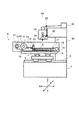
図1は本発明に係るレーザ加工機の正面一部断面図、図2は図1におけるA部拡大図である。 FIG. 1 is a partial front sectional view of a laser beam machine according to the present invention, and FIG. 2 is an enlarged view of part A in FIG.
本発明に係るレーザ加工機50において、門形のコラム30はベッド1上に固定されて設置されている。コラム30には、レーザ発振器31と、複数のミラー32(図では2個)と、一対のガルバノスキャナミラー33と、fθレンズ34が配置されている。
In the
直線案内装置2はベッド1の上面に配置されている。Xテーブル3は、直線案内装置2により、ベッド1上をX方向に移動自在である。直線案内装置4はXテーブル3の上面に配置されている。Yテーブル(移動テーブル)5は、直線案内装置4により、Xテーブル3上をY方向に移動自在である。以上の構成であるから、Yテーブル5は、ベッド1に対してXY方向に移動自在である。
The linear guide device 2 is disposed on the upper surface of the
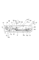
図2に示すように、Yテーブル5の上面には、加工テーブル6とリールホルダ10とが配置されている。加工テーブル6の下面にはX方向において、シート状ワーク(以下、単に「ワーク」という)wの幅以上の横幅を有する溝6mが形成されている。加工テーブル6の上面には、図示を省略する内部の中空部に接続する複数の孔が形成されており、その図示を省略する内部の中空部は図示を省略する真空源に接続されている。また、リールホルダ10には、供給リール11、巻き取りリール12、ガイドローラ13.14,15、クランパ16,17、反転ローラ18、及びワーク搬送装置(移動手段)20が配置されている。
As shown in FIG. 2, a processing table 6 and a
供給リール11の軸の下端11bはガイドローラ13の上端13tよりも下方になるようにしてリールホルダ10に配置されており、図示を省略するモータにより回転自在となっている。即ち、供給リール11には未加工のワークwがロール状に巻かれた供給ロール40が保持されていると共に、不図示のモータの駆動によりワークwを供給し得るようになっている(供給側ロール保持装置)。
The
また、巻き取りリール12は巻き取ったワークwの巻き取りロール41の下端がガイドローラ14の下端14bよりも上方となる位置に配置されており、図示を省略するモータにより回転自在となっている。即ち、リール軸12には加工されたワークwをロール状に巻かれた巻き取りリール41が保持されていると共に、不図示のモータの駆動によりワークwを巻き取りし得るようになっている(巻き取り側ロール保持装置)。
The take-
回転自在のガイドローラ13は、上端13tが加工テーブル6の表面よりも上方になるようにしてリールホルダ10に支持されている。回転自在のガイドローラ14、15は、下端14b、15bが溝6mの底面よりも下方になるようにしてリールホルダ10に支持されている。
The
クランパ16、17は、受け台16u、17uと、受け台16u、17uに対向して配置された押さえ16p、17pとから構成され、受け台17uを除き、それぞれ図示を省略する手段によりZ方向(図の上下方向)に移動自在である。受け台16uは下降端にあるときが待機位置であり、このとき上面は加工テーブル6の表面よりも低い位置に、また上昇端にあるときの上面は、上記ガイドローラ13の上端13tと同一の高さの位置に、それぞれ位置決めされる。また、押さえ16pの下降端は、該押さえ16pの下面が待機位置にある受け台16uの上面に押圧し得るように、待機位置にある受け台16uの上面よりも僅かに下方となる位置である。更に、押さえ17pの下降端も、該押さえ17pの下面が受け台17uの上面に押圧し得るように、受け台17uの上面よりも僅かに下方となる位置である。
The
回転自在の反転ローラ18は、その上端18tがガイドローラ13の上端13tと同一の高さになるようにしてリールホルダ10に支持されている。
The
ワーク搬送装置20は、図示を省略するモータやガイドレール機構等の手段により、リールホルダ10に対してX方向に移動・位置決め自在である。ワーク搬送装置20には、クランパ21が支持されている。クランパ21は、上下方向に移動自在の押さえ21pと受け台21uとから構成されている。受け台21uの待機位置は、図2に実線で示すように、上面が加工テーブル6の上面よりも低い位置であり、上昇端はガイドローラ13の上端13tと反転ローラ18の上端18tと同一の高さ位置である。また、押さえ21pの待機位置は、同図に実線で示すように、下面がガイドローラ13の上端13tや反転ローラ18の上端18tの高さよりも上方となる位置であり、下降端は、押さえ21pの下面が、上昇端にある受け台21uの上面に押圧し得るように、上昇端にある受け台21uの上面よりも僅かに下方となる位置である。なお、ワーク搬送装置20のX方向における待機位置は、同図に実線で示す移動の左端であり、移動の右端は同図に点線で示す位置である。
The
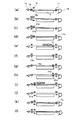
次に、本レーザ加工機50の動作を図に沿って説明する。図3は本発明の動作を示す動作説明図である。
Next, the operation of the
まず、段取り作業について説明する。 First, the setup work will be described.
予めクランパ16、17および21を総て開いた状態で(受け台16u、21uを待機位置に、押さえ16p、17p、21p上昇端にそれぞれ位置決めする)、供給ロール40を供給リール11に支持させ、図示のように、ワークwを反転ローラ18に巻きつけてから加工テーブル6の溝6mを通し、端部を巻き取りリール12(巻き取りロール41)に固定する。
With all the
次に、図3(a)に示すように、供給リール11、及び巻き取りリール12に図中時計回り方向のトルクを付加させた状態で、押さえ16pを動作させ(すなわち、押さえ16pを下降させ)、受け台16uとの間でワークwを固定する。次に、押さえ17pを動作させ(すなわち、押さえ17pを下降させ)、受け台17uとの間でワークwを固定する。この結果、ワークwは弛みのない状態で加工テーブル6の表面に固定される。この状態で図示を省略する真空源を動作させ、ワークwを加工テーブル6の表面に密着させる。
Next, as shown in FIG. 3A, the
続いて、加工を行う。即ち、レーザ発振器31を動作させ、レーザ発振器31から出力されたレーザ光をミラー32を介してガルバノスキャナミラー33に導く。そして、ガルバノスキャナミラー33によりレーザ光を位置決めし、fθレンズ34によりレーザ光の光軸を垂直にしてワークwに入射させ、ワークwを加工する。fθレンズ34で決まる領域の加工が終了したら、Xテーブル3あるいはYテーブル5を移動させて、加工を行う。
Subsequently, processing is performed. That is, the
次に、加工終了後のワーク移動工程について説明する。 Next, the workpiece moving process after the end of machining will be described.
加工が終了したら、図示を省略する真空源を停止させ、その後、図3(b)に示すように、押さえ16pを上昇させる。
When the processing is completed, the vacuum source (not shown) is stopped, and then the
次に、図3(c)に示すように、クランパ21を動作させ、すなわち受け台21uを上昇させた後、押さえ21pを下降させ、押さえ21pと受け台21uによりワークwを保持させる。
Next, as shown in FIG. 3C, the
次に、図3(d)に示すように、押さえ17pを上昇させる。この結果、ワークwはローラ13の上端13t及びローラ18の上端18tに高さ位置に位置決めされる(図2参照)。
Next, as shown in FIG. 3D, the
この状態で、図3(e)に示すように、ワーク搬送装置20を所望の距離(所望量)だけ図の右方に移動させる。なおこの際、供給リール11によりワークwを供給しつつ、巻き取りリール12により加工が終了したワークwを巻き取る。
In this state, as shown in FIG. 3E, the
次に、図3(f)に示すように、受け台16uを上昇端に移動させた後、図3(g)に示すように、押さえ16pを下降させ、クランパ16によりワークwを保持させる。
Next, as shown in FIG. 3 (f), after the
次に、図3(h)に示すように、クランパ21を解放し(この場合、押さえ21pは上昇端に、受け台21uは上面がワークwに接触せず、かつ加工テーブル6の上面に接触しない位置に、それぞれ移動させる。)、図3(i)に示すように、ワーク搬送装置20を待機位置に戻す。
Next, as shown in FIG. 3 (h), the
次に、図3(j)に示すように、受け台21uを待機位置に位置決めした後、図3(k)に示すように、押さえ17pを下降させ、クランパ17によりワークwを保持させる。
Next, as shown in FIG. 3 (j), after positioning the
そして、図3(l)に示すように、クランパ16を解放する。
Then, as shown in FIG. 3 (l), the
その後、受け台16uを待機位置に位置決めし、その後、押さえ16pを下降させ、クランパ16によりワークwを保持させ(図3(a)参照)、図示を省略する真空源を動作させ、ワークwを加工に密着させ、次の加工を行う。以降は同様に上記工程を繰り返す。
Thereafter, the
上記の工程の間、及び加工時においては、供給リール11及び巻き取りリール12を回転させるモータを、ワークwに悪影響を与えない範囲のトルクで駆動し、ワークwに張力を付加して、ワークwに弛みが発生しないように制御する。なお、ローラ13、ローラ14、或いは反転ローラ18等をバネ等で所定方向に付勢することで、ワークwに張力を付加し、それによって弛みが発生しないようにしてもよい。
During the above steps and during processing, the motor that rotates the
以上説明したように、本発明に係るシート状ワークのレーザ加工機50によると、シート状ワークに自由ループを形成させる場所をなくすことができ、レーザ加工機50全体の設置面積を小さくすることができる。また、構成要素が少ないので、制御が容易である。
As described above, according to the
また、供給リールと巻き取りリールを加工テーブル5上の一方側に配置したので、加工テーブル5の両側に配置する場合に比べて、レーザ加工機50全体の設置面積を小さくすることができる。
Further, since the supply reel and the take-up reel are arranged on one side of the processing table 5, the installation area of the entire
なお、本実施の形態においては、供給リール11及び巻き取りリール12を両方ともYテーブル5上に配設したものについて説明したが、供給リール11及び巻き取りリール12の少なくとも一方をYテーブル5上に配設すれば、少なくとも1つの自由ループを減らせるので、従来に比して、レーザ加工機50全体の設置面積を小さくすることができる。
In the present embodiment, the
1 ベッド
5 移動テーブル(Yテーブル)
11 供給側ロール保持装置(リール軸)
12 巻き取り側ロール保持装置(リール軸)
20 移動手段(ワーク搬送装置)
30 レーザ光照射手段(コラム)
31 レーザ光照射手段(レーザ発振器)
32 レーザ光照射手段(ミラー)
33 レーザ光照射手段(ガルバノスキャナミラー)
34 レーザ光照射手段(fθレンズ)
40 供給側ロール(供給ロール)
41 巻き取り側ロール(巻き取りロール)
50 シート状ワークのレーザ加工機
w シート状ワーク
1
11 Supply side roll holding device (reel shaft)
12 Winding side roll holding device (reel shaft)
20 Moving means (work transfer device)
30 Laser beam irradiation means (column)
31 Laser beam irradiation means (laser oscillator)
32 Laser beam irradiation means (mirror)
33 Laser beam irradiation means (galvano scanner mirror)
34 Laser light irradiation means (fθ lens)
40 Supply side roll (supply roll)
41 Winding roll (winding roll)
50 Laser processing machine for sheet workpiece w Sheet workpiece
Claims (3)
前記供給側ロール保持装置と前記巻き取り側ロール保持装置との少なくとも一方を、前記移動テーブル上に配設した、
ことを特徴とするシート状ワークのレーザ加工機。 A laser beam irradiation means installed on the bed and capable of irradiating laser light, a moving table provided at least in a plane direction perpendicular to the laser light, and a sheet-like workpiece are wound in a roll shape. While holding the supply-side roll, the supply-side roll holding device capable of supplying the sheet-like workpiece on the movable table, and the winding-side roll obtained by winding the processed sheet-like workpiece into a roll shape A winding-side roll holding device capable of winding up the sheet-like workpiece on the moving table, and fixing the sheet-like workpiece in the processing area on the moving table at the time of processing, and the moving table and the laser By irradiating the laser beam with the laser beam irradiating means while relatively moving the light irradiating unit, the processing area on the moving table is set. In the laser processing machine of the sheet workpiece to machine the sheet workpiece,
At least one of the supply side roll holding device and the winding side roll holding device is disposed on the moving table,
A laser processing machine for sheet-like workpieces.
ことを特徴とする請求項1に記載のシート状ワークのレーザ加工機。 The supply side roll holding device and the winding side roll holding device are arranged on one side on the moving table with respect to the processing region,
The laser beam machine for a sheet-like workpiece according to claim 1.
ことを特徴とする請求項1または請求項2に記載のシート状ワークのレーザ加工機。
After the processing is completed, when winding the sheet-like workpiece while being fed by the supply-side roll holding device and the winding-side roll holding device, a moving means that holds the sheet-like workpiece and moves it by a desired amount in the winding direction. Prepared,
The laser beam machine for sheet-like workpieces according to claim 1 or 2.
Priority Applications (6)
| Application Number | Priority Date | Filing Date | Title |
|---|---|---|---|
| JP2004114508A JP4215675B2 (en) | 2004-04-08 | 2004-04-08 | Laser processing machine for sheet workpieces |
| TW094110304A TWI367140B (en) | 2004-04-08 | 2005-03-31 | Laser machining apparatus for sheet-like workpiece |
| US11/100,521 US7897894B2 (en) | 2004-04-08 | 2005-04-07 | Laser machining apparatus for sheet-like workpiece |
| KR1020050028749A KR101215109B1 (en) | 2004-04-08 | 2005-04-07 | Laser machining apparatus for sheet-like workpiece |
| DE102005016538.9A DE102005016538B4 (en) | 2004-04-08 | 2005-04-08 | Laser processing device for a plate-shaped workpiece |
| CN2005100635053A CN1680067B (en) | 2004-04-08 | 2005-04-08 | Laser machining apparatus for sheet-like workpiece |
Applications Claiming Priority (1)
| Application Number | Priority Date | Filing Date | Title |
|---|---|---|---|
| JP2004114508A JP4215675B2 (en) | 2004-04-08 | 2004-04-08 | Laser processing machine for sheet workpieces |
Publications (3)
| Publication Number | Publication Date |
|---|---|
| JP2005296981A true JP2005296981A (en) | 2005-10-27 |
| JP2005296981A5 JP2005296981A5 (en) | 2006-04-27 |
| JP4215675B2 JP4215675B2 (en) | 2009-01-28 |
Family
ID=35059494
Family Applications (1)
| Application Number | Title | Priority Date | Filing Date |
|---|---|---|---|
| JP2004114508A Expired - Lifetime JP4215675B2 (en) | 2004-04-08 | 2004-04-08 | Laser processing machine for sheet workpieces |
Country Status (6)
| Country | Link |
|---|---|
| US (1) | US7897894B2 (en) |
| JP (1) | JP4215675B2 (en) |
| KR (1) | KR101215109B1 (en) |
| CN (1) | CN1680067B (en) |
| DE (1) | DE102005016538B4 (en) |
| TW (1) | TWI367140B (en) |
Cited By (3)
| Publication number | Priority date | Publication date | Assignee | Title |
|---|---|---|---|---|
| JP2019115929A (en) * | 2017-11-23 | 2019-07-18 | ダッラン・ソチエタ・ペル・アツィオーニDALLAN S.p.A. | Apparatus for laser or plasma cutting pieces from laminar material wound in coil |
| CN111266732A (en) * | 2020-02-21 | 2020-06-12 | 中南大学 | Four-piece type optical device coupling welding equipment based on power and light spot detection |
| WO2022186975A1 (en) * | 2021-03-05 | 2022-09-09 | Electro Scientific Industries, Inc. | Laser-processing apparatus, methods of operating the same, and methods of processing workpieces using the same |
Families Citing this family (10)
| Publication number | Priority date | Publication date | Assignee | Title |
|---|---|---|---|---|
| JP4778031B2 (en) * | 2008-09-26 | 2011-09-21 | 日立ビアメカニクス株式会社 | Laser processing machine |
| JP5800486B2 (en) * | 2010-10-06 | 2015-10-28 | 住友化学株式会社 | Laser cutting apparatus, slitter machine equipped with the same, and laser cutting method |
| CN103372723A (en) * | 2012-04-24 | 2013-10-30 | 星云电脑股份有限公司 | Compound automatic feeding and feeding laser processing machine |
| DE102015109740A1 (en) * | 2015-06-18 | 2016-12-22 | Trumpf Werkzeugmaschinen Gmbh + Co. Kg | Machine for separating processing of plate-shaped materials |
| JP6487413B2 (en) * | 2016-12-22 | 2019-03-20 | ファナック株式会社 | Laser processing head and laser processing system including the same |
| JP7041482B2 (en) * | 2017-09-13 | 2022-03-24 | 株式会社オーク製作所 | Exposure device |
| IT201700111570A1 (en) | 2017-10-05 | 2019-04-05 | Dallan Spa | APPARATUS AND METHOD FOR LASER OR PLASMA CUTTING OF PIECES WITH LAMINAR MATERIAL WRAPPED INTO COIL |
| CN110320765B (en) * | 2018-03-29 | 2023-05-16 | 株式会社Orc制作所 | Exposure apparatus |
| KR102596484B1 (en) * | 2021-09-10 | 2023-11-01 | 해성디에스 주식회사 | Working table for reel-to-reel process |
| TWI830529B (en) * | 2022-12-07 | 2024-01-21 | 信力特科技股份有限公司 | Laser processing device and method |
Family Cites Families (10)
| Publication number | Priority date | Publication date | Assignee | Title |
|---|---|---|---|---|
| US3226527A (en) * | 1963-10-23 | 1965-12-28 | William H Harding | Apparatus for perforating sheet material |
| JPH0710438B2 (en) * | 1986-04-30 | 1995-02-08 | オークマ株式会社 | Laser processing machine with automatic nozzle changer |
| JPH0642504B2 (en) | 1989-06-15 | 1994-06-01 | 東レエンジニアリング株式会社 | Inner lead bonder |
| US5767480A (en) * | 1995-07-28 | 1998-06-16 | National Semiconductor Corporation | Hole generation and lead forming for integrated circuit lead frames using laser machining |
| US5853530A (en) * | 1997-04-11 | 1998-12-29 | Label Aire Inc. | Label applicator |
| JP2000094472A (en) * | 1998-09-18 | 2000-04-04 | Dainippon Printing Co Ltd | Sheet unwinding and feeding device for simultaneous painting with injection molding |
| JP2000143052A (en) | 1998-11-05 | 2000-05-23 | Sony Corp | Supply device and supply method for film-shaped workpiece |
| JP3942135B2 (en) * | 1999-01-22 | 2007-07-11 | 日立ビアメカニクス株式会社 | Laser processing machine |
| JP2000246479A (en) * | 1999-02-25 | 2000-09-12 | Hitachi Via Mechanics Ltd | Laser processing machine |
| US20040154749A1 (en) * | 2003-02-10 | 2004-08-12 | Rice Clifford B. | Label applicator |
-
2004
- 2004-04-08 JP JP2004114508A patent/JP4215675B2/en not_active Expired - Lifetime
-
2005
- 2005-03-31 TW TW094110304A patent/TWI367140B/en not_active IP Right Cessation
- 2005-04-07 US US11/100,521 patent/US7897894B2/en active Active
- 2005-04-07 KR KR1020050028749A patent/KR101215109B1/en not_active Expired - Lifetime
- 2005-04-08 DE DE102005016538.9A patent/DE102005016538B4/en not_active Expired - Lifetime
- 2005-04-08 CN CN2005100635053A patent/CN1680067B/en not_active Expired - Lifetime
Cited By (6)
| Publication number | Priority date | Publication date | Assignee | Title |
|---|---|---|---|---|
| JP2019115929A (en) * | 2017-11-23 | 2019-07-18 | ダッラン・ソチエタ・ペル・アツィオーニDALLAN S.p.A. | Apparatus for laser or plasma cutting pieces from laminar material wound in coil |
| JP7182260B2 (en) | 2017-11-23 | 2022-12-02 | ダッラン・ソチエタ・ペル・アツィオーニ | Apparatus for laser or plasma cutting coiled sheet material into pieces |
| CN111266732A (en) * | 2020-02-21 | 2020-06-12 | 中南大学 | Four-piece type optical device coupling welding equipment based on power and light spot detection |
| CN111266732B (en) * | 2020-02-21 | 2021-03-30 | 中南大学 | Four-piece type optical device coupling welding equipment based on power and light spot detection |
| WO2022186975A1 (en) * | 2021-03-05 | 2022-09-09 | Electro Scientific Industries, Inc. | Laser-processing apparatus, methods of operating the same, and methods of processing workpieces using the same |
| JP2024512331A (en) * | 2021-03-05 | 2024-03-19 | エレクトロ サイエンティフィック インダストリーズ インコーポレーテッド | Laser processing equipment, how to operate the laser processing equipment, and how to process a workpiece using the laser processing equipment |
Also Published As
| Publication number | Publication date |
|---|---|
| DE102005016538A1 (en) | 2005-10-27 |
| KR20060045539A (en) | 2006-05-17 |
| US20050224476A1 (en) | 2005-10-13 |
| CN1680067B (en) | 2010-08-18 |
| KR101215109B1 (en) | 2012-12-24 |
| TWI367140B (en) | 2012-07-01 |
| CN1680067A (en) | 2005-10-12 |
| US7897894B2 (en) | 2011-03-01 |
| JP4215675B2 (en) | 2009-01-28 |
| TW200536648A (en) | 2005-11-16 |
| DE102005016538B4 (en) | 2017-10-19 |
Similar Documents
| Publication | Publication Date | Title |
|---|---|---|
| JP4215675B2 (en) | Laser processing machine for sheet workpieces | |
| KR101209999B1 (en) | Method and device for holding sheet-like workpiece | |
| JP2010188427A (en) | Cutting plotter and method of cut-plotting | |
| JP6041556B2 (en) | Label forming device for in-mold label forming | |
| EP4411763A2 (en) | Wire material winding device and winding method | |
| CN1623870B (en) | Substrate Processing Equipment | |
| JP4542495B2 (en) | Projection exposure apparatus and projection exposure method | |
| US7098423B2 (en) | Laser machining apparatus | |
| TWI601591B (en) | Optically processing apparatus | |
| CN1972776B (en) | Machining device and machining method | |
| JP2000246479A (en) | Laser processing machine | |
| JP4283810B2 (en) | Drilling device | |
| JP4367828B2 (en) | Drilling machine | |
| JP4276573B2 (en) | Laser processing method and laser processing machine | |
| JP3289258B2 (en) | Engraving method of work | |
| JP2002045986A (en) | Laser processing apparatus and processing method | |
| JP7144119B2 (en) | LASER PROCESSING DEVICE AND METHOD OF PROCESSING LONG WORKED WORK WITH LASER PROCESSING DEVICE | |
| KR102693326B1 (en) | Laser processing apparatus | |
| JP2005088015A (en) | Laser processing machine | |
| JP4027873B2 (en) | Laser processing apparatus and laser processing method | |
| JP2006212640A (en) | Sheet material forming machine | |
| JP2005040833A (en) | Laser beam machining device | |
| JP6410649B2 (en) | Laser processing machine and work jig for laser processing machine | |
| KR20230148335A (en) | Laser-processing device, method of operation thereof and method of processing workpieces using the same | |
| JPH04361838A (en) | Working table in planar material working machine |
Legal Events
| Date | Code | Title | Description |
|---|---|---|---|
| A521 | Request for written amendment filed |
Free format text: JAPANESE INTERMEDIATE CODE: A523 Effective date: 20060310 |
|
| A621 | Written request for application examination |
Free format text: JAPANESE INTERMEDIATE CODE: A621 Effective date: 20060310 |
|
| A977 | Report on retrieval |
Free format text: JAPANESE INTERMEDIATE CODE: A971007 Effective date: 20080612 |
|
| A131 | Notification of reasons for refusal |
Free format text: JAPANESE INTERMEDIATE CODE: A131 Effective date: 20080617 |
|
| A521 | Request for written amendment filed |
Free format text: JAPANESE INTERMEDIATE CODE: A523 Effective date: 20080818 |
|
| TRDD | Decision of grant or rejection written | ||
| A01 | Written decision to grant a patent or to grant a registration (utility model) |
Free format text: JAPANESE INTERMEDIATE CODE: A01 Effective date: 20081028 |
|
| A01 | Written decision to grant a patent or to grant a registration (utility model) |
Free format text: JAPANESE INTERMEDIATE CODE: A01 |
|
| A61 | First payment of annual fees (during grant procedure) |
Free format text: JAPANESE INTERMEDIATE CODE: A61 Effective date: 20081104 |
|
| R150 | Certificate of patent or registration of utility model |
Ref document number: 4215675 Country of ref document: JP Free format text: JAPANESE INTERMEDIATE CODE: R150 Free format text: JAPANESE INTERMEDIATE CODE: R150 |
|
| FPAY | Renewal fee payment (event date is renewal date of database) |
Free format text: PAYMENT UNTIL: 20111114 Year of fee payment: 3 |
|
| FPAY | Renewal fee payment (event date is renewal date of database) |
Free format text: PAYMENT UNTIL: 20111114 Year of fee payment: 3 |
|
| FPAY | Renewal fee payment (event date is renewal date of database) |
Free format text: PAYMENT UNTIL: 20121114 Year of fee payment: 4 |
|
| FPAY | Renewal fee payment (event date is renewal date of database) |
Free format text: PAYMENT UNTIL: 20131114 Year of fee payment: 5 |
|
| S533 | Written request for registration of change of name |
Free format text: JAPANESE INTERMEDIATE CODE: R313533 |
|
| R350 | Written notification of registration of transfer |
Free format text: JAPANESE INTERMEDIATE CODE: R350 |
|
| S531 | Written request for registration of change of domicile |
Free format text: JAPANESE INTERMEDIATE CODE: R313532 |
|
| R350 | Written notification of registration of transfer |
Free format text: JAPANESE INTERMEDIATE CODE: R350 |
|
| S531 | Written request for registration of change of domicile |
Free format text: JAPANESE INTERMEDIATE CODE: R313531 |
|
| R350 | Written notification of registration of transfer |
Free format text: JAPANESE INTERMEDIATE CODE: R350 |
|
| EXPY | Cancellation because of completion of term |