JP2005296070A - Game machine - Google Patents
Game machine Download PDFInfo
- Publication number
- JP2005296070A JP2005296070A JP2004112393A JP2004112393A JP2005296070A JP 2005296070 A JP2005296070 A JP 2005296070A JP 2004112393 A JP2004112393 A JP 2004112393A JP 2004112393 A JP2004112393 A JP 2004112393A JP 2005296070 A JP2005296070 A JP 2005296070A
- Authority
- JP
- Japan
- Prior art keywords
- command
- lottery
- effect
- inspection
- main control
- Prior art date
- Legal status (The legal status is an assumption and is not a legal conclusion. Google has not performed a legal analysis and makes no representation as to the accuracy of the status listed.)
- Pending
Links
Images
Landscapes
- Pinball Game Machines (AREA)
- Display Devices Of Pinball Game Machines (AREA)
Abstract
Description
本発明は、例えば、スロットマシンに用いて好適な遊技機に関する。 The present invention relates to a gaming machine suitable for use in, for example, a slot machine.
遊技機として、例えば、特許文献1に開示されたスロットマシンが知られている。スロットマシンには、同文献1の図1に示されているように、本体部前面に3列のリール19a,19b,19cを有するリール機構が組み込まれ、これらリール19a,19b,19cの側方(右側壁面)に、いわゆる演出表示を行うための表示装置としての表示パネル(ELランプ)3が設けられている。
As a gaming machine, for example, a slot machine disclosed in
かかる構成において、遊技者により回転開始ノブが押下されると、ゲーム開始となり、リール19a,19b,19cを所定速度で回転させ、次に停止釦が押下されると、リール19a,19b,19cを順次停止させる。そして、停止した3個のリール19a,19b,19cに描かれている特定の絵柄(例えば、数字の7)が入賞ライン上に揃うと「大当り」となり、表示パネル3に同文献1の図4に示されている表示を行うことによって大当たりが出たことを知らせ、遊技者に対し快感を与えるようにしている。 In such a configuration, when the rotation start knob is pressed by the player, the game starts, the reels 19a, 19b, 19c are rotated at a predetermined speed, and then when the stop button is pressed, the reels 19a, 19b, 19c are turned on. Stop sequentially. When a specific pattern (for example, numeral 7) drawn on the three reels 19a, 19b, and 19c that are stopped is aligned on the winning line, a “big hit” is obtained, and the display panel 3 displays FIG. By giving the display shown in the above, it is notified that a big hit has been made, and the player is given a pleasant feeling.
ところで上記したスロットマシンでは、リール19a,19b,19cの回転制御、回転開始ノブ、停止釦押下による指令取り込み、大当り抽選、光と音による演出、画像再生表示等、制御が煩雑に入り組んでいる。このため、抽選によって遊技の入賞態様を決定する主制御装置と、抽選結果に応じて遊技演出を制御する演出管理装置と、遊技演出を表示モニタに表示する画像再生装置のそれぞれにCPUを割当て負荷分散させることが行なわれる。 By the way, in the slot machine described above, control is complicated such as rotation control of the reels 19a, 19b, and 19c, command acquisition by pressing a rotation start knob, a stop button, lottery lottery, production by light and sound, and image reproduction display. For this reason, a CPU is allocated to each of the main control device that determines the winning mode of the game by lottery, the effect management device that controls the game effect according to the lottery result, and the image playback device that displays the game effect on the display monitor. Dispersion is performed.
上記した主制御装置と演出管理装置、演出管理装置と画像再生装置とは、それぞれコマンドラインを介して接続されており、メーカ側では、デバッグ等の用途で主制御装置から画像再生装置に送信するコマンドを指定したいことがある。
しかしながら、スロットマシンは、その構成上、演出管理装置および画像再生装置のコマンドおよびデータはいずれも双方向であるのに対し、主制御装置は、演出管理装置に対してコマンドやデータを送信する単方向の機能しか持たない。このため、主制御装置が持つコマンドは画像再生装置に直接反映されず、従って、画像再生装置の検査が困難であった。
The main control device, the production management device, the production management device, and the image reproduction device are connected via a command line, and the manufacturer transmits the image from the main control device to the image reproduction device for debugging or the like. You may want to specify a command.
However, in the slot machine, the command and data of the production management device and the image reproduction device are both bidirectional because of the configuration, whereas the main control device simply transmits commands and data to the production management device. Has only a function of direction. For this reason, the command possessed by the main control device is not directly reflected on the image reproducing device, and therefore it is difficult to inspect the image reproducing device.
また、営業移行時等、デモンストレーションのために特定の演出を出現させたいといった要望があり、これらは抽選処理を経て出現するため抽選確率を変更してその出現を待つか、あるいは過去に出現した演出を記録し、必要に応じて再生する他に対応することができなかった。 In addition, there is a request for specific effects to appear for demonstrations, such as during business transitions. These appear after the lottery process, so change the lottery probability and wait for the appearance, or effects that have appeared in the past It was not possible to cope with other than recording and reproducing as needed.
本発明は上記事情に鑑みてなされたものであり、外部接続される検査装置が主制御装置による検査コマンドによる実行をエミュレーションすることで、画像再生装置の検査を容易化し、かつ特定の演出を見たいときに再現可能な遊技機を提供することを目的とする。 The present invention has been made in view of the above circumstances, and an inspection apparatus connected externally emulates execution by an inspection command by a main control apparatus, thereby facilitating inspection of an image reproducing apparatus and viewing a specific effect. An object is to provide a reproducible gaming machine when desired.
上記した課題を解決するために本発明は、抽選によって遊技の入賞態様を決定する主制御装置と、前記抽選結果に応じて遊技演出を制御する演出管理装置と、前記遊技演出を表示モニタに表示する画像再生装置とを備えて成る遊技機であって、前記主制御装置、もしくは外部接続される検査装置から演出抽選を指定する選択乱数を取り込み、当該選択乱数に基づき演出抽選処理を行い、希望する演出を前記画像再生装置に出力する前記演出管理装置中の演出選択手段、を備えたことを特徴とする。 In order to solve the above-described problems, the present invention provides a main control device that determines a game winning mode by a lottery, an effect management device that controls a game effect according to the lottery result, and displays the game effect on a display monitor. A game machine comprising an image playback device that captures a selected random number for designating an effect lottery from the main control device or an externally connected inspection device, performs an effect lottery process based on the selected random number, and An effect selecting means in the effect management device for outputting the effect to be output to the image reproduction device.
また、本発明において、前記演出選択手段は、演出頻度表が設定されるテーブルメモリを備え、前記検査装置から出力されるコマンドを解釈して前記テーブルメモリを強制的に書き換えることを特徴とする。 In the present invention, the effect selecting means includes a table memory in which an effect frequency table is set, and the table memory is forcibly rewritten by interpreting a command output from the inspection apparatus.
また、本発明において、前記演出選択手段は、前記主制御装置、もしくは外部接続される検査装置から出力されるコマンドを解釈して前記選択乱数による抽選処理後、通常確率での抽選に復帰させることを特徴とする。 Further, in the present invention, the effect selection means interprets a command output from the main control device or an externally connected inspection device, and returns to a lottery with a normal probability after the lottery process using the selected random number. It is characterized by.
また、本発明において、前記演出選択手段は、前記抽選によって遊技の入賞態様を決定する主制御装置が実装される主基板とは別のサブ制御基板に実装されることを特徴とする。 In the present invention, the effect selection means is mounted on a sub control board different from a main board on which a main control device for determining a winning mode of a game by the lottery is mounted.
本発明によれば、演出管理装置中の演出選択手段が外部接続される検査装置から演出抽選を指定する選択乱数を取り込み、当該選択乱数に基づき演出抽選処理を行い、希望する演出を画像再生装置に出力することで、見たいときに、あるいは聴きたい時に特定の演出を出現させることが可能となる。
また、外部接続される検査装置が主制御装置から画像再生装置に対して発行されるコマンドのエミュレーションを行い、画像再生装置に対して送信することにより、主制御装置が持つコマンドを画像再生装置に直接反映させることができ、このため、画像再生装置の検査が容易になる。
According to the present invention, a selection random number for designating an effect lottery is fetched from an inspection device to which an effect selection means in the effect management device is externally connected, an effect lottery process is performed based on the selected random number, and the desired effect is displayed in the image reproduction device. By outputting the signal, it is possible to make a specific effect appear when you want to see or listen.
Also, the inspection device connected externally emulates a command issued from the main control device to the image reproduction device, and transmits it to the image reproduction device, whereby the command possessed by the main control device is sent to the image reproduction device. The image reproduction apparatus can be easily inspected.
以下、本発明の好適な実施形態として、遊戯場等に設置される回胴式遊技機(以下「スロットマシン」という)について図面を参照して説明する。
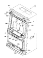
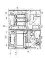
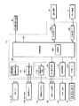
図1は、本スロットマシン100の外観構造を示した正面図、図2は、本スロットマシン100の内部構造を示した断面図、図3は、本スロットマシン100に設けられている制御システムの内部構成を示したブロック図である。
In the following, as a preferred embodiment of the present invention, a spinning machine (hereinafter referred to as “slot machine”) installed in an amusement hall or the like will be described with reference to the drawings.
FIG. 1 is a front view showing the external structure of the
図1において、本スロットマシン100は、遊技者に面するフロントドア101と、フロントドア101が開閉可能に取り付けられた箱形形状の筐体102とを備えて構成されている。
フロントドア101は、基本的に、金属製のフレーム(図示略)に硬質プラスチック等で成形された前面パネルが取り付けられた機械的に強固な構造を有し、当該前面パネルによって、上部パネル部103と中部パネル部104と下部パネル部105が構成されている。
In FIG. 1, the
The
上部パネル部103には、演出用ランプ103aと、スピーカが取り付けられた放音部103b,103cと、クレジット枚数等を表示するLEDや大当たり等を表示するランプ類が実装される中央表示基板103dが取り付けられている。
On the
また、中部パネル部104には、複数個(本実施形態では3個)の回胴リールR1,R2,R3を備えた回胴リール装置200が略中央の位置に設けられている。また、回胴リール装置200の前面に、略長方形のリール表示窓を持つ、(ここでは透明液晶)が実装されている。液晶表示パネル106は、リール表示窓によって回胴リール装置200を外部から保護すると共に、遊技者がリール表示窓を介して回胴リールR1,R2,R3を見ることが可能となっている。
液晶表示パネル(透明液晶)106は、薄膜トランジスタ層が形成されたガラス板等の透明基板と、これに対向する透明な基板間に液晶が封入されて形成される。液晶表示パネル106は、表示面側に光が透過し、透過した光が外部から視認される構造を持つ。この構造を採用することで、液晶を駆動していなくてもリール表示窓を介して回胴リールR1,R2,R3を視認することができるようになっている。
Further, the middle panel unit 104 is provided with a
The liquid crystal display panel (transparent liquid crystal) 106 is formed by sealing liquid crystal between a transparent substrate such as a glass plate on which a thin film transistor layer is formed and a transparent substrate facing the transparent substrate. The liquid
中部パネル部104の下端には、遊技者が操作するための操作部104aが備えられ、遊技用メダルを投入するためのメダル投入部MDが備え付けられている。また、操作部104aの操作面上に、1ゲーム当たりのメダル数を提示するためのベットボタンBET(B1,B2,B3)が設けられ、更にその前面には、1ゲームの開始を指示するためのスタートレバーSTと、回転中の回胴リールR1,R2,R3を個別に停止させるための3個のストップボタンSP1,SP2,SP3が設けられている、操作部104に設けられたこれらボタン類は、図3中、符号300で示されている。
更に、下部パネル部105には、本スロットマシン100のゲーム内容に関連した画像等(図示略)が描かれており、遊技者の獲得したメダルを払い出すための排出口105a及び受皿105bと、スピーカが設けられた放音部105cが設けられている。
At the lower end of the middle panel portion 104, an
Further, the
次に、図2を参照して、フロントドア101の裏面構造と、筐体102の内部構造を説明する。図2はフロントドア101を開錠して筐体102から開いた状態を表している。
同図において、フロントドア101の裏面上部に、放音部103b,103cを構成するスピーカSR,SLが設けられている。
更に、回胴リール装置200下部には、メダル投入部MDより投入される投入物を正規の遊技用メダルか異物か判別して振り分ける振り分け機構G0と、振り分け機構G0で振り分けられた遊技用メダルを筐体102側に設けられているホッパ装置HPへ案内するガイド部材G1と、振り分け機構G0で振り分けられた異物を排出口105aへ案内して排出するガイド部材G2と、ホッパ装置HPから出力される払い出し用のメダルを排出口105aへ案内して出力するガイド部材G3が設けられ、更に排出口105aの近傍に、スピーカSWが放音部105cに対応させて取り付けられている。
Next, the back surface structure of the
In the figure, speakers SR and SL constituting
Further, at the lower part of the
筐体102内には、主電源装置PWUと、ホッパ装置HPから溢れた遊技用メダルを収容するための補助貯留部SHPと、フロントドア101側の透過窓WDに対向する回胴リールR1,R2,R3を備えた回胴リール装置200と、本スロットマシン100の動作全体を集中制御する電気回路基板等を備えた主制御ユニット400が設けられている。
Inside the
ここで、主制御ユニット400は、図3のブロック図に示すように、スロットマシン100の動作全体を管理するシステムプログラム及びスロットマシンゲーム用の実行プログラムが予め記憶されている半導体メモリ等で形成された記憶部と、これらのプログラムを実行する図示せぬマイクロプロセッサとを有する主制御基板400aを備える。
また、主制御基板400aが搭載されている電気回路基板とは夫々別個の電気回路基板で形成され、主制御基板400aからの指令に従って分散制御を行うサブ制御基板400b、そして、画像再生基板400k、中央制御基板400i、外部集中端子基板600を備えて構成されている。また、回胴リール制御部400c、入力ポート400d、入出力ポート400g、400hも備えて構成されている。
Here, as shown in the block diagram of FIG. 3, the
Further, each of the electric circuit boards on which the
上記した構成において、遊技者が操作部104aに配置されたベットボタンBET(B1,B2,B3)およびスタートレバーST(300)を操作することにより遊技が開始され、適当なタイミングでストップボタンSP1,SP2,SP3(300)を順次操作することにより、大当たり抽選が開始される。これら操作内容は入力ポート400dを介して取り込まれ、また、主制御基板400aによって抽選を含む大当たり抽選処理が実行され、その結果は、中央表示基板103dに供給され、表示される。中央表示基板103dは、主制御基板400aによる制御の下、接続される7セグLED500、あるいはランプ等の表示デバイスの駆動、あるいは点灯制御を行う。
In the above-described configuration, the game is started when the player operates the bet buttons BET (B1, B2, B3) and the start lever ST (300) arranged on the
また、振り分け機構GOとホッパ装置HPは、入出力ポート400g,400hを介して主制御基板400aに接続され、制御される。更に、サブ制御基板400bは、音響制御部400iと、照明制御部400jおよび表示装置制御部400kを備え、音響制御部400iにはスピーカSL,SR,SWが、照明制御部400jには演出用ランプ103a,104a,104bが、そして、画像再生装置400kには演出用の液晶表示パネル106が接続されている。
Further, the distribution mechanism GO and the hopper device HP are connected to and controlled by the
そして、ゲームの進行等に応じて主制御基板400aから指令される演出制御の内容に従って、音響制御部400iはスピーカSL,SR,SWによる音響演出の制御、照明制御部400jは演出用ランプ103a,104a,104bによる照明演出の制御、画像再生基板400kは液晶表示パネル106による演出表示の制御を行う。演出表示の制御については後述する。
また、回胴リール制御部400cは、回胴リール装置200に設けられている電動モータ(図示略)を制御し、回胴リールR1,R2,R3の回転と制動及び停止の制御を行う。
Then, according to the contents of the effect control commanded from the
The spinning reel control unit 400c controls an electric motor (not shown) provided in the
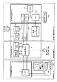
図4は、図3に示す主制御基板、サブ制御基板、画像再生基板の接続構成を説明するために引用したブロック図である。
主制御基板400aは、大当り抽選を行う主CPU11を含み、図3に示す回胴リール装置200、7セグLED500、BT、ST、STPから成る各種ボタン類300から成る周辺装置を制御する主制御部10として機能する。
FIG. 4 is a block diagram cited for explaining the connection configuration of the main control board, the sub control board, and the image reproduction board shown in FIG.
The
また、サブ制御基板400bは、演出管理CPU21を核に、制御用E2PROM22、バックアップRAM23、制御&キャラクタROM34、サウンドROM35、そして、サウンドプレーヤ36を周辺LSIとして備えている。
演出管理CPU21は、演出管理について主CPU11から負荷分散して処理を行うところであり、制御用E2PROM22に記録されたプログラムに従い、バックアップRAM23を作業用メモリとして用い後述する画像再生CPU31に遊技演出情報を引き渡し、かつ、演出用ランプ103a、104a、104bの点灯、消灯を直接制御する。
なお、上記した構成のうち、演出管理CPU21と、制御用E2PROM22と、バックアップRAM23のみが演出管理部20として機能する。また、サウンドプレーヤ36は、サウンドROM35に記録された音声素片に基づき音声合成を行い、スピーカSL、SR、SWを介して出力する。サウンドプレーヤ36は、演出管理CPU21による管理の下、後述する画像再生CPU31によって制御される。
The
The
Of the configurations described above, only the
一方、画像再生基板400kは、画像再生CPU31を核に、VDP(Video Display Processor)32、VRAM(Video Random Access Memory)33で構成される。
画像再生CPU31は、演出管理CPU21によって供給される演出情報に基づき、画像情報を生成してVRAM33に書き込む。また、VDP32は、制御&キャラクタROM34から得られるキャラクタをVRAM33に合成して書き込むと共に、表示タイミングに従いVRAM33に書き込まれたデータを読み出し、液晶表示パネル106に表示のために供給する。なお、サブ制御基板400bの制御&キャラクタROM34、サウンドROM35、サウンドプレーヤ36、そして、画像再生基板400kで画像ならびに音響制御部30として機能する。
On the other hand, the
The image reproduction CPU 31 generates image information based on the effect information supplied by the
なお、主CPU11と、演出管理CPU21間は、単方向の8ビットのサブ制御データラインおよび1ビットのサブ制御データストローブ信号線を介して接続され、演出管理CPU21と、画像再生CPU31は、36ビットの送受信データライン(TxD、RxD)、1ビットのWDT(Watch Dog Timer)アウト信号ライン、リセットアウト信号ラインを介して接続されている。
The main CPU 11 and the
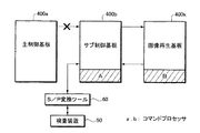
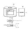
図5は、検査装置を遊技機に接続して診断を行う場合の一実施形態を示すブロック図である。ここでは、検査装置50として、Windows(登録商標)が搭載されたPCが例示されている。図5中、図3、図4に示す番号と同じ番号が付されたブロックは、図3、図4に示すそれと同じとする。
図5に示されるように、サブ制御基板400bは、主制御基板400aから切り離され、代わって検査装置50がサブ制御基板400bにS/P(Serial/Parallel)変換ツール60を介して接続される。ここでは、USB(Universal Serial Bus)を用いることとする。検査装置50は、生成される検査コマンドをサブ制御基板400bおよび双方向のデータラインを介して画像再生基板400kへ供給し、当該画像再生基板400kによる検査コマンドの実行結果を取込み、画像再生基板400kの診断を行う。検査装置50はまた、サブ制御基板400bに対し、例えば、演出抽選を指定する乱数を指定することにより、見たいときに、あるいは聴きたい時に特定の演出を出現させることも可能である。
FIG. 5 is a block diagram illustrating an embodiment in which diagnosis is performed by connecting an inspection apparatus to a gaming machine. Here, a PC on which Windows (registered trademark) is mounted is exemplified as the
As shown in FIG. 5, the
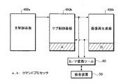
図6は、検査装置を遊技機に接続して診断を行う場合の他の実施形態を示すブロック図である。検査装置50として、同じくWindows(登録商標)が搭載されたPCが例示されている。
ここでは、サブ制御基板400bを主制御基板400aから切り離すことなく、遊技機同様、主制御基板400aに実装されたROM(図示せず)に記録されたプログラムをそのまま使用するものとする。この場合、検査装置50は、サブ制御基板400bと画像再生基板400kを接続する双方向のデータラインから分岐してS/P変換ツール60を介して接続される。このため、サブ制御基板400bは、主制御基板400qによって発行される検査コマンドを画像再生基板400kに引き渡し、画像再生基板400kで実行されるコマンドの実行結果を検査装置50によって取込み、診断を行う。
なお、図中、A、Bは、サブ制御基板400b、画像再生基板400kに実装される演出管理CPU21、画像再生CPU31のそれぞれで実行されるコマンドを解読し処理するコマンドプロセッサであって、ここでは、いずれも主CPU11が持つコマンド体系と同じものを使用することとする。詳細は後述する。
FIG. 6 is a block diagram showing another embodiment when a diagnosis is performed by connecting an inspection apparatus to a gaming machine. As the
Here, it is assumed that a program recorded in a ROM (not shown) mounted on the
In the figure, A and B are command processors for decoding and processing commands executed by the
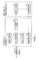
図7に、検査装置が接続されたときのサブ制御基板400b、および画像再生基板400kのそれぞれに実装される、遊技管理部20、画像&音響制御部30の内部構成が機能展開され示されている。ここでは、本発明と関係するブロックのみ抽出して示されている。
遊技管理部20は、機能的に、モード遷移管理部201と、通常モード実行部202と、検査モード実行部203と、検査コマンド転送部204と、検査結果取込み部205で構成される。
FIG. 7 shows functionally expanded internal configurations of the game management unit 20 and the image & sound control unit 30 mounted on each of the
The game management unit 20 functionally includes a mode
モード遷移管理部301は、動作モードとして、主制御基板400aによって発行されたコマンドを実行する通常モードと、コマンドを画像再生基板400kに引き渡すコマンド転送モードとを備え、各モード間の遷移を制御する機能を持つ。そして、通常モード実行部201で通常の遊技モードを、検査モード実行部203で演出管理部20内の検査モードを、検査コマンド転送部204で画像再生基板400kへ検査コマンドを送信する検査コマンド転送モードのそれぞれを実行する。
モード遷移管理部301はまた、通常の遊技で使用しないコマンドを受信したときに検査コマンド転送モードに設定し、更に、コマンド転送モードに設定するコマンドとは別のコマンドを受信したときに検査コマンド転送モードから通常モードに遷移させる。
The mode
The mode
画像&音響制御部30は、検査コマンド実行部301と、実行結果送信部302で構成される。
検査コマンド実行部301は、演出管理部20から、検査コマンド転送部204を介して送信される画像再生基板400kの検査コマンドを受信し、実行して、その結果を、実行検査送信部302を介してサブ制御基板400bへ送信する。
実行結果送信部302により送信される検査結果は、演出管理部20の検査結果取り込み部204、もしくは、サブ制御基板400bと画像再生基板400k間を接続する双方向データラインにマルチドロップ接続される検査装置50に供給される。
The image & sound control unit 30 includes an inspection
The inspection
The inspection result transmitted by the execution result transmitting unit 302 is an inspection that is multidrop-connected to the inspection
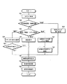
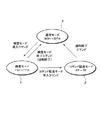
図8は、本発明実施形態の動作を説明するために引用したフローチャートであり、図9に上記した動作モードの状態遷移図を示す。
以下、図8に示すフローチャート、および図9に示す状態遷移図を参照しながら本発明実施形態の動作について詳細に説明する。
FIG. 8 is a flowchart cited for explaining the operation of the embodiment of the present invention, and FIG. 9 shows a state transition diagram of the operation mode described above.
Hereinafter, the operation of the embodiment of the present invention will be described in detail with reference to the flowchart shown in FIG. 8 and the state transition diagram shown in FIG.
ところで、主制御基板400aとコマンド線(サブ制御データ)により接続されているサブ制御基板400bは、更に、別の画像再生基板400kとコマンド線(TxD)により接続されていることは図4に示したとおりである。ここでは、主制御基板400aとサブ制御基板400bのコマンドと、サブ制御基板400bと画像再生基板400k間のコマンドの構成を1対1に対応させ、かつ、通常のコマンドを動作させないようにすることで、主制御基板400aから画像再生基板400kに直接コマンドを指定することを実現している。
FIG. 4 shows that the
図9に示されるように、通常のコマンドが動作しないようにするためには、通常の遊技動作を行う通常モードXと、検査用の動作を行う検査モードYの他に、画像再生基板400kに検査コマンドを直接送信する検査コマンド転送モードZを新設する。このモードZに突入すると、サブ制御基板400bが受信したコマンドに対応するコマンドを画像再生基板400kに送信するように制御される。また、強制終了コマンドを定義することでこのモードから通常モードに復帰することができる。
通常モードで有効なコマンドとして解釈されるのは、例えば、80H〜EFHである。また、検査コマンド転送モード突入のためのコマンドとして解釈されるのは、例えばF0Hであり、更に、F1H〜FFHが検査コマンドとして割当てられる。また、強制終了コマンドとしてFF−7Fが割当てられる。
As shown in FIG. 9, in order to prevent a normal command from operating, in addition to the normal mode X in which a normal game operation is performed and the inspection mode Y in which an operation for inspection is performed, an
For example, 80H to EFH are interpreted as valid commands in the normal mode. Also, F0H is interpreted as a command for entering the inspection command transfer mode, and F1H to FFH are assigned as inspection commands. Also, FF-7F is assigned as the forced termination command.
図8に示すフローチャートにおいて、サブ制御基板400bは、まずコマンドを受信する(S81)。続いてサブ制御基板400bは、コマンドの出所をチェックし(S82)、主制御基板400aであれば、更に、動作モードのチェックが行なわれる。動作モードのチェックおよびその状態遷移は、モード遷移管理部201によって行われる。
In the flowchart shown in FIG. 8, the
すなわち、サブ制御基板400bの演出管理CPU21(演出管理部20)は、主制御基板400aの主CPU11からコマンド線(サブ制御データ)を介して通常モードのコマンドを受信した場合(S83“通常モード”)、モード遷移管理部201が通常モード実行部202を起動し、通常モード実行部52にてそのコマンドに応じた処理を実行する(S84)。ここで、画像再生基板400k(画像&音響制御部30)への送信を要求する場合(S85、Yes)にのみそのコマンドを画像再生基板400kへ送信する(S88)。
また、検査モードであれば(S83“検査モード”)、サブ制御基板400bの演出管理CPU21はその検査コマンドを実行して自身の検査を行う。更に、コマンド転送モードであれば(S83“コマンド転送モード”)、モード遷移管理部201がコマンド転送モード実行部204を起動し、コマンド転送モード実行部54が受信したコマンドを画像再生基板400k用のコマンドに1対1に変換し(S87)、そのコマンドを、コマンド線(TxD)を介して画像再生CPU31へ送信する(S88)。
That is, the effect management CPU 21 (effect management unit 20) of the
If it is in the inspection mode (S83 “inspection mode”), the
一方、S82の出所チェック処理で、サブ制御基板400bの演出管理CPU21(演出管理部20)は、検査装置50から発行されたコマンドを受信すると、主制御基板400aとサブ制御基板400bとの接続が切り離されていることから、代わって接続される検査装置によって生成された検査コマンドであることを認識するとモード遷移管理部301を介してコマンド転送モード実行部204を起動し、受信したコマンドを、双方向のデータライン経由で画像再生基板400k(画像&音響制御部30)へ供給する(S89)。画像&音響制御部30では検査コマンド実行部301がそのコマンドを実行し、実行結果送信部302がそのコマンドの実行結果を演出管理部20へ送信する。演出管理部20は、検査結果取り込み部205を介してそのコマンドによる検査実行結果を取り込み(S90)、このことにより、画像&音響制御部30の診断、およびその通知を行うことができる(S91、S92)。
なお、上記した検査モードにおいて、あるいはコマンド転送モードにおいて、サブ制御基板400bで、あるいは画像再生基板400kでコマンドが実行された結果は、バックアップRAM23あるいは画像再生基板400kに実装された類似のメモリから、RS232C装置60経由で検査結果データが取り込まれ、検査装置50内で解析されることになる。
On the other hand, when the production management CPU 21 (production management unit 20) of the
In the above-described inspection mode or command transfer mode, the result of executing a command on the
図10は、本発明実施形態における演出制御手段の構成を機能展開して示したブロック図である。
演出制御手段は、演出管理装置(サブ制御基板400a)に設けられ、演出頻度表401と、乱数抽選部402と、コマンド解読部403と、乱数選択部404で構成される。演出頻度表401は、予告毎の変動パタン出現頻度(抽選確率)が設定されるテーブルメモリである。乱数抽選部402は、演出頻度表401に示される抽選確率に従い乱数を抽選して演出管理を行う。
コマンド解読部403は、検査装置50から出力される、例えば、選択乱数指定コマンドを受信したときに、乱数選択部404を介して演出頻度表401を強制的に書替え、乱数抽選部402は、選択乱数指定コマンドに付与されて送信される乱数に基づき抽選処理を行う。
なお、検査装置50は、乱数指定抽選終了コマンドも用意しており、線数を指定した抽選を終了した後、通常確率で抽選処理を行うときに発行される。
FIG. 10 is a block diagram showing a functional development of the configuration of the effect control means in the embodiment of the present invention.
The effect control means is provided in the effect management device (
The
The
以上説明のように本発明は、外部接続される検査装置が主制御装置から画像再生装置に対して発行されるコマンドのエミュレーションを行い、画像再生装置に対して送信するものであり、このことにより、主制御装置が持つコマンドを画像再生装置に直接反映させることができ、このため、画像再生装置の検査が容易になる。また、演出管理装置中の演出選択手段が外部接続される検査装置から演出抽選を指定する選択乱数を取り込み、当該選択乱数に基づき演出抽選処理を行い、希望する演出を画像再生装置に出力することで、見たいときに、あるいは聴きたい時に特定の演出を出現させることが可能となる。 As described above, the present invention emulates a command issued from an externally connected inspection apparatus to the image reproduction apparatus from the main control apparatus, and transmits it to the image reproduction apparatus. The command of the main control device can be directly reflected on the image reproducing device, which facilitates the inspection of the image reproducing device. In addition, a selection random number for designating a drawing lottery is fetched from an inspection device to which a production selection unit in the production management device is externally connected, a production lottery process is performed based on the selected random number, and a desired production is output to the image reproduction device. Thus, it is possible to make a specific effect appear when you want to see or listen.
なお、主制御装置により発行されるコマンドを使用する場合は、通常モードとコマンド転送モード間の遷移を制御し、通常の遊技で使用されないコマンドを受信したときに画像再生装置へ直接そのコマンドを送信して検査結果を取り込み、検査装置で診断を行うことで画像再生装置の検査を容易に行うことができる。この場合、主制御装置を切り離す必要が無くなるため、一層、検査が容易化される。但し、この場合、画像再生装置へ直接コマンドを送信するにあたり、主制御装置と演出管理装置、演出管理装置と画像再生装置の各装置間で使用するコマンド体系は同一とすることが必須となる。 When using a command issued by the main controller, the transition between the normal mode and the command transfer mode is controlled, and when a command that is not used in a normal game is received, the command is directly transmitted to the image playback device. Then, the inspection of the image reproducing apparatus can be easily performed by capturing the inspection result and performing the diagnosis with the inspection apparatus. In this case, since it is not necessary to disconnect the main controller, the inspection is further facilitated. However, in this case, when the command is directly transmitted to the image reproduction device, it is essential that the command system used between the main control device and the effect management device, and between the effect management device and the image reproduction device is the same.
上記した本発明実施形態によれば、遊技機としてスロットマシンのみ例示して説明したが、他にパチンコ機等に適用することも可能であり、この場合もスロットマシンと同様の効果が得られる。
また、図10に示した演出管理装置中の演出選択手段を構成する、演出頻度表401、乱数抽選部402、コマンド解読部403、乱数選択部404のそれぞれで実行される手順をコンピュータ読み取り可能な記録媒体に記録し、この記録媒体に記録されたプログラムをコンピュータシステムに読み込ませ、実行することによって本発明の遊技機を実現することができる。ここでいうコンピュータシステムとは、OSや周辺機器等のハードウェアを含む。
According to the above-described embodiment of the present invention, only the slot machine is illustrated and described as a gaming machine, but it can also be applied to a pachinko machine or the like. In this case, the same effect as the slot machine can be obtained.
Further, the procedure executed by each of the effect frequency table 401, the random
50 検査装置
60 S/P変換ツール
400a 主制御基板(主制御装置)
400b サブ制御基板(演出管理装置)
400k 画像再生基板(画像再生装置)
401 演出頻度表
402 乱数抽選部
403 コマンド解読部
4040 乱数選択部
50 Inspection Device 60 S /
400b Sub control board (Production management device)
400k image reproduction board (image reproduction device)
401 Production frequency table 402 Random
Claims (4)
前記主制御装置もしくは、外部接続される検査装置から演出抽選を指定する選択乱数を取り込み、当該選択乱数に基づき演出抽選処理を行い、希望する演出を前記画像再生装置に出力する前記演出管理装置中の演出選択手段、
を備えたことを特徴とする遊技機。 A gaming machine comprising: a main control device that determines a winning mode of a game by lottery; an effect management device that controls a game effect according to the lottery result; and an image playback device that displays the game effect on a display monitor. There,
In the production management device that takes in a selected random number for designating an effect lottery from the main control device or an externally connected inspection device, performs an effect lottery process based on the selected random number, and outputs a desired production to the image reproduction device. Production selection means,
A gaming machine characterized by comprising:
演出頻度表が設定されるテーブルメモリを備え、前記検査装置から出力されるコマンドを解釈して前記テーブルメモリを強制的に書き換えることを特徴とする請求項1に記載の遊技機。 The production selection means includes:
The gaming machine according to claim 1, further comprising a table memory in which an effect frequency table is set, and forcibly rewriting the table memory by interpreting a command output from the inspection device.
前記主制御装置もしくは、外部接続される検査装置から出力されるコマンドを解釈して前記選択乱数による抽選処理後、通常確率での抽選に復帰させることを特徴とする請求項1または2に記載の遊技機。 The production selection means includes:
The command output from the main control device or an externally connected inspection device is interpreted, and after the lottery process using the selected random number, the lottery is returned to the lottery with the normal probability. Gaming machine.
前記抽選によって遊技の入賞態様を決定する主制御装置が実装される主基板とは別のサブ制御基板に実装されることを特徴とする請求項1〜3のいずれか1項に記載の遊技機。 The production selection means includes:
The gaming machine according to any one of claims 1 to 3, wherein the gaming machine is mounted on a sub control board different from a main board on which a main control device that determines a winning mode of a game by the lottery is mounted. .
Priority Applications (1)
| Application Number | Priority Date | Filing Date | Title |
|---|---|---|---|
| JP2004112393A JP2005296070A (en) | 2004-04-06 | 2004-04-06 | Game machine |
Applications Claiming Priority (1)
| Application Number | Priority Date | Filing Date | Title |
|---|---|---|---|
| JP2004112393A JP2005296070A (en) | 2004-04-06 | 2004-04-06 | Game machine |
Publications (1)
| Publication Number | Publication Date |
|---|---|
| JP2005296070A true JP2005296070A (en) | 2005-10-27 |
Family
ID=35328352
Family Applications (1)
| Application Number | Title | Priority Date | Filing Date |
|---|---|---|---|
| JP2004112393A Pending JP2005296070A (en) | 2004-04-06 | 2004-04-06 | Game machine |
Country Status (1)
| Country | Link |
|---|---|
| JP (1) | JP2005296070A (en) |
Cited By (12)
| Publication number | Priority date | Publication date | Assignee | Title |
|---|---|---|---|---|
| JP2012045280A (en) * | 2010-08-30 | 2012-03-08 | Fujishoji Co Ltd | Game machine |
| JP2013013606A (en) * | 2011-07-05 | 2013-01-24 | Fujishoji Co Ltd | Game machine |
| JP2013013607A (en) * | 2011-07-05 | 2013-01-24 | Fujishoji Co Ltd | Game machine |
| JP2013013608A (en) * | 2011-07-05 | 2013-01-24 | Fujishoji Co Ltd | Game machine |
| JP2013013605A (en) * | 2011-07-05 | 2013-01-24 | Fujishoji Co Ltd | Game machine |
| JP2013166034A (en) * | 2013-06-03 | 2013-08-29 | Fujishoji Co Ltd | Game machine |
| JP2017185406A (en) * | 2017-07-25 | 2017-10-12 | 京楽産業.株式会社 | Game machine |
| JP2017185407A (en) * | 2017-07-25 | 2017-10-12 | 京楽産業.株式会社 | Game machine |
| JP2017185408A (en) * | 2017-07-25 | 2017-10-12 | 京楽産業.株式会社 | Game machine |
| JP2017185386A (en) * | 2017-07-24 | 2017-10-12 | 京楽産業.株式会社 | Game machine |
| JP2017185385A (en) * | 2017-07-24 | 2017-10-12 | 京楽産業.株式会社 | Game machine |
| JP2017202342A (en) * | 2017-07-24 | 2017-11-16 | 京楽産業.株式会社 | Game machine |
Citations (7)
| Publication number | Priority date | Publication date | Assignee | Title |
|---|---|---|---|---|
| JP2000312770A (en) * | 1999-04-30 | 2000-11-14 | Sophia Co Ltd | Inspection device |
| JP2002113159A (en) * | 2000-10-10 | 2002-04-16 | Sankyo Kk | Game machine |
| JP2002119648A (en) * | 2000-10-16 | 2002-04-23 | Fuji Shoji:Kk | Game machine |
| JP2002159713A (en) * | 2000-11-29 | 2002-06-04 | Sansei R & D:Kk | Game machine |
| JP2003236118A (en) * | 2002-02-20 | 2003-08-26 | Aruze Corp | Pachinko machine, server and program |
| JP2004008245A (en) * | 2002-06-03 | 2004-01-15 | Daiichi Shokai Co Ltd | Game machine |
| JP2004016440A (en) * | 2002-06-14 | 2004-01-22 | Olympia:Kk | Game machine, program therefor and computer readable recording medium |
-
2004
- 2004-04-06 JP JP2004112393A patent/JP2005296070A/en active Pending
Patent Citations (7)
| Publication number | Priority date | Publication date | Assignee | Title |
|---|---|---|---|---|
| JP2000312770A (en) * | 1999-04-30 | 2000-11-14 | Sophia Co Ltd | Inspection device |
| JP2002113159A (en) * | 2000-10-10 | 2002-04-16 | Sankyo Kk | Game machine |
| JP2002119648A (en) * | 2000-10-16 | 2002-04-23 | Fuji Shoji:Kk | Game machine |
| JP2002159713A (en) * | 2000-11-29 | 2002-06-04 | Sansei R & D:Kk | Game machine |
| JP2003236118A (en) * | 2002-02-20 | 2003-08-26 | Aruze Corp | Pachinko machine, server and program |
| JP2004008245A (en) * | 2002-06-03 | 2004-01-15 | Daiichi Shokai Co Ltd | Game machine |
| JP2004016440A (en) * | 2002-06-14 | 2004-01-22 | Olympia:Kk | Game machine, program therefor and computer readable recording medium |
Cited By (12)
| Publication number | Priority date | Publication date | Assignee | Title |
|---|---|---|---|---|
| JP2012045280A (en) * | 2010-08-30 | 2012-03-08 | Fujishoji Co Ltd | Game machine |
| JP2013013606A (en) * | 2011-07-05 | 2013-01-24 | Fujishoji Co Ltd | Game machine |
| JP2013013607A (en) * | 2011-07-05 | 2013-01-24 | Fujishoji Co Ltd | Game machine |
| JP2013013608A (en) * | 2011-07-05 | 2013-01-24 | Fujishoji Co Ltd | Game machine |
| JP2013013605A (en) * | 2011-07-05 | 2013-01-24 | Fujishoji Co Ltd | Game machine |
| JP2013166034A (en) * | 2013-06-03 | 2013-08-29 | Fujishoji Co Ltd | Game machine |
| JP2017185386A (en) * | 2017-07-24 | 2017-10-12 | 京楽産業.株式会社 | Game machine |
| JP2017185385A (en) * | 2017-07-24 | 2017-10-12 | 京楽産業.株式会社 | Game machine |
| JP2017202342A (en) * | 2017-07-24 | 2017-11-16 | 京楽産業.株式会社 | Game machine |
| JP2017185406A (en) * | 2017-07-25 | 2017-10-12 | 京楽産業.株式会社 | Game machine |
| JP2017185407A (en) * | 2017-07-25 | 2017-10-12 | 京楽産業.株式会社 | Game machine |
| JP2017185408A (en) * | 2017-07-25 | 2017-10-12 | 京楽産業.株式会社 | Game machine |
Similar Documents
| Publication | Publication Date | Title |
|---|---|---|
| US8001369B2 (en) | Information processing unit for automatically copying system information | |
| JP5443240B2 (en) | Game machine | |
| JP2005296070A (en) | Game machine | |
| JP4914118B2 (en) | Game machine circuit and game machine | |
| JP2005211449A (en) | Game machine | |
| JP2007260014A (en) | Game machine | |
| JP2005296071A (en) | Game machine | |
| JP5449917B2 (en) | Game machine | |
| JP2005211451A (en) | Game machine | |
| JP5071911B2 (en) | Game machine, sound control device, sound control method, and software program | |
| JP4632231B2 (en) | Game machine | |
| JP2021087511A (en) | Game machine | |
| JP2021087510A (en) | Game machine | |
| JP2021087509A (en) | Game machine | |
| JP2005296068A (en) | Game machine | |
| JP2007319441A (en) | Computer for game machine, game machine and game machine control method | |
| JP2008005882A (en) | Computer for game machine, game machine, and game machine control method | |
| JP2005296072A (en) | Game machine | |
| JP4683404B2 (en) | Game machine | |
| JP2005296067A (en) | Game machine | |
| JP2006271553A (en) | Picture performance development system | |
| JP2005296069A (en) | Game machine | |
| JP6635333B2 (en) | Gaming machine | |
| JP4668595B2 (en) | Game machine | |
| JP5070244B2 (en) | Game machine |
Legal Events
| Date | Code | Title | Description |
|---|---|---|---|
| A621 | Written request for application examination |
Free format text: JAPANESE INTERMEDIATE CODE: A621 Effective date: 20070404 |
|
| A977 | Report on retrieval |
Free format text: JAPANESE INTERMEDIATE CODE: A971007 Effective date: 20091222 |
|
| A131 | Notification of reasons for refusal |
Free format text: JAPANESE INTERMEDIATE CODE: A131 Effective date: 20100105 |
|
| A521 | Written amendment |
Free format text: JAPANESE INTERMEDIATE CODE: A523 Effective date: 20100303 |
|
| RD02 | Notification of acceptance of power of attorney |
Free format text: JAPANESE INTERMEDIATE CODE: A7422 Effective date: 20100303 |
|
| RD04 | Notification of resignation of power of attorney |
Free format text: JAPANESE INTERMEDIATE CODE: A7424 Effective date: 20100714 |
|
| A02 | Decision of refusal |
Free format text: JAPANESE INTERMEDIATE CODE: A02 Effective date: 20100917 |