JP2005291505A - 調湿装置 - Google Patents
調湿装置 Download PDFInfo
- Publication number
- JP2005291505A JP2005291505A JP2004102384A JP2004102384A JP2005291505A JP 2005291505 A JP2005291505 A JP 2005291505A JP 2004102384 A JP2004102384 A JP 2004102384A JP 2004102384 A JP2004102384 A JP 2004102384A JP 2005291505 A JP2005291505 A JP 2005291505A
- Authority
- JP
- Japan
- Prior art keywords
- air
- heat exchanger
- casing
- humidity control
- control apparatus
- Prior art date
- Legal status (The legal status is an assumption and is not a legal conclusion. Google has not performed a legal analysis and makes no representation as to the accuracy of the status listed.)
- Granted
Links
Images
Classifications
-
- F—MECHANICAL ENGINEERING; LIGHTING; HEATING; WEAPONS; BLASTING
- F24—HEATING; RANGES; VENTILATING
- F24F—AIR-CONDITIONING; AIR-HUMIDIFICATION; VENTILATION; USE OF AIR CURRENTS FOR SCREENING
- F24F3/00—Air-conditioning systems in which conditioned primary air is supplied from one or more central stations to distributing units in the rooms or spaces where it may receive secondary treatment; Apparatus specially designed for such systems
- F24F3/12—Air-conditioning systems in which conditioned primary air is supplied from one or more central stations to distributing units in the rooms or spaces where it may receive secondary treatment; Apparatus specially designed for such systems characterised by the treatment of the air otherwise than by heating and cooling
- F24F3/14—Air-conditioning systems in which conditioned primary air is supplied from one or more central stations to distributing units in the rooms or spaces where it may receive secondary treatment; Apparatus specially designed for such systems characterised by the treatment of the air otherwise than by heating and cooling by humidification; by dehumidification
- F24F3/1411—Air-conditioning systems in which conditioned primary air is supplied from one or more central stations to distributing units in the rooms or spaces where it may receive secondary treatment; Apparatus specially designed for such systems characterised by the treatment of the air otherwise than by heating and cooling by humidification; by dehumidification by absorbing or adsorbing water, e.g. using an hygroscopic desiccant
- F24F3/1429—Air-conditioning systems in which conditioned primary air is supplied from one or more central stations to distributing units in the rooms or spaces where it may receive secondary treatment; Apparatus specially designed for such systems characterised by the treatment of the air otherwise than by heating and cooling by humidification; by dehumidification by absorbing or adsorbing water, e.g. using an hygroscopic desiccant alternatively operating a heat exchanger in an absorbing/adsorbing mode and a heat exchanger in a regeneration mode
Landscapes
- Engineering & Computer Science (AREA)
- Chemical & Material Sciences (AREA)
- Combustion & Propulsion (AREA)
- Mechanical Engineering (AREA)
- General Engineering & Computer Science (AREA)
- Central Air Conditioning (AREA)
Abstract
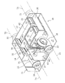
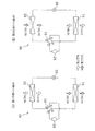
【解決手段】吸着剤を担持する第1及び第2熱交換器(61,62)が接続されて冷凍サイクルを行うと共に冷媒循環方向が反転可能な冷媒回路(60)と、内部の空気通路に上記熱交換器(61,62)が設置されるケーシング(11)と、上記熱交換器(61,62)のうち蒸発器となっている方を第1空気が通過して凝縮器となっている方を第2空気が通過するように、上記ケーシング(11)内での空気の流通経路を上記冷媒回路(60)での冷媒循環方向に応じて切り換える切換機構とを設ける。冷媒回路(60)の圧縮機(63)と膨張機構(65)と冷媒循環方向を反転させるための反転機構(64)とを熱交換器(61,62)と共に上記ケーシング(11)内に設置する。
【選択図】図2
Description
以下、本発明の実施形態1を図面に基づいて詳細に説明する。
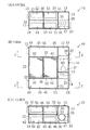
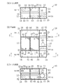
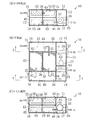
上記調湿装置(10)の調湿動作について説明する。この調湿装置(10)では、除湿運転と加湿運転とが切り換え可能となっている。また、上記調湿装置(10)において、除湿運転中や加湿運転中には、第1動作と第2動作とが比較的短い時間間隔(例えば3分間隔)で交互に繰り返される。
除湿運転時において、調湿装置(10)では、給気ファン(25)及び排気ファン(26)が運転される。そして、調湿装置(10)は、室外空気(OA)を第1空気として取り込んで室内に供給する一方、室内空気(RA)を第2空気として取り込んで室外に排出する。
加湿運転時において、調湿装置(10)では、給気ファン(25)及び排気ファン(26)が運転される。そして、調湿装置(10)は、室内空気(RA)を第1空気として取り込んで室外に排出する一方、室外空気(OA)を第2空気として取り込んで室内に供給する。
本実施形態では、冷媒回路(60)の圧縮機(63)と膨張機構(65)と冷媒循環方向を反転させるための反転機構(64)とを熱交換器(61,62)と共にケーシング(11)内に設置している。このため、冷媒を充填したまま出荷して設置することができるので、その設置作業が容易であり、また、圧力損失を軽減して凝縮温度を上げて調湿装置の効率を向上させることができる。
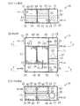
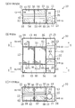
上記実施形態の調湿装置(10)において、ケーシング(11)の第1空間(17)の内部を、第7仕切板(37)によって2分割しているが、図8に示すように、第3仕切り板(38)を設けてケーシング(11)を空気通路から隔離したものとしてもよい。この場合には、圧縮機(63)が空気通路と遮断されて、室内に供給される空気が圧縮機(63)自体の放射熱による悪影響を受けることがない。さらに、第1熱交換室(41)と第1空間(17)との間に差圧が生じにくくなり、第1熱交換室(41)から配管用開口(31a )を通って第1空間(17)側へ空気が流入することはない。
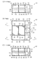
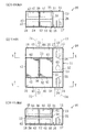
図9は本発明の実施形態2を示し、室外空気吸込口(21)、室内空気吸込口(22)、排気吹出口(23)、給気吹出口(24)の配置位置が異なる点で上記実施形態1と異なる。なお、以下の各実施形態では、図1〜図7と同じ部分については同じ符号を付してその詳細な説明は省略し、また、調湿装置(10)の調湿動作は上記実施形態1と全く同じであるため、省略する。
なお、ケーシング(11)の第1流入路(43)と第1流出路(44)とを天地逆転させ、かつ第2流入路(45)と第2流出路(46)と天地逆転させ、底面板(図示せず)において、給気ファン(25)の下側に給気吹出口(24)を形成し、かつ、第1流入路(43)の下側に室内空気吸込口(22)を形成するいわゆるカセット型にしてもよい。そして、ケーシング(11)における第4側板(15)の室外空気吸込口(21)に室外空気吸込ダクト(71)を接続し、排気吹出口(23)に排気吹出ダクト(73)を接続してもよい。このことで、室内に連通するダクト(72,74)を設ける必要がないので、天井などのスペースを有効利用できる。
11 ケーシング
21 室外空気吸込口
22 室内空気吸込口
23 排気吹出口
24 給気吹出口
60 冷媒回路
61 第1熱交換器
62 第2熱交換器
63 圧縮機
64 四方切換弁(反転機構)
65 電動膨張弁(膨張機構)
71 室外空気吸込ダクト
72 室内空気吸込ダクト
73 排気吹出ダクト
74 給気吹出ダクト
Claims (5)
- 除湿した第1空気と加湿した第2空気との一方を室内へ供給して他方を室外へ排出する調湿装置であって、
吸着剤を担持する第1及び第2熱交換器(61,62)が接続されて冷凍サイクルを行うと共に冷媒循環方向が反転可能な冷媒回路(60)と、
内部の空気通路に上記熱交換器(61,62)が設置されるケーシング(11)と、
上記熱交換器(61,62)のうち蒸発器となっている方を第1空気が通過して凝縮器となっている方を第2空気が通過するように、上記ケーシング(11)内での空気の流通経路を上記冷媒回路(60)での冷媒循環方向に応じて切り換える切換機構とを備え、
上記冷媒回路(60)の圧縮機(63)と膨張機構(65)と冷媒循環方向を反転させるための反転機構(64)とは、上記熱交換器(61,62)と共に上記ケーシング(11)内に設置されていることを特徴とする調湿装置。 - 請求項1に記載の調湿装置において、
上記圧縮機(63)は、上記ケーシング(11)内部における空気通路から仕切られた空間に配置されていることを特徴とする調湿装置。 - 請求項1に記載の調湿装置において、
上記圧縮機(63)は、上記ケーシング(11)内部における空気通路内に配置されていることを特徴とする調湿装置。 - 請求項1乃至3のいずれか1つに記載の調湿装置において、
上記ケーシング(11)には、室内に連通するダクト(72,74)を接続するための吹出口(24)及び吸込口(22)と、室外に連通するダクト(71,73)を接続するための吹出口(23)及び吸込口(21)とがそれぞれ開口されていることを特徴とする調湿装置。 - 請求項1乃至3のいずれか1つに記載の調湿装置において、
上記ケーシング(11)には、該ケーシング(11)内と室内とを直接連通させる吹出口(24)及び吸込口(22)と、室外に連通するダクト(71,73)を接続するための吹出口(23)及び吸込口(21)とがそれぞれ開口されていることを特徴とする調湿装置。
Priority Applications (7)
| Application Number | Priority Date | Filing Date | Title |
|---|---|---|---|
| JP2004102384A JP3815485B2 (ja) | 2004-03-31 | 2004-03-31 | 調湿装置 |
| KR1020067022465A KR100740770B1 (ko) | 2004-03-31 | 2005-03-30 | 조습장치 |
| PCT/JP2005/006102 WO2005095874A1 (ja) | 2004-03-31 | 2005-03-30 | 調湿装置 |
| AU2005227460A AU2005227460B2 (en) | 2004-03-31 | 2005-03-30 | Humidity control system |
| EP05727409A EP1739371A4 (en) | 2004-03-31 | 2005-03-30 | HUMIDITY CONTROL |
| CN200580005362.9A CN1922451B (zh) | 2004-03-31 | 2005-03-30 | 调湿装置 |
| US10/594,916 US8047014B2 (en) | 2004-03-31 | 2005-03-30 | Humidity control system |
Applications Claiming Priority (1)
| Application Number | Priority Date | Filing Date | Title |
|---|---|---|---|
| JP2004102384A JP3815485B2 (ja) | 2004-03-31 | 2004-03-31 | 調湿装置 |
Publications (2)
| Publication Number | Publication Date |
|---|---|
| JP2005291505A true JP2005291505A (ja) | 2005-10-20 |
| JP3815485B2 JP3815485B2 (ja) | 2006-08-30 |
Family
ID=35324636
Family Applications (1)
| Application Number | Title | Priority Date | Filing Date |
|---|---|---|---|
| JP2004102384A Expired - Fee Related JP3815485B2 (ja) | 2004-03-31 | 2004-03-31 | 調湿装置 |
Country Status (2)
| Country | Link |
|---|---|
| JP (1) | JP3815485B2 (ja) |
| CN (1) | CN1922451B (ja) |
Families Citing this family (5)
| Publication number | Priority date | Publication date | Assignee | Title |
|---|---|---|---|---|
| CN102967007A (zh) * | 2011-08-31 | 2013-03-13 | 大金工业株式会社 | 调湿装置 |
| ES2744524T3 (es) * | 2012-09-04 | 2020-02-25 | Daikin Ind Ltd | Dispositivo de humidificación |
| JP6563287B2 (ja) * | 2015-09-18 | 2019-08-21 | シャープ株式会社 | 除加湿装置 |
| CN106989473B (zh) * | 2017-05-19 | 2023-06-20 | 珠海格力电器股份有限公司 | 新风系统 |
| JP6970930B1 (ja) * | 2020-10-05 | 2021-11-24 | パナソニックIpマネジメント株式会社 | 空気調和機 |
Family Cites Families (1)
| Publication number | Priority date | Publication date | Assignee | Title |
|---|---|---|---|---|
| TW564770U (en) * | 2000-08-17 | 2003-12-01 | Daikin Ind Ltd | Dehumidifying device and a device for dehumidifying local space |
-
2004
- 2004-03-31 JP JP2004102384A patent/JP3815485B2/ja not_active Expired - Fee Related
-
2005
- 2005-03-30 CN CN200580005362.9A patent/CN1922451B/zh not_active Expired - Fee Related
Also Published As
| Publication number | Publication date |
|---|---|
| CN1922451A (zh) | 2007-02-28 |
| JP3815485B2 (ja) | 2006-08-30 |
| CN1922451B (zh) | 2010-05-05 |
Similar Documents
| Publication | Publication Date | Title |
|---|---|---|
| JP3668786B2 (ja) | 空気調和装置 | |
| JP3649236B2 (ja) | 空気調和装置 | |
| JP5018402B2 (ja) | 調湿装置 | |
| JP2003314856A (ja) | 調湿装置 | |
| JP3695417B2 (ja) | 調湿装置 | |
| JP3646722B2 (ja) | 調湿装置 | |
| KR100740770B1 (ko) | 조습장치 | |
| CN1930427B (zh) | 调湿装置 | |
| JP4325716B2 (ja) | 調湿装置 | |
| JP2006078108A (ja) | 調湿装置 | |
| JP3815485B2 (ja) | 調湿装置 | |
| KR100829678B1 (ko) | 조습 장치 | |
| JP2005291532A (ja) | 調湿装置 | |
| JP2005315463A (ja) | 調湿装置 | |
| JP2005283076A (ja) | 調湿装置 | |
| JP3879762B2 (ja) | 調湿装置 | |
| JP3815486B2 (ja) | 調湿装置 | |
| JP5949112B2 (ja) | 調湿装置 | |
| JP5353977B2 (ja) | 調湿装置 | |
| JP2013228167A (ja) | 調湿装置 | |
| JP4273818B2 (ja) | 調湿装置 | |
| JP2013124778A (ja) | 調湿装置 | |
| JP2006078171A (ja) | 調湿装置 | |
| JP4483376B2 (ja) | 調湿装置 | |
| JP4175405B2 (ja) | 調湿装置 |
Legal Events
| Date | Code | Title | Description |
|---|---|---|---|
| A131 | Notification of reasons for refusal |
Free format text: JAPANESE INTERMEDIATE CODE: A131 Effective date: 20050719 |
|
| A521 | Written amendment |
Free format text: JAPANESE INTERMEDIATE CODE: A523 Effective date: 20050916 |
|
| A131 | Notification of reasons for refusal |
Free format text: JAPANESE INTERMEDIATE CODE: A131 Effective date: 20051011 |
|
| A521 | Written amendment |
Free format text: JAPANESE INTERMEDIATE CODE: A523 Effective date: 20051207 |
|
| TRDD | Decision of grant or rejection written | ||
| A01 | Written decision to grant a patent or to grant a registration (utility model) |
Free format text: JAPANESE INTERMEDIATE CODE: A01 Effective date: 20060516 |
|
| A61 | First payment of annual fees (during grant procedure) |
Free format text: JAPANESE INTERMEDIATE CODE: A61 Effective date: 20060529 |
|
| R151 | Written notification of patent or utility model registration |
Ref document number: 3815485 Country of ref document: JP Free format text: JAPANESE INTERMEDIATE CODE: R151 |
|
| FPAY | Renewal fee payment (event date is renewal date of database) |
Free format text: PAYMENT UNTIL: 20100616 Year of fee payment: 4 |
|
| FPAY | Renewal fee payment (event date is renewal date of database) |
Free format text: PAYMENT UNTIL: 20100616 Year of fee payment: 4 |
|
| FPAY | Renewal fee payment (event date is renewal date of database) |
Free format text: PAYMENT UNTIL: 20110616 Year of fee payment: 5 |
|
| FPAY | Renewal fee payment (event date is renewal date of database) |
Free format text: PAYMENT UNTIL: 20120616 Year of fee payment: 6 |
|
| FPAY | Renewal fee payment (event date is renewal date of database) |
Free format text: PAYMENT UNTIL: 20130616 Year of fee payment: 7 |
|
| LAPS | Cancellation because of no payment of annual fees |