JP2005231663A - Carrier tape manufacturing device and carrier tape manufacturing method - Google Patents
Carrier tape manufacturing device and carrier tape manufacturing method Download PDFInfo
- Publication number
- JP2005231663A JP2005231663A JP2004042648A JP2004042648A JP2005231663A JP 2005231663 A JP2005231663 A JP 2005231663A JP 2004042648 A JP2004042648 A JP 2004042648A JP 2004042648 A JP2004042648 A JP 2004042648A JP 2005231663 A JP2005231663 A JP 2005231663A
- Authority
- JP
- Japan
- Prior art keywords
- tape
- carrier tape
- die
- tape manufacturing
- carrier
- Prior art date
- Legal status (The legal status is an assumption and is not a legal conclusion. Google has not performed a legal analysis and makes no representation as to the accuracy of the status listed.)
- Pending
Links
- 238000004519 manufacturing process Methods 0.000 title claims abstract description 18
- 238000000465 moulding Methods 0.000 claims abstract description 9
- 238000000034 method Methods 0.000 abstract description 10
- 238000005452 bending Methods 0.000 abstract 1
- 238000003860 storage Methods 0.000 description 6
- 238000004049 embossing Methods 0.000 description 3
- 238000010586 diagram Methods 0.000 description 2
- 239000003990 capacitor Substances 0.000 description 1
- 230000000052 comparative effect Effects 0.000 description 1
- 239000012050 conventional carrier Substances 0.000 description 1
- 230000000694 effects Effects 0.000 description 1
- 238000009434 installation Methods 0.000 description 1
- 239000002184 metal Substances 0.000 description 1
- 238000007493 shaping process Methods 0.000 description 1
- 229920001169 thermoplastic Polymers 0.000 description 1
- 239000004416 thermosoftening plastic Substances 0.000 description 1
- 238000004804 winding Methods 0.000 description 1
Images
Landscapes
- Containers And Plastic Fillers For Packaging (AREA)
- Blow-Moulding Or Thermoforming Of Plastics Or The Like (AREA)
Abstract
Description
本発明は、小型電子部品などを収納するポケットをエンボス成形によりテープ長手方法に連続的に設けたキャリアテープの製造装置及び製造方法に関する。 The present invention relates to a carrier tape manufacturing apparatus and a manufacturing method in which pockets for storing small electronic components and the like are continuously provided in a tape longitudinal method by embossing.
キャリアテープはIC、トランジスタ、ダイオード、コンデンサなどの表面実装用小型電子部品を電子機器の自動組立ラインに供給するために、小型電子部品を長尺なテープに設けられた収納ボックスに1個ずつ収納できるようにしたものであって、収納ポケットそれぞれに同じ小型電子部品を収納配置してなるこのキャリアテープを実装機械へ巡回させ、所定位置で前記小型部品を取り出して電子回路基板へ表面実装する自動実装が行えるようにしている。この種のキャリアテープの製造方法としては広幅の熱可塑性樹脂製テープを成形機に間欠的に供給し、予熱工程で所定の温度に加熱し、エンボス成形によって収納ボックスを成形し、スプロケット孔を穿孔し、所定の幅にスリットして巻き取る方法が取られており、特許文献1及び2などに提案されている。
Carrier tapes are used to store small electronic components such as ICs, transistors, diodes, capacitors, etc., one by one in a storage box provided on a long tape to supply electronic components to automatic assembly lines. The carrier tape, in which the same small electronic components are stored and arranged in the respective storage pockets, is circulated to the mounting machine, and the small components are taken out at a predetermined position and automatically mounted on the surface of the electronic circuit board. Implementation is possible. As a method of manufacturing this type of carrier tape, a wide thermoplastic tape is intermittently supplied to a molding machine, heated to a predetermined temperature in a preheating process, a storage box is formed by embossing, and a sprocket hole is drilled. However, a method of taking a slit by winding to a predetermined width is adopted, which is proposed in
ところで、エンボス成形によって収納ボックスを成形する工程においては、収納ボックスの形状が複雑であった場合に、成形した収納ボックスが成形金型から離型できず潰れが生じる。また、離型が悪いとその部分のテープに弛みが生じテープ送りの際、所定の距離を送れずテープ長手方向の寸法が規格外れとなる問題があった。
本発明は、このような従来のキャリアテープの欠点を解決するためになされたもので、その目的とするところは、離型をよくすることにより、複雑なデザインのキャリアテープを規格どおりに成形できる製造装置及び製造方法を提供するものである。 The present invention has been made in order to solve the drawbacks of the conventional carrier tape, and the object of the present invention is to improve the mold release so that a carrier tape with a complicated design can be formed according to the standard. A manufacturing apparatus and a manufacturing method are provided.
本発明は、
(1)キャリアテープの成形機において、成形金型の上型にテープ流れ方向に対し平行に、少なくとも片側にテープ受けを設けたことを特徴とするキャリアテープの製造装置、
(2)(1)項記載の製造装置で製造されるキャリアテープの製造方法、
である。
The present invention
(1) In a carrier tape molding machine, a carrier tape manufacturing apparatus characterized in that a tape receiver is provided on at least one side of the upper mold in parallel with the tape flow direction,
(2) A method for producing a carrier tape produced by the production apparatus according to (1),
It is.
本発明の方法に従うと、複雑な形状の成形が可能となり、小型電子部品の形状に沿ったデザインのキャリアテープの製造装置及び製造方法を提供することができる。 According to the method of the present invention, it is possible to form a complicated shape, and it is possible to provide a carrier tape manufacturing apparatus and a manufacturing method having a design along the shape of a small electronic component.
本発明を実施の形態に基づいて図1〜図6に沿って詳細に説明する。
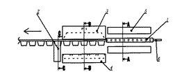
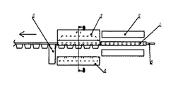
図1は、従来の成形方式を示した模式図であり、図2、図3、図4は図1のA−A、B−B、C−C各部の断面図である。入り口テープガイド1と出口テープガイド2でテープ6が下方に行かないよう保持している。予熱工程で所定の温度に加熱したテープ6が上型3と下型4の間に間欠的に送られた後、下型4が上昇し、テープ6をクランプして上型3より0.1〜0.5MPaの圧縮空気を供給し、テープ6を下型4に沿って成形する。その後、下型4が下降し成形したテープ6と下型4の引き離しを行う。このとき、ポケット形状が多面で複雑な形状の場合、引き離しができず、下型4にテープ6が引っ張られ、上型3と下型4の中間でテープに弛みが生じ、次にテープ6を間欠で送った際、ストロークが安定せず、長手方向の寸法が規格外となる。
The present invention will be described in detail with reference to FIGS.
FIG. 1 is a schematic view showing a conventional molding method, and FIGS. 2, 3, and 4 are cross-sectional views of respective parts AA, BB, and CC in FIG. The entrance tape guide 1 and the
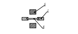
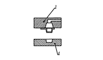
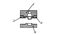
図5、6は本発明のひとつの実施例を示すものである。
テープ流れ方向に対し両側に、テープ受け7,8を設けたものである。テープ受け7,8は上型3に固定し図6のように、コの字状の隙間にテープ6を通すことにより、成形後下型4とテープ6の離型を補助する。
このコの字状の隙間は、テープ厚み0.2〜0.4mmに対し、0.3〜0.6mmが好ましく、あまり隙間が大きすぎてもテープが外れてしまい、効果がない。
また、テープを受ける寸法としては、テープ端面より内側に大きく受けた方が効果あるが、テープの規格幅及びポケット寸法の関係で0.5〜2.0mmが原料のロスも少なく好ましい。
また、片側のみに設置することもでき、設置方向はキャリアテープのスプロケット孔側がテープ端面からポケットまでの距離があり、上型3及び下型4を加工し易い。
5 and 6 show one embodiment of the present invention.
Tape receivers 7 and 8 are provided on both sides with respect to the tape flow direction. The tape receivers 7 and 8 are fixed to the upper die 3 and the tape 6 is passed through a U-shaped gap as shown in FIG. 6 to assist in releasing the lower die 4 and the tape 6 after molding.
The U-shaped gap is preferably 0.3 to 0.6 mm with respect to the tape thickness of 0.2 to 0.4 mm. Even if the gap is too large, the tape comes off and there is no effect.
In addition, as a dimension for receiving the tape, it is more effective to receive the tape on the inner side than the end face of the tape.
Moreover, it can also install only in one side, and the installation direction has the distance from the tape end surface to a pocket in the sprocket hole side of a carrier tape, and it is easy to process the upper mold | type 3 and the lower mold | type 4.
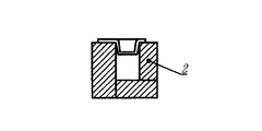
<実施例1〜2及び比較例1>
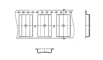
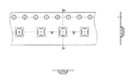
図7、8のキャリアテープ形状での、図6に示した本発明のテープ受け7,8の有無による成形結果を表1にまとめた。ここで、テープ厚みは0.3mm、コの字状隙間0.5mm、テープ受け7の長さ2.0mm、テープ受け8の長さ1.2mmであった。
表1中の記号は下記のような結果を示した。
×:離型できずテープ詰まりが発生
○:離型が良好でテープ送りもスムーズ
<Examples 1-2 and Comparative Example 1>
Table 1 summarizes the molding results with and without the tape receivers 7 and 8 of the present invention shown in FIG. Here, the tape thickness was 0.3 mm, the U-shaped gap was 0.5 mm, the length of the tape receiver 7 was 2.0 mm, and the length of the tape receiver 8 was 1.2 mm.
The symbols in Table 1 show the following results.
×: Can not be released and clogged with tape ○: Good release and smooth tape feeding

本発明によると複雑な形状の成形が可能となり、小型電子部品の形状に沿ったデザインのキャリアテープを供給することができ、ついては、小型電子部品を挿入後、運送途中で発生しているリード曲がり等のトラブルを無くすことができる。 According to the present invention, it is possible to form a complicated shape, and it is possible to supply a carrier tape having a design that conforms to the shape of a small electronic component. Troubles such as can be eliminated.
1 入り口テープガイド
2 出口テープガイド
3 上型
4 下型
5 予熱ヒーター
6 テープ
7 テープ受け
8 テープ受け
1 Entrance tape guide
2 Exit tape guide
3 Upper mold
4 Lower mold
5 Preheating heater
6 tapes
7 Tape holder
8 Tape receiver
Claims (2)
Priority Applications (1)
| Application Number | Priority Date | Filing Date | Title |
|---|---|---|---|
| JP2004042648A JP2005231663A (en) | 2004-02-19 | 2004-02-19 | Carrier tape manufacturing device and carrier tape manufacturing method |
Applications Claiming Priority (1)
| Application Number | Priority Date | Filing Date | Title |
|---|---|---|---|
| JP2004042648A JP2005231663A (en) | 2004-02-19 | 2004-02-19 | Carrier tape manufacturing device and carrier tape manufacturing method |
Publications (1)
| Publication Number | Publication Date |
|---|---|
| JP2005231663A true JP2005231663A (en) | 2005-09-02 |
Family
ID=35015032
Family Applications (1)
| Application Number | Title | Priority Date | Filing Date |
|---|---|---|---|
| JP2004042648A Pending JP2005231663A (en) | 2004-02-19 | 2004-02-19 | Carrier tape manufacturing device and carrier tape manufacturing method |
Country Status (1)
| Country | Link |
|---|---|
| JP (1) | JP2005231663A (en) |
Citations (3)
| Publication number | Priority date | Publication date | Assignee | Title |
|---|---|---|---|---|
| JPH04239415A (en) * | 1991-01-09 | 1992-08-27 | Dainippon Printing Co Ltd | Sheet guide device |
| JP2000128128A (en) * | 1998-10-30 | 2000-05-09 | Shin Etsu Polymer Co Ltd | Embossed carrier tape forming device |
| JP2003170913A (en) * | 2001-12-06 | 2003-06-17 | Ckd Corp | Pocket part forming device and blister pack manufacturing device |
-
2004
- 2004-02-19 JP JP2004042648A patent/JP2005231663A/en active Pending
Patent Citations (3)
| Publication number | Priority date | Publication date | Assignee | Title |
|---|---|---|---|---|
| JPH04239415A (en) * | 1991-01-09 | 1992-08-27 | Dainippon Printing Co Ltd | Sheet guide device |
| JP2000128128A (en) * | 1998-10-30 | 2000-05-09 | Shin Etsu Polymer Co Ltd | Embossed carrier tape forming device |
| JP2003170913A (en) * | 2001-12-06 | 2003-06-17 | Ckd Corp | Pocket part forming device and blister pack manufacturing device |
Similar Documents
| Publication | Publication Date | Title |
|---|---|---|
| CN105051405B (en) | The manufacture device of knuckle support and manufacture method | |
| JP2009137621A (en) | Carrier tape production device, component insertion device, and taping device | |
| US7320772B2 (en) | System for embossing carrier tape and method for producing carrier tape | |
| JP2005231663A (en) | Carrier tape manufacturing device and carrier tape manufacturing method | |
| JPS59202830A (en) | Injection mold equipment for painting | |
| JP2013227065A (en) | Carrier tape for holding electronic component, and manufacturing method and package of carrier tape for holding electronic component | |
| JP2005255174A (en) | Apparatus and method for manufacturing carrier tape | |
| JP2011136715A (en) | Method for molding carrier tape | |
| CN105818406A (en) | Automatic bearing belt machining and forming device | |
| CN206436318U (en) | Multifunctional hardware mould is used in a kind of cutting part processing | |
| JP6076194B2 (en) | Embossed carrier tape and manufacturing method thereof | |
| KR20190061507A (en) | Injection apparatus for manufacturing a connector | |
| WO2019098364A1 (en) | Carrier tape and method for forming carrier tape | |
| JPH059294Y2 (en) | ||
| CN205414111U (en) | Make continuous stamping die of high electric current transmission connector hardware product | |
| JPH08125096A (en) | Lead frame and method and apparatus for manufacturing the same | |
| CN217252120U (en) | Continuous stamping die applied to stretching forming of resonant rod | |
| CN221754418U (en) | Automobile exterior trimming part processing die | |
| WO2004028782A1 (en) | Emboss carrier tape forming machine | |
| CN217373434U (en) | Automatic punching device for material belt positioning hole | |
| JP2012140149A (en) | Device and method for manufacturing carrier tape | |
| JP2003095211A (en) | Manufacturing method and manufacturing apparatus for embossed carrier tape | |
| KR101549402B1 (en) | a consecutive presser and a plate fabricating method thereof | |
| JP2005035553A (en) | Manufacturing method for carrier tape | |
| JP2006051996A (en) | Apparatus and method for manufacturing carrier tape |
Legal Events
| Date | Code | Title | Description |
|---|---|---|---|
| A621 | Written request for application examination |
Free format text: JAPANESE INTERMEDIATE CODE: A621 Effective date: 20070116 |
|
| A131 | Notification of reasons for refusal |
Free format text: JAPANESE INTERMEDIATE CODE: A131 Effective date: 20100223 |
|
| A02 | Decision of refusal |
Free format text: JAPANESE INTERMEDIATE CODE: A02 Effective date: 20100622 |