JP2005055152A - Heating device - Google Patents
Heating device Download PDFInfo
- Publication number
- JP2005055152A JP2005055152A JP2003289359A JP2003289359A JP2005055152A JP 2005055152 A JP2005055152 A JP 2005055152A JP 2003289359 A JP2003289359 A JP 2003289359A JP 2003289359 A JP2003289359 A JP 2003289359A JP 2005055152 A JP2005055152 A JP 2005055152A
- Authority
- JP
- Japan
- Prior art keywords
- heating
- heat
- heated
- space
- wall bodies
- Prior art date
- Legal status (The legal status is an assumption and is not a legal conclusion. Google has not performed a legal analysis and makes no representation as to the accuracy of the status listed.)
- Granted
Links
- 238000010438 heat treatment Methods 0.000 title claims abstract description 122
- 239000011810 insulating material Substances 0.000 claims abstract description 13
- 230000005855 radiation Effects 0.000 claims description 16
- 230000004308 accommodation Effects 0.000 claims description 13
- 229910052751 metal Inorganic materials 0.000 claims description 10
- 239000002184 metal Substances 0.000 claims description 10
- 229910052782 aluminium Inorganic materials 0.000 claims description 9
- XAGFODPZIPBFFR-UHFFFAOYSA-N aluminium Chemical compound [Al] XAGFODPZIPBFFR-UHFFFAOYSA-N 0.000 claims description 9
- 238000004381 surface treatment Methods 0.000 claims description 4
- 239000011521 glass Substances 0.000 abstract description 17
- 239000000758 substrate Substances 0.000 abstract description 17
- 230000003749 cleanliness Effects 0.000 abstract description 6
- 238000011282 treatment Methods 0.000 description 8
- 239000000470 constituent Substances 0.000 description 3
- 230000000694 effects Effects 0.000 description 3
- 239000004973 liquid crystal related substance Substances 0.000 description 3
- 238000013021 overheating Methods 0.000 description 3
- 229910001220 stainless steel Inorganic materials 0.000 description 3
- 239000010935 stainless steel Substances 0.000 description 3
- 238000009825 accumulation Methods 0.000 description 2
- 238000001035 drying Methods 0.000 description 2
- 238000009413 insulation Methods 0.000 description 2
- 238000000034 method Methods 0.000 description 2
- 230000000630 rising effect Effects 0.000 description 2
- 206010037660 Pyrexia Diseases 0.000 description 1
- 239000000919 ceramic Substances 0.000 description 1
- 230000007423 decrease Effects 0.000 description 1
- 239000011491 glass wool Substances 0.000 description 1
- 238000007747 plating Methods 0.000 description 1
- 238000003756 stirring Methods 0.000 description 1
- 239000002699 waste material Substances 0.000 description 1
Images

Landscapes
- Furnace Details (AREA)
- Liquid Crystal (AREA)
- Muffle Furnaces And Rotary Kilns (AREA)
Abstract
Description
本発明は、液晶表示パネルやプラズマ表示パネルなどの構成部材であるガラス基板あるいはその他の金属板の熱処理に用いられる加熱装置に関する。 The present invention relates to a heating device used for heat treatment of a glass substrate or other metal plate which is a constituent member of a liquid crystal display panel or a plasma display panel.
液晶表示パネルなどの構成部材であるガラス基板を熱処理する装置としては、従来、加熱気体循環型のクリーンオーブンと呼ばれる加熱装置が使用されている(例えば、特許文献1参照。)。このクリーンオーブンは、ガラス基板などの被熱物を恒温槽内に収容し、この恒温槽内で循環する加熱気体によって被加熱物を熱処理するものである。 As a device for heat-treating a glass substrate which is a constituent member such as a liquid crystal display panel, a heating device called a heated gas circulation type clean oven has been conventionally used (for example, see Patent Document 1). This clean oven accommodates an object to be heated such as a glass substrate in a thermostat and heat-treats the object to be heated with a heating gas circulating in the thermostat.
しかしながら、加熱気体循環型のクリーンオーブンの場合、ガラス基板などの被加熱物を多段状に収容する構造を採用しやすいので、スペース効率に優れている反面、加熱温度分布を均一化することが困難であり、加熱気体の撹拌によりクリーン度が悪化するおそれがある。また、被加熱物が軽いものである場合、加熱気体の対流によって被加熱物が所定の位置から移動することがある。 However, in the case of a heated gas circulation type clean oven, it is easy to adopt a structure that accommodates a heated object such as a glass substrate in multiple stages, so it is excellent in space efficiency, but it is difficult to make the heating temperature distribution uniform. The cleanliness may be deteriorated by stirring the heated gas. When the object to be heated is light, the object to be heated may move from a predetermined position due to convection of the heated gas.
そこで、内部に発熱体を有する放熱板の両面にそれぞれ遠赤外線放射セラミックスの薄層が被覆され、この放熱板の加熱によってその両面から遠赤外線が放射される両面加熱式の遠赤外線パネルヒータからなる多数の棚ヒータが、炉本体内に上下方向に一定ピッチをおいて多段配置され、上下の各棚ヒータで形成される各空間部をそれぞれ乾燥室とした加熱炉が開発されている(例えば、特許文献2参照。)。 Therefore, a thin layer of far-infrared radiation ceramics is coated on both sides of a heat sink having a heating element inside, and a far-infrared panel heater of a double-sided heating type in which far-infrared radiation is emitted from both sides by heating of the heat sink. A large number of shelf heaters are arranged in a plurality of stages in the furnace body at a constant pitch in the vertical direction, and a heating furnace has been developed in which each space formed by the upper and lower shelf heaters is a drying chamber (for example, (See Patent Document 2).
特許文献2に記載の加熱炉の場合、両面加熱式の遠赤外線パネルヒータからなる多数の棚ヒータが多段配置されているため、上下の各棚ヒータで形成される各空間部(乾燥室)を効率的に加熱することができる点では優れている。
In the case of the heating furnace described in
しかしながら、この加熱炉においては、上下方向に配置された多数の棚ヒータから発される熱は加熱炉内を上昇して炉内の天壁寄りの部分に集まる傾向があるため、炉内上部の温度は炉内下部の温度よりも高くなっており、このような炉内上部と炉内下部との間の温度差をなくすことは極めて困難である。 However, in this heating furnace, heat generated from a number of shelf heaters arranged in the vertical direction tends to rise in the heating furnace and collect in a portion near the top wall in the furnace. The temperature is higher than the temperature in the lower part of the furnace, and it is extremely difficult to eliminate such a temperature difference between the upper part in the furnace and the lower part in the furnace.
本発明が解決しようとする課題は、温度分布の均一性およびクリーン度の安定性に優れ、被加熱物の移動が生じることもなく、省エネルギも図ることができる、加熱装置を提供することにある。 The problem to be solved by the present invention is to provide a heating device that is excellent in uniformity of temperature distribution and stability of cleanliness, does not cause movement of an object to be heated, and can save energy. is there.
本発明の加熱装置は、断熱材で囲まれた空間内に距離を隔てて立設された複数の加熱用壁体と、これらの加熱用壁体に設けられた発熱手段と、被加熱物を出し入れ可能に収容するための収容スペースを隔てて加熱用壁体の間に棚状に配置された複数の熱放射部材とを備えたことを特徴とする。 A heating device according to the present invention includes a plurality of heating wall bodies standing at a distance in a space surrounded by a heat insulating material, heating means provided on these heating wall bodies, and an object to be heated. It is characterized by comprising a plurality of heat radiation members arranged in a shelf shape between the heating wall bodies with an accommodation space for accommodating in a removable manner.
このような構成とすることにより、断熱材で囲まれた空間内に存在する複数の被加熱物の収容スペースはそれぞれ左右に加熱用壁体が配置され、上下に熱放射部材が配置された構造となる。このため、各々の収容スペース内は、発熱手段の熱によって昇温した左右の加熱用壁体と、これらの加熱用壁体を経由して複数の熱放射部材に到達し、上下の熱放射部材から放射される熱によって加熱されることとなり、各収容スペース内は均一かつ効率的に加熱される。 By adopting such a structure, the housing space for the plurality of objects to be heated existing in the space surrounded by the heat insulating material has a structure in which heating walls are arranged on the left and right sides, and heat radiation members are arranged on the upper and lower sides. It becomes. Therefore, in each housing space, the left and right heating walls heated by the heat of the heating means, and the plurality of heat radiating members are reached via these heating walls, and the upper and lower heat radiating members It will be heated by the heat | fever radiated from, and the inside of each accommodation space will be heated uniformly and efficiently.
発熱手段は加熱用壁体にのみ設けられており、各収容スペースは上下の熱放射部材によって区画されているため、熱気の上昇に起因する上部空間の熱蓄積および過熱が発生せず、温度分布の均一性に優れている。また、加熱気体を循環させたり、撹拌したりすることがないので、クリーン度の安定性に優れており、被加熱物の移動が生じることもない。また、断熱材で囲まれた空間内に被加熱物の収容スペースを配置しているため、温度の散逸が少なく、省エネルギも図ることができる。 The heating means is provided only on the heating wall, and each storage space is partitioned by upper and lower heat radiating members, so that heat accumulation and overheating of the upper space due to the rise of hot air does not occur, and temperature distribution Excellent in uniformity. In addition, since the heated gas is not circulated or stirred, the cleanliness stability is excellent, and the object to be heated does not move. Moreover, since the accommodation space for the object to be heated is disposed in the space surrounded by the heat insulating material, there is little temperature dissipation and energy saving can be achieved.
ここで、前記熱放射部材として、熱放射率を高めるための表面処理を施した金属部材を用いることにより、優れた熱放射機能が得られるため、それぞれの収容スペース内を効率的に加熱することができる。このような表面処理としては、例えば、黒化処理、つや消し処理およびこれらを組み合わせたつや消し黒化処理が好適である。なお、これらの処理を同一の金属部材に施した後の熱放射率の大小を比較すると、概ね、黒化処理<つや消し処理<つや消し黒化処理の順に熱放射率が高まることが分かっている。 Here, as the heat radiating member, by using a metal member that has been subjected to a surface treatment for increasing the heat emissivity, an excellent heat radiating function can be obtained. Can do. As such a surface treatment, for example, a blackening treatment, a matte treatment, and a matte blackening treatment combining them are suitable. In addition, when comparing the magnitudes of the thermal emissivities after applying these treatments to the same metal member, it is known that the thermal emissivity generally increases in the order of blackening treatment <matte treatment <matte blackening treatment.
この場合、前記金属部材としては、表面に黒色メッキを施したアルミニウム板を用いることが望ましい。黒色メッキを施されたアルミニウム板の表面は、つや消し黒化処理された状態となっているため、加熱手段によって昇温した加熱用壁体の熱は、熱伝導度の高いアルミニウム板全体に速やかに拡散されるとともに、黒色メッキされた表面全体から効率良く放射されるため、収容スペース内の被加熱物を均一かつ効率良く加熱することができる。 In this case, as the metal member, it is desirable to use an aluminum plate having a black plated surface. The surface of the aluminum plate that has been black-plated is in a state of matte blackening treatment, so the heat of the heating wall heated by the heating means is promptly applied to the entire aluminum plate with high thermal conductivity. While being diffused and efficiently radiated from the entire black-plated surface, the object to be heated in the accommodation space can be uniformly and efficiently heated.
一方、前記発熱手段を前記加熱用壁体内に形成した空洞部に内蔵させた構造とすることが望ましい。このような構成とすることにより、加熱手段が発する熱を逃すことなく、加熱用壁体の内部から当該加熱用壁体に伝達することができるようなるため、加熱用壁体全体を効率良く、均等に昇温させることができる。また、加熱効率および均等加熱機能が向上することにより、加熱手段の配置個数や制御点の個数を減らすことも可能となる。さらに、加熱手段が空洞部に内蔵されていることにより、被加熱物の出し入れによる温度降下を抑制することができる。 On the other hand, it is desirable to have a structure in which the heat generating means is built in a cavity formed in the heating wall. By adopting such a configuration, it is possible to transmit the heating wall body from the inside of the heating wall body to the heating wall body without losing the heat generated by the heating means. The temperature can be increased evenly. Further, by improving the heating efficiency and the uniform heating function, the number of heating means arranged and the number of control points can be reduced. Furthermore, since the heating means is built in the cavity, it is possible to suppress a temperature drop caused by taking in and out the object to be heated.
また、前記加熱用壁体の一部に、上下方向の熱伝導を抑制するための断熱部を設けた構造とすることもできる。このような断熱部を設ければ、加熱用壁体を経由して熱が上昇するのを抑制することができるため、上方に位置する収容スペースが設定値を超えて温度上昇するのを防止することができ、上下方向の温度分布の均一性をさらに向上させることができる。断熱部としては、加熱用壁体より熱電伝導率の小さな断熱部材を配置したり、隙間を設けたりすることができる。 Moreover, it can also be set as the structure which provided the heat insulation part for suppressing the heat conduction of an up-down direction in a part of said heating wall. If such a heat insulating portion is provided, it is possible to suppress the heat from rising through the heating wall, and therefore, it is possible to prevent the housing space located above the temperature from exceeding the set value. It is possible to further improve the uniformity of the temperature distribution in the vertical direction. As the heat insulating portion, a heat insulating member having a smaller thermal conductivity than the heating wall body can be disposed, or a gap can be provided.
本発明により、以下に示す効果を奏する。 The present invention has the following effects.
(1)断熱材で囲まれた空間内に距離を隔てて立設された複数の加熱用壁体と、これらの加熱用壁体に設けられた発熱手段と、被加熱物を出し入れ可能に収容するための収容スペースを隔てて加熱用壁体の間に棚状に配置された複数の熱放射部材とを備えたことにより、温度分布の均一性およびクリーン度の安定性に優れたものとなり、被加熱物の移動が生じることもなく、省エネルギも図ることができる。 (1) A plurality of heating walls standing at a distance in a space surrounded by a heat insulating material, heat generating means provided on these heating walls, and an object to be heated so that it can be taken in and out By providing a plurality of heat radiating members arranged in a shelf shape between the heating wall bodies with a storage space to be made, it becomes excellent in uniformity of temperature distribution and stability of cleanliness, There is no movement of the object to be heated, and energy can be saved.
(2)前記熱放射部材として、熱放射率を高めるための表面処理を施した金属部材を用いることにより、優れた熱放射機能が得られるため、それぞれの収容スペース内を効率的に加熱することができる。 (2) Since an excellent heat radiation function can be obtained by using a metal member that has been subjected to a surface treatment for increasing the heat emissivity as the heat radiation member, the inside of each housing space is efficiently heated. Can do.
(3)前記金属部材として、表面に黒色メッキを施したアルミニウム板を用いることにより、加熱手段によって昇温した加熱用壁体の熱は、熱伝導度の高いアルミニウム板全体に速やかに拡散されるとともに、つや消し黒化処理された状態にある表面全体から効率良く放射されるため、収容スペース内の被加熱物を均一かつ効率良く加熱することができる。 (3) By using an aluminum plate whose surface is black-plated as the metal member, the heat of the heating wall heated by the heating means is quickly diffused throughout the aluminum plate having high thermal conductivity. At the same time, since the entire surface in the matte blackening process is efficiently radiated, the object to be heated in the accommodation space can be heated uniformly and efficiently.
(4)前記発熱手段を前記加熱用壁体内に形成した空洞部に内蔵させた構造とすることにより、加熱手段が発する熱を逃すことなく、加熱用壁体の内部から当該加熱用壁体に伝達することができるようなるため、加熱用壁体全体を効率良く、均等に昇温させることができ、加熱手段の配置個数や制御点の個数を減らすことも可能となり、被加熱物の出し入れによる温度降下を抑制することができる。 (4) By adopting a structure in which the heat generating means is built in a hollow portion formed in the heating wall body, the heating wall body can be transferred from the inside of the heating wall body to the heating wall body without missing the heat generated by the heating means. Since it can be transmitted, the entire heating wall can be heated efficiently and evenly, and the number of heating means and the number of control points can be reduced. Temperature drop can be suppressed.
(5)前記加熱用壁体の一部に、上下方向の熱伝導を抑制するための断熱部を設けることにより、加熱用壁体を経由した熱上昇を抑制することができるため、上方位置の収容スペースの過熱を防止することができ、上下方向の温度分布の均一性をさらに向上させることができる。 (5) By providing a heat insulating part for suppressing heat conduction in the vertical direction in a part of the heating wall body, it is possible to suppress a heat rise via the heating wall body, so Overheating of the accommodation space can be prevented, and the uniformity of the temperature distribution in the vertical direction can be further improved.
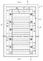
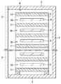
図1は本発明の第1実施形態である加熱装置を一部省略した状態で示す正面図であり、図2は図1におけるA−A線断面図である。 FIG. 1 is a front view showing the heating apparatus according to the first embodiment of the present invention with a part thereof omitted, and FIG. 2 is a cross-sectional view taken along line AA in FIG.
図1は本実施形態の加熱装置1を正面の開閉扉2を取り外した状態で示しているが、同図に示すように、直方体の箱体形状に組み立てられた断熱材3によって囲まれた空間4内に、距離を隔てて垂直に立設された複数のステンレス製の加熱用壁体5,6と、これらの加熱用壁体5,6に設けられた複数の孔部7と、それぞれの孔部7に挿入された発熱手段である電気ヒータ8と、被加熱物であるガラス基板9を出し入れ可能に収容するための収容スペース10を隔てて加熱用壁体5,6の間に棚状に配置された複数の熱放射部材11とを備えている。断熱材3は、ステンレス鋼板の間にサンドイッチ状にグラスウールを挟んだ構造となっている。
FIG. 1 shows the
それぞれの孔部7は、加熱用壁体5,6の正面に開口し、その奥行き方向に伸びるように形成されている。複数の孔部7は、加熱用壁体5,6の垂直方向にほぼ等間隔をおいて配置され、電気ヒータ8はそれぞれの孔部7に開口部分から出し入れ可能に挿入されている。
Each
複数の熱放射部材11も加熱用壁体5,6の間にほぼ等間隔に配置され、内容積のほぼ等しい複数の収容スペース10が形成されている。それぞれの収容スペース10内にはガラス基板9が1枚ずつ収容されている。収容スペース10内におけるガラス基板9の保持手段としては、例えば、加熱用壁体5,6の内側面にそれぞれガラス基板9の側部を支えるための係合部を設けたり、加熱用壁体5,6の内側面にガラス基板9の側部を支えるための支持部材を取り付けたりすることができる。
The plurality of
本実施形態の加熱装置1においては、開閉扉2を含む断熱材3によって前後および上下左右を囲まれた空間4内に存在する複数の被加熱物の収容スペース10は、いずれも左右に加熱用壁体5,6が配置され、上下に熱放射部材11が配置された構造となる。このため、各々の収容スペース10内は、電気ヒータ8の発熱によって昇温した左右の加熱用壁体5,6と、これらの加熱用壁体5,6を経由して複数の熱放射部材11に到達し、上下の熱放射部材11から放射される熱によって加熱される。したがって、各収容スペース10内は上下左右から加熱されることとなり、収容スペース内10内のガラス基板9を均一かつ効率的に加熱することができる。
In the
発熱手段である電気ヒータ8は、加熱用壁体5,6にのみ内蔵されており、各収容スペース10は上下の熱放射部材11によって区画されているため、熱気上昇に起因する上部空間の熱蓄積および過熱が発生せず、均一な温度分布を得ることができる。また、断熱材3で囲まれた空間4内において加熱気体を循環させたり、撹拌したりしないので、クリーン度の安定性に優れており、被加熱物であるガラス基板9が勝手に移動することもない。また、断熱材3で囲まれた空間4内に被加熱物の収容スペース10を配置しているため、加熱用壁体5,6および熱放射部材11からの温度の散逸が少なく、省エネルギも図ることができる。
The
また、本実施形態の加熱装置では、熱放射部材11として、表面全体に黒色メッキを施したアルミニウム板を用いているため、その表面はつや消し黒化処理を施された状態となっており、優れた熱放射機能を発揮し、それぞれの収容スペース10内を効率的に加熱することができる。特に、黒色メッキを施したアルミニウム板を用いたことにより、電気ヒータ8によって昇温した加熱用壁体5,6の熱は、熱伝導度の高いアルミニウム板全体に速やかに拡散されるととともに、黒色メッキされた表面全体から放射されるため、収容スペース10内の被加熱物を均一かつ効率良く加熱することができる。
Moreover, in the heating apparatus of this embodiment, since the aluminum plate which gave the whole surface black plating is used as the
一方、発熱手段である電気ヒータ8を加熱用壁体5,6内に形成した空洞部である孔部7に内蔵させた構造としているため、加熱用壁体5,6全体を効率良く、均等に昇温させることができる。また、熱放射部材11内に電気ヒータ8を組み込む必要がないため、熱放射部材11の厚さを小さくすることができ、空間4内における高さ方向のスペースを有効活用することができる。
On the other hand, since the
なお、加熱装置1においては被加熱物がガラス基板9である場合について説明したが、被加熱物はガラス基板9に限定するものではないので、これ以外のワークとして、例えば、ステンレス鋼板などの金属板の熱処理を行うことも可能である。また、被加熱物のサイズ、形状に応じて、加熱用壁体5,6間の距離あるいは熱放射部材11の配置間隔や厚さを任意に変更することができるので、加熱装置1は様々な技術分野において広く使用することができる。
In the
次に、図3を参照して、本発明の第2実施形態である加熱装置21について説明する。なお、図3において、第1実施形態の加熱装置1の場合と同じ機能、効果を発揮する部分については、図1,図2と同じ符号を付して説明を省略する。
Next, with reference to FIG. 3, the
加熱装置21においては、断熱材3で形成された空間24内に、3枚以上の加熱用壁体25,26,27を垂直に立設し、これらの加熱用壁体25,26,27の間にそれぞれ複数の熱放射部材11を棚状に配置することによって複数の収容スペース20を形成している。
In the
このように、複数の収容スペース20を縦方向および横方向に配列した構造とすることにより、1バッチで熱処理することのできるガラス基板9の枚数を増大させ、作業効率の向上を図ることができる。また、中央に位置する加熱用壁体26は、その左右に配列された複数の収容スペース20によって共有された状態にあるため、加熱用壁体1枚当たりの収容スペースの増大を図ることができる。さらに、加熱用壁体26はその左右にある複数の収容スペース20を同時に加熱することとなるため、加熱用壁体26が発する熱は無駄なく収容スペース20の加熱に供されることとなり、エネルギ効率も向上する。その他の構造、機能については加熱装置1の場合と同様である。
In this way, by adopting a structure in which the plurality of
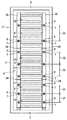
次に、図4を参照して、本発明の第3実施形態である加熱装置31について説明する。なお、第2実施形態の場合と同様、図4において第1実施形態の加熱装置1の場合と同じ機能、効果を発揮する部分については、図1,図2と同じ符号を付して説明を省略する。
Next, with reference to FIG. 4, the heating apparatus 31 which is 3rd Embodiment of this invention is demonstrated. In addition, like the case of 2nd Embodiment, about the part which exhibits the same function and effect as the case of the
本実施形態の加熱装置31においては、加熱用壁体35,36に形成された、電気ヒータ8を挿入するための孔部7同士の配置間隔S1,S2,S3を、加熱用壁体35,36の下部では小さくし、加熱用壁体35,36の上部に向かって徐々に大きくしている。すなわち、配置間隔S1<S2<S3としている。このような配置間隔とすれば、それぞれの孔部7に挿入された電気ヒータ8による昇温程度は、加熱用壁体35,36の下部では大きく、上部にいくにつれて徐々に小さくなるため、加熱用壁体35,36の上部における設定値を超える温度上昇を抑制することができる。
In the heating device 31 of the present embodiment, the arrangement intervals S1, S2, and S3 between the
また、加熱装置31においては、加熱用壁体35,36の一部に、上下方向の熱伝導を抑制するための断熱部34を設けた構造としている。このような断熱部34を設けたことにより、加熱用壁体35,36を経由して熱が上昇するのを抑制することができるため、上方に位置する収容スペース10が設定値を超えて温度上昇するのを防止することができ、上下方向の温度分布の均一性がさらに向上する。なお、本実施形態では、断熱部34として加熱用壁体35,36よりより熱電伝導率の小さな断熱部材を配置している。その他の構造、機能については加熱装置1の場合と同様である。
Moreover, in the heating apparatus 31, it is set as the structure which provided the
本発明の加熱装置は、液晶表示パネルやプラズマ表示パネルなどの構成部材であるガラス基板の熱処理工程、あるいはその他の金属板の熱処理工程を行う産業分野において広く利用することができる。 The heating device of the present invention can be widely used in industrial fields in which a heat treatment step for a glass substrate, which is a constituent member of a liquid crystal display panel or a plasma display panel, or a heat treatment step for other metal plates is performed.
1,21,31 加熱装置
2 開閉扉
3 断熱材
4 空間
5,6,25,26,27,35,36 加熱用壁体
7 孔部
8 電気ヒータ
9 ガラス基板
10 収容スペース
11 熱放射部材
S1,S2,S3 配置間隔
DESCRIPTION OF
Claims (5)
Priority Applications (1)
| Application Number | Priority Date | Filing Date | Title |
|---|---|---|---|
| JP2003289359A JP4462868B2 (en) | 2003-08-07 | 2003-08-07 | Heating device |
Applications Claiming Priority (1)
| Application Number | Priority Date | Filing Date | Title |
|---|---|---|---|
| JP2003289359A JP4462868B2 (en) | 2003-08-07 | 2003-08-07 | Heating device |
Publications (2)
| Publication Number | Publication Date |
|---|---|
| JP2005055152A true JP2005055152A (en) | 2005-03-03 |
| JP4462868B2 JP4462868B2 (en) | 2010-05-12 |
Family
ID=34367725
Family Applications (1)
| Application Number | Title | Priority Date | Filing Date |
|---|---|---|---|
| JP2003289359A Expired - Lifetime JP4462868B2 (en) | 2003-08-07 | 2003-08-07 | Heating device |
Country Status (1)
| Country | Link |
|---|---|
| JP (1) | JP4462868B2 (en) |
Cited By (15)
| Publication number | Priority date | Publication date | Assignee | Title |
|---|---|---|---|---|
| JP2005352306A (en) * | 2004-06-11 | 2005-12-22 | Kyushu Nissho:Kk | Heating device |
| JP2009115425A (en) * | 2007-11-09 | 2009-05-28 | Kyushu Nissho:Kk | Heat treatment apparatus |
| CN102508381A (en) * | 2011-11-29 | 2012-06-20 | 深圳市华星光电技术有限公司 | Baking device for liquid crystal display panel |
| CN102992602A (en) * | 2012-11-28 | 2013-03-27 | 江苏宜达光电科技有限公司 | Microcrystalline glass heat treatment furnace |
| JP2013200077A (en) * | 2012-03-26 | 2013-10-03 | Kyushu Nissho:Kk | Heater |
| CN105217940A (en) * | 2015-08-21 | 2016-01-06 | 四川省洪雅县中保光学元件有限公司 | The annealing furnace that a kind of safety is controlled |
| JP2016173230A (en) * | 2016-04-21 | 2016-09-29 | 株式会社九州日昌 | Heating device |
| JP2017106711A (en) * | 2017-01-27 | 2017-06-15 | 株式会社九州日昌 | Heating apparatus and heating method |
| JP2018048805A (en) * | 2017-10-11 | 2018-03-29 | 株式会社九州日昌 | Heating device |
| JP2019049408A (en) * | 2018-11-21 | 2019-03-28 | 株式会社九州日昌 | Heating device |
| CN110282862A (en) * | 2019-06-24 | 2019-09-27 | 鞍钢股份有限公司 | Device and method for preparing foam glass |
| JP2020109351A (en) * | 2020-04-13 | 2020-07-16 | 株式会社九州日昌 | Heating device |
| JPWO2020241488A1 (en) * | 2019-05-31 | 2020-12-03 | ||
| JP2021042928A (en) * | 2019-09-13 | 2021-03-18 | 株式会社九州日昌 | Heating device and heating method |
| JP2021185557A (en) * | 2020-05-25 | 2021-12-09 | 株式会社九州日昌 | Heating device and heating method |
-
2003
- 2003-08-07 JP JP2003289359A patent/JP4462868B2/en not_active Expired - Lifetime
Cited By (21)
| Publication number | Priority date | Publication date | Assignee | Title |
|---|---|---|---|---|
| JP2005352306A (en) * | 2004-06-11 | 2005-12-22 | Kyushu Nissho:Kk | Heating device |
| JP2009115425A (en) * | 2007-11-09 | 2009-05-28 | Kyushu Nissho:Kk | Heat treatment apparatus |
| CN102508381A (en) * | 2011-11-29 | 2012-06-20 | 深圳市华星光电技术有限公司 | Baking device for liquid crystal display panel |
| WO2013078692A1 (en) * | 2011-11-29 | 2013-06-06 | 深圳市华星光电技术有限公司 | Baking device for liquid crystal panel |
| JP2013200077A (en) * | 2012-03-26 | 2013-10-03 | Kyushu Nissho:Kk | Heater |
| CN102992602A (en) * | 2012-11-28 | 2013-03-27 | 江苏宜达光电科技有限公司 | Microcrystalline glass heat treatment furnace |
| CN105217940A (en) * | 2015-08-21 | 2016-01-06 | 四川省洪雅县中保光学元件有限公司 | The annealing furnace that a kind of safety is controlled |
| JP2016173230A (en) * | 2016-04-21 | 2016-09-29 | 株式会社九州日昌 | Heating device |
| JP2017106711A (en) * | 2017-01-27 | 2017-06-15 | 株式会社九州日昌 | Heating apparatus and heating method |
| JP2018048805A (en) * | 2017-10-11 | 2018-03-29 | 株式会社九州日昌 | Heating device |
| JP2019049408A (en) * | 2018-11-21 | 2019-03-28 | 株式会社九州日昌 | Heating device |
| JPWO2020241488A1 (en) * | 2019-05-31 | 2020-12-03 | ||
| WO2020241488A1 (en) * | 2019-05-31 | 2020-12-03 | 株式会社九州日昌 | Heating device and heating method |
| JP7079042B2 (en) | 2019-05-31 | 2022-06-01 | 株式会社九州日昌 | Heating device and heating method |
| CN110282862A (en) * | 2019-06-24 | 2019-09-27 | 鞍钢股份有限公司 | Device and method for preparing foam glass |
| CN110282862B (en) * | 2019-06-24 | 2021-09-14 | 鞍钢股份有限公司 | Device and method for preparing foam glass |
| JP2021042928A (en) * | 2019-09-13 | 2021-03-18 | 株式会社九州日昌 | Heating device and heating method |
| JP7473147B2 (en) | 2019-09-13 | 2024-04-23 | 株式会社九州日昌 | Heating device and heating method |
| JP2020109351A (en) * | 2020-04-13 | 2020-07-16 | 株式会社九州日昌 | Heating device |
| JP2021185557A (en) * | 2020-05-25 | 2021-12-09 | 株式会社九州日昌 | Heating device and heating method |
| JP7398107B2 (en) | 2020-05-25 | 2023-12-14 | 株式会社九州日昌 | Heating device and heating method |
Also Published As
| Publication number | Publication date |
|---|---|
| JP4462868B2 (en) | 2010-05-12 |
Similar Documents
| Publication | Publication Date | Title |
|---|---|---|
| JP4462868B2 (en) | Heating device | |
| JP4553637B2 (en) | Heating device | |
| JP6388041B2 (en) | Heating apparatus and heating method | |
| JP7473700B2 (en) | Organic Film Forming Equipment | |
| EP2637478A2 (en) | High frequency heating apparatus | |
| JP5925550B2 (en) | Heating device | |
| JP7079044B2 (en) | Heating device and heating method | |
| CN105386126B (en) | Magnetic annealing device | |
| JP6537570B2 (en) | Heating device | |
| JP5294607B2 (en) | Heat treatment equipment | |
| CN101278799A (en) | heating cooker | |
| JP7473147B2 (en) | Heating device and heating method | |
| JP7398107B2 (en) | Heating device and heating method | |
| EP2637479B1 (en) | High frequency heating apparatus | |
| JP7291384B2 (en) | Heating device and heating method | |
| JP2010236779A (en) | Method of burning workpiece by roller hearth kiln | |
| JP2019049408A (en) | Heating device | |
| JP6888766B2 (en) | Heating device | |
| JP6168325B2 (en) | Heating device | |
| JP7079042B2 (en) | Heating device and heating method | |
| JP7289161B2 (en) | Heating device and heating method | |
| KR102514718B1 (en) | Heat treatment electric furnace with hybrid heated system | |
| CN221149960U (en) | Semiconductor wafer heating and baking equipment | |
| JP5583626B2 (en) | Means to achieve uniformity of thermal power and temperature in the oven cabinet | |
| JPH0222317B2 (en) |
Legal Events
| Date | Code | Title | Description |
|---|---|---|---|
| A621 | Written request for application examination |
Free format text: JAPANESE INTERMEDIATE CODE: A621 Effective date: 20060221 |
|
| A977 | Report on retrieval |
Free format text: JAPANESE INTERMEDIATE CODE: A971007 Effective date: 20080528 |
|
| A131 | Notification of reasons for refusal |
Free format text: JAPANESE INTERMEDIATE CODE: A131 Effective date: 20080805 |
|
| A521 | Request for written amendment filed |
Free format text: JAPANESE INTERMEDIATE CODE: A523 Effective date: 20081002 |
|
| TRDD | Decision of grant or rejection written | ||
| A01 | Written decision to grant a patent or to grant a registration (utility model) |
Free format text: JAPANESE INTERMEDIATE CODE: A01 Effective date: 20100119 |
|
| A01 | Written decision to grant a patent or to grant a registration (utility model) |
Free format text: JAPANESE INTERMEDIATE CODE: A01 |
|
| A61 | First payment of annual fees (during grant procedure) |
Free format text: JAPANESE INTERMEDIATE CODE: A61 Effective date: 20100216 |
|
| FPAY | Renewal fee payment (event date is renewal date of database) |
Free format text: PAYMENT UNTIL: 20130226 Year of fee payment: 3 |
|
| R150 | Certificate of patent or registration of utility model |
Ref document number: 4462868 Country of ref document: JP Free format text: JAPANESE INTERMEDIATE CODE: R150 Free format text: JAPANESE INTERMEDIATE CODE: R150 |
|
| FPAY | Renewal fee payment (event date is renewal date of database) |
Free format text: PAYMENT UNTIL: 20130226 Year of fee payment: 3 |
|
| FPAY | Renewal fee payment (event date is renewal date of database) |
Free format text: PAYMENT UNTIL: 20140226 Year of fee payment: 4 |
|
| R250 | Receipt of annual fees |
Free format text: JAPANESE INTERMEDIATE CODE: R250 |
|
| EXPY | Cancellation because of completion of term |