JP2004267647A - Game machine - Google Patents
Game machine Download PDFInfo
- Publication number
- JP2004267647A JP2004267647A JP2003065790A JP2003065790A JP2004267647A JP 2004267647 A JP2004267647 A JP 2004267647A JP 2003065790 A JP2003065790 A JP 2003065790A JP 2003065790 A JP2003065790 A JP 2003065790A JP 2004267647 A JP2004267647 A JP 2004267647A
- Authority
- JP
- Japan
- Prior art keywords
- variable display
- game state
- special
- display
- special game
- Prior art date
- Legal status (The legal status is an assumption and is not a legal conclusion. Google has not performed a legal analysis and makes no representation as to the accuracy of the status listed.)
- Withdrawn
Links
Images


Abstract
Description
【0001】
【発明の属する技術分野】
本発明は、パチンコ遊技機等の遊技機に係り、詳しくは、所定の始動条件が成立したことに基づいて各々が識別可能な複数種類の識別情報の可変表示を行い、識別情報の表示結果を導出表示する可変表示装置と、始動条件が成立したことに基づいて識別情報の表示結果を当該表示結果が導出表示される以前に決定する表示結果事前決定手段、とを備え、表示結果事前決定手段により識別情報の表示結果を予め定められた特定表示結果とすることが決定されたとき可変表示装置にて特定表示結果を導出表示した後に、遊技者にとって有利な特定遊技状態を発生させる遊技機に関する。
【0002】
【従来の技術】
パチンコ遊技機等の遊技機においては、液晶表示装置(以下LCD:Liquid Crystal Display)等の表示装置上に所定の識別情報(以下、表示図柄)を更新表示させることで可変表示を行い、その組合せ結果である表示結果により所定の遊技価値を付与するか否かを決定する、いわゆる可変表示ゲームによって遊技興趣を高めたものが数多く提供されている。
【0003】
可変表示ゲームには、前述した表示装置を画像表示装置として用いることにより行うもの(以下、特図ゲーム)がある。特図ゲームは、始動入賞口を通過する遊技球の検出(可変表示の始動条件が成立したこと)に基づいて表示図柄の更新表示を行い、表示図柄の更新表示が完全に停止した際の停止図柄態様が予め定められた特定表示態様となっている場合を「大当り」とするゲームである。特図ゲームにおいて「大当り」となると、大入賞口またはアタッカと呼ばれる特別電動役物を開放状態とし、遊技者に対して遊技球の入賞が極めて容易となる状態を一定時間継続的に提供する。この状態を「特定遊技状態」という。
【0004】
こうした特図ゲームにおいては、停止図柄態様が特定表示態様となって「大当り」となるか否かに遊技者の最大の関心が払われることになる。そこで、特定遊技状態が終了した後も遊技者の期待度を高めるための遊技機能として、特定遊技状態の終了後に、特図ゲームにおける停止図柄態様が特定表示態様となって「大当り」となる確率を通常よりも向上させる確率変動制御(確変制御)や、普通図ゲームあるいは特図ゲームの実行時間を通常よりも短縮する時間短縮制御(時短制御)等の機能を備える遊技機も一般的である。
【0005】
このような確変制御や時短制御を行う遊技機において、確変制御と時短制御のいずれかが行われていることを任意の遊技時点で遊技者に報知するために、各々の制御が行われていることを遊技者が識別可能な表示態様とするものが提案されている(例えば、特許文献1)。
【0006】
【特許文献1】
特開平10−266号公報(例えば、第8頁、図22など)
【0007】
また、特図ゲームが複数回実行されるまで普通図柄の可変表示時間を短縮する時短制御を行う遊技機において、時短制御の実行期間となる特別図柄の始動回数(時短回数)を所定の数値データの抽出値に基づいて決定し、決定された時短回数を表示するものも提案されている(例えば、特許文献2)。
【0008】
【特許文献2】
特開平9−262347号公報(例えば、第7−9頁、図17、図19など)
【0009】
【発明が解決しようとする課題】
特許文献1や特許文献2に開示された遊技機では、確変制御や時短制御が行われる期間が遊技者に対して明確に報知されることになる。しかしながら、このように明確に遊技状態が報知されることで、かえって遊技者の興趣が低下するおそれがある。
【0010】
例えば、確変制御が行われるときには、特図ゲームにおいて「大当り」となる確率が向上されるので、時短制御が行われるときよりも遊技者にとって有利な遊技状態となる。そのため、遊技者は、確変制御が行われることを期待していることが多い。このように確変制御が行われることを期待していた遊技者は、時短制御が行われることを知ることで、期待感が減退して興趣が低下することもある。
【0011】
この発明は上記実状に鑑みてなされたものであり、遊技者にとって有利な遊技状態であることを報知しつつ、遊技者の興趣を向上させることができる遊技機を提供することを目的とする。
【0012】
【課題を解決するための手段】
上記目的を達成するため、本願の請求項1に記載の遊技機は、所定の始動条件(例えば普通可変入賞球装置6への入賞の後に可変表示装置4における前回の可変表示及び大当り遊技状態が終了したこと)が成立したことに基づいて各々が識別可能な複数種類の識別情報の可変表示を行い、識別情報の表示結果を導出表示する可変表示装置(例えば可変表示装置4)と、前記始動条件が成立したことに基づいて識別情報の表示結果を当該表示結果が導出表示される以前に決定する表示結果事前決定手段(例えばCPU103がステップS204の大当り判定処理を実行する部分など)、とを備え、前記表示結果事前決定手段により識別情報の表示結果を予め定められた特定表示結果とすることが決定されたとき前記可変表示装置にて前記特定表示結果を導出表示した後に、遊技者にとって有利な特定遊技状態を発生させる遊技機であって、前記特定遊技状態が終了した後、特定遊技状態とは異なる遊技者にとって有利な特別遊技状態に制御する特別遊技制御手段(例えば確変フラグや時短フラグがオンとなっているときに、CPU103がステップS204の大当り判定処理、ステップS131の普通図柄可変表示開始処理、ステップS134の普通可変入賞球装置開放処理を実行する部分など)と、前記表示結果事前決定手段によって決定された表示結果に対応して前記可変表示装置における識別情報の可変表示を制御する表示制御手段(例えばCPU103がステップS327〜S329、S334〜S338の処理を実行する部分、及びCPU112など)、とを備え、前記特別遊技制御手段は、特定遊技状態とは遊技者にとって有利度合が異なる第1特別遊技状態に移行制御する機能と、第1特別遊技状態とは遊技者にとって有利度合が異なる第2特別遊技状態に移行制御する機能を有するとともに、前記特定遊技状態が終了した後、識別情報の可変表示の実行回数が所定の可変表示回数となるまでの間、前記第1特別遊技状態と、前記第2特別遊技状態とのうち、少なくともいずれかを含んだ特別遊技状態に継続制御する遊技状態継続制御手段(例えば確変フラグや時短フラグがオンとなっているときに、CPU103がステップS204の大当り判定処理、ステップS131の普通図柄可変表示開始処理、ステップS134の普通可変入賞球装置開放処理を実行する部分など)を含み、前記遊技状態継続制御手段によって継続制御される特別遊技状態の遊技状態を、前記第1特別遊技状態と、前記第2特別遊技状態と、前記第1特別遊技状態と前記第2特別遊技状態とのうちいずれか一方の遊技状態に継続制御された後に続けて他方の遊技状態に継続制御される第3特別遊技状態とのうち、いずれの種類の特別遊技状態にするかを決定する遊技状態決定手段(例えばCPU103がステップS111の確定特別図柄設定処理を実行する部分など)と、前記遊技状態決定手段によって決定された種類の特別遊技状態に制御する前記可変表示回数を決定する特別可変表示回数決定手段(例えばCPU103がステップS214の処理を実行する部分など)と、前記遊技状態決定手段によって決定された特別遊技状態の種類を報知することなく、前記特別可変表示回数決定手段によって決定された可変表示回数を示す報知を行う特別遊技報知手段(例えばCPU112がステップS157のチャンスタイム開始演出表示処理を実行する部分など)とを備える。なお、可変表示装置は、識別情報として特別識別情報を可変表示するものであってもよいし、特別識別情報とともに装飾識別情報を可変表示するものであってもよい。
【0013】
請求項1に記載の構成によれば、特別遊技報知手段が、遊技状態決定手段によって決定された遊技状態を報知することなく、特別可変表示回数決定手段によって決定された可変表示回数に基づく報知のみを行う。この報知により、遊技者は、遊技者にとって有利な遊技状態となることと、その遊技状態に継続制御される可変表示回数とを認識することできる。一方で、その遊技状態が複数種類ある特別遊技状態のいずれであるかは報知されないため、発生する特別遊技状態の種類に対する遊技者の期待感が高められ、遊技者の興趣を向上させることができる。
【0014】
請求項2に記載の遊技機においては、前記第1特別遊技状態は、前記特定遊技状態となる確率が通常遊技状態時よりも高いとともに、前記可変表示装置における識別情報の可変表示時間が通常遊技状態時よりも短く制御され、前記第2特別遊技状態は、前記特定遊技状態となる確率が通常遊技状態時と同一であるとともに、前記可変表示装置における識別情報の可変表示時間が通常遊技状態時よりも短く制御される。この構成によれば、遊技状態継続制御手段によって複数種類の特別遊技状態のいずれかに継続制御することができるので、遊技者の興趣を向上できる。
【0015】
請求項3に記載の遊技機においては、前記遊技状態継続制御手段によって前記第1特別遊技状態に継続制御される可変表示回数と、前記第2特別遊技状態に継続制御される可変表示回数として、予め定められた複数種類の可変表示回数を選択するために用いられる可変表示回数パターンデータを複数種類格納した個別可変表示回数パターンデータ格納手段(例えばチャンスタイム期間決定用テーブルメモリ125)をさらに備え、前記特別可変表示回数決定手段は、前記個別可変表示回数パターンデータ格納手段に格納された可変表示回数パターンデータを選択する個別可変表示回数パターンデータ選択手段(例えばCPU103がステップS214の処理を実行する部分など)を含み、前記個別可変表示回数パターンデータ格納手段に格納された可変表示回数パターンデータとして、前記第1特別遊技状態に継続制御されるときに選択される可変表示回数パターンデータには、前記第2特別遊技状態に継続制御されるときに選択される可変表示回数パターンデータと継続制御される可変表示回数が同一となる可変表示回数パターンデータが含まれる。この構成によれば、異なる種類の特別遊技状態について遊技状態継続制御手段によって継続制御される可変表示回数が同じになるので、遊技者が複数種類の特別遊技状態のいずれとなったかを認識することが困難になり、遊技者の期待感を持続させて遊技興趣を向上させることができる。
【0016】
請求項4に記載の遊技機においては、前記遊技状態継続制御手段によって前記第3特別遊技状態に継続制御される可変表示回数である前記第1特別遊技状態に継続制御される可変表示回数と前記第2特別遊技状態に継続制御される可変表示回数との合計可変表示回数を予め定められた複数種類の合計可変表示回数パターンから選択するために用いられる合計可変表示回数パターンデータを、複数種類格納した合計可変表示回数パターンデータ格納手段(例えばチャンスタイム期間決定用テーブルメモリ125)をさらに備え、前記特別可変表示回数決定手段は、前記合計可変表示回数パターンデータ格納手段に格納された可変表示回数パターンデータを選択する合計可変表示回数パターンデータ選択手段(例えばCPU103がステップS214の処理を実行する部分など)を含み、前記合計可変表示回数パターンデータ格納手段に格納された可変表示回数パターンデータとして、前記第1特別遊技状態に継続制御されるときに選択される可変表示回数パターンデータと前記第2特別遊技状態に継続制御されるときに選択される可変表示回数パターンデータとの合計可変表示回数が同一で、各々の可変表示回数パターンデータの組合せが異なる複数種類の可変表示回数パターンデータが含まれる。この構成によれば、異なる種類の特別遊技状態に継続制御される可変表示回数の合計回数が同一であっても、各々の特別遊技状態に継続制御される可変表示回数の組合せが異なるので、遊技者が複数種類の特別遊技状態のいずれとなったかを認識することが困難になり、遊技者の期待感を持続させて遊技興趣を向上させることができる。
【0017】
請求項5に記載の遊技機においては、前記特別遊技報知手段は、前記特別可変表示回数決定手段によって決定された可変表示回数より少ない可変表示回数を報知する少数報知手段(例えばCPU103がステップS269の処理を実行したときにCPU112がステップS158のチャンスタイム開始演出表示処理を実行する部分など)と、識別情報の可変表示の実行回数が前記少数報知手段により報知された可変表示回数に達したときに、さらに特別遊技状態に継続制御されることを報知する追加報知手段(例えばCPU103がステップS328の処理を実行したときにCPU112がステップS155のチャンスタイム更新演出表示処理を実行する部分など)、とを含む。この構成によれば、一旦報知された可変表示回数だけ識別情報の可変表示が実行されたときでも、さらにまだ特別遊技状態が続くことを遊技者に報知することができ、遊技者の興趣を長く持続させることができる。
【0018】
請求項6に記載の遊技機においては、前記特別遊技報知手段は、前記特定遊技状態が終了したときに、前記特別可変表示回数決定手段によって決定された可変表示回数に基づく報知を行う(例えばCPU112はステップS156の大当り終了表示処理を実行した後にステップS157のチャンスタイム開始演出表示処理を実行する)。この構成によれば、特別遊技状態に継続制御される可変表示回数が、特定遊技状態の終了時に報知されるので、特定遊技状態が終了する時点での遊技者の期待感を高めて興趣を向上させることができる。
【0019】
請求項7に記載の遊技機においては、前記表示制御手段は、前記特別遊技制御手段によって特別遊技状態に継続制御されている間、前記特別可変表示回数決定手段により決定された可変表示回数の消化回数又は残可変表示回数を前記可変表示装置に表示させる回数表示制御手段(例えばCPU112がステップS502の処理を実行する部分)を含む。この構成によれば、特別遊技状態に継続制御される可変表示の消化回数や残回数が表示され、この表示により遊技者は、現在の遊技状態と、その進行状況を把握することができる。
【0020】
請求項8に記載の遊技機においては、前記表示制御手段は、特別遊技状態である旨を報知する報知情報(例えば図2(B)に示すチャンスタイム表示エリア44にて表示される情報)を、前記第1特別遊技状態と前記第2特別遊技状態において同一の表示態様で前記可変表示装置に表示させる特別遊技表示制御手段(例えばCPU112がステップS151の表示制御設定処理を実行する部分など)を含む。この構成によれば、特別遊技状態である旨の表示が行われ、この表示により遊技者は、現在特別遊技状態であることを把握することができる。また、遊技者が複数種類の特別遊技状態のいずれとなったかを認識することは困難になるので、遊技者の期待感を持続させて遊技興趣を向上させることができる。
【0021】
請求項9に記載の遊技機においては、前記表示制御手段は、特別遊技状態における識別情報の可変表示が予め決められた所定回数実行されるまで前記表示結果事前決定手段によって特定表示結果とすることが決定されなかったときに、前記特別遊技制御手段によりそれまで継続制御されてきた特別遊技状態の種類を報知する遊技種類報知手段(例えばCPU112がステップS543の処理を実行する部分)を含む。この構成によれば、遊技状態決定手段によって決定された特別遊技状態の種類を事後報知することで、遊技者の遊技に対する興味を持続させることができ、遊技興趣を向上させることができる。
【0022】
請求項10に記載の遊技機においては、前記可変表示装置にて可変表示される識別情報は、第1識別情報(例えば図柄番号が「3」、「7」以外の飾り図柄)と、第1識別情報とは異なる第2識別情報(例えば図柄番号が「3」、「7」の飾り図柄)とを含み、前記表示制御手段は、前記遊技状態決定手段が前記遊技状態継続制御手段によって前記第1特別遊技状態を含んだ特別遊技状態に継続制御することを決定したときに、識別情報の表示結果として第1識別情報と第2識別情報のいずれかからなる特定表示結果を前記可変表示装置に導出表示させる第1導出表示制御手段(例えばCPU112がステップS611の処理を実行する部分など)と、前記遊技状態決定手段が前記遊技状態継続制御手段によって前記第2特別遊技状態に継続制御することを決定したときに、識別情報の表示結果として第2識別情報からなる特定表示結果を前記可変表示装置に導出表示させる第2導出表示制御手段(例えばCPU112がステップS609の処理を実行する部分など)、とを含む。この構成によれば、第1識別情報からなる特定表示結果が導出表示されたときには必ず第1特別遊技状態が発生する一方で、第2識別情報からなる特定表示結果が導出表示されたときには、第1特別遊技状態が発生する場合と、第2特別遊技状態が発生する場合とがある。こうした表示結果により遊技者は、複数種類の特別遊技状態のいずれが発生するかをある程度予測することができるものの、完全には予測することができないので、表示結果に対する遊技者の期待感が高められ、遊技興趣を向上させることができる。
【0023】
【発明の実施の形態】
以下、図面を参照しつつ、本発明の一実施形態を詳細に説明する。なお、以下の説明においてリーチとは、表示結果として導出表示した図柄(リーチ図柄という)が大当り図柄の一部を構成しているときに未だ導出表示していない図柄(リーチ変動図柄という)については可変表示が行われている状態、あるいは、全て又は一部の図柄が大当り図柄の全て又は一部を構成しながら同期して可変表示している状態のことである。具体的には、予め定められた複数の表示領域に、予め定められた図柄が停止することで大当りとなる有効ラインが定められ、その有効ライン上の一部の表示領域に予め定められた図柄が停止しているときに未だ停止していない有効ライン上の表示領域において可変表示が行われている状態(例えば、左、中、右の表示領域のうち左、中の表示領域には大当り図柄の一部となる(例えば「7」)が停止表示されている状態で右の表示領域は未だ可変表示が行われている状態)、あるいは、有効ライン上の表示領域の全て又は一部の図柄が大当り図柄の全て又は一部を構成しながら同期して可変表示している状態(例えば、左、中、右の表示領域の全てで可変表示が行われてどの状態が表示されても同一の図柄が揃っている態様で可変表示が行われている状態)である。
【0024】
本実施例における遊技機としては、LCD等からなる画像表示装置により特図ゲームを行う遊技機であり、プリペイドカードによって球貸しを行うカードリーダ(CR:Card Reader)式の第1種パチンコ遊技機や、LCDを搭載したスロットマシン等の遊技機である。
【0025】
また、パチンコ遊技機等の弾球遊技機であっても、画像表示装置を有するものであれば、例えば、第2種あるいは第3種に分類されるパチンコ遊技機や、一般電役機、又はパチコンと呼ばれる確率設定機能付き弾球遊技機等であっても構わない。さらには、プリペイドカードによって球貸しを行うCR式パチンコ遊技機だけではなく、現金によって球貸しを行うパチンコ遊技機にも適用可能である。すなわち、LCD等からなる画像表示装置を有し、識別情報としての図柄を可変表示することが可能な遊技機であれば、どのような形態のものであっても構わない。
【0026】
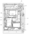
図1は、本実施例におけるパチンコ遊技機の正面図であり、主要部材の配置レイアウトを示す。パチンコ遊技機(遊技機)1は、大別して、遊技盤面を構成する遊技盤(ゲージ盤)2と、遊技盤2を支持固定する遊技機用枠(台枠)3とから構成されている。遊技盤2にはガイドレールによって囲まれた、ほぼ円形状の遊技領域が形成されている。この遊技領域のほぼ中央位置には、各々が識別可能な識別情報として特別図柄及び飾り図柄を可変表示可能に表示する可変表示装置4が設けられている。この可変表示装置4の下側には、普通可変入賞球装置(始動入賞口)6が配置されている。普通可変入賞球装置6の下側には、特別可変入賞球装置(大入賞口)7が配置されている。また、可変表示装置4の上部には、普通図柄表示器40が設けられている。
【0027】
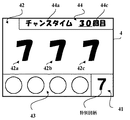
可変表示装置4は、例えばLCD等からなり、普通可変入賞球装置6に遊技球が入賞することが始動条件となる可変表示ゲーム(特図ゲーム)において、数字、文字、図柄から構成され、各々が識別可能な複数種類の識別情報として機能する表示図柄を、複数の可変表示領域にて可変表示可能に表示する。図2(A)及び(B)は、可変表示装置4における画像表示例を示す図である。図2に示す例では、可変表示装置4上に、特別図柄と、装飾図柄となる左中右の飾り図柄と、特図保留記憶数とが表示されるものとする。特別図柄は特別図柄表示エリア41において可変表示される。左中右の飾り図柄はそれぞれ、飾り図柄表示エリア42に設けられた3つの可変表示部42a、42b、42cにおいて可変表示される。特図保留記憶数は特図保留数表示エリア43に表示され、遊技球が普通可変入賞球装置6に入賞して特別図柄及び飾り図柄の可変表示を実行するための始動条件が成立したが、従前の可変表示を実行中であるなどの理由のために可変表示を実際に開始するための条件である開始条件が成立していない保留数を示す。
【0028】
可変表示装置4により行われる特図ゲームでは、特別図柄及び飾り図柄の可変表示を開始した後、一定時間が経過すると、特別図柄と飾り図柄の表示結果を所定の順序で導出表示し、確定図柄(最終停止図柄)を停止表示する。そして、確定図柄の組合せが所定の特定表示結果(大当り組合せ)となったときに、このパチンコ遊技機1は、特定遊技状態(大当り遊技状態ともいう)となる。この特定遊技状態においては、特別可変入賞球装置7が所定期間(例えば、29秒)あるいは所定個数(例えば、10個)の入賞球が発生するまで開成され、開成されている間、遊技盤2の表面を落下する遊技球を受け止める。そして、この開成サイクルを所定の上限回数(例えば、16回)まで繰り返すことができる。
【0029】
また、大当り遊技状態が終了した後、確率変動制御(確変制御)と時間短縮制御(時短制御)のいずれかが行われていることを報知しつつ、いずれの制御が行われているかを遊技者に分からないようにするチャンスタイムでは、可変表示装置4上にチャンスタイム表示エリア44が設けられる。ここで、確変制御が行われる第1特別遊技状態では、特図ゲームにおける特別図柄及び飾り図柄の可変表示時間が通常遊技状態のときよりも短くなるとともに、表示結果が予め定められた特定表示結果となって大当り遊技状態となる確率が向上する。また、時短制御が行われる第2特別遊技状態では、特図ゲームにおける特別図柄及び飾り図柄の可変表示時間が通常遊技状態のときよりも短くなる。なお、通常遊技状態とは、大当り遊技状態や第1及び第2特別遊技状態以外の遊技状態のことである。
【0030】
こうした確変制御が行われる第1特別遊技状態や、時短制御が行われる第2特別遊技状態への移行制御は、後述する主基板11に搭載されたCPU103によって実現される特別遊技状態制御手段により行われる。すなわち、特別遊技状態制御手段は、第1特別遊技状態に移行制御する機能と、第2特別遊技状態に移行制御する機能を有している。
【0031】
チャンスタイム表示エリア44には、チャンスタイムであることを示す報知情報44aと、特別遊技状態に継続制御されるチャンスタイムにて実行可能な特図ゲームの残り実行回数(残り可変表示回数)を示す報知情報44bとが表示される。
【0032】
図3は、この実施の形態で用いられる特別図柄の例を示す図である。この実施の形態では、特別図柄として表示される図柄は13図柄であり、各図柄には「0」〜「12」の図柄番号が付されている。特別図柄表示エリア41には、図3に示すような13種類の特別図柄が可変表示される。ここで、図柄番号が「12」の特別図柄「−」が表示されると、次に、図柄番号が「0」の特別図柄「0」が表示される。
【0033】
この実施の形態では、図柄番号が「0」、「2」、「4」、「6」、「8」、「10」である特別図柄を通常大当り図柄とし、図柄番号が「1」、「3」、「5」、「7」、「9」、「11」である特別図柄を確変大当り図柄とする。すなわち、可変表示装置4による特図ゲームにおいて、特別図柄の可変表示を開始した後、図柄番号が「0」〜「11」である特別図柄を表示結果として導出表示して確定したときに、パチンコ遊技機1は、大当り遊技状態となる。
【0034】
ここで、特別図柄の表示結果が確変大当り図柄であるときには、大当り遊技状態が終了した後のチャンスタイムにおいて、確変制御が行われる第1特別遊技状態となり、以後、各々の確変大当り図柄に応じて予め決められた可変表示回数の特図ゲームが実行されるまで、特図ゲームにおける可変表示時間が通常遊技状態のときよりも短くなるとともに、各回の特図ゲームで表示結果が大当り図柄となって大当り遊技状態となる確率が向上する。また、特別図柄の表示結果が通常大当り図柄であるときには、大当り遊技状態が終了した後のチャンスタイムにおいて、時短制御が行われる第1特別遊技状態となり、以後、各々の通常大当り図柄に応じて予め決められた可変表示回数の特図ゲームが実行されるまで、特図ゲームにおける可変表示時間が通常遊技状態のときよりも短くなる。なお、特別図柄の表示結果が確変大当り図柄であるときには、所定の可変表示回数の特図ゲームが実行されるまで確変制御が行われた後、さらに所定の可変表示回数の特図ゲームが実行されるまでの間、時短制御が行われることもある。
【0035】
また、確変制御が行われる第1特別遊技状態、及び時短制御が行われる第2特別遊技状態では、普通図柄表示器40による普通図柄の可変表示(普通図ゲーム)における可変表示時間が通常遊技状態のときよりも短くなるとともに、各回の普通図ゲームで表示結果が当り図柄となる確率が向上する。このときにはさらに、普通可変入賞球装置6の開放時間が通常遊技状態のときよりも長くなるとともに、その開放回数が通常遊技状態のときよりも増加する。このように、第1及び第2特別遊技状態では、大当り遊技状態とは異なる遊技者にとって有利な遊技状態となる。
【0036】
図4は、この実施の形態で用いられる左中右の各飾り図柄の例を示す図である。この実施の形態では、左中右の飾り図柄として表示される各図柄は、「1」〜「8」の図柄番号が付された8図柄を含む。飾り図柄表示エリア42に設けられた左・中・右の各可変表示部42a〜42cでは、特図ゲーム中に図柄番号が小さい飾り図柄から大きい飾り図柄へと更新表示が行われ、図柄番号が「8」の飾り図柄が表示されると、次に図柄番号「1」の図柄が表示される。そして、特別図柄の確定図柄が通常大当り図柄あるいは確変大当り図柄である場合すなわち大当り発生時には、左中右の飾り図柄が同一図柄で停止する。
【0037】
普通図柄表示器40は、発光ダイオード(LED)等を備えて構成され、遊技領域に設けられた通過ゲート5のいずれかを遊技球が通過することを始動条件とする普通図ゲームにおいて、点灯、点滅、発色などが制御される。この普通図ゲームにおいて所定の当りパターンで表示が行われると、普通図ゲームにおける表示結果が「当り」となり、普通可変入賞球装置6を構成する電動チューリップの可動翼片を所定時間が経過するまで傾動制御する。
【0038】
普通可変入賞球装置6は、ソレノイド21(図6)によって垂直(通常開放)位置と傾動(拡大開放)位置との間で可動制御される一対の可動翼片を有するチューリップ型役物として構成される。普通可変入賞球装置6への遊技球の入賞に基づく特別図柄及び飾り図柄の可変表示は、所定回数(本実施形態では、4回)まで後述する特図保留メモリ120(図10)に記憶される。
【0039】
特別可変入賞球装置7は、ソレノイド22(図6)によって入賞領域を開成・閉成制御する開閉板を備える。この開閉板は、通常時には閉成し、普通可変入賞球装置6への遊技球の入賞に基づいて可変表示装置4による特図ゲームが行われた結果、大当り遊技状態となった場合に、ソレノイド22によって入賞領域を所定期間(例えば、29秒)あるいは所定個数(例えば、10個)の入賞球が発生するまで開成(開成サイクル)する状態となるように設定され、その開成している間に遊技領域を落下する遊技球を受け止める。そして、この開成サイクルを例えば最高16回繰り返すことができるようになっている。特別可変入賞球装置7に入賞した遊技球は、所定の検出部により検出される。入賞球の検出に応答し、後述する主基板11と払出制御基板15(図5)とにより、所定数の賞球の払い出しが行われる。
【0040】
また、遊技盤2の表面には、上記した構成以外にも、ランプを内蔵した風車、アウト口等が設けられている。また、パチンコ遊技機1には、点灯又は点滅する遊技効果ランプ9や効果音を発生するスピーカ8L、8Rが設けられている。
【0041】
図5は、パチンコ遊技機1の背面図であり、主要基板の配置レイアウトを示す。本実施例におけるパチンコ遊技機1は、主として、電源基板10と、主基板11と、表示制御基板12と、音声制御基板13と、ランプ制御基板14と、払出制御基板15と、情報端子基板16とを備え、それぞれ適所に配設されている。なお、表示制御基板12、音声制御基板13及びランプ制御基板14は、それぞれ独立した基板として、例えば、パチンコ遊技機1の裏面において、1つのボックスに収容された状態で配置されてもよい。さらに、表示制御基板12、音声制御基板13及びランプ制御基板14を、まとめて1つの基板として構成してもよい。
【0042】
電源基板10は、パチンコ遊技機1内の各回路に所定の電源電圧を供給するものである。
【0043】
主基板11は、メイン側の制御基板であり、パチンコ遊技機1における遊技の進行を制御するための各種回路が搭載されている。主基板11は、主として、可変表示ゲームにおいて用いる乱数の生成機能、所定位置に配設されたスイッチ等からの信号の入力を行う機能、表示制御基板12、音声制御基板13、ランプ制御基板14及び払出制御基板15などからなるサブ側の制御基板に対して、それぞれ指令情報の一例となる制御コマンドを出力して送信する機能、ホールの管理コンピュータに対して各種情報を出力する機能などを備えている。
【0044】
主基板11から表示制御基板12へ送信される制御コマンドは表示制御コマンドである。図6は、主基板11における回路構成、及び主基板11から表示制御基板12に送信される表示制御コマンドの信号線を示すブロック図である。図6に示すように、この実施の形態では、表示制御コマンドが、表示制御信号CD0〜CD7の8本の信号線で主基板11から表示制御基板12へ送信される。また、主基板11と表示制御基板12との間には、ストローブ信号を送信するための表示制御INT信号の信号線も配線されている。
【0045】
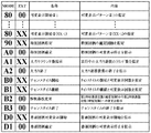
図7は、この実施の形態で用いられる主基板11から表示制御基板12へ送信される表示制御コマンドの内容の一例を示す説明図である。表示制御コマンドは2バイト構成であり、1バイト目はMODE(コマンドの分類)を表し、2バイト目はEXT(コマンドの種類)を表す。MODEデータの先頭ビット(ビット7)は必ず「1」とされ、EXTデータの先頭ビットは「0」とされる。なお、図7に示されたコマンド形態は一例であって、他のコマンド形態を用いてもよい。また、この例では、制御コマンドが2つの制御信号で構成されることになるが、制御コマンドを構成する制御信号数は、1であってもよいし、3以上の複数であってもよい。
【0046】
図7に示す例において、コマンド80XX(h)は、可変表示装置4における特別図柄及び飾り図柄の可変表示の開始を指令する可変表示開始コマンドである。なお、以下では、XX(h)が不特定の16進数であることを示し、表示制御コマンドによる指示内容に応じて任意に設定される値であるものとする。表示制御基板12の側では、可変表示開始コマンドに含まれるEXTデータに対応して、特別図柄と飾り図柄の総可変表示時間、可変表示の表示結果が特定表示結果になるか否かの判定結果やリーチとするか否かの判定結果などを特定することができる。
【0047】
コマンド90XX(h)は、特別図柄の予定停止図柄(確定図柄として導出表示される図柄)を指定する特別図柄指定コマンドである。特別図柄には通常大当り図柄と確変大当り図柄とが含まれており、特別図柄の確定図柄を指定することにより、通常大当りとするか確変大当りとするかを識別することができる。すなわち、特別図柄指定コマンドは、確変大当りとするか否かを示す情報を含んでいる。
【0048】
コマンドA000(h)は、特別図柄の可変表示の停止を指示する特別図柄確定コマンドである。また、コマンドA1XX(h)は、大当り遊技状態において実行されているラウンド遊技の実行回数を指示するための大当りラウンド数指示コマンドである。コマンドA200(h)は、大当り遊技状態の終了を指示する大当り終了コマンドである。
【0049】
コマンドB0XX(h)は、大当り遊技状態が終了するときに、チャンスタイムの開始を指示するためのチャンスタイム開始コマンドであり、EXTデータにより、チャンスタイム中の特別遊技状態にて実行可能な特図ゲームの可変表示回数を指定する。図8は、チャンスタイム開始コマンドのEXTデータとして設定される可変表示回数設定データの一例を示す図である。表示制御基板12の側では、チャンスタイム開始コマンドに含まれるEXTデータに対応して、特別遊技状態に継続制御される特図ゲームの可変表示回数を特定することができる。コマンドB1XX(h)は、チャンスタイム中に、さらにチャンスタイムが継続することを指示するためのチャンスタイム継続コマンドであり、チャンスタイム開始コマンドと同様のEXTデータにより、さらにチャンスタイムが継続可能な特図ゲームの可変表示回数を指定する。
【0050】
コマンドB200(h)は、チャンスタイム中に、特別遊技状態が確変制御の行われる第1特別遊技状態から、時短制御が行われる第2特別遊技状態に変更されることを指示するための特別遊技変更コマンドである。コマンドB300(h)は、チャンスタイムの終了を指示するためのチャンスタイム終了コマンドである。
【0051】
コマンドD0XX(h)は、普通図柄表示器40における普通図柄の可変表示の開始を指令する普通図柄可変表示開始コマンドであり、EXTデータにより、普通図ゲームにおける可変表示時間と表示結果とを指定する。図9は、普通図柄可変表示開始コマンドにおけるEXTデータの一例を示す図である。表示制御基板12の側では、普通図柄可変表示開始コマンドに含まれるEXTデータに対応して普通図ゲームにおける可変表示時間と表示結果を特定し、普通図柄表示器40の点灯/消灯制御による普通図ゲームを開始する。コマンドD100(h)は、普通図柄の可変表示の停止を指示する普通図柄確定コマンドである。
【0052】
主基板11には、図6に示すように、始動入賞口である普通可変入賞球装置6や、大入賞口である特別可変入賞球装置7、その他の入賞口への遊技球の入賞、及び通過ゲート5における遊技球の通過を検出するための各入賞口スイッチ70からの配線も接続されている。さらに、主基板11には、普通可変入賞球装置6における可動翼片の可動制御や特別可変入賞球装置7における開成・閉成制御を行うためのソレノイド21、22への配線が接続されている。
【0053】
主基板11は、遊技制御用マイクロコンピュータ100、スイッチ回路107、ソレノイド回路108などを搭載して構成される。遊技制御用マイクロコンピュータ100は、例えば1チップマイクロコンピュータであり、ゲーム制御用のプログラム等を記憶するROM(Read Only Memory)101、ワークメモリとして使用されるRAM(Random Access Memory)102、プログラムに従って制御動作を行うCPU(Central Processing Unit)103及びI/O(Input/Output)ポート104を含んでいる。
【0054】
また、遊技制御用マイクロコンピュータ100は、図10に示すように、特図保留メモリ120と、普通図保留メモリ121と、ランダムカウンタ122と、判定テーブルメモリ123と、可変表示パターンテーブルメモリ124と、チャンスタイム期間決定用テーブルメモリ125と、確変カウンタ126と、時短カウンタ127と、フラグメモリ128と、可変表示時間タイマ129とを備えている。
【0055】
特図保留メモリ120は、遊技球が普通可変入賞球装置6に入賞して特別図柄及び飾り図柄の可変表示(特図ゲーム)を実行するための条件(始動条件)が成立したが、従前の可変表示を実行中である等の理由のために可変表示を実際に開始するための条件(開始条件)が成立していない保留状態を記憶するためのメモリである。図10に示す特図保留メモリ120では、4つのエントリが設けられており、各エントリには、普通可変入賞球装置6への入賞順に保留番号とその入賞により抽出された乱数値(後述するランダムR1の値)が対応付けて格納される。主基板11から表示制御基板12へ確定コマンドが送信されて特別図柄及び飾り図柄の可変表示が1回終了したり、大当り遊技状態が終了したりするごとに、最上位の情報に基づいた可変表示の開始条件が成立し、最上位の情報に基づいた可変表示が実行される。このとき、第2位以下の登録情報が1位ずつ繰り上がる。また、特別図柄及び飾り図柄の可変表示中等に遊技球が普通可変入賞球装置6に新たに入賞した場合には、その入賞による乱数値が最上位の空エントリに登録される。
【0056】
普通図保留メモリ121は、通過ゲート5における遊技球の通過が検出されて普通図柄表示器40による普通図ゲームを実行するための条件が成立したが、開始条件が成立していない保留状態を記憶するためのメモリである。
【0057】
ランダムカウンタ122は、遊技制御に用いられる判定用乱数や表示用乱数のカウントを行うものである。図11は、ランダムカウンタ122によりカウントされる各乱数を示す説明図である。ランダムカウンタ122は、図11に示すように、ランダムR1〜R6のカウントを行う。ランダムR1は、大当りを発生させてパチンコ遊技機1を特定遊技状態とするか否かを決定する大当り判定用の乱数であり、「0」〜「299」の範囲の値をとる。ランダムR2は、ハズレ時にリーチとするか否かを決定するリーチ判定用の乱数であり、「0」〜「1530」の範囲の値をとる。ランダムR3は、特別図柄及び飾り図柄の可変表示に用いる可変表示パターンを決定するための表示用の乱数であり、「0」〜「108」の範囲の値をとる。ランダムR4は、大当り時における特別図柄の確定図柄を決定するための表示用の乱数であり、「0」〜「11」の範囲の値をとる。上述したように、図柄番号が「0」〜「11」である特別図柄は大当り用の特別図柄であり、通常大当り図柄と確変大当り図柄とに分類される。従って、ランダムR4の値により大当り用の特別図柄を決定することで、大当り遊技状態の終了後のチャンスタイムにおいて確変制御が行われるか否かを決定することができる。すなわち、ランダムR4は、確変判定用の乱数として機能する。
【0058】
ランダムR5は、特別遊技状態に継続制御されるチャンスタイムにて実行可能な特図ゲームの残り可変表示回数を遊技者などに報知する際の表示動作モードであるチャンスタイム報知モード(以下では、単に「報知モード」ともいう)として、加算報知モードと個別報知モードのいずれかを選択決定するための表示用の乱数であり、「0」〜「9」の範囲の値をとる。ここで、加算報知モードとは、後述する確変カウンタ126のカウント値と時短カウンタ127のカウント値とを加算した値を、例えば可変表示装置4における表示画面に配置されたチャンスタイム表示エリア44の表示により、チャンスタイムにて実行可能な特図ゲームの残り可変表示回数として報知するための表示動作モードである。
【0059】
また、個別報知モードとは、確変カウンタ126のカウント値が「0」以外であるときに、確変カウンタ126のカウント値のみを、チャンスタイムにて実行可能な特図ゲームの残り可変表示回数として報知し、一方、確変カウンタ126のカウント値が「0」であるときには、時短カウンタ127のカウント値を、チャンスタイムにて実行可能な特図ゲームの残り可変表示回数として報知する表示動作モードである。すなわち、個別報知モードとすることが選択決定されたときには、実際にチャンスタイムにて実行可能な特図ゲームの可変表示回数より少ない可変表示回数が報知された後、各特図ゲームにおける表示結果が大当りとなることなく、チャンスタイムにおける特図ゲームの可変表示回数が報知された可変表示回数に達したときに、さらにチャンスタイムに継続制御されることが報知される。
【0060】
ランダムR6は、普通図柄表示器40による普通図ゲームにおける表示結果を「当り」とするか否かを決定する普通図当り判定用の乱数であり、「0」〜「14」の範囲の値をとる。なお、遊技効果を高めるために、ランダムR1〜R6以外の乱数が用いられてもよい。
【0061】
図10に示す判定テーブルメモリ123は、CPU103が各種の判定を行うために設定される複数の判定テーブルを記憶する。具体的には、判定テーブルメモリ123は、図12(A)に示す通常・時短時大当り判定テーブル150、図12(B)に示す確変時大当り判定テーブル151、図13(A)に示す通常時普通図当り判定テーブル152、図13(B)に示す確変・時短時普通図当り判定テーブル153を格納する。
【0062】
図12(A)に示す通常・時短時大当り判定テーブル150と、図12(B)に示す確変時大当り判定テーブル151は、可変表示装置4による特図ゲームの表示結果を大当りとするか否かを判定するためのテーブルである。各大当り判定テーブルでは、ランダムR1の値と特図ゲームの表示結果を示す設定データとが対応付けて格納されている。そして、確変時大当り判定テーブル151では、通常・時短時大当り判定テーブル150に比べてより多くのランダムR1の値が、「大当り」の表示結果と対応付けられている。すなわち、確変時大当り判定テーブル151を用いて特図ゲームの表示結果を決定することで、通常遊技状態のときや時短制御が行われているときよりも大当り遊技状態となる確率が高い第1特別遊技状態とすることができる。
【0063】
図13(A)に示す通常時普通図当り判定テーブル152と、図13(B)に示す確変・時短時普通図当り判定テーブル153は、普通図柄表示器40による普通図ゲームの表示結果を当りとするか否かを判定するためのテーブルである。各普通図当り判定テーブルでは、ランダムR6の値と普通図ゲームの表示結果を示す設定データとが対応付けて格納されている。そして、確変・時短時普通図当り判定テーブル153では、通常時普通図当り判定テーブル152に比べてより多くのランダムR6の値が、「当り」の表示結果と対応付けられている。
【0064】
可変表示パターンテーブルメモリ124は、特図ゲームで使用される複数の可変表示パターンを記憶する。具体的には、可変表示パターンテーブルメモリ124は、図14に示す可変表示パターンテーブル154を格納する。
【0065】
図14に示す可変表示パターンテーブル154には、例えば、複数の可変表示パターンと、可変表示時間タイマ129が計測する特別図柄と飾り図柄の総可変表示時間と、可変表示開始コマンド(80XX(h))のEXTデータとして設定される制御コードとが対応付けて格納されている。すなわち、主基板11から送信されて表示制御基板12が受信する可変表示開始コマンドは、特別図柄及び飾り図柄の可変表示における可変表示パターンを、EXTデータにより指定する。また、表示結果をハズレとするか、大当りとするか、及び、ハズレの場合にリーチとするか否かに応じて、異なる可変表示パターンが用いられる。さらに、可変表示パターンテーブル154には、チャンスタイム中に表示結果をハズレとするときに用いる可変表示パターン#50が格納されている。この可変表示パターン#50では、通常遊技状態のときに表示結果をリーチとすることなくハズレとするために用いる可変表示パターン#1に比べて、総可変表示時間が短く設定されている。これにより、確変制御が行われる第1特別遊技状態や時短制御が行われる第2特別遊技状態となるチャンスタイムでは、通常遊技状態のときよりも特図ゲームにおける可変表示時間を短くすることができる。
【0066】
また、可変表示パターンテーブルメモリ124には、図15(A)に示す大当り可変表示パターン決定テーブル155と、図15(B)に示すリーチハズレ可変表示パターン決定テーブル156とが格納されている。各可変表示パターン決定テーブル155、156は、表示結果を大当りあるいはリーチハズレとするときに、ランダムカウンタ122より抽出したランダムR3の値に基づいて、複数種類ある可変表示パターンのうちから特図ゲームに使用するものを選択決定できるように設定されている。ここで、大当り可変表示パターン決定テーブル155と、リーチハズレ可変表示パターン決定テーブル156とを比べると、各可変表示パターン(リーチの種類)に対するランダムR3の値の割当が異なっている。すなわち、特図ゲームにおける表示結果が大当りとなるか否かに応じて、選択されるリーチ種類の割合が異なるものとなっている。これにより、特図ゲーム中に出現するリーチの種類に応じて、表示結果が大当りとなる確率は異なるものとなる。
【0067】
図15に示す例では、表示結果がリーチハズレとなる場合にリーチAの可変表示パターンが用いられる割合は、リーチJの可変表示パターンが用いられる割合よりも高くなっている。一方で、表示結果が大当りとなる場合にリーチAの可変表示パターンが用いられる割合は、リーチJの可変表示パターンが用いられる割合よりも低くなっている。このため、特図ゲーム中にリーチJの可変表示パターンによるリーチが出現した場合には、リーチAの可変表示パターンによるリーチが出現した場合よりも、表示結果が大当りとなる確率が高くなる。こうしたリーチの種類ごとに決められる表示結果が大当りとなる確率は、リーチの大当り信頼度、あるいは単に、リーチの信頼度と称される。
【0068】
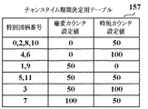
チャンスタイム期間決定用テーブルメモリ125は、チャンスタイムにて継続制御される特別遊技状態の種類と、チャンスタイムにて実行可能な特図ゲームの可変表示回数とを決定するためのチャンスタイム期間決定用テーブル157を格納する。チャンスタイム期間決定用テーブル157には、図16に示すように、通常大当り図柄あるいは確変大当り図柄となる特別図柄の図柄番号と、確変カウンタ126に対する設定値(確変カウンタ設定値)と、時短カウンタ127に対する設定値(時短カウンタ設定値)とが対応付けて格納されている。このようなチャンスタイム期間決定用テーブル157を用いることにより、大当り用の特別図柄の図柄番号に基づいて、チャンスタイム中に確変制御が行われる第1特別遊技状態にて実行可能な特図ゲームの可変表示回数と、時短制御が行われる第2特別遊技状態にて実行可能な特図ゲームの可変表示回数との組合せからなる可変表示回数パターンを、選択決定することができる。
【0069】
ここで、図16に示すチャンスタイム期間決定用テーブル157を用いて可変表示回数パターンを選択決定することにより、確変カウンタ設定値と時短カウンタ設定値は、予め定められた複数種類の設定値「0」、「50」、「100」のいずれかに決められる。すなわち、チャンスタイム期間決定用テーブル157は、確変制御が行われる第1特別遊技状態に継続制御される特図ゲームの可変表示回数と、時短制御が行われる第2特別遊技状態に継続制御される特図ゲームの可変表示回数とを、予め定められた複数種類の可変表示回数「0」、「50」、「100」のいずれかに設定するための可変表示パターンを複数種類格納している。そして、チャンスタイム期間決定用テーブル157に格納された可変表示パターンには、一方の可変表示パターンで第1特別遊技状態に継続制御される特図ゲームの可変表示回数と、他方の可変表示パターンで第2特別遊技状態に継続制御される特図ゲームの可変表示回数とが同一となる複数種類の可変表示パターンが含まれている。例えば、特別図柄の図柄番号「1」に対応した可変表示パターンにおける確変カウンタ設定値と、特別図柄の図柄番号「5」に対応した可変表示パターンにおける時短カウンタ設定値は、いずれも同一の値「50」となっている。
【0070】
また、図16に示すチャンスタイム期間決定用テーブル157を用いて可変表示回数パターンを選択決定することにより、確変カウンタ設定値と時短カウンタ設定値とを加算した合計値は、予め定められた複数種類の設定値「50」、「100」、「150」のいずれかに決められる。すなわち、チャンスタイム期間決定用テーブル157は、確変制御が行われる第1特別遊技状態に継続制御される特図ゲームの可変表示回数と、時短制御が行われる第2特別遊技状態に継続制御される特図ゲームの可変表示回数とを、それらの合計回数が予め定められた複数種類の合計回数「50」、「100」、「150」のいずれかとなるように設定する可変表示パターンを複数種類格納している。そして、チャンスタイム期間決定用テーブル157に格納された可変表示回数パターンには、第1特別遊技状態に継続制御される特図ゲームの可変表示回数と第2特別遊技状態に継続制御される特図ゲームの可変表示回数の合計回数が同一で、各々の可変表示回数の組合せが異なる複数種類の可変表示パターンが含まれている。
【0071】
例えば、図16に示すチャンスタイム期間決定用テーブル157によると、特別図柄の図柄番号「3」に対応した可変表示パターンにおける確変カウンタ設定値と時短カウンタ設定値とを加算した合計値は「150」であり、特別図柄の図柄番号「7」に対応した可変表示パターンにおける確変カウンタ設定値と時短カウンタ設定値とを加算した合計値も「150」である。その一方で、特別図柄の図柄番号「3」に対応した可変表示パターンでは確変カウンタ設定値が「50」であり、時短カウンタ設定値が「100」である。これに対して、特別図柄の図柄番号「7」に対応した可変表示パターンでは確変カウンタ設定値が「100」、時短カウンタ設定値が「50」となっており、確変制御が行われる特図ゲームの回数と、時短制御が行われる特図ゲームの回数との組合せが異なっている。
【0072】
確変カウンタ126は、チャンスタイムにおいて第1特別遊技状態となり確変制御が行われるときに、その第1特別遊技状態にて実行可能な特図ゲームの残り可変表示回数をカウントするためのものである。確変カウンタ126には、可変表示装置4による特図ゲームの表示結果が大当りとなるときに、チャンスタイム期間決定用テーブル157を用いて選択決定した可変表示回数パターンで指定される確変カウンタ設定値が初期値として設定される。
【0073】
時短カウンタ127は、チャンスタイムにおいて第2特別遊技状態となり時短制御が行われるときに、その第2特別遊技状態にて実行可能な特図ゲームの残り可変表示回数をカウントするためのものである。時短カウンタ127には、可変表示装置4による特図ゲームの表示結果が大当りとなるときに、チャンスタイム期間決定用テーブル157を用いて選択決定した可変表示回数パターンで指定される時短カウンタ設定値が初期値として設定される。
【0074】
フラグメモリ128は、パチンコ遊技機1における遊技の進行を制御するために用いられる複数種類のフラグを設定するためのものである。例えば、フラグメモリ128には、特別図柄プロセスフラグ、普通図柄プロセスフラグ、大当りフラグ、確変フラグ、時短フラグ、報知モードフラグ、入力状態フラグ、エラーフラグ、タイマ割込フラグなどが設けられている。
【0075】
特別図柄プロセスフラグは、後述する特別図柄プロセス処理(図27)において、どの処理を選択・実行すべきかを指示する。普通図柄プロセスフラグは、後述する普通図柄プロセス処理(図37)において、どの処理を選択・実行すべきかを指示する。大当りフラグは、可変表示装置4による特図ゲームの表示結果が大当りとなるときにオン状態にセットされ、大当り遊技状態が終了するときにクリアされてオフ状態となる。確変フラグは、チャンスタイムにおいて確変制御が行われる第1特別遊技状態となるときにオン状態にセットされ、第1特別遊技状態が終了するときにクリアされてオフ状態となる。時短フラグは、チャンスタイムにおいて時短制御が行われる第2特別遊技状態となるときにオン状態にセットされ、第2特別遊技状態が終了するときにクリアされてオフ状態となる。
【0076】
報知モードフラグは、チャンスタイムにて実行可能な特図ゲームの残り可変表示回数を報知するための報知モードが、加算報知モードと個別報知モードのいずれであるかを示す。入力状態フラグは、I/Oポート104に入力される各種信号の状態や各入賞口スイッチ70から入力される検出信号の状態等に応じて各々セットあるいはクリアさせる複数ビットからなるフラグである。エラーフラグは、パチンコ遊技機1において各種のエラーが発生したときに、発生したエラーの種類に対応するビットがセットされる複数ビットからなるフラグである。タイマ割込フラグは、所定時間が経過してタイマ割込みが発生するごとにオン状態にセットされる。
【0077】
可変表示時間タイマ129は、特図ゲーム及び普通図ゲームの実行時間である可変表示時間をメイン側で計測するためのダウンカウンタであり、特図用タイマと普通図用タイマとを含んでいる。特図用タイマは、可変表示装置4による特図ゲームにて特別図柄及び飾り図柄の可変表示を開始してからの経過時間を計測するためのものであり、主基板11が表示制御基板12に可変表示開始コマンドを送信するに際して、可変表示パターンで指定される総可変表示時間に対応したカウント値が初期値として設定される。普通図用タイマは、普通図柄表示器40による普通図ゲームにて普通図柄の可変表示を開始してからの経過時間を計測するためのものであり、主基板11が表示制御基板12に普通図柄可変表示開始コマンドを送信するに際して、そのコマンドで指定される総可変表示時間に対応したカウント値が初期値として設定される。
【0078】
図6に示すスイッチ回路107は、各入賞口スイッチ70からの検出信号を取り込んで、遊技制御用マイクロコンピュータ100に伝達する。ソレノイド回路108は、遊技制御用マイクロコンピュータ100からの指令に従って各ソレノイド21、22を駆動する。ソレノイド21は、リンク機構を介して普通可変入賞球装置6の可動翼片に連結されている。ソレノイド22は、リンク機構を介して特別可変入賞球装置7の開閉板に連結されている。
【0079】
表示制御基板12は、主基板11とは独立して可変表示ゲームにおける画像処理のための表示制御を行うものである。表示制御基板12は、主基板11から出力される表示制御コマンドに基づいて、可変表示ゲームに用いられる画像を可変表示装置4上に表示させるとともに、普通図柄表示器40の点灯/消灯制御を行う。
【0080】
図17は、表示制御基板12のハードウェア構成例を示すブロック図である。表示制御基板12は、発振回路110と、リセット回路111と、表示制御用のCPU112と、ROM113と、RAM114と、GCL(Graphic Control LSI)115と、CGROM116と、VRAM(Video RAM)117とを備えている。
【0081】
発振回路110は、CPU112及びGCL115に基準クロック信号を出力するものであり、リセット回路111は、CPU112及びGCL115をリセットするためのリセット信号を出力するものである。CPU112は、主基板11から表示制御コマンドを受信するとRAM114を作業領域として用いながらROM113から表示制御を行うための制御データを読み出す。また、CPU112は、読み出した制御データに基づいてGCL115に描画命令を送る。ROM113は、CPU112によって利用される各種制御プログラム等を格納する半導体メモリであり、RAM114は、CPU112によって作業領域として利用される半導体メモリである。
【0082】
GCL115は、画像表示を行うための表示装置制御機能及び高速描画機能を有し、CPU112からの描画命令に従って動作する。また、CPU112とは独立した二次元のアドレス空間を持ち、そこにVRAM117をマッピングしている。CGROM116は、可変表示装置4にて画像表示を行うための各種画像データを記憶しておくためのものである。例えば、CGROM116には、可変表示装置4に表示される画像の中で使用頻度の高いキャラクタ画像データ、具体的には、人物、動物、又は、文字、図形もしくは記号等が予め記憶されている。VRAM117は、GCL115によって生成された画像データを展開するためのフレームバッファメモリである。
【0083】
また、表示制御基板12は、図18に示すように、ランダムカウンタ140と、表示制御パターンメモリ141と、各種タイマ142と、飾り図柄決定用テーブルメモリ143と、フラグメモリ144と、チャンスタイムカウンタ145とを備えている。
【0084】
ランダムカウンタ140は、飾り図柄の可変表示内容を決定するために用いられる各種乱数のカウントを行うものである。図19は、ランダムカウンタ140によりカウントされる各乱数を示す説明図である。ランダムカウンタ140は、図19に示すように、ランダムR10〜R12のカウントを行う。ランダムR10は、大当り時における飾り図柄の確定図柄と、ハズレ時に左側の飾り図柄における確定図柄とを、決定する乱数であり、「0」〜「106」の範囲の値をとる。ランダムR11は、ハズレ時に中央の飾り図柄における確定図柄を決定する乱数であり、「0」〜「162」の範囲の値をとる。ランダムR12は、リーチとしない通常ハズレ時に右側の飾り図柄における確定図柄を決定する乱数であり、「0」〜「72」の範囲の値をとる。
【0085】
表示制御パターンメモリ141は、主基板11から送信された表示制御コマンドに基づいて選択される複数の表示制御パターンを記憶する。例えば、表示制御パターンメモリ141は、図20に示すように、図柄表示プロセステーブルと、チャンスタイム開始表示制御パターンと、チャンスタイム更新表示制御パターンとを、それぞれ複数種類格納する。
【0086】
各図柄表示プロセステーブルは、特別図柄及び飾り図柄の表示状態を制御するためのデータからなり、主基板11からの可変表示開始コマンドで指定された可変表示パターンに対応して選択される。各図柄表示プロセステーブルには、図21に示すように、時系列的に特別図柄及び飾り図柄の可変表示速度やその速度での表示期間、背景やキャラクタの切替タイミング等が設定されている。また、ある速度での表示期間を決めるために、図柄表示プロセスタイマの設定値も格納されている。
【0087】
各チャンスタイム開始表示制御パターンは、大当り遊技状態が終了したときに、チャンスタイムに移行する旨の報知情報を可変表示装置4に表示させることにより出力するための制御データからなり、主基板11からのチャンスタイム開始コマンドで指定された可変表示回数に対応して選択される。すなわち、チャンスタイム開始表示制御パターンに従って可変表示装置4における表示動作を制御することにより、チャンスタイムとなる可変表示回数を遊技者に報知するための演出表示が行われる。
【0088】
各チャンスタイム更新表示制御パターンは、チャンスタイムが継続する旨の報知情報を可変表示装置4に表示させることにより出力するための制御データからなり、主基板11からのチャンスタイム継続コマンドで指定された可変表示回数、あるいは特別遊技変更コマンドを受信したことに対応して、選択される。すなわち、チャンスタイム更新表示制御パターンに従って可変表示装置4における表示動作を制御することにより、チャンスタイムが継続することや、チャンスタイムが継続する可変表示回数などを遊技者に報知するための演出表示が行われる。
【0089】
図18に示す各種タイマ142は、可変表示装置4の表示制御に用いられる複数種類のタイマを含んで構成される。例えば、各種タイマ142は、図柄表示プロセスタイマ、可変表示時間タイマ及び監視タイマを含んでいる。図柄表示プロセスタイマは、図柄表示プロセステーブルに設定されているプロセスタイマ値をカウントダウンすることにより、特別図柄及び飾り図柄を表示制御パターンに従った態様で可変表示させる可変表示期間を計測する。
【0090】
各種タイマ142に含まれる可変表示時間タイマは、特図ゲーム及び普通図ゲームの実行時間である可変表示時間をサブ側で計測するためのダウンカウンタであり、遊技制御用マイクロコンピュータ100に設けられた可変表示時間タイマ129と同様に、特図用タイマと普通図用タイマとを含んでいる。監視タイマは、可変表示時間タイマがタイムアウトしてからの経過時間を計測するためのものであり、主基板11から表示制御コマンドを所定時間以上受信しなかったときにタイムアウトする。
【0091】
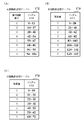
飾り図柄決定用テーブルメモリ143は、可変表示装置4にて可変表示される飾り図柄の確定図柄を決定するために用いられる複数種類の図柄決定用テーブルを記憶する。具体的には、飾り図柄決定用テーブルメモリ143は、図22に示す通常大当り図柄決定用テーブル170、図23に示す確変大当り図柄決定用テーブル171、図24(A)に示す左図柄決定用テーブル172、図24(B)に示す中図柄決定用テーブル173、及び図24(C)に示す右図柄決定用テーブル174を格納する。
【0092】
図22に示す通常大当り図柄決定用テーブル170は、特図ゲームの表示結果を通常大当りとするときに、左中右で同一となる飾り図柄の確定図柄を決定するためのテーブルである。例えば、通常大当り図柄決定用テーブル170には、特別図柄指定コマンド(90XX(h))で指定された特別図柄の図柄番号と、ランダムR10の値、及び飾り図柄における確定図柄の図柄番号とが対応付けて格納されている。すなわち、通常大当り図柄決定用テーブル170は、特別図柄指定コマンドで指定された大当り図柄となる特別図柄と、ランダムカウンタ140から抽出されるランダムR10の値とに基づいて、通常大当り時における飾り図柄の確定図柄を決定可能に構成されている。
【0093】
図23に示す確変大当り図柄決定用テーブル171は、特図ゲームの表示結果を確変大当りとするときに、左中右で同一となる飾り図柄の確定図柄を決定するためのテーブルである。例えば、確変大当り図柄決定用テーブル171には、通常大当り図柄決定用テーブル170と同様に、特別図柄指定コマンドで指定された特別図柄の図柄番号と、ランダムR10の値、及び飾り図柄における確定図柄の図柄番号とが対応付けて格納されている。
【0094】
ここで、図柄番号が「3」である飾り図柄と、図柄番号が「7」である飾り図柄については、確変大当り図柄決定用テーブル171においてのみ、特別図柄の図柄番号及びランダムR10の値が割り当てられている。すなわち、図柄番号「3」あるいは「7」の飾り図柄が左中右で揃って導出表示され、確定したときには、必ず確変大当りとなる。他方、その他の飾り図柄が揃って導出表示され、確定したときには、確変大当りとなることもあれば、通常大当りとなることもある。
【0095】
このように、確変大当り図柄決定用テーブル171を用いることで、チャンスタイムに確変制御の行われる第1特別遊技状態が含まれるとき、すなわち特別図柄の確定図柄として確変大当り図柄が選択決定されたときに、図柄番号が「3」、「7」の飾り図柄を含んだすべての飾り図柄のうちから、特図ゲームの表示結果を構成する飾り図柄の確定図柄を選択決定して導出表示させることができる。一方、通常大当り図柄決定用テーブル170を用いることで、チャンスタイムが時短制御の行われる第2特別遊技状態のみからなるとき、すなわち特別図柄の確定図柄として通常大当り図柄が選択決定されたときに、図柄番号が「3」、「7」の飾り図柄を除く6種類の飾り図柄のうちから、飾り図柄の確定図柄を選択決定して導出表示させることができる。
【0096】
図24(A)に示す左図柄決定用テーブル172は、当りとすることなくハズレの表示結果を導出表示するとき、すなわち特別図柄の確定図柄を「−」とするときに、左可変表示部42aにおける飾り図柄の確定図柄(左確定図柄)を決定するためのテーブルである。例えば、左図柄決定用テーブル172には、左可変表示部42aにおける確定図柄となる飾り図柄の図柄番号と、ランダムR10の値とが対応付けて格納されている。すなわち、左図柄決定用テーブル172は、ランダムカウンタ140から抽出されるランダムR10の値に基づいて、ハズレ時における左可変表示部42aの確定図柄を決定可能に構成されている。なお、リーチ表示態様とした後に大当りとすることなくハズレの確定図柄を導出表示するときには、中・右可変表示部42b又は42cにおける飾り図柄の確定図柄を、左図柄決定用テーブル172を用いて決定された左可変表示部42aにおける飾り図柄の確定図柄と同一のものに設定すればよい。あるいは、中・右可変表示部42b及び42cにおける飾り図柄の確定図柄を、左可変表示部42aにおける飾り図柄の確定図柄とは異なる同一のものに設定してもよい。
【0097】
図24(B)に示す中図柄決定用テーブル173は、ハズレの表示結果を導出表示するときに、中可変表示部42bにおける飾り図柄の確定図柄(中確定図柄)を決定するためのテーブルである。例えば、中図柄決定用テーブル173には、左可変表示部42aにおける確定図柄の図柄番号に対する加算値と、ランダムR11の値とが対応付けて格納されている。すなわち、大当りとしないハズレ時には、ランダムカウンタ140から抽出されるランダムR11の値に基づき中図柄決定用テーブル173を用いて決定した加算値を、左図柄決定用テーブル172を用いて決定した左可変表示部42aにおける確定図柄の図柄番号に加算することで、中可変表示部42bにおける確定図柄を決めることができる。なお、リーチとした後に大当りとすることなくハズレの表示結果を導出表示するときに、中図柄決定用テーブル173を用いて決定された加算値が「0」である場合には、導出される表示結果をハズレとするために、中可変表示部42bにおける確定図柄の図柄番号を1加算するなどしてもよい。
【0098】
図24(C)に示す右図柄決定用テーブル174は、ハズレの表示結果を導出表示するときに、右可変表示部42cにおける飾り図柄の確定図柄(右確定図柄)を決定するためのテーブルである。例えば、右図柄決定用テーブル174には、左可変表示部42aにおける確定図柄の図柄番号に対する加算値と、ランダムR12の値とが対応付けて格納されている。
【0099】
フラグメモリ144は、可変表示装置4における表示状態や主基板11からのコマンド受信に応じて各々セットあるいはクリアされる複数種類のフラグを設定するためのものである。例えば、フラグメモリ144には、表示制御プロセスフラグ、可変表示開始フラグ、有効フラグ、特別遊技開始フラグ、特別遊技変更フラグ、特別遊技継続フラグ、チャンスタイムフラグ、可変表示回数抽選表示フラグ、タイマ割込フラグなどが設けられている。
【0100】
表示制御プロセスフラグは、後述する特図表示制御プロセス処理(図43)において、どの処理を選択・実行すべきかを指示する。可変表示開始フラグは、主基板11からの可変表示開始コマンド(80XX(h))を受信したときにオン状態にセットされる。有効フラグは、主基板11から特別図柄指定コマンド(90XX(h))を受信したときにオン状態にセットされる。特別遊技開始フラグは、主基板11からチャンスタイム開始コマンド(B0XX(h))を受信したときにオン状態にセットされる。特別遊技変更フラグは、主基板11から特別遊技変更コマンド(B200(h))を受信したときにオン状態にセットされる。特別遊技継続フラグは、主基板11からチャンスタイム継続コマンド(B1XX(h))を受信したときにオン状態にセットされる。チャンスタイムフラグは、確変制御あるいは時短制御が行われるチャンスタイムである間、オン状態にセットされる。可変表示回数抽選表示フラグは、可変表示装置4によりチャンスタイムが継続する特図ゲームの実行回数を報知するための演出表示が行われている間、オン状態にセットされる。
【0101】
チャンスタイムカウンタ145は、チャンスタイムにて実行可能な特図ゲームの残り可変表示回数をカウントするためのものであり、チャンスタイム開始コマンドやチャンスタイム継続コマンドを受信したときに、そのコマンドの可変表示回数設定データに応じたカウント初期値が設定される。そして、可変表示装置4にて特図ゲームが実行されるごとにチャンスタイムカウンタ145のカウント値が1ずつ減算され、カウント値が「0」となったときに、チャンスタイムが終了したとして、可変表示装置4におけるチャンスタイム表示エリア44の表示が消去される。
【0102】
図5に示す音声制御基板13、ランプ制御基板14は、主基板11から送信される制御コマンドに基づいて、音声出力制御、ランプ出力制御を、それぞれ主基板11とは独立して実行するサブ側の制御基板である。払出制御基板15は、遊技球の貸出や賞球等の払出制御を行うものである。情報端子基板16は、各種の遊技関連情報を外部に出力するためのものである。
【0103】
次に、本実施例におけるパチンコ遊技機1の動作(作用)を説明する。図25は、主基板11に搭載された遊技制御用マイクロコンピュータ100が実行する遊技制御メイン処理を示すフローチャートである。主基板11では、電源基板10からの電源電圧が供給されると、遊技制御用マイクロコンピュータ100が起動し、CPU103が、まず、図25のフローチャートに示す遊技制御メイン処理を実行する。遊技制御メイン処理を開始すると、CPU103は、割込禁止に設定した後(ステップS11)、必要な初期設定を行う(ステップS12)。この初期設定では、例えば、RAM102がクリアされる。また、遊技制御用マイクロコンピュータ100に内蔵されたCTC(カウンタ/タイマ回路)のレジスタ設定を行うことにより、定期的(例えば、2ミリ秒ごと)にタイマ割込を発生させる。初期設定が終了すると、割込を許可した後(ステップS13)、ループ処理に入る。
【0104】
こうした遊技制御メイン処理の実行により、2ミリ秒ごとに繰り返しタイマ割込が発生するように設定され、タイマ割込が発生すると、CPU103は、図26のフローチャートに示す遊技制御割込処理を実行する。
【0105】
図26のフローチャートに示す遊技制御割込処理を開始すると、CPU103は、まず、所定のスイッチ処理を実行することにより、スイッチ回路107を介して各入賞口スイッチ70から入力される検出信号の状態を判定する(ステップS21)。続いて、所定のエラー処理を実行することにより、パチンコ遊技機1の異常診断を行い、その診断結果に応じて必要ならば警告を発生可能とする(ステップS22)。この後、ランダムカウンタ122によりカウントされる判定用乱数であるランダムR1、R2及びR6を更新する判定用乱数更新処理(ステップS23)と、表示用乱数であるランダムR3〜R5を更新する表示用乱数更新処理(ステップS24)とを、順次実行する。
【0106】
次に、CPU103は、特別図柄プロセス処理を実行する(ステップS25)。特別図柄プロセス処理では、遊技状態に応じてパチンコ遊技機1を所定の順序で制御するために、フラグメモリ128に設けられた特別図柄プロセスフラグに従って該当する処理が選択されて実行される。特別図柄プロセス処理に続いて、CPU103は、普通図柄プロセス処理を実行する(ステップS26)。普通図柄プロセス処理では、普通図柄表示器40を所定の順序で制御するために、フラグメモリ128に設けられた普通図柄プロセスフラグに従って該当する処理が選択されて実行される。
【0107】
さらに、CPU103は、所定のコマンド制御処理を実行することにより、主基板11から表示制御基板12等のサブ側の制御基板に対して制御コマンドを送出し、遊技状態に合わせた動作制御を指示する(ステップS27)。このコマンド制御処理により主基板11から送出された表示制御コマンドを表示制御基板12のCPU112が受け取り、その表示制御コマンドに従って可変表示装置4の表示制御や普通図柄表示器40の点灯制御などが行われる。
【0108】
また、CPU103は、所定の情報出力処理を実行することにより、各種出力データの格納領域の内容をI/Oポート104に含まれる各出力ポートに出力する(ステップS28)。この情報出力処理では、主基板11から情報端子基板16に、大当り情報、始動情報、確率変動情報などをホール管理用コンピュータに対して出力する指令の送出も行われる。
【0109】
続いて、CPU103は、所定のソレノイド出力処理を実行することにより、所定の条件が成立したときに普通可変入賞球装置6における可動翼片の可動制御や特別可変入賞球装置7における開閉板の開閉駆動を行う(ステップS29)。この後、所定の賞球処理を実行することにより、各入賞口スイッチ70から入力された検出信号に基づく賞球数の設定などを行い、払出制御基板15に対して払出制御コマンドを出力可能とする(ステップS30)。
【0110】
図27は、ステップS25にて実行される特別図柄プロセス処理を示すフローチャートである。特別図柄プロセス処理を開始すると、CPU103は、まず、遊技球が普通可変入賞球装置6に入賞したか否かを、各入賞口スイッチ70に含まれる始動球検出スイッチから入力される検出信号や、フラグメモリ128に設けられた入力状態フラグなどをチェックすることにより、判別する(ステップS100)。遊技球が入賞して始動球検出スイッチからの検出信号がオン状態となった場合(ステップS100;Yes)、入賞処理を実行し(ステップS101)、遊技球が入賞していない場合(ステップS100;No)、入賞処理をスキップする。
【0111】
ステップS101の入賞処理では、特図保留メモリ120の保留数が上限値の4以上であるか否かが判別され、保留数が4以上であれば、今回の入賞による特図ゲームの始動は無効として特に何も行わない。一方、保留数が上限値の4未満である場合には、保留記憶数を1加算するとともに、ランダムカウンタ122より大当り判定用のランダムR1の値を抽出し、抽出したランダムR1の値を特図保留メモリ120の空エントリの先頭にセットする。
【0112】
この後、CPU103は、フラグメモリ128に格納されている特別図柄プロセスフラグの値に基づいて、図27に示すステップS110〜S118の9個の処理のいずれかを選択する。以下に、ステップS110〜S118の各処理について説明する。
【0113】
ステップS110の特別図柄通常処理は、特別図柄プロセスフラグの値が初期値「0」のときに実行される処理である。図28のフローチャートは、特別図柄通常処理を示す。特別図柄通常処理において、CPU103は、まず、特図保留メモリ120における保留数が「0」であるか否かを判別する(ステップS201)。ここで、特図保留メモリ120において、保留番号「1」に対応したランダムR1の値が記憶されていない場合には、保留数が「0」であると判別される。保留数が「0」であれば(ステップS201;Yes)、表示制御基板12を介して可変表示装置4上にデモンストレーション画面を表示させるなどして、処理を終了する。一方、保留数が「0」ではないと判別すると(ステップS201;No)、特図保留メモリ120から保留番号「1」に対応して格納されているランダムR1の値を読み出す(ステップS202)。この際、保留数を1減算し、かつ、特図保留メモリ120の第2〜第4エントリ(保留番号「2」〜「4」)に格納されたランダムR1の値を1エントリずつ上位にシフトする(ステップS203)。
【0114】
その後、CPU103は、大当り判定処理を実行することにより、ステップS202で読み出した値、すなわち上述したステップS101の入賞処理にて既に抽出されているランダムR1の値に基づいて、大当りとするか否かを判定する(ステップS204)。図29は、ステップS204にて実行される大当り判定処理を示すフローチャートである。
【0115】
図29に示す大当り判定処理において、CPU103は、フラグメモリ128に設けられた確変フラグがオンとなっているか否かを判別する(ステップS301)。確変フラグがオフであるときには(ステップS301;No)、大当りとするか否かを判定するためのテーブルとして、通常・時短時大当り判定テーブル150を設定する(ステップS302)。一方、確変フラグがオンであるときには(ステップS301;Yes)、大当りとするか否かを判定するためのテーブルとして、確変時大当り判定テーブル151を設定する(ステップS303)。
【0116】
続いて、CPU103は、ステップS202にて読み出したランダムR1の値に基づき、設定した大当り判定テーブルを用いて大当りとするか否かを判定する(ステップS304)。そして、判定結果が「大当り」であるか否かを判別し(ステップS305)、「大当り」であるときには(ステップS305;Yes)、フラグメモリ128に設けられた大当りフラグをオン状態にセットする(ステップS306)。一方、判定結果が「大当り」ではないときには(ステップS305;No)、ステップS306をスキップして、大当り判定処理を終了する。こうして大当り判定処理が終了すると、CPU103は、特別図柄プロセスフラグの値を確定特別図柄設定処理に対応する値である「1」に更新する(図28のステップS205)。
【0117】
図27に示すステップS111の確定特別図柄設定処理は、特別図柄プロセスフラグの値が「1」のときに実行される処理である。この処理において、CPU103は、図30に示すように、まず、フラグメモリ128に設けられた大当りフラグがオンとなっているか否かを判別する(ステップS211)。大当りフラグがオンであるときには(ステップS211;Yes)、ランダムカウンタ122よりランダムR4の値を抽出し、抽出したランダムR4の値に基づいて大当り用の特別図柄を選択決定する(ステップS212)。例えば、ランダムR4は「0」〜「11」の範囲の値をとることから、ランダムカウンタ122より抽出したランダムR4の値を図柄番号とする特別図柄を選択することで、大当り図柄となる特別図柄を決定することができる。
【0118】
大当り図柄を選択決定すると、CPU103は、大当り遊技状態が終了した後のチャンスタイムにおける遊技状態、及びその遊技状態に継続制御される特図ゲームの実行回数(可変表示回数)とを決定するためのテーブルとして、チャンスタイム期間決定用テーブル157を設定する(ステップS213)。そして、チャンスタイム期間決定用テーブル157を参照することにより、ステップS212にて選択決定した大当り図柄に対応する可変表示回数パターンを決定する(ステップS214)。こうして可変表示回数パターンを決定することで、チャンスタイムにて実行可能な特図ゲームの可変表示回数が決められる。
【0119】
続いて、CPU103は、可変表示回数パターンで指定された確変カウンタ設定値が「0」であるか否かを判別することにより、可変表示装置4による特図ゲームの表示結果が通常大当りとなるか確変大当りとなるかを判定する(ステップS215)。確変カウンタ設定値が「0」以外のときには(ステップS215;Yes)、確変大当りになると判断して、フラグメモリ128に設けられた確変フラグをオン状態にセットする(ステップS216)。一方、確変カウンタ設定値が「0」であるときには(ステップS215;No)、通常大当りになると判断して、フラグメモリ128に設けられた時短フラグをオン状態にセットする(ステップS217)。ステップS216及びS217の後には、ステップS219に進む。
【0120】
また、ステップS211において大当りフラグがオフであると判別したとき(ステップS211;No)、CPU103は、表示結果がハズレになると判断して、特別図柄の確定図柄として図柄番号が「12」の特別図柄「−」を選択決定する(ステップS218)。そして、ステップS219において、特別図柄プロセスフラグの値を可変表示パターン設定処理に対応した値である「2」に更新する。
【0121】
図27に示すステップS112の可変表示パターン設定処理は、特別図柄プロセスフラグの値が「2」のときに実行される処理である。図31は、可変表示パターン設定処理を示すフローチャートである。この可変表示パターン設定処理において、CPU103は、まず、フラグメモリ128に設けられた大当りフラグがオンとなっているか否かを判別する(ステップS231)。
【0122】
ステップS231にて大当りフラグがオフであると判別したとき(ステップS231;No)、CPU103は、ランダムカウンタ122よりランダムR2の値を抽出し(ステップS232)、抽出したランダムR2の値に基づいてリーチとするか否かを決定する(ステップS233)。例えば、抽出したランダムR2の値が「105」〜「1530」のいずれかであるときには、リーチとしないことを決定し、「0」〜「104」のいずれかであるときには、リーチとすることを決定する。また、フラグメモリ128に設けられた確変フラグがオンとなっているか否かに応じてリーチとするランダムR2の値が異なるテーブルを用意しておき、確変フラグの状態に応じて選択したテーブルを用いてリーチとするか否かを決定してもよい。
【0123】
ステップS233にてリーチとしないことを決定したとき(ステップS233;No)、CPU103は、確変フラグと時短フラグがオンとなっているか否かを判別する(ステップS234、S235)。確変フラグと時短フラグのいずれかがオンであるときには(ステップS234;Yes又はステップS235;Yes)、図14に示す可変表示パターンテーブル154に格納された可変表示パターンのうちから、チャンスタイムハズレの可変表示パターン#50を使用するものとして選択決定する(ステップS236)。一方、確変フラグと時短フラグがいずれもオフであるときには(ステップS234;No及びステップS235;No)、通常ハズレの可変表示パターン#1を使用するものとして選択決定する(ステップS237)。ステップS236及びS237の後、ステップS242に進む。
【0124】
また、ステップS231にて大当りフラグがオンであるとき(ステップS231;Yes)、CPU103は、可変表示パターンを決定するためのテーブルとして、図15(A)に示す大当り可変表示パターン決定テーブル155を設定する(ステップS238)。また、ステップS233にてリーチとすることを決定したときには(ステップS233;Yes)、可変表示パターンを決定するためのテーブルとして、図15(B)に示すリーチハズレ可変表示パターン決定テーブル156を設定する(ステップS239)。
【0125】
ステップS238又はS239にて可変表示パターン決定テーブルを設定した後、CPU103は、ランダムカウンタ122よりランダムR3の値を抽出し(ステップS240)、設定した可変表示パターン決定テーブルを用いて可変表示パターンを決定する(ステップS241)。そして、ステップS242において、特別図柄プロセスフラグの値を特別図柄可変表示指令処理に対応する値である「3」に更新する。
【0126】
図27に示すステップS113の特別図柄可変表示指令処理は、特別図柄プロセスフラグの値が「3」のときに実行される処理である。この処理において、CPU103は、可変表示装置4において特別図柄及び飾り図柄の全図柄が可変表示を開始するように制御する。具体的には、上述したステップS111の確定特別図柄設定処理にて決定した特別図柄の確定図柄に対応する制御データや、ステップS112の可変表示パターン設定処理にて決定した可変表示パターンに対応する制御データを、所定のコマンド送信テーブルに設定するなどして、可変表示開始コマンドと特別図柄指定コマンドを送信可能に設定する。そして、可変表示パターンに対応する総可変表示時間を可変表示時間タイマ129の特図用タイマに設定し、可変表示開始コマンドが送信されるとともにカウントダウンを開始する。この後、可変表示時間タイマ129にて特図用タイマがタイムアウトすると、特別図柄プロセスフラグの値を特別図柄可変表示停止時処理に対応した値である「4」に更新する。
【0127】
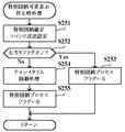
ステップS114の特別図柄可変表示停止時処理は、特別図柄プロセスフラグの値が「4」のときに実行される処理である。この処理において、CPU103は、図32に示すように、まず、特別図柄確定コマンドを表示制御基板12に対して送出するための設定を行う(ステップS251)。例えば、特別図柄確定コマンドに対応する制御データを、所定のコマンド送信テーブルに設定するなどして、特別図柄確定コマンドを送出可能に設定する。
【0128】
続いて、CPU103は、フラグメモリ128に設けられた大当りフラグがオンとなっているか否かを判別し(ステップS252)、オンとなっているときには(ステップS252;Yes)、特別図柄プロセスフラグの値を大入賞口開放前処理に対応する値である「5」に更新する(ステップS253)。一方、大当りフラグがオフであるときには(ステップS252;No)、図33のフローチャートに示すチャンスタイム制御処理を実行した後(ステップS254)、特別図柄プロセスフラグの値を「0」に更新する(ステップS255)。
【0129】
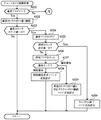
図33のフローチャートに示すチャンスタイム制御処理において、CPU103は、フラグメモリ128に設けられた確変フラグがオンとなっているか否かを判別する(ステップS321)。そして、確変フラグがオンであるときには(ステップS321;Yes)、確変カウンタ126のカウント値を1減算し(ステップS322)、確変カウンタのカウント値が「0」となったか否かを判別する(ステップS323)。確変カウンタのカウント値が「0」以外であれば(ステップS323;No)、そのままチャンスタイム制御処理を終了する。
【0130】
ステップS323にて確変カウンタのカウント値が「0」となったとき(ステップS323;Yes)、CPU103は、確変フラグをクリアしてオフ状態とした後(ステップS324)、時短カウンタ127に設定されている値が「0」であるか否かを判別する(ステップS325)。時短カウンタ127の設定値が「0」以外であるときには(ステップS325;No)、フラグメモリ128に設けられた時短フラグをオン状態にセットし(ステップS326)、チャンスタイムにて実行可能な特図ゲームの残り可変表示回数を報知するための報知モードが、加算報知モードと個別報知モードのいずれであるかを判別する(ステップS327)。この報知モードは、後述するチャンスタイム開始時処理(図35)のステップS263において決定される。
【0131】
報知モードが加算報知モードであるとき(ステップS327;加算報知)、CPU103は、表示制御基板12に対して特別遊技変更コマンドを送出するための設定を行う(ステップS328)。一方、報知モードが個別報知モードであるときには(ステップS327;個別報知)、時短カウンタ127のカウント値に対応するチャンスタイム継続コマンドを送出するための設定を行う(ステップS329)。すなわち、時短カウンタ127に設定されているカウント値に対応する回数の特図ゲームが実行されるまでチャンスタイムが継続するものとして、図8に示すようなチャンスタイム継続コマンドのEXTデータを設定し、所定のコマンド送信テーブルにセットする。
【0132】
また、ステップS325にて時短カウンタの設定値が「0」であるときには(ステップS325;Yes)、表示制御基板12に対してチャンスタイム終了コマンドを送出するための設定を行い(ステップS330)、チャンスタイム制御処理を終了する。
【0133】
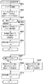
ステップS321にて確変フラグがオフであると判別したとき(ステップS321;No)、CPU103は、時短フラグがオンとなっているか否かを判別する(図34に示すステップS331)。確変フラグ及び時短フラグがオフであるときには(ステップS331;No)、チャンスタイムではないと判断して、そのままチャンスタイム制御処理を終了する。
【0134】
ステップS331にて時短フラグがオンであると判別したとき(ステップS331;Yes)、CPU103は、時短カウンタ127のカウント値を1減算し(ステップS332)、時短カウンタのカウント値が「0」となったか否かを判別する(ステップS333)。時短カウンタのカウント値が「0」以外であれば(ステップS333;No)、そのままチャンスタイム制御処理を終了する。
【0135】
ステップS333にて時短カウンタのカウント値が「0」であるとき(ステップS333;Yes)、CPU103は、時短フラグをクリアしてオフ状態とした後(ステップS334)、表示制御基板12に対してチャンスタイム終了コマンドを送出するための設定を行う(ステップS335)。
【0136】
こうしたチャンスタイム制御処理により、この実施の形態では、チャンスタイムにおいて確変制御が行われる第1特別遊技状態となった場合に、可変表示回数パターンにより予め決められた回数の特図ゲームにて表示結果が大当りとならなかったとき、さらに時短制御が行われる第2特別遊技状態へと移行する。
【0137】
図27に示すステップS115の大入賞口開放前処理は、特別図柄プロセスフラグの値が「5」のときに実行される処理である。この処理において、CPU103は、大入賞口としての特別可変入賞球装置7を開放する制御を開始するための設定を行う。そして、特別可変入賞球装置7を開放する制御を開始するとともに、特別図柄プロセスフラグの値を大入賞口開放中処理に対応した値である「6」に更新する。
【0138】
ステップS116の大入賞口開放中処理は、特別図柄プロセスフラグの値が「6」のときに実行される処理である。この処理において、CPU103は、開成された特別可変入賞球装置7への遊技球の入賞検出、賞球の払出指令、開成時間の計測、及び開成サイクルのラウンド数表示のための表示制御コマンド設定等を行う。そして、例えば、1回の大当りについて、特別可変入賞球装置7の開成回数をカウントし、開成回数が例えば16回に達していれば、特定遊技状態(大当り遊技状態)を終了する条件が終了したとして特別図柄プロセスフラグの値を大当り終了処理に対応した値である「7」に更新する。一方、開成回数が16回に達していなければ、特別可変入賞球装置7を一旦閉成した後、所定時間が経過するのを待って再度開成する。
【0139】
ステップS117の大当り終了処理は、特別図柄プロセスフラグの値が「7」のときに実行される処理である。この処理において、CPU103は、表示制御基板12に対して大当り終了コマンド(A200(h))を送出するための設定を行うなどして、大当り遊技状態を終了させる。また、CPU103は、フラグメモリ128に設けられた大当りフラグをクリアしてオフ状態とする。そして、特別図柄プロセスフラグの値をチャンスタイム開始時処理に対応した値である「8」に更新する。
【0140】
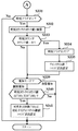
ステップS118のチャンスタイム開始時処理は、特別図柄プロセスフラグの値が「8」のときに実行される処理である。図35は、チャンスタイム開始時処理を示すフローチャートである。このチャンスタイム開始時処理において、CPU103は、ランダムカウンタ122よりランダムR5の値を抽出する(ステップS261)。そして、抽出したランダムR5の値に基づいてチャンスタイムにおける報知モードを決定し、決定結果に応じてフラグメモリ128に設けられた報知モードフラグを設定する(ステップS262)。例えば、CPU103は、図36に示すように、ランダムカウンタ122より抽出したランダムR5の値が奇数であるときには、報知モードを加算報知モードとする。一方、ランダムR5の値が偶数であるときには、報知モードを個別報知モードとする。
【0141】
CPU103は、ステップS262にて決定した報知モードが加算報知モードであるか、個別報知モードであるかを判別し(ステップS263)、加算報知モードであるときには(ステップS263;加算報知)、確変カウンタ126のカウント設定値と時短カウンタ127のカウント設定値とを加算する(ステップS264)。続いて、ステップS264における加算値を可変表示回数として指定するチャンスタイム開始コマンドを、表示制御基板12に対して送出するための設定を行う(ステップS265)。この後、特別図柄プロセスフラグの値を「0」に更新する(ステップS266)。
【0142】
また、ステップS262にて決定した報知モードが個別報知モードであるとき(ステップS263;個別報知)、CPU103は、フラグメモリ128に設けられた確変フラグがオンとなっているか否かを判別する(ステップS267)。確変フラグがオフであるときには(ステップS267;No)、時短カウンタ127のカウント設定値を可変表示回数として指定するチャンスタイム開始コマンドを、表示制御基板12に対して送出するための設定を行う(ステップS268)。これに対して、確変フラグがオンであるときには(ステップS267;Yes)、確変カウンタ126のカウント設定値を可変表示回数として指定するチャンスタイム開始コマンドを、表示制御基板12に対して送出するための設定を行う(ステップS269)。ステップS268及びS269の後、特別図柄プロセスフラグの値を「0」に更新する(ステップS270)。
【0143】
こうしたチャンスタイム開始時処理により、大当り遊技状態が終了したときに、報知モードに従って特定される可変表示回数が、チャンスタイムにおいて実行可能な特図ゲームの可変表示回数として表示制御基板12の側に伝達される。すなわち、報知モードが加算報知モードであるときには、チャンスタイムにおいて実行可能な特図ゲームの可変表示回数の最大値が、表示制御基板12の側に伝達される。他方、報知モードが個別報知モードであるときには、チャンスタイムにおいて第1特別遊技状態で実行可能な特図ゲームの可変表示回数、あるいは第2特別遊技状態で実行可能な特図ゲームの可変表示回数が、表示制御基板12の側に個別に伝達される。そして、表示制御基板12の側では、主基板11から伝達された可変表示回数を可変表示装置4により遊技者などに報知する抽選演出表示のための処理が実行される。
【0144】
図37は、図26のステップS26にて実行される普通図柄プロセス処理を示すフローチャートである。普通図柄プロセス処理を開始すると、CPU103は、まず、遊技球が通過ゲート5を通過したか否かを、通過ゲート5に配置されたゲート通過球検出スイッチから入力される検出信号や、フラグメモリ128に設けられた入力状態フラグをチェックすることにより、判別する(ステップS120)。ゲート通過球検出スイッチからの検出信号がオン状態となった場合には、ゲート通過球があるものとして(ステップS120;Yes)、始動検出処理を実行する(ステップS121)。一方、ゲート通過球がないときには(ステップS120;No)、始動検出処理をスキップする。
【0145】
ステップS121の始動検出処理では、普通図保留メモリ121の保留数が上限値の4以上であるか否かが判別され、保留数が4以上であれば、今回の入賞による普通図ゲームの始動は無効として特に何も行わない。一方、保留数が上限値の4未満である場合には、保留記憶数を1加算するとともに、ランダムカウンタ122より普通図当り判定用のランダムR6の値を抽出し、抽出したランダムR6の値を普通図保留メモリ121の空エントリの先頭にセットする。
【0146】
この後、CPU103は、フラグメモリ128に格納されている普通図柄プロセスフラグの値に基づいて、図37に示すステップS130〜S134の5個の処理のいずれかを選択する。以下に、ステップS130〜S134の各処理について説明する。
【0147】
ステップS130の普通図柄通常処理は、普通図柄プロセスフラグの値が初期値「0」のときに実行される処理である。この処理において、CPU103は、普通図保留メモリ121における保留数が「0」であるか否かを判別する。ここで、普通図保留メモリ121において、保留番号「1」に対応した乱数値が記憶されていない場合には、保留数が「0」であると判別される。保留数が「0」であれば、そのまま普通図柄通常処理を終了する。一方、保留数が「0」ではないと判別すると、普通図保留メモリ121から保留番号「1」に対応して格納されているランダムR6の値を読み出し、第2〜第4エントリ(保留番号「2」〜「4」)に格納されたランダムR6の値を1エントリずつ上位にシフトする。そして、普通図柄プロセスフラグの値を普通図柄可変表示開始処理に対応した値である「1」に更新する。
【0148】
ステップS131の普通図柄可変表示開始処理は、普通図柄プロセスフラグの値が「1」であるときに実行される処理である。この処理において、CPU103は、図38に示すように、まず、確変フラグと時短フラグがオンとなっているか否かを判別する(ステップS401、S402)。確変フラグと時短フラグがいずれもオフであるときには(ステップS401;No及びステップS402;No)、普通図ゲームにおける表示結果を当りとするか否かを判定するためのテーブルとして、通常時普通図当り判定テーブル152を設定する(ステップS403)。一方、確変フラグと時短フラグのいずれかがオンであるときには(ステップS401;Yes又はステップS402;Yes)、確変・時短時普通図当り判定テーブル153を設定する(ステップS404)。
【0149】
続いて、CPU103は、ステップS130の普通図柄通常処理にて読み出したランダムR6の値に基づき、ステップS403又はS404にて設定した普通図当り判定テーブルを用いて普通図柄の表示結果を決定する(ステップS405)。そして、決定した表示結果に基づき、時短制御あるいは確変制御が行われているか否かに応じた普通図柄可変表示開始コマンドを送出するための設定を行う(ステップS406)。例えば、CPU103は、普通図柄可変表示開始コマンドに対応する制御データを、所定のコマンド送信テーブルメモリに設定するなどして、普通図柄可変表示開始コマンドを表示制御基板12に対して送出可能に設定する。また、時短制御あるいは確変制御が行われているか否かに応じて予め定められた普通図柄の可変表示時間(例えば、29.3秒又は6.0秒)に対応するカウント値が、可変表示時間タイマ129の普通図用タイマに設定され、普通図ゲームにおける可変表示時間の計測が開始される。この後、普通図柄プロセスフラグの値を普通図柄可変表示中処理に対応した値である「2」に更新する(ステップS407)。
【0150】
図37に示すステップS132の普通図柄可変表示中処理は、普通図柄プロセスフラグの値が「2」のときに実行される処理である。この処理において、CPU103は、可変表示時間タイマ129の普通図用タイマのカウント値を1減算し、普通図用タイマの値が「0」であるか否かを判別する。普通図用タイマの値が0のときには、普通図柄を所定の可変表示時間だけ可変表示させたとして、普通図柄プロセスフラグの値を普通図柄停止処理に対応した値である「3」に更新する。
【0151】
ステップS133の普通図柄停止処理は、普通図柄プロセスフラグの値が「3」のときに実行される処理である。この処理において、CPU103は、表示制御基板12に対して普通図柄停止コマンドを送出するための設定を行い、普通図柄プロセスフラグの値を普通可変入賞球装置開放処理に対応した値である「4」に更新する。
【0152】
ステップS134の普通可変入賞球装置開放処理は、普通図柄プロセスフラグの値が「4」のときに実行される処理である。この処理において、CPU103は、図39に示すように、まず、普通図柄の表示結果が「当り」であるか否かを判別する(ステップS411)。表示結果が「当り」であるときには、確変フラグと時短フラグがオンとなっているか否かを判別する(ステップS412、S413)。確変フラグと時短フラグがいずれもオフであるときには(ステップS412;No及びステップS413;No)、通常の開放(例えば、1秒間の開放を1回)を指示するコマンドを、ソレノイド回路108に対して送出するための設定を行う(ステップS414)。また、確変フラグと時短フラグのいずれかがオンであるときには(ステップS412;Yes又はステップS413;Yes)、遊技者に有利な態様での延長された開放(例えば、0.8秒を2回)を指示するコマンドを、ソレノイド回路108に対して送出するための設定を行う(ステップS415)。
【0153】
ステップS414、S415の後、あるいはステップS411にて普通図柄の表示結果が「ハズレ」であると判別したときには(ステップS411;No)、ステップS416に進み、普通図柄プロセスフラグの値を「0」に更新する。このようにして、普通図ゲームでは、通過ゲート5を遊技球が通過することを契機として、普通図柄の可変表示を行って、最終的な表示結果が当りに相当する場合に、普通可変入賞球装置6を、遊技者に不利な閉状態から有利な状態に開放する。また、確変制御や時短制御が行われている特別遊技状態では、普通図柄の可変表示時間を通常遊技状態のときよりも短くするとともに表示結果が「当り」となる確率を向上し、普通可変入賞球装置6の開放時間も通常遊技状態のときに比べて延長させる。このように、特別遊技状態では、大当り遊技状態とは異なる遊技者にとって有利な状態となる。
【0154】
次に、表示制御基板12に搭載された表示制御用のCPU112の動作を説明する。図40は、CPU112が実行する表示制御メイン処理を示すフローチャートである。表示制御メイン処理を開始すると、まず、所定の初期化処理を実行することにより、RAM114のクリアや各種初期値の設定、また表示制御の起動間隔を決めるための33ミリ秒タイマの初期設定等を行う(ステップS51)。
【0155】
その後、CPU112は、フラグメモリ144に設けられたタイマ割込フラグを監視し、タイマ割込フラグがセットされるまでループ処理を実行する(ステップS52;No)。このループ処理では、ランダムカウンタ140がカウントするランダムR10〜R12を更新する乱数更新処理が実行されてもよい。この実施の形態では、CPU112にて33ミリ秒ごとにタイマ割込みが発生し、このタイマ割込みが発生すると、所定のタイマ割込処理を実行することにより、フラグメモリ144に設けられたタイマ割込フラグがセットされる。
【0156】
CPU112では、33ミリ秒ごとに発生するタイマ割込みとは別に、主基板11からの表示制御コマンドを受信するための割込みが発生する。この割込みは、主基板11からの表示制御INT信号がオン状態となることにより発生する割込みである。表示制御INT信号がオン状態となることによる割込みが発生すると、CPU112は、自動的に割込禁止状態に設定するが、自動的に割込禁止状態にならないCPUを用いている場合には、割込禁止命令(DI命令)を発行することが好ましい。
【0157】
主基板11からの表示制御INT信号がオン状態となることによりCPU112において割込みがかかることで、CPU112は、表示制御コマンドデータの入力に割り当てられている入力ポートから、データを読み込む。そして、2バイト構成である表示制御コマンドのMODEデータ、EXTデータを順次受信し、所定の受信コマンドバッファに受信したコマンドを格納する。こうして受信コマンドバッファに主基板11から送信された表示制御コマンドが格納される一方で、図40に示すステップS52にてタイマ割込みの発生が確認される。このタイマ割込みの発生が確認されると(ステップS52;Yes)、CPU112は、コマンド解析処理を実行することにより、受信した表示制御コマンドを解析する(ステップS53)。
【0158】
コマンド解析処理が終了すると、CPU112は、ランダムカウンタ140がカウントするランダムR10〜R12を更新するためのカウンタ更新処理を実行した後(ステップS54)、特図表示制御プロセス処理を実行する(ステップS55)。特図表示制御プロセス処理では、表示状態に応じて可変表示装置4における表示動作を所定の順序で制御するために、フラグメモリ144に設けられた表示制御プロセスフラグの値に従って該当する処理が選択されて実行される。特図表示制御プロセス処理に続いて、CPU112は、所定の普通図表示制御処理を実行することにより普通図柄表示器40の点灯/消灯制御を行い、主基板11から受信した表示制御コマンドに従った普通図ゲームを進行する(ステップS56)。普通図表示制御処理が終了すると、ステップS52にリターンする。
【0159】
図41は、ステップS53のコマンド解析処理を示すフローチャートである。このコマンド解析処理を開始すると、CPU112は、まず、主基板11から受信した表示制御コマンドがあるか否かを確認する(ステップS451)。例えば、受信コマンドバッファに受信コマンドが格納されているなどして、受信コマンドがあることを確認したときには(ステップS451;Yes)、受信コマンドを読み出し(ステップS452)、そのコマンドが特別図柄指定コマンドであるか否かを判別する(ステップS453)。
【0160】
ステップS452にて読み出した受信コマンドが特別図柄指定コマンドであれば(ステップS453;Yes)、そのコマンドのEXTデータをRAM114に確保された特別図柄用の確定図柄格納エリアに格納するとともに(ステップS454)、フラグメモリ144に設けられた有効フラグをオン状態にセットする(ステップS455)。特別図柄指定コマンドのEXTデータは、特別図柄の図柄番号を示すデータとなっている。これに対して、ステップS452にて読み出した受信コマンドが特別図柄指定コマンドではないときには(ステップS453;No)、そのコマンドが可変表示開始コマンドであるか否かを判別する(ステップS456)。
【0161】
ステップS452にて読み出した受信コマンドが可変表示開始コマンドであれば(ステップS456;Yes)、そのコマンドのEXTデータをRAM114に確保された可変表示パターン格納エリアに格納してセーブするとともに(ステップS457)、フラグメモリ144に設けられた可変表示開始受信フラグをオン状態にセットする(ステップS458)。これに対して、ステップS452にて読み出した受信コマンドが可変表示開始コマンドではないときには(ステップS456;No)、そのコマンドがチャンスタイム開始コマンドであるか否かを判別する(ステップS459)。
【0162】
ステップS452にて読み出した受信コマンドがチャンスタイム開始コマンドであれば(ステップS459;Yes)、そのコマンドのEXTデータをRAM114に格納して可変表示回数設定データをセーブするとともに(ステップS460)、フラグメモリ144に設けられた特別遊技開始フラグをオン状態にセットする(ステップS461)。これに対して、ステップS452にて読み出した受信コマンドがチャンスタイム開始コマンドではないときには(ステップS459;No)、そのコマンドが特別遊技変更コマンドであるか否かを判別する(ステップS462)。
【0163】
ステップS452にて読み出した受信コマンドが特別遊技変更コマンドであれば(ステップS462;Yes)、フラグメモリ144に設けられた特別遊技変更フラグをオン状態にセットする(ステップS463)。これに対して、ステップS452にて読み出した受信コマンドが特別遊技変更コマンドではないときには(ステップS462;No)、そのコマンドがチャンスタイム継続コマンドであるか否かを判別する(図42に示すステップS464)。
【0164】
ステップS452にて読み出した受信コマンドがチャンスタイム継続コマンドであれば(ステップS464;Yes)、そのコマンドのEXTデータをRAM114に格納して可変表示回数設定データをセーブするとともに(ステップS465)、フラグメモリ144に設けられた特別遊技継続フラグをオン状態にセットする(ステップS466)。
【0165】
また、読み出した受信コマンドがその他の表示制御コマンド(例えば特別図柄確定コマンド)であるときには、フラグメモリ144にて受信した表示制御コマンドに対応するコマンド受信フラグをセットし(ステップS467)、ステップS451にリターンする。こうして全ての受信コマンドが読み出されると(ステップS451;No)、コマンド解析処理が終了する。
【0166】
図43は、ステップS55(図40)の特図表示制御プロセス処理を示すフローチャートである。この特図表示制御プロセス処理において、CPU112は、フラグメモリ144に設けられている表示制御プロセスフラグの値に基づいて、図43に示すステップS150〜S157の8個の処理のいずれかを選択する。以下に、ステップS150〜S157の各処理について説明する。
【0167】
ステップS150の可変表示開始コマンド受信待ち処理は、表示制御プロセスフラグの値が初期値「0」のときに実行される処理である。この処理において、CPU112は、フラグメモリ144に設けられた可変表示開始フラグがオンとなっているか否かを判別する。上述したコマンド解析処理において、可変表示開始コマンドが受信コマンドバッファから読み出されたときには、可変表示開始フラグがオン状態にセットされている。可変表示開始フラグがオン状態であれば、可変表示開始フラグをクリアしてオフ状態とし、表示制御プロセスフラグの値を表示制御設定処理に対応した値である「1」に更新する。一方、可変表示開始フラグがオフのときには、そのまま可変表示開始コマンド受信待ち処理を終了する。
【0168】
図43に示すステップS151の表示制御設定処理は、表示制御プロセスフラグの値が「1」のときに実行される処理である。図44は、ステップS151の表示制御設定処理を示すフローチャートである。この表示制御設定処理において、CPU112は、まず、フラグメモリ144に設けられたチャンスタイムフラグがオンとなっているか否かを判別する(ステップS501)。
【0169】
チャンスタイムフラグがオンであるとき(ステップS501;Yes)、CPU112は、チャンスタイムカウンタ145のカウント値に対応する表示設定を行う(ステップS502)。すなわち、CPU112は、GCL115に対して所定の描画命令を送出し、可変表示装置4上のチャンスタイム表示エリア44に、チャンスタイムであることを示す報知情報44aと、チャンスタイムにて実行可能な特図ゲームの残り可変表示回数を示す報知情報44bとを表示させる。このとき、可変表示装置4上のチャンスタイム表示エリア44に表示される報知情報44a、44bは、確変制御が行われる第1特別遊技状態であるときも、時短制御が行われる第2特別遊技状態であるときも、同一の表示態様で表示される。ステップS501にてチャンスタイムフラグがオフであるときには(ステップS501;No)、チャンスタイムではないと判断して、ステップS502をスキップする。
【0170】
この後、CPU112は、図45のフローチャートに示す飾り図柄演出設定処理を実行する(ステップS503)。飾り図柄演出設定処理を開始すると、CPU112は、まず、可変表示開始コマンドで指定された可変表示パターンに対応する飾り図柄の表示制御パターンを決定する(ステップS601)。例えば、CPU112は、RAM114に確保された可変表示パターン格納エリアに格納されたデータに応じて表示制御パターンメモリ141に格納された図柄表示プロセステーブルを選択することにより、飾り図柄の表示制御パターンを決定する。
【0171】
続いて、CPU112は、特別図柄指定コマンドにより指定された特別図柄がハズレ図柄である図柄番号「12」の特別図柄「−」であるか否かを判別する(ステップS602)。指定された特別図柄がハズレ図柄であるときには(ステップS602;Yes)、左可変表示部42aにおける飾り図柄の確定図柄である左確定図柄を決定するためのテーブルとして、図24(A)に示す左図柄決定用テーブル172を設定する(ステップS603)。そして、ランダムカウンタ140より抽出したランダムR10の値に基づき、左図柄決定用テーブル172を用いて左確定図柄を決定する(ステップS604)。
【0172】
左確定図柄を決定した後、CPU112は、可変表示開始コマンドで指定された可変表示パターンがリーチ用の可変表示パターンであるか否かを判別する(ステップS605)。そして、通常ハズレの可変表示パターンであるときには(ステップS605;No)、右可変表示部42cにおける飾り図柄の確定図柄である右確定図柄を決定するためのテーブルとして、図24(C)に示す右図柄決定用テーブル174を設定し、ランダムカウンタ140より抽出したランダムR12の値に基づいて、右確定図柄を左確定図柄とは異なるものとして決定する。さらに、任意の飾り図柄を、中可変表示部42bにおける飾り図柄の確定図柄である中確定図柄として決定する(ステップS606)。
【0173】
ステップS605にて判別した可変表示パターンがリーチ用の可変表示パターンであるときには(ステップS605;Yes)、例えば、右確定図柄を左確定図柄と同一のものにすることを決定するとともに、左・右確定図柄とは異なる飾り図柄を、中確定図柄として決定する(ステップS607)。
【0174】
また、ステップS602にて、特別図柄指定コマンドで指定された特別図柄が通常大当り図柄あるいは確変大当り図柄であると判別したときには(ステップS602;No)、さらに、指定された特別図柄が確変大当り図柄であるか否かを判別する(ステップS608)。そして、通常大当り図柄であるときには(ステップS608;No)、左中右で同一の飾り図柄の確定図柄を決定するためのテーブルとして、図22に示す通常大当り図柄決定用テーブル170を設定する(ステップS609)。一方、確変大当り図柄が指定されたときには(ステップS608;Yes)、図23に示す確変大当り図柄決定用テーブル171を設定する(ステップS610)。
【0175】
こうしてステップS609又はS610にて大当り図柄決定用テーブルを設定した後、CPU112は、特別図柄指定コマンドで指定された特別図柄の図柄番号と、ランダムカウンタ140より抽出したランダムR10とに基づき、設定した大当り図柄決定用テーブルを用いて大当り用の飾り図柄を決定する(ステップS611)。
【0176】
このような飾り図柄演出設定処理が終了すると、CPU112は、例えばGCL115に対して所定の描画命令を送出するなどして、特別図柄と飾り図柄の可変表示を開始するための表示設定を行う(図44に示すステップS504)。この際、ステップS601にて決定した表示制御パターンに従って、各種タイマ142に設けられた図柄表示プロセスタイマの設定なども行われる。そして、可変表示開始コマンドで指定された可変表示パターンにおける総可変表示時間に対応するカウント初期値を、各種タイマ142に設けられた可変表示時間タイマのうちの特図用タイマにセットしてカウントダウン動作を開始させることにより、特図ゲームにおける可変表示時間の計測を開始させる(ステップS505)。この後、表示制御プロセスフラグの値を可変表示開始時処理に対応した値である「2」に更新する。
【0177】
図43に示すステップS152の特別図柄可変表示中処理は、表示制御プロセスフラグの値が「2」のときに実行される処理である。この処理において、CPU112は、各種タイマ142に含まれる図柄プロセスタイマがタイムアウトするごとに、図柄表示プロセステーブルにおける読出位置を切り替え、その読出位置から読み出された図柄表示プロセスタイマ設定値、特別図柄制御実行データ及び飾り図柄制御実行データに従って、可変表示装置4の表示制御を変更する。そして、各種タイマ142に設けられた可変表示時間タイマの特図用タイマがタイムアウトすると、監視タイマに対して予め定められたタイマ初期値を設定し、その監視タイマのカウントダウン動作を開始させるとともに、表示制御プロセスフラグの値を特別図柄停止待ち処理に対応した値である「3」に更新する。
【0178】
ステップS153の特別図柄停止待ち処理は、表示制御プロセスフラグの値が「3」のときに実行される処理である。この処理において、CPU112は、図46に示すように、まず、主基板11から送信された特別図柄確定コマンドを表示制御コマンドとして受信したか否かを判別する(ステップS521)。特別図柄確定コマンドを受信していないときには(ステップS521;No)、監視タイマがタイムアウトしたか否かを判別し(ステップS522)、タイムアウトしていなければ(ステップS522;No)、そのまま特別図柄停止待ち処理を終了する。
【0179】
一方、特別図柄確定コマンドを受信することなく監視タイマがタイムアウトしたとき(ステップS522;Yes)、CPU112は、何らかの異常が発生したと判断して、可変表示装置4上に所定のエラー画面を表示する制御を行う(ステップS523)。この後、表示制御プロセスフラグの値を「0」に更新して(ステップS524)、特別図柄停止待ち処理を終了する。
【0180】
また、ステップS521にて特別図柄確定コマンドを受信したと判別したとき(ステップS521;Yes)、CPU112は、可変表示装置4にて実行中である特別図柄及び飾り図柄の可変表示を終了させ、各図柄における確定図柄を停止表示する制御を行い(ステップS525)、導出された表示結果が特定表示結果である大当りとなったか否かを判別する(ステップS526)。
【0181】
こうして導出された可変表示の表示結果が大当りでないときには(ステップS526;No)、図47のフローチャートに示すようなチャンスタイム表示判定処理を実行する(ステップS527)。このチャンスタイム表示判定処理において、CPU112は、まず、フラグメモリ144に設けられたチャンスタイムフラグがオンとなっているか否かを判別する(ステップS621)。チャンスタイムフラグがオフであるときには(ステップS621;No)、チャンスタイムではないと判断して、ステップS630に進む。一方、チャンスタイムフラグがオンであるときには(ステップS621;Yes)、チャンスタイムが継続中であるとして、チャンスタイムカウンタ145のカウント値を1減算する(ステップS622)。そして、フラグメモリ144に設けられた特別遊技変更フラグがオンとなっているか否かを判別する(ステップS623)。ここで、主基板11から表示制御基板12に対して特別遊技変更コマンド(B200(h))が送出されたときには、特別遊技変更コマンドがオン状態にセットされている。
【0182】
ステップS623にて特別遊技変更フラグがオンであるとき(ステップS623;Yes)、CPU112は、表示制御プロセスフラグの値をチャンスタイム更新演出表示処理に対応した値である「4」に更新する(ステップS624)。一方、特別遊技変更フラグがオフであるときには(ステップS623;No)、チャンスタイムカウンタ145のカウント値が「0」となったか否かを判別する(ステップS625)。チャンスタイムカウンタ145のカウント値が「0」以外のときには(ステップS625;No)、ステップS630に進み、チャンスタイムカウンタ145のカウント値が0のときには(ステップS625;Yes)、フラグメモリ144に設けられた特別遊技継続フラグがオンとなっているか否かを判別する(ステップS626)。ここで、主基板11から表示制御基板12に対してチャンスタイム継続コマンド(B1XX(h))が送出されたときには、特別遊技継続フラグがオン状態にセットされている。
【0183】
ステップS626にて特別遊技継続フラグがオンであるときには(ステップS626;Yes)、ステップS624に進み、表示制御プロセスフラグの値を「4」に更新する。一方、特別遊技継続フラグがオフであるとき(ステップS626;No)、CPU112は、チャンスタイム終了コマンドを受信したか否かを判別する(ステップS627)。そして、チャンスタイム終了コマンドを受信しているときには(ステップS627;Yes)、チャンスタイムフラグをクリアする一方で、チャンスタイム終了コマンドを受信していないときには(ステップS627;No)、表示制御コマンドを適正に受信することができなかったと判断して、可変表示装置4上にエラー画面を表示させる(ステップS629)。そして、ステップS630において、CPU112は、表示制御プロセスフラグの値を「0」に更新し、チャンスタイム表示判定処理が終了するとともに、特別図柄停止待ち処理も終了する。
【0184】
また、図46に示すステップS526において、表示結果が大当りであると判別したとき(ステップS526;Yes)、CPU112は、表示制御プロセスフラグの値を大当り表示処理に対応する値である「5」に更新し(ステップS528)、特別図柄停止待ち処理を終了する。
【0185】
図43に示すステップS154のチャンスタイム更新演出表示処理は、表示制御プロセスフラグの値が「4」のときに実行される処理である。図48は、チャンスタイム更新演出表示処理を示すフローチャートである。このチャンスタイム更新演出表示処理において、CPU112は、まず、フラグメモリ144に設けられた特別遊技変更フラグがオンとなっているか否かを判別する(ステップS541)。特別遊技変更フラグがオンであるときには(ステップS541;Yes)、特別遊技変更フラグをクリアしてオフ状態とした後(ステップS542)、表示制御パターンメモリ141に格納された複数種類のチャンスタイム更新表示制御パターンのうちから、特別遊技状態が変更されたことを報知するためのチャンスタイム更新表示制御パターンを選択決定し、その表示制御パターンを読み出す(ステップS543)。ここで、特別遊技状態が変更されたことを報知するための表示制御パターンとして、例えば、今回の特図ゲーム終了時点まで継続制御されていた特別遊技状態が確変制御の行われる第1特別遊技状態であったことを遊技者に報知するためのチャンスタイム更新表示制御パターンが使用される。
【0186】
また、ステップS541にて特別遊技変更フラグがオフであるとき(ステップS541;No)、CPU112は、続けて特別遊技継続フラグがオンとなっているか否かを判別する(ステップS544)。特別遊技継続フラグがオフのときには(ステップS544;No)、図47に示すチャンスタイム表示判定処理のステップS623及びS626における判別結果との矛盾が発生したと判断して、可変表示装置4上にエラー画面を表示させる(ステップS545)。一方、特別遊技継続フラグがオンであるときには(ステップS544;Yes)、特別遊技継続フラグをクリアしてオフ状態とした後(ステップS546)、RAM114に格納された可変表示回数設定データに基づいて、図8に示すような可変表示回数設定データの内容に従ったチャンスタイムカウンタ145のカウント値を設定する。なお、主基板11から送信されたチャンスタイム継続コマンドを受信したときには、図41及び図42に示すコマンド解析処理のステップS465において、予めRAM114に可変表示回数設定データが格納されている。
【0187】
ステップS547に続いて、CPU112は、表示制御パターンメモリ141に格納された複数種類のチャンスタイム更新表示制御パターンのうちから、可変表示回数設定データに対応して、特別遊技状態が継続することを報知するためのチャンスタイム更新表示制御パターンを選択決定し、その表示制御パターンを読み出す(ステップS548)。ここで、特別遊技状態が継続することを報知するための表示制御パターンとして、例えば、以後も継続するチャンスタイムにて実行可能な特図ゲームの回数(可変表示回数)を遊技者に報知するためのチャンスタイム更新表示制御パターンが使用される。
【0188】
ステップS543及びS548にてチャンスタイム更新表示制御パターンを決定した後、CPU112は、例えばGCL115に対して表示制御パターンに基づく描画命令を送出するなどして、決定したチャンスタイム更新表示制御パターンに従った可変表示装置4による演出表示のための設定を行う(ステップS549)。そして、ステップS550において、表示制御プロセスフラグの値を「0」に更新する。
【0189】
図43に示すステップS155の大当り表示処理は、表示制御プロセスフラグの値が「5」のときに実行される処理である。この処理において、CPU112は、可変表示装置4を制御することにより、大当り遊技状態に応じた画像を表示する制御を行う。例えば、主基板11から受信した大当りラウンド数指示コマンド(A1XX(h))に対応したラウンド数を、可変表示装置4上に表示させることにより、遊技者に対して報知可能とする。そして、大当り遊技状態において実行されるラウンド遊技が最終ラウンド(例えば、16回目)になると、表示制御プロセスフラグの値を「6」に更新する。
【0190】
ステップS156の大当り終了表示処理は、表示制御プロセスフラグの値が「6」のときに実行される処理である。この処理において、CPU112は、主基板11から大当り終了コマンド(A200(h))を受信したことに応答して、可変表示装置4にて大当り遊技状態が終了したことを報知する演出表示の制御を行う。そして、その演出表示が終了すると、表示制御プロセスフラグの値を「7」に更新する。
【0191】
ステップS157のチャンスタイム開始演出表示処理は、表示制御プロセスフラグの値が「7」のときに実行される処理である。図49は、チャンスタイム開始演出表示処理を示すフローチャートである。このチャンスタイム開始演出表示処理において、CPU112は、まず、フラグメモリ144に設けられた特別遊技開始フラグがオンとなっているか否かを判別する(ステップS561)。ここで、主基板11から表示制御基板12に対してチャンスタイム開始コマンド(B0XX(h))が送出されたときには、特別遊技開始フラグがオン状態にセットされている。
【0192】
ステップS561にて特別遊技開始フラグがオンであるときには(ステップS561;Yes)、特別遊技開始フラグをクリアしてオフ状態とした後(ステップS562)、RAM114に格納された可変表示回数設定データに基づいて、図8に示すような可変表示回数設定データの内容に従ったチャンスタイムカウンタ145のカウント値を設定する(ステップS563)。続いて、表示制御パターンメモリ141に格納された複数種類のチャンスタイム開始表示制御パターンのうちから、可変表示回数設定データに対応して、特別遊技状態が開始されることを報知するためのチャンスタイム開始表示制御パターンを選択決定し、そのチャンスタイム開始表示制御パターンを読み出す(ステップS564)。ここで、特別遊技状態が開始されることを報知するための表示制御パターンとして、例えば、これから開始されるチャンスタイムにて実行可能な特図ゲームの回数(可変表示回数)が抽選により決定されることを報知するためのチャンスタイム開始表示制御パターンが使用される。
【0193】
チャンスタイム開始表示制御パターンを決定した後、CPU112は、例えば115に対して表示制御パターンに基づく描画命令を送出するなどして、決定したチャンスタイム開始表示制御パターンに従った可変表示装置4による可変表示回数の抽選演出表示をスタートさせる(ステップS565)。そして、フラグメモリ144に設けられた可変表示回数抽選表示フラグをオン状態にセットする(ステップS566)。
【0194】
また、ステップS561にて特別遊技開始フラグがオフであるとき(ステップS561;No)、CPU112は、可変表示回数抽選表示フラグがオンとなっているか否かを判別する(ステップS567)。ここで、可変表示回数抽選表示フラグがオフであるときには(ステップS567;No)、可変表示回数の抽選演出表示が適正に行われていないと判断して、可変表示装置4上にエラー画面を表示させる(ステップS568)。エラー画面を表示した後には、ステップS573に進む。一方、ステップS567にて可変表示回数抽選表示フラグがオンであるときには(ステップS567;Yes)、可変表示装置4によるチャンスタイムにおける可変表示回数の抽選演出表示が終了したか否かを判別する(ステップS569)。
【0195】
チャンスタイムにおける可変表示回数の抽選演出表示が実行されている間は(ステップS569;No)、チャンスタイム開始表示制御パターンに従った可変表示装置4による可変表示回数の抽選演出表示のための設定を行う(ステップS570)。そして、可変表示回数の抽選演出表示が終了すると(ステップS569;Yes)、CPU112は、可変表示回数抽選表示フラグをクリアしてオフ状態とし(ステップS571)、チャンスタイムフラグをオン状態にセットする(ステップS572)。そして、ステップS573において、表示制御プロセスフラグの値を「0」に更新する。
【0196】
上述したパチンコ遊技機1の動作を、次に、具体例に基づいて説明する。
【0197】
パチンコ遊技機1の右下位置に設けられたハンドルを遊技者が操作すると、発射モータにより遊技球が遊技領域に打ち込まれ、遊技領域内を下りてくる。主基板11は、各入賞口スイッチ70の入力の有無を監視している。
【0198】
遊技球が普通可変入賞球装置6に入賞すると、始動球検出器により遊技球の入賞が検出される。遊技制御用マイクロコンピュータ100のCPU103は、各入賞口スイッチ70に含まれる始動球検出スイッチからの検出信号がオン状態となると(図27に示すステップS100;Yes)、ランダムカウンタ122よりランダムR1の値を抽出し、抽出した乱数値を特図保留メモリ120の空きエントリの先頭に登録する(ステップS101)。
【0199】
CPU103は、特図ゲームが実行されていない場合に、特図保留メモリ120に記憶されているランダムR1の値を先頭エントリから読み出し、読み出した乱数値に従って大当りとハズレの別を決定する(図29に示す大当り判定処理)。そして、「大当り」と決定したときには、ランダムカウンタ122より抽出したランダムR4の値に応じた大当り用の特別図柄を選択決定するとともに、図16に示すチャンスタイム期間決定用テーブル157を用いて、可変表示パターンを決定する(図30に示す確定図柄設定処理)。こうして選択決定された大当り用の特別図柄に対応する特別図柄指定コマンドが、主基板11から表示制御基板12に対して送出される。
【0200】
また、CPU103は、図14に示す可変表示パターンテーブル154に格納された複数の可変表示パターンのうちから状況に応じたものを選択し、選択した可変表示パターンに対応する可変表示開始コマンドを、表示制御基板12に対して送出する(図31に示す可変表示パターン設定処理)。
【0201】
表示制御基板12では、CPU112が主基板11から受信した可変表示開始コマンド及び特別図柄指定コマンドや、ランダムカウンタ140より抽出したランダムR10〜R12などに基づいて、飾り図柄の確定図柄を決定する(図45に示す飾り図柄演出設定処理)。また、CPU112は、可変表示開始コマンドにて指定された可変表示パターンに対応する表示制御パターンを表示制御パターンメモリ141から読み出し、読み出した表示制御パターンに従って可変表示装置4による特別図柄及び飾り図柄の可変表示を開始する。
【0202】
こうして図50(A)に示すように、可変表示装置4上にて特別図柄及び飾り図柄の可変表示が開始され、可変表示パターンに対応した総可変表示時間が経過したときに、表示結果となる特別図柄と飾り図柄の確定図柄が導出表示される。このとき導出表示された確定図柄がハズレとなる組合せであれば、特別可変入賞球装置7の開閉板の開成等を行わず、1回分の特図ゲームの実行が終了する。
【0203】
一方、例えば図50(B)に示すように、確定図柄が大当り組合せとなっていれば、パチンコ遊技機1は大当り遊技状態となり、特別可変入賞球装置7の開閉板が一定時間又は一定数の遊技球が入賞するまで開成し、開閉を一定サイクル繰り返す。このとき主基板11に搭載されたCPU103は、例えば図50(C)に示すように、表示制御基板12に対する大当りラウンド数指示コマンド(A1XX(h))の送出などにより、大当り遊技状態において実行されているラウンド遊技の実行回数を報知するための情報を、可変表示装置4上にて表示させる(図27に示すステップS116)。
【0204】
この後、大当り遊技状態が終了すると、主基板11から表示制御基板12に対して大当り終了コマンド(A200(h))を送出する(図27に示すステップS117)。表示制御基板12では、CPU112が大当り終了コマンドを受信したことに応答して、例えば図50(D)に示すように、大当り遊技状態が終了したことを報知するための情報を、可変表示装置4上にて表示させる(図43に示すステップS156)。これにより、CPU103が図30に示すステップS214の処理を実行することによって既に決定されたチャンスタイムにおける特図ゲームの可変表示回数に基づく報知が、大当り遊技状態の終了時に行われる。
【0205】
続いて、主基板11から表示制御基板12に対して、チャンスタイム開始コマンド(B0XX(h))が送出される(図34に示すチャンスタイム開始時処理)。例えば、図16に示すチャンスタイム期間決定用テーブル157では、特別図柄の図柄番号「5」に対応する可変表示回数パターンにより、確変カウンタ126のカウント設定値と、時短カウンタ127のカウント設定値とが、いずれも「50」となる。そして、図35に示すステップS262において報知モードを加算報知モードとすることが決定された場合、チャンスタイム開始コマンドのEXTデータは、確変カウンタ126のカウント設定値と時短カウンタ127のカウント設定値とを加算した値「100」に対応するものとなる。すなわち、図8に示すように、CPU103は、チャンスタイム開始コマンドのEXTデータとして、01(h)を設定する。
【0206】
表示制御基板12では、CPU112が受信したチャンスタイム開始コマンドのEXTデータ01(h)に基づいて、例えば図50(E)〜(G)に示すように、チャンスタイムにおいて実行可能な特図ゲームの可変表示回数を報知するための抽選演出表示を、可変表示装置4上にて行わせる(図49に示すチャンスタイム開始演出表示処理)。
【0207】
こうしてチャンスタイムのための抽選演出表示が終了すると、チャンスタイムにおける特図ゲームが実行可能となり、可変表示装置4では、図51(A)に示すように、チャンスタイム表示エリア44が配置され、チャンスタイムであることを示す報知情報44aと、チャンスタイムにて実行可能な特図ゲームの残り可変表示回数を示す報知情報44bとが表示される。チャンスタイムにて実行可能な特図ゲームの残り可変表示回数は、表示制御基板12にてチャンスタイムカウンタ145によってカウントされ、そのカウント値に応じた報知情報44bが表示される(図44に示すステップS502)。
【0208】
この後、特図ゲームが実行されるごとに、遊技制御用マイクロコンピュータ100では確変カウンタ126のカウント値が1減算されるとともに(図33に示すステップS322)、表示制御基板12ではチャンスタイムカウンタ145のカウント値も1減算される(図47に示すステップS622)。そして、報知モードが加算報知モードであることから、チャンスタイムカウンタ145のカウント値が「0」となるより前に、確変カウンタ126のカウント値が「0」となる。具体的には、チャンスタイムにおいて表示結果が「大当り」となることなく50回の特図ゲームが実行されたときに、チャンスタイムカウンタ145のカウント値は「50」となる一方で、確変カウンタ126のカウント値が「0」となる。
【0209】
このとき、主基板11から表示制御基板12に対して特別遊技変更コマンドが送出され、第1特別遊技状態における確変制御から第2特別遊技状態における時短制御への変更が指示される(図33に示すステップS328)。表示制御基板12では、CPU112が特別遊技変更コマンドを受信したことに応答して、例えば図51(G)に示すように、今回の特図ゲーム終了時点まで継続制御されていた特別遊技状態が確変制御の行われる第1特別遊技状態であったことを報知するための情報を、可変表示装置4上に表示させる(図48に示すステップS543及びS549)。こうして特図ゲームが可変表示回数パターンによって予め定められた所定回数実行されるまでの間、各々の特図ゲームにおいて「大当り」とすることが決定されなかったときに、例えばCPU112が図48に示すステップS543の処理を実行することにより、それまで継続制御されてきた特別遊技状態の種類が報知される。
【0210】
この後、さらにチャンスタイムにおける特図ゲームが実行されることになる。このとき、可変表示装置4上の表示には、チャンスタイム表示エリア44が配置され、確変制御が行われていたときと同一の表示態様で、チャンスタイムであることを示す報知情報44aと、チャンスタイムにて実行可能な特図ゲームの残り可変表示回数を示す報知情報44bとが表示される(図44に示すステップS502)。そして、特図ゲームにおける表示結果が「大当り」となれば、特別図柄の確定図柄に応じて、再びチャンスタイムにおいて実行可能な特図ゲームの可変表示回数が設定される。一方、表示結果が「ハズレ」となる特図ゲームが続けて実行され、チャンスタイムカウンタ145におけるカウント値と、時短カウンタ127におけるカウント値とが、ともに「0」となったときに、チャンスタイムが終了する。
【0211】
また、例えば図52(A)に示すように可変表示装置4上にて特別図柄及び飾り図柄が可変表示され、図52(B)に示すように図柄番号「3」の特別図柄が確定図柄に含まれる特定表示結果が導出表示されたときにも、パチンコ遊技機1は大当り遊技状態となり、特別可変入賞球装置7の開閉が一定サイクル繰り返される。ここで、図16に示すチャンスタイム期間決定用テーブル157では、特別図柄の図柄番号「3」に対応する可変表示回数パターンにより、確変カウンタ126のカウント設定値が「50」となり、時短カウンタ127のカウント設定値が「100」となる。そして、図35に示すステップS262において報知モードを個別報知モードとすることが決定された場合、チャンスタイム開始コマンドのEXTデータは、確変カウンタ126のカウント設定値のみの値「50」に対応するものとなる。すなわち、図8に示すように、CPU103は、チャンスタイム開始コマンドのEXTデータとして、00(h)を設定する。
【0212】
表示制御基板12では、チャンスタイム開始コマンドB000(h)をCPU112が受信すると、例えば図52(E)〜(G)に示すように、チャンスタイムにおいて実行可能な特図ゲームの可変表示回数を報知するための抽選演出表示が、可変表示装置4上にて行われる(図49に示すチャンスタイム開始演出表示処理)。実際にチャンスタイムにおいて実行可能な特図ゲームの可変表示回数は、確変カウンタ126のカウント設定値と時短カウンタ127のカウント設定値とを加算した値「150」である。しかしながら、個別報知モードでは、確変カウンタ126のカウント設定値のみが、チャンスタイムにおける可変表示回数として表示制御基板12に伝達されることになる。このため、個別報知モードのときには、実際に決定されたチャンスタイムにおける可変表示回数よりも少ない可変表示回数が、抽選演出表示において報知される。
【0213】
この後、特図ゲームが実行されるごとに、確変カウンタ126のカウント値が1減算されるとともに、チャンスタイムカウンタ145のカウント値も1減算される。そして、報知モードが個別報知モードであることから、確変カウンタ126のカウント値が「0」となるときに、チャンスタイムカウンタ145のカウント値も「0」となる。このとき、時短カウンタ127にはカウント設定値として「100」が設定されていることに応じて、主基板11から表示制御基板12に対し、EXTデータが01(h)であるチャンスタイム継続コマンドが送出される(図33に示すステップS329)。
【0214】
表示制御基板12では、CPU112がチャンスタイム継続コマンドB101(h)を受信したことに応答して、例えば図53(H)に示すように、以後も継続するチャンスタイムにて実行可能な特図ゲームの可変表示回数を報知するための情報を、可変表示装置4上に表示させる(図48に示すステップS548及びS549)。また、チャンスタイム継続コマンドのEXTデータである可変表示回数設定データに基づいて、チャンスタイムカウンタ145のカウント値が「100」に設定される(ステップS547)。こうして報知モードが個別報知モードであるときには、実際に決定されたチャンスタイムにおける可変表示回数よりも少ない可変表示回数が報知された後、その可変表示回数に達するまで特図ゲームの表示結果が「大当り」とならなかったときに、さらにチャンスタイムが継続して特別遊技状態に継続制御されることが、可変表示装置4上の表示によって報知される。
【0215】
以上説明したように、この実施の形態によれば、特図ゲームの表示結果が大当りとなって大当り遊技状態となった後、大当り遊技状態の終了時に、チャンスタイムにて確変制御が行われる第1特別遊技状態となるか、時短制御が行われる第2特別遊技状態となるかが報知されることなく、チャンスタイムで実行可能な特図ゲームの可変表示回数に基づく報知が行われる。この報知により、遊技者は、遊技者にとって有利なチャンスタイムとなることと、チャンスタイムとなる特図ゲームの実行回数(可変表示回数)とを認識することができる。一方で、そのチャンスタイムで確変制御が行われるのか、時短制御が行われるのかは報知されないため、発生する特別遊技状態に対する遊技者の期待感が高められる。
【0216】
また、チャンスタイム期間決定用テーブル157は、確変制御が行われる第1特別遊技状態に継続制御される特図ゲームの可変表示回数と、時短制御が行われる第2特別遊技状態に継続制御される特図ゲームの可変表示回数とを、予め定められた複数種類の可変表示回数「0」、「50」、「100」のいずれかに設定するための可変表示パターンを複数種類格納している。そして、それらの可変表示パターンのうちには、一方の可変表示パターンで第1特別遊技状態に継続制御される特図ゲームの可変表示回数と、他方の可変表示パターンで第2特別遊技状態に継続制御される特図ゲームの可変表示回数とが同一となる複数種類の可変表示パターンが含まれている。これにより、各々の大当り遊技状態後のチャンスタイムにおける遊技内容を比較すると、確変制御が行われる特図ゲームの回数と時短制御が行われる特図ゲームの回数とが同じになることがあり、遊技者にとっては、チャンスタイムにおける遊技状態が第1特別遊技状態であるのか第2特別遊技状態であるのかを特定することが困難になる。
【0217】
さらに、チャンスタイム期間決定用テーブル157は、確変制御が行われる第1特別遊技状態に継続制御される特図ゲームの可変表示回数と、時短制御が行われる第2特別遊技状態に継続制御される特図ゲームの可変表示回数とを、それらの合計回数が予め定められた複数種類の合計回数「50」、「100」、「150」のいずれかとなるように設定する可変表示パターンを複数種類格納している。そして、それらの可変表示パターンのうちには、第1特別遊技状態に継続制御される特図ゲームの可変表示回数と第2特別遊技状態に継続制御される特図ゲームの可変表示回数の合計回数が同一で、各々の可変表示回数の組合せが異なる複数種類の可変表示パターンが含まれている。これにより、各々の大当り遊技状態後のチャンスタイムにおける遊技内容を比較すると、確変制御が行われる特図ゲームの回数と時短制御が行われる特図ゲームの回数との組合せは異なるが、一連のチャンスタイム全体として実行可能な特図ゲームの回数は同じになることがある。そのため、遊技者にとっては、チャンスタイムにおける遊技状態が第1特別遊技状態であるのか第2特別遊技状態であるのかを特定することが、さらに困難になる。
【0218】
また、図35に示すステップS262においてCPU103が報知モードを個別報知モードとすることを決定したときには、実際に可変表示回数パターンに応じて決められたチャンスタイムにおける可変表示回数よりも少ない可変表示回数が、大当り遊技状態終了後の抽選演出表示において報知される。その後、一旦報知した可変表示回数に達するまで特図ゲームの表示結果が「大当り」とならなかったときには、さらにチャンスタイムが継続して特別遊技状態に継続制御されることが報知される。これにより、一旦報知された可変表示回数だけ特図ゲームが実行されたときでも、さらにまだチャンスタイムが継続することを報知することができ、遊技者の興趣を長く持続させることができる。
【0219】
また、CPU112は、チャンスタイム中に、可変表示装置4での表示においてチャンスタイム表示エリア44を配置し、確変制御と時短制御のいずれが行われるときにも同一の表示態様で、チャンスタイムであることを示す報知情報44aと、チャンスタイムにて実行可能な特図ゲームの残り可変表示回数を示す報知情報44bとを表示させる。この表示により遊技者は、現在の遊技状態がチャンスタイムにおける特別遊技状態となっていることは把握することができるが、その特別遊技状態で確変制御が行われているのか、それとも時短制御が行われているのかは、知ることができない。従って、この表示により遊技者の期待感を持続させて遊技興趣を向上させることができる。
【0220】
また、図35に示すステップS262においてCPU103が報知モードを加算報知モードとすることを決定したときには、チャンスタイムにおいて特図ゲームが可変表示回数パターンによって予め定められた所定回数実行されるまでの間、各々の特図ゲームにおいて「大当り」とすることが決定されなかったときに、それまで継続制御されてきた特別遊技状態の種類が報知される。これにより、CPU103が図30に示すステップS204にてチャンスタイム期間決定用テーブル157を用いて決定した特別遊技状態の種類は、その特別遊技状態が終了するときに事後報知されるので、遊技者の遊技に対する興味を持続させることができ、遊技興趣を向上させることができる。
【0221】
また、遊技制御用マイクロコンピュータ100のCPU103が、図30に示すステップS213にて、特別図柄の確定図柄として確変大当り図柄を選択決定したときには、表示制御基板12に搭載されたCPU112が、図45に示すステップS610及びS611にて、確変大当り図柄決定用テーブル171を用いることで、大当り用の飾り図柄を選択決定する。このとき選択可能な飾り図柄には、図柄番号「3」、「7」の飾り図柄が含まれており、チャンスタイムにて確変制御が行われる「確変大当り」であるときには、図柄番号が「3」、「7」の飾り図柄を含んだすべての飾り図柄のうちから、特図ゲームの表示結果を構成する飾り図柄の確定図柄を選択決定して導出表示させることができる。これに対して、CPU103が図30に示すステップS213にて、特別図柄の確定図柄として通常大当り図柄を選択決定したときには、CPU112が図45に示すステップS609及びS611にて、通常大当り図柄決定用テーブル170を用いることで、大当り用の飾り図柄を選択決定する。このときに選択可能な飾り図柄には、図柄番号「3」、「7」の飾り図柄が含まれておらず、チャンスタイムにて時短制御のみが行われる「通常大当り」であるときには、図柄番号「3」、「7」の飾り図柄を除く飾り図柄のうちから、飾り図柄の確定図柄が決定される。こうした飾り図柄の確定図柄により遊技者は、第1特別遊技状態と第2特別遊技状態のいずれが発生するかをある程度予測することができるものの、完全には予測することができないので、特図ゲームにおける表示結果に対する遊技者の期待感が高められ、遊技興趣を向上させることができる。
【0222】
上記実施の形態では、チャンスタイム開始コマンドあるいはチャンスタイム継続コマンドのEXTデータにより指定される可変表示回数が、確変カウンタ設定値と時短カウンタ設定値とを加算した値、又は確変カウンタ設定値と時短カウンタ設定値のうちのいずれかであるものとして説明した。しかしながら、この発明はこれに限定されるものではなく、より少ない設定値を可変表示回数として指定するようにしてもよい。例えば、チャンスタイムが終了するまでの間、50回の特図ゲームが実行されるごとに、さらに50回の可変表示回数を指定するチャンスタイム継続コマンドを、主基板11から表示制御基板12に対して送出するようにしてもよい。
【0223】
この場合、CPU103は、図35に示すステップS267〜S269の処理に代えて、確変カウンタ設定値及び時短カウンタ設定値に関係なく、チャンスタイムにおいて実行可能な特図ゲームの可変表示回数として「50」を指定するチャンスタイム開始コマンドを送出するための設定を行う。そして、図54に示すように、チャンスタイム制御処理のステップS329では、常に可変表示回数として「50」を指定するチャンスタイム継続コマンドを送出するように設定する。さらに、ステップS323にて確変カウンタのカウント値が「0」以外であると判定したときや、ステップS328、S329、S330の処理を実行した後に、図54に示すステップS336〜S338の処理を実行する。
【0224】
すなわち、CPU103は、報知モードが加算報知モードであるか個別報知モードであるかを判別し(ステップS336)、個別報知モードであるときには(ステップS336;個別報知)、確変カウンタ126のカウント値が「50」又は「100」であるか否かを判別する(ステップS337)。そして、確変カウンタ126のカウント値が「50」と「100」のいずれかであるときには(ステップS337;Yes)、さらに継続するチャンスタイムにおいて実行可能な特図ゲームの可変表示回数として「50」を指定するチャンスタイム継続コマンドを送出するための設定を行う(ステップS338)。
【0225】
また、図55に示すように、チャンスタイム制御処理のステップS333にて時短カウンタのカウント値が「0」以外であると判別したときや、ステップS335の処理を実行した後には、ステップS339〜S341の処理を実行する。すなわち、CPU103は、報知モードが加算報知モードであるか個別報知モードであるかを判別し(ステップS339)、個別報知モードであるときには(ステップS339;個別報知)、確変カウンタ126のカウント値が「50」又は「100」であるか否かを判別する(ステップS340)。そして、確変カウンタ126のカウント値が「50」と「100」のいずれかであるときには(ステップS340;Yes)、さらに継続するチャンスタイムにおいて実行可能な特図ゲームの可変表示回数として「50」を指定するチャンスタイム継続コマンドを送出するための設定を行う(ステップS341)。
【0226】
こうした処理を実行することにより、例えば図53に示した表示動作例に代えて、図56に示すような表示動作が行われることになる。すなわち、図53(H)に示す場合と同様に、あと100回の特図ゲームが実行されるまでチャンスタイムを継続できるときでも、図56(H)に示すように、50回の特図ゲームが実行されるまでチャンスタイムを継続できることを報知する。そして、この後に50回の特図ゲームが実行されても表示結果が「大当り」になることがなかったときには、さらにあと50回の特図ゲームが実行されるまでチャンスタイムを継続できることを報知する。また、報知する可変表示回数は「50」や「100」、「150」などに限定されず、予め定めた任意の数値とすることが可能である。
【0227】
上記実施の形態では、チャンスタイム期間決定用テーブル157を用いて可変表示回数パターンを選択決定することにより、確変カウンタ設定値と時短カウンタ設定値が、「0」、「50」、「100」のいずれかに決められるものとして説明した。しかしながら、この発明はこれに限定されるものではなく、具体的な確変カウンタ設定値及び時短カウンタ設定値については、予め決められた複数種類の設定値のいずれかとすることができれば、任意の値に定めることができる。
【0228】
また、チャンスタイム期間決定用テーブル157を用いて選択決定される可変表示回数パターンにおける確変カウンタ設定値と時短カウンタ設定値とを加算した合計値についても、「50」、「100」、「150」といった具体的数値は一例であり、予め決められた複数種類の設定値のいずれかとすることができれば、任意の値に定めることができる。
【0229】
上記実施形態では、チャンスタイムにおいて可変表示装置4の表示画面に配置されたチャンスタイム表示エリア44の表示により、チャンスタイムにて実行可能な特図ゲームの残り可変表示回数を報知するものとして説明した。しかしながら、本発明はこれに限定されるものではなく、例えば図57に示すように、大当り遊技状態が終了した後にチャンスタイムとなってから、既に実行された特図ゲームの可変表示回数の消化回数を報知するようにしてもよい。この場合、例えばチャンスタイムにおける特図ゲームの実行回数をカウントするためのカウンタを表示制御基板12に設け、当該カウンタにおけるカウント値を、図57に示すように、チャンスタイムにて既に実行された特図ゲームの消化回数を示す報知情報44cとして、チャンスタイム表示エリア44に表示するようにすればよい。
【0230】
上記実施の形態では、特図ゲームにおける表示結果として導出表示される特別図柄の確定図柄が確変大当り図柄であるときには、チャンスタイムにおいて、確変制御が行われる第1特別遊技状態となった後、確変カウンタ126のカウント値が「0」となったときに、時短制御が行われる第2特別遊技状態になるものとして説明した。しかしながら、この発明はこれに限定されるものではなく、チャンスタイムにおいて第1特別遊技状態と第2特別遊技状態になる順番は、任意に設定することができる。例えば、図58(A)に示すように、チャンスタイム期間決定用テーブル157において、特別図柄の確定図柄が確変大当り図柄であるときには、確変カウンタ設定値と時短カウンタ設定値のほかに、チャンスタイムにおける特別遊技状態の制御順序を規定する特別遊技変更モードを設定するようにしてもよい。この場合には、図7に示すコマンドに加えて、図58(B)に示すような時短制御から確変制御への変更を指示する特別遊技変更コマンドB201(h)を設けておく。
【0231】
そして、図30に示すステップS215〜S217に代えて、特別図柄の確定図柄が確変大当り図柄である場合には、特別遊技変更モードに応じて確変フラグあるいは時短フラグをセットする。すなわち、特別遊技変更モードが「確変→時短」であるときには、確変フラグをオン状態にセットし、特別遊技状態変更モードが「時短→確変」であるときには、時短フラグをオン状態にセットしておく。また、特別遊技変更モードが「時短→確変」であるときには、図33、図34、図54、図55に示すチャンスタイム制御処理と、図35にチャンスタイム開始時処理において、確変フラグと時短フラグ、確変カウンタと時短カウンタとを、それぞれ入れ替えた処理を実行するようにすればよい。
【0232】
また、上記実施の形態では、可変表示装置4による抽選演出表示や、チャンスタイム表示エリア44における表示により、チャンスタイムとなることや、チャンスタイムにて実行可能な特図ゲームの可変表示回数などを報知するものとして説明した。しかしながら、この発明はこれに限定されるものではなく、チャンスタイムとなることや、チャンスタイムにて実行可能な特図ゲームの可変表示回数を遊技者などに報知可能な任意の遊技機に適用することができる。例えば、音声制御基板13の制御下にスピーカ8L、8Rから音声を出力させることにより、これらの報知を行うようにしてもよい。また、ランプ制御基板14の制御下に遊技効果ランプ9に含まれる所定の報知用ランプを点灯又は点滅させるなどしてこれらの報知を行うようにしてもよい。さらに、可変表示装置4における表示、スピーカ8L、8Rからの音声出力、報知用ランプの点灯又は点滅のいずれかを組み合わせて、これらの報知を行うようにしてもよい。
【0233】
上記実施の形態では、可変表示装置4に特別図柄表示エリア41と飾り図柄表示エリア42とが設けられ、飾り図柄表示エリア42に含まれる3つの可変表示部42a、42b、42cにおいて左中右の飾り図柄がそれぞれ可変表示されるものとして説明した。しかしながら、この発明はこれに限定されるものではなく、可変表示装置4に設けられた複数の可変表示領域において、各々が識別可能な複数種類の識別情報を可変表示するものであればよい。例えば、可変表示装置4に設けられた3つの可変表示領域において、左中右の特別図柄がそれぞれ可変表示されるものであってもよい。
【0234】
図1及び図5に示した装置構成、図6、図10、図17及び図18に示すブロック構成、図12〜図16、図21〜図24、図58に示すテーブル構成や、図25〜図35、図37〜図49、図54、図55に示すフローチャート構成は、発明の趣旨を逸脱しない範囲で任意に変更及び修正が可能である。
【0235】
さらに、パチンコ遊技機1の動作をシミュレーションするゲーム機などにも本発明を適用することができる。本発明を実現するためのプログラム及びデータは、コンピュータ装置等に対して、着脱自在の記録媒体により配布・提供される形態に限定されるものではなく、予めコンピュータ装置等の有する記憶装置にプリインストールしておくことで配布される形態を採っても構わない。さらに、本発明を実現するためのプログラム及びデータは、通信処理部を設けておくことにより、通信回線等を介して接続されたネットワーク上の、他の機器からダウンロードすることによって配布する形態を採っても構わない。
【0236】
そして、ゲームの実行形態も、着脱自在の記録媒体を装着することにより実行するものだけではなく、通信回線等を介してダウンロードしたプログラム及びデータを、内部メモリ等にいったん格納することにより実行可能とする形態、通信回線等を介して接続されたネットワーク上における、他の機器側のハードウェア資源を用いて直接実行する形態としてもよい。さらには、他のコンピュータ装置等とネットワークを介してデータの交換を行うことによりゲームを実行するような形態とすることもできる。
【0237】
また、本発明は、入賞球の検出に応答して所定数の賞球を払い出す払出式遊技機に限定されるものではなく、遊技球を封入し入賞球の検出に応答して得点を付与する封入式遊技機にも適用することができる。
【0238】
【発明の効果】
以上説明したように本発明は、以下に示す効果を有する。
【0239】
請求項1に記載の遊技機によれば、特別遊技報知手段が、遊技状態決定手段によって決定された遊技状態を報知することなく、特別可変表示回数決定手段によって決定された可変表示回数に基づく報知のみを行う。この報知により、遊技者は、遊技者にとって有利な遊技状態となることと、その遊技状態に継続制御される可変表示回数とを認識することできる。一方で、その遊技状態が複数種類ある特別遊技状態のいずれであるかは報知されないため、発生する特別遊技状態の種類に対する遊技者の期待感が高められ、遊技者の興趣を向上させることができる。
【0240】
請求項2に記載の遊技機においては、遊技状態継続制御手段によって複数種類の特別遊技状態のいずれかに継続制御することができるので、遊技者の興趣を向上できる。
【0241】
請求項3に記載の遊技機においては、第1特別遊技状態と第2特別遊技状態について、遊技状態継続制御手段によって継続制御される可変表示回数が同じになるので、遊技者が複数種類の特別遊技状態のいずれとなったかを認識することが困難になり、遊技者の期待感を持続させて遊技興趣を向上させることができる。
【0242】
請求項4に記載の遊技機においては、第1特別遊技状態と第2特別遊技状態に継続制御される可変表示回数の合計回数が同一であっても、各々の特別遊技状態に継続制御される可変表示回数の組合せが異なるので、遊技者が複数種類の特別遊技状態のいずれとなったかを認識することが困難になり、遊技者の期待感を持続させて遊技興趣を向上させることができる。
【0243】
請求項5に記載の遊技機においては、少数報知手段が特別可変表示回数決定手段によって決定された可変表示回数より少ない可変表示回数を報知し、識別情報の可変表示の実行回数が前記少数報知手段により報知された可変表示回数に達したときに、追加報知手段がさらに特別遊技状態に継続制御されることを報知するので、一旦報知された可変表示回数だけ識別情報の可変表示が実行されたときでも、さらにまだ特別遊技状態が続くことを遊技者に報知することができ、遊技者の興趣を長く持続させることができる。
【0244】
請求項6に記載の遊技機においては、特定遊技状態が終了したときに、特別遊技報知手段が特別可変表示回数決定手段によって決定された可変表示回数に基づく報知を行うので、特定遊技状態の終了時に、特別遊技状態に継続制御される可変表示回数が報知され、特定遊技状態が終了する時点での遊技者の期待感を高めて興趣を向上させることができる。
【0245】
請求項7に記載の遊技機においては、特別遊技制御手段によって特別遊技状態に継続制御されている間、回数表示制御手段が特別可変表示回数決定手段により決定された可変表示回数の消化回数又は残可変表示回数を可変表示装置に表示させるので、特別遊技状態に継続制御される可変表示の消化回数や残回数が表示され、この表示により遊技者は、現在の遊技状態と、その進行状況を把握することができる。
【0246】
請求項8に記載の遊技機においては、特別遊技表示制御手段が可変表示装置に特別遊技状態である旨を報知する報知情報を表示させるので、特別遊技状態である旨の表示が行われ、この表示により遊技者は、現在特別遊技状態であることを把握することができる。また、このとき表示される報知情報は、第1特別遊技状態と第2特別遊技状態において同一の表示態様となるので、遊技者が複数種類の特別遊技状態のいずれとなったかを認識することは困難になり、遊技者の期待感を持続させて遊技興趣を向上させることができる。
【0247】
請求項9に記載の遊技機においては、特別遊技状態における識別情報の可変表示が予め決められた所定回数実行されるまで表示結果事前決定手段によって特定表示結果とすることが決定されなかったときに、遊技種類報知手段が特別遊技制御手段によりそれまで継続制御されてきた特別遊技状態の種類を報知するので、遊技状態決定手段によって決定された特別遊技状態の種類が事後報知され、遊技者の遊技に対する興味を持続させることができ、遊技興趣を向上させることができる。
【0248】
請求項10に記載の遊技機においては、遊技状態決定手段が遊技状態継続制御手段によって第1特別遊技状態を含んだ特別遊技状態に継続制御することを決定したときに、第1導出表示制御手段が識別情報の表示結果として第1識別情報と第2識別情報のいずれかからなる特定表示結果を導出表示させる。一方、遊技状態決定手段が遊技状態継続制御手段によって第2特別遊技状態を含んだ特別遊技状態に継続制御することを決定したときには、第2導出表示制御手段が識別情報の表示結果として第2識別情報からなる特定表示結果を導出表示させる。これにより、第1識別情報からなる特定表示結果が導出表示されたときには必ず第1特別遊技状態が発生する一方で、第2識別情報からなる特定表示結果が導出表示されたときには、第1特別遊技状態が発生する場合と、第2特別遊技状態が発生する場合とがある。こうした表示結果により遊技者は、複数種類の特別遊技状態のいずれが発生するかをある程度予測することができるものの、完全には予測することができないので、表示結果に対する遊技者の期待感が高められ、遊技興趣を向上させることができる。
【図面の簡単な説明】
【図1】本発明の実施の形態におけるパチンコ遊技機の正面図である。
【図2】可変表示装置における画像表示例を示す図である。
【図3】この実施の形態で用いられる特別図柄の例を示す図である。
【図4】この実施の形態で用いられる左中右の飾り図柄の例を示す図である。
【図5】本発明の実施の形態におけるパチンコ遊技機の背面図である。
【図6】主基板における回路構成等を示すブロック図である。
【図7】表示制御コマンドの内容の一例を示す図である。
【図8】チャンスタイム開始/継続コマンドのEXTデータの一例を示す図である。
【図9】普通図柄可変表示開始コマンドのEXTデータの一例を示す図である。
【図10】遊技制御用マイクロコンピュータの構成例を示すブロック図である。
【図11】遊技制御用マイクロコンピュータのランダムカウンタによりカウントされる各乱数の例を示す図である。
【図12】大当り判定テーブルの構成例を示す図である。
【図13】普通図当り判定テーブルの構成例を示す図である。
【図14】可変表示パターンテーブルの構成例を示す図である。
【図15】可変表示パターン決定テーブルの構成例を示す図である。
【図16】チャンスタイム期間決定用テーブルの構成例を示す図である。
【図17】表示制御基板におけるハードウェア構成の一例を示すブロック図である。
【図18】表示制御基板の構成例を示すブロック図である。
【図19】表示制御基板のランダムカウンタによりカウントされる各乱数の例を示す図である。
【図20】表示制御パターンメモリに格納された表示制御パターンの構成例を示す図である。
【図21】図柄表示プロセステーブルの構成例を示す図である。
【図22】通常大当り図柄決定用テーブルの構成例を示す図である。
【図23】確変大当り図柄決定用テーブルの構成例を示す図である。
【図24】左・中・右図柄決定用テーブルの構成例を示す図である。
【図25】遊技制御メイン処理を示すフローチャートである。
【図26】遊技制御割込処理を示すフローチャートである。
【図27】特別図柄プロセス処理を示すフローチャートである。
【図28】図27における特別図柄通常処理の詳細を示すフローチャートである。
【図29】図28における大当り判定処理の詳細を示すフローチャートである。
【図30】図27における確定特別図柄設定処理の詳細を示すフローチャートである。
【図31】図27における可変表示パターン設定処理の詳細を示すフローチャートである。
【図32】図27における特別図柄可変表示停止時処理の詳細を示すフローチャートである。
【図33】図32におけるチャンスタイム制御処理の詳細を示すフローチャートである。
【図34】図32におけるチャンスタイム制御処理の詳細を示すフローチャートである。
【図35】図27におけるチャンスタイム開始時処理の詳細を示すフローチャートである。
【図36】ランダムR5に基づいて報知モードを決定する動作を説明するための図である。
【図37】普通図柄プロセス処理を示すフローチャートである。
【図38】図37における普通図柄可変表示開始処理の詳細を示すフローチャートである。
【図39】図37における普通可変入賞球装置開放処理の詳細を示すフローチャートである。
【図40】表示制御メイン処理を示すフローチャートである。
【図41】コマンド解析処理を示すフローチャートである。
【図42】コマンド解析処理を示すフローチャートである。
【図43】特図表示制御プロセス処理を示すフローチャートである。
【図44】図43における表示制御設定処理の詳細を示すフローチャートである。
【図45】図44における飾り図柄演出設定処理の詳細を示すフローチャートである。
【図46】図43における特別図柄停止待ち処理の詳細を示すフローチャートである。
【図47】図46におけるチャンスタイム表示判定処理の詳細を示すフローチャートである。
【図48】図43におけるチャンスタイム更新演出表示処理の詳細を示すフローチャートである。
【図49】図43におけるチャンスタイム開始演出表示処理の詳細を示すフローチャートである。
【図50】可変表示装置における表示動作の一例を示す図である。
【図51】可変表示装置における表示動作の一例を示す図である。
【図52】可変表示装置における表示動作の一例を示す図である。
【図53】可変表示装置における表示動作の一例を示す図である。
【図54】本発明の変形例におけるチャンスタイム制御処理を示すフローチャートである。
【図55】本発明の変形例におけるチャンスタイム制御処理を示すフローチャートである。
【図56】本発明の変形例での可変表示装置における表示動作の一例を示す図である。
【図57】本発明の変形例での可変表示装置における画像表示例を示す図である。
【図58】本発明の変形例におけるチャンスタイム期間決定用テーブルの構成例と、特別遊技変更コマンドとを示す図である。
【符号の説明】
1 … パチンコ遊技機
2 … 遊技盤
3 … 遊技機用枠
4 … 可変表示装置
5 … 通過ゲート
6 … 普通可変入賞球装置
7 … 特別可変入賞球装置
8L、8R … スピーカ
9 … 遊技効果ランプ
10 … 電源基板
11 … 主基板
12 … 表示制御基板
13 … 音声制御基板
14 … ランプ制御基板
15 … 払出制御基板
16 … 情報端子基板
21、22 … ソレノイド
40 … 普通図柄表示器
41 … 特別図柄表示エリア
42 … 飾り図柄表示エリア
42a〜42c … 可変表示部
43 … 特図保留数表示エリア
44 … チャンスタイム表示エリア
70 … 各入賞口スイッチ
100 … 遊技制御用マイクロコンピュータ
101、113 … ROM
102、114 … RAM
103、112 … CPU
104 … I/Oポート
107 … スイッチ回路
108 … ソレノイド回路
110 … 発振回路
111 … リセット回路
115 … GCL
120 … 特図保留メモリ
121 … 普通図保留メモリ
122、140 … ランダムカウンタ
123 … 判定テーブルメモリ
124 … 可変表示パターンテーブルメモリ
125 … チャンスタイム期間決定用テーブルメモリ
126 … 確変カウンタ
127 … 時短カウンタ
128、144 … フラグメモリ
129 … 可変表示時間タイマ
141 … 表示制御パターンメモリ
142 … 各種タイマ
143 … 飾り図柄決定用テーブルメモリ
145 … チャンスタイムカウンタ
150 … 通常・時短時大当り判定テーブル
151 … 確変時大当り判定テーブル
152 … 通常時普通図当り判定テーブル
153 … 確変・時短時普通図当り判定テーブル
154 … 可変表示パターンテーブル
155 … 大当り可変表示パターン決定テーブル
156 … リーチハズレ可変表示パターン決定テーブル
157 … チャンスタイム期間決定用テーブル
170 … 通常大当り図柄決定用テーブル
171 … 確変大当り図柄決定用テーブル
172 … 左図柄決定用テーブル
173 … 中図柄決定用テーブル
174 … 右図柄決定用テーブル[0001]
TECHNICAL FIELD OF THE INVENTION
The present invention relates to a gaming machine such as a pachinko gaming machine, and more specifically, variably displays a plurality of types of identification information each of which can be identified based on a predetermined starting condition being satisfied, and displays a display result of the identification information. A variable display device for deriving and displaying, and display result pre-determining means for determining a display result of the identification information based on the start condition being satisfied before the display result is derived and displayed; When the display result of the identification information is determined to be a predetermined specific display result, the variable display device derives and displays the specific display result, and then generates a specific game state advantageous to the player. .
[0002]
[Prior art]
In a gaming machine such as a pachinko gaming machine, a variable display is performed by updating predetermined identification information (hereinafter, a display pattern) on a display device such as a liquid crystal display device (hereinafter, an LCD: Liquid Crystal Display), and a combination thereof. There have been provided a large number of so-called variable display games that enhance amusement of a game by determining whether or not to give a predetermined game value based on a display result as a result.
[0003]
Some variable display games are played by using the above-described display device as an image display device (hereinafter, a special figure game). In the special figure game, the display symbol is updated and displayed based on the detection of a game ball passing through the starting winning opening (the variable display starting condition is satisfied), and the display is stopped when the update of the displayed symbol is completely stopped. This is a game in which a case where the symbol mode is a predetermined specific display mode is a “big hit”. When a "big hit" occurs in the special map game, a special winning combination or a special electric accessory called an attacker is opened, and a state in which winning of a game ball becomes extremely easy is continuously provided to a player for a certain period of time. This state is referred to as a “specific game state”.
[0004]
In such a special figure game, the maximum attention of the player is paid on whether or not the stop symbol mode becomes the specific display mode and becomes “big hit”. Therefore, as a game function for increasing the degree of expectation of the player even after the specific game state ends, the probability that the stop symbol mode in the special figure game will be the specific display mode and "big hit" after the specific game state ends. Gaming machines having functions such as probability variation control (probability change control) for improving the game time more than usual, and time reduction control (time saving control) for shortening the execution time of the ordinary figure game or the special figure game than usual are also common. .
[0005]
In a gaming machine that performs such a probability change control or a time reduction control, each control is performed in order to notify a player at any time of the game that either the probability change control or the time reduction control is being performed. There is proposed a display mode in which this can be identified by a player (for example, Patent Document 1).
[0006]
[Patent Document 1]
JP-A-10-266 (for example,
[0007]
Also, in a gaming machine that performs time-saving control for shortening the variable display time of a normal symbol until the special figure game is executed a plurality of times, the number of times of starting a special symbol (the number of time savings) during which the time-saving control is executed is determined by predetermined numerical data. There is also proposed an apparatus that determines the number of time savings determined based on the extracted value of the above (for example, Patent Document 2).
[0008]
[Patent Document 2]
JP-A-9-262347 (for example, page 7-9, FIG. 17, FIG. 19, etc.)
[0009]
[Problems to be solved by the invention]
In the gaming machines disclosed in
[0010]
For example, when the probability change control is performed, the probability of a “big hit” in the special figure game is improved, so that the gaming state is more advantageous for the player than when the time reduction control is performed. Therefore, the player often expects that the probability change control is performed. In this way, the player who expects that the probable change control is performed may know that the time saving control is performed, so that the expectation may be reduced and the interest may be reduced.
[0011]
The present invention has been made in view of the above situation, and has an object to provide a gaming machine that can improve the interest of a player while notifying that the player is in a gaming state that is advantageous for the player.
[0012]
[Means for Solving the Problems]
In order to achieve the above object, the gaming machine according to
[0013]
According to the configuration of the first aspect, the special game notification means does not notify the game state determined by the game state determination means, but only the notification based on the variable display number determined by the special variable display number determination means. I do. By this notification, the player can recognize that the game state is advantageous for the player and that the number of display times is continuously controlled in the game state. On the other hand, it is not notified which of the plurality of types of special game state the game state is, so that the player's expectation of the type of special game state to be generated is increased, and the interest of the player can be improved. .
[0014]
In the gaming machine according to
[0015]
In the gaming machine according to
[0016]
In the gaming machine according to
[0017]
In the gaming machine according to the fifth aspect, the special game notifying means notifies the small number of variable displays less than the variable number of times determined by the special variable number of times determining means. When the process is executed, the
[0018]
In the gaming machine according to the sixth aspect, the special game notification means performs a notification based on the variable display number determined by the special variable display number determination means when the specific game state ends (for example, the CPU 112). Executes the big hit end display process of step S156, and then executes the chance time start effect display process of step S157). According to this configuration, the variable number of times of continuous control in the special game state is notified at the end of the specific game state, so that the player's expectation at the end of the specific game state is enhanced and the interest is improved. Can be done.
[0019]
8. The gaming machine according to
[0020]
In the gaming machine according to the eighth aspect, the display control means may display notification information (for example, information displayed in the chance
[0021]
10. The gaming machine according to
[0022]
In the gaming machine according to the tenth aspect, the identification information variably displayed on the variable display device includes first identification information (for example, a decorative symbol having a symbol number other than “3” and “7”) and a first symbol. The display control means includes second identification information different from the identification information (for example, a decorative symbol having a symbol number of “3” or “7”). (1) When it is determined to continuously control the special game state including the special game state, a specific display result including one of the first identification information and the second identification information is displayed on the variable display device as a display result of the identification information. First derivation display control means for deriving and displaying (for example, a portion where the
[0023]
BEST MODE FOR CARRYING OUT THE INVENTION
Hereinafter, an embodiment of the present invention will be described in detail with reference to the drawings. In the following description, the term “reach” refers to a symbol that has been derived and displayed as a display result (referred to as a reach symbol) and a symbol that has not yet been derived and displayed (referred to as a reach variation symbol) when the symbol constitutes a part of the big hit symbol. This is a state in which variable display is being performed, or a state in which all or some of the symbols constitute all or part of the big hit symbol and are synchronously variably displayed. Specifically, in a plurality of predetermined display areas, an effective line that becomes a big hit when the predetermined symbol stops is determined, and a predetermined symbol is displayed in a part of the display area on the effective line. Is in a state where variable display is performed in a display area on an active line that has not been stopped when the display is stopped (for example, the left, middle display area of the left, middle, and right display areas has a big hit symbol). (For example, “7”), the display area on the right is still variable display in a state where it is stopped and displayed, or all or part of the display area on the activated line Is a state in which variable display is performed synchronously while composing all or a part of a big hit symbol (for example, the variable display is performed in all of the left, middle, and right display areas, and the same state is displayed regardless of which state is displayed). Variable display is performed in a state where the symbols are aligned And is that state).
[0024]
The gaming machine in the present embodiment is a gaming machine for performing a special map game using an image display device such as an LCD, and a card reader (CR: Card Reader) type first-type pachinko gaming machine for lending a ball with a prepaid card. And a gaming machine such as a slot machine equipped with an LCD.
[0025]
In addition, even if it is a ball and ball game machine such as a pachinko game machine, as long as it has an image display device, for example, a pachinko game machine classified into the second or third type, a general electric machine, or A ball game machine with a probability setting function called a pachicon may be used. Further, the present invention is applicable not only to a CR-type pachinko gaming machine that lends a ball using a prepaid card, but also to a pachinko gaming machine that lends a ball using cash. That is, any form of gaming machine having an image display device such as an LCD and capable of variably displaying symbols as identification information may be used.
[0026]
FIG. 1 is a front view of a pachinko gaming machine according to the present embodiment, and shows an arrangement layout of main members. The pachinko gaming machine (gaming machine) 1 is roughly divided into a gaming board (gauge board) 2 constituting a gaming board surface, and a gaming machine frame (base frame) 3 for supporting and fixing the
[0027]
The
[0028]
In the special figure game performed by the
[0029]
Further, after the big hitting game state is over, the player is notified that either the probability variation control (probable change control) or the time reduction control (time reduction control) is being performed, and determines which control is being performed. In the chance time to be invisible, a chance
[0030]
The transition control to the first special game state in which the probability change control is performed and the second special game state in which the time saving control is performed are executed by a special game state control means realized by a
[0031]
In the chance
[0032]
FIG. 3 is a diagram showing an example of a special symbol used in this embodiment. In this embodiment, 13 symbols are displayed as special symbols, and each symbol is assigned a symbol number of “0” to “12”. In the special
[0033]
In this embodiment, the special symbols having the symbol numbers “0”, “2”, “4”, “6”, “8”, and “10” are the normal big hit symbols, and the symbol numbers “1” and “ The special symbols of “3”, “5”, “7”, “9”, and “11” are set as the probable big hit symbols. That is, in the special figure game by the
[0034]
Here, when the display result of the special symbol is a probability variable big hit symbol, it becomes the first special game state in which the probability change control is performed at the chance time after the big hit game state ends, and thereafter, according to each probability variable big hit symbol. Until the special figure game with the predetermined variable number of display times is executed, the variable display time in the special figure game becomes shorter than that in the normal gaming state, and the display result in each special figure game becomes a big hit symbol. The probability of the big hit gaming state is improved. Further, when the display result of the special symbol is a normal big hit symbol, the first special game state in which the time saving control is performed at the chance time after the big hit gaming state is completed, and thereafter, in advance, according to each normal big hit symbol. Until the special figure game with the determined variable display count is executed, the variable display time in the special figure game is shorter than in the normal game state. When the display result of the special symbol is a probability-variable big hit symbol, the special-variation control is performed until the special-variable-number of special-display games are executed, and then the special-variable-number-of-variable-displays special figure game is executed. In some cases, time-saving control may be performed until the operation is completed.
[0035]
In the first special game state in which the probability change control is performed and in the second special game state in which the time saving control is performed, the variable display time in the variable display of the normal symbol (ordinary symbol game) by the
[0036]
FIG. 4 is a diagram showing an example of each of the left, middle, and right decorative patterns used in this embodiment. In this embodiment, each of the symbols displayed as the left, middle, and right decorative symbols includes eight symbols with symbol numbers “1” to “8”. In each of the left, middle, and right
[0037]
The
[0038]
The ordinary variable winning
[0039]
The special variable winning
[0040]
In addition to the above-described configuration, a windmill with a built-in lamp, an outlet, and the like are provided on the surface of the
[0041]
FIG. 5 is a rear view of the
[0042]
The
[0043]
The
[0044]
The control command transmitted from the
[0045]
FIG. 7 is an explanatory diagram showing an example of the content of a display control command transmitted from the
[0046]
In the example illustrated in FIG. 7, the command 80XX (h) is a variable display start command for instructing the
[0047]
The command 90XX (h) is a special symbol designation command for designating a scheduled stop symbol of a special symbol (a symbol derived and displayed as a fixed symbol). The special symbol includes a normal jackpot symbol and a probable variable jackpot symbol. By designating a fixed symbol of the special symbol, it is possible to identify whether to use the normal jackpot or the probable variable jackpot. That is, the special symbol designating command includes information indicating whether or not to make a probability change big hit.
[0048]
The command A000 (h) is a special symbol determination command for instructing stop of the variable display of the special symbol. The command A1XX (h) is a jackpot round number instruction command for instructing the number of round games executed in the jackpot game state. The command A200 (h) is a big hit end command for instructing the big hit gaming state to end.
[0049]
The command B0XX (h) is a chance time start command for instructing the start of a chance time when the big hitting game state ends, and is a special figure that can be executed in the special game state during the chance time based on the EXT data. Specify the number of variable display times for the game. FIG. 8 is a diagram illustrating an example of variable display count setting data set as EXT data of a chance time start command. On the
[0050]
The command B200 (h) is a special game for instructing that the special game state is changed from the first special game state in which the probability change control is performed to the second special game state in which the time saving control is performed during the chance time. This is a change command. Command B300 (h) is a chance time end command for instructing the end of the chance time.
[0051]
The command D0XX (h) is a normal symbol variable display start command for instructing the start of variable display of the normal symbol on the normal
[0052]
On the
[0053]
The
[0054]
Further, as shown in FIG. 10, the
[0055]
In the special
[0056]
The normal
[0057]
The
[0058]
The random R5 is a chance time notification mode (hereinafter simply referred to as a “play time mode”) that is a display operation mode for notifying a player or the like of the remaining variable display times of the special figure game that can be executed at the chance time continuously controlled in the special game state. This is a display random number for selecting and determining one of the addition notification mode and the individual notification mode, and has a value in the range of “0” to “9”. Here, the addition notification mode refers to a value obtained by adding a count value of the
[0059]
In the individual notification mode, when the count value of the
[0060]
The random number R6 is a random number for determining whether or not the display result in the normal symbol game by the normal
[0061]
The
[0062]
The normal / time-saving big hit determination table 150 shown in FIG. 12A and the probability change big hit determination table 151 shown in FIG. 12B are used to determine whether or not the display result of the special figure game by the
[0063]
13A and 13B, the normal-variable / time-short-time regular figure-hit determination table 153 shown in FIG. It is a table for determining whether or not to set. In each ordinary figure hit determination table, the value of the random R6 and the setting data indicating the display result of the ordinary figure game are stored in association with each other. Then, in the probability change / time saving normal figure hit determination table 153, more random R6 values are associated with the display result of "hit" than in the normal time normal figure hit determination table 152.
[0064]
The variable display
[0065]
The variable display pattern table 154 shown in FIG. 14 includes, for example, a plurality of variable display patterns, the total variable display time of special symbols and decorative symbols measured by the variable
[0066]
The variable display
[0067]
In the example shown in FIG. 15, when the display result is reach loss, the ratio of using the variable display pattern of reach A is higher than the ratio of using the variable display pattern of reach J. On the other hand, when the display result is a big hit, the ratio at which the reach A variable display pattern is used is lower than the ratio at which the reach J variable display pattern is used. For this reason, when the reach by the variable display pattern of the reach J appears during the special figure game, the probability that the display result becomes a big hit becomes higher than when the reach by the variable display pattern of the reach A appears. The probability that the display result determined for each type of reach becomes a big hit is referred to as the hit reliability of the reach or simply the reliability of the reach.
[0068]
The chance time period determining
[0069]
Here, the variable display count pattern is selected and determined using the chance time period determination table 157 shown in FIG. "," 50 ", or" 100 ". In other words, the chance time period determination table 157 is continuously controlled to the variable number of display times of the special figure game continuously controlled to the first special game state in which the probability change control is performed and to the second special game state in which the time saving control is performed. A plurality of types of variable display patterns for setting the number of variable display times of the special figure game to any one of a plurality of predetermined variable display times “0”, “50”, and “100” are stored. The variable display patterns stored in the chance time period determination table 157 include the variable display pattern of the special figure game that is continuously controlled to the first special game state in one variable display pattern and the variable display pattern in the other variable display pattern. A plurality of types of variable display patterns including the same number of variable display times of the special figure game that is continuously controlled in the second special game state are included. For example, the positive variable set value in the variable display pattern corresponding to the symbol number “1” of the special symbol and the time reduction counter set value in the variable display pattern corresponding to the symbol number “5” of the special symbol are the same value “ 50 ".
[0070]
Further, by selecting and determining the variable display number pattern using the chance time period determination table 157 shown in FIG. 16, the total value obtained by adding the positive variable counter setting value and the time reduction counter setting value is a plurality of predetermined types. Is set to one of “50”, “100”, and “150”. In other words, the chance time period determination table 157 is continuously controlled to the variable number of display times of the special figure game continuously controlled to the first special game state in which the probability change control is performed and to the second special game state in which the time saving control is performed. A plurality of variable display patterns for setting the variable number of display times of the special figure game so that the total number thereof is one of a plurality of predetermined total number of times “50”, “100”, and “150” are stored. are doing. The variable display count pattern stored in the chance time period determination table 157 includes the variable display count of the special figure game continuously controlled in the first special game state and the special figure continuously controlled in the second special game state. The game includes a plurality of types of variable display patterns in which the total number of variable display times of the game is the same and the combination of each variable display number is different.
[0071]
For example, according to the chance time period determination table 157 shown in FIG. 16, the total value obtained by adding the positive variable set value and the time reduction counter set value in the variable display pattern corresponding to the symbol number “3” of the special symbol is “150”. The total value obtained by adding the set value of the positive variable counter and the set value of the time reduction counter in the variable display pattern corresponding to the symbol number "7" of the special symbol is also "150". On the other hand, in the variable display pattern corresponding to the symbol number “3” of the special symbol, the set value of the variable counter is “50” and the set value of the time reduction counter is “100”. On the other hand, in the variable display pattern corresponding to the symbol number “7” of the special symbol, the probable variable counter set value is “100” and the time reduction counter set value is “50”. And the number of special figure games in which time saving control is performed are different.
[0072]
The
[0073]
The
[0074]
The
[0075]
The special symbol process flag indicates which process should be selected and executed in a special symbol process process (FIG. 27) described later. The normal symbol process flag indicates which process is to be selected and executed in a normal symbol process process (FIG. 37) described later. The big hit flag is set to the on state when the display result of the special figure game by the
[0076]
The notification mode flag indicates whether the notification mode for notifying the remaining variable display count of the special figure game that can be executed at the chance time is the addition notification mode or the individual notification mode. The input state flag is a flag composed of a plurality of bits to be set or cleared according to the state of various signals input to the I /
[0077]
The variable
[0078]
The
[0079]
The
[0080]
FIG. 17 is a block diagram illustrating a hardware configuration example of the
[0081]
The
[0082]
The
[0083]
As shown in FIG. 18, the
[0084]
The
[0085]
The display
[0086]
Each symbol display process table includes data for controlling a display state of a special symbol and a decorative symbol, and is selected in accordance with a variable display pattern specified by a variable display start command from the
[0087]
Each of the chance time start display control patterns is composed of control data for outputting, by displaying, on the
[0088]
Each chance time update display control pattern is composed of control data to be output by displaying notification information indicating that the chance time continues on the
[0089]
The
[0090]
The variable display time timer included in the
[0091]
The decorative symbol
[0092]
The normal jackpot symbol determination table 170 shown in FIG. 22 is a table for determining a fixed symbol of the same decorative symbol on the left, middle, and right when the display result of the special figure game is a normal jackpot. For example, in the normal jackpot symbol determination table 170, the symbol number of the special symbol specified by the special symbol designation command (90XX (h)), the value of the random R10, and the symbol number of the fixed symbol in the decorative symbol correspond. Stored. That is, the normal jackpot symbol determination table 170 is based on the special symbol which is the jackpot symbol designated by the special symbol designation command and the value of the random R10 extracted from the
[0093]
The probability changing big hit symbol determination table 171 shown in FIG. 23 is a table for determining a fixed symbol of the same decorative symbol in the left middle right when the display result of the special figure game is the probability changing big hit. For example, like the regular jackpot symbol determination table 170, the probability change jackpot symbol determination table 171 has the symbol number of the special symbol designated by the special symbol designation command, the value of the random R10, and the confirmed symbol in the decorative symbol. The symbol numbers are stored in association with each other.
[0094]
Here, with respect to the decorative symbol having the symbol number “3” and the decorative symbol having the symbol number “7”, the symbol number of the special symbol and the value of the random R10 are assigned only in the probability variable big hit symbol determination table 171. Have been. That is, the decorative symbol of the symbol number "3" or "7" is derived and displayed at the left, middle, and right sides. On the other hand, other decorative symbols are derived and displayed together, and when confirmed, may be a probability-change big hit or a normal big hit.
[0095]
As described above, by using the probability changing big hit symbol determination table 171, when the chance time includes the first special game state in which the probability changing control is performed, that is, when the probability changing big hit symbol is selected and determined as the fixed symbol of the special symbol. In addition, from among all the decorative symbols including the decorative symbols having the symbol numbers “3” and “7”, the determined symbol of the decorative symbol constituting the display result of the special figure game can be selected and determined to be derived and displayed. it can. On the other hand, by using the normal big hit symbol determination table 170, when the chance time consists only of the second special game state in which the time saving control is performed, that is, when the normal big hit symbol is selected and determined as the fixed symbol of the special symbol, From among the six types of decorative symbols except for the decorative symbols with the symbol numbers “3” and “7”, the fixed symbol of the decorative symbol can be selected and determined, and can be derived and displayed.
[0096]
The left symbol determination table 172 shown in FIG. 24 (A) is used to derive and display a loss display result without hitting, that is, when the fixed symbol of the special symbol is set to “−”, the left
[0097]
The medium symbol determination table 173 shown in FIG. 24 (B) is a table for determining the fixed symbol (medium fixed symbol) of the decorative symbol in the middle
[0098]
The right symbol determination table 174 shown in FIG. 24 (C) is a table for determining a fixed symbol (right fixed symbol) of a decorative symbol in the right
[0099]
The
[0100]
The display control process flag indicates which process is to be selected / executed in the special figure display control process (to be described later) (FIG. 43). The variable display start flag is set to an on state when a variable display start command (80XX (h)) from the
[0101]
The
[0102]
The
[0103]
Next, an operation (action) of the
[0104]
By executing such a game control main process, it is set so that a timer interrupt is repeatedly generated every 2 milliseconds. When the timer interrupt is generated, the
[0105]
When the game control interrupt process shown in the flowchart of FIG. 26 is started, the
[0106]
Next, the
[0107]
Further, the
[0108]
Further, the
[0109]
Subsequently, the
[0110]
FIG. 27 is a flowchart showing the special symbol processing executed in step S25. When the special symbol process process is started, the
[0111]
In the winning process in step S101, it is determined whether or not the number of holds in the special
[0112]
Thereafter, the
[0113]
The special symbol normal process of step S110 is a process executed when the value of the special symbol process flag is the initial value “0”. The flowchart of FIG. 28 shows the special symbol normal processing. In the special symbol normal processing, the
[0114]
Thereafter, the
[0115]
In the big hit determination process shown in FIG. 29, the
[0116]
Subsequently, based on the value of the random R1 read in step S202, the
[0117]
The fixed special symbol setting process of step S111 shown in FIG. 27 is a process executed when the value of the special symbol process flag is “1”. In this process, as shown in FIG. 30, the
[0118]
When the big hit symbol is selected and determined, the
[0119]
Subsequently, the
[0120]
Further, when it is determined in step S211 that the big hit flag is off (step S211; No), the
[0121]
The variable display pattern setting process in step S112 shown in FIG. 27 is a process executed when the value of the special symbol process flag is “2”. FIG. 31 is a flowchart showing the variable display pattern setting process. In the variable display pattern setting process, the
[0122]
When it is determined in step S231 that the big hit flag is OFF (step S231; No), the
[0123]
When determining not to reach in step S233 (step S233; No), the
[0124]
When the big hit flag is on in step S231 (step S231; Yes), the
[0125]
After setting the variable display pattern determination table in step S238 or S239, the
[0126]
The special symbol variable display instruction process of step S113 shown in FIG. 27 is a process executed when the value of the special symbol process flag is “3”. In this process, the
[0127]
The special symbol variable display stop time process in step S114 is a process executed when the value of the special symbol process flag is “4”. In this process, as shown in FIG. 32, first, the
[0128]
Subsequently, the
[0129]
In the chance time control process shown in the flowchart of FIG. 33, the
[0130]
When the count value of the probable variable counter becomes “0” in step S323 (step S323; Yes), the
[0131]
When the notification mode is the addition notification mode (step S327; addition notification), the
[0132]
If the set value of the time reduction counter is "0" in step S325 (step S325; Yes), the setting for transmitting the chance time end command to the
[0133]
When it is determined in step S321 that the probability change flag is off (step S321; No), the
[0134]
When it is determined in step S331 that the time reduction flag is on (step S331; Yes), the
[0135]
When the count value of the time reduction counter is “0” in step S333 (step S333; Yes), the
[0136]
With this chance time control processing, in this embodiment, when the first special game state in which the probability change control is performed at the chance time, the display result of the special figure game of a predetermined number of times by the variable display number pattern is displayed. Does not become a big hit, the game shifts to a second special game state in which time saving control is further performed.
[0137]
The big winning opening pre-processing of step S115 shown in FIG. 27 is a processing executed when the value of the special symbol process flag is “5”. In this process, the
[0138]
The special winning opening opening process in step S116 is a process executed when the value of the special symbol process flag is “6”. In this process, the
[0139]
The big hit end process in step S117 is a process executed when the value of the special symbol process flag is “7”. In this process, the
[0140]
The chance time start process of step S118 is a process executed when the value of the special symbol process flag is “8”. FIG. 35 is a flowchart showing the process at the start of the chance time. In the process at the start of the chance time, the
[0141]
The
[0142]
When the notification mode determined in step S262 is the individual notification mode (step S263; individual notification), the
[0143]
By such a process at the start of the chance time, when the big hitting game state ends, the variable display number specified in accordance with the notification mode is transmitted to the
[0144]
FIG. 37 is a flowchart showing the ordinary symbol process executed in step S26 of FIG. When the normal symbol process process is started, the
[0145]
In the start detection process of step S121, it is determined whether or not the number of reserves in the normal
[0146]
Thereafter, the
[0147]
The normal symbol normal process in step S130 is a process executed when the value of the normal symbol process flag is the initial value “0”. In this process, the
[0148]
The normal symbol variable display start process in step S131 is a process executed when the value of the normal symbol process flag is “1”. In this process, as shown in FIG. 38, the
[0149]
Subsequently, the
[0150]
The normal symbol variable display process in step S132 shown in FIG. 37 is a process executed when the value of the ordinary symbol process flag is “2”. In this process, the
[0151]
The normal symbol stop process of step S133 is a process executed when the value of the normal symbol process flag is “3”. In this process, the
[0152]
The normal variable winning ball device opening process of step S134 is a process executed when the value of the normal symbol process flag is “4”. In this process, as shown in FIG. 39, the
[0153]
After steps S414 and S415, or when it is determined in step S411 that the display result of the ordinary symbol is "losing" (step S411; No), the process proceeds to step S416, and the value of the ordinary symbol process flag is set to "0". Update. In this way, in the ordinary figure game, when the game ball passes through the
[0154]
Next, the operation of the
[0155]
Thereafter, the
[0156]
In the
[0157]
The
[0158]
When the command analysis processing ends, the
[0159]
FIG. 41 is a flowchart showing the command analysis processing in step S53. When the command analysis process is started, the
[0160]
If the received command read in step S452 is a special symbol designation command (step S453; Yes), the EXT data of the command is stored in the special symbol storage area for the special symbol secured in the RAM 114 (step S454). Then, the valid flag provided in the
[0161]
If the received command read in step S452 is the variable display start command (step S456; Yes), the EXT data of the command is stored in the variable display pattern storage area secured in the
[0162]
If the received command read in step S452 is a chance time start command (step S459; Yes), the EXT data of the command is stored in the
[0163]
If the received command read in step S452 is a special game change command (step S462; Yes), the special game change flag provided in the
[0164]
If the received command read in step S452 is the chance time continuation command (step S464; Yes), the EXT data of the command is stored in the
[0165]
When the read received command is another display control command (for example, a special symbol determination command), a command reception flag corresponding to the display control command received in the
[0166]
FIG. 43 is a flowchart showing the special figure display control process of step S55 (FIG. 40). In the special figure display control process, the
[0167]
The variable display start command reception waiting process in step S150 is a process executed when the value of the display control process flag is the initial value “0”. In this process, the
[0168]
The display control setting process in step S151 shown in FIG. 43 is a process executed when the value of the display control process flag is “1”. FIG. 44 is a flowchart showing the display control setting process in step S151. In the display control setting process, the
[0169]
When the chance time flag is on (step S501; Yes), the
[0170]
Thereafter, the
[0171]
Subsequently, the
[0172]
After determining the left confirmed symbol, the
[0173]
When the variable display pattern determined in step S605 is the variable display pattern for reach (step S605; Yes), for example, it is determined that the right determined symbol is the same as the left determined symbol, and the left and right symbols are determined. A decorative symbol different from the final symbol is determined as a middle final symbol (step S607).
[0174]
When it is determined in step S602 that the special symbol specified by the special symbol designating command is a normal big hit symbol or a probable variable big hit symbol (step S602; No), further, the specified special symbol is a positive variable big hit symbol. It is determined whether or not there is (step S608). If it is a normal big hit symbol (step S608; No), a normal big hit symbol determining table 170 shown in FIG. 22 is set as a table for determining a fixed symbol of the same decorative symbol in the left middle right (step S608). S609). On the other hand, when the probability variable big hit symbol is designated (step S608; Yes), the probability variable big hit symbol determination table 171 shown in FIG. 23 is set (step S610).
[0175]
After setting the big hit symbol determination table in step S609 or S610, the
[0176]
When the decorative symbol effect setting processing is completed, the
[0177]
The special symbol variable display process in step S152 shown in FIG. 43 is a process executed when the value of the display control process flag is “2”. In this process, the
[0178]
The special symbol stop waiting process in step S153 is a process executed when the value of the display control process flag is “3”. In this process, as shown in FIG. 46, the
[0179]
On the other hand, when the monitoring timer times out without receiving the special symbol determination command (step S522; Yes), the
[0180]
When it is determined in step S521 that the special symbol confirmation command has been received (step S521; Yes), the
[0181]
When the derived display result of the variable display is not a big hit (step S526; No), a chance time display determination process as shown in the flowchart of FIG. 47 is executed (step S527). In this chance time display determination processing, the
[0182]
When the special game change flag is ON in step S623 (step S623; Yes), the
[0183]
When the special game continuation flag is ON in step S626 (step S626; Yes), the process proceeds to step S624, and the value of the display control process flag is updated to “4”. On the other hand, when the special game continuation flag is off (Step S626; No), the
[0184]
In addition, when it is determined in step S526 shown in FIG. 46 that the display result is a big hit (step S526; Yes), the
[0185]
The chance time update effect display process in step S154 shown in FIG. 43 is a process executed when the value of the display control process flag is “4”. FIG. 48 is a flowchart showing the chance time update effect display process. In the chance time update effect display process, the
[0186]
When the special game change flag is off in step S541 (step S541; No), the
[0187]
Subsequent to step S547, the
[0188]
After determining the chance time update display control pattern in steps S543 and S548, the
[0189]
The big hit display process in step S155 shown in FIG. 43 is a process executed when the value of the display control process flag is “5”. In this process, the
[0190]
The big hit end display process in step S156 is a process executed when the value of the display control process flag is “6”. In this process, in response to receiving the big hit end command (A200 (h)) from the
[0191]
The chance time start effect display process in step S157 is a process executed when the value of the display control process flag is “7”. FIG. 49 is a flowchart showing a chance time start effect display process. In the chance time start effect display processing, the
[0192]
When the special game start flag is on at step S561 (step S561; Yes), the special game start flag is cleared and turned off (step S562), and based on the variable display count setting data stored in the
[0193]
After determining the chance time start display control pattern, the
[0194]
Further, when the special game start flag is off in step S561 (step S561; No), the
[0195]
During the execution of the lottery effect display of the variable number of display times at the chance time (step S569; No), the setting for the variable number of display times of the variable display number by the
[0196]
Next, the operation of the above-described
[0197]
When the player operates a handle provided at the lower right position of the
[0198]
When a game ball wins the normal variable winning
[0199]
When the special figure game is not executed, the
[0200]
Further, the
[0201]
In the
[0202]
In this way, as shown in FIG. 50A, the variable display of the special symbol and the decorative symbol is started on the
[0203]
On the other hand, for example, as shown in FIG. 50 (B), if the determined symbol is a big hit combination, the
[0204]
Thereafter, when the big hit gaming state ends, a big hit end command (A200 (h)) is transmitted from the
[0205]
Subsequently, a chance time start command (B0XX (h)) is sent from the
[0206]
In the
[0207]
When the lottery effect display for the chance time ends, the special figure game at the chance time can be executed, and in the
[0208]
Thereafter, each time the special figure game is executed, the count value of the
[0209]
At this time, a special game change command is sent from the
[0210]
Thereafter, the special figure game at the chance time is further executed. At this time, a chance
[0211]
Further, for example, as shown in FIG. 52 (A), a special symbol and a decorative symbol are variably displayed on the
[0212]
When the
[0213]
Thereafter, every time the special figure game is executed, the count value of the
[0214]
In the
[0215]
As described above, according to this embodiment, after the display result of the special figure game becomes a big hit and the big hit game state, at the end of the big hit game state, the probability change control is performed at the chance time. The notification based on the variable number of times of the special figure game that can be executed in the chance time is performed without being notified of the 1 special game state or the second special game state in which the time saving control is performed. By this notification, the player can recognize that the chance time is advantageous for the player and the number of times (variable display number) of the special figure game that is the chance time. On the other hand, whether the probability change control or the time saving control is performed at the chance time is not notified, and the player's sense of expectation for the special game state to be generated is increased.
[0216]
Further, the chance time period determination table 157 is continuously controlled to the variable number of times of the special figure game continuously controlled to the first special game state in which the probability change control is performed and to the second special game state in which the time saving control is performed. A plurality of types of variable display patterns for setting the number of variable display times of the special figure game to any one of a plurality of predetermined variable display times “0”, “50”, and “100” are stored. And among these variable display patterns, the variable display frequency of the special figure game that is continuously controlled to the first special game state by one variable display pattern and the second special game state by the other variable display pattern A plurality of types of variable display patterns in which the number of variable displays of the controlled special figure game is the same are included. As a result, when the game content at the chance time after each big hit gaming state is compared, the number of special figure games in which the probability change control is performed may be the same as the number of special figure games in which the time saving control is performed. It becomes difficult for the player to specify whether the gaming state at the chance time is the first special gaming state or the second special gaming state.
[0219]
Further, the chance time period determination table 157 is continuously controlled to the variable number of display times of the special figure game continuously controlled to the first special game state in which the probability change control is performed and to the second special game state in which the time saving control is performed. A plurality of variable display patterns for setting the variable number of display times of the special figure game so that the total number thereof is one of a plurality of predetermined total number of times “50”, “100”, and “150” are stored. are doing. And among these variable display patterns, the total number of variable display times of the special figure game continuously controlled in the first special game state and the variable display number of the special figure game continuously controlled in the second special game state , And a plurality of types of variable display patterns having different combinations of the variable display times are included. As a result, when comparing the game content at the chance time after each big hit gaming state, the combination of the number of special figure games in which the probability change control is performed and the number of special figure games in which the time saving control is performed is different, The number of special figure games that can be executed for the entire time may be the same. Therefore, it becomes more difficult for the player to specify whether the gaming state at the chance time is the first special gaming state or the second special gaming state.
[0218]
In addition, when the
[0219]
Further, the
[0220]
When the
[0221]
In addition, when the
[0222]
In the above embodiment, the variable display count specified by the EXT data of the chance time start command or the chance time continuation command is a value obtained by adding the set value of the probability variable counter and the value of the time reduction counter, or the value of the variable probability set value and the time reduction counter. It has been described as being one of the setting values. However, the present invention is not limited to this, and a smaller set value may be designated as the variable display count. For example, every time the special figure game is executed 50 times until the end of the chance time, a chance time continuation command specifying the variable display number of 50 times is sent from the
[0223]
In this case, the
[0224]
That is, the
[0225]
As shown in FIG. 55, when it is determined in step S333 of the chance time control process that the count value of the time reduction counter is other than “0”, or after the process of step S335 is performed, steps S339 to S341 are performed. The processing of is performed. That is, the
[0226]
By executing such processing, a display operation as shown in FIG. 56 is performed instead of the display operation example shown in FIG. 53, for example. That is, as in the case shown in FIG. 53 (H), even when the chance time can be continued until another 100 special figure games are executed, as shown in FIG. 56 (H), 50 special figure games are executed. That the chance time can be continued until is executed. Then, if the display result does not become "big hit" even after the 50 special figure games have been executed thereafter, it is notified that the chance time can be continued until the further 50 special figure games are executed. . Further, the variable display count to be notified is not limited to “50”, “100”, “150”, etc., and may be an arbitrary predetermined numerical value.
[0227]
In the above embodiment, the variable display number pattern is selected and determined by using the chance time period determination table 157, so that the set value of the variable probability counter and the set value of the time reduction counter are “0”, “50”, and “100”. It has been described as being determined to either. However, the present invention is not limited to this, and the specific probable variable counter setting value and the time saving counter setting value may be any values as long as they can be any of a plurality of types of predetermined setting values. Can be determined.
[0228]
In addition, the total value obtained by adding the set value of the probable variable counter and the set value of the time reduction counter in the variable display number pattern selected and determined using the chance time period determination table 157 is also “50”, “100”, and “150”. Is a mere example, and can be set to any value as long as it can be any of a plurality of types of predetermined set values.
[0229]
In the above embodiment, the chance
[0230]
In the above embodiment, when the confirmed symbol of the special symbol derived and displayed as the display result in the special figure game is the probability variable big hit symbol, the chance change is performed after the first special game state in which the probability variation control is performed is performed. When the count value of the
[0231]
Then, in place of steps S215 to S217 shown in FIG. 30, if the confirmed symbol of the special symbol is the probability variable big hit symbol, the probability variable flag or the time reduction flag is set according to the special game change mode. That is, when the special game change mode is “probable change → time saving”, the probable change flag is set to the on state, and when the special game state change mode is “time saving → probable change”, the time reduction flag is set to the on state. . When the special game change mode is “time saving → probable change”, the chance change flag and the time reduction flag are set in the chance time control processing shown in FIGS. 33, 34, 54, and 55 and the chance time start processing shown in FIG. It is only necessary to execute the processing in which the probability change counter and the time reduction counter are exchanged.
[0232]
Further, in the above-described embodiment, the lottery effect display by the
[0233]
In the above embodiment, the
[0234]
The device configuration shown in FIGS. 1 and 5, the block configuration shown in FIGS. 6, 10, 17 and 18, the table configuration shown in FIGS. 12 to 16, 21 to 24 and 58, and FIGS. The flowchart configurations shown in FIGS. 35, 37 to 49, 54, and 55 can be arbitrarily changed and modified without departing from the gist of the invention.
[0235]
Further, the present invention can be applied to a game machine or the like that simulates the operation of the
[0236]
The game can be executed not only by attaching a detachable recording medium, but also by storing programs and data downloaded via a communication line or the like in an internal memory or the like. Alternatively, the program may be directly executed using hardware resources of another device on a network connected via a communication line or the like. Furthermore, the game may be executed by exchanging data with another computer device or the like via a network.
[0237]
Further, the present invention is not limited to a payout type gaming machine that pays out a predetermined number of prize balls in response to the detection of a winning ball, but encloses game balls and awards points in response to the detection of a winning ball. It can also be applied to enclosed game machines.
[0238]
【The invention's effect】
As described above, the present invention has the following effects.
[0239]
According to the gaming machine of the first aspect, the special game notifying unit notifies the game based on the variable display number determined by the special variable display number determining unit without notifying the gaming state determined by the game state determining unit. Do only. By this notification, the player can recognize that the game state is advantageous for the player and that the number of display times is continuously controlled in the game state. On the other hand, it is not notified which of the plurality of types of special game state the game state is, so that the player's expectation of the type of special game state to be generated is increased, and the interest of the player can be improved. .
[0240]
In the gaming machine according to the second aspect, since the gaming state continuation control means can continuously control any one of a plurality of types of special gaming states, the interest of the player can be improved.
[0241]
In the gaming machine according to the third aspect, in the first special game state and the second special game state, the number of variable displays continuously controlled by the game state continuation control means is the same. It becomes difficult to recognize which of the gaming states has occurred, and it is possible to maintain the player's sense of expectation and improve the interest in the game.
[0242]
In the gaming machine according to the fourth aspect, even if the total number of variable display times continuously controlled in the first special game state and the second special game state is the same, the special game state is continuously controlled. Since the combination of the variable number of times of display is different, it becomes difficult for the player to recognize which of the plural kinds of special game states has been reached, and it is possible to maintain the player's sense of expectation and improve the interest in the game.
[0243]
6. The gaming machine according to
[0244]
In the gaming machine according to the sixth aspect, when the specific game state ends, the special game notification unit performs notification based on the variable display number determined by the special variable display number determination unit. At times, the number of times of variable display that is continuously controlled in the special game state is notified, and the player's sense of expectation at the time when the specific game state ends is enhanced, so that interest can be improved.
[0245]
In the gaming machine according to
[0246]
In the gaming machine according to the eighth aspect, the special game display control means causes the variable display device to display the notification information for notifying that the special game state is set, so that the special game state is displayed. The display allows the player to know that the game is currently in the special game state. In addition, since the notification information displayed at this time has the same display mode in the first special game state and the second special game state, it is possible for the player to recognize which of the plural kinds of special game states has been reached. It becomes difficult, and the sense of expectation of the player can be maintained and the entertainment interest of the game can be improved.
[0247]
In the gaming machine according to the ninth aspect, when the display result pre-determining means does not determine the specific display result until the variable display of the identification information in the special game state is performed a predetermined number of times. Since the game type notifying means notifies the type of the special game state that has been continuously controlled by the special game control means until then, the type of the special game state determined by the game state determining means is notified ex post facto, and the game of the player Interest in the game can be maintained, and the entertainment interest in the game can be improved.
[0248]
In the gaming machine according to
[Brief description of the drawings]
FIG. 1 is a front view of a pachinko gaming machine according to an embodiment of the present invention.
FIG. 2 is a diagram showing an example of image display on a variable display device.
FIG. 3 is a diagram showing an example of a special symbol used in this embodiment.
FIG. 4 is a diagram showing an example of a left-middle-right decorative pattern used in this embodiment.
FIG. 5 is a rear view of the pachinko gaming machine according to the embodiment of the present invention.
FIG. 6 is a block diagram showing a circuit configuration and the like on a main board.
FIG. 7 is a diagram illustrating an example of the content of a display control command.
FIG. 8 is a diagram showing an example of EXT data of a chance time start / continuation command.
FIG. 9 is a diagram showing an example of EXT data of a normal symbol variable display start command.
FIG. 10 is a block diagram illustrating a configuration example of a game control microcomputer.
FIG. 11 is a view showing an example of each random number counted by a random counter of the game control microcomputer.
FIG. 12 is a diagram illustrating a configuration example of a big hit determination table.
FIG. 13 is a diagram illustrating an example of the configuration of an ordinary figure hit determination table.
FIG. 14 is a diagram illustrating a configuration example of a variable display pattern table.
FIG. 15 is a diagram illustrating a configuration example of a variable display pattern determination table.
FIG. 16 is a diagram illustrating a configuration example of a chance time period determination table.
FIG. 17 is a block diagram illustrating an example of a hardware configuration of a display control board.
FIG. 18 is a block diagram illustrating a configuration example of a display control board.
FIG. 19 is a diagram illustrating an example of each random number counted by a random counter of the display control board.
FIG. 20 is a diagram illustrating a configuration example of a display control pattern stored in a display control pattern memory.
FIG. 21 is a diagram showing a configuration example of a symbol display process table.
FIG. 22 is a diagram showing a configuration example of a normal big hit symbol determination table.
FIG. 23 is a diagram showing a configuration example of a probability changing big hit symbol determination table.
FIG. 24 is a diagram showing a configuration example of a left / middle / right symbol determination table.
FIG. 25 is a flowchart showing a game control main process.
FIG. 26 is a flowchart showing a game control interruption process.
FIG. 27 is a flowchart showing a special symbol process process.
28 is a flowchart showing details of special symbol normal processing in FIG. 27.
FIG. 29 is a flowchart showing details of a big hit determination process in FIG. 28.
FIG. 30 is a flowchart showing details of a fixed special symbol setting process in FIG. 27.
FIG. 31 is a flowchart showing details of a variable display pattern setting process in FIG. 27;
32 is a flowchart showing details of a special symbol variable display stop processing in FIG. 27.
FIG. 33 is a flowchart showing details of a chance time control process in FIG. 32;
FIG. 34 is a flowchart showing details of a chance time control process in FIG. 32.
FIG. 35 is a flowchart showing details of a chance time start process in FIG. 27;
FIG. 36 is a diagram illustrating an operation of determining a notification mode based on random R5.
FIG. 37 is a flowchart showing a normal symbol process process.
FIG. 38 is a flowchart showing details of a normal symbol variable display start process in FIG. 37.
39 is a flowchart showing details of the normal variable winning ball device opening process in FIG. 37.
FIG. 40 is a flowchart showing a display control main process.
FIG. 41 is a flowchart showing a command analysis process.
FIG. 42 is a flowchart showing a command analysis process.
FIG. 43 is a flowchart showing a special figure display control process.
FIG. 44 is a flowchart showing details of a display control setting process in FIG. 43.
FIG. 45 is a flowchart showing details of a decorative symbol effect setting process in FIG. 44.
46 is a flowchart showing details of a special symbol stop waiting process in FIG. 43.
FIG. 47 is a flowchart showing details of a chance time display determination process in FIG. 46.
FIG. 48 is a flowchart showing details of a chance time update effect display process in FIG. 43.
FIG. 49 is a flowchart showing details of a chance time start effect display process in FIG. 43.
FIG. 50 is a diagram illustrating an example of a display operation in the variable display device.
FIG. 51 is a diagram illustrating an example of a display operation in the variable display device.
FIG. 52 is a diagram illustrating an example of a display operation in the variable display device.
FIG. 53 is a diagram illustrating an example of a display operation in the variable display device.
FIG. 54 is a flowchart showing a chance time control process in a modification of the present invention.
FIG. 55 is a flowchart showing a chance time control process in a modification of the present invention.
FIG. 56 is a diagram illustrating an example of a display operation in the variable display device according to the modification of the present invention.
FIG. 57 is a diagram showing an example of image display on a variable display device according to a modification of the present invention.
FIG. 58 is a diagram showing a configuration example of a chance time period determination table and a special game change command in a modification of the present invention.
[Explanation of symbols]
1 ... Pachinko machine
2 ... game board
3 ... frames for gaming machines
4. Variable display device
5 ... Passing gate
6 ... Normal variable winning ball device
7… Special variable winning ball device
8L, 8R ... speaker
9 ... Game effect lamp
10 Power supply board
11 Main board
12 Display control board
13 Voice control board
14… Lamp control board
15 ... payout control board
16 Information terminal board
21, 22… Solenoid
40… Ordinary symbol display
41… Special symbol display area
42… decoration pattern display area
42a to 42c: Variable display unit
43… Special figure reservation number display area
44… Chance time display area
70 ... each winning switch
100 ... microcomputer for game control
101, 113 ... ROM
102, 114… RAM
103, 112 ... CPU
104… I / O port
107 ... switch circuit
108… Solenoid circuit
110 ... oscillation circuit
111 ... reset circuit
115… GCL
120… Special figure reservation memory
121… Normal drawing hold memory
122, 140… random counter
123 ... judgment table memory
124 ... variable display pattern table memory
125… Chance time period table memory
126… Probable change counter
127… Time saving counter
128, 144 ... Flag memory
129… Variable display time timer
141 ... display control pattern memory
142… Various timers
143… Decorative design decision table memory
145… Chance time counter
150… normal / time saving big hit judgment table
151 ... probability change big hit judgment table
152… Ordinary normal drawing hit judgment table
153… Probable change / time saving normal drawing hit judgment table
154… Variable display pattern table
155… jackpot variable display pattern determination table
156… Reach loss variable display pattern determination table
157… Chance time period determination table
170… normal jackpot design decision table
171… Stable variation big hit symbol decision table
172… left design decision table
173… Middle design decision table
174… right symbol determination table
Claims (10)
前記特定遊技状態が終了した後、特定遊技状態とは異なる遊技者にとって有利な特別遊技状態に制御する特別遊技制御手段と、
前記表示結果事前決定手段によって決定された表示結果に対応して前記可変表示装置における識別情報の可変表示を制御する表示制御手段、とを備え、
前記特別遊技制御手段は、特定遊技状態とは遊技者にとって有利度合が異なる第1特別遊技状態に移行制御する機能と、第1特別遊技状態とは遊技者にとって有利度合が異なる第2特別遊技状態に移行制御する機能を有するとともに、
前記特定遊技状態が終了した後、識別情報の可変表示の実行回数が所定の可変表示回数となるまでの間、前記第1特別遊技状態と、前記第2特別遊技状態とのうち、少なくともいずれかを含んだ特別遊技状態に継続制御する遊技状態継続制御手段を含み、
前記遊技状態継続制御手段によって継続制御される特別遊技状態の遊技状態を、前記第1特別遊技状態と、前記第2特別遊技状態と、前記第1特別遊技状態と前記第2特別遊技状態とのうちいずれか一方の遊技状態に継続制御された後に続けて他方の遊技状態に継続制御される第3特別遊技状態とのうち、いずれの種類の特別遊技状態にするかを決定する遊技状態決定手段と、
前記遊技状態決定手段によって決定された種類の特別遊技状態に制御する前記可変表示回数を決定する特別可変表示回数決定手段と、
前記遊技状態決定手段によって決定された特別遊技状態の種類を報知することなく、前記特別可変表示回数決定手段によって決定された可変表示回数を示す報知を行う特別遊技報知手段とを備える、
ことを特徴とする遊技機。A variable display device that variably displays a plurality of types of identification information each of which can be identified based on the satisfaction of a predetermined start condition, and that derives and displays a display result of the identification information; and Display result pre-determining means for determining the display result of the identification information before the display result is derived and displayed, and the display result of the identification information is determined by the display result pre-determination means with a predetermined specific display result. A gaming machine that generates a specific gaming state advantageous to a player after deriving and displaying the specific display result on the variable display device when it is determined to be performed,
After the specific game state ends, a special game control means for controlling to a special game state advantageous to a player different from the specific game state,
Display control means for controlling variable display of identification information in the variable display device corresponding to the display result determined by the display result pre-determining means,
The special game control means has a function of controlling transition to a first special game state having a different degree of advantage for the player from the specific game state, and a second special game state having a different degree of advantage for the player from the first special game state. With the function of controlling the transition to
At least one of the first special game state and the second special game state until the execution number of variable display of identification information reaches a predetermined variable display number after the end of the specific game state. Including a game state continuation control means for continuously controlling to a special game state including
The game state of the special game state continuously controlled by the game state continuation control means includes the first special game state, the second special game state, the first special game state, and the second special game state. A game state determining means for determining which kind of special game state, of a third special game state continuously controlled to the other game state after being continuously controlled to one of the game states. When,
Special variable display count determining means for determining the variable display count for controlling to the special game state of the type determined by the game status determining means,
Without notifying the type of the special game state determined by the game state determination means, and a special game notification means for performing notification indicating the variable display number determined by the special variable display number determination means,
A gaming machine characterized by that:
前記第2特別遊技状態は、前記特定遊技状態となる確率が通常遊技状態時と同一であるとともに、前記可変表示装置における識別情報の可変表示時間が通常遊技状態時よりも短く制御される、
ことを特徴とする請求項1に記載の遊技機。The first special game state is controlled such that the probability of being in the specific game state is higher than in the normal game state and the variable display time of the identification information on the variable display device is shorter than in the normal game state,
The second special game state, the probability of the specific game state is the same as in the normal game state, and the variable display time of the identification information on the variable display device is controlled to be shorter than in the normal game state,
The gaming machine according to claim 1, wherein:
前記特別可変表示回数決定手段は、前記個別可変表示回数パターンデータ格納手段に格納された可変表示回数パターンデータを選択する個別可変表示回数パターンデータ選択手段を含み、
前記個別可変表示回数パターンデータ格納手段に格納された可変表示回数パターンデータとして、前記第1特別遊技状態に継続制御されるときに選択される可変表示回数パターンデータには、前記第2特別遊技状態に継続制御されるときに選択される可変表示回数パターンデータと継続制御される可変表示回数が同一となる可変表示回数パターンデータが含まれる、
ことを特徴とする請求項1又は2に記載の遊技機。As the variable number of display times continuously controlled to the first special game state by the game state continuous control means and the variable number of display times continuously controlled to the second special game state, a plurality of types of predetermined variable display times are set. Further provided is an individual variable display frequency pattern data storage means storing a plurality of types of variable display frequency pattern data used for selecting,
The special variable display times determination means includes an individual variable display times pattern data selection means for selecting the variable display times pattern data stored in the individual variable display times pattern data storage means,
As the variable display number pattern data stored in the individual variable display number pattern data storage means, the variable display number pattern data selected when continuously controlled in the first special game state includes the second special game state. The variable display count pattern data selected when the continuous control is performed and the variable display count pattern data including the same variable display count that is continuously controlled are included.
The gaming machine according to claim 1 or 2, wherein:
前記特別可変表示回数決定手段は、前記合計可変表示回数パターンデータ格納手段に格納された可変表示回数パターンデータを選択する合計可変表示回数パターンデータ選択手段を含み、
前記合計可変表示回数パターンデータ格納手段に格納された可変表示回数パターンデータとして、前記第1特別遊技状態に継続制御されるときに選択される可変表示回数パターンデータと前記第2特別遊技状態に継続制御されるときに選択される可変表示回数パターンデータとの合計可変表示回数が同一で、各々の可変表示回数パターンデータの組合せが異なる複数種類の可変表示回数パターンデータが含まれる、
ことを特徴とする請求項1、2又は3に記載の遊技機。The variable number of times continuously controlled to the first special game state, which is the variable number of times continuously controlled to the third special game state by the game state continuous control means, and the variable number of times continuously controlled to the second special game state. A total variable display frequency pattern data storage means for storing a plurality of types of total variable display frequency pattern data used for selecting a total variable display frequency pattern with the display frequency from a plurality of predetermined total variable display frequency patterns; Prepare,
The special variable display times determination means includes a total variable display times pattern data selection means for selecting the variable display times pattern data stored in the total variable display times pattern data storage means,
As the variable display number pattern data stored in the total variable display number pattern data storage means, the variable display number pattern data selected when the control is continuously performed in the first special game state and the variable display number pattern data continued in the second special game state The variable display number pattern data selected when controlled is the same as the total variable display number pattern data, and includes a plurality of types of variable display number pattern data in which the combination of each variable display number pattern data is different.
The gaming machine according to claim 1, 2 or 3, wherein:
前記特別可変表示回数決定手段によって決定された可変表示回数より少ない可変表示回数を報知する少数報知手段と、
識別情報の可変表示の実行回数が前記少数報知手段により報知された可変表示回数に達したときに、さらに特別遊技状態に継続制御されることを報知する追加報知手段、とを含む、
ことを特徴とする請求項1から4のいずれか1項に記載の遊技機。The special game notification means,
A minority notifying unit for notifying a variable display number smaller than the variable display number determined by the special variable display number determination unit,
When the number of times of execution of the variable display of the identification information reaches the number of times of variable display notified by the minority notifying unit, an additional notifying unit that notifies that the game machine is continuously controlled to the special game state.
The gaming machine according to any one of claims 1 to 4, wherein:
ことを特徴とする請求項1から5のいずれか1項に記載の遊技機。The special game notification means, when the specific game state is finished, performs a notification based on the variable display number determined by the special variable display number determination means,
The gaming machine according to any one of claims 1 to 5, characterized in that:
ことを特徴とする請求項1から6のいずれか1項に記載の遊技機。The display control means, while being continuously controlled to the special game state by the special game control means, the number of times of variable display times determined by the special variable display number determination means or the remaining variable display times, the variable display device. Including a number display control means to be displayed on the
The gaming machine according to any one of claims 1 to 6, wherein:
ことを特徴とする請求項1から7のいずれか1項に記載の遊技機。The special game display control means for displaying, on the variable display device, the same display mode in the first special game state and the second special game state as information indicating that the game is in a special game state. including,
The gaming machine according to any one of claims 1 to 7, wherein:
ことを特徴とする請求項1から8のいずれか1項に記載の遊技機。The display control means is configured to execute the special game when the display result pre-determination means does not determine the specific display result until the variable display of the identification information in the special game state is executed a predetermined number of times. Including a game type notifying unit for notifying the type of the special game state that has been continuously controlled by the control unit until then,
The gaming machine according to any one of claims 1 to 8, wherein:
前記表示制御手段は、
前記遊技状態決定手段が前記遊技状態継続制御手段によって前記第1特別遊技状態を含んだ特別遊技状態に継続制御することを決定したときに、識別情報の表示結果として第1識別情報と第2識別情報のいずれかからなる特定表示結果を前記可変表示装置に導出表示させる第1導出表示制御手段と、
前記遊技状態決定手段が前記遊技状態継続制御手段によって前記第2特別遊技状態に継続制御することを決定したときに、識別情報の表示結果として第2識別情報からなる特定表示結果を前記可変表示装置に導出表示させる第2導出表示制御手段、とを含む、
ことを特徴とする請求項1から9のいずれか1項に記載の遊技機。The identification information variably displayed on the variable display device includes first identification information and second identification information different from the first identification information,
The display control means,
When the game state determination means determines that the game state continuation control means performs continuous control to the special game state including the first special game state, the first identification information and the second identification information are displayed as identification information display results. First derived display control means for causing the variable display device to derive and display a specific display result comprising any of information;
When the game state determination means determines that the game state continuation control means performs continuous control to the second special game state, a specific display result including the second identification information is displayed as the display result of the identification information on the variable display device. A second derived display control means for causing the second derived display to be displayed.
The gaming machine according to any one of claims 1 to 9, wherein:
Priority Applications (1)
| Application Number | Priority Date | Filing Date | Title |
|---|---|---|---|
| JP2003065790A JP2004267647A (en) | 2003-03-11 | 2003-03-11 | Game machine |
Applications Claiming Priority (1)
| Application Number | Priority Date | Filing Date | Title |
|---|---|---|---|
| JP2003065790A JP2004267647A (en) | 2003-03-11 | 2003-03-11 | Game machine |
Publications (2)
| Publication Number | Publication Date |
|---|---|
| JP2004267647A true JP2004267647A (en) | 2004-09-30 |
| JP2004267647A5 JP2004267647A5 (en) | 2006-02-16 |
Family
ID=33126683
Family Applications (1)
| Application Number | Title | Priority Date | Filing Date |
|---|---|---|---|
| JP2003065790A Withdrawn JP2004267647A (en) | 2003-03-11 | 2003-03-11 | Game machine |
Country Status (1)
| Country | Link |
|---|---|
| JP (1) | JP2004267647A (en) |
Cited By (6)
| Publication number | Priority date | Publication date | Assignee | Title |
|---|---|---|---|---|
| JP2006239033A (en) * | 2005-03-01 | 2006-09-14 | Samii Kk | Pinball game machine |
| JP2007125244A (en) * | 2005-11-04 | 2007-05-24 | Daikoku Denki Co Ltd | Slot machine |
| JP2013154050A (en) * | 2012-01-31 | 2013-08-15 | Kyoraku Sangyo Kk | Game machine |
| JP2013179957A (en) * | 2012-02-29 | 2013-09-12 | Kyoraku Sangyo Kk | Game machine |
| JP2014131722A (en) * | 2013-12-11 | 2014-07-17 | Kyoraku Sangyo Co Ltd | Game machine |
| JP2017148625A (en) * | 2017-06-07 | 2017-08-31 | 株式会社ユニバーサルエンターテインメント | Game machine |
-
2003
- 2003-03-11 JP JP2003065790A patent/JP2004267647A/en not_active Withdrawn
Cited By (6)
| Publication number | Priority date | Publication date | Assignee | Title |
|---|---|---|---|---|
| JP2006239033A (en) * | 2005-03-01 | 2006-09-14 | Samii Kk | Pinball game machine |
| JP2007125244A (en) * | 2005-11-04 | 2007-05-24 | Daikoku Denki Co Ltd | Slot machine |
| JP2013154050A (en) * | 2012-01-31 | 2013-08-15 | Kyoraku Sangyo Kk | Game machine |
| JP2013179957A (en) * | 2012-02-29 | 2013-09-12 | Kyoraku Sangyo Kk | Game machine |
| JP2014131722A (en) * | 2013-12-11 | 2014-07-17 | Kyoraku Sangyo Co Ltd | Game machine |
| JP2017148625A (en) * | 2017-06-07 | 2017-08-31 | 株式会社ユニバーサルエンターテインメント | Game machine |
Similar Documents
| Publication | Publication Date | Title |
|---|---|---|
| JP4526238B2 (en) | Game machine | |
| JP4204851B2 (en) | Game machine | |
| JP6249603B2 (en) | Game machine | |
| JP5557474B2 (en) | Game machine | |
| JP2003290528A (en) | Pachinko game machine | |
| JP2005052508A (en) | Game machine | |
| JP4376037B2 (en) | Game machine | |
| JP4102249B2 (en) | Game machine | |
| JP4808739B2 (en) | Game machine | |
| JP2014144059A (en) | Game machine | |
| JP2006014759A (en) | Game machine | |
| JP2004350871A (en) | Game machine | |
| JP2004267647A (en) | Game machine | |
| JP2015181814A (en) | Game machine | |
| JP4373192B2 (en) | Game machine | |
| JP5364766B2 (en) | Game machine | |
| JP2005006673A (en) | Game machine | |
| JP2005143839A (en) | Game machine | |
| JP2005028004A (en) | Game machine | |
| JP5706361B2 (en) | Game machine | |
| JP5078974B2 (en) | Game machine | |
| JP2017056362A (en) | Game machine | |
| JP5079058B2 (en) | Game machine | |
| JP2006304897A (en) | Game machine | |
| JP2005034546A (en) | Game machine |
Legal Events
| Date | Code | Title | Description |
|---|---|---|---|
| A621 | Written request for application examination |
Free format text: JAPANESE INTERMEDIATE CODE: A621 Effective date: 20041217 |
|
| A521 | Written amendment |
Free format text: JAPANESE INTERMEDIATE CODE: A523 Effective date: 20051222 |
|
| A871 | Explanation of circumstances concerning accelerated examination |
Free format text: JAPANESE INTERMEDIATE CODE: A871 Effective date: 20051222 |
|
| A975 | Report on accelerated examination |
Free format text: JAPANESE INTERMEDIATE CODE: A971005 Effective date: 20060316 |
|
| A131 | Notification of reasons for refusal |
Free format text: JAPANESE INTERMEDIATE CODE: A131 Effective date: 20060322 |
|
| A521 | Written amendment |
Free format text: JAPANESE INTERMEDIATE CODE: A523 Effective date: 20060522 |
|
| A02 | Decision of refusal |
Free format text: JAPANESE INTERMEDIATE CODE: A02 Effective date: 20061107 |
|
| A521 | Written amendment |
Free format text: JAPANESE INTERMEDIATE CODE: A523 Effective date: 20070105 |
|
| A911 | Transfer of reconsideration by examiner before appeal (zenchi) |
Free format text: JAPANESE INTERMEDIATE CODE: A911 Effective date: 20070112 |
|
| A912 | Removal of reconsideration by examiner before appeal (zenchi) |
Free format text: JAPANESE INTERMEDIATE CODE: A912 Effective date: 20070406 |
|
| A761 | Written withdrawal of application |
Free format text: JAPANESE INTERMEDIATE CODE: A761 Effective date: 20080606 |