JP2004229488A - Control device of electric power conversion system - Google Patents
Control device of electric power conversion system Download PDFInfo
- Publication number
- JP2004229488A JP2004229488A JP2003151409A JP2003151409A JP2004229488A JP 2004229488 A JP2004229488 A JP 2004229488A JP 2003151409 A JP2003151409 A JP 2003151409A JP 2003151409 A JP2003151409 A JP 2003151409A JP 2004229488 A JP2004229488 A JP 2004229488A
- Authority
- JP
- Japan
- Prior art keywords
- power supply
- period
- power
- circuit
- voltage
- Prior art date
- Legal status (The legal status is an assumption and is not a legal conclusion. Google has not performed a legal analysis and makes no representation as to the accuracy of the status listed.)
- Granted
Links
Images


Landscapes
- Inverter Devices (AREA)
Abstract
Description
【0001】
【発明の属する技術分野】
この発明は、交流電源の電圧を整流する整流回路とこの整流電圧を前記交流電源の周波数より高い周波数の交流電圧に変換するインバータ回路と制御装置とからなる電力変換装置において、前記インバータ回路を動作させて負荷に電力を供給する給電期間と該インバータ回路の動作を停止させる停止期間とを交互に繰り返す制御を行う電力変換装置の制御装置に関する。
【0002】
【従来の技術】
この種の電力変換装置は、例えば、オゾン発生用の放電管の電源として使用され、一般にパルス密度変調式インバータと称されている。また、この電力変換装置に電力を供給する交流電源としての電力系統および該電力系統の他の機器への擾乱を軽減する制御方法が知られている(例えば、特許文献1参照。)。
【0003】
上記特許文献1を含む従来の前記電力変換装置について、図面を参照しつつ、以下に説明する。
【0004】
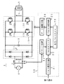
図10は前記電力変換装置の従来例を示す回路構成図であり、1は電力系統などの三相交流電源、2は電力変換装置、3は電力変換装置2の負荷としての例えばオゾン発生用の放電管である。
【0005】
この電力変換装置2には図示の如くダイオードを三相ブリッジ接続してなる整流回路11と、整流回路11の整流電圧を平滑するコンデンサ12と、コンデンサ12の両端電圧が入力され、この両端電圧を所望の交流電圧に変換するために図示の如くIGBTとダイオードの逆並列回路13a〜13dを単相ブリッジ接続してなるインバータ回路13と、制御装置20とを備えている。
【0006】
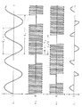
図10に示した電力変換装置2の動作と制御装置20の構成要素の動作を、図11に示す動作波形図を参照しつつ、以下に説明する。
【0007】
この電力変換装置2の負荷としての放電管3に対する放電電圧を維持しつつ、放電管3に供給する電力を所望の値にするために、図11に示す方形波状の高周波の交流電圧(v2 )をインバータ回路13から出力する期間と出力しない期間とを制御装置20を介してそれぞれ制御することにより、電力変換装置2が出力する平均電力が調整され、この平均電力を放電管3に供給するようにしている。
【0008】
また、三相交流電源1としての電力系統および該電力系統の他の機器への擾乱を軽減するために、前記方形波状の高周波の交流電圧v2 をインバータ回路13から出力する期間と出力しない期間とを加算した周期T0 (図11参照)と三相(すなわちM=3)交流電源1の基本波の周期TN (図11参照)との関係を2×K×M=TN /T0 ,(K=1,2,・・・、図11の波形図ではK=1)に設定している。
【0009】
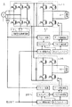
そこで制御装置20にはパルス数指令器21と、パルスカウンタ22と、出力パルスタイマ23と、リセット回路24と、パルス分配回路25と、ゲート駆動回路26とを備え、パルス数指令器21では外部より入力される放電管3に供給する電力指令に基づき、前記方形波状の高周波の交流電圧を出力する際の繰り返しサイクル数(a)を演算し、このサイクル数(a)をパルスカウンタ22のプリセット値とする。
【0010】
出力パルスタイマ23は前記方形波状の交流電圧の周波数を設定するタイマであり、ほぼ1対1の比率の論理「H」レベルと論理「L」レベルとを出力し、その合計期間T2 (図11参照)を有している。また、リセット回路24は三相交流電源1の基本波の周期TN の1/6倍を前記T0 とするリセット信号を、三相交流電源1の線間電圧(図11に示すvRS,vST,vTRを参照)の零クロス点それぞれにほぼ同期して出力するようにしている。
【0011】
従って、パルスカウンタ22では前記リセット信号が出力される毎にパルスカウンタ22を形成する計測カウンタをリセットして前記プリセット値aを読み込み、更に、パルス分配回路25における後述のパルス分配動作を開始させる。また、前記計測カウンタは出力パルスタイマ23の、例えば、論理「H」レベルの回数を計測し、この計測値と前記プリセット値とが一致し、このときの論理「H」レベルの次の論理「L」レベルが終了すると、パルス分配回路25における後述のパルス分配動作を停止させる停止信号を送出する。
【0012】
すなわち、パルス分配回路25では前記停止信号が出力されていないときの出力パルスタイマ23の論理レベルに対応し、例えば、論理「H」レベルのときにはインバータ回路13の前記逆並列回路13a,13dへのオン指令、13b,13cへのオフ指令を生成し、また、論理「L」レベルのときにはインバータ回路13の前記逆並列回路13b,13cへのオン指令、13a,13dへのオフ指令を生成し、これらをゲート駆動回路26へ送出する。ゲート駆動回路26では上述のオン指令,オフ指令に対応してインバータ回路13の前記逆並列回路13a〜13dそれぞれのIGBTへのゲート信号を生成する。
【0013】
上述の如く制御装置20が動作することにより、電力変換装置2から負荷としての放電管3への給電動作を三相交流電源1に同期させつつ、該給電動作の有無に無関係に、図11に示す如く、交流電源1からの相電流iR ,iS ,iT それぞれの変動を該電流の正極性時,負極性時共に抑制することができる。また、このときの電力変換装置2から放電管3へ供給される平均電力(PAV)は下記式(1)のように表される。
【0014】
PAV∝a・T2 /T0 …(1)
上記式(1)からも明らかなように、前記T0 をT2 に比して十分大きく設定することにより、パルス数指令器21における前記電力指令に対応したサイクル数aの値を大きく変化させることができ、その結果、平均電力PAVをほぼ連続的に可変させることができる。
【0015】
【特許文献1】
特開2001−119953号公報(第3頁,第3図)
【0016】
【発明が解決しようとする課題】
従来の電力変換装置2において、図11に示した動作波形図の例では前記T2 とT0 の比率を1:9に設定していることから、交流電源1の周波数が50Hzのときには前記交流電圧v2 の周波数が3kHz程度に設定した場合に対応する。すなわち、前記交流電圧v2 の周波数が3kHz以上であれば、前記式(1)で示した平均電力PAVも9段階以上に可変できる。しかしながら、電力変換装置2における図12に示した動作波形図のように、交流電源1の周波数が50Hzのときで前記交流電圧v2 の周波数が1kHz程度と低い場合には、前記T2 とT0 の比率が1:3程度となることから、前記式(1)で示す平均電力PAVが3段階にしか可変できず、この種の電力変換装置の用途に対して、前記平均電力PAVの可変範囲が十分とは言えないという問題があった。
【0017】
この発明の目的は、上記問題点を解決する電力変換装置の制御装置を提供することにある。
【0018】
【課題を解決するための手段】
この第1の発明は、交流電源の電圧を整流する整流回路とこの整流電圧を前記交流電源の周波数より高い周波数の交流電圧に変換するインバータ回路と制御装置とからなる電力変換装置において、
前記制御装置が前記インバータ回路を動作させて負荷に電力を供給する給電期間と該インバータ回路の動作を停止させる停止期間とを交互に繰り返す制御を行う際に、該給電期間と停止期間とを加算した周期(T0 )と前記交流電源の基本波の周期(TN )との関係を2×T0 =K×TN ,(K=3,5,7,・・・)に設定したことを特徴とする。
【0019】
また第2の発明は、多相(M相)交流電源の電圧を整流する整流回路とこの整流電圧を前記交流電源の周波数より高い周波数の交流電圧に変換するインバータ回路と制御装置とからなる電力変換装置において、
前記制御装置が前記インバータ回路を動作させて負荷に電力を供給する給電期間と該インバータ回路の動作を停止させる停止期間とを交互に繰り返す制御を行う際に、該給電期間と停止期間とを加算した周期(T0 )と前記M相交流電源の基本波の周期(TN )との関係を2×M×T0 =K×TN ,(K=2,3,4,・・・)に設定したことを特徴とする。
【0020】
また第3の発明は、交流電源の電圧を整流する整流回路とこの整流電圧を前記交流電源の周波数より高い周波数の交流電圧に変換する複数(L)台のインバータ回路および制御装置とからなる電力変換装置において、
前記制御装置それぞれが対応する前記インバータ回路それぞれを動作させてそれぞれの負荷に電力を供給する給電期間と該インバータ回路それぞれの動作を停止させる停止期間とを交互に繰り返す制御を行う際に、該インバータ回路それぞれにおける前記給電期間と停止期間とを加算した周期(T0 )それぞれと前記交流電源の基本波の周期(TN )との関係を2×T0 =K×TN ,(K=3,5,7,・・・)に設定し、更に、該インバータ回路それぞれの動作の間には順にT0 /Lなる時間差を持たせたことを特徴とする。
【0021】
また第4の発明は、多相(M相)交流電源の電圧を整流する整流回路とこの整流電圧を前記交流電源の周波数より高い周波数の交流電圧に変換する複数(L)台のインバータ回路および制御装置とからなる電力変換装置において、
前記制御装置それぞれが対応する前記インバータ回路それぞれを動作させてそれぞれの負荷に電力を供給する給電期間と前記インバータ回路それぞれの動作を停止させる停止期間とを交互に繰り返す制御を行う際に、該インバータ回路それぞれにおける前記給電期間と停止期間とを加算した周期(T0 )それぞれと前記M相交流電源の基本波の周期(TN )との関係を2×M×T0 =K×TN ,(K=2,3,4,・・・)に設定し、更に、該インバータ回路それぞれの動作の間には順にT0 /Lなる時間差を持たせたことを特徴とする。
【0022】
また第5の発明は、交流電源の電圧を整流する整流回路とこの整流電圧を前記交流電源の周波数より高い周波数の交流電圧に変換するインバータ回路と制御装置とが複数(P)組からなる電力変換装置において、
前記制御装置それぞれが対応する前記インバータ回路それぞれを動作させてそれぞれの負荷に電力を供給する給電期間と該インバータ回路それぞれの動作を停止させる停止期間とを交互に繰り返す制御を行う際に、該インバータ回路それぞれにおける前記給電期間と停止期間とを加算した周期(T0 )それぞれと前記交流電源の基本波の周期(TN )との関係を2×T0 =K×TN ,(K=3,5,7,・・・)に設定し、更に、該インバータ回路それぞれの動作の間には順にT0 /Pなる時間差を持たせたことを特徴とする。
【0023】
さらに第6の発明は、多相(M相)交流電源の電圧を整流する整流回路とこの整流電圧を前記交流電源の周波数より高い周波数の交流電圧に変換するインバータ回路と制御装置とが複数(P)組からなる電力変換装置において、
前記制御装置それぞれが対応する前記インバータ回路それぞれを動作させてそれぞれの負荷に電力を供給する給電期間と前記インバータ回路それぞれの動作を停止させる停止期間とを交互に繰り返す制御を行う際に、該インバータ回路それぞれにおける前記給電期間と停止期間とを加算した周期(T0 )それぞれと前記M相交流電源の基本波の周期(TN )との関係を2×M×T0 =K×TN ,(K=2,3,4,・・・)に設定し、更に、該インバータ回路それぞれの動作の間には順にT0 /Pなる時間差を持たせたことを特徴とする。
【0024】
この発明によれば、前記インバータ回路が出力し、負荷に印加される交流電圧の周波数が比較的低い場合にも、該負荷に供給される平均電力をより広く変化させることができると共に、このとき、前記交流電源から前記電力変換装置への電流の変動を該交流電源の数周期で平準化することにより、前記交流電源としての電力系統および該電力系統の他の機器への擾乱を軽減することができる。
【0025】
【発明の実施の形態】
図1は、この発明の第1の実施例を示す電力変換装置の回路構成図であり、図10に示した従来例回路と同一機能を有するものには同一符号を付して、ここではその説明を省略する。
【0026】
すなわち、図1に示した電力変換装置5の回路構成では従来の電力変換装置2に対して、交流電源が単相交流電源4に代わったことから、ダイオードを単相ブリッジ接続した整流回路14になり、また、制御装置50では従来の制御装置20のリセット回路24がリセット回路51に置き換わっている。
【0027】
図1に示した電力変換装置5の動作を、図2に示す動作波形図を参照しつつ、以下に説明する。
【0028】
この電力変換装置5において、単相交流電源4としての電力系統および該電力系統の他の機器への擾乱を軽減するために、図2に示す方形波状の高周波の交流電圧v2 をインバータ回路13から出力する期間と出力しない期間とを加算した周期T0 (図2参照)と単相交流電源4の基本波の周期TN (図2参照)との関係を2×T0 =K×TN ,(K=3,5,7,・・・、図2の波形図ではK=3)に設定している。
【0029】
そこで制御装置50のリセット回路51では、単相交流電源4の基本波の周期TN の3/2倍を前記T0 とするリセット信号を単相交流電源4の電圧v1 (図2参照)の零クロス点にほぼ同期して出力するようにしている。
【0030】
その結果、単相交流電源4の1周期(=TN )では、図2に示すように電力変換装置5への電流i1 は変動するが、この単相交流電源4の3周期では、図2に示すように前記電流i1 の正極性時,負極性時共に平準化される。また、図2に示した動作波形図の例では前記T2 とT0 の比率を1:18に設定していることから、単相交流電源4の周波数が50Hzのときには前記交流電圧v2 の周波数が600Hz程度に設定した場合に対応している。従って、この図からも明らかなように、前記交流電圧v2 の周波数が1kHz以上であれば、前記式(1)で示した平均電力PAVも30段階以上に可変できる。
【0031】
この電力変換装置5において、上述の周期T0 と周期TN との関係をT0 の2倍をTN のK(K=3,5,7,・・・)倍にして、単相交流電源4の基本波の位相と同期させることは、単相交流電源4からの電流i1 の正極性時,負極性時共に平準化することを目的としており、仮に、Kが偶数であると、前記T0 とTN のK/2倍が同期するために、前記電流i1 の正極性時,負極性時の双方に対する平準化が出来なくなる。
【0032】
図3は、この発明の第2の実施例を示す電力変換装置の回路構成図であり、図10に示した従来例回路と同一機能を有するものには同一符号を付して、ここではその説明を省略する。
【0033】
すなわち、図3に示した電力変換装置6の制御装置60では、従来の制御装置20におけるリセット回路24をリセット回路61に置き換えている。
【0034】
図3に示した電力変換装置6の動作を、図4に示す動作波形図を参照しつつ、以下に説明する。
【0035】
この電力変換装置6において、三相交流電源1としての電力系統および該電力系統の他の機器への擾乱を軽減するために、図4に示す方形波状の高周波の交流電圧v2 をインバータ回路13から出力する期間と出力しない期間とを加算した周期T0 (図4参照)と三相(すなわち、M=3)交流電源1の基本波の周期TN (図4参照)との関係を2×M×T0 =K×TN ,(K=2,3,4,・・・、図4の波形図ではK=8)に設定している。
【0036】
そこで、この制御装置60のリセット回路61では、三相交流電源1の基本波の周期TN の4/3(8/6)倍を前記T0 とするリセット信号を三相交流電源1の線間電圧(図4に示すvRS,vST,vTRを参照)のいずれかの零クロス点にほぼ同期して出力するようにしている。
【0037】
その結果、三相交流電源1の1周期(=TN )では図4に示すように電力変換装置6への電流iR ,iS ,iT は変動するが、この三相交流電源1の4周期では図4に示すように前記電流iR ,iS ,iT それぞれは平準化される。また、図4に示した動作波形図の例では前記T2 とT0 の比率を1:16に設定していることから、三相交流電源1の周波数が50Hzのときには前記交流電圧v2 の周波数が600Hz程度に設定した場合に対応している。従って、この図からも明らかなように、前記交流電圧v2 の周波数が1kHz以上であれば、前記式(1)で示した平均電力PAVも26段階以上に可変できる。
【0038】
この電力変換装置6において、上述の周期T0 と周期TN との関係をT0 の2×M倍をTN のK(K=2,3,4,・・・)倍にして、三相(すなわち、M=3)交流電源1の基本波の位相と同期させることは、三相交流電源1からの電流iR ,iS ,iT それぞれの正極性時,負極性時共に平準化することを目的としている。
【0039】
ただし、前記Kが偶数のときには、M×T0 =(K/2)×TN の場合も、三相交流電源1からの電流iR ,iS ,iT それぞれの正極性時,負極性時共に平準化することが可能である。このときには前記T0 のM倍が三相交流電源1の周期TN のK/2倍に同期することとなり、前記電流iR ,iS ,iT それぞれにおいて、時間的位相が360°/M,(360°/M)×2,・・・・(360°/M)×MずれたM個を平均すると零となるため、前記電流iR ,iS ,iT それぞれの正極性時,負極性時共に平準化することができる。
【0040】
さらに、前記Mが2×[素数]で、前記Kが4の倍数のときには、(M/2)×T0 =(K/4)×TN の場合も、三相交流電源1からの電流iR ,iS ,iT それぞれ同士およびそれぞれの正極性時,負極性時共に平準化することが可能である。このときには前記M相交流電源は[M/2]相交流電源の各相の電流それぞれに対して、全く逆向きに流れる相の電流を加えてM相交流電源となっている。そのため、前記電流iR ,iS ,iT それぞれにおいて、時間的位相が360°/M,(360°/M)×2,・・・・(360°/M)×MずれたM個に対して、前記相数の半分の[M/2]相交流電源の各相の電流も平均すると零となり、さらに、前記M個の各相の電流も平均すると零となるため、前記電流iR ,iS ,iT それぞれの正極性時,負極性時共に平準化することができる。
【0041】
図5は、この発明の第3の実施例を示す電力変換装置の回路構成図であり、図1に示した実施例回路と同一機能を有するものには同一符号を付して、ここではその説明を省略する。
【0042】
すなわち、図5に示した電力変換装置7の回路構成では上述の電力変換装置5に対して、コンデンサ12,インバータ回路13,整流回路14の約2倍の出力容量の整流回路70の他に、コンデンサ12と同一機能のコンデンサ15,インバータ回路13と同一機能のインバータ回路16が追加され、また、制御装置71と制御装置73とを備え、この制御装置71では前述の制御装置50におけるリセット回路51をリセット回路72に、制御装置73では前述の制御装置50におけるリセット回路51をリセット回路74にそれぞれ置き換え、さらに、インバータ回路16の出力には放電管10が接続されている。
【0043】
図5に示した電力変換装置7の動作を、図6に示す動作波形図を参照しつつ、以下に説明する。
【0044】
この電力変換装置7において、単相交流電源4としての電力系統および該電力系統の他の機器への擾乱を軽減するために、図6に示す方形波状の高周波の交流電圧v2 および交流電圧v3 をインバータ回路13およびインバータ回路16からそれぞれ出力する期間と出力しない期間とを加算した周期T0 (図6参照)と単相交流電源4の基本波の周期TN (図6参照)との関係を2×T0 =K×TN ,(K=3,5,7,・・・、図6の波形図ではK=3)に設定し、更に、インバータ回路13およびインバータ回路16それぞれの動作の間にはT0 /2(すなわち、L=2)なる時間差を持たせている。
【0045】
そこで制御装置71のリセット回路72では、単相交流電源4の基本波の周期TN の3/2倍を前記T0 とするリセット信号を単相交流電源4の電圧v1 (図6参照)の零クロス点にほぼ同期して出力するようにしている。更に、制御装置73のリセット回路74では、上述のリセット回路72と同様の動作をT0 /2だけ遅れて行うようにしている。
【0046】
その結果、単相交流電源4の1周期(=TN )では図6に示すように電力変換装置7への電流i1 は変動するが、この単相交流電源4の3周期では図6に示すように前記電流i1 の正極性時,負極性時共に、上述の電力変換装置5に比してより平準化される。また、図6に示した動作波形図の例では前記T2 とT0 の比率を1:18に設定していることから、交流電源4の周波数が50Hzのときには前記交流電圧v2 および交流電圧v3 の周波数が600Hz程度に設定した場合に対応している。従って、図6からも明らかなように、前記交流電圧v2 および交流電圧v3 の周波数が1kHz以上であれば、前記式(1)で示したそれぞれの平均電力PAVも30段階以上に可変できる。
【0047】
図7は、この発明の第4の実施例を示す電力変換装置の回路構成図であり、図3に示した実施例回路と同一機能を有するものには同一符号を付して、ここではその説明を省略する。
【0048】
すなわち、図7に示した電力変換装置8の回路構成では上述の電力変換装置6に対して、整流回路11の約2倍の出力容量の整流回路80,コンデンサ12,インバータ回路13の他に、コンデンサ12と同一機能のコンデンサ15,インバータ回路13と同一機能のインバータ回路16が追加され、また、制御装置81と制御装置83とを備え、この制御装置81では前述の制御装置60におけるリセット回路61をリセット回路82に、制御装置83では前述の制御装置60におけるリセット回路61をリセット回路84にそれぞれ置き換え、更に、インバータ回路16の出力には放電管10が接続されている。
【0049】
図7に示した電力変換装置8の動作を、図8に示す動作波形図を参照しつつ、以下に説明する。
【0050】
この電力変換装置8において、三相交流電源1としての電力系統および該電力系統の他の機器への擾乱を軽減するために、図8に示す方形波状の高周波の交流電圧v2 および交流電圧v3 をインバータ回路13およびインバータ回路16からそれぞれ出力する期間と出力しない期間とを加算した周期T0 (図8参照)と三相(すなわち、M=3)交流電源1の基本波の周期TN (図8参照)との関係を2×M×T0 =K×TN ,(K=2,3,4,・・・、図8の波形図ではK=8)に設定し、更に、インバータ回路13およびインバータ回路16それぞれの動作の間にはT0 /2(すなわち、L=2)なる時間差を持たせている。
【0051】
そこで、この制御装置81のリセット回路82では、三相交流電源1の基本波の周期TN の4/3(8/6)倍を前記T0 とするリセット信号を三相交流電源1の線間電圧(図8に示すvRS,vST,vTRを参照)のいずれかの零クロス点にほぼ同期して出力するようにしている。更に、制御装置83のリセット回路84では、上述のリセット回路82と同様の動作をT0 /2だけ遅れて行うようにしている。
【0052】
その結果、三相交流電源1の1周期(=TN )では図8に示すように電力変換装置8への電流iR ,iS ,iT は変動するが、この三相交流電源1の2周期では図8に示すように前記電流iR ,iS ,iT それぞれは上述の電力変換装置6に比してより平準化される。また、図8に示した動作波形図の例では前記T2 とT0 の比率を1:16に設定していることから、三相交流電源1の周波数が50Hzのときには前記交流電圧v2 の周波数が600Hz程度に設定した場合に対応している。従って、この図からも明らかなように、前記交流電圧v2 の周波数が1kHz以上であれば、前記式(1)で示した平均電力PAVも26段階以上に可変できる。
【0053】
図9は、この発明の第5の実施例を示す電力変換装置の回路構成図であり、図7に示した実施例回路と同一機能を有するものには同一符号を付して、ここではその説明を省略する。
【0054】
すなわち、図9に示した電力変換装置9の回路構成では上述の電力変換装置8に対して、整流回路11がIGBTとダイオードの逆並列回路を三相ブリッジ接続した自励式整流回路17と、この自励式整流回路17の動作を制御する自励整流器制御回路18とに置き換わっている。
【0055】
従って、図9に示した電力変換装置9の動作は上述の電力変換装置8と同様であり、さらに、この電力変換装置9では三相交流電源1からの電流が正弦波状の波形となって該電流の高調波成分が低減し、また、三相交流電源1から見た基本波の力率をほぼ1にすることができ、三相交流電源1としての電力系統および該電力系統の他の機器への擾乱をより軽減することができるので、従って、大容量のこの種の電力変換装置に適用される。
【0056】
図13は、この発明の第6の実施例を示す電力変換装置の回路構成図であり、図1,図5に示した実施例回路と同一機能を有するものには同一符号を付して、ここではその説明を省略する。
【0057】
すなわち、図13に示した電力変換装置30の回路構成では上述の電力変換装置5に対して、コンデンサ12,インバータ回路13,整流回路14の他に、これらと同一仕様のコンデンサ15,インバータ回路16,整流回路31が追加され、また、制御装置71と制御装置73とを備え、この制御装置71では前述の制御装置50におけるリセット回路51をリセット回路72に、制御装置73では前述の制御装置50におけるリセット回路51をリセット回路74にそれぞれ置き換え、さらに、インバータ回路16の出力には放電管10が接続されている。
【0058】
この電力変換装置30において、単相交流電源4としての電力系統および該電力系統の他の機器への擾乱を軽減するために、先述の方形波状の高周波の交流電圧v2 および交流電圧v3 をインバータ回路13およびインバータ回路16からそれぞれ出力する期間と出力しない期間とを加算した周期T0 と単相交流電源4の基本波の周期TN との関係を2×T0 =K×TN ,(K=3,5,7,・・・)に設定し、更に、インバータ回路13およびインバータ回路16それぞれの動作の間にはT0 /2(すなわち、P=2)なる時間差を持たせている。
【0059】
そこで制御装置71のリセット回路72では、単相交流電源4の基本波の周期TN のK/2倍を前記T0 とするリセット信号を単相交流電源4の電圧v1 の零クロス点にほぼ同期して出力するようにしている。更に、制御装置73のリセット回路74では、上述のリセット回路72と同様の動作をT0 /2だけ遅れて行うようにしている。
【0060】
その結果、単相交流電源4の1周期(=TN )では電力変換装置30への電流i1 は変動するが、この単相交流電源4では前記電流i1 の正極性時,負極性時共に、例えば前記K=3としたときには図6に示した電力変換装置7の特性図と同様に、電力変換装置5に比してより平準化される。
【0061】
図14は、この発明の第7の実施例を示す電力変換装置の回路構成図であり、図3,図7に示した実施例回路と同一機能を有するものには同一符号を付して、ここではその説明を省略する。
【0062】
すなわち、図14に示した電力変換装置40の回路構成では上述の電力変換装置6に対して、整流回路11,コンデンサ12,インバータ回路13の他に、これらと同一仕様の整流回路41,コンデンサ15,インバータ回路16が追加され、また、制御装置81と制御装置83とを備え、この制御装置81では前述の制御装置60におけるリセット回路61をリセット回路82に、制御装置83では前述の制御装置60におけるリセット回路61をリセット回路84にそれぞれ置き換え、更に、インバータ回路16の出力には放電管10が接続されている。
【0063】
この電力変換装置40において、三相交流電源1としての電力系統および該電力系統の他の機器への擾乱を軽減するために、先述の方形波状の高周波の交流電圧v2 および交流電圧v3 をインバータ回路13およびインバータ回路16からそれぞれ出力する期間と出力しない期間とを加算した周期T0 と三相(すなわち、M=3)交流電源1の基本波の周期TN との関係を2×M×T0 =K×TN ,(K=2,3,4,・・・)に設定し、更に、インバータ回路13およびインバータ回路16それぞれの動作の間にはT0 /2(すなわち、P=2)なる時間差を持たせている。
【0064】
そこで、この制御装置81のリセット回路82では、三相交流電源1の基本波の周期TN のK/6倍を前記T0 とするリセット信号を三相交流電源1の線間電圧vRS,vST,vTRのいずれかの零クロス点にほぼ同期して出力するようにしている。更に、制御装置83のリセット回路84では、上述のリセット回路82と同様の動作をT0 /2だけ遅れて行うようにしている。
【0065】
その結果、三相交流電源1の1周期(=TN )では電力変換装置40への電流iR ,iS ,iT は変動するが、この三相交流電源1の2周期では電流iR ,iS ,iT それぞれは、例えば前記K=8としたときには図8に示した電力変換装置8の特性図と同様に、上述の電力変換装置6に比してより平準化される。
【0066】
【発明の効果】
この発明の電力変換装置、すなわち、パルス密度変調式インバータによれば、その出力周期を前記インバータの交流電源の位相と同期させることにより、前記交流電源の電流の変動を該交流電源の数周期で平準化でき、また、前記電流の脈動周期を前記交流電源の数周期とすることができるため、前記交流電源としての電力系統および該電力系統の他の機器への擾乱を軽減することが可能である。
【0067】
また、前記インバータ回路を複数(L)台並列接続する場合には、その出力動作開始時点を[出力1周期/L]毎の時間差を持たせることにより、前記交流電源からの電流の変動をより小さくでき、また、その変動周期およびこの変動の脈動周期をより短い周期にできるため、このインバータの設置に伴う前記電力系統に、新たな高調波抑制機器の追加設置を不要にすることが可能となる。
【0068】
また、前記整流回路,コンデンサ,インバータ回路を複数(P)組を備える場合には、その出力動作開始時点を[出力1周期/P]毎の時間差を持たせることにより、前記交流電源からの電流の変動をより小さくでき、また、その変動周期およびこの変動の脈動周期をより短い周期にできるため、このインバータの設置に伴う前記電力系統に、新たな高調波抑制機器の追加設置を不要にすることが可能となる。また、この回路構成では前記整流回路とインバータ回路とを同一モジュール化することが容易であり、その結果、この電力変換装置としてのパルス密度変調式インバータの標準回路化とコスト低減が可能となる。
【図面の簡単な説明】
【図1】この発明の第1の実施例を示す電力変換装置の回路構成図
【図2】図1の動作を説明する波形図
【図3】この発明の第2の実施例を示す電力変換装置の回路構成図
【図4】図3の動作を説明する波形図
【図5】この発明の第3の実施例を示す電力変換装置の回路構成図
【図6】図5の動作を説明する波形図
【図7】この発明の第4の実施例を示す電力変換装置の回路構成図
【図8】図7の動作を説明する波形図
【図9】この発明の第5の実施例を示す電力変換装置の回路構成図
【図10】従来例を示す電力変換装置の回路構成図
【図11】図10の動作を説明する波形図
【図12】図10の動作を説明する波形図
【図13】この発明の第6の実施例を示す電力変換装置の回路構成図
【図14】この発明の第7の実施例を示す電力変換装置の回路構成図
【符号の説明】
1…三相交流電源、2,5〜9,30,40…電力変換装置、3,10…放電管、4…単相交流電源、11,14,31,41,70,80…整流回路、12,15…コンデンサ、13,16…インバータ回路、17…自励式整流回路、18…自励整流器制御回路、20,50,60,71,73,81,83…制御装置、21…パルス数指令器、22…パルスカウンタ、23…出力パルスタイマ、24,51,61,72,74,82,84…リセット回路、25…パルス分配回路、26…ゲート駆動回路。[0001]
TECHNICAL FIELD OF THE INVENTION
The present invention provides a power converter including a rectifier circuit for rectifying a voltage of an AC power supply, an inverter circuit for converting the rectified voltage to an AC voltage having a frequency higher than the frequency of the AC power supply, and a control device, wherein the inverter circuit operates. The present invention relates to a control device for a power conversion device that performs control to alternately repeat a power supply period for supplying power to a load and a stop period for stopping the operation of the inverter circuit.
[0002]
[Prior art]
This type of power converter is used, for example, as a power source for a discharge tube for generating ozone, and is generally called a pulse density modulation type inverter. Further, there is known a power system as an AC power supply for supplying power to the power conversion device and a control method for reducing disturbance to other devices of the power system (for example, see Patent Document 1).
[0003]
The conventional power converter including
[0004]
FIG. 10 is a circuit configuration diagram showing a conventional example of the power converter, wherein 1 is a three-phase AC power supply such as a power system, 2 is a power converter, and 3 is a load of the
[0005]
As shown, a rectifier circuit 11 in which diodes are connected in a three-phase bridge, a
[0006]
The operation of the
[0007]
In order to maintain the discharge voltage for the
[0008]
Further, in order to reduce disturbance to the power system as the three-phase
[0009]
Therefore, the
[0010]
The
[0011]
Therefore, the
[0012]
In other words, the
[0013]
By operating the
[0014]
P AV ∝a ・ T 2 / T 0 … (1)
As is clear from the above equation (1), the T 0 To T 2 , The value of the cycle number a corresponding to the power command in the
[0015]
[Patent Document 1]
JP 2001-119553 A (
[0016]
[Problems to be solved by the invention]
In the
[0017]
An object of the present invention is to provide a control device for a power converter that solves the above problems.
[0018]
[Means for Solving the Problems]
The first invention is a power converter including a rectifier circuit for rectifying a voltage of an AC power supply, an inverter circuit for converting the rectified voltage to an AC voltage having a frequency higher than the frequency of the AC power supply, and a control device.
When the control device performs control to alternately repeat a power supply period for supplying power to a load by operating the inverter circuit and a stop period for stopping the operation of the inverter circuit, the power supply period and the stop period are added. Cycle (T 0 ) And the period of the fundamental wave (T N ) And 2 × T 0 = K × T N , (K = 3, 5, 7,...).
[0019]
According to a second aspect of the present invention, there is provided a rectifier circuit for rectifying a voltage of a multi-phase (M-phase) AC power supply, an inverter circuit for converting the rectified voltage into an AC voltage having a frequency higher than the frequency of the AC power supply, and a control device. In the conversion device,
When the control device performs control to alternately repeat a power supply period for supplying power to a load by operating the inverter circuit and a stop period for stopping the operation of the inverter circuit, the power supply period and the stop period are added. Cycle (T 0 ) And the period (T) of the fundamental wave of the M-phase AC power supply. N ) Is 2 × M × T 0 = K × T N , (K = 2, 3, 4,...).
[0020]
According to a third aspect of the present invention, there is provided a power supply comprising: a rectifier circuit for rectifying a voltage of an AC power supply; and a plurality (L) of inverter circuits and a control device for converting the rectified voltage to an AC voltage having a frequency higher than the frequency of the AC power supply. In the conversion device,
When performing control to alternately repeat a power supply period for supplying power to each load by operating each of the inverter circuits corresponding to each of the control devices and a stop period for stopping the operation of each of the inverter circuits, A cycle (T) obtained by adding the power supply period and the suspension period in each circuit. 0 ) And the period of the fundamental wave (T N ) And 2 × T 0 = K × T N , (K = 3, 5, 7,...), And T is sequentially set between operations of the inverter circuits. 0 / L.
[0021]
According to a fourth aspect of the present invention, there is provided a rectifier circuit for rectifying a voltage of a multi-phase (M-phase) AC power supply, a plurality of (L) inverter circuits for converting the rectified voltage to an AC voltage having a frequency higher than the frequency of the AC power supply, and In a power conversion device including a control device,
When performing control to alternately repeat a power supply period for supplying power to each load by operating each of the inverter circuits corresponding to each of the control devices and a stop period for stopping the operation of each of the inverter circuits, A cycle (T) obtained by adding the power supply period and the suspension period in each circuit. 0 ) And the period of the fundamental wave (T N ) Is 2 × M × T 0 = K × T N , (K = 2, 3, 4,...), And T is sequentially set between operations of the inverter circuits. 0 / L.
[0022]
According to a fifth aspect of the present invention, there is provided a power supply comprising a plurality (P) sets of a rectifier circuit for rectifying a voltage of an AC power supply, an inverter circuit for converting the rectified voltage to an AC voltage having a frequency higher than the frequency of the AC power supply, and a control device. In the conversion device,
When performing control to alternately repeat a power supply period for supplying power to each load by operating each of the inverter circuits corresponding to each of the control devices and a stop period for stopping the operation of each of the inverter circuits, A cycle (T) obtained by adding the power supply period and the suspension period in each circuit. 0 ) And the period of the fundamental wave (T N ) And 2 × T 0 = K × T N , (K = 3, 5, 7,...), And T is sequentially set between operations of the inverter circuits. 0 / P time difference.
[0023]
According to a sixth aspect of the present invention, there is provided a rectifier circuit for rectifying a voltage of a multi-phase (M-phase) AC power supply, an inverter circuit for converting the rectified voltage to an AC voltage having a frequency higher than the frequency of the AC power supply, and a plurality of control devices. P) In a power converter comprising a set,
When performing control to alternately repeat a power supply period for supplying power to each load by operating each of the inverter circuits corresponding to each of the control devices and a stop period for stopping the operation of each of the inverter circuits, A cycle (T) obtained by adding the power supply period and the suspension period in each circuit. 0 ) And the period of the fundamental wave (T N ) Is 2 × M × T 0 = K × T N , (K = 2, 3, 4,...), And T is sequentially set between operations of the inverter circuits. 0 / P time difference.
[0024]
According to the present invention, even when the frequency of the AC voltage output from the inverter circuit and applied to the load is relatively low, the average power supplied to the load can be changed more widely. By leveling the fluctuation of the current from the AC power supply to the power converter in several cycles of the AC power supply, it is possible to reduce disturbance to the power system as the AC power supply and other devices of the power system. Can be.
[0025]
BEST MODE FOR CARRYING OUT THE INVENTION
FIG. 1 is a circuit diagram of a power converter showing a first embodiment of the present invention. Components having the same functions as those of the conventional circuit shown in FIG. Description is omitted.
[0026]
That is, in the circuit configuration of the
[0027]
The operation of the
[0028]
In the
[0029]
Therefore, in the reset circuit 51 of the control device 50, the cycle T of the fundamental wave of the single-phase
[0030]
As a result, one cycle of the single-phase AC power supply 4 (= T N ), The current i to the
[0031]
In this
[0032]
FIG. 3 is a circuit diagram of a power converter according to a second embodiment of the present invention. Components having the same functions as those of the conventional circuit shown in FIG. Description is omitted.
[0033]
That is, in the control device 60 of the
[0034]
The operation of the
[0035]
In this
[0036]
Therefore, in the reset circuit 61 of the control device 60, the period T of the fundamental wave of the three-phase
[0037]
As a result, one cycle of the three-phase AC power supply 1 (= T N In FIG. 4, the current i to the
[0038]
In this
[0039]
However, when K is an even number, M × T 0 = (K / 2) × T N , The current i from the three-phase
[0040]
Further, when the M is 2 × [prime number] and the K is a multiple of 4, (M / 2) × T 0 = (K / 4) × T N , The current i from the three-phase
[0041]
FIG. 5 is a circuit configuration diagram of a power converter showing a third embodiment of the present invention. Components having the same functions as those of the circuit of the embodiment shown in FIG. Description is omitted.
[0042]
That is, in the circuit configuration of the
[0043]
The operation of the
[0044]
In the
[0045]
Therefore, in the reset circuit 72 of the control device 71, the cycle T of the fundamental wave of the single-phase
[0046]
As a result, one cycle of the single-phase AC power supply 4 (= T N In FIG. 6), as shown in FIG. 1 Varies in the three cycles of the single-phase
[0047]
FIG. 7 is a circuit diagram of a power converter showing a fourth embodiment of the present invention. Components having the same functions as those of the embodiment shown in FIG. Description is omitted.
[0048]
That is, in the circuit configuration of the
[0049]
The operation of the
[0050]
In this
[0051]
Therefore, in the reset circuit 82 of the control device 81, the cycle T of the fundamental wave of the three-phase
[0052]
As a result, one cycle of the three-phase AC power supply 1 (= T N In FIG. 8, the current i to the
[0053]
FIG. 9 is a circuit configuration diagram of a power conversion device showing a fifth embodiment of the present invention. Components having the same functions as those of the embodiment circuit shown in FIG. Description is omitted.
[0054]
That is, in the circuit configuration of the
[0055]
Therefore, the operation of the
[0056]
FIG. 13 is a circuit configuration diagram of a power conversion device showing a sixth embodiment of the present invention, in which components having the same functions as those of the embodiment shown in FIGS. Here, the description is omitted.
[0057]
That is, in the circuit configuration of the
[0058]
In the
[0059]
Therefore, in the reset circuit 72 of the control device 71, the cycle T of the fundamental wave of the single-phase
[0060]
As a result, one cycle of the single-phase AC power supply 4 (= T N ) Indicates the current i to the
[0061]
FIG. 14 is a circuit configuration diagram of a power converter showing a seventh embodiment of the present invention. Components having the same functions as those of the embodiment shown in FIGS. Here, the description is omitted.
[0062]
That is, in the circuit configuration of the
[0063]
In the
[0064]
Therefore, in the reset circuit 82 of the control device 81, the cycle T of the fundamental wave of the three-phase
[0065]
As a result, one cycle of the three-phase AC power supply 1 (= T N ) Indicates the current i to the
[0066]
【The invention's effect】
According to the power conversion device of the present invention, that is, according to the pulse density modulation type inverter, the output cycle is synchronized with the phase of the AC power supply of the inverter, so that the fluctuation of the current of the AC power supply is performed in several cycles of the AC power supply. Since the leveling can be performed and the pulsation cycle of the current can be set to several cycles of the AC power supply, it is possible to reduce disturbance to the power system as the AC power source and other devices of the power system. is there.
[0067]
Further, when a plurality (L) of the inverter circuits are connected in parallel, the output operation start time is given a time difference for every [one cycle of output / L] so that the fluctuation of the current from the AC power supply can be reduced. Since it is possible to reduce the fluctuation period and the pulsation period of the fluctuation to a shorter period, it is possible to eliminate the need for additional installation of a new harmonic suppression device in the power system associated with the installation of the inverter. Become.
[0068]
When a plurality (P) sets of the rectifier circuit, the capacitor, and the inverter circuit are provided, the output operation start time is set to have a time difference for every [one cycle of output / P] so that the current from the AC power supply is changed. Can be made smaller, and its fluctuation period and the pulsation period of this fluctuation can be made shorter. Therefore, it is not necessary to additionally install a new harmonic suppression device in the power system accompanying the installation of the inverter. It becomes possible. Further, in this circuit configuration, it is easy to integrate the rectifier circuit and the inverter circuit into the same module. As a result, it is possible to make a pulse density modulation type inverter as a power conversion device into a standard circuit and reduce the cost.
[Brief description of the drawings]
FIG. 1 is a circuit configuration diagram of a power converter showing a first embodiment of the present invention.
FIG. 2 is a waveform chart illustrating the operation of FIG.
FIG. 3 is a circuit configuration diagram of a power converter showing a second embodiment of the present invention.
FIG. 4 is a waveform diagram illustrating the operation of FIG.
FIG. 5 is a circuit configuration diagram of a power converter showing a third embodiment of the present invention.
FIG. 6 is a waveform chart for explaining the operation of FIG. 5;
FIG. 7 is a circuit configuration diagram of a power converter showing a fourth embodiment of the present invention.
FIG. 8 is a waveform chart for explaining the operation of FIG. 7;
FIG. 9 is a circuit configuration diagram of a power converter showing a fifth embodiment of the present invention.
FIG. 10 is a circuit configuration diagram of a power converter showing a conventional example.
FIG. 11 is a waveform chart illustrating the operation of FIG.
FIG. 12 is a waveform chart illustrating the operation of FIG.
FIG. 13 is a circuit configuration diagram of a power converter showing a sixth embodiment of the present invention.
FIG. 14 is a circuit configuration diagram of a power converter showing a seventh embodiment of the present invention.
[Explanation of symbols]
DESCRIPTION OF
Claims (6)
前記制御装置が前記インバータ回路を動作させて負荷に電力を供給する給電期間と該インバータ回路の動作を停止させる停止期間とを交互に繰り返す制御を行う際に、該給電期間と停止期間とを加算した周期(T0 )と前記交流電源の基本波の周期(TN )との関係を2×T0 =K×TN ,(K=3,5,7,・・・)に設定したことを特徴とする電力変換装置の制御装置。In a power converter comprising a rectifier circuit for rectifying the voltage of the AC power supply, an inverter circuit for converting the rectified voltage to an AC voltage having a frequency higher than the frequency of the AC power supply, and a control device,
When the control device performs control to alternately repeat a power supply period for supplying power to a load by operating the inverter circuit and a stop period for stopping the operation of the inverter circuit, the power supply period and the stop period are added. The relationship between the calculated cycle (T 0 ) and the cycle (T N ) of the fundamental wave of the AC power supply is set to 2 × T 0 = K × TN , (K = 3, 5, 7,...) A control device for a power conversion device, comprising:
前記制御装置が前記インバータ回路を動作させて負荷に電力を供給する給電期間と該インバータ回路の動作を停止させる停止期間とを交互に繰り返す制御を行う際に、該給電期間と停止期間とを加算した周期(T0 )と前記M相交流電源の基本波の周期(TN )との関係を2×M×T0 =K×TN ,(K=2,3,4,・・・)に設定したことを特徴とする電力変換装置の制御装置。In a power converter including a rectifier circuit for rectifying a voltage of a polyphase (M-phase) AC power supply, an inverter circuit for converting the rectified voltage to an AC voltage having a frequency higher than the frequency of the AC power supply, and a control device,
When the control device performs control to alternately repeat a power supply period for supplying power to a load by operating the inverter circuit and a stop period for stopping the operation of the inverter circuit, the power supply period and the stop period are added. The relationship between the calculated period (T 0 ) and the period (T N ) of the fundamental wave of the M-phase AC power supply is expressed as 2 × M × T 0 = K × T N , (K = 2, 3, 4,...) A control device for a power conversion device, wherein the control device is set to:
前記制御装置それぞれが対応する前記インバータ回路それぞれを動作させてそれぞれの負荷に電力を供給する給電期間と該インバータ回路それぞれの動作を停止させる停止期間とを交互に繰り返す制御を行う際に、該インバータ回路それぞれにおける前記給電期間と停止期間とを加算した周期(T0 )それぞれと前記交流電源の基本波の周期(TN )との関係を2×T0 =K×TN ,(K=3,5,7,・・・)に設定し、更に、該インバータ回路それぞれの動作の間には順にT0 /Lなる時間差を持たせたことを特徴とする電力変換装置の制御装置。In a power converter including a rectifier circuit for rectifying a voltage of an AC power supply, a plurality of (L) inverter circuits for converting the rectified voltage to an AC voltage having a frequency higher than the frequency of the AC power supply, and a control device,
When performing control to alternately repeat a power supply period for supplying power to each load by operating each of the inverter circuits corresponding to each of the control devices and a stop period for stopping the operation of each of the inverter circuits, The relationship between the cycle (T 0 ) obtained by adding the power supply period and the stop period in each circuit and the cycle (T N ) of the fundamental wave of the AC power supply is 2 × T 0 = K × TN , (K = 3 , 5, 7,...), And a time difference of T 0 / L is sequentially provided between operations of the inverter circuits.
前記制御装置それぞれが対応する前記インバータ回路それぞれを動作させてそれぞれの負荷に電力を供給する給電期間と前記インバータ回路それぞれの動作を停止させる停止期間とを交互に繰り返す制御を行う際に、該インバータ回路それぞれにおける前記給電期間と停止期間とを加算した周期(T0 )それぞれと前記M相交流電源の基本波の周期(TN )との関係を2×M×T0 =K×TN ,(K=2,3,4,・・・)に設定し、更に、該インバータ回路それぞれの動作の間には順にT0 /Lなる時間差を持たせたことを特徴とする電力変換装置の制御装置。A power converter comprising a rectifier circuit for rectifying a voltage of a multi-phase (M-phase) AC power supply, and a plurality (L) of inverter circuits and a control device for converting the rectified voltage to an AC voltage having a frequency higher than the frequency of the AC power supply. In the device,
When performing control to alternately repeat a power supply period for supplying power to each load by operating each of the inverter circuits corresponding to each of the control devices and a stop period for stopping the operation of each of the inverter circuits, The relationship between each cycle (T 0 ) obtained by adding the power supply period and the suspension period in each circuit and the cycle (T N ) of the fundamental wave of the M-phase AC power supply is 2 × M × T 0 = K × T N , (K = 2, 3, 4,...), And a time difference of T 0 / L is sequentially provided between operations of the inverter circuits. apparatus.
前記制御装置それぞれが対応する前記インバータ回路それぞれを動作させてそれぞれの負荷に電力を供給する給電期間と該インバータ回路それぞれの動作を停止させる停止期間とを交互に繰り返す制御を行う際に、該インバータ回路それぞれにおける前記給電期間と停止期間とを加算した周期(T0 )それぞれと前記交流電源の基本波の周期(TN )との関係を2×T0 =K×TN ,(K=3,5,7,・・・)に設定し、更に、該インバータ回路それぞれの動作の間には順にT0 /Pなる時間差を持たせたことを特徴とする電力変換装置の制御装置。In a power converter comprising a plurality (P) sets of a rectifier circuit for rectifying a voltage of an AC power supply, an inverter circuit for converting the rectified voltage to an AC voltage having a frequency higher than the frequency of the AC power supply, and a control device,
When performing control to alternately repeat a power supply period for supplying power to each load by operating each of the inverter circuits corresponding to each of the control devices and a stop period for stopping the operation of each of the inverter circuits, The relationship between the cycle (T 0 ) obtained by adding the power supply period and the stop period in each circuit and the cycle (T N ) of the fundamental wave of the AC power supply is 2 × T 0 = K × TN , (K = 3 , 5, 7,...), And a time difference of T 0 / P is sequentially provided between operations of the inverter circuits.
前記制御装置それぞれが対応する前記インバータ回路それぞれを動作させてそれぞれの負荷に電力を供給する給電期間と前記インバータ回路それぞれの動作を停止させる停止期間とを交互に繰り返す制御を行う際に、該インバータ回路それぞれにおける前記給電期間と停止期間とを加算した周期(T0 )それぞれと前記M相交流電源の基本波の周期(TN )との関係を2×M×T0 =K×TN ,(K=2,3,4,・・・)に設定し、更に、該インバータ回路それぞれの動作の間には順にT0 /Pなる時間差を持たせたことを特徴とする電力変換装置の制御装置。A rectifier circuit for rectifying the voltage of a multi-phase (M-phase) AC power supply, an inverter circuit for converting the rectified voltage to an AC voltage having a frequency higher than the frequency of the AC power supply, and a control device comprising a plurality (P) of power conversion units In the device,
When performing control to alternately repeat a power supply period in which each of the control devices operates the corresponding inverter circuit to supply power to each load and a stop period in which the operation of each of the inverter circuits is stopped, The relationship between each cycle (T 0 ) obtained by adding the power supply period and the suspension period in each circuit and the cycle (T N ) of the fundamental wave of the M-phase AC power supply is 2 × M × T 0 = K × T N , (K = 2, 3, 4,...), And a time difference of T 0 / P is sequentially provided between operations of the inverter circuits. apparatus.
Priority Applications (1)
| Application Number | Priority Date | Filing Date | Title |
|---|---|---|---|
| JP2003151409A JP4069420B2 (en) | 2002-11-27 | 2003-05-28 | Control device for power converter |
Applications Claiming Priority (2)
| Application Number | Priority Date | Filing Date | Title |
|---|---|---|---|
| JP2002343938 | 2002-11-27 | ||
| JP2003151409A JP4069420B2 (en) | 2002-11-27 | 2003-05-28 | Control device for power converter |
Publications (2)
| Publication Number | Publication Date |
|---|---|
| JP2004229488A true JP2004229488A (en) | 2004-08-12 |
| JP4069420B2 JP4069420B2 (en) | 2008-04-02 |
Family
ID=32910892
Family Applications (1)
| Application Number | Title | Priority Date | Filing Date |
|---|---|---|---|
| JP2003151409A Expired - Fee Related JP4069420B2 (en) | 2002-11-27 | 2003-05-28 | Control device for power converter |
Country Status (1)
| Country | Link |
|---|---|
| JP (1) | JP4069420B2 (en) |
Cited By (2)
| Publication number | Priority date | Publication date | Assignee | Title |
|---|---|---|---|---|
| WO2012133241A1 (en) * | 2011-03-31 | 2012-10-04 | 株式会社 Trigence Semiconductor | Inverter for driving motor |
| US11255581B2 (en) * | 2019-12-24 | 2022-02-22 | Twinbird Corporation | Free piston Stirling refrigerator |
-
2003
- 2003-05-28 JP JP2003151409A patent/JP4069420B2/en not_active Expired - Fee Related
Cited By (4)
| Publication number | Priority date | Publication date | Assignee | Title |
|---|---|---|---|---|
| WO2012133241A1 (en) * | 2011-03-31 | 2012-10-04 | 株式会社 Trigence Semiconductor | Inverter for driving motor |
| US9287809B2 (en) | 2011-03-31 | 2016-03-15 | Trigence Semiconductor, Inc. | Inverter for a driving a motor |
| JP5947287B2 (en) * | 2011-03-31 | 2016-07-06 | 株式会社 Trigence Semiconductor | Inverter for motor drive |
| US11255581B2 (en) * | 2019-12-24 | 2022-02-22 | Twinbird Corporation | Free piston Stirling refrigerator |
Also Published As
| Publication number | Publication date |
|---|---|
| JP4069420B2 (en) | 2008-04-02 |
Similar Documents
| Publication | Publication Date | Title |
|---|---|---|
| JP4904534B2 (en) | Pulse width modulation control of matrix converter | |
| JP2011109789A (en) | Power conversion equipment | |
| TWI660566B (en) | Power converter | |
| JP6957196B2 (en) | Power converter | |
| EP3151412B1 (en) | Power conversion device and three-phase ac power supply device | |
| WO2019019925A1 (en) | Control method and device for alternating-current and direct-current conversion circuit, and computer storage medium | |
| JP3967657B2 (en) | Power converter | |
| JP2012228025A (en) | Unit cell and ac-dc conversion device using the same | |
| JP2013192424A (en) | Power conversion device | |
| JP2009232619A (en) | Power conversion apparatus | |
| JP2011120325A (en) | Power converter | |
| WO2013157051A1 (en) | Inverter circuit | |
| JP6270696B2 (en) | Power converter | |
| JP2006238621A (en) | Uninterruptible power supply | |
| JP2004236460A (en) | Combined alternating-current and direct-current power supply device | |
| JP6361539B2 (en) | Conversion device | |
| JP2010220382A (en) | Power conversion apparatus | |
| JP4069420B2 (en) | Control device for power converter | |
| JP2010110179A (en) | Rectifying circuit | |
| JP2003189474A (en) | System linked power converter | |
| JP3326790B2 (en) | Control device for power converter | |
| JP3409039B2 (en) | Control device for power converter | |
| JP5378244B2 (en) | Power converter | |
| JP2005278304A (en) | Power supply apparatus | |
| JP2009177901A (en) | Uninterruptible power supply device |
Legal Events
| Date | Code | Title | Description |
|---|---|---|---|
| A621 | Written request for application examination |
Free format text: JAPANESE INTERMEDIATE CODE: A621 Effective date: 20050714 |
|
| A977 | Report on retrieval |
Free format text: JAPANESE INTERMEDIATE CODE: A971007 Effective date: 20071212 |
|
| TRDD | Decision of grant or rejection written | ||
| A01 | Written decision to grant a patent or to grant a registration (utility model) |
Free format text: JAPANESE INTERMEDIATE CODE: A01 Effective date: 20071220 |
|
| A61 | First payment of annual fees (during grant procedure) |
Free format text: JAPANESE INTERMEDIATE CODE: A61 Effective date: 20080102 |
|
| R150 | Certificate of patent or registration of utility model |
Free format text: JAPANESE INTERMEDIATE CODE: R150 Ref document number: 4069420 Country of ref document: JP Free format text: JAPANESE INTERMEDIATE CODE: R150 |
|
| FPAY | Renewal fee payment (event date is renewal date of database) |
Free format text: PAYMENT UNTIL: 20110125 Year of fee payment: 3 |
|
| FPAY | Renewal fee payment (event date is renewal date of database) |
Free format text: PAYMENT UNTIL: 20110125 Year of fee payment: 3 |
|
| FPAY | Renewal fee payment (event date is renewal date of database) |
Free format text: PAYMENT UNTIL: 20120125 Year of fee payment: 4 |
|
| R250 | Receipt of annual fees |
Free format text: JAPANESE INTERMEDIATE CODE: R250 |
|
| FPAY | Renewal fee payment (event date is renewal date of database) |
Free format text: PAYMENT UNTIL: 20120125 Year of fee payment: 4 |
|
| S111 | Request for change of ownership or part of ownership |
Free format text: JAPANESE INTERMEDIATE CODE: R313111 |
|
| FPAY | Renewal fee payment (event date is renewal date of database) |
Free format text: PAYMENT UNTIL: 20120125 Year of fee payment: 4 |
|
| R350 | Written notification of registration of transfer |
Free format text: JAPANESE INTERMEDIATE CODE: R350 |
|
| FPAY | Renewal fee payment (event date is renewal date of database) |
Free format text: PAYMENT UNTIL: 20120125 Year of fee payment: 4 |
|
| FPAY | Renewal fee payment (event date is renewal date of database) |
Free format text: PAYMENT UNTIL: 20130125 Year of fee payment: 5 |
|
| R250 | Receipt of annual fees |
Free format text: JAPANESE INTERMEDIATE CODE: R250 |
|
| FPAY | Renewal fee payment (event date is renewal date of database) |
Free format text: PAYMENT UNTIL: 20130125 Year of fee payment: 5 |
|
| FPAY | Renewal fee payment (event date is renewal date of database) |
Free format text: PAYMENT UNTIL: 20140125 Year of fee payment: 6 |
|
| R250 | Receipt of annual fees |
Free format text: JAPANESE INTERMEDIATE CODE: R250 |
|
| R250 | Receipt of annual fees |
Free format text: JAPANESE INTERMEDIATE CODE: R250 |
|
| R250 | Receipt of annual fees |
Free format text: JAPANESE INTERMEDIATE CODE: R250 |
|
| R250 | Receipt of annual fees |
Free format text: JAPANESE INTERMEDIATE CODE: R250 |
|
| R250 | Receipt of annual fees |
Free format text: JAPANESE INTERMEDIATE CODE: R250 |
|
| R250 | Receipt of annual fees |
Free format text: JAPANESE INTERMEDIATE CODE: R250 |
|
| R250 | Receipt of annual fees |
Free format text: JAPANESE INTERMEDIATE CODE: R250 |
|
| R250 | Receipt of annual fees |
Free format text: JAPANESE INTERMEDIATE CODE: R250 |
|
| R250 | Receipt of annual fees |
Free format text: JAPANESE INTERMEDIATE CODE: R250 |
|
| R250 | Receipt of annual fees |
Free format text: JAPANESE INTERMEDIATE CODE: R250 |
|
| LAPS | Cancellation because of no payment of annual fees |