JP2004204839A - 隣接する部材間を跨ぐ表面埋込形シールを有するシュラウドセグメント及び組立体 - Google Patents
隣接する部材間を跨ぐ表面埋込形シールを有するシュラウドセグメント及び組立体 Download PDFInfo
- Publication number
- JP2004204839A JP2004204839A JP2003357151A JP2003357151A JP2004204839A JP 2004204839 A JP2004204839 A JP 2004204839A JP 2003357151 A JP2003357151 A JP 2003357151A JP 2003357151 A JP2003357151 A JP 2003357151A JP 2004204839 A JP2004204839 A JP 2004204839A
- Authority
- JP
- Japan
- Prior art keywords
- shroud
- recess
- shroud segment
- segment
- assembly
- Prior art date
- Legal status (The legal status is an assumption and is not a legal conclusion. Google has not performed a legal analysis and makes no representation as to the accuracy of the status listed.)
- Pending
Links
Images

Classifications
-
- F—MECHANICAL ENGINEERING; LIGHTING; HEATING; WEAPONS; BLASTING
- F01—MACHINES OR ENGINES IN GENERAL; ENGINE PLANTS IN GENERAL; STEAM ENGINES
- F01D—NON-POSITIVE DISPLACEMENT MACHINES OR ENGINES, e.g. STEAM TURBINES
- F01D11/00—Preventing or minimising internal leakage of working-fluid, e.g. between stages
- F01D11/005—Sealing means between non relatively rotating elements
-
- F—MECHANICAL ENGINEERING; LIGHTING; HEATING; WEAPONS; BLASTING
- F01—MACHINES OR ENGINES IN GENERAL; ENGINE PLANTS IN GENERAL; STEAM ENGINES
- F01D—NON-POSITIVE DISPLACEMENT MACHINES OR ENGINES, e.g. STEAM TURBINES
- F01D9/00—Stators
- F01D9/02—Nozzles; Nozzle boxes; Stator blades; Guide conduits, e.g. individual nozzles
- F01D9/04—Nozzles; Nozzle boxes; Stator blades; Guide conduits, e.g. individual nozzles forming ring or sector
-
- F—MECHANICAL ENGINEERING; LIGHTING; HEATING; WEAPONS; BLASTING
- F05—INDEXING SCHEMES RELATING TO ENGINES OR PUMPS IN VARIOUS SUBCLASSES OF CLASSES F01-F04
- F05C—INDEXING SCHEME RELATING TO MATERIALS, MATERIAL PROPERTIES OR MATERIAL CHARACTERISTICS FOR MACHINES, ENGINES OR PUMPS OTHER THAN NON-POSITIVE-DISPLACEMENT MACHINES OR ENGINES
- F05C2203/00—Non-metallic inorganic materials
- F05C2203/08—Ceramics; Oxides
- F05C2203/0804—Non-oxide ceramics
- F05C2203/083—Nitrides
- F05C2203/0839—Nitrides of boron
-
- F—MECHANICAL ENGINEERING; LIGHTING; HEATING; WEAPONS; BLASTING
- F05—INDEXING SCHEMES RELATING TO ENGINES OR PUMPS IN VARIOUS SUBCLASSES OF CLASSES F01-F04
- F05D—INDEXING SCHEME FOR ASPECTS RELATING TO NON-POSITIVE-DISPLACEMENT MACHINES OR ENGINES, GAS-TURBINES OR JET-PROPULSION PLANTS
- F05D2240/00—Components
- F05D2240/10—Stators
- F05D2240/11—Shroud seal segments
-
- F—MECHANICAL ENGINEERING; LIGHTING; HEATING; WEAPONS; BLASTING
- F05—INDEXING SCHEMES RELATING TO ENGINES OR PUMPS IN VARIOUS SUBCLASSES OF CLASSES F01-F04
- F05D—INDEXING SCHEME FOR ASPECTS RELATING TO NON-POSITIVE-DISPLACEMENT MACHINES OR ENGINES, GAS-TURBINES OR JET-PROPULSION PLANTS
- F05D2250/00—Geometry
- F05D2250/10—Two-dimensional
- F05D2250/13—Two-dimensional trapezoidal
- F05D2250/131—Two-dimensional trapezoidal polygonal
-
- F—MECHANICAL ENGINEERING; LIGHTING; HEATING; WEAPONS; BLASTING
- F05—INDEXING SCHEMES RELATING TO ENGINES OR PUMPS IN VARIOUS SUBCLASSES OF CLASSES F01-F04
- F05D—INDEXING SCHEME FOR ASPECTS RELATING TO NON-POSITIVE-DISPLACEMENT MACHINES OR ENGINES, GAS-TURBINES OR JET-PROPULSION PLANTS
- F05D2300/00—Materials; Properties thereof
- F05D2300/20—Oxide or non-oxide ceramics
- F05D2300/21—Oxide ceramics
-
- F—MECHANICAL ENGINEERING; LIGHTING; HEATING; WEAPONS; BLASTING
- F05—INDEXING SCHEMES RELATING TO ENGINES OR PUMPS IN VARIOUS SUBCLASSES OF CLASSES F01-F04
- F05D—INDEXING SCHEME FOR ASPECTS RELATING TO NON-POSITIVE-DISPLACEMENT MACHINES OR ENGINES, GAS-TURBINES OR JET-PROPULSION PLANTS
- F05D2300/00—Materials; Properties thereof
- F05D2300/20—Oxide or non-oxide ceramics
- F05D2300/22—Non-oxide ceramics
- F05D2300/226—Carbides
- F05D2300/2261—Carbides of silicon
-
- F—MECHANICAL ENGINEERING; LIGHTING; HEATING; WEAPONS; BLASTING
- F05—INDEXING SCHEMES RELATING TO ENGINES OR PUMPS IN VARIOUS SUBCLASSES OF CLASSES F01-F04
- F05D—INDEXING SCHEME FOR ASPECTS RELATING TO NON-POSITIVE-DISPLACEMENT MACHINES OR ENGINES, GAS-TURBINES OR JET-PROPULSION PLANTS
- F05D2300/00—Materials; Properties thereof
- F05D2300/20—Oxide or non-oxide ceramics
- F05D2300/22—Non-oxide ceramics
- F05D2300/228—Nitrides
- F05D2300/2283—Nitrides of silicon
-
- F—MECHANICAL ENGINEERING; LIGHTING; HEATING; WEAPONS; BLASTING
- F05—INDEXING SCHEMES RELATING TO ENGINES OR PUMPS IN VARIOUS SUBCLASSES OF CLASSES F01-F04
- F05D—INDEXING SCHEME FOR ASPECTS RELATING TO NON-POSITIVE-DISPLACEMENT MACHINES OR ENGINES, GAS-TURBINES OR JET-PROPULSION PLANTS
- F05D2300/00—Materials; Properties thereof
- F05D2300/50—Intrinsic material properties or characteristics
-
- F—MECHANICAL ENGINEERING; LIGHTING; HEATING; WEAPONS; BLASTING
- F05—INDEXING SCHEMES RELATING TO ENGINES OR PUMPS IN VARIOUS SUBCLASSES OF CLASSES F01-F04
- F05D—INDEXING SCHEME FOR ASPECTS RELATING TO NON-POSITIVE-DISPLACEMENT MACHINES OR ENGINES, GAS-TURBINES OR JET-PROPULSION PLANTS
- F05D2300/00—Materials; Properties thereof
- F05D2300/60—Properties or characteristics given to material by treatment or manufacturing
- F05D2300/603—Composites; e.g. fibre-reinforced
Landscapes
- Engineering & Computer Science (AREA)
- Mechanical Engineering (AREA)
- General Engineering & Computer Science (AREA)
- Turbine Rotor Nozzle Sealing (AREA)
- Gasket Seals (AREA)
Abstract
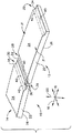
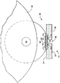
【解決手段】 シュラウドセグメント(12)の半径方向外側表面(24)は、円周方向に間隔を置いて配置された対向する第1及び第2の端縁部表面陥凹部(32、34)を含む。表面陥凹部は、セグメント(12、14)間、又はセグメントとエンジン部材との間に形成された表面陥凹部(36)内に半径方向外側の流体シール部材(44)を受ける形状のシール面(40)を有する。凹部シール面(40)は、円弧状の移行面(42)によりシュラウドセグメントの半径方向外側表面(24)と結合されている。表面陥凹部(32、34)は第1の形状を備え、該陥凹部(32、34)内に配置された流体シール部材(44)は、第1の形状と形状が一致する第2の形状の表面(46)を備える。
【選択図】 図2
Description
12 第1のシュラウドセグメント
14 第2のシュラウドセグメント
24 半径方向外側表面
26 半径方向内側表面
38 分離部分
40 陥凹部シール面
42 移行面
44 流体シール部材
46 流体シール部材表面
48 シール保持装置
Claims (16)
- 少なくとも一対の第1(28)及び第2(30)の間隔を置いて配置された対向する外側表面端部間で延びる半径方向外側表面(24)を有するシュラウドセグメント本体(22)を含むタービンエンジンのシュラウドセグメント(12)であって、
前記対における前記半径方向外側表面(24)の前記第1及び第2の外側端縁部(28、30)の少なくとも1つが、表面陥凹部(32/34)を含み、前記表面陥凹部(32/34)が、該陥凹部(32/34)に沿って第1の形状の陥凹部シール面(40)を含み、
前記陥凹部シール面(40)が、円弧状の移行面(42)により前記シュラウド本体の半径方向外側表面(24)と結合されている、
ことを特徴とするシュラウドセグメント(12)。 - 前記第1及び第2の外側端縁部(28、30)の各々が、表面陥凹部(32、34)を含むことを特徴とする、請求項1に記載のシュラウドセグメント(12)。
- 前記一対の第1及び第2の外側表面端部(28、30)が、円周方向(16)に間隔を置いて配置され、
前記陥凹部(32、34)の前記陥凹部シール面(40)が、該陥凹部(32、34)に沿って軸方向(18)に延びている、
ことを特徴とする、請求項1に記載のシュラウドセグメント(12)。 - 前記一対の第1及び第2の外側表面端部(31)が、軸方向(18)に間隔を置いて配置され、
前記陥凹部(32、34)の前記陥凹部シール面(40)が、該陥凹部(32、34)に沿って円周方向(16)に延びている、
ことを特徴とする、請求項1に記載のシュラウドセグメント(12)。 - 前記シュラウドセグメント(10)が、円周方向(16)に間隔を置いて配置された第2の対の第1及び第2の外側表面端部(28、30)を含み、該第2の対の前記陥凹部シール面(40)が、軸方向(18)に延びていることを特徴とする、請求項4に記載のシュラウドセグメント(12)。
- 前記陥凹部シール面(40)の前記第1の形状が、平坦であることを特徴とする、請求項1に記載のシュラウドセグメント(12)。
- 前記シュラウドセグメント(12)が、室温で測定して約1%より大きくない引張り延性を有する低延性材料で作られていることを特徴とする、請求項1に記載のシュラウドセグメント(12)。
- 前記低延性材料が、セラミックマトリックス複合材料であることを特徴とする、請求項7に記載のシュラウドセグメント(12)。
- 複数の円周方向(16)に配置されたシュラウドセグメント(12、14)を含むタービンエンジンのシュラウド組立体(10)であって、
前記シュラウドセグメント(12、14)は、該シュラウドセグメント(12)の前記第1及び第2の外側端縁部(28、30)が並置された隣接する第2の部材(14)の表面(40)から該表面との間の分離部分(38)により分離された状態で、請求項1に記載の該シュラウドセグメント(12)を含み、
前記表面陥凹部(32、34)内に保持されかつ前記分離部分(38)を跨いでいる流体シール部材(44)が設けられ、
前記流体シール部材(44)が、前記陥凹部シール面(40)の前記第1の形状と形状が一致しかつ前記分離部分(38)に沿って前記陥凹部シール面(40)と接触するように並置された第2の形状の流体シール部材表面(46)を含む、
ことを特徴とする、シュラウド組立体(10)。 - 前記流体シール部材(44)が、前記陥凹部シール面(40)との接触を可能にするのに十分な撓み性を有することを特徴とする、請求項9に記載のシュラウド組立体(10)。
- 前記一対の第1及び第2の外側表面端縁部(28、30)が、円周方向(16)に間隔を置いて配置され、
前記シュラウドセグメント(12、14)は、円周方向(16)に隣接する前記第1及び第2の外側端縁部(28、30)の前記陥凹部(32、34)が該陥凹部の間に前記第1の形状の陥凹部シール面(40)と軸方向(18)に延びる分離部分(38)とを含む軸方向(18)に延びる表面陥凹部(36)を形成する状態で、円周方向(16)に配置され、
前記流体シール部材(44)が、前記分離部分(38)に沿って軸方向(18)に配置されている、
ことを特徴とする、請求項9に記載のシュラウド組立体(10)。 - 前記シュラウドセグメント(12、14)の各々が、室温で測定して約1%より大きくない引張り延性を有する低延性材料で作られていることを特徴とする、請求項9に記載のシュラウド組立体(10)。
- 前記低延性材料が、セラミックマトリックス複合材料であることを特徴とする、請求項12に記載のシュラウド組立体(10)。
- 前記流体シール部材(44)が、室温で測定して約1%より大きくない引張り延性を有する低延性材料で作られていることを特徴とする、請求項12に記載のシュラウド組立体(10)。
- 前記低延性材料が、セラミックマトリックス複合材料であることを特徴とする、請求項14に記載のシュラウド組立体(10)。
- 前記陥凹部シール面(40)の前記第1の形状と前記流体部材シール面(46)の前記第2の形状との両方が、平坦であることを特徴とする、請求項9に記載のシュラウド組立体(10)。
Applications Claiming Priority (1)
| Application Number | Priority Date | Filing Date | Title |
|---|---|---|---|
| US10/325,779 US6893214B2 (en) | 2002-12-20 | 2002-12-20 | Shroud segment and assembly with surface recessed seal bridging adjacent members |
Publications (2)
| Publication Number | Publication Date |
|---|---|
| JP2004204839A true JP2004204839A (ja) | 2004-07-22 |
| JP2004204839A5 JP2004204839A5 (ja) | 2006-11-30 |
Family
ID=32393110
Family Applications (1)
| Application Number | Title | Priority Date | Filing Date |
|---|---|---|---|
| JP2003357151A Pending JP2004204839A (ja) | 2002-12-20 | 2003-10-17 | 隣接する部材間を跨ぐ表面埋込形シールを有するシュラウドセグメント及び組立体 |
Country Status (3)
| Country | Link |
|---|---|
| US (1) | US6893214B2 (ja) |
| EP (1) | EP1431518A3 (ja) |
| JP (1) | JP2004204839A (ja) |
Cited By (4)
| Publication number | Priority date | Publication date | Assignee | Title |
|---|---|---|---|---|
| JP2008095106A (ja) * | 2006-10-16 | 2008-04-24 | General Electric Co <Ge> | 高温シール及び高温封止系 |
| JP2010216473A (ja) * | 2009-03-12 | 2010-09-30 | General Electric Co <Ge> | タービンエンジンのシュラウドリング |
| JP2011241806A (ja) * | 2010-05-21 | 2011-12-01 | Mitsubishi Heavy Ind Ltd | 分割体、これを用いたタービン分割環およびこれを備えたガスタービン |
| JP2011241805A (ja) * | 2010-05-21 | 2011-12-01 | Mitsubishi Heavy Ind Ltd | タービン分割環、これを備えたガスタービンおよびこれを備えた発電プラント |
Families Citing this family (72)
| Publication number | Priority date | Publication date | Assignee | Title |
|---|---|---|---|---|
| US6997673B2 (en) * | 2003-12-11 | 2006-02-14 | Honeywell International, Inc. | Gas turbine high temperature turbine blade outer air seal assembly |
| US7374395B2 (en) * | 2005-07-19 | 2008-05-20 | Pratt & Whitney Canada Corp. | Turbine shroud segment feather seal located in radial shroud legs |
| US7238002B2 (en) * | 2005-11-03 | 2007-07-03 | General Electric Company | Damper seal system and method |
| US7556475B2 (en) * | 2006-05-31 | 2009-07-07 | General Electric Company | Methods and apparatus for assembling turbine engines |
| US20080025838A1 (en) * | 2006-07-25 | 2008-01-31 | Siemens Power Generation, Inc. | Ring seal for a turbine engine |
| US7950234B2 (en) * | 2006-10-13 | 2011-05-31 | Siemens Energy, Inc. | Ceramic matrix composite turbine engine components with unitary stiffening frame |
| US7887929B2 (en) * | 2007-08-28 | 2011-02-15 | United Technologies Corporation | Oriented fiber ceramic matrix composite abradable thermal barrier coating |
| JP5091615B2 (ja) * | 2007-10-15 | 2012-12-05 | 三菱重工業株式会社 | 静翼環セグメントの組立方法、静翼環セグメント、結合部材、溶接方法 |
| US20090110546A1 (en) * | 2007-10-29 | 2009-04-30 | United Technologies Corp. | Feather Seals and Gas Turbine Engine Systems Involving Such Seals |
| US8206092B2 (en) * | 2007-12-05 | 2012-06-26 | United Technologies Corp. | Gas turbine engines and related systems involving blade outer air seals |
| US8118546B2 (en) * | 2008-08-20 | 2012-02-21 | Siemens Energy, Inc. | Grid ceramic matrix composite structure for gas turbine shroud ring segment |
| US8132442B2 (en) * | 2008-09-22 | 2012-03-13 | Siemens Energy, Inc. | Compressible ceramic seal |
| US8684680B2 (en) * | 2009-08-27 | 2014-04-01 | Pratt & Whitney Canada Corp. | Sealing and cooling at the joint between shroud segments |
| WO2011047693A1 (en) * | 2009-10-19 | 2011-04-28 | Siemens Aktiengesellschaft | Nozzle guide vane arrangement and turbine engine |
| JP5356345B2 (ja) * | 2010-09-28 | 2013-12-04 | 株式会社日立製作所 | ガスタービンのシュラウド構造 |
| US8790067B2 (en) | 2011-04-27 | 2014-07-29 | United Technologies Corporation | Blade clearance control using high-CTE and low-CTE ring members |
| US8864492B2 (en) | 2011-06-23 | 2014-10-21 | United Technologies Corporation | Reverse flow combustor duct attachment |
| US8739547B2 (en) | 2011-06-23 | 2014-06-03 | United Technologies Corporation | Gas turbine engine joint having a metallic member, a CMC member, and a ceramic key |
| US9335051B2 (en) | 2011-07-13 | 2016-05-10 | United Technologies Corporation | Ceramic matrix composite combustor vane ring assembly |
| US8920127B2 (en) | 2011-07-18 | 2014-12-30 | United Technologies Corporation | Turbine rotor non-metallic blade attachment |
| US9726043B2 (en) | 2011-12-15 | 2017-08-08 | General Electric Company | Mounting apparatus for low-ductility turbine shroud |
| US9528376B2 (en) * | 2012-09-13 | 2016-12-27 | General Electric Company | Compressor fairing segment |
| US9771818B2 (en) | 2012-12-29 | 2017-09-26 | United Technologies Corporation | Seals for a circumferential stop ring in a turbine exhaust case |
| GB201303995D0 (en) * | 2013-03-06 | 2013-04-17 | Rolls Royce Plc | CMC turbine engine component |
| CN105612313B (zh) | 2013-05-17 | 2017-11-21 | 通用电气公司 | 燃气涡轮机的cmc护罩支撑系统 |
| WO2015009384A1 (en) * | 2013-07-16 | 2015-01-22 | United Technologies Corporation | Gas turbine engine with ceramic panel |
| WO2015013503A1 (en) * | 2013-07-24 | 2015-01-29 | United Technologies Corporation | Trough seal for gas turbine engine |
| US9399926B2 (en) * | 2013-08-23 | 2016-07-26 | Siemens Energy, Inc. | Belly band seal with circumferential spacer |
| EP3080403B1 (en) | 2013-12-12 | 2019-05-01 | General Electric Company | Cmc shroud support system |
| WO2015191174A1 (en) | 2014-06-12 | 2015-12-17 | General Electric Company | Multi-piece shroud hanger assembly |
| EP3155231B1 (en) | 2014-06-12 | 2019-07-03 | General Electric Company | Shroud hanger assembly |
| WO2015191169A1 (en) | 2014-06-12 | 2015-12-17 | General Electric Company | Shroud hanger assembly |
| US9863323B2 (en) | 2015-02-17 | 2018-01-09 | General Electric Company | Tapered gas turbine segment seals |
| US10281045B2 (en) | 2015-02-20 | 2019-05-07 | Rolls-Royce North American Technologies Inc. | Apparatus and methods for sealing components in gas turbine engines |
| US10934871B2 (en) | 2015-02-20 | 2021-03-02 | Rolls-Royce North American Technologies Inc. | Segmented turbine shroud with sealing features |
| US9874104B2 (en) | 2015-02-27 | 2018-01-23 | General Electric Company | Method and system for a ceramic matrix composite shroud hanger assembly |
| EP3088679A1 (en) | 2015-04-30 | 2016-11-02 | Rolls-Royce Corporation | Seal for a gas turbine engine assembly |
| US9759079B2 (en) | 2015-05-28 | 2017-09-12 | Rolls-Royce Corporation | Split line flow path seals |
| US20170030211A1 (en) * | 2015-07-28 | 2017-02-02 | General Electric Company | Seals with a conformable coating for turbomachinery |
| US10458263B2 (en) * | 2015-10-12 | 2019-10-29 | Rolls-Royce North American Technologies Inc. | Turbine shroud with sealing features |
| US20170276000A1 (en) * | 2016-03-24 | 2017-09-28 | General Electric Company | Apparatus and method for forming apparatus |
| US9869194B2 (en) | 2016-03-31 | 2018-01-16 | General Electric Company | Seal assembly to seal corner leaks in gas turbine |
| US10450897B2 (en) | 2016-07-18 | 2019-10-22 | General Electric Company | Shroud for a gas turbine engine |
| US10301955B2 (en) | 2016-11-29 | 2019-05-28 | Rolls-Royce North American Technologies Inc. | Seal assembly for gas turbine engine components |
| US10443420B2 (en) | 2017-01-11 | 2019-10-15 | Rolls-Royce North American Technologies Inc. | Seal assembly for gas turbine engine components |
| US11111858B2 (en) | 2017-01-27 | 2021-09-07 | General Electric Company | Cool core gas turbine engine |
| US10371383B2 (en) | 2017-01-27 | 2019-08-06 | General Electric Company | Unitary flow path structure |
| US10393381B2 (en) | 2017-01-27 | 2019-08-27 | General Electric Company | Unitary flow path structure |
| US10378770B2 (en) | 2017-01-27 | 2019-08-13 | General Electric Company | Unitary flow path structure |
| US10816199B2 (en) | 2017-01-27 | 2020-10-27 | General Electric Company | Combustor heat shield and attachment features |
| US10253643B2 (en) | 2017-02-07 | 2019-04-09 | General Electric Company | Airfoil fluid curtain to mitigate or prevent flow path leakage |
| ES2758187T3 (es) * | 2017-02-17 | 2020-05-04 | MTU Aero Engines AG | Disposición de sellado para una turbina de gas |
| US10577977B2 (en) * | 2017-02-22 | 2020-03-03 | Rolls-Royce Corporation | Turbine shroud with biased retaining ring |
| US10247019B2 (en) | 2017-02-23 | 2019-04-02 | General Electric Company | Methods and features for positioning a flow path inner boundary within a flow path assembly |
| US10385709B2 (en) | 2017-02-23 | 2019-08-20 | General Electric Company | Methods and features for positioning a flow path assembly within a gas turbine engine |
| US10385776B2 (en) | 2017-02-23 | 2019-08-20 | General Electric Company | Methods for assembling a unitary flow path structure |
| US10378373B2 (en) | 2017-02-23 | 2019-08-13 | General Electric Company | Flow path assembly with airfoils inserted through flow path boundary |
| US10370990B2 (en) | 2017-02-23 | 2019-08-06 | General Electric Company | Flow path assembly with pin supported nozzle airfoils |
| US10253641B2 (en) | 2017-02-23 | 2019-04-09 | General Electric Company | Methods and assemblies for attaching airfoils within a flow path |
| US10385731B2 (en) | 2017-06-12 | 2019-08-20 | General Electric Company | CTE matching hanger support for CMC structures |
| US10865654B2 (en) * | 2017-06-15 | 2020-12-15 | General Electric Company | Turbine shroud assembly |
| US10718226B2 (en) * | 2017-11-21 | 2020-07-21 | Rolls-Royce Corporation | Ceramic matrix composite component assembly and seal |
| US10822973B2 (en) | 2017-11-28 | 2020-11-03 | General Electric Company | Shroud for a gas turbine engine |
| US11402097B2 (en) | 2018-01-03 | 2022-08-02 | General Electric Company | Combustor assembly for a turbine engine |
| US20190284947A1 (en) | 2018-03-14 | 2019-09-19 | General Electric Company | Cmc shroud segment with interlocking mechanical joints and fabrication |
| DE102018210600A1 (de) * | 2018-06-28 | 2020-01-02 | MTU Aero Engines AG | Mantelringanordnung für eine strömungsmaschine |
| DE102018210601A1 (de) | 2018-06-28 | 2020-01-02 | MTU Aero Engines AG | Segmentring zur montage in einer strömungsmaschine |
| US10934873B2 (en) * | 2018-11-07 | 2021-03-02 | General Electric Company | Sealing system for turbine shroud segments |
| US10968761B2 (en) * | 2018-11-08 | 2021-04-06 | Raytheon Technologies Corporation | Seal assembly with impingement seal plate |
| US11187096B2 (en) | 2019-11-07 | 2021-11-30 | Raytheon Technologies Corporation | Platform seal |
| US11268394B2 (en) | 2020-03-13 | 2022-03-08 | General Electric Company | Nozzle assembly with alternating inserted vanes for a turbine engine |
| US11428160B2 (en) | 2020-12-31 | 2022-08-30 | General Electric Company | Gas turbine engine with interdigitated turbine and gear assembly |
Citations (3)
| Publication number | Priority date | Publication date | Assignee | Title |
|---|---|---|---|---|
| JP2000145406A (ja) * | 1998-11-06 | 2000-05-26 | Ishikawajima Harima Heavy Ind Co Ltd | タービンシュラウド |
| JP2002295202A (ja) * | 2001-03-07 | 2002-10-09 | General Electric Co <Ge> | 低延性の翼を備えたタービン翼組立体 |
| US20020187040A1 (en) * | 2001-06-06 | 2002-12-12 | Predmore Daniel Ross | Overlapping interference seal and methods for forming the seal |
Family Cites Families (26)
| Publication number | Priority date | Publication date | Assignee | Title |
|---|---|---|---|---|
| US3798899A (en) | 1971-12-29 | 1974-03-26 | Power Technology Corp | Gas turbine engine |
| US3807891A (en) | 1972-09-15 | 1974-04-30 | United Aircraft Corp | Thermal response turbine shroud |
| US3966353A (en) | 1975-02-21 | 1976-06-29 | Westinghouse Electric Corporation | Ceramic-to-metal (or ceramic) cushion/seal for use with three piece ceramic stationary vane assembly |
| US4087199A (en) * | 1976-11-22 | 1978-05-02 | General Electric Company | Ceramic turbine shroud assembly |
| US4193738A (en) | 1977-09-19 | 1980-03-18 | General Electric Company | Floating seal for a variable area turbine nozzle |
| DE2851507C2 (de) | 1978-11-29 | 1982-05-19 | Aktiengesellschaft Kühnle, Kopp & Kausch, 6710 Frankenthal | Isolations-Federkörper und dessen Verwendung |
| FR2724973B1 (fr) * | 1982-12-31 | 1996-12-13 | Snecma | Dispositif d'etancheite d'aubages mobiles de turbomachine avec controle actif des jeux en temps reel et methode de determination dudit dispositif |
| FR2540939A1 (fr) * | 1983-02-10 | 1984-08-17 | Snecma | Anneau d'etancheite pour un rotor de turbine d'une turbomachine et installation de turbomachine munie de tels anneaux |
| US4768924A (en) | 1986-07-22 | 1988-09-06 | Pratt & Whitney Canada Inc. | Ceramic stator vane assembly |
| GB2236809B (en) | 1989-09-22 | 1994-03-16 | Rolls Royce Plc | Improvements in or relating to gas turbine engines |
| US5071313A (en) | 1990-01-16 | 1991-12-10 | General Electric Company | Rotor blade shroud segment |
| US5127793A (en) | 1990-05-31 | 1992-07-07 | General Electric Company | Turbine shroud clearance control assembly |
| US5074748A (en) | 1990-07-30 | 1991-12-24 | General Electric Company | Seal assembly for segmented turbine engine structures |
| DE59205187D1 (de) * | 1992-10-05 | 1996-03-07 | Asea Brown Boveri | Leitschaufeleinhängung für axialdurchströmte Turbomaschine |
| US5388962A (en) | 1993-10-15 | 1995-02-14 | General Electric Company | Turbine rotor disk post cooling system |
| US5562408A (en) | 1995-06-06 | 1996-10-08 | General Electric Company | Isolated turbine shroud |
| JPH10103013A (ja) * | 1996-09-30 | 1998-04-21 | Toshiba Corp | ガスタービンシュラウド構造 |
| US6000906A (en) | 1997-09-12 | 1999-12-14 | Alliedsignal Inc. | Ceramic airfoil |
| US6113349A (en) * | 1998-09-28 | 2000-09-05 | General Electric Company | Turbine assembly containing an inner shroud |
| US6142734A (en) | 1999-04-06 | 2000-11-07 | General Electric Company | Internally grooved turbine wall |
| US6325593B1 (en) * | 2000-02-18 | 2001-12-04 | General Electric Company | Ceramic turbine airfoils with cooled trailing edge blocks |
| US6412784B1 (en) * | 2000-05-26 | 2002-07-02 | The United States Of America As Represented By The Secretary Of The Navy | Split face mechanical seal system |
| US6554563B2 (en) * | 2001-08-13 | 2003-04-29 | General Electric Company | Tangential flow baffle |
| US6702550B2 (en) * | 2002-01-16 | 2004-03-09 | General Electric Company | Turbine shroud segment and shroud assembly |
| US6733235B2 (en) * | 2002-03-28 | 2004-05-11 | General Electric Company | Shroud segment and assembly for a turbine engine |
| US6648597B1 (en) * | 2002-05-31 | 2003-11-18 | Siemens Westinghouse Power Corporation | Ceramic matrix composite turbine vane |
-
2002
- 2002-12-20 US US10/325,779 patent/US6893214B2/en not_active Expired - Lifetime
-
2003
- 2003-10-17 JP JP2003357151A patent/JP2004204839A/ja active Pending
- 2003-10-17 EP EP03256564A patent/EP1431518A3/en not_active Withdrawn
Patent Citations (3)
| Publication number | Priority date | Publication date | Assignee | Title |
|---|---|---|---|---|
| JP2000145406A (ja) * | 1998-11-06 | 2000-05-26 | Ishikawajima Harima Heavy Ind Co Ltd | タービンシュラウド |
| JP2002295202A (ja) * | 2001-03-07 | 2002-10-09 | General Electric Co <Ge> | 低延性の翼を備えたタービン翼組立体 |
| US20020187040A1 (en) * | 2001-06-06 | 2002-12-12 | Predmore Daniel Ross | Overlapping interference seal and methods for forming the seal |
Cited By (5)
| Publication number | Priority date | Publication date | Assignee | Title |
|---|---|---|---|---|
| JP2008095106A (ja) * | 2006-10-16 | 2008-04-24 | General Electric Co <Ge> | 高温シール及び高温封止系 |
| JP2010216473A (ja) * | 2009-03-12 | 2010-09-30 | General Electric Co <Ge> | タービンエンジンのシュラウドリング |
| CN101892870A (zh) * | 2009-03-12 | 2010-11-24 | 通用电气公司 | 涡轮发动机护罩环 |
| JP2011241806A (ja) * | 2010-05-21 | 2011-12-01 | Mitsubishi Heavy Ind Ltd | 分割体、これを用いたタービン分割環およびこれを備えたガスタービン |
| JP2011241805A (ja) * | 2010-05-21 | 2011-12-01 | Mitsubishi Heavy Ind Ltd | タービン分割環、これを備えたガスタービンおよびこれを備えた発電プラント |
Also Published As
| Publication number | Publication date |
|---|---|
| US6893214B2 (en) | 2005-05-17 |
| EP1431518A2 (en) | 2004-06-23 |
| US20040120808A1 (en) | 2004-06-24 |
| EP1431518A3 (en) | 2006-08-23 |
Similar Documents
| Publication | Publication Date | Title |
|---|---|---|
| JP2004204839A (ja) | 隣接する部材間を跨ぐ表面埋込形シールを有するシュラウドセグメント及び組立体 | |
| JP4446710B2 (ja) | 平面状セグメント表面における円周方向シールを備えるシュラウドセグメント及び組立体 | |
| EP1643084B1 (en) | Turbine engine shroud segment, hanger and assembly | |
| JP4383060B2 (ja) | タービンエンジン用のシュラウドセグメント及び組立体 | |
| CA2729528C (en) | Mounting apparatus for low-ductility turbine shroud | |
| JP2006105129A (ja) | タービンエンジンのシュラウドセグメント | |
| US6884026B2 (en) | Turbine engine shroud assembly including axially floating shroud segment | |
| US7726936B2 (en) | Turbine engine ring seal | |
| JP6063285B2 (ja) | 低延性タービンシュラウド | |
| US6702550B2 (en) | Turbine shroud segment and shroud assembly | |
| US6733233B2 (en) | Attachment of a ceramic shroud in a metal housing | |
| US6821085B2 (en) | Turbine engine axially sealing assembly including an axially floating shroud, and assembly method | |
| JP3636721B2 (ja) | カットバック保持フックを有するシュラウドセグメント | |
| US7575416B2 (en) | Rotor assembly for a rotary machine | |
| US9534500B2 (en) | Seal arrangement for segmented gas turbine engine components | |
| JPH09504588A (ja) | タービンシュラウドセグメントのマウント及びシール配置 | |
| JPH10196309A (ja) | タービンブレードプラットホームシール | |
| JP2002309902A (ja) | シール歯の摩耗を減少させる方法、ハニカムシールおよびガスタービンエンジン | |
| JP3631491B2 (ja) | タービンシュラウドセグメント | |
| JP2017061932A (ja) | ガスタービンエンジン用のノズル及びノズルアセンブリ | |
| JP4363149B2 (ja) | タービン用シール構造、シールステータ、及びタービンノズルセグメント |
Legal Events
| Date | Code | Title | Description |
|---|---|---|---|
| A521 | Written amendment |
Free format text: JAPANESE INTERMEDIATE CODE: A523 Effective date: 20061016 |
|
| A621 | Written request for application examination |
Free format text: JAPANESE INTERMEDIATE CODE: A621 Effective date: 20061016 |
|
| A131 | Notification of reasons for refusal |
Free format text: JAPANESE INTERMEDIATE CODE: A131 Effective date: 20090317 |
|
| A601 | Written request for extension of time |
Free format text: JAPANESE INTERMEDIATE CODE: A601 Effective date: 20090615 |
|
| RD02 | Notification of acceptance of power of attorney |
Free format text: JAPANESE INTERMEDIATE CODE: A7422 Effective date: 20090615 |
|
| RD04 | Notification of resignation of power of attorney |
Free format text: JAPANESE INTERMEDIATE CODE: A7424 Effective date: 20090615 |
|
| A602 | Written permission of extension of time |
Free format text: JAPANESE INTERMEDIATE CODE: A602 Effective date: 20090713 |
|
| A521 | Written amendment |
Free format text: JAPANESE INTERMEDIATE CODE: A523 Effective date: 20090910 |
|
| A02 | Decision of refusal |
Free format text: JAPANESE INTERMEDIATE CODE: A02 Effective date: 20100316 |
|
| A521 | Written amendment |
Free format text: JAPANESE INTERMEDIATE CODE: A523 Effective date: 20100712 |
|
| A521 | Written amendment |
Free format text: JAPANESE INTERMEDIATE CODE: A523 Effective date: 20100927 |
|
| A911 | Transfer of reconsideration by examiner before appeal (zenchi) |
Free format text: JAPANESE INTERMEDIATE CODE: A911 Effective date: 20101006 |
|
| A912 | Removal of reconsideration by examiner before appeal (zenchi) |
Free format text: JAPANESE INTERMEDIATE CODE: A912 Effective date: 20101112 |
|
| A601 | Written request for extension of time |
Free format text: JAPANESE INTERMEDIATE CODE: A601 Effective date: 20110304 |
|
| A602 | Written permission of extension of time |
Free format text: JAPANESE INTERMEDIATE CODE: A602 Effective date: 20110309 |