JP2004136584A - Perfecting press and paper carrying member - Google Patents

Perfecting press and paper carrying member Download PDF

Info

Publication number
JP2004136584A
JP2004136584A JP2002304381A JP2002304381A JP2004136584A JP 2004136584 A JP2004136584 A JP 2004136584A JP 2002304381 A JP2002304381 A JP 2002304381A JP 2002304381 A JP2002304381 A JP 2002304381A JP 2004136584 A JP2004136584 A JP 2004136584A
Authority
JP
Japan
Prior art keywords
sheet
plate
paper
plate cylinder
press roller
Prior art date
Legal status (The legal status is an assumption and is not a legal conclusion. Google has not performed a legal analysis and makes no representation as to the accuracy of the status listed.)
Pending
Application number
JP2002304381A
Other languages
Japanese (ja)
Inventor
Mitsuo Sato
佐藤 光雄
Current Assignee (The listed assignees may be inaccurate. Google has not performed a legal analysis and makes no representation or warranty as to the accuracy of the list.)
Tohoku Ricoh Co Ltd
Original Assignee
Tohoku Ricoh Co Ltd
Priority date (The priority date is an assumption and is not a legal conclusion. Google has not performed a legal analysis and makes no representation as to the accuracy of the date listed.)
Filing date
Publication date
Application filed by Tohoku Ricoh Co Ltd filed Critical Tohoku Ricoh Co Ltd
Priority to JP2002304381A priority Critical patent/JP2004136584A/en
Priority to US10/626,604 priority patent/US7284479B2/en
Priority to CNB031597238A priority patent/CN1298545C/en
Publication of JP2004136584A publication Critical patent/JP2004136584A/en
Pending legal-status Critical Current

Links

Images

Abstract

<P>PROBLEM TO BE SOLVED: To provide a perfecting press which effectively prevents stains caused by ink transferring, and obtains a good printed matter. <P>SOLUTION: The perfecting press 1 has at least one plate cylinder 12 and at least one press roller 13 for pressing a paper P onto the plate cylinder 12, and performs a printing on one face of the paper P and then, performs another printing on the other face of the paper P within three seconds. An uneven part 13e having a number of projections 13h each formed with the radius R of the apex of ≤0.04 mm by a mean pitch L of ≤0.4 mm is provided on the outer peripheral face of the press roller 13 for pressing the other face of the paper P on the plate cylinder 12. <P>COPYRIGHT: (C)2004,JPO

Description

【0001】
【発明の属する技術分野】
本発明は、用紙の一方の面及び他方の面に印刷を行う両面印刷装置に関し、詳しくは用紙の印刷面に接触して印刷後の用紙を版胴に押圧するプレスローラの構造に関する。
【0002】
【従来の技術】
従来、簡便な印刷方法としてデジタル式感熱孔版印刷が知られている。この孔版印刷に用いられる孔版印刷装置は、微細な発熱素子が一列に配置されたサーマルヘッドを感熱孔版マスタ(以下、「マスタ」という)に接触させ、パルス的に発熱素子に通電させながらマスタを搬送することで画像情報に応じてマスタを加熱溶融穿孔し、このマスタを多孔性円筒状の版胴の外周面に巻装した後に用紙を介して版胴の外周面をプレスローラ等の押圧手段によって押圧することで、マスタ穿孔部よりインキを透過させてこれを用紙に転移させることにより印刷画像を得るものである。
【0003】
この孔版印刷において、近年では用紙の消費量及び書類の保管スペースを低減させるため等の目的から、用紙の両面に印刷を行う両面印刷が頻繁に行われるようになってきている。この両面印刷は、従来の方法では給紙部に積載した用紙を印刷部に通紙し、一面に印刷をした後に用紙を裏返して再度印刷部に通紙して他面に印刷をすることで両面印刷物を得ていたが、一度排紙された用紙を再度給紙部にセットしたり片面印刷後の用紙を揃えたりする作業が面倒であるという問題点があった。また、印刷部への通紙を2回行うために、正味の印刷時間においても片面印刷に比べて2倍の時間を要し、時間がかかりすぎるという問題点もあった。
【0004】
上述の問題点を解決するため、第1の版胴と、用紙搬送路を介して第1の版胴に対向配置され第1の版胴に対して圧接・離間可能に設けられた第1の押圧手段と、第1の版胴より用紙搬送方向下流側であって用紙搬送路を介して第1の版胴と対向する側に配置された第2の版胴と、用紙搬送路を介して第2の版胴に対向配置され第2の版胴に対して圧接・離間可能に設けられた第2の押圧手段とを具備し、第1の版胴と第1の押圧手段とを圧接させた後、第2の版胴と第2の押圧手段とを圧接させることにより両面印刷を行う孔版印刷装置が、例えば「特許文献1」に開示されている。
【0005】
また、用紙の一方の面に印刷される第1の画像と用紙の他方の面に印刷される第2の画像とを有する分割製版済みマスタを版胴に巻き付け、第1のプレスローラにより用紙を版胴に押圧して用紙の一方の面に第1の画像を印刷した後、付勢手段により片面印刷済み用紙を再給紙して第2のプレスローラにより用紙の他方の面に第2の画像を印刷することにより両面印刷を行う孔版印刷装置が、例えば「特許文献2」に開示されている。
【0006】
上述した各公報に開示された技術を用いることにより、1回の通紙で用紙の両面に印刷を行うことができ、従来に比較して印刷作業時間を半分程度に短縮することが可能となる。
【0007】
さらに、両面印刷時において、上流側の印刷部で印刷された片面印刷済み用紙を下流側の印刷部で印刷する際に、未定着状態のインキが押圧ロールに転写され、この押圧ロールに転写されたインキがさらに用紙の裏面に再転写されるという不具合を防止するため、下流側の印刷部に用いられる押圧ロールの外周面に微小な凹凸を設ける技術が、例えば「特許文献3」に開示されている。
【0008】
【特許文献1】
特開2002−103768号公報 (第4−6頁、図1)
【特許文献2】
特開平9−95033号公報 (第3−6頁、図1)
【特許文献3】
特開2002−219849号公報 (第2−3頁、図1)
【0009】
【発明が解決しようとする課題】
しかし、「特許文献1」及び「特許文献2」に開示された技術では、用紙の一方の面に印刷を行った後に用紙の他方の面に印刷を行っているため、用紙の他方の面に印刷を行う際に用紙の一方の面に付着しているインキがプレスローラ表面に転移し、次の用紙の一方の面に印刷を行う際にこの用紙の他方の面に先の用紙から転移したインキが付着して裏汚れが発生してしまうという問題点がある。
【0010】
そこで、上記各技術に「特許文献3」で開示されたプレスローラを適用して両面印刷を行うことが考えられるが、「特許文献3」の図11(B)に示されるようなほぼ同一形状の球状体を表面が平滑となるように並べたものでは、用紙の画像面に接触する球状体の総合面積がそれほど平面と変わらなくなり、インキ転移汚れの防止には効果が低いことが判明した。また、同図10(B)に示されるような構造でも結果的には用紙の画像面に接触する面積が大きくなり、さほどの効果は得られなかった。
【0011】
このインキ転移汚れを完全に防止するためには、用紙の画像面に接触するプレスローラの面積を小さくすることが効果的であるが、接触面積を小さくすると接触部の先端形状が鋭角状となり、用紙に押圧された際に用紙あるいは用紙を介してマスタにまで穴をあけてしまう虞があり、接触面積の低減には限界がある。
【0012】
さらに本発明者は、1工程で用紙の両面に印刷を行うことが可能な両面印刷装置を用い、用紙の一方の面に印刷を行った後にこの用紙の一方の面をプレスローラで押圧して用紙の他方の面に印刷を行う際に、一方の面の印刷後、どの程度の時間をおいて他方の面に印刷を行えばインキ転移汚れの発生が減少するのかを調査した。この結果を図24に示す。図から明らかなように、一方の面の印刷後、5秒以上経過した後に他方の面に印刷を行えばインキ転移汚れの発生をほとんど防止できることが判明したが、実際の印刷時において孔版印刷はその高速性にメリットがあるため、3秒以内で他方の面の印刷が行われることを避けられない。
【0013】
本発明は上述の問題点を解決し、インキ転移汚れの発生を効果的に防止することが可能な両面印刷装置の提供を目的とする。
【0014】
【課題を解決するための手段】
請求項1記載の発明は、少なくとも1つの版胴と、前記版胴に用紙を押圧する前記版胴に対応して設けられた少なくとも1つのプレスローラとを有し、前記用紙の一方の面に印刷した後、3秒以内に前記用紙の他方の面に印刷する両面印刷装置であって、前記用紙の他方の面を前記版胴に押圧するプレスローラの外周面には、先端部半径0.04mm以下で形成された突起を平均ピッチ0.4mm以下で多数有する凹凸部が設けられていることを特徴とする。
【0015】
請求項2記載の発明は、用紙の一方の面に印刷される第1の画像と前記用紙の他方の面に印刷される第2の画像とが版胴の円周方向に並ぶように製版された分割製版済みマスタを前記版胴に巻き付け、プレスローラにより前記用紙を前記版胴に押圧して前記一方の面に第1の画像を印刷した後、次にこの表面印刷済み用紙を再給紙して前記プレスローラにより前記版胴に押圧することにより、第1の画像印刷後から3秒以内に前記他方の面に第2の画像を印刷する両面印刷装置であって、前記プレスローラの外周面には、先端部半径0.04mm以下で形成された突起を平均ピッチ0.4mm以下で多数有する凹凸部が設けられていることを特徴とする。
【0016】
請求項3記載の発明は、用紙の一方の面に印刷される第1の画像が製版された第1のマスタを巻装する第1の版胴と、第1の版胴に対向して配置され前記用紙を第1の版胴に押圧する第1のプレスローラと、第1の版胴よりも前記用紙の搬送方向下流側に対向配置され前記用紙の他方の面に印刷される第2の画像が製版された第2のマスタを巻装する第2の版胴と、第2の版胴に対向して配置され前記用紙を第2の版胴に押圧する第2のプレスローラとを有し、第1のプレスローラにより前記用紙を第1の版胴に押圧して前記用紙の一方の面に第1の画像を印刷した後、3秒以内に第2のプレスローラにより前記用紙を第2の版胴に押圧して前記用紙の他方の面に第2の画像を印刷する両面印刷装置であって、少なくとも第2のプレスローラの外周面には、先端部半径0.04mm以下で形成された突起を平均ピッチ0.4mm以下で多数有する凹凸部が設けられていることを特徴とする。
【0017】
請求項4記載の発明は、請求項1ないし請求項3のうちの何れか1つに記載の両面印刷装置において、さらに前記突起はその頂角が100度以下の多角錘形状あるいは円錐形状を呈する合成樹脂からなることを特徴とする。
【0018】
請求項5記載の発明は、請求項4記載の両面印刷装置において、さらに前記凹凸部は一定幅を有する長尺のシート部材を前記プレスローラの外周面に螺旋状に巻き付けたものであることを特徴とする。
【0019】
請求項6記載の発明は、少なくとも1つの版胴と、前記版胴に用紙を押圧する前記版胴に対応して設けられた少なくとも1つのプレスローラとを有し、前記用紙の一方の面に印刷した後、3秒以内に前記用紙の他方の面に印刷する両面印刷装置であって、さらに前記用紙の他方の面を前記版胴に押圧するプレスローラの外周面には、平均直径0.1mm以下の球状体を最大段差0.03mm以上かつ最大突出部間の平均ピッチ0.15mm以上で多数有する段差部が設けられていることを特徴とする。
【0020】
請求項7記載の発明は、用紙の一方の面に印刷される第1の画像と前記用紙の他方の面に印刷される第2の画像とが版胴の円周方向に並ぶように製版された分割製版済みマスタを前記版胴に巻き付け、プレスローラにより前記用紙を前記版胴に押圧して前記一方の面に第1の画像を印刷した後、次にこの表面印刷済み用紙を再給紙して前記プレスローラにより前記版胴に押圧することにより、第1の画像印刷後から3秒以内に前記他方の面に第2の画像を印刷する両面印刷装置であって、前記プレスローラの外周面には、平均直径0.1mm以下の球状体を最大段差0.03mm以上かつ最大突出部間の平均ピッチ0.15mm以上で多数有する段差部が設けられていることを特徴とする。
【0021】
請求項8記載の発明は、用紙の一方の面に印刷される第1の画像が製版された第1のマスタを巻装する第1の版胴と、第1の版胴に対向して配置され前記用紙を第1の版胴に押圧する第1のプレスローラと、第1の版胴よりも前記用紙の搬送方向下流側に対向配置され前記用紙の他方の面に印刷される第2の画像が製版された第2のマスタを巻装する第2の版胴と、第2の版胴に対向して配置され前記用紙を第2の版胴に押圧する第2のプレスローラとを有し、第1のプレスローラにより前記用紙を第1の版胴に押圧して前記用紙の一方の面に第1の画像を印刷した後、3秒以内に第2のプレスローラにより前記用紙を第2の版胴に押圧して前記用紙の他方の面に第2の画像を印刷する両面印刷装置であって、少なくとも第2のプレスローラの外周面には、平均直径0.1mm以下の球状体を最大段差0.03mm以上かつ最大突出部間の平均ピッチ0.15mm以上で多数有する段差部が設けられていることを特徴とする。
【0022】
請求項9記載の発明は、請求項6ないし請求項8のうちの何れか1つに記載の両面印刷装置において、さらに前記球状体はガラスからなることを特徴とする。
【0023】
請求項10記載の発明は、請求項9記載の両面印刷装置において、さらに前記段差部は一定幅を有する長尺のシート部材を前記プレスローラの外周面に螺旋状に巻き付けたものであることを特徴とする。
【0024】
請求項11記載の発明は、請求項1ないし請求項10のうちの何れか1つに記載の両面印刷装置において、さらに前記プレスローラの外周面に付着したインキを除去するクリーニング手段を有することを特徴とする。
【0025】
請求項12記載の発明は、請求項11記載の両面印刷装置において、さらに前記クリーニング手段が多孔性のクリーニングローラであり、該クリーニングローラは印刷時における前記プレスローラの回転周速度よりも低速で回転駆動されることを特徴とする。
【0026】
請求項13記載の発明は、請求項12記載の両面印刷装置において、さらに前記クリーニングローラは3N以下の付勢力で前記プレスローラの外周面に付勢されていることを特徴とする。
【0027】
請求項14記載の発明は、印刷画像が形成された用紙の印刷面に、印刷後3秒以内に接触して前記用紙を搬送する用紙搬送部材であって、さらに先端部半径0.04mm以下で形成された突起を平均ピッチ0.4mm以下で多数有する凹凸部をその外周面に有することを特徴とする。
【0028】
請求項15記載の発明は、請求項14記載の用紙搬送部材において、さらに前記突起はその頂角が100度以下の多角錘形状あるいは円錐形状を呈する合成樹脂からなることを特徴とする。
【0029】
請求項16記載の発明は、請求項15記載の用紙搬送部材において、さらに前記凹凸部は一定幅を有する長尺のシート部材を前記外周面に螺旋状に巻き付けたものであることを特徴とする。
【0030】
【実施例】
図1は、本発明の第1の実施例を採用した両面印刷装置を示している。両面印刷装置1は、印刷部2、製版部3、給紙部4、排版部5、排紙部6、画像読取部7、補助トレイ8、再給紙手段9、切換部材10等を有している。
【0031】
装置本体11のほぼ中央に配設された印刷部2は、版胴12とプレスローラ13とを有している。
版胴12は、インキ供給パイプを兼ねた支軸14に回転自在に支持された図示しない一対の端板と、各端板の外周面に巻装された図示しない多孔性支持板と、図示しない多孔性支持板の外周面に巻装された図示しないメッシュスクリーンとから主に構成されており、版胴駆動手段121(図14参照)によって回転駆動されると共に装置本体11に対して着脱可能に構成されている。本実施例において版胴12は、片面印刷時において最大でA3サイズの印刷物を得ることが可能な大きさを有している。
【0032】
版胴12の内部にはインキ供給手段15が配設されている。インキ供給手段15は、支軸14、インキローラ16、ドクターローラ17等を有している。
インキローラ16は、版胴12内に設けられた図示しない側板間に回転自在に支持されており、その周面を版胴12の内周面に近接して配置され、図示しない駆動手段によって版胴12と同方向に回転駆動される。ドクターローラ17も前記側板間に回転自在に支持されており、その周面をインキローラ16の周面に近接して配置され、図示しない駆動手段によって版胴12とは逆方向に回転駆動される。支軸14には複数の小さな孔が穿設されており、支軸14から供給されたインキがインキローラ16とドクターローラ17との近接部に形成される断面楔形状の空間に溜まることによりインキ溜まり18が形成される。
【0033】
版胴12の外周面上には、版胴12の一母線に沿った平面をなすステージ部19aが形成されており、この上には版胴12の外周面上にマスタの先端を保持させるクランパ19bが配設されている。クランパ19bは、版胴12が所定の位置まで回転されたときに図示しない開閉手段によって開閉される。
【0034】
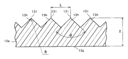
版胴12の下方にはプレスローラ13が配設されている。プレスローラ13は、図2に示すように、アルミニウム等の軽量金属製の中空パイプ13b、中空パイプ13bの両端部に一体的に取り付けられた軽量金属製の一対の端板13c、各端板13cに一体的に取り付けられた金属製の一対の芯部13aによって基体を構成され、この基体の外周に厚さ5〜10mm程度のシリコンゴム等の弾性体13dを、さらにその外周に一定幅で長尺のシート部材13eを巻成されて構成されている。シート部材13eは、その隙間が0.3mm以下となるようにきれいな螺旋状に巻き付けられて弾性体13dの周面に接着されており、その端部にはほどけ止めのテープ13fが取り付けられている。プレスローラ13は、本実施例においてはその外径が70mm程度に形成され、その長さは版胴12の軸方向長さとほぼ同じとされている。
【0035】
図3は、シート部材13eの部分拡大断面図を示している。シート部材13eの、弾性体13dに接着される取付面13gと対向する面には複数の突起13hが形成されており、この複数の突起13hを有するシート部材13eによって凹凸部が形成されている。シート部材13eは、ポリウレタン系あるいはポリオレフィン系等の熱可塑性合成樹脂を特別な金型によって成型したものであり、本実施例においてその厚みTは0.3〜0.4mmに形成されている。各突起13hは円錐形状あるいは多角錘形状の同一形状を呈しており、各頂角13iの角度がθ、頂角13iの先端部半径がR、各頂角13i間のピッチがLとなるようにそれぞれ形成されている。なお、これら角度θ、先端部半径R、ピッチLについては後述する。
【0036】
プレスローラ13は、図4に示すように各芯部13aの端部を一対のアーム部材20によってそれぞれ回転自在に支持されている。ほぼL字形状を呈する各アーム部材20は、その曲折部近傍の部位に取り付けられた揺動軸21によってそれぞれ一体化されており、揺動軸21は装置本体11によって回動自在に支持されている。各アーム部材20間には、プレスローラ13の他、再給紙案内部材22、再給紙レジストローラ23、再給紙位置決め部材24、再給紙搬送ユニット25、クリーニング手段としてのクリーニングローラ26、ガイド板27等が設けられている。
【0037】
プレスローラ13の右方近傍に配設された再給紙案内部材22は、各支軸28a,29a,30a上にそれぞれ一体的に設けられそれぞれの周面をプレスローラ13の周面に圧接させた複数のころ状のローラ28,29,30と、表面印刷済み用紙PAをプレスローラ13の周面に沿わせるための曲面状に形成された用紙ガイド板31とを有している。各支軸28a,29a,30aはそれぞれの両端部を各アーム部材20に回転自在に支持されており、図示しない付勢手段によってそれぞれ芯部13aに向けて付勢されている。各ローラ28,29,30は、対応する支軸28a,29a,30aに、プレスローラ13のほぼ全幅にわたってそれぞれ所定の間隔をもって一体的に取り付けられている。
【0038】
用紙ガイド板31はプレスローラ13の周面から各ローラ28,29,30の半径よりも小さな距離である所定距離だけ離れた位置に配設されており、その両端部を各アーム部材20に固着されている。用紙ガイド板31は芯部13aを中心とした曲面となるように形成されており、用紙ガイド板31には各ローラ28,29,30の周面をプレスローラ13の周面に当接させるための図示しない複数の開口部が形成されている。
【0039】
プレスローラ13の下方には再給紙レジストローラ23が配設されている。ころ状の再給紙レジストローラ23は支軸23aに回転自在に支持されており、支軸23aは一対の揺動アーム32の一端間に取り付けられている。ほぼへ字形状を呈する各揺動アーム32は、各アーム部材20間に固設された支軸32aにその曲折部をそれぞれ揺動自在に支持されており、その配設位置は揺動時において各ローラ30と干渉しない位置となるようにそれぞれ定められている。
【0040】
一方の揺動アーム32の他端には、図示しないブラケットを介して一方のアーム部材20に取り付けられたソレノイド33のプランジャ33aと、一端を一方のアーム部材20に固着され揺動アーム32に対して支軸32aを中心に図4において反時計回り方向への回動付勢力を付与する引張ばね34の他端とが取り付けられている。この構成より再給紙レジストローラ23は、ソレノイド33が作動されるとその周面を所定の圧接力でプレスローラ13の周面に圧接する図4に実線で示す圧接位置を占め、ソレノイド33の作動が解除されると引張ばね34の付勢力によってその周面がプレスローラ13の周面から離間する図4に二点鎖線で示す離間位置を占める。
【0041】
プレスローラ13の左下方には再給紙搬送ユニット25が配設されている。再給紙搬送ユニット25は、搬送ユニット本体35、駆動ローラ36、従動ローラ37、無端ベルト38、吸引ファン39等を有しており、その上面に補助トレイ8を一体的に有している。
【0042】
上面が開放され、その幅が各アーム部材20間の間隔よりも若干小さくなるように形成された筐体である搬送ユニット本体35は、その用紙搬送方向上流側及び下流側の両側面に図示しない軸受を有しており、図示しない各軸受は駆動軸36a及び従動軸37aをそれぞれ回転自在に支持している。駆動軸36aはその両端部が搬送ユニット本体35の両側面を貫通しており、貫通した両端部は装置本体11に設けられた図示しない軸受部材によって回転自在に支持されている。また、駆動軸36aの一端には図示しない駆動ギヤが取り付けられており、駆動軸36aは装置本体11に設けられた搬送ユニット駆動モータ122(図14参照)によって回転駆動される。従動軸37aはその両端部が搬送ユニット本体35の両側面を貫通しないように構成されている。
【0043】
搬送ユニット本体35の用紙搬送方向上流側端部の両側面外側にはボス35aがそれぞれ一体的に設けられており、各ボス35aは各アーム部材20に形成された図示しない長穴にそれぞれ嵌合されている。この構成より搬送ユニット本体35は、後述するプレスローラ接離機構55によりプレスローラ13が版胴12に対して接離される際に、各アーム部材20の揺動に伴って駆動軸36aを中心とした揺動が可能となっている。
【0044】
ころ状をなす複数の駆動ローラ36はそれぞれ駆動軸36aに一体的に取り付けられており、各駆動ローラ36間にはそれぞれ所定の間隔が設けられている。駆動ローラ36と同形状である複数の従動ローラ37は、各駆動ローラ36と同じ間隔でそれぞれ従動軸37aに一体的に取り付けられている。各駆動ローラ36とこれに対応した各従動ローラ37との間には、無端ベルト38が所定の張力でそれぞれ掛け渡されている。摩擦抵抗部材からなる無端ベルト38は、搬送ユニット駆動モータ122によって駆動軸36aが回転駆動されることにより図4に矢印で示す方向に移動される。
【0045】
搬送ユニット本体35の下面には吸引ファン39が、上面には補助トレイ8がそれぞれ一体的に取り付けられている。補助トレイ8は各ローラ36,37の周面の一部が用紙搬送面に臨むように構成されており、図5に示すように、用紙搬送面上の各無端ベルト38の両側部にはそれぞれ複数の開孔8bが穿設され、その用紙搬送方向下流側端部には印刷部2より送られた表面印刷済み用紙PAの一端を受け止めるための2個のエンドフェンス8aがそれぞれ一体的に設けられている。
【0046】
補助トレイ8の用紙搬送方向上流側端部には、再給紙搬送ユニット25によって印刷部2へと再給紙される表面印刷済み用紙PAの他端を定位置で一時停止させるための再給紙位置決め部材24が配設されている。本実施例において再給紙位置決め部材24は2個設けられており、それぞれ補助トレイ8に一体的に取り付けられている。さらに補助トレイ8には、表面印刷済み用紙PAの他端が再給紙位置決め部材24に近接したことを検知するセンサ8cが配設されている。センサ8cは、表面印刷済み用紙PAの他端を検知した際に後述する制御手段129へ向けて信号を出力する。
【0047】
吸引ファン39の取付面である搬送ユニット本体35の下面には図示しない穴部が設けられており、これにより吸引ファン39が作動することで筐体である搬送ユニット本体35の内部に負圧を発生させ、移動する各無端ベルト38の上面に表面印刷済み用紙PAを吸引させる。吸引ファン39の吸引力及び無端ベルト38の摩擦抵抗力は、表面印刷済み用紙PAの他端が再給紙位置決め部材24に当接した際に、表面印刷済み用紙PAと各無端ベルト38との間で滑りが発生する程度の強さにそれぞれ設定されている。
【0048】
上述した補助トレイ8、再給紙案内部材22、再給紙レジストローラ23、再給紙位置決め部材24、及び再給紙搬送ユニット25によって再給紙手段9が構成されている。また、再給紙手段9は、図1、図4及び図5に示す用紙受け板40を有している。以下、この用紙受け板40について説明する。
【0049】
断面コ字形状を呈する用紙受け板40は、図5に示すようにその両側部に突起40a,40b,40c,40dを有しており、各突起40a,40b,40c,40dは搬送ユニット本体35の両側板に穿設された図示しない長穴にそれぞれ嵌合されている。また、用紙受け板40の一端部には各エンドフェンス8aが嵌合可能な切欠部40eが形成されており、用紙受け板40の両側部には他端側に延出したラック部40fがそれぞれ形成されている。用紙受け板40は各無端ベルト38よりも上方に離隔した位置に配設されており、その下面と各無端ベルト38との間隔は、表面印刷済み用紙PAが各無端ベルト38上を良好に搬送可能となる所定の間隔に設定されている。
【0050】
搬送ユニット本体35の一方の側板の外側には、その出力軸138a上に2個のピニオン139を有するステッピングモータ138が取り付けられている。出力軸138aの先端は搬送ユニット本体35の他方の側板に回転自在に支持されており、各ピニオン139は搬送ユニット本体35の両側板近傍の位置であって各ラック部40fとそれぞれ噛合する位置に配設されている。
【0051】
ステッピングモータ138の近傍には、用紙受け板40のホームポジションを検知するためのホームポジションセンサ140が配設されている。ホームポジションセンサ140は、突起40dの突出部を検知可能な位置に配設されており、ホームポジションセンサ140からの信号は後述する制御手段129に向けて出力される。
【0052】
上述の構成より、用紙受け板40はステッピングモータ138によって、プレスローラ13に最も近付き印刷部2より搬送される表面印刷済み用紙PAの一端を受け止める、図6に示すホームポジションである第1の位置と、プレスローラ13より最も離れその上面上に載置した表面印刷済み用紙PAの他端が各無端ベルト38に接触する、図7に示す第2の位置とを選択的に占めるべく往復動される。
【0053】
用紙受け板40の用紙搬送方向における長さは、用紙受け板40が第2の位置を占め、用紙受け板40上の表面印刷済み用紙PAの他端が用紙受け板40上より各無端ベルト38上に落下し、表面印刷済み用紙PAが再給紙搬送ユニット25によって搬送されてその他端が再給紙位置決め部材24に当接したときに、表面印刷済み用紙PAの一端が第2の位置を占めている用紙受け板40上より落下する長さに設定されている。
【0054】
プレスローラ13の近傍であって再給紙搬送ユニット25の上方に位置する部位には、プレスローラ13の周面をクリーニングするクリーニングローラ26が配設されている。プレスローラ13の幅とほぼ同じ幅を有するクリーニングローラ26は、図4に示すようにその中心に芯部26aを一体的に有している。クリーニングローラ26は、芯部26aを各アーム部材20に形成された図示しない長穴に嵌合されることで回転自在に支持されており、この長穴内に設けられた図示しない付勢手段によってプレスローラ13に向けて付勢され、その周面をプレスローラ13の周面に1〜3N程度の圧接力で常時圧接されている。
【0055】
クリーニングローラ26は、一方のアーム部材20に設けられた図示しないクリーニングローラ駆動手段によって、プレスローラ13の回転時においてプレスローラ13と同方向に、プレスローラ13の周速度の10分の1程度の周速度で回転駆動される。なお、プレスローラ13とクリーニングローラ26との回転周速度の差が大きいため、クリーニングローラ26をプレスローラ13とは逆方向に回転駆動してもクリーニング効果は得られるが、同方向に回転駆動した方がクリーニング効果は大きい。
【0056】
クリーニングローラ26は、少なくともその表面が多孔性の部材によって構成されている。多孔性の部材としては、和紙、スポンジ、吸湿性の高い発泡体ゴム、発泡体合成樹脂、不織布、フェルト、クリーナーシート等が挙げられる。また、オイルあるいは洗浄液等を含浸させたフェルトあるいはクリーナーシート等も効果的である。この場合、インキの拭き取り効果を大きくするためには、クリーニングローラ26をプレスローラ13の外周面に所定の押圧力で圧接させながら、プレスローラ13の周速度との間に速度差を与えて低速で回転駆動することが必要である。
【0057】
クリーニングローラ26の左上方にはガイド板27が配設されている。板材であるガイド板27はその両端部を各アーム部材20に固設されており、印刷部2より送られる表面印刷済み用紙PAがクリーニングローラ26に触れないように、かつ補助トレイ8に向かうように案内する。ガイド板27はプレスローラ13及びクリーニングローラ26の各周面に近接する位置に配設されている。ガイド板として、図8に示すように、再給紙手段9によって再給紙される表面印刷済み用紙PAがクリーニングローラ26に接触することをも防止可能なガイド板27aを用いてもよい。クリーニングローラ26を設けることにより、プレスローラ13表面に転移されたインキを拭き取ることでプレスローラ13から用紙Pあるいは表面印刷済み用紙PAへのインキの再転移をより確実に抑制することが可能となり、より一層良好な印刷物を得ることができる。
【0058】
各アーム部材20の、プレスローラ13が支持された一端側と対向する他端側には、それぞれ回転自在なカムフォロア41が互いに外側を向く態様で配設されている。また、各アーム部材20のカムフォロア41が配設された位置の近傍には、一端を装置本体11に固着された印圧ばね42の他端がそれぞれ取り付けられている。これにより各アーム部材20は、揺動軸21を中心に図4において時計回り方向への回動付勢力をそれぞれ付与されている。
【0059】
各カムフォロア41の左方近傍には、3枚のカム板43A,43B,43Cを有する多段カム43がそれぞれ配設されている。各カム板43A,43B,43Cは、両端を装置本体11に回転自在かつ図4の紙面方向に移動自在に支持されたカム軸44にそれぞれ所定の間隙をもって固着されており、装置手前側からカム板43B、カム板43A、カム板43Cの順に配設されている。各カム板43A,43B,43Cは、カム軸44と同心の円板である基部とそれぞれ同一突出量の凸部とを有している。多段カム43は、図9に示すように、カム軸44に取り付けられた駆動ギヤ45及び装置本体11に回転自在に支持された支軸46に取り付けられた伝達ギヤ47を介して版胴駆動手段121からの回転力を伝達され、図4において時計回り方向に回転駆動される。
【0060】
プレスローラ13は、各カム板43A,43B,43Cの何れかの凸部がカムフォロア41と当接したときにその周面が版胴12の周面より離間する図4に示す離間位置を占め、何れかの凸部とカムフォロア41との当接が解除されたときに印圧ばね42の付勢力によってその周面が版胴12の周面に圧接する図10に示す圧接位置を占める。各カム板43A,43B,43Cは、プレスローラ13が圧接位置を占めたときにその基部とカムフォロア41とが接触しないように構成されている。
【0061】
各カム板43A,43B,43Cの凸部の形状は、プレスローラ13と版胴12との接触範囲が、カム板43Aでは図1に示す表面領域と中間領域と裏面領域とを全て合わせた範囲となるように、カム板43Bでは表面領域と同じ範囲となるように、カム板43Cでは表面領域の下流側部分と中間領域と裏面領域とを合わせた範囲となるようにそれぞれ形成されている。また、各カム板43A,43B,43C間の間隔は、アーム部材20の板厚よりも十分に大きくなるように設定されている。
【0062】
図4において各アーム部材20の右方近傍には、プレスローラ13が離間位置を占めた状態で各アーム部材20の揺動を禁止する、図示しないプレスローラ係止手段が配設されている。図示しないプレスローラ係止手段は図示しないソレノイドを有しており、この図示しないソレノイドのオン・オフの切り換えによって各アーム部材20を保持する状態と保持を解除する状態とが選択的に切り換えられる。図示しないソレノイドは、カムフォロア41が各カム板43A,43B,43Cの何れかの凸部と当接した状態で作動される。
【0063】
カム軸44の下方近傍には、図9に示すように移動アーム48と段差カム49とが配設されている。ほぼL字形状を呈する移動アーム48は、装置本体11に回転自在に支持された支軸48aにその曲折部を取り付けられており、移動アーム48の一端にはローラ48bが、他端にはカムフォロア48cがそれぞれ回転自在に取り付けられている。さらに移動アーム48の他端と曲折部との間の部位には、一端を装置本体11に取り付けられた引張ばね50の他端が取り付けられており、移動アーム48には支軸48aを中心に、図において時計回り方向への回動付勢力が付与されている。
【0064】
ローラ48bはカム軸44の中程に間隔をおいて固着された円板44a,44b間に配置されており、カムフォロア48cは引張ばね50の付勢力によってその周面を段差カム49の周面に当接させている。各円板44a,44b間の間隔は、ローラ48bの直径よりも僅かに大きくなるように設定されている。
【0065】
段差カム49はその周面に3箇所のカム部49a,49b,49cを有しており、装置本体11に回転自在に支持された支軸51に固着されている。支軸51には、装置本体11に取り付けられたステッピングモータ52の出力軸に取り付けられたギヤ53と噛合するギヤ54が取り付けられており、ステッピングモータ52の作動により段差カム49は図9の矢印方向に回転駆動される。この構成より、ステッピングモータ52が作動して段差カム49が回転すると移動アーム48が支軸48aを中心に揺動し、ローラ48bが円板44aあるいは円板44bを押すことでカム軸44が図9の左右方向に移動する。
【0066】
各カム部49a,49b,49cは、カムフォロア48cとカム部49aとが当接したときにカム板43Bがカムフォロア41と当接可能位置となるように、カムフォロア48cとカム部49bとが当接したときにカム板43Aがカムフォロア41と当接可能位置となるように、カムフォロア48cとカム部49cとが当接したときにカム板43Cがカムフォロア41と当接可能位置となるようにカム軸44を移動させる形状にそれぞれ形成されている。
【0067】
上述したカムフォロア41、印圧ばね42、多段カム43、図示しないプレスローラ係止手段、移動アーム48、段差カム49によってプレスローラ接離機構55が構成されており、このプレスローラ接離機構55の作動によってプレスローラ13は、図4に示す離間位置と図10に示す圧接位置とを選択的に占める。
【0068】
版胴12とプレスローラ13との接触位置の左方であって用紙Pの搬送経路上には、用紙Pの搬送経路を切り換える切換部材10が配設されている。版胴12及びプレスローラ13とほぼ同じ幅を有する板材からなる切換部材10は、その用紙搬送方向下流側端部を装置本体11に回動自在に支持された支軸に固着されており、ソレノイド123(図14参照)が作動することによって断面鋭角状に形成された用紙搬送方向上流側端部を図1に実線で示す第1の位置と二点鎖線で示す第2の位置とに選択的に位置決めされる。
【0069】
切換部材10は、第1の位置を占めたときにその先端がプレスローラ13の周面に近接すると共に版胴12上のクランパ19bと干渉しない位置に置かれ、第2の位置を占めたときにその先端が版胴12の周面に近接する位置に置かれる。版胴12とプレスローラ13との間を通過した表面印刷済み用紙PAは、切換部材10が第1の位置を占めたときに排紙部6へと案内され、切換部材10が第2の位置を占めたときにガイド板27と装置本体11に固着されたガイド板56との間を通って補助トレイ8へと案内される。
【0070】
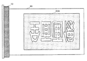
装置本体11の右上部には製版部3が配設されている。製版部3は、マスタ保持部材57、プラテンローラ58、サーマルヘッド59、切断手段60、マスタストック部61、テンションローラ対62、反転ローラ対63等を有している。製版部3は後述するマスタ64に製版を行い、図11に示すような第1の画像としての第1製版画像65Aと第2の画像としての第2製版画像65Bとを有する分割製版済みマスタ65、あるいは図12に示すような第1製版画像65Aと第2製版画像65Bとの2面分の画像領域を有する第3製版画像66Aを有する製版済みマスタ66を作成する。第1製版画像65Aは、分割製版済みマスタ65が版胴12の外周面上に巻装されたときに図1に示す表面領域と対応する位置に形成され、第2製版画像65Bは裏面領域と対応する位置に形成される。
【0071】
マスタ保持部材57は製版部3の図示しない側板対にそれぞれ設けられており、熱可塑性樹脂フィルムと多孔性支持体とを貼り合わせたマスタ64をロール状に巻成してなるマスタロール64aの芯部64bの両端を回転自在かつ着脱自在に支持する。
【0072】
マスタ保持部材57の左方に設けられたプラテンローラ58は製版部3の図示しない側板に回転自在に支持されており、ステッピングモータを含む製版駆動手段124(図14参照)によって回転駆動される。プラテンローラ58の下方に位置し多数の発熱素子を有するサーマルヘッド59も製版部3の図示しない側板に取り付けられており、図示しない付勢手段の付勢力によってその発熱素子面をプラテンローラ58に圧接されている。サーマルヘッド59はマスタ64の熱可塑性樹脂フィルム面に接触しつつ発熱素子を選択的に発熱させ、マスタ64に対して熱溶融穿孔製版を行う。
【0073】
プラテンローラ58及びサーマルヘッド59の左方には切断手段60が配設されている。製版部3の図示しない側板に固設された固定刃60aと、この固定刃60aに移動自在に支持された可動刃60bとを有する切断手段60は、固定刃60aに対して可動刃60bが回転移動することによりマスタ64を切断する周知の構成である。
【0074】
切断手段60のマスタ搬送方向下流側下方にはマスタストック部61が配設されている。分割製版済みマスタ65あるいは製版済みマスタ66を一時的に貯容する空間であるマスタストック部61は複数の板部材によってその内部を仕切られており、その最奥部には図示しない吸引ファンが配設されている。この吸引ファンが作動することにより密閉された空間であるマスタストック部61の内部に負圧が発生し、製版搬送されてきた分割製版済みマスタ65あるいは製版済みマスタ66はマスタストック部61の最奥部に向けて貯容される。
【0075】
切断手段60とマスタストック部61との間の部位にはテンションローラ対62が配設されている。それぞれ製版部3の図示しない側板に回転自在に支持された駆動ローラ62aと従動ローラ62bとからなるテンションローラ対62は、従動ローラ62bが図示しない付勢手段によってその周面を駆動ローラ62aの周面に圧接されており、製版駆動手段124によって駆動ローラ62aが回転駆動されることによりマスタ64を挟持して搬送する。駆動ローラ62aは、その周速度がプラテンローラ58の周速度よりも若干速く設定されていると共にその内部には図示しないトルクリミッタが設けられており、プラテンローラ58とテンションローラ対62との間においてマスタ64に対して所定の張力が付与されるように構成されている。
【0076】
マスタストック部61のマスタ搬送方向下流側には、それぞれ製版部3の図示しない側板に回転自在に支持された駆動ローラ63aと従動ローラ63bとからなる反転ローラ対63が配設されている。反転ローラ対63は、製版駆動手段124によって回転駆動される駆動ローラ63aと、図示しない付勢手段によってこれに圧接配置された従動ローラ63bとによってマスタ64を挟持して搬送する。駆動ローラ63aの内部には、図示しないワンウェイクラッチが設けられている。
【0077】
また、テンションローラ対62と反転ローラ対63との間の部位には、図示しない可動マスタガイド板が配設されている。この可動マスタガイド板は図示しない支持部材に揺動自在に支持されており、図示しないソレノイドによってその上面がマスタ64の搬送路を構成する搬送位置と、マスタ64のマスタストック部61への進入を妨げない退避位置とに選択的に位置決めされる。
【0078】
製版部3の下方には給紙部4が配設されている。給紙部4は、給紙トレイ67、給紙ローラ68、分離ローラ69、分離パッド70、レジストローラ対71等を有している。
上面に多数の用紙Pを積載可能な給紙トレイ67は装置本体11に上下動自在に支持されており、昇降手段を含む給紙駆動手段125(図14参照)によって上下動される。A3サイズの用紙Pを縦置き可能な給紙トレイ67の上面には、図示しないレール部材によって用紙搬送方向と直行する用紙幅方向に移動自在に支持された一対のサイドフェンス72が設けられている。また、給紙トレイ67の自由端部側には、積載された用紙Pのサイズを検知する複数の用紙サイズ検知センサ73が設けられている。
【0079】
給紙トレイ67の上方には、表面に高摩擦抵抗部材を有する給紙ローラ68が配設されている。給紙ローラ68は装置本体11に揺動自在に支持された図示しないブラケットに回転自在に支持されており、給紙トレイ67が図示しない昇降手段によって上昇されたときに所定の圧接力で給紙トレイ67上の最上位の用紙Pに圧接する。給紙ローラ68は給紙駆動手段125によって回転駆動される。
【0080】
給紙ローラ68の左方には、表面にそれぞれ高摩擦抵抗部材を有する分離ローラ69と分離パッド70とが配設されている。分離ローラ69はタイミングベルト69aを介して給紙ローラ68に駆動連結されており、給紙ローラ68の回転駆動時にこれと同期して同方向に回転駆動される。分離パッド70は図示しない付勢手段の付勢力によって分離ローラ69に圧接されている。
【0081】
分離ローラ69及び分離パッド70の左方にはレジストローラ対71が配設されている。駆動ローラ71aと従動ローラ71bとからなるレジストローラ対71は、版胴駆動手段121からの回転駆動力をギヤやカム等の図示しない駆動力伝達手段によって伝達されることで駆動ローラ71aが版胴12と同期した所定のタイミングで回転し、駆動ローラ71aに圧接された従動ローラ71bとによって用紙Pを印刷部2に向けて所定のタイミングで給送する。
【0082】
レジストローラ対71の用紙搬送方向上流側及び下流側には、給紙部4から印刷部2へと給送される用紙Pの搬送をガイドするための給紙ガイド板136,137がそれぞれ配設されている。各給紙ガイド板136,137は、装置本体11の図示しない側板間にそれぞれ固定されている。
【0083】
印刷部2の左上方には排版部5が配設されている。排版部5は、上排版部材74、下排版部材75、排版ボックス76、圧縮板77等を有している。
上排版部材74は、駆動ローラ78、従動ローラ79、無端ベルト80等を有し、排版駆動手段126(図14参照)によって駆動ローラ78が図の時計回り方向に回転駆動されることにより無端ベルト80が図1の矢印方向に移動する。下排版部材75は、駆動ローラ81、従動ローラ82、無端ベルト83等を有し、駆動ローラ78を回転駆動する排版駆動手段126の駆動力をギヤやベルト等の図示しない駆動力伝達手段によって伝達されることで駆動ローラ81が図の反時計回り方向に回転駆動されることにより、無端ベルト83が図1の矢印方向に移動する。また、下排版部材75は排版駆動手段126に含まれる図示しない移動手段によって移動自在に設けられており、図に示す位置と従動ローラ82の外周面上に位置する無端ベルト83が版胴12の外周面に当接する位置とを選択的に占める。
【0084】
内部に使用済みマスタ64cを貯容する排版ボックス76は、装置本体11に対して着脱自在に設けられている。上排版部材74と下排版部材75とによって運ばれた使用済みマスタ64cを排版ボックス76の内部に押し込む圧縮板77は装置本体11に上下動自在に支持されており、排版駆動手段126に含まれる図示しない昇降手段によって上下動される。
【0085】
排版部5の下方には排紙部6が配設されている。排紙部6は、剥離爪84、排紙搬送ユニット85、排紙トレイ86等を有している。
剥離爪84は版胴12の幅方向に複数配置され、装置本体11に揺動自在に支持された支軸にそれぞれ一体的に取り付けられている。複数の剥離爪84は図示しない爪揺動手段によって揺動され、その先端が版胴12の周面に近接する図に示す位置と、クランパ19b等の障害物を回避するためにその先端が版胴12の外周面から離間する位置とを選択的に占める。図示しない爪揺動手段は、版胴駆動手段121からの駆動力を図示しない駆動力伝達手段により伝達され、版胴12の回転と同期して剥離爪84を揺動させる。
【0086】
剥離爪84の下方であって切換部材10の左方に配設された排紙搬送ユニット85は、駆動ローラ87、従動ローラ88、無端ベルト89、吸引ファン90等を有している。ころ状の駆動ローラ87は図示しないユニット側板に回転自在に支持された図示しない支軸に所定の間隔で複数取り付けられており、排紙駆動手段127(図14参照)によってそれぞれ一体的に回転駆動される。従動ローラ88も同側板に回転自在に支持された図示しない支軸に各駆動ローラ87と等間隔で複数設けられており、各駆動ローラ87及びこれと対応する各従動ローラ88には無端ベルト89がそれぞれ掛け渡されている。駆動ローラ87、従動ローラ88、無端ベルト89の下方には吸引ファン90が配設されている。排紙搬送ユニット85は、吸引ファン90の吸引力によって各無端ベルト89上に用紙Pを吸引し、各駆動ローラ87の回転によって印刷済み用紙PBを図1の矢印方向に搬送する。
【0087】
排紙搬送ユニット85によって搬送された印刷済み用紙PBをその上面に積載する排紙トレイ86は、用紙搬送方向に移動自在な1個のエンドフェンス91と用紙幅方向に移動自在な一対のサイドフェンス92とを有している。
【0088】
装置本体11の上部には画像読取部7が配設されている。画像読取部7は、原稿を載置するコンタクトガラス93、コンタクトガラス93に対して接離自在に設けられた圧板94、原稿画像を走査して読み取る反射ミラー95,96,97,98及び蛍光灯99、走査された原稿画像を集束するレンズ100、集束された画像を処理するCCD等の画像センサ101、原稿のサイズを検知する複数の原稿サイズ検知センサ102、読み取られた画像データを記憶する画像メモリ135等を有しており、原稿画像の読取動作は読取駆動手段128(図14参照)の作動によって行われる。
【0089】
また、図1に示すように、版胴12を構成する図示しない端板の外面にはドグ133が取り付けられており、版胴12の周囲近傍には装置本体11に取り付けられたホームポジションセンサ134が配設されている。ホームポジションセンサ134は、クランパ19bがプレスローラ13と対向する位置を版胴12が占めたときに、ドグ133を検知して後述する制御手段129に向けて信号を出力する。
【0090】
図13は両面印刷装置1の操作パネルを示している。同図において装置本体11の上部前面に設けられた操作パネル103は、その上面に製版スタートキー104、印刷スタートキー105、試し刷りキー106、連続キー107、クリア/ストップキー108、テンキー109、エンターキー110、プログラムキー111、モードクリアキー112、印刷速度設定キー113、4方向キー114、用紙サイズ設定キー115、用紙厚み設定キー116、両面印刷キー117、片面印刷キー118、7セグメントLEDからなる表示装置119、LCDからなる表示装置120等を有している。
【0091】
製版スタートキー104は両面印刷装置1に製版動作を行わせる際に押下され、製版スタートキー104が押下されると排版動作及び原稿読取動作が行われた後に製版動作が行われ、その後、版付け動作が行われて両面印刷装置1は印刷待機状態となる。印刷スタートキー105は両面印刷装置1に印刷動作を行わせる際に押下され、両面印刷装置1が印刷待機状態となり各種印刷条件が設定された後に印刷スタートキー105が押下されることにより印刷動作が行われる。試し刷りキー106は両面印刷装置1に試し刷りを行わせる際に押下され、各種条件が設定された後に試し刷りキー106が押下されることにより1枚だけ印刷が行われる。連続キー107は製版動作と印刷動作とを連続して行う際に製版スタートキー104の押下前に押下され、連続キー107の押下後、印刷条件が入力された後に製版スタートキー104が押下されると、排版動作、原稿読取動作、製版動作に引き続いて印刷動作が行われる。
【0092】
クリア/ストップキー108は両面印刷装置1の動作を停止させる際あるいは置数のクリア時に押下され、テンキー109は数値入力に用いられる。エンターキー110は各種設定時に数値等を設定する際に、プログラムキー111はよく行う操作を登録したりそれを呼び出したりする際にそれぞれ押下され、モードクリアキー112は各種のモードをクリアして初期状態に戻す際に押下される。印刷速度設定キー113は印刷動作に先立って印刷速度を設定する際に押下され、濃いめの画像を得たい場合あるいは雰囲気温度が低い場合等には印刷速度を遅く、薄めの画像を得たい場合あるいは雰囲気温度が高い場合等には印刷速度を速く設定する。4方向キー114は上キー114a、下キー114b、左キー114c、右キー114dを有しており、画像編集時に画像位置を調整する場合あるいは各種設定時に数値や項目等を選択する場合等に押下される。
【0093】
用紙サイズ設定キー115は用紙サイズを任意で入力する際に押下され、用紙サイズ設定キー115で入力された用紙サイズは用紙サイズ検知センサ73によって検知された用紙サイズに優先される。用紙厚み設定キー116は両面印刷に先立って用紙Pの厚みを入力する際に押下され、本実施例では「普通紙」、「薄紙」、「厚紙」の3種類のうちの何れかを選択する構成となっている。
【0094】
両面印刷キー117は両面印刷装置1に両面印刷動作を行わせる際に製版スタートキー104の押下前に押下され、両面印刷キー117が押下されるとその近傍に配置されたLED117aが点灯してオペレータに両面印刷モードであることが表示される。また、両面印刷キー117が押下された際には、用紙厚み設定キー116によって使用する用紙Pの厚みを入力した後でないと製版スタートキー104の入力が拒否される。片面印刷キー118も両面印刷キー117と同様に両面印刷装置1に片面印刷動作を行わせる際にスタートキー104の押下前に押下され、片面印刷キー118が押下されるとその近傍に配置されたLED118aが点灯してオペレータに片面印刷モードであることが表示される。両面印刷装置1は初期状態時においてLED118aが点灯しており、片面印刷モードとなっている。
【0095】
7セグメントLEDからなる表示装置119は、主に印刷枚数等の数字を表示する。LCDからなる表示装置120は階層表示構造となっており、その下方に設けられた選択設定キー120a,120b,120c,120dを押下することにより、変倍や位置調整等の様々なモードへの変更及び各モードでの設定が可能に構成されている。また表示装置120には、図示したように「製版・プリントできます」のような両面印刷装置1の状態が表示される他、製版あるいは排版ジャム、給紙あるいは排紙ジャム等のアラーム、印刷用紙、マスタ、インキ等のサプライの供給指示等も表示される。
【0096】
図14は、両面印刷装置1に用いられる制御手段のブロック図を示している。同図において制御手段129は、内部にCPU130、ROM131、RAM132を有する周知のマイクロコンピュータであり、装置本体11の内部に設けられている。
【0097】
CPU130は、操作パネル103からの各種信号及び装置本体11に設けられた各種センサからの検知信号及びROM131から呼び出された動作プログラムに基づいて、印刷部2、製版部3、給紙部4、排版部5、排紙部6、画像読取部7に設けられた各駆動手段、再給紙手段9に設けられたソレノイド33及び搬送ユニット駆動モータ122、切換部材10を作動させるソレノイド123の作動等を制御し、両面印刷装置1全体の動作を制御する。ROM131には両面印刷装置1全体の動作プログラムが記憶されており、この動作プログラムはCPU130によって適宜呼び出される。RAM132は、CPU130の計算結果を一時的に記憶する機能、操作パネル103上の各種キー及び各種センサから設定及び入力されたデータ信号及びオン・オフ信号を随時記憶する機能等を有している。また制御手段129は、ホームポジションセンサ134からのホームポジション信号と、版胴駆動手段121に設けられた図示しないエンコーダからの信号とに基づいて、版胴12の位置の把握も行っている。
【0098】
上述の構成に基づき、以下に両面印刷装置1の動作を説明する。
オペレータは給紙トレイ67上に印刷に使用される用紙Pを積載し、圧板94を開放してコンタクトガラス93上に印刷すべき原稿を載置した後、再び圧板94を閉じる。その後、操作パネル103上の各種キーによって製版条件を設定した後、両面印刷キー117あるいは片面印刷キー118を押下して印刷モードを設定して製版スタートキー104を押下する。先ず、片面印刷キー118を押下して片面印刷を行う場合を説明する。
【0099】
オペレータは片面印刷モードであることをLED118aの点灯によって確認した後、製版スタートキー104を押下する。製版スタートキー104が押下されると、用紙サイズ検知センサ73から用紙サイズ検知信号が、また原稿サイズ検知センサ102から原稿サイズ検知信号がそれぞれ制御手段129に送られ、信号を受けた制御手段129は各信号を比較する。このとき、用紙サイズと原稿サイズとが同じ場合は直ちに画像読取動作が行われ、用紙サイズと原稿サイズとが異なる場合には、制御手段129はその旨を表示装置120に表示してオペレータに注意を促す。用紙サイズと原稿サイズとが異なる場合に、制御手段129からの指令で自動的に拡大または縮小の変倍を行い、原稿サイズと画像サイズとを整合させるように構成してもよい。
【0100】
製版スタートキー104が押下されると、画像読取部7では原稿画像の読取動作が行われる。原稿画像の読み取りは、蛍光灯99によって露光された反射光を各反射ミラー95,96,97,98によって反射することにより行われ、読み取られた原稿画像はレンズ100で集束された後に画像センサ101に入射されて光電変換される。光電変換された電気信号は装置本体11内の図示しないA/D変換器に入力された後、画像メモリ135内に画像データ信号として格納される。
【0101】
画像読取部7での画像読取動作と並行して、排版部5では版胴12の外周面から使用済みマスタを剥離する排版動作が行われる。製版スタートキー104が押下されると版胴12が回転を開始し、版胴12が図1に示すホームポジションに達するとドグ133がホームポジションセンサ134に検知され、ホームポジションセンサ134から制御手段129に向けてホームポジション信号が送られる。ホームポジション信号を受けた制御手段129は、このホームポジションを基点として図示しないエンコーダが発するパルス数を計測し、版胴12の外周面上に巻装された使用済みマスタの先端が従動ローラ82の外周面上に位置する無端ベルト83と対応する所定の排版位置に達したと判断すると、版胴駆動手段121の作動を停止させる。
【0102】
版胴駆動手段121が停止されて版胴12が所定の排版位置で停止すると、版胴駆動手段121及び排版駆動手段126が作動して各駆動ローラ78,81が回転駆動されると共に下排版部材75が版胴12側に移動し、従動ローラ82の外周面上に位置する無端ベルト83が版胴12上の使用済みマスタ64cと当接する。すると、版胴12の回転及び無端ベルト83の移動によって版胴12の外周面上よりすくい上げられた使用済みマスタ64cは、下排版部材75と上排版部材74とで挟持搬送されて版胴12の外周面より剥離される。剥離された使用済みマスタ64cは排版ボックス76内に廃棄された後、圧縮板77によって圧縮される。
【0103】
外周面上より使用済みマスタ64cが全て剥離された後も版胴12は回転を継続し、クランパ19bが右上方に位置する所定の給版待機位置まで回転して停止する。版胴12が給版待機位置で停止すると図示しない開閉手段が作動してクランパ19bが開放され、両面印刷装置1は給版待機状態となる。
【0104】
排版動作と並行して、製版部3では製版動作が行われる。製版スタートキー104が押下されると、プラテンローラ58、テンションローラ対62、反転ローラ対63がそれぞれ回転駆動されてマスタロール64aよりマスタ64が引き出される。このとき図示しない可動マスタガイド板は搬送位置に位置決めされている。マスタ64が引き出されてその画像形成領域がサーマルヘッド59の発熱素子と対応する位置に達すると、画像メモリ135内に格納されている画像データ信号が画像処理を施された後に呼び出され、図示しないサーマルヘッドドライバがサーマルヘッド59の各発熱素子を選択的に発熱させることにより、マスタ64の熱可塑性樹脂フィルム面に第3製版画像66Aが形成される。マスタ64は製版されつつ搬送され、その先端部が反転ローラ対63に挟持されると図示しない可動マスタガイド板が退避位置に移動されると共に、反転ローラ対63の回転が停止される。
【0105】
反転ローラ対63の回転停止後もプラテンローラ58及びテンションローラ対62は回転を継続しており、サーマルヘッド59によって製版された製版済みマスタ66はマスタストック部61内に貯容される。反転ローラ対63の停止時においてマスタストック部61に設けられた図示しない吸引ファンが作動されており、製版済みマスタ66は図示しない吸引ファンに吸引されることによって良好にマスタストック部61内に貯容される。
【0106】
上述の製版動作中、排版動作が完了して両面印刷装置1が給版待機状態となると、反転ローラ対63が回転を開始してマスタストック部61内に貯容されている製版済みマスタ66がステージ部19aと開放されているクランパ19bとの間に向けて搬送される。そして、製版済みマスタ66の先端部がクランパ19bによって挟持可能な所定位置まで搬送されると、図示しない開閉手段が作動してクランパ19bが閉じられ、製版済みマスタ66はその先端部をステージ部19aとクランパ19bとによって版胴12の外周面上に保持される。
【0107】
その後、版胴12が図1において時計回り方向に間欠的に回転駆動され、製版済みマスタ66の版胴12への巻装動作が行われる。このとき反転ローラ対63は回転を停止しており、駆動ローラ63aは内部に設けられた図示しないワンウェイクラッチによって製版済みマスタ66の引き出しに伴い連れ回りする。そして、画像メモリ135からの画像データ信号が途絶えるとサーマルヘッド59の作動が停止し、1版分の製版済みマスタ66が製版搬送されるとプラテンローラ58、テンションローラ対62、反転ローラ対63の回転がそれぞれ停止されると共に、切断手段60が作動して製版済みマスタ66が切断される。切断された製版済みマスタ66は版胴12の回転によって製版部3より引き出され、版胴12がホームポジションまで回転して停止することで製版動作及び給版動作が完了する。
【0108】
給版動作に引き続き版付け動作が行われる。版胴12がホームポジションで停止すると、ソレノイド123が作動して切換部材10が第1の位置に位置決めされた後、図示しないプレスローラ係止手段が作動すると共にステッピングモータ52が作動して段差カム49が回転され、そのカム部49bをカムフォロア48cに当接させる。これにより移動アーム48が支軸48aを中心に揺動され、カム軸44がカム板43Aをカムフォロア41に対して当接可能となる位置に移動された後、図示しないプレスローラ係止手段の作動が解除される。
【0109】
その後、給紙ローラ68、分離ローラ69、駆動ローラ87、吸引ファン90がそれぞれ駆動されると共に版胴12が低速で図1の時計回り方向に回転駆動され、給紙トレイ67上に積載された用紙Pの最上位の1枚が引き出されてその先端をレジストローラ対71に挟持される。そして、版胴12上に巻装された製版済みマスタ66の版胴回転方向における第3製版画像66Aの画像領域先端部がプレスローラ13と対応する位置に到達する所定のタイミングで駆動ローラ71aが回転駆動され、引き出された用紙Pは版胴12とプレスローラ13との間に向けて給送される。
【0110】
版胴12の回転に同期して、プレスローラ接離機構55ではカム軸44及びこれと一体に設けられた多段カム43が回転駆動されており、上述したようにカムフォロア41と当接可能となる位置に移動されたカム板43Aは、上記所定のタイミングにおいてその凸部をカムフォロア41から離脱させる。これによりプレスローラ13がその周面を版胴12の外周面に印圧ばね42の付勢力によって圧接させ、レジストローラ対71によって給送された用紙Pが版胴12に巻装された製版済みマスタ66に押圧される。この押圧動作によりプレスローラ13と用紙Pと製版済みマスタ66と版胴12とが圧接し、インキローラ16によって版胴12の内周面に供給されたインキが版胴12の開口部より滲出し、版胴12を構成する図示しない多孔性支持板及び図示しないメッシュスクリーン及び版胴12に巻装された製版済みマスタ66の多孔性支持体に充填された後に、製版済みマスタ66の穿孔部を介して用紙Pに転写され、いわゆる版付けが行われる。
【0111】
版付けにより第3製版画像66Aに応じた画像を印刷された用紙Pは、印刷済み用紙PBとなって第1の位置を占めた切換部材10により排紙搬送ユニット85へと案内されると共に、剥離爪84によってその先端部から版胴外周面上の製版済みマスタ66より剥離される。剥離された印刷済み用紙PBは下方へと落下して排紙搬送ユニット85に受け止められ、吸引ファン90の吸引力によって無端ベルト89の上面に引き付けられつつ左方へと搬送されて排紙トレイ86上に排出される。その後、版胴12が再びホームポジションまで回転して停止し、版付け動作を終えて両面印刷装置1は印刷待機状態となる。
【0112】
両面印刷装置1が印刷待機状態となった後、印刷速度設定キー113及び操作パネル103上の各種キーによって印刷条件を入力した後に試し刷りキー106が押下されると試し刷りが行われる。試し刷りキー106が押下されると、設定された印刷速度で版胴12が回転駆動されると共に、給紙部4から用紙Pが1枚給送される。給送された用紙Pはレジストローラ対71で一時停留された後に版付け時と同じタイミングで給送され、プレスローラ13によって版胴外周面上の製版済みマスタ66に圧接される。画像を印刷された印刷済み用紙PBは切換部材10によって排紙部6へと案内された後、剥離爪84によって版胴外周面上の製版済みマスタ66より剥離され、排紙搬送ユニット85により搬送されて排紙トレイ86上に排出される。
【0113】
試し刷りにより画像の位置あるいは濃度等が確認され、テンキー109によって印刷枚数が入力された後に印刷スタートキー105が押下されると、給紙部4から用紙Pが連続的に給送され、試し刷りと同条件で印刷動作が行われる。そして、設定された印刷枚数が消化されると版胴12がホームポジションで停止し、両面印刷装置1は再び印刷待機状態となる。
【0114】
次に、両面印刷キー117を押下して両面印刷を行う場合を説明する。オペレータは両面印刷モードであることをLED117aの点灯によって確認した後、用紙厚み設定キー116を押下して使用する用紙Pの厚みを設定する。この両面印刷モードでは、用紙厚み設定キー116が押下されない場合には製版スタートキー104の入力を拒否し、用紙厚み設定キー116が押下されずに製版スタートキー104が押下された場合には、制御手段129は用紙の厚みを設定して下さいという旨の表示を表示装置120に表示させる。本実施例において、用紙厚み設定キー116によって設定された用紙Pの厚みが「普通紙」あるいは「薄紙」の場合には製版スタートキー104の入力が許容され、「厚紙」が設定された場合には用紙Pの搬送ジャムを防止するために製版スタートキー104の入力が拒否されると共に、制御手段129は表示装置120に正しい用紙をセットして下さいという旨の警告を表示させる。
【0115】
給紙トレイ67上に「普通紙」あるいは「薄紙」である用紙Pがセットされ、用紙Pに基づいた用紙厚みが用紙厚み設定キー116によって設定された後に製版スタートキー104が押下されると、片面印刷時と同様に各センサ73,102から用紙サイズ検知信号及び原稿サイズ検知信号がそれぞれ制御手段129に送られ、制御手段129は入力された各信号を比較する。本実施例では、版胴12で印刷可能な最大用紙サイズがA3サイズであるため、両面印刷時において使用可能な用紙サイズはA4横置きまでである。原稿サイズと用紙サイズとを比較した結果、両サイズが同じ場合には直ちに画像読取動作が行われ、両サイズが異なる場合には、制御手段129はその旨を表示装置120に警告として表示してオペレータに注意を促す。用紙サイズと原稿サイズとが異なる場合に、制御手段129からの指令で自動的に拡大または縮小の変倍を行って原稿サイズと画像サイズとを整合させる構成、表示装置120に縮小や画像データの回転等の手順を表示してオペレータの操作の手助けを行う構成としてもよい。また、用紙サイズがA4横置きを超える大きさの場合には、制御手段129は両面印刷を禁止して片面印刷を促す旨を表示装置120に表示させてもよい。
【0116】
製版スタートキー104が押下されると、画像読取部7では片面印刷時と同様に1枚目の原稿画像が読み取られる。読み取られた原稿画像は画像メモリ135内に1枚目の画像データ信号として格納される。1枚目の原稿の読取動作が完了して画像データ信号が画像メモリ135内に格納されると、制御手段129は表示装置120に2枚目の原稿をセットして下さいという旨の表示を行わせる。オペレータは、この表示に従って圧板94を開放してコンタクトガラス93上より1枚目の原稿を取り除き、2枚目の原稿を載置して再び圧板94を閉じる。圧板94が閉じられたことを図示しないセンサが検知し、コンタクトガラス93上に原稿があることを他の図示しないセンサが検知すると、1枚目と同様に2枚目の原稿の読取動作が行われる。読み取られた原稿画像は、画像メモリ135内に2枚目の画像データ信号として格納される。
【0117】
なお、本実施例において、片面印刷モード時及び両面印刷モード時における原稿の読取動作は、オペレータが圧板94を開閉してコンタクトガラス93上に読み取られる原稿をセットする構成としたが、ADFを用いて自動的に原稿をコンタクトガラス93上に搬送する構成、あるいは図示しない外部装置から画像データを取り込む構成としてもよい。また、両面印刷モード時において1枚の原稿を反転させて搬送し、その表面及び裏面から2枚分の画像データを取得する構成としてもよい。
【0118】
画像読取部7での画像読取動作と並行して、排版部5では片面印刷時と同様に排版動作が行われる。外周面上より使用済みマスタ64cを剥離された版胴12は給版待機位置で停止し、図示しない開閉手段によってクランパ19bが開放される。また、この排版動作と並行して製版部3では製版動作が行われる。製版動作は片面印刷モード時と同様の手順で行われるが、マスタ64にはその熱可塑性樹脂フィルム面に第1製版画像65Aと第2製版画像65Bとが形成される。このとき第1製版画像65Aと第2製版画像65Bとの間には、図11に示すように所定の空白部Sが設けられるように各画像65A,65Bが製版される。この所定の空白部Sは、分割製版済みマスタ65が版胴12の外周面上に巻装されたときに、図1に示す中間領域と対応する位置に設けられる。
【0119】
各画像65A,65Bが形成された分割製版済みマスタ65はマスタストック部61内に貯容され、排版動作が完了して両面印刷装置1が給版待機状態となると、反転ローラ対63の作動によって分割製版済みマスタ65がステージ部19aと開放されているクランパ19bとの間に向けて搬送される。その後、版胴12が片面印刷モード時と同様に間欠回転され、分割製版済みマスタ65の版胴12への巻装が行われる。そして、画像メモリ135から2枚分の画像データが全て送られると、切断手段60が作動して分割製版済みマスタ65が切断される。切断された分割製版済みマスタ65は版胴12の回転によって製版部3より引き出され、版胴12がホームポジションで停止して製版動作及び給版動作が完了する。
【0120】
給版動作に引き続き版付け動作が行われる。版胴12がホームポジションで停止すると、ステッピングモータ52が作動して段差カム49が回転されると共に、図示しないプレスローラ係止手段が作動され、カム部49aをカムフォロア48cに当接させる。これにより移動アーム48が支軸48aを中心に揺動され、カム軸44がカム板43Bをカムフォロア41に対して当接可能となる位置に移動された後、図示しないプレスローラ係止手段の作動が解除される。
【0121】
その後、給紙ローラ68、分離ローラ69、各駆動ローラ36,87、各吸引ファン39,90がそれぞれ駆動されると共に版胴12が低速で図1の時計回り方向に回転駆動され、給紙トレイ67上から1枚目の用紙Pが引き出されてその先端をレジストローラ対71に挟持される。そして、クランパ19bが切換部材10と対応する位置を通過するとソレノイド123が作動して切換部材10が第2の位置に位置決めされ、その後、版胴12上に巻装された分割製版済みマスタ65の版胴回転方向における第1製版画像65Aの画像領域先端部がプレスローラ13と対応する位置に到達する所定のタイミングで駆動ローラ71aが回転駆動されることで、引き出された1枚目の用紙Pは版胴12とプレスローラ13との間に向けて給送される。
【0122】
上記所定のタイミングにおいて、カムフォロア41と当接可能である位置に移動されたカム板43Bはその凸部をカムフォロア41から離脱させ、プレスローラ13が印圧ばね42の付勢力によってその周面を版胴12の外周面に圧接させる。これによりプレスローラ13と1枚目の用紙Pの一方の面と分割製版済みマスタ65の第1製版画像65A形成部と版胴12とが圧接し、インキローラ16によって版胴12の内周面に供給されたインキが版胴12の開口部より滲出し、版胴12に巻装された図示しない多孔性支持板及び図示しないメッシュスクリーン、及び分割製版済みマスタ65の多孔性支持体に充填された後に第1製版画像65Aの穿孔部を介して1枚目の用紙Pの一方の面に転写され、分割製版済みマスタ65のうちの第1製版画像65Aが形成された部分の版付けが行われる。
【0123】
版付けにより第1製版画像65Aに応じた画像をその一方の面に印刷され、表面印刷済み用紙PAとなった1枚目の用紙Pは、切換部材10の先端によってその一端から版胴外周面上の分割製版済みマスタ65から剥離されつつ、第2の位置を占めた切換部材10によって再給紙手段9へと案内される。
【0124】
切換部材10によって下方へと導かれた表面印刷済み用紙PAは、各ガイド板27,56間を通って図6に示すように第1の位置を占めている用紙受け板40にその一端を当接させる。そして、版胴12及びこれに圧接して従動回転するプレスローラ13の回転と同期して移動する用紙受け板40が図7に示す第2の位置を占めることにより、一端をエンドフェンス8aに当接させると共に他端を補助トレイ8上に接触させる。
【0125】
補助トレイ8上に接触された表面印刷済み用紙PAの他端は、吸引ファン39の吸引力によって無端ベルト38に保持されつつ図1の矢印方向に搬送され、再給紙位置決め部材24に当接される。このときセンサ8cが表面印刷済み用紙PAの他端を検知し、センサ8cからの検知信号が制御手段129へ向けて出力されることにより、制御手段129から指令が送られて駆動ローラ36及び吸引ファン39の作動が停止される。
【0126】
1枚目の用紙Pが補助トレイ8上に案内されている間も版胴12は回転を継続しており、プレスローラ13は版胴12の表面領域との接触を終えるとカム板43Bの凸部がカムフォロア41に当接することで離間位置を占める。このカム板43Bの働きにより、用紙Pが存在しない状態で版胴12の裏面領域とプレスローラ13とが圧接することがなく、プレスローラ13の周面へのインキの転移を防止できる。このとき図示しないプレスローラ係止手段が作動してプレスローラ13を離間位置で保持した後、ステッピングモータ52が作動して段差カム49が回転され、そのカム部49bをカムフォロア48cに当接させる。これにより移動アーム48が支軸48aを中心に揺動され、カム軸44がカム板43Aをカムフォロア41に対して当接可能となる位置に移動される。
【0127】
上述の動作とほぼ同時に給紙ローラ68及び分離ローラ69が駆動され、給紙トレイ67上から2枚目の用紙Pが引き出されてその先端をレジストローラ対71に挟持される。そして、上述と同様の所定のタイミングで駆動ローラ71aが回転駆動され、引き出された2枚目の用紙Pは版胴12とプレスローラ13との間に向けて給送される。
【0128】
一方、プレスローラ接離機構55では、移動されたカム板43Aの凸部がカムフォロア41と当接可能な位置までカム軸44が回転すると、図示しないプレスローラ係止手段の作動が解除される。このときカム軸44と同期して回転している版胴12は、表面領域及び裏面領域及び中間領域以外の部位である非開孔部がプレスローラ13と対向する位置を占めている。また、版胴12の表面領域がプレスローラ13との対向部を通過し、クランパ19bが再び切換部材10と対応する位置を占めるまでの間にソレノイド123が作動され、切換部材10が第2の位置から第1の位置に変位される。
【0129】
2枚目の用紙Pがレジストローラ対71によって給送される所定のタイミングにおいて、カム板43Aがその凸部をカムフォロア41から離脱させることにより、プレスローラ13が印圧ばね42の付勢力によってその周面を版胴12の外周面に圧接させる。これによりプレスローラ13と2枚目の用紙Pの一方の面と分割製版済みマスタ65の第1製版画像65A形成部と版胴12とが圧接し、インキローラ16によって版胴12の内周面に供給されたインキが版胴12の開口部、図示しない多孔性支持板及び図示しないメッシュスクリーン、第1製版画像65Aの穿孔部を介して2枚目の用紙Pの一方の面に転写される。
【0130】
第1製版画像65Aに応じた画像をその一方の面に印刷され印刷済み用紙PBとなった2枚目の用紙Pは、第1の位置を占めた切換部材10によって排紙搬送ユニット85へと案内されると共に、剥離爪84によってその一端から版胴外周面上の分割製版済みマスタ65より剥離される。剥離された印刷済み用紙PBは下方へと落下し、排紙搬送ユニット85へと送られた後に排紙トレイ86上に排出される。
【0131】
レジストローラ対71によって2枚目の用紙Pが給送された後、分割製版済みマスタ65の版胴回転方向における第2製版画像65Bの画像領域先端部がプレスローラ13と対応する位置に到達するよりもやや早いタイミングである所定のタイミングでソレノイド33が作動され、揺動アーム32が支軸32aを中心に図3における時計回り方向に揺動される。これにより再給紙レジストローラ23が離間位置から圧接位置に揺動され、他端を再給紙位置決め部材24に当接させた状態で停留されていた表面印刷済み用紙PAが版胴12と当接して従動回転しているプレスローラ13の周面に当接される。
【0132】
再給紙レジストローラ23によりプレスローラ13の周面に当接された表面印刷済み用紙PAは、プレスローラ13の回転力によってその回転方向下流側へと搬送され、用紙ガイド板31及び各ローラ28,29,30によってプレスローラ13の周面に密着した状態で版胴12との当接部に向けて搬送される。このとき表面印刷済み用紙PAの一方の面には第1製版画像65Aに応じた画像が印刷されているが、再給紙案内部材22の働きによって表面印刷済み用紙PAがプレスローラ13の周面に密着されているので、一度プレスローラ13の周面に接触した表面印刷済み用紙PAがずれることがなく、擦れ汚れあるいは画線の太りといった不具合の発生が防止される。そして、2枚目の用紙Pの後端及び中間領域がプレスローラ13と対応する位置を通過した後、裏面領域の先端部がプレスローラ13と対応する位置に到達するタイミングで表面印刷済み用紙PAが版胴12とプレスローラ13との当接部に送り込まれる。
【0133】
これによりプレスローラ13と表面印刷済み用紙PAの他方の面と分割製版済みマスタ65の第2製版画像65B形成部と版胴12とが圧接し、インキローラ16によって版胴12の内周面に供給されたインキが版胴12の開口部、図示しない多孔性支持板及び図示しないメッシュスクリーン、第2製版画像65Bの穿孔部を介して表面印刷済み用紙PAの他方の面に転写され、分割製版済みマスタ65のうちの第2製版画像65Bが形成された部分の版付けが行われる。
【0134】
第1製版画像65Aに応じた画像を一方の面に、第2製版画像65Bに応じた画像を他方の面にそれぞれ印刷され印刷済み用紙PBとなった1枚目の用紙Pは、第1の位置を占めた切換部材10によって排紙搬送ユニット85へと案内されると共に、剥離爪84によってその一端から版胴外周面上の分割製版済みマスタ65より剥離される。剥離された印刷済み用紙PBは下方へと落下して排紙搬送ユニット85に受け止められた後に排紙トレイ86上に排出され、これにより分割製版済みマスタ65の版付け動作が完了して両面印刷装置1は印刷待機状態となる。
【0135】
両面印刷装置1が印刷待機状態となった後、印刷速度設定キー113及び操作パネル103上の各種キーによって印刷条件を入力した後に試し刷りキー106が押下されると、試し刷りが行われる。この試し刷りキー106の押下時においても制御手段129は用紙の厚みを設定して下さいという旨の表示を表示装置120に表示させ、「厚紙」が設定された場合には試し刷りキー106の入力を拒否して表示装置120に正しい用紙をセットして下さいという旨の警告を表示させる。
【0136】
試し刷りキー106が押下されると、版付け時と同様にカム板43Bがカムフォロア41に当接可能となる位置にカム軸44が移動された後に設定された印刷速度で版胴12が回転駆動され、さらに版付け時と同様に切換部材10が第2の位置に位置決めされる。版胴12の回転開始後、給紙部4から1枚目の用紙Pが給送され、給送された1枚目の用紙Pはレジストローラ対71で一時停留された後に版付け時と同じタイミングで給送され、プレスローラ13によって分割製版済みマスタ65の第1製版画像65Aに圧接される。
【0137】
一方の面に第1製版画像65Aに対応した画像を印刷されて表面印刷済み用紙PAとなった1枚目の用紙Pは、切換部材10によって版胴外周面上の分割製版済みマスタ65より剥離されつつ第1の位置を占めている用紙受け板40上へと案内される。用紙受け板40上に搬送された表面印刷済み用紙PAは、用紙受け板40が第2の位置へと移動することによりその一端をエンドフェンス8aに当接させると共にその他端を無端ベルト38上に接触させ、吸引ファン39の吸引力によって無端ベルト38上に保持されつつ他端を再給紙位置決め部材24に当接させた状態で停留される。
【0138】
その後、図示しないプレスローラ係止手段が作動してプレスローラ13が離間位置で保持され、段差カム49が回転してカム板43Aをカムフォロア41に対して当接可能となる位置にカム軸44が移動された後、図示しないプレスローラ係止手段の作動が解除される。切換部材10は、クランパ19bが再び切換部材10と対応する位置を占めるまでの間に第2の位置から第1の位置に変位される。また、この動作とほぼ同時に給紙部4から2枚目の用紙Pが給送され、給送された2枚目の用紙Pはレジストローラ対71で一時停留された後、1枚目の用紙Pと同じタイミングで印刷部2に向けて給送される。
【0139】
給送された2枚目の用紙Pは、揺動するプレスローラ13によって分割製版済みマスタ65の第1製版画像65Aに圧接され、一方の面に第1製版画像65Aに対応した画像を印刷されて印刷済み用紙PBとなった2枚目の用紙Pは、第1の位置を占めた切換部材10によって排紙搬送ユニット85へと案内される。印刷済み用紙PBは剥離爪84によって分割製版済みマスタ65より剥離され、下方へと落下して排紙搬送ユニット85に受け止められた後、搬送されて排紙トレイ86上に排出される。
【0140】
レジストローラ対71によって2枚目の用紙Pが給送された後、版付け時と同じタイミングでソレノイド33が作動されて再給紙レジストローラ23が離間位置から圧接位置へと変位され、補助トレイ8上で一時停留されていた表面印刷済み用紙PAが回転しているプレスローラ13の周面に当接される。表面印刷済み用紙PAは版胴12に接触することで従動回転しているプレスローラ13の回転力によって搬送され、再給紙案内部材22によってプレスローラ13の周面に密着した状態で印刷部2へと搬送される。
【0141】
搬送された表面印刷済み用紙PAは、揺動するプレスローラ13によって分割製版済みマスタ65の第2製版画像65Bに圧接され、その他方の面に第2製版画像65Bに対応する画像を転写される。両面に各製版画像65A,65Bに対応した画像を印刷されて印刷済み用紙PBとなった1枚目の用紙Pは、切換部材10によって排紙搬送ユニット85へと案内される。その後、印刷済み用紙PBが剥離爪84によって分割製版済みマスタ65より剥離され、排紙搬送ユニット85によって搬送されて排紙トレイ86上に排出されることにより試し刷りが完了する。
【0142】
試し刷りにより画像の位置あるいは濃度等が確認され、テンキー109によって印刷枚数が入力された後に印刷スタートキー105が押下されると、印刷動作が行われる。この印刷スタートキー105の押下時においても制御手段129は用紙の厚みを設定して下さいという旨の表示を表示装置120に表示させ、「厚紙」が設定された場合には印刷スタートキー105の入力を拒否して表示装置120に正しい用紙をセットして下さいという旨の警告を表示させる。本実施例では、印刷枚数としてN枚が入力された場合を説明する。
【0143】
印刷スタートキー105が押下されると、版付け時及び試し刷り時と同様に、カム板43Bがカムフォロア41に対して当接可能となる位置にカム軸44が移動された後に設定された印刷速度で版胴12が回転駆動され、版付け時及び試し刷り時と同様に切換部材10が第2の位置に位置決めされる。版胴12の回転開始後に給紙部4から1枚目の用紙Pが給送され、給送された1枚目の用紙Pはレジストローラ対71で一時停留された後に、試し刷り時と同じタイミングで給送される。1枚目の用紙Pはプレスローラ13によって分割製版済みマスタ65の第1製版画像65Aに圧接されることで、その一方の面に第1製版画像65Aに対応した画像を印刷されて1枚目の表面印刷済み用紙PAとなる。
【0144】
表面印刷済み用紙PAは、第2の位置を占めた切換部材10によって版胴12の外周面上より剥離されつつ案内され、第1の位置を占めている用紙受け板40にその一端を当接させる。そして用紙受け板40が第2の位置を占めることにより、表面印刷済み用紙PAは一端をエンドフェンス8aに当接させると共に他端を補助トレイ8上に接触させる。補助トレイ8上の各無端ベルト38によって搬送された表面印刷済み用紙PAは、他端を再給紙位置決め部材24に当接させた状態で停留される。
【0145】
その後、図示しないプレスローラ係止手段が作動してプレスローラ13が離間位置で保持され、カム板43Aがカムフォロア41に対して当接可能となる位置にカム軸44が移動された後、図示しないプレスローラ係止手段の作動が解除される。また、この動作とほぼ同時に給紙部4から2枚目の用紙Pが給送され、2枚目の用紙Pはレジストローラ対71で一時停留された後に1枚目の用紙Pと同じタイミングで印刷部2に向けて給送される。切換部材10はクランパ19bとの衝突を回避すべく第1の位置に位置決めされた後、クランパ19bの通過後に再び第2の位置に位置決めされる。
【0146】
給送された2枚目の用紙Pはプレスローラ13によって分割製版済みマスタ65の第1製版画像65Aに圧接され、一方の面に第1製版画像65Aに対応した画像を印刷されて2枚目の表面印刷済み用紙PAとなった後、第2の位置を占めた切換部材10によって剥離案内され、第1の位置を占めている用紙受け板40を介して補助トレイ8上に搬送される。このとき試し刷り時と同じタイミングでソレノイド33が作動され、補助トレイ8上に停留されていた1枚目の表面印刷済み用紙PAがプレスローラ13の回転力によって印刷部2へと搬送される。
【0147】
2枚目の表面印刷済み用紙PAの、補助トレイ8への搬送時において、用紙受け板40の働きにより2枚目の表面印刷済み用紙PAの一端が1枚目の表面印刷済み用紙PAの一端側に接触することが防止され、各表面印刷済み用紙PA同士が接触することによって発生する、2枚目の表面印刷済み用紙PAの一端部及び裏面部への擦れ汚れの発生、及び1枚目の表面印刷済み用紙PAの一端側への擦れ汚れの発生を防止することができる。
【0148】
また、このときに2枚目の表面印刷済み用紙PAの一端は図6において左方に向けて搬送されなければならないが、用紙受け板40がない場合には2枚目の表面印刷済み用紙PAの一端が図6において右方に向けて搬送される1枚目の表面印刷済み用紙PAの一端に接触し、1枚目の表面印刷済み用紙PA上のインキの粘着力及び図6の右方への搬送力によって2枚目の表面印刷済み用紙PAの図中左方への搬送力が打ち消され、2枚目の表面印刷済み用紙PAがその場に止まってしまい搬送ジャムが発生してしまう。
【0149】
さらにその後、送られてきた2枚目の表面印刷済み用紙PAは1枚目の表面印刷済み用紙PAが送られて用紙がない状態となった補助トレイ8上に直接落下し、作動している吸引ファン39の吸引力によって補助トレイ8上に引き付けられると共に無端ベルト38の摩擦力によっても図中左方への搬送力を打ち消され、2枚目の表面印刷済み用紙PAの良好な搬送が妨げられて搬送ジャムが発生してしまう。
用紙受け板40が印刷部2から搬送される表面印刷済み用紙PAの一端を受け止めることにより、上述したような不具合の発生を防止することができ、良好な印刷動作を継続的に行うことができる。
【0150】
1枚目の表面印刷済み用紙PAは、2枚目の表面印刷済み用紙PAの後端が版胴12とプレスローラ13との当接部を抜けきった後、版胴12の中間領域がプレスローラ13と対向する位置を通過して裏面領域がプレスローラ13と対向するタイミングで版胴12とプレスローラ13との当接部に送られ、プレスローラ13によって分割製版済みマスタ65の第2製版画像65Bに圧接されることで、その他方の面に第2製版画像65Bに対応した画像を印刷されて印刷済み用紙PBとなる。
【0151】
上述の動作中、版胴12の中間領域がプレスローラ13と対向する位置を占める直前にソレノイド123が作動され、切換部材10が第2の位置から第1の位置に変位される。これにより切換部材10によって案内されていた2枚目の表面印刷済み用紙PAの他端は、切換部材10の下面10aとプレスローラ13の周面との間の僅かな隙間を通って用紙受け板40を介して補助トレイ8上に案内され、これに続いて搬送された1枚目の印刷済み用紙PBの一端は、切換部材10の上面10bに沿って排紙搬送ユニット85へと案内される。1枚目の印刷済み用紙PBは、剥離爪84によって分割製版済みマスタ65より剥離された後に排紙搬送ユニット85によって搬送され、排紙トレイ86上に排出される。
【0152】
その後、給紙部4から3枚目の用紙Pが給送され、3枚目の用紙Pはレジストローラ対71で一時停留された後に1枚目及び2枚目の用紙Pと同じタイミングで印刷部2に向けて給送される。切換部材10はクランパ19bとの衝突を回避すべく第1の位置に位置決めされ、クランパ19bの通過後に再び第2の位置に位置決めされる。給送された3枚目の用紙Pは、一方の面に第1製版画像65Aに対応した画像を印刷されて表面印刷済み用紙PAとなった後、切換部材10によって用紙受け板40を介して補助トレイ8上に案内される。そして所定のタイミングでソレノイド33が作動され、補助トレイ8上に停留されていた2枚目の表面印刷済み用紙PAが印刷部2へと搬送される。
【0153】
2枚目の表面印刷済み用紙PAは1枚目の表面印刷済み用紙PAと同様のタイミングで版胴12とプレスローラ13との当接部に送られ、その他方の面に第2製版画像65Bに対応した画像を印刷されて2枚目の印刷済み用紙PBとなる。切換部材10は上述と同様のタイミングで第2の位置から第1の位置に変位され、3枚目の表面印刷済み用紙PAの他端は切換部材10の下面10aとプレスローラ13の周面との間の僅かな隙間を通り、用紙受け板40を介して補助トレイ8上に案内される。
【0154】
これに続いて補助トレイ8上より搬送された2枚目の印刷済み用紙PBの一端は、切換部材10の上面10bに沿って排紙搬送ユニット85へと案内され、2枚目の印刷済み用紙PBは剥離爪84によって分割製版済みマスタ65より剥離された後に、排紙搬送ユニット85によって搬送されて排紙トレイ86上に排出される。
【0155】
以下、上述と同様の印刷動作が(N―1)枚目まで行われる。そして、N枚目の用紙Pが給紙部4から給送されてその一方の面に第1製版画像65Aに対応した画像を印刷され、N枚目の表面印刷済み用紙PAとして用紙受け板40を介して補助トレイ8上に案内された後、(N−1)枚目の表面印刷済み用紙PAがその他方の面に第2製版画像に対応した画像を印刷されて(N−1)枚目の印刷済み用紙PBとして排紙トレイ86上に排出されると、図示しないプレスローラ係止手段が作動してプレスローラ13が離間位置で保持され、カム板43Cをカムフォロア41に対して当接可能となる位置にカム軸44が移動された後、図示しないプレスローラ係止手段の作動が解除される。このとき切換部材10は第1の位置を占めた状態を維持している。
【0156】
そして、分割製版済みマスタ65の版胴回転方向における第2製版画像65Bの画像領域先端部がプレスローラ13と対応する位置に到達するよりも早い第1のタイミングでカムフォロア41と当接可能である位置に移動されたカム板43Cはその凸部をカムフォロア41から離脱させ、プレスローラ13が印圧ばね42の付勢力によってその周面を版胴12の外周面に圧接させる。その後、分割製版済みマスタ65の版胴回転方向における第2製版画像65Bの画像領域先端部がプレスローラ13と対応する位置に到達するよりもやや早い第2のタイミングでソレノイド33が作動され、揺動アーム32が支軸32aを中心に図4における時計回り方向に揺動される。これにより再給紙レジストローラ23が離間位置から圧接位置に揺動され、他端を再給紙位置決め部材24に当接させた状態で停留されていたN枚目の表面印刷済み用紙PAが版胴12と当接して従動回転しているプレスローラ13の周面に当接される。
【0157】
N枚目の表面印刷済み用紙PAは、1枚目の表面印刷済み用紙PAと同様のタイミングで版胴12とプレスローラ13との当接部に送られ、その他方の面に第2製版画像65Bに対応した画像を印刷されてN枚目の印刷済み用紙PBとなる。N枚目の印刷済み用紙PBは切換部材10の上面10bに沿って排紙搬送ユニット85へと案内され、剥離爪84によって分割製版済みマスタ65より剥離された後に排紙搬送ユニット85によって搬送され、排紙トレイ86上に排出される。その後、プレスローラ13は版胴12の裏面領域との接触を終えるとカム板43Cの凸部がカムフォロア41に当接することで離間位置を占める。このカム板43Cの働きにより、用紙Pが存在しない状態で版胴12の表面領域とプレスローラ13とが圧接することがなく、プレスローラ13の周面へのインキの転移を防止できる。このとき図示しないプレスローラ係止手段が作動してプレスローラ13が離間位置で保持され、その後に版胴12がホームポジションで停止して両面印刷装置1は印刷動作を終えて再び印刷待機状態となる。
【0158】
上述した両面印刷時における連続印刷時において、プレスローラ13に代えて、図15に示すように、シート部材13eを有しておらず金属製の一対の芯部141aと軽量金属製の中空パイプ141bと軽量金属製の一対の端板141cと厚さ5〜10mm程度の弾性体141dとからなる一般的に用いられているプレスローラ141を用いた場合の問題点を以下に説明する。
【0159】
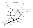
図16は、給紙部4より給送された1枚目の用紙P1が印刷部2においてその一方の面にインキ142を転写された後に補助トレイ8上に送られて表面印刷済み用紙PA1となり、用紙P1に続いて給紙部4より給送された2枚目の用紙P2が印刷部2においてその一方の面にインキ142を転写されて表面印刷済み用紙PA2として補助トレイ8に送られると共に、補助トレイ8上から表面印刷済み用紙PA1が印刷部2に向けて再給紙される状態を示している。
【0160】
図17は、図16に示した状態からさらに時間が経過し、補助トレイ8上から再給紙された表面印刷済み用紙PA1がプレスローラ141によって版胴12に押圧され、その他方の面にもインキ142を転写されて印刷済み用紙PB1となる状態を示している。この再給紙手段9によって補助トレイ8上から再給紙される表面印刷済み用紙PA1は、その一方の面に転写されたインキ142が未乾燥状態であり、この未乾燥状態のインキ142がプレスローラ141によって押圧されると、プレスローラ141の表面に再転移して再転移インキ143を形成してしまう。
【0161】
このようにプレスローラ141の表面上に形成された再転移インキ143は、さらに印刷動作が進んで図18に示すように給紙部4より3枚目の用紙P3が給送されたときに、印刷部2において用紙P3の他方の面に転写されて裏汚れとなると共に、補助トレイ8上より再給紙される表面印刷済み用紙PA2の一方の面にも転写されて画像不良を引き起こしてしまう。
【0162】
本発明は、上述の問題点を解決すべく発明されたものであり、プレスローラとしてその表面にシート部材13eを有するプレスローラ13を用いることにより、上述した再転移インキ143の発生を極力抑え、良好な両面印刷物を得ることを目的としている。そこで本発明者は、図3に示したシート部材13eの頂角13iの先端部半径R、頂角13iの角度θ、頂角13i間のピッチLをそれぞれ変化させて両面印刷を行い、印刷面の画像品質並びに再転移インキ143によるインキ転移汚れの発生を調査した。以下にその結果を示す。
【0163】
【表1】

Figure 2004136584
【0164】
実験の結果、以下のことが判明した。頂角13iの先端部半径Rは、0.04mmを超えると再転移インキ143が付着し易く転移汚れが多く発生するが、0.04mm以下では再転移インキ143が付着しにくくなり、特に0.03mm以下では再転移インキ143の付着が抑制され転移汚れがほとんど目立たなくなった。頂角13iの角度θは、100度を超えると再転移インキ143が付着し易く転移汚れが多く発生するが、100度以下では再転移インキ143が付着しにくくなり、特に90度以下では再転移インキ143の付着が抑制され転移汚れがほとんど目立たなくなった。しかし、60度以下とすると突起13hの強度が不足し、耐久性が悪化した。頂角13i間のピッチLは、0.4mmを超えると見かけの平滑度が得られずにプレスローラとしての画像形成機能が低下して印刷画像に点状のむらが発生してしまい良好な画像を得ることができなかったが、0.4mm以下ではむらが目立たなくなり良好な画像が得られ、特に0.3mm以下ではむらの発生がほとんどなく良好な画像が得られた。しかし、0.1mmを下回ると、十分な溝深さが取れずに転移汚れが発生した。
【0165】
上述の結果、頂角13iの先端部半径Rを0.04mm以下、望ましくは0.03mm以下、頂角13iの角度θを100度以下、望ましくは70〜90度、各頂角13i間のピッチLを0.4mm以下、望ましくは0.1〜0.3mmとしたシート部材13eを有するプレスローラ13を用いることにより、再転移インキ143の発生を極力抑えて転移汚れの発生を防止し、かつ上質の画像品質を有する両面印刷物を得ることができる。
【0166】
図19は、第1の実施例の変形例に用いられるシート部材13qの部分平面図である。凹凸部であるシート部材13qは、シート部材13eと同様に熱可塑性合成樹脂を特別な金型によって成型することにより形成されており、三角錐形状の複数の突起13rが規則正しく並べられた形状を呈している。同図において、太線は各突起13rの底辺部を、細線は各突起13rの稜線を、黒点は各突起13rの頂点をそれぞれ示している。このシート部材13qを用いた場合であっても、各頂点の先端部半径、各頂点の角度、各頂点間のピッチを第1の実施例と同様に設定することにより、第1の実施例と同様の作用効果を得ることができる。本変形例では突起13rの形状を三角錐としたが、円錐あるいは多角錘で突起を形成してもよい。
【0167】
図20は、本発明の第2の実施例に用いられるシート部材13jの部分拡大断面図である。シート部材13jは、ポリエステル等の熱可塑性樹脂からなる厚さ0.05〜0.1mm程度の樹脂シート13kの表面に、ガラスからなる複数の球状体13lをポリウレタン系あるいはエポキシ系の接着剤13mによって、各球状体13lが平面をなさないように接着することにより構成されており、シート部材13jによって段差部が形成される。
【0168】
シート部材13jはシート部材13eに代えて用いられ、その厚みTが0.15〜0.2mmとなるように形成されている。複数の球状体13lとしては平均直径Dのものが用いられ、各球状体13lは、その各頂点の凹凸最大段差がH、最大突出部間の平均ピッチがWとなるようにそれぞれ配置されている。また、各球状体13lの表面には、低粘度の接着剤を塗布して皮膜13nを形成することが望ましく、これにより各球状体13lの凹凸段差を確保するための強度が増加すると共に再転移インキ143が付着しにくい表面状態を得ることができる。
【0169】
ここで再び本発明者は、シート部材13jを構成する各球状体13lの平均直径D、最大段差H、最大突出部間の平均ピッチWをそれぞれ変化させて両面印刷を行い、印刷面の画像品質並びに再転移インキ143によるインキ転移汚れの発生を調査した。以下にその結果を示す。
【0170】
【表2】
Figure 2004136584
【0171】
実験の結果、以下のことが判明した。球状体13lの平均直径Dは、0.1mmを超えると点状の転移汚れが多く発生するが、0.1mm以下では転移汚れが目立たなくなり、特に0.08mm以下とすると転移汚れの発生がほとんど見られなかった。なお、0.03mm以下とした場合には最大段差Hと平均ピッチWとを後述する適正値とすることが難しくなることが解った。最大段差Hは、0.03mmを下回ると球状体13lの表面が平滑となりすぎて砂目状の転移汚れが発生するが、0.03mm以上とすると転移汚れがほとんど発生しなくなった。しかし、0.10mmを超えると段差が大きくなりすぎ、画像にむらが発生した。平均ピッチWは、0.4mmを超えると画像に点状のむらが発生するが、0.4mm以下ではむらが発生することなく良好な画像を得ることができた。しかし、0.15mmを下回ると、球状体13lの表面が平滑となりすぎ、砂目状の転移汚れが発生した。
【0172】
上述の結果、各球状体13lの平均直径Dを0.1mm以下、望ましくは0.04mm〜0.08mm、各球状体13lの最大段差Hを0,03mm以上、望ましくは0.03mm〜0.10mm、各球状体13lの最大突出部間の平均ピッチWを0.15mm以上、望ましくは0.15mm〜0.40mmとしたシート部材13jを有するプレスローラ13を用いることにより、再転移インキ143の発生を極力抑えて転移汚れの発生を防止し、かつ上質の画像品質を有する両面印刷物を得ることができる。
【0173】
図21は、第2の実施例の変形例に用いられるシート部材13sの部分断面図を示している。段差部であるシート部材13sは、平均直径Dが80μmの球状体13tと平均直径Dが30μmの球状体13uとを一定の割合(この例では1:3)で混合して樹脂シート13k上に接着することにより構成されている。このシート部材13sを用いた場合には、球状体13tの平均ピッチを0.15mm以上、望ましくは0.15mm〜0.40mmとすることにより第2の実施例と同様の作用効果を得ることができる。
【0174】
第2の実施例及び変形例では、複数の球状体13l,13t,13uを樹脂シート13k上に接着によって固定したシート部材13j,13sを弾性体13dの周面に螺旋状に巻き付けた例を示したが、図22に示すように、弾性体13dの周面にプライマ処理を兼ねた特定の表面硬化剤13oを塗布し、この上に複数の球状体13lを固定して作成した段差部としてのシート部材13pを用いてもよい。この構成は、第1の実施例及び変形例で示したシート部材13e,13qに代えて用いることも可能である。
【0175】
第1及び第2の実施例及び変形例で示したシート部材13e,13j,13p,13q,13sが適用可能な両面印刷装置は、各実施例で示した両面印刷装置1に限られることはなく、特開平9−95033号公報に開示された孔版印刷装置1あるいは特開2002−103768号公報に開示された孔版印刷装置1のように、複数のプレスローラを有する両面印刷装置に適用することも可能である。この場合、用紙搬送方向上流側に位置するプレスローラで用紙を押圧する際には、用紙上に画像が形成されていないために用紙からプレスローラへのインキの再転移が行われないため、各実施例で示したシート部材13e,13j,13p,13q,13sは、少なくとも用紙搬送方向下流側に位置するプレスローラに適用すればよい。
【0176】
図23は、本発明の第3の実施例を示している。同図において、符号144は孔版印刷装置を、符号145は孔版印刷装置144に接続されたソータをそれぞれ示している。
【0177】
孔版印刷装置144は、図示しない画像読取部、図示しない製版部、図示しない排版部、図示しない給紙部、版胴146、プレスローラ147、レジストローラ対148、排紙コンベヤ149を有しており、図示しない給紙部から分離給送された用紙をレジストローラ対148によって所定のタイミングで版胴146とプレスローラ147との間に向けて給送し、プレスローラ147によって版胴146の外周面に用紙を押圧して画像を転写した後、排紙コンベヤ149によって機外に排出する通常の構成を有する。
【0178】
ソータ145は、排紙コンベヤ149によって排出された印刷済み用紙を受け入れて水平方向に搬送する水平搬送コンベヤ150、印刷済み用紙の搬送をガイドするガイド板151,152、印刷済み用紙を搬送する用紙搬送部材としての用紙搬送ローラ対153,154、印刷済み用紙を垂直方向に搬送する垂直搬送コンベヤ155、固定配置された複数のビントレイ156、ガイド板152と用紙搬送ローラ対154とを垂直方向に一体的に移動させるインデクサ157を有する通常の構成である。各用紙搬送ローラ対153,154はそれぞれ2個のローラ153a,153b及び154a,154bを有しており、通常は一方が駆動ローラで他方が駆動ローラに圧接された従動ローラである。
【0179】
上述の構成によれば、孔版印刷装置144によって画像を転写された用紙はソータ145へと送られ、水平搬送コンベヤ150、用紙搬送ローラ対153、垂直搬送コンベヤ155によって搬送された後、インデクサ157によって所定の位置を占めた用紙搬送ローラ対154によって所定のビントレイ156に排出される。通常、孔版印刷装置144による印刷後、印刷済み用紙は3秒以内に各ビントレイ156に排出される。
【0180】
このソータ145における印刷済み用紙の排出時において、ローラ153aとローラ154aとには印刷済み用紙の印刷面が接触することとなり、第1の実施例で説明したプレスローラ13と同様に、その表面には印刷済み用紙からの再転移インキ143が付着することとなる。各ローラ153a,154aに再転移インキ143が付着すると、次に送られた印刷済み用紙の印刷面に再転移インキ143が再び転写され、画像のだぶりが発生して印刷不良を引き起こしてしまう。そこで、各ローラ153a,154aの表面に、上記各実施例及び各変形例で示したシート部材13e,13j,13p,13q,13sと同様の構成を有するシート部材を設けることにより、再転移インキ143の付着を抑制して良好な印刷物を得ることが可能となる。
【0181】
【発明の効果】
本発明によれば、先端部半径0.04mm以下で形成された突起を平均ピッチ0.4mm以下で多数有する凹凸部をプレスローラの外周面に設けることにより、プレスローラ外周面への再転移インキの付着を抑制して転移汚れの発生を防止することができ、良好な印刷物を得ることができる。
【0182】
本発明によれば、平均直径0.1mm以下の球状体を最大段差0.03mm以上かつ最大突出部間の平均ピッチ0.15mm以上で多数有する段差部をプレスローラの外周面に設けることにより、プレスローラ外周面への再転移インキの付着を抑制して転移汚れの発生を防止することができ、良好な印刷物を得ることができる。
【0183】
本発明によれば、先端部半径0.04mm以下で形成された突起を平均ピッチ0.4mm以下で多数有する凹凸部を用紙搬送部材の外周面に設けることにより、用紙搬送部材外周面への再転移インキの付着を抑制して転移汚れの発生を防止することができ、良好な印刷物を得ることができる。
【図面の簡単な説明】
【図1】本発明の第1の実施例を採用した両面印刷装置の概略正面図である。
【図2】本発明の第1の実施例に用いられるプレスローラの概略構成図である。
【図3】本発明の第1の実施例に用いられるシート部材を説明する概略図である。
【図4】本発明の第1の実施例に用いられるプレスローラ接離機構及び版胴外周面から離間したプレスローラを説明する概略正面図である。
【図5】本発明の第1の実施例に用いられる再給紙搬送ユニット及び用紙受け板を説明する概略平面図である。
【図6】本発明の第1の実施例に用いられる両面印刷装置の連続印刷時における用紙の挙動を説明するための印刷部要部の概略正面図である。
【図7】本発明の第1の実施例に用いられる両面印刷装置の連続印刷時における用紙の挙動を説明するための印刷部要部の概略正面図である。
【図8】本発明の第1の実施例に用いられる他のガイド板を示す概略図である。
【図9】本発明の第1の実施例に用いられるプレスローラ接離機構を説明する概略側面図である。
【図10】本発明の第1の実施例に用いられるプレスローラ接離機構及び版胴外周面に圧接したプレスローラを説明する概略正面図である。
【図11】本発明の第1の実施例に用いられる分割製版済みマスタを説明する概略図である。
【図12】本発明の第1の実施例に用いられる製版済みマスタを説明する概略図である。
【図13】本発明の第1の実施例に用いられる操作パネルを示す概略図である。
【図14】本発明の第1の実施例に用いられる制御手段のブロック図である。
【図15】通常用いられるプレスローラの概略構成図である。
【図16】本発明の第1の実施例における問題点を説明するための概略図である。
【図17】本発明の第1の実施例における問題点を説明するための概略図である。
【図18】本発明の第1の実施例における問題点を説明するための概略図である。
【図19】本発明の第1の実施例の変形例に用いられるシート部材の平面図である。
【図20】本発明の第2の実施例に用いられるシート部材の概略構成図である。
【図21】本発明の第2の実施例の変形例に用いられるシート部材の概略構成図である。
【図22】本発明の第1及び第2の実施例の変形例として適用可能なシート部材を示す概略構成図である。
【図23】本発明の第3の実施例を採用した孔版印刷装置及びソータを示す概略構成図である。
【図24】印刷間隔時間とインキ転移汚れの度合いとの相関関係を示す線図である。
【符号の説明】
1 両面印刷装置
12 版胴
13 プレスローラ
13e,13q シート部材(凹凸部)
13h,13r 突起
13i 頂角
13j,13p,13s シート部材(段差部)
13l,13t,13u 球状体
26 クリーニング手段(クリーニングローラ)
65 分割製版済みマスタ
65A 第1の画像(第1製版画像)
65B 第2の画像(第2製版画像)
153 用紙搬送部材(用紙搬送ローラ対)
154 用紙搬送部材(用紙搬送ローラ対)
P 用紙
PA 表面印刷済み用紙
θ 頂角の角度
R 頂角の先端部半径
L 頂角間の平均ピッチ
D 球状体の平均直径
H 球状体の最大段差
W 最大突出部間の平均ピッチ[0001]
TECHNICAL FIELD OF THE INVENTION
The present invention relates to a two-sided printing apparatus that performs printing on one surface and the other surface of a sheet, and more particularly, to a structure of a press roller that contacts a printing surface of the sheet and presses the printed sheet against a plate cylinder.
[0002]
[Prior art]
Conventionally, digital thermosensitive stencil printing has been known as a simple printing method. The stencil printing apparatus used for stencil printing is such that a thermal head in which fine heating elements are arranged in a row is brought into contact with a heat-sensitive stencil master (hereinafter, referred to as "master"), and the master is pulsated while energizing the heating elements. The master is heated and melt-punched according to the image information by being conveyed, and the master is wound around the outer peripheral surface of a porous cylindrical plate cylinder, and then the outer peripheral surface of the plate cylinder is pressed through a sheet with pressing means such as a press roller. By pressing the ink, the ink is transmitted from the master perforated portion and transferred to a sheet to obtain a printed image.
[0003]
In recent years, in stencil printing, double-sided printing, in which printing is performed on both sides of a sheet, has been frequently performed in order to reduce the amount of paper consumption and the storage space for documents. In the conventional double-sided printing, the paper loaded in the paper feeding unit is passed through the printing unit according to the conventional method, and after printing on one side, the sheet is turned over, and then passed through the printing unit again to print on the other side. Although a two-sided printed material has been obtained, there is a problem in that it is troublesome to set the paper once discharged in the paper feeding unit again or to align the paper after one-sided printing. Further, since the paper is passed twice to the printing unit, the net printing time is twice as long as the one-sided printing, so that it takes too much time.
[0004]
In order to solve the above-mentioned problems, a first plate cylinder and a first plate cylinder which is disposed to face the first plate cylinder via a sheet conveyance path and which is provided so as to be able to press and separate from the first plate cylinder. Pressing means, a second plate cylinder disposed downstream of the first plate cylinder in the sheet conveyance direction and facing the first plate cylinder via the sheet conveyance path, and a sheet conveyance path. A second pressing means disposed opposite to the second plate cylinder and provided so as to be able to press and separate from the second plate cylinder, and press-contact the first plate cylinder with the first pressing means. After that, a stencil printing apparatus that performs double-sided printing by pressing the second plate cylinder and the second pressing means against each other is disclosed in, for example, Japanese Patent Application Laid-Open No. H11-163873.
[0005]
In addition, a divided plate-making master having a first image printed on one side of a sheet and a second image printed on the other side of the sheet is wound around a plate cylinder, and the sheet is rolled by a first press roller. After the first image is printed on one side of the sheet by pressing against the plate cylinder, the single-sided printed sheet is re-fed by the biasing means, and the second press roller applies the second image to the other side of the sheet. A stencil printing apparatus that performs double-sided printing by printing an image is disclosed in, for example, Patent Document 2.
[0006]
By using the technology disclosed in each of the above-mentioned publications, printing can be performed on both sides of the paper in one pass, and the printing work time can be reduced to about half as compared with the related art. .
[0007]
Furthermore, at the time of double-sided printing, when the single-sided printed paper printed by the upstream printing unit is printed by the downstream printing unit, the unfixed ink is transferred to the pressing roll and transferred to the pressing roll. For example, Japanese Patent Application Laid-Open Publication No. H10-163,086 discloses a technique for providing minute irregularities on the outer peripheral surface of a pressing roll used in a downstream printing unit in order to prevent a problem that the ink is further retransferred to the back surface of the paper. ing.
[0008]
[Patent Document 1]
JP-A-2002-103768 (page 4-6, FIG. 1)
[Patent Document 2]
JP-A-9-95033 (page 3-6, FIG. 1)
[Patent Document 3]
JP-A-2002-219849 (page 2-3, FIG. 1)
[0009]
[Problems to be solved by the invention]
However, in the techniques disclosed in Patent Literature 1 and Patent Literature 2, printing is performed on one side of a sheet and then printing is performed on the other side of the sheet. When printing, the ink adhering to one side of the sheet was transferred to the press roller surface, and when printing on one side of the next sheet, it was transferred from the previous sheet to the other side of this sheet. There is a problem that the ink adheres and the back stain occurs.
[0010]
Therefore, it is conceivable to perform double-sided printing by applying the press roller disclosed in “Patent Document 3” to each of the above-mentioned technologies. However, the same shape as shown in FIG. 11B of “Patent Document 3” can be considered. When the spherical bodies were arranged so that the surface became smooth, the total area of the spherical bodies in contact with the image surface of the paper was not so much different from a flat surface, and it was found that the effect of preventing ink transfer stain was low. In addition, even with the structure as shown in FIG. 10B, the area in contact with the image surface of the sheet eventually increased, and no significant effect was obtained.
[0011]
In order to completely prevent this ink transfer stain, it is effective to reduce the area of the press roller in contact with the image surface of the paper, but if the contact area is reduced, the tip shape of the contact portion becomes an acute angle, When pressed against a sheet, there is a possibility that a hole may be made in the master through the sheet or the sheet, and there is a limit in reducing the contact area.
[0012]
Further, the inventor uses a double-sided printing apparatus capable of printing on both sides of a sheet in one step, and after printing on one side of the sheet, presses one side of the sheet with a press roller. When printing on the other side of the paper, it was investigated how long after printing on one side, printing on the other side would reduce the occurrence of ink transfer stains. The result is shown in FIG. As is clear from the figure, it was found that if printing on the other side was performed 5 seconds or more after printing on one side, the occurrence of ink transfer stains could be substantially prevented, but stencil printing was not performed during actual printing. Since there is a merit in the high speed, it is inevitable that the other side is printed within 3 seconds.
[0013]
SUMMARY OF THE INVENTION It is an object of the present invention to solve the above-mentioned problems and to provide a double-sided printing apparatus capable of effectively preventing the occurrence of ink transfer stains.
[0014]
[Means for Solving the Problems]
The invention according to claim 1 has at least one plate cylinder and at least one press roller provided corresponding to the plate cylinder for pressing a sheet against the plate cylinder, and has one surface of the sheet. A two-sided printing apparatus for printing on the other side of the sheet within three seconds after printing, wherein the outer peripheral surface of a press roller for pressing the other side of the sheet against the plate cylinder has a tip radius of 0. An uneven portion having a large number of protrusions formed with a diameter of 0.4 mm or less and having an average pitch of 0.4 mm or less is provided.
[0015]
According to a second aspect of the present invention, the plate is formed such that the first image printed on one side of the sheet and the second image printed on the other side of the sheet are arranged in the circumferential direction of the plate cylinder. After winding the divided plate-making master around the plate cylinder, pressing the sheet against the plate cylinder with a press roller to print the first image on the one surface, and then refeeding the surface-printed sheet A two-sided printing apparatus that prints a second image on the other surface within three seconds after printing the first image by pressing against the plate cylinder with the press roller; The surface is provided with an uneven portion having a large number of projections formed with a tip radius of 0.04 mm or less at an average pitch of 0.4 mm or less.
[0016]
According to a third aspect of the present invention, there is provided a first plate cylinder for winding a first master on which a first image to be printed on one side of a sheet is made, and the first plate cylinder is arranged to face the first plate cylinder. A first press roller for pressing the sheet against a first plate cylinder, and a second press roller which is arranged on the downstream side of the first plate cylinder in the sheet conveyance direction and is printed on the other surface of the sheet. A second plate cylinder on which a second master on which an image is made is wound; and a second press roller disposed opposite to the second plate cylinder and pressing the sheet against the second plate cylinder. Then, the first press roller presses the sheet against the first plate cylinder to print a first image on one surface of the sheet, and then presses the sheet to the second press roller within three seconds. A two-sided printing apparatus for printing a second image on the other side of the sheet by pressing against a second plate cylinder, wherein at least a second press roller The outer peripheral surface, wherein the uneven portion having a large number of protrusions formed by the following tip radius 0.04mm below an average pitch of 0.4mm is provided.
[0017]
According to a fourth aspect of the present invention, in the double-sided printing apparatus according to any one of the first to third aspects, the projection has a polygonal pyramid shape or a conical shape having a vertex angle of 100 degrees or less. It is characterized by being made of synthetic resin.
[0018]
According to a fifth aspect of the present invention, in the double-sided printing apparatus according to the fourth aspect, the uneven portion is formed by spirally winding a long sheet member having a constant width around the outer peripheral surface of the press roller. Features.
[0019]
The invention according to claim 6 has at least one plate cylinder, and at least one press roller provided corresponding to the plate cylinder for pressing a sheet against the plate cylinder, and has one surface of the sheet. A two-sided printing apparatus for printing on the other side of the sheet within three seconds after printing, and further having an average diameter of 0. 0 on the outer peripheral surface of a press roller for pressing the other side of the sheet against the plate cylinder. There is provided a stepped portion having a large number of spherical bodies of 1 mm or less with a maximum stepped height of 0.03 mm or more and an average pitch between the maximum protruding portions of 0.15 mm or more.
[0020]
According to a seventh aspect of the present invention, plate making is performed such that the first image printed on one side of the sheet and the second image printed on the other side of the sheet are arranged in the circumferential direction of the plate cylinder. After winding the divided plate-making master around the plate cylinder, pressing the sheet against the plate cylinder with a press roller to print the first image on the one surface, and then refeeding the surface-printed sheet A two-sided printing apparatus that prints a second image on the other surface within three seconds after printing the first image by pressing against the plate cylinder with the press roller; The surface is provided with a step portion having a large number of spherical bodies having an average diameter of 0.1 mm or less with a maximum step of 0.03 mm or more and an average pitch between the maximum protrusions of 0.15 mm or more.
[0021]
According to an eighth aspect of the present invention, there is provided a first plate cylinder for winding a first master on which a first image to be printed on one surface of a sheet is made, and the first plate cylinder is arranged to face the first plate cylinder. A first press roller for pressing the sheet against a first plate cylinder, and a second press roller which is arranged on the downstream side of the first plate cylinder in the sheet conveyance direction and is printed on the other surface of the sheet. A second plate cylinder on which a second master on which an image is made is wound; and a second press roller disposed opposite to the second plate cylinder and pressing the sheet against the second plate cylinder. Then, the first press roller presses the sheet against the first plate cylinder to print a first image on one surface of the sheet, and then presses the sheet to the second press roller within three seconds. A two-sided printing apparatus for printing a second image on the other side of the sheet by pressing against a second plate cylinder, wherein at least a second press roller The outer peripheral surface, wherein the stepped portion having a number average diameter 0.1mm or less spherical body with maximum step 0.03mm or more and more average pitch 0.15mm between the maximum protrusion portion is provided.
[0022]
According to a ninth aspect of the present invention, in the double-sided printing apparatus according to any one of the sixth to eighth aspects, the spherical body is made of glass.
[0023]
According to a tenth aspect of the present invention, in the double-sided printing apparatus according to the ninth aspect, the step portion is formed by spirally winding a long sheet member having a fixed width around the outer peripheral surface of the press roller. Features.
[0024]
An eleventh aspect of the present invention is the double-sided printing apparatus according to any one of the first to tenth aspects, further comprising a cleaning unit for removing ink attached to an outer peripheral surface of the press roller. Features.
[0025]
According to a twelfth aspect of the present invention, in the double-sided printing apparatus according to the eleventh aspect, the cleaning means is a porous cleaning roller, and the cleaning roller rotates at a speed lower than the rotational peripheral speed of the press roller during printing. It is characterized by being driven.
[0026]
According to a thirteenth aspect of the present invention, in the double-sided printing apparatus according to the twelfth aspect, the cleaning roller is further urged against the outer peripheral surface of the press roller with an urging force of 3N or less.
[0027]
The invention according to claim 14 is a paper transporting member that transports the paper by contacting the printing surface of the paper on which the print image is formed within 3 seconds after printing, and further has a tip radius of 0.04 mm or less. An uneven portion having a large number of formed protrusions at an average pitch of 0.4 mm or less is provided on an outer peripheral surface thereof.
[0028]
According to a fifteenth aspect of the present invention, in the paper transport member according to the fourteenth aspect, the protrusion is made of a synthetic resin having a polygonal pyramid shape or a conical shape having a vertex angle of 100 degrees or less.
[0029]
According to a sixteenth aspect of the present invention, in the paper transport member according to the fifteenth aspect, the uneven portion is formed by spirally winding a long sheet member having a fixed width around the outer peripheral surface. .
[0030]
【Example】
FIG. 1 shows a double-sided printing apparatus employing the first embodiment of the present invention. The double-sided printing apparatus 1 includes a printing unit 2, a plate making unit 3, a sheet feeding unit 4, a plate discharging unit 5, a sheet discharging unit 6, an image reading unit 7, an auxiliary tray 8, a sheet re-feeding unit 9, a switching member 10, and the like. ing.
[0031]
The printing unit 2 disposed substantially at the center of the apparatus main body 11 has a plate cylinder 12 and a press roller 13.
The plate cylinder 12 has a pair of end plates (not shown) rotatably supported by a spindle 14 also serving as an ink supply pipe, a porous support plate (not shown) wound around the outer peripheral surface of each end plate, and a not-shown plate. It is mainly composed of a mesh screen (not shown) wound around the outer peripheral surface of the porous support plate, and is rotatably driven by the plate cylinder driving means 121 (see FIG. 14) and is detachable from the apparatus main body 11. It is configured. In the present embodiment, the plate cylinder 12 has a size capable of obtaining a printed matter of A3 size at the maximum during single-sided printing.
[0032]
Inside the plate cylinder 12, an ink supply means 15 is provided. The ink supply means 15 has a support shaft 14, an ink roller 16, a doctor roller 17, and the like.
The ink roller 16 is rotatably supported between side plates (not shown) provided in the plate cylinder 12, and its peripheral surface is arranged close to the inner peripheral surface of the plate cylinder 12. It is driven to rotate in the same direction as the body 12. The doctor roller 17 is also rotatably supported between the side plates, and its peripheral surface is arranged close to the peripheral surface of the ink roller 16, and is driven to rotate in the opposite direction to the plate cylinder 12 by driving means (not shown). . The support shaft 14 is provided with a plurality of small holes. The ink supplied from the support shaft 14 is accumulated in a space formed in the vicinity of the ink roller 16 and the doctor roller 17 and having a wedge-shaped cross section. A reservoir 18 is formed.
[0033]
On the outer peripheral surface of the plate cylinder 12, there is formed a stage portion 19a which forms a plane along one generatrix of the plate cylinder 12. On this stage portion, a clamper for holding the leading end of the master on the outer peripheral surface of the plate cylinder 12 is formed. 19b is provided. The clamper 19b is opened and closed by opening and closing means (not shown) when the plate cylinder 12 is rotated to a predetermined position.
[0034]
A press roller 13 is provided below the plate cylinder 12. As shown in FIG. 2, the press roller 13 includes a hollow pipe 13b made of a lightweight metal such as aluminum, a pair of lightweight metal end plates 13c integrally attached to both ends of the hollow pipe 13b, and each end plate 13c. A base is constituted by a pair of metal cores 13a integrally attached to the base, and an elastic body 13d such as silicon rubber having a thickness of about 5 to 10 mm is provided on the outer periphery of the base, and a length of a fixed width is further provided on the outer periphery thereof. It is configured by winding a sheet member 13e having a length. The sheet member 13e is wound in a clean spiral shape so that the gap is 0.3 mm or less, and is adhered to the peripheral surface of the elastic body 13d, and an unwinding tape 13f is attached to an end thereof. . In this embodiment, the press roller 13 is formed to have an outer diameter of about 70 mm, and its length is substantially the same as the axial length of the plate cylinder 12.
[0035]
FIG. 3 shows a partially enlarged sectional view of the sheet member 13e. A plurality of projections 13h are formed on a surface of the sheet member 13e opposite to the mounting surface 13g adhered to the elastic body 13d, and an uneven portion is formed by the sheet member 13e having the plurality of projections 13h. The sheet member 13e is formed by molding a thermoplastic synthetic resin such as a polyurethane-based or polyolefin-based resin with a special mold, and has a thickness T of 0.3 to 0.4 mm in this embodiment. Each projection 13h has the same shape of a conical shape or a polygonal pyramid shape, such that the angle of each apex angle 13i is θ, the tip radius of the apex angle 13i is R, and the pitch between each apex angle 13i is L. Each is formed. The angle θ, the tip radius R, and the pitch L will be described later.
[0036]
As shown in FIG. 4, the press roller 13 is rotatably supported at one end of each core 13 a by a pair of arm members 20. Each of the arm members 20 having a substantially L-shape is integrated by a swing shaft 21 attached to a portion near the bent portion, and the swing shaft 21 is rotatably supported by the apparatus main body 11. I have. Between each arm member 20, in addition to the press roller 13, a re-feed guide member 22, a re-feed registration roller 23, a re-feed positioning member 24, a re-feed transport unit 25, a cleaning roller 26 as cleaning means, A guide plate 27 and the like are provided.
[0037]
The re-feed guide member 22 disposed near the right side of the press roller 13 is integrally provided on each of the support shafts 28a, 29a, and 30a, and presses the respective peripheral surfaces against the peripheral surface of the press roller 13. Roller rollers 28, 29, and 30, and a paper guide plate 31 formed into a curved surface for causing the surface-printed paper PA to follow the peripheral surface of the press roller 13. Both ends of each support shaft 28a, 29a, 30a are rotatably supported by each arm member 20, and are urged toward the core 13a by urging means (not shown). The rollers 28, 29, 30 are integrally attached to the corresponding support shafts 28a, 29a, 30a at predetermined intervals over substantially the entire width of the press roller 13.
[0038]
The paper guide plate 31 is disposed at a position separated from the peripheral surface of the press roller 13 by a predetermined distance that is smaller than the radius of each of the rollers 28, 29, and 30. Both ends are fixed to each arm member 20. Have been. The paper guide plate 31 is formed so as to have a curved surface centered on the core portion 13 a, and the paper guide plate 31 is used for bringing the peripheral surfaces of the rollers 28, 29, 30 into contact with the peripheral surface of the press roller 13. (Not shown) are formed.
[0039]
Below the press roller 13, a re-feed registration roller 23 is provided. The roller re-feed resist roller 23 is rotatably supported by a support shaft 23 a, and the support shaft 23 a is mounted between one ends of a pair of swing arms 32. Each of the swing arms 32 having a substantially curvilinear shape has its bent portion swingably supported by a support shaft 32a fixed between the arm members 20, and its arrangement position is at the time of swing. The position is determined so as not to interfere with each roller 30.
[0040]
The other end of one swing arm 32 has a plunger 33 a of a solenoid 33 attached to one arm member 20 via a bracket (not shown), and one end is fixed to one arm member 20 and The other end of a tension spring 34 for applying a biasing force in the counterclockwise direction in FIG. With this configuration, when the solenoid 33 is actuated, the refeeding registration roller 23 presses the peripheral surface thereof against the peripheral surface of the press roller 13 with a predetermined pressing force, and occupies a pressing position shown by a solid line in FIG. When the operation is released, the peripheral surface is separated from the peripheral surface of the press roller 13 by the urging force of the tension spring 34, and occupies a separated position shown by a two-dot chain line in FIG.
[0041]
At the lower left of the press roller 13, a paper re-feeding / conveying unit 25 is provided. The refeeding conveyance unit 25 includes a conveyance unit main body 35, a driving roller 36, a driven roller 37, an endless belt 38, a suction fan 39, and the like, and integrally has the auxiliary tray 8 on an upper surface thereof.
[0042]
The transport unit main body 35, which is a housing whose upper surface is open and whose width is slightly smaller than the interval between the arm members 20, is not shown on both sides on the upstream side and the downstream side in the paper transport direction. Each bearing (not shown) rotatably supports the drive shaft 36a and the driven shaft 37a. Both ends of the drive shaft 36a penetrate both side surfaces of the transport unit main body 35, and the penetrated both ends are rotatably supported by bearing members (not shown) provided on the apparatus main body 11. A drive gear (not shown) is attached to one end of the drive shaft 36a, and the drive shaft 36a is driven to rotate by a transport unit drive motor 122 (see FIG. 14) provided on the apparatus main body 11. The driven shaft 37 a is configured such that both ends do not penetrate both side surfaces of the transport unit main body 35.
[0043]
Bosses 35a are integrally provided on both outer sides of the upstream end of the transport unit body 35 in the paper transport direction, and the bosses 35a are respectively fitted into elongated holes (not shown) formed in the arm members 20. Have been. With this configuration, when the press roller 13 is brought into contact with or separated from the plate cylinder 12 by the press roller contacting / separating mechanism 55 described later, the transport unit main body 35 is centered on the drive shaft 36 a with the swing of each arm member 20. Swinging is possible.
[0044]
The plurality of roller-shaped driving rollers 36 are integrally attached to the driving shaft 36a, and a predetermined interval is provided between the driving rollers 36. The plurality of driven rollers 37 having the same shape as the driving roller 36 are integrally attached to the driven shaft 37 a at the same intervals as the driving rollers 36. An endless belt 38 is stretched between each drive roller 36 and each corresponding driven roller 37 with a predetermined tension. The endless belt 38 made of a frictional resistance member is moved in a direction indicated by an arrow in FIG. 4 when the drive shaft 36a is rotationally driven by the transport unit drive motor 122.
[0045]
The suction fan 39 is attached to the lower surface of the transport unit main body 35, and the auxiliary tray 8 is attached to the upper surface thereof. The auxiliary tray 8 is configured so that a part of the peripheral surface of each of the rollers 36 and 37 faces the paper transport surface. As shown in FIG. A plurality of openings 8b are formed, and two end fences 8a for receiving one end of the front-printed paper PA sent from the printing unit 2 are integrally provided at the downstream end in the paper transport direction. Have been.
[0046]
At the upstream end of the auxiliary tray 8 in the sheet conveyance direction, a re-feed for temporarily stopping the other end of the front side printed paper PA to be re-supplied to the printing unit 2 by the re-feed conveyance unit 25 at a fixed position. A paper positioning member 24 is provided. In this embodiment, two re-feed positioning members 24 are provided, each of which is integrally attached to the auxiliary tray 8. Further, the auxiliary tray 8 is provided with a sensor 8c for detecting that the other end of the front-surface-printed paper PA has approached the re-feed positioning member 24. The sensor 8c outputs a signal to a control unit 129 described later when detecting the other end of the front-side printed paper PA.
[0047]
A hole (not shown) is provided on the lower surface of the transport unit main body 35, which is a mounting surface of the suction fan 39, so that the suction fan 39 operates to apply a negative pressure to the inside of the transport unit main body 35, which is a housing. The surface printed paper PA is sucked on the upper surface of each endless belt 38 that is generated and moves. The suction force of the suction fan 39 and the frictional resistance force of the endless belt 38 indicate that when the other end of the surface-printed paper PA comes into contact with the re-feeding positioning member 24, the surface-printed paper PA and each endless belt 38 The strength is set to such a degree that slippage occurs between them.
[0048]
The above-mentioned auxiliary tray 8, re-feed guide member 22, re-feed registration roller 23, re-feed positioning member 24, and re-feed transport unit 25 constitute a re-feed means 9. Further, the sheet re-feeding means 9 has a sheet receiving plate 40 shown in FIGS. 1, 4 and 5. Hereinafter, the sheet receiving plate 40 will be described.
[0049]
The paper receiving plate 40 having a U-shaped cross section has protrusions 40a, 40b, 40c, and 40d on both sides as shown in FIG. 5, and each of the protrusions 40a, 40b, 40c, and 40d is provided in the conveyance unit main body 35. Are fitted in elongated holes (not shown) formed in both side plates. Notch portions 40e into which the end fences 8a can be fitted are formed at one end of the paper receiving plate 40, and rack portions 40f extending to the other end side are formed at both sides of the paper receiving plate 40, respectively. Is formed. The paper receiving plate 40 is disposed above the endless belts 38 and is spaced apart from the endless belts 38. The space between the lower surface and the endless belts 38 is such that the surface-printed paper PA is favorably conveyed on the endless belts 38. The predetermined interval is set so that it becomes possible.
[0050]
A stepping motor 138 having two pinions 139 on its output shaft 138a is mounted outside one side plate of the transport unit main body 35. The tip of the output shaft 138a is rotatably supported by the other side plate of the transport unit main body 35, and each pinion 139 is located at a position near both side plates of the transport unit main body 35 and at a position where it meshes with each rack portion 40f. It is arranged.
[0051]
In the vicinity of the stepping motor 138, a home position sensor 140 for detecting the home position of the sheet receiving plate 40 is provided. The home position sensor 140 is provided at a position where the protrusion of the protrusion 40d can be detected, and a signal from the home position sensor 140 is output to a control unit 129 described later.
[0052]
According to the above-described configuration, the paper receiving plate 40 is moved closer to the press roller 13 by the stepping motor 138 and receives one end of the front-printed paper PA conveyed from the printing unit 2. 7 is reciprocated so as to selectively occupy the second position shown in FIG. 7 where the other end of the surface-printed paper PA furthest from the press roller 13 and placed on the upper surface thereof contacts each endless belt 38. You.
[0053]
The length of the paper receiving plate 40 in the paper transport direction is such that the paper receiving plate 40 occupies the second position, and the other end of the surface-printed paper PA on the paper receiving plate 40 is separated from the endless belts 38 by the paper receiving plate 40. When the paper PA with the front surface printed thereon is conveyed by the re-feeding conveyance unit 25 and the other end abuts on the re-feeding positioning member 24, one end of the paper PA with the front surface printed moves to the second position. The length is set to fall from the occupied sheet receiving plate 40.
[0054]
A cleaning roller 26 that cleans the peripheral surface of the press roller 13 is disposed near the press roller 13 and above the sheet re-feeding and conveying unit 25. The cleaning roller 26 having substantially the same width as the width of the press roller 13 has a core 26a at the center as shown in FIG. The cleaning roller 26 is rotatably supported by fitting the core portion 26a into an elongate hole (not shown) formed in each arm member 20. The cleaning roller 26 is pressed by urging means (not shown) provided in the elongate hole. It is urged toward the roller 13 and its peripheral surface is constantly pressed against the peripheral surface of the press roller 13 with a pressing force of about 1 to 3N.
[0055]
The cleaning roller 26 is rotated by the cleaning roller driving means (not shown) provided on one arm member 20 in the same direction as the press roller 13 during rotation of the press roller 13 so that the peripheral speed of the press roller 13 is about 1/10. It is driven to rotate at the peripheral speed. In addition, since the difference in the rotational peripheral speed between the press roller 13 and the cleaning roller 26 is large, the cleaning effect can be obtained even when the cleaning roller 26 is driven to rotate in the opposite direction to the press roller 13, but the cleaning roller 26 is driven to rotate in the same direction. The cleaning effect is greater.
[0056]
At least the surface of the cleaning roller 26 is formed of a porous member. Examples of the porous member include Japanese paper, sponge, foam rubber having high hygroscopicity, synthetic resin foam, non-woven fabric, felt, and a cleaner sheet. A felt or a cleaner sheet impregnated with oil or a cleaning liquid is also effective. In this case, in order to increase the ink wiping effect, the cleaning roller 26 is pressed against the outer peripheral surface of the press roller 13 with a predetermined pressing force while providing a speed difference between the peripheral speed of the press roller 13 and the low speed. It is necessary to drive in rotation.
[0057]
A guide plate 27 is provided at the upper left of the cleaning roller 26. The guide plate 27, which is a plate material, has both ends fixed to the arm members 20 so that the front-printed paper PA sent from the printing unit 2 does not touch the cleaning roller 26 and heads toward the auxiliary tray 8. To guide. The guide plate 27 is provided at a position close to each peripheral surface of the press roller 13 and the cleaning roller 26. As shown in FIG. 8, a guide plate 27a that can prevent the front-printed sheet PA re-fed by the re-feeding means 9 from contacting the cleaning roller 26 may be used as the guide plate. By providing the cleaning roller 26, it is possible to more reliably suppress re-transfer of ink from the press roller 13 to the paper P or the surface-printed paper PA by wiping the ink transferred to the surface of the press roller 13, Even better printed matter can be obtained.
[0058]
A rotatable cam follower 41 is arranged on the other end of each arm member 20 opposite to the one end on which the press roller 13 is supported, so as to face each other. In the vicinity of the position where the cam follower 41 of each arm member 20 is provided, the other end of a printing pressure spring 42 having one end fixed to the apparatus main body 11 is attached. Thereby, each arm member 20 is provided with a biasing force in the clockwise direction in FIG.
[0059]
Near the left side of each cam follower 41, a multi-stage cam 43 having three cam plates 43A, 43B, 43C is provided, respectively. Each of the cam plates 43A, 43B, 43C is fixed with a predetermined gap to a cam shaft 44 supported at both ends by the apparatus main body 11 so as to be rotatable and movable in the direction of the paper surface of FIG. The plate 43B, the cam plate 43A, and the cam plate 43C are arranged in this order. Each of the cam plates 43A, 43B, and 43C has a base that is a disc that is concentric with the cam shaft 44, and a protrusion that has the same amount of protrusion. As shown in FIG. 9, the multi-stage cam 43 is driven by a plate gear driving means via a drive gear 45 attached to a cam shaft 44 and a transmission gear 47 attached to a support shaft 46 rotatably supported by the apparatus main body 11. The rotation force is transmitted from the motor 121, and the motor is rotated clockwise in FIG.
[0060]
The press roller 13 occupies the separated position shown in FIG. 4 in which the peripheral surface is separated from the peripheral surface of the plate cylinder 12 when any of the convex portions of the cam plates 43A, 43B, 43C comes into contact with the cam follower 41, When the contact between any of the protrusions and the cam follower 41 is released, the circumferential surface of the cam follower 41 occupies the pressed position shown in FIG. Each of the cam plates 43A, 43B, and 43C is configured such that when the press roller 13 occupies the pressed position, the base thereof does not contact the cam follower 41.
[0061]
The shape of the convex portion of each of the cam plates 43A, 43B and 43C is such that the contact range between the press roller 13 and the plate cylinder 12 is a range where the front surface region, the intermediate region and the rear surface region shown in FIG. The cam plate 43B is formed so as to be in the same range as the front surface region, and the cam plate 43C is formed so as to be in the range including the downstream portion, the intermediate region, and the back surface region of the front surface region. Further, the interval between the cam plates 43A, 43B, 43C is set to be sufficiently larger than the plate thickness of the arm member 20.
[0062]
In FIG. 4, near the right side of each arm member 20, there is provided a not-shown press roller locking means for inhibiting the swing of each arm member 20 with the press roller 13 occupying the separated position. The press roller locking means (not shown) has a solenoid (not shown), and the state of holding each arm member 20 and the state of releasing the holding are selectively switched by turning on / off the solenoid (not shown). The solenoid (not shown) is operated in a state where the cam follower 41 is in contact with any one of the protrusions of the cam plates 43A, 43B, 43C.
[0063]
A moving arm 48 and a step cam 49 are provided near the lower portion of the cam shaft 44 as shown in FIG. The moving arm 48 having a substantially L-shape has a bent portion attached to a support shaft 48a rotatably supported by the apparatus main body 11, a roller 48b is provided at one end of the moving arm 48, and a cam follower is provided at the other end. 48c are attached rotatably. Further, the other end of the tension spring 50 having one end attached to the apparatus main body 11 is attached to a portion between the other end of the moving arm 48 and the bent portion. In the drawings, a clockwise urging force is applied.
[0064]
The roller 48b is arranged between the discs 44a and 44b fixed at an interval in the middle of the camshaft 44. The cam follower 48c moves its peripheral surface to the peripheral surface of the step cam 49 by the urging force of the tension spring 50. Abutted. The interval between the disks 44a, 44b is set to be slightly larger than the diameter of the roller 48b.
[0065]
The step cam 49 has three cam portions 49a, 49b, and 49c on its peripheral surface, and is fixed to a support shaft 51 rotatably supported by the apparatus main body 11. A gear 54 that meshes with a gear 53 attached to an output shaft of a stepping motor 52 attached to the apparatus main body 11 is attached to the support shaft 51. It is driven to rotate in the direction. With this configuration, when the stepping motor 52 operates and the step cam 49 rotates, the moving arm 48 swings about the support shaft 48a, and the roller 48b pushes the disk 44a or the disk 44b, so that the cam shaft 44 is moved. 9 in the horizontal direction.
[0066]
In each of the cam portions 49a, 49b, 49c, the cam follower 48c and the cam portion 49b contact each other so that the cam plate 43B can be brought into contact with the cam follower 41 when the cam follower 48c contacts the cam portion 49a. When the cam follower 48c and the cam portion 49c come into contact with each other, the cam shaft 44 is moved so that the cam plate 43C comes into contact with the cam follower 41 so that the cam plate 43A comes into contact with the cam follower 41. Each is formed in a shape to be moved.
[0067]
The above-described cam follower 41, printing pressure spring 42, multi-stage cam 43, press roller engaging means (not shown), moving arm 48, and step cam 49 constitute a press roller contact / separation mechanism 55. By operation, the press roller 13 selectively occupies the separated position shown in FIG. 4 and the pressed position shown in FIG.
[0068]
A switching member 10 for switching the transport path of the paper P is disposed on the transport path of the paper P on the left side of the contact position between the plate cylinder 12 and the press roller 13. A switching member 10 made of a plate having substantially the same width as the plate cylinder 12 and the press roller 13 has a downstream end in the sheet conveying direction fixed to a support shaft rotatably supported by the apparatus main body 11, and a solenoid. When the 123 (see FIG. 14) is actuated, the upstream end in the sheet conveyance direction formed into an acute angle in cross section is selectively switched between a first position shown by a solid line in FIG. 1 and a second position shown by a two-dot chain line. Is positioned.
[0069]
When the switching member 10 occupies the first position, the leading end thereof is located close to the peripheral surface of the press roller 13 and at a position where it does not interfere with the clamper 19b on the plate cylinder 12, and when the switching member 10 occupies the second position. Is placed at a position where its tip is close to the peripheral surface of the plate cylinder 12. The surface-printed sheet PA that has passed between the plate cylinder 12 and the press roller 13 is guided to the sheet discharge section 6 when the switching member 10 occupies the first position, and the switching member 10 is moved to the second position. Is guided to the auxiliary tray 8 through the space between the guide plate 27 and the guide plate 56 fixed to the apparatus main body 11.
[0070]
In the upper right part of the apparatus main body 11, a plate making unit 3 is provided. The plate making unit 3 includes a master holding member 57, a platen roller 58, a thermal head 59, a cutting unit 60, a master stock unit 61, a tension roller pair 62, a reversing roller pair 63, and the like. The plate making section 3 performs plate making on a master 64 to be described later, and a divided plate making master 65 having a first plate making image 65A as a first image and a second plate making image 65B as a second image as shown in FIG. Alternatively, a plate-making master 66 having a third plate-making image 66A having an image area for two surfaces of a first plate-making image 65A and a second plate-making image 65B as shown in FIG. 12 is created. The first plate making image 65A is formed at a position corresponding to the front surface region shown in FIG. 1 when the divided plate making master 65 is wound on the outer peripheral surface of the plate cylinder 12, and the second plate making image 65B is formed at the back surface region. It is formed at the corresponding position.
[0071]
The master holding member 57 is provided on each of a pair of side plates (not shown) of the plate making section 3, and is a core of a master roll 64a formed by winding a master 64 in which a thermoplastic resin film and a porous support are bonded together in a roll shape. Both ends of the portion 64b are rotatably and detachably supported.
[0072]
A platen roller 58 provided on the left side of the master holding member 57 is rotatably supported by a side plate (not shown) of the plate making section 3 and is rotationally driven by plate making drive means 124 (see FIG. 14) including a stepping motor. A thermal head 59, which is located below the platen roller 58 and has a number of heating elements, is also attached to a side plate (not shown) of the plate making section 3, and the heating element surface is pressed against the platen roller 58 by the urging force of a urging means (not shown). Have been. The thermal head 59 selectively heats the heat generating element while contacting the thermoplastic resin film surface of the master 64, and performs hot-melt perforation on the master 64.
[0073]
A cutting unit 60 is provided on the left side of the platen roller 58 and the thermal head 59. The cutting means 60 having a fixed blade 60a fixedly mounted on a side plate (not shown) of the plate making section 3 and a movable blade 60b movably supported by the fixed blade 60a rotates the movable blade 60b with respect to the fixed blade 60a. This is a well-known configuration that disconnects the master 64 by moving.
[0074]
A master stock unit 61 is provided below the cutting means 60 on the downstream side in the master transport direction. The master stock unit 61, which is a space for temporarily storing the divided masters 65 or 66, is partitioned by a plurality of plate members, and a suction fan (not shown) is provided at the innermost part. Have been. When the suction fan is operated, a negative pressure is generated inside the master stock unit 61 which is a sealed space, and the divided master master 65 or the master 66 which has been conveyed is the deepest part of the master stock unit 61. Stored for the department.
[0075]
A tension roller pair 62 is disposed between the cutting unit 60 and the master stock unit 61. A pair of tension rollers 62 each composed of a driving roller 62a and a driven roller 62b rotatably supported by a side plate (not shown) of the plate making unit 3 is driven by the driven roller 62b by a biasing means (not shown). The master 64 is held in pressure contact with the surface, and is conveyed while nipping the master 64 by rotating the drive roller 62 a by the plate making drive unit 124. The driving roller 62a has a peripheral speed set slightly higher than the peripheral speed of the platen roller 58, and a torque limiter (not shown) is provided inside the driving roller 62a. A predetermined tension is applied to the master 64.
[0076]
A reversing roller pair 63 composed of a driving roller 63a and a driven roller 63b rotatably supported by a side plate (not shown) of the plate making unit 3 is disposed downstream of the master stock unit 61 in the master transport direction. The reversing roller pair 63 nips and conveys the master 64 between a driving roller 63a that is rotationally driven by the plate making driving unit 124 and a driven roller 63b that is pressed against the driving roller 63a by an urging unit (not shown). A one-way clutch (not shown) is provided inside the driving roller 63a.
[0077]
A movable master guide plate (not shown) is provided between the tension roller pair 62 and the reversing roller pair 63. The movable master guide plate is swingably supported by a support member (not shown). A solenoid (not shown) controls the upper surface of the movable master guide plate to form a transfer path for the master 64 and the master 64 enters the master stock unit 61. It is selectively positioned to a retreat position which does not interfere.
[0078]
Below the plate making section 3, a sheet feeding section 4 is provided. The paper supply unit 4 includes a paper supply tray 67, a paper supply roller 68, a separation roller 69, a separation pad 70, a registration roller pair 71, and the like.
A paper feed tray 67 capable of stacking a large number of papers P on the upper surface is supported by the apparatus main body 11 so as to be vertically movable, and is moved up and down by paper feed driving means 125 (see FIG. 14) including elevating means. A pair of side fences 72 movably supported by a rail member (not shown) in a sheet width direction orthogonal to the sheet conveyance direction are provided on an upper surface of the sheet supply tray 67 on which A3 size sheets P can be vertically placed. . A plurality of paper size detection sensors 73 for detecting the size of the stacked paper P are provided on the free end side of the paper feed tray 67.
[0079]
Above the paper feed tray 67, a paper feed roller 68 having a high friction resistance member on its surface is provided. The paper feed roller 68 is rotatably supported by a bracket (not shown) that is swingably supported by the apparatus main body 11, and is supplied with a predetermined pressing force when the paper feed tray 67 is lifted by a lifting means (not shown). The uppermost sheet P on the tray 67 is pressed. The paper feed roller 68 is driven to rotate by the paper feed drive unit 125.
[0080]
On the left side of the paper feed roller 68, a separation roller 69 and a separation pad 70 each having a high frictional resistance member on its surface are provided. The separation roller 69 is drivingly connected to the paper feed roller 68 via a timing belt 69a, and is rotated in the same direction in synchronization with the rotation of the paper feed roller 68. The separation pad 70 is pressed against the separation roller 69 by the urging force of an urging means (not shown).
[0081]
A registration roller pair 71 is disposed on the left side of the separation roller 69 and the separation pad 70. A registration roller pair 71 composed of a driving roller 71a and a driven roller 71b transmits the rotational driving force from the plate cylinder driving unit 121 by a driving force transmitting unit (not shown) such as a gear or a cam, so that the driving roller 71a The sheet P rotates at a predetermined timing synchronized with the driving roller 12 and is fed at a predetermined timing toward the printing unit 2 by the driven roller 71b pressed against the driving roller 71a.
[0082]
Paper feed guide plates 136 and 137 for guiding the conveyance of the paper P fed from the paper feeding unit 4 to the printing unit 2 are arranged on the upstream side and the downstream side of the registration roller pair 71 in the paper conveying direction, respectively. Have been. The paper feed guide plates 136 and 137 are fixed between side plates (not shown) of the apparatus main body 11, respectively.
[0083]
A plate discharging section 5 is provided at the upper left of the printing section 2. The plate discharging section 5 has an upper plate discharging member 74, a lower plate discharging member 75, a plate discharging box 76, a compression plate 77, and the like.
The upper plate discharging member 74 has a driving roller 78, a driven roller 79, an endless belt 80, and the like. The endless belt is driven by the driving roller 78 being rotated clockwise in the drawing by plate discharging driving means 126 (see FIG. 14). 80 moves in the direction of the arrow in FIG. The lower plate discharging member 75 has a driving roller 81, a driven roller 82, an endless belt 83, and the like, and transmits a driving force of a plate discharging driving unit 126 that rotationally drives the driving roller 78 by a driving force transmitting unit (not shown) such as a gear or a belt. As a result, the drive roller 81 is driven to rotate in the counterclockwise direction in the figure, whereby the endless belt 83 moves in the direction of the arrow in FIG. The lower plate discharging member 75 is provided movably by a moving unit (not shown) included in the plate discharging driving unit 126, and the endless belt 83 located at the position shown in the drawing and on the outer peripheral surface of the driven roller 82 is attached to the plate cylinder 12. And a position in contact with the outer peripheral surface.
[0084]
A plate discharging box 76 for storing the used master 64c therein is provided detachably with respect to the apparatus main body 11. A compression plate 77 that pushes the used master 64c carried by the upper plate discharging member 74 and the lower plate discharging member 75 into the inside of the plate discharging box 76 is vertically movably supported by the apparatus main body 11, and is included in the plate discharging driving means 126. It is moved up and down by lifting means (not shown).
[0085]
Below the plate discharging section 5, a paper discharging section 6 is provided. The paper discharge unit 6 includes a peeling claw 84, a paper discharge transport unit 85, a paper discharge tray 86, and the like.
A plurality of peeling claws 84 are arranged in the width direction of the plate cylinder 12, and are integrally attached to support shafts that are swingably supported by the apparatus main body 11. The plurality of peeling claws 84 are oscillated by claw oscillating means (not shown), and their ends are close to the peripheral surface of the plate cylinder 12 as shown in the figure, and their ends are used to avoid obstacles such as the clamper 19b. A position distant from the outer peripheral surface of the body 12 is selectively occupied. The not-shown claw swinging means transmits the driving force from the plate cylinder driving means 121 by the not-shown driving force transmitting means, and rocks the peeling claw 84 in synchronization with the rotation of the plate cylinder 12.
[0086]
The sheet discharge conveyance unit 85 disposed below the separation claw 84 and to the left of the switching member 10 includes a driving roller 87, a driven roller 88, an endless belt 89, a suction fan 90, and the like. A plurality of roller-like drive rollers 87 are attached at predetermined intervals to a support shaft (not shown) rotatably supported on a unit side plate (not shown), and are integrally rotated by sheet discharge drive means 127 (see FIG. 14). Is done. A plurality of driven rollers 88 are also provided at equal intervals with each drive roller 87 on a support shaft (not shown) rotatably supported by the same side plate, and an endless belt 89 is provided for each drive roller 87 and each corresponding driven roller 88. Has been passed over each. A suction fan 90 is provided below the driving roller 87, the driven roller 88, and the endless belt 89. The paper discharge transport unit 85 sucks the paper P onto each endless belt 89 by the suction force of the suction fan 90, and transports the printed paper PB in the direction of the arrow in FIG.
[0087]
A paper discharge tray 86 on which the printed paper PB conveyed by the paper discharge conveyance unit 85 is stacked has one end fence 91 movable in the paper conveyance direction and a pair of side fences movable in the paper width direction. 92.
[0088]
An image reading section 7 is provided at an upper portion of the apparatus main body 11. The image reading unit 7 includes a contact glass 93 on which a document is placed, a pressure plate 94 provided to be able to freely contact and separate from the contact glass 93, reflection mirrors 95, 96, 97, 98 for scanning and reading a document image, and a fluorescent lamp. 99, a lens 100 for focusing the scanned document image, an image sensor 101 such as a CCD for processing the focused image, a plurality of document size detection sensors 102 for detecting the size of the document, an image for storing the read image data It has a memory 135 and the like, and the reading operation of the document image is performed by the operation of the reading driving means 128 (see FIG. 14).
[0089]
As shown in FIG. 1, a dog 133 is attached to an outer surface of an end plate (not shown) constituting the plate cylinder 12, and a home position sensor 134 attached to the apparatus main body 11 near the periphery of the plate cylinder 12. Are arranged. When the plate cylinder 12 occupies a position where the clamper 19b faces the press roller 13, the home position sensor 134 detects the dog 133 and outputs a signal to a control unit 129 described later.
[0090]
FIG. 13 shows an operation panel of the duplex printing apparatus 1. In the figure, an operation panel 103 provided on the upper front surface of the apparatus main body 11 has a plate making start key 104, a print start key 105, a trial printing key 106, a continuous key 107, a clear / stop key 108, a numeric keypad 109, an enter key Key 110, a program key 111, a mode clear key 112, a print speed setting key 113, a four-way key 114, a paper size setting key 115, a paper thickness setting key 116, a two-sided printing key 117, a one-sided printing key 118, and a seven-segment LED. A display device 119, a display device 120 including an LCD, and the like are provided.
[0091]
The plate making start key 104 is pressed when the duplex printing apparatus 1 performs a plate making operation, and when the plate making start key 104 is pressed, a plate making operation is performed after a plate discharging operation and a document reading operation are performed. The operation is performed, and the duplex printing apparatus 1 enters a printing standby state. The print start key 105 is pressed when the duplex printing apparatus 1 performs a printing operation. The printing operation is performed when the printing start key 105 is pressed after the duplex printing apparatus 1 enters a print standby state and various printing conditions are set. Done. The trial printing key 106 is pressed when the duplex printing apparatus 1 performs trial printing, and only one sheet is printed by pressing the trial printing key 106 after various conditions are set. The continuous key 107 is pressed before pressing the plate making start key 104 when performing the plate making operation and the printing operation continuously. After the continuous key 107 is pressed, the printing condition is input, and then the plate making start key 104 is pressed. Then, the printing operation is performed subsequent to the plate discharging operation, the original reading operation, and the plate making operation.
[0092]
The clear / stop key 108 is depressed when stopping the operation of the duplex printing apparatus 1 or when clearing the numerical value, and the numeric keypad 109 is used for numerical input. An enter key 110 is pressed when setting a numerical value or the like at the time of various settings, a program key 111 is pressed to register a frequently-used operation or calling it, and a mode clear key 112 is used to clear various modes and initialize the mode. Pressed to return to the state. The print speed setting key 113 is depressed when setting the print speed prior to the printing operation. When the user wants to obtain a darker image or when the ambient temperature is low, the print speed is reduced, and when the user wants to obtain a thinner image, When the ambient temperature is high, the printing speed is set to be high. The four-way key 114 has an up key 114a, a down key 114b, a left key 114c, and a right key 114d, and is depressed when adjusting an image position when editing an image or when selecting a numerical value or an item at the time of various settings. Is done.
[0093]
The paper size setting key 115 is pressed to arbitrarily input a paper size, and the paper size input by the paper size setting key 115 has priority over the paper size detected by the paper size detection sensor 73. The paper thickness setting key 116 is depressed when inputting the thickness of the paper P prior to double-sided printing. In this embodiment, one of three types of “plain paper”, “thin paper”, and “thick paper” is selected. It has a configuration.
[0094]
When the two-sided printing key 117 is pressed before pressing the plate making start key 104 when the two-sided printing apparatus 1 performs the two-sided printing operation, when the two-sided printing key 117 is pressed, the LED 117a disposed near the key is turned on to turn on the operator. Indicates that the mode is the duplex printing mode. When the double-sided printing key 117 is pressed, the input of the plate making start key 104 is rejected only after the thickness of the paper P to be used has been input by the paper thickness setting key 116. Similarly to the two-sided printing key 117, the one-sided printing key 118 is pressed before the start key 104 is pressed when the two-sided printing apparatus 1 performs the one-sided printing operation, and is arranged near the one-sided printing key 118 when the one-sided printing key 118 is pressed. The LED 118a lights up to indicate to the operator that the single-sided printing mode is set. In the double-sided printing apparatus 1, the LED 118a is turned on in the initial state, and the single-sided printing mode is set.
[0095]
The display device 119 composed of 7-segment LEDs mainly displays numbers such as the number of prints. The display device 120 composed of an LCD has a hierarchical display structure. By pressing selection setting keys 120a, 120b, 120c, and 120d provided below the display device 120, various modes such as scaling and position adjustment can be changed. And setting in each mode is possible. Further, the display device 120 displays the state of the duplex printing apparatus 1 such as “can make and print” as shown in the figure, as well as alarms such as plate making or discharging jam, paper feeding or discharging jam, and printing paper. A supply instruction of a supply of a master, ink, etc. is also displayed.
[0096]
FIG. 14 is a block diagram of a control unit used in the duplex printing apparatus 1. In the figure, a control unit 129 is a well-known microcomputer having a CPU 130, a ROM 131, and a RAM 132 therein, and is provided inside the apparatus main body 11.
[0097]
Based on various signals from the operation panel 103, detection signals from various sensors provided in the apparatus main body 11, and an operation program called from the ROM 131, the CPU 130 performs printing, a plate making unit 3, a sheet feeding unit 4, The operation of the solenoids 123 and the drive unit 122 of the unit 5, the paper discharge unit 6, and the image reading unit 7, the solenoid 33 and the transport unit driving motor 122 provided in the re-feeding unit 9, and the like. And controls the operation of the entire duplex printing apparatus 1. An operation program for the entire duplex printing apparatus 1 is stored in the ROM 131, and the operation program is appropriately called by the CPU. The RAM 132 has a function of temporarily storing the calculation result of the CPU 130, a function of storing data signals and ON / OFF signals set and input from various keys and various sensors on the operation panel 103 as needed, and the like. The control unit 129 also grasps the position of the plate cylinder 12 based on a home position signal from the home position sensor 134 and a signal from an encoder (not shown) provided in the plate cylinder driving unit 121.
[0098]
The operation of the duplex printing apparatus 1 based on the above configuration will be described below.
The operator places the paper P used for printing on the paper feed tray 67, opens the pressure plate 94, places the document to be printed on the contact glass 93, and then closes the pressure plate 94 again. Then, after setting the plate making conditions using various keys on the operation panel 103, the user presses the double-sided printing key 117 or the single-sided printing key 118 to set the printing mode and presses the plate making start key 104. First, a case in which one-sided printing is performed by pressing the one-sided printing key 118 will be described.
[0099]
After confirming that the mode is the single-sided printing mode by turning on the LED 118a, the operator presses the plate making start key 104. When the plate-making start key 104 is pressed, a paper size detection signal is sent from the paper size detection sensor 73 and a document size detection signal is sent from the document size detection sensor 102 to the control unit 129. Compare each signal. At this time, if the paper size and the document size are the same, the image reading operation is immediately performed. If the paper size and the document size are different, the control unit 129 displays the fact on the display device 120 and warns the operator. Prompt. When the paper size and the document size are different, the enlargement or reduction of the magnification may be automatically performed by a command from the control unit 129 so that the document size and the image size are matched.
[0100]
When the plate making start key 104 is pressed, the image reading section 7 performs an operation of reading a document image. The reading of the original image is performed by reflecting the reflected light exposed by the fluorescent lamp 99 by each of the reflecting mirrors 95, 96, 97, 98. The read original image is converged by the lens 100, and then the image sensor 101. And is photoelectrically converted. The photoelectrically converted electric signal is input to an A / D converter (not shown) in the apparatus main body 11, and then stored in the image memory 135 as an image data signal.
[0101]
In parallel with the image reading operation of the image reading unit 7, the plate discharging unit 5 performs a plate discharging operation of separating the used master from the outer peripheral surface of the plate cylinder 12. When the plate making start key 104 is depressed, the plate cylinder 12 starts rotating. When the plate cylinder 12 reaches the home position shown in FIG. 1, the dog 133 is detected by the home position sensor 134, and the control means 129 is output from the home position sensor 134. The home position signal is sent to. The control means 129 having received the home position signal measures the number of pulses generated by an encoder (not shown) with the home position as a base point, and the leading end of the used master wound on the outer peripheral surface of the plate cylinder 12 is driven by the driven roller 82. When it is determined that the predetermined plate discharging position corresponding to the endless belt 83 located on the outer peripheral surface has been reached, the operation of the plate cylinder driving means 121 is stopped.
[0102]
When the plate cylinder driving unit 121 is stopped and the plate cylinder 12 stops at a predetermined plate discharging position, the plate cylinder driving unit 121 and the plate discharging driving unit 126 operate to drive the respective drive rollers 78 and 81 to rotate, and the lower plate discharging member. 75 moves to the plate cylinder 12 side, and the endless belt 83 located on the outer peripheral surface of the driven roller 82 comes into contact with the used master 64 c on the plate cylinder 12. Then, the used master 64 c scooped up from the outer peripheral surface of the plate cylinder 12 by the rotation of the plate cylinder 12 and the movement of the endless belt 83 is nipped and conveyed by the lower plate discharging member 75 and the upper plate discharging member 74, and Peeled from the outer peripheral surface. The used master 64 c that has been peeled off is discarded in the plate discharge box 76 and then compressed by the compression plate 77.
[0103]
After all the used masters 64c have been peeled off from the outer peripheral surface, the plate cylinder 12 continues to rotate, and the clamper 19b rotates to a predetermined plate supply standby position located at the upper right and stops. When the plate cylinder 12 stops at the plate feeding standby position, the opening / closing means (not shown) operates to open the clamper 19b, and the duplex printing apparatus 1 enters a plate feeding standby state.
[0104]
In parallel with the plate discharging operation, the plate making section 3 performs a plate making operation. When the plate-making start key 104 is pressed, the platen roller 58, the tension roller pair 62, and the reversing roller pair 63 are respectively driven to rotate, and the master 64 is pulled out from the master roll 64a. At this time, the movable master guide plate (not shown) is positioned at the transport position. When the master 64 is pulled out and its image forming area reaches a position corresponding to the heating element of the thermal head 59, the image data signal stored in the image memory 135 is called after being subjected to image processing, and is not shown. The third plate-making image 66A is formed on the surface of the thermoplastic resin film of the master 64 by causing the thermal head driver to selectively heat each heating element of the thermal head 59. The master 64 is conveyed while the plate is being made. When the leading end of the master 64 is held between the pair of reversing rollers 63, the movable master guide plate (not shown) is moved to the retracted position, and the rotation of the pair of reversing rollers 63 is stopped.
[0105]
After the rotation of the reversing roller pair 63 is stopped, the platen roller 58 and the tension roller pair 62 continue to rotate, and the plate-making master 66 made by the thermal head 59 is stored in the master stock unit 61. When the pair of reversing rollers 63 is stopped, the suction fan (not shown) provided in the master stock unit 61 is operated, and the plate-making master 66 is favorably stored in the master stock unit 61 by being sucked by the suction fan (not shown). Is done.
[0106]
During the plate making operation described above, when the plate discharging operation is completed and the duplex printing apparatus 1 enters the plate feeding standby state, the pair of reversing rollers 63 starts rotating, and the plate made master 66 stored in the master stock unit 61 is moved to the stage. The sheet is transported between the section 19a and the opened clamper 19b. Then, when the leading end of the pre-made master 66 is transported to a predetermined position where it can be clamped by the clamper 19b, an opening / closing means (not shown) is operated to close the clamper 19b, and the pre-made master 66 moves its leading end to the stage 19a. And the clamper 19b are held on the outer peripheral surface of the plate cylinder 12.
[0107]
Thereafter, the plate cylinder 12 is intermittently driven to rotate clockwise in FIG. 1 to perform the operation of winding the plate-making master 66 around the plate cylinder 12. At this time, the reversing roller pair 63 has stopped rotating, and the driving roller 63a is rotated by the one-way clutch (not shown) provided inside the master roller 66 as the plate-making master 66 is pulled out. When the image data signal from the image memory 135 is interrupted, the operation of the thermal head 59 is stopped, and when the plate-making master 66 for one plate is conveyed, the platen roller 58, the tension roller pair 62, and the reversing roller pair 63 are moved. The rotation is stopped, and the cutting means 60 is operated to cut the plate-making master 66. The cut master 66 is pulled out of the plate making unit 3 by the rotation of the plate cylinder 12, and the plate cylinder 12 rotates to the home position and stops, thereby completing the plate making operation and the plate feeding operation.
[0108]
The printing operation is performed subsequent to the printing operation. When the plate cylinder 12 is stopped at the home position, the solenoid 123 is operated to position the switching member 10 at the first position. Then, the not-shown press roller locking means is operated, and the stepping motor 52 is operated to operate the step cam. 49 is rotated to bring the cam portion 49b into contact with the cam follower 48c. As a result, the moving arm 48 is swung about the support shaft 48a, and the cam shaft 44 is moved to a position where the cam plate 43A can be brought into contact with the cam follower 41. Is released.
[0109]
Thereafter, the sheet feeding roller 68, the separation roller 69, the driving roller 87, and the suction fan 90 are respectively driven, and the plate cylinder 12 is driven to rotate at a low speed in the clockwise direction in FIG. The topmost sheet of the paper P is pulled out and its leading end is held between the registration roller pair 71. Then, at a predetermined timing when the leading end of the image area of the third plate making image 66A in the plate cylinder rotating direction of the plate-making master 66 wound on the plate cylinder 12 reaches a position corresponding to the press roller 13, the drive roller 71a is turned on. The rotationally driven and pulled out sheet P is fed between the plate cylinder 12 and the press roller 13.
[0110]
In synchronization with the rotation of the plate cylinder 12, the cam shaft 44 and the multi-stage cam 43 provided integrally therewith are rotationally driven by the press roller contact / separation mechanism 55, and can come into contact with the cam follower 41 as described above. The cam plate 43A, which has been moved to the position, causes the convex portion to separate from the cam follower 41 at the predetermined timing. As a result, the press roller 13 presses its peripheral surface against the outer peripheral surface of the plate cylinder 12 by the urging force of the printing pressure spring 42, and the sheet P fed by the registration roller pair 71 is wound around the plate cylinder 12. Pressed by master 66. By this pressing operation, the press roller 13, the sheet P, the plate-making master 66, and the plate cylinder 12 are pressed against each other, and the ink supplied to the inner peripheral surface of the plate cylinder 12 by the ink roller 16 oozes out from the opening of the plate cylinder 12. After filling the porous support plate (not shown) and the mesh screen (not shown) constituting the plate cylinder 12 and the porous support of the plate-made master 66 wound around the plate cylinder 12, the perforated portion of the plate-made master 66 is removed. The image is transferred to the sheet P via a so-called printing plate, and so-called printing is performed.
[0111]
The sheet P on which an image corresponding to the third plate-making image 66A is printed by printing is turned into a printed sheet PB and guided to the sheet discharge conveyance unit 85 by the switching member 10 occupying the first position. The exfoliation claw 84 separates the leading end from the master 66 on the outer peripheral surface of the plate cylinder. The peeled printed paper PB falls downward, is received by the paper discharge conveyance unit 85, and is conveyed to the left while being attracted to the upper surface of the endless belt 89 by the suction force of the suction fan 90, and is discharged to the paper discharge tray 86. Is discharged on top. After that, the plate cylinder 12 rotates again to the home position and stops, and the plate attaching operation is completed, and the duplex printing apparatus 1 enters a printing standby state.
[0112]
After the duplex printing apparatus 1 is in the printing standby state, the test printing is performed when the test printing key 106 is pressed after the printing conditions are input using the printing speed setting key 113 and various keys on the operation panel 103. When the test printing key 106 is pressed, the plate cylinder 12 is driven to rotate at the set printing speed, and one sheet of paper P is fed from the paper feeding unit 4. The fed sheet P is temporarily stopped by the pair of registration rollers 71 and then fed at the same timing as the time of printing, and is pressed by the press roller 13 against the master 66 on the outer peripheral surface of the printing drum. The printed sheet PB on which the image has been printed is guided to the sheet discharge unit 6 by the switching member 10, then separated from the plate-made master 66 on the outer peripheral surface of the plate cylinder by the separation claw 84, and is conveyed by the sheet discharge conveyance unit 85. The paper is then discharged onto the paper discharge tray 86.
[0113]
When the print start key 105 is pressed after the number of prints is input by the numeric keypad 109 after the position or density of the image is confirmed by the trial printing, the paper P is continuously fed from the paper feeding unit 4 and the trial printing is performed. The printing operation is performed under the same conditions as described above. Then, when the set number of prints is exhausted, the plate cylinder 12 stops at the home position, and the duplex printing apparatus 1 returns to the printing standby state.
[0114]
Next, a case in which double-sided printing is performed by pressing the double-sided printing key 117 will be described. After confirming that the mode is the duplex printing mode by turning on the LED 117a, the operator presses the paper thickness setting key 116 to set the thickness of the paper P to be used. In this double-sided printing mode, if the paper thickness setting key 116 is not pressed, the input of the plate making start key 104 is rejected, and if the paper thickness setting key 116 is not pressed but the plate making start key 104 is pressed, The means 129 causes the display device 120 to display an indication that the thickness of the sheet is to be set. In this embodiment, when the thickness of the paper P set by the paper thickness setting key 116 is “plain paper” or “thin paper”, the input of the plate making start key 104 is permitted, and when “thick paper” is set. In order to prevent the paper P from being jammed, input of the plate making start key 104 is rejected, and the control means 129 causes the display device 120 to display a warning that the correct paper must be set.
[0115]
When a sheet P that is “plain paper” or “thin paper” is set on the sheet feeding tray 67 and the sheet thickness based on the sheet P is set by the sheet thickness setting key 116, the plate making start key 104 is pressed. As in the case of single-sided printing, a sheet size detection signal and a document size detection signal are sent from the sensors 73 and 102 to the control unit 129, respectively, and the control unit 129 compares the input signals. In this embodiment, since the maximum paper size that can be printed by the plate cylinder 12 is A3 size, the paper size that can be used in duplex printing is up to A4 landscape. As a result of comparing the document size and the paper size, if the two sizes are the same, the image reading operation is immediately performed. If the two sizes are different, the control unit 129 displays a warning on the display device 120 as a warning. Call attention to the operator. When the paper size is different from the document size, the size of the document is matched with the image size by automatically enlarging or reducing the size in response to a command from the control unit 129. A configuration may be adopted in which a procedure such as rotation is displayed to assist the operator's operation. If the paper size is larger than A4 landscape, the control unit 129 may display on the display device 120 a message indicating that double-sided printing is prohibited and single-sided printing is encouraged.
[0116]
When the plate making start key 104 is pressed, the image reading section 7 reads the first document image in the same manner as in the case of single-sided printing. The read document image is stored in the image memory 135 as a first image data signal. When the reading operation of the first document is completed and the image data signal is stored in the image memory 135, the control unit 129 displays on the display device 120 a message indicating that the second document should be set. Let The operator opens the pressure plate 94 according to this display, removes the first document from the contact glass 93, places the second document, and closes the pressure plate 94 again. When a sensor (not shown) detects that the pressure plate 94 is closed, and when another sensor (not shown) detects that a document is present on the contact glass 93, the reading operation of the second document is performed similarly to the first document. Be done. The read document image is stored in the image memory 135 as a second image data signal.
[0117]
In the present embodiment, the document reading operation in the single-sided printing mode and the double-sided printing mode is configured such that the operator opens and closes the pressure plate 94 and sets the document to be read on the contact glass 93. The document may be automatically conveyed onto the contact glass 93 or image data may be fetched from an external device (not shown). Further, in the double-sided printing mode, one document may be inverted and conveyed, and two pages of image data may be obtained from the front and back surfaces.
[0118]
In parallel with the image reading operation in the image reading unit 7, the plate discharging operation is performed in the plate discharging unit 5 in the same manner as in single-sided printing. The plate cylinder 12 from which the used master 64c has been peeled off from the outer peripheral surface is stopped at the plate feeding standby position, and the clamper 19b is opened by opening / closing means (not shown). The plate making section 3 performs a plate making operation in parallel with the plate discharging operation. The plate making operation is performed in the same procedure as in the single-sided printing mode, but the master 64 has a first plate making image 65A and a second plate making image 65B formed on its thermoplastic resin film surface. At this time, the respective images 65A and 65B are prepressed such that a predetermined blank portion S is provided between the first prepress image 65A and the second prepress image 65B as shown in FIG. The predetermined blank portion S is provided at a position corresponding to the intermediate area shown in FIG. 1 when the divided master plate master 65 is wound on the outer peripheral surface of the plate cylinder 12.
[0119]
The divided master plate 65 on which the images 65A and 65B are formed is stored in the master stock unit 61. When the plate discharging operation is completed and the duplex printing apparatus 1 is in the plate feeding standby state, the master 65 is divided by the operation of the reversing roller pair 63. The prepressed master 65 is transported between the stage section 19a and the opened clamper 19b. Thereafter, the plate cylinder 12 is intermittently rotated in the same manner as in the single-sided printing mode, and the divided master plate master 65 is wound around the plate cylinder 12. Then, when all of the two image data are sent from the image memory 135, the cutting means 60 is operated to cut the divided master plate master 65. The cut divided master plate master 65 is pulled out of the plate making section 3 by the rotation of the plate cylinder 12, the plate cylinder 12 stops at the home position, and the plate making operation and the plate feeding operation are completed.
[0120]
The printing operation is performed subsequent to the printing operation. When the plate cylinder 12 stops at the home position, the stepping motor 52 is operated to rotate the step cam 49, and at the same time, the press roller locking means (not shown) is operated to bring the cam portion 49a into contact with the cam follower 48c. As a result, the moving arm 48 is swung about the support shaft 48a, and the cam shaft 44 is moved to a position where the cam plate 43B can be brought into contact with the cam follower 41. Is released.
[0121]
Thereafter, the sheet supply roller 68, the separation roller 69, the respective drive rollers 36 and 87, and the respective suction fans 39 and 90 are respectively driven, and the plate cylinder 12 is rotated at a low speed in the clockwise direction in FIG. The first sheet P is pulled out from above 67, and the leading end thereof is held between the pair of registration rollers 71. When the clamper 19b passes through the position corresponding to the switching member 10, the solenoid 123 is operated to position the switching member 10 at the second position, and thereafter, the divided master plate 65 wound around the plate cylinder 12 is moved. The driving roller 71a is driven to rotate at a predetermined timing at which the leading end of the image area of the first plate making image 65A in the plate cylinder rotating direction reaches a position corresponding to the press roller 13, so that the first sheet P pulled out. Is fed between the plate cylinder 12 and the press roller 13.
[0122]
At the predetermined timing, the cam plate 43B, which has been moved to a position where it can come into contact with the cam follower 41, releases its convex portion from the cam follower 41, and the press roller 13 presses the peripheral surface thereof by the urging force of the printing pressure spring 42. It is pressed against the outer peripheral surface of the body 12. As a result, the press roller 13, one surface of the first sheet P, the first plate-making image 65 </ b> A forming portion of the divided plate-making master 65 and the plate cylinder 12 are pressed against each other, and the ink roller 16 presses the inner peripheral surface of the plate cylinder 12. Is leached from the opening of the plate cylinder 12, and is filled in the porous support plate (not shown) and the mesh screen (not shown) wound around the plate cylinder 12, and the porous support of the divided master plate 65. Is transferred to one surface of the first sheet P via the perforated portion of the first plate-making image 65A, and the portion of the divided plate-making master 65 where the first plate-making image 65A is formed is printed. Is
[0123]
An image corresponding to the first plate-making image 65 </ b> A is printed on one side by printing, and the first sheet P, which has become the surface-printed sheet PA, is moved from one end by the leading end of the switching member 10 to the outer peripheral surface of the plate cylinder. While being separated from the upper divided plate-making master 65, it is guided to the re-feeding means 9 by the switching member 10 occupying the second position.
[0124]
The front surface printed paper PA guided downward by the switching member 10 passes between the guide plates 27 and 56, and one end thereof is applied to the paper receiving plate 40 occupying the first position as shown in FIG. Contact Then, the plate cylinder 12 and the paper receiving plate 40 which moves in synchronization with the rotation of the press roller 13 which is driven to rotate in contact with the plate cylinder 12 occupy the second position shown in FIG. Then, the other end is brought into contact with the auxiliary tray 8.
[0125]
The other end of the surface-printed paper PA that has come into contact with the auxiliary tray 8 is conveyed in the direction of the arrow in FIG. 1 while being held by the endless belt 38 by the suction force of the suction fan 39, and abuts on the re-feed positioning member 24. Is done. At this time, the sensor 8c detects the other end of the front-side printed paper PA, and a detection signal from the sensor 8c is output to the control unit 129. The operation of the fan 39 is stopped.
[0126]
While the first sheet P is being guided on the auxiliary tray 8, the plate cylinder 12 continues to rotate, and when the press roller 13 finishes contact with the surface area of the plate cylinder 12, the projection of the cam plate 43B becomes convex. The part occupies the separated position by abutting on the cam follower 41. By the function of the cam plate 43B, the back surface area of the plate cylinder 12 and the press roller 13 do not come into pressure contact with each other in a state where the sheet P is not present, and the transfer of the ink to the peripheral surface of the press roller 13 can be prevented. At this time, after the press roller locking means (not shown) is operated to hold the press roller 13 at the separated position, the stepping motor 52 is operated to rotate the step cam 49 and bring the cam portion 49b into contact with the cam follower 48c. As a result, the moving arm 48 is swung about the support shaft 48a, and the cam shaft 44 is moved to a position where the cam plate 43A can contact the cam follower 41.
[0127]
At substantially the same time as the above operation, the paper feed roller 68 and the separation roller 69 are driven, the second paper P is pulled out from the paper feed tray 67, and the leading end thereof is held between the pair of registration rollers 71. Then, the drive roller 71a is driven to rotate at the same predetermined timing as described above, and the second sheet P pulled out is fed between the plate cylinder 12 and the press roller 13.
[0128]
On the other hand, in the press roller contacting / separating mechanism 55, when the cam shaft 44 rotates to a position where the moved convex portion of the cam plate 43A can come into contact with the cam follower 41, the operation of the not-shown press roller locking means is released. At this time, the plate cylinder 12 rotating in synchronization with the cam shaft 44 occupies a position where the non-opening portion, which is a portion other than the front surface region, the back surface region, and the intermediate region, faces the press roller 13. Further, the solenoid 123 is operated until the surface area of the plate cylinder 12 passes through the portion facing the press roller 13 and the clamper 19b again occupies the position corresponding to the switching member 10, and the switching member 10 is moved to the second position. Displaced from a position to a first position.
[0129]
At a predetermined timing at which the second sheet P is fed by the pair of registration rollers 71, the cam plate 43A separates its convex portion from the cam follower 41, so that the press roller 13 is pressed by the urging force of the printing pressure spring 42. The peripheral surface is pressed against the outer peripheral surface of the plate cylinder 12. As a result, the press roller 13 and one surface of the second sheet P come into pressure contact with the first plate-making image 65A forming portion of the divided plate-making master 65 and the plate cylinder 12, and the ink roller 16 presses the inner peripheral surface of the plate cylinder 12. Is transferred to one surface of the second sheet P via an opening of the plate cylinder 12, a porous support plate (not shown), a mesh screen (not shown), and a perforated portion of the first plate making image 65A. .
[0130]
An image corresponding to the first plate-making image 65A is printed on one side thereof, and the second sheet P which has become the printed sheet PB is transferred to the sheet discharge conveyance unit 85 by the switching member 10 occupying the first position. While being guided, the one end thereof is peeled off from the divided master master 65 on the outer peripheral surface of the plate cylinder by the peeling claw 84. The peeled printed paper PB falls downward, is sent to the paper discharge transport unit 85, and is discharged onto the paper discharge tray 86.
[0131]
After the second sheet P is fed by the registration roller pair 71, the leading end of the image area of the second plate making image 65B in the plate cylinder rotation direction of the divided plate making master 65 reaches a position corresponding to the press roller 13. The solenoid 33 is operated at a predetermined timing that is slightly earlier than the above, and the swing arm 32 swings clockwise in FIG. 3 around the support shaft 32a. As a result, the re-feed registration roller 23 is swung from the separated position to the pressure contact position, and the front-printed sheet PA that has been stopped with the other end in contact with the re-feed positioning member 24 is brought into contact with the plate cylinder 12. It comes into contact with the peripheral surface of the press roller 13 which is in contact therewith and is being rotated.
[0132]
The surface-printed sheet PA abutted on the peripheral surface of the press roller 13 by the re-feed resist roller 23 is conveyed to the downstream side in the rotation direction by the rotational force of the press roller 13, and the sheet guide plate 31 and each roller 28 , 29, and 30 are conveyed toward the contact portion with the plate cylinder 12 in a state of being in close contact with the peripheral surface of the press roller 13. At this time, an image corresponding to the first plate-making image 65A is printed on one surface of the front-surface printed paper PA. , The front-printed paper PA that has once contacted the peripheral surface of the press roller 13 does not shift, thereby preventing problems such as rubbing stains and thickening of image lines. Then, after the rear end and the intermediate area of the second sheet P have passed the position corresponding to the press roller 13, the front-printed sheet PA has a timing at which the front end of the back area reaches the position corresponding to the press roller 13. Is sent to a contact portion between the plate cylinder 12 and the press roller 13.
[0133]
As a result, the press roller 13, the other surface of the front surface printed paper PA, the second plate-making image 65 </ b> B forming portion of the divided plate-making master 65 and the plate cylinder 12 are pressed against each other, and the ink roller 16 contacts the inner peripheral surface of the plate cylinder 12. The supplied ink is transferred to the other surface of the surface-printed paper PA through the opening of the plate cylinder 12, a porous support plate (not shown), a mesh screen (not shown), and a perforated portion of the second plate making image 65B, and the divided plate making is performed. The printing of the portion of the finished master 65 where the second plate making image 65B is formed is performed.
[0134]
An image corresponding to the first plate-making image 65A is printed on one side, and an image corresponding to the second plate-making image 65B is printed on the other side. The switching member 10 occupying the position guides the sheet to the sheet discharge conveyance unit 85, and is peeled off from one end of the master 65 on the outer peripheral surface of the plate cylinder by one end thereof by the peeling claw 84. The peeled printed paper PB falls downward, is received by the paper discharge transport unit 85, and is then discharged onto the paper discharge tray 86, thereby completing the printing operation of the divided plate-making master 65 and performing double-sided printing. The apparatus 1 enters a printing standby state.
[0135]
After the duplex printing apparatus 1 is in the printing standby state, when the test printing key 106 is pressed after the printing conditions are input using the printing speed setting key 113 and various keys on the operation panel 103, the test printing is performed. Even when the test print key 106 is depressed, the control means 129 causes the display device 120 to display a message to the effect that the thickness of the paper should be set, and when "thick paper" is set, the input of the test print key 106 is performed. Is rejected and a warning is displayed on the display device 120 stating that correct paper is set.
[0136]
When the test printing key 106 is pressed, the plate cylinder 12 is driven to rotate at the set printing speed after the cam shaft 44 is moved to a position where the cam plate 43B can come into contact with the cam follower 41, as in the case of plate printing. Then, the switching member 10 is positioned at the second position in the same manner as at the time of printing. After the rotation of the plate cylinder 12, the first sheet P is fed from the sheet feeding unit 4, and the fed first sheet P is temporarily stopped by the registration roller pair 71, and is the same as at the time of printing. It is fed at the timing, and is pressed against the first plate-making image 65A of the divided plate-making master 65 by the press roller 13.
[0137]
An image corresponding to the first plate-making image 65A is printed on one surface, and the first sheet P which has become the front-side printed sheet PA is separated from the divided plate-making master 65 on the outer peripheral surface of the plate cylinder by the switching member 10. While being guided to the sheet receiving plate 40 occupying the first position. The front-surface-printed paper PA conveyed onto the paper receiving plate 40 is moved to the second position so that one end of the paper PA is brought into contact with the end fence 8a and the other end is placed on the endless belt 38. The sheet is stopped while being held on the endless belt 38 by the suction force of the suction fan 39 while the other end is in contact with the re-feed positioning member 24.
[0138]
Thereafter, the press roller locking means (not shown) is activated to hold the press roller 13 at the separated position, and the cam 49 is rotated to rotate the cam shaft 43 to a position where the cam plate 43A can contact the cam follower 41. After the movement, the operation of the not-shown press roller locking means is released. The switching member 10 is displaced from the second position to the first position until the clamper 19b occupies a position corresponding to the switching member 10 again. Almost simultaneously with this operation, the second sheet P is fed from the sheet feeding unit 4, and the fed second sheet P is temporarily stopped by the registration roller pair 71, and then the first sheet P is fed. It is fed to the printing unit 2 at the same timing as P.
[0139]
The fed second sheet P is pressed against the first plate-making image 65A of the divided plate-making master 65 by the oscillating press roller 13, and an image corresponding to the first plate-making image 65A is printed on one surface. The second sheet P, which has become the printed sheet PB, is guided to the sheet discharge conveyance unit 85 by the switching member 10 occupying the first position. The printed paper PB is peeled from the divided master plate master 65 by the peeling claw 84, falls downward, is received by the paper discharge transport unit 85, is transported, and is discharged onto the paper discharge tray 86.
[0140]
After the second sheet P is fed by the pair of registration rollers 71, the solenoid 33 is actuated at the same timing as when printing is performed, and the re-feed registration roller 23 is displaced from the separated position to the press-contact position. The front-printed paper PA temporarily stopped on the sheet 8 comes into contact with the peripheral surface of the rotating press roller 13. The surface-printed paper PA is conveyed by the rotational force of the press roller 13 which is driven and rotated by contacting the plate cylinder 12, and is brought into close contact with the peripheral surface of the press roller 13 by the re-feeding guide member 22, and the printing unit 2. Transported to
[0141]
The conveyed front surface printed paper PA is pressed against the second prepress image 65B of the divided prepress master 65 by the oscillating press roller 13, and an image corresponding to the second prepress image 65B is transferred to the other surface. . An image corresponding to each of the plate making images 65A and 65B is printed on both sides, and the first sheet P that has become a printed sheet PB is guided to the sheet discharge conveyance unit 85 by the switching member 10. Thereafter, the printed paper PB is peeled off from the divided plate-making master 65 by the peeling claw 84, conveyed by the paper discharge conveyance unit 85 and discharged onto the paper discharge tray 86, thereby completing the test printing.
[0142]
The position or density of the image is confirmed by trial printing, and when the print start key 105 is pressed after the number of prints is input using the numeric keypad 109, a printing operation is performed. Even when the print start key 105 is pressed, the control means 129 causes the display device 120 to display a message to the effect that the thickness of the paper must be set, and when "thick paper" is set, the input of the print start key 105 is performed. Is rejected and a warning is displayed on the display device 120 stating that correct paper is set. In the present embodiment, a case where N sheets are input as the number of prints will be described.
[0143]
When the print start key 105 is pressed, the printing speed set after the cam shaft 44 is moved to a position where the cam plate 43B can come into contact with the cam follower 41, as in the case of plate printing and test printing. , The plate cylinder 12 is driven to rotate, and the switching member 10 is positioned at the second position in the same manner as at the time of plate setting and test printing. After the rotation of the plate cylinder 12, the first sheet P is fed from the sheet feeding unit 4, and the fed first sheet P is temporarily stopped by the pair of registration rollers 71, and is the same as in trial printing. It is fed at the timing. The first sheet P is pressed against the first plate-making image 65A of the divided plate-making master 65 by the press roller 13, so that an image corresponding to the first plate-making image 65A is printed on one surface thereof, and the first sheet P is printed. Is the paper PA with the surface printed thereon.
[0144]
The front-printed sheet PA is guided while being separated from the outer peripheral surface of the plate cylinder 12 by the switching member 10 occupying the second position, and one end of the sheet PA abuts on the sheet receiving plate 40 occupying the first position. Let it. When the sheet receiving plate 40 occupies the second position, the front surface printed sheet PA has one end in contact with the end fence 8 a and the other end in contact with the auxiliary tray 8. The front-surface printed paper PA conveyed by the endless belts 38 on the auxiliary tray 8 is stopped with the other end in contact with the re-feed positioning member 24.
[0145]
After that, the press roller locking means (not shown) is operated to hold the press roller 13 at the separated position, and the cam shaft 44 is moved to a position where the cam plate 43A can abut on the cam follower 41, and then, not shown. The operation of the press roller locking means is released. Almost simultaneously with this operation, the second sheet P is fed from the sheet feeding unit 4, and the second sheet P is temporarily stopped by the registration roller pair 71 and then at the same timing as the first sheet P. It is fed to the printing unit 2. The switching member 10 is positioned at the first position to avoid collision with the clamper 19b, and is then positioned again at the second position after passing through the clamper 19b.
[0146]
The fed second sheet P is pressed against the first plate-making image 65A of the divided plate-making master 65 by the press roller 13, and an image corresponding to the first plate-making image 65A is printed on one surface, and the second sheet P is printed. After the surface-printed paper PA is formed, the paper PA is peeled and guided by the switching member 10 occupying the second position, and is conveyed onto the auxiliary tray 8 via the paper receiving plate 40 occupying the first position. At this time, the solenoid 33 is actuated at the same timing as the time of the trial printing, and the first surface-printed sheet PA stopped on the auxiliary tray 8 is conveyed to the printing unit 2 by the rotational force of the press roller 13.
[0147]
When the second surface-printed paper PA is conveyed to the auxiliary tray 8, one end of the second surface-printed paper PA becomes one end of the first surface-printed paper PA by the function of the paper receiving plate 40. Of the second surface-printed paper PA, which is caused by the contact of the front-surface-printed papers PA with each other. Of the front side printed paper PA can be prevented from being rubbed and stained.
[0148]
At this time, one end of the second surface-printed sheet PA must be conveyed to the left in FIG. 6, but if the sheet receiving plate 40 is not provided, the second surface-printed sheet PA is not provided. 6 contacts one end of the first surface-printed paper PA conveyed rightward in FIG. 6, and the adhesive force of the ink on the first surface-printed paper PA and the right side of FIG. The conveying force to the left of the second front side printed paper PA is canceled by the conveying force to the left side, and the second front side printed paper PA stops at the place and a conveyance jam occurs. .
[0149]
After that, the second front-side printed sheet PA that has been sent directly falls onto the auxiliary tray 8 where the first front-side printed sheet PA has been sent and no paper is present, and is operating. The suction force of the suction fan 39 causes the suction force to be attracted onto the auxiliary tray 8, and the frictional force of the endless belt 38 cancels the conveyance force to the left in the figure, preventing the good conveyance of the second front-side printed sheet PA. And a transport jam occurs.
Since the paper receiving plate 40 receives one end of the front-surface-printed paper PA conveyed from the printing unit 2, it is possible to prevent the above-described problem from occurring, and it is possible to continuously perform a good printing operation. .
[0150]
After the rear end of the second surface-printed paper PA has completely passed through the contact portion between the plate cylinder 12 and the press roller 13, the middle area of the first surface-printed paper PA is pressed. The sheet is sent to the contact portion between the plate cylinder 12 and the press roller 13 at the timing when the back surface area passes through the position facing the roller 13 and the press roller 13 and the second plate making of the divided plate-making master 65 by the press roller 13. By being pressed against the image 65B, an image corresponding to the second plate-making image 65B is printed on the other surface, and becomes the printed paper PB.
[0151]
During the operation described above, the solenoid 123 is operated just before the intermediate region of the plate cylinder 12 occupies the position facing the press roller 13, and the switching member 10 is displaced from the second position to the first position. As a result, the other end of the second surface-printed sheet PA guided by the switching member 10 passes through a slight gap between the lower surface 10a of the switching member 10 and the peripheral surface of the press roller 13, and the sheet receiving plate One end of the first printed sheet PB guided on the auxiliary tray 8 via 40 and subsequently conveyed is guided to the paper discharge conveyance unit 85 along the upper surface 10 b of the switching member 10. . The first printed sheet PB is separated from the divided master plate 65 by the separation claw 84 and then conveyed by the sheet discharge conveyance unit 85 to be discharged onto the sheet discharge tray 86.
[0152]
Thereafter, the third sheet P is fed from the sheet feeding unit 4, and the third sheet P is temporarily stopped by the pair of registration rollers 71 and then printed at the same timing as the first and second sheets P. It is fed to the section 2. The switching member 10 is positioned at the first position to avoid collision with the clamper 19b, and is again positioned at the second position after passing through the clamper 19b. The fed third sheet P is printed on one side with an image corresponding to the first plate-making image 65A to become a front-printed sheet PA, and is then switched by the switching member 10 via the sheet receiving plate 40. It is guided on the auxiliary tray 8. Then, at a predetermined timing, the solenoid 33 is operated, and the second surface-printed sheet PA stopped on the auxiliary tray 8 is transported to the printing unit 2.
[0153]
The second surface-printed sheet PA is sent to the contact portion between the plate cylinder 12 and the press roller 13 at the same timing as the first surface-printed sheet PA, and the second plate-making image 65B is printed on the other surface. Is printed and the second printed paper PB is obtained. The switching member 10 is displaced from the second position to the first position at the same timing as described above, and the other end of the third surface-printed paper PA is connected to the lower surface 10 a of the switching member 10 and the peripheral surface of the press roller 13. Is guided on the auxiliary tray 8 through the sheet receiving plate 40 through a small gap between the two.
[0154]
Subsequently, one end of the second printed paper PB conveyed from the auxiliary tray 8 is guided to the paper discharge conveyance unit 85 along the upper surface 10b of the switching member 10, and the second printed paper PB is guided. After the PB is peeled off from the divided master plate master 65 by the peeling claw 84, the PB is transported by the paper discharge transport unit 85 and discharged onto the paper discharge tray 86.
[0155]
Hereinafter, the same printing operation as described above is performed up to the (N-1) th sheet. Then, the N-th sheet P is fed from the sheet feeding unit 4 and an image corresponding to the first plate-making image 65A is printed on one surface thereof, and the sheet receiving plate 40 is used as the N-th surface-printed sheet PA. , The (N-1) th surface-printed sheet PA is printed on the other surface with an image corresponding to the second plate-making image, and the (N-1) th sheet is printed. When the printed sheet PB is discharged onto the discharge tray 86, the press roller locking means (not shown) is operated, the press roller 13 is held at the separated position, and the cam plate 43C contacts the cam follower 41. After the camshaft 44 is moved to a position where the camshaft 44 becomes possible, the operation of the not-shown press roller locking means is released. At this time, the switching member 10 maintains the state occupying the first position.
[0156]
The cam follower 41 can be brought into contact with the cam follower 41 at a first timing earlier than when the leading end of the image area of the second plate making image 65B in the plate cylinder rotating direction of the divided plate making master 65 reaches a position corresponding to the press roller 13. The cam plate 43C, which has been moved to the position, disengages its convex portion from the cam follower 41, and the press roller 13 presses the peripheral surface of the cam plate 43 against the outer peripheral surface of the plate cylinder 12 by the urging force of the printing pressure spring. Thereafter, the solenoid 33 is actuated at a second timing slightly earlier than when the leading end of the image area of the second plate making image 65B in the plate cylinder rotation direction of the divided plate making master 65 reaches the position corresponding to the press roller 13, and the rocking is performed. The moving arm 32 is swung clockwise in FIG. 4 around the support shaft 32a. As a result, the re-feed resist roller 23 is swung from the separated position to the pressure contact position, and the N-th surface-printed sheet PA that has been stopped with the other end in contact with the re-feed positioning member 24 is moved to the plate. It is in contact with the peripheral surface of the press roller 13 which is in contact with the body 12 and is being driven and rotated.
[0157]
The N-th surface-printed sheet PA is sent to the contact portion between the plate cylinder 12 and the press roller 13 at the same timing as that of the first surface-printed sheet PA, and the second plate-making image is printed on the other surface. The image corresponding to 65B is printed and becomes the Nth printed sheet PB. The N-th printed sheet PB is guided along the upper surface 10b of the switching member 10 to the sheet discharging and conveying unit 85, and is separated by the separating claw 84 from the divided plate-making master 65 and then transferred by the sheet discharging and conveying unit 85. Is discharged onto the paper discharge tray 86. Thereafter, when the press roller 13 finishes contact with the back surface area of the plate cylinder 12, the convex portion of the cam plate 43C comes into contact with the cam follower 41 to occupy the separated position. By the action of the cam plate 43C, the surface area of the plate cylinder 12 and the press roller 13 do not come into pressure contact with each other in a state where the sheet P is not present, and the transfer of ink to the peripheral surface of the press roller 13 can be prevented. At this time, the press roller locking means (not shown) operates to hold the press roller 13 at the separated position, and then the plate cylinder 12 stops at the home position, the duplex printing apparatus 1 finishes the printing operation, and returns to the printing standby state. Become.
[0158]
At the time of continuous printing in the above-described double-sided printing, instead of the press roller 13, as shown in FIG. 15, a pair of metal cores 141a having no sheet member 13e and a hollow pipe 141b made of lightweight metal are provided. The problem in the case of using a generally used press roller 141 comprising a pair of lightweight metal end plates 141c and an elastic body 141d having a thickness of about 5 to 10 mm will be described below.
[0159]
FIG. 16 shows a state in which the first sheet P1 fed from the sheet feeding unit 4 is transferred to the auxiliary tray 8 after the ink 142 is transferred to one surface in the printing unit 2 and becomes the front-printed sheet PA1. The second sheet P2 fed from the sheet feeding unit 4 following the sheet P1 is transferred to the auxiliary tray 8 as the front-printed sheet PA2 by transferring the ink 142 to one surface of the second sheet P2 in the printing unit 2. 2 shows a state in which the front-printed paper PA1 is re-fed to the printing unit 2 from the auxiliary tray 8.
[0160]
FIG. 17 shows that the front-printed sheet PA1 re-fed from the auxiliary tray 8 is pressed against the plate cylinder 12 by the press roller 141, and the other side is also pressed. The state in which the ink 142 is transferred and becomes the printed paper PB1 is shown. The surface-printed paper PA1 re-fed from the auxiliary tray 8 by the re-feeding means 9 has the ink 142 transferred to one surface thereof in an undried state, and the undried state of the ink 142 is pressed. When pressed by the roller 141, the ink re-transfers to the surface of the press roller 141 to form the re-transfer ink 143.
[0161]
The re-transfer ink 143 formed on the surface of the press roller 141 as described above further proceeds in the printing operation, and when the third sheet P3 is fed from the sheet feeding unit 4 as shown in FIG. In the printing unit 2, the image is transferred to the other surface of the sheet P3 and becomes back stain, and is also transferred to one surface of the front-printed sheet PA2 re-fed from the auxiliary tray 8 to cause an image defect. .
[0162]
The present invention has been invented to solve the above-described problems. By using the press roller 13 having the sheet member 13e on its surface as a press roller, the generation of the retransfer ink 143 described above is suppressed as much as possible. The purpose is to obtain good double-sided printed matter. The inventor of the present invention performs double-sided printing by changing the tip radius R of the apex angle 13i, the angle θ of the apex angle 13i, and the pitch L between the apex angles 13i, respectively, of the sheet member 13e shown in FIG. And the occurrence of ink transfer stains with the retransferred ink 143 were investigated. The results are shown below.
[0163]
[Table 1]
Figure 2004136584
[0164]
As a result of the experiment, the following was found. If the radius R of the tip of the apex angle 13i exceeds 0.04 mm, the re-transfer ink 143 easily adheres and a large amount of transfer stain occurs. However, if the tip radius R is 0.04 mm or less, the re-transfer ink 143 becomes difficult to adhere. When the thickness is 03 mm or less, the adhesion of the retransfer ink 143 is suppressed, and the transfer stain becomes almost inconspicuous. When the angle θ of the apex angle 13i exceeds 100 degrees, the re-transfer ink 143 easily adheres and a large amount of transfer stain occurs. However, when the angle θ is less than 100 degrees, the re-transfer ink 143 becomes difficult to adhere. The adhesion of the ink 143 was suppressed, and the transfer stain became almost inconspicuous. However, when the angle is 60 degrees or less, the strength of the projection 13h is insufficient, and the durability is deteriorated. If the pitch L between the apex angles 13i exceeds 0.4 mm, apparent smoothness cannot be obtained, the image forming function as a press roller is reduced, and dot-like unevenness occurs in a printed image, and a good image is obtained. Although it could not be obtained, when the thickness was 0.4 mm or less, the unevenness became inconspicuous and a good image was obtained. In particular, when the thickness was 0.3 mm or less, a good image with almost no unevenness was obtained. However, when the thickness was less than 0.1 mm, a sufficient groove depth could not be obtained, and transfer contamination occurred.
[0165]
As a result of the above, the tip end radius R of the apex angle 13i is 0.04 mm or less, preferably 0.03 mm or less, and the angle θ of the apex angle 13i is 100 degrees or less, preferably 70 to 90 degrees, and the pitch between the apex angles 13i. By using the press roller 13 having the sheet member 13e having L of 0.4 mm or less, desirably 0.1 to 0.3 mm, the generation of the retransfer ink 143 is suppressed as much as possible, and the generation of the transfer stain is prevented. A double-sided printed material having high quality image quality can be obtained.
[0166]
FIG. 19 is a partial plan view of a sheet member 13q used in a modification of the first embodiment. The sheet member 13q, which is an uneven portion, is formed by molding a thermoplastic synthetic resin using a special mold in the same manner as the sheet member 13e, and has a shape in which a plurality of triangular pyramid-shaped protrusions 13r are regularly arranged. ing. In the figure, a thick line indicates a bottom portion of each projection 13r, a thin line indicates a ridge line of each projection 13r, and a black dot indicates a vertex of each projection 13r. Even when this sheet member 13q is used, the tip radius of each vertex, the angle of each vertex, and the pitch between the vertices are set in the same manner as in the first embodiment, so that the first embodiment is different from the first embodiment. Similar functions and effects can be obtained. In the present modification, the shape of the projection 13r is a triangular pyramid, but the projection may be formed by a cone or a polygonal pyramid.
[0167]
FIG. 20 is a partially enlarged sectional view of a sheet member 13j used in the second embodiment of the present invention. The sheet member 13j is formed by applying a plurality of spherical bodies 13l made of glass to a surface of a resin sheet 13k having a thickness of about 0.05 to 0.1 mm made of a thermoplastic resin such as polyester by using a polyurethane-based or epoxy-based adhesive 13m. And the spherical bodies 13l are bonded so as not to form a plane, and a step portion is formed by the sheet member 13j.
[0168]
The sheet member 13j is used in place of the sheet member 13e, and is formed so that the thickness T is 0.15 to 0.2 mm. The plurality of spherical bodies 13l each having an average diameter D are used, and the respective spherical bodies 13l are arranged such that the maximum unevenness of each vertex is H and the average pitch between the maximum protruding parts is W. . Further, it is desirable to apply a low-viscosity adhesive to the surface of each spherical body 13l to form a film 13n, thereby increasing the strength for securing the uneven steps of each spherical body 13l and retransferring. A surface state to which the ink 143 does not easily adhere can be obtained.
[0169]
Here, the inventor again performs double-sided printing by changing the average diameter D, the maximum step H, and the average pitch W between the maximum protrusions of each spherical body 13l constituting the sheet member 13j, and performs image quality on the printing surface. In addition, the occurrence of ink transfer stains by the retransferred ink 143 was investigated. The results are shown below.
[0170]
[Table 2]
Figure 2004136584
[0171]
As a result of the experiment, the following was found. When the average diameter D of the spherical body 13l exceeds 0.1 mm, a lot of point-like transfer stains are generated. However, when the average diameter D is 0.1 mm or less, the transfer stain becomes inconspicuous. I couldn't see it. In addition, it was found that it is difficult to set the maximum step H and the average pitch W to appropriate values described later when the thickness is 0.03 mm or less. When the maximum step height H is less than 0.03 mm, the surface of the spherical body 13l becomes too smooth to generate a grain-like transfer stain, but when the maximum step H is 0.03 mm or more, the transfer stain hardly occurs. However, if it exceeds 0.10 mm, the step becomes too large, and the image becomes uneven. When the average pitch W exceeds 0.4 mm, dot-like unevenness occurs in the image, but when the average pitch W is 0.4 mm or less, a good image can be obtained without unevenness. However, when the thickness was less than 0.15 mm, the surface of the spherical body 13l became too smooth, and grain-like transfer stains occurred.
[0172]
As a result of the above, the average diameter D of each spherical body 13l is 0.1 mm or less, preferably 0.04 mm to 0.08 mm, and the maximum step H of each spherical body 13l is 0.03 mm or more, preferably 0.03 mm to 0.3 mm. By using a press roller 13 having a sheet member 13j of 10 mm and an average pitch W between the largest protrusions of each spherical body 13l of 0.15 mm or more, desirably 0.15 mm to 0.40 mm, the re-transfer ink 143 is formed. It is possible to obtain a double-sided printed matter which suppresses generation of transfer stains as much as possible and which has high quality image quality.
[0173]
FIG. 21 is a partial cross-sectional view of a sheet member 13s used in a modification of the second embodiment. The sheet member 13s, which is a step, is formed by mixing a spherical body 13t having an average diameter D of 80 μm and a spherical body 13u having an average diameter D of 30 μm at a fixed ratio (1: 3 in this example), and forming the mixture on the resin sheet 13k. It is configured by bonding. When the sheet member 13s is used, the same operation and effect as in the second embodiment can be obtained by setting the average pitch of the spherical bodies 13t to 0.15 mm or more, preferably 0.15 mm to 0.40 mm. it can.
[0174]
In the second embodiment and the modified example, sheet members 13j and 13s in which a plurality of spherical bodies 13l, 13t and 13u are fixed on a resin sheet 13k by bonding are spirally wound around the peripheral surface of an elastic body 13d. However, as shown in FIG. 22, a specific surface hardening agent 13o serving also as a primer treatment is applied to the peripheral surface of the elastic body 13d, and a plurality of spherical bodies 13l are fixed thereon to form a stepped portion. The sheet member 13p may be used. This configuration can be used in place of the sheet members 13e and 13q shown in the first embodiment and the modification.
[0175]
The double-sided printing apparatus to which the sheet members 13e, 13j, 13p, 13q, and 13s shown in the first and second embodiments and the modified examples are applicable is not limited to the double-sided printing apparatus 1 shown in each embodiment. The present invention can be applied to a stencil printing apparatus 1 disclosed in JP-A-9-95033 or a double-sided printing apparatus having a plurality of press rollers, such as a stencil printing apparatus 1 disclosed in JP-A-2002-103768. It is possible. In this case, when the paper is pressed by the press roller positioned on the upstream side in the paper transport direction, since no image is formed on the paper, the ink is not re-transferred from the paper to the press roller. The sheet members 13e, 13j, 13p, 13q, and 13s shown in the embodiments may be applied to at least a press roller located on the downstream side in the sheet conveying direction.
[0176]
FIG. 23 shows a third embodiment of the present invention. In the figure, reference numeral 144 denotes a stencil printing apparatus, and reference numeral 145 denotes a sorter connected to the stencil printing apparatus 144.
[0177]
The stencil printing apparatus 144 includes an image reading unit (not shown), a plate making unit (not shown), a plate discharging unit (not shown), a paper feeding unit (not shown), a plate cylinder 146, a press roller 147, a pair of registration rollers 148, and a sheet discharging conveyor 149. The paper separated and fed from a paper feed unit (not shown) is fed at a predetermined timing between the plate cylinder 146 and the press roller 147 by the registration roller pair 148, and the outer peripheral surface of the plate cylinder 146 is pressed by the press roller 147. After the image is transferred by pressing the sheet to the outside, the sheet is discharged by the sheet discharge conveyor 149 outside the apparatus.
[0178]
The sorter 145 includes a horizontal transport conveyor 150 that receives printed paper discharged by the discharge conveyor 149 and transports the printed paper in the horizontal direction, guide plates 151 and 152 that guide the transport of the printed paper, and a paper transport that transports the printed paper. A pair of paper transport rollers 153 and 154 as members, a vertical transport conveyor 155 for vertically transporting printed paper, a plurality of fixedly arranged bin trays 156, a guide plate 152 and a pair of paper transport rollers 154 are integrally integrated in the vertical direction. This is a normal configuration having an indexer 157 for moving the image data to the position shown in FIG. Each of the paper transport roller pairs 153 and 154 has two rollers 153a and 153b and 154a and 154b, respectively. Usually, one is a driven roller and the other is a driven roller pressed against the driven roller.
[0179]
According to the above-described configuration, the sheet on which the image has been transferred by the stencil printing apparatus 144 is sent to the sorter 145, and is conveyed by the horizontal conveyor 150, the sheet conveying roller pair 153, and the vertical conveyor 155, and then by the indexer 157. The sheet is discharged to a predetermined bin tray 156 by a pair of sheet transport rollers 154 occupying a predetermined position. Usually, after printing by the stencil printing apparatus 144, the printed paper is discharged to each bin tray 156 within three seconds.
[0180]
When the printed paper is discharged by the sorter 145, the printed surface of the printed paper comes into contact with the rollers 153a and 154a, and the surface of the printed paper is contacted similarly to the press roller 13 described in the first embodiment. Means that the retransfer ink 143 from the printed paper adheres. When the re-transfer ink 143 adheres to each of the rollers 153a and 154a, the re-transfer ink 143 is transferred again to the printing surface of the next printed sheet, causing image fouling to cause printing failure. Therefore, by providing a sheet member having the same configuration as the sheet members 13e, 13j, 13p, 13q, and 13s shown in the above embodiments and modifications, on the surfaces of the rollers 153a and 154a, the retransfer ink 143 is provided. And it is possible to obtain a good printed matter by suppressing the adhesion.
[0181]
【The invention's effect】
According to the present invention, the ink transferred to the outer peripheral surface of the press roller is provided by providing the outer peripheral surface of the press roller with uneven portions having a large number of protrusions formed with a tip radius of 0.04 mm or less at an average pitch of 0.4 mm or less. And the occurrence of transfer stains can be prevented, and good printed matter can be obtained.
[0182]
According to the present invention, by providing, on the outer peripheral surface of the press roller, a step portion having a large number of spherical bodies having an average diameter of 0.1 mm or less with a maximum step height of 0.03 mm or more and an average pitch between the maximum protrusions of 0.15 mm or more. Adhesion of the re-transferred ink to the outer peripheral surface of the press roller can be suppressed to prevent the occurrence of transfer dirt, and a good printed matter can be obtained.
[0183]
According to the present invention, the unevenness having a large number of protrusions formed with a tip radius of 0.04 mm or less at an average pitch of 0.4 mm or less is provided on the outer circumferential surface of the sheet conveying member, so that the outer circumferential surface of the sheet conveying member can be regenerated. It is possible to prevent the occurrence of transfer stains by suppressing the adhesion of the transfer ink, and to obtain good printed matter.
[Brief description of the drawings]
FIG. 1 is a schematic front view of a duplex printing apparatus employing a first embodiment of the present invention.
FIG. 2 is a schematic configuration diagram of a press roller used in the first embodiment of the present invention.
FIG. 3 is a schematic diagram illustrating a sheet member used in the first embodiment of the present invention.
FIG. 4 is a schematic front view illustrating a press roller contact / separation mechanism used in the first embodiment of the present invention and a press roller separated from an outer peripheral surface of a plate cylinder.
FIG. 5 is a schematic plan view illustrating a sheet re-feeding conveyance unit and a sheet receiving plate used in the first embodiment of the present invention.
FIG. 6 is a schematic front view of a main part of a printing unit for explaining the behavior of a sheet during continuous printing of the duplex printing apparatus used in the first embodiment of the present invention.
FIG. 7 is a schematic front view of a main part of a printing unit for explaining the behavior of a sheet during continuous printing of the duplex printing apparatus used in the first embodiment of the present invention.
FIG. 8 is a schematic view showing another guide plate used in the first embodiment of the present invention.
FIG. 9 is a schematic side view illustrating a press roller contact / separation mechanism used in the first embodiment of the present invention.
FIG. 10 is a schematic front view illustrating a press roller contact / separation mechanism used in the first embodiment of the present invention and a press roller pressed against an outer peripheral surface of a plate cylinder.
FIG. 11 is a schematic diagram illustrating a divided master making master used in the first embodiment of the present invention.
FIG. 12 is a schematic diagram illustrating a prepressed master used in the first embodiment of the present invention.
FIG. 13 is a schematic diagram showing an operation panel used in the first embodiment of the present invention.
FIG. 14 is a block diagram of control means used in the first embodiment of the present invention.
FIG. 15 is a schematic configuration diagram of a normally used press roller.
FIG. 16 is a schematic diagram for explaining a problem in the first embodiment of the present invention.
FIG. 17 is a schematic diagram for explaining a problem in the first embodiment of the present invention.
FIG. 18 is a schematic diagram for explaining a problem in the first embodiment of the present invention.
FIG. 19 is a plan view of a sheet member used in a modification of the first embodiment of the present invention.
FIG. 20 is a schematic configuration diagram of a sheet member used in a second embodiment of the present invention.
FIG. 21 is a schematic configuration diagram of a sheet member used in a modification of the second embodiment of the present invention.
FIG. 22 is a schematic configuration diagram showing a sheet member applicable as a modification of the first and second embodiments of the present invention.
FIG. 23 is a schematic configuration diagram showing a stencil printing apparatus and a sorter employing a third embodiment of the present invention.
FIG. 24 is a diagram showing a correlation between a printing interval time and a degree of ink transfer contamination.
[Explanation of symbols]
1 Double-sided printing device
12 plate cylinder
13 Press roller
13e, 13q Sheet member (uneven part)
13h, 13r protrusion
13i apex angle
13j, 13p, 13s Sheet member (step portion)
13l, 13t, 13u spherical body
26 Cleaning means (cleaning roller)
65 Master with divided prepress
65A First image (first plate making image)
65B 2nd image (2nd plate making image)
153 Paper transport member (paper transport roller pair)
154 Paper transport member (paper transport roller pair)
P paper
PA Surface-printed paper
θ Vertical angle
R Radius of tip of apex angle
L Average pitch between apex angles
D Average diameter of sphere
H Maximum step of spherical body
W Average pitch between protruding parts

Claims (16)

少なくとも1つの版胴と、前記版胴に用紙を押圧する前記版胴に対応して設けられた少なくとも1つのプレスローラとを有し、前記用紙の一方の面に印刷した後、3秒以内に前記用紙の他方の面に印刷する両面印刷装置であって、
前記用紙の他方の面を前記版胴に押圧するプレスローラの外周面には、先端部半径0.04mm以下で形成された突起を平均ピッチ0.4mm以下で多数有する凹凸部が設けられていることを特徴とする両面印刷装置。
At least one plate cylinder, and at least one press roller provided corresponding to the plate cylinder for pressing a sheet against the plate cylinder, within 3 seconds after printing on one surface of the sheet A two-sided printing apparatus for printing on the other side of the paper,
On the outer peripheral surface of the press roller for pressing the other surface of the paper against the plate cylinder, an uneven portion having a large number of protrusions formed with a tip radius of 0.04 mm or less at an average pitch of 0.4 mm or less is provided. A double-sided printing device characterized by the above-mentioned.
用紙の一方の面に印刷される第1の画像と前記用紙の他方の面に印刷される第2の画像とが版胴の円周方向に並ぶように製版された分割製版済みマスタを前記版胴に巻き付け、プレスローラにより前記用紙を前記版胴に押圧して前記一方の面に第1の画像を印刷した後、次にこの表面印刷済み用紙を再給紙して前記プレスローラにより前記版胴に押圧することにより、第1の画像印刷後から3秒以内に前記他方の面に第2の画像を印刷する両面印刷装置であって、
前記プレスローラの外周面には、先端部半径0.04mm以下で形成された突起を平均ピッチ0.4mm以下で多数有する凹凸部が設けられていることを特徴とする両面印刷装置。
A divided plate-making master, which is made so that a first image printed on one side of a sheet and a second image printed on the other side of the sheet are arranged in the circumferential direction of the plate cylinder, After wrapping the paper around the cylinder and pressing the paper against the plate cylinder with a press roller to print the first image on the one surface, then re-feeding the surface-printed paper and pressing the plate with the press roller A double-sided printing apparatus that prints a second image on the other surface within three seconds after printing the first image by pressing the cylinder,
A double-sided printing apparatus, wherein an outer peripheral surface of the press roller is provided with a concavo-convex portion having a large number of protrusions formed with a tip radius of 0.04 mm or less at an average pitch of 0.4 mm or less.
用紙の一方の面に印刷される第1の画像が製版された第1のマスタを巻装する第1の版胴と、第1の版胴に対向して配置され前記用紙を第1の版胴に押圧する第1のプレスローラと、第1の版胴よりも前記用紙の搬送方向下流側に対向配置され前記用紙の他方の面に印刷される第2の画像が製版された第2のマスタを巻装する第2の版胴と、第2の版胴に対向して配置され前記用紙を第2の版胴に押圧する第2のプレスローラとを有し、第1のプレスローラにより前記用紙を第1の版胴に押圧して前記用紙の一方の面に第1の画像を印刷した後、3秒以内に第2のプレスローラにより前記用紙を第2の版胴に押圧して前記用紙の他方の面に第2の画像を印刷する両面印刷装置であって、
少なくとも第2のプレスローラの外周面には、先端部半径0.04mm以下で形成された突起を平均ピッチ0.4mm以下で多数有する凹凸部が設けられていることを特徴とする両面印刷装置。
A first plate cylinder for winding a first master on which a first image to be printed on one side of a sheet is made, and a first plate arranged opposite to the first plate cylinder to apply the sheet to a first plate A first press roller that presses against the cylinder, and a second plate on which a second image to be printed on the other surface of the sheet is disposed opposite to the first plate cylinder on the downstream side in the sheet conveying direction and printed on the other surface of the sheet. A second plate cylinder on which the master is wound, and a second press roller disposed opposite to the second plate cylinder and pressing the sheet against the second plate cylinder; After printing the first image on one side of the sheet by pressing the sheet against the first plate cylinder, pressing the sheet against the second plate cylinder by a second press roller within 3 seconds A two-sided printing apparatus that prints a second image on the other side of the paper,
A double-sided printing apparatus characterized in that at least an outer peripheral surface of the second press roller is provided with a concave / convex portion having a large number of protrusions formed with a tip radius of 0.04 mm or less at an average pitch of 0.4 mm or less.
請求項1ないし請求項3のうちの何れか1つに記載の両面印刷装置において、前記突起はその頂角が100度以下の多角錘形状あるいは円錐形状を呈する合成樹脂からなることを特徴とする両面印刷装置。The double-sided printing apparatus according to any one of claims 1 to 3, wherein the protrusion is made of a synthetic resin having a polygonal pyramid shape or a conical shape having an apex angle of 100 degrees or less. Double-sided printing device. 請求項4記載の両面印刷装置において、
前記凹凸部は一定幅を有する長尺のシート部材を前記プレスローラの外周面に螺旋状に巻き付けたものであることを特徴とする両面印刷装置。
The double-sided printing apparatus according to claim 4,
The double-sided printing apparatus according to claim 1, wherein the uneven portion is formed by spirally winding a long sheet member having a fixed width around an outer peripheral surface of the press roller.
少なくとも1つの版胴と、前記版胴に用紙を押圧する前記版胴に対応して設けられた少なくとも1つのプレスローラとを有し、前記用紙の一方の面に印刷した後、3秒以内に前記用紙の他方の面に印刷する両面印刷装置であって、
前記用紙の他方の面を前記版胴に押圧するプレスローラの外周面には、平均直径0.1mm以下の球状体を最大段差0.03mm以上かつ最大突出部間の平均ピッチ0.15mm以上で多数有する段差部が設けられていることを特徴とする両面印刷装置。
At least one plate cylinder, and at least one press roller provided corresponding to the plate cylinder for pressing a sheet against the plate cylinder, within 3 seconds after printing on one surface of the sheet A two-sided printing apparatus for printing on the other side of the paper,
On the outer peripheral surface of a press roller for pressing the other surface of the paper against the plate cylinder, a spherical body having an average diameter of 0.1 mm or less is formed with a maximum step of 0.03 mm or more and an average pitch between the maximum protrusions of 0.15 mm or more. A double-sided printing apparatus comprising a plurality of step portions.
用紙の一方の面に印刷される第1の画像と前記用紙の他方の面に印刷される第2の画像とが版胴の円周方向に並ぶように製版された分割製版済みマスタを前記版胴に巻き付け、プレスローラにより前記用紙を前記版胴に押圧して前記一方の面に第1の画像を印刷した後、次にこの表面印刷済み用紙を再給紙して前記プレスローラにより前記版胴に押圧することにより、第1の画像印刷後から3秒以内に前記他方の面に第2の画像を印刷する両面印刷装置であって、
前記プレスローラの外周面には、平均直径0.1mm以下の球状体を最大段差0.03mm以上かつ最大突出部間の平均ピッチ0.15mm以上で多数有する段差部が設けられていることを特徴とする両面印刷装置。
A divided plate-making master, which is made so that a first image printed on one side of a sheet and a second image printed on the other side of the sheet are arranged in the circumferential direction of the plate cylinder, After wrapping the paper around the cylinder and pressing the paper against the plate cylinder with a press roller to print the first image on the one surface, then re-feeding the surface-printed paper and pressing the plate with the press roller A double-sided printing apparatus that prints a second image on the other surface within three seconds after printing the first image by pressing the cylinder,
An outer peripheral surface of the press roller is provided with a step portion having a large number of spherical bodies having an average diameter of 0.1 mm or less with a maximum step difference of 0.03 mm or more and an average pitch between maximum projecting portions of 0.15 mm or more. Double-sided printing device.
用紙の一方の面に印刷される第1の画像が製版された第1のマスタを巻装する第1の版胴と、第1の版胴に対向して配置され前記用紙を第1の版胴に押圧する第1のプレスローラと、第1の版胴よりも前記用紙の搬送方向下流側に対向配置され前記用紙の他方の面に印刷される第2の画像が製版された第2のマスタを巻装する第2の版胴と、第2の版胴に対向して配置され前記用紙を第2の版胴に押圧する第2のプレスローラとを有し、第1のプレスローラにより前記用紙を第1の版胴に押圧して前記用紙の一方の面に第1の画像を印刷した後、3秒以内に第2のプレスローラにより前記用紙を第2の版胴に押圧して前記用紙の他方の面に第2の画像を印刷する両面印刷装置であって、
少なくとも第2のプレスローラの外周面には、平均直径0.1mm以下の球状体を最大段差0.03mm以上かつ最大突出部間の平均ピッチ0.15mm以上で多数有する段差部が設けられていることを特徴とする両面印刷装置。
A first plate cylinder for winding a first master on which a first image to be printed on one side of a sheet is made, and a first plate arranged opposite to the first plate cylinder to apply the sheet to a first plate A first press roller that presses against the cylinder, and a second plate on which a second image to be printed on the other surface of the sheet is disposed opposite to the first plate cylinder on the downstream side in the sheet conveying direction and printed on the other surface of the sheet. A second plate cylinder on which the master is wound, and a second press roller disposed opposite to the second plate cylinder and pressing the sheet against the second plate cylinder; After printing the first image on one side of the sheet by pressing the sheet against the first plate cylinder, pressing the sheet against the second plate cylinder by a second press roller within 3 seconds A two-sided printing apparatus that prints a second image on the other side of the paper,
At least an outer peripheral surface of the second press roller is provided with a step portion having a large number of spherical bodies having an average diameter of 0.1 mm or less with a maximum step difference of 0.03 mm or more and an average pitch between maximum projecting portions of 0.15 mm or more. A double-sided printing apparatus characterized by the above-mentioned.
請求項6ないし請求項8のうちの何れか1つに記載の両面印刷装置において、
前記球状体はガラスからなることを特徴とする両面印刷装置。
The double-sided printing apparatus according to any one of claims 6 to 8,
The double-sided printing apparatus, wherein the spherical body is made of glass.
請求項9記載の両面印刷装置において、
前記段差部は一定幅を有する長尺のシート部材を前記プレスローラの外周面に螺旋状に巻き付けたものであることを特徴とする両面印刷装置。
The double-sided printing apparatus according to claim 9,
The double-sided printing apparatus according to claim 1, wherein the step portion is formed by spirally winding a long sheet member having a fixed width around an outer peripheral surface of the press roller.
請求項1ないし請求項10のうちの何れか1つに記載の両面印刷装置において、
前記プレスローラの外周面に付着したインキを除去するクリーニング手段を有することを特徴とする両面印刷装置。
The double-sided printing apparatus according to any one of claims 1 to 10,
A double-sided printing apparatus comprising a cleaning unit for removing ink attached to an outer peripheral surface of the press roller.
請求項11記載の両面印刷装置において、
前記クリーニング手段が多孔性のクリーニングローラであり、該クリーニングローラは印刷時における前記プレスローラの回転周速度よりも低速で回転駆動されることを特徴とする両面印刷装置。
The double-sided printing apparatus according to claim 11,
The double-sided printing apparatus according to claim 1, wherein the cleaning unit is a porous cleaning roller, and the cleaning roller is driven to rotate at a lower speed than the rotational peripheral speed of the press roller during printing.
請求項12記載の両面印刷装置において、
前記クリーニングローラは3N以下の付勢力で前記プレスローラの外周面に付勢されていることを特徴とする両面印刷装置。
The double-sided printing apparatus according to claim 12,
The double-sided printing apparatus according to claim 1, wherein the cleaning roller is urged to an outer peripheral surface of the press roller with an urging force of 3N or less.
印刷画像が形成された用紙の印刷面に、印刷後3秒以内に接触して前記用紙を搬送する用紙搬送部材であって、
先端部半径0.04mm以下で形成された突起を平均ピッチ0.4mm以下で多数有する凹凸部をその外周面に有することを特徴とする用紙搬送部材。
A paper transport member that transports the paper by contacting the print surface of the paper on which the print image is formed within 3 seconds after printing,
A sheet conveying member having an uneven surface on its outer peripheral surface having a large number of protrusions formed with a tip radius of 0.04 mm or less at an average pitch of 0.4 mm or less.
請求項14記載の用紙搬送部材において、
前記突起はその頂角が100度以下の多角錘形状あるいは円錐形状を呈する合成樹脂からなることを特徴とする用紙搬送部材。
The paper conveying member according to claim 14,
A paper transport member, wherein the protrusion is made of a synthetic resin having a polygonal pyramid shape or a conical shape having an apex angle of 100 degrees or less.
請求項15記載の用紙搬送部材において、
前記凹凸部は一定幅を有する長尺のシート部材を前記外周面に螺旋状に巻き付けたものであることを特徴とする用紙搬送部材。
The paper conveying member according to claim 15,
The sheet conveying member according to claim 1, wherein the uneven portion is formed by spirally winding a long sheet member having a fixed width around the outer peripheral surface.
JP2002304381A 2002-07-26 2002-10-18 Perfecting press and paper carrying member Pending JP2004136584A (en)

Priority Applications (3)

Application Number Priority Date Filing Date Title
JP2002304381A JP2004136584A (en) 2002-10-18 2002-10-18 Perfecting press and paper carrying member
US10/626,604 US7284479B2 (en) 2002-07-26 2003-07-25 Printer operable in duplex print mode
CNB031597238A CN1298545C (en) 2002-07-26 2003-07-26 Printing machine operated with perfecting mode

Applications Claiming Priority (1)

Application Number Priority Date Filing Date Title
JP2002304381A JP2004136584A (en) 2002-10-18 2002-10-18 Perfecting press and paper carrying member

Publications (1)

Publication Number Publication Date
JP2004136584A true JP2004136584A (en) 2004-05-13

Family

ID=32451820

Family Applications (1)

Application Number Title Priority Date Filing Date
JP2002304381A Pending JP2004136584A (en) 2002-07-26 2002-10-18 Perfecting press and paper carrying member

Country Status (1)

Country Link
JP (1) JP2004136584A (en)

Cited By (1)

* Cited by examiner, † Cited by third party
Publication number Priority date Publication date Assignee Title
JP2005238670A (en) * 2004-02-26 2005-09-08 Tohoku Ricoh Co Ltd Stencil printing plate type double face printing apparatus

Citations (10)

* Cited by examiner, † Cited by third party
Publication number Priority date Publication date Assignee Title
JPH0995033A (en) * 1995-09-29 1997-04-08 Riso Kagaku Corp Perfect printing device
JPH09169152A (en) * 1995-12-20 1997-06-30 Tohoku Ricoh Co Ltd Screen printing machine
JPH10291357A (en) * 1998-04-17 1998-11-04 Tohoku Ricoh Co Ltd Perfecting press
JPH1191226A (en) * 1997-09-24 1999-04-06 Tohoku Ricoh Co Ltd Stencil printing device
JP2000085233A (en) * 1998-09-09 2000-03-28 Tohoku Ricoh Co Ltd Stencil printer
JP2000085223A (en) * 1998-09-14 2000-03-28 Casio Comput Co Ltd Printing device and storage medium
JP2001031335A (en) * 1999-07-21 2001-02-06 Tohoku Ricoh Co Ltd Printer
JP2001260561A (en) * 2000-03-15 2001-09-25 Mitsubishi Heavy Ind Ltd Impression cylinder jacket of sheet-fed reversing press
JP2002103768A (en) * 2000-09-28 2002-04-09 Riso Kagaku Corp Printing equipment
JP2002219849A (en) * 2000-11-27 2002-08-06 Riso Kagaku Corp Stencil printing equipment

Patent Citations (10)

* Cited by examiner, † Cited by third party
Publication number Priority date Publication date Assignee Title
JPH0995033A (en) * 1995-09-29 1997-04-08 Riso Kagaku Corp Perfect printing device
JPH09169152A (en) * 1995-12-20 1997-06-30 Tohoku Ricoh Co Ltd Screen printing machine
JPH1191226A (en) * 1997-09-24 1999-04-06 Tohoku Ricoh Co Ltd Stencil printing device
JPH10291357A (en) * 1998-04-17 1998-11-04 Tohoku Ricoh Co Ltd Perfecting press
JP2000085233A (en) * 1998-09-09 2000-03-28 Tohoku Ricoh Co Ltd Stencil printer
JP2000085223A (en) * 1998-09-14 2000-03-28 Casio Comput Co Ltd Printing device and storage medium
JP2001031335A (en) * 1999-07-21 2001-02-06 Tohoku Ricoh Co Ltd Printer
JP2001260561A (en) * 2000-03-15 2001-09-25 Mitsubishi Heavy Ind Ltd Impression cylinder jacket of sheet-fed reversing press
JP2002103768A (en) * 2000-09-28 2002-04-09 Riso Kagaku Corp Printing equipment
JP2002219849A (en) * 2000-11-27 2002-08-06 Riso Kagaku Corp Stencil printing equipment

Cited By (2)

* Cited by examiner, † Cited by third party
Publication number Priority date Publication date Assignee Title
JP2005238670A (en) * 2004-02-26 2005-09-08 Tohoku Ricoh Co Ltd Stencil printing plate type double face printing apparatus
JP4568509B2 (en) * 2004-02-26 2010-10-27 東北リコー株式会社 Stencil type duplex printing device

Similar Documents

Publication Publication Date Title
JP4355123B2 (en) Duplex printing device
JP2007331159A (en) Printing equipment
JP4410500B2 (en) Duplex printing device
JP4294937B2 (en) Printing device
JP3940036B2 (en) Duplex printing device
JP2004058384A (en) Perfecting press
JP4651901B2 (en) Duplex printing device
JP4456843B2 (en) Duplex printing device
JP5005974B2 (en) Duplex printing device
JP4608222B2 (en) Stencil printing machine
JP4099050B2 (en) Duplex printing device
JP4146283B2 (en) Image forming apparatus and duplex printing apparatus
JP2004136584A (en) Perfecting press and paper carrying member
JP4037277B2 (en) Printing device
JP5103646B2 (en) Paper peeling apparatus, paper peeling method, printing apparatus and printing method
JP2009107125A (en) Image forming apparatus/image forming method
JP4226958B2 (en) Paper feeding device and duplex printing device
JP4402900B2 (en) Duplex printing device
JP5272222B2 (en) Printing device
JP2006131375A (en) Paper delivery carrying device and stencil printing device
JP4777671B2 (en) Duplex printing method and duplex printing apparatus
JP4351438B2 (en) Duplex printing device
JP2004230735A (en) Perfecting press
JP4423335B2 (en) Duplex printing device
JP4355258B2 (en) Paper feeding device, image forming apparatus, paper feeding method, and image forming method

Legal Events

Date Code Title Description
A621 Written request for application examination

Free format text: JAPANESE INTERMEDIATE CODE: A621

Effective date: 20051012

A977 Report on retrieval

Free format text: JAPANESE INTERMEDIATE CODE: A971007

Effective date: 20080326

A131 Notification of reasons for refusal

Free format text: JAPANESE INTERMEDIATE CODE: A131

Effective date: 20090224

A521 Written amendment

Free format text: JAPANESE INTERMEDIATE CODE: A523

Effective date: 20090424

A131 Notification of reasons for refusal

Free format text: JAPANESE INTERMEDIATE CODE: A131

Effective date: 20090908

A521 Written amendment

Free format text: JAPANESE INTERMEDIATE CODE: A523

Effective date: 20091109

A02 Decision of refusal

Free format text: JAPANESE INTERMEDIATE CODE: A02

Effective date: 20091201

A521 Written amendment

Free format text: JAPANESE INTERMEDIATE CODE: A523

Effective date: 20100224

A911 Transfer of reconsideration by examiner before appeal (zenchi)

Free format text: JAPANESE INTERMEDIATE CODE: A911

Effective date: 20100308

A912 Removal of reconsideration by examiner before appeal (zenchi)

Free format text: JAPANESE INTERMEDIATE CODE: A912

Effective date: 20100402