EP4583445A1 - Verzögerungskalibrierungsvorrichtung und verzögerungskalibrierungsverfahren - Google Patents
Verzögerungskalibrierungsvorrichtung und verzögerungskalibrierungsverfahren Download PDFInfo
- Publication number
- EP4583445A1 EP4583445A1 EP23859175.4A EP23859175A EP4583445A1 EP 4583445 A1 EP4583445 A1 EP 4583445A1 EP 23859175 A EP23859175 A EP 23859175A EP 4583445 A1 EP4583445 A1 EP 4583445A1
- Authority
- EP
- European Patent Office
- Prior art keywords
- pulse signal
- unit
- delay calibration
- channel associated
- air interface
- Prior art date
- Legal status (The legal status is an assumption and is not a legal conclusion. Google has not performed a legal analysis and makes no representation as to the accuracy of the status listed.)
- Pending
Links
Images


Classifications
-
- H—ELECTRICITY
- H04—ELECTRIC COMMUNICATION TECHNIQUE
- H04J—MULTIPLEX COMMUNICATION
- H04J3/00—Time-division multiplex systems
- H04J3/02—Details
- H04J3/06—Synchronising arrangements
- H04J3/0635—Clock or time synchronisation in a network
- H04J3/0682—Clock or time synchronisation in a network by delay compensation, e.g. by compensation of propagation delay or variations thereof, by ranging
-
- H—ELECTRICITY
- H03—ELECTRONIC CIRCUITRY
- H03K—PULSE TECHNIQUE
- H03K7/00—Modulating pulses with a continuously-variable modulating signal
- H03K7/08—Duration or width modulation ; Duty cycle modulation
-
- H—ELECTRICITY
- H04—ELECTRIC COMMUNICATION TECHNIQUE
- H04J—MULTIPLEX COMMUNICATION
- H04J3/00—Time-division multiplex systems
- H04J3/02—Details
- H04J3/06—Synchronising arrangements
-
- H—ELECTRICITY
- H04—ELECTRIC COMMUNICATION TECHNIQUE
- H04L—TRANSMISSION OF DIGITAL INFORMATION, e.g. TELEGRAPHIC COMMUNICATION
- H04L27/00—Modulated-carrier systems
- H04L27/0014—Carrier regulation
Definitions
- Embodiments of the present disclosure relate to, but are not limited to, the technical field of communications, and in particular to a delay calibration apparatus and a delay calibration method.
- a method used for this processing involves constructing special excitation data, performing dual-point sampling of digital link data, obtaining a transmission delay of the data link according to correlation algorithm analysis, and then aligning the data through correction. The data is then corrected and aligned accordingly.
- the precision of delay calibration of the double-point sampling link is limited, and the entire algorithm analysis process is relatively complex and cumbersome, with significant costs.
- the present disclosure provides a delay calibration apparatus and a delay calibration method.
- the precise delay calibration unit 20 includes a precise delay calibration sub-unit 21 and a phase calibration sub-unit 22.
- the precise delay calibration sub-unit 21 is configured to perform delay compensation on the channel associated pulse signal in an analog clock domain after the coarse delay calibration unit 22 performs the delay compensation on the channel associated pulse signal in the digital clock domain according to the air interface pulse signal.
- the phase calibration sub-unit 22 is configured to calibrate a clock domain phase after the precise delay calibration sub-unit 21 performs the delay compensation on the channel associated pulse signal in the analog clock domain.
- the air interface pulse signal (denoted as ref_pluse) is generated by the frequency division of a GPS 1PPS signal, which is generally an integer multiple of a cycle T and maintains a high level for a period of time.
- the channel associated pulse signal (denoted as data_pluse) has the same cycle as the air interface pulse signal, and maintains the high level for one cycle in the clock domain.
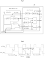
- Fig. 2 is a schematic diagram of an overall structure of a delay calibration apparatus according to some embodiments of the present disclosure.
- the delay calibration apparatus includes a transmission link (denoted as TX link), and the delay calibration module includes a first delay calibration module (e.g., Digital-to-Analog Converter (DAC) calibration) 100, the first delay calibration module being located in the transmission link.
- the coarse delay calibration unit 10 is a first coarse delay calibration unit 101
- the precise delay calibration unit 20 is a first precise delay calibration unit 201
- the channel associated pulse signal is a transmission channel associated pulse signal.
- the transmission channel associated pulse signal is generated in the transmission channel associated pulse signal generation module 110, and reaches the first delay calibration module (DAC calibration) 100 for calibration through each clock domain of the TX link.
- DAC calibration first delay calibration module
- the transmission channel associated pulse signal and the link data pass through multiple clock domains of the TX link together, and perform aligned transmission by using the data valid enable signal, so that the transmission channel associated pulse signal may reflect the delay condition of the link data transmission.
- the delay calibration apparatus further includes a reception link (denoted as RX link), and the delay calibration module includes a second delay calibration module (e.g., Analog-to-Digital Converter (ADC) calibration) 200, the second delay calibration module 200 being located in the reception link.
- the channel associated pulse signal is a reception channel associated pulse signal
- the precise delay calibration unit 20 is a second precise delay calibration unit 202
- the coarse delay calibration unit 10 is a second coarse delay calibration unit 102
- the second coarse delay calibration unit 102 is further configured to generate the reception channel associated pulse signal (denoted as rx_data_pluse) according to the air interface pulse signal after receiving the air interface pulse signal.
- the reception channel associated pulse calibration module 210 is configured to perform delay compensation on the received channel associated pulse signal in the digital clock domain according to the air interface pulse signal.
- the second coarse delay calibration unit 102 includes a second air interface pulse processing sub-unit (denoted as posedge0), a second channel associated pulse signal regeneration sub-unit (denoted as regen2), a second delay sub-unit (denoted as delay2), and a second coarse delay calibration sub-unit (denoted as ct_g).
- the second air interface pulse processing sub-unit (denoted as posedge0) is configured to generate a single-cycle air interface pulse signal according to a rising edge of the air interface pulse signal (denoted as ref_pluse).
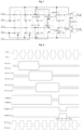
- Fig. 6 is a schematic diagram of a delay calibration timing sequence of a TX link according to some embodiments of the present disclosure.
- a cycle T and a preset multiple N of the air interface pulse signal are pre-configured in the first air interface pulse signal regeneration sub-unit (denoted as regen_1), and a cyclic regenerated air interface pulse signal is generated according to the cycle T and the preset multiple N of the air interface pulse signal (denoted as ref_pluse).
- the first channel associated pulse signal regeneration sub-unit (denoted as regen_0) is connected to the first delay sub-unit (denoted as delay1), and is configured to reduce the transmission channel associated pulse signal (denoted as dac_data_pluse) transmitted to the first coarse delay calibration unit 101 by a preset multiple according to a cycle ratio to generate a regenerated transmission channel associated pulse signal, and transmit the regenerated transmission channel associated pulse signal to the first delay sub-unit (denoted as delay1), so that the first delay sub-unit eliminates a delay between the regenerated transmission channel associated pulse signal and the next air interface pulse signal.
- a cycle T and a preset multiple N of the transmission channel associated pulse signal are pre-configured in the first channel associated pulse signal regeneration sub-unit (denoted as regen_0), and a cyclic regenerated transmission channel associated pulse signal is generated according to the cycle T and the preset multiple N of the transmission channel associated pulse signal (denoted as dac_data_pluse).
- the transmission channel associated pulse signal (denoted as dac_data_pluse) and the air interface pulse signal (denoted as ref_pluse) are reduced by N times according to a cycle ratio and are cyclically regenerated, and the coarse delay calibration process may be performed N times within one air interface pulse signal cycle, which greatly accelerates the speed of coarse delay calibration.
- the first coarse delay calibration unit 101 further includes a first expansion sub-unit (denoted as expand1).
- the first expansion sub-unit (denoted as expand1) is connected to the first delay sub-unit (denoted as delay1) and the first coarse delay calibration sub-unit (denoted as ct_f), and is configured to expand a high level length of the first signal (denoted as ct_data_pluse) according to one clock cycle, and transmit the expanded first signal to the first coarse delay calibration sub-unit (denoted as ct_f), so that the first coarse delay calibration sub-unit (denoted as ct_f) performs the logical AND operation on the expanded first signal and the single-cycle air interface pulse signal.
- the first expansion sub-unit expands the high level length of the channel associated pulse signal (i.e., the first signal) according to one clock cycle, thereby avoiding the uncertainty of the delay difference that may be caused by two asynchronous samplings and clock domain crossing, and ensuring that the channel associated pulse signal is earlier than the air interface pulse signal.
- the transmission channel associated pulse generation module 110 synchronously generates the channel associated pulse signal (denoted as data_pluse).
- the channel associated pulse signal here refers to the transmission channel associated pulse signal.
- the delay difference between the channel associated pulse signal (denoted as data_pluse) and the air interface pulse signal (denoted as ref_pluse) is a T1 clock domain cycle Td1.
- the channel associated pulse signal passes through multiple clock domains of the transmission link channel associated pulse transfer module 120 in sequence, and is controlled by the data valid enable signal.
- the channel associated pulse signal (denoted as data_pluse) is processed according to different working scenarios or modes, such as the multiple expansion of different extraction filters or the non-power-saving processing of Time Division Duplexing (TDD) scenarios, so as to ensure that the channel associated pulse signal is sampled by the low-level circuit and only maintains a high level for one clock cycle, and is transmitted to the low-level circuit synchronously with the data.
- TDD Time Division Duplexing
- the difference between the channel associated pulse signal (denoted as data_pluse) and the air interface pulse signal (denoted as ref_pluse) that generates the channel associated pulse signal is Td1+Td2, where Td2 is a fixed link delay Td21 plus the uncertain clock domain crossing delay Td22.
- the channel associated pulse processing sub-unit (denoted as posedge) is configured to receive the channel associated pulse signal transmitted by the coarse delay calibration unit in the delay calibration module where the channel associated pulse processing sub-unit is located, generate a single-cycle channel associated pulse signal according to a rising edge of the channel associated pulse signal, and transmit the single-cycle channel associated pulse signal to the first precise delay calibration interrupt sub-unit.
- the channel associated pulse signal is the first signal transmitted by the first coarse delay calibration unit 101
- the second precise delay calibration unit 202 the channel associated pulse signal is the second signal transmitted by the second coarse delay calibration unit 102.
- the air interface pulse synchronization sub-unit (denoted as sync1) is configured to synchronize the air interface pulse signal to the corresponding clock domain, and transmit the synchronized air interface pulse signal to the determination sub-unit (denoted as count).
- the channel associated pulse synchronization sub-unit (denoted as sync0) is configured to synchronize the channel associated pulse signal to the corresponding clock domain, and transmit the synchronized channel associated pulse signal to the determination sub-unit (denoted as count).
- the determination sub-unit (denoted as count) is configured to perform a logic AND operation on the synchronized air interface pulse signal and the synchronized channel associated pulse signal.
- the precise delay calibration sub-unit is configured to perform precise delay calibration in a case where an operation result obtained by the determination sub-unit (denoted as count) is 0. It is to be noted that the precise delay calibration sub-unit may be a functional module implemented by software.
- the precise delay calibration sub-unit of the second precise delay calibration unit 202 is configured to adjust the delay between the regenerated reception channel associated pulse signal and the next air interface pulse signal.
- the channel associated pulse signal is received, and a single-cycle channel associated pulse signal is generated according to a rising edge of the channel associated pulse signal, where the channel associated pulse signal is the first signal or the second signal.
Landscapes
- Engineering & Computer Science (AREA)
- Computer Networks & Wireless Communication (AREA)
- Signal Processing (AREA)
- Pulse Circuits (AREA)
- Synchronisation In Digital Transmission Systems (AREA)
Applications Claiming Priority (2)
| Application Number | Priority Date | Filing Date | Title |
|---|---|---|---|
| CN202211058378.8A CN117675065A (zh) | 2022-08-31 | 2022-08-31 | 时延校准装置及时延校准方法 |
| PCT/CN2023/113693 WO2024046141A1 (zh) | 2022-08-31 | 2023-08-18 | 时延校准装置及时延校准方法 |
Publications (2)
| Publication Number | Publication Date |
|---|---|
| EP4583445A1 true EP4583445A1 (de) | 2025-07-09 |
| EP4583445A4 EP4583445A4 (de) | 2025-12-17 |
Family
ID=90066858
Family Applications (1)
| Application Number | Title | Priority Date | Filing Date |
|---|---|---|---|
| EP23859175.4A Pending EP4583445A4 (de) | 2022-08-31 | 2023-08-18 | Verzögerungskalibrierungsvorrichtung und verzögerungskalibrierungsverfahren |
Country Status (3)
| Country | Link |
|---|---|
| EP (1) | EP4583445A4 (de) |
| CN (1) | CN117675065A (de) |
| WO (1) | WO2024046141A1 (de) |
Families Citing this family (3)
| Publication number | Priority date | Publication date | Assignee | Title |
|---|---|---|---|---|
| CN120639065A (zh) * | 2024-03-14 | 2025-09-12 | 深圳市中兴微电子技术有限公司 | 一种时钟校准方法及电路 |
| CN119003404B (zh) * | 2024-10-21 | 2025-04-11 | 灿芯半导体(苏州)有限公司 | 一种ddr主机低延迟小面积读数据通路 |
| CN120804007B (zh) * | 2025-09-03 | 2025-12-16 | 之江实验室 | 一种基于RFSoC的板内同步平台及方法 |
Family Cites Families (8)
| Publication number | Priority date | Publication date | Assignee | Title |
|---|---|---|---|---|
| JP4558347B2 (ja) * | 2004-02-27 | 2010-10-06 | 凸版印刷株式会社 | Dll回路 |
| US7280930B2 (en) * | 2005-02-07 | 2007-10-09 | Lecroy Corporation | Sequential timebase |
| US7977994B2 (en) * | 2007-06-15 | 2011-07-12 | The Regents Of The University Of Colorado, A Body Corporate | Digital pulse-width-modulator with discretely adjustable delay line |
| US8681839B2 (en) * | 2010-10-27 | 2014-03-25 | International Business Machines Corporation | Calibration of multiple parallel data communications lines for high skew conditions |
| CN109257033B (zh) * | 2018-08-27 | 2020-12-22 | 中国科学院电子学研究所 | 高精度步进延迟系统 |
| CN110365317B (zh) * | 2019-07-24 | 2021-01-08 | 电子科技大学 | 具有自适应延迟补偿的高精度混合型数字脉宽调制器 |
| CN112104342B (zh) * | 2020-09-01 | 2023-06-23 | 西北工业大学 | 一种由计数器和快慢延迟链构成的高精度数字脉宽调制器 |
| CN113364434B (zh) * | 2021-06-23 | 2024-03-01 | 中国科学院微电子研究所 | 一种占空比校准电路及方法 |
-
2022
- 2022-08-31 CN CN202211058378.8A patent/CN117675065A/zh active Pending
-
2023
- 2023-08-18 EP EP23859175.4A patent/EP4583445A4/de active Pending
- 2023-08-18 WO PCT/CN2023/113693 patent/WO2024046141A1/zh not_active Ceased
Also Published As
| Publication number | Publication date |
|---|---|
| EP4583445A4 (de) | 2025-12-17 |
| JP2025526151A (ja) | 2025-08-07 |
| CN117675065A (zh) | 2024-03-08 |
| WO2024046141A1 (zh) | 2024-03-07 |
Similar Documents
| Publication | Publication Date | Title |
|---|---|---|
| EP4583445A1 (de) | Verzögerungskalibrierungsvorrichtung und verzögerungskalibrierungsverfahren | |
| CN103036667B (zh) | 一种高速串行通讯接口自适应时序校准方法 | |
| CN114567926B (zh) | 一种用于无线分布式测试系统的时钟同步和触发装置 | |
| US7924054B1 (en) | Latency measurements for wireless communications | |
| US9465404B2 (en) | Timing synchronization circuit for wireless communication apparatus | |
| US6949955B2 (en) | Synchronizing signals between clock domains | |
| US20240231418A9 (en) | Timing synchronization system | |
| US12506491B2 (en) | Sampling circuit, method for using sampling circuit, storage medium, and electronic device | |
| US7936789B2 (en) | Disparate clock domain synchronization | |
| CN114070445B (zh) | 一种分布式电源计时校准器及同步触发方法 | |
| JP7852145B2 (ja) | 遅延キャリブレーション装置及び遅延キャリブレーション方法 | |
| WO2012009160A1 (en) | Methods and apparatus for determining a phase error in signals | |
| CN119363275B (zh) | 一种用于分布式数据同步采集的ptp时频同步方法 | |
| US20040223564A1 (en) | Programmable clock synchronizer | |
| Deev et al. | Subnanosecond synchronization method based on the synchronous Ethernet network | |
| CN116112011B (zh) | 一种用于软件可定义soc芯片的无sysref分布式时钟架构 | |
| CN114545201B (zh) | 一种总线回环测试结构和方法 | |
| WO2024139457A1 (zh) | 时延电路同步方法及装置 | |
| Xie et al. | Application of synchronous acquisition technology based on JESD204B protocol in phased array radar | |
| CN115694492B (zh) | 一种基于fpga的ad芯片同步校正方法及装置 | |
| WO2012103837A2 (zh) | 时延调整方法和数据转换器 | |
| Wang | Design and Implementation of Multi-channel Synchronous Acquisition Based on JESD204B Protocol | |
| Zhao et al. | Implementation of Deterministic Latency at the Receiver of JESD204C | |
| CN117498976A (zh) | 基于网络同步的分布式采集系统的时钟同步方法 | |
| CN121773560A (zh) | 跨用户装备微睡眠模式的模数转换器(adc)时钟相位连续性 |
Legal Events
| Date | Code | Title | Description |
|---|---|---|---|
| STAA | Information on the status of an ep patent application or granted ep patent |
Free format text: STATUS: THE INTERNATIONAL PUBLICATION HAS BEEN MADE |
|
| PUAI | Public reference made under article 153(3) epc to a published international application that has entered the european phase |
Free format text: ORIGINAL CODE: 0009012 |
|
| STAA | Information on the status of an ep patent application or granted ep patent |
Free format text: STATUS: REQUEST FOR EXAMINATION WAS MADE |
|
| 17P | Request for examination filed |
Effective date: 20250219 |
|
| AK | Designated contracting states |
Kind code of ref document: A1 Designated state(s): AL AT BE BG CH CY CZ DE DK EE ES FI FR GB GR HR HU IE IS IT LI LT LU LV MC ME MK MT NL NO PL PT RO RS SE SI SK SM TR |
|
| REG | Reference to a national code |
Ref country code: DE Ref legal event code: R079 Free format text: PREVIOUS MAIN CLASS: H04L0005000000 Ipc: H03K0007080000 |
|
| DAV | Request for validation of the european patent (deleted) | ||
| DAX | Request for extension of the european patent (deleted) | ||
| A4 | Supplementary search report drawn up and despatched |
Effective date: 20251118 |
|
| RIC1 | Information provided on ipc code assigned before grant |
Ipc: H03K 7/08 20060101AFI20251112BHEP Ipc: H04L 27/00 20060101ALI20251112BHEP Ipc: H04J 3/06 20060101ALI20251112BHEP |