EP4571004A2 - Modulares deckensystem - Google Patents
Modulares deckensystem Download PDFInfo
- Publication number
- EP4571004A2 EP4571004A2 EP24219671.5A EP24219671A EP4571004A2 EP 4571004 A2 EP4571004 A2 EP 4571004A2 EP 24219671 A EP24219671 A EP 24219671A EP 4571004 A2 EP4571004 A2 EP 4571004A2
- Authority
- EP
- European Patent Office
- Prior art keywords
- channel
- ceiling
- bracket
- edge
- recess
- Prior art date
- Legal status (The legal status is an assumption and is not a legal conclusion. Google has not performed a legal analysis and makes no representation as to the accuracy of the status listed.)
- Pending
Links
Images


Classifications
-
- E—FIXED CONSTRUCTIONS
- E04—BUILDING
- E04B—GENERAL BUILDING CONSTRUCTIONS; WALLS, e.g. PARTITIONS; ROOFS; FLOORS; CEILINGS; INSULATION OR OTHER PROTECTION OF BUILDINGS
- E04B9/00—Ceilings; Construction of ceilings, e.g. false ceilings; Ceiling construction with regard to insulation
- E04B9/04—Ceilings; Construction of ceilings, e.g. false ceilings; Ceiling construction with regard to insulation comprising slabs, panels, sheets or the like
- E04B9/0435—Ceilings; Construction of ceilings, e.g. false ceilings; Ceiling construction with regard to insulation comprising slabs, panels, sheets or the like having connection means at the edges
-
- E—FIXED CONSTRUCTIONS
- E04—BUILDING
- E04B—GENERAL BUILDING CONSTRUCTIONS; WALLS, e.g. PARTITIONS; ROOFS; FLOORS; CEILINGS; INSULATION OR OTHER PROTECTION OF BUILDINGS
- E04B9/00—Ceilings; Construction of ceilings, e.g. false ceilings; Ceiling construction with regard to insulation
- E04B9/06—Ceilings; Construction of ceilings, e.g. false ceilings; Ceiling construction with regard to insulation characterised by constructional features of the supporting construction, e.g. cross section or material of framework members
-
- E—FIXED CONSTRUCTIONS
- E04—BUILDING
- E04B—GENERAL BUILDING CONSTRUCTIONS; WALLS, e.g. PARTITIONS; ROOFS; FLOORS; CEILINGS; INSULATION OR OTHER PROTECTION OF BUILDINGS
- E04B9/00—Ceilings; Construction of ceilings, e.g. false ceilings; Ceiling construction with regard to insulation
-
- E—FIXED CONSTRUCTIONS
- E04—BUILDING
- E04B—GENERAL BUILDING CONSTRUCTIONS; WALLS, e.g. PARTITIONS; ROOFS; FLOORS; CEILINGS; INSULATION OR OTHER PROTECTION OF BUILDINGS
- E04B9/00—Ceilings; Construction of ceilings, e.g. false ceilings; Ceiling construction with regard to insulation
- E04B9/06—Ceilings; Construction of ceilings, e.g. false ceilings; Ceiling construction with regard to insulation characterised by constructional features of the supporting construction, e.g. cross section or material of framework members
- E04B9/064—Ceilings; Construction of ceilings, e.g. false ceilings; Ceiling construction with regard to insulation characterised by constructional features of the supporting construction, e.g. cross section or material of framework members comprising extruded supporting beams
-
- E—FIXED CONSTRUCTIONS
- E04—BUILDING
- E04B—GENERAL BUILDING CONSTRUCTIONS; WALLS, e.g. PARTITIONS; ROOFS; FLOORS; CEILINGS; INSULATION OR OTHER PROTECTION OF BUILDINGS
- E04B9/00—Ceilings; Construction of ceilings, e.g. false ceilings; Ceiling construction with regard to insulation
- E04B9/22—Connection of slabs, panels, sheets or the like to the supporting construction
- E04B9/28—Connection of slabs, panels, sheets or the like to the supporting construction with the slabs, panels, sheets or the like having grooves engaging with horizontal flanges of the supporting construction or accessory means connected thereto
-
- E—FIXED CONSTRUCTIONS
- E04—BUILDING
- E04B—GENERAL BUILDING CONSTRUCTIONS; WALLS, e.g. PARTITIONS; ROOFS; FLOORS; CEILINGS; INSULATION OR OTHER PROTECTION OF BUILDINGS
- E04B9/00—Ceilings; Construction of ceilings, e.g. false ceilings; Ceiling construction with regard to insulation
- E04B9/06—Ceilings; Construction of ceilings, e.g. false ceilings; Ceiling construction with regard to insulation characterised by constructional features of the supporting construction, e.g. cross section or material of framework members
- E04B9/065—Ceilings; Construction of ceilings, e.g. false ceilings; Ceiling construction with regard to insulation characterised by constructional features of the supporting construction, e.g. cross section or material of framework members comprising supporting beams having a folded cross-section
-
- E—FIXED CONSTRUCTIONS
- E04—BUILDING
- E04B—GENERAL BUILDING CONSTRUCTIONS; WALLS, e.g. PARTITIONS; ROOFS; FLOORS; CEILINGS; INSULATION OR OTHER PROTECTION OF BUILDINGS
- E04B9/00—Ceilings; Construction of ceilings, e.g. false ceilings; Ceiling construction with regard to insulation
- E04B9/18—Means for suspending the supporting construction
- E04B9/183—Means for suspending the supporting construction having a lower side adapted to be connected to a channel of the supporting construction
Definitions
- the present invention relates to a modular ceiling system, a support bracket for a modular ceiling system and to a method of installing a modular ceiling system.
- the ceiling system of the invention may be used to install a suspended ceiling and may allow a ceiling to be retrofit in an existing building.
- the building When constructing new buildings and, in particular, new houses, the building can be designed to have excellent insulation so that the energy loss from the building is minimised.
- a first aspect of the present invention provides a modular ceiling system comprising:
- the ceiling panel preferably has a first outer surface and an opposite second outer surface.
- a part of the first outer surface is preferably disposed between the first and second channels and the planes of the attachment plates such that the attachment plates are preferably disposed above and spaced apart from the first outer surface.
- a part of the first outer surface preferably extends over one of the lips of each of the first and second channels.
- a part of the second surface preferably extends over a part of an external face of the base plate of each of the first and second channels. In this way, the channel is preferably concealed by edge regions of the ceiling panel.
- the modular ceiling system preferably further comprises a third channel including a base plate, two side plates and two inwardly extending lips, and a recess of the third channel being defined between the two side plates.
- the modular ceiling system preferably further comprises a wall bracket including a base portion engaged in the recess of the third channel and an attachment portion extending out of the recess, the attachment portion including an attachment plate including an aperture, and a plane of the attachment plate being generally parallel to the side plates of the first channel.
- a part of the third channel preferably extends into a third edge recess in a third edge of the ceiling panel such that the third edge of the ceiling panel is parallel to a longitudinal axis of the third channel and the ceiling panel is supported by the first, second and third channels.
- the ceiling panel is preferably a laminated panel having first and second outer boards and an insulation layer between the first and second outer boards.
- the edge recess is preferably disposed between the first and second outer boards. A width of the edge recess may be equal to a thickness of the insulation layer.
- the ceiling panel is a first ceiling panel and the system further comprises a second ceiling panel including a first edge recess in a first edge of the second ceiling panel.
- a part of the first channel preferably extends into the first edge recess of the second ceiling panel such that the first edge of the second ceiling panel is parallel to a longitudinal axis of the first channel.
- a part of the first edge of the first ceiling panel is preferably in contact with a part of the first edge of the second ceiling panel so that the first channel is concealed by the first and second ceiling panels.
- Both the first and second ceiling panels may be laminated panels having first and second outer boards and an insulation layer between the first and second outer boards.
- the edge recesses may be disposed between the first and second outer boards.
- An external surface of the second outer board of the first ceiling panel is preferably continuous with and lies in the same plane as an external surface of the second outer board of the second ceiling panel. In this way, the external surfaces of the second outer boards form a flat, continuous ceiling that may be easily decorated. For example, it may only be necessary to fill any small gaps between the ceiling boards before painting the external surfaces of the second outer boards.
- one of the first and second ceiling panels may be a heating panel including a heating element disposed between the insulation layer and the second outer board.
- a second aspect of the present invention provides a support bracket for use in the modular ceiling system of the first aspect of the invention.
- the support bracket comprises:
- the stem portion extends parallel to the side plates.
- the stem portion is disposed midway between the side plates.
- the aperture of the attachment portion is preferably elongate so that a position of the bracket when attached to a support structure, such as a joist, can be easily adjusted.
- the attachment portion comprises an attachment plate extending perpendicularly from the stem portion, the aperture extending through the thickness of the attachment plate.
- the stem portion may include an adjustment section configured to permit adjustment of the stem portion to increase or decrease a distance between the attachment plate and the base element.
- the attachment portion comprises an attachment plate extending parallel to but offset from the stem portion, the aperture extending through the thickness of the attachment plate.
- a plane of the attachment plate preferably lies at the same distance or a greater distance from the stem portion than a plane of one of the side plates.
- the support bracket is preferably formed from sheet metal.
- the base element and the attachment element may each be made from sheet metal that is folded to form the required shape.
- the base element and the attachment element may be welded to each other so that the attachment element is permanently fixed to the base element.
- a third aspect of the present invention provides a modular ceiling kit comprising:
- the modular ceiling kit may further comprise a plurality of lengths of channel, each length of channel including a base plate, two side plates extending from side edges of the base plate and two inwardly extending lips extending from the side plates.
- the modular ceiling kit may further comprise a plurality of ceiling panels in the form of heating panels including a heating element disposed between the insulation layer and the second outer board.
- each of the ceiling panels includes an edge recess that extends around the full perimeter of the ceiling panel.
- a fourth aspect of the present invention provides a method of installing a modular ceiling, the method comprising:
- a fifth aspect of the present invention provides a method of installing a modular ceiling, the method comprising:
- the method of the fourth or fifth aspect of the invention may further comprise:
- the step of sliding the ceiling panel into engagement with the first length of channel comprises inserting the first length of channel into the edge recess until the first edge of the ceiling panel contacts the stem portion of the first ceiling bracket.
- the step of sliding the second length of channel into engagement with the edge recess of the ceiling panel comprises inserting the second length of channel into the edge recess until the second edge of the ceiling panel contacts the stem portion of the second ceiling bracket.
- Preferred methods may further comprise adjusting a length of the stem portion of at least one of the ceiling brackets so that a plane of the ceiling panel is horizontal.
- the modular ceiling system 10 of the present invention generally includes one or more wall brackets 12, one or more ceiling brackets 14, one or more channels 16 and one or more ceiling panels 18.
- the modular ceiling system 10 is designed to be suspended from ceiling/floor joists and additionally secured to walls surrounding the area of the ceiling.
- the modular ceiling system 10 may be suspended below and possibly connected to an existing ceiling to increase thermal insulation.
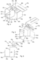
- the modular ceiling system 10 utilises standard known C-section or U-section channel 16, as shown most clearly in Figure 7 .
- the channel 16 has a base plate or base section 22 and two side plates or side sections 24. Each of the base plate 22 and side plates 24 is generally planar. Each of the side plates 24 extends from a longitudinal edge of the base plate 22 in a direction generally perpendicular to a plane of the base plate 22, so that the channel 16 has a U-shaped cross-sectional shape perpendicular to a longitudinal axis 26 of the channel 16.
- a lip 28 extends from a longitudinal edge of each of the side plates 24 furthest from the base plate 22. The lips 28 extend generally perpendicular to planes of the side plates 24 and extend inwardly in directions towards each other.
- a gap 30 is defined between the lips 28 which forms a longitudinal opening 30 of the channel 16. The opening 30 provides access to a recess 32 of the channel 16 between the two side plates 24.
- a length of the channel 16 is defined in a direction parallel to the longitudinal axis 26 of the channel 16.
- a width of the recess 32 is defined as the distance between internal surfaces of the side plates 24 of the channel, and a width of the opening 30 is defined as the distance between the lips 28. It will be appreciated that the width of the opening 30 is less than the width of the recess 32.
- a height of the recess 32 is defined as the distance between the base plate 22 and a lower or internal surface of each of the lips 28.
- a width of the channel 16 is defined as the distance between external surfaces of the side plates 24, and a depth of the channel 16 is defined as the distance between an upper or external surface of the lips 28 and a lower or external surface of the base plate 22.
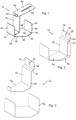
- a first preferred embodiment of a ceiling bracket 14 includes a base element 34 and an attachment element 36.
- the base element 34 is configured to be inserted into the recess 32 of a length of channel 16 through the opening 30 of the channel 16.
- the base element 34 is further configured to engage in the recess 32 to retain the ceiling bracket 14 in the channel 16 so that the channel 16 can be suspended from the ceiling bracket 14.
- the base element 34 comprises a base plate or base portion 38 and two side plates or side portions 40.
- the base plate 38 has opposite first and second planar surfaces 42, 44 and in this embodiment has six edges.
- a first pair of side edges 46 are parallel to each other, a second pair of insertion edges 48 are parallel to each other, and a third pair of end edges 50 are parallel to each other. Angles between adjacent edges are not, however, identical, such that the base plate 38 has the shape of an irregular hexagon.
- a distance between the insertion edges 48 is substantially the same as the width of the opening 30 of the channel 16.
- the distance between the insertion edges 48 is preferably slightly smaller than the width of the opening 30 so that there is clearance between the base plate 38 and the lips 28, and the base element 34 can pass through the opening 30 with the base plate 38 oriented with the insertion edges 48 parallel to the side plates 24 of the channel 16, as illustrated in Figures 7 and 8 .
- a distance between the side edges 46 is substantially the same as or slightly smaller than the width of the recess 32 of the channel 16.
- the side plates 40 of the base element 34 extend perpendicularly from the side edges 46 of the base plate 38.
- a height of each of the side plates 40 is substantially the same as or slightly smaller than the height of the recess 32. In this way, when the base element 34 is rotated into the second orientation, the side plates 40 locate under the lips 28 of the channel 16, as shown most clearly in Figure 10 . This retains the base element 34 in the recess 32 of the channel 16.
- the attachment element 36 is fixed to the base element 34 so that the attachment element 36 does not move with respect to the base element 34.
- the attachment element 36 comprises a support plate or support portion 52, a stem portion 54, and an attachment plate or attachment portion 56.
- the attachment element 36 is fixed to the base element 34 by the support plate 52.
- the support plate 52 is fixed to the first surface 42 of the base plate 38.
- the stem portion 54 extends from the support portion 52. With the support portion 52 secured to the base element 34, the stem portion 54 extends perpendicular to a plane of the base plate 38.
- the stem portion 54 is positioned with respect to the base element 34 so that the stem portion 54 is disposed between the two side plates 40.
- the stem portion 54 is disposed midway between the side plates 40.
- the stem portion 54 extends parallel to the side plates 40.
- a height of the stem portion 54 is greater than the height of the side plates 40 such that the stem portion 54 protrudes or extends from the base element 34.
- the stem portion 54 When the base element 34 is engaged in the recess 32 of a channel 16, the stem portion 54 extends through the opening 30. With the stem portion 54 is disposed midway between the side plates 40, the stem portion is also disposed midway between the lips 28 of the channel 16 and therefore midway across the width of the channel 16.
- the attachment portion 56 extends from an end of the stem portion 54 furthest from the support portion 52. In this embodiment the attachment portion 56 extends generally perpendicularly from the stem portion 54 such that the attachment portion 56 extends over one of the side plates 40 of the base element 34. A plane of the attachment portion 56 is preferably parallel to a plane of the base plate 38. The height of the stem portion 54 is such that there is a gap between the attachment portion 56 and the upper edge of the side plate 40 of the base element 34.
- the attachment portion 56 includes an aperture 58 extending through the thickness of the attachment portion 56 in a direction perpendicular to the plane of the attachment portion 56. In this embodiment the aperture 58 is elongate.
- the attachment element 36 is configured to be secured to a ceiling joist or the underside of an upper floor joist by a mechanical fastener 20 extending through the aperture 58 in the attachment portion 56.
- the mechanical fastener 20 may be a screw or bolt for example.
- the attachment portion 56 is in the form of an attachment plate 56 and a retaining channel 60 is secured to a face of the attachment plate 56.
- the retaining channel 60 is aligned with the aperture 58.
- the retaining channel 60 may be used to hold a head of a bolt with a shaft of the bolt extending through the aperture 58.
- the ceiling bracket 14 is preferably made of a metal material, most preferably steel. In preferred embodiments the ceiling bracket 14 is made from sheet metal.
- the attachment element 36 is preferably welded to the base element 34. The attachment element 36 may, in other embodiments, be adhered or otherwise securely and permanently attached to the base element 34.
- a first preferred embodiment of a wall bracket 12 includes a base element 34 and an attachment element 62.
- the base element 34 of the wall bracket 12 is identical to the base element 34 of the ceiling bracket 14.
- the attachment element 62 is fixed to the base element 34 so that the attachment element 62 does not move with respect to the base element 34.
- the attachment element 62 comprises a support plate or support portion 64, a stem portion 66, and an attachment plate or attachment portion 68.
- the attachment element 62 is fixed to the base element 34 by the support plate 64.
- the support plate 64 is fixed to the first surface 42 of the base plate 38 of the base element 34.
- the stem portion 66 extends from the support portion 64. With the support portion 64 secured to the base element 34, the stem portion 66 extends perpendicular to a plane of the base plate 38. The stem portion 66 is positioned with respect to the base element 34 so that the stem portion 66 is disposed between the two side plates 40. In this example, the stem portion 66 extends parallel to the side plates 40. Preferably the stem portion 66 is disposed closer to one of the side plates 40 than to the other. A height of the stem portion 66 is slightly greater than the height of the side plates 40 such that the stem portion 66 protrudes or extends slightly above the side plates 40 of the base element 34.
- the stem portion 66 When the base element 34 is engaged in the recess 32 of a channel 16, the stem portion 66 extends through the opening 30. With the stem portion 66 is disposed midway between the side plates 40, the stem portion is also disposed midway between the lips 28 of the channel 16 and therefore midway across the width of the channel 16.
- the attachment portion 68 extends from an end of the stem portion 66 furthest from the support portion 64.
- the attachment portion 68 includes an overhang section 70 and a contact section 72.
- the overhang section 70 extends generally perpendicularly from the stem portion 66 such that the overhang section 70 extends over one of the side plates 40 of the base element 34.
- the contact section 72 extends from the overhang section 70 in a direction generally parallel to the side plates 40 of the base element 34.
- a dimension of the overhang section 70 is such that, when the base element 34 is engaged in a channel 16, the overhang section 70 extends over one of the lips 28 of the channel 16 and a plane of the contact section 72 is aligned with a plane of the side plate 24 of the channel 16.
- the contact section 72 of the attachment portion 68 includes an aperture 74. In this embodiment the aperture 74 is elongate.
- the attachment element 62 is configured to be secured to a wall stud or other part of a wall by a mechanical fastener 20 extending through the aperture 74 in the attachment portion 68.
- the mechanical fastener 20 may be a screw or bolt for example.
- the wall bracket 12 is preferably made of a metal material, most preferably steel. In preferred embodiments the wall bracket 12 is made from sheet metal.
- the attachment element 62 is preferably welded to the base element 34. The attachment element 62 may, in other embodiments, be adhered or otherwise securely and permanently attached to the base element 34.
- each of the side plates 40 of the base element 34 locates between the base plate 22 and a respective lip 28 of the channel 16, and one of the lips 28 locates between the top edge of one of the side plates 40 of the base element 34 and the overhang section 70.
- a length of channel 16 may be engaged with the base element 34 such that the channel 16 is supported by and suspended from the base element 34.
- each of the side plates 40 of the base element 34 locates between the base plate 22 and a respective lip 28 of the channel 16, as shown most clearly in Figures 9 and 10 .
- FIGS 4 to 6 illustrate an alternative embodiment of a ceiling bracket 214.
- the ceiling bracket 214 includes a base element 234 and an attachment element 236.
- the base element 234 is identical to the base element 34 of the first embodiment of the ceiling bracket 14.
- the base element 234 comprises a base plate or base portion 238 and two side plates or side portions 240.
- the base plate 238 has opposite first and second planar surfaces 242, 244 and in this embodiment has six edges.
- a first pair of side edges 246 are parallel to each other, a second pair of insertion edges 248 are parallel to each other, and a third pair of end edges 250 are parallel to each other.
- Angles between adjacent edges are not, however, identical, such that the base plate 238 has the shape of an irregular hexagon.
- a distance between the insertion edges 248 is substantially the same as the width of the opening 30 of the channel 16.
- the distance between the insertion edges 248 is preferably slightly smaller than the width of the opening 30 so that there is clearance between the base plate 238 and the lips 28, and the base element 234 can pass through the opening 30 with the base plate 238 oriented with the insertion edges 248 parallel to the side plates 24 of the channel 16.
- a distance between the side edges 246 is substantially the same as or slightly smaller than the width of the recess 32 of the channel 16.
- the side plates 240 of the base element 234 extend perpendicularly from the side edges 246 of the base plate 238.
- a height of each of the side plates 240 is substantially the same as or slightly smaller than the height of the recess 32. In this way, when the base element 234 is rotated into the second orientation, the side plates 240 locate under the lips 28 of the channel 16. This retains the base element 234 in the recess 32 of the channel 16.
- the attachment element 236 comprises a support plate or support portion 252, a stem portion 254, and an attachment plate or attachment portion 256.
- the attachment element 236 is fixed to the base element 234 by the support plate 252.
- the support plate 252 is fixed to the first surface 242 of the base plate 238.
- the stem portion 254 extends from the support portion 252.
- the stem portion 254 includes a drop section 251 and an adjustment section 253. With the support portion 252 secured to the base element 234, the drop section 251 is disposed between the two side plates 240.
- the drop section 251 is disposed midway between the side plates 240. In this example, the drop section 251 extends parallel to the side plates 240.
- a height of the drop section 251 is greater than the height of the side plates 240 such that the drop section 251 protrudes or extends from the base element 234.
- the adjustment section 253 extends from the drop section 251 in a direction generally perpendicular to the drop section 251. In this embodiment the adjustment section 253 extends over one of the side plates 240 of the base element 234.
- the height of the drop section 251 is such that there is a gap between the adjustment section 253 and the upper edge of the side plate 240 of the base element 234.
- the adjustment section 253 includes a trough or cavity 255 for receiving the head of a bolt.
- the attachment portion 256 is secured to the stem portion 254.
- the attachment portion 256 comprises an adjustment section 276, a spacing section 278 and a contact section 280.
- the adjustment section 276 and contact section 280 extend from opposite edges of the spacing section 278, and both the adjustment section 276 and contact section 280 extend parallel to each other and perpendicular to the spacing section 278, such that the attachment portion 256 is at least partially U-shaped.
- Both the adjustment section 253 of the stem portion 254 and the adjustment section 276 of the attachment portion 256 include an aperture.
- the apertures align to receive the stem of a bolt 282 therethrough, as illustrated in Figures 4 to 6 .
- the head of the bolt 282 is preferably seated in the cavity 255 such that the head of the bolt 282 does not rotate.
- a nut 284 can then be attached to the stem of the bolt 282 to secure the attachment portion 256 to the stem portion 254 with the two adjustment sections 253, 276 clamped between the head of the bolt 282 and the nut 284.
- the attachment portion 256 is secured to the stem portion 254 so that a distance between the contact section 280 and the base element 234 can be adjusted.
- This allows the ceiling to be suspended at the desired height below existing ceiling joists or other ceiling structures. It may be desirable, for example, to suspend the ceiling at a greater distance below the ceiling joists to accommodate pipes, ducts and the like.
- one or more spacer elements may be positioned between the two adjustment sections 253, 276 before they are clamped between the head of the bolt 282 and the nut 284.
- the spacer element may be in the form of a nut.
- the ceiling panel 18 comprises first and second outer boards 86, 88 and an insulation layer 90 between the first and second outer boards.
- the insulation layer 90 preferably provides thermal insulation.
- the first and second outer boards 86, 88 and the insulation layer 90 are bonded together and are preferably adhered to each other.
- Each of the first and second outer boards 86, 88 and insulation layer 90 are rectangular.
- the first outer board 86 includes a pair of opposite side edges 92 and a pair of opposite end edges 94.
- the second outer board 88 includes a pair of opposite side edges 96 and a pair of opposite end edges 98.
- a length of each of the first and second outer boards 86, 88 is defined between the respective pair of end edges 94, 98, and a width of each of the first and second outer boards 86, 88 is defined between the respective pair of side edges 92, 96.
- the lengths of the first and second outer boards 86, 88 are identical, and the widths of the first and second outer boards 86, 88 are identical.
- the insulation layer 90 has a pair of opposite side edges 100 and a pair of opposite end edges 102.
- a length of the insulation layer 90, between the end edges 102, is smaller than the lengths of the first and second outer boards 86, 88.
- a width of the insulation layer 90, between the side edges 100, is smaller than the widths of the first and second outer boards 86, 88.
- the ceiling panel 18 includes an edge recess 104 extending around the full perimeter of the ceiling board 18.
- a width dimension of the edge recess 104 is defined as the distance between inner faces of the first and second outer boards 86, 88 and is equal to a thickness of the insulation layer 90.
- a depth dimension of the edge recess 104 is defined in a direction perpendicular to the respective edge of the first and second outer boards 86, 88 and parallel to a plane of the first and second outer boards 86, 88.
- the depth of the edge recess 104 is the same around the full perimeter of the ceiling board 18.
- first and second outer boards 86, 88 comprise gypsum fibre boards.
- the insulation layer 90 preferably comprises a mineral wool or a closed cell insulating material.
- the side edges 92, 96 of the first and second outer boards 86, 88 define side edges 93 of the ceiling panel 18.
- a width of the ceiling panel 18 is defined as the distance between the side edges 93.
- the end edges 94, 98 of the first and second outer boards 86, 88 define end edges 95 of the ceiling panel 18.
- a length of the ceiling panel 18 is defined as the distance between the end edges 95. It will be appreciated that the modular ceiling system 10 may include ceiling boards 18 having different length and width dimensions.
- the edge recess 104 is configured and sized to receive part of a channel 16.
- the width of the edge recess 104 (and therefore the thickness of the insulation layer 90) is substantially the same as a height of the channel 16, and a depth of the edge recess 104 is substantially equal to half the width of the channel 16.
- the ceiling panel 18 may be made of suitable materials to provide fire resistance and/or acoustic insulation.
- a plurality of wall brackets 12 are secured to wall studs or a wall structure (not shown).
- the wall brackets 12 may be fixed to the wall studs or wall structure by mechanical fasteners 20, such as screws, extending through the openings 74 in the attachment elements 62.
- a first length of channel 16e is engaged with the base elements 34 and suspended from the wall brackets 12.
- one of the side plates 24 of the channel 16e may be clamped between the stem portion 66 of the wall bracket 12 and a part of the wall structure.
- the first length of channel 16e will be located at a perimeter edge of the final modular ceiling.
- each of the openings 74 is elongate in a vertical direction so that the respective heights of the wall brackets 12 can be adjusted to ensure that the first length of channel 16e is level (horizontal).
- a second length of channel 16i is suspended from a plurality of ceiling brackets 14, 214.
- Each of the ceiling brackets 14, 214 is secured to a ceiling joist or other ceiling structure.
- the ceiling brackets 14, 214 may be fixed to the ceiling joists by mechanical fasteners 20, such as screws, extending through the openings 58 in the attachment elements 36.
- the second length of channel 16i is engaged with the base elements 34 and suspended from the ceiling brackets 14, 214.
- the ceiling brackets 214 are adjustable such that a distance between the contact section 280 of the attachment element 236 and the base element 234 can be adjusted. This allows the distance between the second length of channel 16i and the ceiling joists to be adjusted to ensure that the second length of channel 16i is level (horizontal) and lies in the same horizontal plane as the first length of channel 16e.
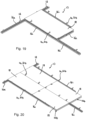
- the second length of channel 16i is positioned so that an end of the channel 16i abuts or lies in close proximity to a side plate 24 of the first length of channel 16e.
- the longitudinal axis 26 of the second length of channel 16i is preferably perpendicular to the longitudinal axis 26 of the first length of channel 16e. It will be appreciated that the second length of channel 16i spans part of the area of the ceiling and provides an internal support.
- a ceiling panel 18 is then engaged with the first and second channels 16e, 16i.
- the ceiling panel 18 is slid into engagement with the first channel 16e so that a part of the first channel 16e is received in the edge recess 104 along a first end edge 95 of the ceiling panel 18.
- the ceiling panel 18 is also slid into engagement with the second channel 16i so that a part of the second channel 16i is received in the edge recess 104 along a first side edge 93 of the ceiling panel 18.
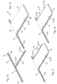
- a further set of ceiling brackets 14, 214 is secured to a ceiling joist proximate a second side edge 93 of the ceiling panel 18. As illustrated in Figures 17 and 21 , each ceiling bracket 14, 214 may initially be secured to the ceiling joist such that the base element 34 is separated from or clear of the ceiling panel 18. A third length of channel 16i may then be engaged with and suspended from the base elements 34. The third channel 16i, together with the associated ceiling brackets 14, 214 may then be slid into engagement with the ceiling panel 18, as illustrated in Figures 18 and 22 . In particular, the third channel 16i may be moved in a direction perpendicular to its longitudinal axis to insert a part of the third channel 16i in the edge recess 104 along the second side edge 93 of the ceiling panel 18.
- the mechanical fastener 20 (for example a screw) which is used to secure the ceiling bracket 14, 214 to the ceiling joist may be initially disposed at a first end of the elongate aperture 58 in the ceiling bracket 14, 214.
- the mechanical fastener may slide towards a second end of the elongate aperture 58 in the ceiling bracket 14, 214.
- the mechanical fasteners may then be tightened to secure the ceiling brackets 14, 214 in the desired position.
- ceiling brackets 14, 214 are attached to ceiling joists and further channels 16 are suspended from the ceiling brackets 14, 214 so that, preferably, channels 16 are disposed in the edge recess 104 around the full perimeter of the ceiling panel 18. This ensures that the ceiling panel 18 is securely supported between channels 16.
- a plurality of ceiling panels 18 are suspended from a plurality of channels 16.
- a single length of channel 16 engages with opposing edge recesses 104 of neighbouring ceiling panels 18.
- a first ceiling panel 18 may engage with a length of channel 16 such that half of the width of the channel 16 is seated in the edge recess 104 of that first panel 18 and a second ceiling panel 18 may engage with the same length of channel 16 such that the other half of the width of the channel 16 is seated in the edge recess 104 of that second panel 18.
- the opposing side edges 93 of the first and second ceiling panels 18 preferably abut the stem portions 54 of the ceiling brackets 14, 214 supporting the channel 16.
- the depth of the edge recess 104 is approximately half of the width of the channel 16. Accordingly, when the channel 16 is fully inserted into the edge recess 104 so that the edge 93, 95 of the panel 18 abuts the stem portion 54, the side plate 24 of the channel 16 lies in close proximity to the respective edge 100, 102 of the insulation layer 90.
- the depth of the edge recess 104 may be substantially equal to the full width of a channel 16.
- a gap will remain between the external surface of the side plate 24 and the edge 100, 102 of the insulation layer 90.
- an edge region of the second outer board 88 (defined by the depth of the edge recess 104) is able to cover the full width of the base plate 22 of the channel 16.
- a ceiling panel 18 may be provided in which the depth of the edge recess 104 is not the same around the full perimeter of the ceiling panel 18.
- a depth of the edge recess 104 along one of the side edges or end edges of the ceiling panel 18 may be greater than along the other side edges or end edges. In this way, the edge of the panel 18 having the edge recess 104 with the greater depth may be engaged with a channel 16 suspended from wall brackets 12, while the remaining edges are engaged with channels 16 suspended from ceiling brackets 14, 214.
- channels 16 and panels 18 are added until the complete area of the ceiling is covered.
- end edges and side edges of neighbouring ceiling panels 18 contact or abut each other, Not only does this maximise the thermal insulation of the ceiling, but it also creates a continuous lower surface of the ceiling.
- the channels 16 of the modular ceiling system are fully concealed by the ceiling panels 18. With neighbouring second outer boards abutting, a continuous lower surface of the modular ceiling is formed which does not need to be plastered before being decorated.
- the time taken for filling and drying of the filler will be less than the time required to fully plaster a ceiling and wait for the plaster to dry before painting.
- the modular ceiling system of the present invention is quick and easy to install and allows the ceiling to be decorated soon after installation, thereby minimising disruption.
- both the wall brackets 12 and the ceiling brackets 14, 214 are able to be slid along the length of the channel 16, and located at any position along the length of the channel 16. This allows the brackets 12, 14, 214 to be attached to any and/or all existing wall supports, ceiling/floor joists and other supports, while still providing the necessary support to the channels 16 and ceiling panels 18.
- a further advantage of the modular ceiling system 10 is that the ceiling brackets 14, 214 suspend the ceiling panels 18 at a distance below the ceiling/floor joists or existing ceiling structure.
- An air gap is therefore formed above the modular ceiling which increases the thermal insulation of the ceiling as it reduces thermal bridging.
- the suspension of the ceiling panels 18 at a distance below the ceiling/floor joists or existing ceiling structure may also increase the acoustic insulation or sound-proofing of the ceiling.
- heating panels 106, 120 may be used in place of the ceiling panels 18 described above and may provide radiant heating either via a hot water heating element or via an electric heating element.
- FIG. 24 illustrates a heating panel 106 according to an embodiment of the invention.
- the composite heating panel 106 comprises a first, back board 108, a second, front board 110 and an insulation panel 112.
- a length of pipe or tubing 114 is disposed between the front board 110 and the insulation panel 112.
- the tubing 114 provides a conduit through which, in use, a fluid flows.
- the fluid flowing through the tubing 114 will typically be above ambient temperature.
- the temperature of the fluid is less than 70 °C, more preferably between 20 °C and 70 °C, and more preferably between 25 °C and 50 °C.
- the tubing 114 is preferably made of a suitable polymeric or metal material. The tubing 114, therefore, provides a heating element of the heating panel 106.
- a heat dissipation panel 116 is disposed between the tubing 114 and the front board 110.
- One function of this heat dissipation panel 116 is to transfer heat energy more efficiently from the tubing 114 to the front board 110 and, as such, acts as a form of heat sink.
- the heat dissipation panel 116 also transfers the heat energy from the tubing 114 more evenly over the area of the front board 110. As such, heat is more evenly radiated from the surface of the front board 110 and the presence of "hot spots" and "cool spots” over the surface of the front board 110 is minimised.
- a further function of the heat dissipation panel 116 is to protect the tubing 114 from damage.
- the heat dissipation panel 116 is preferably made of a suitable metal material. In preferred embodiments the heat dissipation panel 116 is made of steel.
- the tubing 114 is preferably disposed as close to the front surface as possible.
- a channel 118 is provided in a rear surface of the front board 110 for receiving the tubing 114.
- the channel 118 is formed in the rear surface of the front board 110 by computerised numerical control (CNC) machining.
- the front board 110 may be moulded or otherwise cut or shaped to form the channel 118.
- a depth or distance between a base of the channel 118 and the front surface of the front board 110 is preferably minimised to result in efficient heat transfer from the tubing 114 to the front surface. This depth or distance is preferably between 1 mm and 10 mm, more preferably between 1 mm and 5 mm, and more preferably about 4 mm.
- the front board 110 is preferably made from a gypsum fibre board.
- Figure 25 shows an alternative embodiment of a heating panel 120.
- the heating panel 120 includes a first, back board 122, a second, front board 124 and an insulation panel 126.
- a carbon fibre heating mat or heating pad 128 is disposed between the front board 124 and the insulation panel 126.
- the carbon fibre heating pad 128 has electrical connections extending from one end of the heating pad 128.
- the carbon fibre heating pad 128 provides a heating element of the heating panel 120.
- Both of the illustrated heating panels 106, 120 have an insulation layer or panel 112, 126 that has smaller dimensions that the front and back boards 110, 108, 124, 122, so that an edge recess is formed in the same manner as in the ceiling panels 18 described above. In this way, a heating panel 106, 120 may be installed simply in place of any of the ceiling panels 18 without needing to change any other parts of the modular ceiling system 10.
- Figure 23 illustrates a complete modular ceiling including a plurality wall brackets 12 around a perimeter edge of the ceiling, and a plurality of ceiling brackets 14, 214 distributed or spaced apart over the internal area of the ceiling.
- the modular ceiling of this example includes a number of standard laminated ceiling panels 18 and a number of heating panels 120 including electrical heating pads 128. All of the ceiling panels 18 and heating panels 120 are supported around their full perimeters by lengths of channel 16.
- channel 16 is received in the edge recesses 104 of the ceiling panels 18 and the heating panels 120, most of the channels 16, between the ceiling panels 18 and heating panels 120, are not visible from either above or below once the ceiling is fully constructed. In this embodiment channels 16 are visible around the perimeter edge of the ceiling.
- a plurality of wall brackets 12, a plurality of ceiling brackets 14, 214 and a plurality of ceiling panels 18 may be supplied as a kit.
- the kit may optionally also include a plurality of lengths of channel 16; however, these may not always form part of the kit as the modular ceiling system 10 utilises standard U-shaped channel 16.
- a kit may include a number of different sizes of ceiling panel 18.
- a kit may include ceiling brackets 14, 214 pre-assembled with a length of channel 16. This may be time saving, as at least one ceiling bracket 14, 214 (or wall bracket 12) is required to support each length of channel 16.
- the position of the ceiling bracket 14, 214 (or wall bracket 12) along the length of the channel 16 may be altered by sliding the bracket 14, 214, 12 through the recess 32 of the channel 16 in a longitudinal direction. Additional brackets 14, 214, 12 may also be engaged with the channel 16 either by inserting the bracket 14, 214, 12 into an end of the recess 32 and then sliding the bracket 14, 214, 12 along the length of the channel to the desired position, or by inserting the bracket 14, 214, 12 at the desired location through the opening 30 of the channel 16.
Landscapes
- Engineering & Computer Science (AREA)
- Architecture (AREA)
- Physics & Mathematics (AREA)
- Electromagnetism (AREA)
- Civil Engineering (AREA)
- Structural Engineering (AREA)
- Residential Or Office Buildings (AREA)
- Building Environments (AREA)
Applications Claiming Priority (1)
| Application Number | Priority Date | Filing Date | Title |
|---|---|---|---|
| GB2319240.4A GB2636448A (en) | 2023-12-15 | 2023-12-15 | Modular ceiling system |
Publications (2)
| Publication Number | Publication Date |
|---|---|
| EP4571004A2 true EP4571004A2 (de) | 2025-06-18 |
| EP4571004A3 EP4571004A3 (de) | 2025-07-02 |
Family
ID=89662643
Family Applications (1)
| Application Number | Title | Priority Date | Filing Date |
|---|---|---|---|
| EP24219671.5A Pending EP4571004A3 (de) | 2023-12-15 | 2024-12-13 | Modulares deckensystem |
Country Status (2)
| Country | Link |
|---|---|
| EP (1) | EP4571004A3 (de) |
| GB (1) | GB2636448A (de) |
Family Cites Families (13)
| Publication number | Priority date | Publication date | Assignee | Title |
|---|---|---|---|---|
| US3848385A (en) * | 1970-06-12 | 1974-11-19 | Nat Ceiling Corp | Modular ceiling construction |
| JPS60108622U (ja) * | 1983-12-27 | 1985-07-24 | 株式会社パイロット | 天井パネル |
| US4794745A (en) * | 1986-12-15 | 1989-01-03 | National Rolling Mills Inc. | Tier drop grid system |
| US5495697A (en) * | 1994-03-24 | 1996-03-05 | Bischel; Wesley T. K. | Decorative elements for subceilings |
| JPH1171849A (ja) * | 1997-08-27 | 1999-03-16 | Takenaka Komuten Co Ltd | 天井構造 |
| JP4117329B2 (ja) * | 2006-04-11 | 2008-07-16 | 株式会社奥村製作所 | 天井板吊持用長尺材 |
| US7712274B2 (en) * | 2006-12-29 | 2010-05-11 | Usg Interiors, Inc. | Downwardly accessible lift-and-shift ceiling system |
| KR200441132Y1 (ko) * | 2007-04-25 | 2008-07-28 | 주식회사 삼우이엠씨 | 천장패널 고정장치 |
| US9331629B2 (en) * | 2012-07-02 | 2016-05-03 | A. Raymond Et Cie | Photovoltaic frame fastener |
| US10017934B2 (en) * | 2016-10-04 | 2018-07-10 | Jeffrey Getz | Systems and methods for bracket configurations of a framing assembly |
| US10060460B1 (en) * | 2017-07-05 | 2018-08-28 | Brandon C. Winn | Precursor for a furring channel clip, furring channel clip formed therefrom, method of making a furring channel clip, and method of mounting a furring channel to a load bearing member |
| AU2018250416A1 (en) * | 2017-10-20 | 2019-05-09 | Etex Australia Pty Ltd | Improvements in suspended ceilings |
| US20230332425A1 (en) * | 2020-08-28 | 2023-10-19 | Sasan Saidian | Structural soffit restraint arrangements |
-
2023
- 2023-12-15 GB GB2319240.4A patent/GB2636448A/en active Pending
-
2024
- 2024-12-13 EP EP24219671.5A patent/EP4571004A3/de active Pending
Also Published As
| Publication number | Publication date |
|---|---|
| EP4571004A3 (de) | 2025-07-02 |
| GB202319240D0 (en) | 2024-01-31 |
| GB2636448A (en) | 2025-06-18 |
Similar Documents
| Publication | Publication Date | Title |
|---|---|---|
| US5287675A (en) | Wall stud assembly | |
| US20080022616A1 (en) | H-shaped boot-to-register cover mounting adapter | |
| US20120137610A1 (en) | Modular system for cladding exterior walls of a structure and insulating the structure walls | |
| US8720137B2 (en) | KE architectural element | |
| US3442058A (en) | Concrete floor construction with duct-forming voids | |
| US20150059270A1 (en) | Flexible wall system | |
| US6178713B1 (en) | Mounting system for panels for use in facade cladding on buildings | |
| EP4571004A2 (de) | Modulares deckensystem | |
| JP7494100B2 (ja) | 天井下地構造、天井下地構造の施工方法及び耐震接続部材 | |
| RU67134U1 (ru) | Устройство для крепления фасадных плит | |
| JP6998137B2 (ja) | 耐火建物構造および受け部材 | |
| JP7740586B1 (ja) | 鉄骨造建物の断熱構造 | |
| EP2212484B1 (de) | Bodenanordnung | |
| JPH0216218Y2 (de) | ||
| JP3046565U (ja) | 建築物の室内用間仕切壁 | |
| EP0420308A1 (de) | Durchlaufende Verkleidungshaube | |
| US20230060043A1 (en) | Modular Suspended Ceiling and Method of Installation Same | |
| GB2428085A (en) | Underfloor heating | |
| WO1999011982A1 (en) | Device for the temperature control of buildings | |
| JP2002004473A (ja) | 二重床下構造 | |
| GB2349453A (en) | Ceiling or underfloor heating or cooling apparatus with heat conducting grooved panels | |
| JP3289402B2 (ja) | ダクト兼用天井パネルの連結構造 | |
| JP2003106544A (ja) | 床暖房装置および方法 | |
| JP3074263U (ja) | 既成根太支持枠体、およびそれ用の細断面束様材 | |
| GB2610638A (en) | An assembly and a method for providing insulation below the floor of a building |
Legal Events
| Date | Code | Title | Description |
|---|---|---|---|
| PUAI | Public reference made under article 153(3) epc to a published international application that has entered the european phase |
Free format text: ORIGINAL CODE: 0009012 |
|
| STAA | Information on the status of an ep patent application or granted ep patent |
Free format text: STATUS: THE APPLICATION HAS BEEN PUBLISHED |
|
| PUAL | Search report despatched |
Free format text: ORIGINAL CODE: 0009013 |
|
| AK | Designated contracting states |
Kind code of ref document: A2 Designated state(s): AL AT BE BG CH CY CZ DE DK EE ES FI FR GB GR HR HU IE IS IT LI LT LU LV MC ME MK MT NL NO PL PT RO RS SE SI SK SM TR |
|
| AK | Designated contracting states |
Kind code of ref document: A3 Designated state(s): AL AT BE BG CH CY CZ DE DK EE ES FI FR GB GR HR HU IE IS IT LI LT LU LV MC ME MK MT NL NO PL PT RO RS SE SI SK SM TR |
|
| RIC1 | Information provided on ipc code assigned before grant |
Ipc: E04B 9/28 20060101ALI20250527BHEP Ipc: E04B 9/04 20060101AFI20250527BHEP |
|
| STAA | Information on the status of an ep patent application or granted ep patent |
Free format text: STATUS: REQUEST FOR EXAMINATION WAS MADE |
|
| 17P | Request for examination filed |
Effective date: 20251230 |