EP4570851A1 - Procédé de traitement de dégradation de résine et dispositif de traitement de dégradation - Google Patents
Procédé de traitement de dégradation de résine et dispositif de traitement de dégradation Download PDFInfo
- Publication number
- EP4570851A1 EP4570851A1 EP23852176.9A EP23852176A EP4570851A1 EP 4570851 A1 EP4570851 A1 EP 4570851A1 EP 23852176 A EP23852176 A EP 23852176A EP 4570851 A1 EP4570851 A1 EP 4570851A1
- Authority
- EP
- European Patent Office
- Prior art keywords
- resin
- cylinder
- thermoplastic resin
- supplier
- decomposition
- Prior art date
- Legal status (The legal status is an assumption and is not a legal conclusion. Google has not performed a legal analysis and makes no representation as to the accuracy of the status listed.)
- Pending
Links
Images



Classifications
-
- C—CHEMISTRY; METALLURGY
- C08—ORGANIC MACROMOLECULAR COMPOUNDS; THEIR PREPARATION OR CHEMICAL WORKING-UP; COMPOSITIONS BASED THEREON
- C08J—WORKING-UP; GENERAL PROCESSES OF COMPOUNDING; AFTER-TREATMENT NOT COVERED BY SUBCLASSES C08B, C08C, C08F, C08G or C08H
- C08J11/00—Recovery or working-up of waste materials
- C08J11/04—Recovery or working-up of waste materials of polymers
- C08J11/10—Recovery or working-up of waste materials of polymers by chemically breaking down the molecular chains of polymers or breaking of crosslinks, e.g. devulcanisation
- C08J11/18—Recovery or working-up of waste materials of polymers by chemically breaking down the molecular chains of polymers or breaking of crosslinks, e.g. devulcanisation by treatment with organic material
- C08J11/22—Recovery or working-up of waste materials of polymers by chemically breaking down the molecular chains of polymers or breaking of crosslinks, e.g. devulcanisation by treatment with organic material by treatment with organic oxygen-containing compounds
- C08J11/24—Recovery or working-up of waste materials of polymers by chemically breaking down the molecular chains of polymers or breaking of crosslinks, e.g. devulcanisation by treatment with organic material by treatment with organic oxygen-containing compounds containing hydroxyl groups
-
- C—CHEMISTRY; METALLURGY
- C08—ORGANIC MACROMOLECULAR COMPOUNDS; THEIR PREPARATION OR CHEMICAL WORKING-UP; COMPOSITIONS BASED THEREON
- C08J—WORKING-UP; GENERAL PROCESSES OF COMPOUNDING; AFTER-TREATMENT NOT COVERED BY SUBCLASSES C08B, C08C, C08F, C08G or C08H
- C08J11/00—Recovery or working-up of waste materials
- C08J11/04—Recovery or working-up of waste materials of polymers
- C08J11/10—Recovery or working-up of waste materials of polymers by chemically breaking down the molecular chains of polymers or breaking of crosslinks, e.g. devulcanisation
- C08J11/12—Recovery or working-up of waste materials of polymers by chemically breaking down the molecular chains of polymers or breaking of crosslinks, e.g. devulcanisation by dry-heat treatment only
-
- B—PERFORMING OPERATIONS; TRANSPORTING
- B01—PHYSICAL OR CHEMICAL PROCESSES OR APPARATUS IN GENERAL
- B01J—CHEMICAL OR PHYSICAL PROCESSES, e.g. CATALYSIS OR COLLOID CHEMISTRY; THEIR RELEVANT APPARATUS
- B01J10/00—Chemical processes in general for reacting liquid with gaseous media other than in the presence of solid particles, or apparatus specially adapted therefor
-
- B—PERFORMING OPERATIONS; TRANSPORTING
- B01—PHYSICAL OR CHEMICAL PROCESSES OR APPARATUS IN GENERAL
- B01J—CHEMICAL OR PHYSICAL PROCESSES, e.g. CATALYSIS OR COLLOID CHEMISTRY; THEIR RELEVANT APPARATUS
- B01J19/00—Chemical, physical or physico-chemical processes in general; Their relevant apparatus
- B01J19/0006—Controlling or regulating processes
- B01J19/0013—Controlling the temperature of the process
-
- B—PERFORMING OPERATIONS; TRANSPORTING
- B01—PHYSICAL OR CHEMICAL PROCESSES OR APPARATUS IN GENERAL
- B01J—CHEMICAL OR PHYSICAL PROCESSES, e.g. CATALYSIS OR COLLOID CHEMISTRY; THEIR RELEVANT APPARATUS
- B01J19/00—Chemical, physical or physico-chemical processes in general; Their relevant apparatus
- B01J19/18—Stationary reactors having moving elements inside
- B01J19/20—Stationary reactors having moving elements inside in the form of helices, e.g. screw reactors
-
- B—PERFORMING OPERATIONS; TRANSPORTING
- B01—PHYSICAL OR CHEMICAL PROCESSES OR APPARATUS IN GENERAL
- B01J—CHEMICAL OR PHYSICAL PROCESSES, e.g. CATALYSIS OR COLLOID CHEMISTRY; THEIR RELEVANT APPARATUS
- B01J3/00—Processes of utilising sub-atmospheric or super-atmospheric pressure to effect chemical or physical change of matter; Apparatus therefor
- B01J3/008—Processes carried out under supercritical conditions
-
- B—PERFORMING OPERATIONS; TRANSPORTING
- B01—PHYSICAL OR CHEMICAL PROCESSES OR APPARATUS IN GENERAL
- B01J—CHEMICAL OR PHYSICAL PROCESSES, e.g. CATALYSIS OR COLLOID CHEMISTRY; THEIR RELEVANT APPARATUS
- B01J3/00—Processes of utilising sub-atmospheric or super-atmospheric pressure to effect chemical or physical change of matter; Apparatus therefor
- B01J3/02—Feed or outlet devices therefor
-
- C—CHEMISTRY; METALLURGY
- C08—ORGANIC MACROMOLECULAR COMPOUNDS; THEIR PREPARATION OR CHEMICAL WORKING-UP; COMPOSITIONS BASED THEREON
- C08J—WORKING-UP; GENERAL PROCESSES OF COMPOUNDING; AFTER-TREATMENT NOT COVERED BY SUBCLASSES C08B, C08C, C08F, C08G or C08H
- C08J11/00—Recovery or working-up of waste materials
- C08J11/04—Recovery or working-up of waste materials of polymers
- C08J11/10—Recovery or working-up of waste materials of polymers by chemically breaking down the molecular chains of polymers or breaking of crosslinks, e.g. devulcanisation
- C08J11/14—Recovery or working-up of waste materials of polymers by chemically breaking down the molecular chains of polymers or breaking of crosslinks, e.g. devulcanisation by treatment with steam or water
-
- B—PERFORMING OPERATIONS; TRANSPORTING
- B01—PHYSICAL OR CHEMICAL PROCESSES OR APPARATUS IN GENERAL
- B01J—CHEMICAL OR PHYSICAL PROCESSES, e.g. CATALYSIS OR COLLOID CHEMISTRY; THEIR RELEVANT APPARATUS
- B01J2219/00—Chemical, physical or physico-chemical processes in general; Their relevant apparatus
- B01J2219/00049—Controlling or regulating processes
- B01J2219/00051—Controlling the temperature
- B01J2219/00054—Controlling or regulating the heat exchange system
- B01J2219/00056—Controlling or regulating the heat exchange system involving measured parameters
- B01J2219/00058—Temperature measurement
- B01J2219/00063—Temperature measurement of the reactants
-
- B—PERFORMING OPERATIONS; TRANSPORTING
- B01—PHYSICAL OR CHEMICAL PROCESSES OR APPARATUS IN GENERAL
- B01J—CHEMICAL OR PHYSICAL PROCESSES, e.g. CATALYSIS OR COLLOID CHEMISTRY; THEIR RELEVANT APPARATUS
- B01J2219/00—Chemical, physical or physico-chemical processes in general; Their relevant apparatus
- B01J2219/00049—Controlling or regulating processes
- B01J2219/00051—Controlling the temperature
- B01J2219/00074—Controlling the temperature by indirect heating or cooling employing heat exchange fluids
- B01J2219/00087—Controlling the temperature by indirect heating or cooling employing heat exchange fluids with heat exchange elements outside the reactor
-
- C—CHEMISTRY; METALLURGY
- C08—ORGANIC MACROMOLECULAR COMPOUNDS; THEIR PREPARATION OR CHEMICAL WORKING-UP; COMPOSITIONS BASED THEREON
- C08J—WORKING-UP; GENERAL PROCESSES OF COMPOUNDING; AFTER-TREATMENT NOT COVERED BY SUBCLASSES C08B, C08C, C08F, C08G or C08H
- C08J2377/00—Characterised by the use of polyamides obtained by reactions forming a carboxylic amide link in the main chain; Derivatives of such polymers
-
- Y—GENERAL TAGGING OF NEW TECHNOLOGICAL DEVELOPMENTS; GENERAL TAGGING OF CROSS-SECTIONAL TECHNOLOGIES SPANNING OVER SEVERAL SECTIONS OF THE IPC; TECHNICAL SUBJECTS COVERED BY FORMER USPC CROSS-REFERENCE ART COLLECTIONS [XRACs] AND DIGESTS
- Y02—TECHNOLOGIES OR APPLICATIONS FOR MITIGATION OR ADAPTATION AGAINST CLIMATE CHANGE
- Y02W—CLIMATE CHANGE MITIGATION TECHNOLOGIES RELATED TO WASTEWATER TREATMENT OR WASTE MANAGEMENT
- Y02W30/00—Technologies for solid waste management
- Y02W30/50—Reuse, recycling or recovery technologies
- Y02W30/62—Plastics recycling; Rubber recycling
Definitions
- the present invention relates to a decomposition method and a decomposition apparatus for resin.
- plastic products are used in a very wide range of fields, and a use amount of the plastic products is enormous.
- the disposal of the plastic products costs money, and there is a problem of their influence on environment due to the flow of their components into rivers, seas and the like, when, for example, they are left in the natural environment.
- Patent Document 1 Japanese Patent Application Laid-open Publication No. H11 (1999)-106427
- predetermined temperature and pressure need to be set depending on the liquid (fluid) to be used. Since the conditions are usually high temperature and high pressure, a sealed apparatus or the like is considered as a decomposition apparatus used for such applications.
- an object of the present invention is to provide a decomposition method and a decomposition apparatus for resin being capable of efficiently decomposing a resin in order to promote the recycling of the resin as described above.
- a decomposition method for resin includes: a step (a) of supplying a thermoplastic resin from a resin supplier to a cylinder; a step (b) of heating and pressurizing and then melt-plasticizing the supplied thermoplastic resin in the cylinder; a step (c) of supplying a heated and pressurized fluid from a fluid supplier to the melt-plasticized thermoplastic resin and mixing them; a step (d) of decomposing the melt-plasticized thermoplastic resin by exposing the melt-plasticized thermoplastic resin to a subcritical state or a supercritical state by the supplied fluid; and a step (e) of extruding a decomposed product of the thermoplastic resin obtained in the step (d) from an extruder provided at a tip of the cylinder.
- the cylinder is cooled between the resin supplier and the fluid supplier by a coolant.
- a decomposition apparatus for resin includes: a cylinder; a resin supplier supplying a thermoplastic resin to be decomposed to the cylinder; a screw transporting the supplied thermoplastic resin and a melt-plasticized thermoplastic resin in the cylinder; a fluid supplier supplying a heated and pressurized fluid into the cylinder in order to decompose the melt-plasticized thermoplastic resin in a subcritical state or a supercritical state; an extruder provided at a tip of the cylinder and extruding a decomposed product of the thermoplastic resin to outside of the cylinder; and a cooling mechanism arranged between the resin supplier and the fluid supplier and being capable of cooling the cylinder.
- One embodiment disclosed in the present application can provide a decomposition method and a decomposition apparatus for resin to be efficiently performed.
- the present inventors have considered a possibility that the resin can be continuously and efficiently decomposed by using such a resin extruder, without preparing a special process container for the decomposition of resin but with using an existing extruder that remains unchanged or with slight modifications suitable for the decomposition.
- the thermoplastic resin as a raw material is supplied from one end of a tubular cylinder, and is gradually heated and kneaded in the cylinder, and then, the melt-plasticized resin is transported by a screw. Then, the melt-plasticized resin is sufficiently kneaded during the transportation in the cylinder, and is extruded as a uniformly mixed resin material from a die provided at a tip of the cylinder.
- An inner condition of the cylinder is a heated and pressurized condition, and therefore, even in the decomposition of resin, it has been assumed that the decomposition can be performed under use of the apparatus that remains unchanged by mixing the resin with the fluid of the subcritical state or the supercritical state in the cylinder.
- the present inventors have variously studied to provide a decomposition apparatus that can safely and continuously decompose the resin without occurrence of the backflow of the melt-plasticized resin even in the decomposition of resin in the subcritical state under the use of the extruder, and the present inventors have found a decomposition method and a decomposition apparatus for resin that can suppress the occurrence of the backflow.
- the decomposition method and the decomposition apparatus for resin in the present embodiment will be explained in detail below.
- FIG. 1 is a diagram showing a configuration example of a decomposition apparatus for resin in the present embodiment.
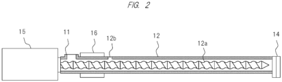
- FIG. 2 is a diagram in a side view for explaining a screw disposed in a cylinder of the decomposition apparatus for resin shown in FIG. 1 .
- a decomposition apparatus for resin 10 shown in FIG. 1 is an apparatus used to decompose a resin to be decomposed by exposing the resin to a fluid of a subcritical state or a supercritical state.
- the decomposition apparatus for resin 10 includes a resin supplier 11, a cylinder 12 with a screw, a fluid supplier 13 supplying a fluid to the cylinder 12, an extruder 14, a rotary drive mechanism 15 driving the screw of the cylinder 12, and a cooling mechanism 16.
- the resin supplier 11 supplies the resin to be decomposed to the cylinder 12.
- a thermoplastic resin is supplied as the resin to be decomposed.
- the thermoplastic resin to be used and supplied is of a various form such as a pellet, powder, and a flake, and is fed from above into the resin supplier 11 including a hopper by, for example, a feeder or the like, and is supplied into the cylinder 12.
- a case of the pellet as the thermoplastic resin to be supplied will be exemplified and explained below.
- FIG. 2 is a diagram in a cross-sectional view of the cylinder 12 so that the internal structure of the cylinder 12 of the decomposition apparatus for resin 10 in FIG. 1 is viewable.
- a fluid supply hole 12b where the fluid supplier 13 is disposed is also illustrated.
- a twin-screw extruder can be configured by using a twin screw having two screws as the screw 12a.
- the twin-screw extruder has the flexibility to freely change operating conditions such as a screw rotation speed and a barrel setting temperature, and also has various advantages such as high transportability and continuous processability.
- the cylinder 12 is made of, for example, connection of a plurality of cylinder blocks, and each cylinder block includes a space through which the thermoplastic resin can be transported.
- the screw 12a is provided in this space, and the screw 12a is connected to the rotary drive mechanism 15.
- the screw 12a is rotated by the rotary drive mechanism 15 to transport the resin to be decomposed in the cylinder 12.
- the cylinder 12 is provided with a heater so that its temperature can be adjusted.
- the thermoplastic resin is gradually heated by the above-described heater, thereby easily providing the melt-plasticized thermoplastic resin.
- the melt-plasticized thermoplastic resin provided as described above can easily be transported in the cylinder 12 and is further transported toward the downstream side.
- the molten resin in the cylinder 12 and the fluid supplied from the fluid supplier 13 are pressurized by the screw 12a to reach the subcritical state or the supercritical state.
- the melt-plasticized thermoplastic resin and the fluid are mixed, and at this time, the inside of the cylinder 12 is adjusted to predetermined temperature and pressure by the heater and the screw provided in the cylinder 12 as described above, and therefore, the subcritical state or the supercritical state is achieved. Then, during further transportation in the cylinder 12 in the subcritical state or supercritical state, the decomposition of the thermoplastic resin is advanced.
- the fluid supplier 13 supplies the heated and pressurized fluid into the cylinder 12.
- the fluid supplier 13 is disposed so that the thermoplastic resin is melt-plasticized in the cylinder 12 and then is supplied into the cylinder 12.
- the melt-plasticized thermoplastic resin is decomposed when being exposed to the fluid of the subcritical state or the supercritical state. Note that it is only necessary that the subcritical state or the supercritical state of the fluid supplied from the fluid supplier 13 is achieved in the cylinder 12, and the fluid does not need to be of the subcritical state or the supercritical state immediately before being supplied to the cylinder 12. However, if the fluid to be supplied is put into the subcritical state or the supercritical state before being supplied to the cylinder 12 and then is supplied into the cylinder 12 while maintaining this state, the decomposition of the melt-plasticized thermoplastic resin starts immediately after the fluid is supplied, and therefore, this state is preferable.
- the fluid is added to the melt-plasticized thermoplastic resin as described above. Since the inside of the cylinder 12 at the time of the addition is heated and pressurized, the fluid supplied at this time is supplied into the cylinder 12 while being against the pressure. That is, this fluid is supplied from the fluid supplier 13 into the cylinder 12 while being pressurized to have a pressure larger than a pressure in the cylinder 12 provided with the fluid supplier 13.
- a temperature of the fluid to be supplied is preferably equal to or higher than a temperature of the melt-plasticized thermoplastic resin in the fluid supplier 13.
- the fluid supplier 13 is preferably provided with a heating means that can put the fluid to be supplied into a predetermined heated state.
- FIG. 1 shows a diagram in which the fluid supplier 13 is connected to a heated-water production apparatus 13a. It is sufficient to produce the fluid of the predetermined heated state by using the heated-water production apparatus 13a as described above, and then, supply the resultant fluid from the fluid supplier 13 into the cylinder 12 through a pipe by using a pump such as a plunger pump.
- the extruder 14 is a member that discharges, to the outside of the decomposition apparatus 10, the decomposed of the thermoplastic resin transported through the cylinder 12, and has a hole for extrusion or an extrusion opening aperture.
- the extruder 14 may be configured to allow the decomposed product to be discharged to the outside while maintaining the pressure in the apparatus.
- the extruder 14 may be connected to a container for collecting the raw material, or may be connected to a different process apparatus so that the extruded decomposed product of the thermoplastic resin is further subjected to a predetermined process.
- the rotary drive mechanism 15 is an apparatus for rotating the screw 12a provided inside the cylinder 12.
- the thermoplastic resin to be decomposed is transported through the cylinder 12 by the screw rotated by the rotary drive mechanism 15.
- twin-screw extruder provided with two screws in the cylinder 12 or a single-screw extruder provided with a single screw is applicable.
- the twin-screw extruder the two screws are rotated while being in parallel with each other.
- the two shafts may be disposed to mesh with or not to mesh with each other.
- the twin screw with two screws is more preferable than the single screw with one screw if a screw bore diameter is the same, because of causing the high extrusion amount due to the high transportation efficiency of the raw material and the high kneading performance.
- an extending direction of the cylinder 12 is the same as an extending direction of the screw(s) inside the cylinder 12.
- the cooling mechanism 16 cools a predetermined region of the cylinder 12.
- the cooling mechanism 16 is disposed on an outer circumference of the cylinder 12 so as to cool a space between the resin supplier 11 and the fluid supplier 13.
- a publicly-known cooling mechanism is applicable if this can cool the outer circumference of the cylinder 12, and a cooler jacket provided on the outer circumference of the cylinder 12 is exemplified.
- the exemplified cooler jacket is connected to a chiller (that is a coolant circulating apparatus) that can always circulate/supply a coolant with a predetermined temperature in/into this cooler jacket to cool the cylinder 12 to a predetermined temperature.
- this cooling mechanism 16 a region of the outer circumference of the cylinder 12 close to the resin supplier 11 can be cooled, and therefore, the supplied thermoplastic resin and the melt-plasticized thermoplastic resin can be cooled in the region close to the resin supplier 11, and the pressure in the cylinder 12 can be reduced. Therefore, in the cylinder 12, the backflow such as the spout of the melt-plasticized thermoplastic resin from the resin supplied 11 can be suppressed.
- thermoplastic resin is supplied from the resin supplier 11 to the cylinder 12 (step (a): resin supply step).
- thermoplastic resin to be decomposed is supplied into the cylinder 12 which is the body of the decomposition apparatus.
- the resin product to be decomposed and supplied here is not particularly limited as long as it is made of thermoplastic resin.
- types of resins for example, polyamide (PA) resin, polycarbonate (PC) resin, polyethylene terephthalate (PET) resin, polybutylene terephthalate (PBT) resin or the like is exemplified.
- PA polyamide
- PC polycarbonate
- PET polyethylene terephthalate
- PBT polybutylene terephthalate
- nylon resin is preferable.
- thermoplastic resin supplied in the above resin supply step is heated and pressurized while being transported in the cylinder 12 toward the extruder 15 by the screw 12a.
- thermoplastic resin is gradually heated to a high temperature by the heater provided on the outer circumference of cylinder 12 while being transported, and the thermoplastic resin is gradually pressurized by a pressurizing pump capable of pressurizing the inside of the cylinder 12 while being transported.
- the thermoplastic resin that is melt-plasticized by the heating and the pressurization as described above can be easily transported by the screw 12a.
- the thermoplastic resin it is preferable to heat and pressurize the thermoplastic resin under conditions of, for example, the resin temperature that is 250°C to 400°C and the resin pressure that is 15 to 22 MPa before the fluid supply step described next.
- the conditions preferably reach 150 to 250°C and 15 to 20 MPa.
- the resin temperature preferably reaches to 300°C to 350°C, and the resin pressure preferably reaches to 15 to 18 MPa.
- the fluid supplied here is mixed with the melt-plasticized thermoplastic resin.
- the fluid supplied at this time to be exemplified is a fluid such as water or alcohol such as methanol that can be put into the subcritical state or the supercritical state in order to decompose the melt-plasticized resin, and water is preferable.
- the supercritical state indicates a state with activity that is an intermediate state between liquid and gas in a region beyond the critical point of the liquid, while the subcritical state indicates a liquid phase state with activity in a slightly lower region than that of the supercritical state.
- the conditions for the subcritical state and supercritical state vary depending on the fluid to be used.
- the pressure is enough to be equal to or higher than the saturation pressure at 150 to 350°C (such as the saturation pressure of 8.59 MPa at 300°C, or the saturation pressure of 16.54 MPa at 350°C).
- the temperature is enough to be equal to or higher than 374°C, and the pressure is enough to be equal to or higher than 22 MPa.
- the fluid may be put into the subcritical state or the supercritical state even before or after being supplied to the melt-plasticized thermoplastic resin.
- the heating and pressurization states are adjusted so that the fluid to be supplied meets the desired conditions.
- the melt-plasticized thermoplastic resin is mixed with the fluid, and the decomposition can be started at the same time as the mixing.
- thermoplastic resin melt-plasticized in the cylinder 12 is mixed with the fluid of the subcritical state or the supercritical state, and therefore, is decomposed (step (d): decomposition step).
- This decomposition step is preferably performed for a time period during which the thermoplastic resin is sufficiently decomposed, and, as for this, the time of mixing with the fluid of the subcritical state or the supercritical state can be adjusted by a length of the cylinder 12 and a transporting speed caused by a rotation of the screw 12a or the like.
- the time period for the above decomposition is, for example, preferably 2 to 5 minutes, more preferably 5 to 10 minutes, and even more preferably 10 to 15 minutes.
- thermoplastic resin exposed to the subcritical state or the supercritical state as described above is cut at its bond, and then, becomes the decomposed product of the resin that has been decomposed (depolymerized) to be a monomer that is the raw material.
- the decomposed and extruded resin product is collected. This decomposed product can be reused as the raw material upon the manufacturing of resin.
- an impurity removal step may be performed upon the collection.
- the thermoplastic resin fed into the cylinder 12 has, for example, a granular pellet form so as to be easily handled, and then, is heated and pressurized to be melt-plasticized as described above after the feeding.
- a solid pellet 50 supplied from the resin supplier 11 becomes semi-melted while being transported to the downstream side, and then, becomes the fully-melted molten resin 51.
- the operation can be continued, and the decomposition can be performed efficiently.
- this balance is lost to increase the pressure on the molten resin 51 side to be higher than the pressure on the pellet 50 side, the molten resin 51 flows back while pushing the pellet 50 back toward the resin supplier 11, and finally, the molten resin 51 and the pellet 50 in the mixed state may spout out of the resin supplier 11.
- the outer circumference of the cylinder 12 has the cooling mechanism 16 as shown in FIG. 1 .
- the cooling mechanism 16 is disposed on the outer circumference of the cylinder 12 between the resin supplier 11 and the fluid supplier 13, thereby preventing the excessive high internal temperature in the cylinder 12.
- the cooling mechanism 16 is preferably configured to cool the cylinder 12 to 3 to 130°C or the resin temperature in the cylinder 12 to 20 to 200°C. Because of such a temperature, the backflow can be effectively suppressed.
- the cylinder block from the resin supplier 11 to the fluid supplier 13 may be provided with at least one measurement sensor selected from a resin thermometer, a resin pressure gauge, and a cylinder thermometer.
- the backflow can be also effectively suppressed by not operating the cooling mechanism 16 at the beginning of the operation of the decomposition apparatus but operating the cooling mechanism 16 at the time of detecting a sign of the occurrence of the backflow.
- the cylinder block on the resin supplier 11 side is preferably provided therewith. In this manner, if there is a change in the numerical value in the cylinder block on the resin supplier 11 side measured by the measurement sensor, the occurrence of the backflow can be accurately detected, and then, a suppression operation by the cooling can be started.
- the decomposition is continued in the state shown in FIG. 3 but the pressure on the molten resin 51 side increases to start the backflow of the molten resin toward the resin supplier 11 side as shown in FIG. 4 , the change in the value measured by the measurement sensor is detected. If the occurrence of the backflow is determined because of the detection of the change, a controller connected to the measurement sensor operates the cooling mechanism 16 to cool the cylinder 12. By this, the pressure of the molten resin inside the cylinder 12 is decreased, thereby suppressing a situation of the backflow and the spout of the molten resin 51 together with the pellet 50 toward the resin supplier 11 side.
- a threshold value based on the measured value may be set, or a threshold value based on the changed value obtained by monitoring its temporal change may be set.
- This threshold value may be appropriately set depending on the resin or fluid to be used, the conditions for decomposition or the like.
- the threshold value based on the measured value to be exemplified for example, 50 to 225°C may be set for the resin temperature, 1 to 8 MPa may be set for the resin pressure, and 25 to 250°C may be set for the cylinder temperature.
- the threshold value based on the changed value to be exemplified for example, 5 to 30% may be set for the resin temperature, 5 to 30% may be set for the resin pressure, and 5 to 30% may be set for the cylinder pressure.
- the decomposition apparatus for resin 10 is activated, and the operation is started (S1).
- the cylinder 12 is heated to a predetermined temperature, and the driving of the screw 12a is also started.
- the cooling of the cylinder 12 by the cooling mechanism 16 is started (S2).
- the supply of the pellet 50 as the resin to be decomposed to the resin supplier 11 is started (S3). After confirming the sufficient resin melting/plasticization and the transportation in the cylinder 12, the supply of the heated and pressurized fluid from the fluid supplier 13 is started (S4).
- the pressurization is started to set the pressure in the cylinder 12 to a predetermined pressure (S5). Then, after confirming that the pressure has reached the specified pressure (S6), the resin decomposition is started. After the start of the operation of the decomposition, it is confirmed whether there is any backflow sign (S7). If there is no backflow sign, the operation is continued (S8). If there is any backflow sign, the cooled temperature of the cylinder 12 by the cooling mechanism 13 is lowered, and this procedure is repeated until no backflow sign is observed (S9).
- the cylinder 12 Since the cylinder 12 is always cooled by the cooling mechanism 16, the pressure on the resin supplier 11 side is not excessively decreased, and therefore, the backflow can be suppressed (prevented). The operation is still continued until the end of all the decompositions for resin. At the time of the end of all, the decomposition apparatus is stopped.
- the decomposition apparatus for resin 10 explained above may be provided with a safety holler in order to suppress influence of the occurrence of the backflow, if happened, on an operator in surroundings or the like.
- the safety hopper to be exemplified is, for example, a safety hopper 21 as shown in FIG. 6 .
- the safety hopper 21 is configured to include: a resin feeding port 22; a connecting structure 23 to be connected to the resin supplier 11; and a cover 24 including a lower-end opening 22a of the resin feeding port 22 therein, covering a periphery of the lower-end opening 22a of the resin feeding port 22 from the connecting structure 23, and having an opening at a different position from that of an upper-end opening 22b of the resin feeding port 22.
- the resin feeding port 22 is a member configured to guide the resin fed to the resin supplier 11 at the time of the feeding of the resin.
- the resin such as the pellet is moved downward by force of gravity after being fed from the upper-end opening 22b of the resin feeding port 22, passes through the lower-end opening 22a, and is further moved downward by falling or the like, and therefore, the resin is supplied to the resin supplier 11.
- the lower-end opening 22a is preferably positioned to be vertically above the opening of the resin supplier 11 to which the resin is supplied.
- the resin vertically falls downward, and the connecting structure 23 is a member connecting and fixing the resin supplier 11 with the safety holler 21, and is arranged and fixed at a periphery of the opening of the resin supplier 11 to which the resin is supplied.
- This connecting structure 23 has an opening hole corresponding to the opening of the resin supplier 11, and is configured to reliably supply, to the resin supplier 11, the resin having been fed from the resin feeding port 22.
- the cover 24 is a member covering the periphery of the lower-end opening 22a of the resin feeding port 22 from the connecting structure 23 and having an opening 24a at a position different from that of the upper-end opening 22b of the resin feeding port 22.
- the lower-end opening 22a of the resin feeding port 22 is disposed inside the cover 24 while the upper-end opening 22b of the same is not disposed therein.
- the upper-end opening 22b is exposed to outside while the lower-end opening 22a is not exposed thereto. In this manner, the resin can be easily fed from the upper-end opening 22b, and the fed resin can be reliably supplied to the resin supplier 11 through the inside of the cover 24.
- the fed resin can be prevented from spilling over, and all of the fed resin can be supplied to the resin supplier 11, and therefore, the loss of the process-target resin or the like can be suppressed.
- the safety hopper 21 is disposed on purpose for preventing the influence and the damage of the backflow on the operator or the like even if the molten resin 51 flows back from the decomposition apparatus for resin 10.
- the molten resin 51 flows back and spouts out from the decomposition apparatus for resin 10, the molten resin 51 forcefully spouts out from the opening of the resin supplier 11 while pushing back the pellet 50 toward the resin supplier 11. At this time, in a case without the safety hopper 21, the molten rein 51 or the like adversely spouts out upward from the opening of the resin supplier 11. Since a feeder or the like for the resin supply is generally disposed on an upper side of such spout, the spout affects the resin supply operation. Also, if there is the operator around it, the molten resin spouting out upward may spread around the resin supplier 11, and the operator may receive the damage such as burn injury.
- the molten resin 51 can be guided by the cover 24 to spout toward a direction of the opening 24a of the cover 24.
- a spout direction of the molten resin 51 can be controlled to an optional direction.
- the opening direction of the opening 24a of the cover 24 is preferably set to a different opening direction of the resin feeding port 22 such as a horizontal direction or a downward direction.
- a different opening direction of the resin feeding port 22 such as a horizontal direction or a downward direction.
- the resin feeding port 22 and the opening 24a are preferably disposed so that their opening directions are perpendicular to each other.
- an area of the cover 24 (excluding an area of the lower-end opening 22a) in a horizontal surface of the lower-end opening 22a of the resin feeding port 22 is preferably larger than an area of the lower-end opening 22a therein.
- FIG. 7 is a diagram for explaining a relation in size between the lower-end opening 22a and the cover 24 at a cross-sectional surface on the horizontal surface of the lower-end opening 22a.
- the area of the cover 24 (excluding the area of the lower-end opening 22a) described here is preferably three times the area of the lower-end opening 22a or larger, more preferably four times the area or larger, even more preferably eight times the area or larger, and particularly preferably sixteen times the area or larger.
- the spout of the molten resin 51 is preferably guided by not the resin feeding port 22 but the cover 24.
Landscapes
- Chemical & Material Sciences (AREA)
- Chemical Kinetics & Catalysis (AREA)
- Organic Chemistry (AREA)
- Life Sciences & Earth Sciences (AREA)
- Sustainable Development (AREA)
- Health & Medical Sciences (AREA)
- Medicinal Chemistry (AREA)
- Polymers & Plastics (AREA)
- Physics & Mathematics (AREA)
- Thermal Sciences (AREA)
- Separation, Recovery Or Treatment Of Waste Materials Containing Plastics (AREA)
Applications Claiming Priority (2)
| Application Number | Priority Date | Filing Date | Title |
|---|---|---|---|
| JP2022126497A JP2024022995A (ja) | 2022-08-08 | 2022-08-08 | 樹脂の分解処理方法および分解処理装置 |
| PCT/JP2023/015797 WO2024034190A1 (fr) | 2022-08-08 | 2023-04-20 | Procédé de traitement de dégradation de résine et dispositif de traitement de dégradation |
Publications (1)
| Publication Number | Publication Date |
|---|---|
| EP4570851A1 true EP4570851A1 (fr) | 2025-06-18 |
Family
ID=89851506
Family Applications (1)
| Application Number | Title | Priority Date | Filing Date |
|---|---|---|---|
| EP23852176.9A Pending EP4570851A1 (fr) | 2022-08-08 | 2023-04-20 | Procédé de traitement de dégradation de résine et dispositif de traitement de dégradation |
Country Status (5)
| Country | Link |
|---|---|
| US (1) | US20260042894A1 (fr) |
| EP (1) | EP4570851A1 (fr) |
| JP (1) | JP2024022995A (fr) |
| CN (1) | CN119546683A (fr) |
| WO (1) | WO2024034190A1 (fr) |
Family Cites Families (9)
| Publication number | Priority date | Publication date | Assignee | Title |
|---|---|---|---|---|
| JP3806223B2 (ja) * | 1997-05-13 | 2006-08-09 | アイ・ケー・ジー株式会社 | スクリュ式押出機 |
| JP3410343B2 (ja) | 1997-10-08 | 2003-05-26 | 高水化学工業株式会社 | アクリル樹脂の連続再生方法およびその装置 |
| JP3686002B2 (ja) * | 2001-03-16 | 2005-08-24 | 株式会社日本製鋼所 | 超臨界流体を利用した混練・混合押出成形装置 |
| JP4537614B2 (ja) * | 2001-05-09 | 2010-09-01 | 日立電線株式会社 | 架橋ポリマーのリサイクル方法 |
| JP3905397B2 (ja) * | 2002-02-21 | 2007-04-18 | 株式会社神戸製鋼所 | ゴムあるいはゴム系組成物の混練装置 |
| JP4102260B2 (ja) * | 2003-07-02 | 2008-06-18 | 日立電線株式会社 | ポリマーの超臨界処理装置 |
| JP4325542B2 (ja) * | 2004-11-17 | 2009-09-02 | 日立電線株式会社 | 高分子化合物の処理方法及びその装置 |
| JP7709834B2 (ja) * | 2021-02-19 | 2025-07-17 | 株式会社日本製鋼所 | 熱分解用押出機、分解ガスの製造方法及び排出方法 |
| JP7335930B2 (ja) * | 2021-09-28 | 2023-08-30 | 株式会社日本製鋼所 | 処理装置および処理方法 |
-
2022
- 2022-08-08 JP JP2022126497A patent/JP2024022995A/ja active Pending
-
2023
- 2023-04-20 CN CN202380052161.2A patent/CN119546683A/zh active Pending
- 2023-04-20 WO PCT/JP2023/015797 patent/WO2024034190A1/fr not_active Ceased
- 2023-04-20 EP EP23852176.9A patent/EP4570851A1/fr active Pending
- 2023-04-20 US US19/101,422 patent/US20260042894A1/en active Pending
Also Published As
| Publication number | Publication date |
|---|---|
| US20260042894A1 (en) | 2026-02-12 |
| JP2024022995A (ja) | 2024-02-21 |
| CN119546683A (zh) | 2025-02-28 |
| WO2024034190A1 (fr) | 2024-02-15 |
Similar Documents
| Publication | Publication Date | Title |
|---|---|---|
| EP0638017B1 (fr) | Procede et dispositif pour le recyclage de matiere plastique soufflee | |
| US9808963B2 (en) | Method for recycling plastic materials | |
| US20230321873A1 (en) | Extruder and molding assembly | |
| US4573799A (en) | Degassing extrusion device | |
| US8105540B2 (en) | Method of treating polymer compound and treatment system for the same | |
| AT517972B1 (de) | Vorrichtung und Verfahren zur Verarbeitung von thermoplastischem Kunststoff mit einer Temperiereinrichtung für eine Transportschnecke | |
| WO2022096179A1 (fr) | Procédé et dispositif pour le traitement de polycondensats | |
| EP4570851A1 (fr) | Procédé de traitement de dégradation de résine et dispositif de traitement de dégradation | |
| CN111231252A (zh) | 模塑机和模塑零件的方法 | |
| CN207432552U (zh) | 一种废料回收的塑料颗粒均匀造粒设备 | |
| US20260035532A1 (en) | Decomposition method and decomposition apparatus for resin | |
| CN108698293B (zh) | 模塑零件的方法 | |
| CN210282856U (zh) | 螺杆式密炼挤出机 | |
| CN106273053A (zh) | 一种低温粉体造粒设备及方法 | |
| JP4563739B2 (ja) | 押出成形品の製造方法および製造装置 | |
| CN107972202A (zh) | 一种高均匀性塑料造粒设备 | |
| Canedo et al. | Mixing in the farrel continuous mixer | |
| CN106003461A (zh) | 废塑料再生利用带气体保护与改性造粒一体化装置 | |
| EP0829338A1 (fr) | Procédé et dispositif pour le dosage d'un matériau plastique | |
| CN205853153U (zh) | 一种废塑料再生利用造粒装置的气体保护机构 | |
| JP2008132703A (ja) | 樹脂押出機用スクリュー、樹脂押出機、およびペレット製造方法 | |
| Szycher | -Processing Methods | |
| HK40031243A (en) | Molding machine and method of molding a part | |
| Spalding | Single‐Screw Extrusion of Polyethylene Resins | |
| CN110341072A (zh) | 螺杆式密炼挤出机 |
Legal Events
| Date | Code | Title | Description |
|---|---|---|---|
| STAA | Information on the status of an ep patent application or granted ep patent |
Free format text: STATUS: THE INTERNATIONAL PUBLICATION HAS BEEN MADE |
|
| PUAI | Public reference made under article 153(3) epc to a published international application that has entered the european phase |
Free format text: ORIGINAL CODE: 0009012 |
|
| STAA | Information on the status of an ep patent application or granted ep patent |
Free format text: STATUS: REQUEST FOR EXAMINATION WAS MADE |
|
| 17P | Request for examination filed |
Effective date: 20250228 |
|
| AK | Designated contracting states |
Kind code of ref document: A1 Designated state(s): AL AT BE BG CH CY CZ DE DK EE ES FI FR GB GR HR HU IE IS IT LI LT LU LV MC ME MK MT NL NO PL PT RO RS SE SI SK SM TR |
|
| DAV | Request for validation of the european patent (deleted) | ||
| DAX | Request for extension of the european patent (deleted) |