EP0638017B1 - Procede et dispositif pour le recyclage de matiere plastique soufflee - Google Patents
Procede et dispositif pour le recyclage de matiere plastique soufflee Download PDFInfo
- Publication number
- EP0638017B1 EP0638017B1 EP19930908784 EP93908784A EP0638017B1 EP 0638017 B1 EP0638017 B1 EP 0638017B1 EP 19930908784 EP19930908784 EP 19930908784 EP 93908784 A EP93908784 A EP 93908784A EP 0638017 B1 EP0638017 B1 EP 0638017B1
- Authority
- EP
- European Patent Office
- Prior art keywords
- plastics material
- mixer
- melt
- melt pump
- plastic
- Prior art date
- Legal status (The legal status is an assumption and is not a legal conclusion. Google has not performed a legal analysis and makes no representation as to the accuracy of the status listed.)
- Expired - Lifetime
Links
- 239000004033 plastic Substances 0.000 title claims abstract description 113
- 229920003023 plastic Polymers 0.000 title claims abstract description 113
- 238000000034 method Methods 0.000 title claims abstract description 42
- 238000004064 recycling Methods 0.000 title claims abstract description 11
- 239000000155 melt Substances 0.000 claims abstract description 41
- 239000000463 material Substances 0.000 claims description 84
- 238000002156 mixing Methods 0.000 claims description 15
- 238000001816 cooling Methods 0.000 claims description 12
- OFBQJSOFQDEBGM-UHFFFAOYSA-N Pentane Chemical compound CCCCC OFBQJSOFQDEBGM-UHFFFAOYSA-N 0.000 claims description 8
- 238000010438 heat treatment Methods 0.000 claims description 6
- 238000010309 melting process Methods 0.000 claims description 5
- 239000000203 mixture Substances 0.000 claims description 5
- 238000005187 foaming Methods 0.000 claims description 4
- 238000005469 granulation Methods 0.000 claims description 4
- 230000003179 granulation Effects 0.000 claims description 4
- 230000001105 regulatory effect Effects 0.000 claims description 4
- 239000007788 liquid Substances 0.000 claims description 2
- 238000012545 processing Methods 0.000 claims description 2
- 238000012935 Averaging Methods 0.000 claims 1
- 229920006327 polystyrene foam Polymers 0.000 claims 1
- 238000007664 blowing Methods 0.000 abstract 3
- 239000007789 gas Substances 0.000 description 37
- 239000003380 propellant Substances 0.000 description 26
- 238000007872 degassing Methods 0.000 description 9
- 239000007795 chemical reaction product Substances 0.000 description 8
- 239000008187 granular material Substances 0.000 description 7
- 238000001125 extrusion Methods 0.000 description 5
- 239000004793 Polystyrene Substances 0.000 description 4
- 229920002223 polystyrene Polymers 0.000 description 4
- 238000003958 fumigation Methods 0.000 description 3
- 238000002844 melting Methods 0.000 description 3
- 230000008018 melting Effects 0.000 description 3
- 238000005453 pelletization Methods 0.000 description 3
- 239000002699 waste material Substances 0.000 description 3
- 238000010521 absorption reaction Methods 0.000 description 2
- 238000011001 backwashing Methods 0.000 description 2
- 230000033228 biological regulation Effects 0.000 description 2
- 238000007906 compression Methods 0.000 description 2
- 230000006835 compression Effects 0.000 description 2
- 230000007423 decrease Effects 0.000 description 2
- 230000007613 environmental effect Effects 0.000 description 2
- 229920006248 expandable polystyrene Polymers 0.000 description 2
- 238000004880 explosion Methods 0.000 description 2
- 238000010348 incorporation Methods 0.000 description 2
- 239000002245 particle Substances 0.000 description 2
- 230000003068 static effect Effects 0.000 description 2
- 229920001169 thermoplastic Polymers 0.000 description 2
- 239000004416 thermosoftening plastic Substances 0.000 description 2
- 238000011144 upstream manufacturing Methods 0.000 description 2
- 229920000426 Microplastic Polymers 0.000 description 1
- 238000006243 chemical reaction Methods 0.000 description 1
- 238000004140 cleaning Methods 0.000 description 1
- 238000007596 consolidation process Methods 0.000 description 1
- 238000011109 contamination Methods 0.000 description 1
- 230000001276 controlling effect Effects 0.000 description 1
- 230000006735 deficit Effects 0.000 description 1
- 238000013461 design Methods 0.000 description 1
- 238000011161 development Methods 0.000 description 1
- 230000000694 effects Effects 0.000 description 1
- 238000003912 environmental pollution Methods 0.000 description 1
- 238000001914 filtration Methods 0.000 description 1
- 239000012535 impurity Substances 0.000 description 1
- 238000009434 installation Methods 0.000 description 1
- 239000013067 intermediate product Substances 0.000 description 1
- 238000004519 manufacturing process Methods 0.000 description 1
- 238000005259 measurement Methods 0.000 description 1
- 238000004806 packaging method and process Methods 0.000 description 1
- 239000000047 product Substances 0.000 description 1
- 238000007711 solidification Methods 0.000 description 1
- 230000008023 solidification Effects 0.000 description 1
- 238000003860 storage Methods 0.000 description 1
- 239000000126 substance Substances 0.000 description 1
Images

Classifications
-
- B—PERFORMING OPERATIONS; TRANSPORTING
- B29—WORKING OF PLASTICS; WORKING OF SUBSTANCES IN A PLASTIC STATE IN GENERAL
- B29B—PREPARATION OR PRETREATMENT OF THE MATERIAL TO BE SHAPED; MAKING GRANULES OR PREFORMS; RECOVERY OF PLASTICS OR OTHER CONSTITUENTS OF WASTE MATERIAL CONTAINING PLASTICS
- B29B17/00—Recovery of plastics or other constituents of waste material containing plastics
- B29B17/02—Separating plastics from other materials
-
- B—PERFORMING OPERATIONS; TRANSPORTING
- B29—WORKING OF PLASTICS; WORKING OF SUBSTANCES IN A PLASTIC STATE IN GENERAL
- B29B—PREPARATION OR PRETREATMENT OF THE MATERIAL TO BE SHAPED; MAKING GRANULES OR PREFORMS; RECOVERY OF PLASTICS OR OTHER CONSTITUENTS OF WASTE MATERIAL CONTAINING PLASTICS
- B29B17/00—Recovery of plastics or other constituents of waste material containing plastics
- B29B17/0005—Direct recuperation and re-use of scrap material during moulding operation, i.e. feed-back of used material
-
- B—PERFORMING OPERATIONS; TRANSPORTING
- B29—WORKING OF PLASTICS; WORKING OF SUBSTANCES IN A PLASTIC STATE IN GENERAL
- B29C—SHAPING OR JOINING OF PLASTICS; SHAPING OF MATERIAL IN A PLASTIC STATE, NOT OTHERWISE PROVIDED FOR; AFTER-TREATMENT OF THE SHAPED PRODUCTS, e.g. REPAIRING
- B29C48/00—Extrusion moulding, i.e. expressing the moulding material through a die or nozzle which imparts the desired form; Apparatus therefor
- B29C48/25—Component parts, details or accessories; Auxiliary operations
- B29C48/92—Measuring, controlling or regulating
-
- B—PERFORMING OPERATIONS; TRANSPORTING
- B29—WORKING OF PLASTICS; WORKING OF SUBSTANCES IN A PLASTIC STATE IN GENERAL
- B29B—PREPARATION OR PRETREATMENT OF THE MATERIAL TO BE SHAPED; MAKING GRANULES OR PREFORMS; RECOVERY OF PLASTICS OR OTHER CONSTITUENTS OF WASTE MATERIAL CONTAINING PLASTICS
- B29B17/00—Recovery of plastics or other constituents of waste material containing plastics
- B29B17/04—Disintegrating plastics, e.g. by milling
- B29B2017/0424—Specific disintegrating techniques; devices therefor
- B29B2017/048—Cutter-compactors, e.g. of the EREMA type
-
- B—PERFORMING OPERATIONS; TRANSPORTING
- B29—WORKING OF PLASTICS; WORKING OF SUBSTANCES IN A PLASTIC STATE IN GENERAL
- B29C—SHAPING OR JOINING OF PLASTICS; SHAPING OF MATERIAL IN A PLASTIC STATE, NOT OTHERWISE PROVIDED FOR; AFTER-TREATMENT OF THE SHAPED PRODUCTS, e.g. REPAIRING
- B29C2948/00—Indexing scheme relating to extrusion moulding
- B29C2948/92—Measuring, controlling or regulating
- B29C2948/92009—Measured parameter
- B29C2948/92019—Pressure
-
- B—PERFORMING OPERATIONS; TRANSPORTING
- B29—WORKING OF PLASTICS; WORKING OF SUBSTANCES IN A PLASTIC STATE IN GENERAL
- B29C—SHAPING OR JOINING OF PLASTICS; SHAPING OF MATERIAL IN A PLASTIC STATE, NOT OTHERWISE PROVIDED FOR; AFTER-TREATMENT OF THE SHAPED PRODUCTS, e.g. REPAIRING
- B29C2948/00—Indexing scheme relating to extrusion moulding
- B29C2948/92—Measuring, controlling or regulating
- B29C2948/92323—Location or phase of measurement
- B29C2948/92466—Auxiliary unit, e.g. for external melt filtering, re-combining or transfer between units
-
- B—PERFORMING OPERATIONS; TRANSPORTING
- B29—WORKING OF PLASTICS; WORKING OF SUBSTANCES IN A PLASTIC STATE IN GENERAL
- B29C—SHAPING OR JOINING OF PLASTICS; SHAPING OF MATERIAL IN A PLASTIC STATE, NOT OTHERWISE PROVIDED FOR; AFTER-TREATMENT OF THE SHAPED PRODUCTS, e.g. REPAIRING
- B29C2948/00—Indexing scheme relating to extrusion moulding
- B29C2948/92—Measuring, controlling or regulating
- B29C2948/92504—Controlled parameter
- B29C2948/92514—Pressure
-
- B—PERFORMING OPERATIONS; TRANSPORTING
- B29—WORKING OF PLASTICS; WORKING OF SUBSTANCES IN A PLASTIC STATE IN GENERAL
- B29C—SHAPING OR JOINING OF PLASTICS; SHAPING OF MATERIAL IN A PLASTIC STATE, NOT OTHERWISE PROVIDED FOR; AFTER-TREATMENT OF THE SHAPED PRODUCTS, e.g. REPAIRING
- B29C2948/00—Indexing scheme relating to extrusion moulding
- B29C2948/92—Measuring, controlling or regulating
- B29C2948/92504—Controlled parameter
- B29C2948/9258—Velocity
- B29C2948/9259—Angular velocity
-
- B—PERFORMING OPERATIONS; TRANSPORTING
- B29—WORKING OF PLASTICS; WORKING OF SUBSTANCES IN A PLASTIC STATE IN GENERAL
- B29C—SHAPING OR JOINING OF PLASTICS; SHAPING OF MATERIAL IN A PLASTIC STATE, NOT OTHERWISE PROVIDED FOR; AFTER-TREATMENT OF THE SHAPED PRODUCTS, e.g. REPAIRING
- B29C2948/00—Indexing scheme relating to extrusion moulding
- B29C2948/92—Measuring, controlling or regulating
- B29C2948/92819—Location or phase of control
- B29C2948/92857—Extrusion unit
- B29C2948/92876—Feeding, melting, plasticising or pumping zones, e.g. the melt itself
- B29C2948/92885—Screw or gear
-
- B—PERFORMING OPERATIONS; TRANSPORTING
- B29—WORKING OF PLASTICS; WORKING OF SUBSTANCES IN A PLASTIC STATE IN GENERAL
- B29C—SHAPING OR JOINING OF PLASTICS; SHAPING OF MATERIAL IN A PLASTIC STATE, NOT OTHERWISE PROVIDED FOR; AFTER-TREATMENT OF THE SHAPED PRODUCTS, e.g. REPAIRING
- B29C2948/00—Indexing scheme relating to extrusion moulding
- B29C2948/92—Measuring, controlling or regulating
- B29C2948/92819—Location or phase of control
- B29C2948/92961—Auxiliary unit, e.g. for external melt filtering, re-combining or transfer between units
-
- B—PERFORMING OPERATIONS; TRANSPORTING
- B29—WORKING OF PLASTICS; WORKING OF SUBSTANCES IN A PLASTIC STATE IN GENERAL
- B29K—INDEXING SCHEME ASSOCIATED WITH SUBCLASSES B29B, B29C OR B29D, RELATING TO MOULDING MATERIALS OR TO MATERIALS FOR MOULDS, REINFORCEMENTS, FILLERS OR PREFORMED PARTS, e.g. INSERTS
- B29K2025/00—Use of polymers of vinyl-aromatic compounds or derivatives thereof as moulding material
-
- B—PERFORMING OPERATIONS; TRANSPORTING
- B29—WORKING OF PLASTICS; WORKING OF SUBSTANCES IN A PLASTIC STATE IN GENERAL
- B29K—INDEXING SCHEME ASSOCIATED WITH SUBCLASSES B29B, B29C OR B29D, RELATING TO MOULDING MATERIALS OR TO MATERIALS FOR MOULDS, REINFORCEMENTS, FILLERS OR PREFORMED PARTS, e.g. INSERTS
- B29K2105/00—Condition, form or state of moulded material or of the material to be shaped
- B29K2105/04—Condition, form or state of moulded material or of the material to be shaped cellular or porous
-
- Y—GENERAL TAGGING OF NEW TECHNOLOGICAL DEVELOPMENTS; GENERAL TAGGING OF CROSS-SECTIONAL TECHNOLOGIES SPANNING OVER SEVERAL SECTIONS OF THE IPC; TECHNICAL SUBJECTS COVERED BY FORMER USPC CROSS-REFERENCE ART COLLECTIONS [XRACs] AND DIGESTS
- Y02—TECHNOLOGIES OR APPLICATIONS FOR MITIGATION OR ADAPTATION AGAINST CLIMATE CHANGE
- Y02W—CLIMATE CHANGE MITIGATION TECHNOLOGIES RELATED TO WASTEWATER TREATMENT OR WASTE MANAGEMENT
- Y02W30/00—Technologies for solid waste management
- Y02W30/50—Reuse, recycling or recovery technologies
- Y02W30/62—Plastics recycling; Rubber recycling
-
- Y—GENERAL TAGGING OF NEW TECHNOLOGICAL DEVELOPMENTS; GENERAL TAGGING OF CROSS-SECTIONAL TECHNOLOGIES SPANNING OVER SEVERAL SECTIONS OF THE IPC; TECHNICAL SUBJECTS COVERED BY FORMER USPC CROSS-REFERENCE ART COLLECTIONS [XRACs] AND DIGESTS
- Y10—TECHNICAL SUBJECTS COVERED BY FORMER USPC
- Y10S—TECHNICAL SUBJECTS COVERED BY FORMER USPC CROSS-REFERENCE ART COLLECTIONS [XRACs] AND DIGESTS
- Y10S264/00—Plastic and nonmetallic article shaping or treating: processes
- Y10S264/911—Recycling consumer used articles or products
- Y10S264/916—From porous material containing articles, e.g. sponge, foam
Definitions
- the invention relates to a method for recycling fumigated plastic material, e.g. B. foamed polystyrene, in a plant in which the plastic material is melted, filtered, degassed, granulated and gassed again by mixing with propellant gas, with the re-gassing in the same plant as the granulation.
- the invention further relates to a device for performing such a method.
- the plasticized, degassed plastic material thus produced is processed into granules in a granulating device and solidified in this way.
- the granulate forms a free-flowing, uniform, degassed mass, which is then reinserted into an extruder and melted by it.
- a propellant gas is metered into the extruder, which is homogenized by the extruder into the plastic melt, taking into account the necessary dwell times.
- the use of free-flowing, uniform granules is imperative because this is the only way to ensure a uniform melt throughput in the extruder and therefore a uniform degree of filling of the melt with propellant gas.
- a disadvantage of these known procedures is that two melting processes are necessary, which are usually carried out at different locations, since the homogeneous incorporation of the propellant gas is delicate and can therefore not be carried out everywhere.
- the amount of plastic to be fed into the recycling process is therefore granulated where a tear compactor is available. The granulate is then shipped to a re-gassing facility.
- the associated transport and conversion costs lead to such a high price of the re-fumigated material that the recycling product thus obtained is difficult to sell.
- the result is an environmental impact from waste made of foamed plastic material or from improperly treated plastic material. Hiebei is disruptive that in the past such substances (e.g. fluorocarbons) were frequently used as propellants, which are of concern for environmental reasons and should therefore not be released into the atmosphere.
- the invention has for its object to improve a method of the type described last so that the recycling process fumigated plastic material faster, easier, with significantly less effort on the device and space without environmental pollution and without using new goods.
- the invention solves this problem in that the re-gassing is carried out on the plastic material subjected to the degassing and before pelletizing in that plastic state of the plastic material which still results from the melting process and the degassing and that in order to equalize the degree of gassing that per unit time in the plastic material introduced propellant gas volume and the mixing volume processed by the mixer per unit of time are regulated proportionally to the plastic volume supplied per unit of time of the fumigation.
- the quality of the end product obtained is good, also with regard to the homogeneity with regard to the propellant gas content, which is due to the inventive regulation of the gassing depending on the current intensity of the Fumigation supplied plastic material flow is achieved.
- Another advantage is that the plastic material used is melted only once, so that the second melting process previously required is saved. This means that the plastic material is protected since each melting process entails the risk of a reduction in the molecular chain length of the plastic material.
- the plastic material has to be solidified only once to carry out the method according to the invention, and - in contrast to the known method mentioned at the outset - only after re-gassing.
- the invention also takes into account the fact that the plastic material supplied to the recycling process is not always of the same quality, particularly with regard to the density or the degree of foaming.
- the invention takes into account that when using lighter (higher foamed) material, the throughput of the device used for the melting will decrease. As a result, the amount of plastic supplied in the time unit of the fumigation decreases. If this volume measured per unit of time is used as a reference variable in the sense of the invention for the amount of propellant gas used for gassing per unit of time, the degree of gassing for the recycling end product remains at least essentially constant, which is desirable with regard to the further processing of this end product.
- the proportional readjustment of the amount of mixture processed by the mixer per unit of time as a function of the reference variable mentioned also contributes to this homogeneity of the end product, since both under-mixing and over-mixing are avoided and the cell structure of the regrind obtained as the end product is at least essentially kept constant .
- the volume of plastic material supplied per unit of time of gassing is within one predetermined range, preferably close to the maximum capacity of the system used. This can easily be achieved by running the system parts used for plasticizing and degassing the plastic material used more quickly or with increased output.
- the procedure is that the plastic material used is crushed and then plasticized and degassed by means of a screw, that the degassed melt thus obtained is conveyed to a mixer by means of a melt pump, preferably a gear pump, which also used propellant gas is supplied, the amount of plastic conveyed by the melt pump per unit of time being monitored and used as a guide variable for the propellant gas supply, and that the pressure of the plastic material on the suction side of the melt pump is monitored and within a predetermined range, preferably at a value that is as constant as possible Change in the course of the melt pump and / or the course of the screw is kept.
- the melt pressure upstream of the melt pump is therefore kept approximately constant by adapting the conveying of the plasticizing screw or the melt pump, whereby the desired constant propellant gas content in the end product produced by the mixer is adjusted by proportional readjustment of the propellant gas supply depending on the conveyance of the melt pump serving as a guide variable and measured per unit of time is obtained.
- the aforementioned compliance with a certain interval of the pressure of the material supplied to the melt pump ensures that the melt pump does not perform any empty strokes and in this way the delivery volume is exactly proportional to the running of the melt pump, in particular to the speed of the gear pump.
- the system can easily be brought up to the maximum system capacity in this way.
- the propellant gas is particularly advantageous to add the propellant gas to the flow of the plastic material before it is introduced into the mixer in order to achieve a certain mixing of the plastic material and propellant gas before the plastic material or the propellant gas enters the mixer.
- the melt pressure downstream of the melt pump is important for even propellant gas absorption. According to a development of the invention, the procedure is therefore such that if the pressure of the plastic melt conveyed by the melt pump deviates from a predetermined desired value, the viscosity of the mixture processed by the mixer is changed accordingly by cooling and / or heating, preferably until this desired value is reached.
- pentane is used for the re-gassing.
- the Invention in the degassing of the plastic material monitors the vacuum.
- the device according to the invention for carrying out the method according to the invention is based on a system with a comminution device for the plastic material to be processed, to which at least one screw driven by a motor for plasticizing this material is connected, which is assigned a degassing device for the plastic material.
- the device according to the invention is characterized in that the outlet of only these screws is connected by means of at least one line to a mixer, to which a device for supplying propellant gas is also connected, and in that at least one of these lines has a device for detecting the unit of time in this line flowing plastic quantity is connected, which device is connected to a control unit for the propellant gas supply to the mixer and for the speed of the motor of the screw.
- the method according to the invention can be carried out with a simple design effort.
- the device leading from the screw to the mixer Line a melt pump, in particular a gear pump, switched on to convey the plastic melt, with a measuring device for the running speed of this melt pump being present, and with this line a pressure sensor for the pressure on the suction side of this melt pump being connected, which pressure sensor as well as the measuring unit are connected to the control unit.
- The, expediently electronic, control unit evaluates the measurement results given to them by the pressure sensor and by the measuring device and regulates the propellant gas supply to the plastic melt in such a way that their propellant gas content remains at least approximately constant, so that a homogeneous end product is obtained.
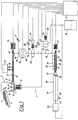
- the system 1 used to carry out the method has a shredding device 2 designed as a tear compactor, which comprises the plastic material 3 to be fed to the recycling process, in particular foamed polystyrene, e.g. B. polystyrene (Wz), is fed by means of a conveyor 4.
- the plastic material 3 falls from above into a receptacle 5 of the shredding device 2, in the bottom area of which a tool 6 for the shredding or mixing of the plastic material 3 revolves around a vertical axis 7, the tool 6 being driven by a motor 8.
- the tool 6 is provided with knives 9 acting on the plastic material 3, which cut up and mix the material 3, the material circulating in the receptacle 5 in the form of a mixing drum 10.
- the side wall of the receptacle 5 has a discharge opening 11, to which the housing 12 of a screw 13 is connected in the radial direction.
- the screw is driven by a motor 14.
- the plastic material supplied from the container 5 is plasticized by means of the screw 13 and pressed into a line 16 at the extent 15 of the housing 12 in the plasticized state or as a melt.
- the housing 12 is also provided with lateral openings through which gases can escape from the melt conveyed by the screw 13 into a degassing device 17 via one or more lines 18. These gases are appropriately collected, cleaned if necessary and recycled.
- At least one filter 19 is switched on in line 16, through which the plastic melt is freed of entrained impurities.
- a pressure sensor 21 is connected to line 16, which is also connected to a control unit 22, by means of which the entire system 1 is monitored and controlled in the sense of an optimal operating state.
- the motor 14 is also connected to this control unit 22.
- a melt pump 23 designed as a gear pump, which is driven by a motor 31 and leads the plastic material through line 16 into the housing 24 of a mixer 25, which can be designed as a static or dynamic mixer.
- the exemplary embodiment shown shows a dynamic mixer which has a mixing element, for example a mixing screw 26, which is mounted in the housing 24 and is driven by a motor 27.
- a static mixer can also be used, in which 24 baffles are provided in the housing, which have a mixing effect on the supplied plastic material.
- the gassing of the plastic material or the incorporation of the gas into the plasticized or melt-like plastic, which is only an intermediate product is carried out, which is fed directly from the degassing extruder 12, 13 by means of the pump 23, without any addition of a gas-containing plastic or new plastic material .
- a further pressure sensor 28 and a device 29 for supplying gas into the plastic melt are connected to the line 16 between the melt pump 23 and the mixer 25.
- Another pressure sensor 30 is connected to the line 16 between the filter 19 and the pump 23.
- the gas supply device 29 has a metering device 32 with a pump for the propellant gas to be introduced into the plastic melt, which device 32 is driven by a motor 33 and is supplied with propellant gas, for example pentane liquid at atmospheric pressure, from a propellant gas source 34. All of these motors 14, 27, 31, 33 as well as the pressure sensors 21, 28, 30 and the filter 19 are connected to the control unit 22.
- a motor 35 for a granulating device 36 is connected to this control device 22, and the plastic material to be granulated is fed from the mixer 25 via an extruder head 37.
- At least one knife 38 driven by the motor 35 rotates in front of the extruder head 37 and the chipped plastic grains collect in a granulating housing 39, where they are cooled and discharged through an outlet 39 'in the direction of the arrow 40.
- the amount of plastic supplied to the re-gassing comes exclusively from the extruder which is formed by the housing 12 and the screw 13, but of course several such extruders are used together the line 16 can be connected. There is therefore no addition of new goods to the plastic material conveyed by the screw 13 into the line 16, unless new goods are introduced into the comminution device 2 together with the other plastic material via the conveyor 4.
- the latter can be the case if waste from the production of new goods from foamed plastics is processed, for example the remains of foamed plastic blocks etc.
- the entire system 1 is controlled by the control device 22 so that the level of propellant gas in the plastic granules discharged through the outlet 39 'remains at least approximately constant, even if the quality of the plastic material 3 fed via the conveyor 4 changes.
- a device 43 is used to measure the amount of plastic flowing in the line 16 per unit of time, which device 43 is connected to the control unit 22. Since the pressure sensor 30 and the device 22 ensure that the pressure of the plastic material supplied via the line 16 of the gear pump 23 moves within a predetermined pressure range, so that the gear pump 23 is always fully filled, but also a fluctuating compression of the plastic material is avoided, the amount of plastic delivered by the gear pump 23 is proportional to the speed of the gear pump 23.
- this speed can be detected by a tachometer 44 forming the device 43 and reported to the control device 22.
- the pressure sensor 30 is used to sense the admission pressure of the gear pump 23. For example, if lighter (higher-foamed) plastic material 3 is drawn in by the screw 13 forming an extruder, it sinks through the outlet 15 from the amount of plastic conveyed into the line 16 per unit of time. As a result, the pressure upstream of the melt pump 23 will also drop, which is reported to the control unit 22 by the pressure sensor 30. This causes the worm 13 to be driven faster by the motor 14 and / or the melt pump 23 to be driven more slowly by the motor 31.
- the tachometer 44 of the device 43 causes the control device 22 at the same time that a gas pump 45 present in the metering device 32 is also proportionally adjusted.
- the control unit 22 primarily regulates the working speed of the plasticizing screw 13 accordingly by controlling the speed of the motor 14.
- the speed of the motor 31 of the gear pump 23 can also be regulated accordingly by the control unit 22, in particular if the mentioned speed control of the motor 14 is not sufficient.
- the resistance in the mixer 25 can be influenced by changing the viscosity of the plastic material in the mixer 25.
- a plurality of heating or cooling zones 47 are arranged on the casing of the housing 46 of the mixer 25, which together result in a heating and cooling cascade control and individually or in any combination by the control unit 22 depending on the constant pressure serving as a reference variable in the rear the gear pump 23 lying section of line 16 can be switched on.
- line 41 via which the propellant gas is supplied to the melt, opens into the line 16, so that in that section of the line 16 which lies between the line 41 and the mixer 25, a premixing of the plastic material with the Propellant occurs.
- line 41 can also be connected to the housing of mixer 25.
- a check valve (not shown) is expediently located in line 41.
- the two screws 13, 26 are provided at their ends facing the motors 14 and 27 with screw threads 42 which convey in the opposite direction and form a seal for the drive shafts driven by the motors 14 and 27.
- the pressure sensor 21 serves to sense the pressure of the plastic melt directly at the outlet 15 and in front of the filter 19. The purpose of this is to monitor the contamination of the filter 19 and to initiate a screen change process or screen backwashing process in good time if the pressure in the line 16 in front of the filter 19 rises above a predetermined value. These processes are also initiated by the control unit 22. Suitable filters 19 which carry out a screen change or screen cleaning process, e.g. by backwashing without significant impairment of the plastic material pressure in the line 16 after the filter 19 are known.
- a vacuum control device 48 is connected to the housing 12 of the screw 13 and reports the measured vacuum to the control unit 22. This serves to monitor the function of the degassing device 17 and therefore prevents an explosion risk for the pentane used for the gassing.
- a pelletizing device 36 is not directly connected to the pelletizing head 37 or its extrusion nozzle 49, but with the interposition of an extrusion cooling device 50 in which the extrusion nozzle 49 is arranged.
- the plastic strand produced by it runs in the cooling device 50 in a cooling bath and only enters the granulating device 36 after passing through the strand cooling device 50, in which the granulate particles are produced in a manner known per se from the strand by knocking off by means of rotating knives.
- the granulate emerges from the granulating device 36 through the outlet 39 ′ in the direction of the arrow 40.
- the conditions too in the strand cooling device 50 can be influenced by the control unit 22 in the desired manner.
Abstract
Claims (15)
- Procédé pour le recyclage de matière plastique soufflée, par exemple de polystyrène expansé, dans une installation dans laquelle la matière plastique est fondue, filtrée, dégazée, granulée et soufflée à nouveau par mélange avec un gaz de soufflage, le soufflage à nouveau ayant lieu dans la même installation que la granulation, caractérisé par le fait que l'on réalise le soufflage à nouveau sur la matière plastique soumise au dégazage, et avant la granulation, dans l'état de plasticité de la matière plastique qui provient encore de l'opération de fusion et du dégazage, et par le fait qu'aux fins d'une homogénéisation du taux de soufflage, on régule ici le volume de gaz de soufflage qui est introduit dans la matière plastique par unité de temps et le volume de mélange qui est traité par unité de temps lors du mélange, et ce, proportionnellement au volume de matière plastique qui est amené au soufflage par unité de temps.
- Procédé selon la revendication 1, caractérisé par le fait que l'on maintient le volume de matière plastique qui est amené au soufflage par unité de temps à l'intérieur d'une gamme prédéterminée qui est de préférence située au voisinage de la capacité maximale de l'installation utilisée.
- Procédé selon la revendication 1 ou 2, caractérisé par le fait que l'on fragmente la matière plastique utilisée, qu'on la ramollit ensuite au moyen d'une vis sans fin et qu'on la dégaze, par le fait que c'est uniquement la masse fondue dégazée ainsi obtenue que l'on amène au moyen d'une pompe à masse fondue, et de préférence d'une pompe à engrenages, à un mélangeur auquel est également amené le gaz de soufflage utilisé, cependant que l'on surveille la quantité de matière plastique qui est déplacée par la pompe à masse fondue par unité de temps et qu'on l'utilise comme grandeur de commande pour l'amenée de gaz de soufflage, et par le fait que l'on surveille la pression de la matière plastique du côté de l'aspiration de la pompe à masse fondue, et qu'on la maintient à l'intérieur d'une gamme prédéterminée, et de préférence à une valeur aussi constante que possible, en modifiant la vitesse de rotation de la pompe à masse fondue et/ou la vitesse de rotation de la vas sans fin.
- Procédé selon la revendication 3, caractérisé par le fait que l'on ajoute déjà le gaz de soufflage au courant de la matière plastique avant son introduction dans le mélangeur.
- Procédé selon la revendication 3 ou 4, caractérisé par le fait que, lorsque la pression de la masse fondue de matière plastique déplacée par la pompe à masse fondue s'écarte d'une valeur de consigne prédéterminée, on modifie en conséquence par refroidissement et/ou par chauffage la viscosité du mélange traité par le mélangeur, de préférence jusqu'à ce que cette valeur de consigne soit atteinte.
- Procédé selon l'une des revendications 1 à 5, caractérisé par le fait que l'on surveille le vide lors du dégazage de la matière plastique.
- Procédé selon l'une des revendications 1 à 6, caractérisé par le fait que l'on utilise du pentane liquide comme gaz de soufflage.
- Dispositif pour la mise en oeuvre du procédé selon l'une des revendications 1 à 7, comprenant un dispositif (2) de fragmentation de la matière plastique à traiter auquel est raccordée au moins une vis sans fin (13) de ramollissement de cette matière qui est entraînée par un moteur (14) et à laquelle est associé un dispositif (17) de dégazage de la matière plastique, caractérisé par le fait que la sortie (15) de cette seule vis sans fin (13) est reliée au moyen d'au moins une conduite (16) à un mélangeur (25) auquel est également relié un dispositif (29) d'amenée de gaz de soufflage, et par le fait qu'est relié à l'une au moins de ces conduites (16) un dispositif (43) pour déterminer la quantité de matière plastique qui s'écoule dans cette conduite (16) par unité de temps, ce dispositif (43) étant relié à une unité de commande (22) qui agit sur l'amenée de gaz de soufflage au mélangeur (25) et sur la vitesse de rotation du moteur (14) de la vis sans fin (13).
- Dispositif selon la revendication 8, caractérisé par le fait qu'est montée dans la conduite (16) qui amène de la vis sans fin (13) au mélangeur (25) une pompe à masse fondue (23), et en particulier une pompe à engrenages, pour déplacer la masse fondue de matière plastique, cependant qu'il est prévu un dispositif de mesure, comme par exemple un indicateur du nombre de tours (44), qui détermine la vitesse de rotation de cette pompe à masse fondue (23), et par le fait qu'un capteur de pression (30) déterminant la pression du côté de l'aspiration de cette pompe à masse fondue (23) est raccordé à cette conduite (16), cependant que ce capteur de pression (30) et le dispositif de mesure, comme par exemple l'indicateur du nombre de tours (44), sont reliés à l'unité de commande (22).
- Dispositif selon la revendication 8 ou 9, caractérisé par le fait que le dispositif (29) d'amenée de gaz de soufflage est raccordé au moyen d'une conduite de gaz (41) à la conduite (16) qui amène la matière plastique au mélangeur (25).
- Dispositif selon la revendication 9 ou 10, caractérisé par le fait qu'un filtre (19) destiné à la matière plastique est monté en amont de la pompe à masse fondue (23).
- Dispositif selon la revendication 11, caractérisé par le fait qu'un autre capteur de pression (21) est raccordé avant le filtre (19) à la conduite (16) qui amène la matière plastique à la pompe à masse fondue (23), ce capteur de pression (21) étant également relié à l'unité de commande (22).
- Dispositif selon l'une des revendications 9 à 12, caractérisé par le fait qu'un capteur de pression (30) déterminant la pression de la matière plastique qui est déplacée depuis la pompe à masse fondue (23) jusqu'au mélangeur (25) est également raccordé à la conduite (16), ce capteur de pression (30) étant également relié à l'unité de commande (22).
- Dispositif selon la revendication 13, caractérisé par le fait que le mélangeur (25) est pourvu d'une zone de chauffage et de refroidissement (47), et de préférence de plusieurs, qui sont reliées à l'unité de commande (22).
- Dispositif selon l'une des revendications 8 à 14, caractérisé par le fait qu'un dispositif de contrôle du vide (48) est raccordé au carter (12) de la vis sans fin (13) dans la région du dispositif de dégazage (17) (figure 2).
Applications Claiming Priority (3)
| Application Number | Priority Date | Filing Date | Title |
|---|---|---|---|
| AT894/92 | 1992-04-30 | ||
| AT0089492A AT398772B (de) | 1992-04-30 | 1992-04-30 | Verfahren und vorrichtung zum recycling von begastem kunststoffmaterial |
| PCT/AT1993/000073 WO1993022119A1 (fr) | 1992-04-30 | 1993-04-26 | Procede et dispositif pour le recyclage de matiere plastique soufflee |
Publications (2)
| Publication Number | Publication Date |
|---|---|
| EP0638017A1 EP0638017A1 (fr) | 1995-02-15 |
| EP0638017B1 true EP0638017B1 (fr) | 1997-04-09 |
Family
ID=3502282
Family Applications (1)
| Application Number | Title | Priority Date | Filing Date |
|---|---|---|---|
| EP19930908784 Expired - Lifetime EP0638017B1 (fr) | 1992-04-30 | 1993-04-26 | Procede et dispositif pour le recyclage de matiere plastique soufflee |
Country Status (12)
| Country | Link |
|---|---|
| US (1) | US5882558A (fr) |
| EP (1) | EP0638017B1 (fr) |
| JP (1) | JP2596512B2 (fr) |
| KR (2) | KR950701269A (fr) |
| AT (1) | AT398772B (fr) |
| AU (1) | AU670077B2 (fr) |
| BR (1) | BR9306251A (fr) |
| CA (1) | CA2134648C (fr) |
| DE (1) | DE59306123D1 (fr) |
| DK (1) | DK0638017T3 (fr) |
| ES (1) | ES2103079T3 (fr) |
| WO (1) | WO1993022119A1 (fr) |
Cited By (3)
| Publication number | Priority date | Publication date | Assignee | Title |
|---|---|---|---|---|
| EP1925418A1 (fr) * | 2006-11-23 | 2008-05-28 | Sulzer Chemtech AG | Procédé et installation destinés à la fabrication de particules polymères |
| WO2010089173A2 (fr) | 2009-02-03 | 2010-08-12 | Starlinger & Co Gesellschaft M.B.H. | Extrudeuse pour matière plastique |
| US7776244B2 (en) | 2002-06-14 | 2010-08-17 | Basf Aktiengesellschaft | Method for producing expandable polystyrene |
Families Citing this family (30)
| Publication number | Priority date | Publication date | Assignee | Title |
|---|---|---|---|---|
| DE4307323A1 (de) * | 1993-03-09 | 1994-09-15 | Clemens Becker | Formkörper unter Verwendung von Schaumstoffen |
| KR100299178B1 (ko) * | 1998-12-24 | 2001-10-29 | 이용묵 | 대용목재의제조방법 |
| AT407235B (de) * | 1999-04-23 | 2001-01-25 | Bacher Helmut | Vorrichtung zum kontinuierlichen recyclen von kunststoffmaterial, vorzugsweise polyester |
| US6344159B1 (en) * | 1999-09-21 | 2002-02-05 | Ut-Battelle, Llc | Method for extruding pitch based foam |
| JP3745183B2 (ja) | 2000-02-10 | 2006-02-15 | 株式会社日立製作所 | 発泡断熱材の発泡ガスの回収方法及び回収装置 |
| JP2002031458A (ja) * | 2000-07-14 | 2002-01-31 | Matsushita Electric Ind Co Ltd | 冷蔵庫の解体方法、圧縮装置、及び冷蔵庫の解体装置 |
| KR20010008099A (ko) * | 2000-11-08 | 2001-02-05 | 김명교 | 플라스틱 재생 처리장치 |
| JP2002144344A (ja) * | 2000-11-16 | 2002-05-21 | Matsushita Electric Ind Co Ltd | 発泡樹脂及び発泡ガスの回収方法と、冷蔵庫の解体方法 |
| WO2003024684A1 (fr) * | 2001-09-20 | 2003-03-27 | Atlas Roofing Corporation | Traitement de mousse de polystyrene |
| AT411235B (de) * | 2002-06-05 | 2003-11-25 | Bacher Helmut | Vorrichtung zur aufbereitung von thermoplastischem kunststoffmaterial |
| KR20050058506A (ko) * | 2002-08-28 | 2005-06-16 | 제이에프이 엔지니어링 가부시키가이샤 | 발포 스티롤 수지의 재생방법 |
| DE10357182A1 (de) * | 2003-12-06 | 2005-06-30 | Bayer Materialscience Ag | Verfahren zum schonenden Eintragen von Additiven, Katalysatoren oder Inhibitoren in Polymerschmelzen |
| DE102005020794A1 (de) * | 2005-05-04 | 2006-11-09 | Coperion Werner & Pfleiderer Gmbh & Co. Kg | Anlage zur Erzeugung einer Schaumkunststoff-Folie |
| AT504709B1 (de) * | 2006-11-23 | 2008-09-15 | Erema | Verfahren und vorrichtung zur einbringung von zusatzstoffen |
| DE102009014363A1 (de) * | 2009-03-29 | 2010-09-30 | Dieffenbacher Gmbh + Co. Kg | Verfahren zur taktweise Herstellung und kontinuierlichen Bereitstellung eines Harz-Füllstoffgemisches im Zuge der Produktion von Kunststoff-Formteilen |
| AT508951B1 (de) * | 2009-04-17 | 2012-03-15 | Erema | Verfahren und anordnung zur recyclierung von kunststoff |
| AT511362B1 (de) | 2010-04-14 | 2014-01-15 | Erema | Vorrichtung zum aufbereiten von kunststoffmaterial |
| AT512148B1 (de) | 2011-10-14 | 2015-02-15 | Erema | Vorrichtung zum aufbereiten von kunststoffmaterial |
| AT512212B1 (de) * | 2011-10-14 | 2015-02-15 | Erema | Vorrichtung zum aufbereiten von kunststoffmaterial |
| AT512209B1 (de) * | 2011-10-14 | 2015-02-15 | Erema | Vorrichtung zum aufbereiten von kunststoffmaterial |
| AT512145B1 (de) * | 2011-10-14 | 2015-02-15 | Erema | Vorrichtung zum aufbereiten von kunststoffmaterial |
| AT512208B1 (de) | 2011-10-14 | 2015-02-15 | Erema | Vorrichtung zum aufbereiten von kunststoffmaterial |
| AT512222B1 (de) | 2011-10-14 | 2015-02-15 | Erema | Vorrichtung zum aufbereiten von kunststoffmaterial |
| AT512223B1 (de) * | 2011-10-14 | 2015-02-15 | Erema | Vorrichtung zum aufbereiten von kunststoffmaterial |
| AT512149B1 (de) * | 2011-10-14 | 2015-02-15 | Erema | Vorrichtung zum aufbereiten von kunststoffmaterial |
| AT512146B1 (de) * | 2011-10-14 | 2015-02-15 | Erema | Vorrichtung zum aufbereiten von kunststoffmaterial |
| AT512205B1 (de) * | 2011-10-14 | 2015-02-15 | Erema | Vorrichtung zum aufbereiten von kunststoffmaterial |
| AT512207B1 (de) * | 2011-10-14 | 2015-02-15 | Erema | Vorrichtung zum aufbereiten von kunststoffmaterial |
| JP5607197B2 (ja) * | 2013-03-11 | 2014-10-15 | 東洋ゴム工業株式会社 | ギアポンプの寿命予測方法及びゴム押出装置 |
| JP2022092768A (ja) * | 2020-12-11 | 2022-06-23 | 株式会社日本製鋼所 | 押出成形装置及びその制御方法 |
Family Cites Families (18)
| Publication number | Priority date | Publication date | Assignee | Title |
|---|---|---|---|---|
| US3344212A (en) * | 1967-09-26 | Recovery of thermoplastic foam scrap material | ||
| DE1569024A1 (de) * | 1964-03-31 | 1969-09-11 | Haveg Industries Inc | Verfahren zur Wiederverwendung von Abfallprodukten aus geschaeumten thermoplastischen Harzen |
| US3535408A (en) * | 1968-04-04 | 1970-10-20 | Cupples Container Co | Recovery and utilization of scrap in production of foamed vinyl aromatic polymeric products |
| US3787160A (en) * | 1969-02-01 | 1974-01-22 | Bayer Ag | Apparatus having extrusion and mixing zones |
| US3723582A (en) * | 1970-05-22 | 1973-03-27 | T Winstead | Method for reclaiming the selvage of foamed thermoplastic web |
| JPS48545U (fr) * | 1971-06-02 | 1973-01-06 | ||
| US3883624A (en) * | 1971-11-18 | 1975-05-13 | Grandview Ind Limited | Recovery and utilization of scrap in production of foamed thermoplastic polymeric products |
| US4063860A (en) * | 1974-04-15 | 1977-12-20 | Deerfield Plastics Co., Inc. | Apparatus for employing a high percentage of reground thermoplastic scrap resin in an extruder |
| DE2811642C2 (de) * | 1978-03-17 | 1979-07-26 | Dynamit Nobel Ag, 5210 Troisdorf | Verfahren zum Herstellen von Schaumstoffen auf Polyolefinbasis |
| US4448737A (en) * | 1982-12-30 | 1984-05-15 | Mobil Oil Corporation | Method and apparatus for producing foamed products from a mix of reclaimed plastic foam material and foamable virgin plastic resin |
| US4613471A (en) * | 1984-07-16 | 1986-09-23 | Harrel, Incorporated | Extruded plastic foam density control system and method |
| US4666646A (en) * | 1985-07-24 | 1987-05-19 | Chang Kun H | Method of producing high-density PU foam material |
| DE3933811A1 (de) * | 1989-10-10 | 1991-04-18 | Pohl Gert | Verfahren und anlage zur emissionsfreien rueckgewinnung von fluorkohlenwasserstoff aus polyurethanschaum |
| DE4016512A1 (de) * | 1990-05-22 | 1991-11-28 | Adelmann Gmbh | Verfahren zur beseitigung von treibmitteln aus kunststoffschaeumen sowie vorrichtung hierfuer |
| US5217660A (en) * | 1991-07-01 | 1993-06-08 | Hewlett-Packard Company | Method for manufacturing expanded polystyrene foam components from used polystyrene materials |
| DE9109781U1 (fr) * | 1991-08-07 | 1991-12-05 | Fischer Recycling Gmbh U. Co Kg, 7980 Ravensburg, De | |
| US5424013A (en) * | 1993-08-09 | 1995-06-13 | Lieberman; Mark | Thermoplastic closed loop recycling process |
| ES2104246T3 (es) * | 1993-09-28 | 1997-10-01 | Dow Corning Toray Silicone | Metodo para mezclar un gas en un liquido altamente viscoso. |
-
1992
- 1992-04-30 AT AT0089492A patent/AT398772B/de not_active IP Right Cessation
-
1993
- 1993-04-26 KR KR1019940703901A patent/KR950701269A/ko not_active IP Right Cessation
- 1993-04-26 US US08/758,214 patent/US5882558A/en not_active Expired - Lifetime
- 1993-04-26 JP JP51874893A patent/JP2596512B2/ja not_active Expired - Fee Related
- 1993-04-26 BR BR9306251A patent/BR9306251A/pt not_active IP Right Cessation
- 1993-04-26 ES ES93908784T patent/ES2103079T3/es not_active Expired - Lifetime
- 1993-04-26 WO PCT/AT1993/000073 patent/WO1993022119A1/fr active IP Right Grant
- 1993-04-26 CA CA 2134648 patent/CA2134648C/fr not_active Expired - Lifetime
- 1993-04-26 AU AU39464/93A patent/AU670077B2/en not_active Expired
- 1993-04-26 DE DE59306123T patent/DE59306123D1/de not_active Expired - Lifetime
- 1993-04-26 DK DK93908784T patent/DK0638017T3/da not_active Application Discontinuation
- 1993-04-26 KR KR1019940703901A patent/KR0147010B1/ko active
- 1993-04-26 EP EP19930908784 patent/EP0638017B1/fr not_active Expired - Lifetime
Cited By (4)
| Publication number | Priority date | Publication date | Assignee | Title |
|---|---|---|---|---|
| US7776244B2 (en) | 2002-06-14 | 2010-08-17 | Basf Aktiengesellschaft | Method for producing expandable polystyrene |
| EP1925418A1 (fr) * | 2006-11-23 | 2008-05-28 | Sulzer Chemtech AG | Procédé et installation destinés à la fabrication de particules polymères |
| CN101186084B (zh) * | 2006-11-23 | 2012-05-23 | 苏舍化学技术有限公司 | 制造聚合物颗粒的方法和设备 |
| WO2010089173A2 (fr) | 2009-02-03 | 2010-08-12 | Starlinger & Co Gesellschaft M.B.H. | Extrudeuse pour matière plastique |
Also Published As
| Publication number | Publication date |
|---|---|
| KR0147010B1 (ko) | 1998-08-17 |
| CA2134648A1 (fr) | 1993-11-11 |
| AT398772B (de) | 1995-01-25 |
| CA2134648C (fr) | 1998-11-17 |
| WO1993022119A1 (fr) | 1993-11-11 |
| DE59306123D1 (de) | 1997-05-15 |
| EP0638017A1 (fr) | 1995-02-15 |
| BR9306251A (pt) | 1998-06-23 |
| KR950701269A (ko) | 1995-03-23 |
| JPH07500296A (ja) | 1995-01-12 |
| ES2103079T3 (es) | 1997-08-16 |
| DK0638017T3 (da) | 1997-10-13 |
| AU670077B2 (en) | 1996-07-04 |
| AU3946493A (en) | 1993-11-29 |
| ATA89492A (de) | 1994-06-15 |
| US5882558A (en) | 1999-03-16 |
| JP2596512B2 (ja) | 1997-04-02 |
Similar Documents
| Publication | Publication Date | Title |
|---|---|---|
| EP0638017B1 (fr) | Procede et dispositif pour le recyclage de matiere plastique soufflee | |
| EP3648946B1 (fr) | Extrudeuse compactee et methode pour extruder de granules deformable thermomechanicquement | |
| DE4039943C2 (fr) | ||
| EP2766163B1 (fr) | Dispositif pour préparer une matière plastique | |
| EP1951500B1 (fr) | Dispositif pour travailler un matériau par mélange et/ou plastification | |
| EP2768645B1 (fr) | Dispositif pour préparer une matière plastique | |
| EP2766164B1 (fr) | Dispositif pour préparer une matière plastique | |
| EP1233855B1 (fr) | Dispositif permettant de pretraiter, puis de plastifier ou d'agglomerer des matieres plastiques | |
| EP2957412A1 (fr) | Mélange de matière synthétique et particules de bois | |
| WO2002030652A1 (fr) | Extrudeuse a plusieurs vis et procede de preparation et / ou de traitement d'elastomeres a matiere de charge ajoutee | |
| DE2656484A1 (de) | Vorrichtung zur verarbeitung von resten bzw. abfaellen aus geschaeumten thermoplastischen kunststoffen und dergleichen | |
| DE3233416C2 (fr) | ||
| DE19635706C2 (de) | Verfahren zum Plastifizieren, Sieben, Dosieren und Fördern hochviskoser Kautschukmischungen und Einrichtung für die Durchführung des Verfahrens | |
| DE102020113072A1 (de) | Kunststoffaufbereitungsanlage und Verfahren zum Aufbereiten von Kunststoffmaterial | |
| WO2009097633A1 (fr) | Dispositif d'extrusion de matière thermoplastique | |
| WO2023116984A1 (fr) | Installation de films de soufflage et procédé de fabrication d'une bande de film | |
| EP1075367B1 (fr) | Dispositif et procede pour l'agglomeration en continu de produits en matiere plastique, notamment a des fins de recyclage | |
| EP3995278B1 (fr) | Procédé et dispositif de traitement de polycondensats | |
| EP1908569A1 (fr) | Dispositif d'extrusion avec une balance, destiné à extruder un granulat en matière synthétique thermoplastique | |
| EP1075368B1 (fr) | Dispositif et procede pour l'agglomeration en continu de produits en matiere plastique, notamment a des fins de recyclage | |
| DE102022108758A1 (de) | Einschneckenextruder, Aufbereitungsanlage und Verfahren zum Aufbereiten von Kautschukmaterial | |
| DE4232616A1 (de) | Kaskadenextruder | |
| DE102022107060A1 (de) | Verfahren und Anordnung zum Extrudieren von Recyclingmaterial |
Legal Events
| Date | Code | Title | Description |
|---|---|---|---|
| PUAI | Public reference made under article 153(3) epc to a published international application that has entered the european phase |
Free format text: ORIGINAL CODE: 0009012 |
|
| 17P | Request for examination filed |
Effective date: 19940806 |
|
| AK | Designated contracting states |
Kind code of ref document: A1 Designated state(s): BE CH DE DK ES FR GB IT LI LU NL PT SE |
|
| RAP1 | Party data changed (applicant data changed or rights of an application transferred) |
Owner name: WENDELIN, GEORG Owner name: SCHULZ, HELMUTH Owner name: BACHER, HELMUT |
|
| GRAG | Despatch of communication of intention to grant |
Free format text: ORIGINAL CODE: EPIDOS AGRA |
|
| 17Q | First examination report despatched |
Effective date: 19960312 |
|
| GRAH | Despatch of communication of intention to grant a patent |
Free format text: ORIGINAL CODE: EPIDOS IGRA |
|
| RAP1 | Party data changed (applicant data changed or rights of an application transferred) |
Owner name: SUNPOR TECHNOLOGY A/S |
|
| RIN1 | Information on inventor provided before grant (corrected) |
Inventor name: WENDELIN, GEORG Inventor name: SCHULZ, HELMUTH Inventor name: BACHER, HELMUT |
|
| GRAH | Despatch of communication of intention to grant a patent |
Free format text: ORIGINAL CODE: EPIDOS IGRA |
|
| GRAA | (expected) grant |
Free format text: ORIGINAL CODE: 0009210 |
|
| AK | Designated contracting states |
Kind code of ref document: B1 Designated state(s): BE CH DE DK ES FR GB IT LI LU NL PT SE |
|
| REG | Reference to a national code |
Ref country code: CH Ref legal event code: EP |
|
| ITF | It: translation for a ep patent filed |
Owner name: BARZANO' E ZANARDO MILANO S.P.A. |
|
| REF | Corresponds to: |
Ref document number: 59306123 Country of ref document: DE Date of ref document: 19970515 |
|
| GBT | Gb: translation of ep patent filed (gb section 77(6)(a)/1977) |
Effective date: 19970429 |
|
| REG | Reference to a national code |
Ref country code: CH Ref legal event code: NV Representative=s name: BUECHEL, VON REVY & PARTNER |
|
| ET | Fr: translation filed | ||
| REG | Reference to a national code |
Ref country code: ES Ref legal event code: FG2A Ref document number: 2103079 Country of ref document: ES Kind code of ref document: T3 |
|
| REG | Reference to a national code |
Ref country code: PT Ref legal event code: SC4A Free format text: AVAILABILITY OF NATIONAL TRANSLATION Effective date: 19970616 |
|
| REG | Reference to a national code |
Ref country code: DK Ref legal event code: T3 |
|
| PLBE | No opposition filed within time limit |
Free format text: ORIGINAL CODE: 0009261 |
|
| STAA | Information on the status of an ep patent application or granted ep patent |
Free format text: STATUS: NO OPPOSITION FILED WITHIN TIME LIMIT |
|
| 26N | No opposition filed | ||
| REG | Reference to a national code |
Ref country code: GB Ref legal event code: IF02 |
|
| REG | Reference to a national code |
Ref country code: FR Ref legal event code: TP Ref country code: FR Ref legal event code: CD |
|
| REG | Reference to a national code |
Ref country code: CH Ref legal event code: PUE Owner name: EREMA ENGINEERING RECYCLING MASCHINEN UND ANLAGEN Free format text: SUNPOR TECHNOLOGY A/S#BRYGGEGATA 3#0250 OSLO (NO) -TRANSFER TO- EREMA ENGINEERING RECYCLING MASCHINEN UND ANLAGEN GESELLSCHAFT M.B.H.#UNTERFELDSTRASSE 3 FREINDORF#4052 ANSFELDEN (AT) Ref country code: PT Ref legal event code: PD4A Owner name: EXTECH AS, NO Effective date: 20061108 Ref country code: PT Ref legal event code: PC4A Owner name: EREMA ENGINEERING-RECYCLING-MASCHINEN-ANLAGEN , AT Effective date: 20061108 |
|
| NLS | Nl: assignments of ep-patents |
Owner name: EREMA ENGINEERING RECYCLING MASCHINEN UND ANLAGEN Effective date: 20061027 |
|
| NLT1 | Nl: modifications of names registered in virtue of documents presented to the patent office pursuant to art. 16 a, paragraph 1 |
Owner name: EXTECH AS |
|
| REG | Reference to a national code |
Ref country code: ES Ref legal event code: PC2A |
|
| BECH | Be: change of holder |
Owner name: *EREMA ENGINEERING RECYCLING MASCHINEN UND ANLAGEN Effective date: 20070118 |
|
| PGFP | Annual fee paid to national office [announced via postgrant information from national office to epo] |
Ref country code: LU Payment date: 20120426 Year of fee payment: 20 Ref country code: DE Payment date: 20120420 Year of fee payment: 20 Ref country code: DK Payment date: 20120418 Year of fee payment: 20 Ref country code: BE Payment date: 20120418 Year of fee payment: 20 Ref country code: CH Payment date: 20120420 Year of fee payment: 20 Ref country code: NL Payment date: 20120425 Year of fee payment: 20 |
|
| PGFP | Annual fee paid to national office [announced via postgrant information from national office to epo] |
Ref country code: GB Payment date: 20120419 Year of fee payment: 20 Ref country code: SE Payment date: 20120418 Year of fee payment: 20 Ref country code: FR Payment date: 20120507 Year of fee payment: 20 |
|
| PGFP | Annual fee paid to national office [announced via postgrant information from national office to epo] |
Ref country code: IT Payment date: 20120424 Year of fee payment: 20 |
|
| PGFP | Annual fee paid to national office [announced via postgrant information from national office to epo] |
Ref country code: ES Payment date: 20120425 Year of fee payment: 20 |
|
| PGFP | Annual fee paid to national office [announced via postgrant information from national office to epo] |
Ref country code: PT Payment date: 20120424 Year of fee payment: 20 |
|
| REG | Reference to a national code |
Ref country code: DE Ref legal event code: R071 Ref document number: 59306123 Country of ref document: DE |
|
| REG | Reference to a national code |
Ref country code: DK Ref legal event code: EUP |
|
| BE20 | Be: patent expired |
Owner name: *EREMA ENGINEERING RECYCLING MASCHINEN UND ANLAGEN Effective date: 20130426 |
|
| REG | Reference to a national code |
Ref country code: CH Ref legal event code: PL |
|
| REG | Reference to a national code |
Ref country code: PT Ref legal event code: MM4A Free format text: MAXIMUM VALIDITY LIMIT REACHED Effective date: 20130426 |
|
| REG | Reference to a national code |
Ref country code: NL Ref legal event code: V4 Effective date: 20130426 |
|
| REG | Reference to a national code |
Ref country code: GB Ref legal event code: PE20 Expiry date: 20130425 |
|
| PG25 | Lapsed in a contracting state [announced via postgrant information from national office to epo] |
Ref country code: GB Free format text: LAPSE BECAUSE OF EXPIRATION OF PROTECTION Effective date: 20130425 Ref country code: DE Free format text: LAPSE BECAUSE OF EXPIRATION OF PROTECTION Effective date: 20130427 |
|
| PG25 | Lapsed in a contracting state [announced via postgrant information from national office to epo] |
Ref country code: PT Free format text: LAPSE BECAUSE OF EXPIRATION OF PROTECTION Effective date: 20130507 |
|
| REG | Reference to a national code |
Ref country code: ES Ref legal event code: FD2A Effective date: 20140828 |
|
| PG25 | Lapsed in a contracting state [announced via postgrant information from national office to epo] |
Ref country code: ES Free format text: LAPSE BECAUSE OF EXPIRATION OF PROTECTION Effective date: 20130427 |