EP4566748A1 - Verfahren zur überwachung der laserbearbeitungsqualität und überwachungsanordnung sowie bearbeitungsvorrichtung und speichermedium - Google Patents
Verfahren zur überwachung der laserbearbeitungsqualität und überwachungsanordnung sowie bearbeitungsvorrichtung und speichermedium Download PDFInfo
- Publication number
- EP4566748A1 EP4566748A1 EP23848909.0A EP23848909A EP4566748A1 EP 4566748 A1 EP4566748 A1 EP 4566748A1 EP 23848909 A EP23848909 A EP 23848909A EP 4566748 A1 EP4566748 A1 EP 4566748A1
- Authority
- EP
- European Patent Office
- Prior art keywords
- laser
- standard
- reflected light
- luminous intensity
- laser processing
- Prior art date
- Legal status (The legal status is an assumption and is not a legal conclusion. Google has not performed a legal analysis and makes no representation as to the accuracy of the status listed.)
- Pending
Links
Images


Classifications
-
- B—PERFORMING OPERATIONS; TRANSPORTING
- B23—MACHINE TOOLS; METAL-WORKING NOT OTHERWISE PROVIDED FOR
- B23K—SOLDERING OR UNSOLDERING; WELDING; CLADDING OR PLATING BY SOLDERING OR WELDING; CUTTING BY APPLYING HEAT LOCALLY, e.g. FLAME CUTTING; WORKING BY LASER BEAM
- B23K26/00—Working by laser beam, e.g. welding, cutting or boring
- B23K26/70—Auxiliary operations or equipment
- B23K26/702—Auxiliary equipment
- B23K26/705—Beam measuring devices
-
- B—PERFORMING OPERATIONS; TRANSPORTING
- B23—MACHINE TOOLS; METAL-WORKING NOT OTHERWISE PROVIDED FOR
- B23K—SOLDERING OR UNSOLDERING; WELDING; CLADDING OR PLATING BY SOLDERING OR WELDING; CUTTING BY APPLYING HEAT LOCALLY, e.g. FLAME CUTTING; WORKING BY LASER BEAM
- B23K26/00—Working by laser beam, e.g. welding, cutting or boring
- B23K26/02—Positioning or observing the workpiece, e.g. with respect to the point of impact; Aligning, aiming or focusing the laser beam
- B23K26/03—Observing, e.g. monitoring, the workpiece
- B23K26/032—Observing, e.g. monitoring, the workpiece using optical means
-
- B—PERFORMING OPERATIONS; TRANSPORTING
- B23—MACHINE TOOLS; METAL-WORKING NOT OTHERWISE PROVIDED FOR
- B23K—SOLDERING OR UNSOLDERING; WELDING; CLADDING OR PLATING BY SOLDERING OR WELDING; CUTTING BY APPLYING HEAT LOCALLY, e.g. FLAME CUTTING; WORKING BY LASER BEAM
- B23K26/00—Working by laser beam, e.g. welding, cutting or boring
- B23K26/02—Positioning or observing the workpiece, e.g. with respect to the point of impact; Aligning, aiming or focusing the laser beam
- B23K26/06—Shaping the laser beam, e.g. by masks or multi-focusing
- B23K26/062—Shaping the laser beam, e.g. by masks or multi-focusing by direct control of the laser beam
- B23K26/0622—Shaping the laser beam, e.g. by masks or multi-focusing by direct control of the laser beam by shaping pulses
-
- B—PERFORMING OPERATIONS; TRANSPORTING
- B23—MACHINE TOOLS; METAL-WORKING NOT OTHERWISE PROVIDED FOR
- B23K—SOLDERING OR UNSOLDERING; WELDING; CLADDING OR PLATING BY SOLDERING OR WELDING; CUTTING BY APPLYING HEAT LOCALLY, e.g. FLAME CUTTING; WORKING BY LASER BEAM
- B23K26/00—Working by laser beam, e.g. welding, cutting or boring
- B23K26/36—Removing material
- B23K26/362—Laser etching
-
- B—PERFORMING OPERATIONS; TRANSPORTING
- B23—MACHINE TOOLS; METAL-WORKING NOT OTHERWISE PROVIDED FOR
- B23K—SOLDERING OR UNSOLDERING; WELDING; CLADDING OR PLATING BY SOLDERING OR WELDING; CUTTING BY APPLYING HEAT LOCALLY, e.g. FLAME CUTTING; WORKING BY LASER BEAM
- B23K26/00—Working by laser beam, e.g. welding, cutting or boring
- B23K26/70—Auxiliary operations or equipment
- B23K26/702—Auxiliary equipment
- B23K26/707—Auxiliary equipment for monitoring laser beam transmission optics
-
- B—PERFORMING OPERATIONS; TRANSPORTING
- B23—MACHINE TOOLS; METAL-WORKING NOT OTHERWISE PROVIDED FOR
- B23K—SOLDERING OR UNSOLDERING; WELDING; CLADDING OR PLATING BY SOLDERING OR WELDING; CUTTING BY APPLYING HEAT LOCALLY, e.g. FLAME CUTTING; WORKING BY LASER BEAM
- B23K31/00—Processes relevant to this subclass, specially adapted for particular articles or purposes, but not covered by any single one of main groups B23K1/00 - B23K28/00
- B23K31/12—Processes relevant to this subclass, specially adapted for particular articles or purposes, but not covered by any single one of main groups B23K1/00 - B23K28/00 relating to investigating the properties, e.g. the weldability, of materials
- B23K31/125—Weld quality monitoring
Definitions
- the present disclosure relates to the technical field of laser processing, and more particularly, to a method and device for monitoring laser processing quality, a processing apparatus, and a storage medium.
- the present disclosure provides a method and device for monitoring laser processing quality, a processing apparatus, and a storage medium, which can realize automatic monitoring of the laser processing quality and improve the yield of the laser processing.
- a method for monitoring laser processing quality is provided.
- the method is applied to a pulsed laser and includes:
- detecting, when the present laser processing process is executed, the luminous intensity of the reflected light of each laser pulse on the processed surface of the product sequentially includes: acquiring an optical signal of the reflected light of each laser pulse on the processed surface of the product sequentially, and converting the optical signal into a voltage signal.
- comparing the luminous intensity of the reflected light of each laser pulse with the preset luminous intensity sequentially, and determining whether the luminous intensity of the reflected light of the corresponding laser pulse reaches the standard includes: comparing a value of the converted voltage signal with a preset voltage signal value, and generating a counting signal when the value of the converted voltage signal is greater than the preset voltage signal value.
- counting the number of laser pulses reaching the standard includes: counting the number of laser pulses reaching the standard based on the number of the generated counting signals.
- the method includes: turning off the pulsed laser, and generating an alarm signal.
- the method includes: proceeding to a next laser processing process automatically.
- the method includes: resetting the number of the laser pulses reaching the standard counted in a previous processing process to zero.
- a device for monitoring laser processing quality is provided.
- the device is applied to a pulsed laser, and includes:
- a laser processing apparatus includes a processor, and a memory having a computer program stored therein.
- the processor is caused to implement the method.
- a computer-readable storage medium has computer-executable instructions stored therein.
- the computer-executable instructions are configured to execute the method.
- the method and device for monitoring laser processing quality, the processing apparatus and the storage medium provided in the present disclosure can determine whether the processing of each laser pulse is qualified by detecting the luminous intensity of the reflected light of each laser pulse, and then monitor the overall processing quality of the present laser processing process. Meanwhile, the monitoring step can be performed without manual participation, and the real-time processing effect of the laser processing apparatus can be automatically monitored with the help of the control system, thus achieving the purpose of reducing the labor cost and improving the automation productivity of the apparatus.
- the present disclosure provides a method for monitoring laser processing quality, which is applied to a pulsed laser.
- the pulsed laser is a laser whose pulse width is less than 0.25 seconds and which works once every certain time interval.
- the pulsed laser has a large output power, and can accurately control the output of each pulse point. Therefore, the pulsed laser can be used in fine laser processing scenarios, such as laser marking, cutting, ranging, and rust removal.
- the pulsed laser marking machine includes an industrial control machine, a laser scanning head, a marking board, and the pulsed laser.
- each module of the pulsed laser marking machine must cooperate closely, which has strict requirements on the technology and the working environment. Therefore, the pulsed laser marking machine may often suffers from missing graphics or unqualified marking effect due to software bugs or hardware failures in its components during the marking process. In serious cases, the marked materials may even be scrapped, resulting in corresponding losses.
- the present disclosure provides a method for monitoring laser processing quality for automatically monitoring the effect of laser processing and confirming whether the present laser processed product meets the qualified quality requirements.
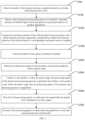
- the method includes the following steps:
- the normal laser processing process is not affected. That is, on the basis of performing the original laser processing steps of the pulsed laser marking machine, it is possible for the pulsed laser marking machine to simultaneously detect the luminous intensity of the reflected light of the laser pulse on the processed surface of the product.
- a normal luminous intensity threshold for the reflected light of the laser pulse i.e., a preset luminous intensity
- the range of the number of normal pulses generated by the pulsed laser when the processed product is qualified during the present laser processing process i.e., a preset range
- the number of qualified pulses is compared with the preset range to confirm that the number of qualified pulses is within the preset range. If the number of qualified pulses is not within the preset range, it means that the quality of this laser processing is unqualified.
- the processing of each laser pulse is qualified by detecting the luminous intensity of the reflected light of each laser pulse, and then monitor the overall processing quality of the present laser processing process. Meanwhile, the monitoring step can be performed without manual participation, and the real-time processing effect of the laser processing apparatus can be automatically monitored with the help of the control system, thus achieving the purpose of reducing the labor cost and improving the automation productivity of the apparatus.
- the step S100 includes: acquiring an optical signal of the reflected light of each laser pulse on the processed surface of the product sequentially, and converting the optical signal into a voltage signal.
- a detection module 10 such as a photoelectric probe or a photoelectric sensor, for detecting the optical signal can be provided in the laser processing apparatus.
- the optical signal of the reflected light of the laser pulse can be converted into a corresponding voltage signal by means of the detection module 10, thereby realizing the detection of the luminous intensity of the reflected light of each laser pulse.
- the photoelectric probe detects the intensity of light by using a built-in photodiode to receive irradiation of the light and generate a current.
- the detection sensitivity of different photodiodes to light of different wavelengths is different. Therefore, the pulse lasers of different wavelengths need to be matched with an appropriate type of photoelectric probe, so as to accurately detect the intensity of the reflected light.
- the photoelectric probe can be fixed on the laser scanning head.
- the photoelectric probe can also be fixed at an appropriate position on the marking platform by providing a bracket to fix the photoelectric probe.
- the step S200 includes: comparing a value of the converted voltage signal with a preset voltage signal value, and generating a counting signal when the value of the converted voltage signal is greater than the preset voltage signal value.
- the preset voltage signal value is generally the lowest voltage value of the voltage signal converted from the reflected light of the normal laser pulse detected by the photoelectric probe.
- a comparison module 20 such as a comparator or a comparison circuit, can be provided in the laser processing apparatus.
- the comparison module 20 compares the value of the converted voltage signal with the preset voltage signal value to determine whether the value of the converted voltage signal exceeds the preset voltage signal value, and generates a counting signal once the value of the converted voltage signal exceeding the preset voltage signal value.
- the step S200 includes: counting the number of laser pulses reaching the standard based on the number of the generated counting signals.
- a counting module 30 can be provided in the laser processing apparatus.
- the counting module 30 is connected to the comparison module 20, and the counting module 30 can receive the counting signal sent by the comparison module 20 and count.
- the comparison module 20 generates the counting signal once
- the counting module 30 increases the number of the laser pulses reaching the standard once.
- the counting module 30 may be implemented using an FPGA control chip in combination with a digital-to-analog conversion circuit.
- the model of the FPGA control chip may be LatticeXP2, or other models with similar functions.
- the FPGA control chip is connected to a negative terminal of the comparator through the digital-to-analog conversion circuit, and a preset voltage signal value is input as a reference for comparison by the comparator.
- the voltage signal converted by the photoelectric probe is input through a positive terminal of the comparator, and when the peak value of the Gaussian waveform of this voltage signal is higher than the set voltage at the negative terminal of the comparator, an output terminal of the comparator outputs a high level to the FPGA control chip.
- the FPGA control chip receives the high level and performs a count once.
- the counting module 30 may also use a DSP chip with a model of TMS320VC5509A, or other models but having a similar function.
- the counting module 30 may also use an MCU chip with a model of stm32f4, or other models but having a similar function.
- the counting module 30 may also use a DAC chip with a model of TLV5608, or other models but having a similar function.
- the present disclosure is not limited thereto.
- the step S400 may be implemented by the determination module 40.
- the determination module 40 can realize its function, i.e., acquiring the number of the laser pulses reaching the standard and determining whether the number of the laser pulses reaching the standard is within the preset range, directly by means of the original industrial control machine of the laser processing apparatus.
- the counting module 30 is communicatively connected to the industrial control machine through a serial port or other means.
- the laser processing software first estimates the range of the number of the normal laser pulses for this laser process. After the laser processing is completed, the laser processing software reads the number counted by the counting module 30, and determines whether the number counted by the counting module 30 is within the normal range, thereby determining whether the quality of this laser processing is qualified.
- the method after executing step S500 to confirm the processing quality, the method also includes: in step S600, turning off, if the processing quality is confirmed to be unqualified, the pulsed laser, and generating an alarm signal.
- the industrial control machine will turn off the pulsed laser, stop the marking process and generate the alarm signal. Then a site operator can be notified by an alarm lamp which receives the alarm signal alarm, or a display screen which receives the alarm signal and displays the alarm signal in the operation interface, or in other ways.
- the laser processing is restarted after the site operator has dealt with the fault or reset the laser processing parameters.
- the method also includes: in step S700, proceeding, if the processing quality is confirmed to be qualified, to a next laser processing process automatically.
- the next laser processing process is automatically started, and the next processing quality monitoring step is started to realize uninterrupted processing, improve processing efficiency, and ensure processing quality.
- the method after the step S700 or before the step S100, the method also includes: in step S50, resetting the number of the laser pulses reaching the standard counted in a previous processing process to zero.
- the laser processing software in the industrial control machine clears the number counted by the counting module 30, so as to prevent the stored count from interfering with the monitoring of the present laser processing quality and improve the accuracy of the monitoring.
- the present disclosure provides a device for monitoring laser processing quality.
- the device is applied to a pulsed laser.
- the device includes:
- the detection module 10 may be implemented by a device such as a photoelectric probe or a photoelectric sensor.
- the optical signal of the reflected light of the laser pulse can be converted into a corresponding voltage signal by means of the detection module 10, thereby realizing the detection of the luminous intensity of the reflected light of each laser pulse.
- the comparison module 20 may be implemented by a device such as a comparator or a comparison circuit.
- the comparison module 20 compares the value of the converted voltage signal with the preset voltage signal value to determine whether the value of the converted voltage signal exceeds the preset voltage signal value, and generates a counting signal once the value of the converted voltage signal exceeding the preset voltage signal value.
- the counting module 30 may be implemented using an FPGA control chip in combination with a digital-to-analog conversion circuit, or other control chip with similar functions.
- the FPGA control chip is connected to a negative terminal of the comparator through the digital-to-analog conversion circuit, and a preset voltage signal value is input as a reference for comparison by the comparator.
- the voltage signal converted by the photoelectric probe is input through a positive terminal of the comparator, and when the peak value of the Gaussian waveform of this voltage signal is higher than the set voltage at the negative terminal of the comparator, an output terminal of the comparator outputs a high level to the FPGA control chip.
- the FPGA control chip receives the high level and performs a count once.
- the determination module 40 may realize its function by means of the original industrial control machine of the laser processing apparatus.
- the industrial control machine is communicatively connected to the counting module 30 through a serial port or other means.
- the laser processing software first estimates the range of the number of the normal laser pulses for this laser process. After the laser processing is completed, the laser processing software reads the number counted by the counting module 30, and determines whether the number counted by the counting module 30 is within the normal range, thereby determining whether the quality of this laser processing is qualified.
- the determination module 40 is further configured to turning off, if the processing quality is confirmed to be unqualified, the pulsed laser, and generating an alarm signal to notify the site operator.
- the laser processing is restarted after the site operator has dealt with the fault or reset the laser processing parameters.
- the determination module 40 is further configured to proceed, if the processing quality is confirmed to be qualified, to a next laser processing process automatically, thus realizing uninterrupted processing. In addition, before each laser process, the determination module 40 is further configured to reset the number counted by the counting module 30 to zero, to ensure accurate calculation for the present processing process.
- the present disclosure also provides a non-transitory computer-readable storage medium.
- the non-transitory computer-readable storage medium has computer-executable instructions stored therein.
- the computer-executable instructions is configured to execute a method for monitoring laser processing quality as described in the above embodiment.
- the present disclosure also provides a laser processing apparatus.
- the laser processing apparatus includes, at least one central processor A1 (taking one central processor A1 as an example in FIG.3 ), a memory A2, a display screen A3, a laser processing head A4, a pulsed laser A5, a device for monitoring laser processing quality A6, a bus and a communication interface.
- the central processor A1, the memory A2, the display screen A3, the laser processing head A4, the pulsed laser A5, the device for monitoring laser processing quality A6, and the communication interface can be communicated with each other through the bus.
- the display screen A3 is configured to display a user operation interface preset in an initial setup mode, and the display screen A3 is further configured to display a process control window.
- the communication interface can transmit information.
- the central processor A1 can call logic instructions in the memory A2 to execute the method in the above embodiment by controlling the pulsed laser A5, the laser processing head A4, and the device for monitoring laser processing quality A6.
- the central processor A1 may be a central processing unit (CPU), and the central processor A1 may also be other general-purpose processors, such as a digital signal processor (DSP), an application-specific integrated circuit (ASIC), a fieldprogrammable gate array (FPGA), or other programmable logic device, discrete gate, transistor logic device or discrete hardware component.
- DSP digital signal processor
- ASIC application-specific integrated circuit
- FPGA fieldprogrammable gate array
- logic instructions in the memory A2 may be stored in a computer-readable storage medium when implemented in the form of software function unit and sold or used as a separate workpiece.
- the memory A2 as a computer-readable storage medium, may be configured to store a software program or a computer-executable program, such as program instructions or modules corresponding to the method in the embodiment of the present disclosure.
- the central processor A1 executes a functional application and data processing by executing the software program, instructions or modules stored in the memory A2, to implement the method in the above embodiment.
- the memory A2 may include a program storage area and a data storage area.
- the program storage area may store an operating system, an application program required for at least one function.
- the data storage area may store data or the like created according to the use of the terminal device.
- the memory A2 may include a high-speed random access memory and may also include a non-volatile memory.
- the program may be stored in a computer-readable storage medium.
- the computer-readable storage medium may be a non-transitory storage medium including a USB flash disk, a removable hard disk, a read-only memory (ROM), a random access memory (RAM), a magnetic disk, an optical disk, or other media that can store the program code.
- the computer-readable storage medium may also be a transitory storage medium.
Landscapes
- Engineering & Computer Science (AREA)
- Physics & Mathematics (AREA)
- Optics & Photonics (AREA)
- Mechanical Engineering (AREA)
- Plasma & Fusion (AREA)
- Quality & Reliability (AREA)
- Laser Beam Processing (AREA)
Applications Claiming Priority (2)
| Application Number | Priority Date | Filing Date | Title |
|---|---|---|---|
| CN202210921395.3A CN115319318A (zh) | 2022-08-02 | 2022-08-02 | 激光加工质量监测方法、监测组件、加工设备及存储介质 |
| PCT/CN2023/087864 WO2024027198A1 (zh) | 2022-08-02 | 2023-04-12 | 激光加工质量监测方法、监测组件、加工设备及存储介质 |
Publications (2)
| Publication Number | Publication Date |
|---|---|
| EP4566748A1 true EP4566748A1 (de) | 2025-06-11 |
| EP4566748A4 EP4566748A4 (de) | 2025-12-17 |
Family
ID=83918957
Family Applications (1)
| Application Number | Title | Priority Date | Filing Date |
|---|---|---|---|
| EP23848909.0A Pending EP4566748A4 (de) | 2022-08-02 | 2023-04-12 | Verfahren zur überwachung der laserbearbeitungsqualität und überwachungsanordnung sowie bearbeitungsvorrichtung und speichermedium |
Country Status (6)
| Country | Link |
|---|---|
| US (1) | US20250345879A1 (de) |
| EP (1) | EP4566748A4 (de) |
| JP (1) | JP2025518264A (de) |
| KR (1) | KR20250019130A (de) |
| CN (1) | CN115319318A (de) |
| WO (1) | WO2024027198A1 (de) |
Families Citing this family (3)
| Publication number | Priority date | Publication date | Assignee | Title |
|---|---|---|---|---|
| CN115319318A (zh) * | 2022-08-02 | 2022-11-11 | 大族激光科技产业集团股份有限公司 | 激光加工质量监测方法、监测组件、加工设备及存储介质 |
| CN117506180A (zh) * | 2023-11-29 | 2024-02-06 | 深圳市杰普特光电股份有限公司 | 激光器监控方法、装置、激光打标器系统和存储介质 |
| CN119105430A (zh) * | 2024-09-18 | 2024-12-10 | 成都苔岑智能设备有限公司 | 生产任务执行方法、系统、设备、程序产品及存储介质 |
Family Cites Families (18)
| Publication number | Priority date | Publication date | Assignee | Title |
|---|---|---|---|---|
| JPS54117998A (en) * | 1978-03-06 | 1979-09-13 | Toshiba Corp | Laser working device |
| JP2684480B2 (ja) * | 1991-11-29 | 1997-12-03 | ファナック株式会社 | レーザ加工装置 |
| JPH05329669A (ja) * | 1992-06-02 | 1993-12-14 | Komatsu Ltd | レーザ加工機における加工制御装置 |
| JPH10263859A (ja) * | 1997-03-19 | 1998-10-06 | Miyachi Technos Corp | レーザモニタ装置及びレーザ装置 |
| JP3460678B2 (ja) * | 2000-06-02 | 2003-10-27 | 松下電器産業株式会社 | レーザ加工方法および加工装置 |
| JP2005081358A (ja) * | 2003-09-05 | 2005-03-31 | Matsushita Electric Ind Co Ltd | レーザパルスモニタリング方法ならびに装置 |
| JP2006247681A (ja) * | 2005-03-09 | 2006-09-21 | Miyachi Technos Corp | レーザ加工用モニタリング装置 |
| JP6423812B2 (ja) * | 2016-02-29 | 2018-11-14 | ファナック株式会社 | 反射光を抑制しつつレーザ加工を開始できるレーザ加工装置 |
| JP6363660B2 (ja) * | 2016-07-13 | 2018-07-25 | ファナック株式会社 | レーザ加工装置及びレーザ加工システム |
| JP6987453B2 (ja) * | 2018-01-29 | 2022-01-05 | 住友重機械工業株式会社 | 評価装置、及び評価方法 |
| CN109217102A (zh) * | 2018-11-05 | 2019-01-15 | 广东水利电力职业技术学院(广东省水利电力技工学校) | 一种激光功率监测系统及监测方法 |
| CN112179489A (zh) * | 2019-07-01 | 2021-01-05 | 南京孚翔电子科技有限公司 | 脉冲激光器的功率测试方法 |
| CN111707359A (zh) * | 2020-05-12 | 2020-09-25 | 固高科技(深圳)有限公司 | 激光加工检测系统和方法 |
| CN112222104A (zh) * | 2020-08-29 | 2021-01-15 | 武汉光谷航天三江激光产业技术研究院有限公司 | 一种适用于激光清洗质量在线监测的装置与方法 |
| CN112461860B (zh) * | 2020-12-04 | 2025-01-07 | 广州德擎光学科技有限公司 | 激光加工件加工点质量检测方法、装置和系统 |
| JP7542422B2 (ja) * | 2020-12-11 | 2024-08-30 | 株式会社東芝 | 溶接状態の検出方法、および溶接装置 |
| CN112688155A (zh) * | 2020-12-25 | 2021-04-20 | 武汉奇致激光技术股份有限公司 | 一种激光光强度的控制方法及控制系统 |
| CN115319318A (zh) * | 2022-08-02 | 2022-11-11 | 大族激光科技产业集团股份有限公司 | 激光加工质量监测方法、监测组件、加工设备及存储介质 |
-
2022
- 2022-08-02 CN CN202210921395.3A patent/CN115319318A/zh active Pending
-
2023
- 2023-04-12 US US18/880,725 patent/US20250345879A1/en active Pending
- 2023-04-12 JP JP2024570892A patent/JP2025518264A/ja active Pending
- 2023-04-12 EP EP23848909.0A patent/EP4566748A4/de active Pending
- 2023-04-12 WO PCT/CN2023/087864 patent/WO2024027198A1/zh not_active Ceased
- 2023-04-12 KR KR1020257000171A patent/KR20250019130A/ko active Pending
Also Published As
| Publication number | Publication date |
|---|---|
| WO2024027198A1 (zh) | 2024-02-08 |
| US20250345879A1 (en) | 2025-11-13 |
| KR20250019130A (ko) | 2025-02-07 |
| CN115319318A (zh) | 2022-11-11 |
| EP4566748A4 (de) | 2025-12-17 |
| JP2025518264A (ja) | 2025-06-12 |
Similar Documents
| Publication | Publication Date | Title |
|---|---|---|
| EP4566748A1 (de) | Verfahren zur überwachung der laserbearbeitungsqualität und überwachungsanordnung sowie bearbeitungsvorrichtung und speichermedium | |
| KR101343403B1 (ko) | 공작기계 운전시의 이상 검출방법 | |
| JP5587393B2 (ja) | 工具を設定または分析する装置 | |
| CN101508035A (zh) | 加工成型设备的断刀监测方法和系统 | |
| KR20150112814A (ko) | 레이저 가공장치 및 레이저 가공방법 | |
| CN110988578A (zh) | 激光器测试系统、方法及可读存储介质 | |
| US12330232B2 (en) | Method for monitoring a laser machining process on workpieces | |
| CN103862166A (zh) | 一种激光束焦平面的确定方法 | |
| JP2011240361A (ja) | レーザ加工装置およびレーザ加工装置の異常監視方法 | |
| WO2020135636A1 (zh) | 一种轮毂刀具管理系统和方法 | |
| CN117020502B (zh) | 焊接设备点检方法、系统以及设备 | |
| CN112203797A (zh) | 激光加工机、控制装置及判定方法 | |
| US3695771A (en) | Method and apparatus for inspecting surfaces | |
| CN110134069B (zh) | 数控机床自诊断方法及系统 | |
| CN117744003A (zh) | 激光切割异常识别方法、系统、设备及存储介质 | |
| JP2016087676A (ja) | レーザ加工装置及びレーザ加工方法 | |
| CN113834986A (zh) | 测量电信号防错的方法、测量设备及可读存储介质 | |
| US10101201B2 (en) | System for continuous laser beam monitoring and analysis | |
| KR100870710B1 (ko) | 스캐너 오작동 감지방법 | |
| JPH07116872A (ja) | レーザ加工機の制御方法及び装置 | |
| JPH03207586A (ja) | レーザ加工装置 | |
| KR102088065B1 (ko) | 공작물 공급 및 회수 장치의 자동 좌표 설정 방법 및 장치 | |
| CN121685643A (zh) | 车辆位置度检测方法、系统、设备及存储介质 | |
| CN119502053A (zh) | 主轴检测方法、控制器、存储介质、程序产品及加工设备 | |
| CN120347591A (zh) | 一种数控机床防碰撞用监测方法及系统 |
Legal Events
| Date | Code | Title | Description |
|---|---|---|---|
| STAA | Information on the status of an ep patent application or granted ep patent |
Free format text: STATUS: THE INTERNATIONAL PUBLICATION HAS BEEN MADE |
|
| PUAI | Public reference made under article 153(3) epc to a published international application that has entered the european phase |
Free format text: ORIGINAL CODE: 0009012 |
|
| STAA | Information on the status of an ep patent application or granted ep patent |
Free format text: STATUS: REQUEST FOR EXAMINATION WAS MADE |
|
| 17P | Request for examination filed |
Effective date: 20241128 |
|
| AK | Designated contracting states |
Kind code of ref document: A1 Designated state(s): AL AT BE BG CH CY CZ DE DK EE ES FI FR GB GR HR HU IE IS IT LI LT LU LV MC ME MK MT NL NO PL PT RO RS SE SI SK SM TR |
|
| DAV | Request for validation of the european patent (deleted) | ||
| DAX | Request for extension of the european patent (deleted) | ||
| A4 | Supplementary search report drawn up and despatched |
Effective date: 20251117 |
|
| RIC1 | Information provided on ipc code assigned before grant |
Ipc: B23K 26/70 20140101AFI20251111BHEP Ipc: B23K 26/362 20140101ALI20251111BHEP Ipc: B23K 26/03 20060101ALI20251111BHEP Ipc: B23K 31/12 20060101ALI20251111BHEP |