EP4560052A1 - Katalysator und anode zur elektrolytischen herstellung von wasserstoff und herstellungsverfahren dafür, aktivierungsverfahren dafür und verwendung davon - Google Patents
Katalysator und anode zur elektrolytischen herstellung von wasserstoff und herstellungsverfahren dafür, aktivierungsverfahren dafür und verwendung davon Download PDFInfo
- Publication number
- EP4560052A1 EP4560052A1 EP24822464.4A EP24822464A EP4560052A1 EP 4560052 A1 EP4560052 A1 EP 4560052A1 EP 24822464 A EP24822464 A EP 24822464A EP 4560052 A1 EP4560052 A1 EP 4560052A1
- Authority
- EP
- European Patent Office
- Prior art keywords
- catalyst
- electrolysis
- anode
- hydrogen production
- alkaline
- Prior art date
- Legal status (The legal status is an assumption and is not a legal conclusion. Google has not performed a legal analysis and makes no representation as to the accuracy of the status listed.)
- Pending
Links
Images


Classifications
-
- C—CHEMISTRY; METALLURGY
- C25—ELECTROLYTIC OR ELECTROPHORETIC PROCESSES; APPARATUS THEREFOR
- C25B—ELECTROLYTIC OR ELECTROPHORETIC PROCESSES FOR THE PRODUCTION OF COMPOUNDS OR NON-METALS; APPARATUS THEREFOR
- C25B11/00—Electrodes; Manufacture thereof not otherwise provided for
- C25B11/04—Electrodes; Manufacture thereof not otherwise provided for characterised by the material
- C25B11/051—Electrodes formed of electrocatalysts on a substrate or carrier
- C25B11/073—Electrodes formed of electrocatalysts on a substrate or carrier characterised by the electrocatalyst material
- C25B11/091—Electrodes formed of electrocatalysts on a substrate or carrier characterised by the electrocatalyst material consisting of at least one catalytic element and at least one catalytic compound; consisting of two or more catalytic elements or catalytic compounds
-
- C—CHEMISTRY; METALLURGY
- C25—ELECTROLYTIC OR ELECTROPHORETIC PROCESSES; APPARATUS THEREFOR
- C25B—ELECTROLYTIC OR ELECTROPHORETIC PROCESSES FOR THE PRODUCTION OF COMPOUNDS OR NON-METALS; APPARATUS THEREFOR
- C25B11/00—Electrodes; Manufacture thereof not otherwise provided for
- C25B11/04—Electrodes; Manufacture thereof not otherwise provided for characterised by the material
- C25B11/051—Electrodes formed of electrocatalysts on a substrate or carrier
- C25B11/073—Electrodes formed of electrocatalysts on a substrate or carrier characterised by the electrocatalyst material
- C25B11/075—Electrodes formed of electrocatalysts on a substrate or carrier characterised by the electrocatalyst material consisting of a single catalytic element or catalytic compound
-
- C—CHEMISTRY; METALLURGY
- C01—INORGANIC CHEMISTRY
- C01G—COMPOUNDS CONTAINING METALS NOT COVERED BY SUBCLASSES C01D OR C01F
- C01G53/00—Compounds of nickel
- C01G53/80—Compounds containing nickel, with or without oxygen or hydrogen, and containing one or more other elements
- C01G53/84—Hydroxides
-
- C—CHEMISTRY; METALLURGY
- C25—ELECTROLYTIC OR ELECTROPHORETIC PROCESSES; APPARATUS THEREFOR
- C25B—ELECTROLYTIC OR ELECTROPHORETIC PROCESSES FOR THE PRODUCTION OF COMPOUNDS OR NON-METALS; APPARATUS THEREFOR
- C25B1/00—Electrolytic production of inorganic compounds or non-metals
- C25B1/01—Products
- C25B1/02—Hydrogen or oxygen
- C25B1/04—Hydrogen or oxygen by electrolysis of water
-
- C—CHEMISTRY; METALLURGY
- C25—ELECTROLYTIC OR ELECTROPHORETIC PROCESSES; APPARATUS THEREFOR
- C25B—ELECTROLYTIC OR ELECTROPHORETIC PROCESSES FOR THE PRODUCTION OF COMPOUNDS OR NON-METALS; APPARATUS THEREFOR
- C25B11/00—Electrodes; Manufacture thereof not otherwise provided for
- C25B11/02—Electrodes; Manufacture thereof not otherwise provided for characterised by shape or form
- C25B11/03—Electrodes; Manufacture thereof not otherwise provided for characterised by shape or form perforated or foraminous
- C25B11/031—Porous electrodes
-
- C—CHEMISTRY; METALLURGY
- C25—ELECTROLYTIC OR ELECTROPHORETIC PROCESSES; APPARATUS THEREFOR
- C25B—ELECTROLYTIC OR ELECTROPHORETIC PROCESSES FOR THE PRODUCTION OF COMPOUNDS OR NON-METALS; APPARATUS THEREFOR
- C25B11/00—Electrodes; Manufacture thereof not otherwise provided for
- C25B11/04—Electrodes; Manufacture thereof not otherwise provided for characterised by the material
- C25B11/051—Electrodes formed of electrocatalysts on a substrate or carrier
- C25B11/052—Electrodes comprising one or more electrocatalytic coatings on a substrate
-
- C—CHEMISTRY; METALLURGY
- C25—ELECTROLYTIC OR ELECTROPHORETIC PROCESSES; APPARATUS THEREFOR
- C25B—ELECTROLYTIC OR ELECTROPHORETIC PROCESSES FOR THE PRODUCTION OF COMPOUNDS OR NON-METALS; APPARATUS THEREFOR
- C25B11/00—Electrodes; Manufacture thereof not otherwise provided for
- C25B11/04—Electrodes; Manufacture thereof not otherwise provided for characterised by the material
- C25B11/051—Electrodes formed of electrocatalysts on a substrate or carrier
- C25B11/055—Electrodes formed of electrocatalysts on a substrate or carrier characterised by the substrate or carrier material
- C25B11/057—Electrodes formed of electrocatalysts on a substrate or carrier characterised by the substrate or carrier material consisting of a single element or compound
- C25B11/061—Metal or alloy
-
- C—CHEMISTRY; METALLURGY
- C25—ELECTROLYTIC OR ELECTROPHORETIC PROCESSES; APPARATUS THEREFOR
- C25B—ELECTROLYTIC OR ELECTROPHORETIC PROCESSES FOR THE PRODUCTION OF COMPOUNDS OR NON-METALS; APPARATUS THEREFOR
- C25B9/00—Cells or assemblies of cells; Constructional parts of cells; Assemblies of constructional parts, e.g. electrode-diaphragm assemblies; Process-related cell features
- C25B9/17—Cells comprising dimensionally-stable non-movable electrodes; Assemblies of constructional parts thereof
-
- C—CHEMISTRY; METALLURGY
- C01—INORGANIC CHEMISTRY
- C01P—INDEXING SCHEME RELATING TO STRUCTURAL AND PHYSICAL ASPECTS OF SOLID INORGANIC COMPOUNDS
- C01P2002/00—Crystal-structural characteristics
- C01P2002/70—Crystal-structural characteristics defined by measured X-ray, neutron or electron diffraction data
- C01P2002/72—Crystal-structural characteristics defined by measured X-ray, neutron or electron diffraction data by d-values or two theta-values, e.g. as X-ray diagram
-
- C—CHEMISTRY; METALLURGY
- C01—INORGANIC CHEMISTRY
- C01P—INDEXING SCHEME RELATING TO STRUCTURAL AND PHYSICAL ASPECTS OF SOLID INORGANIC COMPOUNDS
- C01P2004/00—Particle morphology
- C01P2004/01—Particle morphology depicted by an image
- C01P2004/03—Particle morphology depicted by an image obtained by SEM
-
- C—CHEMISTRY; METALLURGY
- C01—INORGANIC CHEMISTRY
- C01P—INDEXING SCHEME RELATING TO STRUCTURAL AND PHYSICAL ASPECTS OF SOLID INORGANIC COMPOUNDS
- C01P2004/00—Particle morphology
- C01P2004/01—Particle morphology depicted by an image
- C01P2004/04—Particle morphology depicted by an image obtained by TEM, STEM, STM or AFM
-
- C—CHEMISTRY; METALLURGY
- C01—INORGANIC CHEMISTRY
- C01P—INDEXING SCHEME RELATING TO STRUCTURAL AND PHYSICAL ASPECTS OF SOLID INORGANIC COMPOUNDS
- C01P2004/00—Particle morphology
- C01P2004/60—Particles characterised by their size
- C01P2004/61—Micrometer sized, i.e. from 1-100 micrometer
-
- Y—GENERAL TAGGING OF NEW TECHNOLOGICAL DEVELOPMENTS; GENERAL TAGGING OF CROSS-SECTIONAL TECHNOLOGIES SPANNING OVER SEVERAL SECTIONS OF THE IPC; TECHNICAL SUBJECTS COVERED BY FORMER USPC CROSS-REFERENCE ART COLLECTIONS [XRACs] AND DIGESTS
- Y02—TECHNOLOGIES OR APPLICATIONS FOR MITIGATION OR ADAPTATION AGAINST CLIMATE CHANGE
- Y02E—REDUCTION OF GREENHOUSE GAS [GHG] EMISSIONS, RELATED TO ENERGY GENERATION, TRANSMISSION OR DISTRIBUTION
- Y02E60/00—Enabling technologies; Technologies with a potential or indirect contribution to GHG emissions mitigation
- Y02E60/30—Hydrogen technology
- Y02E60/36—Hydrogen production from non-carbon containing sources, e.g. by water electrolysis
Definitions
- CN202410452007.0 filed with the China National Intellectual Property Administration on April 15, 2024 , titled "CATALYST AND ANODE FOR HYDROGEN PRODUCTION BY ELECTROLYSIS AS WELL AS PREPARATION METHOD, ACTIVATION METHOD AND USE THEREOF", the disclosure of which is incorporated by reference herein in its entirety as part of the present application.
- the present disclosure belongs to the technical fields of materials and energy catalysis, and particularly relates to a catalyst and anode for hydrogen production by electrolysis, as well as a preparation method, activation method and use thereof.
- Hydrogen is one of the most promising energy carriers, which can replace fossil fuel to solve the future global warming effect. Hydrogen production by electrolysis of water driven by renewable energy sources can provide a new approach for relieving the current energy shortage without affecting the sustainability of an environment.
- Hydrogen produced by electrolysis of water is relatively high in purity, high energy consumption formed by electrolysis of water can be reduced by technical means, however, limited fresh water resources can greatly restrict the development and large-scale application of electrolysis of water. From a practical perspective, direct electrolysis of seawater has huge advantages, rich seawater reserves on earth are the fundamental support for achieving large-scale application of seawater electrolysis, and similarly has the ability of producing high-purity hydrogen.
- nickel iron hydrotalcites have been widely reported and researched due to their characteristics of excellent performance and low cost, but they are prone to corrosion in seawater, leading to their short service lives, thereby seriously restricting the application of them in an aqueous solution containing chlorine ions, especially in hydrogen production by electrolysis of seawater.
- the main objective of the present disclosure is to provide a catalyst and anode for hydrogen production by electrolysis as well as a preparation method, activation method and use thereof in order to overcome the defects in the prior art.
- the third aspect of the present disclosure provides an activated catalyst for hydrogen production by electrolysis, including the catalyst for hydrogen production by electrolysis and a sulfate activating layer, wherein the sulfate activating layer includes sulfate ions distributed on the surface of the catalyst, and the sulfate ions bind to alkali earth metal ions in the catalyst.
- the fourth aspect of the present disclosure provides an anode for hydrogen production by electrolysis of seawater, including the catalyst for hydrogen production by electrolysis or the activated catalyst for hydrogen production by electrolysis.
- the fifth aspect of the present disclosure provides use of the catalyst for hydrogen production by electrolysis, the activated catalyst for hydrogen production by electrolysis or the anode for hydrogen production by electrolysis in hydrogen production by electrolysis.
- the sixth aspect of the present disclosure provides a method for hydrogen production by electrolysis, including: placing an anode and cathode for hydrogen production by electrolysis in an aqueous solution containing chlorine ions, and applying a working voltage between the anode and the cathode, thereby achieving hydrogen production by electrolysis.
- the seventh aspect of the present disclosure provides a system for hydrogen production by electrolysis, including an anode and a cathode, wherein the system for hydrogen production by electrolysis is used for performing hydrogen production by electrolysis on the aqueous solution containing chlorine ions, and the anode includes the anode for hydrogen production by electrolysis.
- the present disclosure at least has the following beneficial effects:
- relationship terms such as “first” and “second” are only used for distinguishing one substance or method step from another substance or method step having the same name, but are not necessary to require or imply that there are any actual relationships or order between these substances or method steps.
- the catalyst has at least one of the following features:
- the catalyst has at least one of the following features:
- M and N are respectively Ni 2+ and Fe 3+ , M' is Ba 2+ , and A n- is CO 3 2 -.
- M' is selected from Ba 2+ .
- the catalyst is barium-doping nickel iron hydrotalcite, wherein M and N are respectively Ni 2+ and Fe 3+ , and the atomic percentage content of the barium element in the catalyst is 0.4%-0.5%, wherein if the content of the barium element is too low, it will lead to less fixed sulfate, the catalyst cannot be comprehensively protected, conversely, if the content of the barium element is too high, it will adversely affect the performance of the catalyst.
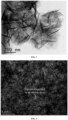
- the catalyst has a nano hexagonal sheet structure.
- the nano hexagonal sheet structure has at least one of the following features: a) a thickness is 100-200 nm; b) an area is 0.01-0.05 ⁇ m 2 .
- the catalyst being barium-doping nickel iron hydrotalcite
- the sulfate ions react with the barium ions in the catalyst to generate barium sulfate so as to form a fixed sulfate activating layer (hereinafter referred to as a sulfate activating layer or a chlorine removing layer) for chlorine removal, so as to hinder that other chloride ions in the solution are further adsorbed on the surface of the catalyst, thereby achieving the effect of delaying chloride ion corrosion, improving the stability of the catalyst and the corrosion resistance of the anode and greatly extending the service life of the anode.
- a fixed sulfate activating layer hereinafter referred to as a sulfate activating layer or a chlorine removing layer
- the appropriately doped barium and barium sulfate nano layer structure basically do not affect the catalytic activity of the catalyst.
- the catalyst can be activated in advance through an alkaline sulfate solution so that the foregoing sulfate activating layer is formed on the surface of the catalyst, and then the catalyst is applied to the aqueous solution containing chlorine ions for hydrogen production by electrolysis, which similarly achieves the effects of improving the stability of the catalyst and corrosion resistance of the anode, and prolonging the service life of the anode.
- Some embodiments of the present disclosure also provide a preparation method of the catalyst for hydrogen production by electrolysis, including: performing a hydrothermal reaction on a mixed reaction solution containing M, N and M' to prepare the catalyst for hydrogen production by electrolysis, wherein the catalyst has a chemical formula of [M 1-x N x M'(OH) 2 ] x+ [(A n- ) x/n •mH 2 O] x- , M and N are any two of scandium, vanadium, chromium, manganese, iron, cobalt and nickel ions, and M and N are respectively in +2 and +3 valent, M' is selected from alkaline-earth metal ions and dispersed in the catalyst in an atomic level, A n- is selected from CO 3 2- , NO 3 2- , Cl - , OH - or SO 4 2- , and the values of x, m and n are as described above.
- the preparation method specifically includes: performing a hydrothermal reaction on a mixed reaction solution containing a first transition metal compound, a second transition metal compound and an alkaline-earth metal compound in a molar ratio of 2-5:2-5:0.4-1 at 90-120°C to prepare the catalyst; wherein, the first transition metal compound, the second transition metal compound and the alkaline-earth metal compound respectively contain M, N and M', and the pH value of the mixed reaction solution is 8-10.
- the preparation method further specifically includes:
- the first transition metal compound includes a soluble nickel salt such as nickel nitrate and nickel chloride
- the second transition metal compound includes a soluble iron salt such as iron nitrate and iron chloride
- the alkaline-earth metal compound includes a soluble barium salt such as barium nitrate and barium chloride.
- the concentrations of the first transition metal compound, the second transition metal compound and the alkaline-earth metal compound contained in the mixed reaction solution are respectively 0.1-1 mmol/L, 0.2-0.5 mmol/L and 0.1-1 mmol/L.
- the alkaline substance includes any one of urea, hexamethylenetetraammonium or triethanolamine, or a combination thereof, and is not limited thereto.
- the preparation method of the catalyst for hydrogen production by electrolysis can be achieved by one-step solvothermal reaction, is simple to operate, does not need harsh reaction conditions such as high temperature and high pressure and notable reaction equipment, and the raw materials are mainly common metal salts which are cheap and easily available, low in cost and environmental-friendly.
- Some embodiments of the present disclosure also provide an activated catalyst for hydrogen production by electrolysis, including the catalyst for hydrogen production by electrolysis and a sulfate activating layer, wherein the sulfate activating layer includes sulfate ions distributed on the surface of the catalyst, and the sulfate ions bind to the alkaline-earth metal ions.
- the sulfate activating layer includes sulfate ions distributed on the surface of the catalyst, and the sulfate ions bind to the alkaline-earth metal ions.
- a nano layer structure can be formed on the surface of the catalyst, and the nano layer structure is mainly composed of nano particles with a particle size of larger than 0 nm but less than 5 nm. For example, if the alkaline-earth metal ion is a barium ion, the nano particle is a barium sulfate nano particle.
- Some embodiments of the present disclosure also provide an activation method of a catalyst for hydrogen production by electrolysis, including placing the catalyst in an alkaline solution containing sulfate ions, and activating the catalyst using an electrochemical method.
- the electrochemical method used for activation includes but is not limited to cyclic voltammetry
- the electrochemical method is cyclic voltammetry, wherein the used scanning voltage is 0 V-1 V, the scanning voltage speed is 5 mV/s-50 mV/s, and the scanning cycles are 10-30 cycles, so that the above nano particles are uniformly distributed, avoiding the agglomeration of the nano particles.
- the alkaline solution contains sulfate ions with a concentration of 0.01-0.1 mol/L so that the above nano particles are small in size and uniformly distributed, and the activity of the catalyst is not affected after covering on the surface of the catalyst, that is, the formed sulfate activating layer can not only hinder the entry of the chlorine ions, but also has sufficient channels to allow the contact of water molecules with the catalyst.
- the alkaline solution contains a sulfate salt
- the sulfate salt includes sodium sulfate or potassium sulfate, etc, and is not limited thereto.
- the alkaline solution contains an alkaline substance with a concentration of 0.1-1 mol/L, wherein the alkaline substance can include but is not limited to sodium hydroxide or potassium hydroxide, etc.
- Some embodiments of the present disclosure also provide an anode for hydrogen production by electrolysis, including the catalyst for hydrogen production by electrolysis or the activated catalyst for hydrogen production by electrolysis.
- a plurality of the catalyst nanosheets are erectly arranged on the surface of the anode, and mutually and intensively arranged to form an array structure.
- the specific surface area of the array structure is 40-50 m 2 /g.
- the anode also includes a conducting substrate for loading the catalyst, wherein the conducting substrate includes foam nickel, a nickel mesh, foam iron or foam nickel iron, etc., and is not limited thereto.
- the conducting substrate is also considered as an anode collector.
- Some embodiments of the present disclosure also provide a preparation method of the catalyst for hydrogen production by electrolysis, including: placing the conducting substrate into a mixed reaction solution containing a first transition metal compound, a second transition metal compound and an alkaline-earth metal compound in a molar ratio of 2-5:2-5:0.4-1 and performing a hydrothermal reaction on the above solution at 90-120°C so as to generate the catalyst for hydrogen production by electrolysis on the conducting substrate in situ.
- the preparation method of the anode for hydrogen production by electrolysis is to use a one-step hydrothermal method to prepare an anode for hydrogen production by electrolysis of nickel iron barium hydrotalcite.
- the preparation method specifically includes the following steps:
- a solution prepared by nickel iron hydrotalcite can be used as a solvent, and a densely coated catalyst slowly grows on the conducting substrate in situ as an anode in comparative example;
- a solution prepared by nickel iron barium hydrotalcite is used as a solvent, a densely coated catalyst slowly grows on the conducting substrate in situ, the prepared anode catalyst has an excellent ability of oxygen evolution performance by electrocatalysis of seawater and resistance to chlorine corrosion. Therefore, the anode can be used for hydrogen production by catalytic electrolysis.
- the catalyst loaded by the anode i.e., nickel iron barium hydrotalcite
- the sulfate ions in the solution can react with barium in the hydrotalcite to generate barium sulfate to form a fixed sulfate layer for chlorine removal, thereby hindering other chlorine ions in the solution to be further adsorbed on the surface of the electrode, achieving the effect of delaying the chlorine ion corrosion of the anode.
- the proper barium doping and the barium sulfate nano layer structure do not greatly affect the catalysis of the anode, thereby improving the stability of the anode in a reaction for hydrogen production by electrolysis of seawater.
- the above technical solution can also include steps of material characterization, selectivity and stability test characterization on the anode after hydrogen production by electrolysis of seawater. These steps can be for quality monitoring or for in-depth research, whether or not characterization is performed and by what means, they are within the scope of protection of the present disclosure.
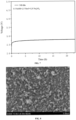
- the material characterization of the modified anode can include but is not limited to: X-ray diffraction (XRD) and X-ray photoelectron spectroscopy (XPS) characterizations to determine the characteristics of the coated material; scanning electron microscopy (SEM) and transmission electron microscopy (TEM) characterizations to characterize material morphology, lattice and element content; the selectivity and stability characterization of the modified anode can include but is not limited to: linear sweep voltammetry (LSV) and i-t constant current test.
- XRD X-ray diffraction
- XPS X-ray photoelectron spectroscopy
- SEM scanning electron microscopy
- TEM transmission electron microscopy
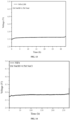
- the selectivity and stability characterization of the modified anode can include but is not limited to: linear sweep voltammetry (LSV) and i-t constant current test.
- the preparation method of the anode for hydrogen production by electrolysis includes evenly doping barium in the anode using a hydrothermal method, wherein the used hydrothermal solution includes a nickel salt, an alkaline-earth metal salt and an iron salt in a molar ratio of 2-5:0.4-1:2-5, and additional alkaline substances, wherein the alkaline-earth metal salt includes but is not limited to barium nitrate, and the concentration of the alkaline-earth metal salt in the hydrothermal solution is 0.1-1 mmol/L; the nickel salt includes but is not limited to nickel nitrate, and the concentration of the nickel salt in the hydrothermal solution is 0.1-1 mmol/L; the iron salt includes but is not limited to iron nitrate, and the concentration of the iron salt in the hydrothermal solution is 0.2-0.5 mmol/L; the alkaline substance includes but is not limited to any one or more of urea, hexamethylenetetraammonium or triethanolamine, and
- the hydrothermal temperature used in the hydrothermal method can be 80-150°C, preferably 90-120°C, and the hydrothermal time can be 4-48 h, preferably 8-12 h.
- the method for co-deposition of nickel iron barium by a hydrothermal method includes heating a conducting substrate in a hydrothermal solution to deposit barium ions in the solution onto the conducting substrate, and dispersing the barium ions in a catalyst in an atomic level.
- the preparation method of the anode for hydrogen production by electrolysis specifically includes: immersing a conducting substrate into a hydrothermal solution, mixing and stirring to form the nickel iron barium hydrotalcite; wherein, the hydrothermal solution is prepared by dissolving an alkaline-earth metal salt, a nickel salt and an iron salt as well as additional alkaline substances into water, and the amount of water is 35-50 mL; the rotation speed of the mixing and stirring is 800-1200 rmp.
- the preferred hydrothermal method differs from the existing preparation process of a hydrothermal nickel iron hydrotalcite anode, for example, the concentrations of the barium salt, the nickel salt and the iron salt are different from the existing preparation process of the hydrothermal nickel iron hydrotalcite anode. This is a change made to form the above nano layer structure.
- the activation method of the anode for hydrogen production by electrolysis includes activating the anode for hydrogen production by electrolysis in the alkaline solution containing sulfate.
- the activation method of the anode for hydrogen production by electrolysis includes activating the anode for hydrogen production by electrolysis in the sulfate solution by using cyclic voltammetry.
- the solution used by cyclic voltammetry includes an alkaline substance and a sulfate salt, the alkaline substance includes sodium hydroxide or potassium hydroxide, and the sulfate salt can include sodium sulfate, but is not limited thereto.
- the concentration of the alkaline substance in the solution is 0.1-1 mol/L, and the concentration of sulfate salt is 0.01-0.1 mol/L.
- the test system used in cyclic voltammetry can be a three-electrode system, the used pair electrode is a carbon rod, and the used reference electrode is a silver/silver chloride electrode; the ambient temperature used in cyclic voltammetry is 20-25°C, the used scanning cycles are 10-30 cycles, the used scanning voltage range is 0 V-1 V, and the used scanning voltage rate is 5 mV/s-50 mV/s.
- the above preferred activation method is a unique activation method in the present disclosure.
- the scanning voltage rate, scanning voltage range and electrode system are different from those in the existing anode activation processes. This is a change made to fix the above sulfate activating layer.
- Some embodiments of the present disclosure also provide use of the catalyst for hydrogen production by electrolysis, the activated catalyst for hydrogen production by electrolysis or the anode for hydrogen production by electrolysis in hydrogen production by electrolysis.
- the use includes: placing the anode and cathode for hydrogen production by electrolysis into an aqueous solution containing chlorine ions, and applying a working voltage between the anode and the cathode.
- Some embodiments of the present disclosure also provide use of the catalyst for hydrogen production by electrolysis in hydrogen production by electrolysis.
- the use includes: placing the anode and cathode for hydrogen production by electrolysis into an aqueous solution containing chlorine ions, and applying a working voltage between the anode and the cathode, thereby achieving hydrogen production by electrolysis; wherein, the anode includes the catalyst for hydrogen production by electrolysis.
- Some embodiments of the present disclosure also provide a method for hydrogen production by electrolysis, including: placing the anode and cathode for hydrogen production by electrolysis into an aqueous solution containing chlorine ions, and applying a working voltage between the anode and the cathode, thereby achieving hydrogen production by electrolysis.
- the aqueous solution containing chlorine ions includes but is not limited to seawater or chlorine-containing industrial wastewater, etc.
- the aqueous solution containing chlorine ions is alkaline.
- the hydrogen evolution efficiency can be up to more than 0.27 L/h through the method for hydrogen production by electrolysis under the conditions that the temperature is 25°C, the voltage is 2 V, a distance between the anode and the cathode is 1 cm, and the surface area of the anode is 1 cm 2 .
- Some embodiments of the present disclosure also provide a system for hydrogen production by electrolysis, including an anode and a cathode.
- the system for hydrogen production by electrolysis is used for performing hydrogen production by electrolysis on the aqueous solution containing chlorine ions, and the anode includes the anode for hydrogen production by electrolysis.
- the aqueous solution containing chlorine ions includes but is not limited to seawater or chlorine-containing industrial wastewater, etc.
- the optimal choice for the aqueous solution containing chloride ions is seawater.
- the system for hydrogen production by electrolysis can also include a power supply, etc.
- the cathode can select Pt, Ni, Raney Ni, NiMo alloy, etc.
- the present disclosure provides a new thought for the stability of the anode in the process of producing hydrogen by electrolysis of seawater.
- the raw materials, detection reagents and detection equipment used in the following embodiments can be purchased from the market, and the detection methods used are also commonly used in the art.
- the foam nickel used as follows is commercial foam nickel, which has been cleaned before use. The specific cleaning methods include: cutting commercial foam nickel into 1 cm ⁇ 4 cm long strips, ultrasonic treatment in 2 mol ⁇ L -1 hydrochloric acid solution for 3 min, ultrasonic cleaning in deionized water and non-aqueous ethanol for three times respectively, and then natural drying in air.
- step (1) barium nitrate in step (1) was omitted, the rest operations and process conditions were all the same as those in steps (1)-(2), and a NiFe-LDH/NF anode was finally prepared.
- the stability of the prepared anode was tested by using the same method as that in step (4).
- test results showed that the stability of the NiFe-LDH/NF anode prepared in this example in harsh simulated seawater electrolysis was maintained as about 2 h, while the NiFe-LDH/NF anode can only operate for 30 min in the same solution environment, indicating that the NiFe-LDH/NF anode prepared in this example takes the effect of protecting the conducting substrate.
- a preparation method of a NiFeBa/NF anode provided in this example is basically the same as that in example 1 only except that: the solvothermal reaction in step (2) was carried out for 12 h at a temperature of 90°C.
- the stability of the NiFeBa/NF anode in this example was tested by using a method that was the same as that in example 1.
- the test results show that the stability of the NiFeBa/NF anode prepared in this example in harsh stimulated seawater electrolysis is maintained as about 3 h.
- step (1) barium nitrate in step (1) was omitted, the rest operations and process conditions were all the same as those in steps (1)-(2), and a NiFe-LDH/NF anode was finally prepared.
- the stability of the prepared anode was tested by using the same method as that in step (4).
- the electrode prepared in this example can stably work for up to 120 h in stimulated seawater electrolysis, and the stability of this electrode was four times that of NiFe-LDH/NF. It shows that the NiFeBa/NF anode prepared in this example takes the effect of protecting the substrate.
- a preparation method of a NiFeBa/NF anode provided in this example is basically the same as that in example 2 only except that: the solvothermal reaction in step (2) was carried out for 4 h at a temperature of 120°C.
- the stability of the NiFeBa/NF anode in this example was tested by using a method that was the same as that in example 2.
- the test results show that the stability of the NiFeBa/NF anode prepared in this example in stimulated seawater electrolysis is maintained as about 140 h.
- step (1) barium nitrate in step (1) was omitted, the rest operations and process conditions were all the same as those in steps (1)-(2), and a NiFe-LDH/NF anode was finally prepared.
- the stability of the prepared anode was tested by using the same method as that in step (4).
- the electrode prepared in this example can stably work for up to 18 h in seawater electrolysis, and the stability of this electrode was about 8 times that of NiFe-LDH/NF, indicating that the NiFeBa/NF anode prepared in this example takes the effect of protecting the substrate.
- a preparation method of a NiFeBa/NF anode provided in this example is basically the same as that in example 2 only except that: the solvothermal reaction in step (2) was carried out for 4 h at a temperature of 120°C.
- the stability of the NiFeBa/NF anode in this example was tested by using a method that was the same as that in example 3.
- the test results show that the stability of the NiFeBa/NF anode prepared in this example in stimulated seawater electrolysis was maintained as about 25 h.
- step (1) barium nitrate in step (1) was omitted, the rest operations and process conditions were all the same as those in steps (1)-(2), and a NiFe-LDH/NF anode was finally prepared.
- the stability of the prepared anode was tested by using the same method as that in step (4).
- NiFeBa/NF anode prepared in this example can stably work for up to 20 h in seawater electrolysis, the stability of the NiFeBa/NF anode is about seven times that of NiFe-LDH/NF, indicating that the NiFeBa/NF anode prepared in this example takes the effect of protecting the substrate.
- step (1) barium nitrate in step (1) was omitted, the rest operations and process conditions were all the same as those in steps (1)-(2), and a NiFe-LDH/NF anode was finally prepared.
- the stability of the NiFe-LDH/NF anode was tested by using the same method as that in step (4).
- NiFeBa/NF anode prepared in this example can stably work for up to over 600 h in seawater electrolysis, while the NiFe-LDH/NF anode can only work for 60 h, indicating that the NiFeBa/NF anode prepared in this example takes the effect of protecting the substrate.
- a preparation method of a NiFeBa/NF anode provided in this example is basically the same as that in example 2 only except that: the solvothermal reaction in step (2) was carried out for 4 h at a temperature of 100°C.
- the stability of the NiFeBa/NF anode in this example was tested by using a method that was the same as that in example 5.
- the test results showed that the stability of the NiFeBa/NF anode prepared in this example in stimulated seawater electrolysis was maintained as about 630 h.
- a preparation method of a NiFeCa/NF anode provided in this example is basically the same as that in example 5 only except that barium nitrate used in step (1) was replaced with calcium nitrate.
- the stability of the NiFeCa/NF anode was tested by using a method that was the same as that in example 5. The test results showed that the stability of the NiFeCa/NF anode prepared in this example in stimulated seawater electrolysis was maintained as about 530 h.
- a preparation method of a NiFeSr/NF anode provided in this example is basically the same as that in example 5 only except that barium nitrate used in step (1) was replaced with strontium nitrate.
- the stability of the NiFeSr/NF anode was tested by using a method that was the same as that in example 5. The test results showed that the stability of the NiFeSr/NF anode prepared in this example in stimulated seawater electrolysis was maintained as about 560 h.
- step (1) barium nitrate in step (1) was omitted, the rest operations and process conditions were all the same as those in steps (1)-(2), and a NiFe-LDH/NF anode was finally prepared.
- the stability of the prepared anode was tested by using the same method as that in step (4).
- NiFeBa/NF anode prepared in this example can stably work for up to 500 h in seawater electrolysis, the stability of the NiFeBa/NF anode was about twice that of NiFe-LDH/NF, indicating that the substrate protecting effect of the NiFeBa/NF anode prepared in this example is improved to a certain extent without the addition of sulfate.
- a preparation method of a NiFeBa/NF anode provided in this example is basically the same as that in example 2 only except that: the solvothermal reaction in step (2) was carried out for 12 h at a temperature of 90°C.
- the stability of the NiFeBa/NF anode in this example was tested by using a method that was the same as that in example 6.
- the test results showed that the stability of the NiFeBa/NF anode prepared in this example in stimulated seawater electrolysis was maintained as about 550 h.
- step (1) barium nitrate in step (1) was omitted, the rest operations and process conditions were all the same as those in steps (1)-(2), and a NiFe-LDH/NF anode was finally prepared.
- the stability of the prepared anode was tested by using the same method as that in step (4).
- NiFeBa/NF anode prepared in this example has stably worked for 4000 h in seawater electrolysis. At present, the stability of the NiFeBa/NF anode is about 3 times that of NiFe-LDH/NF, indicating that the NiFeBa/NF anode prepared in this example has excellent stability.
- the activated NiFeBa/NF anode prepared in this example can stably work for up to 310 h in seawater electrolysis, while the NiFe-LDH/NF anode can only work for 30 h, indicating that the activated NiFeBa/NF anode prepared in this example takes the effect of protecting the substrate.
- step (3) was omitted and test in step (5) was directly performed on the NiFeBa/NF anode in step (2).
- step (5) was directly performed on the NiFeBa/NF anode in step (2).
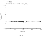
- the results showed that without the activation, the activated NiFeBa/NF anode prepared in this example stably worked for 30 h in a high-concentration stimulated seawater solution containing 1 M NaOH and 2.5M NaCl.
- the anodes in example 1-example 8 were respectively utilized to electrolyze the stimulated seawater in example 7 to produce hydrogen.
- the hydrogen evolution efficiencies were respectively 0.272, 0.268, 0.271, 0.265, 0.267, 0.270, 0.273 and 0.266 L/h.
- the anodes in comparative example 1-comparative example 3 were respectively utilized to electrolyze the stimulated seawater in example 1 to produce hydrogen.
- the hydrogen evolution efficiencies were respectively 0.257, 0.251 and 0.254 L/h.
- the inventor also used a commercial nickel network, commercial foam iron and commercial foam nickel iron as conducting substrates to replace foam nickel in example 1-example 8 to prepare NiFeBa/NF anodes, and the stability and electrolytic hydrogen production efficiency of these NiFeBa/NF anodes were tested according to the methods that were the same as those in example 1-example 8.
- the test results show these NiFeBa/NF anodes exhibit excellent stability and relatively high electrolytic hydrogen production electrolysis efficiency.
- Example 9 A preparation method of a NiFeCa/NF anode is basically the same as that in example 3 only except that barium nitrate was replaced with calcium nitrate.
- Example 9-1 A preparation method of a NiFeCa/NF anode is basically the same as that in example 3-1 only except that barium nitrate was replaced with calcium nitrate.
- Example 10 A preparation method of a NiFeSr/NF anode is basically the same as that in example 3 only except that barium nitrate was replaced with strontium nitrate.
- Example 10-1 A preparation method of a NiFeSr/NF anode is basically the same as that in example 3-1 only except that barium nitrate was replaced with strontium nitrate.
- Performance test was performed on the anodes in example 9, example 9-1, example 10 and example 10-1 by referring to the methods in example 3 and example 3-1. The results are seen in Table 1.
- Table 1 Performance test results of anodes in example 9, example 9-1, example 10 and example 10-1 Example Test environment Stability 9 0.5 M NaOH+2.5 M NaCl+0.25 M Na 2 SO 4 13 h 9-1 0.5 M NaOH+2.5 M NaCl+0.25 M Na 2 SO 4 20 h 10 0.5 M NaOH+2.5 M NaCl+0.25 M Na 2 SO 4 16 h 10-1 0.5 M NaOH+2.5 M NaCl+0.25 M Na 2 SO 4 22 h
- the catalyst for hydrogen production by electrolysis provided in the present disclosure enables the surface of the anode for hydrogen production by electrolysis to have higher resistance to chloride ions, which can significantly delay the corrosion of the conductive substrate and catalyst by chloride ions in seawater electrolysis, and thus enable the anode to have excellent stability in the electrolysis hydrogen production process of chlorine-containing aqueous solutions, especially in the hydrogen production by electrolysis reaction in seawater.
- the NiFeBa/NF, NiFeCa/NF, NiFeSr/NF oxygen evolution catalysts and the like densely coated on the conducting substrate were prepared by a simple hydrothermal method, non-precious metals were used as a catalyst metal source with the advantage of low cost, and the service life of the anode for hydrogen production by electrolysis was significantly prolonged.
Landscapes
- Chemical & Material Sciences (AREA)
- Organic Chemistry (AREA)
- Engineering & Computer Science (AREA)
- Chemical Kinetics & Catalysis (AREA)
- Electrochemistry (AREA)
- Materials Engineering (AREA)
- Metallurgy (AREA)
- Inorganic Chemistry (AREA)
- Catalysts (AREA)
- Electrolytic Production Of Non-Metals, Compounds, Apparatuses Therefor (AREA)
- Electrodes For Compound Or Non-Metal Manufacture (AREA)
Applications Claiming Priority (3)
| Application Number | Priority Date | Filing Date | Title |
|---|---|---|---|
| CN202310720257 | 2023-06-16 | ||
| CN202410452007.0A CN119144993B (zh) | 2023-06-16 | 2024-04-15 | 电解制氢催化剂、阳极及其制备方法、活化方法与应用 |
| PCT/CN2024/093372 WO2024255512A1 (zh) | 2023-06-16 | 2024-05-15 | 电解制氢催化剂、阳极及其制备方法、活化方法与应用 |
Publications (2)
| Publication Number | Publication Date |
|---|---|
| EP4560052A1 true EP4560052A1 (de) | 2025-05-28 |
| EP4560052A4 EP4560052A4 (de) | 2025-09-10 |
Family
ID=93814613
Family Applications (1)
| Application Number | Title | Priority Date | Filing Date |
|---|---|---|---|
| EP24822464.4A Pending EP4560052A4 (de) | 2023-06-16 | 2024-05-15 | Katalysator und anode zur elektrolytischen herstellung von wasserstoff und herstellungsverfahren dafür, aktivierungsverfahren dafür und verwendung davon |
Country Status (4)
| Country | Link |
|---|---|
| US (1) | US12454765B2 (de) |
| EP (1) | EP4560052A4 (de) |
| CN (1) | CN119144993B (de) |
| WO (1) | WO2024255512A1 (de) |
Families Citing this family (2)
| Publication number | Priority date | Publication date | Assignee | Title |
|---|---|---|---|---|
| CN119144993B (zh) * | 2023-06-16 | 2025-04-18 | 中国科学院宁波材料技术与工程研究所 | 电解制氢催化剂、阳极及其制备方法、活化方法与应用 |
| CN120291148B (zh) * | 2025-06-13 | 2025-08-29 | 安徽笃舜新能源装备制造有限公司 | 一种双金属磷化物耦合层状双氢氧化物电催化剂的制备方法和应用 |
Family Cites Families (19)
| Publication number | Priority date | Publication date | Assignee | Title |
|---|---|---|---|---|
| US5393722A (en) * | 1993-08-20 | 1995-02-28 | Uop | Hydrothermally stable metal oxide solid solutions |
| KR101130282B1 (ko) * | 2009-10-26 | 2012-03-26 | 이화여자대학교 산학협력단 | 층상형 금속 이중층 수산화물 변이체 세피오사이트 화합물 및 그의 제조방법 |
| CN102161526B (zh) * | 2011-03-04 | 2012-12-12 | 北京化工大学 | 氧化镁负载钴铁金属磁性纳米材料在降解废水中橙黄ⅱ的应用 |
| CN104607191B (zh) * | 2015-01-06 | 2017-02-22 | 中国科学院理化技术研究所 | 一种水滑石量子点电催化剂及其制备方法和电催化分解水产氧应用 |
| CN105177288B (zh) * | 2015-10-28 | 2018-04-03 | 中国科学院青海盐湖研究所 | 一种利用高镁锂比盐湖卤水制备氢氧化锂的方法 |
| CN106693978A (zh) * | 2016-12-30 | 2017-05-24 | 王艳 | 金属羟基氧化物催化剂、电极及制法与电化学电解装置 |
| CN108439556A (zh) * | 2018-03-12 | 2018-08-24 | 广东卓信环境科技股份有限公司 | 一种软化型次氯酸盐的现场制备方法 |
| WO2019193486A1 (en) * | 2018-04-04 | 2019-10-10 | Zolfaghar Rezvani | Oxidation of water using layered double hydroxide catalysts |
| US11913125B2 (en) | 2018-11-05 | 2024-02-27 | Newsouth Innovations Pty Limited | Trimetallic layered double hydroxide composition |
| CN111229232B (zh) | 2020-03-20 | 2023-10-31 | 苏州大学 | 泡沫镍基多孔NiFe水滑石纳米片及其制备和应用 |
| CN113355686B (zh) * | 2021-06-02 | 2022-04-19 | 宁波材料所杭州湾研究院 | 一种具有多层结构的纳米阵列材料、其制备方法与应用 |
| CN113912387A (zh) * | 2021-09-13 | 2022-01-11 | 安徽虹泰磁电有限公司 | 一种高性能稀土复配型永磁铁氧体材料及其制备方法 |
| CN114196971A (zh) * | 2022-01-04 | 2022-03-18 | 华东理工大学 | 一种用于电化学全解水的贵金属掺杂双金属磷化物催化剂的制备方法 |
| CN114808001B (zh) * | 2022-03-29 | 2023-04-18 | 宁波大学 | 一种Co掺杂NiCr-LDHs泡沫镍纳米片的制备方法及用途 |
| CN114657591B (zh) | 2022-03-30 | 2023-08-15 | 青岛科技大学 | 镍铁类水滑石/硫化镍铁异质结构海水氧化电催化剂及其制备方法 |
| CN115305481B (zh) * | 2022-08-26 | 2024-10-01 | 青岛科技大学 | 氧化铬功能化镍铁类水滑石纳米片及其制备方法和电催化应用 |
| CN116161704A (zh) * | 2023-02-14 | 2023-05-26 | 苏州大学 | 一种掺杂型镁铁水滑石及其制备方法与应用 |
| WO2024243644A1 (en) * | 2023-06-01 | 2024-12-05 | The University Of Adelaide | Hydrogen production from seawater |
| CN119144993B (zh) * | 2023-06-16 | 2025-04-18 | 中国科学院宁波材料技术与工程研究所 | 电解制氢催化剂、阳极及其制备方法、活化方法与应用 |
-
2024
- 2024-04-15 CN CN202410452007.0A patent/CN119144993B/zh active Active
- 2024-05-15 WO PCT/CN2024/093372 patent/WO2024255512A1/zh not_active Ceased
- 2024-05-15 US US19/104,715 patent/US12454765B2/en active Active
- 2024-05-15 EP EP24822464.4A patent/EP4560052A4/de active Pending
Also Published As
| Publication number | Publication date |
|---|---|
| WO2024255512A1 (zh) | 2024-12-19 |
| EP4560052A4 (de) | 2025-09-10 |
| CN119144993B (zh) | 2025-04-18 |
| CN119144993A (zh) | 2024-12-17 |
| US12454765B2 (en) | 2025-10-28 |
| US20250257483A1 (en) | 2025-08-14 |
Similar Documents
| Publication | Publication Date | Title |
|---|---|---|
| CN114452982B (zh) | 一种W18O49/CoO/CoWO4/NF自支撑电催化材料及其制备方法 | |
| CN114875442A (zh) | 一种钌修饰的钼镍纳米棒复合催化剂及其制备方法和应用 | |
| EP4560052A1 (de) | Katalysator und anode zur elektrolytischen herstellung von wasserstoff und herstellungsverfahren dafür, aktivierungsverfahren dafür und verwendung davon | |
| CN113445072A (zh) | 一种泡沫镍复合电极及其制备方法和应用 | |
| CN112080759B (zh) | 一种用于电催化氧化尿素的铋掺杂双金属硫化物电极的制备方法 | |
| CN111001428B (zh) | 一种无金属碳基电催化剂及制备方法和应用 | |
| CN116254569B (zh) | 一种用于阴离子交换膜水电解槽的普鲁士蓝类似物自支撑阳极及其制备方法 | |
| CN115505949A (zh) | 一种铱掺杂金属有机框架衍生材料及其制备方法与电催化析氧方面的应用 | |
| CN117512683A (zh) | 一种具有双相的铜基纳米催化剂及其制备方法与在电催化二氧化碳还原中的应用 | |
| CN118028880A (zh) | 一种镍钴双金属磷化物催化剂及其在电催化碱性生物质水溶液制氢中的应用 | |
| CN115896810A (zh) | 一种基于高熵效应的贵金属单原子催化剂及其制备方法 | |
| CN116837406A (zh) | 一种磷化镍基底负载铁钴氧化物电解海水析氧催化剂及制备和应用 | |
| CN112023922B (zh) | 一种Pt-MnO2材料及其制备方法和应用 | |
| CN118480805B (zh) | 平方米级不锈钢表面改性的双金属硫化一体式电极、制备方法及其应用 | |
| CN114892212B (zh) | 一种具有仿生活性域的硫掺杂镍基金属有机框架电极材料的制备方法及其产品和应用 | |
| CN117344344A (zh) | 一种泡沫镍原位生长的铬掺杂硫化镍铁阵列电催化剂及其制备方法和应用 | |
| CN116949492A (zh) | 一种镍锡复合物及其制备方法和应用 | |
| CN114717599A (zh) | 一种钌负载的镍金属三维碳球电催化剂及其制备方法和应用 | |
| CN121344668B (zh) | 一种仿酶CeO2基多活性位点催化剂及其制备方法和应用、电解池和电池 | |
| CN120818842B (zh) | 一种高熵反式钙钛矿催化剂及其制备方法和应用 | |
| CN119040932B (zh) | 一种阴离子交换膜电解槽催化电极的制备方法及其产品和应用 | |
| Song et al. | Construction of CuO/Co3O4 Heterojunction Catalyst for High‐Efficiency Ammonia Synthesis via Nitrate Reduction | |
| CN121044637A (zh) | 一种钴基尖晶石氧化物纳米材料及其制备方法和用途 | |
| CN121428598A (zh) | 一种硼掺杂镍铁层状双氢氧化物电催化阳极及其制备方法和应用 | |
| CN121874831A (zh) | 一种高熵层状双氢氧化物析氧催化剂的制备方法及其应用 |
Legal Events
| Date | Code | Title | Description |
|---|---|---|---|
| STAA | Information on the status of an ep patent application or granted ep patent |
Free format text: STATUS: THE INTERNATIONAL PUBLICATION HAS BEEN MADE |
|
| PUAI | Public reference made under article 153(3) epc to a published international application that has entered the european phase |
Free format text: ORIGINAL CODE: 0009012 |
|
| STAA | Information on the status of an ep patent application or granted ep patent |
Free format text: STATUS: REQUEST FOR EXAMINATION WAS MADE |
|
| 17P | Request for examination filed |
Effective date: 20250221 |
|
| AK | Designated contracting states |
Kind code of ref document: A1 Designated state(s): AL AT BE BG CH CY CZ DE DK EE ES FI FR GB GR HR HU IE IS IT LI LT LU LV MC ME MK MT NL NO PL PT RO RS SE SI SK SM TR |
|
| A4 | Supplementary search report drawn up and despatched |
Effective date: 20250813 |
|
| RIC1 | Information provided on ipc code assigned before grant |
Ipc: C25B 11/091 20210101AFI20250807BHEP Ipc: C25B 1/04 20210101ALI20250807BHEP Ipc: C25B 11/031 20210101ALI20250807BHEP Ipc: C25B 11/061 20210101ALI20250807BHEP Ipc: C25B 11/052 20210101ALI20250807BHEP Ipc: C25B 9/17 20210101ALI20250807BHEP Ipc: C01G 53/00 20250101ALI20250807BHEP Ipc: C01G 49/00 20060101ALI20250807BHEP |
|
| STAA | Information on the status of an ep patent application or granted ep patent |
Free format text: STATUS: EXAMINATION IS IN PROGRESS |