EP4556725A2 - Abhängevorrichtung zum abhängen von gegenständen - Google Patents
Abhängevorrichtung zum abhängen von gegenständen Download PDFInfo
- Publication number
- EP4556725A2 EP4556725A2 EP23020215.2A EP23020215A EP4556725A2 EP 4556725 A2 EP4556725 A2 EP 4556725A2 EP 23020215 A EP23020215 A EP 23020215A EP 4556725 A2 EP4556725 A2 EP 4556725A2
- Authority
- EP
- European Patent Office
- Prior art keywords
- ceiling
- screw
- suspension
- receptacle
- suspension device
- Prior art date
- Legal status (The legal status is an assumption and is not a legal conclusion. Google has not performed a legal analysis and makes no representation as to the accuracy of the status listed.)
- Pending
Links
Images


Classifications
-
- F—MECHANICAL ENGINEERING; LIGHTING; HEATING; WEAPONS; BLASTING
- F21—LIGHTING
- F21V—FUNCTIONAL FEATURES OR DETAILS OF LIGHTING DEVICES OR SYSTEMS THEREOF; STRUCTURAL COMBINATIONS OF LIGHTING DEVICES WITH OTHER ARTICLES, NOT OTHERWISE PROVIDED FOR
- F21V21/00—Supporting, suspending, or attaching arrangements for lighting devices; Hand grips
- F21V21/02—Wall, ceiling, or floor bases; Fixing pendants or arms to the bases
-
- F—MECHANICAL ENGINEERING; LIGHTING; HEATING; WEAPONS; BLASTING
- F16—ENGINEERING ELEMENTS AND UNITS; GENERAL MEASURES FOR PRODUCING AND MAINTAINING EFFECTIVE FUNCTIONING OF MACHINES OR INSTALLATIONS; THERMAL INSULATION IN GENERAL
- F16B—DEVICES FOR FASTENING OR SECURING CONSTRUCTIONAL ELEMENTS OR MACHINE PARTS TOGETHER, e.g. NAILS, BOLTS, CIRCLIPS, CLAMPS, CLIPS OR WEDGES; JOINTS OR JOINTING
- F16B13/00—Dowels or other devices fastened in walls or the like by inserting them in holes made therein for that purpose
- F16B13/04—Dowels or other devices fastened in walls or the like by inserting them in holes made therein for that purpose with parts gripping in the hole or behind the reverse side of the wall after inserting from the front
- F16B13/08—Dowels or other devices fastened in walls or the like by inserting them in holes made therein for that purpose with parts gripping in the hole or behind the reverse side of the wall after inserting from the front with separate or non-separate gripping parts moved into their final position in relation to the body of the device without further manual operation
- F16B13/0808—Dowels or other devices fastened in walls or the like by inserting them in holes made therein for that purpose with parts gripping in the hole or behind the reverse side of the wall after inserting from the front with separate or non-separate gripping parts moved into their final position in relation to the body of the device without further manual operation by a toggle-mechanism
-
- F—MECHANICAL ENGINEERING; LIGHTING; HEATING; WEAPONS; BLASTING
- F16—ENGINEERING ELEMENTS AND UNITS; GENERAL MEASURES FOR PRODUCING AND MAINTAINING EFFECTIVE FUNCTIONING OF MACHINES OR INSTALLATIONS; THERMAL INSULATION IN GENERAL
- F16B—DEVICES FOR FASTENING OR SECURING CONSTRUCTIONAL ELEMENTS OR MACHINE PARTS TOGETHER, e.g. NAILS, BOLTS, CIRCLIPS, CLAMPS, CLIPS OR WEDGES; JOINTS OR JOINTING
- F16B35/00—Screw-bolts; Stay-bolts; Screw-threaded studs; Screws; Set screws
- F16B35/04—Screw-bolts; Stay-bolts; Screw-threaded studs; Screws; Set screws with specially-shaped head or shaft in order to fix the bolt on or in an object
- F16B35/06—Specially-shaped heads
-
- F—MECHANICAL ENGINEERING; LIGHTING; HEATING; WEAPONS; BLASTING
- F16—ENGINEERING ELEMENTS AND UNITS; GENERAL MEASURES FOR PRODUCING AND MAINTAINING EFFECTIVE FUNCTIONING OF MACHINES OR INSTALLATIONS; THERMAL INSULATION IN GENERAL
- F16B—DEVICES FOR FASTENING OR SECURING CONSTRUCTIONAL ELEMENTS OR MACHINE PARTS TOGETHER, e.g. NAILS, BOLTS, CIRCLIPS, CLAMPS, CLIPS OR WEDGES; JOINTS OR JOINTING
- F16B9/00—Connections of rods or tubular parts to flat surfaces at an angle
- F16B9/05—Connections of rods or tubular parts to flat surfaces at an angle by way of an intermediate member
- F16B9/054—Connections of rods or tubular parts to flat surfaces at an angle by way of an intermediate member the intermediate member being threaded
Definitions
- the invention relates to a suspension device for suspending objects, such as lights, from a ceiling, comprising a ceiling-side receiving part and a suspension means, such as a suspension rope, which can be fastened to the latter.
- Suspension devices are used to suspend various objects from ceilings. Suspension is usually achieved using ropes, chains, rods, and the like. Suspension devices are used, for example, for suspending individual luminaires or decorative elements, track systems, strip lights, and multi-part lighting structures, as well as luminaires combined with decorative elements, such as crystals, glass bodies, etc., which do not contain a light source themselves but together form an object.
- a ceiling-side support piece is attached to the ceiling, to which the suspension element has already been attached or to which the suspension element is attached after the ceiling has been attached.
- the attachment of the ceiling-side support piece is usually carried out as a surface-mounted installation using suitable fastening materials, such as screws.
- suitable fastening materials such as screws.
- the advantage of surface-mounted installation is that it is easy to carry out using commonly available tools.
- the disadvantage is that such ceiling-side support pieces are perceived as aesthetically disturbing, as they contradict the concept of suspended systems based on visual lightness and inconspicuousness.
- the surface-mounted arrangement of several support pieces or a single, but correspondingly large-area recording part has a detrimental aesthetic effect.
- the ceiling-side receiving element is designed as a plasterboard element or as part of it.
- a plasterboard element is installed, for example, in a recess in a plasterboard ceiling and then fixed flush with the surface by applying plastering material, thus avoiding any components protruding from the ceiling.
- the receiving element is flush with the ceiling and therefore aesthetically a significant improvement over surface-mounted installation, it is still visible.
- the present invention therefore aims to further develop a suspension device of the type mentioned at the outset in such a way that it meets the highest aesthetic requirements and only the suspension means, such as the suspension cable, is visible.
- the invention provides for a suspension device of the type mentioned above, in which the ceiling-side receiving part is designed as a screw-in part which can be sunk into the ceiling and which has a downwardly open receptacle, and in which the suspension means has a fastening piece which can be inserted into the receptacle from below. Due to the fact that the ceiling-side receiving part is designed as a screw-in part which can be sunk into the ceiling, it can be fastened to the ceiling by a simple screwing process and can be screwed in so far that it is sunk into the ceiling, i.e. opposite the room-side The recessed surface of the ceiling is recessed.
- the cavity created by the recess can be filled with plastering compound, thus achieving a flush ceiling finish.
- the plastering compound is applied around the suspension element hanging from the support element, leaving a hole whose dimensions are adapted to the suspension element. Viewed from below, only the suspension element emerging from the hole is visible.
- the screw-in part is preferably provided with an external, at least partially helical structure which, when screwed in around a rotation axis, causes the screw-in part to penetrate into the ceiling in the direction of the rotation axis.
- the ceiling-side receiving part has a downwardly open receptacle, the fastening piece of the suspension device can be inserted into the receiving part already mounted in the ceiling and secured there.
- the ceiling-side receiving part can therefore be screwed into the ceiling while the suspension device is not yet attached, so that screwing can be carried out using a screwing-in tool applied from below without being impaired by the suspension device.
- the ceiling-side receiving part preferably has a tool receptacle, such as a hexagon socket, a Phillips head, or the like, on a downward-facing end face for the positive engagement of a screwing-in tool.
- the fastening piece in the receptacle of the ceiling-side receiving part provides that the receptacle and the fastening piece have connecting means that interact with one another.
- the connecting means can preferably be designed to produce a threaded connection, a magnetic connection or a material connection.
- the connecting means of the screw-in part preferably has a blind hole with an internal thread formed in the receptacle.
- the fastening piece of the suspension means has a corresponding external thread, which can be screwed from below into the internal thread of the screw-in part.
- the threaded connection can preferably be provided with a chemical thread locking agent in crystalline form, which liquefies during screwing and solidifies into an adhesive after screwing to form the chemical thread locking agent.
- a material connection between the fastening piece and the ceiling-side receiving part can be achieved, for example, by means of a suitable adhesive.
- a snap-in connection can be provided in which a spring-mounted part can snap into a snap-in position in which the fastening piece of the suspension means is held in the receptacle of the receiving part by positive locking.
- the ceiling-side receiving part can have an expanding inner part, which is deformed by a pressing part of the suspension means after being driven in, e.g. by means of a slotted punch, in a force-fitting and form-fitting manner.
- the ceiling-side receiving part can be equipped with a self-locking mechanism, into which only the bare end of the rope has to be inserted from below, where it is locked, e.g. according to the principle of self-locking.
- the suspension means In order to be attached to the ceiling-side receiving part, the suspension means requires a holding part at its end which is rigidly connected to the suspension means, for example by pressing on, welding or soldering.
- the holding part defines the tensile load of the suspension means.
- the holding part can be formed by the above-mentioned fastening piece or represent a component separate from the fastening piece.
- the holding part is equipped with connecting means for attaching the holding part to the ceiling-side receiving part and can, for example, be designed as a cylindrical threaded piece with two opposite blind holes as a drive for screwing in or as a cylinder with a bayonet link on the cylinder surface.
- the holding element arranged at the end of the suspension means forms a contact surface for the separate fastening piece of the suspension means.
- the fastening piece can, for example, be designed as a threaded sleeve which can be threaded onto the suspension means, such as the suspension cable, and on which the holding part together with the suspension means and the load hanging thereon is supported via the said contact surface.
- the ceiling-side receiving part can be adapted to the respective ceiling structure and, for example, be designed differently for screwing into a hollow ceiling than for screwing into a solid ceiling.
- the screw-in part is designed as a screw with an external thread for screwing into the ceiling or a dowel arranged in the ceiling.
- the screw-in part can be designed as a stud screw, which is provided with a receptacle for the suspension device in a preferably threadless end area.
- the end area has essentially the same outer diameter as the screw shaft with the external thread, so that the stud screw does not have a widened screw head. This means that the screw-in part can be countersunk into the ceiling when screwed in.
- the suspension device After countersinking the screw-in part, the suspension device is secured in the receptacle of the screw-in part and then filler is applied around the suspension device so that visually only the suspension device, such as the suspension cable, which comes out of the ceiling is visible.
- the screw-in part can have an undercut at the end so that the filler bonds positively to the ceiling.
- the screw is designed according to an embodiment not according to the invention such that the external thread is formed on a screw head of the screw.
- the external thread can, for example, be designed as a self-tapping thread, which, when screwed into the ceiling, turns in the usually relatively
- the external thread can be adapted to the ceiling material in terms of its shape and pitch and is preferably similar to the thread of a drywall screw for plasterboard or a wood screw. If the external thread is cylindrical, it can have at least one pocket to accommodate ceiling material that accrues when the thread is cut into the ceiling panel.
- a screw drive such as a TORX T40 drive
- a blind thread can extend deeper than the screw drive into the screw head, which serves as the receptacle for the suspension attachment piece.
- the component height of the screw head is preferably matched to the panel thickness of the suspended ceiling, in particular slightly less than the panel thickness.
- an embodiment not according to the invention provides for a tilt anchor to be screwed onto a screw shaft provided with an external thread.
- the screw shaft has a (significantly) smaller diameter than the screw head.
- the tilt anchor is intended to be inserted into the cavity behind the suspended ceiling in order to support itself there on the area of the suspended ceiling surrounding the drill hole and thus engage behind the suspended ceiling.
- a tilt anchor In order to be able to insert the anchor through the drill hole into the cavity, it is known as a tilt anchor. After being inserted into the cavity, the tilt anchor is pivoted 90° relative to the screw shaft. The tilt anchor, which is attached to the screw shaft by a threaded connection, is then pulled toward the back of the suspended ceiling by turning the screw until the screw is tightened.
- An advantageous design provides for the external thread on the screw head and the external thread on the screw shaft to have the same thread pitch. This simultaneously tightens the toggle anchor as described above when the screw is turned, while simultaneously screwing the screw head into the suspended ceiling.
- installation is carried out by first turning the screw until the toggle anchor rests against the back of the suspended ceiling.
- the screw is then further turned or driven, preferably with a power tool such as a cordless screwdriver with a slip clutch, so that the external thread on the screw head screws itself into the ceiling panel and connects with it.
- the toggle anchor is "under tension.”
- the toggle anchor is preferably designed as a U-shaped profile so that, when the toggle anchor is attached to the screw shaft, it requires little space for insertion through the drill hole in the suspended ceiling.
- the design is preferably such that, when the toggle anchor is attached, the screw shaft lies between the legs of the U-shaped toggle anchor.
- a profile other than a U-profile can be used, which can be tightened in the ceiling cavity to the Ceiling slab is pulled.
- another clamping device can be provided, such as a structure that unfolds or expands when the screw is turned.
- the cable suspension of the present invention can alternatively also be used to anchor a diagonally or horizontally tensioned cable to a ceiling, wall, floor, or room divider.
- the anchoring system according to the invention to anchor vertically tensioned cables, e.g., fall protection cables for railings.
- Thin threaded rods or rods with threaded ends could also be attached to a ceiling, wall, or floor in this way.
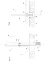
- Fig. 1 a screw for a solid ceiling as part of a suspension device
- Fig. 2 a view of the screw head of the Fig. 1
- Fig. 3 the screw according to Fig. 1 in a state screwed into the ceiling
- Fig. 4 an enlarged view of the Fig. 3
- Fig. 5 a screw for a hollow ceiling during the assembly process according to an embodiment not according to the invention
- Fig. 6 the screw according to Fig. 5 in assembled condition
- Fig. 7 a detailed view of a suspension rope with fastening piece
- Fig. 8 a representation of the suspension rope according to Fig. 7 in assembled condition
- Fig. 9 an alternative fastening of the suspension cable in the ceiling-side receiving part before installation
- Fig. 10 the execution according to Fig. 9 in assembled condition.
- Fig. 1 shows a ceiling-side screw-in part in the form of a stud screw 1, which has a threaded screw shaft 2 and a threadless end section 3.
- the end section 3 comprises a downwardly open receptacle 4, which is designed as a blind bore with an internal thread.
- a screw drive 5 is incorporated centrally into the end section 3, for example in a TORX design as shown in Fig. 2 is shown.
- a suspension cable 10 is fastened in the holder 4 by means of a fastening piece 12.
- the fastening piece 12 is designed as a threaded sleeve that is pushed onto the suspension cable 10 and whose external thread is screwed into the internal thread of the blind bore 4.
- the suspension cable has a rigidly attached holding element 11 at its end, which is supported from above on the fastening piece 12, namely the threaded sleeve.
- the free space created by the offset 9 can be filled with a plastering compound, so that from below only the suspension cable 10 emerging from the ceiling is visible.
- Figs. 5 and 6 show a non-inventive embodiment of the screw-in part for a hollow ceiling 13.
- the screw-in part comprises a screw 14, which has a screw head 15 and a screw shaft 16.
- the screw head 15 is formed with an external thread, which during installation is screwed into a drilled hole 17 formed in the ceiling 13.
- the screw shaft 16 also has an external thread, onto which a drum 18 is screwed, which forms a pivot bearing for the tilting anchor 19.
- the tilting anchor 19 is accordingly shown in the figure according to the arrow 20.
- the tilting anchor 19 is preferably U-shaped in cross section, so that the screw shaft 16 can be pivoted in the position shown in Fig. 5 shown position of the tilting anchor 19 lies between the two legs of the U-shape.
- the screw shaft 16 is inserted together with the tilt anchor 19 through the drill hole 17 into the cavity behind the ceiling, as shown in Fig. 5 is shown.
- the screw 14 is turned in the screwing direction, e.g. by engaging the hexagon socket 22, whereby the toggle anchor 19 is pulled towards the back of the ceiling 13 according to the arrow 21, while the screw head 15 has not yet penetrated into the drill hole 17.
- the toggle anchor 19 rests against the back of the ceiling 13
- further screwing in of the screw 14 causes the screw head 15 to be pulled towards the drill hole 17 and screwed into the drill hole 17, whereby the external thread of the screw head 15 and the external thread of the screw shaft 19 have the same thread pitch.
- the screw head 15 is fixed in the ceiling in this way, whereby as in the design according to the Fig. 1-4 An offset 9 can be provided to cover the screw head with a plastering compound when screwed in. Before plastering, however, the suspension cable 10 is secured with the aid of of the fastening piece 12 in a receptacle formed in the screw head 15, which can be done in the same way as for the Fig. 1-4 explained.
- the suspension cable 10 has a holding element 11 at its end, which is rigidly attached to it, e.g. by a press fit, by welding or soldering or the like.
- a threaded sleeve 12 is arranged, which is screwed into the internal thread of the blind hole formed in the screw head 23.
- the threaded sleeve can have a screw drive on the front side, ie on the underside.
- the screw head 23 can, analogously to the design according to the Figs. 5 and 6 , be part of a screw including the screw shaft, or alternatively represent the screw-in part according to the invention in itself. In the latter case, the interaction of the external thread of the screw-in part 23 with the drilled hole in the ceiling alone provides the required holding forces.
- the screw-in part is also formed only by a screw-head-like part 24.
- the suspension cable 10 is fastened here by means of a press fit between a fastening part designed as a press part 25 at the end of the cable 10, which, when driven in by means of a slotted punch, for example, deforms a spreading inner part 26 in a force-fitting and form-fitting manner.
Landscapes
- Engineering & Computer Science (AREA)
- General Engineering & Computer Science (AREA)
- Mechanical Engineering (AREA)
- Installation Of Indoor Wiring (AREA)
- Supports Or Holders For Household Use (AREA)
- Joining Of Building Structures In Genera (AREA)
- Dowels (AREA)
- Supports For Pipes And Cables (AREA)
- Load-Engaging Elements For Cranes (AREA)
Abstract
Description
- Die Erfindung betrifft eine Abhängevorrichtung zum Abhängen von Gegenständen, wie z.B. Leuchten, von einer Raumdecke, umfassend ein deckenseitiges Aufnahmeteil und ein an diesem befestigbares Abhängemittel, wie z.B. ein Abhängeseil.
- Abhängevorrichtungen dienen dem Abhängen von verschiedenen Gegenständen von Raumdecken, wobei die Abhängung meist unter Verwendung von Seilen, Ketten, Stangen und dgl. erfolgt. Abhängevorrichtungen werden beispielswiese für das Abhängen von Einzel-Leuchten oder dekorativen Einzelelementen, Stromschienen, Lichtbändern und mehrteiligen Lichtstrukturen, aber auch von Leuchten in Kombinationen mit dekorativen Elementen, wie z.B. Kristallen, Glaskörpern, etc., die selbst kein Leuchtmittel/Lichtquelle enthalten, aber in Summe ein Objekt bilden, verwendet.
- Bei herkömmlichen Abhängesystemen wird an der Decke ein deckenseitiges Aufnahmeteil befestigt, an dem das Abhängemittel bereits zuvor befestigt wurde oder an dem das Abhängemittel nach erfolgter Deckenbefestigung angebracht wird. Die Anbringung des deckenseitigen Aufnahmeteils erfolgt üblicherweise als Aufputzinstallation mit Hilfe geeigneter Befestigungsmittel, wie z.B. Schrauben. Der Vorteil der Aufputzmontage ist die einfache Durchführung mit Hilfe allgemein verfügbarer Werkzeuge. Nachteilig jedoch ist, dass solche deckenseitigen Aufnahmeteile hinsichtlich ihrer Ästhetik als störend empfunden werden, da sie dem auf optischer Leichtigkeit und Unauffälligkeit beruhenden Konzept abgehängter Systeme widersprechen. Insbesondere bei Abhängungen, die eine Mehrzahl von Abhängeseilen und eine dementsprechende Mehrzahl von deckenseitigen Befestigungspunkten erfordern, entsteht durch die Aufputzanordnung von mehreren Aufnahmeteilen oder eines einzigen, jedoch entsprechend großflächigen Aufnahmeteils eine nachteilige ästhetische Wirkung.
- Alternativ sind Befestigungssysteme bekannt geworden, bei denen das deckenseitige Aufnahmeteil als Einputzelement oder als Teil desselben ausgebildet ist. Ein solches Einputzelement wird beispielsweise in einer Ausnehmung einer Gipskartondecke angeordnet und danach durch Anbringen von Verputzmaterial flächenbündig fixiert, sodass von der Decke vorstehende Bauteile vermieden werden. Das Aufnahmeteil ist zwar deckenbündig angeordnet und daher in ästhetischer Hinsicht eine deutliche Verbesserung gegenüber einer Aufputzmontage, aber weiterhin sichtbar. Wünschenswert wäre es jedoch, wenn die Abhängemittel direkt aus der Raumdecke kommen würden, sodass das Aufnahmeteil völlig unsichtbar ist.
- Die vorliegende Erfindung zielt daher darauf ab, eine Abhängevorrichtung der eingangs genannten Art dahingehend weiterzubilden, dass es höchsten ästhetischen Ansprüchen genügt und lediglich das Abhängemittel, wie z.B. das Abhängeseil sichtbar ist.
- Zur Lösung dieser Aufgabe sieht die Erfindung bei einer Abhängevorrichtung der eingangs genannten Art vor, dass das deckenseitige Aufnahmeteil als in die Decke versenkbares Einschraubteil ausgebildet ist, welches eine nach unten offene Aufnahme aufweist, und dass das Abhängemittel ein Befestigungsstück aufweist, welches von unten in die Aufnahme einführbar ist. Dadurch, dass das deckenseitige Aufnahmeteil als in die Decke versenkbares Einschraubteil ausgebildet ist, kann dieses durch einen einfachen Eindrehvorgang in der Decke befestigt und dabei soweit eingedreht werden, dass es in die Decke versenkt wird, d.h. gegenüber der raumseitigen Oberfläche der Decke zurückversetzt ist. Der durch den Rücksprung entstehende Hohlraum kann durch Verputzmasse gefüllt und dadurch ein deckenbündiger Abschluss erreicht werden. Die Verputzmasse wird dabei um das vom Aufnahmeteil herabhängende Abhängemittel herum aufgebracht, sodass die Verputzmasse ein Loch freilässt, dessen Abmessungen dem Abhängemittel angepasst ist. Von unten betrachtet ist hierbei lediglich das aus dem Loch kommende Abhängemittel sichtbar.
- Um das Eindrehen in die Decke zu ermöglichen, ist das Einschraubteil vorzugsweise mit einer außenliegenden, zumindest abschnittsweise schraubenlinienförmigen Struktur versehen, die beim Eindrehen um eine Drehachse ein Eindringen des Einschraubteils in Richtung der Drehachse in die Decke bewirkt.
- Dadurch, dass das deckenseitige Aufnahmeteil eine nach unten offene Aufnahme aufweist, kann das Befestigungsstück des Abhängemittels in das bereits in die Decke montierte Aufnahmeteil eingeführt und dort befestigt werden. Das Eindrehen des deckenseitigen Aufnahmeteils in die Decke kann daher in einem Zustand erfolgen, in dem das Abhängemittel noch nicht angebracht ist, sodass das Eindrehen mit Hilfe eines von unten angesetzten Eindrehwerkzeugs erfolgen kann, ohne dass dies durch das Abhängemittel beeinträchtigt wird. Bevorzugt weist das deckenseitige Aufnahmeteil zu diesem Zweck an einer nach unten gerichteten Stirnfläche eine Werkzeugaufnahme, wie z.B. einen Innensechskant, einen Kreuzschlitz, oder dgl., zum formschlüssigen Eingreifen eines Eindrehwerkzeugs auf.
- Für das Befestigen des Befestigungsstücks in der Aufnahme des deckenseitigen Aufnahmeteils ist gemäß einer bevorzugten Ausführungsform vorgesehen, dass die Aufnahme und das Befestigungsstück miteinander zusammenwirkende Verbindungsmittel aufweisen.
- Die Verbindungsmittel können hierbei bevorzugt zur Herstellung einer Gewindeverbindung, einer magnetischen Verbindung oder einer stoffschlüssigen Verbindung ausgebildet sein.
- Für die Ausbildung einer Gewindeverbindung weist das Verbindungsmittel des Einschraubteils bevorzugt ein in der Aufnahme ausgebildetes Sackloch mit einem Innengewinde auf. Das Befestigungsstück des Abhängemittels weist in diesem Fall ein korrespondierendes Außengewinde auf, welches von unten in das Innengewinde des Einschraubteils eingedreht werden kann. Die Gewindeverbindung kann vorzugsweise mit einer chemischen Gewindesicherung in kristalliner Form versehen sein, die sich beim Eindrehen verflüssigt und sich nach erfolgtem Eindrehen zur Ausbildung der chemischen Gewindesicherung zu einem Kleber verfestigt.
- Eine stoffschlüssige Verbindung des Befestigungsstücks mit dem deckenseitigen Aufnahmeteil kann beispielsweise mittels eines geeigneten Klebstoffs erreicht werden.
- Alternativ kann auch eine Rastverbindung vorgesehen sein, bei der ein federnd angeordneter Teil in eine Rastposition schnappen kann, in der das Befestigungsstück des Abhängemittels durch Formschluss in der Aufnahme des Aufnahmeteils gehalten wird.
- Alternativ kann das deckenseitige Aufnahmeteil einen Spreiz-Innenteil aufweisen, der durch einen Pressteil des Abhängemittels nach dem Einschlagen mittels eines z.B. geschlitzten Durchschlages kraft- und formschlüssig verformt wird.
- Weiters kann das deckenseitige Aufnahmeteil mit einer selbstverriegelnden Mechanik ausgestattet sein, in welche lediglich das bloße Seilende von unten eingeschoben werden muss, wo es verriegelt wird, z.B. nach dem Prinzip der Selbsthemmung.
- Für die Befestigung an dem deckenseitigen Aufnahmeteil benötigt das Abhängemittel an seinem Ende ein Halteteil, das mit dem Abhängemittel starr verbunden ist, wie z.B. durch Aufpressen, Verschweißen oder Löten. Das Halteteil definiert hierbei die Zuglast des Abhängemittels. Das Halteteil kann von dem oben genannten Befestigungsstück gebildet sein oder ein von Befestigungsstück gesondertes Bauteil darstellen. Im ersten Fall ist das Halteteil mit Verbindungsmitteln zum Befestigen des Halteteils an dem deckenseitigen Aufnahmeteil ausgestattet und kann beispielsweise als zylindrisches Gewindestück mit zwei gegenüber liegenden Sacklöchern als Antrieb zum Eindrehen oder als Zylinder mit einer Bajonett-Kulisse an der Zylinderfläche ausgebildet sein. Im zweiten Fall kann bevorzugt vorgesehen sein, dass das am Ende des Abhängemittels angeordnete Halteelement eine Anlagefläche für das gesonderte Befestigungsstück des Abhängemittels ausbildet. Das Befestigungsstück kann beispielsweise als auf das Abhängemittel, wie z.B. das Abhängeseil, auffädelbare Gewindehülse ausgebildet sein, auf welcher das Halteteil samt dem Abhängemittel und der daran hängenden Last über die genannte Anlagefläche abgestützt ist.
- Das deckenseitige Aufnahmeteil kann an den jeweiligen Deckenaufbau angepasst sein und beispielsweise für das Einschrauben in eine Hohldecke anders ausgebildet sein als für das Einschrauben in eine Massivdecke.
- Im Fall einer Massivdecke ist das Einschraubteil als Schraube mit einem Außengewinde zum Einschrauben in die Raumdecke oder einen in der Raumdecke angeordneten Dübel ausgebildet. Insbesondere kann das Einschraubteil hierbei als Stiftschraube ausgebildet sein, die in einem bevorzugt gewindelosen Endbereich mit der Aufnahme für das Abhängemittel versehen ist. Der Endbereich weist dabei im Wesentlichen denselben Außendurchmesser auf wie der mit dem Außengewinde versehene Schraubenschaft, sodass die Stiftschraube keinen verbreiterten Schraubenkopf aufweist. Dies führt dazu, dass das Einschraubteil beim Eindrehen in die Decke versenkt werden kann. Nach dem Versenken des Einschraubteils wird das Abhängemittel in der Aufnahme des Einschraubteils befestigt und im Anschluss daran wird um das Abhängemittel herum gespachtelt, sodass optisch nur mehr das Abhängemittel, wie z.B. das Abhängeseil zu sehen ist, welches aus der Decke kommt. Das Einschraubteil kann hierfür am Abschluss eine Hinterschneidung aufweisen, damit sich die Spachtelmasse formschlüssig mit der Decke verbindet.
- Im Fall einer Hohldecke, wie z.B. einer abgehängten Gipskartondecke, ist die Schraube gemäß einer nicht erfindungsgemäßen Ausführungsform derart ausgebildet, dass das Außengewinde an einem Schraubenkopf der Schraube ausgebildet ist. Das Außengewinde kann hierbei beispielswiese als selbstschneidendes Gewinde ausgebildet sein, das sich beim Eindrehen in die Decke in dem üblicherweise relativ weichen Material der Zwischendecke verankert. Das Außengewinde kann hinsichtlich seiner Ausformung und auch Steigung auf das Deckenmaterial abgestimmt sein und ist vorzugsweise ähnlich dem Gewinde einer Trockenbauschraube für Gipskarton oder dem einer Holzschraube ausgebildet. Für den Fall, dass das Außengewinde zylindrisch ist, kann es mindestens eine Tasche zur Aufnahme von Deckenmaterial aufweisen, das beim Schneiden des Gewindes in die Deckenplatte anfällt.
- Für das Einschrauben der Schraube in die Zwischendecke ist in den Schraubenkopf bevorzugt zentrisch ein Schraubenantrieb eingearbeitet, wie z.B. ein TORX T40-Antrieb. Tiefer als der Schraubenantrieb kann hierbei ein Sackgewinde in den Schraubenkopf gehen, welches die Aufnahme für das Befestigungsstück des Abhängungsmittels bildet.
- Die Bauteilhöhe des Schraubenkopfes ist vorzugsweise auf die Plattenstärke der Zwischendecke abgestimmt, insbesondere etwas geringer als die Plattenstärke gewählt.
- Um einen zusätzlichen Halt des Einschraubteils in der Zwischendecke zu erreichen, sieht eine nicht erfindungsgemäße Ausführungsform vor, dass auf einen mit einem Außengewinde versehenen Schraubenschaft der Schraube ein Kippanker aufgeschraubt ist. Der Schraubenschaft weist hierbei einen (wesentlich) geringeren Durchmesser als der Schraubenkopf auf. Der Kippanker ist dazu vorgesehen, in den hinter der Zwischendecke liegenden Hohlraum eingebracht zu werden, um sich dort an dem das Bohrloch umgebenden Bereich der Zwischendecke abzustützen und die Zwischendecke auf diese Weise gleichsam zu hintergreifen. Um den Anker durch das Bohrloch in den Hohlraum einführen zu können, ist dieser wie an sich bekannt als Kippanker ausgeführt. Der Kippanker wird nach erfolgtem Einführen in den Hohlraum um 90° relativ zum Schraubenschaft verschwenkt. Danach wird der Kippanker, der mittels einer Gewindeverbindung am Schraubenschaft befestigt ist, durch Drehen der Schraube an die Rückseite der Zwischendecke herangezogen, bis die Schraube festgezogen ist.
- Eine vorteilhafte Ausführung sieht hierbei vor, dass das am Schraubenkopf ausgebildete Außengewinde und das am Schraubenschaft ausgebildete Außengewinde dieselbe Gewindesteigung aufweisen. Dies führt beim Drehen der Schraube gleichzeitig zu dem oben beschriebenen Festspannen des Kippankers und zu einem Eindrehen des Schraubenkopfes in die Zwischendecke. Insbesondere erfolgt die Montage dabei derart, dass die Schraube zuerst soweit gedreht wird, bis der Kippanker an der Rückseite der Zwischendecke anliegt, und dann weiter gedreht bzw. angetrieben wird, vorzugsweise mit einem Elektro-Handwerkzeug wie einem Akkuschrauber mit Rutschkupplung, sodass sich das am Schraubenkopf ausgebildete Außengewinde selbst in die Deckenplatte einschraubt und sich mit dieser verbindet. Gleichzeitig geht der Kippanker "auf Zug".
- Der Kippanker ist bevorzugt als U-Profil ausgebildet, damit der Kippanker im an den Schraubenschaft angelegten Zustand für das Einführen durch das Bohrloch der Zwischendecke wenig Platz benötigt. Die Ausbildung ist dabei bevorzugt so getroffen, dass der Schraubenschaft im angelegten Zustand des Kippankers zwischen die Schenkel der U-Form des Kippankers zu liegen kommt.
- Alternativ kann auch ein anderes Profil als ein U-Profil verwendet werden, das durch Anziehen im Deckenhohlraum an die Deckenplatte gezogen wird. Alternativ kann statt eines Kippankers ein anderes Spannmittel vorgesehen sein, wie z.B. eine sich bei Drehung der Schraube auffaltende oder aufspreizende Struktur.
- Die Seilabhängung der vorliegenden Erfindung kann alternativ auch dazu verwendet werden, um ein schräg oder horizontal gespanntes Seil an einer Decke, einer Wand, einem Boden oder einem Raumtrennelement eines Raums zu verankern. Weiters ist es denkbar, das erfindungsgemäße Verankerungssystem zur Verankerung von senkrecht gespannten Seilen, z.B. Seile als Absturzsicherungen bei Geländern, einzusetzen. Es könnten in dieser Art auch dünne Gewindestangen oder Stäbe mit Gewindeabschluss an einer Decke, Wand oder am Boden befestigt werden.
- Die Erfindung wird nachfolgend anhand eines in der Zeichnung dargestellten Ausführungsbeispiels näher erläutert. In dieser zeigen
Fig. 1 eine Schraube für eine Massivdecke als Teil einer Abhängevorrichtung,Fig. 2 eine Ansicht des Schraubenkopfes derFig. 1, Fig. 3 die Schraube gemäßFig. 1 in einem in die Decke eingeschraubten Zustand,Fig. 4 eine vergrößerte Ansicht derFig. 3 ,Fig. 5 eine Schraube für eine Hohldecke während des Montagevorgangs gemäß einer nicht erfindungsgemäßen Ausführungsform,Fig. 6 die Schraube gemäßFig. 5 in montiertem Zustand,Fig. 7 eine Detailansicht eines Abhängeseils mit Befestigungsstück,Fig. 8 eine Darstellung des Abhängeseils gemäßFig. 7 in montiertem Zustand,Fig. 9 eine alternative Befestigung des Abhängeseils im deckenseitigen Aufnahmeteil vor der Montage undFig. 10 die Ausführung gemäßFig. 9 in montiertem Zustand. -
Fig. 1 zeigt ein deckenseitiges Einschraubteil in Form einer Stiftschraube 1, die einen mit einem Gewinde versehenen Schraubenschaft 2 und einen gewindelosen Endabschnitt 3 aufweist. Der Endabschnitt 3 umfasst eine nach unten offene Aufnahme 4, welche als Sackbohrung mit Innengewinde ausgeführt ist. Weiters ist in den Endabschnitt 3 zentrisch ein Schraubenantrieb 5 eingearbeitet, beispielsweise in einer TORX-Ausführung wie dies inFig. 2 dargestellt ist. - In
Fig. 3 ist die unter Oberfläche einer Raumdecke mit 6 bezeichnet, wobei in die Massivdecke ein Bohrloch 7 eingebracht wurde. Im Bohrloch 7 ist ein Dübel 7 angeordnet, der gegenüber der Deckenfläche 6 zurückversetzt ist. In den Dübel wurde die Stiftschraube 1 eingedreht, und zwar so weit, dass sie ebenfalls gegenüber der Deckenfläche einen Versatz 9 aufweist. Weiters ist inFig. 3 ersichtlich, dass ein Abhängeseil 10 mit Hilfe eines Befestigungsstücks 12 in der Aufnahme 4 befestigt ist. - In der Detaildarstellung gemäß
Fig. 4 ist erkennbar, dass das Befestigungsstück 12 als Gewindehülse ausgebildet ist, die auf das Abhängeseil 10 aufgeschoben ist und deren Außengewinde in das Innengewinde der Sackbohrung 4 geschraubt ist. Das Abhängeseil weist an seinem Ende ein starr angebrachtes Halteelement 11 auf, welches sich von oben auf dem Befestigungsstück 12, nämlich der Gewindehülse, abstützt. Der durch der Versatz 9 entstandene Freiraum kann mit einer Verputzmasse verfüllt werden, sodass von unten nur mehr das aus der Decke kommende Abhängeseil 10 sichtbar ist. -
Fig. 5 und 6 zeigen eine nicht erfindungsgemäße Ausführung des Einschraubteils für eine Hohldecke 13. Das Einschraubteil umfasst eine Schraube 14, die einen Schraubenkopf 15 und einen Schraubenschaft 16 aufweist. Der Schraubenkopf 15 ist mit einem Außengewinde ausgebildet, welches bei der Montage in ein in die Decke 13 ausgebildetes Bohrloch 17 eingedreht wird. Der Schraubenschaft 16 weist ebenfalls ein Außengewinde auf, auf welches eine Trommel 18 aufgeschraubt ist, welche ein Drehlager für den Kippanker 19 ausbildet. Der Kippanker 19 ist demgemäß entsprechend dem Pfeil 20 aus der inFig. 5 dargestellten, an den Schraubenschaft 16 angelegten Position in die inFig. 6 dargestellte Position verschwenkbar. Der Kippanker 19 ist im Querschnitt bevorzugt U-förmig ausgebildet, sodass der Schraubenschaft 16 in der inFig. 5 dargestellten Lage des Kippankers 19 zwischen die beiden Schenkel der U-Form zu liegen kommt. - Der Schraubenschaft 16 wird gemeinsam mit dem Kippanker 19 durch das Bohrloch 17 in den hinter der Decke vorhandenen Hohlraum eingeführt, wie dies in
Fig. 5 dargestellt ist. Nach einer 90°-Verschwenkung des Kippankers wird die Schraube 14 z.B. durch Eingriff in den Innensechskant 22 in Einschraubrichtung gedreht, wodurch der Kippanker 19 entsprechend dem Pfeil 21 zur Rückseite der Decke 13 gezogen wird, während der Schraubenkopf 15 noch nicht in das Bohrloch 17 eindringt. Sobald der Kippanker 19 an der Rückseite der Decke 13 anliegt, bewirkt ein weiteres Eindrehen der Schraube 14 ein Heranziehen des Schraubenkopfes 15 zum Bohrloch 17 und ein Eindrehen des Schraubenkopfes 15 in das Bohrloch 17, wobei das Außengewinde des Schraubenkopfes 15 und das Außengewinde des Schraubenschafts 19 dieselbe Gewindesteigung aufweisen. Der Schraubenkopf 15 wird auf diese Weise in der Decke fixiert, wobei wie bei der Ausführung gemäß denFig. 1-4 ein Versatz 9 vorgesehen sein kann, um den Schraubenkopf im eingeschraubten Zustand mit einer Verputzmasse zu bedecken. Vor dem Verputzen wird jedoch das Abhängeseil 10 mit Hilfe des Befestigungsstücks 12 in einer im Schraubenkopf 15 ausgebildeten Aufnahme befestigt, was auf die gleiche Weise erfolgen kann wie zu denFig. 1-4 erläutert. - In den
Fig. 7 und 8 ist die Befestigung des Abhängeseils 10 gesondert dargestellt. Das Abhängeseil 10 weist an seinem Ende ein Halteelement 11 auf, welches starr an diesem angebracht ist, z.B. durch einen Presssitz, durch Schweißen oder Löten oder dgl. Unterhalb des Halteelements ist eine Gewindehülse 12 angeordnet, welche in das Innengewinde des im Schraubenkopf 23 ausgebildeten Sacklochs eingeschraubt wird. Zur Erleichterung des Einschraubvorgangs kann die Gewindehülse stirnseitig, d.h. an der Unterseite einen Schraubenantrieb aufweisen. Der Schraubenkopf 23 kann, analog zu der Ausbildung gemäß denFig. 5 und 6 , Teil einer Schraube samt Schraubenschaft sein oder alternativ für sich selbst das erfindungsgemäße Einschraubteil darstellen. Im letzteren Fall stellt das Zusammenwirken des Außengewindes des Einschraubteils 23 mit dem Bohrloch der Decke alleine die erforderlichen Haltekräfte bereit. - Bei der Ausführung gemäß den
Fig. 9 und 10 ist das Einschraubteil ebenfalls nur von einem schraubenkopfartigen Teil 24 gebildet. Die Befestigung des Abhängeseils 10 erfolgt hier mit Hilfe einen Pressitzes zwischen einem als Pressteil 25 ausgebildeten Befestigungsteil am Ende des Seils 10, der beim Einschlagen mittels eines z.B. geschlitzten Durchschlages kraft- und formschlüssig einen Spreiz-Innenteil 26 verformt.
Claims (7)
- Abhängevorrichtung zum Abhängen von Gegenständen, wie z.B. Leuchten, von einer Raumdecke, umfassend ein deckenseitiges Aufnahmeteil und ein an diesem befestigbares Abhängemittel (10), wie z.B. ein Abhängeseil, dadurch gekennzeichnet, dass das deckenseitige Aufnahmeteil als in die Decke versenkbares Einschraubteil (1, 23, 24) ausgebildet ist, welches als Schraube (1) mit einem Außengewinde zum Einschrauben in die Raumdecke (13) oder einen in der Raumdecke angeordneten Dübel (8) ausgebildet ist und eine nach unten offene Aufnahme (4, 26) aufweist, und dass das Abhängemittel (10) ein Befestigungsstück (12, 25) aufweist, welches von unten in die Aufnahme (4, 26) einführbar ist.
- Abhängevorrichtung nach Anspruch 1, dadurch gekennzeichnet, dass die Aufnahme (4, 26) und das Befestigungsstück (12, 25) miteinander zusammenwirkende Verbindungsmittel aufweisen.
- Abhängevorrichtung nach Anspruch 2, dadurch gekennzeichnet, dass die Verbindungsmittel zur Herstellung einer Gewindeverbindung, einer magnetischen Verbindung oder einer stoffschlüssigen Verbindung ausgebildet sind.
- Abhängevorrichtung nach Anspruch 2, dadurch gekennzeichnet, dass das Abhängemittel (10) an seinem Ende ein Halteelement (11) aufweist, welches eine Anlagefläche für das Verbindungsmittel bzw. das Befestigungsstück (12) des Abhängemittels (10) ausbildet.
- Abhängevorrichtung nach einem der Ansprüche 1 bis 4, dadurch gekennzeichnet, dass das Verbindungsmittel des Einschraubteils (1, 23) ein in der Aufnahme (4) ausgebildetes Sackloch mit einem Innengewinde aufweist.
- Abhängevorrichtung nach einem der Ansprüche 1 bis 5, dadurch gekennzeichnet, dass das Einschraubteil als Stiftschraube (1) ausgebildet ist, die in einem gewindelosen Endbereich (3) mit der Aufnahme (4) für das Abhängemittel (10) versehen ist.
- Einschraubteil (1, 23, 24), welches eine nach unten offene Aufnahme (4, 26) aufweist, zur Verwendung in einer Abhängevorrichtung gemäß den Ansprüchen 1 bis 6.
Priority Applications (1)
| Application Number | Priority Date | Filing Date | Title |
|---|---|---|---|
| EP23020215.2A EP4556725A3 (de) | 2021-02-22 | 2021-02-22 | Abhängevorrichtung zum abhängen von gegenständen |
Applications Claiming Priority (2)
| Application Number | Priority Date | Filing Date | Title |
|---|---|---|---|
| EP21020082.0A EP4047265B1 (de) | 2021-02-22 | 2021-02-22 | Abhängevorrichtung zum abhängen von gegenständen |
| EP23020215.2A EP4556725A3 (de) | 2021-02-22 | 2021-02-22 | Abhängevorrichtung zum abhängen von gegenständen |
Related Parent Applications (1)
| Application Number | Title | Priority Date | Filing Date |
|---|---|---|---|
| EP21020082.0A Division EP4047265B1 (de) | 2021-02-22 | 2021-02-22 | Abhängevorrichtung zum abhängen von gegenständen |
Publications (2)
| Publication Number | Publication Date |
|---|---|
| EP4556725A2 true EP4556725A2 (de) | 2025-05-21 |
| EP4556725A3 EP4556725A3 (de) | 2025-08-27 |
Family
ID=74673005
Family Applications (2)
| Application Number | Title | Priority Date | Filing Date |
|---|---|---|---|
| EP23020215.2A Pending EP4556725A3 (de) | 2021-02-22 | 2021-02-22 | Abhängevorrichtung zum abhängen von gegenständen |
| EP21020082.0A Active EP4047265B1 (de) | 2021-02-22 | 2021-02-22 | Abhängevorrichtung zum abhängen von gegenständen |
Family Applications After (1)
| Application Number | Title | Priority Date | Filing Date |
|---|---|---|---|
| EP21020082.0A Active EP4047265B1 (de) | 2021-02-22 | 2021-02-22 | Abhängevorrichtung zum abhängen von gegenständen |
Country Status (4)
| Country | Link |
|---|---|
| EP (2) | EP4556725A3 (de) |
| CN (1) | CN117043511A (de) |
| ES (1) | ES2963930T3 (de) |
| WO (1) | WO2022175922A1 (de) |
Family Cites Families (8)
| Publication number | Priority date | Publication date | Assignee | Title |
|---|---|---|---|---|
| US5746556A (en) * | 1995-03-13 | 1998-05-05 | Kabushiki Kaisha Youma Kohboh | Anchor unit with expansive anchor member expanded by utilizing turning force of bolt |
| US8764364B2 (en) * | 2004-03-24 | 2014-07-01 | Illinois Tool Works Inc. | System and methods for wall and ceiling fastening |
| CA2502044A1 (en) * | 2005-03-21 | 2006-09-21 | Cobra Fixations Cie Ltee. - Cobra Anchors Co. Ltd. | Anchor assembly for fastener |
| JP5453503B1 (ja) * | 2012-10-11 | 2014-03-26 | パナソニック株式会社 | 光源ユニット及び照明器具 |
| CN205824902U (zh) * | 2016-06-28 | 2016-12-21 | 浙江火蓝鑫光电科技有限公司 | 便于固定与悬挂的警示灯 |
| KR20180097020A (ko) * | 2017-02-22 | 2018-08-30 | 현대플러스 주식회사 | 쉽게 간격을 조절할 수 있는 창호 프레임 고정용 고정구 |
| CN210291602U (zh) * | 2019-04-11 | 2020-04-10 | 成都佰人佰思科技有限公司 | 一种便于减震的吊灯固定装置 |
| KR102183879B1 (ko) * | 2020-05-07 | 2020-11-27 | 이순석 | 너트식 앙카볼트 |
-
2021
- 2021-02-22 ES ES21020082T patent/ES2963930T3/es active Active
- 2021-02-22 EP EP23020215.2A patent/EP4556725A3/de active Pending
- 2021-02-22 EP EP21020082.0A patent/EP4047265B1/de active Active
-
2022
- 2022-02-22 CN CN202280016380.0A patent/CN117043511A/zh active Pending
- 2022-02-22 WO PCT/IB2022/051549 patent/WO2022175922A1/de not_active Ceased
Also Published As
| Publication number | Publication date |
|---|---|
| EP4047265B1 (de) | 2023-08-02 |
| WO2022175922A1 (de) | 2022-08-25 |
| CN117043511A (zh) | 2023-11-10 |
| EP4047265A1 (de) | 2022-08-24 |
| ES2963930T3 (es) | 2024-04-03 |
| EP4556725A3 (de) | 2025-08-27 |
Similar Documents
| Publication | Publication Date | Title |
|---|---|---|
| DE69101016T2 (de) | Fugenausbildungsvorrichtung für das Befestigen der blockförmigen Platten auf Seitenmauern eines Gebäudes. | |
| DE8715256U1 (de) | Montageschieneneinheit | |
| DE8601106U1 (de) | Einstellbare Befestigungsvorrichtung zum Zusammenfügen von zwei Bauteilen | |
| EP0206327B1 (de) | Vorrichtung zum Verbinden von Rohren | |
| EP2923011B1 (de) | Kombination mit einem anker für plattenförmige bauteile sowie befestigungsanordnung | |
| EP2185827B1 (de) | Montageschraube und befestigungsanordnung mit einem hohlkammerprofil | |
| DE1801913A1 (de) | Anordnung von Beschlagteilen in Profilrahmen von Fenstern,Tueren od.dgl. | |
| EP3540160B1 (de) | Befestigungsanordnung zum befestigen eines türbandes an einem hohlkammer-profil | |
| DE3430332A1 (de) | Verankerungsvorrichtung zum befestigen eines teiles an einer wand | |
| EP4047265B1 (de) | Abhängevorrichtung zum abhängen von gegenständen | |
| EP0626522B1 (de) | Kippdübel | |
| DE19959254C1 (de) | Vorrichtung zur Befestigung von Wand- und/oder Deckenelementen | |
| DE19522044A1 (de) | Eck- oder T-Verbindung an Rahmen oder Gestellen | |
| DE3611873A1 (de) | Befestigungselement zum verstellbaren befestigen von bauelementen an bauwerken | |
| EP3792416B1 (de) | Befestigungsvorrichtung | |
| EP3473779A1 (de) | Verbindungselement mit feststellelement sowie verfahren zum feststellen des verbindungselements | |
| DE102004005328A1 (de) | Spezialschraube | |
| EP0666426A1 (de) | Spreizbolzen | |
| DE2417541A1 (de) | Befestigungselement zur verankerung in bauwerksteilen | |
| DE3515416A1 (de) | Scharnier fuer tueren mit ueberschlag | |
| EP0646730A2 (de) | Vorrichtung und deren Anwendung zur Befestigung eines Gegenstands an einer Wand | |
| DE102008015045B4 (de) | Vorrichtung zur Installation von elektrischen Leuchten an Decken von Gebäuden | |
| AT405561B (de) | Plattenbefestigungselement | |
| EP0666965A1 (de) | Verbindung zwischen zwei oder mehreren profilelementen oder zwischen montageteilen und einem oder mehreren profilelementen. | |
| DE20318823U1 (de) | Seilfixiervorrichtung |
Legal Events
| Date | Code | Title | Description |
|---|---|---|---|
| PUAI | Public reference made under article 153(3) epc to a published international application that has entered the european phase |
Free format text: ORIGINAL CODE: 0009012 |
|
| STAA | Information on the status of an ep patent application or granted ep patent |
Free format text: STATUS: THE APPLICATION HAS BEEN PUBLISHED |
|
| AC | Divisional application: reference to earlier application |
Ref document number: 4047265 Country of ref document: EP Kind code of ref document: P |
|
| AK | Designated contracting states |
Kind code of ref document: A2 Designated state(s): AL AT BE BG CH CY CZ DE DK EE ES FI FR GB GR HR HU IE IS IT LI LT LU LV MC MK MT NL NO PL PT RO RS SE SI SK SM TR |
|
| REG | Reference to a national code |
Ref country code: DE Ref legal event code: R079 Free format text: PREVIOUS MAIN CLASS: F16B0013000000 Ipc: F21V0021020000 |
|
| PUAL | Search report despatched |
Free format text: ORIGINAL CODE: 0009013 |
|
| AK | Designated contracting states |
Kind code of ref document: A3 Designated state(s): AL AT BE BG CH CY CZ DE DK EE ES FI FR GB GR HR HU IE IS IT LI LT LU LV MC MK MT NL NO PL PT RO RS SE SI SK SM TR |
|
| RIC1 | Information provided on ipc code assigned before grant |
Ipc: F21V 21/02 20060101AFI20250718BHEP Ipc: F16B 13/00 20060101ALI20250718BHEP Ipc: F16B 9/00 20060101ALI20250718BHEP Ipc: F16B 13/08 20060101ALI20250718BHEP |
|
| STAA | Information on the status of an ep patent application or granted ep patent |
Free format text: STATUS: REQUEST FOR EXAMINATION WAS MADE |
|
| 17P | Request for examination filed |
Effective date: 20260227 |