EP4552606A2 - Zahnärztliches handstück - Google Patents
Zahnärztliches handstück Download PDFInfo
- Publication number
- EP4552606A2 EP4552606A2 EP25166408.2A EP25166408A EP4552606A2 EP 4552606 A2 EP4552606 A2 EP 4552606A2 EP 25166408 A EP25166408 A EP 25166408A EP 4552606 A2 EP4552606 A2 EP 4552606A2
- Authority
- EP
- European Patent Office
- Prior art keywords
- movable pieces
- treatment tool
- dental treatment
- divided movable
- peripheral surface
- Prior art date
- Legal status (The legal status is an assumption and is not a legal conclusion. Google has not performed a legal analysis and makes no representation as to the accuracy of the status listed.)
- Pending
Links
Images


Classifications
-
- A—HUMAN NECESSITIES
- A61—MEDICAL OR VETERINARY SCIENCE; HYGIENE
- A61C—DENTISTRY; APPARATUS OR METHODS FOR ORAL OR DENTAL HYGIENE
- A61C1/00—Dental machines for boring or cutting ; General features of dental machines or apparatus, e.g. hand-piece design
- A61C1/02—Dental machines for boring or cutting ; General features of dental machines or apparatus, e.g. hand-piece design characterised by the drive of the dental tools
- A61C1/05—Dental machines for boring or cutting ; General features of dental machines or apparatus, e.g. hand-piece design characterised by the drive of the dental tools with turbine drive
-
- A—HUMAN NECESSITIES
- A61—MEDICAL OR VETERINARY SCIENCE; HYGIENE
- A61C—DENTISTRY; APPARATUS OR METHODS FOR ORAL OR DENTAL HYGIENE
- A61C1/00—Dental machines for boring or cutting ; General features of dental machines or apparatus, e.g. hand-piece design
- A61C1/08—Machine parts specially adapted for dentistry
- A61C1/14—Tool-holders, i.e. operating tool holders, e.g. burr holders
- A61C1/142—Operating tool blocking means
- A61C1/144—Operating tool blocking means constricting the operating tool, e.g. chuck
-
- A—HUMAN NECESSITIES
- A61—MEDICAL OR VETERINARY SCIENCE; HYGIENE
- A61B—DIAGNOSIS; SURGERY; IDENTIFICATION
- A61B17/00—Surgical instruments, devices or methods
- A61B17/16—Instruments for performing osteoclasis; Drills or chisels for bones; Trepans
- A61B17/1613—Component parts
- A61B17/162—Chucks or tool parts which are to be held in a chuck
-
- A—HUMAN NECESSITIES
- A61—MEDICAL OR VETERINARY SCIENCE; HYGIENE
- A61C—DENTISTRY; APPARATUS OR METHODS FOR ORAL OR DENTAL HYGIENE
- A61C1/00—Dental machines for boring or cutting ; General features of dental machines or apparatus, e.g. hand-piece design
- A61C1/08—Machine parts specially adapted for dentistry
- A61C1/14—Tool-holders, i.e. operating tool holders, e.g. burr holders
- A61C1/141—Tool-holders, i.e. operating tool holders, e.g. burr holders in an angled handpiece
-
- A—HUMAN NECESSITIES
- A61—MEDICAL OR VETERINARY SCIENCE; HYGIENE
- A61C—DENTISTRY; APPARATUS OR METHODS FOR ORAL OR DENTAL HYGIENE
- A61C1/00—Dental machines for boring or cutting ; General features of dental machines or apparatus, e.g. hand-piece design
- A61C1/08—Machine parts specially adapted for dentistry
- A61C1/14—Tool-holders, i.e. operating tool holders, e.g. burr holders
- A61C1/142—Operating tool blocking means
-
- A—HUMAN NECESSITIES
- A61—MEDICAL OR VETERINARY SCIENCE; HYGIENE
- A61C—DENTISTRY; APPARATUS OR METHODS FOR ORAL OR DENTAL HYGIENE
- A61C1/00—Dental machines for boring or cutting ; General features of dental machines or apparatus, e.g. hand-piece design
- A61C1/08—Machine parts specially adapted for dentistry
- A61C1/14—Tool-holders, i.e. operating tool holders, e.g. burr holders
- A61C1/145—Instruments or accessories for tool holders
-
- A—HUMAN NECESSITIES
- A61—MEDICAL OR VETERINARY SCIENCE; HYGIENE
- A61C—DENTISTRY; APPARATUS OR METHODS FOR ORAL OR DENTAL HYGIENE
- A61C3/00—Dental tools or instruments
- A61C3/02—Tooth drilling or cutting instruments; Instruments acting like a sandblast machine
Definitions
- the present disclosure relates to a dental handpiece.
- An air turbine handpiece that cuts an affected part by a rotational force of an air turbine, and a motor handpiece that cuts an affected part by a driving force of a motor are known as dental handpieces.
- Each of these dental handpieces holds a dental treatment tool by a chuck mechanism housed in a head portion, and cuts the affected part by rotating the dental treatment tool at a high speed.
- JP3126887B discloses a configuration in which the dental treatment tool (chucked member) is chucked by a ball that protrudes and retracts in a radial direction from a tubular chuck shaft.
- JP2006-122080A discloses a holding mechanism including: a tubular tool holding member that holds the dental treatment tool; a tapered member that is disposed outside the tool holding member; and a coil spring that biases the tool holding member upward.
- Slits are formed at three locations along a circumferential direction of the tool holding member, and small pieces are fitted into the respective slits. An outer peripheral surface of each of the small pieces comes into contact with the tapered member when the tool holding member receives a biasing force from the coil spring, and each small piece is pushed inward in a radial direction due to a wedge effect of a tapered surface. As a result, each small piece engages with the dental treatment tool, and the dental treatment tool is held in the tool holding member.
- the dental treatment tool is locally gripped by the ball, so that problems arise that wear easily occurs and a gripping force is easily reduced.
- a gripping force on the dental treatment tool depends on a frictional force of the tapered surface. Therefore, when a particularly strong vibration is, for example, applied to the tapered surface during cutting, a gap may be created between the dental treatment tool and the small piece, and the dental treatment tool may drop out of the tool holding member. Since the tapered member is thin-walled, a gradient of a taper is shallow, and biting on the tapered surface easily occurs. As a result, attachment and detachment failures of the dental treatment tool easily occur.
- an object of the present disclosure is to provide a dental handpiece capable of improving wear resistance of a chuck mechanism and always stably holding a dental treatment tool regardless of a cutting condition.
- the present disclosure has the following configuration.
- a dental handpiece configured to rotatably drive a dental treatment tool mounted in a chuck mechanism includes the chuck mechanism in which the dental treatment tool is mounted so as to be attachable and detachable.
- the chuck mechanism includes:
- At least one of the outer peripheral surface of each of the plurality of divided movable pieces and the inner peripheral surface of the cylindrical slide member comes into contact with the other of the outer peripheral surface of each of the plurality of divided movable pieces and the inner peripheral surface of the cylindrical slide member via a tapered fitting portion having a gradient in the axial direction, and the divided movable pieces are moved in a radial direction by relative movement between each of the divided movable pieces and the cylindrical slide member in the axial direction, so that fixation of the dental treatment tool and release of the fixation are performed.
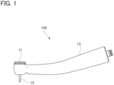
- Fig. 1 is an overall view of a dental handpiece 100 according to the present disclosure.
- the dental handpiece 100 includes a head portion 11 and a grip portion 13 that extends rearward from the head portion 11.
- the head portion 11 includes a chuck mechanism which will be described in detail later and in which a dental treatment tool 15 is mounted so as to be attachable and detachable, and rotatably drives the dental treatment tool 15 mounted in the chuck mechanism.
- a grip portion is provided with an air supply passage (not shown) and an exhaust passage (not shown) for compressed air, the dental treatment tool 15 is rotatably driven by the compressed air supplied from the air supply passage, and the compressed air used for driving is discharged through the exhaust passage.
- Fig. 2 is a schematic cross-sectional view of the head portion 11 of the dental handpiece 100 shown in Fig. 1 .
- an insertion and extraction direction of the dental treatment tool 15 when the dental treatment tool 15 is mounted in the head portion 11 is also referred to as an up and down direction or an insertion direction
- a front in the insertion direction is also referred to as an upper side
- a rear in the insertion direction is also referred to as a lower side.
- the head portion 11 is formed by being surrounded by: a head housing 21 that is connected to the grip portion 13 and covers an outer periphery of the head portion 11; a head cap 23 that covers an upper portion of the head housing 21 and is fixed to the head housing 21; and a push button 25 that covers a top of the head cap 23.
- a biasing spring 27 is provided between the push button 25 and the head cap 23, and the biasing spring 27 biases the push button 25 upward.
- a cartridge case 29 is housed inside the head housing 21.
- the cartridge case 29 is fixed integrally with the head housing 21 by assembling the head cap 23 from above the head housing 21.
- Outer rings 33 of a pair of rolling bearings 31A and 31B are fixed to an inner peripheral side of the cartridge case 29.
- Inner rings 35 of the rolling bearings 31A and 31B are fitted with an outer peripheral surface of a hollow cylindrical sleeve 37.
- the sleeve 37 is rotatably supported by the rolling bearings 31A and 31B, and the dental treatment tool 15 is inserted into the sleeve.
- a rotor 39 is fixed between the rolling bearing 31A and the rolling bearing 31B on the sleeve 37.
- the rotor 39 is a rotating body including a turbine blade, generates a rotational force by the compressed air supplied into the cartridge case 29, and rotatably drives the sleeve 37. That is, the sleeve 37 is supported by the head housing 21 and the cartridge case 29 through the rolling bearings 31A and 31B, so that the sleeve 37 rotates with the rotational force generated by the rotor 39 as a drive source.
- the sleeve 37 includes a small diameter portion 37a and a large diameter portion 37b on an inner peripheral surface thereof.
- a coil spring 41 which serves as an elastic biasing member that biases a cylindrical slide member 45 forward in the insertion direction of the dental treatment tool 15, is disposed at a lower end of the large diameter portion 37b.
- the coil spring 41 has an inner diameter that allows the dental treatment tool 15 to be inserted through the coil spring 41 along an axis Lc of the sleeve 37, and has a configuration in which space efficiency is improved in the sleeve 37.
- a chuck mechanism 43 to be described below includes the sleeve 37 and members housed in the large diameter portion 37b of the sleeve 37.
- Fig. 3 is a partially enlarged cross-sectional view showing the chuck mechanism 43 housed in the sleeve 37.
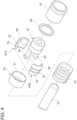
- Fig. 4 is an exploded view showing the members constituting the chuck mechanism 43.
- the same members or the same locations are denoted by the same reference numerals, so that descriptions thereof will be omitted or simplified.
- the chuck mechanism 43 mainly includes the sleeve 37, the cylindrical slide member 45, a plurality of (two in the configuration) divided movable pieces 47A and 47B, the coil spring 41 described above, and a stopper unit 49 (see Fig. 3 ).
- the cylindrical slide member 45 is housed in the sleeve 37 so as to be movable in an axial direction of the sleeve 37, and includes, on an inner peripheral surface thereof, a first tapered surface 51 whose diameter increases upward (forward in the insertion direction of the dental treatment tool 15).
- the divided movable pieces 47A and 47B each include, on an outer peripheral surface thereof, a second tapered surface 53 that comes into sliding contact with the first tapered surface 51.
- the pair of divided movable pieces 47A and 47B are disposed so as to face each other in a diameter direction of the sleeve 37, and may independently rotate in the sleeve 37 together with a pusher 61 which will be described later.
- the stopper unit 49 includes a cylindrical fixing member 57 that includes a third tapered surface 55 (third tapered surface) on an inner peripheral surface thereof, and a fourth tapered surface 59 provided on each of the divided movable pieces 47A and 47B. These tapered surfaces each have a gradient in a direction of the axis Lc, thereby functioning as tapered fitting portions that convert movement of the divided movable pieces 47A and 47B in the direction of the axis Lc into movement of the divided movable pieces 47A and 47B in a radial direction. As will be described in detail later, the stopper unit 49 is at least partially fixed to the sleeve 37, and restricts forward axial movement of the divided movable pieces 47A and 47B in the insertion direction.
- the pusher 61 which is moved by the push button 25 that is pressed down when the dental treatment tool 15 is to be detached from the chuck mechanism 43, is disposed above the divided movable pieces 47A and 47B.
- the pusher 61 includes a pair of push pieces 63 that extend toward the cylindrical slide member 45 through circumferential gaps between the divided movable pieces 47A and 47B.
- An annular restriction ring 65 fixed to the sleeve 37 is disposed below the cylindrical fixing member 57 (at a rear end portion thereof in the insertion direction of the dental treatment tool 15).
- the restriction ring 65 is held between a stepped portion 38 formed on the inner peripheral surface of the sleeve 37 and a lower end of the cylindrical fixing member 57.
- Fig. 5 is a perspective view of the divided movable pieces 47A and 47B.
- the divided movable pieces 47A and 47B are disposed at different circumferential positions in the sleeve 37, and have the same shape.
- the divided movable pieces 47A and 47B each include the outer peripheral surface that comes into contact with the inner peripheral surface of the cylindrical slide member 45, and an inner peripheral surface that comes into contact with an outer peripheral surface of the dental treatment tool 15 inserted into the sleeve 37, and the divided movable pieces 47A and 47B are disposed such that the dental treatment tool 15 is held therebetween.
- the second tapered surface 53 and the fourth tapered surface 59 which are gradually reduced in radius of an outer peripheral surface outward in the axial direction, are formed on one end side and the other end side of each of the divided movable pieces 47A and 47B in the axial direction.
- a recessed groove 67 along a circumferential direction is formed between the second tapered surface 53 and the fourth tapered surface 59.
- a groove wall 69 on a second tapered surface 53 side and a groove wall 71 on a fourth tapered surface 59 side are formed by the recessed groove 67.
- the restriction ring 65 is inserted into the recessed groove 67.
- a cutout portion 60 which gradually increases in radius of an inner peripheral surface outward in the axial direction, is formed at at least one end portion of the inner peripheral surface of each of the divided movable pieces 47A and 47B.
- Each of the divided movable pieces 47A and 47B shown here has a symmetrical shape in which a plane passing through an axial center and perpendicular to the axial direction is used as a symmetry plane. Since the divided movable piece has the symmetrical shape, it is not necessary to consider directionality of the divided movable piece when the chuck mechanism 43 is assembled, and assembling workability may be improved.
- Fig. 6 is a perspective view showing a state after the members shown in Fig. 4 are assembled.
- the cylindrical fixing member 57 is not shown.
- a tip end of each of the push pieces 63 disposed between the pair of divided movable pieces 47A and 47B is in contact with the cylindrical slide member 45.
- the push button 25 down see Fig. 3
- the cylindrical slide member 45 is moved along the axis Lc against an elastic force of the coil spring 41.
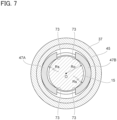
- Fig. 7 is a cross-sectional view taken along a line VII-VII shown in Fig. 3 .
- a radius Rs of the inner peripheral surface of each of the divided movable pieces 47A and 47B is smaller than a radius R0 of the outer peripheral surface of the gripped dental treatment tool 15 (Rs ⁇ R0).
- Rs ⁇ R0 the radius of the outer peripheral surface of the gripped dental treatment tool 15
- each of circumferential end portions 73 of the inner peripheral surface of each of the divided movable pieces 47A and 47B comes into line contact with the outer peripheral surface of the dental treatment tool 15.
- the circumferential end portions 73 are easy to elastically bite into the dental treatment tool 15, and reliable chucking of the dental treatment tool 15 may be realized.
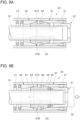
- Figs. 8A to 8D are views stepwisely illustrating a process of performing the chucking operation by inserting a dental treatment tool into the chuck mechanism 43. Although illustration is simplified, rearward movement of the restriction ring 65 in the insertion direction is restricted by the stepped portion 38 provided on the inner peripheral surface of the sleeve 37 shown in Fig. 3 .
- the dental treatment tool 15 is inserted into the sleeve 37 in a direction of an arrow K, and as shown in Fig. 8C , a tip end of the dental treatment tool 15 is inserted into the inner peripheral surfaces of the divided movable pieces 47A and 47B.
- the tip end of the dental treatment tool 15 comes into contact with the chamfered portion 60 formed at the end portion of the inner peripheral surface of each of the divided movable pieces 47A and 47B, and the dental treatment tool 15 is inserted while the divided movable pieces 47A and 47B are pushed so as to be moved outward.
- Radial positions of the divided movable pieces 47A and 47B are adjusted by sliding of the first tapered surface 51 and the second tapered surface 53 and sliding of the fourth tapered surface 59 on the third tapered surface 55 which are associated with an insertion operation of the dental treatment tool 15.
- the divided movable pieces 47A and 47B are disposed at the radial positions corresponding to an outer diameter of the dental treatment tool 15. Since the divided movable pieces 47A and 47B are rotatably disposed in the sleeve 37, it becomes easy to match an outer peripheral surface of the dental treatment tool 15 and inner circumferential surfaces of the divided movable pieces 47A and 48B, and catching is less likely to occur when the dental treatment tool 15 is inserted.
- Figs. 9A to 9D are views stepwisely illustrating the operation of releasing the chucking of the dental treatment tool inserted into the chuck mechanism 43.
- the pusher 61 is moved in the direction opposite to the insertion direction of the dental treatment tool 15 by pressing the push button 25 down. Then, as described above, the pusher 61 and the cylindrical slide member 45 are moved in the direction opposite to the insertion direction against the biasing force of the coil spring 41, so that the divided movable pieces 47A and 47B are separated from the cylindrical slide member 45.
- the chucking of the dental treatment tool 15 is released and the dental treatment tool 15 may be extracted as shown in Fig. 9D .
- each of the divided movable pieces 47A and 47B and the inner peripheral surface of the cylindrical slide member 45 come into contact with each other via tapered fitting portions each having a gradient in the axial direction, and the divided movable pieces 47A and 47B are moved in the radial direction by relative movement between each of the divided movable pieces 47A and 47B and the cylindrical slide member 45 in the axial direction, so that fixation of the dental treatment tool 15 and release of the fixation are performed.
- the chuck mechanism 43 having the configuration may maintain reliable chucking without loosening the chucking of the dental treatment tool 15.
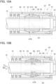
- Figs. 10A to 10C are views stepwisely illustrating an operation of the chuck mechanism when an external force is applied to the chuck mechanism 43.
- the chuck mechanism 43 always continues to chuck the dental treatment tool 15, and the chucking is not loosened.
- Fig. 11 is a schematic cross-sectional view showing a state where the dental treatment tool 15 is held between the divided movable pieces 47A and 47B.
- the clamping force Fc (see Figs. 8D and 10B ) due to tapered fitting described above is converted into a normal force Fn for chucking the dental treatment tool 15 via the divided movable piece 47A.
- a central angle ⁇ formed by connecting the pair of circumferential end portions 73 of each of the divided movable pieces 47A and 47B with a center O of the dental treatment tool 15 increases, the normal force Fn increases.
- the radius Rs of the inner peripheral surface of each of the divided movable pieces 47A and 47B that grip the dental treatment tool 15 is preferably smaller than the radius R0 of the outer peripheral surface of the dental treatment tool 15.
- the divided movable pieces 47A and 47B are formed to have the circumferential length that allows a circumferential length of at least one sixth or more, preferably one fourth or more, and more preferably one third or more of an outer periphery of the dental treatment tool 15 to be exposed. That is, the central angle ⁇ formed by connecting the pair of circumferential end portions 73 of each of the divided movable pieces 47A and 47B with a center O of the dental treatment tool 15 is preferably 165 degrees or less, more preferably 152.5 degrees or less, and further preferably 150 degrees or less.
- taper angle an angle formed by an axis of the sleeve 37 and a tapered surface
- the taper angle is preferably 5 degrees or more, more preferably 7 degrees or more, and further preferably 10 degrees or more.
- the taper angle is preferably 30 degrees or less, more preferably 20 degrees or less, and further preferably 15 degrees or less.
- Figs. 12 and 13 are views each illustrating a case where a taper angle of the first tapered surface 51 and the second tapered surface 53 is different from a taper angle of the third tapered surface 55 and the fourth tapered surface 59.
- Each of the divided movable pieces 47A and 47B has the symmetrical shape in which the plane passing through the axial center and perpendicular to the axial direction is used as the symmetry plane, and a taper angle ⁇ 1 of the first tapered surface 51 and the second tapered surface 53 is equal to a taper angle ⁇ 2 of the third tapered surface 55 and the fourth tapered surface 59, but the taper angles are not limited thereto.
- the taper angles may be different from each other on one side and the other side, in the axial direction, of the plane perpendicular to the axial direction.
- a clamping force Fc1 is a component of a force of Fn1 in a direction perpendicular to a rotation axis, the clamping force Fc1 may also be increased.
- the divided movable pieces 47A and 47B have a configuration in which dividing into two parts in the circumferential direction is performed, the number of divisions is not limited thereto. For example, dividing into three parts or four parts in the circumferential direction may be performed. However, since a chucking force generated on one divided movable piece due to tapered fitting is reduced as the number of divisions increases, it is preferable to reduce the number of divisions when a radial force due to the tapered fitting is small.
- the divided movable pieces 47A and 47B are formed into a two-piece structure and each provided with tapered surfaces, so that a wedge effect may be produced, and a small force in a direction of the rotation axis generated by the coil spring 41 may be converted into a large force in the radial direction.
- Each of the divided movable pieces 47A and 47B is provided with the tapered surfaces at two locations, so that an effect of converting a direction of a force by a taper may be doubled, and a sufficient radial force may be obtained even when the taper angle increases. Biting that causes attachment and detachment failures of the dental treatment tool 15 is less likely to occur. Furthermore, since the dental treatment tool 15 is chucked while the outer peripheral surface of the dental treatment tool 15 is in line contact with the inner peripheral surface of each of the divided movable pieces 47A and 47B, a region that contributes to the chucking is widened. As a result, it is possible to obtain a configuration that is resistant to wear and has high durability. In the chuck mechanism 43, a member requiring an elastic force and a member requiring rigidity are separated from each other, so that a material having characteristics required for each member may be freely selected, and a degree of freedom in design may be improved.
- Sliding members (the divided movable pieces 47A and 47B, the cylindrical slide member 45, and the cylindrical fixing member 57) that each slide on the tapered surface are formed separately from the coil spring 41 serving as the elastic biasing member. Therefore, as compared with a case where the sliding members also function as an elastic biasing member, the sliding members may be formed of a material having a low spring property and higher hardness. As a result, it is possible to further improve wear resistance of the divided movable pieces 47A and 47B, the cylindrical slide member 45, and the cylindrical fixing member 57.
- each of the divided movable pieces 47A and 47B, the cylindrical slide member 45, and the cylindrical fixing member 57 is provided with the tapered surface, but only one of the tapered surfaces that are fitted together may be formed as the tapered surface.
- a structure of the chuck mechanism 43 may be simplified.
- Fig. 14 is a schematic cross-sectional view showing the divided movable pieces 47A and 47B that each include the second tapered surface 53 on the outer peripheral surface, and the cylindrical slide member 45 that includes no first tapered surface on the inner peripheral surface.
- the cylindrical slide member 45 may not be provided with the first tapered surface, and an end portion 45a of the inner peripheral surface of the cylindrical slide member 45 may slide on the second tapered surface 53.
- the third tapered surface 55 may not be provided on the inner peripheral surface of the cylindrical fixing member 57 shown in Fig. 3 , and an end portion of the inner peripheral surface of the cylindrical fixing member 57 may slide on the fourth tapered surface 59 of each of the divided movable pieces 47A and 47B. Even in such a case, the chucking operation described above may be performed.
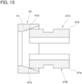
- Fig. 15 is a schematic cross-sectional view showing the divided movable pieces 47A and 47B that each include no second tapered surface 53 on the outer peripheral surface, and the cylindrical slide member 45 that includes the first tapered surface on the inner peripheral surface.
- each of the divided movable pieces 47A and 47B may not be provided with the second tapered surface, and one end portion 47a of the outer peripheral surface of each of the divided movable pieces 47A and 47B may slide on the first tapered surface 51 of the cylindrical slide member 45.
- each of the divided movable pieces 47A and 47B may not be provided with the fourth tapered surface, and the other end portion 47b of the outer peripheral surface of each of the divided movable pieces 47A and 47B may slide on the third tapered surface 55 on the inner peripheral surface of the cylindrical fixing member 57 shown in Fig. 3 . Even in such a case, the chucking operation described above may be performed.
- the above configurations may also be appropriately combined, for example, by not providing the tapered surface on one side, in the axial direction, of each of the divided movable pieces 47A and 47B, and providing the tapered surface only on the other side in the axial direction.
- the above configurations may be similarly applied to each modification to be described below.
- Fig. 16 is a partial cross-sectional view of a chuck mechanism 43A according to a first modification including the cylindrical fixing member 57 that is divided into two parts.
- the cylindrical fixing member 57 of the chuck mechanism 43A is divided, along the axial direction, into a tapered cylindrical member 57A in a region including the third tapered surface 55, and a remaining cylindrical member 57B in a region excluding the tapered cylindrical member 57A.
- the third tapered surface 55 is formed on the inner peripheral surface of the cylindrical fixing member 57, and the third tapered surface 55 performs tapered fitting with the fourth tapered surface 59 and is thus required to have high machining accuracy and high wear resistance.
- the region other than the third tapered surface 55 such conditions are often not required. Therefore, it is preferable to, as shown in Fig. 16 , divide the cylindrical fixing member 57 into the region including the third tapered surface 55 for which particularly high machining accuracy and wear resistance are required, and the other region.
- the tapered cylindrical member 57A may be formed by machining, with high accuracy, a material having high wear resistance
- the remaining cylindrical member 57B may be formed using a material that is relatively low in cost and good in machinability. That is, the cylindrical fixing member 57 may be formed with little waste so that necessary performance may be sufficiently exhibited while reducing material cost. Since an axial length of the tapered cylindrical member 57A is shortened, machinability thereof is improved.
- Fig. 17 is a cross-sectional view showing a chuck mechanism 43B according to a second modification that includes divided movable pieces 48A and 48B whose axial length is extended.
- a length from the recessed groove 67 to the second tapered surface 53 of each of the divided movable pieces 48A and 48B of the chuck mechanism 43B is extended.
- the configuration when an inclination of the second tapered surface 53 is set to be small, a space for forming the tapered surface is easily ensured.
- a contact area between the first tapered surface 51 and the second tapered surface 53 may be increased so as to reduce a surface pressure and reduce wear.
- a contact area may be increased by extending a length from the recessed groove 67 to the fourth tapered surface 59.
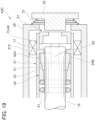
- Fig. 18 is a cross-sectional view showing a chuck mechanism 43C according to a third modification in which each of protruding portions is formed integrally with a respective one of divided movable pieces 49A and 49B.
- Each of the divided movable pieces 49A and 49B of the chuck mechanism 43C is formed, between the second tapered surface 53 and the fourth tapered surface 59, with a protruding portion 81 which is formed along the circumferential direction and protrudes outward in the radial direction.
- the protruding portion 81 may come into contact with one of end portions of the cylindrical slide member 45 and the cylindrical fixing member 57 facing each other.
- the sleeve 37 is formed with an annular groove portion 83 that prevents interference when the divided movable pieces 49A and 49B each including the protruding portion 81 are moved outward in the radial direction.
- a structure may be simplified by omitting the restriction ring 65 ( Fig. 3 ) described above, and movement of the divided movable pieces 49A and 49B in the axial direction may be restricted.
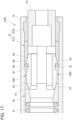
- Fig. 19 is a schematic cross-sectional view showing a simplified configuration of a chuck mechanism 43D according to a fourth modification.
- axial movement of divided movable pieces 50A and 50B each including the second tapered surface 53 is restricted by a protruding portion 75 that protrudes inward from the inner peripheral surface of the sleeve 37 in the radial direction.
- Other configurations may be the same as those of the chuck mechanisms 43, 43A, and 43B described above.
- Each of the divided movable pieces 50A and 50B includes, on one end side in the axial direction, a tapered surface (second tapered surface 53) that is in sliding contact with the first tapered surface 51 of the cylindrical slide member 45, and includes, on the other end side in the axial direction, an end surface 77 that is in contact with the protruding portion 75. That is, the fourth tapered surface 59 described above is not provided.
- the protruding portion 75 may be formed on the inner peripheral surface of the sleeve 37 continuously in the circumferential direction, or may be a plurality of protruding portions obtained by dividing in the circumferential direction.
- the protruding portion 75 only needs to be in contact with the end surface 77 of each of the divided movable pieces 50A and 50B, and functions as the stopper unit 49 that restricts the axial movement of the divided movable pieces 50A and 50B.
- reliable chucking of the dental treatment tool 15 may be performed by tapered fitting of the first tapered surface 51 with the second tapered surface 53. Moreover, since a member that requires flexible elasticity such as the coil spring 41, and members that perform tapered fitting with each other and each have excellent wear resistance and high rigidity are separately formed, characteristics required for each member may be easily selected.
- Fig. 20 is a schematic cross-sectional view showing another simplified configuration of a chuck mechanism 43E according to a fifth modification.
- the chuck mechanism 43E includes divided movable pieces 52A and 52B that are each provided with a tapered surface only on one side in the axial direction, and axial movement of the divided movable pieces 52A and 52B is restricted by the restriction ring 65.
- An end portion of the cylindrical fixing member 57 on a restriction ring 65 side does not include a tapered surface (third tapered surface 55), and an end surface of the cylindrical fixing member 57 abuts against the restriction ring 65.
- Other configurations are the same as those of the chuck mechanism 43 shown in Fig. 3 .
- the reliable chucking may be performed by the tapered fitting of the first tapered surface 51 with the second tapered surface 53, and machining of the sleeve 37 may be simplified.
Landscapes
- Health & Medical Sciences (AREA)
- Oral & Maxillofacial Surgery (AREA)
- Life Sciences & Earth Sciences (AREA)
- Veterinary Medicine (AREA)
- Animal Behavior & Ethology (AREA)
- General Health & Medical Sciences (AREA)
- Public Health (AREA)
- Dentistry (AREA)
- Epidemiology (AREA)
- Surgery (AREA)
- Nuclear Medicine, Radiotherapy & Molecular Imaging (AREA)
- Orthopedic Medicine & Surgery (AREA)
- Engineering & Computer Science (AREA)
- Biomedical Technology (AREA)
- Heart & Thoracic Surgery (AREA)
- Medical Informatics (AREA)
- Molecular Biology (AREA)
- Dental Tools And Instruments Or Auxiliary Dental Instruments (AREA)
Applications Claiming Priority (3)
| Application Number | Priority Date | Filing Date | Title |
|---|---|---|---|
| JP2021205568 | 2021-12-17 | ||
| JP2022148345A JP2023090621A (ja) | 2021-12-17 | 2022-09-16 | 歯科用ハンドピース |
| EP22213738.2A EP4197484B1 (de) | 2021-12-17 | 2022-12-15 | Zahnärztliches handstück |
Related Parent Applications (2)
| Application Number | Title | Priority Date | Filing Date |
|---|---|---|---|
| EP22213738.2A Division-Into EP4197484B1 (de) | 2021-12-17 | 2022-12-15 | Zahnärztliches handstück |
| EP22213738.2A Division EP4197484B1 (de) | 2021-12-17 | 2022-12-15 | Zahnärztliches handstück |
Publications (2)
| Publication Number | Publication Date |
|---|---|
| EP4552606A2 true EP4552606A2 (de) | 2025-05-14 |
| EP4552606A3 EP4552606A3 (de) | 2025-07-16 |
Family
ID=84536985
Family Applications (2)
| Application Number | Title | Priority Date | Filing Date |
|---|---|---|---|
| EP22213738.2A Active EP4197484B1 (de) | 2021-12-17 | 2022-12-15 | Zahnärztliches handstück |
| EP25166408.2A Pending EP4552606A3 (de) | 2021-12-17 | 2022-12-15 | Zahnärztliches handstück |
Family Applications Before (1)
| Application Number | Title | Priority Date | Filing Date |
|---|---|---|---|
| EP22213738.2A Active EP4197484B1 (de) | 2021-12-17 | 2022-12-15 | Zahnärztliches handstück |
Country Status (6)
| Country | Link |
|---|---|
| US (1) | US20230190407A1 (de) |
| EP (2) | EP4197484B1 (de) |
| KR (1) | KR102820932B1 (de) |
| CN (1) | CN116264991B (de) |
| ES (1) | ES3031258T3 (de) |
| TW (1) | TWI822518B (de) |
Citations (2)
| Publication number | Priority date | Publication date | Assignee | Title |
|---|---|---|---|---|
| JP3126887B2 (ja) | 1994-10-26 | 2001-01-22 | 株式会社長田中央研究所 | チャック機構 |
| JP2006122080A (ja) | 2004-10-26 | 2006-05-18 | Nakanishi:Kk | 歯科用ハンドピース、これに用いる歯科処置工具及び工具保持機構 |
Family Cites Families (16)
| Publication number | Priority date | Publication date | Assignee | Title |
|---|---|---|---|---|
| AT219193B (de) * | 1960-03-09 | 1962-01-10 | Buermoos Dentalwerk | Spannvorrichtung für zahnärztliche Werkzeuge |
| JPS5684957A (en) * | 1979-12-13 | 1981-07-10 | Mitsubishi Plastics Ind | Cooextruding composite film |
| FR2576775B1 (fr) * | 1985-02-04 | 1990-03-16 | Micro Mega Sa | Tete de contre-angle ou de turbine d'une piece a main dentaire |
| AT388283B (de) * | 1987-08-24 | 1989-05-26 | Buermoos Dentalwerk | Zahnaerztliches handstueck |
| JPH01250247A (ja) * | 1988-03-31 | 1989-10-05 | Yoshida Dental Mfg Co Ltd | 歯科用ハンドピースのチャック装置 |
| EP0421907A1 (de) * | 1989-09-07 | 1991-04-10 | Micro Mega S.A. | Gerät zur LÀ¶sung bzw. Festsetzung der Kupplung eines zahnärztlichen Handstückes |
| JP3152427B2 (ja) | 1990-08-07 | 2001-04-03 | 株式会社ナカニシ | 歯科用ハンドピースのチャック装置 |
| JP3208249B2 (ja) * | 1993-12-28 | 2001-09-10 | 株式会社モリタ製作所 | 歯科用切削工具の把持装置 |
| CA2414908A1 (en) * | 2002-12-20 | 2004-06-20 | Derek Turner | Dental handpiece |
| JP2010220635A (ja) * | 2009-03-19 | 2010-10-07 | J Morita Tokyo Mfg Corp | 歯科用ハンドピースのチャック装置 |
| WO2011052034A1 (ja) | 2009-10-27 | 2011-05-05 | Soma Kuniji | ハンドピースの治療用工具把持装置 |
| US20130029288A1 (en) | 2011-07-29 | 2013-01-31 | Dentsply International, Inc. | Positive drive chuck and bur arrangement for a dental handpiece |
| DE102012108265A1 (de) * | 2012-09-05 | 2014-03-06 | Aesculap Ag | Chirurgisches, Drehmoment übertragendes Instrument einschließlich zugehöriges Werkzeug |
| CN110876646B (zh) * | 2019-12-12 | 2025-09-19 | 西诺医疗器械集团有限公司 | 用于牙科低速手机的阶形钩后置式车针夹持装置 |
| CN113749795A (zh) * | 2021-10-15 | 2021-12-07 | 桂林市啄木鸟医疗器械有限公司 | 牙科手机及其机头 |
| JP7267495B1 (ja) | 2022-11-29 | 2023-05-01 | 株式会社ナカニシ | タービンロータ、カートリッジ、及び、医療用切削器械 |
-
2022
- 2022-12-12 KR KR1020220172401A patent/KR102820932B1/ko active Active
- 2022-12-13 CN CN202211601533.6A patent/CN116264991B/zh active Active
- 2022-12-14 TW TW111147922A patent/TWI822518B/zh active
- 2022-12-15 EP EP22213738.2A patent/EP4197484B1/de active Active
- 2022-12-15 US US18/081,927 patent/US20230190407A1/en active Pending
- 2022-12-15 ES ES22213738T patent/ES3031258T3/es active Active
- 2022-12-15 EP EP25166408.2A patent/EP4552606A3/de active Pending
Patent Citations (2)
| Publication number | Priority date | Publication date | Assignee | Title |
|---|---|---|---|---|
| JP3126887B2 (ja) | 1994-10-26 | 2001-01-22 | 株式会社長田中央研究所 | チャック機構 |
| JP2006122080A (ja) | 2004-10-26 | 2006-05-18 | Nakanishi:Kk | 歯科用ハンドピース、これに用いる歯科処置工具及び工具保持機構 |
Also Published As
| Publication number | Publication date |
|---|---|
| EP4197484B1 (de) | 2025-05-21 |
| TWI822518B (zh) | 2023-11-11 |
| US20230190407A1 (en) | 2023-06-22 |
| EP4197484C0 (de) | 2025-05-21 |
| ES3031258T3 (en) | 2025-07-07 |
| EP4552606A3 (de) | 2025-07-16 |
| KR102820932B1 (ko) | 2025-06-16 |
| CN116264991A (zh) | 2023-06-20 |
| TW202327526A (zh) | 2023-07-16 |
| KR20230092766A (ko) | 2023-06-26 |
| EP4197484A1 (de) | 2023-06-21 |
| CN116264991B (zh) | 2025-12-05 |
Similar Documents
| Publication | Publication Date | Title |
|---|---|---|
| RU2448815C2 (ru) | Вращающийся режущий инструмент с устанавливаемой с возможностью раскрепления самозажимной режущей головкой с запирающим элементом | |
| JPH1110418A (ja) | 保持工具 | |
| WO2018110681A1 (ja) | 作業機械のびびり防止構造 | |
| JP2023521369A (ja) | 強制機械振動補助を伴う高速スピンドル | |
| EP4552606A2 (de) | Zahnärztliches handstück | |
| US20020105149A1 (en) | Centrifugal dental drill bit chuck | |
| US7357608B2 (en) | Rotary tapered tool holder | |
| JP2003211303A (ja) | ガイドブッシュ | |
| JP2002018614A (ja) | 工具ホルダ取付け構造 | |
| BR102022025338A2 (pt) | Peça de mão dentária | |
| JP7267495B1 (ja) | タービンロータ、カートリッジ、及び、医療用切削器械 | |
| JPH1058211A (ja) | 工具着脱装置 | |
| KR20240031043A (ko) | 디버링 공구 | |
| JP2009131930A (ja) | コレット式工具ホルダ | |
| JPH11342138A (ja) | 医療用または歯科用回転工具の着脱自在の固定装置 | |
| JPS6015538Y2 (ja) | 歯科治療器具用チャック | |
| JP4124019B2 (ja) | 工具ホルダ | |
| JP2003039214A (ja) | 工具ホルダ取付け構造 | |
| JPH042730Y2 (de) | ||
| CN119610000A (zh) | 装卸工具以及安装有装卸工具的处理工具 | |
| JP2954919B2 (ja) | 歯科用ストレートハンドピース | |
| JP2010264554A (ja) | コレット式工具ホルダ | |
| JP2025073707A (ja) | 医療用切削器械、及び、カートリッジ | |
| CN118924449A (zh) | 一种按压式芯轴夹持机构及牙科手机 | |
| CN118845257A (zh) | 医疗用切削器械以及机芯 |
Legal Events
| Date | Code | Title | Description |
|---|---|---|---|
| PUAI | Public reference made under article 153(3) epc to a published international application that has entered the european phase |
Free format text: ORIGINAL CODE: 0009012 |
|
| STAA | Information on the status of an ep patent application or granted ep patent |
Free format text: STATUS: REQUEST FOR EXAMINATION WAS MADE |
|
| 17P | Request for examination filed |
Effective date: 20250326 |
|
| AC | Divisional application: reference to earlier application |
Ref document number: 4197484 Country of ref document: EP Kind code of ref document: P |
|
| AK | Designated contracting states |
Kind code of ref document: A2 Designated state(s): AL AT BE BG CH CY CZ DE DK EE ES FI FR GB GR HR HU IE IS IT LI LT LU LV MC ME MK MT NL NO PL PT RO RS SE SI SK SM TR |
|
| REG | Reference to a national code |
Ref country code: DE Ref legal event code: R079 Free format text: PREVIOUS MAIN CLASS: A61C0001120000 Ipc: A61C0001140000 |
|
| PUAL | Search report despatched |
Free format text: ORIGINAL CODE: 0009013 |
|
| AK | Designated contracting states |
Kind code of ref document: A3 Designated state(s): AL AT BE BG CH CY CZ DE DK EE ES FI FR GB GR HR HU IE IS IT LI LT LU LV MC ME MK MT NL NO PL PT RO RS SE SI SK SM TR |
|
| RIC1 | Information provided on ipc code assigned before grant |
Ipc: A61C 1/14 20060101AFI20250611BHEP Ipc: A61B 17/16 20060101ALI20250611BHEP Ipc: A61C 1/12 20060101ALI20250611BHEP |