EP4538752A1 - Desodorierungsbehandlungsvorrichtung und informationssammelsystem - Google Patents
Desodorierungsbehandlungsvorrichtung und informationssammelsystem Download PDFInfo
- Publication number
- EP4538752A1 EP4538752A1 EP24219073.4A EP24219073A EP4538752A1 EP 4538752 A1 EP4538752 A1 EP 4538752A1 EP 24219073 A EP24219073 A EP 24219073A EP 4538752 A1 EP4538752 A1 EP 4538752A1
- Authority
- EP
- European Patent Office
- Prior art keywords
- water
- tank
- odorous gas
- amount
- deodorant
- Prior art date
- Legal status (The legal status is an assumption and is not a legal conclusion. Google has not performed a legal analysis and makes no representation as to the accuracy of the status listed.)
- Pending
Links
Images


Classifications
-
- B—PERFORMING OPERATIONS; TRANSPORTING
- B01—PHYSICAL OR CHEMICAL PROCESSES OR APPARATUS IN GENERAL
- B01D—SEPARATION
- B01D53/00—Separation of gases or vapours; Recovering vapours of volatile solvents from gases; Chemical or biological purification of waste gases, e.g. engine exhaust gases, smoke, fumes, flue gases, aerosols
- B01D53/34—Chemical or biological purification of waste gases
- B01D53/74—General processes for purification of waste gases; Apparatus or devices specially adapted therefor
- B01D53/84—Biological processes
- B01D53/85—Biological processes with gas-solid contact
-
- B—PERFORMING OPERATIONS; TRANSPORTING
- B01—PHYSICAL OR CHEMICAL PROCESSES OR APPARATUS IN GENERAL
- B01D—SEPARATION
- B01D53/00—Separation of gases or vapours; Recovering vapours of volatile solvents from gases; Chemical or biological purification of waste gases, e.g. engine exhaust gases, smoke, fumes, flue gases, aerosols
- B01D53/34—Chemical or biological purification of waste gases
- B01D53/346—Controlling the process
-
- G—PHYSICS
- G16—INFORMATION AND COMMUNICATION TECHNOLOGY [ICT] SPECIALLY ADAPTED FOR SPECIFIC APPLICATION FIELDS
- G16Y—INFORMATION AND COMMUNICATION TECHNOLOGY SPECIALLY ADAPTED FOR THE INTERNET OF THINGS [IoT]
- G16Y20/00—Information sensed or collected by the things
-
- G—PHYSICS
- G16—INFORMATION AND COMMUNICATION TECHNOLOGY [ICT] SPECIALLY ADAPTED FOR SPECIFIC APPLICATION FIELDS
- G16Y—INFORMATION AND COMMUNICATION TECHNOLOGY SPECIALLY ADAPTED FOR THE INTERNET OF THINGS [IoT]
- G16Y40/00—IoT characterised by the purpose of the information processing
- G16Y40/30—Control
-
- A—HUMAN NECESSITIES
- A61—MEDICAL OR VETERINARY SCIENCE; HYGIENE
- A61L—METHODS OR APPARATUS FOR STERILISING MATERIALS OR OBJECTS IN GENERAL; DISINFECTION, STERILISATION OR DEODORISATION OF AIR; CHEMICAL ASPECTS OF BANDAGES, DRESSINGS, ABSORBENT PADS OR SURGICAL ARTICLES; MATERIALS FOR BANDAGES, DRESSINGS, ABSORBENT PADS OR SURGICAL ARTICLES
- A61L2209/00—Aspects relating to disinfection, sterilisation or deodorisation of air
- A61L2209/10—Apparatus features
- A61L2209/11—Apparatus for controlling air treatment
- A61L2209/111—Sensor means, e.g. motion, brightness, scent, contaminant sensors
-
- A—HUMAN NECESSITIES
- A61—MEDICAL OR VETERINARY SCIENCE; HYGIENE
- A61L—METHODS OR APPARATUS FOR STERILISING MATERIALS OR OBJECTS IN GENERAL; DISINFECTION, STERILISATION OR DEODORISATION OF AIR; CHEMICAL ASPECTS OF BANDAGES, DRESSINGS, ABSORBENT PADS OR SURGICAL ARTICLES; MATERIALS FOR BANDAGES, DRESSINGS, ABSORBENT PADS OR SURGICAL ARTICLES
- A61L9/00—Disinfection, sterilisation or deodorisation of air
- A61L9/14—Disinfection, sterilisation or deodorisation of air using sprayed or atomised substances including air-liquid contact processes
- A61L9/145—Disinfection, sterilisation or deodorisation of air using sprayed or atomised substances including air-liquid contact processes air-liquid contact processes, e.g. scrubbing
-
- B—PERFORMING OPERATIONS; TRANSPORTING
- B01—PHYSICAL OR CHEMICAL PROCESSES OR APPARATUS IN GENERAL
- B01D—SEPARATION
- B01D2251/00—Reactants
- B01D2251/95—Specific microorganisms
-
- B—PERFORMING OPERATIONS; TRANSPORTING
- B01—PHYSICAL OR CHEMICAL PROCESSES OR APPARATUS IN GENERAL
- B01D—SEPARATION
- B01D2257/00—Components to be removed
- B01D2257/30—Sulfur compounds
- B01D2257/304—Hydrogen sulfide
-
- B—PERFORMING OPERATIONS; TRANSPORTING
- B01—PHYSICAL OR CHEMICAL PROCESSES OR APPARATUS IN GENERAL
- B01D—SEPARATION
- B01D2257/00—Components to be removed
- B01D2257/40—Nitrogen compounds
- B01D2257/406—Ammonia
-
- B—PERFORMING OPERATIONS; TRANSPORTING
- B01—PHYSICAL OR CHEMICAL PROCESSES OR APPARATUS IN GENERAL
- B01D—SEPARATION
- B01D2257/00—Components to be removed
- B01D2257/90—Odorous compounds not provided for in groups B01D2257/00 - B01D2257/708
-
- B—PERFORMING OPERATIONS; TRANSPORTING
- B01—PHYSICAL OR CHEMICAL PROCESSES OR APPARATUS IN GENERAL
- B01D—SEPARATION
- B01D2258/00—Sources of waste gases
- B01D2258/06—Polluted air
-
- Y—GENERAL TAGGING OF NEW TECHNOLOGICAL DEVELOPMENTS; GENERAL TAGGING OF CROSS-SECTIONAL TECHNOLOGIES SPANNING OVER SEVERAL SECTIONS OF THE IPC; TECHNICAL SUBJECTS COVERED BY FORMER USPC CROSS-REFERENCE ART COLLECTIONS [XRACs] AND DIGESTS
- Y02—TECHNOLOGIES OR APPLICATIONS FOR MITIGATION OR ADAPTATION AGAINST CLIMATE CHANGE
- Y02A—TECHNOLOGIES FOR ADAPTATION TO CLIMATE CHANGE
- Y02A50/00—TECHNOLOGIES FOR ADAPTATION TO CLIMATE CHANGE in human health protection, e.g. against extreme weather
- Y02A50/20—Air quality improvement or preservation, e.g. vehicle emission control or emission reduction by using catalytic converters
Definitions
- the present invention relates to a deodorization treatment apparatus and an information collection system. More specifically, the present invention relates to the deodorization treatment apparatus and the information collection system that control an operation according to measured values of various sensors and realize remote monitoring of an operating state.
- a deodorization apparatus in which microorganism-retaining carriers are contained in a deodorant tank, and the odor component is decomposed and deodorized by microorganisms living in the microorganism-retaining carriers.
- the conventional deodorization apparatus using the microorganism-retaining carriers does not operate properly and there is a case where adequate deodorization cannot be performed, depending on an ammonia concentration and flow rate of the odorous gas discharged from the facilities, and situations of various operating environments (outside air temperature and pH of circulating water). Further, it is not possible to appropriately monitor a state of the deodorization apparatus, and it is difficult to grasp a timing and contents of maintenance.
- a deodorization treatment apparatus including: a deodorant tank housing microorganism-retaining carriers retaining microorganisms, the deodorant tank supplied with odorous gas, and the deodorant tank discharging an exhaust gas in which an odor has been removed by the microorganisms, a water sprinkler device sprinkling treat water onto the microorganism-retaining carriers, a water tank connected to the deodorant tank, the water tank storing treat water flowing out from the deodorant tank, a water sprinkler pipe supplying treat water stored in the water tank to the water sprinkler device, an exhaust pipe connected to a treatment facility that emits odorous gas and supplying the odorous gas to the deodorant tank, a first blower arranged in a path of the exhaust pipe for blowing the odorous gas, an aeration device aerating the treat water stored in the water tank, and a control device measuring at least one of (1) a flow rate, an ammonia
- the deodorization treatment apparatus of an embodiment of the present invention may further include a cooler arranged in the path of the exhaust pipe and cooling the odorous gas, and a gas flow resistance regulator arranged in the path of the exhaust pipe for adjusting the flow rate of the odorous gas, wherein the control device may control a cooling capacity of the cooler or an opening degree of the gas flow resistance regulator.
- the deodorization treatment apparatus of an embodiment of the present invention may further include a second blower blowing an outside air into the path of the exhaust pipe, wherein the control device may control a blowing amount of the second blower.
- the deodorization treatment apparatus of an embodiment of the present invention may further include a spraying device spraying a mist to the water tank, wherein the control device may control the spraying of the mist to the water tank.
- the deodorization treatment apparatus of an embodiment of the present invention may further include a third blower blowing the outside air to the deodorant tank, wherein the control device may control a blowing amount of the third blower.
- the odor source may be the deodorization treatment apparatus described above, and the control device may control blowing amount of the first blower or amount of discharge of the exhaust gas according to the measurement results.
- the deodorization apparatus can operate properly and perform sufficient deodorization even if there is a variation in the concentration and the flow rate of the ammonia of the odorous gas discharged from the facilities, or the situation of various operating environments. Further, it is possible to grasp the timing and contents of maintenance by appropriately monitoring the state of the deodorization apparatus.
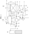
- the deodorization treatment apparatus 100 is connected to a facility 200 emitting the odorous gas.
- the facility 200 emits the odorous gas containing a high ammonia concentration or the like and exhibiting a strong offensive odor.
- Specific examples of the facility include a composting treatment facility and a drainage treatment facility, but other facilities may be if the facilities emit offensive odors.
- the odorous gas discharged from the facility 200 is supplied to the deodorization treatment apparatus 100 by a gas pipe 151.
- the gas pipe 151 is formed of a material having pressure resistance and corrosion resistance, for example, a material such as metal, vinyl chloride, or the like, and is formed in a pipe shape, a tube shape, or a hose shape capable of allowing a gas to pass therethrough.
- a blower 152 for increasing air volume, gas flow resistance regulators 153 and 155 for controlling the air volume, and a cooling device 154 for cooling the odorous gas are arranged in a middle of the gas pipe 151.
- the deodorization treatment apparatus 100 is arranged with a treatment apparatus including a deodorant tank 110, a water sprinkler device 120, a drainage tank 130, and a water tank 140. Among them, an odor of the odorous gas is removed by the microorganisms immobilized to microorganism-retaining carriers filled in the deodorant tank 110.
- the deodorant tank 110 is, for example, a rectangular parallelepiped container having a height of 8 meters, width and length of 9 meters ⁇ 12 meters, respectively.
- the deodorant tank is made of a material having high pressure resistance and high corrosion resistance, for example, metal, hard resin, reinforced concrete, or the like.
- a port connected to the gas pipe 151 for taking in the odorous gas is arranged, and a space such that the odorous gas spreads over the entire in plain view is arranged. It is desirable to secure the space by covering a pallet or the like formed of a skeleton having a height of 20cm to 40cm or the like. It is preferable that a mesh-like sheet or plate is arranged on the pallet to prevent the microorganism-retaining carriers from flowing out to the drainage tank 130.
- An inside of the deodorant tank 110 is filled with a microorganism-retaining carriers.
- Ammonia-degrading microorganisms and hydrogen sulfide-degrading microorganisms are immobilized on the microorganism-carrying carrier.
- the ammonia-degrading microorganisms are microorganisms that degrade ammonia dissolved in water or convert it into another substance.
- Exemplary ammonia-degrading bacteria include nitrifying bacteria.
- the nitrifying bacteria nitrify dissolved ammonia and convert it into nitrous acid or nitric acid.
- nitrification refers to an oxidative decomposition of ammonia.
- nitrifying bacteria examples include ammonia oxidizing bacteria and nitrite oxidizing bacteria, the former convert ammonia into nitrous acid and the latter convert nitrous acid into nitric acid. In this way, ammonia of the odorous gas is decomposed and the odor is removed.
- the hydrogen sulfide-degrading microorganisms are microorganisms that decompose hydrogen sulfide dissolved in water or convert it into another substance.
- Exemplary hydrogen sulfide-degrading bacteria include sulfur bacteria. The sulfur bacteria decompose dissolved hydrogen sulfide into water and sulfur. The gas from which the odor has been removed in this way is discharged to the outside from an upper part of the deodorant tank 110.
- the microorganism-retaining carrier is preferably a porous glass, but is not particularly limited if it can appropriately retain microorganisms.
- synthetic resin foam fusable polyethylene
- wood wood, ceramic, or the like
- shape thereof may be spherical, irregular shape, honeycomb shape, cylindrical shape, or the like.
- the microorganisms living in the microorganism-retaining carriers generate heat during their activities, and the treat water deprives the heat and cools the microorganisms. Therefore, for example, in the summer when the temperature is high, it is desirable to increase the number of times of water sprinkling and amount of water sprinkling each time. Specifically, it is desirable to increase the number of times of water sprinkling, such as sprinkling water for about 5 minutes in one hour in winter and sprinkling water for about 5 minutes in 30 minutes in summer.
- the drainage tank 130 is a tank for recovering the treat water descended from the deodorant tank 110.
- a drainage drain is arranged at a central portion or one end of a bottom of the drainage tank 130, and the bottom of the drainage tank 130 is inclined by about 2 degrees toward the drainage drain.
- the present invention is not limited thereto, and the bottom portion of the drainage tank 130 may be, for example, inclined by one degree or more toward the drainage drain.
- the drainage drain is arranged with a basket for receiving the microorganism-retaining carriers that has passed through the mesh. The treat water discharged from the drainage drain flows into the water tank 140 via the drain recovery pipe 141.
- the water tank 140 stores the recovered treat water.
- the water tank 140 is arranged with an aeration device 142 so that the treat water contains a high concentration of air, in particular oxygen.
- the aeration device 142 may be, for example, a microbubble generation device. In this case, the microbubble generation device may generate microbubbles containing oxygen in the treat water.
- the treat water stored in the water tank 140 is supplied to the water sprinkler device by the pump 122.
- the water tank 140 may further include a water supply pipe via the drain valve 143, a water supply pipe via the water supply valve 144, and a spraying device 145.
- the odorous gas discharged from the facility 200 is supplied to the deodorization treatment apparatus 100 by the gas pipe 151.
- the blower 152 for supplying an odorous gas from the facility 200 to the gas pipe 151, the gas flow resistance regulators 153 and 155 for controlling the air volume, and the cooling device 154 for cooling the odorous gas are arranged in the middle of the gas pipe 151.
- a demister or the like for dehumidifying and dedusting may be further arranged between the facility 200 and the blower 152.
- the demister may be, for example, a sponge-like material that separates foreign matters such as liquid particles and dust contained in the odorous gas.
- the blower 152 increases the flow rate of the odorous gas discharged from the facility 200.
- a negative pressure is generated on a suction side (left side in the drawing) and a positive pressure is generated on an exhaust side (right side in the drawing) of the blower 152.
- the blower is controlled by an inverter, and number of revolutions can be continuously controlled. By controlling the number of revolutions, the air volume and the air pressure can be controlled. Whether or not the operation is performed and the number of revolutions are controlled by the control device 160.
- the odorous gas discharged from the facility 200 is relatively hot. It may exceed 70°C depending on the temperature and operating conditions of the facility. Only passing through the gas pipe 151 has some cooling effect, but this is insufficient, and the odorous gas is cooled by the cooling device 154. As a result, the odorous gas becomes 40°C or less at the output side of the cooling device 154.
- the configuration of the cooling device may include, for example, a configuration in which the odorous gas is passed through a radiator in which many water pipes are arranged and cooling water circulates, and a configuration in which the odorous gas is directly cooled by sprinkling water into the cavity, and the like. Cooling capacities can be adjusted by changing a circulation speed of the cooling water in the former case, and can be adjusted by changing watering amount in the latter case. The operation is controlled by the control device 160.
- the gas flow resistance regulators 153 and 155 are arranged on an input side and an output side of the cooling device 154, respectively.
- the gas flow resistance regulators 153 and 155 may be, for example, gas dampers.
- the gas flow resistance regulators 153 and 155 can adjust the resistance of the flow of the odorous gas by rotating movable valves to reduce the flow rate of the odorous gas.
- the gas flow resistance regulators 153 and 155 can also cool and dilute the odorous gas by opening and closing air supply ports that lead to outside air. Adjustment of opening/closing angle of the movable valve (adjustment of the flow resistance) and adjustment of opening/closing of the air supply port are performed by a motor, and the control is performed by the control device 160.
- the deodorization treatment apparatus 100 includes sensors 171, 172, 173, 174, 175, 176, 177, 178, and 179. Although the values measured by these sensors vary, the sensors 171, 172, 173, 174 measure any or more of the flow rate of the odorous gas, the ammonia concentration, the temperature, or the amount of dust, or pressure in the pipe.
- the sensor 175 measures one or more of the flow rates, the ammonia concentration, or the temperature of the gas discharged outdoors.
- the sensor 176 measures any one or more of the pressures, the ammonia concentration, or the pressure inside the deodorant tank 110.
- the sensor 177 measures the flow rate of the treat water in the drain recovery pipe 141, and the sensor 178 measures any one or more of the pH, the temperature, the ammonia concentration, the NO concentration, the NO 2 concentration, the dissolved oxygen concentration, electric conductivity, and the water level of the treat water stored in the water tank 140.
- the sensor 179 measures the flow rate of the treat water in the water supply pipe between the pump 122 and the water sprinkler nozzle 121. The measured values of these sensors are then sent to the control device 160.
- the drain of the drainage tank 130 may be arranged with an outflow microorganism-retaining carrier basket (not shown) for receiving the microorganism-retaining carrier that has passed through the mesh, and a sensor for measuring weight of the outflow microorganism-retaining carrier basket or amount of outflow microorganism-retaining carriers in the basket.
- an outflow microorganism-retaining carrier basket (not shown) for receiving the microorganism-retaining carrier that has passed through the mesh
- a sensor for measuring weight of the outflow microorganism-retaining carrier basket or amount of outflow microorganism-retaining carriers in the basket.
- a case where the temperature of the deodorant tank 110 being elevated is detected by the sensor 176, a case where the ammonia concentration of the exhaust gas becomes equal to or higher than a predetermined value is detected by the sensor 175, a case where the water level of the water tank 140 becomes equal to or lower than a predetermined value, a case where the temperature of the odorous gas supplied to the deodorant tank 110 is equal to or higher than a predetermined temperature is detected by the sensor 174, and a case where clogging of the water sprinkler nozzle 121 is detected by the sensor 179, and the like.
- the weight of the outflow microorganism-retaining carrier basket or the amount of the microorganism-retaining carrier in the basket is detected to be equal to or larger than a predetermined value.
- the measurement frequency is increased when the first threshold value is exceeded, and an alarm is issued when the second threshold value is exceeded.
- the measured values transmitted from the sensors 171, 172, 173, 174, 175, 176, 177, 178, and 179 are temporarily stored in the storage device in the control device 160. Then, the control device 160 controls any or more of the amount of air blowing of the blower 152, the watering amount or the watering frequency of the water sprinkler device 120 (controlling a pumping timing and pumping amount of the pump 122, and controlling the amount of the water sprinkler nozzle 121 used used by a solenoid valve (not shown)), the cooling capacity of the cooling device 154, the opening degree of the gas flow resistance regulator 153 and 155, the amount of air bubbles generated in liquid of the aeration device 142, the water supply and drainage to the water tank 140 (water supply and drainage are performed by opening and closing the drain valve 143 and the water supply valve 144), the spraying of the mist to the water tank 140, the temperature of the deodorant tank 110 (raising the temperature by operating a heater (not shown)).
- the control device 160 controls any or more of the amount of air blowing of the blower 152, the watering amount or the watering frequency of the water sprinkler device 120, the cooling capacity of the cooling device 154, the opening degree of the gas flow resistance regulators 153 and 155, the amount of the air bubbles generated in liquid of the aeration device 142, the water supply and the drainage to the water tank 140, the spraying of the mist to the water tank 140, and the temperature of the deodorant tank 110 by operating a corresponding control mode by operating a program that implements the following algorithms based on the measured values transmitted from the sensors 171, 172, 173, 174, 175, 176, 177, 178, and 179. Detailed description will be given below.
- the resistance of the flow of the gas flow resistance regulator 155 is increased (the valve is rotated from the open side to the closed side).
- the gas flow resistance regulator 155 may be operated more strictly by comparing pressures at its input side and output side with measured values of a pressure sensor contained in the sensors 173 and 174.
- the temperature of the odorous gas at the point of supplying the odorous gas to the deodorant tank 110 is measured by the temperature sensor in the sensor 174.
- the capacity of the cooling device 154 is improved.
- the cooling device 154 in which many water pipes are arranged and cooling water circulates is a radiator system, the circulation speed of the cooling water is increased, and if the cooling device is a system in which the odorous gas is directly cooled by watering in the cavity, the capacity can be improved by increasing the watering amount.
- a control mode 2 is preferably used in combination with the control mode 1. In this way, even if the temperature of the odorous gas supplied from the facility 200 changes according to the outside air or the situation of the facility 200, it is always possible to operate the deodorization treatment apparatus with high efficiency.
- the nitrifying bacteria in the deodorant tank 110 lower decomposition efficiency when the ammonia concentration of the supplied odorous gas becomes equal to or higher than a certain level. Therefore, the ammonia concentration in the odorous gas at the point of supplying the odorous gas to the deodorant tank 110 is measured by an ammonia concentration sensor in the sensor 174.
- an ammonia concentration sensor a laser sensor that measures the concentration by a degree of absorption of the laser and a high-frequency sensor that supplies a high frequency between electrodes and measures the concentration by a degree of resonance thereof, and the like can be used.
- ammonia concentration of the gas discharged from the deodorant tank 110 is equal to or higher than a certain value means that the deodorant tank 110 is operating at a high load that exceeds its capacity. Therefore, the ammonia concentration of the gas discharged from the deodorant tank 110 is measured by an ammonia concentration sensor in the sensor 175. In the case where the ammonia concentration in the exhaust gas exceeds an environmental standard or other set value, the inverter of the blower 152 is controlled to reduce the amount of air blowing. In the case where the ammonia concentration in the exhaust gas does not sufficiently decrease even if the amount of air blowing decreases, the resistance of the flow of the gas flow resistance regulator 155 is subsequently increased. In this way, even if the ammonia concentration of the odorous gas supplied from the facility 200 increases, it is possible to always operate the deodorization treatment apparatus with high efficiency.
- the fact that the ammonia concentration of the gas discharged from the deodorant tank 110 is equal to or higher than a certain value means that the deodorant tank 110 is operating at a high load that exceeds its capacity. As a cause thereof, there is a possibility that the treat water sprayed on the microorganism-retaining carriers in the deodorant tank 110 is insufficient, and as a result, the activity amount of the immobilized microorganism is reduced.
- the fact that the ammonia concentration of the gas discharged from the deodorant tank 110 is equal to or higher than a certain value means that the deodorant tank 110 is operating at a high load that exceeds its capacity. As a cause thereof, there is a possibility that the oxygen concentration in the treat water sprayed to the microorganism-retaining carriers in the deodorant tank 110 is insufficient, and as a result, the activity amount of the immobilized microorganisms is lowered. Therefore, in the case where the measured value of the ammonia concentration sensor of the sensor 175 is equal to or higher than the predetermined value, the aeration device 142 can be operated to apply more oxygen to the treat water. In this way, it is possible to prevent the deodorization treatment apparatus from being overloaded.
- a reason for the decrease in the activity amount of the microorganisms may be due to the temperature in the deodorant tank 110 described above.
- the pump 122 is controlled to increase the watering amount or increase the watering frequency, and the number of nozzles used by operating a solenoid valve (not shown) can be increased to increase the watering amount. Cooling progresses as the amount of water sprinkled increases. In this way, it is possible to prevent the deodorization treatment apparatus from being overloaded.
- a reason for the decrease in the activity amount of the microorganisms may be due to the temperature in the deodorant tank 110 described above. Then, in the case where the measured value of the temperature sensor of the sensor 176 exceeds a predetermined value, for example 50°C, the temperature is lowered by the control mode 1 or 2 and the combination thereof. In this way, it is possible to prevent the deodorization treatment apparatus from being overloaded.
- a predetermined value for example 50°C
- the treat water is circulated and used.
- the thermometer of the sensor 178 indicates a temperature equal to or higher than a predetermined value
- the water supply valve 144 is opened to supply water to the water tank, or mist is sprayed to the water tank by the spraying device 145.
- the spraying of the mist by the spraying device 145 also contributes to the removal of dust in the water tank.
- the water supply valve 144 is opened to supply water.
- the drain valve 143 is opened to drain the water.
- the server 301 receives the measured values (data) transmitted from the sensors 171, 172, 173, 174, 175, 176, 177, 178, and 179 from the communication devices 161-1 and 161-2, and stores them in the storage device therein. Frequency of loading the measured value (data) into the server 301 may be performed at intervals of, for example, once an hour, once a day, once a week, or may be performed according to instructions from user terminals 303 and 304.
- the captured data may be one measured value or multiple measured values (for example, in the case where 24 data measured once per hour are transmitted once a day).
- a web server is running on the server 301, and the measured values obtained by this web server are displayed on the browser screens of the user terminals 303 and 304. It is desirable to be able to understand hourly or daily transitions by displaying a graph. In addition, various measured values for each region may be displayed on one web page, and various measured values corresponding to multiple regions may be superimposed on one graph. In this way, it becomes possible to manage the deodorization treatment apparatuses of multiple regions in a unified manner, and it is possible to compare and examine the operation statuses.
- the measured values collected via the server 301 are browsed by the user terminals 303 and 304, but the software (applet (app) in the case of a smartphone terminal) installed in the user terminals 303 and 304 may directly receive the measured values (data) from the communication devices 161-1 and 161-2.
- the user terminals 303 and 304 may be configured to transmit instructions to the communication devices 161-1 and 161-2 via the server 301 or directly to control any or more of the amount of air blowing of the blower 152, the watering amount or the watering frequency of the water sprinkler device 120, the cooling capacity of the cooling device 154, the opening degree of the gas flow resistance regulators 153 and 155, the amount of the air bubbles generated in liquid of the aeration device 142, the water supply and drainage to the water tank 140, and the temperature of the deodorant tank 110.
- FIG. 3 is a diagram showing a configuration of a deodorization treatment apparatus according to an embodiment of the present invention.
- the configuration of the deodorization treatment apparatus according to the second embodiment is same as the configuration of the deodorization treatment apparatus according to the first embodiment except having a second blower instead of the cooling device, and further including a third blower and a demister. Descriptions that are same as those in the first embodiment are omitted, and the different parts from the configuration of the deodorization treatment apparatus according to the first embodiment will be described here.
- a deodorization treatment apparatus 100a is connected to the facility 200 emitting the odorous gas.
- the odorous gas discharged from the facility 200 is supplied to the deodorization treatment apparatus 100 by the gas pipe 151.
- a demister 156 and the first blower 152 for increasing the air volume are arranged in the middle of the gas pipe 151.
- the demister 156 filters the odorous gas discharged from the facility 200 to perform dehumidification and dust removal. Condensation (drainage) discharged by the demister 156 flows into the water tank 140 via a drain recovery pipe 157.
- a pipe 181 is connected between the demister 156 and the first blower 152, which is arranged with a second blower 182 that takes in outside air and dilutes the odorous gas discharged from the facility 200.
- the odorous gas is taken in from the lower part of the deodorant tank 110, and as the odorous gas slowly rises, the odor is removed by the microorganisms living in the microorganism-retaining carriers. Then, the gas from which the odor has been removed is discharged from the upper part of the deodorant tank 110 to the outside.
- a port connected to a pipe 185 for taking in the outside air is provided, and a space for further diluting the gas from which the odor has been removed with the outside air is provided.
- the pipe 185 is arranged with a third blower 186 that blows outside air.
- the drainage tank 130 is a tank for recovering the treat water descended from the deodorant tank 110.
- the treat water discharged from the drainage drain flows into the water tank 140 via the drain recovery pipe 141.
- the water tank 140 stores the recovered treat water.
- the water tank 140 is arranged with the aeration device 142 so that the treat water contains a high concentration of air, in particular oxygen.
- the treat water stored in the water tank 140 is supplied to the water sprinkler device by the pump 122 via a water supply valve 146.
- the water tank 140 may further include a water supply pipe via a pump 147 and the drain valve 143, a water supply pipe via the water supply valve 144, and the spraying device 145.
- Each of the drain valve 143, the water supply valve 144, and the water supply valve 146 is a solenoid valve, and the operation thereof is controlled by the control device 160, which will be described later, together with the pump 122 and the pump 147.
- the deodorization treatment apparatus 100 is a treatment apparatus comprising of one deodorant tank 110, one water sprinkler device 120, one drainage tank 130, and one water tank 140, respectively.
- the treatment apparatus may be configured such that two deodorant tanks 110 are connected to each other, and in this case, two water tanks 140 may be provided. The two water tanks 140 may exchange water with each other.
- the odorous gas discharged from the facility 200 is supplied to the deodorization treatment apparatus 100a by the gas pipe 151.
- the demister 156 for dehumidification and dust removal and the first blower 152 for supplying an odorous gas from the facility 200 to the gas pipe 151 are arranged in the middle of the gas pipe 151.
- the second blower 182 for blowing outside air and the pipe 181 arranged with an inlet valve 183 are further connected between the demister 156 and the first blower 152.
- the first blower 152 increases the flow rate of the odorous gas discharged from the facility 200.
- the first blower 152 is controlled by the inverter, and number of revolutions can be continuously controlled. By controlling the number of revolutions, the air volume and the air pressure can be controlled. Whether or not the operation is performed and the number of revolutions of the first blower 152 are controlled by the control device 160.
- the deodorization treatment apparatus 100 includes sensors 170, 171, 175, 176, 177, 178, and 179. Although the values measured by these sensors vary, the sensors 170 and 171 measure any or more of the flow rate of the odorous gas, ammonia concentration, temperature, humidity or amount of dust, or pressure in the pipe.
- the sensor 175 measures one or more of the flow rates, the ammonia concentration, or the temperature of the gas discharged outdoors.
- the sensor 176 measures any one or more of the pressures, the ammonia concentration, the temperature, or the pressure inside the deodorant tank 110.
- the sensor 177 measures the flow rate of the treat water in the drain recovery pipe 141, and the sensor 178 measures any one or more of pH, the temperature, the ammonia concentration, the NO concentration, the NO 2 concentration, the dissolved oxygen concentration, the electric conductivity, and the water level of the treat water stored in the water tank 140.
- the sensor 179 measures the flow rate of the treat water in the water supply pipe between the pump 122 and the water sprinkler nozzle 121. The measured values of these sensors are then sent to the control device 160.
- the deodorization treatment apparatus 100a is arranged with a control device 160.
- the control device 160 is a microcontroller and includes a CPU and a storage device (not shown).
- the measured values transmitted from the sensors 170, 171, 175, 176, 177, 178, and 179 are temporarily stored in the storage device in the control device 160. Then, the control device 160 controls one or more of the amount of air blowing of the first blower 152, the amount of air blowing of the second blower 182, the amount of air blowing of the third blower 186, the watering amount or the watering frequency of the water sprinkler device 120 (controlling a pumping timing and pumping amount of the pump 122 and the water supply valve 146, and controlling the amount of the water sprinkler nozzle 121 used used by a solenoid valve (not shown)), the amount of the air bubbles generated in liquid of the aeration device 142, the water supply to the water tank 140 and the drainage water (water supply and drainage are performed by controlling drainage timing and drainage amount of the pump 147, and opening and closing the water drain valve 143 and the water supply valve 144), the spraying of the mist to the water tank 140, and the temperature of the deodorant tank 110 (
- the control device 160 includes a communication device 161.
- the measured values transmitted from the sensors 170, 171, 175, 176, 177, 178, and 179 are taken into the storage device in the control device 160 temporarily, and the communication device 161 transfers the acquired measured values (data) to a remote server.
- the communication device 161 wirelessly communicates with base stations using, for example, the 4G network or the 5G network.
- the temperature of the supplied odorous gas exceeds 40°C, the activity amount of the nitrifying bacteria in the deodorant tank 110 decreases. Therefore, proper temperature control is required.
- the temperature of the odorous gas at the point of supplying the odorous gas to the deodorant tank 110 is measured by a temperature sensor in the sensor 171. Then, the temperature takes a constant margin from 40°C is a control temperature, for example, exceeds 35°C, to reduce the amount of air blowing by controlling the inverter of the first blower 152 (for example, lowering the number of revolutions).
- the nitrifying bacteria in the deodorant tank 110 lower the decomposition efficiency when the ammonia concentration of the supplied odorous gas becomes equal to or higher than a certain level. Therefore, the ammonia concentration in the odorous gas discharged from the facility 200 is measured by an ammonia concentration sensor in the sensor 170. The ammonia concentration in the odorous gas at the point of supplying the odorous gas to the deodorant tank 110 is measured by an ammonia concentration sensor in the sensor 171. In the case where the ammonia concentration in the odorous gas discharged from the facility 200 exceeds an appropriate concentration that can be processed in the deodorant tank 110, the inverter of the first blower 152 is controlled to reduce the amount of air blowing.
- the ammonia concentration of the gas discharged from the deodorant tank 110 is equal to or higher than a certain value means that the deodorant tank 110 is operating at a high load that exceeds its capacity. Therefore, the ammonia concentration of the gas discharged from the deodorant tank 110 is measured by the ammonia concentration sensor in the sensor 175.
- the inverter of the first blower 152 is controlled to reduce the amount of air blowing.
- the inverter of the second blower 182 is controlled to increase the amount of air blowing of the outside air. In this way, even if the ammonia concentration of the odorous gas supplied from the facility 200 increases, it is possible to always operate the deodorization treatment apparatus with high efficiency.
- the fact that the ammonia concentration of the gas discharged from the deodorant tank 110 is equal to or higher than a certain value means that the deodorant tank 110 is operating at a high load that exceeds its capacity. Therefore, the ammonia concentration of the gas discharged from the deodorant tank 110 is measured by the ammonia concentration sensor in the sensor 175.
- the inverter of the third blower 186 is controlled to increase the amount of air blowing of the outside air.
- the ammonia concentration in the exhaust gas can be controlled to an environmental standard or other set value by diluting the gas discharged from the deodorant tank 110 with outside air.
- the ammonia concentration in the gas discharged from the deodorant tank 110 may be, for example, 50ppm. In the case where an environmental standard value is 5ppm, the environmental standard value can be satisfied by diluting the gas discharged from the deodorant tank 110 by 10 times.
- the fact that the ammonia concentration of the gas discharged from the deodorant tank 110 is equal to or higher than a certain value means that the deodorant tank 110 is operating at a high load that exceeds its capacity. As a cause thereof, there is a possibility that the treat water sprayed on the microorganism-retaining carriers in the deodorant tank 110 is insufficient, and as a result, the activity amount of the immobilized microorganisms is reduced.
- the pump 122 can be controlled to increase the watering amount or increase the watering frequency, and the number of nozzles used by operating a solenoid valve (not shown) can be increased to increase the watering amount.
- the watering amount of the treat water can also be more strictly operated by the water supply valve 146. In this way, it is possible to prevent the deodorization treatment apparatus from being overloaded.
- the drain valve 143 is opened to drain the water. Drainage amount of the treat water can further control the pump 147 to increase the drainage amount or increase drainage frequency.
- the drain valve 143 is opened to drain the water and the water supply valve 144 is opened to supply new water.
- the drainage amount of the treat water can further control the pump 147 to increase the drainage amount or increase the drainage frequency.
- pH of the treat water is, for example, preferably 6.5 or more and 8.5 or less, and more preferably 6.5 or more and 8.3 or less. In this way, it is possible to prevent the treated water from becoming inappropriate for the activity of microorganisms or malfunctioning due to the water scale attached to the pipe.
- a sensor 190 arranged outside the deodorization treatment apparatus 100 measures, for example, any or more of the odors (not limited to ammonia), wind direction, atmospheric pressure, humidity, and temperature of the outside environment.
- the sensor 190 is preferably arranged in four different directions around the deodorization treatment apparatus 100.
- the communication device 161 arranged in the deodorization treatment apparatus 100 wirelessly communicates with the base stations 311 and 312 using, for example, the 4G or the 5G network.
- a nearby institution 400 is arranged (the institution 400-1 is arranged in one area, the institution 400-2 is arranged in another area, the number of areas may be more.).
- the nearby institution 400 is arranged at a location different from the facility 200 and the deodorization treatment apparatus 100 that emits the odorous gas.
- the location of the nearby institution 400 is not particularly limited, and is preferably arranged exhaustively.
- the form of the nearby institution 400 is not particularly limited.
- the nearby institution 400 may be an individual's house or may be a movable facility.
- a sensor 402 arranged outside of the institution 400 measures, for example, any or more of the odors (not limited to ammonia), wind direction, atmospheric pressure, humidity, and temperature in the outside environment.
- the sensors 402 are preferably arranged in four different directions around the institution 400.
- a communication device 401 arranged in the institution 400 (a communication device 401-1 is arranged in the institution 400-1 in one region, and a communication device 401-2 is arranged in the institution 400-2 in another region) wirelessly communicates with the base stations 311 and 312 using, for example, the 4G or the 5G network.
- the base stations 311 and 312 are connected to wireless user terminals 304 and 305 via the server 301, the user terminal 303, and another base station 313 by the Internet 302.
- the user terminal 303 and the wireless user terminals 304 and 305 may be located at the location different from the facility 200 and the institution 400, and the deodorization treatment apparatus 100 that emit the odorous gas and may be located at a remote location.
- the server 301 receives the measured values (data) transmitted from the sensors 190-1 and 190-2 from the communication devices 161-1 and 161-2, and stores them in the storage device therein.
- the server 301 receives the measured values (data) transmitted from the sensors 402-1 and 402-2 from the communication devices 401-1 and 401-2, and stores them in the storage device therein.
- the measured values (data) transmitted from the multiple sensors 190-1, 190-2, 402-1, and 402-2 include ID information for distinguishing the sensors and position information of the sensors.
- the frequency of loading the measured value (data) into the server 301 may be performed at intervals of, for example, once every 10 minutes, once every hour, once a day, once a week, or may be performed according to instructions from the user terminals 303 and 304.
- the measured values collected via the server 301 are browsed by the user terminals 303, 304, and 305, but the software (applet (app) in the case of a smartphone terminal) installed in the user terminals 303, 304, and 305 may directly receive the measured values (data) from the communication devices 161-1, 161-2, 401-1, and 401-2.
- the data may be pushed to the server 301 under the initiative of the control device 160.
- the emergency information (alert information) may be transmitted to the user terminals 303, 304, and 305 at the same time by using a SMS or an e-mail protocol.
- the emergency information may include measured values of the sensor, ID information that distinguishes the sensor, and the position information of the sensor. The administrators of the system operating the user terminals 303, 304, and 305 can immediately act.
- the administrators are possible to adjust the operation status of the deodorization treatment apparatus 100-1, and in the case where the sensor 402-1 also detects an abnormal value, the administrators are possible to further inconvenience to the institution 400-1. Adjustment of the operation status of the deodorization treatment apparatus 100-1 may be carried out directly on-site or by remote control. The apology to the institution 400-1 may be directly dealt with (apologized) in person, or may be returned to the facility in preset point or money.
- the server 301 can identify the source of the odor among the multiple deodorization treatment apparatuses 100-1 and 100-2 by correlating environmental factors such as the type, intensity, location, direction, wind direction, atmospheric pressure, humidity, and temperature of the odor transmitted from the multiple sensors 190-1, 190-2, 402-1, and 402-2. For example, even if an odor is not detected by the sensors 190-1 and 190-2, in the case where the sensor 402-2 detects an odor after the sensor 402-1, it is possible to specify that the source of the odor is the deodorization treatment apparatus 100-1 by correlating a movement and delay time of the odor detection place with environmental factors such as wind direction, atmospheric pressure, humidity, and temperature before and after the odor detection place.
- the emergency information transmitted to the user terminals 303, 304, and 305 may include information on the source of the odor.
- the server 301 is possible to prepare the operation status of the deodorization treatment apparatus 100 based on environmental factors such as the type, intensity, location, direction, wind direction, atmospheric pressure, humidity, and temperature of the odor transmitted from the multiple sensors 190-1, 190-2, 402-1, and 402-2. For example, since it is easy to smell odors when the air pressure in an area is low or the humidity and temperature are high, it is possible to adjust the operating conditions of the deodorization treatment apparatus 100 in that area.
- 100: deodorization treatment apparatus 110: deodorant tank, 120: water sprinkler device, 121: water sprinkler nozzle, 122: pump, 130: drainage tank, 140: water tank, 141: drain recovery pipe, 142: aeration device, 143: drain valve, 144: water supply valve, 151: gas pipe, 152: blower, 153: gas flow resistance regulator, 155: gas flow resistance regulator, 154: cooling device, 160: control device, 161: communication device, 171: sensor, 172: sensor, 173: sensor, 174: sensor, 175: sensor, 176: sensor, 177:sensor, 178: sensor, 179: sensor, 200: facility
Landscapes
- Engineering & Computer Science (AREA)
- Health & Medical Sciences (AREA)
- Chemical & Material Sciences (AREA)
- Biomedical Technology (AREA)
- Environmental & Geological Engineering (AREA)
- Life Sciences & Earth Sciences (AREA)
- Computing Systems (AREA)
- Analytical Chemistry (AREA)
- General Chemical & Material Sciences (AREA)
- Oil, Petroleum & Natural Gas (AREA)
- Chemical Kinetics & Catalysis (AREA)
- General Health & Medical Sciences (AREA)
- Public Health (AREA)
- Veterinary Medicine (AREA)
- Animal Behavior & Ethology (AREA)
- Epidemiology (AREA)
- Molecular Biology (AREA)
- Treating Waste Gases (AREA)
Applications Claiming Priority (3)
| Application Number | Priority Date | Filing Date | Title |
|---|---|---|---|
| JP2020170656 | 2020-10-08 | ||
| EP21877700.1A EP4227713A4 (de) | 2020-10-08 | 2021-10-07 | Desodorierungsbehandlungsvorrichtung und informationssammelsystem |
| PCT/JP2021/037104 WO2022075401A1 (ja) | 2020-10-08 | 2021-10-07 | 脱臭処理装置および情報収集システム |
Related Parent Applications (2)
| Application Number | Title | Priority Date | Filing Date |
|---|---|---|---|
| EP21877700.1A Division EP4227713A4 (de) | 2020-10-08 | 2021-10-07 | Desodorierungsbehandlungsvorrichtung und informationssammelsystem |
| EP21877700.1A Division-Into EP4227713A4 (de) | 2020-10-08 | 2021-10-07 | Desodorierungsbehandlungsvorrichtung und informationssammelsystem |
Publications (1)
| Publication Number | Publication Date |
|---|---|
| EP4538752A1 true EP4538752A1 (de) | 2025-04-16 |
Family
ID=81126517
Family Applications (2)
| Application Number | Title | Priority Date | Filing Date |
|---|---|---|---|
| EP24219073.4A Pending EP4538752A1 (de) | 2020-10-08 | 2021-10-07 | Desodorierungsbehandlungsvorrichtung und informationssammelsystem |
| EP21877700.1A Pending EP4227713A4 (de) | 2020-10-08 | 2021-10-07 | Desodorierungsbehandlungsvorrichtung und informationssammelsystem |
Family Applications After (1)
| Application Number | Title | Priority Date | Filing Date |
|---|---|---|---|
| EP21877700.1A Pending EP4227713A4 (de) | 2020-10-08 | 2021-10-07 | Desodorierungsbehandlungsvorrichtung und informationssammelsystem |
Country Status (5)
| Country | Link |
|---|---|
| US (1) | US20230233730A1 (de) |
| EP (2) | EP4538752A1 (de) |
| JP (1) | JPWO2022075401A1 (de) |
| CN (1) | CN116324522A (de) |
| WO (1) | WO2022075401A1 (de) |
Families Citing this family (3)
| Publication number | Priority date | Publication date | Assignee | Title |
|---|---|---|---|---|
| CN218188979U (zh) * | 2022-09-27 | 2023-01-03 | 沛乐迪(厦门)卫浴有限公司 | 微气泡发生容器及出水装置 |
| FR3165410A1 (fr) * | 2024-08-06 | 2026-02-13 | Suez International | Procédé de traitement d’un flux d’air à traiter à travers un biofiltre et installation associée |
| CN119386664A (zh) * | 2024-12-31 | 2025-02-07 | 上海展冀环境有限公司 | 一种废气除臭器用生物除臭装置 |
Citations (10)
| Publication number | Priority date | Publication date | Assignee | Title |
|---|---|---|---|---|
| JPH0724247A (ja) | 1993-07-09 | 1995-01-27 | Kubota Corp | 充填式生物脱臭塔の運転方法 |
| JP2000176239A (ja) | 1998-12-18 | 2000-06-27 | Nkk Corp | アンモニアの生物脱臭装置 |
| WO2002035495A1 (en) * | 2000-10-25 | 2002-05-02 | NYSTART 15 i AROS AB | A sensor, system and method for monitoring an environment and for comparing sensed information with reference data |
| JP2005007369A (ja) | 2003-06-23 | 2005-01-13 | World Giken Kk | 脱臭装置 |
| JP2011056339A (ja) | 2009-09-07 | 2011-03-24 | Gunma Industry Support Organization | 脱臭装置 |
| KR101185027B1 (ko) * | 2010-04-13 | 2012-09-26 | (주)에어스텍 | 원격제어 시스템을 갖춘 탈취장치 |
| JP2015172494A (ja) * | 2014-03-11 | 2015-10-01 | 新日鐵住金株式会社 | 環境負荷分子発生源評価方法、環境負荷分子発生源評価システム、及びコンピュータプログラム |
| US20180304195A1 (en) * | 2015-11-06 | 2018-10-25 | Suez Groupe | Process for controlling air purification systems |
| KR101937705B1 (ko) * | 2018-11-30 | 2019-01-14 | 윤용수 | 수처리시설 가스 발생지역 내의 악취 및 유해가스 원방감시 제어시스템 |
| WO2020184159A1 (ja) * | 2019-03-12 | 2020-09-17 | 株式会社ミライエ | 微生物脱臭装置及び脱臭処理システム |
Family Cites Families (10)
| Publication number | Priority date | Publication date | Assignee | Title |
|---|---|---|---|---|
| JP2692183B2 (ja) * | 1988-10-28 | 1997-12-17 | 栗田工業株式会社 | 汚泥脱臭装置 |
| JPH08131760A (ja) * | 1994-11-04 | 1996-05-28 | Nippon Steel Corp | 排ガスの生物脱臭装置 |
| JP2000015049A (ja) * | 1998-06-29 | 2000-01-18 | Hitachi Plant Eng & Constr Co Ltd | 生物脱臭方法及び装置 |
| JP2000140571A (ja) * | 1998-11-11 | 2000-05-23 | Nkk Corp | 脱臭装置および脱臭方法 |
| JP2001137651A (ja) * | 1999-11-16 | 2001-05-22 | Okumura Kikai Engineering:Kk | 生物脱臭装置 |
| JP2005161258A (ja) * | 2003-12-04 | 2005-06-23 | Japan Steel Works Ltd:The | 高濃度アンモニア含有ガスの亜硝酸化方法およびその装置 |
| JP2006116457A (ja) * | 2004-10-22 | 2006-05-11 | Yamamoto Giken Koki Kk | 汚泥乾燥機の脱臭装置 |
| JP6111080B2 (ja) * | 2013-02-06 | 2017-04-05 | 国立研究開発法人農業・食品産業技術総合研究機構 | 微生物脱臭方法及び装置 |
| CN107158931A (zh) * | 2017-07-06 | 2017-09-15 | 广西博世科环保科技股份有限公司 | 一体化生物除臭处理装置及处理工艺 |
| CN115605781A (zh) * | 2020-06-08 | 2023-01-13 | 株式会社卡鲁摩爱(Jp) | 臭气减少系统及臭气减少方法 |
-
2021
- 2021-10-07 EP EP24219073.4A patent/EP4538752A1/de active Pending
- 2021-10-07 WO PCT/JP2021/037104 patent/WO2022075401A1/ja not_active Ceased
- 2021-10-07 JP JP2022555555A patent/JPWO2022075401A1/ja active Pending
- 2021-10-07 CN CN202180067961.2A patent/CN116324522A/zh active Pending
- 2021-10-07 EP EP21877700.1A patent/EP4227713A4/de active Pending
-
2023
- 2023-04-03 US US18/130,380 patent/US20230233730A1/en active Pending
Patent Citations (10)
| Publication number | Priority date | Publication date | Assignee | Title |
|---|---|---|---|---|
| JPH0724247A (ja) | 1993-07-09 | 1995-01-27 | Kubota Corp | 充填式生物脱臭塔の運転方法 |
| JP2000176239A (ja) | 1998-12-18 | 2000-06-27 | Nkk Corp | アンモニアの生物脱臭装置 |
| WO2002035495A1 (en) * | 2000-10-25 | 2002-05-02 | NYSTART 15 i AROS AB | A sensor, system and method for monitoring an environment and for comparing sensed information with reference data |
| JP2005007369A (ja) | 2003-06-23 | 2005-01-13 | World Giken Kk | 脱臭装置 |
| JP2011056339A (ja) | 2009-09-07 | 2011-03-24 | Gunma Industry Support Organization | 脱臭装置 |
| KR101185027B1 (ko) * | 2010-04-13 | 2012-09-26 | (주)에어스텍 | 원격제어 시스템을 갖춘 탈취장치 |
| JP2015172494A (ja) * | 2014-03-11 | 2015-10-01 | 新日鐵住金株式会社 | 環境負荷分子発生源評価方法、環境負荷分子発生源評価システム、及びコンピュータプログラム |
| US20180304195A1 (en) * | 2015-11-06 | 2018-10-25 | Suez Groupe | Process for controlling air purification systems |
| KR101937705B1 (ko) * | 2018-11-30 | 2019-01-14 | 윤용수 | 수처리시설 가스 발생지역 내의 악취 및 유해가스 원방감시 제어시스템 |
| WO2020184159A1 (ja) * | 2019-03-12 | 2020-09-17 | 株式会社ミライエ | 微生物脱臭装置及び脱臭処理システム |
Also Published As
| Publication number | Publication date |
|---|---|
| CN116324522A (zh) | 2023-06-23 |
| US20230233730A1 (en) | 2023-07-27 |
| WO2022075401A1 (ja) | 2022-04-14 |
| JPWO2022075401A1 (de) | 2022-04-14 |
| EP4227713A1 (de) | 2023-08-16 |
| EP4227713A4 (de) | 2025-02-12 |
Similar Documents
| Publication | Publication Date | Title |
|---|---|---|
| US20230233730A1 (en) | Deodorization treatment apparatus and information collection system | |
| US10681879B2 (en) | System, apparatus and method for growing marijuana | |
| US10987444B2 (en) | Integrated fogging system providing atomized solution to an enclosed treatment area and related methods | |
| AU2018300250B2 (en) | Systems for controlled treatment of water with ozone and related methods therefor | |
| EP1226834B1 (de) | Formaldehydgas-sterilisator | |
| CN214409742U (zh) | 一种数字化智能冷藏保鲜系统 | |
| US12053740B2 (en) | Method and device for managing a waste gas treatment device | |
| US20050263015A1 (en) | Distribution/retention plate for minimizing off-gassing | |
| KR20130122519A (ko) | 공기 정화 가습 장치 | |
| CN112972743A (zh) | 一种杀菌装置及其方法 | |
| CN107166550B (zh) | 室内环境调节设备 | |
| KR101178851B1 (ko) | 악취제거를 위한 살수 여과 시스템의 운전 방법 | |
| JP4932760B2 (ja) | 除染方法、及び除染システム | |
| JP2019041637A (ja) | 栽培設備 | |
| WO2020184159A1 (ja) | 微生物脱臭装置及び脱臭処理システム | |
| KR101807078B1 (ko) | 음식물 폐기물 발효소멸 장치의 공기 순환 시스템 | |
| JP7533888B2 (ja) | 栽培施設の熱交換システム | |
| CN116608537B (zh) | 空调的控制方法、装置、电子设备和存储介质 | |
| JP2004223404A (ja) | オゾン水製造システム | |
| CN108870697A (zh) | 一种可调控袋装粮食保鲜储藏的装置及方法 | |
| CN117184158B (zh) | 一种轨道交通车辆内的空气净化方法及空气净化装置 | |
| JP2001137815A (ja) | 水中分解式有機廃棄物処理システム | |
| JP2001034876A (ja) | 臭気の遠隔監視装置およびこれを用いた生物脱臭設備の馴致運転方法並びに生物脱臭設備の設計方法 | |
| JP7774949B1 (ja) | 熟成装置 | |
| CN217351207U (zh) | 一种用于好氧发酵堆肥系统的电控箱 |
Legal Events
| Date | Code | Title | Description |
|---|---|---|---|
| PUAI | Public reference made under article 153(3) epc to a published international application that has entered the european phase |
Free format text: ORIGINAL CODE: 0009012 |
|
| STAA | Information on the status of an ep patent application or granted ep patent |
Free format text: STATUS: THE APPLICATION HAS BEEN PUBLISHED |
|
| AC | Divisional application: reference to earlier application |
Ref document number: 4227713 Country of ref document: EP Kind code of ref document: P |
|
| AK | Designated contracting states |
Kind code of ref document: A1 Designated state(s): AL AT BE BG CH CY CZ DE DK EE ES FI FR GB GR HR HU IE IS IT LI LT LU LV MC MK MT NL NO PL PT RO RS SE SI SK SM TR |
|
| STAA | Information on the status of an ep patent application or granted ep patent |
Free format text: STATUS: REQUEST FOR EXAMINATION WAS MADE |
|
| 17P | Request for examination filed |
Effective date: 20251016 |