EP4538533A1 - Schraubenverdichter, vorrichtung damit und verwendungsverfahren dafür - Google Patents
Schraubenverdichter, vorrichtung damit und verwendungsverfahren dafür Download PDFInfo
- Publication number
- EP4538533A1 EP4538533A1 EP24828310.3A EP24828310A EP4538533A1 EP 4538533 A1 EP4538533 A1 EP 4538533A1 EP 24828310 A EP24828310 A EP 24828310A EP 4538533 A1 EP4538533 A1 EP 4538533A1
- Authority
- EP
- European Patent Office
- Prior art keywords
- screw
- disposed
- chamber
- screw compressor
- end seat
- Prior art date
- Legal status (The legal status is an assumption and is not a legal conclusion. Google has not performed a legal analysis and makes no representation as to the accuracy of the status listed.)
- Pending
Links
Images


Classifications
-
- F—MECHANICAL ENGINEERING; LIGHTING; HEATING; WEAPONS; BLASTING
- F01—MACHINES OR ENGINES IN GENERAL; ENGINE PLANTS IN GENERAL; STEAM ENGINES
- F01C—ROTARY-PISTON OR OSCILLATING-PISTON MACHINES OR ENGINES
- F01C21/00—Component parts, details or accessories not provided for in groups F01C1/00 - F01C20/00
- F01C21/10—Outer members for co-operation with rotary pistons; Casings
- F01C21/104—Stators; Members defining the outer boundaries of the working chamber
-
- F—MECHANICAL ENGINEERING; LIGHTING; HEATING; WEAPONS; BLASTING
- F04—POSITIVE - DISPLACEMENT MACHINES FOR LIQUIDS; PUMPS FOR LIQUIDS OR ELASTIC FLUIDS
- F04C—ROTARY-PISTON, OR OSCILLATING-PISTON, POSITIVE-DISPLACEMENT MACHINES FOR LIQUIDS; ROTARY-PISTON, OR OSCILLATING-PISTON, POSITIVE-DISPLACEMENT PUMPS
- F04C18/00—Rotary-piston pumps specially adapted for elastic fluids
- F04C18/08—Rotary-piston pumps specially adapted for elastic fluids of intermeshing-engagement type, i.e. with engagement of co-operating members similar to that of toothed gearing
- F04C18/082—Details specially related to intermeshing engagement type pumps
- F04C18/086—Carter
-
- F—MECHANICAL ENGINEERING; LIGHTING; HEATING; WEAPONS; BLASTING
- F04—POSITIVE - DISPLACEMENT MACHINES FOR LIQUIDS; PUMPS FOR LIQUIDS OR ELASTIC FLUIDS
- F04C—ROTARY-PISTON, OR OSCILLATING-PISTON, POSITIVE-DISPLACEMENT MACHINES FOR LIQUIDS; ROTARY-PISTON, OR OSCILLATING-PISTON, POSITIVE-DISPLACEMENT PUMPS
- F04C18/00—Rotary-piston pumps specially adapted for elastic fluids
- F04C18/08—Rotary-piston pumps specially adapted for elastic fluids of intermeshing-engagement type, i.e. with engagement of co-operating members similar to that of toothed gearing
- F04C18/12—Rotary-piston pumps specially adapted for elastic fluids of intermeshing-engagement type, i.e. with engagement of co-operating members similar to that of toothed gearing of other than internal-axis type
- F04C18/14—Rotary-piston pumps specially adapted for elastic fluids of intermeshing-engagement type, i.e. with engagement of co-operating members similar to that of toothed gearing of other than internal-axis type with toothed rotary pistons
- F04C18/16—Rotary-piston pumps specially adapted for elastic fluids of intermeshing-engagement type, i.e. with engagement of co-operating members similar to that of toothed gearing of other than internal-axis type with toothed rotary pistons with helical teeth, e.g. chevron-shaped, screw type
-
- F—MECHANICAL ENGINEERING; LIGHTING; HEATING; WEAPONS; BLASTING
- F04—POSITIVE - DISPLACEMENT MACHINES FOR LIQUIDS; PUMPS FOR LIQUIDS OR ELASTIC FLUIDS
- F04C—ROTARY-PISTON, OR OSCILLATING-PISTON, POSITIVE-DISPLACEMENT MACHINES FOR LIQUIDS; ROTARY-PISTON, OR OSCILLATING-PISTON, POSITIVE-DISPLACEMENT PUMPS
- F04C29/00—Component parts, details or accessories of pumps or pumping installations, not provided for in groups F04C18/00 - F04C28/00
- F04C29/04—Heating; Cooling; Heat insulation
-
- F—MECHANICAL ENGINEERING; LIGHTING; HEATING; WEAPONS; BLASTING
- F04—POSITIVE - DISPLACEMENT MACHINES FOR LIQUIDS; PUMPS FOR LIQUIDS OR ELASTIC FLUIDS
- F04C—ROTARY-PISTON, OR OSCILLATING-PISTON, POSITIVE-DISPLACEMENT MACHINES FOR LIQUIDS; ROTARY-PISTON, OR OSCILLATING-PISTON, POSITIVE-DISPLACEMENT PUMPS
- F04C29/00—Component parts, details or accessories of pumps or pumping installations, not provided for in groups F04C18/00 - F04C28/00
- F04C29/12—Arrangements for admission or discharge of the working fluid, e.g. constructional features of the inlet or outlet
-
- F—MECHANICAL ENGINEERING; LIGHTING; HEATING; WEAPONS; BLASTING
- F04—POSITIVE - DISPLACEMENT MACHINES FOR LIQUIDS; PUMPS FOR LIQUIDS OR ELASTIC FLUIDS
- F04C—ROTARY-PISTON, OR OSCILLATING-PISTON, POSITIVE-DISPLACEMENT MACHINES FOR LIQUIDS; ROTARY-PISTON, OR OSCILLATING-PISTON, POSITIVE-DISPLACEMENT PUMPS
- F04C2240/00—Components
- F04C2240/30—Casings or housings
Definitions
- the present disclosure relates to the technical field of compressor, and in particular, relates to a screw compressor, a device with screw compressor and use method.
- Screw compressor is a type of positive displacement compressor, typically classified into two categories: oil-injected screw compressor and oil-free screw compressor.
- the oil-injected screw compressor is primarily used for gas boosting in the fields of air and refrigeration, the working media of the oil-injected screw compressor is friendly; the oil-free screw compressor is usually used for process gas boosting in the fields of petrochemical, natural gas, marine, electronic and food, the working media of the oil-free screw compressor is usually flammable and explosive gas, the application environment is special, and often requires customized design.
- the oil-free screw compressor is divided into two types: liquid spray and dry type, the liquid spray oil-free screw compressor is designed to meet the requirement of large-scale petrochemical equipment, by spraying water or diesel oil into the medium gas during the pressurization process for cooling, allowing for high pressure ratios in a single stage; the dry type oil-free screw compressor is to ensure the purity of the medium gas, without spraying any cooling liquid on the medium, the process of pressurization can realize high-purity compression of the gas, the dry type oil-free screw compressor has currently become the preferred compressor model in food, electronics , natural gas liquefaction and other fields.
- the leakage loss is relatively large, in order to ensure a certain volumetric efficiency, it is necessary to increase the rotational speed and reduce the leakage volume. Therefore, the most significant characteristic of the dry type oil-free screw compressor is high rotatioinal speed, the high rotational speed will result in high temperature of the medium gas, thus leads to the deformation of the shell.
- the embodiment of the present application provides a screw compressor, a device with screw compressor and use method, to improve the cooling efficiency of the screw compressor.
- the embodiment of the present application provides a screw compressor, comprises a main body, a screw and a cooling structure, the main body is provided with a screw working chamber; the screw has a helical section, the helical section is disposed in the screw working chamber; the cooling structure is disposed on the outer side of the main body, so as to form a cooling chamber between the main body and the cooling structure, the cooling chamber is configured to introduce cooling medium, and the projection of the cooling chamber in the radial direction of the screw covers at least a part of the helical section.
- the cooling structure comprises a chamber body and a sealing plate; the chamber body is disposed on the outer side of the main body, and a plurality of hollowed out portions are disposed at intervals on the chamber body, the hollowed out portion penetrate the chamber body along the radial direction of the screw, the cooling chamber comprises a space between the chamber body and the main body and a space inside the hollowed out portion; the sealing plate is disposed at one side of the chamber body away from the screw, and the sealing plate is installed on the chamber body to close one side of the hollowed out portion away from the screw.
- the chamber body comprises a bottom connection surface and a side connection surface
- the bottom connection surface is disposed at the bottom of the main body
- the side connection surface is disposed on the lateral side of the main body in the radial direction
- the bottom connection surface and the side connection surface are both provided with the hollowed out portion.
- the screw compressor is further provided with a cooling liquid circulation pipeline
- the sealing plate is provided with a first opening and a second opening, the first opening and the second opening communicate with the cooling chamber, and the cooling chamber is configured in the cooling liquid circulation pipeline through the first opening and the second opening.
- the main body is provided with an anchor, an anchor bolt hole is disposed on the anchor, the anchor bolt hole penetrates the anchor vertically, and the anchor bolt hole extends along the axial direction of the screw to have a first length in the axial direction.
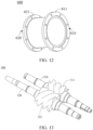
- the main body comprises an inlet end seat and an exhaust end seat sequentially connected along the axial direction of the screw, the screw comprises a first screw and a second screw, the inlet end seat is provided with a first bearing chamber; the exhaust end seat is provided with a second bearing chamber, the screw working chamber is disposed in the exhaust end seat; one of the first screw and the second screw is provided with a female rotor, the other one is provided with a male rotor, the female rotor and the male rotor mesh with each other, and the position where the female rotor and the male rotor mesh with each other is the helical section, the two ends of the first screw and the second screw are rotatably fitted in the first bearing chamber and the second bearing chamber.
- the gear ratio between the female rotor and the male rotor ranges from 3:4 to 3:5, the single-stage compression ratio of the screw compressor does not exceed 4.
- a first connecting flange is disposed on the inlet end seat, the first connecting flange is provided with an inlet, the inlet faces the radial direction of the screw;
- a second connecting flange is disposed on the exhaust end seat, the second connecting flange is provided with an outlet, the outlet faces the radial direction of the screw.
- the screw compressor further comprises an exhaust end cover, the exhaust end cover is disposed on one end of the exhaust end seat away from the inlet end seat, a connecting end face is disposed on one side of the exhaust end cover away from the exhaust end seat, the connecting end face is configured to connect with a driving mechanism.
- the screw compressor further comprises a coupling and a coupling guard
- the coupling is disposed in the coupling guard
- the coupling guard comprises a first end and a second end opposite to each other
- the connecting end face is further provided with a hole
- the screw passes through the hole and is connected to the coupling, wherein, a first positioning step is disposed on the first end, the first positioning step is sleeved at the connecting end face; and/or, a second positioning step is disposed on the second end, and the second positioning step is sleeved at the driving mechanism.
- the embodiment of the present application further provides a device, the device comprises the above-mentioned screw compressor and a driving mechanism, the driving mechanism is connected to the screw of the screw compressor.
- the embodiment of the present application further provides a use method of the screw compressor mentioned above, the use method comprises, introducing the cooling medium into the cooling chamber, and allowing the cooling medium to flow between the hollowed out portions in the cooling chamber, so as to cool the main body of the screw compressor.
- the embodiment of the present application provides a screw compressor, a device with the screw compressor and a use method of the screw compressor, a cooling structure is disposed in the screw compressor, hollowed out portions are disposed on the chamber body of the cooling structure, the chamber body is provided with a solid structure between the hollowed out portions, therefore the structural strength of the chamber body is enhanced, at the same time, the chamber body is also divided into a plurality of interconnected independent hollowed out portions, the cooling medium can pass through the independent hollowed out portions in sequent, ensures that the cooling medium can circulate to all portions of the chamber body, and contributes to increase the flow rate and uniformity of flow of the cooling medium, and enhances the cooling effect, and then effectively controls the deformation of the shell caused by temperature.
- main body-10 inlet end seat-100, air inlet port-110, first bearing chamber-120, balance air port-130, low-pressure sealing gas inlet-140, low-pressure end lubricating oil inlet-150, bearing oil return port-160, low-pressure end bearing temperature measuring port-170, first anchor bolt hole-180, inlet end cover-190, synchronous gear oil inlet-191, balance plate hole-192, tail cover-193, exhaust end seat-200, exhaust port-210, second bearing chamber-220, sealing balance chamber-230, high-pressure end sealing gas inlet-240, high-pressure end lubricating oil inlet-250, screw working chamber-260, high-pressure end bearing temperature measuring port-270, second anchor bolt hole-280, exhaust end cover-290, shaft hole-291, connecting end face-292, support point-293, oil return port-294, screw-300, first screw-310, second screw-320, chamber body-400, bottom connection surface-410, side connection surface-420, hollowed out portion-430, sealing plate-
- first and second are used for descriptive purposes only, and cannot be interpreted as indicating or implying relative importance or implicitly specifying the quantity of indicated technical features.
- the features defined as “first” and “second” may explicitly or implicitly include at least one of these features.
- the present application provides a screw compressor, a device with the screw compressor and use method, which will be described in detail below. It should be noted that the description order of the following embodiments is not intended to limit the preferred order of the embodiments of the present application. And in the following embodiments, the description of each embodiment has its own focus, and for the part not described in detail in a certain embodiment, the relevant descriptions of other embodiments can be referred to.
- the screw compressor comprises a stationary component and a rotating component.
- the stationary component is the main body 10 of the screw compressor
- the stationary component mainly comprises an inlet end seat 100 and an exhaust end seat 200
- the rotating component mainly comprises a screw 300.
- the main body 10 is a two-stage structure consisting of the inlet end seat 100 and the exhaust end seat 200, this structure helps ensure the concentricity of the screw compressor, reduces machining and assembly errors, and also helps simplify the assembly process.
- the structure of the main body 10 is not limited to this, and the example in this embodiment dores not constitute undue limitations to the structure of the main body 10.
- the screw compressor adapts two-stage structure, helps ensure the concentricity, reduces machining and assembly errors, and also helps simplify the assembly process.
- the anchor bolt hole of the screw compressor can be designed as an oversized circular hole or an elongated hole, so as to release the displacement caused by thermal expansion in the screw compressor, helps to reduce the stress concentration, improve the reliability of the device.
- a coupling guard and a connecting end face can be disposed on the exhaust end cover of the exhaust end seat, to achieve the safe protection of the high-speed coupling and ensure the alignment between the compressor and the driving structure.
- the screw 300 is defined to have an axis, and with respect to the screw 300 and its axis are defined to have axial direction, radial direction, and circumferential direction.
- the axial direction refers to the direction along the extension of the axis
- radial direction refers to the direction perpendicular to the axis
- circumferential direction refers to the direction along the circular line extending concentrically around the axis.
- the axes of each screw 300 are parallel, and one of the screws 300 can be configured to define the aforementioned directions, for example, the second screw 320, which is connected to the driving mechanism such as a motor, can be configured to define the aforementioned directions, therefore, the aforementioned axis can refer to the axis of the second screw 320, certainly, the examples provided in this embodiment do not constitute undue limitations to the present application.
- corresponding component and structure can be additionally disposed on the inlet end seat 100.
- a balance chamber can be disposed in the inlet end seat 100, the balance chamber is connected to the air inlet port 110, for example, the balance chamber is provided with a balance air port 130, the balance air port 130 is disposed at one side of the air inlet port 110 and connected to the air inlet port 110.
- the balance chamber here is configured to connect to the sealing balance chamber 230 disposed on the exhaust end seat 200 (please refer to FIG.
- the bottom connection surface 410 and the side connection surface 420 are integrally formed on the shell of the exhaust end seat 200, in other words, the bottom connection surface 410 and the side connection surface 420 can be a part integrated with the main body 10 in terms of solid structure, of course, in other embodiments, a bottom plate provided with a bottom connection surface and a side panel provided with a side connection surface can be disposed, and the bottom plate and the side panel are connected to the exhaust end seat 200 by welding or other methods, the examples in the embodiments do not constitute undue limitations thereto.
- the number of the sealing plate 500 corresponds to the sum of the number of the bottom connection surface 410 and the side connection surface 420, exemplarily, in the embodiment where one bottom connection surface 410 and two side connection surfaces 420 are disposed, three sealing plates 500 are disposed correspondingly.
- two sealing plates 500 are approximately L-shape, which are similar to the shape of the approximately L-shaped side connection surface 420, the L-shaped sealing plate 500 is configured to fit on the outer side of the side connection surface 420 to close the outer side of the hollowed out portion 430 of the side connection surface 420.
- another one sealing plate 500 is approximately similar to the shape of the bottom connection surface 410, the sealing plate 500 shown in FIG. 9 is configured to fit on the outer side of the bottom connection surface 410, that is, the bottom of the bottom connection surface 410, to close the outer side of the hollowed out portion 430 on the bottom connection surface 410.
- the setting of the cooling structure is not limited to the above, as long as the cooling structure can form a cooling chamber for cooling the helical section.
- the cooling chamber can only comprise the space inside the hollowed out portion 430, and/or other components can be disposed at one end of the hollowed out portion 430 closes to the main body 10 to connect each of the hollowed out portions 430, to form communication between the hollowed out portions 430, the example in this embodiment does not constitute undue limitations to the present application.
- the cooling chamber is formed by setting the cooling structure in the embodiment of the present application, and the main body 10, especially the screw working chamber 260 of the exhaust end seat 200 is cooled by the cooling medium in the cooling chamber, the heat of the main body 10 can be reduced efficiently, the main body 10 is prevented from being deformed by heat to affect the overall structure and working stability.
- the screw compressor further comprises a cooling liquid circulation pipeline
- the sealing plate 500 is provided with an opening 510, here please refer to FIG. 8
- the two sealing plates 500 disposed on the side connection surface 420 correspondingly are both provided with the opening 510, thus the opening 510 on one sealing plate 500 is designated as the first opening 510, the opening 510 on the other sealing plate 500 is designated as the second opening 510, the first opening 510 and the second opening 510 communicate with the hollowed out portion 430, that is, communicate with the cooling chamber.
- the first opening 510 is designated as an inlet
- the second opening 510 is designated as an outlet
- the first opening 510 and the second opening are configured in the cooling liquid circulation pipeline through pipe, so that the cooling chamber can be configured in the cooling liquid circulation pipeline through the two openings 510.
- the cooling liquid circulation pipeline further comprises a power source such as a pump disposed therein, as well as structures such as valve that can be disposed, the example in this embodiment does not constitute undue limitations to the specific structure of the cooling liquid circulation pipeline.
- corresponding component and structure can be additionally disposed on the inlet end seat 100.
- a sealing balance chamber 230 can be disposed in the inlet end seat 100, the sealing balance chamber 230 is connected to the aforementioned balance air port 130 and/or other low-pressure pipelines through an external pipeline, for example, the sealing balance chamber 230 is connected to other low-pressure pipeline of the screw compressor or connected to the low-pressure pipeline of other compressors, to reduce the pressure of the medium gas leaking into the sealing balance chamber 230.
- the two sides of the exhaust end seat 200 can also be respectively provided with a high-pressure end sealing gas inlet 240 for injecting nitrogen or other gas into the exhaust end seat 200 as the sealing gas, and further prevents the medium gas leaking into the sealing balance chamber 230 from entering the second bearing chamber 220.
- the two sides of the exhaust end seat 200 can be respectively provided with a high-pressure end lubricating oil inlet 250, the high-pressure end lubricating oil inlet 250 is connected with the bearing in the exhaust end seat 200 to supply oil to the bearing.
- an oil return port can further be disposed below the exhaust end seat 200 for the outflow of the lubricating oil, and the oil return port can further be connected to the high-pressure end lubricating oil inlet 250 through the pipe to form a circulation circuit and realize the reuse of lubricating oil.
- a high-pressure end bearing temperature measuring port 270 can be disposed on the exhaust end seat 200, the temperature measuring component can be extended into the position in the exhaust end seat 200 where the bearing is disposed through the high-pressure end bearing temperature measuring port 270, to perform temperature detection.
- a second anchor is disposed on the inlet end seat 100
- a second anchor bolt hole 280 is disposed on the second anchor
- the second anchor bolt hole 280 is usually disposed on the anchor at the bottom of the exhaust end seat 200
- the second anchor bolt hole 280 penetrates the second anchor vertically
- the second anchor bolt hole 280 extends along the axial direction of the screw 300. That is to say, the second anchor bolt hole 280 has a first length on the axial direction, the first length is longer than the length of the anchor bolt, therefore, the second anchor bolt hole 280 can accommodate the potential slippage of the exhaust end seat 200 under certain conditions due to thermal expansion and contraction.
- the second anchor bolt hole 280 can be an oversized circular hole or an elongated hole or the like.
- both the first anchor bolt hole 180 and the second anchor bolt hole 280 have a first length
- the first anchor bolt hole 180 and the second anchor bolt hole 280 can have different lengths in the axial direction, the example in this embodiment does not contribute undue limitations thereto.
- the above-mentioned configuration can be applied only to the second anchor bolt hole 280, or only to the first anchor bolt hole 180, as long as the aforementioned first anchor bolt hole 180 and/or the second anchor bolt hole 280 is disposed on the main body 10 as the anchor bolt hole.
- an exhaust end cover 290 can also be disposed, the exhaust end cover 290 is disposed at one end of the exhaust end seat 200 away from the inlet end seat 100.
- an shaft hole 291 can be disposed on the exhaust end cover 290 for the screw 300 to pass through and to connect with an external driving mechanism.
- a connecting end face 292 is disposed at one side of the exhaust end cover 290 away from the exhaust end seat 200, the connecting end face 292 is used for connecting with the driving mechanism.
- the screw compressor further comprises a coupling and a coupling guard 600, the coupling is disposed in the coupling guard 600.
- the coupling guard 600 comprises a first end 610 and a second end 620 opposite to each other, the first end 610 is adjacent to the exhaust end cover 290.
- the first end 610 protrudes radially to form a first positioning step 611, the first positioning step 611 is sleeved on the connecting end face 292.
- the second end 620 protrudes radially to from a second positioning step 621, and the second positioning step 621 is configured to be sleeved on the driving mechanism.
- the screw 300 passes through the hole and is connected to the coupling.
- a support point 293 can also be disposed on the exhaust end cover 290 to facilitate the users to disassemble, assemble and place.
- a rotation mark of the screw 300 can also be disposed on the exhaust end cover 290, to facilitate the users to observe.
- An oil return port 294 can also be disposed below the exhaust end cover 290 to facilitate the return of the lubricating oil at the high-pressure end.
- the first screw 310 is provided with the female rotor
- the second screw 320 is provided with the male rotor
- the example in this embodiment does not contribute undue limitations thereto.
- the gear ratio between the female rotor and the male rotor ranges from 3:4 to 3:5, and the single-stage compression ratio of the screw compressor does not exceed 4.
- the gear ratio of the female rotor and male rotor can be set as 3:4, 3:5, 4:6, and so on.
- the temperature difference between the inlet and outlet of the screw compressor can be controlled within 200°C.
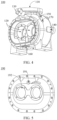
- a synchronous gear 700 can also be disposed, please refer to FIG. 12 , the synchronous gear 700 comprises a pinion gear 720 and a bull gear 720 meshing with each other, the diameter of the pinion gear 720 is smaller than the diameter of the bull gear 710.
- the pinion gear 720 and the bull gear 710 are fixedly installed on the male rotor and the female rotor respectively, thus ensuring that the male rotor and the female rotor rotate synchronously at a fixed speed ratio.
- the male rotor, the female rotor and the screw working chamber 260 jointly form a compression chamber.
- the coupling guard 600 can also protect the coupling inside the coupling guard 600.
- An oil return port 294 can also be disposed on the exhaust end cover 290 for oil returning of the second bearing chamber 220 on the exhaust end seat 200 .
Landscapes
- Engineering & Computer Science (AREA)
- Mechanical Engineering (AREA)
- General Engineering & Computer Science (AREA)
- Applications Or Details Of Rotary Compressors (AREA)
Applications Claiming Priority (2)
| Application Number | Priority Date | Filing Date | Title |
|---|---|---|---|
| CN202310761261.4A CN116608126A (zh) | 2023-06-26 | 2023-06-26 | 螺杆压缩机、具有其的设备及使用方法 |
| PCT/CN2024/082956 WO2025001341A1 (zh) | 2023-06-26 | 2024-03-21 | 螺杆压缩机、具有其的设备及使用方法 |
Publications (2)
| Publication Number | Publication Date |
|---|---|
| EP4538533A1 true EP4538533A1 (de) | 2025-04-16 |
| EP4538533A4 EP4538533A4 (de) | 2025-11-19 |
Family
ID=87683769
Family Applications (1)
| Application Number | Title | Priority Date | Filing Date |
|---|---|---|---|
| EP24828310.3A Pending EP4538533A4 (de) | 2023-06-26 | 2024-03-21 | Schraubenverdichter, vorrichtung damit und verwendungsverfahren dafür |
Country Status (3)
| Country | Link |
|---|---|
| EP (1) | EP4538533A4 (de) |
| CN (1) | CN116608126A (de) |
| WO (1) | WO2025001341A1 (de) |
Families Citing this family (1)
| Publication number | Priority date | Publication date | Assignee | Title |
|---|---|---|---|---|
| CN116608126A (zh) * | 2023-06-26 | 2023-08-18 | 中国船舶集团有限公司第七一一研究所 | 螺杆压缩机、具有其的设备及使用方法 |
Family Cites Families (17)
| Publication number | Priority date | Publication date | Assignee | Title |
|---|---|---|---|---|
| GB665565A (en) * | 1948-08-04 | 1952-01-23 | Ljungstroms Angturbin Ab | Improvements in or relating to displacement engines of the helical screw wheel type |
| SE462232B (sv) * | 1988-11-16 | 1990-05-21 | Svenska Rotor Maskiner Ab | Skruvkompressor med oljedraenering |
| CN2718270Y (zh) * | 2004-07-26 | 2005-08-17 | 西安交通大学 | 一种干式高速螺杆空气压缩机 |
| CN202250859U (zh) * | 2011-09-28 | 2012-05-30 | 上海齐耀螺杆机械有限公司 | 焦炉煤气螺杆压缩机组 |
| BE1020311A3 (nl) * | 2012-02-28 | 2013-07-02 | Atlas Copco Airpower Nv | Schroefcompressor. |
| DE102012011820A1 (de) * | 2012-06-15 | 2013-12-19 | Ralf Steffens | Spindelverdichter-Abdichtung |
| CN105041648B (zh) * | 2015-09-15 | 2017-11-17 | 珠海格力电器股份有限公司 | 一种螺杆压缩机及其机体 |
| JP6692725B2 (ja) * | 2016-09-08 | 2020-05-13 | 株式会社神戸製鋼所 | オイルフリースクリュ圧縮機 |
| CN108843568B (zh) * | 2018-08-01 | 2024-05-17 | 珠海格力电器股份有限公司 | 螺杆压缩机及其机体 |
| CN209212564U (zh) * | 2018-11-19 | 2019-08-06 | 天津市舒塔克压缩机有限公司 | 一种新型螺杆式空气压缩机主机安装结构 |
| CN109441814A (zh) * | 2018-12-29 | 2019-03-08 | 无锡五洋赛德压缩机有限公司 | 新型螺杆压缩机 |
| CN209818296U (zh) * | 2018-12-29 | 2019-12-20 | 无锡五洋赛德压缩机有限公司 | 新型螺杆压缩机 |
| CN110701045B (zh) * | 2019-11-22 | 2020-12-18 | 海门市晶盛真空设备有限公司 | 一种双螺杆真空泵 |
| JP7507717B2 (ja) * | 2021-03-31 | 2024-06-28 | 株式会社日立産機システム | スクリュー圧縮機 |
| CN113153746A (zh) * | 2021-04-23 | 2021-07-23 | 宋月坤 | 内置排气增压器式复合螺杆真空泵 |
| CN215213938U (zh) * | 2021-07-02 | 2021-12-17 | 厦门东亚机械工业股份有限公司 | 一种无油螺杆压缩机 |
| CN116608126A (zh) * | 2023-06-26 | 2023-08-18 | 中国船舶集团有限公司第七一一研究所 | 螺杆压缩机、具有其的设备及使用方法 |
-
2023
- 2023-06-26 CN CN202310761261.4A patent/CN116608126A/zh active Pending
-
2024
- 2024-03-21 EP EP24828310.3A patent/EP4538533A4/de active Pending
- 2024-03-21 WO PCT/CN2024/082956 patent/WO2025001341A1/zh active Pending
Also Published As
| Publication number | Publication date |
|---|---|
| WO2025001341A1 (zh) | 2025-01-02 |
| CN116608126A (zh) | 2023-08-18 |
| EP4538533A4 (de) | 2025-11-19 |
Similar Documents
| Publication | Publication Date | Title |
|---|---|---|
| EP2119915B1 (de) | Zweistufiger Schraubenverdichter und Kühlvorrichtung | |
| EP2310688B1 (de) | Gasverdichtermagnetkoppler | |
| US11221013B2 (en) | Centrifugal compressor | |
| US20160177954A1 (en) | Multi-stage centrifugal compressor and air conditioning unit | |
| EP4538533A1 (de) | Schraubenverdichter, vorrichtung damit und verwendungsverfahren dafür | |
| TWI705186B (zh) | 螺旋式壓縮機 | |
| CA2693876A1 (en) | Thrust and intake chamber for pump | |
| CN114320902A (zh) | 涡旋压缩机、空调设备及车辆 | |
| US9945384B2 (en) | Turbo compressor and turbo refrigerator | |
| CN102213232B (zh) | 驱动轴构造、涡轮压缩机及涡轮制冷机 | |
| KR100873043B1 (ko) | 기어 케이스 어셈블리 | |
| CN115163492B (zh) | 泵体组件、活塞式压缩机及制冷设备 | |
| CN113217411B (zh) | 压缩机以及空调机组 | |
| CN111946632B (zh) | 一种用于制冷剂泵与压缩机双循环系统的制冷剂泵 | |
| CN116733754B (zh) | 一种浸入式静密封隔热泵及其应用系统和应用方法 | |
| KR101145417B1 (ko) | 다단 고압 펌프 | |
| US11560889B1 (en) | Scroll compressor with second intermediate cap to facilitate refrigerant injection | |
| CN207420858U (zh) | 支架组件、涡旋压缩机以及压缩机系统 | |
| CN205383078U (zh) | 涡旋压缩机 | |
| CN110685918A (zh) | 多相混输泵 | |
| CN216306225U (zh) | 一种转子组件、压缩机和空调 | |
| JP2005171959A (ja) | モータ一体型燃料ガス圧縮機の軸封機構 | |
| CN221647190U (zh) | 卧式屏蔽泵 | |
| CN223156852U (zh) | 一种具有冷却性能的机壳、电机和压缩机 | |
| CN221096968U (zh) | 一种泵体冷却结构、泵体冷却系统及分子泵 |
Legal Events
| Date | Code | Title | Description |
|---|---|---|---|
| STAA | Information on the status of an ep patent application or granted ep patent |
Free format text: STATUS: UNKNOWN |
|
| STAA | Information on the status of an ep patent application or granted ep patent |
Free format text: STATUS: THE INTERNATIONAL PUBLICATION HAS BEEN MADE |
|
| PUAI | Public reference made under article 153(3) epc to a published international application that has entered the european phase |
Free format text: ORIGINAL CODE: 0009012 |
|
| STAA | Information on the status of an ep patent application or granted ep patent |
Free format text: STATUS: REQUEST FOR EXAMINATION WAS MADE |
|
| 17P | Request for examination filed |
Effective date: 20250107 |
|
| AK | Designated contracting states |
Kind code of ref document: A1 Designated state(s): AL AT BE BG CH CY CZ DE DK EE ES FI FR GB GR HR HU IE IS IT LI LT LU LV MC ME MK MT NL NO PL PT RO RS SE SI SK SM TR |
|
| A4 | Supplementary search report drawn up and despatched |
Effective date: 20251021 |
|
| RIC1 | Information provided on ipc code assigned before grant |
Ipc: F04C 18/16 20060101AFI20251015BHEP Ipc: F01C 21/10 20060101ALI20251015BHEP |