EP4535534A1 - Batterieschutzgrundplatte, verbundschutzstruktur für batteriepack und fahrzeug - Google Patents
Batterieschutzgrundplatte, verbundschutzstruktur für batteriepack und fahrzeug Download PDFInfo
- Publication number
- EP4535534A1 EP4535534A1 EP23815131.0A EP23815131A EP4535534A1 EP 4535534 A1 EP4535534 A1 EP 4535534A1 EP 23815131 A EP23815131 A EP 23815131A EP 4535534 A1 EP4535534 A1 EP 4535534A1
- Authority
- EP
- European Patent Office
- Prior art keywords
- fiber reinforced
- reinforced resin
- frame
- resin layer
- bottom plate
- Prior art date
- Legal status (The legal status is an assumption and is not a legal conclusion. Google has not performed a legal analysis and makes no representation as to the accuracy of the status listed.)
- Pending
Links
Images


Classifications
-
- B—PERFORMING OPERATIONS; TRANSPORTING
- B32—LAYERED PRODUCTS
- B32B—LAYERED PRODUCTS, i.e. PRODUCTS BUILT-UP OF STRATA OF FLAT OR NON-FLAT, e.g. CELLULAR OR HONEYCOMB, FORM
- B32B15/00—Layered products comprising a layer of metal
- B32B15/14—Layered products comprising a layer of metal next to a fibrous or filamentary layer
-
- B—PERFORMING OPERATIONS; TRANSPORTING
- B32—LAYERED PRODUCTS
- B32B—LAYERED PRODUCTS, i.e. PRODUCTS BUILT-UP OF STRATA OF FLAT OR NON-FLAT, e.g. CELLULAR OR HONEYCOMB, FORM
- B32B15/00—Layered products comprising a layer of metal
- B32B15/18—Layered products comprising a layer of metal comprising iron or steel
-
- B—PERFORMING OPERATIONS; TRANSPORTING
- B32—LAYERED PRODUCTS
- B32B—LAYERED PRODUCTS, i.e. PRODUCTS BUILT-UP OF STRATA OF FLAT OR NON-FLAT, e.g. CELLULAR OR HONEYCOMB, FORM
- B32B5/00—Layered products characterised by the non- homogeneity or physical structure, i.e. comprising a fibrous, filamentary, particulate or foam layer; Layered products characterised by having a layer differing constitutionally or physically in different parts
- B32B5/02—Layered products characterised by the non- homogeneity or physical structure, i.e. comprising a fibrous, filamentary, particulate or foam layer; Layered products characterised by having a layer differing constitutionally or physically in different parts characterised by structural features of a fibrous or filamentary layer
- B32B5/12—Layered products characterised by the non- homogeneity or physical structure, i.e. comprising a fibrous, filamentary, particulate or foam layer; Layered products characterised by having a layer differing constitutionally or physically in different parts characterised by structural features of a fibrous or filamentary layer characterised by the relative arrangement of fibres or filaments of different layers, e.g. the fibres or filaments being parallel or perpendicular to each other
-
- B—PERFORMING OPERATIONS; TRANSPORTING
- B60—VEHICLES IN GENERAL
- B60L—PROPULSION OF ELECTRICALLY-PROPELLED VEHICLES; SUPPLYING ELECTRIC POWER FOR AUXILIARY EQUIPMENT OF ELECTRICALLY-PROPELLED VEHICLES; ELECTRODYNAMIC BRAKE SYSTEMS FOR VEHICLES IN GENERAL; MAGNETIC SUSPENSION OR LEVITATION FOR VEHICLES; MONITORING OPERATING VARIABLES OF ELECTRICALLY-PROPELLED VEHICLES; ELECTRIC SAFETY DEVICES FOR ELECTRICALLY-PROPELLED VEHICLES
- B60L50/00—Electric propulsion with power supplied within the vehicle
- B60L50/50—Electric propulsion with power supplied within the vehicle using propulsion power supplied by batteries or fuel cells
- B60L50/60—Electric propulsion with power supplied within the vehicle using propulsion power supplied by batteries or fuel cells using power supplied by batteries
- B60L50/64—Constructional details of batteries specially adapted for electric vehicles
-
- H—ELECTRICITY
- H01—ELECTRIC ELEMENTS
- H01M—PROCESSES OR MEANS, e.g. BATTERIES, FOR THE DIRECT CONVERSION OF CHEMICAL ENERGY INTO ELECTRICAL ENERGY
- H01M50/00—Constructional details or processes of manufacture of the non-active parts of electrochemical cells other than fuel cells, e.g. hybrid cells
- H01M50/20—Mountings; Secondary casings or frames; Racks, modules or packs; Suspension devices; Shock absorbers; Transport or carrying devices; Holders
- H01M50/204—Racks, modules or packs for multiple batteries or multiple cells
-
- H—ELECTRICITY
- H01—ELECTRIC ELEMENTS
- H01M—PROCESSES OR MEANS, e.g. BATTERIES, FOR THE DIRECT CONVERSION OF CHEMICAL ENERGY INTO ELECTRICAL ENERGY
- H01M50/00—Constructional details or processes of manufacture of the non-active parts of electrochemical cells other than fuel cells, e.g. hybrid cells
- H01M50/20—Mountings; Secondary casings or frames; Racks, modules or packs; Suspension devices; Shock absorbers; Transport or carrying devices; Holders
- H01M50/218—Mountings; Secondary casings or frames; Racks, modules or packs; Suspension devices; Shock absorbers; Transport or carrying devices; Holders characterised by the material
- H01M50/22—Mountings; Secondary casings or frames; Racks, modules or packs; Suspension devices; Shock absorbers; Transport or carrying devices; Holders characterised by the material of the casings or racks
- H01M50/222—Inorganic material
- H01M50/224—Metals
-
- H—ELECTRICITY
- H01—ELECTRIC ELEMENTS
- H01M—PROCESSES OR MEANS, e.g. BATTERIES, FOR THE DIRECT CONVERSION OF CHEMICAL ENERGY INTO ELECTRICAL ENERGY
- H01M50/00—Constructional details or processes of manufacture of the non-active parts of electrochemical cells other than fuel cells, e.g. hybrid cells
- H01M50/20—Mountings; Secondary casings or frames; Racks, modules or packs; Suspension devices; Shock absorbers; Transport or carrying devices; Holders
- H01M50/218—Mountings; Secondary casings or frames; Racks, modules or packs; Suspension devices; Shock absorbers; Transport or carrying devices; Holders characterised by the material
- H01M50/22—Mountings; Secondary casings or frames; Racks, modules or packs; Suspension devices; Shock absorbers; Transport or carrying devices; Holders characterised by the material of the casings or racks
- H01M50/227—Organic material
-
- H—ELECTRICITY
- H01—ELECTRIC ELEMENTS
- H01M—PROCESSES OR MEANS, e.g. BATTERIES, FOR THE DIRECT CONVERSION OF CHEMICAL ENERGY INTO ELECTRICAL ENERGY
- H01M50/00—Constructional details or processes of manufacture of the non-active parts of electrochemical cells other than fuel cells, e.g. hybrid cells
- H01M50/20—Mountings; Secondary casings or frames; Racks, modules or packs; Suspension devices; Shock absorbers; Transport or carrying devices; Holders
- H01M50/218—Mountings; Secondary casings or frames; Racks, modules or packs; Suspension devices; Shock absorbers; Transport or carrying devices; Holders characterised by the material
- H01M50/22—Mountings; Secondary casings or frames; Racks, modules or packs; Suspension devices; Shock absorbers; Transport or carrying devices; Holders characterised by the material of the casings or racks
- H01M50/229—Composite material consisting of a mixture of organic and inorganic materials
-
- H—ELECTRICITY
- H01—ELECTRIC ELEMENTS
- H01M—PROCESSES OR MEANS, e.g. BATTERIES, FOR THE DIRECT CONVERSION OF CHEMICAL ENERGY INTO ELECTRICAL ENERGY
- H01M50/00—Constructional details or processes of manufacture of the non-active parts of electrochemical cells other than fuel cells, e.g. hybrid cells
- H01M50/20—Mountings; Secondary casings or frames; Racks, modules or packs; Suspension devices; Shock absorbers; Transport or carrying devices; Holders
- H01M50/218—Mountings; Secondary casings or frames; Racks, modules or packs; Suspension devices; Shock absorbers; Transport or carrying devices; Holders characterised by the material
- H01M50/22—Mountings; Secondary casings or frames; Racks, modules or packs; Suspension devices; Shock absorbers; Transport or carrying devices; Holders characterised by the material of the casings or racks
- H01M50/231—Mountings; Secondary casings or frames; Racks, modules or packs; Suspension devices; Shock absorbers; Transport or carrying devices; Holders characterised by the material of the casings or racks having a layered structure
-
- H—ELECTRICITY
- H01—ELECTRIC ELEMENTS
- H01M—PROCESSES OR MEANS, e.g. BATTERIES, FOR THE DIRECT CONVERSION OF CHEMICAL ENERGY INTO ELECTRICAL ENERGY
- H01M50/00—Constructional details or processes of manufacture of the non-active parts of electrochemical cells other than fuel cells, e.g. hybrid cells
- H01M50/20—Mountings; Secondary casings or frames; Racks, modules or packs; Suspension devices; Shock absorbers; Transport or carrying devices; Holders
- H01M50/233—Mountings; Secondary casings or frames; Racks, modules or packs; Suspension devices; Shock absorbers; Transport or carrying devices; Holders characterised by physical properties of casings or racks, e.g. dimensions
- H01M50/236—Hardness
-
- H—ELECTRICITY
- H01—ELECTRIC ELEMENTS
- H01M—PROCESSES OR MEANS, e.g. BATTERIES, FOR THE DIRECT CONVERSION OF CHEMICAL ENERGY INTO ELECTRICAL ENERGY
- H01M50/00—Constructional details or processes of manufacture of the non-active parts of electrochemical cells other than fuel cells, e.g. hybrid cells
- H01M50/20—Mountings; Secondary casings or frames; Racks, modules or packs; Suspension devices; Shock absorbers; Transport or carrying devices; Holders
- H01M50/233—Mountings; Secondary casings or frames; Racks, modules or packs; Suspension devices; Shock absorbers; Transport or carrying devices; Holders characterised by physical properties of casings or racks, e.g. dimensions
- H01M50/24—Mountings; Secondary casings or frames; Racks, modules or packs; Suspension devices; Shock absorbers; Transport or carrying devices; Holders characterised by physical properties of casings or racks, e.g. dimensions adapted for protecting batteries from their environment, e.g. from corrosion
-
- H—ELECTRICITY
- H01—ELECTRIC ELEMENTS
- H01M—PROCESSES OR MEANS, e.g. BATTERIES, FOR THE DIRECT CONVERSION OF CHEMICAL ENERGY INTO ELECTRICAL ENERGY
- H01M50/00—Constructional details or processes of manufacture of the non-active parts of electrochemical cells other than fuel cells, e.g. hybrid cells
- H01M50/20—Mountings; Secondary casings or frames; Racks, modules or packs; Suspension devices; Shock absorbers; Transport or carrying devices; Holders
- H01M50/233—Mountings; Secondary casings or frames; Racks, modules or packs; Suspension devices; Shock absorbers; Transport or carrying devices; Holders characterised by physical properties of casings or racks, e.g. dimensions
- H01M50/242—Mountings; Secondary casings or frames; Racks, modules or packs; Suspension devices; Shock absorbers; Transport or carrying devices; Holders characterised by physical properties of casings or racks, e.g. dimensions adapted for protecting batteries against vibrations, collision impact or swelling
-
- H—ELECTRICITY
- H01—ELECTRIC ELEMENTS
- H01M—PROCESSES OR MEANS, e.g. BATTERIES, FOR THE DIRECT CONVERSION OF CHEMICAL ENERGY INTO ELECTRICAL ENERGY
- H01M50/00—Constructional details or processes of manufacture of the non-active parts of electrochemical cells other than fuel cells, e.g. hybrid cells
- H01M50/20—Mountings; Secondary casings or frames; Racks, modules or packs; Suspension devices; Shock absorbers; Transport or carrying devices; Holders
- H01M50/244—Secondary casings; Racks; Suspension devices; Carrying devices; Holders characterised by their mounting method
-
- H—ELECTRICITY
- H01—ELECTRIC ELEMENTS
- H01M—PROCESSES OR MEANS, e.g. BATTERIES, FOR THE DIRECT CONVERSION OF CHEMICAL ENERGY INTO ELECTRICAL ENERGY
- H01M50/00—Constructional details or processes of manufacture of the non-active parts of electrochemical cells other than fuel cells, e.g. hybrid cells
- H01M50/20—Mountings; Secondary casings or frames; Racks, modules or packs; Suspension devices; Shock absorbers; Transport or carrying devices; Holders
- H01M50/249—Mountings; Secondary casings or frames; Racks, modules or packs; Suspension devices; Shock absorbers; Transport or carrying devices; Holders specially adapted for aircraft or vehicles, e.g. cars or trains
-
- B—PERFORMING OPERATIONS; TRANSPORTING
- B32—LAYERED PRODUCTS
- B32B—LAYERED PRODUCTS, i.e. PRODUCTS BUILT-UP OF STRATA OF FLAT OR NON-FLAT, e.g. CELLULAR OR HONEYCOMB, FORM
- B32B2262/00—Composition or structural features of fibres which form a fibrous or filamentary layer or are present as additives
- B32B2262/10—Inorganic fibres
- B32B2262/101—Glass fibres
-
- B—PERFORMING OPERATIONS; TRANSPORTING
- B32—LAYERED PRODUCTS
- B32B—LAYERED PRODUCTS, i.e. PRODUCTS BUILT-UP OF STRATA OF FLAT OR NON-FLAT, e.g. CELLULAR OR HONEYCOMB, FORM
- B32B2307/00—Properties of the layers or laminate
- B32B2307/70—Other properties
- B32B2307/732—Dimensional properties
- B32B2307/737—Dimensions, e.g. volume or area
- B32B2307/7375—Linear, e.g. length, distance or width
- B32B2307/7376—Thickness
-
- B—PERFORMING OPERATIONS; TRANSPORTING
- B32—LAYERED PRODUCTS
- B32B—LAYERED PRODUCTS, i.e. PRODUCTS BUILT-UP OF STRATA OF FLAT OR NON-FLAT, e.g. CELLULAR OR HONEYCOMB, FORM
- B32B2457/00—Electrical equipment
- B32B2457/10—Batteries
-
- H—ELECTRICITY
- H01—ELECTRIC ELEMENTS
- H01M—PROCESSES OR MEANS, e.g. BATTERIES, FOR THE DIRECT CONVERSION OF CHEMICAL ENERGY INTO ELECTRICAL ENERGY
- H01M2220/00—Batteries for particular applications
- H01M2220/20—Batteries in motive systems, e.g. vehicle, ship, plane
-
- Y—GENERAL TAGGING OF NEW TECHNOLOGICAL DEVELOPMENTS; GENERAL TAGGING OF CROSS-SECTIONAL TECHNOLOGIES SPANNING OVER SEVERAL SECTIONS OF THE IPC; TECHNICAL SUBJECTS COVERED BY FORMER USPC CROSS-REFERENCE ART COLLECTIONS [XRACs] AND DIGESTS
- Y02—TECHNOLOGIES OR APPLICATIONS FOR MITIGATION OR ADAPTATION AGAINST CLIMATE CHANGE
- Y02E—REDUCTION OF GREENHOUSE GAS [GHG] EMISSIONS, RELATED TO ENERGY GENERATION, TRANSMISSION OR DISTRIBUTION
- Y02E60/00—Enabling technologies; Technologies with a potential or indirect contribution to GHG emissions mitigation
- Y02E60/10—Energy storage using batteries
Definitions
- the present disclosure relates to the technical field of batteries, and specifically, to a battery protection bottom plate, a battery pack composite protection structure, and a vehicle.
- a battery pack of a new energy electric vehicle is usually arranged at a bottom of the vehicle. Faced with complicated working conditions, the battery pack is susceptible to an impact from a hard object such as an external stone during vehicle driving. Therefore, it is usually necessary to take certain protective measures at a bottom of the battery pack to prevent the battery pack from being affected by the impact, which otherwise causes the problems of surface damage and electrolyte solution leakage.
- An existing battery pack bottom protection scheme is mainly to protect the bottom of the battery pack by providing a steel plate. In order to prevent the steel plate from being corroded by water vapor and other factors, an electrophoresis process is adopted for anti-corrosion treatment.
- An existing battery pack bottom protection structure has the following problems:
- the present disclosure provides a battery protection bottom plate, a battery pack composite protection structure, and a vehicle.
- the present disclosure provides a battery protection bottom plate, including an upper fiber reinforced resin layer, a metal plate, a fiber reinforced resin frame and a lower fiber reinforced resin layer.
- the metal plate and the fiber reinforced resin frame are located between the upper fiber reinforced resin layer and the lower fiber reinforced resin layer, and the metal plate is located inside the fiber reinforced resin frame.
- a top surface of the fiber reinforced resin frame is integrally connected to the upper fiber reinforced resin layer, and a bottom surface of the fiber reinforced resin frame is integrally connected to the lower fiber reinforced resin layer.
- the fiber reinforced resin frame is of a frame structure formed by connecting multiple frame plates end to end, and the fiber reinforced resin frame and the metal plate satisfy the following condition: 0.01 ⁇ W / L ⁇ 0.07, where W is a width of the frame plate in mm; and L is a length of the metal plate in mm.
- the width W of the frame plate ranges from 30 mm to 200 mm, and the length of the metal plate ranges from 1200 mm to 2200 mm.
- the upper fiber reinforced resin layer, the metal plate and the lower fiber reinforced resin layer each are of an approximately square sheet structure; and the fiber reinforced resin frame is of a sheet-like approximately square frame structure.
- the multiple frame plates have the same width, or the width of the frame plate extending along a widthwise direction of the fiber reinforced resin frame is greater than 1.2 times the width of the frame plate extending along a lengthwise direction of the fiber reinforced resin frame.
- the metal plate has a thickness ranging from 0.7 mm to 1.6 mm, and a thickness difference between the fiber reinforced resin frame and the metal plate is less than 0.1 mm.
- multiple mounting holes are spaced away in an inner side of an edge of the battery protection bottom plate, and the mounting holes sequentially run through the upper fiber reinforced resin layer, the fiber reinforced resin frame and the lower fiber reinforced resin layer.
- the upper fiber reinforced resin layer includes multiple layers of first fiber reinforced prepregs stacked with each other; the fiber reinforced resin frame includes multiple layers of second fiber reinforced prepregs stacked with each other; and the lower fiber reinforced resin layer includes multiple layers of third fiber reinforced prepregs stacked with each other.
- the metal plate is a steel plate, and a galvanized layer, a galvanized iron alloy layer or an electrophoretic paint protective layer is arranged at an outer surface of the steel plate.
- the present disclosure provides a battery pack composite protection structure, including a battery pack and the battery protection bottom plate as described above.
- the battery protection bottom plate is arranged below the battery pack, and a buffer zone is formed between the battery pack and the battery protection bottom plate.
- the buffer zone is filled with a buffer layer, and the buffer layer is selected from a honeycomb material or a rigid foam material.
- the present disclosure provides a vehicle, including the battery protection bottom plate and the battery pack protection structure as described above.
- the upper fiber reinforced resin layer and the lower fiber reinforced resin layer are compounded on a front surface and a back surface of the metal plate, so that on the one hand, the upper fiber reinforced resin layer and the lower fiber reinforced resin layer can improve corrosion resistance of the metal plate.
- the lower fiber reinforced resin layer can resist an impact of stones and the like on a bottom of the battery protection bottom plate, thereby avoiding the corrosion problem of an impacted part.
- the stiffness and strength of the metal plate are effectively improved, and the metal plate has higher impact resistance.
- the upper fiber reinforced resin layer and the lower fiber reinforced resin layer feature uniform thickness, which ensures consistent strength and stiffness at different positions, so that the metal plate does not need to be additionally punched, thereby improving production efficiency and reducing production costs.
- the fiber reinforced resin frame is arranged on a periphery of the metal plate as a frame connection transition member for the upper fiber reinforced resin layer and the lower fiber reinforced resin layer. This can effectively offset an influence of the thickness of the metal plate on frame connection for the upper fiber reinforced resin layer and the lower fiber reinforced resin layer, ensure the strength of a frame of the battery protection bottom plate, and further facilitate use of the frame of the battery protection bottom plate as a mounting structure of the battery protection bottom plate on a battery, and improve impact resistance of the battery protection bottom plate.
- orientation or position relationships indicated by the terms such as “upper”, “lower”, “top”, “bottom”, “inner” and “outer” are based on orientation or position relationships shown in the accompanying drawings, and are merely for ease of description of the present disclosure and simplification of the description, rather than indicating or implying that the apparatus or element referred to needs to have a specific orientation or be constructed and operated in a specific orientation, and therefore cannot be construed as limiting the present disclosure.
- a plurality of/multiple means two or more.
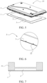
- an embodiment of the present disclosure provides a battery protection bottom plate 1, including an upper fiber reinforced resin layer 11, a metal plate 12, a fiber reinforced resin frame 13 and a lower fiber reinforced resin layer 14.
- the metal plate 12 and the fiber reinforced resin frame 13 are located between the upper fiber reinforced resin layer 11 and the lower fiber reinforced resin layer 14, and the metal plate 12 is located inside the fiber reinforced resin frame 13.
- a top surface of the fiber reinforced resin frame 13 is integrally connected to the upper fiber reinforced resin layer 11, and a bottom surface of the fiber reinforced resin frame 13 is integrally connected to the lower fiber reinforced resin layer 14.
- the upper fiber reinforced resin layer 11 and the lower fiber reinforced resin layer 14 are compounded on a front surface and a back surface of the metal plate 12, so that on the one hand, the upper fiber reinforced resin layer 11 and the lower fiber reinforced resin layer 14 can improve corrosion resistance of the metal plate 12. In addition, the lower fiber reinforced resin layer 14 can resist an impact of stones and the like on a bottom of the battery protection bottom plate 1, thereby avoiding the corrosion problem of an impacted part.
- the stiffness and strength of the metal plate 12 are effectively improved, and the metal plate has higher impact resistance.
- the upper fiber reinforced resin layer 11 and the lower fiber reinforced resin layer 14 feature uniform thickness, which ensures consistent strength and stiffness at different positions, so that the metal plate 12 does not need to be additionally punched, thereby improving production efficiency and reducing production costs.
- the fiber reinforced resin frame 13 is arranged on a periphery of the metal plate 12 as a frame connection transition member for the upper fiber reinforced resin layer 11 and the lower fiber reinforced resin layer 14. This can effectively offset an influence of the thickness of the metal plate 12 on frame connection for the upper fiber reinforced resin layer 11 and the lower fiber reinforced resin layer 14, ensure the strength of a frame of the battery protection bottom plate 1, and further facilitate use of the frame of the battery protection bottom plate 1 as a mounting structure of the battery protection bottom plate on a battery pack 3, and improve impact resistance of the battery protection bottom plate.
- the fiber reinforced resin frame 13 is of a frame structure formed by connecting multiple frame plates 131 end to end, and the fiber reinforced resin frame 13 and the metal plate 12 satisfy the following condition: 0.01 ⁇ W / L ⁇ 0.07, where W is a width of the frame plate in mm; and L is a length of the metal plate in mm.
- W / L may be 0.01, 0.03, 0.04, 0.05, 0.06, 0.07, or the like.
- the length L of the metal plate 12 is the length of a longer side of the metal plate 12.
- the metal plate 12 is embedded in the middle of the fiber reinforced resin frame 13 and is fixed by the upper fiber reinforced resin layer 11 and the lower fiber reinforced resin layer 14.
- the metal plate 12 may vibrate up and down and conduct a stress, and then a tensile stress and a shear stress are formed at a joint between the metal plate 12 and the upper fiber reinforced resin layer 11, the lower fiber reinforced resin layer 14 and the fiber reinforced resin frame 13.
- a tensile shear force exceeds a tolerable range of the joint, the problem of separation of delamination of the joint between the metal plate 12 and the upper fiber reinforced resin layer 11, the lower fiber reinforced resin layer 14 or the fiber reinforced resin frame 13 is likely to occur.
- the inventor has found through experiments that when mounted on a battery pack 3, the battery protection bottom plate 1 has a maximum overhanging amount in a lengthwise direction of the metal plate 12 under normal working conditions.
- a stress in the lengthwise direction thereof is greater, and delamination is more likely to occur, while the width of the frame plate 131 is related to resistance of the fiber reinforced resin frame 13 to a tensile shear effect generated when the metal plate 12 is impacted.
- the width W of the frame plate 131 ranges from 30 mm to 200 mm, and the length L of the metal plate 12 ranges from 1200 mm to 2200 mm.
- the battery protection bottom plate When the width W of the frame plate 131 is in the above range, the battery protection bottom plate has a suitable mounting area, which effectively supports and locates the metal plate 12 on a middle portion thereof.
- W may be 30 mm, 50 mm, 80 mm, 100 mm, 130 mm, 150 mm, 180 mm, 200 mm, or the like; and L may be 1200 mm, 1350 mm, 1500 mm, 1800 mm, 2000 mm, 2100 mm, 2200 mm, or the like.
- the upper fiber reinforced resin layer 11, the metal plate 12 and the lower fiber reinforced resin layer 14 each are of an approximately square sheet structure; and the fiber reinforced resin frame 13 is of a sheet-like approximately square frame structure.
- the square sheet structure means that the overall shape is roughly square
- the sheet-like square frame structure means that the overall shape is roughly square, while some details may be changed without affecting the overall shape. For example, a rounded corner is provided at a corner of the square, or a protrusion or a groove is provided at an edge of the square.
- the above-mentioned roughly square structure can better match the shape of the battery pack.
- the upper fiber reinforced resin layer 11 and the lower fiber reinforced resin layer 14 are consistent in shape to ensure connection stability of the upper fiber reinforced resin layer 11 and the lower fiber reinforced resin layer 14.
- the shapes of the upper fiber reinforced resin layer 11 and the lower fiber reinforced resin layer 14 are adapted to the shape of the bottom of the battery pack 3. In other embodiments, when the battery pack 3 is in another shape, the upper fiber reinforced resin layer 11 and the lower fiber reinforced resin layer 14 may be in another adaptive shape, such as a triangle, a pentagon, or a hexagon.
- the multiple frame plates 131 have the same width.
- the width of the frame plate 131 extending along a widthwise direction of the fiber reinforced resin frame 13 is greater than 1.2 times the width of the frame plate 131 extending along a lengthwise direction of the fiber reinforced resin frame 13.
- Increasing the width of the frame plate 131 extending in the widthwise direction of the fiber reinforced resin frame 13 is beneficial to improving the impact strength of the battery protection bottom plate 1 in the lengthwise direction.
- the metal plate 12 has a thickness ranging from 0.7 mm to 1.6 mm, and a thickness difference between the fiber reinforced resin frame 13 and the metal plate 12 is less than 0.1 mm.
- the thickness of the metal plate 12 may be 0.7 mm, 0.9 mm, 1 mm, 1.2 mm, 1.5 mm, 1.6 mm, or the like.
- the metal plate 12 When the thickness of the metal plate 12 is in the above range, the metal plate has good impact resistance and a low material cost.
- the fiber reinforced resin frame 13 can effectively fill a peripheral space of the metal plate 12, so as to connect the upper fiber reinforced resin layer 11 to the lower fiber reinforced resin layer 14, avoid a height difference between frames of the upper fiber reinforced resin layer 11 and the lower fiber reinforced resin layer 14 and ensure surface smoothness of the battery protection bottom plate 1.
- the thickness difference between the fiber reinforced resin frame 13 and the metal plate 12 may be 0.09 mm, 0.08 mm, 0.07 mm, 0.05 mm, 0.02 mm, 0.01 mm, or the like.
- the fiber reinforced resin frame 13 and the metal plate 12 have the same thickness.
- multiple mounting holes 15 are spaced away in an inner side of an edge of the battery protection bottom plate 1, and the mounting holes 15 sequentially run through the upper fiber reinforced resin layer 11, the fiber reinforced resin frame 13 and the lower fiber reinforced resin layer 14.
- the mounting holes 15 are configured to mount and fasten the battery protection bottom plate 1 to a bottom of the battery pack 3.
- the mounting holes 15 are provided in the inner side of the edge of the battery protection bottom plate 1 and sequentially run through the upper fiber reinforced resin layer 11, the fiber reinforced resin frame 13 and the lower fiber reinforced resin layer 14, so that the mounting holes 15 can be prevented from running through the metal plate 12, and the corrosion problem caused by the exposure of the metal plate 12 at the mounting holes 15 can be avoided.
- the fiber reinforced resin frame 13 is beneficial to improving the overall thickness and tensile shear strength of a mounting position, and has sufficient mounting stability.
- the multiple mounting holes 15 are provided around the periphery of the metal plate 12, so as to uniformly disperse a top gravity and a bottom impact force on the metal plate 12.
- connection member is provided to pass through the mounting hole 15 to secure the battery protection bottom plate 1 to the bottom of the battery pack 3.
- the connection member is a rivet, a screw or a bolt.
- resins of the upper fiber reinforced resin layer 11, the fiber reinforced resin frame 13 and the lower fiber reinforced resin layer 14 each are independently selected from thermosetting and/or thermoplastic materials.
- examples may include, but are not limited to, an epoxy resin, phenolic plastic, phenols, cyanate esters, imides (such as polyimide, bismaleimide (BMI) and polyetherimide), polypropylenes, polyesters, benzoxazines, polybenzimidazoles, polybenzothiazoles, polyamides, polyamideimides, polysulfones, polyethersulfones, polycarbonates, polyethylene terephthalates and polyether ketones (such as polyether ketone (PEK), polyetheretherketone (PEEK) and polyether ketone ketone (PEKK)), and a combination thereof.
- PEK polyether ketone
- PEEK polyetheretherketone
- PEKK polyether ketone ketone
- fibers of the upper fiber reinforced resin layer 11, the fiber reinforced resin frame 13 and the lower fiber reinforced resin layer 14 each are independently selected from a glass fiber, an aramid fiber, a carbon fiber, a graphite fiber, a boron fiber, an aromatic polyamide fiber and a mixture thereof.
- the fibers of the upper fiber reinforced resin layer 11, the fiber reinforced resin frame 13 and the lower fiber reinforced resin layer 14 may be embedded in resins in the form of chopped fibers, long-cut fibers, non-woven fabrics, unidirectional reinforced fiber base materials, woven fabrics, and the like.
- the upper fiber reinforced resin layer 11, the fiber reinforced resin frame 13 and the lower fiber reinforced resin layer 14 each are independently selected from a glass fiber reinforced polyamide resin member, a glass fiber reinforced polypropylene resin member, a glass fiber reinforced polyethylene resin member, a glass fiber reinforced polycarbonate resin member or a glass fiber reinforced polystyrene resin member.
- the fiber reinforced resin layer, the fiber reinforced resin frame 13 and the lower fiber reinforced resin layer 14 are made of a same resin material, and the same resin material can ensure affinity of materials between different layers, thereby ensuring an integration degree of combination between different layers and improving the overall strength.
- the upper fiber reinforced resin layer 11 includes multiple layers of first fiber reinforced prepregs 110 stacked with each other; the fiber reinforced resin frame 13 includes multiple layers of second fiber reinforced prepregs stacked with each other; and the lower fiber reinforced resin layer 14 includes multiple layers of third fiber reinforced prepregs stacked with each other.
- the upper fiber reinforced resin layer 11 includes multiple layers of first fiber reinforced prepreg unidirectional tapes 111 stacked with each other. Fiber arrangement directions of two adjacent layers of first fiber reinforced prepreg unidirectional tapes 111 are staggered at approximately 90°, and an allowable ply angle deviation range of two adjacent layers of first fiber reinforced prepreg unidirectional tapes 111 is ⁇ 20°.
- Fibers of each first fiber reinforced prepreg unidirectional tape 111 are provided unidirectionally, and when subjected to a tensile force along a fiber extension direction, the fibers of the first fiber reinforced prepreg unidirectional tape 111 can effectively bear the tensile force. Stress uniformity of the upper fiber reinforced resin layer 11 in each direction is improved by staggering fiber arrangement directions of adjacent first fiber reinforced prepreg unidirectional tapes 111 at approximately 90°.
- the fiber reinforced resin frame 13 includes multiple layers of second fiber reinforced prepreg unidirectional tapes stacked with each other. Fibers of each second fiber reinforced prepreg unidirectional tape are unidirectionally arranged. Fiber arrangement directions of two adjacent layers of second fiber reinforced prepreg unidirectional tapes are staggered at approximately 90°, and an allowable ply angle deviation range of two adjacent layers of second fiber reinforced prepreg unidirectional tapes is ⁇ 20°.
- the lower fiber reinforced resin layer 14 includes multiple layers of third fiber reinforced prepreg unidirectional tapes stacked with each other. Fibers of each third fiber reinforced prepreg unidirectional tape are unidirectionally arranged. Fiber arrangement directions of two adjacent layers of third fiber reinforced prepreg unidirectional tapes are staggered at approximately 90°, and an allowable ply angle deviation range of two adjacent layers of third fiber reinforced prepreg unidirectional tapes is ⁇ 20°.
- Fiber arrangements of the fiber reinforced resin frame 13 and the lower fiber reinforced resin layer 14 are similar to those of the upper fiber reinforced resin layer 11, and details are not repeated.
- the upper fiber reinforced resin layer 11 includes multiple layers of first fiber woven fabric reinforced prepregs 112 stacked with each other, and fibers of each first fiber woven fabric reinforced prepreg 112 form a woven fabric in a staggered form.
- the fiber reinforced resin frame 13 includes multiple layers of second fiber woven fabric reinforced prepregs stacked with each other, and fibers of each second fiber woven fabric reinforced prepreg form a woven fabric in a staggered form.
- the lower fiber reinforced resin layer 14 includes multiple layers of third fiber woven fabric reinforced prepregs stacked with each other, and fibers of each third fiber woven fabric reinforced prepreg form a woven fabric in a staggered form.
- the metal plate 12 is selected from iron and an alloy thereof, aluminum and an alloy thereof, magnesium and an alloy thereof, copper and an alloy thereof, titanium and an alloy thereof or nickel and an alloy thereof.
- the metal plate 12 is a steel plate, and a galvanized layer, a galvanized iron alloy layer or an electrophoretic paint protective layer is arranged at an outer surface of the steel plate.
- the steel plate used as the metal plate 12 has a better tensile strength and elongation, can satisfy requirements for impact resistance, and is beneficial to improving a protective effect on the battery pack 3.
- the galvanized layer, the galvanized iron alloy layer or the electrophoretic paint protective layer is arranged at the outer surface of the steel plate, to improve corrosion resistance of the steel plate.
- a galvanic effect formed by the galvanized layer or the galvanized iron alloy layer and the steel plate causes the galvanized layer or the galvanized iron alloy layer to corrode prior to the steel plate, thereby achieving a protective effect on the steel plate.
- the electrophoretic paint protective layer has good adhesion and can effectively isolate the steel plate from an external environment.
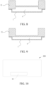
- FIGS. 5 to 9 another embodiment of the present disclosure provides a battery pack composite protection structure 10, including a battery pack 3 and the battery protection bottom plate 1 as described above.
- the battery protection bottom plate 1 is arranged below the battery pack 3, and a buffer zone 4 is formed between the battery pack 3 and the battery protection bottom plate 1.
- the battery pack composite protection structure 10 can effectively buffer a stress on the battery pack 3 and protect the battery pack under an external impact, and avoid damage to the battery pack 3 caused by the external impact.
- the battery protection bottom plate 1 has good corrosion resistance, which can avoid the problem that corrosion resistance of the battery protection bottom plate 1 decreases due to the external impact.
- the battery pack 3 includes a tray 31 and a battery arranged on the tray 31.
- the buffer zone 4 may be provided between the battery pack 3 and the battery protection bottom plate 1 in different ways.
- a bottom surface of the tray 31 is provided with a groove inward to form the buffer zone 4, and the battery protection bottom plate 1 is in the shape of a flat plate.
- the battery protection bottom plate 1 covers the buffer zone 4.
- the frame of the battery protection bottom plate 1 is connected to the bottom surface of the tray 31, and the bottom surface of the tray 31 is internally provided with a groove.
- the battery protection bottom plate 1 protrudes in a direction facing away from the tray 31 to form the buffer zone 4 between the tray 31 and the battery protection bottom plate 1.
- the frame of the battery protection bottom plate 1 is connected to the bottom surface of the tray 31, and the bottom surface of the tray 31 is a flat surface.
- the battery protection bottom plate 1 protrudes in a direction facing away from the tray 31 to form the buffer zone 4 between the tray 31 and the battery protection bottom plate 1.
- the buffer zone 4 is filled with a buffer layer 2, and the buffer layer 2 is selected from a honeycomb material or a rigid foam material.
- the honeycomb material or the rigid foam material can absorb a collapse deformation space of the battery protection bottom plate 1 under an external strong impact, buffer and absorb part of energy of the external strong impact, and prevent compression deformation of the battery protection bottom plate 1 from impacting on internal battery cores of the battery pack, thereby further protecting the battery pack 3.
- the honeycomb material is selected from a PP honeycomb material or an aluminum honeycomb material; and the rigid foam material is selected from a PU rigid foam material, a PET rigid foam material, a PMI rigid foam material, a PVC rigid foam material, a PET rigid foam material, a MPP rigid foam material, a PLA rigid foam material, a PI rigid foam material or an EPTU rigid foam material.
- FIG. 10 Another embodiment of the present disclosure provides a vehicle 100, as shown in FIG. 10 , including the battery protection bottom plate 1 or the battery pack composite protection structure 10 as described above.
Landscapes
- Chemical & Material Sciences (AREA)
- General Chemical & Material Sciences (AREA)
- Electrochemistry (AREA)
- Chemical Kinetics & Catalysis (AREA)
- Engineering & Computer Science (AREA)
- Inorganic Chemistry (AREA)
- Power Engineering (AREA)
- Mechanical Engineering (AREA)
- Transportation (AREA)
- Life Sciences & Earth Sciences (AREA)
- Sustainable Energy (AREA)
- Sustainable Development (AREA)
- Composite Materials (AREA)
- Materials Engineering (AREA)
- Aviation & Aerospace Engineering (AREA)
- Battery Mounting, Suspending (AREA)
- Laminated Bodies (AREA)
- Electric Propulsion And Braking For Vehicles (AREA)
Applications Claiming Priority (2)
| Application Number | Priority Date | Filing Date | Title |
|---|---|---|---|
| CN202221349344.XU CN217788608U (zh) | 2022-05-31 | 2022-05-31 | 一种电池防护底板、电池包复合防护结构及车辆 |
| PCT/CN2023/096769 WO2023231950A1 (zh) | 2022-05-31 | 2023-05-29 | 一种电池防护底板、电池包复合防护结构及车辆 |
Publications (1)
| Publication Number | Publication Date |
|---|---|
| EP4535534A1 true EP4535534A1 (de) | 2025-04-09 |
Family
ID=83918382
Family Applications (1)
| Application Number | Title | Priority Date | Filing Date |
|---|---|---|---|
| EP23815131.0A Pending EP4535534A1 (de) | 2022-05-31 | 2023-05-29 | Batterieschutzgrundplatte, verbundschutzstruktur für batteriepack und fahrzeug |
Country Status (6)
| Country | Link |
|---|---|
| US (1) | US20250015414A1 (de) |
| EP (1) | EP4535534A1 (de) |
| JP (1) | JP2025511564A (de) |
| KR (1) | KR20240154038A (de) |
| CN (1) | CN217788608U (de) |
| WO (1) | WO2023231950A1 (de) |
Families Citing this family (8)
| Publication number | Priority date | Publication date | Assignee | Title |
|---|---|---|---|---|
| CN217788608U (zh) * | 2022-05-31 | 2022-11-11 | 比亚迪股份有限公司 | 一种电池防护底板、电池包复合防护结构及车辆 |
| CN117199658A (zh) * | 2022-05-31 | 2023-12-08 | 比亚迪股份有限公司 | 一种电池包复合防护结构及车辆 |
| CN115972705A (zh) * | 2022-12-09 | 2023-04-18 | 上海汽车地毯总厂有限公司 | 一种基于聚脲防水涂料的电池底部防护复合材料 |
| CN118269845B (zh) * | 2022-12-30 | 2025-09-16 | 比亚迪股份有限公司 | 一种防护板及车辆 |
| CN219498065U (zh) * | 2023-02-02 | 2023-08-08 | 比亚迪股份有限公司 | 电池包盖板、电池包和车辆 |
| CN117698218B (zh) * | 2023-11-08 | 2026-04-07 | 青岛中集创赢复合材料科技有限公司 | 一种电池包护板及其制备工艺 |
| CN121460824A (zh) * | 2024-07-31 | 2026-02-03 | 宁德时代新能源科技股份有限公司 | 电池装置及用电装置 |
| CN223314615U (zh) * | 2024-09-23 | 2025-09-09 | 广东金发复合材料有限公司 | 一种电池底护板 |
Family Cites Families (7)
| Publication number | Priority date | Publication date | Assignee | Title |
|---|---|---|---|---|
| TWI353303B (en) * | 2004-09-07 | 2011-12-01 | Toray Industries | Sandwich structure and integrated molding using th |
| JP6722886B2 (ja) * | 2015-11-30 | 2020-07-15 | パナソニックIpマネジメント株式会社 | 化粧パネル及びパネル製造方法 |
| JP7155483B2 (ja) * | 2018-12-27 | 2022-10-19 | 前田工繊株式会社 | 繊維強化複合材及びその製造方法 |
| CN215451600U (zh) * | 2021-06-08 | 2022-01-07 | 比亚迪股份有限公司 | 电池包底护板及车辆 |
| CN216288737U (zh) * | 2021-10-29 | 2022-04-12 | 比亚迪股份有限公司 | 防护组件、电池包及车辆 |
| CN217788632U (zh) * | 2022-05-31 | 2022-11-11 | 比亚迪股份有限公司 | 一种电池防护底板及电池包复合防护结构、车辆 |
| CN217788608U (zh) * | 2022-05-31 | 2022-11-11 | 比亚迪股份有限公司 | 一种电池防护底板、电池包复合防护结构及车辆 |
-
2022
- 2022-05-31 CN CN202221349344.XU patent/CN217788608U/zh active Active
-
2023
- 2023-05-29 KR KR1020247031556A patent/KR20240154038A/ko active Pending
- 2023-05-29 JP JP2024555457A patent/JP2025511564A/ja active Pending
- 2023-05-29 WO PCT/CN2023/096769 patent/WO2023231950A1/zh not_active Ceased
- 2023-05-29 EP EP23815131.0A patent/EP4535534A1/de active Pending
-
2024
- 2024-09-20 US US18/891,522 patent/US20250015414A1/en active Pending
Also Published As
| Publication number | Publication date |
|---|---|
| WO2023231950A9 (zh) | 2024-04-18 |
| WO2023231950A1 (zh) | 2023-12-07 |
| CN217788608U (zh) | 2022-11-11 |
| KR20240154038A (ko) | 2024-10-24 |
| US20250015414A1 (en) | 2025-01-09 |
| JP2025511564A (ja) | 2025-04-16 |
Similar Documents
| Publication | Publication Date | Title |
|---|---|---|
| EP4535534A1 (de) | Batterieschutzgrundplatte, verbundschutzstruktur für batteriepack und fahrzeug | |
| EP4535535A1 (de) | Batterieschutzgrundplatte, verbundschutzstruktur für batteriepack und fahrzeug | |
| US20250030102A1 (en) | Battery protection bottom plate, battery pack composite protection structure, and vehicle | |
| EP4535530A1 (de) | Batterieschutzgrundplatte, batteriepackverbundschutzstruktur und fahrzeug | |
| CN117199669B (zh) | 一种电池防护底板、电池包复合防护结构及车辆 | |
| EP2671795B1 (de) | Verbundmaterialstruktur und flugzeugflügel damit | |
| US8864117B2 (en) | Fiber-reinforced plastic spring | |
| CA2736145A1 (en) | Fiber composite component for energy absorption in the event of a crash for an aircraft or spacecraft, fuselage structural section of an aircraft or spacecraft, and aircraft or spacecraft | |
| US20250007066A1 (en) | Battery pack composite protection structure and vehicle | |
| CN117199672A (zh) | 一种电池包复合防护结构及车辆 | |
| CN117199668A (zh) | 一种电池防护底板、电池包复合防护结构及车辆 | |
| CN115816959A (zh) | 泡沫芯材、其制备方法及风电叶片 | |
| CN215704723U (zh) | 一种带有加强筋的玻璃钢制品 | |
| CN213800063U (zh) | 玻璃钢船艇甲板结构 | |
| JP6865084B2 (ja) | 風車用ブレード | |
| JP2007170328A (ja) | 風力発電用風車翼およびその製造方法 | |
| JP4047484B2 (ja) | 耐衝撃性ヘルメット | |
| JP2001262421A (ja) | 耐衝撃性ヘルメット | |
| JP4047473B2 (ja) | 耐衝撃性ヘルメット | |
| JP2001262422A (ja) | 耐衝撃性ヘルメット | |
| JP2000054217A (ja) | 複合ヘルメット |
Legal Events
| Date | Code | Title | Description |
|---|---|---|---|
| STAA | Information on the status of an ep patent application or granted ep patent |
Free format text: STATUS: THE INTERNATIONAL PUBLICATION HAS BEEN MADE |
|
| PUAI | Public reference made under article 153(3) epc to a published international application that has entered the european phase |
Free format text: ORIGINAL CODE: 0009012 |
|
| STAA | Information on the status of an ep patent application or granted ep patent |
Free format text: STATUS: REQUEST FOR EXAMINATION WAS MADE |
|
| 17P | Request for examination filed |
Effective date: 20240923 |
|
| AK | Designated contracting states |
Kind code of ref document: A1 Designated state(s): AL AT BE BG CH CY CZ DE DK EE ES FI FR GB GR HR HU IE IS IT LI LT LU LV MC ME MK MT NL NO PL PT RO RS SE SI SK SM TR |
|
| DAV | Request for validation of the european patent (deleted) | ||
| DAX | Request for extension of the european patent (deleted) |