EP4535345A2 - Systeme und verfahren zur manipulation von licht aus umgebungslichtquellen - Google Patents
Systeme und verfahren zur manipulation von licht aus umgebungslichtquellen Download PDFInfo
- Publication number
- EP4535345A2 EP4535345A2 EP25158698.8A EP25158698A EP4535345A2 EP 4535345 A2 EP4535345 A2 EP 4535345A2 EP 25158698 A EP25158698 A EP 25158698A EP 4535345 A2 EP4535345 A2 EP 4535345A2
- Authority
- EP
- European Patent Office
- Prior art keywords
- display
- ambient light
- user
- light
- stimulus
- Prior art date
- Legal status (The legal status is an assumption and is not a legal conclusion. Google has not performed a legal analysis and makes no representation as to the accuracy of the status listed.)
- Pending
Links
Images






Classifications
-
- G—PHYSICS
- G02—OPTICS
- G02B—OPTICAL ELEMENTS, SYSTEMS OR APPARATUS
- G02B27/00—Optical systems or apparatus not provided for by any of the groups G02B1/00 - G02B26/00, G02B30/00
- G02B27/01—Head-up displays
- G02B27/017—Head mounted
- G02B27/0172—Head mounted characterised by optical features
-
- G—PHYSICS
- G02—OPTICS
- G02B—OPTICAL ELEMENTS, SYSTEMS OR APPARATUS
- G02B27/00—Optical systems or apparatus not provided for by any of the groups G02B1/00 - G02B26/00, G02B30/00
- G02B27/0081—Optical systems or apparatus not provided for by any of the groups G02B1/00 - G02B26/00, G02B30/00 with means for altering, e.g. enlarging, the entrance or exit pupil
-
- G—PHYSICS
- G02—OPTICS
- G02B—OPTICAL ELEMENTS, SYSTEMS OR APPARATUS
- G02B27/00—Optical systems or apparatus not provided for by any of the groups G02B1/00 - G02B26/00, G02B30/00
- G02B27/01—Head-up displays
- G02B27/017—Head mounted
-
- G—PHYSICS
- G02—OPTICS
- G02B—OPTICAL ELEMENTS, SYSTEMS OR APPARATUS
- G02B3/00—Simple or compound lenses
- G02B3/12—Fluid-filled or evacuated lenses
- G02B3/14—Fluid-filled or evacuated lenses of variable focal length
-
- G—PHYSICS
- G02—OPTICS
- G02F—OPTICAL DEVICES OR ARRANGEMENTS FOR THE CONTROL OF LIGHT BY MODIFICATION OF THE OPTICAL PROPERTIES OF THE MEDIA OF THE ELEMENTS INVOLVED THEREIN; NON-LINEAR OPTICS; FREQUENCY-CHANGING OF LIGHT; OPTICAL LOGIC ELEMENTS; OPTICAL ANALOGUE/DIGITAL CONVERTERS
- G02F1/00—Devices or arrangements for the control of the intensity, colour, phase, polarisation or direction of light arriving from an independent light source, e.g. switching, gating or modulating; Non-linear optics
- G02F1/0009—Materials therefor
- G02F1/0018—Electro-optical materials
-
- G—PHYSICS
- G02—OPTICS
- G02F—OPTICAL DEVICES OR ARRANGEMENTS FOR THE CONTROL OF LIGHT BY MODIFICATION OF THE OPTICAL PROPERTIES OF THE MEDIA OF THE ELEMENTS INVOLVED THEREIN; NON-LINEAR OPTICS; FREQUENCY-CHANGING OF LIGHT; OPTICAL LOGIC ELEMENTS; OPTICAL ANALOGUE/DIGITAL CONVERTERS
- G02F1/00—Devices or arrangements for the control of the intensity, colour, phase, polarisation or direction of light arriving from an independent light source, e.g. switching, gating or modulating; Non-linear optics
- G02F1/01—Devices or arrangements for the control of the intensity, colour, phase, polarisation or direction of light arriving from an independent light source, e.g. switching, gating or modulating; Non-linear optics for the control of the intensity, phase, polarisation or colour
- G02F1/0128—Devices or arrangements for the control of the intensity, colour, phase, polarisation or direction of light arriving from an independent light source, e.g. switching, gating or modulating; Non-linear optics for the control of the intensity, phase, polarisation or colour based on electro-mechanical, magneto-mechanical, elasto-optic effects
-
- G—PHYSICS
- G02—OPTICS
- G02F—OPTICAL DEVICES OR ARRANGEMENTS FOR THE CONTROL OF LIGHT BY MODIFICATION OF THE OPTICAL PROPERTIES OF THE MEDIA OF THE ELEMENTS INVOLVED THEREIN; NON-LINEAR OPTICS; FREQUENCY-CHANGING OF LIGHT; OPTICAL LOGIC ELEMENTS; OPTICAL ANALOGUE/DIGITAL CONVERTERS
- G02F1/00—Devices or arrangements for the control of the intensity, colour, phase, polarisation or direction of light arriving from an independent light source, e.g. switching, gating or modulating; Non-linear optics
- G02F1/29—Devices or arrangements for the control of the intensity, colour, phase, polarisation or direction of light arriving from an independent light source, e.g. switching, gating or modulating; Non-linear optics for the control of the position or the direction of light beams, i.e. deflection
-
- G—PHYSICS
- G06—COMPUTING OR CALCULATING; COUNTING
- G06F—ELECTRIC DIGITAL DATA PROCESSING
- G06F3/00—Input arrangements for transferring data to be processed into a form capable of being handled by the computer; Output arrangements for transferring data from processing unit to output unit, e.g. interface arrangements
- G06F3/01—Input arrangements or combined input and output arrangements for interaction between user and computer
- G06F3/011—Arrangements for interaction with the human body, e.g. for user immersion in virtual reality
- G06F3/013—Eye tracking input arrangements
-
- G—PHYSICS
- G06—COMPUTING OR CALCULATING; COUNTING
- G06T—IMAGE DATA PROCESSING OR GENERATION, IN GENERAL
- G06T7/00—Image analysis
- G06T7/50—Depth or shape recovery
-
- G—PHYSICS
- G09—EDUCATION; CRYPTOGRAPHY; DISPLAY; ADVERTISING; SEALS
- G09G—ARRANGEMENTS OR CIRCUITS FOR CONTROL OF INDICATING DEVICES USING STATIC MEANS TO PRESENT VARIABLE INFORMATION
- G09G3/00—Control arrangements or circuits, of interest only in connection with visual indicators other than cathode-ray tubes
- G09G3/001—Control arrangements or circuits, of interest only in connection with visual indicators other than cathode-ray tubes using specific devices not provided for in groups G09G3/02 - G09G3/36, e.g. using an intermediate record carrier such as a film slide; Projection systems; Display of non-alphanumerical information, solely or in combination with alphanumerical information, e.g. digital display on projected diapositive as background
-
- G—PHYSICS
- G02—OPTICS
- G02B—OPTICAL ELEMENTS, SYSTEMS OR APPARATUS
- G02B27/00—Optical systems or apparatus not provided for by any of the groups G02B1/00 - G02B26/00, G02B30/00
- G02B27/01—Head-up displays
- G02B27/0101—Head-up displays characterised by optical features
- G02B2027/014—Head-up displays characterised by optical features comprising information/image processing systems
-
- G—PHYSICS
- G02—OPTICS
- G02B—OPTICAL ELEMENTS, SYSTEMS OR APPARATUS
- G02B27/00—Optical systems or apparatus not provided for by any of the groups G02B1/00 - G02B26/00, G02B30/00
- G02B27/01—Head-up displays
- G02B27/0179—Display position adjusting means not related to the information to be displayed
-
- G—PHYSICS
- G02—OPTICS
- G02B—OPTICAL ELEMENTS, SYSTEMS OR APPARATUS
- G02B6/00—Light guides; Structural details of arrangements comprising light guides and other optical elements, e.g. couplings
- G02B6/0001—Light guides; Structural details of arrangements comprising light guides and other optical elements, e.g. couplings specially adapted for lighting devices or systems
- G02B6/0011—Light guides; Structural details of arrangements comprising light guides and other optical elements, e.g. couplings specially adapted for lighting devices or systems the light guides being planar or of plate-like form
- G02B6/0075—Arrangements of multiple light guides
- G02B6/0076—Stacked arrangements of multiple light guides of the same or different cross-sectional area
-
- G—PHYSICS
- G06—COMPUTING OR CALCULATING; COUNTING
- G06F—ELECTRIC DIGITAL DATA PROCESSING
- G06F3/00—Input arrangements for transferring data to be processed into a form capable of being handled by the computer; Output arrangements for transferring data from processing unit to output unit, e.g. interface arrangements
- G06F3/01—Input arrangements or combined input and output arrangements for interaction between user and computer
- G06F3/011—Arrangements for interaction with the human body, e.g. for user immersion in virtual reality
Definitions
- the present disclosure relates to optical devices, including virtual reality and augmented reality imaging and visualization systems.
- optical devices comprising a variable optical material that undergoes a physical and/or a chemical change in response to a stimulus are described herein such as the examples enumerated below:
- a wearable display device e.g., an augmented reality and/or virtual reality eyewear
- at least one variable optical material that can vary at least one of: the intensity of ambient light transmitted through the display device, spectral content of ambient light transmitted through the display device, or the optical path of the ambient light transmitted through the display device (e.g., by diffraction or by changing the refractive index of the variable optical element) in response to an external stimulus (e.g., an optical stimulus, an electrical stimulus, a thermal stimulus, an ultrasonic/sonic stimulus, a radiation pressure, etc.).
- the at least one variable optical material can be configured to attenuate the intensity of the ambient light in one or more wavelength ranges.
- the at least one variable optical material can be configured to reflect, refract, scatter, diffract or absorb incoming light.
- the wearable display device takes advantage of the physical changes/chemical changes that are brought about in the at least one variable optical material by the external stimulus.
- the at least one variable optical material can vary at least one of the intensity of ambient light transmitted through the display device, spectral content of ambient light transmitted through the display device, or the optical path of the ambient light transmitted through the display device depending on the intensity and/or spectral characteristics of the incoming light to improve user experience.
- Various studies can be performed to characterize the light altering characteristics of the variable optical material.
- Different studies can also be performed to characterize the type of light alteration that will result in a desired user experience for different types of ambient light sources. Feedback from the various studies can be taken into consideration to determine which regions of the display device should have altered light transmission and the amount of light alteration that would provide the desired user experience.
- the at least one variable optical material can be embedded in a display surface of the display device. In some other embodiments, the at least one variable optical material can be included in an accessory component that can be disposed over the display device.
- the at least one variable optical material can include photosensitive, electro-active and/or radiosensitive materials.
- the at least one variable optical material can comprise organic or inorganic compounds.
- the at least one variable optical material can comprise photosensitive materials, such as, for example, silver-based compounds (e.g., silver chloride or silver halide).
- the at least one variable optical material can comprise organic compounds such as oxazines and/or napthopyrans.
- the at least one variable optical material can comprise one or more layers of molecules.
- the at least one variable optical material can be activated by an optical stimulus provided from a source of illumination, for example, on the eyewear or integrated with the eyewear.
- the source of illumination can be monochromatic or polychromatic.
- the source of illumination can include a LED, a scanning fiber projector, an ultraviolet source of light or a source configured to provide an electron beam.
- the source of illumination can be controlled by electrical or mechanical devices.
- the source of illumination can be controlled by a movable shutter or a variable filter.
- the source of illumination can be electrically controlled by a processor.
- the processor is configured to trigger the device that provides optical, electrical, thermal and/or sonic/ultrasonic stimulus based on information obtained from one or more sensors (e.g., a light sensor, one or more cameras, eye-tracking cameras, position sensing devices, pose sensing devices, environmental sensors configured to detect temperature, global positioning system sub-assemblies, accelerometers, color sensors, etc.).
- sensors e.g., a light sensor, one or more cameras, eye-tracking cameras, position sensing devices, pose sensing devices, environmental sensors configured to detect temperature, global positioning system sub-assemblies, accelerometers, color sensors, etc.
- the processor can be configured to turn on or turn off, activate or deactivate, or otherwise control the device that provides optical, electrical, thermal and/or sonic/ultrasonic stimulus that would activate or control the at least one variable material in different portions of the display device to change at least one of: the intensity of ambient light transmitted through the display device, spectral content of ambient light transmitted through the display device, or the optical path of the ambient light transmitted through the display device based on information obtained from the one or more sensors.
- the at least one variable optical material can undergo a physical and/or a chemical change.
- the molecules of the at least one variable optical material can undergo a change in size (e.g., shrink or enlarge) in response to the stimulus.
- the molecules of the at least one variable optical material can undergo a change in shape in response to the stimulus.
- density of the molecules of the at least one variable optical material can change in response to the stimulus.
- the stimulus may change at least one of: the intensity of ambient light transmitted through the display device, spectral content of ambient light transmitted through the display device, or the optical path of the ambient light transmitted through the display device.
- the molecules of the at least one variable optical material may be configured to move, shift, rotate, twist or otherwise change or respond upon providing the stimulus.
- the movement, shift, rotation or twisting of molecules of the at least one variable optical material may be configured to be random in some embodiments. However, in some other embodiments, the movement, shift, rotation or twisting of molecules of the at least one variable optical material may be configured to be along a specific direction.
- the speed with which the molecules of the at least one variable optical material are moved, shifted, rotated or twisted can be varied by changing a characteristic of the stimulus provided.
- the molecules of the at least one variable optical material can be moved closer together in response to the stimulus. In some other embodiments, the molecules of the at least one variable optical material can be moved farther apart from each other in response to the stimulus.
- the molecules of the at least one variable optical material can be configured to form nanostructures in response to the stimulus.
- the physical and/or chemical change of the molecules of the at least one variable optical material can be brought about by controlling a characteristic of the stimulus.
- the physical and/or chemical change of the molecules of the at least one variable optical material can be brought about by controlling the wavelength and/or intensity of the optical stimulus.
- the stimulus when the stimulus is electrical, the physical and/or chemical change of the molecules of the at least one variable optical material can be brought about by controlling the voltage and/or current of the electrical stimulus.
- the physical and/or chemical change of the molecules of the at least one variable optical material can be controlled by modulating the source that provides the stimulus.
- the physical and/or chemical change of the molecules of the at least one variable optical material can be reversible such that when the stimulus is removed, the molecules of the at least one variable optical material revert back to their original state.
- the stimulus is constantly provided to maintain the altered state of the molecules of the at least one variable optical material.
- the physical and/or chemical change of the molecules of the at least one variable optical material can be maintained in the absence of the stimulus until de-activation energy is provided to revert the molecules of the at least one variable optical material to their original state.
- the stimulus can be provided for a short duration of time to initiate the alteration of the molecules of the at least one variable optical material.
- the wearable display device are configured to map objects in the real world surrounding the user, including objects that are visible to the user through the display device, using a variety of sensor assemblies and/or imaging apparatus.
- the information obtained from the variety of sensor assemblies and/or imaging apparatus can be used to create a database including, for example, the position of various objects in the real world with respect to the display device and /or the user's head/eyes and potentially other characteristics of the objects such as their size, shape, and/or how bright the objects appear.
- the database can be updated and/or provide updated information in real time or in near real time as the objects in the surrounding real world appear to move with respect to the display device and /or the user's head/eyes as the user moves his/her head and/or body.
- the wearable display device are configured to attenuate incoming ambient light incident on various portions of the display surface. Accordingly, the amount of variation of at least one of: the intensity of ambient light transmitted through the display device, spectral content of ambient light transmitted through the display device, or the optical path of the ambient light transmitted through the display device can vary across the surface of the display device and need not be uniform. This can be advantageous in maintaining user experience when one portion of the display surface introduces more glare than another portion.
- incoming light transmitted through a portion of the display device that is aligned with the sun or bright light can be attenuated by a larger amount than intensity of incoming light transmitted through other portions of the display device.
- incoming light transmitted through a portion of the display device near the window or the desk light can be attenuated by a larger amount than intensity of incoming light transmitted through a portion of the display device farther from the window or the desk light, since the portion of the display device near the window or the desk light may have more glare.
- embodiments disclosed herein include optical systems, including display systems, generally.
- the display systems are wearable, which may advantageously provide a more immersive VR or AR experience.
- displays containing one or more waveguides e.g., a stack of waveguides
- two stacks of waveguides, one for each eye of a viewer may be utilized to provide different images to each eye.
- FIG. 2A illustrates an example of wearable display system 60.
- the display system 60 includes a display 70, and various mechanical and electronic modules and systems to support the functioning of that display 70.
- the display 70 may be coupled to a frame 80, which is wearable by a display system user or viewer 90 and which is configured to position the display 70 in front of the eyes of the user 90.
- the display 70 may be considered eyewear in some embodiments.
- a speaker 100 is coupled to the frame 80 and configured to be positioned adjacent the ear canal of the user 90 (in some embodiments, another speaker, not shown, is positioned adjacent the other ear canal of the user to provide stereo/shapeable sound control).
- the display system may also include one or more microphones 110 or other devices to detect sound.
- the microphone is configured to allow the user to provide inputs or commands to the system 60 (e.g., the selection of voice menu commands, natural language questions, etc.), and/or may allow audio communication with other persons (e.g., with other users of similar display systems.
- the microphone may further be configured as a peripheral sensor to collect audio data (e.g., sounds from the user and/or environment).
- the display system may also include a peripheral sensor 120a, which may be separate from the frame 80 and attached to the body of the user 90 (e.g., on the head, torso, an extremity, etc. of the user 90).
- the peripheral sensor 120a may be configured to acquire data characterizing the physiological state of the user 90 in some embodiments.
- the sensor 120a may be an electrode.
- the display 70 is operatively coupled by communications link 130, such as by a wired lead or wireless connectivity, to a local data processing module 140 which may be mounted in a variety of configurations, such as fixedly attached to the frame 80, fixedly attached to a helmet or hat worn by the user, embedded in headphones, or otherwise removably attached to the user 90 (e.g., in a backpack-style configuration, in a belt-coupling style configuration).
- the sensor 120a may be operatively coupled by communications link 120b, e.g., a wired lead or wireless connectivity, to the local processor and data module 140.
- the local processing and data module 140 may comprise a hardware processor, as well as digital memory, such as non-volatile memory (e.g., flash memory or hard disk drives), both of which may be utilized to assist in the processing, caching, and storage of data.
- the data include data a) captured from sensors (which may be, e.g., operatively coupled to the frame 80 or otherwise attached to the user 90), such as image capture devices (such as cameras), microphones, inertial measurement units, accelerometers, compasses, GPS units, radio devices, gyros, and/or other sensors disclosed herein; and/or b) acquired and/or processed using remote processing module 150 and/or remote data repository 160 (including data relating to virtual content), possibly for passage to the display 70 after such processing or retrieval.
- sensors which may be, e.g., operatively coupled to the frame 80 or otherwise attached to the user 90
- image capture devices such as cameras
- microphones such as cameras
- inertial measurement units such as cameras
- accelerometers compasses
- the local processing and data module 140 may be operatively coupled by communication links 170, 180, such as via a wired or wireless communication links, to the remote processing module 150 and remote data repository 160 such that these remote modules 150, 160 are operatively coupled to each other and available as resources to the local processing and data module 140.
- the local processing and data module 140 may include one or more of the image capture devices, microphones, inertial measurement units, accelerometers, compasses, GPS units, radio devices, and/or gyros. In some other embodiments, one or more of these sensors may be attached to the frame 80, or may be standalone structures that communicate with the local processing and data module 140 by wired or wireless communication pathways.
- the display system 60 can include one or more components (e.g., cameras, light sensors, color sensors, temperature sensors, motion detectors, accelerometers, gyroscopes, global positioning sub-systems, etc.) that are configured to sense the environment surrounding the user 90.
- the one or more components included in the display system 60 can also be configured to monitor the position of the head and/or track eye movements of the user 90.
- the one or more components included in the display system 60 can be configured to determine constriction of the pupil in response to bright light, enlargement of the pupil in response to low light, blink response, etc.
- the one or more components included in the display system 60 can be configured to monitor and/or track movement of the user's head.
- the one or more components included in the display system 60 can be configured to monitor and/or track position of real world objects (e.g., trees, sun, ambient light sources, etc.) with respect to the user's eyes as the user's head moves.
- real world objects e.g., trees, sun, ambient light
- the display system can include one or more outward facing cameras 112 that are configured to image the environment around the user 90.
- the cameras 112 can comprise wide-field-of-view machine vision cameras.
- the cameras 112 can be dual capture visible light / non-visible (e.g., infrared) light cameras.
- the cameras 112 can be integrated with the frame 80 as depicted in Figure 2B .
- the cameras 112 can be positioned elsewhere.
- the cameras 112 can be configured to be attached to the head, arms, neck or some other parts of the body of the user 90.
- the cameras 112 need not be attached to the user 90 but instead, can be positioned beside the user.
- the local processing and data module 140 and/or the remote processing module 150 may comprise a processor such as an ASIC (application specific integrated circuit), FPGA (field programmable gate array), and/or ARM processor (advanced reduced-instruction-set machine), which may be configured to calculate real or near-real time user head pose from the information obtained by the inward facing cameras 114, the outward facing cameras 112, light sensor 128, and/or the sensor assembly 126.
- the processor can be configured to provide information about the user's environment from the information obtained by the inward facing cameras 114, the outward facing cameras 112, the light sensor 128 and/or the sensor assembly 126.
- the display system 60 can be configured to determine the ambient light conditions. For example, the information obtained from the outward facing cameras 112, the light sensor 128 and/or the sensor assembly 126 can be processed using one or more electronic processors of the local processing and data module 140 and/or the remote processing module 150 to determine whether the ambient light is diffused. If the ambient light is not diffused, then the system 60 can use the information obtained from the outward facing cameras 112, the light sensor 128 and/or the sensor assembly 126 to determine the direction from which ambient light is incident on the display 70. The system 60 can be configured to determine the type of illuminant that provides the ambient light.
- the inward facing cameras 114 may be utilized to track the eyes. Accordingly, the information provided by the inward facing cameras 114 can be used to determine the object at which or the direction along which the user is looking, as well as the depth at which the user's eyes are focusing. The information provided by the inward facing cameras 114 can also be used to determine the ambient light condition. For example, the information obtained by the light sensor 128, the sensor assembly 126, the outward facing cameras 112 and possibly one or more head pose sensors can be combined with the information provided by the inward facing cameras 114 regarding the size of the pupil of the user's eyes 122 to determine the pose of the user's head (and/or eyes) and locate and identify different ambient light sources in the real world visible to the user through the display device.
- the display system 60 determines based on the information obtained from the light sensor 128, the sensor assembly 126, the outward facing cameras 112 and/or inward facing cameras 114 that the ambient light conditions on a portion of the display lens 106 are bright or that a bright object is in the field of view of the user and is aligned with a portion of the display, then the display system 60 can be configured to provide a stimulus (e.g., thermal, sonic/ultrasonic, optical or electrical stimulus) that can change at least one of: the intensity of ambient light transmitted through that portion of the display lens 106, spectral content of ambient light transmitted through that portion of the display lens 106, or the optical path of the ambient light transmitted through that portion of the display lens 106 to reduce intensity of ambient light transmitted through that portion of the display lens 106 and/or from the bright object and improve visual experience.
- a stimulus e.g., thermal, sonic/ultrasonic, optical or electrical stimulus
- various embodiments of the display system 60 can comprise a light emitting module 134 that is configured to emit ultraviolet, infrared and/or visible light to provide an optical stimulus to at least a portion of the display lens 106; an electrical system 132 that can provide an electrical stimulus to at least a portion of the display lens 106; a thermal source 136 that can provide a thermal stimulus to at least a portion of the display lens 106; and/or a sonic/ultrasonic transducer 138 to provide sonic and/or ultrasonic stimulus to at least a portion of the display lens 106.
- the light emitting module 134, the thermal source 136, the sonic/ultrasonic transducer 138, and/or the electrical system 132 can be integrated with the frame 80 as shown in Figure 2B .
- one or all the light emitting module 134 the thermal source 136, the sonic/ultrasonic transducer 138 and the electrical system 132 can be positioned remotely from the display 70.
- Such systems are uncomfortable for many viewers, however, since they, among other things, simply provide a different presentation of a scene, but with the eyes viewing all the image information at a single accommodated state, and work against the "accommodation-vergence reflex.”
- Display systems that provide a better match between accommodation and vergence may form more realistic and comfortable simulations of three-dimensional imagery contributing to increased duration of wear and in turn compliance to diagnostic and therapy protocols.
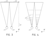
- Figure 4 illustrates aspects of an approach for simulating three-dimensional imagery using multiple depth planes.
- objects at various distances from eyes 210, 220 on the z-axis are accommodated by the eyes 210, 220 so that those objects are in focus.
- the eyes 210, 220 assume particular accommodated states to bring into focus objects at different distances along the z-axis. Consequently, a particular accommodated state may be said to be associated with a particular one of depth planes 240, with has an associated focal distance, such that objects or parts of objects in a particular depth plane are in focus when the eye is in the accommodated state for that depth plane.
- the human eye typically can interpret a finite number of depth planes to provide depth perception. Consequently, a highly believable simulation of perceived depth may be achieved by providing, to the eye, different presentations of an image corresponding to each of these limited number of depth planes.
- the different presentations may be separately focused by the viewer's eyes, thereby helping to provide the user with depth cues based on the accommodation of the eye required to bring into focus different image features for the scene located on different depth plane and/or based on observing different image features on different depth planes being out of focus.
- FIG. 6 illustrates an example of a waveguide stack for outputting image information to a user.
- a display system 250 includes a stack of waveguides, or stacked waveguide assembly, 260 that may be utilized to provide three-dimensional perception to the eye/brain using a plurality of waveguides 270, 280, 290, 300, 310.
- the display system 250 is the system 60 of Figure 2A and/or Figure 2B , with Figure 6 schematically showing some parts of that system 60 in greater detail.
- the waveguide assembly 260 may be part of the display 70 of Figure 2A .
- the waveguide assembly 260 may be part of the display lens 106 of Figure 2B . It will be appreciated that the display system 250 may be considered a light field display in some embodiments.
- the each of the input surfaces 460, 470, 480, 490, 500 may be an edge of a corresponding waveguide, or may be part of a major surface of the corresponding waveguide (that is, one of the waveguide surfaces directly facing the world 510 or the viewer's eye 210).
- a single beam of light e.g. a collimated beam
- the image injection devices 360, 370, 380, 390, 400 are discrete displays that each produce image information for injection into a corresponding waveguide 270, 280, 290, 300, 310, respectively.
- the image injection devices 360, 370, 380, 390, 400 are the output ends of a single multiplexed display which may, e.g., pipe image information via one or more optical conduits (such as fiber optic cables) to each of the image injection devices 360, 370, 380, 390, 400.
- the image information provided by the image injection devices 360, 370, 380, 390, 400 may include light of different wavelengths, or colors (e.g., different component colors, as discussed herein).
- the image injection devices 360, 370, 380, 390, 400 can be a part of the light projection systems 118 of Figure 2B .
- the light injected into the waveguides 270, 280, 290, 300, 310 is provided by a light projector system 520, which comprises a light module 530, which may include a light emitter, such as a light emitting diode (LED).
- the light from the light module 530 may be directed to and modified by a light modulator 540, e.g., a spatial light modulator, via a beam splitter 550.
- the light modulator 540 may be configured to change the perceived intensity of the light injected into the waveguides 270, 280, 290, 300, 310.
- Examples of spatial light modulators include liquid crystal displays (LCD) including a liquid crystal on silicon (LCOS) displays.
- the light projector system 520 can be a part of the light projection systems 118 of Figure 2B .
- a controller 560 controls the operation of one or more of the stacked waveguide assembly 260, including operation of the image injection devices 360, 370, 380, 390, 400, the light source 530, and the light modulator 540.
- the controller 560 is part of the local data processing module 140.
- the controller 560 includes programming (e.g., instructions in a non-transitory medium) that regulates the timing and provision of image information to the waveguides 270, 280, 290, 300, 310 according to, e.g., any of the various schemes disclosed herein.
- the controller may be a single integral device, or a distributed system connected by wired or wireless communication channels.
- the controller 560 may be part of the processing modules 140 or 150 ( Figure 2A ) in some embodiments.
- Extracted light may also be referred to as out-coupled light and the out-coupling optical elements light may also be referred to light extracting optical elements.
- An extracted beam of light may be outputted by the waveguide at locations at which the light propagating in the waveguide strikes a light extracting optical element.
- the out-coupling optical elements 570, 580, 590, 600, 610 may, for example, be gratings, including diffractive optical features, as discussed further herein.
- the out-coupling optical elements 570, 580, 590, 600, 610 may be disposed at the top and/or bottom major surfaces, and/or may be disposed directly in the volume of the waveguides 270, 280, 290, 300, 310, as discussed further herein.
- the out-coupling optical elements 570, 580, 590, 600, 610 may be formed in a layer of material that is attached to a transparent substrate to form the waveguides 270, 280, 290, 300, 310.
- the next waveguide up 280 may be configured to send out collimated light which passes through the first lens 350 (e.g., a negative lens) before it can reach the eye 210; such first lens 350 may be configured to create a slight convex wavefront curvature so that the eye/brain interprets light coming from that next waveguide up 280 as coming from a first focal plane closer inward toward the eye 210 from optical infinity.
- first lens 350 e.g., a negative lens
- the other waveguide layers 300, 310 and lenses 330, 320 are similarly configured, with the highest waveguide 310 in the stack sending its output through all of the lenses between it and the eye for an aggregate focal power representative of the closest focal plane to the person.
- a compensating lens layer 620 may be disposed at the top of the stack to compensate for the aggregate power of the lens stack 320, 330, 340, 350 below.
- Such a configuration provides as many perceived focal planes as there are available waveguide/lens pairings.
- Both the out-coupling optical elements of the waveguides and the focusing aspects of the lenses may be static (i.e., not dynamic or electro-active). In some alternative embodiments, either or both may be dynamic using electro-active features.
- the out-coupling optical elements 570, 580, 590, 600, 610 may be configured to both redirect light out of their respective waveguides and to output this light with the appropriate amount of divergence or collimation for a particular depth plane associated with the waveguide.
- waveguides having different associated depth planes may have different configurations of out-coupling optical elements 570, 580, 590, 600, 610, which output light with a different amount of divergence depending on the associated depth plane.
- the light extracting optical elements 570, 580, 590, 600, 610 may be volumetric or surface features, which may be configured to output light at specific angles.
- the out-coupling optical elements 570, 580, 590, 600, 610 are diffractive features that form a diffraction pattern, or "diffractive optical element" (also referred to herein as a "DOE").
- the DOE's have a sufficiently low diffraction efficiency so that only a portion of the light of the beam is deflected away toward the eye 210 with each intersection of the DOE, while the rest continues to move through a waveguide via TIR.
- the light carrying the image information is thus divided into a number of related exit beams that exit the waveguide at a multiplicity of locations and the result is a fairly uniform pattern of exit emission toward the eye 210 for this particular collimated beam bouncing around within a waveguide.
- the camera assembly 630 may be attached to the frame 80 ( Figure 2A ) and may be in electrical communication with the processing modules 140 and/or 150, which may process image information from the camera assembly 630 to make various determinations regarding, e.g., the physiological state of the user, as discussed herein. It will be appreciated that information regarding the physiological state of user may be used to determine the behavioral or emotional state of the user. Examples of such information include movements of the user and/or facial expressions of the user. The behavioral or emotional state of the user may then be triangulated with collected environmental and/or virtual content data so as to determine relationships between the behavioral or emotional state, physiological state, and environmental or virtual content data. In some embodiments, one camera assembly 630 may be utilized for each eye, to separately monitor each eye.
- FIG. 7 an example of exit beams outputted by a waveguide is shown.
- One waveguide is illustrated, but it will be appreciated that other waveguides in the waveguide assembly 260 ( Figure 6 ) may function similarly, where the waveguide assembly 260 includes multiple waveguides.
- Light 640 is injected into the waveguide 270 at the input surface 460 of the waveguide 270 and propagates within the waveguide 270 by TIR. At points where the light 640 impinges on the DOE 570, a portion of the light exits the waveguide as exit beams 650.
- references to a given color of light throughout this disclosure will be understood to encompass light of one or more wavelengths within a range of wavelengths of light that are perceived by a viewer as being of that given color.
- red light may include light of one or more wavelengths in the range of about 620-780 nm
- green light may include light of one or more wavelengths in the range of about 492-577 nm
- blue light may include light of one or more wavelengths in the range of about 435-493 nm.
- the light source 530 ( Figure 6 ) may be configured to emit light of one or more wavelengths outside the visual perception range of the viewer, for example, infrared and/or ultraviolet wavelengths.
- the in-coupling, out-coupling, and other light redirecting structures of the waveguides of the display 250 may be configured to direct and emit this light out of the display towards the user's eye 210, e.g., for imaging and/or user stimulation applications.
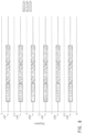
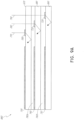
- FIG. 9A illustrates a cross-sectional side view of an example of a plurality or set 660 of stacked waveguides that each includes an in-coupling optical element.
- the waveguides may each be configured to output light of one or more different wavelengths, or one or more different ranges of wavelengths.
- the in-coupling optical elements 700, 710, 720 are wavelength selective, such that they selectively redirect one or more wavelengths of light, while transmitting other wavelengths of light. While illustrated on one side or corner of their respective waveguide 670, 680, 690, it will be appreciated that the in-coupling optical elements 700, 710, 720 may be disposed in other areas of their respective waveguide 670, 680, 690 in some embodiments.
- the lower refractive index layers 760a, 760b may function as cladding layers that facilitate TIR of light through the waveguides 670, 680, 690 (e.g., TIR between the top and bottom major surfaces of each waveguide).
- the layers 760a, 760b are formed of air. While not illustrated, it will be appreciated that the top and bottom of the illustrated set 660 of waveguides may include immediately neighboring cladding layers.
- light rays 770, 780, 790 are incident on the set 660 of waveguides. It will be appreciated that the light rays 770, 780, 790 may be injected into the waveguides 670, 680, 690 by one or more image injection devices 360, 370, 380, 390, 400 ( Figure 6 ).
- the light rays 770, 780, 790 have different properties, e.g., different wavelengths or different ranges of wavelengths, which may correspond to different colors.
- the in-coupling optical elements 700, 710, 720 each deflect the incident light such that the light propagates through a respective one of the waveguides 670, 680, 690 by TIR.
- in-coupling optical element 700 may be configured to deflect ray 770, which has a first wavelength or range of wavelengths.
- the transmitted ray 780 impinges on and is deflected by the in-coupling optical element 710, which is configured to deflect light of a second wavelength or range of wavelengths.
- the ray 790 is deflected by the in-coupling optical element 720, which is configured to selectively deflect light of third wavelength or range of wavelengths.
- the deflected light rays 770, 780, 790 are deflected so that they propagate through a corresponding waveguide 670, 680, 690; that is, the in-coupling optical elements 700, 710, 720 of each waveguide deflects light into that corresponding waveguide 670, 680, 690 to in-couple light into that corresponding waveguide.
- the light rays 770, 780, 790 are deflected at angles that cause the light to propagate through the respective waveguide 670, 680, 690 by TIR.
- the light rays 770, 780, 790 propagate through the respective waveguide 670, 680, 690 by TIR until impinging on the waveguide's corresponding light distributing elements 730, 740, 750.
- FIG. 9B a perspective view of an example of the plurality of stacked waveguides of Figure 9A is illustrated.
- the in-coupled light rays 770, 780, 790 are deflected by the in-coupling optical elements 700, 710, 720, respectively, and then propagate by TIR within the waveguides 670, 680, 690, respectively.
- the light rays 770, 780, 790 then impinge on the light distributing elements 730, 740, 750, respectively.
- the light distributing elements 730, 740, 750 deflect the light rays 770, 780, 790 so that they propagate towards the out-coupling optical elements 800, 810, 820, respectively.
- the light distributing elements 730, 740, 750 are orthogonal pupil expanders (OPE's).
- OPE's both deflect or distribute light to the out-coupling optical elements 800, 810, 820 and also increase the beam or spot size of this light as it propagates to the out-coupling optical elements.
- the light distributing elements 730, 740, 750 may be omitted and the in-coupling optical elements 700, 710, 720 may be configured to deflect light directly to the out-coupling optical elements 800, 810, 820.
- the light distributing elements 730, 740, 750 may be replaced with out-coupling optical elements 800, 810, 820, respectively.
- the out-coupling optical elements 800, 810, 820 are exit pupils (EP's) or exit pupil expanders (EPE's) that direct light in a viewer's eye 210 ( Figure 7 ).
- the OPE's may be configured to increase the dimensions of the eye box in at least one axis and the EPE's may be to increase the eye box in an axis crossing, e.g., orthogonal to, the axis of the OPEs.
- the set 660 of waveguides includes waveguides 670, 680, 690; in-coupling optical elements 700, 710, 720; light distributing elements (e.g., OPE's) 730, 740, 750; and out-coupling optical elements (e.g., EP's) 800, 810, 820 for each component color.
- the waveguides 670, 680, 690 may be stacked with an air gap/cladding layer between each one.
- the in-coupling optical elements 700, 710, 720 redirect or deflect incident light (with different in-coupling optical elements receiving light of different wavelengths) into its waveguide.
- light ray 770 (e.g., blue light) is deflected by the first in-coupling optical element 700, and then continues to bounce down the waveguide, interacting with the light distributing element (e.g., OPE's) 730 and then the out-coupling optical element (e.g., EPs) 800, in a manner described earlier.
- the light rays 780 and 790 (e.g., green and red light, respectively) will pass through the waveguide 670, with light ray 780 impinging on and being deflected by in-coupling optical element 710.
- the light ray 780 then bounces down the waveguide 680 via TIR, proceeding on to its light distributing element (e.g., OPEs) 740 and then the out-coupling optical element (e.g., EP's) 810.
- light ray 790 (e.g., red light) passes through the waveguide 690 to impinge on the light in-coupling optical elements 720 of the waveguide 690.
- the light in-coupling optical elements 720 deflect the light ray 790 such that the light ray propagates to light distributing element (e.g., OPEs) 750 by TIR, and then to the out-coupling optical element (e.g., EPs) 820 by TIR.
- the out-coupling optical element 820 then finally out-couples the light ray 790 to the viewer, who also receives the out-coupled light from the other waveguides 670, 680.
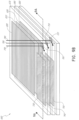
- Figure 9C illustrates a top-down plan view of an example of the plurality of stacked waveguides of Figures 9A and 9B .
- the waveguides 670, 680, 690, along with each waveguide's associated light distributing element 730, 740, 750 and associated out-coupling optical element 800, 810, 820 may be vertically aligned.
- the in-coupling optical elements 700, 710, 720 are not vertically aligned; rather, the in-coupling optical elements are preferably non-overlapping (e.g., laterally spaced apart as seen in the top-down view).
- contrast, brightness and/or clarity of the augmented reality content and/or virtual reality content that is displayed can be improved in a dim or dimmer environment.
- contrast, brightness and/or clarity of augmented reality content and/or virtual reality content can be reduced when embodiments of the display system 60 configured as augmented reality and/or virtual reality devices are viewed outside in bright sunlight, in brightly lit rooms, and/or in rainy/foggy environments with a lot of glare.
- reducing the intensity of ambient light through a portion of the display 70 that is in an environment with bright ambient light conditions can advantageously improve the user's visual experience.
- the display system 60 can be configured to measure the light intensity of bright ambient light sources, such as, for example, but not limited to, desk lamps, overhead lights, street lights, car head lights, sun or combinations thereof and attenuate the amount of light transmitted through one or more portions of the display 70 on which light from the bright ambient light sources is incident.
- the amount of light from the bright ambient light sources that is transmitted through the one or more portions of the display 70 can be reduced by changing the transmissivity of the one or more portions of the display 70.
- the one or more portions of the display 70 may be darkened to reduce the amount of light from the bright ambient light sources that is transmitted through the one or more portions.
- the transmissivity of light through the one or more portions of the display 70 need not be reduced to an amount that the bright ambient light sources are not visible through the display. Instead, the transmissivity of light through the one or more portions of the display 70 can be reduced to a level that allows visibility of the virtual reality content with sufficient visual acuity and also allows visibility of the bright ambient light sources.
- a method of determining the location of the bright light sources in the scene and/or the intensity of the bright light sources in the scene can be similar to the method of updating one or more settings of a content capture device using automatic exposure control (AEC) described in U.S. Patent Application No. 15/841,043, filed on December 13, 2017 , which is incorporated by reference herein in its entirety. Similar to the method illustrated in Fig. 1A and described in paragraphs [0060] - [0065] of U.S. Patent Application No.
- the total number may be divided by the number of pixels in the pixel group to compute an average luma pixel group value for the pixel group. This process may be repeated for each pixel group in the image.
- the pixel value associated with the plurality of pixel groups of the grayscale image correspond to the average luma value.
- color images captured by the ambient light sensor can be converted to YUV image format and the luma value corresponding to the Y component of the YUV image can be determined.
- one or more bright spots on the display 70 can be identified to correspond to one or more saturation regions of the image captured by the ambient light sensor.
- one or more bright spots on the display 70 that corresponds to the position of the bright light sources in the scene can be determined based on a maximum allowable luma value difference between adjacent pixels, or adjacent groups of pixels.
- the maximum allowable luma value difference between adjacent pixels can be calculated in different ways. For example, in one method pixels that have relative pixel values within a certain threshold of each other can be grouped together. Another method of grouping the relative pixel values relies on adaptive k-means clustering algorithm which outputs a set of clusters with luma values above a certain threshold level.
- saturation region can correspond to the portion of the image having luma value above a threshold value.
- the threshold value can, for example, be 220 for an 8-bit image ranging from 0 for black to 255 for white.
- the portions of the display 70 that correspond to the portions of the image having luma values above a certain threshold can be selectively occluded to reduce transmissivity of the light from the bright light sources. Other approaches may be employed.
- the display system 60 can comprise an electronic processor (e.g., local processing & data module 140 and/or remote processing module 150) that is configured to reduce the amount of light transmitted through the portions of the display 70 that receive light from the locations of the ambient environment that have higher light intensity than an average light intensity of the ambient environment. In this manner, the intensity of light transmitted through display 70 can be reduced in portions of the display 70 that receive the most ambient light.
- the electronic processor can be configured to determine the portions of the display 70 where the virtual reality content is displayed and reduce the amount of ambient light transmitted through those portions to increase the relative brightness of the virtual reality content.
- the electronic processor e.g., local processing & data module 140 and/or remote processing module 150
- the electronic processor can be configured to selectively reduce the amount of light transmitted through one or more of the plurality of pixels to reduce brightness of ambient light sources and/or to improve contrast ratio of the virtual reality content.
- the display 70 can include a display lens 106.
- the display lens 106 can be a unitary lens positioned in front of both eyes of the user 90.
- the unitary lens can have ocular regions positioned in front of each eye through which the user can view the surrounding environment.
- the display lens 106 can comprise two lens elements, each lens element positioned in front of each eye of the user 90. Each lens element can have an ocular region through which the user can view the surrounding.
- the intensity of ambient light transmitted through a portion of one or both the ocular regions of the display lens 106 is reduced while the intensity of ambient light transmitted through the remainder of the display lens 106 is not reduced (or is reduced but by a lesser amount).
- the intensity of ambient light transmitted through a first portion of the display lens 106 is reduced while the intensity of ambient light transmitted through a second portion of the display lens is not reduced.
- various embodiments of the display lens 106 are configured to darken or lighten non-uniformly.
- the display lens 106 may darken partially, e.g., only part of the lens 106 may darken.
- darkening or lightening of the display lens 106 need not occur automatically in response to ambient light conditions but in response to a stimulus provided by the display system (e.g., optical stimulus provided by the light emitting module 134, electrical stimulus provided by the electrical system 132, thermal energy provided by the thermal source 136 and/or sonic/ultrasonic energy provided by the sonic/ultrasonic transducer 138) based on environmental information obtained by one or more cameras/sensors of the system 60 with/without data from an associated cloud computing resource.
- a stimulus provided by the display system e.g., optical stimulus provided by the light emitting module 134, electrical stimulus provided by the electrical system 132, thermal energy provided by the thermal source 136 and/or sonic/ultrasonic energy provided by the sonic/ultrasonic transducer 138
- at least one portion of the display lens 106 can be configured to transmit between about 1% - 100% of incident ambient light.
- the at least one portion of the display lens 106 can be configured to transmit between about 5% - 90% of incident ambient light, between about 10% - 80% of incident ambient light, between about 15% - 75% of incident ambient light, between about 20%-70% of incident ambient light, between about 25% - 60% of incident ambient light, between about 30% - 50% of incident ambient light, or any value in these ranges and/or sub-ranges.
- the at least one variable optical material can comprise protein based electroactive materials that respond to an electrical stimulus (e.g., a voltage signal and/or a current signal) provided by the display system 60 to vary at least one of: the intensity of ambient light transmitted through the display lens 106, spectral content of ambient light transmitted through the display lens 106, or the optical path of the ambient light transmitted through the display lens 106.
- an electrical stimulus e.g., a voltage signal and/or a current signal
- the protein based electroactive materials can move, expand, contract, twist, rotate, adhere together or move away from each other to vary at least one of: the intensity of ambient light transmitted through the display lens 106, spectral content of ambient light transmitted through the display lens 106, or the optical path of the ambient light transmitted through the display lens 106.
- the at least one variable optical material can comprise one or more molecules that are bound with certain chemicals that can be configured to vary the transmissivity of light in response to a stimulus provided by the system 60.
- the chemicals bound to the one or more molecules can be configured to vary intensity of incoming ambient light, direction of incoming ambient light and/or spectral content of incoming ambient light when irradiated by specific wavelengths of light (e.g., UV, infrared and/or one or more wavelengths in the visible spectrum).
- the at least one variable optical material e.g., photoreactive and/or electroactive materials
- the at least one variable optical material are configured to vary at least one of: the intensity of ambient light transmitted through the display lens 106, spectral content of ambient light transmitted through the display lens 106, or the optical path of the ambient light transmitted through the display lens 106 in response to stimulus provided by the display system 60, the location of the desired portion of the display lens 106 through which the intensity of incoming ambient light, direction of incoming ambient light and/or spectral content of incoming ambient light is changed (e.g., by absorption in the desired portion, by changing color of the desired portion and/or by diffraction/refraction/scattering of the ambient light away from the desired portion), the duration of time that the desired portion of the display lens 106 is configured to change intensity of incoming ambient light, direction of incoming ambient light and/or spectral content of incoming ambient light and the speed at which the desired portion of the display lens 106 is darkened or lightened can be controlled (e.g.
- the distribution of the at least one variable optical material across the surface of the display lens 106 can be tailored to meet certain requirements/functions.
- the at least one variable optical material can be distributed uniformly across the surface of the display lens 106.
- the at least one variable optical material can be distributed unevenly across the surface of the display lens 106 such that portions of the display lens 106 can have higher density of the at least one variable optical material as compared to other portions of the display lens 106.
- the density of the at least one variable optical material in portions of the ocular regions of the display lens 106 may be greater than in portions of the non-ocular regions (e.g., regions of the display lens corresponding to the temples, nose bridge, eye orbitals and other non-ocular portions of the user's face) which the user cannot see through.
- certain regions of the display lens 106 e.g., the non-ocular regions
- some embodiments of the display lens 106 can include a first layer comprising a first variable optical material that is configured to attenuate (e.g., by absorption, diffraction, refraction, reflection or scattering) red light in response to a stimulus provided by the display system 60, a second layer comprising a second variable optical material that is configured to attenuate (e.g., by absorption, diffraction, refraction, reflection or scattering) green light in response to a stimulus provided by the display system 60, a third layer comprising a third variable optical material that is configured to attenuate (e.g., by absorption, diffraction, refraction, reflection or scattering) blue light in response to a stimulus provided by the display system 60, a fourth layer comprising a fourth variable optical material that is configured to attenuate (e.g., by absorption, diffraction, refraction, reflection or scattering) ultraviolet light in response to a stimulus provided by the display system 60 and/or a fifth layer compris
- a subset of theses layers can alternatively be included in the display lens or display system.
- first, second, and third layers for attenuating, red, green, and blue light respectively.
- thermal, sonic/ultrasonic, optical or electrical stimulus can be provided to one or more of the plurality of layers to attenuate (e.g., by absorption, diffraction, refraction, reflection or scattering) specific wavelengths of light based on environmental information obtained by one or more cameras/sensors of the system 60 with/without data from an associated cloud computing resource.
- variable optical materials having the same chemical/physical property can be individually activated to perform a variety of functions without activating other groups of variable optical materials having different chemical/physical property.
- the variable optical materials that change at least one of: intensity of ambient light, spectral content of ambient light or optical path of ambient light incident on the display lens 106 can only be provided in certain portions of the display lens 106 (e.g., the ocular portions of the display lens 106, a part of the ocular portions of the display lens 106, only one of the ocular portions of the display lens 106, etc.).
- the portions of the display lens 106 comprising the variable optical materials may automatically darken/lighten in the presence/absence of sunlight without requiring any additional stimulus from the display system 60.
- variable optical materials can be integrated with the display lens 106.
- the variable optical materials may be included in an add-on device that can be attached or detached to the display lens 106.
- the embodiments of display lenses integrated with the variable optical materials and/or add-on devices including the variable optical materials can be configured to be activated by a small amount of activation energy (e.g., thermal, sonic/ultrasonic, optical and/or electrical energy).
- activation energy e.g., thermal, sonic/ultrasonic, optical and/or electrical energy
- the physical and/or chemical changes of the molecules of variable optical materials that changes at least one of: intensity of ambient light, spectral content of ambient light or optical path of ambient light may occur without requiring any additional amount of energy.
- the physical and/or chemical changes of the variable optical materials may be maintained until the variable optical materials are deactivated by providing deactivation energy (e.g., thermal, sonic/ultrasonic, optical and/or electrical energy).
- the display 70 can be configured as a pixelated display.
- the surface of the display 70 can comprise a plurality of electronically addressable pixels that can vary the amount of light transmitted therethrough in response to an electrical or an optical stimulus.
- the plurality of electronically addressable pixels can comprise a plurality of spatial light modulators.
- the display 70 can comprise an occlusion mask comprising a plurality of mask elements associated with the plurality of electronically addressable pixels.
- the electronic processor e.g., local processing & data module 140 and/or remote processing module 150
- the electronic processor can be configured to provide an electrical or an optical signal to selectively reduce the amount of light transmitted through one or more of the plurality of pixels to reduce brightness of ambient light sources and/or to improve contrast ratio of the virtual reality content.
- the following examples illustrate the advantages and the various operational characteristics of an embodiment of the display system 60 that is configured to alter at least one of: intensity of ambient light, spectral content of ambient light and/or direction of ambient light incident on the display 70 as described above.
- the display system 60 comprising variable optical materials (either integrated with the display lens 106 of the display system 60 or included in an add-on device) that is worn by the user 90.
- the sensors assemblies e.g., light sensors, outwards facing cameras, inward facing cameras, etc.
- the sensor assemblies may be configured to detect change in ambient light condition by detecting changes in the intensity of ambient light as well as by detecting changes in the environment using location-specific information (e.g., information obtained by a GPS, a compass and/or information obtained from an associated cloud computing resource ), information regarding the surrounding environment obtained using object recognition algorithms to determine trees/park, buildings, rooms, etc., temperature sensors, etc.
- location-specific information e.g., information obtained by a GPS, a compass and/or information obtained from an associated cloud computing resource
- the sensor assemblies may be configured to determine the spectral characteristics of the incident light as well.
- the sensor assemblies may be configured to determine the intensity/spectral characteristic of ambient light that is incident on different portions of the display lens 106.
- the sensor assemblies may include sensors having filters and/or specific spectral responses to determine the spectral characteristics of ambient or incident light.
- the system 60 can provide optical, electrical, thermal and/or sonic/ultrasonic stimulus to different portions of the display lens 106 to cause a portion of the incident ambient light to be absorbed, deflected, refracted, scattered and/or reflected such that the amount of ambient light transmitted through that portions of the display lens 106 that coincide with the ambient light sources in the real world is reduced or otherwise altered. In this manner, the amount of ambient light transmitted through the display lens 106 can be varied across the surface of the display lens 106 depending on the environmental conditions.
- the system 60 can be configured to transmit a greater amount of light through one portion of the display lens 106 than the amount of light transmitted through another portion of the display lens 106.
- the amount of light transmitted through one portion of the display lens 106 can be about 1% - 100% (e.g., 2% - 95%, 5% - 90%, 7% - 80%, 10% - 75%, 15% - 50%, 20% - 60%, 30% - 85%, etc.) greater than the amount of light transmitted through another portion of the display lens 106.
- the information obtained from the various sensors and/or camera assemblies can be sent to the local processing & data module 140 and/or the remote processing module 150 for processing.
- the local processing & data module 140 and/or the remote processing module 150 can determine one or more locations of the display lens 106 that are aligned with different ambient light sources by processing the information obtained from the various sensors and/or camera assemblies.
- the local processing & data module 140 and/or the remote processing module 150 can store the position of various objects in the real world with respect to the display device and /or the user's head/eyes in a database.
- the database can be updated or provide information in real time or in near real time as the objects in the surrounding real world appear to move with respect to the display device and /or the user's head/eyes as the user moves his/her head.
- the database can be updated or provide information in real time or in near real time regarding position with respect to the display device and /or the user's head/eyes of new objects from the surrounding real world that come into the user's field of view as the user moves his/her head.
- the local processing & data module 140 and/or the remote processing module 150 can be configured to determine the intensity/spectral characteristics of the ambient light sources that appear to be aligned with different portions of the display lens 106 when viewed through the display lens 106.
- the local processing & data module 140 and/or the remote processing module 150 can be configured to reduce the amount of ambient light transmitted through the portions of the display lens 106 when viewed through the display lens 106 that appear to be aligned with the ambient light sources.
- the local processing & data module 140 and/or the remote processing module 150 can send signals that can trigger the light emitting module 134, the electrical system 132, the thermal source 136 and/or the sonic/ultrasonic transducers 138 to provide the appropriate stimulus to activate the variable optical element in the different portions of the display lens 106 to attenuate ambient light in those portions by the appropriate amount.
- the system 60 can be configured to obtain information about the environment continuously or substantially continuously.
- the system 60 can be configured to obtain information about the environment from the various cameras/sensor assemblies at 1 - 30 microsecond intervals, at 100 - 500 microsecond intervals, 400 microseconds - 1 millisecond intervals, at 1 - 30 millisecond intervals, at 20 - 100 millisecond intervals, at 50 - 500 millisecond intervals, at 400 millisecond - 1 second intervals, at 1 - 5 second intervals, or at any values in these ranges or sub-ranges or any combinations thereof.
- the light sensors 128 can be configured to sense intensity and/or spectral characteristics of ambient light incident on the display lens.
- the outward facing cameras, the inward facing cameras and other sensor assemblies can be configured to obtain information about the surrounding world viewable to the user through the display lens 106 that can help in identifying different sources of ambient light and/or glare producing objects in the real world as well as their position with respect to the display 70, and/or the display lens 106 and/or the user's eye.
- the display system 60 can also be configured to identify the nature of the ambient light source that appears to be aligned with different portions of the display lens 106 (e.g., sunlight, fluorescent light, incandescent light, LED light, candle).
- the system 60 may be configured to store maps of locations frequently visited by the user in a data repository accessible by the local processing & data module 140 and/or the remote processing module 150.
- the stored map for one or more locations frequently visited by the user can include positions of ambient light sources (e.g., street lights, porch lights, traffic lights, etc.).
- Information about the intensity and/or spectral content of light from the ambient light sources at one or more locations frequently visited can also be stored in the data repository.
- Information about how the light transmission characteristics of various portions of the display lens 106 should be changed at various times of the day, night and/or year may be predetermined for one or more locations frequently visited by the user and stored in the data repository as well.
- information about how the light transmission capability of different portions of the display lens 106 that appear to be aligned with different ambient light sources at that location should be changed during daytime can be stored in the data repository.
- information about how the light transmission capability of different portions of the display lens 106 that appear to be aligned with different ambient light sources at that location should be changed during nighttime (or any other time) can be stored in the data repository.
- information about how the light transmission capability of different portions of the display lens 106 that appear to be aligned with different ambient light sources at that location should be changed during daytime in summer can be stored in the data repository.
- the local processing & data module 140 and/or the remote processing module 150 may be configured to identify the location from the sensor information; access the information from the data repository on the location and other characteristics of the light sources (e.g., size, shape, brightness, color etc.) as well as potentially how the light transmission capability of different portions of the display lens 106 that appear to be aligned with different ambient light sources at that location should be changed for that particular time of day and year.
- This information can be used to direct the stimulus providing sources to activate the variable optical materials in various portions of the display lens to change the intensity, spectral content and/or direction of ambient light in accordance with the predetermined information.
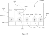
- the sensors associated with the display system can continuously or intermittently obtain information of the scene 1000.
- the information can include position of the ambient light sources 1005a - 1005f with respect to the display lens 1006, the direction, intensity and spectral content of ambient light from the ambient light sources 1005a - 1005f.
- the electronic processing systems can process the information obtained by the one or more sensors, determine how the distribution of ambient light across the surface of the display lens 1006 should be changed.
- the one or more electronic processing systems can send signals to turn on or otherwise cause an optical source or system associated with the display system 60 to provide an optical signal to change the physical/chemical characteristics of the molecules of the variable optical material in at least a portion of the display lens 106 to alter the light ambient transmission characteristic of that portion.
- the optical signal can be of predetermined intensity and wavelength.
- the optical signal can be a beam of visible or invisible light of a certain wavelength.
- the display system 60 can be configured to obtain feedback from the user regarding the size and/or location of the portions of the display 70 and/or the display lens 106 that have altered light transmission capability and the extent to which the light transmission should be altered in various portions of the display 70 and/or the display lens 106 to improve the user's visual experience.
- the local processing & data module 140 and/or the remote processing module 150 can make an initial determination of the size and/or location of the portions of the display 70 and/or the display lens 106 that have altered light transmission capability based on the information obtained from the various sensors and/or the imaging systems associated with the system 60.
- a display system that determines one or more portions of the display lens that appear to be aligned with one or more ambient light sources in a scene viewed by the user through the display lens.
- the system can be configured to darken the one or more portions of the display lens that appear to be aligned with one or more ambient light sources in the scene.
- the system can then request feedback from the user regarding the size and/or locations of the one or more darkened portions of the display lens and the amount of darkening in those portions.
- the user can provide feedback that the system can use to adjust the size and/or locations of the one or more darkened portions of the display lens and the amount of darkening in those portions.
Landscapes
- Physics & Mathematics (AREA)
- General Physics & Mathematics (AREA)
- Optics & Photonics (AREA)
- Engineering & Computer Science (AREA)
- Nonlinear Science (AREA)
- Theoretical Computer Science (AREA)
- General Engineering & Computer Science (AREA)
- Human Computer Interaction (AREA)
- Computer Hardware Design (AREA)
- Computer Vision & Pattern Recognition (AREA)
- Eyeglasses (AREA)
- User Interface Of Digital Computer (AREA)
- Diffracting Gratings Or Hologram Optical Elements (AREA)
- Mechanical Optical Scanning Systems (AREA)
- Mechanical Light Control Or Optical Switches (AREA)
- Optical Filters (AREA)
- Electrochromic Elements, Electrophoresis, Or Variable Reflection Or Absorption Elements (AREA)
- Optical Communication System (AREA)
- Non-Portable Lighting Devices Or Systems Thereof (AREA)
Applications Claiming Priority (3)
| Application Number | Priority Date | Filing Date | Title |
|---|---|---|---|
| US201662438325P | 2016-12-22 | 2016-12-22 | |
| PCT/US2017/067968 WO2018119276A1 (en) | 2016-12-22 | 2017-12-21 | Systems and methods for manipulating light from ambient light sources |
| EP17883527.8A EP3559728B1 (de) | 2016-12-22 | 2017-12-21 | Systeme und verfahren zur manipulation von licht aus umgebungslichtquellen |
Related Parent Applications (1)
| Application Number | Title | Priority Date | Filing Date |
|---|---|---|---|
| EP17883527.8A Division EP3559728B1 (de) | 2016-12-22 | 2017-12-21 | Systeme und verfahren zur manipulation von licht aus umgebungslichtquellen |
Publications (2)
| Publication Number | Publication Date |
|---|---|
| EP4535345A2 true EP4535345A2 (de) | 2025-04-09 |
| EP4535345A3 EP4535345A3 (de) | 2025-05-21 |
Family
ID=62627526
Family Applications (2)
| Application Number | Title | Priority Date | Filing Date |
|---|---|---|---|
| EP17883527.8A Active EP3559728B1 (de) | 2016-12-22 | 2017-12-21 | Systeme und verfahren zur manipulation von licht aus umgebungslichtquellen |
| EP25158698.8A Pending EP4535345A3 (de) | 2016-12-22 | 2017-12-21 | Systeme und verfahren zur manipulation von licht aus umgebungslichtquellen |
Family Applications Before (1)
| Application Number | Title | Priority Date | Filing Date |
|---|---|---|---|
| EP17883527.8A Active EP3559728B1 (de) | 2016-12-22 | 2017-12-21 | Systeme und verfahren zur manipulation von licht aus umgebungslichtquellen |
Country Status (9)
| Country | Link |
|---|---|
| US (5) | US11036049B2 (de) |
| EP (2) | EP3559728B1 (de) |
| JP (5) | JP7143300B2 (de) |
| KR (3) | KR20240009545A (de) |
| CN (2) | CN110325891B (de) |
| AU (3) | AU2017382880B2 (de) |
| CA (1) | CA3046662A1 (de) |
| IL (2) | IL308598A (de) |
| WO (1) | WO2018119276A1 (de) |
Families Citing this family (35)
| Publication number | Priority date | Publication date | Assignee | Title |
|---|---|---|---|---|
| KR20240009545A (ko) | 2016-12-22 | 2024-01-22 | 매직 립, 인코포레이티드 | 주변 광원들로부터의 광을 조작하기 위한 시스템들 및 방법들 |
| US10371896B2 (en) | 2016-12-22 | 2019-08-06 | Magic Leap, Inc. | Color separation in planar waveguides using dichroic filters |
| US11733516B2 (en) | 2017-10-11 | 2023-08-22 | Magic Leap, Inc. | Augmented reality display comprising eyepiece having a transparent emissive display |
| KR102698364B1 (ko) | 2017-10-26 | 2024-08-23 | 매직 립, 인코포레이티드 | 증강 현실 디스플레이를 위한 광대역 적응형 렌즈 어셈블리 |
| JP7037860B2 (ja) * | 2017-11-17 | 2022-03-17 | 株式会社トプコン | 測量装置及び測量装置システム |
| US10667366B2 (en) * | 2018-06-29 | 2020-05-26 | Osram Sylvania Inc. | Lighting devices with automatic lighting adjustment |
| WO2020023404A1 (en) * | 2018-07-24 | 2020-01-30 | Magic Leap, Inc. | Flicker mitigation when toggling eyepiece display illumination in augmented reality systems |
| JP2021536592A (ja) | 2018-08-31 | 2021-12-27 | マジック リープ, インコーポレイテッドMagic Leap, Inc. | 拡張現実デバイスのための空間的に分解された動的調光 |
| EP3857520A4 (de) * | 2018-09-24 | 2021-12-01 | Magic Leap, Inc. | Verfahren und systeme zum teilen von dreidimensionalen modellen |
| WO2020092271A1 (en) * | 2018-10-29 | 2020-05-07 | Holosports Corporation | Racing helmet with visual and audible information exchange |
| CN111352239A (zh) * | 2018-12-22 | 2020-06-30 | 杭州融梦智能科技有限公司 | 增强现实显示设备及应用增强现实显示设备的交互方法 |
| KR102629149B1 (ko) | 2019-01-03 | 2024-01-26 | 삼성전자주식회사 | 외부 광에 따라 디스플레이의 특성을 변경하는 전자 장치 및 방법 |
| JP7585206B2 (ja) | 2019-01-11 | 2024-11-18 | マジック リープ, インコーポレイテッド | 種々の深度における仮想コンテンツの時間多重化された表示 |
| KR102648198B1 (ko) * | 2019-01-14 | 2024-03-19 | 삼성디스플레이 주식회사 | 잔상 보상부 및 이를 포함하는 표시 장치 |
| US11092324B2 (en) * | 2019-03-28 | 2021-08-17 | GM Global Technology Operations LLC | Semi-transparent sign temperature protection |
| JP7660113B2 (ja) | 2019-10-17 | 2025-04-10 | マジック リープ, インコーポレイテッド | ウェアラブルディスプレイ内の光透過率アーチファクトの減衰 |
| CN114830637A (zh) * | 2019-12-18 | 2022-07-29 | 科鲁斯股份有限公司 | 基于凝视的显示器照明系统和方法 |
| CN111123522A (zh) * | 2020-01-17 | 2020-05-08 | 光感(上海)科技有限公司 | 一种增强现实眼镜的光学系统 |
| WO2021178908A1 (en) | 2020-03-06 | 2021-09-10 | Magic Leap, Inc. | Angularly selective attenuation of light transmission artifacts in wearable displays |
| US11209676B2 (en) * | 2020-04-15 | 2021-12-28 | Facebook Technologies, Llc | Local dimming in a device |
| US11422390B2 (en) | 2020-04-15 | 2022-08-23 | Meta Platforms Technologies, Llc | Digital projector for local dimming in a device |
| JP7663612B2 (ja) * | 2020-06-25 | 2025-04-16 | マジック リープ, インコーポレイテッド | ウェアラブルディスプレイ内の光透過アーチファクトの調整可能減衰 |
| US12133559B2 (en) | 2020-09-11 | 2024-11-05 | Rai Strategic Holdings, Inc. | Device agnostic PSA for aerosol generation device |
| JP7481225B2 (ja) * | 2020-10-08 | 2024-05-10 | エルジー ディスプレイ カンパニー リミテッド | ヘッドマウントディスプレイ |
| KR102638480B1 (ko) * | 2020-11-09 | 2024-02-19 | 루머스 리미티드 | 역반사되는 환경의 주변광의 색도를 조절하는 방법 |
| CN112799433B (zh) * | 2021-01-20 | 2022-08-12 | 深圳市达特文化科技股份有限公司 | 一种基于点光源的文字显示系统 |
| CN113126300B (zh) * | 2021-04-13 | 2023-12-05 | 维沃移动通信有限公司 | 增强现实眼镜及其显示画面的调节方法 |
| CN113325585B (zh) * | 2021-05-27 | 2023-03-28 | 京东方科技集团股份有限公司 | 显示装置、可穿戴显示设备及注视点的位置的确定方法 |
| US11256987B1 (en) | 2021-06-02 | 2022-02-22 | SambaNova Systems, Inc. | Memory efficient dropout, with reordering of dropout mask elements |
| US11328209B1 (en) | 2021-06-02 | 2022-05-10 | SambaNova Systems, Inc. | Dual cycle tensor dropout in a neural network |
| US12281957B2 (en) | 2021-06-11 | 2025-04-22 | Apple Inc. | Methodology and application of acoustic detection of optical integrity |
| TWI828397B (zh) * | 2021-11-18 | 2024-01-01 | 東陽實業廠股份有限公司 | 智能透明遮光系統 |
| CN114585140A (zh) * | 2022-03-15 | 2022-06-03 | 北京有竹居网络技术有限公司 | 台灯的控制方法、装置、台灯、可读介质和电子设备 |
| US12256059B2 (en) | 2023-05-09 | 2025-03-18 | T-Mobile Usa, Inc. | Stimulus-responsive depth-changing display |
| US12430843B2 (en) * | 2023-11-14 | 2025-09-30 | Varjo Technologies Oy | Generating lighting map using ambient light sensor and tracking camera |
Citations (1)
| Publication number | Priority date | Publication date | Assignee | Title |
|---|---|---|---|---|
| EP3559728A1 (de) | 2016-12-22 | 2019-10-30 | Magic Leap, Inc. | Systeme und verfahren zur manipulation von licht aus umgebungslichtquellen |
Family Cites Families (78)
| Publication number | Priority date | Publication date | Assignee | Title |
|---|---|---|---|---|
| US6222525B1 (en) | 1992-03-05 | 2001-04-24 | Brad A. Armstrong | Image controllers with sheet connected sensors |
| JPH07193841A (ja) * | 1993-12-27 | 1995-07-28 | Matsushita Electric Ind Co Ltd | 三次元画像撮像方法および三次元画像表示装置 |
| EP0650301B1 (de) | 1993-10-26 | 2000-05-31 | Matsushita Electric Industrial Co., Ltd. | Vorrichtung zur dreidimensionalen Bildanzeige |
| US5670988A (en) | 1995-09-05 | 1997-09-23 | Interlink Electronics, Inc. | Trigger operated electronic device |
| US5781330A (en) * | 1996-04-05 | 1998-07-14 | Lucent Technologies, Inc. | High efficiency optical switching and display devices |
| JPH1031217A (ja) * | 1996-07-16 | 1998-02-03 | Fuji Xerox Co Ltd | 調光素子、調光素子製造方法および反射型表示装置 |
| JP2002090660A (ja) * | 2000-09-19 | 2002-03-27 | Sharp Corp | 光変調素子 |
| JP2002244074A (ja) | 2001-02-15 | 2002-08-28 | Mixed Reality Systems Laboratory Inc | 画像表示装置 |
| JP4029601B2 (ja) | 2001-11-20 | 2008-01-09 | 富士ゼロックス株式会社 | 電気泳動材料、及びそれを用いた光学素子 |
| USD514570S1 (en) | 2004-06-24 | 2006-02-07 | Microsoft Corporation | Region of a fingerprint scanning device with an illuminated ring |
| EP1893074B2 (de) | 2005-05-18 | 2017-06-14 | Visual Physics, LLC | Bilddarstellung und mikrooptisches sicherheitssystem |
| US20070081123A1 (en) | 2005-10-07 | 2007-04-12 | Lewis Scott W | Digital eyewear |
| US8696113B2 (en) | 2005-10-07 | 2014-04-15 | Percept Technologies Inc. | Enhanced optical and perceptual digital eyewear |
| US11428937B2 (en) | 2005-10-07 | 2022-08-30 | Percept Technologies | Enhanced optical and perceptual digital eyewear |
| US7970172B1 (en) * | 2006-01-24 | 2011-06-28 | James Anthony Hendrickson | Electrically controlled optical shield for eye protection against bright light |
| US7893890B2 (en) | 2007-03-05 | 2011-02-22 | The Boeing Company | Electrically dimmable combiner optics for head-up display |
| JP5320986B2 (ja) | 2008-11-04 | 2013-10-23 | Tdk株式会社 | 光透過調整装置 |
| JP4752911B2 (ja) * | 2008-12-26 | 2011-08-17 | ソニー株式会社 | 照明装置、表示装置、およびエッジライト方式のバックライトに用いる光変調素子の製造方法 |
| US8472120B2 (en) * | 2010-02-28 | 2013-06-25 | Osterhout Group, Inc. | See-through near-eye display glasses with a small scale image source |
| US9129295B2 (en) | 2010-02-28 | 2015-09-08 | Microsoft Technology Licensing, Llc | See-through near-eye display glasses with a fast response photochromic film system for quick transition from dark to clear |
| US9529424B2 (en) | 2010-11-05 | 2016-12-27 | Microsoft Technology Licensing, Llc | Augmented reality with direct user interaction |
| US9304319B2 (en) | 2010-11-18 | 2016-04-05 | Microsoft Technology Licensing, Llc | Automatic focus improvement for augmented reality displays |
| US10156722B2 (en) | 2010-12-24 | 2018-12-18 | Magic Leap, Inc. | Methods and systems for displaying stereoscopy with a freeform optical system with addressable focus for virtual and augmented reality |
| NZ706893A (en) | 2010-12-24 | 2017-02-24 | Magic Leap Inc | An ergonomic head mounted display device and optical system |
| US20120182206A1 (en) | 2011-01-17 | 2012-07-19 | Ronald Steven Cok | Head-mounted display control with sensory stimulation |
| US20120212696A1 (en) * | 2011-01-27 | 2012-08-23 | Pixeloptics, Inc. | Variable optical element comprising a liquid crystal alignment layer |
| CA3035118C (en) | 2011-05-06 | 2022-01-04 | Magic Leap, Inc. | Massive simultaneous remote digital presence world |
| EP2760363A4 (de) | 2011-09-29 | 2015-06-24 | Magic Leap Inc | Taktiler handschuh zur mensch-computer-interaktion |
| RU2017115669A (ru) | 2011-10-28 | 2019-01-28 | Мэджик Лип, Инк. | Система и способ для дополненной и виртуальной реальности |
| US9087471B2 (en) * | 2011-11-04 | 2015-07-21 | Google Inc. | Adaptive brightness control of head mounted display |
| US8752963B2 (en) * | 2011-11-04 | 2014-06-17 | Microsoft Corporation | See-through display brightness control |
| US8982471B1 (en) * | 2012-01-04 | 2015-03-17 | Google Inc. | HMD image source as dual-purpose projector/near-eye display |
| EP2808725B1 (de) * | 2012-01-24 | 2018-09-26 | Sony Corporation | Kopfmontierte anzeigevorrichtung mit lichtabschirmelement |
| JP5516616B2 (ja) * | 2012-02-07 | 2014-06-11 | 日立化成株式会社 | 懸濁粒子装置及びこれを用いた調光装置並びにその駆動方法 |
| US9147111B2 (en) * | 2012-02-10 | 2015-09-29 | Microsoft Technology Licensing, Llc | Display with blocking image generation |
| US20130240804A1 (en) * | 2012-03-16 | 2013-09-19 | Canopy Valley LLC | Silicone material having a photochromic additive |
| JP6060512B2 (ja) | 2012-04-02 | 2017-01-18 | セイコーエプソン株式会社 | 頭部装着型表示装置 |
| BR112014024941A2 (pt) | 2012-04-05 | 2017-09-19 | Magic Leap Inc | dispositivo de imagem de campo de visão amplo com capacidade de focalização ativa |
| US9671566B2 (en) * | 2012-06-11 | 2017-06-06 | Magic Leap, Inc. | Planar waveguide apparatus with diffraction element(s) and system employing same |
| JP5694257B2 (ja) | 2012-08-27 | 2015-04-01 | 株式会社東芝 | 表示装置、表示方法及びプログラム |
| JP2015534108A (ja) | 2012-09-11 | 2015-11-26 | マジック リープ, インコーポレイテッド | 人間工学的な頭部搭載型ディスプレイデバイスおよび光学システム |
| US9030495B2 (en) * | 2012-11-21 | 2015-05-12 | Microsoft Technology Licensing, Llc | Augmented reality help |
| JP6089705B2 (ja) | 2013-01-07 | 2017-03-08 | セイコーエプソン株式会社 | 表示装置、および、表示装置の制御方法 |
| IL301489B2 (en) | 2013-01-15 | 2024-08-01 | Magic Leap Inc | A system for scanning electromagnetic imaging radiation |
| KR20230044041A (ko) | 2013-03-11 | 2023-03-31 | 매직 립, 인코포레이티드 | 증강 및 가상 현실을 위한 시스템 및 방법 |
| CN105229719B (zh) | 2013-03-15 | 2018-04-27 | 奇跃公司 | 显示系统和方法 |
| JP6341355B2 (ja) | 2013-05-20 | 2018-06-13 | コニカミノルタ株式会社 | 拡張現実空間表示装置 |
| US10262462B2 (en) | 2014-04-18 | 2019-04-16 | Magic Leap, Inc. | Systems and methods for augmented and virtual reality |
| US9874749B2 (en) * | 2013-11-27 | 2018-01-23 | Magic Leap, Inc. | Virtual and augmented reality systems and methods |
| JP6364715B2 (ja) | 2013-07-18 | 2018-08-01 | セイコーエプソン株式会社 | 透過型表示装置および透過型表示装置の制御方法 |
| EP3058418B1 (de) | 2013-10-16 | 2023-10-04 | Magic Leap, Inc. | Kopfhörer für virtuelle oder erweiterte realität mit einstellbarem zwischenpupillenabstand |
| US10677969B2 (en) | 2013-11-27 | 2020-06-09 | Magic Leap, Inc. | Manufacturing for virtual and augmented reality systems and components |
| KR102651578B1 (ko) | 2013-11-27 | 2024-03-25 | 매직 립, 인코포레이티드 | 가상 및 증강 현실 시스템들 및 방법들 |
| US9857591B2 (en) | 2014-05-30 | 2018-01-02 | Magic Leap, Inc. | Methods and system for creating focal planes in virtual and augmented reality |
| US20160320621A1 (en) | 2013-12-23 | 2016-11-03 | Essilor International (Compagnie Generale D'optique) | Head-mounted display with filter function |
| CN110764267B (zh) * | 2014-01-09 | 2022-04-19 | 三星电子株式会社 | 可穿戴显示装置 |
| WO2015109145A1 (en) * | 2014-01-17 | 2015-07-23 | Osterhout Group, Inc. | See-through computer display systems |
| US9651784B2 (en) * | 2014-01-21 | 2017-05-16 | Osterhout Group, Inc. | See-through computer display systems |
| NZ722903A (en) | 2014-01-31 | 2020-05-29 | Magic Leap Inc | Multi-focal display system and method |
| KR102177133B1 (ko) | 2014-01-31 | 2020-11-10 | 매직 립, 인코포레이티드 | 멀티-포컬 디스플레이 시스템 및 방법 |
| US9389423B2 (en) | 2014-03-11 | 2016-07-12 | Google Inc. | Head wearable display with adjustable transparency |
| US10203762B2 (en) | 2014-03-11 | 2019-02-12 | Magic Leap, Inc. | Methods and systems for creating virtual and augmented reality |
| EP3140779A4 (de) | 2014-05-09 | 2017-11-29 | Google LLC | Systeme und verfahren zur verwendung von augensignalen mit sicherer mobilkommunikation |
| USD759657S1 (en) | 2014-05-19 | 2016-06-21 | Microsoft Corporation | Connector with illumination region |
| NZ764905A (en) | 2014-05-30 | 2022-05-27 | Magic Leap Inc | Methods and systems for generating virtual content display with a virtual or augmented reality apparatus |
| USD752529S1 (en) | 2014-06-09 | 2016-03-29 | Comcast Cable Communications, Llc | Electronic housing with illuminated region |
| US9576398B1 (en) * | 2014-08-14 | 2017-02-21 | Amazon Technologies, Inc. | Pixelated light shutter mechanisms for improving contrast between computer-generated images and an ambient visible environment |
| US9626936B2 (en) | 2014-08-21 | 2017-04-18 | Microsoft Technology Licensing, Llc | Dimming module for augmented and virtual reality |
| EP3241055B1 (de) * | 2014-12-31 | 2020-04-15 | Essilor International | Binokulare vorrichtung mit einer monokularen anzeigevorrichtung |
| KR102320737B1 (ko) | 2015-01-14 | 2021-11-03 | 삼성디스플레이 주식회사 | 헤드-장착 전자장치 |
| WO2016141372A1 (en) | 2015-03-05 | 2016-09-09 | Magic Leap, Inc. | Improved manufacturing for virtual and augmented reality systems and components |
| SG11201708481TA (en) * | 2015-04-15 | 2017-11-29 | Razer (Asia-Pacific) Pte Ltd | Filtering devices and filtering methods |
| US9989769B2 (en) | 2015-04-30 | 2018-06-05 | Sony Corporation | Display apparatus |
| USD805734S1 (en) | 2016-03-04 | 2017-12-26 | Nike, Inc. | Shirt |
| USD794288S1 (en) | 2016-03-11 | 2017-08-15 | Nike, Inc. | Shoe with illuminable sole light sequence |
| US10067344B2 (en) * | 2016-07-01 | 2018-09-04 | Intel Corporation | Variable transmissivity virtual image projection system |
| EP3276327B1 (de) * | 2016-07-29 | 2019-10-02 | Essilor International | Verfahren zur virtuellen prüfung von mindestens einer linse mit einem vorbestimmten optischen merkmal und zugehörige vorrichtung |
| WO2018057050A1 (en) * | 2016-09-23 | 2018-03-29 | Bao Sheng | Selectably opaque displays |
-
2017
- 2017-12-21 KR KR1020247001620A patent/KR20240009545A/ko active Pending
- 2017-12-21 WO PCT/US2017/067968 patent/WO2018119276A1/en not_active Ceased
- 2017-12-21 KR KR1020237013034A patent/KR102626911B1/ko active Active
- 2017-12-21 IL IL308598A patent/IL308598A/en unknown
- 2017-12-21 CN CN201780086897.6A patent/CN110325891B/zh active Active
- 2017-12-21 EP EP17883527.8A patent/EP3559728B1/de active Active
- 2017-12-21 US US15/850,465 patent/US11036049B2/en active Active
- 2017-12-21 AU AU2017382880A patent/AU2017382880B2/en active Active
- 2017-12-21 EP EP25158698.8A patent/EP4535345A3/de active Pending
- 2017-12-21 IL IL267411A patent/IL267411B2/en unknown
- 2017-12-21 CN CN202210280466.6A patent/CN114675420A/zh active Pending
- 2017-12-21 KR KR1020197020385A patent/KR102524010B1/ko active Active
- 2017-12-21 CA CA3046662A patent/CA3046662A1/en active Pending
- 2017-12-21 JP JP2019531465A patent/JP7143300B2/ja active Active
-
2021
- 2021-06-14 US US17/347,201 patent/US11520151B2/en active Active
-
2022
- 2022-09-14 JP JP2022146048A patent/JP7404472B2/ja active Active
- 2022-10-17 US US17/967,331 patent/US11971551B2/en active Active
-
2023
- 2023-01-25 AU AU2023200386A patent/AU2023200386B2/en active Active
- 2023-10-27 JP JP2023184797A patent/JP7511070B2/ja active Active
-
2024
- 2024-02-20 AU AU2024201098A patent/AU2024201098B2/en active Active
- 2024-03-29 US US18/622,116 patent/US12474586B2/en active Active
- 2024-06-10 JP JP2024093659A patent/JP7731474B2/ja active Active
-
2025
- 2025-08-04 JP JP2025129991A patent/JP2025166044A/ja active Pending
- 2025-10-19 US US19/362,436 patent/US20260044007A1/en active Pending
Patent Citations (1)
| Publication number | Priority date | Publication date | Assignee | Title |
|---|---|---|---|---|
| EP3559728A1 (de) | 2016-12-22 | 2019-10-30 | Magic Leap, Inc. | Systeme und verfahren zur manipulation von licht aus umgebungslichtquellen |
Also Published As
Similar Documents
| Publication | Publication Date | Title |
|---|---|---|
| US12474586B2 (en) | Systems and methods for manipulating light from ambient light sources | |
| JP7280922B2 (ja) | Ar/vrディスプレイシステムにおける電流ドレイン低減 |
Legal Events
| Date | Code | Title | Description |
|---|---|---|---|
| PUAI | Public reference made under article 153(3) epc to a published international application that has entered the european phase |
Free format text: ORIGINAL CODE: 0009012 |
|
| STAA | Information on the status of an ep patent application or granted ep patent |
Free format text: STATUS: THE APPLICATION HAS BEEN PUBLISHED |
|
| AC | Divisional application: reference to earlier application |
Ref document number: 3559728 Country of ref document: EP Kind code of ref document: P |
|
| AK | Designated contracting states |
Kind code of ref document: A2 Designated state(s): AL AT BE BG CH CY CZ DE DK EE ES FI FR GB GR HR HU IE IS IT LI LT LU LV MC MK MT NL NO PL PT RO RS SE SI SK SM TR |
|
| REG | Reference to a national code |
Ref country code: DE Ref legal event code: R079 Free format text: PREVIOUS MAIN CLASS: G09G0005000000 Ipc: G02B0027010000 |
|
| PUAL | Search report despatched |
Free format text: ORIGINAL CODE: 0009013 |
|
| AK | Designated contracting states |
Kind code of ref document: A3 Designated state(s): AL AT BE BG CH CY CZ DE DK EE ES FI FR GB GR HR HU IE IS IT LI LT LU LV MC MK MT NL NO PL PT RO RS SE SI SK SM TR |
|
| RIC1 | Information provided on ipc code assigned before grant |
Ipc: G09G 5/00 20060101ALI20250415BHEP Ipc: G02B 5/18 20060101ALI20250415BHEP Ipc: B29D 11/00 20060101ALI20250415BHEP Ipc: G06T 1/00 20060101ALI20250415BHEP Ipc: G02B 27/01 20060101AFI20250415BHEP |
|
| STAA | Information on the status of an ep patent application or granted ep patent |
Free format text: STATUS: REQUEST FOR EXAMINATION WAS MADE |
|
| 17P | Request for examination filed |
Effective date: 20251120 |