EP4535084A1 - Bilderzeugungsgerät - Google Patents
Bilderzeugungsgerät Download PDFInfo
- Publication number
- EP4535084A1 EP4535084A1 EP24199334.4A EP24199334A EP4535084A1 EP 4535084 A1 EP4535084 A1 EP 4535084A1 EP 24199334 A EP24199334 A EP 24199334A EP 4535084 A1 EP4535084 A1 EP 4535084A1
- Authority
- EP
- European Patent Office
- Prior art keywords
- pull
- unit
- engaged
- path
- feed cassette
- Prior art date
- Legal status (The legal status is an assumption and is not a legal conclusion. Google has not performed a legal analysis and makes no representation as to the accuracy of the status listed.)
- Pending
Links
Images











Classifications
-
- G—PHYSICS
- G03—PHOTOGRAPHY; CINEMATOGRAPHY; ANALOGOUS TECHNIQUES USING WAVES OTHER THAN OPTICAL WAVES; ELECTROGRAPHY; HOLOGRAPHY
- G03G—ELECTROGRAPHY; ELECTROPHOTOGRAPHY; MAGNETOGRAPHY
- G03G21/00—Arrangements not provided for by groups G03G13/00 - G03G19/00, e.g. cleaning, elimination of residual charge
- G03G21/16—Mechanical means for facilitating the maintenance of the apparatus, e.g. modular arrangements
- G03G21/1604—Arrangement or disposition of the entire apparatus
- G03G21/1623—Means to access the interior of the apparatus
-
- G—PHYSICS
- G03—PHOTOGRAPHY; CINEMATOGRAPHY; ANALOGOUS TECHNIQUES USING WAVES OTHER THAN OPTICAL WAVES; ELECTROGRAPHY; HOLOGRAPHY
- G03G—ELECTROGRAPHY; ELECTROPHOTOGRAPHY; MAGNETOGRAPHY
- G03G15/00—Apparatus for electrographic processes using a charge pattern
- G03G15/06—Apparatus for electrographic processes using a charge pattern for developing
- G03G15/08—Apparatus for electrographic processes using a charge pattern for developing using a solid developer, e.g. powder developer
- G03G15/0896—Arrangements or disposition of the complete developer unit or parts thereof not provided for by groups G03G15/08 - G03G15/0894
-
- G—PHYSICS
- G03—PHOTOGRAPHY; CINEMATOGRAPHY; ANALOGOUS TECHNIQUES USING WAVES OTHER THAN OPTICAL WAVES; ELECTROGRAPHY; HOLOGRAPHY
- G03G—ELECTROGRAPHY; ELECTROPHOTOGRAPHY; MAGNETOGRAPHY
- G03G15/00—Apparatus for electrographic processes using a charge pattern
- G03G15/20—Apparatus for electrographic processes using a charge pattern for fixing, e.g. by using heat
- G03G15/2003—Apparatus for electrographic processes using a charge pattern for fixing, e.g. by using heat using heat
- G03G15/2014—Apparatus for electrographic processes using a charge pattern for fixing, e.g. by using heat using heat using contact heat
- G03G15/2017—Structural details of the fixing unit in general, e.g. cooling means, heat shielding means
-
- G—PHYSICS
- G03—PHOTOGRAPHY; CINEMATOGRAPHY; ANALOGOUS TECHNIQUES USING WAVES OTHER THAN OPTICAL WAVES; ELECTROGRAPHY; HOLOGRAPHY
- G03G—ELECTROGRAPHY; ELECTROPHOTOGRAPHY; MAGNETOGRAPHY
- G03G15/00—Apparatus for electrographic processes using a charge pattern
- G03G15/20—Apparatus for electrographic processes using a charge pattern for fixing, e.g. by using heat
- G03G15/2003—Apparatus for electrographic processes using a charge pattern for fixing, e.g. by using heat using heat
- G03G15/2014—Apparatus for electrographic processes using a charge pattern for fixing, e.g. by using heat using heat using contact heat
- G03G15/2064—Apparatus for electrographic processes using a charge pattern for fixing, e.g. by using heat using heat using contact heat combined with pressure
-
- G—PHYSICS
- G03—PHOTOGRAPHY; CINEMATOGRAPHY; ANALOGOUS TECHNIQUES USING WAVES OTHER THAN OPTICAL WAVES; ELECTROGRAPHY; HOLOGRAPHY
- G03G—ELECTROGRAPHY; ELECTROPHOTOGRAPHY; MAGNETOGRAPHY
- G03G15/00—Apparatus for electrographic processes using a charge pattern
- G03G15/65—Apparatus which relate to the handling of copy material
- G03G15/6502—Supplying of sheet copy material; Cassettes therefor
-
- G—PHYSICS
- G03—PHOTOGRAPHY; CINEMATOGRAPHY; ANALOGOUS TECHNIQUES USING WAVES OTHER THAN OPTICAL WAVES; ELECTROGRAPHY; HOLOGRAPHY
- G03G—ELECTROGRAPHY; ELECTROPHOTOGRAPHY; MAGNETOGRAPHY
- G03G21/00—Arrangements not provided for by groups G03G13/00 - G03G19/00, e.g. cleaning, elimination of residual charge
- G03G21/16—Mechanical means for facilitating the maintenance of the apparatus, e.g. modular arrangements
- G03G21/1642—Mechanical means for facilitating the maintenance of the apparatus, e.g. modular arrangements for connecting the different parts of the apparatus
- G03G21/1647—Mechanical connection means
-
- G—PHYSICS
- G03—PHOTOGRAPHY; CINEMATOGRAPHY; ANALOGOUS TECHNIQUES USING WAVES OTHER THAN OPTICAL WAVES; ELECTROGRAPHY; HOLOGRAPHY
- G03G—ELECTROGRAPHY; ELECTROPHOTOGRAPHY; MAGNETOGRAPHY
- G03G21/00—Arrangements not provided for by groups G03G13/00 - G03G19/00, e.g. cleaning, elimination of residual charge
- G03G21/16—Mechanical means for facilitating the maintenance of the apparatus, e.g. modular arrangements
- G03G21/1661—Mechanical means for facilitating the maintenance of the apparatus, e.g. modular arrangements means for handling parts of the apparatus in the apparatus
- G03G21/1695—Mechanical means for facilitating the maintenance of the apparatus, e.g. modular arrangements means for handling parts of the apparatus in the apparatus for paper transport
-
- G—PHYSICS
- G03—PHOTOGRAPHY; CINEMATOGRAPHY; ANALOGOUS TECHNIQUES USING WAVES OTHER THAN OPTICAL WAVES; ELECTROGRAPHY; HOLOGRAPHY
- G03G—ELECTROGRAPHY; ELECTROPHOTOGRAPHY; MAGNETOGRAPHY
- G03G21/00—Arrangements not provided for by groups G03G13/00 - G03G19/00, e.g. cleaning, elimination of residual charge
- G03G21/16—Mechanical means for facilitating the maintenance of the apparatus, e.g. modular arrangements
- G03G21/1604—Arrangement or disposition of the entire apparatus
- G03G21/1623—Means to access the interior of the apparatus
- G03G21/1633—Means to access the interior of the apparatus using doors or covers
-
- G—PHYSICS
- G03—PHOTOGRAPHY; CINEMATOGRAPHY; ANALOGOUS TECHNIQUES USING WAVES OTHER THAN OPTICAL WAVES; ELECTROGRAPHY; HOLOGRAPHY
- G03G—ELECTROGRAPHY; ELECTROPHOTOGRAPHY; MAGNETOGRAPHY
- G03G21/00—Arrangements not provided for by groups G03G13/00 - G03G19/00, e.g. cleaning, elimination of residual charge
- G03G21/16—Mechanical means for facilitating the maintenance of the apparatus, e.g. modular arrangements
- G03G21/1661—Mechanical means for facilitating the maintenance of the apparatus, e.g. modular arrangements means for handling parts of the apparatus in the apparatus
- G03G21/1676—Mechanical means for facilitating the maintenance of the apparatus, e.g. modular arrangements means for handling parts of the apparatus in the apparatus for the developer unit
-
- G—PHYSICS
- G03—PHOTOGRAPHY; CINEMATOGRAPHY; ANALOGOUS TECHNIQUES USING WAVES OTHER THAN OPTICAL WAVES; ELECTROGRAPHY; HOLOGRAPHY
- G03G—ELECTROGRAPHY; ELECTROPHOTOGRAPHY; MAGNETOGRAPHY
- G03G21/00—Arrangements not provided for by groups G03G13/00 - G03G19/00, e.g. cleaning, elimination of residual charge
- G03G21/16—Mechanical means for facilitating the maintenance of the apparatus, e.g. modular arrangements
- G03G21/1661—Mechanical means for facilitating the maintenance of the apparatus, e.g. modular arrangements means for handling parts of the apparatus in the apparatus
- G03G21/1685—Mechanical means for facilitating the maintenance of the apparatus, e.g. modular arrangements means for handling parts of the apparatus in the apparatus for the fixing unit
-
- G—PHYSICS
- G03—PHOTOGRAPHY; CINEMATOGRAPHY; ANALOGOUS TECHNIQUES USING WAVES OTHER THAN OPTICAL WAVES; ELECTROGRAPHY; HOLOGRAPHY
- G03G—ELECTROGRAPHY; ELECTROPHOTOGRAPHY; MAGNETOGRAPHY
- G03G2221/00—Processes not provided for by group G03G2215/00, e.g. cleaning or residual charge elimination
- G03G2221/16—Mechanical means for facilitating the maintenance of the apparatus, e.g. modular arrangements and complete machine concepts
- G03G2221/1651—Mechanical means for facilitating the maintenance of the apparatus, e.g. modular arrangements and complete machine concepts for connecting the different parts
- G03G2221/1654—Locks and means for positioning or alignment
-
- G—PHYSICS
- G03—PHOTOGRAPHY; CINEMATOGRAPHY; ANALOGOUS TECHNIQUES USING WAVES OTHER THAN OPTICAL WAVES; ELECTROGRAPHY; HOLOGRAPHY
- G03G—ELECTROGRAPHY; ELECTROPHOTOGRAPHY; MAGNETOGRAPHY
- G03G2221/00—Processes not provided for by group G03G2215/00, e.g. cleaning or residual charge elimination
- G03G2221/16—Mechanical means for facilitating the maintenance of the apparatus, e.g. modular arrangements and complete machine concepts
- G03G2221/1678—Frame structures
- G03G2221/1684—Frame structures using extractable subframes, e.g. on rails or hinges
-
- G—PHYSICS
- G03—PHOTOGRAPHY; CINEMATOGRAPHY; ANALOGOUS TECHNIQUES USING WAVES OTHER THAN OPTICAL WAVES; ELECTROGRAPHY; HOLOGRAPHY
- G03G—ELECTROGRAPHY; ELECTROPHOTOGRAPHY; MAGNETOGRAPHY
- G03G2221/00—Processes not provided for by group G03G2215/00, e.g. cleaning or residual charge elimination
- G03G2221/16—Mechanical means for facilitating the maintenance of the apparatus, e.g. modular arrangements and complete machine concepts
- G03G2221/18—Cartridge systems
- G03G2221/183—Process cartridge
- G03G2221/1853—Process cartridge having a submodular arrangement
- G03G2221/1869—Cartridge holders, e.g. intermediate frames for placing cartridge parts therein
Definitions
- the present invention relates to an image forming apparatus that forms an image on a recording material.
- the present invention is directed to providing a new form of image forming apparatus that includes a main body (apparatus main body) and a unit detachably attachable to the main body.
- a vertical direction when an image forming apparatus 1 is installed on a horizontal surface will be referred to as a Z direction.
- a direction that intersects the Z direction and in which a sheet feed cassette 2 to be described below is pulled out and inserted will be referred to as an X direction.
- a direction intersecting both the Z and X directions will be referred to as a Y direction.
- the X and Y directions are desirably horizontal directions.
- the X, Y, and Z directions are desirably orthogonal to each other.
- the directions of the arrows X, Y, and Z illustrated in the drawings will be referred to as a +X side, +Y side, and +Z side, respectively, and the opposite directions as a -X side, -Y side, and -Z side, respectively, where appropriate.
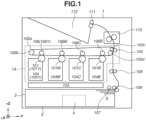
- FIG. 1 A schematic configuration of an image forming apparatus and a series of image forming operations according to a first embodiment will be described with reference to Fig. 1 .
- Fig. 1 is a sectional view illustrating an outline of a full-color laser beam printer (hereinafter, referred to as an "image forming apparatus 1") that is an example of the image forming apparatus.
- image forming apparatus 1 a full-color laser beam printer
- the image forming apparatus 1 includes an image forming unit 1A that electrophotographically forms an image on a sheet S, and a fixing unit 110 that fixes the formed image to the sheet S.
- the image forming unit 1A includes stations that form toner images in four respective colors yellow Y, magenta M, cyan C, and black B, and an intermediate transfer belt 102a.
- the image forming unit 1A includes photosensitive drums 101 (101Y, 101M, 101C, and 101B), and developing units 104 (104Y, 104M, 104C, and 104B) including developing rollers.
- each station includes one of the photosensitive drums 101Y to 101B and a corresponding one of the developing units 104Y to 104B.
- the intermediate transfer belt 102a is an endless belt and stretched across a tension roller 102b, a driving roller 102c that circulates the intermediate transfer belt 102a, and a turn roller 102d.
- a laser scanner 103 serving as an exposure device irradiates each of the photosensitive drums 101Y to 101B with light corresponding to an image signal, whereby electrostatic latent images are formed on the respective photosensitive drums 101Y to 101B.
- the electrostatic latent images are developed with color toners in yellow, magenta, cyan, and black accommodated in the respective developing units 104Y to 104B.
- Toner images visible images
- the toner images formed on the surfaces of the photosensitive drums 101Y to 101B are primarily transferred to the surface of the intermediate transfer belt 102a in succession.
- the toner image formed with the four color toners is conveyed to the secondary transfer nip by the intermediate transfer belt 102a.
- the sheet S to which the toner image is transferred is then conveyed to the fixing unit 110.
- the fixing unit 110 applies heat and pressure to fix the toner image to the sheet S.
- the sheet S is discharged to a discharge unit 112 located at the top of the apparatus main body by a discharge roller 111.
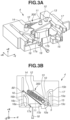
- Fig. 2A is a perspective view of the image forming apparatus 1, and illustrates a state where the sheet feed cassette 2 is pulled out from the image forming apparatus 1.
- Fig. 2B is a perspective view illustrating a part of a rear plate 2C of the sheet feed cassette 2.
- the image forming apparatus 1 includes a main body (apparatus main body) 1a of the image forming apparatus 1 and the sheet feed cassette 2.
- the sheet feed cassette 2 is an accommodation unit where recording materials can be accommodated.
- the sheet feed cassette 2 can be attached to the main body 1a.
- the sheet feed cassette 2 is an example of a unit detachably attachable to the main body 1a.
- a -X direction-side end refers to a downstream end in a pull-out direction or an upstream end in an insertion direction.
- a +X direction-side end refers to a downstream end in the insertion direction or an upstream end in the pull-out direction.
- the insertion direction and the pull-out direction can be referred to collectively as an attachment-detachment direction or moving direction of the sheet feed cassette 2 with respect to the main body 1a.
- the X direction is a direction intersecting (desirably orthogonal to) the conveyance direction of the recording materials (sheets) S.
- the sheet feed cassette 2 includes a front plate (front wall) 2A and the rear plate (rear wall) 2C.
- the front plate 2A is located at the -X direction-side end of the sheet feed cassette 2.
- the rear plate 2C is located at the +X direction-side end of the sheet feed cassette 2.
- the front plate 2A is located at one end of the sheet feed cassette 2 in the X direction
- the rear plate 2C is located at the other end of the sheet feed cassette 2 opposite the one end.
- the rear plate 2C is located downstream of the front plate 2A in the insertion direction of the sheet feed cassette 2.
- the front plate 2A has grips 2B at its +Y direction-side and -Y direction-side ends.
- the sheet feed cassette 2 includes a sheet accommodation portion 2D for accommodating the sheets S, and side walls 2E to be guided by slide guides (unit guides) 113 disposed on inner walls of the accommodation unit 3.
- the side walls 2E are connected to the front plate 2A.
- the sheet feed cassette 2 (side walls 2E) can move in the insertion direction (+X direction) and the pull-out direction (-X direction) opposite to the insertion direction along the slide guides (unit guides) 113 disposed on the inner walls of the accommodation unit 3.
- An opening 1C is formed in the -X direction-side end of the main body 1a.
- the sheet feed cassette 2 can move into and out of the main body 1a through the opening 1C. More specifically, the sheet feed cassette 2 can be inserted into the accommodation unit 3 of the main body 1a and taken out of the accommodation unit 3 through the opening 1C.
- a first direction refers to the direction where the sheet feed cassette 2 (unit) is inserted into the main body 1a, i.e., the +X direction.
- a second direction refers to the direction opposite to the first direction, i.e., the direction where the sheet feed cassette 2 (unit) is pulled out from the main body 1a, or the -X direction.
- the front plate 2A is located at the upstream end of the sheet feed cassette 2 in the +X direction, and widely covers the opening 1C of the main body 1a.
- the length of the front plate 2A in the Y direction is greater than that of the sheet accommodation portion 2D, and greater than the distance between the two side walls 2E.
- the length of the front plate 2A in the Z direction is greater than that of the sheet accommodation portion 2D.
- the user can move the sheet feed cassette 2 in the X direction with respect to the main body 1a by applying an external force in the X direction to the sheet feed cassette 2 using the front plate 2A and the grips 2B.
- the front plate 2A in the +X direction (the front plate 2A undergoes an external force in the +X direction)
- the front plate 2A, the sheet accommodation portion 2D, the side walls 2E, and the rear plate 2C of the sheet feed cassette 2 move in the +X direction.
- the sheet feed cassette 2 includes a to-be-engaged member 100 and a moving member 200. As illustrated in Fig. 2B , the to-be-engaged member 100 and the moving member 200 are attached to the +X direction-side end of the rear plate 2C. In other words, the to-be-engaged member 100 and the moving member 200 are located downstream of the rear plate 2C in the insertion direction of the sheet feed cassette 2.
- the to-be-engaged member 100 includes a latch pin (force receiving portion, first force receiving portion) 5, a latch pin holding arm 6, and a fulcrum shaft 7.
- the latch pin 5 is held by the latch pin holding arm 6.
- the latch pin holding arm 6 and the latch pin 5 can rotate with respect to the sheet feed cassette 2 via the fulcrum shaft 7.
- the fulcrum shaft 7 extends in a direction intersecting (desirably orthogonal to) the X and Y directions.
- the rotation axis direction of the latch pin holding arm 6 and the latch pin 5 refers to the direction intersecting (desirably orthogonal to) the X and Y directions.
- the moving member 200 includes a pin (second force application portion) 80, a pin holding arm 8, and a fulcrum shaft 9.
- the pin 80 is held by the pin holding arm 8.
- the distance from the rear plate 2C to the pin 80 in the +X direction is greater than that from the rear plate 2C to the latch pin 5 in the +X direction.
- the pin holding arm 8 and the pin 80 can rotate with respect to the sheet feed cassette 2 via the fulcrum shaft 9.
- the fulcrum shaft 9 extends in a direction intersecting (desirably orthogonal to) the X and Y directions.
- the rotation axis direction of the pin holding arm 8 and the pin 80 refers to the direction intersecting (desirably orthogonal to) the X and Y directions.
- the main body 1a includes a rear-side plate 1b downstream of the opening 1C in the +X direction.
- the unit moving device 4 is disposed on the rear-side plate 1b.
- the main body 1a includes one end (front end, upstream end) and the other end (far end, downstream end) opposite the one end in the X direction.
- the opening 1C is closer to the one end of the main body 1a than to the other end of the main body 1a in the X direction.
- the unit moving device 4 and the rear-side plate 1b are closer to the other end of the main body 1a than to the one end of the main body 1a in the X direction.
- the unit moving device 4 and the rear-side plate 1b can be said to be located at the downstream end of the accommodation unit 3 in the insertion direction.
- the toggle spring 12 is hooked on a connection shaft 13 of the toggle arm 10 and the toggle spring shaft 14 about which the toggle spring 12 swings.
- the pull-in unit 300 generates a rotational moment on the toggle arm 10 from the contraction force of the toggle spring 12, which produces a force to retract the sheet feed cassette 2.
- the toggle spring 12 biases the toggle arm 10 in a direction where the pull-in unit 300 pulls in the to-be-engaged member 100.
- the toggle spring 12 is a tension spring, a compression spring or a torsion coil spring may be used.
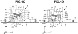
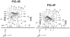
- FIGs. 4A to 4F are plan views illustrating the unit moving device 4 and a part of the sheet feed cassette 2.
- the toggle arm 10 can be rotated about the rotation axis between the standby position illustrated in Fig. 4A and the release position illustrated in Fig. 4C .
- the engagement member 10a is located at an engagement position where the engagement member 10a can engage with the latch pin 5.
- Rotating the toggle arm 10 at the standby position counterclockwise when seen in the -Z direction moves the toggle arm 10 to the release position.
- the engagement member 10a is located at a disengagement position where the engagement member 10a can disengage from the latch pin 5.
- the engagement member 10a is assumed to be at the engagement position when the toggle arm 10 is located at the standby position, and at the disengagement position when the toggle arm 10 is located at the release position, and a description thereof may be omitted.
- the state where the toggle arm 10 is at the standby position can be referred to as a standby state of the pull-in unit 300.
- the state where the toggle arm 10 is at the release position can be referred to as a release state (pull-in state) of the pull-in unit 300.
- the pull-in unit 300 can transition between the standby state and the release state.
- the toggle arm 10 in the state where the toggle arm 10 is at the standby position, the toggle arm 10 is biased by the toggle spring 12 in a direction from the release position to the standby position, and received by the first restriction member 17b.
- the sheet feed cassette 2 can be moved in the +X direction with respect to the main body 1a by applying an external force in the +X direction to the front plate 2A.
- the latch pin 5 moves in the +X direction with respect to the main body 1a, enters the first path 15a, and engages with the recess of the engagement member 10a at the engagement position.
- the pin 80 passes through the fourth path 16a and the sixth path 16b. This operation will be described below.
- the toggle arm 10 After the toggle arm 10 has reached this state, in response to the sheet feed cassette 2 being further moved in the +X direction, the toggle arm 10 starts to swing about the toggle arm shaft 11 due to the contraction force of the toggle spring 12, and rotates counterclockwise when seen in the -Z direction.
- the toggle arm 10 In such a state, the toggle arm 10 is biased from the standby position to the release position by the toggle spring 12. The direction in which the toggle arm 10 is biased switches thus in the process of the toggle arm 10 moving from the standby state to the release state.
- the latch pin 5 receives the force exerted by the rotational moment acting on the toggle arm 10 from the engagement member 10a. As a result, the latch pin 5 is pulled in along the first path 15a in the +X direction. In other words, the sheet feed cassette 2 is pulled in in the insertion direction. With the sheet feed cassette 2 pulled in in the insertion direction by the biasing force of the toggle spring 12, the sheet feed cassette 2 moves in the +X direction even without external force acting on the sheet feed cassette 2 in the +X direction. After the user moves the sheet feed cassette 2 to the position where the toggle arm 10 starts to be pulled in, the sheet feed cassette 2 therefore does not need to be pushed in any further in the insertion direction.
- the pull-in by the pull-in unit 300 refers to the movement of the sheet feed cassette 2 in the insertion direction due to the toggle arm 10 and the toggle spring 12.
- the damper 18 has a function of reducing the moving speed of the sheet feed cassette 2 in the first direction as the pull-in unit 300 pulls in the to-be-engaged member 100.
- the damping effect of the damper 18 prevents the toggle arm 10 from being sharply rotated by the toggle spring 12, and the moving speed decreases. This can reduce the moving speed of the sheet feed cassette 2 in the +X direction.
- the pin 80 moves in the fifth path 16c in the +X direction.
- the toggle arm 10 When the latch pin 5 in the state of Fig. 4B is further pulled in by the pull-in unit 300, the toggle arm 10 is located at the release position and the engagement member 10a is located at the disengagement position where the engagement member 10a can disengage from the latch pin 5 ( Fig. 4C ). In such a manner, the toggle arm 10 can move from the standby position to the release position, and the engagement member 10a can move from the engagement position to the disengagement position.
- the state where the toggle arm 10 is at the release position and the engagement member 10a engaged with the latch pin 5 is at the foregoing disengagement position is referred to as an attached state where the sheet feed cassette 2 is attached to the main body 1a (accommodation unit 3).
- the toggle arm 10 undergoes the contraction force of the toggle spring 12, and a rotational moment in an A1 direction (counterclockwise) is acting on the toggle arm 10.
- the toggle arm 10 is abutted against the second restriction member 17a, whereby the movement of the engagement member 10a in the +X direction is restricted.
- the second restriction member 17a restricts the movement of the toggle arm 10 in the pull-in direction by making contact with the pull-in unit 300.
- the second restriction member 17a restricts the movement of the toggle arm 10 in the pull-in direction by making contact with the toggle arm 10.
- the main body 1a of the image forming apparatus 1 includes the push-out members 19 including a spring (elastic body).
- the push-out members 19 include a spring (elastic body).
- the push-out members 19 are disposed on the rear-side plate 1b of the main body 1a.
- the push-out members 19 may be disposed on the sheet feed cassette 2.
- the push-out members 19 may be disposed on the rear plate 2C.
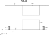
- the push-out members 19 With the engagement member 10a at the disengagement position, the push-out members 19 have a certain level of elastic force or higher and are exerting force to push out the sheet feed cassette 2 in the -X direction (second direction) via the rear plate 2C. In other words, the elastic force of the push-out members 19 presses the latch pin 5 against the toggle arm 10.
- the second restriction member 17a receives the toggle arm 10, and the biasing force of the toggle spring 12 does not act on the latch pin 5.
- the sheet feed cassette 2 is biased in the -X direction by the push-out members 19, and the latch pin 5 is pressed against the toggle arm 10 in the -X direction.
- the sheet feed cassette 2 enters the attached state with respect to the main body 1a.
- the position of the sheet feed cassette 2 here can be referred to as an attached position with respect to the main body 1a.
- the pin 80 is located downstream of the fifth path 16c in the -X direction.
- the sheet feed cassette 2 at the attached position is moved in the +X direction by the external force
- the sheet feed cassette 2 is moved in the -X direction to the detachment position by the push-out members 19.
- the sheet feed cassette 2 is moved from the attached position to the detached position with the toggle arm 10 at the release position ( Fig. 4E ).
- the front plate 2A With the sheet feed cassette 2 at the attached position, the front plate 2A is exposed from the main body 1a to outside (outside the image forming apparatus 1).
- the front plate 2A can be said to be an external force receiving portion that receives the external force in the +X direction when the sheet feed cassette 2 is detached using the second detachment method.
- the user With the sheet feed cassette 2 at the attached position, the user can detach the sheet feed cassette 2 by pressing any part of the front plate 2A in the +X direction.
- the sheet feed cassette 2 can be pulled out from the main body 1a using the foregoing two detachment methods. This improves the usability of the sheet feed cassette 2 during detachment.
- the toggle arm 10 In a case where the sheet feed cassette 2 is detached using the first detachment method, the toggle arm 10 is pressed in the -X direction by the latch pin 5 and the engagement member 10a reaches the engagement position. This enables the latch pin 5 to engage with the engagement member 10a when the sheet feed cassette 2 is inserted into the main body 1a again.
- the toggle arm 10 is at the release position where the engagement member 10a is located at the disengagement position. With the engagement member 10a located at the disengagement position when the sheet feed cassette 2 is inserted into the main body 1a again, the latch pin 5 is unable to engage with the engagement member 10a.
- the toggle arm 10 in a case where the sheet feed cassette 2 is inserted into the main body 1a with the toggle arm 10 at the release position, the toggle arm 10 is therefore restored from the release position to the standby position before the latch pin 5 engages with the toggle arm 10. Restoring the toggle arm 10 from the release position to the standby position will hereinafter be referred to as resetting the position of the toggle arm 10 or resetting the position of the engagement member 10a.
- the moving member 200 is provided on the rear plate 2C and the second groove shape 16 is formed in the guide member 17.
- a method for resetting the position of the engagement member 10a will be described.
- the toggle arm 10 In response to the detachment of the sheet feed cassette 2 from the main body 1a using the second detachment method and the detachment of the latch pin 5 and the pin 80 from the guide member 17, the toggle arm 10 is located at the release position ( Fig. 4D ).
- the toggle arm 10 overlaps the fourth path 16a.
- the pin 80 enters the fourth path 16a as illustrated in Fig. 4E .
- the toggle arm 10 overlaps the moving course of the pin 80 to move through the fourth path 16a.
- the pin 80 thus comes into contact with the toggle arm 10.
- the pin 80 moves from the fourth path 16a toward the fifth path 16c while pressing the toggle arm 10 in the +X direction. Since the toggle arm 10 is pressed in the +X direction, the toggle arm 10 rotates clockwise (A2 direction) when seen in the -Z direction as illustrated in Fig. 4F .
- the pin 80 finally rotates the toggle arm 10 up to a position where the toggle arm 10 is biased toward the standby position by the toggle spring 12, and the toggle arm 10 is located at the standby position by the toggle spring 12.
- the engagement member 10a is reset to the engagement position.
- the moving member 200 can thus move the toggle arm 10 from the release position to the standby position with the latch pin 5 separated from the toggle arm 10.
- the toggle arm 10 at the standby position does not overlap the fourth path 16a.
- the pin 80 reaches the fifth path 16c. Meanwhile, the latch pin 5 can engage with the engagement member 10a at the engagement position (see Fig. 4A ).
- the moving member 200 can be brought into contact with the pull-in unit 300 and move the toggle arm 10 from the release position to the standby position. More specifically, when the sheet feed cassette 2 is inserted in the first direction with the toggle arm 10 at the release position, the moving member 200 comes into contact with the toggle arm 10. The moving member 200 moves the toggle arm 10 to the standby position. By further inserting the sheet feed cassette 2 in the first direction, the to-be-engaged member 100 is engaged with the toggle arm 10 at the standby position.
- FIGs. 5A to 5E are plan views illustrating the unit moving device 4 and a part of the sheet feed cassette 2 according to the first modification.
- the distance from the rear plate 2C to the pin 80 in the +X direction is greater than that from the rear plate 2C to the latch pin 5 in the +X direction.
- the pin 80 therefore first comes into contact with the toggle arm 10 to reset the position of the engagement member 10a before the latch pin 5 engages with the engagement member 10a.
- the distance from the rear plate 2C to a pin 38 in the +X direction is smaller than that from the rear plate 2C to the latch pin 5 in the +X direction.
- the latch pin 5 is separated from the engagement member 10a and then the pin 38 comes into contact with the toggle arm 10 to reset the position of the engagement member 10a. Except for the latch pin 5 and the pin 38, the configuration is similar to the first embodiment. A detailed description thereof will thus be omitted.
- Fig. 5A illustrates the state where the engagement member 10a is at the disengagement position.
- the pin 38 is yet to come into contact with the toggle arm 10.
- the latch pin 5 is separated from the engagement member 10a of the toggle arm 10 and then the pin 38 comes into contact with the toggle arm 10 as illustrated in Fig. 5B .
- the latch pin 5 separated from the engagement member 10a lies in the third path 15b.
- the pin 38 moves from the fourth path 16a toward the fifth path 16c while pressing the toggle arm 10 in the +X direction ( Fig. 5C ).
- the pin 38 finally presses the toggle arm 10 so that the engagement member 10a at the engagement position moves to the disengagement position ( Fig. 5D ).
- the pin 38 rotates the toggle arm 10 up to a position where the toggle arm 10 is biased toward the standby position by the toggle spring 12, whereby the toggle arm 10 is located at the standby position.
- inserting the sheet feed cassette 2 in the first direction disengages the to-be-enraged member 100 and the pull-in unit 300. Inserting the sheet feed cassette 2 further in the first direction brings the moving member 200 into contact with the pull-in unit 300, whereby the toggle arm 10 is moved to the standby position.
- a seventh path 15e is further formed in the first groove shape 15.
- the seventh path 15e extends in the Y direction and connects the first path 15a and the second path 15c.
- the seventh path 15e is located upstream of the third path 15b in the +X direction.
- a path 15e1 where the seventh path 15e intersects the first path 15a is located upstream of the engagement member 10a at the disengagement position in the +X direction.
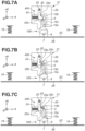
- FIGS. 7A to 7C are plan views illustrating the unit moving device 21 and a part of a sheet feed cassette 2.
- a pull-in unit 400 according to the second embodiment has a configuration different from that of the pull-in unit 300 according to the first embodiment.
- the second embodiment differs from the first embodiment in not including the moving member 200 or the second groove shape 16.
- the unit moving device 21 includes the pull-in unit 400 and a guide member 25.
- the guide member 25 includes a first path 15a, a second path 15c, and a third path 15b.
- the configuration of the first path 15a, the second path 15c, and the third path 15b is similar to that of the first embodiment, and a description thereof will thus be omitted.
- the guide member 25 includes a restriction portion 25a.
- the pull-in unit 400 includes a stopper 22 (pull-in member, force application member, first force application member, first arm), a stopper shaft 23, and a stopper spring 24.
- the stopper 22 is a latch unit that can swing about the stopper shaft 23 disposed on the guide member 25.
- the stopper 22 includes a first surface 22a, a corner portion 22b, and a second surface 22c on its -Y direction-side end.
- the corner portion 22b connects the first surface 22a and the second surface 22c.
- the first surface 22a extends in the Y direction and the X direction, and overlaps the first path 15a when seen in the vertical direction.
- the corner portion 22b overlaps the first path 15a when seen in the vertical direction.
- the second surface 22c extends in the Y direction and the X direction, and overlaps the first path 15a when seen in the vertical direction.
- the stopper spring 24 is disposed on the guide member 25.
- the stopper spring 24 is in contact with the +Y direction-side end of the stopper 22.
- the stopper spring 24 accumulates elastic force when the stopper 22 moves in the +Y direction, and functions to push the stopper 22 in the -Y direction. As illustrated in Fig. 7A , the stopper 22 is pushed by the stopper spring 24 into contact with the restriction portion 25a so that the stopper 22 is unable to move in the -Y direction side beyond the restriction portion 25a.
- the latch pin 5 presses the first surface 22a and moves the stopper 22 in the +Y direction.
- the elastic force of the stopper spring 24 is thereby accumulated.
- the elastic force of the stopper spring 24 becomes maximum when the latch pin 5 reaches the corner portion 22b as illustrated in Fig. 7B .
- the sheet feed cassette 2 at the attached position is biased in the -X direction by the push-out members 19, and the latch pin 5 is in contact with the second surface 22c of the stopper 22.
- Such a state where the latch pin 5 is in contact with the second surface 22c and the stopper 22 is in contact with restriction portion 25a will be referred to as a state where the sheet feed cassette 2 is at the attached position.
- the user can detach the sheet feed cassette 2 according to the second embodiment using a first detachment method and a second detachment method.
- the first detachment method will be described.
- the latch pin 5 presses the second surface 22c in the -X direction.
- the latch pin 5 passes the corner portion 22B.
- the latch pin 5 moves along the first surface 22a, and the sheet feed cassette 2 can finally be detached.
- the second detachment method will be described.
- the latch pin 5 enters the third path 15b and further enters the second path 15c.
- the force by which the push-out members 19 press the sheet feed cassette 2 in the -X direction moves the latch pin 5 in the -X direction in the second path 15c, whereby the sheet feed cassette 2 can be finally detached.
- the stopper 22 serving as the latching unit for the latch pin 5 is disposed on the guide member 25.
- an elastically deformable lever may be disposed on the guide member 25 instead of the stopper 22, without the swing fulcrum or the elastic member.
- a path switching flapper 45 may be disposed on the guide member 25 as illustrated in Fig. 8 .
- the path switching flapper 45 is biased to rotate clockwise when seen in the -Z direction.
- the path switching flapper 45 when seen in the vertical direction, the path switching flapper 45 thus is in contact with the guide member 25 to block the connection between the first path 15a and the second path 15c.
- the path switching flapper 45 can be rotated counterclockwise when seen in the -Z direction by applying an external force.
- the latch pin 5 presses the path switching flapper 45 in the +X direction.
- the position of the stopper 22 is reset by the elastic force of the stopper spring 24. Unlike the first embodiment, the moving member 200 therefore does not need to be provided.
- the sheet feed cassette 2 can be pulled out from the main body 1a using the foregoing first and second detachment methods. This improves the usability of the sheet feed cassette 2 during detachment.
- FIG. 9A and 9B are sectional views of a guide member 28 taken along the X direction.
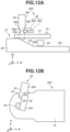
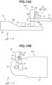
- Figs. 9B , 10 , 11B , 12B , and 14B are plan views of a to-be-engaged member 500 seen in the vertical direction (Z direction).
- a main body 1a according to the third embodiment includes the unit moving device 27, and a sheet feed cassette 2 includes the to-be-engaged member 500.
- the unit moving device 27 is located at the same position as the unit moving device 4 according to the first embodiment.
- the unit moving device 27 includes a pull-in unit 400 and a guide member 28.
- the to-be-engaged member 500 and the guide member 28 of an image forming apparatus 1 according to the third embodiment have a configuration different from that of the to-be-engaged member 100 and the guide member 25 according to the second embodiment.
- the rest of the configuration is similar to that of the second embodiment. A description thereof will thus be omitted.
- the configuration of the guide member 28 will be described with reference to Fig. 9A .
- the guide member 28 according to the present embodiment does not include the second path 15c or the third path 15b according to the second embodiment.
- the guide member 28 includes an eighth path 15f that is a path along which a latch pin 29 moves.
- the eighth path 15f extends from a first path 15a.
- the direction in which the eighth path 15f extends includes a +X-direction component and a +Z-direction component.
- the guide member 28 has a slope 15fb on the eighth path 15f, and the latch pin 29 can move along the slope 15fb.
- the configuration of the to-be-engaged member 500 will be described with reference to Figs. 9A, 9B , 12A, and 12B .
- the to-be-engaged member 500 includes a fulcrum shaft 70, a latch pin holding arm 31, the latch pin 29, and a fixing mechanism 30.
- the fulcrum shaft 70 and the latch pin holding arm 31 have a configuration similar to that of the fulcrum shaft 7 and the latch pin holding arm 6 according to the second embodiment, respectively. More specifically, the latch pin 29 is held by the latch pin holding arm 31.
- the latch pin holding arm 31 and the latch pin 29 can rotate with respect to the sheet feed cassette 2 via the fulcrum shaft 70.
- the latch pin 29 has a groove portion 29a, a restriction surface 29b, and a to-be-pressed surface 29c.
- the groove portion 29a has a radially recessed groove shape.
- the restriction surface 29b is a flat surface constituting the groove portion 29a and extends radially.
- the latch pin 29 runs through the latch pin holding arm 31 in the Z direction via a hole 44 formed in the latch pin holding arm 31.
- the restriction surface 29b is in contact with the +Z direction-side end of the latch pin holding arm 31. In other words, the restriction surface 29b restricts the latch pin 29 from moving in the -Z direction with respect to the latch pin holding arm 31 due to its own weight.
- the latch pin 29 can move in the +Z direction with respect to the latch pin holding arm 31 through the hole 44 when undergoing an external force in the +Z direction.
- the to-be-pressed surface 29c of the latch pin 29 refers to the outer peripheral surface of the latch pin 29.
- the to-be-engaged member 500 includes the fixing mechanism 30.
- the fixing mechanism 30 includes a first fixing member 30a and a second fixing member 30b.
- the first fixing member 30a is disposed to be rotatable about a first support shaft 32 disposed on the latch pin holding arm 31.
- the first fixing member 30a is rotated clockwise (B1 direction) when seen in the -Z direction by a not-illustrated torsion coil spring.
- the second fixing member 30b is disposed to be rotatable about a second support shaft 33 disposed on the first fixing member 30a by a not-illustrated torsion coil spring.
- the second fixing member 30b rotates counterclockwise (B2 direction) when seen in the -Z direction.
- Figs. 9A and 9B are diagrams illustrating the state where the latch pin 29 is located upstream of the guide member 28 in the +X direction. In other words, in this state, the sheet feed cassette 2 is not attached to the main body 1a.
- the second fixing member 30b has an end surface 34.
- the second fixing member 30b is in contact with the first fixing member 30a via the end surface 34.
- the torsion coil spring that rotates the first fixing member 30a has a larger biasing force than the torsion coil spring that rotates the second fixing member 30b.
- the fixing mechanism 30 rotates clockwise when seen in the - Z direction, the first fixing member 30a presses the to-be-pressed surface 29c of the first fixing member 30a.
- the restriction surface 29b is in contact with the +Z direction-side end of the latch pin holding arm 31 to restrict the latch pin 29 from moving in the -Z direction with respect to the latch pin holding arm 31 due to its own weight.
- the latch pin 29 and the stopper 22 overlap when seen in the X direction.
- the second fixing member 30b is pressed by the pin 35 and rotates clockwise (B3 direction) when seen in the -Z direction. After the second fixing member 30b is located downstream of the pin 35 in the +X direction, the second fixing member 30b returns to the state of Fig. 9B .
- the latch pin 29 moves the stopper 22 and then engages with the stopper 22 as illustrated in Fig. 11A.
- Fig. 11B illustrates the state of the to-be-engaged member 500 here.
- the engaging operation of the latch pin 29 with the stopper 22 has been described in the second embodiment. A description thereof will thus be omitted.
- the latch pin 29 moves on the eighth path 15f along the slope 15fb.
- the -Z direction-side end of the latch pin 29 comes into contact with the slope 15fb and receives force in the +Z direction from the slope 15fb. This moves the latch pin 29 in the +Z direction with respect to the latch pin holding arm 31 and the fixing mechanism 30. With the latch pin 29 moved in the +Z direction with respect to the fixing mechanism 30, as illustrated in Figs.
- the first fixing member 30a engages with the groove portion 29a.
- the first fixing member 30a is brought into contact to press the groove portion 29a by the biasing force of the torsion coil spring.
- the groove portion 29a includes a flat surface 29at that constitutes the groove portion 29a and extends radially.
- the flat surface 29at is located downstream of the first fixing member 30a in the +Z direction, and overlaps the first fixing member 30a when seen in the Z direction. This prevents the latch pin 29 from moving in the -Z direction with respect to the latch pin holding arm 31 due to its own weight.
- the latch pin 29 With the first fixing member 30a engaged with the groove portion 29a, the latch pin 29 is located above the stopper 22 in the vertical direction.
- Fig. 12A illustrates a state where the latch pin 29 is on the +X direction side of the stopper 22.
- the sheet feed cassette 2 is pressed by the push-out members 19 in the -X direction.
- the sheet feed cassette 2 thus moves in the -X direction with respect to the main body 1a as illustrated in Fig. 13 .
- the latch pin 29 is located above the stopper 22 in the vertical direction and therefore does not interfere with the stopper 22.
- the -X direction-side end of the second fixing member 30b comes into contact with the pin 35 as illustrated in Fig. 14B .
- the second fixing member 30b rotates in the B2 direction, whereby the first fixing member 30a is also rotated in the B2 direction via the end surface 34. This disengages the first fixing member 30a and the groove portion 29a, and the latch pin 29 moves in the -Z direction with respect to the latch pin holding arm 31 due to its own weight.
- the restriction surface 29b comes into contact with the +Z direction-side end of the latch pin holding arm 31.
- the latch pin 29 is restricted from moving in the -Z direction with respect to the latch pin holding arm 31.
- a first detachment method will be described.
- the latch pin 29 and the stopper 22 can be disengaged.
- the operation for disengaging the latch pin 29 and the stopper 22 using the first detachment method is similar to the operation described in the second embodiment. A description thereof will thus be omitted.
- the operation of the fixing mechanism 30 in the first detachment method will now be described.
- the second fixing member 30b comes into contact with the pin 35 as illustrated in Fig. 14B .
- the second fixing member 30b is pressed by the pin 35 to rotate counterclockwise when seen in the -Z direction. This moves the second fixing member 30b in the-X direction with respect to the pin 35, and the second fixing member 30b is finally located on the -X direction side of the pin 35.
- the fixing mechanism 30 returns to the state where the first fixing member 30a presses the to-be-pressed surface 29c as illustrated in Fig. 9B .
- the first detachment method and the second detachment method can be implemented without the moving member 200 according to the first embodiment. Since the configuration does not include the second path 15c or the third path 15b according to the second embodiment, the guide member 28 can be reduced in size in the +Y direction.
- FIG. 15 is a plan view of the unit moving device 37.
- a main body 1a according to the fourth embodiment includes the unit moving device 37, and a sheet feed cassette 2 includes a to-be-engaged member 100.
- the unit moving device 37 is located at the same position as the unit moving device 4 according to the first embodiment.
- the unit moving device 37 includes a guide member 41.
- the guide member 41 includes a pull-in unit 600, a plunger solenoid 60, and a sensor unit 55.
- the sensor unit 55 is a transmissive photoelectric sensor, and includes a light emitting element 55a and a light receiving element 55b.
- Fig. 15 illustrates the state where the sheet feed cassette 2 is attached to the main body 1a.
- push-out members 19 are pressed by the sheet feed cassette 2 to accumulate elastic force.
- the latch pin 5 moves in the +X direction with respect to the main body 1a.
- the push-out members 19 are thus further compressed in the +X direction by the sheet feed cassette 2 and accumulate elastic force.
- the sensor unit 55 detects the latch pin 5.
- a not-illustrated control unit (central processing unit [CPU]) of the image forming apparatus 1 energizes the plunger solenoid 60 based on a detection signal from the sensor unit 55.
- the plunger solenoid 60 thus generates a magnetic flux inside.
- the plunger solenoid 60 pulls in the movable core 42 in the +X direction with the magnetic force. Pulling in the movable core 42 in the +X direction pulls in the connection shaft 43 in the +X direction.
- the plunger solenoid 60 pulls in the connection shaft 43 so that the toggle arm 39 rotates clockwise when seen in the -Z direction.
- the toggle arm 39 is located at the release position with the movable core 42 protruded, and located at the standby position with the movable core 42 pulled in.
- the toggle arm 39 may be located at the standby position with the movable core 42 protruded, and located at the release position with the movable core 42 pulled in.
- the plunger solenoid 60 may be a keep solenoid.
- the toggle arm 39 is made of a nonmagnetic material so that no current follows from the movable core 42 to the toggle arm 39.
- the second detachment method can be implemented without the moving member 200 according to the first embodiment. Since the biasing force of the plunger solenoid 60 is applied in addition to the biasing force of the push-out members 19 when the second detachment method is practiced, the usability of the user's pull-out operation can be improved.
- the unit moving device is fixed to the rear-side plate 1b of the image forming apparatus 1, and the to-be-engaged member is fixed to the -X direction-side end of the rear plate 2C.
- the to-be-engaged member is disposed on the sheet feed cassette 2 serving as the unit, and the unit moving device is disposed on the main body 1a.
- the to-be-engaged member may be disposed on the main body 1a, and the unit moving member may be disposed on the sheet feed cassette 2.
- the moving member is disposed on the main body 1a.
- the unit moving device moves in the +X direction with respect to the to-be-engaged member when the sheet feed cassette 2 is inserted into the main body 1a.
- the unit moving device moves in the -X direction with respect to the to-be-engaged member.
- the unit moving device moves in the +X direction with respect to the to-be-engaged member and then moves in the -X direction.
- the unit moving device 4 may be fixed to the +X direction-side end of the rear plate 2C, and the to-be-engaged member 100 and the moving member 200 may be fixed to the rear-side plate 1b of the main body 1a.
- the operation for inserting the sheet feed cassette 2 into the main body 1a and the operation for detaching the sheet feed cassette 2 from the main body 1a are similar to those in the first embodiment. More specifically, in attaching the sheet feed cassette 2, the sheet feed cassette 2 is inserted into the main body 1a in the first direction, whereby the unit moving device 4 is moved in the +X direction with respect to the main body 1a and engages with the latch pin 5. Specifically, the toggle arm 10 at the standby position moves in the +X direction with respect to the main body 1a and engages with the latch pin 5 disposed on the main body 1a. When the sheet feed cassette 2 is further inserted in the +X direction, the toggle arm 10 moves to the release position and pulls in the latch pin 5 in the second direction so that the sheet feed cassette 2 is displaced in the first direction.
- an external force in the +X direction is applied to the sheet feed cassette 2 at the attached position.
- This moves the sheet feed cassette 2 in the +X direction from the attached position, and the guide member 17 including the first path 15a and the toggle arm 10 move in the +X direction with respect to the latch pin 5.
- the latch pin 5 and the toggle arm 10 are thereby disengaged, with the toggle arm 10 at the release position.
- the latch pin 5 enters the third path 15b and then enters the second path 15c.
- the sheet feed cassette 2 is then pressed in the second direction by the push-out members 19, whereby the sheet feed cassette 2 is moved with respect to the main body 1a.
- the unit moving device 21 according to the second embodiment may be fixed to the +X direction-side end of the rear plate 2C, and the to-be-engaged member 100 may be fixed to the rear-side plate 1b of the main body 1a.
- the unit moving device 27 according to the third embodiment may be fixed to the +X direction-side end of the rear plate 2C, and the to-be-engaged member 500 may be fixed to the rear-side plate 1b of the main body 1a.
- the unit moving device 37 according to the fourth embodiment may be fixed to the +X direction-side end of the rear plate 2C, and the to-be-engaged member 100 may be fixed to the rear-side plate 1b of the main body 1a.
- the push-out members 19 are disposed on the main body 1a. In the first modification, the push-out members 19 are disposed on the rear plate 2C. That is, the push-out members 19 may be disposed on either the main body 1a and the sheet feed cassette 2.
- the sheet feed cassette 2 is described as an example of the unit to be attached to and detached from the main body 1a of the image forming apparatus 1.
- the unit is not limited to the sheet feed cassette 2.
- the unit may be any part detachably attachable to the main body 1a.
- an embodiment of the present invention may be applied with the fixing unit 110 that fixes a toner image to a sheet or the developing unit (toner accommodation unit) 104 that accommodates toner as the unit.
- the present disclosure includes at least the following configurations.
- An image forming apparatus comprising:
- the image forming apparatus according to configuration 1, wherein the pull-in member is configured to move between a standby position where the pull-in member engages with the to-be-engaged member and a release position where the pull-in member disengages from the to-be-engaged member.
- the image forming apparatus further comprising a guide member configured to guide movement of the to-be-engaged member,
- the image forming apparatus according to any one of configurations 2 to 5, further comprising a restriction member, wherein the restriction member is configured to, in a case where the pull-in member reaches the release position, come into contact with the pull-in member to restrict movement of the pull-in member in a pull-in direction.
- the image forming apparatus according to any one of configurations 2 to 6, further comprising a moving member, wherein the moving member is configured to, in a case where the unit is moved in the first direction, come into contact with the pull-in member and move the pull-in member from the release position to the standby position.
- the image forming apparatus according to configurations 1 to 9, further comprising a damper member, wherein the damper member is configured to, as the pull-in member pulls in the to-be-engaged member, reduce moving speed of the unit in the first direction.
- the image forming apparatus according to any one of configurations 1 to 11, wherein the unit is an accommodation unit configured to accommodate a recording material.
- the image forming apparatus according to any one of configurations 1 to 12, wherein the unit is a fixing unit configured to fix a toner image formed on a recording material or a toner accommodation unit configured to accommodate toner.
- the image forming apparatus according to any one of configurations 1 to 13, further comprising an elastic member, wherein the elastic member is configured to bias the pull-in member in a direction where the pull-in member pulls in the to-be-engaged member.
- the image forming apparatus according to any one of configurations 1 to 15, wherein the to-be-engaged member is disposed on the unit and the pull-in member is disposed on the main body.
- the image forming apparatus according to any one of configurations 1 to 15, wherein the to-be-engaged member is disposed on the main body and the pull-in member is disposed on the unit.
Landscapes
- Physics & Mathematics (AREA)
- General Physics & Mathematics (AREA)
- Sheets, Magazines, And Separation Thereof (AREA)
- Electrophotography Configuration And Component (AREA)
Applications Claiming Priority (1)
| Application Number | Priority Date | Filing Date | Title |
|---|---|---|---|
| JP2023171827A JP2025062658A (ja) | 2023-10-03 | 2023-10-03 | 画像形成装置 |
Publications (1)
| Publication Number | Publication Date |
|---|---|
| EP4535084A1 true EP4535084A1 (de) | 2025-04-09 |
Family
ID=92712572
Family Applications (1)
| Application Number | Title | Priority Date | Filing Date |
|---|---|---|---|
| EP24199334.4A Pending EP4535084A1 (de) | 2023-10-03 | 2024-09-09 | Bilderzeugungsgerät |
Country Status (4)
| Country | Link |
|---|---|
| US (1) | US20250110443A1 (de) |
| EP (1) | EP4535084A1 (de) |
| JP (1) | JP2025062658A (de) |
| CN (1) | CN119758687A (de) |
Citations (4)
| Publication number | Priority date | Publication date | Assignee | Title |
|---|---|---|---|---|
| JPH11310331A (ja) * | 1998-04-27 | 1999-11-09 | Canon Inc | 画像形成装置 |
| JP2008254841A (ja) * | 2007-04-02 | 2008-10-23 | Canon Inc | 画像形成装置 |
| JP2012101888A (ja) | 2010-11-09 | 2012-05-31 | Canon Inc | ユニット移動装置および画像形成装置 |
| US20160279974A1 (en) * | 2015-03-26 | 2016-09-29 | Brother Kogyo Kabushiki Kaisha | Sheet Feeding Device and Image Forming Apparatus Employing the Same |
-
2023
- 2023-10-03 JP JP2023171827A patent/JP2025062658A/ja active Pending
-
2024
- 2024-09-09 EP EP24199334.4A patent/EP4535084A1/de active Pending
- 2024-09-13 CN CN202411282321.5A patent/CN119758687A/zh active Pending
- 2024-09-24 US US18/894,661 patent/US20250110443A1/en active Pending
Patent Citations (4)
| Publication number | Priority date | Publication date | Assignee | Title |
|---|---|---|---|---|
| JPH11310331A (ja) * | 1998-04-27 | 1999-11-09 | Canon Inc | 画像形成装置 |
| JP2008254841A (ja) * | 2007-04-02 | 2008-10-23 | Canon Inc | 画像形成装置 |
| JP2012101888A (ja) | 2010-11-09 | 2012-05-31 | Canon Inc | ユニット移動装置および画像形成装置 |
| US20160279974A1 (en) * | 2015-03-26 | 2016-09-29 | Brother Kogyo Kabushiki Kaisha | Sheet Feeding Device and Image Forming Apparatus Employing the Same |
Also Published As
| Publication number | Publication date |
|---|---|
| CN119758687A (zh) | 2025-04-04 |
| JP2025062658A (ja) | 2025-04-15 |
| US20250110443A1 (en) | 2025-04-03 |
Similar Documents
| Publication | Publication Date | Title |
|---|---|---|
| US8737868B2 (en) | Image forming apparatus | |
| US20080073830A1 (en) | Image forming apparatus | |
| US8203586B2 (en) | Image forming apparatus having a cleaning member configured to clean a transparent member of an optical device | |
| US9310752B2 (en) | Unit moving device and image forming apparatus | |
| US8705989B2 (en) | Color electrophotographic image forming apparatus | |
| KR20050022858A (ko) | 프로세스 카트리지, 이를 위한 장착 기구 및 전자사진화상 형성 장치 | |
| JP2018090359A (ja) | シート搬送装置及びシート搬送装置を備える画像形成装置 | |
| CN111071839B (zh) | 成像装置 | |
| JP2018097285A (ja) | プロセスカートリッジ及び画像形成装置 | |
| CN107608191B (zh) | 成像设备 | |
| US20190196392A1 (en) | Image forming apparatus | |
| JP2018090360A (ja) | シート搬送装置、シート搬送装置からの回転体ユニットの取り外し方法及びシート搬送装置を備える画像形成装置 | |
| JP2013068842A (ja) | 画像形成装置および搬送案内装置 | |
| EP4535084A1 (de) | Bilderzeugungsgerät | |
| JP5860853B2 (ja) | 画像形成ユニット及び画像形成装置 | |
| JP5821465B2 (ja) | 画像形成装置および転写装置 | |
| JP4360616B2 (ja) | 画像形成装置 | |
| US9989894B2 (en) | Image forming apparatus | |
| JP5504947B2 (ja) | 給紙装置およびこれを備えた画像形成装置 | |
| JP6245203B2 (ja) | シート供給装置およびこれを備える画像形成装置 | |
| US9046859B2 (en) | Sheet conveyance apparatus and image forming apparatus | |
| US12189329B2 (en) | Image forming apparatus | |
| CN107797430A (zh) | 图像形成装置 | |
| US11754968B2 (en) | Image forming apparatus | |
| US20230324841A1 (en) | Image forming apparatus |
Legal Events
| Date | Code | Title | Description |
|---|---|---|---|
| PUAI | Public reference made under article 153(3) epc to a published international application that has entered the european phase |
Free format text: ORIGINAL CODE: 0009012 |
|
| STAA | Information on the status of an ep patent application or granted ep patent |
Free format text: STATUS: THE APPLICATION HAS BEEN PUBLISHED |
|
| AK | Designated contracting states |
Kind code of ref document: A1 Designated state(s): AL AT BE BG CH CY CZ DE DK EE ES FI FR GB GR HR HU IE IS IT LI LT LU LV MC ME MK MT NL NO PL PT RO RS SE SI SK SM TR |
|
| STAA | Information on the status of an ep patent application or granted ep patent |
Free format text: STATUS: REQUEST FOR EXAMINATION WAS MADE |
|
| 17P | Request for examination filed |
Effective date: 20251009 |