EP4531246A1 - Axial gap motor - Google Patents
Axial gap motor Download PDFInfo
- Publication number
- EP4531246A1 EP4531246A1 EP23811399.7A EP23811399A EP4531246A1 EP 4531246 A1 EP4531246 A1 EP 4531246A1 EP 23811399 A EP23811399 A EP 23811399A EP 4531246 A1 EP4531246 A1 EP 4531246A1
- Authority
- EP
- European Patent Office
- Prior art keywords
- phase
- board
- motor
- boards
- stator
- Prior art date
- Legal status (The legal status is an assumption and is not a legal conclusion. Google has not performed a legal analysis and makes no representation as to the accuracy of the status listed.)
- Pending
Links
Images


Classifications
-
- H—ELECTRICITY
- H02—GENERATION; CONVERSION OR DISTRIBUTION OF ELECTRIC POWER
- H02K—DYNAMO-ELECTRIC MACHINES
- H02K3/00—Details of windings
- H02K3/04—Windings characterised by the conductor shape, form or construction, e.g. with bar conductors
- H02K3/26—Windings characterised by the conductor shape, form or construction, e.g. with bar conductors consisting of printed conductors
-
- H—ELECTRICITY
- H02—GENERATION; CONVERSION OR DISTRIBUTION OF ELECTRIC POWER
- H02K—DYNAMO-ELECTRIC MACHINES
- H02K1/00—Details of the magnetic circuit
- H02K1/06—Details of the magnetic circuit characterised by the shape, form or construction
- H02K1/12—Stationary parts of the magnetic circuit
- H02K1/14—Stator cores with salient poles
-
- H—ELECTRICITY
- H02—GENERATION; CONVERSION OR DISTRIBUTION OF ELECTRIC POWER
- H02K—DYNAMO-ELECTRIC MACHINES
- H02K1/00—Details of the magnetic circuit
- H02K1/06—Details of the magnetic circuit characterised by the shape, form or construction
- H02K1/12—Stationary parts of the magnetic circuit
- H02K1/16—Stator cores with slots for windings
-
- H—ELECTRICITY
- H02—GENERATION; CONVERSION OR DISTRIBUTION OF ELECTRIC POWER
- H02K—DYNAMO-ELECTRIC MACHINES
- H02K1/00—Details of the magnetic circuit
- H02K1/06—Details of the magnetic circuit characterised by the shape, form or construction
- H02K1/22—Rotating parts of the magnetic circuit
- H02K1/27—Rotor cores with permanent magnets
- H02K1/2793—Rotors axially facing stators
- H02K1/2795—Rotors axially facing stators the rotor consisting of two or more circumferentially positioned magnets
- H02K1/2796—Rotors axially facing stators the rotor consisting of two or more circumferentially positioned magnets where both axial sides of the rotor face a stator
-
- H—ELECTRICITY
- H02—GENERATION; CONVERSION OR DISTRIBUTION OF ELECTRIC POWER
- H02K—DYNAMO-ELECTRIC MACHINES
- H02K16/00—Machines with more than one rotor or stator
- H02K16/04—Machines with one rotor and two stators
-
- H—ELECTRICITY
- H02—GENERATION; CONVERSION OR DISTRIBUTION OF ELECTRIC POWER
- H02K—DYNAMO-ELECTRIC MACHINES
- H02K21/00—Synchronous motors having permanent magnets; Synchronous generators having permanent magnets
- H02K21/12—Synchronous motors having permanent magnets; Synchronous generators having permanent magnets with stationary armatures and rotating magnets
- H02K21/24—Synchronous motors having permanent magnets; Synchronous generators having permanent magnets with stationary armatures and rotating magnets with magnets axially facing the armatures, e.g. hub-type cycle dynamos
-
- H—ELECTRICITY
- H02—GENERATION; CONVERSION OR DISTRIBUTION OF ELECTRIC POWER
- H02K—DYNAMO-ELECTRIC MACHINES
- H02K3/00—Details of windings
- H02K3/04—Windings characterised by the conductor shape, form or construction, e.g. with bar conductors
- H02K3/28—Layout of windings or of connections between windings
-
- H—ELECTRICITY
- H05—ELECTRIC TECHNIQUES NOT OTHERWISE PROVIDED FOR
- H05K—PRINTED CIRCUITS; CASINGS OR CONSTRUCTIONAL DETAILS OF ELECTRIC APPARATUS; MANUFACTURE OF ASSEMBLAGES OF ELECTRICAL COMPONENTS
- H05K3/00—Apparatus or processes for manufacturing printed circuits
- H05K3/40—Forming printed elements for providing electric connections to or between printed circuits
- H05K3/4038—Through-connections; Vertical interconnect access [VIA] connections
-
- H—ELECTRICITY
- H02—GENERATION; CONVERSION OR DISTRIBUTION OF ELECTRIC POWER
- H02K—DYNAMO-ELECTRIC MACHINES
- H02K2203/00—Specific aspects not provided for in the other groups of this subclass relating to the windings
- H02K2203/03—Machines characterised by the wiring boards, i.e. printed circuit boards or similar structures for connecting the winding terminations
Definitions
- the present invention relates to an axial gap motor, and particularly relates to an axial gap motor provided with distributedly wound motor coils.
- Patent documents 1 and 2 Distributedly wound axial gap motors have been proposed in Patent documents 1 and 2.
- motor coils of three phases are each distributedly wound over a plurality of salient-pole teeth, thereby reducing spatial harmonics of magnetic flux and lowering vibration and noise.
- Patent document 3 proposes an axial gap motor provided with concentratedly wound motor coils, a fixed element of the axial gap motor being provided with a magnetic body and a plurality of wiring boards that are laminated on the magnetic body from an axial direction, and respective coil winding patterns being formed on the wiring boards.
- Distributedly wound motors are superior to concentratedly wound motors in that rotating magnetic fields produced by motor stators in the former are closer to sine waves and in that the former have exceptional motor rotation characteristics and output performance.
- it is more difficult to increase a space factor in distributed windings than in concentrated windings.
- there does not exist any winding mechanism (slotter) or main winding technology dedicated to distributed windings for axial gap motors. Therefore, existing distributed windings are wound through a manual operation, which results in low precision (space factor).
- the distributedly wound coil winding patterns are formed on the surface of the printed wiring board (PCB board) using copper foils or other electroconductive metal foils, therefore making it possible to increase the space factor in the distributed windings.
- the winding structure spanning the plurality of salient-pole teeth is similar to that of prior-art distributed windings, but because a printed wiring board (PCB board) is used, any increase in dimensions caused by stacking of coil winding patterns in a length direction (axial direction) can be suppressed, which is advantageous for achieving a flatter motor profile.
- the gap-forming member is disposed between adjacent phase boards, and the phase boards of each phase are laminated in a state in which the fixed inter-board gap is formed therebetween due to the gap-forming member.
- a phase board is directly laminated in the axial direction onto the surface of a separate phase board in which a coil winding pattern of a metal foil is formed on the surface thereof, it is possible to ensure a sufficient spatial distance between the phase boards of each phase.
- the dielectric strength required for a motor can be maintained, and the danger of short-circuiting of the windings also decreases.
- An insulating resin material (mold, varnish, or the like) can easily be filled into the inter-board gap in accordance with the spatial shape of the gap. This makes it possible to simultaneously improve dielectric strength, improve heat dissipation properties (for generation of heat by the coil winding patterns), and achieve fixation between the phase boards.
- the printed wiring board is a laminated board in which a plurality of phase boards, e.g., three phase boards respectively having a U phase, a V phase, and a W phase, are laminated in the axial direction.
- the phase boards may merely be laminated in a state of being positioned in the circumferential direction.
- a distributedly wound axial gap motor according to embodiments of the present invention is described below with reference to the accompanying diagrams.
- the embodiments described below illustrate examples of the present invention, but the present invention is in no way limited thereto.
- the number of phases, the number of magnet poles, the number of slots, the shape of magnets, and the shape of slots are not limited to the numbers and shapes in the embodiments below.
- the distributed windings may be wound using any of coaxial winding, lap winding, or wave winding.
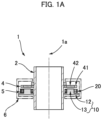
- FIG. 1A is a schematic diagram showing a distributedly wound axial gap motor.
- the axial gap motor 1 (referred to below simply as the "motor 1") is a three-phase motor having eight poles and 36 slots.
- the motor 1 has: a hollow motor shaft 2; a motor rotor 4 that is coaxially secured to the hollow motor shaft 2; a motor stator 5 that coaxially faces the motor rotor 4 at a fixed gap in an axial direction, which is the direction following a central axis 1a; and a motor housing 6 to which the motor stator 5 is secured.
- FIG. 1B is a perspective view showing the motor rotor 4 and the motor stator 5.
- the motor rotor 4 and the motor stator 5 are shown in a state in which a gap therebetween is enlarged.
- the motor rotor 4 is provided with an annular rotor disk 41 that is made from iron or another ferromagnetic material, and a magnet 42 that is attached to the rotor disk 41.
- eight magnets 42 are embedded in the rotor disk 41 at fixed angular intervals in a circumferential direction.
- FIG. 1C is a side view showing the motor stator 5.
- the motor stator 5 is provided with a plate-form stator core 10 that is made from a ferromagnetic material, and an annular printed wiring board 20 (PCB board) that is coaxially laminated on an end surface 11 of the stator core 10, the end surface 11 being located on the motor-rotor 4 side.
- the printed wiring board 20 is configured such that motor coils 30 that respectively correspond to a U phase, a V phase, and a W phase, other circuits, and the like are printed onto the printed wiring board 20.
- the printed wiring board 20 is a laminated board configured such that a plurality of phase boards 21 having the same configuration sandwich spacers 26 for forming an inter-board gap and are laminated coaxially in the axial direction.
- the printed wiring board 20 is a laminated board configured such that three phase boards 21 are laminated coaxially in the axial direction with fixed inter-board gaps G interposed therebetween, the inter-board gaps G being formed by the spacers 26.
- a portion of the printed wiring board 20 of the motor stator 5 configured in this manner is covered by a mold material 27 made from an insulating resin, as shown by the virtual-line frame in FIG. 1C .
- FIG. 1D is a plan view of the phase boards 21 constituting the printed wiring board 20 of the motor stator 5.
- FIG. 1E is a perspective view showing the spacers 26 and three phase boards 21 constituting the printed wiring board 20, specifically showing a state in which the phase boards 21 are separated from one another.
- the three phase boards 21 respectively are a U-phase board 21U on which a U-phase motor coil 30U is formed, a V-phase board 21V on which a V-phase motor coil 30V is formed, and a W-phase board 21W on which a W-phase motor coil 30W is formed.
- spacers 26 that are disposed at equiangular intervals in the circumferential direction are sandwiched between the U-phase board 21U laminated on the stator core 10 and the V-phase board 21V laminated on the U-phase board 21U.
- six spacers 26 are sandwiched between the V-phase board 21V and the W-phase board 21W laminated on the V-phase board 21V.
- the spacers 26, which are members for forming the inter-board gap are fabricated as separate members from the phase boards and are disposed between the phase boards.
- the spacers 26 are formed integrally with parts of the phase boards 21 as protruding parts for forming the inter-board gap.
- FIG. 2 is a perspective view showing the stator core 10 of the motor stator 5.
- the stator core 10 is made from, e.g., a sintered body or a green compact, the stator core 10 being provided with: a plate-form back yoke 12 in which a circular opening is formed in the center thereof; and salient-pole teeth 13 that are formed on an end surface 11 of the back yoke 12, the end surface 11 being the motor-rotor-side end surface.
- the salient-pole teeth 13 protrude in the axial direction and are arranged at fixed angular intervals in the circumferential direction about the center axis 1a.
- the salient-pole teeth 13 are formed corresponding to the 36 slots, 36 being an integral multiple of 3 (the number of phases).
- FIG. 3(A) is a perspective view showing one of the phase boards 21 (21U, 21V, 21W) constituting the printed wiring board 20, and FIG. 3(B) is a perspective view showing a state in which two insulated boards constituting the phase board 21 are separated from one another.
- the phase board 21 is a two-layer board in which two insulated boards 22(1), 22(2) having the same shape are laminated in the axial direction.
- the insulated boards 22(1), 22(2) are each formed in a disk shape in which a circular opening is formed in the center thereof.
- Salient-pole-tooth passage holes 23 passing through in a thickness direction (axial direction) are formed in the insulated boards 22(1), 22(2).
- a plurality of motor coils 30 are disposed at fixed angular intervals on the surfaces (surfaces located on the motor-rotor side) of the insulated boards 22(1), 22(2).
- the motor coils 30 are distributedly wound and are defined by coil winding patterns made from copper foils.
- the coil winding patterns which are each printed so as to surround four adjacent slots, are formed at six locations at equiangular intervals in the circumferential direction.
- the two insulated boards 22(1), 22(2) configured in this manner are laminated in the axial direction and integrated in a state of being shifted relative to one another by an angle corresponding to three slots in the circumferential direction, whereby one phase board 21 is configured.
- the orientation of a current of the motor coil 30 on the upper-side insulated board 22(2) is set as a CCW direction as shown by the solid-line arrows
- the orientation of a current of the motor coil 30 on the lower-side insulated board 22(1) is set as a CW direction that is opposite from the CCW direction as shown by the dashed-line arrows.
- a through-hole (not shown) is formed in the insulated board 22(2), the coil winding patterns formed on the two insulated boards being connected via the through-hole.
- FIG. 4 is a perspective view showing the lamination state of the three phase boards 21, specifically showing a state in which the three phase boards 21 are separated from one another, and not showing the spacers 26 between the phase boards 21.
- the three phase boards 21 having the same configuration are laminated coaxially in the axial direction and are integrated with the end surface 11 of the back yoke 12 in the stator core 10, as a result of which the printed wiring board 20 is configured.
- the three phase boards 21 are laminated in a state of being shifted relative to one another by an angle corresponding to one slot in the circumferential direction. In the present example, because there are 36 slots, the phase boards 21 are shifted in the circumferential direction by 10° (i.e., 360°/36 slots) in terms of mechanical angle.
- the phase board 21 that is laminated on the end surface 11 of the back yoke 12 is the U-phase board 21U
- the motor coil 30 of the U-phase board 21U is the U-phase motor coil 30U
- the phase board 21 that is laminated on the U-phase board 21U is the V-phase board 21V on which the V-phase motor coil 30V is printed
- the phase board 21 that is laminated on the V-phase board 21V is the W-phase board 21W on which the W-phase motor coil 30W is printed.
- the coil winding patterns of the motor coils 30U, 30V, 30W are respectively formed on the phase boards 21U, 21V, 21W, and neutral-point connection patterns for connecting the coil winding patterns of each of the U, V, and W phases at a neutral point are also formed, although FIG. 4 does not show this configuration.
- FIG. 5 is an explanatory diagram showing neutral-point connection patterns formed on the phase boards 21 (21U, 21V, 21W).
- the neutral-point connection patterns 24 (24U, 24V, 24W) are formed using copper foils on the surfaces (surfaces located on the motor-rotor 4 side) of the phase boards 21 (21U, 21V, 21W), together with the coil winding patterns (not shown).
- the neutral-point connection patterns 24 have a prescribed length and extend in the circumferential direction.
- the neutral-point connection patterns 24 have an arcuate shape and spread over a fixed angle centered on the central axis 1a.
- a plurality of through-holes 25 passing through in the thickness direction are also formed in the phase boards 21.
- the through-holes 25 are formed along the neutral-point connection patterns 24 at angular intervals that correspond to the amount of circumferential-direction shifting of the phase boards 21.
- FIG. 6 shows one example of a connection circuit of the motor coils 30 of the three phases (U, V, W).
- Wiring patterns for forming crossover lines or another circuit connection linking the coil winding patterns that regulate the motor coils 30 of each phase are also patterned onto the phase boards 21 using copper foils or the like.
- the coil winding patterns of each phase are connected to each other at a neutral point (position of the mutually aligned through-holes) via the neutral-point connection patterns 24 of each phase.
- the printed wiring board 20 which is a laminate of the phase boards 21U, 21V, 21W of U, V, and W phases on which are printed the motor coils 30U, 30V, 30W of each phase regulated by the copper-foil coil winding patterns, is used in the motor 1 according to the present example.
- the phase boards 21 (21U, 21V, 21W) having the same structure are laminated on the back yoke 12 in a number corresponding to the number of phases, whereby the motor stator 5 is configured.
- the phase boards 21 (21U, 21V, 21W) of each phase are formed as two-layer integrated structures in each of which two insulated boards 22(1), 22(2) are laminated. Between the insulated boards 22(1), 22(2), the motor coils 30 (coil winding patterns) are shifted in the circumferential direction, and the orientation of currents is inverted, whereby distributed winding is achieved.
- the distributedly wound coil winding patterns are formed on the surface of the printed wiring board 20 using copper foils or the like. Accordingly, a space factor in distributed windings can be increased, a degree of freedom in designing windings can be improved, and any of coaxial winding, lap winding, or wave winding can be employed in the distributed windings. The incidence of damage and burnout in the coils can also be suppressed.
- the winding structure spanning the plurality of salient-pole teeth 13 is similar to that in the case of prior-art distributed windings, but the printed wiring board 20 is used.
- any increase in dimensions caused by stacking of coil winding patterns in a length direction (axial direction) can be suppressed, which is advantageous for flattening the motor.
- the copper-foil patterns on the printed wiring board have higher precision than manually applied windings.
- variation in induced voltage values, waveform maximum values (P-P), and execution values (rms) is low.
- P-P waveform maximum values
- rms execution values
- the printed wiring board is a laminated board in which a plurality of phase boards, e.g., three phase boards respectively having a U phase, a V phase, and a W phase, are laminated in the axial direction.
- the phase boards may merely be laminated in a state of being positioned in the circumferential direction.
- the phase boards can also be configured to have the same structure.
- Neutral-point connection patterns are also formed on the phase boards 21, together with the coil winding patterns of the motor coils of each phase. With the phase boards 21 in a laminated state, one through-hole in each phase is positioned in alignment with each other. The coil winding patterns of each phase are connected via the through-holes using the position of the aligned through-holes as a neutral point.
- terminals of coil windings are linked together as described below. Specifically, it is common for the positions of the terminals of the coil windings of each phase to not be aligned, irrespective of whether the coil windings are distributedly wound or concentratedly wound. Therefore, in cases where the coil windings of each phase are linked together at a neutral point, it has been necessary to partially change the length of the coil windings for design or manufacturing considerations, or to link together the terminals via interpolation with a separate connection component.
- neutral-point connection patterns having a prescribed length are formed on the phase boards along the circumferential direction in consideration of the lamination state of the phase boards, and through-holes are formed at a plurality of locations along the neutral-point connection patterns, as described above. This makes it possible to easily and precisely carry out work for connecting the coil winding patterns of each phase at the neutral point while maintaining standardization of the phase boards.
- the spacers 26 are sandwiched between the phase boards 21U, 21V, 21W of each phase, and the phase boards are laminated.
- the spacers 26 are sandwiched between the phase board 21U and the phase board 21V, whereby the fixed inter-board gap G therebetween is ensured, and, similarly, the spacers 26 are also sandwiched between the phase board 21V and the phase board 21W, whereby the fixed inter-board gap G therebetween is ensured.
- gaps (spaces) are provided between the phase boards, thereby making it possible to improve dielectric resistance.
- Providing gaps (spaces) between the phase boards also makes it possible to easily fill an insulating resin material (molding materials, varnishes, or the like) into the gaps between the phase boards in accordance with the shapes of the gaps. As a result, it is possible to simultaneously improve dielectric strength, improve heat dissipation properties (for generation of heat by the coil winding patterns), and mutually secure the phase boards.
- the motor 1 is a three-phase motor having 8 poles and 36 slots; however, as indicated previously, the number of magnet poles, the number of slots, and other features are not limited to those in the example described above.
- the shapes of the magnets and the slots also are not limited to those in the example described above, and various shapes and structures can be employed.
- the motor stator having the configuration described above may be configured to have multiple stages in the axial direction.
- a motor stator 5 and a motor stator 5A having the same configuration are disposed symmetrically on both sides of a motor rotor 4 so as to sandwich the motor rotor 4.
- the motor rotor and the set of motor stators can be configured to have a greater number of stages.
Landscapes
- Engineering & Computer Science (AREA)
- Power Engineering (AREA)
- Manufacturing & Machinery (AREA)
- Microelectronics & Electronic Packaging (AREA)
- Windings For Motors And Generators (AREA)
Applications Claiming Priority (2)
| Application Number | Priority Date | Filing Date | Title |
|---|---|---|---|
| JP2022021163 | 2022-05-23 | ||
| PCT/JP2023/009370 WO2023228518A1 (ja) | 2022-05-23 | 2023-03-10 | アキシャルギャップ型モータ |
Publications (1)
| Publication Number | Publication Date |
|---|---|
| EP4531246A1 true EP4531246A1 (en) | 2025-04-02 |
Family
ID=88918945
Family Applications (1)
| Application Number | Title | Priority Date | Filing Date |
|---|---|---|---|
| EP23811399.7A Pending EP4531246A1 (en) | 2022-05-23 | 2023-03-10 | Axial gap motor |
Country Status (7)
| Country | Link |
|---|---|
| US (1) | US20260045844A1 (https=) |
| EP (1) | EP4531246A1 (https=) |
| JP (1) | JP7805698B2 (https=) |
| KR (1) | KR20240150517A (https=) |
| CN (1) | CN119156760A (https=) |
| TW (1) | TW202410601A (https=) |
| WO (1) | WO2023228518A1 (https=) |
Families Citing this family (3)
| Publication number | Priority date | Publication date | Assignee | Title |
|---|---|---|---|---|
| DE102024102369A1 (de) * | 2024-01-29 | 2025-07-31 | Schaeffler Technologies AG & Co. KG | Eisenbehafteter Leiterplattenlinearmotor |
| JP7828387B2 (ja) * | 2024-05-28 | 2026-03-11 | シナノケンシ株式会社 | アキシャルギャップモータの固定子の製造方法及びアキシャルギャップモータの固定子 |
| WO2026019449A1 (en) * | 2024-07-17 | 2026-01-22 | Power Integrations, Inc. | A stator with an integrated drive circuit for an axial flux brushless dc motor |
Family Cites Families (5)
| Publication number | Priority date | Publication date | Assignee | Title |
|---|---|---|---|---|
| JP2006187091A (ja) | 2004-12-27 | 2006-07-13 | Daikin Ind Ltd | コア、電機子、モータ及び圧縮機並びにそれらの製造方法 |
| JP4962033B2 (ja) | 2007-02-06 | 2012-06-27 | ダイキン工業株式会社 | アキシャルギャップ型モータ |
| RU2018108629A (ru) | 2015-08-11 | 2019-09-12 | Дженезис Роботикс Энд Мотион Текнолоджиз Канада, Улс | Электрическая машина |
| JP6743668B2 (ja) | 2016-12-06 | 2020-08-19 | 三菱電機株式会社 | 積層コイル、固定子およびモータ |
| KR102192837B1 (ko) | 2017-02-14 | 2020-12-18 | 성균관대학교산학협력단 | 무선 사용자 단말 및 단말의 페어링 방법 |
-
2023
- 2023-03-10 KR KR1020247032253A patent/KR20240150517A/ko active Pending
- 2023-03-10 US US18/843,961 patent/US20260045844A1/en active Pending
- 2023-03-10 EP EP23811399.7A patent/EP4531246A1/en active Pending
- 2023-03-10 CN CN202380029936.4A patent/CN119156760A/zh active Pending
- 2023-03-10 JP JP2024522923A patent/JP7805698B2/ja active Active
- 2023-03-10 WO PCT/JP2023/009370 patent/WO2023228518A1/ja not_active Ceased
- 2023-03-20 TW TW112110192A patent/TW202410601A/zh unknown
Also Published As
| Publication number | Publication date |
|---|---|
| US20260045844A1 (en) | 2026-02-12 |
| JPWO2023228518A1 (https=) | 2023-11-30 |
| CN119156760A (zh) | 2024-12-17 |
| WO2023228518A1 (ja) | 2023-11-30 |
| KR20240150517A (ko) | 2024-10-15 |
| TW202410601A (zh) | 2024-03-01 |
| JP7805698B2 (ja) | 2026-01-26 |
Similar Documents
| Publication | Publication Date | Title |
|---|---|---|
| EP4531246A1 (en) | Axial gap motor | |
| JP5140389B2 (ja) | 回転電機用の固定子、及びこれを用いた回転電機 | |
| JP5214064B2 (ja) | インバータ一体型駆動モジュール | |
| JP3745884B2 (ja) | モータ構造及びその製造方法 | |
| US8471669B2 (en) | Disc-type coil | |
| JP4670868B2 (ja) | モータとそのモータに使用されるステータの製造方法 | |
| US10320253B2 (en) | Armature, rotating electric machine, cross-flow fan, and method for manufacturing pair of teeth of armature | |
| US20200091805A1 (en) | Dynamo-electric machine with reduced cogging torque | |
| JP2011151875A (ja) | 同期回転機の固定子 | |
| WO2021131575A1 (ja) | コイル及びそれを備えたステータ、モータ | |
| JP2009106008A (ja) | 回転電機の固定子 | |
| US10284034B2 (en) | Armature, rotating electric machine, crossflow fan | |
| CN211930351U (zh) | 定子以及无刷马达 | |
| JP2018093650A (ja) | 積層コイル、固定子およびモータ | |
| WO2024034364A1 (ja) | コイル、ステータ及び回転電機 | |
| US12308718B2 (en) | Molded coil, stator, and rotary electric machine | |
| JP7222293B2 (ja) | ステータ | |
| JP2000014069A (ja) | モータ | |
| JP7446552B1 (ja) | 電動機 | |
| JP2002034229A (ja) | コアレスリニアモータ | |
| US20240339879A1 (en) | Coil assembly, armature and rotating electric machine | |
| CN112272913A (zh) | 电动机及用于该电动机的线圈 | |
| WO2025248809A1 (ja) | 電機子、回転電機、及び電機子の製造方法 | |
| JP2025163894A (ja) | モータ | |
| WO2025197166A1 (ja) | 電機子、回転電機、リニアモータおよび電機子の製造方法 |
Legal Events
| Date | Code | Title | Description |
|---|---|---|---|
| STAA | Information on the status of an ep patent application or granted ep patent |
Free format text: STATUS: THE INTERNATIONAL PUBLICATION HAS BEEN MADE |
|
| PUAI | Public reference made under article 153(3) epc to a published international application that has entered the european phase |
Free format text: ORIGINAL CODE: 0009012 |
|
| STAA | Information on the status of an ep patent application or granted ep patent |
Free format text: STATUS: REQUEST FOR EXAMINATION WAS MADE |
|
| 17P | Request for examination filed |
Effective date: 20240902 |
|
| AK | Designated contracting states |
Kind code of ref document: A1 Designated state(s): AL AT BE BG CH CY CZ DE DK EE ES FI FR GB GR HR HU IE IS IT LI LT LU LV MC ME MK MT NL NO PL PT RO RS SE SI SK SM TR |
|
| DAV | Request for validation of the european patent (deleted) | ||
| DAX | Request for extension of the european patent (deleted) |