EP4530563A1 - Essoreuse centrifuge pour gerbes - Google Patents
Essoreuse centrifuge pour gerbes Download PDFInfo
- Publication number
- EP4530563A1 EP4530563A1 EP24000107.3A EP24000107A EP4530563A1 EP 4530563 A1 EP4530563 A1 EP 4530563A1 EP 24000107 A EP24000107 A EP 24000107A EP 4530563 A1 EP4530563 A1 EP 4530563A1
- Authority
- EP
- European Patent Office
- Prior art keywords
- cage
- containers
- loading
- retaining
- pressure plate
- Prior art date
- Legal status (The legal status is an assumption and is not a legal conclusion. Google has not performed a legal analysis and makes no representation as to the accuracy of the status listed.)
- Granted
Links
Images



Classifications
-
- F—MECHANICAL ENGINEERING; LIGHTING; HEATING; WEAPONS; BLASTING
- F26—DRYING
- F26B—DRYING SOLID MATERIALS OR OBJECTS BY REMOVING LIQUID THEREFROM
- F26B5/00—Drying solid materials or objects by processes not involving the application of heat
- F26B5/08—Drying solid materials or objects by processes not involving the application of heat by centrifugal treatment
Definitions
- centrifuge with a vertical rotation axis is known from the same applicant for rectangular prismatic trays with hinged side walls, where the side walls can be folded or unfolded, or for trays of different sizes with fixed side walls.
- the centrifugation cage of this machine is arranged in a position above the horizontal transfer devices for the incoming trays at a distance slightly greater than the maximum height of the trays that can be processed.
- the trays are The bottom is fed in aligned with the conveyor belts or transfer devices, the side walls can be folded up or down, or non-foldable and pointing upwards, towards the centrifuge cage.
- the centrifuge cage is open at the bottom and has at least one row of rungs which project downwards from the bottom of the cage and are dimensioned according to the internal dimensions of the crate to be spun, so that the crate, inserted into the cage by means of a lifting table, is secured in a central position.
- one or more rows of downward-projecting rungs can be provided, which are arranged concentrically to the first row, inside or outside of it.
- the crate is held inside the cage between the lifting table acting vertically from below and a pressure plate acting from above, both acting coaxially to the axis of rotation of the cage.
- This centrifuge has the disadvantage that, in particular, the travel of the lifting table, regardless of the height of the crates' sides or whether they are folded or unfolded, during insertion of the crates into the cage or removal from the cage, must always be greater than the maximum height of the crates that can be processed, with fixed or unfolded sides, because the cage, with its lower edge, must be spaced from the crates' support surface by more than the maximum height of the crates that can be processed during their insertion.
- This means that the times for loading and unloading the cage are long, even for crates with folded sides, which are of very modest height, and for those with low sides.
- the arrangement of the centrifuge cage above the transfer belts or transfer devices complicates the effective collection and drainage of water and makes cleaning and maintenance of the cage itself and the corresponding collection and drainage devices more difficult.
- the invention has for its object to provide a spin dryer as described above, which is suitable for the efficient drying of individual containers with fixed or foldable side walls in the open or closed position or of stacks of containers which have a modest height, in very short times, wherein the containers fed to the spin dryer can also have different dimensions and an efficient drainage of the water as well as convenient access to the spin cage and to its external and internal components for the purpose of cleaning and maintenance work is ensured.
- the invention proposes a spin dryer with a vertical rotation axis of the centrifuge cage, which can be loaded from above by means of a horizontal loading/unloading platform which is attached to the upper end of a shaft which projects from the bottom of the cage and is mounted so as to be vertically displaceable, coaxial with the cage's rotation axis.
- This loading/unloading platform is loaded with individual containers or a container stack of modest height by means of a transfer device which extends in a horizontal plane parallel to the plane in which the upper edge of the loading/unloading opening of the centrifuge cage is located.
- a retaining/pressure plate which is rotatably mounted coaxially with the cage's rotation axis on a first vertically movable rod.
- This rod can itself be mounted so as to be vertically movable, or a second vertically movable rod is mounted on this first rod, which has a sliding element for a cover plate or a cover grid at its lower end.
- This non-rotating plate closes the loading/unloading opening of the cage during the spinning process by resting, slightly spaced from the upper edge of the cage, on fixed parts of the machine frame, the frame of the transfer devices, or the upper edge of the container that surrounds the spinning cage for the purpose of collecting and draining the water.
- the rods for actuating the retaining/pressure plate or the closure plate can be actuated pneumatically or hydraulically by means of a cylinder with a piston, or mechanically by means of a rack, toothed belt, chain, or electric actuator.
- Said actuating devices can be equipped with known devices for detecting the target position of said plates in order to indicate any malfunctions caused by damaged containers or improperly closed side walls.
- detection devices can be, for example, a pressure sensor in the case of hydraulic or pneumatic actuation or, in the case of mechanical actuation, a linear detection probe and can be attached to one of the mechanical actuating elements or to the plate itself.
- the said detection of irregularities during the loading phase of the centrifuge cage causes the ejection of the damaged or poorly positioned container from the cage to be removed as waste after the centrifuge.
- the vertical actuation of the loading/unloading platform which acts vertically inside the centrifuge cage, and its positioning can be detected, for example, by a magnetic linear detector or a reader for a mark applied to the actuating rod or to the platform itself, in order to continuously monitor the movement and position of the platform inside the centrifuge cage, indicating any blockages and malfunctions in the event of the presence of faulty/deformed or incorrectly positioned containers that cause malfunctions during the loading and/or unloading phase of the containers.
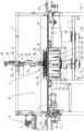
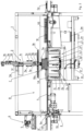
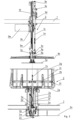
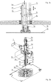
- the Fig. 1 shows a sectional view according to a vertical section plane which runs through the axis of rotation of the drying centrifuge according to the invention and through the horizontal center line of the transfer devices for the supply and removal of the containers, with a "full size" crate with folded side walls and bottom facing upwards, lying on the loading/unloading platform during the loading phase.
- the non-rotatable closing plate 3b is lowered further 3v by actuating the cylinder until it rests on the stops provided for this purpose, which are attached, for example, to the vertical walls of the enclosing structure for collecting the water, to the fixed structure of the conveyor belts 4a or the transfer device for loading the cage or to the frame 1 of the machine in such a way as not to come into contact with the cage.
- the stops provided for this purpose which are attached, for example, to the vertical walls of the enclosing structure for collecting the water, to the fixed structure of the conveyor belts 4a or the transfer device for loading the cage or to the frame 1 of the machine in such a way as not to come into contact with the cage.
- the invention does not exclude the loading of the containers 10, 10a, or the stack of containers, into the centrifuge fig 2 by gravity, possibly by free fall, and that, during spinning, the individual or stacked containers are not retained by the retaining/pressure plate 3a.
Landscapes
- Engineering & Computer Science (AREA)
- Health & Medical Sciences (AREA)
- Life Sciences & Earth Sciences (AREA)
- Molecular Biology (AREA)
- Mechanical Engineering (AREA)
- General Engineering & Computer Science (AREA)
- Centrifugal Separators (AREA)
- Drying Of Solid Materials (AREA)
Applications Claiming Priority (1)
| Application Number | Priority Date | Filing Date | Title |
|---|---|---|---|
| IT102023000020025A IT202300020025A1 (it) | 2023-09-28 | 2023-09-28 | "centrifuga per l'asciugatura di contenitori" |
Publications (2)
| Publication Number | Publication Date |
|---|---|
| EP4530563A1 true EP4530563A1 (fr) | 2025-04-02 |
| EP4530563B1 EP4530563B1 (fr) | 2026-04-01 |
Family
ID=89427174
Family Applications (1)
| Application Number | Title | Priority Date | Filing Date |
|---|---|---|---|
| EP24000107.3A Active EP4530563B1 (fr) | 2023-09-28 | 2024-09-05 | Sécheur centrifuge pour conteneurs |
Country Status (2)
| Country | Link |
|---|---|
| EP (1) | EP4530563B1 (fr) |
| IT (1) | IT202300020025A1 (fr) |
Citations (5)
| Publication number | Priority date | Publication date | Assignee | Title |
|---|---|---|---|---|
| DE4140989A1 (de) | 1991-12-12 | 1992-07-02 | Guenter Martin Landesberger | Kistentrocknungsanlage |
| EP1154214A1 (fr) | 2000-05-11 | 2001-11-14 | Misuzu Koki Company Limited | Dispositif de séchage par centrifugation pour récipients |
| EP1191292A1 (fr) | 2000-08-30 | 2002-03-27 | Tanzer Peter Maschinenbau | Essoreuse centrifuge |
| JP2002206857A (ja) | 2001-01-11 | 2002-07-26 | Central Conveyor Kk | 各種パレット対応遠心脱水乾燥方法とその装置 |
| EP3392585B1 (fr) | 2017-04-20 | 2020-11-04 | Tanzer Maschinenbau S.r.l. | Essoreuse et procédé de séchage pour cageots |
-
2023
- 2023-09-28 IT IT102023000020025A patent/IT202300020025A1/it unknown
-
2024
- 2024-09-05 EP EP24000107.3A patent/EP4530563B1/fr active Active
Patent Citations (5)
| Publication number | Priority date | Publication date | Assignee | Title |
|---|---|---|---|---|
| DE4140989A1 (de) | 1991-12-12 | 1992-07-02 | Guenter Martin Landesberger | Kistentrocknungsanlage |
| EP1154214A1 (fr) | 2000-05-11 | 2001-11-14 | Misuzu Koki Company Limited | Dispositif de séchage par centrifugation pour récipients |
| EP1191292A1 (fr) | 2000-08-30 | 2002-03-27 | Tanzer Peter Maschinenbau | Essoreuse centrifuge |
| JP2002206857A (ja) | 2001-01-11 | 2002-07-26 | Central Conveyor Kk | 各種パレット対応遠心脱水乾燥方法とその装置 |
| EP3392585B1 (fr) | 2017-04-20 | 2020-11-04 | Tanzer Maschinenbau S.r.l. | Essoreuse et procédé de séchage pour cageots |
Also Published As
| Publication number | Publication date |
|---|---|
| EP4530563B1 (fr) | 2026-04-01 |
| IT202300020025A1 (it) | 2025-03-28 |
Similar Documents
| Publication | Publication Date | Title |
|---|---|---|
| DE60007226T2 (de) | Vorrichtung zum Zuführen von Platten | |
| DE3303786C2 (de) | Automatische Banknotenannahme- und -ausgabevorrichtung | |
| EP3486589B1 (fr) | Dispositif de séchage et / ou de nettoyage de caisses | |
| EP3392585B1 (fr) | Essoreuse et procédé de séchage pour cageots | |
| DE3220606C2 (de) | Einrichtung zum automatischen Be- und Entladen von Röntgenfilmkassetten | |
| DE69506513T2 (de) | Automatische Einrichtung zum Vereinzeln von leichten, hohlen und länglichen Gegenständen und zum Abgeben dieser Gegenständen in einer Reihe | |
| DE202021105697U1 (de) | Maschine zum Sortieren und Stapeln von Behältern mit Klappwänden | |
| DE3630191A1 (de) | Vorrichtung zur ausgabe von muenzenrollen | |
| CH715871B1 (de) | Vorrichtung, insbesondere Haustierfütterungsvorrichtung und Verfahren zum Bereitstellen und Öffnen gefüllter Behälter. | |
| DE1904475A1 (de) | Vorrichtung zum Stapeln und/oder Abstapeln | |
| DE69011820T2 (de) | Verfahren und Vorrichtung zum Handhaben von Artikeln. | |
| DE60107886T2 (de) | Vorrichtung zum Zuführen von Behältern | |
| DE60200304T2 (de) | Fördersystem für Plastikbehälter | |
| DE3618247A1 (de) | Verfahren und vorrichtung zum ersetzen von aus einem foerderstrom ausgesonderten fehlerhaften packungen durch fehlerfreie packungen | |
| DE2537268A1 (de) | Vorrichtung zur entnahme von behaeltern aus kaesten | |
| EP2776347B1 (fr) | Dispositif d'alimentation pour fermetures de contenant | |
| EP4530563B1 (fr) | Sécheur centrifuge pour conteneurs | |
| DE69302070T2 (de) | Anlage zur Behandlung, zum Ordnen und zum Sortieren von kurzen zylindrischen Körpern, wie zum Beispiel Kernbrennstofftabletten | |
| EP4620876A1 (fr) | Machine de dépilage | |
| EP0822739B1 (fr) | Appareil automatisé de test de cartes de circuit électronique | |
| DE2732080A1 (de) | Zufuhrvorrichtung fuer paletten und flachmaterial | |
| DE60201667T2 (de) | Verfahren und vorrichtung zum herausnehmen von wäschestücken aus einem haufen | |
| DE10049181A1 (de) | Vorrichtung zum Ausschleusen von Probe-und Fehlerbogen aus einer Bogen verarbeitenden Maschine | |
| EP1462395B1 (fr) | Tampon intermédiaire | |
| DE2356285A1 (de) | Vorrichtung zum entwaessern von waesche |
Legal Events
| Date | Code | Title | Description |
|---|---|---|---|
| PUAI | Public reference made under article 153(3) epc to a published international application that has entered the european phase |
Free format text: ORIGINAL CODE: 0009012 |
|
| STAA | Information on the status of an ep patent application or granted ep patent |
Free format text: STATUS: THE APPLICATION HAS BEEN PUBLISHED |
|
| AK | Designated contracting states |
Kind code of ref document: A1 Designated state(s): AL AT BE BG CH CY CZ DE DK EE ES FI FR GB GR HR HU IE IS IT LI LT LU LV MC ME MK MT NL NO PL PT RO RS SE SI SK SM TR |
|
| STAA | Information on the status of an ep patent application or granted ep patent |
Free format text: STATUS: REQUEST FOR EXAMINATION WAS MADE |
|
| 17P | Request for examination filed |
Effective date: 20250812 |
|
| GRAP | Despatch of communication of intention to grant a patent |
Free format text: ORIGINAL CODE: EPIDOSNIGR1 |
|
| STAA | Information on the status of an ep patent application or granted ep patent |
Free format text: STATUS: GRANT OF PATENT IS INTENDED |
|
| INTG | Intention to grant announced |
Effective date: 20251118 |
|
| GRAS | Grant fee paid |
Free format text: ORIGINAL CODE: EPIDOSNIGR3 |
|
| GRAA | (expected) grant |
Free format text: ORIGINAL CODE: 0009210 |
|
| STAA | Information on the status of an ep patent application or granted ep patent |
Free format text: STATUS: THE PATENT HAS BEEN GRANTED |
|
| AK | Designated contracting states |
Kind code of ref document: B1 Designated state(s): AL AT BE BG CH CY CZ DE DK EE ES FI FR GB GR HR HU IE IS IT LI LT LU LV MC ME MK MT NL NO PL PT RO RS SE SI SK SM TR |
|
| REG | Reference to a national code |
Ref country code: CH Ref legal event code: F10 Free format text: ST27 STATUS EVENT CODE: U-0-0-F10-F00 (AS PROVIDED BY THE NATIONAL OFFICE) Effective date: 20260401 Ref country code: GB Ref legal event code: FG4D Free format text: NOT ENGLISH |
|
| REG | Reference to a national code |
Ref country code: IE Ref legal event code: FG4D Free format text: LANGUAGE OF EP DOCUMENT: GERMAN |
|
| REG | Reference to a national code |
Ref country code: DE Ref legal event code: R096 Ref document number: 502024000941 Country of ref document: DE |