EP4530563A1 - Drying spinner for containers - Google Patents
Drying spinner for containers Download PDFInfo
- Publication number
- EP4530563A1 EP4530563A1 EP24000107.3A EP24000107A EP4530563A1 EP 4530563 A1 EP4530563 A1 EP 4530563A1 EP 24000107 A EP24000107 A EP 24000107A EP 4530563 A1 EP4530563 A1 EP 4530563A1
- Authority
- EP
- European Patent Office
- Prior art keywords
- cage
- containers
- loading
- retaining
- pressure plate
- Prior art date
- Legal status (The legal status is an assumption and is not a legal conclusion. Google has not performed a legal analysis and makes no representation as to the accuracy of the status listed.)
- Granted
Links
Images



Classifications
-
- F—MECHANICAL ENGINEERING; LIGHTING; HEATING; WEAPONS; BLASTING
- F26—DRYING
- F26B—DRYING SOLID MATERIALS OR OBJECTS BY REMOVING LIQUID THEREFROM
- F26B5/00—Drying solid materials or objects by processes not involving the application of heat
- F26B5/08—Drying solid materials or objects by processes not involving the application of heat by centrifugal treatment
Definitions
- centrifuge with a vertical rotation axis is known from the same applicant for rectangular prismatic trays with hinged side walls, where the side walls can be folded or unfolded, or for trays of different sizes with fixed side walls.
- the centrifugation cage of this machine is arranged in a position above the horizontal transfer devices for the incoming trays at a distance slightly greater than the maximum height of the trays that can be processed.
- the trays are The bottom is fed in aligned with the conveyor belts or transfer devices, the side walls can be folded up or down, or non-foldable and pointing upwards, towards the centrifuge cage.
- the centrifuge cage is open at the bottom and has at least one row of rungs which project downwards from the bottom of the cage and are dimensioned according to the internal dimensions of the crate to be spun, so that the crate, inserted into the cage by means of a lifting table, is secured in a central position.
- one or more rows of downward-projecting rungs can be provided, which are arranged concentrically to the first row, inside or outside of it.
- the crate is held inside the cage between the lifting table acting vertically from below and a pressure plate acting from above, both acting coaxially to the axis of rotation of the cage.
- This centrifuge has the disadvantage that, in particular, the travel of the lifting table, regardless of the height of the crates' sides or whether they are folded or unfolded, during insertion of the crates into the cage or removal from the cage, must always be greater than the maximum height of the crates that can be processed, with fixed or unfolded sides, because the cage, with its lower edge, must be spaced from the crates' support surface by more than the maximum height of the crates that can be processed during their insertion.
- This means that the times for loading and unloading the cage are long, even for crates with folded sides, which are of very modest height, and for those with low sides.
- the arrangement of the centrifuge cage above the transfer belts or transfer devices complicates the effective collection and drainage of water and makes cleaning and maintenance of the cage itself and the corresponding collection and drainage devices more difficult.
- the invention has for its object to provide a spin dryer as described above, which is suitable for the efficient drying of individual containers with fixed or foldable side walls in the open or closed position or of stacks of containers which have a modest height, in very short times, wherein the containers fed to the spin dryer can also have different dimensions and an efficient drainage of the water as well as convenient access to the spin cage and to its external and internal components for the purpose of cleaning and maintenance work is ensured.
- the invention proposes a spin dryer with a vertical rotation axis of the centrifuge cage, which can be loaded from above by means of a horizontal loading/unloading platform which is attached to the upper end of a shaft which projects from the bottom of the cage and is mounted so as to be vertically displaceable, coaxial with the cage's rotation axis.
- This loading/unloading platform is loaded with individual containers or a container stack of modest height by means of a transfer device which extends in a horizontal plane parallel to the plane in which the upper edge of the loading/unloading opening of the centrifuge cage is located.
- a retaining/pressure plate which is rotatably mounted coaxially with the cage's rotation axis on a first vertically movable rod.
- This rod can itself be mounted so as to be vertically movable, or a second vertically movable rod is mounted on this first rod, which has a sliding element for a cover plate or a cover grid at its lower end.
- This non-rotating plate closes the loading/unloading opening of the cage during the spinning process by resting, slightly spaced from the upper edge of the cage, on fixed parts of the machine frame, the frame of the transfer devices, or the upper edge of the container that surrounds the spinning cage for the purpose of collecting and draining the water.
- the rods for actuating the retaining/pressure plate or the closure plate can be actuated pneumatically or hydraulically by means of a cylinder with a piston, or mechanically by means of a rack, toothed belt, chain, or electric actuator.
- Said actuating devices can be equipped with known devices for detecting the target position of said plates in order to indicate any malfunctions caused by damaged containers or improperly closed side walls.
- detection devices can be, for example, a pressure sensor in the case of hydraulic or pneumatic actuation or, in the case of mechanical actuation, a linear detection probe and can be attached to one of the mechanical actuating elements or to the plate itself.
- the said detection of irregularities during the loading phase of the centrifuge cage causes the ejection of the damaged or poorly positioned container from the cage to be removed as waste after the centrifuge.
- the vertical actuation of the loading/unloading platform which acts vertically inside the centrifuge cage, and its positioning can be detected, for example, by a magnetic linear detector or a reader for a mark applied to the actuating rod or to the platform itself, in order to continuously monitor the movement and position of the platform inside the centrifuge cage, indicating any blockages and malfunctions in the event of the presence of faulty/deformed or incorrectly positioned containers that cause malfunctions during the loading and/or unloading phase of the containers.
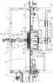
- the Fig. 1 shows a sectional view according to a vertical section plane which runs through the axis of rotation of the drying centrifuge according to the invention and through the horizontal center line of the transfer devices for the supply and removal of the containers, with a "full size" crate with folded side walls and bottom facing upwards, lying on the loading/unloading platform during the loading phase.
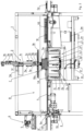
- the non-rotatable closing plate 3b is lowered further 3v by actuating the cylinder until it rests on the stops provided for this purpose, which are attached, for example, to the vertical walls of the enclosing structure for collecting the water, to the fixed structure of the conveyor belts 4a or the transfer device for loading the cage or to the frame 1 of the machine in such a way as not to come into contact with the cage.
- the stops provided for this purpose which are attached, for example, to the vertical walls of the enclosing structure for collecting the water, to the fixed structure of the conveyor belts 4a or the transfer device for loading the cage or to the frame 1 of the machine in such a way as not to come into contact with the cage.
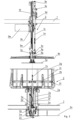
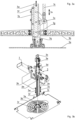
- the invention does not exclude the loading of the containers 10, 10a, or the stack of containers, into the centrifuge fig 2 by gravity, possibly by free fall, and that, during spinning, the individual or stacked containers are not retained by the retaining/pressure plate 3a.
Landscapes
- Engineering & Computer Science (AREA)
- Health & Medical Sciences (AREA)
- Life Sciences & Earth Sciences (AREA)
- Molecular Biology (AREA)
- Mechanical Engineering (AREA)
- General Engineering & Computer Science (AREA)
- Centrifugal Separators (AREA)
- Drying Of Solid Materials (AREA)
Abstract
Trockenschleuder für einzelne Gebinde mit festen oder offenen oder geschlossenen klappbaren Seitenwänden oder für Gebindestapel (10, 10a) deren Höhe nicht größer ist als die maximale Höhe der bearbeitbaren einzelnen Gebinde, welche über ein Zuführförderband (4x) und ein anschließendes Förderband (4) der Trockenschleuder zugeführt (H) werden um sie anschließend horizontal, mittels Transportbänder (4a) oder Transfervorrichtungen welche seitlich auf die Gebinde wirken, in einen Bereich oberhalb des Schleuderkäfigs (2) zu bringen, welcher mittels Welle (2y) an einem Rahmen (1), innerhalb einer feststehenden umfassenden Struktur für das Sammeln und Ableiten des Schleuderwassers, gemäß einer vertikalen Achse drehbar (2r), gelagert (2s) ist und von einem Motor (2m) angetrieben wird, wobei der Käfig einen horizzontalen Boden (2a) aufweist von welchem, in Richtung Lade-/Entladeöffnung des Käfigs (2), Sprossen (2b, 2c) abstehen, zwischen welchen die Gebinde (10, 10a), während der Schleuderung, zwischen einer Lade-/Entladeplattform (2t) und einer Rückhalte-/Druckplatte (3a) welche beide vertikal und koachsial zur Rotationsachse des Käfigs (2) wirken (3w, 2v), zurückgehalten werden, wobei der Käfig (2) unterhalb der Ebene für den Transfer der Gebinde (10, 10a) welche mittels Transportbänder (4a) mit nach oben gerichtetem Boden (10, 10a) zugeführt werden, angeordnet ist, wobei die Lade-/Entladeöffnung des Käfigs (2) nach oben ausgerichtet ist, wobei die Lade-/Entladeplattform (2t) samt dem Schaft (2u) im Inneren des Käfigs (2) vertikal wirkt und zusammen mit diesem rotiert (2r) und wobei die im Leerlauf an einer Stange (3f) drehbar (3r) gelagerte Rückhalte-/Druckplatte (3a) vertikal (3v) wirkt um während der Schleuderung das einzelne Gebinde (10, 10a), bzw. den Gebindestapel, im Innern des Käfigs (2), an der Lade-/Entladeplattform (2t) anliegend, zurückzuhalten.

Description
Die Erfindung bezieht sich auf eine Trockenschleuder mit vertikaler Rotationsachse für Gebinde mit rechteckprismatischer Form, verschiedener Größen welche beispielsweise als Pfandgebinde für den Transport von Obst, Gemüse, Getränke verwendet werden, mit feststehenden oder klappbaren Seitenwänden in auf- oder zugeklappter Position und für relativ niedrig gestapelte Gebinde, wobei die Stapelhöhe gleich oder etwas kleiner als die Höhe der schleuderbaren Gebinde mit nicht zuklappbaren Seitenwänden ist.The invention relates to a spin dryer with a vertical axis of rotation for containers with a rectangular prismatic shape, of various sizes, which are used, for example, as deposit containers for the transport of fruit, vegetables, drinks, with fixed or foldable side walls in the open or closed position and for relatively low stacked containers, wherein the stack height is equal to or slightly smaller than the height of the spin-drying containers with non-foldable side walls.
Aus der
Aus der
Aus der
Aus der
Aus der
Die Erfindung stellt sich die Aufgabe eine eingangs beschriebene Trockenschleuder zu schaffen, welche für das effiziente Trocknen einzelner Gebinde mit festen oder klappbaren Seitenwänden in auf- oder zugeklappter Position oder von Gebindestapel welche eine bescheidene Höhe aufweisen, in sehr kurzen Zeiten geeignet ist, wobei die der Schleuder zugeführten Gebinde auch unterschiedliche Abmaße aufweisen können und ein effizienter Abfluss des Wassers sowie ein bequemer Zugang zum Schleuderkäfig und zu dessen äußeren und inneren Bauteilen, zwecks Reinigungs- und Wartungsarbeiten, sichergestellt ist.The invention has for its object to provide a spin dryer as described above, which is suitable for the efficient drying of individual containers with fixed or foldable side walls in the open or closed position or of stacks of containers which have a modest height, in very short times, wherein the containers fed to the spin dryer can also have different dimensions and an efficient drainage of the water as well as convenient access to the spin cage and to its external and internal components for the purpose of cleaning and maintenance work is ensured.
Zur Lösung dieser Aufgabe schlägt die Erfindung eine Trockenschleuder mit vertikaler Rotationsachse des Schleuderkäfigs vor, wobei dieser von oben, mittels einer horizontalen Lade-/Entladeplattform, beschickbar ist welche am oberen Ende eines Schaftes befestigt ist welcher vom Boden des Käfigs absteht und vertikal verschiebbar, koachsial zur Drehachse des Käfigs, gelagert ist. Diese Lade-/Entladeplattform wird mittels Transfereinrichtung welche sich in einer horizontalen Ebene, parallel zur Ebene in welcher sich der obere Rand der Beschickungs-/Entladeöffnung des Schleuderkäfigs befindet, erstreckt, mit einzelnen Gebinden, bzw. einem Gebindestapel bescheidener Höhe, beschickt. Oberhalb des Schleuderkäfigs und koachsial zu diesem ist eine Rückhalte-/Druckplatte vorgesehen welche koachsial zur Rotationsachse des Käfigs an einer ersten vertikal bewegbaren Stange drehbar gelagert ist. Diese Stange kann selbst vertikal beweglich gelagert sein oder an dieser ersten Stange ist eine zweite vertikal bewegliche Stange gelagert welche an ihrem unteren Ende ein Gleitelement für eine Abdeckplatte oder ein Abdeckgitter aufweist. Diese nicht drehbare Platte verschließt, während des Schleudervorgangs, die Lade-/Entladeöffnung des Käfigs indem sie, leicht beabstandet zum oberen Rand des Käfigs, an feststehenden Teilen des Maschinenrahmens, des Rahmens der Transfereinrichtungen oder des oberen Randes des Behälters welcher den Schleuderkäfig, zwecks Auffangen und Ableiten des Wassers, umhüllt, aufliegt. Im Fall dass die Stange für die Verschließplatte an der Stange für die vertikale Betätigung der Rückhalte-/Druckplatte gelagert ist, erfolgt ein Teil des Absenk- und Anhebeweges für die vorgenannten Platten durch Betätigung der Stange welche die Rückhalte-/Druckplatte hält, wobei die Verschlussplatte durch die entsprechende Stange zusätzlich vertikal bewegt wird um während der Anpressfase den nötige Absenkweg in Richtung Schließstellung für den Schleuderkäfig, bzw. während des Anhebens, einen zusätzlichen Anhebeweg zu erreichen.To achieve this object, the invention proposes a spin dryer with a vertical rotation axis of the centrifuge cage, which can be loaded from above by means of a horizontal loading/unloading platform which is attached to the upper end of a shaft which projects from the bottom of the cage and is mounted so as to be vertically displaceable, coaxial with the cage's rotation axis. This loading/unloading platform is loaded with individual containers or a container stack of modest height by means of a transfer device which extends in a horizontal plane parallel to the plane in which the upper edge of the loading/unloading opening of the centrifuge cage is located. Provided above the centrifuge cage and coaxial with it is a retaining/pressure plate which is rotatably mounted coaxially with the cage's rotation axis on a first vertically movable rod. This rod can itself be mounted so as to be vertically movable, or a second vertically movable rod is mounted on this first rod, which has a sliding element for a cover plate or a cover grid at its lower end. This non-rotating plate closes the loading/unloading opening of the cage during the spinning process by resting, slightly spaced from the upper edge of the cage, on fixed parts of the machine frame, the frame of the transfer devices, or the upper edge of the container that surrounds the spinning cage for the purpose of collecting and draining the water. In the case that the rod for the closing plate is mounted on the rod for the vertical actuation of the retaining/pressure plate, part of the lowering and raising travel for the aforementioned plates takes place by actuating the rod that holds the retaining/pressure plate, whereby the closing plate is additionally moved vertically by the corresponding rod in order to achieve the necessary lowering travel during the pressing phase. Towards the closed position for the centrifuge cage, or during lifting, to achieve an additional lifting path.
Gemäß einer erfindungsgemäßen Weiterentwicklung können die Stangen für die Betätigung der Rückhalte-/Druckplatte, bzw. der Verschlussplatte, pneumatisch oder hydraulisch mittels Zylinder mit Kolben oder mechanisch mittels Zahnstange, Zahnriemen, Kette oder elektrischem Stellantrieb betätigt werden. Die besagten Betätigungsvorrichtungen können mit bekannten Vorrichtungen für die Erkennung der Zielposition der genannten Platten ausgestattet sein um eventuelle, durch beschädigte Gebinde oder nicht regulär zugeklappter Seitenwände verursachte, Funktionsstörungen anzuzeigen, diese Erkennungsvorrichtungen können, z.B. im Fall hydraulischer oder pneumatischer Betätigung, ein Drucksensor sein oder, oder im Fall mechanischer Betätigung, eine lineare Detektionssonde sein und können an einem der mechanischen Betätigungsorgane oder an der Platte selbst angebracht sein. Die besagten Erhebungen von Unregelmäßigkeiten während der Beschickungsfase des Schleudrkäfigs bewirken den Auswurf des beschädigten oder schlecht positionierten Gebindes aus dem Käfig um nach der Trockenschleuder als Ausschuss abgeführt zu werden.According to a further development of the invention, the rods for actuating the retaining/pressure plate or the closure plate can be actuated pneumatically or hydraulically by means of a cylinder with a piston, or mechanically by means of a rack, toothed belt, chain, or electric actuator. Said actuating devices can be equipped with known devices for detecting the target position of said plates in order to indicate any malfunctions caused by damaged containers or improperly closed side walls. These detection devices can be, for example, a pressure sensor in the case of hydraulic or pneumatic actuation or, in the case of mechanical actuation, a linear detection probe and can be attached to one of the mechanical actuating elements or to the plate itself. The said detection of irregularities during the loading phase of the centrifuge cage causes the ejection of the damaged or poorly positioned container from the cage to be removed as waste after the centrifuge.
Gemäß einer zusätzlichen Weiterentwicklung der Erfindung kann die vertikale Betätigung der Lade-/Entladeplattform welche vertikal im Innern des Schleuderkäfigs wirkt und deren Positionierung, z.B. durch einen Magnet-Lineardetektor oder ein Einlesegerät für eine an der Betätigungsstange oder an der Plattform selbst angebrachte Markierung, zwecks durchgehender Überwachung der Bewegung und der Position der Plattform im Innern des Schleuderkäfigs, erhoben werden, wobei eventuelle Hemmungen und Funktionsstörungen, im Fall der Präsenz fehlerhafter/verformter oder nicht korrekt positionierter Gebinde welche während der Lade- und/oder Entladefase der Gebinde Funktionsstörungen verursachen, anzeigen.According to a further development of the invention, the vertical actuation of the loading/unloading platform, which acts vertically inside the centrifuge cage, and its positioning can be detected, for example, by a magnetic linear detector or a reader for a mark applied to the actuating rod or to the platform itself, in order to continuously monitor the movement and position of the platform inside the centrifuge cage, indicating any blockages and malfunctions in the event of the presence of faulty/deformed or incorrectly positioned containers that cause malfunctions during the loading and/or unloading phase of the containers.
Die Anordnung der Trockenschleuder unterhalb der Zuführ- und Abführebene der einzelnen Gebinde, bzw. der Gebindestapel bescheidener Höhe und das Einführen der Gebinde von oben in den Schleuderkäfig mit dem Gebindeboden nach oben gerichtet, ermöglichen es den Hubweg der Belade-/Entladeplattform und der Rückhalte-/Druckplatte an die effektive Höhe des zu bearbeitenden einzelnen Gebindes, bzw. Gebindestapels, anzupassen und die Struktur für das Auffangen und Ableiten des Wassers zu vereinfachen welche dadurch leicht zugänglich für alle Überwachungs-, Reinigungs-, Instandhaltungs- und Austauscharbeiten wird und dass der Schleuderkäfig, die Lade-/Entladeplattform und die umschließende Struktur zum Auffangen des Wassers zusammen mit den Abflüssen alle direkt von oben, durch die Ladeöffnung des Schleuderkäfigs und der freien Öffnung der Struktur zum Auffangen des Wassers hindurch, welche größere Abmaße als die größte Diagonale der Öffnung des Schleuderkäfigs hat, zugänglich ist.The arrangement of the dryer below the feeding and discharge level of the individual containers or the container stacks of modest height and the introduction of the containers from above into the centrifuge cage with the container bottom facing upwards, make it possible to adapt the stroke of the loading/unloading platform and the retaining/pressure plate to the effective height of the individual container or container stack to be processed and to simplify the structure for collecting and draining the water, which is therefore easily accessible for all monitoring, cleaning, maintenance and replacement work and that the centrifuge cage, the loading/unloading platform and the enclosing The water collection structure, together with the drains, is all accessible directly from above, through the loading opening of the centrifuge cage and the free opening of the water collection structure, which has larger dimensions than the largest diagonal of the opening of the centrifuge cage.
Die Erfindung schließt nicht aus, dass bestimmte Gebindemodelle mit klappbaren Seitenwänden welche einzeln oder gestapelt zugeführt werden, mit dem Boden nach unten zugeführt werden, um eine eventuelle Öffnungsbewegung (nach unten) der zugeklappten Seitenwände während der Beladungsfase des Schleuderkäfigs zu verhindern.The invention does not exclude that certain container models with foldable side walls, which are fed individually or stacked, are fed with the bottom downwards in order to prevent any opening movement (downwards) of the folded side walls during the loading phase of the centrifuge cage.
Die Erfindung wird anschließend anhand eines, in den beigelegten Zeichnungen schematisch dargestellten, vorzuziehenden Ausführungsbeispieles einer erfindungsgemäßen Trockenschleuder für Gebinde samt den spezifischen Zuführ- und Abführvorrichtungen näher erklärt, dabei erfüllen diese rein erklärenden, nicht begrenzenden Zweck.The invention will now be explained in more detail with reference to a preferred embodiment of a centrifuge dryer according to the invention for containers, including the specific feeding and discharging devices, which are schematically illustrated in the accompanying drawings; these serve a purely explanatory, non-limiting purpose.
Die
Die
Die
Die
Die
Die
Die
Die
Die erfindungsgemäße Trockenschleuder für einzelne oder bescheiden hoch gestapelte Gebinde 10, 10a mit unterschiedlichen Ausmaßen, mit festen oder klappbaren Seitenwänden, in aufgeklapptem oder zugeklapptem Zustand, welche erfindungsgemäß, allgemein zugeklappt mit nach oben ausgerichtetem Boden und im Fall bestimmter Modelle mit zugeklappten Seitenwänden mit nach unten ausgerichtetem Boden zugeführt werden, besteht wesentlich aus:
- einem
Rahmen 1 welcher horizontal von mindestens einem Zuführ-Transportband oder einer Zuführ-Transportvorrichtung Abführband 4b für den Transfer derGebinde
- a
frame 1 which is horizontally traversed by at least one feed conveyor belt or afeed conveyor device discharge belt 4b for the transfer of thecontainers
Um den Schleudervorgang zu beschleunigen werden die Gebinde 10, 10a auf bekannte Weise, jedoch allgemein mit nach oben ausgerichtetem Boden, der Schleuderstation C zugeführten H einzeln vom äußeren horizontalen, bekannten, durchgehend laufenden Zuführtransportband 4x, von einem horizontalen Beschickungs-Transportband 4 welches mit Laufpausen und einer höheren Geschwindigkeit als das obgenannte äußere Zuführband 4x, zwecks Beabstandung zwischen dem entnommenen Gebinde und den auf dem äußeren Zuführtransportband 4x herangeführten Gebinden, arbeitet einzeln entnommen und dem, mit einer Druck- und Verschlussvorrichtung 3 ausgestatteten, Schleuderkä
Das erste vom äußeren Zuführtransportband 4x herangeführte H Gebinde 10, 10a wird in der bekannten Erkennungsstation A, zwecks Erhebungen der Abmaße, des Modells eventueller Beschädigungen und/oder der geöffneten/geschlossenen Position der Seitenwände mittels Fotokamera 5, zurückgehalten 6a. Natürlich ist, im Fall des Einsatzes der Trockenschleuder in einem Betrieb welche nur ein einziges Modell von Gebinden bearbeitet, keine fotographische Erhebung erforderlich sondern wird nur die Erhebung der regulären Aufklapp- oder Zuklappstellung der Seitenwände, z.B. mittels Liuchtschranke oder Laser, durchgeführt. Im Fall der Erhebung von Defekten, von nur teilweise auf- oder zugeklappten Seitenwänden oder von Abmaßen oder Modellen welche nicht für die folgende Schleuderung vorgesehen sind, wird das Gebinde auf bekannte Weise durch Schub, quer zur Zuführrichtung H, oder durch freien Fall, z.B. bei Zuführbänder welche seitlich an den Gebinden greifen und zueinander distanziert werden können, ausgestoßen. Im Fall eines Modells eines Gebindes 10, 10a welches schleuderbar ist, keine Defekte aufweist und deren Seitenwände alle auf- oder zugeklappt sind, wird dieses Gebinde 10, 10a horizontal in die Schleuderstation C befördert indem es vom Zuführ- und Warteförderband 4, mittels welchem auch der Ausstoß nicht schleuderbarer oder defekter Gebinde erfolgen kann, auf ein zueinander paralleler, seitlich am Gebinde 10, 10a wirkender, Transportbänder 4a wechselt um eine Position über der offenen Seite des erfindungsgemäßen Schleuderkä
Die Bewegungen 3w, bzw. 3v der Rückhalte-/Druckplatte 3a und der Verschlussplatte 3b können in Abhängigkeit der Abmaße (Höhe) der einzelnen oder gestapelten Gebinde, bzw. der Gebinde, während des Anhebens seitens der Lade-/Entladeplattform 2t, ausgeführt werden.The
Die Erfindung schließt nicht aus, dass das Laden der Gebinde 10, 10a, bzw. des Gebindestapels, in den Schleuderkä
Claims (11)
Applications Claiming Priority (1)
| Application Number | Priority Date | Filing Date | Title |
|---|---|---|---|
| IT102023000020025A IT202300020025A1 (en) | 2023-09-28 | 2023-09-28 | "CENTRIFUGE FOR DRYING CONTAINERS" |
Publications (2)
| Publication Number | Publication Date |
|---|---|
| EP4530563A1 true EP4530563A1 (en) | 2025-04-02 |
| EP4530563B1 EP4530563B1 (en) | 2026-04-01 |
Family
ID=89427174
Family Applications (1)
| Application Number | Title | Priority Date | Filing Date |
|---|---|---|---|
| EP24000107.3A Active EP4530563B1 (en) | 2023-09-28 | 2024-09-05 | Centrifugal dryer for containers |
Country Status (2)
| Country | Link |
|---|---|
| EP (1) | EP4530563B1 (en) |
| IT (1) | IT202300020025A1 (en) |
Citations (5)
| Publication number | Priority date | Publication date | Assignee | Title |
|---|---|---|---|---|
| DE4140989A1 (en) | 1991-12-12 | 1992-07-02 | Guenter Martin Landesberger | Drying installation for crates - spin dries stacks after washing inside rotating cylinder driven by electromotor |
| EP1154214A1 (en) | 2000-05-11 | 2001-11-14 | Misuzu Koki Company Limited | Container centrifugal drying device |
| EP1191292A1 (en) | 2000-08-30 | 2002-03-27 | Tanzer Peter Maschinenbau | Centrifugal dryer |
| JP2002206857A (en) | 2001-01-11 | 2002-07-26 | Central Conveyor Kk | Centrifugal dehydration drying method adaptable to various pallets and apparatus therefor |
| EP3392585B1 (en) | 2017-04-20 | 2020-11-04 | Tanzer Maschinenbau S.r.l. | Centrifugal dryer and drying process for crates |
-
2023
- 2023-09-28 IT IT102023000020025A patent/IT202300020025A1/en unknown
-
2024
- 2024-09-05 EP EP24000107.3A patent/EP4530563B1/en active Active
Patent Citations (5)
| Publication number | Priority date | Publication date | Assignee | Title |
|---|---|---|---|---|
| DE4140989A1 (en) | 1991-12-12 | 1992-07-02 | Guenter Martin Landesberger | Drying installation for crates - spin dries stacks after washing inside rotating cylinder driven by electromotor |
| EP1154214A1 (en) | 2000-05-11 | 2001-11-14 | Misuzu Koki Company Limited | Container centrifugal drying device |
| EP1191292A1 (en) | 2000-08-30 | 2002-03-27 | Tanzer Peter Maschinenbau | Centrifugal dryer |
| JP2002206857A (en) | 2001-01-11 | 2002-07-26 | Central Conveyor Kk | Centrifugal dehydration drying method adaptable to various pallets and apparatus therefor |
| EP3392585B1 (en) | 2017-04-20 | 2020-11-04 | Tanzer Maschinenbau S.r.l. | Centrifugal dryer and drying process for crates |
Also Published As
| Publication number | Publication date |
|---|---|
| EP4530563B1 (en) | 2026-04-01 |
| IT202300020025A1 (en) | 2025-03-28 |
Similar Documents
| Publication | Publication Date | Title |
|---|---|---|
| DE60007226T2 (en) | Device for feeding plates | |
| DE3303786C2 (en) | Automatic banknote acceptance and dispensing device | |
| EP3486589B1 (en) | Crates drying and/or cleaning device | |
| EP3392585B1 (en) | Centrifugal dryer and drying process for crates | |
| DE3220606C2 (en) | Device for automatic loading and unloading of X-ray film cassettes | |
| DE69506513T2 (en) | Automatic device for separating light, hollow and elongated objects and for dispensing these objects in a row | |
| DE202021105697U1 (en) | Machine for sorting and stacking containers with hinged walls | |
| DE3630191A1 (en) | DEVICE FOR DISPENSING COIN ROLLS | |
| CH715871B1 (en) | Device, in particular pet feeding device and method for providing and opening filled containers. | |
| DE1904475A1 (en) | Device for stacking and / or destacking | |
| DE69011820T2 (en) | Method and device for handling articles. | |
| DE60107886T2 (en) | Device for feeding containers | |
| DE60200304T2 (en) | Conveying system for plastic containers | |
| DE3618247A1 (en) | METHOD AND DEVICE FOR REPLACING DEFECTIVE PACKS SEPARATED FROM A CONVEYOR CURRENT BY Fault-free Packings | |
| DE2537268A1 (en) | DEVICE FOR REMOVING CONTAINERS FROM BOXES | |
| EP2776347B1 (en) | Feeding device for container closures | |
| EP4530563B1 (en) | Centrifugal dryer for containers | |
| DE69302070T2 (en) | System for treating, sorting and sorting short cylindrical bodies, such as nuclear fuel tablets | |
| EP4620876A1 (en) | Unstacking machine | |
| EP0822739B1 (en) | Automated apparatus for printed circuit board inspection | |
| DE2732080A1 (en) | FEED DEVICE FOR PALLETS AND FLAT MATERIAL | |
| DE60201667T2 (en) | METHOD AND DEVICE FOR TAKING OUT FACILITY FROM A HEAP | |
| DE10049181A1 (en) | Two-position capture tray for printing machine sample sheets and printed errors | |
| EP1462395B1 (en) | Intermediate buffer | |
| DE2356285A1 (en) | DEVICE FOR DRAINING LAUNDRY |
Legal Events
| Date | Code | Title | Description |
|---|---|---|---|
| PUAI | Public reference made under article 153(3) epc to a published international application that has entered the european phase |
Free format text: ORIGINAL CODE: 0009012 |
|
| STAA | Information on the status of an ep patent application or granted ep patent |
Free format text: STATUS: THE APPLICATION HAS BEEN PUBLISHED |
|
| AK | Designated contracting states |
Kind code of ref document: A1 Designated state(s): AL AT BE BG CH CY CZ DE DK EE ES FI FR GB GR HR HU IE IS IT LI LT LU LV MC ME MK MT NL NO PL PT RO RS SE SI SK SM TR |
|
| STAA | Information on the status of an ep patent application or granted ep patent |
Free format text: STATUS: REQUEST FOR EXAMINATION WAS MADE |
|
| 17P | Request for examination filed |
Effective date: 20250812 |
|
| GRAP | Despatch of communication of intention to grant a patent |
Free format text: ORIGINAL CODE: EPIDOSNIGR1 |
|
| STAA | Information on the status of an ep patent application or granted ep patent |
Free format text: STATUS: GRANT OF PATENT IS INTENDED |
|
| INTG | Intention to grant announced |
Effective date: 20251118 |
|
| GRAS | Grant fee paid |
Free format text: ORIGINAL CODE: EPIDOSNIGR3 |
|
| GRAA | (expected) grant |
Free format text: ORIGINAL CODE: 0009210 |
|
| STAA | Information on the status of an ep patent application or granted ep patent |
Free format text: STATUS: THE PATENT HAS BEEN GRANTED |
|
| AK | Designated contracting states |
Kind code of ref document: B1 Designated state(s): AL AT BE BG CH CY CZ DE DK EE ES FI FR GB GR HR HU IE IS IT LI LT LU LV MC ME MK MT NL NO PL PT RO RS SE SI SK SM TR |
|
| REG | Reference to a national code |
Ref country code: CH Ref legal event code: F10 Free format text: ST27 STATUS EVENT CODE: U-0-0-F10-F00 (AS PROVIDED BY THE NATIONAL OFFICE) Effective date: 20260401 Ref country code: GB Ref legal event code: FG4D Free format text: NOT ENGLISH |
|
| REG | Reference to a national code |
Ref country code: IE Ref legal event code: FG4D Free format text: LANGUAGE OF EP DOCUMENT: GERMAN |
|
| REG | Reference to a national code |
Ref country code: DE Ref legal event code: R096 Ref document number: 502024000941 Country of ref document: DE |