EP4530400A2 - Système de mesure - Google Patents
Système de mesure Download PDFInfo
- Publication number
- EP4530400A2 EP4530400A2 EP25158019.7A EP25158019A EP4530400A2 EP 4530400 A2 EP4530400 A2 EP 4530400A2 EP 25158019 A EP25158019 A EP 25158019A EP 4530400 A2 EP4530400 A2 EP 4530400A2
- Authority
- EP
- European Patent Office
- Prior art keywords
- connecting element
- section
- sensor
- measuring system
- screed
- Prior art date
- Legal status (The legal status is an assumption and is not a legal conclusion. Google has not performed a legal analysis and makes no representation as to the accuracy of the status listed.)
- Pending
Links
Images


Classifications
-
- G—PHYSICS
- G01—MEASURING; TESTING
- G01D—MEASURING NOT SPECIALLY ADAPTED FOR A SPECIFIC VARIABLE; ARRANGEMENTS FOR MEASURING TWO OR MORE VARIABLES NOT COVERED IN A SINGLE OTHER SUBCLASS; TARIFF METERING APPARATUS; MEASURING OR TESTING NOT OTHERWISE PROVIDED FOR
- G01D21/00—Measuring or testing not otherwise provided for
- G01D21/02—Measuring two or more variables by means not covered by a single other subclass
-
- E—FIXED CONSTRUCTIONS
- E01—CONSTRUCTION OF ROADS, RAILWAYS, OR BRIDGES
- E01C—CONSTRUCTION OF, OR SURFACES FOR, ROADS, SPORTS GROUNDS, OR THE LIKE; MACHINES OR AUXILIARY TOOLS FOR CONSTRUCTION OR REPAIR
- E01C19/00—Machines, tools or auxiliary devices for preparing or distributing paving materials, for working the placed materials, or for forming, consolidating, or finishing the paving
- E01C19/48—Machines, tools or auxiliary devices for preparing or distributing paving materials, for working the placed materials, or for forming, consolidating, or finishing the paving for laying-down the materials and consolidating them, or finishing the surface, e.g. slip forms therefor, forming kerbs or gutters in a continuous operation in situ
-
- E—FIXED CONSTRUCTIONS
- E01—CONSTRUCTION OF ROADS, RAILWAYS, OR BRIDGES
- E01C—CONSTRUCTION OF, OR SURFACES FOR, ROADS, SPORTS GROUNDS, OR THE LIKE; MACHINES OR AUXILIARY TOOLS FOR CONSTRUCTION OR REPAIR
- E01C23/00—Auxiliary devices or arrangements for constructing, repairing, reconditioning, or taking-up road or like surfaces
- E01C23/01—Devices or auxiliary means for setting-out or checking the configuration of new surfacing, e.g. templates, screed or reference line supports; Applications of apparatus for measuring, indicating, or recording the surface configuration of existing surfacing, e.g. profilographs
-
- E—FIXED CONSTRUCTIONS
- E01—CONSTRUCTION OF ROADS, RAILWAYS, OR BRIDGES
- E01C—CONSTRUCTION OF, OR SURFACES FOR, ROADS, SPORTS GROUNDS, OR THE LIKE; MACHINES OR AUXILIARY TOOLS FOR CONSTRUCTION OR REPAIR
- E01C19/00—Machines, tools or auxiliary devices for preparing or distributing paving materials, for working the placed materials, or for forming, consolidating, or finishing the paving
- E01C19/004—Devices for guiding or controlling the machines along a predetermined path
- E01C19/006—Devices for guiding or controlling the machines along a predetermined path by laser or ultrasound
-
- E—FIXED CONSTRUCTIONS
- E01—CONSTRUCTION OF ROADS, RAILWAYS, OR BRIDGES
- E01C—CONSTRUCTION OF, OR SURFACES FOR, ROADS, SPORTS GROUNDS, OR THE LIKE; MACHINES OR AUXILIARY TOOLS FOR CONSTRUCTION OR REPAIR
- E01C23/00—Auxiliary devices or arrangements for constructing, repairing, reconditioning, or taking-up road or like surfaces
- E01C23/06—Devices or arrangements for working the finished surface; Devices for repairing or reconditioning the surface of damaged paving; Recycling in place or on the road
- E01C23/08—Devices or arrangements for working the finished surface; Devices for repairing or reconditioning the surface of damaged paving; Recycling in place or on the road for roughening or patterning; for removing the surface down to a predetermined depth high spots or material bonded to the surface, e.g. markings; for maintaining earth roads, clay courts or like surfaces by means of surface working tools, e.g. scarifiers, levelling blades
- E01C23/085—Devices or arrangements for working the finished surface; Devices for repairing or reconditioning the surface of damaged paving; Recycling in place or on the road for roughening or patterning; for removing the surface down to a predetermined depth high spots or material bonded to the surface, e.g. markings; for maintaining earth roads, clay courts or like surfaces by means of surface working tools, e.g. scarifiers, levelling blades using power-driven tools, e.g. vibratory tools
-
- G—PHYSICS
- G01—MEASURING; TESTING
- G01D—MEASURING NOT SPECIALLY ADAPTED FOR A SPECIFIC VARIABLE; ARRANGEMENTS FOR MEASURING TWO OR MORE VARIABLES NOT COVERED IN A SINGLE OTHER SUBCLASS; TARIFF METERING APPARATUS; MEASURING OR TESTING NOT OTHERWISE PROVIDED FOR
- G01D11/00—Component parts of measuring arrangements not specially adapted for a specific variable
- G01D11/30—Supports specially adapted for an instrument; Supports specially adapted for a set of instruments
-
- H—ELECTRICITY
- H01—ELECTRIC ELEMENTS
- H01R—ELECTRICALLY-CONDUCTIVE CONNECTIONS; STRUCTURAL ASSOCIATIONS OF A PLURALITY OF MUTUALLY-INSULATED ELECTRICAL CONNECTING ELEMENTS; COUPLING DEVICES; CURRENT COLLECTORS
- H01R13/00—Details of coupling devices of the kinds covered by groups H01R12/70 or H01R24/00 - H01R33/00
- H01R13/46—Bases; Cases
-
- H—ELECTRICITY
- H01—ELECTRIC ELEMENTS
- H01R—ELECTRICALLY-CONDUCTIVE CONNECTIONS; STRUCTURAL ASSOCIATIONS OF A PLURALITY OF MUTUALLY-INSULATED ELECTRICAL CONNECTING ELEMENTS; COUPLING DEVICES; CURRENT COLLECTORS
- H01R13/00—Details of coupling devices of the kinds covered by groups H01R12/70 or H01R24/00 - H01R33/00
- H01R13/62—Means for facilitating engagement or disengagement of coupling parts or for holding them in engagement
- H01R13/6205—Two-part coupling devices held in engagement by a magnet
-
- H—ELECTRICITY
- H01—ELECTRIC ELEMENTS
- H01R—ELECTRICALLY-CONDUCTIVE CONNECTIONS; STRUCTURAL ASSOCIATIONS OF A PLURALITY OF MUTUALLY-INSULATED ELECTRICAL CONNECTING ELEMENTS; COUPLING DEVICES; CURRENT COLLECTORS
- H01R24/00—Two-part coupling devices, or either of their cooperating parts, characterised by their overall structure
-
- H—ELECTRICITY
- H01—ELECTRIC ELEMENTS
- H01R—ELECTRICALLY-CONDUCTIVE CONNECTIONS; STRUCTURAL ASSOCIATIONS OF A PLURALITY OF MUTUALLY-INSULATED ELECTRICAL CONNECTING ELEMENTS; COUPLING DEVICES; CURRENT COLLECTORS
- H01R2201/00—Connectors or connections adapted for particular applications
- H01R2201/20—Connectors or connections adapted for particular applications for testing or measuring purposes
Definitions
- Embodiments of the present invention relate to a measuring system for a construction machine.
- Preferred embodiments relate to a measuring system with a support having one or more connectable sections.
- Further embodiments relate to a construction machine, in particular a road construction machine, such as a road paver or a road milling machine, with a corresponding measuring system.
- Another embodiment relates to a support with one or more sections that are mechanically and electrically connectable to one another.
- the application is in the field of measurement technology for construction machines, in particular road construction machines, such as road pavers.
- Fig. 4 shows a well-known road paver, such as the one used in the EP 0 542 297 A1 is described.
- the road paver is designated as a whole by the reference numeral 1 and comprises a crawler chassis 2 with which the road paver 1 travels on the prepared subsurface 4.
- a height-adjustable screed 10 which is articulated on the road paver 1 by means of a traction arm 12 at a traction point 14 ZP.
- the height of the traction point 14 ZP is adjustable by means of the cylinder 14 (not shown).
- the screed 10 In front of the screed 10 there is a supply 3 of asphalt material, this supply being kept constant essentially over the entire width range of the screed 10 by appropriate, known control of the speed of a screw-like conveyor device 4.
- the screed 10 floats on the asphalt of the road surface 16 to be finished.
- the thickness of the road surface to be paved before its final compaction by road rollers is adjusted by regulating the height of the trailing edge 10k of the screed 10. This height adjustment is achieved by changing the angle of attack of the screed 10 and is typically carried out by controlling actuating cylinders that engage the front ends of the towing arms 12.
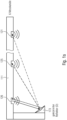
- the road paver comprises three ultrasonic sensors 5a, 5b, 5c, which are attached to a bracket 5h.
- the bracket 5h is attached to the towing arm 12.
- the three ultrasonic sensors 5a, 5b, 5c serve to scan a reference surface, which can be formed, for example, by an already paved or old road surface.
- the distance to the subsoil or to a reference is measured at one or more points.
- ultrasonic sensors have become established on the market for this purpose. These sensors are attached by means of booms, e.g., to a road paver's screed, a road paver's drawbar, and/or a road paver's chassis. In some applications, a so-called sonic ski is used, which combines several parallel measuring heads into one distance sensor.
- a plurality of distance sensors such as ultrasonic measuring heads or sensors based on a different measuring principle such as lasers, are attached to the towing arm via a common rod.
- the rod extends in the direction of travel roughly along the length of the machine or even beyond it and is arranged so that a distance to the subsoil can be measured at two, three or more measuring points along this rod or direction of travel.
- one sensor can be aligned to the applied layer, while another sensor is aligned to the subsoil for the layer to be applied.
- two or more sensor heads are provided, with one sensor head arranged in front of the screed and one sensor head behind the screed.
- This so-called Big Sonic Ski (or Big Ski) application has a number of advantages, such as the ability to suppress or average out systematic measurement errors, e.g., caused by stones in the ground.
- a disadvantage of this so-called Big Sonic Ski is the considerable installation effort required for the rods and individual sensor heads. Given that such measurement systems are dismantled overnight to prevent possible theft, this installation effort is not negligible in daily workflows. Therefore, there is a need for an improved approach.
- the object of the present invention is to create a concept that enables measurement at at least two positions relative to the ground, whereby overall an improved compromise between installation effort, measuring range (in the sense of a large distance between the individual measuring points) and reliability.
- the measuring system comprises a support that can be connected to the construction machine (or a component, such as the screed or the towing arm of the construction machine), e.g., such that the support extends along a subsurface.
- the support can extend laterally along a longitudinal axis of the construction machine.
- the support comprises at least a first section, wherein the first section has a plurality of sensor heads attached to or integrated into the first section for contactless measurement relative to a subsurface or, in general, a reference. These are, for example, aligned parallel, i.e., have a scanning range that extends parallel or substantially parallel.
- the first section has a second connecting element on a second end face, wherein the second connecting element can be connected to a first connecting element in such a way that both a mechanical and an electrical connection is formed.
- the first and/or second connecting element has a hook, so that the first connecting element and the second connecting element can be brought into engagement by a rotational movement about a rotation axis in order to form the mechanical connection.
- the first connecting element (generally: one of the two connecting elements) has a plug, wherein the second connecting element (generally: the other of the two connecting elements) then has a socket.
- the plug and socket together form the electrical connection; here, the plug and/or socket are designed to be tilted, and/or wherein the plug and/or the socket have at least partially a conical shape.
- the plug and/or the socket extends substantially along a longitudinal direction of the first and/or second portion.
- Embodiments of the present invention are based on the finding that by using plug-in connections which, for example, are adapted in terms of their flexibility or geometry to the movement of the first and second carriers when they are joined together, the mechanical and electrical connection can be formed both securely and efficiently.
- One variant here is to mount the plug and/or the socket flexibly or freely suspended. If, for example, it is assumed that the connecting elements with the hooks execute a rotational movement, the joining direction of the plug and socket runs tangentially on a radius around the axis of rotation of the rotational movement with which the two connecting elements are brought into engagement.
- the flexible mounting or rotatable mounting makes it possible for the orientation of the plug and/or socket to vary during the rotational movement, so that the plug and socket do not tilt or jam due to the curved joining path.
- the plug and socket when they are joined, they align themselves in such a way that the joining can also take place along a rotational path.
- This alignment is achieved through the degrees of freedom of the plug and/or socket.
- the geometry of the plug and/or socket can be adapted accordingly so that jamming does not occur when the plug and socket are joined along a joining direction running on a circular path.
- the plug and/or socket it would be conceivable for the plug and/or socket to be conical or at least partially conical. This results in centering and sliding of the plug and/or socket.
- the plug can be conical in the front area, resulting in a type of chamfering.
- the conical shape, with or without the flexible bearing, can advantageously ensure that the plug and socket are electrically connected to one another when the mechanical connection is made along a rotational axis.
- the plug can, for example, have a conical tip or a tapered tip or even a chamfer.
- the conical shape can also be present only partially, i.e., it does not necessarily have to extend along the entire circumference of the, for example, round plug and/or over the entire length.
- the socket has a conical opening. This means that it widens in diameter towards the opening, for example.
- the plug and/or socket is rotatable about one or more rotational axes (e.g., a plug rotational axis or a socket rotational axis) to form the flexible mounting.
- the rotational axes can run parallel to the rotational axis around which the mechanical hooking occurs.
- poles or magnetic poles respectively, through which the electrical connection is established.
- the use of a plurality of poles ensures that both an electrical connection and a data connection are possible.
- only an electrical connection is established in the sense of power supply or only a data connection in the sense of data communication.
- the hook of the first and/or the second connecting element or the hooks of the first and/or the second connecting element have an engagement surface which is substantially perpendicular to the longitudinal direction of the respective section is open.
- the rotary movement is defined by an end stop, which requires contact between the first and second end faces.
- the measuring system comprises a fastening element.
- This fastening element can be connected to the construction machine or a component of the construction machine and, for this purpose, has a first and/or a second connecting element. This can be done, for example, in such a way that the first section can be connected to the construction machine or the component of the construction machine.
- the first and/or the second section can have sensor heads aligned perpendicular to the longitudinal axis of the first and second sections on one long side.
- the sensor heads are directed towards the substrate (in the installed state), i.e., the sensor heads are aligned towards the layer already applied or towards the substrate for the layer to be applied.
- the sensor heads are attached or integrated, with a plurality, i.e., at least three sensor heads, being attached/integrated per section. The higher the number or density of sensors, the better unevenness of a specific wavelength, e.g., 5 m, is compensated for.
- the measuring system can have at least one first further sensor head for each first and/or second section or each carrier, which is aligned parallel to the longitudinal axis and/or which is arranged on the first and/or second end face; and/or wherein the first further sensor head is designed to carry out a reference measurement.
- the measuring system can have a second sensor head for each first and/or second section, which is arranged along the longitudinal axis of the respective first and/or second section or of the carrier and is located on the opposite end face to the first further sensor head.
- the measuring system can have a reflector (e.g. parallel to the longitudinal axis) or an inclined reflector (e.g.
- the measuring system can also be integrated/formed in the receptacle of one and/or more sensor heads.
- the measuring system it would also be conceivable for the measuring system to have at least one additional sensor head per first and/or second section or per carrier, which is aligned parallel to the longitudinal axis and/or which is arranged on the first and/or second end face;
- the additional sensor head is designed to determine a distance to an object that performs a relative movement to the construction machine or a component of the construction machine.
- Another embodiment relates to a carrier comprising a first section of the carrier.
- the first section has a second connecting element on a second end face, wherein the second connecting element can be connected to a first connecting element in such a way that a mechanical and electrical connection is formed.
- the first and/or second connecting element has a hook, so that the first connecting element and the second connecting element can be brought into engagement by a rotational movement about a rotation axis in order to form the mechanical connection.
- the first connecting element has a plug and the second connecting element has a socket, wherein the plug and the socket together form the electrical connection.
- the plug and/or socket are designed to be tilted. Additionally or alternatively, the plug and/or the socket have at least a partially conical shape.
- a further embodiment relates to a construction machine, such as a road construction machine with a measuring system as explained above.
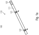
- a sensor arrangement 100 is explained with reference to an initial aspect.
- this comprises a carrier 110, which comprises at least one section 111. At least two sensors 121, 122 are integrated (generally fastened) in this section 111. These sensors are arranged at a distance from one another.
- the carrier 110 comprises a second connecting element 132, which can be connected to a first connecting element (not shown).
- the connecting element 132 as well as the first connecting element (not shown) are designed to form, firstly, a mechanical connection and, secondly, an electrical connection.
- An electrical connection is understood to mean, for example, a contact connection, a contactless connection, such as, for example, an inductive connection.
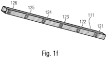
- the carrier 110 and thus also the section 111 can, for example, have a square shape (cf. carrier section 111 from Fig. 1f ). As can be seen in particular from Fig. 1f As can be seen, the integrated sensor elements 121, 122 ff. are integrated into the carrier and are all aligned in the same direction.
- all sensor heads 121, 122 et seq. are oriented toward the ground. In other words, this means that they have a scanning range that extends perpendicular to the longitudinal axis of the support 110 or section 111.
- sensor heads 121 and 122 can be transported together with section 111.
- Section 111 of the support can be connected via interface 132 either to a mounting device on the construction machine or to another section, as in Fig. 1b is shown.
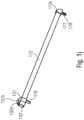
- Fig. 1b shows a carrier 110' with a section 111 and a section 112.
- Each section comprises embedded sensor heads 121 and 122.
- the connection between the two sections 111 and 112 is made via the connecting elements 131 and 132, which are compatible with each other and are each arranged on the front side.
- each section 111 and 112 may also have further connecting elements 131 and 132 on the respective opposite end faces.
- the carrier 110 may, for example, consist of a section 111 or of a plurality of sections 111 and 112. The following are described with reference to Fig. 1c and 1d different installation situations are explained.
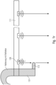
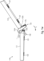
- Fig. 1c shows section 111, which here includes connecting element 131.
- Connecting element 131 is connected to a connector 135, which has connecting element 132.
- Connector 135 is coupled to the machine.
- connector 135 extends in an S-shape below the footboard 10t of screed 10, longitudinally rearward in the direction of travel.
- Sensor heads 121 and 122 are shown as examples. As can be seen, they are oriented such that the subsurface 16', or here the applied material layer 16', is scanned.
- the section 111 can be one or two meters long, or generally in the range of 50 to 300 cm.
- a cascading of the carrier 110 by connecting two sections 111 and 112 is possible. Fig. 1d shown.
- Fig. 1d shows a section 111 that is connected in alignment with a section 112.
- the two sections 111 and 112 together form the support 110 of the sensor arrangement.
- the sensor arrangement 110 is connected to the screed 10 via a connector 135', so that the sensor arrangement 110 extends from the screed to the rear approximately in the direction of travel.
- a longer area can be scanned, optimizing handling, particularly during assembly and disassembly. This is achieved by the fact that the sections 111 and 112 are separable from one another and can thus be stowed individually.
- the connecting elements 131 and 132 are designed in such a way that, in addition to the mechanical connection, an electrical connection is also formed. Therefore, no additional wiring is required to contact section 112, which significantly reduces the assembly effort.
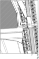
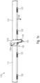
- Fig. 1d shows a further exemplary installation situation on the pulling arm 12.
- a further holder 135' is arranged, which has both a first connecting element 131 and a second connecting element 132.
- the sensor arrangement 110' in turn comprises two sections 111 and 112, wherein both the section 111 is connected via its connecting element 132 to the connector 135' and the section 112 is connected to its connecting element 131.
- the element 135' which is firmly connected to the machine or the pulling arm 12 of the machine, lies between the two sections 111 and 112 of the carrier. Both sections are, as in the sensor arrangement 110 of Fig. 1d oriented in the same way, so that the substrate or the applied layer is scanned.
- This example has shown that not only cascading as in arrangement 110 through series connection is possible, but also cascading by connecting them together with a common connector 135'.
- This cascading also makes it possible for the measuring system to have a third section, which is arranged in series, for example.
- this example has shown that different mounting positions are possible, e.g., on the screed 10 itself or on the tension arm 12. It is important that the element 135' is permanently connected to the screed 10 or the tension arm 12. Screw connections, welded connections, or other connections are suitable for this. For example, this element 135' can remain directly connected to the machine, while the technology-bearing sensor elements/sections 111 and 112 are dismantled at night.
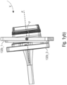
- the element 135' of the sensor arrangement 110' is in Fig. 1e shown.
- Fig. 1e shows the element 135', in which the section 111 is connected on the first side and the section 112 on the second side.
- the connecting element 135 is shaped as a type of sleeve, the cross-sectional shape of which corresponds to the cross-section of the profiles 111 and 112 (rectangular here, alternatively another e.g. round cross-section), wherein the dimensions, in particular the internal dimensions of the sleeve of the element 135' are formed such that the elements 111 and 112 can be inserted.
- the elements 111 and 112 can be fixed by means of the screws 135s' shown here.
- the electrical connection is not shown.
- the sections 111 and 112 extend substantially in alignment in both the sensor arrangement 110 and the sensor arrangement 110', so that all sensors 121 and 122 have a substantially parallel scanning lobe.
- the section 111 can have a plurality of sensor heads 121 and 122, such as six sensor heads here. These are marked with the reference numerals 121 to 126.
- the arrangement can be equidistant, although another arrangement is also useful, as described below with reference to Fig. 1m The number may also vary accordingly (see explanations in connection with Fig. 1k and 1l ).
- the sensor heads 121 to 126 are embedded on one side of the rectangular profile, as shown in Fig. 1f and in Fig. 1g is shown.
- Fig. 1g represents an exemplary profile measuring 60 x 80 mm, with a sensor head 126 embedded on the narrower side 60. This can be clicked in or screwed in, for example.
- the sensor head 126 is approximately flush, i.e., +/- 3 mm, +/- 10 mm, or +/- 20 mm, with the surface of the profile.
- the sensor head is an ultrasonic sensor, although other sensor technologies, such as laser or capacitive sensors, can also be used. Different measurement principles can also be used for the different sensor heads for each section 111 or each sensor arrangement 110.
- Fig. 1h shows the two sections 111 and 112, which are connected to each other by a connector 138.
- the sections 111 and 112 are simple profiles that are inserted into the connector 138 and connected on each side by means of the eccentric 138e.
- the profiles have the connecting elements 131 and 132 on the corresponding end faces, at which the connection to the connector 138 is made, whereby the connector 138 has the corresponding counterparts to form not only the mechanical but also the electrical connection.
- the electrical connector can be realized, for example, by a plug integrated into the connector 138, which is closed in the longitudinal direction of the sections 111 and 112.
- FIG. 1i Another example of a slide-in connector is in Fig. 1i shown.
- a modified connecting element 138' with the eccentric 138e is shown, into which the section 111 is inserted.
- the connecting element 138' can, for example, belong to the further section of the carrier or be firmly connected to the machine.
- a screw connection with a knurled screw instead of the eccentric 138e a screw connection with a knurled screw, as in Fig. 1e shown.
- profile 111 or 112 is inserted and secured by another means, such as an eccentric or a screw.
- a type of quick-release fastener, as is common on bicycles, or a bayonet lock would also be possible.
- section 111 can, for example, be designed with a closure cap 111v on one end face.
- Fig. 1j represents another connection concept.
- section 112 has a type of hook 131h' as connecting element 131', so that the hook can be connected to an engagement section of connecting element 132'.
- the engagement section of element 132' is provided with the reference numeral 132e'.
- Element 112 in turn, has a cap on the opposite end face.
- the cap is designated by reference numeral 112v.
- Fig. 1w and 1x represent a carrier 110 with two sections 111 and 112.
- the two sections can be connected to each other via connecting elements.
- These are provided with the reference numerals 131 and 132.
- the first connecting element 131 has a hook 131h, which engages in an engagement section 132h, e.g. a raised portion 132e. This intervention is in Fig. 1w
- Each of these engagement areas 131 and 132 has a front surface on the front side, which serves as a kind of stop, so that after hooking in the elements 111 and 112 are connected to each other, as in Fig. 1x is shown.
- the end faces of the connecting elements 131 and 132 rest on one another, forming a stop for the joining movement V about the rotation axis 132r. If, for example, the hook 131h of the sensor bar 112 is first hooked into the holder 132e, the sensor bar 112 can then be fastened/joined by a downward movement or rotational movement V.
- each connecting element 131 and 132 has matching electrical connecting elements. These are designed here as a type of plug-socket pair.
- the plug is designated by reference numeral 132s, and the socket by reference numeral 132b.
- Plug 132s can be arranged either on the hook side 131h or on the engagement section side 132e.
- the socket is provided either on the engagement section 132e side or on the hook side 131h.
- Both plug and socket are provided, for example, on the respective end faces of the connecting elements 131 and 132 and are aligned such that they open in the longitudinal direction or substantially in the longitudinal direction. This means that plug 132s protrudes from the end face in the longitudinal direction, while socket 132b protrudes from the end face in the longitudinal direction into element 111.
- these are arranged in such a way that during the joining movement V around the rotation axis 132r, the two extension directions of plug and socket 132s and 132b are aligned with each other or flush, so that a good joining of the two elements 132s and 132b is possible.
- the plug socket 132B* e.g. can be used as socket 132b (cf. Fig. 1w ), flexible, in this case rotatable around the rotation axis P.
- the counterpart 132s* from Fig. 1z e.g. usable as plug 132s (cf. Fig. 1w ) can, but does not necessarily have to, be flexible. Because part of the connector, in this case the 132B* socket, is flexibly mounted or freely suspended, it can tilt during assembly (see Fig. 1yb )), so that an electrical connection is established even with a translational movement path of the connector socket 132B* and the connector housing 132S*.
- the tilting of an element 132b_2 of the plug socket 132B* takes place around the point P, specifically relative to a fixedly mountable element 132b_1.
- the connector housing 132s_1 can also be made of Fig. 1z have a conical shape 132s_1m inside to accommodate the socket 132b*.
- the combination of the conical shape and the flexible mounting of the plug socket 132B* allows the plug 132s and the socket 132b* to mechanically come together during the rotational movement of the sensor bar 111, creating a secure electrical connection when plugged in. This is referred to as a self-centering plug connection.
- the plug 132S* and the socket 132B* contain contacts 132s_1k for power and/or data transmission.
- the reference numerals 132b_ak (cf. Fig. 1ya )) and 132s_ak (cf. Fig. 1z ) each denotes a connection
- the reference numeral 132s_1b denotes a housing fastening.
- a magnet (not shown) can be provided inside the connector. This keeps the connector closed in the plugged-in state without the need for a mechanical locking mechanism, e.g., a bayonet lock. This ensures a secure mechanical and thus also electrical connection, for example, in the event of vibrations or other external forces (such as shocks, impacts, etc.). If the sensor bar 112 is released/unhooked from the sensor bar 111, the connector automatically releases.
- a mechanical locking mechanism e.g., a bayonet lock.
- the hooked sensor bar 112 by means of a mechanical lock on the sensor bar 111 (for example, by means of a bracket).
- Mechanical coding of plug 132s* and socket 132b* is not absolutely necessary according to further embodiments, since the sensor bar 112 can only be attached in one direction.
- connection options are also conceivable.
- the respective connecting element could also have guides extending orthogonally to the longitudinal direction, forming a type of dovetail joint.
- the electrical connection can also be made wirelessly.
- Wireless data and/or power transmission can be considered an alternative to the plug/socket system.
- an energy transmitter e.g., an induction loop, is provided on the side of the engagement area 131 and on the side of the engagement area 132.
- the connecting elements 131 and 132 can have contactless energy transmission elements via which both an energy supply to the sensor heads and a data transmission between the sensor heads and a computer unit takes place.
- the energy transmission element may comprise an induction loop or induction coil or be configured to inductively transmit electrical energy. According to embodiments, the energy transmission element may further be configured to exchange data with the energy receiving device of the sensor along with the electrical energy.
- Embodiments provide a receiving device comprising a plurality of mechanical pickups, each with a plurality of energy transmission elements for a plurality of supports 110 / sections 111 and 112.
- a cabling can be provided, via which the energy transmission element is supplied with electrical energy. is supplied by the construction machine.
- the energy receiving element is designed to receive at least 5 W or 10 W of electrical energy and to provide at least 5 W or 10 W of electrical energy to a sensor element or an electrical circuit.
- the energy receiving element has, for example, an induction loop or induction coil or is designed to inductively receive electrical energy.
- the energy receiving element can also be designed to exchange data.
- Further embodiments relate to a receiving device for a construction machine.
- the receiving device comprises a mechanical pickup for receiving a display and an energy transmission element which is designed to wirelessly or contactlessly transmit electrical energy to an energy receiving element of the display in order to supply energy to the display.
- each section may comprise a plurality of sensor elements 121 ff.
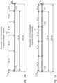
- Fig. 1k It is assumed that section 100 has a length of 2 m (200 cm) and that the sensor heads 121-126 (here, six sensor heads) are evenly distributed. This results in a distance of 33 cm between the sensor heads, with 33/2 cm being provided from the front side to the first sensor head 121 or to the last sensor head 126.
- Fig. 1l shows a section 100 with a length of 2 m (200 cm), with five sensor heads 121-125. The spacing is again equidistant, resulting in a distance of 40 cm between the sensor heads and 20 cm from the front to the first or last sensor head 121/125.
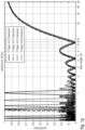
- Fig. 1o shows a comparison between a classic Big Sonic Ski (Big Ski for short) with a 12 m extension using three, four, and five sensors.
- the Big Sonic Ski with three sensors has problems in the 6 m range
- the Big Sonic Ski with four sensors has problems in the 4 m range
- the Big Sonic Ski with five sensors has problems in the 3 m range.
- the Big Sonic Ski with three sensors also has the same problems. By increasing the sensor density, these high-frequency problems (compared to vibrations) can be reduced in the range of 20 m and beyond.
- the improvement through the use of the Fig. 1 described (and according to the invention) sensor arrangement is shown in Fig. 1p This example assumes an 8 m long beam with three to six sensors. As the number of sensors increases, the control gaps become more frequent, but this is less critical given the lower probability of high-frequency interference.
- a non-equidistant sensor pattern can be used per section, as shown in further examples. Examples are shown for a distance of five sensor heads 121-125 in Fig. 1m Here, the distance between the front face and the first sensor 121 increases from 20 cm. The distances are, for example, 32, 40, 46, and 58, as well as 4 cm.
- Fig. 1n shows another illustration, where equidistant sensors with a spacing of 44 cm are used again, but the distance between the front end and the first sensor 121 is selected such that an equidistance is maintained across two sections.
- the section between the front end and the first sensor is selected such that half the distance between the further sensor, or in particular, sensors 121 and 122, is present.
- Fig. 1q shows a section 111 with sensor heads 121 ff.
- One or each sensor head has a bracket 171 arranged at a defined distance in front of the sensor 121.
- This bracket 171 is located at least partially within the entire measuring field and can be folded in or rigid, as shown in examples.
- the bracket 171 reflects the measurement signal, as shown here by the dashed line.
- Fig. 1s shows a further variant, wherein a further reflector 173 is provided in a laterally arranged bracket, which extends approximately perpendicular to the longitudinal extent of section 111.
- This reflector 173 is again arranged at a distance from the sensor 126, but serves not only as a reference for the nearest sensor 126, but also for the adjacent sensors 125, ... 121.
- the reflector 173 can be arranged at an angle, e.g., 45° with respect to the measuring direction of the individual sensor heads 121 to 126.
- the reflector surface 173 can be curved in order to serve as a reflector for all channels 121 to 126.
- the bracket connecting the reflector 173 to the section 111 can either be attached directly to the section 111 or can be integrated into the connecting element, as for example in connection with Fig. 1r is shown.
- Fig. 1t is essentially comparable to the example from Fig. 1s , where the reflector 174 has an active mirror which aligns itself depending on which channel (sensor head) is to be calibrated.
- the active reflector 174 is designed as an active transmitting unit, which then directs an ultrasonic signal to the receivers 121 to 126.
- an ultrasonic sensor 176 is used for reference measurement by means of a bracket 175 arranged below the sensor heads 121 to 126. Below here means between the support/section 111 and the road surface.
- the ultrasonic sensor 176 is arranged parallel to the support/section 111 and can be arranged, for example, by means of an additional reflector 177 on the other end face or between the end faces, for example in the middle (see dashed element 177').
- the active transmitter 176 which is arranged on the bracket 175, can cooperate with an active receiver 178, which is arranged on a bracket 175 on the other end.
- the reference measurement is taken in the area of ultrasonic sensors 121 to 126. This has the advantage that the same ambient conditions, e.g., ambient temperature and infrared radiation, prevail here.
- Fig. 1i The measuring principle shown with active transmitter 176 and active receiver 178 is shown in Fig. 1i
- an active transmitter 176 is integrated into the element 138', while the receiver 178 is integrated into the closure cap 111v.
- a reflector 177 instead of the receiver 178.
- Fig. 1j A similar variant is shown in Fig. 1j shown.
- the transmitter 176 is integrated into the element 131', while the receiver or reflector 177 and 178 is integrated into the closure cap 112v.
- 176 with 177/178 in the examples from Fig. 1i and 1 year has been exchanged.
- measurements of the sensor heads are carried out essentially simultaneously (synchronous measurement within a time window, e.g., within a time window of 3s, 1s, 0.5s, 0.1s or less).
- a simultaneous measurement in principle, a snapshot of, for example, the substrate or reference profile (the already applied layer or the substrate for the layer to be applied) and the reference measurement(s) is taken under the same Conditions (e.g., environmental conditions such as ambient temperature) are created.
- Conditions e.g., environmental conditions such as ambient temperature
- a correct reference profile or correct subsurface profile is recorded by all sensor heads in all sections and all supports of the measuring system.
- Essentially simultaneous measurement is also advantageous with regard to a high measurement rate (sampling rate), as is required today for leveling in road construction (e.g., height leveling of the screed).
- Fig. 1g Another feature is explained.
- Fig. 1g An LED 181 is also displayed on one end face. This can indicate, for example, by color coding or flashing, whether the electrical connections between the sections or from the section to the machine are correct. Furthermore, information such as necessary readjustments can also be displayed. Furthermore, it would also be conceivable that the LED, if it is, for example, on the ending end face at Fig. 1d the measuring arrangement 110, provides a signal regarding the distance to a vehicle traveling behind it, such as a roller.
- a further distance sensor can be aligned in the other direction on the front side, similar to the distance sensor for reference measurement 176, which then measures the distance to a following vehicle.
- a complex display such as an LCD display can be provided to display, for example, text and/or symbols.
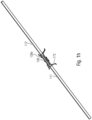
- the following describes a measuring system 200 that uses a regression line to determine the position.
- the sensor head 221 is arranged closer to the screed edge 10k, which represents a pivot point 10 of the screed, than sensor 223.
- the sensor head 222 is located in the middle or in between.
- A the distance to the perpendicular base point on the screed edge 10k
- B the distance from the perpendicular base point of the screed edge 10k to the sensor 223.
- the screed 10 can also have another pivot point, e.g., in front of the screed rear edge 10k (especially when it rests on hot asphalt), as an alternative to the pivot point around the screed rear edge 10k.
- the distances to the pivot point are taken into account accordingly.
- the sensors 221, 222 and 223 are arranged substantially parallel and measure a distance from the carrier 110 to the substrate, here the applied layer 16'.
- distance H1 is greater than distance H3.
- the sensor values can be recorded, for example, in a two-dimensional space, here height versus distance. Based on the sensor values, it can be seen that the regression line RG also runs according to angle ⁇ .
- the regression line RG when located in two-dimensional space, can be determined in such a way that angle ⁇ can be calculated. By determining angle ⁇ , the position of component 10 relative to the ground is also known.
- the position ⁇ does not necessarily have to be an absolute position, but can in particular be a relative position to the ground.
- the values H1 and H3 also change, although, assuming a parallel displacement, the angle ⁇ remains constant. Therefore, if slight fluctuations in the values occur, for example due to vibrations, these values can be plotted in the common space and a regression line RG determined. This represents an average. Using more than three sensors results in averaging if all sensors are arranged exactly on the carrier 210.
- the determination of the regression line RG for a point cloud is explained.
- This example assumes that more than two sensors are planned.
- the sensor array from aspect 1 can be used.
- the deviations, as shown here using the height points H1 to Hn, can arise, for example, from unevenness in the ground.
- the height values essentially increase from a to n, so that this can be inserted into the regression line RG here.
- the regression line RG is inserted in such a way that the distance between the regression line RG, represented here by small arrows, and the measurement points is minimal overall.
- the regression line is angled relative to the distance axis, e.g., by the angle ⁇ . This position can be determined and provides an indication of the angle of the component.
- the roll angle of the screed around its longitudinal axis can be determined. If, in addition to the longitudinal component, a transverse component is also present, a combination of the roll angle and the transverse inclination angle is determined. Knowing the transverse component to the longitudinal component, these two angles can be separated.
- the transverse component can, for example, be determined using the support from Fig. 2a with the sensors 221, 222 and 223 when it is arranged in the longitudinal direction of the screed (ie transverse to the direction of travel of the machine).
- the support runs without an angular offset relative to the component.
- An offset can also be taken into account.
- a calibration can be performed at the beginning or a comparison can be made with an optional angle sensor, such as an inclination sensor.
- the plank could also be attached to the tension arm, for example.
- An example of such an attachment is explained in aspect 1, since here a beam comprising a plurality of sections is attached. This beam has a plurality of integrated sensors, which then an averaging regression line according to the execution from Fig. 2b corresponds.
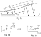
- Fig. 2c shows the use of the sensors 221 and 223 by means of the carrier 210 and the use of another carrier 215 which houses the sensors 225 and 227.
- the sensor array 210 is as in Fig. 2a arranged behind the screed, while the sensor array 215 is arranged in front of the screed. A reversed arrangement would, of course, also be conceivable. It is assumed that both extend in the longitudinal direction.
- the resulting sensor values H1, H3, H4 and H6 are in two-dimensional space in Fig. 2d
- both regression lines RG1 and RG2 are tilted around the pivot point of the plank, namely the rear edge 10k of the plank, the regression lines are mapped to the corresponding RG1' and RG2', as shown in Fig. 2e
- the center distance in Fig. 2e runs parallel to the background or to the reference against which the measurement is made.
- the tilted regression lines RG1' and RG2' are no longer as in Fig. 2d They are not aligned with each other, but have an offset V.
- This offset V results from the fact that the array 210, associated with the regression line RG1, measures the layer 16' to be applied, while the sensor array 215 measures the substrate 17. This offset is therefore dependent on the layer thickness of the layer 16' to be applied. Conversely, this means that the layer thickness can be determined, i.e., calculated, using this approach.
- the distances A, B, C and D between the respective sensor 221, 223, 225 and 227 to the plumb line base point on the plank edge 10k are used during the rotation to perform the rotation.
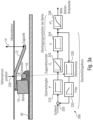
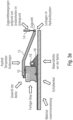
- Fig. 3a shows a conventional control loop 300 (flatness control loop) used for leveling the screed 10, which is pulled by the towing arm 12.
- the towing arm 12 is fixedly connected to the screed 10, or at least during operation.
- the screed is towed by a tractor (not shown), for which purpose the towing arm 12 is connected to the tractor via the towing point.
- the towing point is typically adjustable in height, as illustrated here by arrow 14. This height adjustment is controlled by the flatness control loop 300.
- the screed smooths the asphalt or the material for the layer 16' to be applied, which is provided by the auger 18 in front of the screed (see material 16).
- the flatness control loop 300 includes a flatness controller 310, which controls the traction point cylinder (see reference numeral 14) based on a target/actual comparison 320. The result is a changed height, which is detected by the height sensor 330. The height sensor signal from the height sensor 330 is then fed to the target/actual comparison 320.
- a filter 335 can also be provided. This filter is designed either as a low-pass filter, a low-pass filter with a low/increased cutoff frequency, a band-pass filter, or a high-pass filter, depending on how the transmission behavior is to be corrected. Other frequency filters, such as Chebyshev filters or similar, are also conceivable in this context.
- the transmission behavior of the traction cylinder can be described using an IT 1 control loop (see block 342).
- the transmission behavior of the screed can be described as follows: in the sensor position, it is represented by a P behavior (see 344).
- the screed itself can be represented by a PT 2 element (see 346).
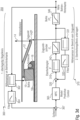
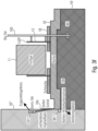
- Fig. 3b illustrates the thus interpreted transmission behavior of the controlled system from the trailing edge of the screed to the cylinder.
- Fig. 3b again shows the screed 10, which is pulled or adjusted in height via the pulling arm 12 at the pulling point 14 ZP by means of the pulling point cylinder 14.
- the basic idea behind optimizing the height leveling of screed 10 is the targeted monitoring of the paver screed, and in particular the trailing edge, using an additional control loop or the implementation of a control loop overlay to the existing height leveling.
- the control loop for normal height leveling acts as a subordinate control loop. This new control loop structure can be applied to all leveling tasks and will be discussed in detail below.
- control loop 350 shown here comprises two individual control loops 360 and 370.
- the control loop 360 is referred to as the first control loop or superimposed control loop.
- the control loop 370 is referred to as the second control loop.
- the control loop 370 is comparable to the control loop 300 as it is in relation to Fig. 3a explained, whereby the sensor 330 is positioned differently (see reference numeral 331).
- the sensor 331 is in the area of the pulling point 14 ZP and no longer in the area of the screw 18 (see arrangement Fig. 3b ).
- control loop 370 corresponds to control loop 300, i.e., it includes comparison 320, evenness controller 310, and optional filter 335.
- control loop 370 A significant difference, based on the positioning of the height sensor, is that in control loop 370, the transmission behavior of screed 344 no longer needs to be taken into account, but only the transmission behavior of the traction point cylinder (see reference numeral 342).
- the behavior of the screed, described by PT 2 (see reference numeral 346), is also taken into account by control loop 360.
- the control loop 360 also includes a height sensor 362 and an optional filter 364.
- the sensor 362 is arranged in the area of the screed 10 or, for example, in the area of the rear edge of the screed 10.
- the behavior of point 10k in response to a change in height at the traction point 14 ZP is relatively sluggish. This becomes quite clear when considering the arrangement of the screed 10, traction arm 12, and traction point 14 ZP, since the height cylinder 14 shifts the traction point 14 ZP around the pivot point 10k, so that a change in height only occurs gradually. This behavior is simulated by the Model Predictive Control 365.
- the input variable for the MPC 365 is the result of a target-actual comparison (see reference numeral 367), whereby the same signal from the sensor 362 is used as the actual signal.
- the result of the MPC is a target signal, which serves as the input for the comparison 320.
- control circuit 370 which is located in Fig. 3a is shown, extended by a control loop 360 superimposed on it, which is Fig. 3d
- This measure changes the structure of control loop 350 such that the disturbances acting on traction point 14 ZP and screed 10 can be compensated separately.
- the higher-level control loop compensates for the disturbances acting on screed 10, and the lower-level control loop 360 compensates for the disturbances that change the height of the traction point.
- the control system 350 structured in this way can be optimized separately, resulting in improved control behavior overall.
- a further optimization of the control loop structure results from shifting the sampling point of the height sensor for the subordinate flatness control loop 370 towards the pulling point 14 ZP.
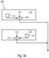
- Fig. 3d shows a control loop 350 composed of two control loops 370 and 360.
- Each control loop includes at least one sensor, which in the case of control loop 360 is the height sensor 362, while in the case of control loop 370 it is the pull point sensor 331.
- the sensors are arranged in the area of the pulling point (see sensor 331) and on the screed (see sensor 361).
- Each control loop also includes a corresponding processor, which outputs the control signal for the traction point cylinder based on the actual value from sensors 331 and 362 and a setpoint.
- the processors are labeled 379 and 369, respectively. According to examples, processors 369 and 379 can also be combined into a single processor, which then receives the actual signals from the two sensors 331 and 362 and processes them separately before outputting the combined control signal.
- the disturbances at the pulling point are compensated by the subordinate control loop 370 (evenness control loop)
- the disturbances of the screed 10 are compensated by the superimposed control loop 360. Due to the different transfer functions (see also Fig. 3b ) of the partial control system Werige (IT1) and the partial control system Bohle (PT2), the controllers used for this purpose are also structured and optimized differently.
- control deviations will be corrected extremely quickly, whereas the controller for the higher-level control loop 360 corrects control deviations more slowly and takes into account the knowledge of the influencing disturbances.
- An example of disturbances that influence the floating behavior of screed 10 is the effect of material temperature changes. If a temperature change in the material is already known before a temperature-dependent effect on the screed height occurs, the controller can avoid or reduce a height deviation of the screed based on a model.
- the model of screed 10 which describes the dependence of a height change on material temperature changes, must be known. This would also typically be an example of an MPC controller for the higher-level control loop 360.
- control loop structure 350 Different application cases of the control loop structure 350 are explained below.
- the single-head sonic sensor without a reference is suitable because the measurement distance to the existing asphalt surface at the trailing edge of the screed can be minimized. This significantly reduces the measurement error compared to larger distances. Minimizing the measurement distance is possible because the measurement distance to the ground is always approximately the same. In this application, the sensors focus as closely as possible on the ground.
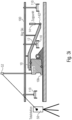
- the Fig. 3f shows the mounting area and thus also the possible and useful scanning positions to realize the control loop structure.
- Fig. 3f shows the road paver from above with the screed 10, the applied layer 16' or existing layer 16*, the auger 18 and the tractor 11.
- the screed is connected to the traction point 14 ZP via the traction arm 12.
- a so-called Big Sonic Ski (short: Big Ski, see aspect 1) 100 can be connected to the towing arm 14 or the screed 10 (not shown).
- the Big Sonic Ski has the sensor 361 located in the area of the screed's trailing edge 10k.
- the sensor 331 can also be arranged on the Big Sonic Ski 100 at the height of the towing point.
- the scanning of the trailing edge of the screed for the screed control loop and the scanning for the traction point control loop can also be carried out on the side of an existing asphalt track 16*.
- a Sonic Ski 331* is provided via a side plate 10s for scanning at the level of the traction point 14 ZP.
- a screed trailing edge sensor 361* is also provided on the side plate. As shown, the Sonic Ski 331* is slightly offset with its scanning area outside the subgrade to scan the existing asphalt track 16*.
- sensor 331* on the side of the existing asphalt track 16* serves the purpose of using the existing asphalt track as a reference.
- sensor 331* scans the distance to the existing asphalt track 16*.
- the purpose of scanning the existing asphalt track 16* with the traction point control loop is to directly compensate for disturbances (e.g., material under the tractor's crawler track) that affect the traction point.
- sensor 361* is preferably directed at the existing asphalt layer 16* and monitors the height of the screed in relation to the existing asphalt track 16*, compensating for deviations from the set target value of the superimposed control loop 360.
- Fig. 3g shows a road paver with a tractor 11, a screed 10, and a screed trailing edge 10k.
- the screed 10 is connected to the paver 11 via a towing arm 12.
- the Big Sonic Ski 100 with three sensors is provided on one of the towing arms 12.
- the sensors are marked with the reference numeral 110 for example; depending on the application, they can be evenly distributed along the Big Sonic Ski 100 or arranged in the area of the towing point 14 ZP or in the area of the screed trailing edge 10k.
- a sensor system can also be provided via the side plates 10s of the screed 10.
- a screed sensor 361* and a towing point sensor 331* can be provided. Both are directed towards a cable 16s in order to scan the cable 16s.
- the cable scanning at the trailing edge 10k of the plank can be carried out contactlessly with an ultrasonic sensor (sonic ski) or with a mechanical rotary encoder, as is usual in practice with the scanning methods currently used.
- the sensors 331*, 361* are guided over the reference cable 16s with a corresponding sensor mount 10k.
- the control deviation measured relative to the reference cable 16s at the trailing edge 10k of the plank also provides information about the installed evenness over the path.
- a second height sensor can be guided over the rope using an additional sensor mount.
- a Big Sonic-Ski system Big Ski for short
- a tension arm sensor See Fig. 3h .
- Fig. 3h shows the comparable structure as Fig. 3g of the road paver 11 with the screed 10.
- Sensor 361* is used as the screed sensor on the left side.
- the Big Sonic-Ski 100R is used as the towing point sensor on the left side. As previously explained, this is permanently connected to the towing arm 12 and has a plurality of sensors 110.
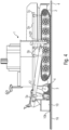
- Fig. 3i shows the screed 10 with the screed trailing edge 10k and the pulling arm 12, which is connected to the pulling cylinder 14 at the pulling point 14 ZP.
- a Big Sonic Ski 100 which is connected to the pulling arm 12, is also provided.
- the Big Sonic Ski 100 comprises three distance sensors 110, which, in this example, together determine the distance at the pulling point 14 ZP.
- the screed trailing edge 10k is monitored using a total station 50 and a reflector 52 attached to the screed. This sensor, consisting of the elements 50+52, is referred to as a 3D sensor.
- 3D leveling with a total station 50 consists of a prism 52, which is mounted on the paver 11 or the screed 10 so that it is visible to the total station 50. The total station 50 then determines the 3D position of the prism in space and transmits this information wirelessly to the 3D control system on the paver.
- a major disadvantage of 3D control is that the installed height level must be checked repeatedly. In practice, this task is performed by a surveyor who uses an additional total station 50 to check the installed height and, if necessary, makes manual adjustments. This is necessary because the installation location of the prism (a 3D point in space, precisely determined by the total station via the reflection of a laser beam) is not at the rear edge of the screed, but rather, as is usually the case with other height sensors, on the drawbar at the height of the screed auger. This means that over a certain period of time, a change in the height at the rear edge of the screed occurs, which the surveyor must then correct.
- the control of the built-in height measurement could be avoided by placing the height sensor (prism) on the screed's rear edge 10k.
- the sensor then functions as a height sensor for the screed and is thus used in the superimposed 360 control loop as a supplier of height information.
- a Big Sonic Ski system Big Ski for short, which provides the altitude value for the subordinate control loop 370.
- two total stations 50 are required for leveling (one total station for each side). This is necessary because in this configuration, the sampling rate of the 3D height measurement must be high in order to compensate for all influencing disturbances.
- the sampling rate can be reduced so that one total station is sufficient for both sides, which then continuously and successively determines the left prism 52l and the right prism 52r in the position at the rear edge 10k of the pile.
- Fig. 3k is now used instead of the left Big Sonic-Ski 100 L, which is Fig. 3j served as a traction point control, the traction point sensor is also implemented as a laser sensor.
- a laser transmitter 54 provides a height reference, which can be received via the receivers 56z at the traction point 14 ZP and 56b on the screed 10.
- the new 350 control loop structure can also be applied when using a laser plane as a height reference.
- a laser receiver is mounted on both the towing arm and the trailing edge of the screed, acting as a height sensor in both cases.
- the projected laser plane precisely represents the desired position of the road with a corresponding height offset.
- Fig. 3k shows the basic leveling setup with a laser height reference on the left.
- the right side is leveled with a Big Sonic Ski System 100.
- other measuring elements such as inclination sensors or Sonic Skis can also be used to level the screed.
- Model Predictive Control extends the control loop structure as follows.
- a further improvement for the control system is that the controller for the higher-level control loop, whose associated sensor is mounted near the trailing edge of the screed, takes the respective process state into account.
- Each state is assigned a control value, which is partly responsible for calculating the controller output.
- the process state is predetermined using a process model.
- the process model is the foundation of Model Predictive Control, where the model comprehensively captures the process dynamics and can thus calculate predictions of the future process state.
- the process model is necessary to calculate the predicted output variables in a future instance.
- the various MPC strategies can use numerous models to demonstrate the relationship between the output variables and the measurable input variables.
- Comparison variants are based on the fact that the use of attached/integrated sensor heads in a support that is divided into one or more sections can significantly reduce assembly effort. Because the connecting elements form a mechanical and electrical connection simultaneously, no cabling is necessary. According to comparison examples, the connection between the section and the construction machine can also be established via a corresponding connecting element. For example, the first section can be connected to the construction machine (which has a corresponding second section as a counterpart) using its first connecting element. Here, too, an electrical connection can be formed in addition to the mechanical connection. According to comparison examples, the measuring system can be extended by additional sections with attached/integrated sensor heads in order to scan a large area simultaneously.
- a type of hook connection can be used.
- the first and/or the second connecting element can have a hook, so that the first connecting element and the second connecting element can be engaged by a rotary movement.
- the hook of the first or the second connecting element or the hooks of the first and the second connecting element can have an engagement surface that is open substantially perpendicular to the longitudinal direction of the respective section.
- the rotary movement is defined by an end stop that requires contact between the first and the second end side or end surface.
- the first and/or the second connecting element can have an electrical coupler that extends substantially along the longitudinal direction of the respective section.
- a shearing movement of the two sections or of one section relative to a further connecting element can also form the connection.
- the first and/or the second connecting element can comprise a profile extending substantially perpendicular to the longitudinal direction of the respective section and having an end stop, so that the two connecting elements can be connected by a translational movement substantially perpendicular to the longitudinal direction of the respective section.
- the first connecting element has a lever mechanism, e.g., with an eccentric, in order to translationally fix the first connecting element to the second connecting element.
- the first and/or the second connecting element can each have an electrical coupler extending substantially perpendicular to the longitudinal direction of the respective section.
- the first connecting element can have a sleeve that extends essentially in the longitudinal direction of the respective section and wherein the two connecting elements can be connected by inserting the second connecting element into the sleeve.
- the first and/or the second connecting element can have a respective electrical coupler that extends substantially longitudinally to the longitudinal direction of the respective section.
- the measuring principles of the sensor heads can vary, i.e., the sensor heads can be designed as ultrasonic sensors, laser sensors, radar sensors, or the like.
- the sensor heads are spaced apart from one another, e.g., 10 cm, 20 cm, 33 cm, 40 cm, or generally in the range of 5 cm to 50 cm or 2 cm to 100 cm.
- the spacing can be adjusted accordingly depending on the measuring principle of the sensor heads.
- the spacing can, for example, be selected so that there is an even distribution across the respective section or across the carrier.
- the distance from sensor/sensor head to sensor/sensor head can change, for example, increase. This is advantageous for compensating for unevenness in the layer to be applied with certain frequencies/wavelengths.
- measurements by the sensor heads are carried out essentially simultaneously, i.e., for example, within a time window of 3 s, 1 s, 0.5 s, 0.1 s, or less.
- Distance measurements to the substrate (reference, to the layer already applied or to the substrate for the layer to be applied) and/or to the object, and/or as reference measurement(s) are carried out essentially simultaneously (synchronous measurement within a time window, as stated above). This means that it is possible for all sensor heads arranged in the measuring system to carry out measurements essentially simultaneously. This is advantageous with regard to the measurement accuracy of the measuring system, since simultaneous measurement essentially creates a snapshot of, for example, the substrate or reference profile and the reference measurement(s) under the same conditions (e.g., environmental conditions).
- asynchronous measurement In contrast to an asynchronous measurement (not simultaneous, for example, one carried out one after the other), changes in distances or external conditions, for example caused by mechanical vibrations (oscillations) of the machine or tool or machine parts or caused by temperature fluctuations, are not relevant in a measurement that is carried out essentially simultaneously, since at the moment of the (simultaneous) measurements, for example, the subsurface or reference profile is recorded by the measuring system with the same distance and reference measurement(s) are also carried out under the same conditions.
- a correct reference profile or correct profile of the subsurface is recorded by all sensor heads in all sections and all supports of the measuring system.
- a Simultaneous measurement is advantageous in terms of a high measuring rate (sampling rate), as is required today for leveling in road construction (for example, height leveling of the screed).
- the first and/or second section has a display, such as an LED or LED indicator.
- the display or LED indicator is configured to indicate a connection status between the first and second or each additional section or to display information, e.g., regarding a deviation, of the measuring system or a control and/or regulation system connected to the measuring system.
- An LCD display or the like is also conceivable as a display, on which, for example, text and/or symbols are displayed.
- the measurement system may include a GNSS sensor, an inclination sensor, an infrared sensor, a temperature sensor, an attitude sensor (inertial measurement unit), or another sensor. Also, according to examples, each section may include lighting.
- the measuring system has a first connecting element on a (first) end face, wherein the first connecting element is connected to a second connecting element, which is fastened to the machine, for example, and on the second end face to which a further measuring system, e.g. a distance measuring system, is attached.
- a further measuring system e.g. a distance measuring system
- a calculation unit is designed to use the first measured value and the second measured value to determine a regression line together with a gradient of the regression line relative to the ground or the reference and, based on the gradient, to determine an angle which describes the gradient of the regression line and the position of the component of the construction machine relative to the ground or the reference.
- Components of construction machinery such as a screed
- a screed are monitored for their position.
- the screed, or components of construction machinery in general are subject to significant disturbances, such as vibrations, mechanisms are required to compensate for these disturbances.
- the inclination is determined using different measuring principles in order to combine the advantages of different measuring principles in terms of "immunity to interference", accuracy, etc.
- Comparative examples provide a measuring system for a construction machine, wherein the measuring system has a carrier that can be connected to a component of the construction machine.
- the measuring system comprises at least a first, second, and third sensor head and a calculation unit.
- the first, second, and third sensor heads are connected to the carrier.
- a parallel alignment can again be achieved; the system can also be used according to comparative examples according to aspect 1.
- the sensor heads are designed to measure a first distance from the first sensor head to the ground or a reference in order to obtain a first measured value, or to measure a second distance from the second sensor head to a ground or a reference in order to obtain a second measured value, or to measure a third distance from the third sensor head to a ground or a reference in order to obtain a third measured value.
- the calculation unit is designed to determine, based on the first, second and third measured values, a regression line together with a gradient of the regression line relative to the ground or the reference and, based on the gradient, to determine an angle which describes the gradient of the regression line and thus the position of the component of the construction machine relative to the ground or the reference.
- the component may comprise a tension arm or a plank or a plank that is firmly, rigidly and/or at least rigidly connected via the tension arm during the working process, i.e. in particular with a firmly defined relationship or at least a relationship that is firmly defined during the working process.
- Comparative examples of the present invention are based on the finding that a regression line, and in particular the position of the regression line in space, can be determined using three measured values. Assuming that the sensors (which are spaced apart from one another, for example) are arranged on a support that is arranged or attached in a known or fixed position relative to the component, a regression line can be determined using the three measured values, which lies at a fixed angle to the component. For example, the regression line can be arranged parallel to the position of the component.
- a conclusion about a change in the position of the component can be drawn by observing the change in the position of the regression line. Knowing the position of the regression line or the position of the sensor heads relative to the component (e.g., distance along the support and offset), it is also possible to determine the position (relative to the reference or the background) of the regression line and thus also of the component. Since the regression line is generally not too dependent on individual measurements, a very precise and robust measurement is possible.
- the results of the regression line are particularly stable and robust. Furthermore, due to the rigid coupling via the carrier, the values change evenly, so that the position can advantageously be detected even despite disturbances (objects on the ground or vibrations). By determining the position of the regression line, the position, such as the inclination of a component, can be detected in a robust manner.
- the support can be arranged behind the screed, e.g., firmly connected to the screed.
- the support is then directed towards the layer just laid and, using the layer as a reference, enables the position of the screed to be determined.
- the support it would be conceivable for the support to extend along the longitudinal axis in order to determine the rotation of the screed about its longitudinal axis (Note: The longitudinal axis of the screed, for a road paver as described above, extends transversely to its direction of travel). If the support is arranged transversely to the longitudinal direction or at an angle (e.g., 45°), a profile and/or additionally a lateral inclination (in addition to the profile) can be determined.
- an angle e.g. 45°
- the measuring system can also be considered around an additional support with additional (three) sensors.
- This can, for example, be arranged behind the screed.
- two regression lines are determined, with a lateral offset of the first regression line relative to the second regression line corresponding to a layer thickness.
- This layer thickness measuring system is robust against rotations of the screed, since, assuming For example, if the two beams are aligned or parallel to each other, the regression lines also run parallel. The parallel offset corresponds to the layer thickness, regardless of the solid angle of the regression lines.
- a further comparative example provides a layer thickness measuring system.
- the layer thickness measuring system for a construction machine has a support and a further support that can be connected to a screed of the construction machine such that the support extends in front of the screed and the further support extends behind the screed. It further comprises a first, second, and third sensor head that is connected to the support and is designed to measure a first distance from the first sensor head to a subsurface or a reference in order to obtain a first measured value, and to measure a second distance from the second sensor head to a subsurface or a reference in order to obtain a second measured value; and to measure a third distance from the third sensor head to a subsurface or a reference in order to obtain a third measured value.
- first, second, and third sensor heads are provided, which are connected to a further support and are designed to measure a further first, second, and third distance from the further first, second, and third sensor heads to the subsurface/reference in order to obtain a further first, second, and third measured value.
- a calculation unit is configured to determine a regression line based on the first, second, and third measured values, and to determine a further regression line based on the further first, second, and third measured values.
- the calculation unit is configured to determine a layer thickness based on the position of the regression line relative to the further regression line.
- the layer thickness measuring system can be designed such that the relative positions of the carrier and the additional carrier are known, and thus the regression line and the additional regression line can be aligned so that they run parallel.
- the offset of the regression lines relative to each other represents or corresponds to the layer thickness or, more generally, allows for a conclusion.
- the measuring system can also be attached to another component, such as the chassis itself, in order to determine a position there.
- the measuring system can comprise four sensor heads, which are arranged, for example, on a common support.
- the calculation unit can be configured to define a regression line starting from a point cloud in order to determine the first, second, third, and fourth measured values. The regression line is arranged in space such that the distances to the points of the point cloud are, for example, minimal.
- the measuring system can be extended by an inclination sensor, wherein the calculation unit is then designed, for example, to determine an absolute inclination of the component of the construction machine based on the absolute inclination determined by the inclination sensor, together with the angle determined via the regression line.
- a temporal averaging is performed for each measurement point or a temporal averaging of the regression parameters after repeated determination of these parameters.
- the averaging can also be performed locally or in a different way.
- the first and second sensor heads are typically spaced apart.
- the calculation unit can be configured to take the distance between the sensor heads into account. This is particularly important for determining the slope of the regression line.
- the calculation unit can be configured to generate a distance-related/position-related measurement from a time-related measurement using a speed signal, which can be generated from a distance signal or position signal, e.g., a GNSS signal. This makes it possible to react to stationary disturbances.
- Another comparative example is a construction machine, such as in particular a road construction machine with a measuring system or a layer thickness measuring system.
- a further comparative example provides a method for determining a position of a component of a construction machine using a measuring system with a carrier, which can be connected to a component of the construction machine.
- the method comprises the following steps: determining, based on the first measured value, the second measured value, and the third measured value, a regression line together with a slope of the regression line relative to the ground; and determining, based on the slope, an angle that describes the slope of the regression line and the position of the component of the construction machine relative to the ground.
- the method can also comprise the following steps: determining a further regression line together with a gradient of the further regression line relative to the subsurface based on the further first, second and third measured values; determining an angle that describes the gradient of the further regression line and the position of the component of the construction machine relative to the subsurface, based on the gradient; and determining a layer thickness based on the regression line and the further regression line.
- Another method relates to the determination of a layer thickness. This method comprises three steps: determining a regression line based on the first, second, and third measured values; and determining another regression line based on another first, second, and third measured values; and determining a layer thickness based on the position of the regression line relative to the other regression line.
- the method can also be computer-implemented according to comparative examples. Therefore, a further comparative example relates to a computer program for carrying out the method according to one of the previous comparative examples.
- the main task of the road paver is to ensure continuous evenness during the paving process. However, due to a variety of different disturbances, this can be so influenced that the desired evenness is at least compromised.
- a key disadvantage of screed height leveling is that the measurement of the screed height information does not take place near the rear edge of the screed, but rather in the area of the screed auger. This ultimately represents a compromise solution. so that, despite the screed's very sluggish behavior, a necessary dynamic reaction takes place at the traction point as soon as a control deviation in height occurs.
- the height leveling system adjusts the screed's traction point in such a way that the height deviation from the reference at the height sensing position (in the area of the screed auger) is corrected as quickly as possible. At this position, the height to the reference is therefore maintained exactly.
- the decisive height at the rear edge of the screed can change via this point (height sensor in the area of the screed auger), so that over time a different height is ultimately established at the rear edge of the screed compared to the desired height target value.
- the height of the rear edge of the screed therefore changes in relation to the reference, which in turn represents a deviation from the desired height and which is not compensated for by the leveling system.
- a measuring system for a leveling system is, for example, in the US 5,356,238 shown.
- Comparative examples provide a control system for a road machine with a screed configured to adjust a traction point of the screed.
- the control system comprises a first and a second control loop.
- the first control loop varies the traction point depending on a first sensor value
- the second control loop varies the traction point depending on a second sensor value.
- the first sensor value represents a distance (from the sensor) to a subsurface or a reference in the area of the screed
- the second sensor value represents a distance (from the sensor) to the subsurface or a reference in the area of the traction point.
- the first control loop takes a first setpoint into account during the variation, while the second control loop takes a second setpoint into account during the variation.
- Comparative examples of the present invention are based on the finding that splitting the control system into two control loops takes into account the situation where different disturbances affect the leveling.
- the control loop that controls in the area of the traction point for example, compensates for disturbances that directly affect the chassis.
- this control loop can be designed to be less sluggish than the other control loop to counteract the disturbance accordingly.
- the control loop that determines its measured values in the area of the screed essentially compensates for the disturbances acting on the screed. These disturbances interact not only between the chassis and the traction point, as in the so-called second control loop, but also via the screed, including the "asphalt" mechanism, so that a more sluggish control loop can be used here. While splitting the two control loops increases the complexity of the control system, it also allows for more individualized and significantly better control of disturbances.
- the first control loop is designed to be slower than the second control loop.
- each control loop can include a filter (first control loop, first filter, and/or second control loop, second filter).
- the first control loop is designed for low-frequency control and has, for example, a low-pass filter with a low cutoff frequency.
- the second control loop can, for example, be designed for high-frequency or higher-frequency control and include a low-pass filter with a higher cutoff frequency.
- a model is used to model the transfer behavior of the screed, as shown in the comparative examples.
- This model can take into account a speed or distance traveled by the construction machine, as shown in the comparative examples.
- the model can take into account a screed rotation around the longitudinal axis, a screed weight, and/or a tamper or vibration frequency of the screed.
- the model can take into account a viscosity and/or a temperature of the layer or road surface to be applied. Furthermore, factors such as angle of repose or material height in front of the screed can also be taken into account.
- the first control loop uses the model that has a speed, a screed rotation around the longitudinal axis, a viscosity, and/or a temperature as input variables.
- the first control loop and the second control loop are designed according to further comparative examples to take into account the transmission behavior of the traction point adjustment and/or the transmission behavior of the screed.
- the transmission behavior of the traction point adjustment can be described by an IT behavior (integral behavior with time component).
- the transmission behavior of the screed for example, is can be approximately described by a PT 2 behavior (proportional behavior with time component and a 2nd order delay).
- these can be designed as ultrasonic sensors, laser sensors, radar sensors, or more generally as distance sensors, which, in the simplest case, measure the distance to the subsurface or the applied layer.
- a reference e.g., a rope, edge or curb, line.
- the use of a total station as a sensor or laser receiver in combination with a central transmitter (3D control) would also be conceivable.
- Another comparison example relates to a screed control system with a control as explained above and an actuator for adjusting the towing point.
- the screed control system has a first sensor in the area of the screed and a second sensor in the area of the pulling point or is connected to it.
- Another comparison example relates to a construction machine, in particular a road construction machine with a corresponding control or screed control.
- Another comparative example provides a method for controlling a road construction machine with a screed.
- the method comprises the following steps: adjusting a pulling point of the screed using a first and second control loop, varying the pulling point in the first control loop as a function of a first sensor value; and varying the pulling point in the second control loop as a function of a second sensor value.
- the first sensor value represents a distance to the ground or to a reference.
- the second sensor value represents a distance to the ground or to the reference.
- the method can be computer-implemented.
- the above-mentioned measuring system can serve as a sensor arrangement for the control system.
- This measuring system can also serve as a sensor arrangement for the measuring methodology (see above).
- the measuring methodology can advantageously be combined with the control system, since the same points on the subsurface are typically scanned here.
- all three aspects can be combined. All three aspects pursue a common goal, namely to improve the leveling and/or control of a road construction machine (in particular, a road paver or a road milling machine).
- a measuring system 100 for a construction machine 1 wherein the measuring system 100 comprises a carrier 110 that can be connected to the construction machine 1, has the following features: a first section 111 of the carrier 110; and wherein the first section 111 has one or more sensor heads 121-126 fastened to or integrated with the first section 111 for contactless measurement relative to a substrate or a reference, wherein the first section 111 has a second connecting element 132 on a second end face, wherein the second connecting element 132 can be connected to a first connecting element 131 such that a mechanical and electrical connection is formed; wherein the first and/or the second connecting element 132 has a hook 131h such that the first connecting element 131 and the second connecting element 132 can be engaged by a rotational movement about a rotation axis 132r in order to form the mechanical connection; wherein the first connecting element 131 has a plug 132s and wherein the second connecting element 132 has a socket 132b, wherein the plug 132s and the socket 132
- the measuring system 100 comprises the second section 112, wherein the second section 112 comprises one or more has sensor heads 121-126 attached or integrated to the second section 112, wherein the second section 112 has a first connecting element 131 on a first end face.
- the plug 132s has a conical tip 132b_2m and/or a tapered tip 132b_2m and/or a chamfer; and/or the socket 132b has a conical opening or has a diameter that widens towards the opening.
- the plug 132s and/or the socket 132b are rotatable about one or more further axes of rotation; or the plug 132s and/or the socket 132b are rotatable about one or more further axes of rotation, wherein the further axes of rotation run parallel to the axis of rotation 132r.
- the plug 132s and/or the socket 132b has one or more magnets which are designed to fix and/or mutually align and/or contact the plug 132s and/or the socket 132b by a magnetic force.
- the plug 132s and/or the socket 132b are configured by their geometry and/or magnets to center each other.
- the plug 132s and/or the socket 132b comprise one or more electrical poles; and/or wherein the electrical connection is configured to transmit electrical energy and/or data.
- the first connecting element 131 and/or the second connecting element 132 has a mechanism for mechanically fixing the first and second connecting elements 131, 132; or wherein the first connecting element 131 has a lever mechanism 138e and/or a lever mechanism 138e with an eccentric in order to translationally fix the first connecting element 131 to the second connecting element.
- the plug 132s and/or the socket 132b extend substantially along a longitudinal direction of the first and/or second portion.
- the hook 131h of the first and/or second connecting element 131, 132 or the hooks 131h of the first and/or second connecting element 131, 132 have an engagement surface 132e ⁇ that is open substantially perpendicular to the longitudinal direction of the respective section; and/or wherein the rotational movement is defined by an end stop that requires contact between the first and second end faces.
- a second section on a second end face has a second connecting element and/or the first section on a first end face has a first connecting element
- the measuring system has a fastening element that can be connected to the construction machine 1 and a component of the construction machine 1 and that has a first and/or a second connecting element 131, 132; and/or wherein the measuring system has a fastening element that can be connected to the construction machine 1 or a component of the construction machine 1 and that has a first and/or a second connecting element 131, 132, so that the first section can be connected to the construction machine 1 or the component of the construction machine 1.
- the first and/or second section 111, 112 has sensor heads 121-126 aligned perpendicular to the longitudinal axis of the first and/or second section 111, 112 on a longitudinal side; or wherein the first and/or second section 111, 112 has sensor heads 121-126 on a longitudinal side that are directed towards the background or the reference.
- the measuring system 100 has at least one first further sensor head per first and/or second section 111, 112 or per carrier 110, which is aligned parallel to the longitudinal axis and/or which is arranged on the first and/or the second end face; and/or wherein the first further sensor head is designed to perform a reference measurement to be carried out, and/or wherein the measuring system 100 has a second sensor head for each first and/or second section 111, 112, which is arranged along the longitudinal axis of the respective first and/or second section 111, 112 or of the carrier 110 and is located on the opposite end face to the first further sensor head; and/or wherein the measuring system has a reflector or an inclined reflector on the first and/or second end face.
- a fourteenth aspect relates to a construction machine 1, in particular a road construction machine 1, such as a road paver or a road milling machine, with a measuring system 100 according to one of the previous aspects.
- a fifteenth aspect relates to a carrier 110 having the following features: a first section 111 of the carrier 110; wherein the first section 111 has a second connecting element 132 on a second end face, wherein the second connecting element 132 can be connected to a first connecting element 131 such that a mechanical and electrical connection is formed; wherein the first and/or the second connecting element 132 has a hook 131h, so that the first connecting element 131 and the second connecting element 132 can be brought into engagement by a rotational movement about a rotation axis 132r in order to form the mechanical connection; wherein the first connecting element 131 has a plug 132s and wherein the second connecting element 132 has a socket 132b, wherein the plug 132s and the socket 132b together form the electrical connection; and wherein the plug 132s and/or the socket 132b are designed to be tilted, and/or wherein the plug 132s and/or the socket 132b at least partially have a conical shape 132b_2m.
- aspects have been described in connection with a device, it should be understood that these aspects also represent a description of the corresponding method, so that a block or component of a device can also be understood as a corresponding method step or as a feature of a method step. Analogously, aspects described in connection with or as a method step also represent a description of a corresponding block, detail, or feature of a corresponding device.
- Some or all of the method steps may be performed by (or using) a hardware device, such as a microprocessor, a programmable computer, or an electronic circuit. In some examples, some or more of the most important process steps are carried out by such an apparatus.
- examples of the invention may be implemented in hardware or software.
- the implementation may be performed using a digital storage medium, such as a floppy disk, a DVD, a Blu-ray Disc, a CD, a ROM, a PROM, an EPROM, an EEPROM, or a FLASH memory, a hard disk, or other magnetic or optical storage device storing electronically readable control signals that can interact or cooperate with a programmable computer system to perform the respective method. Therefore, the digital storage medium may be computer-readable.
- Some examples according to the invention thus comprise a data carrier having electronically readable control signals capable of interacting with a programmable computer system in such a way that one of the methods described herein is carried out.
- examples of the present invention may be implemented as a computer program product having program code, the program code being operable to perform one of the methods when the computer program product is run on a computer.
- the program code can, for example, also be stored on a machine-readable medium.
- an example of the method according to the invention is thus a computer program which has a program code for carrying out one of the methods described herein when the computer program runs on a computer.
- a further example of the methods according to the invention is thus a data carrier (or a digital storage medium or a computer-readable medium) on which the computer program for performing one of the methods described herein is recorded.
- the data carrier, the digital storage medium, or the computer-readable medium is typically tangible and/or non-perishable or non-transitory.
- a further example of the method according to the invention is thus a data stream or a sequence of signals that represents the computer program for carrying out one of the methods described herein.
- the data stream or the sequence of signals can, for example, be configured to be transferred via a data communication connection, for example via the Internet.
- Another example includes a processing device, such as a computer or a programmable logic device, configured or adapted to perform one of the methods described herein.
- a processing device such as a computer or a programmable logic device, configured or adapted to perform one of the methods described herein.
- Another example includes a computer having the computer program installed for performing any of the methods described herein.
- Another example according to the invention comprises a device or system configured to transmit a computer program for performing at least one of the methods described herein to a recipient.
- the transmission may, for example, be electronic or optical.
- the recipient may, for example, be a computer, a mobile device, a storage device, or a similar device.
- the device or system may, for example, comprise a file server for transmitting the computer program to the recipient.
- a programmable logic device e.g., a field-programmable gate array, an FPGA
- a field-programmable gate array may interact with a microprocessor to perform any of the methods described herein.
- the methods are performed by any hardware device. This may be general-purpose hardware, such as a computer processor (CPU), or method-specific hardware, such as an ASIC.
- the devices described herein may be implemented, for example, using a hardware apparatus, or using a computer, or using a combination of a hardware apparatus and a computer.
- the devices described herein, or any components of the devices described herein may be implemented at least partially in hardware and/or in software (computer program).
- the methods described herein may be implemented, for example, using a hardware apparatus, or using a computer, or using a combination of a hardware apparatus and a computer.
Landscapes
- Engineering & Computer Science (AREA)
- Architecture (AREA)
- Civil Engineering (AREA)
- Structural Engineering (AREA)
- Physics & Mathematics (AREA)
- General Physics & Mathematics (AREA)
- Mining & Mineral Resources (AREA)
- Optics & Photonics (AREA)
- Mechanical Engineering (AREA)
- Length Measuring Devices With Unspecified Measuring Means (AREA)
- Arrangements For Transmission Of Measured Signals (AREA)
- Component Parts Of Construction Machinery (AREA)
Priority Applications (1)
| Application Number | Priority Date | Filing Date | Title |
|---|---|---|---|
| EP25158019.7A EP4530400A3 (fr) | 2021-03-23 | 2021-03-23 | Système de mesure |
Applications Claiming Priority (2)
| Application Number | Priority Date | Filing Date | Title |
|---|---|---|---|
| EP21164220.2A EP4063564B1 (fr) | 2021-03-23 | 2021-03-23 | Système de mesure |
| EP25158019.7A EP4530400A3 (fr) | 2021-03-23 | 2021-03-23 | Système de mesure |
Related Parent Applications (1)
| Application Number | Title | Priority Date | Filing Date |
|---|---|---|---|
| EP21164220.2A Division EP4063564B1 (fr) | 2021-03-23 | 2021-03-23 | Système de mesure |
Publications (2)
| Publication Number | Publication Date |
|---|---|
| EP4530400A2 true EP4530400A2 (fr) | 2025-04-02 |
| EP4530400A3 EP4530400A3 (fr) | 2025-09-10 |
Family
ID=75173120
Family Applications (2)
| Application Number | Title | Priority Date | Filing Date |
|---|---|---|---|
| EP21164220.2A Active EP4063564B1 (fr) | 2021-03-23 | 2021-03-23 | Système de mesure |
| EP25158019.7A Pending EP4530400A3 (fr) | 2021-03-23 | 2021-03-23 | Système de mesure |
Family Applications Before (1)
| Application Number | Title | Priority Date | Filing Date |
|---|---|---|---|
| EP21164220.2A Active EP4063564B1 (fr) | 2021-03-23 | 2021-03-23 | Système de mesure |
Country Status (5)
| Country | Link |
|---|---|
| US (1) | US12435477B2 (fr) |
| EP (2) | EP4063564B1 (fr) |
| CN (1) | CN115183811A (fr) |
| ES (1) | ES3029161T3 (fr) |
| PL (1) | PL4063564T3 (fr) |
Families Citing this family (1)
| Publication number | Priority date | Publication date | Assignee | Title |
|---|---|---|---|---|
| CN118087339B (zh) * | 2024-04-23 | 2024-07-30 | 四川锦城建筑机械有限责任公司 | 一种路面施工整平机器人及施工方法 |
Citations (2)
| Publication number | Priority date | Publication date | Assignee | Title |
|---|---|---|---|---|
| EP0542297A1 (fr) | 1991-11-15 | 1993-05-19 | MOBA-electronic Gesellschaft für Mobil-Automation mbH | Appareil de contrôle pour un finisseur |
| US5356238A (en) | 1993-03-10 | 1994-10-18 | Cedarapids, Inc. | Paver with material supply and mat grade and slope quality control apparatus and method |
Family Cites Families (62)
| Publication number | Priority date | Publication date | Assignee | Title |
|---|---|---|---|---|
| US3334560A (en) * | 1964-05-25 | 1967-08-08 | George E Long | Control system for establishing predetermined surfaces |
| US3908765A (en) | 1973-03-01 | 1975-09-30 | Honeywell Inc | Floating position proportional control system |
| GB8313339D0 (en) | 1983-05-14 | 1983-06-22 | Gen Electric Co Plc | Vehicle guidance |
| JPH02136405A (ja) | 1988-11-15 | 1990-05-25 | Sumitomo Heavy Ind Ltd | 舗装厚検出装置 |
| JPH0749641B2 (ja) | 1990-11-14 | 1995-05-31 | 株式会社新潟鐵工所 | 敷均し機械における舗装厚制御方法 |
| JPH0749642B2 (ja) | 1990-11-14 | 1995-05-31 | 株式会社新潟鐵工所 | 敷均し機械における舗装厚制御方法 |
| KR100206726B1 (ko) * | 1990-11-14 | 1999-07-01 | 와시오히데오 | 포장 기계에 있어서의 포장 두께 제어방법 및 자동 제어의 조건 설정방법 |
| US5327345A (en) | 1991-02-15 | 1994-07-05 | Laser Alignment, Inc. | Position control system for a construction implement such as a road grader |
| US5484227A (en) * | 1993-04-09 | 1996-01-16 | Niigata Engineering Co., Ltd. | Control device for asphalt finisher |
| JP2505210Y2 (ja) | 1993-04-09 | 1996-07-24 | 建設省東北地方建設局長 | 舗装作業車の自動操向装置 |
| US5721685A (en) * | 1995-06-29 | 1998-02-24 | Holland; Robert E. | Digi-track digital roadway and railway analyzer |
| US6287048B1 (en) | 1996-08-20 | 2001-09-11 | Edmund D. Hollon | Uniform compaction of asphalt concrete |
| DE29723171U1 (de) | 1997-03-06 | 1998-04-23 | ABG Allgemeine Baumaschinen-Gesellschaft mbH, 31785 Hameln | Walzeneinrichtung zur Verdichtung von Asphaltdecken |
| DE19755324A1 (de) | 1997-12-12 | 1999-06-17 | Michael Dipl Ing Sartori | Verfahren und Vorrichtung zum Steuern eines Fahrzeugs |
| US5975473A (en) * | 1998-03-12 | 1999-11-02 | Topcon Laser Systems, Inc. | Mounting device for non-contacting sensors |
| US5984420A (en) * | 1998-05-29 | 1999-11-16 | Wirtgen America, Inc. | Grade averaging system with floating boom and method of using the same |
| DE19951296C2 (de) | 1999-10-25 | 2003-09-25 | Moba Mobile Automation Gmbh | Vorrichtung und Verfahren zum Steuern eines Strassenfertigers |
| DE50008220D1 (de) | 2000-01-19 | 2004-11-18 | Joseph Voegele Ag | Verfahren zum Steuern einer Baumaschine bzw. eines Strassenfertigers und Strassenfertiger |
| DE10038943A1 (de) | 2000-08-09 | 2002-02-21 | Joseph Voegele Ag | Strassenfertiger und Einbauverfahren |
| DE10060903C2 (de) | 2000-12-07 | 2002-10-31 | Moba Mobile Automation Gmbh | Laser-Höhenregeleinrichtung für eine Baumaschine |
| DE10138563B4 (de) | 2001-08-06 | 2010-01-14 | Joseph Voegele Ag | Rad-Straßenfertiger und Verfahren zum Lenken eines Rad-Straßenfertigers |
| DE10234217B4 (de) | 2002-07-27 | 2009-02-05 | Hermann Kirchner Gmbh & Co Kg | Verfahren und Vorrichtung zur Ermittlung der Dicke einer Asphaltschicht |
| DE10242645A1 (de) | 2002-09-13 | 2004-03-25 | Magcode Ag | Verfahren und Vorrichtung zur Herstellung einer elektrischen Verbindung von Baugruppen und Modulen |
| ATE393263T1 (de) * | 2002-09-25 | 2008-05-15 | Tecnologia Maquinaria Y Compon | Trag- und positionseinstellkonstruktion für eine automatische niveauregelanlage |
| US7172363B2 (en) | 2004-08-31 | 2007-02-06 | Caterpillar Paving Products Inc | Paving machine output monitoring system |
| DE102005022266A1 (de) | 2005-05-10 | 2006-11-16 | Abg Allgemeine Baumaschinen-Gesellschaft Mbh | Fertiger zum bodenseitigen Einbau von Schichten für Straßen oder dgl. |
| DE102006039799B3 (de) | 2006-08-24 | 2007-11-22 | Tyco Electronics Amp Gmbh | Elektrischer Stecker |
| EP2006448A1 (fr) | 2007-06-21 | 2008-12-24 | Leica Geosystems AG | Train de finisseuses pour la fabrication d'une couche de revêtement routier en béton ou en asphalte |
| CN201660836U (zh) * | 2010-02-02 | 2010-12-01 | 德国Moba自动控制股份有限公司 | 非接触式平衡梁机械支架 |
| US8371769B2 (en) | 2010-04-14 | 2013-02-12 | Caterpillar Trimble Control Technologies Llc | Paving machine control and method |
| CN201770931U (zh) * | 2010-06-13 | 2011-03-23 | 江苏四明工程机械有限公司 | 用于路面机械的非接触超声波平均找平梁 |
| EP2511781A1 (fr) | 2011-04-14 | 2012-10-17 | Hexagon Technology Center GmbH | Système et procédé de commande d'un aéronef sans pilote |
| EP2535456B1 (fr) | 2011-06-15 | 2013-12-18 | Joseph Vögele AG | Finisseuse de route dotée d'un dispositif de mesure de l'épaisseur de couche |
| PL2535458T5 (pl) * | 2011-06-15 | 2020-09-07 | Joseph Vögele AG | Układarka nawierzchni z urządzeniem pomiarowym grubości warstwy |
| WO2013037966A1 (fr) | 2011-09-16 | 2013-03-21 | Fci | Ensemble connecteur à articulation |
| DE102011113752B4 (de) | 2011-09-19 | 2021-05-06 | Bomag Gmbh | Fräsvorrichtung mit einer Sensoreinrichtung zur Fräskantenerkennung, Verfahren zur Fräskantenerkennung und Sensoreneinrichtung zur Fräskantenerkennung. |
| DE102011119272A1 (de) * | 2011-11-24 | 2013-05-29 | Thomas Tennagels | Magnetischer Entkupplungsmechanismus für aneinander zu reihende leistenförmige Profile sowie Leisten mit einem derartigen Entkupplungsmechanismus |
| US8944719B2 (en) * | 2012-11-09 | 2015-02-03 | Caterpillar Paving Products Inc. | Tracking of machine system movements in paving machine |
| PL2743399T3 (pl) | 2012-12-14 | 2016-03-31 | Joseph Voegele Ag | Maszyna budowlana z regulującym systemem pomocniczym dla jednostki sensorowej |
| DE102013008701B3 (de) | 2013-05-22 | 2014-10-09 | Audi Ag | Verfahren zum Betreiben einer Getriebeeinrichtung sowie entsprechende Getriebeeinrichtung |
| JP5709185B2 (ja) | 2013-08-22 | 2015-04-30 | 鹿島道路株式会社 | 敷き均し方法 |
| EP2869095B1 (fr) | 2013-10-29 | 2016-12-07 | Sick Ag | Capteur optoélectronique |
| US9529087B2 (en) | 2014-07-24 | 2016-12-27 | GM Global Technology Operations LLC | Curb detection using lidar with sparse measurements |
| CN104833367A (zh) | 2015-05-11 | 2015-08-12 | 京东方科技集团股份有限公司 | 车载投影系统 |
| US10599157B2 (en) | 2015-06-10 | 2020-03-24 | Doog Inc. | Autonomous movement system |
| EP3106562A1 (fr) | 2015-06-19 | 2016-12-21 | TF-Technologies A/S | Unité de correction |
| DE102015008315A1 (de) | 2015-06-30 | 2017-01-05 | Dynapac Gmbh | Einbaubohle und Straßenfertiger |
| EP3130939A1 (fr) | 2015-08-13 | 2017-02-15 | Joseph Vögele AG | Finisseuse de route dotée d'un dispositif d'égalisation par radar et procédé de commande |
| DE102015216060A1 (de) | 2015-08-21 | 2017-02-23 | Mts Maschinentechnik Schrode Ag | Verbindungsanordnung |
| DE202016100093U1 (de) | 2016-01-12 | 2017-04-20 | Joseph Vögele AG | Straßenfertiger mit Projektor als Navigationshilfe |
| EP3228747B1 (fr) * | 2016-04-08 | 2018-07-04 | Joseph Vögele AG | Finisseuse de route comprenant un dispositif de retenue destiné à porter et à positionner une unité de capteur |
| DE102017010238A1 (de) | 2017-11-03 | 2019-05-09 | Bomag Gmbh | Messung der Einbauschichtdicke durch Straßenwalze |
| CN113260876B (zh) | 2018-11-02 | 2024-09-10 | 摩巴自动控制股份有限公司 | 用于道路整修机的传感器系统 |
| CN109356005A (zh) | 2018-12-07 | 2019-02-19 | 石家庄辰启科技有限公司 | 摊铺机熨平板平衡测控系统及摊铺机 |
| EP3712328B1 (fr) | 2019-03-20 | 2022-11-23 | MOBA Mobile Automation AG | Machine de construction avec un système de mesure |
| EP3835485B1 (fr) | 2019-12-11 | 2022-08-24 | MOBA Mobile Automation AG | Système de mesure pour une machine de construction |
| EP4097418B1 (fr) | 2020-01-31 | 2025-03-12 | MOBA Mobile Automation AG | Engin de chantier avec système de mesure |
| US11550058B2 (en) | 2020-04-10 | 2023-01-10 | Caterpillar Paving Products Inc. | Perception system three lidar coverage |
| US11810364B2 (en) | 2020-08-10 | 2023-11-07 | Volvo Car Corporation | Automated road damage detection |
| WO2022037764A1 (fr) | 2020-08-18 | 2022-02-24 | Moba Mobile Automation Ag | Système de mesure pour un engin de construction routière |
| CN113152215A (zh) | 2021-06-01 | 2021-07-23 | 山推工程机械股份有限公司 | 一种压路机贴边系统 |
| US11810370B2 (en) | 2021-06-30 | 2023-11-07 | Zoox, Inc. | Techniques for identifying curbs |
-
2021
- 2021-03-23 ES ES21164220T patent/ES3029161T3/es active Active
- 2021-03-23 PL PL21164220.2T patent/PL4063564T3/pl unknown
- 2021-03-23 EP EP21164220.2A patent/EP4063564B1/fr active Active
- 2021-03-23 EP EP25158019.7A patent/EP4530400A3/fr active Pending
-
2022
- 2022-03-22 US US17/655,935 patent/US12435477B2/en active Active
- 2022-03-23 CN CN202210289648.XA patent/CN115183811A/zh active Pending
Patent Citations (2)
| Publication number | Priority date | Publication date | Assignee | Title |
|---|---|---|---|---|
| EP0542297A1 (fr) | 1991-11-15 | 1993-05-19 | MOBA-electronic Gesellschaft für Mobil-Automation mbH | Appareil de contrôle pour un finisseur |
| US5356238A (en) | 1993-03-10 | 1994-10-18 | Cedarapids, Inc. | Paver with material supply and mat grade and slope quality control apparatus and method |
Also Published As
| Publication number | Publication date |
|---|---|
| PL4063564T3 (pl) | 2025-06-23 |
| US20220307207A1 (en) | 2022-09-29 |
| EP4063564B1 (fr) | 2025-03-05 |
| US12435477B2 (en) | 2025-10-07 |
| EP4063564C0 (fr) | 2025-03-05 |
| CN115183811A (zh) | 2022-10-14 |
| EP4063564A1 (fr) | 2022-09-28 |
| ES3029161T3 (en) | 2025-06-23 |
| EP4530400A3 (fr) | 2025-09-10 |
Similar Documents
| Publication | Publication Date | Title |
|---|---|---|
| EP4097418B1 (fr) | Engin de chantier avec système de mesure | |
| EP2562309B1 (fr) | Finisseuse de route dotée d'un dispositif de mesure | |
| EP3739122B1 (fr) | Finisseuse de route et procédé de détermination de l'épaisseur de couche de route | |
| EP1339920B1 (fr) | Dispositif de reglage de hauteur au laser pour un engin de chantier | |
| EP3835485B1 (fr) | Système de mesure pour une machine de construction | |
| EP1118713B1 (fr) | Procédé de commande d'une machine de chantier ou finisseuse et finisseuse | |
| DE10317160A1 (de) | System und Verfahren zur automatisierten Bodenverdichtung | |
| DE102008058481A1 (de) | Asphaltierungssystem und Asphaltierungsverfahren | |
| EP1985760A1 (fr) | Procédé et système destinés à la commande de machines de compactage | |
| EP3498914B1 (fr) | Ajustement de réglage de cylindre à niveler dans une finisseuse de route | |
| EP2006448A1 (fr) | Train de finisseuses pour la fabrication d'une couche de revêtement routier en béton ou en asphalte | |
| EP2535458A1 (fr) | Finisseuse de route dotée d'un dispositif de mesure de l'épaisseur de couche | |
| EP3872258B1 (fr) | Transfert de matière sans contact entre un poids lourd et un véhicule mobile pour travaux routiers | |
| EP3045998A1 (fr) | Chariot et procédé de traçage | |
| EP3124698A1 (fr) | Finisseuse de route dotée d'un dispositif d'affichage d'indicateur de rouleau | |
| DE102016207841B4 (de) | Schichtdickenmessvorrichtung und Verfahren zur Schichtdickenmessung | |
| WO2022037764A1 (fr) | Système de mesure pour un engin de construction routière | |
| EP4063564B1 (fr) | Système de mesure | |
| DE102016225502B4 (de) | Messsystem zur Schichtdickenerfassung | |
| DE102009003061A1 (de) | Verfahren und Vorrichtung zur Bahnregelung, insbesondere von mobilen Fahrzeugen | |
| DE29918747U1 (de) | Vorrichtung zum Steuern eines Straßenfertigers | |
| EP4056760B1 (fr) | Finisseuse de routes à régulation en cascade de nivellement | |
| DE102014010837A1 (de) | Verfahren zur Herstellung eines Straßenbelags und Straßenfertiger | |
| EP3712328B1 (fr) | Machine de construction avec un système de mesure | |
| EP3208380A1 (fr) | Procede de commande d'une finisseuse de route sur roues et finisseuse de route sur roues |
Legal Events
| Date | Code | Title | Description |
|---|---|---|---|
| PUAI | Public reference made under article 153(3) epc to a published international application that has entered the european phase |
Free format text: ORIGINAL CODE: 0009012 |
|
| STAA | Information on the status of an ep patent application or granted ep patent |
Free format text: STATUS: THE APPLICATION HAS BEEN PUBLISHED |
|
| AC | Divisional application: reference to earlier application |
Ref document number: 4063564 Country of ref document: EP Kind code of ref document: P |
|
| AK | Designated contracting states |
Kind code of ref document: A2 Designated state(s): AL AT BE BG CH CY CZ DE DK EE ES FI FR GB GR HR HU IE IS IT LI LT LU LV MC MK MT NL NO PL PT RO RS SE SI SK SM TR |
|
| REG | Reference to a national code |
Ref country code: DE Ref legal event code: R079 Free format text: PREVIOUS MAIN CLASS: E01C0019000000 Ipc: E01C0019480000 |
|
| PUAL | Search report despatched |
Free format text: ORIGINAL CODE: 0009013 |
|
| AK | Designated contracting states |
Kind code of ref document: A3 Designated state(s): AL AT BE BG CH CY CZ DE DK EE ES FI FR GB GR HR HU IE IS IT LI LT LU LV MC MK MT NL NO PL PT RO RS SE SI SK SM TR |
|
| RIC1 | Information provided on ipc code assigned before grant |
Ipc: E01C 19/48 20060101AFI20250804BHEP Ipc: E01C 19/00 20060101ALI20250804BHEP Ipc: G01D 11/30 20060101ALI20250804BHEP |