EP4530400A2 - Measurement system - Google Patents
Measurement system Download PDFInfo
- Publication number
- EP4530400A2 EP4530400A2 EP25158019.7A EP25158019A EP4530400A2 EP 4530400 A2 EP4530400 A2 EP 4530400A2 EP 25158019 A EP25158019 A EP 25158019A EP 4530400 A2 EP4530400 A2 EP 4530400A2
- Authority
- EP
- European Patent Office
- Prior art keywords
- connecting element
- section
- sensor
- measuring system
- screed
- Prior art date
- Legal status (The legal status is an assumption and is not a legal conclusion. Google has not performed a legal analysis and makes no representation as to the accuracy of the status listed.)
- Pending
Links
Images


Classifications
-
- G—PHYSICS
- G01—MEASURING; TESTING
- G01D—MEASURING NOT SPECIALLY ADAPTED FOR A SPECIFIC VARIABLE; ARRANGEMENTS FOR MEASURING TWO OR MORE VARIABLES NOT COVERED IN A SINGLE OTHER SUBCLASS; TARIFF METERING APPARATUS; MEASURING OR TESTING NOT OTHERWISE PROVIDED FOR
- G01D21/00—Measuring or testing not otherwise provided for
- G01D21/02—Measuring two or more variables by means not covered by a single other subclass
-
- E—FIXED CONSTRUCTIONS
- E01—CONSTRUCTION OF ROADS, RAILWAYS, OR BRIDGES
- E01C—CONSTRUCTION OF, OR SURFACES FOR, ROADS, SPORTS GROUNDS, OR THE LIKE; MACHINES OR AUXILIARY TOOLS FOR CONSTRUCTION OR REPAIR
- E01C19/00—Machines, tools or auxiliary devices for preparing or distributing paving materials, for working the placed materials, or for forming, consolidating, or finishing the paving
- E01C19/48—Machines, tools or auxiliary devices for preparing or distributing paving materials, for working the placed materials, or for forming, consolidating, or finishing the paving for laying-down the materials and consolidating them, or finishing the surface, e.g. slip forms therefor, forming kerbs or gutters in a continuous operation in situ
-
- E—FIXED CONSTRUCTIONS
- E01—CONSTRUCTION OF ROADS, RAILWAYS, OR BRIDGES
- E01C—CONSTRUCTION OF, OR SURFACES FOR, ROADS, SPORTS GROUNDS, OR THE LIKE; MACHINES OR AUXILIARY TOOLS FOR CONSTRUCTION OR REPAIR
- E01C23/00—Auxiliary devices or arrangements for constructing, repairing, reconditioning, or taking-up road or like surfaces
- E01C23/01—Devices or auxiliary means for setting-out or checking the configuration of new surfacing, e.g. templates, screed or reference line supports; Applications of apparatus for measuring, indicating, or recording the surface configuration of existing surfacing, e.g. profilographs
-
- E—FIXED CONSTRUCTIONS
- E01—CONSTRUCTION OF ROADS, RAILWAYS, OR BRIDGES
- E01C—CONSTRUCTION OF, OR SURFACES FOR, ROADS, SPORTS GROUNDS, OR THE LIKE; MACHINES OR AUXILIARY TOOLS FOR CONSTRUCTION OR REPAIR
- E01C19/00—Machines, tools or auxiliary devices for preparing or distributing paving materials, for working the placed materials, or for forming, consolidating, or finishing the paving
- E01C19/004—Devices for guiding or controlling the machines along a predetermined path
- E01C19/006—Devices for guiding or controlling the machines along a predetermined path by laser or ultrasound
-
- E—FIXED CONSTRUCTIONS
- E01—CONSTRUCTION OF ROADS, RAILWAYS, OR BRIDGES
- E01C—CONSTRUCTION OF, OR SURFACES FOR, ROADS, SPORTS GROUNDS, OR THE LIKE; MACHINES OR AUXILIARY TOOLS FOR CONSTRUCTION OR REPAIR
- E01C23/00—Auxiliary devices or arrangements for constructing, repairing, reconditioning, or taking-up road or like surfaces
- E01C23/06—Devices or arrangements for working the finished surface; Devices for repairing or reconditioning the surface of damaged paving; Recycling in place or on the road
- E01C23/08—Devices or arrangements for working the finished surface; Devices for repairing or reconditioning the surface of damaged paving; Recycling in place or on the road for roughening or patterning; for removing the surface down to a predetermined depth high spots or material bonded to the surface, e.g. markings; for maintaining earth roads, clay courts or like surfaces by means of surface working tools, e.g. scarifiers, levelling blades
- E01C23/085—Devices or arrangements for working the finished surface; Devices for repairing or reconditioning the surface of damaged paving; Recycling in place or on the road for roughening or patterning; for removing the surface down to a predetermined depth high spots or material bonded to the surface, e.g. markings; for maintaining earth roads, clay courts or like surfaces by means of surface working tools, e.g. scarifiers, levelling blades using power-driven tools, e.g. vibratory tools
-
- G—PHYSICS
- G01—MEASURING; TESTING
- G01D—MEASURING NOT SPECIALLY ADAPTED FOR A SPECIFIC VARIABLE; ARRANGEMENTS FOR MEASURING TWO OR MORE VARIABLES NOT COVERED IN A SINGLE OTHER SUBCLASS; TARIFF METERING APPARATUS; MEASURING OR TESTING NOT OTHERWISE PROVIDED FOR
- G01D11/00—Component parts of measuring arrangements not specially adapted for a specific variable
- G01D11/30—Supports specially adapted for an instrument; Supports specially adapted for a set of instruments
-
- H—ELECTRICITY
- H01—ELECTRIC ELEMENTS
- H01R—ELECTRICALLY-CONDUCTIVE CONNECTIONS; STRUCTURAL ASSOCIATIONS OF A PLURALITY OF MUTUALLY-INSULATED ELECTRICAL CONNECTING ELEMENTS; COUPLING DEVICES; CURRENT COLLECTORS
- H01R13/00—Details of coupling devices of the kinds covered by groups H01R12/70 or H01R24/00 - H01R33/00
- H01R13/46—Bases; Cases
-
- H—ELECTRICITY
- H01—ELECTRIC ELEMENTS
- H01R—ELECTRICALLY-CONDUCTIVE CONNECTIONS; STRUCTURAL ASSOCIATIONS OF A PLURALITY OF MUTUALLY-INSULATED ELECTRICAL CONNECTING ELEMENTS; COUPLING DEVICES; CURRENT COLLECTORS
- H01R13/00—Details of coupling devices of the kinds covered by groups H01R12/70 or H01R24/00 - H01R33/00
- H01R13/62—Means for facilitating engagement or disengagement of coupling parts or for holding them in engagement
- H01R13/6205—Two-part coupling devices held in engagement by a magnet
-
- H—ELECTRICITY
- H01—ELECTRIC ELEMENTS
- H01R—ELECTRICALLY-CONDUCTIVE CONNECTIONS; STRUCTURAL ASSOCIATIONS OF A PLURALITY OF MUTUALLY-INSULATED ELECTRICAL CONNECTING ELEMENTS; COUPLING DEVICES; CURRENT COLLECTORS
- H01R24/00—Two-part coupling devices, or either of their cooperating parts, characterised by their overall structure
-
- H—ELECTRICITY
- H01—ELECTRIC ELEMENTS
- H01R—ELECTRICALLY-CONDUCTIVE CONNECTIONS; STRUCTURAL ASSOCIATIONS OF A PLURALITY OF MUTUALLY-INSULATED ELECTRICAL CONNECTING ELEMENTS; COUPLING DEVICES; CURRENT COLLECTORS
- H01R2201/00—Connectors or connections adapted for particular applications
- H01R2201/20—Connectors or connections adapted for particular applications for testing or measuring purposes
Definitions
- Embodiments of the present invention relate to a measuring system for a construction machine.
- Preferred embodiments relate to a measuring system with a support having one or more connectable sections.
- Further embodiments relate to a construction machine, in particular a road construction machine, such as a road paver or a road milling machine, with a corresponding measuring system.
- Another embodiment relates to a support with one or more sections that are mechanically and electrically connectable to one another.
- the application is in the field of measurement technology for construction machines, in particular road construction machines, such as road pavers.
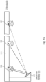
- Fig. 4 shows a well-known road paver, such as the one used in the EP 0 542 297 A1 is described.
- the road paver is designated as a whole by the reference numeral 1 and comprises a crawler chassis 2 with which the road paver 1 travels on the prepared subsurface 4.
- a height-adjustable screed 10 which is articulated on the road paver 1 by means of a traction arm 12 at a traction point 14 ZP.
- the height of the traction point 14 ZP is adjustable by means of the cylinder 14 (not shown).
- the screed 10 In front of the screed 10 there is a supply 3 of asphalt material, this supply being kept constant essentially over the entire width range of the screed 10 by appropriate, known control of the speed of a screw-like conveyor device 4.
- the screed 10 floats on the asphalt of the road surface 16 to be finished.
- the thickness of the road surface to be paved before its final compaction by road rollers is adjusted by regulating the height of the trailing edge 10k of the screed 10. This height adjustment is achieved by changing the angle of attack of the screed 10 and is typically carried out by controlling actuating cylinders that engage the front ends of the towing arms 12.
- the road paver comprises three ultrasonic sensors 5a, 5b, 5c, which are attached to a bracket 5h.
- the bracket 5h is attached to the towing arm 12.
- the three ultrasonic sensors 5a, 5b, 5c serve to scan a reference surface, which can be formed, for example, by an already paved or old road surface.
- the distance to the subsoil or to a reference is measured at one or more points.
- ultrasonic sensors have become established on the market for this purpose. These sensors are attached by means of booms, e.g., to a road paver's screed, a road paver's drawbar, and/or a road paver's chassis. In some applications, a so-called sonic ski is used, which combines several parallel measuring heads into one distance sensor.
- a plurality of distance sensors such as ultrasonic measuring heads or sensors based on a different measuring principle such as lasers, are attached to the towing arm via a common rod.
- the rod extends in the direction of travel roughly along the length of the machine or even beyond it and is arranged so that a distance to the subsoil can be measured at two, three or more measuring points along this rod or direction of travel.
- one sensor can be aligned to the applied layer, while another sensor is aligned to the subsoil for the layer to be applied.
- two or more sensor heads are provided, with one sensor head arranged in front of the screed and one sensor head behind the screed.
- This so-called Big Sonic Ski (or Big Ski) application has a number of advantages, such as the ability to suppress or average out systematic measurement errors, e.g., caused by stones in the ground.
- a disadvantage of this so-called Big Sonic Ski is the considerable installation effort required for the rods and individual sensor heads. Given that such measurement systems are dismantled overnight to prevent possible theft, this installation effort is not negligible in daily workflows. Therefore, there is a need for an improved approach.
- the object of the present invention is to create a concept that enables measurement at at least two positions relative to the ground, whereby overall an improved compromise between installation effort, measuring range (in the sense of a large distance between the individual measuring points) and reliability.
- the measuring system comprises a support that can be connected to the construction machine (or a component, such as the screed or the towing arm of the construction machine), e.g., such that the support extends along a subsurface.
- the support can extend laterally along a longitudinal axis of the construction machine.
- the support comprises at least a first section, wherein the first section has a plurality of sensor heads attached to or integrated into the first section for contactless measurement relative to a subsurface or, in general, a reference. These are, for example, aligned parallel, i.e., have a scanning range that extends parallel or substantially parallel.
- the first section has a second connecting element on a second end face, wherein the second connecting element can be connected to a first connecting element in such a way that both a mechanical and an electrical connection is formed.
- the first and/or second connecting element has a hook, so that the first connecting element and the second connecting element can be brought into engagement by a rotational movement about a rotation axis in order to form the mechanical connection.
- the first connecting element (generally: one of the two connecting elements) has a plug, wherein the second connecting element (generally: the other of the two connecting elements) then has a socket.
- the plug and socket together form the electrical connection; here, the plug and/or socket are designed to be tilted, and/or wherein the plug and/or the socket have at least partially a conical shape.
- the plug and/or the socket extends substantially along a longitudinal direction of the first and/or second portion.
- Embodiments of the present invention are based on the finding that by using plug-in connections which, for example, are adapted in terms of their flexibility or geometry to the movement of the first and second carriers when they are joined together, the mechanical and electrical connection can be formed both securely and efficiently.
- One variant here is to mount the plug and/or the socket flexibly or freely suspended. If, for example, it is assumed that the connecting elements with the hooks execute a rotational movement, the joining direction of the plug and socket runs tangentially on a radius around the axis of rotation of the rotational movement with which the two connecting elements are brought into engagement.
- the flexible mounting or rotatable mounting makes it possible for the orientation of the plug and/or socket to vary during the rotational movement, so that the plug and socket do not tilt or jam due to the curved joining path.
- the plug and socket when they are joined, they align themselves in such a way that the joining can also take place along a rotational path.
- This alignment is achieved through the degrees of freedom of the plug and/or socket.
- the geometry of the plug and/or socket can be adapted accordingly so that jamming does not occur when the plug and socket are joined along a joining direction running on a circular path.
- the plug and/or socket it would be conceivable for the plug and/or socket to be conical or at least partially conical. This results in centering and sliding of the plug and/or socket.
- the plug can be conical in the front area, resulting in a type of chamfering.
- the conical shape, with or without the flexible bearing, can advantageously ensure that the plug and socket are electrically connected to one another when the mechanical connection is made along a rotational axis.
- the plug can, for example, have a conical tip or a tapered tip or even a chamfer.
- the conical shape can also be present only partially, i.e., it does not necessarily have to extend along the entire circumference of the, for example, round plug and/or over the entire length.
- the socket has a conical opening. This means that it widens in diameter towards the opening, for example.
- the plug and/or socket is rotatable about one or more rotational axes (e.g., a plug rotational axis or a socket rotational axis) to form the flexible mounting.
- the rotational axes can run parallel to the rotational axis around which the mechanical hooking occurs.
- poles or magnetic poles respectively, through which the electrical connection is established.
- the use of a plurality of poles ensures that both an electrical connection and a data connection are possible.
- only an electrical connection is established in the sense of power supply or only a data connection in the sense of data communication.
- the hook of the first and/or the second connecting element or the hooks of the first and/or the second connecting element have an engagement surface which is substantially perpendicular to the longitudinal direction of the respective section is open.
- the rotary movement is defined by an end stop, which requires contact between the first and second end faces.
- the measuring system comprises a fastening element.
- This fastening element can be connected to the construction machine or a component of the construction machine and, for this purpose, has a first and/or a second connecting element. This can be done, for example, in such a way that the first section can be connected to the construction machine or the component of the construction machine.
- the first and/or the second section can have sensor heads aligned perpendicular to the longitudinal axis of the first and second sections on one long side.
- the sensor heads are directed towards the substrate (in the installed state), i.e., the sensor heads are aligned towards the layer already applied or towards the substrate for the layer to be applied.
- the sensor heads are attached or integrated, with a plurality, i.e., at least three sensor heads, being attached/integrated per section. The higher the number or density of sensors, the better unevenness of a specific wavelength, e.g., 5 m, is compensated for.
- the measuring system can have at least one first further sensor head for each first and/or second section or each carrier, which is aligned parallel to the longitudinal axis and/or which is arranged on the first and/or second end face; and/or wherein the first further sensor head is designed to carry out a reference measurement.
- the measuring system can have a second sensor head for each first and/or second section, which is arranged along the longitudinal axis of the respective first and/or second section or of the carrier and is located on the opposite end face to the first further sensor head.
- the measuring system can have a reflector (e.g. parallel to the longitudinal axis) or an inclined reflector (e.g.
- the measuring system can also be integrated/formed in the receptacle of one and/or more sensor heads.
- the measuring system it would also be conceivable for the measuring system to have at least one additional sensor head per first and/or second section or per carrier, which is aligned parallel to the longitudinal axis and/or which is arranged on the first and/or second end face;
- the additional sensor head is designed to determine a distance to an object that performs a relative movement to the construction machine or a component of the construction machine.
- Another embodiment relates to a carrier comprising a first section of the carrier.
- the first section has a second connecting element on a second end face, wherein the second connecting element can be connected to a first connecting element in such a way that a mechanical and electrical connection is formed.
- the first and/or second connecting element has a hook, so that the first connecting element and the second connecting element can be brought into engagement by a rotational movement about a rotation axis in order to form the mechanical connection.
- the first connecting element has a plug and the second connecting element has a socket, wherein the plug and the socket together form the electrical connection.
- the plug and/or socket are designed to be tilted. Additionally or alternatively, the plug and/or the socket have at least a partially conical shape.
- a further embodiment relates to a construction machine, such as a road construction machine with a measuring system as explained above.
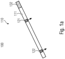
- a sensor arrangement 100 is explained with reference to an initial aspect.
- this comprises a carrier 110, which comprises at least one section 111. At least two sensors 121, 122 are integrated (generally fastened) in this section 111. These sensors are arranged at a distance from one another.
- the carrier 110 comprises a second connecting element 132, which can be connected to a first connecting element (not shown).
- the connecting element 132 as well as the first connecting element (not shown) are designed to form, firstly, a mechanical connection and, secondly, an electrical connection.
- An electrical connection is understood to mean, for example, a contact connection, a contactless connection, such as, for example, an inductive connection.
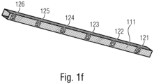
- the carrier 110 and thus also the section 111 can, for example, have a square shape (cf. carrier section 111 from Fig. 1f ). As can be seen in particular from Fig. 1f As can be seen, the integrated sensor elements 121, 122 ff. are integrated into the carrier and are all aligned in the same direction.
- all sensor heads 121, 122 et seq. are oriented toward the ground. In other words, this means that they have a scanning range that extends perpendicular to the longitudinal axis of the support 110 or section 111.
- sensor heads 121 and 122 can be transported together with section 111.
- Section 111 of the support can be connected via interface 132 either to a mounting device on the construction machine or to another section, as in Fig. 1b is shown.
- Fig. 1b shows a carrier 110' with a section 111 and a section 112.
- Each section comprises embedded sensor heads 121 and 122.
- the connection between the two sections 111 and 112 is made via the connecting elements 131 and 132, which are compatible with each other and are each arranged on the front side.
- each section 111 and 112 may also have further connecting elements 131 and 132 on the respective opposite end faces.
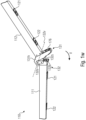
- the carrier 110 may, for example, consist of a section 111 or of a plurality of sections 111 and 112. The following are described with reference to Fig. 1c and 1d different installation situations are explained.
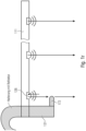
- Fig. 1c shows section 111, which here includes connecting element 131.
- Connecting element 131 is connected to a connector 135, which has connecting element 132.
- Connector 135 is coupled to the machine.
- connector 135 extends in an S-shape below the footboard 10t of screed 10, longitudinally rearward in the direction of travel.
- Sensor heads 121 and 122 are shown as examples. As can be seen, they are oriented such that the subsurface 16', or here the applied material layer 16', is scanned.
- the section 111 can be one or two meters long, or generally in the range of 50 to 300 cm.
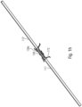
- a cascading of the carrier 110 by connecting two sections 111 and 112 is possible. Fig. 1d shown.
- Fig. 1d shows a section 111 that is connected in alignment with a section 112.
- the two sections 111 and 112 together form the support 110 of the sensor arrangement.
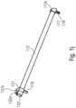
- the sensor arrangement 110 is connected to the screed 10 via a connector 135', so that the sensor arrangement 110 extends from the screed to the rear approximately in the direction of travel.
- a longer area can be scanned, optimizing handling, particularly during assembly and disassembly. This is achieved by the fact that the sections 111 and 112 are separable from one another and can thus be stowed individually.
- the connecting elements 131 and 132 are designed in such a way that, in addition to the mechanical connection, an electrical connection is also formed. Therefore, no additional wiring is required to contact section 112, which significantly reduces the assembly effort.
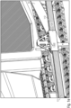
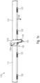
- Fig. 1d shows a further exemplary installation situation on the pulling arm 12.
- a further holder 135' is arranged, which has both a first connecting element 131 and a second connecting element 132.
- the sensor arrangement 110' in turn comprises two sections 111 and 112, wherein both the section 111 is connected via its connecting element 132 to the connector 135' and the section 112 is connected to its connecting element 131.
- the element 135' which is firmly connected to the machine or the pulling arm 12 of the machine, lies between the two sections 111 and 112 of the carrier. Both sections are, as in the sensor arrangement 110 of Fig. 1d oriented in the same way, so that the substrate or the applied layer is scanned.
- This example has shown that not only cascading as in arrangement 110 through series connection is possible, but also cascading by connecting them together with a common connector 135'.
- This cascading also makes it possible for the measuring system to have a third section, which is arranged in series, for example.
- this example has shown that different mounting positions are possible, e.g., on the screed 10 itself or on the tension arm 12. It is important that the element 135' is permanently connected to the screed 10 or the tension arm 12. Screw connections, welded connections, or other connections are suitable for this. For example, this element 135' can remain directly connected to the machine, while the technology-bearing sensor elements/sections 111 and 112 are dismantled at night.
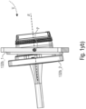
- the element 135' of the sensor arrangement 110' is in Fig. 1e shown.
- Fig. 1e shows the element 135', in which the section 111 is connected on the first side and the section 112 on the second side.
- the connecting element 135 is shaped as a type of sleeve, the cross-sectional shape of which corresponds to the cross-section of the profiles 111 and 112 (rectangular here, alternatively another e.g. round cross-section), wherein the dimensions, in particular the internal dimensions of the sleeve of the element 135' are formed such that the elements 111 and 112 can be inserted.
- the elements 111 and 112 can be fixed by means of the screws 135s' shown here.
- the electrical connection is not shown.
- the sections 111 and 112 extend substantially in alignment in both the sensor arrangement 110 and the sensor arrangement 110', so that all sensors 121 and 122 have a substantially parallel scanning lobe.
- the section 111 can have a plurality of sensor heads 121 and 122, such as six sensor heads here. These are marked with the reference numerals 121 to 126.
- the arrangement can be equidistant, although another arrangement is also useful, as described below with reference to Fig. 1m The number may also vary accordingly (see explanations in connection with Fig. 1k and 1l ).
- the sensor heads 121 to 126 are embedded on one side of the rectangular profile, as shown in Fig. 1f and in Fig. 1g is shown.
- Fig. 1g represents an exemplary profile measuring 60 x 80 mm, with a sensor head 126 embedded on the narrower side 60. This can be clicked in or screwed in, for example.
- the sensor head 126 is approximately flush, i.e., +/- 3 mm, +/- 10 mm, or +/- 20 mm, with the surface of the profile.
- the sensor head is an ultrasonic sensor, although other sensor technologies, such as laser or capacitive sensors, can also be used. Different measurement principles can also be used for the different sensor heads for each section 111 or each sensor arrangement 110.
- Fig. 1h shows the two sections 111 and 112, which are connected to each other by a connector 138.
- the sections 111 and 112 are simple profiles that are inserted into the connector 138 and connected on each side by means of the eccentric 138e.
- the profiles have the connecting elements 131 and 132 on the corresponding end faces, at which the connection to the connector 138 is made, whereby the connector 138 has the corresponding counterparts to form not only the mechanical but also the electrical connection.
- the electrical connector can be realized, for example, by a plug integrated into the connector 138, which is closed in the longitudinal direction of the sections 111 and 112.
- FIG. 1i Another example of a slide-in connector is in Fig. 1i shown.
- a modified connecting element 138' with the eccentric 138e is shown, into which the section 111 is inserted.
- the connecting element 138' can, for example, belong to the further section of the carrier or be firmly connected to the machine.
- a screw connection with a knurled screw instead of the eccentric 138e a screw connection with a knurled screw, as in Fig. 1e shown.
- profile 111 or 112 is inserted and secured by another means, such as an eccentric or a screw.
- a type of quick-release fastener, as is common on bicycles, or a bayonet lock would also be possible.
- section 111 can, for example, be designed with a closure cap 111v on one end face.
- Fig. 1j represents another connection concept.
- section 112 has a type of hook 131h' as connecting element 131', so that the hook can be connected to an engagement section of connecting element 132'.
- the engagement section of element 132' is provided with the reference numeral 132e'.
- Element 112 in turn, has a cap on the opposite end face.
- the cap is designated by reference numeral 112v.
- Fig. 1w and 1x represent a carrier 110 with two sections 111 and 112.
- the two sections can be connected to each other via connecting elements.
- These are provided with the reference numerals 131 and 132.
- the first connecting element 131 has a hook 131h, which engages in an engagement section 132h, e.g. a raised portion 132e. This intervention is in Fig. 1w
- Each of these engagement areas 131 and 132 has a front surface on the front side, which serves as a kind of stop, so that after hooking in the elements 111 and 112 are connected to each other, as in Fig. 1x is shown.
- the end faces of the connecting elements 131 and 132 rest on one another, forming a stop for the joining movement V about the rotation axis 132r. If, for example, the hook 131h of the sensor bar 112 is first hooked into the holder 132e, the sensor bar 112 can then be fastened/joined by a downward movement or rotational movement V.
- each connecting element 131 and 132 has matching electrical connecting elements. These are designed here as a type of plug-socket pair.
- the plug is designated by reference numeral 132s, and the socket by reference numeral 132b.
- Plug 132s can be arranged either on the hook side 131h or on the engagement section side 132e.
- the socket is provided either on the engagement section 132e side or on the hook side 131h.
- Both plug and socket are provided, for example, on the respective end faces of the connecting elements 131 and 132 and are aligned such that they open in the longitudinal direction or substantially in the longitudinal direction. This means that plug 132s protrudes from the end face in the longitudinal direction, while socket 132b protrudes from the end face in the longitudinal direction into element 111.
- these are arranged in such a way that during the joining movement V around the rotation axis 132r, the two extension directions of plug and socket 132s and 132b are aligned with each other or flush, so that a good joining of the two elements 132s and 132b is possible.
- the plug socket 132B* e.g. can be used as socket 132b (cf. Fig. 1w ), flexible, in this case rotatable around the rotation axis P.
- the counterpart 132s* from Fig. 1z e.g. usable as plug 132s (cf. Fig. 1w ) can, but does not necessarily have to, be flexible. Because part of the connector, in this case the 132B* socket, is flexibly mounted or freely suspended, it can tilt during assembly (see Fig. 1yb )), so that an electrical connection is established even with a translational movement path of the connector socket 132B* and the connector housing 132S*.
- the tilting of an element 132b_2 of the plug socket 132B* takes place around the point P, specifically relative to a fixedly mountable element 132b_1.
- the connector housing 132s_1 can also be made of Fig. 1z have a conical shape 132s_1m inside to accommodate the socket 132b*.
- the combination of the conical shape and the flexible mounting of the plug socket 132B* allows the plug 132s and the socket 132b* to mechanically come together during the rotational movement of the sensor bar 111, creating a secure electrical connection when plugged in. This is referred to as a self-centering plug connection.
- the plug 132S* and the socket 132B* contain contacts 132s_1k for power and/or data transmission.
- the reference numerals 132b_ak (cf. Fig. 1ya )) and 132s_ak (cf. Fig. 1z ) each denotes a connection
- the reference numeral 132s_1b denotes a housing fastening.
- a magnet (not shown) can be provided inside the connector. This keeps the connector closed in the plugged-in state without the need for a mechanical locking mechanism, e.g., a bayonet lock. This ensures a secure mechanical and thus also electrical connection, for example, in the event of vibrations or other external forces (such as shocks, impacts, etc.). If the sensor bar 112 is released/unhooked from the sensor bar 111, the connector automatically releases.
- a mechanical locking mechanism e.g., a bayonet lock.
- the hooked sensor bar 112 by means of a mechanical lock on the sensor bar 111 (for example, by means of a bracket).
- Mechanical coding of plug 132s* and socket 132b* is not absolutely necessary according to further embodiments, since the sensor bar 112 can only be attached in one direction.
- connection options are also conceivable.
- the respective connecting element could also have guides extending orthogonally to the longitudinal direction, forming a type of dovetail joint.
- the electrical connection can also be made wirelessly.
- Wireless data and/or power transmission can be considered an alternative to the plug/socket system.
- an energy transmitter e.g., an induction loop, is provided on the side of the engagement area 131 and on the side of the engagement area 132.
- the connecting elements 131 and 132 can have contactless energy transmission elements via which both an energy supply to the sensor heads and a data transmission between the sensor heads and a computer unit takes place.
- the energy transmission element may comprise an induction loop or induction coil or be configured to inductively transmit electrical energy. According to embodiments, the energy transmission element may further be configured to exchange data with the energy receiving device of the sensor along with the electrical energy.
- Embodiments provide a receiving device comprising a plurality of mechanical pickups, each with a plurality of energy transmission elements for a plurality of supports 110 / sections 111 and 112.
- a cabling can be provided, via which the energy transmission element is supplied with electrical energy. is supplied by the construction machine.
- the energy receiving element is designed to receive at least 5 W or 10 W of electrical energy and to provide at least 5 W or 10 W of electrical energy to a sensor element or an electrical circuit.
- the energy receiving element has, for example, an induction loop or induction coil or is designed to inductively receive electrical energy.
- the energy receiving element can also be designed to exchange data.
- Further embodiments relate to a receiving device for a construction machine.
- the receiving device comprises a mechanical pickup for receiving a display and an energy transmission element which is designed to wirelessly or contactlessly transmit electrical energy to an energy receiving element of the display in order to supply energy to the display.
- each section may comprise a plurality of sensor elements 121 ff.
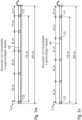
- Fig. 1k It is assumed that section 100 has a length of 2 m (200 cm) and that the sensor heads 121-126 (here, six sensor heads) are evenly distributed. This results in a distance of 33 cm between the sensor heads, with 33/2 cm being provided from the front side to the first sensor head 121 or to the last sensor head 126.
- Fig. 1l shows a section 100 with a length of 2 m (200 cm), with five sensor heads 121-125. The spacing is again equidistant, resulting in a distance of 40 cm between the sensor heads and 20 cm from the front to the first or last sensor head 121/125.
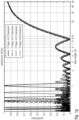
- Fig. 1o shows a comparison between a classic Big Sonic Ski (Big Ski for short) with a 12 m extension using three, four, and five sensors.
- the Big Sonic Ski with three sensors has problems in the 6 m range
- the Big Sonic Ski with four sensors has problems in the 4 m range
- the Big Sonic Ski with five sensors has problems in the 3 m range.
- the Big Sonic Ski with three sensors also has the same problems. By increasing the sensor density, these high-frequency problems (compared to vibrations) can be reduced in the range of 20 m and beyond.
- the improvement through the use of the Fig. 1 described (and according to the invention) sensor arrangement is shown in Fig. 1p This example assumes an 8 m long beam with three to six sensors. As the number of sensors increases, the control gaps become more frequent, but this is less critical given the lower probability of high-frequency interference.
- a non-equidistant sensor pattern can be used per section, as shown in further examples. Examples are shown for a distance of five sensor heads 121-125 in Fig. 1m Here, the distance between the front face and the first sensor 121 increases from 20 cm. The distances are, for example, 32, 40, 46, and 58, as well as 4 cm.
- Fig. 1n shows another illustration, where equidistant sensors with a spacing of 44 cm are used again, but the distance between the front end and the first sensor 121 is selected such that an equidistance is maintained across two sections.
- the section between the front end and the first sensor is selected such that half the distance between the further sensor, or in particular, sensors 121 and 122, is present.
- Fig. 1q shows a section 111 with sensor heads 121 ff.
- One or each sensor head has a bracket 171 arranged at a defined distance in front of the sensor 121.
- This bracket 171 is located at least partially within the entire measuring field and can be folded in or rigid, as shown in examples.
- the bracket 171 reflects the measurement signal, as shown here by the dashed line.
- Fig. 1s shows a further variant, wherein a further reflector 173 is provided in a laterally arranged bracket, which extends approximately perpendicular to the longitudinal extent of section 111.
- This reflector 173 is again arranged at a distance from the sensor 126, but serves not only as a reference for the nearest sensor 126, but also for the adjacent sensors 125, ... 121.
- the reflector 173 can be arranged at an angle, e.g., 45° with respect to the measuring direction of the individual sensor heads 121 to 126.
- the reflector surface 173 can be curved in order to serve as a reflector for all channels 121 to 126.
- the bracket connecting the reflector 173 to the section 111 can either be attached directly to the section 111 or can be integrated into the connecting element, as for example in connection with Fig. 1r is shown.
- Fig. 1t is essentially comparable to the example from Fig. 1s , where the reflector 174 has an active mirror which aligns itself depending on which channel (sensor head) is to be calibrated.
- the active reflector 174 is designed as an active transmitting unit, which then directs an ultrasonic signal to the receivers 121 to 126.
- an ultrasonic sensor 176 is used for reference measurement by means of a bracket 175 arranged below the sensor heads 121 to 126. Below here means between the support/section 111 and the road surface.
- the ultrasonic sensor 176 is arranged parallel to the support/section 111 and can be arranged, for example, by means of an additional reflector 177 on the other end face or between the end faces, for example in the middle (see dashed element 177').
- the active transmitter 176 which is arranged on the bracket 175, can cooperate with an active receiver 178, which is arranged on a bracket 175 on the other end.
- the reference measurement is taken in the area of ultrasonic sensors 121 to 126. This has the advantage that the same ambient conditions, e.g., ambient temperature and infrared radiation, prevail here.
- Fig. 1i The measuring principle shown with active transmitter 176 and active receiver 178 is shown in Fig. 1i
- an active transmitter 176 is integrated into the element 138', while the receiver 178 is integrated into the closure cap 111v.
- a reflector 177 instead of the receiver 178.
- Fig. 1j A similar variant is shown in Fig. 1j shown.
- the transmitter 176 is integrated into the element 131', while the receiver or reflector 177 and 178 is integrated into the closure cap 112v.
- 176 with 177/178 in the examples from Fig. 1i and 1 year has been exchanged.
- measurements of the sensor heads are carried out essentially simultaneously (synchronous measurement within a time window, e.g., within a time window of 3s, 1s, 0.5s, 0.1s or less).
- a simultaneous measurement in principle, a snapshot of, for example, the substrate or reference profile (the already applied layer or the substrate for the layer to be applied) and the reference measurement(s) is taken under the same Conditions (e.g., environmental conditions such as ambient temperature) are created.
- Conditions e.g., environmental conditions such as ambient temperature
- a correct reference profile or correct subsurface profile is recorded by all sensor heads in all sections and all supports of the measuring system.
- Essentially simultaneous measurement is also advantageous with regard to a high measurement rate (sampling rate), as is required today for leveling in road construction (e.g., height leveling of the screed).
- Fig. 1g Another feature is explained.
- Fig. 1g An LED 181 is also displayed on one end face. This can indicate, for example, by color coding or flashing, whether the electrical connections between the sections or from the section to the machine are correct. Furthermore, information such as necessary readjustments can also be displayed. Furthermore, it would also be conceivable that the LED, if it is, for example, on the ending end face at Fig. 1d the measuring arrangement 110, provides a signal regarding the distance to a vehicle traveling behind it, such as a roller.
- a further distance sensor can be aligned in the other direction on the front side, similar to the distance sensor for reference measurement 176, which then measures the distance to a following vehicle.
- a complex display such as an LCD display can be provided to display, for example, text and/or symbols.
- the following describes a measuring system 200 that uses a regression line to determine the position.
- the sensor head 221 is arranged closer to the screed edge 10k, which represents a pivot point 10 of the screed, than sensor 223.
- the sensor head 222 is located in the middle or in between.
- A the distance to the perpendicular base point on the screed edge 10k
- B the distance from the perpendicular base point of the screed edge 10k to the sensor 223.
- the screed 10 can also have another pivot point, e.g., in front of the screed rear edge 10k (especially when it rests on hot asphalt), as an alternative to the pivot point around the screed rear edge 10k.
- the distances to the pivot point are taken into account accordingly.
- the sensors 221, 222 and 223 are arranged substantially parallel and measure a distance from the carrier 110 to the substrate, here the applied layer 16'.
- distance H1 is greater than distance H3.
- the sensor values can be recorded, for example, in a two-dimensional space, here height versus distance. Based on the sensor values, it can be seen that the regression line RG also runs according to angle ⁇ .
- the regression line RG when located in two-dimensional space, can be determined in such a way that angle ⁇ can be calculated. By determining angle ⁇ , the position of component 10 relative to the ground is also known.
- the position ⁇ does not necessarily have to be an absolute position, but can in particular be a relative position to the ground.
- the values H1 and H3 also change, although, assuming a parallel displacement, the angle ⁇ remains constant. Therefore, if slight fluctuations in the values occur, for example due to vibrations, these values can be plotted in the common space and a regression line RG determined. This represents an average. Using more than three sensors results in averaging if all sensors are arranged exactly on the carrier 210.
- the determination of the regression line RG for a point cloud is explained.
- This example assumes that more than two sensors are planned.
- the sensor array from aspect 1 can be used.
- the deviations, as shown here using the height points H1 to Hn, can arise, for example, from unevenness in the ground.
- the height values essentially increase from a to n, so that this can be inserted into the regression line RG here.
- the regression line RG is inserted in such a way that the distance between the regression line RG, represented here by small arrows, and the measurement points is minimal overall.
- the regression line is angled relative to the distance axis, e.g., by the angle ⁇ . This position can be determined and provides an indication of the angle of the component.
- the roll angle of the screed around its longitudinal axis can be determined. If, in addition to the longitudinal component, a transverse component is also present, a combination of the roll angle and the transverse inclination angle is determined. Knowing the transverse component to the longitudinal component, these two angles can be separated.
- the transverse component can, for example, be determined using the support from Fig. 2a with the sensors 221, 222 and 223 when it is arranged in the longitudinal direction of the screed (ie transverse to the direction of travel of the machine).
- the support runs without an angular offset relative to the component.
- An offset can also be taken into account.
- a calibration can be performed at the beginning or a comparison can be made with an optional angle sensor, such as an inclination sensor.
- the plank could also be attached to the tension arm, for example.
- An example of such an attachment is explained in aspect 1, since here a beam comprising a plurality of sections is attached. This beam has a plurality of integrated sensors, which then an averaging regression line according to the execution from Fig. 2b corresponds.
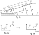
- Fig. 2c shows the use of the sensors 221 and 223 by means of the carrier 210 and the use of another carrier 215 which houses the sensors 225 and 227.
- the sensor array 210 is as in Fig. 2a arranged behind the screed, while the sensor array 215 is arranged in front of the screed. A reversed arrangement would, of course, also be conceivable. It is assumed that both extend in the longitudinal direction.
- the resulting sensor values H1, H3, H4 and H6 are in two-dimensional space in Fig. 2d
- both regression lines RG1 and RG2 are tilted around the pivot point of the plank, namely the rear edge 10k of the plank, the regression lines are mapped to the corresponding RG1' and RG2', as shown in Fig. 2e
- the center distance in Fig. 2e runs parallel to the background or to the reference against which the measurement is made.
- the tilted regression lines RG1' and RG2' are no longer as in Fig. 2d They are not aligned with each other, but have an offset V.
- This offset V results from the fact that the array 210, associated with the regression line RG1, measures the layer 16' to be applied, while the sensor array 215 measures the substrate 17. This offset is therefore dependent on the layer thickness of the layer 16' to be applied. Conversely, this means that the layer thickness can be determined, i.e., calculated, using this approach.
- the distances A, B, C and D between the respective sensor 221, 223, 225 and 227 to the plumb line base point on the plank edge 10k are used during the rotation to perform the rotation.
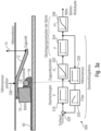
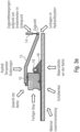
- Fig. 3a shows a conventional control loop 300 (flatness control loop) used for leveling the screed 10, which is pulled by the towing arm 12.
- the towing arm 12 is fixedly connected to the screed 10, or at least during operation.
- the screed is towed by a tractor (not shown), for which purpose the towing arm 12 is connected to the tractor via the towing point.
- the towing point is typically adjustable in height, as illustrated here by arrow 14. This height adjustment is controlled by the flatness control loop 300.
- the screed smooths the asphalt or the material for the layer 16' to be applied, which is provided by the auger 18 in front of the screed (see material 16).
- the flatness control loop 300 includes a flatness controller 310, which controls the traction point cylinder (see reference numeral 14) based on a target/actual comparison 320. The result is a changed height, which is detected by the height sensor 330. The height sensor signal from the height sensor 330 is then fed to the target/actual comparison 320.
- a filter 335 can also be provided. This filter is designed either as a low-pass filter, a low-pass filter with a low/increased cutoff frequency, a band-pass filter, or a high-pass filter, depending on how the transmission behavior is to be corrected. Other frequency filters, such as Chebyshev filters or similar, are also conceivable in this context.
- the transmission behavior of the traction cylinder can be described using an IT 1 control loop (see block 342).
- the transmission behavior of the screed can be described as follows: in the sensor position, it is represented by a P behavior (see 344).
- the screed itself can be represented by a PT 2 element (see 346).
- Fig. 3b illustrates the thus interpreted transmission behavior of the controlled system from the trailing edge of the screed to the cylinder.
- Fig. 3b again shows the screed 10, which is pulled or adjusted in height via the pulling arm 12 at the pulling point 14 ZP by means of the pulling point cylinder 14.
- the basic idea behind optimizing the height leveling of screed 10 is the targeted monitoring of the paver screed, and in particular the trailing edge, using an additional control loop or the implementation of a control loop overlay to the existing height leveling.
- the control loop for normal height leveling acts as a subordinate control loop. This new control loop structure can be applied to all leveling tasks and will be discussed in detail below.
- control loop 350 shown here comprises two individual control loops 360 and 370.
- the control loop 360 is referred to as the first control loop or superimposed control loop.
- the control loop 370 is referred to as the second control loop.
- the control loop 370 is comparable to the control loop 300 as it is in relation to Fig. 3a explained, whereby the sensor 330 is positioned differently (see reference numeral 331).
- the sensor 331 is in the area of the pulling point 14 ZP and no longer in the area of the screw 18 (see arrangement Fig. 3b ).
- control loop 370 corresponds to control loop 300, i.e., it includes comparison 320, evenness controller 310, and optional filter 335.
- control loop 370 A significant difference, based on the positioning of the height sensor, is that in control loop 370, the transmission behavior of screed 344 no longer needs to be taken into account, but only the transmission behavior of the traction point cylinder (see reference numeral 342).
- the behavior of the screed, described by PT 2 (see reference numeral 346), is also taken into account by control loop 360.
- the control loop 360 also includes a height sensor 362 and an optional filter 364.
- the sensor 362 is arranged in the area of the screed 10 or, for example, in the area of the rear edge of the screed 10.
- the behavior of point 10k in response to a change in height at the traction point 14 ZP is relatively sluggish. This becomes quite clear when considering the arrangement of the screed 10, traction arm 12, and traction point 14 ZP, since the height cylinder 14 shifts the traction point 14 ZP around the pivot point 10k, so that a change in height only occurs gradually. This behavior is simulated by the Model Predictive Control 365.
- the input variable for the MPC 365 is the result of a target-actual comparison (see reference numeral 367), whereby the same signal from the sensor 362 is used as the actual signal.
- the result of the MPC is a target signal, which serves as the input for the comparison 320.
- control circuit 370 which is located in Fig. 3a is shown, extended by a control loop 360 superimposed on it, which is Fig. 3d
- This measure changes the structure of control loop 350 such that the disturbances acting on traction point 14 ZP and screed 10 can be compensated separately.
- the higher-level control loop compensates for the disturbances acting on screed 10, and the lower-level control loop 360 compensates for the disturbances that change the height of the traction point.
- the control system 350 structured in this way can be optimized separately, resulting in improved control behavior overall.
- a further optimization of the control loop structure results from shifting the sampling point of the height sensor for the subordinate flatness control loop 370 towards the pulling point 14 ZP.
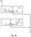
- Fig. 3d shows a control loop 350 composed of two control loops 370 and 360.
- Each control loop includes at least one sensor, which in the case of control loop 360 is the height sensor 362, while in the case of control loop 370 it is the pull point sensor 331.
- the sensors are arranged in the area of the pulling point (see sensor 331) and on the screed (see sensor 361).
- Each control loop also includes a corresponding processor, which outputs the control signal for the traction point cylinder based on the actual value from sensors 331 and 362 and a setpoint.
- the processors are labeled 379 and 369, respectively. According to examples, processors 369 and 379 can also be combined into a single processor, which then receives the actual signals from the two sensors 331 and 362 and processes them separately before outputting the combined control signal.
- the disturbances at the pulling point are compensated by the subordinate control loop 370 (evenness control loop)
- the disturbances of the screed 10 are compensated by the superimposed control loop 360. Due to the different transfer functions (see also Fig. 3b ) of the partial control system Werige (IT1) and the partial control system Bohle (PT2), the controllers used for this purpose are also structured and optimized differently.
- control deviations will be corrected extremely quickly, whereas the controller for the higher-level control loop 360 corrects control deviations more slowly and takes into account the knowledge of the influencing disturbances.
- An example of disturbances that influence the floating behavior of screed 10 is the effect of material temperature changes. If a temperature change in the material is already known before a temperature-dependent effect on the screed height occurs, the controller can avoid or reduce a height deviation of the screed based on a model.
- the model of screed 10 which describes the dependence of a height change on material temperature changes, must be known. This would also typically be an example of an MPC controller for the higher-level control loop 360.
- control loop structure 350 Different application cases of the control loop structure 350 are explained below.
- the single-head sonic sensor without a reference is suitable because the measurement distance to the existing asphalt surface at the trailing edge of the screed can be minimized. This significantly reduces the measurement error compared to larger distances. Minimizing the measurement distance is possible because the measurement distance to the ground is always approximately the same. In this application, the sensors focus as closely as possible on the ground.
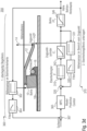
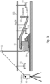
- the Fig. 3f shows the mounting area and thus also the possible and useful scanning positions to realize the control loop structure.
- Fig. 3f shows the road paver from above with the screed 10, the applied layer 16' or existing layer 16*, the auger 18 and the tractor 11.
- the screed is connected to the traction point 14 ZP via the traction arm 12.
- a so-called Big Sonic Ski (short: Big Ski, see aspect 1) 100 can be connected to the towing arm 14 or the screed 10 (not shown).
- the Big Sonic Ski has the sensor 361 located in the area of the screed's trailing edge 10k.
- the sensor 331 can also be arranged on the Big Sonic Ski 100 at the height of the towing point.
- the scanning of the trailing edge of the screed for the screed control loop and the scanning for the traction point control loop can also be carried out on the side of an existing asphalt track 16*.
- a Sonic Ski 331* is provided via a side plate 10s for scanning at the level of the traction point 14 ZP.
- a screed trailing edge sensor 361* is also provided on the side plate. As shown, the Sonic Ski 331* is slightly offset with its scanning area outside the subgrade to scan the existing asphalt track 16*.
- sensor 331* on the side of the existing asphalt track 16* serves the purpose of using the existing asphalt track as a reference.
- sensor 331* scans the distance to the existing asphalt track 16*.
- the purpose of scanning the existing asphalt track 16* with the traction point control loop is to directly compensate for disturbances (e.g., material under the tractor's crawler track) that affect the traction point.
- sensor 361* is preferably directed at the existing asphalt layer 16* and monitors the height of the screed in relation to the existing asphalt track 16*, compensating for deviations from the set target value of the superimposed control loop 360.
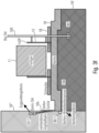
- Fig. 3g shows a road paver with a tractor 11, a screed 10, and a screed trailing edge 10k.
- the screed 10 is connected to the paver 11 via a towing arm 12.
- the Big Sonic Ski 100 with three sensors is provided on one of the towing arms 12.
- the sensors are marked with the reference numeral 110 for example; depending on the application, they can be evenly distributed along the Big Sonic Ski 100 or arranged in the area of the towing point 14 ZP or in the area of the screed trailing edge 10k.
- a sensor system can also be provided via the side plates 10s of the screed 10.
- a screed sensor 361* and a towing point sensor 331* can be provided. Both are directed towards a cable 16s in order to scan the cable 16s.
- the cable scanning at the trailing edge 10k of the plank can be carried out contactlessly with an ultrasonic sensor (sonic ski) or with a mechanical rotary encoder, as is usual in practice with the scanning methods currently used.
- the sensors 331*, 361* are guided over the reference cable 16s with a corresponding sensor mount 10k.
- the control deviation measured relative to the reference cable 16s at the trailing edge 10k of the plank also provides information about the installed evenness over the path.
- a second height sensor can be guided over the rope using an additional sensor mount.
- a Big Sonic-Ski system Big Ski for short
- a tension arm sensor See Fig. 3h .
- Fig. 3h shows the comparable structure as Fig. 3g of the road paver 11 with the screed 10.
- Sensor 361* is used as the screed sensor on the left side.
- the Big Sonic-Ski 100R is used as the towing point sensor on the left side. As previously explained, this is permanently connected to the towing arm 12 and has a plurality of sensors 110.
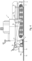
- Fig. 3i shows the screed 10 with the screed trailing edge 10k and the pulling arm 12, which is connected to the pulling cylinder 14 at the pulling point 14 ZP.
- a Big Sonic Ski 100 which is connected to the pulling arm 12, is also provided.
- the Big Sonic Ski 100 comprises three distance sensors 110, which, in this example, together determine the distance at the pulling point 14 ZP.
- the screed trailing edge 10k is monitored using a total station 50 and a reflector 52 attached to the screed. This sensor, consisting of the elements 50+52, is referred to as a 3D sensor.
- 3D leveling with a total station 50 consists of a prism 52, which is mounted on the paver 11 or the screed 10 so that it is visible to the total station 50. The total station 50 then determines the 3D position of the prism in space and transmits this information wirelessly to the 3D control system on the paver.
- a major disadvantage of 3D control is that the installed height level must be checked repeatedly. In practice, this task is performed by a surveyor who uses an additional total station 50 to check the installed height and, if necessary, makes manual adjustments. This is necessary because the installation location of the prism (a 3D point in space, precisely determined by the total station via the reflection of a laser beam) is not at the rear edge of the screed, but rather, as is usually the case with other height sensors, on the drawbar at the height of the screed auger. This means that over a certain period of time, a change in the height at the rear edge of the screed occurs, which the surveyor must then correct.
- the control of the built-in height measurement could be avoided by placing the height sensor (prism) on the screed's rear edge 10k.
- the sensor then functions as a height sensor for the screed and is thus used in the superimposed 360 control loop as a supplier of height information.
- a Big Sonic Ski system Big Ski for short, which provides the altitude value for the subordinate control loop 370.
- two total stations 50 are required for leveling (one total station for each side). This is necessary because in this configuration, the sampling rate of the 3D height measurement must be high in order to compensate for all influencing disturbances.
- the sampling rate can be reduced so that one total station is sufficient for both sides, which then continuously and successively determines the left prism 52l and the right prism 52r in the position at the rear edge 10k of the pile.
- Fig. 3k is now used instead of the left Big Sonic-Ski 100 L, which is Fig. 3j served as a traction point control, the traction point sensor is also implemented as a laser sensor.
- a laser transmitter 54 provides a height reference, which can be received via the receivers 56z at the traction point 14 ZP and 56b on the screed 10.
- the new 350 control loop structure can also be applied when using a laser plane as a height reference.
- a laser receiver is mounted on both the towing arm and the trailing edge of the screed, acting as a height sensor in both cases.
- the projected laser plane precisely represents the desired position of the road with a corresponding height offset.
- Fig. 3k shows the basic leveling setup with a laser height reference on the left.
- the right side is leveled with a Big Sonic Ski System 100.
- other measuring elements such as inclination sensors or Sonic Skis can also be used to level the screed.
- Model Predictive Control extends the control loop structure as follows.
- a further improvement for the control system is that the controller for the higher-level control loop, whose associated sensor is mounted near the trailing edge of the screed, takes the respective process state into account.
- Each state is assigned a control value, which is partly responsible for calculating the controller output.
- the process state is predetermined using a process model.
- the process model is the foundation of Model Predictive Control, where the model comprehensively captures the process dynamics and can thus calculate predictions of the future process state.
- the process model is necessary to calculate the predicted output variables in a future instance.
- the various MPC strategies can use numerous models to demonstrate the relationship between the output variables and the measurable input variables.
- Comparison variants are based on the fact that the use of attached/integrated sensor heads in a support that is divided into one or more sections can significantly reduce assembly effort. Because the connecting elements form a mechanical and electrical connection simultaneously, no cabling is necessary. According to comparison examples, the connection between the section and the construction machine can also be established via a corresponding connecting element. For example, the first section can be connected to the construction machine (which has a corresponding second section as a counterpart) using its first connecting element. Here, too, an electrical connection can be formed in addition to the mechanical connection. According to comparison examples, the measuring system can be extended by additional sections with attached/integrated sensor heads in order to scan a large area simultaneously.
- a type of hook connection can be used.
- the first and/or the second connecting element can have a hook, so that the first connecting element and the second connecting element can be engaged by a rotary movement.
- the hook of the first or the second connecting element or the hooks of the first and the second connecting element can have an engagement surface that is open substantially perpendicular to the longitudinal direction of the respective section.
- the rotary movement is defined by an end stop that requires contact between the first and the second end side or end surface.
- the first and/or the second connecting element can have an electrical coupler that extends substantially along the longitudinal direction of the respective section.
- a shearing movement of the two sections or of one section relative to a further connecting element can also form the connection.
- the first and/or the second connecting element can comprise a profile extending substantially perpendicular to the longitudinal direction of the respective section and having an end stop, so that the two connecting elements can be connected by a translational movement substantially perpendicular to the longitudinal direction of the respective section.
- the first connecting element has a lever mechanism, e.g., with an eccentric, in order to translationally fix the first connecting element to the second connecting element.
- the first and/or the second connecting element can each have an electrical coupler extending substantially perpendicular to the longitudinal direction of the respective section.
- the first connecting element can have a sleeve that extends essentially in the longitudinal direction of the respective section and wherein the two connecting elements can be connected by inserting the second connecting element into the sleeve.
- the first and/or the second connecting element can have a respective electrical coupler that extends substantially longitudinally to the longitudinal direction of the respective section.
- the measuring principles of the sensor heads can vary, i.e., the sensor heads can be designed as ultrasonic sensors, laser sensors, radar sensors, or the like.
- the sensor heads are spaced apart from one another, e.g., 10 cm, 20 cm, 33 cm, 40 cm, or generally in the range of 5 cm to 50 cm or 2 cm to 100 cm.
- the spacing can be adjusted accordingly depending on the measuring principle of the sensor heads.
- the spacing can, for example, be selected so that there is an even distribution across the respective section or across the carrier.
- the distance from sensor/sensor head to sensor/sensor head can change, for example, increase. This is advantageous for compensating for unevenness in the layer to be applied with certain frequencies/wavelengths.
- measurements by the sensor heads are carried out essentially simultaneously, i.e., for example, within a time window of 3 s, 1 s, 0.5 s, 0.1 s, or less.
- Distance measurements to the substrate (reference, to the layer already applied or to the substrate for the layer to be applied) and/or to the object, and/or as reference measurement(s) are carried out essentially simultaneously (synchronous measurement within a time window, as stated above). This means that it is possible for all sensor heads arranged in the measuring system to carry out measurements essentially simultaneously. This is advantageous with regard to the measurement accuracy of the measuring system, since simultaneous measurement essentially creates a snapshot of, for example, the substrate or reference profile and the reference measurement(s) under the same conditions (e.g., environmental conditions).
- asynchronous measurement In contrast to an asynchronous measurement (not simultaneous, for example, one carried out one after the other), changes in distances or external conditions, for example caused by mechanical vibrations (oscillations) of the machine or tool or machine parts or caused by temperature fluctuations, are not relevant in a measurement that is carried out essentially simultaneously, since at the moment of the (simultaneous) measurements, for example, the subsurface or reference profile is recorded by the measuring system with the same distance and reference measurement(s) are also carried out under the same conditions.
- a correct reference profile or correct profile of the subsurface is recorded by all sensor heads in all sections and all supports of the measuring system.
- a Simultaneous measurement is advantageous in terms of a high measuring rate (sampling rate), as is required today for leveling in road construction (for example, height leveling of the screed).
- the first and/or second section has a display, such as an LED or LED indicator.
- the display or LED indicator is configured to indicate a connection status between the first and second or each additional section or to display information, e.g., regarding a deviation, of the measuring system or a control and/or regulation system connected to the measuring system.
- An LCD display or the like is also conceivable as a display, on which, for example, text and/or symbols are displayed.
- the measurement system may include a GNSS sensor, an inclination sensor, an infrared sensor, a temperature sensor, an attitude sensor (inertial measurement unit), or another sensor. Also, according to examples, each section may include lighting.
- the measuring system has a first connecting element on a (first) end face, wherein the first connecting element is connected to a second connecting element, which is fastened to the machine, for example, and on the second end face to which a further measuring system, e.g. a distance measuring system, is attached.
- a further measuring system e.g. a distance measuring system
- a calculation unit is designed to use the first measured value and the second measured value to determine a regression line together with a gradient of the regression line relative to the ground or the reference and, based on the gradient, to determine an angle which describes the gradient of the regression line and the position of the component of the construction machine relative to the ground or the reference.
- Components of construction machinery such as a screed
- a screed are monitored for their position.
- the screed, or components of construction machinery in general are subject to significant disturbances, such as vibrations, mechanisms are required to compensate for these disturbances.
- the inclination is determined using different measuring principles in order to combine the advantages of different measuring principles in terms of "immunity to interference", accuracy, etc.
- Comparative examples provide a measuring system for a construction machine, wherein the measuring system has a carrier that can be connected to a component of the construction machine.
- the measuring system comprises at least a first, second, and third sensor head and a calculation unit.
- the first, second, and third sensor heads are connected to the carrier.
- a parallel alignment can again be achieved; the system can also be used according to comparative examples according to aspect 1.
- the sensor heads are designed to measure a first distance from the first sensor head to the ground or a reference in order to obtain a first measured value, or to measure a second distance from the second sensor head to a ground or a reference in order to obtain a second measured value, or to measure a third distance from the third sensor head to a ground or a reference in order to obtain a third measured value.
- the calculation unit is designed to determine, based on the first, second and third measured values, a regression line together with a gradient of the regression line relative to the ground or the reference and, based on the gradient, to determine an angle which describes the gradient of the regression line and thus the position of the component of the construction machine relative to the ground or the reference.
- the component may comprise a tension arm or a plank or a plank that is firmly, rigidly and/or at least rigidly connected via the tension arm during the working process, i.e. in particular with a firmly defined relationship or at least a relationship that is firmly defined during the working process.
- Comparative examples of the present invention are based on the finding that a regression line, and in particular the position of the regression line in space, can be determined using three measured values. Assuming that the sensors (which are spaced apart from one another, for example) are arranged on a support that is arranged or attached in a known or fixed position relative to the component, a regression line can be determined using the three measured values, which lies at a fixed angle to the component. For example, the regression line can be arranged parallel to the position of the component.
- a conclusion about a change in the position of the component can be drawn by observing the change in the position of the regression line. Knowing the position of the regression line or the position of the sensor heads relative to the component (e.g., distance along the support and offset), it is also possible to determine the position (relative to the reference or the background) of the regression line and thus also of the component. Since the regression line is generally not too dependent on individual measurements, a very precise and robust measurement is possible.
- the results of the regression line are particularly stable and robust. Furthermore, due to the rigid coupling via the carrier, the values change evenly, so that the position can advantageously be detected even despite disturbances (objects on the ground or vibrations). By determining the position of the regression line, the position, such as the inclination of a component, can be detected in a robust manner.
- the support can be arranged behind the screed, e.g., firmly connected to the screed.
- the support is then directed towards the layer just laid and, using the layer as a reference, enables the position of the screed to be determined.
- the support it would be conceivable for the support to extend along the longitudinal axis in order to determine the rotation of the screed about its longitudinal axis (Note: The longitudinal axis of the screed, for a road paver as described above, extends transversely to its direction of travel). If the support is arranged transversely to the longitudinal direction or at an angle (e.g., 45°), a profile and/or additionally a lateral inclination (in addition to the profile) can be determined.
- an angle e.g. 45°
- the measuring system can also be considered around an additional support with additional (three) sensors.
- This can, for example, be arranged behind the screed.
- two regression lines are determined, with a lateral offset of the first regression line relative to the second regression line corresponding to a layer thickness.
- This layer thickness measuring system is robust against rotations of the screed, since, assuming For example, if the two beams are aligned or parallel to each other, the regression lines also run parallel. The parallel offset corresponds to the layer thickness, regardless of the solid angle of the regression lines.
- a further comparative example provides a layer thickness measuring system.
- the layer thickness measuring system for a construction machine has a support and a further support that can be connected to a screed of the construction machine such that the support extends in front of the screed and the further support extends behind the screed. It further comprises a first, second, and third sensor head that is connected to the support and is designed to measure a first distance from the first sensor head to a subsurface or a reference in order to obtain a first measured value, and to measure a second distance from the second sensor head to a subsurface or a reference in order to obtain a second measured value; and to measure a third distance from the third sensor head to a subsurface or a reference in order to obtain a third measured value.
- first, second, and third sensor heads are provided, which are connected to a further support and are designed to measure a further first, second, and third distance from the further first, second, and third sensor heads to the subsurface/reference in order to obtain a further first, second, and third measured value.
- a calculation unit is configured to determine a regression line based on the first, second, and third measured values, and to determine a further regression line based on the further first, second, and third measured values.
- the calculation unit is configured to determine a layer thickness based on the position of the regression line relative to the further regression line.
- the layer thickness measuring system can be designed such that the relative positions of the carrier and the additional carrier are known, and thus the regression line and the additional regression line can be aligned so that they run parallel.
- the offset of the regression lines relative to each other represents or corresponds to the layer thickness or, more generally, allows for a conclusion.
- the measuring system can also be attached to another component, such as the chassis itself, in order to determine a position there.
- the measuring system can comprise four sensor heads, which are arranged, for example, on a common support.
- the calculation unit can be configured to define a regression line starting from a point cloud in order to determine the first, second, third, and fourth measured values. The regression line is arranged in space such that the distances to the points of the point cloud are, for example, minimal.
- the measuring system can be extended by an inclination sensor, wherein the calculation unit is then designed, for example, to determine an absolute inclination of the component of the construction machine based on the absolute inclination determined by the inclination sensor, together with the angle determined via the regression line.
- a temporal averaging is performed for each measurement point or a temporal averaging of the regression parameters after repeated determination of these parameters.
- the averaging can also be performed locally or in a different way.
- the first and second sensor heads are typically spaced apart.
- the calculation unit can be configured to take the distance between the sensor heads into account. This is particularly important for determining the slope of the regression line.
- the calculation unit can be configured to generate a distance-related/position-related measurement from a time-related measurement using a speed signal, which can be generated from a distance signal or position signal, e.g., a GNSS signal. This makes it possible to react to stationary disturbances.
- Another comparative example is a construction machine, such as in particular a road construction machine with a measuring system or a layer thickness measuring system.
- a further comparative example provides a method for determining a position of a component of a construction machine using a measuring system with a carrier, which can be connected to a component of the construction machine.
- the method comprises the following steps: determining, based on the first measured value, the second measured value, and the third measured value, a regression line together with a slope of the regression line relative to the ground; and determining, based on the slope, an angle that describes the slope of the regression line and the position of the component of the construction machine relative to the ground.
- the method can also comprise the following steps: determining a further regression line together with a gradient of the further regression line relative to the subsurface based on the further first, second and third measured values; determining an angle that describes the gradient of the further regression line and the position of the component of the construction machine relative to the subsurface, based on the gradient; and determining a layer thickness based on the regression line and the further regression line.
- Another method relates to the determination of a layer thickness. This method comprises three steps: determining a regression line based on the first, second, and third measured values; and determining another regression line based on another first, second, and third measured values; and determining a layer thickness based on the position of the regression line relative to the other regression line.
- the method can also be computer-implemented according to comparative examples. Therefore, a further comparative example relates to a computer program for carrying out the method according to one of the previous comparative examples.
- the main task of the road paver is to ensure continuous evenness during the paving process. However, due to a variety of different disturbances, this can be so influenced that the desired evenness is at least compromised.
- a key disadvantage of screed height leveling is that the measurement of the screed height information does not take place near the rear edge of the screed, but rather in the area of the screed auger. This ultimately represents a compromise solution. so that, despite the screed's very sluggish behavior, a necessary dynamic reaction takes place at the traction point as soon as a control deviation in height occurs.
- the height leveling system adjusts the screed's traction point in such a way that the height deviation from the reference at the height sensing position (in the area of the screed auger) is corrected as quickly as possible. At this position, the height to the reference is therefore maintained exactly.
- the decisive height at the rear edge of the screed can change via this point (height sensor in the area of the screed auger), so that over time a different height is ultimately established at the rear edge of the screed compared to the desired height target value.
- the height of the rear edge of the screed therefore changes in relation to the reference, which in turn represents a deviation from the desired height and which is not compensated for by the leveling system.
- a measuring system for a leveling system is, for example, in the US 5,356,238 shown.
- Comparative examples provide a control system for a road machine with a screed configured to adjust a traction point of the screed.
- the control system comprises a first and a second control loop.
- the first control loop varies the traction point depending on a first sensor value
- the second control loop varies the traction point depending on a second sensor value.
- the first sensor value represents a distance (from the sensor) to a subsurface or a reference in the area of the screed
- the second sensor value represents a distance (from the sensor) to the subsurface or a reference in the area of the traction point.
- the first control loop takes a first setpoint into account during the variation, while the second control loop takes a second setpoint into account during the variation.
- Comparative examples of the present invention are based on the finding that splitting the control system into two control loops takes into account the situation where different disturbances affect the leveling.
- the control loop that controls in the area of the traction point for example, compensates for disturbances that directly affect the chassis.
- this control loop can be designed to be less sluggish than the other control loop to counteract the disturbance accordingly.
- the control loop that determines its measured values in the area of the screed essentially compensates for the disturbances acting on the screed. These disturbances interact not only between the chassis and the traction point, as in the so-called second control loop, but also via the screed, including the "asphalt" mechanism, so that a more sluggish control loop can be used here. While splitting the two control loops increases the complexity of the control system, it also allows for more individualized and significantly better control of disturbances.
- the first control loop is designed to be slower than the second control loop.
- each control loop can include a filter (first control loop, first filter, and/or second control loop, second filter).
- the first control loop is designed for low-frequency control and has, for example, a low-pass filter with a low cutoff frequency.
- the second control loop can, for example, be designed for high-frequency or higher-frequency control and include a low-pass filter with a higher cutoff frequency.
- a model is used to model the transfer behavior of the screed, as shown in the comparative examples.
- This model can take into account a speed or distance traveled by the construction machine, as shown in the comparative examples.
- the model can take into account a screed rotation around the longitudinal axis, a screed weight, and/or a tamper or vibration frequency of the screed.
- the model can take into account a viscosity and/or a temperature of the layer or road surface to be applied. Furthermore, factors such as angle of repose or material height in front of the screed can also be taken into account.
- the first control loop uses the model that has a speed, a screed rotation around the longitudinal axis, a viscosity, and/or a temperature as input variables.
- the first control loop and the second control loop are designed according to further comparative examples to take into account the transmission behavior of the traction point adjustment and/or the transmission behavior of the screed.
- the transmission behavior of the traction point adjustment can be described by an IT behavior (integral behavior with time component).
- the transmission behavior of the screed for example, is can be approximately described by a PT 2 behavior (proportional behavior with time component and a 2nd order delay).
- these can be designed as ultrasonic sensors, laser sensors, radar sensors, or more generally as distance sensors, which, in the simplest case, measure the distance to the subsurface or the applied layer.
- a reference e.g., a rope, edge or curb, line.
- the use of a total station as a sensor or laser receiver in combination with a central transmitter (3D control) would also be conceivable.
- Another comparison example relates to a screed control system with a control as explained above and an actuator for adjusting the towing point.
- the screed control system has a first sensor in the area of the screed and a second sensor in the area of the pulling point or is connected to it.
- Another comparison example relates to a construction machine, in particular a road construction machine with a corresponding control or screed control.
- Another comparative example provides a method for controlling a road construction machine with a screed.
- the method comprises the following steps: adjusting a pulling point of the screed using a first and second control loop, varying the pulling point in the first control loop as a function of a first sensor value; and varying the pulling point in the second control loop as a function of a second sensor value.
- the first sensor value represents a distance to the ground or to a reference.
- the second sensor value represents a distance to the ground or to the reference.
- the method can be computer-implemented.
- the above-mentioned measuring system can serve as a sensor arrangement for the control system.
- This measuring system can also serve as a sensor arrangement for the measuring methodology (see above).
- the measuring methodology can advantageously be combined with the control system, since the same points on the subsurface are typically scanned here.
- all three aspects can be combined. All three aspects pursue a common goal, namely to improve the leveling and/or control of a road construction machine (in particular, a road paver or a road milling machine).
- a measuring system 100 for a construction machine 1 wherein the measuring system 100 comprises a carrier 110 that can be connected to the construction machine 1, has the following features: a first section 111 of the carrier 110; and wherein the first section 111 has one or more sensor heads 121-126 fastened to or integrated with the first section 111 for contactless measurement relative to a substrate or a reference, wherein the first section 111 has a second connecting element 132 on a second end face, wherein the second connecting element 132 can be connected to a first connecting element 131 such that a mechanical and electrical connection is formed; wherein the first and/or the second connecting element 132 has a hook 131h such that the first connecting element 131 and the second connecting element 132 can be engaged by a rotational movement about a rotation axis 132r in order to form the mechanical connection; wherein the first connecting element 131 has a plug 132s and wherein the second connecting element 132 has a socket 132b, wherein the plug 132s and the socket 132
- the measuring system 100 comprises the second section 112, wherein the second section 112 comprises one or more has sensor heads 121-126 attached or integrated to the second section 112, wherein the second section 112 has a first connecting element 131 on a first end face.
- the plug 132s has a conical tip 132b_2m and/or a tapered tip 132b_2m and/or a chamfer; and/or the socket 132b has a conical opening or has a diameter that widens towards the opening.
- the plug 132s and/or the socket 132b are rotatable about one or more further axes of rotation; or the plug 132s and/or the socket 132b are rotatable about one or more further axes of rotation, wherein the further axes of rotation run parallel to the axis of rotation 132r.
- the plug 132s and/or the socket 132b has one or more magnets which are designed to fix and/or mutually align and/or contact the plug 132s and/or the socket 132b by a magnetic force.
- the plug 132s and/or the socket 132b are configured by their geometry and/or magnets to center each other.
- the plug 132s and/or the socket 132b comprise one or more electrical poles; and/or wherein the electrical connection is configured to transmit electrical energy and/or data.
- the first connecting element 131 and/or the second connecting element 132 has a mechanism for mechanically fixing the first and second connecting elements 131, 132; or wherein the first connecting element 131 has a lever mechanism 138e and/or a lever mechanism 138e with an eccentric in order to translationally fix the first connecting element 131 to the second connecting element.
- the plug 132s and/or the socket 132b extend substantially along a longitudinal direction of the first and/or second portion.
- the hook 131h of the first and/or second connecting element 131, 132 or the hooks 131h of the first and/or second connecting element 131, 132 have an engagement surface 132e ⁇ that is open substantially perpendicular to the longitudinal direction of the respective section; and/or wherein the rotational movement is defined by an end stop that requires contact between the first and second end faces.
- a second section on a second end face has a second connecting element and/or the first section on a first end face has a first connecting element
- the measuring system has a fastening element that can be connected to the construction machine 1 and a component of the construction machine 1 and that has a first and/or a second connecting element 131, 132; and/or wherein the measuring system has a fastening element that can be connected to the construction machine 1 or a component of the construction machine 1 and that has a first and/or a second connecting element 131, 132, so that the first section can be connected to the construction machine 1 or the component of the construction machine 1.
- the first and/or second section 111, 112 has sensor heads 121-126 aligned perpendicular to the longitudinal axis of the first and/or second section 111, 112 on a longitudinal side; or wherein the first and/or second section 111, 112 has sensor heads 121-126 on a longitudinal side that are directed towards the background or the reference.
- the measuring system 100 has at least one first further sensor head per first and/or second section 111, 112 or per carrier 110, which is aligned parallel to the longitudinal axis and/or which is arranged on the first and/or the second end face; and/or wherein the first further sensor head is designed to perform a reference measurement to be carried out, and/or wherein the measuring system 100 has a second sensor head for each first and/or second section 111, 112, which is arranged along the longitudinal axis of the respective first and/or second section 111, 112 or of the carrier 110 and is located on the opposite end face to the first further sensor head; and/or wherein the measuring system has a reflector or an inclined reflector on the first and/or second end face.
- a fourteenth aspect relates to a construction machine 1, in particular a road construction machine 1, such as a road paver or a road milling machine, with a measuring system 100 according to one of the previous aspects.
- a fifteenth aspect relates to a carrier 110 having the following features: a first section 111 of the carrier 110; wherein the first section 111 has a second connecting element 132 on a second end face, wherein the second connecting element 132 can be connected to a first connecting element 131 such that a mechanical and electrical connection is formed; wherein the first and/or the second connecting element 132 has a hook 131h, so that the first connecting element 131 and the second connecting element 132 can be brought into engagement by a rotational movement about a rotation axis 132r in order to form the mechanical connection; wherein the first connecting element 131 has a plug 132s and wherein the second connecting element 132 has a socket 132b, wherein the plug 132s and the socket 132b together form the electrical connection; and wherein the plug 132s and/or the socket 132b are designed to be tilted, and/or wherein the plug 132s and/or the socket 132b at least partially have a conical shape 132b_2m.
- aspects have been described in connection with a device, it should be understood that these aspects also represent a description of the corresponding method, so that a block or component of a device can also be understood as a corresponding method step or as a feature of a method step. Analogously, aspects described in connection with or as a method step also represent a description of a corresponding block, detail, or feature of a corresponding device.
- Some or all of the method steps may be performed by (or using) a hardware device, such as a microprocessor, a programmable computer, or an electronic circuit. In some examples, some or more of the most important process steps are carried out by such an apparatus.
- examples of the invention may be implemented in hardware or software.
- the implementation may be performed using a digital storage medium, such as a floppy disk, a DVD, a Blu-ray Disc, a CD, a ROM, a PROM, an EPROM, an EEPROM, or a FLASH memory, a hard disk, or other magnetic or optical storage device storing electronically readable control signals that can interact or cooperate with a programmable computer system to perform the respective method. Therefore, the digital storage medium may be computer-readable.
- Some examples according to the invention thus comprise a data carrier having electronically readable control signals capable of interacting with a programmable computer system in such a way that one of the methods described herein is carried out.
- examples of the present invention may be implemented as a computer program product having program code, the program code being operable to perform one of the methods when the computer program product is run on a computer.
- the program code can, for example, also be stored on a machine-readable medium.
- an example of the method according to the invention is thus a computer program which has a program code for carrying out one of the methods described herein when the computer program runs on a computer.
- a further example of the methods according to the invention is thus a data carrier (or a digital storage medium or a computer-readable medium) on which the computer program for performing one of the methods described herein is recorded.
- the data carrier, the digital storage medium, or the computer-readable medium is typically tangible and/or non-perishable or non-transitory.
- a further example of the method according to the invention is thus a data stream or a sequence of signals that represents the computer program for carrying out one of the methods described herein.
- the data stream or the sequence of signals can, for example, be configured to be transferred via a data communication connection, for example via the Internet.
- Another example includes a processing device, such as a computer or a programmable logic device, configured or adapted to perform one of the methods described herein.
- a processing device such as a computer or a programmable logic device, configured or adapted to perform one of the methods described herein.
- Another example includes a computer having the computer program installed for performing any of the methods described herein.
- Another example according to the invention comprises a device or system configured to transmit a computer program for performing at least one of the methods described herein to a recipient.
- the transmission may, for example, be electronic or optical.
- the recipient may, for example, be a computer, a mobile device, a storage device, or a similar device.
- the device or system may, for example, comprise a file server for transmitting the computer program to the recipient.
- a programmable logic device e.g., a field-programmable gate array, an FPGA
- a field-programmable gate array may interact with a microprocessor to perform any of the methods described herein.
- the methods are performed by any hardware device. This may be general-purpose hardware, such as a computer processor (CPU), or method-specific hardware, such as an ASIC.
- the devices described herein may be implemented, for example, using a hardware apparatus, or using a computer, or using a combination of a hardware apparatus and a computer.
- the devices described herein, or any components of the devices described herein may be implemented at least partially in hardware and/or in software (computer program).
- the methods described herein may be implemented, for example, using a hardware apparatus, or using a computer, or using a combination of a hardware apparatus and a computer.
Landscapes
- Engineering & Computer Science (AREA)
- Architecture (AREA)
- Civil Engineering (AREA)
- Structural Engineering (AREA)
- Physics & Mathematics (AREA)
- General Physics & Mathematics (AREA)
- Mining & Mineral Resources (AREA)
- Optics & Photonics (AREA)
- Mechanical Engineering (AREA)
- Length Measuring Devices With Unspecified Measuring Means (AREA)
- Arrangements For Transmission Of Measured Signals (AREA)
- Component Parts Of Construction Machinery (AREA)
Abstract
Die Erfindung bezieht sich auf ein Messsystem für eine Baumaschine mit einem Träger, der mehrere Abschnitte aufweist, die mittels Haken mechanisch und elektrisch verbunden werden..

Description
Ausführungsbeispiele der vorliegenden Erfindung beziehen sich auf ein Messsystem für eine Baumaschine. Bevorzugte Ausführungsbeispiele beziehen sich auf ein Messsystem mit einem Träger, der einen oder mehrere verbindbare Abschnitte aufweist. Weitere Ausführungsbeispiele beziehen sich auf eine Baumaschine, insbesondere eine Straßenbaumaschine, wie einen Straßenfertiger oder eine Straßenfräse, mit einem entsprechenden Messsystem. Ein weiteres Ausführungsbeispiel bezieht sich auf einen Träger mit einem oder mehreren Abschnitten, die mechanisch und elektrisch miteinander verbindbar sind. Im Allgemeinen befindet sich die Anmeldung auf dem Gebiet von Messtechnik für Baumaschinen, insbesondere Straßenbaumaschinen, wie Straßenfertiger.Embodiments of the present invention relate to a measuring system for a construction machine. Preferred embodiments relate to a measuring system with a support having one or more connectable sections. Further embodiments relate to a construction machine, in particular a road construction machine, such as a road paver or a road milling machine, with a corresponding measuring system. Another embodiment relates to a support with one or more sections that are mechanically and electrically connectable to one another. In general, the application is in the field of measurement technology for construction machines, in particular road construction machines, such as road pavers.
Bei Baumaschinen, wie insbesondere Straßenbaumaschinen wird, wie im Zusammenhang mit
Bei einer weiteren Stand der Technik-Lösung (Big Sonic-Ski oder auch kurz Big Ski genannt) werden eine Mehrzahl von Abstandssensoren, wie z. B. Ultraschallmessköpfen oder auch Sensoren basierend auf einem anderen Messprinzip wie z. B. Lasern, über ein gemeinsames Gestänge an dem Zugarm angebracht. Das Gestänge erstreckt sich in Fahrtrichtung in etwa entlang der Maschinenlänge oder sogar über diese hinaus und ist so angeordnet, dass an zwei, drei oder mehreren Messpunkten entlang dieses Gestänges bzw. Fahrtrichtung ein Abstand zum Untergrund gemessen werden kann. Beispielsweise kann ein Sensor auf die aufgebrachte Schicht ausgerichtet sein, während ein weiterer Sensor auf den Untergrund für die aufzubringende Schicht ausgerichtet ist. Hierbei sind also zwei oder mehr Sensorköpfe vorgesehen, wobei ein Sensorkopf vor der Bohle und ein Sensorkopf hinter der Bohle angeordnet ist.In another state-of-the-art solution (Big Sonic-Ski or Big Ski for short), a plurality of distance sensors, such as ultrasonic measuring heads or sensors based on a different measuring principle such as lasers, are attached to the towing arm via a common rod. The rod extends in the direction of travel roughly along the length of the machine or even beyond it and is arranged so that a distance to the subsoil can be measured at two, three or more measuring points along this rod or direction of travel. For example, one sensor can be aligned to the applied layer, while another sensor is aligned to the subsoil for the layer to be applied. In this case, two or more sensor heads are provided, with one sensor head arranged in front of the screed and one sensor head behind the screed.
Diese sogenannte Big Sonic-Ski (bzw. Big Ski) Anwendung hat eine Mehrzahl von Vorteilen, wie z. B., dass systematische Fehlmessungen, z. B. bedingt durch auf dem Untergrund befindliche Steine, ausgeblendet oder ausgemittelt werden können. Nachteilig bei diesem sog. Big Sonic-Ski ist, dass der Montageaufwand für das Gestänge und die einzelnen Sensorköpfe recht hoch ist. Ausgehend davon, dass, um einem eventuellen Diebstahl vorzubeugen, derartige Messsysteme über Nacht abgebaut werden, ist dieser Montageaufwand im täglichen Arbeitsablauf nicht vernachlässigbar. Deshalb besteht der Bedarf nach einem verbesserten Ansatz.This so-called Big Sonic Ski (or Big Ski) application has a number of advantages, such as the ability to suppress or average out systematic measurement errors, e.g., caused by stones in the ground. A disadvantage of this so-called Big Sonic Ski is the considerable installation effort required for the rods and individual sensor heads. Given that such measurement systems are dismantled overnight to prevent possible theft, this installation effort is not negligible in daily workflows. Therefore, there is a need for an improved approach.
Aufgabe der vorliegenden Erfindung ist es, ein Konzept zu schaffen, dass die Messung an zumindest zwei Positionen gegenüber dem Untergrund ermöglicht, wobei insgesamt ein verbesserter Kompromiss aus Montageaufwand, Messbereich (im Sinne von einem hohen Abstand zwischen den einzelnen Messpunkten) und Zuverlässigkeit aufweist.The object of the present invention is to create a concept that enables measurement at at least two positions relative to the ground, whereby overall an improved compromise between installation effort, measuring range (in the sense of a large distance between the individual measuring points) and reliability.
Die Aufgabe wird durch unabhängige Patentansprüche gelöst.The problem is solved by independent patent claims.
Ein Ausführungsbeispiel schafft ein Messsystem bzw. eine Messanordnung für eine Baumaschine, wie z.B. einen Straßenfertiger oder eine Fräse. Das Messsystem umfasst einen Träger, der mit der Baumaschine (oder einer Komponente, wie z. B. der Bohle oder dem Zugarm der Baumaschine) verbindbar ist, z.B. derart, dass sich der Träger entlang eines Untergrunds erstreckt. Beispielsweise kann sich der Träger entlang einer Längsachse der Baumaschine, seitlich an selbiger erstrecken. Der Träger umfasst zumindest einen ersten Abschnitt, wobei der erste Abschnitt eine Mehrzahl an dem ersten Abschnitt befestigten oder integrierten Sensorköpfen zur berührungslosen Messung gegenüber einem Untergrund oder allgemein einer Referenz aufweist. Diese sind z.B. parallel ausgerichtet, d.h. haben einen sich parallel bzw. im Wesentlichen parallel erstreckenden Scanbereich. Der erste Abschnitt weist an einer zweiten Stirnseite ein zweites Verbindungselement auf, wobei das zweite Verbindungselement mit einem ersten Verbindungselement derart verbindbar ist, dass sowohl eine mechanische als auch eine elektrische Verbindung ausgebildet wird. Das erste und/oder das zweite Verbindungselement weist einen Haken auf, so dass das erste Verbindungselement und das zweite Verbindungselement durch eine Drehbewegung um eine Rotationsachse in Eingriff bringbar ist, um die mechanische Verbindung auszubilden. Das erste Verbindungselement (allgemein: eines der zwei Verbindungselemente) weist einen Stecker auf, wobei dann das zweite Verbindungselement (allgemein: das andere der zwei Verbindungselemente) eine Buchse aufweist. Stecker und Buchse bilden zusammen die elektrische Verbindung aus; hier sind Stecker und/oder Buchse ausgebildet, verkippt zu werden, und/oder wobei der Stecker und/oder die Buchse zumindest partiell eine konische Form aufweisen.One embodiment provides a measuring system or a measuring arrangement for a construction machine, such as a road paver or a milling machine. The measuring system comprises a support that can be connected to the construction machine (or a component, such as the screed or the towing arm of the construction machine), e.g., such that the support extends along a subsurface. For example, the support can extend laterally along a longitudinal axis of the construction machine. The support comprises at least a first section, wherein the first section has a plurality of sensor heads attached to or integrated into the first section for contactless measurement relative to a subsurface or, in general, a reference. These are, for example, aligned parallel, i.e., have a scanning range that extends parallel or substantially parallel. The first section has a second connecting element on a second end face, wherein the second connecting element can be connected to a first connecting element in such a way that both a mechanical and an electrical connection is formed. The first and/or second connecting element has a hook, so that the first connecting element and the second connecting element can be brought into engagement by a rotational movement about a rotation axis in order to form the mechanical connection. The first connecting element (generally: one of the two connecting elements) has a plug, wherein the second connecting element (generally: the other of the two connecting elements) then has a socket. The plug and socket together form the electrical connection; here, the plug and/or socket are designed to be tilted, and/or wherein the plug and/or the socket have at least partially a conical shape.
Entsprechend weiteren Ausführungsbeispielen umfasst das Messsystem einen zweiten Abschnitt des Trägers, wobei der zweite Abschnitt ebenfalls eine Mehrzahl an befestigten / integrierten (parallelen) Sensorköpfen aufweist. Der zweite Abschnitt weist an einer ersten Stirnseite das erste Verbindungselement auf, so dass das zweite Verbindungselement des ersten Abschnitts mit dem ersten Verbindungselement des zweiten Abschnitts verbindbar ist. Entsprechend Ausführungsbeispielen kann ein zweiter Abschnitt an einer zweiten Stirnseite ein zweites Verbindungselement aufweisen und/oder der erste Abschnitt an einer ersten Stirnseite ein erstes Verbindungselement. Insofern können diese zwei Abschnitte gleich ausgebildet sein, so dass nicht nur zwei Abschnitte zu einem Träger zusammensteckbar sind, sondern auch eine Mehrzahl von Abschnitten.According to further embodiments, the measuring system comprises a second section of the carrier, wherein the second section also has a plurality of attached/integrated (parallel) sensor heads. The second section has the first connecting element on a first end face, such that the second connecting element of the first section can be connected to the first connecting element of the second section. According to embodiments, a second section can have a second connecting element on a second end face and/or the first section can have a first connecting element on a first end face. In this respect, these two sections can be designed identically, such that not only two sections can be plugged together to form a carrier, but also a plurality of sections.
Entsprechend einem Ausführungsbeispiel erstreckt sich der Stecker und/oder die Buchse sich im Wesentlichen längs einer Längsrichtung des ersten und/oder zweiten Abschnitts.According to one embodiment, the plug and/or the socket extends substantially along a longitudinal direction of the first and/or second portion.
Ausführungsbeispielen der vorliegenden Erfindung liegt die Erkenntnis zugrunde, dass durch die Verwendung von Steckverbindungen, die, z. B. bezüglich ihrer Flexibilität oder Geometrie an die Bewegung des ersten und zweiten Trägers, wenn diese aneinandergefügt werden, angepasst sind, die mechanische und elektrische Verbindung gleichsam sicher und effizient ausgebildet werden kann. Eine Variante hierbei ist es, die Stecker und/oder die Buchse flexibel beziehungsweise freihängend zu lagern. Wenn man beispielsweise davon ausgeht, dass die Verbindungselemente mit den Haken eine Rotationsbewegung ausführen, verläuft die Fügerichtung von Stecker und Buchse tangential auf einem Radius um die Rotationsachse der Rotationsbewegung, mit welcher die zwei Verbindungselemente in Eingriff gebracht werden. Durch die flexible Lagerung beziehungsweise drehbare Lagerung ist es möglich, dass sich die Ausrichtung von Stecker und/oder Buchse während der Rotationsbewegung variiert, so dass es nicht zu einem Verkanten oder Verklemmen von Stecker und Buchse infolge der gebogenen Fügebahn kommt. Anders ausgedrückt heißt es, dass beim Fügen von Stecker und Buchse sich diese so ausrichten, dass das Fügen auch entlang einer Rotationsbahn erfolgen kann. Diese Ausrichtung wird durch die Freiheitsgrade von Stecker und/oder Buchse realisiert. Additiv oder alternativ kann die Geometrie von Stecker und/oder Buchse entsprechend angepasst sein, so dass es beim Zusammenfügen von Stecker und Buchse entlang einer, auf einer Kreisbahn verlaufenden, Fügerichtung nicht zum Verklemmen kommt. Beispielsweise wäre es denkbar, dass Stecker und/oder Buchse konisch oder zumindest partiell konisch ausgeführt sind. Hierdurch kommt es zu einer Zentrierung und einem Ineinandergleiten von Stecker und/oder Buchse. Beispielsweise kann der Stecker im vorderen Bereich konisch ausgeführt sein, so dass eine Art Anphasung vorliegt. Die konische Form kann mit oder ohne die flexible Lagerung vorteilhafterweise sicherstellen, dass Stecker und Buchse elektrisch miteinander in Verbindung gebracht werden, wenn die mechanische Verbindung entlang einer Rotationsachse erfolgt.Embodiments of the present invention are based on the finding that by using plug-in connections which, for example, are adapted in terms of their flexibility or geometry to the movement of the first and second carriers when they are joined together, the mechanical and electrical connection can be formed both securely and efficiently. One variant here is to mount the plug and/or the socket flexibly or freely suspended. If, for example, it is assumed that the connecting elements with the hooks execute a rotational movement, the joining direction of the plug and socket runs tangentially on a radius around the axis of rotation of the rotational movement with which the two connecting elements are brought into engagement. The flexible mounting or rotatable mounting makes it possible for the orientation of the plug and/or socket to vary during the rotational movement, so that the plug and socket do not tilt or jam due to the curved joining path. In other words, when the plug and socket are joined, they align themselves in such a way that the joining can also take place along a rotational path. This alignment is achieved through the degrees of freedom of the plug and/or socket. Additionally or alternatively, the geometry of the plug and/or socket can be adapted accordingly so that jamming does not occur when the plug and socket are joined along a joining direction running on a circular path. For example, it would be conceivable for the plug and/or socket to be conical or at least partially conical. This results in centering and sliding of the plug and/or socket. For example, the plug can be conical in the front area, resulting in a type of chamfering. The conical shape, with or without the flexible bearing, can advantageously ensure that the plug and socket are electrically connected to one another when the mechanical connection is made along a rotational axis.
Entsprechend Ausführungsbeispielen sei darauf hingewiesen, dass der Stecker beispielsweise eine konische Spitze oder eine sich verjüngende Spitze oder auch eine Anphasung aufweisen kann. Die konische Form kann entsprechend weiteren Ausführungsbeispielen auch nur partiell vorliegen, das heißt, dass diese sich nicht zwingend entlang des gesamten Umfangs des beispielsweise runden Steckers und/oder über die gesamte Länge erstecken muss. Entsprechend einem Ausführungsbeispiel weist die Buchse eine konische Öffnung auf, das heißt also, dass diese sich beispielsweise zur Öffnung hin mit ihrem Durchmesser aufweitet.According to embodiments, it should be noted that the plug can, for example, have a conical tip or a tapered tip or even a chamfer. According to further embodiments, the conical shape can also be present only partially, i.e., it does not necessarily have to extend along the entire circumference of the, for example, round plug and/or over the entire length. According to one embodiment, the socket has a conical opening. This means that it widens in diameter towards the opening, for example.
Entsprechend Ausführungsbeispielen ist Stecker und/oder Buchse um eine oder mehrere Rotationsachsen (beispielsweise eine Rotationsachse Stecker oder eine Rotationsachse Buchse) rotierbar, um die flexible Lagerung auszubilden. Entsprechend einem Ausführungsbeispiel können die Rotationsachsen parallel zu der Rotationsachse verlaufen, um die das mechanische Einhaken erfolgt.According to embodiments, the plug and/or socket is rotatable about one or more rotational axes (e.g., a plug rotational axis or a socket rotational axis) to form the flexible mounting. According to one embodiment, the rotational axes can run parallel to the rotational axis around which the mechanical hooking occurs.
Wie oben bereits angedeutet, kann eine Selbstzentrierung von Stecker und/oder Buchse erfolgen. Diese kann beispielsweise durch ein oder mehrere Magnete unterstützt werden, die beim Fügen Stecker und/oder Buchse führen beziehungsweise gegenseitig aufrichten, so dass ein Kontakt hergestellt wird. Die Magnetkraft hat einen weiteren Vorteil, nämlich, dass hier der Kontakt auch ausgebildet bleibt, wenn es zu Vibrationen oder ähnlichen kommt. Insofern sind die Magnete ausgebildet, um Stecker und Buchse zueinander zu fixieren.As already mentioned above, the plug and/or socket can be self-centered. This can be supported, for example, by one or more magnets that guide the plug and/or socket during assembly or align them with each other, thus establishing contact. The magnetic force has another advantage: contact is maintained even when vibrations or similar forces occur. In this respect, the magnets are designed to fix the plug and socket together.
Bezüglich des Steckers und/oder der Buchse sei angemerkt, dass diese Pole beziehungsweise magnetische Pole umfassen, über welche die elektrische Verbindung ausgebildet wird. Durch die Verwendung einer Mehrzahl von Polen kann sichergestellt werden, dass sowohl eine elektrische Verbindung als auch eine Datenverbindung ermöglicht wird. Natürlich ist es auch denkbar, dass nur eine elektrische Verbindung im Sinne von Energieversorgung oder nur eine Datenverbindung im Sinne von Datenkommunikation erfolgt.Regarding the plug and/or socket, it should be noted that these comprise poles or magnetic poles, respectively, through which the electrical connection is established. The use of a plurality of poles ensures that both an electrical connection and a data connection are possible. Of course, it is also conceivable that only an electrical connection is established in the sense of power supply or only a data connection in the sense of data communication.
Entsprechend Ausführungsbeispielen weist das erste Verbindungselement und/oder das zweite Verbindungselement einen Mechanismus zur mechanischen Fixierung des ersten und des zweiten Verbindungselements auf; beispielsweise kann das erste Verbindungselement einen Hebelmechanismus und/oder einen Hebelmechanismus mit einem Exzenter aufweisen, um das erste Verbindungselement mit dem zweiten Verbindungselement translatorisch zu fixieren.According to embodiments, the first connecting element and/or the second connecting element comprises a mechanism for mechanically fixing the first and second connecting elements; for example, the first connecting element may comprise a lever mechanism and/or a lever mechanism with an eccentric in order to translationally fix the first connecting element to the second connecting element.
Entsprechend Ausführungsbeispielen weist der Haken des ersten und/oder des zweiten Verbindungselements oder die Haken des ersten und/oder des zweiten Verbindungselements eine Eingriffsfläche auf, die im Wesentlichen senkrecht zu der Längsrichtung des jeweiligen Abschnitts geöffnet ist. Entsprechend Ausführungsbeispielen ist die Drehbewegung durch einen Endanschlag definiert, der eine Berührung der ersten und zweiten Stirnseite voraussetzt.According to embodiments, the hook of the first and/or the second connecting element or the hooks of the first and/or the second connecting element have an engagement surface which is substantially perpendicular to the longitudinal direction of the respective section is open. According to embodiments, the rotary movement is defined by an end stop, which requires contact between the first and second end faces.
Entsprechend weiteren Ausführungsbeispielen weist das Messsystem ein Befestigungselement auf. Dieses ist mit der Baumaschine oder einer Komponente der Baumaschine verbindbar und weist hierzu ein erstes und/oder ein zweites Verbindungselement auf. Das kann beispielsweise derart erfolgen, dass der erste Abschnitt mit der Baumaschine oder der Komponente der Baumaschine verbindbar ist.According to further embodiments, the measuring system comprises a fastening element. This fastening element can be connected to the construction machine or a component of the construction machine and, for this purpose, has a first and/or a second connecting element. This can be done, for example, in such a way that the first section can be connected to the construction machine or the component of the construction machine.
Entsprechend Ausführungsbeispielen kann der erste und/oder der zweite Abschnitt auf einer Längsseite senkrecht zu der Längsachse des ersten und des zweiten Abschnitts ausgerichtete Sensorköpfe aufweisen. Anders ausgedrückt heißt es, dass die Sensorköpfe auf den Untergrund (im eingebauten Zustand) gerichtet sind, d. h. die Sensorköpfe sind auf die bereits aufgebrachte Schicht bzw. auf den Untergrund für die aufzubringende Schicht ausgerichtet. Wie oben bereits erläutert, sind die Sensorköpfe befestigt bzw. integriert, wobei je Abschnitt eine Vielzahl, das heißt mindestens drei Sensorköpfe befestigt / integriert sind. Umso höher die Anzahl bzw. Dichte der Sensoren ist, umso besser werden Unebenheiten einer bestimmten Wellenlänge, z.B. 5 m ausgeregelt.According to embodiments, the first and/or the second section can have sensor heads aligned perpendicular to the longitudinal axis of the first and second sections on one long side. In other words, the sensor heads are directed towards the substrate (in the installed state), i.e., the sensor heads are aligned towards the layer already applied or towards the substrate for the layer to be applied. As already explained above, the sensor heads are attached or integrated, with a plurality, i.e., at least three sensor heads, being attached/integrated per section. The higher the number or density of sensors, the better unevenness of a specific wavelength, e.g., 5 m, is compensated for.
Entsprechend weiteren Ausführungsbeispielen kann das Messsystem je ersten und/oder zweiten Abschnitt oder je Träger zumindest einen ersten weiteren Sensorkopf aufweisen, der parallel zu der Längsachse ausgerichtet ist und/oder der an der ersten und/oder zweiten Stirnseite angeordnet ist; und/oder wobei der erste weitere Sensorkopf ausgebildet ist, um eine Referenzmessung durchzuführen. Hier kann entsprechend Ausführungsbeispielen das Messsystem je ersten und/oder zweiten Abschnitt einen zweiten Sensorkopf aufweisen, der entlang der Längsachse des jeweiligen ersten und/oder zweiten Abschnitts oder des Trägers angeordnet ist und sich an der gegenüberliegenden Stirnseite zu dem ersten weiteren Sensorkopf befindet. Zur Bestimmung der Referenz kann entsprechend weiteren Ausführungsbeispielen das Messsystem an der ersten und/oder zweiten Stirnseite einen Reflektor (z.B. parallel zu der Längsachse) oder einen geneigten Reflektor (z.B. 135° geneigt zu der Längsachse) aufweisen. Der Reflektor kann auch in der Aufnahme eines und/oder mehrerer Sensorköpfe integriert/ausgebildet sein. Entsprechend weiteren Ausführungsbeispielen wäre es auch denkbar, dass das Messsystem je ersten und/oder zweiten Abschnitt oder je Träger zumindest einen zusätzlichen Sensorkopf aufweist, der parallel zu der Längsachse ausgerichtet ist und/oder der an der ersten und/oder zweiten Stirnseite angeordnet ist; der zusätzliche Sensorkopf ist ausgebildet, um einen Abstand zu einem Objekt, das eine Relativbewegung gegenüber der Baumaschine oder einer Komponente der Baumaschine durchführt, zu bestimmen.According to further embodiments, the measuring system can have at least one first further sensor head for each first and/or second section or each carrier, which is aligned parallel to the longitudinal axis and/or which is arranged on the first and/or second end face; and/or wherein the first further sensor head is designed to carry out a reference measurement. Here, according to embodiments, the measuring system can have a second sensor head for each first and/or second section, which is arranged along the longitudinal axis of the respective first and/or second section or of the carrier and is located on the opposite end face to the first further sensor head. To determine the reference, according to further embodiments, the measuring system can have a reflector (e.g. parallel to the longitudinal axis) or an inclined reflector (e.g. inclined at 135° to the longitudinal axis) on the first and/or second end face. The reflector can also be integrated/formed in the receptacle of one and/or more sensor heads. According to further embodiments, it would also be conceivable for the measuring system to have at least one additional sensor head per first and/or second section or per carrier, which is aligned parallel to the longitudinal axis and/or which is arranged on the first and/or second end face; The additional sensor head is designed to determine a distance to an object that performs a relative movement to the construction machine or a component of the construction machine.
Ein weiteres Ausführungsbeispiel bezieht sich auf einen Träger, mit einem ersten Abschnitt des Trägers. Der erste Abschnitt weist an einer zweiten Stirnseite ein zweites Verbindungselement auf, wobei das zweite Verbindungselement mit einem ersten Verbindungselement derart verbindbar ist, dass eine mechanische und elektrische Verbindung ausgebildet wird.Another embodiment relates to a carrier comprising a first section of the carrier. The first section has a second connecting element on a second end face, wherein the second connecting element can be connected to a first connecting element in such a way that a mechanical and electrical connection is formed.
Das erste und/oder das zweite Verbindungselement weist einen Haken auf, so dass das erste Verbindungselement und das zweite Verbindungselement durch eine Drehbewegung um eine Rotationsachse in Eingriff bringbar ist, um die mechanische Verbindung auszubilden. Das erste Verbindungselement weist einen Stecker auf und das zweite Verbindungselement eine Buchse, wobei der Stecker und die Buchse zusammen die elektrische Verbindung ausbilden. Stecker und/oder Buchse sind dazu ausgebildet, verkippt zu werden. Additiv oder alternativ weisen der Stecker und/oder die Buchse zumindest partiell eine konische Form auf.The first and/or second connecting element has a hook, so that the first connecting element and the second connecting element can be brought into engagement by a rotational movement about a rotation axis in order to form the mechanical connection. The first connecting element has a plug and the second connecting element has a socket, wherein the plug and the socket together form the electrical connection. The plug and/or socket are designed to be tilted. Additionally or alternatively, the plug and/or the socket have at least a partially conical shape.
Ein weiteres Ausführungsbeispiel bezieht sich auf eine Baumaschine, wie z. B. eine Stra-βenbaumaschine mit einem oben erläuterten Messsystem.A further embodiment relates to a construction machine, such as a road construction machine with a measuring system as explained above.
Ausführungsbeispiele der vorliegenden Erfindung werden beiliegend anhand der folgenden Figuren erläutert. Es zeigen:
- Fig. 1a
- eine schematische Darstellung eines Abschnitts mit Sensorköpfen für eine Messanordnung gemäß Beispielen;
- Fig. 1b
- eine schematische Darstellung zur Illustration der Kaskadierung von mehreren Trägern bei einer Messanordnung gemäß weiteren Beispielen;
- Fig. 1c - 1e
- eine schematische Darstellung für die Applizierung der Messanordnung an einem Straßenfertiger gemäß weiteren Beispielen;
- Fig. 1f
- eine schematische Darstellung eines Abschnitts im Detail gemäß Beispielen;
- Fig. 1g
- eine schematische Darstellung eines Sensorkopfs zur Integration gemäß Beispielen;
- Fig. 1h - 1j
- schematische Darstellungen von Verbindungsmöglichkeiten zwischen Abschnitten bzw. Verbindern und einem Abschnitt;
- Fig. 1w - 1z
- schematische Darstellungen einer bevorzugten Verbindungsmöglichkeiten auf Basis eines Hakens gemäß Ausführungsbeispielen;
- Fig. 1k - 1n
- eine schematische Darstellung von Abständen zwischen Sensorköpfen bei einem Abschnitt;
- Fig. 1o und 1p
- schematische Darstellungen von entstehenden Welligkeiten bei aufgetragenen Schichten zur Illustration von unterschiedlichen Anzahlen von Sensoren;
- Fig. 1q bis 1v
- schematische Darstellungen von Anordnungen zur Referenzmessung;
- Fig. 2a
- eine schematische Darstellung eines Schichtdickenmesssystems unter Verwendung einer Regressionsgerade gemäß einem Beispiel;
- Fig. 2b
- eine schematische Darstellung des dreidimensionalen Raums zur Erläuterung der Bestimmung einer Regressionsgerade bei einer Vielzahl von Abstandspunkten;
- Fig. 2c bis 2e
- eine schematische Darstellung zur Illustration eines Schichtdickenmesssystems basierend auf der Bestimmung von Regressionsgeraden;
- Fig. 3a
- eine schematische Darstellung eines üblichen Regelkreises für die Nivellierung der Bohle;
- Fig. 3b
- eine schematische Darstellung der Regelstrecke beim System Bohle-Zugarm;
- Fig. 3c
- eine schematische Darstellung einer Regelkreisstruktur für die Bohlennivellierung gemäß einem Beispiel;
- Fig. 3d
- eine schematische Darstellung einer Regelkreisstruktur für die Bohlennivellierung gemäß erweiterten Beispielen;
- Fig. 3e
- eine schematische Darstellung der Illustration der Störgrößen, die am System Bohle-Zugarm wirken zur Erläuterung von Beispielen;
- Fig. 3f
- eine schematische Darstellung einer Einbausituation Bahn an Bahn;
- Fig. 3g
- eine schematische Darstellung einer Seilabtastung mit zwei Sensoren;
- Fig. 3h
- eine Seilabtastung mit Bohlensensor und Big Sonic-Ski für die Zugpunktregelung;
- Fig. 3i
- eine schematische Darstellung eines Aufbaus eines 3D-Systems mit Totalstation und Big Sonic-Ski;
- Fig. 3j
- eine schematische Darstellung einer Nivellierung mit einer Totalstation und zwei Prismen;
- Fig. 3k
- eine schematische Darstellung einer Nivellierung mit Laser; und
- Fig. 4
- einen bekannten Straßenfertiger.
- Fig. 1a
- a schematic representation of a section with sensor heads for a measuring arrangement according to examples;
- Fig. 1b
- a schematic representation to illustrate the cascading of several carriers in a measuring arrangement according to further examples;
- Fig. 1c - 1e
- a schematic representation of the application of the measuring arrangement to a road paver according to further examples;
- Fig. 1f
- a schematic representation of a section in detail according to examples;
- Fig. 1g
- a schematic representation of a sensor head for integration according to examples;
- Fig. 1h - 1j
- schematic representations of connection options between sections or connectors and a section;
- Fig. 1w - 1z
- schematic representations of a preferred connection option based on a hook according to embodiments;
- Fig. 1k - 1n
- a schematic representation of distances between sensor heads in a section;
- Fig. 1o and 1p
- schematic representations of wavinesses occurring in applied layers to illustrate different numbers of sensors;
- Fig. 1q to 1v
- schematic representations of arrangements for reference measurement;
- Fig. 2a
- a schematic representation of a layer thickness measuring system using a regression line according to an example;
- Fig. 2b
- a schematic representation of three-dimensional space to explain the determination of a regression line for a large number of distance points;
- Fig. 2c to 2e
- a schematic diagram illustrating a layer thickness measuring system based on the determination of regression lines;
- Fig. 3a
- a schematic representation of a typical control loop for leveling the screed;
- Fig. 3b
- a schematic representation of the control system in the Bohle-Zugarm system;
- Fig. 3c
- a schematic representation of a control loop structure for screed leveling according to an example;
- Fig. 3d
- a schematic representation of a control loop structure for screed leveling according to extended examples;
- Fig. 3e
- a schematic representation of the illustration of the disturbance variables acting on the Bohle-tension arm system to explain examples;
- Fig. 3f
- a schematic representation of an installation situation track to track;
- Fig. 3g
- a schematic representation of a rope scanning system with two sensors;
- Fig. 3h
- a rope scanning system with plank sensor and Big Sonic ski for tow point control;
- Fig. 3i
- a schematic representation of a 3D system setup with total station and Big Sonic ski;
- Fig. 3j
- a schematic representation of a leveling system with a total station and two prisms;
- Fig. 3k
- a schematic representation of a laser leveling system; and
- Fig. 4
- a well-known road paver.
Nachfolgend werden Ausführungsbeispiele der vorliegenden Erfindung anhand der beiliegenden Zeichnungen erläutert. Hierbei sind gleichwirkende Elemente und Strukturen mit gleichem Bezugszeichen zu versehen, so dass die Beschreibung derer aufeinander anwendbar bzw. austauschbar ist.Embodiments of the present invention are explained below with reference to the accompanying drawings. Similar elements and structures are provided with the same reference numerals so that the descriptions are applicable and interchangeable.
Nachfolgend wird bezugnehmend auf einen Ausgangsaspekt eine Sensoranordnung 100 erläutert. Diese umfasst in seiner einfachsten Ausführung einen Träger 110, der zumindest einen Abschnitt 111 umfasst. In diesem Abschnitt 111 sind zumindest zwei Sensoren 121, 122 integriert (allgemein befestigt). Diese Sensoren sind beabstandet voneinander angeordnet. Darüber hinaus umfasst der Träger 110 ein zweites Verbindungselement 132, das mit einem ersten Verbindungselement (nicht dargestellt) verbindbar ist. Das Verbindungselement 132 sowie auch das nicht dargestellte erste Verbindungselement sind dazu ausgebildet, um erstens eine mechanische Verbindung und zweitens eine elektrische Verbindung auszubilden. Unter einer elektrischen Verbindung wird beispielsweise eine Kontaktverbindung, eine kontaktlose Verbindung, wie z. B. eine induktive Verbindung verstanden. Der Träger 110 und damit auch der Abschnitt 111 kann beispielsweise eine Vierkantform (vgl. Trägerabschnitt 111 aus
Wenn man von der Einbausituation des Trägers 110 parallel zum Untergrund ausgeht und weiter davon ausgeht, dass die Sensoranordnung 100 dazu verwendet werden soll, um einen Abstand zum Untergrund zu messen, sind alle Sensorköpfe 121, 122 ff. zum Boden hin ausgerichtet. Anders gesagt heißt es, dass diese einen Abtastbereich haben, der sich senkrecht zu der Längsachse des Trägers 110 bzw. Abschnitt 111 erstreckt.Assuming the installation situation of the
Durch die Integration der Sensoren 121 und 122, wobei Integration heißt, dass diese vollständig in das Rohr des Abschnitts 111 eingebettet sein können oder auch einfach nur mit diesem verbunden sein können, wird der Montageaufwand erheblich reduziert, da nur noch der Abschnitt 111 an der Baustelle montiert wird und nicht mehr die einzelnen Sensorköpfe. Anders gesagt heißt es, dass die Sensorköpfe 121 und 122 zusammen mit dem Abschnitt 111 transportierbar sind. Der Abschnitt 111 des Trägers ist über die Schnittstelle 132 entweder mit einer Aufnahmevorrichtung an der Baumaschine oder mit einem weiteren Abschnitt verbindbar, wie beispielsweise in
Bezugnehmend auf
Beispielsweise kann der Abschnitt 111 ein oder zwei Meter bzw. allgemein in der Größenordnung zwischen 50 und 300 cm lang sein. Um insgesamt einen längeren Bereich abtasten zu können, ist entsprechend weiteren Beispielen eine Kaskadierung des Trägers 110 durch Verbindung von zwei Abschnitten 111 und 112 möglich. Das ist in
Dieses Beispiel hat also gezeigt, dass nicht nur eine Kaskadierung wie bei der Anordnung 110 durch Serienschaltung, sondern auch eine Kaskadierung durch gemeinsames Verbinden mit einem gemeinsamen Verbinder 135' möglich ist. Über diese Kaskadierung ist es natürlich auch möglich, dass das Messsystem einen dritten Abschnitt aufweist, der z.B. in Reihe angeordnet ist. Des Weiteren hat dieses Beispiel gezeigt, dass unterschiedliche Anbringungspositionen, z. B. an der Bohle 10 selbst oder am Zugarm 12 möglich sind. Wichtig ist, dass das Element 135' jeweils fix mit der Bohle 10 oder dem Zugarm 12 verbunden ist. Hierzu eignen sich Schraubverbindungen, Schweißverbindungen oder andere Verbindungen. Beispielsweise kann dieses Element 135' direkt mit der Maschine verbunden bleiben, während nachts die Technologie tragenden Sensorelemente/Abschnitte 111 und 112 demontiert werden. Das Element 135' der Sensoranordnung 110' ist in
Entsprechend Beispielen wird das oder kann das Element 135' gegenüber dem Zugarm 12 verdreht werden, um die Sensoranordnung 110 oder 110' parallel zum Untergrund auszurichten. An dieser Stelle sei gleich angemerkt, dass dies nicht zwingend erforderlich ist, da mit dem Prinzip der Verwendung einer Regressionsgerade, das im Zusammenhang mit Aspekt 2 erläutert werden wird, hier auch rechentechnische Korrekturen möglich sind.According to examples, the element 135' is or can be rotated relative to the
Entsprechend Beispielen erstrecken sich die Abschnitte 111 und 112 sowohl bei der Sensoranordnung 110 als auch bei der Sensoranordnung 110' im Wesentlichen fluchtend, so dass alle Sensoren 121 und 122 eine im Wesentlichen parallele Abtastkeule aufweisen.According to examples, the
Bezugnehmend auf
Die Sensorköpfe 121 bis 126 sind auf einer Seite des hier rechteckigen Profils eingebettet, wie in
Entsprechend Beispielen handelt es sich bei dem Sensorkopf um einen Ultraschallsensor, wobei auch andere Sensortechnologien, wie z. B. Laser oder kapazitive Sensoren zum Einsatz kommen können. Auch können je Abschnitt 111 oder je Sensoranordnung 110 unterschiedliche Messprinzipien bei den unterschiedlichen Sensorköpfen verwendet werden.According to the examples, the sensor head is an ultrasonic sensor, although other sensor technologies, such as laser or capacitive sensors, can also be used. Different measurement principles can also be used for the different sensor heads for each
Ein weiteres Beispiel für einen Einschubverbinder ist in
Entsprechend einem weiteren Beispiel wäre es auch denkbar, dass statt des Exzenters 138e eine Schraubverbindung mit einer Rändelschraube, wie in
Das Element 112 weist wiederum eine Kappe an der gegenüberliegenden Stirnseite auf. Die Kappe mit dem Bezugszeichen 112v versehen.
Ausgehend von dem Verbindungskonzept aus
Dadurch, dass das Element 131h in den Eingriffnahmeabschnitt 132e eingehakt ist, kann eine Querkraft, zumindest entlang eines Freiheitsgrades, übertragen werden. Das Element 112 und seine Gewichtskraft 112g werden durch den Eingriffnahmeabschnitt 132e abgestützt. Ebenso wird ein Drehmoment resultierend aus der Gewichtskraft 112g durch den Eingriffnahmeabschnitt 132e in Kombination mit dem stirnseitigen Anschlag abgestützt. Infolgedessen erstrecken sich die Abschnitte 111 und 112 fluchtend/längs und formen zusammen den Träger 110. Um die Sensorköpfe 121 und 122 des jeweiligen Abschnitts 111 und 112 mit elektrischer Energie versorgen zu können beziehungsweise Daten dieser übertragen zu können, weist jedes Verbindungselement 131 und 132 zueinander passende elektrische Verbindungselemente auf. Diese sind hier als eine Art Stecker-Buchsen-Paar ausgebildet. Der Stecker ist mit dem Bezugszeichen 132s, die Buchse mit dem Bezugszeichen 132b versehen. Stecker 132s kann sowohl auf Hakenseite 131h als auch auf Eingriffnahmeabschnittseite 132e angeordnet sein. Analog hierzu ist die Buchse entweder auf Seiten des Eingriffnahmeabschnitts 132e oder auf Seiten des Hakens 131h vorgesehen. Sowohl Stecker als auch Buchse sind beispielsweise auf der jeweiligen Stirnseite der Verbindungselemente 131 und 132 vorgesehen und so ausgerichtet, dass diese sich in der Längsrichtung beziehungsweise im Wesentlichen in der Längsrichtung öffnen. Das heißt also, dass der Stecker 132s aus der Stirnseite in Längsrichtung herausragt, während die Buchse 132b von der Stirnseite in Längsrichtung in das Element 111 hineinragt. Geometrisch sind diese so angeordnet, dass bei der Fügebewegung V um die Rotationsachse 132r die beiden Erstreckungsrichtungen von Stecker und Buchse 132s und 132b zueinander ausgerichtet sind beziehungsweise fluchten, so dass ein gutes Fügen der zwei Elemente 132s und 132b möglich ist.Because the
Da die Bewegungsrichtung des Steckers 132s beim Einhaken des Elements 112 um die Rotationsachse 132r entlang einer Kreisbahn verläuft (beziehungsweise Allgemein beim Fügen der Elemente 111 und 112 die Elemente 132s und 132b entlang einer Kreisbahn gefügt werden), ist es wichtig, dass ein Verkanten von Stecker 132s gegenüber Buchse 132b beim Herstellen der elektrischen Verbindung verhindert wird. Hintergrund ist, dass aufgrund der Drehbewegung eine elektrische Verbindung über bekannte Standard-Stecker/Buchsen-Systeme nicht möglich ist, da diese im Regelfall nur dann gut funktionieren, wenn beim Zusammenfügen Stecker und Buchse exakt gerade zueinander zeigen (das heißt Stecker und Buchse müssen sich in einer Flucht zueinander gegenüberstehen). Stecker- und Buchsengröße sind bei Standardkomponenten im Regelfall zylindrisch geformt und passen nur zusammen, wenn diese exakt in einer Flucht zueinander geführt beziehungsweise zusammengesteckt werden. Werden diese mechanisch (leicht) verdreht zueinander zusammengeführt, dann wird eine mechanische Kopplung von Stecker und Buchse schwierig. Somit wäre eine sichere elektrische Verbindung bei Standardkomponenten nicht immer möglich. Deshalb besteht der Bedarf nach einem verbesserten Ansatz.Since the direction of movement of the
Der verbesserte Ansatz wird durch ein oder mehrere der nachfolgenden Konzepte erreicht:
- Einbringen von Flexibilität in
den Stecker 132s und/oder dieBuchse 132b; - Verwenden einer konischen Geometrie für
den Stecker 132s und/oder dieBuchse 132b.
- Introducing flexibility into the
plug 132s and/or thesocket 132b; - Using a conical geometry for the
plug 132s and/or thesocket 132b.
Wie in
Entsprechend Ausführungsbeispielen erfolgt die Verkippung eines Elements 132b_2 der Steckerbuchse 132B* um den Punkt P und zwar gegenüber einem fest montierbaren Element 132b_1.According to embodiments, the tilting of an element 132b_2 of the plug socket 132B* takes place around the point P, specifically relative to a fixedly mountable element 132b_1.
Entsprechend weiteren Ausführungsbeispielen kann, wie oben bereits erläutert, die Steckerbuchse 132B* beziehungsweise insbesondere das Element 132b_2 beziehungsweise 132b_2m eine sich verjüngende Form aufweisen. Im Detail verjüngt sich der Mantel 132b_2m zum vorderen Ende hin, das heißt also zur Stirnfläche 132b_2s. Die Steckerbuchse 132B* weist somit eine konische Form auf.According to further embodiments, as already explained above, the connector socket 132B*, or in particular the element 132b_2 or 132b_2m, can have a tapered shape. Specifically, the jacket 132b_2m tapers toward the front end, i.e., toward the end face 132b_2s. The connector socket 132B* thus has a conical shape.
Entsprechend Ausführungsbeispielen kann auch das Steckergehäuse 132s_1 aus
Ein Beispiel für einen flexiblen und gleichsam konischen Stecker ist der Stecker der Firma Rosenberger (https: //www.rosenberger.com/de/produkt/ropd/).An example of a flexible and conical plug is the plug from Rosenberger (https://www.rosenberger.com/de/produkt/ropd/).
Entsprechend Ausführungsbeispielen kann ein Magnet im Steckerinneren (nicht dargestellt) vorgesehen sein. Dieser hält die Steckverbindung in gestecktem Zustand geschlossen, ohne dass eine mechanische Verriegelung, z. B. mittels Bajonettverschluss verwendet wird. Dies sorgt für eine sichere mechanische und somit auch elektrische Verbindung beispielsweise bei Vibrationen oder sonstigen äußeren Krafteinwirkungen (wie beispielsweise Stößen, Schlägen, etc.). Wird der Sensorbalken 112 von dem Sensorbalken 111 wieder gelöst/ausgehakt, dann löst sich die Steckverbindung von selbst auf.According to embodiments, a magnet (not shown) can be provided inside the connector. This keeps the connector closed in the plugged-in state without the need for a mechanical locking mechanism, e.g., a bayonet lock. This ensures a secure mechanical and thus also electrical connection, for example, in the event of vibrations or other external forces (such as shocks, impacts, etc.). If the
Entsprechend Ausführungsbeispielen ist es auch möglich, den eingehakten Sensorbalken 112 mittels einer mechanischen Verriegelung am Sensorbalken 111 zu sichern (beispielsweise mittels eines Bügels). Mechanische Codierung von Stecker 132s* und Buchse 132b* ist entsprechend weiteren Ausführungsbeispielen nicht unbedingt notwendig, da der Sensorbalken 112 ja nur in eine Richtung angebracht werden kann.According to embodiments, it is also possible to secure the hooked
An dieser Stelle sei auch angemerkt, dass auch weitere Verbindungsmöglichkeiten denkbar wären. Beispielsweise kann das jeweilige Verbindungselement auch sich orthogonal zu der in Längsrichtung erstreckenden Führungen aufweisen, so dass eine Art Schwalbenschwanzverbindung ausgebildet wird.It should also be noted at this point that other connection options are also conceivable. For example, the respective connecting element could also have guides extending orthogonally to the longitudinal direction, forming a type of dovetail joint.
Alle diese genannten Verbindungen haben gemein, dass ein Abschnitt an einem Befestigungselement oder mehrere Abschnitte miteinander verbindbar sind, wobei neben der mechanischen Verbindung auch eine elektrische Verbindung ausgebildet wird. Auch ist die Winkelausrichtung des Längsabschnitts durch den Verbinder fixiert.What all of these connections have in common is that one section can be connected to a fastening element or several sections can be connected to each other, creating an electrical connection in addition to the mechanical connection. The angular orientation of the longitudinal section is also fixed by the connector.
Nachfolgend wird eine alternative Variante erläutert. Entsprechendem einem alternativen Ausführungsbeispiel kann die elektrische Verbindung auch drahtlos erfolgen. Eine drahtlose Daten und/oder Energieübertragung kann als Alternative zu dem Stecker/Buchse-System gesehen werden. Hier werden dann beispielsweise statt dem Stecker und statt der Buchse jeweils ein Energieübertrager, z. B. eine Induktionsschleife auf Seiten des Eingriffnahmebereichs 131 und auf Seiten des Eingriffnahmebereichs 132 vorgesehen.An alternative variant is explained below. According to an alternative embodiment, the electrical connection can also be made wirelessly. Wireless data and/or power transmission can be considered an alternative to the plug/socket system. Here, for example, instead of the plug and the socket, an energy transmitter, e.g., an induction loop, is provided on the side of the
D.h. also dass entsprechend Ausführungsbeispielen die Verbindungselemente 131 und 132 kontaktlose Energieübertragungselemente aufweisen können, über welche sowohl eine Energieversorgung zu den Sensorköpfen als auch eine Datenübertagung zwischen den Sensorköpfen und einer Rechnereinheit erfolgt.This means that, according to embodiments, the connecting
Gemäß Ausführungsbeispielen kann das Energieübertragungselement eine Induktionsschleife oder Induktionsspule umfassen oder ausgebildet sein, um induktiv elektrische Energie zu übertragen. Gemäß Ausführungsbeispielen kann das Energieübertragungselement ferner ausgebildet sein, um zusammen mit der elektrischen Energie Daten mit dem Energieempfangsgerät des Sensors auszutauschen.According to embodiments, the energy transmission element may comprise an induction loop or induction coil or be configured to inductively transmit electrical energy. According to embodiments, the energy transmission element may further be configured to exchange data with the energy receiving device of the sensor along with the electrical energy.
Ausführungsbeispiele schaffen eine Aufnahmevorrichtung, die eine Mehrzahl an mechanischen Aufnehmern mit jeweils einer Mehrzahl an Energieübertragungselementen für eine Mehrzahl an Träger 110 / Abschnitten 111 und 112 aufweist. Hierbei kann einen Verkabelung vorgesehen sein, über welche das Energieübertragungselement mit elektrischer Energie von der Baumaschine versorgt wird. Gemäß Ausführungsbeispielen ist das Energieempfangselement ausgebildet, um mindestens 5 W oder 10 W elektrische Energie zu empfangen und mindestens 5 W oder 10 W elektrische Energie einem Sensorelement oder einer elektrischen Schaltung bereitzustellen. Hierzu hat z.B. das Energieempfangselement eine Induktionsschleife oder Induktionsspule oder ist ausgebildet, um induktiv elektrische Energie zu empfangen. Das Energieempfangselement kann ferner ausgebildet sein, um Daten auszutauschen. Weitere Ausführungsbeispiele beziehen sich auf eine Aufnahmevorrichtung für eine Baumaschine. Die Aufnahmevorrichtung umfasst einen mechanischen Aufnehmer zur Aufnahme einer Anzeige und ein Energieübertragungselement, welches ausgebildet ist, um zur Energieversorgung der Anzeige an ein Energieempfangselement der Anzeige eine elektrische Energie drahtlos bzw. kontaktlos zu übertragen.Embodiments provide a receiving device comprising a plurality of mechanical pickups, each with a plurality of energy transmission elements for a plurality of
Wie bereits oben erläutert, kann jeder Abschnitt eine Mehrzahl von Sensorelementen 121 ff. umfassen. Bei
Wie in
Zusammenfassend ist also festzustellen, dass eine Steigerung der Sensordichte in Längsrichtung einen Qualitätsvorteil bietet. Insgesamt wird davon ausgegangen, dass bevorzugte Beispiele eine Sensoranordnung mit einer Länge mindestens 4 m aufweisen, das heißt also zwei Abschnitte umfasst. Noch bessere Qualitäten sind mit 6 m oder 8 m langen Sensoranordnungen erreichbar.In summary, it can be stated that increasing the sensor density in the longitudinal direction offers a quality advantage. Overall, it is assumed that preferred examples have a sensor array with a length of at least 4 m, i.e., comprising two sections. Even better quality can be achieved with 6 m or 8 m long sensor arrays.
Um auch hochfrequente Lücken bzw. allgemein Lücken, die aufgrund von harmonischen Schwingungen herrühren, zu verbessern, kann entsprechend weiteren Beispielen auch ein nicht-äquidistantes Sensormuster je Abschnitt verwendet werden. Solche Beispiele sind für einen Abstand mit fünf Sensorköpfen 121-125 in
Nachfolgend werden bezugnehmend auf
Eine weitere Variante ist in
Bezugnehmend auf die Beispiele aus
Entsprechend weiteren Beispielen wäre es auch denkbar, dass der aktive Reflektor 174 als aktive Sendeeinheit ausgeführt ist, die dann ein Ultraschallsignal zu den Empfängern 121 bis 126 richtet.According to further examples, it would also be conceivable that the
Bei dem Beispiel aus
Entsprechend einer weiteren Variante, die in
Alle Beispiele haben gemein, dass die Referenzmessung im Bereich der Ultraschallsensoren 121 bis 126 erfolgt. Das hat den Vorteil, dass hier die gleichen Umgebungsbedingungen, z. B. Umgebungstemperatur und Infrarotstrahlung, vorherrschen.What all examples have in common is that the reference measurement is taken in the area of
Alle Möglichkeiten der Referenzmessung mittels an den Stirnseiten angeordneten Reflektoren, mittels an den Stirnseiten angeordneten aktiven Sendern oder Empfängern, oder mittels an den Stirnseiten angeordneten Sendern oder Empfängern, die beispielsweise ein Parallelsignal formen, können derart implementiert sein, dass die Verbindungselemente, die beispielsweise an das Profil angeschweißt oder allgemein an dem Profil angeordnet sind, diese Reflektoren oder Sender integriert haben. In diesem Zusammenhang sei auf
Bei allen Beispielen ist es vorteilhaft, dass Messungen der Sensorköpfe im Wesentlichen gleichzeitig erfolgen (synchrone Messung innerhalb eines Zeitfensters, z.B. innerhalb eines Zeitfensters von 3s, 1s, 0,5s, 0,1s oder kleiner). D. h., es ist von Vorteil, dass alle im Messsystem angeordneten Sensorköpfe im Wesentlichen zeitgleich Messungen durchführen. Denn bei einer gleichzeitigen Messung wird im Prinzip eine Momentaufnahme von beispielsweise des Untergrund- bzw. Referenzprofils (die bereits aufgebrachte Schicht bzw. der Untergrund für die aufzubringende Schicht) und der Referenzmessung(en) unter gleichen Bedingungen (beispielsweise Umweltbedingungen wie Umgebungstemperatur) erstellt. Es wird somit ein korrektes Referenzprofil bzw. korrektes Profil des Untergrunds von allen Sensorköpfen in allen Abschnitten und allen Trägern des Messsystems erfasst. Eine im Wesentlichen gleichzeitige Messung ist weiterhin vorteilhaft im Hinblick auf eine hohe Messrate (Abtastrate), wie es bei einer Nivellierung im Straßenbau (beispielsweise einer Höhennivellierung der Bohle) heutzutage erforderlich ist.In all examples, it is advantageous that measurements of the sensor heads are carried out essentially simultaneously (synchronous measurement within a time window, e.g., within a time window of 3s, 1s, 0.5s, 0.1s or less). This means that it is advantageous that all sensor heads arranged in the measuring system carry out measurements essentially at the same time. This is because with a simultaneous measurement, in principle, a snapshot of, for example, the substrate or reference profile (the already applied layer or the substrate for the layer to be applied) and the reference measurement(s) is taken under the same Conditions (e.g., environmental conditions such as ambient temperature) are created. Thus, a correct reference profile or correct subsurface profile is recorded by all sensor heads in all sections and all supports of the measuring system. Essentially simultaneous measurement is also advantageous with regard to a high measurement rate (sampling rate), as is required today for leveling in road construction (e.g., height leveling of the screed).
Bezugnehmend auf
Entsprechend weiteren Beispielen kann statt der LED auch eine komplexe Anzeige, wie z. B. eine LCD-Anzeige vorgesehen sein, um beispielsweise einen Text und/oder Symbole anzuzeigen.According to further examples, instead of the LED, a complex display such as an LCD display can be provided to display, for example, text and/or symbols.
Nachfolgend wird ein Messsystem 200 erläutert, das eine Regressionsgerade zur Lagebestimmung verwendet.The following describes a
Wie im Beispiel aus
Auf dem Träger 210 sind drei Sensorköpfe 221 und 222 und 223 vorgesehen. Auch wenn es erst Mal für die Berechnung nicht wichtig ist, sei an dieser Stelle angemerkt, dass der Sensorkopf 221 näher an der Bohlenkante 10k, die einen Drehpunkt 10 der Bohle darstellt, angeordnet ist als Sensor 223. Der Sensorkopf 222 liegt in der Mitte bzw. dazwischen. Beispielsweise kann der Abstand zu dem Lotfußpunkt auf die Bohlenkante 10k mit A bezeichnet werden, während der Abstand auf den Lotfußpunkt der Bohlenkante 10k zu dem Sensor 223 mit B bezeichnet ist. Allgemein sein darauf hingewiesen, dass die Bohle 10 alternative zu dem Drehpunkt um die Bohlenhinterkante 10k auch einen anderen Drehpunkt, z.B. vor der Bohlenhinterkante 10k (insbesondere, wenn diese auf heißem Asphalt aufliegt), haben kann. In diesem Fall werden dann beispielsweise die Abstände zum Drehpunkt entsprechend berücksichtigt.Three sensor heads 221, 222, and 223 are provided on the
Die Sensoren 221, 222 und 223 sind im Wesentlichen parallel angeordnet und messen einen Abstand von dem Träger 110 zu dem Untergrund, hier der aufgebrachten Schicht 16'.The
Ausgehend von dem Winkel α ist der Abstand H1 größer als der Abstand H3. Die Sensorwerte können beispielsweise in einem zweidimensionalen Raum, hier Höhe über Abstand, aufgezeichnet sein. Ausgehend von den Sensorwerten zeigt sich, dass die Regressionsgerade RG ebenfalls entsprechend dem Winkel α verläuft. Die Regressionsgerade RG ist, wenn sie im zweidimensionalen Raum sich befindet, derart bestimmbar, dass der Winkel α rechentechnisch bestimmt werden kann. Unter Bestimmung des Winkels α ist also auch die Lage der Komponente 10 gegenüber dem Untergrund bekannt.Based on angle α, distance H1 is greater than distance H3. The sensor values can be recorded, for example, in a two-dimensional space, here height versus distance. Based on the sensor values, it can be seen that the regression line RG also runs according to angle α. The regression line RG, when located in two-dimensional space, can be determined in such a way that angle α can be calculated. By determining angle α, the position of
An dieser Stelle sei angemerkt, dass die Lage α nicht zwingend eine absolute Lage sein muss, sondern insbesondere eine relative Lage gegenüber dem Untergrund sein kann.At this point it should be noted that the position α does not necessarily have to be an absolute position, but can in particular be a relative position to the ground.
Bezug nehmend auf die Abstände A und B sei angemerkt, dass bei zwei Sensorwerten, diese keine Rolle spielen, es viel wichtiger ist, dass die Lage der Sensoren 221, 222 und 223 zueinander bekannt ist. Das gleiche gilt selbstverständlich auch für mehr als zwei Sensoren, um die Höhenwerte im zweidimensionalen Raum zu bestimmen.With regard to the distances A and B, it should be noted that, when two sensor values are used, these do not play a role; it is much more important that the relative positions of
Wenn beispielsweise sich die Bohlenhöhe verändert, verändern sich auch die Werte H1 und H3, wobei ausgehend von einer Parallelverschiebung der Winkel α konstant bleibt. Wenn es also beispielsweise infolge von Vibrationen zu leichten Schwankungen der Werte kommt, so können diese Werte in dem gemeinsamen Raum aufgetragen werden und eine Regressionsgerade RG bestimmt werden. Diese stellt also eine Mittelung dar. Auch die Verwendung von mehr als drei Sensoren führt zu einer Mittelung, wenn alle Sensoren exakt auf dem Träger 210 angeordnet sind.If, for example, the plank height changes, the values H1 and H3 also change, although, assuming a parallel displacement, the angle α remains constant. Therefore, if slight fluctuations in the values occur, for example due to vibrations, these values can be plotted in the common space and a regression line RG determined. This represents an average. Using more than three sensors results in averaging if all sensors are arranged exactly on the
Bezug nehmend auf
Auch hier ist die Regressionsgerade gewinkelt gegenüber der Abstandsachse, z. B. um den Winkel α. Diese Lage kann bestimmt werden und gibt einen Rückschluss auf den Winkel der Komponente.Here, too, the regression line is angled relative to the distance axis, e.g., by the angle α. This position can be determined and provides an indication of the angle of the component.
Wenn man beispielsweise den Träger aus
Entsprechend Beispielen verläuft der Träger ohne Winkel-Offset gegenüber der Komponente. Auch kann ein Offset mit berücksichtigt werden. Zur Ermittlung des Offsets kann beispielsweise eine Kalibrierung am Anfang durchgeführt werden oder ein Abgleich mit einem optionalen Winkelsensor, wie zum Beispiel einem Neigungssensor, erfolgen.According to the examples, the support runs without an angular offset relative to the component. An offset can also be taken into account. To determine the offset, for example, a calibration can be performed at the beginning or a comparison can be made with an optional angle sensor, such as an inclination sensor.
Entsprechend Beispielen könnte man auch, statt der Befestigung des Trägers an der Bohle, die Bohle beispielsweise an dem Zugarm befestigen. Ein Beispiel für eine derartige Befestigung ist in Aspekt 1 erläutert, da hier ein Träger, umfassend eine Mehrzahl von Abschnitten, befestigt wird. Dieser Träger weist eine Mehrzahl von integrierten Sensoren auf, was dann eine mittelnde Regressionsgerade entsprechend der Ausführung aus
Nachfolgend wird Bezug nehmend auf
Die resultierenden Sensorwerte H1, H3, H4 und H6 sind im zweidimensionalen Raum in
Entsprechend Beispielen werden die Abstände A, B, C und D zwischen dem jeweiligen Sensor 221, 223, 225 und 227 zu dem Lotfußpunkt auf die Bohlenkante 10k bei der Rotation verwendet, um die Rotation durchzuführen.According to examples, the distances A, B, C and D between the
Bei obigen Beispielen ist zu bedenken, dass bei einer Messung mit Ultraschall das Lot zum Boden und nicht die Senkrechte bezogen auf den Träger zum Boden vermessen wird. Anders ausgedrückt, stellt die dargestellte Variante z.B. eine Messung mit einem Laser oder ähnliches dar.In the above examples, it should be noted that an ultrasound measurement measures the perpendicular to the ground, not the vertical line from the support to the ground. In other words, the variant shown represents a measurement using a laser or similar device.
Bei allem oben erläuterten Messsystemen, war von vergleichbarer (gleicher) Anbringungshöhe ausgegangen, wobei angemerkt sei, dass diese auch variieren kann und dann im Nachgang rechentechnisch korrigiert wird.For all measuring systems explained above, a comparable (same) mounting height was assumed, although it should be noted that this can also vary and is then subsequently corrected mathematically.
Der Vollständigkeit halber sei darauf hingewiesen, dass die Bohle den Asphalt bzw. das Material für die aufzutragende Schicht 16' glatt zieht, das durch die Schnecke 18 vor der Bohle bereitgestellt wird (vgl. Material 16).For the sake of completeness, it should be noted that the screed smooths the asphalt or the material for the layer 16' to be applied, which is provided by the
Der Ebenheitsregelkreis 300 umfasst einen Ebenheitsregler 310, der ausgehend von einem Soll-Ist-Vergleich 320 den Zugpunktzylinder (vgl. Bezugszeichen 14) ansteuert. Das Resultat ist eine veränderte Höhe, die mittels des Höhensensors 330 detektiert wird. Das Höhensensorsignal des Höhensensors 330 wird dann wiederum dem Soll-Ist-Vergleich 320 zugeführt. Optionaler Weise kann auch ein Filter 335 vorgesehen sein. Dieses Filter ist entweder als Tiefpassfilter, Tiefpassfilter mit niedriger/erhöhter Eckfrequenz, Bandpassfilter oder Hochpassfilter ausgelegt, je nachdem wie das Übertragungsverhalten korrigiert werden soll. Denkbar sind in diesem Zusammenhang auch andere Frequenzfilter, wie bspw. Tschebyscheff-Filter oder ähnlich.The
Einfluss auf das Übertragungsverhalten hat einerseits der Zugpunktzylinder sowie auch die Bohle selber. Das Übertragungsverhalten des Zugpunktzylinders ist anhand eines IT1-Regelkreises beschreibbar (vgl. Block 342). Das Übertragungsverhalten der Bohle lässt sich wie folgt beschreiben: in Sensorposition repräsentiert durch ein P-Verhalten (vgl. 344). Die Bohle selbst kann durch ein PT2-Glied repräsentiert werden (vgl. 346).Both the traction cylinder and the screed itself influence the transmission behavior. The transmission behavior of the traction cylinder can be described using an IT 1 control loop (see block 342). The transmission behavior of the screed can be described as follows: in the sensor position, it is represented by a P behavior (see 344). The screed itself can be represented by a PT 2 element (see 346).
An dieser Stelle sei angemerkt, dass bei der unmittelbaren Höhenregelung mit dem Regelkreis 300 zwar das Übertragungsverhalten 342 und 344 mit berücksichtigt wird, nicht aber 346, da dieses sehr träge ist. Insofern muss das Verhalten 346 über die Zeit nachgeregelt werden. Das Übertragungsverhalten 344 wird deshalb mit berücksichtigt, da eine Änderung der Höhenposition am Zugpunkt 14 ZP (vgl. Bezugszeichen 14) auch zu einer Änderung der Höhenposition an dem Abtastpunkt im Bereich der Schnecke 18 führt.At this point, it should be noted that, while the direct height control with
Bisherige Nivelliersysteme für den Fertiger versuchen alle Störgrößen über einen einzigen Regelkreis zu kompensieren. Hierbei besteht aber die Problematik, dass in der Regelstrecke "Bohle - Zugarm" zwei dominierende und signifikant unterschiedliche Zeitkonstanten vorhanden sind, auf die getrennt und verschieden reagiert werden muss, um die einwirkenden Störgrößen optimal zu kompensieren. Während die Bohle selbst ein sehr träges Verhalten aufweist und somit eine vergleichsweise hohe Zeitkonstante im Bereich von mehreren Sekunden besitzt, hat der Zugpunkt, der in der Regel von einem Hydraulikzylinder angesteuert wird, eine sehr kleine Zeitkonstante die im Bereich von Millisekunden liegt.Previous leveling systems for pavers attempt to compensate for all disturbances via a single control loop. However, this poses the problem that two dominant and significantly different time constants exist in the "screed - tow arm" control loop, which require separate and distinct responses in order to optimally compensate for the influencing disturbances. While the screed itself exhibits very sluggish behavior and thus has a comparatively high time constant in the range of several seconds, the tow point, which is usually controlled by a hydraulic cylinder, has a very short time constant in the range of milliseconds.
Wie oben bereits angedeutet, lässt sich das Übertragungsverhalten vom System Bohle-Zugarm als Art Reihenschaltung von Übertragungsgliedern beschreiben:
- Zugpunktzylinder mit einem IT1-Verhalten
- Höhensensorposition repräsentiert durch ein P-Verhalten
- Die Bohle selbst beschrieben durch ein PT2-Glied
- Tension point cylinder with an IT1 behavior
- Height sensor position represented by a P-behavior
- The plank itself described by a PT2 element
Die
Ausgehend von diesem üblichen und in der Praxis verwendeten Regelkreisstruktur für die Höhennivellierung der Bohle 10 wird nachfolgend die verbesserte und optimierte Erweiterung der Bohlennivellierung erläutert.Based on this common control loop structure used in practice for the height leveling of the
Der Grundgedanke für die Optimierung der Höhennivellierung der Bohle 10 ist die gezielte Überwachung der Fertiger-Bohle und hier insbesondere der Bohlenhinterkante durch einen zusätzlichen Regelkreis bzw. die Implementierung einer Regelkreisüberlagerung zur vorhandenen Höhennivellierung. Der Regelkreis für die normale Höhennivellierung fungiert als unterlagerter Regelkreis. Diese neue Regelkreisstruktur kann auf alle Nivellieraufgaben angewandt werden und soll im Folgenden im Einzelnen betrachtet werden.The basic idea behind optimizing the height leveling of
Dieser Regelkreisaufbau ist in
Der Regelkreis 360 umfasst ebenfalls einen Höhensensor 362 sowie ein optionales Filter 364. Der Sensor 362 ist im Bereich der Bohle 10 oder z. B. im Bereich der Hinterkante der Bohle 10 angeordnet. Das Verhalten des Punktes 10k in Antwort auf eine Höhenänderung am Zugpunkt 14 ZP (vgl. Bezugszeichen 14) ist relativ träge. Das wird bei der Betrachtung der Anordnung der Bohle 10, Zugarm 12 und Zugpunkt 14 ZP recht deutlich, da der Höhenzylinder 14 den Zugpunkt 14 ZP um den Drehpunkt 10k verschiebt, so dass es erst nach und nach zu einer Höhenänderung kommt. Dieses Verhalten wird mittels des Model Predictive Controls 365 nachgebildet. Die Eingangsgröße für das MPC 365 ist das Ergebnis eines Soll-Ist-Vergleichs (vgl. Bezugszeichen 367), wobei das selbe Signal des Sensors 362 als Ist-Signal verwendet wird. Das Ergebnis des MPCs ist ein Soll-Signal, das als Eingangsgröße für den Vergleich 320 dient. Nachdem nun die Struktur erläutert wurde, wird auf die Funktionsweise eingegangen.The
Basierend auf diesem Sachverhalt wird der Regelkreis 370, der in
Eine weitere Optimierung vom Regelkreisaufbau ergibt sich, indem man den Abtastpunkt vom Höhensensor für den unterlagerten Ebenheitsregelkreis 370 tendenziell in Richtung Zugpunkt 14 ZP verlagern kann.A further optimization of the control loop structure results from shifting the sampling point of the height sensor for the subordinate
Ausgehend von diesem komplexen Beispiel wird nun auf eine vereinfachte Variante unter Bezugnahme auf
Wie der Name schon sagt und wie oben erläutert wurde, sind die Sensoren einmal im Bereich vom Zugpunkt (vgl. Sensor 331) und an der Bohle (vgl. Sensor 361) angeordnet.As the name suggests and as explained above, the sensors are arranged in the area of the pulling point (see sensor 331) and on the screed (see sensor 361).
Jeder Regelkreis umfasst auch noch einen entsprechenden Prozessor, der ausgehend von dem Ist-Wert der Sensoren 331 und 362 sowie einem Sollwert das Regelsignal für den Zugpunktzylinder ausgibt. Die Prozessoren sind mit 379 bzw. 369 markiert. Entsprechend Beispielen können auch die Prozessoren 369 und 379 zu einem Prozessor zusammengefasst sein, der dann von den zwei Sensoren 331 und 362 die Ist-Signale erhält und diese erst einmal getrennt verarbeitet, um dann das gemeinsame Steuersignal auszugeben.Each control loop also includes a corresponding processor, which outputs the control signal for the traction point cylinder based on the actual value from
Die getrennte Betrachtung von einwirkenden Störgrößen für die Regelstrecke 346 Bohle-Zugarm hat für den Aufbau der Regelkreise 350 ebenfalls eine entscheidende Bedeutung. In
Während die Störgrößen am Zugpunkt vom unterlagerten Regelkreis 370 (Ebenheitsregelkreis) kompensiert werden, erfolgt die Kompensation der Störgrößen der Bohle 10 vom überlagertem Regelkreis 360. Aufgrund der unterschiedlichen Übertragungsfunktionen (siehe auch
Für den unterlagerten Regelkreis 370 wird ein extrem schnelles Ausregeln von Regelabweichungen erfolgen, während der Regler für den überlagerten Regelkreis 360 eher langsam und unter Einbeziehung der Kenntnis von einwirkenden Störgrößen die Ausregelung von Regelabweichungen durchführt. Als Beispiel für Störgrößen die das Schwimmverhalten der Bohle 10 beeinflussen, sei hier die Auswirkung von Materialtemperaturänderungen genannt. Ist eine Temperaturänderung vom Material schon bekannt, bevor eine temperaturabhängige Auswirkung der Bohlenhöhe entsteht, kann der Regler auf der Basis eines Modells, eine Höhenabweichung der Bohle vermeiden bzw. reduzieren. Dabei muss das Modell der Bohle 10 was die Abhängigkeit einer Höhenänderung aufgrund von Materialtemperaturänderungen beschreibt, bekannt sein. Dies wäre auch typischer Weise ein Beispiel für einen MPC-Regler für den überlagerten Regelkreis 360.For the lower-
Nachfolgend werden unterschiedliche Anwendungsfälle der Regelkreisstruktur 350 erläutert.Different application cases of the
Ausgehend von der Regelkreisstruktur 350 in
- Bahn an Bahn
- Abtasten am Bordstein
- Seilabtastung
- Abtasten an einer Linie (Tunnelbau)
- Einbau ohne Referenz (Big Sonic-Ski)
- 3D Einbau mit Totalstation
- 3D Einbau mit GNSS
- Querneigung Bohle
- Abtasten mit Laser
- Track to track
- Feeling at the curb
- Rope scanning
- Scanning along a line (tunnel construction)
- Installation without reference (Big Sonic-Ski)
- 3D installation with total station
- 3D installation with GNSS
- Transverse slope plank
- Scanning with laser
Natürlich kann auch für die jeweils gegenüberliegende Seite eine andere Abtastkonstellation ausgewählt werden, sodass sich insgesamt eine Vielzahl von Einbausituationen mit dem optimierten Regelkreis 350 darstellen lassen. Zusätzlich können mit Hilfe der neuen Regelkreisstruktur 350 weitere Optimierungen realisiert werden. Hierzu zählen:
- Anfahren nach Fertigerstop
- Tagesansatz (Neuansatz)
- Integration Model Predictive Control
- Starting up after paver stop
- Daily approach (new approach)
- Integration Model Predictive Control
Im Folgenden sollen exemplarisch einige Anwendungsfälle für die neue Regelkreisstruktur 350 beschrieben werden.In the following, some application cases for the new
Erfolgt die Höhenabtastung von einer vorhandenen oder zuvor gelegten Asphaltbahn (Einbau Bahn an Bahn), so können für die Bohlenhinterkante folgende Sensoren zum Einsatz kommen:
- Sonic-Ski
- Ein-Kopf-Sonic mit und ohne Referenzsignal
- Laserscanner
- Mechanische Drehgeber
- Sonic Ski
- Single-head sonic with and without reference signal
- Laser scanner
- Mechanical encoders
Der Ein-Kopf-Sonic ohne Referenz ist deswegen einsetzbar, weil der Messabstand zur vorhandenen Asphaltbahn an der Bohlenhinterkante minimiert werden kann. Aus diesem Grund reduziert sich der Messfehler sehr stark im Vergleich zu großen Abständen. Eine Minimierung vom Messabstand ist möglich, weil der Messabstand zum Untergrund immer annähernd gleich ist. Die / alle Sensoren schauen in diesem Anwendungsfall möglichst fokussiert auf den Untergrund.The single-head sonic sensor without a reference is suitable because the measurement distance to the existing asphalt surface at the trailing edge of the screed can be minimized. This significantly reduces the measurement error compared to larger distances. Minimizing the measurement distance is possible because the measurement distance to the ground is always approximately the same. In this application, the sensors focus as closely as possible on the ground.
Für den Zugpunkt kommen vorzugsweise folgende Sensoren zum Einsatz:
- Sonic-Ski
- Laserscanner
- Big Sonic-Ski (kurz: Big Ski)
- Sonic Ski
- Laser scanner
- Big Sonic Ski (short: Big Ski)
Die
Entsprechend einer ersten Variante kann ein sogenannter Big Sonic-Ski (kurz: Big Ski, vgl. Aspekt 1) 100 mit dem Zugarm 14 oder auch der Bohle 10 (nicht dargestellt) verbunden werden. Der Big Sonic-Ski hat beispielsweise den Sensor 361 im Bereich der Bohlenhinterkante 10k vorgesehen. Auf Höhe des Zugpunkts kann der Sensor 331 ebenfalls am Big Sonic-Ski 100 angeordnet sein.According to a first variant, a so-called Big Sonic Ski (short: Big Ski, see aspect 1) 100 can be connected to the
Entsprechend einer weiteren Ausführungsform kann auch die Abtastung der Bohlenhinterkante für den Bohlenregelkreis und die Abtastung für den Zugpunktregelkreis auf Seiten einer vorhandenen Asphaltbahn 16* erfolgen.According to a further embodiment, the scanning of the trailing edge of the screed for the screed control loop and the scanning for the traction point control loop can also be carried out on the side of an existing
Hier wird über ein Seitenschild 10s ein Sonic-Ski 331* zur Abtastung in Höhe des Zugpunkts 14 ZP vorgesehen. An dem Seitenschild ist ebenfalls auch noch ein Bohlenhinterkantensensor 361* vorgesehen. Wie dargestellt, ist der Sonic-Ski 331* etwas mit seinem Abtastbereich außerhalb des Untergrunds versetzt, um so die vorhandene Asphaltbahn 16* abzutasten.Here, a
Die Anordnung des Sensors 331* auf der Seite der vorhandenen Asphaltbahn 16* hat den Zweck, die vorhandene Asphaltbahn als Referenz zu verwenden. Insofern wird mit dem Sensor 331* der Abstand zu der vorhandenen Asphaltbahn 16* abgetastet. Mit dem Zugpunktregelkreis die vorhandene Asphaltbahn 16* abzutasten hat den Sinn, dass Störgrößen (bspw. Material unter der Raupenkette des Traktors), die auf den Zugpunkt wirken, direkt ausgeregelt werden. Im Gegensatz dazu ist der Sensor 361* bevorzugterweise auf die vorhandene Asphaltschicht 16* gerichtet und überwacht den Höhenverlauf der Bohle in Bezug zur vorhandenen Asphaltbahn 16*, wobei Abweichungen vom eingestellten Sollwert des überlagerten Regelkreises 360 kompensiert werden.The arrangement of
Bezugnehmend auf
Die Seilabtastung an der Bohlenhinterkante 10k kann man, wie bei den derzeitig verwendeten Abtastmethoden in der Praxis üblich, berührungslos mit einem Ultraschallsensor (Sonic-Ski) oder mit einem mechanischem Drehgeber durchführen.The cable scanning at the trailing
Die Sensoren 331*, 361* werden dabei mit einer entsprechenden Sensorhalterung 10k über das Referenzseil 16s geführt. Die Regelabweichung gemessen gegenüber zum Referenzseil 16s an der Bohlenhinterkante 10k liefert über den Weg betrachtet auch die Information der eingebauten Ebenheit.The
Für den Bereich vom Zugpunkt 14 ZP gibt es mehrere Wege um eine Höheninformation für den Regelkreis zu erhalten. Im Folgenden sind 2 Möglichkeiten dargestellt.For the area around the 14th point of travel, there are several ways to obtain altitude information for the control loop. Two options are presented below.
Über eine weitere Sensorhalterung kann ein zweiter Höhensensor (Sonic-Ski) über das Seil geführt werden. Alternativ kann hierzu ein Big Sonic-Ski System (kurz: Big Ski) als Zugarmsensor dienen. Siehe
Bezüglich des Big Sonic-Skis 100 sei darauf hingewiesen, dass wie im Zusammenhang mit Aspekt 1 bereits erläutert wurde, bevorzugterweise ein oder mehrere Sensoren, z. B. gleich verteilt, vor und hinter der Bohle 10 angeordnet sind. Bezüglich weiteren Details hierzu sei auf die Ausführung aus Aspekt 1 verwiesen.With regard to the
Bezugnehmend auf
Eine Höhenbestimmung an der Bohlenhinterkante mit einem 3D - Sensor 50+52 hat den Vorteil, dass man hierrüber auch eine absolute Höhenlage der einzubauenden Asphaltbahn überwachen kann. Eine 3D Nivellierung mit Totalstation 50 besteht aus einem Prisma 52, das am Fertiger 11 bzw. der Bohle 10 so montiert wird, dass es für die Totalstation 50 sichtbar ist. Die Totalstation 50 bestimmt dann die 3D Position vom Prisma im Raum und überträgt diese Information dem 3D Regelsystem am Fertiger per Funk.Determining the height at the rear edge of the screed with a
Ein großer Nachteil bei der 3D Regelung besteht darin, dass man das eingebaute Höhenniveau immer wieder kontrollieren muss. Diese Aufgabe übernimmt in der Praxis ein Vermesser, der mit einer zusätzlichen Totalstation 50 die eingebaute Höhenlage kontrolliert und, wenn nötig, entsprechende Korrekturen manuell vornimmt. Dies ist notwendig, da der Montageort vom Prisma (3D-Punkt im Raum, der von der Totalstation über die Reflektion eines Laserstrahls exakt bestimmt wird) sich nicht an der Bohlenhinterkante befindet, sondern, wie üblicherweise auch bei anderen Höhensensoren, am Zugarm in Höhe der Bohlenschnecke. Dies hat zur Folge, dass über eine gewisse Zeit eine Veränderung der Höhenlage an der Bohlenhinterkante auftritt, die der Vermesser dann wieder korrigieren muss.A major disadvantage of 3D control is that the installed height level must be checked repeatedly. In practice, this task is performed by a surveyor who uses an additional
Betrachtet man nun die verbesserte Regelkreisstruktur 350, so ergeben sich auch für die 3D Regelung mit Totalstation Optimierungsmöglichkeiten.If we now consider the improved
Die Kontrolle der eingebauten Höhenmessung könnte dadurch vermieden werden, indem man den Höhensensor (Prisma) auf die Bohlenhinterkante 10k setzt. Hier fungiert der Sensor dann als Höhensensor für die Bohle und wird somit im überlagerten Regelkreis 360 als Lieferant der Höheninformation verwendet. Am Zugpunkt befindet sich dann beispielsweise ein Big Sonic-Ski-System (kurz: Big Ski), welches den Höhenwert für den unterlagerten Regelkreis 370 liefert.The control of the built-in height measurement could be avoided by placing the height sensor (prism) on the screed's
Ein weiterer Vorteil ergibt sich, wenn man beide Seiten der Bohle 10 über eine Totalstation 50 in Verbindung mit einem Prisma 52 nivellieren möchte (vgl.
Bezugnehmend auf
Prinzipiell kann man auch bei Verwendung einer Laserebene als Höhenreferenz die neue Regelkreisstruktur 350 anwenden. Hierbei wird sowohl am Zugarm als auch an der Bohlenhinterkante jeweils ein Laserempfänger angebracht, der in beiden Fällen als Höhensensor arbeitet. In dieser Konstellation repräsentiert die projizierte Laserebene exakt die gewünschte Lage der Straße mit einem entsprechenden Höhenoffset.In principle, the new 350 control loop structure can also be applied when using a laser plane as a height reference. A laser receiver is mounted on both the towing arm and the trailing edge of the screed, acting as a height sensor in both cases. In this configuration, the projected laser plane precisely represents the desired position of the road with a corresponding height offset.
Bezugnehmend auf
Eine weitere Verbesserung für das Regelsystem ergibt sich dadurch, dass der Regler für den überlagerten Regelkreis, dessen zugehöriger Sensor in der Nähe der Bohlenhinterkante angebracht ist, den jeweiligen Prozesszustand mit berücksichtigt. Dabei wird im Prinzip jedem Zustand einen Kontrollwert zuordnet, der für die Berechnung vom Regler-Ausgang mit verantwortlich ist. Weiterhin wird der Prozesszustand mit der Hilfe eines Prozessmodells vorherbestimmt.A further improvement for the control system is that the controller for the higher-level control loop, whose associated sensor is mounted near the trailing edge of the screed, takes the respective process state into account. In principle, Each state is assigned a control value, which is partly responsible for calculating the controller output. Furthermore, the process state is predetermined using a process model.
Das Prozessmodell ist der eigentliche Grundstein vom Model Predictive Control, worin das Modell die Prozessdynamik umfänglich erfasst und so die Vorhersagen des zukünftigen Prozesszustandes berechnen kann. Das Prozessmodell ist notwendig, um die vorhergesagten Ausgangsgrößen in einer zukünftigen Instanz zu kalkulieren. Die verschiedenen Strategien von MPC können zahlreiche Modelle benutzen, um die Beziehung zwischen den Ausgangsgrößen und den messbaren Eingangsgrößen aufzuzeigen.The process model is the foundation of Model Predictive Control, where the model comprehensively captures the process dynamics and can thus calculate predictions of the future process state. The process model is necessary to calculate the predicted output variables in a future instance. The various MPC strategies can use numerous models to demonstrate the relationship between the output variables and the measurable input variables.
Nachfolgend werden Vergleichsformen erläutert, die einerseits im Zusammenhang mit obigen Aspekten verwendet werden können beziehungsweise auch obige Aspekte umfassen oder auch alternativ zu obigen Aspekten Verwendung finden. Darüber hinaus werden Vergleichsbeispiele erläutert, die Details zu den Vergleichsformen und Ausführungsbeispielen enthalten.Below, comparative forms are explained that can be used in connection with the above aspects, or that also encompass the above aspects, or that can be used as an alternative to the above aspects. Furthermore, comparative examples are explained that contain details on the comparative forms and exemplary embodiments.
Vergleichsvarianten basieren darauf, dass durch die Verwendung von befestigten / integrierten Sensorköpfen in einem Träger, der sich in ein oder mehrere Abschnitte untergliedert, der Montageaufwand erheblich reduziert werden kann. Dadurch, dass die Verbindungselemente gleichzeitig eine mechanische und eine elektrische Verbindung ausbilden, ist keine Verkabelung notwendig. Entsprechend Vergleichsbeispielen kann auch die Verbindung zwischen dem Abschnitt und der Baumaschine über ein entsprechendes Verbindungselement erfolgen. Beispielsweise kann der erste Abschnitt mit seinem ersten Verbindungselement mit der Baumaschine (die einen entsprechenden zweiten Abschnitt als Gegenstück aufweist) verbindbar sein. Auch hierbei kann beispielsweise neben der mechanischen auch eine elektrische Verbindung ausgebildet werden. Das Messsystem ist entsprechend Vergleichsbeispielen durch die weiteren Abschnitte mit befestigten / integrierten Sensorköpfen verlängerbar, um einen großen Bereich gleichzeitig abtasten zu können. Beim Aufbau eines so aufgebauten Messsystems mit zwei Abschnitten je Träger sind also nur noch zwei Verbindungen (eine mit der Maschine und eine zwischen den zwei Abschnitten) herzustellen und nicht die einzelnen Sensorköpfe einzuhängen und zu verkabeln. Dies ist gegenüber dem konventionellen Ansatz ein erheblicher Zeitgewinn. Dadurch, dass die Messköpfe auch alle zueinander ausgerichtet sind, muss auch keine weitere Einstellung mehr vorgenommen werden, was insgesamt die Messqualität sicherstellt.Comparison variants are based on the fact that the use of attached/integrated sensor heads in a support that is divided into one or more sections can significantly reduce assembly effort. Because the connecting elements form a mechanical and electrical connection simultaneously, no cabling is necessary. According to comparison examples, the connection between the section and the construction machine can also be established via a corresponding connecting element. For example, the first section can be connected to the construction machine (which has a corresponding second section as a counterpart) using its first connecting element. Here, too, an electrical connection can be formed in addition to the mechanical connection. According to comparison examples, the measuring system can be extended by additional sections with attached/integrated sensor heads in order to scan a large area simultaneously. When setting up a measuring system constructed in this way with two sections per support, only two connections (one to the machine and one between the two sections) need to be established, and the individual sensor heads do not need to be suspended and wired. This represents a significant time saving compared to the conventional approach. Because the Since all measuring heads are aligned with each other, no further adjustment is required, which ensures overall measurement quality.
Für die mechanische Verbindung gibt es unterschiedliche Ansätze. Nachfolgend werden drei Vergleichsvarianten erläutert, wobei auch weitere möglich wären.There are different approaches to mechanical connection. Three comparison variants are explained below, although others are also possible.
Entsprechend einer ersten Variante kann eine Art Hakenverbindung verwendet werden. Entsprechend Vergleichsbeispielen kann das erste und/oder das zweite Verbindungselement einen Haken aufweisen, so dass das erste Verbindungselement und das zweite Verbindungselement durch eine Drehbewegung in Eingriff bringbar ist. Entsprechend weiteren Vergleichsbeispielen kann der Haken des ersten oder des zweiten Verbindungselements oder die Haken des ersten und des zweiten Verbindungselements eine Eingrifffläche aufweisen, die im Wesentlichen senkrecht zur Längsrichtung des jeweiligen Abschnitts geöffnet ist. Hierbei ist die Drehbewegung durch einen Endanschlag definiert, der eine Berührung der ersten und der zweiten Stirnseite bzw. Stirnfläche voraussetzt. Entsprechend weiteren Vergleichsbeispielen kann das erste und/oder das zweite Verbindungselement einen elektrischen Koppler aufweisen, der sich im Wesentlichen längs der Längsrichtung des jeweiligen Abschnitts erstreckt.According to a first variant, a type of hook connection can be used. According to comparative examples, the first and/or the second connecting element can have a hook, so that the first connecting element and the second connecting element can be engaged by a rotary movement. According to further comparative examples, the hook of the first or the second connecting element or the hooks of the first and the second connecting element can have an engagement surface that is open substantially perpendicular to the longitudinal direction of the respective section. In this case, the rotary movement is defined by an end stop that requires contact between the first and the second end side or end surface. According to further comparative examples, the first and/or the second connecting element can have an electrical coupler that extends substantially along the longitudinal direction of the respective section.
Entsprechend einer Vergleichsvariante kann auch eine Scherbewegung der zwei Abschnitte bzw. eines Abschnitts gegenüber einem weiteren Verbindungselement die Verbindung ausbilden. Bei dieser Vergleichsvariante kann das erste und/oder das zweite Verbindungselement ein sich im Wesentlichen senkrecht zu der Längsrichtung des jeweiligen Abschnitts erstreckendendes Profil mit einem Endanschlag umfassen, so dass die zwei Verbindungselemente durch eine translatorische Bewegung im Wesentlichen senkrecht zu der Längsrichtung des jeweiligen Abschnitts verbindbar sind. Entsprechend Vergleichsbeispielen weist das erste Verbindungselement einen Hebelmechanismus, z.B. mit einem Exzenter auf, um das erste Verbindungselement mit dem zweiten Verbindungselement translatorisch zu fixieren. Entsprechend einem Vergleichsbeispiel kann das erste und/oder das zweite Verbindungselement jeweils einen elektrischen Koppler aufweisen, der sich im Wesentlichen senkrecht zu der Längsrichtung des jeweiligen Abschnitts erstreckt.According to a comparison variant, a shearing movement of the two sections or of one section relative to a further connecting element can also form the connection. In this comparison variant, the first and/or the second connecting element can comprise a profile extending substantially perpendicular to the longitudinal direction of the respective section and having an end stop, so that the two connecting elements can be connected by a translational movement substantially perpendicular to the longitudinal direction of the respective section. According to comparison examples, the first connecting element has a lever mechanism, e.g., with an eccentric, in order to translationally fix the first connecting element to the second connecting element. According to a comparison example, the first and/or the second connecting element can each have an electrical coupler extending substantially perpendicular to the longitudinal direction of the respective section.
Entsprechend einer weiteren Vergleichsvariante wäre auch eine translatorische Bewegung der zwei Abschnitte zueinander zum Ausbilden der Verbindung denkbar. Deshalb kann entsprechend Vergleichsbeispielen das erste Verbindungselement eine Hülse aufweisen, die sich im Wesentlichen in Längsrichtung des jeweiligen Abschnitts erstreckt und wobei die zwei Verbindungselemente durch Einführen des zweiten Verbindungselements in die Hülse verbindbar sind. Entsprechend Vergleichsbeispielen kann das erste und/oder das zweite Verbindungselement einen jeweiligen elektrischen Koppler aufweisen, der sich im Wesentlichen längs zur Längsrichtung des jeweiligen Abschnitts erstreckt.According to a further comparison variant, a translational movement of the two sections relative to each other would also be conceivable for forming the connection. Therefore, according to comparative examples, the first connecting element can have a sleeve that extends essentially in the longitudinal direction of the respective section and wherein the two connecting elements can be connected by inserting the second connecting element into the sleeve. According to comparative examples, the first and/or the second connecting element can have a respective electrical coupler that extends substantially longitudinally to the longitudinal direction of the respective section.
Bei den Sensorköpfen kann sich das Messprinzipien unterscheiden, d. h. die Sensorköpfe können beispielsweise als Ultraschallsensoren, als Lasersensoren oder als Radarsensoren oder dergleichen ausgebildet sein. Entsprechend einer bevorzugten Variante sind die Sensorköpfe voneinander beabstandet, z. B. 10 cm, 20 cm, 33 cm, 40 cm oder allgemein im Bereich von 5 cm bis 50 cm bzw. 2 cm bis 100 cm. Der Abstand kann je nach Messprinzip der Sensorköpfe entsprechend angepasst sein. Der Abstand kann beispielsweise so gewählt sein, dass über den jeweiligen Abschnitt bzw. über den Träger eine gleiche Verteilung vorliegt. Ferner kann der Abstand von Sensor/Sensorkopf zu Sensor/Sensorkopf sich verändern, wie z.B. anwachsen. Das ist vorteilhaft bei der Ausregelung von Unebenheiten in der aufzubringenden Schicht mit bestimmten Frequenzen/Wellenlängen.The measuring principles of the sensor heads can vary, i.e., the sensor heads can be designed as ultrasonic sensors, laser sensors, radar sensors, or the like. According to a preferred variant, the sensor heads are spaced apart from one another, e.g., 10 cm, 20 cm, 33 cm, 40 cm, or generally in the range of 5 cm to 50 cm or 2 cm to 100 cm. The spacing can be adjusted accordingly depending on the measuring principle of the sensor heads. The spacing can, for example, be selected so that there is an even distribution across the respective section or across the carrier. Furthermore, the distance from sensor/sensor head to sensor/sensor head can change, for example, increase. This is advantageous for compensating for unevenness in the layer to be applied with certain frequencies/wavelengths.
Entsprechend Vergleichsbeispielen erfolgen Messungen der Sensorköpfe im Wesentlichen gleichzeitig, d.h. z.B. innerhalb eines Zeitfensters von 3s, 1s, 0,5s, 0,1s oder kleiner. Abstandsmessungen zu dem Untergrund (Referenz, auf die bereits aufgebrachte Schicht bzw. auf den Untergrund für die aufzubringende Schicht) und/oder zu dem Objekt, und/oder als Referenzmessung(en) werden im Wesentlichen gleichzeitig durchgeführt (synchrone Messung innerhalb eines Zeitfensters, wie oben angegeben). D. h., es ist möglich, dass alle im Messsystem angeordneten Sensorköpfe im Wesentlichen zeitgleich Messungen durchführen. Dies ist im Hinblick auf die Messgenauigkeit des Messsystems vorteilhaft, da bei einer gleichzeitigen Messung im Prinzip eine Momentaufnahme von beispielsweise des Untergrund- bzw. Referenzprofils und der Referenzmessung(en) unter gleichen Bedingungen (beispielsweise Umweltbedingungen) erstellt wird. Im Gegensatz zu einer asynchronen (nicht zeitgleichen, beispielsweise nacheinander durchgeführten) Messung sind bei einer im Wesentlichen zeitgleich durchgeführten Messung Veränderungen von Abständen oder äußeren Bedingungen, beispielsweise ausgelöst durch mechanische Vibrationen (Schwingungen) der Maschine bzw. des Werkzeugs oder von Maschinenteilen oder ausgelöst durch Temperaturschwankungen, nicht relevant, da im Moment der (zeitgleichen) Messungen beispielsweise das Untergrund- bzw. Referenzprofil abstandsgetreu vom Messsystem erfasst wird und auch Referenzmessung(en) unter gleichen Bedingungen erfolgen. Es wird somit ein korrektes Referenzprofil bzw. korrektes Profil des Untergrunds von allen Sensorköpfen in allen Abschnitten und allen Trägern des Messsystems erfasst. Ferner ist eine gleichzeitige Messung vorteilhaft im Hinblick auf eine hohe Messrate (Abtastrate), wie es bei einer Nivellierung im Straßenbau (beispielsweise einer Höhennivellierung der Bohle) heutzutage erforderlich ist.According to comparative examples, measurements by the sensor heads are carried out essentially simultaneously, i.e., for example, within a time window of 3 s, 1 s, 0.5 s, 0.1 s, or less. Distance measurements to the substrate (reference, to the layer already applied or to the substrate for the layer to be applied) and/or to the object, and/or as reference measurement(s) are carried out essentially simultaneously (synchronous measurement within a time window, as stated above). This means that it is possible for all sensor heads arranged in the measuring system to carry out measurements essentially simultaneously. This is advantageous with regard to the measurement accuracy of the measuring system, since simultaneous measurement essentially creates a snapshot of, for example, the substrate or reference profile and the reference measurement(s) under the same conditions (e.g., environmental conditions). In contrast to an asynchronous measurement (not simultaneous, for example, one carried out one after the other), changes in distances or external conditions, for example caused by mechanical vibrations (oscillations) of the machine or tool or machine parts or caused by temperature fluctuations, are not relevant in a measurement that is carried out essentially simultaneously, since at the moment of the (simultaneous) measurements, for example, the subsurface or reference profile is recorded by the measuring system with the same distance and reference measurement(s) are also carried out under the same conditions. Thus, a correct reference profile or correct profile of the subsurface is recorded by all sensor heads in all sections and all supports of the measuring system. Furthermore, a Simultaneous measurement is advantageous in terms of a high measuring rate (sampling rate), as is required today for leveling in road construction (for example, height leveling of the screed).
Entsprechend einem weiteren Vergleichsbeispiel weist der erste und/oder der zweite Abschnitt eine Anzeige, wie z. B. eine LED, LED-Anzeige, auf. Die Anzeige bzw. LED-Anzeige ist ausgebildet, um einen Verbindungsstatus zwischen dem ersten und zweiten oder jedem weiteren Abschnitt anzuzeigen oder um eine Information, z.B. bzgl. einer Abweichung, des Messsystems oder eines mit dem Messsystem verbundenen Regel- und/oder Steuersystems anzuzeigen. Denkbar ist hierbei auch eine LCD-Anzeige oder dergleichen als Anzeige, auf der beispielsweise ein Text und/oder Symbole angezeigt werden.According to another comparative example, the first and/or second section has a display, such as an LED or LED indicator. The display or LED indicator is configured to indicate a connection status between the first and second or each additional section or to display information, e.g., regarding a deviation, of the measuring system or a control and/or regulation system connected to the measuring system. An LCD display or the like is also conceivable as a display, on which, for example, text and/or symbols are displayed.
Entsprechend weiteren Vergleichsbeispielen kann das Messsystem einen GNSS-Sensor, einen Neigungssensor, einen Infrarotsensor, einen Temperatursensor, einen Lagesensor (Inertial Measurement Unit) oder einen weiteren Sensor aufweisen. Auch kann entsprechend Beispielen jeder Abschnitt eine Beleuchtung umfassen.According to further examples, the measurement system may include a GNSS sensor, an inclination sensor, an infrared sensor, a temperature sensor, an attitude sensor (inertial measurement unit), or another sensor. Also, according to examples, each section may include lighting.
Entsprechend einem weiteren Vergleichsbeispiel weist das Messsystem an einer (ersten) Stirnseite ein erstes Verbindungselement auf, wobei das erste Verbindungselement mit einem zweiten Verbindungselement, welches beispielhaft an der Maschine befestigt ist verbunden ist und an der zweiten Stirnseite an der ein weiteres Messsystem z.B. ein Abstandsmesssystem angebracht ist.According to a further comparative example, the measuring system has a first connecting element on a (first) end face, wherein the first connecting element is connected to a second connecting element, which is fastened to the machine, for example, and on the second end face to which a further measuring system, e.g. a distance measuring system, is attached.
Entsprechend weiteren Vergleichsbeispielen ist eine Berechnungseinheit ausgebildet, um mit dem ersten Messwert und dem zweiten Messwert eine Regressionsgerade zusammen mit einer Steigung der Regressionsgerade gegenüber dem Untergrund oder der Referenz zu bestimmen und ausgehend von der Steigung einen Winkel zu bestimmen, der die Steigung der Regressionsgerade und die Lage der Komponente der Baumaschine gegenüber dem Untergrund oder der Referenz beschreibt.According to further comparative examples, a calculation unit is designed to use the first measured value and the second measured value to determine a regression line together with a gradient of the regression line relative to the ground or the reference and, based on the gradient, to determine an angle which describes the gradient of the regression line and the position of the component of the construction machine relative to the ground or the reference.
Weiter Details werden nachfolgend erläutert. Komponenten von Baumaschinen, wie z. B. eine Bohle, werden hinsichtlich ihrer Lage überwacht. Beispielsweise gibt es Winkel- oder Neigungssensoren, die die Rotation der Bohle um ihre Längsachse, das heißt also die Verkippung der Bohle gegenüber dem Untergrund ermitteln. Da auf die Bohle oder allgemein auf Komponenten der Baumaschinen erhebliche Störeinflüsse, wie z. B. Vibrationen, wirken, bedarf es Mechanismen, um diese Störeinflüsse zu kompensieren.Further details are explained below. Components of construction machinery, such as a screed, are monitored for their position. For example, there are angle or inclination sensors that determine the rotation of the screed around its longitudinal axis, i.e., the tilt of the screed relative to the ground. Since the screed, or components of construction machinery in general, are subject to significant disturbances, such as vibrations, mechanisms are required to compensate for these disturbances.
Im Stand der Technik wird beispielsweise die Neigung über unterschiedliche Messprinzipien ermittelt, um so die Vorteile unterschiedlicher Messprinzipien hinsichtlich "Störunanfälligkeit", Genauigkeit, etc. zu kombinieren.In the state of the art, for example, the inclination is determined using different measuring principles in order to combine the advantages of different measuring principles in terms of "immunity to interference", accuracy, etc.
Vergleichsbeispiele schaffen ein Messsystem für eine Baumaschine, wobei das Messsystem einen Träger aufweist, der mit einer Komponente der Baumaschine verbindbar ist. Das Messsystem umfasst in der Basisausführung zumindest einen ersten, zweiten und dritten Sensorkopf sowie eine Berechnungseinheit. Der erste, zweite und dritte Sensorkopf sind mit dem Träger verbunden. Bevorzugt kann wiederum eine parallele Ausrichtung erfolgen; auch kann das System entsprechend Vergleichsbeispielen nach Aspekt 1 verwendet werden. Im allgemeinen sind die Sensorköpfe ausgebildet, um einen ersten Abstand von dem ersten Sensorkopf zu dem Untergrund oder einer Referenz zu messen, um einen ersten Messwert zu erhalten, bzw. einen zweiten Abstand von dem zweiten Sensorkopf zu einem Untergrund bzw. einer Referenz zu messen, um einen zweiten Messwert zu erhalten, bzw. einen dritten Abstand von dem dritten Sensorkopf zu einem Untergrund bzw. einer Referenz zu messen, um einen dritten Messwert zu erhalten. Die Berechnungseinheit ist ausgebildet, um ausgehend von dem ersten, zweiten und dritten Messwert eine Regressionsgerade zusammen mit einer Steigung der Regressionsgerade gegenüber dem Untergrund bzw. der Referenz zu bestimmen und ausgehend von der Steigung einen Winkel zu bestimmen, der die Steigung der Regressionsgerade und damit die Lage der Komponente der Baumaschine gegenüber dem Untergrund bzw. der Referenz beschreibt.Comparative examples provide a measuring system for a construction machine, wherein the measuring system has a carrier that can be connected to a component of the construction machine. In the basic embodiment, the measuring system comprises at least a first, second, and third sensor head and a calculation unit. The first, second, and third sensor heads are connected to the carrier. Preferably, a parallel alignment can again be achieved; the system can also be used according to comparative examples according to
Entsprechend Vergleichsbeispielen kann die Komponente einen Zugarm oder eine Bohle oder eine über den Zugarm fest, starr und/oder zumindest im Arbeitsprozess starr verbunden Bohle, d.h. insbesondere mit einer fest definierten Beziehung bzw. zumindest während des Arbeitsprozesses fest definierten Beziehung, umfassen.According to comparative examples, the component may comprise a tension arm or a plank or a plank that is firmly, rigidly and/or at least rigidly connected via the tension arm during the working process, i.e. in particular with a firmly defined relationship or at least a relationship that is firmly defined during the working process.
Vergleichsbeispielen der vorliegenden Erfindung liegt die Erkenntnis zugrunde, dass durch drei Messwerte eine Regressionsgerade und insbesondere die Lage der Regressionsgerade im Raum bestimmbar ist. Wenn man davon ausgeht, dass die Sensoren (die beispielsweise voneinander beabstandet sind) auf einem Träger angeordnet sind, der in einer bekannten bzw. festen Lage zu der Komponente angeordnet ist bzw. befestigt ist, kann durch die drei Messwerte eine Regressionsgerade bestimmt werden, die mit einem festen Winkel zu der Komponente liegt. Beispielsweise kann die Regressionsgerade parallel zu der Lage der Komponente angeordnet sein.Comparative examples of the present invention are based on the finding that a regression line, and in particular the position of the regression line in space, can be determined using three measured values. Assuming that the sensors (which are spaced apart from one another, for example) are arranged on a support that is arranged or attached in a known or fixed position relative to the component, a regression line can be determined using the three measured values, which lies at a fixed angle to the component. For example, the regression line can be arranged parallel to the position of the component.
Ausgehend von einem Ausgangszustand, in welchem die Lage der Komponente bekannt ist, kann durch Beobachtung der Lageänderung der Regressionsgerade ein Rückschluss auf eine Lageänderung der Komponente geschlossen werden. Unter Kenntnis der Lage der Regressionsgerade bzw. der Lage der Sensorköpfe zu der Komponente (z. B. Abstand entlang des Trägers und Offset) ist es auch möglich, die Lage (gegenüber der Referenz oder dem Untergrund) der Regressionsgerade und damit auch der Komponente zu bestimmen. Da die Regressionsgerade im Regelfall nicht zu stark von Einzelmessungen abhängt, wird eine sehr genaue und gleichsam robuste Messung ermöglicht.Starting from an initial state in which the position of the component is known, a conclusion about a change in the position of the component can be drawn by observing the change in the position of the regression line. Knowing the position of the regression line or the position of the sensor heads relative to the component (e.g., distance along the support and offset), it is also possible to determine the position (relative to the reference or the background) of the regression line and thus also of the component. Since the regression line is generally not too dependent on individual measurements, a very precise and robust measurement is possible.
Durch die Verwendung von mehr als zwei Sensorwerten bzw. insbesondere die Verwendung von mehr als zwei Messpunkten in Folge von zeitlich aufeinanderfolgenden Messungen sind die Ergebnisse der Regressionsgerade(nberechnung) besonders stabil und robust. Ferner verändern sich die Werte aufgrund der starren Kopplung über den Träger gleichmäßig, so dass die Lage vorteilhafterweise auch trotz Störungen (Gegenstände auf dem Untergrund bzw. Vibrationen) detektierbar ist. Durch die Bestimmung der Lage der Regressionsgerade ist die Lage, wie z. B. eine Neigung einer Komponente in robuster Art und Weise detektierbar.By using more than two sensor values, or in particular, by using more than two measurement points in a sequence of sequential measurements, the results of the regression line (calculation) are particularly stable and robust. Furthermore, due to the rigid coupling via the carrier, the values change evenly, so that the position can advantageously be detected even despite disturbances (objects on the ground or vibrations). By determining the position of the regression line, the position, such as the inclination of a component, can be detected in a robust manner.
Entsprechend dem Vergleichsbeispiel kann der Träger hinter der Bohle angeordnet sein, z. B. fest mit der Bohle verbunden. Der Träger ist dann auf die gerade aufgebrachte Schicht gerichtet und ermöglicht unter Verwendung der Schicht als Referenz die Bestimmung der Lage der Bohle. Beispielsweise wäre es denkbar, dass sich der Träger entlang der Längsachse erstreckt, um hier die Rotation der Bohle um deren Längsachse zu bestimmen (Anmerkung: Die Längsachse der Bohle erstreckt sich bei einem wie eingangs beschriebenen Straßenfertiger quer zu dessen Fahrtrichtung). Wenn der Träger quer der Längsrichtung oder schräg (z.B. 45°) angeordnet ist, kann ein Profil und/oder zusätzlich eine Seitenneigung (zusätzlich zum Profil) bestimmt werden.According to the comparative example, the support can be arranged behind the screed, e.g., firmly connected to the screed. The support is then directed towards the layer just laid and, using the layer as a reference, enables the position of the screed to be determined. For example, it would be conceivable for the support to extend along the longitudinal axis in order to determine the rotation of the screed about its longitudinal axis (Note: The longitudinal axis of the screed, for a road paver as described above, extends transversely to its direction of travel). If the support is arranged transversely to the longitudinal direction or at an angle (e.g., 45°), a profile and/or additionally a lateral inclination (in addition to the profile) can be determined.
Entsprechend einem weiteren Vergleichsbeispiel kann auch das Messsystem um einen weiteren Träger mit weiteren (drei) Sensoren berücksichtigt werden. Dieser kann beispielsweise hinter der Bohle angeordnet sein. Bei diesem Ansatz werden dann zwei Regressionsgeraden bestimmt, wobei ein lateraler Versatz der ersten Regressionsgerade gegenüber der zweiten Regressionsgerade einer Schichtdicke entspricht. Dieses Schichtdickenmesssystem ist robust gegenüber Rotationen der Bohle, da, wenn man davon ausgeht, dass beispielsweise die zwei Träger fluchtend zueinander bzw. parallel zueinander angeordnet sind, die Regressionsgeraden auch parallel verlaufen. Der parallele Versatz entspricht der Schichtdicke, unabhängig, wie die Regressionsgeraden im Raumwinkel sind.According to another comparative example, the measuring system can also be considered around an additional support with additional (three) sensors. This can, for example, be arranged behind the screed. With this approach, two regression lines are determined, with a lateral offset of the first regression line relative to the second regression line corresponding to a layer thickness. This layer thickness measuring system is robust against rotations of the screed, since, assuming For example, if the two beams are aligned or parallel to each other, the regression lines also run parallel. The parallel offset corresponds to the layer thickness, regardless of the solid angle of the regression lines.
Insofern schafft ein weiteres Vergleichsbeispiel ein Schichtdickenmesssystem. Das Schichtdickenmesssystem für eine Baumaschine weist einen Träger und weiteren Träger auf, die mit einer Bohle der Baumaschine derart verbindbar sind, dass der Träger sich vor der Bohle erstreckt und der weitere Träger sich hinter der Bohle erstreckt. Das umfasst ferner einen ersten, zweiten und dritten Sensorkopf, die mit dem Träger verbunden sind und ausgebildet sind, um einen ersten Abstand von dem ersten Sensorkopf zu einem Untergrund oder einer Referenz zu messen, um einen ersten Messwert zu erhalten, und einen zweiten Abstand von dem zweiten Sensorkopf zu einem Untergrund oder einer Referenz zu messen, um einen zweiten Messwert zu erhalten; und einen dritten Abstand von dem dritten Sensorkopf zu einem Untergrund oder einer Referenz zu messen, um einen dritten Messwert zu erhalten. Ferner sind weitere erste, zweite und dritte Sensorköpfe vorgesehen, die mit einem weiteren Träger verbunden sind und ausgebildet sind, um einen weiteren ersten, zweiten und dritten Abstand von dem weiteren ersten, zweiten und dritten Sensorkopf zum Untergrund/Referenz zu messen, um einen weiteren ersten, zweiten und dritten Messwert zu erhalten; eine Berechnungseinheit ist ausgebildet, um ausgehend von dem ersten, zweiten und dritten Messwert eine Regressionsgerade zu bestimmen und um ausgehend von dem weiteren ersten, weiteren zweiten und weiteren dritten Messwert eine weitere Regressionsgerade zu bestimmen. Die Berechnungseinheit ist ausgebildet, um ausgehend von der Lage der Regressionsgerade gegenüber der weiteren Regressionsgerade eine Schichtdicke zu bestimmen.In this respect, a further comparative example provides a layer thickness measuring system. The layer thickness measuring system for a construction machine has a support and a further support that can be connected to a screed of the construction machine such that the support extends in front of the screed and the further support extends behind the screed. It further comprises a first, second, and third sensor head that is connected to the support and is designed to measure a first distance from the first sensor head to a subsurface or a reference in order to obtain a first measured value, and to measure a second distance from the second sensor head to a subsurface or a reference in order to obtain a second measured value; and to measure a third distance from the third sensor head to a subsurface or a reference in order to obtain a third measured value. Furthermore, further first, second, and third sensor heads are provided, which are connected to a further support and are designed to measure a further first, second, and third distance from the further first, second, and third sensor heads to the subsurface/reference in order to obtain a further first, second, and third measured value. A calculation unit is configured to determine a regression line based on the first, second, and third measured values, and to determine a further regression line based on the further first, second, and third measured values. The calculation unit is configured to determine a layer thickness based on the position of the regression line relative to the further regression line.
Das Schichtdickenmesssystem kann entsprechend Vergleichsbeispielen derart ausgebildet sein, dass der Träger und der weitere Träger in ihrer gegenseitigen Lage bekannt sind und damit auch die Regressionsgerade und die weitere Regressionsgerade so ausgerichtet werden können, dass sie parallel verlaufen. Wie bereits angesprochen, stellt bzw. entspricht der Versatz der Regressionsgeraden zueinander der Schichtdicke oder lässt allgemein gesprochen einen Rückschluss zu.According to comparative examples, the layer thickness measuring system can be designed such that the relative positions of the carrier and the additional carrier are known, and thus the regression line and the additional regression line can be aligned so that they run parallel. As already mentioned, the offset of the regression lines relative to each other represents or corresponds to the layer thickness or, more generally, allows for a conclusion.
Entsprechend einer weiteren Variante kann das Messsystem auch an einer weiteren Komponente, wie z. B. dem Chassis selber, befestigt sein, um hier eine Lage zu bestimmen. Entsprechend einem weiteren Vergleichsbeispiel kann das Messsystem vier Sensorköpfe umfassen, die beispielsweise an einem gemeinsamen Träger angeordnet sind. Entsprechend Vergleichsbeispielen kann die Berechnungseinheit ausgebildet sein, eine Regressionsgerade ausgehend von einer Punktwolke zu definieren, um den ersten, den zweiten, den dritten und den vierten Messwert zu bestimmen. Die Regressionsgerade wird so im Raum angeordnet, dass die Abstände beispielsweise minimal zu den Punkten der Punktwolke sind.According to another variant, the measuring system can also be attached to another component, such as the chassis itself, in order to determine a position there. According to another comparative example, the measuring system can comprise four sensor heads, which are arranged, for example, on a common support. According to comparative examples, the calculation unit can be configured to define a regression line starting from a point cloud in order to determine the first, second, third, and fourth measured values. The regression line is arranged in space such that the distances to the points of the point cloud are, for example, minimal.
Da mittels der Regressionsgerade immer eine relative Neigung zu einer Referenz bzw. zum Untergrund bestimmt wird, kann das Messsystem um einen Neigungssensor erweitert werden, wobei dann die Berechnungseinheit beispielsweise ausgebildet ist, um ausgehend von der absoluten Neigung, bestimmt durch den Neigungssensor, zusammen mit dem Winkel, bestimmt über die Regressionsgerade, eine absolute Neigung der Komponente der Baumaschine zu bestimmen.Since a relative inclination to a reference or to the ground is always determined by means of the regression line, the measuring system can be extended by an inclination sensor, wherein the calculation unit is then designed, for example, to determine an absolute inclination of the component of the construction machine based on the absolute inclination determined by the inclination sensor, together with the angle determined via the regression line.
Ausgehend von einem Fahrzustand (z.B. Geschwindigkeit < 2km/h) werden je Sensorkopf mehrere Messwerte hintereinander ermittelt. Hierbei erfolgt dann zur Bestimmung der Regressionsgerade eine zeitliche Mittelung je Messpunkt bzw. eine zeitliche Mittelung der Regressionsparameter nach wiederholter Bestimmung dieser Parameter. Entsprechend weiteren Vergleichsbeispielen kann die Mittelung auch lokal oder anders geartet ausgeführt sein.Starting from a driving condition (e.g., speed < 2 km/h), several measured values are determined consecutively for each sensor head. To determine the regression line, a temporal averaging is performed for each measurement point or a temporal averaging of the regression parameters after repeated determination of these parameters. According to further comparative examples, the averaging can also be performed locally or in a different way.
Der erste und der zweite Sensorkopf bzw. bei Vergleichsbeispielen mehrerer Sensorköpfe sind die Sensorköpfe typischerweise beabstandet. Entsprechend einem Vergleichsbeispiel kann die Berechnungseinheit ausgebildet sein, um den Abstand der Sensorköpfe mit zu berücksichtigen. Dies ist insbesondere wichtig, um die Steigung der Regressionsgeraden zu bestimmen. Weiterhin kann die Berechnungseinheit ausgebildet sein um mit einem Geschwindigkeitssignal, welches aus einem Wegsignal oder Positionssignal, z.B. GNSS Signal, erzeugt werden kann, aus einer zeitbezogenen Messung eine wegbezogene/positionsbezogene Messung zu erzeugen. Somit kann auf ortsfeste Störungen reagiert werden.The first and second sensor heads, or in comparative examples with multiple sensor heads, are typically spaced apart. According to a comparative example, the calculation unit can be configured to take the distance between the sensor heads into account. This is particularly important for determining the slope of the regression line. Furthermore, the calculation unit can be configured to generate a distance-related/position-related measurement from a time-related measurement using a speed signal, which can be generated from a distance signal or position signal, e.g., a GNSS signal. This makes it possible to react to stationary disturbances.
Ein weiteres Vergleichsbeispiel schafft eine Baumaschine, wie insbesondere eine Straßenbaumaschine mit einem Messsystem oder einem Schichtdickenmesssystem.Another comparative example is a construction machine, such as in particular a road construction machine with a measuring system or a layer thickness measuring system.
Ein weiteres Vergleichsbeispiel schafft ein Verfahren zur Bestimmung einer Lage einer Komponente einer Baumaschine unter Verwendung eines Messsystems mit einem Träger, der mit einer Komponente der Baumaschine verbindbar ist. Das Verfahren hat die folgenden Schritte: Bestimmen, ausgehend von dem ersten Messwert, dem zweiten Messwert und dem dritten Messwert, einer Regressionsgerade zusammen mit einer Steigung der Regressionsgerade gegenüber dem Untergrund; und Bestimmen ausgehend von der Steigung eines Winkels, der die Steigung der Regressionsgerade und die Lage der Komponente der Baumaschine gegenüber dem Untergrund beschreibt.A further comparative example provides a method for determining a position of a component of a construction machine using a measuring system with a carrier, which can be connected to a component of the construction machine. The method comprises the following steps: determining, based on the first measured value, the second measured value, and the third measured value, a regression line together with a slope of the regression line relative to the ground; and determining, based on the slope, an angle that describes the slope of the regression line and the position of the component of the construction machine relative to the ground.
Das Verfahren kann, wenn man von weiteren Sensorköpfen an einem weiteren Träger ausgeht, auch die folgenden Schritte aufweisen: Bestimmen einer weiteren Regressionsgerade zusammen mit einer Steigung der weiteren Regressionsgerade gegenüber dem Untergrund ausgehend von den weiteren ersten, zweiten und dritten Messwerten; Bestimmen eines Winkels, der die Steigung der weiteren Regressionsgerade und die Lage der Komponente der Baumaschine gegenüber dem Untergrund beschreibt, ausgehend von der Steigung; und Bestimmen einer Schichtdicke anhand der Regressionsgerade und der weiteren Regressionsgerade.If further sensor heads are used on a further support, the method can also comprise the following steps: determining a further regression line together with a gradient of the further regression line relative to the subsurface based on the further first, second and third measured values; determining an angle that describes the gradient of the further regression line and the position of the component of the construction machine relative to the subsurface, based on the gradient; and determining a layer thickness based on the regression line and the further regression line.
Ein weiteres Verfahren bezieht sich auf die Bestimmungen einer Schichtdicke. Dieses Verfahren umfasst die drei Schritte: Bestimmen ausgehend von dem ersten, zweiten und dritten Messwert einer Regressionsgerade; und Bestimmen ausgehend von weiteren ersten, zweiten und dritten Messwert einer weiteren Regressionsgerade; Bestimmen ausgehend von der Lage der Regressionsgerade gegenüber der weiteren Regressionsgerade einer Schichtdicke.Another method relates to the determination of a layer thickness. This method comprises three steps: determining a regression line based on the first, second, and third measured values; and determining another regression line based on another first, second, and third measured values; and determining a layer thickness based on the position of the regression line relative to the other regression line.
Das Verfahren kann entsprechend Vergleichsbeispielen auch Computer-implementiert sein. Deshalb bezieht sich ein weiteres Vergleichsbeispiel auf ein Computerprogramm zur Durchführung des Verfahrens nach einem der vorherigen Vergleichsbeispielen.The method can also be computer-implemented according to comparative examples. Therefore, a further comparative example relates to a computer program for carrying out the method according to one of the previous comparative examples.
Betrachtet man die Hauptaufgabe vom Straßenfertiger, so besteht diese darin, eine kontinuierliche Ebenheit während dem Einbauprozess sicherzustellen. Hierbei gibt es jedoch aufgrund von einer Vielzahl von verschiedenen Störgrößen derartige Beeinflussungen, dass die gewünschte Ebenheit zumindest beeinträchtigt wird.The main task of the road paver is to ensure continuous evenness during the paving process. However, due to a variety of different disturbances, this can be so influenced that the desired evenness is at least compromised.
Ein entscheidender Nachteil der Höhennivellierung der Bohle liegt darin begründet, dass die Messung der Höheninformation der Bohle nicht in der Nähe der Bohlenhinterkante stattfindet, sondern im Bereich der Bohlenschnecke. Dies stellt letztendlich eine Kompromisslösung dar, damit trotz der sehr trägen Verhaltensweise der Bohle eine notwendige dynamische Reaktion am Zugpunkt stattfindet, sobald eine Regelabweichung in der Höhe vorhanden ist. Dabei verstellt das Höhennivellierungssystem den Zugpunkt der Bohle derart, dass die Höhenabweichung zur Referenz an der Position der Höhenabtastung (im Bereich der Bohlenschnecke) schnellstmöglich ausgeregelt wird. An dieser Position wird somit exakt die Höhe zur Referenz eingehalten. Die maßgebende Höhe an der Bohlenhinterkante kann sich jedoch über diesen Punkt (Höhensensor im Bereich der Bohlenschnecke) ändern, sodass sich letztendlich über die Zeit eine andere Höhe an der Bohlenhinterkante im Vergleich zum gewünschten Höhensollwert einstellt. Somit verändert sich die Höhe der Bohlenhinterkante in Bezug zur Referenz, was wiederum eine Abweichung der gewünschten Höhe darstellt und die vom Nivelliersystem nicht kompensiert wird.A key disadvantage of screed height leveling is that the measurement of the screed height information does not take place near the rear edge of the screed, but rather in the area of the screed auger. This ultimately represents a compromise solution. so that, despite the screed's very sluggish behavior, a necessary dynamic reaction takes place at the traction point as soon as a control deviation in height occurs. The height leveling system adjusts the screed's traction point in such a way that the height deviation from the reference at the height sensing position (in the area of the screed auger) is corrected as quickly as possible. At this position, the height to the reference is therefore maintained exactly. However, the decisive height at the rear edge of the screed can change via this point (height sensor in the area of the screed auger), so that over time a different height is ultimately established at the rear edge of the screed compared to the desired height target value. The height of the rear edge of the screed therefore changes in relation to the reference, which in turn represents a deviation from the desired height and which is not compensated for by the leveling system.
Ein Messystem für ein Nivelliersystemen ist z.B. in der
Auch die Praxis zeigt, dass es bei den heute üblichen Nivelliersystemen immer wieder zu unerwünschten Höhenabweichungen der Bohle kommt. Deshalb besteht der Bedarf nach einem verbesserten Ansatz.Practical experience also shows that today's standard leveling systems repeatedly result in undesirable height deviations of the screed. Therefore, there is a need for an improved approach.
Vergleichsbeispiele schaffen eine Steuerung einer Straßenmaschine mit einer Bohle, die ausgebildet ist, um einen Zugpunkt der Bohle zu verstellen. Die Steuerung umfasst einen ersten und einen zweiten Regelkreis. Der erste Regelkreis variiert den Zugpunkt in Abhängigkeit von einem ersten Sensorwert, während der zweite Regelkreis den Zugpunkt in Abhängigkeit von einem zweiten Sensorwert variiert. Der erste Sensorwert repräsentiert einen Abstand (von dem Sensor) zu einem Untergrund bzw. einer Referenz im Bereich der Bohle, während der zweite Sensorwert einen Abstand (von dem Sensor) zu dem Untergrund bzw. einer Referenz im Bereich des Zugpunkts repräsentiert.Comparative examples provide a control system for a road machine with a screed configured to adjust a traction point of the screed. The control system comprises a first and a second control loop. The first control loop varies the traction point depending on a first sensor value, while the second control loop varies the traction point depending on a second sensor value. The first sensor value represents a distance (from the sensor) to a subsurface or a reference in the area of the screed, while the second sensor value represents a distance (from the sensor) to the subsurface or a reference in the area of the traction point.
Entsprechend Vergleichsbeispielen berücksichtigt der erste Regelkreis bei der Variation einen ersten Sollwert, während der zweite Regelkreis einen zweiten Sollwert bei der Variation berücksichtigt.According to comparative examples, the first control loop takes a first setpoint into account during the variation, while the second control loop takes a second setpoint into account during the variation.
Vergleichsbeispielen der vorliegenden Erfindung liegt die Erkenntnis zugrunde, dass die Aufsplittung der Regelung in zwei Regelkreise der Situation Rechnung trägt, dass unterschiedliche Störgrößen auf die Nivellierung einwirken. Der Regelkreis, der im Bereich des Zugpunkts regelt, regelt beispielsweise Störgrößen, die direkt auf das Chassis wirken, aus.Comparative examples of the present invention are based on the finding that splitting the control system into two control loops takes into account the situation where different disturbances affect the leveling. The control loop that controls in the area of the traction point, for example, compensates for disturbances that directly affect the chassis.
Beispielsweise kann dieser Regelkreis weniger träge ausgeführt sein als der andere Regelkreis, um der Störgröße entsprechend entgegenzuwirken. Der Regelkreis, der im Bereich der Bohle seine Messwerte ermittelt, regelt im Wesentlichen die Störgrößen aus, die auf die Bohle wirken. Diese Störgrößen interagieren nicht nur zwischen Fahrwerk und Zugpunkt, wie beim sogenannten zweiten Regelkreis, sondern über die Bohle inklusive dem Wirkmechanismen "Asphalt", so dass hier ein trägerer Regelkreis zugrunde gelegt werden kann. Durch die Aufteilung der zwei Regelkreise wird zwar die Komplexität in der Steuerung erhöht, aber so Störgrößen individueller und signifikant besser ausgeregelt.For example, this control loop can be designed to be less sluggish than the other control loop to counteract the disturbance accordingly. The control loop that determines its measured values in the area of the screed essentially compensates for the disturbances acting on the screed. These disturbances interact not only between the chassis and the traction point, as in the so-called second control loop, but also via the screed, including the "asphalt" mechanism, so that a more sluggish control loop can be used here. While splitting the two control loops increases the complexity of the control system, it also allows for more individualized and significantly better control of disturbances.
Entsprechend Vergleichsbeispielen ist der erste Regelkreis träger ausgelegt als der zweite Regelkreis. Beispielsweise kann entsprechend Vergleichsbeispielen jeder Regelkreis einen Filter umfassen (erster Regelkreis erstes Filter und/oder zweiter Regelkreis zweites Filter). Entsprechend Vergleichsbeispielen ist der erste Regelkreis für eine niedrig-frequente Regelung ausgelegt und hat beispielsweise einen Tiefpassfilter mit niedriger Eckfrequenz. Der zweite Regelkreis kann beispielsweise für hochfrequente bzw. höher-frequente Regelungen ausgelegt sein und einen Tiefpassfilter mit erhöhter Eckfrequenz umfassen.According to comparative examples, the first control loop is designed to be slower than the second control loop. For example, according to comparative examples, each control loop can include a filter (first control loop, first filter, and/or second control loop, second filter). According to comparative examples, the first control loop is designed for low-frequency control and has, for example, a low-pass filter with a low cutoff frequency. The second control loop can, for example, be designed for high-frequency or higher-frequency control and include a low-pass filter with a higher cutoff frequency.
Beim ersten Regelkreis wird entsprechend Vergleichsbeispielen ein Modell zur Abbildung des Übertragungsverhaltens der Bohle verwendet. Dieses Modell kann entsprechend Vergleichsbeispielen eine Geschwindigkeit oder zurückgelegte Distanz der Baumaschine berücksichtigen. Entsprechend weiteren Vergleichsbeispielen kann das Modell eine Bohlenrotation um die Längsachse, ein Gewicht der Bohle und/oder eine Tamper- oder VibrationsFrequenz der Bohle berücksichtigen. Entsprechend weiteren Vergleichsbeispielen kann das Modell eine Viskosität und/oder eine Temperatur der aufzubringenden Schicht bzw. des aufzubringenden Straßenbelags berücksichtigen. Weiterhin können auch Faktoren wie Schüttwinkel oder Materialhöhe vor der Bohle berücksichtigt werden. Insofern verwendet der erste Regelkreis gemäß Vergleichsbeispielen das Modell, das als Inputgröße eine Geschwindigkeit, eine Bohlenrotation um die Längsachse, eine Viskosität und/oder eine Temperatur hat.In the first control loop, a model is used to model the transfer behavior of the screed, as shown in the comparative examples. This model can take into account a speed or distance traveled by the construction machine, as shown in the comparative examples. In accordance with further comparative examples, the model can take into account a screed rotation around the longitudinal axis, a screed weight, and/or a tamper or vibration frequency of the screed. In accordance with further comparative examples, the model can take into account a viscosity and/or a temperature of the layer or road surface to be applied. Furthermore, factors such as angle of repose or material height in front of the screed can also be taken into account. In this respect, the first control loop, as shown in the comparative examples, uses the model that has a speed, a screed rotation around the longitudinal axis, a viscosity, and/or a temperature as input variables.
Der erste Regelkreis und der zweite Regelkreis sind entsprechend weiteren Vergleichsbeispielen ausgebildet, um ein Übertragungsverhalten der Zugpunktverstellung und/oder ein Übertragungsverhalten der Bohle zu berücksichtigen. Entsprechend Vergleichsbeispielen ist das Übertragungsverhalten der Zugpunktverstellung durch ein IT-Verhalten (Integralverhalten mit Zeitanteil) beschreibbar. Das Übertragungsverhalten der Bohle ist beispielsweise annäherungsweise durch ein PT2-Verhalten (Proportionalverhalten mit Zeitanteil und einer Verzögerung 2. Ordnung) beschreibbar.The first control loop and the second control loop are designed according to further comparative examples to take into account the transmission behavior of the traction point adjustment and/or the transmission behavior of the screed. According to comparative examples, the transmission behavior of the traction point adjustment can be described by an IT behavior (integral behavior with time component). The transmission behavior of the screed, for example, is can be approximately described by a PT 2 behavior (proportional behavior with time component and a 2nd order delay).
Bezüglich der Sensoren sei angemerkt, dass diese entsprechend Vergleichsbeispielen als Ultraschallsensoren oder als Lasersensoren oder als Radarsensoren oder ganz allgemein als Abstandsensoren ausgebildet sein können, die im einfachsten Fall den Abstand zum Untergrund bzw. der aufgebrachten Schicht messen. Selbstverständlich wäre es auch denkbar, gegenüber einer Referenz (z. B. Seil, Kante bzw. Bordsteinkante, Linie) zu messen. Auch wäre die Verwendung einer Totalstation als Sensorik oder Laserempfänger in Kombination mit einem zentralen Sender denkbar (3D-Steuerung).Regarding the sensors, it should be noted that, according to comparative examples, these can be designed as ultrasonic sensors, laser sensors, radar sensors, or more generally as distance sensors, which, in the simplest case, measure the distance to the subsurface or the applied layer. Of course, it would also be conceivable to measure relative to a reference (e.g., a rope, edge or curb, line). The use of a total station as a sensor or laser receiver in combination with a central transmitter (3D control) would also be conceivable.
Ein weiteres Vergleichsbeispiel bezieht sich auf ein Bohlensteuerungssystem mit einer Steuerung, wie sie oben erläutert worden ist, sowie einem Aktor zur Zugpunktverstellung.Another comparison example relates to a screed control system with a control as explained above and an actuator for adjusting the towing point.
Entsprechend Vergleichsbeispielen weist das Bohlensteuerungssystem einen ersten Sensor im Bereich der Bohle sowie einen zweiten Sensor im Bereich des Zugpunkts auf bzw. ist mit diesem verbunden.According to comparative examples, the screed control system has a first sensor in the area of the screed and a second sensor in the area of the pulling point or is connected to it.
Ein weiteres Vergleichsbeispiel bezieht sich auf eine Baumaschine, insbesondere eine Straßenbaumaschine mit einer entsprechenden Steuerung bzw. Bohlensteuerung.Another comparison example relates to a construction machine, in particular a road construction machine with a corresponding control or screed control.
Ein weiteres Vergleichsbeispiel schafft ein Verfahren zum Steuern einer Straßenbaumaschine mit einer Bohle. Das Verfahren umfasst die folgenden Schritte: Verstellen eines Zugpunkts der Bohle unter Verwendung eines ersten und zweiten Regelkreises, Variieren des Zugpunkts in dem ersten Regelkreis in Abhängigkeit von einem ersten Sensorwert; und Variieren des Zugpunkts in dem zweiten Regelkreis in Abhängigkeit von einem zweiten Sensorwert. Der erste Sensorwert repräsentiert einen Abstand zum Untergrund bzw. zu einer Referenz. Der zweite Sensorwert repräsentiert einen Abstand zum Untergrund bzw. zu der Referenz.Another comparative example provides a method for controlling a road construction machine with a screed. The method comprises the following steps: adjusting a pulling point of the screed using a first and second control loop, varying the pulling point in the first control loop as a function of a first sensor value; and varying the pulling point in the second control loop as a function of a second sensor value. The first sensor value represents a distance to the ground or to a reference. The second sensor value represents a distance to the ground or to the reference.
Entsprechend weiteren Vergleichsbeispielen kann das Verfahren Computer-implementiert ausgeführt sein.According to further comparative examples, the method can be computer-implemented.
Bevor nachfolgend Vergleichsbeispiele der vorliegenden Erfindung anhand der beiliegenden Zeichnungen erläutert werden, sei darauf hingewiesen, dass alle oben genannten Aspekte entsprechend einer bevorzugten Variante in Kombination verwendet werden können.Before comparative examples of the present invention are explained below with reference to the accompanying drawings, it should be noted that all of the above-mentioned aspects can be used in combination according to a preferred variant.
So kann beispielsweise das o.g. Messsystem als Sensoranordnung für die Steuerung dienen. Ebenso kann dieses Messsystem als Sensoranordnung für die Messmethodik (vgl. oben) dienen. Die Messmethodik ist vorteilhafterweise mit der Steuerung verbindbar, da hier typischerweise die gleichen Punkte am Untergrund abgetastet werden. Natürlich können entsprechend einem weiteren bevorzugten Vergleichsbeispiel alle drei Aspekte miteinander kombiniert werden. Alle drei Aspekte verfolgen ein gemeinsames Ziel, nämlich die Nivellierung und/oder Steuerung einer Straßenbaumaschine (insbesondere eines Straßenfertigers oder einer Straßenfräse) zu verbessern.For example, the above-mentioned measuring system can serve as a sensor arrangement for the control system. This measuring system can also serve as a sensor arrangement for the measuring methodology (see above). The measuring methodology can advantageously be combined with the control system, since the same points on the subsurface are typically scanned here. Of course, according to another preferred comparative example, all three aspects can be combined. All three aspects pursue a common goal, namely to improve the leveling and/or control of a road construction machine (in particular, a road paver or a road milling machine).
Im Folgenden werden zusätzliche Ausführungsbeispiele und Aspekte der Erfindung beschrieben, die einzeln oder in Kombination mit beliebigen der hierin beschriebenen Merkmale, Funktionalitäten und Einzelheiten verwendet werden können.The following describes additional embodiments and aspects of the invention that may be used individually or in combination with any of the features, functionalities, and details described herein.
Gemäß einem ersten Aspekt weist ein Messsystem 100 für eine Baumaschine 1, wobei das Messsystem 100 einen Träger 110 umfasst, der mit der Baumaschine 1 verbindbar ist, folgende Merkmale auf: einen ersten Abschnitt 111 des Trägers 110; und wobei der erste Abschnitt 111 einen oder mehrere an dem ersten Abschnitt 111 befestigte oder integrierte Sensorköpfe 121-126 zur berührungslosen Messung gegenüber einem Untergrund oder einer Referenz aufweist, wobei der erste Abschnitt 111 an einer zweiten Stirnseite ein zweites Verbindungselement 132 aufweist, wobei das zweite Verbindungselement 132 mit einem ersten Verbindungselement 131 derart verbindbar ist, dass eine mechanische und elektrische Verbindung ausgebildet wird; wobei das erste und/oder das zweite Verbindungselement 132 einen Haken 131h aufweist, so dass das erste Verbindungselement 131 und das zweite Verbindungselement 132 durch eine Drehbewegung um eine Rotationsachse 132r in Eingriff bringbar ist, um die mechanische Verbindung auszubilden; wobei das erste Verbindungselement 131 einen Stecker 132s aufweist und wobei das zweite Verbindungselement 132 eine Buchse 132b aufweist, wobei der Stecker 132s und die Buchse 132b zusammen die elektrische Verbindung ausbilden; und wobei der Stecker 132s und/oder die Buchse 132b ausgebildet sind, verkippt zu werden, und/oder wobei der Stecker 132s und/oder die Buchse 132b zumindest partiell eine konische Form 132b_2m aufweisen.According to a first aspect, a
Gemäß einem zweiten Aspekt unter Bezugnahme auf den ersten Aspekt weist das Messsystem 100 den zweiten Abschnitt 112 auf, wobei der zweite Abschnitt 112 ein oder mehrere an dem zweiten Abschnitt 112 befestigte oder integrierte Sensorköpfe 121-126 aufweist, wobei der zweite Abschnitt 112 an einer ersten Stirnseite ein erstes Verbindungselement 131 aufweist.According to a second aspect with reference to the first aspect, the measuring
Gemäß einem dritten Aspekt unter Bezugnahme auf zumindest einen der vorherigen Aspekte weist der Stecker 132s eine konische Spitze 132b_2m und/oder eine sich verjüngende Spitze 132b_2m und/oder eine Anphasung auf; und/oder die Buchse 132b weist eine konische Öffnung auf oder weist einen sich zur Öffnung hin aufweitenden Durchmesser auf.According to a third aspect, with reference to at least one of the previous aspects, the
Gemäß einem vierten Aspekt unter Bezugnahme auf zumindest einen der vorherigen Aspekte sind der Stecker 132s und/oder die Buchse 132b um eine oder mehrere weitere Rotationsachsen rotierbar; oder der Stecker 132s und/oder die Buchse 132b sind um eine oder mehrere weitere Rotationsachsen rotierbar, wobei die weiteren Rotationsachsen parallel zu der Rotationsachse 132r verlaufen.According to a fourth aspect, with reference to at least one of the previous aspects, the
Gemäß einem fünften Aspekt unter Bezugnahme auf zumindest einen der vorherigen Aspekte weist der Stecker 132s und/oder die Buchse 132b einen oder mehrere Magneten auf, die ausgebildet sind, um die Stecker 132s und/oder die Buchse 132b durch eine Magnetkraft zu fixieren und/oder gegenseitig auszurichten und/oder zu kontaktieren.According to a fifth aspect with reference to at least one of the previous aspects, the
Gemäß einem sechsten Aspekt unter Bezugnahme auf zumindest einen der vorherigen Aspekte sind der Stecker 132s und/oder die Buchse 132b durch ihre Geometrie und/oder Magnete ausgebildet, um sich gegenseitig zu zentrieren.According to a sixth aspect with reference to at least one of the previous aspects, the
Gemäß einem siebten Aspekt unter Bezugnahme auf zumindest einen der vorherigen Aspekte umfassen der Stecker 132s und/oder die Buchse 132b ein oder mehrere elektrische Pole; und/oder wobei die elektrische Verbindung ausgebildet ist, um elektrische Energie und/oder Daten zu übertragen.According to a seventh aspect, with reference to at least one of the previous aspects, the
Gemäß einem achten Aspekt unter Bezugnahme auf zumindest einen der vorherigen Aspekte weist das erste Verbindungselement 131 und/oder das zweite Verbindungselement 132 einen Mechanismus zur mechanischen Fixierung des ersten und des zweiten Verbindungselements 131, 132 auf; oder wobei das erste Verbindungselement 131 ein Hebelmechanismus 138e und/oder einen Hebelmechanismus 138e mit einem Exzenter aufweist, um das erste Verbindungselement 131 mit dem zweiten Verbindungselement translatorisch zu fixieren.According to an eighth aspect with reference to at least one of the previous aspects, the first connecting
Gemäß einem neunten Aspekt unter Bezugnahme auf zumindest einen der vorherigen Aspekte erstrecken der Stecker 132s und/oder die Buchse 132b sich im Wesentlichen längs einer Längsrichtung des ersten und/oder zweiten Abschnitts.According to a ninth aspect with reference to at least one of the previous aspects, the
Gemäß einem zehnten Aspekt unter Bezugnahme auf zumindest einen der vorherigen Aspekte weist der Haken 131h des ersten und/oder des zweiten Verbindungselements 131, 132 oder die Haken 131h des ersten und/oder des zweiten Verbindungselements 131, 132 eine Eingriffsfläche 132e` auf, die im Wesentlichen senkrecht zu der Längsrichtung des jeweiligen Abschnitts geöffnet ist; und/oder wobei die Drehbewegung durch einen Endanschlag definiert ist, der eine Berührung der ersten und zweiten Stirnseite voraussetzt.According to a tenth aspect, with reference to at least one of the previous aspects, the
Gemäß einem elften Aspekt unter Bezugnahme auf zumindest einen der vorherigen Aspekte weist ein zweiter Abschnitt an einer zweiten Stirnseite ein zweites Verbindungselement und/oder der erste Abschnitt an einer ersten Stirnseite ein erstes Verbindungselement auf, und/oder wobei das Messsystem ein Befestigungselement aufweist, das mit der Baumaschine 1 und einer Komponente der Baumaschine 1 verbindbar ist und das ein erstes und/oder ein zweites Verbindungselement 131, 132 aufweist; und/oder wobei das Messsystem ein Befestigungselement aufweist, das mit der Baumaschine 1 oder einer Komponente der Baumaschine 1 verbindbar ist und das ein erstes und/oder ein zweites Verbindungselement 131, 132 aufweist, so dass der erste Abschnitt mit der Baumaschine 1 oder der Komponente der Baumaschine 1 verbindbar ist.According to an eleventh aspect with reference to at least one of the previous aspects, a second section on a second end face has a second connecting element and/or the first section on a first end face has a first connecting element, and/or wherein the measuring system has a fastening element that can be connected to the
Gemäß einem zwölften Aspekt unter Bezugnahme auf zumindest einen der vorherigen Aspekte weist der erste und/oder der zweite Abschnitt 111, 112 auf einer Längsseite senkrecht zu der Längsachse des ersten und/oder des zweiten Abschnitts 111, 112 ausgerichtete Sensorköpfe 121-126 auf; oder wobei der erste und/oder der zweite Abschnitt 111, 112 auf einer Längsseite Sensorköpfe 121-126 aufweist, die auf den Untergrund oder die Referenz gerichtet sind.According to a twelfth aspect, with reference to at least one of the previous aspects, the first and/or
Gemäß einem dreizehnten Aspekt unter Bezugnahme auf zumindest einen der vorherigen Aspekte weist das Messsystem 100 je ersten und/oder zweiten Abschnitt 111, 112 oder je Träger 110 zumindest einen ersten weiteren Sensorkopf auf, der parallel zu der Längsachse ausgerichtet ist, und/oder der an der ersten und/oder der zweiten Stirnseite angeordnet ist; und/oder wobei der erste weitere Sensorkopf ausgebildet ist, um eine Referenzmessung durchzuführen, und/oder wobei das Messsystem 100 je ersten und/oder zweiten Abschnitt 111, 112 einen zweiten Sensorkopf aufweist, der entlang der Längsachse des jeweiligen ersten und/oder zweiten Abschnitts 111, 112 oder des Trägers 110 angeordnet ist und sich an der gegenüberliegenden Stirnseite zu dem ersten weiteren Sensorkopf befindet; und/oder wobei das Messsystem an der ersten und/oder an der zweiten Stirnseite einen Reflektor oder einen geneigten Reflektor aufweist.According to a thirteenth aspect with reference to at least one of the previous aspects, the measuring
Ein vierzehnter Aspekt bezieht sich auf eine Baumaschine 1, insbesondere Straßenbaumaschine 1, wie ein Straßenfertiger oder eine Straßenfräse, mit einem Messsystem 100 gemäß einem der vorherigen Aspekte.A fourteenth aspect relates to a
Ein fünfzehnter Aspekt bezieht sich auf einen Träger 110 mit folgenden Merkmalen: einem ersten Abschnitt 111 des Trägers 110; wobei der erste Abschnitt 111 an einer zweiten Stirnseite ein zweites Verbindungselement 132 aufweist, wobei das zweite Verbindungselement 132 mit einem ersten Verbindungselement 131 derart verbindbar ist, dass eine mechanische und elektrische Verbindung ausgebildet wird; wobei das erste und/oder das zweite Verbindungselement 132 einen Haken 131h aufweist, so dass das erste Verbindungselement 131 und das zweite Verbindungselement 132 durch eine Drehbewegung um eine Rotationsachse 132r in Eingriff bringbar ist, um die mechanische Verbindung auszubilden; wobei das erste Verbindungselement 131 einen Stecker 132s aufweist und wobei das zweite Verbindungselement 132 eine Buchse 132b aufweist, wobei der Stecker 132s und die Buchse 132b zusammen die elektrische Verbindung ausbilden; und wobei der Stecker 132s und/oder die Buchse 132b ausgebildet sind, verkippt zu werden, und/oder wobei der Stecker 132s und/oder die Buchse 132b zumindest partiell eine konische Form 132b_2m aufweisen.A fifteenth aspect relates to a
Obwohl manche Aspekte im Zusammenhang mit einer Vorrichtung beschrieben wurden, versteht es sich, dass diese Aspekte auch eine Beschreibung des entsprechenden Verfahrens darstellen, sodass ein Block oder ein Bauelement einer Vorrichtung auch als ein entsprechender Verfahrensschritt oder als ein Merkmal eines Verfahrensschrittes zu verstehen ist. Analog dazu stellen Aspekte, die im Zusammenhang mit einem oder als ein Verfahrensschritt beschrieben wurden, auch eine Beschreibung eines entsprechenden Blocks oder Details oder Merkmals einer entsprechenden Vorrichtung dar. Einige oder alle der Verfahrensschritte können durch einen Hardware-Apparat (oder unter Verwendung eines Hardware-Apparats), wie zum Beispiel einen Mikroprozessor, einen programmierbaren Computer oder eine elektronische Schaltung ausgeführt werden. Bei einigen Beispielen können einige oder mehrere der wichtigsten Verfahrensschritte durch einen solchen Apparat ausgeführt werden.Although some aspects have been described in connection with a device, it should be understood that these aspects also represent a description of the corresponding method, so that a block or component of a device can also be understood as a corresponding method step or as a feature of a method step. Analogously, aspects described in connection with or as a method step also represent a description of a corresponding block, detail, or feature of a corresponding device. Some or all of the method steps may be performed by (or using) a hardware device, such as a microprocessor, a programmable computer, or an electronic circuit. In some examples, some or more of the most important process steps are carried out by such an apparatus.
Je nach bestimmten Implementierungsanforderungen können Beispiele der Erfindung in Hardware oder in Software implementiert sein. Die Implementierung kann unter Verwendung eines digitalen Speichermediums, beispielsweise einer Floppy-Disk, einer DVD, einer Blu-ray Disc, einer CD, eines ROM, eines PROM, eines EPROM, eines EEPROM oder eines FLASH-Speichers, einer Festplatte oder eines anderen magnetischen oder optischen Speichers durchgeführt werden, auf dem elektronisch lesbare Steuersignale gespeichert sind, die mit einem programmierbaren Computersystem derart zusammenwirken können oder zusammenwirken, dass das jeweilige Verfahren durchgeführt wird. Deshalb kann das digitale Speichermedium computerlesbar sein.Depending on specific implementation requirements, examples of the invention may be implemented in hardware or software. The implementation may be performed using a digital storage medium, such as a floppy disk, a DVD, a Blu-ray Disc, a CD, a ROM, a PROM, an EPROM, an EEPROM, or a FLASH memory, a hard disk, or other magnetic or optical storage device storing electronically readable control signals that can interact or cooperate with a programmable computer system to perform the respective method. Therefore, the digital storage medium may be computer-readable.
Manche Beispiele gemäß der Erfindung umfassen also einen Datenträger, der elektronisch lesbare Steuersignale aufweist, die in der Lage sind, mit einem programmierbaren Computersystem derart zusammenzuwirken, dass eines der hierin beschriebenen Verfahren durchgeführt wird.Some examples according to the invention thus comprise a data carrier having electronically readable control signals capable of interacting with a programmable computer system in such a way that one of the methods described herein is carried out.
Allgemein können Beispiele der vorliegenden Erfindung als Computerprogrammprodukt mit einem Programmcode implementiert sein, wobei der Programmcode dahingehend wirksam ist, eines der Verfahren durchzuführen, wenn das Computerprogrammprodukt auf einem Computer abläuft.In general, examples of the present invention may be implemented as a computer program product having program code, the program code being operable to perform one of the methods when the computer program product is run on a computer.
Der Programmcode kann beispielsweise auch auf einem maschinenlesbaren Träger gespeichert sein.The program code can, for example, also be stored on a machine-readable medium.
Andere Beispiele umfassen das Computerprogramm zum Durchführen eines der hierin beschriebenen Verfahren, wobei das Computerprogramm auf einem maschinenlesbaren Träger gespeichert ist.Other examples include the computer program for performing any of the methods described herein, wherein the computer program is stored on a machine-readable medium.
Mit anderen Worten ist ein Beispiel des erfindungsgemäßen Verfahrens somit ein Computerprogramm, das einen Programmcode zum Durchführen eines der hierin beschriebenen Verfahren aufweist, wenn das Computerprogramm auf einem Computer abläuft.In other words, an example of the method according to the invention is thus a computer program which has a program code for carrying out one of the methods described herein when the computer program runs on a computer.
Ein weiteres Beispiel der erfindungsgemäßen Verfahren ist somit ein Datenträger (oder ein digitales Speichermedium oder ein computerlesbares Medium), auf dem das Computerprogramm zum Durchführen eines der hierin beschriebenen Verfahren aufgezeichnet ist. Der Datenträger, das digitale Speichermedium oder das computerlesbare Medium sind typischerweise gegenständlich und/oder nicht-vergänglich bzw. nicht-vorübergehend.A further example of the methods according to the invention is thus a data carrier (or a digital storage medium or a computer-readable medium) on which the computer program for performing one of the methods described herein is recorded. The data carrier, the digital storage medium, or the computer-readable medium is typically tangible and/or non-perishable or non-transitory.
Ein weiteres Beispiel des erfindungsgemäßen Verfahrens ist somit ein Datenstrom oder eine Sequenz von Signalen, der bzw. die das Computerprogramm zum Durchführen eines der hierin beschriebenen Verfahren darstellt bzw. darstellen. Der Datenstrom oder die Sequenz von Signalen kann bzw. können beispielsweise dahingehend konfiguriert sein, über eine Datenkommunikationsverbindung, beispielsweise über das Internet, transferiert zu werden.A further example of the method according to the invention is thus a data stream or a sequence of signals that represents the computer program for carrying out one of the methods described herein. The data stream or the sequence of signals can, for example, be configured to be transferred via a data communication connection, for example via the Internet.
Ein weiteres Beispiel umfasst eine Verarbeitungseinrichtung, beispielsweise einen Computer oder ein programmierbares Logikbauelement, die dahingehend konfiguriert oder angepasst ist, eines der hierin beschriebenen Verfahren durchzuführen.Another example includes a processing device, such as a computer or a programmable logic device, configured or adapted to perform one of the methods described herein.
Ein weiteres Beispiel umfasst einen Computer, auf dem das Computerprogramm zum Durchführen eines der hierin beschriebenen Verfahren installiert ist.Another example includes a computer having the computer program installed for performing any of the methods described herein.
Ein weiteres Beispiel gemäß der Erfindung umfasst eine Vorrichtung oder ein System, die bzw. das ausgelegt ist, um ein Computerprogramm zur Durchführung zumindest eines der hierin beschriebenen Verfahren zu einem Empfänger zu übertragen. Die Übertragung kann beispielsweise elektronisch oder optisch erfolgen. Der Empfänger kann beispielsweise ein Computer, ein Mobilgerät, ein Speichergerät oder eine ähnliche Vorrichtung sein. Die Vorrichtung oder das System kann beispielsweise einen Datei-Server zur Übertragung des Computerprogramms zu dem Empfänger umfassen.Another example according to the invention comprises a device or system configured to transmit a computer program for performing at least one of the methods described herein to a recipient. The transmission may, for example, be electronic or optical. The recipient may, for example, be a computer, a mobile device, a storage device, or a similar device. The device or system may, for example, comprise a file server for transmitting the computer program to the recipient.
Bei manchen Beispielen kann ein programmierbares Logikbauelement (beispielsweise ein feldprogrammierbares Gatterarray, ein FPGA) dazu verwendet werden, manche oder alle Funktionalitäten der hierin beschriebenen Verfahren durchzuführen. Bei manchen Beispielen kann ein feldprogrammierbares Gatterarray mit einem Mikroprozessor zusammenwirken, um eines der hierin beschriebenen Verfahren durchzuführen. Allgemein werden die Verfahren bei einigen Beispielen seitens einer beliebigen Hardwarevorrichtung durchgeführt. Diese kann eine universell einsetzbare Hardware wie ein Computerprozessor (CPU) sein oder für das Verfahren spezifische Hardware, wie beispielsweise ein ASIC.In some examples, a programmable logic device (e.g., a field-programmable gate array, an FPGA) may be used to perform some or all of the functionality of the methods described herein. In some examples, a field-programmable gate array may interact with a microprocessor to perform any of the methods described herein. In general, in some examples, the methods are performed by any hardware device. This may be general-purpose hardware, such as a computer processor (CPU), or method-specific hardware, such as an ASIC.
Die hierin beschriebenen Vorrichtungen können beispielsweise unter Verwendung eines Hardware-Apparats, oder unter Verwendung eines Computers, oder unter Verwendung einer Kombination eines Hardware-Apparats und eines Computers implementiert werden.The devices described herein may be implemented, for example, using a hardware apparatus, or using a computer, or using a combination of a hardware apparatus and a computer.
Die hierin beschriebenen Vorrichtungen, oder jedwede Komponenten der hierin beschriebenen Vorrichtungen können zumindest teilweise in Hardware und/oder in Software (Computerprogramm) implementiert sein.The devices described herein, or any components of the devices described herein, may be implemented at least partially in hardware and/or in software (computer program).
Die hierin beschriebenen Verfahren können beispielsweise unter Verwendung eines Hardware-Apparats, oder unter Verwendung eines Computers, oder unter Verwendung einer Kombination eines Hardware-Apparats und eines Computers implementiert werden.The methods described herein may be implemented, for example, using a hardware apparatus, or using a computer, or using a combination of a hardware apparatus and a computer.
Die hierin beschriebenen Verfahren, oder jedwede Komponenten der hierin beschriebenen Verfahren können zumindest teilweise durch Hardware und/oder durch Software ausgeführt werden.The methods described herein, or any components of the methods described herein, may be implemented at least in part by hardware and/or by software.
Die oben beschriebenen Beispiele stellen lediglich eine Veranschaulichung der Prinzipien der vorliegenden Erfindung dar. Es versteht sich, dass Modifikationen und Variationen der hierin beschriebenen Anordnungen und Einzelheiten anderen Fachleuten einleuchten werden. Deshalb ist beabsichtigt, dass die Erfindung lediglich durch den Schutzumfang der nachstehenden Patentansprüche und nicht durch die spezifischen Einzelheiten, die anhand der Beschreibung und der Erläuterung der Beispiele hierin präsentiert wurden, beschränkt sei.The examples described above are merely illustrative of the principles of the present invention. It is understood that modifications and variations of the arrangements and details described herein will be apparent to others skilled in the art. Therefore, it is intended that the invention be limited only by the scope of the following claims and not by the specific details presented in the description and explanation of the examples herein.
Claims (14)
wobei das erste Verbindungselement (131) ein Hebelmechanismus (138e) und/oder einen Hebelmechanismus (138e) mit einem Exzenter aufweist, um das erste Verbindungselement (131) mit dem zweiten Verbindungselement translatorisch zu fixieren.Measuring system (100) according to one of the preceding claims, wherein the first connecting element (131) and/or the second connecting element (132) has a mechanism for mechanically fixing the first and second connecting elements (131, 132); or
wherein the first connecting element (131) has a lever mechanism (138e) and/or a lever mechanism (138e) with an eccentric in order to fix the first connecting element (131) to the second connecting element in a translational manner.
wobei die Drehbewegung durch einen Endanschlag definiert ist, der eine Berührung der ersten und zweiten Stirnseite voraussetzt.Measuring system (100) according to one of the preceding claims, wherein the hook (131h) of the first and/or second connecting element (131, 132) or the hooks (131h) of the first and/or second connecting element (131, 132) have an engagement surface (132e`) which is opened substantially perpendicular to the longitudinal direction of the respective section; and/or
wherein the rotary movement is defined by an end stop which requires contact between the first and second end faces.
wobei der erste und/oder der zweite Abschnitt (111, 112) auf einer Längsseite Sensorköpfe (121-126) aufweist, die auf den Untergrund oder die Referenz gerichtet sind.Measuring system (100) according to one of the preceding claims, wherein the first and/or the second section (111, 112) has sensor heads (121-126) aligned perpendicular to the longitudinal axis of the first and/or the second section (111, 112) on one longitudinal side; or
wherein the first and/or the second section (111, 112) has sensor heads (121-126) on one longitudinal side which are directed towards the background or the reference.
wobei der erste weitere Sensorkopf ausgebildet ist, um eine Referenzmessung durchzuführen.Measuring system (100) according to one of the preceding claims, wherein the measuring system (100) has at least one first further sensor head per first and/or second section (111, 112) or per carrier (110), which is aligned parallel to the longitudinal axis and/or which is arranged on the first and/or second end face; and/or
wherein the first further sensor head is designed to perform a reference measurement.
Priority Applications (1)
| Application Number | Priority Date | Filing Date | Title |
|---|---|---|---|
| EP25158019.7A EP4530400A3 (en) | 2021-03-23 | 2021-03-23 | Measurement system |
Applications Claiming Priority (2)
| Application Number | Priority Date | Filing Date | Title |
|---|---|---|---|
| EP21164220.2A EP4063564B1 (en) | 2021-03-23 | 2021-03-23 | Measuring system |
| EP25158019.7A EP4530400A3 (en) | 2021-03-23 | 2021-03-23 | Measurement system |
Related Parent Applications (1)
| Application Number | Title | Priority Date | Filing Date |
|---|---|---|---|
| EP21164220.2A Division EP4063564B1 (en) | 2021-03-23 | 2021-03-23 | Measuring system |
Publications (2)
| Publication Number | Publication Date |
|---|---|
| EP4530400A2 true EP4530400A2 (en) | 2025-04-02 |
| EP4530400A3 EP4530400A3 (en) | 2025-09-10 |
Family
ID=75173120
Family Applications (2)
| Application Number | Title | Priority Date | Filing Date |
|---|---|---|---|
| EP21164220.2A Active EP4063564B1 (en) | 2021-03-23 | 2021-03-23 | Measuring system |
| EP25158019.7A Pending EP4530400A3 (en) | 2021-03-23 | 2021-03-23 | Measurement system |
Family Applications Before (1)
| Application Number | Title | Priority Date | Filing Date |
|---|---|---|---|
| EP21164220.2A Active EP4063564B1 (en) | 2021-03-23 | 2021-03-23 | Measuring system |
Country Status (5)
| Country | Link |
|---|---|
| US (1) | US12435477B2 (en) |
| EP (2) | EP4063564B1 (en) |
| CN (1) | CN115183811A (en) |
| ES (1) | ES3029161T3 (en) |
| PL (1) | PL4063564T3 (en) |
Families Citing this family (1)
| Publication number | Priority date | Publication date | Assignee | Title |
|---|---|---|---|---|
| CN118087339B (en) * | 2024-04-23 | 2024-07-30 | 四川锦城建筑机械有限责任公司 | Road construction leveling robot and construction method |
Citations (2)
| Publication number | Priority date | Publication date | Assignee | Title |
|---|---|---|---|---|
| EP0542297A1 (en) | 1991-11-15 | 1993-05-19 | MOBA-electronic Gesellschaft für Mobil-Automation mbH | Ultrasonic control device for a road-finisher |
| US5356238A (en) | 1993-03-10 | 1994-10-18 | Cedarapids, Inc. | Paver with material supply and mat grade and slope quality control apparatus and method |
Family Cites Families (62)
| Publication number | Priority date | Publication date | Assignee | Title |
|---|---|---|---|---|
| US3334560A (en) * | 1964-05-25 | 1967-08-08 | George E Long | Control system for establishing predetermined surfaces |
| US3908765A (en) | 1973-03-01 | 1975-09-30 | Honeywell Inc | Floating position proportional control system |
| GB8313339D0 (en) | 1983-05-14 | 1983-06-22 | Gen Electric Co Plc | Vehicle guidance |
| JPH02136405A (en) | 1988-11-15 | 1990-05-25 | Sumitomo Heavy Ind Ltd | Detector of pavement thickness |
| JPH0749641B2 (en) | 1990-11-14 | 1995-05-31 | 株式会社新潟鐵工所 | Pavement thickness control method for leveling machine |
| JPH0749642B2 (en) | 1990-11-14 | 1995-05-31 | 株式会社新潟鐵工所 | Pavement thickness control method for leveling machine |
| KR100206726B1 (en) * | 1990-11-14 | 1999-07-01 | 와시오히데오 | Packing thickness control method and automatic control condition setting method in packing machine |
| US5327345A (en) | 1991-02-15 | 1994-07-05 | Laser Alignment, Inc. | Position control system for a construction implement such as a road grader |
| US5484227A (en) * | 1993-04-09 | 1996-01-16 | Niigata Engineering Co., Ltd. | Control device for asphalt finisher |
| JP2505210Y2 (en) | 1993-04-09 | 1996-07-24 | 建設省東北地方建設局長 | Automatic steering device for paving vehicles |
| US5721685A (en) * | 1995-06-29 | 1998-02-24 | Holland; Robert E. | Digi-track digital roadway and railway analyzer |
| US6287048B1 (en) | 1996-08-20 | 2001-09-11 | Edmund D. Hollon | Uniform compaction of asphalt concrete |
| DE29723171U1 (en) | 1997-03-06 | 1998-04-23 | ABG Allgemeine Baumaschinen-Gesellschaft mbH, 31785 Hameln | Roller device for compacting asphalt surfaces |
| DE19755324A1 (en) | 1997-12-12 | 1999-06-17 | Michael Dipl Ing Sartori | Controlling place and position of vehicle |
| US5975473A (en) * | 1998-03-12 | 1999-11-02 | Topcon Laser Systems, Inc. | Mounting device for non-contacting sensors |
| US5984420A (en) * | 1998-05-29 | 1999-11-16 | Wirtgen America, Inc. | Grade averaging system with floating boom and method of using the same |
| DE19951296C2 (en) | 1999-10-25 | 2003-09-25 | Moba Mobile Automation Gmbh | Device and method for controlling a paver |
| DE50008220D1 (en) | 2000-01-19 | 2004-11-18 | Joseph Voegele Ag | Method for controlling a construction machine or a paver and paver |
| DE10038943A1 (en) | 2000-08-09 | 2002-02-21 | Joseph Voegele Ag | Asphalt pavers and paving processes |
| DE10060903C2 (en) | 2000-12-07 | 2002-10-31 | Moba Mobile Automation Gmbh | Laser height control device for a construction machine |
| DE10138563B4 (en) | 2001-08-06 | 2010-01-14 | Joseph Voegele Ag | Wheel paver and method for steering a wheel paver |
| DE10234217B4 (en) | 2002-07-27 | 2009-02-05 | Hermann Kirchner Gmbh & Co Kg | Method and device for determining the thickness of an asphalt layer |
| DE10242645A1 (en) | 2002-09-13 | 2004-03-25 | Magcode Ag | Method of creating electrical connection to modules e.g. in motor vehicle, by using magnetic bodies in current providing unit and current receiving unit to form contact automatically |
| ATE393263T1 (en) * | 2002-09-25 | 2008-05-15 | Tecnologia Maquinaria Y Compon | SUPPORT AND POSITION ADJUSTMENT CONSTRUCTION FOR AN AUTOMATIC LEVELING SYSTEM |
| US7172363B2 (en) | 2004-08-31 | 2007-02-06 | Caterpillar Paving Products Inc | Paving machine output monitoring system |
| DE102005022266A1 (en) | 2005-05-10 | 2006-11-16 | Abg Allgemeine Baumaschinen-Gesellschaft Mbh | Paver for floor-level installation of layers for roads or the like. |
| DE102006039799B3 (en) | 2006-08-24 | 2007-11-22 | Tyco Electronics Amp Gmbh | Electrical plug, has retainer with holder holding conductor units of cable, and housing units and contact units arranged opposite to retainer, where contact units are connected with conductor units when housing units are in closed position |
| EP2006448A1 (en) | 2007-06-21 | 2008-12-24 | Leica Geosystems AG | Paving machine for applying a cover layer made of concrete or asphalt material |
| CN201660836U (en) * | 2010-02-02 | 2010-12-01 | 德国Moba自动控制股份有限公司 | Mechanical support for non-contact type balance beam |
| US8371769B2 (en) | 2010-04-14 | 2013-02-12 | Caterpillar Trimble Control Technologies Llc | Paving machine control and method |
| CN201770931U (en) * | 2010-06-13 | 2011-03-23 | 江苏四明工程机械有限公司 | Non-contact ultrasonic average leveling beam for pavement machinery |
| EP2511781A1 (en) | 2011-04-14 | 2012-10-17 | Hexagon Technology Center GmbH | Method and system for controlling an unmanned aircraft |
| EP2535456B1 (en) | 2011-06-15 | 2013-12-18 | Joseph Vögele AG | Road finisher with coating measuring device |
| PL2535458T5 (en) * | 2011-06-15 | 2020-09-07 | Joseph Vögele AG | Road finisher with coating measuring device |
| WO2013037966A1 (en) | 2011-09-16 | 2013-03-21 | Fci | Hingeable connector assembly |
| DE102011113752B4 (en) | 2011-09-19 | 2021-05-06 | Bomag Gmbh | Milling device with a sensor device for milling edge detection, method for milling edge detection and sensor device for milling edge detection. |
| DE102011119272A1 (en) * | 2011-11-24 | 2013-05-29 | Thomas Tennagels | Magnetic Entkupplungsmechanismus for mutually to be joined strip-shaped profiles and strips with such a decoupling mechanism |
| US8944719B2 (en) * | 2012-11-09 | 2015-02-03 | Caterpillar Paving Products Inc. | Tracking of machine system movements in paving machine |
| PL2743399T3 (en) | 2012-12-14 | 2016-03-31 | Joseph Voegele Ag | Construction machine with adjustment assistance system for a sensor unit |
| DE102013008701B3 (en) | 2013-05-22 | 2014-10-09 | Audi Ag | Method for operating a transmission device and corresponding transmission device |
| JP5709185B2 (en) | 2013-08-22 | 2015-04-30 | 鹿島道路株式会社 | Leveling method |
| EP2869095B1 (en) | 2013-10-29 | 2016-12-07 | Sick Ag | Optoelectronic sensor |
| US9529087B2 (en) | 2014-07-24 | 2016-12-27 | GM Global Technology Operations LLC | Curb detection using lidar with sparse measurements |
| CN104833367A (en) | 2015-05-11 | 2015-08-12 | 京东方科技集团股份有限公司 | Vehicle-mounted projection system |
| US10599157B2 (en) | 2015-06-10 | 2020-03-24 | Doog Inc. | Autonomous movement system |
| EP3106562A1 (en) | 2015-06-19 | 2016-12-21 | TF-Technologies A/S | Correction unit |
| DE102015008315A1 (en) | 2015-06-30 | 2017-01-05 | Dynapac Gmbh | Screed and paver |
| EP3130939A1 (en) | 2015-08-13 | 2017-02-15 | Joseph Vögele AG | Road finisher with a radar based levelling device and control method |
| DE102015216060A1 (en) | 2015-08-21 | 2017-02-23 | Mts Maschinentechnik Schrode Ag | joint assembly |
| DE202016100093U1 (en) | 2016-01-12 | 2017-04-20 | Joseph Vögele AG | Paver with projector as navigation aid |
| EP3228747B1 (en) * | 2016-04-08 | 2018-07-04 | Joseph Vögele AG | Road finisher with holding device for holding and positioning a sensor unit |
| DE102017010238A1 (en) | 2017-11-03 | 2019-05-09 | Bomag Gmbh | Measurement of installation layer thickness by road roller |
| CN113260876B (en) | 2018-11-02 | 2024-09-10 | 摩巴自动控制股份有限公司 | Sensor systems for road finishing machines |
| CN109356005A (en) | 2018-12-07 | 2019-02-19 | 石家庄辰启科技有限公司 | Paver screed balances TT&C system and paver |
| EP3712328B1 (en) | 2019-03-20 | 2022-11-23 | MOBA Mobile Automation AG | Construction maschine with measuring system |
| EP3835485B1 (en) | 2019-12-11 | 2022-08-24 | MOBA Mobile Automation AG | Measuring system for a construction machine |
| EP4097418B1 (en) | 2020-01-31 | 2025-03-12 | MOBA Mobile Automation AG | Construction machine with a measuring system |
| US11550058B2 (en) | 2020-04-10 | 2023-01-10 | Caterpillar Paving Products Inc. | Perception system three lidar coverage |
| US11810364B2 (en) | 2020-08-10 | 2023-11-07 | Volvo Car Corporation | Automated road damage detection |
| WO2022037764A1 (en) | 2020-08-18 | 2022-02-24 | Moba Mobile Automation Ag | Measuring system for a road-building machine |
| CN113152215A (en) | 2021-06-01 | 2021-07-23 | 山推工程机械股份有限公司 | Edge pasting system of road roller |
| US11810370B2 (en) | 2021-06-30 | 2023-11-07 | Zoox, Inc. | Techniques for identifying curbs |
-
2021
- 2021-03-23 ES ES21164220T patent/ES3029161T3/en active Active
- 2021-03-23 PL PL21164220.2T patent/PL4063564T3/en unknown
- 2021-03-23 EP EP21164220.2A patent/EP4063564B1/en active Active
- 2021-03-23 EP EP25158019.7A patent/EP4530400A3/en active Pending
-
2022
- 2022-03-22 US US17/655,935 patent/US12435477B2/en active Active
- 2022-03-23 CN CN202210289648.XA patent/CN115183811A/en active Pending
Patent Citations (2)
| Publication number | Priority date | Publication date | Assignee | Title |
|---|---|---|---|---|
| EP0542297A1 (en) | 1991-11-15 | 1993-05-19 | MOBA-electronic Gesellschaft für Mobil-Automation mbH | Ultrasonic control device for a road-finisher |
| US5356238A (en) | 1993-03-10 | 1994-10-18 | Cedarapids, Inc. | Paver with material supply and mat grade and slope quality control apparatus and method |
Also Published As
| Publication number | Publication date |
|---|---|
| PL4063564T3 (en) | 2025-06-23 |
| US20220307207A1 (en) | 2022-09-29 |
| EP4063564B1 (en) | 2025-03-05 |
| US12435477B2 (en) | 2025-10-07 |
| EP4063564C0 (en) | 2025-03-05 |
| CN115183811A (en) | 2022-10-14 |
| EP4063564A1 (en) | 2022-09-28 |
| ES3029161T3 (en) | 2025-06-23 |
| EP4530400A3 (en) | 2025-09-10 |
Similar Documents
| Publication | Publication Date | Title |
|---|---|---|
| EP4097418B1 (en) | Construction machine with a measuring system | |
| EP2562309B1 (en) | Road finisher with measuring device | |
| EP3739122B1 (en) | Road finisher and method for determining a thickness of a layer of an established installation layer | |
| EP1339920B1 (en) | Laser height adjustment device for a construction machine | |
| EP3835485B1 (en) | Measuring system for a construction machine | |
| EP1118713B1 (en) | Method for steering a construction machine or roadpaver and road finisher | |
| DE10317160A1 (en) | System and method for automated soil compaction | |
| DE102008058481A1 (en) | Asphalting system and Asphaltierungsverfahren | |
| EP1985760A1 (en) | Method and system for controlling compacting machines | |
| EP3498914B1 (en) | Adjustment of the levelling cylinder in a road finisher | |
| EP2006448A1 (en) | Paving machine for applying a cover layer made of concrete or asphalt material | |
| EP2535458A1 (en) | Road finisher with coating measuring device | |
| EP3872258B1 (en) | Contactless material transfer between a truck and a moving road construction vehicle | |
| EP3045998A1 (en) | Marking vehicle and method | |
| EP3124698A1 (en) | Road finisher with roller indication display device | |
| DE102016207841B4 (en) | Layer thickness measuring device and method for coating thickness measurement | |
| WO2022037764A1 (en) | Measuring system for a road-building machine | |
| EP4063564B1 (en) | Measuring system | |
| DE102016225502B4 (en) | Measuring system for coating thickness detection | |
| DE102009003061A1 (en) | Method and device for web control, in particular of mobile vehicles | |
| DE29918747U1 (en) | Device for controlling a paver | |
| EP4056760B1 (en) | Road finisher with levelling cascade control | |
| DE102014010837A1 (en) | Process for the production of a road surface and road paver | |
| EP3712328B1 (en) | Construction maschine with measuring system | |
| EP3208380A1 (en) | Method of controlling a road paver with wheel running gear and road paver with wheel running gear |
Legal Events
| Date | Code | Title | Description |
|---|---|---|---|
| PUAI | Public reference made under article 153(3) epc to a published international application that has entered the european phase |
Free format text: ORIGINAL CODE: 0009012 |
|
| STAA | Information on the status of an ep patent application or granted ep patent |
Free format text: STATUS: THE APPLICATION HAS BEEN PUBLISHED |
|
| AC | Divisional application: reference to earlier application |
Ref document number: 4063564 Country of ref document: EP Kind code of ref document: P |
|
| AK | Designated contracting states |
Kind code of ref document: A2 Designated state(s): AL AT BE BG CH CY CZ DE DK EE ES FI FR GB GR HR HU IE IS IT LI LT LU LV MC MK MT NL NO PL PT RO RS SE SI SK SM TR |
|
| REG | Reference to a national code |
Ref country code: DE Ref legal event code: R079 Free format text: PREVIOUS MAIN CLASS: E01C0019000000 Ipc: E01C0019480000 |
|
| PUAL | Search report despatched |
Free format text: ORIGINAL CODE: 0009013 |
|
| AK | Designated contracting states |
Kind code of ref document: A3 Designated state(s): AL AT BE BG CH CY CZ DE DK EE ES FI FR GB GR HR HU IE IS IT LI LT LU LV MC MK MT NL NO PL PT RO RS SE SI SK SM TR |
|
| RIC1 | Information provided on ipc code assigned before grant |
Ipc: E01C 19/48 20060101AFI20250804BHEP Ipc: E01C 19/00 20060101ALI20250804BHEP Ipc: G01D 11/30 20060101ALI20250804BHEP |