EP4527442A2 - Schätzung des herzzeitvolumens - Google Patents
Schätzung des herzzeitvolumens Download PDFInfo
- Publication number
- EP4527442A2 EP4527442A2 EP25151821.3A EP25151821A EP4527442A2 EP 4527442 A2 EP4527442 A2 EP 4527442A2 EP 25151821 A EP25151821 A EP 25151821A EP 4527442 A2 EP4527442 A2 EP 4527442A2
- Authority
- EP
- European Patent Office
- Prior art keywords
- distal
- impeller
- applications
- tip
- typically
- Prior art date
- Legal status (The legal status is an assumption and is not a legal conclusion. Google has not performed a legal analysis and makes no representation as to the accuracy of the status listed.)
- Pending
Links
Images


Classifications
-
- A—HUMAN NECESSITIES
- A61—MEDICAL OR VETERINARY SCIENCE; HYGIENE
- A61B—DIAGNOSIS; SURGERY; IDENTIFICATION
- A61B5/00—Measuring for diagnostic purposes; Identification of persons
- A61B5/02—Detecting, measuring or recording for evaluating the cardiovascular system, e.g. pulse, heart rate, blood pressure or blood flow
- A61B5/021—Measuring pressure in heart or blood vessels
- A61B5/02141—Details of apparatus construction, e.g. pump units or housings therefor, cuff pressurising systems, arrangements of fluid conduits or circuits
-
- A—HUMAN NECESSITIES
- A61—MEDICAL OR VETERINARY SCIENCE; HYGIENE
- A61B—DIAGNOSIS; SURGERY; IDENTIFICATION
- A61B5/00—Measuring for diagnostic purposes; Identification of persons
- A61B5/02—Detecting, measuring or recording for evaluating the cardiovascular system, e.g. pulse, heart rate, blood pressure or blood flow
- A61B5/021—Measuring pressure in heart or blood vessels
- A61B5/0215—Measuring pressure in heart or blood vessels by means inserted into the body
-
- A—HUMAN NECESSITIES
- A61—MEDICAL OR VETERINARY SCIENCE; HYGIENE
- A61M—DEVICES FOR INTRODUCING MEDIA INTO, OR ONTO, THE BODY; DEVICES FOR TRANSDUCING BODY MEDIA OR FOR TAKING MEDIA FROM THE BODY; DEVICES FOR PRODUCING OR ENDING SLEEP OR STUPOR
- A61M60/00—Blood pumps; Devices for mechanical circulatory actuation; Balloon pumps for circulatory assistance
- A61M60/10—Location thereof with respect to the patient's body
- A61M60/122—Implantable pumps or pumping devices, i.e. the blood being pumped inside the patient's body
- A61M60/126—Implantable pumps or pumping devices, i.e. the blood being pumped inside the patient's body implantable via, into, inside, in line, branching on, or around a blood vessel
- A61M60/13—Implantable pumps or pumping devices, i.e. the blood being pumped inside the patient's body implantable via, into, inside, in line, branching on, or around a blood vessel by means of a catheter allowing explantation, e.g. catheter pumps temporarily introduced via the vascular system
-
- A—HUMAN NECESSITIES
- A61—MEDICAL OR VETERINARY SCIENCE; HYGIENE
- A61M—DEVICES FOR INTRODUCING MEDIA INTO, OR ONTO, THE BODY; DEVICES FOR TRANSDUCING BODY MEDIA OR FOR TAKING MEDIA FROM THE BODY; DEVICES FOR PRODUCING OR ENDING SLEEP OR STUPOR
- A61M60/00—Blood pumps; Devices for mechanical circulatory actuation; Balloon pumps for circulatory assistance
- A61M60/10—Location thereof with respect to the patient's body
- A61M60/122—Implantable pumps or pumping devices, i.e. the blood being pumped inside the patient's body
- A61M60/126—Implantable pumps or pumping devices, i.e. the blood being pumped inside the patient's body implantable via, into, inside, in line, branching on, or around a blood vessel
- A61M60/135—Implantable pumps or pumping devices, i.e. the blood being pumped inside the patient's body implantable via, into, inside, in line, branching on, or around a blood vessel inside a blood vessel, e.g. using grafting
-
- A—HUMAN NECESSITIES
- A61—MEDICAL OR VETERINARY SCIENCE; HYGIENE
- A61M—DEVICES FOR INTRODUCING MEDIA INTO, OR ONTO, THE BODY; DEVICES FOR TRANSDUCING BODY MEDIA OR FOR TAKING MEDIA FROM THE BODY; DEVICES FOR PRODUCING OR ENDING SLEEP OR STUPOR
- A61M60/00—Blood pumps; Devices for mechanical circulatory actuation; Balloon pumps for circulatory assistance
- A61M60/10—Location thereof with respect to the patient's body
- A61M60/122—Implantable pumps or pumping devices, i.e. the blood being pumped inside the patient's body
- A61M60/126—Implantable pumps or pumping devices, i.e. the blood being pumped inside the patient's body implantable via, into, inside, in line, branching on, or around a blood vessel
- A61M60/148—Implantable pumps or pumping devices, i.e. the blood being pumped inside the patient's body implantable via, into, inside, in line, branching on, or around a blood vessel in line with a blood vessel using resection or like techniques, e.g. permanent endovascular heart assist devices
-
- A—HUMAN NECESSITIES
- A61—MEDICAL OR VETERINARY SCIENCE; HYGIENE
- A61M—DEVICES FOR INTRODUCING MEDIA INTO, OR ONTO, THE BODY; DEVICES FOR TRANSDUCING BODY MEDIA OR FOR TAKING MEDIA FROM THE BODY; DEVICES FOR PRODUCING OR ENDING SLEEP OR STUPOR
- A61M60/00—Blood pumps; Devices for mechanical circulatory actuation; Balloon pumps for circulatory assistance
- A61M60/10—Location thereof with respect to the patient's body
- A61M60/122—Implantable pumps or pumping devices, i.e. the blood being pumped inside the patient's body
- A61M60/165—Implantable pumps or pumping devices, i.e. the blood being pumped inside the patient's body implantable in, on, or around the heart
- A61M60/17—Implantable pumps or pumping devices, i.e. the blood being pumped inside the patient's body implantable in, on, or around the heart inside a ventricle, e.g. intraventricular balloon pumps
- A61M60/174—Implantable pumps or pumping devices, i.e. the blood being pumped inside the patient's body implantable in, on, or around the heart inside a ventricle, e.g. intraventricular balloon pumps discharging the blood to the ventricle or arterial system via a cannula internal to the ventricle or arterial system
-
- A—HUMAN NECESSITIES
- A61—MEDICAL OR VETERINARY SCIENCE; HYGIENE
- A61M—DEVICES FOR INTRODUCING MEDIA INTO, OR ONTO, THE BODY; DEVICES FOR TRANSDUCING BODY MEDIA OR FOR TAKING MEDIA FROM THE BODY; DEVICES FOR PRODUCING OR ENDING SLEEP OR STUPOR
- A61M60/00—Blood pumps; Devices for mechanical circulatory actuation; Balloon pumps for circulatory assistance
- A61M60/10—Location thereof with respect to the patient's body
- A61M60/122—Implantable pumps or pumping devices, i.e. the blood being pumped inside the patient's body
- A61M60/165—Implantable pumps or pumping devices, i.e. the blood being pumped inside the patient's body implantable in, on, or around the heart
- A61M60/178—Implantable pumps or pumping devices, i.e. the blood being pumped inside the patient's body implantable in, on, or around the heart drawing blood from a ventricle and returning the blood to the arterial system via a cannula external to the ventricle, e.g. left or right ventricular assist devices
-
- A—HUMAN NECESSITIES
- A61—MEDICAL OR VETERINARY SCIENCE; HYGIENE
- A61M—DEVICES FOR INTRODUCING MEDIA INTO, OR ONTO, THE BODY; DEVICES FOR TRANSDUCING BODY MEDIA OR FOR TAKING MEDIA FROM THE BODY; DEVICES FOR PRODUCING OR ENDING SLEEP OR STUPOR
- A61M60/00—Blood pumps; Devices for mechanical circulatory actuation; Balloon pumps for circulatory assistance
- A61M60/20—Type thereof
- A61M60/205—Non-positive displacement blood pumps
- A61M60/216—Non-positive displacement blood pumps including a rotating member acting on the blood, e.g. impeller
- A61M60/226—Non-positive displacement blood pumps including a rotating member acting on the blood, e.g. impeller the blood flow through the rotating member having mainly radial components
-
- A—HUMAN NECESSITIES
- A61—MEDICAL OR VETERINARY SCIENCE; HYGIENE
- A61M—DEVICES FOR INTRODUCING MEDIA INTO, OR ONTO, THE BODY; DEVICES FOR TRANSDUCING BODY MEDIA OR FOR TAKING MEDIA FROM THE BODY; DEVICES FOR PRODUCING OR ENDING SLEEP OR STUPOR
- A61M60/00—Blood pumps; Devices for mechanical circulatory actuation; Balloon pumps for circulatory assistance
- A61M60/20—Type thereof
- A61M60/205—Non-positive displacement blood pumps
- A61M60/216—Non-positive displacement blood pumps including a rotating member acting on the blood, e.g. impeller
- A61M60/237—Non-positive displacement blood pumps including a rotating member acting on the blood, e.g. impeller the blood flow through the rotating member having mainly axial components, e.g. axial flow pumps
-
- A—HUMAN NECESSITIES
- A61—MEDICAL OR VETERINARY SCIENCE; HYGIENE
- A61M—DEVICES FOR INTRODUCING MEDIA INTO, OR ONTO, THE BODY; DEVICES FOR TRANSDUCING BODY MEDIA OR FOR TAKING MEDIA FROM THE BODY; DEVICES FOR PRODUCING OR ENDING SLEEP OR STUPOR
- A61M60/00—Blood pumps; Devices for mechanical circulatory actuation; Balloon pumps for circulatory assistance
- A61M60/40—Details relating to driving
- A61M60/403—Details relating to driving for non-positive displacement blood pumps
- A61M60/408—Details relating to driving for non-positive displacement blood pumps the force acting on the blood contacting member being mechanical, e.g. transmitted by a shaft or cable
- A61M60/411—Details relating to driving for non-positive displacement blood pumps the force acting on the blood contacting member being mechanical, e.g. transmitted by a shaft or cable generated by an electromotor
- A61M60/414—Details relating to driving for non-positive displacement blood pumps the force acting on the blood contacting member being mechanical, e.g. transmitted by a shaft or cable generated by an electromotor transmitted by a rotating cable, e.g. for blood pumps mounted on a catheter
-
- A—HUMAN NECESSITIES
- A61—MEDICAL OR VETERINARY SCIENCE; HYGIENE
- A61M—DEVICES FOR INTRODUCING MEDIA INTO, OR ONTO, THE BODY; DEVICES FOR TRANSDUCING BODY MEDIA OR FOR TAKING MEDIA FROM THE BODY; DEVICES FOR PRODUCING OR ENDING SLEEP OR STUPOR
- A61M60/00—Blood pumps; Devices for mechanical circulatory actuation; Balloon pumps for circulatory assistance
- A61M60/40—Details relating to driving
- A61M60/403—Details relating to driving for non-positive displacement blood pumps
- A61M60/419—Details relating to driving for non-positive displacement blood pumps the force acting on the blood contacting member being permanent magnetic, e.g. from a rotating magnetic coupling between driving and driven magnets
-
- A—HUMAN NECESSITIES
- A61—MEDICAL OR VETERINARY SCIENCE; HYGIENE
- A61M—DEVICES FOR INTRODUCING MEDIA INTO, OR ONTO, THE BODY; DEVICES FOR TRANSDUCING BODY MEDIA OR FOR TAKING MEDIA FROM THE BODY; DEVICES FOR PRODUCING OR ENDING SLEEP OR STUPOR
- A61M60/00—Blood pumps; Devices for mechanical circulatory actuation; Balloon pumps for circulatory assistance
- A61M60/40—Details relating to driving
- A61M60/403—Details relating to driving for non-positive displacement blood pumps
- A61M60/422—Details relating to driving for non-positive displacement blood pumps the force acting on the blood contacting member being electromagnetic, e.g. using canned motor pumps
-
- A—HUMAN NECESSITIES
- A61—MEDICAL OR VETERINARY SCIENCE; HYGIENE
- A61M—DEVICES FOR INTRODUCING MEDIA INTO, OR ONTO, THE BODY; DEVICES FOR TRANSDUCING BODY MEDIA OR FOR TAKING MEDIA FROM THE BODY; DEVICES FOR PRODUCING OR ENDING SLEEP OR STUPOR
- A61M60/00—Blood pumps; Devices for mechanical circulatory actuation; Balloon pumps for circulatory assistance
- A61M60/50—Details relating to control
- A61M60/508—Electronic control means, e.g. for feedback regulation
- A61M60/515—Regulation using real-time patient data
- A61M60/523—Regulation using real-time patient data using blood flow data, e.g. from blood flow transducers
-
- A—HUMAN NECESSITIES
- A61—MEDICAL OR VETERINARY SCIENCE; HYGIENE
- A61M—DEVICES FOR INTRODUCING MEDIA INTO, OR ONTO, THE BODY; DEVICES FOR TRANSDUCING BODY MEDIA OR FOR TAKING MEDIA FROM THE BODY; DEVICES FOR PRODUCING OR ENDING SLEEP OR STUPOR
- A61M60/00—Blood pumps; Devices for mechanical circulatory actuation; Balloon pumps for circulatory assistance
- A61M60/50—Details relating to control
- A61M60/508—Electronic control means, e.g. for feedback regulation
- A61M60/515—Regulation using real-time patient data
- A61M60/531—Regulation using real-time patient data using blood pressure data, e.g. from blood pressure sensors
-
- A—HUMAN NECESSITIES
- A61—MEDICAL OR VETERINARY SCIENCE; HYGIENE
- A61M—DEVICES FOR INTRODUCING MEDIA INTO, OR ONTO, THE BODY; DEVICES FOR TRANSDUCING BODY MEDIA OR FOR TAKING MEDIA FROM THE BODY; DEVICES FOR PRODUCING OR ENDING SLEEP OR STUPOR
- A61M60/00—Blood pumps; Devices for mechanical circulatory actuation; Balloon pumps for circulatory assistance
- A61M60/50—Details relating to control
- A61M60/508—Electronic control means, e.g. for feedback regulation
- A61M60/538—Regulation using real-time blood pump operational parameter data, e.g. motor current
- A61M60/546—Regulation using real-time blood pump operational parameter data, e.g. motor current of blood flow, e.g. by adapting rotor speed
-
- A—HUMAN NECESSITIES
- A61—MEDICAL OR VETERINARY SCIENCE; HYGIENE
- A61M—DEVICES FOR INTRODUCING MEDIA INTO, OR ONTO, THE BODY; DEVICES FOR TRANSDUCING BODY MEDIA OR FOR TAKING MEDIA FROM THE BODY; DEVICES FOR PRODUCING OR ENDING SLEEP OR STUPOR
- A61M60/00—Blood pumps; Devices for mechanical circulatory actuation; Balloon pumps for circulatory assistance
- A61M60/50—Details relating to control
- A61M60/508—Electronic control means, e.g. for feedback regulation
- A61M60/538—Regulation using real-time blood pump operational parameter data, e.g. motor current
- A61M60/554—Regulation using real-time blood pump operational parameter data, e.g. motor current of blood pressure
-
- A—HUMAN NECESSITIES
- A61—MEDICAL OR VETERINARY SCIENCE; HYGIENE
- A61M—DEVICES FOR INTRODUCING MEDIA INTO, OR ONTO, THE BODY; DEVICES FOR TRANSDUCING BODY MEDIA OR FOR TAKING MEDIA FROM THE BODY; DEVICES FOR PRODUCING OR ENDING SLEEP OR STUPOR
- A61M60/00—Blood pumps; Devices for mechanical circulatory actuation; Balloon pumps for circulatory assistance
- A61M60/80—Constructional details other than related to driving
- A61M60/802—Constructional details other than related to driving of non-positive displacement blood pumps
- A61M60/804—Impellers
- A61M60/806—Vanes or blades
- A61M60/808—Vanes or blades specially adapted for deformable impellers, e.g. expandable impellers
-
- A—HUMAN NECESSITIES
- A61—MEDICAL OR VETERINARY SCIENCE; HYGIENE
- A61M—DEVICES FOR INTRODUCING MEDIA INTO, OR ONTO, THE BODY; DEVICES FOR TRANSDUCING BODY MEDIA OR FOR TAKING MEDIA FROM THE BODY; DEVICES FOR PRODUCING OR ENDING SLEEP OR STUPOR
- A61M60/00—Blood pumps; Devices for mechanical circulatory actuation; Balloon pumps for circulatory assistance
- A61M60/80—Constructional details other than related to driving
- A61M60/802—Constructional details other than related to driving of non-positive displacement blood pumps
- A61M60/81—Pump housings
- A61M60/812—Vanes or blades, e.g. static flow guides
-
- A—HUMAN NECESSITIES
- A61—MEDICAL OR VETERINARY SCIENCE; HYGIENE
- A61M—DEVICES FOR INTRODUCING MEDIA INTO, OR ONTO, THE BODY; DEVICES FOR TRANSDUCING BODY MEDIA OR FOR TAKING MEDIA FROM THE BODY; DEVICES FOR PRODUCING OR ENDING SLEEP OR STUPOR
- A61M60/00—Blood pumps; Devices for mechanical circulatory actuation; Balloon pumps for circulatory assistance
- A61M60/80—Constructional details other than related to driving
- A61M60/802—Constructional details other than related to driving of non-positive displacement blood pumps
- A61M60/81—Pump housings
- A61M60/816—Sensors arranged on or in the housing, e.g. ultrasonic flow sensors
-
- A—HUMAN NECESSITIES
- A61—MEDICAL OR VETERINARY SCIENCE; HYGIENE
- A61M—DEVICES FOR INTRODUCING MEDIA INTO, OR ONTO, THE BODY; DEVICES FOR TRANSDUCING BODY MEDIA OR FOR TAKING MEDIA FROM THE BODY; DEVICES FOR PRODUCING OR ENDING SLEEP OR STUPOR
- A61M60/00—Blood pumps; Devices for mechanical circulatory actuation; Balloon pumps for circulatory assistance
- A61M60/80—Constructional details other than related to driving
- A61M60/802—Constructional details other than related to driving of non-positive displacement blood pumps
- A61M60/818—Bearings
- A61M60/824—Hydrodynamic or fluid film bearings
-
- A—HUMAN NECESSITIES
- A61—MEDICAL OR VETERINARY SCIENCE; HYGIENE
- A61M—DEVICES FOR INTRODUCING MEDIA INTO, OR ONTO, THE BODY; DEVICES FOR TRANSDUCING BODY MEDIA OR FOR TAKING MEDIA FROM THE BODY; DEVICES FOR PRODUCING OR ENDING SLEEP OR STUPOR
- A61M60/00—Blood pumps; Devices for mechanical circulatory actuation; Balloon pumps for circulatory assistance
- A61M60/80—Constructional details other than related to driving
- A61M60/802—Constructional details other than related to driving of non-positive displacement blood pumps
- A61M60/818—Bearings
- A61M60/825—Contact bearings, e.g. ball-and-cup or pivot bearings
-
- A—HUMAN NECESSITIES
- A61—MEDICAL OR VETERINARY SCIENCE; HYGIENE
- A61M—DEVICES FOR INTRODUCING MEDIA INTO, OR ONTO, THE BODY; DEVICES FOR TRANSDUCING BODY MEDIA OR FOR TAKING MEDIA FROM THE BODY; DEVICES FOR PRODUCING OR ENDING SLEEP OR STUPOR
- A61M60/00—Blood pumps; Devices for mechanical circulatory actuation; Balloon pumps for circulatory assistance
- A61M60/80—Constructional details other than related to driving
- A61M60/802—Constructional details other than related to driving of non-positive displacement blood pumps
- A61M60/833—Occluders for preventing backflow
-
- A—HUMAN NECESSITIES
- A61—MEDICAL OR VETERINARY SCIENCE; HYGIENE
- A61M—DEVICES FOR INTRODUCING MEDIA INTO, OR ONTO, THE BODY; DEVICES FOR TRANSDUCING BODY MEDIA OR FOR TAKING MEDIA FROM THE BODY; DEVICES FOR PRODUCING OR ENDING SLEEP OR STUPOR
- A61M60/00—Blood pumps; Devices for mechanical circulatory actuation; Balloon pumps for circulatory assistance
- A61M60/80—Constructional details other than related to driving
- A61M60/855—Constructional details other than related to driving of implantable pumps or pumping devices
- A61M60/857—Implantable blood tubes
-
- A—HUMAN NECESSITIES
- A61—MEDICAL OR VETERINARY SCIENCE; HYGIENE
- A61M—DEVICES FOR INTRODUCING MEDIA INTO, OR ONTO, THE BODY; DEVICES FOR TRANSDUCING BODY MEDIA OR FOR TAKING MEDIA FROM THE BODY; DEVICES FOR PRODUCING OR ENDING SLEEP OR STUPOR
- A61M60/00—Blood pumps; Devices for mechanical circulatory actuation; Balloon pumps for circulatory assistance
- A61M60/80—Constructional details other than related to driving
- A61M60/855—Constructional details other than related to driving of implantable pumps or pumping devices
- A61M60/865—Devices for guiding or inserting pumps or pumping devices into the patient's body
-
- A—HUMAN NECESSITIES
- A61—MEDICAL OR VETERINARY SCIENCE; HYGIENE
- A61M—DEVICES FOR INTRODUCING MEDIA INTO, OR ONTO, THE BODY; DEVICES FOR TRANSDUCING BODY MEDIA OR FOR TAKING MEDIA FROM THE BODY; DEVICES FOR PRODUCING OR ENDING SLEEP OR STUPOR
- A61M60/00—Blood pumps; Devices for mechanical circulatory actuation; Balloon pumps for circulatory assistance
- A61M60/80—Constructional details other than related to driving
- A61M60/855—Constructional details other than related to driving of implantable pumps or pumping devices
- A61M60/884—Constructional details other than related to driving of implantable pumps or pumping devices being associated to additional implantable blood treating devices
- A61M60/888—Blood filters
-
- A—HUMAN NECESSITIES
- A61—MEDICAL OR VETERINARY SCIENCE; HYGIENE
- A61M—DEVICES FOR INTRODUCING MEDIA INTO, OR ONTO, THE BODY; DEVICES FOR TRANSDUCING BODY MEDIA OR FOR TAKING MEDIA FROM THE BODY; DEVICES FOR PRODUCING OR ENDING SLEEP OR STUPOR
- A61M60/00—Blood pumps; Devices for mechanical circulatory actuation; Balloon pumps for circulatory assistance
- A61M60/80—Constructional details other than related to driving
- A61M60/855—Constructional details other than related to driving of implantable pumps or pumping devices
- A61M60/89—Valves
- A61M60/894—Passive valves, i.e. valves actuated by the blood
- A61M60/896—Passive valves, i.e. valves actuated by the blood having flexible or resilient parts, e.g. flap valves
-
- F—MECHANICAL ENGINEERING; LIGHTING; HEATING; WEAPONS; BLASTING
- F04—POSITIVE - DISPLACEMENT MACHINES FOR LIQUIDS; PUMPS FOR LIQUIDS OR ELASTIC FLUIDS
- F04D—NON-POSITIVE-DISPLACEMENT PUMPS
- F04D15/00—Control, e.g. regulation, of pumps, pumping installations or systems
- F04D15/0066—Control, e.g. regulation, of pumps, pumping installations or systems by changing the speed, e.g. of the driving engine
-
- F—MECHANICAL ENGINEERING; LIGHTING; HEATING; WEAPONS; BLASTING
- F04—POSITIVE - DISPLACEMENT MACHINES FOR LIQUIDS; PUMPS FOR LIQUIDS OR ELASTIC FLUIDS
- F04D—NON-POSITIVE-DISPLACEMENT PUMPS
- F04D25/00—Pumping installations or systems
- F04D25/02—Units comprising pumps and their driving means
-
- F—MECHANICAL ENGINEERING; LIGHTING; HEATING; WEAPONS; BLASTING
- F04—POSITIVE - DISPLACEMENT MACHINES FOR LIQUIDS; PUMPS FOR LIQUIDS OR ELASTIC FLUIDS
- F04D—NON-POSITIVE-DISPLACEMENT PUMPS
- F04D29/00—Details, component parts, or accessories
- F04D29/04—Shafts or bearings, or assemblies thereof
- F04D29/041—Axial thrust balancing
-
- F—MECHANICAL ENGINEERING; LIGHTING; HEATING; WEAPONS; BLASTING
- F04—POSITIVE - DISPLACEMENT MACHINES FOR LIQUIDS; PUMPS FOR LIQUIDS OR ELASTIC FLUIDS
- F04D—NON-POSITIVE-DISPLACEMENT PUMPS
- F04D29/00—Details, component parts, or accessories
- F04D29/04—Shafts or bearings, or assemblies thereof
- F04D29/042—Axially shiftable rotors
-
- F—MECHANICAL ENGINEERING; LIGHTING; HEATING; WEAPONS; BLASTING
- F04—POSITIVE - DISPLACEMENT MACHINES FOR LIQUIDS; PUMPS FOR LIQUIDS OR ELASTIC FLUIDS
- F04D—NON-POSITIVE-DISPLACEMENT PUMPS
- F04D29/00—Details, component parts, or accessories
- F04D29/18—Rotors
- F04D29/181—Axial flow rotors
-
- F—MECHANICAL ENGINEERING; LIGHTING; HEATING; WEAPONS; BLASTING
- F04—POSITIVE - DISPLACEMENT MACHINES FOR LIQUIDS; PUMPS FOR LIQUIDS OR ELASTIC FLUIDS
- F04D—NON-POSITIVE-DISPLACEMENT PUMPS
- F04D29/00—Details, component parts, or accessories
- F04D29/18—Rotors
- F04D29/22—Rotors specially for centrifugal pumps
- F04D29/24—Vanes
- F04D29/247—Vanes elastic or self-adjusting
-
- F—MECHANICAL ENGINEERING; LIGHTING; HEATING; WEAPONS; BLASTING
- F04—POSITIVE - DISPLACEMENT MACHINES FOR LIQUIDS; PUMPS FOR LIQUIDS OR ELASTIC FLUIDS
- F04D—NON-POSITIVE-DISPLACEMENT PUMPS
- F04D3/00—Axial-flow pumps
- F04D3/02—Axial-flow pumps of screw type
-
- F—MECHANICAL ENGINEERING; LIGHTING; HEATING; WEAPONS; BLASTING
- F04—POSITIVE - DISPLACEMENT MACHINES FOR LIQUIDS; PUMPS FOR LIQUIDS OR ELASTIC FLUIDS
- F04D—NON-POSITIVE-DISPLACEMENT PUMPS
- F04D7/00—Pumps adapted for handling specific fluids, e.g. by selection of specific materials for pumps or pump parts
-
- A—HUMAN NECESSITIES
- A61—MEDICAL OR VETERINARY SCIENCE; HYGIENE
- A61B—DIAGNOSIS; SURGERY; IDENTIFICATION
- A61B2562/00—Details of sensors; Constructional details of sensor housings or probes; Accessories for sensors
- A61B2562/02—Details of sensors specially adapted for in-vivo measurements
- A61B2562/0223—Magnetic field sensors
-
- A—HUMAN NECESSITIES
- A61—MEDICAL OR VETERINARY SCIENCE; HYGIENE
- A61M—DEVICES FOR INTRODUCING MEDIA INTO, OR ONTO, THE BODY; DEVICES FOR TRANSDUCING BODY MEDIA OR FOR TAKING MEDIA FROM THE BODY; DEVICES FOR PRODUCING OR ENDING SLEEP OR STUPOR
- A61M2205/00—General characteristics of the apparatus
- A61M2205/02—General characteristics of the apparatus characterised by a particular materials
- A61M2205/0266—Shape memory materials
-
- A—HUMAN NECESSITIES
- A61—MEDICAL OR VETERINARY SCIENCE; HYGIENE
- A61M—DEVICES FOR INTRODUCING MEDIA INTO, OR ONTO, THE BODY; DEVICES FOR TRANSDUCING BODY MEDIA OR FOR TAKING MEDIA FROM THE BODY; DEVICES FOR PRODUCING OR ENDING SLEEP OR STUPOR
- A61M2205/00—General characteristics of the apparatus
- A61M2205/33—Controlling, regulating or measuring
- A61M2205/3317—Electromagnetic, inductive or dielectric measuring means
-
- A—HUMAN NECESSITIES
- A61—MEDICAL OR VETERINARY SCIENCE; HYGIENE
- A61M—DEVICES FOR INTRODUCING MEDIA INTO, OR ONTO, THE BODY; DEVICES FOR TRANSDUCING BODY MEDIA OR FOR TAKING MEDIA FROM THE BODY; DEVICES FOR PRODUCING OR ENDING SLEEP OR STUPOR
- A61M2205/00—General characteristics of the apparatus
- A61M2205/33—Controlling, regulating or measuring
- A61M2205/3327—Measuring
-
- A—HUMAN NECESSITIES
- A61—MEDICAL OR VETERINARY SCIENCE; HYGIENE
- A61M—DEVICES FOR INTRODUCING MEDIA INTO, OR ONTO, THE BODY; DEVICES FOR TRANSDUCING BODY MEDIA OR FOR TAKING MEDIA FROM THE BODY; DEVICES FOR PRODUCING OR ENDING SLEEP OR STUPOR
- A61M2205/00—General characteristics of the apparatus
- A61M2205/33—Controlling, regulating or measuring
- A61M2205/3331—Pressure; Flow
- A61M2205/3334—Measuring or controlling the flow rate
-
- A—HUMAN NECESSITIES
- A61—MEDICAL OR VETERINARY SCIENCE; HYGIENE
- A61M—DEVICES FOR INTRODUCING MEDIA INTO, OR ONTO, THE BODY; DEVICES FOR TRANSDUCING BODY MEDIA OR FOR TAKING MEDIA FROM THE BODY; DEVICES FOR PRODUCING OR ENDING SLEEP OR STUPOR
- A61M2205/00—General characteristics of the apparatus
- A61M2205/33—Controlling, regulating or measuring
- A61M2205/3331—Pressure; Flow
- A61M2205/3344—Measuring or controlling pressure at the body treatment site
-
- A—HUMAN NECESSITIES
- A61—MEDICAL OR VETERINARY SCIENCE; HYGIENE
- A61M—DEVICES FOR INTRODUCING MEDIA INTO, OR ONTO, THE BODY; DEVICES FOR TRANSDUCING BODY MEDIA OR FOR TAKING MEDIA FROM THE BODY; DEVICES FOR PRODUCING OR ENDING SLEEP OR STUPOR
- A61M2205/00—General characteristics of the apparatus
- A61M2205/33—Controlling, regulating or measuring
- A61M2205/3365—Rotational speed
-
- A—HUMAN NECESSITIES
- A61—MEDICAL OR VETERINARY SCIENCE; HYGIENE
- A61M—DEVICES FOR INTRODUCING MEDIA INTO, OR ONTO, THE BODY; DEVICES FOR TRANSDUCING BODY MEDIA OR FOR TAKING MEDIA FROM THE BODY; DEVICES FOR PRODUCING OR ENDING SLEEP OR STUPOR
- A61M2205/00—General characteristics of the apparatus
- A61M2205/50—General characteristics of the apparatus with microprocessors or computers
-
- A—HUMAN NECESSITIES
- A61—MEDICAL OR VETERINARY SCIENCE; HYGIENE
- A61M—DEVICES FOR INTRODUCING MEDIA INTO, OR ONTO, THE BODY; DEVICES FOR TRANSDUCING BODY MEDIA OR FOR TAKING MEDIA FROM THE BODY; DEVICES FOR PRODUCING OR ENDING SLEEP OR STUPOR
- A61M2207/00—Methods of manufacture, assembly or production
-
- A—HUMAN NECESSITIES
- A61—MEDICAL OR VETERINARY SCIENCE; HYGIENE
- A61M—DEVICES FOR INTRODUCING MEDIA INTO, OR ONTO, THE BODY; DEVICES FOR TRANSDUCING BODY MEDIA OR FOR TAKING MEDIA FROM THE BODY; DEVICES FOR PRODUCING OR ENDING SLEEP OR STUPOR
- A61M60/00—Blood pumps; Devices for mechanical circulatory actuation; Balloon pumps for circulatory assistance
- A61M60/80—Constructional details other than related to driving
- A61M60/802—Constructional details other than related to driving of non-positive displacement blood pumps
- A61M60/804—Impellers
-
- A—HUMAN NECESSITIES
- A61—MEDICAL OR VETERINARY SCIENCE; HYGIENE
- A61M—DEVICES FOR INTRODUCING MEDIA INTO, OR ONTO, THE BODY; DEVICES FOR TRANSDUCING BODY MEDIA OR FOR TAKING MEDIA FROM THE BODY; DEVICES FOR PRODUCING OR ENDING SLEEP OR STUPOR
- A61M60/00—Blood pumps; Devices for mechanical circulatory actuation; Balloon pumps for circulatory assistance
- A61M60/80—Constructional details other than related to driving
- A61M60/802—Constructional details other than related to driving of non-positive displacement blood pumps
- A61M60/827—Sealings between moving parts
- A61M60/829—Sealings between moving parts having a purge fluid supply
Definitions
- Some applications of the present invention generally relate to medical apparatus. Specifically, some applications of the present invention relate to a ventricular assist device and methods of use thereof.
- Ventricular assist devices are mechanical circulatory support devices designed to assist and unload cardiac chambers in order to maintain or augment cardiac output. They are used in patients suffering from a failing heart and in patients at risk for deterioration of cardiac function during percutaneous coronary interventions. Most commonly, a left-ventricular assist device is applied to a defective heart in order to assist left-ventricular functioning. In some cases, a right-ventricular assist device is used in order to assist right-ventricular functioning. Such assist devices are either designed to be permanently implanted or mounted on a catheter for temporary placement.
- a blood pump includes an impeller.
- the impeller includes proximal and distal bushings, and two or more helical elongate elements (and typically three helical elongate elements) that extend from the proximal bushing to the distal bushing.
- An axial structure e.g., a cylindrical axial structure, such as a spring
- a film of material is supported between the helical elongate elements and the axial structure such that each of the helical elongate elements with the film of material coupled thereto defines a respective blade of the impeller.
- An impeller-overexpansion-prevention element is disposed within the impeller.
- the impeller-overexpansion-prevention element is a single integrated structure comprising a ring disposed around the axial structure, and a plurality of elongate elements.
- Each of the elongate elements extends from the ring to a respective helical elongate element and is coupled to the respective helical elongate element so as to prevent radial expansion of the impeller.
- the elongate elements are configured to not resist compression, and the elongate elements are configured to prevent the impeller from radially expanding by applying tensile force to the helical elongate elements.
- the film of material forms a continuous U-shaped curved surface, with the U-shaped curvature of the film of material being substantially unbroken at the axial structure.
- the pressure side of each of the blades of the impeller i.e., the side that is configured to push the blood during operation of the impeller
- the pressure side of each of the blades of the impeller transforms to being substantially radially oriented in a region of the elongate element within the impeller blade.
- an impeller is manufactured by forming a structure having first and second bushings at proximal and distal ends of the structure, the first and second bushings being connected to one another by at least one elongate element.
- the at least one elongate element is made to radially expand and form at least one helical elongate element, at least partially by axially compressing the structure.
- the at least one helical elongate element is coated with a coupling agent, the coupling agent being configured to enhance bonding between the helical elongate element and an elastomeric layer.
- the coated helical elongate element is then coated with the elastomeric layer.
- an elastomeric film is coupled to the at least one helical elongate element, such that the at least one helical elongate element with the elastomeric film coupled thereto defines a blade of the impeller.
- the helical elongate element may be dipped into an elastomeric material from which the elastomeric layer is made.
- the elastomeric film comprises an elastic material having an ultimate elongation of more than 300 percent, having a melt flow index of at least 4, and/or having an ultimate tensile strength of more than 6000 psi.
- the impeller is driven to rotate by one or more drive magnets (which are coupled to a motor) driving one or more driven magnets to rotate, with the driven magnet being coupled to the impeller via a drive cable.
- a magnetic phase difference between the driven magnet(s) and the drive magnet(s) is measured, and a physiological parameter of the subject is determined, at least partially in response thereto.
- a computer processor may determine the difference between a subject's left-ventricular pressure and the subject's aortic pressure, the subject's left ventricular pressure, an event in the subject's cardiac cycle, the subject's cardiac afterload, and/or a different physiological parameter.
- the physiological parameter is determined based upon the phase difference measurements in combination with one or more additional measurements, such as magnetic flux amplitude measurements, power consumed by the motor, and/or current consumed by the motor.
- additional measurements such as magnetic flux amplitude measurements, power consumed by the motor, and/or current consumed by the motor.
- additional measurements such as magnetic flux amplitude measurements, power consumed by the motor, and/or current consumed by the motor.
- such measurements are combined in a mathematical model, such as a linear regression model, and/or a space state model.
- the subject's arterial pulsatility is measured and a parameter is derived from the subject's arterial pulsatility.
- a parameter is derived from the subject's arterial pulsatility.
- the rotation rate of the impeller increases, the flow rate that is generated by the blood pump increases.
- flow that is generated by the blood pump is non-pulsatile, since the blood pump is a continuous-flow blood pump rather than a pulsatile blood pump.
- the subject's arterial pulsatility decreases.
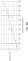
- the subject's arterial pulsatility is measured as the rotation rate of the impeller changes.
- a relationship between the arterial pulsatility and the impeller rotation rate and/or the pump flow rate is derived.
- the subject's native cardiac output is derived.
- the relationship between the subject's arterial pulsatility and the pump flow rate is extrapolated to determine what the pump flow rate would be when the subject's arterial pulsatility reaches zero. It is hypothesized that, at this value, the blood pump is replacing the native function of the heart and that the flow rate that is generated by the pump at this value provides an approximation of the subject's native cardiac output.
- apparatus including: a blood pump configured to be placed inside a body of subject, the blood pump including:
- the impeller includes three helical elongate elements, such that the three helical elongate elements with the film of material coupled thereto defines three blades of the impeller, and a respective elongate element extends from the ring to each of the three helical elongate elements, such that there is a respective elongate element within each of the three blades of the impeller.
- the elongate elements are configured to not resist compression, and the elongate elements are configured to prevent the impeller from radially expanding by applying tensile force to the helical elongate elements.
- the film of material forms a continuous U-shaped curved surface, with the U-shaped curvature of the film of material being substantially unbroken at the axial structure.
- a pressure side of each of the blades of the impeller when viewed from a distal end of the impeller, is convex in a distal region of the impeller and is concave in a proximal region of the impeller.
- the pressure side of each of the blades of the impeller transforms to being substantially radially oriented in a region of the elongate element within the impeller blade.
- the helical elongate elements are coated with a coupling agent that is configured to enhance bonding between the helical elongate element and the film of material.
- the film of material includes an elastomeric material
- the coupling agent includes at least two functional groups that are configured to bond respectively with the helical elongate elements and with the elastomeric material.
- the coupling agent includes a silane compound.
- the apparatus further includes a layer of an elastomer disposed between the film of material and the coupling agent.
- the layer of the elastomer is configured to round the helical elongate elements.
- the film of material is made of the elastomer.
- the elastomer includes a polycarbonate-based thermoplastic polyurethane.
- the axial structure includes a spring.
- the spring includes a tube at an intermediate location along a length of the spring and the ring is disposed around the tube.
- coupling the elastomeric film to the at least one helical elongate element, such that the at least one helical elongate element with the elastomeric film coupled thereto defines a blade of the impeller includes dipping the helical elongate element into an elastomeric material from which the elastomeric film is made.
- the elastomeric film includes an elastic material having an ultimate elongation of more than 300 percent. In some applications, the elastomeric film includes an elastic material having a melt flow index of at least 4. In some applications, the elastomeric film includes an elastic material having an ultimate tensile strength of more than 6000 psi.
- coating the at least one helical elongate element with the coupling agent includes coating the at least one helical elongate element with a silane compound containing a first functional group which is configured to bond with the helical elongate element, and a second functional group which is configured to bond with the elastomeric layer.
- the elastomeric layer is made of a given elastomeric material and the elastomeric film is made of the given elastomeric material. In some applications, the elastomeric layer is made of a first elastomeric material and the elastomeric film is made of a second elastomeric material that is different from the first elastomeric material.
- coating the coated helical elongate element with the elastomeric layer includes spraying an elastomer onto the coated helical elongate element. In some applications, coating the coated helical elongate element with the elastomeric layer includes at least partially rounding the coated helical elongate element.
- coating the coated helical elongate element with the elastomeric layer includes coating the coated helical elongate element with the elastomeric layer within a given time period of coating the at least one helical elongate element with the coupling agent. In some applications, coating the coated helical elongate element with the elastomeric layer further includes spraying additional elastomeric material onto the coated helical elongate element subsequent to coating the coated helical elongate element with the elastomeric layer within the given time period of coating the at least one helical elongate element with the coupling agent.
- apparatus including: a ventricular assist device including:
- the set of sensors is additionally configured to measure a magnetic flux amplitude signal
- computer processor is configured to determine the physiological parameter of the subject at least partially based upon a combination of the magnetic flux amplitude signal and the detected magnetic phase difference.
- the computer processor is configured to determine a pressure difference between the subject's left ventricle and an aorta of the subject at least partially in response to the magnetic phase difference between the driven magnet and the drive magnet. In some applications, the computer processor is configured to determine left ventricular pressure of the subject at least partially in response to the magnetic phase difference between the driven magnet and the drive magnet. In some applications, the computer processor is configured to determine an event in a cardiac cycle of the subject at least partially in response to the magnetic phase difference between the driven magnet and the drive magnet.
- the set of sensors includes a first magnetometer configured to measure magnetic phase of the driven magnet, and a second magnetometer configured to measure magnetic phase of the driven magnet.
- the second magnetometer is configured to measure the magnetic phase of the driven magnet by measuring a magnetic phase of the motor.
- the computer processor is configured to receive a signal indicative of current consumption by the motor and is configured to determine the physiological parameter of the subject at least partially based upon a combination of the current consumption by the motor and the detected magnetic phase difference.
- the set of sensors is additionally configured to measure a magnetic flux amplitude signal, and computer processor is configured to determine the physiological parameter of the subject at least partially based upon a combination of the current consumption by the motor, the magnetic flux amplitude signal, and the detected magnetic phase difference.
- apparatus including:
- apparatus including: a left-ventricular assist device configured to assist left-ventricular functioning of a subject, the left-ventricular assist device including:
- the frame has a length of more than 25 mm.
- apparatus including:
- the axial structure includes a cylindrical axial structure. In some applications, the cylindrical axial structure includes a spring.
- apparatus including: a blood pump including:
- apparatus including: a blood pump including:
- apparatus including: a blood pump including:
- apparatus including: a blood pump including:
- apparatus including: a blood pump including:
- proximal and related terms when used with reference to a device or a portion thereof, should be interpreted to mean an end of the device or the portion thereof that, when inserted into a subject's body, is typically closer to a location through which the device is inserted into the subject's body.
- distal when used with reference to a device or a portion thereof, should be interpreted to mean an end of the device or the portion thereof that, when inserted into a subject's body, is typically further from the location through which the device is inserted into the subject's body.
- the scope of the present invention includes using the apparatus and methods described herein in anatomical locations other than the left ventricle and the aorta. Therefore, the ventricular assist device and/or portions thereof are sometimes referred to herein (in the specification and the claims) as a blood pump.
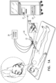
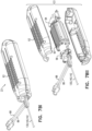
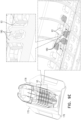
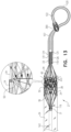
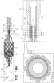
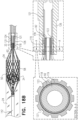
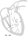
- FIGs. 1A , 1B , and 1C are schematic illustrations of a ventricular assist device 20, a distal end of which is configured to be disposed in a subject's left ventricle 22, in accordance with some applications of the present invention.
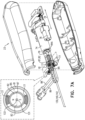
- Fig. 1A shows an overview of the ventricular assist device system including a control console 21, and a motor unit 23. (As described hereinbelow, the motor unit is typically a handle that houses a motor.)
- Fig. 1B shows the ventricular assist device being inserted into the subject's left ventricle, and Fig. 1C shows a pump portion 27 of the ventricular assist device in greater detail.
- the ventricular assist device includes a pump-outlet tube 24, which traverses an aortic valve 26 of the subject, such that a proximal end 28 of the pump-outlet tube is disposed in an aorta 30 of the subject and a distal end 32 of the pump-outlet tube is disposed within left ventricle 22.
- Pump-outlet tube 24 is typically an elongate tube, an axial length of the pump-outlet tube typically being substantially larger than its diameter.
- the scope of the present invention includes using the apparatus and methods described herein in anatomical locations other than the left ventricle and the aorta. Therefore, the ventricular assist device and/or portions thereof are sometimes referred to herein (in the specification and the claims) as a blood pump.
- the ventricular assist device is used to assist the functioning of a subject's left ventricle during a percutaneous coronary intervention.
- the ventricular assist device is typically used for a period of up to 10 hours (e.g., up to six hours), during a period in which there is risk of developing hemodynamic instability (e.g., during or immediately following the percutaneous coronary intervention).
- the ventricular assist device is used to assist the functioning of a subject's left ventricle for a longer period (e.g., for example, 2-20 days, e.g., 4-14 days) upon a patient suffering from cardiogenic shock, which may include any low-cardiac-output state (e.g., acute myocardial infarction, myocarditis, cardiomyopathy, post-partum, etc.).
- cardiogenic shock which may include any low-cardiac-output state (e.g., acute myocardial infarction, myocarditis, cardiomyopathy, post-partum, etc.).
- the ventricular assist device is used to assist the functioning of a subject's left ventricle for yet a longer period (e.g., several weeks or months), e.g., in a "bridge to recovery" treatment.
- the ventricular assist device is permanently or semi-permanently implanted, and the impeller of the ventricular assist device is powered transcutaneously, e.g.,
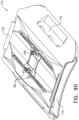
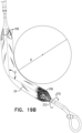
- Fig. 1B which shows steps in the deployment of the ventricular assist device in the left ventricle
- the distal end of the ventricular assist device is guided to the left ventricle over a guidewire 10.
- a delivery catheter 143 is disposed over the distal end of the device.
- the delivery catheter is typically retracted to the aorta, and the guidewire is withdrawn from the subject's body. The retraction of the delivery catheter typically causes self-expandable components of the distal end of the device to assume non-radially-constrained configurations, as described in further detail hereinbelow.
- the ventricular assist device is inserted into the subject's body in order to provide an acute treatment to the subject.
- the delivery catheter is advanced over the distal end of the device, which causes the self-expandable components of the distal end of the device to assume radially-constrained configurations.
- the distal end of the device is retracted into the delivery catheter which causes the self-expandable components of the distal end of the device to assume radially-constrained configurations.
- the ventricular assist device and/or delivery catheter 143 includes an ultrasound transducer at its distal end and the ventricular assist device is advanced toward the subject's ventricle under ultrasound guidance.
- an impeller 50 is disposed within a distal section 102 of pump-outlet tube 24 and is configured to pump blood from the left ventricle into the aorta by rotating.
- the pump-outlet tube typically defines one or more blood inlet openings 108 at the distal end 32 of the pump-outlet tube, via which blood flows into the pump-outlet tube from the left ventricle, during operation of the impeller.
- proximal section 106 of the pump-outlet tube defines one or more blood outlet openings 109, via which blood flows from the pump-outlet tube into the ascending aorta, during operation of the impeller.
- control console 21 which typically includes a computer processor 25, controls impeller rotation.
- the computer processor may control a motor 74 (shown in Fig. 7A , for example), which is disposed within motor unit 23 (shown in Fig. 1A ) and which drives the impeller to rotate via a drive cable 130 (shown in Fig. 7A , for example).
- the computer processor is configured to detect a physiological parameter of the subject (such as left-ventricular pressure, cardiac afterload, rate of change of left-ventricular pressure, etc.) and to control rotation of the impeller in response thereto, as described in further detail hereinbelow.
- Computer processor 25 is typically a hardware device programmed with computer program instructions to produce a special-purpose computer.
- computer processor 25 when programmed to perform the techniques described herein, computer processor 25 typically acts as a special-purpose, ventricular-assist computer processor and/or a special-purpose, blood-pump computer processor.
- a purging system 29 (shown in Fig. 1A ) drives a fluid (e.g., a glucose solution) to pass through portions of ventricular assist device 20, for example, in order to cool portions of the device and/or in order to wash debris from portions of the device.
- a fluid e.g., a glucose solution
- Purging system 29 is described in further detail hereinbelow.
- a frame 34 is disposed within the pump-outlet tube around impeller 50.
- the frame is typically made of a shape-memory alloy, such as nitinol.
- the shape-memory alloy of the frame is shape set such that at least a portion of the frame (and thereby distal section 102 of tube 24) assumes a generally circular, elliptical, or polygonal cross-sectional shape in the absence of any forces being applied to distal section 102 of tube 24.
- the frame is configured to hold the distal portion of the pump-outlet tube in an open state.
- the distal portion of the pump-outlet tube is configured to be placed within the subject's body, such that the distal portion of the pump-outlet tube is disposed at least partially within the left ventricle.
- Pump-outlet tube 24 is typically made of a blood-impermeable collapsible material.
- pump-outlet tube 24 may include polyurethane, polyester, and/or silicone.
- the pump-outlet tube is made of polyethylene terephthalate (PET) and/or polyether block amide (e.g., PEBAX ® ).
- the pump-outlet tube is reinforced with a reinforcement structure, e.g., a braided reinforcement structure, such as a braided nitinol tube.
- a reinforcement structure e.g., a braided reinforcement structure, such as a braided nitinol tube.
- the proximal portion of the pump-outlet tube is configured to be placed such that it is at least partially disposed within the subject's ascending aorta.
- the proximal portion of the pump-outlet tube traverses the subject's aortic valve, passing from the subject's left ventricle into the subject's ascending aorta, as shown in Fig. 1B .
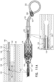
- the frame defines the following portions (a) coupling portion 31 via which the frame is coupled to a proximal bearing 116 (shown in Fig. 4 ) of the ventricular assist device, (b) proximal conical portion 36, (c) cylindrical portion 38, (d) distal conical portion 40, and (e) distal strut junctions 33.
- struts 37 of the frame pass through junctions 35, at which the two struts branch from a single strut, in a Y-shape.
- typically frame 34 is placed in a radially-constrained (i.e., crimped) configuration within delivery catheter 143 by the frame being axially elongated.
- the frame typically transmits its radial narrowing to the impeller, and the impeller becomes radially constrained by becoming axially elongated within the frame.
- Each of the helical elongate elements together with the film extending from the helical elongate element to the spring, defines a respective impeller blade, with the helical elongate elements defining the outer edges of the blades, and the axial spring defining the axis of the impeller.
- the film of material extends along and coats the spring.
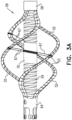
- sutures 53 e.g., polyester sutures, shown in Figs. 3B and 3C
- sutures 53 are wound around the helical elongate elements, e.g., as described in US 10,864,310 to Schwammenthal, which is incorporated herein by reference.
- the sutures are configured to facilitate bonding between the film of material (which is typically an elastomer, such as polyurethane, or silicone) and the helical elongate element (which is typically a shape-memory alloy, such as nitinol).
- sutures e.g., polyester sutures, not shown
- the sutures are configured to facilitate bonding between the film of material (which is typically an elastomer, such as polyurethane, or silicone) and the spring (which is typically a shape-memory alloy, such as nitinol).
- Enlargements A and B of Fig. 3C show two alternative ways in which the sutures are tied around helical elongate elements 52.
- the sutures are tied around the outer surface of the helical elongate elements, as shown in enlargement A.
- the helical elongate elements define grooves 45 on their outer surfaces, and the sutures are embedded within the grooves, as shown in enlargement B.
- the sutures typically do not add to the outer profile of the impeller, and the outer profile of the impeller is defined by the outer surfaces of the helical elongate elements.
- proximal ends of spring 54 and helical elongate elements 52 extend from a proximal bushing (i.e., sleeve bearing) 64 of the impeller, such that the proximal ends of spring 54 and helical elongate elements 52 are disposed at approximately the same point and have a similar radial distance from the longitudinal axis of the impeller.
- distal ends of spring 54 and helical elongate elements 52 extend from a distal bushing 58 of the impeller, such that the distal ends of spring 54 and helical elongate elements 52 are disposed at approximately the same point and have a similar radial distance from the longitudinal axis of the impeller.
- spring 54, as well as proximal bushing 64 and distal bushing 58 of the impeller define a lumen therethrough, such that the impeller defines a continuous lumen 62 therethrough (shown in Fig. 3C ).
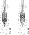
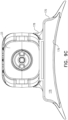
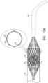
- Fig. 4 is a schematic illustration of impeller 50 disposed inside frame 34 of ventricular assist device 20, in accordance with some applications of the present invention.
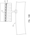
- an inner lining 39 lines the frame, as described hereinbelow with reference to Figs. 12A-B .
- the inner lining partially overlaps or fully overlaps with pump-outlet tube 24 over the portion of the frame that the inner lining lines.
- the pump-outlet tube and the inner lining both terminate before the distal end of cylindrical portion 38 of the frame, such that a distal part of the cylindrical portion of the frame is uncovered, as described hereinbelow with reference to Fig. 13 .
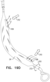
- the pump-outlet tube continues to cover the distal conical portion of the frame, as described with reference to Fig. 1D .
- the inner lining lines the inside of the cylindrical portion of the frame and pump-outlet tube 24 does not cover the cylindrical portion of the frame.
- the scope of the present application includes applying the apparatus and methods described with reference to Fig. 4 to any one of the applications described hereinbelow with reference to Figs. 1D , 12A-B or Fig. 13 .
- a gap G typically there is a gap G, between the outer edge of impeller 50 and inner lining 39, even at a location at which the span of the impeller is at its maximum.
- the gap between the outer edge of the blade of the impeller and the inner lining 39 be relatively small, in order for the impeller to efficiently pump blood from the subject's left ventricle into the subject's aorta.
- a gap between the outer edge of the blade of the impeller and the inner surface of frame 34 be maintained substantially constant throughout the rotation of the impeller within frame 34, for example, in order to reduce the risk of hemolysis.
- gap G between the outer edge of the impeller and the inner lining 39, at the location at which the span of the impeller is at its maximum is greater than 0.05 mm (e.g., greater than 0.1 mm), and/or less than 1 mm (e.g., less than 0.4 mm), e.g., 0.05-1 mm, or 0.1-0.4 mm.
- the outer diameter of the impeller at the location at which the outer diameter of the impeller is at its maximum is more than 7 mm (e.g., more than 8 mm), and/or less than 10 mm (e.g., less than 9 mm), e.g., 7-10 mm, or 8-9 mm.
- the inner diameter of frame 34 (as measured from the inside of inner lining 39 on one side of the frame to the inside of inner lining on the opposite side of the frame) is greater than 7.5 mm (e.g., greater than 8.5 mm), and/or less than 10.5 mm (e.g., less than 9.5 mm), e.g., 7.5-10.5 mm, or 8.5-9.5 mm.
- the outer diameter of frame 34 is greater than 8 mm (e.g., greater than 9 mm), and/or less than 13 mm (e.g., less than 12 mm), e.g., 8-13 mm, or 9-12 mm.
- an axial shaft 92 passes through the axis of impeller 50, via lumen 62 of the impeller.
- the axial shaft is rigid, e.g., a rigid tube.
- a portion of the axial shaft is at least partially flexible, e.g., as described with reference to Figs. 20A-C .
- proximal bushing 64 of the impeller is coupled to the shaft such that the axial position of the proximal bushing with respect to the shaft is fixed, and distal bushing 58 of the impeller is slidable with respect to the shaft.
- the axial shaft itself is radially stabilized via a proximal radial bearing 116 and a distal radial bearing 118.
- the axial shaft by passing through lumen 62 defined by the impeller, radially stabilizes the impeller with respect to the inner surface of frame 34, such that even a relatively small gap between the outer edge of the blade of the impeller and the inner surface of frame 34 (e.g., a gap that is as described above) is maintained, during rotation of the impeller.
- the impeller includes a plurality of elongate elements 67 extending radially from central axial spring 54 to outer helical elongate elements 52.
- Elongate elements 67 are typically flexible but are substantially non-stretchable along the axis defined by elongate elements 67. Further typically, each of elongate elements 67 is configured to substantially not resist compression.
- each elongate element 67 is configured to exert a tensile force upon helical elongate element 52 that prevents helical elongate element 52 from moving radially outward, such that (in the absence of elongate element 67) a separation between helical elongate element 52 and central axial spring 54 would be greater than a length of elongate element 67.
- elongate elements 67 may include strings (such as polyester, and/or another polymer or a natural material that contains fibers) and/or wires (such as nitinol wires, and/or wires made of a different alloy, or a metal). In this manner, the elongate elements prevent the impeller from radially expanding by applying tensile force to the helical elongate elements.
- elongate elements 67 maintain helical elongate element 52 (which defines the outer edge of the impeller blade) within a given distance with respect to central axial spring 54. In this manner, elongate elements 67 are configured to prevent the outer edge of the impeller from being forced radially outward due to forces exerted upon the impeller during the rotation of the impeller. In other words, elongate elements 67 act as impeller-expansion-prevention elements. Elongate elements 67 are thereby configured to maintain the gap between the outer edge of the blade of the impeller and the inner surface of frame 34, during rotation of the impeller.
- more than one (e.g., more than two) and/or fewer than eight (e.g., fewer than four) elongate elements 67 are used in the impeller, with each of elongate elements 67 typically being doubled (i.e., extending radially from central axial spring 54 to an outer edge of helical elongate element 52, and then returning from the helical elongate element back to the central axial spring).
- a plurality of elongate elements 67, each of which extends from the spring to a respective helical elongate element 52 and back to central axial spring 54, are formed from a single piece of string or a single wire.
- the impeller is manufactured in the following manner.
- Proximal bushing 64, distal bushing 58, and helical elongate elements 52 are cut from a tube of shape-memory material, such as nitinol.
- the cutting of the tube, as well as the shape setting of the shape-memory material, is typically performed such that the helical elongate elements and the bushings are defined by a tube of shape-memory material that is cut and shape set, e.g., using generally similar techniques to those described in US 10,039,874 to Schwammenthal .
- spring 54 is inserted into the cut and shape-set tube, such that the spring extends along the length of the tube from at least the proximal bushing to the distal bushing.
- the spring is inserted into the cut and shape-set tube while the spring is in an axially compressed state, and the spring is configured to be held in position with respect to the tube, by exerting a radial force upon the proximal and distal bushings.
- portions of the spring are welded to the proximal and distal bushings.
- the spring is cut from a tube of a shape-memory material, such as nitinol.
- the spring is configured such that, when the spring is disposed in a non-radially-constrained configuration (in which the spring is typically disposed during operation of the impeller), there are substantially no gaps between windings of the spring and adjacent windings thereto.
- elongate elements 67 are placed such as to extend between the spring and one or more of helical elongate elements 52, for example, in the following manner.
- a mandrel e.g., a polyether ether ketone (PEEK) and/or a polytetrafluoroethylene (PTFE) mandrel
- PEEK polyether ether ketone
- PTFE polytetrafluoroethylene
- a string or a wire is then threaded such that it passes (a) from the mandrel to a first one of the helical elongate elements 52, (b) back from the first of the helical elongate elements 52 to the mandrel, (c) around the mandrel, and to a second one of the helical elongate elements 52, (d) back from the second one of the helical elongate elements 52 to the mandrel, etc.
- the ends of the string or the wire are coupled to each other, e.g., by tying them to each other.
- each string or wire passes from the helical elongate element around the mandrel and back to the helical elongate element, with the two ends of the string being tied to each other.
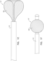
- the spring is shaped to define a tube 70 (i.e., at this location the spring does not define windings), as shown, and the string or the wire is wound around the tube.
- the string or the wire is not wound around the tube, and does not cross the longitudinal axis of the impeller. Rather, the string or the wire is secured with respect to tube 70 via a securing element 75 (such as a ring), as described in further detail hereinbelow with reference to Fig. 3F .
- sutures 53 are wound around helical elongate elements 52, in order to facilitate bonding between the film of material (which is typically an elastomer, such as polyurethane, or silicone) and helical elongate elements 52 (which is typically a shape-memory alloy, such as nitinol), in a subsequent stage of the manufacture of the impeller.
- sutures e.g., polyester sutures, not shown
- spring 54 are wound around spring 54.
- the sutures are configured to facilitate bonding between the film of material (which is typically an elastomer, such as polyurethane, or silicone) and the spring (which is typically a shape-memory alloy, such as nitinol), in the subsequent stage of the manufacture of the impeller.
- the film of material which is typically an elastomer, such as polyurethane, or silicone
- the spring which is typically a shape-memory alloy, such as nitinol
- a structure 59 has been assembled that is as shown in Fig. 3A .
- the structure includes the cut and shape-set tube that defines the proximal and distal bushings, the helical elongate elements, and the spring (and, optionally, the elongate elements, and the sutures).
- This structure is dipped into the material that defines film 56.
- the assembled structure is dipped into the material with the mandrel disposed through the lumen defined by the spring and the bushings, although it is noted that the mandrel is not shown in Fig. 3A .
- the material from which the film is made is silicone and/or polyurethane (and/or a similar elastomer), and the assembled structure is dipped into the material, while the material is in an uncured, liquid state. Subsequently, the material is cured such that it solidifies, e.g., by being left to dry. For some applications, while the material is drying the assembled structure is rotated, which typically facilitates the formation of a film of material having a substantially uniform thickness within each of the impeller blades. Once the material has dried, the mandrel is typically removed from the lumen defined by the bushings and the spring.
- the result of the process described above is typically that there is a continuous film of material extending between each of the helical elongate elements to the spring, and also extending along the length of the spring, such as to define a tube, with the spring embedded within the tube.
- the portions of the film that extend from each of the helical elongate elements to the spring define the impeller blades.
- the impeller includes elongate elements 67, the elongate elements are typically embedded within these portions of film.
- elongate elements 67 are configured to limit the radial expansion of the blades of the impeller, as described in detail hereinabove.
- the span to which the elongate elements allow the impeller blades to expand is set using the following technique.
- the two ends of the string or the wire within respective blades are tied to each other.
- the ends of the string or the wire in each of the blade are tied such that the spans of the impeller blades are set to less than the span of the impeller that is desired, and such that there is some slack in the knots via which the two ends of the strings or the wires are tied to each other.
- the outer edges of the impeller blades are pulled apart from each other, such as to increase the spans of the impeller blades, by tightening the knots between the ends of the strings or the wires within the respective blades.
- the process is repeated and the spans of the impeller blades are measured, until the desired span of the impeller blades has been achieved.
- structure 59 with the string or wires tied thereto is dipped in an elastomeric material from which film 56 is made, and the elastomeric material is allowed to dry, such that the strings or the wires are maintained with the ends tied to each other at the desired span of the impeller blades.
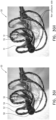
- impeller 50 is inserted into the left ventricle transcatheterally, while impeller 50 is in a radially-constrained configuration.
- both helical elongate elements 52 and central axial spring 54 become axially elongated, and radially constrained.
- film 56 of the material e.g., silicone and/or polyurethane
- film 56 of the material changes shape to conform to the shape changes of the helical elongate elements and the central axial spring, both of which support the film of material.
- using a spring to support the inner edge of the film allows the film to change shape without the film becoming broken or collapsing, due to the spring providing a large surface area to which the inner edge of the film bonds.
- using a spring to support the inner edge of the film reduces a diameter to which the impeller can be radially constrained, relative to if, for example, a rigid shaft were to be used to support the inner edge of the film, since the diameter of the spring itself can be reduced by axially elongating the spring.
- proximal bushing 64 of impeller 50 is coupled to axial shaft 92 such that the axial position of the proximal bushing with respect to the shaft is fixed, and distal bushing 58 of the impeller is slidable with respect to the shaft.
- the impeller when the impeller is radially constrained for the purpose of inserting the impeller into the ventricle or for the purpose of withdrawing the impeller from the subject's body, the impeller axially elongates by the distal bushing sliding along the axial shaft distally. Subsequent to being released inside the subject's body, the impeller assumes its non-radially-constrained configuration (in which the impeller is typically disposed during operation of the impeller), as shown in Figs. 3A-C .
- impeller 50 is shown without including all of the features of the impeller as shown and described with respect to Figs. 3A-C .
- some of the figures show the impeller not including sutures 53 and/or elongate elements 67.
- the scope of the present application includes using an impeller with any of the features shown and described with respect to Figs. 3A-C in combination with any of the apparatus and methods described herein.
- the following technique is used to enhance bonding of the elastomeric material to the at least one helical elongate element in a manner that does not cause a protrusion from the effective edge of the impeller blade.
- the helical elongate elements Prior to being dipped in the elastomeric material, the helical elongate elements are coated with a coupling agent.
- a coupling agent is selected that has at least two functional groups that are configured to bond respectively with the helical elongate elements and with the elastomeric material.
- a coat of elastomeric material is applied around the helical elongate elements.
- the coat of elastomeric material is the same elastomeric material or a similar elastomeric material to that used in film 56.
- a polycarbonate-based thermoplastic polyurethane such as Aromatic Carbothane TM (e.g., Aromatic Carbothane TM 75A) may be used in film 56, and the coating may be the same polycarbonate-based thermoplastic polyurethane, or a similar polycarbonate-based thermoplastic polyurethane, such as Pellethane@ (e.g., Pellethane@ 90A).
- the coated helical elongate elements are sprayed with a further layer of an elastomeric material.
- the elastomeric material that is sprayed is the same elastomeric material or a similar elastomeric material to that used as film 56.
- structure 59 is dipped in the elastomer from which film 56 is made, e.g., as described hereinabove.
- the material from which the film is made is an elastic material having an ultimate elongation of more than 300 percent, e.g., more than 400 percent.
- the material has a relatively low molecular weight.
- the material has a melt flow index (which is an indirect measure of molecular weight) of at least 4, e.g., at least 4.3.
- the material has an ultimate tensile strength of more than 6000 psi, e.g., more than 7000 psi, or more than 7500 psi.
- the material is a thermoplastic polyurethane, e.g., a Carbothane TM .
- Aromatic Carbothane TM 75 A is used.
- such materials combine one or more of the following properties: no outer diameter loss caused during the dip process, resistance to fatigue, resistance to becoming misshaped by being crimped, and low outer diameter loss during crimping.
- the scope of the present invention includes any technique whereby, prior to the helical elongate elements being dipped into the elastomeric material from which film 56 is made, additional layers of the same elastomeric material, a different elastomeric material, and/or a mediating material are applied to the helical elongate elements, whether by spraying, dipping, or a different coating method.
- additional layers of elastomeric material are configured to round the helical elongate elements, and/or to act as mediators to enhance bonding between the helical elongate elements and film 56 of material.
- a mediating material (such as silane) is configured to act as a mediator to enhance bonding between the helical elongate elements and film 56 of material.
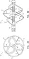
- Figs. 3D and 3E are schematic illustrations of impeller 50, the impeller including a single integrated impeller-overexpansion-prevention element 72 that defines a plurality of elongate elements 67, in accordance with some applications of the present invention.
- Figs. 3D and 3E show the impeller in the absence of the film 56 of material, for illustrative purposes.
- element 72 defines a ring 73 and the plurality of elongate elements 67 extending radially from the ring.
- ring 73 of element 72 is placed around the spring, e.g., by being placed around tube 70, which is typically disposed at the longitudinally-central location of the spring.
- the ends of respective elongate elements 67 are then coupled to respective helical elongate elements 52.
- elongate elements 67 are typically flexible but are substantially non-stretchable along the axis defined by the elongate elements. Further typically, each of elongate elements 67 is configured to substantially not resist compression.
- each elongate element 67 is configured to exert a tensile force upon helical elongate element 52 that prevents helical elongate element 52 from moving radially outward, such that (in the absence of elongate element 67) a separation between helical elongate element 52 and central axial spring 54 would be greater than a length of elongate element 67.
- the impeller-overexpansion-prevention element is configured to prevent radial expansion of the impeller.
- a respective elongate element 67 is disposed within each one of the impeller blades and is configured to prevent the impeller blade from radially expanding.
- element 72 is made of polyester, and/or another polymer or a natural material that contains fibers, and/or nitinol (or a similar shape-memory alloy).
- the scope of the present application includes using single integrated impeller-overexpansion-prevention element 72 with an impeller having a different construction from that shown in Figs. 3D-E .
- the single integrated impeller-overexpansion-prevention element 72 could be used with an impeller having a differently constructed axial structure than spring 54.
- the axial structure defines a lumen therethrough, such that the impeller defines lumen 62 therethrough.
- Fig. 3F is a schematic illustration of impeller 50, the impeller including a securing element 75 that is configured to secure elongate elements 67 with respect to tube 70, in accordance with some applications of the present invention.
- the string or the wire that comprises elongate element 67 is not wound around tube 70, and does not cross the longitudinal axis of the impeller. Rather, the string or the wire is secured with respect to tube 70 via securing element 75.
- the string or the wire is secured to the outer surface of tube 70 at a location on the outer surface of the tube that is closest to the maximum span of the helical elongate element to which the ends of the string or the wire are tied.
- the securing element comprises a ring, as shown.
- the ring define small notches (or eyelets) 80 through which the string or the wire passes between the ring and tube 70.
- Figs. 3Gi and 3Gii are photographs of impeller 50, in accordance with some applications of the present invention.
- adjacent blades 51 of impeller 50 becomes shaped such as to define a continuous U-shaped curved surface.
- curve 55 which has been added to Fig. 3Gii , along at least a portion of the length of the impeller, as film 56 of the elastomeric material transition from one blade to an adjacent blade, the film forms a continuous U-shaped curve.
- the curvature of the film of material is substantially unbroken.
- the film of material assumes the above-described curvature.
- the impeller blades are configured to provide smooth flow lines along which blood flows through the impeller, thereby enhancing efficiency of blood pumping by the impeller and/or reducing a risk of hemolysis, relative to if the adjacent blades did not define a continuous curved surface (e.g., relative to if the curvature were to be broken at spring 54).
- a generally similar impeller is used in which the impeller has an axial structure (e.g., a cylindrical axial structure) that is configured differently from spring 54.
- the axial structure defines a lumen therethrough, such that the impeller defines lumen 62 therethrough.
- the impeller includes spring 54 (which includes tube 70) as an axial structure, as shown.
- the pressure side of each of the blades of the impeller i.e., the side that pushes the blood during operation of the impeller
- the pressure side of each of the blades of the impeller is convex in the distal region of the impeller, transforms to being substantially radially oriented in the region of the elongate elements 67, and then is concave in the proximal region of the impeller.
- the opposite side to the pressure side of the impeller blades i.e., the "non-pressure side" is indicated in Fig.
- the blood that is pumped by the impeller is first pumped by a convex impeller surface and then pumped by a concave impeller surface.
- elongate elements 67 are disposed approximately halfway along the length of the impeller blade and are configured to facilitate the transition of the film of material from having a convex curvature to having a concave curvature.
- the blade is substantially radially oriented.
- the pressure side of the blades of the impeller are configured to add flow and/or pressure to the blood even after blood has had flow and/or pressure applied to it within the distal region of the impeller.
- the pressure side of each of the blades of the impeller i.e., the side that pushes the blood during operation of the impeller
- the pressure side of each of the blades of the impeller is concave in the distal region of the impeller, transforms to being substantially radially oriented in the region of the elongate elements 67, and then is convex in the proximal region of the impeller.
- Figs. 5A and 5B are schematic illustrations of impeller 50 and frame 34 of ventricular assist device 20, respectively in non-radially-constrained and radially-constrained states thereof, in accordance with some applications of the present invention.
- the impeller and the frame are typically disposed in the radially-constrained states during the transcatheteral insertion of the impeller and the frame into the subject's body, and are disposed in the non-radially-constrained states during operation of the impeller inside the subject's left ventricle.
- typically pump-outlet tube 24 is disposed over at least some of the frame and extends proximally therefrom.
- the frame and the impeller are shown in the absence of pump-outlet tube 24 in Figs. 5A-B .
- the frame and the impeller are typically maintained in radially-constrained configurations by delivery catheter 143.
- the impeller has a total length of more than 15 mm (e.g., more than 20 mm), and/or less than 30 mm (e.g., less than 25 mm), e.g., 15-30 mm, or 20-25 mm.
- the impeller has a length of more than 8 mm (e.g., more than 10 mm), and/or less than 18 mm (e.g., less than 15 mm), e.g., 8-18 mm, or 10-15 mm.
- the impeller and frame 34 are disposed in radially constrained configurations (as shown in Fig. 5B )
- the impeller has an outer diameter of less than 2 mm (e.g., less than 1.6 mm) and the frame has an outer diameter of less than 2.5 mm (e.g., less than 2.1 mm).
- axial shaft 92 passes through the axis of impeller 50, via lumen 62 of the impeller (lumen 62 being shown in Fig. 3C ).
- proximal bushing 64 of the impeller is coupled to the shaft via a coupling element 65 such that the axial position of the proximal bushing with respect to the shaft is fixed, and distal bushing 58 of the impeller is slidable with respect to the shaft.
- the axial shaft itself is radially stabilized via a proximal radial bearing 116 and a distal radial bearing 118.
- coupling portion 31 of frame 34 is coupled to proximal radial bearing 116, for example, via snap-fit coupling, and/or via welding.
- distal strut junctions 33 are placed into grooves defined by the outer surface of distal radial bearing 118, the grooves being shaped to conform with the shapes of the distal strut portions.
- the proximal end of distal-tip element 107 (which defines distal-tip portion 120) typically holds the distal strut portions in their closed configurations around the outside of distal radial bearing 118, as shown.
- the device includes a distal extension 121 that extends distally from the distal radial bearing.
- the extension is configured to stiffen a region of the distal-tip element into which the distal end of shaft 92 moves (e.g., an axial-shaft-receiving tube 126, described hereinbelow, or a portion thereof).
- axial shaft 92 is radially stabilized via proximal radial bearing 116 and distal radial bearing 118.
- the axial shaft by passing through lumen 62 defined by the impeller, radially stabilizes the impeller with respect to the inner surface of frame 34, such that even a relatively small gap between the outer edge of the blade of the impeller and the inner surface of frame 34 (e.g., a gap that is as described above) is maintained, during rotation of the impeller, as described hereinabove.
- axial shaft 92 is made of stainless steel, and proximal bearing 116 and/or distal bearing 118 are made of hardened steel.
- distal bushing 58 of the impeller is configured to slide along the axial shaft in the distal direction, such that the impeller becomes axially elongated, while the proximal bushing remains in an axially fixed position with respect to the axial shaft. More generally, the impeller changes from its radially-constrained configuration to its non-radially-constrained configuration, and vice versa, by the distal bushing sliding over the axial shaft, while the proximal bushing remains in an axially fixed position with respect to the axial shaft.
- impeller itself is not directly disposed within any radial bearings or thrust bearings. Rather, bearings 116 and 118 act as radial bearings with respect to the axial shaft.
- pump portion 27 does not include any thrust bearing that is configured to be disposed within the subject's body and that is configured to oppose thrust generated by the rotation of the impeller.
- one or more thrust bearings are disposed outside the subject's body (e.g., within motor unit 23, shown in Figs. 1A and 7A-Bii ), and opposition to thrust generated by the rotation of the impeller is provided solely by the one or more thrust bearings disposed outside the subject's body.
- a mechanical element and/or a magnetic element is configured to maintain the impeller within a given range of axial positions.
- a magnet e.g., magnet 82, described hereinbelow with reference to Fig. 7A
- drive cable 130 e.g., outside the subject's body
- Figs. 6A and 6B are schematic illustrations of ventricular assist device 20 at respective stages of a motion cycle of impeller 50 of the ventricular assist device with respect to frame 34 of the ventricular assist device, in accordance with some applications of the present invention.
- axial shaft 92 to which the impeller is fixated
- axial shaft 92 is driven to move the impeller axially back-and-forth within frame 34, by the axial shaft moving in an axial back-and-forth motion, as described in further detail hereinbelow with reference to Fig. 7A-Bii .
- the impeller and the axial shaft are configured to move axially back-and-forth within frame 34 in response to forces that are acting upon the impeller, and without requiring the axial shaft to be actively driven to move in the axial back-and-forth motion.
- the pressure difference between the left ventricle and the aorta varies from being approximately zero during ventricular systole (hereinafter "systole”) to a relatively large pressure difference (e.g., 50-70 mmHg) during ventricular diastole (hereinafter "diastole").
- the impeller is pushed distally with respect to frame 34 during diastole, relative to the location of the impeller with respect to frame 34 during systole.
- the impeller since the impeller is connected to the axial shaft, the axial shaft is moved forward.
- the impeller and, in turn, the axial shaft) move back to their systolic positions.
- Fig. 6A shows the impeller and axial shaft disposed at their typical systolic positions and Fig. 6B shows the impeller and axial shaft disposed at their typical diastolic positions.
- the portions of the axial shaft that are in contact with proximal bearing 116 and distal bearing 118 are constantly changing.
- the frictional force that is exerted upon the axial shaft by the bearings is spread over a larger area of the axial shaft than if the axial shaft were not to move relative to the bearings, thereby reducing wear upon the axial shaft, ceteris paribus.
- the axial shaft cleans the interface between the axial shaft and the bearings from any residues, such as blood residues.
- the length of the frame exceeds the length of the impeller by at least 2 mm (e.g., at least 4 mm, or at least 8 mm).
- the proximal bearing 116 and distal bearing 118 are each 2-4 mm (e.g., 2-3 mm) in length.
- the impeller and the axial shaft are configured to move axially within the frame in the back-and-forth motion at least along the length of each of the proximal and distal bearings, or at least along twice the length of each of the bearings.
- the axial shaft is wiped clean on either side of each of the bearings.
- the range of the impeller motion is as indicated in Figs. 6A-B , with Fig. 6A indicating the proximal-most disposition of the impeller over the course of the cardiac cycle (at which the impeller is typically disposed during systole) and Fig. 6B indicating the distal-most disposition of the impeller over the course of the cardiac cycle (at which the impeller is typically disposed during diastole).
- Fig. 6A for some applications, at its proximal-most position the proximal end of the impeller is disposed at location Ip, which is within the proximal conical section of frame 34.
- Ip the proximal conical section of frame 34
- the distal end of the impeller is disposed at location Id, which is at the distal end of the cylindrical section of frame 34.
- the entire section of the frame from Ip to Id may be considered as housing the impeller, since this entire section of the frame typically houses at least a portion of the impeller over at least a portion of the cardiac cycle.
- the section of the impeller at which the span of the impeller is at its maximum is disposed within the cylindrical portion of the frame 34.
- a proximal portion of the impeller is typically disposed within the proximal conical section of the frame during at least a portion of the cardiac cycle.
- distal-tip element 107 which includes axial-shaft-receiving tube 126 and distal-tip portion 120 of ventricular assist device 20, in accordance with some applications of the present invention.
- distal-tip element 107 is a single integrated element that includes both axial-shaft-receiving tube 126 and distal-tip portion 120.
- distal-tip element 107 is configured to be soft, such that the distal-tip portion is configured not to injure tissue of the subject, even if the distal-tip portion comes into contact with the tissue (e.g., tissue of the left ventricle).
- distal-tip element 107 may be made of silicone, polyethylene terephthalate (PET) and/or polyether block amide (e.g., PEBAX ® ).
- the distal-tip portion defines a lumen 122 therethrough.
- guidewire 10 Fig. 1B
- the distal-tip portion of the ventricular assist device is then guided to the left ventricle by advancing the distal-tip portion over the guidewire, with the guidewire disposed inside lumen 122.
- a duckbill valve 390 (or a different type of hemostasis valve) is disposed at the distal end of lumen 122 of distal-tip portion 120.
- delivery catheter 143 is placed over impeller 50 and frame 34 and maintains the impeller and the frame in their radially-constrained configurations.
- distal-tip element 107 extends distally from the delivery catheter during the insertion of the delivery catheter into the subject's ventricle.
- the distal-tip element has a flared portion 124 that acts as a stopper and prevents the delivery catheter from advancing beyond the flared portion.
- distal-tip portion in Figs. 6A-C (as well as in some other figures) is shown as defining a complete loop, with the distal end of the distal-tip portion (within which duckbill valve 390 is disposed) crossing over a more proximal portion of the distal-tip portion.
- the distal-tip portion remains partially straightened, even after the removal of the guidewire from the distal-tip portion.
- the partial straightening of the distal-tip portion is such that, when the distal-tip portion is disposed within the left ventricle, in the absence of external forces acting upon the distal-tip portion, the distal-tip portion does not define a complete loop, e.g., as shown in Fig. 1B , 15D , and Fig. 16A .
- Fig. 1B , 15D , and Fig. 16A in order to insert the guidewire through the distal-tip potion of straightening element 270 is used, as described in further detail hereinbelow, for example, with reference to Figs. 23A-C .
- Other aspects of the shape of the distal-tip portion are described in further detail hereinbelow.
- Figs. 6D and 6E are schematic illustrations of impeller 50, proximal bushing 64 of the impeller being coupled to a coupling element 65 that is proximally-extended such as to function as a stopper, in accordance with some applications of the present invention.
- Fig. 6D shows the impeller at the systolic phase of the motion cycle of the impeller and the Fig. 6E shows the impeller at the diastolic phase of its motion cycle.
- the coupling element is proximally-extended such as to prevent a central region of the impeller (at which the span of the impeller is at its maximum) from sliding proximally into the proximal conical portion of frame 34.
- the proximally-extended coupling element would contact proximal radial bearing 116, thereby preventing further proximal motion of the impeller.
- the coupling element is proximally extended such that it has a total length of more than 1.5 mm, e.g., more than 4 mm.
- a separate stopper element is disposed upon axial shaft proximally with respect to the coupling element.
- the stopper is configured as described with reference to the proximally-extended coupling element. Namely, such that if the impeller were to slide further proximally by more than a given amount, the stopper element would contact proximal radial bearing 116, thereby preventing further proximal motion of the impeller.
- Fig. 7A is a schematic illustration of an exploded view of motor unit 23 of ventricular assist device 20, in accordance with some applications of the present invention.
- the motor unit is typically a handle that is configured to be disposed outside the subject's body, and which houses a motor.
- the motor unit may alternatively be referred to as a handle unit.
- control console 21 ( Fig. 1A ) that controls the rotation of impeller 50 is also configured to control the back-and-forth motion of the axial shaft.
- both types of motion are generated using motor unit 23.
- the scope of the present invention includes controlling the back-and-forth motion at any frequency.
- an indication of the subject's cardiac cycle is detected (e.g., by detecting the subject's ECG), and the back-and-forth motion of the axial shaft is synchronized to the subject's cardiac cycle.
- motor unit 23 includes a motor 74 that is configured to impart rotational motion to impeller 50, via drive cable 130.
- the motor is magnetically coupled to the drive cable.
- an axial motion driver 76 is configured to drive the motor to move in an axial back-and-forth motion, as indicated by double-headed arrow 79.
- the motor imparts the back-and-forth motion to the drive cable, which it turn imparts this motion to the impeller.
- the drive cable, the impeller, and/or the axial shaft undergo axial back-and-forth motion in a passive manner, e.g., due to cyclical changes in the pressure gradient against which the impeller is pumping blood.
- motor unit 23 does not include axial motion driver 76.
- the magnetic coupling of the motor to the drive cable is as shown in Fig. 7A .
- a least one more driving magnet 77 e.g., two driving magnets 77
- the driving magnet housing includes ring 81 (e.g., a steel ring), and the driving magnets are adhered to an inner surface of the ring.
- a spacer 85 is adhered to the inner surface of ring 81, between the two driving magnets, as shown.
- At least one driven magnet 82 is disposed between the driving magnets such that there is axial overlap between the driving magnets and the driven magnet.
- the driven magnet is coupled to a pin 131, which extends to beyond the distal end of driven magnet 82, where the pin is coupled to the proximal end of drive cable 130.
- the driven magnet may be cylindrical and define a hole therethrough, and pin 131 may be adhered to an inner surface of the driven magnet that defines the hole.
- the driven magnet is cylindrical, and the magnet includes a North pole and a South pole, which are divided from each other along the length of the cylinder along a line 83 that bisects the cylinder, as shown.
- the driven magnet is housed inside a cylindrical housing 87.
- pin 131 defines a lumen 133, via which guidewire 10 is inserted through the pin.
- the driving magnets are disposed outside the driven magnet.
- the scope of the present application includes reversing the configurations of the driving magnets and the driven magnet, mutatis mutandis.
- the proximal end of the drive cable may be coupled to two or more driven magnets, which are disposed around a driving magnet, such that there is axial overlap between the driven magnets and the driving magnet.
- typically purging system 29 (shown in Fig. 1A ) is used with ventricular assist device 20.
- motor unit 23 includes an inlet port 86 and an outlet port 88, for use with the purging system.
- a purging fluid is continuously or periodically pumped into the ventricular assist device via inlet port 86 and out of the ventricular assist device via outlet port 88. Additional aspects of the purging system are described hereinbelow.
- magnet 82 and pin 131 are held in axially relatively-fixed positions within motor unit 23.
- magnet 82 does have a small freedom of movement axially and/or rotationally relative to other components of the motor unit, such as the driving magnets 77.
- movement is measurable, as described in further detail hereinbelow.
- the proximal end of the drive cable is typically coupled to pin 131 and is thereby held in an axially fixed position relative to the pin.
- drive cable 130 extends from pin 131 to axial shaft 92 and thereby at least partially fixes the axial position of the axial shaft, and in turn impeller 50.
- the drive cable is somewhat stretchable.
- the drive cable may be made of coiled wires that are stretchable, as described in further detail hereinbelow.
- the drive cable typically allows the axial shaft (and in turn the impeller) to assume a range of axial positions (by the drive cable becoming more or less stretched), but limits the axial motion of the axial shaft and the impeller to being within a certain range of motion (by virtue of the proximal end of the drive cable being held in an axially relatively-fixed position, and the stretchability of the drive cable being limited).
- Figs. 7Bi and 7Bii are schematic illustrations of motor unit 23, in accordance with some applications of the present invention.
- motor unit 23 as shown in Figs. 7Bi and 7Bii is similar to that shown in Fig. 7A , and, unless described otherwise, motor unit 23 as shown in Figs. 7Bi and 7Bii contains similar components to motor unit 23 as shown in Fig. 7A .
- the motor unit includes a heat sink 90 that is configured to dissipate heat that is generated by the motor.
- the motor unit includes ventilation ports 93 that are configured to facilitate the dissipation of heat that is generated by the motor.
- the motor unit includes vibration dampeners 94 and 96 that are configured to dampen vibration of the motor unit that is caused by rotational motion and/or axial back-and-forth motion of components of the ventricular assist device.
- impeller 50 and axial shaft 92 are configured to move axially back-and-forth within frame 34 in response to forces that act upon the impeller, and without requiring the axial shaft to be actively driven to move in the axial back-and-forth motion.
- the pressure difference between the left ventricle and the aorta varies from being approximately zero during systole to a relatively large pressure difference (e.g., 50-70 mmHg) during diastole.
- the impeller is pushed distally with respect to frame 34 during diastole, relative to the location of the impeller with respect to frame 34 during systole.
- the axial shaft is moved forward.
- the impeller and, in turn, the axial shaft
- the axial back-and-forth motion of the impeller and the axial shaft is generated in a passive manner, i.e., without requiring active driving of the axial shaft and the impeller, in order to cause them to undergo this motion.
- Fig. 8A is a graph indicating variations in the length of a drive cable of a ventricular assist device, as a pressure gradient against which the impeller of the ventricular assist device varies, as measured in experiments.
- An impeller and a drive cable as described herein were used to pump a glycerin-based solution through chambers, with the chambers set up to replicate the left ventricle and the aorta, and the solution having properties (such as, density and viscosity) similar to those of blood.
- the pressure gradient against which the impeller was pumping was varied in a pulsatile manner to represent the pulsatility of the pressure gradient against which the impeller typically pumps when it is pumping blood from the left ventricle to the aorta.
- movement of the drive cable was imaged and changes in the length of the drive cable were determined via analysis of the images.
- the graph shown in Fig. 8A indicates the changes in the length of the drive cable that were measured, as a function of the pressure gradient.
- the pressure gradient against which the impeller pumped increased, the drive cable became increasingly elongated.
- computer processor 25 of control console 21 is configured to measure an indication of the pressure exerted upon the impeller (which is indicative of the pressure difference between the left ventricle and the aorta), by measuring an indication of tension in drive cable 130, and/or axial motion of the drive cable.
- the computer processor detects events in the subject's cardiac cycle, determines the subject's left-ventricular pressure, and/or determines the subject's cardiac afterload.
- the computer processor controls the rotation of the impeller, and/or the axial back-and-forth motion of the axial shaft in response thereto.
- ventricular assist device 20 includes a sensor 84.
- the sensor may include a magnetometer (e.g., a Hall sensor) that is disposed within motor unit 23, as shown in Fig. 7A .
- magnetometer 84 is referred to as magnetometer 84.
- the axial back-and-forth motion of the impeller gives rise to a measurable back-and-forth motion of the inner, driven magnet 82 relative to the outer, one or more drive magnets 77, since the driven magnet is held in place with respect to the drive magnets via magnetic coupling, rather than rigid mechanical coupling.
- the magnetometer measures variations in the magnetic field that is generated by one of the magnets in order to measure the axial motion of drive cable 130, and, in turn, to determine the pressure against which the impeller is pumping.
- the inner, driven magnet 82 may be axially longer than the outer, driving magnets 77.
- the inner magnet Due to the inner magnet being longer than the outer magnets, there are magnetic field lines that emanate from the inner magnet that do not pass to the outer magnets, and the magnetic flux generated by those field lines, as measured by the magnetometer, varies as the drive cable, and, in turn, the inner magnet moves axially.
- motor 74 rotates, creating an AC signal in the magnetometer, which typically has a frequency of between 200 Hz and 800 Hz.
- the tension in the drive cable changes due to the subject's cardiac cycle, this gives rise to a low frequency envelope in the signal measured by the magnetometer, the low frequency envelope typically having a frequency of 0.5-2 Hz.
- the computer processor measures the low frequency envelope, and derives the subject's cardiac cycle from the measured envelope.
- the magnetometer measurements are initially calibrated, such that the change in magnetic flux per unit change in pressure against which the impeller is pumping (i.e., per unit change in the pressure difference between the left ventricle and the aorta, or per unit change in the pressure gradient) is known. It is known that, in most subjects, at systole, the left-ventricular pressure is equal to the aortic pressure.
- the subject's aortic pressure is measured, and the subject's left-ventricular pressure at a given time is then calculated by the computer processor, based upon (a) the measured aortic pressure, and (b) the difference between the magnetic flux measured by the magnetometer at that time, and the magnetic flux measured by the magnetometer during systole (when the pressure in the left ventricle is assumed to be equal to that of the aorta).
- the subject's aortic pressure may be measured by measuring pressure in a channel 224 defined by delivery catheter 143, as described in further detail hereinbelow.
- alternative or additional physiological parameters are determined using the above-described technique. For example, events in the subject's cardiac cycle and/or the subject's cardiac afterload may be determined.
- a different parameter is measured in order to determine left ventricular blood pressure (and/or a different physiological parameter, e.g., events in the subject's cardiac cycle and/or the subject's cardiac afterload) at a given time.
- a different physiological parameter e.g., events in the subject's cardiac cycle and/or the subject's cardiac afterload
- the subject's aortic pressure is measured, and the subject's left-ventricular pressure at a given time is then calculated by the computer processor, based upon (a) the measured aortic pressure, (b) the power (and/or current) consumption by the motor that is required to rotate the impeller at a given rotation rate at that time, and (c) the predetermined relationship between power (and/or current) consumption by the motor that is required to rotate the impeller at a given rotation rate and the pressure difference that is generated by the impeller.
- the above-described technique is performed while maintaining the rotation rate of the impeller at a constant rate.
- the rotation rate of the impeller is varied, and the variation of the rotation rate of the impeller is accounted for in the above-described calculations.
- alternative or additional physiological parameters are determined using the above-described technique. For example, events in the subject's cardiac cycle and/or the subject's cardiac afterload may be determined.
- a second magnetometer 84A measures an indication of the magnetic flux density generated by the driving magnet.
- the second magnetometer measures magnetic flux density of the motor, which is indicative of the flux density cycle of the driving magnet, since the motor directly drives the driving magnet to rotate.
- the impeller rotates such as to pump blood
- torque is generated upon the impeller.
- the strength of the torque is dependent upon various parameters, such as the flow that is generated by the impeller, the rotational speed of the impeller, and/or the pressure gradient against which the impeller is pumping.
- the torque generated upon the impeller gives rise to a measurable torque on the inner, driven magnet 82 relative to the outer, drive magnets 77, since the driven magnet is held in place with respect to the drive magnets via magnetic coupling, rather than rigid mechanical coupling.
- the torque generated upon the driven magnet is substantially less than that generated upon the impeller, since the torque that is generated upon the impeller is not transmitted along the length of the drive cable.
- the torque that is generated upon the impeller is at least partially transmitted to the driven magnet via the drive cable.
- the torque that is transmitted to the driven magnet typically gives rise to a phase difference between the signal that is measured by magnetometer 84 (which measures magnetic flux density of the driven magnet) and the signal that is measured by second magnetometer 84A (which measures magnetic flux density of the motor and/or the driving magnet).
- magnetometer 84 which measures magnetic flux density of the driven magnet
- second magnetometer 84A which measures magnetic flux density of the motor and/or the driving magnet.
- the computer processor detects the variation in the aforementioned phase difference, and determines a physiological parameter of the subject, at least partially in response thereto.
- the computer processor may determine the difference between the subject's left-ventricular pressure and the subject's aortic pressure, the subject's left ventricular pressure, an event in the subject's cardiac cycle, the subject's cardiac afterload, and/or a different physiological parameter.
- the technique described in the present paragraph is used as an alternative to the above-described technique for using magnetic flux density measurements and/or power consumption measurements to determine physiological parameters.
- two or more of these techniques are used in combination with each other.
- the subject's physiological parameters may be determined based upon a mathematical model that incorporates two or more measurements, and/or one of the techniques may be used to validate estimations of the subject's physiological parameters that are made using another one of the techniques.
- Figs. 8B and 8C are graphs that demonstrate the correlation between the phase difference signal and the pressure gradient against which impeller 50 pumps, in accordance with some applications of the present invention.
- the graph shown in Fig. 8B shows the results of an experiment in which a ventricular assist device as described herein was used to pump blood against respective pressure gradients within a static in vitro system (i.e., in which when each measurement was taken, the pressure gradient was constant).
- a linear regression model was used to estimate the pressure gradient against which the impeller was pumping based upon a combination of the phase difference signal the magnetic flux amplitude signal, and the current consumed by the motor.
- the graph shown in Fig. 8B shows the estimated pressure gradient versus the measured pressure gradient. As shown the linear regression model which incorporates phase difference measurements provides a reliable method for estimating the pressure gradient against which the impeller is pumping.
- the graph shown in Fig. 8C shows the results of an experiment in which a ventricular assist device as described herein was used to pump blood against respective pressure gradients within a pulsatile in vitro system (i.e., in which the pressure gradient was varied in a pulsatile manner).
- a space state model was used to estimate the pressure gradient against which the impeller was pumping based upon a combination of the phase difference signal the magnetic flux amplitude signal, and the current consumed by the motor.
- the graph shown in Fig. 8C shows the estimated pressure gradient overlaid upon the measured pressure gradient.
- a space state model which incorporates phase difference measurements provides a reliable method for estimating the pressure gradient against which the impeller is pumping.
- a magnetic phase difference between the one or more driven magnets and the one or more drive magnets is measured, and a physiological parameter of the subject is determined, at least partially in response thereto.
- the computer processor may determine the difference between the subject's left-ventricular pressure and the subject's aortic pressure, the subject's left ventricular pressure, an event in the subject's cardiac cycle, the subject's cardiac afterload, and/or a different physiological parameter.
- the physiological parameter is determined based upon the phase difference measurements in combination with one or more additional measurements, such as magnetic flux amplitude measurements, power consumed by the motor, and/or current consumed by the motor.
- additional measurements such as magnetic flux amplitude measurements, power consumed by the motor, and/or current consumed by the motor.
- such measurements are combined into a mathematical model, such as a linear regression model, and/or a space state model.
- Figs. 9A-G are schematic illustrations of respective views of a motor-unit support 170 configured to support motor unit 23 on a patient's leg 172, in accordance with some applications of the present invention.
- the ventricular assist device is inserted into the patient's body via a femoral access point 173, and the motor-unit support is configured to be placed on the patient's upper leg below the femoral access point, as shown.
- the motor unit support is configured to at least partially isolate the patient's leg from vibrations and/or heat that is generated by the motor unit, during operation of the motor unit.
- the motor-unit support comprises a curved base 176, which is configured to be placed on the patient's upper leg, as well as a motor-unit dock 178, upon which the motor unit is docked.
- a gap 179 between the motor-unit dock and the curved base of the motor-unit support such that the patient's leg is separated from the motor unit by the gap, with the gap serving to at least partially isolate the patient's leg from vibrations and/or heat that is generated by the motor unit, during operation of the motor unit.
- the motor-unit support is configured to receive a strap 174 through the gap, the strap being used to strap the motor-unit support to the patient leg.
- the strap is elasticated and/or is adjustable to fit the patient's leg.
- the motor-unit support includes coupling elements 180 for coupling the motor-unit dock to the motor unit (shown in Fig. 9D , for example).
- the motor unit includes ventilation ports 93 that are configured to facilitate the dissipation of heat that is generated by the motor.
- the coupling elements comprise snap-fit coupling elements that are configured to couple the motor-unit dock to the motor unit by the coupling elements snapping into ventilation ports of the motor unit, as shown in Fig. 9E , for example.
- the motor unit includes ventilation ports on both sides of the motor unit such that either side of the motor unit can be coupled to the motor-unit dock.
- Figs. 10A , 10B, and 10C are schematic illustrations of drive cable 130 of ventricular assist device 20, in accordance with some applications of the present invention.
- the rotational motion of the of the motor is transmitted to the axial shaft via the drive cable.
- the drive cable extends from motor unit 23 (which is typically disposed outside the subject's body) to the proximal end of axial shaft 92 (with the connection between the distal end of the drive cable and the proximal end of the axial shaft being shown in the left enlarged portion of Fig. 5A for example) .
- the drive cable includes a plurality of wires 134 that are disposed in a coiled configuration in order to impart sufficient strength and flexibility to the drive cable, such that a portion of the cable is able to be maintained within the aortic arch (i.e., the portion corresponding to arrow 145 in Fig. 10A ), while the cable is rotating and moving in the axial back-and-forth motion.
- the drive cable includes a plurality of coaxial layers of coiled wires.
- the drive cable may include an outer layer 136 and an inner layer 138, which are coaxial with each other and each of which comprises coiled wires.
- the drive cable is typically disposed within a first outer tube 140, which is configured to remain stationary while the drive cable undergoes rotational and/or axial back-and-forth motion.
- the first outer tube is configured to effectively act as a bearing tube for the drive cable, along the length of the drive cable.
- first outer tube is also referred to herein as the drive-cable bearing tube.
- the drive-cable bearing tube is described in further detail hereinbelow with reference to Fig. 10D .
- the drive-cable bearing tube is disposed within a second outer tube 142, which is typically made of a material having greater flexibility than that of the drive-cable bearing tube (e.g., nylon, and/or polyether block amide), and typically has a thickness that is greater than that of the drive cable bearing tube.
- a material having greater flexibility than that of the drive-cable bearing tube e.g., nylon, and/or polyether block amide
- impeller 50 and frame 34 are maintained in a radially-constrained configuration by delivery catheter 143.
- the delivery catheter is retracted.
- the delivery catheter remains in the subject's aorta during operation of the left ventricular device, and outer tube 142 is disposed inside the delivery catheter.
- FIG. 10A shows the distal end of the delivery catheter disposed within the aortic arch, for some application, the distal end of the delivery catheter is disposed within the descending aorta during operation of the left ventricular device.
- a channel 224 is defined between delivery catheter 143 and outer tube 142.
- the subject's aortic blood pressure is measured by measuring the pressure of blood within channel 224.
- pressure sensor 216 illustrated schematically in Fig.
- 1A may be in fluid communication with channel 224, and may be configured to measure the subject's aortic pressure by measuring the pressure of blood within channel 224.
- the delivery catheter is advanced over the impeller and the frame, such that the impeller and the frame assume their radially-constrained configurations. The catheter is then withdrawn from the subject's body.
- drive cable 130 is made up of a plurality of coaxial layers each of which comprises plurality of coiled wires 134.
- the drive cable includes outer layer 136 and inner layer 138, each of which comprises coiled wires.
- outer layer 136 and inner layer 138 each of which comprises coiled wires.
- this would also cause the impeller to advance with respect to the frame when the rotation of the impeller is initiated, due to the coiled wires tightening (i.e., becoming wound up such that the radius of the coil decreases), and thereby axially elongating.
- At least a portion of the drive cable is configured such that (a) in response to the impeller pumping blood from the left ventricle to the aorta, by rotating in a predefined direction of rotation, (b) rotation of the drive cable in this direction results in the coiled wires of the drive cable along the portion of the drive cable at least partially unwinding, such that the portion of the drive cable axially shortens (i.e., becoming unwound such that the radii of the coils increase).
- the impeller is configured to rotate in the counterclockwise direction when viewed from the proximal end of the impeller to the distal end of the impeller, and the coiled wires in each of the layers of the drive cable are configured in a left-handed lay.
- the impeller rotates in the counterclockwise direction, the counterpressure exerted on the coiled wires of each of the layers of the drive cable causes them to partially unwind, thereby shortening each of the layers of the drive cable.
- the impeller is configured to rotate in the clockwise direction when viewed from the proximal end of the impeller to the distal end of the impeller, and the coiled wires in each of the layers of the drive cable are configured in a right-handed lay.
- Figs. 6A and 6B show the range of axial back-and forth motion of the impeller within frame 34 over the course of the cardiac cycle, in accordance with some applications of the present invention.
- Fig. 6A indicates the proximal-most disposition of the impeller over the course of the cardiac cycle (at which the impeller is typically disposed during systole) and
- Fig. 6B indicates the distal-most disposition of the impeller over the course of the cardiac cycle (at which the impeller is typically disposed during diastole).
- Fig. 6A indicates the proximal-most disposition of the impeller over the course of the cardiac cycle (at which the impeller is typically disposed during systole)
- Fig. 6B indicates the distal-most disposition of the impeller over the course of the cardiac cycle (at which the impeller is typically disposed during diastole).
- the drive cable would shorten if the impeller were to be rotated in the absence of any fluid
- the drive cable does not shorten. This because, when the impeller is rotated within the subject's blood stream, the unwinding of the drive cable (which would result in the drive cable shortening) is offset by the impeller being pushed distally by virtue of the counterpressure of the blood that the impeller is pumping.
- the drive cable does in fact become elongated relative to when the impeller is at rest, due to the pressure gradient against which the impeller is pumping increasing relative to during systole.
- the drive cable is configured not to become elongated relative to when the impeller is at rest, due to the windings of the coil being configured as described hereinabove.
- the drive cable is initially held within frame 34 in a preloaded (i.e., pretensioned) state, such that even before the drive cable and the impeller start to rotate, it is already stretched. That is to say that, even before the drive cable and the impeller start to rotate, the drive cable is in a stretched state relative to the drive cable rest state (i.e., the state of the drive cable in the absence of any external forces acting upon the drive cable.)
- the drive cable rest state i.e., the state of the drive cable in the absence of any external forces acting upon the drive cable.
- coupling element 65 which in some applications is proximally-extended, as described hereinabove with reference to Figs.
- proximal bearing 116 may engage proximal bearing 116, such as to hold the drive cable in a preloaded state.
- proximal bearing 116 such as to hold the drive cable in a preloaded state.
- the drive cable does not become stretched even during diastole (e.g., even when the impeller is pumping against a pressure gradient of 50-70 mmHg).
- the drive cable does not become stretched even during diastole until the impeller is rotating at a rotation speed of more than 6,000 RPM, or more than 8,000 RPM.
- the amount that the drive cable becomes elongated over the course of the cardiac cycle is limited to less than 5 mm (and typically less than 4 mm), even when the impeller is rotating at more than 20,000 RPM.
- the widest portion of the impeller (which is typically located at the center of the length of the impeller) is disposed within the proximal half of frame 34 for more than 50 percent of the duration of the cardiac cycle, even when the impeller is rotating at more than 20,000 RPM.
- this reduces hemolysis (relative to if there were a smaller axial distance or no axial distance between the location of the impeller at which the impeller is at its maximum diameter and the blood inlet opening) and/or enhances the efficacy of the impeller by reducing turbulence, by allowing flow lines of the blood that enters the blood inlet opening to become at least partially aligned with the longitudinal axis of the impeller prior to being pumped by the impeller.
- the coiled wires of both layers are made of an alloy.
- the inner diameter of the drive cable i.e., the diameter of lumen 132
- the outer diameter of the drive cable (defined by outer layer 138) is between 1 mm and 1.2 mm.
- drive cable 130 has a total length of more than 1 m (e.g., more than 1.1 m), and/or less than 1.4 m (e.g., less than 1.3 m), e.g., 1-1.4 m, or 1.1-1.3 m.
- the diameters of lumen 122 and lumen 133 are generally similar to that of lumen 132.
- the drive cable includes first (distal) and second (proximal) portions.
- the first portion is configured to be disposed in the subject's aortic arch
- the second portion is configured to be disposed along the descending aorta, and typically to extend until motor unit 23, outside the subject's body.
- the drive cable typically is desirable for the drive cable to be relatively flexible.
- a drive cable having greater flexibility is typically also more axially stretchable than a drive cable having less flexibility.
- the ratio of the number of the wires within the outer layer of the distal portion of the drive cable to those within the proximal portion of the drive cable is between 3:2 and 5:2.
- the diameter of the coiled wires within the proximal portion of the drive cable is greater than that of the coiled wires within even the outer layer of the distal portion of the drive cable.
- the ratio of the diameter of the wires within the proximal portion to the diameter of the wires within the outer layer of the distal portion is between 3:2 and 5:2.
- the diameters of the wires within the distal portion of the drive cable are between 0.2 mm and 0.35 mm.
- the inner and outer diameters of both the distal and proximal portions of the drive cable are similar (or identical) to each other, and are typically as described hereinabove.
- the drive-cable bearing tube includes an outer layer 141 and inner layer 144, each of which is typically made of a biocompatible polymeric material, and a coil 153 embedded between the outer and inner layers.
- outer layer 141 is made of Pebax
- inner layer 144 is made of PTFE and/or polyimide (e.g., a mixture of PTFE and/or polyimide)
- the coil is made of an alloy, such as stainless steel.
- the inner layer includes materials that are configured to provide low levels of friction and high wear resistance.
- the outer layer is configured to provide additional strength to the drive-cable bearing tube, while still providing the drive-cable bearing tube with sufficient flexibility that it is able to conform with the curvature of the aortic arch, for example.
- the coil is configured such as to maintain a substantially circular cross-section for the drive-cable bearing tube, even within regions in which the drive-cable bearing tube undergoes a substantial curve (e.g., within the aortic arch).
- the drive-cable bearing tube would have a tendency to flatten and form an elliptical cross-section within such regions.
- the axial shaft and the drive cable define a continuous lumen 132 therethrough.
- the left ventricular device is guided to the aorta and to the left ventricle by placing the axial shaft and the cable over guidewire 10 (described hereinabove), such that the guidewire is disposed inside lumen 132.
- the guidewire is inserted through duckbill valve 390 (or other hemostasis valve) disposed at the distal end of distal tip portion of distal-tip element 107.
- the guidewire passes through lumen 122 (of the distal-tip portion), and then passes into lumen 132 which is defined by the axial shaft at that point.
- the guidewire then continues to pass through lumen 132 all the way until the proximal end of the drive cable. From the proximal end of the drive cable, the guidewire passes through lumen 133 defined by pin 131, which is disposed outside of the subject's body even after insertion of the distal end of ventricular assist device 20 into the subject's left ventricle. Typically, when the distal end of the ventricular assist device is disposed inside the subject's left ventricle, the guidewire is retracted from the subject's body by pulling the guidewire out of the proximal end of lumen 133.
- the axial position of driven magnet 82 (within which pin 131 is disposed) is fixed such as to be disposed between driving magnets 77, as shown in Fig. 7A .
- a portion of motor unit 23 in which the driven magnet is disposed may be coupled to a portion of the motor unit in which driving magnets 77 are disposed using click-lock element 150 (shown in Fig. 11B ).
- click-lock element 150 shown in Fig. 11B
- techniques as described hereinbelow with reference to Figs. 23A-C are used for inserting the guidewire into distal-tip element 107.
- lumen 132 is additionally used by purging system 29 (shown in Fig. 1A ) of the ventricular assist device.
- purging system 29 controls the flow of a purging fluid (e.g., a fluid containing glucose or dextrose) via inlet port 86 and outlet port 88 (shown in Figs. 7A-Bii , 11B , and 11C ).
- a purging fluid e.g., a fluid containing glucose or dextrose
- the fluid is configured to remove air from the space between the drive cable and the outer tube, and/or to reduce frictional forces between drive cable 130 (which rotates), and outer tube 140 (which remains stationary, during rotation of the drive cable), and/or to reduce frictional forces between axial shaft 92 and proximal bearing 116 and/or distal bearing 118.
- the purging fluid is pumped between the first and second outer tubes 140, 142, and there is an opening 146 within the first outer tube in the vicinity of the proximal bearing.
- the purging fluid is pumped via a purging-fluid channel 226 defined between the first and second outer tubes, as described in further detail hereinbelow with reference to Fig. 21 .
- the purging fluid flows between first outer tube 140 and drive cable 130 via opening 146, as indicated by purging-fluid-flow arrow 148 in Fig. 11A .
- the interface between drive cable 130 (which rotates), and outer tube 140 (which acts as the drive-cable bearing tube and remains stationary, during rotation of the drive cable) is purged.
- some of the purging fluid additionally flows to the interface between the axial shaft and proximal bearing 116, thereby purging the interface (and/or reducing frictional forces at the interface), as indicated by purging-fluid-flow arrows 149 in Fig. 11A .
- the flow of the purging fluid in the direction of arrows 149 also prevents blood from flowing into the interface between the axial shaft and the proximal bearing.
- the drive cable typically includes a plurality of coiled wires.
- purging fluid passes into lumen 132 defined by the drive cable via gaps in the coiled wires. Once the purging fluid is disposed within lumen 132 it flows in both proximal and distal directions, as indicated by arrow 151 of Fig. 11A .
- the purging fluid that flows in the distal direction typically flows out of the distal end of lumen 132 and toward lumen 122 defined by distal-tip portion, as indicated by arrow 152 of Fig. 11A .
- the purging fluid flows in both proximal and distal directions, as indicated by arrow 151 of Fig. 11A .
- the purging fluid flows in the direction of arrows 156 out of the proximal end of lumen 132 and then out of the proximal end of lumen 133 defined by pin 131.
- the purging fluid then flows in the direction of arrow 157 and around driven magnet 82, such as to reduce frictional forces that the driven magnet is exposed to.
- the purging fluid then flows out of outlet port 88, in the direction of arrow 158.
- the purging fluid is then disposed of.
- the purging fluid is pumped back into the device, via inlet port 86.
- lumens 122, 132, and 133 are typically used as flow channels for purging fluid, during use of the ventricular assist device.
- ventricular assist device includes an additional purging fluid inlet port 89, which is typically used to pump purging fluid into channel 224 between delivery catheter 143 and outer tube 142.
- the purging fluid is pumped into this channel at a low enough pressure, that it is still possible to detect aortic blood pressure via this channel, as described elsewhere in this application.
- fluid is pumped into this channel periodically in order to flush the channel.
- port 89 and channel 224 are used for aortic pressure sensing.
- pressure sensor 216 (which is illustrated schematically in Fig. 1A ) may be disposed within channel 224, within port 89, and/or at a different location that is in fluid communication with channel 224.
- axial shaft 92 includes purging fluid holes that are configured to allow the flow of the purging fluid from out of lumen 132, which is defined by axial shaft 92.
- the axial shaft defines purging fluid holes 190 in the vicinity of distal bushing 58 of impeller 50.
- the distal bushing is configured to be slidable with respect to the axial shaft.
- the interface between the distal bushing and the axial shaft is purged by the purging fluid flowing out of purging fluid holes 190.
- the axial shaft defines holes 192 in the vicinity of distal radial bearing 118.
- the interface between the distal radial bearing and the axial shaft is purged by the purging fluid flowing out of purging fluid holes 192.
- the axial shaft defines holes 194 in the vicinity of proximal radial bearing 116.
- the interface between the distal radial bearing and the axial shaft is purged by the purging fluid flowing out of purging fluid holes 194.
- Figs. 12A and 12B are schematic illustrations of ventricular assist device 20, the device including inner lining 39 that lines the inside of frame 34 that houses impeller 50, in accordance with some applications of the present invention.
- inner lining 39 and pump-outlet tube 24 on the side of the device facing out of the page are shown as transparent in Figs. 12A-B .
- inner lining 39 is disposed inside frame 34, in order to provide a smooth inner surface through which blood is pumped by impeller.
- the covering material reduces hemolysis that is caused by the pumping of blood by the impeller, relative to if the blood were pumped between the impeller and struts of frame 34.
- inner lining includes polyurethane, polyester, and/or silicone.
- the inner lining includes polyethylene terephthalate (PET) and/or polyether block amide (PEBAX ® ).
- the inner lining is disposed over at least the inner surface of the cylindrical portion of frame 34 (the cylindrical portion being indicated in Figs. 2A-C, for example).
- pump-outlet tube 24 also covers the cylindrical portion 38 of frame 34, around the outside of the frame, for example, such that pump-outlet tube 24 and inner lining 39 overlap over at least 50 percent of the length of the inner lining, for example, over the entire length of the cylindrical portion of frame 34, e.g., as shown in Fig. 12A .
- there is only partial overlap between pump-outlet tube 24 and inner lining 39 e.g., as shown in Fig. 12B .
- pump-outlet tube 24 may overlap with inner lining along less than 50 percent (e.g., along less than 25 percent) of the length of the inner lining.
- the impeller is advanced distally within frame 34, such that the impeller is not disposed within the area of overlap between the pump-outlet tube and the inner lining, such that there is no longitudinal location at which the impeller, pump-outlet tube 24, frame 34, and inner lining 39 all overlap with each other.
- pump-outlet tube 24 extends to the end of distal conical portion 40 of the frame, and the pump-outlet tube defines a plurality of lateral blood inlet openings.
- the cylindrical portion of the frame is lined with inner lining 39.
- the inner lining is shaped to form a smooth surface (e.g., in order to reduce hemolysis, as described hereinabove), and pump-outlet tube 24 is shaped to conform with the struts of frame 34 (e.g., as shown in the cross-section in Fig. 12A ).
- the pump-outlet tube and the inner lining are coupled to each other, e.g., via vacuum, via an adhesive, and/or using a thermoforming procedure, for example as described hereinbelow.
- inner lining 39 and pump-outlet tube 24 are made of different materials.
- the inner lining may be made of polyurethane
- the pump-outlet tube may be made of polyether block amide (PEBAX ® ).
- the material from which the inner lining is made has a higher thermoforming temperature than that of the material from which the pump-outlet tube is made.
- the pump-outlet tube and the inner lining are bonded to each other and/or the frame in the following manner. Initially, the inner lining is placed over a mandrel. The frame is then placed over the inner lining.
- pump-outlet tube 24 is placed around the outside of the frame.
- the frame is heated to a temperature that is above the thermoforming temperature of pump-outlet tube 24 but below the thermoforming temperature of inner lining 39.
- the frame is heated from inside the frame, using the mandrel.
- an outer tube (which is typically made from silicone) applies pressure to pump-outlet tube 24 that causes pump-outlet tube 24 to be pushed radially inwardly, in order to cause the pump-outlet tube to conform with the shapes of the struts of the frame, as shown in the cross-section of Fig. 12A .
- the combination of the frame, the inner lining, and the portion of pump-outlet tube 24 disposed around the frame is subsequently shape set to a desired shape and dimensions using shape setting techniques that are known in the art.
- a density of struts of the frame at the distal end of the cylindrical portion of the frame is greater than the density of the struts within other parts of the cylindrical portion of the frame.
- the increased density of the struts of the frame at the distal end of the cylindrical portion of the frame facilitates bonding of the inner lining and/or the pump-outlet tube to the frame.
- the inner lining and/or the pump-outlet tube does not extend all the way to the end of the cylindrical portion of the frame, e.g., as described with reference to Fig. 13 .
- the density of the struts of the frame is increased relative to at other locations along the cylindrical portion of the frame.
- Fig. 13 is a schematic illustration of ventricular assist device 20, in which at least a distal part 333 of cylindrical portion 38 of frame 34 is uncovered, in accordance with some applications of the present invention.
- the part of the impeller at which the span of the impeller is at its maximum does not advance beyond a given location within the cylindrical portion of the frame (e.g., as described hereinabove with reference to Figs. 10A-C ).
- part of the frame that is disposed distally beyond this location is not covered by either pump-outlet tube 24 or inner lining 39.
- the uncovered distal part of the cylindrical portion of the frame functions as a virtual widened inlet, since (as indicated by the blood flow arrows in Fig. 13 ) blood flows into the cylindrical portion of the frame from the sides of the cylindrical portion of the frame. For some applications, this reduces hemolysis that is generated by the impeller pumping blood.
- the diameter of pump portion 27, when the pump portion is in its radially-constrained configuration may be reduced.
- the pump portion may be radially constrained such that the widest portion of the impeller overlaps with the uncovered part of the cylindrical portion of the frame in order to reduce the diameter of the pump portion of the ventricular assist device (relative to if the widest portion of the impeller overlaps with a covered part of the cylindrical portion of the frame, such that the widest portion of the impeller overlaps with the frame as well as covering material).
- ventricular assist device is configured such that, even during diastole, there is an axial distance between the location of the impeller at which the impeller is at its maximum diameter and the blood inlet opening.
- the ventricular assist device is configured such that, during diastole, there is an axial distance of more than 3 mm (e.g., more than 5 mm) between the location of the impeller at which the impeller is at its maximum diameter and the blood inlet opening (e.g., as described hereinabove with reference to Figs. 10A-C ).
- this reduces hemolysis (relative to if there were a smaller axial distance or no axial distance between the location of the impeller at which the impeller is at its maximum diameter and the blood inlet opening) and/or enhances the efficacy of the impeller by reducing turbulence, by allowing flow lines of the blood that enters the blood inlet opening to become at least partially aligned with the longitudinal axis of the impeller prior to being pumped by the impeller.
- FIG. 14 is a schematic illustration of ventricular assist device 20 being placed inside a subject's left ventricle 22 ( a transverse cross-sectional view of the left ventricle being illustrated), in accordance with some applications of the present invention.
- Fig. 14 shows aortic valve 26 overlaid on the transverse cross-section of the left ventricle even though the aortic valve lies in a different plane from the plane of the main cross-sectional view, for illustrative purposes.
- Figs. 14 shows aortic valve 26 overlaid on the transverse cross-section of the left ventricle even though the aortic valve lies in a different plane from the plane of the main cross-sectional view, for illustrative purposes.
- FIGS. 15A-D are schematic illustrations of distal-tip element 107 of the ventricular assist device that is at least partially curved such as to define a curvature that is similar to that of a question mark, in accordance with some applications of the present invention
- Figs. 16A and 16B are schematic illustrations of the ventricular assist device of Figs. 15C-D disposed inside a subject's left ventricle, in accordance with some applications of the present invention.
- the ventricular assist device is guided by the guidewire over which it is inserted toward apex 342 of the left ventricle.
- the walls of the left ventricle may be thought of as being made up of the septal wall 338 (which separates the left ventricle from the right ventricle 340), the posterior wall 336 (from which the papillary muscles 341 protrude, and above which the mitral apparatus is disposed), and the free wall 334, each of these three walls occupying approximately one third of the circumference of the left ventricle (as illustrated by the dashed lines, which trisect the left ventricle in Fig. 14 ).
- the distal-tip element or any other portions of the ventricular assist device
- the ventricular assist device is introduced into the subject's ventricle over a guidewire, as described hereinabove.
- Distal-tip portion 120 defines lumen 122, such that the distal-tip portion is held in a straightened configuration during the introduction of the ventricular assist device into the subject's ventricle.
- distal-tip portion upon the guidewire being removed, distal-tip portion is configured to assume its curved shape. It is noted that Figs. 15A-D illustrate the shape of distal-tip portion 120 as it is initially formed.
- the curvature of the distal-tip portion is less than that shown in at least some of Figs. 15A-D .
- Fig. 15C shows that the curvature of the distal-tip portion is such that the curved portion of the distal-tip portion forms a complete loop.
- the distal-tip portion of Fig. 15C is shown in Fig. 16A within the subject's left ventricle and it does not form a complete loop.
- distal-tip portion 120 typically forms a portion of distal-tip element 107 which also includes axial-shaft receiving tube 126.
- distal-tip element 107 is configured such that in its non-constrained configuration (i.e., in the absence of any forces acting upon the distal-tip portion), the distal-tip element is at least partially curved.
- distal-tip element 107 has a proximal, straight portion 346 (at least a portion of which typically comprises axial-shaft-receiving tube 126).
- the proximal straight portion of distal-tip element 107 defines a longitudinal axis 348.
- the curved portion of distal-tip element 107 curves away from longitudinal axis 348 in a first direction, and then passes through an inflection point and curves in the opposite direction with respect to longitudinal axis 348.
- the distal-tip element first curves to the top of the page, then curves to the bottom of the page, and as shown in Figs. 15C-D , within the plane of the page, the distal-tip element first curves to the bottom of the page, then curves to the top of the page.
- Figs. 15A-B within the plane of the page, the distal-tip element first curves to the top of the page, then curves to the bottom of the page, then curves to the top of the page.
- the distal-tip element defines an overall curvature that is similar to that of a question mark or a tennis-racket, the distal-tip element defining a bulge 351 on one side of the longitudinal axis of the straight proximal straight portion of the distal-tip element.
- the bulge is generally shaped as a semi-ellipse. (It is noted that in this context the term "semi-ellipse" includes a semi-circle. It is further noted that is some cases, the tip does not define a precise semi-ellipse, but rather a bulged shape that is substantially similar to a semi-ellipse.)
- Figs. 15A-B after passing through the inflection point the distal-tip element continues to curve such that the distal-tip element crosses back over longitudinal axis 348.
- Fig. 15A shows an example in which the end of the distal-tip element does not cross back over the longitudinal axis yet again, and there is a larger gap between the distal end of the distal-tip element and the proximal end of the curved portion.
- Fig. 15B shows an example in which the end distal-tip element does cross back over the longitudinal axis yet again, and there is a smaller gap between the distal end of the distal-tip element and the proximal end of the curved portion.
- Figs. 15A shows an example in which the end of the distal-tip element does not cross back over the longitudinal axis yet again, and there is a larger gap between the distal end of the distal-tip element and the proximal end of the curved portion.
- Figs. 15B shows an example in which the end
- 15C-D which are, respectively, cross-sectional and isometric views of the same shaped distal-tip element
- the tip after passing through the inflection point the tip does not curve such that the distal-tip element crosses back over longitudinal axis 348. Rather, all of the curvature of the curved portion of the distal-tip element occurs on one side of longitudinal axis 348.
- a hemostasis valve e.g., duckbill valve 390
- a hemostasis valve is disposed within a distal section of distal-tip portion 120, and is configured to prevent blood flow into lumen 122.
- the duckbill valve has a maximum width of less than 3 mm, e.g., less than 2 mm.
- the entire duckbill valve is disposed within a distal section of the distal-tip portion that is disposed within the distal-most 10 mm, e.g., the distal most 5 mm of the distal-tip portion.
- the duckbill valve is proximally facing (i.e., such that the wide inlet of the valve faces the distal end of distal-tip portion and such that the narrow tip of the valve faces away from the distal end of distal-tip portion 120).
- the curvature of the curved portion of distal-tip element 107 is configured to provide an atraumatic tip to ventricular assist device 20.
- the distal-tip element is configured to space the inlet openings 108 of the ventricular assist device from walls of the left ventricle.
- FIGs. 16A and 16B show a cross-sectional view of the left ventricle 22 in which septal wall 338 is disposed on the left of the page and free wall 334 is disposed on the right of the page.
- the left atrium 359, and left atrial appendage 358 are visible above the left ventricle
- right ventricle 340 is visible to the left of the left ventricle.
- the view of the aorta and the left ventricle as shown in Figs. 16A-B (as well as in Figs. 17Ai-17D ) is different to that shown, for example, in Fig. 1B.
- Fig. 1B is a schematic illustration, provided for illustrative purposes, and does not properly depict the scale and orientation of the ventricular assist device with respect to the anatomy.
- distal-tip element 107 is configured to separate the blood inlet opening from a posterior wall of the subject's left ventricle when the distal-tip element is placed against the apex of the subject's left ventricle.
- the distal-tip element is configured to separate the blood-inlet opening from a septal wall of the subject's left ventricle as the distal-tip element contacts the apex of the subject's left ventricle.
- distal-tip element 107 is inserted into the left ventricle, such that bulge 351 bulges toward the septal wall 338.
- blood inlet opening 108 typically gets pushed in the direction of free wall 334 and away from the septal wall 338 (in the direction of the arrows shown in Fig. 16B .
- this is due to proximal straight portion 346 pivoting about the curved portion of the question mark shape, as shown.
- the scope of the present invention includes using a question-mark or tennis-racket shaped distal-tip element in combination with any ventricular assist device, and even in the absence of other features and/or portions of distal-tip element 107 (such as, axial-shaft-receiving tube 126). It is further noted that, typically, the curvatures of the distal-tip portion are all within a single plane.
- Figs. 17Ai and 17Aii are schematic illustrations of ventricular assist device 20, the device having a balloon 220 disposed on its distal-tip element 107, the balloon being configured to facilitate movement of axial shaft 92 with respect to walls of the ventricle, in accordance with some applications of the present invention.
- axial shaft 92 typically passes through the axis of impeller 50, via lumen 62 of the impeller.
- the axial shaft is rigid, e.g., a rigid tube.
- the axial shaft itself is radially stabilized via proximal radial bearing 116 and distal radial bearing 118.
- the axial shaft by passing through lumen 62 defined by the impeller, radially stabilizes the impeller with respect to the inner surface of frame 34.
- the axial shaft passes into axial-shaft-receiving tube 126 of distal-tip element 107.
- friction between the axial shaft and the distal and radial bearings is increased if the axial shaft is bent.
- balloon 220 provides the distal end of the distal-tip element with freedom of movement with respect to the walls of the left ventricle is a manner that does not cause the proximal end of the distal tip portion (which defines the axial-shaft-receiving tube) to undergo substantial movement.
- the balloon may rotate with respect to the apex without causing substantial movement of the axial-shaft receiving tube.
- the axial shaft is maintained in a substantially straight configuration.
- balloon 220 is inflated using purging fluid, e.g., using a technique as described with reference to Fig. 13D of US 2020/0237981 to Tuval , which is incorporated herein by reference.
- Figs. 17Bi and 17Bii are schematic illustrations of ventricular assist device 20, the device having a joint 230 that is configured to facilitate pivoting of its distal tip portion 120 with respect to its axial shaft, in accordance with some applications of the present invention.
- distal-tip element 107 includes axial-shaft-receiving tube 126, as well as distal-tip portion 120.
- joint 230 allows distal-tip portion 120 to move with respect to axial-shaft receiving tube 126.
- joint 230 may be a ball-and-socket joint as shown, and/or it may be a swivel joint, and/or a Cardan joint.
- FIG. 17C is a schematic illustration of a ventricular assist device, an outer tube 140 and/or 142 of which is shaped to a predefined curvature, such that axial shaft 92 of the ventricular assist device is maintained in a substantially straight configuration when the axial shaft is disposed inside the subject's left ventricle 22, in accordance with some applications of the present invention.
- drive cable 130 is disposed within a first outer tube 140, which is configured to act a drive-cable bearing tube, first outer tube 140 remaining stationary while the drive cable undergoes rotational and/or axial back-and-forth motion.
- the first outer tube is configured to effectively act as a bearing along the length of the drive cable.
- first outer tube 140 is disposed within second outer tube 142.
- At least one of the first and second outer tubes is shaped such that a portion of the outer tube that is disposed within the aortic arch has a predefined radius of curvature RC of more than 18 mm and/or less than 32 mm (e.g., less than 24 mm), e.g., 18-32 mm or 18-24 mm.
- RC radius of curvature
- the axial shaft enters the left ventricle at such an angle that when the distal tip portion of the ventricular assist device is disposed in the vicinity of apex 342, the axial shaft is in a substantially straight configuration.
- Fig. 17D is a schematic illustration of ventricular assist device 20 having a distal tip 240 that is configured to be anchored to tissue of the left ventricular apex 342, in accordance with some applications of the present invention.
- distal tip 240 is a screw-shaped element (e.g., a corkscrew-shaped element as shown), and the distal tip is configured to be screwed into tissue of the apex, in order to anchor the distal end of the ventricular assist device to the apex.
- anchoring the distal tip the apex reduces movement of pump portion 27 with respect to inner structures of the left ventricle, and thereby reduces a risk of damage to the inner structure of the left ventricle that may be caused by such movement.
- FIGS. 18A , 18B , and 18C are schematic illustrations of a distal radial bearing 118 of a ventricular assist device, in accordance with respective applications of the present invention.
- the radial bearing is disposed inside a bearing housing 119.
- the radial bearing and the bearing housing are made of respective, different materials from each other.
- the radial bearing may be made of a first material that has a relatively high hardness, such as ceramic
- the bearing housing may be made of a second material that is relatively easy to shape into a desired shaped, such as a metal or an alloy (e.g., stainless steel, cobalt chromium, and/or nitinol).
- proximal radial bearing 116 is also disposed inside a bearing housing, with the proximal radial bearing and the bearing housing being made of respective, different materials from each other (in a generally similar manner to that described with reference to distal radial bearing 118).
- the ventricular assist device includes a distal extension 121 that is configured to stiffen a region of the distal-tip element into which the distal end of shaft 92 moves (e.g., axial-shaft-receiving tube 126, described hereinbelow, or a portion thereof).
- distal extension 121 typically comprises an extension from bearing housing 119 rather than from the distal radial bearing itself.
- distal strut junctions 33 are placed into grooves defined by the outer surface of distal radial bearing 118, the grooves being shaped to conform with the shapes of the distal strut portions.
- the outer surface of the bearing housing (rather than that of the bearing) is shaped to define such grooves (the grooves being indicated by reference numeral 127 in Figs. 18A and 18B ).
- a layer of material 123 is disposed between radial bearing 118 and bearing housing 119.
- the material is configured to allow some movement of the radial bearing with respect to the bearing housing, and/or to cushion such movement.
- the layer of material may include a layer of elastomeric material.
- proximal radial bearing 116 has a similar configuration, with a material (e.g., an elastomeric material) being disposed between the radial bearing and the bearing housing that is configured to allow some movement of the radial bearing with respect to the bearing housing, and/or to cushion such movement.
- the material layers permit some movement of the rigid axial shaft with respect to frame 34.
- axial shaft 92 is permitted to become slightly misaligned with the longitudinal axis of the frame.
- an outer surface 125 of distal radial bearing 118 which abuts the inner surface of bearing housing 119, has a convex curve.
- the convexly curved outer surface of the bearing is configured to allow some movement of the radial bearing with respect to the bearing housing.
- the inner radial surface of the bearing housing (which abuts the outer surface of the bearing) has a convex curve, such as to allow some movement of the radial bearing with respect to the bearing housing.
- proximal radial bearing 116 has a similar configuration, with the outer surface of the bearing and/or the inner radial surface of the bearing housing having a convex curve.
- the above-described shapes of the bearing and/or bearing housings allows movement of the rigid axial shaft with respect to frame 34.
- the axial shaft is permitted to become slightly misaligned with the longitudinal axis of the frame.
- the lengths of the radial bearings are such as to allow movement of the rigid axial shaft with respect to frame 34, such that the axial shaft is permitted to become slightly misaligned with the longitudinal axis of the frame.
- the lengths of each of the proximal and distal radial bearings may be less than 2 mm, less than 1.5 mm, or less than 1 mm, for example, 0-1.5 mm, or 0.5-1 mm.
- Fig. 19A is a schematic illustration of ventricular assist device 20, pump-outlet tube 24 of the device being configured to become curved when blood is pumped through the pump-outlet tube, and the pump-outlet tube being rotatable with respect to distal-tip portion 120 of the ventricular assist device, in accordance with some applications of the present invention.
- Fig. 19B is a schematic illustration of pump-outlet tube 24 of Fig. 19A , in the absence of other components of the ventricular assist device, in accordance with some applications of the present invention.
- Fig. 19C is a schematic illustration of ventricular assist device 20 of Figs.
- FIG. 19A-B disposed inside a subject's aorta 30 and left ventricle 22, in accordance with some applications of the present invention.
- the view of the aorta and the left ventricle as shown in Fig. 19C is different to that shown, for example, in Fig. 1B.
- Fig. 1B is a schematic illustration, provided for illustrative purposes, and does not properly depict the scale and orientation of the ventricular assist with respect to the anatomy.
- the view of the aorta and the left ventricle as shown in Fig. 19C is different to that shown, for example, in Figs. 16A-B , and 17Ai-17D .
- Fig. 19C shows a cross-sectional view of the left ventricle in which the posterior wall 336 is disposed on the left of the page and the free wall 334 is disposed on the right of the page.
- Tube 24 is typically made of a blood-impermeable, collapsible material.
- tube 24 may include polyurethane, polyester, and/or silicone.
- the tube is made of polyethylene terephthalate (PET) and/or polyether block amide (PEBAX ® ).
- PET polyethylene terephthalate
- PEBAX ® polyether block amide
- the proximal portion of the tube is configured to be placed such that it is at least partially disposed within the subject's ascending aorta.
- the proximal portion of the tube traverses the subject's aortic valve, passing from the subject's left ventricle into the subject's ascending aorta, as shown in Fig. 1B .
- the tube typically defines one or more blood inlet openings 108 at the distal end of the tube, via which blood flows into the tube from the left ventricle, during operation of the impeller.
- the proximal portion of the tube defines one or more blood outlet openings 109, via which blood flows from the tube into the ascending aorta, during operation of the impeller.
- the pressure of the blood flow through the tube typically maintains the proximal portion of the tube in an open state.
- pump-outlet tube 24 is pre-shaped such that, during operation of the impeller, when the pressure of the blood flow through the tube maintains the proximal portion of the tube in an open state, the tube is curved.
- the curvature is such that when the proximal end of the tube is disposed within the aorta, at least a portion of the tube is disposed within the left ventricle and curving away from the posterior wall of the left ventricle, toward the apex of the left ventricle and/or toward the free wall.
- the curvature is such that when the proximal end of the tube is disposed within the aorta, at least a portion of the tube is disposed within the left ventricle and curving away from the septal wall of the left ventricle, toward the apex of the left ventricle and/or toward the free wall.
- the curvature of the tube is such that a separation is maintained between blood inlet openings 108 and posterior wall 336 of the left ventricle, mitral valve leaflets 402 and/or subvalvular components of the mitral valve (such as chordae tendineae 404, trabeculae carneae, and/or papillary muscles 341), as shown in Fig. 19C .
- tube 24 is pre-shaped using blow molding in a curved mold, or using a shaping mold after a blow-molding process or a dipping process.
- the distal portion of the tube, within which frame 34, impeller 50 and axial shaft 92 are disposed is maintained in a straight and open configuration by frame 34.
- the portion of the tube, which is proximal to frame 34 and which is disposed within the left ventricle, is typically shaped to define the above-described curvature.
- the curvature is such that an angle gamma between the longitudinal axis of the tube at the proximal end of the tube, and the longitudinal axis of the tube at the distal end of the tube is greater than 90 degrees (e.g., greater than 120 degrees, or greater than 140 degrees), and/or less than 180 degrees (e.g., less than 160 degrees, or less than 150 degrees), e.g., 90-180 degrees, 90-160 degrees, 120-160 degrees, or 140-150 degrees.
- the curvature of the tube is such that the surface of the tube that is at the inside of the curve defines a radius of curvature R that is greater than 10 mm, e.g.
- Fig. 19B A dashed circle with a dashed line across its diameter is shown in Fig. 19B , in order to indicate how radius of curvature R is measured.
- pump-outlet tube 24, as described with reference to Figs. 19A-C is configured such that (a) in the absence of blood flowing through the tube, the tube typically collapses in response to pressure outside the tube exceeding pressure inside the tube, and (b) when blood flows through the tube at a sufficient rate that pressure within the tube exceeds pressure outside the tube, then the tube assumes its pre-shaped, curved configuration. It is further noted that when tube 24 assumes its curved configuration, the tube typically causes the portion of drive cable 130 that is disposed within the curved portion of the tube to also become curved, as shown in Figs. 19A and 19C .
- outer tube 140 and/or 142 (which is disposed around the drive cable) is shaped to define the curve, and the outer tube causes the drive cable and tube 24 to assume the curved shapes.
- both outer tube 140 and/or 142 and tube 24 are shaped to define curved shapes.
- FIGs. 19D-E are schematic illustrations of ventricular assist device 20, pump-outlet tube 24 of the device being configured to become curved when blood is pumped through the tube, in accordance with some applications of the present invention.
- tube 24 is shown in the absence of other components of the ventricular assist device (such as impeller 50, frame 34, etc.), for illustrative purposes.
- Fig. 19E is a schematic illustration of ventricular assist device 20 of Fig. 19D disposed inside a subject's aorta 30 and left ventricle 22, in accordance with some applications of the present invention.
- the view of the left ventricle shown in Fig. 19E is similar to that shown in Fig. 19C .
- inlet openings 108 and/or outlet openings 109 are disposed in a non-axisymmetric configuration around tube 24.
- tube 24 defines the inlet openings and/or the outlet openings at locations that are such as to cause tube 24 to become curved and/or such as to maintain the curvature of tube 24 as described with reference to Figs. 19A-C .
- the blood inlet holes may be disposed on the side of tube 24 that is at the inside of the curve of the tube (or on the inside of the desired curve of the tube). As blood flows into the blood inlet opening, this lowers the pressure in the region above the blood inlet opening, and the distal end of tube 24 is then pulled toward this region (as indicated by arrow 310).
- the blood outlet openings 109 may be disposed on the side of tube 24 that is at the inside of the curve of the tube (or on the inside of the desired curve of the tube). As blood exits the blood outlet openings the blood impacts the wall of the aorta, which causes the proximal end of tube 24 to be pushed in the opposite direction, in the direction of arrow 312.
- the curvature of the pump-outlet tube is such that a separation is maintained between blood inlet openings 108 and posterior wall 336 of the left ventricle, mitral valve leaflets 402 and/or subvalvular components of the mitral valve (such as chordae tendineae 404, trabeculae carneae, and/or papillary muscles 341), as shown in Fig. 19E .
- the curvature is such that when the proximal end of the tube is disposed within the aorta, at least a portion of the tube is disposed within the left ventricle and curving away from the posterior wall of the left ventricle, toward the apex of the left ventricle and/or toward the free wall. Further typically, the curvature is such that when the proximal end of the tube is disposed within the aorta, at least a portion of the tube is disposed within the left ventricle and curving away from the septal wall of the left ventricle, toward the apex of the left ventricle and/or toward the free wall.
- the distal-tip portion when deploying the ventricular assist device within the left ventricle, the distal-tip portion is deployed first. As described hereinabove, the distal-tip portion is typically deployed in a given orientation with respect to the left ventricular anatomy. Typically, after deploying the distal-tip portion, the pump-outlet tube is deployed. In some cases, having already deployed the distal-tip portion in the desired orientation with respect to the left ventricular anatomy, the curved portion of the tube is not disposed within the left ventricle in a desired orientation.
- the distal-tip portion is coupled (directly or indirectly) to the pump-outlet tube via a joint 212 that permits rotation of the pump-outlet tube with respect to a distal-tip portion of the ventricular assist device, as indicated by arrow 210 in Figs. 19A-E .
- the joint may be a swivel joint and/or a ball-and-socket joint (e.g., like ball-and-socket joint 230 shown in Figs. 17Bi-Bii ), and/or a Cardan joint (e.g., like joint 232 shown in Figs. 20A-C ).
- the joint is disposed within a proximal portion of distal-tip element 107.
- the joint is disposed between distal-tip portion 120, and axial-shaft receiving tube 126 (e.g., as shown in Figs. 17Bi-Bii ).
- Fig. 19F is a schematic illustration of ventricular assist device 20, the ventricular assist device including a curved element 218 that is configured to provide tube 24 with a predefined curvature, in accordance with some applications of the present invention.
- the ventricular assist device includes curved element 218.
- the curved element is made of a shape-memory material, e.g., a shape-memory alloy, such as nitinol.
- the curved element is formed from a nitinol tube that is cut to define holes or slits, such that the tube is able to be pre-shaped in the desired curved shape.
- the nitinol element may be what is known in the art as a nitinol "hypotube" (i.e., a nitinol tube with micro-engineered features along its length).
- curved element 218 is disposed around drive cable 130 along a longitudinal section of the drive cable that is proximal to (e.g., immediately proximal to) proximal radial bearing 116.
- the curved element is used in place of outer tube 142.
- the curved element is shape set to have a curvature that is generally similar to that described with respect to tube 24, with reference to Figs. 19A-E .
- the curvature is such that angle omega between the longitudinal axis of the curved element at the proximal end of the curved element, and the longitudinal axis of the curved element at the distal end of the curved element is greater than 90 degrees (e.g., greater than 120 degrees, or greater than 140 degrees), and/or less than 180 degrees (e.g., less than 160 degrees, or less than 150 degrees), e.g., 90-180 degrees, 90-160 degrees, 120-160 degrees, or 140-150 degrees.
- the curvature of the tube is such that the surface of the curved element that is at the inside of the curve defines radius of curvature that is greater than 10 mm, e.g. greater than 20 mm, and/or less than 200 mm (e.g., 100 mm), e.g., 10-200mm, or 20-100 mm. As described with reference to Figs.
- the curvature of the tube is such that a separation is maintained between blood inlet openings 108 and posterior wall 336 of the left ventricle, mitral valve leaflets 402 and/or subvalvular components of the mitral valve (such as chordae tendineae 404, trabeculae carneae, and/or papillary muscles 341), as shown in Fig. 19C .
- the curvature is such that when the proximal end of the tube is disposed within the aorta, at least a portion of the tube is disposed within the left ventricle and curving away from the posterior wall of the left ventricle, toward the apex of the left ventricle and/or toward the free wall.
- the curvature is such that when the proximal end of the tube is disposed within the aorta, at least a portion of the tube is disposed within the left ventricle and curving away from the septal wall of the left ventricle, toward the apex of the left ventricle and/or toward the free wall.
- the distal-tip portion when deploying the ventricular assist device within the left ventricle, the distal-tip portion is deployed first. As described hereinabove, the distal-tip portion is typically deployed in a given orientation with respect to the left ventricular anatomy. Typically, after deploying the distal-tip portion, curved element 218 is deployed. In some cases, having already deployed the distal-tip portion in the desired orientation with respect to the left ventricular anatomy, curved element 218 is not disposed within the left ventricle in a desired orientation.
- the distal-tip portion is coupled (directly or indirectly) to the curved element 218 via a joint 212 that permits rotation of the pump-outlet tube with respect to a distal-tip portion of the ventricular assist device, as indicated by arrow 210 in Figs. 19A-E .
- the joint may be a swivel joint and/or a ball-and-socket joint (e.g., like ball-and-socket joint 230 shown in Figs. 17Bi-Bii ), and/or a Cardan joint (e.g., like joint 232 shown in Figs. 20A-C ).
- the joint is disposed within a proximal portion of distal-tip element 107.
- the joint is disposed between distal-tip portion 120, and axial-shaft receiving tube 126 (e.g., as shown in Figs. 17Bi-Bii ).
- tube 24 adopts a curved shape by virtue of outer tube 142 becoming anchored to the aorta and distal-tip portion 120 becoming anchored to the inner wall of the left ventricle (e.g., the free wall in the vicinity of the apex), as described hereinabove.
- the curvature of the tube shown in Figs. 16A-B is less than that shown in Figs. 19A-F because Figs. 16A-B show a different view of the device. In the view shown in Figs. 16A-B , the curvature is typically less pronounced than in the view shown in Figs. 19A-F .
- Figs. 20A-C are schematic illustrations of ventricular-assist device 20, axial shaft 92 of the device including a joint 232 (such as a Cardan joint, as shown), in accordance with some applications of the present invention.
- the joint is typically disposed within a portion of the axial shaft that is configured to be disposed between proximal bushing 64 and distal bushing 58 of the impeller, as shown. It is noted that in Figs.
- portions of the impeller are not shown, for illustrative purposes, and in order to provide visibility of the portion of the axial shaft that is typically disposed between proximal bushing 64 and distal bushing 58 of the impeller within lumen 62 defined by the impeller (lumen 62 being shown in Figs. 3A-C , for example).
- the joint is disposed at a different location along axial shaft, such as proximal to the impeller or distal to the impeller.
- joint 232 is disposed between a proximal portion 234 of the axial shaft and a distal portion 236 of the axial shaft that are coupled to each other via the joint, such that the proximal and distal portion can flex with respect to each other via the joint.
- the joint allows the axial shaft to adopt a shape that conforms with the curvature of other portions of the left-ventricular device and/or the subject's anatomy.
- the joint is configured to allow the axial shaft to conform with curvature of frame 34, such that even if frame 34 becomes slightly curved, the proximal portion of the axial shaft is disposed coaxially with respect to proximal bearing 116 and the distal portion of the axial shaft is disposed coaxially with respect to distal bearing 118.
- Fig. 21 is a schematic illustration of a ventricular assist device that includes one or more blood-pressure-measurement tubes 222, in accordance with some applications of the present invention.
- the ventricular assist device includes pump-outlet tube 24, which traverses the subject's aortic valve, such that a proximal end of the tube is disposed within the subject's aorta and a distal end of the tube is disposed within the subject's left ventricle.
- a blood pump (which typically includes impeller 50), is disposed within the subject's left ventricle within tube 24, and is configured to pump blood through tube 24 from the left ventricle into the subject's aorta.
- ventricular blood-pressure-measurement tube 222 is configured to extend to at least an outer surface 213 of tube 24, such that an opening 214 at the distal end of the blood-pressure-measurement tube is in direct fluid communication with the patient's bloodstream outside tube 24.
- opening 214 is configured to be within the subject's left ventricle proximal to the blood pump (e.g., proximal to impeller 50).
- a pressure sensor 216 (illustrated schematically in Fig. 1A ) measures pressure of blood within the ventricular blood-pressure-measurement tube.
- the pressure sensor thereby measures the subject's blood pressure outside tube 24 (i.e., left ventricular blood pressure).
- blood-pressure-measurement tube 222 extends from outside the subject's body to opening 214 at the distal end of the tube, and pressure sensor 216 is disposed toward a proximal end of the tube, e.g., outside the subject's body.
- computer processor 25 receives an indication of the measured blood pressure and controls the pumping of blood by the impeller, in response to the measured blood pressure.
- the ventricular assist device includes two or more such ventricular blood-pressure-measurement tubes 222, e.g., as shown in Fig. 21 .
- computer processor 25 determines whether the opening of one of the two or more ventricular blood-pressure-measurement tubes is occluded. This may occur, for example, due to the opening coming into contact with the wall of the interventricular septum, and/or a different intraventricular portion.
- the computer processor determines the subject's left-ventricular pressure based upon the blood pressure measured within a different one of the two or more ventricular blood-pressure-measurement tubes.
- outer tube 142 defines a groove 215 in a portion of the outer surface of the outer tube that is configured to be disposed within tube 24.
- the portion of ventricular blood-pressure-measurement tube 222 that extends from within tube 24 to at least an outer surface of tube 24, is configured to be disposed within the groove, such that the portion of the ventricular blood-pressure-measurement tube does not protrude from the outer surface of the outer tube.
- blood-pressure-measurement tubes 222 are disposed on the outside of pump-outlet tube 24.
- blood-pressure-measurement tubes 222 may extend from outer tube 142 to the proximal end of pump-outlet tube 24, and thereafter the blood pressure measurement tubes may be built into the outer surface of tube pump-outlet tube 24, as shown in Fig. 16D of US 10,881,770 to Tuval , which is incorporated herein by reference, for example.
- drive cable 130 extends from a motor outside the subject's body to axial shaft 92 upon which impeller 50 is disposed.
- the drive cable is disposed within first outer tube 140 and second outer tube 142, as described hereinabove.
- a proximal portion of blood-pressure-measurement tube 222 comprises a channel between first outer tube 140 and second outer tube 142, as shown in the cross-section of Fig. 21 .
- blood-pressure-measurement tube should be understood to refer to a continuous lumen extending from pressure sensor 216 to the outside of pump-outlet tube 24 within the subject's left ventricle, regardless of whether there are changes in the structure of the lumen along the length of the lumen.
- typically purging fluid is also pumped between outer tube 140 and outer tube 142, and for some applications, the purging fluid is pumped via channel 226.
- blood-pressure-measurement tube 222 occupies more of the cross-sectional area defined between outer tube 140 and outer tube 142 than purging fluid channel 226, as shown in Fig. 21 .
- the ratio of (a) the cross-sectional area defined between outer tube 140 and outer tube 142 that is occupied by blood-pressure-measurement tube to (b) the cross-sectional area defined between outer tube 140 and outer tube 142 that is occupied purging fluid channel 226 is typically more than 3:2, more than 3:1, or more than 5:1.
- blood-pump-measurement tube occupies a relatively large proportion of the cross-sectional area defined between outer tube 140 and outer tube 142, in order for the blood pressure outside of pump-outlet tube 24 within the subject's left ventricle to be conveyed proximally to pressure sensor 216.
- Figs. 22A and 22B are schematic illustrations of a sterile sleeve 242 configured to form a seal between delivery catheter 143 and outer tube 142 of ventricular assist device 20, in accordance with some applications of the present invention.
- delivery catheter 143 is inserted into an artery of the subject (such as a femoral artery or a radial artery) via an introducer sheath (not shown) that is inserted into an incision in the artery and that typically remains in place within the artery throughout the operation of the ventricular assist device.
- a sterile sleeve (that is generally similar to that shown in Figs. 22A-B ) is typically disposed between delivery catheter 143 and the introducer sheath (not shown), in order to permit movement between the delivery catheter and the introducer sheath, while maintaining the sterility of the artery incision.
- the ventricular assist device is initially inserted into the artery incision via an introducer sheath, which is subsequently removed for the remainder of the operation of the ventricular assist device.
- the ventricular assist device may be inserted via a peel-away introducer sheath.
- the delivery catheter is typically in direct contact with the artery incision. Typically, this reduces the diameter of the devices that are disposed within the artery incision for the remainder of the procedure, relative to if the introducer sheath were to remain inside the artery incision throughout the operation of the ventricular assist device.
- the outer diameter of the delivery catheter may be less than 3.3 mm (i.e., 10 French), and this is the diameter that passes through the incision once the introducer sheath has been removed.
- the inner diameter of the delivery catheter typically less than 3 mm (i.e., 9 French), for example, the inner diameter may be 2.7 mm (i.e., 8 French).
- an introducer sheath were to remain in place throughout the duration of the operation of the ventricular assist device, then this would increase the diameter that passes through the incision because the thickness of the walls of the introducer sheath must additionally be accommodated by the incision. For example, it may increase the diameter by 0.3-0.6 mm (i.e., approximately 1-2 French).
- the delivery catheter is advanced until the distal end of the delivery catheter is disposed at a given location within the subject's aorta (e.g., within the ascending aorta). Subsequently, the pump portion 27 of the ventricular assist device is advanced relative to the distal end of the delivery catheter by outer tube 142 being advance relative to the delivery catheter.
- sterile sleeve 242 forms a seal between delivery catheter 143 and outer tube 142 of ventricular assist device 20, such as to permit movement of the outer tube relative to the delivery catheter while maintaining sterility of the artery incision.
- the ventricular assist device is provided to a user in a kit that contains sterile sleeve 242 disposed in place between outer tube 142 and delivery catheter 143.
- Figs. 23A-C are schematic illustrations of a tip straightening element 270 that is used to straighten distal-tip portion 120 of ventricular assist device 20 during insertion of guidewire 10 therethrough, in accordance with some applications of the present invention.
- typically ventricular assist device is inserted into the subject ventricle over guidewire 10, which the ventricular assist device is disposed in a radially constrained (i.e., crimped) configuration inside delivery catheter 143 (e.g., as schematically illustrated in Fig. 1B ).
- the guidewire is first inserted into the ventricular assist device at the distal end of distal-tip element 107.
- tip straightening element 270 is placed around the distal-tip element, such as to hold the distal-tip element in a straightened configuration.
- the straightening element is a housing that defines a straight lumen 271. The straightening element is placed around the distal-tip element, such that the distal tip element is disposed in a straightened configuration within lumen 271, and the guidewire is inserted into the distal end of the distal-tip element (i.e., through distal-tip portion 120), e.g., as shown in Fig. 23B .
- the straightening element is configured to be removable from the distal-tip element, while the guidewire is disposed in the distal-tip-element.
- the straightening element may be scored, perforated, and/or have a slit 272 (as shown) that passes along its length such as to facilitate removal of the straightening element from the distal-tip element, e.g., as shown in Fig. 23C .
- FIGs. 24A , 24B , and 24C are graphs showing measurements performed during the use of a left-ventricular assist device, in accordance with some applications of the present invention.
- a left-ventricular assist device as described herein was deployed inside a pig heart.
- the pig's arterial pulsatility was measured using an intra-aortic pressure sensor, while the left-ventricular assist device was operated at respective rotation rates. Based upon in-vitro tests that had been performed upon the device, the device had been calibrated such that the flow generated by the device when the impeller rotates at respective rotation rates was known.
- Fig. 24A , 24B , and 24C are graphs showing measurements performed during the use of a left-ventricular assist device, in accordance with some applications of the present invention.
- FIG. 24A shows the plot of arterial pulsatility versus flow generated by the device, as measured in the experiment performed on the pig (and using the predetermined correspondence between impeller rotation rate and flow).
- the plot shown in Fig. 24A was then fitted to a curve, and the curve was extrapolated to the y-intercept (i.e., where arterial pulsatility is zero), as shown in Fig. 24B .
- the flow at an arterial pulsatility of zero was estimated to be 5.6 L/min, by extrapolation of the curve.
- a Swan-Ganz catheter was used to measure cardiac output when the left-ventricular assist device was not active.
- the Swan-Ganz catheter measured the pig's native cardiac output as 5.2 L/min, i.e., a similar value to the flow at an arterial pulsatility of zero as estimated by extrapolation of the flow/arterial-pulsatility curve. It is hypothesized, that, at an arterial pulsatility of zero, the left-ventricular device is largely replacing the native function of the heart and that the flow rate that is generated by the pump at this value provides a reasonable approximation of the subject's native cardiac output.
- the subject's arterial pulsatility is measured and a parameter is derived from the subject's arterial pulsatility.
- a parameter is derived from the subject's arterial pulsatility.
- the rotation rate of the impeller increases, the flow rate that is generated by the blood pump increases.
- flow that is generated by the blood pump is non-pulsatile, since the blood pump is a continuous-flow blood pump rather than a pulsatile blood pump.
- the subject's arterial pulsatility is measured as the rotation rate of the impeller changes. Based upon the aforementioned measurements, a relationship between the arterial pulsatility and the impeller rotation rate and/or the pump flow rate is derived. For some applications, based upon the aforementioned relationship, the subject's native cardiac output is derived. For some such applications, the relationship between the subject's arterial pulsatility and the pump flow rate is extrapolated to determine what the pump flow rate would be when the subject's arterial pulsatility reaches zero. In accordance with the above-described results, it is hypothesized that, at this value, the pump is replacing the native function of the heart and that the flow rate that is generated by the pump at this value provides an approximation of the subject's native cardiac output.
- ventricular assist device 20 With regards to all aspects of ventricular assist device 20 described with reference to Figs. 1A-24C , it is noted that, although Figs. 1A and 1B show ventricular assist device 20 in the subject's left ventricle, for some applications, device 20 is placed inside the subject's right ventricle, such that the device traverses the subject's pulmonary valve, and techniques described herein are applied, mutatis mutandis. For some applications, components of device 20 are applicable to different types of blood pumps.
- aspects of the present invention may be applicable to a pump that is used to pump blood from the vena cava and/or the right atrium into the right ventricle, from the vena cava and/or the right atrium into the pulmonary artery, and/or from the renal veins into the vena cava.
- Such aspects may include features of tube 24 (e.g., the curvature of the tube), impeller 50, features of pump portion 27, drive cable 130, etc.
- device 20 and/or a portion thereof e.g., impeller 50, even in the absence of tube 24
- a portion thereof is placed inside a different portion of the subject's body, in order to assist with the pumping of blood from that portion.
- device 20 and/or a portion thereof may be placed in a blood vessel and may be used to pump blood through the blood vessel.
- device 20 and/or a portion thereof e.g., impeller 50, even in the absence of tube 24
- the ventricular assist device and/or portions thereof are sometimes referred to herein (in the specification and the claims) as a blood pump.
Landscapes
- Health & Medical Sciences (AREA)
- Engineering & Computer Science (AREA)
- Heart & Thoracic Surgery (AREA)
- Cardiology (AREA)
- Life Sciences & Earth Sciences (AREA)
- Mechanical Engineering (AREA)
- General Health & Medical Sciences (AREA)
- Veterinary Medicine (AREA)
- Biomedical Technology (AREA)
- Public Health (AREA)
- Animal Behavior & Ethology (AREA)
- Anesthesiology (AREA)
- Hematology (AREA)
- Vascular Medicine (AREA)
- General Engineering & Computer Science (AREA)
- Medical Informatics (AREA)
- Physics & Mathematics (AREA)
- Biophysics (AREA)
- Physiology (AREA)
- Pathology (AREA)
- Molecular Biology (AREA)
- Surgery (AREA)
- Transplantation (AREA)
- Fluid Mechanics (AREA)
- External Artificial Organs (AREA)
- Prostheses (AREA)
Applications Claiming Priority (6)
| Application Number | Priority Date | Filing Date | Title |
|---|---|---|---|
| US202063006122P | 2020-04-07 | 2020-04-07 | |
| US202063114136P | 2020-11-16 | 2020-11-16 | |
| US202063129983P | 2020-12-23 | 2020-12-23 | |
| EP21718229.4A EP3956010B1 (de) | 2020-04-07 | 2021-04-06 | Ventrikelunterstützungsvorrichtung |
| EP22163640.0A EP4039319B1 (de) | 2020-04-07 | 2021-04-06 | Herzleistungsschätzung |
| PCT/IB2021/052857 WO2021205346A2 (en) | 2020-04-07 | 2021-04-06 | Ventricular assist device |
Related Parent Applications (3)
| Application Number | Title | Priority Date | Filing Date |
|---|---|---|---|
| EP22163640.0A Division EP4039319B1 (de) | 2020-04-07 | 2021-04-06 | Herzleistungsschätzung |
| EP22163640.0A Division-Into EP4039319B1 (de) | 2020-04-07 | 2021-04-06 | Herzleistungsschätzung |
| EP21718229.4A Division EP3956010B1 (de) | 2020-04-07 | 2021-04-06 | Ventrikelunterstützungsvorrichtung |
Publications (2)
| Publication Number | Publication Date |
|---|---|
| EP4527442A2 true EP4527442A2 (de) | 2025-03-26 |
| EP4527442A3 EP4527442A3 (de) | 2025-05-14 |
Family
ID=75478122
Family Applications (7)
| Application Number | Title | Priority Date | Filing Date |
|---|---|---|---|
| EP21209256.3A Active EP3984589B1 (de) | 2020-04-07 | 2021-04-06 | Magnetische phasenmessung |
| EP22163648.3A Active EP4052754B1 (de) | 2020-04-07 | 2021-04-06 | Achswelle mit gelenk |
| EP25151821.3A Pending EP4527442A3 (de) | 2020-04-07 | 2021-04-06 | Schätzung des herzzeitvolumens |
| EP21718229.4A Active EP3956010B1 (de) | 2020-04-07 | 2021-04-06 | Ventrikelunterstützungsvorrichtung |
| EP22163653.3A Active EP4039320B1 (de) | 2020-04-07 | 2021-04-06 | Seitliche bluteinlassöffnungen |
| EP21208803.3A Active EP3998102B1 (de) | 2020-04-07 | 2021-04-06 | Herstellung eines laufrads |
| EP22163640.0A Active EP4039319B1 (de) | 2020-04-07 | 2021-04-06 | Herzleistungsschätzung |
Family Applications Before (2)
| Application Number | Title | Priority Date | Filing Date |
|---|---|---|---|
| EP21209256.3A Active EP3984589B1 (de) | 2020-04-07 | 2021-04-06 | Magnetische phasenmessung |
| EP22163648.3A Active EP4052754B1 (de) | 2020-04-07 | 2021-04-06 | Achswelle mit gelenk |
Family Applications After (4)
| Application Number | Title | Priority Date | Filing Date |
|---|---|---|---|
| EP21718229.4A Active EP3956010B1 (de) | 2020-04-07 | 2021-04-06 | Ventrikelunterstützungsvorrichtung |
| EP22163653.3A Active EP4039320B1 (de) | 2020-04-07 | 2021-04-06 | Seitliche bluteinlassöffnungen |
| EP21208803.3A Active EP3998102B1 (de) | 2020-04-07 | 2021-04-06 | Herstellung eines laufrads |
| EP22163640.0A Active EP4039319B1 (de) | 2020-04-07 | 2021-04-06 | Herzleistungsschätzung |
Country Status (7)
| Country | Link |
|---|---|
| US (7) | US20220226632A1 (de) |
| EP (7) | EP3984589B1 (de) |
| JP (2) | JP7712289B2 (de) |
| CN (5) | CN114746142B (de) |
| AU (1) | AU2021253815A1 (de) |
| CA (2) | CA3299876A1 (de) |
| WO (1) | WO2021205346A2 (de) |
Families Citing this family (58)
| Publication number | Priority date | Publication date | Assignee | Title |
|---|---|---|---|---|
| EP3532120B1 (de) | 2016-10-25 | 2024-05-01 | Magenta Medical Ltd. | Ventrikelunterstützungsvorrichtung |
| CN115192896A (zh) | 2018-01-10 | 2022-10-18 | 马真塔医药有限公司 | 心室辅助装置 |
| US10905808B2 (en) | 2018-01-10 | 2021-02-02 | Magenta Medical Ltd. | Drive cable for use with a blood pump |
| DE102018201030B4 (de) | 2018-01-24 | 2025-10-16 | Kardion Gmbh | Magnetkuppelelement mit magnetischer Lagerungsfunktion |
| US12491356B2 (en) | 2018-03-20 | 2025-12-09 | Second Heart Assist, Inc. | Circulatory assist pump |
| DE102018207594A1 (de) | 2018-05-16 | 2019-11-21 | Kardion Gmbh | Rotor, Magnetkupplungsvorrichtung, Elektromotor für ein Herzunterstützungssystem, Pumpeneinheit für ein Herzunterstützungssystem sowie Verfahren zum Herstellen eines Rotors |
| DE102018207611A1 (de) | 2018-05-16 | 2019-11-21 | Kardion Gmbh | Rotorlagerungssystem |
| DE102018207575A1 (de) | 2018-05-16 | 2019-11-21 | Kardion Gmbh | Magnetische Stirndreh-Kupplung zur Übertragung von Drehmomenten |
| DE102018208539A1 (de) | 2018-05-30 | 2019-12-05 | Kardion Gmbh | Motorgehäusemodul zum Abdichten eines Motorraums eines Motors eines Herzunterstützungssystems und Herzunterstützungssystem und Verfahren zum Montieren eines Herzunterstützungssystems |
| DE102018208555A1 (de) | 2018-05-30 | 2019-12-05 | Kardion Gmbh | Vorrichtung zum Verankern eines Herzunterstützungssystems in einem Blutgefäß, Verfahren zum Betreiben und Herstellverfahren zum Herstellen einer Vorrichtung und Herzunterstützungssystem |
| DE102018208541A1 (de) | 2018-05-30 | 2019-12-05 | Kardion Gmbh | Axialpumpe für ein Herzunterstützungssystem und Verfahren zum Herstellen einer Axialpumpe für ein Herzunterstützungssystem |
| DE102018208564A1 (de) | 2018-05-30 | 2019-12-05 | Kardion Gmbh | Steuerbare Einführungshülse |
| DE102018208538A1 (de) | 2018-05-30 | 2019-12-05 | Kardion Gmbh | Intravasale Blutpumpe und Verfahren zur Herstellung von elektrischen Leiterbahnen |
| DE102018208537A1 (de) | 2018-05-30 | 2019-12-05 | Kardion Gmbh | Vorrichtung zum Anbinden eines Herzunterstützungssystems an eine Einführeinrichtung und Verfahren zum Herstellen einer Vorrichtung zum Anbinden eines Herzunterstützungssystems an eine Einführeinrichtung |
| DE102018208550A1 (de) | 2018-05-30 | 2019-12-05 | Kardion Gmbh | Leitungsvorrichtung zum Leiten eines Blutstroms für ein Herzunterstützungssystem, Herzunterstützungssystem und Verfahren zum Herstellen einer Leitungsvorrichtung |
| DE102018208549A1 (de) | 2018-05-30 | 2019-12-05 | Kardion Gmbh | Elektronikmodul für ein Herzunterstützungssystem und Verfahren zum Herstellen eines Elektronikmoduls für ein Herzunterstützungssystem |
| DE102018208933A1 (de) | 2018-06-06 | 2019-12-12 | Kardion Gmbh | Verfahren zur Bestimmung einer Strömungsgeschwindigkeit eines durch ein implantiertes, vaskuläres Unterstützungssystem strömenden Fluids |
| DE102018208931A1 (de) | 2018-06-06 | 2019-12-12 | Kardion Gmbh | Vorrichtung zum Bestimmen eines Herzzeitvolumens für ein Herzunterstützungssystem, Herzunterstützungssystem und Verfahren zum Bestimmen eines Herzzeitvolumens |
| DE102018208862A1 (de) | 2018-06-06 | 2019-12-12 | Kardion Gmbh | Implantierbares, vaskuläres Unterstützungssystem |
| DE102018208870A1 (de) | 2018-06-06 | 2019-12-12 | Kardion Gmbh | Verfahren zur Bestimmung eines Fluid-Volumenstroms durch ein implantiertes, vaskuläres Unterstützungssystem |
| DE102018208913A1 (de) | 2018-06-06 | 2019-12-12 | Kardion Gmbh | Verfahren zum Betreiben eines implantierten, ventrikulären Unterstützungssystems |
| DE102018208879A1 (de) | 2018-06-06 | 2020-01-30 | Kardion Gmbh | Verfahren zur Bestimmung eines Fluid-Gesamtvolumenstroms im Bereich eines implantierten, vaskuläres Unterstützungssystems |
| DE102018208936A1 (de) | 2018-06-06 | 2019-12-12 | Kardion Gmbh | Bestimmvorrichtung und Verfahren zum Bestimmen einer Viskosität eines Fluids |
| DE102018208929A1 (de) | 2018-06-06 | 2019-12-12 | Kardion Gmbh | Verfahren zur Bestimmung einer Strömungsgeschwindigkeit eines durch ein implantiertes, vaskuläres Unterstützungssystem strömenden Fluids |
| DE102018208945A1 (de) | 2018-06-06 | 2019-12-12 | Kardion Gmbh | Analysevorrichtung und Verfahren zum Analysieren einer Viskosität eines Fluids |
| DE102018208892A1 (de) | 2018-06-06 | 2019-12-12 | Kardion Gmbh | Sensorkopfvorrichtung für ein minimalinvasives Herzunterstützungssystem und Verfahren zum Herstellen einer Sensorkopfvorrichtung für ein Herzunterstützungssystem |
| DE102018208899A1 (de) | 2018-06-06 | 2019-12-12 | Kardion Gmbh | Verfahren zum Ermitteln der Schallgeschwindigkeit in einem Fluid im Bereich eines implantierten, vaskulären Unterstützungssystems |
| DE102018210058A1 (de) | 2018-06-21 | 2019-12-24 | Kardion Gmbh | Statorschaufelvorrichtung zur Strömungsführung eines aus einer Austrittsöffnung eines Herzunterstützungssystems ausströmenden Fluids, Herzunterstützungssystem mit Statorschaufelvorrichtung, Verfahren zum Betreiben einer Statorschaufelvorrichtung und Herstellverfahren |
| DE102018210076A1 (de) | 2018-06-21 | 2019-12-24 | Kardion Gmbh | Verfahren und Vorrichtung zum Erkennen eines Verschleißzustands eines Herzunterstützungssystems, Verfahren und Vorrichtung zum Betreiben eines Herzunterstützungssystems und Herzunterstützungssystem |
| DE102018211297A1 (de) | 2018-07-09 | 2020-01-09 | Kardion Gmbh | Herzunterstützungssystem und Verfahren zur Überwachung der Integrität einer Haltestruktur eines Herzunterstützungssystems |
| DE102018211327A1 (de) | 2018-07-10 | 2020-01-16 | Kardion Gmbh | Laufrad für ein implantierbares, vaskuläres Unterstützungssystem |
| DE102018211328A1 (de) | 2018-07-10 | 2020-01-16 | Kardion Gmbh | Laufradgehäuse für ein implantierbares, vaskuläres Unterstützungssystem |
| DE102018212153A1 (de) | 2018-07-20 | 2020-01-23 | Kardion Gmbh | Zulaufleitung für eine Pumpeneinheit eines Herzunterstützungssystems, Herzunterstützungssystem und Verfahren zum Herstellen einer Zulaufleitung für eine Pumpeneinheit eines Herzunterstützungssystems |
| EP3833410B1 (de) | 2018-08-07 | 2025-10-08 | Kardion GmbH | Lagervorrichtung für ein herzunterstützungssystem und verfahren zum spülen eines zwischenraums in einer lagervorrichtung für ein herzunterstützungssystem |
| DE102018213350A1 (de) | 2018-08-08 | 2020-02-13 | Kardion Gmbh | Vorrichtung und Verfahren zur Überwachung eines Gesundheitszustands des Patienten |
| EP3858422B1 (de) | 2019-01-24 | 2022-11-02 | Magenta Medical Ltd. | Ventrikelunterstützungsvorrichtung |
| DE102020102474A1 (de) | 2020-01-31 | 2021-08-05 | Kardion Gmbh | Pumpe zum Fördern eines Fluids und Verfahren zum Herstellen einer Pumpe |
| IL294964B2 (en) * | 2020-02-04 | 2026-04-01 | Abiomed Inc | Intravascular blood pump with inlet filter |
| EP3984589B1 (de) * | 2020-04-07 | 2023-08-23 | Magenta Medical Ltd. | Magnetische phasenmessung |
| AU2021340802A1 (en) | 2020-09-14 | 2023-05-18 | Kardion Gmbh | Cardiovascular support pump having an impeller with a variable flow area |
| AU2021383931A1 (en) | 2020-11-20 | 2023-07-06 | Kardion Gmbh | Mechanical circulatory support system with guidewire aid |
| EP4218900B1 (de) | 2021-03-09 | 2025-05-21 | Magenta Medical Ltd. | Ventrikuläre hilfsvorrichtung |
| JP2024531912A (ja) * | 2021-08-31 | 2024-09-03 | アビオメド インコーポレイテッド | 患者の心臓内でのポンプの位置を制御するように構成されたカテーテルと組み合わせられた血管内血液ポンプ |
| EP4252827A3 (de) | 2021-10-11 | 2024-01-10 | Magenta Medical Ltd. | Ventrikuläre hilfsvorrichtung |
| US12502524B2 (en) | 2021-12-03 | 2025-12-23 | Kardion Gmbh | Cardiac pump with optical fiber for laser doppler |
| US20250114591A1 (en) * | 2022-01-28 | 2025-04-10 | Shifamed Holdings, Llc | Blood pump systems and methods |
| CN119546364A (zh) * | 2022-06-02 | 2025-02-28 | 第二心脏辅助公司 | 血管泵 |
| CN115192215B (zh) * | 2022-07-19 | 2024-07-05 | 启晨(上海)医疗器械有限公司 | 一种心室减容用可调恒力计 |
| EP4467828A3 (de) | 2022-09-14 | 2025-02-12 | Magenta Medical Ltd. | Kupplung zwischen welle und antriebskabel |
| CN115920228B (zh) * | 2022-12-28 | 2024-03-08 | 心擎医疗(苏州)股份有限公司 | 一种导管泵 |
| CN120957779A (zh) * | 2023-03-30 | 2025-11-14 | 波士顿科学国际有限公司 | 包含成角度的压力传感器的经皮循环支持装置 |
| US20250099742A1 (en) * | 2023-09-25 | 2025-03-27 | Boston Scientific Scimed, Inc. | Circulatory support devices, systems, and methods |
| CN121693312A (zh) | 2023-12-28 | 2026-03-17 | 马真塔医药有限公司 | 用于血泵的包装 |
| CN117919588B (zh) * | 2023-12-28 | 2025-07-25 | 唯柯启源(无锡)医疗科技有限公司 | 一种可折叠的叶轮及心室辅助泵血装置 |
| CN118681125B (zh) * | 2024-06-07 | 2025-04-22 | 苏州心岭迈德医疗科技有限公司 | 一种搏动泵双向阀及心室辅助装置 |
| CN119327031B (zh) * | 2024-10-28 | 2025-10-03 | 同济大学 | 左心室辅助装置 |
| CN119327028B (zh) * | 2024-10-28 | 2025-08-01 | 同济大学 | 微型泵头 |
| CN119327029B (zh) * | 2024-10-28 | 2025-10-03 | 同济大学 | 微型泵头的制备方法 |
Citations (13)
| Publication number | Priority date | Publication date | Assignee | Title |
|---|---|---|---|---|
| WO2013183060A2 (en) | 2012-06-06 | 2013-12-12 | Magenta Medical Ltd. | Prosthetic renal valve |
| WO2014141284A2 (en) | 2013-03-13 | 2014-09-18 | Magenta Medical Ltd. | Renal pump |
| WO2015177793A2 (en) | 2014-05-19 | 2015-11-26 | Magenta Medical Ltd. | Blood pump |
| WO2016185473A1 (en) | 2015-05-18 | 2016-11-24 | Magenta Medical Ltd. | Blood pump |
| US9764113B2 (en) | 2013-12-11 | 2017-09-19 | Magenta Medical Ltd | Curved catheter |
| WO2018061002A1 (en) | 2016-09-29 | 2018-04-05 | Magenta Medical Ltd. | Blood vessel tube |
| WO2018078615A1 (en) | 2016-10-25 | 2018-05-03 | Magenta Medical Ltd. | Ventricular assist device |
| WO2018096531A1 (en) | 2016-11-23 | 2018-05-31 | Magenta Medical Ltd. | Blood pumps |
| WO2019050186A1 (ko) | 2017-09-07 | 2019-03-14 | 임채현 | 적층형 광심선 저장함 |
| US20190209758A1 (en) | 2018-01-10 | 2019-07-11 | Magenta Medical Ltd. | Impeller for blood pump |
| WO2019138350A2 (en) | 2018-01-10 | 2019-07-18 | Magenta Medical Ltd | Ventricular assist device |
| US10583231B2 (en) | 2013-03-13 | 2020-03-10 | Magenta Medical Ltd. | Blood pump |
| US20200237981A1 (en) | 2019-01-24 | 2020-07-30 | Magenta Medical Ltd. | Distal tip element for a ventricular assist device |
Family Cites Families (419)
| Publication number | Priority date | Publication date | Assignee | Title |
|---|---|---|---|---|
| DE1033690B (de) | 1955-04-26 | 1958-07-10 | Caterpillar Tractor Co | Verfahren und Vorrichtung zum Abschrecken eines erhitzten Stahlwerkstueckes beliebigen Querschnitts mittels eines stroemenden Abschreckmittels |
| US3932068A (en) | 1966-10-04 | 1976-01-13 | March Manufacturing Company | Magnetically-coupled pump |
| US3592183A (en) | 1969-05-27 | 1971-07-13 | David H Watkins | Heart assist method and apparatus |
| US4625712A (en) | 1983-09-28 | 1986-12-02 | Nimbus, Inc. | High-capacity intravascular blood pump utilizing percutaneous access |
| US4753221A (en) | 1986-10-22 | 1988-06-28 | Intravascular Surgical Instruments, Inc. | Blood pumping catheter and method of use |
| US5066282A (en) | 1987-09-23 | 1991-11-19 | Leocor, Inc. | Positive displacement piston driven blood pump |
| US5061256A (en) | 1987-12-07 | 1991-10-29 | Johnson & Johnson | Inflow cannula for intravascular blood pumps |
| US5011469A (en) | 1988-08-29 | 1991-04-30 | Shiley, Inc. | Peripheral cardiopulmonary bypass and coronary reperfusion system |
| US4964864A (en) * | 1988-09-27 | 1990-10-23 | American Biomed, Inc. | Heart assist pump |
| US4919647A (en) | 1988-10-13 | 1990-04-24 | Kensey Nash Corporation | Aortically located blood pumping catheter and method of use |
| US4957504A (en) | 1988-12-02 | 1990-09-18 | Chardack William M | Implantable blood pump |
| US4969865A (en) | 1989-01-09 | 1990-11-13 | American Biomed, Inc. | Helifoil pump |
| US4944722A (en) | 1989-02-23 | 1990-07-31 | Nimbus Medical, Inc. | Percutaneous axial flow blood pump |
| US4954055A (en) | 1989-06-22 | 1990-09-04 | Baxter International, Inc. | Variable roller pump tubing |
| US4985014A (en) | 1989-07-11 | 1991-01-15 | Orejola Wilmo C | Ventricular venting loop |
| US5037403A (en) | 1989-11-08 | 1991-08-06 | Cordis Corporation | Pigtail catheter with angled apertures |
| GB2239675A (en) | 1989-12-05 | 1991-07-10 | Man Fai Shiu | Pump for pumping liquid |
| JPH0636821B2 (ja) | 1990-03-08 | 1994-05-18 | 健二 山崎 | 体内埋設形の補助人工心臓 |
| ES2020787A6 (es) | 1990-07-20 | 1991-09-16 | Figuera Aymerich Diego | Bomba intra-ventricular expansible de asistencia circulatoria. |
| DE4025825A1 (de) | 1990-08-16 | 1992-02-20 | Cook William Europ | Vorrichtung zum zerkleinern von blutgerinnseln |
| US5348545A (en) | 1990-08-21 | 1994-09-20 | Advanced Cardiovascular Systems, Inc. | Guiding catheter for the right coronary artery |
| US6387052B1 (en) | 1991-01-29 | 2002-05-14 | Edwards Lifesciences Corporation | Thermodilution catheter having a safe, flexible heating element |
| US5569275A (en) | 1991-06-11 | 1996-10-29 | Microvena Corporation | Mechanical thrombus maceration device |
| US5879499A (en) | 1996-06-17 | 1999-03-09 | Heartport, Inc. | Method of manufacture of a multi-lumen catheter |
| US6346120B1 (en) | 1992-06-23 | 2002-02-12 | Sun Medical Technology Research Corporation | Auxiliary artificial heart of an embedded type |
| US5300112A (en) | 1992-07-14 | 1994-04-05 | Aai Corporation | Articulated heart pump |
| SE501215C2 (sv) | 1992-09-02 | 1994-12-12 | Oeyvind Reitan | Kateterpump |
| US5713730A (en) | 1992-09-04 | 1998-02-03 | Kyocera Corporation | Ceramic pivot bearing arrangement for a sealless blood pump |
| DE4321260C1 (de) | 1993-06-25 | 1995-03-09 | Westphal Dieter Dipl Ing Dipl | Blutpumpe als Zentrifugalpumpe |
| US5947892A (en) | 1993-11-10 | 1999-09-07 | Micromed Technology, Inc. | Rotary blood pump |
| US5957672A (en) | 1993-11-10 | 1999-09-28 | The United States Of America As Represented By The Administrator Of The National Aeronautics And Space Administration | Blood pump bearing system |
| US5527159A (en) | 1993-11-10 | 1996-06-18 | The United States Of America As Represented By The Administrator Of The National Aeronautics And Space Administration | Rotary blood pump |
| US5531789A (en) | 1993-12-24 | 1996-07-02 | Sun Medical Technology Research Corporation | Sealing system of an artificial internal organ |
| US5507629A (en) | 1994-06-17 | 1996-04-16 | Jarvik; Robert | Artificial hearts with permanent magnet bearings |
| US5613935A (en) | 1994-12-16 | 1997-03-25 | Jarvik; Robert | High reliability cardiac assist system |
| US5843158A (en) | 1996-01-05 | 1998-12-01 | Medtronic, Inc. | Limited expansion endoluminal prostheses and methods for their use |
| US5772693A (en) | 1996-02-09 | 1998-06-30 | Cardiac Control Systems, Inc. | Single preformed catheter configuration for a dual-chamber pacemaker system |
| US5911685A (en) | 1996-04-03 | 1999-06-15 | Guidant Corporation | Method and apparatus for cardiac blood flow assistance |
| DE19613564C1 (de) | 1996-04-04 | 1998-01-08 | Guenter Prof Dr Rau | Intravasale Blutpumpe |
| NL1003135C2 (nl) * | 1996-05-15 | 1997-11-18 | Cordis Europ | Katheter-einddeelstrekker. |
| DE19625300A1 (de) | 1996-06-25 | 1998-01-02 | Guenter Prof Dr Rau | Blutpumpe |
| US6244835B1 (en) | 1996-06-26 | 2001-06-12 | James F. Antaki | Blood pump having a magnetically suspended rotor |
| JP3563540B2 (ja) | 1996-09-13 | 2004-09-08 | テルモ株式会社 | カテーテル |
| US5964694A (en) | 1997-04-02 | 1999-10-12 | Guidant Corporation | Method and apparatus for cardiac blood flow assistance |
| US6123725A (en) | 1997-07-11 | 2000-09-26 | A-Med Systems, Inc. | Single port cardiac support apparatus |
| AT407960B (de) | 1997-09-22 | 2001-07-25 | Mohl Werner Ddr | Einrichtung zur unterstützung der leistung eines herzens |
| US6007478A (en) | 1997-11-13 | 1999-12-28 | Impella Cardiotechnik Aktiengesellschaft | Cannula having constant wall thickness with increasing distal flexibility and method of making |
| WO1999034847A2 (en) | 1998-01-12 | 1999-07-15 | Klein Enrique J | Improved sealless blood pump |
| US6533770B1 (en) | 1998-01-21 | 2003-03-18 | Heartport, Inc. | Cannula and method of manufacture and use |
| JPH11244376A (ja) | 1998-02-27 | 1999-09-14 | Kyocera Corp | 血液ポンプ |
| DE29804046U1 (de) | 1998-03-07 | 1998-04-30 | Günther, Rolf W., Prof. Dr.med., 52074 Aachen | Perkutan implantierbare selbstentfaltbare Axialpumpe zur temporären Herzunterstützung |
| US5928132A (en) | 1998-03-31 | 1999-07-27 | Datascope Investment Corp. | Closed chest intra-aortic balloon based ventricular assist device |
| US6086527A (en) | 1998-04-02 | 2000-07-11 | Scimed Life Systems, Inc. | System for treating congestive heart failure |
| DE19821307C1 (de) | 1998-05-13 | 1999-10-21 | Impella Cardiotech Gmbh | Intrakardiale Blutpumpe |
| US6217541B1 (en) | 1999-01-19 | 2001-04-17 | Kriton Medical, Inc. | Blood pump using cross-flow principles |
| US7780628B1 (en) | 1999-01-11 | 2010-08-24 | Angiodynamics, Inc. | Apparatus and methods for treating congestive heart disease |
| US6749598B1 (en) | 1999-01-11 | 2004-06-15 | Flowmedica, Inc. | Apparatus and methods for treating congestive heart disease |
| US6123659A (en) * | 1999-01-26 | 2000-09-26 | Nimbus Inc. | Blood pump with profiled outflow region |
| US6162017A (en) | 1999-04-14 | 2000-12-19 | Cardiovascular Innovations Llc | Blood pump |
| US6254355B1 (en) | 1999-04-19 | 2001-07-03 | California Institute Of Technology | Hydro elastic pump which pumps using non-rotary bladeless and valveless operations |
| US20050165269A9 (en) | 1999-06-18 | 2005-07-28 | Aboul-Hosn Walid N. | Cannulation system and related methods |
| US6247892B1 (en) | 1999-07-26 | 2001-06-19 | Impsa International Inc. | Continuous flow rotary pump |
| US6136025A (en) | 1999-07-27 | 2000-10-24 | Barbut; Denise R. | Endoscopic arterial pumps for treatment of cardiac insufficiency and venous pumps for right-sided cardiac support |
| US7022100B1 (en) | 1999-09-03 | 2006-04-04 | A-Med Systems, Inc. | Guidable intravascular blood pump and related methods |
| AU7354400A (en) | 1999-09-03 | 2001-04-10 | A-Med Systems, Inc. | Guidable intravascular blood pump and related methods |
| US7655016B2 (en) | 1999-09-17 | 2010-02-02 | Covidien | Mechanical pump for removal of fragmented matter and methods of manufacture and use |
| US6585758B1 (en) | 1999-11-16 | 2003-07-01 | Scimed Life Systems, Inc. | Multi-section filamentary endoluminal stent |
| DE29921352U1 (de) | 1999-12-04 | 2001-04-12 | Impella Cardiotechnik AG, 52074 Aachen | Intravasale Blutpumpe |
| US6592567B1 (en) | 1999-12-07 | 2003-07-15 | Chf Solutions, Inc. | Kidney perfusion catheter |
| US20010031981A1 (en) | 2000-03-31 | 2001-10-18 | Evans Michael A. | Method and device for locating guidewire and treating chronic total occlusions |
| DE10016422B4 (de) | 2000-04-01 | 2013-10-31 | Impella Cardiosystems Ag | Parakardiale Blutpumpe |
| US6413222B1 (en) | 2000-04-13 | 2002-07-02 | Boston Scientific Corporation | Catheter drive shaft clutch |
| DE10040403A1 (de) | 2000-08-18 | 2002-02-28 | Impella Cardiotech Ag | Intrakardiale Blutpumpe |
| US6616624B1 (en) | 2000-10-30 | 2003-09-09 | Cvrx, Inc. | Systems and method for controlling renovascular perfusion |
| WO2002038085A1 (en) | 2000-11-13 | 2002-05-16 | Kensey Kenneth R | Device and method for reducing blood pressure |
| US6482228B1 (en) | 2000-11-14 | 2002-11-19 | Troy R. Norred | Percutaneous aortic valve replacement |
| DE10059714C1 (de) | 2000-12-01 | 2002-05-08 | Impella Cardiotech Ag | Intravasale Pumpe |
| DE10060275A1 (de) | 2000-12-05 | 2002-06-13 | Impella Cardiotech Ag | Verfahren zum Kalibrieren eines Drucksensors oder eines Flussensors an einer Rotationspumpe |
| US8038708B2 (en) | 2001-02-05 | 2011-10-18 | Cook Medical Technologies Llc | Implantable device with remodelable material and covering material |
| US20020107536A1 (en) | 2001-02-07 | 2002-08-08 | Hussein Hany M. | Device and method for preventing kidney failure |
| WO2002070039A2 (en) | 2001-03-01 | 2002-09-12 | Three Arch Partners | Intravascular device for treatment of hypertension |
| US6632169B2 (en) * | 2001-03-13 | 2003-10-14 | Ltk Enterprises, L.L.C. | Optimized pulsatile-flow ventricular-assist device and total artificial heart |
| US8091556B2 (en) | 2001-04-20 | 2012-01-10 | V-Wave Ltd. | Methods and apparatus for reducing localized circulatory system pressure |
| US20040210236A1 (en) | 2001-07-09 | 2004-10-21 | Mats Allers | Flow path control catheter with funnel-shaped expandable structure at proximal part and tubular-shaped structure at distal part and perfusion system with such a catheter |
| US20030055486A1 (en) | 2001-09-19 | 2003-03-20 | Adams John M. | Vascular reinforcement device and method |
| WO2003030786A2 (en) | 2001-10-09 | 2003-04-17 | William Cook Europe Aps | Cannula stent |
| US20050119682A1 (en) | 2001-10-30 | 2005-06-02 | Eric Nguyen | Vascular exclusion catheter |
| US6981942B2 (en) | 2001-11-19 | 2006-01-03 | University Of Medicine And Dentristy Of New Jersey | Temporary blood circulation assist device |
| CA2374989A1 (en) * | 2002-03-08 | 2003-09-08 | Andre Garon | Ventricular assist device comprising a dual inlet hybrid flow blood pump |
| DK175275B1 (da) | 2002-03-19 | 2004-08-02 | Lm Glasfiber As | Overgangsområde i vindmöllevinge |
| AU2003236497A1 (en) | 2002-06-11 | 2003-12-22 | Walid Aboul-Hosn | Expandable blood pump and related methods |
| US6884210B2 (en) | 2002-06-12 | 2005-04-26 | Miwatec Incorporated | Blood pump |
| US7338521B2 (en) | 2002-06-13 | 2008-03-04 | World Heart, Inc. | Low profile inlet for an implantable blood pump |
| WO2004014474A1 (en) | 2002-08-08 | 2004-02-19 | Neovasc Medical Ltd. | Flow reducing implant |
| US7258679B2 (en) | 2002-08-09 | 2007-08-21 | Vascor, Inc. | Inflow conduit for ventricular assist device |
| US6949066B2 (en) | 2002-08-21 | 2005-09-27 | World Heart Corporation | Rotary blood pump diagnostics and cardiac output controller |
| WO2004032791A2 (en) | 2002-09-20 | 2004-04-22 | Flowmedica, Inc. | Method and apparatus for selective material delivery via an intra-renal catheter |
| US20050197624A1 (en) | 2004-03-04 | 2005-09-08 | Flowmedica, Inc. | Sheath for use in peripheral interventions |
| WO2004030718A2 (en) | 2002-09-20 | 2004-04-15 | Flowmedica, Inc. | Method and apparatus for intra aortic substance delivery to a branch vessel |
| CA2839329C (en) | 2002-12-06 | 2016-09-20 | World Heart Corporation | Miniature, pulsatile implantable ventricular assist devices and methods of controlling ventricular assist devices |
| US20040111006A1 (en) | 2002-12-17 | 2004-06-10 | Scout Medical Technologies, Llc | System and method for regulating blood pressure |
| JP4373083B2 (ja) * | 2002-12-26 | 2009-11-25 | テルモ株式会社 | ガイドワイヤ・インサータ |
| IL154531A (en) | 2003-02-19 | 2006-04-10 | Yair Tal | Device and method for regulating blood flow |
| WO2004075776A2 (en) | 2003-02-24 | 2004-09-10 | Plc Systems Inc. | Method and system for prevention of radiocontrast nephropathy |
| EP1596903A2 (de) | 2003-02-25 | 2005-11-23 | The Cleveland Clinic Foundation | Gerät und verfahren für die auto-retroperfusion einer koronarvene |
| DE602004023700D1 (de) | 2003-03-18 | 2009-12-03 | Veryan Medical Ltd | Spiralförmiger stent |
| US7159593B2 (en) | 2003-04-17 | 2007-01-09 | 3F Therapeutics, Inc. | Methods for reduction of pressure effects of cardiac tricuspid valve regurgitation |
| US7717952B2 (en) | 2003-04-24 | 2010-05-18 | Cook Incorporated | Artificial prostheses with preferred geometries |
| EP2133039B1 (de) | 2003-04-24 | 2014-10-08 | Cook Medical Technologies LLC | Künstliche Klappenprothese mit verbesserter Flussdynamik |
| EP1635736A2 (de) | 2003-06-05 | 2006-03-22 | FlowMedica, Inc. | Systeme und verfahren zur durchführung von bilateralen interventionen oder diagnose in verzweigten körperlumen |
| US7201772B2 (en) | 2003-07-08 | 2007-04-10 | Ventor Technologies, Ltd. | Fluid flow prosthetic device |
| US20050033406A1 (en) | 2003-07-15 | 2005-02-10 | Barnhart William H. | Branch vessel stent and graft |
| DE10336902C5 (de) | 2003-08-08 | 2019-04-25 | Abiomed Europe Gmbh | Intrakardiale Pumpvorrichtung |
| WO2005020848A2 (en) | 2003-08-28 | 2005-03-10 | Advanced Research And Technology Institute, Inc. | Cavopulmonary assist device and associated method |
| US20050049692A1 (en) | 2003-09-02 | 2005-03-03 | Numamoto Michael J. | Medical device for reduction of pressure effects of cardiac tricuspid valve regurgitation |
| US7699865B2 (en) | 2003-09-12 | 2010-04-20 | Rubicon Medical, Inc. | Actuating constraining mechanism |
| US6984411B2 (en) | 2003-10-14 | 2006-01-10 | Boston Scientific Scimed, Inc. | Method for roll coating multiple stents |
| US7763011B2 (en) | 2003-12-22 | 2010-07-27 | Boston Scientific Scimed, Inc. | Variable density braid stent |
| US7811221B2 (en) | 2004-02-10 | 2010-10-12 | Yossi Gross | Extracardiac blood flow amplification device |
| ATE397953T1 (de) * | 2004-03-01 | 2008-07-15 | Terumo Corp | Vorrichtung zum einbringen von langgestrecktem medizinischem gut |
| WO2006026805A1 (en) | 2004-09-07 | 2006-03-16 | Droneon Pty Limited | Peripheral access devices and systems |
| US7393181B2 (en) | 2004-09-17 | 2008-07-01 | The Penn State Research Foundation | Expandable impeller pump |
| US20060064059A1 (en) | 2004-09-21 | 2006-03-23 | Mark Gelfand | Treatment of infarct expansion by partially occluding vena cava |
| DE102004049986A1 (de) | 2004-10-14 | 2006-04-20 | Impella Cardiosystems Gmbh | Intrakardiale Blutpumpe |
| DE102004054714A1 (de) | 2004-11-12 | 2006-05-24 | Impella Cardiosystems Gmbh | Faltbare intravasal einführbare Blutpumpe |
| US7744642B2 (en) | 2004-11-19 | 2010-06-29 | Biomedical Research Associates, Inc. | Prosthetic venous valves |
| US7402151B2 (en) | 2004-12-17 | 2008-07-22 | Biocardia, Inc. | Steerable guide catheters and methods for their use |
| GB0428257D0 (en) * | 2004-12-23 | 2005-01-26 | Harefield Cardiac Ltd | A blood circulation assistance device |
| US7527637B2 (en) | 2005-01-07 | 2009-05-05 | Medtronic Vascular Inc. | Distal protection device for filtering and occlusion |
| DE102005017546A1 (de) | 2005-04-16 | 2006-10-19 | Impella Cardiosystems Gmbh | Verfahren zur Steuerung einer Blutpumpe |
| EP2438937B1 (de) | 2005-06-06 | 2015-10-28 | The Cleveland Clinic Foundation | Blutpumpe |
| US9125567B2 (en) | 2005-07-25 | 2015-09-08 | Vascular Dynamics, Inc. | Devices and methods for control of blood pressure |
| US7569071B2 (en) | 2005-09-21 | 2009-08-04 | Boston Scientific Scimed, Inc. | Venous valve, system, and method with sinus pocket |
| AU2013205145B2 (en) | 2005-10-05 | 2013-08-15 | Heartware, Inc. | Axial flow pump with multi-grooved rotor |
| US7878967B1 (en) | 2005-10-06 | 2011-02-01 | Sanjaya Khanal | Heart failure/hemodynamic device |
| US20070100414A1 (en) | 2005-11-02 | 2007-05-03 | Cardiomind, Inc. | Indirect-release electrolytic implant delivery systems |
| CN101336119A (zh) | 2005-11-28 | 2008-12-31 | 米奥特克有限责任公司 | 用于微创直接机械式心室促动的方法和装置 |
| DE102005063411A1 (de) | 2005-12-15 | 2007-10-11 | Up Management Gmbh & Co Med-Systems Kg | Blutgefäßkatheter und Injektionssystem zum Durchführen einer Blutdruckmessung eines Patienten |
| JP5147720B2 (ja) | 2006-01-06 | 2013-02-20 | カリフォルニア インスティテュート オブ テクノロジー | 共鳴多層インピーダンスポンプ |
| EP1990066B1 (de) | 2006-02-23 | 2017-03-08 | Thoratec Delaware LLC | Perfusionskanüle und Blut-Managementsystem |
| US7758531B2 (en) | 2006-03-02 | 2010-07-20 | Vinod Patel | Method and apparatus for treatment of congestive heart disease |
| US7438699B2 (en) | 2006-03-06 | 2008-10-21 | Orqis Medical Corporation | Quick priming connectors for blood circuit |
| CA2646277C (en) | 2006-03-23 | 2016-01-12 | The Penn State Research Foundation | Heart assist device with expandable impeller pump |
| EP1839600A1 (de) | 2006-03-30 | 2007-10-03 | Levitronix LLC | Expandierbarer Führungstubus |
| US9162019B2 (en) | 2006-04-26 | 2015-10-20 | The Cleveland Clinic Foundation | Two-stage rotodynamic blood pump |
| WO2007127477A2 (en) | 2006-04-27 | 2007-11-08 | Synecor, Llc | Renal blood flow augmentation for congestive heart failure treatment |
| ITMI20061080A1 (it) | 2006-06-01 | 2007-12-02 | Ngc Medical Spa | Apparecchiatura per la rivascolarizzazione miocardica in condizioni di cuore battente e con assistenza ventricolare sinistra |
| US20070282413A1 (en) | 2006-06-02 | 2007-12-06 | Cardiac Pacemakers, Inc. | Cardiac lead having stiffening structures for fixation |
| US7914436B1 (en) | 2006-06-12 | 2011-03-29 | Abiomed, Inc. | Method and apparatus for pumping blood |
| US20080004485A1 (en) | 2006-06-30 | 2008-01-03 | Moreschi Rafael M | Trans-Septal Heart Assist Devices and Methods of Use |
| US7717844B2 (en) | 2006-07-06 | 2010-05-18 | Apaxis Medical, Inc. | Method and apparatus for stabilization and positioning during surgery |
| CA2664557C (en) | 2006-11-07 | 2015-05-26 | Corvia Medical, Inc. | Devices and methods for the treatment of heart failure |
| US20080132748A1 (en) | 2006-12-01 | 2008-06-05 | Medical Value Partners, Llc | Method for Deployment of a Medical Device |
| US9028392B2 (en) | 2006-12-01 | 2015-05-12 | NuCardia, Inc. | Medical device |
| JP5593545B2 (ja) | 2006-12-06 | 2014-09-24 | メドトロニック シーブイ ルクセンブルク エス.アー.エール.エル. | 弁輪に固定された自己拡張型弁の経心尖的送達のためのシステムおよび方法 |
| US8303649B2 (en) | 2007-01-29 | 2012-11-06 | Cook Medical Technologies Llc | Artificial venous valve with discrete shaping members |
| DE102007007198A1 (de) | 2007-02-09 | 2008-08-14 | Maquet Cardiopulmonary Ag | Verfahren und Vorrichtung zur Überwachung und Optimierung eines durch eine Pumpe bewirkten Blutkreislaufs |
| US7989528B2 (en) * | 2007-02-23 | 2011-08-02 | Nv Bekaert Sa | Coupling agent to provide the coupling of a metal element to a material to be reinforced |
| AT504990B1 (de) | 2007-02-27 | 2008-12-15 | Miracor Medizintechnik Handels | Katheter zur unterstützung der leistung eines herzens |
| AU2008229639A1 (en) | 2007-03-20 | 2008-09-25 | Thoratec Corporation | Heart assist device, cannula and filter therefor |
| WO2008128070A2 (en) | 2007-04-11 | 2008-10-23 | The Cleveland Clinic Foundation | Method and apparatus for renal neuromodulation |
| US7762941B2 (en) | 2007-04-25 | 2010-07-27 | Robert Jarvik | Blood pump bearings with separated contact surfaces |
| US8075472B2 (en) | 2007-05-03 | 2011-12-13 | Leviticus-Cardio Ltd. | Permanent ventricular assist device for treating heart failure |
| US7828710B2 (en) | 2007-06-05 | 2010-11-09 | Medical Value Partners, Llc | Apparatus comprising a drive cable for a medical device |
| EP2000159A1 (de) * | 2007-06-07 | 2008-12-10 | NewCorTec S.p.A. | Leitung für eine ventrikuläre Hilfsvorrichtung |
| CA2693227A1 (en) | 2007-07-13 | 2009-01-22 | Yigal Gat | Methods and apparatus for treating the prostate |
| US20090024157A1 (en) | 2007-07-18 | 2009-01-22 | Abbott Laboratories | Embolic protection device with open cell design |
| GB0714124D0 (en) | 2007-07-20 | 2007-08-29 | Foster Graham | Cardiac pumps |
| US8079948B2 (en) | 2007-08-29 | 2011-12-20 | NuCardia, Inc. | Article comprising an impeller |
| EP2195043B1 (de) | 2007-10-01 | 2014-12-03 | Minvasc Devices, LLC | Intraatriale ventrikuläre Unterstützungsvorrichtung |
| US8439859B2 (en) | 2007-10-08 | 2013-05-14 | Ais Gmbh Aachen Innovative Solutions | Catheter device |
| EP2047872B1 (de) * | 2007-10-08 | 2010-09-08 | Ais Gmbh Aachen Innovative Solutions | Katheter-Vorrichtung |
| US8489190B2 (en) | 2007-10-08 | 2013-07-16 | Ais Gmbh Aachen Innovative Solutions | Catheter device |
| ATE491483T1 (de) | 2007-10-08 | 2011-01-15 | Ais Gmbh Aachen Innovative Solutions | Katheter-vorrichtung |
| US8512731B2 (en) * | 2007-11-13 | 2013-08-20 | Medtronic Minimed, Inc. | Antimicrobial coatings for medical devices and methods for making and using them |
| US20110106120A1 (en) | 2008-01-18 | 2011-05-05 | Med Institute, Inc. | Intravascular device attachment system having tubular expandable body |
| EP3449875B1 (de) | 2008-01-24 | 2025-10-15 | Medtronic, Inc. | Stents für herzklappenprothesen |
| EP2244668A1 (de) | 2008-01-25 | 2010-11-03 | JenaValve Technology Inc. | Medizinisches gerät für die therapeutische behandlung von herzklappeninsuffizienz |
| US8538535B2 (en) | 2010-08-05 | 2013-09-17 | Rainbow Medical Ltd. | Enhancing perfusion by contraction |
| JP2011517417A (ja) | 2008-03-18 | 2011-06-09 | サーカ・サイエンティフィック,エルエルシー | 大表面積温度感知装置 |
| AU2009236062A1 (en) | 2008-04-18 | 2009-10-22 | Cook Medical Technologies Llc | Branched vessel prosthesis |
| US8192451B2 (en) | 2008-06-05 | 2012-06-05 | Cardiovascular Systems, Inc. | Cutting and coring atherectomy device and method |
| US10245165B2 (en) | 2009-04-02 | 2019-04-02 | Q3 Medical Devices Limited | Stent |
| BRPI0911493B8 (pt) | 2008-06-23 | 2021-06-22 | Cardiobridge Gmbh | bomba de cateter para suporte circulatório |
| US8652202B2 (en) | 2008-08-22 | 2014-02-18 | Edwards Lifesciences Corporation | Prosthetic heart valve and delivery apparatus |
| WO2010042546A1 (en) | 2008-10-06 | 2010-04-15 | Indiana University Research And Technology Corporation | Methods and apparatus for active or passive assistance in the circulatory system |
| US8301224B2 (en) * | 2008-10-09 | 2012-10-30 | Siemens Aktiengesellschaft | System and method for automatic, non-invasive diagnosis of pulmonary hypertension and measurement of mean pulmonary arterial pressure |
| AT507578B1 (de) | 2008-11-27 | 2011-06-15 | Miracor Medical Systems Gmbh | Implantierbare vorrichtung zur intermittierenden okklusion eines blutgefässes |
| EP2194278A1 (de) * | 2008-12-05 | 2010-06-09 | ECP Entwicklungsgesellschaft mbH | Fluidpumpe mit einem rotor |
| US8923970B2 (en) | 2008-12-09 | 2014-12-30 | Nephera Ltd. | Stimulation of the urinary system |
| EP2218469B1 (de) | 2009-02-12 | 2012-10-31 | ECP Entwicklungsgesellschaft mbH | Gehäuse für ein Funktionselement |
| US8770945B2 (en) * | 2009-03-06 | 2014-07-08 | Thoratec Corporation | Centrifugal pump apparatus |
| EP2229965A1 (de) | 2009-03-18 | 2010-09-22 | ECP Entwicklungsgesellschaft mbH | Fluidpumpe mit besonderer Gestaltung eines Rotorblattes |
| US8632449B2 (en) | 2009-04-16 | 2014-01-21 | Bivacor Pty Ltd | Heart pump controller |
| EP2246078A1 (de) | 2009-04-29 | 2010-11-03 | ECP Entwicklungsgesellschaft mbH | Wellenanordnung mit einer Welle, die innerhalb einer fluidgefüllten Hülle verläuft |
| EP2248544A1 (de) | 2009-05-05 | 2010-11-10 | ECP Entwicklungsgesellschaft mbH | Im Durchmesser veränderbare Fluidpumpe, insbesondere für die medizinische Verwendung |
| WO2010133567A1 (en) | 2009-05-18 | 2010-11-25 | Cardiobridge Gmbh | Catheter pump |
| CA3009244C (en) | 2009-06-23 | 2020-04-28 | Endospan Ltd. | Vascular prostheses for treating aneurysms |
| EP2266640A1 (de) | 2009-06-25 | 2010-12-29 | ECP Entwicklungsgesellschaft mbH | Komprimierbares und expandierbares Schaufelblatt für eine Fluidpumpe |
| WO2011003043A1 (en) | 2009-07-01 | 2011-01-06 | The Penn State Research Foundation | Blood pump with expandable cannula |
| EP2282070B1 (de) | 2009-08-06 | 2012-10-17 | ECP Entwicklungsgesellschaft mbH | Kathetereinrichtung mit einer Ankopplungseinrichtung für eine Antriebseinrichtung |
| JP5736374B2 (ja) | 2009-09-09 | 2015-06-17 | アビオメド インコーポレイテッド | 単一の流体供給源で流体を二重管腔カテーテルへ同時に送達するための方法 |
| JP5775082B2 (ja) | 2009-09-11 | 2015-09-09 | オンセット メディカル コーポレイションOnset Medical Corporation | 拡張可能な脳血管シースおよび使用方法 |
| EP2298371A1 (de) | 2009-09-22 | 2011-03-23 | ECP Entwicklungsgesellschaft mbH | Funktionselement, insbesondere Fluidpumpe, mit einem Gehäuse und einem Förderelement |
| EP2298372A1 (de) | 2009-09-22 | 2011-03-23 | ECP Entwicklungsgesellschaft mbH | Rotor für eine Axialpumpe zur Förderung eines Fluids |
| DK3441616T3 (da) | 2009-09-22 | 2023-05-30 | Ecp Entw Mbh | Komprimerbar rotor til en fluidpumpe |
| EP2298373A1 (de) | 2009-09-22 | 2011-03-23 | ECP Entwicklungsgesellschaft mbH | Fluidpumpe mit wenigstens einem Schaufelblatt und einer Stützeinrichtung |
| US9174065B2 (en) | 2009-10-12 | 2015-11-03 | Kona Medical, Inc. | Energetic modulation of nerves |
| EP2314331B1 (de) | 2009-10-23 | 2013-12-11 | ECP Entwicklungsgesellschaft mbH | Katheterpumpenanordnung und flexible Wellenanordnung mit einer Seele |
| EP2314330A1 (de) | 2009-10-23 | 2011-04-27 | ECP Entwicklungsgesellschaft mbH | Flexible Wellenanordnung |
| US8690749B1 (en) | 2009-11-02 | 2014-04-08 | Anthony Nunez | Wireless compressible heart pump |
| US9861438B2 (en) | 2009-12-11 | 2018-01-09 | Biosense Webster (Israel), Ltd. | Pre-formed curved ablation catheter |
| US8734508B2 (en) | 2009-12-21 | 2014-05-27 | Boston Scientific Scimed, Inc. | Systems and methods for making and using percutaneously-delivered pumping systems for providing hemodynamic support |
| EP2338539A1 (de) | 2009-12-23 | 2011-06-29 | ECP Entwicklungsgesellschaft mbH | Pumpeneinrichtung mit einer Detektionseinrichtung |
| EP2338540A1 (de) | 2009-12-23 | 2011-06-29 | ECP Entwicklungsgesellschaft mbH | Förderschaufel für einen komprimierbaren Rotor |
| EP2338541A1 (de) | 2009-12-23 | 2011-06-29 | ECP Entwicklungsgesellschaft mbH | Radial komprimierbarer und expandierbarer Rotor für eine Fluidpumpe |
| EP2347778A1 (de) | 2010-01-25 | 2011-07-27 | ECP Entwicklungsgesellschaft mbH | Fluidpumpe mit einem radial komprimierbaren Rotor |
| EP2353626A1 (de) | 2010-01-27 | 2011-08-10 | ECP Entwicklungsgesellschaft mbH | Fördereinrichtung für ein Fluid |
| WO2011094521A2 (en) | 2010-01-29 | 2011-08-04 | Dc Devices, Inc. | Devices and methods for reducing venous pressure |
| EP2363157A1 (de) | 2010-03-05 | 2011-09-07 | ECP Entwicklungsgesellschaft mbH | Vorrichtung zur mechanischen Einwirkung auf ein Medium, insbesondere Fluidpumpe |
| EP2566555A1 (de) | 2010-03-06 | 2013-03-13 | Nfusion Vascular Systems, LLC | Anordnung für einen rückholkatheter |
| US8870863B2 (en) | 2010-04-26 | 2014-10-28 | Medtronic Ardian Luxembourg S.A.R.L. | Catheter apparatuses, systems, and methods for renal neuromodulation |
| EP2388029A1 (de) | 2010-05-17 | 2011-11-23 | ECP Entwicklungsgesellschaft mbH | Pumpenanordnung |
| EP2399639A1 (de) | 2010-06-25 | 2011-12-28 | ECP Entwicklungsgesellschaft mbH | System zum einführen einer pumpe |
| EP2407186A1 (de) | 2010-07-15 | 2012-01-18 | ECP Entwicklungsgesellschaft mbH | Rotor für eine Pumpe, hergestellt mit einem ersten, elastischen Werkstoff |
| EP2407185A1 (de) | 2010-07-15 | 2012-01-18 | ECP Entwicklungsgesellschaft mbH | Radial komprimierbarer und expandierbarer Rotor für eine Pumpe mit einem Schaufelblatt |
| EP2407187A3 (de) | 2010-07-15 | 2012-06-20 | ECP Entwicklungsgesellschaft mbH | Blutpumpe für die invasive Anwendung innerhalb eines Körpers eines Patienten |
| US9561094B2 (en) | 2010-07-23 | 2017-02-07 | Nfinium Vascular Technologies, Llc | Devices and methods for treating venous diseases |
| US20120143141A1 (en) | 2010-08-03 | 2012-06-07 | Verkaik Josiah E | Conformal cannula device and related methods |
| US20120089047A1 (en) | 2010-08-05 | 2012-04-12 | Medtronic Vascular, Inc. | Cryoablation apparatuses, systems, and methods for renal neuromodulation |
| RU2013112926A (ru) | 2010-08-24 | 2014-09-27 | Асахи Гласс Компани, Лимитед | Устройство для создания расчетных данных, способ создания расчетных данных и программа для создания расчетных данных |
| EP2422735A1 (de) | 2010-08-27 | 2012-02-29 | ECP Entwicklungsgesellschaft mbH | Implantierbare Blutfördereinrichtung, Manipulationseinrichtung sowie Koppeleinrichtung |
| WO2012040240A1 (en) | 2010-09-20 | 2012-03-29 | Altura Medical, Inc. | Stent graft delivery systems and associated methods |
| US9227001B2 (en) | 2010-10-07 | 2016-01-05 | Everheart Systems Inc. | High efficiency blood pump |
| US9775936B2 (en) | 2010-10-18 | 2017-10-03 | WorldHeart Corp. | Blood pump with separate mixed-flow and axial-flow impeller stages, components therefor and related methods |
| WO2012061161A1 (en) | 2010-10-25 | 2012-05-10 | Medtronic Ardian Luxembourg S.A.R.L. | Catheter apparatuses having multi-electrode arrays for renal neuromodulation and associated systems and methods |
| CA2819593C (en) | 2010-12-01 | 2016-04-12 | Abiomed, Inc. | Loading guide lumen |
| US8562509B2 (en) | 2010-12-30 | 2013-10-22 | Cook Medical Technologies Llc | Ventricular assist device |
| US8597170B2 (en) | 2011-01-05 | 2013-12-03 | Thoratec Corporation | Catheter pump |
| US8485961B2 (en) | 2011-01-05 | 2013-07-16 | Thoratec Corporation | Impeller housing for percutaneous heart pump |
| US8591393B2 (en) | 2011-01-06 | 2013-11-26 | Thoratec Corporation | Catheter pump |
| WO2012094641A2 (en) | 2011-01-06 | 2012-07-12 | Thoratec Corporation | Percutaneous heart pump |
| US9839540B2 (en) | 2011-01-14 | 2017-12-12 | W. L. Gore & Associates, Inc. | Stent |
| EP2693609B1 (de) | 2011-03-28 | 2017-05-03 | Thoratec Corporation | Dreh- und antriebsvorrichtung und zentrifugalpumpvorrichtung damit |
| WO2012158968A2 (en) | 2011-05-18 | 2012-11-22 | Thoratec Corporation | Needle guard, assembly and method of implanting a heart assist system |
| US20130053732A1 (en) | 2011-08-24 | 2013-02-28 | Richard R. Heuser | Devices and methods for treating hypertension with energy |
| US9162017B2 (en) | 2011-08-29 | 2015-10-20 | Minnetronix, Inc. | Expandable vascular pump |
| US8734331B2 (en) | 2011-08-29 | 2014-05-27 | Minnetronix, Inc. | Expandable blood pumps and methods of their deployment and use |
| US8849398B2 (en) | 2011-08-29 | 2014-09-30 | Minnetronix, Inc. | Expandable blood pump for cardiac support |
| EP2564771A1 (de) | 2011-09-05 | 2013-03-06 | ECP Entwicklungsgesellschaft mbH | Medizinprodukt mit einem Funktionselement zum invasiven Einsatz im Körper eines Patienten |
| DE102011053988B3 (de) | 2011-09-27 | 2012-11-29 | E.S. BIO-Tech Ltd. | Ausgleichsgefäß |
| US8926492B2 (en) | 2011-10-11 | 2015-01-06 | Ecp Entwicklungsgesellschaft Mbh | Housing for a functional element |
| DE112012004282T5 (de) | 2011-10-13 | 2014-07-03 | Thoratec Corporation | Pumpe und verfahren zum halbaxialpumpen von blut |
| WO2013070186A1 (en) | 2011-11-07 | 2013-05-16 | California Institute Of Technology | Correction and optimization of wave reflection in blood vessels |
| EP2607712B1 (de) | 2011-12-22 | 2016-07-13 | ECP Entwicklungsgesellschaft mbH | Pumpengehäuse mit einem Innenraum zur Aufnahme eines Pumpenrotors |
| US9039365B2 (en) | 2012-01-06 | 2015-05-26 | General Electric Company | Rotor, a steam turbine and a method for producing a rotor |
| DE102012202411B4 (de) | 2012-02-16 | 2018-07-05 | Abiomed Europe Gmbh | Intravasale blutpumpe |
| HK1205964A1 (en) | 2012-03-01 | 2015-12-31 | Medical Device Works Nv | Kit and devices for organ perfusion |
| US10905851B2 (en) | 2012-03-23 | 2021-02-02 | Acist Medical Systems, Inc. | Catheter sheath and methods thereof |
| ES3041040T3 (en) | 2012-03-26 | 2025-11-06 | Procyrion Inc | Systems and methods for fluid flows and/or pressures for circulation and perfusion enhancement |
| DE102012207056B4 (de) | 2012-04-27 | 2021-11-11 | Abiomed Europe Gmbh | Kathethersystem und intravasale blutpumpe mit diesem kathetersystem |
| DE102012207053A1 (de) | 2012-04-27 | 2013-10-31 | Abiomed Europe Gmbh | Intravasale rotationsblutpumpe |
| DE102012207049A1 (de) | 2012-04-27 | 2015-08-13 | Abiomed Europe Gmbh | Intravasale rotationsblutpumpe |
| EP2662099B1 (de) | 2012-05-09 | 2014-09-10 | Abiomed Europe GmbH | Intravaskuläre Blutpumpe |
| GB2504176A (en) | 2012-05-14 | 2014-01-22 | Thoratec Corp | Collapsible impeller for catheter pump |
| US8721517B2 (en) | 2012-05-14 | 2014-05-13 | Thoratec Corporation | Impeller for catheter pump |
| US9327067B2 (en) | 2012-05-14 | 2016-05-03 | Thoratec Corporation | Impeller for catheter pump |
| US9872947B2 (en) | 2012-05-14 | 2018-01-23 | Tc1 Llc | Sheath system for catheter pump |
| DE102013008159A1 (de) | 2012-05-14 | 2013-11-14 | Thoratec Corporation | Mantelsystem für Katheterpumpe |
| US9446179B2 (en) | 2012-05-14 | 2016-09-20 | Thoratec Corporation | Distal bearing support |
| DE102013008158A1 (de) | 2012-05-14 | 2013-11-14 | Thoratec Corporation | Distaler Lagerträger |
| US9421311B2 (en) | 2012-07-03 | 2016-08-23 | Thoratec Corporation | Motor assembly for catheter pump |
| US9358329B2 (en) | 2012-07-03 | 2016-06-07 | Thoratec Corporation | Catheter pump |
| EP2869883A4 (de) | 2012-07-05 | 2016-03-30 | Bio2 Medical Inc | Zentralvenenkatheter mit multilumenschleuse und hohlvenenfiltervorrichtung sowie verwendungsverfahren dafür |
| JP6050045B2 (ja) | 2012-07-20 | 2016-12-21 | テルモ株式会社 | 冠動脈用カテーテル |
| EP2692369B1 (de) | 2012-07-31 | 2015-04-15 | Rheinisch-Westfälische Technische Hochschule Aachen | Blutpumpenvorrichtung mit axialem Durchfluss |
| CN104768589B (zh) * | 2012-09-05 | 2017-04-19 | 哈特威尔公司 | 集成流传感器的vad |
| EP2745869A1 (de) | 2012-12-21 | 2014-06-25 | ECP Entwicklungsgesellschaft mbH | Schleusenanordnung für die Einführung eines strangförmigen Körpers, insbesondere eines Katheters, in einen Patientenkörper |
| US20140276051A1 (en) | 2013-03-13 | 2014-09-18 | Gyrus ACM, Inc. (d.b.a Olympus Surgical Technologies America) | Device for Minimally Invasive Delivery of Treatment Substance |
| US11077294B2 (en) | 2013-03-13 | 2021-08-03 | Tc1 Llc | Sheath assembly for catheter pump |
| EP3834876B1 (de) | 2013-03-13 | 2022-09-14 | Tc1 Llc | Flüssigkeitsbehandlungssystem |
| US9144638B2 (en) | 2013-03-14 | 2015-09-29 | Thoratec Corporation | Blood pump rotor bearings |
| US8777832B1 (en) | 2013-03-14 | 2014-07-15 | The University Of Kentucky Research Foundation | Axial-centrifugal flow catheter pump for cavopulmonary assistance |
| US9308302B2 (en) | 2013-03-15 | 2016-04-12 | Thoratec Corporation | Catheter pump assembly including a stator |
| US9713663B2 (en) | 2013-04-30 | 2017-07-25 | Tc1 Llc | Cardiac pump with speed adapted for ventricle unloading |
| US10052420B2 (en) | 2013-04-30 | 2018-08-21 | Tc1 Llc | Heart beat identification and pump speed synchronization |
| US10130371B2 (en) * | 2013-05-13 | 2018-11-20 | Edwards Lifesciences Corporation | Aortic occlusion device |
| ES2774270T3 (es) | 2013-06-20 | 2020-07-20 | Constantinos Anagnostopoulos | Aparato de balón intraaórtico para mejorar el flujo, la contrapulsación y la hemodinámica |
| US10449274B2 (en) | 2013-06-26 | 2019-10-22 | Circulite, Inc. | System and method of facilitating connection between cannulae and a blood pump |
| EP2860849B1 (de) | 2013-10-11 | 2016-09-14 | ECP Entwicklungsgesellschaft mbH | Komprimierbarer Motor, Implantieranordnung sowie Verfahren zum Positionieren des Motors |
| EP2868331B1 (de) * | 2013-11-01 | 2016-07-13 | ECP Entwicklungsgesellschaft mbH | Pumpe, insbesondere Blutpumpe |
| EP2868289A1 (de) | 2013-11-01 | 2015-05-06 | ECP Entwicklungsgesellschaft mbH | Flexibler Katheter mit einer Antriebswelle |
| DE102014012850A1 (de) | 2014-09-03 | 2016-03-03 | Novapump Gmbh | Katheter |
| US9616159B2 (en) | 2014-03-05 | 2017-04-11 | Medtronic Vascular Galway | Modular implantable ventricular assist device |
| US10029037B2 (en) | 2014-04-15 | 2018-07-24 | Tc1 Llc | Sensors for catheter pumps |
| EP4417244A3 (de) | 2014-04-15 | 2024-10-16 | Tc1 Llc | Katheterpumpeneinführersystem |
| US10583232B2 (en) | 2014-04-15 | 2020-03-10 | Tc1 Llc | Catheter pump with off-set motor position |
| EP3131599B1 (de) | 2014-04-15 | 2019-02-20 | Tc1 Llc | Katheterpumpe mit zugangsports |
| US10363349B2 (en) | 2014-04-15 | 2019-07-30 | Tc1 Llp | Heart pump providing adjustable outflow |
| DK3142722T3 (da) | 2014-05-13 | 2021-03-01 | Abiomed Inc | Blodpumpehuskomponent |
| EP3142721B1 (de) | 2014-05-13 | 2022-04-20 | Abiomed, Inc. | Kanülenanordnung |
| US9901722B2 (en) | 2014-06-01 | 2018-02-27 | White Swell Medical Ltd | System and method for treatment of pulmonary edema |
| US10245363B1 (en) | 2014-06-17 | 2019-04-02 | Stanton J. Rowe | Catheter-based pump for improving organ function |
| CN106573090B (zh) | 2014-06-30 | 2020-02-11 | 天主教大学基金会 | 心脏支持装置 |
| EP4574200A3 (de) | 2014-07-04 | 2025-09-10 | Abiomed Europe GmbH | Hülle |
| US9345824B2 (en) | 2014-07-07 | 2016-05-24 | Assistocor Gmbh & Co Kg | Ventricular assist device |
| US10029040B2 (en) | 2014-08-08 | 2018-07-24 | Heartware, Inc. | Implantable pump with tapered diffuser region |
| EP3583973A1 (de) | 2014-08-18 | 2019-12-25 | Tc1 Llc | Führungsfunktionen für perkutane katheterpumpe |
| US9623161B2 (en) | 2014-08-26 | 2017-04-18 | Tc1 Llc | Blood pump and method of suction detection |
| WO2016070059A1 (en) | 2014-10-31 | 2016-05-06 | Rutgers, The State University Of New Jersey | Transection device |
| EP3223880A4 (de) | 2014-11-26 | 2018-07-18 | Tc1 Llc | Pumpe und verfahren zum pumpen eines gemischten blutstroms |
| EP3247420B1 (de) | 2015-01-22 | 2019-10-02 | Tc1 Llc | Motorbaugruppe verringerter rotierender masse für katheterpumpe |
| WO2016118784A1 (en) | 2015-01-22 | 2016-07-28 | Thoratec Corporation | Attachment mechanisms for motor of catheter pump |
| DK3795208T3 (da) | 2015-03-18 | 2023-12-11 | Abiomed Europe Gmbh | Blodpumpe |
| US9835550B2 (en) | 2015-03-18 | 2017-12-05 | Kabushiki Kaisha Toshiba | Breath analyzer |
| US10368986B2 (en) | 2015-04-15 | 2019-08-06 | Medtronic, Inc. | Transcatheter prosthetic heart valve delivery system and method |
| US9907890B2 (en) | 2015-04-16 | 2018-03-06 | Tc1 Llc | Catheter pump with positioning brace |
| EP3088018A1 (de) | 2015-04-30 | 2016-11-02 | ECP Entwicklungsgesellschaft mbH | Rotor für eine fluidpumpe sowie verfahren und giessform für seine herstellung |
| US10801511B2 (en) * | 2015-04-30 | 2020-10-13 | Ecp Entwicklungsgesellschaft Mbh | Rotor for a fluid pump and method and mold for the production thereof |
| GB2538072B (en) * | 2015-05-05 | 2017-11-15 | Strait Access Tech Holdings (Pty) Ltd | A non-occlusive dilation and deployment catheter device |
| IL294513B2 (en) | 2015-05-11 | 2024-10-01 | White Swell Medical Ltd | Systems and methods for reducing pressure at an outflow of a duct |
| EP3294367A4 (de) | 2015-05-15 | 2019-01-16 | Tc1 Llc | Blutpumpe mit verbessertem axialfluss |
| EP4364787A3 (de) | 2015-06-23 | 2024-07-10 | Abiomed Europe GmbH | Blutpumpe |
| US20170007403A1 (en) | 2015-07-08 | 2017-01-12 | AdjuCor GmbH | Implantable device for the locationally accurate delivery and administration of substances into the pericardium or onto the surface of the heart |
| DK3808404T3 (da) | 2015-08-04 | 2025-05-19 | Abiomed Europe Gmbh | Blodpumpe med selvspulende leje |
| US10279152B2 (en) | 2015-08-17 | 2019-05-07 | Tufts Medical Center, Inc. | Systems and methods for treating acute and chronic heart failure |
| US9393384B1 (en) | 2015-08-17 | 2016-07-19 | Tufts Medical Center, Inc. | Systems and methods for treating acute and chronic heart failure |
| EP3135326A1 (de) | 2015-08-24 | 2017-03-01 | Berlin Heart GmbH | Herzpumpe sowie verfahren zum betrieb einer herzpumpe |
| CN108348315B (zh) | 2015-08-25 | 2020-03-10 | 尹诺文有限责任公司 | 静脉瓣膜假体 |
| US9821146B2 (en) | 2015-09-22 | 2017-11-21 | Abiomed, Inc. | Guidewire for cannula placement |
| EP4290081A3 (de) | 2015-09-25 | 2024-02-21 | Procyrion, Inc. | Okklusionsfreie intravaskulare blutpumpe mit reduzierter hämolyse |
| EP3153191A1 (de) | 2015-10-09 | 2017-04-12 | ECP Entwicklungsgesellschaft mbH | Blutpumpe |
| EP3153190A1 (de) | 2015-10-09 | 2017-04-12 | ECP Entwicklungsgesellschaft mbH | Pumpe, insbesondere blutpumpe |
| JP6937313B2 (ja) | 2015-11-09 | 2021-09-22 | リヴァンプ メディカル リミテッド | 心血管処置のための血流低減器 |
| EP3407930B1 (de) | 2016-01-29 | 2021-08-25 | Abiomed, Inc. | Thermoformkanüle mit kanülenkörper mit variabler steifigkeit |
| EP3205360B1 (de) | 2016-02-11 | 2018-08-29 | Abiomed Europe GmbH | Blutpumpe |
| EP3205359B1 (de) | 2016-02-11 | 2018-08-29 | Abiomed Europe GmbH | Blutpumpensystem |
| EP3419688A4 (de) | 2016-02-24 | 2019-08-14 | Oscar H. Frazier | Vorrichtung zur intraatrialen ventrikulären unterstützung |
| EP3222302B1 (de) | 2016-03-23 | 2018-05-16 | Abiomed Europe GmbH | Blutpumpe mit filter |
| EP3437665A4 (de) * | 2016-03-31 | 2019-11-20 | Terumo Kabushiki Kaisha | Flüssiges material für beschichtung eines medizinprodukts und medizinprodukt mit gleitendem beschichtungsfilm |
| US10238782B2 (en) | 2016-04-11 | 2019-03-26 | Abiomed, Inc. | Magnetic fixation apparatus for percutaneous catheter |
| AU2017257508B2 (en) | 2016-04-29 | 2021-10-14 | Artio Medical, Inc. | Conduit tips and systems and methods for use |
| EP3451978B1 (de) | 2016-05-06 | 2026-01-21 | University of Virginia Patent Foundation | Ventrikelunterstützungsvorrichtungsstent und ventrikelunterstützungsvorrichtung |
| US10722625B2 (en) | 2016-05-17 | 2020-07-28 | Abiomed, Inc. | Corkscrew shape for right-sided cardiac device |
| ES3036798T3 (en) | 2016-06-06 | 2025-09-24 | Abiomed Inc | Blood pump assembly having a sensor and a sensor shield |
| CN106075623B (zh) * | 2016-08-12 | 2018-06-22 | 常俊 | 一种生理旋动后导叶人工心脏 |
| WO2018033920A1 (en) | 2016-08-18 | 2018-02-22 | Angioslide Ltd. | Drug delivery catheter and method of use thereof |
| EP3287154B1 (de) | 2016-08-23 | 2019-10-09 | Abiomed Europe GmbH | Ventrikelunterstützungsvorrichtung |
| US11123541B2 (en) | 2016-09-01 | 2021-09-21 | Abiomed, Inc. | Anti-suction blood pump inlet |
| DK3515523T3 (da) | 2016-09-19 | 2021-05-17 | Abiomed Inc | Kardiovaskulart hjælpesystem som kvantificerer hjertefunktion og fremmer hjerterestitution |
| IL248115A0 (en) | 2016-09-28 | 2017-01-31 | Yeda Res & Dev | Thermoelectric device |
| EP3300750A1 (de) * | 2016-09-29 | 2018-04-04 | Berlin Heart GmbH | Blutpumpe |
| EP3519008A4 (de) | 2016-10-03 | 2020-08-26 | Queen Mary University of London | Mechanische kreislaufunterstützungsvorrichtung mit axialströmungsturbomaschine mit optimierung für herzinsuffizienz und herz-nieren-syndrom |
| EP3311859B1 (de) | 2016-10-19 | 2019-12-04 | Abiomed Europe GmbH | Ventrikelunterstützungsvorrichtungssteuerung |
| GB2555435A (en) | 2016-10-27 | 2018-05-02 | Calon Cardio Tech Ltd | Cardiac pump |
| EP3319098A1 (de) | 2016-11-02 | 2018-05-09 | Abiomed Europe GmbH | Intravaskuläre blutpumpe mit korrosionsbeständigem dauermagneten |
| US10638932B2 (en) * | 2016-11-09 | 2020-05-05 | Biosense Webster (Israel) Ltd. | MRI thermography for cardiac lesion assessment |
| EP3858421A1 (de) | 2016-11-14 | 2021-08-04 | Tc1 Llc | Hülsenanordnung für katheterpumpe |
| US10179197B2 (en) | 2016-11-21 | 2019-01-15 | Cardiobridge Gmbh | Catheter pump with a pump head for insertion into the aorta |
| IL267367B (en) | 2016-12-19 | 2022-09-01 | Abiomed Inc | Heart pump with pure passive system |
| WO2018158636A1 (en) | 2017-03-02 | 2018-09-07 | White Swell Medical Ltd | Systems and methods for reducing pressure at outflow of a duct |
| US11406393B2 (en) | 2017-03-19 | 2022-08-09 | White Swell Medical Ltd | Methods and devices for reducing pressure |
| US10478542B2 (en) | 2017-03-20 | 2019-11-19 | Abiomed, Inc. | Cannula having nitinol reinforced inflow region |
| ES2980273T3 (es) | 2017-03-21 | 2024-09-30 | Abiomed Inc | Sistema para determinar el gasto cardíaco nativo mientras se mantiene el soporte al corazón con una bomba de sangre intracardiaca dispuesta en un catéter que tiene un termistor incorporado |
| US10926013B2 (en) | 2017-04-07 | 2021-02-23 | Ecp Entwicklungsgesellschaft Mbh | Methods and systems for an external drive unit for an implantable heart assist pump |
| IL318031A (en) | 2017-04-07 | 2025-02-01 | Ecp Entw Mbh | External drive unit for implantable heart assist pump |
| EP3398625A1 (de) | 2017-05-04 | 2018-11-07 | Abiomed Europe GmbH | Blutpumpe mit verstärktem katheter |
| EP3398624A1 (de) | 2017-05-04 | 2018-11-07 | Abiomed Europe GmbH | Blutpumpe mit verstärktem katheter |
| EP3630694A1 (de) * | 2017-05-31 | 2020-04-08 | Corning Research & Development Corporation | Material und verfahren zur herstellung von verbundschichten, eingebetteten merkmalen oder armierung |
| WO2018220589A1 (en) | 2017-06-02 | 2018-12-06 | HemoDynamx Technologies, Ltd. | Flow modification in body lumens |
| EP4732889A2 (de) | 2017-06-07 | 2026-04-29 | Supira Medical, Inc. | Vorrichtungen, systeme und verfahren zur bewegung intravaskulärer flüssigkeiten |
| CN115814262B (zh) * | 2017-06-09 | 2025-09-16 | 阿比奥梅德公司 | 用于调节血液泵支持的对心脏参数的确定 |
| WO2018234454A1 (en) | 2017-06-21 | 2018-12-27 | Abiomed Europe Gmbh | CANNULA FOR AN INTRAVASCULAR BLOOD PUMP |
| DK3446729T3 (da) | 2017-08-22 | 2021-04-26 | Ecp Entw Mbh | Ekstern drivenhed til en implanterbar hjertehjælpepumpe |
| EP3446730B1 (de) | 2017-08-23 | 2021-10-06 | ECP Entwicklungsgesellschaft mbH | Antriebswellenabdeckung mit einem wärmeleitenden element |
| IL312321B2 (en) | 2017-09-14 | 2025-05-01 | Abiomed Inc | Integrated scalable approach for medical device lead |
| US11351355B2 (en) | 2017-10-19 | 2022-06-07 | Datascope Corporation | Devices for pumping blood, related systems, and related methods |
| US11058863B2 (en) | 2017-11-06 | 2021-07-13 | Heartware, Inc. | VAD with intra-housing fluid access ports |
| JP7319266B2 (ja) | 2017-11-13 | 2023-08-01 | シファメド・ホールディングス・エルエルシー | 血管内流体移動デバイス、システム、および使用方法 |
| US20190183354A1 (en) | 2017-12-18 | 2019-06-20 | Edwards Lifesciences Corporation | Monitoring blood pressure in the inferior vena cava |
| EP3508230A1 (de) | 2018-01-09 | 2019-07-10 | Abiomed Europe GmbH | Verfahren und vorrichtung zur kalibrierung und verwendung bei der schätzung des blutflusses in einer intravaskulären blutpumpe |
| EP4085965A1 (de) | 2018-02-01 | 2022-11-09 | Shifamed Holdings, LLC | Intravaskuläre blutpumpen und verfahren zur verwendung und herstellung |
| EP3752237A4 (de) | 2018-02-13 | 2021-11-17 | White Swell Medical Ltd | Intravaskuläre katheter |
| CN118320290A (zh) | 2018-03-09 | 2024-07-12 | 波士顿科学国际有限公司 | 用于恒温转子密封的磁性联接器 |
| US10918773B2 (en) | 2018-03-26 | 2021-02-16 | Tci Llc | Collapsible and self-expanding cannula for a percutaneous heart pump and method of manufacturing |
| EP3545983A1 (de) | 2018-03-28 | 2019-10-02 | Berlin Heart GmbH | Blutpumpe |
| US12048797B2 (en) * | 2018-04-06 | 2024-07-30 | Kanha Vijay SINGRU | Ventricular decompression and assisting apparatus |
| US11110264B2 (en) | 2018-04-20 | 2021-09-07 | Cardiovascular Systems, Inc. | Intravascular pump with expandable distal region |
| US11020582B2 (en) | 2018-04-20 | 2021-06-01 | Cardiovascular Systems, Inc. | Intravascular pump with expandable region |
| WO2019209697A1 (en) | 2018-04-24 | 2019-10-31 | Tc1 Llc | Percutaneous heart pump transitionable between separated and operational configurations |
| DE102018208541A1 (de) | 2018-05-30 | 2019-12-05 | Kardion Gmbh | Axialpumpe für ein Herzunterstützungssystem und Verfahren zum Herstellen einer Axialpumpe für ein Herzunterstützungssystem |
| US11096757B2 (en) | 2018-06-28 | 2021-08-24 | Medtronic, Inc. | Implantable medical lead indicators |
| WO2020018742A1 (en) | 2018-07-19 | 2020-01-23 | Abiomed, Inc. | Systems and methods for reducing leaks from a catheter |
| CN118526706A (zh) | 2018-09-21 | 2024-08-23 | 阿比奥梅德公司 | 使用光纤传感器作为基于导管的医疗设备中的诊断工具 |
| WO2020073047A1 (en) | 2018-10-05 | 2020-04-09 | Shifamed Holdings, Llc | Intravascular blood pumps and methods of use |
| US20220249830A1 (en) | 2019-01-21 | 2022-08-11 | Hydraheart, Inc. | Percutaneous Blood Pump Systems and Related Methods |
| US20210170081A1 (en) | 2019-01-21 | 2021-06-10 | William R. Kanz | Percutaneous Blood Pump Systems and Related Methods |
| EP3698820A1 (de) | 2019-02-22 | 2020-08-26 | ECP Entwicklungsgesellschaft mbH | Kathetervorrichtung mit einer antriebswellenabdeckung |
| US11724095B2 (en) | 2019-02-26 | 2023-08-15 | White Swell Medical Ltd | Devices and methods for treating edema |
| US11931560B2 (en) | 2019-02-26 | 2024-03-19 | White Swell Medical Ltd | Devices and methods for treating edema |
| US12097016B2 (en) | 2019-03-14 | 2024-09-24 | Abiomed, Inc. | Blood flow rate measurement system |
| US11679250B2 (en) | 2019-06-28 | 2023-06-20 | Theodosios Alexander | Removable mechanical circulatory support for short term use |
| EP3996797A4 (de) | 2019-07-12 | 2023-08-02 | Shifamed Holdings, LLC | Intravaskuläre blutpumpen und verfahren zur herstellung und verwendung |
| US11654275B2 (en) | 2019-07-22 | 2023-05-23 | Shifamed Holdings, Llc | Intravascular blood pumps with struts and methods of use and manufacture |
| WO2021026469A1 (en) | 2019-08-07 | 2021-02-11 | Daniel Hildebrand | Catheter blood pumps and impellers |
| US12420076B2 (en) | 2020-01-14 | 2025-09-23 | Abiomed, Inc. | Intravascular blood pump with outflow hose |
| EP3858399A1 (de) | 2020-01-31 | 2021-08-04 | ECP Entwicklungsgesellschaft mbH | Intravaskuläre blutpumpe |
| EP3858398A1 (de) | 2020-01-31 | 2021-08-04 | ECP Entwicklungsgesellschaft mbH | Intravaskuläre blutpumpe |
| IL294964B2 (en) | 2020-02-04 | 2026-04-01 | Abiomed Inc | Intravascular blood pump with inlet filter |
| WO2021198881A1 (en) | 2020-04-02 | 2021-10-07 | Magenta Medical Ltd | Centrifugal and mixed-flow impellers for use with a blood pump |
| EP3984589B1 (de) | 2020-04-07 | 2023-08-23 | Magenta Medical Ltd. | Magnetische phasenmessung |
| EP4218900B1 (de) | 2021-03-09 | 2025-05-21 | Magenta Medical Ltd. | Ventrikuläre hilfsvorrichtung |
| CN113457006B (zh) | 2021-06-30 | 2023-03-17 | 苏州心擎医疗技术有限公司 | 可折叠叶轮以及血泵 |
| EP4252827A3 (de) | 2021-10-11 | 2024-01-10 | Magenta Medical Ltd. | Ventrikuläre hilfsvorrichtung |
| CN114259646A (zh) | 2022-01-11 | 2022-04-01 | 丰凯利医疗器械(上海)有限公司 | 血液循环辅助装置及控制系统 |
| EP4467828A3 (de) | 2022-09-14 | 2025-02-12 | Magenta Medical Ltd. | Kupplung zwischen welle und antriebskabel |
| CN116036463B (zh) | 2023-02-15 | 2025-12-12 | 安徽通灵仿生科技有限公司 | 血液循环辅助系统 |
| CN116328174B (zh) | 2023-03-01 | 2024-03-12 | 心擎医疗(苏州)股份有限公司 | 导管泵及其过滤器组装方法 |
| CN116474257A (zh) | 2023-04-27 | 2023-07-25 | 安徽通灵仿生科技有限公司 | 导管泵组件的锚定结构 |
-
2021
- 2021-04-06 EP EP21209256.3A patent/EP3984589B1/de active Active
- 2021-04-06 EP EP22163648.3A patent/EP4052754B1/de active Active
- 2021-04-06 CN CN202180006817.8A patent/CN114746142B/zh active Active
- 2021-04-06 CN CN202210802982.0A patent/CN115154886A/zh active Pending
- 2021-04-06 CN CN202210803770.4A patent/CN115154888B/zh active Active
- 2021-04-06 CN CN202210847103.6A patent/CN115337532B/zh active Active
- 2021-04-06 US US17/609,589 patent/US20220226632A1/en active Pending
- 2021-04-06 EP EP25151821.3A patent/EP4527442A3/de active Pending
- 2021-04-06 JP JP2022559757A patent/JP7712289B2/ja active Active
- 2021-04-06 EP EP21718229.4A patent/EP3956010B1/de active Active
- 2021-04-06 EP EP22163653.3A patent/EP4039320B1/de active Active
- 2021-04-06 CA CA3299876A patent/CA3299876A1/en active Pending
- 2021-04-06 CA CA3176272A patent/CA3176272A1/en active Pending
- 2021-04-06 EP EP21208803.3A patent/EP3998102B1/de active Active
- 2021-04-06 WO PCT/IB2021/052857 patent/WO2021205346A2/en not_active Ceased
- 2021-04-06 AU AU2021253815A patent/AU2021253815A1/en active Pending
- 2021-04-06 EP EP22163640.0A patent/EP4039319B1/de active Active
- 2021-04-06 CN CN202210803565.8A patent/CN115154887B/zh active Active
- 2021-11-17 US US17/528,807 patent/US12128227B2/en active Active
- 2021-11-22 US US17/532,318 patent/US12440665B2/en active Active
-
2022
- 2022-02-23 US US17/678,812 patent/US20220184371A1/en active Pending
- 2022-02-28 US US17/682,104 patent/US20220184376A1/en active Pending
- 2022-02-28 US US17/682,073 patent/US20220184375A1/en active Pending
-
2024
- 2024-11-15 US US18/949,258 patent/US20250073447A1/en active Pending
-
2025
- 2025-07-10 JP JP2025116458A patent/JP2025156360A/ja active Pending
Patent Citations (21)
| Publication number | Priority date | Publication date | Assignee | Title |
|---|---|---|---|---|
| US9597205B2 (en) | 2012-06-06 | 2017-03-21 | Magenta Medical Ltd. | Prosthetic renal valve |
| WO2013183060A2 (en) | 2012-06-06 | 2013-12-12 | Magenta Medical Ltd. | Prosthetic renal valve |
| US10039874B2 (en) | 2013-03-13 | 2018-08-07 | Magenta Medical Ltd. | Renal pump |
| WO2014141284A2 (en) | 2013-03-13 | 2014-09-18 | Magenta Medical Ltd. | Renal pump |
| US10864310B2 (en) | 2013-03-13 | 2020-12-15 | Magenta Medical Ltd. | Impeller for use in blood pump |
| US10583231B2 (en) | 2013-03-13 | 2020-03-10 | Magenta Medical Ltd. | Blood pump |
| US9764113B2 (en) | 2013-12-11 | 2017-09-19 | Magenta Medical Ltd | Curved catheter |
| WO2015177793A2 (en) | 2014-05-19 | 2015-11-26 | Magenta Medical Ltd. | Blood pump |
| US20180169313A1 (en) | 2015-05-18 | 2018-06-21 | Magenta Medical Ltd. | Blood pump |
| WO2016185473A1 (en) | 2015-05-18 | 2016-11-24 | Magenta Medical Ltd. | Blood pump |
| US20190239998A1 (en) | 2016-09-29 | 2019-08-08 | Magenta Medical Ltd. | Blood vessel tube |
| WO2018061002A1 (en) | 2016-09-29 | 2018-04-05 | Magenta Medical Ltd. | Blood vessel tube |
| US20190175806A1 (en) | 2016-10-25 | 2019-06-13 | Magenta Medical Ltd. | Ventricular assist device |
| WO2018078615A1 (en) | 2016-10-25 | 2018-05-03 | Magenta Medical Ltd. | Ventricular assist device |
| US20190269840A1 (en) | 2016-11-23 | 2019-09-05 | Magenta Medical Ltd. | Blood pumps |
| WO2018096531A1 (en) | 2016-11-23 | 2018-05-31 | Magenta Medical Ltd. | Blood pumps |
| WO2019050186A1 (ko) | 2017-09-07 | 2019-03-14 | 임채현 | 적층형 광심선 저장함 |
| WO2019138350A2 (en) | 2018-01-10 | 2019-07-18 | Magenta Medical Ltd | Ventricular assist device |
| US20190209758A1 (en) | 2018-01-10 | 2019-07-11 | Magenta Medical Ltd. | Impeller for blood pump |
| US10881770B2 (en) | 2018-01-10 | 2021-01-05 | Magenta Medical Ltd. | Impeller for blood pump |
| US20200237981A1 (en) | 2019-01-24 | 2020-07-30 | Magenta Medical Ltd. | Distal tip element for a ventricular assist device |
Also Published As
Similar Documents
| Publication | Publication Date | Title |
|---|---|---|
| EP4039320B1 (de) | Seitliche bluteinlassöffnungen | |
| JP7662732B2 (ja) | 心室補助デバイス | |
| US20250082920A1 (en) | Impeller and frame for a blood pump | |
| WO2023062453A1 (en) | Ventricular assist device |
Legal Events
| Date | Code | Title | Description |
|---|---|---|---|
| PUAI | Public reference made under article 153(3) epc to a published international application that has entered the european phase |
Free format text: ORIGINAL CODE: 0009012 |
|
| STAA | Information on the status of an ep patent application or granted ep patent |
Free format text: STATUS: REQUEST FOR EXAMINATION WAS MADE |
|
| 17P | Request for examination filed |
Effective date: 20250210 |
|
| AC | Divisional application: reference to earlier application |
Ref document number: 3956010 Country of ref document: EP Kind code of ref document: P Ref document number: 4039319 Country of ref document: EP Kind code of ref document: P |
|
| AK | Designated contracting states |
Kind code of ref document: A2 Designated state(s): AL AT BE BG CH CY CZ DE DK EE ES FI FR GB GR HR HU IE IS IT LI LT LU LV MC MK MT NL NO PL PT RO RS SE SI SK SM TR |
|
| REG | Reference to a national code |
Ref country code: DE Ref legal event code: R079 Free format text: PREVIOUS MAIN CLASS: A61M0060865000 Ipc: A61M0060130000 |
|
| PUAL | Search report despatched |
Free format text: ORIGINAL CODE: 0009013 |
|
| AK | Designated contracting states |
Kind code of ref document: A3 Designated state(s): AL AT BE BG CH CY CZ DE DK EE ES FI FR GB GR HR HU IE IS IT LI LT LU LV MC MK MT NL NO PL PT RO RS SE SI SK SM TR |
|
| RIC1 | Information provided on ipc code assigned before grant |
Ipc: A61M 60/888 20210101ALI20250408BHEP Ipc: A61M 60/865 20210101ALI20250408BHEP Ipc: A61M 60/857 20210101ALI20250408BHEP Ipc: A61M 60/816 20210101ALI20250408BHEP Ipc: A61M 60/808 20210101ALI20250408BHEP Ipc: A61M 60/538 20210101ALI20250408BHEP Ipc: A61M 60/523 20210101ALI20250408BHEP Ipc: A61M 60/414 20210101ALI20250408BHEP Ipc: A61M 60/237 20210101ALI20250408BHEP Ipc: A61M 60/13 20210101AFI20250408BHEP |